Shae Enterprises Inc. PO Box 6174 Hickory, NC 28603 Terry ...
52
Project : Shae Enterprises Inc. P.O. Box 6174 Hickory, NC 28603 Terry Wilson Phone 828-851-1843 Quote No. : US-5181-1553 Customer : Fax : Phone : Date : Monday, July 2, 2018 Contact : Page No : 1 Item No Description Qty Weight (lb) Item: 1 Model : Peerless - 8AEF20 Summary Quotation: Flow (US gpm) Head (psi) Eff. (%) Power (hp) Speed (RPM) 2000 155 78.1 236.4 1780 Liquid Temp. (°F) Sp. Gravity Visc. (cSt) Water 68 1.000 1.007 Dia. (inch) 19.25 1 8AEF20 - Bronze Fitted, Pkd UL-FM Listed 1330 1 2 CI Casing with 125lb Suct/250lb Disch FF ANSI flanges 0 1 3 Hardware & Split Flange Gasket for 125lb/250lb ANSI Csg 0 1 4 Bronze Impeller with Integral Rings 0 1 5 Bronze Casing Rings 0 2 6 Standard Grease Lube Bearings 0 1 7 RH Steel Shaft Single Row Outboard Bearing 0 1 8 Single Row Outboard/Inboard Brgs with Std Lip Seals 0 1 9 304 SS Shaft Sleeves (set of 2) 0 1 10 Standard Packing Suction Pressure < 100 Psi 0 1 11 UL-FM Lantern Ring with Seal Piping Std or High Pressure Pkg 0 1 12 UL Listed/FM Approved Fire Pump Nameplate US 0 1 13 US H I Std NW Perf Test Included in Pump Price 0 1 14 US H I Non-Witness Hydrostatic Test Included in Pump Price 0 1 15 , Risers & Hardware Only, Factory 0 1 16 JU6H UFADW8 282Bhp/1760Rpm 230V 50/60H Htr NSPS Tier 3, Diesel Engine UL/FM/ULC 12V NG, Clarke CW Rotation Only 2551 1 17 Non Drip Rim Base 0 0 18 Standard engine cooling water loop is suitable for water temperature up 100 Degrees F. (37.78 C.). If exceeded refer to Clarke Fire website for cooling water piping size calculator to see if optional larger cooling loop is required 0 0 19 Minimum Inlet Pressure is 80 Psig @ 150% of Pump Rated flow, Pressure Regulator set at 60 psig and 10 psig discharge pressure. If less than minimum required inlet pressure, refer to Clarke Fire (www.clarkefire.com) for Cooling Loop Online Calculator. 0 0 Quote valid for 30 days Grundfos - RAPID v8.25.9.1 (Windows 7) - 06th March 2012.
-
Upload
khangminh22 -
Category
Documents
-
view
2 -
download
0
Transcript of Shae Enterprises Inc. PO Box 6174 Hickory, NC 28603 Terry ...

Project :
Shae Enterprises Inc.
P.O. Box 6174 Hickory, NC 28603Terry WilsonPhone 828-851-1843
Quote No. : US-5181-1553
Customer :
Fax :Phone :
Date : Monday, July 2, 2018
Contact :
Page No : 1
Item No Description QtyWeight (lb)
Item: 1
Model : Peerless - 8AEF20
Summary Quotation:
Flow (US gpm) Head (psi) Eff. (%) Power (hp) Speed (RPM)
2000 155 78.1 236.4 1780
Liquid Temp. (°F) Sp. Gravity Visc. (cSt)
Water 68 1.000 1.007
Dia. (inch)
19.25
1 8AEF20 - Bronze Fitted, Pkd UL-FM Listed 1330 1
2 CI Casing with 125lb Suct/250lb Disch FF ANSI flanges 0 1
3 Hardware & Split Flange Gasket for 125lb/250lb ANSI Csg 0 1
4 Bronze Impeller with Integral Rings 0 1
5 Bronze Casing Rings 0 2
6 Standard Grease Lube Bearings 0 1
7 RH Steel Shaft Single Row Outboard Bearing 0 1
8 Single Row Outboard/Inboard Brgs with Std Lip Seals 0 1
9 304 SS Shaft Sleeves (set of 2) 0 1
10 Standard Packing Suction Pressure < 100 Psi 0 1
11 UL-FM Lantern Ring with Seal Piping Std or High Pressure Pkg 0 1
12 UL Listed/FM Approved Fire Pump Nameplate US 0 1
13 US H I Std NW Perf Test Included in Pump Price 0 1
14 US H I Non-Witness Hydrostatic Test Included in Pump Price 0 1
15 , Risers & Hardware Only, Factory 0 1
16 JU6H UFADW8 282Bhp/1760Rpm 230V 50/60H Htr NSPS Tier 3, Diesel Engine UL/FM/ULC 12V NG, Clarke CW Rotation Only
2551 1
17 Non Drip Rim Base 0 0
18 Standard engine cooling water loop is suitable for water temperature up 100 Degrees F. (37.78 C.). If exceeded refer to Clarke Fire website for cooling water piping size calculator to see if optional larger cooling loop is required
0 0
19 Minimum Inlet Pressure is 80 Psig @ 150% of Pump Rated flow, Pressure Regulator set at 60 psig and 10 psig discharge pressure. If less than minimum required inlet pressure, refer to Clarke Fire (www.clarkefire.com) for Cooling Loop Online Calculator.
0 0
Quote valid for 30 days
Grundfos - RAPID v8.25.9.1 (Windows 7) - 06th March 2012.

Project :
Shae Enterprises Inc.
P.O. Box 6174 Hickory, NC 28603Terry WilsonPhone 828-851-1843
Quote No. : US-5181-1553
Customer :
Fax :Phone :
Date : Monday, July 2, 2018
Contact :
Page No : 2
20 Standard 1" w/ 1 1/4" Regulator HSC/ES FM Engine Cooling Loop Galv Stl Piping Included in Engine Price
0 1
21 Combination Flex Shaft FlyWheel Cover Guard, Fuel Lines, Flexible Exhaust Connector (Included in Engine price)
0 0
22 Lead Acid Batteries (Dry) 0 0
23 UL Listed Flexible Drive Shaft and Guard Furnished 0 0
24 Mark II XG LA Batts UL/ULC/FM, FP Diesel Controller 12 VDC, Firetrol Clarke JU, JW Electronic 200 1
25 NEMA Type 2 Enclosure Standard 0 1
26 0 300 psi (0 20.7 bars) wet parts for fresh water applications 0 1
27 110 120 VAC 1 Ph 60 Hz Operation 0 1
28 Low fuel level switch furnished by others 0 1
29 Wall Mounting (Standard) 0 1
30 15 300Psi Suct 0 600Psi Disc, Suction and Discharge Gauges, Factory 6 1
31 6x10 125 Lb ANSI Flg CI, Enclosed Over Flow Cone, Factory 136 1
32 8" x 300# Grooved Inlet D.I., Hose Valve Head, Factory 125 1
33 10x8 300 Lb R F ANSI Flg Fab Stl, Concentric Discharge Reducer, Factory 210 1
34 2.5NPT Natl Std, Angle Hose Valves w/Caps&Chns, Factory 84 6
35 350 Gal E,1/8,1/4,3/8,1/2,5/8,3/4,7/8,Full Scale, Tank Direct Reading Fuel Gauge, Factory Choice 5 1
36 For Double Wall Fuel Tanks, Leak Sensing Float Switch, Flotronix FLO L10785 5 1
37 Diesel Fuel System w/Std Vent, For UL Labld Dble Wall Tank, Factory 0 1
38 1/2 In, 300 Psi Max FM , Automatic Air Release Valve, Factory Choice 9 1
39 6 in 100 300 Psi Range UL/FM, Pilot Oper Rel Val 250x125 Lb, Cla Val 2050B 4KG 295 1
40 CR 3 15 3Hp 182TCFr 3Ph 208 230/460V, Jockey Pump w/TEFC Motor, Grundfos 99 1
41 Cast Iron Base w/ 1 inch Oval Suction/Discharge Flange 0 0
42 3Hp 460V/3Ph/60Hz, FTA550F Manual Motor Protector, Firetrol Jockey Control 15 1
43 NEMA 2/12 (IEC IP22/IP54) Polycarbonate Enclosure 0 1
44 Door Mounted Graphical Display/User Interface/Pressure Display 0 1
45 Hand OFF Auto Switch 0 1
46 Minimum run timer 0 1
47 On Delay Timer 0 1
Quote valid for 30 days
Grundfos - RAPID v8.25.9.1 (Windows 7) - 06th March 2012.

Project :
Shae Enterprises Inc.
P.O. Box 6174 Hickory, NC 28603Terry WilsonPhone 828-851-1843
Quote No. : US-5181-1553
Customer :
Fax :Phone :
Date : Monday, July 2, 2018
Contact :
Page No : 3
48 Water Hammer Pump Restart Timer 0 1
49 Control Transformer 0 1
50 Pump Run Light 0 1
51 Power On Light 0 1
52 Overpressure Indication 0 1
53 Low Pressure Indication 0 1
54 Fail to Start Indication 0 1
55 Main Switch not in "Auto" alarm 0 1
56 Pressure Recording 0 1
57 3000 Event Log 0 1
58 Cycle Counter 0 1
59 Two line User Selectable Data Display Information 0 1
60 0 300 psi (0 20.7 bar) Stainless Steel Pressure Transducer 0 1
61 C06534 6.0x12.0x56 EI EO, Residential Muffler 98 1
62 6" 150# flanged Flexible Exhaust Connector (Pipe and fitting adaption to muffler to be supplied by others)
0 1
63 350 US Gal UL Label Double Wall, NFPA Diesel Fuel Tank with Legs, Factory Choice 780 1
64 TW (TW) 0 1
Total ($):
Plus Applicable Taxes
Terms of Payment:
Shipment Terms (INCOTERM)
Estimated Schedule (week[s]):
Net Weight Total (lb):10
5948
Prices quoted subject to acceptance of the Company'sTerms, Conditions, Warranty and our acceptance within 30 daysfrom the date quoted herein.
0.00
Payment Terms:
Quote valid for 30 days
Grundfos - RAPID v8.25.9.1 (Windows 7) - 06th March 2012.

Project :
Shae Enterprises Inc.
P.O. Box 6174 Hickory, NC 28603Terry WilsonPhone 828-851-1843
Quote No. : US-5181-1553
Customer :
Fax :Phone :
Date : Monday, July 2, 2018
Contact :
Page No : 4
Type: AEF - Horizontal Split Case Single Stage Fire
Pump Model:
Nom. Speed: 1780 RPM, Diesel
Peerless - 8AEF20
Impeller Dia.: 19.25 inch
Impeller No.:
Curve No.: 3136082 Viscosity: 1.007
1.000
68 °F
WaterFluid:
Temperature:
Sp. Gravity:
cSt
Item : 1
Market : FM/UL/ULC Listed Fire Pump
Your Ref. :
2693333
Rated Flow
Rated Head
Imp. Dia.
Rated Power Required
2000
155
19.25
234.3
US gpm
psi
inch
hp
Flow at 150%
psiHead at 150%
Power Req. at 150%
Peak Power
3000
129.2
US gpm
270.5
275.8
hp
hp
Rated Efficiency 77.3 %
Efficiency at 150% 83.7 %
Approval/Listing FM/UL
Flow - US gpm
5,0004,0003,0002,0001,000
Pow
er
- hp 250
20015010050
Head -
psi
200
150
100
50
Eff
icie
ncy -
%
90
80
70
60
50
40
30
20
10
D4
D1
D1-19.25 inch, D2-18.00 inch, D3-17.00 inch, D4-16.00 inch
NFPA Limits:
140% Head at shutoff 217.1 psi
65% Head at 150% flow
100.8 psi
Comments
Performance curve represents typical performance. NPSH data is
Closed Valve Head 171.2 psi
Add 2% Engine Cooling
Flow
(US gpm)
Head
(psi)
Efficiency
(%)
Power Required
(hp)
NPSH Required
(ft)
0.0 171.2 0.0 104.8
484.1 167.4 37.6 125.9
968.2 165.5 57.5 162.5
1452.4 162.2 68.8 199.9
1936.5 156.1 76.5 230.8
2420.6 146.3 81.5 253.6
2904.7 132.3 83.6 268.4
3388.9 115.1 82.6 275.5
3873.0 93.2 77.2 272.9
Grundfos - RAPID v8.25.9.1 (Windows 7) - 06th March 2012.

Project :
Shae Enterprises Inc.
P.O. Box 6174 Hickory, NC 28603Terry WilsonPhone 828-851-1843
Quote No. : US-5181-1553
Customer :
Fax :Phone :
Date : Monday, July 2, 2018
Contact :
Page No : 5
Item:
Model :
1
Peerless - 8AEF20
Flow (US gpm) Head (psi) Eff. (%) Power (hp) Speed (RPM)
2000 155 78.1 236.39 1780
Liquid Temp. (°F) Sp. Gravity Visc. (cSt)
Water 68 1.000 1.007
Dia. (inch)
19.25
Technical Information:
Technical Information: 8AEF20
Casing Suction Design Double
Casing Volute Design Single
Nominal Casing Thickness Inches 0.69
Corrosion Allow Inches 0.12
Max Suct Press PSI Packed 125# Suct CI Csg 150
Max Suct Press PSI Packed 250# Suct CI Csg Refer to Factory
Max Suct Press PSI Packed 250# Suct DI Csg Refer to Factory
Max Work Press PSI Packed 125# Disch CI Csg 175
Max Work Press PSI Packed 250# Disch CI Csg 300
Max Work Press PSI Packed 250# Disch DI Csg Not Available
Cutwater Diameter Inches 20.84
Number of Impeller Vanes 8
Minimum Impeller Diameter Inches 16
WR2 Lb-Ft2 Wet Bronze Impeller 22
Shaft Diameter Through Impeller Inches 2.5
Shaft Dia Through Coupling Inches 2.25
Stuffing Box Shaft Sleeve Diameter Inches 2.75
Stuffing Box Bore Inches 4
Stuffing Box Depth Inches 4.12
Stuffing Box Face Nearest Obstruction Along Shaft In 2.44
Stuffing Box Square Packing Inches 0.625
Stuffing Box Packing Rows without Lantern Ring 6
Stuffing Box Packing Rows with Lantern Ring 5
Stuffing Box Gland Bolt Circle 7.5
Grundfos - RAPID v8.25.9.1 (Windows 7) - 06th March 2012.
Project :
Shae Enterprises Inc.
P.O. Box 6174 Hickory, NC 28603Terry WilsonPhone 828-851-1843
Quote No. : US-5181-1553
Customer :
Fax :Phone :
Date : Monday, July 2, 2018
Contact :
Page No : 6
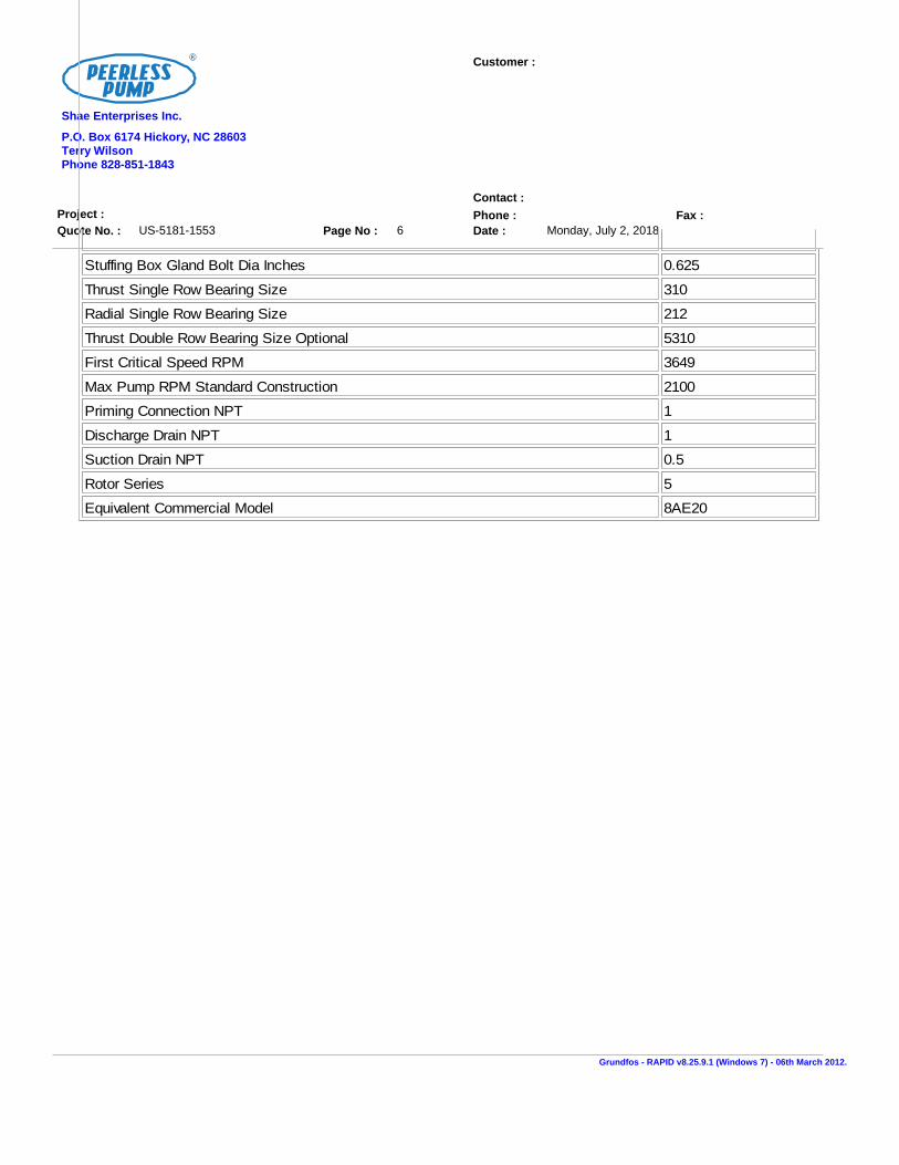
Stuffing Box Gland Bolt Dia Inches 0.625
Thrust Single Row Bearing Size 310
Radial Single Row Bearing Size 212
Thrust Double Row Bearing Size Optional 5310
First Critical Speed RPM 3649
Max Pump RPM Standard Construction 2100
Priming Connection NPT 1
Discharge Drain NPT 1
Suction Drain NPT 0.5
Rotor Series 5
Equivalent Commercial Model 8AE20
Grundfos - RAPID v8.25.9.1 (Windows 7) - 06th March 2012.

Elec. Spec.:
Project :
Customer:
Item No.: 1
Quote No. : US-5181-1553
DC/1 Ph. 12/230 V. 60 Hz
Pump Model: Peerless - 8AEF20
Capacity: 2000 (US gpm)
Total Head: 155 (psi)
Pump Speed: 1780 (RPM)
Impeller Dia.: 19.25 (inch) Rotation: Clockwise
Power: 282 (hp)
Service Factor: 1
Frame/Model: JU6H-UFADW8
Enclosure/Type:
Page No : 7
Date :
Grundfos - RAPID v8.25.9.1 (Windows 7) - 06th March 2012.
P.O. Box 6174 Hickory, NC 28603Terry WilsonPhone 828-851-1843
Monday, July 2, 2018
Shae Enterprises Inc.

Ele
c.
Sp
ec
.:
Pro
ject
:
Cu
sto
mer:
Ite
m N
o.:
1
Qu
ote
No
. :
US
-5181-1
553
DC
/1 P
h.
12/2
30 V
. 60 H
z
Pu
mp
Mo
de
l:P
ee
rle
ss -
8A
EF
20
Cap
acit
y:
2000 (
US
gpm
)
To
tal
Head
:155 (
psi
)
Pu
mp
Sp
ee
d:
1780 (
RP
M)
Imp
ell
er
Dia
.:19.2
5 (
inch
)R
ota
tio
n:
Clo
ckw
ise
Po
we
r:282 (
hp)
Serv
ice F
acto
r:1
Fra
me
/Mo
de
l:JU
6H
-UF
AD
W8
En
clo
su
re/T
yp
e:
Pag
e N
o :
8
Date
:
Gru
nd
fos -
RA
PID
v8.2
5.9
.1 (
Win
do
ws 7
) -
06th
Marc
h 2
012.
P.O
. B
ox 6
174 H
icko
ry,
NC
28603
Terr
yW
ils
on
Ph
on
e 8
28-8
51-1
843
Monday,
July
2,
2018
Sh
ae E
nte
rpri
ses I
nc.

* The pump suction and discharge
piping must be restrained and
supported near the pump to avoid
application of forces and
moments to pump casing.
NOZZLE LOADING MAX IMUM FORCES & MOMENTS*
271254232712355988963559
2000400020008002000800
3390677933904137103644137
2500500025009302330930
2.249 INCH
AGENCYAPPROVAL/LISTING: FM/UL
8 INCH
10 INCH
AIR VENT
DIA 4 HOLES
PLAN VIEW OF FEET
DETAIL - SHAFT END
A-A VIEW FROM DRIVER END
SOME HOLES MAYBE TAPPED
RH ROTATION (CW)LH ROTATION (CCW)
A-A VIEW FROM DRIVER END
PUMP WT 1330 LB / 605 Kg
DISCHARGE FLANGE
SUCTION FLANGE
250 LB ANSIFLG DRILLING
250 LB ANSIFLG DRILLING
125 LB ANSI FLG DRILLING
125 LB ANSI FLG DRILLING
DRAIN 2 PLACES
1/2" NPT BRACKET
42.75
24.0024.00
18.75
DISCHARGE FLANGE
4.004.00
4.884.88
1.12
18.00
32.88
FAR SIDE ONLYSUCTION AND DISCHARGE1/4" NPT GAGE CONNECTION
DISCHARGE FLANGE
SUCTION FLANGE
41.00
20.75
13.0019.25
11.00
1.19 1.62
21.0020.00
2.25 INCH
0.25 INCH
0.5 INCH
1.00
9.509.50
19.00
8.25
8.25
4.00
22.00
SOME HOLES MAYBE TAPPED
Elec. Spec.:
Project :
Customer:
Item No.: 1
Quote No. : US-5181-1553
DC/1 Ph. 12/230 V. 60 Hz
Pump Model: Peerless - 8AEF20
Capacity: 2000 (US gpm)
Total Head: 155 (psi)
Pump Speed: 1780 (RPM)
Impeller Dia.: 19.25 (inch) Rotation: Clockwise
Power: 282 (hp)
Service Factor: 1
Frame/Model: JU6H-UFADW8
Enclosure/Type:
Grundfos - RAPID v8.25.9.1 (Windows 7) - 06th March 2012.
Page No : 9
Date :
P.O. Box 6174 Hickory, NC 28603Terry WilsonPhone 828-851-1843
Monday, July 2, 2018
Shae Enterprises Inc.
Dimensions in (inch)

CLOCKWISERH ROTATION
ELECTRIC MOTOR
DIESEL ENGINE
DISCHARGE
SUCTION
8AEF20
Elec. Spec.:
Project :
Customer:
Item No.: 1
Quote No. : US-5181-1553
DC/1 Ph. 12/230 V. 60 Hz
Pump Model: Peerless - 8AEF20
Capacity: 2000 (US gpm)
Total Head: 155 (psi)
Pump Speed: 1780 (RPM)
Impeller Dia.: 19.25 (inch) Rotation: Clockwise
Power: 282 (hp)
Service Factor: 1
Frame/Model: JU6H-UFADW8
Enclosure/Type:
Grundfos - RAPID v8.25.9.1 (Windows 7) - 06th March 2012.
Page No : 10
Date :
P.O. Box 6174 Hickory, NC 28603Terry WilsonPhone 828-851-1843
Monday, July 2, 2018
Shae Enterprises Inc.
Dimensions in (inch)


FIRE PUMP ENGINES
MODELSJU6H-UFADMG JU6H-UFADP0 JU6H-UFADR0 JU6H-UFADT0JU6H-UFAD58 JU6H-UFADP8 JU6H-UFADR8 JU6H-UFADW8
JU6H-UFADNG JU6H-UFADQ0 JU6H-UFADS8 JU6H-UFADX8JU6H-UFADN0 JU6H-UFAD88 JU6H-UFADS0 JU6H-UFAD98
JU6H
MODEL
RATED SPEED US-EPA (NSPS)
Available Until
1760 2100 2350 2400
UFADMG 175 131 175 131 No Expiration
UFAD58 183 137 No Expiration
UFADNG 190 142 181 135 183 137 183 137 No Expiration
UFADN0 197 147 197 147 200 149 200 149 No Expiration
UFADP0 209 156 211 157 211 157 No Expiration
UFADP8 220 164 No Expiration
UFADQ0 224 167 226 169 226 169 No Expiration
UFAD88 237 177 No Expiration
UFADR0 238 177.5 240 179 240 179 No Expiration
UFADR8 250 187 No Expiration
UFADS8 260 194 No Expiration
UFADS0 260 194 268 200 268 200 No Expiration
UFADT0 274 204 275 205 275 205 No Expiration
UFADW8 282 211 No Expiration
UFADX8 305 227.5 No Expiration
UFAD98 315 235 No Expiration
ITEM
JU6H MODELS
MG 58 NG N0 P8 88 P0 Q0 R0 S0 T0 R8 S8 W8 X8 98Number of Cylinders 6
Aspiration TRWA
Rotation* CW
Overall Dimensions – in. (mm) 59.8 (1519) H x 56.7 (1414) L x 36.7 (933) W 60.9 (1547) H x 58.6 (1488) L x 40.0 (1015) W
Crankshaft Centerline Height – in. (mm) 14 (356)
Weight – lb (kg) 1747 (791)
Compression Ratio 19.0:1 17.0:1
Displacement – cu. in. (L) 415 (6.8)
Engine Type 4 Stroke Cycle – Inline Construction
Bore & Stroke – in. (mm) 4.19 x 5.00 (106 x 127)
Installation Drawing D628
Wiring Diagram AC C07651
Wiring Diagram DC C071367, C072146, C071361 C071368, C072146, C071761
Engine Series John Deere 6068 Series Power Tech E John Deere 6068 Series Power Tech Plus
Speed Interpolation N/A
SPECIFICATIONS
Abbreviations: CW – Clockwise TRWA – Turbocharged with Raw Water Aftercooling N/A - Not Available L – Length W – Width H - Height
*Rotation viewed from Heat Exchanger / Front of engine
FM
®
FM-UL-cUL APPROVED RATINGS BHP/KW
CERTIFIED POWER RATING
• Each engine is factory tested to verify power and performance.
• FM-UL power ratings are shown at specific speeds, Clarke engines can be applied at a single rated RPM setting ± 50 RPM.
Picture represents JU6H-TRWA Power Tech Plus Engine Series
USA EPA (NSPS) Tier 3 Emissions Certified Off-Road (40 CFR Part 89) and NSPS Stationary (40 CFR Part 60 Sub Part llll). Meet EU Stage IIIA emission levels.
All Models available for Export
ENGINE RATINGS BASELINES
• Engines are to be used for stationary emergency standby fire pump service only. Engines are to be tested in accordance with NFPA 25.
• Engines are rated at standard SAE conditions of 29.61 in. (752.1 mm) Hg barometer and 77°F (25°C) inlet air temperature [approximates 300 ft. (91.4 m) above sea level] by the testing laboratory (see SAE Standard J 1349).
• A deduction of 3 percent from engine horsepower rating at standard SAE conditions shall be made for diesel engines for each 1000 ft. (305 m) altitude above 300 ft. (91.4 m)
• A deduction of 1 percent from engine horsepower rating as corrected to standard SAE conditions shall be made for diesel engines for every 10°F (5.6°C) above 77°F (25°C) ambient temperature.

ENGINE EQUIPMENTEQUIPMENT STANDARD OPTIONAL
Air Cleaner Direct Mounted, Washable, Indoor Service with Drip Shield Disposable, Drip Proof, Indoor Service Outdoor Type, Single or Two Stage (Cyclonic)
Alarms Overspeed Alarm & Shutdown, Low Oil Pressure, Low & High Coolant Temperature, Low Raw Water Flow, High Raw Water Temperature, Alternate ECM Warning, Fuel Injection Malfunction, ECM Warning and Failure with Automatic Switching
Low Coolant Level, Low Oil Level, Oil Filter Differential Pressure, Fuel Filter Differential Pressure, Air Filter Restriction
Alternator 12V-DC, 42 Amps with Poly-Vee Belt and Guard 24V-DC, 40 Amps with Poly-Vee Belt and Guard
Coupling Bare Flywheel UL Listed Driveshaft and Guard, JU6H-UFAD58/NG/ADMG/ADM8/K0/N0/Q0/R0-CDS30-S1; JU6H-UFADP8/P0/T0/88/R8/S8/S0/W8/X8/98- CDS50-SC at 1760/2100 RPM only
Electronic Control Module 12V-DC, Energized to Stop, Primary ECM always Powered on 24V-DC, Energized to Stop, Primary ECM always Powered on
Engine Heater 115V-AC, 1360 Watt 230V-AC, 1360 Watt
Exhaust Flex Connection SS Flex, 150# ANSI Flanged Connection, 5” for JU6H-UFAD58/MG/NG/N0/P8/88;
SS Flex, 150# ANSI Flanged Connection, 6” for JU6H-UFADP0/Q0/R0/S0/T0/R8/S8/W8/X8/98 (w/ orifice plate)
SS Flex, 150# ANSI Flanged Connection, 6” for JU6H-UFAD58/MG/NG/N0/P8/88;
SS Flex, 150# ANSI Flanged Connection, 8” for JU6H-UFADP0/Q0/R0/S0/T0/R8/S8/W8/X8/98 (w/ orifice plate)
Exhaust Protection Metal Guards on Manifolds and Turbocharger
Flywheel Housing SAE #3
Flywheel Power Take Off 11.5” SAE Industrial Flywheel Connection
Fuel Connections Fire Resistant, Flexible, USA Coast Guard Approved, Supply and Return Lines
SS, Braided, cUL Listed, Supply and Return Lines
Fuel Filter Primary Filter with Priming Pump
Fuel Injection System High Pressure Common Rail
Governor, Speed Dual Electronic Control Modules
Heat Exchanger Tube and Shell Type, 60 PSI (4 BAR), NPT(F) Connections – Sea Water Compatible
Instrument Panel Multimeter to Display English and Metric, Tachometer, Hourmeter, Water Temperature, Oil Pressure and One (1) Voltmeter with Toggle Switch, Front Opening
Junction Box Integral with Instrument Panel; For DC Wiring Interconnection to Engine Controller
Lube Oil Cooler Engine Water Cooled, Plate Type
Lube Oil Filter Full Flow with By-Pass Valve
Lube Oil Pump Gear Driven, Gear Type
Manual Start Control On Instrument Panel with Control Position Warning Light
Overspeed Control Electronic, Factory Set, Not Field Adjustable
Raw Water Cooling Loop w/Alarms
Galvanized Seawater, All 316SS, High Pressure
Raw Water Cooling Loop Solenoid Operation
Automatic from Fire Pump Controller and from Engine Instrument Panel (for Horizontal Fire Pump Applications)
Not Supplied (for Vertical Turbine Fire Pump Applications)
Run – Stop Control On Instrument Panel with Control Position Warning Light
Starters Two (2) 12V-DC Two (2) 24V-DC
Throttle Control Adjustable Speed Control by Increase/Decrease Button, Tamper Proof in Instrument Panel
Water Pump Centrifugal Type, Poly-Vee Belt Drive with Guard
C133421 revR19JUN15
Specifications and information contained in this brochure subject to change without notice.
FIRE PUMP ENGINES
Fire Protection Products, Inc.100 Progress Place, Cincinnati, Ohio 45246United States of America
Tel +1-513-475-FIRE(3473) Fax +1-513-771-8930www.clarkefire.com
UK, Ltd.Grange Works, Lomond Rd., Coatbridge, ML5-2NNUnited KingdomTel +44-1236-429946 Fax +44-1236-427274www.clarkefire.com
®
®
Abbreviations: DC – Direct Current, AC – Alternating Current, SAE – Society of Automotive Engineers, NPT(F) – National Pipe Tapered Thread (Female), ANSI – American National Standards Institute, SS – Stainless Steel
MODELSJU6H-UFADMG JU6H-UFADP0 JU6H-UFADR0 JU6H-UFADT0JU6H-UFAD58 JU6H-UFADP8 JU6H-UFADR8 JU6H-UFADW8
JU6H-UFADNG JU6H-UFADQ0 JU6H-UFADS8 JU6H-UFADX8JU6H-UFADN0 JU6H-UFAD88 JU6H-UFADS0 JU6H-UFAD98
JU6H - UFADR0John Deere Base Engine
350 Series6 Cylinders
Heat Exchanger Cooled
Power Curve NumberEPA Tier 3 Certified
Built in USAFM Approved
UL Listed
MODEL NOMENCLATURE: (10 Digit Models)


JU6H-UFADW8INSTALLATION & OPERATION DATA (I&O)
USA Produced
Basic Engine DescriptionEngine Manufacturer ......................................................................................................................................................John Deere Co.Ignition Type ......................................................................................................................................................Compression (Diesel)Number of Cylinders ......................................................................................................................................................6Bore and Stroke - in (mm) ......................................................................................................................................................4.19 (106) X 5 (127)Displacement - in³ (L) ......................................................................................................................................................415 (6.8)Compression Ratio ......................................................................................................................................................17.0:1Valves per cylinder
Intake ......................................................................................................................................................2Exhaust ......................................................................................................................................................2
Combustion System ......................................................................................................................................................Direct InjectionEngine Type ......................................................................................................................................................In-Line, 4 Stroke CycleFuel Management Control ......................................................................................................................................................Electronic, High Pressure Common RailFiring Order (CW Rotation) ......................................................................................................................................................1-5-3-6-2-4Aspiration ......................................................................................................................................................TurbochargedCharge Air Cooling Type ......................................................................................................................................................Raw WaterRotation, viewed from front of engine, C lockwise (CW) ......................................................................................................................................................StandardEngine Crankcase Vent System ......................................................................................................................................................OpenInstallation Drawing ......................................................................................................................................................D628Weight - lb (kg) ......................................................................................................................................................1747 (792)
Power Rating 1760Nameplate Power - HP (kW) ¹ ......................................................................................................................................................282 (211)
Cooling System - [C051386] 1760Engine Coolant Heat - Btu/sec (kW) ......................................................................................................................................................133 (140)Engine Radiated Heat - Btu/sec (kW) ......................................................................................................................................................19.1 (20.2)Heat Exchanger Minimum Flow
60°F (15°C) Raw H2O - gal/min (L/min) ......................................................................................................................................................28 (106)
100°F (37°C) Raw H2O - gal/min (L/min) ......................................................................................................................................................38 (144)
Heat Exchanger Maximum Cooling Raw WaterInlet Pressure - psi (bar) ......................................................................................................................................................60 (4.1)Flow - gal/min (L/min) ......................................................................................................................................................40 (151)
Typical Engine H2O Operating Temp - °F (°C) ......................................................................................................................................................180 (82.2) - 195 (90.6)
ThermostatStart to Open - °F (°C) ......................................................................................................................................................180 (82.2)Fully Opened - °F (°C) ......................................................................................................................................................203 (95)
Engine Coolant Capacity - qt (L) ......................................................................................................................................................22.2 (21)Coolant Pressure Cap - lb/in² (kPa) ......................................................................................................................................................15 (103)Maximum Engine Coolant Temperature - °F (°C) ......................................................................................................................................................230 (110)Minimum Engine Coolant Temperature - °F (°C) ......................................................................................................................................................160 (71.1)High Coolant Temp Alarm Switch - °F (°C) ......................................................................................................................................................235 (113) - 241 (116)
Electric System - DC Standard OptionalSystem Voltage (Nominal) ......................................................................................................................................................12 24Battery Capacity for Ambients Above 32°F (0°C)
Voltage (Nominal) ......................................................................................................................................................12 {C07633} 12 {C07633}Qty. Per Battery Bank ......................................................................................................................................................1 2SAE size per J537 ......................................................................................................................................................8D 8DCCA @ 0°F (-18°C) ......................................................................................................................................................1400 1400Reserve Capacity - Minutes ......................................................................................................................................................430 430
Battery Cable C ircuit, Max Resistance - ohm ......................................................................................................................................................0.0012 0.0012Battery Cable Minimum Size
0-120 in. C ircuit Length ² ......................................................................................................................................................00 00121-160 in. C ircuit Length ² ......................................................................................................................................................000 000161-200 in. C ircuit Length ² ......................................................................................................................................................0000 0000
Charging Alternator Maximum Output - Amp, ......................................................................................................................................................40 {C071363} 55 {C071365}Starter C ranking Amps, Rolling - @60°F (15°C) ......................................................................................................................................................440 {RE69704/RE70404} 250 {C07819/C07820}
* All footnotes are at the bottom of Page 2
Page 1 of 2 C133101 Rev H
DSP 17OCT16

JU6H-UFADW8INSTALLATION & OPERATION DATA (I&O)
USA Produced
Exhaust System (Single Exhaust Outlet) 1760Exhaust Flow - ft.³/min (m³/min) ......................................................................................................................................................1400 (39.6)Exhaust Temperature - °F (°C) ......................................................................................................................................................961 (516)Maximum Allowable Back Pressure - in H2O (kPa) ......................................................................................................................................................30 (7.5)
Minimum Exhaust Pipe Dia. - in (mm) ³ ......................................................................................................................................................6 (152)
Fuel System 1760Fuel Consumption - gal/hr (L/hr) ......................................................................................................................................................13.7 (51.9)Fuel Return - gal/hr (L/hr) ......................................................................................................................................................21.3 (80.6)Fuel Supply - gal/hr (L/hr) ......................................................................................................................................................35.0 (132)Fuel Pressure - lb/in² (kPa) ......................................................................................................................................................3 (20.7) - 6 (41.4)Minimum Line Size - Supply - in. .......................................................................................................................................................50 Schedule 40 Steel Pipe
Pipe Outer Diameter - in (mm) ......................................................................................................................................................0.848 (21.5)Minimum Line Size - Return - in. .......................................................................................................................................................375 Schedule 40 Steel Pipe
Pipe Outer Diameter - in (mm) ......................................................................................................................................................0.675 (17.1)Maximum Allowable Fuel Pump Suction Lift
with clean Filter - in H2O (mH2O) ......................................................................................................................................................80 (2)
Maximum Allowable Fuel Head above Fuel pump, Supply or Return - ft (m) ......................................................................................................................................................6.6 (2)Fuel Filter Micron Size ......................................................................................................................................................2 (Secondary)
Heater System Standard OptionalEngine Coolant Heater
Wattage (Nominal) ......................................................................................................................................................1360 1360Voltage - AC , 1 Phase ......................................................................................................................................................115 (+5% -10%) 230 (+5%, -10%)Part Number ......................................................................................................................................................{C123640} {C123644}
Air System 1760Combustion Air Flow - ft.³/min (m³/min) ......................................................................................................................................................474 (13.4)Air C leaner ......................................................................................................................................................Standard Optional
Part Number ......................................................................................................................................................{C03244} {C03327}Type ......................................................................................................................................................Indoor Service Only, Canister,
with Shield Single-StageC leaning method ......................................................................................................................................................Washable Disposable
Air Intake Restriction Maximum LimitDirty Air C leaner - in H2O (kPa) ......................................................................................................................................................14 (3.5) 14 (3.5)
C lean Air C leaner - in H2O (kPa) ......................................................................................................................................................7 (1.7) 5 (1.2)
Maximum Allowable Temperature (Air To Engine Inlet) - °F (°C) ......................................................................................................................................................130 (54.4)
Lubrication SystemOil Pressure - normal - lb/in² (kPa) ......................................................................................................................................................40 (276) - 60 (414)Low Oil Pressure Alarm Switch - lb/in² (kPa) to ......................................................................................................................................................30 (207) - 35 (241)In Pan Oil Temperature - °F (°C) ......................................................................................................................................................220 (104) - 245 (118)Total Oil Capacity with Filter - qt (L) ......................................................................................................................................................34.3 (32.5)
Lube Oil Heater Optional OptionalWattage (Nominal) ......................................................................................................................................................150 150Voltage ......................................................................................................................................................120V (+5%, -10%) 240V (+5%, -10%)Part Number ......................................................................................................................................................{C04430} {C04431}
Performance 1760BMEP - lb/in² (kPa) ......................................................................................................................................................306 (2110)Piston Speed - ft/min (m/min) ......................................................................................................................................................1467 (447)Mechanical Noise - dB(A) @ 1m ......................................................................................................................................................C133379Power Curve ......................................................................................................................................................C132968
NOTE: This engine is intended for indoor installation or in a weatherproof enclosure. ¹ Derate 3% per every 1000 ft. 304.8m above 300 ft. 91.4m and derate 1%for every 10°F 5.55 °C above 77°F 25°C. ² Positive and Negative Cables Combined Length. ³ Minimum Exhaust Pipe Diameter is based on: 15 feet of pipe, one
90° elbow, and one Industrial silencer. A Back-pressure flow analysis must be performed on the actual field installed exhaust system to assure engine maximumallowable back pressure is not exceeded. See Exhaust Sizing Calculator on www.clarkefire.com. { } indicates component reference part number.
Page 2 of 2 C133101 Rev H
DSP 17OCT16

Rating Specific Emissions Data
Nameplate Rating Information
Clarke Model JU6H-UFADW8 Power Rating (BHP/kW) 282/211 Certified Speed (RPM) 1760
Refer to Rating Data section on page 2 for emissions output values

Rating Specific Emissions Data - John Deere Power Systems
Rating Data
Rating 6068HFC48A
Certified Power(kW) 235
Rated Speed 1760
Vehicle Model Number OEM (Clarke Fire Pump-
Units g/kW-hr g/hp-hr
NOx 3.61 2.69
HC 0.08 0.06
NOx + HC N/A N/A
Pm 0.07 0.06
CO 0.6 0.4
Certificate Data
Engine Model Year 2018
EPA Family Name JJDXL13.5103
EPA JD Name 650HAA
EPA Certificate Number JJDXL13.5103-010
CARB Executive Order
Parent of Family 6135HF485A
Units g/kW-hr
NOx 3.31
HC 0.11
NOx + HC N/A
Pm 0.10
CO 0.6
* The emission data listed is measured from a laboratory test engine according to the testprocedures of 40 CFR 89 or 40 CFR 1039, as applicable. The test engine is intended to representnominal production hardware, and we do not guarantee that every production engine will haveidentical test results. The family parent data represents multiple ratings and this data may havebeen collected at a different engine speed and load. Emission results may vary due to enginemanufacturing tolerances, engine operating conditions, fuels used, or other conditions beyondour control.
This information is property of Deere & Company. It is provided solely for the purpose ofobtaining certification or permits of Deere powered equipment. Unauthorized distribution of thisinformation is prohibited.
Emissions Results by Rating run on Jan-30-2018
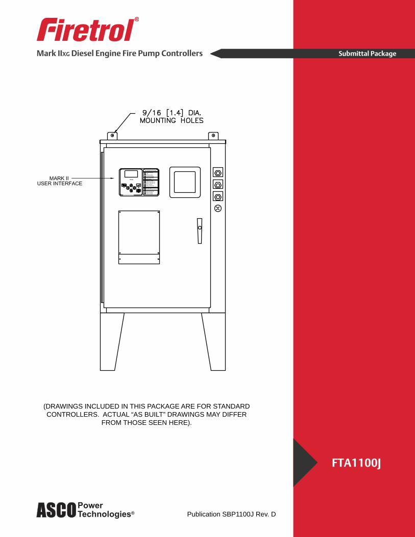
Mark IIXG Diesel Engine Fire Pump Controllers
FTA1100J
Submittal Package
Publication SBP1100J Rev. D
(DRAWINGS INCLUDED IN THIS PACKAGE ARE FOR STANDARDCONTROLLERS. ACTUAL “AS BUILT” DRAWINGS MAY DIFFER
FROM THOSE SEEN HERE).

Firetrol Mark IIxg Diesel Engine Fire Pump ControllerFTA1100J - 12 or 24 VoltSpecifications
1.0 Main Fire Pump ControllerThe main fire pump controller shall be a factory assembled, wired and tested unit. The controller shall be of the combined manual and automatic type designed for diesel engine operation of the fire pump.
1.1 Standards, Listings & ApprovalsThe controller shall conform to all the requirements of the latest editions of:NFPA 20, Standard for the Installation of Stationary Pumps for Fire ProtectionNFPA 70, National Electrical Code.
The controller shall be listed by:Underwriters Laboratories, Inc., in accordance with UL218, Standard for Fire Pump ControllersCanadian Standards Association CSA-C22.2, Standard for Industrial Control Equipment (cUL)
The controller shall be approved by:Factory Mutual (IEC 62091)
1.2 EnclosureThe controller components shall be housed in a NEMA Type 2 (IEC IP22) drip-proof, wall mounted enclosure.
1.3 Operator InterfaceThe fire pump controller shall feature an operator interface with user keypad. The interface shall monitor and display motor operating conditions, including all alarms, events, and pressure condi-tions. All alarms, events, and pressure conditions shall be displayed with a time and date stamp. The display shall be a 128x64 Backlit LCD capable of customized graphics. The display and in-terface shall be NEMA rated for Type 2, 3R, 4, 4X, and 12 protection and shall be fully accessible without opening the controller door. The display and user interface shall utilize multiple levels of password protection for system security. A minimum of 3 password levels shall be provided.
1.4 Digital Status/Alarm MessagesThe digital display shall indicate text messages for the status and alarm conditions of:• Engine Run • Remote Start • Min. Run Time / Off Delay Time • Manual Engine Crank • Engine Fail To Start • Electric Control Module (ECM) Warning • Drive Not Installed • ECM Failure • Disk Error • Low Suction Pressure PLD (Pressure Limiting Driver) • Sequential Start Time • High Raw Water Temp. • Crank/Rest Time Cycle • Clogged Raw Water Strainer • Low Engine Temp. • Interstitial/Fuel Spill • Disk Near Full • Pressure Error
The Sequential Start Timer and Minimum Run Timer/Off Delay Timer shall be displayed as numeric values reflecting the value of the remaining time.

1.5 LED Visual IndicatorsLED indicators, visible with the door closed, shall indicate:• AC Power Available • Alarm • Main Switch in Auto• Main Switch In Manual • System Pressure Low • Engine Running• Engine Fail To Start • Engine Temperature High • Engine Oil Pressure Low • Engine Overspeed • Engine Alternate ECM • Engine Fuel Injector Malfunction• Fuel Level Low • Automatic Shutdown Disabled• Charger Malfunction • Battery #1 Trouble • Battery #2 Trouble
1.6 Data LoggingThe digital display shall monitor the system and log the following data:• Motor Calls/Starts • Pump Total Run Time • Pump Last Run Time • Total Controller Pwr On Time • Last Pump Start • Min/Max System Pressure • Last High Temperature • Last Low Oil Pressure • Last Engine Overspeed • Last Low Fuel Level• Last Charger Fail • Last Battery Trouble • Battery #1 Volts (Min./Now/Max.) • Battery #2 Volts (Min./Now/Max.) • Battery #1 Amps (Min./Now/Max)• Battery #2 Amps (Min./Now/Max.)
1.7 Event RecordingMemory - The controller shall record all operational and alarm events to system memory. All events shall be time and date stamped and include an index number. The system memory shall have the capability of storing 3000 events and allow the user access to the event log via the user interface. The user shall have the ability to scroll through the stored messages in groups of 1 or 10.
1.8 USB Host ControllerThe controller shall have a built-in USB Host Controller. A USB port capable of accepting a USB Flash Memory Disk shall be provided. The controller shall save all operational and alarm events to the flash memory on a daily basis. Each saved event shall be time and date stamped. The total amount of historical data saved shall solely depend on the size of the flash disk utilized. The controller shall have the capability to save settings and values to the flash disk on demand via the user interface.
1.9 Serial CommunicationsThe controller shall feature a RS485 serial communications port for use with 2 or 4 wire Modbus RTU communications.
2.0 Solid State Pressure TransducerThe controller shall be supplied with a solid state pressure transducer with a range of 0-300 psi (0-20.7 bar) ±1 psi. The solid state pressure switch shall be used for both display of the system pressure and control of the fire pump controller. Systems using analog pressure devices or mer-cury switches for operational control will not be accepted.The START, STOP and SYSTEM PRESSURE shall be digitally displayed and adjustable through the user interface. The pressure transducer shall be mounted inside the controller to prevent accidental damage. The pressure transducer shall be directly pipe mounted to a bulkhead pipe coupling without any other supporting members. Field connections shall be made externally at the controller coupling to prevent distortion of the pressure switch element and mechanism.
2.1 Seismic CertificationThe controller shall be certified to meet or exceed the requirements of the 2006 International Build-ing Code and the 2010 California Building Code for Importance Factor 1.5 Electrical Equipment for Sds equal to 1.88 or less severe seismic regions. Qualifications shall be based upon successful tri-axial shake-table testing in accordance with ICC-ES AC-156. Certification without testing shall be unacceptable. Controller shall be clearly labeled as rated for installation in seismic areas and a Certificate of Conformance shall be provided with the controller.
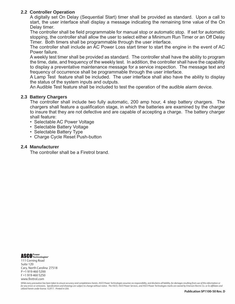
2.2 Controller OperationA digitally set On Delay (Sequential Start) timer shall be provided as standard. Upon a call to start, the user interface shall display a message indicating the remaining time value of the On Delay timer.The controller shall be field programmable for manual stop or automatic stop. If set for automatic stopping, the controller shall allow the user to select either a Minimum Run Timer or an Off Delay Timer. Both timers shall be programmable through the user interface.The controller shall include an AC Power Loss start timer to start the engine in the event of AC Power failure. A weekly test timer shall be provided as standard. The controller shall have the ability to program the time, date, and frequency of the weekly test. In addition, the controller shall have the capability to display a preventative maintenance message for a service inspection. The message text and frequency of occurrence shall be programmable through the user interface.A Lamp Test feature shall be included. The user interface shall also have the ability to display the status of the system inputs and outputs.An Audible Test feature shall be included to test the operation of the audible alarm device.
2.3 Battery ChargersThe controller shall include two fully automatic, 200 amp hour, 4 step battery chargers. The chargers shall feature a qualification stage, in which the batteries are examined by the charger to insure that they are not defective and are capable of accepting a charge. The battery charger shall feature:• Selectable AC Power Voltage• Selectable Battery Voltage• Selectable Battery Type• Charge Cycle Reset Push-button
2.4 ManufacturerThe controller shall be a Firetrol brand.
111 Corning RoadSuite 120Cary, North Carolina 27518P +1 919 460 5200F +1 919 460 5250www.firetrol.comWhile every precaution has been taken to ensure accuracy and completeness herein, ASCO Power Technologies assumes no responsibility, and disclaims all liability, for damages resulting from use of this information or for any errors or omissions. Specifications and drawings are subject to change without notice. The ASCO, ASCO Power Services, and ASCO Power Technologies marks are owned by Emerson Electric Co. or its affiliates and utilized herein under license. ©2017. Printed in USA.
Publication SP1100-50 Rev. D

Description – Firetrol® combined automatic and manual Mark IIXG based diesel engine fire pump controllers are intended for starting and monitoring fire pump diesel engines. They are suitable for use with both mechanical and electronic type engines. The controller is available for 12 or 24 volt negative ground systems, using lead acid or Nickel-Cadmium batteries. The controller monitors, displays and records fire pump system information.
Approvals – Firetrol fire pump controllers are listed by Underwriters’ Laboratories, Inc., in accordance with UL218, Standard for Fire Pump Controllers, CSA, Standard for Industrial Control Equipment (cUL), and approved by Factory Mutual. They are built to meet or exceed the requirements of the approving authorities as well as NEMA and the latest editions of NFPA 20, Installation of Centrifugal Fire Pumps, and NFPA 70, National Electri-cal Code.
Standard Features – The following are included as standard with each controller:� AC Line & Battery circuit breakers� Manual-Off-Auto selector switch� Manual test push-button� Two manual crank push-buttons� Two 10 Amp battery chargers with 4 stage charging cycle,
selectable AC voltage (110 / 220), selectable DC voltage (12 / 24), and selectable battery type (Lead Acid, Ni-Cad 9/18 Cell, Ni-Cad 10/20 Cell)
� Door mounted display/interface panel featuring a 128 x 64 pixel backlit LCD graphical display, Membrane Type User Control Push-buttons and easy to read LED Indicators for:• AC POWER AVAILABLE • ALARM • MAIN SWITCH IN AUTO • MAIN SWITCH IN MANUAL • SYSTEM PRESSURE LOW • ENGINE RUNNING • ENGINE FAIL TO START
• ENGINE TEMPERATURE HIGH • ENGINE OIL PRESSURE LOW • ENGINE OVERSPEED • ENGINE ALTERNATE ECM • ENGINE FUEL INJECTOR MALFUNCTION• FUEL LEVEL LOW• AUTOMATIC SHUTDOWN DISABLED• CHARGER MALFUNCTION• BATTERY #1 TROUBLE• BATTERY #2 TROUBLE
� Minimum Run Timer / Off Delay Timer� Programmable Daylight Saving Time Option• Weekly Test Timer• Engine Run Time Meter� Digital Pressure Display� USB Host Controller and Port� Solid State Pressure Transducer� Data Log� Event Log (3000 events)� Simultaneous Display of Battery Voltages, Charging Rates,
AC Volts, Pressure and Alarm Messages� Disk Error Message� Disk Near Full Message� Pressure Error Message� Fail to Start Message� Low Suction Pressure Message� Crank Cycle Status Indication (Displays Cranking Battery,
Number of Starting Attempts and Crank/Rest Time Remaining)
� 300 psi (20.7 bar) wet parts (solid state pressure transduc-er, solenoid valve, plumbing) for fresh water applications
� NEMA Type 2 enclosure (IEC IP22)� Each standard controller comes with user set options for:
� AC Power Loss Start � Interlock Alarm� Low Pressure Aud. � Low Suction� Main Sw. Mis-Set � Manual Test� Pump Run Alarm � Remote Start� User Defined Input � Weekly Test Setup� Low Pump Rm Temp � Low Reservoir� Relief Valve Open � High Fuel Level� High Reservoir
� Also included (as required) are Audible/Visible alarm notifications for:• Electronic Engine Control Module (ECM) Warning• Electronic Engine Control Module (ECM) Failure� Low Engine Temperature� High Raw Cooling Water Temperature� Low Raw Water Flow (Clogged Stainer)� Fuel Spill (Interstitial Space Liquid Intrusion)� Low Suction Pressure (At Variable Speed Suction Limiting Engine Controls)
Mark IIXG Diesel Engine Fire Pump Controller
FTA1100JProduct Description

Special Enclosures-E Enclosuer, NEMA Type 4 (IEC IP 66), Painted Steel-F Enclosure, NEMA Type 4X (IP66), #304 Stainless Steel,
Brushed Finish-FD Enclosure, NEMA Type 4X (IP66), #316 Stainless Steel,
Brushed Finish-FDB Enclosure, NEMA Type 4X (IP66), #316 Stainless Steel,
12 Gauge, Seam Welded, Brushed Finish-FDP Enclosure, NEMA Type 4X, #316 Stainless Steel,
Painted Finish-FXP Enclosure, NEMA Type 4X (IP66), #304 Stainless Steel
Painted Finish-G Enclosure, NEMA Type 12 (IP54), Painted Steel-T Enclosure, NEMA Type 3R (IP24), Painted Steel
Mounting Legs-N31 Mounting Legs, Standard 12 Inch, Painted Steel-N31S Mounting Legs, Standard 12 Inch, Stainless Steel
Anti-Condensation Space Heaters-H Space Heater, 120V Externally Powered with Circuit Breaker-J Space Heater, 120V Externally Powered with Circuit Breaker and
Thermostat-K Space Heater, 120V Externally Powered with Circuit Breaker and
Humidistat-L Space Heater, 240V Externally Powered with Circuit Breaker-M Space Heater, 240V Externally Powered with Circuit Breaker and
Thermostat-N Space Heater, 240V Externally Powered with Citcuit Breaker and
Humidistat
Pressure Transducers, Solenoid Valves, Plumbing-B Wetted Parts Including Pressure Sensor, 600 PSI (42 Bar), Fresh
Water-C Wetted Parts Including Pressure Sensor, 300 PSI (21 Bar), Sea
Water-D Wetted Parts Including Pressure Sensor, 600 PSI (42 Bar), Sea
Water
Alarms-AC Alarm Output Contacts, Extra, Engine Running (3 Sets)-AJ Alarm Output Contacts, Engine Overspeed-AK Alarm Output Contacts, Low Oil Pressure-AL Alarm Output Contacts, High Water Temperature-AM Alarm Output Contacts, Fail To Start-AN Alarm Output Contacts, Battery / Charger Failure-AP Alarm Output Contacts, Main Switch In Manual-AR Alarm Output Contacts, Main Switch In Off-AS Alarm Output Contacts, Main Switch In Auto-AT Alarm Output Contacts, Pump Room Trouble1
-AV Alarm Output Contacts, Low Pump Room Temperature1 -AW Alarm Output Contacts, Reservoir Low1 -AY Alarm Output Contacts, Low Suction Pressure1 -COM Alarm, Audible/Visible/Output Contacts, Low Suction Pressure
with Manual Reset Option. Pressure Switch Not Included1
-CPL Alarm Output Contacts, Overpressure(for use with PLD engines only)
-CTS Alarm, Audible/Visible/Output Contacts, Low Suction Pressure with Manual Reset Option and Pressure Switch
-ECMFR Alarm Output Contacts, Electronic Engine ECM Failure-ECMWR Alarm Output Contacts, Electronic Engine ECM Warning-EE Alarm Output Contacts, Extra, Engine Trouble (1 Set)-EF Alarm Output Contacts, Extra, Main Switch Not In Auto (1 Set)-EH Alarm Output Contacts, Relief Valve Discharge1 -EJ Alarm, Audible/Visible, Flow Meter On1 -HRTR Alarm Output Contacts, High Raw Water Temperature-EK Alarm Output Contacts, Flow Meter On1 (Requires option -EJ)-LETR Alarm Output Contacts, Low Engine Temperature-LRFR Alarm Output Contacts, Low Raw Water Flow (Clogged Strainer)-JR Visible Indicator, Jockey Pump Operating (Requires Jockey
Pump To Be Ordered With Option -AC)-LSPR Alarm Output Contacts, Low Suction Pressure (at Variable
Speed Suction Limiting Engine Controls)-JT Alarm, Audible/Visible, Jockey Pump Trouble (Requires Jockey
Pump To Be Ordered With Option -KH)-LC Alarm Output Contacts, High Fuel Level1 -LE Alarm Output Contacts, Fuel Spill-LG Alarm Output Contacts, Reservoir High1 -PE Alarm Output Contacts, Low System Pressure (Pump On
Demand)
Miscellaneous-AZ Thermostat, Low Pump Room Temperature, Mounted and
Wired-BA AC Input, 220-240V-EL Series Pumping Operation, High Zone Controller-EM Series Pumping Operation, Mid Zone Controller-EN Series Pumping Operation, Low Zone Controller-IEC Marking, CE With External Wet Parts-IECI Marking, CE With Internal Wet Parts-OSP Marking, OSHPD Seismic Cerrtification, State of California
(Requires Option -SEI)-S Tropicalization-SEI Marking, Seismic Certified (in accordance with IBC)-USBX Data Port, External USB-ZPA Scheduled Service Message-ZPM Data Port, Serial Modbus RTU Over 2-Wire or 4-Wire RS485-ZPN Data Port, Serial Modbus RTU Over Ethernet TCP/IP
FTA1100-K1 Low fuel level switch, 16” max insertion length2 FTA1100-K1-X High/Low fuel level switch - specify levels/tank dimen-
sionsFTA1100-K2 Low fuel level switch, 25” max. insertion length2
FTAK21 380-480 volt operation (transformer)2 Export packaging (Wooden crating to conform to IPPC Standards)
1 - Initiating switches by others2 - Shipped loose for installation by the customer
Product Description - Options & Modifications
111 Corning RoadSuite 120Cary, North Carolina 27518P +1 919 460 5200F +1 919 460 5250www.firetrol.comWhile every precaution has been taken to ensure accuracy and completeness herein, ASCO Power Technologies assumes no responsibility, and disclaims all liability, for damages resulting from use of this information or for any errors or omissions. Specifications and drawings are subject to change without notice. The ASCO, ASCO Power Services, and ASCO Power Technologies marks are owned by Emerson Electric Co. or its affiliates and utilized herein under license. ©2017. Printed in USA.
Publication PD1100-50 Rev. F
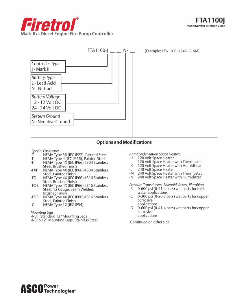
FTA1100-J __ __ N- __ (Example: FTA1100-JL24N-G-AM)
Controller Type J - Mark II
Battery Type L - Lead Acid N - Ni-Cad
Battery Voltage 12 - 12 Volt DC 24 - 24 Volt DC
System Ground N - Negative Ground
Special Enclosures-T NEMA Type 3R (IEC IP22), Painted Steel-E NEMA Type 4 (IEC IP 66), Painted Steel-F NEMA Type 4X (IEC IP66) #304 Stainless Steel, Brushed Finish-FXP NEMA Type 4X (IEC IP66) #304 Stainless Steel, Painted Finish-FD NEMA Type 4X (IEC IP66) #316 Stainless Steel, Brushed Finish-FDB NEMA Type 4X (IEC IP66) #316 Stainless Steel, 12 Gauge, Seam Welded, Brushed Finish-FDP NEMA Type 4X (IEC IP66) #316 Stainless Steel, Painted Finish-G NEMA Type 12 (IEC IP54)
Mounting Legs-N31 Standard 12” Mounting Legs-N31S 12” Mounting Legs, Stainless Steel
Options and Modifications
Anti-Condensation Space Heaters-H 120 Volt Space Heater-J 120 Volt Space Heater with Thermostat-K 120 Volt Space Heater with Humidistat-L 240 Volt Space Heater-M 240 Volt Space Heater with Thermostat-N 240 Volt Space Heater with Humidistat
Pressure Transducers, Solenoid Valves, Plumbing-B 0-600 psi (0-41.4 bars) wet parts for fresh
water applications-C 0-300 psi (0-20.7 bars) wet parts for copper
corrosive applications-D 0-600 psi (0-41.4 bars) wet parts for copper
corrosive applications
Continued on other side
Mark IIXG Diesel Engine Fire Pump Controller
FTA1100JModel Number Selection Guide

Alarms-AC Additional contacts for remote indication, en-
gine running - 2 sets provided as standard-AJ Contacts for remote indication, engine over-
speed-AK Contacts for remote indication, low oil pressure-AL Contacts for remote indication, high water tem-
perature-AM Contacts for remote indication, engine failed to
start-AN Contacts for remote indication, battery / charger
failure-AP Contacts for remote indication, main switch in
manual-AR Contacts for remote indication, main switch in
off-AS Contacts for remote indication, main switch in
auto-AT Contacts for remote indication, pump room
trouble1
-AV Contacts for remote indication, low pump room temperature1
-AW Contacts for remote indication, reservoir low1 -AY Contacts for remote indication, low suction pres-
sure1 -COM Visible low suction pressure alarm,
Manual reset only (Includes reset push-button, initiating pressure switch not included)1
-CPL Contacts for remote indication, system 115% over pressure (for use with PLD engines only)
-CTS Built-in low suction pressure alarm panel (In-cludes selectable auto/manual reset, audible, visible and remote alarms and mounted and wired pressure switch)
-EE Additional contacts for remote indication, en-gine trouble - 1 set provided as standard
-EF Additional contacts for remote indication, main switch mis-set - 1 set provided as standard
-EH Contacts for remote indication, relief valve discharge1
-EJ Audible&Visibleflowmeteronalarm1 -EK Contactsforremoteindication,flowmeteron1
(Requires option -EJ)-JR Visible jockey pump running indication
-JT Audible and visible jockey pump trouble indica-tion
-LC Contacts for remote indication, high fuel level1 -LD Audible & Visible fuel spill alarm1 -LE Contacts for remote indication, fuel spill1 (Re-
quires option -LD)-LG Contacts for remote indication, reservoir high1 -PE Contacts for remote indication, low system
pressure (Pump On Demand)
Miscellaneous-AZ Low pump room temperature switch, mounted
and wired-BA 220-240 Volt operation-EL Series pumping, high zone controller-EM Series pumping, mid zone controller-EN Series pumping, low zone controller-IEC CE Marking with Externally Mounted Wet Parts-IECI CE Marking (Internal Wet Parts)-OSP OSHPDSeismicCertification(StateofCalifor-
nia) (Requires Option -SEI)-S Tropicalization-SEI SeismicCertification(inaccordancewithIBC)-USBX External USB Port-ZPA Customized, annual service display message
(factory programmed)-ZPN Serial Modbus RTU over Ethernet TCP/IP using 5150 Connectivity Module-ZPM Serial Modbus RTU over 2-wire or 4-wire RS485
FTA1100-K1 Low fuel level switch, 16” max insertion length2
FTA1100-K1-X High/Low fuel level switch - specify levels/tank dimensions
FTA1100-K2 Low fuel level switch, 25” max. insertion length2
FTAK21 380-480 volt operation (transformer)2 Export packaging (Wooden crating to conform to IPPC
Standards)
1 - Initiating switches by others2 - Shipped loose for installation by the customer
Model Number Selection Guide - Options & Modifications
111 Corning RoadSuite 120Cary, North Carolina 27518P +1 919 460 5200F +1 919 460 5250www.firetrol.comWhile every precaution has been taken to ensure accuracy and completeness herein, ASCO Power Technologies assumes no responsibility, and disclaims all liability, for damages resulting from use of this information or for any errors or omissions. Specifications and drawings are subject to change without notice. The ASCO, ASCO Power Services, and ASCO Power Technologies marks are owned by Emerson Electric Co. or its affiliates and utilized herein under license. ©2017. Printed in USA.
Publication SD1100-50 Rev. D

Mark IIXG Diesel Engine Fire Pump Controller
FTA1100JWall Mount
Dimensional Drawing

Mark IIXG Diesel Engine Fire Pump Controller
FTA1100JWith Modification N31 - 12” Mounting Legs
Dimensional Drawing
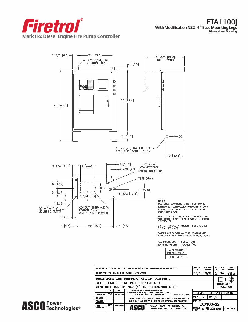
Mark IIXG Diesel Engine Fire Pump Controller
FTA1100JWith Modification N32 - 6” Base Mounting Legs
Dimensional Drawing

Mark IIXG Diesel Engine Fire Pump Controller
FTA1100JWiring Schematic

Mark IIXG Diesel Engine Fire Pump Controller
FTA1100JField Connections

13
Vertical multistage centrifugal pumpsConstruction
CR(E) 1s, 1, 3, 5, 10, 15 and 20
Sectional drawing
Materials: CR(E)
1) CR(E) 1s, 1, 3, 52) CR(E) 10, 15, 203) Stainless steel available on request.4) CF 8M is cast equivalent of AISI 316 stainless steel.5) CRI(E)/CRN(E) 1s, 1, 3, 56) CRN(E) 10, 15, 207) CRI(E) 10, 15, 20
CRI(E), CRN(E) 1s, 1, 3, 5, 10, 15 and 20
Sectional drawing
Materials: CRI(E), CRN(E)
TM0
2 11
98
06
01
- GR
7377
- G
R737
9TM
02
119
4 14
03
Pos. Designation Materials AISI/ASTM
1 Pump head Cast iron A 48-30 B
3 Shaft Stainless steelAISI 316 1)
AISI 431 2)
4 Impeller Stainless steel AISI 304
5 Chamber Stainless steel AISI 304
6 Outer sleeve Stainless steel AISI 304
7O-ring for outer sleeve
EPDM or FKM
8 Base Cast iron A 48-30 B
9 Neck ring PTFE
10 Shaft seal Cartridge type
Bearing rings Silicon carbide
Rubber parts EPDM or FKM
1
3
10
4
5
9
8
67
TM0
2 18
08
200
1 - G
R737
3 - G
R737
5TM
03
2156
380
5
Pos. Designation Materials AISI/ASTM
1 Pump head Cast iron 3) A 48-30 B
2 Pump head cover Stainless steel CF 8M 4)
3 Shaft Stainless steelAISI 316 5)
AISI 329 6)
AISI 431 7)
8 Base Stainless steel CF 8M4)
9 Neck ring PTFE
10 Shaft seal Cartridge type
11 Base plate Cast iron 3) A 48-30 B
Bearing rings Silicon carbide
Rubber parts EPDM or FKM
CRI(E)
4 Impeller Stainless steel AISI 304
5 Chamber Stainless steel AISI 304
6 Outer sleeve Stainless steel AISI 304
7 O-ring for outer sleeve EPDM or FKM
12 FGJ flange ring Ductile iron 3) A 65-45-12
CRN(E)
4 Impeller Stainless steel AISI 316
5 Chamber Stainless steel AISI 316
6 Outer sleeve Stainless steel AISI 316
7 O-ring for outer sleeve EPDM or FKM
12 FGJ flange ring Ductile iron 3) A 65-45-12
1
2 10
4
5
8
6
3
7
9
1211
CrCriCrn.book Page 13 Tuesday, September 27, 2005 2:47 PM


32
TM0
2 40
84 1
303C
R(E
), C
RI(
E), C
RN
(E)
3
0 2 4 6 8 10 12 14 16 18 20 22 Q [US GPM]
0
50
100
150
200
250
300
350
400
450
500
550
600
650
700
750
800[ft]H
0.0 0.5 1.0 1.5 2.0 2.5 3.0 3.5 4.0 4.5 5.0 Q [m³/h]
0
20
40
60
80
100
120
140
160
180
200
220
240
[m]H
0
50
100
150
200
250
300
350
400
450
500
550
600
650
700
750
800[ft]H
CR(E) 3
2-pole, 60 Hz
CRI(E) 3
CRN(E) 3
-2
-3 (E)
-4
-5 (E)
-6 (E)
-7
-8
-9 (E)
-10
-11
-12 (E)
-13
-15 (E)
-17
-19 (E)
-21
-23
-25 (E)
0 2 4 6 8 10 12 14 16 18 20 22 Q [US GPM]
0.00
0.05
0.10
0.15
P2[hp]
0
20
40
60
Eff[%]
0.00
0.05
0.10
P2[kW]
P2
Eff
0 2 4 6 8 10 12 14 16 18 20 22 Q [US GPM]
0
5
10
NPSH[ft]
0
2
[m]H
0
5
10
[ft]H
NPSHR
Performance curves CR(E) 3, CRI(E) 3, CRN(E) 3
CrCriCrn.book Page 32 Tuesday, September 27, 2005 2:47 PM
Pavilion
Line
Pavilion
Line
Pavilion
Line
Pavilion
Line
Pavilion
Line
Pavilion
Line
Pavilion
Highlight
Pavilion
Highlight
Pavilion
Highlight
Pavilion
Highlight
Pavilion
Highlight
Pavilion
Line
Pavilion
Line

33
Technical data CR(E) 3
Dimensional sketches
Dimensions and weights
TM0
3 14
50 2
205
7/8" M10 x 40
B2
G 1/2 PLUG
3"
2"
13/1
6"
B1
5 11/16"3 15/16"
6 5/16"7 1/16"
8 11/16"
4 x ø1/2"
WITH 1/4"TAPFOR GAUGE/SENSOR
PRIMINGPORT (G 1/2)
DISCHARGESUCTION AND1"NPT (F)
PLUG (G 1/2)DRAIN
D2
D1
TM0
3 14
51 2
205
G 1/2 PLUG
B1
WITH 1/4"TAPFOR GAUGE/SENSOR
PRIMINGPORT (G 1/2)
DISCHARGESUCTION AND1 1/4"250 lb.R.F.
PLUG (G 1/2)DRAIN
ø1 3/8"
ø5
1/2"
3"
13/1
6"
5 9/16"3 15/16"
9 7/8"
ø3
15/1
6"ø
3 1/
2"
7 1/16"8 11/16"
4 x ø1/2"
3/4"x1"
B2
D2
D1
Pump type Hp Ph VoltageNEMAFrame
size
OvalB1
ANSIB1
TEFC OvalShip
Wt.1
[lbs.]
ANSIShip
Wt.1
[lbs.]
MLE OvalShip
Wt.1
[lbs.]
ANSIShip
Wt.1
[lbs.]D1 D2
OvalB1+B2
ANSIB1+B2
D1 D2Oval
B1+B2ANSI
B1+B2
CR 3-2 1/31 115/230 56C 11 12 6 1/4 5 20 3/8 21 3/8 53 62 - - - -
3 208-230/460 56C 11 12 5 5/8 4 5/8 18 5/8 19 5/8 53 62 - - - -
CR(E) 3-3 1/21 115/230 56C 11 12 6 1/4 5 20 3/8 21 3/8 52 61 5 1/2 5 1/2 18 1/2 19 1/2 54 63
3 208-230/460 56C 11 12 5 5/8 4 5/8 18 5/8 19 5/8 53 62 - - - - - -
CR 3-4 3/41 115/208-230 56C 11 3/4 12 3/4 6 1/4 5 21 3/4 22 3/4 54 64 - - - - - -
3 208-230/460 56C 11 3/4 12 3/4 5 5/8 4 5/8 19 3/8 20 3/8 53 62 - - - - - -
CR(E) 3-5 3/41 115/208-230 56C 12 1/2 13 1/2 6 1/4 5 22 1/2 23 1/2 55 64 5 1/2 5 1/2 20 21 57 66
3 208-230/460 56C 12 1/2 13 1/2 5 5/8 4 5/8 20 1/8 21 1/8 54 63 - - - - - -
CR(E) 3-6 11 115-230 56C 13 1/8 14 1/8 7 1/4 5 3/4 24 3/8 25 3/8 57 66 5 1/2 5 1/2 22 1/4 23 1/4 60 69
3 208-230/460 56C 13 1/8 14 1/8 5 5/8 4 5/8 22 23 54 64 7 6 5/8 24 5/8 25 5/8 73 82
CR 3-7 1 1/21 115/208-230 56C 13 7/8 14 7/8 7 1/4 5 3/4 25 5/8 26 5/8 65 75 - - - - - -
3 208-230/460 56C 13 7/8 14 7/8 5 5/8 4 5/8 22 3/4 23 3/4 54 64 - - - - - -
CR 3-8 1 1/21 115/208-230 56C 14 5/8 15 5/8 7 1/4 5 3/4 26 3/8 27 3/8 67 77 - - - - - -
3 208-230/460 56C 14 5/8 15 5/8 5 5/8 4 5/8 23 1/2 24 1/2 55 65 - - - - - -
CR(E) 3-9 1 1/21 115/208-230 56C 15 1/4 16 1/4 7 1/4 5 3/4 27 28 69 79 5 1/2 5 1/2 24 3/8 25 3/8 69 78
3 208-230/460 56C 15 1/4 16 1/4 5 5/8 4 5/8 24 1/8 25 1/8 57 67 7 6 5/8 26 3/4 27 3/4 81 91
CR 3-10 21 115-230 56C 16 17 7 1/4 5 3/4 28 5/8 29 5/8 74 84 - - - - - -
3 208-230/460 56C 16 17 7 1/8 4 3/8 27 1/2 28 1/2 77 87 - - - - - -
CR 3-11 21 115-230 56C 16 3/4 17 3/4 7 1/4 5 3/4 29 3/8 30 3/8 77 86 - - - - - -
3 208-230/460 56C 16 3/4 17 3/4 7 1/8 4 3/8 28 1/4 29 1/4 79 88 - - - - - -
CR(E) 3-12 21 115-230 56C 17 3/8 18 3/8 7 1/4 5 3/4 30 31 78 87 - - - - - -
3 208-230/460 56C 17 3/8 18 3/8 7 1/8 4 3/8 28 7/8 29 7/8 80 89 7 6 5/8 28 7/8 29 7/8 98 107
CR 3-13 31 115/208-230 182TC 19 1/4 20 1/8 8 5/8 6 7/8 33 3/4 34 5/8 95 104 - - - - - -
3 208-230/460 182TC 19 1/4 20 1/8 7 1/8 4 3/8 31 31 7/8 82 91 - - - - - -
CR(E) 3-15 31 115/208-230 182TC 20 5/8 21 5/8 8 5/8 6 7/8 35 1/8 36 1/8 96 105 - - - - - -
3 208-230/460 182TC 20 5/8 21 5/8 7 1/8 4 3/8 32 3/8 33 3/8 83 92 7 6 5/8 34 35 111 120
CR 3-17 31 115/208-230 182TC 22 23 8 5/8 6 7/8 36 1/2 37 1/2 97 106 - - - - - -
3 208-230/460 182TC 22 23 7 1/8 4 3/8 33 3/4 34 3/4 84 93 - - - - - -
CR(E) 3-19 31 115/208-230 182TC - 24 3/8 8 5/8 6 7/8 - 38 7/8 - 107 - - - - - -
3 208-230/460 182TC - 24 3/8 7 1/8 4 3/8 - 36 1/8 - 94 7 6 5/8 - 37 3/4 123
CR 3-21 51 208-230 182TC - 25 7/8 10 5/8 7 1/2 - 41 1/4 - 116 - - - - - -
3 208-230/460 182TC - 25 7/8 7 1/8 4 3/8 - 39 1/8 - 95 - - - - - -
CR 3-23 51 208-230 182TC - 27 1/4 10 5/8 7 1/2 - 42 5/8 - 118 - - - - - -
3 208-230/460 182TC - 27 1/4 7 1/8 4 3/8 - 40 1/2 - 97 - - - - - -
CR(E) 3-25 51 208-230 182TC - 28 5/8 10 5/8 7 1/2 - 44 - 121 - - - - - -
3 208-230/460 182TC - 28 5/8 7 1/8 4 3/8 - 41 7/8 - 99 8 3/4 7 1/2 - 44 1/8 162
Weights are based on pump with TEFC motor (see price list for individual weights)
All dimensions in inches unless otherwise noted.
CrCriCrn.book Page 33 Tuesday, September 27, 2005 2:47 PM
Pavilion
Line
Pavilion
Highlight
Pavilion
Highlight
Pavilion
Highlight
Pavilion
Highlight
Pavilion
Highlight
Pavilion
Highlight
Pavilion
Line
Pavilion
Line
Pavilion
Oval

Limited Option Jockey XG Pump Controller
FTA550F
Submittal Package
Publication SBP550F Rev. B
(DRAWINGS INCLUDED IN THIS PACKAGE ARE FOR STANDARDCONTROLLERS. ACTUAL “AS BUILT” DRAWINGS MAY DIFFER
FROM THOSE SEEN HERE).

Firetrol Limited Option JockeyXG Pump ControllerFTA550F - Full Voltage StartingSpecifications
1.0 Main Fire Pump ControllerThe auxiliary jockey pump controller, if required and specified on the plans and specifications, shall be factory assembled, wired, and tested and specifically designed for this type of service. This controller shall be of the same manufacturer as the main fire pump controller.
1.1 Standards, Listings & ApprovalsThe controller shall conform to all the requirements of the latest editions of:NFPA 70, National Electrical Code.
The controller shall be listed by:Underwriters Laboratories, Inc., in accordance with UL508A, Standard for Industrial ControlsCanadian Standards Association CSA-C22.2, Standard for Industrial Control Equipment (cUL)
1.2 EnclosureThe controller components shall be housed in a NEMA Type 2/12 (IEC IP22/IP54) polycarbonate, wall mounted enclosure (UL50E Construction).
1.3 Withstand Ratings (Short Circuit Current Ratings)The jockey shall have standard short circuit current ratings of:30kA @ 480 Volts Max. (3-Phase)18kA @ 600 Volts (3-Phase)5kA @ 240 Volts Max. (1-Phase)
1.4 ConstructionThe jockey pump controller shall be full voltage starting, rated for wye-connected power systems above 240V. The controller shall incorporate a horsepower rated manual circuit protector and starting contactor, control circuit transformer with 24VAC secondary and 200-600V multi-tap pri-mary, main disconnect switch, HAND-OFF-AUTOMATIC selector switch and a 0-300 psi (0-20.7 bar) stainless steel solid state pressure transducer.
1.5 Operator InterfaceThe fire pump controller shall feature an operator interface with user keypad. The interface shall monitor and display motor operating conditions, including all alarms, events, and pressure condi-tions. All alarms, events, and pressure conditions shall be displayed with a time and date stamp. The display shall be a 128x64 Backlit LCD capable of customized graphics. The display and in-terface shall be NEMA rated for Type 2, 3R, 4, 4X, and 12 protection and shall be fully accessible without opening the controller door. The display and user interface shall utilize multiple levels of password protection for system security. A minimum of 3 password levels shall be provided.
1.6 Digital Status/Alarm MessagesThe digital display shall indicate text messages for the status and alarm conditions of:
• Pump Running • Sequential Start Time • Minimum Run Time • Low System Pressure • Pump Restart Timer • Fail to Start • Automatic Start • System Overpressure • User Selectable #11
• Main Switch Position • User Selectable #21
1 User may choose from the following to be shown on main display (stop pressure setting, start pressure setting, cycles/period, cycles/month, cycles/day, cycles/hour, total cycle count, pump total run time)
The Sequential Start Timer, Minimum Run Timer/Off Delay Timer and Pump Restart Timer shall be displayed as numeric values reflecting the value of the remaining time.
1.7 LED Visual IndicatorsLED indicators, visible with the door closed, shall indicate:• Power ON • Alarm • Pump Running
1.8 Event RecordingMemory - The controller shall record all operational and alarm events to system memory. All events shall be time and date stamped and include an index number. The system memory shall have the capability of storing 3000 events and allow the user access to the event log via the user interface. The user shall have the ability to scroll through the stored messages in groups of 1 or 10.
1.9 Serial CommunicationsThe controller shall feature a RS485 serial communications port for use with 2 or 4 wire Modbus RTU communications.
2.0 Solid State Pressure TransducerThe controller shall be supplied with a solid state pressure transducer with a range of 0-300 psi (0-20.7 bar) ±1 psi. The solid state pressure switch shall be used for both display of the system pressure and control of the fire pump controller. Systems using analog pressure devices or mer-cury switches for operational control will not be accepted.The START, STOP and SYSTEM PRESSURE shall be digitally displayed and adjustable through the user interface. The pressure transducer shall be mounted inside the controller to prevent accidental damage. The pressure transducer shall be directly pipe mounted to a bulkhead pipe coupling without any other supporting members. Field connections shall be made externally at the controller coupling to prevent distortion of the pressure switch element and mechanism.
2.1 Seismic CertificationThe controller shall be certified to meet or exceed the requirements of the 2006 International Build-ing Code and the 2010 California Building Code for Importance Factor 1.5 Electrical Equipment for Sds equal to 1.88 or less severe seismic regions. Qualifications shall be based upon successful tri-axial shake-table testing in accordance with ICC-ES AC-156. Certification without testing shall be unacceptable. Controller shall be clearly labeled as rated for installation in seismic areas and a Certificate of Conformance shall be provided with the controller.NOTE: Not available on Model FTA1500 Controllers
2.2 Controller OperationA digitally set On Delay (Sequential Start) timer shall be provided as standard. Upon a call to start, the user interface shall display a message indicating the remaining time value of the On Delay timer.The controller shall include a Minimum Run Timer to allow the motor to run for a set period of timer after starting. The timer shall be programmable through the user interface.A pump restart delay timer shall be provided to allow the residual voltage of the motor to decay prior to restarting the motor and to prevent severe short cycling of the motor. The timer shall be programmable through the user interface.

A Lamp Test feature shall be included. The user interface shall also have the ability to display the status of the system inputs and outputs.An Audible Test feature shall be included to test the operation of the audible alarm device (if supplied). The disconnect switch shall be mechanically interlocked so that the enclosure door cannot be opened with the handle in the ON position except by a hidden tool operated defeater mechanism. The disconnect switch shall be capable of being padlocked in the OFF position for installation and maintenance safety.
2.3 ManufacturerThe controller shall be a Firetrol brand.
111 Corning RoadSuite 120Cary, North Carolina 27518P +1 919 460 5200F +1 919 460 5250www.firetrol.comWhile every precaution has been taken to ensure accuracy and completeness herein, ASCO Power Technologies assumes no responsibility, and disclaims all liability, for damages resulting from use of this information or for any errors or omissions. Specifications and drawings are subject to change without notice. The ASCO, ASCO Power Services, and ASCO Power Technologies marks are owned by Emerson Electric Co. or its affiliates and utilized herein under license. ©2017. Printed in USA.
Publication SP550F-01 Rev. D

Description—Firetrol® FTA550F XG Jockey Pump Controllers are intended for use with fire pump systems. They are used for pressure maintenance in fire pump installations to prevent unnecessary operation of the main fire pump.
Approvals—Firetrol jockey pump controllers are listed by Underwriters’ Laboratories, Inc., in ac-cordance with UL508A, Standard for Industrial Controls, and CSA, Standard for Industrial Control Equipment. They are built to meet or exceed the requirements of the approving authorities as well as NEMA and the latest edition NFPA 70, National Electrical Code.
Standard Features—The following are included as standard with each controller:· NEMA Type 2/12 (IEC IP22/IP54) Polycarbonate
enclosure (UL50E Construction)· Horsepower rated motor circuit protector and
starting contactor· Suitable for use as service equipment· HAND-OFF-AUTO selector switch· Minimum run timer· On-Delay timer· Pump Restart Timer· Control circuit transformer with 24VAC
secondary· 0-300 psi (0-20.7 bar) stainless steel solid state
pressure transducer· Overpressure indication
· Low Pressure indication· Failed to start indication· Main switch not in “Auto” alarm· Pressure recording· Event log (3000 events stored in controller
memory)· Data log (including cycle counter)· Door mounted display/user interface featuring
a 128 x 64 pixel backlit LCD Graphical Display, Membrane Type User Controller Push-buttons and LED indication for:· Power ON· Pump Running· Alarm
· 2 lines of user selectable display information
NOTE: FTA550F XG Jockey Pump Controllers are only available in the voltage/horsepower combinations shown below and with the op-tions shown on the reverse side. For other combinations and options, see documen-tation for FTA550E series XG Jockey Pump Controllers.
VOLTAGE 3-PHASE MAX HP Short Circuit(50/60 Hertz) (MCP) Current Rating
-H 200-208 7.5 30kA-A 220-240 10 30kA-F 380-415V - WYE 15 30kA-B 440-480V - WYE 20 30kA-C 550-600V - WYE 20 18kA
VOLTAGE 1-PHASE MAX HP Short Circuit(50/60 Hertz) (MCP) Current Rating
-D 110-120 Volts 2 5kA-T 200-208 Volts 3 5kA-E 220-240 Volts 5 5kA
NOTE: Firetrol Brand Jockey Pump controllers DO NOT CONTAIN MERCURY filled pressure switches.
Limited Option JockeyXG Pump Controller
FTA550FProduct Description

OPTIONS & MODIFICATIONS
SPECIAL ENCLOSURES-E Enclosure, NEMA Type 4 (IP66)*-F Enclosure, NEMA Type 4X (IP66)*-T Enclosure, NEMA Type 3R (IP24)*
*Supplied with non-metallic enclosure
ANTI-CONDENSATION SPACE HEATERS1
-J Space Heater, 120V Externally Powered with Circuit Breaker and Thermostat
-K Space Heater, 120V Externally Powered with Circuit Breaker and Humidistat
-M Space Heater, 240V Externally Powered with Circuit Breaker and Thermostat
-N Space Heater, 240V Externally Powered with Circuit Breaker and Humidistat
1 Power source supplied by others
PRESSURE TRANSDUCERS -B Wetted Parts Including Pressure Sensor, 600
PSI (42 Bar), Fresh Water-C Wetted Parts Including Pressure Sensor, 300
PSI (21 Bar), Sea Water-D Wetted Parts Including Pressure Sensor, 600
PSI (42 Bar), Sea Water
MISCELLANEOUS-AC Alarm Output Contacts, Pump Operating (2
Sets)-AM Alarm Output Contacts, Fail To Start-AST Input Terminals, Automatic Start-BW Alarm Output Contacts, Phase Failure/Phase
Reversal
-BY Alarm Output Contacts, Pump Overload-EF Alarm Output Contacts, Main Switch Not In
Auto (1 Set)-HV Alarm, Audible-IECI Marking, CE With Internal Wet Parts-KH Alarm Output Contacts, Common Alarm-NZ Input Terminals, Shutdown Interlock-OSP Marking, OSHPD Seismic Certification (State
of California) (Requires option -SEI)-S Tropicalization-SEI Marking, Seismic Certified-ZPA Scheduled Service Message-ZPJ Data Port, Serial Modbus RTU Over 2-Wire or
4-Wire RS485
*Export Packaging available for additional cost
NOTE: For requirements not listed here (higher short circuit ratings, larger horsepowers, options not listed...etc) please refer to documentation for FTA550E series Jockey Pump Controllers.
Product Description - Options & Modifications
111 Corning RoadSuite 120Cary, North Carolina 27518P +1 919 460 5200F +1 919 460 5250www.firetrol.comWhile every precaution has been taken to ensure accuracy and completeness herein, ASCO Power Technologies assumes no responsibility, and disclaims all liability, for damages resulting from use of this information or for any errors or omissions. Specifications and drawings are subject to change without notice. The ASCO, ASCO Power Services, and ASCO Power Technologies marks are owned by Emerson Electric Co. or its affiliates and utilized herein under license. ©2017. Printed in USA.
Publication PD550F-01 Rev. D

FTA550F JOCKEYxg PUMP CONTROLLERS
FTA NUMBERFTA550F
TIMER OPTION-A With Programmable
Running Period Timer
MOTOR CURRENT PROTECTION -G Manual Motor Protector
*Suitable for Use as Service Equipment*Short Circuit Current Rating
3 Phase --200-480V - 30kA /600V - 18kA1 Phase -- 110-240V - 5kA
HORSEPOWER (KW)014 - 1/4 HP (.18) 004 - 4 HP (3)013 - 1/3 HP (.23) 005 - 5 HP (3.7)012 - 1/2 HP (.37) 006 - 5 1/2 HP (4)034 - 3/4 HP (.56) 007 - 7 1/2 HP (5.5)001 - 1 HP (.75) 010 - 10 HP (7.5)011 - 1 1/2 HP (1.1) 015 - 15 HP (11)002 - 2 HP (1.5) 020 - 20 HP (15)003 - 3 HP (2.2)
(See Voltage Selection for Maximum HP/Voltage Combinations)
FTA550F-A G __ __ __ __ - __ (Example: FTA550F-AG015B-T-BY)
OPTIONS & MODIFICATIONS(See other side)
VOLTAGE 3-PHASE MAX HP (50/60 Hertz)
-H 200-208 Volts 7.5-A 220-240 Volts 10-F 380-415V - WYE 15-B 440-480V - WYE 20-C 550-600V - WYE 20
VOLTAGE 1-PHASE MAX HP (50/60 Hertz)
-D 110-120 Volts 2-T 200-208 Volts 3-E 220-240 Volts 3
NOTE: For requirements not listed here (higher short circuit ratings, larger horsepowers, options not listed...etc) please refer to documentation for FTA550E series Jockey Pump Controllers.
Limited Option JockeyXG Pump Controller
FTA550FModel Number Selection Guide

OPTIONS & MODIFICATIONS
SPECIAL ENCLOSURES-E Enclosure, NEMA Type 4 (IP66)*-F Enclosure, NEMA Type 4X (IP66)*-T Enclosure, NEMA Type 3R (IP24)*
*Supplied with non-metallic enclosure
ANTI-CONDENSATION SPACE HEATERS1
-J Space Heater, 120V Externally Powered with Circuit Breaker and Thermostat
-K Space Heater, 120V Externally Powered with Circuit Breaker and Humidistat
-M Space Heater, 240V Externally Powered with Circuit Breaker and Thermostat
-N Space Heater, 240V Externally Powered with Circuit Breaker and Humidistat
1 Power source supplied by others
PRESSURE TRANSDUCERS -B Wetted Parts Including Pressure Sensor, 600
PSI (42 Bar), Fresh Water-C Wetted Parts Including Pressure Sensor, 300
PSI (21 Bar), Sea Water-D Wetted Parts Including Pressure Sensor, 600
PSI (42 Bar), Sea Water
MISCELLANEOUS-AC Alarm Output Contacts, Pump Operating (2
Sets)-AM Alarm Output Contacts, Fail To Start-AST Input Terminals, Automatic Start
-BW Alarm Output Contacts, Phase Failure/Phase Reversal
-BY Alarm Output Contacts, Pump Overload-EF Alarm Output Contacts, Main Switch Not In
Auto (1 Set)-HV Alarm, Audible-IECI Marking, CE With Internal Wet Parts-KH Alarm Output Contacts, Common Alarm-NZ Input Terminals, Shutdown Interlock-OSPMarking,OSHPDSeismicCertification(State
of California) (Requires option -SEI)-S Tropicalization-SEI Marking,SeismicCertified-ZPA Scheduled Service Message-ZPJ Data Port, Serial Modbus RTU Over 2-Wire or
4-Wire RS485
*Export Packaging available for additional cost
NOTE: For requirements not listed here (higher short circuit ratings, larger horsepowers, options not listed...etc) please refer to documentation for FTA550E series Jockey Pump Controllers.
Model Number Selection Guide - Options & Modifications
111 Corning RoadSuite 120Cary, North Carolina 27518P +1 919 460 5200F +1 919 460 5250www.firetrol.comWhile every precaution has been taken to ensure accuracy and completeness herein, ASCO Power Technologies assumes no responsibility, and disclaims all liability, for damages resulting from use of this information or for any errors or omissions. Specifications and drawings are subject to change without notice. The ASCO, ASCO Power Services, and ASCO Power Technologies marks are owned by Emerson Electric Co. or its affiliates and utilized herein under license. ©2017. Printed in USA.
Publication SD550F-01 Rev. D
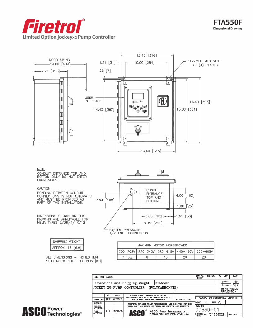
Limited Option JockeyXG Pump Controller
FTA550FDimensional Drawing

Limited Option JockeyXG Pump Controller
FTA550F3 Phase
Wiring Schematic

Limited Option JockeyXG Pump Controller
FTA550FOptions and Modifications
Wiring Schematic

Limited Option JockeyXG Pump Controller
FTA550F220-240V - 1 Phase
Wiring Schematic

Limited Option JockeyXG Pump Controller
FTA550F110-120V - 1 Phase
Wiring Schematic

Fire Protection Pressure Relief Valve
50B-4KG1 Globe2050B-4KG1 Angle
MODEL
• U.L. Listed / U.L.C. Listed
• Factory Mutual Approved
• Fast Opening to Maintain Steady Line Pressure
• Accommodates Wide Range of Flow Rates
• Closes Gradually for Surge-Free Operation
• Adjustable Pressure Settings, Not Affected by Pressure At Valve Discharge
The Cla-Val Model 50B-4KG1 Globe / 2050B-4KG1 Angle
Pressure Relief Valve is designed specifically to automati-
cally relieve excess pressure in fire protection pumping sys-
tems. Pilot controlled, it maintains constant system pres-
sure at the pump discharge within very close limits as
demands change. The 50B-4KG1 and 2050B-4KG1 can be
supplied with optional internal and external epoxy coating of
the main valve wetted surfaces.
At pump start, Cla-Val Relief Valve modulates to relieveexcess pump capacity, maintaining positive system pres-sure at the pump discharge.
When fire demand slows or ceases, Cla-Val Model50B-4KG1 opens, diverting entire pump output to dis-charge, allowing fire pump to be stopped without causingsurging in the lines.
(Please note that if the Model 50B-4KG1 is to be used ona continuous duty basis to maintain fire-system pressure,suitable back pressure must be provided on the valve toprevent cavitation damage. Consult the factory for details.)
Operation SequenceTypical Application Model 2050B-4KG1Pressure Relief Valve
(Angle Pattern)
Fire Pump
Check Valve
"Fluid Control at It's Best"
2050B-4KG1 (Angle)
To Fire Protection System
U.L. Listed...............Sizes 3" thru 8" F.M. Approved.........Sizes 3" thru 8"U.L.C. Listed............Sizes 2” thru 10”
LABLLED BY
UN
DE
RW
RITERS LABORATORIE
SO
FC
AN
AD
AULC
Pavilion
Highlight

PO Box 1325 Newport Beach CA 92659-0325 Phone: 949-722-4800Fax: 949-548-5441 Web Site: cla-val.com E-mail: [email protected]
CLA-VAL
CLA-VAL CANADA CLA-VAL EUROPE4687 Christie DriveBeamsville, OntarioCanada L0R 1B4Phone: 905-563-4963Fax: 905-563-4040E-Mail: [email protected]
Chemin des Mésanges 1CH-1032 Romanel/Lausanne, SwitzerlandPhone: 41-21-643-15-55Fax: 41-21-643-15-50E-Mail: [email protected]
Copyright CLA-VAL 2011 Printed in USA Specifications subject to change without notice.
CLA-VAL UKDainton House, Goods Station RoadGB - Tunbridge Wells Kent TN1 2 DH EnglandPhone: 44-1892-514-400Fax: 44-1892-543-423E-Mail: [email protected]
©
Represented By:
Specifications Seawater Service OptionSizes Globe: 2" - 10" flanged
Angle: 2" - 10" flangedConsult factory for materials and flange ratings.
E-50B-4KG1 (R-9/2011)
Valve Size (mm) 50 100 150 200
G & H 152 200 216
Threaded Ends 238 -- -- --
248
A 150 Flanged 238 381 508 645
300 Flanged 254 397 533 670
300 x 150 -- 389 522 657
C 305 330 363 414
D 38 81 109 135
Threaded Ends 121 -- -- --
E 150 Flanged 121 191 254 324
300 Flanged 127 200 267 337
Threaded Ends 83 -- -- --
F 150 Flanged 83 127 152 203
300 Flanged 89 135 165 216
250
--
337
756
790
773
457
235
--
378
395
--
219
236
300
--
362
864
902
883
522
273
--
432
451
--
349
368
300B 84 146 200 254 356
80
197
318
305
337
327
318
65
116
159
152
162
114
102
111
65
170
279
279
295
--
311
43
102
140
140
149
102
102
109
Model 2050B-4KG1 AngleModel 50B-4KG1 Globe
We recommend providing adequate space around valve for maintenance work.
Specifications
Globe: 2" - 12" flangedAngle: 2" - 12" flanged
150 and 300 ANSI B16.42
class - 175 psi Max.class - 300 psi Max
Water, to 180°F Max.
Main Valve Body & CoverDuctile Iron ASTM A-536Naval Bronze ASTM B61Other Material Available
Standard Main Valve Trim:Bronze Seat, Teflon CoatedStainless Steel Stem, Delrin Sleeved
Standard Pilot Control System:Cast Bronze with Stainless Steel trim
Available in the following relief pressure ranges:
20-200 psi (150 Class)100-300 psi (300 Class)
Protective epoxy resin coatingof wetted surfaces of main valve cast iron components(UL listed HNFX EX2855)
DimensionsB
G
C
F
H E
C
D
A
The Fire Pump Pressure Relief Valve shall modulate to relieve excesspressure in a fire protection system. It shall maintain constant pressurein the system regardless of demand changes. It shall be pilot controlledand back pressure shall not affect its set point. It shall be actuated byline pressure through a pilot control system and open fast in order tomaintain steady system pressure as system demand decreases. It shallclose gradually to control surges and shall re-seat drip-tight within 5% ofits pressure setting. The main valve shall be of the hydraulically-operat-ed, pilot-controlled, diaphragm-type, globe or angle valve. It shall havea single, removable, teflon-coated seat, a grooved stem guided at bothends, and a resilient disc with a rectangular cross section, being con-tained on 3 1/2 sides. No external packing glands shall be permitted andthe diaphragm shall not be used as a seating surface. The pilot controlshall be a direct-acting, adjustable, spring-loaded, diaphragm-type valvedesigned for modulating service to permit flow when controlling pressureexceeds spring setting. This valve shall be UL Listed and Factory Mutualapproved. It shall be the Model 50B-4KG1 (globe) or Model 2050B-4KG1 (angle) Pressure Relief Valve as manufactured by Cla-Val NewportBeach, California.*Special Note:The Model 50B-4KG1 Pressure Relief Valve is available with 300# ANSIinlet flange and 150# ANSI outlet flange. This valve is used on higherpressure systems where 300# flange connections are required, andallows for adapting of a discharge cone (generally supplied with 150#flange) to accommodate "atmospheric break" at relief valve discharge.This relief valve, with 300# / 150# flanges is available on special order,and is UNDERWRITERS LABORATORIES LISTED AND FACTORYMUTUAL APPROVED.
Purchase Specifications
Valve Size (inches) 2" 4" 6" 8"
G & H 6.00 7.88 8.50
Threaded Ends 9.38 -- -- --
9.75
A 150 Flanged 9.38 15.00 20.00 25.38
300 Flanged 10.00 15.62 21.00 26.38
300 x 150 15.31 20.56 25.88
C 12.00 13.00 14.31 16.31
D 1.50 3.19 4.31 5.31
Threaded Ends 4.75 -- -- --
E 150 Flanged 4.75 7.50 10.00 12.75
300 Flanged 5.00 7.88 10.50 13.25
Threaded Ends 3.25 -- -- --
F 150 Flanged 3.25 5.00 6.00 8.00
300 Flanged 3.50 5.31 6.50 8.50
10"
--
13.25
29.75
31.12
30.44
18.00
9.25
--
14.88
15.56
--
8.62
9.31
12"
--
14.25
34.00
35.50
34.75
20.56
10.75
--
17.00
17.75
--
13.75
14.50
11.81B 3.31 5.75 7.88 10.00 14.00
3"
7.75
12.50
12.00
13.25
12.88
12.50
2.56
4.56
6.25
6.00
6.38
4.50
4.00
4.38
Sizes
End Details
Pressure Ratings
Materials
Adjustment Range
Optional
2 1/2"
6.69
11.00
11.00
11.62
12.25
1.69
4.00
5.50
5.50
5.88
4.00
4.00
4.31
Valve CapacityValve Sizes in Inches: 2" 2 1/2" 3" 4" 6" 8" 10" 12"
NFPA 20 Maximum
Recommended GPM 208 300 500 1000 2500 5000 11000 16000
Pavilion
Line
Pavilion
Line
Pavilion
Rectangle
Pavilion
Line
Pavilion
Rectangle
Pavilion
Highlight
Pavilion
Highlight