Settleability and Solids Content of - Sludges 1984 - The ...
55
The Conditionability, Filterability, Settleability and Solids Content of Sludges 1984 (A compendium of Methods and Tests) Methods for the Examination of Waters and Associated Materials London Her Majesty's Stationery Office £5.35 net This document contains 56 pages
-
Upload
khangminh22 -
Category
Documents
-
view
0 -
download
0
Transcript of Settleability and Solids Content of - Sludges 1984 - The ...

The Conditionability, Filterability, Settleability and Solids Content of Sludges 1984 (A compendium of Methods and Tests)
Methods for the Examination of Waters and Associated Materials
London Her Majesty's Stationery Office £5.35 net This document contains 56 pages

The Conditionability, Filterability, Settleability and Solids Content of Sludges 1984
(A Compendium of Methods and Tests)
Methods for the Examination of Waters and Associated Materials This Compendium contains the following Methods and Tests:
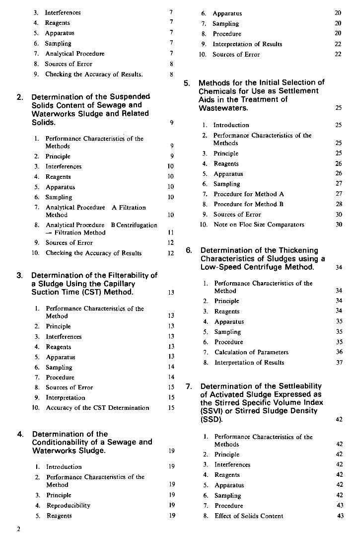
1. Determination of the Total Solids Content (Dry Residue at 105°C) and the Loss on Ignition of Dry Residue at 550°C of Sewage and Waterworks Sludges and Related Solids; 2 methods. 6 — 8
2. Determination of the Suspended Solids Content and Sewage of Waterworks Sludges and Related Solids; 2 methods (the second in two variants). 9 — 12
3. Determination of the Filterability of a Sludge using the Capillary Suction Time (CST) Method. 13 — 18
4. Determination of the Conditionability of Sewage and Waterworks Sludges. 19 — 24
5. Methods for the Initial Selection of Chemicals for Use as Settlement Aids in the Treatment of Wastewaters; 2 methods. 25 — 33
6. Determination of the Thickening Characteristics of Sludges using a Low-Speed Centrifuge Method. 34 — 41
7. Determination of the Settleability of Activated Sludge expressed as the Stirred Specific Volume Index (SSVI) or Stirred Sludge Density (SSD). 42 — 44
8. Measurement of the Specific Resistance to Dewatering of a Sludge, and the Sludge Cake Compressibility Coefficient. 45 — 51
Note: Measurement of Suspended, Settleable and Total Dissolved Solids is given in a companion volume (Ref 1.).
Contents
Warning to Users 4
About this Series 5
1. Determination of the Total Solids Content (Dry Residue at 105°C) and the Loss on Ignition of Dry Residue at 550°C of Sewage and Waterworks Sludges and Related Solids. 6
1. Performance Characteristics of the Methods 6
2. Principle 6
London Her Majesty's Stationery Office
1
3. Interferences
4. Reagents
5. Apparatus 6. Sampling 7. Analytical Procedure
8. Sources of Error 9. Checking the Accuracy of Results.
2. Determination of the Suspended Solids Content of Sewage and Waterworks Sludge and Related Solids. 9
1. Performance Characteristics of the Methods
2. Principle 3. Interferences
4. Reagents
5. Apparatus 6. Sampling 7. Analytical Procedure A Filtration
Method 8. Analytical Procedure B Centrifugation
— Filtration Method 9. Sources of Error
10. Checking the Accuracy of Results
3. Determination of the Filterability of a Sludge Using the Capillary Suction Time (CST) Method. 13
1. Performance Characteristics of the Method
2. Principle 3. Interferences 4. Reagents 5. Apparatus 6. Sampling 7. Procedure 8. Sources of Error
9. Interpretation 10. Accuracy of the CST Determination
4. Determination of the Conditionability of a Sewage and Waterworks Sludge. 19
1. Introduction 2. Performance Characteristics of the
Method
3. Principle 4. Reproducibility 5. Reagents
6. Apparatus 7. Sampling 8. Procedure
9. Interpretation of Results 10. Sources of Error
5. Methods for the Initial Selection of Chemicals for Use as Settlement Aids in the Treatment of Wastewaters. 25
1. Introduction
2. Performance Characteristics of the Methods
3. Principle 4. Reagents
5. Apparatus 6. Sampling 7. Procedure for Method A 8. Procedure for Method B
9. Sources of Error
10. Note on Floc Size Comparators
6. Determination of the Thickening Characteristics of Sludges using a Low-Speed Centrifuge Method. 34
1. Performance Characteristics of the Method
2. Principle 3. Reagents
4. Apparatus 5. Sampling 6. Procedure 7. Calculation of Parameters
8. Interpretation of Results
15 7. Determination of the Settleability 15 of Activated Sludge Expressed as
the Stirred Specific Volume Index 15
(SSVI) or Stirred Sludge Density (SSD).
1. Performance Characteristics of the Methods
2. Principle 3. Interferences
4. Reagents 5. Apparatus 6. Sampling 7. Procedure
8. Effect of Solids Content
7
7
7
7
7
8
8
20
20
20
22
22
9
9
10
10
10
10
10
11
12
12
25
25
25
26
26
27
27
28
30
30
13
13
13
13
13
14
14
34
34
34
35
35
35
36
37
42
42
42
42
42
42
42
43
43
2
19
19
19
19
19

8. Measurement of the Specific Resistance to Dewatering of a Sludge, and the Sludge Cake Compressibility Coefficient. 45
1. Introduction 45
2. Interpretation 46
3. Performance Characteristics of the Method 46
4. Principle 47
5. Hazards 47
6. Apparatus 47
7. Sample Preparation 48
8. Test Procedure 48
9. Calculation of the Specific Resistance to Dewatering 49
10. Calculation of the Sludge Cake Compressibility Coefficient 50
11. Calculation of the Filter Medium Resistance 50
12. Sources of Error 50
13. Measurement of Filtrate Viscosity 51
14. Analytical Quality Control 51
References 52
Address for Correspondence 53 Members associated with the production of this booklet 54
3

Warning to Users
The analytical procedures given in this booklet should be carried out only by competent trained persons, with
adequate supervision when necessary. Local Safety Regulations must be observed. Laboratory procedures should be carried out only in properly equipped laboratories. Field operations should be conducted with due regard to possible local hazards, and portable safety equipment should be carried. Care should be taken against creating hazards whether for one's self, one's colleagues in the laboratory, outsiders or subsequently for maintenance workers. Lone working, whether in the laboratory or field, should be discouraged. Reagents of adequate purity must be used, along with properly maintained apparatus and equipment of correct specifications. Specifications for reagents, apparatus and equipment are given in manufacturers' catalogues and various published standards. If contamination is suspected, reagent purity should be checked before use.
There are numerous handbooks on first aid and laboratory safety. Among such publications are: 'Code of Practice for Chemical Laboratories' and 'Hazards in the Chemical Laboratory' issued by the Royal Society of Chemistry, London; 'Safety in Biological Laboratories' (Editors Hartree and Booth), Biochemical Society Special Publication No 5, The Biochemical Society, London, which includes biological hazards; and 'The Prevention of Laboratory Acquired Infection', Public Health Laboratory Service Monograph 6, HMSO, London.
Where the Committee have considered that a special unusual hazard exists, attention has been drawn to this in the text so that additional care must be taken beyond that which should be exercised at all times when carrying out analytical procedures. It cannot be too strongly
© Crown copyright 1985 First published 1985
ISBN 0 11 7517879
emphasised that prompt first aid, decontamination or administration of the correct antidote can save life; but that incorrect treatment can make matters worse. It is
suggested that both supervisors and operators be familiar with emergency procedures before starting even a slightly hazardous operation, and that doctors consulted after any accident involving chemical contamination, ingestion, or inhalation, be made familiar with the chemical nature of the injury, as some chemical injuries require specialist treatment not normally encountered by most doctors. Similar warning should be given if a biological or radio-chemical injury is suspected. Some very unusual parasites, viruses and other micro- organisms are occasionally encountered in samples and when sampling in the field. In the latter case, all equipment including footwear should be disinfected by appropriate methods if contamination is suspected.
The best safeguard is a thorough consideration of hazards and the consequent safety precautions and remedies well in advance. Without intending to give a complete checklist, points that experience has shown are often forgotten include: laboratory tidiness, stray radiation leaks (including ultra violet), use of correct protective clothing and goggles, removal of toxic fumes and wastes, containment in the event of breakage, access to taps, escape routes, and the accessibility of the correct and properly maintained first-aid, fire-fighting, and rescue equipment. Hazardous reagents and solutions should always be stored in plain sight and below face level. Attention should also be given to potential vapour and fire risks. If in doubt, it is safer to assume that the hazard may exist and take reasonable precautions, rather than to assume that no hazard exists until proved otherwise.

About this series
This booklet is part of a series intended to provide both recommended methods for the determination of water quality, and in addition, short reviews of the more important analytical techniques of interest to the water and sewage industries. In the past, the Department of the Environment and its predecessors, in collaboration with various learned societies, have issued volumes of methods for the analysis of water and sewage culminating in 'Analysis of Raw, Potable and Waste Waters'. These volumes inevitably took some years to prepare, so that they were often partially out of date before they appeared in print. The present series will be published as individual methods, thus allowing for the replacement or addition of methods as quickly as possible without need of waiting for the next edition. The rate of publication will also be related to the urgency of requirement for that particular method, tentative methods being issued when necessary. The aim is to provide as complete and up to date a collection of methods and reviews as is practicable, which will, as far as possible, take into account the analytical facilities available in different parts of the Kingdom, and the quality criteria of interest to those responsible for the various aspects of the water cycle. Because both needs and equipment vary widely, where necessary, a selection of methods may be recommended for a single determinand. It will be the responsibility of the users — the senior analytical chemist, biologist, bacteriologist etc., to decide which of these methods to use for the determination in hand. Whilst the attention of the user is drawn to any special known hazards which may occur with the use of any particular method, responsibility for proper supervision and the provision of safe working conditions must remain with the user.
The preparation of this series and its continuous revision
is the responsibility of the Standing Committee of Analysts (to review Standard Methods for Quality Control of the Water Cycle). The Standing Committee of Analysts is a committee of the Department of the Environment set up in 1972. Currently it has seven Working Groups, each responsible for one section or aspect of water cycle quality analysis. They are as follows:
1.0 General principles of sampling and accuracy of results
3.0 Empirical and physical methods 4.0 Metals and metalloids 5.0 General nonmetallic substances 6.0 Organic impurities 7.0 Biological methods 9.0 Radiochemical methods.
The actual methods and reviews are produced by smaller panels of experts in the appropriate field, under the overall supervision of the appropriate working group and the main committee. The names of those associated with this method are listed inside the back cover. Publication of new or revised methods will be notified to the technical press, whilst a list of Methods in Print is given in the current HMSO Sectional Publication List No.5.
Whilst an effort is made to prevent errors from occurring in the published text, a few errors have been found in booklets in this series. Correction notes and minor additions to published booklets not warranting a new booklet in this series will be issued periodically as the need arises. Should an error be found affecting the operation of a method, the true sense not being obvious, or an error in the printed text be discovered prior to sale, a separate correction note will be issued for inclusion in that booklet.
L R PITTWELL Secretary
31 October 1983
5

Determination of the Total Solids Content (Dry Residues at 105°C) and the Loss on Ignition of Dry Residue at 550°C of Sewage and Waterworks Sludges and Related Solids
1. Performance Characteristics of the Methods
2. Principle
1.1 Parameters determined (a) Total solids content. (b) Loss on ignition of dry residue at 550°C (a
measure of the volatile organic matter content of the solids).
1.2 Type of sample Sewage and waterworks sludge and related solids.
1.3 Basis of the methods (a) Total solids content — gravimetrically by evaporation and drying in a tared dish.
(b) Loss on ignition of dry residue —
gravimetrically following ignition at 550°C. of the residue from the total solids determination
1.4 Range of application (a) 0—100% W/W total solids. (b) 0—100% W/W loss on ignition as % of total
solids.
1.5 Standard deviation For both determinations precision and accuracy are sample-type dependent. (a) Relative standard deviation usually better
than 10% but increasing as solids content falls (see 1.7 below).
(b) Relative standard deviation usually better than 20% (see 1.7 below).
1.6 Limit of detection 0.1% (based on the criterion of detection).
1.7 Bias (a) If the dry residue is hygroscopic there will be a tendency for results to be slightly high. See also Section 3 for an effect which may cause negative bias.
(b) If used as a measure of organic matter the bias is sample-type dependent; many inorganic compounds including some metal oxides and salts volatilize or decompose below 5 50°C causing a positive bias.
1.8 Interferences See Section 3.
1.9 Time required for analysis The overall time for all determinations is sample- type dependent but under 7 h per batch. Batch size is dependent on the apparatus used but 20 and over could be achieved.
(a) The total solids content of sludge is determined gravimetrically by drying at 105°C to constant weight.
(b) The loss on ignition of dry residue is also determined gravimetrically. The residue in the dish from the total solids content determination is ignited in a furnace at 5 50°C to constant weight.

3. Interferences (a) The presence of substances which are volatile at temperatures below 105°C or which decompose at temperatures below 105°C to form volatile compounds will give falsely low results for the total solids determination.
(b) There are theoretically no interferences with the loss on ignition determination. However, for many purposes this determination is used as a measure of the organic solids content. In these circumstances the loss of volatile inorganic substances may occur giving high results and there may be incomplete combustion of all organic substances giving low results.
4. Reagents No reagents are required.
5. Apparatus 5.1 Silica or platinum dishes or crucibles suitable for ignition at 550°C
5.2 Water bath (boiling)
5.3 Ovens controlled at 105 ± 2°C and
5.4 Muffle furnace controlled at 550 ± 20°C
5.5 Analytical balance capable of weighing to ± 0.1 mg
5.6 Desiccator
For notes on care of platinum ware see Ref.2.
6. Sampling It is most important that the sample is truly representative of the sludge concerned (see publication in this series Ref 10). Sludge samples may change composition through microbiological activity and it is very important that they are analysed as soon as possible.
7. Analytical Procedure
Step Procedure Notes
Total Solids content
7.1 Weigh a suitably sized dish. Let the weight be W1g. (a) Ensure that a representative subsample is taken. The weight of subsample required will vary with
7.2 Transfer between 10 and 50g of the sample into the the anticipated total solids content of the tared dish (Note a) and reweigh. Let this weight be sample. Sludge cake should be broken up. W2g.
7.3 Place the dish on a boiling water bath and allow the (b) If a forced ventilation oven is available this step contents to evaporate to near dryness. (Note b) may be carried out in the oven.
7.4 Remove the dish from the water bath, blot any (c) Retain the dish and solid for the determination of water from the bottom and put it into an oven at 105°C loss on ignition of dry residue. for at least 1 hour. Remove the dish, place in a desiccator until cool and reweigh.
7.5 Replace the dish in the oven for a further 15 minutes, (d) Some samples may continue to lose weight in which cool and reweigh. Repeat this step until a constant case constant weight may be difficult to obtain. weight is obtained. Let this weight be W3g (Notes c and d).
Calculation
7.6 Total solids content =
W3 — W1 lJ ' — YVI
(as a percentage of the wet sludge)
Step Procedure Notes
Loss on ignition of d!y residue
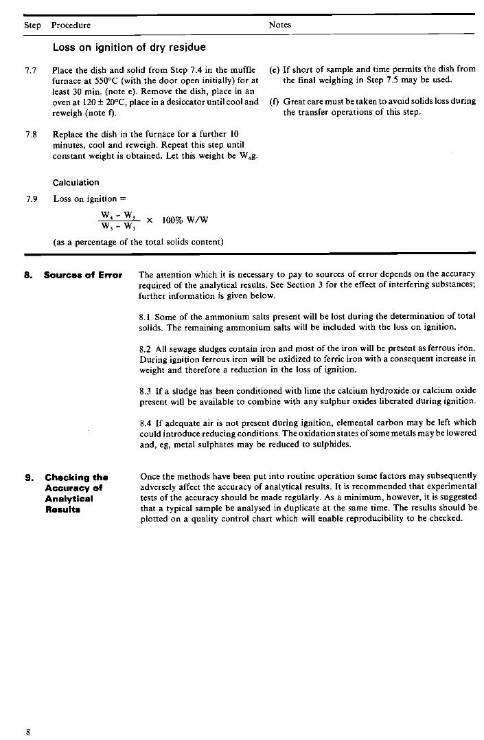
7.7 Place the dish and solid from Step 7.4 in the muffle (e) If short of sample and time permits the dish from furnace at 550°C (with the door open initially) for at the final weighing in Step 7.5 may be used. least 30 mm. (note e). Remove the dish, place in an oven at 120 ± 20°C, place in a desiccator until cool and (1) Great care must be taken to avoid solids loss during reweigh (note I). the transfer operations of this step.
7.8 Replace the dish in the furnace for a further 10
minutes, cool and reweigh. Repeat this step until constant weight is obtained. Let this weight be W4g.
Calculation
7.9 Loss on ignition = —
x yv3 — YVI
(as a percentage of the total solids content)
8. Sources of Error The attention which it is necessary to pay to sources of error depends on the accuracy required of the analytical results. See Section 3 for the effect of interfering substances; further information is given below.
8.1 Some of the ammonium salts present will be lost during the determination of total solids. The remaining ammonium salts will be included with the loss on ignition.
8.2 All sewage sludges contain iron and most of the iron will be present as ferrous iron. During ignition ferrous iron will be oxidized to ferric iron with a consequent increase in
weight and therefore a reduction in the loss of ignition.
8.3 If a sludge has been conditioned with lime the calcium hydroxide or calcium oxide present will be available to combine with any sulphur oxides liberated during ignition.
8.4 If adequate air is not present during ignition, elemental carbon may be left which could introduce reducing conditions. The oxidation states of some metals may be lowered and, eg, metal sulphates may be reduced to sulphides.
9. Checking the Once the methods have been put into routine operation some factors may subsequently Accuracy of adversely affect the accuracy of analytical results. It is recommended that experimental Analytical tests of the accuracy should be made regularly. As a minimum, however, it is suggested Results that a typical sample be analysed in duplicate at the same time. The results should be
plotted on a quality control chart which will enable reproducibility to be checked.
8

Determination of the Suspended Solids Content of Sewage and Waterworks Sludges and Related Solids
Method A Filtration - Direct Method B Centrifugation/Filtration - Indirect
1. Performance Characteristics of the Methods
2. Principle
1.1 Parameter determined Suspended solids content.
1.2 Type of sample Sewage and waterworks sludge suspensions and related solids.
1.3 Basis of the method Method A should be used for any suspensions which filter easily and Method B should be used for any which do not filter easily. (a) Gravimetrically following filtration
through a glass fibre or cellulose acetate filter medium and drying.
(b) Gravimetrically by the difference between the total solids content of the suspension and the total solids content of the centrate/ filtrate after centrifugation/filtration of the suspension.
1.4 Range of applications (a) 500—10,000 mg/I. (b) Greater than 10,000 mg/l.
1.5 Standard deviation (a) Relative standard deviation is usually better than 5%.
(b) If the sample is centrifuged to separate, the relative standard deviation is usually better than 20%, if the sample is filtered to separate, the Relative standard deviation is usually better than 15%.
1.6 Limit of detection 100 mg/l.
1.7 Bias Sample dependent. Samples which are hygroscopic tend to give high results. See also section 3 for sample types tending to have negative bias.
1.8 Interferences See Section 3.
1.9 Time required for analysis The overall time for these methods is sample dependent, but should be under 7 h per batch. Batch size is dependent on equipment availability and capacity.
* The ranges of application are given as a guide. Ease of filtration is a more important criterion.
(a) The suspended solids content of "thin" sludges (those containing less than about 10,000 mg/l suspended solids) or other readily filtered suspensions is determined by filtering the suspension through a tared filter medium, drying in an oven at 105° C and reweighing to constant weight.
(b) The suspended solids content of sludges and other suspensions which do not filter readily is determined by an indirect method. The total solids content of the sludge is
9

determined by drying a sample in the oven at 105°C to constant weight. A further portion of the sludge is centrifuged/filtered and the total solids of the centrate/filtrate determined by drying in an oven at 105°C to constant weight. The suspended solids concentration = (concentration of total solids of sludge) —
(concentration of solids of centrate/filtrate).
3. Interferences The presence of substances which are volatile at temperatures below 105°C or which
decompose at temperatures below 105°C to form volatile compounds will give falsely low results.
4. Reagents Distilled or deionized water is required. No other reagents are needed.
5. Apparatus 5.1 General
Analytical balance capable of weighing to ± 0.1 mg Oven controlled at 105 ± 2°C Desiccator
5.2 A. Filtration Method
Glass fibre or cellulose acetate filter medium 3 component Hartley-type filter funnels 70 mm diameter is suitable Buchner filter flasks
5.3 B. Centrifugation/Filtration Method
Centrifuge capable of at least 1,500 r.c.f. with tubes of at least 100 ml capacity or filtration apparatus Silica or platinum dishes Water bath (boiling)
6. Sampling It is most important that the sample is truly representative of the sludge concerned (see publication in this series Ref 10). Sludge samples may change composition through microbiological activity and it is important that they are analysed as soon as possible.
7. Analytical Procedure A. Filtration Method
Step Procedure Notes
7.1 Wash the filter medium by the following procedure: Insert a glass fibre or cellulose acetate filter medium (a) Care must be taken in placing the filter media in the into the funnel assembly, and using slight suction wash oven. They may be placed on a specially designed with approximately 100 ml of water. Carefully rack or placed between filter papers. remove the filter medium, (note a) and dry in the oven for approximately lh at 105°C. Cool the filter medium in a desiccator and weigh. Let the weight be W 1g.
7.2 Replace the filter medium in the funnel assembly and (b) Ensure that a representative sub-sample is taken. moisten with a little water. Measure a suitable volume, The volume of sub-sample required will vary with V ml, (up to 100 ml) of the well mixed sample into a the anticipated suspended solids content but measuring cylinder (note b). Using slight suction should be such that at least 1 mg of solid is filter the sub-sample ensuring that all the solids are weighed following drying, but preferably 1g. transferred to the filter medium. Wash the residue three times with approximately 10 ml of water, allowing it to drain free of water after each wash.
7.3 Remove the filter medium, (note c) and dry in the (c) Care must be taken in placing the used filter oven at 105°C for at least 1 hr. Cool in a desiccator and medium in the oven. First the medium is folded
weigh. to retain sample, then it is either placed on the special rack or between filter papers, which are carefully removed later.
10

Step Procedure Notes
7.4 Replace the filter medium in the oven at 105°C for a (d) Some samples may continue to lose weight and a further 15 minutes. Cool in a desiccator and reweigh. constant we ight ma y be difficult to obtain. Repeat this step until a constant weight is obtained (note d). Let this weight be W2g.
Calculation
7.5 Suspended solids content
= W2-W1 x 106mg/1
8. Analytical Procedure B.
Centrifugation/Fi Itration Method
Step Procedure Notes
Total Solids content of suspensions
8.1 Weigh a suitably sized dish. Let the weight be W1g. (a) Ensure that a representative sub-sample is taken. The weight of sub-sample required will vary with
8.2 Transfer between 10 and 50 g of the sample into the the anticipated total solids content of the sample. tared dish (note a) and reweigh. Let this weight be W2g.
8.3 Place the dish on a boiling water-bath and allow the (b) If a forced ventilation oven is available this step contents to evaporate to near dryness (note b). may be carried out in the oven.
8.4 Place the dish for at least 1 h in an oven at 105°C. (c) Some samples may continue to lose weight and a Remove the dish, place in a desiccator until cool and constant weight may be difficult to obtain. reweigh.
8.5 Replace the dish in the oven for a further 15 minutes, (d) If required, retain the dish and solid for the cool and reweigh. Repeat this step until a constant determination of loss on ignition of dry residue. weight (note c) is obtained. Let this weight be W3g (note d).
Calculation
8.6 Total solids content of suspension =
V,3 —
7 i\ —
Total Solids content of the centrate/filtrate.
8.7 Centrifuge or filter sufficient sludge to give at least 50 ml of clear centrate/filtrate (see section 9).
8.8 Weigh a suitably sized dish. Let the weight be W4g.
8.9 Transfer approximately 50 ml of the clear centrate/ (e) For centrates take care to exclude floating matter. filtrate (note e) to the dish and weigh. Let the weight be W5g.
8.10 Repeat steps 8.3 to 8.5 inclusive. Let the constant weigh be W6g. (note d).
11

Step Procedure Notes
Calculation
8.11 Total solids content of centrate/filtrate.
x 100% W/W
Calculation of suspended solids content
8.12 Suspended solids content, per cent w/w = (total solids content of suspension — total solids content of centrate/filtrate).
9. Sources of Error The attention which it is necessary to pay to sources of error depends on the accuracy required of the analytical results. See Section 3 for the effect of interfering substances.
Method B assumes that the total solids content of the centrate/filtrate is equal to dissolved solids content of the original suspension. It may not always be possible to obtain a clear centrate or filtrate because of the presence of colloidal matter.
10. Checking the Once the method has been put into routine operation many factors may subsequently Accuracy of adversely affect the accuracy of analytical results. It is recommended that experimental Analytical tests of the accuracy should be regularly made. As a minimum, however, it is suggested Results that a typical sample be analysed in duplicate at the same time. The results should be
plotted on a quality control chart which will enable reproducibility to be checked.
12

Determination of the Filterability of a Sludge Using the Capillary Suction Time (CST) Method
1. Performance Characteristics of the Method
2. Principle
3. Interferences
4. Reagents
5. Apparatus
1.1 Parameters determined Capillary suction time (CST).
1.2 Type of sample Any suspension of solid particles in an aqueous liquid, excepting very thin sludges where the concentration of suspended solids is less than 0.5
per cent or those sludges which have a CST very close to that of water alone.
1.3 Basis of the method Measurement of the time for a given area of paper to become wetted with filtrate from a sludge using a standard apparatus.
1.4 Range of application CST depends on the size of reservoir, and on the nature of sludge and paper. 10-mm diam. reservoir 9—3000s 18-mm diam. reservoir 5—3000s The lower figure in each case is the CST of water.
1.5 Standard deviation Relative standard deviation usually better than 10 per cent.
1.6 Interferences See Section 3.
1.7 Time required for analysis Overall time is dependent on the time to determine the concentration of solids in the sample (see method in this series). Up to 5 minutes for individual CST measurements.
Filtrate is withdrawn from a sludge sample placed in contact with an absorbent filter paper by the capillary suction exerted by the paper. The rate at which filtrate wets the filter paper is mainly dependent upon the sludge filtrability. The time to wet a standard area of paper between two sets of electrodes which start and stop an electrical clock is the Capillary Suction Time (CST). This time is also dependent on the size of the sludge reservoir used and on the concentration of suspended solids of the sludge, which latter therefore has to be determined.
Some dissolved chemicals in the filtrate of the sludge, particularly unadsorbed polyelectrolyte, may adsorb on to the CST paper and produce a falsely high CST.
Sodium Chloride, reagent grade, may be needed.
5.1 The standard Capillary Suction Time apparatus (Ref. 3) (Fig 1) with 2 different sized sludge reservoirs of 18 mm and 10 mm diameter. (It is recommended that the counting mechanism be checked at intervals against a stop watch and if necessary adjusted to give deviations not greater than ± 1%).
5.2 A supply of standard CST papers. (Whatman No. 17 Chromatography Grade Filter paper of nominal thickness 0.88 mm and weight per unit area of 440 g/m2).

5.3 Two 250 ml low form eg. ISO draft spec. 522 glass beakers.
5.4 Paper tissues.
5.5 A 100 ml wide-mouthed sample bottle.
5.6 A fluorescent light box (not essential).
5.7 Desiccator, to store the CST papers.
6. Sampling
7. Procedure
It is important that the sample is truly representative of the sludge concerned (see publication in this series Ref 10). Sludge samples may change composition through microbiological activity or temperature variation. It is important therefore that the samples are analysed as soon as possible after collection. It is necessary to know the time
elapsed from the time of taking the sample and the change in temperature so that the effect of storage on the filtrability can be assessed. Coarse solids should be removed by passing the sample through a 4-mm mesh sieve before testing.
Step Procedure Notes
7.1 Prepare the CST apparatus (after ensuring that the electrical probes are clean) with the probes resting on the rougher side of the CST paper. Initially use the 18 mm diameter sludge reservoir (note a).
7.2 Pour tap water into the sludge reservoir, observe
advancing water interface and check that the clock starts and stops satisfactorily. If the conductivity of the tap water is too low to trigger the timing mechanism, dissolve sufficient sodium chloride in the water to raise the conductivity high enough to work the mechanism (over about 500 1umhos/cm). Record the CST of water alone (note b).
7.3 Remove and discard wetted CST paper. Clean and dry reservoir and acrylate block with tissues. Reassemble
apparatus.
7.4 Thoroughly mix sample by carefully pouring sludge sample from one beaker to another (notes c and d) and immediately pour a sub-sample into the sludge reservoir.
7.5 Record CST. Let this be t1 seconds.
7.6 Repeat steps 7.3—7.5. Let second CST be t2 seconds (note e).
7.7 After transferring the remaining sludge sample from one beaker to another pour a portion of the sludge into the 100-mI sample bottle for subsequent determination of suspended-solids content as described in this booklet.
(a) The polymethylmethacrylate (or similar) block carrying the paper and reservoir may be placed on a light box to aid observation of the water front.
(b) This is for reference. The CST of a sludge sample is not very meaningful if it is close to that of water.
(c) The filtrate from the sludge must have a conductivity sufficiently high (ca 500 ,umhos/cm) to trigger the electrical clock. The conductivity of sewage sludges is usually high enough, but some waterworks sludges may require addition of a small amount of ionizable material, such as sodium chloride, to raise the conductivity.
(d) Sludge properties may be either temporarily or permanently altered if shaken.
(e) If t1 and t2 differ by more than 20 per cent, the clock may not have operated correctly, or it may not be possible to get a representative sub- sample of sludge. Stir sample and repeat procedure.

Step Procedure Notes
7.8 If the CST determined using the 18-mm diameter sludge reservoir has a value of less than 100 s, it is desirable to repeat the procedure using the 10-mm reservoir.
Quote results as CST 1 + 2 seconds
at a suspended-solids content of C per cent dry matter (stating the size of reservoir). (note b).
8. Sources of Error The attention which it is necessary to pay to sources of error depends on the accuracy required of the analytical results. See Section 3 for the effect of interfering substances; further information is given below.
8.1 Because the CST of a sludge with less than 0.5 per cent dry solids is not very meaningful, (see Section 9 below), it is usually desirable to remove as much water as possible from thin sludges by settlement before the determination. Ideally the supernatant liquor removed should not contain any suspended solids, but in practice the removal of some solids will tend to reduce the CST.
8.2 Biological sludges are often very unstable and several determinations of filtrability during a storage period may be desirable to assess the effect of time. Samples for analysis should be taken just prior to analysis.
8.3 If left for some time on the light box, the temperature of the block will rise, which will affect the CST.
8.4 Shear, in for example stirring, can affect CST and it is desirable to use a standard stirrer (see method in this series for determining coagulant demand).
8.5 CST is dependent on the solids content of the sample, but the results may be expressed in terms of the more absolute parameter, specific resistance to filtration after constructing a calibration graph of the CST against the product of suspended solids of the sludge and the specific resistance to filtration (see method in this series).
8.6 Batches of CST paper may vary slightly in absorptive power and thickness. Therefore it is desirable to note the batch number of paper being used, and where specific resistance to filtration is required to recalibrate for each batch of paper.
9. Interpretation CST are useful for controlling the dosing of sludges prior to filtration. CST below a critical value, dependent on conditioner and filter, invariably give good quality filter cake.
10. Accuracy of The principal factors affecting the CST of a sludge will be the filtrability (the specific the CST resistance to filtration) and the suspended solids of the sludge. Changes in either of these Determination two parameters can cause the CST to alter by a factor of 100 or more, with sludge varying
in CST from 5 seconds to over 3000 seconds.
There are a number of other factors which can also affect the CST, fortunately, usually to a much lesser degree than the filtrability or suspended solids of the sludge. They may be either associated with the instrument together with the conditions surrounding its use, or pertaining to the sludge being used.
Variation in CST results due to the instrument and operating conditions may be caused by:
A variation in the thickness and weight per unit area of the CST paper. (The paper used in the CST apparatus is actually a Whatman No 17 chromatography grade filter paper of nominal thickness 0.88 mm and weight per unit area of 440 g/m2.) A variation in the temperature of the sludge and the humidity of the atmosphere in which the CST papers are stored.

A variation in the accuracy of the timing mechanism in the CST counter, or the physical dimensions of the CST perspex block.
The variability associated with the sludge is dependant on:
The degree to which the sludge sample is homogenous, (such that a representative sample can be poured into the CST reservoir).
The extent to which the sludge settles during the time over which the CST measurement takes place.
The viscosity of the filtrate being withdrawn from the sludge.
If necessary some of the variability associated with the CST apparatus, or how it is used, can be overcome by measuring the CST at a fairly constant temperature and keeping the CST papers in an atmosphere of fairly constant humidity, such as pertains in a centrally heated laboratory, or a desiccator. However, variation in CST due to either temperature or humidity is fairly small with a reduction in temperature of 16°C causing a 20% increase in CST, while a reduction in relative humidity by 80% at constant temperature causes a similar increase.
The variation in CST due to variation in paper thickness and weight per unit area is best overcome by using CST papers from the same manufacturing batch for one whole series of tests. (Each production batch of papers has its own number indicated on the outside of the box of CST papers). This is desirable because the variation within each batch of paper manufactured at any one time is fairly small, (with coefficients of variation in thickness being of the order of 2 per cent or less) while the variation between different batches can be considerable. If this is the case when the thickness of two batches of paper vary by X per cent, then the difference in CST of a sludge between that given by each batch of paper has been found to be of the order of 2X per cent.
The counting mechanism of the CST apparatus should, of course, count in seconds. It is advisable to check occasionally the accuracy of this mechanism against a stop-watch. Should the counter be inaccurate by more than 1 per cent resetting of the internal variable potentiometer should restore the accuracy of timing.
Inaccuracies due to the polymethylmethacrylate CST block are usually associated with probe corrosion. This may usually be overcome by gentle rubbing on a fine grade emery paper. Occasionally probes become damaged or deformed; should this occur replacement of the whole block should be made, because any shift in the position of the start and stop probes relative to one another, or to the sludge reservoir will substantially effect the results, as the CST is proportional to the fourth power of the radius of the circle in which the probe is set.
Variable and atypical CST results due to the sludge are usually due to lack of homogeneity of the sample, particularly after a conditioning chemical such as a polyelectrolyte has been added. Satisfactory sludge sampling is usually easier if immediately prior to pouring the sludge sample into the CST reservoir the sample is transferred between vessels. If liquor only is poured into the reservoir it is not valid to treat this result as the CST of the sludge, but the result can still be of considerable value. If the results of this CST, with liquor only in the reservoir, is different to that of water, it is usually indicative of surplus unadsorbed chemical, usually a polyelectrolyte being present in the liquor. The CST is then higher than that of water because of the increased viscosity of the liquor as compared with water, and the ability of the CST paper to adsorb the surplus polyelectrolyte.
The variation in CST will therefore be dependent upon the interaction of many different factors. The results for 2 different circumstances were as follows:
1) Anaerobic digested sludge (elutriated)
All the data is from one instrument being the average of 8 results in 6 series of tests. 3 series with rough side of paper uppermost, 3 series with smooth side uppermost.

CST using the 10 mm reservoir
Paper surface smooth smooth rough smooth rough rough Individual means(S) 201.1 202.5 201.4 204.6 193.3 205.5 Individual standard deviation (S) 11.86 12.38 14.90 15.98 21.11 43.04 Individual variance (per cent) 5.87 6.11 7.40 7.81 10.9 21.0 Overall variance (per cent) 9.86
2) Water only
Same instrument as 1, and similar series of tests .
CST using the 10 mm reservoir
Paper surface rough rough smooth smooth smooth rough Individual means(S) 8.04 7.85 8.23 7.90 8.29 8.01 Individual standard deviation (S) 0.3419 0.5099 0.5365 0.5292 0.6129 0.6977 Individual variance (per cent) 4.25 6.50 6.52 6.70 7.39 8.71
Overall variance (per cent) 6.67
Conclusion
The typical range of variances in CST results is from 6 to 10 per cent but other factors can cause a considerable increase in this figure.

Filtration block
(Plan)
Electronically operated
digital stop clock
Probes resting on
filter paper Start 1A,1B
Stop 2
Sludge
Reference marks on underside
of block
Filtration block
(Section) Base
Sludge reservoir
Sludge
Block holding probes
Thick filter paper
FIGURE 1 DIAGRAM OF THE CST APPARATUS

Determination of the Conditionability of a Sewage and Waterworks Sludge
1. Introduction
2. Performance Characteristics of the Method
3. Principle
4. Reproducibility
5. Reagents
It is usually necessary to condition, that is improve the filtration characteristics of, a sewage or waterworks sludge before mechanical dewatering. Conditioning may also be advantageous before dewatering on drying beds. Conditioning may be effected by physical means (heat treatment, freeze/thaw) or by the addition of chemical coagulants. The object of this method is to facilitate the choice of the type and dose of chemical for any particular sludge and any particular type of mechanical dewatering equipment. The method is described as the determination of a characteristic of the sludge, that is its amenability to conditioning, or the quantity of chemical required to achieve a given filtrability measured either by specific resistance to filtration (SRF) or Capillary Suction Time (CST). However, the filtrability required will depend on the mechanical dewatering equipment to be used. The type of equipment will also define characteristics of the conditioned sludge other than filtrability, such as the strength of the floc and its susceptibility to shear in pumps, pipework, etc. Approximate values of specific resistance to filtration and other parameters for satisfactory performance of various types of mechanical dewatering equipment are given in Table 1.
2.1 Parameters determined The amount and type of chemical required to improve the filtrability of a sludge to a value such that the sludge is suitable for mechanical dewatering.
2.2 Type of sample Sewage, waterworks or industrial sludge.
2.3 Basis of method The filtrability of a sludge is measured using the Capillary Suction Time (CST) apparatus before and after varying quantities of different coagulating chemicals have been added to the sludge.
2.4 Time required for analysis 2—4 hours per chemical.
Samples are conditioned with various quantities of different chemicals and compared with a control to which the same quantity of water has been added. Filtrability is assessed by determining the CST of the conditioned sludge. Floc strength is assessed by determining the CST after different periods of shear in a standard laboratory stirrer. The sludge is said to be conditioned when the filtrability and floc strength are such that the sludge can readily be dewatered using the chosen apparatus. The amount of chemical required to achieve this conditioning is termed the coagulant demand. Either a single chemical or a combination of chemicals may be used.
Tests by Southern and other WAs indicate that with the exception of very wet sludges or those high in solids that float, this test can indicate optimum plant conditions within 20%.
The single chemical systems which can be used for conditioning sewage sludge are:
Aluminium chloride Aluminium chlorohydrate Ferric chloride Cationic polyelectroytes
19

When dual chemical systems are used lime (either calcium hydroxide or calcium oxide) is almost invariably one of the chemicals. The second chemical can be any of the above or more usually a ferrous salt such as ferrous sulphate.
For conditioning waterworks sludges, anionic polyelectrolytes may be more suitable.
6. Apparatus 6.1 The standard Capillary Suction Time apparatus — see previous method in this booklet with 2 different size sludge reservoirs of 18-mm and 10-mm diameter. (Multiple units will
speed up the procedure.)
6.2 A supply of standard CST papers. (Whatman No 17 Chromatography Grade filter paper of nominal thickness 0.88 mm and weight per unit area of 440 g/m2.)
6.3 A standard laboratory stirrer (designed by WRC) (Ref. 3)
6.4 Six 250-mi low form glass beakers, calibrated at 50-mI intervals
6.5 Two 2-1 glass beakers
6.6 A 20-mi calibrated pipette
6.7 A 20-mi graduated pipette
6.8 Rubber-bulb pipette filler
6.9 Paper tissues
6.10 Wide-mouthed 100-mi sample bottles
6.11 Fluorescent light box (not essential)
6.12 Desiccator to store CST papers
7. Sampling It is most important that the sample is truly representative of the sludge concerned (see publication in this series Ref 10). Samples may change composition through chemical or microbial activity and it is important that the test is carried out as soon after sampling as possible.
8. Procedure
Step Procedure Notes
8.1 Prepare at least 100 ml of a standard solution of the (a) The strengths of the standard solutions expressed chemical to be tested (note a.) as weight per cent volume are:
Aluminium chlorohydrate 1% A1203 Aluminium chloride 1% A1203 Ferric chloride 5% FeC 13
Ferrous sulphate 10% FeSO4 (Prepared with deoxygenated distilled water acidified to pH 1) Polyelectrolyte (solid) 1.0%
product Polyelectrolyte (liquid) 1.0%
product
8.2 Place a 1—1 representative sample of sludge to be tested in a 2—1 beaker.

Step Procedure Notes
8.3 Pour the sludge into another 2—1 beaker and back again. Repeat until the sludge is thoroughly mixed, then pour Ca. 50 ml into a wide-mouthed 100-mi sample bottle for determination of suspended solids (see method in this booklet), and measure at least five 100-mI portions of sludge directly into calibrated 250-mi beakers.
8.4 Place one 250-mi beaker containing 100 ml of sludge under the standard laboratory stirrer.
8.5 Fill a 20-mi pipette with distilled water, press the start button to commence the 10-s stirring period and immediately start to empty the pipette into the sample of sludge (note b).
8.6 Lower the beaker so that the stirrer blade is just above the surface of the sludge, and switch on stirrer for a brief period, to remove adhering sludge. Remove beaker from stirrer and pour sludge into a clean 250-mi beaker and back again, and immediately pour a sample into the CST reservoir (note c).
8.7 Replace remaining sludge under stirrer and stir for a 20-s period, then repeat Step 8.6.
8.8 Repeat Section 8.7 for a further 30-s stirring period.
8.9 Repeat Section 8.7 for a further 60-s stirring period (note d).
8.10 Estimate (or determine by direct measurement) the concentration of suspended solids in the sludge. Let the value be y per cent dry matter. Measure 8y ml of the chemical solution prepared in Section 8.1, using a calibrated pipette, into an empty 250-mi beaker. Dilute to a total volume of 40 ml by adding (40—8y) ml of distilled water (note e).
8.11 Using half of the 40-mi portion of diluted solution prepared in Section 8.10 fill a 20-mi pipette, and set aside the remaining 20 ml of solution for subsequent use (note 0.
8.12 Repeat Steps 8.4 to 8.9, using the 20 ml of diluted solution from 8.11 instead of distilled water (note g).
8.13 To the 20 ml of diluted solution left over from Section 8.11 add 20 ml of distilled water to produce 40 ml of solution of half the strength of that used in Section 8.12.
8.14 Repeat Sections 8.4 to 8.9 using the diluted solution prepared in Section 8.13 (note h).
8.15 To the 20 ml of dilution solution left over from Section 8.13 add 20 ml of distilled water to produce 40 ml of solution of half the strength of that used in Section 8.14.
(b) The pipette should always drain sufficiently rapidly to empty by the end of the 20-s stirring period. A standard pipette can be modified by removing part of the tip.
(c) For most sludges the 18-mm CST reservoir is used. For details of the use of the CST apparatus, see method in this booklet.
(d) The CST results for Sections 8.6 to 8.9 are for zero dose of chemical for 4 different stirring periods, and are control data.
(e) If a two-chemical system is to be evaluated where one of the chemicals is lime, pretreat the bulk of the unconditioned sludge with lime, add as a 10 per cent suspension, to give a typical dose of 10 or 25
per cent weight of lime (calcium hydroxide) per weight of dry sludge solids.
(f) This dose is the maximum to be used (usually expressed as weight per weight of dry sludge solids). For each chemical this will be:
Aluminium chloride and chlorohydrate Ferric chloride
Polyelectrolyte
(g) If a second coagulant is to be used add after removing beaker from stirrer in Step 8.5. Mix by pouring from beaker to beaker.
4% Ai203 20% FeC13 0.4%
(h) This dose represents half of the maximum dose.

Step Procedure Notes
8.16 Repeat Sections 8.4 to 8.9 using the diluted solution (i) This represents a quarter of the maximum dose.
prepared in Section 8.15 (note i). For completeness this progressive dilution technique can be continued until the CST of the conditioned sludge approaches the CST of the unconditioned sludge, as measured in Steps 8.5 to 8.9.
9. Interpretation of Results may be plotted as CST against period of stirring in the standard apparatus. Some
Results examples are given in Fig. 2. For a well-conditioned sludge with a high floc strength the line should be low and almost horizontal (Curve A). For a filter belt press the initial CST of the conditioned sludge should approach that of water, and the curve should rise steeply (Curve B).
If the curve falls initially (Curve C), it indicates inadequate mixing of the sludge and conditioner, and may also indicate that the concentration of polyelectrolyte is too high.
For assessment of the optimum concentration of any given chemical, concentration should be plotted against CST measured after a period of stirring appropriate to the type of dewatering being considered. For example, sludge fed to a drying bed, rotary vacuum filter or filter belt press undergoes little shear, and a period of stirring of 0—10 s is appropriate. Sludge pumped under pressure into a filter press will experience shear equivalent to 20—40 s in the laboratory stirrer, depending on the type of pump, length of pipework, etc. Worn pumps, excessive lengths of pipe or numbers of valves and bends may exert a level of shear equivalent to much greater than 40 s in the laboratory stirrer.
A typical graph of concentration of chemical against CST after stirring for a period of 40s is given in Fig 3. In order to compare different chemicals, the cost of each chemical at its optimum dose can be compared , or the cost of each chemical can be plotted against CST on one graph (Fig. 4).
10. Sources of Error 10.1 Conditioning may be strongly dependent on pH value, alkalinity, presence of dissolved salts, and concentration of very fine particles, all of which may change owing to microbial action.
10.2 It is very difficult to maintain homogeneity in a superfiocculated sludge, and the initial CST may not be representative of the whole sample.
10.3 Some chemical solutions will lose their effectiveness with time, especially if made up with tap water. It is recommended that new solutions are made up regularly. It is also recommended that polyelectrolyte solutions at a concentration of 1% are prepared using dc-ionized water. They can be stored for up to week in the dark and diluted to 0.1% for the test.
10.4 There are a number of sources of error associated with the use of the CST apparatus, and reference should be made to the method in this booklet.
22

Table 1. Approximate values of specific resistance to filtration and other parameters for satisfactory performance of various types of mechanical dewatering equipment
Properties required of conditioned sludge to ensure satisfactory dewatering Method of dewatering
Specific resistance to filtration (1012 rn/kg)
CST at (18-mm (s)
5% solids reservoir)
Floc strength
Drying beds with underdrains
30 300 Not very important
Filter press 1 15 Strong Vacuum filter 4 40 Medium. Flocs should be
strong enough to avoid cake drop-off
Filter belt press* 10 Weak
Centrifuge* 4 40 Strong
* The method does not give all the information required for the selection of chemicals for filter belt pressing or centrifugation. In the former case super-flocculation is required and tests to determine the rate of drainage and the final solids content of the cake should be carried out. For centrifugation pilot-scale tests are normally preferred.
23

csT
(5)
1.000-
100-
10-.
FIGURE 2
CST
after 40s stirring
(s)
FIGURE 3
Period of stirring (s)
B
A
24
CST
after 1 Os stirring
(5)
FIGURE 4
C
I —
10 30 1Q'o
conc. of chemical % on dry solids
E
D
Cost of chemical C/tonne dry solids

Methods for the Initial Selection of Chemicals for Use as Settlement Aids in the Treatment of Wastewater
1. Introduction Chemicals are being employed increasingly in wastewater treatment to enhance settlement by coagulation and flocculation.
"Coagulation" and "flocculation" are terms which are often used loosely and interchangeably. Coagulation is defined as the neutralisation of surface charges on the particles to be removed by settlement. The small non-settleable particles present in sewage carry negative charges causing repulsion between particles. Once coagulation has been effected flocculation can occur. This involves the agglomeration of the coagulated colloids or of larger particles by polymer bridging to form larger, more rapidly settling flocs. Flocculation is brought about by gentle agitation which is sufficient to cause the particles to collide but not violent enough to cause floc break up.
The methods are designed to screen available chemicals for their applicability as settlement aids for a given wastewater before carrying out full-scale tests. Laboratory- scale settlement tests using vessels of two different sizes are described. As it is difficult to simulate full-scale mixing conditions in the laboratory, it is not expected that the tests will enable the removal of suspended solids on the full scale to be predicted accurately. However, examination of the relative effect of different chemicals should enable those chemicals to be selected which warrant trial on a full scale.
2. Performance Characteristics of the Methods
3. Principle
Similarly1 it is important to be able to examine the relative characteristics of sludges produced by different chemicals, as the use of a settlement aid may increase the quantity of sludge produced, and the cost of sludge treatment and disposal may be a significant proportion of the total cost of wastewater treatment. Thus the size of vessel in one method is such that a usable quantity of sludge is produced.
2.1 Parameter determined Quantity of chemical for a given enhancement of settlement.
2.2 Type of samples Sewages or industrial wastewaters.
2.3 Nature of method Qualitative.
2.4 Basis of method Comparisons of effects of different concentrations of chemicals on: A. Quality of supernatant liquor in 1-litre
beakers. B. Quantity and quality of sludges produced
in 25-litre vessels.
2.5 Time required for A. 3 hours excluding determination of suspended solids and other desired parameters.
B. 4 hours excluding determination of suspended solids and other desired parameters.
Samples are treated with different quantities of chemical and compared with a control containing no chemical, under standardized conditions in a jar test. After flocculation the samples are allowed to settle and the effectiveness of the chemical is judged by the qualities of the supernatant liquor and sludge. The principle is one of comparison on a small scale to give an approximate ranking before testing on a full scale. The results are not intended to predict a particular removal of suspended solids for a given dose of chemical.
25

4. Reagents 4.1 Settlement aids. These will usually include quick or hydrated lime, iron and aluminium salts and ranges of anionic and cationic polyelectrolytes.
4.2 Acetone for initial wetting of solid polymer products.
4.3 Acid and alkali for adjustment of pH value.
4.4 De'-ionized water.
Solutions to be made up according to the manufacturers' recommendations.
Method A
5. Apparatus 5.1 The principal item is a laboratory apparatus incorporating a bank of stirrers driven at a number of set speeds. Each stirrer consists of a vertically mounted shaft with a two-bladed paddle. Each blade is 35-mm wide and 50-mm deep (see Fig. 5). It is recommended that the apparatus has positions for six samples to be stirred simultaneously at the same speed. The stirrer speeds should be reproducible to within ± 5% and all the speed settings needed by the test clearly marked on the speed controller. The stirrers should be located centrally in the beakers with the bottom edge of the paddle being 20 mm from the bottom of the beaker. Illumination of the samples can be helpful (see Section 9.2.)
Other equipment needed:
5.2 1-litre beakers "tall-form"
5.3 pH meter
5.4 Thermometer
5.5 Stop watch
5.6 1-litre measuring cylinders
5.7 Pipettes or syringes
5.8 Dosing rack
5.9 Apparatus for determination of suspended solids (see method in this booklet), or turbidity, or other desired parameter.
Method B
5.10 The essential equipment consists of two 25-litre test vessels* mounted in a suitable framework which holds the vessels and provides a support for mounting a variable-speed stirrer over each of the vessels. Each test vessel should be marked to indicate the level
equivalent to 20 litres. Provision should be made to remove both supernatant liquor and settled sludge. This is conveniently done by inserting two vertical drain tubes of differing lengths (see Fig. 6) through the apex of the conical section. The longer pipe projects to a point above the sludge level and the other is fitted flush with the apex of the conical section. The upper pipe is used to drain supernatant liquor after the settlement period and the lower pipe is used to take the settled sludge which has collected in the conical section.
* Note: The apparatus may be either:
(i) fabricated as shown in Fig. 6. (ii) made from conically-topped polyethylene bottles,
or (iii) borrowed from WRC, Stevenage Laboratory.
26

Other equipment needed:
5.11 pH meter
5.12 Thermometer
5.13 Stop watch
5.14 Measuring cylinders
5.15 Pipettes
5.16 Apparatus for assessing thickenability (see method in this booklet)
5.17 Apparatus for determination of Capillary Section Time (CST) (Ref 3), Specific Resistance to Filtration (SRF) (Ref 7), or other desired parameters.
6. Sampling It is most important that the sample is truly representative of the wastewater concerned (see publication in this series Ref 10). Samples may change composition through chemical or microbial activity and it is important that the test is carried out as soon after sampling as possible. If it is not possible to carry out the test immediately, samples should be stored at 4°C.
7. Procedure for Method A
Step Procedure Notes
7.1 Measure the temperature and pH value of the sample. (a) The pH value for optimum settlement may not be See Section 9.2. Adjust pH value if required (note a). the same as that of the sample. It is normally not
economic to adjust the pH value of sewage on the full scale.
7.2 Thoroughly mix the sample and pour 800 ml portions (b) The range of concentrations to be added may be into the 1-litre tall-form beakers. recommended by the supplier of the chemical, or
may be chosen after reference to the literature. 7.3 Place the beakers in the apparatus. Lower the paddles Lime is normally added in the range 100—1000mg
and start stirring at the appropriate flash-mixing Ca(OH)2/l sewage, iron and aluminium salts in the speed shown below in Table 1. After 15 s add the range 10—500 mg product/litre sewage and chosen chemical to produce a range of concentrations polyelectrolytes in the range 0.1—3 mg product/ in the sample (note b). litre sewage. The procedure may have to be
repeated using a narrower range of concentrations to enable the optimum concentration to be located more accurately.
Table 1.
Step Hydrated Aluminium and Polyelectrolytes lime iron salts
Flash mixing Speed 100 rpm 100 rpm 300 rpm ' (Coagulation) Period 2 mm 2 mm 30 s
Flocculation Speed 20 rpm 20 rpm 40 rpm Period 15 mm 15 mm 4 mm
I Enhanced performance may be obtained at higher stirring speeds.
27

Step Procedure Notes
7.4 Stir the samples for the appropriate flash mixing period shown in Table 1.
7.5 Reduce the speed to that appropriate for flocculation (shown in Table 1) and continue for the period shown
(note c).
7.6 Switch off and remove stirrers. Note approximate floe size (See Section 10 below). Remove beakers and allow samples to settle noting the settlement rate. Withdraw a 50- or lOO-ml sample from the middle of the supernatant liquor (note d) for determination of suspended solids or other desired parameter (note e) after 60 mm (note f).
7.7 Measure temperature and pH value again (See 9.2).
7.8 Repeat the procedure 7.1 to 7.7 for the next chemical of interest (note g).
7.9 To compare chemicals, rank them in terms of their effectiveness in enhancing the removal of suspended solids (compared with the control) at the optimum concentration (note h).
(c) If a second chemical, or coagulant aid is to be used, stir slowly for only 2 mm (longer periods may be necessary for very dilute suspensions). Add the second chemical, stir at high speed for 30 s, and proceed with step 7.5.
(d) Size of sample appropriate to SS and other desired
parameters. (e) Visual examination of samples may allow rough
screening at this stage. (f) When screening for rapid removal of solids,
samples may be examined after 15 or 30 mm.
(g) If different samples of the wastewater have been used in the determination of the optimum concentration for a number of chemicals, the test should be repeated by adding this concentration of each chemical in step 7.3. to aliquot portions of a single sample of the wastewater.
(h) There is much confusion in the expression of concentrations of chemicals. For the purpose of comparison the concentrations should wherever possible be expressed as Al for aluminium salts, Fe for iron salts, and Ca(OH)2 for hydrated lime. Where the product has an indeterminate chemical composition, it is recommended that concentration be expressed as weight of a specified active ingredient per unit volume of liquid. For polyelectrolytes, and products which are a mixture of salts, concentrations should be expressed as weight of product per unit volume of liquid. For operational purposes it may be more convenient to express all concentrations as volume or weight of product supplied per unit volume of wastewater.
8. Procedure for Method B
Step Procedure Notes
8.1 Measure the temperature and pH value of the sample. Adjust pH value if necessary (note a).
8.2 Thoroughly mix the sample, and pour 20-litre portions into each of the test vessels.
8.3 Place the stirrers in the vessels and start stirring at the appropriate flash-mixing speed shown in Table 2
(note b). After 15 s add the chosen chemical to give a concentration selected from results of Method A.
8.4 Stir the samples for the appropriate flash-mixing period as shown in Table 2.
28
(a) The pH value for optimum settlement may not be the same as that of the sample. It is normally not economic to adjust the pH value of sewage on the full scale.
(b) The optimum speeds for flash mixing and flocculation may vary over a range dependent upon the chemical being used and the waste-water being tested.

Step Procedure Notes
8.5 Reduce the speed to the appropriate flocculation (c) If a second chemical, or coagulant aid is to be used, speed (shown in Table 2) and continue for the period stir slowly for only 2 mm, add the second chemical, shown (note c). stir at high speed for 30 s and proceed with step 8.5.
Table 2.
8.6 Switch off and remove stirrers from the test vessels. Allow sample to settle for 1 hr (note d).
8.7 Measure temperature and pH value again (See 9.2).
8.8 Drain off supernatant liquor via the upper (liquid) drain line in the base of the unit (note e).
8.9 When liquid drainage is complete drain off sludge via the lower pipe into a suitable container. Leave the sludge to settle for 1 h, and then decant off supernatant liquor. The volume and solids content of the thickened sludge should be estimated using the methods in this booklet. See also note f.
8.10 Carry out additional sludge characterization such as Filtrability (note g), Specific Resistance to Filtration (SRF) (see method in this booklet) or Capillary Suction Time (CST) (see methods in this booklet).
(d) A settling period of 15 or 30 mm may be selected if using polyelectrolytes.
(e) If supernatant liquor analysis as well as sludge quality and quantity is desired, withdraw samples from the middle of the supernatant liquor in volumes appropriate to the parameters to be determined.
(f) Volume and solids concentration measured from further thickening by gravity in a shallow vessel will not normally represent the volumes achieved in a full-scale settlement tank but sludges produced in this way may be used to improve the measurement of CST (see 8.10).
(g) Filtrability is not as useful as a characteristic as the amount of additional chemical required to condition the sludge for satisfactory dewatering. Sufficient sludge for this measurement is not normally available from this test unless the procedure is repeated several times under identical conditions.
8.11 Repeat the procedure 8.1 to 8.10 for the next chemical (h) If different samples of the wastewater have been of interest (note h). used in the determination of the optimum
concentration for a number of chemicals, the test should be repeated by adding the optimum concentration of each chemical in step 8.3 to aliquot portions of a single sample of wastewater.
29
Step Hydrated lime
Aluminium and iron salts
Polyelectrolytes
Flash mixing (Coagulations)
Speed Period
100 rpm 2 mm
100 rpm 2 mm
300 rpm 30 s
Flocculation Speed Period
20 rpm 15 mm
20 rpm 15 mm
40 rpm 4 mm
Step Procedure Notes

Step Procedure Notes
8.12 To compare chemicals, rank them in order of (i) There is much confusion in the expression of increasing volume, concentration, or other concentrations of chemicals. For the purposes of characteristic of the sludge produced (note i). comparison the concentrations should wherever
possible be expressed as Al for aluminium salts, Fe for iron salts and Ca(OH)2 for hydrated lime. Where the product has an indeterminate chemical composition, it is recommended that concentration be expressed as weight of a specified active ingredient per unit volume of liquid. For polyelectrolytes, and products which are mixtures of salts, concentrations should be expressed as weight of product per unit volume of liquid. For operational purposes it may be more convenient to express all concentrations as volume or weight of product supplied per unit volume of wastewater.
9. Sources of Error 9.1 Coagulation and flocculation may be strongly dependent upon pH value.
9.2 Results will be dependent on temperature. The test should be repeated if significant changes (more than 2—3°C) in temperature are observed. Continuous illumination of the samples may cause convection currents and disturb the settlement.
9.3 Some chemical solutions will lose their effectiveness with time, especially if made up with tap water. It is recommended that new solutions are made up regularly. It is also recommended that polyelectrolyte solutions at a concentration of 1% are prepared using de-ionized water. They can be stored for up to a week in the dark and diluted to 0.05% for the test.
9.4 The loss of carbon dioxide or other gases during the flocculation step may interfere with the chemical reaction and may lead to erroneous results.
10. Note on Floc Floc size is one of the important factors which determine the settleability and filterability Size and of suspended solids. Precipitation is often necessary for the clarification of liquids, for the Floc Size removal of undesirable substances from waters and effluents or for the concentration of Measurement materials from solution into the solid state. Material may itself be removed directly as the (See Step 7.6 above) precipitate, engulfed in a precipitate or absorbed by one. The floc size of a precipitate is
highly dependent on the conditions of preparation and on subsequent treatment. Factors affecting floc size are reagent concentration, the order and rate of mixing whether small seed crystals or particles are already present in suspension, if and when a coagulant or coagulant aid or filter aid is added, and whether a mixing process is used or flocculation occurs gradually from a relatively homogeneous solution.
Floc size and shapes are equally dependent on treatment after initial formation. Important factors in this category are violence of stirring, agitation, turbulence or handling which can break up flocs especially irregularly shaped ones; settling and thickening; washing and simmering or other variations in temperature including daily fluctuations. Washing can either increase or reduce floc size. If it removes adsorbed ions which are causing neutral particles, or particles with balanced positive and negative charges to repel each other, washing can lead to an increase in floc size, but if washing removes ions which have been attracted to opposite charges occurring in the surface of particles thus bonding them together, then washing can cause peptization. Temperature fluctuation as when particles circulate between the top and bottom of a simmering liquid or vary with room temperature causes alternating solution and redeposition which leads to the gradual disappearance of the smaller particles and the growth of the largest, it may lead to the slow crystallization of amorphous materials.
Flocs are often approximately spherical, but sausage shaped, tabular and dendritic forms are not uncommon. Likewise unless some form of natural or artificial size grading or conditioning has taken place variations in particle size are not uncommon and, it may be
30

advisable to grade giving the smallest and largest sizes noticed as well as the size of the majority, adding a short note if some or all particles are markedly not spheroidal, tend to float instead of sink or have other unusual tendencies. Because of this variability within one batch and the labile nature of most flocs very precise measurements are seldom required but some quantification is helpful in controlling sludge processes.
Two simple methods of estimating particle size are suggested, comparison with illustrations and inspection through grids of known size. Simple operator precision can often be achieved, but agreement between different operators can be poor, though the variations will rarely be serious. Comparative tests are recommended when changing the technicians doing this assessment.

32
FIGURE 5 800m1 TEST ARRANGEMENT
' 1 litre "TALL FORM" beaker / (86mm 0)
800 ml level
140mm
3mm thick uPVC /
nm
50mm
35mm I 20r

20 I level
approx 360mm
420mm
60r nm
60mm -' Rubber bung
Rubber tubing
FIGURE 6
Copper tubing (9mm ID)
Hoffman clip
20 LITRE TEST ARRANGEMENT
33

Determination of the Thickening Characteristics of Sludges using a Low-Speed Centrifuge Method
1. Performance Characteristics of the Method
2. Principle (see also Ref. 5)
3. Reagents
34
1.1 Parameters determined (a) Ultimate suspended solids concentration (C).
(b) Compressibility index (B). (c) Thickening time (a).
1.2 Type of samples Any suspension of solid particles having density greater than unity. Not suitable for very thin sludges where the concentration of suspended solids is less than 0.2% or those sludges that settle with more than one interface.
1.3 Basis of the method Observation of the fall of interface between the sludge and suprnatant liquor.
1.4 Range of application (a) Ultimate suspended solids concentration usually within the range of 0.5—60% solids.
(b) Compressibility indices between 0 and 0.4. Increasing index implies increasing compressibility.
(c) Thickening time between 0 and l0 mm. Increasing number implies increasing time to achieve a particular solids concentration.
1.5 Standard deviation Relative standard deviation usually better than
(a) 3% (For C) (b) 10% (For B) (c) 10% (For a)
1.6 Interferences None
1.7 Time required for analysis About 1 hour, but very dependent on sample.
Samples of sludge of known initial suspended solids concentration (see method in this
booklet) are centrifuged at 3 defined centrifugal accelerations and the fall in the interface level is observed with time, with the aid of a stroboscope synchronized to the speed of the centrifuge.
The various centrifugal accelerations used model different sludge blanket depths. The
ultimate concentration can be determined either experimentally by observing the interface until there is no further movement or by extrapolating the results by calculation to infinite time.
The compressibility index is defined as the gradient of a logarithmic plot of the ultimate concentration against centrifugal acceleration.
The thickening time is defined as a coefficient in an empirical equation used to describe the change in suspended solids concentration with time.
No reagents are used.

4. Apparatus 4.1 The low speed (frozen-image) centrifuge (Ref. 6)
4.2 Flat-bottomed graduated centrifuge tubes of diameter 14 and 26 mm, and depth 90 mm.
4.3 Two 250-mi glass beakers
4.4 100-mI widemouth sample bottle.
5. Sampling It is important that the sample is truly representative of the sludge concerned (see publication in this series). Sludge samples may change composition through microbiological activity. It is important therefore that the samples be analysed as soon as possible. It is necessary to know the time elapsed from the time of taking of the samples so that the effect of storage on the thickening characteristics can be assessed.
6. Procedure
Step Procedure Notes
6.1 Select two appropriately sized centrifuge tubes (note a) (a) The 26-mm diameter centrifuge tube should be used if the sludge is widely heterogeneous in particle size.
6.2 Fill tubes with water and place in carriers.
6.3 Close centrifuge lid and start motor.
6.4 Adjust speed of centrifuge to 700 rpm. (note b). (b) Individual centrifuges can be precalibrated.
6.5 Stop centrifuge, leaving speed adjustment control at the 700 rpm position.
6.6 Empty and dry centrifuge tubes.
6.7 Thoroughly mix sample of sludge by pouring from one beaker to another.
6.8 Pour sample into centrifuge tube up to 70-mm mark (c) If two different samples are to be analysed, mix and place tube in carrier in centrifuge (note c). second sample as in 6.7 above and pour into the
second centrifuge tube. If only one sample is to be analysed the second centrifuge tube can be used for a duplicate measurement.
6.9 Record placing of the different samples in the (d) Samples in positions A and B are observed carriers, A and B and close centrifuge lid. (note d). separately by use of selector switch on control
panel of centrifuge.
6.10 Start centrifuge and adjust speed, if necessary, to 700 rpm ± 10 rpm.
6.11 Record height of liquid in each centrifuge tube (e) The initial height of sludge is used to calculate the (note e). change in suspended solids concentration with
time.
6.12 Record the position of the interface at known time (t) Sludges thicken at highly variable rates and it is not intervals (note 0. possible to specify in advance an appropriate
frequency for taking readings. Reading should be taken more frequently in the early stages of the test.
6.13 Repeat steps 6.2 to 6.12 using centrifuge speeds of 500 rpm and 300 rpm.
35

Step Procedure Notes
6.14 Calculate the average suspended concentration C (g) This equation assumes that there are no suspended of the sludge in the centrifuge tube at time t for all the solids in the supernatant liquor. The error results using the equation introduced by this assumption will in most cases be
C0h0 small; if, however, the supernatant liquor has a high concentration of suspended solids, C then the
— C = -
equation h,
where C0 is the initial concentration in the centrifuge tube filled to a height h0 and h the height of sludge
= h C s (h - h ) h
—
h from the base at time t (note g).
must be used.
7. Calculation of 7.1 Ultimate concentration Parameters
7.1. 1 Direct method
Plot the results as suspended solids concentration against time for each of the three centrifugal accelerations. An example of such a graph is shown in Fig. 7. The ultimate concentrations m'ay be determined from this graph where the tests can be continued to produce a plateau for each curve.
The ultimate concentration is dependent on the compressive force, which will be proportional to the product of the initial solids concentration, C0, and the centrifugal acceleration, , and so these must be stated when quoting the results.
7.1.2 Calculation
The equation
= (C(J-CO)(t-tO) (1) — ° a+(t—t0) has been shown (Ref. 6) to fit the data from the centrifuge, where a is a time coefficient and t , is the rearrangement time of the particles as illustrated in Fig. 8.
To determine the ultimate concentration, plot a graph of against t — t where t is
greater than t and C* the suspended solids concentration at t. See for example Fig. 9. The gradient of the straight line produced is equal to l/o - *). The ultimate concentration, C) is calculated from the equation;
= Gradient
+ (2)
ThusinFig.9,Czr- + 1.45 at=2.9% (C00.55,a45)
7.2 Compressibility index
Having calculated the ultimate concentration for each of the centrifugal accelerations using either of the two methods above, plot a logarithmic graph of the ultimate concentration (y-axis) against centrifugal acceleration (x-axis), as shown in Fig. 10. The compressibility index is the gradient of this line.
7.3 Thickening time t —
The intercept on the graph of against t — t (Figure 9) is used to calculate the thickening time. The time coefficient a from equation 1 is defined as the thickening time and is calculated from the equation ( - C*)2 a = Intercept — — (3) C - C0
36

The thickening time is dependent on the centrifugal acceleration and the initial concentration. The results should be quoted at 45 gand the initial solids concentration clearly stated. For example; the thickening time for the results shown in Fig. 7 is 1.5 mm
from an initial solids concentration of 0.55% and written as a = 1.5 mm (C0 = 0.55%).
The value of may be calculated from the equation
t ,= t* — intercept —C) (4)
8. Interpretation of The centrifuge speeds of 700, 500 and 300 rpm produce centrifugal accelerations at the Results base of the centrifuge tUbes of 85, 45 and 15 g respectively. The heights of sludge in a
thickener (H), in metres, to which these centrifugal accelerations correspond are calculated using the equation
H = 0.07a (5)
where , is the centrifugal acceleration, provided the initial suspended solids concentrations are the same in the thickener and centrifuge.
The thickening time, a, is approximately the time required in the centrifuge for the sludge to achieve the concentration half-way between the initial and ultimate concentrations, (ie.
0 + (C — )/2). If the value of a is small compared tot0 then the time to reach the half- way concentration is (a + t ).
37

4 3 C
0 4-
Co
I...
4-. C
a)
2
Tim
e (m
iii)
FIG
UR
E 7
S
US
PE
ND
ED
SO
LID
S
CO
NC
EN
TR
AT
ION
PLO
TT
ED
AG
AIN
ST
T
IME
IN
TH
E C
EN
TR
IFU
GE
AT
A N
UM
BE
R O
F C
EN
TR
IFU
GA
L A
CC
ELE
RA
TIO
NS
FO
R A
SU
RP
LUS
AC
TIV
AT
ED
SLU
DG
E
85g 45
g 15g
1 2
3 4
5 6
7 8
9 10
11
12
13
14
15
16

FIGURE 8 A TYPICAL THICKENING CURVE
39
C 0 I- C
C 0 C.,
V c. U,
C
tot. Time

11
10
9 8 7 6 t —
t•
c-
4 3 2
t-t
(mm
)
FIG
UR
E
9 S
HO
WIN
G L
INE
AR
ITY
OB
TA
INE
D B
Y P
LOT
TIN
G tt
*/C
C*
AG
AIN
ST
t-t.
45g
t=lm
in
=1
45%
C00
55%
1 2
3 4
5 6
7 8
9 10
11
12
13
14
15
16

Determination of the Settleability of Activated Sludge Expressed as the Stirred Specific Volume Index (SSVI) or Stirred Sludge Density (SSD)
1. Performance Characteristics of the Methods
2. Principle
3. Interferences
4. Reagents
5. Apparatus
1.1 Parameters determined (a) Stirred specific volume index (SSVI). (b) Stirred sludge density (SSD).
1.2 Type of sample Activated sludge.
1.3 Basis of method Settlement of sludge of a known solids concentration in a stirred cylinder for 0.5 hour
1.4 Range of application Depends on solids content of sludge (see Section 8)
1.5 Standard deviation Sample dependent but normally less than 10% Relative Standard Deviation, except for sludges with very long settling times, and sludges that will not settle at all.
1.6 Interferences See Section 3.
1.7 Time required for analysis 0.75 h per settlement test. Overall time
approximately 3 h including determination of sludge solids (SS) (see method in this booklet).
The volume of sludge after 0.5 h settlement in a standard stirred cylinder is measured, and a specific volume is derived by dividing this figure by the weight of sludge solids present, determined gravimetrically by the method described in this booklet.
Vibration or rapid changes in temperature may influence the result obtained.
No reagents are required.
The recommended apparatus consists of a polymethylmethacrylate cylinder, 10-cm
diameter, marked with a 50-cm vertical scale, and fitted with a 1 rev/mm stirrer, as shown in Fig. 11.
Stop clock.
Apparatus for determination of suspended solids.
6. Sampling
42
It is most important that the sample is truly representative of the sludge concerned (see publication in this series Ref 10). Sludge samples may change composition through microbiological activity and it is important that the settlement test is carried out immediately.

7. Procedure
Step Procedure Notes
7.1 Take about 3.5 1 of activated sludge and pour it from (a) See method published in this booklet. one vessel to another several times to make sure the (b) The apparatus should be on a level horizontal sample is homogeneous. Immediately take a small sub- surface. sample for determination of suspended solids (note a) (c) If excessive care is taken to fill the apparatus to the and quickly pour the rest of the sample into a stirred 50-cm mark the final liquid poured in may not settlement apparatus (note b) approximately up to the contain a representative concentration of 50-cm mark (note c). Connect up the stirrer, start the suspended solids and hence the concentration of timing device and record the height of the suspension suspended solids determined in the sub-sample will in the column. Let this height be h cm. not relate to that in the apparatus.
7.2 After 0.5 h record the height of the suspension again. Let this height be h cm.
Calculation
7.3 Let the initial concentration of suspended solids be C per cent w/w
(a) SSVI = ml/g
(b) SSD = ° per cent
8. Effect of Solids The parameters SSVI and SSD depend on the solids content of the sludge. Solids contents Content of activated sludge are usually in the range 0.5 to lOg/I. For a typical sludge of 3.5 g/l, for
example, the SSVI will not exceed 280 ml/g. Correspondingly, SSD will be not less than 0.35 per cent (when the sludge does not settle) and will probably not exceed 6.7 per cent.
Determination of SSVI or SSD at a solid concentration of 3.5 g/l enables the solids loading on secondary settlement tanks to be estimated (Refs. 8,9).
43

Bearing point
lued
Nylon base bearing
Base flange
Approximate cross-sectional dimensions
of tube and thickener rods in cms
FIGURE 11 STANDARD SETTLING APPARATUS
I Motor I (lrev/min or 1/4 RPM)
r " "L__
Fork coupling
— Polymethylmethacrylate tube
- 5mm dia stainless steel rods
50
40 -
30 -
20 -
10 -
a)
b)
E 0
Co 0 4-
I
2 O•5 > <
I
< l0cmod >
Tube
1<
2 3 0.5 1 > < ><
Tube
5 >< 5 >1
t
44

Measurement of the Specific Resistance to Dewatering of a Sludge and Sludge Cake Compressibility
Introduction Although solids can often be separated from liquids by settling or by flotation, filtration is usually necessary if only to polish the effluent and is usually quicker though more expensive. Similarly, although filtration can be achieved by diffusion of the liquid away from the solids when placed on the surface of a filter medium, practical filtration requires the use of some form of pressure which can be simply the force of gravity, but industrially is usually either suction as in a vacuum filter, applied pressure to the mixture as in a filter press, or an overall force as in centrifugal filters. There are many variations in the design of filters but the basic principle is always the same. A suspension of a solid in a liquid passes through a medium with pores smaller than the size of the particles to be retained, under an applied pressure gradient. As filtration proceeds a cake builds up on the filter which itself acts as a filter. If there are fine particles or compactable particles in the suspension they may clog either the filter medium or the pores in the filter cake thus blinding the filter and eventually stopping filtration. Some materials undergo some form of re-structuring during filtration resulting in a denser more compact cake. Metal oxides and hydroxides often do this by chemical condensation or recrystallization. Even so, many filter cakes contain as much as 70—80% of retained moisture and over 90% is not unknown. Various filter aids and conditions are used to improve the filterability of sludges so as to achieve the maximum economic effluent removal in minimum time with as little filter blinding as possible. Similarly, squeezing the filter cake, by increasing the filtration pressure gradient, can produce a denser cake, though at the expense of reducing pore size and causing filtration to slow down.
Over the years, two parameters have been devised for measuring the ease of dewatering a filter cake and of assessing its response to pressure changes.
These are (1) The Specific Resistance, and
(2) the Cake Compressibility.
1.1 Specific Resistance
The time taken to filter a given volume of liquid is given by the formula
t — urC — uR V 2PA
where t is the time taken to filter the volume V. u is the filtrate viscosity, r is the specific resistance, C is the sludge concentration, P is the pressure difference across the filter, including cake, A is the filter area, and R is the filter medium resistance.
urC The filtration rate is dependent on two factors: the resistance of the cake, given by 2PA2
V and the resistance of the filter medium, which includes the effect of blinding of the pores in the filter medium itself, and which can change with time as the filter medium gets older.
The Specific Resistance is usually measured by plotting the time per unit volume (t/V) against V keeping all other variables constant, which includes the temperature, not included in the above equation but which is a variable affecting the filtrate viscosity.
45

The gradient of this plot of t/V against V
is usually written b which equals
b2PA2 Hence r = uC
The specific resistance of a cake can therefore be measured for any constant set of conditions. Knowing the specific resistance it is then also possible, if desired to calculate the filter medium resistance (R) to filtration of that sludge.
1.2 Cake Compressibility
As mentioned above the specific resistance (r) varies with the applied pressure gradient across the cake. This variation is usually measured by the coefficient of compressibility (S) which is given by r = r0PS
where r is the specific resistance at pressure P and r is a constant.
Hence if a series of tests is made in which the specific resistance is measured at different pressures, all other variables being kept constant and a log/log plot made of the specific resistance against pressure, the gradient of this plot is the cake compressibility coefficient
(S).
1.3 Units
The units used have varied over the years. At the present time the following units are used for the measurements
Time t Volume V Viscosity N
(see below) Sludge Concentration C in kilograms per metre cube (kg/rn3) Pressure P in Pascals (Pa) Filter area A in square metres
Giving the Specific Resistance r in metres per kilogram The filter medium resistance is measured in reciprocal metres (m -'). The cake compressibility coefficient S is a pure number.
in seconds (S) in metre cube in Newton seconds per square metre (Ns/m2)
Measurement of the sludge concentration is often taken as the total solids content, but if the dissolved solids content is high, the suspended solids value would be more appropriate. Similarly the viscosity of the effluent filtrate is usually assumed to be the same as for water, but this may not necessarily be true. Information on measuring viscosity, which in turn entails measuring the density is given with the method.
For further information see Refs. 11 and 12.
2. Interpretation
3. Performance Characteristics of the Method
46
From consideration of the equations for rate of filtration above, the smaller the value of the Specific Resistance and of the Filter Medium Resistance the more rapid the filtration should be.
3.1 Parameters determined (a) Specific Resistance to Dewatering (b) Sludge Cake Compressibility (c) Filter Medium Resistance
3.2 Type of Sample and Sewage, Waterworks and similar sludges and Problem Investigated slurries and also evaluation of filter aids, and
coagulants for given sludges. Also the effect of pressure and temperature on plant operation.

3.3 Basis of the method Measurement of the variation in the filtration rate with time at various pressure drops at constant temperature.
3.4 Reliability and Application Measurements are usually for qualitative use to determine if one set of conditions or coagulant procedure is better than another and the effect of changing pressure. The biggest source of variability in obtaining the measurements is sludge sample inhomogeneity; results should not vary by more than 10% of the value determined.
3.5 Time required This is highly dependent on the way in which the tests are carried out and the equipment used; but is usually several days for a complete study.
4. Principle An appropriate filtration apparatus is assembled with either the filter medium to be used or some suitable substitute. The sludge-effluent sample to be evaluated is treated with any initial pretreatment that may be necessary, and then filtered at constant pressure and temperature, the volume of filtrate produced being measured for a convenient length of time. If the effect of pressure variation is being studied the test is repeated several more times with different overall pressure differences across the filter the temperature remaining unchanged. Similarly if the effect of temperature is being investigated the test would be repeated several times more with the same pressure drops but with variation in the temperature.
5. Hazards Apparatus at above or below atmospheric pressure needs suitable guards to protect operators. Glass and ceramic vacuum filtration apparatus must always be surrounded by a guard in case of implosion. Unless relatively high pressures are used the greatest risk from apparatus at elevated pressures is from leaks spurting. Adequate blast walls or screens should be used if there is any risk of pressure vessels bursting. Adequate eye protection must be worn (visor and safety glasses which do not protect against liquid which might spray round their sides are not suitable). Compressed gas and Pressure Vessel Regulations should be consulted and obeyed.
6. Apparatus 6.1 Filter — this will be dependent on the type of filtration being studied, and should be chosen keeping in mind the full scale plant to which the results will be applied.
6.1.1 Vacuum — a large filter flask, connected to a source of vacuum by a regulating valve (or an alternative device for obtaining a steady sub-atmospheric pressure may be used), fitted with a vacuum pressure gauge or manometer, and with a deep Buchner type filter funnel. The filter paper or cloth used must sit on a fine grid or nylon gauze so as to ensure that the whole surface is used at the same pressure. A narrow rubber or similar collar should fit tightly inside the funnel, pressing down onto the filter paper or cloth to prevent channelling round the edges of the filter medium at the filter funnel walls.
6.1.2 Pressure Buchner Funnel (a suitable apparatus is illustrated in ref 11). A metal funnel is assembled with screwed or flanged joints and rubber gaskets holding a perforated filter support plate, a distribution grid and the filter paper or cloth to resemble a vacuum filter funnel as in 6.1.1 above; but a tubular metal body screws down onto the filter to form the sludge slurry reservoir. The top of this reservoir is closed by a gasketted cap firmly secured, and either the cap or top of the reservoir carries a compressed air connection to which is also fitted a pressure regulating valve, a pressure gauge and a vent valve. A master pressure isolation valve must be installed within easy reach of the operator, between the air supply line and the apparatus.
6.1.3 Pressure plate press — small commercially available plate and frame presses can be assembled with only one frame unit and used for these measurements. Leaf and other similar bag filters are not recommended for test purposes.
6.1.4 The tests can also be made on full size plant provided suitably calibrated tanks for measuring the effluent delivered in various times (or amount of sludge used) are available and the various other measurements are obtainable with sufficient accuracy.
47

6.2 Timer
6.3 Measures
6.4 Other equipment may be needed in order to make other measurements needed in the calculation. See Procedure steps 8.2.1, 8.2.2, 8.3, 8.7 and 13.
6.5 Provision should also be made for keeping the temperature constant during the tests (± 2°C).
7. Sample Prepare a suitable stock of slurry for each test, with any necessary conditioner, filter aid or Preparation necessary flocculation, ensuring as far as possible that the overall within batch and
between batch composition is as constant as possible.
8. Test Procedure All Calculations
It is impossible to lay down one single procedure, as what is done is dependent on the equipment used, why the test is being carried out, and the type of filtration being studied. However basic guidelines are possible. The procedure must be kept standardized for each type of test a laboratory makes.
8.1 The apparatus is assembled in such a way that the volume of filtrate can be measured after known intervals of time by collection directly either in a measuring cylinder or in another suitably calibrated vessel. (A previously weighed container mounted on accurate heavy load scales for recording increases in weight during the test may be useful in some instances provided the filtrate density is determined or known.)
8.1. 1 If this is not possible a few other alternative ways of measuring the filtrate flow rate may be possible, such as by being able to stop filtration without damaging the filter cake or pressure seals (this may be difficult or impossible), decant the filtrate for measurement and then resume filtration, or by running batch filtrations with new filters filtering progressively larger amounts of slurry and timing the filtration.
8.1.2 Another alternative which may be possible for thin slurries is to measure the slurry input. This is only usable provided it is possible to measure in separate small-scale
laboratory tests the amount of filtrate obtainable from a sample of the same slurry, in a filtration giving a cake of the same solids content as the sludges obtained in the main tests.
8.2 Using a separate representative sample of the slurry to be filtered determine either the total solids content or the suspended solids content, whichever is more appropriate (see Section 1.3 above).
8.2.1 Determination of Total Solids Content
See the first set of methods in this compendium.
8.2.2 Determination of the Suspended Solids Content
See the second set of methods in this compendium, or the corresponding method in reference 1. Choose the appropriate method of filtration.
8.3 Measure the area of filter to be covered with filter cake. Allow for areas
covered by gaskets or otherwise obscured and not available for filtration.
If calculation from direct measurements is too difficult the area can be measured by marking the filter size, allowing for gaskets etc. onto a sheet of 1mm squared graph paper and counting squares (such papers always have centimetre and larger squares also indicated).
8.4 If the filter paper or cloth needs pre-coating with a filter aid in order to prevent blinding or in order to aid release of the cake after filtration, do that prior to starting slurry filtration. Such pre-coating should be carried out in a reproducible manner and all old coating removed and replaced before replicate runs are made.
48

8.5 Add the sample slurry to the apparatus and filter at constant known pressure and constant known temperature, noting the time taken to collect known amounts of filtrate (or to filter known amounts of slurry of known filtrate content, see 8.1.2 above).
Take sufficient volume-time readings to ensure that a reliable gradient can be measured for the plot of time/volume versus volume. Readings should preferably be over a tenfold to one hundredfold range in volumes.
8.5.1 If a centrifugal filter is used keep the rotation rate and drum charge depths constant.
8.5.2 If the initial filtrate is cloudy but subsequently becomes bright, note both the time and filtrate volume at which this occurs. There is a possibility that the graph may not be linear before this point as the quality of filtration has been changing. (See Sections 9.1.1 and 12.4 below.)
Sludge Cake Compression Coefficient
8.6 Repeat the above test at several different filtration pressures by adjusting either the vacuum, or applied inlet pressures (or for centrifugal filters, centrifuge speed).
Effect of Temperature
8.7 If it is desired to study the effect of temperature, arrange for both filter and incoming slurry temperatures to be adjusted to the temperature desired and kept as constant as possible throughout while the test is repeated as often as necessary. Record the temperature of the slurry just prior to the filter during each test.
9. Calculation of Ensure that all units used for measurement are converted to accord with Section 1.3. the Specific Resistance to 9.1 From the test data calculate the various values of Dewatering t • /V • where t is the time taken to collect volume V
Plot the graph of t /V against V . 9.1.1 If the filtrate took a significant length of time (t ) to become clear (step 8.5.1 above) and the graph is not vertically linear, calculate
tx— t and
plot against V — V
9.2 Measure the gradient of the graph in 9.1 (or 9.1.1) — let this be b.
9.3 The Specific Resistance is
2bPA2 uC
where b is as in 9.2 P is the constant filtration pressure drop* (See footnote on p 50) A is the available filter area (steps 8.3) u is the filtrate viscosity. If markedly different from that of water or if it is
desirable to check this see Section 13. C is the solids concentration of the slurry (step 8.2).
49

10. Calculation of 10.1 Determine the Specific Resistance to Dewatering(r) (Section 9) for a range of the Sludge Cake pressure drops(P). Compressibility Coefficient 10.2 Plot the logarithm of specific resistance against the logarithm of pressure drop (log r
versus log P) and measure the gradient of the curve (S): this is the sludge cake compressibility coefficient.
11. Calculation of From Section 1.1 the Filter PAt rCV Medium R= - -
2A Resistance
Using data obtained in Sections 8 and 9 substitute in the above formula to obtain R.
12. Sources of Error The following factors are important sources of error.
12.1 Reproducibility of the Sludge Slurry composition.
12.2 Constancy of pressure drop and temperature.
12.3 Reproducibility of filter medium
This is especially true if filter cloths are used and more so if filter aid coated cloth is used.
12.4 Variation in effective filter pore size with time
If there is a wide variation in the sizes of particles being filtered, at the start of filtration only large particles may be retained, small ones being passed, but the large particles then constitute a filter which may retain the small particles, in which the t/V versus V curve
may not be linear until the filtrate becomes clear. (See Section 8.5.2 and 9.11 above).
12.5 Approximations for sludge solids concentration and filtrate viscosity (see Section 13
and 12.8 below).
12.6 For centrifugal drum filters, the pressure calculation which is based on
Pressure = Force/unit area = load mass/unit area X (angular velocity in radians)2 X radius.
It is likely that the drum loading will be uniform over the surface from top to bottom. The solids content will contribute to the pressure on the drum itself, but may not contribute directly to the fluid pressure. (In the calculation in section 9.3 above only the liquid density is considered.)
12.7 For pressure and vacuum filters there will also be a contribution to the pressure from the head of liquid in the filter, usually small and dependent on whether the filter is vertical or horizontal. For plate and frame presses this will give a small gradient down the filter.
12.8 Other small inaccuracies of measurement such as loss of head (pressure) due to the kinetic energy of liquids (especially in calculating viscosity where measurement should be so regulated that drops drip and not flow, to avoid this error). Correction is possible but complicated see Ref 13. Another similar minor error is due to curvatures of meniscus. However, in the measurement of the capillary bore used for absolute viscosity measurement make the length measured many times the bore to minimize error due to the meniscus the measured length would be for a true cylinder of that amount of mercury.
* For vacuum filters deduct the vacuum pressure from atmospheric pressure
dl(2V)2a For centrifuges = 3600
where d is the density of the slurry, 1 is the cake thickness on the wall V is the number of revolutions per minute
and a is the internal radius of the drum
50

13. Measurement of Filtrate viscosity is often assumed to be that of water which varies between 0.018 and Filtrate Viscosity 0.010 c.g.s units at 0°C and 20°C respectively. This assumption may not necessarily be
valid for moderately strong solutions.
The usual methods for measuring viscosity are by measurement of flow through a capillary tube under constant pressure at constant temperature, or comparatively either by comparing the time taken for liquids to flow through a viscosimeter or by comparing the time taken for a very small ball to fall under standard conditions in both liquids (see Ref 13 or similar text for further information on all methods).
For some of these measurements a knowledge of the effluent density may be required. For strong solutions, this too may differ significantly from that for water and should be checked.
14. Analytical As mentioned in Section 12, the biggest source of error in this test is variability of the Quality Control material filtered. Sludge suspensions tend to change characteristics on storage, hence if
routine laboratory checks on reproducibility are to be made recourse must be made to a freshly prepared synthetic material such as ferric or aluminium hydroxides prepared to a carefully controlled recipe and used at once as even such materials can vary with method of preparation and age with time.
On the other hand, if due allowance is made for variation in the sample, a control chart, with investigation of deviations, may be used for control purposes, not only of the analytical procedure but of the plant operation itself. (See Refs 14 and 15.)
S

52
References
(1) Suspended, Settleable, and Total Dissolved Solids in Waters and Effluents 1980, in this series HMSO, London.
(2) Fluoride in Waters, Effluents, Sludges, Plants and Soils 1982, Section Gl 1.2, in this
series HMSO, London.
(3) Baskerville, R.C. and Gale, R.S. Water Pollut. Control 67. 233—241 1968.
(4) Walker, J.G. Water and Water Engineering. Dec. 1955. 534—541.
(5) Lockyear, C.F. Eff. Water Treatment J. May 1979, 223—228.
(6) Lockyear, C.F. and White M.J.D., Inst of Chem Eng Symposium Series No. 59.
Paper 2.2. A Laboratory Centrifuge Test for simulating gravity thickeners 1980.
(7) Gale R.S. Optimizing the use of pretreatment chemicals in Solid-Liquid Separation Equipment Scale up. Ed. Purchas D.B. Uplands Press Ltd, Croydon, U.K. 1977.
(8) White M.J.D. Water Research Centre Technical Report 11. WRC Stevenage, 1976.
(9) White M.J.D. Water Pollution Control 75. 459—467. 1976.
(10) The Sampling & Initial Preparation of Sewage and Waterwork's Sludge, Soils, Sediments and Plant Materials prior to Analysis 1977, in this series. Also Additions, Corrections and Index to 1984. HMSO, London.
(11) Wilson F. Design Calculations in Wastewater Treatment, E & FN.Spon, London 1981.
(12) Hoyland G, Day M, and Baskerville R.C., Getting more out of a Filter Press WRC Technical Report TRI73. WRC Stevenage 1981.
(13) Starling S.G., Mechanical Properties of Matter, Macmillan, London 1935. (See index for the relevant sections.)
(14) Dewey D.J., and Hunt D.T.E., The use of cumulative sum charts in Analytical Quality Control WRC Technical Report TR 174 WRC Medmenham 1982.
(15) British Standards 5700 to 5703 inclusive.

Address for Correspondence
Users of these methods are asked to send their comments and relevant data derived from use of the methods to the address below in order that the methods can be revised and improved in the light of experience.
The Secretary Standing Committee of Analysts Department of the Environment 43 Marsham Street London SW1P 3PY
53

Department of the Environment
Standing Committee of Analysts
Members of the Committee assisting with these Methods
Printed in England for Her Majesty's Stationery Office
by Robendene Ltd, Amersham Dd 736590 CI0 5/85
54
Dr G J Barrow i Mr P Morries I
Mr R C Baskerville 2 Dr R E R Mugridge 2
Mr F B Bsketter i Mr D Myles 1 (deceased) Mr G A Best i Mr A H Nield
Mr J Borland 1 Dr P E Norris 2
Dr J M Carter 1 Mr V Pace 2
Mr P A Chave i Dr D J Packham Mr E I Clarke 2 Dr H A Painter I, 2
Dr G W Clayfield i Dr S J Patterson Mr B E P Clement i Mr L R Pittwell 1,2
Mr B Cocksey 2 Dr J E Portmann Dr R L Cooper i Mr L D Purdie Mr H Crabtree 2 Mr B D Ravenscroft 1,2
Dr B T Croll i Mr B Rhodes
Mr T A Dick i Prof J P Riley I
Mr J W R Dutton i Mr R C Robinson 2
Mr M C Finniear i Mr R Sinar i (deceased) Mr G S Ford 2 Dr D Taylor Mrs B Franklin 2 Mr A Tetlow Dr J Gardiner t Dr K C Thompson Mr R Gardiner I Dr A M Ure Mr G I Goodfellow i Mr R Varley 2
Mr K Goodhead i Mr J L Vosser 2
Mr T R Graham I Mr B T Whitham Mr I Harper i Dr D A Williams 1
W Hartley 2 Mr A L Wilson Mr E Hodges i Mr K W Wilson 2
Mr J G Holland I Dr R Wood Dr D T E Hunt i Mr P Worthington 2
MrJSLeahy i
MrWMLewis MrPJLong
i
I
Dr P J Matthews 2 i Main Committee Member Mr J C McCullins 1 2 Working Group or Panel Member

HER MAJESTY'S STATIONERY OFFICE Government Bookshops
49 High Holborn, London WC1V 6HB 13a Castle Street, Edinburgh EH2 3AR
41 The Hayes, Cardiff CF1 1JW Brazennose Street, Manchester M60 8AS
Southey House, Wine Street, Bristol BS1 2BQ 258 Broad Street, Birmingham B! 2HE 80 Chichester Street, Belfast BT1 4JY
Government publications are also available
ISBN 0 11 7517879