SESCo eTender Notices System - Sarawak Energy
150
SUPPLY, DELIVERY, INSTALLATION, TESTING AND COMMISSIONING OF MAIN 2 CURRENT DIFFERENTIAL PROTECTION RELAYS FOR OHL 1 & 2 LINKING KEMANTAN AND SARIKEI 132KV SUBSTATIONS (TENDER REF. NO.: TPCI/T/01/22) TENDER NOTICE Suitably qualified tenderers are invited for the SUPPLY, DELIVERY, INSTALLATION, TESTING AND COMMISSIONING OF MAIN 2 CURRENT DIFFERENTIAL PROTECTION RELAYS FOR OHL 1 & 2 LINKING KEMANTAN AND SARIKEI 132KV SUBSTATIONS stated as follows: Tender Reference No. Title Eligibility TPCI/T/01/22 SUPPLY, DELIVERY, INSTALLATION, TESTING AND COMMISSIONING OF MAIN 2 CURRENT DIFFERENTIAL PROTECTION RELAYS FOR OHL 1 & 2 LINKING KEMANTAN AND SARIKEI 132KV SUBSTATIONS UPKJ Works: Electrical Works Class: I Heads: VIIB SUB-HEAD 4a Instruction to Tenderers: Mandatory Requirement Tenderers shall possess adequate financial capability and experience as follows: 1. MUST BE REGISTERED WITH UPKJ (WORKS: ELECTRICAL WORKS, CLASS: I; HEADS: VIIB; SUB-HEAD 4A) *Interested tenderers are required to produce evidence of fulfilling above-mentioned mandatory requirement. Failing which, your intention will be rejected. General Instructions 1. This tender exercise will be conducted on an online Ariba platform. The entire event will be managed by SEPRO (Sarawak Energy e-Procurement) Team. Tender details are available for viewing at https://etender.sarawakenergy.com/etender/notice/notice.jsp 2. Please note that all Tenderers are required to register in SEPRO to participate in this tender. If your company is not registered in SEPRO, please allow ample time to complete registration. Vendors can self-register to SEPRO via the URL provided: http://bit.ly/register2SEPRO. The registration is free of charge. 3. Interested Tenderer that meets the eligibility is required to do the following steps: A) Email your interest to participate for this tender exercise to [email protected]. Please include the following details: • Tender Reference: • Tender Title: • Company Contact Person: • Company Name: • Phone Number: • Email Address: • (Attach all softcopy of evidence for mandatory requirement)
-
Upload
khangminh22 -
Category
Documents
-
view
0 -
download
0
Transcript of SESCo eTender Notices System - Sarawak Energy

SUPPLY, DELIVERY, INSTALLATION, TESTING AND COMMISSIONING OF MAIN 2 CURRENT DIFFERENTIAL PROTECTION RELAYS FOR OHL 1 & 2 LINKING KEMANTAN AND SARIKEI 132KV SUBSTATIONS
(TENDER REF. NO.: TPCI/T/01/22)
TENDER NOTICE
Suitably qualified tenderers are invited for the SUPPLY, DELIVERY, INSTALLATION, TESTING AND COMMISSIONING OF MAIN 2 CURRENT DIFFERENTIAL PROTECTION RELAYS FOR OHL 1 & 2 LINKING KEMANTAN AND SARIKEI 132KV SUBSTATIONS stated as follows:
Tender Reference No. Title Eligibility
TPCI/T/01/22
SUPPLY, DELIVERY, INSTALLATION, TESTING AND COMMISSIONING OF MAIN 2 CURRENT DIFFERENTIAL PROTECTION RELAYS FOR OHL 1 & 2 LINKING KEMANTAN AND SARIKEI 132KV SUBSTATIONS
UPKJ Works: Electrical Works Class: I Heads: VIIB SUB-HEAD 4a
Instruction to Tenderers:
Mandatory Requirement Tenderers shall possess adequate financial capability and experience as follows:
1. MUST BE REGISTERED WITH UPKJ (WORKS: ELECTRICAL WORKS, CLASS: I; HEADS: VIIB; SUB-HEAD 4A) *Interested tenderers are required to produce evidence of fulfilling above-mentioned mandatory requirement. Failing
which, your intention will be rejected.
General Instructions
1. This tender exercise will be conducted on an online Ariba platform. The entire event will be managed by SEPRO (Sarawak Energy e-Procurement) Team. Tender details are available for viewing at https://etender.sarawakenergy.com/etender/notice/notice.jsp
2. Please note that all Tenderers are required to register in SEPRO to participate in this tender. If your company is not registered in SEPRO, please allow ample time to complete registration. Vendors can self-register to SEPRO via the URL provided: http://bit.ly/register2SEPRO. The registration is free of charge.
3. Interested Tenderer that meets the eligibility is required to do the following steps: A) Email your interest to participate for this tender exercise to [email protected]. Please
include the following details:
• Tender Reference:
• Tender Title:
• Company Contact Person:
• Company Name:
• Phone Number:
• Email Address:
• (Attach all softcopy of evidence for mandatory requirement)

4. Tender documents can only be accessible to the Tenderer after registration. A) SEPRO team will acknowledge receipt upon receiving your email on interest to participate. If you have
any inquiries on SEPRO please contact us at the following channel:
• Email: [email protected]
• Phone: 082-330127
Monday to Thursday : 9.00am – 1.00pm and 2.00pm – 4.00pm
Friday : 9.00am – 11.30am and 2.30pm – 4.00pm
Note: Sarawak Energy Berhad is not liable for any cost incurred by the Tenderer in preparing the tenders.
Tender submission shall be submitted online through SEPRO system no later than 3:00 p.m. (Malaysia Local Time) on the date specified
below.
Tender Reference Number Closing Date Closing Time
TPCI/T/01/22 Wednesday, 23rd March 2022 3:00 PM
All enquiries regarding the Tender should be addressed to:
Transmission Protection, Control, and Instrumentation (TPCI) Sarawak Energy Berhad, Level 5, Menara Sarawak Energy No.1, The Isthmus 93050 Kuching, Sarawak. Attention: Ir. Ling Lee Eng Designation: Senior Manager II Tel. No.: +6 082 – 388 388 (8524) Fax No.: +6 082 – 344054 Email: [email protected] Lau Li Chuan Designation: Electrical Engineer Tel. No.: +6019-8111247 Email: [email protected] Chia Min Piau Designation: Technical Executive Tel. No.: +6019-8596342 Email: [email protected]

SUPPLY, DELIVERY, INSTALLATION, TESTING AND COMMISSIONING
OF MAIN 2 CURRENT DIFFERENTIAL PROTECTION RELAYS FOR OHL
1 & 2 LINKING KEMANTAN AND SARIKEI 132KV SUBSTATIONS
TENDER DOCUMENTS: SARAWAK ENERGY REF. NO. TPCI/T/01/22
PART I – TENDER PROCEDURES

SUPPLY, DELIVERY, INSTALLATION, TESTING AND COMMISSIONING
OF MAIN 2 CURRENT DIFFERENTIAL PROTECTION RELAYS FOR OHL
1 & 2 LINKING KEMANTAN AND SARIKEI 132KV SUBSTATIONS
TENDER DOCUMENTS: SARAWAK ENERGY REF. NO. TPCI/T/01/22
PART I – TENDER PROCEDURES
SECTION 1 – INTRODUCTION
This Introduction should be read in conjunction with Tender Appendix A [Scope of Works /
Specifications] set out in Part II, Section 2 of the Tender Documents.

Part I, Section 1 – Introduction
Tender for Supply, Delivery, Installation, Testing and Commissioning of Main 2 Current Differential Protection
Relays for OHL 1 and 2 Linking Kemantan and Sarikei 132kV Substations. (Sarawak Energy Ref. No.
TPCI/T/01/22) 1
INTRODUCTION
Purpose The purpose of this tender process is to procure Tender Offers from contractors to perform all Works required in connection with Supply, Delivery, Installation, Testing and Commissioning of Main 2 Current Differential Protection Relays for OHL 1 and 2 Linking Kemantan and Sarikei 132kV Substations.
Background Sarawak Energy is wholly owned by the State Government of Sarawak and is responsible for the generation, transmission, and distribution of electricity to industrial and residential customers within Sarawak.
Sarawak Energy has a proud history of more than 70 years of service to the Sarawak community and now provides electricity to more than 500,000 account holders. In recent years, Sarawak Energy has made strong progress on an exciting transformation journey, focused on harnessing the State’s abundant energy resources in hydropower, natural gas and coal to create new opportunities for the Sarawak community. With firm plans for further rapid growth, Sarawak Energy is on track to become the leading producer of renewable energy in Southeast Asia.
By supporting the State Government’s Sarawak Corridor of Renewable Energy or SCORE program, Sarawak Energy is helping our community reach the goal of becoming a high-income State by 2020.
Commercial basis for tender offers Tender Offers shall be submitted in accordance with the requirements set out in the Tender Documents.
The Conditions of Contract are based upon Sarawak Energy’s standard terms and supported by Contract Appendices that collectively set out and describe Sarawak Energy’s requirements for the Works.
The Contract Price shall be in lump sum price.

Part I, Section 1 – Introduction
Tender for Supply, Delivery, Installation, Testing and Commissioning of Main 2 Current Differential Protection
Relays for OHL 1 and 2 Linking Kemantan and Sarikei 132kV Substations. (Sarawak Energy Ref. No.
TPCI/T/01/22) 2
SCOPE OF WORKS / SPECIFICATIONS
The Works to be performed by the Contractor include the following:
CONTENTS
1 GENERAL REQUIREMENT 5
2 SCOPE OF WORK 6
2.1 KEMANTAN 275/132/33KV SUBSTATION 6
2.2 SARIKEI 132/33KV SUBSTATION 8
2.3 RELAY SETTINGS & SCHEME TESTS BY CAPE SIMULATION 10
2.4 DOCUMENTATION 10
3 PROTECTION SYSTEM 11
3.1 GENERAL 11
3.2 RELAYS 13
3.3 PROTECTION SCHEME 14
3.4 TRANSMISSION LINE PROTECTION 14
3.4.1 GENERAL 14
3.4.2 LINE DISTANCE PROTECTION 17
3.4.3 LINE DIFFERENTIAL PROTECTION 20
3.4.4 AUTO-RECLOSING SCHEME 22
3.4.5 TRIPPING RELAY 24
3.4.6 TRIP CIRCUIT SUPERVISION 24
3.4.7 RELAY SETTINGS 25
3.4.8 ENGINEERING DESIGN DRAWING 27
3.4.9 CURRENT TRANSFORMER CALCULATIONS 27
4 ASSOCIATED WORK AND INTERFACE 28
4.1 ARRANGEMENT OF FACILITIES 28

Part I, Section 1 – Introduction
Tender for Supply, Delivery, Installation, Testing and Commissioning of Main 2 Current Differential Protection
Relays for OHL 1 and 2 Linking Kemantan and Sarikei 132kV Substations. (Sarawak Energy Ref. No.
TPCI/T/01/22) 3
4.2 CONTROL SWITCHES AND PUSHBUTTONS 28
4.3 MINIATURE CIRCUIT BREAKERS, FUSE AND LINKS 28
4.4 PANEL WIRING 29
4.5 ALARMS 30
5 INSTALLATION, TESTING & COMMISSIONING 32
5.1 GENERAL 32
5.2 TESTING SCHEDULE AND PROCEDURES 33
5.3 SITE ACCEPTANCE TESTING (SAT) PROCESS FLOWCHAT 34
5.3.1 MULTICORE CABLE TERMINATION CHECK AND TESTS 34
5.3.2 COMPONENT LEVEL TESTING FOR SECONDARY EQUIPMENT 35
5.3.3 PROTECTION SCHEME TESTING, INCLUDING CORRECT SCHEME
OPERATION, STABILITY AND TRIP TESTS. 38
5.4 PRE-COMMISSIONING INSPECTION (PCXI) 39
5.4.1 DOCUMENTATION REVIEW 39
5.4.2 DRAWING ACCURACY 39
5.4.3 SETTINGS 40
5.4.4 SITE ACCEPTANCE TEST RECORDS 40
5.4.5 DEFECTS 40
5.4.6 SPARES AND SPECIAL TOOLS 40
5.4.7 CUBICLE INSPECTION 40
5.4.8 SETTINGS CHECK 41
5.5 END TO END TESTS 41
5.6 ON-LOAD TESTS 42
6 LOCAL TECHNICAL SUPPORT 44
7 PAYMENT TERMS 44
8 PROJECT COMPLETION 44

Part I, Section 1 – Introduction
Tender for Supply, Delivery, Installation, Testing and Commissioning of Main 2 Current Differential Protection
Relays for OHL 1 and 2 Linking Kemantan and Sarikei 132kV Substations. (Sarawak Energy Ref. No.
TPCI/T/01/22) 4
9 APPENDIX 45
9.1 ACCEPTED RELAY LIST 45
9.2 TRANSIENT NETWORK ANALYSER TEST PLAN 45
9.3 PROTECTION RELAY TEST REQUIREMENT 45

Part I, Section 1 – Introduction
Tender for Supply, Delivery, Installation, Testing and Commissioning of Main 2 Current Differential Protection
Relays for OHL 1 and 2 Linking Kemantan and Sarikei 132kV Substations. (Sarawak Energy Ref. No.
TPCI/T/01/22) 5
1 GENERAL REQUIREMENT
I. The Contractor shall provide at minimum, one reference from the project cited as related experience to show the competence of the erecting organization to undertake installation, testing and commissioning of protection relay in EHV substation together with details of specialised staff and testing personnel.
II. The Contractor shall provide at minimum, one reference from the project cited as related experience to show the competence of perform the protection coordination study and transmission line protection settings calculation by using Transient Network Analyzer (TNA).
III. The Contractor shall provide two (2) competent person (tester) who holds a valid Certificate of Competency (permitted scope of work: Protection, Control & Instrumentation works up to 275kV) issued by SESCO's Competency, Authorisation and Safety Council permitting him to carry out specific operations and or work on SESCO’s protection, control, and instrumentation equipment during installation, testing and commissioning.
IV. The Contractor will be deemed to have visited and examined the site before tendering to ascertain local conditions under which the works are to be executed. The Tender amount or rates will be held to include the completion of all the Works indicated in the drawings or in the Specification. No claim will be entertained on lack of knowledge of the site conditions or any difficulty that may arise in respect with the entirely of the works specified.
V. Any equipment supplied under this contract found faulty prior to the end of the maintenance period shall be replaced by the Contractor. The Contractor shall also provide a fault report from the manufacturer detailing the cause of the fault.

Part I, Section 1 – Introduction
Tender for Supply, Delivery, Installation, Testing and Commissioning of Main 2 Current Differential Protection
Relays for OHL 1 and 2 Linking Kemantan and Sarikei 132kV Substations. (Sarawak Energy Ref. No.
TPCI/T/01/22) 6
2 SCOPE OF WORK
The works to be performed by the Contractor under the Contract comprises the
performance of all activities and the provision of all resources necessary to complete
the engineering, procurement, installation, testing and commissioning of Main 2
Current Differential Protection for OHL 1 and 2 Linking Kemantan and Sarikei 132kV
Substation.
These activities include:
2.1 KEMANTAN 275/132/33KV SUBSTATION
a) Supply, delivery and install two (2) nos. of Main 2 Current Differential Protection
relay for Sarikei 132kV OHL 1 & 2 feeders including complete wiring and cabling.
b) Supply, delivery and install of all the necessary materials to complete the installation
of the current differential protection as listed following:
I. Three (3) units Test Block compatible with Main protection relay
II. One (1) unit Test Plug compatible with supplied Test Block
III. (Four) 4 units Tripping Relay c/w base
IV. Twelve (12) units of auxiliary relay c/w base
V. Four (4) lots of Fibre Patch Code
VI. Six (6) Units of 2 Pole MCB C/W Auxiliary Contact
VII. Six (6) Units of 3 Pole MCB C/W Auxiliary Contact
VIII. Ten (10) units of component terminal block with integrated diodes
IX. Twenty (20) units for tripping isolation link c/w front connected fuse holder
X. Two (2) units Test Mode switch for Current Differential Relay
XI. Two (2) units of Tele protection Normal/Test/Lamp Test Switch For DI
XII. Eight (8) units Tele protection push button.
XIII. Four (4) set of Terminal Block Number Labelling (no. 1 to 50)
XIV. Four (4) pieces of Blanking plates for relay panel
XV. 3 Box of ABB Cable Lugs (2.5mm)
XVI. Any additional flexible PVC conduit, cable trunking, terminal blocks, cable
tray, labeling, earthing cable, cable, cable lug, cable marker and ferrules
(Brand: Partex), combine flex with cable lug, belden cable, coxial cable, balun,
dc changeover, test socket etc. required for internal relay panel, converter
panel and control panel etc to complete the retrofitting work shall be
deemed in this contract.
XVII. Any other equipment needed to satisfy the requirements of Contract Clause
3 [Protection System] and Clause 4 [Associated Work and Interface].

Part I, Section 1 – Introduction
Tender for Supply, Delivery, Installation, Testing and Commissioning of Main 2 Current Differential Protection
Relays for OHL 1 and 2 Linking Kemantan and Sarikei 132kV Substations. (Sarawak Energy Ref. No.
TPCI/T/01/22) 7
c) Supply, install, test and commission four (4) units of 2Mbps communication converter with accessories i.e Balun (IDC) at existing communication converter panel for Sarikei 132kV OHL 1 & 2 feeders Main 2 Current Differential protection including complete wiring and cabling.
d) Retrofitting of existing Relay Panel, Control Panel and Communication Converter
panel for Sarikei 132kV OHL 1 & 2 feeders includes: i. All the modification works on the relay panels, control panel for alarm and trip
signals to complete Main 2 Current Differential Protection retrofitting works
shall be included in this contract.
ii. To lay control cable from switchyard to control panel or relay panel, and from
relay panel to control panel or interface panel.
iii. Any necessary cable trays, fixing materials and all other equipment needed to
satisfy the requirements of Contract Clause 3 [Protection System].
iv. Communication converter panel:
✓ Supply, lay and terminate complete lot of communication cables from
communication converter to multiplexer via BELDEN type 8102 double
shielded twisted pair cables. The cable shall be laid in flexible conduit.
✓ Supply, lay and terminate complete lot of fibre optic cable and all accessories
for connection from relay panels to communication converter panel.
Dedicated flexible conduit shall be used for each run of fibre optic cable.
✓ The following works are included in the scope of this Contract and the cost of
these are deemed to be included in the Contract price:
- Cut and hack of the lean concrete for the cable entry from the
basement to the communication panels for the converter panels.
- Remedial works to buildings, foundations etc. as a result of damage
caused during installation under this Contract
e) Complete testing and commissioning of Main 2 Current Differential Protection system for Sarikei 132kV OHL 1 & 2 feeders including Bench Tests, Relay functional and conjunctive tests, end to end tests and trip tests. Refer to Contract Clause 5 [Installation, testing and Commissioning] for requirement of testing and commissioning for Main 2 Current Differential Protection system.

Part I, Section 1 – Introduction
Tender for Supply, Delivery, Installation, Testing and Commissioning of Main 2 Current Differential Protection
Relays for OHL 1 and 2 Linking Kemantan and Sarikei 132kV Substations. (Sarawak Energy Ref. No.
TPCI/T/01/22) 8
2.2 SARIKEI 132/33KV SUBSTATION
a) Supply, delivery and install two (2) nos. of Main 2 Current Differential Protection relay
for Kemantan 132kV OHL 1 & 2 feeders including complete wiring and cabling.
b) Supply, delivery and install of all the necessary materials to complete the installation
of the current differential protection as listed following:
I. Three (3) units Test Block compatible with Main protection relay
II. One (1) unit Test Plug compatible with supplied Test Block
III. (Four) 4 units Tripping Relay c/w base
IV. Twelve (12) units of auxiliary relay c/w base
V. Four (4) lots of Fibre Patch Code
VI. Six (6) Units of 2 Pole MCB C/W Auxiliary Contact
VII. Six (6) Units of 3 Pole MCB C/W Auxiliary Contact
VIII. Ten (10) units of component terminal block with integrated diodes
IX. Twenty (20) units for tripping isolation link c/w front connected fuse holder
X. Two (2) units Test Mode switch for Current Differential Relay
XI. Two (2) units of Tele protection Normal/Test/Lamp Test Switch For DI
XII. Eight (8) units Tele protection push button.
XIII. Four (4) set of Terminal Block Number Labelling (no. 1 to 50)
XIV. Four (4) pieces of Blanking plates for relay panel
XV. 3 Box of ABB Cable Lugs (2.5mm)
XVI. Any additional flexible PVC conduit, cable trunking, terminal blocks, cable
tray, labeling, earthing cable, cable, cable lug, cable marker and ferrules
(Brand: Partex), combine flex with cable lug, belden cable, coxial cable, balun,
dc changeover, test socket etc. required for internal relay panel, converter
panel and control panel etc to complete the retrofitting work shall be
deemed in this contract.
XVII. Any other equipment needed to satisfy the requirements of Contract Clause
3 [Protection System] and Clause 4 [Associated Work and Interface].
c) Supply, delivery and install of one (1) communication converter cubicle including four (4) units of 2Mbps communication converter with all the necessary accessories i.e Balun (IDC), cables and wiring where applicable for Kemantan 132kV OHL 1 & 2 feeders Main 2 Current Differential protection.
d) Retrofitting of existing Relay Panel and Control Panel for Kemantan 132kV OHL 1 & 2 feeders includes:

Part I, Section 1 – Introduction
Tender for Supply, Delivery, Installation, Testing and Commissioning of Main 2 Current Differential Protection
Relays for OHL 1 and 2 Linking Kemantan and Sarikei 132kV Substations. (Sarawak Energy Ref. No.
TPCI/T/01/22) 9
i. All the modification works on the relay panels, control panel for alarm and trip
signals to complete Main 2 Current Differential Protection retrofitting works
shall be included in this contract.
ii. To lay control cable from switchyard to control panel or relay panel, and from
relay panel to control panel or interface panel.
iii. Any necessary cable trays, fixing materials and all other equipment needed to
satisfy the requirements of Contract Clause 3 [Protection System].
iv. Supply, lay and terminate complete lot of communication cables from
communication converter to multiplexer via BELDEN type 8102 double shielded
twisted pair cables. The cable shall be laid in flexible conduit.
v. Supply, lay and terminate complete lot of fibre optic cable and all accessories for
connection from relay panels to communication converter panel. Dedicated
flexible conduit shall be used for each run of fibre optic cable.
e) Complete testing and commissioning of Main 2 Current Differential Protection system for Kemantan 132kV OHL 1 & 2 feeders including Bench Tests, Relay functional and conjunctive tests, end to end tests and trip tests. Refer to Contract Clause 5 [Installation, testing and Commissioning] for requirement of testing and commissioning for Main 2 Current Differential Protection system.

Part I, Section 1 – Introduction
Tender for Supply, Delivery, Installation, Testing and Commissioning of Main 2 Current Differential Protection
Relays for OHL 1 and 2 Linking Kemantan and Sarikei 132kV Substations. (Sarawak Energy Ref. No.
TPCI/T/01/22) 10
2.3 RELAY SETTINGS & SCHEME TESTS BY TRANSIENT NETWORK ANALYSER (TNA) OR
SIMULATOR
a) Proposed and recommend the relay setting for Main 2 Current Differential Protection
relay with backup distance protection for Kemantan – Sarikei 132kV OHL 1 & 2 feeders
and carry out scheme tests by using transient network analyser (TNA) or simulator to
determine suitability of settings recommendation includes:
I. Submit a written report on the TNA test results. The report shall in the least
contain an executive summary and recommendations of practical solutions
based on the findings of the study, study methodologies, descriptions and
definitions of cases studied, simulation and calculation results and analyses.
2.4 DOCUMENTATION
a) Three (3) sets of hardcopy and softcopy of the following document shall be provided
within 1 month from the date of commissioning of the current differential protection
to the Employer:
i. As-build drawings.
ii. Test reports.
iii. Operation & Maintenance instruction manual.

Part I, Section 1 – Introduction
Tender for Supply, Delivery, Installation, Testing and Commissioning of Main 2 Current Differential Protection
Relays for OHL 1 and 2 Linking Kemantan and Sarikei 132kV Substations. (Sarawak Energy Ref. No.
TPCI/T/01/22) 11
3 PROTECTION SYSTEM
3.1 GENERAL
(a) The protective system shall be designed to disconnect faulty circuits with speed and
certainty without interference of healthy circuits. It shall also be designed to prevent
incorrect operation of the circuit-breakers as a result of transient phenomena not
arising from a faulty condition of the section of the plant associated with each set of
relays, but which may occur during fault periods due to disturbances of the electrical
network.
(b) All elements of the protection system shall work with greatest possible reliability
under all expected service conditions.
(c) All protection schemes shall be shown to be suitable and stable for the stated
maximum system fault levels.
(d) The protection sensitivity shall be shown to be adequate for the stated minimum
system fault levels.
(e) The protection system plus the circuit-breakers shall have fault clearing time of 120-
140 ms for 275kV and 132kV systems.
(f) Each trip relay and/or tripping circuit shall be separately protected by a miniature
circuit-breaker. The voltage and integrity of each tripping circuit and/or trip coil shall
be separately monitored.
(g) Advance warning of impending trip action shall be given where possible. This is
generally to be achieved by the initiation of a first stage alarm, set to operate before
the trip condition is reached.
(h) The Contractor shall ensure that each electrical protection relay is independent of
others and can be individually isolated to allow each one alone to be taken out of
service for testing or operational purposes.
(i) All trip initiating devices shall include a LED operation indicator on the respective
protection cubicle. Electrical protective devices may require interposing relays with
sufficient contacts to perform the alarm functions plus one spare normally-open

Part I, Section 1 – Introduction
Tender for Supply, Delivery, Installation, Testing and Commissioning of Main 2 Current Differential Protection
Relays for OHL 1 and 2 Linking Kemantan and Sarikei 132kV Substations. (Sarawak Energy Ref. No.
TPCI/T/01/22) 12
contact. A minimum of two initiating contacts are required: one for tripping and the
other for operating the interposing relay.
(j) Front panel mounted relay test facilities shall be provided. Test facilities shall consist
of a relay test block mounted adjacent to each relay with provision for automatic short
circuiting of current transformer secondary circuit. It should only be necessary to plug
a test handle in the test block to get the correct opening of trip circuits, short-circuiting
of current transformer secondary circuits (make before break) and opening of voltage
transformer circuits.
(k) Test block shall be of approved type (refer to Appendix F: SEB Accepted Relay List with
provision for isolation and short circuiting of current transformer secondary circuit by
means of shorting the contacts or movement of links from their normal operating
position or any other testing arrangement approved by the Employer. Test block
insulation shall be rated at 2kV and be suitable for cable size of minimum 4 square
mm.
(l) Isolation of tripping circuits via solid links shall be provided for test and maintenance
purposes. Links shall be provided for isolation of individual protection trip circuits and
the common protection trip circuit to each circuit breaker trip coil.
(m) Links shall be clearly labelled, mounted in accessible positions and the link covers
coloured white.
(n) Each current transformer circuit shall be earthed through a removable link at one
point only and this shall be located in the relay cubicle.
(o) The following requirements shall apply to all electrical protective relays:
I.All relays offered must therefore have been accepted to be used in SEB
transmission system and listed in the SEB Accepted relay list (refer to Appendix
9.1)
II.All necessary, converters and auxiliary power supply units etc. shall be provided
by the Contractor.
(p) The Contractor shall submit, for the Employer's approval, tables (facility schedules)
detailing the proposed monitoring, control, indication, alarm and protection facilities

Part I, Section 1 – Introduction
Tender for Supply, Delivery, Installation, Testing and Commissioning of Main 2 Current Differential Protection
Relays for OHL 1 and 2 Linking Kemantan and Sarikei 132kV Substations. (Sarawak Energy Ref. No.
TPCI/T/01/22) 13
to be provided for Line Current Differential protection for Kemantan - Sarikei OHL 1 &
2 feeders.
3.2 RELAYS
(a) The specific technical requirements for the electrical protective relays, auxiliary relays
and associated devices required for the protection of the transmission lines are
described in the following paragraphs.
i. All relays offered must therefore have been accepted to be used in SEB
transmission system and listed in the SEB accepted relay list (refer to Appendix
9.1)
ii. All necessary, converters and auxiliary power supply units etc. shall be
provided by the Contractor.
iii. Relays which rely for their operation on an external DC supply shall utilise for
this purpose the trip supply of the associated circuit-breaker. This supply shall
be monitored, and an alarm provided in event of failure.
iv. Any auxiliary supplies necessary to power electronic circuits shall be derived
from the main station battery and not from batteries internal to the protection.
v. Relays, whether mounted in panels or not, shall be provided with clearly
inscribed labels describing their application and rating in addition to the general-
purpose labels.
vi. All metal bases and frames of relays shall be earthed at the main cubicle
earthing bar, except when the latter must be insulated for special
requirements.
vii. Main tripping function is not preferred to go through trip relays. Direct contact
from protection to trip coil shall be implemented as far as possible.
viii. DC operating coils shall be placed in the circuit so that they are not connected
to the positive pole of the battery except through normally open (NO)
contacts.

Part I, Section 1 – Introduction
Tender for Supply, Delivery, Installation, Testing and Commissioning of Main 2 Current Differential Protection
Relays for OHL 1 and 2 Linking Kemantan and Sarikei 132kV Substations. (Sarawak Energy Ref. No.
TPCI/T/01/22) 14
3.3 PROTECTION SCHEME
(a) The Contractor shall provide a comprehensive Main 1 Current Differential protection
scheme for Kemantan - Sarikei 132kV OHL 1 & 2 feeders. Details of the complete
proposed protection scheme shall be submitted by the Contractor for approval by the
Employer.
(b) The protection scheme shall secure detection of all faults and operate to disconnect
the faulty circuit and/or equipment in a minimum of time to minimise permanent
damage. All protection facilities necessary to achieve such a scheme shall be provided
by the Contractor.
(c) Protection equipment shall be designed and applied to provide maximum
discrimination between faulty and healthy circuits. All equipment is to remain stable
during transient phenomena which may arise during switching or other disturbances
to the system.
(d) Wherever practicable the design of the duplicated protection schemes shall be based
on the "fail-safe" principle. For example, care shall be taken to ensure that loss of DC
supply or an open circuit does not cause incorrect opening or closing of any circuit-
breaker. Circuit-breaker or disconnector repeat relays shall be of the non-latching
type, and a discrepancy alarm shall be provided to check correct operation of the
repeat relays following a circuit-breaker or disconnector operation.
3.4 TRANSMISSION LINE PROTECTION
3.4.1 GENERAL
(a) Facilities shall be provided to enable one protection (Protection 1 or Protection 2) to
be taken out of service for maintenance or testing without affecting the operation of
the other protection in any way. The facilities shall include duplicate circuit-breaker
trip coils, separately fused DC circuits and the use of separate CT core. The protection
relays shall be arranged to initiate a single set of auto-reclosing equipment.
(b) The line protection schemes for each transmission line shall include the following protection relays:
i. Protection 1 – Line Current Differential Relay with backup distance and carrier assisted directional earth fault protection (*POTT).
ii. Protection 2 – Line Current Differential Relay with backup distance and carrier assisted directional earth fault protection (*POTT) for overhead line distance less than 80km, distance relay (*POTT) with carrier assisted directional earth fault protection(*POTT) for overhead line distance more than 80km.

Part I, Section 1 – Introduction
Tender for Supply, Delivery, Installation, Testing and Commissioning of Main 2 Current Differential Protection
Relays for OHL 1 and 2 Linking Kemantan and Sarikei 132kV Substations. (Sarawak Energy Ref. No.
TPCI/T/01/22) 15
iii. Different make of line differential relay shall be proposed if current differential relay is to be utilized for both Protection 1 and Protection 2.
iv. Three-phase over-current and earth fault relay, as back-up protection.
v. Auto reclose relay, initiated separately by Protection 1 and Protection 2.
vi. Trip circuit supervision, visible from the front of the cubicle without having to open the cubicle door, for Protection 1 and Protection 2.
vii. Auto-reclose (ARC) IN/Out switch located at control cubicle.
viii. Disturbance and event records, including software for disturbance analysis.
Note: *POTT - permissive overreach transfer trip scheme
(c) The existing line protection scheme for Kemantan - Sarikei 132kV line feeders
comprises:
i. Main 1: Current Differential Protection relay (LFCB) and external backup
directional earth fault protection operating in conjunction with tele-protection
channels over power line carrier circuits in a permissive scheme.
ii. Main 2: Distance Protection relay (Optimho LFZP) supplemented with SOTF
and carrier-assisted direction earth fault protection.
(d) The Main 2 Distance Protection Relays at these substations are to be replaced with
new Current Differential protection under this Contract for OHL 1 and 2 linking
Kemantan and Sarikei substation. Different make of line Current differential relay shall
be proposed for main 2 protection.
(e) The current differential shall be equipped supplemented with backup distance, SOTF,
VT supervision, power swing block and directional earth fault protection with all
optional features available on the existing protection at both Kemantan and Sarikei
substations.
(f) These Current Differential relays are also to operate with duplicate channels 2Mbits/s
protection data communication interface and the entire necessary communication
converter which required shall be included in this contract.

Part I, Section 1 – Introduction
Tender for Supply, Delivery, Installation, Testing and Commissioning of Main 2 Current Differential Protection
Relays for OHL 1 and 2 Linking Kemantan and Sarikei 132kV Substations. (Sarawak Energy Ref. No.
TPCI/T/01/22) 16
(g) Backup Directional Earth Fault Protection at both Kemantan and Sarikei substations
operate in conjunction with tele-protection channels to form a permissive scheme.
The Directional Earth Fault shall be available with 2 stages where stage 1 is aided
operation with carrier received and stage 2 with the time delay. The carrier send shall
be delay in minimum 100ms.

Part I, Section 1 – Introduction
Tender for Supply, Delivery, Installation, Testing and Commissioning of Main 2 Current Differential Protection
Relays for OHL 1 and 2 Linking Kemantan and Sarikei 132kV Substations. (Sarawak Energy Ref. No.
TPCI/T/01/22) 17
3.4.2 LINE DISTANCE PROTECTION
(a) The line distance protection shall include complete distance relays of full scheme, non-switched type for phase/earth and phase/phase faults, with the following functions:
i. Five phase–phase distance protection zones, comprise of three forward zones, one reverse zone and one accelerated zone. Each zone with independent setting
ii. Five phase–earth distance protection zones, comprise of three forward zones, one reverse zone and one accelerated zone. Each zone with independent setting.
iii. Tele-protection scheme for distance function - permissive underreach, permissive overreach, blocking scheme is ready to be selected.
iv. Direct intertripping via protection signalling channels.
v. Weak infeed logic to achieve fast tripping at the sending end in the event of a weak infeed at the receiving end.
vi. Switch on to fault protection.
vii. Fault locator.
viii. Power swing detection. Reset times shall be low to ensure the associated distance relay reverts to its normal role as soon as possible following a power swing.
ix. Indicators to show the relay tripped, zone indication and the phase or phases faulted. Indication must not be lost in the event of a supply failure.
x. Display: faulted phase(s), time and zone of operation and distance to fault.
xi. Fuse failure supervision.
xii. Single-pole and Three-pole tripping logic.
xiii. Auto-reclose logic 1 and/or 3 phases.
xiv. Disturbance and event records including software for disturbance analysis.
xv. At least six (6) binary inputs.
xvi. Mho/quadrilateral characteristics, separately configurable for each zone. Partially cross-polarised mho relays are preferred for Zones 1 and 2 for 2-phase and 3- phase faults but other characteristics will be considered. Quadrilateral characteristics with adaptive reactance measurement to avoid overreach or underreach for resistive faults with pre-fault load shall be provided for earth faults. The relays shall operate for faults in the direction of the protected line only.

Part I, Section 1 – Introduction
Tender for Supply, Delivery, Installation, Testing and Commissioning of Main 2 Current Differential Protection
Relays for OHL 1 and 2 Linking Kemantan and Sarikei 132kV Substations. (Sarawak Energy Ref. No.
TPCI/T/01/22) 18
xvii. Tele-protection scheme for directional earth fault (DEF) function. Directional earth fault relays will be arranged to operate in a permissive overreach scheme, which should be capable of being enabled or disabled as an option on the relay menu. A dedicated DEF-function communication channel is preferred to have the highest possible security against maloperations due to communication or polarising problems.
xviii. Directional polarisation may be by negative sequence voltage and current or by zero sequence voltage and current.
xix. The forward-looking directional earth fault function shall incorporate a definite time back-up stage. It shall also be possible to set standard inverse characteristic, with a minimum time delay so as not to interfere with the normal tripping from distance protection under maximum fault conditions.
(b) The directional earth fault protection shall initiate three pole tripping without auto-reclosing. It must therefore include a short time delay of 100ms to permit single pole tripping by the distance protection.
(c) The necessary circuitry shall be incorporated to inhibit the directional earth fault (DEF) elements during single phase to earth faults (by any main line differential or distance relay) and during the single phase auto reclose dead time. This feature shall be selectable by links or switches. Provision shall also be made to ensure that the earth fault elements reset during the single-phase dead time.
(d) Neither the distance protection scheme nor the directional earth fault scheme shall maloperate due to fault current reversal during sequential clearance of a fault on the parallel circuit. A current reversal guard is required to prevent the possibility of maloperation on current reversals following sequential opening of circuit breakers.
(e) Suitable time delays, or other approved means shall also be provided to extend the duration of the send signal initiated by the Zone 1 unit, to enable both ends of a protected circuit to trip, following a fault close to one end of a parallel circuit, which is fed from one end only. The extension of the duration of the send signal must not occur for permissive intertripping signals initiated by Zone 2 elements, as this may result in unwanted tripping of a healthy circuit during current reversals during fault clearance on a parallel circuit.
(f) The effect of zero sequence mutual coupling between the double circuit lines on the protection shall be described, together with any measures considered necessary to overcome this effect.
(g) The distance protection time delayed back-up Zones 2 and 3 and the directional earth fault scheme and back-up stage shall intertrip the remote station circuit breakers over direct intertripping channels. Auto reclosing shall not be initiated on receipt of direct

Part I, Section 1 – Introduction
Tender for Supply, Delivery, Installation, Testing and Commissioning of Main 2 Current Differential Protection
Relays for OHL 1 and 2 Linking Kemantan and Sarikei 132kV Substations. (Sarawak Energy Ref. No.
TPCI/T/01/22) 19
intertripping signal. Direct intertripping shall also be initiated in the event of a 3 phase fault in any zone.
(h) The unit scheme shall be self-monitoring from end-to-end and give separate alarms for relay failure or communication channel failure.
(i) The relays shall incorporate fault and event recording features. It shall be possible to transfer recordings out through a serial communication link and be saved in COMTRADE format. All necessary application and communication software are to be provided for protection monitoring through serial communication facilities.
(j) The integral direct intertripping facility shall be employed to initiate direct intertripping from one substation terminal to the remote terminal (and vice versa) on operation of:
i. Circuit breaker failure
ii. Directional earth fault protection
iii. Distance protection time delayed backup zones
iv. Backup overcurrent and earth fault protection.
v. Switch On To Fault protection
vi. Busbar protection
(k) A protection interface channel shall be provided. The protection interface channel shall be able to support 512kbit/s transmission speed and 2Mbit/s communication converter which support ITU-T G.703 (E1) standard shall also be supplied for interfacing with communication equipment (supplied by other). The distance between communication converter and communication equipment shall be less than the distance recommended by communication converter’s manufacturer.
(l) In addition, the relay shall readily support IEEE C37.94 communication protocol or be able to support it in the future by hardware and/or software upgrade without replacing the entire relay.
(m) The fibre optic cable for connection from relay to communication converter shall be under this contract. Connection from the communication converter to the multiplexer (provided by others) shall be via BELDEN 8102 shielded twisted pair cables supplied and connected to the relay under this contract. However, terminations to certain converters deploys RJ45 socket and plug. In that case, cable used should follow the recommendation as specified by the manufacturer of the communication converter.

Part I, Section 1 – Introduction
Tender for Supply, Delivery, Installation, Testing and Commissioning of Main 2 Current Differential Protection
Relays for OHL 1 and 2 Linking Kemantan and Sarikei 132kV Substations. (Sarawak Energy Ref. No.
TPCI/T/01/22) 20
3.4.3 LINE DIFFERENTIAL PROTECTION
(a) The line differential protection relay shall be an instantaneous percent differential type,
with double biased characteristic. The measurement system shall be of the three-phase,
low impedance principle. Three-phase and phase-phase faults shall be detected. Digital
current differential protection relays shall have phase segregated measuring elements,
providing single phase tripping for single phase faults and three phase tripping for multi-
phase faults. Evaluation should be done simultaneously at both line ends and take into
consideration both amplitude and phase angle.
(b) The relay shall be equipped with charging current and load compensation features.
(c) Delay in communication shall be continuously measured and automatically
compensated for.
(d) The maximum fault resistance coverage provided by the current differential relay for
each line section shall be stated assuming the load current is 1 per unit and the CT ratio
is selected to the maximum value.
(e) The unit scheme shall be self-monitoring from end-to-end and give separate alarms for
relay failure or communication channel failure. Any failure of the scheme shall
automatically render the scheme inoperative.
(f) The relay shall have backup distance and carrier-assisted directional earth fault (DEF)
protection. Refer to Section 3.4.2 for the requirements of backup distance and DEF
protection.
(g) In addition, the relay shall have the following functions:
i. Direct intertripping via protection signalling channels.
ii. Switch on to fault protection.
iii. Indicators to show the relay tripped, zone indication and the phase or phases
faulted. Indication must not be lost in the event of a supply failure.
iv. Display: faulted phase(s), time and zone of operation and distance to fault.
v. Fuse failure supervision.
vi. Single-pole and Three-pole tripping logic.
vii. Auto-reclose logic 1 and/or 3 phases.

Part I, Section 1 – Introduction
Tender for Supply, Delivery, Installation, Testing and Commissioning of Main 2 Current Differential Protection
Relays for OHL 1 and 2 Linking Kemantan and Sarikei 132kV Substations. (Sarawak Energy Ref. No.
TPCI/T/01/22) 21
viii. Disturbance and event records including software for disturbance analysis.
ix. At least six (6) binary inputs.
(h) The relays shall incorporate fault and event recording features. It shall be possible to
transfer recordings out through a serial communication link and be saved in COMTRADE
format. All necessary application and communication software are to be provided for
protection monitoring through serial communication facilities.
(i) The integral direct intertripping facility shall be employed to initiate direct intertripping
from one substation terminal to the remote terminal (and vice versa) on operation of:
i. circuit breaker failure
ii. directional earth fault protection
iii. distance protection time delayed backup zones
iv. Backup overcurrent and earth fault protection
v. Busbar protection
(j) Redundant protection interface channels shall be provided. The protection interface
channel shall be able to support 512kbit/s transmission speed and 2Mbit/s
communication converter which support ITU-T G.703 (E1) standard shall also be
supplied for interfacing with communication equipment (supplied by others). The
distance between communication converter and communication equipment shall be
less than the distance recommended by communication converter’s manufacturer.
(k) The fibre optic cable for connection from relay to communication converter shall be
under this contract. Connection from the communication converter to the multiplexer
(provided by others) shall be via BELDEN 8102 shielded twisted pair cables supplied and
connected to the relay under this contract. However, terminations to certain converters
deploys RJ45 socket and plug. In that case, cable used should follow the
recommendation as specified by the manufacturer of the communication converter.

Part I, Section 1 – Introduction
Tender for Supply, Delivery, Installation, Testing and Commissioning of Main 2 Current Differential Protection
Relays for OHL 1 and 2 Linking Kemantan and Sarikei 132kV Substations. (Sarawak Energy Ref. No.
TPCI/T/01/22) 22
3.4.4 AUTO-RECLOSING SCHEME
(a) The auto-reclose relay shall incorporate the following features:
i. Selectable 1 - 3 auto-reclose shots.
ii. Independent set dead time for each shot.
iii. Auto-reclose inhibit after manual close.
iv. Auto-reclose inhibition for backup protection.
v. Synchronism check.
(b) Reclosing shall be initiated following tripping by the digital current differential relay,
distance protection Zone 1 or accelerated Zone 2, or on receipt of a permissive
intertripping signal. Reclosure shall not be initiated in event of a three-phase fault,
tripping following circuit breaker failure, any type of fault in the second or third
distance relay back-up zones or when the circuit breaker is closed onto a fault on a
previously de-energised line. The following modes of operation shall be selectable by
means of a switch or switches:
i. Single pole, high speed reclosing. Auto-reclosing shall only be initiated in the
event of a single phase to earth. All other type of faults shall result in three
phase tripping without auto-reclosing.
ii. Three pole delayed reclosing. Delayed reclosing shall only be initiated in the
event of a single phase or two-phase fault. Three phase faults shall result in
tripping without auto-reclosing.
iii. Single pole, high speed/three pole delayed reclosing. Single pole, high speed
auto-reclosing shall be initiated only in the event of a single phase-earth fault
and delayed three pole reclosing initiated in the event of a two-phase fault.
Three phase tripping without reclosing shall take place for three phase faults.
(b) Means shall be provided to switch the auto reclosing equipment in and out of service
from the control panel and by supervisory control.
(c) If a second earth fault occurs during the single pole auto-reclose dead time, three
phase tripping with subsequent delayed three pole auto-reclose shall take place if the
auto-reclose selector switch is in the single and/or three pole reclosing mode. If the
selector switch is in the single pole reclose mode, three phase tripping with lockout

Part I, Section 1 – Introduction
Tender for Supply, Delivery, Installation, Testing and Commissioning of Main 2 Current Differential Protection
Relays for OHL 1 and 2 Linking Kemantan and Sarikei 132kV Substations. (Sarawak Energy Ref. No.
TPCI/T/01/22) 23
should follow. If the second fault is a phase-to-phase fault, three pole tripping without
reclosing shall take place for both selector switch positions.
(d) It is appreciated that if the second fault occurs just prior to or during the elapse of the
single pole dead time, it may not always be feasible to halt the single pole reclosing
sequence. Under such circumstances single pole closing will be tolerated but the
relaying scheme must ensure that all poles are then tripped immediately without
further reclosure. Tripping initiated by the circuit breaker pole discrepancy scheme
will not be permitted. Two shot reclosing i.e. single pole high speed followed by
delayed reclosing will not be permitted.
(e) The reclaim time shall be chosen to match the duty cycle of the circuit breakers,
assuming the shortest available dead time is chosen. The reclaim time shall not,
however, be less than five seconds, and the reclaim timer range shall extend to 180
seconds. The closing command shall be limited to two seconds, after which time the
reclosing equipment shall automatically reset without resetting the reclaim timer. The
reclosing equipment shall also reset if dead line check or synchronism check conditions
are not satisfied within five seconds of the check relays being energised.
(f) A counter shall be provided to record the number of reclosures.
(g) Deadline check relays shall monitor the condition of the line and busbar and permit
three pole reclosing under dead line conditions only when the line is de-energised and
the busbar is energised. The line is considered to be de-energised when the voltage is
less than 20% of rated voltage, and the busbar is considered to be energised when the
voltage is greater than 80% of rated voltage.
(h) In the case of an energised line, a synchronism check relay shall monitor the
magnitudes of the voltages on both sides of the open circuit breaker, and the phase
angle and frequency between these voltages. Closing is only permitted when these
are within prescribed limits.

Part I, Section 1 – Introduction
Tender for Supply, Delivery, Installation, Testing and Commissioning of Main 2 Current Differential Protection
Relays for OHL 1 and 2 Linking Kemantan and Sarikei 132kV Substations. (Sarawak Energy Ref. No.
TPCI/T/01/22) 24
3.4.5 TRIPPING RELAY
(a) All lock-out trips shall be routed via a hand reset and electrical reset relay with heavy
duty contacts.
(b) All tripping relays, where specified shall be of the heavy-duty type suitable for panel
mounting and have been accepted to be used in SEB transmission system and listed in
SEB accepted Relay List
(c) Trip relay contacts shall be suitably rated to satisfactorily perform their required duty
and relay operating time shall not exceed 10ms from initiation of trip relay operating
coil to contact close.
(d) The minimum operating current shall not be less than 50mA and the trip relay shall
not operate when a 10-microfarad capacitor charged to 150 volts (for a 110/125V trip
relay) is discharged into the relay operating coil.
(e) Closing of circuit-breakers from the substation control board or local control cubicle
or State Dispatch Centre shall be inhibited if the respective lock-out trip relays are not
reset.
(f) Facilities for electrical reset from the control panel and by supervisory control shall be
provided.
3.4.6 TRIP CIRCUIT SUPERVISION
(g) The trip circuit supervision shall be independent of the protection relays and provided
to monitor each pole of each trip circuit on each circuit-breaker, with separate
mechanisms per pole with the circuit-breaker in both the open and closed positions.
The status of the trip circuit shall be indicated on the front of the cubicle.
(h) Alarms shall be initiated to signal faulty trip circuits. The alarms circuits shall be
designed to prevent mal operation during momentary dips in the DC supply.
(i) The trip circuit supervision scheme shall provide continuous supervision of the trip
circuits of the circuit breaker in either the open or closed position and independent of
Local or Remote selection at the local operating position. It shall be suitable for use in
single pole tripping schemes where required. Series resistances shall be provided as
necessary to ensure that the trip coil will not operate in the event of a short circuit of
any one component in the supervision circuit.

Part I, Section 1 – Introduction
Tender for Supply, Delivery, Installation, Testing and Commissioning of Main 2 Current Differential Protection
Relays for OHL 1 and 2 Linking Kemantan and Sarikei 132kV Substations. (Sarawak Energy Ref. No.
TPCI/T/01/22) 25
(j) If an auto-reclose relay uses bridging contacts in the circuit breaker tripping scheme
where single pole tripping is employed, the bridging contacts provide an alternative
path for trip circuit supervision current and therefore a trip circuit failure in one phase
only, may not be detected. The trip circuit supervision scheme shall operate
satisfactorily and correctly under such conditions.
(k) Where specified, power supply supervision relays shall be provided to monitor the
duplicated DC power supplies within a relay cubicle where this supply is not already
monitored by the circuit breaker trip circuit supervision scheme. An alarm shall be
given if either supply voltage falls below 70% of nominal voltage. The relay shall be
equipped with a self-resetting flag indicator and shall be suitable for continuous
operation at 125% of nominal DC voltage.
3.4.7 RELAY SETTINGS
(a) The Contractor shall develop the protection plan for relay settings and submit for
Employer approval.
i. Relay settings for all protection relays shall be submitted to the Employer prior to
commissioning of any plant for approval. Because of the need to co-ordinate the
distance relay settings, settings shall also be provided for all distance relays
supplied under this Contract and existing devices which require settings to be
amended as a result of the work carried out under this Contract. Settings shall also
be provided for those relays and other equipment provided under this Section of
the Contract which do not require an intimate knowledge of existing relay settings
e.g. circuit breaker fail relays. Detailed calculations shall be provided supporting
the recommended settings.
ii. The Contractor shall also be responsible for the preparation of all device logic and
configuration files for protection relays. These settings and relay configuration
files shall be submitted for review along with protection settings.
iii. Where the programmable internal logic of numerical relays forms part of the
scheme design, the Contractor shall also provide these proposed configurations
along with the external schematic diagrams.
iv. The Contractor shall, prior to commencement of the Tests on Completion for the
substation protection system, apply the settings to the equipment, including those
on the corresponding line protection relays at remote end substation.

Part I, Section 1 – Introduction
Tender for Supply, Delivery, Installation, Testing and Commissioning of Main 2 Current Differential Protection
Relays for OHL 1 and 2 Linking Kemantan and Sarikei 132kV Substations. (Sarawak Energy Ref. No.
TPCI/T/01/22) 26
(b) Verify the recommended settings by using transient network analyser or simulator:
I. The 132kV line protection shall be subjected to scheme test using a transient network analyzer or real time digital simulator, such as RTDS or equivalent. A section of the SESCO power system shall be modelled, inclusive of line reactors.
II. Conjunctive tests are required to test the operation and stability of the line protection relays at both ends of a transmission line, for simulated SESCO power system faults, with sources at both ends. The simulation shall include the teleprotection signalling channel pickup & drop-off times.
III. The tests shall comprehensively cover the different fault types, fault incident angles, for various circuit configurations, double line, and single line operation, under maximum and minimum generation conditions.
IV. Fault shall be applied on 0%, 30%, 70%, 100% of the transmission line for internal solid and high ohmic fault and busbar, 0%, 100% of the parallel line for external solid and high ohmic faults. Tests for current reversal shall include solid and high ohmic faults.
V. Fault resistive coverage shall be determined iteratively to obtain the fault resistance which would lead to an instantaneous fault clearance at Kemantan and Sarikei.
VI. The tests are to include autoreclosing sequence, including evolving faults for a single pole tripping, reclosure, and three pole tripping sequence to the distance relays to simulate the distance protection response to a reclosure.
The TNA test plan requirements and guidelines shall be referred to APPENDIX 9.2

Part I, Section 1 – Introduction
Tender for Supply, Delivery, Installation, Testing and Commissioning of Main 2 Current Differential Protection
Relays for OHL 1 and 2 Linking Kemantan and Sarikei 132kV Substations. (Sarawak Energy Ref. No.
TPCI/T/01/22) 27
3.4.8 ENGINEERING DESIGN DRAWING
a) The Contractor shall submit engineering design drawing for Main 2 Current Differential
protection relay scheme for Kemantan – Sarikei 132kV OHL 1 & 2 feeders for the
Employer’s approval within three (3) months of the Contract commencement date.
b) The Contract documentation shall include modified circuits at existing substations.
These may include existing drawings and cable numbering systems where they are
unchanged and new drawings covering the modified and new equipment.
3.4.9 CURRENT TRANSFORMER CALCULATIONS
(a) The Contractor shall submit to the Engineer detailed calculation to prove that the
existing current transformer (CT ratio 500/1 and 250/1) can be used for the current
differential protection for Kemantan - Sarikei 132kV OHL 1 & 2 feeders. They shall be
presented within six weeks of the Contract commencement date.
The existing current transformer ratio details are such as listed below:
i. At Kemantan Substation
• 1250/500/250/1A – 5P15 *
ii. At Sarikei Substation
• 1250/500/250/1A - 5P15 *
The NEW current transformer ratio details are such as listed below:
i. At Kemantan Substation
• 1250/500/250/1A - 5P15 *
ii. At Sarikei Substation
• 1250/500/250/1A - 5P15 *
Note *: The upgrading of CT ratio from 250/1 to 500/1 for this relay retrofitting
works will be done by Employer.

Part I, Section 1 – Introduction
Tender for Supply, Delivery, Installation, Testing and Commissioning of Main 2 Current Differential Protection
Relays for OHL 1 and 2 Linking Kemantan and Sarikei 132kV Substations. (Sarawak Energy Ref. No.
TPCI/T/01/22) 28
4 ASSOCIATED WORK AND INTERFACE 4.1 ARRANGEMENT OF FACILITIES
(a) Relay equipment shall be mounted on existing relay panels and cubicles as specified. It
shall be mounted on Blanking Plate and any holes should be covered up.
(b) The Contractor shall be responsible under this Contract for the provision of terminal
blocks with isolating facilities where required for connection to relay and its accessories
under this contract. All circuits provided under this Contract whether or not they are
subject to the system control requirements at the present time, shall be designed and
constructed so that the standard facilities specified can be readily provided as required
in the future.
4.2 CONTROL SWITCHES AND PUSHBUTTONS
(a) Control switches and pushbuttons shall comply with IEC60947-5-1.
(b) Switches for other apparatus shall be operated by shrouded push button or have
handles of the spade type. Control reversing, selector and test switches shall be
mounted, constructed, and wired so as to facilitate the maintenance of contract without
the necessity for disconnecting wiring.
(c) Where necessary, control switches shall be capable of being locked in appropriate
positions. Such switches shall be controlled by independent springs, the use of contact
springs alone for restoring not being acceptable.
(d) All pushbuttons shall be of the non-retaining type made of non- hygroscopic material,
non-swelling and fitted to avoid any possibility of sticking. The contacts of all switches
and pushbuttons shall be strong and to have a positive wiping action when operated.
(e) Control switches use in direct control schemes shall be rated for the power station or
substation battery voltage and in any case not lower than 110V.
4.3 MINIATURE CIRCUIT BREAKERS, FUSE AND LINKS
(a) Facilities shall be provided for protection ad isolation of circuits associated with
protection, control, and instrumentations. They shall be of approved type and grouped,
as far as possible, according to their functions. They shall be clearly labelled, both on the
panels and the associated wiring diagrams.

Part I, Section 1 – Introduction
Tender for Supply, Delivery, Installation, Testing and Commissioning of Main 2 Current Differential Protection
Relays for OHL 1 and 2 Linking Kemantan and Sarikei 132kV Substations. (Sarawak Energy Ref. No.
TPCI/T/01/22) 29
(b) Facilities shall be provided to enable the control circuits for any circuit – breaker to be
individually isolated for maintenance purposes.
(c) All fuses shall incorporate HRC cartridges to BS HD 60269-2:2010 and IEC 60269 (BS EN
60269-1) Rewire-able type fuse will not be accepted.
(d) Fuse holders shall be designed to lock the cartridges firmly into position without the use
of screw champing devices.
(e) Miniature circuit- breaker shall comply with IEC60898 (BS EN 60898).
(f) When miniature air circuit – breaker is used on control, protection and alarm supplies,
tripping shall cause an alarm to be displayed.
4.4 PANEL WIRING
(a) All control and relay panel wiring secondary control wiring in circuit – breakers, motor
starters, control gear and the like shall be carried out in a neat and systematic manner
with cable supported clear of the panels and other surfaces at all points to obtain free
circulation of air.
(b) In all cases, the sequence of the wiring terminal shall be such that junction between
multi-core cables and the terminals is affected without crossover. Except where
terminals are approved by the Engineer for use with bare conductors, crimped
connectors of approved type shall be used to terminal all small wiring. Insulating bushes
shall be provided where necessary to prevent the chafing of wiring.
(c) All panel wiring shall comply with the requirement of BS 6231, Type A or B, as
appropriate. Conductors shall be copper and have a minimum cross section equivalent
to 50/0.25mm (2.5mm2), 7/0.67mm (2.5mm2) or 1/1.78mm (2.5mm2) but single
stranded conductors should only be employed for rigid connections which are not
subject to movement or vibration during shipment, operation or maintenance. Flexible
conductor equivalent to 30/0.25 (1.5mm2) or smaller sizes generally shall only be
employed when necessitated by design of panel or rack and its provision for
terminations, such design being subject to approval by Engineer.
(d) Wire colours shall comply with IEC 60227. Alternatively, where equipment is wired in
accordance with a manufacturer’s standard diagram, wiring may be carried out in a
single colour except that all connections to earth shall be green or green/yellow.

Part I, Section 1 – Introduction
Tender for Supply, Delivery, Installation, Testing and Commissioning of Main 2 Current Differential Protection
Relays for OHL 1 and 2 Linking Kemantan and Sarikei 132kV Substations. (Sarawak Energy Ref. No.
TPCI/T/01/22) 30
(e) Wiring diagrams must indicate wire colours. All wires shall be fitted with numbered
markers of approved type at each termination. At points of inter-connection between
wiring, where a change a numbering cannot be avoided, double markers shall be
provided. Such points shall be clearly indicated on the wiring diagram.
(f) The markers on all wiring directly connected to circuit breaker trip coils, tripping
switches, etc., shall be of a colour, preferably red, different from that of the remainder
and marked “trip”. No wires may be teed or jointed between terminal points. Electrical
wiring and instruments shall be so located that leakage of oil or water cannot affect
them. Bus wiring between control panels, etc. shall be fully insulated and completely
segregated from the main panel wiring.
(g) All metallic cases of instruments, control switches, relay etc., mounted on control panels
or in cubicles, steel or otherwise, shall be connected by means of copper conductors of
not less than 4 green and yellow or green/yellow.
4.5 ALARMS
(a) An alarm relay shall be provided for initiating a remote supervisory alarm at the system
control room and remote direct wire alarm at electric room.
(b) Alarm shall be sub-divided into trip and non-trip functions, and each arranged to
operate a common bell or buzzer as specified. All the expenses for making the existing
bell or buzzer into operation or replace the faulty bell or buzzer are deemed to be
included in the Contract Cost.
(c) Trip alarms are located on top rows of annunciator window while non-trip alarms are at
the bottom. Non-trip alarms are supposed to trigger a buzzer and trip alarms are to
trigger a bell. Red colour filter or red luminaries (LED type is preferred) shall be used for
trip alarms. Yellow colour filter or yellow luminaries shall be used for non-trip alarms.
(d) Means shall be provided for silencing audible alarms whilst leaving the bell or buzzer
free to sound if any other alarm circuit is energised.
(e) Alarm indicating lamps shall remain alight until cancelled by the resetting devices
initiating the alarms and the operation of a separate cancellation switch.

Part I, Section 1 – Introduction
Tender for Supply, Delivery, Installation, Testing and Commissioning of Main 2 Current Differential Protection
Relays for OHL 1 and 2 Linking Kemantan and Sarikei 132kV Substations. (Sarawak Energy Ref. No.
TPCI/T/01/22) 31
(f) Where devices initiate alarms when machines are shut-down the circuit should avoid
unnecessary display and sounding of the alarm condition.
(g) A common fascia for each circuit shall be provided and mounted on the associated
control panel. Common alarm fascia shall be of the multi-window type (preferably with
individually replaceable windows) with individual alarms operated from self seal-in
relays and indicated by flashing illumination of an inscribed transparent window. The
number and type of alarm of alarms shall be to the approval of the Engineer. A common
accept key shall operate in such a way that it causes the light to become steady and
silence the audible alarm, and the flasher relays shall be arranged to be cut-out when
the substation is unattended. When no alarm fascia is specified, alarms shall be
displayed by means of individual lamps mounted on the control panels. Resetting of the
individual alarm relays shall only be possible after initiating contacts have been reset.
(h) For the purpose of transmission to the system control centre, alarms shall also be
received by SCADA interface cabinet located in the Substation Control Room (to present
these signals to the supervisory equipment and interposing relays). Therefore, a switch
internally (repeater to output) in the annunciator is preferable rather than individual
auxiliary switches.
(i) PC based software must be provided according to the contract, if applicable.

Part I, Section 1 – Introduction
Tender for Supply, Delivery, Installation, Testing and Commissioning of Main 2 Current Differential Protection
Relays for OHL 1 and 2 Linking Kemantan and Sarikei 132kV Substations. (Sarawak Energy Ref. No.
TPCI/T/01/22) 32
5 INSTALLATION, TESTING & COMMISSIONING 5.1 GENERAL
(a) The Contractor shall provide two (2) experienced and competent person/tester who
holds a valid Certificate of Competency (permitted scope of work: Protection, Control
& instrumentation works up to 275kV) i s s u e d by SESCO's Competency,
Authorisation and Safety Council permitting him to carry out specific operations and
or work on SESCO’s protection, control, and instrumentation equipment during installation,
testing and commissioning. The testing shall be carried out during normal working hours
as far as is applicable. Tests which involve existing apparatus and outages may be
carried out outside normal working hours. The Contractor shall give sufficient notice to
allow for the necessary outage arrangements to be made in conformity with the testing
program.
(b) The Tester shall complete Site Acceptance Tests (SAT) and verifications according to SAT
requirements (refer to Appendix 9.3: Protection Relay Test Requirements), IEC
standards and equipment manufacturer’s recommendations.
(c) The Tester shall provide all equipment and personnel required to carry out the tests at
Site, including the provision, installation and removal of all test instruments, the
connection and disconnection of plant items and obtaining of all records.
(d) The Tester shall submit evidence to the Employer that the instruments used for the tests
at Site have been calibrated at an approved testing laboratory within a period of up to
three months prior to the tests at Site.
(e) All tests conducted shall be documented on a proper test form.
(f) Expected values shall be presented on the test form for all test/measurements results.
A test shall only commence when the expected range of values of the test is available
and presented on the test form. Where the test result involves obtaining a particular
measurement, then error calculation for measurement shall be made available on the
test form.
(g) For test/check results that is not within the expected range, the tester is required to
mention it clearly in the test form. The tester is also required immediately update this
defect in the master defect list.
(h) All results shall be entered onto the test form immediately upon completion of a test.
Recording test results elsewhere and later transferring it onto the test form shall not be
practised.
(i) Employer shall participate and witness all SAT activities. All test reports shall be signed
by the Employer and the Tester immediately after the testing. A defect list shall be

Part I, Section 1 – Introduction
Tender for Supply, Delivery, Installation, Testing and Commissioning of Main 2 Current Differential Protection
Relays for OHL 1 and 2 Linking Kemantan and Sarikei 132kV Substations. (Sarawak Energy Ref. No.
TPCI/T/01/22) 33
maintained and monitored by the Tester/Contractor and the Employer respectively.
Any major defect or outstanding works that may affect the integrity of the operation
shall be rectified before commissioning. Any test results not signed by the Employer and
tester will not be accepted.
(j) The Tester himself shall certify all the test reports, relay configuration and updated
drawings immediately after completion of the SAT. These reports shall be compiled and
submitted to Employer for approval before commissioning.
(k) One set of these documents shall be kept in the Substation after commissioning.
(l) During the course of erection, the Employer shall have full access for the inspection of
the progress of work and for checking workmanship and accuracy as may be required.
On completion of the work prior to commissioning, all equipment shall be tested to the
satisfaction of the Employer to demonstrate that it is entirely suitable for operation.
(m) Commissioning tests shall be carried out in the presence, and to the satisfaction, of the
Employer. The Contractor will also need to conduct parts of the tests, especially those
related to operational functions and features. The tests shall be exhaustive and shall
demonstrate that the overall performance of the complete system satisfies every
requirement specified.
5.2 TESTING SCHEDULE AND PROCEDURES
(a) The Contractor/Tester shall prepare and submit the following to the Employer for
comments and approval prior to the commencement of SAT:
i. Comprehensive SAT testing schedule; and
ii. Test procedures for all tests and scheme check, explain in detail the steps taken
to conduct each test. These tests shall conform to certain standards and
practises.
(b) The SAT procedures shall detail the following:
i. Method of testing
ii. Equipment to be used for testing
iii. Parameters or guarantees to be established
iv. Sequence of tests to be performed
v. Test result form of the particular test
vi. All safety aspects performing a particular test
vii. A checklist on the preparation required before carrying the test

Part I, Section 1 – Introduction
Tender for Supply, Delivery, Installation, Testing and Commissioning of Main 2 Current Differential Protection
Relays for OHL 1 and 2 Linking Kemantan and Sarikei 132kV Substations. (Sarawak Energy Ref. No.
TPCI/T/01/22) 34
viii. A checklist on the normalization required after performing the test.
ix. Additional specific requirements, instructions or precaution notes shall be
clearly mentioned in the test procedure if it is to be used in a live substation.
x. All safety aspects required to carry out the test shall be clearly documented in
the test procedure.
5.3 SITE ACCEPTANCE TESTING (SAT) PROCESS FLOWCHAT
SAT process shall be conducted in stages, in the sequence listed below.
(a) Stage 1: Multicore cable termination check & Test.
(b) Stage 2: Component level testing for secondary equipment.
(c) Stage 3: Protection scheme testing, including correct scheme operation, stability,
and trip tests.
5.3.1 MULTICORE CABLE TERMINATION CHECK AND TESTS
(a) The Tester shall complete the multicore termination check and tests prior to
proceeding with other SAT activities.
(b) All multicore cables of the facility to be commissioned shall be checked and tested.
This shall include multicore cables from switchgear cubicles/panels to the Marshalling
Kiosk and all other cables between cubicles/panels.
(c) At least the following shall be checked and confirmed to be in accordance with the
cable schedule.
i. The multicore cable is numbered at both ends in accordance with the cable
core schedule.
ii. The multicore cable core size used in accordance with the cable core schedule.
iii. The multicore cable colour in accordance with the cable core schedule.
iv. The multicore cable scree/armour is effectively ground.
v. All spare cores are numbered in accordance with the cable core schedule.
vi. The spare multicores are separated numbered (cable and ferrule number) and
grouped according to cable number.
vii. The terminal block type and numbering in accordance with the cable core
schedule

Part I, Section 1 – Introduction
Tender for Supply, Delivery, Installation, Testing and Commissioning of Main 2 Current Differential Protection
Relays for OHL 1 and 2 Linking Kemantan and Sarikei 132kV Substations. (Sarawak Energy Ref. No.
TPCI/T/01/22) 35
viii. No jointing along the multicore cable.
ix. Type of cable marker and ferrule [cable marker and ferrules (Brand: Partex)
should be used for this contract].
x. Core numbering and terminal block numbering in accordance with the cable
core schedule.
xi. The termination is neat, proper, and tight.
xii. The correct size of cable glands and lugs are used.
xiii. Separate multicore cable used for AC/DC.
(d) At least the following test shall be performed on each core.
i. Insulation resistance test at 1kV DC.
ii. Continuity check.
5.3.2 COMPONENT LEVEL TESTING FOR SECONDARY EQUIPMENT
(a) All functions utilised in the Contractor’s design for the Works in accordance with the
Scope of Works and Employer’s Technical Requirements shall be tested according to
the Employer’s Protection Relay Test Requirements (refer to Appendix 9.3).
(b) Relay settings used to test the performance of the relay shall be noted in the test form
before injection.
(c) Check and record all protection relays, instrument and test plugs are labelled clearly
as required.
(d) Check and record that by inserting the test plug, the following action will take place:
I. The DC supply for the relay or instrument is not interrupted.
II. The signalling circuit for alarm, SCADA and event recorder are not interrupted.
III. Insertion of test plug shall isolate in the following sequence:
• First, all tripping signals from the relay are isolated.
• Followed by the incoming current circuits are short-circuited.
• Finally, the incoming voltage circuits are open-circuited.
(e) For the following protection scheme test, secondary injection shall be carried out from
terminal blocks instead of the test blocks:
I. Protection trip test.

Part I, Section 1 – Introduction
Tender for Supply, Delivery, Installation, Testing and Commissioning of Main 2 Current Differential Protection
Relays for OHL 1 and 2 Linking Kemantan and Sarikei 132kV Substations. (Sarawak Energy Ref. No.
TPCI/T/01/22) 36
II. Auto-reclose test.
III. Signalling check to control panel
IV. Signalling check to SCADA panel
V. Signalling check to disturbance/fault recorder
(f) In addition to test required in the Employer’s Protection Relay Test Requirements
(refer to Appendix 9.3), all test required by the relay or instrument manufacturer shall
also be performed.
(g) Any repair work of a relay after the completion of secondary injection tests, shall
subject the relay to a full retest.
(h) Secondary injection tests shall be undertaken with the final, approved settings and
configuration files installed in numerical relays. In case of upload of new settings or
configuration changes, all secondary injection testing of the affected relay(s) shall be
repeated.
(i) For protection relays, all functions that are in use shall be tested. Any function not in
use shall be proven to be defeated by testing.
(j) Each relay must be provided with a test form. In addition to the general information
required in a test form as in Employer’s standard test forms, at least the following
details of the relay under test shall be mentioned:
I. Relay Make
II. Relay Type
III. Version No.
IV. Relay Input Rating- Vac, Iac, Hz, Vdc
V. Burden (VA)
VI. Serial No.
(k) Expected results of the test shall be made available prior to any test.
(l) Error calculations shall be recorded for any result obtained.
(m) During secondary injection of protection relays, output contacts shall be monitored
and recorder for its functionality. For example:
I. Contacts initiating trip circuits
II. Contacts initiating mater trip relay
III. Contacts initiating breaker failure

Part I, Section 1 – Introduction
Tender for Supply, Delivery, Installation, Testing and Commissioning of Main 2 Current Differential Protection
Relays for OHL 1 and 2 Linking Kemantan and Sarikei 132kV Substations. (Sarawak Energy Ref. No.
TPCI/T/01/22) 37
IV. Contacts initiating auto-reclose
V. Contacts initiating counter
VI. Contacts initiating annunciator
VII. Contacts wired to disturbance recorder
VIII. Contacts wired to SCADA
(n) Test and record all digital inputs in use of a protection relay or instrument.
(o) For relays with any of the following functions, the function shall be tested and
documented.
I. Built-in instrument or metering function
II. Built-in event recorders
III. Built-in disturbance recorder
(p) Secondary injection tests shall be undertaken with the final, approved settings and
configuration files installed in numerical relays. In case of upload of new settings or
configuration changes, all secondary injection testing of the affected relay(s) shall be
repeated.

Part I, Section 1 – Introduction
Tender for Supply, Delivery, Installation, Testing and Commissioning of Main 2 Current Differential Protection
Relays for OHL 1 and 2 Linking Kemantan and Sarikei 132kV Substations. (Sarawak Energy Ref. No.
TPCI/T/01/22) 38
5.3.3 PROTECTION SCHEME TESTING, INCLUDING CORRECT SCHEME OPERATION, STABILITY
AND TRIP TESTS.
5.3.3.1 CT AND VT SECONDARY WIRING CHECK
(a) The correct polarity of CT connection and wiring accuracy shall be proven by primary
injection, recording measured quantities at the associated protection, metering,
disturbance recorder and control device(s).
(b) VTs circuits shall be similarly proven, although secondary injection may be utilised
where constrained by ratio(s).
5.3.3.2 CONTROL SCHEME TEST
(a) Monitoring and control system functional tests shall be undertaken to demonstrate
that all controls, protections, alarms, indications and calculations, including all
sequences, displays and printouts operate correctly.
(b) Check of functional characteristics or each of the electrical protections.
(c) Each control scheme shall be tested and proven (e.g. interlocks, voltage selection,
synchronising, alarms and interlocks). It shall be shown that a function works before
demonstrating that an interlock inhibits it.
(d) The correct function of all trip links shall be similarly proven.
(e) Schematic diagrams shall be highlighted “bit-by-bit” as control schemes are proven
and shall form part of the commissioning record.
(f) If any wiring is disturbed/disconnected, its function shall be proven again following
reconnection.
(g) A master list of any and all temporary links/jumpers shall be maintained on site by the
Tester at all times.
5.3.3.3 PROTECTION SCHEME & TRIP TESTS
(a) The function and correct tripping sequences of each protection scheme shall be
proven.
(b) Coordination of protection functions between the substation protections and the
related complementary generating unit protection functions (where applicable i.e.
power station interconnecting switchyards).
(c) Analysis of consistency of information and alarms originating from the substation
protection system.

Part I, Section 1 – Introduction
Tender for Supply, Delivery, Installation, Testing and Commissioning of Main 2 Current Differential Protection
Relays for OHL 1 and 2 Linking Kemantan and Sarikei 132kV Substations. (Sarawak Energy Ref. No.
TPCI/T/01/22) 39
(d) All functions utilised in the Contractor’s design for the Works in accordance with the
Scope of Works and Employer’s Technical Requirements shall be tested according to
the Employer’s Protection Relay Test Requirements.
(e) In addition to test required in the Employer’s Protection Relay Test Requirements, all
test required by the relay or instrument manufacturer shall also be performed.
5.4 PRE-COMMISSIONING INSPECTION (PCXI)
The Pre-Commissioning Inspection shall be carried out jointly by the Contractor, Tester, and
Employer, and include the items outlined in the following sub-clauses.
5.4.1 DOCUMENTATION REVIEW
The following documentation shall be presented in a dossier and available during PCXI:
(a) Master list of documentation
(b) Equipment database
(c) Operation and maintenance manuals
(d) Inspection and tests during manufacture reports (Type, Routine and Special Tests)
(e) Construction quality assurance records
(f) Mark-up drawings
(g) Site Acceptance Test records
(h) Settings and plant configuration
(i) Temporary link/jumpers master list
(j) Master Defect List
(k) List of spares and special tools
5.4.2 DRAWING ACCURACY
Random checks of drawings (including cable schedules/termination diagrams) shall be
conducted for accuracy.

Part I, Section 1 – Introduction
Tender for Supply, Delivery, Installation, Testing and Commissioning of Main 2 Current Differential Protection
Relays for OHL 1 and 2 Linking Kemantan and Sarikei 132kV Substations. (Sarawak Energy Ref. No.
TPCI/T/01/22) 40
5.4.3 SETTINGS
A record of all final endorsed primary and secondary settings and configuration details shall
be compiled in a logical manner and available on Site. A selective audit will be undertaken to
verify correct implementation.
5.4.4 SITE ACCEPTANCE TEST RECORDS
All SAT shall have been carried out prior to commissioning except:
I. Tests that can only be carried out during commissioning outage
II. On-load commissioning tests
All test records shall be available and signed by the Tester, Contractor, and (where applicable,
i.e. Witness and Hold points) the Employer
5.4.5 DEFECTS
The Master Defect List shall be reviewed to ensure no significant defects remain outstanding.
An action plan shall be in place to ensure all defects will be cleared within a reasonable time
following commissioning.
5.4.6 SPARES AND SPECIAL TOOLS
Receipt of spare parts and special tools required under the Contract shall be confirmed by the
Employer.
5.4.7 CUBICLE INSPECTION
(a) The inspection shall be carried out using an approved checklist. Each cubicle shall have
a dedicated check list. Cubicle inspection shall be documented as part of
commissioning report.
(b) As a minimum, the following criteria shall be checked for each Protection, Control and
Marshalling cubicle:
I. Heaters are switched on
II. All MCB’s are switched on
III. All terminal block links are closed and tight including spares
IV. All wires are properly terminated (except spare wires)

Part I, Section 1 – Introduction
Tender for Supply, Delivery, Installation, Testing and Commissioning of Main 2 Current Differential Protection
Relays for OHL 1 and 2 Linking Kemantan and Sarikei 132kV Substations. (Sarawak Energy Ref. No.
TPCI/T/01/22) 41
V. A proper note (to include: purpose, person-in charge and date) shall be made
available for any of the following case:
i. terminal block links are left Open intentionally
ii. wires open/disconnected intentionally
iii. MCBs left ‘ off’
VI. Check that there are no openings e.g holes, doors are properly closed and door
gasket seals are in tact
VII. Cubicle lighting facility shall be functioning
VIII. Panel earthing and component earthing is completed
IX. Cleanliness of panel
X. All temporary shorting/looping are removed
5.4.8 SETTINGS CHECK
a. All protection relay settings shall be re-checked with the documented final
approved/endorsed settings
b. Confirm that date and time of relays are set correctly
c. Confirm that relay fault recorders are set correctly
d. Clear all test records/events from relays and recorders
5.5 END TO END TESTS
(a) Transmission line feeders shall be subjected to successful End to End test before
energisation.
(b) End to end tests shall be conducted only after the successful completion of all PCXI
activities.
(c) The secondary injection test set shall be equipped with GPS facilities.
(d) After completion of end-to-end tests, it shall be confirmed all permanent settings are
restored and temporary links etc. normalised, as required for energisation.
(e) End to End test shall be carried out according to the Employer’s Protection Relay Test
Requirements

Part I, Section 1 – Introduction
Tender for Supply, Delivery, Installation, Testing and Commissioning of Main 2 Current Differential Protection
Relays for OHL 1 and 2 Linking Kemantan and Sarikei 132kV Substations. (Sarawak Energy Ref. No.
TPCI/T/01/22) 42
5.6 ON-LOAD TESTS
(a) On energizing of Plant, measurements shall be made on all associated CTs and
circuits of the plant.
(b) For voltage circuits the following secondary measurements and tests shall be carried
out at the source e.g. MK and at the component end e.g. protection relays,
instruments, recorders and etc.
i. all phase-to-phase voltage measurement;
ii. All phase to neutral voltage measurement;
iii. All phase to ground voltage measurements;
iv. All phase sequence tests;
v. phasing test (if reference bay is viable).
(c) For current circuits the following secondary measurements shall be carried out at the
component end, such as protection relays, instruments, recorders and associated
control devices.
i. all phase current measurement
ii. All neutral current measurement
(d) For all protection with specific operation direction “DEF, DOC” directional tests shall
be performed.
(e) For all protection relays with built-in instrument functions, all measurement reading
available from the relay shall be recorded.
(f) All fault recorders to be manually triggered and printout of this shall be documented.
(g) For CB with synchronizing facilities phase concurrence of VT secondary circuits shall
be checked with a closed-circuit breaker, then (and only then) all the following
closing conditions shall be tested from REMOTE and SUPERVISORY.
i. Live line – live bus
ii. Live line – dead bus
iii. Dead line – live bus
(h) For transformer, the on-load tap changer facility shall be checked e.g. parallel
operation, independent operation, auto tap raising and lowering.

Part I, Section 1 – Introduction
Tender for Supply, Delivery, Installation, Testing and Commissioning of Main 2 Current Differential Protection
Relays for OHL 1 and 2 Linking Kemantan and Sarikei 132kV Substations. (Sarawak Energy Ref. No.
TPCI/T/01/22) 43
(i) Monitoring of the performance of the substation metering facilities during ongoing
commissioning of the plant.
(j) All the above checks and tests shall be documented clearly as part of the
commissioning test report.

Part I, Section 1 – Introduction
Tender for Supply, Delivery, Installation, Testing and Commissioning of Main 2 Current Differential Protection
Relays for OHL 1 and 2 Linking Kemantan and Sarikei 132kV Substations. (Sarawak Energy Ref. No.
TPCI/T/01/22) 44
6 LOCAL TECHNICAL SUPPORT
(a) The contractor shall provide local technical support to Employer at all times with regards
to the entire proposed protection relay systems. The contractor shall submit to Employer
three names including the contact number of their local support based in Malaysia.
7 PAYMENT TERMS
(a) Payment shall be made in the following manner the Contract Price adjusted to give effect
to such additions thereto and such deductions therefrom as are provided for in this
Contract. For all payments, 10% of the payment value will be hold as retention sum.
i. 100 per cent of the CIF Definite Work value of the Contract, within 45 days after
presentation to the Employer of site receiving inspection, certificate or the Interim
Certificates issued by the Engineer and shipping document as appropriate.
ii. 100 per cent of the LTE and civil works costs, within 45 days after presentation to
the Employer of the Interim Certificated issued by Engineer.
iii. 2.5 percent retention sum (from each payment) within 45 days after presentation
to the Employer of the Provisional Acceptance Certificate issued by the Engineer.
iv. 2.5 percent retention sum (from each payment) within 45 days after presentation
to the Employer of the Final Acceptance Certificate issued by the Engineer.
(b) The Contractor shall submit an invoice for each Interim Payment.
8 PROJECT COMPLETION DURATION
(a) The duration of the Contract commencing 14 days from the date of official notice from
Employer until commissioning shall be less than 18 calendar months. The Contractor
shall summit details of the program for the complete system project.

Part I, Section 1 – Introduction
Tender for Supply, Delivery, Installation, Testing and Commissioning of Main 2 Current Differential Protection
Relays for OHL 1 and 2 Linking Kemantan and Sarikei 132kV Substations. (Sarawak Energy Ref. No.
TPCI/T/01/22) 45
9 APPENDIX
9.1 ACCEPTED RELAY LIST
9.2 TRANSIENT NETWORK ANALYSER TEST PLAN
9.3 PROTECTION RELAY TEST REQUIREMENT
**Kindly Refer to all Three (3) Document attached at the end of this document.

Part I – Tender Procedures
SUPPLY, DELIVERY, INSTALLATION, TESTING AND COMMISSIONING
OF MAIN 2 CURRENT DIFFERENTIAL PROTECTION RELAYS FOR OHL
1 & 2 LINKING KEMANTAN AND SARIKEI 132KV SUBSTATIONS
TENDER DOCUMENTS: SARAWAK ENERGY REF. NO. TPCI/T/01/22
PART I – TENDER PROCEDURES
SECTION 2 – TENDER PARTICULARS
These Tender Particulars specify matters particular to this tender process and should be read
in conjunction with the Instructions to Tenderers set out in Part I, Section 3 of the Tender
Documents.

Part I, Section 3 – Instructions to Tenderers
Tender for Supply, Delivery, Installation, Testing and Commissioning of Main 2 Current Differential Protection
Relays for OHL 1 and 2 Linking Kemantan and Sarikei 132kV Substations. (Sarawak Energy Ref. No.
TPCI/T/01/22) 1
Tender Particulars
Tender for Supply, Delivery, Installation, Testing and Commissioning of Main 2 Current Differential Protection Relays for OHL 1 and 2 Linking Kemantan and Sarikei 132kV
Substations.
No. Clause Reference
Description Details
1. Clause Error! Reference source not found.
Closing Date and Time 3:00 pm on 23rd March 2022
2. Clause Error! Reference source not found.
Eligibility Requirements
Eligibility Requirements include: UPKJ Works: Electrical Works Class: I Heads: VIIB SUB-HEAD 4a
3. Clause Error! Reference source not found. and Clause Error! Reference source not found.
Sarawak Energy’s Representative
Name and designation: Chia Min Piau (TE) Contact details: 019-8596342 Email: [email protected] Name and designation: LAU LI CHUAN (EE) Contact details: 019-8111247 Email: [email protected]
4. Clause Error! Reference source not found.
Tender Validity Period The period commencing from the Closing Date and Time and expiring on the date falling [one hundred and eighty (180)] days from the Closing Date and Time
5. Clause Error! Reference
Tender Briefing A tender briefing will be conducted as
follows:

Part I, Section 3 – Instructions to Tenderers
Tender for Supply, Delivery, Installation, Testing and Commissioning of Main 2 Current Differential Protection
Relays for OHL 1 and 2 Linking Kemantan and Sarikei 132kV Substations. (Sarawak Energy Ref. No.
TPCI/T/01/22) 2
Tender Particulars
Tender for Supply, Delivery, Installation, Testing and Commissioning of Main 2 Current Differential Protection Relays for OHL 1 and 2 Linking Kemantan and Sarikei 132kV
Substations.
source not found.
The date and time for the tender briefing
is: Not Applicable
The location for the tender briefing is:
Not Applicable
6. Clause Error! Reference source not found.
Site Visit A site visit will be conducted as follows:
The date and time for the Site visit is:
To be advised upon request
The meeting point for the purposes of the
Site visit is:
To be advised upon request
7. Clause Error! Reference source not found.
Pricing Method Lump Sum
8. Clause Error! Reference source not found.
Value of Tender Security
I. Sarawakian Tenderers – Tender Security Waived.
II. Local Tenders (Malaysian except for Sarawakian Tenderers) – for estimated Tender Sum of above RM 2,000,000, the amount of Bid Bond shall be 2% of the tender sum subject to a maximum of RM100,000.
III. International Tenders - the amount shall be 5% of the Tender Sum subject to a maximum of RM1,000,000.
NOTE:
A scanned copy of the Tender Security shall be submitted digitally in SEPRO, and

Part I, Section 3 – Instructions to Tenderers
Tender for Supply, Delivery, Installation, Testing and Commissioning of Main 2 Current Differential Protection
Relays for OHL 1 and 2 Linking Kemantan and Sarikei 132kV Substations. (Sarawak Energy Ref. No.
TPCI/T/01/22) 3
Tender Particulars
Tender for Supply, Delivery, Installation, Testing and Commissioning of Main 2 Current Differential Protection Relays for OHL 1 and 2 Linking Kemantan and Sarikei 132kV
Substations.
the original copy shall be submitted to the respective tender offices.
9. Clause 32 Format of Tender Offer Tenderers to submit the Tender Offer
online with all the required documents
including scanned copies of Tender
Securities where applicable, by uploading
the said documentation in SEPRO on or
before the tender Closing Date and Time.
10. Clause 34 Address for submission of Tender Offers
Tenderers to complete the Event Contents
by way of “Submit Entire Response” by the
Closing Date and Time.
11. Clause 35.1 Alternative Tender Offers
Tenderers may not submit Alternative Tender Offers.

ISSUED BY Protection, Control & Instrumentation Division, Transmission Department
DATE ISSUED 22 November 2021
VERSION 2.6
SEB Accepted Relay List

SEB Accepted Relay List
The items shown in this SEB Accepted Relay List (ARL) includes protection relays, disturbance
recorders and ancillary equipment used for transmission and distribution substation. The list
stipulated in this document supersedes all preceding issues including revisions.
Any supplier/manufacturer who desire to have their items placed on the list, or any user believing
an existing item should be removed from the list, or any communication calling attention to an
error or omission in the list, such as an obsolete item, etc, should address to:
Attention: SEB ARL [Vice-President, Transmission for Chief Executive Officer]
Every effort has been made to ensure the accuracy of this document. However, in case of any discrepancies, records of Transmission Protection, Control & Instrumentation Division are the authoritative source.
Chief Executive Officer Sarawak Energy Berhad
Menara Sarawak Energy No. 1, The Isthmus, 93050 Kuching
Sarawak, MALAYSIA. Tel : +6 082-388388 Fax : +6082-389983 / +6082-344054

SEB Accepted Relay List
TABLE OF CONTENTS
1 Protection Relays ............................................................................................................ 1
1.1 Current Differential Relay ............................................................................................................. 1
1.2 Distance Protection Relay ............................................................................................................. 3
1.3 Transformer Bias Differential Protection Relay ............................................................................ 6
1.4 Restricted Earth Fault Protection Relay ........................................................................................ 9
1.5 Busbar Protection Relay .............................................................................................................. 10
1.6 Overcurrent and Earth Fault Protection Relay ............................................................................ 11
1.7 Directional Overcurrent and Earth Fault Protection Relay ......................................................... 12
1.8 Transformer Standby Earth Fault Protection Relay .................................................................... 13
1.9 Sensitive Earth Fault Protection Relay ........................................................................................ 14
1.10 Directional Sensitive Earth Fault Protection Relay ..................................................................... 15
1.11 Circuit Breaker Fail Protection Relay .......................................................................................... 16
1.12 Over/Under Frequency Protection Relay .................................................................................... 17
1.13 Over/Under Voltage Protection Relay ........................................................................................ 18
1.14 Shunt Reactor High Impedance Circulating Protection Relay ..................................................... 19
1.15 Autoreclose + Synchro-Check Relay ............................................................................................ 20
1.16 Synchro-Check Relay ................................................................................................................... 22
1.17 Capacitor Bank Protection Relay ................................................................................................. 23
1.18 Stub Protection Relay .................................................................................................................. 25
2 Disturbance Recorder .................................................................................................... 26
3 Ancillary Equipment ...................................................................................................... 27
3.1 Trip Circuit Supervision Relay ..................................................................................................... 27
3.2 Lockout Relay .............................................................................................................................. 28
3.3 Tripping Relay ............................................................................................................................. 29
3.4 Test Terminal Block ..................................................................................................................... 31
3.5 DC Supervision Relay ................................................................................................................... 33
4 Substation Interrogation and Monitoring System ............................................................ 34

SEB Accepted Relay List
1 November 22, 2021
1 Protection Relays
1.1 Current Differential Relay
Function Manufacturer
/Country Relay Model
Ordering Code Firmware Version Voltage Limit Remarks
Current Differential
ABB Power Grids /
Sweden RED670
RED670*2.2-F00X00-A00000000000001000- B41100000100000000110000000- C01000100100000000010000000-D11000010-T0000- E11000-F0-S0-G010-H00000000000-K01010110-L0000- M0010000-P00000000000000000-B1X0-CF-CB-B-A6X0- C❶-PXXXXXXXXAAXXY ❶ - BIM / BOM
2.2.5.11 (2.2.2.1)
500kV
1MRK002810-AG (Short Ordering Code for RED670) RED670*2.2-F00X00-A00000000000001000- B41100000100000000110000000- C01000100100000000010000000-D11000010-T0000- E11000-F0-S0-G010-H00000000000-K01010110-L0000- M0010000-P00000000000000000-B1X0-CF-CB-B-A6X0- CD1AAXX-PXXXXXXXXAAXXY
275kV and 132kV
Ordering code for RED670 V2.2 if the remote end is using RED670 V1.1 :- RED670*2.2-F00X00-A00000000010000100- B41100000100000000110000000- C01000100100000000010000000-D11000010-T0000- E11000-F0-S0-G010-H00000000000-K01010110-L0000- M0010000-P00000000000000000-B1X0-CF-CB-B-A6X0- CD1AAXX-PXXXXXXXXAAXXX

SEB Accepted Relay List
2 November 22, 2021
Function Manufacturer
/Country Relay Model
Ordering Code Firmware Version Voltage Limit Remarks
SIEMENS /
Berlin, Germany
7SD522 7SD5221-4PB99-9HK5+ M1A+ N2A+ LOR
4.72 500kV, 275kV
and 132kV
GE / Stafford,
UK P545 P54581◊A◊S0760M
76 (Firmware) M (Hardware)
500kV, 275kV and 132kV
• Mandatory Accessories & Software:-
(a) MiCOM S1 Agile Software Communication Converter 2Mbps (P591601A0M0200B)
Schneider Electric /
Wuxi, Jiang Su, China
P545
P54531EA3M0H99M-SEB (without IEC61850) P54531QA6M0H99M-SEB (with IEC61850)
H9 500kV, 275kV
and 132kV
• Mandatory Accessories & Software:-
(a) Easergy Studio Communication Converter 2Mbps (P-2M-L3A11A011A)
NR Electric /
Nanjing, China PCS-931
PCS-931-AACB-BA◊XXBBXBBD◊XA-EN-R3.40
3.30 (CRC:55A2D7DB)
500kV, 275kV and 132kV
• PCS Explorer V1.1.6 (Unlimited
License)
• Communication Converter 2Mbps (MUX-2M)
SIEMENS /
Berlin, Germany
7SD 610 7SD6101-◊BB09-0BJ0+M2◊ 4.74 33kV and
below P-Set 4.73
Schneider Electric /
Wuxi, Jiang Su, China
P521 P521B0◊Z112DG0-SEB DG (Software
Version) 33kV and
below

SEB Accepted Relay List
3 November 22, 2021
1.2 Distance Protection Relay
Function Manufacturer
/Country Relay Model
Ordering Code Firmware Version
Voltage Limit Remarks
Distance Protection
SIEMENS / Berlin,
Germany 7SA 612
7SA6121-4NB99+5GB4+ M1A+LOR
4.74 500kV, 275kV
and 132kV
Schneider Electric /
Wuxi, Jiang Su, China
P443
P44331E◊3M0 H99M-SEB (if more binary inputs are required and without IEC61850) P44331QF6M0H99M-SEB (with IEC-61850)
H9
500kV • Mandatory Accessories & Software:-
(a) Easergy Studio (b) Communication Converter
2Mbps (P-2M-L-3A11A011A)
P44331EF3M0H99M-SEB
275kV and 132kV
GE / Stafford,
UK Agile P443
P44381◊F◊S0760M
76 (Firmware) M (Hardware)
500kV, 275kV and 132kV
• Mandatory Accessories & Software:-
(a) Micom S1 Agile Software
Version 1.20 and above
(b) Communication Converter G.703 2Mbps (P591602A0M0200B)

SEB Accepted Relay List
4 November 22, 2021
Function Manufacturer
/Country Relay Model
Ordering Code Firmware Version
Voltage Limit Remarks
ABB Power Grids /
Sweden REL670
REL670*2.2-F00X00-A00000000000000000- B00000000000001000120000000- C01000100100000000020000000-D11000020-T0000- E11000-F0-S0-G010-H00000000000-K01010110-L0000- M0010000-P00000000000000000-B1X0-CF-CB-B-A6X0- C❶-PXXXXXXXXAAXXX ❶ - BIM / BOM 2.2.5.11
(2.2.2.1)
500kV
1MRK002812-AG (Short Ordering Code for REL670) REL670*2.2-F00X00-A00000000000000000- B00000000000001000120000000- C01000100100000000020000000-D11000020-T0000- E11000-F0-S0-G010-H00000000000-K01010110-L0000- M0010000-P00000000000000000-B1X0-CF-CB-B-A6X0- CD1AAXX-PXXXXXXXXAAXXX
275kV and 132kV

SEB Accepted Relay List
5 November 22, 2021
Function Manufacturer
/Country Relay Model
Ordering Code Firmware Version
Voltage Limit Remarks
NR Electric /
Nanjing, China PCS-902
PCS-902-AACB-BA◊XXBBXBBD◊XA-EN-R3.40
3.30 (CRC:925276E6)
500kV, 275kV and 132kV
• PCS Explorer V1.1.6 (Unlimited License)
• Communication Converter 2Mbps (MUX-2M)

SEB Accepted Relay List
6 November 22, 2021
1.3 Transformer Bias Differential Protection Relay
Function Manufacturer
/Country Relay Model
Ordering Code Firmware Version
Voltage Limit
Remarks
Transformer Bias
Differential Protection
GE / Stafford, UK
P643
P64392◊F◊S0060M
06 (Firmware)
M (Hardware)
500kV, 275kV and
132kV • 3 Windings
SIEMENS / Berlin,
Germany 7UT613
7UT6131-4EB91-1AB0+LOR
4.65
500kV • B= for Over flux
• 2 & 3 Windings
7UT6131-4EB91-1AA0+LOR 275kV and
132kV • 2 & 3 Windings
Schneider Electric /
Wuxi, Jiang Su, China
P633
P633-8B991◊H0-315-430-672-701-921-SEB (500kV without IEC61850) P633-8B9910H0-315-430-672-701-971-SEB (500kV with IEC61850)
315-430-672-701
500kV • 3 Windings
P633-8B9910H0-315-430-672-701-971-SEB (132kV and 275kV without IEC61850)
275kV and 132kV
• 3 Windings
Schneider Electric /
Wuxi, Jiang Su, China
P632 P632-8B9010F0-315-420-672-701-921-SEB 315-420-672-701
275kV and 132kV
• 2 Windings

SEB Accepted Relay List
7 November 22, 2021
Function Manufacturer
/Country Relay Model
Ordering Code Firmware Version
Voltage Limit
Remarks
ABB Power Grids /
Sweden RET670
RET670*2.2-F00X00-A00001000000000000- B00000000000000000000000000- C01000100100000000010000000-D11010010-T0000- E00000-F0-S0-G000-H00000000000-K00000000-L0000- M0010000-P00000000000000000-B1X0-CF-CB-B-A3X0- CD1AXXX-PXXXXXXXXXXXXX
2.2.5.11 (2.2.2.1)
500kV • 3 Windings
1MRK002816-AG (Short Ordering Code for RET670) RET670*2.2-F00X00-A00010000000000000- B00000000000000000000000000- C01000100100000000010000000-D11000010-T0000- E00000-F0-S0-G000-H00000000000-K00000000-L0000- M0010000-P00000000000000000-B1X0-CF-CB-B-A3X0- CD1AXXX-PXXXXXXXXXXXXX
275kV and 132kV
• 2 Windings
RET670*2.2-F00X00-A00001000000000000- B00000000000000000000000000- C01000100100000000010000000-D11010010-T0000- E00000-F0-S0-G000-H00000000000-K00000000-L0000- M0010000-P00000000000000000-B1X0-CF-CB-B-A3X0- CD1AXXX-PXXXXXXXXXXXXX
• 3 Windings

SEB Accepted Relay List
8 November 22, 2021
Function Manufacturer
/Country Relay Model
Ordering Code Firmware Version
Voltage Limit
Remarks
NR Electric / Nanjing, China
PCS-978 PCS-978-ACCB-CBBXXXAAXAA-EN-R3.42 1.67
(CRC:9D86D08A)
500kV, 275kV and
132kV
• PCS Explorer V1.1.6
(Unlimited License)
SIEMENS (REYROLLE) /
Berlin, Germany or Goa, India
7SR24 7SR2422-2NA11-0BA0
R8e-7e 33kV and
below • 2 Windings
SIEMENS/ Berlin,
Germany 7UT613 7UT6131-◊EB02-1AA0 4.65
33kV and below
Schneider Electric /
Wuxi, Jiang Su, China
P631 P631-4B9000◊0-316-428-672-701-921-SEB
316-428-672-701
(Software Version)
33kV and below
ABB/ Finland RET 615 RET615 HBT DBABA NBA1 ANN ◊1G 5.0 FP1 (5.1.6)
33kV and below

SEB Accepted Relay List
9 November 22, 2021
1.4 Restricted Earth Fault Protection Relay
Function Manufacturer
/Country Relay Model
Ordering Code Firmware Version Voltage Limit Remarks
Restricted Earth Fault Protection
SIEMENS (REYROLLE) /
Berlin, Germany or Goa, India
7SR1101
7SR1101-3◊A◊◊-2CA0 *Pos 11 & 12 for IEC 61850
R4K-3d 500kV and
below
Schneider Electric /
Wuxi, Jiang Su, China
P721 P721000Z112CB0-SEB 12.B 500kV and
below
GE / Stafford, UK
P14N-B
P14NB11A1B062BA (No IEC61850 Option) P14NB16A6C062BA (IEC61850 Option)
62 500kV and
below
ABB/ Finland REB611 REB611HBA ABA 1NN ◊1G 2.0
(2.0.1) 33kV and
below
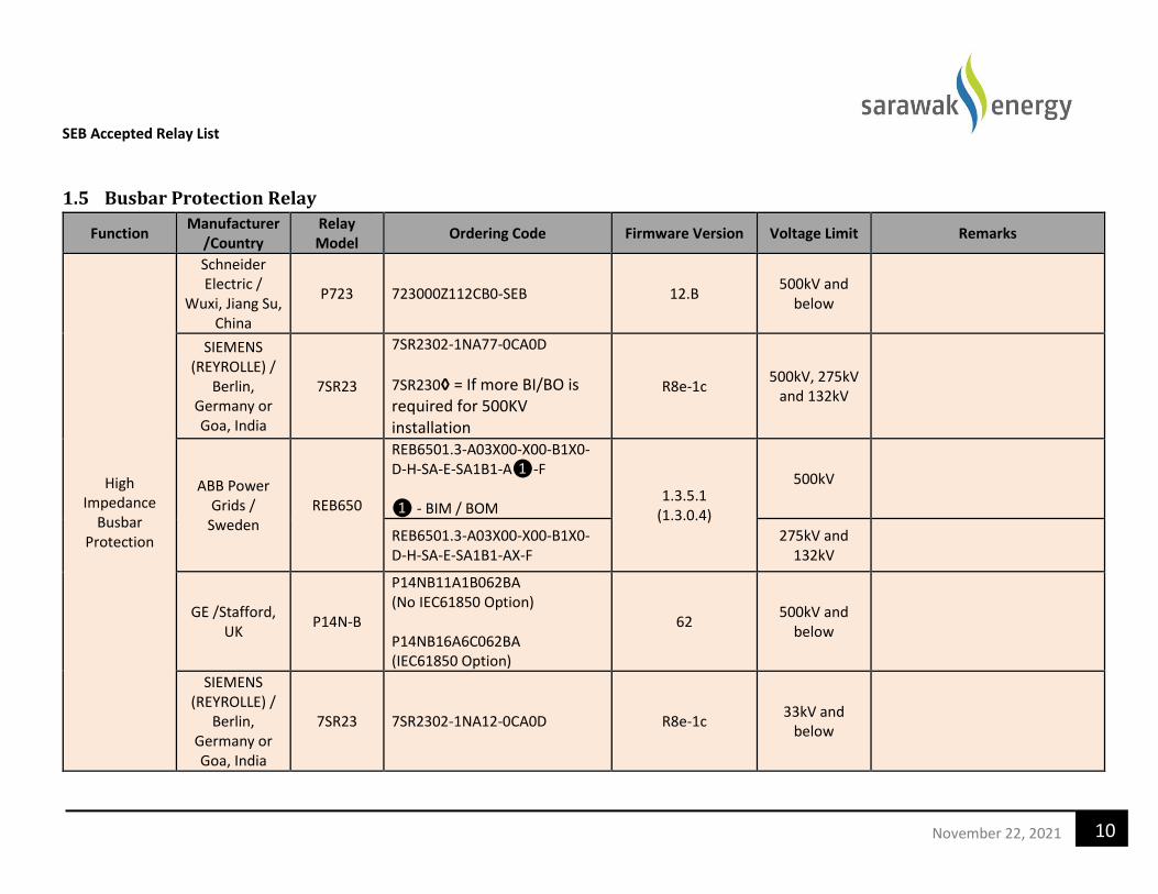
SEB Accepted Relay List
10 November 22, 2021
1.5 Busbar Protection Relay
Function Manufacturer
/Country Relay Model
Ordering Code Firmware Version Voltage Limit Remarks
High Impedance
Busbar Protection
Schneider Electric /
Wuxi, Jiang Su, China
P723 723000Z112CB0-SEB 12.B 500kV and
below
SIEMENS (REYROLLE) /
Berlin, Germany or Goa, India
7SR23
7SR2302-1NA77-0CA0D
7SR230◊ = If more BI/BO is required for 500KV installation
R8e-1c 500kV, 275kV
and 132kV
ABB Power Grids /
Sweden REB650
REB6501.3-A03X00-X00-B1X0-D-H-SA-E-SA1B1-A❶-F ❶ - BIM / BOM
1.3.5.1 (1.3.0.4)
500kV
REB6501.3-A03X00-X00-B1X0-D-H-SA-E-SA1B1-AX-F
275kV and 132kV
GE /Stafford, UK
P14N-B
P14NB11A1B062BA (No IEC61850 Option) P14NB16A6C062BA (IEC61850 Option)
62 500kV and
below
SIEMENS (REYROLLE) /
Berlin, Germany or Goa, India
7SR23 7SR2302-1NA12-0CA0D R8e-1c 33kV and
below

SEB Accepted Relay List
11 November 22, 2021
1.6 Overcurrent and Earth Fault Protection Relay
Function Manufacturer
/Country Relay Model
Ordering Code Firmware Version Voltage Limit Remarks
Schneider Electric /
Wuxi, Jiang Su, China
P123 P123-B00- Z112-EB-0-SEB EB (Software
Version) 500kV and
below
Overcurrent and Earth
Fault Protection
SIEMENS (REYROLLE) /
Berlin, Germany or Goa, India
7SR1103 7SR1103-1◊A◊◊-2CA0 *Pos 11 & 12 for IEC 61850
R4K-3d 500kV and
below
GE / Stafford,
UK P14N
P14NB1◊A◊◊0530A
53 500kV and
below
SEL / USA 751A
For 110Vdc, 1A model: 751A11D1D0X0X810610 For 110Vdc, 5A model: 751A11D1D0X0X850610
R419 500kV, 275kV
and 132kV
SIEMENS/
Berlin, Germany
7SJ612 7SJ6121-4EB91-1FA0+L0R 4.93 500kV, 275kV
and 132kV
ABB / Finland REF611 REF611 HBB ABA 1NA◊ 1G 2.0
(2.0.1)
275kV and below

SEB Accepted Relay List
12 November 22, 2021
1.7 Directional Overcurrent and Earth Fault Protection Relay
Function Manufacturer
/Country Relay Model
Ordering Code Firmware Version Voltage Limit Remarks
SIEMENS (REYROLLE) /
Berlin, Germany or Goa, India
7SR1206 7SR1206-2◊A◊◊-2CA0 *Pos 11 & 12 for IEC 61850
R4K-3d 500kV and
below
Directional Overcurrent
and Earth Fault
Protection
Schneider Electric /
Wuxi, Jiang Su, China
P127 P127-BA0- Z112-FE-0-SEB FE (Software
Version) 500kV and
below
GE / Stafford, UK
P14D P14DB1◊A◊C0530A
53 500kV and
below
SIEMENS/
Berlin, Germany
7SJ622 7SJ6221-4EB91-1FC0+L0R 4.93 500kV and
below
ABB / Finland REF 615 REF615 HBF FAEAG NBA1 ANA◊ 1G
5.0 FP1 (5.1.6)
275kV and below

SEB Accepted Relay List
13 November 22, 2021
1.8 Transformer Standby Earth Fault Protection Relay
Function Manufacturer
/Country Relay Model Ordering Code Firmware Version
Voltage Limit
Remarks
SIEMENS (REYROLLE) /
Berlin, Germany or Goa, India)
7SR1101 7SR1101-1◊A◊◊-2CA0 *Pos 11 & 12 for IEC 61850
R4K-3d 500kV and
below
Transformer Standby Earth
Fault protection
GE / Stafford, UK
P14N P14NB1◊A◊◊0530A 53 500kV and
below
Schneider Electric /
Wuxi, Jiang Su, China
P122 P122-B00- Z112-EB-0-SEB EB (Software
Version) 33kV and
below

SEB Accepted Relay List
14 November 22, 2021
1.9 Sensitive Earth Fault Protection Relay
Function Manufacturer
/Country Relay Model
Ordering Code Firmware Version Voltage Limit Remarks
Sensitive Earth Fault Protection
SIEMENS / Berlin,
Germany 7SJ612 7SJ6122-◊EB92-1FB0 4.93
33kV and below
SIEMENS (REYROLLE) /
Berlin, Germany or Goa, India)
7SR1101 7SR1101-3◊A12-2CA0 R4K-3d 33kV and
below
Schneider Electric /
China P122 P122-C00-Z112-EC-0-SEB EC (Software Version)
33kV and below

SEB Accepted Relay List
15 November 22, 2021
1.10 Directional Sensitive Earth Fault Protection Relay
Function Manufacturer
/Country Relay Model
Ordering Code Firmware Version Voltage Limit Remarks
Directional Sensitive
Earth Fault Protection
Schneider Electric /
China P127
P127CA0Z112FE0-SEB
15.E 33kV and
below

SEB Accepted Relay List
16 November 22, 2021
1.11 Circuit Breaker Fail Protection Relay
Function Manufacturer/
Country Relay Model
Ordering Code Firmware Version
Voltage Limit
Remarks
Schneider Electric /
Wuxi, Jiang Su, China
P821 P821B00Z112AE0-SEB 10.E 500kV and
below
Circuit Breaker Failure
Protection
SIEMENS / Berlin, Germany
7VK611 7VK6111-4AB91-4YC0+L0R 4.71 500kV,
275kV and 132kV
ABB Power Grids / Sweden
REQ650
REQ650*1.3-A11X00-X00-B1X0-D-❶-S❷-E-SA3-AA❸-F ❶ - Mounting details ❷ - PSM ❸ - BIM /BOM
1.3.5.1 (Firmware)
1.3.0.4 (Product Version)
500kV
REQ650*1.3-A11X00-X00-B1X0-D-❶-S❷-E-SA3-AAXX-F ❶ - Mounting details ❷ - PSM
275kV and 132kV
GE /Stafford, UK P841 P84191◊A◊S081AM 81 500kV,
275kV and 132kV
SEL /USA 751A
For 110Vdc, 1A model: 751A11D1D0X0X810610 For 110Vdc, 5A model: 751A11D1D0X0X850610
R419 33kV and
below
SIEMENS /
Berlin, Germany or Goa, India
7SR1103 7SR1103-1◊A12-2CA0 R4K-3d 33kV and
below

SEB Accepted Relay List
17 November 22, 2021
1.12 Over/Under Frequency Protection Relay
Function Manufacturer/
Country Relay Model
Ordering Code Firmware Version Voltage Limit Remarks
Over / Under
Frequency
SEL /USA 751A For 110Vdc model: 751A11D1D0X73810610
R419 500kV and
below
Schneider Electric / China
P3U30
P3U30-6AAA2BBBM (without IEC61850) P3U30-6AAA2BCBM (with IEC 61850)
30.108 500kV and
below
SIEMENS / Berlin, Germany
or Goa, India
7RW 7RW8020-5EB96-1DA0+L0R 4.62 500kV, 275kV
and 132kV
7RW 7RW8020-5EB00-1DA0 4.62 33kV and below

SEB Accepted Relay List
18 November 22, 2021
1.13 Over/Under Voltage Protection Relay
Function Manufacturer
/Country Relay Model
Ordering Code Firmware Version Voltage Limit Remarks
SEL /USA 751A For 110Vdc model: 751A11D1D0X73810610
R419 500kV and
below
SIEMENS
(REYROLLE) / Goa, India
7SR158 7SR1587 – 5HA12-2DA0/BB 2436H80011R4e-2a 500kV and
below
Over / Under
Voltage
Schneider Electric / China
P3U30
P3U30-6AAA2BBBM (without IEC61850) P3U30-6AAA2BCBM (with IEC 61850)
30.108 500kV and
below
SIEMENS / Berlin,
Germany or Goa, India
7RW 7RW8020-5EB96-1DA0+L0R 4.62 500kV, 132kV
and 132kV

SEB Accepted Relay List
19 November 22, 2021
1.14 Shunt Reactor High Impedance Circulating Protection Relay
Function Manufacturer/
Country Relay Model
Ordering Code Firmware Version Voltage Limit Remarks
Shunt Reactor
High Impedance Circulating Protection
SIEMENS (REYROLLE) /
Berlin, Germany or Goa, India
7SR23
7SR2302-1NA77-0CA0D (Transmission) 7SR2302-1NA12-0CA0D (Distribution)
7SR230◊ = If more BI/BO is required for 500KV installation
R8e-1c 500kV and
below
Schneider Electric / China
P723 P723000Z112CB0-SEB 12.B 500kV and
below
GE / Stafford, UK P14N-B
P14NB11A1B062BA (No IEC61850 Option) P14NB16A6C062BA (IEC61850 Option)
62 500kV and
below

SEB Accepted Relay List
20 November 22, 2021
1.15 Autoreclose + Synchro-Check Relay
Function Manufacturer/
Country Relay Model
Ordering Code Firmware Version Voltage Limit Remarks
Autoreclose + Synchro-
check
SIEMENS/ Berlin, Germany
7VK 7VK6111-4AB91-4YN0+LOR 4.71 500kV, 275kV
and 132kV
Schneider Electric /
Wuxi, Jiang Su, China
P841
P841311A3M0G79M-SEB (without IEC61850) P84131QA6M0G79M-SEB (with IEC61850)
G7 500kV, 275kV
and 132kV
ABB Power Grids / Sweden
REQ650
REQ650*1.3-A11X00-X00-B1X0-D-❶-S❷-E-SA3-AA❸-F ❶ - Mounting details ❷ - PSM ❸ - BIM /BOM
1.3.5.1 (1.3.0.4)
500kV
REQ650*1.3-A11X00-X00-B1X0-D-❶-S❷-E-SA3-AAXX-F ❶ - Mounting details ❷ - PSM
275kV and 132kV
GE / Stafford, UK
P841
P84191◊A◊S081AM
81 500kV, 275kV
and 132kV

SEB Accepted Relay List
21 November 22, 2021
Function Manufacturer/
Country Relay Model
Ordering Code Firmware Version Voltage Limit Remarks
Schneider Electric /
Wuxi, Jiang Su, China
P123 P123-B00- Z112-EB-0-SEB EB (Software
Version) 33kV and below
SEL /USA 751A 751A6◊◊◊◊0X◊◊8◊0◊◊0 R419 33kV and below
SIEMENS / Berlin, Germany
or Goa, India) 7SR1103 7SR1103-1◊A12-2DA0 R4K-3d 33kV and below

SEB Accepted Relay List
22 November 22, 2021
1.16 Synchro-Check Relay
Function Manufacturer/
Country Relay Model
Ordering Code Firmware Version Voltage Limit Remarks
Synchronising Check
Schneider Electric / China
P3U30 P3U30-6AAA2BBBM (without IEC61850)
30.108 500kV and
below
SIEMENS/ Berlin, Germany
7VK 7VK6101-4AB91-4YN0+LOR 4.71 500kV, 275kV
and 132kV
Schneider Electric /
Wuxi, Jiang Su, China
P841
P841311A3M0G79M-SEB (without IEC61850) P84131QA6M0G79M-SEB (with IEC61850)
G7 500kV, 275kV
and 132kV
SIEMENS / Berlin,
Germany or Goa, India
7RW 7RW8020-5EB96-1DC0+L0R 4.62 500kV, 275kV
and 132kV
SIEMENS (REYROLLE) /
Goa, India 7SR157 7SR1578-5HA12-2CAO/BB 2436H80010R4e-2a
275kV and below
SIEMENS / Berlin,
Germany or Goa, India
7VK 7VK6101-◊AB02-4YN0 4.71 33kV and below
SIEMENS / Berlin,
Germany or Goa, India
7RW 7RW8020-5EB00-1DC0 4.62 33kV and below
SEL /USA 751A 751A5◊◊◊◊0X728◊0◊◊0 R419 33kV and below

SEB Accepted Relay List
23 November 22, 2021
1.17 Capacitor Bank Protection Relay
Function Manufacturer/
Country Relay Model
Ordering Code Firmware Version
Voltage Limit Remarks
Capbank Overall Differential Protection
ABB Power Grids / Sweden
RET670
RET670*1.2-A30X00-D03-B1X0-AF-KB-B-A3-❶-XXX-XD ❶ - BIM / BOM
1.2
500kV
1MRK 004 816-AC (Short Ordering Code for Capbank RET670) RET670*1.2-A30X00-D03-B1X0-AF-KB-B-A3-DIAA-XXX-XD
275kV and 132kV
SIEMENS /
Berlin, Germany 7UT613 7UT6131-4EB91-1AA0+LOR 4.65
500kV, 275kV and 132kV
SIEMENS (REYROLLE) /
Berlin, Germany or Goa, India
7SR23 7SR2303-1◊A◊◊-0CA0 R8e-1c 500kV, 275kV
and 132kV
1. Capacitor unbalance
2. Thermal overload protection
3. Reactor thermal overload protection
4. Resistor thermal overload
5. Resistor open circuit protection
SIEMENS (REYROLLE) /
Goa, India 7SR191
7SR1916-1HA12-2CAO (no IEC 61850) 7SR1916-1HA77-2CA0 (with IEC 61850)
R4e-2a 500kV, 275kV
and 132kV
• Function: a) Capacitor Bank
Unbalance Protection

SEB Accepted Relay List
24 November 22, 2021
Function Manufacturer/
Country Relay Model
Ordering Code Firmware Version
Voltage Limit Remarks
SIEMENS
(REYROLLE) / Goa, India
7SR1206
7SR1206-2◊A◊◊-2CA0 *Pos No 11 & 12 option for IEC 61850
R4K-3d 500kV, 275kV
and 132kV
• Function: a) Reactor Thermal
Overload Protection
SIEMENS
(REYROLLE) / Goa, India
7SR1103 7SR1103-1◊A◊◊-2CA0 *Pos No 11 & 12 option for IEC 61850
R4K-3d 500kV275kV,
and 132kV
• Function: a) Resistor Thermal
Overload Protection b) Resistor Open Circuit
Protection
1. Capacitor unbalance/ thermal overload protection
2. Reactor thermal overload protection
3. Resistor thermal overload /open circuit protection
TRENCH /Austria
CPR 04 CPR4-00-110 4v81
(Software Version: 5v1)
275kV and 132kV
• Function: (a) Capacitor Bank
Unbalance Protection (b) Capacitor Bank
Thermal Overload Protection
(c) Reactor Thermal Overload Protection
(d) Resistor Thermal Overload Protection
(e) Resistor Open Circuit Protection
Schneider
Electric / China P3U30
P3U30-6AAA2BBBM (without IEC61850)
30.108 500kV and
below
• Function: (a) Capacitor Bank
Unbalance Protection (b) Capacitor Bank
Thermal Overload Protection

SEB Accepted Relay List
25 November 22, 2021
1.18 Stub Protection Relay
Function Manufacturer/
Country Relay Model
Ordering Code Firmware Version
Voltage Limit Remarks
GE / Stafford,
UK P14N P14NB1◊A◊◊0530A 53
500kV and 275kV
Schneider Electric /
Wuxi, Jiang Su, China
P723 P723000Z112CB0-SEB 12.B 500kV and
275kV
Stub Protection
SIEMENS (REYROLLE) /
Berlin, Germany or Goa, India
7SR23
7SR2302-1NA77-0CA0D
7SR230◊ = If more BI/BO is required for 500KV installation
R8e-1c 500kV and
275kV
ABB / Sweden REB650
REB6501.3-A03X00-X00-B1X0-D-H-SA-E-SA1B1-A❶-F ❶ - BIM /BOM
1.3.5.1 (1.3.0.4)
500kV and 275kV

SEB Accepted Relay List
26 November 22, 2021
2 Disturbance Recorder
Function Manufacturer/
Country Model Ordering Code Firmware Version Voltage Limit Remarks
Disturbance Recorder
QUALITROL / Northern Ireland
BEN 6000 BEN 6000 2.5.25 500kV and
below
SIEMENS/Berlin, Germany
7KE85
7KE85-JAAA-AA0-0AAAA0-AA8111-13113A-AAA000-000AC1-CB1BA1-CB1CB1-
CB1CB1-BC1CG0-◊◊◊
7.50 500kV and
below
• Mandatory Accessories & Software: -
(a) DIGSI 5 software premium (b) SICAM PQ Analyzer (PQA)
software Ver 3.17 (c) SICAM PQS/PAS (Data
Concentrator) Ver 8.17 (d) GPS Clock
(e) Ethernet Switch
NR Electric / China
PCS-996 PCS-996RC-R4.08 PCS-996RA-4.08
4.08 (CRC: B703A1A0)
500kV, 275kV and 132kV
• Mandatory Accessories & Software: -
(a) PCS-PC5 Tools Software (b) DFR Manager Software
(c) DFR Helper (d) GPS Clock NR PCS-9785

SEB Accepted Relay List
27 November 22, 2021
3 Ancillary Equipment
3.1 Trip Circuit Supervision Relay
Function Manufacturer/
Country Model Ordering Code Voltage Limit Remarks
Trip Circuit Supervision
GE / Stafford, UK MVAX31 MVAX31S1DE0754A
500kV and below
SIEMENS / Europe
7PA3032 7PA3032-1AA00-1
500kV and below
(a) Single phase
Schneider Electric / Spain
REL913 REL91323
500kV and below
RMS / Australia ALPHA
XR5-◊◊ -1/4/6◊ (ALPHA XR Series)
500kV and below
ARTECHE / Spain VDF VDF10 500kV and
below
ABB / Sweden SPER IBI -
33kV and below

SEB Accepted Relay List
28 November 22, 2021
3.2 Lockout Relay
Function Manufacturer/
Country Model Ordering Code Voltage Limit Remarks
Lockout
GE / Stafford, UK MVAJ105 MVAJ105RA0802B 500kV and
below (a) Voltage rating: 110/125V
SIEMENS / Europe
7PA2231 7PA2◊◊1-1 500kV and
below
RMS/ Australia ALPHA/
DELTA/ 6RJ
TR 5/12 - ◊◊ - 1/2/3/4 ◊ (ALPHA TR Series)
500kV and below
AR 5/12 - ◊◊ - 1/2/3/4 ◊ (ALPHA AR Series- 1 element)
AR25 - ◊◊ - 1/2/3/4 ◊ (ALPHA AR Series- 2 element)
TRD-4◊◊ (DELTA TRD Series)
6RJ25-20-◊◊ (6RJ Series)
Schneider Electric / Spain
REL912
REL91263 (4 changeover contacts) 500kV and
below
REL91283 (8 changeover contacts)
ARTECHE / Spain B◊◊RP
BF4RP (4 changeover contacts)
500kV and below
BJ8RP (8 changeover contacts)
BJ10RP (10 changeover contacts)

SEB Accepted Relay List
29 November 22, 2021
3.3 Tripping Relay
Function Manufacturer/
Country Model Ordering Code Voltage Limit Remarks
Tripping
ABB / India ABB RXMS RXMS1 RK216 x63-AN 500kV and
below
SIEMENS/ Europe
7PA2732 7PA2◊◊2-0AA00-◊ 500kV and
below
SIEMENS/ Berlin,
Germany or Goa, India
TR221 7PG1522-1HA40-1AF0 500kV and
below
AR ◊11 7PG11◊1-1EA10-0C◊0
RMS/ Australia ALPHA/ DELTA
TR 5/12 - ◊◊ - 1/2/3/4 ◊ (ALPHA TR Series)
500kV and below
AR 5/12 - ◊◊ - 1/2/3/4 ◊ (ALPHA AR Series- 1 element)
AR 25 - ◊◊ - 1/2/3/4 ◊ (ALPHA AR Series-2 element)
TRD-4◊◊ - (DELTA TRD Series)
Schneider Electric / Spain
REL912
REL91203 (4 changeover contacts)
500kV and below
REL91223 (Fast trip relay with 4 changeover contacts)

SEB Accepted Relay List
30 November 22, 2021
Function Manufacturer/
Country Model Ordering Code Voltage Limit Remarks
GE / Stafford, UK MVAJ05
MVAJ051RA08◊◊B (5 Contact)
500kV and below
MVAJ101RA08◊◊A (10 Contact)
ARTECHE / Spain R◊◊R
OP01◊◊◊
RF4R OP01◊◊◊ (4 changeover contacts)
500kV and below
RJ8R OP01◊◊◊ (8 changeover contacts)
RI16R OP01◊◊◊ (16 changeover contacts)

SEB Accepted Relay List
31 November 22, 2021
3.4 Test Terminal Block
Function Manufacturer/
Country Model Ordering Code Voltage Limit Remarks
Test Terminal Block
ABB / India RTXP 18/24
a) Test Socket:
i. RTXP 18 RK926-115-◊◊
ii. RTXH 24 RK926 315-◊◊ b) Test Plug:
i. RTXH 18 RK926 011-BC ii. RTXH 24 RK926 016-AA
500kV and below
GE / Stafford, UK MMLG01 • Test Block: MMLG01R1AB0001E
• Test Plug: MMLB01AXAA0011E
500kV and below
SIEMENS (REYROLLE) /
Berlin, Germany or Goa, India
2RMLG07 • Test Socket: 7XG2220-3AA00-0AA0
• Test Plug: 7XG2240-3AA00-0AA0
500kV, 275kV and 132kV
RMS/ Australia 4M Series • Test Socket: 4M400-◊◊
• Test Plug: 4M42◊-◊
500kV, 275kV and 132kV
Schneider Electric / Spain ETB14 • Test Socket: ETB14◊◊◊◊◊◊◊◊◊◊◊◊◊◊-V
• Test Plug: ETB14PV
500kV and below
ARTECHE / Spain TSB14
• Test Block:
TSB-14-◊◊◊◊◊◊◊◊◊◊◊◊◊◊-V
(Ordering Code for Manual CT Shorting:
TSB-14-11111111111111-V)
• Test Plug: TSB-14-P-V
500kV and below
Manual CT Shorting is required for 33kV and
below

SEB Accepted Relay List
32 November 22, 2021
Function Manufacturer/
Country Model Ordering Code Voltage Limit Remarks
ARTECHE / Spain TSB18
• Test Block:
TSB-18-◊◊◊◊◊◊◊◊◊◊◊◊◊◊◊◊◊◊-V
(Ordering Code for Manual CT Shorting:
TSB-18-111111111111111111-V)
• Test Plug: TSB-18-P-V
500kV and below
Manual CT Shorting is required for 33kV and
below
SIEMENS (REYROLLE) /
Berlin, Germany or Goa, India
2RMLG01 • Test Socket: 7XG2220-1AA00-0AA0
• Test Plug: 7XG2240-1AA00-0AA0
33kV and below
RMS / Australia 4M Series • Test Block: 4M200-01
• Test Plug: 4M220-00
33kV and below

SEB Accepted Relay List
33 November 22, 2021
3.5 DC Supervision Relay
Function Manufacturer/
Country Model Ordering Code Voltage Limit Remarks
DC Supervision
SIEMENS (REYROLLE) /
Berlin, Germany or Goa, India
XR152 7PG1741-3BD10-4AA0 500kV and
below
Schneider Electric / Spain
REL913 REL91344 500kV and
below
RMS / Australia Delta XRD
Series XRD-4◊◊
500kV and below
GE / Stafford, UK MVAX12 MVAX12R1CB075◊A 500kV and
below
ARTECHE / Spain RUT4 RUT4OP 500kV and
below

SEB Accepted Relay List
34 November 22, 2021
4 Substation Interrogation and Monitoring System Function Manufacturer/
Country Model Ordering Code Voltage Limit Remarks
Substation
Interrogation
and Monitoring
system
Malaysia
Advance
Remote
Access
Commander
(ARAC)
NA 132kV and above
• Mandatory Accessories &
Software:
a) ARAC Interrogation
Software
Important Note:
1. The recommended relay ordering no. indicated by ◊ are to be specified based on actual installation requirement / SEB application. 2. The protection relay manufacturer/supplier shall provide 10 years product warranty from the date of supply. Faulty relays shall be
collected from and replacement shall be delivered to SEB office without cost to SEB. 3. The Disturbance recorder manufacturer/supplier shall provide 5 years product warranty from the date of supply. Faulty disturbance
recorders shall be collected from and replacement shall be delivered to SEB office without cost to SEB. 4. The ancillary equipment manufacturer/supplier shall provide 5 years product warranty from the date of supply. Faulty ancillary
equipment shall be collected from and replacement shall be delivered to SEB office without cost to SEB.

Protection, Control & Instrumentation—Protection Relay RTDS Test Plan
SARAWAK ENERGY BERHAD
Line Protection Relay
Real Time Digital Simulation Test Plan
VERSION NO:
4.0
DATE: 27th May 2021

Protection, Control & Instrumentation—Protection Relay RTDS Test Plan
1
F11
GA
Fault Location
Note:
GA, GB : Source F1 : 0.1% F2 : 30% F3 : 70% F4 : 99.9% F5 : Fault on Left side Busbar F6 : Fault on Right side Busbar F7 : 0.1% on Parallel line F8 : 30% on Parallel line
F9 : 70% on Parallel line F10 : 99.9% on Parallel line F11 : 50% on Left Adjacent Longest Line F12 : 50% on Right Adjacent Longest Line F13 : Fault on Left Side Transformer LV Side F14 : Fault on Right Side Transformer LV Side F15 : Fault on Left Side Transformer HV Side F16 : Fault on Right Side Transformer HV Side
*All Test with Auto-Recloser in 1+3Pole Mode. Signals to be monitor for each side
CB Trip R Trip Lockout
CB Trip Y DEF Pickup Forward
CB Trip B DEF Pickup Reverse
DEF Carrier Received DEF Operated
DEF Carrier Send AR Operated
SOTF (Impedance) Operated AR Blocked
SOTF (Differential) Operated EF Blocked
Differential Trip Differential Lowset
Distance Z1 Pickup Differential Highset
Distance Z1 Trip Negative Sequence (Trip Enhanced)
Distance Z2 Pickup Distance R-ph Carrier Received
Distance Z2 Trip Distance R-ph Carrier Send
Distance Z3 Pickup Distance Y-ph Carrier Received
Distance Z3 Trip Distance Y-ph Carrier Send
Distance Z4 Pickup Distance B-ph Carrier Received
Distance Z4 Trip Distance B-ph Carrier Send
RELAY A LEFT SIDE
CB1B
F1 F2 F3 F4 F6 F5
F7 F8 F9 F10
LINE 1 CB1A
LINE 2 CB2B
CB2A
F14
F12
GB
RELAY B RIGHT SIDE
F13 F15 F16

Protection, Control & Instrumentation— Protection Relay RTDS Test Plan
2
No. Type of Fault: Line
Current Differential
Distance
1. Internal Fault with Successful Auto Reclose 1-12 1-12
2. Internal Resistive and High Resistive Fault with Unsuccessful Auto Reclose 13-23 13-36
3. Evolving fault 24-32 37-53
4.
Switch on to fault i. Switch on to fault with communication
a) Left Side Close onto fault 33-38 54-59
b) Right Side Close onto fault 39-44 60-65
ii. Switch on to fault without communication a) Left Side Close onto fault
45-50 66-71
b) Right Side Close onto fault 51-56 72-77
5. Permanent Metallic and High Resistive Faults on Protected Line without Communication
57-84 78-105
6. Busbar Fault, Parallel Line Open and Grounded with Communication Failure
85-96 106-117
7. Busbar Fault, Parallel Line in Service* 97-108 118-129
8. Permanent Metallic and Resistive Fault on Parallel Line (Parallel Line Unequal CB Opening Time)
109-122 130-143
9. Simultaneous Fault (Cross Country fault) 144-151
10.
External Permanent Metallic Fault on Adjacent Line and Remote End
Transformer LV Fault*
a) External Permanent Metallic Fault on Adjacent Line
123-130 152-159
b) Remote End Transformer LV Fault 131-138 160-167
c) Remote End Transformer HV Fault 139-146 168-175
11. Internal Fault with CT saturation 147-150 176-179 12. External Fault with CT saturation 151-154 180-183 13. Fault After Fuse Failure Monitor 155-156 184-185
14. Fault on parallel Line under heavily loaded condition, with successful Auto Reclose *
157-172 186-201
Notes:
*Not applicable for Product Approval TNA test.

Protection, Control & Instrumentation— Protection Relay RTDS Test Plan
3
1 Internal Fault with Successful Auto Reclose
Test Case : Internal Fault with Successful Auto Reclose
Fault Type : Transient Metallic Fault
Loading : Minimum Generation
Fault Duration : 0.3s
Expected Trip and Reclose Operation
:
Single Phase fault, trip faulted Phase and reclose
Phase-Phase Fault, trip three phase and reclose
Three Phase fault, no reclose
Possible Protection Operation : Current Differential Operation Distance Zone 1 Operation Distance Teleprotection Zone Operation
Test Case No. Fault Position Type of fault Rf [ohm] Angle [Degree]
Line Current Differential Distance
1. 1. F1 BG 0.05 0
2. 2. F1 BG 0.05 90
3. 3. F1 BC 0.05 0
4. 4. F1 BC 0.05 90
5. 5. F1 BCG 0.05 0
6. 6. F1 BCG 0.05 90
7. 7. F4 CG 0.05 0
8. 8. F4 CG 0.05 90
9. 9. F4 CA 0.05 0
10. 10. F4 CA 0.05 90
11. 11. F4 CAG 0.05 0
12. 12. F4 CAG 0.05 90

Protection, Control & Instrumentation— Protection Relay RTDS Test Plan
4
2 Internal Resistive and High Resistive Fault with Unsuccessful
Auto Reclose
Test Case : Internal Resistive and High Resistive Fault with Unsuccessful Auto Reclose
Fault Type : Permanent Resistive Fault
Loading : Maximum Generation
Fault Duration : 3s
Expected Result :
Single Phase fault, trip faulted phase, reclose and tripped three phases
Phase-Phase Fault, trip three phase and reclose and tripped three phases
Three Phase fault, no reclose
Possible Protection
Operation :
Current Differential Operation Distance Zone 1 Operation Distance Teleprotection Zone Operation Directional Earth Fault (DEF) Operation
Test Case No. Fault Position Type of fault Rf [ohm] Angle [Degree]
Line Current Differential Distance
13. 13. F1 AG 0.05 90
14. 14. F1 AG 3 0
15. 15. F1 AG 10 90
16. 16. F1 AG 40 0
17. 17. F1 AG 80 90
18. 18. F1 AG 180 0
19. F2 BCG 0.05 90
20. F2 BCG 3 0
21. F2 BCG 10 90
22. F2 BCG 40 0
23. F2 BCG 80 90
24. F2 BCG 180 0
25. F3 CG 0.05 90
26. F3 CG 3 0
27. F3 CG 10 90
28. F3 CG 40 0
29. F3 CG 80 90
30. F3 CG 180 0
31. F4 ABG 0.05 0
19. 32. F4 ABG 3 90
20. 33. F4 ABG 10 0
21. 34. F4 ABG 40 90
22. 35. F4 ABG 80 0
23. 36. F4 ABG 180 90

Protection, Control & Instrumentation— Protection Relay RTDS Test Plan
5
3 Evolving Fault Test Case : Evolving Fault
Fault Type : Permanent Metallic Fault
Loading : Minimum Generation
Fault Duration : 3s
Expected Result : Trip faulted phase follow by tripped the other two phase and reclose
Possible Protection Operation
: Current Differential Operation Distance Zone 1 Operation Distance Teleprotection Zone Operation
Test Case No. FAULT 1 FAULT 2
Scenario Line
Current Differential
Distance Fault
Position Fault
Rf [ohm]
Fault Inception Angle[◦]
Fault Position
Fault Rf [ohm] Fault Inception
Angle [◦]
24. 37. F1 AG 0.05 0 F1 BG 0.05 0 Fault 2 in 10ms after F1
25. 38. F1 AG 0.05 90 F1 BG 0.05 90 Fault 2 in 20ms after F1
26. 39. F1 AG 0.05 0 F1 BG 0.05 0 Fault 2 in 30ms after F1
27. 40. F1 AG 0.05 90 F1 BG 0.05 90 Fault 2 in 150ms after F1
41. F2 BG 0.05 90 F2 CG 0.05 90 Fault 2 in 10ms after F1
42. F2 BG 0.05 0 F2 CG 0.05 0 Fault 2 in 20ms after F1
43. F2 BG 0.05 90 F2 CG 0.05 90 Fault 2 in 30ms after F1
44. F2 BG 0.05 0 F2 CG 0.05 0 Fault 2 in 150ms after F1
45. F3 CG 0.05 0 F3 AG 0.05 0 Fault 2 in 10ms after F1
46. F3 CG 0.05 90 F3 AG 0.05 90 Fault 2 in 20ms after F1
47. F3 CG 0.05 0 F3 AG 0.05 0 Fault 2 in 30ms after F1
48. F3 CG 0.05 90 F3 AG 0.05 90 Fault 2 in 150ms after F1
28. 49. F4 BG 0.05 90 F4 CG 0.05 90 Fault 2 in 10ms after F1
29. 50. F4 BG 0.05 0 F4 CG 0.05 0 Fault 2 in 20ms after F1
30. 51. F4 BG 0.05 90 F4 CG 0.05 90 Fault 2 in 30ms after F1
31. 52. F4 BG 0.05 0 F4 CG 0.05 0 Fault 2 in 150ms after F1
32. 53. F4 BG 0.05 90 F4 CG 0.05 90 Fault 2 in 150ms after F1

Protection, Control & Instrumentation— Protection Relay RTDS Test Plan
6
4 Switch On to Fault (SOTF) Test Case : Both Circuit Breakers are Open (Left Side Close Onto Fault)
Fault Type : Permanent Metallic Fault
Loading : Minimum Generation
Fault Duration : 0.3s
Expected Operation : SOTF Operation and Trip Three Phase. No reclose.
Possible Protection Operation : Current Differential Operation Distance Zone 1 Operation Switch On to Fault Operation
Test Case No. Fault Position Type of fault Rf [ohm] Angle [Degree]
Line Current Differential Distance
33. 54. F1 AG 0.05 0
34. 55. F1 ABG 0.05 90
35. 56. F1 ABCG 0.05 0
36. 57. F4 AG 0.05 90
37. 58. F4 ABG 0.05 0
38. 59. F4 ABCG 0.05 90
Test Case : Both Circuit Breakers are Open (Right Side Close Onto Fault)
Fault Type : Permanent Metallic Fault
Loading : Minimum Generation
Fault Duration : 0.3s
Expected Operation : SOTF Operation and Trip Three Phase. No reclose.
Possible Protection Operation : Current Differential Operation Distance Zone 1 Operation Switch On to Fault Operation
Test Case No. Fault Position Type of fault Rf [ohm] Angle [Degree]
Line Current Differential Distance
39. 60. F1 BG 0.05 0
40. 61. F1 BCG 0.05 90
41. 62. F1 ABCG 0.05 0
42. 63. F4 BG 0.05 90
43. 64. F4 BCG 0.05 0
44. 65. F4 ABCG 0.05 90

Protection, Control & Instrumentation— Protection Relay RTDS Test Plan
7
Test Scenario : Both Circuit Breakers are Open (Left Side Close Onto Fault) All Communication Fail, Backup Distance Protection Activated
Fault Type : Permanent Metallic Fault
Loading : Minimum Generation
Fault Duration : 0.3s
Expected Operation : SOTF Operation and Trip Three Phase. No reclose.
Possible Protection Operation : Distance Zone 1 Operation Switch On to Fault Operation
Test Case No. Fault Position Type of fault Rf [ohm] Angle [Degree]
Line Current Differential Distance
45. 66. F1 AG 0.05 0
46. 67. F1 ABG 0.05 90
47. 68. F1 ABCG 0.05 0
48. 69. F4 AG 0.05 90
49. 70. F4 ABG 0.05 0
50. 71. F4 ABCG 0.05 90
Test Case : Both Circuit Breakers are Open (Right Side Close Onto Fault) All Communication Fail, Backup Distance Protection Activated
Fault Type : Permanent Metallic Fault
Loading : Minimum Generation
Fault Duration : 0.3s
Expected Operation : SOTF Operation and Trip Three Phase. No reclose.
Possible Protection Operation : Distance Zone 1 Operation Switch On to Fault Operation
Test Case No. Fault Position Type of fault Rf [ohm] Angle [Degree]
Line Current Differential Distance
51. 72. F1 BG 0.05 0
52. 73. F1 BCG 0.05 90
53. 74. F1 ABCG 0.05 0
54. 75. F4 BG 0.05 90
55. 76. F4 BCG 0.05 0
56. 77. F4 ABCG 0.05 90

Protection, Control & Instrumentation— Protection Relay RTDS Test Plan
8
5 Permanent Metallic and High Resistive Faults on Protected Line
without Communication
Test Case : Permanent Metallic and High Resistive Faults on Protected Line
Fault Type : Permanent Metallic Fault and High Resistive Fault
Loading : Maximum Generation
Fault Duration : 3s
Expected
Operation
: Single Phase fault, trip faulted phase, reclose and tripped three phases
Phase-Phase Fault, trip three phase, reclose and tripped three phases
Trip three phase and no auto reclose (Zone 2,4 and DEF Operation)
Possible
Protection
Operation
:
Distance Zone 1 Operation Distance Zone 2 Operation Distance Zone 4 Operation Directional Earth Fault (DEF) Operation
Test Case No. Fault Position Type of fault Rf [ohm] Angle [Degree]
Line Current Differential Distance
57. 78. F1 AG 0.05 0
58. 79. F1 AB 0.05 90
59. 80. F1 ABG 0.05 0
60. 81. F1 ABCG 0.05 90
61. 82. F1 AG 10 0
62. 83. F1 AG 40 90
63. 84. F1 AG 80 0
64. 85. F2 BG 0.05 90
65. 86. F2 BC 0.05 0
66. 87. F2 BCG 0.05 90
67. 88. F2 ABCG 0.05 0
68. 89. F2 BG 10 90
69. 90. F2 BG 40 0
70. 91. F2 BG 80 90
71. 92. F3 CG 0.05 0
72. 93. F3 CA 0.05 90
73. 94. F3 CAG 0.05 0
74. 95. F3 ABCG 0.05 90
75. 96. F3 CG 10 0
76. 97. F3 CG 40 90
77. 98. F3 CG 80 0
78. 99. F4 BG 0.05 90
79. 100. F4 BC 0.05 0
80. 101. F4 BCG 0.05 90
81. 102. F4 ABCG 0.05 0
82. 103. F4 BG 10 90
83. 104. F4 BG 40 0
84. 105. F4 BG 80 90

Protection, Control & Instrumentation— Protection Relay RTDS Test Plan
9
6 Busbar Faults, Parallel Line Open and Grounded with
Communication Failure
Test Case : Busbar Faults, Parallel Line Open and Grounded with Communication Failure
Fault Type : Permanent Metallic Fault and High Resistive Fault
Loading : Maximum Generation
Fault Duration : 3s
Expected Operation : Trip three phase and no auto reclose
Possible Protection Operation
: Distance Zone 2 Operation Distance Zone 4 Operation Directional Earth Fault (DEF) Operation
Test Case No. Fault Position Type of fault Rf [ohm] Angle [Degree]
Line Current Differential Distance
85. 106. F5 AG 0.05 0
86. 107. F5 AB 0.05 90
87. 108. F5 ABG 0.05 0
88. 109. F5 ABCG 0.05 90
89. 110. F5 AG 3 0
90. 111. F5 AG 10 90
91. 112. F6 BG 0.05 0
92. 113. F6 BC 0.05 90
93. 114. F6 BCG 0.05 0
94. 115. F6 ABCG 0.05 90
95. 116. F6 BG 10 0
96. 117. F6 BG 3 90

Protection, Control & Instrumentation— Protection Relay RTDS Test Plan
10
7 Busbar Faults, Parallel Line in Service
Test Case : Busbar Faults, Parallel Line in Service
Fault Type : Permanent Metallic Fault and High Resistive Fault
Loading : Maximum Generation
Fault Duration : 3s
Expected Operation : Trip three phase and no auto reclose
Possible Protection Operation : Distance Zone 2 Operation
Distance Zone 4 Operation Directional Earth Fault (DEF) Operation
Test Case No. Fault Position Type of fault Rf [ohm] Angle [Degree]
Line Current Differential Distance
97. 118. F5 AG 0.05 0
98. 119. F5 AB 0.05 90
99. 120. F5 ABG 0.05 0
100. 121. F5 ABCG 0.05 90
101. 122. F5 AG 3 0
102. 123. F5 AG 10 90
103. 124. F6 BG 0.05 0
104. 125. F6 BC 0.05 90
105. 126. F6 BCG 0.05 0
106. 127. F6 ABCG 0.05 90
107. 128. F6 AG 3 0
108. 129. F6 AG 10 90

Protection, Control & Instrumentation— Protection Relay RTDS Test Plan
11
8 Permanent Metallic and Resistive Fault on Parallel Line
(Parallel Line Unequal CB Opening Time)
Test Case : External Permanent Metallic and Resistive Fault on Parallel Line (Parallel Line CB Open)
Fault Type : Permanent Metallic Fault and High Resistive Fault CB’s of parallel line open at 65/40ms
Loading : Maximum Generation
Fault Duration : 0.3s
Expected Operation : No Tripping
Possible Protection Operation
: No protection operates
Test Case No. Fault Position Type of fault Rf [ohm] Angle [Degree]
Line Current Differential Distance
109. 130. F7 AG 0.05 0
110. 131. F7 AG 10 90
111. 132. F7 AB 0.05 0
112. 133. F7 ABG 0.05 90
113. 134. F7 ABG 10 0
114. 135. F7 ABCG 0.05 90
115. 136. F7 ABCG 3 0
116. 137. F10 AG 0.05 90
117. 138. F10 AG 10 0
118. 139. F10 AB 0.05 90
119. 140. F10 ABG 0.05 0
120. 141. F10 ABG 10 90
121. 142. F10 ABCG 0.05 0
122. 143. F10 ABCG 3 90

Protection, Control & Instrumentation— Protection Relay RTDS Test Plan
12
9 Simultaneous Faults (Cross Country Faults)
Test Case : Simultaneous Faults (Cross Country Faults)
Fault Type : Transient Metallic Fault on Protected and on Parallel Line CB’s of parallel line will open and clear fault
Loading : Maximum Generation
Fault Duration : 0.3s
Expected Operation : Single Phase fault, trip faulted Phase and reclose
Possible Protection Operation : Distance Zone 1 Operation
Distance Teleprotection Zone Operation
Test Case No. FAULT 1 FAULT 2
Line Current
Differential Distance
Fault Position Fault
Rf [ohm]
Fault Inception
Angle [◦]
Fault Position
Fault Rf
[ohm]
Fault Inception
Angle [◦]
144. F1 AG 0.05 0 F7 BG 0.05 0
145. F1 BG 0.05 90 F7 AG 0.05 90
146. F2 AG 0.05 0 F8 BG 0.05 0
147. F2 BG 0.05 90 F8 AG 0.05 90
148. F3 AG 0.05 0 F9 BG 0.05 0
149. F3 BG 0.05 90 F9 AG 0.05 90
150. F4 AG 0.05 0 F10 BG 0.05 0
151. F4 BG 0.05 90 F10 AG 0.05 90

Protection, Control & Instrumentation— Protection Relay RTDS Test Plan
13
10 External Permanent Metallic Fault on Adjacent Line and
Remote End (Transformer LV Fault)
a) External Permanent Metallic Fault on Adjacent Line Test Case : External Permanent Metallic Fault on Adjacent Line
Fault Type : Metallic Fault
Loading : Maximum Generation
Fault Duration : 3s
Expected Operation : No Operation Three phase trip and no reclose
Possible Protection Operation : Distance Zone 2 Operation
Distance Zone 4 Operation Directional Earth Fault Operation
Test Case No. Fault Position Type of fault Rf [ohm] Angle [Degree]
Line Current Differential Distance
123. 152. F11 AG 0.05 0
124. 153. F11 AB 0.05 90
125. 154. F11 ABG 0.05 0
126. 155. F11 ABCG 0.05 90
127. 156. F12 AG 0.05 0
128. 157. F12 AB 0.05 90
129. 158. F12 ABG 0.05 0
130. 159. F12 ABCG 0.05 90
b) Remote End Transformer LV Fault Test Case : Remote End Transformer LV Fault
Fault Type : Permanent Metallic Fault at Remote End Transformer LV Left and Right Side
Loading : Maximum Generation
Fault Duration : 3s
Expected Operation : No Operation Three phase trip and no reclose
Possible Protection Operation : Directional Earth Fault Operation
Test Case No. Fault Position Type of fault Rf [ohm] Angle [Degree]
Line Current Differential Distance
131. 160. F13 AG 0.05 0
132. 161. F13 AB 0.05 90
133. 162. F13 ABG 0.05 0
134. 163. F13 ABCG 0.05 90
135. 164. F14 AG 0.05 0
136. 165. F14 AB 0.05 90
137. 166. F14 ABG 0.05 0
138. 167. F14 ABCG 0.05 90

Protection, Control & Instrumentation— Protection Relay RTDS Test Plan
14
c) Remote End Transformer HV Fault Test Case : Remote End Transformer HV Fault
Fault Type : Permanent Metallic Fault at Remote End Transformer HV Left and Right Side
Loading : Maximum Generation
Fault Duration : 3s
Expected Operation
: No Operation Three phase trip and no reclose
Possible Protection Operation
: Distance Zone 2 Operation Distance Zone 4 Operation Directional Earth Fault Operation
Test Case No. Fault Position Type of fault Rf [ohm] Angle [Degree]
Line Current Differential Distance
139. 168. F15 AG 0.05 0
140. 169. F15 AB 0.05 90
141. 170. F15 ABG 0.05 0
142. 171. F15 ABCG 0.05 90
143. 172. F16 AG 0.05 0
144. 173. F16 AB 0.05 90
145. 174. F16 ABG 0.05 0
146. 175. F16 ABCG 0.05 90

Protection, Control & Instrumentation— Protection Relay RTDS Test Plan
15
11 Internal Fault with CT Saturation
Test Case : Internal Fault with CT Saturation
Fault Type : Permanent Metallic Faults on the Line With CT Saturation
Loading : Maximum Generation
Fault Duration : 3s
Expected Trip and Reclose Operation
: Single Phase fault, trip faulted Phase and reclose
Three Phase fault, no reclose
Possible Protection Operation
: Current Differential Operation Distance Zone 1 Operation Distance Teleprotection Zone Operation
Test Case No. Fault Position Type of fault Rf [ohm] Angle [Degree]
Line Current Differential Distance
147. 176. F1 AG 0.05 0
148. 177. F4 AG 0.05 90
149. 178. F1 ABC 0.05 0
150. 179. F4 ABC 0.05 90
12 External Fault with CT Saturation
Test Case : External Fault with CT Saturation
Fault Type : Permanent Metallic Faults on the Line With CT Saturation
Loading : Maximum Generation
Fault Duration : 3s
Expected Trip and Reclose Operation
: No operation
Possible Protection Operation
: No protection operation
Test Case No. Fault Position Type of fault Rf [ohm] Angle [Degree]
Line Current Differential Distance
151. 180. F11 AG 0.05 0
152. 181. F11 ABCG 0.05 90
153. 182. F12 AG 0.05 0
154. 183. F12 ABCG 0.05 90

Protection, Control & Instrumentation— Protection Relay RTDS Test Plan
16
13 Fault After Fuse Failure Monitor
Test Case : Fault After Fuse Failure Monitor
Fault Type : Permanent Metallic Faults on the Line With Fuse Failure Operate
Loading : Maximum Generation
Fault Duration : 3s
Expected Trip and Reclose Operation
: Single Phase fault, trip faulted Phase and reclose
Three Phase fault, no reclose
Possible Protection Operation
: Current Differential Operation Distance Zone 1 Operation Distance Teleprotection Zone Operation
Test Case No. Fault Position Type of fault Rf [ohm] Angle [Degree]
Line Current Differential Distance
155. 184. F1 AG 0.05 0
156. 185. F4 ABCG 0.05 90

Protection, Control & Instrumentation— Protection Relay RTDS Test Plan
17
14 Fault on parallel line under heavily loaded condition with
successful Auto Reclose
Test Case : Fault on parallel line under heavily loaded condition with successful Auto Reclose
Fault Type : Transient Metallic Fault
Loading : Heavily Loaded Network
Fault Duration : 3s
Expected Trip and Reclose Operation
: No operation
Possible Protection Operation
: No protection operation
Test Case No. Fault Position Type of fault Rf [ohm] Angle [Degree]
Line Current Differential Distance
157. 186. F7 AG 0.05 0
158. 187. F7 AB 0.05 90
159. 188. F7 ABG 0.05 0
160. 189. F7 ABC 0.05 90
161. 190. F7 ABCG 0.05 0
162. 191. F8 BG 0.05 90
163. 192. F8 BC 0.05 0
164. 193. F8 ABC 0.05 90
165. 194. F9 BG 0.05 0
166. 195. F9 BC 0.05 90
167. 196. F9 ABC 0.05 0
168. 197. F10 AG 0.05 90
169. 198. F10 AB 0.05 0
170. 199. F10 ABG 0.05 90
171. 200. F10 ABC 0.05 0
172. 201. F10 ABCG 0.05 90

Transmission Protection, Control & Instrumentation – Protection Relay Testing Requirements
Transmission Protection, Control and Instrumentation Division
Transmission Protection Relay Testing Requirement Version 3.2 6th August 2018

Transmission Protection, Control & Instrumentation – Protection Relay Testing Requirements
Page 1
Terminology
All fault types : Include all Ph-G, Ph-Ph, 3Ph fault
Ph-G : Includes all single phase to ground fault – R-G, Y-G, B-G
Ph-Ph : Includes all phase to phase fault- R-Y, -Y-B, B-R
3Ph : Three phase fault – RYB
DOC : Directional Overcurrent
DEF : Directional Earth Fault
REF : Restricted Earth Fault
SBEF : Standby Earth Fault
CB : Circuit Breaker
CBF : Circuit Breaker Failure
AR : Auto Reclose
CT : Current Transformer
VT : Voltage Transformer

Transmission Protection, Control & Instrumentation – Protection Relay Testing Requirements
Page 2
Table of Contents
Terminology ............................................................................................................................................ 1
1. Distance Protection Relay .......................................................................................................... 3
2. Line Differential Protection Relay ....................................................................................................... 7
3. Biased Differential Protection Relay ........................................................................................ 13
4. Directional Overcurrent / Directional Earth Fault (DOC / DEF) Protection Relay .................... 16
5. Non Directional Overcurrent / Non Directional Earth Fault (OC / EF) Protection Relay .......... 18
6. Autoreclose (AR) and Synchronising Check Relay .................................................................... 20
7. Breaker Fail Protection Relay ................................................................................................... 23
8. Busbar Protection (BBP) and CT Supervision (Main and Duplicate) Relay............................... 25
9. Restricted Earth Fault (REF) Protection Relay .......................................................................... 27
10. Standby Earth Fault (SBEF) Protection Relay ........................................................................... 29
11. Synchronizing Timing Test ........................................................................................................ 31
12. Intertripping and Trip Test ....................................................................................................... 31
13. Disturbance Recorder .............................................................................................................. 32
14. Appendix .................................................................................................................................. 34

Transmission Protection, Control & Instrumentation – Protection Relay Testing Requirements
Page 3
1. Distance Protection Relay
1.1 Characteristic Test (Search Test)
Objective: To ascertain the reach setting of each individual zone.
Testing Requirement:
1. Each zone must be tested for every fault type with individual report.
2. The acceptable search test shall include at least 3 search points on each blinder. Refer Appendix 1a for example.
1.2 Operating Time Test (Shot Test)
Objective: To ascertain the trip time of each zone using test points
Testing Requirement :
1. All fault types must be tested. 2. At least 10 shots per zone to be distributed evenly over the zone with at least 3 test points on the
line angle. Refer Appendix 1b, 1c, 1d and 1e for example. 3. Shots at the boundary are to be avoided. Other active zone settings are not to be disabled when
testing is performed at a particular zone.
1.3 Teleprotection Signaling Test
Objective : To test the pulse length and transmission delay of all teleprotection signal
Testing Requirement :
1. All teleprotection signaling tests must be performed inclusive of teleprotection push button test.
All teleprotection signals (e.g. DI Send, DI Received, PI DEF Send, PI DEF Receive, PI Distance R, PI Distance Y, PI Distance B, PI Distance Send and PI Distance Received) must be verified.
2. For signaling via Power Line Carrier (PLC) and Fiber Communication, a signal pulse length of 150ms is injected and the received signal is measured at the remote end by using Disturbance Recorder. If Disturbance Recorder is not available, protection relay’s internal disturbance recorder will be sufficient.
3. Can be performed during ETE test.
1.4 AR Dead Time and Distance All Zone Pickup DEF Blocking Test
Objective: To test the blocking of DEF during AR Dead Time and distance pickup on all zones.
Testing Requirement :
1. All Phase-to-Ground fault types must be tested to ensure the DEF function is blocked during AR Dead Time and Distance protection pickup.

Transmission Protection, Control & Instrumentation – Protection Relay Testing Requirements
Page 4
1.5 Backup Directional Earth Fault (DEF) – Operating Boundary Angle Check
Objective : To test the operating angle of DEF
Testing Requirement:
3. All Phase-to-Ground fault types must be tested.
1.6 Backup Directional Earth Fault (DEF) – Operating Time Test (Aided & Delayed Trip)
Objective : To test the operating time of the backup Directional Earth Fault protection
Testing Requirement
1. All Phase-to-Ground fault types must be tested on both aided trip operation and time delay operation.
2. If there are parallel lines, communication can be looped together to perform the test, otherwise spare relay shall be used.
3. To be perform before ETE.
1.7 Backup Directional Earth Fault (DEF) – Pickup and Drop Off Test
Objective: To test the pickup and drop off current of the backup Directional Earth Fault.
Testing Requirement
1. All Phase-to-Ground fault types must be tested at maximum torque angle (MTA) of the relay.
1.8 Loss of Potential Test
Objective: To test the pickup value U0 and to ensure VT dependent protection are blocked.
Testing Requirement:
1. Pickup and drop off test on all 3 phases must be tested.
2. VT Failure must block all active VT dependent protections (e.g., Distance protection, DEF)
1.9 Switch-On-To-Fault Operating Timing Test (Impedance Principle)
Objective : To test the operating time of switch-on-to-fault for Impedance based Principle on all zones
Testing Requirement:
1. All fault types must be tested.
1.10 Switch-On-To-Fault Operating Timing Test (Overcurrent Principle)
Objective : To measure the operating time of switch-on-to-fault for Overcurrent based Principle
Testing Requirement:
1. All fault types must be tested.

Transmission Protection, Control & Instrumentation – Protection Relay Testing Requirements
Page 5
1.11 Switch-On-To-Fault Pickup Test (Overcurrent Principle)
Objective : To test the pickup current of Overcurrent based SOTF
Testing Requirement
1. All fault types must be tested.
1.12 Functional / Supervision Test - Alarm and Indicator Check
Objective : To test the Relay LED, Alarm check at annunciator, SCADA and Disturbance Recorder (DR) correct as per design
Testing Requirement:
1. Check relay LED labeling, alarm at annunciator and Disturbance Recorder event according to the SEB standard.
2. All alarm must be simulated by injection from relay output up to annunciator, SCADA and DR. 3. All spare alarm windows at annunciator (Control Panel) and repeat relay output must be tested
up to the interface cubicle.
1.13 Functional / Supervision Test – Isolation Check
Objective: To test the isolation of the relay.
Testing Requirement:
1. Relay does not maloperate when it is isolated and during normalization while being injected with fault current.
2. Isolation through Test Plug Checklist :
• Power Supply not interrupted
• CTs Shorted, VTs Open
• Signaling Circuit Isolated as per design
• Tripping Output Function on Test Plug Isolated 3. Isolation through Trip Link
1.14 Functional / Supervision Test – DC Interruption Test
Objective: To test the stability of the relay when power supply is switched off and on.
Testing Requirement:
1. Relay does not maloperate during on load (through secondary injection) and no load condition
when DC power supply is interrupted.
1.15 Functional / Supervision Test – Measurement Check
Objective : To check the measurement of the relay
Testing Requirement:
1. Inject nominal current & voltage. Measure secondary value for CT, VT and take relay measurement.
2. On Load Measurement check for symmetrical voltage and current after energising the circuit.

Transmission Protection, Control & Instrumentation – Protection Relay Testing Requirements
Page 6
1.16 Functional / Supervision Test – Power Swing Blocking
Objective : To test the stability of the relay during system unbalance
Testing Requirement:
1. Relay stable without operation during power swing for all zones.
2. Prefer to perform using playback file.
1.17 Functional / Supervision Test – Binary Output Test
Objective : To test the binary output with actual operating timing
Testing Requirement:
1. All binary outputs shall operate correctly and with specified timing as per technical manual and output description as per design.
1.18 Functional / Supervision Test – Actual CB Tripping
Objective : To test the wiring from the relay tripping output to the circuit breaker
To confirm that the circuit breaker trip accordingly
Test Requirement:
1. All breakers in the plant should be kept in closed position during the trip test. Only the breaker meant to trip shall trip.
2. Trip Test shall be performed using the actual CB (not Dummy Breaker)
3. During each trip test the performance of CB, Indication, Counter and facia shall be recorded.
4. During trip test, test the trip link isolation functionality
5. Each phase must be tested individually with individual CB operation.
1.19 Conjunctive Scheme Test
Objective : To test the protection scheme at the local end using dummy CB
Testing Requirement :
1. Test Cases based on Appendix 3b Local Conjunctive Testing Matrix for Distance Protection.
1.20 End-to-End Commissioning Test
Objective : To check on the protection scheme and to ensure correct relay operation
Testing Requirement:
1. Test cases based on Appendix 3d End-to-End Testing Matrix for Distance Protection.

Transmission Protection, Control & Instrumentation – Protection Relay Testing Requirements
Page 7
2. Line Differential Protection Relay
2.1. Characteristic Test (Search test)
Objective : To check the Line Differential Protection characteristic
Testing Requirement:
1. All fault types must be tested.
2.2. Operating Time Test (Shot test)
Objective: To test the relay operating time of the Line Differential Protection.
Testing Requirement:
1. Minimum 13 shots per phase. (Refer to appendix 2a for example )
2.3. Pickup and Drop Off Test (Lowset / Highset)
Objective : To test the pickup and drop off current of the Line Differential Protection based on lowest/highset setting
Testing Requirement:
1. All fault types must be tested.
2. For lowest, inject current based on IDiff> setting
2.4. Operating Time (Lowset / Highset) Test
Objective: To test the relay response time on differential current injection based on lowset and highset setting.
Testing Requirement:
1. All fault types must be tested for both Lowset and Hghset setting.
2. For lowset, inject current based on IDiff> setting
3. For highset, inject current based on 1.5x of IDiff>> setting
2.5. Harmonic Restrain Test
Objective : To test the stability of relay during the presence of harmonics
Testing Requirement:
1. Test on Phase-to-Ground and Three Phase Fault.
2. To test the 2nd and 5th harmonics.

Transmission Protection, Control & Instrumentation – Protection Relay Testing Requirements
Page 8
2.6 Teleprotection Signaling Test
Objective : To test the pulse length and transmission delay of all teleprotection signals
Testing Requirement :
1. All teleprotection signaling tests must be performed inclusive of teleprotection push button test. All teleprotection signals (e.g. DI Send, DI Received, PI DEF Send, PI DEF Receive) must be verified.
2. For signaling via Power Line Carrier (PLC) and Fiber Communication, a signal pulse length of 150ms is injected and the received signal is measured at the remote end by using Disturbance Recorder. If Disturbance Recorder is not available, the protection relay’s internal disturbance recorder will be sufficient.
3. Can be performed during ETE test.
2.7 AR Dead Time, Differential Pickup, and Inrush DEF Blocking Test
Objective: To test the blocking of DEF during AR Dead Time, Differential Pickup and presence of inrush.
Testing Requirement :
1. All Phase-to-Ground fault types must be tested to ensure the DEF function is blocked during AR Dead Time, Differential Pickup and presence of inrush.
2.8 Backup Directional Earth Fault (DEF) – Operating Boundary Angle Check
Objective : To check on the operating angle of DEF
Testing Requirement:
1. All Phase-to-Ground fault types must be tested.
2.9 Backup Directional Earth Fault (DEF) – Operating Time Test (Aided & Delayed Trip)
Objective: To check the operating time for the backup Directional Earth Fault protection operation.
Testing Requirement
1. All Phase-to-Ground fault types must be tested on both aided trip operation and time delay operation.
2. If there are parallel lines, communication can be looped together to perform the test, otherwise spare relay can be used.
3. To be perform before ETE.
2.10 Backup Directional Earth Fault (DEF) – Pickup and Drop Off Test
Objective: To test the pickup and drop off current of the backup Directional Earth Fault.
Testing Requirement
1. All Phase-to-Ground fault types must be tested.

Transmission Protection, Control & Instrumentation – Protection Relay Testing Requirements
Page 9
2.11 Backup Distance Characteristic Test (Search Test)
Objective: To ascertain the reach setting of each individual zone.
Testing Requirement:
1. Each zone must be tested for every fault type with individual report.
2. The acceptable search test shall include at least 3 search points on each blinder. Refer Appendix 1a for example.
2.12 Backup Distance Operating Time Test (Shot Test)
Objective: To ascertain the trip time of each zone using test points
Testing Requirement :
1. All fault types must be tested. 2. At least 10 shots per zone to be distributed evenly over the zone with at least 3 test points on
the line angle. Refer Appendix 1b, 1c, 1d and 1e for example.
2.13 Loss of Potential Test
Objective: To test the pickup and drop off value U0 and to ensure VT dependent protection are blocked.
Testing Requirement:
1. Pickup and drop off test on all 3 phases must be tested.
2. VT Failure must block all active VT dependent protections (e.g Distance protection, DEF)
2.14 Switch-On-To-Fault Operating Timing Test (Impedance Principle)
Objective: To ascertain the operating time of switch-on-to-fault for Impedance based Principle on all zones.
Testing Requirement:
1. All fault types must be tested
2.15 Switch -On-To-Fault Operating Timing Test (Differential Principle)
Objective: To ascertain the operating time of switch-on-to-fault for Differential based Principle on all zones.
Test Requirement:
1. All fault types must be tested
2.16 Switch-On-To-Fault Operating Timing Test (Overcurrent Principle)
Objective: To ascertain the operating time of switch-on-to-fault for Overcurrent based Principle.
Testing Requirement:
1. All fault types must be tested.

Transmission Protection, Control & Instrumentation – Protection Relay Testing Requirements
Page 10
2.17 Switch-On-To-Fault Pickup Test (Overcurrent Principle)
Objective : To ascertain the pickup current of Over Current (OC) based SOTF
Testing Requirement:
1. All fault types must be tested.
2.18 Functional / Supervision Test – Alarm and Indicator Check
Objective : To test the Relay LED, Alarm check at annunciator, SCADA and Disturbance Recorder (DR) correct as per design
Testing Requirement:
1. Check relay LED labeling, alarm at annunciator and Disturbance Recorder event according to the SEB standard.
2. All alarms must be simulated by injection from relay output up to annunciator, SCADA and DR.
3. All spare alarm windows at annunciator (Control Panel) and repeat relay output must be tested up to the interface cubicle.
2.19 Functional / Supervision Test – Isolation Check
Objective: To test the isolation of local relay.
Testing Requirement:
1. Relay does not maloperate after isolation and during normalization while being injected with fault current.
2. Isolation through Test Plug Checklist :
• Power Supply not interrupted
• CTs Shorted, VTs Open
• Signaling Circuit Isolated as per design
• Tripping Output Function on Test Plug Isolated 3. Isolation through Trip Link
2.20 Functional / Supervision Test – Test Mode Switch Test
Objective: To test the blocking of relay in test mode.
Testing Requirement
1. Relay must block all tripping signals from all protections when it is switched to test mode.
2.21 Functional / Supervision Test – DC & Any Communication Fail Interruption Test
Objective: To test the stability of the relay when power supply is switched off and on.
To test the stability and alarm of the relay when there is interruption on communication channel.
Testing Requirement: 1. Relay does not maloperate during on load (through secondary injection) and no load condition
when DC power supply is interrupted. 2. Differential protection must be active during failure of 1 communication channel. 3. Differential protection must be blocked when both communication channels are interrupted.

Transmission Protection, Control & Instrumentation – Protection Relay Testing Requirements
Page 11
2.22 Functional / Supervision Test – Power Swing Blocking
Objective: To test the stability of the relay during system unbalance.
Testing Requirement:
1. Relay stable without operate during power swing for all zones.
2. Prefer to perform using playback file.
2.23 Functional / Supervision Test – Binary Output Test
Objective : To test the binary output with actual operating timing.
Testing Requirement:
1. All binary outputs shall operate correctly and with specified timing as per technical manual and output description as per design.
2.24 Functional / Supervision Test – Actual CB Tripping
Objective : To test the wiring from the relay tripping output to the circuit breaker.
To confirm the circuit breaker trip accordingly.
Testing Requirement:
1. All breakers in the plant should be kept in closed position during the trip test. Only the breaker meant to trip shall trip.
2. Trip Test shall be performed using the actual CB (not Dummy Breaker)
3. During each trip test the performance of CB, Indication, Counter and facia shall be recorded.
4. During trip test, test the trip link isolation functionality
5. Each phase must be tested individually with individual CB operation.
2.25 Functional / Supervision Test – Measurement Check
Objective : To check the measurement of the relay
Testing Requirement:
1. Inject nominal current & voltage. Measure secondary value for CT, VT and take relay measurement.
2. On Load Measurement check for symmetrical voltage and current after energising the circuit.
2.26 Conjunctive Scheme Test
Objective: To test the scheme used in the substation.
Testing Requirement :
1. Test Cases based on Appendix 3a Local Conjunctive Testing Matrix for Current Differential Protection.
2. Test can be performed using dummy CB.

Transmission Protection, Control & Instrumentation – Protection Relay Testing Requirements
Page 12
2.27 End-to-End Commissioning Test
Objective : To verify the protection scheme and to ensure correct relay operation
Testing Requirement:
1. Test cases based on Appendix 3c End-to-End Testing Matrix for Current Differential Protection.

Transmission Protection, Control & Instrumentation – Protection Relay Testing Requirements
Page 13
3. Biased Differential Protection Relay
3.1 Pickup and Drop Off Test
Objective: To test the pickup and drop off current of the Biased Differential protection.
Testing Requirement:
1. All fault types must be tested. 2. Inject Current based on IDiff> setting.
3.2 Characteristic Test (Search Test)
Objective : To test the biased differential protection characteristic
Testing Requirement :
1. All fault types must be tested.
3.3 Operating Time for IDiff >(Shot Test)
Objective: To test the operating time of the biased differential protection.
Testing Requirement:
1. All fault types must be tested. 2. At least 10 shots distributed evenly along the graph Refer to appendix 2a for more details.
3.4 Operating Time IDiff >>
Objective : To test the operating time needed for the biased differential relay highset setting
Testing Requirement:
1. All fault types must be tested. 2. Inject highset current 1.5x of IDiff>> setting.
Note : Check the continuous withstand current of the relay before testing
3.5 Harmonic Restrain Test
Objective : To test the biased differential relay’s response to harmonics during fault condition
Testing Requirement:
1. Test on Phase-to-Ground and Three Phase Fault
2. To test the 2nd and 5th harmonics.

Transmission Protection, Control & Instrumentation – Protection Relay Testing Requirements
Page 14
3.6 Biased Differential Protection Relay Stability Test
Objective: To test the stability and operation of the relay during internal and external fault.
Testing Requirement :
1. To test on all Phase-to-Ground fault types.
2. Test for Nominal Tap for HV-LV, HV-TV, LV-TV respectively.
3. Repeat all tests for CT at reverse polarity, in zone fault and out zone fault
4. Minimum injection current: 10% of rated CT Primary current.
3.7 Functional / Supervision Test – Alarm and Indicator Check
Objective : To test the Relay LED, Alarm check at annunciator, SCADA and Disturbance Recorder (DR) correct as per design
Testing Requirement:
1. Check relay LED labeling, alarm at annunciator and Disturbance Recorder event according to the SEB standard.
2. All alarms must be simulated by injection from relay output up to annunciator, SCADA and DR.
3. All spare alarm windows at annunciator (Control Panel) and repeat relay output must be tested up to the interface cubicle.
3.8 Functional / Supervision Test – Isolation Check
Objective : To test the isolation of the relay through Test Plug and isolation procedure
Testing Requirement:
1. Relay does not maloperate after isolation and during normalization while being injected with current.
2. Isolation Checklist
• Power Supply not interrupted
• CTs Shorted
• Tripping Output Function on Test Plug Isolated
• Tripping Link Isolated
3.9 Functional / Supervision Test – DC Interruption Test
Objective: To test the stability of the relay when power supply is switched off and on.
Testing Requirement:
1. Relay does not maloperate during on load (through secondary injection) and no load condition when DC power supply is interrupted.
3.10 Functional / Supervision Test – Binary Output Test
Objective: To test the binary output with actual operating timing.
Testing Requirement:
1. Binary output shall operate correctly and with specified timing & output description

Transmission Protection, Control & Instrumentation – Protection Relay Testing Requirements
Page 15
3.11 Functional / Supervision Test – Actual CB Tripping
Objective: To test the wiring from the relay tripping output to the circuit breaker.
To confirm the circuit breaker trip accordingly.
Testing Requirement:
1. All breakers in the plant should be kept in closed position during the trip test. Only the breaker meant to trip shall trip.
2. Trip Test shall be performed using the actual CB (not Dummy Breaker)
3. During each trip test the performance of CB, Indication, Counter and facia shall be recorded.
4. During trip test, test the trip link isolation functionality
3.12 Functional / Supervision Test – Measurement Check
Objective : To verify the measurement of the relay
Testing Requirement:
1. Inject nominal current. Measure secondary value for CT and take relay measurement.
2. On Load Measurement check for symmetrical current after energising the circuit.

Transmission Protection, Control & Instrumentation – Protection Relay Testing Requirements
Page 16
4. Directional Overcurrent / Directional Earth Fault (DOC / DEF)
Protection Relay
4.1 Operating Time Test
Objective: To test the operating time for the Directional OC/EF protection.
Testing Requirement:
1. All fault types must be tested
2. Test 1: Test at 2x, 4x and 6x of the finalized setting.
3. Test 2: Highset Test. Test using 1.05x of the setting.
4. Test 3: Test the drop-off time of the output contact.
4.2 Pickup and Drop-Off Test
Objective: To test the pickup and drop-off current of the Directional OC/EF protection for Lowset setting.
Testing Requirement:
1. All fault types must be tested.
2. Test at finalized setting.
4.3 Boundary Angle Test
Objective : To test the operating angle of the Directional OC/EF Protection
Testing Requirement
1. All fault types must be tested.
4.4 Functional / Supervision Test – Alarm and Indicator Check
Objective : To test the Relay LED, Alarm check at annunciator and SCADA correct as per design
Testing Requirement:
1. Check relay LED labeling, alarm at annunciator according to SEB standard.
2. All alarms must be simulated by injection from relay output up to annunciator and SCADA.
3. All spare alarm windows at annunciator (Control Panel) and repeat relay output must be tested up to the interface cubicle.

Transmission Protection, Control & Instrumentation – Protection Relay Testing Requirements
Page 17
4.5 Functional / Supervision Test – Isolation Check
Objective: To test the isolation of the relay.
Testing Requirement:
1. Relay does not maloperate after isolation and during normalization while being injected with
fault current.
2. Isolation through Test Plug Checklist :
• Power Supply not interrupted
• CTs Shorted, VTs Open
• Signaling Circuit Isolated as per design
• Tripping Output Function on Test Plug Isolated 3. Isolation through Trip Link
4.6 Functional / Supervision Test – DC Interruption Test
Objective: To test the stability of the relay when power supply is switched off and on.
Testing Requirement:
1. Relay does not maloperate during on load (through secondary injection) and no load condition when DC power supply is interrupted.
2.
4.7 Functional / Supervision Test – Binary Output Test
Objective : To test the binary output with actual operating timing
Testing Requirement:
1. All binary outputs shall operate correctly and with specified timing as per technical manual and output description as per design.
4.8 Functional / Supervision Test – Actual CB Tripping
Objective: To test the wiring from the relay tripping output to the circuit breaker.
To confirm the circuit breaker trip accordingly.
Testing Requirement:
1. All breakers in the plant should be kept in closed position during the trip test. Only the breaker meant to trip shall trip.
2. Trip Test shall be performed using the actual CB (not Dummy Breaker)
3. During each trip test the performance of CB, Indication, Counter and facia shall be recorded.
4. During trip test, test the trip link isolation functionality
4.9 Functional / Supervision Test – Measurement Check
Objective: To check the measurement of the relay.
Testing Requirement:
1. Inject nominal current & voltage. Measure secondary value for CT, VT and take relay measurement.
2. On Load Measurement check for symmetrical voltage and current after energising the circuit.

Transmission Protection, Control & Instrumentation – Protection Relay Testing Requirements
Page 18
5. Non Directional Overcurrent / Non Directional Earth Fault (OC /
EF) Protection Relay
5.1 Operating Time Test
Objective: To test the operating time needed for the Non Directional OC/EF protection.
Testing Requirement:
1. All fault types must be tested
2. Test 1 : Test at 2x, 4x and 6x of the finalized setting
3. Test 2 : Highset Test. Test using 1.05x of the setting
4. Test 3: Test the drop-off time of the output contact.
5.2 Pickup and Drop-Off Test
Objective: To test the pickup and drop-off current of the Non-Directional OC/EF protection for Lowset setting.
Testing Requirement:
1. All fault types must be tested
2. Test at finalized setting
5.3 Functional / Supervision Test – Alarm and Indicator Check
Objective : To test the Relay LED, Alarm check at annunciator and SCADA correct as per design
Testing Requirement:
1. Check relay LED labeling, alarm at annunciator according to SEB standard.
2. All alarms must be simulated by injection from relay output up to annunciator and SCADA.
3. All spare alarm windows at annunciator (Control Panel) and repeat relay output must be tested up to the interface cubicle.
5.4 Functional / Supervision Test – Isolation Check
Objective : To test the isolation of the relay
Testing Requirement:
1. Relay does not maloperate after isolation and during normalization while being injected with
fault current
2. Isolation Checklist :
• Power Supply not interrupted
• CT Shorted
• Signaling Circuit Isolated as per design
• Tripping Output Function on Test Plug Isolated 3. Isolation through Trip Link

Transmission Protection, Control & Instrumentation – Protection Relay Testing Requirements
Page 19
5.5 Functional / Supervision Test – DC Interruption Test
Objective: To test the stability of the relay when power supply is switched off and on.
Testing Requirement:
1. Relay does not maloperate during on load (through secondary injection) and no load condition when DC power supply is interrupted.
5.6 Functional / Supervision Test – Binary Output Test
Objective: To test the binary output with actual operating timing.
Testing Requirement:
1. All binary outputs shall operate correctly and with specified timing as per technical manual and output description as per design.
5.7 Functional / Supervision Test – Actual CB Tripping
Objective: To test the wiring from the relay tripping output to the circuit breaker.
To verify that the circuit breaker trips accordingly.
Testing Requirement:
1. All breakers in the plant should be kept in closed position during the trip test. Only the breaker meant to trip shall trip.
2. Trip Test shall be performed using the actual CB (not Dummy Breaker)
3. During each trip test the performance of CB, Indication, Counter and facia shall be recorded.
4. During trip test, test the trip link isolation functionality
5.8 Functional / Supervision Test – Measurement Check
Objective : To check the measurement of the relay
Testing Requirement:
1. Inject nominal current & voltage. Measure secondary value for CT and take relay measurement
2. On Load Measurement checks for symmetrical current after energising the circuit.

Transmission Protection, Control & Instrumentation – Protection Relay Testing Requirements
Page 20
6. Autoreclose (AR) and Synchronising Check Relay
6.1 Syncheck Relay - Pickup and Drop Off Test
Objective: To test the different value of Syncheck relay in terms of voltage, phase angle and frequency.
Testing Requirement:
1. Test on each of the Voltage (V), phase angle (degree) and frequency (Hz) individually based on
the finalized setting.
6.2 Syncheck – Operating Time Test
Objective: To test the operating time needed for the Syncheck relay to operate.
Testing Requirement:
1. All the following conditions must be tested :
• Live Line/ Dead Bus
• Live Bus/ Dead Line
• Live Line/ Live Bus
• Dead Line/ Dead Bus
6.3 Auto Reclose – Operating Time Check
Objective: To test the operating time of the Autoreclose relay for single pole dead time and three pole dead time and reclaim time.
Testing Requirement:
1. Single Pole Dead Time : 0.8s
2. Three Pole Dead Time : 5s (Source) , 5.5s (Load)
3. Reclaim Time : 180s
6.4 Phase Segregated Binary Input Signal Check
Objective : To check the signaling of binary input in different Autoreclose condition
Testing Requirement:
1. All injections shall be through main 1 and main 2 protection relay.
2. Start AR Red Phase – Inject Red Phase Trip and AR Recloses Red Phase.
3. Start AR Yellow Phase – Inject Yellow Phase Trip and AR Recloses Yellow Phase.
4. Start AR Blue Phase – Inject Blue Phase Trip and AR Recloses Blue Phase

Transmission Protection, Control & Instrumentation – Protection Relay Testing Requirements
Page 21
6.5 Autoreclose Selector Switch Test
Objective: To test the scheme and operation of the Auto-Reclose pole selection.
Testing Requirement :
1. AR OFF, 1 Pole, 3 Pole and 1+3Pole must be tested
2. AR OFF
• Test on one case each for Single phase, phase-to-phase and 3 phase.
3. 1 pole
• Test on all fault types.
4. 3 pole
• Test on all fault types. 5. 1+ 3 pole
• Test on all fault types
6.6 Functional / Supervision Test – Alarm and Indicator Check
Objective: To test the Relay LED, Alarm check at annunciator, SCADA and Disturbance Recorder (DR) correct as per design.
Testing Requirement:
1. Check relay LED labeling, alarm at annunciator and Disturbance Recorder event according to SEB standard.
2. All alarms must be simulated by injection from relay output up to annunciator, SCADA and DR.
3. All spare alarm windows at annunciator (Control Panel) and repeat relay output must be tested up to the interface cubicle.
6.7 Functional / Supervision Test – Isolation Check
Objective: To test the isolation of the relay through Test Plug.
Testing Requirement:
1. Relay does not maloperate after isolation and during normalization while being injected with
fault current.
2. Isolation through Test Plug Checklist :
• Power Supply not interrupted
• CTs Shorted, VTs Open
6.8 Functional / Supervision Test – Binary Output Test
Objective: To test the binary output with actual operating timing.
Testing Requirement:
1. All binary outputs shall operate correctly and with specified timing as per technical manual and output description as per design.

Transmission Protection, Control & Instrumentation – Protection Relay Testing Requirements
Page 22
6.9 Functional / Supervision Test – Actual CB Closing
Objective: To test the actual closing command up to the circuit breaker.
Testing Requirement:
1. All breakers in the plant should be kept in closed position during the trip test. Only the breaker meant to reclose shall reclose.
2. CB re-closure shall be performed using the actual CB (not Dummy Breaker)
3. During each trip and reclose test the performance of CB, Indication, Counter and facia shall be recorded.
4. Each phase must be tested individually with individual CB operation.
6.10 Functional / Supervision Test – Measurement Check
Objective: To check the measurement of the relay.
Testing Requirement:
1. Inject nominal voltage. Confirm secondary value of VT and relay value.
2. Confirm voltage value and phasing after energising the circuit.

Transmission Protection, Control & Instrumentation – Protection Relay Testing Requirements
Page 23
7. Breaker Fail Protection Relay
7.1 Pickup and Drop Off Test
Objective: To test the pickup and drop-off current of the Breaker Fail Relay.
Testing Requirement:
1. All fault types must be tested.
2. Inject current and initialize start signal from relay. (CBF Start R, Y, B & Start 3 Poles)
7.2 Operating Time Test
Objective: To test the operating time needed for the Breaker Fail Protection Relay to operate.
Testing Requirement:
1. All fault types must be tested.
2. Inject current and initialize start signal from relay. (CBF Start R, Y, B & Start 3 Poles)
7.3 Overall Scheme Check (F50BF1 + F50BF2)
Objective: To test the operating time of the 2 breaker fail operation.
Testing Requirement:
1. Test the total operating time from BF initiated up to tripping
7.4 Breaker Fail Phase Segregation Signaling Check
Objective: To test the scheme and operation of the phase segregated breaker fail signaling.
Testing Requirement:
1. All tripping signals to the Lockout relay shall start 3Ø CBF. Without current injection, relay should not operate.
2. Start CBF Red phase - inject Yellow and Blue Phase, relay should not operate. 3. Start CBF Yellow phase - inject Red and Blue Phase, relay should not operate. 4. Start CBF Blue Phase - inject Yellow and Red Phase, relay should not operate. 5. Start CBF R/Y/B/3Ø - inject RYB, relay should operate.
7.5 Functional / Supervision Test – DC Interruption Test
Objective: To test the stability of the relay when power supply is switched off and on.
Testing Requirement:
1. Relay does not maloperate during DC power supply interruption.

Transmission Protection, Control & Instrumentation – Protection Relay Testing Requirements
Page 24
7.6 Functional / Supervision Test – Binary Output Test
Objective: To test the binary output with actual operating timing.
Testing Requirement:
1. All binary outputs shall operate correctly and with specified timing as per technical manual and output description as per design.
7.7 Functional / Supervision Test – Measurement Check
Objective: To check the measurement of the relay.
Testing Requirement:
1. Inject nominal current. Measure secondary value for CT and take relay measurement
2. ON load Measurement check for symmetrical current after energising the circuit.
7.8 Functional / Supervision Test – Isolation Check
Objective: To test the isolation of the relay.
Testing Requirement:
1. Relay does not maloperate after isolation and during normalization while being injected with
fault current.
2. Isolation through Test Plug Checklist :
• Power Supply not interrupted
• CT Shorted
• Signaling Circuit Isolated as per design
• Tripping Output Function on Test Plug Isolated
3. Isolation through Trip Link

Transmission Protection, Control & Instrumentation – Protection Relay Testing Requirements
Page 25
8. Busbar Protection (BBP) and CT Supervision (Main and Duplicate)
Relay
8.1 Pickup and Drop Off
Objective: To test the pickup and drop-off current of the Busbar Protection.
Testing Requirement:
1. All fault types must be tested.
2. Stabilizing resistor has to be set to the correct resistance value.
3. Secondary current injection for Main, Reserve and Check zone relay.
8.2 Operating Time Test
Objective: To test the operating time of the Busbar Protection.
Testing Requirement:
1. All fault types must be tested.
2. Secondary current injection for Main, Reserve and Check zone relay.
8.3 CT Supervision Relay – Pickup and Drop Off test
Objective: To test the pickup and drop-off current of the CT Supervision Relay.
Testing Requirement:
1. Each phase must be tested.
2. Secondary current injection for Main, Reserve and Check zone relay.
3. CT Supervision operation must block Busbar Protection.
8.4 CT Supervision Relay -- Operating Time
Objective: To test the operating time needed for the CT Supervision Relay to operate.
Testing Requirement:
1. Stabilizing resistor has to be adjusted to the correct resistance.
2. Secondary current injection for Main, Reserve and Check zone relay.
8.5 Busbar Stability Test
Objective: To test the operation and stability of the relay during internal and external fault.
Testing Requirement:
1. Each phase must be tested on all feeders.
2. Minimum injection current: 10% of rated CT primary current.
3. Test on CT condition of Reverse Polarity, In Zone Fault and Out Zone Fault

Transmission Protection, Control & Instrumentation – Protection Relay Testing Requirements
Page 26
8.6 Functional / Supervision Test – DC Interruption Test
Objective: To test the stability of the relay when power supply is switched off and on.
Testing Requirement:
1. Relay does not maloperate when DC power supply is interrupted.
8.7 Functional / Supervision Test – Binary Output Test
Objective: To test the binary output with actual operating timing.
Testing Requirement:
1. All binary outputs shall operate correctly and with specified timing as per technical manual and output description as per design.
8.8 Functional / Supervision Test – Measurement Check
Objective: To check the measurement of the relay.
Testing Requirement:
1. Inject nominal current. Measure secondary value for CT and take relay measurement.
2. On Load Measurement check for symmetrical and current after energising the circuit.
8.9 Functional / Supervision Test – Isolation Check
Objective: To test the isolation of the relay via Test Plug.
Testing Requirement:
1. Relay does not maloperate after isolation and during normalization while being injected with
fault current.
2. Isolation Checklist :
• Power Supply not interrupted
• CT Shorted
• Tripping Output Function on Test Plug Isolated
3. Isolation through Trip Link and Tripping Relay.

Transmission Protection, Control & Instrumentation – Protection Relay Testing Requirements
Page 27
9. Restricted Earth Fault (REF) Protection Relay
9.1 Pickup and Drop Off Test
Objective: To test the pickup and drop-off current of the REF relay.
Testing Requirement:
1. All Phase to Ground fault types must be tested.
2. Must be tested together with correct shunt/stabilizing resistor value.
9.2 Operating Time
Objective: To test the operating time of the REF operation.
Testing Requirement:
1. All Phase to Ground fault types must be tested.
2. Must be tested together with correct shunt/stabilizing resistor value.
9.3 REF Stability Test
Objective: To test the operation and stability of the relay during internal and external fault.
Testing Requirement:
1. All Phase to Ground faults must be tested. (Test for HV-G and LV-G or TV-G for REF).
2. Repeat all tests for CT with reverse polarity, in zone fault and out zone fault.
3. Minimum injection current: 10% of rated CT Primary current.
9.4 Functional / Supervision Test – Alarm and Indicator Check
Objective : To test the alarms, LED indication and other annunciation during a fault
Testing Requirement:
1. Check relay LED labeling, alarm at annunciator according to SEB standard.
2. All alarms must be simulated by injection from relay output up to annunciator and SCADA. 3. All spare alarm windows at annunciator (Control Panel) and repeat relay output must be tested
up to the interface cubicle.
9.5 Functional / Supervision Test – Isolation Check
Objective: To test the isolation of the relay.
Testing Requirement:
1. Relay does not maloperate after isolation and during normalization while being injected with
fault current.
2. Isolation through Test Plug Checklist :
• Power Supply not interrupted
• CT Shorted
• Signaling Circuit Isolated as per design
• Tripping Output Function on Test Plug Isolated
3. Isolation through Trip Link.

Transmission Protection, Control & Instrumentation – Protection Relay Testing Requirements
Page 28
9.6 Functional / Supervision Test – DC Interruption Test
Objective: To test the stability of the relay when power supply is switched off and on.
Testing Requirement:
1. Relay does not maloperate during on load (through secondary injection) and no load condition
when DC power supply is interrupted.
9.7 Functional / Supervision Test – Binary Output Test
Objective : To test the binary output with actual operating timing
Testing Requirement:
1. All binary outputs shall operate correctly and with specified timing as per technical manual and output description as per design.
9.8 Functional / Supervision Test – Actual CB Tripping
Objective: To test the wiring from the relay tripping output to the circuit breaker.
To verify that the circuit breaker trips accordingly.
Testing Requirement:
1. All breakers in the plant should be kept in closed position during the trip test. Only the breaker meant to trip shall trip.
2. Trip Test shall be performed using the actual CB (not Dummy Breaker)
3. During each trip test the performance of CB, Indication, Counter and facia shall be recorded.
4. During trip test, test the trip link isolation functionality
9.9 Functional / Supervision Test – Measurement Check
Objective : To check the measurement of the relay (if applicable)
Testing Requirement:
1. Inject nominal current & voltage. Measure secondary value for CT and take relay measurement.
2. On Load Measurement check for symmetrical voltage and current after energizing the circuit.

Transmission Protection, Control & Instrumentation – Protection Relay Testing Requirements
Page 29
10. Standby Earth Fault (SBEF) Protection Relay
10.1 Pickup and Drop Off Test
Objective: To test the pickup and drop-off current of the SBEF.
Testing Requirement:
1. Phase to Ground fault to be tested.
10.2 Operating Time (Shot Test)
Objective: To test the operating time for Stage 1 and Stage 2 of the SBEF operation
Testing Requirement:
1. Phase to Ground fault to be tested
10.3 Functional / Supervision Test – Alarm and Indicator Check
Objective : To test the alarms, LED indication and other annunciation during a fault (if applicable)
Testing Requirement:
1. Check relay LED labeling, alarm at annunciator according to SEB standard.
2. All alarms must be simulated by injection from relay output up to annunciator and SCADA.
3. All spare alarm windows at annunciator (Control Panel) and repeat relay output must be tested up to the interface cubicle.
10.4 Functional / Supervision Test – Isolation Check
Objective: To test the isolation of the relay.
Testing Requirement:
1. Relay does not maloperate after isolation and during normalization while being injected with
fault current.
2. Isolation through Test Plug Checklist :
• Power Supply not interrupted
• CT Shorted
• Signaling Circuit Isolated as per design
• Tripping Output Function on Test Plug Isolated
3. Isolation through Trip Link.
10.5 Functional / Supervision Test – DC Interruption Test
Objective: To test the stability of the relay when power supply is switched off and on.
Testing Requirement:
1. Relay does not maloperate when DC power supply is interrupted.

Transmission Protection, Control & Instrumentation – Protection Relay Testing Requirements
Page 30
10.6 Functional / Supervision Test – Binary Output Test
Objective: To test the binary output with actual operating timing.
Testing Requirement:
1. All binary outputs shall operate correctly and with specified timing as per technical manual and output description as per design.
10.7 Functional / Supervision Test – Actual CB Tripping
Objective: To test the wiring from the relay tripping output to the circuit breaker.
To verify that the circuit breaker trips accordingly.
Testing Requirement:
1. All breakers in the plant should be kept in closed position during the trip test. Only the breaker meant to trip shall trip.
2. Trip Test shall be performed using the actual CB (not Dummy Breaker)
3. During each trip test the performance of CB, Indication, Counter and facia shall be recorded.
4. During trip test, test the trip link isolation functionality
10.8 Functional / Supervision Test – Measurement Check
Objective : To check the measurement of the relay
Testing Requirement:
1. Inject nominal current & voltage. Measure secondary value for CT and take relay measurement.
2. On Load Measurement check for symmetrical voltage and current after energizing the circuit.

Transmission Protection, Control & Instrumentation – Protection Relay Testing Requirements
Page 31
11. Synchronizing Timing Test
11.1 Timing Test
Objective : To test the operating time of the timer/relay output contact
Testing Requirement:
1. Test On-Delay Timer for Automatic Cut Off Synchronizing. 2. Test Supervisory and Local Close Synchronizing On Timer. 3. Test Synchronizing Bypass Timer.
12. Intertripping and Trip Test
12.1 Busbar Protection Trip Test
Objective: To ensure correct operation of Busbar tripping. Testing Requirement: 1. Tripping signal must be simulated from secondary injection to the Busbar protection relay. 2. All feeders must be tested will all circuit breakers closed before test. 3. Test carried out must be able to prove the operation is as per scheme and all tripping circuits are
correct. 4. During the Trip test, testing on isolation via Tripping Relay and Trip Link must be carried out to
ensure isolation is in correct.
12.2 Circuit Breaker Fail Trip Test
Objective : To test and prove the intertripping is correct as per scheme
Testing Requirement :
1. Breaker fail protection for all feeders must be tested.
12.3 Transformer Protection Intertripping Test
Objective: To test and prove the intertripping is correct per scheme.
Testing Requirement
1. All protections on HV, LV and TV must be tested.
2. The intertripping test must be a conjunctive test with the 33kV side breaker and the 33kV Bus
Coupler breaker.
3. Operation of Lockout relay and alarm for all sides must be recorded.
4. Transformer guard protection intertripping must be tested.

Transmission Protection, Control & Instrumentation – Protection Relay Testing Requirements
Page 32
13. Disturbance Recorder
13.1 Accuracy Test (Slow and Fast Sub BEN)
Objective: To test the accuracy of the disturbance recorder in terms of voltage, current, frequency and power (MW and MVar).
Testing Requirement
1. Inject nominal current and voltage.
13.2 Digital Signal Mapping Test
Objective: To confirm the digital signal assignment with the corresponding output from relay.
Testing Requirement
1. Simulate all digital signals at the relay output by secondary injection to the relay, one signal at a time.
2. To check the actual CB open status. Only 3 pole CB is monitored by DR.
13.3 Threshold Test
Objective: To test the threshold setting of voltage, current and frequency.
Testing Requirement
1. Inject current, voltage and frequency based on the threshold setting to trigger the disturbance recorder.
13.4 Pre-fault and Post Fault time Test
Objective: To test the duration of pre-fault and post-fault time.
Testing Requirement
1. Simulate fault from relay to trigger the disturbance recorder.
13.5 Disturbance Recorder Calibration
Objective: To calibrate the disturbance recorder for accurate disturbance recording in terms of voltage, current and frequency.
Testing Requirement
1. Calibrate to the most accurate reading for voltage, current and frequency.
13.6 Disturbance Recorder Fault Locator
Objective : To test the accuracy of the fault locator function in the Disturbance Recorder
Testing Requirement
1. Simulate a fault at the relay and check the fault distance detected by the disturbance recorder.

Transmission Protection, Control & Instrumentation – Protection Relay Testing Requirements
Page 33
13.7 Disturbance Recorder – Alarm Check
Objective : To test the disturbance recorder internal supervision alarm
Testing Requirement
1. All internal supervision alarm of disturbance recorder should be tested.

Transmission Protection, Control & Instrumentation – Protection Relay Testing Requirements
Page 34
14. Appendix
Appendix 1a: Example of Distance Search Test

Transmission Protection, Control & Instrumentation – Protection Relay Testing Requirements
Page 35
Appendix 1b: Shot Test Example for Z1
Appendix 1c: Shot Test Example for Z2

Transmission Protection, Control & Instrumentation – Protection Relay Testing Requirements
Page 36
Appendix 1d: Shot Test Example for Z3
Appendix 1e: Shot Test Example for Z4

Transmission Protection, Control & Instrumentation – Protection Relay Testing Requirements
Page 37
Appendix 2a: Shot Test Example for Differential

Transmission Protection, Control & Instrumentation – Protection Relay Testing Requirements
Page 38
Conjunctive Test Testing Matrix
Current Differential Relay
Protection AR
Switch R Y B RY YB BR RYB Remarks
Local Conjunctive
Test Local Conjunctive
Test Local Conjunctive
Test Local Conjunctive
Test Local Conjunctive
Test Local Conjunctive
Test Local Conjunctive
Test
Current Differential Protection
1 ✓ ✓ ✓ ✓ ✓ ✓ ✓
1+3 ✓ ✓ ✓ ✓ ✓ ✓ ✓
3 ✓ ✓ ✓ ✓ ✓ ✓ ✓
OFF ✓ ✓ ✓ ✓ ✓ ✓ ✓
Back-Up DEF Aided
1 ✓ ✓ ✓ ✓ ✓ ✓ ✓
1+3 ✓ ✓ ✓ ✓ ✓ ✓ ✓
3 ✓ ✓ ✓ ✓ ✓ ✓ ✓
OFF ✓ ✓ ✓ ✓ ✓ ✓ ✓
Back-Up DEF Time Delay
1 ✓ ✓ ✓ ✓ ✓ ✓ ✓
1+3 ✓ ✓ ✓ ✓ ✓ ✓ ✓
3 ✓ ✓ ✓ ✓ ✓ ✓ ✓
OFF ✓ ✓ ✓ ✓ ✓ ✓ ✓
Back-Up Distance
Zone 1 (Forward) 1 ✓ ✓ ✓ ✓ ✓ ✓ ✓
Zone 2 (Forward) 1 ✓ ✓ ✓ ✓ ✓ ✓ ✓
Zone 3 (Reverse) 1 ✓ ✓ ✓ ✓ ✓ ✓ ✓
Zone 4 (Forward) 1 ✓ ✓ ✓ ✓ ✓ ✓ ✓
Back-Up Directional OC 1 ✓ ✓ ✓ ✓ ✓ ✓ ✓
SOTF 1 ✓ ✓ ✓ ✓ ✓ ✓ ✓
Evolving Fault
1 ✓a ✓
b ✓
c
1+3 ✓a ✓
b ✓
c
a : 1st RØ Fault, 2nd YØ Fault
b : 1st YØ Fault, 2nd BØ Fault
c : 1st BØ Fault, 2nd RØ Fault
Pole Discordance 1 ✓ ✓ ✓
Conjunctive Test with Dummy CB ✓
Appendix 3a: Local Conjunctive Testing Matrix for Current Differential Protection

Transmission Protection, Control & Instrumentation – Protection Relay Testing Requirements
Page 39
Conjunctive Test Testing Matrix
Distance Protection Relay
Protection AR Switch R Y B RY YB BR RYB Remarks
Local Conjunctive
Test Local Conjunctive
Test Local Conjunctive
Test Local Conjunctive
Test Local Conjunctive
Test Local Conjunctive
Test Local Conjunctive
Test
Distance Protection
Zone 1 (Forward) Local 50%, Remote 50%
1 ✓ ✓ ✓ ✓ ✓ ✓ ✓
1+3 ✓ ✓ ✓ ✓ ✓ ✓ ✓
3 ✓ ✓ ✓ ✓ ✓ ✓ ✓
OFF ✓ ✓ ✓ ✓ ✓ ✓ ✓
Distance Aided Trip 1 ✓ ✓ ✓ ✓ ✓ ✓ ✓ Local Z1B, Remote Z1B 1+3 ✓ ✓ ✓ ✓ ✓ ✓ ✓
3 ✓ ✓ ✓ ✓ ✓ ✓ ✓
OFF ✓ ✓ ✓ ✓ ✓ ✓ ✓
Zone 2 (Forward)
1 ✓ ✓ ✓ ✓ ✓ ✓ ✓
1+3 ✓ ✓ ✓ ✓ ✓ ✓ ✓
3 ✓ ✓ ✓ ✓ ✓ ✓ ✓
OFF ✓ ✓ ✓ ✓ ✓ ✓ ✓
Zone 3 (Reverse)
1 ✓ ✓ ✓ ✓ ✓ ✓ ✓
1+3 ✓ ✓ ✓ ✓ ✓ ✓ ✓
3 ✓ ✓ ✓ ✓ ✓ ✓ ✓
OFF ✓ ✓ ✓ ✓ ✓ ✓ ✓
Zone 4 (Forward)
1 ✓ ✓ ✓ ✓ ✓ ✓ ✓
1+3 ✓ ✓ ✓ ✓ ✓ ✓ ✓
3 ✓ ✓ ✓ ✓ ✓ ✓ ✓
OFF ✓ ✓ ✓ ✓ ✓ ✓ ✓
Back-Up DEF Aided
1 ✓ ✓ ✓ ✓ ✓ ✓ ✓
1+3 ✓ ✓ ✓ ✓ ✓ ✓ ✓
3 ✓ ✓ ✓ ✓ ✓ ✓ ✓
OFF ✓ ✓ ✓ ✓ ✓ ✓ ✓
Back-Up DEF Time Delay
1 ✓ ✓ ✓ ✓ ✓ ✓ ✓
1+3 ✓ ✓ ✓ ✓ ✓ ✓ ✓
3 ✓ ✓ ✓ ✓ ✓ ✓ ✓
OFF ✓ ✓ ✓ ✓ ✓ ✓ ✓
SOTF 1 ✓ ✓ ✓ ✓ ✓ ✓ ✓
Evolving Fault
1 ✓a ✓
b ✓
c
1+3 ✓a ✓
b ✓
c
a : 1st RØ Fault, 2nd YØ Fault b : 1st YØ Fault, 2nd BØ Fault c : 1st BØ Fault, 2nd RØ Fault
Pole Discordance 1 ✓ ✓ ✓
Conjunctive Test with Dummy CB ✓
Appendix 3b: Local Conjunctive Testing Matrix for Distance Protection

Transmission Protection, Control & Instrumentation – Protection Relay Testing Requirements
Page 40
End To End Testing Matrix
Current Differential Relay
Protection AR
Switch R Y B RY YB BR RYB Remarks
One End
Injection1 Both End Injection
One End Injection1
Both End Injection
One End Injection1
Both End Injection
One End Injection1
Both End Injection
One End Injection1
Both End Injection
One End Injection1
Both End Injection
One End Injection1
Both End Injection
Current Differential Protection
1 • • • • • • •
1+3 • •
3 • •
OFF •
Back-Up DEF Aided
1 • • •
1+3
3
OFF
Back-Up DEF Time Delay
1 •
1+3
3
OFF
Back-Up Distance
Zone 1 (Forward) 1 •
Zone 2 (Forward) 1 •
Zone 3 (Reverse) 1
Zone 4 (Forward) 1
Back-Up Directional OC 1 •
SOTF 1 • • •
Evolving Fault (Simultaneous injection)
1 •a •b •c
1+3
•
a : 1st RØ Fault, 2nd YØ Fault
b : 1st YØ Fault, 2nd BØ Fault
c : 1st BØ Fault, 2nd RØ Fault
Pole Discordance 1 • • •
End to End Testing with Actual CB Test • 1 repeat at both end
Appendix 3c: End to End Testing Matrix for Current Differential Protection

Transmission Protection, Control & Instrumentation – Protection Relay Testing Requirements
Page 41
End To End Testing Matrix
Distance Protection Relay
Protection AR Switch R Y B RY YB BR RYB Remarks
One End
Injection1 Both End Injection
One End Injection1
Both End Injection
One End Injection1
Both End Injection
One End Injection1
Both End Injection
One End Injection1
Both End Injection
One End Injection1
Both End Injection
One End Injection1
Both End Injection
Distance Protection
Zone 1 (Forward) Local 50%, Remote 50%
1 • • •
1+3
3
OFF
Distance Aided Trip Local Z1B, Remote Z1B
1 • • • • • • •
1+3 • •
3 • •
OFF •
Zone 2 (Forward)
1 • •
1+3
3
OFF •
Zone 3 (Reverse)
1 •
1+3
3
Zone 4 (Forward)
1 •
1+3
3
OFF •
Back-Up DEF Aided
1 • • •
1+3
3
OFF
Back-Up DEF Time Delay
1 •
1+3
3
OFF
SOTF 1 • • •
Evolving Fault
1 • a •c
1+3
•b
a : 1st RØ Fault, 2nd YØ Fault b : 1st YØ Fault, 2nd BØ Fault c : 1st BØ Fault, 2nd RØ Fault
Pole Discordance 1 • • •
Simultaneous Fault 1 • • •
End to End Testing with Actual CB Test • 1 repeat at both end
Appendix 3d: End to End Testing Matrix for Distance Protection