SERVICING INFORMATION - ATKUSA
29
SERVICING INFORMATION TROUBLESHOOTING 7- 1 SPECIAL TOOLS 7- 8 TIGHTENING TORQUE 7-11 SERVICE DATA 7-13 WIRE AND CABLE ROUTING 7-20 WIRING DIAGRAM 7-24 CONTENTS 7
-
Upload
khangminh22 -
Category
Documents
-
view
0 -
download
0
Transcript of SERVICING INFORMATION - ATKUSA

SERVICING INFORMATION
TROUBLESHOOTING 7- 1
SPECIAL TOOLS 7- 8
TIGHTENING TORQUE 7-11
SERVICE DATA 7-13
WIRE AND CABLE ROUTING 7-20
WIRING DIAGRAM 7-24
CONTENTS
7
7-1 SERVICING INFORMATION
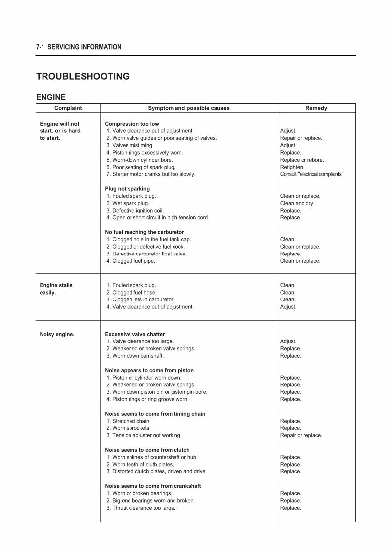
TROUBLESHOOTING
ENGINEComplaint Symptom and possible causes Remedy
Engine will notstart, or is hard to start.
Compression too low1. Valve clearance out of adjustment.2. Worn valve guides or poor seating of valves.3. Valves mistiming4. Piston rings excessively worn.5. Worn-down cylinder bore.6. Poor seating of spark plug.7. Starter motor cranks but too slowly.
Plug not sparking1. Fouled spark plug.2. Wet spark plug.3. Defective ignition coil.4. Open or short circuit in high tension cord.
No fuel reaching the carburetor1. Clogged hole in the fuel tank cap.2. Clogged or defective fuel cock.3. Defective carburetor float valve.4. Clogged fuel pipe.
Adjust.Repair or replace.Adjust.Replace.Replace or rebore.Retighten.Consult “electrical complaints”
Clean or replace.Clean and dry.Replace.Replace..
Clean.Clean or replace.Replace.Clean or replace.
Noisy engine. Excessive valve chatter1. Valve clearance too large.2. Weakened or broken valve springs.3. Worn down camshaft.
Noise appears to come from piston1. Piston or cylinder worn down.2. Weakened or broken valve springs.3. Worn down piston pin or piston pin bore.4. Piston rings or ring groove worn.
Noise seems to come from timing chain1. Stretched chain.2. Worn sprockets.3. Tension adjuster not working.
Noise seems to come from clutch1. Worn splines of countershaft or hub.2. Worn teeth of cluth plates.3. Distorted clutch plates, driven and drive.
Noise seems to come from crankshaft1. Worn or broken bearings.2. Big-end bearings worn and broken.3. Thrust clearance too large.
Adjust.Replace.Replace.
Replace.Replace.Replace.Replace.
Replace.Replace.Repair or replace.
Replace.Replace.Replace.
Replace.Replace.Replace.
Engine stalls easily.
1. Fouled spark plug.2. Clogged fuel hose.3. Clogged jets in carburetor.4. Valve clearance out of adjustment.
Clean.Clean.Clean.Adjust.
SERVICING INFORMATION 7-2
Complaint Symptom and possible causes Remedy
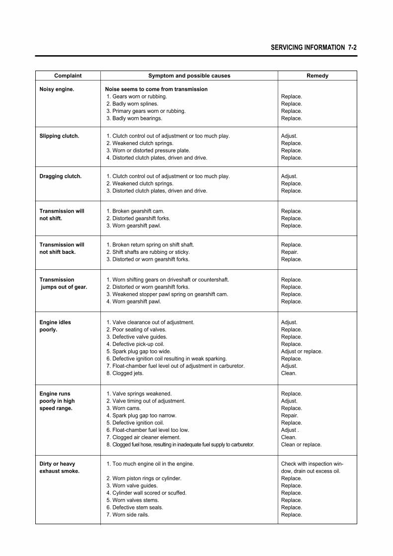
Noisy engine. Noise seems to come from transmission1. Gears worn or rubbing.2. Badly worn splines.3. Primary gears worn or rubbing.3. Badly worn bearings.
Replace.Replace.Replace.Replace.
Slipping clutch. 1. Clutch control out of adjustment or too much play.2. Weakened clutch springs.3. Worn or distorted pressure plate.4. Distorted clutch plates, driven and drive.
Adjust.Replace.Replace.Replace.
Dragging clutch. 1. Clutch control out of adjustment or too much play.2. Weakened clutch springs.3. Distorted clutch plates, driven and drive.
Adjust.Replace.Replace.
Transmission willnot shift.
1. Broken gearshift cam.2. Distorted gearshift forks.3. Worn gearshift pawl.
Replace.Replace.Replace.
Transmission willnot shift back.
1. Broken return spring on shift shaft.2. Shift shafts are rubbing or sticky.3. Distorted or worn gearshift forks.
Replace.Repair.Replace.
Transmissionjumps out of gear.
1. Worn shifting gears on driveshaft or countershaft.2. Distorted or worn gearshift forks.3. Weakened stopper pawl spring on gearshift cam.4. Worn gearshift pawl.
Replace.Replace.Replace.Replace.
Engine idles poorly.
1. Valve clearance out of adjustment.2. Poor seating of valves.3. Defective valve guides.4. Defective pick-up coil.5. Spark plug gap too wide.6. Defective ignition coil resulting in weak sparking.7. Float-chamber fuel level out of adjustment in carburetor.8. Clogged jets.
Adjust.Replace.Replace.Replace.Adjust or replace.Replace.Adjust.Clean.
Engine runs poorly in high speed range.
1. Valve springs weakened.2. Valve timing out of adjustment.3. Worn cams.4. Spark plug gap too narrow.5. Defective ignition coil.6. Float-chamber fuel level too low.7. Clogged air cleaner element.8. Clogged fuel hose, resulting in inadequate fuel supply to carburetor.
Replace.Adjust.Replace.Repair.Replace.Adjust .Clean.Clean or replace.
Dirty or heavy exhaust smoke.
1. Too much engine oil in the engine.
2. Worn piston rings or cylinder.3. Worn valve guides.4. Cylinder wall scored or scuffed.5. Worn valves stems.6. Defective stem seals.7. Worn side rails.
Check with inspection win-dow, drain out excess oil.Replace.Replace.Replace.Replace.Replace.Replace.

7-3 SERVICING INFORMATION
CARBURETORComplaint Symptom and possible causes Remedy
Trouble with starting.
1. Starter jet is clogged.2. Starter pipe is clogged.3. Air leaking from a joint between starter body and carburetor.
4. Starter plunger is not operating properly.
Clean.Clean.Check starter body andcarburetor for tightness,adjust and replace gasket.Check and adjust.
Medium or highspeed trouble.
1. Main jet or main air jet is clogged.2. Needle jet is clogged.3. Throttle valve is not operating properly.
4. Filter is clogged.
Check and clean.Check and clean.Check throttle valve for operation.Check and clean.
Idling or low-speedtrouble.
1. Pilot jet, pilot air jet are clogged or loose.2. Pilot outlet or bypass is clogged.3. Starter plunger is not fully closed.
Check and clean.Check and clean.Check and clean.
Complaint Symptom and possible causes Remedy
Engine lacks power. 1. Loosen of valve clearance.2. Weakened valve springs.3. Valve timing out of adjustment.4. Worn piston ring or cylinder.5. Poor seating of valves.6. Fouled spark plug.7. Worn camshaft.8. Spark plug gap incorrect.9. Clogged jets in carburetor.10. Float-chamber fuel level out of adjustment.11. Clogged air cleaner element. 12. Too much enging oil.13. Defective air intake pipe.
Adjust.Replace.Adjust.Replace.Repair or replace.Clean or replace.Replace.Adjust or replace.Clean.Adjust.Clean.Drain out excess oil.Retighten or replace.
Engine overheats. 1. Heavy carbon deposit on piston head.2. Not enough oil in the engine.3. Defective oil pump or clogged oil circuit.4. Fuel level too low in float chamber.5. Air leak from intake pipe.6. Use of incrrect engine oil.7. Defective oil cooler.
Clean.Add oil.Repair or clean.Adjust.Retighten or replace.change.Clean or replace.
Overflow and fuellevel fluctuations.
1. Needle valve is worn or damaged.2. Spring in needle valve is borken.3. Float is not working properly.4. Foreign matter has adhered to needle valve. 5. Fuel level is too high or low.
Replace.Replace.Check and adjust.Clean.Adjust float height.

SERVICING INFORMATION 7-4
ELECTRICALComplaint Symptom and possible causes Remedy
No sparking or poorsparking.
1. Defective ignition coil.2. Defective spark plug.3. Defective CDI unit.
Replace.Replace.Replace.
Spark plug soonbecome fouled withcarbon.
1. Mixture too rich.2. Idling speed set too high.3. Incorrect gasoline.4. Dirty element in air cleaner.5. Spark plug too cold.
Adjust carburetor.Adjust carburetor.Change.Clean or replace.Replace by hot type plug.
Spark plug becomefouled too soon.
1. Worn piston rings.2. Pistons or cylinder worn.3. Excessive clearance of valve stems in valve guides.4. Worn stem oil seal.
Replace.Replace.Replace.Replace.
Generator charge,but chargingrate is below thespecification.
1. Lead wires tend to get shorted or open-circuited or loosely connected at terminals.
2. Grounded or open-circuited stator coils of generator.3. Defective regulator/rectifier.4. Not enough electrolyte in the battery.
5. Defective cell plates in the battery.
Repair or retighten.
Replace.Replace.Add distilled water betweenthe level lines.Replace the battery.
Generatorovercharges.
1. Internal short-circuit in the battery.2. Resistor element in the regulator/rectifier damaged or defective.3. Regulator/rectifier poorly grounded.
Replace the battery.Replace.
Clean and tightenground connection.
Unstablecharging.
1. Lead wire insulation frayed due to vibration resulting in intermittent shorting.
2. Generator internally shorted.3. Defective regulator/rectifier.
Repair or replace
Replace. Replace.
Starter switch is not effective.
1. Battery run down.2. Defective switch contacts.3. Brushes not seating properly on commutator in starter motor.4. Defective starter relay.
Recharge or replace.Replace.Repair or replace.Replace.
Spark plug electrodesoverheat or burn.
1. Spark plug too hot.2. The engine overheats.3. Spark plug loose.4. Mixture too lean.
Replace by cold type plug.Tune up.Retighten.Adjust carburetor.

7-5 SERVICING INFORMATION
BATTERYComplaint Symptom and possible causes Remedy
“Sulfation”acidicwhite powdery substance or spotson surfaces of cell plates.
1. Not enough electrolyte.
2. Battery case is cracked.3. Battery has been left in a run-down condition for a long time.4. Contaminated electrolyte. (Foreign matter has enters the
battery and become mixed with the electrolyte.)
Add distilled water, if the battery has not been damaged and
“sulfation”has not advanced too far, and recharge.Replace the battery.Replace the battery or recharge.
If “sulfation”has not advanced far, try to restore the battery by replacing the electrolyte, recharing it fully with the battery detached from the motorcycle and then adjusting electrolyte specific gravity.
Battery runs downquickly.
1. The charging method is not correct.
2. Cell plates have lost much of their active material as a result ofover-charging.
3. A short-circuit condition exists within the battery due to excessive accumulation of sediments caused by the high electrolyte specific gravity.
4. Electrolyte specific gravity is too low.
5. Contaminated electrolyte.
6. Battery is too old.
Check the generator, regulator/rectifier and circuit connections, and make necessary adjustments to obtain specified chargingoperation.Replace the battery, and correct the charging system.Replace the battery.
Recharge the battery fully and adjust electrolyte specif icgravity.Replace the electrolyte, recharge the battery and then adjust specific gravity.Replace the battery.
Battery “sulfation” 1. Charging rate too low or too high. (When not in use, batteriesshould be recharged at least once a month to avoid sulfation.)
2. Battery electrolyte excessive or insufficient, or its specific gravity toohigh or too low.
3. The battery left unused for too long in cold climate.
Replace the battery.
Keep the electrolyte up to theprescribed level, or adjust thespecific gravity by consultingthe battery maker’s directions.Replace the battery, if badlysulfated.
Battery discharges too rapidly.
1. Dirty container top and sides.2. Impurities in the electrolyte or electrolyte specific gravity is too high.
Clean.Change the electrolyte byconsulting the battery maker’sdirections.
Reversed battery polarity.
The battery has been connected the wrong way round in the system, so that it is being charged in the reverse direction.
Replace the battery and be sure to connect the batteryproperly.
SERVICING INFORMATION 7-6
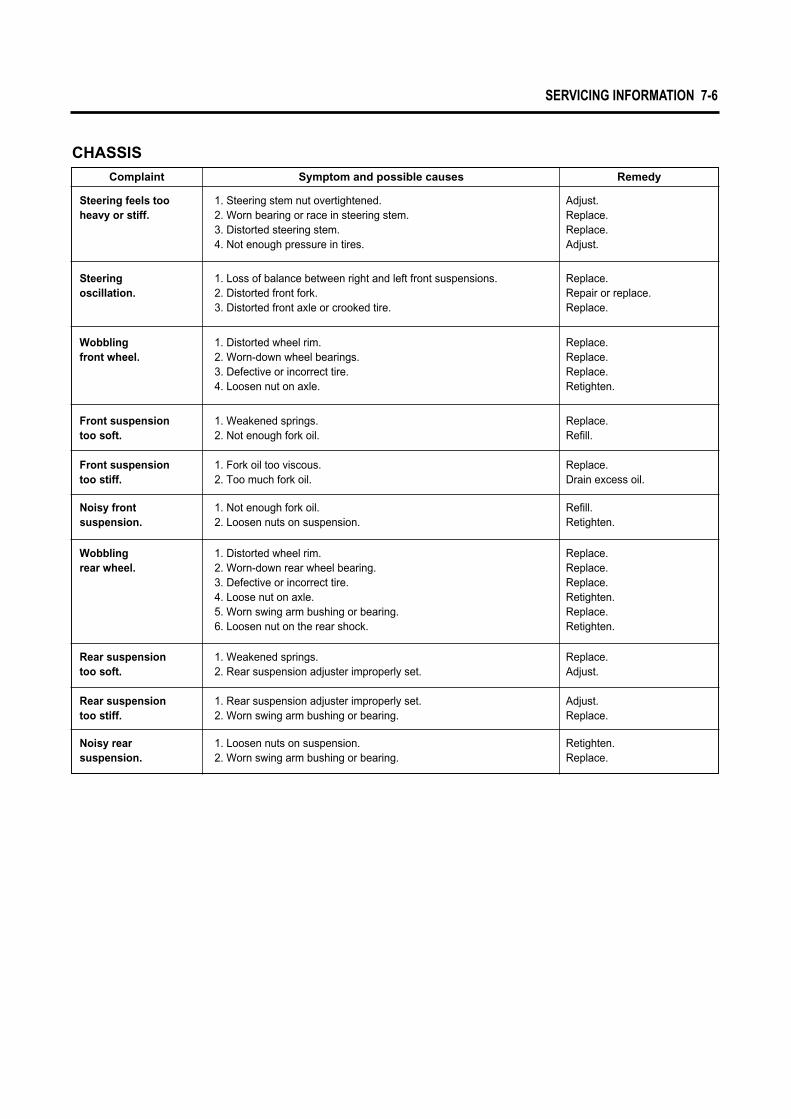
CHASSISComplaint Symptom and possible causes Remedy
Steering feels tooheavy or stiff.
1. Steering stem nut overtightened.2. Worn bearing or race in steering stem.3. Distorted steering stem.4. Not enough pressure in tires.
Adjust.Replace.Replace.Adjust.
Wobbling front wheel.
1. Distorted wheel rim.2. Worn-down wheel bearings.3. Defective or incorrect tire.4. Loosen nut on axle.
Replace.Replace.Replace.Retighten.
Steering oscillation.
1. Loss of balance between right and left front suspensions.2. Distorted front fork.3. Distorted front axle or crooked tire.
Replace.Repair or replace.Replace.
Front suspension too soft.
1. Weakened springs.2. Not enough fork oil.
Replace.Refill.
Front suspension too stiff.
1. Fork oil too viscous.2. Too much fork oil.
Replace.Drain excess oil.
Noisy frontsuspension.
1. Not enough fork oil.2. Loosen nuts on suspension.
Refill.Retighten.
Rear suspensiontoo soft.
1. Weakened springs.2. Rear suspension adjuster improperly set.
Replace.Adjust.
Rear suspensiontoo stiff.
1. Rear suspension adjuster improperly set.2. Worn swing arm bushing or bearing.
Adjust.Replace.
Noisy rearsuspension.
1. Loosen nuts on suspension.2. Worn swing arm bushing or bearing.
Retighten.Replace.
Wobbling rear wheel.
1. Distorted wheel rim.2. Worn-down rear wheel bearing.3. Defective or incorrect tire.4. Loose nut on axle.5. Worn swing arm bushing or bearing.6. Loosen nut on the rear shock.
Replace.Replace.Replace.Retighten.Replace.Retighten.

7-7 SERVICING INFORMATION
BRAKESComplaint Symptom and possible causes Remedy
Poor braking(FRONT and REAR)
1. Not enough brake fluid in the reservoir.2. Air trapped in brake fluid circuit.3. Pads worn down.4. Too much play on brake lever or pedal.5. Shoes worn down.
Refill to level mark.Bleed air out.Replace.Adjust.Replace.
Insufficient brakepower.
1. Leakage of brake fluid from hydraulic system.2. Worn pads.3. Oil adhesion of engaging surface of pads.4. Worn disk.5. Air in hydraulic system.
Repair or replace.Replace.Clean disk and pads.Replace.Bleed air.
Brake squeaking. 1. Carbon adhesion on pad surface.
2. Tilted pad.3. Damaged wheel bearing.4. Loosen front-wheel axle or rear-wheel axle.5. Worn pads.6. Foreign material in brake fluid.7. Clogged return port of master cylinder.
Repair surface withsandpaper.Modify pad fitting.Replace.Tighten to specified torque.Replace.Replace brake fluid.Disassemble and cleanmaster cylinder.
Leakage of brakefluid.
1. Insufficient tightening of connection joints.
2. Cracked hose.3. Worn piston and/or cup.
Tighten to specifiedtorque.Replace.Replace piston and/or cup.
Excessive brakelever stroke.
1. Air in hydraulic system.2. Worn brake lever cam.3. Insufficient brake fluid.
4. Improper quality of brake fluid.
Bleed air.Replace brake lever.Replenish fluid to specifiedlevel ; bleed air.Replace with correct fluid.

SERVICING INFORMATION 7-8
Special tools Part Number∙Part Name∙Description
09900-20101
Vernier Caliper
Used to conveniently measure various dimensions.
09900-20202
Micrometer(25~50mm)
Used for precise measurement (25~50mm measure ranges).
09900-20203
Micrometer(50~75mm)
Used for precise measurement (50~75mm measure ranges).
Special tools Part Number∙Part Name∙Description
09900-20201
Micrometer(0~25mm)
Used for precise measurement (00~25mm measure ranges).
09900-20508
Cylinder gauge set
Measure inside diameter of cylinder.
09900-20605
Dial calipers
Meassure width of conrod big-end.
09900-20606
Dial gauge
Meassure oscillation of wheel with using magnetic stand.
09900-20701
Magnetic stand
With using dial gauge.
09900-20806
Thickness gauge
Measure clearance of piston ring.
09900-21304
V-block
09900-21109
Torque wrench
With using magnetic stand.
Measure torque of tightening.
09900-22301
Plastigauge
Measure clearance of crankshaft thrust.
09900-22401
Small bore gauge
Measure inside diameter of conrod small-end.
09900-25002
Pocket tester
Measure voltage, electric current, resistance.
09900-26006
Engine tachometer
Measure rotational frequency of engine.
09900-28107
Electro tester
Inspect ignition coil.
09910-20115
Conrod holder
Used to lock the crankshaft.
09900-28500
Battery charger
Used to charge the dischared battery.
SPECIAL TOOLS

7-9 SERVICING INFORMATION
Special tools Part Number∙Part Name∙Description
09910-32812
Crankshaft installer
09910-34510
Piston pin puller
Used to install the crankshaft in the crankcase.
Use to remove the piston pin.
09913-10760
Fuel level gauge
Measure height of carburetor.
09913-50121
Oil seal remover
09913-70122
Bearing installer
Used to remove the oil seal.
Used to drive bearing in.
Special tools Part Number∙Part Name∙Description
09913-75520
Bearing installer
Used to drive bearing in.
09913-75820
Bearing installer
Used to drive bearing in.
09913-75830
Bearing installer
Used to install rear axle shaft oil seal.
09913-76010
Bearing installer
Used to drive crankshaft bearing in.
09915-63310
Compression gauge adapter
09913-80112
Bearing installer
Used with compression gauge.
Used to drive bearing in.
09915-64510
Compression gauge
Measure cylinder compression.
09915-74510
Oil pressure gauge
Measure oil pressure of 4-stroke engine.
09915-74531
Oil pressure gauge hose attachment
Used with oil pressure gauge.
Separate to crankcase.
Used to install or remove clutch sleeve hub nut.
09920-13120
Crankcase separater
09920-53710
Clutch sleeve hub holder
Used with valve spring compressor.
09916H35C00
Valve spring compressor attachment
Used to remove and remounting valve stem.
09916-14510
Valve spring compressor
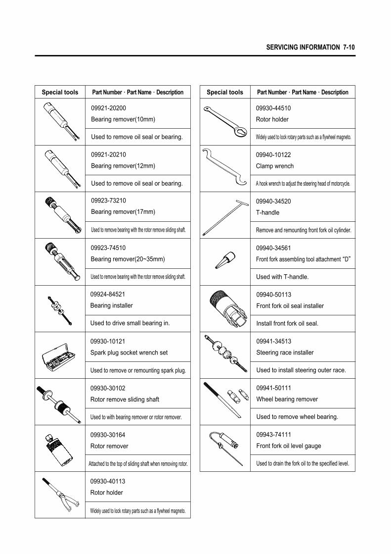
SERVICING INFORMATION 7-10
09940-34520
T-handle
Remove and remounting front fork oil cylinder.
Special tools Part Number∙Part Name∙Description Special tools Part Number∙Part Name∙Description
09940-10122
Clamp wrench
09930-44510
Rotor holder
A hook wrench to adjust the steering head of motorcycle.
Widely used to lock rotary parts such as a flywheel magneto.
09921-20200
Bearing remover(10mm)
Used to remove oil seal or bearing.
09921-20210
Bearing remover(12mm)
Used to remove oil seal or bearing.
09923-73210
Bearing remover(17mm)
Used to remove bearing with the rotor remove sliding shaft.
09924-84521
Bearing installer
Used to drive small bearing in.
09923-74510
Bearing remover(20~35mm)
Used to remove bearing with the rotor remove sliding shaft.
09940-34561
Front fork assembling tool attachment “D”
Used with T-handle.
Used to remove or remounting spark plug.
09930-30102
Rotor remove sliding shaft
09930-30164
Rotor remover
Attached to the top of sliding shaft when removing rotor.
09930-10121
Spark plug socket wrench set
Used to with bearing remover or rotor remover.
09930-40113
Rotor holder
Widely used to lock rotary parts such as a flywheel magneto.
09940-50113
Front fork oil seal installer
Install front fork oil seal.
09941-34513
Steering race installer
Used to install steering outer race.
09941-50111
Wheel bearing remover
Used to remove wheel bearing.
09943-74111
Front fork oil level gauge
Used to drain the fork oil to the specified level.
7-11 SERVICING INFORMATION
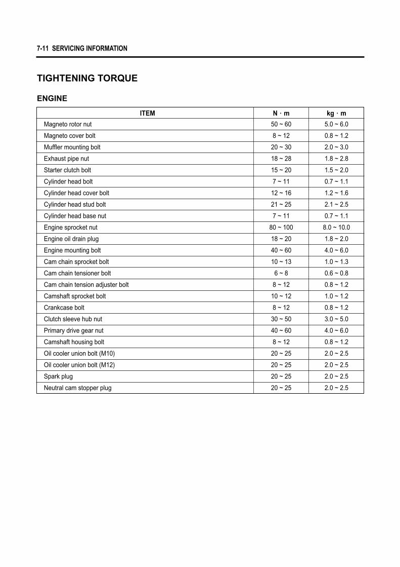
ITEM
Magneto rotor nut
Magneto cover bolt
Muffler mounting bolt
Exhaust pipe nut
Starter clutch bolt
Cylinder head bolt
Cylinder head cover bolt
Cylinder head stud bolt
Cylinder head base nut
Engine sprocket nut
Engine oil drain plug
Engine mounting bolt
Cam chain sprocket bolt
Cam chain tensioner bolt
Cam chain tension adjuster bolt
Camshaft sprocket bolt
Crankcase bolt
Clutch sleeve hub nut
Primary drive gear nut
Camshaft housing bolt
Oil cooler union bolt (M10)
Oil cooler union bolt (M12)
Spark plug
Neutral cam stopper plug
5.0 ~ 6.0
0.8 ~ 1.2
2.0 ~ 3.0
1.8 ~ 2.8
1.5 ~ 2.0
0.7 ~ 1.1
1.2 ~ 1.6
2.1 ~ 2.5
0.7 ~ 1.1
8.0 ~ 10.0
1.8 ~ 2.0
4.0 ~ 6.0
1.0 ~ 1.3
0.6 ~ 0.8
0.8 ~ 1.2
1.0 ~ 1.2
0.8 ~ 1.2
3.0 ~ 5.0
4.0 ~ 6.0
0.8 ~ 1.2
2.0 ~ 2.5
2.0 ~ 2.5
2.0 ~ 2.5
2.0 ~ 2.5
kg∙m
50 ~ 60
8 ~ 12
20 ~ 30
18 ~ 28
15 ~ 20
7 ~ 11
12 ~ 16
21 ~ 25
7 ~ 11
80 ~ 100
18 ~ 20
40 ~ 60
10 ~ 13
6 ~ 8
8 ~ 12
10 ~ 12
8 ~ 12
30 ~ 50
40 ~ 60
8 ~ 12
20 ~ 25
20 ~ 25
20 ~ 25
20 ~ 25
N∙m
TIGHTENING TORQUE
ENGINE
SERVICING INFORMATION 7-12
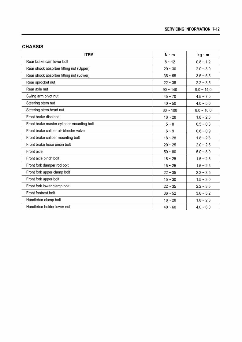
ITEM
Rear brake cam lever bolt
Rear shock absorber fitting nut (Upper)
Rear shock absorber fitting nut (Lower)
Rear sprocket nut
Rear axle nut
Swing arm pivot nut
Steering stem nut
Steering stem head nut
Front brake disc bolt
Front brake master cylinder mounting bolt
Front brake caliper air bleeder valve
Front brake caliper mounting bolt
Front brake hose union bolt
Front axle
Front axle pinch bolt
Front fork damper rod bolt
Front fork upper clamp bolt
Front fork upper bolt
Front fork lower clamp bolt
Front footrest bolt
Handlebar clamp bolt
Handlebar holder lower nut
0.8 ~ 1.2
2.0 ~ 3.0
3.5 ~ 5.5
2.2 ~ 3.5
9.0 ~ 14.0
4.5 ~ 7.0
4.0 ~ 5.0
8.0 ~ 10.0
1.8 ~ 2.8
0.5 ~ 0.8
0.6 ~ 0.9
1.8 ~ 2.8
2.0 ~ 2.5
5.0 ~ 8.0
1.5 ~ 2.5
1.5 ~ 2.5
2.2 ~ 3.5
1.5 ~ 3.0
2.2 ~ 3.5
3.6 ~ 5.2
1.8 ~ 2.8
4.0 ~ 6.0
8 ~ 12
20 ~ 30
35 ~ 55
22 ~ 35
90 ~ 140
45 ~ 70
40 ~ 50
80 ~ 100
18 ~ 28
5 ~ 8
6 ~ 9
18 ~ 28
20 ~ 25
50 ~ 80
15 ~ 25
15 ~ 25
22 ~ 35
15 ~ 30
22 ~ 35
36 ~ 52
18 ~ 28
40 ~ 60
kg∙mN∙m
CHASSIS

7-13 SERVICING INFORMATION
SERVICE DATA
ITEM STANDARD LIMIT
22
19.0
0.1~0.2
0.2~0.3
0.010~0.037
0.030~0.057
———
4.500~4.512
4.475~4.490
4.455~4.470
———
———
45�
———
———
———
12.1~13.9kgf (at length 33.7mm)
12.1~13.9kgf (at length 33.7mm)
0.9~1.1
IN.
EX.
IN.
EX.
IN.
EX.
IN. & EX.
IN. & EX.
IN.
EX.
IN. & EX.
IN. & EX.
IN. & EX.
IN. & EX.
IN.
EX.
IN.
EX.
———
———
———
———
———
———
0.35
———
———
———
0.05
0.5
———
0.03
37.8
37.8
———
———
ITEM STANDARD LIMIT
Cam height
Camshaft journal holder I.D.
Cylinder head distortion
Cylinder head cover distortion
Cam chain pin (Arrow “3”)
———
———
16th pin
34.470 ~ 34.510
34.420 ~ 34.460
35.000 ~ 35.018
IN.
EX.
IN. & EX.
34.170
34.120
———
0.05
0.05
———
VALVE + GUIDE
CAMSHAFT + CYLINDER HEAD Unit : mm
Unit : mm
Valve diam.
Valve clearance (When cold)
Valve guide to valve stem clearance
Valve stem deflection
Valve guide I.D.
Valve stem O.D.
Valve stem runout
Valve head thickness
Valve seat width
Valve seat angle
Valve head radial runout
Valve spring free length
Valve spring tension

SERVICING INFORMATION 7-14
Oil pressure
Oil pump reduction ratio
1.3 ± 0.2 kg/cm2
(at 60 ℃, 4,000 rpm)
58/19×14/20=2.137
———
———
ITEM STANDARD NOTE
ITEM STANDARD LIMIT
14~16 kg/cm2 (at 600 rpm)
0.050~0.060
57.000~57.015
56.945~56.960(Measure at 15mm from the skirt end)
15.002 ~ 15.008
14.994 ~ 15.000
12 kg/cm2
0.120
57.080
0.05
5.7
4.6
0.5
0.5
0.180
0.150
———
———
———
———
———
15.030
14.980
56.880
ITEM STANDARD LIMIT
Conrod small end I.D.
Conrod deflection
Conrod big end side clearance
Conrod big end width
Crank web to web width
Crankshaft runout
15.006~15.014
———
0.40~0.85
15.95~16.00
72 ±0.1
———
15.040
3.0
1.0
———
———
0.05
7.2
5.8
0.20~0.32
0.20~0.32
———
———
1.01~1.03
1.01~1.03
2.01~2.03
0.970~0.990
0.970~0.990
1st
2nd
1st
2nd
1st
2nd
1st
2nd
Oil
1st
2nd
———
CYLINDER + PISTON + PISTON RING Unit : mm
CONROD + CRANKSHAFT Unit : mm
OIL PUMP Unit : mm
Compression pressure
Piston to cylinder clearance
Cylinder bore
Piston diam.
Cylinder or cylinder head distortion
Piston ring free end gap
Piston ring end gap (Assembly condition)
Piston ring to groove clearance
Piston ring to groove width
Piston ring thickness
Piston pin hall I.D.
Piston pin O.D.

7-15 SERVICING INFORMATION
ITEM STANDARD LIMIT
Clutch cable play
Drive plate thickness
Drive plate claw width
Driven plate distortion
Clutch spring free length
4 ———
2.6
11.0
0.1
36.2
CLUTCH Unit : mm
2.9~3.1
11.8~12.0
———
38.2
Primary reduction ratio
Secondary reduction ratio
Gear ratio
Shift fork to groove clearance
Shift fork groove width
Shift fork thickness
Drive chain
Drive chain slack
3.05 (58/19)
3.29 (46/14)
5.0~5.1
5.0~5.1
4.8~4.9
4.8~4.9
20~30
———
———
———
———
———
———
———
0.5
———
———
———
———
———
———
319.4
———
ITEM STANDARD LIMIT
TRANSMISSION + DRIVE CHAIN Unit : mm
2.46 (32/13)
1.56 (28/18)
1.19 (25/21)
0.96 (22/23)
0.84 (21/25)
RK-520DS
116 LINKS
317.5
1st
2nd
3rd
4th
5th
Type
Links
20-pitch length
NO.1 & NO.2
NO.3
NO.1 & NO.2
NO.3
0.10~0.30

SERVICING INFORMATION 7-16
Carburetor type
Bore size
I.D. NO.
Idle r.p.m.
Float height
Throttle cable play
Main jet (M.J.)
Main air jet (M.A.J.)
Jet needle (J.N.)
Needle jet (N.J.)
Pilot jet (P.J.)
Throttle valve (TH.V.)
By-pass (B.P.)
Valve seat (V.S.)
Starter jet (G.S.)
Pilot outlet (P.O.)
PV. Stroke (P.V.)
MIKUNI BDS26TYPE(DOUBLE)
ф 26
HJ 82
1,450~1,550 r.p.m.
17
0.5~1.0
FRONT
90
140
2ND
O-6
20
130
1.2
22.5
0.75
STD
REAR
87.5
140
2ND
6
20
130
1.2
22.5
0.75
STD
ITEM SPECIFICATION
CARBURETOR Unit : mm
#10.9
#20.9
#30.8
#40.8
#10.9
#20.9
#30.8
#40.8
7-17 SERVICING INFORMATION
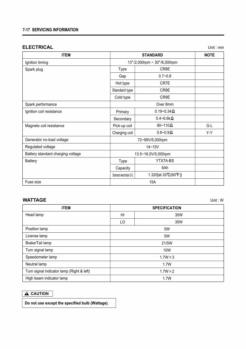
Do not use except the specified bulb (Wattage).
CAUTION
Head lamp
Position lamp
License lamp
Brake/Tail lamp
Turn signal lamp
Speedometer lamp
Neutral lamp
Turn signal indicator lamp (Right & left)
High beam indicator lamp
5W
5W
21/5W
10W
1.7W×3
1.7W
1.7W×2
1.7W
35W
35W
ITEM SPECIFICATION
Ignition timing
Spark plug
Spark performance
Fuse size
Ignition coil resistance
Magneto coil resistance
Battery
Generator no-load voltage
Regulated voltage
Battery standard charging voltage
CR8E
0.7~0.8
CR7E
CR8E
CR9E
Over 8mm
0.19~0.34Ϊ
5.4~6.6kΪ
90~110Ϊ
0.6~0.9Ϊ
YTX7A-BS
6Ah
1.320[at 20℃(60℉)]
Primary
Secondary
Type
Capacity
Standard electrolyte S.G.
HI
LO
Pick-up coil
Charging coil
G-L
Y-Y
Type
Gap
Hot type
Standard type
Cold type
ITEM STANDARD
13�/2,000rpm ~ 30�/6,000rpm
15A
72~99V/5,000rpm
14~15V
13.5~16.0V/5,000rpm
NOTE
ELECTRICAL Unit : mm
WATTAGE Unit : W
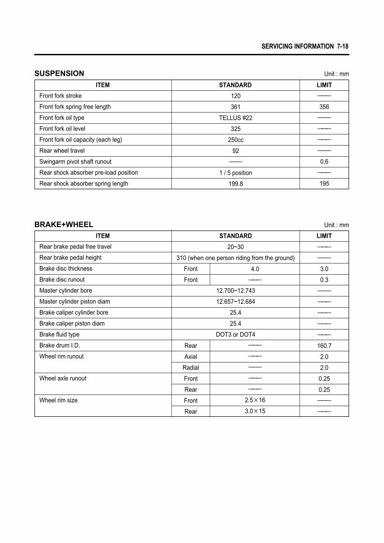
SERVICING INFORMATION 7-18
Front fork stroke
Front fork spring free length
Front fork oil type
Front fork oil level
Front fork oil capacity (each leg)
Rear wheel travel
Swingarm pivot shaft runout
Rear shock absorber pre-load position
Rear shock absorber spring length
———
356
———
———
———
———
0.6
———
195
120
361
TELLUS #22
325
250cc
92
———
1 / 5 position
199.8
ITEM STANDARD LIMIT
SUSPENSION Unit : mm
Rear brake pedal free travel
Rear brake pedal height
Brake disc thickness
Brake disc runout
Master cylinder bore
Master cylinder piston diam
Brake caliper cylinder bore
Brake caliper piston diam
Brake fluid type
Brake drum I.D.
Wheel rim runout
Wheel axle runout
Wheel rim size
12.700~12.743
12.657~12.684
25.4
25.4
DOT3 or DOT4
4.0
———
———
———
———
———
———
2.5×16
3.0×15
20~30
310 (when one person riding from the ground)
———
———
3.0
0.3
———
———
———
———
———
160.7
2.0
2.0
0.25
0.25
———
———
Front
Front
Rear
Axial
Radial
Front
Rear
Front
Rear
ITEM STANDARD LIMIT
BRAKE+WHEEL Unit : mm

7-19 SERVICING INFORMATION
NOTE
Fuel type
Fuel tank capacity
Engine oil type
Engine oil capacity
14.0 ℓ
2.0 ℓ
Gasoline used should be graded 91 octane or higher.An unleaded gasoline is recommened.
SAE 10W40
1,450 mℓ
1,500 mℓ
1,800 mℓ
ITEM SPECIFICATION
FUEL + OIL
Including reserve
Reserve
Change
Filter change
Overhaul
ITEM
Cold inflation tire pressure (Solo riding)
Cold inflation tire pressure (Dual riding)
Tire tread depth
Front
Rear
Front
Rear
Front
Rear
1.75
2.00
1.75
2.25
———
———
———
———
———
———
5.5
8.0
STANDARD LIMIT
TIRE
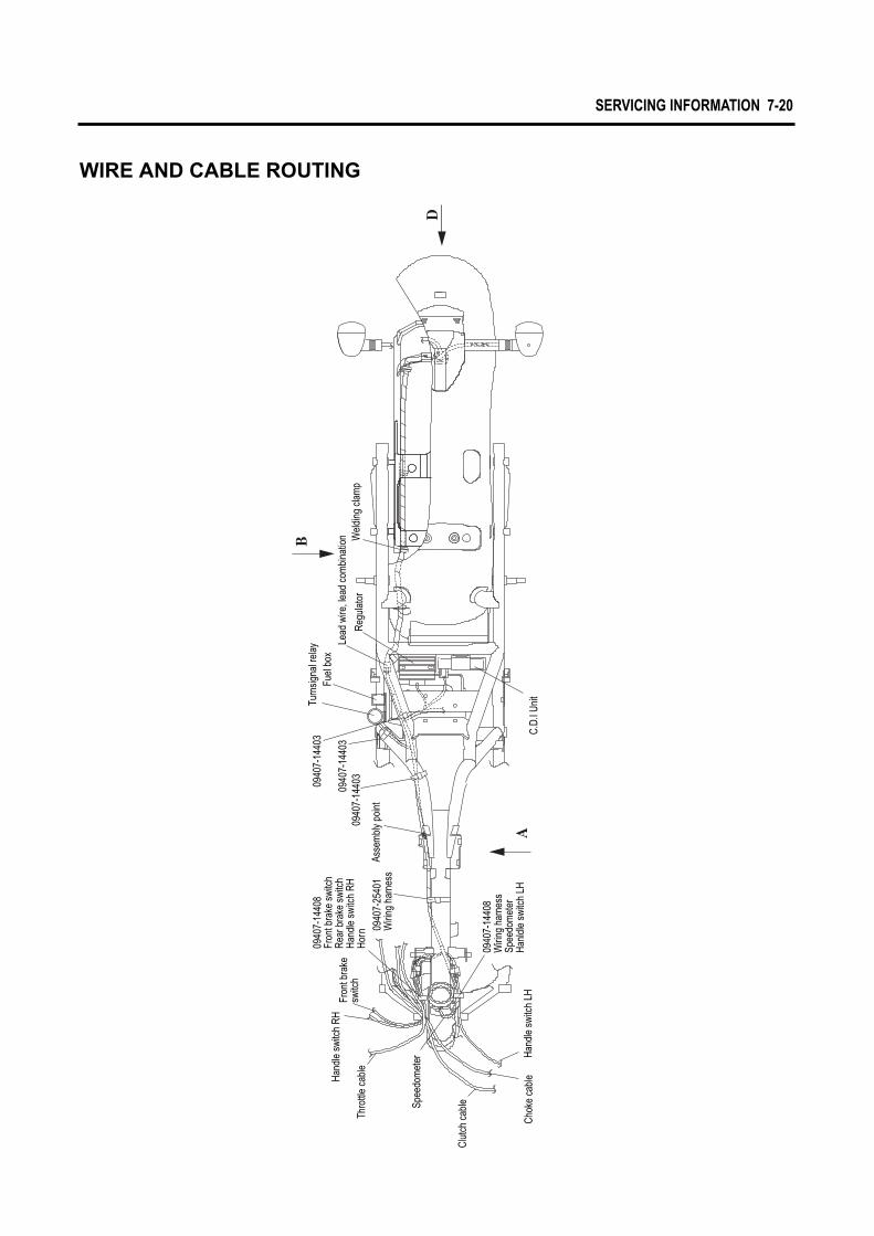
SERVICING INFORMATION 7-20
WIRE AND CABLE ROUTING
Wel
ding
cla
mp
Regu
lato
r
Lead
wire
, lea
d co
mbi
natio
nFu
el b
oxTu
rnsig
nal r
elay
0940
7-14
403
0940
7-14
403
0940
7-14
403
Asse
mbl
y po
int
0940
7-25
401
Wiri
ng h
arne
ss
0940
7-14
408
Fron
t bra
ke s
witc
hRe
ar b
rake
swi
tch
Hand
le s
witc
h RH
Horn
Hand
le s
witc
h RH
Fron
t bra
ke
switc
hTh
rottl
e ca
ble
Spee
dom
eter
Clut
ch c
able
Chok
e ca
ble
Hand
le s
witc
h LH
0940
7-14
408
Wiri
ng h
arne
ssSp
eedo
met
erHa
nldl
e sw
itch
LHC.
D.I U
nit

7-21 SERVICING INFORMATION
3661
8-30
610(
Tube
)M
agne
toNe
utra
l swi
tch
Fuel
gau
geSt
arte
r mot
or re
lay
Batte
ry p
lus
Diod
e Fu
el p
ump
Rear
wire
, rea
r com
bi is
bec
omed
ov
er th
e m
inim
um 1
80 a
t the
in
stal
latio
n of
com
bina
tion
Rear
turn
signa
l lam
p Rh
Rear
turn
signa
l lam
p Lg
Tail &
sto
p la
mp
Fuel
gau
ge
Air
bent
hos
e
0940
4-08
403
Rea
r ign
ition
coi
l
0940
7-25
401
0940
7-14
408
Wiri
ng h
arne
ssSp
eedo
met
erHa
ndle
swi
tch
LHSi
de s
tand
swi
tch
Clut
ch le
ver s
witc
h
0940
4-06
401
Drai
n ho
seDr
ain
hose
0940
7-14
403
0940
7-14
403
Spee
dom
eter
Hand
le s
witc
h LH
Clut
ch le
ver s
witc
h
Fron
t ign
ition
coil
0940
7-14
403
Oil c
ooler
hose
LhSi
de s
tand
swi
tch
Rear
ignit
ion co
il
0940
7-22
402
Fuel
hos
eAi
r ven
t hos
e
Fuel
pum
p
Gea
r shi
ftsw
itch
Mag
neto
VIEW
A
Fuel
pum
p re
lay
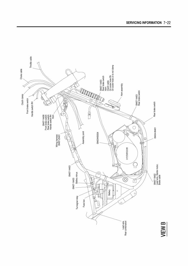
SERVICING INFORMATION 7-22
Thro
ttle
cabl
e
Clut
ch c
lam
p
Fron
t bra
ke s
witc
h
Hand
le s
witc
h RH
Asse
mbl
y po
int
0940
3H09
304
0940
7-14
403
0940
7-14
403
Batte
ry m
inus
Turn
signa
l rel
ay
0940
7-18
402
Lead
wire
, Sta
rter m
otor
,Br
ake
cabl
e
0943
4-06
401
Rear
bra
ke s
witc
h
0940
7-14
403
Rear
bra
ke s
witc
h
Horn
ass
embl
y
0940
7-14
403
Rear
bra
ke s
witc
hHo
rnCl
utch
cab
leO
il coo
ler h
ose
RhO
il coo
ler h
ose
Lh is
not
cla
mp
Batte
ry
Fuse
box
Lead
wire
, Re
ar c
ombi
natio
n
0940
7-14
408
Fron
t bra
ke s
witc
hRe
ar b
rake
swi
tch
Hand
le s
witc
h RH Horn
Wiri
ng h
arne
ss09
407-
2540
1
Chok
e ca
ble
VIEW
B

7-23 SERVICING INFORMATION
Battery plusFuel gauge
Wiring harness
Starter motor relay
Lead wire, starter motor
Fuel pump relay
Turnsignal lamp insert inside after installationwith the wiring be comed out.
Fuel pump
Welding clamp
Magneto
Gearshift switch
36818-30810(Tube)MagnetoNeutral switchFuel gaugeStarter motor relayBattery plusDiodeFuel pump
VIEW C
VIEW D

WIRING DIAGRAM
C.D
.I U
nit
Hor
n
Lighti
ngEn
gine k
illSt
arter
Font
turn
sign
al L
H
Hea
d la
mp
Pos
ition
lam
p
Rea
r tur
nsig
nal L
H
Igni
tion
switc
hG
ear
Pos
ition
Fuel
pum
p
Fuse
box
Rea
r tur
nsig
nal L
H
Tail
& s
top
lam
p
Mag
neto
Han
dle
switc
h LH
Han
dle
switc
h R
HS
peed
omet
er
SPEE
D
HO
RN
TUR
N S
IGN
ALD
IMM
ER
FUEL
TACH
O
Po
sitio
n la
mp
Lic
en
se p
late
lam
pF
ront tu
rnsi
gnal l
am
pR
ea
r tu
rnsi
gn
al l
am
p
5 51
0×
21
0×
21
.71
.71
.7×
21
.7×
35 21
35 /
35
W
Sp
ee
do
me
ter
Indic
ato
r la
mp
Tail
& s
top
lam
p
He
ad
lam
p
La
mp
Ne
utr
al
Hig
h b
ea
mtu
rnsi
gn
al
Illu
min
atio
nT
ail
Sto
pH
I/LO
DIS
T
Fron
t bra
ke
switc
h
Rea
r bra
ke
switc
hFu
el g
auge
SERVICING INFORMATION 7-24
WIR
E C
OLO
R
B
: Bla
ckLg
: Lig
ht g
reen
Y: Y
ello
wR
B: R
ed w
ith B
lack
trac
erB
r: B
row
nO
: Ora
nge
BG
: Bla
ck w
ith G
reen
trac
erR
W: R
ed w
ith W
hite
trac
erG
: Gre
enR
: Red
BW
: Bla
ck w
ith W
hite
trac
erW
B: W
hite
with
Bla
ck tr
acer
Gr
: Gra
yS
b: L
ight
blu
eB
R: B
lack
with
Red
trac
erW
R: W
hite
with
Red
trac
erL
: Blu
eW
: Whi
teW
L: W
hite
with
Blu
e tra
cer
BY
: Bla
ck w
ith Y
ello
w t
race
rO
B
: O
rang
e w
ith B
lack
trac
erG
W
: G
reen
with
Whi
te tr
acer
Dio
de
Side
stan
dsw
itch Clu
tch
leve
r sw
itch
Turn
sign
al
rela
yR
ear i
gnitio
n co
il spa
rk p
lug
Fron
t igni
tion
coil s
park
plu
gR
egul
ator
Rea
r tur
nsig
nal R
H
Lice
nse
lam
p
Eng
ine
earth
BA
TTE
RY
(MF)
Sta
rter m
otor
Fuel
pum
p re
lay


SH
IM N
o.
HO
W T
O U
SE
TH
E C
HA
RT
1. M
easu
re th
e ta
ppet
cle
aran
ce.(W
hen
cold
)2.
Mea
sure
the
shim
thic
knes
s at
pre
sent
.3.
Loo
k fo
r m
eetin
g sp
ace
in th
at h
oriz
onta
l lin
efo
r thi
ckne
ss a
nd v
ertic
al li
ne fo
r cle
aran
ce.
(EX
AM
PLE
)W
hen
the
tapp
et c
lear
ance
is 0
.23m
m a
nd th
e sh
im th
ickn
ess
at p
rese
nt is
1.7
0mm
, the
shi
m
thic
knes
s sh
ould
be
used
1.8
0mm
.
TAP
PE
T S
HIM
SE
LEC
TIO
N C
HA
RT
(IN.)
Spe
cifie
d cl
eara
nce
- Adj
ustm
ent u
nnec
essa
ry
1.20
1.20
0.00
-0.0
4
0.05
-0.0
9
0.10
-0.2
0
0.21
-0.2
5
0.26
-0.3
0
0.31
-0.3
5
0.36
-0.4
0
0.41
-0.4
5
0.46
-0.5
0
0.51
-0.5
5
0.56
-0.6
0
0.61
-0.6
5
0.66
-0.7
0
0.71
-0.7
5
0.76
-0.8
0
0.81
-0.8
5
0.86
-0.9
0
0.91
-0.9
5
0.96
-1.0
0
1.01
-1.0
5
1.06
-1.1
0
1.11
-1.1
5
1.25
1.30
1.35
1.40
1.45
1.50
1.55
1.60
1.65
1.70
1.75
1.80
1.85
1.90
1.95
2.00
2.05
2.10
1.20
1.25
1.30
1.35
1.40
1.45
1.50
1.55
1.60
1.65
1.70
1.75
1.80
1.85
1.90
1.95
2.00
2.05
2.10
2.15
1.30
1.35
1.40
1.45
1.50
1.55
1.60
1.65
1.70
1.75
1.80
1.85
1.90
1.95
2.00
2.05
2.10
2.15
2.20
2.20
1.35
1.40
1.45
1.50
1.55
1.60
1.65
1.70
1.75
1.80
1.85
1.90
1.95
2.00
2.05
2.10
2.15
2.20
1.40
1.45
1.50
1.55
1.60
1.65
1.70
1.75
1.80
1.85
1.90
1.95
2.00
2.05
2.10
2.15
2.20
1.45
1.50
1.55
1.60
1.65
1.70
1.75
1.80
1.85
1.90
1.95
2.00
2.05
2.10
2.15
2.20
1.50
1.55
1.60
1.65
1.70
1.75
1.80
1.85
1.90
1.95
2.00
2.05
2.10
2.15
2.20
1.55
1.60
1.65
1.70
1.75
1.80
1.85
1.90
1.95
2.00
2.05
2.10
2.15
2.20
1.60
1.65
1.70
1.75
1.80
1.85
1.90
1.95
2.00
2.05
2.10
2.15
2.20
1.65
1.70
1.75
1.80
1.85
1.90
1.95
2.00
2.05
2.10
2.15
2.20
1.70
1.75
1.80
1.85
1.90
1.95
2.00
2.05
2.10
2.15
2.20
1.75
1.80
1.85
1.90
1.95
2.00
2.05
2.10
2.15
2.20
1.80
1.85
1.90
1.95
2.00
2.05
2.10
2.15
2.20
1.85
1.90
1.95
2.00
2.05
2.10
2.15
2.20
1.90
1.95
2.00
2.05
2.10
2.15
2.20
1.95
2.00
2.05
2.10
2.15
2.20
2.00
2.05
2.10
2.15
2.20
2.05
2.10
2.15
2.20
2.10
2.15
2.20
2.15
2.20
2.20
SHIM
THICK
NESS
AT PR
ESEN
T(m
m)
ME
AS
UR
ING
TA
PP
ET
CLE
AR
AN
CE
(mm
)
120
1.25125
1.30130
1.35135
1.40140
1.45145
1.50150
1.55155
1.60160
1.65165
1.70170
1.75175
1.80180
1.85185
1.90190
1.95195
2.00200
2.05205
2.10210
2.15215
2.20220
HYOS
UNG M
OTOR
S & MA
CHINE
RY IN
C.

TAP
PE
T S
HIM
SE
LEC
TIO
N C
HA
RT
(EX
.)
Spe
cifie
d cl
eara
nce
- Adj
ustm
ent u
nnec
essa
ry
1.20
1.20
0.05
-0.0
9
0.10
-0.1
4
0.15
-0.1
9
0.20
-0.3
0
0.31
-0.3
5
0.36
-0.4
0
0.41
-0.4
5
0.46
-0.5
0
0.51
-0.5
5
0.56
-0.6
0
0.61
-0.6
5
0.66
-0.7
0
0.71
-0.7
5
0.76
-0.8
0
0.81
-0.8
5
0.86
-0.9
0
0.91
-0.9
5
0.96
-1.0
0
1.01
-1.0
5
1.06
-1.1
0
1.11
-1.1
5
1.16
-1.2
0
1.21
-1.2
5
1.25
1.30
1.35
1.40
1.45
1.50
1.55
1.60
1.65
1.70
1.75
1.80
1.85
1.90
1.95
2.00
2.05
1.20
1.25
1.30
1.35
1.40
1.45
1.50
1.55
1.60
1.65
1.70
1.75
1.80
1.85
1.90
1.95
2.00
2.05
2.10
1.20
1.25
1.30
1.35
1.40
1.45
1.50
1.55
1.60
1.65
1.70
1.75
1.80
1.85
1.90
1.95
2.00
2.05
2.10
2.15
1.30
1.35
1.40
1.45
1.50
1.55
1.60
1.65
1.70
1.75
1.80
1.85
1.90
1.95
2.00
2.05
2.10
2.15
2.20
2.20
1.35
1.40
1.45
1.50
1.55
1.60
1.65
1.70
1.75
1.80
1.85
1.90
1.95
2.00
2.05
2.10
2.15
2.20
1.40
1.45
1.50
1.55
1.60
1.65
1.70
1.75
1.80
1.85
1.90
1.95
2.00
2.05
2.10
2.15
2.20
1.45
1.50
1.55
1.60
1.65
1.70
1.75
1.80
1.85
1.90
1.95
2.00
2.05
2.10
2.15
2.20
1.50
1.55
1.60
1.65
1.70
1.75
1.80
1.85
1.90
1.95
2.00
2.05
2.10
2.15
2.20
1.55
1.60
1.65
1.70
1.75
1.80
1.85
1.90
1.95
2.00
2.05
2.10
2.15
2.20
1.60
1.65
1.70
1.75
1.80
1.85
1.90
1.95
2.00
2.05
2.10
2.15
2.20
1.65
1.70
1.75
1.80
1.85
1.90
1.95
2.00
2.05
2.10
2.15
2.20
1.70
1.75
1.80
1.85
1.90
1.95
2.00
2.05
2.10
2.15
2.20
1.75
1.80
1.85
1.90
1.95
2.00
2.05
2.10
2.15
2.20
1.80
1.85
1.90
1.95
2.00
2.05
2.10
2.15
2.20
1.85
1.90
1.95
2.00
2.05
2.10
2.15
2.20
1.90
1.95
2.00
2.05
2.10
2.15
2.20
1.95
2.00
2.05
2.10
2.15
2.20
2.00
2.05
2.10
2.15
2.20
2.05
2.10
2.15
2.20
2.10
2.15
2.20
2.15
2.20
2.20
120
1.25125
1.30130
1.35135
1.40140
1.45145
1.50150
1.55155
1.60160
1.65165
1.70170
1.75175
1.80180
1.85185
1.90190
1.95195
2.00200
2.05205
2.10210
2.15215
2.20220
HO
W T
O U
SE
TH
E C
HA
RT
1. M
easu
re th
e ta
ppet
cle
aran
ce.(W
hen
cold
)2.
Mea
sure
the
shim
thic
knes
s at
pre
sent
.3.
Loo
k fo
r mee
ting
spac
e in
that
hor
izon
tal l
ine
for t
hick
ness
and
ver
tical
line
for c
lear
ance
.
(EX
AM
PLE
)W
hen
the
tapp
et c
lear
ance
is 0
.33m
m a
nd th
e sh
im th
ickn
ess
at p
rese
nt is
1.7
0mm
, the
shi
m
thic
knes
s sh
ould
be
used
1.8
0mm
.
HYOS
UNG M
OTOR
S & MA
CHINE
RY IN
C.
SH
IM N
o.
SHIM
THICK
NESS
AT PR
ESEN
T(m
m)
ME
AS
UR
ING
TA
PP
ET
CLE
AR
AN
CE
(mm
)

Prepared by
HYOSUNG MOTORS & MACHINERY INC.Overseas Technical Department
2nd Ed. MAY. 2001.
Manual No. 99000-95310Printed in Korea