FUNCTIONAL SERVICING REPORT - Town of Caledon
58
Final Report FUNCTIONAL SERVICING REPORT 12304 Heart Lake Road, Caledon Prepared for Broccolini by IBI Group November 15, 2021 TOWN OF CALEDON PLANNING RECEIVED Nov 26, 2021
-
Upload
khangminh22 -
Category
Documents
-
view
0 -
download
0
Transcript of FUNCTIONAL SERVICING REPORT - Town of Caledon

Final Report
FUNCTIONAL SERVICING REPORT
12304 Heart Lake Road, Caledon
Prepared for Broccolini by IBI Group November 15, 2021
TOWN OF CALEDONPLANNINGRECEIVED
Nov 26, 2021

IBI GROUP FINAL REPORT FUNCTIONAL SERVICING REPORT Prepared for Broccolini
Table of Contents
November 15, 2021 i
1 Introduction ......................................................................................................................... 1
1.1 Background .............................................................................................................. 1
1.2 Site Description ........................................................................................................ 1
1.3 Site Proposal ............................................................................................................ 2
2 Terms of Reference and Methodology ............................................................................. 2
2.1 Terms of Reference ................................................................................................. 2
2.2 Methodology: Sanitary Discharge ............................................................................ 2
2.3 Methodology: Water Usage ..................................................................................... 2
3 Groundwater Discharge ..................................................................................................... 3
3.1 Groundwater Quality ................................................................................................ 3
3.2 Short-term Groundwater Discharge ......................................................................... 3
3.3 Long-term Groundwater Discharge ......................................................................... 3
4 Sanitary Drainage System ................................................................................................. 4
4.1 Existing Sanitary Drainage System ......................................................................... 4
4.2 Proposed Sanitary Drainage System ....................................................................... 4
4.3 Post-Development Population ................................................................................. 4
4.4 Post-Development Sanitary Design Flow ................................................................ 4
4.5 Sanitary Service Connections .................................................................................. 5
4.6 Sanitary Sewer (Abbotside Way Extension) ............................................................ 5
5 Water Supply System ......................................................................................................... 6
5.1 Existing Water Supply System ................................................................................. 6
5.2 Proposed Water Supply System .............................................................................. 6
5.3 Domestic Water Supply Demands ........................................................................... 6
5.4 Fire Supply Demands .............................................................................................. 7
5.5 System Pressure Under Normal Operation ............................................................. 7
5.6 System Pressure Under Fire Flow ........................................................................... 8
5.7 Water Service Connections ..................................................................................... 8
5.8 Hydrant Coverage .................................................................................................... 8
TOWN OF CALEDONPLANNINGRECEIVED
Nov 26, 2021

IBI GROUP FINAL REPORT FUNCTIONAL SERVICING REPORT Prepared for Broccolini
Table of Contents (continued)
November 15, 2021 ii
6 Conclusions and Recommendations ............................................................................... 9
Figure 1 – Vicinity Map ................................................................................................................. 1
Figure 2 – Aerial Plan ................................................................................................................... 1
Appendix A – Background Information ...................................................................................... 2
Appendix B – Groundwater .......................................................................................................... 3
Appendix C – Sanitary Analysis .................................................................................................. 4
Appendix D – Water Analysis ...................................................................................................... 5
Enclosures: Site Plan Drawings SG-01 – Site Grading 01 SG-02 – Site Grading 02 SG-03 – Site Grading 03 SG-04 – Site Grading 04 SS-01 – Site Servicing 01 SS-02 – Site Servicing 02 SS-03 – Site Servicing 03 SS-04 – Site Servicing 04 XS-01 - Sections Abbotside Way Extension Drawings
TOWN OF CALEDONPLANNINGRECEIVED
Nov 26, 2021

IBI GROUP FINAL REPORT FUNCTIONAL SERVICING REPORT Prepared for Broccolini
November 15, 2021 1
1 Introduction 1.1 Background IBI Group Canada (IBI) has been retained by Broccolini (the “Owner”) to prepare a set of engineering drawings for the extension of Abbotside Way as part of a Development Agreement, and to prepare a Functional Servicing Report to support the Zoning By-Law Amendment (ZBA) and Site Plan Application (SPA) processes for a proposed industrial development located at 12304 Heart Lake Road in the Town of Caledon (the “Town”) and the Region of Peel (the “Region”). The purpose of this report is to provide a municipal servicing strategy for both sanitary discharge, and water supply. More specifically, the report will present the following:
• Evaluate groundwater quantity and quality parameters from the hydrogeological report and develop a strategy to manage groundwater under both short- and long-term conditions
• Identify sanitary servicing opportunities and constraints and evaluate the capacity of the receiving municipal sewer.
• Identify water servicing opportunities and constraints, calculate the proposed domestic water and firefighting supply needs; and evaluate the capacity of the municipal infrastructure.
The following documents have been obtained from various sources:
• Approved Town of Caledon plan and profile drawings for Abbotside Way, prepared by SCS Consulting Group Ltd. (SCS), dated August 2016;
• Mayfield West Functional Servicing and Stormwater Management Study (Mayfield West FSR), prepared by David Schaeffer Engineering Ltd., dated November 2007;
• Region of Peel 2041 Wastewater Capital Program, dated June 2020; • Speirs Giffen Avenue Ultimate Sanitary Area Drainage Plan, prepared by IBI Group, dated
July 2019; • Topographic Survey prepared by R-PE Surveying Ltd., dated September 2021; and, • Architectural plans and site statistics prepared by Ware Malcomb.
1.2 Site Description Located at 12304 Heart Lake Road in the Town of Caledon and Region of Peel, the overall subject site is approximately 37 ha in size, however, it should be noted that this report will only consider Phase 1 of the development, which consists of a 9.95 ha portion at the southwest of the site, bounded by Abbotside Way to the north, existing agricultural lands to the east, Highway 410 to the south, and an adjacent industrial development application to the west. A vicinity map and an aerial exhibit can be found as Figure 1 and Figure 2 respectively following the report.
The overall site is currently comprised of agricultural land and slopes in a southwesterly direction with a change in elevation starting at ±274 m at Heart Lake Road and falling to ±266 m at the west property line. A copy of the topographic survey can be found in Appendix A for reference.
The site is located within the Mayfield West Study Area for which a Functional Servicing and Stormwater Management Study was completed in November 2007.
TOWN OF CALEDONPLANNINGRECEIVED
Nov 26, 2021

IBI GROUP FINAL REPORT FUNCTIONAL SERVICING REPORT Prepared for Broccolini
November 15, 2021 2
1.3 Site Proposal As previously noted, this report will only consider Phase 1 of the development, which includes a 48,610 m2 building (Building 1) within a 9.95 ha portion at the southwest corner of the site. Construction will be slab on grade, with no underground levels. Sample architectural drawings can be found in Appendix A for reference.
It should also be noted that Abbotside Way will be extended in an easterly direction to Heart Lake Road and is to be conveyed to the Town through a Development Agreement.
2 Terms of Reference and Methodology 2.1 Terms of Reference The terms of reference used for the scope of this report are based on the Region’s Design, Specifications, and Procedures Manual for Linear Infrastructure, dated March 2017; the Town’s Engineering design criteria; and the aforementioned background studies and reports.
2.2 Methodology: Sanitary Discharge Peak sanitary sewer flows that consider infiltration will be calculated based on Table 2.1 below, in accordance with the Region’s design criteria. Based on the calculated peak flows, the adequacy of the existing infrastructure to support the proposed development will be discussed.
Table 2.1 Sanitary Design Parameters Criteria Unit Source
Industrial Population 70 pp/ha Peel
Average Flow 302.8 L/cap/day Peel
Infiltration 0.0002 m3/s/ha Peel
2.3 Methodology: Water Usage The domestic water usage will be calculated based on Table 2.2 below, in accordance with the Region’s design criteria. Pressure and flow testing to determine the adequacy of the existing watermain to support the development with fire suppression in accordance with the Fire Underwriters Survey (FUS) Guidelines will be discussed in the subsequent sections.
Table 2.2 Water Design Parameters Criteria Unit Source
ICI Average Consumption 300 L/Employee/day Peel
Maximum Day Factor 1.4 Peel
Peak Hour Factor 3.0 Peel
TOWN OF CALEDONPLANNINGRECEIVED
Nov 26, 2021

IBI GROUP FINAL REPORT FUNCTIONAL SERVICING REPORT Prepared for Broccolini
November 15, 2021 3
3 Groundwater Discharge 3.1 Groundwater Quality A hydrogeological assessment was carried out by EXP Services Inc. (EXP) to assess existing groundwater conditions from both quality and quantity perspectives. The following table is a summary of the observed groundwater quality parameters compared to the Region’s limits for discharge:
Table 3.1 Groundwater Quality Exceedances
Parameter Storm By-Law Criteria (µg/L)
Sanitary By-Law Criteria (µg/L)
Measured Reading (µg/L)
Total Manganese 5,000 50 78
Chloroform 40 2 2.8
Per the hydrogeological assessment, observed levels of Total Manganese and Chloroform exceed the City’s and Region’s threshold for discharge to storm sewer but meet the threshold for discharge to sanitary sewers. It is therefore recommended that all dewatering activities be discharged to the sanitary sewer without pre-treatment. Please see Appendix B for an excerpt copy of the hydrogeological assessment.
3.2 Short-term Groundwater Discharge The anticipated average short-term groundwater discharge has been estimated by EXP as shown in the table below. At the time of this report, a dewatering plan was not made available. It is therefore assumed that groundwater pumping will operate for 16 hours per day resulting in a corresponding maximum pumping rate as shown:
Table 3.2 Short-Term Groundwater Discharge
Building Average Discharge1
Average Discharge
Hours of Operation
Peak Discharge
Connection Outlet
Treatment Required
Building 1 640,000 L/day 7.4 L/s 16 hrs 11.1 L/s Sanitary None
It should be noted that a Permit to Take Water (PTTW) application must be submitted to the Ministry of the Environment, Conservation and Parks (MECP) if dewatering rates exceed 50 m3/day.
3.3 Long-term Groundwater Discharge Per the hydrogeological assessment, a Private Water Drainage System (PWDS) will not be required, as the building will utilize slab on grade construction. Please see Appendix B for an excerpt copy of the hydrogeological assessment.
1 Includes short-term groundwater discharge with a safety factor of 2.0, and stormwater removal from a 15 mm precipitation event
TOWN OF CALEDONPLANNINGRECEIVED
Nov 26, 2021

IBI GROUP FINAL REPORT FUNCTIONAL SERVICING REPORT Prepared for Broccolini
November 15, 2021 4
4 Sanitary Drainage System 4.1 Existing Sanitary Drainage System Per the Town’s record information, local sanitary infrastructure consists of a 250 mm sanitary sewer within Abbotside Way which flows in a westerly direction and conveys flows to a 525 mm trunk sanitary sewer within Kennedy Road. Further east of the subject site, an existing 375 mm sanitary sewer is located within Speirs Giffen Avenue which conveys flows in an easterly direction to an existing 525 mm sanitary sewer within Dixie Road.
4.2 Proposed Sanitary Drainage System As illustrated in the sanitary drainage area plan prepared by SCS, the overall site has been identified as industrial lands with a portion in the southwest corner allocated to be conveyed to the existing 250 mm sanitary sewer which will convey flows in a westerly direction to the Abbotside Way sanitary sewer system.
For the balance of the industrial lands, a conceptual 300 mm sanitary sewer with a 0.4% slope has been identified as part of the approved plan and profile drawings (#409 and #410) prepared by SCS. It is therefore proposed to install this 300 mm sanitary sewer which will convey flows in an easterly direction to Heart Lake Road as part of proposed Abbotside Way Extension.
It should be noted that this 300 mm sanitary sewer within Abbotside Way will be constructed as part of the enclosed Abbotside Way Extension drawing set, however will be plugged at Heart Lake Road and remain unused until such a time that Speirs Giffen Avenue is extended to Heart Lake Road per the Mayfield West FSR.
Copies of the approved plan and profile drawings prepared by SCS for the Abbotside Way Extension can be found in Appendix A. Excerpt copies of the Mayfield West FSR, Speirs Giffen sanitary drainage area plan, and the Livingston Estates drainage area plan prepared by SCS can be found in Appendix C for reference.
4.3 Post-Development Population The following post-development population will be used to size the sanitary service connection:
Table 4.1 Post-Development Populations Building Area Population Density Pop.
Building 1 9.95 ha 70 pp/ha/day 697
Please see Appendix C for the detailed design sheet.
4.4 Post-Development Sanitary Design Flow Based on the criteria set in Section 2.2 and the post-development population, the corresponding post-development sanitary sewer flow is calculated as follows:
QBuilding 1 = �302.8 L/c·d ∙ 697 pers ∙ 3.90P.F.
86400 s / day �+ (0.20 L/s·ha ∙ 9.95 ha) = 11.5 L/s
TOWN OF CALEDONPLANNINGRECEIVED
Nov 26, 2021

IBI GROUP FINAL REPORT FUNCTIONAL SERVICING REPORT Prepared for Broccolini
November 15, 2021 5
4.5 Sanitary Service Connection A 250 mm sanitary service and control MH were installed at the time Abbotside Way was constructed as part of the Livingston Estates residential subdivision. The control MH was installed on the adjacent property to the west however was installed for the subject site within an easement. It is therefore proposed the existing 250 mm sanitary service be utilized to service Building 1.
The following table illustrates the peak flow and corresponding capacity of the existing service: Table 4.2 Sanitary Service Performance
Building From To Service Size (mm)
Service Slope
Peak Flow (L/s)
Capacity (L/s)
Percent of Full Flow
Bldg. 1 Cntrl.MH Ex. 250 mm San. Sewer 200 1.0 % 11.5 34.2 34 %
As shown above, the sanitary service will convey the post-development peak sanitary flow while operating at 34% of full flow capacity.
Conceptual 300 mm sanitary services for future applications were identified as part of the approved plan and profile drawings prepared by SCS and will be installed as part of the Abbotside Way Extension to avoid future disruption to the municipal road.
Please see the approved plan and profile drawings prepared by SCS which can be found in Appendix A, the detailed design sheet which can be found in Appendix C, and the enclosed Abbotside Way Extension drawing set.
4.6 Sanitary Sewer (Abbotside Way Extension) As previously mentioned, an existing 250 mm sanitary sewer at a 1.0% slope within Abbotside Way will be utilized to convey flows from Building 1 in a westerly direction.
Furthermore, a new 300 mm sanitary sewer shall be installed within the Abbotside Way extension at a 0.4% slope as outlined in the approved Livingston Estates Plan and Profile prepared by SCS. This new municipal sewer is to be capped until such a time as the proposed Speirs Giffen extension is built. Please see approved plan and profile drawings prepared by SCS which can be found in Appendix A for reference, and the new Abbotside Way Extension drawings enclosed for reference.
TOWN OF CALEDONPLANNINGRECEIVED
Nov 26, 2021

IBI GROUP FINAL REPORT FUNCTIONAL SERVICING REPORT Prepared for Broccolini
November 15, 2021 6
5 Water Supply System 5.1 Existing Water Supply System Per the Town and Region’s record information, local existing water infrastructure consists of a 300 mm watermain within Abbotside Way, a local 400 mm watermain within Heart Lake Road, and both a 900 mm and a 1200 mm feedermain within Heart Lake Road.
Hydrant flow testing was performed at existing fire hydrants along Abbotside Way to confirm the available water supply’s flow-pressure response curve. These tests were performed on November 18, 2021 and were conducted in accordance with NFPA 291. The results are summarized as follows:
Table 6.1 Hydrant Response Curve Abbotside Way
Flow (gpm)
Flow (L/s)
Pressure (psi)
Pressure (kPa)
0 0 81 558 1,126 71.0 74 510 1,838 116.0 73 503
As shown above, static pressure within the system is expected to be approximately 81 psi. A copy of the hydrant flow test can be found in Appendix D for reference.
5.2 Proposed Water Supply System As part of the Mayfield West FSR, the existing 300 mm watermain within Abbotside Way shall be extended within the proposed Abbotside Way extension and connected to the existing 400 mm watermain within Heart Lake Road. Please refer to the water distribution plan as part of the Mayfield West FSR which can be found in Appendix D for reference.
5.3 Domestic Water Supply Demands The Average Day Demand (ADD), Peak Hour Demand (PHD), and Max Day Demand (MDD) for the overall site have been calculated using the criteria set in Section 2.3, and are summarized as follows:
Table 5.1 Domestic Water Demands
Building Population ADD (L/s)
PHD (L/s)
MDD (L/s)
Building 1 697 2.4 7.3 3.4
The domestic supply line for the building will be designed based on PHD while maintaining a minimum available pressure of 40 psi (275 kPa) at the face of the building. Please see Appendix D for the detailed calculations.
TOWN OF CALEDONPLANNINGRECEIVED
Nov 26, 2021
IBI GROUP FINAL REPORT FUNCTIONAL SERVICING REPORT Prepared for Broccolini
November 15, 2021 7
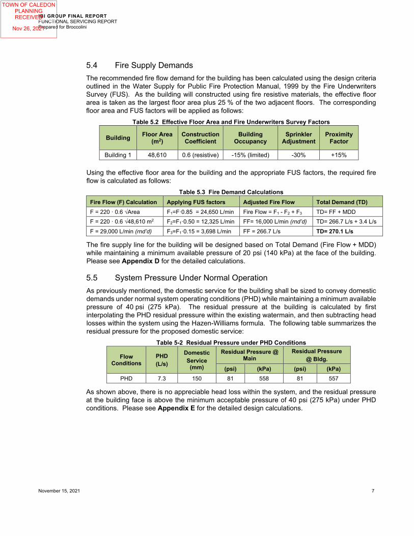
5.4 Fire Supply Demands The recommended fire flow demand for the building has been calculated using the design criteria outlined in the Water Supply for Public Fire Protection Manual, 1999 by the Fire Underwriters Survey (FUS). As the building will constructed using fire resistive materials, the effective floor area is taken as the largest floor area plus 25 % of the two adjacent floors. The corresponding floor area and FUS factors will be applied as follows:
Table 5.2 Effective Floor Area and Fire Underwriters Survey Factors
Building Floor Area (m2)
Construction Coefficient
Building Occupancy
Sprinkler Adjustment
Proximity Factor
Building 1 48,610 0.6 (resistive) -15% (limited) -30% +15%
Using the effective floor area for the building and the appropriate FUS factors, the required fire flow is calculated as follows:
Table 5.3 Fire Demand Calculations Fire Flow (F) Calculation Applying FUS factors Adjusted Fire Flow Total Demand (TD) F = 220 · 0.6 √Area F1=F·0.85 = 24,650 L/min Fire Flow = F1 - F2 + F3 TD= FF + MDD F = 220 · 0.6 √48,610 m2 F2=F1·0.50 = 12,325 L/min FF= 16,000 L/min (rnd’d) TD= 266.7 L/s + 3.4 L/s F = 29,000 L/min (rnd’d) F3=F1·0.15 = 3,698 L/min FF = 266.7 L/s TD= 270.1 L/s
The fire supply line for the building will be designed based on Total Demand (Fire Flow + MDD) while maintaining a minimum available pressure of 20 psi (140 kPa) at the face of the building. Please see Appendix D for the detailed calculations.
5.5 System Pressure Under Normal Operation As previously mentioned, the domestic service for the building shall be sized to convey domestic demands under normal system operating conditions (PHD) while maintaining a minimum available pressure of 40 psi (275 kPa). The residual pressure at the building is calculated by first interpolating the PHD residual pressure within the existing watermain, and then subtracting head losses within the system using the Hazen-Williams formula. The following table summarizes the residual pressure for the proposed domestic service:
Table 5-2 Residual Pressure under PHD Conditions
Flow Conditions
PHD (L/s)
Domestic Service
(mm)
Residual Pressure @ Main
Residual Pressure @ Bldg.
(psi) (kPa) (psi) (kPa) PHD 7.3 150 81 558 81 557
As shown above, there is no appreciable head loss within the system, and the residual pressure at the building face is above the minimum acceptable pressure of 40 psi (275 kPa) under PHD conditions. Please see Appendix E for the detailed design calculations.
TOWN OF CALEDONPLANNINGRECEIVED
Nov 26, 2021

IBI GROUP FINAL REPORT FUNCTIONAL SERVICING REPORT Prepared for Broccolini
November 15, 2021 8
5.6 System Pressure Under Fire Flow As previously mentioned, the fire service shall be sized to convey the total fire demand (Fire + MDD) while maintaining a minimum available pressure of 20 psi (140 kPa). The residual pressure at the building is calculated by first interpolating the residual pressure within the existing watermain, and then subtracting head losses within the system using the Hazen-Williams formula. The following table summarizes the residual pressure for the proposed fire service:
Table 5-3 Residual Pressure under Fire + MDD Conditions
Flow Conditions
FF+MDD (L/s)
Fire Service
(mm)
Residual Pressure @ Main
Residual Pressure @ Bldg.
(psi) (kPa) (psi) (kPa) FF+MDD 270.1 300 43 295 38 262
As shown above, the residual pressure at the building face for the fire service is above the minimum acceptable pressure of 20 psi (140 kPa) under fire demand conditions (Fire + MDD). Please see Appendix D for the detailed design calculations.
5.7 Water Service Connections To service the proposed building, a new 300 mm fire service is proposed to be looped around the building with two connections the 300 mm watermain within Abbotside Way. A separate 150 mm domestic service will tee off from the fire line, and a new valve and box shall be installed at the property line for each incoming service.
Each incoming 300 mm fire service shall be installed with a detector check valve placed in a 1800 mm precast chamber per Peel Dwg. 1-3-1, and the incoming 150 mm water service shall be installed with a meter placed in a 1500 mm precast chamber per Peel Dwg. 1-4-4.
The National Fire Protection Association (NFPA) considers any building over 23 m in height to be classified as a high-rise building and thus requires a remotely located secondary siamese connection for each zone. As the proposed building is less than 23 m in height, one siamese connection will suffice, however additional siamese connections may be required for multiple fire zones, and shall be confirmed at the Building Permit stage. All siamese connections shall be placed within 45 m of a hydrant.
Please see enclosed servicing drawings SS-01 through SS-04, and the enclosed Abbotside Way Extension drawing set for reference.
5.8 Hydrant Coverage Existing hydrants are located on the north side of Abbotside Way and on either side of Heart Lake Road. Four new municipal hydrants are proposed within the north boulevard of the Abbotside Way Extension. Additional private hydrants shall be installed around the permitter of Building 1, and as previously mentioned all proposed siamese connections shall be strategically placed within 45 m of a hydrant to satisfy OBC requirements.
Please see Drawings SS-01 through SS-04 and the enclosed Abbotside Way Extension drawing set for the location of all existing and proposed water infrastructure.
TOWN OF CALEDONPLANNINGRECEIVED
Nov 26, 2021

IBI GROUP FINAL REPORT FUNCTIONAL SERVICING REPORT Prepared for Broccolini
November 15, 2021 9
6 Conclusions and Recommendations Sanitary Sewers
The receiving sanitary system within Abbotside Way, which was designed as part of the Mayfield West FSR, and detailed as part of the Livingston Estates FSR, has been sized to accommodate sanitary flows from the subject site.
Water Supply
The existing watermain network has been designed in accordance with the Mayfield West FSR. It is noted that additional hydrant testing will be conducted shortly, and it is expected that the watermain network will easily support the proposed fire and domestic water demands for the proposed development.
Summary
In summary, it can be concluded that both the Zoning By-Law Amendment and Site Plan Application can be supported from a municipal site servicing perspective subject to further fire flow testing.
Should you have any questions, please do not hesitate to contact the undersigned.
Respectfully Submitted,
IBI Group Canada Inc.
November 15, 2021
Jason Jenkins, P.Eng, P.E. Associate Manager - Land Engineering Tel: +1.905.763.2322 x 63542 E-Mail: [email protected] https://ibigroup.sharepoint.com/sites/projects1/135636/internal documents/6.0_technical/6.04_civil/03_tech-reports/phase 1/zba and spa/revision 1/functional servicing/135636 - functional servicing report (revision 1).docx
TOWN OF CALEDONPLANNINGRECEIVED
Nov 26, 2021

IBI GROUP FINAL REPORT FUNCTIONAL SERVICING REPORT Prepared for Broccolini
November 15, 2021
Figure 1 – Vicinity Map
TOWN OF CALEDONPLANNINGRECEIVED
Nov 26, 2021

HEART LAKE ROAD
KENNEDY ROAD
MAYFIELD
ROAD
HWY. 410
DIXIE ROAD
SITE
PHASE 1
FIGURE NAMESCALE:
PROJECT ENG:
REVISIONFIGURE NO.
PROJECT NAME
APPROVED BY:CHECKED BY:
DRAWN BY:
DATE:
SC
ALE
CH
EC
K1
in10
mm
PROJECT NO:
File
Loc
atio
n: J
:\135
636_
1230
4Hea
rt\7.
0_P
rodu
ctio
n\7.
03_D
esig
n\04
_Civ
il\S
heet
s\S
PA
\Pha
se 1
\Fig
ures
\135
636-
SH
T-FI
G.d
wg
La
st S
aved
: Nov
embe
r 2, 2
021,
by
Jasm
ine.
Zhan
g
Plo
tted:
Thur
sday
, Nov
embe
r 4, 2
021
10:4
4:25
AM
by
Nic
olas
Di S
tefa
no
JJ
N.T.S.
FIG-1
KEY PLAN
INDUSTRIALDEVELOPMENT - PHASE 112304 HEART LAKE ROADCALEDON, ONTARIO
JJ
NDS
NOV 2021
135636
IBI GROUPUnit 300 – 8133 Warden AvenueMarkham ON L6G 1B3 Canadatel 905 763 2322 fax 905 763 9983ibigroup.com
True North
TOWN OF CALEDONPLANNINGRECEIVED
Nov 26, 2021

IBI GROUP FINAL REPORT FUNCTIONAL SERVICING REPORT Prepared for Broccolini
November 15, 2021
Figure 2 – Aerial Plan
TOWN OF CALEDONPLANNINGRECEIVED
Nov 26, 2021

SITE
HEART LAKE RD
KENNEDY RD
MAY
FIEL
D RO
AD
HWY 410
DIXIE ROAD
PHASE 1
FIGURE NAMESCALE:
PROJECT ENG:
REVISIONFIGURE NO.
PROJECT NAME
APPROVED BY:CHECKED BY:
DRAWN BY:
DATE:
SC
ALE
CH
EC
K1
in10
mm
PROJECT NO:
File
Loc
atio
n: J
:\135
636_
1230
4Hea
rt\7.
0_P
rodu
ctio
n\7.
03_D
esig
n\04
_Civ
il\S
heet
s\S
PA
\Pha
se 1
\Fig
ures
\135
636-
SH
T-FI
G.d
wg
La
st S
aved
: Nov
embe
r 2, 2
021,
by
Jasm
ine.
Zhan
g
Plo
tted:
Thur
sday
, Nov
embe
r 4, 2
021
10:4
5:56
AM
by
Nic
olas
Di S
tefa
no
JJ
N.T.S.
FIG-2
AERIAL PLAN
INDUSTRIALDEVELOPMENT - PHASE 112304 HEART LAKE ROADCALEDON , ONTARIO
JJ
NDS
NOV 2021
135636
IBI GROUPUnit 300 – 8133 Warden AvenueMarkham ON L6G 1B3 Canadatel 905 763 2322 fax 905 763 9983ibigroup.com
True North
TOWN OF CALEDONPLANNINGRECEIVED
Nov 26, 2021

IBI GROUP FINAL REPORT FUNCTIONAL SERVICING REPORT Prepared for Broccolini
November 15, 2021
Appendix A – Background Information
Sample Architectural Drawings (Ware Malcomb) Topographic Survey (R-PE) Plan and Profile Drawings (Town of Caledon)
TOWN OF CALEDONPLANNINGRECEIVED
Nov 26, 2021

ABBOTSIDE WAY
BON
NIE
GLE
N F
ARM
BLV
D
LARSON PEAK RD
BLDG 1FOOTPRINT:±48.610 m²
±523,234 SF
BLDG 2FOOTPRINT:±29,830 m²
±321,087 SF
OFFICE
OFFICE
15m
SETB
ACK
FRO
M R
ESID
ENTA
IL
14m
HW
Y SE
TBAC
K18
5'60
'50
'TY
P.7m
10m 56'TYP.
10m
1137'-6"
460'
36'-9"
36'-9"
26m
R.O
.W.
BLDG 3FOOTPRINT:±92,433 m²
±994,941 SF
GTA WEST FAA
RIGHT-INRIGHT-OUT
ACCESS
NO LEFT-TURNSIGN FOR TRUCKS
OFFICE
NOISE BERM
HEA
RT
LAKE
RD
NORTH
SHEET
10.20.2021
TOR21-0032-00
Conceptual Site Plan
12304 Heart Lake Road
scheme: 09
Caledon, ON, Canada 1
This conceptual design is basedupon a preliminary review ofentitlement requirements and onunverified and possibly incompletesite and/or building information, andis intended merely to assist inexploring how the project might bedeveloped.
Boundary Source:PDF ALTA SURVEY
Stormwater Management Design:ASSUMED UNDERGROUNDSYSTEM
0 40m 75m 150m
1:1500
20m0 40m 75m 150m
1:1500
20m
NOTE: HEIGHT VARIANCE MAY BEREQUIRED DEPENDING ON ZONING
TOWN OF CALEDONPLANNINGRECEIVED
Nov 26, 2021

TOWN OF CALEDONPLANNINGRECEIVED
Nov 26, 2021

TOWN OF CALEDONPLANNINGRECEIVED
Nov 26, 2021

TOWN OF CALEDONPLANNINGRECEIVED
Nov 26, 2021

ST
OR
M
INV
ER
T
EX
IST
ING
C
RD
GR
AD
ES
CH
AIN
AG
E
INV
ER
T
SA
NIT
AR
Y
L
CE
NT
ER
LIN
E
PL
AN
AN
D P
RO
FIL
E O
F
Fax.
(905)
475-3
081
600 A
lden R
oad,
Suite 5
00
Ma
rkh
am
, O
nta
rio
, L
3R
0E
7T
el. (
905)
475-3
080
ww
w.D
SE
L.c
a
DS
EL
C
KE
Y P
LA
NS
CA
LE
1:8
000
KEN
NED
Y R
OAD ABBO
TSIDE W
AY
BE
NA
DIR
LO
SIN
O S
TR
EE
T
KE
AR
NY
AV
EN
UE
LEARMONT AVENUE
CASPIAN
CASPIAN
LANE A
-1A
CO
TTONFIELD
AB
BO
TS
IDE
W
AY
BE
NA
DIR
LEARMONT AVENUE
LOSINO
ST
RE
ET
COTTONFIELD
KE
AR
NY
STELLAR AVENUE
ROAD KENNEDY
TOKARA
LAR
SO
N P
EAK R
OAD
LA
RS
ON
P
EA
K
SC
HO
OL
PA
RK
SW
MP
ON
D
SW
MP
ON
D
EM
PL
OY
ME
NT
PH
AS
E 2
PH
AS
E 1
A43M
-1800
43M
-1801
STR
EET
STREET
STREET
STREET
AV
EN
UE
WAY
WA
TE
RV
ILLE
ALNWICK AVENUE
RO
AD
LANE B-2
AV
EN
UE
AV
EN
UE
ST
RE
ET
LO
SIN
O
AVENUE
OD
CK
180
1
0
CO
ND
O
BLO
CK
193
43
M-1
80
0
ST
OR
M
INV
ER
T
EX
IST
ING
C
RD
GR
AD
ES
CH
AIN
AG
E
INV
ER
T
SA
NIT
AR
Y
L
CE
NT
ER
LIN
E
AP
PR
OV
ED
FO
R C
ON
ST
RU
CT
ION
TH
IS A
PP
RO
VA
L C
ON
ST
ITU
TE
S A
GE
NE
RA
L R
EV
IEW
AN
D D
OE
S N
OT
CE
RT
IFY
DIM
EN
SIO
NA
L A
CC
UR
AC
Y.
TH
IS A
PP
RO
VA
L I
S S
UB
JE
CT
TO
TH
E F
UR
TH
ER
CE
RT
IFIC
AT
ION
OF
TH
E "
AS
CO
NS
TR
UC
TE
D"
WO
RK
S B
Y A
RE
GIS
TE
RE
D P
RO
FE
SS
ION
AL
EN
GIN
EE
R O
F T
HE
PR
OV
INC
E O
F O
NT
AR
IO.
DA
TE
:__________________
A
PP
RO
VE
D B
Y:_
_________________________
C.
CA
MP
BE
LL
, C
.E.T
.
DIR
EC
TO
R O
F P
UB
LIC
WO
RK
S
AN
D E
NG
INE
ER
ING
PH
AS
ES
1A
(21T
-06004C
)S
OU
TH
FIE
LD
S C
OM
MU
NIT
Y M
OS
CO
RP
PH
AS
ES
2 (
21T
-06002C
)
AS
-CO
NS
TR
UC
TE
D
(FR
OM
ST
A.
0+
46
0.0
00
TO
ST
A.
0+
59
7.9
83
)
AB
BO
TS
IDE
WA
Y
DW
G N
o.
64
RE
FE
R T
O
AB
BO
TS
IDE
WA
Y
TOWN OF CALEDONPLANNINGRECEIVED
Nov 26, 2021

TOWN OF CALEDONPLANNINGRECEIVED
Nov 26, 2021

IBI GROUP FINAL REPORT FUNCTIONAL SERVICING REPORT Prepared for Broccolini
November 15, 2021
Appendix B – Groundwater
Excerpt Hydrogeological Investigation (EXP)
TOWN OF CALEDONPLANNINGRECEIVED
Nov 26, 2021

1595 Clark Boulevard | Brampton, ON, L6T 4V1 | Brampton
t: 905.793.9800 | f: 905.793.0641 | exp.com
12304 Heart Lake Road, Caledon, Ontario L7C 2J2
Hydrogeological Investigation and Water Balance Assessment
Client: Broccolini Limited Partnership No. 6 2680 Skymark Avenue, Suite 800, Mississauga, Ontario L4W 5L6 Attention: Mr. Ben Wilson
Type of Document: Final
Project Name: 12304 Heart Lake Road, Caledon, Ontario Project Number: BRM-21004344-D0 EXP Services Inc. 1595 Clark Boulevard Brampton, ON, L6T 4V1 t: 905.793.9800 f: 905.793.0641
Date Submitted: 2021-11-12
TOWN OF CALEDONPLANNINGRECEIVED
Nov 26, 2021

EXP Services Inc. 12304 Heart Lake Road, Caledon, Ontario
Hydrogeological Investigation and Water Balance Assessment BRM-21004344-D0
November 12, 2021
1
Table of Contents
1 Introduction ............................................................................................................................................. 4
1.1 Project Description ......................................................................................................................................... 4
1.2 Project Objectives .......................................................................................................................................... 4
1.3 Scope of Work ................................................................................................................................................ 5
1.4 Review of Previous Reports ........................................................................................................................... 6
2 Hydrogeological Setting ........................................................................................................................... 7
2.1 Regional Setting ............................................................................................................................................. 7
2.1.1 Regional Physiography ............................................................................................................................... 7
2.1.2 Regional Geology and Hydrogeology ......................................................................................................... 7
2.1.3 Existing Water Well Survey ........................................................................................................................ 8
2.2 Site Setting ..................................................................................................................................................... 8
2.2.1 Site Topography ......................................................................................................................................... 8
2.2.2 Local Surface Water Features .................................................................................................................... 8
2.2.3 Vulnerability Mapping ............................................................................................................................... 8
2.2.4 Local Geology and Hydrogeology............................................................................................................... 9
3 Results .................................................................................................................................................... 11
3.1 Monitoring Well Details ............................................................................................................................... 11
3.2 Water Level Monitoring ............................................................................................................................... 11
3.3 Hydraulic Conductivity Testing..................................................................................................................... 12
3.4 Groundwater Quality ................................................................................................................................... 12
3.5 Infiltration Testing ........................................................................................................................................ 14
4 Water Balance Study ............................................................................................................................. 15
4.1 Background Information .............................................................................................................................. 15
4.2 Methodology ................................................................................................................................................ 15
4.3 Meteorological Data .................................................................................................................................... 16
4.4 Pre- and Post-Development Site Characteristics ......................................................................................... 16
4.4.1 Pre-Development Site Characteristics ..................................................................................................... 16
4.4.2 Post-Development Site Characteristics .................................................................................................... 17
TOWN OF CALEDONPLANNINGRECEIVED
Nov 26, 2021

EXP Services Inc. 12304 Heart Lake Road, Caledon, Ontario
Hydrogeological Investigation and Water Balance Assessment BRM-21004344-D0
November 12, 2021
2
4.5 Pre-Development Water Balance Estimates ................................................................................................ 17
4.5.1 Climate Data Analysis ............................................................................................................................... 17
4.5.2 Infiltration ................................................................................................................................................ 18
4.5.3 Pre-Development Water Balance Analysis .............................................................................................. 18
4.6 Post-Development Water Balance Estimates .............................................................................................. 19
4.6.1 Post-Development Water Balance ........................................................................................................... 19
4.7 Impact and Proposed Mitigation Measures ................................................................................................. 20
5 Dewatering Assessment ........................................................................................................................ 21
5.1 Dewatering Flow Rate Estimate and Zone of Influence ............................................................................... 22
5.2 Cooper-Jacob’s Radius of Influence ............................................................................................................. 22
5.3 Stormwater .................................................................................................................................................. 22
5.4 Results of Dewatering Rate Estimates ......................................................................................................... 23
5.4.1 Construction Dewatering Rate Estimate .................................................................................................. 23
5.4.2 Post-Construction Dewatering Rate Estimate ......................................................................................... 24
5.5 MECP Water Taking Permits ........................................................................................................................ 24
5.5.1 Short-Term Discharge Rate (Construction Phase) ................................................................................... 24
6 Environmental Impacts .......................................................................................................................... 25
6.1 Surface Water Features ............................................................................................................................... 25
6.2 Groundwater Sources .................................................................................................................................. 25
6.3 Geotechnical Considerations ....................................................................................................................... 25
6.4 Groundwater Quality ................................................................................................................................... 25
6.5 Well Decommissioning ................................................................................................................................. 26
7 Conclusions and Recommendations ...................................................................................................... 27
8 Limitations ............................................................................................................................................. 29
9 References ............................................................................................................................................. 30
TOWN OF CALEDONPLANNINGRECEIVED
Nov 26, 2021

EXP Services Inc. 12304 Heart Lake Road, Caledon, Ontario
Hydrogeological Investigation and Water Balance Assessment BRM-21004344-D0
November 12, 2021
12
One (1) map was created for the Site to show groundwater contours of the overburden water-bearing zone (Figure 6). Accordingly, the groundwater flow directions in overburden interpreted to be southeast and southwest of the Site.
Groundwater levels are expected to show seasonal fluctuations and vary in response to prevailing climate conditions. This may also affect the direction and rate of flow. It is recommended to conduct seasonal groundwater level measurements to provide more information on seasonal groundwater level fluctuations.
3.3 Hydraulic Conductivity Testing
Four (4) Single Well Response Tests (SWRT’s) were completed on monitoring wells BH/MW 1, BH/MW 9, BH/MW 16, and BH/MW 25 on October 7 and 12, 2021. The tests were completed to estimate the saturated hydraulic conductivity (K) of the soils at the well screen depths. Please note that SWRT was not possible to conduct for BH/MW 30 since the well was dry during the monitoring period.
The static water level within each monitoring well was measured prior to the start of testing. In advance of performing SWRTs, each monitoring well underwent development to remove fines introduced into the screens following construction. The development process involved purging of the monitoring wells to induce the flow of fresh formation water through the screen. Each monitoring well was permitted to fully recover prior to performing SWRTs.
Hydraulic conductivity values were calculated from the SWRT and constant rate test data as per Hvorslev’s solution included in the Aqtesolv Pro. V.4.5 software package. The semi-log plots for normalized drawdown versus time are included in Appendix C.
A summary of the hydraulic conductivities (K-values) estimated from the SWRTs are provided in Table 3-2.
Table 3-2: Summary of Hydraulic Conductivity Testing
Monitoring Well Well Depth
(mbgs)
Screen Interval (mbgs) Soil Formation Screened
Estimated Hydraulic Conductivity (m/s)
from to
BH/MW 1 7.60 4.60 7.60 Clayey Silt Till and Sandy Silt Till 3.1E-06
BH/MW 9 7.57 4.57 7.57 Clayey Silt Till and Sandy Silt Till 4.0E-07
BH/MW 16 7.49 4.49 7.49 Clayey Silt Till 3.3E-07
BH/MW 25 7.55 4.55 7.55 Clayey Silt Till 3.9E-07
Highest Estimated K Value 3.1E-06
Geometric Mean of Estimated K values 6.3E-07
SWRTs provide K-estimates of the geological formation surrounding the well screens and may not be representative of bulk formation hydraulic conductivity. As shown in Table 3-2, the highest K-value of the tested water-bearing zone is 3.1E-06 m/s, and the geometric mean of the K-values is 6.3E-07 m/s.
3.4 Groundwater Quality
To assess the suitability for discharging pumped groundwater into the sewers owned by the Regional Municipality of Peel / City of Mississauga during dewatering activities, one (1) groundwater sample was collected from monitoring well BH/MW 1 on October 12, 2021, using a peristaltic pump.
TOWN OF CALEDONPLANNINGRECEIVED
Nov 26, 2021

EXP Services Inc. 12304 Heart Lake Road, Caledon, Ontario
Hydrogeological Investigation and Water Balance Assessment BRM-21004344-D0
November 12, 2021
13
Prior to collecting the noted water sample, approximately three (3) standing well volumes of groundwater were purged from the referred well. The samples were collected unfiltered and placed into pre-cleaned laboratory-supplied vials and/or bottles provided with analytical test group specific preservatives, as required. Dedicated nitrile gloves were used during sample handling. The groundwater samples were submitted for analysis to Bureau Veritas Laboratory, a CALA certified independent laboratory in Mississauga, Ontario. Analytical results are provided in Appendix D.
Table 3-3 summarizes exceedance(s) of the Sanitary (Table 1) and Storm (Table 2) Sewer Use By-Law parameters.
When comparing the chemistry of the collected groundwater samples to the Regional Municipality of Peel Sanitary and Combined Sewer Discharge Criteria (By-Law Number 53-2010, Table 1), there were no parameter exceedances to be reported.
When comparing the chemistry of the collected groundwater samples to the Regional Municipality of Peel Storm Sewer Discharge Criteria (By-Law Number 53-2010, Table 2) the following parameters reported an exceedance: Total manganese and Chloroform
Reporting detection limits (RDLs) were below the Sewer Use By-Law parameter criteria of Tables 1 and 2.
Table 3-3: Summary of Analytical Results
Parameter Units
City of Mississauga / Regional Municipality of
Peel Sanitary and Combined Sewer Discharge Limit
(Table 1)
City of Mississauga / Regional Municipality of Peel Storm Sewer
Discharge Limit (Table 2)
Concentration BH/MW 1 12-Oct-21
Total Manganese (Mn) µg/L 5,000 50 78
Chloroform µg/L 40 2 2.8
Bold – Exceeds City of Mississauga / Regional Municipality of Peel Storm Sewer Discharge Limit (Table 2).
For the short-term dewatering system (construction phase), it is anticipated that TSS levels and some other parameters (for example, Total Metals) in the pumped groundwater may become elevated and exceed both, Sanitary and Storm Sewer Use By-Law limits. To control the concentration of TSS and associated metals, it is recommended that a suitable treatment method be implemented (filtration or decantation facilities and/ or any other applicable treatment system) during construction dewatering activities to discharge to the applicable sewer system. The specifications of the treatment system will need to be adjusted to the reported water quality results by the treatment contractor/process engineer.
The water quality results presented in this report may not be representative of the long-term condition of groundwater quality onsite. As such, regular water quality monitoring is recommended for the post-construction phase, as required by the City.
An agreement to discharge into the sewers owned by the City of Mississauga / Regional Municipality of Peel will be required prior to releasing dewatering effluent.
The Environmental Site Assessment Report(s) shall be reviewed for more information on the groundwater quality conditions at the Site.
TOWN OF CALEDONPLANNINGRECEIVED
Nov 26, 2021

EXP Services Inc. 12304 Heart Lake Road, Caledon, Ontario
Hydrogeological Investigation and Water Balance Assessment BRM-21004344-D0
November 12, 2021
14
3.5 Infiltration Testing
EXP completed four (4) infiltration rate tests (INF 1, INF 9, INF 25 and INF 30) within the Site area on October 7 and 12, 2021. These tests were conducted in proximity of selected monitoring wells: September 7, 2021, at BH/MW 1 (INF 1), BH/MW 9 (INF 9), BH/MW 30 (INF 30) and BH/MW 25 (INF 25).
Infiltration tests were conducted at depths ranged from 0.6 mbgs to 0.9 mbgs. The reported water levels at these monitoring wells are; 4.24 mbgs (BH/MW 1), 5.92 mbgs (BH/MW 9), and <7.58 (BH/MW 30) on October 7, 2021, and 6.66 mbgs (BH/MW 25) on October 12 15, 2021 (Table 3.2).
The stratigraphy of the shallow subsurface comprises a silt/sand with some pebbles. Table 3.5 below shows a summary of field saturated hydraulic conductivity (Kfs) testing and design infiltration rates, as per the Low Impact Development (LID) Stormwater Management Planning and Design Guide, CVC – TRCA, 2010, Appendix G. The estimated field saturated hydraulic conductivities were correlated to infiltration rates based on the relationship provided in Appendix D of the guideline.
Infiltration rate testing locations are shown on Figure 4 and infiltration rate analysis is provided in Appendix E.
Table 3.4: Summary of Infiltration Testing Results
Infiltration Test Location/ MW ID
Depth of Hole
(mbgs) Formation tested
Field Saturated Hydraulic Conductivity,
Kfs (cm/s)
Infiltration Rate (mm/hr)
INF 1 (BH/MW 1) 0.60 Clayey Silt Till 3.4 x 10⁻⁶ 19
INF 9 (BH/MW 9) 0.75 Clayey Silt Till 3.5 x 10⁻⁶ 19
INF 25 (BH/MW 25) 0.90 Clayey Silt Till 2.7 x 10⁻⁶ 18
INF 30 (BH/MW 30) 0.70 Clayey Silt to Sandy Silt (Fill) 9.0 x 10⁻⁶ 24
Geometric Mean 4.12 x 10⁻⁶ 20
Design Infiltration Rate* 8 (20/2.5)
Notes: *Safety Factor of 2.5 was applied to calculate the design infiltration rate (Low Impact Development (LID) Stormwater Management Planning and Design Guide, CVC – TRCA, 2010, Appendix D).
The estimated design infiltration rate based on percolation rate testing for the Site is 8 mm/hr.
TOWN OF CALEDONPLANNINGRECEIVED
Nov 26, 2021

EXP Services Inc. 12304 Heart Lake Road, Caledon, Ontario
Hydrogeological Investigation and Water Balance Assessment BRM-21004344-D0
November 12, 2021
23
A 15 mm precipitation event was utilized for estimating the stormwater volume. The calculation of the stormwater volume is included in Appendix G.
The estimate of the stormwater volume only accounts for direct precipitation into the excavation. The dimensions of the excavation are considered in the dewatering calculations. Runoff from outside of the excavation’s footprint is excluded and it should be directed away from the excavation.
During precipitation events greater than 15 mm (ex: 100-year storm), measures should be taken by the contractor to retain stormwater onsite in a safe manner to not exceed the allowable water taking and discharge limits, as necessary. A two (2) and a one hundred (100) year storm events over a 24-hour period are 57.3 and 125.2 mm, respectively, which would produce 2,419 and 5,286 L of water within Building 1 footprint area.
5.4 Results of Dewatering Rate Estimates
5.4.1 Construction Dewatering Rate Estimate
For this assessment, it was assumed that the proposed construction plans include an excavation without shoring system. EXP should be retained to review the assumptions outlined in this section, should a shoring system be included.
Short-term (construction) dewatering calculations are presented in Appendix G.
Based on the assumptions provided in this report, the results of the dewatering rate estimate can be summarized as follows:
Table 4-2 Summary of Construction Dewatering Rate (Without Basement)
Description Building 1
(L/day)
Estimated Short Term Dewatering Rate (without safety factor or precipitation) 5,000
With Factor of Safety of 2.0 (excluding precipitation) for permit 10,000
From Precipitation Event of 15 mm in one day for whole building footprint 630,000
With Factor of Safety of 2.0 (including precipitation) for designs, and budgeting 640,000
Radius of Influence from sides of excavation (m) 16
It should be noted that the construction dewatering is required mainly to remove rainwater from the excavation after rainfall events. The MECP regulates the groundwater taking and since the estimated flow rate is less than 50,000 L/day then no MECP water taking permit (EASR or PTTW) is required.
The peak dewatering flow rates does not account for flow from utility beddings and variations in hydrogeological properties beyond those encountered during this investigation. Local dewatering may be required for pits (elevator pits, sump pits, raft) and for localized areas with permeable, soft, or wet soil conditions. Local dewatering is not considered to be part of this assessment, but contractor should be ready to install additional system to manage such conditions. Dewatering estimates should be reviewed once the pit dimensions are available.
All grading around the perimeter of the excavation should be graded away from the excavation and ramp/site access to
redirect runoff away from excavation.
TOWN OF CALEDONPLANNINGRECEIVED
Nov 26, 2021

EXP Services Inc. 12304 Heart Lake Road, Caledon, Ontario
Hydrogeological Investigation and Water Balance Assessment BRM-21004344-D0
November 12, 2021
24
The contractor is responsible for the design of the dewatering system to ensure that dry conditions are always maintained within the excavation at all costs.
As shown on Table 4.2, more than 90% of the dewatering volume is expected to be required after rainfall events. As such it is suggested to revise the construction plan to reduce the area of excavation kept open at any given point of time.
5.4.2 Post-Construction Dewatering Rate Estimate
As per preliminary Site drawings, it is our present understanding that the proposed Building 1 will be constructed without basements. Therefore, no long-term dewatering requirements are anticipated for the proposed Building 1.
5.5 MECP Water Taking Permits
5.5.1 Short-Term Discharge Rate (Construction Phase)
In accordance with the Ontario Water Resources Act, if the water taking for the construction dewatering is more than 50,000 L/day but less than 400,000 L/day, then an online registration in the Environmental Activity and Sector Registry (EASR) with the MECP will be required. If groundwater dewatering rates onsite exceed 400,000 L/day, a Category 3 Permit to Take Water (PTTW) will be required from the MECP.
As of July 1, 2021, an amendment of O. Reg. 63/16 has come into effect and replaced the former subsection 7 (5) such that the water taking limit of 400,000 L/day would apply to groundwater takings of each dewatered work area only, excluding stormwater.
The dewatering estimates including a safety factor and excluding precipitation is stated below. The MECP construction dewatering rate excludes the precipitation amount and is the rate used for the permit application.
Table 4-4: MECP Construction Dewatering Flow Rate
Scenario Total Flow Rate
Buildings 1 (L/day)
MECP Construction Dewatering Flow Rate with Safety Factor of 2.0 (excluding rainwater collection)
10,000
Based on the estimated construction dewatering rates, an EASR from the MECP will not be required to facilitate the construction dewatering program of the Site.
TOWN OF CALEDONPLANNINGRECEIVED
Nov 26, 2021

IBI GROUP FINAL REPORT FUNCTIONAL SERVICING REPORT Prepared for Broccolini
November 15, 2021
Appendix C – Sanitary Analysis
Excerpt Mayfield West Functional Servicing Study Speirs Giffen Avenue Ultimate Sanitary Area Drainage Plan Livingston Estates Sanitary Drainage Area Plan Sanitary Demand Calculations
TOWN OF CALEDONPLANNINGRECEIVED
Nov 26, 2021
FUNCTIONAL SERVICING AND
STORMWATER MANAGEMENT STUDY
FOR
MAYFIELD WEST COMMUNITY
IN THE
TOWN OF CALEDON
NOVEMBER 2007
TOWN OF CALEDONPLANNINGRECEIVED
Nov 26, 2021

TABLE OF CONTENTS
Section Page No.
1.0 INTRODUCTION.................................................................................................. 1
2.0 PLANNING CONTEXT......................................................................................... 2
3.0 WASTEWATER SERVICING............................................................................... 3
3.2 Existing Wastewater Services.................................................................... 3 3.3 Population Assumptions ............................................................................ 3 3.4 Proposed Sanitary Servicing...................................................................... 4 3.5 Permanent Sanitary Pump Station............................................................. 5
4.0 WATER SERVICING............................................................................................ 6
4.2 Existing Watermains .................................................................................. 6 4.3 Proposed Water Servicing ......................................................................... 7 4.4 Mayfield West Elevated Tank and Associated Watermains ....................... 7
5.0 STORM DRAINAGE ............................................................................................ 8
5.1 Background Information............................................................................. 8 5.2 Existing Features and Drainage Patterns .................................................. 8
6.0 STORMWATER MANAGEMENT ........................................................................ 9
6.1 Etobicoke Creek Watershed Stormwater Management Requirements...... 9 6.2 West Humber River Watershed Stormwater Management Requirements. 9 6.3 Selection of Stormwater Management Controls....................................... 10 6.4 Preliminary Pond locations ...................................................................... 14
7.0 POND OPERATING CHARACTERISTICS........................................................ 15
8.0 POND COMPONENTS ...................................................................................... 17
8.1 Sediment Forebay ................................................................................... 17 8.2 Permanent Pool ....................................................................................... 18 8.3 Extended Detention Storage.................................................................... 18 8.4 Extended Detention Outlet....................................................................... 18 8.5 Access Road............................................................................................ 20 8.6 Emergency Overflows.............................................................................. 20 8.7 Thermal Mitigation ................................................................................... 20
9.0 OPERATIONS AND MAINTENANCE................................................................ 20
10.0 STORM DRAINAGE .......................................................................................... 21
TOWN OF CALEDONPLANNINGRECEIVED
Nov 26, 2021
10.1 Conveyance of Minor System Flows........................................................ 21 10.2 Conceptual Storm Trunk Sewers ............................................................. 21 10.3 Conveyance of Major Storm Flows .......................................................... 21
11.0 CREEK AND UTILITY CROSSINGS ................................................................. 22
12.0 REGIONAL STORM CONVEYANCE AND FLOODPLAIN STORAGE............. 22
13.0 CONSTRUCTION PRACTICES......................................................................... 23
14.0 PRELIMINARY GRADING AND SERVICING.................................................... 23
15.0 ROAD ALLOWANCE DESIGN.......................................................................... 23
16.0 COST SHARING ................................................................................................ 24
16.1 Region of Peel Development Charge Infrastructure ................................ 24 16.2 Town of Caledon Development Charge Infrastructure............................. 24 16.3 Developers’ Group Cost Sharing Agreement........................................... 24
17.0 RESPONSE TO COMMENTS FROM AGENCIES............................................. 25
TOWN OF CALEDONPLANNINGRECEIVED
Nov 26, 2021

DAVID SCHAEFFER ENGINEERING LTD.
FUNCTIONAL SERVICING AND STORMWATER MANAGEMENT STUDY PAGE 3 MAYFIELD WEST COMMUNITY, TOWN OF CALEDON © DSEL
3.0 WASTEWATER SERVICING 3.1 Background Information Town of Caledon commissioned various studies in order to define the servicing requirements for Mayfield West. The following studies were used to define the preliminary wastewater servicing requirements:
Mayfield West Community Development Plan Study, Existing Water Supply and Sanitary Sewage System, CG&S, November 1996 (Background Studies)
Mayfield West Community Development Plan Study, Water Supply and Sanitary
Sewage System Function Servicing, CG&S, February 1997 (Background Studies)
Region of Peel Sewer and Watermain Maps
Region of Peel Design Criteria, October 2000
The Background Studies commissioned by Town of Caledon for water and wastewater are included in Appendix A. The above documents form the basis of this report. 3.2 Existing Wastewater Services An existing 525 mm diameter sanitary sewer is located at the intersection of Mayfield Road and Inder Heights Drive. The Background Studies determined that the sewer is able to accommodate sanitary flows from 10,000 people. An existing 750 mm diameter sanitary sewer is located on Dixie Road, terminating approximately 1,800 metres south of Mayfield Road. Discussions with Region of Peel have confirmed that the capacity of the existing sewer is not a constraint to the development of this community. The location of the existing sanitary sewers is illustrated in Figure 3. 3.3 Population Assumptions Residential In accordance with population projections provided by Town of Caledon, the following residential population is currently being considered:
Mayfield West 8,500 people Snells Hollow 2,000 people
TOWN OF CALEDONPLANNINGRECEIVED
Nov 26, 2021

DAVID SCHAEFFER ENGINEERING LTD.
FUNCTIONAL SERVICING AND STORMWATER MANAGEMENT STUDY PAGE 4 MAYFIELD WEST COMMUNITY, TOWN OF CALEDON © DSEL
Employment As of this writing, employment populations have not been finalized. As such, an assumption of 70 people per hectare has been applied in accordance with Region of Peel Design Criteria. 3.4 Proposed Sanitary Servicing Region of Peel has included an allowance for the ultimate development of Mayfield West in the planning of the existing infrastructure. Accordingly, existing sewer pipes have been sized to convey the predicted Mayfield West flows. Furthermore, major infrastructure such as treatment plants and pump stations has sufficient existing and planned capacity to accommodate the development of the new community. The Mayfield West community will be serviced by a network of new gravity sewers designed in accordance with Region of Peel design criteria. Two sanitary outlets will be used to service the Mayfield West Community, as follows: Inder Heights Drive An existing 525 mm diameter sanitary sewer is located at the intersection of Mayfield Road and Inder Heights Drive. The Background Studies determined that the sewer is able to accommodate sanitary flows from 10,000 people. It is proposed that the entire residential population in Mayfield West will be directed to the Inder Heights sewer. The total population contribution to Inder Heights is calculated as follows:
Table 1 Population Assumptions
Community Population
Snells Hollow 1,400 Mayfield Residential 8,500 Mayfield Employment 600 Total 10,500
It should be noted that the total Snells Hollow population of 2,000 people has been split between the Inder Heights and Dixie sewers in accordance with the Background Studies. The split has been estimated as 1,400 / 600 (Inder Heights / Dixie). It should also be noted that since the time of the Background Studies per capita flow generation rates have been reduced, due in large part to recent Building Code amendments which require water conservation fixtures in all new residential construction. As such, it is expected that the additional population can be
TOWN OF CALEDONPLANNINGRECEIVED
Nov 26, 2021

DAVID SCHAEFFER ENGINEERING LTD.
FUNCTIONAL SERVICING AND STORMWATER MANAGEMENT STUDY PAGE 5 MAYFIELD WEST COMMUNITY, TOWN OF CALEDON © DSEL
accommodated in the Inder Heights sewer. It is recommended that sanitary flows be monitored during buildout of the community to ensure that the capacity of the receiving sewers in not exceeded. Consideration should also be included for the potential future extension of the Mayfield West urban boundary up to Old School Road. Assuming the same residential land use and population density as the existing community, there is the potential for approximately 25.8 hectares of residential development which will drain to the Inder Heights sewer. This corresponds to 258 units and an additional population of 902. As stated previously, flow monitoring is recommended to ensure that the capacity of the receiving sewers in not exceeded. Dixie Road An existing 750 mm diameter sanitary sewer is located on Dixie Road, terminating approximately 1,800 metres south of Mayfield Road. Discussions with Region of Peel have confirmed that the capacity of the existing sewer is not a constraint to the development of this community. The employment lands and the research campus will be directed to the Dixie Road sewer. Consideration should also be included for the potential future extension of the Mayfield West urban boundary up to Old School Road. Assuming the same residential and employment land use and population density as the existing community, there is the potential for approximately 18.0 hectares of residential development and 90.6 hectares of employment development which will drain to the Dixie sewer. For the residential component, this corresponds to 180 residential units and an additional residential population of 630. For the employment component, this corresponds to an additional residential population of 4,530. The conceptual sanitary sewer plan is illustrated in Figure 3. The conceptual sanitary profiles are illustrated in Appendix B. 3.5 Permanent Sanitary Pump Station A permanent pump station is required in order to convey sanitary flows from approximately 65.7 hectares originating in the north-west portion of the residential lands (between Kennedy Road and Hwy 10). A gravity sewer cannot provide service to this area for the following reasons:
The elevation of Etobicoke Creek precludes a gravity crossing on Hwy 10 to the west, as the valley is several metres lower than the lowest possible sewer invert.
The low grades in this area cannot be serviced to the new internal trunk sewer to
the east.
TOWN OF CALEDONPLANNINGRECEIVED
Nov 26, 2021

DAVID SCHAEFFER ENGINEERING LTD.
FUNCTIONAL SERVICING AND STORMWATER MANAGEMENT STUDY PAGE 6 MAYFIELD WEST COMMUNITY, TOWN OF CALEDON © DSEL
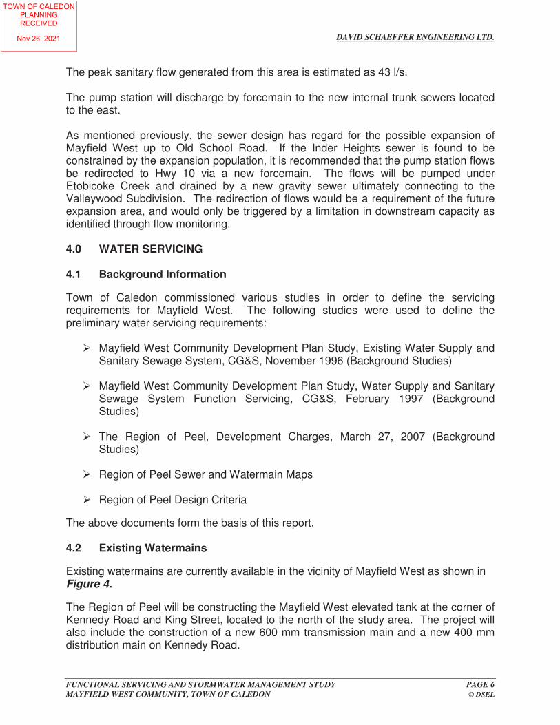
The peak sanitary flow generated from this area is estimated as 43 l/s. The pump station will discharge by forcemain to the new internal trunk sewers located to the east. As mentioned previously, the sewer design has regard for the possible expansion of Mayfield West up to Old School Road. If the Inder Heights sewer is found to be constrained by the expansion population, it is recommended that the pump station flows be redirected to Hwy 10 via a new forcemain. The flows will be pumped under Etobicoke Creek and drained by a new gravity sewer ultimately connecting to the Valleywood Subdivision. The redirection of flows would be a requirement of the future expansion area, and would only be triggered by a limitation in downstream capacity as identified through flow monitoring. 4.0 WATER SERVICING 4.1 Background Information Town of Caledon commissioned various studies in order to define the servicing requirements for Mayfield West. The following studies were used to define the preliminary water servicing requirements:
Mayfield West Community Development Plan Study, Existing Water Supply and Sanitary Sewage System, CG&S, November 1996 (Background Studies)
Mayfield West Community Development Plan Study, Water Supply and Sanitary
Sewage System Function Servicing, CG&S, February 1997 (Background Studies)
The Region of Peel, Development Charges, March 27, 2007 (Background
Studies)
Region of Peel Sewer and Watermain Maps
Region of Peel Design Criteria The above documents form the basis of this report. 4.2 Existing Watermains Existing watermains are currently available in the vicinity of Mayfield West as shown in Figure 4. The Region of Peel will be constructing the Mayfield West elevated tank at the corner of Kennedy Road and King Street, located to the north of the study area. The project will also include the construction of a new 600 mm transmission main and a new 400 mm distribution main on Kennedy Road.
TOWN OF CALEDONPLANNINGRECEIVED
Nov 26, 2021

TOWN OF CALEDONPLANNINGRECEIVED
Nov 26, 2021

TOWN OF CALEDONPLANNINGRECEIVED
Nov 26, 2021

TOWN OF CALEDONPLANNINGRECEIVED
Nov 26, 2021

12304 Heart Lake Road Sanitary Sewer Design SheetIndustrial Development Domestic Flow = 302.8 L/cap/day
Population Density = 70 pp/ha Project Name: 12304 Heart Lake Road
Infiltration= 0.20 L/s/ha Project Number: 135636
Mannings= 0.013 Date: October 29, 2021
Minimum Velocity = 0.75 m/s Designed By: Jason Jenkins, P.Eng., P.E.
Maximum Velocity = 3.50 m/s
DESIGN FLOW CALCULATIONS SEWER DESIGN & ANALYSIS
Area Density Population Cumulative Cumulative Peaking Sewage Infiltration Comm. Ground Total
From To (ha) (pp/ha) Area (ha) Population Factor Flow Flow Flow Water Flow, Qd Notes
(L/s) (L/s) (L/s) (L/s) (L/s)
(1) (2) (3) (4) (1) thru (4) (mm) (%) (m) Qf (L/s) (m/s) (m/s)
Phase 1
Building 1 Ctrl. MH Ex. Sewer 9.95 70 697 10.0 697 3.90 9.5 2.0 0.0 0.0 11.5 200 1.0% 10.0 34.2 1.06 0.95 34% San. Service
Peel Region Design Criteria for Sanitary Sewers
Percent of
Full Flow
(%)
Services
Nominal
Diameter
Pipe
Slope
Pipe
Length
Full Flow
Capacity,
Full Flow
Velocity
Actual
Velocity
Page 1 of 1
TOWN OF CALEDONPLANNINGRECEIVED
Nov 26, 2021

IBI GROUP FINAL REPORT FUNCTIONAL SERVICING REPORT Prepared for Broccolini
November 15, 2021
Appendix D – Water Analysis
Excerpt Mayfield West Functional Servicing Study Heart Lake Road - Capital Works Projects (Region of Peel) Watermain Plan and Profile Drawings (Region of Peel) Water Demand Calculations
TOWN OF CALEDONPLANNINGRECEIVED
Nov 26, 2021

FUNCTIONAL SERVICING AND
STORMWATER MANAGEMENT STUDY
FOR
MAYFIELD WEST COMMUNITY
IN THE
TOWN OF CALEDON
NOVEMBER 2007
TOWN OF CALEDONPLANNINGRECEIVED
Nov 26, 2021
DAVID SCHAEFFER ENGINEERING LTD.
FUNCTIONAL SERVICING AND STORMWATER MANAGEMENT STUDY PAGE 6 MAYFIELD WEST COMMUNITY, TOWN OF CALEDON © DSEL
The peak sanitary flow generated from this area is estimated as 43 l/s. The pump station will discharge by forcemain to the new internal trunk sewers located to the east. As mentioned previously, the sewer design has regard for the possible expansion of Mayfield West up to Old School Road. If the Inder Heights sewer is found to be constrained by the expansion population, it is recommended that the pump station flows be redirected to Hwy 10 via a new forcemain. The flows will be pumped under Etobicoke Creek and drained by a new gravity sewer ultimately connecting to the Valleywood Subdivision. The redirection of flows would be a requirement of the future expansion area, and would only be triggered by a limitation in downstream capacity as identified through flow monitoring. 4.0 WATER SERVICING 4.1 Background Information Town of Caledon commissioned various studies in order to define the servicing requirements for Mayfield West. The following studies were used to define the preliminary water servicing requirements:
Mayfield West Community Development Plan Study, Existing Water Supply and Sanitary Sewage System, CG&S, November 1996 (Background Studies)
Mayfield West Community Development Plan Study, Water Supply and Sanitary
Sewage System Function Servicing, CG&S, February 1997 (Background Studies)
The Region of Peel, Development Charges, March 27, 2007 (Background
Studies)
Region of Peel Sewer and Watermain Maps
Region of Peel Design Criteria The above documents form the basis of this report. 4.2 Existing Watermains Existing watermains are currently available in the vicinity of Mayfield West as shown in Figure 4. The Region of Peel will be constructing the Mayfield West elevated tank at the corner of Kennedy Road and King Street, located to the north of the study area. The project will also include the construction of a new 600 mm transmission main and a new 400 mm distribution main on Kennedy Road.
TOWN OF CALEDONPLANNINGRECEIVED
Nov 26, 2021

DAVID SCHAEFFER ENGINEERING LTD.
FUNCTIONAL SERVICING AND STORMWATER MANAGEMENT STUDY PAGE 7 MAYFIELD WEST COMMUNITY, TOWN OF CALEDON © DSEL
Construction of the elevated tank and Zone 7 watermains is scheduled for fall of 2007. 4.3 Proposed Water Servicing The Mayfield West community will be serviced by a network of new watermains designed in accordance with Town of Caledon design criteria and M.O.E. guidelines. The conceptual watermain requirements were defined through the Background Studies. The primary water distribution network will be comprised primarily of 300 mm mains, with the exception of the following 400 mm watermains:
East / west industrial collector from the north / south industrial collector to Dixie Road.
North / south industrial collector
Dixie Road from Mayfield Road to East / west industrial collector
East/ west residential collector from Main Street (Hwy 10) to Kennedy Road
The water distribution requirements were verified through watermain modeling for Mayfield West based on the proposed Secondary Plan. The watermain analysis conducted by MacViro Consultants in included in Appendix C. The conceptual watermain plan is illustrated in Figure 4. Final watermain sizing will be completed at the detailed design stage based on the actual development characteristics. Furthermore, the water distribution should be looped in order to provide system security. 4.4 Mayfield West Elevated Tank and Associated Watermains It is noted that the proposed Secondary Plan requires the realignment of Kennedy Road from it current location to a new corridor located to the east. Based on the Region’s construction schedule of the Kennedy Road watermains for fall of 2007, the watermains may be placed in their final location along the Mayfield West community’s realignment of Kennedy Road. In the event that the Region’s elevated tank and watermain proceed in advance of the community approvals and construction, portions of the new Kennedy Road watermains will have to be relocated to conform with the new road alignment. Satisfactory construction and financial arrangement would be made between the owners’ and Region of Peel for the relocation of the watermains. Furthermore, there would be limited development in the area prior to triggering the need to relocate the Kennedy Road watermains. As such, opportunities to reduce the size of the watermains during
TOWN OF CALEDONPLANNINGRECEIVED
Nov 26, 2021
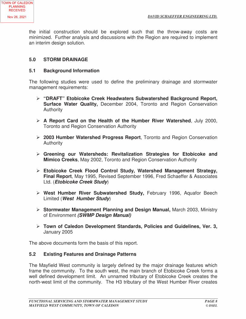
DAVID SCHAEFFER ENGINEERING LTD.
FUNCTIONAL SERVICING AND STORMWATER MANAGEMENT STUDY PAGE 8 MAYFIELD WEST COMMUNITY, TOWN OF CALEDON © DSEL
the initial construction should be explored such that the throw-away costs are minimized. Further analysis and discussions with the Region are required to implement an interim design solution. 5.0 STORM DRAINAGE 5.1 Background Information The following studies were used to define the preliminary drainage and stormwater management requirements:
“DRAFT” Etobicoke Creek Headwaters Subwatershed Background Report, Surface Water Quality, December 2004, Toronto and Region Conservation Authority
A Report Card on the Health of the Humber River Watershed, July 2000,
Toronto and Region Conservation Authority
2003 Humber Watershed Progress Report, Toronto and Region Conservation Authority
Greening our Watersheds: Revitalization Strategies for Etobicoke and
Mimico Creeks, May 2002, Toronto and Region Conservation Authority
Etobicoke Creek Flood Control Study, Watershed Management Strategy, Final Report, May 1995, Revised September 1996, Fred Schaeffer & Associates Ltd. (Etobicoke Creek Study)
West Humber River Subwatershed Study, February 1996, Aquafor Beech
Limited (West Humber Study)
Stormwater Management Planning and Design Manual, March 2003, Ministry of Environment (SWMP Design Manual)
Town of Caledon Development Standards, Policies and Guidelines, Ver. 3,
January 2005 The above documents form the basis of this report. 5.2 Existing Features and Drainage Patterns The Mayfield West community is largely defined by the major drainage features which frame the community. To the south west, the main branch of Etobicoke Creek forms a well defined development limit. An unnamed tributary of Etobicoke Creek creates the north-west limit of the community. The H3 tributary of the West Humber River creates
TOWN OF CALEDONPLANNINGRECEIVED
Nov 26, 2021

TOWN OF CALEDONPLANNINGRECEIVED
Nov 26, 2021
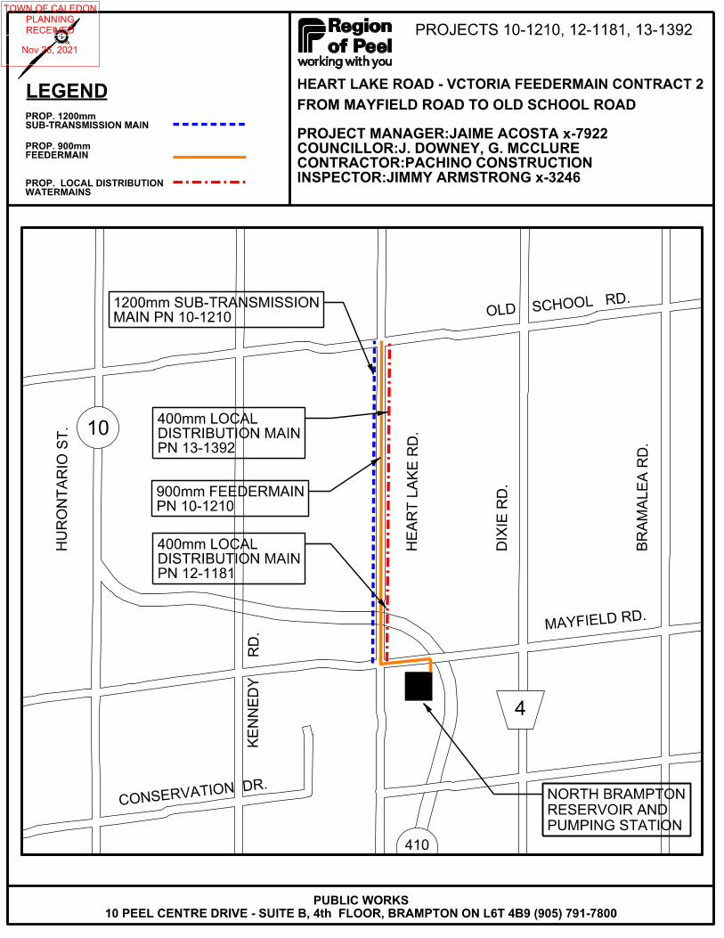
TOWN OF CALEDONPLANNINGRECEIVED
Nov 26, 2021

12280
12304
HOUSE
FIELD ACCESS
PLAN 43R-32427
CONCESSION 2 EHS8
+100
8+12
0
8+14
0
8+160
8+18
0
8+2
00
8+220
8+24
0
8+260
8+280
8+300
8+320
8+34
0
8+3
60
8+380
8+4
00
13-49
13-81
13-50
OH OH
OH
OH
OH
S
OH
OHOH OH
B B B
B
GM GM
ANAN
AN
BELL
PED
HBPAN
BELL
PED
LS
LS
HBP HBP HBP
HBP HBP
POST & WIRE FENCE
POST & WIRE FENCE PO
ST
&
WIR
E
FE
NC
E
POST & WIRE FENCE
POST & WIRE FENCE
GS
POST
&
WIR
E F
EN
CE
MB
GRAV. ENT. GRAV. ENT. GRAV. ENT.
GRAV. ENT.
GRAV. ENT.
ASPH.
ASPH.
HP HP
BURIED
BURIED (NORTH)
375 HDPE375 CSP
450 CSP
375 CSP
8.00379
8.00474
9.00
8.009.00
7.00
5.00
8.00467
465
9.00390
7.00
4.00
6.00
461
460459
3.00
9.00392
456
4534.00
4.00 8.0046813.00
46917.00
8.00
46614.00
46411.00
462
10.00
39111.00
45714.00
39312.00
45210.00
10.00
44912.00
39611.00
39710.00 398
11.00
463
458
448447
9.00
9.00
473
472
454
470
455 450
471451
395
454
PROP. 400 WM
WS
WS
PI-917
PI-1217 KEY PLAN (N.T.S.)
STORM SEWERS
WATERMAINS
TRANSIT
PARKS & REC.
ONT. CLEAN WATER
SAN SEWERS
COMMUNIC. CABLES
CTV
HYDRO ONE
HYDRO U/G CABLE
BELL U/G CABLE
GAS MAINS
SERVICE DATE INIT. SERVICE DATE INIT.
SERVICE DATA
DATE
REVISIONS
DETAILS INIT.
Approved byDesigned by
Chkd.
TO
CAD Area
Checked by
Date
Area
Drawn by
Sheet
EX. ROAD ELEV.
of
Project No.10-1210, 13-1392
Plan No.
DIXIE RD.
CONCESSION 3
HEART LAKE RD.
CONCESSION 2
KENNEDY RD.
HW
Y. 410
OL
D S
CH
OO
L R
D.
MA
YFIE
LD R
D.
C-06/C-07-
ROAD CHAINAGE
RESTRAINED JOINTS
A.F.
General NotesGeneral Notes
Existing Water Service, Size In mm20C
B.M. No.
And Must Be Located Accurately In The Field
All Water And Sanitary Service Locations Are Approximate
All Horizontal And Vertical Bends Are In Degrees
All Driveways Are ASPHALT Unless Otherwise Noted
All Pipes Size In mm
WS20 Proposed Water Service, Size In mm
Description
Location
Elev.
General Notes
Approximate Only, To Be Verified In Field By Contractor.Utilities Prior To And During Construction. Location Of Existing Utilities The Contractor Is Responsible For Locating And Protecting All Existing
NOTICE TO CONTRACTOR
48 HOURS PRIOR TO COMMENCING WORK NOTIFY THE FOLLOWING
FUTUREWAY (FCI BROADBAND)
PSN (PUBLIC SECTOR NETWORK)
ALLSTREAM
ROGERS CABLE
HYDRO ONE TELECOM
ENERSOURCE TELECOM
BELL CANADA
CABLE TELEVISION/FIBREOPTIC PROVIDERS:
HYDRO ONE BRAMPTON
ENERSOURCE, HYDRO MISSISSAUGA
HYDRO ONE NETWORKS
ONTARIO CLEAN WATER AGENCY
ONTARIO MINISTRY OF TRANSPORTATION
ENBRIDGE INCORPORATED-GAS DISTRIBUTION
BELL CANADA
TOWN OF CALEDON WORKS DEPT.
CITY OF BRAMPTON WORKS DEPT.
CITY OF MISSISSAUGA WORKS DEPT.
THE REGIONAL MUNICIPALITY OF PEEL:
HEART LAKE ROAD(FROM OLD SCHOOL RD. TO NORTH BRAMPTON P.S.)
A.F.
- -
A.F.
11.29.2016
12.20.2016
11.18.2016
03.22.2017
A.F.
- -
PROP. 400 WM.
PVI-
12
17
PVI-
917
EX. BELL
EX. BELL
475 CSP375 CSP
HORIZONTAL SCALE
VERTICAL SCALE
1:500
0 5 10 15 20m
1:100
0 1 2 3 4m
26.2
0m R.O.W.
31.1
5m R.O.W.
10.7
0m
13.2
0m
300.00m - 1200mm FDM. A.W.W.A. C-301(L), CL-16 @ 0.10%
2.5
0m
2.5
0m
5.7
5m
3.7
4m
north
construction
MA
TC
H LIN
ER
EF
ER T
O P
LA
N 5
9284-D
ST
A. 8+400
HEART LAKE ROAD
ST
A. 8+100
RE
FE
R T
O P
LA
N 5
9282-D
MA
TC
H LIN
E
272
256
260
278
276
274
262
266
270
264
268
258
272
256
260
278
276
274
262
266
270
264
268
258
INV. EL. 1200 FDM.
274.53274.59 274.40274.45274.61274.52274.48 274.60274.57 274.32
267.80
267.80
273.90274.15 273.65
8+2608+240 8+3008+2808+220 8+4008+3808+2008+180 8+320
274.41
8+100
274.43 273.41
8+120 8+3608+3408+140 8+160
NOTES:
OVERHEAD WIRES
CAUTION:
OVERHEAD WIRES
CAUTION:
(TYP.)
SHEET 59312-D
REFER TO DETAIL
TRENCH PLUG
BENTONITE CLAY
(TYP.)
FEEDERMAIN CONSTRUCTION
RELOCATED PRIOR TO
EXIST. BELL PEDESTAL TO BE
CONSTRUCTION (BY OTHERS)
RELOCATED PRIOR TO FEEDERMAIN
EXIST. HYDRO/BELL POLE TO BE
(BY OTHERS)
FEEDERMAIN CONSTRUCTION
BE RELOCATED PRIOR TO
EXIST. HYDRO/BELL POLE TO
2.5
5m
2.6
8m
PROP. 1200 FDM.
268.11
268.11
PROP. 900 FDM.
300.00m - 900mm FDM. A.W.W.A. C-301(L), CL-16 @ 0.10%
INV. EL. 900 FDM.
(TYP. 3)
REPLACED (SEE NOTES 3 & 4)
TO BE REMOVED AND
EXIST. DRIVEWAY AND CULVERT
4.7
2m
8+321.4
ELEV. 272.9m +/-
TRENCH PLUG. TOP
BENTONITE CLAY
ELEV. 273.4m +/-
TRENCH PLUG. TOP
BENTONITE CLAY
ELEV. 273.4m +/-
TRENCH PLUG. TOP
BENTONITE CLAY
59283-D143
PROP. 1200MM AND 900MM FEEDERMAIN
VICTORIA FEEDERMAIN - CONTRACT 2
13
N.L.
A.F.N.L./M.M.
STA. 8+400STA. 8+100
ALL COORDINATES SHOWN ARE GRID 6° UTM-17N, NAD 83
STATION
OFFSET
BASELINE
DRAWING
STANDARDITEM DESCRIPTION
900 FEEDERMAIN DATA
INVERT
FEEDERMAIN REMARKS / COORDINATES
INSPECTION CHAMBER 8+321.40 4.99m RT. 267.88 E 595717.360IC-902 1-3-13 N 4845731.731
RELEASE VALVE NOT REQUIRED
OUTLET AND SHUT OFF VALVE. AIR
COMPANION FLANGE, 50mm THREADED
REFER TO PEEL STD. DWG. 1-3-13 c/w
CHAMBER FOR 900 FEEDERMAIN.
OUTLET (TOP) FOR CCTV INSPECTION
CHAMBER (IC-902) c/w 900x900X750 FL.
PROP. 2400 PRECAST INSPECTION
BETTER
TO ORIGINAL CONDITION OR
TO BE REMOVED AND REPLACED
EXIST. STONE RETAINING WALLS
ORIGINAL CONDITION
REINSTATED TO MATCH
TEMPORARILY RELOCATED AND
EXIST. MAIL BOX TO BE
8+394.0
8+400.0
PROP. 1200 FEEDERMAIN
PROP. 900 FEEDERMAIN
19mm GRANULAR "A" BEDDING AND COMPACTED GRANULAR "B" AND SUB-BASE (REFER TO 59312-D)
REPLACED TO MATCH EXISTING CONDITIONS OR BETTER.
EXISTING DRIVEWAY RETAINING WALLS TO BE REMOVED AND
ASPHALT, GRAVEL FOR GRAVEL), TO THE PROPERTY LINE.
OR BETTER, WITH MATCHING MATERIAL (I.E. ASPHALT FOR
ALL DRIVEWAYS ARE TO BE RESTORED TO EXISTING CONDITION 4.
LENGTH OF 7.0m, AS PER TOWN OF CALEDON REQUIREMENTS.
PIPE TO MATCH EXISTING INVERTS, GRADE AND WITH A MINIMUM
375mm INTERNAL DIAMETER, HDPE SMOOTH WALL (BOSS 2000)
INTERNAL DIAMETER IF THE EXISTING SIZE IS LARGER THAN
WITH MINIMUM OF 375mm INTERNAL DIAMETER, OR WITH SAME
EXISTING DRIVEWAY CULVERTS TO BE REMOVED AND REPLACED 3.
CONSTRUCTION.
PROPOSED WATER SERVICE LOCATIONS PRIOR TO
EXISTING UTILITIES TO BE LOCATED VIA DAYLIGHTING AT ALL 2.
FOR GENERAL NOTES, SEE PLAN 59272-D.1.
EX. WEST DITCH
EX. C/L ROAD PROFILE
(ABOVE 1200 AND 900 FDM.
EX. C/L GROUND PROFILE
SEP. 14/2017 ISSUED FOR CONSTRUCTION N.L.
MAY 3/2017 ISSUED FOR TENDER
SEPTEMBER 2017
ST
D.
DW
G. 1-3-1
3
CH
AM
BE
R (IC-9
02)
INS
PE
CTIO
N
I F CDISCLAIMER
These records are based upon available and unverified information and may prove inaccurate. The Region of Peel disclaims any responsibility should these records be relied upon to the detriment of any person.
PLEASE NOTE: THIS DRAWING IS NOT MARKED AS CONSTRUCTED
TOWN OF CALEDONPLANNINGRECEIVED
Nov 26, 2021

12280
12304
HOUSE
FIELD ACCESS
PLAN 43R-32427
R.O.W.
R.O.W.
R.O.W.
8+100
8+12
0
8+14
0
8+160
8+18
0
8+2
00
8+220
8+24
0
8+260
8+280
8+300
8+320
8+34
0
8+3
60
8+380
8+4
00
13-49
13-81
13-50
OH OH
OH
OH
OH
S
OH
OHOH OH
B B B
B
GM GM
ANAN
AN
BELL
PED
HBPAN
BELL
PED
LS
LS
HBP HBP HBP
HBP HBP
POST & WIRE FENCE
POST & WIRE FENCE PO
ST
&
WIR
E
FE
NC
E
POST & WIRE FENCE
POST & WIRE FENCE
GS
POST
&
WIR
E F
EN
CE
MB
GRAV. ENT. GRAV. ENT. GRAV. ENT.
GRAV. ENT.
GRAV. ENT.
ASPH.
ASPH.
HP HP
BURIED
BURIED (NORTH)
375 HDPE375 CSP
450 CSP
375 CSP
8.00379
8.00474
9.00
8.009.00
7.00
5.00
8.00467
465
9.00390
7.00
4.00
6.00
461
460459
3.00
9.00392
456
4534.00
4.00 8.0046813.00
46917.00
8.00
46614.00
46411.00
462
10.00
39111.00
45714.00
39312.00
45210.00
10.00
44912.00
39611.00
39710.00 398
11.00
463
458
448447
9.00
9.00
473
472
454
470
455 450
471451
395
454
PROP. 400 WM
WS
WS
PVI-416
PVI-417 PVI-418
PROP. 900 FDM
PROP. 1200 FDM KEY PLAN (N.T.S.)
STORM SEWERS
WATERMAINS
TRANSIT
PARKS & REC.
ONT. CLEAN WATER
SAN SEWERS
COMMUNIC. CABLES
CTV
HYDRO ONE
HYDRO U/G CABLE
BELL U/G CABLE
GAS MAINS
SERVICE DATE INIT. SERVICE DATE INIT.
SERVICE DATA
DATE
REVISIONS
DETAILS INIT.
Approved byDesigned by
Chkd.
TO
CAD Area
Checked by
Date
Area
Drawn by
Sheet
EX. ROAD ELEV.
of
Project No.10-1210, 13-1392
Plan No.
DIXIE RD.
CONCESSION 3
HEART LAKE RD.
CONCESSION 2
KENNEDY RD.
HW
Y. 410
OL
D S
CH
OO
L R
D.
MA
YFIE
LD R
D.
C-06/C-07-
ROAD CHAINAGE
RESTRAINED JOINTS
A.F.
General NotesGeneral Notes
Existing Water Service, Size In mm20C
B.M. No.
And Must Be Located Accurately In The Field
All Water And Sanitary Service Locations Are Approximate
All Horizontal And Vertical Bends Are In Degrees
All Driveways Are ASPHALT Unless Otherwise Noted
All Pipes Size In mm
WS20 Proposed Water Service, Size In mm
Description
Location
Elev.
General Notes
Approximate Only, To Be Verified In Field By Contractor.Utilities Prior To And During Construction. Location Of Existing Utilities The Contractor Is Responsible For Locating And Protecting All Existing
NOTICE TO CONTRACTOR
48 HOURS PRIOR TO COMMENCING WORK NOTIFY THE FOLLOWING
FUTUREWAY (FCI BROADBAND)
PSN (PUBLIC SECTOR NETWORK)
ALLSTREAM
ROGERS CABLE
HYDRO ONE TELECOM
ENERSOURCE TELECOM
BELL CANADA
CABLE TELEVISION/FIBREOPTIC PROVIDERS:
HYDRO ONE BRAMPTON
ENERSOURCE, HYDRO MISSISSAUGA
HYDRO ONE NETWORKS
ONTARIO CLEAN WATER AGENCY
ONTARIO MINISTRY OF TRANSPORTATION
ENBRIDGE INCORPORATED-GAS DISTRIBUTION
BELL CANADA
TOWN OF CALEDON WORKS DEPT.
CITY OF BRAMPTON WORKS DEPT.
CITY OF MISSISSAUGA WORKS DEPT.
THE REGIONAL MUNICIPALITY OF PEEL:
HEART LAKE ROAD(FROM OLD SCHOOL RD. TO NORTH BRAMPTON P.S.)
A.F.
- -
A.F.
11.29.2016
12.20.2016
11.18.2016
03.22.2017
A.F.
- -
PVI-
416
PVI-
417
PVI-
418
375 CSP375 CSP
PROP. 1200 AND 900 FDM
HORIZONTAL SCALE
VERTICAL SCALE
1:500
0 5 10 15 20m
1:100
0 1 2 3 4m
31.1
5m R.O.W.
31.1
5m R.O.W.
10.2
5m
ALL COORDINATES SHOWN ARE GRID 6° UTM-17N, NAD 83
PVI-416 -
PVI-417 8+240.00 -
PVI-418 8+330.00 -
(TYP.)
IPT
north
construction -- 8+250.00 12304
-- 8+340.85 12280
20.65
15.75
NAME
1
STATION ADDRESS
@ P/L
COORDINATES
NUMBER
ROLL
LINE (M)
LENGTH TO PROPERTY
1
ST
A. 8+400
RE
FE
R T
O P
LA
N 5
9321-D
MA
TC
H LIN
E
HEART LAKE ROAD
ST
A. 8+100
RE
FE
R T
O P
LA
N 5
9319-D
MA
TC
H LIN
E
SERVICE CONNECTION DATA
262
264
266
256
258
260
274
276
278
268
270
272
278
276
274
272
270
268
266
264
262
260
258
256
274.32
8+300 8+320
274.40
8+260
274.53
8+280
274.45
269.90
8+380 8+400
273.41273.65
8+340
274.15
8+360
273.90
8+240
274.48 274.52
8+1408+120
274.41
271.33
274.43
8+100 8+220
274.61 274.59
271.40
8+200
274.57
8+160
274.60
8+180
400 WM.
400 GV
400 WATERMAIN DATA
NOTES:
AS PER PEEL STD. DWG. 1-3-19
(LVC-407)
PROP. LINE VALVE CHAMBER
PE
EL S
TD.
DW
G. 1-3-1
9
(LV
C-4
07)
LIN
E V
AL
VE C
HA
MB
ER
8+140.00 1-3-19LINE VALVE CHAMBER
8+100 TO STA 8+400)
SIDE OF HEART LAKE ROAD STA
(TYPICAL FOR ALL HP'S ON EAST
GUY WIRE REPLACEMENT
CONSTRUCTION, INCLUDING
HYDR/BELL POLE DURING
TEMPORARILY SUPPORT EXIST.
BOT. EL. OF WM.
8+124.0
8+153.0
8+182.0
8+208.0
8+318.0
8+345.0
8+130.00 3.01m LT. 271.40
LVC-407
2.84m LT.
2.67m LT.
3.5
0m
3.3
2m
3.5
5m
10.2
0m
271.37 271.40 271.40 271.40 271.40 271.40 271.31 271.24 271.16 271.08 270.22270.88 270.55
271.40
271.40
271.05
8+130.0
8+140.0
8+195.0
8+240.0
8+330.0
0°0
6' V
ER
T.
DE
FL.
0°1
3' V
ER
T.
DE
FL.
0°4
4' V
ER
T.
DE
FL.
C-303, CL-16 @ 0.18%30.00m - 400mm WM. A.W.W.A.
90.00m - 400mm WM. A.W.W.A. C-303, CL-16 @ 0.38%110.00m - 400mm WM. A.W.W.A. C-303, CL-16 @ 0.00% 70.00m - 400mm WM. A.W.W.A. C-303, CL-16 @ 1.65%
(SEE NOTED 3 & 4)
TO BE REMOVED AND REPLACED
EXIST. DRIVEWAY AND CULVERT
LVC-407
REFER TO PEEL STD. DWG. 1-3-19
LINE VALVE CHAMBER
1800 x 3000
WATERMAIN
PROP. 400
STATION
OFFSET
BASELINE
DRAWING
STANDARDITEM DESCRIPTION
INVERT
WATERMAIN REMARKS / COORDINATES
N 4845871.685
N 4845864.655
N 4845794.383
N 4845731.137
E 595586.586
E 595593.703
E 595664.846
E 595728.876
N 4845772.610
N 4845712.201
E 595657.220
E 595725.448
SERVICE CONNECTION
19mm 25mm 50mm 150mm 19mm 25mm 50mm 150mm
STD. DWG. 1-7-1
AS PER REGION OF PEEL
CONNECTION
PROP. 50 WATER SERVICE
STD. DWG. 1-7-1
AS PER REGION OF PEEL
CONNECTION
PROP. 25 WATER SERVICE
2.7
0m
59320-D143
PROP. 400MM WATERMAIN
VICTORIA FEEDERMAIN - CONTRACT 2
50
N.L.
A.F.N.L./M.M.
STA. 8+400STA. 8+100
3.00m LT.
8+246.0
8+234.0
REPLACED TO MATCH EXISTING CONDITIONS OR BETTER.
EXISTING DRIVEWAY RETAINING WALLS TO BE REMOVED AND
ASPHALT, GRAVEL FOR GRAVEL), TO THE PROPERTY LINE.
OR BETTER, WITH MATCHING MATERIAL (I.E. ASPHALT FOR
ALL DRIVEWAYS ARE TO BE RESTORED TO EXISTING CONDITION 4.
GRADE.
WALL (BOSS 2000) PIPE TO MATCH EXISTING INVERTS AND
LARGER THAN 375mm INTERNAL DIAMETER, HDPE SMOOTH
WITH SAME INTERNAL DIAMETER IF THE EXISTING SIZE IS
REPLACED WITH MINIMUM OF 375mm INTERNAL DIAMETER, OR
EXISTING DRIVEWAY CULVERTS TO BE REMOVED AND 3.
CONSTRUCTION.
PROPOSED WATER SERVICE LOCATIONS PRIOR TO
EXISTING UTILITIES TO BE LOCATED VIA DAYLIGHTING AT ALL 2.
FOR GENERAL NOTES, SEE PLAN 59272-D.1.
MAIN AND PROP. HYD
BETWEEN EX. GAS
HORIZ. CLEARANCE
PROVIDE MIN. 1m
MAIN AND PROP. HYD
BETWEEN EX. GAS
HORIZ. CLEARANCE
PROVIDE MIN. 1m
C/W 1
50 V
&B
400x150 T
EE
C/W 1
50 V
&B
400x150 T
EE
8+331.5
(REFER TO 59312-D)COMPACTED FULL DEPTH GRANULAR 'B' 19mm GRANULAR "A" BEDDING AND
UNSHRINKABLE BACKFILL10.00m FULL DEPTH
19mm GRANULAR "A" BEDDING AND COMPACTED FULL DEPTH GRANULAR 'B' (REFER TO 59312-D)
(TYP.)
CONNECTION
WATER SERVICE
EX. EAST DITCH
(ABOVE 400 WM)
EX. C/L GROUND PROFILE
EX. C/L ROAD PROFILE
(TYP.)
SHEET 59312-D
REFER TO DETAIL
TRENCH PLUG
BENTONITE CLAY
ELEV. 273.7m +/-
TRENCH PLUG. TOP
BENTONITE CLAY
ELEV. 274.1m +/-
TRENCH PLUG. TOP
BENTONITE CLAY
ELEV. 273.6m +/-
TRENCH PLUG. TOP
BENTONITE CLAY
SEP. 14/2017 ISSUED FOR CONSTRUCTION N.L.
MAY 3/2017 ISSUED FOR TENDER
SEPTEMBER 2017
I F CDISCLAIMER
These records are based upon available and unverified information and may prove inaccurate. The Region of Peel disclaims any responsibility should these records be relied upon to the detriment of any person.
PLEASE NOTE: THIS DRAWING IS NOT MARKED AS CONSTRUCTED
TOWN OF CALEDONPLANNINGRECEIVED
Nov 26, 2021
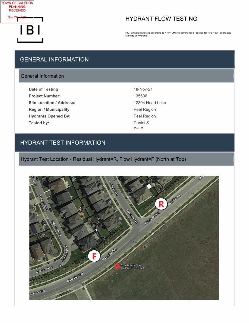
HYDRANT FLOW TESTING
NOTE:Hydrants tested according to NFPA 291: Recommended Practice for Fire Flow Testing and Marking of Hydrants
GENERAL INFORMATION
General Information
Date of Testing 18-Nov-21
Project Number: 135636
Site Location / Address: 12304 Heart Lake
Region / Municipality Peel Region
Hydrants Opened By: Peel Region
Tested by: Daniel S Val V
HYDRANT TEST INFORMATION
Hydrant Test Location - Residual Hydrant=R, Flow Hydrant=F (North at Top)
TOWN OF CALEDONPLANNINGRECEIVED
Nov 26, 2021

2021-11-18 PAGE 2 OF 2
Test Data
Time of Test 8:14 AM
Pipe Size (mm) 300
Flow Hydrant Test Location (description) 101 Abbotside Way and Learmont Ave
Residual Hydrant Test Location (description) First hydrant east of 101 Abbotside Way and Learmont Ave
Static Pressure(PSIG) 81
Q1 Test Data (1 Orifice)
# OUTLETS ORIFICE SIZE(IN) PITOT PRESSURE(PSIG)
FLOW(USGPM) RESIDUAL PRESSURE(PSIG)
1 2.5 45 1126 74
QT Test Data (2 Orifices)
# OUTLETS ORIFICE SIZE(IN) PITOT PRESSURE(PSIG)
FLOW(USGPM) RESIDUAL PRESSURE(PSIG)
2 2.5 30 1838 73
Calculations
FORMULA: Q= 29.83 cd^2√p....................................Where: c- coefficient of discharge (1 in smooth pipe) ............................................................................................................................ d- pipe diameter (inches) .............................................................................................................................p- pitot reading (psig)
Q1 - 1 Orifice(s) Q1= (29.83)(0.9)(2.5)^2 √45=1126
QT - 2 Orifice(s) QT= 2(29.83)(0.9)(2.5)^2 √30=1838
Static Pressure(PSIG) 81
Test Results - Plot
TOWN OF CALEDONPLANNINGRECEIVED
Nov 26, 2021

12304 Heart Lake Road DOMESTIC WATER DEMAND CALCULATIONSIndustrial Development
Project Name: 12304 Heart Lake RoadProject Number: 135636
Date: November 12, 2021Designed By: Jason Jenkins, P.Eng., P.E.
1. ADD = 300 L/cap/day per Region of Peel standards2. Population Densities per Region of Peel standards Land Use Peak Hour Maximum Day3. Peaking factors per Region of Peel standards ICI 3.00 1.40
(ADDxP.F.) (ADDxP.F.) Units / Area Density Population ADD (L/s) PHD (L/s) MDD (L/s)
Building 1 9.95 ha 70 pp/ha 697 2.4 7.3 3.4Totals 697 2.4 7.3 3.4
Peaking Factors
Page 1 of 3
TOWN OF CALEDONPLANNINGRECEIVED
Nov 26, 2021

12304 Heart Lake Road FIRE FLOW DEMAND CALCULATIONSIndustrial Development
Project Name: 12304 Heart Lake RoadProject Number: 135636
Date: November 12, 2021Designed By: Jason Jenkins, P.Eng., P.E.
Based on the Water Supply for Public Fire Protecetion Manual, 1999 by the Fire Underwriters Survey
Construction Coefficient = 0.6 F = required fire flow (L/min)Largest Floor Area = 48,610 m2 C = coefficient related to type of construction
Floor Above = 0 m2 0.6 for fire resistive (fully protected, 3-hr ratings)Floor Below = 0 m2 0.8 for non combustable (i.e. unprotected metal buildings)
Area = 48,610 m2 1.0 for ordinary constructionFire Flow (F) = 29,000 L/min 1.5 for wood frame construction
A = total floor area excluding basements 50% below grade* If vertical openings are inadequately protected, consider two largest two largest adjoining floors plus 50% of each of any floors above up to eight floors.* If vertical openings are adequately protected (one hour rating), consider largest floor area + 25% of two immediately floors.
Occupancy Adjustment = -0.15 Non-Combust. -25% Free Burning 15%F1 = Fire Flow x Adjustment = 24,650 L/min Limited Comb. -15% Rapid Burning 25%
Combustable No change
Sprinkler Adjustment = 50% Automatic Sprinklers (monitored) -50%F2 = F1 x Adjustment = 12,325 L/min Adequatly Designed System -30%
Proximity Adjustment = 15% (max 75%) Separation Adjustment Separation AdjustmentF3 = F1 x Factor = 3,698 L/min 0m to 3m 25% 20.1m to 30m 10%
3.1m to 10m 20% 30.1m to 45m 5%10.1m to 20m 15%
F1 = 24,650 L/min- F2 = 12,325 L/min
+ F3 = 3,698 L/minFire Flow = 16,000 L/min Checks:Fire Flow = 266.7 L/s
Total Demand (Fire Flow + MDD) = 270.1 L/sFire Flow greater than 2000 L/minFire Flow less than 45,000 L/min
Step 1: Calculate Fire Flow (based on area)
Step 2: Adjustment for Building Occupancy (shall not be less than 2000 L/s)
Step 3: Adjust F1 for Fire Supression System
Step 4: Adjust F1 for Exposure / Proximity (shall not exceed 75%)
Step 5: Calculate Adjusted Fire Flow (shall not be less than 2000 L/min or greater than 45,000 L/min)
F = 220C A
Fire Flow = F1 − F2 + F3
Page 2 of 3
TOWN OF CALEDONPLANNINGRECEIVED
Nov 26, 2021

12304 Heart Lake Road HEAD LOSS CALCULATIONSIndustrial Development
Project Name: 12304 Heart Lake Road
Project Number: 135636
Date: November 12, 2021
Designed By: Jason Jenkins, P.Eng., P.E.
Flow Flow Flow Pressure Pressure(gpm) (L/s) (L/min) (psi) (kPa)
0 0.0 0 81 5581,126 71.0 4,262 74 5101,838 116.0 6,958 73 503
Source: Walski, Thomas M. (2007): Advanced Water Distribution Modeling and Management
where: QR = flow predicted at desired residual pressureQF = total flow measured during testhr = pressure drop to desired residual pressurehf = pressure drop to measured during test
Flow Flow Flow(gpm) (L/s) (L/min) (psi) (kPa)115 7.3 435 81 558
4,281 270.1 16,203 43 295 Projecting Curve to Fire Flow
3,579 225.8 13,547 54 369 Projecting Curve to 20 psi(1 gal = 3.785 L) (Goal Seek)
where: hL = Pressure Drop (m)L = Length of Service (m)Q = Flow Rate (m3/s)D = Pipe Diameter (m)C = Roughness Coefficient
Domestic Fire ServiceL= 50.0 m L= 70.0 m
Q= 0.007 m3/s Q= 0.270 m3/s
D= 150 mm D= 300 mm
C= 100 C= 120hL= 0.1 m hL= 3.3 m
hL= 4.7 in hL= 130.1 in
hL= 0.2 psi hL= 4.7 psi
hL= 1.2 kPa hL= 32.4 kPa
Flow Flow Flow(gpm) (L/s) (L/min) (psi) (kPa)
Domestic 115 7.3 435 81 557Fire 4,281 270.1 16,203 38 262
Residual Pressure (DOMESTIC) at building is greater than 40 psi (275 kPa).
Residual Pressure (FIRE) at building is greater than 20 psi (140 kPa).
Hydrant Flow Test - Abbotside Way
Residual Pressure at Main
Residual Pressure @ Main
Residual Pressure at Building
Residual Pressure @ Bldg.
Domestic (PHD)Fire Flow (Fire+MDD)
To 20 psi
PHD Conditions Fire + MDD Conditions
QR = QF ×ℎ𝑟𝑟0.54
ℎ𝑓𝑓0.54
hL =10.675 ∗ L ∗ Q1.85
C1.85 ∗ D4.8655
Page 3 of 3
TOWN OF CALEDONPLANNINGRECEIVED
Nov 26, 2021