
Servicing - CORE
437
IASA-CR-1971SI NASw-4435 MOOSE .."/d- /.3 - _; x__ j i5/: Manned On-Orbit Equipment Servicing O o_ eD tt_ 0 0 University of Maryland College Park Department of Aerospace Engineering ENAE 412 Design Project Spring 1993 Professor David Akin, Sc.D. ,-.q tf_ or, I ad I Z Z_ _Z d_'u", Z cu_ Z:F o 0 0 f_ L9 0 | https://ntrs.nasa.gov/search.jsp?R=19950006377 2020-06-16T09:55:48+00:00Z
-
Upload
khangminh22 -
Category
Documents
-
view
4 -
download
0
Transcript of Servicing - CORE

IASA-CR-1971SINASw-4435
MOOSE
.."/d-/.3 - _;x__
j i5/:
Manned On-Orbit
EquipmentServicing
Oo_
eD
tt_00
University of Maryland College ParkDepartment of Aerospace Engineering
ENAE 412 Design ProjectSpring 1993
Professor David Akin, Sc.D.
,-.qtf_
or,
Iad
I
Z
Z_
_Z
d_' u",
Z
cu_
Z:F
o
00
f_L9
0
|
https://ntrs.nasa.gov/search.jsp?R=19950006377 2020-06-16T09:55:48+00:00Z

Abstract
The ability to service satellites has thus far been limited to Low Earth Orbit
(LEO) platforms within reach of the Space Shuttle. Other orbits, such as
Geosynchronous Orbits (GEO) containing high-value spacecraft have, thus
far, not been attainable by a servicing vehicle. The useful life of a satellite can
be extended by replacing spent propellant and damaged Orbital Replacement
Units (ORUs), forestalling the need for eventual replacement. This growing
need for satellite on-orbit servicing can be met by the Manned On-Orbit
Servicing Equipment (MOOSE). Missions requiring orbit transfer capability,
precision manipulation and maneuvering, and man-in-the-loop control can
be accomplished using MOOSE. MOOSE is a flexible, reusable, single
operator, aerobraking spacecraft designed to refuel, repair, and service orbiting
spacecraft. MOOSE will be deployed from Space Station Freedom, (SSF),
where it will be stored, resupplied, and refurbished.
ii

Acknowledgements
This document was edited by J. Budinoff, N. Leontsinis, J. Lane, and
R. Singh. The MOOSE design team (the undergraduates who
researched and contributed to this paper) consisted of the following
additional 24 students: K. Angelone, C. Boswell, I. Chamberlain, M.
Concha, M. Corrodo, O. Custodio, S. Drennan, N. Eberly, B. Flaherty, D.
Grove, C. Lash, D. Mohr, E. Pearson, T. Rivenbark, D. Roderick, S. Ruehl,
J. Sabean, A. Seaman, T. Septoff, T. Sheridan, C. Smith, M. Solfrank, G.
Tansill, A. Zumbrum. The MOOSE name is credited to B. Flaherty.
The entire MOOSE design team appreciates Dr. Dave Akin, whose
guidence and knowledge proved invaluable to this project. Tharen
Rice, the teaching assitant, who provided his experience and
constructive criticism which helped to shape our efforts. Dr. Mark
Lewis, his sharp criticisms and welcome praise helped focus our
analysis. We also thank Dr. Russ Howard and Dr. Craig Carrigan for
sharing their insight and know-how. Lastly we would like to thank
the USRA for their continued support.
iii


Executive Summary
1.0 Systems Integration1.1 Introduction
1.2 Trajectory Analysis
1.3 Costing
1.4 Mass Properties
2.0 Manipulator/Grappler System2.1 Introduction
2.2 Telerobotic Manipulator Arm (TMA)
2.3 Telorobotic Grappling Arm (TGA)
2.4 Manual Manipulation System2.5 Control Station
3.0 Crew Cabin
3.1 Introduction
3.2 Ergonomic Requirements
3.3 Cabin Components
3.4 Life Support Systems
3.5 Radiation Shielding
3.6 Fire Suppression
3.7 Food System
3.8 Hygiene and Waste Management System
3.9 Structural Analysis of Crew Cabin
4.0 Aerobrake and Structure
4.1 Introduction
4.2 Shape Selection
4.3 Trajectory Analysis
4.4 Aerodynamic Loads4.5 Aerobrake Control
4.6 Materials Selection
4.7 Design Configuration4.8 Mass Total
4.9 Assembly
4.10 Main Spinal Truss
4.11 Thermal Protection System
5.0 Propulsion
5.1 Introduction to the MOOSE Propulsion Sys5.2 Mixture Ratio
5.3 Thrust Chamber
5.4 Injectors
5.5 Ignition Systems
5.6 Nozzle Design
1-1
1-1
1-8
1-15
1-20
2-1
2-1
2-3
2-10
2-14
2-16
3-1
3-1
3-1
3-6
3-13
3-20
3-22
3-23
3-25
3-27
4-1
4-1
4-1
4-2
4-8
4-9
4-11
4-11
4-12
4-13
4-15
4-18
5-1
5-1
5-5
5-6
5-10
5-11
5-11
iv


5.7 Turbopump Feed System/Plumbing 5-14
5.8 Thrust Vectoring Control 5-17
5.9 Main Propulsion Malfunctions 5-17
5.10 Main Propulsion Tanks 5-18
5.11 Introduction to the Reaction Control System 5-21
6.0 Avionics 6-1
6.1 Introduction 6-1
6.2 Attitude Determination and Control System 6-1
6.3 Navigation and Tracking 6-76.4 Communications 6-13
6.5 Data Acquisition and Storage Systems 6-19
6.6 Computation and Data Management System 6-24
7.0 Power
7.1 Introduction 7-1
7.2 Requirements 7-1
7.3 Primary Power Sources 7-2
7.4 Backup Power System 7-2
8.0 Operations 8-1
8.1 Purpose 8-1
8.2 MOOSE Program 8-3
8.3 Operations Support Facilities 8-16
8.4 MOOSE Flight Operational Concepts 8-26
8.5 Mission Planning 8-28
8.6 Real Time Support 8-37
8.7 Premission Training 8-45
8.8 Space Station Operations 8-49
8.9 Satellite Proximity Operations 8-55
8.10 Satellite Servicing 8-60
8.11 Vehicle Servicing Facility (VSF) 8-668.12 MOOSE Mission Model 8-75
Appendices
A1.1.5
A1.2
A1.2.6
A1.3.1
A1.3.2
Delta V Vehicle Mass Trade Study
Delta V Comparisons
Phasing Orbit Sample Calculation
Cost Model Summary
Cost Discounting Analysis
A2.1
A2.2
A2.3
A2.4
Robotic Terminology
Jointed Manipulator Models
TMA AppendixSimulation Code
V

A2.5 Other Trade Studies
A3.1
A3.2
A3.3
A3.4
A3.5
A4.1
A4.2
A4.3
A5.1
A5.2
A5.3
A5.4
A5.5
A5.6
A5.7
A5.8
A5.9
A5.10
A5.11
A5.12
A5.13
A5.14
A6.1
A6.2
A6.3
A6.4
A8.1
A8.2
A8.3
A8.4
Carbon Dioxide Removal
Radiation Environment
Smoke Detector Trade Study
Fire Extinguisher Trade Study
Waste Management Options
Trajectory Program
Aerobrake Structural Analysis
Torque Spreadsheet
Choosing the Optimum Propulsion System
Cooling Schemes
Conical vs Bell Shaped NozzlesResults of the Method of Characteristics
Engine Materials
Representative LOX/LH2 Engines
Structural Analysis
Slew Torque Calculations
Propellant Mass Calculations
Total Impulse & Mass Calculations for Primary RCS Thrusters
Total Impulse & Mass Calculations for Secondary RCS Thrusters
Hydrazine Tank Volume Calculations
Spider Truss Analysis
Helium Tank Material and Mass Analysis
ADCS
Navigation and TrackingCommunications
CDMS
Acronyms
Example Final Approach
Typical ORU's
Typical Consumables
References
vi


MOOSE
Manned On-Orbit Servicing Equipment
University of Maryland, College ParkDepartment of Aerospace Engineering
College Park, Maryland
Professor David L. Akin, Sc.D.Tharen Rice, Teaching Assistant
Jason Budinoff, J. Corde Lane, Nicole Leontsinis, Ram C. Singh,and the MOOSE Design Team
ABSTRACT
The ability to service satellites has thus far been limited toLow Earth Orbit (LEO) platforms within reach of theSpace Shuttle. Other orbits, such as GeosynchronousOrbits (GEO) containing high-value spacecraft have, thusfar, not been reachable by a sere'icing vehicle. The usefullife of a satellite can be extended by rep}acing spentpropellant and damaged Orbital Replacement Units(ORUs), forestalling the need for eventual replacement.This growing need [or satelbte on-orbit servicing can bemet by the Manned On-Orbit Servicing Equipment(MOOSE). Missions requiring orbit transfer capability,precision manipulation and maneuvering, and man-in-the-loop control can De accomplished using MOOSE. MOOSEis a flexible, reusable, single operator, aerobrakingspacecraft designed to refuel, repair, and service orbitingspacecraft. MCRDSE will be deployed from Space Station
Freedom, (SSF), where it will be stored, resupplied, andrefurbished.
INTRODUCTION
MOOSE Description
The MOOSE spacecraft is an orbiting vehicle capable ofsendint_ an astronaut on three day satellite servicingmission_ to GEO or LEO and back to _SF. The astronaut is
housed in a "shirt-sleeve" environment, Extravehicular
Activities (EVAs) are not permitted from the MOOSE, sincethe vehicle is a single-person vessel.
In order to conduct the servicing tasks, MOOSE isequipped with a _ven degree of freedom (DOF) TeleroboticManipulator Arm (TMA), a four DOF Telerobotic
Grappling Arm (TGA), and a Manual ManipulationSystem (MMS). MOOSE will emplo) a 9m reusableaerobrake in order to return rendezvous with SSF fromGEO.
The MOOSE vehicle can be separated into two distinctparts. The first is the MOOSE Manned Module (MMM),shown in Figure 1 (top). It consists of the crew cabin, theReaction Control System (RCSI, spider truss, and theManipulator/GraEp'ler System (Man/GrapL The secondpart is the MOC___E Propulsion Module (MPM), shown inFigure 10:,ottom) It c_nsists of the aer_brake, main spinal
The MOOSE flight vehicle operates in 2 modes. The first isthe primary operational configuration for servicingmissinns to iGEO It entails using the entire flight vehicle,
consistingof MI'U and the MMM fully fueh, d The secondis the "cab-only" mode, in which the MMM flight vehicleseparates from the MPU This configuration is used toconduct se."vicmg mis.,-ions in LEO, or in close proximity toSSF, and enables MOOSE to be more manuuverable andcost-effective
F_, ,.2
_=i._&,:-_>>-,_'_v:_2,_ _._R_i l: l' " ,_...L2'_,,'-"" .-'_ "--:7'_
rigu,-,_ 1 K'k:M (tc,;-.',a d MPM (bp_om}
MOOSLE subsystems are designed as O]<Us which can bechanced out'via the SSF P,emote Manipulator System
(IxMS.. All s_gn'41cant systems .are configured to mdkeaccess, :¢st, andcEange-out as simple as possible.
SSF-Based Operations
MOO.E operation, increa.e the frequencx of S_F• 2, ,,departi.,_g/arrivJng spacecraft. I ropel)ant Ma'_wuvering
Vehicles (PMVs), shutt}es, and MOOSE will be utilizingSSF airspace, possibly simultaneously. A SSF trafficmana_gement scheme has been developed based upon the
Johnson Space Center (JSC) Orbital Maneuvering Vehicleplan fc: SSF termi:_al control ;,one management.
O_ _ QUALITY

Dedicated MOOSE support personnel on-station will beminimal. MOOSE maintenance, check-out, andrefurbishment tasks will be as automated aspossible.Dedicated Inter-Vehicular Activities/Extra-Vehicular
Activities (IVA/EVA) would be performed by theavailable crew as needed.
A second crew member is required, in addition to theastronaut operating the MOOSE, to operate the SSF RMSduring berthing andde-berthing operations.
Expendable Launch Vehicle (ELV) Operations
ELV operations are essential to the MOOSE mission•Regular propellant delivery must be maintained ifflexibility is desired. PMVs would be delivered to SSFfrom their respective launch sites.
VEHICLE OVERVIEW
In its standard configuration (MPU mated to the F.'LMM),the MOOSE vehicle weighs 3067 kg (dry) and 14481 kg(wet). This configuration is the maximum weigh! for athree-day GEO servicing mission. For LEO missions, theMPU can be left at Freedom, creating a vehicle that wouldweigh a maximum of 1235 kg (dry) and 1980 kg (wet).
MOOSE is capable of car_,in:¢ 800 kg of payload to orbits
inclined up to 70" at altitudes from 18_ km to 40,000 kin.Consumables are provided for a nominal 3-day mission,with contingenQ, mission duration of 10 day,s.
COSTING OVERVIEW
Devclep CostRDT&E S2,374.70 M93
Firs! Unit $20390 M93
Flighl Unit $203 90 M93
Developrn_;t Optralions CostsASE RDT&E $1,100 M93
ELV Support $1,182 M93
Ground Support $375 M93
Aqz_s_0,; Operalions Cost
3 sorties/year $294 M93
6 sorties/year $432 M93
13 sorties/year S7g0 M93
Pre_ram Cost @ ]OC
$5,439.50 M_3
,'drd:_,: C,'perahoT;s Cost�year5432 M93
Table 1 Overview of proiecled costs
NAVIGATION AND TRACKING
Orbit and Attitude Determination
Orbit information must be accurate enough at
geostationarx, orbit to bring the vehicle within trackingdistance, c,f the target. The v,,orkingrange of the selectedrendezvous system will be 4.5 nmi. "fhe error in position at
GEO added to the error in the target*s known position mustthere/ore be less then this range. Using a .75 safety factor,the requirement for GEO position determination accuracy',rill therefore be 6 km.
At LEO and below, the main positioning requirement willbe determined bv the aerobraking maneuver. Non-inertialnavJga_ic, n sys{ems will be blacked out during this
maneuver, so inertial guidance will be need to be
accurately calibrated before the maneuver. From GEO, anaccuracy of 2 km will be required for the aerobrakingwindow. On approach to the maneuver, the window willbe smaller, requiring an accuracy, of 100 m for necessarycourse adjustmen ts.
Inertial Measurement Units (IMUs)
Two IMUs will be used on MOOSE, and will consist of
sensors that measure both rotational motion (usingroscopes) and translation motion (using accelerometers).
trapdown units will be used instead of gimbaledplatforms because they have less mechanical complexitiesand mass, while maintaining accuracy comparable to thatof gimbaled systems.
The Inertial Measurement Unit (IMU) was chosen as thedPrimary navigation system for its high accuracy. The main
rawback oflMUs are the time degradation that they,undergo. To keep their accuracy, positron and orientationinformation must be updated before the data is no longeruseful. Immediate updates would be required immediately
after large AV burns.
Global Positioning System (GPS)
GPS provides 25 m accuracy at LEO but it is not designedto work above 8000 nm, ahltude. This system will be usedto meet the 100 m aerobrake accuracy requirement. GPSwill be used in LEO for calibration of the]MUs. All LEO
and GEO transfer orbits will be calculated using GPS andKalman filtering software. A GI_ update occurs at the rateof 2 updates per second. GPS information is used to verifythe aerobraking maneuver approach orbit.--updates arefast enough to allow for mid--course corrections.
Microcosm Autonomous Navigation System (MANS)
This system provides 600m to 1.5 km accuracy using 2sensors. This system is necessary.' for long term navigahonin GEO, and to meet the 2 km aerobrake window
requirement. It can provide orientation updates to anaccuracy, of 0.01 degrees, using the sun as a reference. For11.4% of the time in GEO, the sun will be blocked out, but
the horizon sensors >,'ill still be functional, prov!ding anaccuracy, of 0.1' to 0.25'. For 4.6% of the trine, noorientation updates are possible. For the first 20 hoursafter GPS updates are lost, the ]MUs are more reliable than
MANS. After this point, MANS must begin linearnavigation updates at Its returning frequency' of 0.5 Hz.
Star Trackers
This system can provide updates to an accuracy of 001when {he sun's glare d_es not affect the sensor. Although it
can be used at other points, the star trackers will definitelybe able to be used during the ] 6.'-,, MANS blackout/parti,{]blackout time. Star tracke:*s are.useful in increasing theaccuracy of the altitude measurement, and for determiningthe angle and angle rate to a target for rendezvous
pu rpo.,,es.
OMV Rendezvous Radar
Although the Orbital Maneuvering Vehicle project hasbeen canceled, its rendezvous radar has been fullydesigned. This system was specifically designed to assistthe rendezvous tasks that MOG_ZE is re'quiredto do. It has
a range of 4.5 :_mi, and an accuracv of better then 20 ft, or<2"/,, of the ran,ae. It also provides "a range rate accuracy ofgreater than U.'i ft/sec, or 2% of the range rate.
ORIGIIN.AJ.. PAG'_ f_
OF _ QU_i'rY

CONTROL MOMENT GYROSCOPES
External torques, such as those produced by solarradiation and gravity gradients, and internal torques, suchas that produce by positional uncertainty of the center ofgravity, must be compensated for. A trade study was donecomparing the mass of the fuel required to do orientationadjustment for a typical three day mission versus the massof the control moirient gyroscopes (CMGs) required to dothe same job. The required fuel mass was 150 kgfor thecold gas thrusters and 242 kg of hydrazine for the RCS.This compares with a CMG mass of 76 kg.
The MOOSE vehicle was desig_n_ed to use double-gimbaledCMGs for three-axis control. The CMGs are located nearthe center of gravity for maximumperformance. ThreeCMGs are used for redundancy considerations--should onefail, the other two will be able to maintain three-axis
control. The primary RCS can be used to desaturate theCMG wheels. The impulse torques caused by gravitygradients, solar pressure, and aerodynamic effects are wellbelow the impulse torques that the moment gyros weredesigned for.
The model used to design the wheels was a thin-rim, high-
speed flywheel. It was found that AISI 4340 (normalizedat 1600F, quenched in oil from 1525"F) would give thesmallest wheel radius and the maximum performance. Forhigh-speed bearings, (>3000 rpm), a close, el loop oil systemshouldbe used to give an active flow through lubricationsystem which would enhance the bearing life bycontinuously supplying additional oil to the spinning ballbearing at a controllable rate. A DC brushless motor willbe used for its high torqueing capability. A tachometer willbe used to monitor the wheel speed.
REACTION CONTROL SYSTEM
The manned module must be able to maneuver around and
approach the target .satellite from any angle to capture andrepair it. The reaction control system is comprised of
primary and secondary thrust chambers. The need toensure a contamination-tree environment about the SSF andsatellite hardware drove the two-system design.
Primary RCS
The primary thrusters are utilized for attitude control,course corrections, orienting the MOOSE vehicle forproper guidance & navigation sensing and aerobrake-maneuver positioning, desaturating the control momentgyros, and collision avoidance.
The primary thrust chambers utilize monopropellznt liquidanhydrous hydrazine and operate in pressure blow-downmode with helium as the pressurant gas. The hydrazinesystem does not require an oxidizer for combustion, itspontaneously decomposes as it flows over the Shell 405chtalyst bed and produces hot gases which are expelledthrough the nozzle. The selected level of ammoniadissociation is 0.6 and the resulting performance level, lsp,is 240 seconds.
A total of 24 520 N (100 lbf) hydrazine thrusters will beutilized. Four thrust chambers will be on the lower truss
struts, with one on each strut. Twenty thrust chamberswill be on the spider truss booms with five on each boom.The total monopropellant mass is 512 kg, and the total massof the 24 hydrazine thrusters is 44.74 kg. The figure below
is a schematic of a typical hydrazine thrusterconfiguration.
OT: l_e?._ Qe.Jt_i_l,'Py
0._27m
In,or
....\
_mdem_t
pr_t_ves_,.ml tb
&48514rn
Figure 2 Hydrazine Thruster Configuration
RCS Spider Truss
The RCS Spider truss serves as a platform for the MOOSERCS. The boom extends for only 2.6 m from the center lineof the MOOSE, to protect the nozzles during theaerobraking maneuver. It houses the RCS tanks within itsmembers and acts as a boom for the reaction control
nozzles to ensure, their operation, as far away from the c.g.of the MOOSE vehicle as posstble. The trusses and theavionics box are an integrated structure which attaches tothe bottom of the MOOSE crew cabin.
The material selected for the truss is a high-strength
graphite/epoxy with a 45" fiber orientation to ensure thecomposites strength in bending. The resultingconfiguration for the spider truss consists of two differentcross sections. The inner and outer cross members bothhave circular cross sections of outer radius 1.25 cm and
inner radius of 1.0 cm. The remaining spider truss membershave circular cross sections of outer radius 7 mm and inner
radius 5 ram. The mass per spider truss is 9.36 kg, therefore,the total mass for all four spider trusses is 37.5 kg.
Primary RCS Tanks
Two tanks are necessary to store the hydrazinemonopropellant and helium gas pressurant. The blow-down ratio is 4.2 with a beginning of life tank pressure of420 psi and an end of life pressure of 100 psi. The total
volume for hydrazine propellant is 0.5005 m 3 and the
helium pressurant volume is 0.1564m _. The radius of eachof the tanks is 0.428m and the material is A1 ] 10041 whichis resistant to the corrosive effects of hvdrazine.
Hydrazine freezes at 273K so line heaters were used to
ensure the operability of the thrusters
Secondary RCS
Due to the sensitivity of the SSF and satellite hardware tocontamination from thruster exhaust products, a heliumcold gas thruster system is utilized for all GEO satellite-servicing operations and for separation and dockingmaneuvers The mass of the helium for the secondary,
thrusters is 223 kg. The total mass of the 40 thrusters is3.4 kg The thrusters on the lower truss struts are grouped

in threes with one grouping per strut. Seven cold gasthrusters were located oh eachboom of the spider truss.These thrusters produces 20 lbf (89 N) at a pressure-at-thrust of 1000 psL The area expansion ratio is 25:1.
Arl/latureValveP0pl_
Solzid Core
Valve Seat _
Expansion Nozzle ?
Valve Body Solenoid Coil Gap
Figure 3 Single Seat Cold Gas Thruster
Secondary RCS Tanks
The helium cold gas for the secondary thrusters will bestored in four (4) Ti 8-1-1 tanks at a tank thickness of 1.66cm and a mass per tank of 55.75 kg. The tank pressure is
41 AE6 N/m 2.
MAIN PROPULSION SYSTEM
The main propulsion system of MOOSE will perform fourburns on a typical mission. These burns include GEOtransfer iniection, GEO circularization, LEO transferinjection, and LEO circularization after the aerobrakemaneuver.
Propellant Transport Cost vs. Structural Mass
L,
c:¢
m
7
Z
2.-
1400 .... ............................,......
Isp - 458¢
_,)e..............-...................._......i..............................
_io-.........!.............f-.........................._..............
: c : ,_ i
400 ..............7 .............":......i_......"..............._ ......" .......
. _ • Jl x: £3., .... ,..... i_.......... 4 ......
,.L, | I _o
0 1000 2000 3000 4000 5oo0
Structural Mass (kg)
Figure 4 Propellant Transport Costs vs. Structural Mass
The main propulsion system utilizes cryogenic liquidhydrogen and liquid oxygen as the fuel and oxidizerrespectively. To achieve cost efficiency in propellant
transport cost so the customer price tag does not exceed 100$Million, the performance level, Isp, must be 450 seconds.The figure below demonstrates the relationship betweencost and performance level. The mixture ratio is optimizedat 7:1 which maximizes the Isp, and assures completecombustion of the liquid oxygen while not running toohydrogen rich, where some of the hydrogen does notcombust.
The dimensions of the combustion chamber are as follows:chamber diameter is 0.28| m, chamber volume is 0.022 m 3,and chamber length is 0.355 m.
Injector Design
The injector is designed to deliver the propellants to thecombustion chamber and to sufficiently mix and atomize thepropellants to form a homogeneous fuel-oxidizer mixture.
The injection system selected is a coaxial non-impingingconfiguration which is the most common forOxygen/Hydrogen enl_ines, including the SSME, andprovides good combushon stability. Low velocity liquidoxygen (LOX) is fed through a tube which-is surrounded byhigh velocity gaseous hydrogen (GH2). The GH2, alreadywarmed from the regenerative cooling cycle, warms theliquid oxygen in the tube and vaporizes it. The gaseoushydrogen and oxygen then readily mix in the combustionchamber.
Ignition System
The ignition system is of critical concern for it must ensurerapid ignition of the propellant mixture and equally rapidthrust increase to the designed rating.
A spark-torch igniter was selected for the ignition system.It is highly reliable, has multip]e restart capability (a mustfor MOOSE), and performs well at hiqh altitude. Thespark-torch igniter allows some propellant in, then
supplies a spark for ignition. The flame is then ducted tovarmus locations on the injector face to ignite the mainpropellant flow.
Nozzle Design
The ex ansion nozzle i_ de,qgned to take the hitghtemperature exhaust gas flow and expand it to allow thethermal energy of the flow to be transformed into kineticenergy, i.e. u_ful propulsive energy.
The MOOSE will use a bell shaped nozzle with an areaexpansion ratio of 40:1 at a design roach number of 4.22.
This expansion ratio relates to an exit area of 0.99 m _ anda throat area of 0.024g m 2.
The large heat flux to the n¢_zzle walls from the combustionproducts requires a c_}ing process that will preserve fl_enozzle contour, its materialintegrity, and allow for anindefinite firing duration. A regenerative cooling systemwas selected over nozzle-material ablation since it
satisfies the above mentioned requirements and the vehiclehas available coolant, the LH2 fuel. This ctyoling method isrelatively lightweight since additional on-board coolingsubsystems are not required and the desire to achieve amaximum Isp, to successfully perform the MOOSE missionrequirements, is achieved through augmenting the energycontent in the combustion chamber by utilizing the thermalenergy picked up by the LH2 in c(x'_ling the nozzle. Thehigh heat flux capacity,, necessary for LOX/LH2

combustion, is also accounted for by the regenerativecooling system.
Turbopump Feed System / Plumbing
The pump system selected is an expander cycle turbopumpfeed system. An Auxiliary Power Unit (APU) is used toinitiate the propellant flow to the combustion chamber.The hydrogen fuel exiting the nozzle cooling-jacket willdrive both the oxidizer and fuel turbines wh{ch drive the
fuel and oxidizer pumps. Once initiated, the propellantpumping process is self perpetuating and is sustained by theturbine generating 82.7 kW of power to drive the pumps at
the required pressure of 2.66x10⁶N/m 2.
Figu_ S Main Propulsion System Configuration
Thrust Vectoring Control
Thrust vectoring will be controlled by the RCS for pitch,yaw and roll motions of the MOOSE vehicle The thrustersare located at the ends of each boom of the spider truss andon each of the lower truss struts. The location of the
thrusters will provide three axis stability.
Main Propulsion Malfunctions
The MOOSE can survive a main propulsion systemmalfunction if it occurs either after the first or after the
third main engine burn. In the event that a malfunctionoccurs after the first main engine burn, the astronaut willremain in the elliptical Hohmann transfer orbit until thevehicle returns to the SSF. It will take ten and a half hoursto return to SSF. The astronaut can survive this since the
MOOSE is designed and equipped for a fl_ree day mission.If the malfunction occurs after the third burn for LEO
injection, the RCS will handle the necessary maneuvers toreturn the astronat, safely to the SSF.
Malfunctions occurring after the GEO circularization andprior to the LEO transfer in}ection bums will require theastronaut to wait for a rescue vehicle in order to return to
the space station.
Main Propulsion Tanks
The main propellant tanks will be launched empty fromEarth using the NASA Space Shuttle launch p]atform andwill be integrated with the MOOSE system on orbit atSpace Station Freedom. For the launch from Earth, thetanks will be pressurized to stiffen the structure against
loads resulting from the launch. The tank walls willconsist of Al-lI00 at thicknesses of 3.5 mm and 3.0 mm forthe liquid hydrogen and liquid oxygen tanks respectively,and corresponding tank masses of 178 kg and 99 kg.
The tanks will be integrated to the central support truss bya 10 cmx 5 cm, 1.1 kg Al-1100 disk threaded around itssurface area and located at the top of each of the tanks.The bottom of the tanks rest on the aerobrake supportarches and will be wrapped with a thermal protection foilto withstand the heat transfer from the nozzle and
aerobrake maneuver and allow the Al-ll00 alloy tomaintain its actual yield strength. The final mass total forthe liquid hydrogen tanks is 179 kg and 100 kg for theliquid oxygen tanks.
AEROBRAKE
///_ 90.0 °
/---" V- Z----\
i_ 9.00 m _1
Figure 6 Aerobrake Structure
The design of MOOSE included the aerobrake used topartially, reenter .the atmosphere, and use drag. forces, tomodify its orbit instead of fuel, thus reducmgmass. Aspherical shaj:)e made of an aluminum honeycomb provideda lightweight thermally resistant structure. Ceramicthermal protection tiles were placed on the above structure.The design allowed for assembly and maintenance to easilybe performed.
Trajectory
A two shallow pass trajectory was chosen instead of asingle deep pass. Although the chosen trajectory, speed wasMach 34, because of a shallow pass of 80 km minimumaltitude, the largest aerodynamic forces on the aerobrake
were almost negligible, only a few hundred Pascals. The gforces on the brake during the t_ o pass maneuver were less
than the propulsive forces during an orbital bum, maximumof 1.5 g_.
MAlN SPINAL TRUSS
This structure carried up to 2g loads. All majorcomponents the cabin, spider truss, fuel tanks, propulsionsystem, and aerobrake were connected to the spinal truss."(he titanium longitudinal beams were welded to hardpoinb on fllree spinal rings. These rings integrated theaerobrake, cabin, and fuel tanks.
MANIPULATOR/GRAPPLER SYSTEM
Introduction
The Manipulator/Grappler System is essential to theexecution of MOOSE's duties as an on-orbit servicer. One
of the driving requirements for MOOSE is that theastronaut must not have to do an EVA during the repair

process. To accomplish this, it is necessary to equip thevehicle with a manipulation system that he/she can controlfrom within the spacecraft. The possible components of theMan/Grap System are: a Telerobotic Mampulator Arm(TMA), a Telerobotic Grappling Arm (TGA), and aManual Manipulation System (MMS).
Many possible combinations of these subsystems wereexamined. The primary design criteria were mass,flexibility, complexity, and development/production costs.The culmination of the design process was a system thatutilized all three subsystems.
/3
Figure 7 View of Cabin & Manipulator/Grappler System
The TGA is a four DOF arm, with various possible end-effectors. It is necessary to have a grappling arm tomaintain a fixed position and orientation, with respect tothe target, during repair operations. The TGA has threelinks. Link 0 and link1 are each 2 m long, while link 3 is 3m long. It was determined that the TGA should be able tosuccessfully maneuver a 6000 kg payload.
Spacecraft Subsystem Anomaly Number PercentTiming, Control, and Command 55 9.1Telemetry and Data Handling 112 19.1Power Supply _ 9.2Attitude Control 123 20.3Propulsion 26 4.3Environmental Control 16 2.6Structure 6 1.0Payload�Experiment 208 343
JOJ'AL 602 100%
Table 2 Survey of 602 Satellite Failures
Decree of Failure Number Percent
Negligible Effect 447 74 ?Small Effect 117 19.4
1/3 t(, 2/3 I.os- 32 53
2/3 to near total loss 5 1
"1oral Mission Loss 1 --
Table 3 Failurt.._' Effevt on Mission
Based on the data shown in Tables 2 and 3 above (Shockey1984), it was determined that a significant number ofsatellites (at least 25%) can be expected to has some loss ofattitude or navigational control Therefore, it would bedesirable for MOOSE to be able to grapple with andcontrol errant satellites, so long as the crew member is inminimal danger.
"assistant" to the astronaut, in that it can handle massiveloads, hold "handed-off" tools and equipment, retrieveORUs from storage, etc. By providing a variety of end-effectors, it can also be used to perform simple servicingtasks, such as on-orbit refueling. The TMA should be ableto handle 450 kg ORUs.
(al
y_-_- YS,X6 ¥o,YLZ2.Y3
Figure 8 Side and Top View of TMA Design
The MMS is basically astronaut space suit gloves that areattached to the outside of the vessel's cabin. The astronaut
has the benefit of being able to use his/her over 50 DOFarms and hands to conduct repairs, without having to leavethe cabin. While this option provides the ultimate in finedexterity, the limited workspace envelop necessitates theprovision of the TMA.
Prisma tic-vs-Revolute Joints
The main problem with using prismatic joints in space is thedifficulty involved with sealing the linear beari-ngs fromthe environment. Revolute joints are much easier to seal,
and have large workspaces, and low energy and torquerequirements, l.nspite of the added complexities of the
hardware and software, the jointed manipulator design hasmany benefits, are will from the basis of for the MOOSETMA and TGA.
Direct Drive-vs-Transmitted Drive
One of the main design drivers is that the vehicle systemshave low mass. To illustrate the mass relationships of
direct drive and transmitted arms, a rough cut annie, sis wasconducted, yielding the following data Substantialmass is_ved by using a tramsmitted drive arm design.
v
¢
40OO
3000
2OOO
lOOO
o
o.oo
ARM MASSES-VS-TIP ACCELERATION
payload mass=6OOOkg
link 3 fnas$=_
_ Arm MassG
........................... 7" -'- _"''T"
• I . I • I • I •
0,02 0.04 0.06 0.08 0,10
Tip Acceleration (ms's/s)
The TMA is a seven DOF arm, with interchangeable end- Figure 9 Arm Mass in a Direct Dr,re [k'_lgn vs Geared Dt_ign
effectors. The TMA is expected to function as an

A
3000
2000,
1000
ARM MASSES-VS-LINK MASSES
payloadmass=6OOOkgtip acceleratio_=O.CE,m/s/s
---sO---- ArmMassDD
Arm Mass G
0 - i - i - | - / - i -
0 2 4 6 8 10 12
Link 3 Mass (kg)
Figure 10 Arm Mass in a Direct Drive Design vs. Geared Design
Material Selection
A variety of materials with which to construct the armswere investigated. The final decision was to fabricate themain links of the TGA and TMA from Graphite/Epoxy,and the joints from Titanium (T16 A1-4 V). The majordriver in this selection was the thermal expansioncompatibility of the two materials, as well as their largerelative strength-to-weight ratios. The resistance tocorrosion of Graphite/Epoxy and Titanium was an addedbonus. The TMA will be subjected to highly unfavorableconditions during satellite fluid replenishment missions.
Uanua utamlxaat _'_
t at ioual Hanoi Cnntr_le_
Co_rnuni_ _n
.,, Hea(diet
___!_ 13" LCD Toud_ _eer
19 _ Man LQ:) SM_ok,_nent al C_rOI _ali_
l_n_a If_ Kr{boaO
Figure 11 Control Station Design
COMMUNICATIONS
MOOSE will not communicate with the space stationdirectly during most of the mission. Rather,communications will be routed to SSF from ground links.If SSF were used as the main space relay link, a significantportion t_ its communication system would have to bedevoted _o MOOSE data during missions. In addition,MOOSE and SSF can be in a relative position wherecommunications are blocked by the Earth for significant
eriods of time, requiring the use of relay satellites.
herefore, the communication system would have to be ableto communicate with earth from altitudes ranging from LEO(250 kin) to GEO (39.000 kin).
The uplink, from ground to MOOSE, would consist of voiceand command. Voice will be used to communicate with
astronaut. The ground computers can communicate withthe MOOSE computer system via the command link. In the
case of an emergency where ground control needs to controlthe vehicle, command communication will be essential.
The downlink will transmit voice, video, and telemetryinformation. Video information can be transmitted at anytime, but may be especially usehal during the repair phase ofa mission. The telemetry information is essentiallyhousekeeping data. Unlike other space vehicles, noexperiments will be conducted on board MOOSE, thereforetelemetry will not be as high as an STS, for instance.
Digital communications will be used instead of analog fortwo main reasons. One, digital signals are more reliablethen analog signals. Second, several digital signals can bemultiplexed onto one rf signal. For example, voice, video,and telemetry can be sent on one link.
Structure 6400 bpsLife Support 540 bps
bsMan/Grap 5080 k_psPropulsion 288Attitude Control 3380 bpsNavigation/Tracking 180 bpsReaction Control 2900. bps
Table 4 Communication Data Rate Requirements
The breakdown, according to main systems, of transmissionrate requirements are shown above. Note that most of thesystems will not need to transmit at the maximum rate listedabove for significant periods of time during the mission.To fulfill the above requirements, the Ku-band will be usedfor all transmissions.
At low altitudes, links will be established through TDRSSsatellites. Direct communication to the surface would not
be possible due to unacceptable blackout periods, and dueto the difficulty that is experienced in locking ontogroundstations from low altitude orbits. When MOOSE's
altitude is between 12,000 km and 39,000 kin, direct groundlinks will be used.
MOOSE requires 20 W transmitter to send voice, telemetry,and video from a GEO orbit. The communications systemwill consist of two transponders for redundancy. Theantennae are mounted on telescoping booms, so that theycan be pulled into the protective cone of the shield duringthe aerobraking maneuver.
COMPUTATION AND DATA MANAGEMENT
The Computation and Data Management System (CDMS)
has to provide sufficient processing power for all othersystems. Computations and data transfers must be fast andreliable.
Hardware
Distributed processor architectures offer attractivebenefits such as reliability, ease of growth, and parallelprocessing. It also allows for processors with variouscapabilities and requirements, it) work together with eas_..The physical distribution of hardware on MOOSE,combin(d with the natural delineations and relations of
tasks, makes distribution of processes and processors anatural elternative to a centrahzed system.
Most system processing will be invisible to other systems,
but soh_e operations (such as orbital tranfer and attitudecontrol, att]tude control and manipulator/grappler, etc.)will span several system. This would require thec<×)rdination of .come highly complex computing processes

overvarious processors. This would place a heavyburden on the lone crew member. The required level ofautomation is high, in order to reduce the workload for theastronaut.
Reliability has many facets, including probabilit 3 ofcorrect function over a period of time, probabilit_ ofrecovery (and recovery tim"es) from minor, localized ormajor systems breakdown, gracefulness of performancedegradation when full service is not possible, andassurance that critical calculations and tasks will be
computed in lahe face of unusual computing loads.
A carefully designed distributed processing system hasintrinsic benefits for reliability and secure design,
including: 1. enhanced physical, electrical, and logical
fault isolation., 2. convenience of configuration for
redundant computing resources, 3. well-defined andprotectable constraints on information flow, and 4. easyredelegation of tasks as computational priorities shift inthe face of changing requirements.
MOOSE's CDMS must be able to evolve and grow overtime to meet different and more complicated missionrequirements. Distributed processing provides uniformphysical and logical techniques for interconnecting diverseprocessing activities.
The main processor bus would be required to transfer 32-bits of data at high-speed. The VME-bus has a sustaineddata tranfer rate of 40 Mbyte/s, and utilizes anasynchronous protocol, which allows for easyimplementation of systems with parallel processorsoperating at different speeds.
A network standard was needed to interconnect the
cessors that were physically distributed throughout theE vehicle. Such as standard would have to have
high data transfer rates, high data integrity, and lowsusceptibility to noise and Radio FrequencyInterference/Electro-Magnetic Interference (RFI/EMI).The Fiber Distributed Data Interface provides very hightransfer rates (12.5 Mbits/s, with the development ofGbit/s rates in the near future), very high data reliability,and no susceptibility to RFI/EMI . In addition, it has alow installation expense, and no sparking hazard. Thesebenefits more than compensate for the high transmissionmedia exF_nse.
Figure 12 D_ubh" VMF-bus
MOOSE will utilize a double (for redundancy) VME-busbackplane for its main processor bus. This configurationwill yield a fast and mature system that is easily supported.it will a!so use a FDDl-based network in a double-ringarchitecture (to help eliminate single-point failures) tointerconnect spatially distributed processors.
Figure 13 FDDI Double R/n 8 Architeclure
Software
True modularization of hardware design Cplug-and-play")is a well-accepted and mature idea. Attempts to do the sameon the software level using traditional proceduralprogramming methods has yielded less than adequateresults. The advent of Object-Oriented Programming(OOPs) has created tools that should be used to developand maintain MOOSE software.
Using OOPs, a real-time programmer/team of programmerscan: 1 deal more effectively with complexity, _ create alibrary of readily reusable code, and 3 begin the design at amuch higher level of abstraction, allowing trade-offs to beeffectively examined before commiting toprototypedevelopment. OOPs also produces a system design andarchitecture that permits experts who are not programmersto contribute to the development process much easier.
There is much concern that OOPs programs suffer fromperformance bottlenecks. This stems from themisconception that real-time systems must be "fast". In
reality, such systems need merely be "fast enough". Inaddition, raw speed does not necessarily equate to betterperformance.
Most problems with large systems have to do with the levelof complexity. Programmers are not good at predictingwhere the bottlenecks will occur. OOPs combats this with
fast development times, allowing performance data to becollected much earlier in the development cycle. The well-defined module interfaces that result from'OOP practices
allows for easy elimination of performance problems. Thisis much better than optimizating compilers. Optimizingcompilers technology generally lags far behind hardware
adv;_nces. They also create side effects that rendersperformance measurements difficult.
POWER
The total available power on MOOSE is derived from thecompilation of the individual sub._),stem pc, w_rrequirements. The table below outlines the system, powerrequired, duration, and the resulting energy requirements.
The primary power source for MOOSE will be fuel cells.They will produce a maximum output of 2 kW with anallowable 10% loss due to power conditioning and fullpower for the mission. The fuel cells will operate ongaseous hydrogen and oxygen stored as cryogens. "lheoxygen needed for life support will be stored in the sameoxygen tanks as for the fuel cells. The mass of the fuel,

tanks, and fuel cell will be 63 kg, including life support'soxygen mass. Fuel tanks will be stowed in the avionicsbox below the command module.
The lightest weight power source for the 7 kW hr neededfor backup is nickel cadmium batteries. The energy densi.of these batteries is 0.4 kW/kg so 17.5 kg of batteries willbe used.
S_slem
Power EnergyP_qu_u Time P_qu.euON) 0dN hr)
Recording 0120 |11 6.64
Optical Sensom 0022 all 1.584"CompuSer 0290 all 14.4'Conlxol Sbltlon imd LCD kmene 0008 all 0.576
Ltghll 0040 all 2J_
*Medial Me_uarlng Unit 0030 all 3.16
'LNe Suppoct 0350 all 25.2"Smoke [hdoclor 0005 all 0.36
Commun_tions 0025 Ill IA
"Rende,_ouI Pabdar (P_ndezvous} 0060 1 h¢ 0.06
"GPS Sqm_u)m(LEO) 0006 72 hr 0.432
"Main Fuel Valves and Pumpl (burrn) 0020 12 man 0.004
"Star S_.rmor 0tvery 0 hm) 0003 1 hr 0.003
"Control Moment Gyroo(dr_ing & worldng) 0030 4 hm 0.72
Grappler Arm (grappling Mtelhte} 1000 I hr 1.0
Man/guistor Arm (mpliril_ utellite) 1000 6 hr 6.0
"Reaction Control System 0072 10 hr 0.72
Muimum Power Required 1.830 k'W Total Energy Required 66.539 kW hr
Backup Power Reduk_,d 0.746 kW Backup Energy Required 7 kW hr
• Necessary for safe return of astronaut
Table 5 Outline of Power Requirements
CABIN STRUCTURE
C,,w C,bi_ ,_._.__- rT_ m "---_ _,_opy
I _
I 0,75m !} , " ' I [^._ I
L30m . _,_- , , ._,,__040 n, /
\liy'draze_, "lank Hdmm "l_m k
Figure 14 Mare componenL,-, of lhe MMM
The cabin's design was a simple monocoque cylinder made
from aluminum 7075. Two aluminum crossbeams gavestructural support at the endplates to eliminate mostdeflections. The one centimeter thickness needed far
radiation protection provided an;pie structural safetywhen carrying propulsive 3g loading. The stressconcentration of the docking ring, also made out ofaluminum, were well below material strength. A debrisshield surrounding the cabin was design as a lightweight
protection for the aluminum walls from micrometeorzmpacts. The viewport canopy, made of five centimeterLexan plastic was designed to survive impacts withoutdebris shielding. The base of the cylinder was mounted tothe spider truss completing, the structure for the separatedvehicle.
RADIATION SHIELDING
Using NASA limits for radiation, the cabin walls weredesigned as one centimeter thick aluminum. The averagedose for a two day mission in GEO was approximated fromfour to eight rem. For a LEO or polar mission the radiationdosage isbelow 0.2 rem.
Most radiation protection was needed during solarparticle events where a dosage of 10000 rem during a daymay occur. At GEO with the current shielding, thelargestsolar flares were able to deliver 130 to 200 rein. Howeversince these flares have been predicted 10 to 20 hours priorto the event, the protocol allowed the crew member to takeevasive maneuvers. By orienting the aerobrake toward thesolar flare, more protection was offered by the aerobrakeand propulsive materials. When the vehicle was directedto a lower orbit, tess than a 50 rein dosage was delivered.
CABIN COMPONENTS
175m
.SupponCha__ _ _ T_o20WHalo_emElulb_
E,._,_,_& / _ \\X "f \ I
Lil,.%rc,ocU./l. --' :'_v_lllt_{-'_: _ HM:y_IJCKkllb_e(
.P< v ...,,-,
/'" ' ::,-:::::::::::::::::::4P:: :5:: '_ aa_e
Sappor_
Figure 15 Cabin Layout
OXYGEN AND NITROGEN SUPPLY
A 50/50 atmosphere of oxygen and nitrogen inside of thecabin had a design total pressure of 41.5kPa (0.41 atm).This provided a low pressure, which leads to low overallmass, fire safe atmosphere, that did not affect the crewmem_._er's performance.
The oxygen and nitrogen supply system monitored thelevels of oxygen in the cabin feeding, gas when needed tomaintain the above specifications, vressure valves in thecabin released air into .ps ace when. necessar., y. The oxygenwa.,, supplied from the cryogemc fuel ce,l tanks, howeveran emergency high pressure tank could have been used.Two other backup valves were design to send the oxygen tothe emergency air mask or directly out of the life supj:m., rtunit The crew member then would have monitored the
oxygen flow directly using the sensors.

CabinPressureRegulatorOutflow
Vent _ _O_.. Solenoid ValveHigh Pressure
NitrogenTank ManualValveControlHigh Pressure EmergencyAirRegulator UnitValve
BackupControl
Valve
HighPressureEmergency
Oxygen Tank Oxyge_ From x_-'----- [Cryogenic "---3FuelCells
Figure 16 Oxygen and Nitrogen Supply System Layout
ATMOSPHERIC REVITALIZATION
The crew member was expected to produce 1.02 kg of CO 2,
2 kg of water vapor, and excess heat each day. Theatmospheric revitalization system (ARS) was designed toextract the above and maintain an environment of less than
2000 Pa (0.02 arm) of CO 2, about 40% relative humidity,and around 21°C.
Outflov,_Vent Dual Heat Exchanger
: ',, I I coohog"._;i:_ p ', '_--.-" ', I I flli/_l] Loop
k)/I >mpe,at°,eI / Va vo
/ _ _.._T ''_ Debrls FilterAir Bypass "_\ I{_J__l_]
Duct" _ "Photoelectric Fire Detecto,
" Intake Fan
Figure 17 ARS l.ayoul
The design for an airflow rate of 9.5 m 3 per minute was
achieved by using either of two intake fans. The air passedthrough a photoelectric fire detector and debris filter.Containers holding lithium hydroxide (LiOH) andactivated charcoal extracted the CO 2 and trace
contaminants respectively. At the temperature controlvalve the flow was directed, either bypas_d directly to the
cabin or gaicled in the dual heat ex_:hanger. Here the airwas cooled, water vapor extracted, then reheated to theproper temperature, and returned to the cabin.
FOOD SYSTEM
The food system was a modified version of the MRE (Meal,Ready-to-Eat)., current used by the US Armed Forces,.MREs were storable for a long duration, easy to prepare,inexpensive, compact, and were palatable with a variety otmenu selections. Beverages consisted of powdered drinksin prepackage containers. Rehydration occurred when ahose with an adapter penetrated the container, filling itwith water. Beverage containers can be reused for waterconsumption.
WaterBlad_ _'I_ _
Meal, Ready-to-Eat Bevera e Container
Rehydrater Adapter
Figure 18 Food System Layout
HYGIENE AND WASTE
A hygiene cabinet held personal hygiene articles includingwetnaps for minor clean up, toothbrush and paste, toiletpaper, comb, and other amenities. Also chemically treatedwaste disposal bags were stored here. A urine containerheld a sohd substance that absorbs and chemically treated
the urine. A bagwas provided to solid matter. After use, achemicalpack _as placed into the bag. The bag was thensealed and mixed
All disposal containers were placed in the wastecontainer. A hatch was sealed so that no fumes from thewaste diffused into the cabin. The waste container was
design to be able to exposed its contents to the vacuum ofspace as an auxiliary waste stabilization technique.
FIRE SUPPRESSION
For prevention of fires, flame retardant cabin materialswere integrated into the design. The small cabin interiorallowed the crew member to detect most fires quicklv.However, to detect smoldering fires, which are difficult {o
visually notice, and as a general safety precaution, aphotoelectric smoke detector was inst,alled in the life
support unit. These detect smoke particles precisely andwere not affected by temperature or humidity that _,,ouldyield false alarms.
A small fire extinguisher holding 1.13 kg of halon 1301was placed in the cabin. This instantly cooled andsmothered the fire without damaging electrical equipment.Protocol demands the crew member don the emergency airmask within five minutes after activating the halon,, until
the life support unit replaced the atmosphere in the cabin.

MASSBREAKDOWN
Component Mass (kg)Structure 200
Cabin 355
Cabin Systems 663Aerobrake 650
Tankage 6 !0
Power 52
Avionics ] 96
Propulsion 300ACS 41
LOX 1334
LH2 9335
Hydrazine 522Helium 223
Crew 9 0
Payload 500
Dry Mass 3067
Flight Mass 15071
Table 6 Mass Budget Summary
OPERATIONS
MOOSE has the ability to perform ORU change-outs,refueling of consumables (including cryogens), and Multi-Layer Insulation (MLI) repair to client spacecraft.
Trajectory
MOOSE can service satellites in most orbits, with the
exception of polar/sun-synchronous orbits. MOOSE canexecute plane changes of up to 42". Plane changes areaccomplished by a combined burn at 35,740 km apogee inorder to minimize fuel consumption. A two-passaerobraking maneuver then adjusts for the proper targetaltitude. All propulsive orbit transfers utilize Hohmannminimum energy transfer.
Target Proximity Operations
In the vicinity of the target, the standard closing techniqueis the +V-bar approach. This approach provides goodtarget visibility.
Support Equipment
Successful MOOSE operations require astorage/refurbishment facility on SSF. The MOOSEfacility can store large amounts of cryogenic for extendedperiods of time, possibly on the order of months. Incontains berthinghardware and racks for storage of t(_lsand payloads. The entire facility is partially enclosedwith a micro-meteorite shield.
The crvogenic storage facility can store LO2 and LH2.Boi]-(ff_ losses are countered through the use of a S/irling
cycle refrigerator. Other cryogens are stored in thes_,condarv cryogenic storage tank, when required.Hvdrazine is contained in two other tanks. Fluids are
transferred via positive expulsion, using high-pressureGHe is tht, pressurant. ]-hepressurant supply alsocontains the G/He supply for the MOOSE flight vehicle.
The berthing area contains the lock-down and securinghardware [or the MOOSE vehicle. Crew ingress/egres:; isprovided by a retractable pressurized docking as*embly.This assembly attaches to SSF at one of the resource nodes.The MOOSE vehicle, once berthed, may be rotated aroundthe flight axis to provide the SSF RMS access to all vehiclecomponents.
CONCLUSION
MOOSE was designed to fulfill a primary mission ofservicing satellites m GEO, a task that can be done by nosystem in operation today. The MOOSE design team hadthe foresight to design a vehicle that can fulfill a host ofsecondary missions (astronaut EVA resuce, Space StationFreedom assembly and servicing, Hubble Space Telescope(and other LEO satellites) servicing, for instance). Inaddition, MOOSE can conduct multiple missions perouting, servicing two or more satellites at once. MOOSE isa small, inexpensive, and flexible system that can greatlyexpand the types of activities that can be conducted insphce, with a m_nimal risk to the crew member.
REFERENCES
Shockey, Edward. Analysis of Spacecraft On-OrbitAnonu21ies and Lifetimes. PRCR-3579.February 10, 1984.
Wertz, James R. and Wiley J. Larson, ed. Space MissionAnalysis and Design. Kluwer Academic. Boston.1991.
ACKNOWLEDGMENTS
The editor of this executive summary was R. Singh. J.Budinoff, J. Lane, N. Leontsinis, and R. Singh co-authoredthis document. The MOOSE Design Team ( the
undergraduates who researched and co-au,_ored the fullMOOSE document) consisted of the follow ing additional24 students: K. Angelone, C. Boswell, I. Chamberlain, M.Concha, M. Corrodo, O. Custodio, S. Drennan, N. Eberly, B.Flaherty, D. Grove, C. Lash, D. Mohr, E. Pearson, T.Rivenbark, D. Roderick, S. Ruehl, J Sabean, A. Seaman, P.
Septoff, T. Sheridan, C. Smith, M. Solfrank, G. Tansill, A.Zumbrum. Barbara Flaherty deserves a specialcommendation for originating the name "'MOOSE".
The entire MOOSE design team would like to thank Dave,our most excellent advisor, and Tharen, his able minionand loveable sidekick. We would like to thank Dr. Mark
Lewis for the sharp critisisms and welcome praise thathelped hone this project. We would also like to thank Drs.Russ Howard and Craig Carrigan for sharing their insightand know-how with us. Lastly, we would like to thankthe Academy...ahem...the USRA for their continued support
of this program.


1.0 Systems Integration
1.1 Introduction
1
1.1.1 MOOSE
The Manned On- Orbit Servicing Equipment spacecraft is an orbiting vehicle capable
of sending an ast,'onaut on satellite servicing missions to geosynchronous orbit and
returning safely to low earth orbit, where it will be stationed at Space Station
Freedom. The astronaut is housed in a cylindrical crew cabin that will provide a
"shirt-sleeve" environment, thus precluding the need for extravehicular activities.
In order to conduct the servicing tasks, MOOSE is equipped with a seven degree of
freedom manipulation apparatus, a seven degree of freedom grappling apparatus,
and a manual manipulation system free of mechanical actuation. MOOSE will
employ a reusable aerobrake to bleed the necessary amount of kinetic energy into
the atmosphere in order to return rendezvous at Freedom. The reusable aspect of
the aerobrake allows the entire vehicle to become integrated within its confines.
Figure 1.1.1 illustrates the important features of the spacecraft.
1.1.2 Mission Statement
The project assigned to this class is the design of a reusable spacecraft capable of
transporting one astronaut and necessary equipment from Space Station Freedom
(SSF) at Low Earth Orbit (LEO) to Geosynchronous Earth Orbit (GEO) for a satellite
service mission. The mission at GEO is to rendezvous with a target satellite, grapple
the uncooperative target, and perform on-site servicing. Furthermore, the MOOSE
will be an autonomous system capable of free-flight maneuverability independentof SSF.
MOOSE will be designed with a technology cut-off date of 1993. Demonstrable
technologies will be implemented in order to produce a viable, low-cost design
solution. For this mission, ENAE 412 has developed a set of objectives in order to
proceed with this vehicle design. They are presented as follows.
1.1.3 Mission Objectives
1. To extend the serviceable range of satellites reachable by humans beyond LEO. To
reach GEO satellites will be the MOOSE primary objective. The reference
mission and subsequent vehicle design will reflect this objective.
2. On-orbit satellite servicing
Providing the means to repair faulty hardware, replenish fuel and/or
power systems, and modify existing hardware. MOOSE will be designed
incorporating the necessary equipment and supplies to accomplish thesetasks.
3. Maximize the number of satellites serviceable by MOOSE.
Without changing the overall magnitude of the scale of the design, it would
1-1

RCS
Crew Cabin
Helium 00.76
Grappling Arm
Manipulator Arm
Manual Manipulators
Hydrazine 00.91 m
4.60 m
Aerobr
"A1.18m
en 02.44 m
Oxygen02.15
Fig_el.l.1
1-2

Figure 1.1.2
1-3

,J
.
be desirable to have the capability to service satellites in orbits other than
GEO. Satellites in polar orbits, and high value satellites, such the Gamma Ray
Observatory (GRO) and the Hubble Space Telescope (HST) will be target
objectives for mission and vehicle design. Furthermore, the capability to
service multiple satellites per mission would be desirable in order to further
reduce launch cost per customer.
Economic viability
Cost of course is a high priority. The design of a vehicle such as MOOSE must
provide a cost effective method of satellite maintenance. In order to meet
realistic and prudent design criteria, the technology cut-off will be 1993. In
order to reduce the liability costs of satellite missions, MOOSE design will
strive to meet the following rule of thumb :
COST to use MOOSE < 25% COST satellite replacement 1
1.1.4 Design Requirements
In order to meet the outlined objectives, the following necessary design
requirements were derived or assumed:
Maximum operational
cost per mission
Functional RequirementsCrew
Design Mission time
AV mission
Max. g loadingDeliverable
Payload mass
Table 1.1.4a
$100M1993
1 astronaut
3 days
9.54* km/s
2.0 g's
500 kg
(DERIVED)
(GIVEN)
(DERIVED)
(DERIVED 1.2.1)
(ASSUMED)
(DERIVED 1.4.1)
* NOTE: Propulsive AV =7.00 km/sec
1.1.5 Design History
Initial guess masses for the MOOSE were based on previous vehicles and previous
studies of manned spacecraft and their applications. Conservative estimates of
component masses gave a preliminary vehicle dry mass. Using the rocket equation
for the reference mission requirement AV, propellant and then total vehicle masses
were obtained. An iteration of parametric component equations were worked
through to obtain new masses. When convergence was obtained the final
component mass estimates were compiled as mass budget ceilings.
The major subsystems required for MOOSE were broken down into life support,
propulsion, and structure. The vehicle configuration then became dependent on
what solutions to the requirements these systems could provide. Vehicle concepts
for MOOSE initially included staging configurations, single stage vehicle
1-4

"\
configurations, and expendable tank (blow-off tanks) at LEO configurations. The
conventional staged vehicle that would detach a first stage at GEO was immediately
deemed too environmentally hazardous for consideration. From Figure 1.1.32 . The
number of eventual Ku-band satellites in GEO may reach 113. With a mean angular
separation of 3.2 °, the probability of very large orbital debris in the form of
propellant tanks colliding with any satellite was too high of a risk and was not in
agreement with space debris precautions recommended by DoD and NASA policy
studies 3. It was determined by later calculations (Figure 1.2.4c) that GEO objects with
very small AV drifts, such as those imparted by an stage ejection system, would
eventually travel about the GEO arc with a precessing node at GEO orbit, thereby
constituting a real hazard to existing GEO satellites and MOOSE itself during
subsequent missions. Alternatives including deorbiting and orbital escape ejection
were also deemed unfavorable due to the additional propellant mass and mission
complexity.
A spinoff of the staging concept was to examine the advantages of a configuration
with expendable tanks to be ejected upon LEO insertion, thus establishing a savings
in propellant required for LEO insertion. Early disadvantages foreseen were the
added failure possibihty for the ejection mechanisms. This concept was eventually
excluded from the final configuration due to the complexity required -when an
aerobraking shield was included in the design.
Originally it was assumed that storable cryogenic propellants were not demonstrable
technology. At the time the design incorporated a deliverable propulsion system
that required a launch vehicle per mission. Upon further inspection, the proposed
cost per mission was prohibitively high and too unreliable due to the mission single
point failure scenario at launch.
By demonstrating reliable storability (8.25.2.6), the MOOSE design may now
incorporate more flexibility due to less reliance on launch per mission. In addition,
the capability of the aerobrake to accommodate AV savings provides a smaller mass
budget for the vehicle, wherein a larger mass margin than a conventional single
stage vehicle is obtained.
Finally, the decision to incorporate a marketable degree of mission flexibility led to
the design maximum AV capability of 7.0 km/sec. As outlined in section 1.2.5, a
trade study conducted found that promising GEO coverage is possible for additional
satellite missions within small mass penalties for increasing the vehicle's AV
capability.
1-5


References
1. Akin, Dr. David, classroom lecture, April 1993.
, Wirin, William B., "Limits on Mission Design. Law and Policy Considerations",
Space Mission Design and Analysis, ed. Wertz, J., and Larson, W.,1991,
Kluwer Academic Publishers, Boston, pp. 699-700.
3. Wilson, Andrew, Intervia Space Directory, Jane's Information Group, Virginia,
1990, pp. 490-491.
_J
1-7

1.2 Trajectory Analysis
The trajectory analysis was done using standard orbital mechanics equations. TheVis-Viva equation combined with vector addition analysis for plane changes wasused to calculate the total optimal AV.
The types of transfers that were considered are high energy, low thrust, spiral,
hohmann, and aerobrake/assist. Each of these trajectories were analyzed to see if
they could meet the mission objectives while conforming with the following
constraints. The total AV will need to be minimized in order to reduce the amount
of propellant needed which will reduce the total mission cost. The time of the
transfers will also need to be minimized in order to save on cost. However, MOOSE
will be crewed by an astronaut and crew safety will be the number one constraint.
Appendix 1.2 has the detailed breakdown on the trajectory analysis.
1.2.1 Mission Objectives
MOOSE's main mission will be to repair satellites in geosynchronous orbit. At a
minimum, the OTV will need to perform the following mission. The spacecraft
will be stationed at Space Station Freedom (SSF) in a 333x444 kilometer altitude low
earth orbit and at 28.5 ° inclination. MOOSE will then transfer to geosynchronous
orbit at 35,286 km altitude and at 0 ° inclination. After the spacecraft performs the
satellite repair, it will deorbit and rendezvous with SSF.
1.2.2 Mission Analysis
MOOSE will use a Hohmann
transfer to GEO as it is the most
energy efficient type of transfer.
However, it was determined thatMOOSE -will u tilize an aerobrake
maneuver on the return leg. By
using an aerobrake, the total aV
can be reduced by about 25% as
the aerobrake is used to replacethe final LEO Circurilization
burn. This offers a substansial
savings in propellent mass over
conventional all propulsive
transfers. Figure1.2.1 shows that
up to 40% of the total propellentmass can be saved. The aerobrake
mass on MOOSE is about 22% of
the total vehicle mass so about
Propellent Savings From Aerobrake
O
a-> 10
-1C ..... ' - " - '0 2D 40 60 80 100 12D
Aerobrake _'t as % of Vehicle wt
Figure 1.2.1
1-8

40
32% of propellent mass is saved ,_.e_'-_
over a comparible all propulsive "} _ _
vehicle. This significantly _.._ ,0
reduces the per mission cost of _ _the OTV. From figure 1.2.2 it can s _"
be seen that MOOSE will be about > =_ "_ .10
26% lighter than an all propulsive _-,..vehicle.
-lO
Total Vehicle wt Saved (%)
vs All Propulsive Vehicle
0
, ,,,,I
I
..... ii .... i ..... | ..... i ..... I .....
40 60 IIO 100 120
Aerobrake wt as % of Vehicle wt
Figure 1.2.2
Further DV savings can be
obtained by combining the plane
change burns with the GEO/LEO
tranfer burns and optimizing the
inclination change by splitting the
inclination changes at apogee and
perigee. Figure 1.2.3 shows that
2.25 ° is the optimal inclination
change when comined with the
GEO transfer burn at perigee.
Then at apogee, a 26.25 °
inclination change will becombined with the GEO
circurilization burn.
In order to reduce the heat and
force loads on the spacecraft
during the aerobrake manuever,
two atmosperic passes will be
used.
wise).
4,165
O,,.:jQ3 4_164
e_
1.0
AV vs Angle of Inclination
Change at Perigee
. ! .... I .... ! .... I .... I .... !
1.$ 2.0 2.5 3.0 3.5 4.
Angle of Inclination Changeat Perigee (delz
Figure 1.2.3
This will add about 4.6 hours to the total mision but at no energy cost (AV
1.2.3 Reference Mission
MOOSE will be docked at SSF in a 333x444 km altitude, 28.5 ° inclination orbit. After
MOOSE clears SSF the spacecraft will make a combined GEO inject and a 2.25 ° plane
change burn. 5.3 hours later MOOSE will make a GEO circ, 26.25 ° plane change burn
and rendevous with the target satellite. After the repairs, the spacecraft will make a
1-9

L
combined LEO inject and a 26.25 ° plane change burn. 5.3 hours after this burn
MOOSE will make a first pass into the atmosphere to slow down. The second pass
will occure in about 4.6 hours and place MOOSE at SSF altitude at apogee. MOOSE
will make a final LEO circ burn and manuever back to SSF. The total ,_V used will
be 6468 m/s and the total transfer time will be 15.2 hours. MOOSE will have 532
m/s in reserve which can be used to extend its capabitities in the future.
1.2.4 ,a.V Budget
Event AV (m/s)
Separate 3
GEO Transfer Inject 2400Midcourse 15
GEO Circ 1762
Orbit Trim 9 .
GEO Ops 208
LEO Transfer Inject 1844Midcourse 20
Aeromaneuver 67
LEO Circ 122
Rend & Dock 18
Reserves 532
Total 7000
J
1-10

1.2.5 AV vs. Mass Trade
With the goal in mind of providing a marketable product for production,
investigation into mission flexibility was conducted. The first step in this study
Using the rocket equation, a variation of AV for an initial dry mass yielded a new
propellant mass. In addition, the tank mass was modeled using a parametric
equation as a function of the propellant mass. Thus, through iterative convergence
a new dry mass was obtained.
Then a costing estimate of the resulting propellant mass required was run. The
effect of small and large AV additions to the AV required for one GEO mission is
seen in Table 1.2.5a. Preliminary conclusions were that AV design for MOOSE could
increase substantially with a small mass penalty. For AV required to service one
GEO satellite (AVGEO I ) equal to 6.568 km/sec, an additional "A(AV)" of 0.5 km/sec
integrated into the design would cost approximately $ 21M (FY93) per mission.
The advantages of such added performance are explained in the next section.
Table 1.2.5a
A(AV) M dry M tanks Mpropellant Propellant Cost M vehiclekin/see kg kg kg $M 93 kg
0 3782 1157 13381 94 17163
0.2 3869 1244 14512 102 18381
0.5 4015 1390 16413 115 20428
0.8 4180 1556 18600 130 227801.0 4304 1679 20245 142 24549
2.0 5138 2513 31694 222 36832
3.0 6616 3991 52992 371 59608
4.0 9705 7080 100184 701 109889
1.2.6 Phasing Orbit Study
In order to realize any advantage from designing off of optimum requirements, the
use of the extra AV, hence propellant, must be quantified. By attempting to service
more than one satellite, a reduction in cost per satellite mission may be realized.
The constraints on this study were determined to be phasing orbit perigee altitude,
phasing orbit period (transfer time), and "a(av)"(additional AV to AVGEO I ). Theselimits were determined as follows.
Phasing orbit perigee altitude, hp, was constrained by design to be no smaller than
1000 kin. This altitude was picked without full appreciation of the concerns of a
highly elliptical orbit. It is unknown at this time the hazards, if any (i.e. collisions,
communications degradation, radiation effects) of deploying a crewed spacecraft in
an orbit about earth with apogee at 42000 km and perigee at hp, or 1000 kin. This
altitude was selected as approximately twice LEO altitude, for safety in avoidingcollision with SSF.
1-11

Phasing orbit period, Ttransfer, was constrained by the maximum mission time of
three days, or 72 hours. This mission time drives the amount of radiation
protection incorporated in the vehicle. For the reference mission (1.2.3) the mission
duration is 25 hours (allowing 10 hours for service/repair operations). This leaves a
maximum of 47 hours allowable for transfer, rendezvous, and repair. Allowing
another 10 hours for service/repair operations, the total maximum transfer time, or
Ttransfer, is 37 hours.
The additional AV constraint for this study is 0.532 km/sec. This figure arises from
the last design iteration prior to this report and does not reflect optimum flexibility.
The advantages to this ",MAV)", however, will be quite clear. The sample
calculations in Appendix 1.2.6 may be implemented to suit the mission designer for
other general cases. The new AV, AVGE O II = AVGEO I + A(AV) = 7.000 km/sec.
Using orbital mechanics calculations outlined in Appendix 1.2.6, Figures 1.2.4a-c
were obtained. These graphs illustrate the effects of the constraints on coverage
capability within the GEO arc (Figure 1.2.5). The phase separation between MOOSE
and the target satellite in GEO is O. GEO Arc Coverage is defined as the percentageof an assumed circular orbit with radius = 42000 km that MOOSE could reach. The
results of the Phasing Orbit Study are as follows:
Table 1.2.6a
Constraint • Rang_e.
hp (I) <_150 °
Ttransfer -200 ° < _ < 360 °
GEO Arc Coverage
100 %
100 %
A(AV) -120 ° < • _<72 o 53 %
Clearly, for the constraint conditions chosen, the limiting factor is A(AV). From
Figure 1.2.4c. the effect of increasing A(AV) can be seen by widening the AVavailable
band. Note that excluding A(AV), the other constraints place the range at -220 ° _> • >_
150 °. More coverage is obtained in the +A(AV) range, indicating that a "burn-in"
transfer orbit provides more • per A(AV).
1-12

hperigee
(krn)
100000
8oo_
60o0o
40000
20o00
Perigee Altitude vs. Phase Angle
0
-400
t Oo j............ _yOo O="................. i:................. _'i..................................i i:................. ' "i ................ "i.................
i o%! i i i ! !i .Do _ : : : :-I .................-.................r°%i .................-.................!.................._................--:.................
i i _Oo i i i i! _ _ o o _ _ _ !
.................i .................i.................i...........%; .................i.................T................_.................i i i i°oo i i i
• - . !........ i ..........!.......o.%!................-................_................................i ..............! ................ i ..... .%
....i .... i ......... i.... ..........-300 -200 -100 0 100 200 300 400
(°)
Figure 1.2.4a
Ttransfer
(hrs)
5OTransfer Time vs. Phase Angle
4O
3O
20
10
o
-10
-40O -300 -200 -100 0 100 200 300 400
(o)
Figure 1.2.4b
j
_Vtransfer
Ocm/seO
_V vs. Phase Angle
1
0
-1
-2
-3
-4
-5
-4OO
) ! _ i i i....._oooL............._........:......._,................-.................i.................•................._................
".._u o Oo 0;,.._ i _ _ _ !. ; ._ _00 e_,._,.; ; ; ; ;
• ; T',IO0_ ....: : : "_0 0 : : : :
.... 6V---.7:-:_y_.__:I-:.-.L-t.e_| t s ...... .[,-4 ............. D,6.0,Z ........... i................. ;................. _-................
• : • | : : OQ_ _ ! .
i j,. _. _ Io:.................i................." ..............._................._..............._ ............"................._...............-
" " i i ! o i :
.................i................".............-...............-.....".......".......2'.....[................_................
.................[.................[...............i.................i.................i..............._.................i................,_V hm_ted _ : - i _o
ran i : ._ ! : : i........... _.....¢ ................. 4, ............... 4 ................. _ ................. t ................. ( ................. 4. ................
: " i i i io :
-300 -200 -100 0 loo 200 300(o)
Figure 1.2.4c
1-13
4OO

MOOSE
-6V Burn-in
Orbit
targe +AV Burn out
Orbit
Figure 1.2.5
Conclusions:
With the perscribed AVGEO II = 7.000, or A(AV) = 0.532 km/sec, over half of the GEO
Arc is coverable. This in rough terms means 60 of the 113 Ku-band GEO satellites at
present are reachable from GEO after one GEO satellite servicing mission. The trade
off in mass gain to obtain this capability translates to a full vehicle mass of 16700 kg,
a propellant mass of 13650 kg fully loaded, and a dry mass of 3047 kg. Note that the
Mass Budget (1.4.1) itemizes propellant masses for a GEO I mission, or one satellite
servicing and return. Any additional performance is outlined here. In summary,
the capability demonstrated here is presented as a performance characteristic of the
vehicle with full confidence that it establishes market value for servicing.
1-14

1.3 Costing
Costing estimates for the MOOSE were computed using the NASA JSC costing
model format with several modifications for systems or components not included
in the original model. A detailed breakdown of the original model and the applied
modifications is presented in Appendix 1.3.1. Research, design, testing and
evaluation (RDT&E) costs as well as first unit costs were estimated using the
modified format. Major subsystems such as the crew cabin, avionics and the
aerobrake were broken down into their component subsystems and evaluated.
These component subsystem costs and total program costs are presented in Tables
1.3.1 and 1.3.2. Total program cost is approximately 2.6 billion dollars (FY93) with a
first unit production cost of 204 million dollars (FY93) and a discounted total cost of
2.0 billion dollars (FY93). Program development costs were spread over a seven year
period such that the MOOSE will be operational when Space Station Freedom is
completed in the year 2000. A standard discount rate of 10% was assumed over this
seven year funding period and when applied in conjunction with time spreading of
costs the values given in Appendix 1.3.2 were obtained.
1.3.1 Cost per Mission
At the conclusion of a mission expendables such as propellant and food must be
replaced. In addition, refurbishment and repair of the vehicle if necessary must be
accomplished before another mission can be attempted. Propellant costs are the
major driver of these turnaround costs as large amounts (on the order of 13,500 kg)
are expended during the majority of satellite repair missions. Several launch
vehicles were examined with factors such as launch frequency, reliability and
payload capacity being the major concerns (see Section 8.2.5). Based on these trade
studies it was determined that the Titan IV would be the primary launch vehicle to
resupply the MOOSE. Considering launch cost and payload capacity it was
determined that cargo can be delivered to Freedom for approximately 7000 dollars
per kilogram. A breakdown of cost per mission is given below in Table 1.3.3.
Table 1.3.3: Cost per Mission
System
13,650 kg Propellant (LOX & LH2)
Refurbishment and Repair
Misc. Resupply and Maintenance
Total Cost per Mission
Cost Parameter
$7000 per kg
estimated 10% of fuel cost
estimated 5% of fuel cost
Cost per Mission ($M93)
95.6
9.6
4.8
110.0
I'
1-15

Note that these costs can vary greatly from mission to mission depending on
vehicle condition and thus it is very difficult to estimate a standard cost per mission.
The above figure is the best estimate available for a typical mission to GEO with
minimal structural repair necessary. Also very difficult to predict are major lifecy¢le
repair costs such as a new engine or major aerobrake repair which may become
necessary during the vehicle's projected 20 year lifespan.
1.3.2 Cost Recovery and Profit Potential
During the first few years of MOOSE missions it is expected that there will be
enough satellites already in need of repair such that two or more may be serviced
during a single mission. This will greatly decrease production cost recovery time
and increase profit potential. Based on the mission cost requirement, an upper limit
of 100 million dollars (FY93) per satellite repair can be expected to be paid by the
customer. Given a cost per mission of 110 million dollars (FY93) and conservatively
projected revenues of 175 million dollars (FY93) from two customers, the project
clears a 65 million dollar (FY93) profit per mission. Assuming three missions per
year due to Station servicing constraints and vehicle turnaround, this results in a
195 million dollar (FY93) profit per year. In order to recover the first unit
production costs of 204 million dollars (FY93) missions servicing multiple satellites
must be performed. After those costs are recovered anything above and beyondmission cost can be used to reimburse RDT&E costs. Assuming optimal servicing
conditions (i.e. two satellites serviced per mission and three missions per year)
continue after first unit production costs are recovered this program could
potentially generate as much as 270 million dollars (FY93) in revenue per year.
Projected over the twenty year life span of the vehicle this results in total programrevenues of 5.4 billion dollars (FY93).
_j
1-16

Table 1.3.1: Costing Model Summary I
System
Cabin/Crew Accomodations
Cabin Structure
Insulation and Shielding
Crew Accomodations and Supplies
Subtotal
240
75
180
495
RDT&E
80.4
56.8
292.7
429.8
First Unit
14.0
10.5
33.6
58.0
Avionics
Control Moment Gyros
Computer Equipment and Sensors
Subtotal
56
121
177
38.1
415.9
454.0
2.3
18.0
20.2
Propulsion
Main Engine, Pumps and Piping
20 RCS Thrusters (N2H4)
40 RCS Thrusters (He)
Subtotal
300
37
4
341
63.4
10.1
1.4
75.0
8.2
2.6
0.8
11;6
',9
Main Propellant and RCS Tanks
2 LOX Tanks
2 LH2 Tanks
2 N2H4 Tanks
2 He Tanks
Subtotal
Aerobrake
Aerobrake Structure
Thermal Protection System
Truss Structure
Subtotal
Docking Module
Upper Truss Structure
Power
Satellite Grappler and Robotic Arm
Subtotal
210
370
10
10
600
250
400
100
750
3O
100
52
25O
1-17
14.2
23.5
1101.0
39.6
123.0
154.9
65.4
343.3
8.5
52.3
19.1
205.0
1626.5
1.8
2.5
0.3
0.3
4.8
21.4
26.3
11.9
59.6
1.0
9.5
3.5
35.6
203.9

,':J
Table 1.3.2: Costing Model Summary II
Software
Systems Engineering and Integration
Project Management
Subsystems Development and Testing
Support Equipment
Integration, Assembly and Check
Subtotal
Parameter
k]o¢
RDT&E Cost ($M92)
Total Direct Cost ($M92)
Total Direct Cost ($M92)
Total Direct Cost ($M92)
First Unit Cost ($M92)
RDT&E
230.5
131.0
52.6
128.1
157.9
48.O
748.2
Total RDT&E Cost ($M93)
Total First Unit Cost ($M93)
2374.7
203.9
Total Program Cost ($M93)
Discounted Program Cost ($M93)
2578.6
2026.3
1-18

0'3
v
O
_J
Fig_el.3.1
7°°t600 1
500
400 -
300
200
100
0
1993
-----e----- Annual Cost ($M93)unfed Annual Cost ($M93)
i I I I
1995 1997 1999
Year
Figure1.3.2
3000 -
Ch
"_ 2000
0
" 1000
E
0
1993
ost ($M93)
J • Discounted Curne. Cost ($M93)
! | !
1995 1997 1999
Year
1-19

1.4 Mass Properties
1.41 Mass Budget
The mass budget for the vehicle lists each component of the vehicle and a mass foreach value has been estimated or calculated. Total mass values for a' dry and wet
vehicle are given. The mass margin, which is an indication of how much thevehicle is allowed to increase in mass before effecting the design of the vehicle, is
also given. The mass margin is important because a kilogram saved in structure is a
kilogram that can be used to carry more payload; the payload for this vehicle being
the equipment needed to repair the satellites. Below is the mass budget.
SYSTEM COMPONENT MASS (kg) STATUSAvionics
Power
Propulsion
gps 7 estimatedsun sensors 7 estimated
control moment gyros 76 estimatedaccelerometers 1 estimated
outboard assembly 34 estimated(rendezvous radar)
(antenna)
star trackers 3 estimated
data recorders 28 estimated
primary computer 40 estimated
fuel cells 52 estimated
main thrust chamber assembly 300
(injector)
(ignition system)(inlet and distribution manifold)
(mounting structure)
(combustion chamber)
(expansion nozzle)
(filter for each tank)
(pump fed system for main propulsion)
(RCS pressure fed system)
(plumbing, piping, and valves)
(attitude and control thrusters)
(thermocouples)
(heaters for lines)
estimated
1-20

RCS thrusters20 N2H440 He
374
calculated
calculated
j,,d
Human Factors
Structures
crew member
nitrogen and tankwater
communication headset
keyboard
manual manipulation armstwo 13" touch LCD monitor
19" touch LCD monitor
rotational hand controller
supplemental control stationtranslational hand controller
emergency air mask
fire extinguisher
support chairfood
hygiene cabinet (full)
light system
life support Unitmedical kit
waste container
water bladder
LH2 tank
LH2 tank
LOX tank
LOX tank
RCS tank
RCS tank
cold gas tank
cold gas tank
cold gas tank
cold gas tankcrew module
insulation and debris shield
docking ringwindow
90
15
8
1
I
6
2
1
1
3
1
2
5
8
5
3
2
5O
1
5
3
185
185
105
105
5
5
5
5
5
5
240
75
30
10
estimated
estimated
estimated
estimated
estimated
estimated
estimated
estimated
estimated
estimated
estimated
estimated
estimated
estimated
estimated
estimated
estimated
estimated
estimated
estimated
estimated
calculated
calculated
calculated
calculated
estimated
estimated
estimated
estimated
estimated
estimated
calculated
estimated
estimated
estimated
1-21

Operations
aerobrake 250aerobrake TPS 400grappler and manipulator 250spider truss 100lower truss 100
end effectors, tools, ORU,and extra propellant 200
estimatedestimatedestimatedestimatedestimated
estimated
Propellant
Oxygen 1334Hydrogen 9335N2H4 522He 223
calculatedcalculatedcalculatedcalculated
The overall dry mass of the vehicle is the sum of all the component massesexcluding the propellant mass. The fully loaded mass is the sum of all thecomponent masses including propellant mass.
The total mass of the vehicle excluding payload, which will vary depending onparticular servicing mission to be performed, is:
Vehicle Dry MassVehicle Fully Loaded
3067 Kg
14481 Kg
MASS MARGIN 12.9%
the
One of the capabilities of MOOSE is to do servicing around Space Station Freedom
itself. To become more maneuverable for servicing around the station, MOOSE
separates beneath the spider truss, from the aerobrake and the main propulsion
system. The components which comprise the separable portion of the vehicle arelisted below.
Component Mass (Kg) Status
gps 7 estimatedtwo sun sensors 5 estimated
control moment gyros 76 estimated
1-22

©
accelerometers
outboard assembly
(rendezvous radar)
(antenna)
star trackers
data recorders
primary computerfuel cells
RCS thrusters
20 N2H4
40 He
crew member
nitrogen and tankwater
communication headset
keyboard
manual manipulation armstwo 13" touch LCD monitor
19" touch LCD monitor
rotational hand controller
supplemental control stationtranslational hand controller
emergency air mask
fire extinguisher
support .chairfood
hygiene cabinet (full)
light system
life support unitmedical kit
waste container
water bladder
RCS tank
RCS tank
cold gas tank
cold gas tank
cold gas tank
cold gas tank
crew module
insulation and debris shield
34
3
28
40
52
37
4
90
15
8
1
1
6
2
1
1
3
1
2
5
8
5
3
2
50
1
5
3
5
5
5
5
5
5
240
75
1-23
estimated
estimated
estimated
estimated
estimated
estimated
calculated
calculated
estimated
estimated
estimated
estimated
estimated
estimated
estimated
estimated
estimated
estimated
estimated
estimated
estimated
estimated
estimated
estimated
estimated
estimated
"estimated
estimated
estimated
estimated
estimated
estimated
estimated
estimated
estimated
calculated
estimated

docking ring 30 estimatedwindow 10 estimated
grappler and manipulator 250 estimated
spider truss 100 estimated
N2H4 propellant 522 calculated
He propellant 223 calculated
For this separable portion of the vehicle the total masses are:
Vehicle Dry Mass
Vehicle Fully Loaded
1235 Kg
1980 Kg
1.42 The Center of Gravity
The center of gravity of each component is determined by formulae for the centroid
of homogeneous bodies. Listed below are the Xc.g., Yc.g., and Zc.g. station numbers
associated with each component used to determine total vehicle center of gravity forthe wet vehicle.
%._.J
COMPONENT Zc.g. station no. (m) Yc.g.(m) X c.g. (m)
LH2 tank 1.56 2.19 0
LH2 tank 1.56 -2.19 0
LOX tank 1.25 0 2.19
LOX tank 1.25 0 -2.19
RCS tank 3.6 .96 0
RCS tank 3.6 -.96 0
cold gas tank 3.6 1.15 1.15
cold gas tank 3.6 1.15 -1.15
cold gas tank 3.6 -1.15 1.15
cold gas tank 3.6 -1.15 -1.15crew module 4.85 0 0
aerobrake .375 0 0
grappler/arm 5.5 0 0insulation and shield 4.85 0 0
spider truss 4.2 0 0window 5.6 1.05 0
lower truss 2.97 0 0
interior of cabin 4.75 -.04 .66
1-24

• ''--
I .:kj
upper sun sensor
upper sun sensor
gpslower sun sensor
lower sun sensor
control moment gyros
accelerometers
star trackers
rendezvous radar
data recorders
main thrust assembly
N2H4 & He
N2.H4 & He
N2H4 & He
N2H4 & He
N2H4 & He
N2H4 & He
thrusters
thrusters
thrusters
thrusters
thrusters
thrusters
N2H4 & He thrusters
N2H4 &He thrusters
4.2 1.03 0
4.2 -1.03 0
3.6 0 0
1 4.45 0
1 -4.45 0
3.6 0 0
3.6 0 0
4.2 .95 0
4.2 0 1.03
3.6 0 0
.31 0 0
3.6 2.06 0
3.6 -2.06 0
3.6 0 2.06
3.6 0 -2.06
3.6 3.36 0
3.6 -3.36 0
3.6 0 3.36
3.6 0 -3.36
The overall center of gravity of the vehicle is determined by Xog. vehicle = [_'nass
components*X c.g. of component]/[,_.anass], Yog.= [Y- mass*Yog./Ymass], Zog. =
[_nass* Zog./Ymass].
The overall center of gravity as indicated on figures 1.421 and 1.422 is located at •
(m) _ (m) _ Cm)
Total vehicle before geo 1.77 0.00 0.01
Total vehicle after geo 2.03 0.00 0.03
Separable vehicle 3.85 0.00 0.09
1.43 Moments of Inertia.
The moment of inertia for each component is calculated using the formulae for
moment of inertia of homogeneous bodies. The moment of inertia about the center
of gravity is determined from Ixx c.g. = Ixx + mass*distance to the center of
gravityA2, Iyy c.g. = Iyy + mass*distance to the center of gravity^2, Izz c.g. = Izz +
mass*distance to the center of gravity^2 where the moment of inertia about the
center of gravity is increased by the parallel axis term [mass*distance to the center of
gravity^2]. The cross moments of inertia about the center of gravity is Ixzc.g.= Ixz
+mass*(xdistance to c.g.^2 + zdistance to c.g.^2)^1/2, Iyzc.g.=Iyz +mass*(ydistance to
1-25

".-.:,,4
c.g.A2 + zdistance to c.g.^2)^1/2, Ixyc.g.=Ixy + mass*(xdistance to c.g.^2 + ydistance to
c.g.^2)^1/2. Moments of inertia for individual components can be found in
appendix 1.4. Below are listed the moments of inertia for the total vehicle before
and after servicing and for the separable vehicle fully loaded.
Vehicle before geo mission
Vehicle after geo mission
Separable vehicle* units are rn^4
Iyyc.g. r,cxc.G Lxzc.&56386 22819 15504 11756 28524 25861
14085 15085 53233 6985 9855 5903
1193 1481 24843 1533 1861 1203
References:
Greenwood, Donald T. 1988. Principles of Dynamics. New Jersey: Prentice-Hall,Inc.
Hibbeler, R.C. 1989. Engineering Mechanics. New York: Macmillan Publishing Co.
• j
1-26

Z
1.7 O0 "-"
f O1.1200 HYDRAZINC
_ x_ "_HR-1041Cotd Gos _CSI
_H2 m2
LO_o,._,oo_"__[,.,___ J'_
_y
C[uSler"
FIGURE 1.421: Center of Gravity for Fully Loaded Total Vehicle and SeparableVehicle
• .J
1-27

Z
_H2
,.1200 HYDRAZIN[
cluster"
FIGURE 1.422: Center of Gravity for Vehicle After Geo Servicing
1-28

2.0 Manipulator/Grappler System
2.1 Introduction
2.1.1 System Requirements
The Manipulator/Grappler System is essential to the execution of MOOSE's
duties as an on-orbit servicer. One of the driving requirements for MOOSE is
that the astronaut should not have to do an EVA during the repair process.
To accomplish this, it is necessary to equip the vehicle with a manipulation
system that he/she can control from within the spacecraft. The possible
components of the Man/Grap System are: a Telerobotic Manipulator Arm
(TMA), a Telerobotic Grappling Arm (TGA), and a Manual Manipulation
System (MMS). There are several ways to fulfill the requirement using these
subsystems.
2.1.2 Two Telerobotic Manipulator Arms and a Telerobotic Grappling Arm
This design is the most complicated in terms of implementation and control,
but it offers more flexibility then the other options. The TGA is a four degree
of freedom (DOF) arm, with various possible end effectors. It is necessary to
have a grappling arm in order to maintain a fixed position and orientation,
with respect to the target, during repair operations. The TMAs are both seven
DOF arms (including end effectors).
In this design, the TMAs are capable of fine, dexterous tasks. The astronaut
has to conduct all repairs using these arms, so the TMAs have to be able to
perform all the functions an astronaut in EVA can perform. The need for a
highly dexterous arm design would drive development and production costs
very high, and complicate the control hardware and software. In addition,
the astronaut would need extensive practice with the arms and end effectors
in order to become effective at conducting repairs.
As the need to lower the total mass and size of the vehicle became more
pressing, it became clear that the mass resulting from having three arms
would have to be reduced. In addition, the issue arose as to whether enough
power could be provided to maintain the operation of two TMAs at the same
2-1

time, and whether there was enough space on the outside of the cabin to
mount three arms.
2.1.3 One Telerobotic Manipulator Arm and a Telerobotic Grappling Arm
This design does away with a TMA, leaving just two arms with which to
perform the repair tasks. The TMA is just as complicated as in the
2TMA/1TGA configuration. Unfortunately, the types of repairs that can be
performed with just one arm is limited to on-orbit refueling. Not having
another manipulator to "hand-off" to is a severe limitation.
2.1.4 Manual Manipulator System and a Telerobotic Grappling Arm
In this design, the TMAs are replaced with a MMS, which consists of,
basically, astronaut gloves that are attached to the outside of the vessel's
cabin. The astronaut has the benefit of using most of the flexibility of his/her
over 50 DOF arms and hands to conduct the repairs, without having to leave
the cabin. While this option provides the ultimate in fine dexterity, the
limited workspace envelope leaves much to be desired. The Orbital
Replacement Units (ORUs) and refueling facilities would have to be within
the arms' reach if this configuration is to be useful. In addition, it may be
difficult for the astronaut to conduct repairs on objects that have great size or
mass.
2.1.5 Final Configuration
The culmination of the design process was a system that utilized all three
subsystems. The TGA remains unchanged, as does the MMS. These systems
provide the stable environment and flexibility necessary to conduct the
repairs. The TMA can now be simplified, however.
Since the astronaut is expected to handle the bulk of the fine manipulation
using the MMS, the TMA does not need to have the fine dexterity that was
required in the first two configurations. This means that the mass and
complexity that would have been required to create a very stiff (non-
compliant) arm can be eliminated. The TMA is to function as an "assistant"to the astronaut, in that it can handle massive loads, hold "hand-off" tools
and equipment, retrieve ORUs from storage, etc. By providing a variety of
end effectors, the TMA can still perform simple repair tasks, such as refueling,
etc.
The current design of the Man/Grap system is shown below (Figure 2.1.a).
The MMS is mounted directly below the cupola. The TGA is shown with an
optional third link/stinger end effector.
2-2

Figure2.1.aViewof Cabin & Manipulator/Grappler System
2.2 Telerobotic Manipulator Arm (TMA)
2.2.1 Functional Requirements
The primary functional requirement of the TMA is that it act as a secondary
system to the Manual Manipulation System (MMS). It will assist the MMS in
servicing operations by retrieving MMS tools and providing hand-off
capability.
A secondary functional requirement of the TMA is to maneuver the Satellite
Fluids Replenishment System (SFRS) during a satellite replenishment
mission. The TMA will connect to the SFRS fluid transfer hose and positionthe nozzle for attachment.
The TMA will retrieve satellite ORU's from the MOOSE payload area and
transfer them to the MMS workspace.
The TMA shall also have maximum functional flexibility to perform
unforeseen satellite servicing tasks. The TMA shall have 7 degrees of freedom
as well as a 4 meter reach capability to allow for unexpected tasks.
2.2.2 Design Requirements
The TMA shall be designed primarily as an assistant to the MMS, performingtasks that the MMS cannot achieve.
The TMA shall have a maximum payload capability of 425 kg. This payload
mass is based on the largest possible satellite ORU needed.
The total mass of the TMA will be a maximum of 50 kg. This is a result of a
vehicle requirement to minimize mass.
The TMA shall have 7 degrees of freedom and consist of 2 major links.
2-3
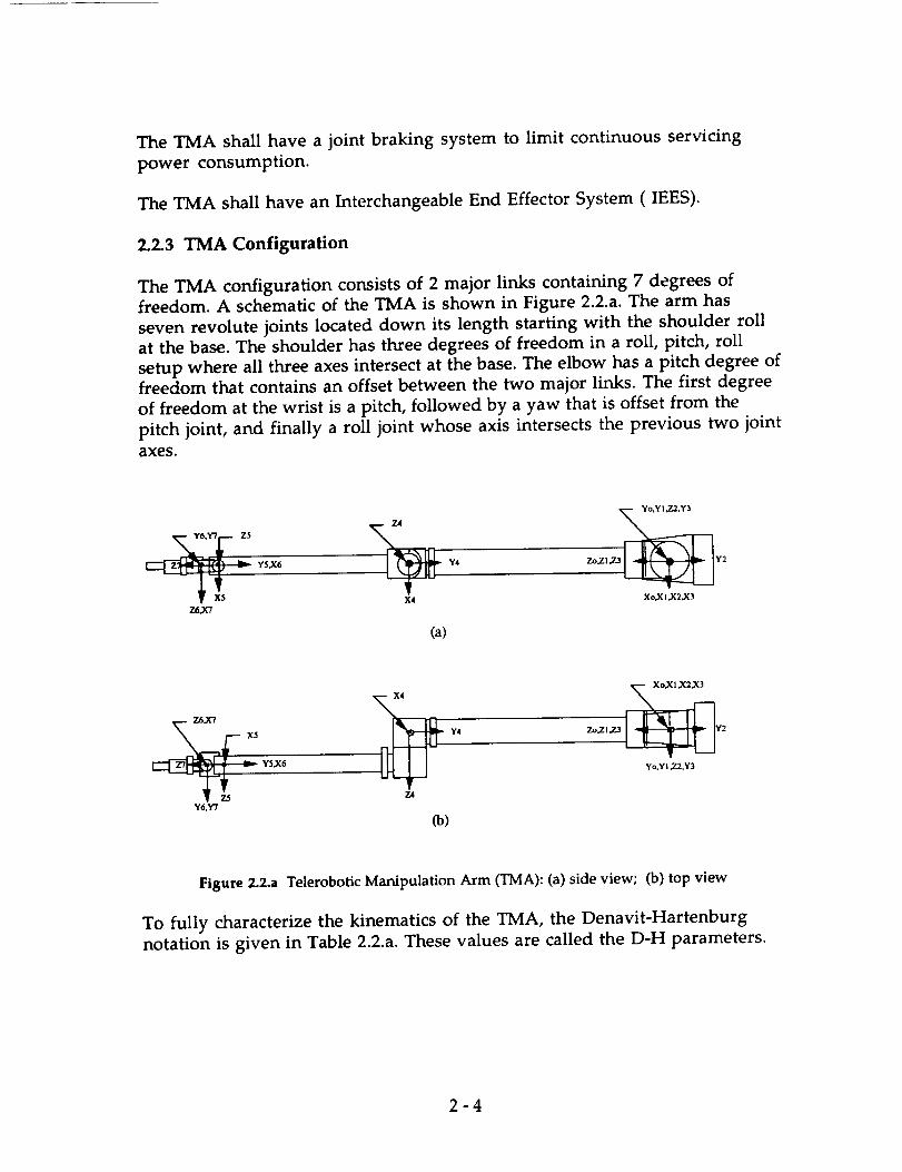
The TMA shall have a joint braking system to limit continuous servicing
power consumption.
The TMA shall have an Interchangeable End Effector System (IEES).
2.2.3 TMA Configuration
The TMA configuration consists of 2 major links containing 7 degrees of
freedom. A schematic of the TMA is shown in Figure 2.2.a. The arm has
seven revolute joints located down its length starting with the shoulder roll
at the base. The shoulder has three degrees of freedom in a roll, pitch, roll
setup where all three axes intersect at the base. The elbow has a pitch degree of
freedom that contains an offset between the two major links. The first degree
of freedom at the wrist is a pitch, followed by a yaw that is offset from the
pitch joint, and finally a roll joint whose axis intersects the previous two jointaxes.
X4 Xo,XI,X2,X3Z6,X'7
(a)
Y4 Zo,Z1,7.3 2Y5,X6 Yo,YI 2.2,Y3
Z4Y6,Y'7
Co)
Figure 2.2.a Telerobotic Manipulation Arm (TMA): (a) side view; (b) top view
TO fully characterize the kinematics of the TMA, the Denavit-Hartenburg
notation is given in Table 2.2.a. These values are called the D-H parameters.
2-4

Joint # i a i-1(meters) ilpha (d_g) c (meters),
1
2
3
4
5
6
7
0.000
0.000
0.000
0.000
2.000
0.I00
0.000
0
+90
-90
-90
0
-90
+90
0.000
0.000
0.000
0.150
0.000
0.000
0.000
Table 2.2.a Denavit-Hartenburg (D-H) Parameters for TMA
There are 3 parameters for each joint that are required to completely describethe fixed portion of the TMA's kinematics. The first is link length,represented in D-H notation by (a). It is defined as the mutually perpendiculardistance between the rotation axes of joint i - 1 and joint i. The secondparameter is link twist, represented by (alpha). It represents the angle formedby the rotation axes of joint i - 1 and joint i. The third parameter is the linkoffset, represented by (d). Neighboring links have a common joint axisbetween them. The distance along this common axis from one link to thenext is defined as the link offset.
If we were to add one more parameter (q), the revolution angle of all joints,to the above list we would have a full kinematic description of our arm.
2.2.4 Configuration Drivers
The TMA configuration summarized above evolved from the desire for aversatile manipulator system. A configuration using two telerobotic
manipulators was considered as well. In the interest of mass savings andmanual dexterity the TMA/MMS configuration was chosen. There was also atrade-off between manipulator and grappler complexity. A choice was madeto have a versatile manipulator and to sacrifice some grappler complexity toachieve this. Complexity is defined here as maneuvering capability (degrees
of freedom, link lengths).
2.2.5 Physical Arm Characteristics
The 2 main links of the TMA are to be fabricated from Graphite/Epoxy. The
joint material is Titanium (T16 A1-4 V). The thermal expansion compatibilityof these materials was a major driver in their selection. Each material has alarge strength-to-weight ratio as well as a good resistance to corrosiveness.
2-5

The arm will be subjected to an unfavorable environment during satellite
fluid replenishment missions. Graphite/Epoxy provides a suitable stiffnessfor the TMA links.
2.2.5.1 Outer Link
The outer link of the TMA is a 2 meter long thin-walled beam made of
Graphite/Epoxy. It has a skin thickness of 0.002 m and radius of 0.05 m.
This link has a mass of 3 kg. The maximum tensile stress on this link is
approximately 2 x e7 N/sq. meter. The critical stress level for this link is
1.337 x e9 N/sq. meter. Therefore there is a factor of safety of at least 10 on
this beam. The inside of the beam has a section of multi-layer insulation for
thermal control. Extensive wiring will pass through the center of the beam.
.002 m skin thickness
R.070 rn
=-- Insulation
Figure 2.2.b Outer Link Cross-section
2.2.5.2 Inner Link
The inner link of the TMA is a 2 meter beam made of Graphite/Epoxy. It has
a skin thickness of 0.01 m and a radius of 0.08 m. The link has a mass of 34 kg.
The inside of the beam has a section of multi-layer insulation for thermal
control. The inner beam has sufficient space for the increasing amount of
wiring that will run up the length of the arm.
2-6

.01 rn skinthickness
R.080 rn
Figure 2.2.c Inner Link Cross-section
2.2.6 TMA Motors
The TMA will use a set of brushless DC motors in each of its joints. The 3
motors for the TMA wrist have been estimated at approximately 0.5 to 1 kg
per motor. The masses of the gearboxes for these motors will be in the range
of I kg each. The elbow motor has been estimated at 1.2 kg. Its gearbox mass is
1.3 kg. The shoulder motors will be more massive due to the larger torques
they supply. The motors will have a mass of approximately 1.5 kg each. Their
gearbox masses will be in the neighborhood of 2 kg each.
2.2.7 TMA Power Requirements
Power requirements for the TMA were estimated from the torques that must
be supplied by the motors. A range of motors that could satisfy the torque
requirements was identified. From the power requirements of these motors a
maximum power requirement of approximately 700 Watts was estimated.
2.2.8 TMA Braking System
The TMA will contain a braking system to brake the arm during any non-use
periods. Each joint will contain an individual brake. This braking system is
essential to limit the maximum power requirements for the entire telerobotic
system. This will allow the TMA to draw minimal power while the TGA is in
use.
2-7

2.2.9 TMA Dynamics
Several TMA movement parameters have been set in order to design the
arm. The maximum tip acceleration for the TMA is 0.05 m/sec sq. This leads
to a maximum angular acceleration of 0.025 rad/sec sq. A maximum angular
velocity of 0.1 rad/sec was set to limit the load on the TMA when translating
a payload.
The TMA takes approximately 5 seconds to reach the maximum angular
velocity. The TMA can traverse a fully extended 180 degree movement in
approximately 45 seconds. Movement of a payload will in all likelihoodincrease travel time.
2.2.10 TMA End Effectors
The TMA will employ the use of the NASA Mobile Servicing System
ORU/Tool Changeout Mechanism (OTCM). The OTCM will be permanently
mounted at the tip of the TMA. The OTCM allows simple changeout of the
TMA's two primary end effectors as well as the attachment to any H-HandleInterface. The OTCM has an electrical interface built in that will allow power
interface to any end effector similarly equipped.
2.2.10.1 Fluid Transfer Nozzle End Effector
This end effector will be an H-Handle interface built into the Fluid Transfer
System (FTS) that will be used when replenishing satellites. The FTS is a self
contained unit containing a fluid tank, a fluid transfer mechanism, and afluid transfer hose. The fluid transfer hose will run from the FTS mounted at
the MOOSE payload attachment point. The payload attachment point is
located on the attitude control system truss. The fluid transfer hose will run
from this point to the base of the crew cabin. It then runs vertically up the
crew cabin and is secured to the cabin wall by several powered attachments.
2-8

Nozzle End Effector
Fluid Transfer Hose
Figure 2.2.d Fluid Transfer Hose Configuration
The TMA use of the fluid transfer will involve several steps that begins with
the OTCM mating with an H-Handle interface mounted on the fluid transfer
hose. The mating will connect power to the FTS and the FTS will then be
powered up. The fluid transfer hose will then be released from the crew cabinwall. The TMA will translate the hose to the satellite work area. The fluid
transfer hose will have a nozzle attached to the end of the hose. This nozzle
will be mated to the satellite fluid interface. After the mating is verified, the
fluid will be transferred to the satellite. De-mating will then occur, and thefluid transfer hose will be translated back to the crew cabin side. The hose will
be re-attached to the crew cabin and the FTS will then be powered down. TheTMA will then de-mate from the FTS's H-Handle interface.
2.2.10.2 Parallel Gripper End Effector
This end effector will be the baseline end effector launched in place on the
TMA. It consists of a parallel gripping mechanism (see Figure 2.2.e) that will
be capable of retrieving tools and other objects for the Manned Manipulation
System (MMS). When the TMA is functioning as an assistant to the MMS
this end effector will be used. This end effector can also be used for any
unforeseen tasks involved in a satellite servicing. The end effector will have
and H-Handle interface on the mounting side for mating with the OTCM.
2-9

/
Parallel Gripper
Screw-AxisActuator
Brushless
DC Motor
Gearbox
- H-Handle Interface
Figure 2.2.e Parallel Gripper End Effector
2.2.11 TMA Stowage
The TMA will be put into stowage position during any MOOSE transfer
burns. The stowage position for the TMA is with link 1 down the crew cabin
side at a slight angle, the elbow located at the base of the crew cabin, and link 2
continuing along the base of the crew cabin. When the TMA is in stowed
position, it will have the braking system applied.
2.3 Telerobotic Grappling Arm (TGA)
2.3.1 Functional Requirements
Provide the ability to firmly grapple and hold a cooperative satellite(i.e. a satellite with fully functioning Attitude Control System,
Reaction Control System, and Communication System).
• Provide ability to grapple, stabilize, and hold an errant satellite in
pure (or near pure) spin.
2- 10

• Be compact in design, so as to be stowable when not in use.
• Minimize the risk of damage to MOOSE and the target satellites.
• Maintain appropriate distance and orientation between MOOSE and
target satellites during operations.
2.3.2 Design Issues
2.3.2.1 Revolute-vs-Prismatic Joints
In Appendix 2.a, several robotic manipulator design criteria are discussed,
including the relative benefits/detriments of revolute-vs-prismatic joints.
The main problem with using prismatic joints in space is the difficulty that
one has in sealing the linear bearings from the space environment, to allow
the joint to remain well lubricated. This contrasts with revolute joints,
which are much easier to seal. In addition, jointed manipulators are very
flexible, with large workspace and low energy and torque requirements. In
spite of the added complexities of the hardware and control software, the
jointed manipulator design has much going for it, and will form the basis for
the MOOSE grappler mechanism.
2.3.2.2 Direct Drive-vs-Transmitted Drive
One of the main design drivers is that the vehicle systems have low masses.
In order to get a basic idea of how direct drive drive manipulators compare to
transmitted drive manipulator in term of mass, a rough cut analysis was
conducted, using the program listed in Appendix 2.b. The resulting data is
shown below (Figure 2.3.a).
ARM MASSES-VS-TIP ACCELERATION
A
O}
mommn
4000 | payload mass=6000kg
3000 I link 3 mass_2000
l f _ Arm Mass DD
1000 _______ _ ArmMI_=G
0 T---: .... ;--- ----.------; .... :-- .-----0.00 0.02 0.04 0.06 0.08 0.10
Tip Acceleration (m/s/l)
Figure 2.3.a Arm Masses -vs-Tip Acceleration for Direct-Drive and Geared Designs
2-11
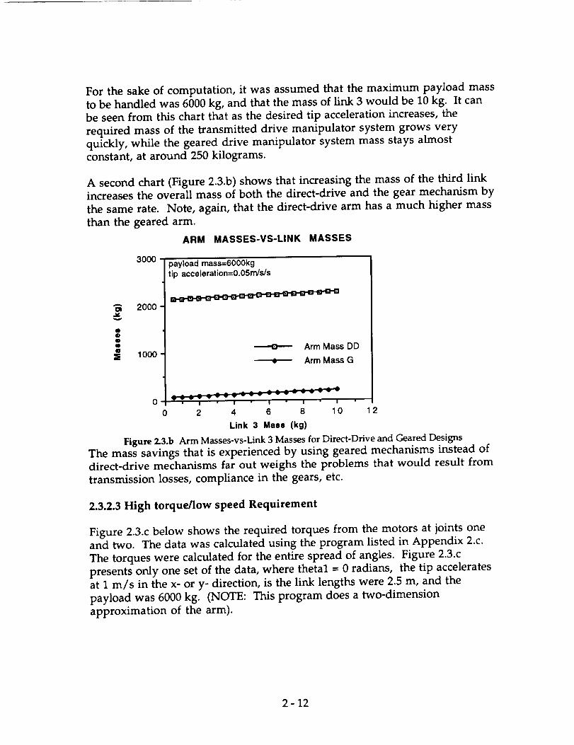
For the sake of computation, it was assumed that the maximum payload mass
to be handled was 6000 kg, and that the mass of link 3 would be 10 kg. It can
be seen from this chart that as the desired tip acceleration increases, the
required mass of the transmitted drive manipulator system grows very
quickly, while the geared drive manipulator system mass stays almost
constant, at around 250 kilograms.
A second chart (Figure 2•3.b) shows that increasing the mass of the third link
increases the overall mass of both the direct-drive and the gear mechanism by
the same rate. Note, again, that the direct-drive arm has a much higher mass
than the geared arm.
ARM MASSES-VS-LINK MASSES
3000
Am 2000
I0ttWZ 1000
payload mass=6000kgtip accoleration=O O5rn/s/s
• • o • • o . ° o • o o o o o • ° • .
Arm Mass DD
• Arm Mass G
0 Vvv I ; I I I
0 2 4 6 8 10 12
Link 3 Mass (kg)
Figure 2.3.b Arm Masses-vs-Link 3 Masses for Direct-Drive and Geared Designs
The mass savings that is experienced by using geared mechanisms instead of
direct-drive mechanisms far out weighs the problems that would result from
transmission losses, compliance in the gears, etc.
2.3.2.3 High torque/low speed Requirement
Figure 2.3.c below shows the required torques from the motors at joints one
and two. The data was calculated using the program listed in Appendix 2.c.
The torques were calculated for the entire spread of angles• Figure 2.3.c
presents only one set of the data, where thetal = 0 radians, the tip accelerates
at 1 m/s in the x- or y- direction, is the link lengths were 2.5 m, and the
payload was 6000 kg. (NOTE: This program does a two-dimension
approximation of the arm).
2-12

Torques -vs- Angular Position
40000
30000
20000
_,_, 10000
0
- 10000
-20000
Torque 1
8 Torque 2
Theta 1 = 0
I
0 1 2
Theta 2
Figure 2.3.c Torques-vs-Angular Position at Joints 1 an d 2
2.3.2.4 Active-vs-passive braking
In order to minimize the required power, it is necessary to use a passive
breaking mechanism in all the joints. The grappling arm is estimated to
require lkW of power.
2.3.2.5 Interchangable end effectors
Since there is no standard interface employed by all satellites, it is necessary to
allow for interchangeable end effectors that can be deployed according to the
mission. Currently, only two designs for end effectors are baselined. The first
is a "stinger" mechanism, which can be use to grapple with the apogee kick
motor of a satellite. The second is a generic gripper type mechanism, which
can be used to grab any sturdy structure in a grapple attempt.
2.3.2.6 Degrees of Freedom (DOF) required
The arm is going to require 4 degrees of freedom: a turn-table type
mechanism, and a revolute joint, at the base, another revolute joint at the
end of the first link, and a revolute joint at the end of the second link. End
effectors can have as many as 4 more degrees of freedom.
2 - 13

2.3.3 Arm Design
Dimensions
5 m extended length (2.5 meters per link)
Work Envelope
AnalysisStress Distributions
Material Selection
Maximum Loading
Torque AnalysisMotor Selection
Power Consumption
Braking Requirements
Mass of Linkages/Motors
Handle (max.) 6000 kg payload--this is the mass of the largest satellitesin LEO
2.3.4 End Effector Design
Stinger/Despinner
Gripper
2.3.5 Grappling Arm Stowage
2.4 Manual Manipulation System (MMS)
2.4.1 Configuration
The MMS consists of two spacesu/t-type arms coming out of the capsule. The
crew member slides their arms into MMS and can actually touch, grab and
hold objects outside the vehicle. The major advantage is the many degrees offreedom inherent to the human arm and hand that can be used without the
need to provide any control or computational hardware/software other than
the astronaut's brain. The shoulder joint is included in the MMS to use the
maximum natural degrees of freedom as possible.
2- 14

anopy
'_Wr_n Cylinder Wall
Figure 2.4.a Detailed View of an Manual Manipulator
Mass (both arms) 6kg
Most maintenance and other manipulation tasks will be performed using the
MMS. A canopy is provided so that the crew member will have the
maximum viewing area possible when observing the worksite. However
because of the short length of a human arm, the MMS is placed at the extreme
end of the vehicle. This way, the crew member can work close to the satellite
without other parts of MOOSE interfering.
o
Figure 2.4.b Location of MMS on MOOSE
This system is similar to an astronaut suit, and is extremely bulky. The range
of motion and work envelop is extremely limited when compared to a robotic
manipulator. The elbow is able to keep much of its range of motion;
however the shoulder's mobility is hindered considerably. This is due to the
integration of the shoulder to the cabin cylinder. As an example of how the
workspace of the left shoulder is limited, see Figure 6.4.c below.
2- 15

Horizontal Vertical .....
Figure 2.4.c Range of Motion of Left Shoulder of MMS
The right shoulder workspace is a mirror image. Although the full freedom
of the crew member can not be perfectly achieved, the MMS will be able to
perform most tasks need to complete the mission.
2.5 Control Station
2.5.1 Functional Requirements
The control station must command the manipulator and grappler. Vehicle
control will also occur here, as will adjustments to the environmental
system, communication operations, and emergency overrides. Effective
utilization of tools and equipment accessible to the manipulator system will
be integrated to the design.
2.5.2 Design Requirements
Human factors, especially ergonomics, will be used to ease operation by the
crew member. Multiple alternative control devices will be placed on the
system so that a task may be performed using the preferred device. The
manipulator worksite (outside the canopy), the essential controls, and the
monitors should be within the optimal range of view of the crew member.
The comfort of the crew member while performing task for a long time
becomes a factor. The crew member should be in the neutral position during
most of the working time.
The control station is simple and lightweight--the total mass of the station is
about 10 kg. The view of the control station is provided in Figure 2.5.a below.
2- 16

__/ Manual Manipulation
System
Canop._
.Rotational Hand Controller
13" LCD Touch Screer
19" Main LeD Supplemental Control Station
Monitor and Keyboard
Figure 2.5.a Control Station Layout
2.5.3 Control Systems
Many control system are provided for the crew member. The systems
overlap, causing many redundancies. This allows the crew member to chose
a prefered system to accomplish a given task. In addition, the reliability of the
control station is high due to the many backup control systems
2.5.3.1 Joystick Control
Most manipulation control will occur using the transitional and rotational
hand controllers. Both manipulation and vehicle movement can be
controlled using these joysticks. It is possible to toggle between vehicle,
grappler, and manipulator control. This is the primary control of the vehicle.
Astronauts are already familiar with this style of control. In general, they will
not need to get accustomed to using the joysticks, only how the joysticks effect
the the manipulation and vehicle control systems. Due to its simplicity, this
is a very compact and lightweight system as compared to other mean of
controlling the manipulators or vehicle.
2.5.3.2 Touch Screen
To help eliminate the need for many switches, monitors using touch screen
technology will be used as a major control component. Three LCD touch
screen monitors are provided. The main 19" will be used primarily for video
imaging. Pictures sent from the end effectors cameras will show the worksitehere. Two 13" LCD screens will be used for interactive touch control. Exact
menus for specific tasks, such a grappling, could be brought up and used, then
2- 17

switched for another task, as dictated. This will save space by having many
menus available to the crew member. What is more important, the touch
screen monitors will be in optimal viewing range so that the important
controls and readouts will be easily seen and used during a task.
2.5.3.3 Voice Control
When both of the crew member's arms are using the MMS, it may be
necessary to adjust the manipulator arm, the grappling arm, or even the
entire vehicle. Since the joystick control or any other system requiring the
crew's hands can not be used, necessary control is established through voice
control. The crew member will wear headphones with a microphone during
most operations. This headset will be linked into the communication system
that will be used to talk to ground control or space station. Using the voice
recognition system, certain simple control can be activated by the crew
member orally. These tasks would include closing an end effector, relative
positioning of a manipulator, hand-off of an ORU or tool, etc. With joystick,
touch screen, and voice control, all tasks can be completed with redundancies
creating high reliability for mission success.
2.5.3.4 Keyboard Control
A keyboard interface with the primary computer is provided. As another
means of control, joint angles or tip positioning can be input into the
computer. Additional menus can be brought up and utilized using the
keyboard. More complex menus requiring the keyboard will be used. General
control of the vehicle and manipulators can be performed at the expense of
efficiency. However. this system provides another control style and backup
system.
2.5.3.5 Supplemental Control Station
Hardwire controls using traditional switches, knobs, and gauges provide
auxiliary control for particularly sensitive systems. Life support can be
controlled from one of the stations that is physically attached to the life
support unit. The two stations shown above (Figure 2.5.a) control the vehicle
propulsion and avionics systems directly. Although this system can be used
for primary control, it is designed as a backup system.
2.5.3.6 Video Cameras
Although the canopy provides a real viewing range of the worksite, cameras
will be used to augment vision during certain tasks. Both the manipulator
and grappler will have cameras to give a local frame of reference to the end
effector. This will aid in grappling satellites, ORU changeout and installation,
and inspection of the worksite from another view besides the canopy.
2- 18

3.0 Crew Cabin
3.1 Introduction
MOOSE design included carrying a crew member to perform the maintenance
tasks on a satellite. The cabin not only housed the equipment necessary to
perform the task, but protected the crew member from the hostile
environment of space. The target probability to complete the mission was
95%. However the probability for crew survival was 99.9%. Therefore the
crew cabin was designed with many redundancies in critical systems. Also,
the human factors were involved, attempting to make the crew member best
able to complete the mission. Finally, the constraint of weight was traded off
with the above; excess in niceties was avoided. The amenities provided in
the cabin were needed to complete the mission and increase crew safety.
3.2 Ergonomic Requirements
3.2.1 Temperature Requirements
To accommodate a crew member, performing mostly light work, wearing
normal light clothing, the cabin temperature should be around 21°C (70°F).
As humidity, duration, and other factors vary, human tolerance to
temperature is shown in figure 3.2.a.
Most of the thermal control will come from exchanging heat between the
structure and space, through radiation transference. The shape, color, and
texture of the external structure will determine the general thermal balance.
A circulation system can be developed to exchange heat between the cabinand electronic areas with that of the skin of the vehicle.
3.2.2 Humidity Requirements
At a temperature of 21°C, the recommended relative humidity is 50%.
Control is needed to take out excess water vapor, which is placed into the air
by human wastes. Calculations can show that a human exhales more than
one pound of water a day. However, perspiration is the major cause of
moisture loss for a crew member. Figure 3.2.b below shows the total amount
3-1

of moisture loss as temperature varies. For a typical day, at about 21°C, a
standard amount of rest, and while performing hard and light work, four to
five pounds of water would need to be extracted from the air.]
_4o__
i
-I0
IO MIN. I HR. I0 HRS. I DAY
.RELATIVE HUMIDITY_/o
HYPOTHERMIA
OF TIG u D[IqAT UMI;:
AT Ir ARTH 'S
SURFACE
1O DAYS 100 DAYS I YR.
TIME
Figure 3.2.a Human Temperature Exposure Limits 2
_um 1.
loss .9c_ -avmKje -8man)
"7
.6
"5
.4
-3
.2
-1
030
j I
IIII I I
13_eTh u_
//
f/
f/ /
/
/
f
//
//
J
/f
400 BTh U(Re'st) • I_
f
fm_"
/i"
IV_al_l_ rate
t_htmlork]
/,r
40 50 60 70 OO 90 10001=Dry bulb temperature
• • . o
o lo 2"o 3"0
Figure 3.2.b Hourly Moisture Loss of a Crew Member 3
3-2

3.2.3Acceleration Requirements
In figure 3.2.c, a crew member's tolerance to acceleration is shown to vary
with duration and body position. The acceleration, in g's, represents a
conservative safe limit. Many astronauts can tolerate three times this value;
however the graph is the lower limit of non-selected crew.
The body position relative to the acceleration force
B (" I)
r]_ n_vel% ...-"
=
Figure 3.2.c Safe Duration For Varying Accelerations 4
3.2.4 Vibration Requirements
Below figure 3.2.d shows a crew member's sensitivity to vibration. This
threshold vibration may occur with very little adverse effects to the crew.
tolerable limit may be established at ten times the amount given below;
however fatigue and other psychological factors develop. Design shoulddictate below this threshold.
A
_" 0.2
I_,o'_t 0
_ I0 too _o00 4000,f
_ FREQUENCY ICP$}
Figure 3.2.d Vibration Limits 5
3-3
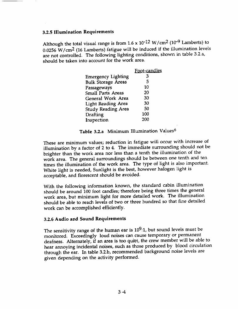
3.2.5 Illumination Requirements
Although the total visual range is from 1.6 x 10⁻¹² W/cm 2 (10 -9 Lamberts) to
0.0256 W/cm 2 (16 Lamberts) fatigue will be induced if the illumination levels
are not controlled. The following lighting conditions, shown in table 3.2.a,should be taken into account for the work area.
Foot-f0ndles
Emergency Lighting 3
Bulk Storage Areas 5
Passageways 10Small Parts Areas 20
General Work Area 30
Light Reading Area 30
Study Reading Area 50
Drafting 100
Inspection 200
Table 3.2.a Minimum Illumination Values 6
These are minimum values; reduction in fatigue will occur with increase of
illumination by a factor of 2 to 4. The immediate surrounding should not be
brighter than the work area nor less than a tenth the illumination of the
work area. The general surroundings should be between one tenth and ten
times the illumination of the work area. The type of light is also important.
White light is needed, Sunlight is the best, however halogen light is
acceptable, and florescent should be avoided.
With the following information known, the standard cabin illumination
should be around 100 foot candles; therefore being three times the general
work area, but minimum light for more detailed work. The illuminationshould be able to reach levels of two or three hundred so that fine detailed
work can be accomplished efficiently.
3.2.6 Audio and Sound Requirements
The sensitivity range of the human ear is 109:1, but sound levels must be
monitored. Exceedingly loud noises can cause temporary or permanent
deafness. Alternately, if an area is too qui_t, the crew member will be able to
hear annoying incidental noises, such as those produced by blood circulation
through the ear. In table 3.2.b, recommended background noise levels are
given depending on the activity performed.
3-4

Location Level, dB
Sanctuaries 30
Sleeping area 35
Rest, reading 40Restaurant 45
Sports 45Detail work 45
Heavy work 50 - 70
Table 3.2.b Recommended Background Noise 7
3.2.7 Interior Volume
A very important dimension of this spacecraft is its interior free volume.
Without a certain minimum amount of living space, there may be a
negative psychological effect on the astronaut. This volume is very sensitive
to mission duration for missions under 30 days, and an approximate relation
is given by figure 3.2.e, which is a power fit to several data points. This fit hasa correlation coefficient of .99997.
E
O
o ?o 2'o do
Mission Duration(days)
Figure 3.2.e Minimum Interior Volume
For a two to three day mission, the necessary interior volume is
approximately two cubic meters. When crew and equipment volume is taken
into account, this results in a crew cabin which is approximately 2.75 meters
tall, 1.22 meters wide, and .91 meters deep.
3-5

3.2.8 Clothing
In order to best perform the mission, the astronaut should be dressed as
comfortably as is possible. Currently, the anticipated attire consists of shorts, a
T-shirt, and special shoes. These shoes will allow the astronaut to lock
themselves into position on a height adjustable platform for easy access to the
controls for manipulation of the satellite. These shoes are similar to those
worn by competition bicycle racers, which click into place, and release with a
simple twist of the foot. Another alternative considered was the possibility of
simple Velcro foot restraints. Problems with this system included possible
slippage, and the difficulty in tightening the restraints onto the foot.
3.2.9 Ergonomics
In order for the astronaut to perform their mission to the best of their
abilities, their working environment must be safe, comfortable, and well
organized. To allow the astronaut to adapt to the working environment as
quickly as possible, a traditional vertical layout has been maintained in the
crew cabin. Although not necessary in micro gravity, this layout is
psychologically more familiar to the astronaut, and therefore it is easier for
the astronaut to adapt.
3.3 Cabin Components
The rear of the cabin holds most of the components that will be used by the
crew member. If the crew member faces away from the control station the
figure 3.3.a would be seen.
Outlined below is each system including estimates on mass and dimensions
and a description of that component.
3.3.1 Adjustable Foot Restraint Support
Mass: 2 kg
Attached to the primary computer, this stand can be swung forward, up to 90
degrees, and propped up to support the crew member when at the control
station. The stand has a triangle grid which will be used with the crew
member's shoes to latch themselves to the grid. More discussion is includedin 3.2.8.
3-6

Cabin Layout
1.75m
Support Chair
Emergency Air Mask
Fire Exti
Life Support Unit
Two 20W Halogen Bulbs
Food Bin
Medical Kit
Hygiene CabinetWater Bladder
Rehydrater Adapter
WasteContainer
Adjustable Foot RestraintSupport
Figure 3.3.a Cabin Layout
PrimaryComputer
3.3.2 Docking Ring
Dimensions"
Mass:
0.75m dia. x O.lm thick
30 kg
This will be used by the crew member to enter and exit the vehicle. A
standard airlock design will be able to mate to Space Station.
3.3.3 Emergency Air Mask
Figure 3.3.b Emergency Air Mask
Mass: 2 kg
In the case where airborne contaminants have saturated the cabin
atmosphere such that it is unsafe to breathe. Standard procedure will be to
3-7

use the air unit. This system is hooked into the cabin's life support; therefore
the crew member can breath directly off life support. A hose leads from the
full face mask to a connector, hooking the air unit into the life support
system. The cabin could then evacuate the contaminants slowly while
replenishing the atmosphere. This method will keep the cabin pressure
constant. However the contaminants are never completely removed; much
atmosphere is wasted in the attempt to saturate with good atmosphere. The
crew member is able to breathe directly off the oxygen and nitrogen tanks
through the air mask. More will be explained about this system in 3.4.7.
3.3.4 Extra Storage Mesh Bags
Dimensions: 0.5m x 0.5 m
Mass: I kg
These large capacity bags can be used to store personal items. For extended
missions extra food and hygiene materials can be kept there.
3.3.5 Fire Extinguisher
Figure 3.3.c Halon Fire Extinguisher
Mass: 2.5 kg
A description of this extinguisher will be given later along in 3.6.3 with fire
suppression procedures.
3-8

3.3.6 Food Storage Bin
0.35m
O.lOm
maximum 90 °
Figure 3.3.d Food Storage Bin
Mass: 5 kg (filled)
This bin holds food and beverage containers for a standard mission duration
of two days. This consists six Food pouches and 20 beverage containers. The
door has two latches keeping it closed during normal vehicle operation. The
door swings down and can be used as a food preparation table. More details
on the food system will be given in 3.7.
3.3.7 Hygiene Cabinet
_-----_ 0.35 m ------_ ,_
Figure 3.3.e Hygiene Cabinet
Mass: 2 kg
This cabinet holds the waste disposal bags for a 2 day mission. Personal
hygiene articles are also provided; these include wetnaps, toothbrush,
toothpaste, toilet paper, hair brush, a pocket mirror, and other amenities.
Greater explanation is provided on the waste disposal bags in 3.8.1.
3-9

3.3.8Life Support System
Life Support Panel _ vL. _ I _ ..__ 0.55m
t-/__ o.a_,
r.ioHC_te,_ _ ®_"--4-.... _'_ [- Easy Acess Panel
lntake Vent ____
Figure 3.3.f Life Support Unit
Mass: 20 kg
The main unit provides the apparatus that controls the cabin temperature
and humidity, scrubs out the CO2, filters the water supply, and monitors any
smoke particles indicating a fire hazard. Due to its importance, it can be
accessed easily by the crew member. An in depth analysis on the whole life
support system will be provided in 3.4.
3.3.9 Lighting System
_O.lOm0 40m
Figure 3.3.g Halogen Light
Mass: 2 kg
Two 20 Watt halogen lights will be used for cabin lighting. Halogen lights
emanate a near white light illumination that is a need for the ergonomics.
Halogen lights are also quite power efficient.
3-10

3.3.10Medical Kit
0.20 m
Figure 3.3.h Medical Kit
Mass: I kg
This is a combination of a first aid kit and medicine cabinet. Contents include
materials for treating burns (electrical and thermal), bleeding, and
muscular/skeletal injuries (sprains, contusions, broken bones). Medications
are provided including pain relievers, cold pills, anti-diuretic, infection
control, etc.
3.3.11 Primary Computer
Dimensions:
Mass:
0.55m x 0.55m x 0.55m
20 kg
The computer will be used to accept commands from the control station and
implement them to the various avionics and propulsion systems. Due to the
fast pace technology advancement in computers, the exact type of computer is
not given so that a computer can be chosen later that can fulfill its
requirements with minimal cost. Space has been allotted for radiation
shielding.
3-11

3.3.12Support Chair
1.40m
0.55m
0.85m
0.40m
0.55 m
_2
Figure 3.3.i Support Chair
Mass: 8 kg
A support chair is integrated to the back wall and primary computer. The
crew member will use this during transfer orbit burns of the propulsion
system. Elastic straps are also used to secure the crew member to the chair
when they are sleeping. This will prevent the likelihood of injury during
propulsive burns or sleeping.
3.3.13 Waste Container
T0.89 m
Maximum
Open Angl90"
Figure 3.3.j
Mass:
Waste Container
5 kg
3- 12

This is the collection and storage of dry waste (i.e. paper products), wet waste
(i.e. unused food, discarded beverage containers, wetnaps, etc.), and the waste
disposal bags. The discussion on the waste container occurs later in 3.8.2.
3.3.14 Water Bladder
O.lOm
Water Hose
Dispenser
Rehydrater Adapter
Figure 3.3.k Water Distribution Unit
Mass: 2 kg
This canister collects water produced by the fuel cells. After the water has
been filtered in the life support unit, it will be placed here until the crew
member uses it. Inside, a bladder expands until it reaches full capacity, at
which time the life support unit will no longer divert water to the bladder.
One half a gallon can be stored at a time. When the crew member uses the
water dispenser, the bladder decreases volume so that the fluid is under
continual pressure. The water is forced through a hose out the dispenser. A
rehydrater adapter is included for food preparation. The hose is secured by a
clip so that it will not float around.
3.4 Life Support Systems
The life support systems for MOOSE should provide a shirt sleeve workingenvironment in the manned module for the astronaut to work in. The
environment should provide the most optimum living and working
conditions for the astronaut during a standard three day mission.
3.4.1 Atmospheric Requirements
Allowing the astronaut to wear a t-shirt and shorts, the atmosphere for the
most optimal conditions should be as similar to the earth's atmosphere, at sea
level, as possible. Providing an atmosphere of 79% nitrogen and 21% oxygen
is possible and would provide the same atmosphere makeup as here on earth.
The atmospheric pressure at sea level is one atmosphere (14.7 psi) and can be
supplied for the astronaut.
3 - 13

However when supplying a pressure of one atmosphere in the manned
module the thickness of the end plates on the manned module increases
greatly to protect from end deflections. This becomes a limiting factor because
the ultimate goal is to achieve our objectives with maximum mass efficiency.
Therefore the pressure in the manned module should be reduced while still
providing the most optimum environment for the astronaut.
In providing an environment for the astronaut to work in with unimpaired
performance the lower the total pressure in the manned module the higher
the percentage of oxygen necessary. However, the larger the percentage of
oxygen in the atmosphere the greater the fire hazard, and the more a health
hazard it becomes to the astronaut. An astronaut that is exposed to pure
oxygen or atmospheres with large percentages of oxygen runs a great risk of
oxygen toxicity, or anoxia. This becomes a trade off, one wants to keep the
percentage of oxygen low to reduce the fire hazard.
In trying to keep the oxygen percentage and the total pressure low the most
optimum pressure would be a total pressure of 0.41 atm (6 psi). With this
pressure, the percentage of oxygen should be anywhere from 42% to 95% for
unimpaired performance of the astronaut; 55% being the sea level equivalent.
In trying to provide with the least percentage of oxygen possible while
maintaining the most optimum conditions for the astronaut an atmospheric
composition of 50% oxygen and 50% nitrogen will be provided. With a total
pressure of 0.41 atm and a composition of 50% oxygen and 50% nitrogen the
partial pressures of oxygen and nitrogen will be 0.205 atm. This composition
will provide the astronaut with the most optimum working conditions while
maintaining the lowest internal pressure possible to help reduce the mass of
the end plates on the manned module.
3.4.2 Atmospheric Control
The manned module needs to be filled with 50% oxygen and 50% nitrogen
both at partial pressures of 0.205 alan. The internal volume of the manned
module is 16 cubic meters and to initially fill the module will require 2.2 kg of
oxygen and 2.0 kg of nitrogen. An astronaut will use 0.9 kg of oxygen per crew
member per day. For a three day mission one astronaut will use 2.7 kg of
oxygen. In the event of a fire the manned module will have to evacuate the
atmosphere and replenish it with new oxygen and nitrogen. This will require
refilling the module with fresh oxygen and nitrogen increasing the amounts
necessary. The amount of oxygen and nitrogen necessary will be 7.1 kg and 4.0
kg respectively.
3.4.3 Temperature and Humidity Control
The temperature and humidity in the manned module should be controlled
to provide the optimum conditions for the astronaut to live and work in. The
3- 14

safest conditions for the astronaut are a temperature from 18°C to 32°C with a
humidity of 30% to 50% with an airflow rate of 9.0 m/rain to 15 m/min.
These conditions will keep the astronaut free from any health hazards such as
hypothermia and hyperthermia. These are the safe living conditions for the
astronaut to survive in but they are not the optimum working conditions.
The ideal working environment for the astronaut, where they will have no
impairment, is at a temperature from 21°C to 24°C with a humidity of
around 40% and an airflow rate of about 9.5 m/min. This temperature and
humidity are the conditions in which the astronaut will be most comfortable
and able to concentrate the best on their work. It will provide the crew
member with an environment in which their hands should not get cold, and
an environment in which they should not sweat.
Maintaining an airflow rate of 9.5 m/min is crucial for odor control, noise
control, and especially for carbon dioxide removal from the atmosphere. A
slower airflow rate of 5 m/min would not circulate the air sufficiently to do a
proper job of removing carbon dioxide quick enough to keep it below its
maximum partial pressure. Odors would tend to linger in the module andthe air would become stale at the lower airflow rate. The circulation of the air
is important for the resupply of oxygen and an airflow rate this slow would
not keep fresh oxygen in the module at all times.
On the other hand an airflow rate of over 15 m/rain, would not be desired for
several reasons. Supplying an airflow rate that fast would cause unwanted
noise for the astronaut. The airflow would create a disturbing breezyenvironment. Therefore a sufficient airflow rate in between these two values
has been chosen, 9.5 m/min. This rate will sufficiently recirculate the air for
removal of odors and carbon dioxide while not disturbing the astronaut withundesired noise and excess breeze within the module.
3.4.4 Carbon Dioxide
The crew will produce 1.02 kg of carbon dioxide per astronaut per day. For the
astronaut to be free and safe from carbon dioxide poisoning the maximum
allowable percentage of carbon dioxide in the atmosphere should be less than
0.5%. To much carbon dioxide in the atmosphere becomes dangerous to the
astronaut and can cause carbon dioxide narcosis, which causes impairment or
even death to the astronaut. Allowing carbon dioxide concentrations above
0.5% of the atmosphere may also alter the astronauts physical response to
radiation. Understanding these requirements shows that the carbon dioxide
removal system must remove 1.02 kg of carbon dioxide per crew member per
day keeping concentrations below a maximum of 0.5% (0.02 atm) of the
atmosphere. The most efficient method of removing the carbon dioxide for
the standard three day mission will be through the use of lithium hydroxide
canisters with activated carbon inside. A resulting trade study that shows
why lithium hydroxide should be used can be found in appendix A3.1. The
3-15

lithium hydroxide will remove the carbon dioxide and the activated carbonwill remove other trace contaminants found in the air.
Each canister will contain enough supply of LiOH to remove CO2 for 1.5 days.
In each canister will also be added activated carbon to filter out impurities in
the air such as odors and other chemicals found in the atmosphere. Each
canister will carry 13 kg of LiOH and 0.09 kg of activated carbon. The amount
of activated carbon necessary to filter out impurities is 0.06 kg per crew
member per day. The activated carbon will be used to remove odors and
numerous chemical compounds found in the atmosphere such as acetic acid,
methanol, ammonia, chlorine, carbon monoxide, and many more.
3.4.5 Life Support Panel
Life Support Panel
NN •olemperamre, \ \_ 0 0 _" _ • \Oxygen, and Nitrogen \ \ _ • • • \ Pressure
_ %_ 4"---"-_ Transducers
Outflow Vent- \ l_!_i?_: _
N Temperature"_ " ! and Pressure
Intake Vent /'-- N_
Figure 3.4.a Life Support Unit
The life support panel above is housed in the manned module on the
atmospheric revitalization system (ARS) and the oxygen and nitrogen supply
system. The air from the cabin will be drawn into the life support unit
through the intake vent and will be released back into the module through
the outflow vent. On this panel will be a temperature sensor that will show
the astronaut the cabin temperature. A temperature dial control will be
provided so the astronaut can control the temperature inside the cabin within
one degree Celsius. The lithium hydroxide canisters, which will be used for
the removal of carbon dioxide will be housed in the unit and can be changed
when necessary. Transducers will be on the panel to tell the astronaut the
partial pressure of the oxygen and nitrogen and the total pressure in the
manned module. The oxygen control valve can be used by the astronaut if the
3- 16
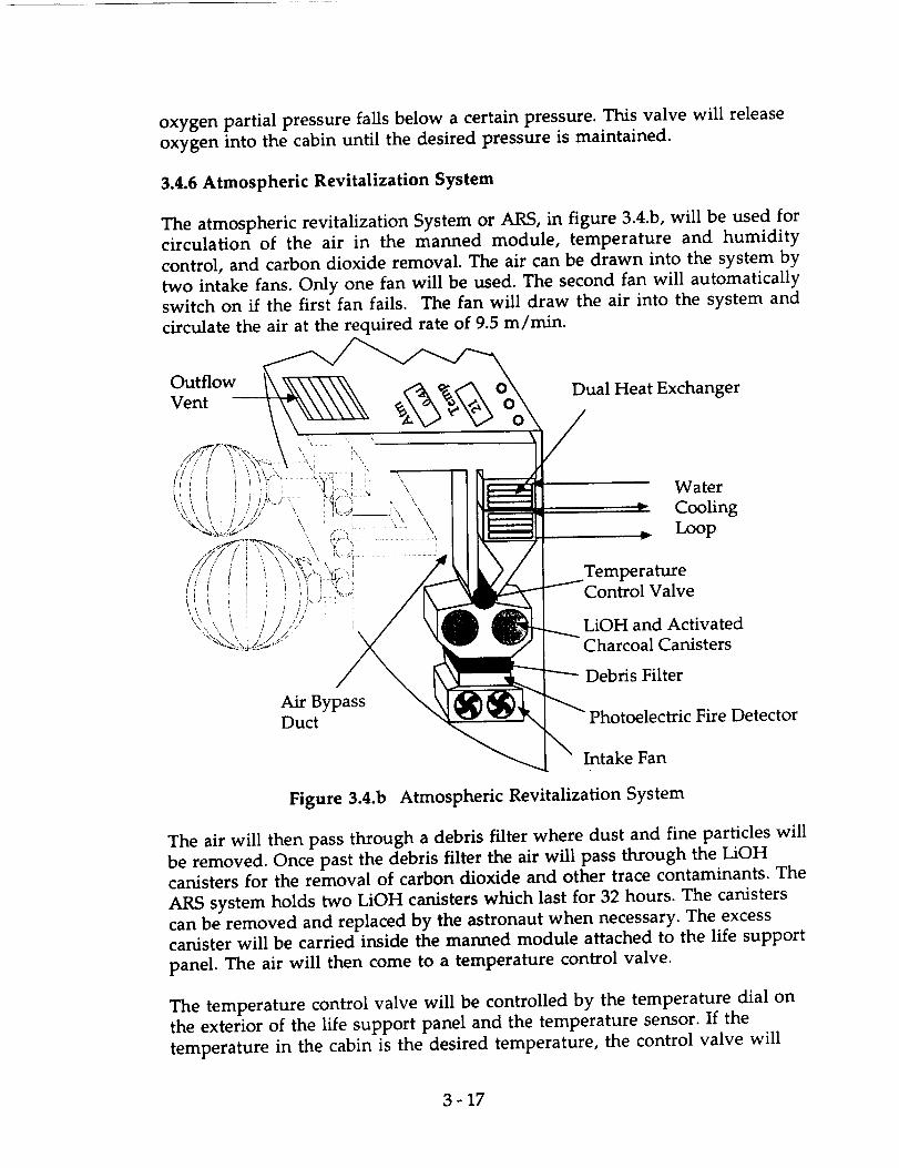
oxygen partial pressure falls below a certain pressure. This valve will release
oxygen into the cabin until the desired pressure is maintained.
3.4.6 Atmospheric Revitalization System
The atmospheric revitalization System or ARS, in figure 3.4.b, will be used for
circulation of the air in the manned module, temperature and humidity
control, and carbon dioxide removal. The air can be drawn into the system by
two intake fans. Only one fan will be used. The second fan will automatically
switch on if the first fan fails. The fan will draw the air into the system and
circulate the air at the required rate of 9.5 m/rain.
Outflow "_ o\Vent Dual Heat Exchanger
Water
a,. Cooling
. Loop
TemperatureControl Valve
LiOH and Activated
Charcoal Canisters
Debris Filter
Air BypassDuct Fire Detector
Intake Fan
Figure 3.4.b Atmospheric Revitalization System
The air will then pass through a debris filter where dust and fine particles will
be removed. Once past the debris filter the air will pass through the LiOHcanisters for the removal of carbon dioxide and other trace contaminants. The
ARS system holds two LiOH canisters which last for 32 hours. The canisters
can be removed and replaced by the astronaut when necessary. The excess
canister will be carried inside the manned module attached to the life support
panel. The air will then come to a temperature control valve.
The temperature control valve will be controlled by the temperature dial on
the exterior of the life support panel and the temperature sensor. If the
temperature in the cabin is the desired temperature, the control valve will
3-17

close the airflow and force the air into the bypass duct where it will go back
into the cabin. If the temperature in the cabin is not the desired temperature,
the control valve will remain open allowing the airflow to enter into the heat
exchanger. In the case of the control valve failing, the airflow will
automatically go into the heat exchanger where the manual temperature
control dial will control the temperature of the airflow in the heat exchanger.
The heat exchanger will use a water cooling loop to cool the air below the dew
point to remove the moisture from the air. The moisture will then be
collected and added into the water cooling loop. If the cabin temperature istoo warm the airflow will remain cool and be returned to the cabin. If the
cabin temperature is too cool the heat exchanger will heat the air to the
desired temperature as determined by the astronaut with the temperature
control dial. The heater in the heat exchanger will consist of two separate
heaters that will both operate together at the same time to heat the air. If one
of the heaters should fail, the other would be able to maintain the necessary
emergency temperature within the cabin to keep the astronaut healthy until
return to the space station.
In the event of an emergency such as a power failure, the system can run on
the one fan necessary and only one heater conserving on the power necessary.
3.4.7 Oxygen and Nitrogen Supply
The oxygen and nitrogen supply system in figure 3.4.c, will take the oxygen
and nitrogen being sent from their storage tanks and regulate their pressure.
Then the proper amount is released into the manned module. The oxygen
and nitrogen will flow into the life support panel from the exterior of the
manned module. Both gases will be entering the panel at high pressures. The
cabin pressure regulator will take the gases and reduce their pressure to a total
pressure of 0.41 atm and partial pressures of 0.205 atm.
A solenoid valve will be used to help regulate the gas flow into the manned
module. If the nitrogen pressure is too low the solenoid valve will close
allowing nitrogen into the cabin until the desired pressure is reestablished.
Otherwise, the solenoid valve will remain open allowing oxygen into the
cabin as necessary. If the solenoid valve should fail the astronaut has manual
control over the release of the oxygen in the cabin to maintain the necessary
supply of oxygen. This manual control valve releases oxygen directly into the
cabin from storage after it has been reduced in pressure. If the pressure inside
the cabin gets too high, two pressure relief valves will be used to vent out the
excess pressure to space. These pressure relief valves will also be used in the
event of evacuating the atmosphere from the cabin.
The oxygen necessary for a three day mission with one astronaut will be 7.1 kg
at a pressure of 0.205 atm. A major concern for this project is mass and
3 - 18

volume. To save on redundancy of oxygen storage tanks, the oxygen will be
stored in the cryogenic storage tanks being used for the fuel cells. This will
save on both space and the excess mass of adding more tanks.
High Pressure
Nitrogen Tank
Outflow
Vent
Cabin Pressure
Regulator
Solenoid Valve
Manual Control
Valve
High Pressure
Regulator
High Pressure
Emergency
Oxygen Tank
Fuel Cells N
Emergency AirUnit Valve
Backup ControlValve
Figure 3.4.c Oxygen and Nitrogen Supply System
The oxygen will be stored cryogenically and pass through a high pressure
regulator where the pressure will be reduced down to 4 atm. The oxygen will
then be released into the oxygen and nitrogen supply system where it will be
regulated and reduced in pressure even further before being released into the
cabin. Monitors and alarms will be provided so that the astronaut can tell
when the oxygen partial pressure is too low. Upon hearing these alarms, the
astronaut can open the manual control valve to restore the oxygen pressurein the manned module.
Upon the failure of the cryogenic storage tanks used by the fuels cells, the
spacecraft would have to return to Space Station Freedom. If the cryogenic
storage tanks failed, the oxygen supply would be cutoff. Therefore an
emergency oxygen storage tank is necessary for the safe return of the
astronaut to the space station. In the event of failure it would take the
spacecraft a maximum of twelve hours to return to the space station, so an
oxygen supply for those twelve hours would be necessary. This would be
done by a small high pressure storage tank that would contain I kg of oxygen
3 - 19

for emergency purposes. This tank would be similar to the nitrogen tank andwould only weigh about 1 kg. The releaseof this oxygen into the mannedmodule would be done by a backup control valve on the life support panel.
The mass of nitrogen needed is so small that the storage of the nitrogen by
cryogenics would be inefficient; therefore the most desirable type of storage
would be high pressure. A tank weighing only 5 kg will be used to store the 5
kg of nitrogen necessary. The tank will store the nitrogen at a pressure of 81
atm and needs a volume of only 0.1 cubic meters. The nitrogen will be
released into the oxygen and nitrogen supply system where the pressure will
be reduced down to 0.205 atm before being released into the module. The tank
used for the nitrogen storage will be made of a titanium liner with a
kevlar/epoxy composite over wrap on the outside. This accounts for the tanks
lightweight and high pressure capabilities. The total weight of this system is
approximately 10 kg. Two pressure lines would come out of the tank and go
into the supply system. This redundancy is used when fone of the lines fail.
The other will take over and supply the cabin with the necessary nitrogen.
The life support system will supply the astronaut with the most optimum
working conditions that can be provided. The system has backup systems and
components to keep the astronaut safe and give them the ability to return to
the space station unharmed during most failure modes. Scenarios would
have to be designed to determine what failure would result in the abortion of
the mission and immediate return to the space station. However, the
emergency systems will allow for the astronaut to be able to return to the
space station.
3.5 Radiation Shielding
Appendix A3.2 discusses many aspects of the radiation environment and how
it affects the crew member. When considering radiation shielding, several
factors must be included to estimate the shieldings appropriate thickness.
Extra aluminum thickness for capsule walls means more weight and more
cost to launch a MOOSE mission. Not enough thickness on a capsule
traveling to geostationary orbit could prove fatal, or at least raise the risk of an
astronaut contracting latent cancers.
Radiation in Earth orbits come from three areas; galactic cosmic radiation or
cosmic rays, trapped particle radiation from the Van Allen belts, and radiation
from Solar Particle Events (SPEs). The Van Allen belts stretch to about 10,000
kilometers for largest doses, but do reach 75,000 kilometers at their greatest
extent. Cosmic rays make up approximately 5-10% of effective radiation doses
at all altitudes. SPEs are the most dangerous element of the space
environment, with anomalously large SPEs delivering on the order of 1500
rem to an unprotected astronaut. SPEs are usually the limiting factor in
designing spacecraft shielding.
3 - 20

The most important factor in determining proper shielding is the radiation
environment, depending on where the mission will be heading. For Low
Earth Orbit (LEO), radiation will be a minor factor, with most particles
shielded by the geomagnetic field. The majority of the radiation will come
from the trapped protons in the Van Allen belts and galactic cosmic rays.Little radiation will be encountered from the majority of SPEs.
For a polar orbit mission, the dose from trapped particles will be small,
considering the Van Allen belts do not extend in any great concentrations insuch orbits. SPEs, however will be more of a factor here, with an astronaut
incurring significant doses of radiation if not properly shielded.
For geostationary orbit (GEO), radiation doses will be by far the highest. For a
two day mission, doses received from the Van Allen belts in traveling to and
from GEO will be significant, around 4-8 rem. Additionally, the potential for
massive radiation doses from SPEs will be high if proper precautions are not
taken.
3.5.1 Radiation Limits
Radiation dose for an astronaut should not exceed certain career radiation
limits set by NASA, according to the equations:
Male Max Career= 200 rein + 7.5 rein(age of astronaut - 30)
Female Max Car = 200 rein + 7.5 rem(age of astronaut - 38)
Additionally, dose should not exceed 25 rem for one month or 50 rein for one
year.
Using these figures, the MOOSE astronaut should not be exposed to greaterthan 10 rem for one mission, or 75 rein emergency dose. These limits help
keep the astronaut from undergoing too much radiation exposure and
having to be either sent home after one mission or having to wait months or
years in between missions. It would be much more cost effective to have one
or two experienced astronauts manning the MOOSE capsule instead of many
new astronauts that must continuously be trained to perform a MOOSE
mission successfully.
3.5.2 Radiation Protection
Considering these dose limits, 2.5 grams per centimeter squared shielding is
required to effectively keep an astronaut safe. This is approximately
equivalent to 1.0 centimeter thick aluminum walls all around the capsule. In
case of emergency, such as an anomalously large SPE, other precautions
should be taken. These include orienting the aerobrake towards the largest
particle concentration during an SPE. Also, solar activity should be studied atthe time of the mission to determine the likelihood of a large SPE occurring.
3 - 21

The most dangerous solar flares can be predicted between 10-20 hours in
advance. Therefore, to avoid overexposure of the astronaut to radiation, the
mission should be aborted at the first sighting of a flare. The MOOSE capsulewill have ten hours to either return to LEO, and thus reduce the radiation
incurred by 50%, or if possible, return directly to the Freedom space stationand allow the astronaut to enter the radiation storm shelter at the station.
However, in the worst case scenario that a SPE strikes without warning, the
astronaut will have sufficient shielding to return to Freedom with minimum
immediate physical damage. No serious disability will prevent the astronaut
from returning to medical attention, but minor radiation sickness may becontracted.
3.6 Fire Suppression
The protocol that must be followed to assure proper levels of safety
aboard MOOSE consists of three steps; prevention, detection of fires, and
extinguishment.
Prevention deals mainly with minimizing the amount of flammables
allowed in the capsule. Fire resistant clothing, normal Earth-like atmosphere
instead of 100% oxygen, and flame retardant fabric on the support chair solve
most of the fire problems aboard the capsule.
Fire detection should occur smoothly and promptly to minimize the damage
to the equipment in the capsule and the astronaut. The most effective means
of detecting a fire aboard the MOOSE is using the astronaut's own senses. In
the NASA space shuttle missions, three fires have occurred, and all have
been detected and dealt with by the astronauts before the smoke detectors in
the ship were tripped. In the MOOSE, human alertness will be even more
prominent because on such a small capsule, most open flames will be
instantly obvious. However, for less visible fires, such as smoldering fires that
cannot be seen by the human eye, a smoke detector is necessary.
Extinguishment includes extreme measures to control fires and save the life
of the astronaut. Usually, extinguishers involve either a fire suppression
system like sprinklers, or manual means, such as a portable fire extinguisher.
For the MOOSE, the cheaper and more direct tool, the portable fire
extinguisher is more appropriate, as the capsule is not large enough to
support a sprinkler system.
3.6.1 Photoelectric Smoke Detector
The fire detection mechanism chosen for the MOOSE will be a
photoelectric sensor, continuously using 5 watts of power and measuring 4
cm length by 4 cm height by 2 cm in depth. The device will be attached to the
3 - 22

air revitalization system directly after the intake fan in the loop. This device
uses two light sources aimed at two photo receivers attached perpendicular to
each other. If smoke particles are present in the air, some of the light will be
obscured, and the sensors directly across from the light sources will receive
less light. Smoke particles will also interfere with light rays to an extent,
hence the sensors perpendicular to the sources will receive some light
scattering of a different frequency. The device responds to a 1.6% per meter
optical obstruction of the sensors and a 5.3 x 101° particle/m 3 smoke
concentration detection of light scattering. This device was chosen because it
is highly effective in detecting smoldering fires, it is attachable to the air
revitalization system and therefore relatively cheap and simple to build, and
it is unresponsive to temperature and humidity changes, which may
fluctuate greatly in a small capsule like the MOOSE. Therefore, false alarms
due to these changes will be avoided. See appendix A.3 for a trade study ondetectors for the MOOSE.
3.6.2 Fire Extinguisher
The portable smoke detector chosen for the MOOSE will measure 40
cm length by 8 cm diameter and weigh 2.25 kg, 1.13kg of which will be the
actual extinguishing chemical. The extinguisher will contain halon 1301
(bromotrifluoromethane) and create a local concentration of 7% halon in less
than 1 second, effectively extinguishing the fire immediately. In the event of
use, the astronaut will breathe through the emergency oxygen mask in place
on the control panel. Halon 1301 may be breathed at 7% concentration for five
minutes without ill health effects, more than enough time for the astronaut
to affix the oxygen mask. Meanwhile, the capsule atmosphere will be bled
into space and replaced with fresh oxygen and nitrogen from reserve supplies
to avoid contaminating the air revitalization system. See appendix A.4 for a
trade study on extinguishers for the MOOSE.
3.7 Food System
The food system for this mission must be easy to prepare, provide all of the
necessary nutrients, and it must have as small a mass possible. In addition,
the meals should be palatable to the astronaut, and should allow for a variety
of menu selections to avoid monotony and account for variation of tastes
among astronauts. Several systems were considered, including the current
system in use on the space shuttle, and a decision was made based on several
key factors.
3.7.1 Nutritional Requirements
During extended duration in space, the human body tends to burn more
calories per day than during a similar day on Earth. This is primarily due to
the fact that more energy is necessary to complete tasks in an unfamiliar
3 - 23

environment, such as micro gravity. The food system for a mission of this
type must provide this extra energy, as well as maintain the nutrient balance
of the body. In order to do this, the food system must supply each of the
following on a daily basis.
Calories: 2800 Vitamin A: 5000 IU
Protein: 56 g Vitamin D: 400 IU
Calcium: 800 g Vitamin E: 15 IU
Phosphorus: 800 mg Ascorbic Acid: 45 mg
Sodium: 150 mEq Niacin: 18 mg
Potassium: 70 mEq Riboflavin: 1.6 mg
Iron: 18 mg Thiamin: 1.4 mg
Magnesium: 350 mg Vitamin B6: 2.0 mg
Zinc: 15 mg Vitamin B12: 3.0 Ilg
Table 3.7.a Daily Nutrient Requirements
3.7.2 MRE
The system of choice is a modified version of the MRE (Meal, Ready-To-Eat),
currently in use by the United States Armed Forces. These meals will provide
approximately 1500 calories per meal, allowing rationing to two meals per day
if necessary.
3.7.3 Packaging, Mass, and Cost Requirements
The major modification to the MRE will be the inclusion of beverage powder
in rehdratable pouches, instead of the current plastic pouch. This will allow
the astronaut to rehydrate the beverage without transferring the powder to a
different container. Another option considered was the food system currently
in use by the Space Shuttle Program. The major problems with this system
were mass and power consumption. The preparation equipment needed for
the galley of the space shuttle was considered much too massive, and the
power consumption was deemed excessive for this mission duration of two
days. Based on these factors, the MRE system was a clear choice. This system
requires no preparation, with the exception of beverage rehydration.
Therefore, the entire food system for a two day mission can be kept to a
fraction of the mass of the current shuttle food system.
3 - 24

Individual MRE Total Food System
Mass:
Length:
Height:
Width:
1.0 kg (including water)
0.05 meters
0.23 meters
0.13 meters
8.0kg(including water)
0.33 meters
0.23 meters
0.13 meters
Table 3.7.b Food System Dimensions
The total food system dimensions include extra beverage packages for
between meals, and the mass figure includes water for these beverages. The
total food packaging can be placed in the food bin provided in the cabin.
MREs can be easily stored for long duration. This may be necessary since the
time between MOOSE repair missions is unpredictable and can be very long.
The cost of the MRE food system is also one of its major benefits. Since it is
off-the-shelf technology, the cost of providing this system to the proposed
mission is negligible.
3.7.4 Food Preparation Requirements
As mentioned before, the MRE food system requires no preparation, with the
exception of rehydration for the beverages. To accomplish this, a small hose
can be unclipped from the wall. A rehydration needle assembly is attached to
the end of the hose with a quick disconnect. This assembly consists of a
stainless steel needle surrounded by a protective sheath. This needle is
inserted into the pouch through a membrane on the container. The water is
injected until the pouch is properly filled. The needle is then removed, the
membrane reseals, and the beverage can then be mixed by kneading the
package. The empty beverage container may then be reused for drinking
water at a later time. In addition to this, the possibility of creating an adapter
for the end of the hose to allow the astronaut to consume water directly,
without the need for a used pouch, should be explored.
3.8 Hygiene and Waste Management System
A general summary of different waste management procedures is given in
appendix A.5. The complexity of the hygiene and waste management systemis a function of mission duration. Below is a table of recommended services
for different mission lengths.
3 - 25

Mission Duration Waste Management Hygiene Services
1 - 2 days Simple containment system Minimal Clean Up
3 - 10 days Waste management systemToilet facilities
Sponge Bath
Personal Hygiene Bubble
10 - 31 days Elaborate treatment
and Storage
Body Shower
Table 3.8.a Hygiene and Waste Management Recommendations
Wet-naps are provided for general clean-up. They can be used for wiping
down the control station, cleaning small articles, and for partial human
hygiene. Articles for grooming and dental hygiene are provided and arediscussed in 3.3.7.
3.8.1 Waste Disposal Bags
The waste management system consists of chemically treated disposable
containers. Different bags for collection of urine and fecal/emesis matter will
be included in the hygiene cabinet. A urine container, that can be used by
either gender, holds a solid substance. This substance absorbs and chemicallytreats the urine. The container can then be sealed and discarded into the
waste container. For solid waste, a bag is provided. After usage, a separate
chemical bag is opened and thrown into the solid waste bag. The bag is then
sealed, its contents mix thoroughly, and discarded into the waste container.
Leftover food and beverage containers may be dealt with using the solid waste
bags. However general paper waste, such as the food packaging, can be
discarded directly into the waste container.
3.8.2 Waste Container
The waste container holds the collection of waste. The inside to this
container is separated from the cabin's atmosphere. A hatch, to the container,
will be sealed, so that no fumes from the container propagate into the cabin
while closed. To discard additional waste into the waste container, first the
hatch is opened. Another door, which has a weak torsion spring, has to be
pushed open to deposit waste. This is very similar to a conventional trash
can; the push door will mechanically close so that waste can not float into thecabin. The crew member must hold the hatch door to counter the force
required to open the push door. Otherwise the spring door will merely push
the crew member away. The contents in the container can be exposed to the
vacuum of space through an outer airlock. When the hatch door is closed,
the airlock can be opened using the control panel on the waste container. The
inside is depressurized and exposed to the vacuum of space. This would be
3 - 26
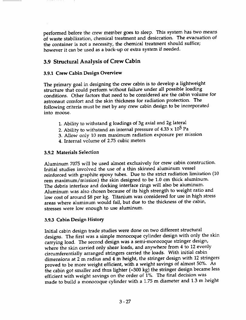
performed before the crew member goes to sleep. This system has two means
of waste stabilization, chemical treatment and desiccation. The evacuation of
the container is not a necessity, the chemical treatment should suffice;
however it can be used as a back-up or extra system if needed.
3.9 Structural Analysis of Crew Cabin
3.9.1 Crew Cabin Design Overview
The primary goal in designing the crew cabin is to develop a lightweight
structure that could perform without failure under all possible loadingconditions. Other factors that need to be considered are the cabin volume for
astronaut comfort and the skin thickness for radiation protection. The
following criteria must be met by any crew cabin design to be incorporatedinto moose.
1. Ability to withstand g loadings of 3g axial and 2g lateral
2. Ability to withstand an internal pressure of 4.33 x 10⁵ Pa
3. Allow only 10 rem maximum radiation exposure per mission4. Internal volume of 2.75 cubic meters
3.9.2 Materials Selection
Aluminum 7075 will be used almost exclusively for crew cabin construction.Initial studies involved the use of a thin skinned aluminum vessel
reinforced with graphite epoxy tubes. Due to the strict radiation limitation (10
rem maximum/mission) the skin designed to be 1.0 cm thick aluminum.
The debris interface and docking interface rings will also be aluminum.
Aluminum was also chosen because of its high strength to weight ratio and
low cost of around $8 per kg. Titanium was considered for use in high stressareas where aluminum would fail, but due to the thickness of the cabin,
stresses were low enough to use aluminum.
3.9.3 Cabin Design History
Initial cabin design trade studies were done on two different structural
designs. The first was a simple monocoque cylinder design with only the skin
carrying load. The second design was a semi-monocoque stringer design,
where the skin carried only shear loads, and anywhere from 4 to 12 evenly
circumferentially arranged stringers carried the loads. With initial cabin
dimensions at 2 m radius and 4 m height, the stringer design with 12 stringers
proved to be more weight efficient, with a weight savings of almost 50%. As
the cabin got smaller and thus lighter (~300 kg) the stringer design became less
efficient with weight savings on the order of 1%. The final decision was
made to build a rnonocoque cylinder with a 1.75 m diameter and 1.3 m height
3 - 27

Cr_W q_;" , "_l,';rll'._,'U[2. ,_!,:,c:,':_;
i j
oocking interface, , _, _,'
\_ i ! ,.;[ ......
., - -- ..III.LUxJ_[_LLLIIIII....
/ •
/ ",
i...... 2.0000 _ "_eht:T_ h';re u:...P,.,z_:r,
I
, :C_)
J
Figure 3.9.a Cabin Structure
OItlQIN.IL PA_EE. fig

after an analysis showed it had met all load factors without any stringers
added for stiffening.
3.9.4 Analysis Procedure
To get rough estimates of the stresses experienced by the vehicle during heavy
g loading an analysis was performed on the cabin assuming the following:
1. Pure axial loading ( no eccentric loadings )
2. Bending moment about cabin neutral axis
3. Thin walled cylinder assumption ( radius/thickness > 50 )
4. Cylinder is symmetric about longitudinal and radial axes
5. Factor of safety of 1.5 used in all calculations
The axial loads were computed by multiplying the mass of all of the spacecraft
below the bottom of the cabin including fuel (-10,000 kg) by a 3g axial load.
The compressive load calculated was 4.41 x 10⁵ N. A bending moment of 3188
N-m was also added acting at the junction of the cabin and the aerobrake
spine truss, as a result of the 2.0 g lateral load Using the general stress
equation (see appendix A3.6) the maximum tensile stress was 8.2 x 10⁶ Pa.
This is much lower than the yield stress of 448 x 106 Pa for aluminum 7075.
Using the equations for skin buckling (see appendix A3.6) the critical load was
1.6 x 10⁶ N. This was much higher than the modeled load of 4.41 x 10⁵ N.
3.9.4.1 Endplate Calculations
At CDR a question was raised concerning the validity of fiat endplates on the
cylinder. Fears were that the stresses at the junction of the plates and the
cabin walls would be very high. By modeling the end plates as fiat circular
plates fixed at the edges an analysis was performed. By using a formula in
Roark's the maximum stress on the plate was calculated to be 1.64 x 10⁸ Pa.
The stresses were the highest at the edges just as they were suspected to be.
This value is well below the yield stress of 448 x 106 Pa for aluminum 7075.
The main problem with the fiat endplate design was the high deflections at
the center of each plate. Two solutions were considered. One solution would
be to increase the stiffness of the whole plate. To achieve an acceptable
deflection the thickness would have to be raised to 1.75 cm per end plate.
This would mean an increase of 50 kg per plate. Due to the strict mass budget
another solution was investigated. Using the principle of super positioning a
beam with square cross-section of 2.5 cm with a thickness of 2.5 mm was
designed to satisfy the stiffness requirements of the deflecting plate. Two
beams crossing at the center of the plate with length 1.75 m were used on each
end of the cabin. The total mass added was only 8.0 kg.
3 - 29

3.9.4.2 Stress Concentrations Around Docking Ring
Another concern was the possibility of areas of high stress concentration near
the docking ring. Knowing that stress concentrations can often reach 3 times
the normal stress around holes, an analysis was performed using a set of
equations from Roark's. The cabin was modeled as a thin walled cylinder
with a hole at midpoint along the length. At the area of highest stress
concentration the stress was only 1.74 x 10⁸ Pa, well below the yield stress of
Aluminum 7075. This stress took into account both axial loads and bendingmoments.
3.9.5 Cabin Interfaces
To connect with other cabin hardware the cabin has three interfaces. One of
these is a docking ring. The docking ring has a diameter of 0.75 m and is
designed for compatibility with the PDA docking modules at SSF. The second
interfaces are the debris shield connecting rings. These are rings with a I-
beam cross-section with a depth of 10 cm and a web with of 10 cm. They are
designed to be welded to the cabin unit before shuttle places MOOSE in orbit.
Finally the cabin is designed to interface with an avionics box at the base of
the cabin. The avionics box is an aluminum 1.24 m square cross-section with
a height of 1.17 m. The skin thickness was sized using a fiat plate analysis for
the bottom plate for Roark's. With a load of 100 kg assumed uniformly
placed on the plate, an equation for plate stress and deflection determined thethickness to be 6.5 mm. The avionics box is mounted to the cabin with four
pin connections at the corners of the box which line up with the edges of thecabin base.
3.9.6 Structural Masses
cabin skin 200 kg
endplates 100 kg
endplate stiffeners 8 kg
viewport 20 kg
debris interface 15 kg
docking interface 30 kg
avionics box 130 kg
Total 5o3ks
Table 3.9.a Cabin Structural Masses
3 - 30

3.9.7 Areas Under Research
One major concern was the mounting of the viewport to the cabin. As of
now the viewport is made of a 5 cm thick Lexan plastic. Testing will have to
be done on debris impact and bonding to cabin surface. The docking
hardware was merely sized for SSF docking capability and may be able to be
made lighter by using composites around the ring.
1 Howle, D.H. "Man in Space" The Space Environment. University of London Press Ltd.,
London, 1969. p200.
2 Merril, Grayson.Handbook of Satellites and Space Vehicle. D. Van Nostrand Company,Inc.Princeton, NJ. 1965. p435.
3 Howle, D.H. "Man in Space" The Space Environment. University of London Press Ltd.,
London, 1969. p200.
4 Merril, Grayson.Handbook of Satellites and Space Vehicle. D. Van Nostrand Company,Inc.Princeton, NJ. 1965. p441.
5 Ibid p443.
6 Ibid p438.
7 Ibid p439.
3 -31


4.0 Aerobrake and Structure
4.1 Introduction
The main purpose of an aerobrake is to dissipate energy through
aerodynamic drag instead of utilizing rockets (fuel) to provide the force
necessary for braking the spacecraft. This leads to a considerable savings in
fuel mass. The recent development of composite materials ( light weight)
makes the aerobrake even more advantageous to propulsive braking than
previously concluded. However, aerobraking requires a greater amount of
structural design compared to a propulsive braking system.
The purpose of the aerobrake is to partially re-enter the atmosphere and
use atmospheric drag forces to slow the vehicle down and modify its orbit.
In this case, the aerobraking maneuver is used to change the orbit of the
servicing vehicle from a geosynchronous orbit to a low earth orbit. This is
done in order to rendezvous with Space Station Freedom, where it will
normally be docked. There were several points taken into consideration
in the design of the aerobrake.
- The shield should be re-usable.
- It should be able to be constructed using existing technology.
- Since it is unlikely that the shield could be sent up in one piece, it was
required to be relatively easy to construct in orbit.
- It should be relatively easy to detect possible failures and repair them.
4.2 Shape Selection
The first major consideration in the design of the aerobrake shield is its
shape. Both high L/D and low L/D configurations were examined. High
L/D shapes, such as bi-conics, have the major advantage of being able to
perform large plane changes. However, they generally require more
structural support in addition to increased thermal protection than lower
L/D configurations. Since it is not required that the vehicle be able to
perform plane changes, a low L/D configuration was chosen.
4-1

The final shape of the shield was chosen to be spherical. Not only would
this save weight in both the thermal protection system (TPS) and in the
structure itself, but it would also allow for the application of past research
and flight data. The spherical shield is similar in design to the Apollocommand module.
4.3 Trajectory Analysis
Before the structural design and analysis of the aerobrake could begin, the
loads that would be encountered during the maneuver had to bedetermined.
4.3.1 Equations of Motion
The loads were determined using the FORTRAN program shown in the
Appendix A4.1. This program used the Runge-Kutta method to
numerically integrate the equations of motion shown here.
dV _ -0"5p V2gsiny
dt
d_/ 0.5_V gcosY.1 V2
-_-= 13 V (g(h+R) )
dh = Vsinydt
4.3.2 One Pass versus a Two Pass Maneuver
By varying the initial conditions of the program, the ideal trajectory was
determined for various vehicle masses and angles of attack as well as the
loads associated with that trajectory. Both one and two pass maneuvers
were considered for the trajectory. The loads associated with both types of
maneuvers are shown in Figure 4.3.a and Figure 4.3.b respectively. These
plots show that the loads are significantly higher for a one pass maneuver
than for a two pass. A two pass maneuver involved the vehicle making
two shallow passes into the atmosphere instead of one long deep pass.
This type of maneuver only added approximately four hours to the total
mission time, which is within the limits of the on-board life support
equipment. Hence, the two pass maneuver was the method chosen forthe vehicle.
4.3.3 Flow Impingement and Angle of Attack
One of the parameters which had to be determined to run the loads
program was angle of attack. The size of the rest of the vehicle, especially
the spider truss housing the reaction control thrusters, initially
4-2
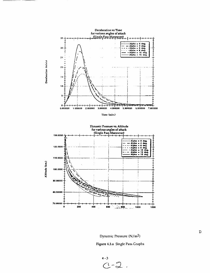
E
s_
o
Deceleration vs Time
for various angles of attack
30_: : ..: I : : : : ,,:(_;.ioRJ.e:P._s.;sM.p_eyvler_,! : : : : i : :-+-_-
T I.......,,_,..oo,0.I :i:- /_ I-- --Alpha = 4 de s. | -_30-4- ............ 1.... AIp,, - • a-S. I--1-
!,_\ / .... Alpha• a aao. I 1"
, [-- -alpha . 1o d*O. I .[
' [--Alpha= 15 de,. I25: • • • II _
,o........i................._'._\............i................_............., ......I.........--__ tL." i _\', i i , . i
•" , _ " i _ I 1 _.I
0.000000 1.000000 2.000000 3.000000 4.000000 S.O00000 6.000000 7.000000
Time (mJn.)
E
<
Dynamic Pressure vs. Altitudefor various angles of attack
(Single Pass Maneuver)13o.oooo!,: • : : : : ; : : : : : : I : _ ' I_ ' ' '
[....... A,_, :
/ .... Alpha -= G des................. i----------I.... _u_. • d.g.'1_,o.oooo i_ _ /-- -_Op,. lo d.O.
,s.. ; i i-"- Alpha 12 dog.! L Alpha 1S dog.
;_1[......_...... __.........
_... .
_'._ _"i_" ! i i_____'-.._ I _
__._-_.. _N
I I
; ; : | : : : ! : ; : , : : : ! : : : I i I
200 400 600 . _:,. 800 1000 1200
110.0000
100.0000'
90.00000-
00.00000 -
70.00000
Dynamic Pressure (N/m 2)
Figure 4.3.a Single Pass Graphs
D

Deceleration vs. Time
for various angles of attack
(Pass 1 of 2 pass maneuver)
i
i I- -0,., [
- - - 4 de|12 .......... ...... T'--'--| - - - i d.g ......
t I _ I dell
\_ /--"-10 des:|-- - 12 deg
16 d_ K
r
,o \4 i
_ ,'/IL> - "A\ '
?, [ ,/z. , :,\ '\ I It f/." ,
4 -t- ...... %..... --_'-:--\,--_----.--_ ;_................ .......... " I i
0 O.G 1 l,G 2 2.5 3 3.S
14
'12
lO
,q
-6
-4
-2
o
Dynamic Pressure vs. Altitude
for various angles of attack(Pass
,1 o _;, ....
l'/,os_.',L............
,oo._-,-_hi......
gSy _ _--
•-, -
Ill 0 . . , •
0 IO0
of 2 pass maneuver)
I "i .... tI_" .Ec I/ I .... zz o£c. I .L
i -l- "-l%_?I-+/"" .,uEc. I 1
I L- -' "_" I
__-._-_ _.
200 300 400 SO0
Dynamic Pressure (N/m 2)
Figure 4.3.b First of Two Pass Manuever
4-4

determined the size of the shield. To stay within the given mass budget,
the shield was downsized to a diameter of 9 meters. Figure 4.3.c shows the
effect of angle of attack on flow impingement. Given that the diameter of
the spider truss was slightly over 3 meters, simple geometry and Figure
4.3.c were used to determine that a maximum angle of attack of 16 degrees
would prevent flow impingement on the spider truss. The location of the
vehicle CG. determined the angle of attack. Since at the time of the
analysis the location of the CG. was unknown, the program was run
varying the angles of attack between 0 and 16 degrees.
4.3.4 Lift and Drag
Figure 4.3.b shows that the dynamic pressure loads increase as angle of
attack increases. The shield was structurally sized to operate at an angle of
attack of 16 degrees, since this is the maximum allowable angle of attack
due to flow impingement effects.
As the vehicle travels at some angle of attack, both lift and drag are
generated. The lift is given by :
where:
L = lift
p =V=
A=
C! =
L = 2_3V2ACI
density of the freestream atmosphere
velocity of the freest-reamcharacteristic area of the aerobrake
lift coefficient
The drag is given by :
D = _pV2ACd
where:
D = drag
Cd = drag coefficient
The lift generated allowed the pilot to make trajectory corrections during
the maneuver. The larger the angle of attack, the larger the margin for
error the pilot had. The lift and drag generated by the shield during the
first pass of the maneuver assumes angles of attack between 0 and 16
degrees is shown in Figure 4.3.d.

36
34
32
30
28
26
_" 24UJ
o 22¢D
_ 2O,J
Z
12
_0UJo
8
6
4
i
*__ II _W TURNINQ ANOLE ....
' FLow............I.."............!.............
---__:: _ow ...............[..:::::::_::::::::i
........ _ ....... J t.', ............
........L.__"_.".................._"
*.4"'"."0.....................'.......
I.m,
m
m
,_Nm,
,retool
ram,
----U.h,,t
I
......b............v.I|.*.............................!..........................FLOW TURNING AtNGLE I .- 0"",_,l TOTAL MPINOEI_IENT e
..................................r:::_;:'''_...............I................ I:-- ............
....:::1...... ............... .............LI.:,_,_.'-_.... _ I, I_
m
..........._ ,o:g_,g..,......_' ::::::::::::::::::::::::::::::::'
I
I
I..... l .......
6 8 I0 12 14 t6 18 20
ANGLE OF ATTACK, _ (DEG)
Figure 4.3.c Flow Impingement
4-6

2JOGO 104
t .r.hn 104.
_) 1.000 104.
SO0_"
0
0.00_00
Drag vs Time for variousangles of aUack
\
12 _.g \ I10 de8 ,/ *
..... i d_ ............ __.,'t........... \i deg / ,'. _'__. . "_ ", ,
/.i"'/,/' "" "" _ "/.."/.", "__--" ,, _• .s -
"YTIi
I: : : 1 : -" : : ' ' " ' " : : :
0.4000000 O. lOOOOO@ 1.200(X)0 ;.600000 2.000000
T'mxe (mJnJ
¢1=
6OOO
4000 ¸
:llDOO.
:_OO@,
1000,
O-
O.OOOO00 .
U_t _s Time for various
angles of attack
I '
! ,
I j
i ." •
..... lg deg-- 12 deg
- -- -le ql4,9
- - -evq• dog
.... 4s_g
"t'"*** ]
/
." /rr
.* /
t!Wll
•, !
T_\ !,.
! \i ..
..-/ ,, ..' _ - _Z__.___.................4-.."-_....-._....,---.--_7C;.___ _-i
.'>'.-.=.r_ j [ _ ":-:[
0.40000_ OJ_ 1.200000 1 .II00000 2.000_
Figure 4.3.d Lift and Drag on the Aerobrake
4-7

4.4 Aerodynamic Loads
For a two pass maneuver, the vehicle dips into the atmosphere about the
same distance for both passes. However, the velocity is lower for the
second pass. Therefore, the loads due to the dynamic pressure are higher
during the first pass. The g-loads, however, are about the same for both.
For this reason, the loads encountered during the first pass were chosen to
be the critical aerodynamic loads.
The chosen trajectory gives a Mach number of 34. For a blunt body, the
stagnation point value of the coefficient of pressure, Cp, can be determined
using:
,, P0,2
:P0,2
The value for the ratio of pressures, -P-1-1' can be obtained from a table of
normal shock properties such as Anderson's Fundamentals of
Aerodynamics. At M=34, the ratio was found to be 1.489 x 10³. This gives
Cpmax = 1.839.
Since the vehicle is traveling at hypersonic speeds, modified Newtonian
theory can be used. This theory states
Cp = Cpmax (cos2(theta))I
where theta is the angle between a normal to the surface and the free
stream velocity. While the maximum pressure would occur only at the
stagnation point, the structural analysis was done assuming stagnation
conditions over the entire shield. This provides an additional factor of
safety. The total dynamic pressure loading was found to equal
Cpmax x q = 1500 N/m 2
where q is the dynamic pressure. The next type of load to consider is the
loading due to acceleration (g-loads). G-loads will be encountered on two
occasions. The first will be during the thrusting maneuver to bring the
vehicle to a geosynchronous orbit. According to the Propulsion group,
this load will be no more than 2g. The second occasion is during the
aerobrake maneuver. As shown in Figure 4.3.b, this load will not exceed
1.5g.
4-8

Due to time constraints, an analysis was not completed on how the nozzle
hole in the shield would affect the aerodynamics.
4.5 Aerobrake Control
For purposes of control while performing the aerobrake maneuver, the
torques of the brake were calculated. The torques that will contribute the
most during this time is the aerodynamic torque and the gravity - gradient
torque. The torques were calculated in a "worst case scenario." The worst
possible thing that could happen is for the two torques to add to each
other, however, it is possible for the two to work against each other.
4.5.1 Aerodynamic Torques
The aerodynamic torques occur in lower orbits or when entering the
atmosphere. The torques are dependent on the density of the atmosphereand therefore on the orbit. At higher orbits, the density is too small to
create a torque, therefore, the calculations of the torques were performed
for the orbit altitudes of 80 km to 100 km, the region of the aerobrake
maneuver.
The torques are also dependent on the locations of the center of pressure
of the shield, Cp, the location of the center of gravity of the space craft, Cg,
and the coefficient of drag of the shield, Cd. For the worst case, the Cp can
be assumed to deviate 5% of the shield diameter from the Cg of the space
craft. The Cg has been calculated to be the center of the shield.
4.5.2 Calculations of Aerodynamic Torques
The equation for the Aerodynamic torque is
Ta = F (Cp-Cg)
where
Cp
CgF
= center of pressure
= center of gravity
= aerodynamic force.
4-9

The equation for the aerodynamic force is
F = .5 p Cd A V 2
where
p = atmospheric density
Cd = coefficient of dragA = characteristic area of the aerobrake
V -- velocity of the spacecraft.
The aerobrake maneuver will be done in two passes and the calculations
for these passes are the following:
pass #1
@ 100 km. F = 1073.6 N Tg = 483.12 N - m
@ 80 kin. F = 34715.3 N Tg = 15621.8 N - m
@ 100 kin. F = 868.3 N Tg = 390.74 N - m
pass #2
@100km. F= 868.3N Tg= 390.74N-m
@ 80 km. F = 27034.6 N Tg = 12165.6 N - m
@ 100 km. F = 643.5 N Tg = 289.58 N - m
The torques are now calculated and a control system can be developed to
overcome these torques.
4.5.3 Gravity - Gradient Torques
Gravity - gradient torques are developed on space craft as they orbit the
earth. These torques are usually quite small. They depend on the
spacecraft's moments of inertia, and the orbit altitudes.
The torques were calculated using the formula
Tg = 3 ( _t ) / [ 2 R 3] /Iz - Iyl sin (2 0)
where
= Earth's gravity constant = 3.986 x 10¹⁴
R is the radius of the orbit in meters
Iz and Iy are the moments of inertia for the space craft
0 = angle between the Z - axis and the local vertical.
4- 10

These calculations were made for the entire mission. Due to their length
and their size, the reader can find these calculations in Appendix A4.3.
4.6 Material Selection
Titanium was first considered as a possible construction material. It has a
high tensile yield strength and a low coefficient of thermal expansion.
However, the structural members needed to support the aerodynamic and
acceleration loads were far too heavy to merit further consideration. Since
saving weight was a driving factor throughout the design process, solidaluminum was the next material considered for the shield and support
structure. The brake was initially sized using aluminum I-beams for the
support structure and covered with a thin aluminum skin on which to
mount the thermal protection system (TPS). This configuration also had a
final mass beyond the allowed mass budget.
The next choice was to use aluminum honeycomb. Hexcel Aerospace
provided some material on designing honeycomb sandwich structures.
Use of honeycomb in the shield and support structure decreased the
weight of the brake to within the given mass limit. The overall thermal
resistance of the honeycomb plate is the sum of the resistances of the core,
facing, adhesive, and boundary layers on each side of the sandwich. This
provides better insulation for the rest of the vehicle than the thin
aluminum sheet originally considered.
4.7 Design Configuration
The aerobrake is composed of plating and a support structure.
The honeycomb plating gives the brake its solid spherical shape. It is also
the surface onto which is mounted the TPS. The plating is composed of
ten equally sized curved trapezoids, which fit together to form a spherical
surface with a hole in the center for the engine nozzle. It was decided to
divide the shield into ten segments because given the size of the brake, ten
equal parts fit nicely in the shuttle cargo bay. The dimensions of the platesare as follows :
Top width = 0.352 m.Bottom width = 2.83 m.
Side edge lengths = 4.88 m.
Plate area = 7.50 sq. m.Plate radius of curvature = 10.63 m.
Honeycomb face sheet thickness
Honeycomb core thickness
= 0.15 mm.
= 15.66 mm.
4-11

The support structure is composed of ten equally spaced arches and rods.
The arches are basically curved beams which the curved plates are
mounted to. These arches are also made of honeycomb. The dimensions
of a typical arch are as follows :
Beam width
Beam lengthBeam radius of curvature
= 0.15 m
= 4.88 m
= 10.63 m
Honeycomb face sheet thickness
Honeycomb core thickness
= 0.63 mm
= 80 mm.
The straight rods are pinned between the edge of the aerobrake and the
main vehicle truss at an angle of 32 degrees to the horizontal. They
mainly provide additional support against global buckling of the shield. Itwas decided to make the rods out of solid aluminum because at the time
of the analysis, there was insufficient information on the behavior of
honeycomb rods under tensile loading. Their use however should not beruled out once more information is available. The dimensions of a typical
rod are as follows :
Rod length = 4.67 mRod radius = 0.018 m.
The arches are pinned in a radial fashion to the nozzle ring (the ring
shaped portion of the main vehicle truss surrounding the engine nozzle).
The other end of the arches are pinned to the rods which in turn are
pinned to the cabin ring (the ring shaped portion of the main vehicle truss
below the crew cabin). The plates are simply pinned on to the arches. The
shield and support structure (without the TPS) are shown in Fig. 5.
The structural analysis of the shield and supporting structure is shown in
the appendix A4.2.
4.8 Mass Total
The total mass of the shield and support structure is tabulated as follows •
Mass of plates 156.72 kg
Mass of rods 134.4 kg
Mass of arches 56.8 kg
Adhesive and Aluminum Pins 20.0 kg
Total Brake Mass 367.92 kg (does not include TPS).
4- 12

4.9 Assembly
The aerobrake will be shipped to space in pieces and then assembled on-
orbit. The determination of in-space EVA/telerobotic assembly issues can
be accomplished by testing a partial full-scale aerobrake structure. Such an
experiment has previously been conducted at the McDonnell Douglas
Space Systems Company Underwater Test Facility in Huntington Beach,
California. Assembly procedures were tested underwater using two EVA
astronauts and a telerobotic manipulator. Several extra divers assisted in
the movement of the core in order to simulate the in-space movement of
the "lazy Susan" structure.
4.9.1 Use of Telerobotics
Among the telerobotic systems that should be available at Space Station
Freedom: Mobile Remote Servicer (MRS), Space Station Remote
Manipulator System (SSRMS), Flight Telerobotic Servicer (FTS), Special
Purpose Dexterous Manipulator (SPDM), and a Mobile Transporter (MT).
The telerobots can be used to back up, assist, or replace EVA crew in the
aerobrake assembly. The telerobots will primarily be used for transporting
and holding large pieces of the aerobrake while the astronauts complete
the tasks requiring more precision. The option of using telerobotics
becomes feasible when one considers problems that may arise in space.
Space suit failures or the presence of solar flares would necessitate the useof telerobots. Therefore, a combination of EVA and telerobotics will be
used in assembly, as a strictly automated assembly would not be cost
effective. In addition, a structure commonly referred to as a "lazy Susan"
is required for rotation of the aerobrake during assembly and
maintenance.
4.9.2 Assembly Procedure
The individual pieces of the aerobrake are small enough to be brought
into orbit on board the space shuttle. Once in orbit, the shield must be
assembled. The first components that must be put on are the arches.
These will simply be attached in a radial fashion by pins to the nozzle ring.
The free ends of the arches will then be pinned to one end of the straight
rods. The other end of the rods will then be pinned in a radial fashion to
the cabin ring. Once this support structure is completed, the plates can be
attached to the arches also using pins. The plates will be delivered to the
station with the TPS already mounted on to them so no further assembly
is required. All of the honeycomb structures will have small perforations
in the core to allow for the release of pressure during the transition from
the earth's atmosphere to the vacuum of space. Figure 4.9.a shows the
aerobrake assembled.
4- 13

Figure 4.9.a Aerobrake Structure
4-14

4.9.3 Time for Assembly
Based on the results obtained from the underwater assembly of a three
petal aerobrake, McDonnell Douglas proceeded to calculate the man-
hours spent per task on a eight petal assembly. The graph on the following
page (figure 4.9.b) depicts the man-hours to be spent per task on our ten
petal assembly. The total time does not include time necessary for
inspection after assembly. The inspection process involves checking the
thermal protection tiles as well as using X-rays, computer enhanced
imaging, or sensors to check the mechanical structure. Some extra time,
however, has been allotted to allow the astronauts to become familiar
with the assembly process. The graph shows the total time required to
perform each assembly task: translate and ingress to PFR (portable foot
restraints), alignment of the petal and soft dock, egress PFR and tether to
the handrails, translate along the handrails and latch on the hard docking
fasteners, and then attach the struts to conclude the assembly process. The
total time to complete the aerobrake assembly is four hours and sixminutes.
4.9.4 Maintenance
The simple pin configuration of the brake allows for easy servicing of the
vehicle. For example, to remove a fuel tank, the appropriate pins can be
removed and the rods that are in the way can simply be swung out. If the
TPS on one of the plates is found to be defective or badly worn, that entire
plate can just as easily be removed and replaced. The same applies for anyof the rods or arches.
4.10 Main Spinal Truss
4.10.1 Requirements
The critical loading, of 2gs, for the main spinal truss is the buckling load
induced during the third orbital burn. The spinal truss is 3.5 meters longand extends from the bottom of the aerobrake to the bottom of the
avionics box and spider truss integrated system. The spinal truss must
sustain the inertial loading of the complete MOOSE system seeing that it
serves as the main load path for the vehicle. As was used for the buckling
analysis for the crew cabin, a 10000 Newton force will be scaled by a factor
of safety of 1.5. This force was applied in such a way that each of the four
longitudinal members of the spinal truss would be required to withstand
this load. This is a conservative analysis.
4- 15

r,] time in minutes per task
100.0
I,._
(D
(/)
E:
Et-
o_
Q)E
°D
80.0
60.0
40.0
20.0
0.0
! :
latches sftdock tethers
• .i ..................................................................
PFR's translation struts
Figure 4.9.b Aerobrake Assembly Time
4-16

4.10.2 Longitudinal Beams
Using the Euler buckling equation with a loading of 15000 Newtons on a
beam of 3.5 meters length, a minimum moment of inertia for the beamcan be found. The beams were assumed to be fixed at both ends with
welds. This dictates an effective length of .71 times the actual length. A
trade study was conducted between two materials, aluminum and
titanium. Because of temperatures of 350°F behind the aerobrake, the
aluminum beams were analyzed using 70% of their strength.
The circular tube cross section required for aluminum beams was found tohave an outer radius of 5 cm and an inner radius of 4.4 cm. This cross
sectional area yielded a mass of 17.35 kg per beam. The circular tube cross
section required for the titanium beams was found to have an outer radius
of 2.5 cm and an inner radius of 2.3 cm. This cross sectional area yielded a
mass of 4.7 kg per beam. Clearly, titanium offers a distinct mass advantage
for our system.
4.10.3 Cross Member Beams
The main longitudinal beams will be connected by 7 cross members of
equal size. These members will have cross sections with half the
dimensions of the main longitudinal members. Their total mass is 26.6
kg.
4.10.4 Spinal Rings
Three rings with box tube cross sections of outer radius 5 cm and inner
radius 4.5 cm will be integrated between the four longitudinal members.
Two of these rings will be located at the bottom and the top of the spinal
truss configuration. The third would be attached at a height of 2.6 meters
above the bottom of the aerobrake to serve as hard points for attaching the
aerobrake, the crew cabin, and the tank interface beams. The total mass of
these three rings is 24.7 kg. Titanium fittings will serve to interface the
aerobrake members to the spinal truss.
4.10.5 Spinal Truss Interface
A cantilever beam analysis of the tank to spinal truss interface yields acircular tube cross section of outer radius 4 cm and inner radius of 3 cm.
This beam must sustain the inertial loading created at the start of the first
orbital burn since at this time the mass of the main propellant tanks is at a
maximum. Although the g-loads here are not at a maximum, the loading
at this point in our mission is still the critical loading for the tank to spinal
truss interface beam. The mass of each of these beams is 5.2 kg. The total
mass of the four beams is therefore 20.8 kg.
4- 17

4.10.6 Spinal Truss Masses
Longitudinal BeamsCross Member Beams
Spinal Rings
Spinal Truss Interface
4 x 4.7 kg 18.8 kg
7 x 3.8 kg 26.6 kg
3 x 8.2 kg 24.7 kg
4 x 5.2 kg 20.8 kg
Total 90.9 kg.
4.11 Thermal Protection System (Tile Sizing)
This section will strictly discuss how to determine the proper TPS tile size.
Shuttle-type TPS tiles are quite fragile and have to be separated by a strain
isolation pad (SIP) from the underlying structure. There is a deflection
limit in the support structure which if exceeded will cause the separation
of the tiles from the structure. The separation occurs due to the failure ofthe SIP. A local induced radius of curvature is calculated from the normal
panel deflections and then analyzed with respect to tile deflection (Wtps)
and tile size (L1,L2) as illustrated in figure 4.11.a. "Using the following
equation for a circle
y2 + Z 2 + C1Y + C2 Z + C3 =0
and the positions of the three deflected points as determined from the
diagram. We obtain solutions for C1, C2, C3 upon substitution of the x
and y values of each deflection point.
C1=1/2L (-Wc 2 + Wa 2 + (Wc-Wa) ( Wc 2 -Wb 2 + Wa 2 +2L2)/Wc-2Wb
+Wa)
C2=(Wc2-2Wb 2 +Wa 2 +2L 2) / Wc-2Wb +Wa
C3=Wb [2L 2 + Wc (Wc-Wb) + Wa (Wa-Wb)]/Wc-2Wb + Wa
The radius of curvature, ROC, related to the normal displacements on the
structural panel is
ROC=0.5 (C12 + C2 2 -4C3) 0.5.
The following equation relates tile size and tile deflection to obtain theROC
(ROC-Wtps,1) 2 +L12=ROC 2.
4-18

Surfac_ of "_,_!"z"undeformedstruc_ur= - L .... L_II _'_C t
i T _-w=w. , j /'-_
ROC w b
etru_ur=
Y
a.Geort_ry for calculating radium-of-curvature from 3 normal dlsplecerne t=.
Deflected structure
Radlum-of-curvature (ROC)
+
Figure 4.11.a Relationship Between TPS Panel Size and Deflection Limit and ROC
4-19


5.0 Propulsion
5.1 Introduction to the MOOSE Propulsion Systems
This chapter outlines the propulsion systems utilized on MOOSE. The main
propulsion system is complemented by a dual-propulsive reaction control system.
Details of the components selected and each propulsive system's requirements further
clarify the role and purpose of each system.
5.1.1 Optimum Propulsion System
Five different propulsion systems were considered for the MOOSE project. These
propulsion systems included three different chemical propulsion systems (liquid,
solid, and hybrid), a nuclear fission reactor, and a laser absorption process. It has been
determined by the design group that the optimum propulsion system for the MOOSE
project is a chemical system with liquid propellants. Section A.5.1 of the appendix,
"Choosing the Optimum Propulsion System", details the four propulsion systems that
were analyzed but not chosen for the MOOSE project. In addition to the results of
section A.5.1, the analysis presented in section 5.1.2, "Propellant Transport Cost for
Chemical Propulsion Systems," details the major factor in determining the optimum
propulsion system for the MOOSE project.
5.1.2 Propellant Transport Cost for Chemical Propulsion Systems
In order to operate MOOSE the propellant needed for the vehicle must be transported
from Earth to Space Station Freedom where MOOSE will be docked. Transporting the
propellants to MOOSE turns out to be a primary cost for the customer, which can be
lowered if the mass of propellants is reduced. The mass of propellants can be reduced
by decreasing the structural mass or by increasing the specific impulse. Figure 5.1.a
shows the relationship of propellant transport cost compared to the vehicle structural
mass for various specific impulses.
The following design criteria was used for this analysis:
• Propellant transport cost = 8.9 $k/kg
• AV=7000m/s
• Structural mass = 3047 kg
(Typical for a Titan IV launch vehicle)
5-1

A chemical propulsion system that uses either solid or hybrid propellants would not
be a cost efficient system for the MOOSE project. The performance level, Isp, for solid
propellants ranges from 180 to 300 seconds. From Figure 5.1.a it can be seen that for a
structural mass of 3047 kg it would cost between 300 to 1100 $Million just to transport
the propellants from Earth to the space station. The performance level, Isp, for hybrid
propellants ranges from 250 to 350 seconds. From Figure 5.1.a it can be seen that for a
structural mass of 3047 kg it would cost between 200 to 510 $Million just to transport
the propellants from Earth to the space station. The results show that it would not be
cost efficient to use a chemical system with either solid or hybrid propellants. The
design group can not expect the customer to pay over 100 $Million in transporting the
propellants from Earth to the space station since the customer can build a new satellite
and have it placed into orbit for an estimated 300 $Million. It would not even be cost
efficient for MOOSE to repair two satellites during the same mission since each
customer would still be paying over 100 $Million in propellant-transport cost.
A chemical propulsion system that uses liquid propellants can be cost efficient if the
propellants chosen have a high enough performance level, Isp. From Figure 5.1.a it
can be seen that for a structural mass of 3047 kg the performance level, Isp, must be
about 450 seconds in order for the system to be cost efficient in propellant transport
(assuming that MOOSE only repairs one satellite per mission). Propellants consisting
of oxygen / hydrogen fit this criteria, costing slightly below 100 $Million in propellant-
transport cost.
If MOOSE is to repair two satellites in one mission then the propellant-transport cost
can be split among the two customers, allowing the propellant-transport cost to
approach 200 $Million and the performance level, Isp, to lower to 350 seconds. A
lower Isp would allow for various choices in liquid propellant combinations such as"
oxygen / hydrogen, fluorine / hydrazine, and fluorine / hydrogen.
Propellant Transport Cost vs. Structural Mass
1600
1200
1000
600 ¸
_. 40o̧
_- 200-
0
0
o ISp = 258 .........'_...............!......o......
• Isp = 388
i o• Isp -458 ........_................_..............
.............. !............... _...... "6....... _............... _...............
..............i..............*...............:................--..-._......: 0
.............._......................-........!.............._..............0 Ip ' ¢ : x
.............. _...... _.......:_......h...... _............._......÷ .......o # . ; _ | ; _ , ,
.._..I.._..._..•.._.... i....
1000 2000 3000 4000 5000
StructuralMass (kg)
Figure 5.1.a Relationship of Propellant Transport Cost Compared
to the Vehicle Structural Mass for Various Specific Impulses
5-2

5.1.3 Requirements for the Selection of Liquid Propellants
The selection criteria for the liquid propellants is based on many properties of the
various potential propellants surveyed. These potential propellant combinations had
to meet the requirements that follow before a final selection could be made based on
the results of trade studies. The propellants must have high energy release per unit
propellant mass as well as low molecular weight of the combustion gases to achieve
high specific impulse. Ignition must be easily induced and stable combustion
maintained. The propellant should have a high density to minimize the size and
weight of the propellant tanks and feed systems. A low freezing point is desired to ease
engine operations at low temperatures. The propellants must be compatible with the
engine materials to assure the absence of corrosive effects. The ability to act as an
effective coolant for the thrust chamber and nozzle is necessary (a combination of high
thermal conductivity, high specific heat, and high critical temperature). Low viscosity
is desired to minimize the pressure drops through the feed system and the injector. To
reduce the risk of explosion and fire hazards, high thermal and shock stability is
required. Low toxicity of the propellants and the combustion products is also desired.
Finally, the propellants should be readily available at an acceptable price.
5.1.4 Liquid Propellant Analysis
From the above analysis on propellant transport cost it has been determined by the
design group that if MOOSE can repair two satellites in one mission then the liquid
propellant combinations that would provide a cost efficient system are: oxygen /
hydrogen, fluorine / hydrazine, fluorine / hydrogen. However, if MOOSE only repairs
one satellite for a given mission then the only liquid propellant combination that
would provide a cost efficient system is oxygen / hydrogen. Note, for this analysis a
cost efficient system is only referring to propellant transport cost under 100 $Million
per customer.
The major disadvantage with using any of the above propellant combinations is that
oxygen, hydrogen, and fluorine are all cryogenic propellants. The only alternative
would be to reduce the structural mass of the vehicle such that liquid propellants with
storability characteristics, such as hydrazine, can be used. However, since the
performance level, Isp, of storable propellants drop below 350 seconds the structural
mass would have to decrease below 2000 kg in order for the system to remain cost
efficient, see Figure 5.1.a. Since the structural mass of MOOSE is 3047 kg the design
group will be using cryogenic propellants, however, if the structural mass does drop
below 2000 kg then using storable propellants needs to be considered.
The design group understands the difficulty in storing cryogenic propellants.
Information on storing the cryogenics during flight can be found in section 5.10 of this
chapter under the heading Propellant Tanks, and information for storing the
cryogenics at the space station can be found in chapter 8. Again, the design group
understands that storing cryogenic propellants is difficult, but no other propellant
combinations are desirable from a cost efficient standpoint unless the structural mass
5-3

decreasesbelow 2000 kg.
With the three cryogenic liquid propellant options available for the MOOSE project the
design group decided to use oxygen / hydrogen for the main propulsion system. The
major determining factor is that with an oxygen / hydrogen system MOOSE will not be
limited to repairing two satellites in one mission. MOOSE can be sent out to repair
one satellite on demand and still remain cost efficient. Note, the analysis for repairing
two satellites in one mission can be found in chapter 1 under the mission analysis
section. Another factor leading to the choice of an oxygen / hydrogen system is that
the other two propellant options use fluorine as the oxidizer. Fluorine is extremely
toxic and corrosive in addition to spontaneously reacting with many common
spacecraft construction metals. Furthermore, fluorine has only been used in
experimental rocket engines and not in production engines.
5.1.5 Chemical Propulsion with Liquid Propellants
A chemical propulsion system with liquid propellants generally consists of a
combustion chamber, injectors, ignition system, nozzle, propellant feed mechanism, a
power source for the feed mechanism, plumbing, and propellant tanks. In a chemical
propulsion system with liquid propellants, the fuel and oxidizer reaction causes a
high-pressure combustion which releases energy that heats the products of the
chemical reaction to very high temperatures. These reaction products, which are in a
gaseous state, are expanded in the nozzle and accelerated to high velocities, thereby
imparting momentum to the system.
The main propulsion system for the MOOSE project is shown below in Figure 5.1.b.
O_lm
Figure 5.1.b Main Propulsion System for the MOOSE Project
5-4

5.2 Mixture Ratio
The following expression is the chemical reaction of liquid hydrogen and liquid
oxygen going to completion:
H_+ _O2_H_O
All of the hydrogen and oxygen are fully consumed to form water vapor. There is no
reactant residue of either hydrogen or oxygen remaining after combustion since the
reactants are in stoichiometric proportions. On a mass basis this stoichiometric
mixture provides a stoichiometric mixture mass ratio of 8:1. The stoichiometric
mixture mass ratio results in the highest combustion temperature and the highest
release of energy per unit mass of propellant mixture. This does not automatically
mean that operating at the stoichiometric mixture mass ratio provides the best
performance. In fact, operating at hydrogen rich levels increases the performance
level, Isp, of the engine. The hydrogen rich levels allow for some of the lightweight
hydrogen molecules to remain unreacted. This reduces the average molecular weight
of the reaction products, and therefore, increases the performance level, Isp, of the
engine. The following equation shows the relationship between the performance
level, Isp, and the average molecular weight of the propellants.
2yR Pe -7-
Isp=_ y-TTTo 1-_o °
The "R" term in the above equation represents the propellant gas constant. The
propellant gas constant is equivalent to the universal gas constant divided by the
average molecular weight of the propellants. From this equation it is obvious that as
the average molecular weight of the propellant decreases the propellant gas constant
"R" increases, thus increasing the performance level, Isp.
Operating at hydrogen rich levels will increase the performance level, Isp, of the
engine, as shown above, however, caution must be taken because if the hydrogen rich
level is too high some of the hydrogen will be avoiding combustion. Any excessive
hydrogen that avoids combustion is considered dead weight, meaning that it is
undesirable to carry any additional propellant mass that is not useful. There is an
obvious trade off on how high a hydrogen-rich level to use, but there are additional
factors that need to be considered. In addition to increasing the performance level of
the engine, hydrogen rich levels will also insure complete combustion of the liquid
oxygen. Any liquid oxygen that does not combust can oxidize the nozzle causing
corrosion, which in turn shortens the life span of the nozzle.
Even though it appears that operating at hydrogen rich levels has several advantages
over operating at the stoichiometric mass mixture ratio, there is one major
disadvantage that needs to be recognized. As the mixture ratio decreases from the
5-5
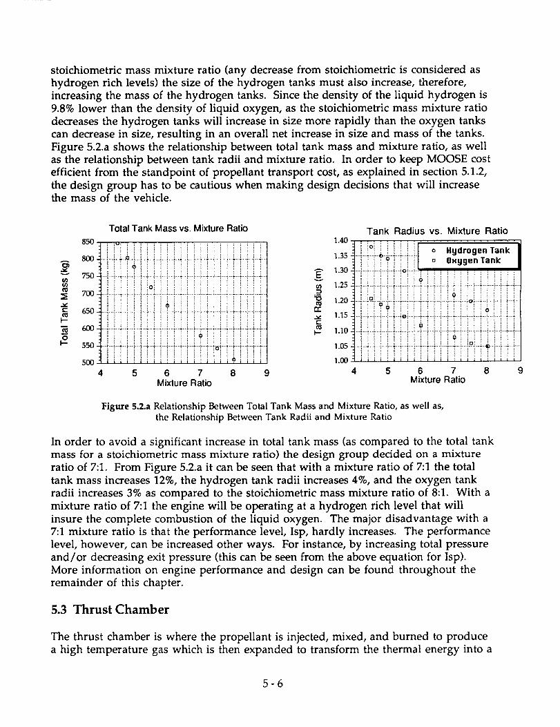
stoichiometric mass mixture ratio (any decrease from stoichiometric is considered as
hydrogen rich levels) the size of the hydrogen tanks must also increase, therefore,
increasing the mass of the hydrogen tanks. Since the density of the liquid hydrogen is
9.8% lower than the density of liquid oxygen, as the stoichiometric mass mixture ratio
decreases the hydrogen tanks will increase in size more rapidly than the oxygen tanks
can decrease in size, resulting in an overall net increase in size and mass of the tanks.
Figure 5.2.a shows the relationship between total tank mass and mixture ratio, as well
as the relationship between tank radii and mixture ratio. In order to keep MOOSE cost
efficient from the standpoint of propellant transport cost, as explained in section 5.1.2,
the design group has to be cautious when making design decisions that will increasethe mass of the vehicle.
Total Tank Mass vs. Mixture Ratio
850 : :o.... . ................. : .. _ 1.40i i i i i ! i i i ! ! ! i :: i :: :: :: :: i i i :: !
800AO_
v 750¢,0
700 -"
" 650
I---
"_ (,000
k- 550-
500
4
i!iioiiill ill iiiii!iiiii
i i ! i i i ioii i i i i i i i i i i i ! i i !
_ i ! i i ! ! ! i01 i! ! i i i i i ! ! !! i
_i_.+_!_!_}_i_i_i_i_i_+_.!_!_i_+_!_i_!_+._!_!_!"_!iiiiiiiiiiiiii_iiiiiiiii
?iiiitiiiiiiiiiiioiiii!tiill; iiiiiiiil iiiiiioiiii
5 6 7 8 9Mixture Ratio
1.35
1.30Eu_ 1.25-"s
.i
-o 1.20
rv1.15
¢..
c_b-- 1.10
1.05
1.00
Tank Radius vs. Mixture Ratio
Li%LIILLI oi iii ii!i I ° O.yg,nT.nk_ i i i i _ ! i iOi ! i _ ! i i i ! ! i i i i
_!_.!_.!_.i._i_._!_!_!_!_.i_i_.i_._i_i_.i_f._i_i_.i_!_
iioiiiiiii?iiii$11iiiiiii._:_.:_-_.:_;_:_.:_;._._:_i_?_+_._._.._÷_r_.
_i_i_.i_..i_._._i_._i_._i_+_i_i_i_+_i_.i_.i_.+_i_i_i._+._i_iiiii!iii=iiiii!iiiiiiii
-'iiiiiiiiiiiiii,iiiiiiiii:::::::::::::::::::::::::
_+._!_!_÷_._._!_÷_!_i_+_._!_!_:_T_i i ! ! ! _ i i i i ! ! ! ! _ ! _ i ! _ ! i E i::::::::::::::::::::::::I|il:llli;llll;ltll:llll
4 5 6 7 8 9Mixture Ratio
Figure 5.2.a Relationship Between Total Tank Mass and Mixture Ratio, as well as,
the Relationship Between Tank Radii and Mixture Ratio
In order to avoid a significant increase in total tank mass (as compared to the total tank
mass for a stoichiometric mass mixture ratio) the design group decided on a mixture
ratio of 7:1. From Figure 5.2.a it can be seen that with a mixture ratio of 7:1 the total
tank mass increases 12%, the hydrogen tank radii increases 4%, and the oxygen tank
radii increases 3% as compared to the stoichiometric mass mixture ratio of 8:1. With a
mixture ratio of 7:1 the engine will be operating at a hydrogen rich level that will
insure the complete combustion of the liquid oxygen. The major disadvantage with a
7:1 mixture ratio is that the performance level, Isp, hardly increases. The performance
level, however, can be increased other ways. For instance, by increasing total pressure
and/or decreasing exit pressure (this can be seen from the above equation for Isp).
More information on engine performance and design can be found throughout the
remainder of this chapter.
5.3 Thrust Chamber
The thrust chamber is where the propellant is injected, mixed, and burned to produce
a high temperature gas which is then expanded to transform the thermal energy into a
5-6

high velocity flow at the exit, hence useful thrust is imparted to the vehicle. A typical
thrust chamber assembly consists of an injector, ignition system, propellant inlet and
distribution manifolds, mounting structures, combustion chamber, and expansion
nozzle.
5.3.1 Thrust Chamber Configuration
The results of the thrust chamber calculations are given below in Table 5.3.a;
subsequent sections elaborate on how these results were obtained.
Thrust, T
Mass flow rate, m
Exit area, Ae
Throat area, At
Expansion Area Ration, Ae/AtChamber diameter, Dc
Chamber volume, Vc
Chamber length, Lc
87 kN
28.8 kg / s
0.99 m 2
0.0248 m 2
40
0.281 m
0.022 m 3
0.355 m
Table 5.3.a Thrust Chamber Characteristic Values
5.3.2 The Combustion Process
In a liquid bipropellant rocket engine, the following basic steps characterize the
conversion of the chemical energy of propellants into thrust. The liquid propellants,
at the proper oxidizer fuel mixture ratio (O/F), are injected into the combustion
chamber and atomized into droplets. The droplets are subsequently vaporized by heat
transfer from the surrounding gas. The vaporized propellants are mixed rapidly,
further heated, and react quickly, thus continuously increasing the mass flow rate
within the combustion chamber. Combustion will essentially be complete upstream of
the chamber throat, when all liquid droplets have been vaporized. Under certain
conditions, shock and detonation waves may be generated by local disturbances in the
chamber, possibly caused by fluctuations in mixing or propellant flow. These may
trigger pressure oscillations that are amplified and maintained by the combustion
processes. These amplified pressure waves are known as combustion instability and
may produce high levels of vibration and heat flux that can be very destructive. As the
gaseous products of the combustion process move toward and through the throat, they
are accelerated to sonic, then supersonic velocities within the diverging nozzle section,
and are finally ejected at the nozzle exit.
5.3.3 Thrust Calculation
The main propulsion system is designed to perform four burns: GEO transfer
injection, GEO circularization, LEO transfer injection, and a small LEO circularization
5-7

after the aerobrake maneuver. A desired maximum acceleration of 2 g's or 19.62 m/s 2
is a design requirement for crew safety and comfort. The system mass and AV budgets
as well as engine size constraints were used to calculate a good thrust level for the
main engine system. With these criteria a nominal thrust level of 87 kN was selected
for the thrust chamber design. At the proper O/F ratio, an Isp of 450 seconds can be
obtained, yielding an ideal exit velocity of Ue = 4415 m/s. Losses associated with non-
ideal expansion at the nozzle are unavoidable in the vacuum of space so a trade study
looked at various exit pressures compared to the expansion ratio necessary to achieve
these pressures; chamber pressure was also varied. As a result of this study, a chamber
pressure of 25 atm was selected and an exit pressure of 0.4 atm was reached at an
expansion are ratio of 40. For expansion area ratios greater than 40, the trend showed a
diminishing effect on reducing the exit pressure; an area ratio of over 100 would be
required to bring the exit pressure below 0.1 atm. This could be achieved through use
of an extendible nozzle skirt, but this option was discarded as it added complexity,
increased engine size envelope, and engine weight beyond its utility as a performance
boost. According to the thrust equation T = mUe - (Pe-Pa)Ae a mass flow m = 28.8 kg/sis the nominal mass flow rate at 100% thrust.
Maximum Mass flow
Bl_m Thrust (N) Acceleration (g's) Burn time (s) rate (kg/s)
GEO transfer injectionDV=2400 m/s
mf= 10,240 kg
87,000 0.87 360 28.8
GEO circularizationDV=1762 m/s
mf=6770 kg
87,000 1.30 170 28.8
LEO transfer injectionDV=1844 m/s 78,000 2.0 120 26.7
mf=3980 kg @ 90%
LEO circularization
DV=122 m/s 72,000 2.0 6.5 25.4
mf=3660 kg @ 83%
Figure 5.3.a Main Propulsion System Bums
5.3.4 Combustion Chamber
The combustion chamber is the heart of the propulsion system. This is where the fuel
and oxidizer are burned at high pressure adding thermal energy to the fluid which will
later be transformed into useful kinetic energy in the expansion nozzle.
5.3.4.1 Requirements
The combustion chamber volume must be sufficient for mixing, vaporization, and
5-8

complete combustion of the propellants, i.e. large enough to allow adequate residence
or stay time of propellants in combustion chamber. The cooling requirements are
reduced by selecting chamber size and geometry such that the net heat transfer is a
minimum. Weight should also be minimized; the weight depends on chamber
geometry and pressure. A spherical shape minimizes weight but is difficult to
manufacture. Fore ease of design and manufacture a simple chamber geometry is
desired• Increasing chamber diameter to decrease length is acceptable, but a chamber
that is somewhat longer (axial direction) than its diameter is desire to aid combustion
stability and provide mixing turbulence. Chamber-pressure drops should be avoided
as they lead to performance losses.
5.3.4.2 Combustion Chamber Calculations
The exact configuration of the combustion chamber tends not to be nearly as critical as
the expansion nozzle. While a spherical chamber geometry has the least cooling
surface and best weight, most U.S. designs favor the simpler cylindrical geometry for
manufacturing considerations.
The combustion chamber volume is related to the throat area and a characteristic
length L* according the equation Vc = L'At, where L* is related to the combustion stay
time. For LOX/LH 2 combustion typical L* = 76 to 102 cm, the design L* selected was 90
cm. For the throat area At = 0.0248 m 2 the chamber volume is calculated as Vc = 0.022
m 3. The chamber cross sectional area, then diameter, are determined from the
contraction ratio (chamber area/throat area). From data on engines of similar size, a
contraction ratio of 2.5 was chosen; the resulting chamber dimensions were then
calculated for a cylindrical geometry: Ac = 0.062 m 2, Lc = 0.355 m, Dc = 0.281 m.
281 m
V
•355 mm=,,=.=v
3Vc = •022 m
\
•178__
/
Figure 5.3.b Combustion Chamber Configuration
5-9

5.4 Injectors
A coaxial non-impinging injector configuration will deliver the propellant to the
combustion chamber. The injector is designed to deliver the propellants to the
combustion chamber and to sufficiently mix and atomize the propellants to form a
homogeneous fuel-oxidizer mixture. Many injector configurations are possible; some
of the more common ones include impinging-stream, shower head, splash plate,
spray, and coaxial non-impinging type injectors. An impinging type injector has holes
milled such that the fuel and oxidizer streams collide thus mixing together as well as
assisting the atomization process. In a non-impinging injector the fuel and oxidizer
generally exit normal the injector surface where mixing is promoted by turbulence and
diffusion. The injection system most common to Oxygen-Hydrogen engines,
including the SSME, is the coaxial non-impinging configuration. Low velocity LOX is
fed through a tube which is surrounded by gaseous Hydrogen GH2 at high velocity.
The GH2, already warmed from its regenerative cooling cycle, warms the liquid oxygen
in the tube thus vaporizing it. The gaseous hydrogen and oxygen then readily mix in
the combustion chamber; combustion stability is also good for coaxial injectors.
Injector face
GH2
LOX
GH2Mixing region
Figure 5.4.a Coaxial Non-Impinging Injector Schematic
Figure 5.4.b Typical Injector Assembly 1 2
5-10

5.5 Ignition Systems
Ignition of the propellants is of critical concern. The ignition system must be able to
ensure rapid ignition of the propellant mixture and equally rapid thrust increase to the
design rating. Accumulation of propellants, not readily ignited, may lead to
detonation of the propellant mixture. Any detonation may cause excessive stress to
thrust chamber and possible loss of the engine system and or vehicle. The proper
design and reliability of the hardware used in the ignition system are of primary
importance.
A spark-torch type igniter was selected for the ignition system. Spark-torch systems are
highly reliable, have multiple restart capability (a must for the MOOSE), and are good
at high altitude. The spark-torch igniter allows some propellant in, then supplies a
spark for ignition. The flame is then ducted to various locations on the injector face to
ignite the main propellant flow. several igniters will be located around the injector
face to ensure complete ignition of the propellant flow and to allow for loss of an
igniter without loss of the mission. Other ignition systems were investigated such as
multiple spark plugs and hypergolics. Spark plugs allowed flame to be introduced at
one point only. Compared to the ducted flame of the spark-torch, the spark plug
system would require more space and weight as more units would be necessary.
Hypergolics are compounds which cause spontaneous ignition of the propellant;
however, for multiple restarts a supply of the hypergolic compound must be
maintained, as well as a mean for its injection. The added complexity of the system, as
well as the possibility of clogging in the hypergolic lines, eliminated the hypergolic
ignition system.
5.6 Nozzle Design
The expansion nozzles takes the high temperature exhaust gas flow and expands it.
The expansion process allows the thermal energy of the flow to be transformed into
kinetic energy, i.e. useful propulsive energy. The nozzle should be designed to
produce uniform, axial gas flow at the nozzle exit for the maximum thrust. Minimum
turbulence and hence separation are also design considerations. The shortest possible
nozzle length is desired to reduce the size envelope, weight, and cooling requirements.
The ease of manufacture is another necessary consideration.
5.6.1 Chamber and Nozzle Cooling
Regenerative cooling was selected due to the availability of good coolant, the LH2 fuel,
and the desire to achieve a maximum Isp to perform the MOOSE mission. There is no
cooling related performance loss since all the thermal energy absorbed by the coolant is
returned to the combustion chamber. Noticeable performance losses are associated
with dump, film, and transpiration cooling schemes. There is no change in wall
contour with time (necessary for reusability); noticeable changes associated with
ablative cooling. Regenerative cooling allows for an indefinite firing duration and is a
relatively lightweight cooling method since the chamber and nozzle walls are
5-11

essentially hollow with the internal mass supplied by the fuel. The high heat fluxcapacity, necessaryfor LOX/LH2 combustion, is another factor which leads to thechoice of regenerative cooling.
For the combustion chamber and throat, channel wall construction is necessarytohandle the highest heat flux possible. Tubular wall construction (lighter weight) issatisfactory for the nozzle where the heat flux is lower. The channel wall is essentiallya solid combustion chamber and throat with channels machined in place. A closeoutplate or shell is then laid over this to complete the cooling channels. The tubularconstruction is comprised of tubes which are shaped into rings to form the nozzle
contour. The tubing is then brazed together to finish the nozzle.
5.6.2 Nozzle Contour
In order to expand the propellant reaction products (gases) from subsonic to supersonic
speeds the gases must travel through a convergent-divergent duct. The divergent
section of the duct is considered to be the nozzle section of the engine. For the MOOSE
vehicle the design group looked at conical nozzles, bell shaped nozzles, minimum
length nozzles, and the method of characteristics to determine the appropriate nozzlecontour.
Conical nozzle shapes are simple and easy to fabricate, however, losses are apparent
from non-axial thrust components. A bell shaped nozzle, on the other hand, can be
designed such that the overall losses are very small, however, it is difficult to fabricate
the nozzle because of the nozzle contour. An analysis to determine whether or not the
losses produced by a conical nozzle are negligible compared to a bell nozzle can be
found in section A.5.3 of the appendix under the heading Conical vs. Bell Shaped
Nozzles. It has been determined from this analysis that a conical half angle of 15
degrees is optimum in avoiding excessive thrust losses while minimizing nozzle
length and weight. In fact the thrust for a conical half angle of 15 degrees is only 2%
less than the thrust for an ideal bell nozzle. Even though conical nozzles are easier
and cheaper to fabricate than bell shaped nozzles, the cost of a bell shaped nozzle is not
significant when compared to the entire vehicle cost. In fact, a bell shaped nozzle
would not represent more than 5% of the entire vehicle cost.
A bell shaped nozzle has a high angle expansion section immediately behind the
throat. This expansion section is followed by a gradual reduction in slope so that the
divergence angle at the nozzle exit is small. As the propellant reaction products (gases)
travel through the expansion section weak expansion shock waves form. In addition,
weak compression shocks form as the gases travel through the nozzle section where
the contour slope is gradually reduced (this section of the nozzle causes a redirection of
the gases which in turn causes weak compression waves). In order to make the bell
shaped nozzle efficient, low thrust losses, the contour must be designed such that the
weak expansion shock waves coincide and diminish the compression waves. By
designing the contour such that the expansion and compression waves coincide it is
possible to obtain a nearly even velocity distribution, but the nozzle length becomes
5-12

too long.
Using the idea of the bell shaped nozzle the design group implemented the method of
characteristics technique to design the appropriate nozzle contour. The method of
characteristics provides a technique for properly designing the contour of a divergent
nozzle for shock free, isentropic flow. If the gradually increasing expansion section is
shrunk to a point, then the expansion takes place through a centered Prandtl-Meyer
wave emanating from a sharp-corner throat and the length of the nozzle is
minimized. If the contour of the nozzle is made any shorter than the minimum
length calculated, shocks can develop inside the nozzle. A minimum length nozzle
reduces the weight of the nozzle, but for space applications the nozzle length should be
as long as possible so that the exit pressure will approach ambient pressure. Therefore,
a trade off is apparent between a minimum length nozzle and a nozzle length that will
allow the exit pressure to approach ambient pressure. Considering the trade off in
nozzle length the design group used the method of characteristics to design a nozzle
for an exit roach number of 4.22 and an area expansion ratio of 40:1.
The nozzle contour is shown below in Figure 5.6.a The sonic line at the throat is
assumed to be straight, and the first characteristic emanating from the sharp-corner
throat was chosen to be inclined slightly from the normal sonic line (Ao = 1.434
degrees). The remainder of the expansion fan is divided into 15 increments with 4e =
3 degrees. The values of K+, K-, 0, and v are tabulated in Table A.5.4.a for the first 33
grid points. The first 33 grid points are a good representation of the analysis, thus, it is
unnecessary to list the properties for all 152 grid points. Note that a small
inconsistency is involved with the properties at point 1. Figure 5.6.a shows point 1 on
the centerline such that o = 0 and Table A.5.4.a shows o = 1.434 for point 1. This
inconsistency is due to starting the calculations with the straight characteristic line,
point A to point 1.
!= LCombustion IChamber I
I/
I /
61v|
Centerline M = 1.C
max
1 B
Expansion
Waves
exit
Extends
Nozzle Walt
Figure 5.6.a Nozzle Contour
5-13

5.7 Turbopump Feed System/Plumbing
5.7.1 Pumps vs. Pressure
The magnitude of propellant tank pressures is considered in deciding whether to use a
pumped or pressure fed system for transporting the fuel and oxidizer from their
respective tanks to the combustion chamber. Tank pressures are much lower,
approximately 10 to 40 times lower, for pumped than for pressure fed systems. This
means that the tanks will not have to be as thick and heavy since the pressures are so
much lower. In addition, since liquid hydrogen is being used as the fuel, which
requires a larger volume tank due its low density, the final mass savings is appealing.
5.7.2 System Description
The pump system selected for MOOSE is an expander-cycle turbopump system shown
in Figure 5.7.a. The system will be much more compact than what is shown, and will
fit in the dashed-line, 1.2 m cylinder shown with dotted lines. Referring to Figure
5.7.a,
Valve
Oxidizer Pump -_
IP.
\% /
\',
Figure 5.7.a Expander Cycle Turbopump
5-14

the hydrogen fuel enters through the fuel pump and then into the cooling jacketaround the nozzle where the fuel will increase its thermal energy content in theprocess of cooling the hot nozzle and combustion chamber walls. After leaving thecooling jacket, the fuel flow splits and part of it strikes the fuel turbine which powersthe fuel pump, and the remainder flows to the oxidizer turbine which powers theoxidizer pump. The hydrogen exhaust flow from both turbines recombines at thecombustion chamber where it reacts with the oxygen.
This system requires auxiliary power to start since both pumps are driven by the
turbines which are driven by the fuel flowing from the cooling jacket of the nozzle.
The auxiliary power will come from the fuel cells and will be necessary during the four
main-propulsion engine burns. In addition, two shut-off valves per line will be used
for redundancy as shown in Figure 5.7.a.
5.7.3 Pump Pressure Requirements
The pumps will have to create a pressure rise, aPump, that is greater than the sum of
the pressure difference between the tanks and the combustion chamber, Ptank & Pc.c.
respectively, and the pressure losses in the lines, aPloss.
APpump > (Pc.c. - Ptank) + APloss
Pc.c = 2.525 x 10⁶ N/m2
Ptank = 1.010 x 10⁵ N/m 2
In order to find the APloss in the pipes, the Hagan-Poiseuille Law was used. It was
assumed that the only place the flow lost pressure was in the cooling jacket since the
other pipes were too short (APloss ~ ALpipe).
When solving the equation, the cooling jacket was assumed to have 10 loops and an
average circumference of 2.0 m. This meant a pipe length of 20 m. With a pipe radius
of 3.0 cm, Ploss was found to be just short of 8% of (Pc.c.-Ptank). This number was
rounded up to 10% (or 2.42 X 10⁶ N/m2). The above equation yielded a required pump
pressure of 2.66 X 10⁶ N/m 2 driven by the turbines producing 82.7 kW of power.
Due to the low mass flow (3.6 kg/s) rate of the fuel and the high chamber pressure, two
or three sets of compressor blades will be required to gradually raise the pressure.
5.7.4 Temperature and Material Considerations
In hydrogen cooled combustion chambers, where the wall surface to chamber volume
ratio is relatively large, the temperature rise in the regenerative coolant will be large.
Concern that the heat transfer to the pipes/fuel lines and especially to the turbine
blades was too high lead to a materials trade study. Four materials with high yield
5-15

stresseswere chosen for consideration and the results are presented in Figure 5.7.b andFigure 5.7.c.
v
0.7
0.6
0.5
0.4
0.3
0.2
0.1
0.0
...... _.......i.......}..................... i .......!.......i.......!.......".......:.......:.......!...............::......._ ..........................
........ ............................ ..............18::::::::::::::::::::::::::::-::::::]
......!- • Tantalum .....i.......................!....................................................
.... _. ......;....................... !....... p.....: ....... ;....... _....... ;...... ._.......-Z:III 0 Zirconium .........................................................................................i......................,_.............................i ............................i. [] Titanium Mass .....i...............43,----i.......! .......:.......!.......i .......,......._........... _. .....! ....... ;....... _....... !....... : ....... _....... ;....... ?...... _...... .. .......-ZII_I • 16 Cr -25 Ni -6 Me ..........._ ...........!......._......._.......!......._.......'......_.......
..... :....................... _....... :....... _....... _....... _............. ._.......:: _ _ . .... -.--.0........................................,_,..................: ........... _.......;......._......._......._.......:ZZI::ZZiZZI;'ZZ:ZIZIZZ:iZZIilZZiZZ_ZI ZZI:ZZI IZI2:ZZI......_......._.......;......._......._......._......._.......i......._ .................................A..................._......._---_ -......!.......i.......i.......'.......'.......:......._......._-----_.......i......._......._,..-..-_.-....._......._......._......._......._......._................... _....... _........ _....... _....... ,.............. _....... _....... i ....... i ...... _.,_i.....i....... _....... _..................... _........ _........... ,....... _....... ._....... i ....... i ....... i ....... t_.....i ....... i ....... i....... _....4 ....... ;....... ;....... _....... _....... ;....... _....... _......
......_......._......._......._......._.......0---._......._......._..-..-.._..-...i......._.......i......._......._......._......._......._......._......
...... ,_....... i ....... i ....... i ....... i ....... _....... i ....... i...... '=_ ....i ....... i ....... _....... _....... i ....... ;....... i ....... _....... _....... ].......
......".".......:........!.......:."*_)'! .......i.......ik.-.-,:.......i.......i.......i.......i.......!.......i......_ ...........!......._......
......i.......!......._::::i:::::i::::==================================================================================================
0 500 1000 1500 2( O0Pressure (psi)
Figure 5.7.b Variation of Mass of Materials With Respect to Pressure
A
¢.-
¢-.
.,,..,
O3
¢.-
oI--
200.0
150.0
100.0
50.0
0.0
::::i::::::::::i:::::!:::::i::::_::::i::::i::::i:::::!::::::::::_:::::i::::::::::i:::::i:::::::! i i i i...............!.........:i:::::.... i.....L...i.....L...L..._.....4......L...._...............i.....i.....L...i., i. _ • Titanium .i.....
....o ..........4...i.....-....-....L....".....:.....:............................o ::_ : i i _ : : : : : : : : : : : : : 16Cr-25Ni-6Mo :'"
....:_&_i_!_i_i_.._`:L_;_4._i_i_i_.i_.i_i._.i_!_ 1-1 Tantalum .i.....
....:....._.....:....._....._....._......_......_....._........................._....._....._....._.......
....:.....i.....i.....].....i.....:....:...._..: : : : : : : : : • Zirconium
....i-i_ii_ !_-!xi..............................9i-+--i_ iiii .....--: :'"":'_'"'"v'..---'-..-----...-..-_,'-:--..-:"0'"':":""":'":" i'""ff'f'f""i i "::_:""i .....
........L...i.....i...::3...i..._....L...-....L....:_"__"_'"_""_'"_"_"_"_...............: : : : _.i.:"_'_'_"_"_'_: : : : i ::'__ _........................_"_.....
....iiiiii-_iiii-!!ii:i:ia:::J::i::::i::J::::::jj:::::::::
....i..........iii_:_i!:_i!_i:i_fi:ii:..........:+_ ................................................................................... 13........ O' • ' i i :
:::::::::::::::::::::::::::::::::::::::::::::::::::::::::::_i i:::::i:::::!:i::::i:iiiiiii.........L.i....i...i....i.....L..:.....:....:.e..:.....:.._.....:.....:.....:..._:i:- _ 6 ::::::::::....i....i....i....._....i.....i......L...!....i....i..:...........:...._.....ii!_: O
i i_li_l_i_l!i! !il i-Ji[iil .....0 200 400 600 800 1000 1200 1400
Temperature (K)
Figure 5.7.c Decrease in Yield Stress of Materials Due to Increase in Temperature
5-16

5.8 Thrust Vectoring Control
By controlling the direction of the thrust vector it is possible to control the pitch, yaw,
and roll motions of the MOOSE vehicle. These motions can be controlled by the
reaction control thrusters, which will perform as auxiliary thrusters when the main
propulsion system is operating. By implementing the reaction control system as a
thrust vectoring control system, the complexity and additional mass of either
secondary fluid injection, jet vanes, or a gimbal system will be avoided. In addition,
the chances of main engine malfunctions will be reduced if the thrust vectoring
control system is a separate subsystem, rather than part of the main propulsion system.
The operation of the thrust vector control system will be determined by the guidance
and control system. The guidance and control system will measure the three-
dimensional position, velocity vectors, and rotational rates of the vehicle. These
measurements are compared to the desired position, velocity, and rotations. The error
signals between actual and measured parameters will be transformed by the computers
into control commands for operating the thrust vector control system until the
measured parameters match the desired parameters (i.e., until the error signals zero).
More information about the guidance and control system can be found in Chapter 6.
5.9 Main Propulsion Malfunctions
The main propulsion system performs four burns for a typical mission. These burns
include: GEO transfer injection, GEO circularization, LEO transfer injection, and LEOcircularization.
The first burn, GEO transfer injection, propels the MOOSE vehicle from Space Station
Freedom to geostationary orbit. Since this is an elliptical orbit, namely a Hohmann
transfer orbit, if any malfunctions occur before the second burn then the MOOSE
vehicle can follow the elliptical orbit back to the space station. It will take ten and a
half hours to return to Space Station Freedom if the vehicle remains in the elliptical
orbit. The astronaut can surely survive the ten and a half hour trip since MOOSE is
equipped with enough supplies to last three full days.
If the MOOSE vehicle is in GEO circularization and a malfunction of the main
propulsion system occurs then the astronaut will have to wait for a rescue vehicle in
order to return to the space station. The reaction control system will not be able to
perform the necessary AV of 1844 m/s necessary to propel the MOOSE vehicle into a
LEO transfer orbit. It was determined from the rocket equation that the MOOSE
vehicle could only weigh between 150 to 370 kg in order to enter a LEO transfer orbit
and return to the space station. This structural mass varies from 150 to 370 kg
depending on the amount of propellant used for attitude adjustments prior to the
main engine malfunction. It is possible to reduce the structural mass of the MOOSE
vehicle by dropping off detachable subsystems, such as the main engine, main
propulsion tanks, and/or the aerobrake shield. However, by dropping off these
subsystems it is not possible to reduce the structural mass below 370 kg. The only
5-17

option is for the astronaut to wait for a rescue vehicle.
The last burn performed by the main propulsion system is LEO circularization. Thisburn propels the MOOSE vehicle from the aerobraking maneuver to a circularized lowEarth orbit. The AV for this burn is 122 m/s. If the main propulsion system fails
before this burn, the reaction control system will be able to take over and perform the
necessary maneuver.
5.10 Main Propulsion Tanks
5.10.1 Requirements
The main propellant tanks of the MOOSE vehicle house the liquid oxygen oxidizer
and the liquid hydrogen fuel utilized by the primary propulsion system to execute the
majority of MOOSE's orbital transfers. These tanks will be launched empty from Earth
using the NASA Space Shuttle launch platform and will be integrated with the
MOOSE system on orbit at Space Station Freedom. During this launch from Earth, the
main propellant tanks will be pressurized to stiffen their structure against the loads
induced during such a launch.
The structural requirements of the MOOSE main propellant tanks are developed
through the analysis of the loading created both during the tanks' launch from Earth
and during actual MOOSE operations while in orbit. While the categories of the
loading created during these times are the same, the magnitudes of the loads are quite
different. The loading categories are as follows:
1) Internal Pressure 2) G-Loading
3) Vibration Loading 4) Acoustic Loading
Table 5.10.a below illustrates the difference in the maximum magnitudes of these
loadings between launch vehicle operations and MOOSE operations.
Internal Pressure
G-Loading
Vibration Loading
Launch Vehicle
needed for stiffening 3
6.5 g's (empty)35 Hz
MOOSE Operations2.6 MPa
2.0 g's (93.6% empty)
35 Hz 4
Acoustic Loading 140 dB 140 dB 5
Table 5.10.a Critical Structural Loading for Main Propulsion Tanks
5.10.2 Analysis
The first step towards developing the appropriate thickness for the main propulsion
tanks was to determine the critical loading from the possibilities illustrated in Table
5.10.a. Initial calculations using the internal operating pressures of the main
5-18

propellants made the internal pressure loading an unlikely candidate. The analysisthen continued on to address the G-Loading and Vibration Loading in the form of atrade study to determine which loading dictated the greater tank thickness. Since theG-loading during the delivery stage of the tanks to SpaceStation is significantly higherthan the G-Loading during MOOSE operations with a similar configuration, it isquickly realized that, in terms of G-Loading, the selected launch platform creates thecritical load.
Appendix A.5.7 illustrates, in detail, the trade studies performed to determine whichwas the critical load between G-Loading and Vibration Loading. Appendix A.5.7 alsoillustrates the trade study between the two candidate materials for the tank structure,A1-1100and Ti-6A1-4V. This material trade study analysis was conducted with thesingle criteria of mass optimization. A1 1100-0was chosen as a starting point becauseofthe necessity of its use in the holding of hydrazine for the reaction control system. A11100-0is resistant to the corrosive effects of hydrazine. To maintain uniformity ofdesign, A1 1100-0was then analyzed for use in all of the tank systems. Ti-6A1-4V wasused as a comparison to determine if its positive material properties (high moduluswith relatively low density) would offer a masssavings for the system. Both candidatematerials were tested under the induced G-Loading and Vibration Loading from thelaunch vehicle. The material chosen was selected to perform under these loading withthe minimum of mass increase to the overall MOOSE configuration.
5.10.3 Results
As Appendix A.5.7 shows, the vibration loading was the critical load and the best
choice of material for the optimization of the MOOSE configuration mass was Al-1100.
The plots of fundamental frequency versus tank thickness are shown below in Figure
5.10.a and Figure 5.10.b for the tank configuration used. Figure 5.10.a shows this plot
for the liquid hydrogen fuel tanks. The liquid hydrogen tanks have an internal radius
of 1.22 meters. 6
A
N 100_ Z¢G v,.. 80r-
e 60
•_,- 40C 0
u. D" 20
u. 0
0 0.002 0.004 0.006 0.008
Thickness (meters
Figure 5.10.a Fundamental Frequency for Liquid Hydrogen Tanks
5-19

Figure 5.10.bshows this plot for the liquid oxygen oxidizer tanks. The liquid oxygentanks have an internal radius of 1.077 meters.
_" 120-- -I-_" 100f-
80
E _ 60•1_ r-
40" _ 20
u. 0
0 0.002 0.004 0.006 0.008
Thickness (meters
Figure 5.10.b Fundamental Frequency for Liquid Oxygen Tanks
Table 5.10.b below shows the required thickness for both the liquid hydrogen and the
liquid oxygen tanks based on the data calculated in Figure 5.10.a and Figure 5.10.b.
Table 5.10.b also shows the mass of each tank using these thicknesses with A1-1100 asthe selected material for the tank walls. The MOOSE vehicle has two fuel tanks and
two oxidizer tanks for its main propulsion configuration.
Required ThicknessCalculated Mass
Liquid Hydrogen Tanks3.5 mm
178 kg
Liquid Oxygen Tanks3.0 mm
99 kg
Table 5.10.b Main Propulsion Tank Thicknesses and Masses
5.10.4 Tank Integration to Central Spine Truss
Each of the main propulsion tanks has a 10 cm x 5 cm A1-1100 disk with threads
around its surface area which is part of the tank structure located at the top of each of
the tanks. Using this threaded disk, the tanks will be integrated with the central
support truss by means of a cantilever tube which has a garden hose-like connector on
its end. At Freedom, the main propulsion tanks are simply positioned and the
adapters on the ends of the beams are thread onto the receptacle disks on each of the
tanks. The bottom of the tanks rest on the aero-brake support arches. Due to the
proximity of the tanks to the back surface of the aero-brake, the tanks will be wrapped
with a thermal protection foil to allow the Al-1000 alloy to operate at its actual yield
strength. Detailed drawings of the main propulsion tanks' structure can be found in
Figure 5.10.c. All dimensions are in meters. Analysis and drawings of the beamswhich interfaces the tanks with the rest of the MOOSE vehicle are found in the aero-
5 - 20

brake section. The mass of the threaded disk interface for each tank is 1.1 kg. Adding
these interface disks to the tanks brings the hydrogen tank mass to a final design total
of 179 kg and the oxygen tanks to a final design mass of 100 kg.
,os1,8835
t to SCG[_)
' -- i F1SOU / '
Liquid HydrogenTank Cross-Section
Liquid OxygenTc nk Cr'oss-Sec<:,on
Figure 5.10.c Tank Structural Drawings
5.11 Introduction to the Reaction Control System
5.11.1 Requirements for the Selection of a Reaction Control System
The criteria for selecting an appropriate Reaction Control System (RCS) are derived
from the MOOSE project's mission requirements. The fact that MOOSE is a manned
vehicle requires three-axis stabilization and this places high demand on the reliability
of the RCS. The baseline mission requirements of the RCS include the following
capabilities: maneuverability in separating and docking with Space Station Freedom
(SSF), rendezvous capability with the satellite to be serviced, control during grappling
and release of the satellite, attitude control in maintaining proper orientation for the
navigation and guidance sensors, counteracting adverse environmental / external /
internal torques and disturbances, orienting the MOOSE for main engine burns and
aerobraking, desaturating the control moment gyros, and collision avoidance.
Another critical requirement of the RCS is to avoid exhaust plume contamination of
the SSF and the malfunctioning satellite hardware. In addition to complementing the
main propulsion system in transferring the MOOSE to the appropriate satellite orbit,
the RCS must be capable of handling small AV missions when the vehicle is in the
"cab-only" mode, and must be capable of providing the high accuracy control and the
necessary translational and rotational maneuvers as defined above.
5.11.2 RCS Systems Analysis
Servicing satellites in GEosynchronous Orbit (GEO) is the primary goal of the vehicle,
5- 21

and a baseline _V budget was determined to meet the transfer requirements from theLow Earth Orbit (LEO) of the SSFout to the malfunctioning satellite and back. Theoverall AV requirements of the RCSsystem are given in Table 5.11.a.
Requirements of the primary RCS system include:From LEO: Mid Course Correction
Orbit Trim
At GEO: Satellite approach
Satellite departure & maneuver for main engine burnFrom GEO: Mid Course Correction
Aerobrake Maneuver
Requirements of the secondary RCS system include:
From LEO: Separation from StationAt GEO: Satellite Servicing
From GEO: Rendezvous & Docking
015 m/s
039 m/s
054 m/s
fF>4m/s
015 m/s
067 m/s
003 m/s
050m/s018 m/s
Table 5.11.a AV requirements for the Primary and Secondary RCS
A more detailed break down of the baseline d_V budget for all propulsion systems is
given below.
]VIarKc_ver
Separation from Station
GEO Transfer Injection
Main Propulsion ReserveMid Course Correction
Attitude Control Reserve
GEO Circularization
Main Propulsion ReserveOrbit Trim
GEO Operation
GEO Operation
GEO Operation
LEO Transfer Injection
Main Propulsion ReserveMid Course Correction
Attitude Control Reserve
Aerobraking ManeuverAttitude Control Reserve
LEO Circularization
Attitude Control Reserve
Rendezvous & DockingAttitude Control Reserve
AV (m/s)
0003
24O0
0030
0015
O0051762
0030
0009
0054
OO50
OO54
1844
0030
0020
OO05
0067
00200122
0020
0018
0010
Propulsion System
COLD
MAIN
MAIN
rK_5
MAIN
MAIN
rcs
COLD
r'¢s
MAIN
MAIN
rcs
r(_
MAIN
rcs
COLDCOLD
COLD=Secondary RCS
rcs=Primary RCS
MAIN=Main Propulsion
Table 5.11.b Baseline AV Budget for LEO-GEO-LEO Mission with Aerobraking
and the Respective Propulsion System Utilized
5 - 22

5.11.3Disturbance Torques
The space environment in which MOOSE will travel is not torque-free so external
perturbations will cause deviations in the spacecraft's stability and intended trajectory.
Environmental torques include aerodynamic, gravity gradient, solar pressure, and
magnetic.
Aerodynamic torques are dominant at altitudes below 800 km and are due to the
strong temperature gradients in the Earth's thermosphere which increases the
atmospheric density at these lower altitudes. Increased temperatures due to ultraviolet
heating from the Sun increases the density in this region due to the increased pressure
from the thermosphere's expansion. ? The aerobrake maneuver will be initiated at an
altitude of approximately 100 km, and the RCS must counteract any torques resulting
from a center of pressure offset from the center of gravity (c.g.).
The Earth's gravitational force is nonuniform which produces gravity gradient torques
on non-symmetrical spacecraft orbiting the Earth. The magnitude of the torques vary
with the inverse cube of the distance from the geocenter to the c.g. of the vehicle.
Gravity gradient torques are minimized when the long axis of the spacecraft is directed
along the nadir, otherwise, orientations deviating from this cause the vehicle to
experience torques. Throughout the mission, the vehicle's orientation will vary to
meet the demands of the guidance and navigation sensors, and to properly orient the
MOOSE for main engine LEO/GEO injection burns, efficient satellite repair, and
aerobraking. The sun and cone sensors require specific spacecraft orientations in order
to provide the optimum accuracy in sensing the vehicle's attitude and meeting
navigational control requirements.
The vehicle's exposure to solar pressure torques will occur primarily at GEO although
the disturbance torques occur throughout the solar system. Solar pressure torques will
be experienced whenever any component of the vehicle is exposed to the sun's
radiation. Utilizing the aerobrake as a shade structure whenever possible will
minimize the number of surfaces exposed to the sun's radiation and will help
minimize the radiation exposure time of the astronaut.
Magnetic torques are the result of interactions between the spacecraft's residual
magnetic field and the geomagnetic field.8 Disturbances are primarily from the
spacecraft's magnetic moment.
5.11.4 Primary RCS Propulsion Systems Considered
The various RCS systems considered had to meet the 1993 proven technology cut-off
date, so analyses were conducted on the monopropellant and bipropellants found in
Table 5.11.c. 9
5 - 23

(o/f) = oxidizer mass flow rate to fuel mass flow rate
(mono) = monopropellant, no oxidizer
N204 = Nitrogen TetroxideUDMH = Unsymmetrical Dimethylhydrazine
50-50 = 50"30 mixture of UDMH and Hydrazine
LH2 = Liquid Hydrogen
Propellant Isp Mass Mixture SpecificName Ratio Gravity
(oxidizer/fuel) (sec) (o/f) (g/cm 3)
Molecular
Weight
(kg/mol)
Hydrazine (mono) 240 1.023 13.0
Oxygen & UDMH 295 1.39 0.96 19.8
Oxygen & N2H4 301 0.74 1.06 18.3N204 & 50-50 288 2.00 1.21 22.6
Fluorine & LH2 398 4.54 0.33 08.9
Table 5.11.c Primary RCS Propellant Contenders and their Chemical Composition
From the baseline AV budget sequence, total masses were calculated for each of the
potential primary and secondary RCS propellants. The sequential calculations are
found in appendix A.5.9, and the final results are shown in Figures 5.11.a and 5.11.b.
Referring to these figures, the liquid fluorine (LF) and liquid hydrogen (LH2) primary
bipropellant combination has the lowest mass requirements (irrespective of the cold
gas used) relative to the other potential propellants, followed by the hydrazine
derivative bipropellant combinations, followed by the monopropellant hydrazine.
LF/LH2
N204/50-50
Propellant Masses with Helium as Cold Gas
r'l Propellant Mass [] Cold Gas Mass
-; o2,N2., ....................I I
LO2/UDMH
N2H4
]
I
0 50 100 150 200 250 300 350 400 450 500
Mass (kg}
Figure 5.11.a Primary and Secondary RCS Propellant Mass Requirements
Utilizing Helium as Cold Gas for Secondary RCS
550
5 - 24

LF/LF_
N204/50-50
LO2/N2H4
LO21UDMI-I
N2H4
Propellant Masses with Nitrogen as Cold Gas
!"1 Propellant Mass [] Cold Gas Mass [
0 50 100 150 200 250 300 350 400 450 500 550
Figure 5.11.b Primary and Secondary RCS Propellant Mass Requirements
Utilizing Nitrogen as Cold Gas for Secondary RCS
Figure 5.11.c shows the variation in initial vehicle mass in relation to the Cold Gas
Secondary RCS propellants used. The dry mass of the vehicle was assumed to be
3000kg.
LF/LH2
N204/50-50
LO2/N2H4
LO2/UDMHB_
N2H4
Relationship between Total Vehicle Max and Cold Gas Utilized
I Owith Helium "withNitrogenl
J, _L n e
II I I I I
I
12750 13000 13250 13500 13750 14000 14250 14500 14750 15000 15250 15500
Mass {k8)
Figure 5.11.c Total Vehicle Mass In Relation to (Cold Gas) Secondary RCS Propellant Utilized
5 - 25

One of the driving factors in selecting the Primary and Secondary RCS propellants is
mass, but it is not the only factor, thus, further consideration is given to how well the
potential propellants uphold most, if not all, aspects of the mission and RCS
requirements. The results of Figures 5.11.a,b,c do not fully demonstrate the most
appropriate Primary RCS propellants to use for MOOSE, as various aspects of the
mission requirements are violated by the bipropellants demonstrating the lowest
individual propellant and total vehicle mass requirements.
Utilizing liquid fluorine as an oxidizer was avoided because it is a highly toxic,
reactive, and corrosive substance which threatens not only the material integrity of
MOOSE, but also that of the satellite. Although it has a high specific gravity and
specific impulse, its threat of contamination and reaction with the MOOSE vehicle
and satellite surfaces, in addition to it only being used in experimental thrusters,
discounts its use as a Primary RCS oxidizer. Systems with lower specific impulse were
favored due to their less harmful exhaust products.
The remaining potential Primary RCS propellants were placed into either the
bipropellant or the monopropellant group. The total mass requirements for the
propellant combinations in the bipropellant group are approximately 410 kg, while the
hydrazine monopropellant mass is approximately 100 kg greater. Due to the difficulty
of storing cryogens in space, liquid oxygen as an oxidizer for the two bipropellant
combinations shown in the above three figures was not favored since storability could
be achieved with the other two potential propellants.
Based on the magnitude of the environmental torques and the worst-case slew
calculations, found in appendix A.5.8, the maximum required thrust for a given
thruster is on the order of 500 N with coupled thruster firings. This magnitude of
thrust is at a level where monopropellant hydrazine thrusters have proven reliability,
but also, hydrazine thrusters are advantageous because of the simplicity of the thruster
design and propellant feed system, relatively clean exhaust plume than many of the
other propellants in contention, and minimal contamination of the catalyst bed with
the use of high purity grade hydrazine containing less than 0.003% aniline and 0.005%carbonaceous materials. Its standard use as RCS thrusters on most satellites makes it
readily available and has proven reliability on satellites orbiting for more than five
years. Also, the technology is available for refueling hydrazine tanks on-orbit which
will eliminate tank replacement costs for refueling.
5.11.5 Hydrazine Monopropellant Thrusters
The Primary RCS thrusters utilize liquid anhydrous hydrazine (N2H4) operating in a
blow down mode with helium (He) as the pressurant gas. The blow down mode
means the pressurant gas and the monopropellant are stored in the same tank and as
the propellant is expelled from the tank the pressure decreases and causes a gradual
decrease in the net thrust. The advantage of this feed system is the simplicity of the
design.
5 - 26

As a monopropellant requiring no oxidizer for combustion, N2H4 spontaneouslydecomposes when passed over a catalyst, like substrate pellets of iridium on alumina,and produces hot gaseswhich are expelled through the nozzle. The reaction is a twostep process with the first being highly exothermic and the second being endothermic:
3N2H4 -> 4NH3 + N2 (step 1)
4NH3 - > 2N2 + 6 H2 (step 2)
The first step always goes to completion but only a fraction of the ammonia is
dissociated in step 2. As a result, these two steps can be combined into one reaction asa function of ammonia dissociation (x = 0.0 - 1.0):
3N2H4 -> 4(1-x)NH3 + (2x+1)N2 + 6xH2
Based on the configuration of the hydrazine thrusters selected, the maximum
Isp = 240 seconds relates to an ammonia dissociation of x=0.6, typical for RCS thrusters.
Table 5.11.d shows the operating parameters at this value of x.
Ammonia Dissociation (x)
Adiabatic Reaction TemperatureVacuum Specific ImpulseCharacteristic Exhaust Velocity
0.61200 "K240 seconds1300 (m/s)
Table 5.11.d Relationship between Ammonia Dissociation and Thruster Operating Parameters 10
In order to verify that the mass budget determined by the AV budget would meet the
requirements of the mission, a 20 hour (72,000 sec) estimated on-time for the primary
RCS system was considered. When firing either of the two RCS's, thruster firings will
be coupled and occurring at 33 second intervals with one second pulse time. This
relates to 1091 pulses and a mass requirement of 249 kg per coupled thruster. To
determine the maximum mass requirement, the equation Thrust = mass flow *
specific impulse was utilized assuming maximum possible thrust of 500 N and
minimum specific impulse of 223 seconds. The total impulse was determined to be399,306 Ns. Details of the calculations are in A.5.10. Table 5.11.e describes the
operational parameters of the Rocket Research Company's MR-104C thruster.
Propellant
Catalyst
Thrust/Steady StateFeed Pressure
Chamber Pressure
Expansion ratioMass Flow Rate
WeightTotal Pulses
HydrazineShell 405/LCH-202
572-205 .N
420-100 psia
155-56 psia53:1
0.241-0.0907 kg/s
1.864 kg1742
5 - 27

Number per spider truss 4Total mass per spider truss 7.456 kg
Number per lower truss 1
Total mass per lower truss 1.864 kgTotal number of thrusters 24
Total mass of thrusters 44.74 kg
Table 5.11.e Individual Hydrazine Monopropellant Thruster Information
Valve body
Inlet filter X
I
Hydrazine fromtank
L
0.3327 mv
Injectordistribution
element XV-t
Injector Feed
Tube
J
Catalyst bed
Injection element
protective screen
0.48514 m
Figure 5.11.d Hydrazine Thruster Schematic
5.11.6 Secondary Cold Gas Thrusters
The secondary RCS thrusters are utilized during maneuvers where avoidance of SSFor satellite hardware contamination and corrosion is critical. These maneuvers
include separation and docking with the SSF and all GEO operations about a
malfunctioning satellite. The use of helium as both a pressurant and a cold gas
thruster is based on the mass calculation totals and the average savings of 1000 kg in
overall vehicle mass. The specific impulse of the helium is 179 seconds as opposed to
nitrogen which is only 76 seconds. This variation in masses offsets the advantage of
nitrogen's higher density.
Based on one hour operations for satellite grappling and six hours for satellite
repairing, 10 hours (36,000 sec) of continuous pulse on-time was considered in order to
determine the mass budget for the secondary RCS thrusters. The rise and decay time of
the thruster is 9.87 msec with a one second pulse and a ten second interval between
firings. Coupled thruster firings will place an 1800 second pulse and a 91 kg mass
5 - 28

requirement per thruster. The final mass requirement is 182 kg with a 22% reserve.
Table 5.11.f outlines Moog Inc. 89 N thruster and Figure 5.11.e is a schematic of a single
seat cold gas thruster engine.ll
Thrust
Service Fluid
Pressure @ Thrust
Expansion RatioExit Diameter
Response Time
Pitot Closing
Power Requirements
Cycle life
Temperature Range
Weight (each)
89 N
Helium
1000 psi25:1
3.175 cm
5.95 msec
3.92 msec
38 W @ 28 VDC
10 000 min
277-322 K
85 g
Number per spider truss 7
Total mass per spider truss 0.595 kg
Number per lower truss 3
Total mass per lower truss 0.255 kgTotal number of thrusters 40
Total mass of thrusters 3.4 kg
Table 5.11.f Individual Cold Gas Thruster Information
ArmatureValve Poppet
N Solenoid Core
\
Expansion Noz/zle J--___ _Sp°r_nlg g
Valve Body Soienoid Coil Solenoid AirGap
Figure 5.11.e Single Seat Cold Gas Thruster 12
5 - 29

5.11.7 Propellants, Tanks and Masses
The equation used to properly size the primary RCS propellant tanks was
R=(Vg i+Vp)/ Vg i
where R is the blow down ratio, Vg i is the initial pressurant gas volume and Vp is the
propellant volume. To find the initial helium pressurant volume, R was derived
from the ratio of beginning of life to end of life pressure of the hydrazine thrusters as
noted in Table 5.11.e, and the value is 4.2. The volume of the propellant was
determined from the product of propellant mass (m) and propellant density (p), where
Vp = m* p. The mass of the hydrazine propellant is 512 kg and the density is 1.023
g/cm 3. The total volume for hydrazine propellant is 0.5005 m 3 and the backed out
total pressurant helium volume is 0.1564 m 3 with a total helium mass of 10.83 kg. To
maintain some symmetry about the long axis of the vehicle and decrease the size of
the tanks, two hydrazine/pressurant tanks were designed to be placed within the
spider truss structure at a radius of 0.428 m, excluding tank thickness. The hydrazine
and helium mass within each tank is 261.42 kg.
The helium secondary RCS thrusters function in a pressure regulated mode. The
equation of state, P'V= m*R*T was utilized to determine the helium tank volume.
Variations in tank pressure were considered to drive down the tank volume and
radius. At P=6000 psi, R= 2077.3 J/kg K, T = 300 K, and m= 223 kg, the volume is 3.357
m 3 which is distributed among four tanks with each tank's volume being 0.8392 m 3
and a radius of 0.585 m each, excluding tank thickness.
5.11.8 RCS Spider Truss
The RCS Spider truss serves as a platform for the MOOSE RCS. It houses the RCStanks within its members and acts as a boom for the reaction control nozzles to ensure
their operation as far away from the c.g. of the MOOSE vehicle as possible. The RCS
Spider Trusses extend approximately 2.6 meters from the center line of the MOOSE
vehicle. The trusses and the avionics box are an integrated structure which attaches to
the bottom of the MOOSE crew cabin. This integrated structure stays with the crew
cabin after separation from the main spine truss and aero-brake modules for service
missions concerning the Space Station itself. During this utilization of MOOSE, the
reaction control system will serve as the main engine and provide mobility and
maneuverability for the vehicle.
5.11.8.1 Requirements
As with the main propulsion tanks and with all of the structural components of the
MOOSE system, the RCS Spider Truss must withstand the loading induced by both the
launch from Earth and the actual operations while integrated with the rest of the
5 - 30

MOOSE system. However, for the spider truss, the loading from its delivery from
Earth will not be the critical load. The spider truss can be positioned horizontally in
the launch vehicle and is therefore not susceptible to buckling along its major axis.
The critical requirements for the RCS Spider Truss will be created during MOOSE
operations. First, the spider truss must contain the RCS tanks within its framework. It
also must provide hard points for the RCS nozzle attachments. Most importantly, the
spider truss must maintain its integrity performing the above mentioned tasks under a
2 g loading sustained during the third burn while MOOSE performs its orbital transfer.
Also, the spider truss must not deflect more than 1 mm at its tip to prevent difficult
corrections while the reaction control system is active. And finally, the spider truss
must sustain the vibration loading created by the MOOSE propulsion system which
has been set at 35 Hz as mentioned in the analysis of the main propulsion tanks. As
with all MOOSE systems, mass is another critical issue for the design of the spider
truss. Optimizing to the least possible mass while still working within the above
requirements will be a primary goal of the spider truss design.
5.11.8.2 Analysis
Before continuing with a description of the analysis performed on the spider truss
structure, it will be helpful to refer to Figure 5.11.f for the geometric configuration of
the spider truss and the nomenclature used throughout the description of its analysis.
Side
2.0260(4x)
Top
Sam_- Cross _41_r
_I_" CROSS Ne_lDer
Front
Figure 5.11.f Spider Truss Geometry and Nomenclature
The worst case loading scenario has been developed to be a combination of the third
burn 2 g inertial loading and a simultaneous firing of a 500 N RCS nozzle in a
direction parallel to the inertial loading. A factor of safety of 1.5 will be used in this
5 - 31

analysis. Material selection has been made to be high-strength graphite/epoxy with a
45 degree fiber orientation to ensure the composites strength in bending. Bending will
be the primary concern for the spider truss loading scenario since it is similar to a
cantilever beam problem. The maximum stress will not exceed two-thirds of the
material's ultimate load strength as specified by Raymer. 13 The maximum deflection
should not exceed the value given in the requirements section.
Figure 5.11.g illustrates the loading diagram for the spider truss.
F1 F2
[ F3+F4
Figure 5.11. 8 Spider Truss Loading Diagram
Table 5.11.g is the corresponding load table for the spider truss.
Loads 14
F1 4352NF2 4215
F3
F4
Inertia
250 N
136N
3g's
Source
RCS helium tank (2 g's)
RCS fuel tank (2 g's)RCS nozzle firing
RCS nozzle (2 g's)Orbital 3rd Burn
Table 5.11.g Spider Truss Loading Table
5.11.8.3 Results
The resulting configuration for the spider truss consists of two different cross sections.The inner and outer cross members both have circular cross sections of outer radius
1.25 cm and inner radius of 1.0 cm. The remaining spider truss members have circularcross sections of outer radius 7 mm and inner radius 5 mm. The resultant maximum
stress using this configuration can be found in the upper inside corner of the innercross member. Its value is 39.57 MPa. This stress is well below the recommended two-
thirds of the ultimate strength of the spider truss's material. The maximum tip
5 - 32

deflection is 1.15 mm. This value is also an acceptable value for the maximum tip
deflection. Although exceeds the value described in the spider truss requirements
section, there is a very small difference considering the rarity of such a worse case
loading scenario. With this configuration, the mass per spider truss is 9.36 kg.
Therefore, the total mass for all four spider trusses is 37.5 kg.
Actual configuration trade studies can be found in appendix A.5.13. Also included in
appendix A.5.13 is a more detailed description of the analysis procedure used to arrive
at the final design configuration for the RCS Spider Truss.
5.11.8.4 RCS Spider Truss Integration with MOOSE Vehicle
The RCS Spider Truss integrates directly with the avionics box. The ends of the spider
truss are fixed to this box by means of aluminum sleeves welded to the avionics box
itself. The composite rods of the spider truss are bonded within the aluminum sleeves
and, hence, fixed at their ends. The avionics box is then pinned to the bottom of the
MOOSE crew cabin. This is a permanent attachment point. The bottom of the
avionics box is attached to the main spinal truss of the MOOSE vehicle. This
attachment point serves as the detach point for MOOSE operations around Space
Station where it need not employ its main propulsion system or aero-brake.
5.11.9 Primary and Secondary RCS Feed Systems
Hydrazine freezes at 0° C, so line heaters will be placed where the fuel lines split toeach individual thrust chamber. The thrusters themselves will also require heaters to
maintain operating temperatures, which will be measured by thermocouples in each
thruster (see Figure 5.11.i).
N2H4 Fill and Drllln Valve
System Filter
Valve
He_er
Thr_
Chamber
Heater
Figure 5.11.i Hydrazine RCS Thruster and Tank Configuration
5 - 33

There will be a total of 64 thrusters, 24 Primary Hydrazine thrusters and 40 Secondary
Helium thrusters. The Hydrazine primary RCS tanks will be cross-linked to allow fuel
from either of the two tanks to flow to any thruster, regardless of location, in the event
that a problem arises with either of the tank's valves or there is a fuel level differencebetween the tanks.
Fuel will flow from the tank, through a filter to extract any pressurant helium gas, and
through two valves to reach the thruster reaction chamber. On each spider truss
boom, there is a pressure transducer between the filter and the first valve to estimate
the fuel remaining in the tanks.
An additional valve will be associated with each thruster. The valve is at the reaction
chamber interface, as shown in Figure 5.11.d, to allow immediate cutoff of any fuel to
the thruster reaction chamber for absolute, fine control of the thrust level. Thus,
during operation the valve will be opened and the fuel flowing to the chamber will becontrolled with this valve on each of the individual thrusters.
In the Secondary RCS tanks, the helium is stored at 6000 psi and is self pressurizing,
thus, heaters are not required because the helium is a gas at low pressure for any
temperature likely to be encountered in operation. The helium will feed to a pressure
regulator that will maintain a combustion chamber pressure of 1000 psi in eachthruster.
5.11.10 Thruster Configurations
The primary and secondary RCS thrusters will be integrated into a thruster pod on the
spider truss structure. On each pod will be 7 cold gas and 5 hydrazine thrusters.
Nozzle and chamber dimensions are given in sections 5.11.5 and 5.11.6. Figure 5.11.j
shows a bottom view of the spider truss structure enclosing the helium and hydrazine
tanks with the thruster pods integrated at the ends of each boom.
5 - 34

Th Helium Tanks
Helium Tanks
Hydrazine Tanks
Helium Thrusters
0
Hydrazine Thrusters
Figure 5.11.j Spider Truss with Primary and Secondary RCS
The configuration shown in Figure 5.11.k is of the lower truss where there will be one
hydrazine and three cold gas thrusters. Again, the dimensions of the thrusters are
given in sections 5.11.5 and 5.11.6.
5 - 35

Lower Truss Strut
CG
H
H = Hydrazine ThrusterCG= Helium Cold Gas Thruster Pod
Figure 5.11.i Lower Truss Strut RCS Configuration
1 Picture taken from: Sutton, George. Rocket Propulsion Elements: An Introduction to
the Engineering of Rockets. John Wiley & Sons, Inc. New York. 1992.
2 Picture taken from: Huzel, D. and D. Huang. Modern Engineering for Design of
Liquid-Propellant Rocket Engines. Progress in Astronautics and Aeronautics, V. 147.1992.
3 Stress stiffening beyond the scope of this tank analysis.recommended for final design/manufacturing iteration.
Stress stiffening analysis
4 Actual vibration loading induced by MOOSE operations not known. The value of 35 Hz
used as general norm for safe space operation.
5 140 dB loading for MOOSE operation chosen to at least match Shuttle environmentsince launch vehicle will induce critical acoustic loading.
6 Tank radii are derived from the volume needed to contain required propellant mass.
5 - 36

7 Wertz, JamesR. and Wiley J. Larson,ed. Space Mission Analysis and Design. Kluwer
Academic Publishers. Boston. 1991. p. 194.
8 Wertz, James R. ed. Spacecraft Attitude Determination and Control. Boston: KluwerAcademic Publishers. Boston. 1978. p. 575.
9 Sutton, George P. Rocket Propulsion Elements: An Introduction to the Engineering ofRockets. John Wiley & Sons, Inc, New York. 1992, p. 194.
10 Rocket Research Company. Hydrazine Handbook. Aerospace Division, Olin Defense
Systems Group.
11 Bzibziak, R., "Miniature Cold Gas Thrusters," AIAA Paper 92-3256, July 1992, 8 pages.
12 ibid
13 Raymer, Daniel P. Aircraft Design: A Conceptual Approach. American Institute of
Aeronautics and Astronautics. Washington, D.C. 1989.
14 Factor of Safety of 1.5 used to scale loads on spider truss.
15 Huzel, D. and D. Huang. Modern Engineering for Design of Liquid-Propellant RocketEngines. Progress in Astronautics and Aeronautics, V. 147. 1992.
16 Sutton, George. Rocket Propulsion Elements: An Introduction to the Engineering ofRockets, 6ed. John Wiley & Sons, Inc. New York. 1992.
17 Wertz, James R. and Wiley J. Larson, ed. Space Mission Analysis and Design, 2ed.Kluwer Academic Publishers. Boston. 1991.
18 Aero-brake maneuver thought to induce greatest G-loading at time of analysis.
Actual aero-brake g-loading around 1.5 g's.


6.0 Avionics
6.1 Introduction
There are five major subsystems of the MOOSE avionics package:
1. Attitude Determination and Control System (ADCS)
2. Navigation and Tracking3. Communications
4. Data Acquisition and Storage
5. Computation and Data Management
6.2 Attitude Determination and Control System (ADCS)
6.2.1 Selection of Spacecraft Control Type
It was determined that a three-axis control technique was required to fullfill the
high accuracy pointing requirements. A combination of 40 small cold gas thrusters
and 20 hydrazine thrusters (covered in section 5.12 ), along with three Control
Moment Gyros (CMGs) will be used to meet this requirement. Trade studies on
pointing requirements considered several areas: (1) controlling vehicle pointing, (2)
determining attitude, and (3) computing trajectory. The manned module must be
able to maneuver around and approach the satellite from any angle to capture and
repair it. Attitude determination is measured with Inertial Measurement Units
(IMUs) which are talked about in section 6.2.4.
Passive control techniques such as gravity gradient, magnetic, or spin control were
studied. It was found that these techniques can not fullfill the mission
requirements for attitude control of the MOOSE spacecraft.
6.2.2 Quantifying the Disturbance Environment
External torques are torques caused by or produced by solar pressure radiation from
the sun, aerodynamic forces, magnetic dipole moments from the spacecraft, and
gravity gradient torques produced by the earth's gravity.
6-1

Internal torques are mostly caused by positional uncertainty of the center of gravity
(cg), usually on the order of 1-3cm, thruster misalignment, on the order of 0.1-0.5
deg., mismatched thruster outputs, on the order of +/- 5%, rotating machinery
(pumps, tape recorders, etc...), liquid sloshing, and dynamics of flexible bodies.
Misalignments in the center of gravity and in thrusters will show up during
thrusting only and are self-correcting in a closed-loop control system. The sloshing
due to fuel will be corrected by baffle plates inside of the fuel tanks.
6.2.2.1 Considerations of External Torques
The four sources of torques which affect for Earth-orbiting spacecraft are gravity-
gradient effects, magnetic field torques, impingement by solar radiation (i.e. solar
radiation pressure), and aerodynamic torques. Although the gravity-gradient and
magnetic torques were not considered for attitude control, they were considered for
influences during assent and descent phases. For our mission, external torques from
satellite capture and maneuvering must be considered. Calculations for this is
shown in section 6.2.3
6.2.2.2 Considerations of Internal Torques
Principle internal disturbance torques come from general mass movement, human
movement, uncertainty of center of gravity (cg), thrust misalignment, mismatch of
thruster outputs, rotating machinery (pumps, taped recorders, etc...), liquid sloshing,
dynamics of flexible bodies, and thermal shocks on flexible appendages.
6.2.3 Selection and sizing of ADCS Hardware
For a three-axis control, the MOOSE vehicle will use three double gimballed control
moment gyroscopes (CMGs), located near the c.g., to allow for maximum
performance. Three CMGs are used for redundancy -- if one should fail the othertwo will be able to maintain three axis control. The primary RCS will be used to
desaturate the wheels. Sizing of the CMG wheels were based on the angular impulse
for a 180 degrees slew in 60 seconds around each principle axis x, y, z. The impulse
torques caused by gravity gradient, solar pressure, and aerodynamic effects are well
below the impulse torque that the control moment gyros were designed for,
therefore, any torque from these three environmental factors will be corrected by
the CMGs.
The wheels are designed to be used mostly at GEO, so the moments of inertia that
were used in the impulse calculations were the moments of inertia for the MOOSE
spacecraft at GEO. These moments of inertia can be found in Appendix A1.4.
The model used to design the wheels was a thin rim high-speed flywheel. The
maximum permissible speed of the flywheels is limited by the stresses induced inthe rim. These stresses result from the effect of the centrifugal force, causing a hoop
6-2

tension by the tendency of the wheel to expand. Using the maximum tensile
strength for each material studied and a 1.5 margin of safety, a trade study was done
using three types of materials, AISI 4340 steel, AISI 302 stainless steel, and PH15-7
MO steel. The trade studies showed that AISI 4340 (normalized at 1600 °F, quenched
in oil from 1525 °F) would give the smallest wheel radius while giving maximum
performance. The graphs below show how the velocity and radius of the wheels
vary with the mass. As the mass of the wheels decreases, the velocity needed to
produce a given impulse increases. On the other hand, as the mass increases the
radius of the wheels will increase but the velocity will decrease. (Keep in mind that
the width of the wheel stays the same.) There is a trade off between the velocity and
the radius of the wheel. The optimum point is defined as the point where the two
lines intersect. This point represents an average trade off between the velocity andradius of the wheel. If the wheel mass were to decrease, the radius would decrease
too, but the velocity would have to increase to keep the same angular impulse. If
the decrease in mass were too far left of the optimum point (i.e. there is too little
mass), the wheel velocity would approach the maximum allowable limits and
would most likely fail. On the other hand, if the mass of the wheel were to increase
the velocity required to maintain the same angular impulse would go down but the
radius of the wheel would increase and a bigger housing unit would be needed to
hold the CMG, thus increasing the total mass of the vehicle.
E
ot-
O
.m
velocity of wheelrpm ..... " ......Radius meters15OOO
14000
13000
12000
11000
10000
9O00
8OO0
8.5
.............. ....
=............................................................>.i................................
7................................. ..........................
' ' ' ' I ' ' ' ' ! ' ' ' ' I ' ' ' ' I ' ' ' ' I ' ' ' ' I ' ' ' '
9 9.5 10 10.5 11 11.5 12
mass kg
0.134
0.132
0.13:30
0.128t-O')
0.126 3
(D
0.124
0.122
0.12
Figure 6.2.a Plot of wheel velocity RPM and radius (m) vx. mass of wheel (kg)
for an angular impulse of 96.67 Nms around the X axis
6-3

w
15000
14000
13000
12000
11000
10000
9000
8000
---0--wheel velocity RPM ......_- Radius (meter!
.... i .... i .... = .... = .... i .... i .... i .... = 0.134
............. i;_;i_.) o__;i_;_i;;/o;; ;_;_;c/_Ed_;_ ...........
.........l f0.128 _
0.126;
0.124 _v
0.122
0.12
.... i .... i .... i ........ i .... i .... i .... , 0.118
10 10.5 11 11.5 12 12.5 13 13.5 14
Mass kg
rv
_Z2"_8O
ooe-
Figure 6.2.b Plot of wheel velocity RPM and radius (m) vx. mass of wheel (kg)
for an angular acceleration of 111.5 Nms around the z axis
---0-- wheel velocity RPM ---a,-- Radius {meter)
13000
12000
11000
10000
J i A , , I , , , , i , , J , l A i i I [ i i i i
_iiiilMax velocity of wheel bfore structual damage
............._'_::_ ..................._2_ ..............................................
,ooo'°°°i iiiiiiiiiiiiiiiiiii7000 .... , ' ' I ' ' .... ' .... _ ....
5 5.5 6 6.5 7
Mass kg
0.114
0.112
0.11
0.108
0.106 ..-.,3
0.104
0.102
0. t *
0.098
7.5
Figure 6.2.c Plot of wheel velocity RPM and radius (m) vs. mass of wheel (kg)
for an angular impulse of 33.16 Nms around the Y axis
6-4

X axis wheel Z axis wheel Y axis wheel
Angular Momentum N m s
Wheel speed (rpm)
Mass of wheel (kg)
Radius (meters)
Power usage (watts)
steady state
maximum
96.67 111.5 33.18
11100 11100 9750
10.25 11.95 5.9
0.1265 0.1255 0.1055
15-30 15-30 15-25
45 45 40
Table 6.2.a Characteristics of the CMGs
Total mass of the three CMGs
Total power consumption
steady statemaximum
= 76 kg
= 45-85 watts
= 130 watts during torquing
Design considerations for the CMGs includes materials/construction, lubrication for
the bearing, types of drive motors, and types of tachometers. Typical housing
assemblies used for CMGs are made from magnesium with aluminum used for
larger wheels. Smaller housings are typically machined hogouts and larger housings
may be made from aluminum investment castings. External magnesium surfaces
are copper, nickel, or tin plated and painted black. Internal and aluminum surfaces
are anodized or chemically treated. For high speed bearings (>3000 rpm), a closed
loop oil system should be used to give an active flow through lubrication system
which will enhance the bearing life by continuously supplying additional new oil to
the spinning ball bearing at a controlled rate. A DC brushless motor will be used
because of its high torquing capability. A tachometer will be used to monitor the
wheel speed.
A trade-study was done on the mass of fuel it would take to maneuver the spacecraft
for a typical three day mission compared to the mass of the CMGs that would do the
same job. The total fuel mass needed is 392 kg (150 kg for cold gas thrusters and 242
kg of hydrazine for RCS) compared to 76 kg needed for the CMGs. The CMGs were
picked primarily because of mass savings.
6-5
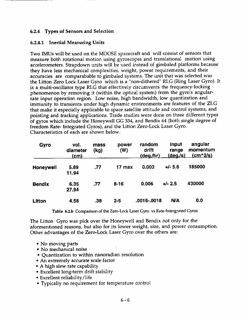
6.2.4 Types of Sensors and Selection
6.2.4.1 Inertial Measuring Units
Two IMUs will be used on the MOOSE spacecraft and will consist of sensors that
measure both rotational motion using gyroscopes and translational motion using
accelerometers. Strapdown units will be used instead of gimbaled platforms because
they have less mechanical complexities, weight, power requirements, and their
accuracies are comparabable to gimbaled systems. The unit that was selected was
the Litton Zero Lock Laser Gyro which is a "non-dithered" RLG (Ring Laser Gyro). It
is a multi-oscillator type RLG that effectively circumvents the frequency-locking
phenomenon by removing it (within the optical system) from the gyro's angular-
rate input operation region. Low noise, high bandwidth, low quantization and
immunity to transients under high dynamic environments are features of the ZLG
that make it especially applicable to space satellite attitude and control systems, and
pointing and tracking applications. Trade studies were done on three different types
of gyros which include the Honeywell GG 334, and Bendix 64 (both single degree of
freedom Rate- Integrated Gyros), and the Litton Zero-Lock Laser Gyro.Characteristics of each are shown below.
Gyro vol. mass power random input angulardiameter (kg) (W) drift range momentum
(cm) (degJhr) (degJs) (cm^2/s)
Honeywell 5.89 .77 17 max 0.003 +1- 5.6 18500011.94
Bendix 6.35 .77 8-16 0.006 +1- 2.5 430000
27.94
Litton 4.58 .38 2-5 .0015-.0018 N/A 0.0
Table 6.2.b Comparison of the Zero-Lock Laser Gyro vs Rate-Intergrated Gyros
The Litton Gyro was pick over the Honeywell and Bendix not only for the
aformentioned reasons, but also for its lower weight, size, and power consumption.
Other advantages of the Zero-Lock Laser Gyro over the others are:
• No moving parts• No mechanical noise
• Quantization to within nanoradian resolution
• An extremely accurate scale factor
• A high slew rate capability
• Excellent long-term drift stability
• Excellent reliability/life
• Typically no requirement for temperature control
6-6

• Negligible acceleration sensitivity
• Rapid reaction
6.2.4.2 Sensors to update IMUs
There will be three types of sensors used to update the IMUs. A Dual Cone sensor
will be used from approximately 8000 nmi to GEO. It has an altitude error of .05" at
LEO, maximum error of .07" at 4500 km and a minimum error of .02" at GEO. More
detail is given in section 6.3.6.1 The second type of sensor is a star tracker which will
be used for updating the IMUs once every 12 hours to give the inertial navigation
system the most precise positioning coordinates and attitude determination.
Accuracy range for a typical star sensor is about I arcsec to 1 arcmin or .0003" to .01".
The weight range is 3 to 7 kg and the power requirements are 5 to 20 W. A Global
Positioning System is the third type of sensor to be used, primarily for getting the
best accuracy prior to, and after, the maneuvers, more on this is covered in the
navigation and telemetry in section 6.3.3.
6.2.5 Define the Control Algorithm
A typical diagram of an inertial attitude-measurement system is shown below.
There are two kinds for feedback control systems. They are the continuous-data and
the sampled-data systems. The MOOSE spacecraft will use the sampled-data system
so as to free up cpu time for other tasks that are required to be done.
6.3 Navigation and Tracking
6.3.1 Navigation and Tracking Requirements
The Navigation and Tracking subsystem has three main requirements:- Orbit and Attitude Determination
- Computational Determination of Delta V requirements
- Target Detection, Tracking, and Rendezvous Guidance
6.3.1.1 Orbit and Attitude Determination
This system must provide for an accurate determination of the vehicle's orbit and
attitude. Orbit information must be accurate enough at geostationary orbit to bring
the vehicle within tracking distance of the destination target. The working range of
the selected rendezvous system will be 4.5 nmi (8334 m). The error in position at
GEO added to the error in the target's known position must therefore be less than
this range. Using a 3/4 safety factor, the requirement for GEO position
determination accuracy will therefore be 6 km.
At LEO and below, the main positioning requirement will be determined by the
aerobraking maneuver. Non-inertial navigation systems will be blacked out during
this maneuver, so inertial guidance will need to be accurately calibrated before the
6-7

maneuver. From GEO, an accuracy of 2 km will be required for the aerobrake
window. On approach to the maneuver, the window will become smaller and an
accuracy of 100 m will be required for any necessary course adjustments.
Attitude determination requirements are listed in the avionics ADCS section (6.2).
6.3.1.2 Computational Determination of Delta V
This system must provide the computational power necessary to determine the
specific course of the vehicle. This system must be able to collect information about:
- The current orbit of the vehicle,
- The destination orbit of the target,
- Information about known satellites and/or debris in projected
transfer path,
- Mid-course positioning information,
The navigation system must provide for redundancy in calculations to verify the
computed delta Vs and timing of the burns. The system will be responsible for
computing delta Vs required for orbit transfers and rendezvous. Actual delta Vs are
monitored and are compared to the planned delta Vs. The vehicle's current course
information is then updated using this information. The navigation system must
also monitor the current course to verify that it matches the planned course and
compensate for any differences. The computer must also be able to decide what
information from each system is most accurate, depending on the orbit or mission
phase. All computations must be done with the highest amount of precision as
possible. A more detailed list of requirements is listed in the Computation and Data
Management System (section 6.6).
6.3.1.3 Target Detection, Tracking, and Rendezvous Guidance
This system must provide a method for detecting a target and guiding the vehicle to
rendezvous. As stated above, the principle requirement is the tracking range is
greater than the total error in relative distance to the target. The system must
provide information for range, range rate, and angle measured to the target. This
information must be provided until the target's range to the vehicle is within reach
of the vehicle's primary grappling arm.
6.3.2 Orbit and Attitude Determination
6.3.2.1 Primary Navigation System - Inertial Navigation
This system was chosen due to its potential for high accuracy. The only drawback to
using IMU (inertial measurement units) is that their accuracy degrades with time.
To keep their accuracy, position and orientation information must be updated
before the accuracy degrades past the necessary requirements. Immediate updates
6-8
would also be required after a large delta V. A more detailed listing of the inertial
navigation system is provided in the avionics ADCS section (6.2).
6.3.2.2 Updating Inertial Navigation
6.3.2.2.1 Linear Position and Velocity Updates
Global Positioning System - Provides 25 m accuracy at LEO. The system is ideal for
use in LEO (9.72 x 5 x 2 cubic inches, 1.37 kg, 3 W) however this system is not
designed to work above 8000 nmi altitude. This system will be necessary to meet the
100 m aerobrake accuracy requirement.
Microcosm Autonomous Navigation System (MANS) - This system provides 600m
to 1.5km accuracies using 2 sensors. This system will be necessary for long term
navigation in GEO and meeting the 2 km aerobrake window requirement.
For a more detailed description of these systems, consult Appendix A6.2.1.
6-9

6.3.2.2.2Orientation Updates
MANS Sensors (Modified Dual Cone Sensors) - This system can provide orientation
updates to an accuracy of 0.01 degrees. To have this accuracy, the sensor must be ableto use the sun as a reference and becomes blacked out 16% of the time in GEO. For
11.4% of this blackout time, horizon sensor information will still be available and
can give an accuracy of 0.1 to 0.25 degrees. For the other 4.6% of the time, no
orientation updates are possible.
Star Trackers - This system can provide orientation updates to an accuracy of 0.01
degrees when the sun's glare does not affect the sensor. Although it can be used at
other points, the star trackers will definitely be able to be used during the 16% ofMANS blackout time.
For a more detailed description of these systems, consult Appendix A6.2.2.
6.3.3 Navigational Update Determination
Navigational update information will be mission phase dependent.
6.3.3.1 LEO Updates
At LEO, the navigational updates will always be provided for by the GPS receiver.
GPS will be used in LEO for calibration and critical information for re-entry. All
LEO orbits and LEO to GEO transfer orbits will be calculated using GPS and Kalman
filtering software. A single GPS reading can determine the orbit to within 100
meters. With Kalman filtering, this accuracy should improve and meet the 100 m
aerobrake accuracy requirement. A GPS position update takes place at the rate of 2
updates per second. This gives the navigation computer plenty of information to
determine an accurate orbit in a short amount of time (less than the 25 seconds
required by MANS).
GPS will be important in verifying the re-entry orbit. The vehicle will have time to
make any mid-course corrections necessary to ensure that it will make the re-entry
window. This provides an accurate method to ensure that the aerobrakingmaneuver will be successful.
The mass and power requirements of GPS are small compared to the overall vehicle
mass and power requirements, therefore GPS will be used.
6.3.3.2 GEO Updates
GEO updates will be decided on by the navigation system. For the first 20 hours after
GPS updates are lost, the inertial navigation system will be more reliable than the
MANS system. After this point, however, MANS must begin linear navigation
6- 10

updates at its return frequency of 0.5 Hz.
6.3.3.3 Overall Performance
The following accuracies will result from the different mission phases, using a GPS
accuracy of 25 m, a MANS accuracy of 1.5 km (assuming MANS cannot use the
moon as a reference), and a linear IMU accuracy degradation of 68 meters per hour:
GEO Mi_ion Phase Best Accuracy_ Update Accuracy/Frequency
LEO Orbit
Transfer LEO to GPSTransfer GPS to GEO
GEO Orbit/First 18 Hours
GEO Orbit/18+ HoursTransfer GEO to GPS
GPS to Aerobrake
Aerobrake (each pass)
25m 25m/2Hz
25m 25m/2Hz
25 - 180 m No Updates / None
180 - 1500 m No Updates / None1500 m 1500 m / 0.5 Hz
1500 m 1500 m / 0.5 Hz
25m 25m/Hz
-25 m No Updates / None
Table 6.3.a Overall Performance of Orbit and Attitude Determination System
during GEO missions
6.3.4 Computational Determination of AVs
The software for the navigation system will utilize all navigational data collected
from GPS in LEO and from MANS in GEO. The system will initially compute all
AVs and their timings based on mission parameters. All transfer orbits will be pre-
computed based on initial GPS readings and assuming perfect burns. During the
mission, the system will constantly check this computed course against current
navigational readings. Course corrections will occur in the event that actual course
has deviated from the computed course by more than the accuracy of the data source
(GPS or MANS). Course corrections will also be necessary in the event the course
plotted intersects with any known satellites (to within a certain degree of tolerance).
In all other aspects, the software should meet all requirements stated in 6.3.1.2.
The computer system hardware will be described in detail in section 6.6.
6.3.5 Target Detection, Tracking, and Rendezvous Guidance
For rendezvous, this system must be able to accurately determine the range, range
rate, angle and angle rate to the target. Several methods were looked at to
accomplish this autonomously.
6-11

6.3.5.1 Systems for Autonomous Rendezvous Tracking
Star Trackers - Useful in increasing the the accuracy of measuring attitude, star
trackers are also useful in determining the angle and angle rate to a target for
rendezvous purposes. It can determine the angle to a target to within 0.02 degrees.
IRACS (Space Shuttle Rendezvous Radar) - This system provides fairly accurate
range and range rate information at a long range (12 nmi range, 80 - 300 ft range
accuracy, I ft/sec range rate accuracy). However, the system has a mass of 75 kg and
requires 460 watts of power. Because of these restrictions, this system was rejected.
OMV Rendezvous Radar - Although the OMV project has been cancelled, the
rendezvous radar for it has been fully designed. This system was specifically
designed to do the rendezvous we intend to use it for. It has a lower range (4.5nmi),
however, it provides range accuracy of the greater of 20ft or 2% of the range. It also
provides greater range rate accuracy of the greater of 0.1 ft/sec or 2% of the range
rate. This system's mass of 35kg and power requirement of <60 W, makes this a
more attractive choice for a rendezvous radar system.
6.3.5.2 Rendezvous Hardware Operations Requirements
Two restrictions will be placed on rendezvous from a hardware standpoint. To
maintain navigational updates as long as possible, rendezvous from a higher energy
orbit (above) will be required. The vehicle will also have to be rotated such that the
radar antenna (mounted on the RCS spider truss, near the crew cabin window) will
be facing toward the target satellite, along with the star tracking sensor.
More specific information on rendezvous will be given in the operations section
(section 8.9)
6.3.6 Mounting of Navigation Sensors and Tracking Hardware
6.3.6.1 MANS Sensor (Dual Cone Sensor) Mounting
The MANS sensors for the GEO mission must be mounted with the sensor spin axis
pointing 69.5 degrees from nadir. For maximum performance, the sun angle cone
must be able to see past the aerobrake as much as possible. This is accomplished by
mounting 2 sensors on retractable platforms connected to the lower truss.
In addition, for future missions in LEO where the separable vehicle is used, 2
normal dual cone sensors must be mounted on the RCS spider truss at an angle of
80 degrees from nadir. Since these sensors would only be used in LEO for
orientation updates, they would not need to be modified MANS sensors.
6- 12

6.3.6.2 Rendezvous Hardware Mounting
The rendezvous hardware will be mounted on the RCS spider truss, near the crew
cabin window. This arrangement will allow the rendezvous system to provide
information on any object that can be seen by the astronaut. In this way, radar and
optical information can still be given to the astronaut during the manual phase ofrendezvous.
The star tracking system will be placed in a passive and fixed position. The radar, as
it is currently designed, provides for an extending mechanism for the antenna, as
well as all servo mechanisms required to move it.
More information on sensor mounting requirements is presented in AppendixA6.2.3.
6.4 Communications
6.4.1 Requirements and Constraints
The communication requirements for MOOSE are divided into four sections.
6.4.1.1 Range
The assumption is made that MOOSE will not communicate with the space station
directly during the mission, but that all communication will be sent first through
ground control. This assumption was made because the earth will sometimes block
MOOSE's signal from the space station and relay satellites will have to be used. Also
if the space station was to be used as a space relay link between MOOSE and earth,
some of its communication system only would be used entirely for this mission.
Direct contact with earth will enable ground control to monitor the vehicle,
releaving the space station of the added burden. In addition, the owners of the
satellite or satellites to be repaired will be able to give first hand information to the
astronaut on board during the repair. MOOSE will therefore need a communication
system that will enable it to communicate with earth from altitudes ranging from
LEO ( 250 km) to GEO ( 38,756 km ).
6.4.1.2 Links
Moose is an interactive vehicle and therefore will need to have two-way
communications with ground control. The uplink, from ground to MOOSE, will
consist of both voice and command. Voice will be used when communicating with
the astronaut, and the ground control's computer will communicate with the
computer system on-board MOOSE using commands. Voice will be primarily used
when servicing a satellite and docking at the space station, and commands will be
received for course and velocity corrections. In the case of an emergency where
ground control needs to control the ship, such as failure of life support systems,
6- 13

command communication will be essential.
The downlink, from MOOSE to ground, will transmit voice, video, and telemetry.
As with the downlink, voice will be used mainly during the satellite repair phase
and docking. Video will be transmitted during the repair phase. It will help to show
the personal on the ground what is wrong with the satellite and how it can be fixed.
With use of the video they can assist the astronaut with the technical aspects. This
will limit the training that will be required by the astronaut. The telemetry that will
be transmitted down will essentially be housekeeping data. Unlike other space
vehicles, there will be no experiments conducted on board MOOSE, therefore, the
telemetry data rates will not be as high as other spacecraft.
6.4.1.3 Data Rates
Digital communications will be used instead of analog for various reasons. The two
most important being, one there is a less chance of error and second, multiple
digital signals can be combined onto one rf signal. For example, voice, video, and
telemetry can be sent along one link. Voice will use 64 kilo bits per second (kbps) to
be communicated. Commands will use 2000 bps. Video will need to have 6 Mbps to
be transmitted. These values are estimates based on other communication systems.
The voice and command data rates seem to be constant through many applications
ranging from the space shuttle to communication satellites. 6 Mbps for video is a
greater estimate but falls into a usable range.
The data rate for telemetry is 307 kbps if all the sensors were being read at one time.
The value of 307 kbps was reached after it was estimated how many sensors were
needed to monitor MOOSE and the individual data rates each required. A complete
breakdown and analysis is given in appendix A6.3.2. The breakdown total data rates
for each subsection of MOOSE is given below.
Structure (aerobrake)
Life Support
Man/Grap
Propulsion
Attitude Control System
Navigation/Tracking
Reaction Control System
6400 bps
540 bps
5080 bps
288 kbps
3380 bps
180 bps
2900 bps
Table 6.4.a Subsystem Communication Data Rate Requirements
The data rates were estimated by sub-section because some sections will not be active
the entire mission. For instance, during the actual repair of a satellite, the
propulsion and structure sensors don't need to be monitored. That is a 95%
reduction in telemetry data that is processed and transmitted. On the other hand,
the high video data rate required during the satellite repair phase calls for more
transmit power. A data rate of 1000 bps must also be added to the telemetry value so
that the orbit, course, acceleration, and velocity vectors computed by the on- board
6- 14

computer can be transmitted.
6.4.1.4 Frequency Band
Because of the data rate values, Ku-band will be used as the rf (radio frequency)
carrier. The uplink frequency ranges from 14.0 - 14.5 GHz. The downlink rangesfrom 12..0 to 12.75 GHz.
6.4.2 Communication Subsystems
There are two communication systems that will be employed, either the Tracking
and Data Relay Satellite System (TDRSS) or a direct space to ground link, dependingon the altitude.
TDRSS consists of two satellites that are in geostationary orbit. There is also a third
satellite in GEO which acts as a spare for the system. The two relay satellites are
spaced 130 ° apart, one over the Atlantic ocean and the other over the Pacific ocean.
Because the relay satellites are in GEO they can virtually maintain constant contact
with the ground stations situated around the earth. One station for TDRSS is located
at White Sands,New Mexico. TDRSS is operational for vehicles operating at
altitudes below 12000 km. It is possible to communicate with an orbiting spacecraft
85% of the time. If the spacecraft is orbiting at altitude between 1200 km and 12000
kin, communication is nearly 100% except for regions near the poles (Stark). Ataltitudes below 1200 km, communication becomes less efficient because the vehicle
will sometimes loose sight of the TDRSS satellites.
The direct space to ground link will be used when MOOSE is orbiting at altitudes
between 12,000 km to 38756 km. The reason the space to ground link was not used
for all altitudes is because at lower altitudes there are longer periods of
communication blackouts. At lower altitudes it is difficult for a spacecraft to lock on
to ground stations. Also the ground sweeping velocity increases as the altitude
decreases, therefore the actual communicating time at a particular ground station
decreases.
6.4.3 Compatibility
Since a Ku-band frequency will be used for both the uplink and downlink, the
communication subsystems must be compatible with Ku-band. TDRSS uses both
Ku-band and S-band and therefore is compatible with the preliminary design. The
problem occurs with the ground stations. Not all ground stations can communicate
using a Ku-band frequency. Therefore there might be a higher ratio of
communication blackouts than normal for the direct space to ground link. Normal
blackouts are based on using S-band.
6- 15

6.4.4 Link Equations
The link budgets are used to determine whether or not a signal will be receivable.
The equations used were taken from Space Mission Analysis And Design l_p 536). In
the equations all values are converted to decibels for ease of calculating. The link
equations used are:
Eb/No(dB ) = P+Ll+Gt+Ls+La+Gr+228.6-101og Ts-101og R
where Eb/No = received energy-per-bit to noise-density
P (dB)= power
Lt(dB)= transmitter line loss
Gt(dB)= Gpt + Lpt transmit antenna gain
Gpt = 44.3 - 10.0log (P)
2 2Lpt = -12.0 * (e t/0 t )
0t(deg ) = transmit antenna beamwidth
e t (deg)= transmit antenna pointing offset
EIRP = P + L l + G t = equiv, isotropic radiated power
Ls(dB)= -92.44 - 20.0 log(s) - 20.0log f = space loss
s(km) = propagation path lenght
f(GHz) = frequency
La(dB ) = propagation and polarization loss
Gr(dB)= Grp + Lpr receive transmit antenna gain
Grp (dB) = 20.40 + 20log D r + 20log f
Dr= receive antenna diameter2 2
Lpr = -12.0 * (e r/O r )
0r(deg ) = receive antenna beamwidth
er(deg)= receive antenna pointing error
Ts(k ) = system noise temperature
R(bps) = data rate
C/No(dB-Hz) = EIRP + S + L a + Gr/T s + 228.6BER = bit error rate
Req Eb/No(dB-Hz ) = required
Implementation Loss (dB)
Margin(dB)= Eb/N o- Req Eb/N o - Imploss
6.4.5 Link Budgets
In designing the link budgets, the desired result is a margin of about three decibels.
This will allow for error free communication over the propagated path length. In a
preliminary design such as this, a link margin of six decibels is desired to allow for
miscalculations. Therefore in the following link designs, the parameters were
6-16
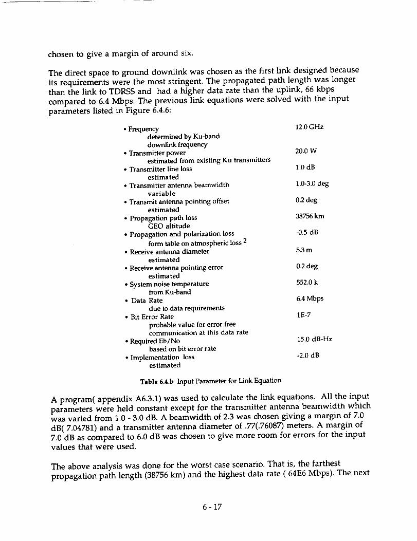
chosen to give a margin of around six.
The direct space to ground downlink was chosen as the first link designed because
its requirements were the most stringent. The propagated path length was longer
than the link to TDRSS and had a higher data rate than the uplink, 66 kbps
compared to 6.4 Mbps. The previous link equations were solved with the input
parameters listed in Figure 6.4.6:
• Frequencydetermined by Ku-banddownlink frequency
• Transmitter powerestimated from existing Ku transmitters
• Transmitter line lossestimated
• Transmitter antenna beamwidthvariable
• Transmit antenna pointing offsetestimated
• Propagation path lossGEO altitude
• Propagation and polarization loss
form table on atmospheric loss 2• Receive antenna diameter
estimated
• Receive antenna pointing errorestimated
• System noise temperaturefrom Ku-band
• Data Rate
due to data requirements• Bit Error Rate
probable value for error freecommunication at this data rate
• Required Eb/Nobased on bit error rate
• Implementation lossestimated
12.0 GHz
20.0 W
1.0 dB
1.0-3.0 deg
0.2 deg
38756 km
-0.5 dB
5.3 m
0.2 deg
552.0 k
6.4 Mbps
1E-7
15.0 dB-Hz
-2.0 dB
Table 6.4.b Input Parameter for Link Equation
A program( appendix A6.3.1) was used to calculate the link equations. All the input
parameters were held constant except for the transmitter antenna beamwidth which
was varied from 1.0 - 3.0 dB. A beamwidth of 2.3 was chosen giving a margin of 7.0
dB(7.04781) and a transmitter antenna diameter of .77(.76087) meters. A margin of
7.0 dB as compared to 6.0 dB was chosen to give more room for errors for the inputvalues that were used.
The above analysis was done for the worst case scenario. That is, the farthest
propagation path length (38756 km) and the highest data rate ( 64E6 Mbps). The next
6-17

step was to back the power out of the link equations for different altitudes and data
rates. For example, if MOOSE was transmitting only voice back to earth at an orbit
of 15,000 krn, the power consumption should be considerable less than the initial
conditions described before. The following graph gives the change in power
consumption for four different data rates in the altitude range where a direct space
to ground link will be used. See appendix A6.3.3 for a table of calculated values.
A
_t
b,,
2 5 -F- ..........................................................................................................................................i
2oi _ ! ! s i
i ! ! _ i i" i
1 5 -+- ..................._.......................i......................, ......................i........... .-..!.......................i ! ! ! ! "• !
telemetry
video
........................................................... i .........................
m_m_mi • m immwn - ........ ..... "-- "" "- "" -",--.-,-.---- i
1.000 104 2.000 10 4 3.000 104 4.000 104
Altiude (m)
Figure 6.4.a Power Requirements-vs-Altitude for Direct Space to Ground Link
Therefore, MOOSE will only be using 20.0 watts of transmitting power when it is at a
GEO orbit and sending back voice, telemetry ,and video. This could either occur
when actually servicing the satellite, or sending back stored data that was
accumulated during a communication blackout.
The uplink budget was designed with a max data rate of 66 kbps, a transmit power
of 5 watts, and a frequency 14.0 GHz. The margin was 7.7 dB.
6.4.6 Communication Subsystem Parameters
Since the parameters for communicating with TDRSS are less than those_0f the
direct space to ground link, the following communication system will work for both
systems.
Downlink
frequency = 12.0 GHz
data rate = 6.4 Mbps
6-18

transmit power = 20.0 W
link margin = 7.0 dBtransmit antenna diameter = .77 m
Uplink
frequency = 14.0 GHz
data rate = 66 kbpstransmit = 5.0 W
link margin = 7.7 dBreceive antenna = .77 m
The antenna will function as both a receiver and transmitter. The antenna will be a
steerable - parabola with a 37.0 dB gain, a 2.3 deg beamwidth, and a mass of 5.8 kg.
The mass of the entire communication system will way 15.0 kg.
6.4.7 Reliability
The communication system will consist of two transponders for redundancy.
If there is a problem communicating with TDRSS a direct link can always be used
but it won't be as efficient and there will be longer blackout periods. If there is a
problem when at altitudes greater than 12,000 km there is no backup for the direct
space to ground link. The two transponders should help to shield against this. The
single point failure is with the antenna. If the antenna is damaged there is no
backup for both transmitting and receiving. If the steering mechanism is jammed or
damaged the antenna can always be aimed by directing the spacecraft.
6.5 Data Acquisition and Storage Systems
6.5.1 Data Handling Capability Requirements for Data Recording and Telemetry
The first requirement to be determined for both data recording and telemetry arethe data rates that will be needed. The data that needs to be considered include:
navigation, ADCS, rendezvous, audio, video, and housekeeping data. For the
process of data recording, instead of recording every data element from each
subsystem ( i.e. the star tracker or the dual cone sensors ), only the finial calculated
values of interest will be recorded. Those being the three components of position,
velocity, acceleration, and a time stamp. To determine the allocation of space
necessary to handle this data, formatting the data using C has been considered. The
double float format in C allots 48 bits for the mantissa and 16 bits for the exponent,
for a total of 64 bits per element of data. The systems requiring the highest accuracy
will use this format. These systems include the navigation and the attitude control
systems. The float format will be used for the data returned from the rendezvous
radar system. The float allots 24 bits for the mantissa and 8 bits for the exponent; 32
bits per data element. The time stamp can be stored with the long integer format.
6- 19

The long integer is capable of holding 10 characters and uses 32 bits. Thesebreakdown as follows.
Navigation: Latitude, Longitude, Altitude
X, Y, and Z VelocityX, Y, and Z AccelerationTime
Total
X 64 = 192
X 64 = 192
X 64 = 192
X 32 = 32
608 bits
Attitude Control: X, Y, and Z Position X 64 = 192
X, Y, and Z velocity X 64 = 192X, Y, and Z Acceleration X 64 = 192Time X 32 = 32
Total 608 bits
Rendezvous: X, Y, and Z Position X 32 = 96
X, Y, and Z Velocity X 32 = 96X, Y, and Z Acceleration X 32 = 96
Time X_2 = 196Total 320 bits
Figure 6.5.a Avionics Subsystem Storage Breakdown
When the spacecraft is in LEO, navigational data will be received from the GPS
system. The GPS is capable of updating the data at 2 Hz. This value of 2 Hz will be
used as an upper limit in computing the data rates for the navigation system.
For the purpose of telemetry, data from each subsystem will be telemetered in the
same form that it is received by the on board computer. These data rates for each
subsystem including all the sensors have been tabulated in appendix A6.3.4.
The frequency of the human voice is approximately 3.5 kHz. It has been
demonstrated that original signals can be duplicated if the sampling rate is at least
twice that of the highest frequency in the original signal. Filter limitations suggest
sampling rates greater than 2.2 times the original signal. Therefor, for digitized
voice, sampling should occur at approximately 8000 times per second. Using 8 bits
per sample results in 64 Kbps.
Commercial video has a frequency of approximately 4 MHz, therefor requiring
samples at 8.8M per second. Using 5 bits per sample leads to a data rate of 44 Mbps.
This is fine to input into the displays, but becomes very costly when trying to store
or transmit that amount of data. In order to limit the cost, the picture quality can be
sacrificed to that of a picturephone for the purpose of telemetry and data recording,
approximately 6 Mbp.
6 - 20

Analog Information Mox Hz samples/sec. Bits/Sample Data Rate (bps)
voice 3600 8000 8 64Kcolor TV 4.0M 8.8M 5 44M
picturephone 9(]0K 2M 3 6M
Table 6.5.a Data Storage Requirements
6.5.2 Telemetry
The main requirement is to commutate all the data that needs to be telemetered as
efficiently as possible. A basic mission can be broken down into four operational
modes: 1. Main engine operation, 2. Repair operations, 3. Post aerobrake, and 4. On
orbit or standby operation. The data to be telemetered during each mode is asfollows:
Main engine mode: Propulsion (290 Kbps), Structure (64 bps)Life support (460 bps), ACS (3380 bps)Total."300 Kbps
Repair mode: Life support (460 bps), Man/Grap ( 5080 bps)ACS (3380 bps ), RCS (2900 bps), Audio (64 Kbps)Video (6 Mbps)Total."6.08 Mbps
Post aerobrake mode: Structure (6400 bps), ACS (3380 bps),RCS (2900 bps), Life support (460 bps),
Navigation (180 bps)Total: 13.4 Kbps
Standby mode: Audio (64 Kbps), ACS (3380 bps), RCS (2900 bps)Life support (460 bps), Navigation (180 bps)Total: 74 Kbps
Figure 6.5.b Telemetry Requirements
The data from the current operating mode will be commutated into a single stream
to facilitate the telemetry process. Each format mode will be arranged into major
and minor frames, with each major frame containing the minimum number of
minor frames required for one complete cycle of all subcommutators. The number
of minor frames needed for that complete cycle is determined by the degree of
supercommutation and subcommutation in each format mode. The data sampled
at higher rates will be allotted several minor frame words, i.e. supercommutated,
while the slower sampled data will be subcommutated. That is, a certain word
position in one minor frame will contain data from one sensor, while that same
word position will contain data from a different sensor in another minor frame.Minor frame words will also be allotted for frame counters and for frame
synchronization. Each format mode will have some variability to allow for audio,
video, and other systems that may not be in continuous operation during that given
operational mode.
6.5.3 Data Storage
6 - 21

Voice, video, navigation, ACS, rendezvous, and housekeeping data all need to be
considered for on board recording. To record everything at full operation, the data
recorder would have to be capable of recording at 6.07 Mbps.
Magnetic tape, magneto-optical, and pure optical recording technology have been
investigated for potential use as the on board data recorders. Magnetic tape
recorders have always been the standard recording equipment on spacecraft, and are
available with storage capacities and record rates in excess of 750 Gbits and 300 Mbps
respectively.
Magneto-optical recorders can store 8 Gbits to 16 Gbits per disk side. Current
technology produces record rates that are only about one-third that of conventional
hard disk drives. The main drawback on magneto-optical recorders is that they are
not currently available as space rated equipment. The high cost of developing a new
space rated hardware leaves magnetic tape recorders as the logical choice for our
system.
Audio and video represent the highest data rates that need to be recorded, but also
the shortest recording duration time. If a typical repair operation takes 5 hours, and
three repairs are performed per mission, audio and video recording time would
accumulate to 15 hours. With a data rate of 6 Mbps the video alone would require a
recorder with a storage capacity of 325 Gbits. The Odetics model 10000 can handle
this storage, but has a mass of 181 Kg. This large mass is more than has been allotted
for the entire avionics package. Therefor, the decision at this point is to not record
the video digitally, but to record it using a rad hardened VHS type recorder.
Allotting 15 hours of audio and 120 hours of repair mode data per mission (that
being the mode with the highest data rate) comprises 3.72 Gbits. The Odetics model
5000EC will easily meet these demands with a reasonable mass and volume.
Tape width (mm) 12.7Record rates (Mbps) 1-100Playback rates (Mbps) 100Capacity (Gbit) 45Record times (min) 750/7.5Packing density (Kbit/cm) 17Record power (W) 114/117Playback power (W) 178/182Mass (Kg) 28.1
Size (cm)Transport unit 33X38X30Electronics unit 28X34X28
Table 6.5.c Odetics Model 500EC Specifications
Data compression and error control schemes will be fully employed for both
telemetry and data recording. The reduced data rates which result from the
compression have been omitted from this analysis as a factor of safety. The extra
6 - 22

space resulting from the compression will allow for added redundancy and permitthe use of smaller band widths for the telemetry.
6.5.4 Video And Information Displays
Status of on board systems, conditions in the cabin and external tanks, and video
during rendezvous and satellite repair all need to be accessible to the pilot. It would
be desirable to minimize the size and weight of the displays when consideration is
taken for the limited space inside the manned module. The capability of displaying
both status type information and video signals on the displays is also of importance.
The displays considered for use in the capsule include cathode ray tubes (CRT),
liquid crystal displays (LCD), electroluminescent, and plasma-address liquid crystal
displays. With current technology, electroluminescent and plasma-address liquid
crystal displays are not capable of handling the high frequency required for video
input. LCD's include active matrix (AMLCD), passive matrix (PMLCD), and
supertwist-nematic (STN) LCD's. A Type of interference, called cross talk, as well as
slow pixel speed, are inherent in the PMLCD design, which results in low contrast
and poor image quality. STN LCD technology has yet to achieve even high levels of
gray, which leaves the focus on CRT's and AMLCD's. CRT's are bulky, typically ten
times as deep as the fiat AMLCD screens. CRT's can have a problem with flicker
since the screen constantly needs to be refreshed with zaps from an electron gun,
and are also known to have electromagnetic emissions. AMLCD's, since they are
continuously backlit, do not have the flicker problem, nor do they have any
emissions or screen static. AMLCD's do though cost 50% to 60% more than CRT's.
CRT AMLCD FMLCD STN-LCD
Contrast 40:1 to 100:1 50:1 to 100:1 12:1 to 40:.1 50:1 to 100:1
Pixel speed on: 0.Sms to 2ms on: 20ms to 50ms on: 120ms tol50ms n/aoff: 15ms off: 50ms off: 50ms
Resolution 1024)(768 640X480 640X480 640)(480
Flicker 72 Hz none none none
Emissions 1 to 75* none none none
Viewing Angle 135 ° 90° 40 ° n/a
* microteslas
Table 6.5.d Display Options
For their low power consumption, small volume, and high picture quality,
AMLCD's are presently the best choice for the video and information displays.Three screen will be used in the manned module. Status and data information can
be displayed among all the AMLCD's, then, as video needs to be displayed,information from the middle screen can be combined to the other information
screens in a windows type format, leaving the pilot with a clear view of the video
screen and still allowing access to the status of the on board systems.
6 - 23

6.5.5 Video Cameras
The video cameras will be located on each of the two manipulator arm for use
during satellite repair. Another camera will be inside the manned module so the
pilot can be viewed by those at earth based telemetry sites. The camera inside the
cabin will operate continuously for telemetry purposes, but will not be recorded.
Those on the manipulator arms will be able to be turned on by the pilot during
satellite repair. These manipulator arm cameras will be both recorded andtelemetered.
6.6 Computation and Data Management System (CDMS)
6.6.1 Requirements
6.6.1.1 CDMS Functional Requirements
The CDMS shall provide:
• sufficient processing power for all subsystems, including propulsion,
manipulators/grapplers, life support, communications, tracking, navigation,
guidance, and control.
• command and status indications to/from all subsystems for overall control, fault
detection and isolation, and maintenance scheduling.
• acquisition, encoding, scaling, formatting, and displaying/transmitting physical
parameters from other subsystems to support real-time operations, trend analysis,and maintenance.
• data transfer between subsystems through a data network with high transfer rates.
• a man/machine interface, that is fully interactive with required CDMS elements.
The crew person shall have total command capabilities and data verification into
each system.
• system security to protect the crew and vehicle's safety. This includes measures to
prevent unauthorized access to MOOSE's control functions, and prevention ofexecution of false/erroneous commands.
6.6.1.2 CDMS Design Considerations
• Degree of decentralization
• Extent of automation
• Interface Options
6 - 24

• Equipment technology options
• Redundancy/degree of fault tolerance
• Overall data system architecture
6.6.1.3 CDMS Design & Performance Requirements
The CDMS shall:
• be distributed and modular on the hardware level, and "object-oriented" on the
software level. This will enable the replacement of individual subsystems without
adversely impacting the whole system.
• employ a redundant scheme as part of the fault tolerant architecture. CDMS
elements that control critical systems/subsystems shall be fail-operational/fail-safe.
• employ built-in test equipment that diagnoses failures. Artificial
intelligence/expert system techniques shall be used to aid in the maintenance of thevehicle.
• employ security techniques to preclude the reception of data/command by
unauthorized persons.
• have software that supports flight operations, control of subsystems, redundancy
management, monitoring of functions, and fault isolation.
• have a high degree of autonomy in its default operation mode.
• have a highly reliable "core" sub-system that can support a minimum of tasksvital to crew survival.
• have a suitable combination of redundancy and radiation-hardness to operate
nominally for the length of a standard mission.
6.6.2 CDMS Subsystems & Tasks
• Communications
Command Processing
Telemetry Processing
Data Compression/ExpansionAntennae Control
6 - 25

• Attitude Sensor Processor
Rate Gyro Interface
Global Positioning SystemHorizon Scanner Interface
Star-Tracker Interface
• Attitude Determination & Control
Kinematic IntegrationError Determination
Thruster Control
Reaction Wheel System ControlCenter of Mass Calculations
• Propulsion
Main Engine Control (Sensors & Actuators)
Fuel Tank Monitoring
Orbit Trajectory Calculations
• Autonomy Functions
Simple Autonomy
Complex Autonomy
• Manipulator/Grappler Control
Kinematic/Inverse Kinematic Equations
Man/Manipulator InterfaceControl Law Calculations
Sensor Integration
• Fault Detection
Monitors
Fault Corrections
Emergency Procedure Initiator
Critical Data Recording
• Power ManagementDistribution/Allocation of Electrical Power
Monitoring Fuel Cell Capacity
Automatic Shutdown of Unused/Unnecessary Systems
• Climate Monitoring/Control
Radiation Detection/WarningThermal Control
Lighting Control
Pressure Vessel Monitoring/Control
Atmosphere Monitoring/Control
Expendables Monitoring
6 - 26

• General Man/Machine Interface
Touch Screens
Joysticks
Voice Command/Feedback Interface
Indicator Interface
6.6.3 CDMS Hardware
6.6.3.1 Distributed Processing
Distributed processor architectures offer attractive benefits such as reliability, ease of
growth, and parallel processing. Combining modular programming practices with
distributed processor architectures allows for increases flexibility in mission-specific
hardware configurations.
6.6.3.1.1 Distributed Computing Functionality
Distributed processor architectures allows for computers with various capabilities
and requirements to work together with ease. The physical distribution of hardware
on the MOOSE, combined with the natural delineations and relations of tasks,
makes distribution of processes and processors a natural alternative to a centralized
system.
Most subsystem processing will be invisible to other subsystems, but some
operations (such as orbital transfer and attitude control, attitude control and
manipulator/grappler, etc.) will span several subsystems. This would require
coordination of some highly complex computing processes over various processors.
This could place a heavy burden on the lone crew member, so the level of
automation that is required is high, regardless of whether the computer system iscentralized or decentralized.
6.6.3.1.2 Distributed System Reliability and Security
Reliability has many facets, including probability of correct function over a period of
time, probability of recovery (and recovery time) from minor, localized, or major
system breakdowns, gracefulness of degradation when full service is impossible, and
assurance that critical calculations will be computed in the face of unusual
computing loads.
A carefully designed distributed processing system has intrinsic benefits for
reliability and secure design, including:
1. enhanced physical, electrical, and logical isolation of faults,
2. convenience of configuration for redundant computing resources,
3. well-defined and protectable constraints on information flow,
6 - 27

4. easy redelegation of tasks as computational priorities shift in the face
of changing requirements.
6.6.3.1.3 Distributed System Growth and Evolution
MOOSE's CDMS must be able to evolve and grow over time to meet different and
more complicated mission requirements. Distributed processing provides uniform
physical and logical techniques for interconnecting diverse processing activities.
6.6.3.1.4 Technical Problems of Distributed Processing
• How can continuity of control and preservation of critical data be
ensured when processors fail and network connectivity isbroken?
• How can data replicated in multiple locations be kept consistent with
low overhead cost?
• How can the design provide for rapid recovery for minor errors and
maximum preservation of resources under major errorconditions?
• How can time and sequentiality constraints be honored for safety-
critical computations, under conditions of high load or system
failures?
• How can the architecture support dynamic relocation of data,
programs, and computation site to meet large changes in
computational load or system breakdown?
6.6.3.1.5 Principles for Distributed Design
Modules should be relatively independent of each other, and should be sharply
constrained as their side-effects on other modules. A clear order of dependence that
relates both functionality and criticality should be established.
The most critical modules should be the most sound, and should be isolated from
from less critical ones.
The interface to each module, and its implementation, should isolate all data and
internal knowledge that need not be visible to users of the interface.
Components that operate concurrently should have a high degree of independence
from one another, except through a carefully constrained communication link.
No untrusted communication, or trusted communication from an untrusted
6 - 28

component, should be allowed to undermine the trust of a given component
6.6.3.1.6 A Cost-Effective Strategy for Evolving a High-Performance
Distributed System-THE KERNAL APPROACH
An initial effort should be expended to develop a portion of the system that exhibits
a high degree of all the desired properties such as fault tolerance, dynamic process
management, etc. Such high-quality, mission critical subsystems are called kernals.
As technology advances, the overhead costs of producing the high-quality solutions
used in kernals can be reduced so that they can be used in a growing fraction of the
MOOSE's CDMS.
6.6.3.2 Fault Tolerance
There are many types of faults--transient, intermittent and permanent, hard and
soft, and including both hardware failures and design and programming errors.
system that can tolerate such faults must provide for:
• fault detection, to reduce the likelihood of two or more simultaneous
faults that can be difficult to identify,
• fault location, to determine the smallest replaceable unit in which
the fault is occurring,
• fault handling, for manual or automatic reconfiguration and repair,
• and fault recovery, to return the system to an acceptable level of
operation.
A
This requires that the system design:
• be appropriately redundant,
• and consist of modules with some degree of self-diagnosis, cross-
diagnosis, and interchangability,
6.6.3.2.1 Fault Tolerant Design Principles
Economical and effective fault tolerance for large systems requires a "hierarchical"
design approach, with fault tolerance distributed over several design levels.
In addition fault tolerance requires the use of modules, with limited information
interfaces (for fault isolation), and as high a degree of replication as possible (for
effective diagnosis, reconfiguration, and recoverability).-
Lastly, fault tolerant designs tend to be simple and conservative, with strong
emphasis on organization and structure as opposed to features such as intricacy and
minimality.
6 - 29

6.6.3.3 Processor Interconnection
Designing the CDMS for the MOOSE is a complicated affair. A distributed processorscheme is to be used, as follows from the discussion in section 6.6.3.3.1. This raises
the issue of processor interconnection.
6.6.3.3.1 Bus Standards
Since MOOSE will require high-speed processors with high calculation accuracy and
speed in order to perform its tasks, only busses with 32-bit data paths wereconsidered. This narrowed down the field of candidates to the VMEbus and the
MultibusII. Though more and more products are coming out, FutureBus
technology is too new and unstable to be considered at this time. (NOTE" MUST
STILL LOOK INTO USING SBUS--data rates of 160Mbytes/s).
The VMEbus has a sustained data transfer rate of 40 Mbyte/s. Its data and address
lines are not multiplexed, meaning it has separate data and address lines. It utilizes
an asynchronous protocol, which allows for easy implementation of systems with
parallel processors operating at different speeds. Lastly, the VMEbus implement
conventional IRQ-type interrupts, allowing for standard programming interfacing
with peripherals/co-processors.
Multibus has a sustained data transfer rate of 20Mbyte/s, and a "block-transfer
mode" capability of 40Mbyte/s. Its data and address lines are multiplexed. A 10MHz
clock is used for synchronization, and conventional interrupts are not used, making
operation of parallel processors at different clock speeds and interfacing with
peripherals more difficult than would be with the VMEbus.
6.6.3.3.2 Network Standards
There are several design requirement for the connection scheme. One is that the
system have low radio-frequency and electromagnetic interference (RFI/EMI). Theother is that it be free of inherent noise. A third is that data transfer rates and
reliability be high. And a fourth requirement is that the interconnection be of low
weight. Figure 6.6.a shows a table with typical characteristics of four types of
network transmission media--twisted wire pair, baseband coaxial cable, broadband
coaxial cable, and fiber-optic cable.
6 - 30

Parll-I
Bmndwl¢lll_
Media
_e (S/kin)
Coupl_1"ermlnml
Hardware Expense
Cable
Weight (kg)
RFI/EMI
Susceptibility
Freedom horn
Inh_ent Noise
SparkHazard
Data Transfer
Reliability
Transmission
Security
Twisted Baseband Broadband Fiber OpUc
Pair Wire Coaxial Cable Coaxial Cable Cable
1.5Mbpe 10Mbps 40Mbps >I 50Mbps
300 1500.5000 1500-5000 300-6000
Low Mad Mad High
Low Mod High Low
50 75-750 150-1 500 30-170
High Mod Low None
Low Mod High Very high
High High High None
Low High High Very high
Low Low Low High
Table 6.6.a Characteristics of Network Transmission Media
It is clear from the table that fiber optic networks have the best overall
characteristics. As the cost of fiber comes down, it is becoming more prevalent in
computer networking. Several standards have been developed to handle the
transmission of data over fiber optic lines.
6.6.3.3.2.1 Fiber Distributed Data Interface (FDDI)
FDDI, as currently defined, only transfers about 12.5Mbits/s, or about 12.5 Mbytes/s,
but developing is proceeding to scale FDDI up an order of magnitude to the Gbit/s
rate. It has a bit error rate (BER) of 2.5x10A-10.
FDDI has a practical interface, that puts as much of the network protocol intelligence
onto a separate intelligent subsystem, to off load protocol management from thehost.
FDDI is currently defined as a fiber optic interface, requiring LED lasers and
photodiode/phototransistor receiver, in addition to special connectors and splicing.
But the FDDI committee has worked out the final details to implement FDDI on
low-cost, twisted-pair copper fiber at the 100Mbit/s standard. This can be kept in
mind as an option, but with the caveat that using copper wire introduces problems
with RFI/EMI that does not occur when fiber optic cables are used.
6 -31

6.6.3.3.2.2 Fiber Channel
In its current incarnation, Fiber Channel is not a network interface. It was designed
as primarily a method to provide point-to-point links in a channel type
environment, and to map existing interfaces such as High Performance Parallel
Interface (HiPPI) and Small Computer Serial Interface (SCSI) into a single standard.
Still, work is being done to develop high-performance Fiber Channel switches, and
to incorporate standard network protocols such as TCP/IP (Transmission Control
Protocol/Internet Protocol) and OSI (Open Systems Interconnect) to it. In addition,
studies are being conducted to put the Asynchronous Transmission Mode (ATM) on
Fiber Channel, but since ATM is still in the specification phase, it is hard to evaluate
this technology.
The primary design goal of HIPPI is to provide a point-to-point channel between
CPUs, and from CPUs to storage systems, printers, and other peripherals. Its
specification calls for 32 data lines, four parity lines, and an assortment of parity
lines in each direction. It was initially designed to be implemented with relatively
inexpensive, readily available components to facilitate its acceptance.
HiPPI is a very convenient way of interconnecting major subsections of a system
with the kind of transfer rate needed for thing such as real-time graphics.
With HIPPI, transfer rates of 100Mbytes/s have been demonstrated, using
conventional parallel HIPPI schemes with copper cables. The Fiber Channel option
has been defined to include different rates, from the lowest of 133Mbits/s, doubling
through 266, 531, and on to 1.062 Gbits/s, the fastest rate currently specified. The
varied transfer rates allows a user to implement the standard that is specific to their
needs. In addition, the different rates provides for the most efficient operation,
given some combinations of data rates and distance. The Fiber Channel standard
makes provision for lower-speed copper interconnections. The ideal solution is
some "mix-and-match" combination of speed, medium, and distance to provide themost economical result.
The first boards (from IBM) measure 1.5"x4.5", costs $300-$400, and provides full
"byte-to-light" interface at transmission rates of 266 Mbits/s. This includes optical
link, encoder, clock recovery unit, and laser safety circuitry. Price are expected to
drop to <$100 by mid-decade.
Broadband Communications developed a product that receives standard parallel
HiPPI signals and converts them to serial fiber optic output. The unit multiplexes
data and control signals to a 1.1Gbaud serial link; the signals are then demultiplexed
and reconstructed at the receiving end. It provides transmit capabilities of up to
15km, compared to 25m of conventional HiPPI. It has reduced bulk and high
reliability (the typical BER is 10^-14)
6 - 32

6.6.3.3.3 Discussion of Network Topologies
Star Configuration
• Common topology for fiber optic networks.
• All traffic passes through a central switch or router.
• Obvious single point of failure of central switch.
• Control software is complex.
• Sensitive to timing.
• Easily overloaded.
Ring Configuration
• Typical for communications dominated system.
• Data and control may flow in one or both directions.
• Each processor is connected to its adjacent neighbors only.
• Control software is simple, and maintenance low.
6.6.3.3.4 MOOSE Processor Interconnection
The proposed MOOSE Processor Interconnection Scheme is shown below (Figure
6.6.b and Figure 6.6.c).
r =, 1 [ _.,._. I I_°_.o,1 I_._,_1 [.uv0,n,...0.I I.._o,.. I
m VMEBus#1
VMEBus#2
Figure 6.6.a Main Processor Bus Interconnection Scheme
The figure above shows the main processor bus interconnection. These subsystems
can be contained in the main electronics box, and represents the bulk of the
computing processing power. It is not mandatory that there be ten separate
computers, as indicated in the figure above. Depending on the processing power of
the microprocessors, many of the tasks can be "doubled up". Note the "double-bus"
6 - 33

architecture, used to create a fault-tolerant design.
[ *(m'TrKgld.. _ J Propu?Jo. _nL
_--_-------_s"_'_ I \1 s._.y._ j
' FDDi
m VME IFDO! Bus #1
VME/FDOi Bus #2
Figure 6.6.b Distributed Processor Bus Interconnection Scheme
The figure above demonstrates how processors dispersed throughout the MOOSE
structure will be connected together via a FDDI interface. The ring bus is made
more fault-tolerant by doubling it. Note that outer ring connects the subsystems in a
straight forward progression, while the inner ring "skips" every two subsystems,
until every processor is connected. This allows for multiple failures to occur, while
still maintaining a continuous ring topology.
6.6.4 CDMS Software
6.6.4.1 Systems/Subsystems Breakdown and Requirements
The code size and peformance requirements for the various subsystems are listed in
Figure 6.6.d below:
SYSTEMS/SUBSYSTEMS CODE SIZE Throughput(word) (KIPS)
Communications
• Command Processing 50K
• Telemetry Processing 50K
• Data Compression/Expansion 100K• Antennae Control 50K
35
15
1000
45
Attitude Sensor Processing
• Rate Gyro Interface 4K
• Global Positioning System 4 K• Sun/Horizon Scanner Interface 10K• Star-Tracker Interface 10K
45
5
65
10
6 - 34

Attitude Determination and Control
• Kinematic Integration• Error Determination• Precession Control
• Magnetic Control• Thruster Control
• Reaction Wheel System Control• Center of Mass Calculations
• Ephemeris Control• Trajectory Calculations
160K20K17K5K3K5K8K6K13K
806O15056307530100
Autonomy Functions• Simple Autonomy• Complex Autonomy
10K75K
5100
Manipulator Control• Kinematic/Inverse Kinematic
• Man/Manipulator Interface• Control Law Calculations• Sensor Interface
100K25K150K50K
16O0O
Fault Detection• Monitors• Fault Corrections
• Emergency Procedure Initiator• Critical Data Recording
20K10K30K20K
7525156O
Other Functions
• Power Management• Thermal Control• Environmental Control
6K4K25K
251525
General Man/Machine Interface
• Physical Interface• Voice Interface
185K150K
50O2500
TOTAL 21001
Table 6.6.b Subsystems CMDS Requirements Breakdown
6.6.4.2 Object-Oriented Programming (OOP) -vs- Procedural Programming
6.6.4.2.1 The Structure of OOP Programs
Programming in an OOP language (such as C++, ObjectC, Smalltalk, etc.) entails a
programmer to deal with classes and objects. A class specifies a particular set of
characteristics, behaviors, and skills used to define an "unborn" object, much like a
DNA template can specify the nature of an organism. When one creates a class, one
specifies a set of features and a library of behaviors, called attributes and methods of
the class. Every instance (i.e. "born" object") created in that class is defined with the
same attributes, although specifi c attribute values can vary from instance to
6 - 35

instance.
Every instance in a class can access the library defined in that class. But, every
instance need not access every method. So, an OOP object is basically its attributes
and its know-how, relating pieces of data and code.
One creates a sub-class when one needs a slightly different set of attributes or
methods than an existing class. Subclasses can add their own unique methods and
attributes to those inherited from the parent class. It can also overshadow attributes
and methods already defined in the parent class. It is easy to see how this feature of
inheritance can make the creation of new code easier for the programmer.
Rather then having to create a new module from scratch, then test and debug it
extensively, the programmer can find a class that that has most of the characteristics
that are needed, and specify merely those attributes and methods that are new. This
creates a big savings of effort in all phases of development, from code generation to
testing, debugging, and maintenance of the code.
It is easy to see how OOP languages force programmers to implement their software
design in an extremely modular manner. Failure to properly utilize the features of
OOP design would result in a lot of frustration on the part of the programmer as
code reuse and software updating issues are addressed. OOP languages demands
modular software design in a way that no procedural language can.
6.6.4.2.2 Communication Between Objects
A programmer creates a program by selecting/creating objects and passing messages
between them. When one sends a message to an object, one communicates with
that object as if it were a black box. The black box is trusted to carry out the tasks
expected of it, or arrange for the task to be carried out by passing messages to other
objects that have the methods necessary to carry out the task. One need not know
how the work got done. This information hiding (the storage of the objects'
methods and attributes in a "black box") is called encapsulation,, a feature that was
discussed as necessary for fault tolerant design (section 6.6.3.2)
6.6.4.2.3 Real-time Programming Issues
There is a misconception that real-time systems need to be "fast and lean", with no
overhead. In reality, real-time systems need to be "fast enough". If one is limited by
one's hardware throughput, the software does indeed have to have low overhead.
However, this "low-overhead" software comes at the expense of creating software
that is easily tested, maintained, modified, and reused.
When "traditional" procedural programming practices are used to develop
complicated software system, a trade-off of development and maintenance overhead
is substituted for software execution overhead. MOOSE is expected to operated in a
6 -36

less that ideal environment. It must be easy to operate, test, and maintain. Changes
to its operational configuration needs to be able to be made easily and reliably, with a
minimum of man-hour expenditure. One of the major driving forces in the
MOOSE design is that a minimum support crew be necessary to maintain theMO(_E's software.
Objected-Oriented Programming principles (OOP) allows a real-time programmer to:
• deal more effectively with complexity,
• create a library of readily reusable code,
• begin the design at a higher level of abstraction, allowing trade-offs to
be effectively examined before committing to prototype
development.
As stated before, raw speed does not necessarily equate to better performance. Most
problems with large systems have to do with the complexity of the software.
Programmers are not good at predicting performance bottlenecks that can limit the
throughput of the computing system.
OOP combats these problems with fast development times, allowing performance
data to be collected early in the development cycle. The well-defined module
interfaces that result from OOP practices allow for easy elimination of performance
problems.
The features of OOP create better systems then the use of optimizing compilers
within the framework of the traditional procedural paradigm. Optimizing
compilers generally lag far behind hardware technology. They also create side effects
that render performance measurements difficult, and can create situations where
testing, debugging, and maintenance of software is difficult.
6.6.4.2.4 Speed of Development
In a procedural language such as C, one has a relatively small set of key words and a
group of syntax rules. The skill is in being able to combine these key words and
syntax rules to build elaborate applications.
A OOP language has a large library of classes that can be instantiated as objects to do
specifics. The programmer's skill lies in browsing through the class libraries,
selecting the right classes, and creating an application out of them, along with new
classes that are added to the library for reuse.
OOP also produces a system design and architecture that permits experts who are not
programmers to contribute to the development process. While recognizing that
objects are still pieces of code, Object Oriented Design (OOD) concentrates more on
what processes do rather than how they work internally.
6 - 37

6.6.4.2.5 The Inherent Modularity of OOP Languages
The use of "modules" in procedural programming is a practice that is encouraged.
However, enforcing a module design framework in traditional language (such as C,
Pascal, etc.) is a difficult task at best. There are no well-defined guidelines for
module development in these languages, nor are there standard module
interfacing. Creating isolated, stand-alone modules that are secure in their
execution is difficult. It is frequently not clear where one module begins, and
another ends, so quality of the independence of the modules is questionable.
To ensure that the software development task is proceeding in a manner consistent
with the requirements of distributed processing and fault tolerant design would
require a significant investment in logistical overhead, in the form of "software
design & style enforcers". This group of people would be charged with reviewing all
code, making sure that the proper design was implemented, and looking for lapses
in the design principles.
The use of OOP principles would make the implementation of the Principles of
Distributed Design (section 6.6.3.1.5) and of the Fault Tolerant Design Principles
(section 6.6.3.2.1) trivial. The interfaces between objects and object types are clearly
defined, so the main task is to select proper objects and combine them into larger
objects that aim toward the goal of the design. Once the larger objects are built and
tested, they are added to the stockpile of library classes for reuse in other
applications.
6.6.4.3 Artificial Intelligence and Expert Systems (AIDES)
6.6.4.3.1 System Monitoring and Diagnosis
It is not unreasonable to expect that there will be a shortage of man-hours to do
maintenance, modifications, and repairs of systems on Space Station. Such tasks
will have to be done with by a minimum crew complement in as short a time-span
as possible. In addition, any problems that occur while the MOOSE is operational
must be manageable by one crew member.
To facilitate such operations, it will be necessary to implement AI systems that can
help maintain MOOSE by diagnosing problems and suggesting repair procedures.
Such systems would relieve the crew of more routine duties, reduce the need for
ground support, and decrease down time.
In addition, expert systems can by used to control MOOSE subsystems. Such an
expert system could monitor and control a subsystem, conduct routine tests, provide
expert analysis when a problem arises, and suggest and/or implement a courses ofaction. This would free the sole crew member of MOOSE from the more mundane
chores, and allow him/her to concentrate on critical issues. A highly autonomous
system would provide a stress-reduced environment in which the MOOSE operator
6 - 38

can work.
Lastly, expert systems can be used as "assistants" to the crew member, when difficult
tasks are undertaken or equipment used. Knowledge about the repairs to be
attempted during a mission can be stored in an expert system for the astronaut torecall if need be.
6 - 39


7.0 Power
7.1 Introduction
This chapter outlines the power requirements of the MOOSE vehicle, the power
sources analyzed, and the final selection for the primary and backup power systems.
7.2 Requirements
The following is a list of power requirements for each of the subsystems.
Power Energy
System Required Tune Required
(W) (kW hr)
Data Recording 0120
Optical Sensors 0022
*Computer 0200*Control Station and LCD Screens 0008
lights 0040
*Inertial Measuring Unit 0030
*Life Support 0350*Smoke Detector 0005
Communications 0025
*Rendezvous Radar (Rendezvous) 0060
*GPS Sensors (LEO) 0006
*Main Fuel Valves and Pumps (burns) 0020*Star Sensor (every 8 hrs) 0003
*Control Moment Gyros
(drifting & working) 0030
Grappler Arm (grappling satellite) 1000
Manipulator Arm (repairing satellite) 1000
*Reaction Control Syst(_m 0072
all 8.64
a 11 1.584
al I 14.4
all 0.576
a 11 2.88
all 2.16
a I l 25.2
a I l 0.36
all 1.8
1 hr 0.06
72 hr 0.432
12 min 0.0041 hr 0.003
4 hrs 0.72
1 hr 1.0
6 hr 6.0
10 hr 0.77
Maximum Power Required
Backup Power Required
1.830 kW
0.746 kWTotal Energy Required 66.539 kW hr
Backup Energy Required 7 kW hr
Systems marked with an * are essential for the safe return of the astronaut. If a
failure of the primary power system occurs, the longest time for return to the station
?-1

is 11 hours. In order to supply power to those systems, 746 W of power and 7 kW hrof energy are needed.
7.3 Primary Power Source
Fuel cells weigh less than the other power sources. Since weight is the drivingfactor in the design of this vehicle, fuel cells are used for the primary power source.A fuel cell producing a maximum output of 2 kW allows a 10% loss due to powerconditioning and full power for the mission. The fuel cells will operate on gaseoushydrogen and oxygen stored as cryogens. This is a more mature technology and ismore efficient than other fuel cell designs (similar to the fuel cells in the spaceshuttle). It also allows the 7.1 kg of oxygen needed for life support to be stored in thesame tanks as the oxygen for the fuel cell. The weight of the fuel, tanks, and fuel cell
will be about 63 kg (including life support's oxygen). 1 The fuel cell and fuel will bestored in the avionics box of the vehicle.
7.4 Backup Power System
The lightest weight power source for the 7 kW hr needed for backup was nickelcadmium batteries. At an energy density of 0.4 kW/kg, 17.5 kg of batteries areneeded. 23
The two figures that follow demonstrate the relation of power and energy needs to
power source mass.Fuel Cell
---- Primary Batteries
----- Secondary Batteries2.5 103 - B,:....T....: .... _.....t ..........;...._...._....: ....
.... !_?._!_!_T_.._.-::_`:_t_!_?..._!._._1_._?_._*:_._?_!"_._
.... !_._!_._f_._g_.!_._!_._f_._._.._._!_._.._.!_._._!_._!_"
2.0 10 3 ::::::::::::::::::::::::::::::::::::::::::::::::::::::::::::::::::::::::::::::::::::::::::::::::::::::::::::::::....i_-:_}_i_._i_!_i_+_i_+_i_+_i_i_i_i_Pn_ i'".'""i'"".... !'"'_'"'!"'" _'" ""?'"'_"'" "._'"'_."""_'"",' """ _ ""'!'""_'"',_'"'t """'!'"" ":'"" "_"!"" "? "'"':'" ""? "'"!'"".'.... !....-.....,...÷ ....-....÷ ...-....._ ...÷.....:....÷....!....÷ ....-....÷ ...÷....:. _p:....!....÷....-....÷....!...._
z=1.5103 :::::::::::::::::::::::::::::::::::::::::::::::::::::::::::::::::::::::::::::::::::::::::::::::::::::::::::::__• .... ! T::'"':'"':'"""'"':"":-'":"":: : : : T ".' 1 T _ T _ ::'":"":'"':'"':"":"":a='":'"':"'"':'"'"'":'"'L":'"'L'";:: : : : : : :
.... i...._......:....._ ...._....÷...+....:....a...._....+...._..dlt.....:......_ .....: ...._...._......'...._ ....;......" ....:....:1.0 10 3 -:""""-"'""""""'-"'":'""::'w ..'--'".-,".'T'"_"'-."r""-_i_.i._b_-_i_/._.4"_;_i_._.._._i.._i_._._;_"6_4_6._J_.i_._i_
: : : : : : : : : : ; .: : : : : : : : : ,. : : :.... ;'"'T.'"'!"":'"":'""T"'T'"T'"':'"T"ll "':'"'-.'"':'"'T'"':.'"'T""_'"":'"'T.'"'!'"".' "'"F"'".... :--.._.-.-:.--..--.--.:---..-.--.:---..---.÷.---j_-.'r ...-.:°.-.+----!--.-.--.°.-_---. ,-----: .-.-:----_-.--.:...--. --..:----:
....i_::_._i_._i_+`_..i_`_._._._._._.i_i_i._._i_;_!_.._5.0 102 ::::::::::::::::::::::::::::::::::::::::::::::::::::::::::::::::::::::::::::::::::::::::::::::::::::::::::::::
0 ::::::::::::::::::::::::::::::::::::::::::.... !'"'?'"'!'"'?'" "'!""".?'"'!'" ""t'"'?: "'"!'""? "'"!"" "_.'""'!'"'?"" "!"""?"" ":'""!"'"?'"" !'"'?'"'.'""_.... !...._...._....t ....y...t....t.....f ..._....!....+....!.... ?....!...._....p...f...._ ....!...._....!...._...._..-._
...._'""'T'"T""'T'"T"', "",""V"T" "'T'"T "T'"i "'T"'T" "1"'""_"","" T TT T" T""'1-5.0 102
-20 0 20 40 60 80
Energy Needed
Figure 7.4.a Mass of Power Source in Relation to Energy Needed
100
7-2

_- 0 2._ 1.5 1
_, PhotovoltaicFuel Cell._,,9.n,,,In2 ..... _. ............ :. .......................................
__ .............-.' ..............._; .......-......._!!t_iti! !_t: i-i---- _- :.--'--.' --i-" _--'i-'_--÷-'_-'_--:-'!-'---'_-':-':-'_-':-'--':-':-"_ ....
-..i.---_._ ...-.-...i-_.-!-i..-.:.i...!.._.......i---.!...i-..+-..i..-i...-..-i.-.i--i------i-i
-? i!i ii!i i!iiiiil i i !ili!i !.:;ill i_;_..;"_._t_._i_;_.i_._;_i_._L_4_.._.i_._; ..... i...i... _,--,_-..4....;,-i-..__._._._i_`:_`_;._._._.._i__._._. _....-.-._..._.-.-_ ....... _-"-_--_-"_
1.0 10 2 -.i...,..,...:..._.._....i...,..._..._...,..._...i...,...i..._....;...'..,..._...÷...i..._..._..._...*..,....--._
5 0 -- i...i...i...i... _...,_..._...,;,...i... _...... i...i...i..._....i...i..._..-.;.--i---_,---i.--i--- S ---;--- _--.S.-._...i_j..._....;..._..._...._...i..._....i ÷...i..,_....;...i..._...._...i...._..._...i...4,...'.. : ".-.;..._-..,;..A---i...;..._..._..._...;.._....,'...; ..;....;..._..._...4...'.....;....;...;...' • . , ...;...,_...-;.-._--._-.._.-._.--;,
...'...Z...L..:..-: .._...L..;...L.. :...i...i..._... : .-.:...&...';..._..._....: ..-L.._....L.-:..- : ..._...:..2...L-. :
"50 i i i i "[" i i i i I i i i i [ i i i i [ i i i i "[ i i i i ]
-0.5 0 0.5 1 1.5 2 2.5Power Needed
Figure 7.4.b Mass of Power Source in Relation to Power Needed
1 Source for weight estimates: Handbook of Batteries and Fuel Cells.1984.
McGraw-Hill.
2 ibid.
3 Wertz, James R. and Wiley J. Larson, ed. Space Mission Analysis and Design.Kluwer Academic. Boston. 1991.
7-3


8.0 Operations & Production
This report represents the Operation & Production Group's baseline
operations plan for the Manned Satellite Servicing System (MSSS) popularly
known as "MOOSE" (Natasha, blow up moose and squirrel .... and get me
taco...). It describes the basic operating concepts to support the MSSS and the
facilities required. Also addressed are MSSS capabilities, training and
simulation facilities, and missionplanning/flight design procedures, and
Operational interfaces with Space Station Freedom and ClientSpacecraft
Operations Control Centers (CSOCC's).
8.1.1 Purpose
The OPS/PROD group has the responsibility of providing a supervisory
environment within which MSSS missions can be successfully executed.
This environment includes MSSS ELV, ground, and airborne
support for design, implementation, and operation of the MSSS.
Once the particulars of the environment are known, the MSSS vehicle
may be designed to operatewithin the realistic infrastructure, aiding the
ENAE 412 design class in it's vision of what the MSSSvehicle should be.
8.1.2 Approach
/"
The MSSS baseline operating plan will provide a complete operating scheme
as it is currentlyunderstood by the OPS/PROD Group. Section 1 establishes
the purpose of the plan and theoperational tasks which will be covered.
Section 2 provides background and description on the MSSS. Also described
are basic design philosophies and a breakdown of "responsibilities between the
MSSS Project Office, NASA centers, and other facilities. Section 3 explains
the capability which the MSSS Operations Support Center (MOSC) will
provide. The MOSC and ground/Pilot/Flight Control Officer control
interface capabilities are discussed in section 3 with specifics operational
concept with realtime support teams. Section 5 describes pre-mission support
8-1

activites for the flight planning process. Section 6 outlines realtime support
teams and their tasks. Section 7 describes MSSS/SSF crew training
requirments and schedules. Section 8 describes how SSF/MSSS operations
will be conducted. Appendix A8.1 contains the acronym list.
8.1.3 Assumptions
The MSSS mission concept is based upon the premise of satellite repair as an
alternative toreplacement. In order to validate the concept financially, a
relatively high frequency of MSSS activity must be maintained such that
"economy of scale" advantages become realized. MSSS will have theability to
service a satellite in any attainable orbit; to only design for GEO missions
exclusively would be impractical. MSSS will be able to provide SSF servicing
as required. Alternative missions include DoD, anti-satellite operations, and
surveillance/ferret operations with the appropriate ORU fits. Others
arepotential STS co-operative missions, and possible STS emergency
assistance.
The amount of propellant consumed on a per-mission basis will vary
considerably. A large amount ofpropellant will be stored on-station;
uncoupling MSSS schedules from ELV-delivered tanker schedules. The on-
orbit depot concept is the key which will make the MSSS system flexible and
responsive to transient mission opportunities.
Prior to the first flight of the MSSS and the start of integrated MSSS
simulations, the Mission Control Center (MSS) at Johnson Spaceflight Center
will house a support room for MSSS operations. This room will be referred
to as the MSSS Operations Support Center (MOSC). Within the MOSC are 2
identical ground control consoles (GC's) and several mission support
workstations. A MSSS pilotstation will be provided, so that remote pilotage
may be accomplished from the MOSC. The workstations must be allow for
rapid reconfiguration and processing of data for OMV planning and support.
The goal is to provide quality flight support while minimizing flight
planning and rehearsal time, allowing a high tempo of MSSS operations to be
maintained.

STS facilities may be used when practical in order to minimize cost.
However, STS facilities are designed for many months (even years) of
premission planning and such a scheme invalidates the inherent MSSS
concept of rapid, flexible mission planning and execution.
8.2.0 MSSS PROGRAM
This Section gives a General Overview of the MSSS Project. It includes a
physical description of thevehicle, the suggested responsibilities of several
NASA centers and supporting sites, and severaloperational modes MSSS may
operate in.
8.2.1 Background
With the growing utility of Earth-orbiting spacecraft, Satellites have become
indispensable parts of modern life. Satellite useful life can be exlended beyond
the life of it's propellant, ORU components, or cryo dewar, thus forestalling
the eventual need for replacement with a new platform.This growing
requirement for satellite on-orbit servicing will be met by the MSSS. Any
Mission requiring orbit transfer capability, precision manipulation or
maneuvering, and man-in-the-loop control can be accomplished using MSSS.
The MSSS is a reusable, single-place, aerobraking spacecraft designed to
refuel, repair, and otherwise service orbiting spacecraft. The MSSS will be
deployed from SSF, where it will be stored, resupplied,and refurbished.
The MSSS development and procurement are being managed by the MSSS
Project Office (MSSSPO)located at the University of Maryland Space Systems
Laboratory. MSSSPO has the responsibility of the design and sustained
engineering support of MSSS. JSC has the primary responsibility of operation
of the MSSS. The principal contractor has yet to be selected. Competitive bids
should be routed to Systems Integration Group, ENAE 412, UMCP.
8-3

8.2.2 MSSS Description
The MSSS overall dimensions have yet to be finalized; yet some aspects of the
design have beenestablished.
The main propulsion system for MSSS is an RL-10 derivative engine fueled
by cryogenic LO2/LH2. It is similar to the re-usable RL-10A4-N to be flown on
the DC-Y SSRT vehicle. The MSSS combines cold-gas and bi-propellant RCS
capacity in a single Aerojet GH2/GO2 system also similar to the DC-Y. The
system operates in the bi-propellant mode producing an Isp of 350 and in the
hydrogen-only vernier mode providing contamination-free attitude and
directional control. Propellant for ACS use is drawn from the joint
APU/ACS cryogenic storage tanks.
MSSS subsystems are designed as orbital replacement units (ORU's) which
can be changed out via the SSF KMS. All significant systems are configured to
make access, test, and change-out as simple as possible.
The MSSS primary communications and data interfaces are S-band links with
the Tracking and Data Relay Satellite System, STS communication system,
and ground network sites. MSSS will also haveKu-band capability in order to
communicate with the space station.
8.2.3 Program Roles & Responsibilities
The MSSS program will require support from several NASA centers and
their contractors. The centerswill have various responsibilities which are
mission dependant. The exact nature of these responsibilities will be .finalized
after primarycontractor selection and the final MSSS vehicle design and
operational concept.
8.2.3.1 University of Maryland Space Systems Laboratory (SSL)
8-4

The SSL is the location of the MSSS Project office. The MSSSPO manages the
entire MSSS program and is responsible for the design, procurement, and the
sustaining engineering requirements or the program. The SSL will provide
engineering and crew staffing support to all OMV operations during MSSS
flight DEM/VAL testing. The SSL shall also provide real-time engineering
support, as required, from the Client Spacecraft Operations Control Center
(CSOCC).
The primary contractor, once selected, will be responsible for the final design
and manufacture of 2 MSSS flight vehicles. Other contractor responsibilities
include ground control facilities and software to be used for MSSS pilot,
realtime support team, and SSF crew training. Additionally, the design and
manufacture of all ASE and SSF-based flight hardware (to include propellant
depot, and storage/refurbishment facility) will be contractor duties.
8.2.3.2 Johnson Spaceflight Center (JSC)
i •
JSC has been designated as the NASA center responsible for MSSS flight
operations. Throughout the MSSS design process, ]SC will provide
operational design inputs to the MSSSPO. JSC will also identify any SSF
requirements affecting MSSS design. It will also be JSC's task to develop the
ground facilities requiem to support MSSS operations in accordance to
guidelines presented in this document. Preflight, and during the course of a
mission, JSC will conduct all necessary integration with SSF, CSOCC, and
their respective control and support teams. JSC primary responsibility must
be operating the MSSS and achieving mission goals. JSC will conduct all
aspects of MSSS flight operations including manifest assessments, mission
planning, crew training, systems management, and missionmanagement and
direction. JSC will evaluate all flight feasibility assessments presented to the
MSSSPO by potential users of MSSS. MSSSPO, however, will have final
approval authority over all potential missions.
q
8.2.3.3 Kennedy Spaceflight Center (KSC)
8-5

KSC, as the primary launch site for STS and PMV tankers, is responsible for
ground support required by MSSS assembly, MSSS resupply, MSSS mission-
specific payloads, and PMV "tanker" flights before and during launch. KSC
will perform all prelaunch interface verification testing between tankers,
MSSS resupply components, and mission dependant hardware and the STS
or ELV. In addition, KSC will participate in the end-to-end testing of MSSS,
STS, and client spacecraft payload communication links. KSC will further
support the program by serving as a storage and maintenance facility MSSS
flight components.
8.2.3.4 Cape Canaveral Air Force Station (CCAFS)
As the primary launch site for Titan IV, Delta, and Atlas ELV's, CCAFS will
provide launch services forPMV tankers. Pre-launch checkout and storage of
PMV's and integration will also be provided by CCAFS.
8.2.3.5 Other NASA Centers
Various other support services will be performed by other NASA centers on a
TBD basis. These services include NASCOM network support provided by
Goddard Spaceflight Center (GSFC) and aerobraking technical support
provided by Langley Research Center (LaRC).
8.2.3.50Lher Facilities
Bulk propellant delivery to the SSF Cryogenic Storage Facility will be
accomplished by ELV (and possibly STS) delivery of PMV tankers. The tempo
of MSSS missions may require additional launch
support. Candidate sites for supplemental propellant support include
Vandenberg Air Force Base/WTR (Titan IV, Delta, Atlas, STS{?}), Kourou
(Ariane 4,5), Tanegashima (H-U), and Baikonur/Tyuratam (Proton/Energiya).
8.2.4 SSF-Based Operations
8-6

MSSS operations increase the frequency of SSFdeparting/arriving spacecraft.PMV's, Shuttles, and MSSS will be utilizing SSF airspace, possibly
simultaneously. A SSF traffic management scheme has been developed based
upon the JSC Orbital Maneuver Vehicle (OMV) plan for SSF terminal
controlzone management. The space around SSF is divided into 3 regions.
The Proximity Operations Zone extends in a 1 km radius around the station.
All docking/release activities occur within the SSPOZ. The Command and
Control Zone (CCZ) is a rectangular space that extends 37 km ahead, above, 37
km below, and +/- 9 km out of plane of SSF. The Flight Control Officer (FCO)
on station has responsibility for all traffic entering the CCZ. The
Departure/Arrival Zone extends 147 km in front of the station.
Entering/Exiting the outer zones must be cleared by the FCO and MOSC.
Transfer among the inner zones must be cleared by the FCO.
Dedicated MSSS support personnel on-station are not required. MSSS
maintenance, check-out, andrefurbishment tasks will be as automated as
possible. Dedicated IVA/EVA activities would be performed by available
crew. During flight operations within the CCZ, the FCO console, located at the
cupola workstation, will be manned at all times. FCO responsibilities would
be rotated in 4 hour shifts during lengthy operations. A second crewperson is
required to operate the RMS during grapple, docking, berthing and de-
berthing operations.
A SSF-based MSSS mission begins with the Moose Project Office (MSSSPO)
and the Space Station Program Office (SSPO) identifying mission objectives
and requirements. The PMV Project Office then presents projected propellant
delivery data/initiates launch preparation of additional tanker flights. A joint
team of JSC/UMCP ENAE personnel then initiate detailed mission planning.
Upon completion of mission planning, the MSSS preparation requirements
can be communicated to the SSF crew. MSSS pilot training and rehearsals are
included as an integral part of the mission plan.
Premission Preparation at SSF includes pilot training, vehicle check-out and
servicing, battery charging, APU and RCS fueling, and primary propulsion
8-7

fueling. The MSSS Operations Support Center (MOSC) will then uplink the
initial software load (I-loads) to the MSSS flight computers (MFC).
After vehicle check-out, any mission payloads (ORU's, liquid tanks, pumps,
etc) are mated to MSSS and interface verification tests will be performed. SSF
state vector and attitude alignment data will then be transmitted to MSSS via
a data umbilical. The MSSS then conducts a self-test as commanded by the
Flight Control Officer (FCO). Concluding a successful self-test the MSSS is
placed in a stand-by mode. The MSSS cabin is then pressurized and the pilot
may board the spacecraft.
The pilot then commands a second self-test and initiates the berthing
removal checklist. The FCO authorizes a SSF crewperson to secure the
pressurized docking assembly and remove the MSSS from the berthing
facility using the SSF RMS. The MSSS is the placed in position for
deployment.
Prior to release, the MSSS will command the MSSS to the primary hold
mode, enabling the ACS and receiving continuous GPS/IMU state vector
updates from SSF via downlink. When the Space StationControl Center
(SSCC) mission director receives a "go-for-release" from the MSSS director
and relays it to the FCO, the MSSS will be released.
The MSSS pilot will have primary responsibility for safety-critical monitoring
and dynamic control of MSSS while it is departing from the Command and
Control Zone (CCZ). Any maneuvers must be cleared by the FCO before
execution.
Upon Completion of the mission, the pilot will return MSSS to a predefined
location outside the CCZ. When directed by the SSCC Mission Director, the
FCO will assume operational command of the MSSS at the CCZ boundary.
The FCO then controls the MSSS approach to SSF. Prior to retrieval, the
MSSS will be maneuvered to the proper attitude and commanded into
primary hold mode with attitude control maintained by the vernier (cold gas)
ACS. A space station crewmember then grapples the MSSS with the RMS.
8-8

The MSSS pilot commands MSSS into a standby mode, disabling the ACS
system. The MSSS is then placed into the berthing facility and the egress
checklist initiated. The PDA is secured and pressurized, and airlock integrity
checks executed. After receiving a "go-for-egress" from the FCO, the MSSS
pilot may exit the spacecraft.
ELV operations are essential to the MSSS mission. Regular propellant
delivery must be maintained if flexibility is desired. PMV's would be
delivered to SSF from their prospective launch sites. Launch Sites for tanker
flights will include ETR and WTR, and possibly foreign sites. Candidate sites
include Kourou, Tanegashima, and Baikonur/Tyuratam.
A PMV tanker delivery would enter the Departure/Arrival area and there the
PMV would be cleared into the CCZ by the FCO and SSCC. Ground Control of
PMV's is excersized from the MOC and PMV Mission Director.
8-9

Operations & Production
Propellant Maneuvering Vehicle
Chris Lash
°
8-10

8.2.5 Propellant Re supply
8.2.5.1 The success of project MOOSE is directly linked to the ability to supply
propellant to the vehicle in the most efficient way. Neglecting development costs
,propellant supply is the most expensive operating factor. An analysis of potential
methods of delivering propellants to LEO shows that the minimum $/Kg value that
can be expected is on the order of $10,000 / Kg of fuel delivered. As a result of this
analysis the MOOSE operational design must have a propellant supply reserve located
on or near space station Freedom. This fuel reserve will give the system the operational
flexibility to utilize the most cost effective means available to lift propellants into LEO
without relying on any one specific launch vehicle.
MOOSE Support Vehicles
Figure 8.2.5.1 shows the capabilities of launch-systems
operations.
supporting MOOSE
|
. \2 5900 7"" t .MI
........ - _.] , ,nos151_,_L I , ", ,n
-[]] - -£- -]--
11 b..
....... i ..... ]
2-1 - _)- ]] zI2], _i • a
0 1000Orbi (_)
100 400
Orbit Altitude (kin)Circular 28.5"
1000
fig.8.2.5.1. Launch System Performance
8-11

8.2.5.2Extensive study of launch systemscapable of supporting MOOSEreveals thefollowing : • Average lead time for launch 30-36months.
• Average three sigma injection accuracy to 440km altitude +/- 5 kmat apogeeand .01_inclination.
• All systems arecapable of handling large amounts of Cryogenic fuels.
8.2.5.3 Propellant Maneuvering Vehicle
8.2.5.3.1The following sectionsdescribe the PROPELLANT MANEUVERING VEHICLE
OR PMV. This unmanned vehicle will be used to transport fuel from the ground to
the propellant storage facility at the space station. The PMV consists of four major
components:
•Oxygen tank
•Hydrogen tank
•Orbital Correction And Maneuvering Set (OCAMS)
•Payload Container
The PMV operational requirements are:
• Multiple propellant tank sizes• Reusable OCAMS
• Tele-operated from ground and space station
adaptable to all launch support vehicles
• Capable of rendezvous with the space station within 24 hrs of launch
The PMV is shown in figure 8.2.5.2
4t!
V-2.73 cu.m
V- 5.5 cv.m
1 69m
• I I
FJ,, : ..',",! "" T •
.-%¢" J%
3.17m
_ O. m
_2.41¢n_
5.
7,1
|m
Im
Top V'm_, O¢,Ak6
8-12

8.2.5.3.2The operational goal of the PMV is to deliver as much usable payload to the
space station as possible. The concept of the MCK)SE has been based on a flight system
that can pay for itself in the commercial market. Study has shown that a single MOOSE
sortie to GEO and back will require 13,000 kg of fuel and other payloads. As a best
estimate launch support costs will average $7,000/kg delivered. At this $/kg rate a
single sortie will cost $91 million just for propellants and Orbital Replacement Units
(ORU).8.2.5.4 PMV Tank Design
8.2.5.4.1The MOOSE uses liquid Hydrogen and liquid Oxygen as main propellants. The
initial thought was to make a tank set made up of multiple common tanks stacked
together to make the required volume.. Analysis of this approach showed two
important design elements. The first was that the current launch systems available fall
into three distinct payload ranges and the second was that the additional structure
weight of a piggy-back tank arrangement is not exceptable. The results of the analysisfrom section 8.2.5.1 shows the need for three PMV tank sizes ; Small (Atlas type )
volume of 8 cubic meters, Medium (A.riane type) volume of 18 cubic meters and
Large(Titan 3 type ) volume of 36 cubic meters. Figure 8.2.5.3 shows a typical
installation of a PMV with a Atlas type tank.
/i
//
!m
1I6
1
q
I I
\i
1IIatI ,A
- 3,TOm ;.g
I
fig.8.2.5.3 Atlas type PMV
II
I
8-13

8.2.5.4.2 The tank design for the PMV chosen is a common bulkhead design, with liquid
oxygen stored in the upper tank and liquid hydrogen in the lower. The upper tapered
portion of the PMV is a payload support structure used for delivery of ORUs or small
amounts of liquid helium or Hydrazine. The cryogenic liquids are expelled from the
tanks by a pressure fed nitrogen gas system. The Atlas type shown in figure 8.2.5.3
requires 35 kg of liquid nitrogen to expel the full volume of cryogen's stored.
8.2.5.4.3 The common bulkhead design is easy to build and has a low weight to
volume ratio 18.75 kg/cubic meter. The tanks are designed to operate at low
pressures with a max. pressure of 50 psig used as the design upper limit.
8.2.5.5 Orbital Correction And Maneuvering Set
8.2.5.5.1 The OCAMS is a reusable propulsion module designed to move the PMV
short distances while in orbit. From the analysis of launch system injection accuracy a
maximum likely error of 5% of the desired orbital altitude was chosen as a worst case
parameter. Since the OCAMS must push varying size payloads of 3500 kg to -15000
kg the largest payload was used for the design study.
8.2.5.5.2 The results of the design study show to push a Titan type PMV from a
insertion altitude of 418 km circ. to the desired altitude of 440 km requires a AV of
13 m/s combined burn. The phasing maneuvers will require an additional AV of 7
m/s per degree out of phase. The combined maneuver plus a reserve will require the
OCAMS to carry 100 kg of fuel.
8.2.5.5.3 The engine for the OCAMS is a single Marquardt R-40A engine developed for
the space shuttle orbit control system. The R-40A has a dry mass of 10.25 kg has multi-
start capability and supplies a 289N-sec rain. impulse. The mass budget for theOCAMS is listed in table 8.2.5.1
OCAMS Mass BudgetItem No. Mass (kg.) Mass Total
RCS thrusters 16 0.34 5.44HMH tanks 1 20 20
Main Engine 1 10.25 10.25He tanks 2 12 24
Pressure feed Sys. 1 7.2 7.2Guidance 1 4 4
Tank suspension Frame 1 20 20
Honeycomb Main Frame 8 4 32
Thrust Structure 1 5 5
Separation Ring 1 10 10Thermal Control Sys. 1 10 10Nitrogen Tet. tank 1 20 20
Structure 167.89Tot.
table.8.2.5.1
8-14

.f
[1] Dennis R. Jenkins (1992). Space Shuttle The history of Developing the National
Space Transportation System. Missouri:Walsworth Publishing.
[2] James R. Wertz and Wiley J. Larson (1991). Space Mission AnalTsis and DesignNetherlands : Kluwer Academic.
[3] K]aus D. Timmerhaus and Thomas M. Flynn (1989). Cryogenic Process
Engineering. New York: Plenum Pub.
[4] Hanns Kellermeier,D.E. Koelle, R. Barbera(1984). A Standardized Propulsion
Module for Future Communications Satellites. AIAA paper 84-0727.
[5] Andrew Wilson (1989-90). Intervia Space Directory Virginia: Jane's Information
Group inc.
[6] Steven J. Isakowitz (1991). International Reference Guide to Space Launch
Systems. Washington D.C. : AIAA publication.
8-15

8.3.0 Operations Support Facilites
This section describes the capability which exists in the MSSS Operations
Support Center (MOSC) to be located at Johnson Spaceflight Center. Included
is an overview of the MOSC interfaces with the MCC, SSCC, Ground Control
(GC), Space Station Mission Simulator (SSMS), POCC, and the CSOCC.
8.3.1 Support Responsibilities
The MOSC will be located at JSC in the MCC near the STS Flight Control
Room (FCR). The MOSC will house two GC (a primary and a secondary'pilot
station) and several controller facilities will also be required for MOSC
personnel. MOSC reconfiguration and maintenance interfaces will also be
provided. The OSC will share STS facilities when possible to reduce system
development cost. STS facilities will be utilized for the engineering and
payload support teams to monitor MSSS operations.
JSC is responsible for all aspects of the OSC including design, development,
operations, and maintenance. JSC will also provide training and flight
support team personnel. JSC has responsibility for design, development, and
integration of the GC.
8.3.2 MOSC Design
The preliminary design of the MOSC is described in this section. MSSS MOSC
assumptions and guidelines are influenced by management, the MOSC
development budget, and existing MCC floor space available for MSSS use.
Existing and planned MCC and SMS capabilities will be used where possible,
to enhance data systems integration, reduce sustained engineering costs, and
reduce MOSC controller training time. The new hardware/software
technology being developed for the MCC will also be utilized in the MSSS
MOSC. Listed below are key assumptions made in the MOSC design:
8-16

(1) The MCC and MOSC data system may be limited to one critical phase at a
time. Hence, while
one vehicle (Orbiter or MSSS) is engaged in a critical phase, the other can
not be. Critical
phases include launch, rendezvous, proximity operations, EVA, or entry.
(2) The MSSS ground navigation and GPS monitoring will utilize the STS
navigation software,
processors and personnel to the extent practical.
(3) The MSSS workstations will possess the capability to build command loads
to be sent by the
avionics position, but the GC will automatically give priority to pilot
commanding.
(4) The GC capabilities will be utilized to the maximum extent practical to
reduce MOSC requirements.
(5) Classified operations may be required.
The MOSC contains all required hardware for integrating individual
operators into a coordinated Flight Control Team. This includes, but is not
limited to, multi-bay workstations, voice, electronic conununication and data
transfer equipment, room displays, and room docks for mission events.
8.3.3 GC Design
The G is completely redundant including the power source, video
monitoring, pilot hand controllers,and commands exiting the GC.
There are two GC's inside the MOSC. Each GC is independent and complete
with the capability to control the MSSS. Each GC contains a Pilot Station, a
terminal for command generation (Command Support Terminal), and a
terminal to interface with the RISC computer (Ground Configuration
Terminal). There are no single point failures which would result in the loss
of both GC'S.
However, single components required for piloting operations do exist
outside the GC, one of which is TDRSS.
8-17

The MOSC workstations are required to support the GC. However, the GC
will have all commanding and monitoring capability necessary to control the
MSSS In the event of a temporary loss of the MOSC workstations.
Permanent loss of the MOSC workstations can not be tolerated because it
contains capabilities which are critical for mission success. Those capabilities
include system health monitoring, failure analysis, trajectory analysis,
mission activity planning and anomaly evaluation.
8.3.3.1 Pilot Station
Only one Pilot Station is required for vehicle control and mission
completion. The redundant console isrequired for backup capability i'f the
primary console fails. The redundant pilot station will have command
capability and can assist the pilot to ease his work load. Its primary task,
however, is to serve as an on-line backup during time-critical phases.
Both Pilot Stations contain an area for time-critical commands and an area for
non-time-critical commands. The time-critical area contains all functions
required for the final phase of docking when the MSSS is manually piloted.
This includes hardware for hand controllers, video monitors, latching
commands, autopilot commands, and an assortment of single function
switches. An area for sending non-time-critical commands is also provided to
give the pilot station a complete command capability. This area consists of
a terminal, keyboard, and some desktop work space.This terminal is
identical in function to the Command Support Terminal
8.3.3.2 Command Support Terminal (CST)
The Command Support Terminal, which is identical to the pilots non-critical
command terminal, allows another operator besides the GC PILOT and the
PROXO to send commands. This terminal will be located near or in the
MOSC and supported by an MOSC operator. The Avionics position will be
able to send commands from this terminal. The system must be user
friendly, easily accessible, and understandable. All commands will be
programmed and placed on a call-up menu for commanding ease and to
8-18

eliminate errors. This call-up will be structured to allow command grouping,
mission to mission reconfiguration, and operational efficiency. The system
must also provide a safety check for critical commands to prevent untimely
execu tion.
8.3.3.3 Ground Configuration Terminal (GCT)
The GC contains a terminal to interface with the RISC computer inside the
MOSC. Ground personnel will use this interface for reconfiguration and
maintenance of the GC hardware. This interface will also allow configuration
control of the GC for check-pointing. Check-pointing is required to assure, in
the event of a GC failure, previous configuration changes are not lost. Cl_eck-
pointing may also be used to assure that each GC is identically configured.
8.3.4 MOSC Training
In addition to supporting real-time mission operations, The MOSC will also
support training of the MOSC controller personnel. The MOSC interfaces
with the MSSS Training Facility (MSSSTF) and the SSFMS simultaneously.
The MSSSTF generates MSSS systems models, visual scenes of MSSS
operations, and simulates the MSSS telemetry downlink. The MOSC
simulated data is distributed throughout the MOSC to all support positions.
The MSSSTF generated data will be used to train MSSS teams for MSSS free--
flight operations which are independent of STS operations.
The MSSSTF will provide all MSSS simulation data to the MOSC and MCC
as required to support Full-up and Integrated simulations. During SSF
berthing and RMS operations the MSSS full-up simulation shall provide
MSSS data to the SMS fororbiter on-board use. The MSSSTF will simulate
MSSS systems, MSSS video, MSSS responses to commands, and the MSSS
telemetry downlink. Preliminary facility architecture reflects an MSSS host
computer which correctly models the MSSS computer commands systems
performancG and responses. The MSSS host also solves equations of motion
and provides the MSSS visual simulation system data needed to accurately
simulate MSSS video scenes. The MSSS host interfaces with the MSSS
8-19

network simulation to output simulated MSSS telemetry downlink,
including TDRSS and ground network. The MSSSTF also contains aninstructor�development station which interfaces with the MSSS host. This
station may be used during MSSS model development to test newly
developed software and allow theinstructor to initialize and control thesimulations.
The MOSC also interfaces with the STS Shuttle Mission Simulator (SMS).
The SMS simulates STS systems, the MSSS in the payload bay, and STS visual
scenes. The SMS will simulate MSSS component removal from the cargo bay
and operations in close proximity of the STS. This includes simulations of the
RF link between MSSS, STS, MCC, and MOSC. Both STS and MSSS personnel
will be trained using the SMS simulated data.
8.3.5 MOSC Reconfiguration
The MOSC will be reconfigured as required before each light to reflect mission
unique telemetry and commands. MOSC reconfiguration can also be
performed in real-time if necessary. MOSC processors and tables which
utilize these mission unique parameters are reconfigured to reflect the
changes. Some items which are reconfigured in the MOSC are: telemetry
definition tables, calibration curves, engineering unit conversion factors,
limit sensing tables, limit sets, special computations, display processing
parameters, and command tables. Software necessary to reconfigure the
MOSC will be provided by JSC.
8.3.6 Software Verification
The GC may be used to test software modifications and isolate problems in
either the MOSC or
light software without utilizing the MSSS. This support may be required
during an MSSS mission.
Mission-unique data software updates are in two categories, vehicle
configuration data and mission profile data. The vehicle configuration data
8-20 ,'

consists of all the hardware and software unique parameters associated
with a particular MSSS (i.e., calibration and alignment data, equipment lists,
etc). Calibration data will be required for gyros, accelerometers, and radar
equipment. Alignment data will be required for sensors, and thrusters.
Mission profile data consists of all the information necessary to perform
orbital maneuvers. Profiles, such as MSSS mass properties, payload mass
properties, and control gains are included. Thruster selection, software
telemetry, and redundancy management tables are included. Other data in
this category are MFC mission sequence, ephemeris (target, TDRS, Orbiter)
piloting data, collision avoidance maneuver (CAM) data, attitude control
data sets, guidance target sets, and software command blocks.
The MFC flight program is the mission common software consisting of
write-protected code and constants, and unprotected variables. It provides
the mission-unique flight design data for incorporation into a memory which
can be updated. The real time variable portion of the MFC memory map
will be verified to a range of values.
The MFC software will be verified and placed under configuration control.
JSC flight design I-loads may be tested at the JSC possible using the MSSSTF.
Verification and control will be managed by the SSL for the first flight and
possible for subsequent flights. This may requprovide software functions for
reconfiguration and verification.
Realtime software changes are avoided because of the risk of inadvertent
changes; However, events will eventually mandate realtime software
changes. All software changes will require
validation. The type of validation will depend upon what software
is involved:
(1) I-Loads - mission unique unprotected variables typically changed during
a mission,
(2) K-Loads - generic write protected constants not typically changed
during a mission
(3) CODE write protected code.
8-21

I-Loads are supported by special software which provides routine changes to
be made without risk of damaging other software. These I-Load changes
may be validated using the MOSC prior to
K-Loads reside in protected code and are not as easily changed as the validated
by the SSL prior to implementation.
CODE changes are only made as a last resort because of the risk of damaging
other software. Any code changes requires validation by the principal
contractor.
8.3.7 Communications and Data Services
MSSS will interface with the GC through the Ground Network, TDRSS, or
the SSF communication systems. In turn, the GC will interface with the
MOSC. The MOSC will interface with the SSCC, SSL, CSOCC, POCC, the
MCC for STS Orbiter data, the MSSSTF, and SMS as required. Note that
MSSS piloted operations for the GC will be performed through TDRSS
communication link only and that Space Station interfaces have not been
identified.
8.3.7.1 Voice
Direct voice communication will be provided between the MSSS PILOT and
the SSF crew. This will allow the SSF crew to relay information should
contingency commanding from the FCO or MSSS Pilot be necessary. Voice
communication will also be provided between the Space Station, MSSS
PILOT and the MOSC GC PILOT. This will allow quick response by the GC
PILOT.
The digital voice communication system used in the MCC will also be used
in the Mosc. Communication will be provided between the MOSC (which
includes the GC) and the STS FCR, SSCC, CSOCC, the Engineering Support
Team, the Customer Support Room (CSR), the POCC, and the SSL.
8-22

The GC will be designed such that the pilot can control the MSSS and still
have person-to-person communication with all operators. During piloting
operations, the MSSS director is the interface between the pilot and the
MOSC operators.
8.3.7.2 Telemetry
Interfaces will be provided to accommodate telemetry data from the MSSS
through TDRSS, Ground Network, or strip and ship data from the Orbiter
telemetry stream. Should an attached payloads's data be interleaved into the
MSSS data stream, the GC will be responsible for the
subsequentdeinterleaving.
The GC will provide data processing capabilities for the MOSC. It may be
possible to uti}ize one of three STS real-time host computers as a dedicated
computer for trajectory, Near-realtime retention,and reduction. In the future,
as MSSS manifesting and scheduling demands increase, additional MSSS
dedicated hardware may be provided to avoid impacting the STS or SSF MCC
schedule.
8.3.7.3 Video
MSSS video is critical for MSSS piloting and mission success. Video
decompression, if needed, will be provided by the GC. Distribution of video
will be to the GC and the MOSC. Video data will be used fordocking and
MSSS checkout by the pilot, FCO, and MOSC operators.
8.3.7.4 Commanding
Commanding from the GC to the MSSS can be by either one or two paths.
The first path is direct from the GC through TDRSS. The second path is
from the GC to the MSSS through the Radio Frequency (RF) systems similar
to STS systems.
8-23

Commands to the MSSS can originate from three specific locations, the GC,
MOSC workstation, or the CSOCC. The CSOCC can only issue payload/client
spacecraft commands. Regardless of origination,all MSSS commanding will
beprocessedby the GC.
8.3.7.4.1 GC Commanding
The GC command processor will ensure that manual (hand
block (MOSC workstation or POCC) commands. The processor will also
perform a "reasonableness" check on all commands.
The pilot station will have the capability to send the full range of ivlSSS
commands, including both control and block commands. No other station
will possess control command capability. Both GCs have the capability to
command. Procedurally, only one GC will be commanding at a time. The
capability will exist to switch to the back-up GC instantaneously if the
primary GC fails.
8.3.7.4.2 SSF Command
8.3.7.4.3 MOSC Command
The MOSC workstations will build, verify, and send the required block
commands to GC. Block commands cover a wide range, such as system
configurations, checkout, trajectory loads, and initiation of orbit adjust
maneuvers.
Commands generated by the MOSC can be inhibited by the MSSS Pilot.
During critical phases, GC commands are used in conjunction with MSSS
Pilot activity. During non-critical phases, such as orbit coast, the MSSS Pilot
can shift command privilege to the MOSC. MOSC-issued commands are
always formatted and hazard-checked by GC before being uplinked.
8.3.7.4.4 CSOCC Command
8-24

8.3.7.5 Command Time Delay
The time delay created by network, transfer, and GC processing must be
minimized to provide the MSSS Pilot and GC PILOT with quick response to
command strings and reaction totransients. Long time delays reduce the
ability of MSSS to be remote commanded and hinderGC supervision. All
time delays will be modeled during simulations in the MSSSTF and
SSFMS.Command Encryption
8.3.7.6 Command Encryption
The policy for the application of communications security (COMSEC) is "to be
set by military standards on a per-mission basis. DoD servicing or
Ferret/ASAT
operations require command
encryption. Planning must support the MSSS command and
telemetry links in either encrypted
or unencrypted mode.
8.3.7.7 Command Validation
A two-stage command capability provides the option for selected commands
to be buffered priorto transfer to destination software applications or ORU or
payload for execution. This capability ensures critical command integrity for
such information as computer memory modifications and SSF or target state
vectors. It also provides a command system troubleshooting tool. Two-stage
buffering is part of the GC command process and features:
r,
(1) downlink telemetry of the buffer contents
(2) execution of buffered commands on GC go-ahead
(3) removal of erroneous commands from the buffer via GC screening
(4) sufficient buffer size to allow review and storage of multiple block
command strings
8.3.8 Project Integration Schedule
8-25

The project development integration schedule for MSSS would reflect
both SSF and STS heritage. A template integration schedule should be
developed showing meetings and events MSSSPOrequire for support.MSSS
will require expanded JSCMOD facilities. These facilities must be designed
and built; therefore, in addition to meetings held for the first test missions,
the MSSS Project Office will be required to support meetings concerning
facilities development.
8.4.0 MSSS FLIGHT OPERATIONAL CONCEPTS
The MSSS will be controlled from the MSSS cockpit. MSSS flight controi and
remote pilotage will be implemented utilizing this baseline operational
concept. The goal is to provide a MOSC flexible enough to accommodate a
variety of tasks in support of MSSS missions. MOSC flight operations must be
simplified and standardized without unduly compromising SSF crew/MSSS
pilot safety or missionsuccess.
8.4.1 Guideline Fundamentals
The fundamental guidelines for establishing this operational concept were
based upon existing STS concepts. The MSSS must perform
rendezvous/docking with SSF which will retain (assumed by the author) the
same fail operational/fail safe requirements as the STS. The MSSS must
operate closelywith SSF especially during proximity operations, as does the
STS. The STS operational concept has grown out of many years of flight
control experience; the same operational concept will be applied to the MSSS.
Most of the MSSS mission will be performed outside the CCZ separate from
SSF. Because of complex and time-critical rendezvous maneuvers, the flight
controllers will be located in a dedicated room in the MCC, called the MOSC.
The MOSC will be located near the MCC FCR because of the critical
information which must be exchanged for joint SSF/STS/MSSS[PMV
operations. Additional support, such as sub-system managers and contractor
hardware experts will be available for contingencies. Customer support will
8-26

also require an interface. Voice communications and data transfer interfaces
will be established between these support facilities to provide an efficient
means of exchanging information in the event of a contingency. Operator
positions will be established to maintain these criticalinterfaces.
The following guidelines are provided to ensure the success of MOSC
Flight Operations:
(1) During MSSS operations, The MSSS vehicle is independent of either SSF
and/or STS. Therefore,
the need for dedicated flight control areas are apparent.
(2) Standardized flight phases will be defined where feasible and convenient.
(3) MSSS procedures will be standardized to the maximum extent possible.
Procedure development
during realtime flight support for coping with systems failures will be
reduced from the STS
precedent due to the limited amount of redundancy and the electrical
power of the vehicle.
8.4.2 Flight Support Teams
Realtime operations will be broken up into four major teams; the SSF flight
control team, MSSS flight control team, engineering support team, and
customer support team.
The MSSS flight control team residing in the MOSC is a dedicated unit. This
team is on duty 24 hour a day for the duration of each mission• This group
will provide direct, realtime support to ensure mission success. This team
controls all aspects of the mission and has primary responsibility for mission
success. The MSSS Director, with SSCC concurrence, will determine mission
priorities and final actions to be taken. This team will control the vehicle
through telemetry monitoring, video, and direct vehicle commands sent via
the GC to either the pilot or the spacecraft systems during all mission phases.
The flight control team will consist of the positions outlined in section 8.6.
8-27
The SSF flight control team resides in the SSCC; however, the principal
member is the Flight Control Officer, who is an SSF crewmember. This team
is responsible for MSSS deployment, retrieval, and berthing. A close interface
is required during the MSSS mission to plan retrieval rendezvous with the
allocated resources. The primary interface will be the FCO, who is under the
authority of the SSF FlightDirector.
The Engineering Support Team will follow the MSSS's activates and mission
progress. Additional data and information can be provided by the flight
control team on request. The Flight Control Team will operate the MSSS
within the limits and constraints set by the MSSS Operational Data Book.
Operations exceeding these limits require engineering support team
evaluation and approval.
The Customer Support Team will have representatives located in the
Customer Support Roorn (CSR) and additional support from the remote
CSOCC. The CSOCC has the ability to send payload and client spacecraft
comrnands through the MOSC when required.
8.4.3 Concurrent Flight Support
Due to the nature of MSSS operations and the many critical phases involved
with other systems (SSF,STS), Standalone capability is required. Interfaces
with the mission control and training simulations of the other systems will
occur often, and may impact upon the ability of the other systems to
prov.ideadequate support of their own operations. Most simulation resource
conflicts can be resolved through scheduling. However, during periods of
high activity, such as simultaneous STS, MSS, SSF andpossibly other
programs, MCC capacity, at it's present level, would be unable to support all
of theoperations simultaneously. The MOSC can only support one MSSS
flight at a time.
8.5.0 Mission Planning
8-28

This section addresses the MSSS flight planning process concentrating on the
major areas of flightdesign, operations, and training. It also describes the
control plan for flight design developmentdocumentation.
8.5.1 Background
MSSS Preflight mission planning will be performed, essentially, the same as
STS flight planning. The process, however, has been streamlined in order to
expedite mission planning in accordance with therapid mission tempo
precept. The planning will be conducted by the flight designers and
missionoperators at JSC.
Several layers of planning must be accomplished before an MSSS mission can
be executed. STS planning software could be used to reduce development of
code. In order to accomplish the flight-specific mission design, modifications
to existing STS mission design software will be required. These modifications
include models of MSSS sensor systems, maneuver limits, ACS system,
launch window, and deploy window routines along with the changes
necessary to accommodate the massproperties of the MSSS.
8.5.2 Flight Definition
Before a detailed mission design can begin, the goals and objectives of the
mission must be formulated and specific requirements identified. When the
mission goals and objectives have been agreed upon bythe MSSSPO, the
SSFPO, and the Client, JSC will be directed to begin planning the mission.
The MSSS flight planning will be coordinated with SSF operations planning
to ensure that MSSS activityis compatible with Space Station crew t!melines,
re-boost schedules, and proximity operations planning. The SSFPO is
responsible for mission planning compatibility.
8.5.2.1 Project Integration Plan
8-29

The Project Integration Plan is an agreement between the MSSSPO and the
SSFPO and the Client. It defines the requirements of each party. It contains
the objectives, constraints, roles and responsibilities, and the general
NASA/Client interfaces.
8.5.2.2 MSSS Program Requirements Documents
All MOSC services to the CSOCC such as voice, video, trajectory services, and
facsimile services will be defined in the MSSS Program Requirements
Document, to be generated by the MSSSPO and theClient organization.
8.5.2.3 Flight Definition and Requirements Directive (FDRD)
The FDRD defines the mission goals and objectives and directs JSC to begin
mission planning and flight design process on the proposed mission. The
FDRD contains such information as proposedmission date, propellant
delivery schedules, STS/ELV Special Payload Deliveries (if required), MSSS
payload manifest, and mission constraints. It will be generated by the
MSSSPO and will be delivered to JSC at approximately launch minus 5
months (L-5m).
8.5.2.4 Trajectory Planning Data Package (TPDP)
The TPDP is delivered to JSC at approximately the same time as the FDRD
and contains tlae technicaldata necessary to perform the trajectory design. The
package will contain such information as MSSS and Payload mass properties
and propulsion performance data. The MSSSPO is responsible to
fordelivering the TPDP to JSC.
8.5.2.5 Flight Requirements Document (FRD)
The FRD is produced by JSC using inputs from the FDRD and the Payload
Integration Plan. The FRD states the mission objectives and specifies flight
requirements. The preliminary flight requirements document is produced
8-30

approximately 4 months (L-4m) before the mission. The requirements
specified in the FRD will be used to subsequent flight profiles.
8.5.3 MSSS Flight Planning Process
The actual long-range flight planning process begins several years before an),
particular mission with the projected mission profiles study. The results of
the study are used to determine ELV-based propellant delivery schedules.
The resulting schedules ensure sufficient propellant availability for a given
tempo of MSSS operations. Any deviance from the projected mission profiles
study may require supplemental ELV support. It is imperative that enough
contingency propellant be available to handle a tanker loss or forego a
dedicated tanker n'fission. Such contingency storage prevents ELV timelines
from interfering with MSSS timelines.
The MSSS preliminary mission flight planning process begins as soon as the
Project Integration Plan is drafted. A number of mission templates will be
available and initial mission estimates made based upon the templates. The
templates produce preliminary assessment data which identifies the necessary
elements to complete the proposed mission. This includes shared STS flight
cargo, rendezvous assessments, crew, mission, and training timelines. Trade
studies will be undertaken to maximize system performance between SSF,
MSSS, target, and STS as needed. Optimum profiles are determined based
upon mission constraints, and previous and following sortie requirements.
The MSSS profile chosen will satisfy the desired mission constraints,
rendezvous windows, and multiple MSSS deployment windows to the fullest
extent possible.
The flight Design Team's first opportunity to develop an integrated (MSSS,
SSF, target) profile and timeline is the Assessment Flight Profile (AFP) design
cycle. The AFP is drafted as soon as possible after the FDRD and TPDP are
delivered to JSC. This cycle allows the MSSSPO and other parties to critique
the flight design at an early stage. The Conceptual Flight Profile (CFP) cycle
runs from launc minus 4 (L--4m)to (L-3m). In this cycle, a detailed assessment
is made in preparation for the PayloadIntegration Review (PIP,). The final
8-31

detailed analysis of the flight is performed during the two Operational Flight
Profiles (OFP) cycles which run from the end of CFP to launch. During thesecycles, the flight products and on-board data loads are generated. Due to the
nature of SSF/MSSS flight design, MSSSdata loads (I-loads) will be produced
in parallel with SSFdata loads and fight products.
8.5.3.1 Assessment Flight Profile (AFP)
During the AFP cycle, a preliminary profile, timeline, propellant budget,
power budget, and deploy/launch window are developed primarily using
desktop computing techniques. Several profiles are considered during this
planning phase.
8.5.3.2 Conceptual Flight Profile (CFP)
In the CFP profile, a set of ground rules and constraints are developed to
better define the flight. Analyses are performed which result in a trajectory
profile, timeline, propellant budget, power budget, deploy/launch window
and other flight design items. The level of detail must be sufficient to support
the PIR.
8.5.3.3 Operational Flight Profile (OFP)
In the two OFP cycles, actual flight products are developed. These include a
more refined set of ground rules and constraints, an activity plan, a pilot
procedures book, critical windows, and I-loads. The analyses done in this
phase use the most complex tools available including Monte Carlo dispersion
analysis and pilot simulations to define procedures. Analysis of off-nominal
launch and deploy times are performed to ensure the trajectory sequence will
function throughout the launch/deploy windows.Crew training is performed
during the OFP cycle using data generated in the flight design process.
8.5.4 Flight Design
8-32

MSSS flight design consists of the development of maneuver profiles, SSF
deploy windows, and MSSS attitude timelines which satisfy mission
objectives while staying within the power, propellant, and time constraints.
Flight design is dependant on SSFcapabilities and mission objectives. Theflight is designed such that the MSSS will operate as independently as
possible.
Certain phases of MSSS flight design will be standardized due to theirrepeatable nature (design templates). For maneuver profile design, several
areas exist which may be the same on most missions.
These standard mission phases will probably include rendezvous approach to
the target (from several kilometers to a few meters), proximity operations
approach, MSSS checkout, deberthing and separationfrom SSF. For an off-nominal flight, any/all of these phases may be modified to accommodate
uniquemission requirements.
Other area will be unique for almost every mission. These include
launch/deploy windows and phasing requirements in the rendezvous
maneuver profile. Many trade-offs exist in SSF/MSSS capabilities; e.g.a SSF
re-boost may be rescheduled to enlarge a MSSSlaunch window.
Throughout the design process a working knowledge of the power, timeline,
and propellant impacts of the design will be used. Once a preliminary profile
is developed, a detailed analysis of windows, trajectory dispersions, power
profile, and propellant usage will be completed. The profile is then modified
to overcome any shortcomings discovered in th.e analysis. The basic process
is repeated during each cycle of the flight design template. Any changes to the
mission objectives or payload requirements are integrated during these cycles.
During the OFP, the mission data loads are generated for the vehicle.
During each flight design cycle, a number of products will be delivered. These
include, but are not limited to, propulsive and non-propulsive consumables
budgets and flight charts, attitude timelines, antenna communications
availability analyses, ground rules and constraints, event sequences,
day/night timelines, deploy windows, on-board data loads, Monte Carlo
8-33

dispersions, rendezvous targeting plans, relative motion plots, plume torque
disturbance assessments, surface damage assessments, flight rules, and pilot
procedures.
8.5.5 Operations Planning
Flight operations planning is the set of tasks which must be accomplished to
ensure that MSSS systems, pilots, and flight controllers can adequately
support the flight. It also includes planning performed to ensure smooth
execution of the flight itself. All of these task will be accomplished by the JSC
staff.
The Client PIP and its annexes and the results of analyses performed during
flight design are the primary inputs to operations planning activity. These
inputs are used in the production of SSF and MOSC Flight Data Files (FDF's)
and operations support documentation. For the MSSS, the MOSC
documentation under the Crew Procedures and Control Board (CPCB). Some
SSF FDF documents pertinent to MSSS operations are the Crew Activity Plan
(CAP), MSSS Deploy and Retrieval checklists, and MSSS/Payload Systems
Malfunction Procedures. MOSC FDF will include a Mission Activity Plan
(MAP) and MSSS/Payload Contingency Procedures. The MAP is the major
mission timeline and includes all mission events, trajectory profiles,
day/night cycles, and NASCOM support schedules.
Several other types of support documents will be required as a result of
detailed mission planning. These are:
(1) MOSC FDF
(2) SSF FDF
(3) MOSC/MCC/SSCC/CSOCC Network Support Plans
(4) MOSC/MCC/SSCC/CSOCC Command Plans
(5) MSSS Communications and Data Plan
(6) MSSS Flight Rules
(7) Console Handbooks and System Briefs
(8) MSSS systems schematics
8-34

(9) MSSS Operational Maintenance Instructions(10) Flight Software Documentation
(11) Payload Handling Characteristics Handbook
(12) MSSS Man Rating Safety Assessment
Also accomplished during this planning period are detailed MSSS systemsand consumables analyses for the flight, using the flight profile and MAP as
the basis for the studies. As s result, detailed maneuver plans, attitude plans,
mass properties history, consumables budgets, and redlines for the flight are
produced. These analyses and plans are converted to their I-Load equivalents
and compiled on an I-load data optical disk or other storage medium. The I-
Loads are sent to the MSSS approximately 3 days prior to the mission date. I-
load update after mission start will performed on-orbit.
8.5.6 Training Planning, Development, and Implementation
The early training planning task involves evaluation of the upcoming flight
to determine mission training requirements, plus facilities required to
accomplish said training. Other activates include determining the MSSS, SSF,
and payload skills required, and determining the skill level and availability of
pilots.
Once detailed operations planning is well underway, the training planning,
development, and implementation task will consist of developing any
unique training, scheduling training facilities, and performing the training to
support pilots and ground controller personnel.
MSSS and SSF related training are the responsibility of JSC for pilots, SSF
crew, and flight control personnel. The client organization is responsible for
payload related training for the flight control team and pilots. Integrated
MSSS/payload training operations is the responsibility of JSC with inputs
from the client. In order to organize a balanced training plan, client
personnel will be an integral part of training development.Section 7 contains
detailed descriptions of training activities.
8-35

8.5.7Payload Integration
Payload Integration is performed premission with several organizations
coordinating with one another. These organizations are the NSTS Integration
and Operations Office, SSFPO, the MSSSPO, and the MOSC and SSCC. JSC
manages the entire operation and coordinates formal agreements and
requirements. The NSTS Integration and Operation Office integrates the
customers payload into theSTS using the STS/PIP. This PIP describes the
interfaces between the STS and the payload. TheSSFPO integrates the
customers payload into SSF using the SSF/PIP. This PIP describes
theinterfaces between the SSF and the payload. The MSSSPO integrates the
customers payload into the MSSS using the MSSS/PIP. This PIP describes the
interfaces between the MSSS and the payload. All PIP's include handling and
mate/demate information, and all services provided to the payload. The
MOSC and JSC flight planners use the PIP's to plan flight activates and
procedures. Flight control team members coordinate closely with the client to
develop payload and servicing operations procedures and to become as
farniliar as possible with the MSSS and client payloads and spacecraft. The
client provides realtime support via the CSOCC and/or the Customer
Support Room (CSR) located on the second floor of the MCC.
8.5.8 Crew Procedures and Control Board (CPCB)
A well organized, effective CPCB is in place for the STS, the MSSS will be
represented as an integral part of a CPCB based upon the STS CPCB in use for
SSF. Many STS procedures will be modified to form MSSS procedures.
Rendezvous and deployment activates especially benefit from using already
existing STS procedure. However, additional standalone procedures will be
developed for the MSSS. These procedures will impact the SSF CPCB as
additional time allocation needed to address MSSS operations.
The CPCB shall be operated under authority of the JSC MOD for
development, validation, and change control of all MSSS FDF.
8-36

The responsibility of the CPCB is to insure the orderly development andcontrol of MOSC FDF and pilot procedures from their inception through
mission completion. Specifically, CPCB activities include:
(1) Directing the development, publication,and distribution process to beutilized for the MOSC FDF
(2) Determine FDF and pilot procedures requirements for each mission
including alternate andcontingency situations. Identify preparation responsibilities, Maintain the
status of each MOSC
FDF item for traceability and control.
(3) Establish and implement procedures to validate MOSC FDF. Ensure timely
and complete review of
MOSC FDF by appropriate technical personnel from NASA, contractors,
and the client.
(4) Coordinate and provide MOSC FDF development schedules compatible
with training requirements
and applicable mission events.
(5) Determine requirements and reference data; i.e. hardware operational
characteristics, system
parameters, trajectory parameters, and constraints for use in development
of MOSC FDF.
(6) Provide and Coordinate pilot procedures development with other
program activates such as
engineering simulations, SSF/MSSS avionics integration laboratories, and
major hardware
testing and provide feedback of test data which impacts the current MOSC
FDF.
The CPCB reviewing of all MSSS documentation shall be chaired by the
Director of Mission Operations. A MSSSPO representative will be on the
CPCB.
8.6.0 MOSC REALTIME SUPPORT
8-37

Realtime MSSS Operations will be performed by the MOSC Flight Control
Team. Support will be provided by the Mission Management Team, the
Engineering Support Team, and the Payload/Client Support Team. This
section describes the MSSS Flight Control Team positions and
responsibilities. The other support teams are also described.
8.6.1 Flight Control Team
The MSSS Flight Control Team performs all realtime MSSS operations in
support of the MSSS Pilot, and is responsible for the mission. The Flight
Control Team consists of the MSSS Director, the Ground Control Pilot (GC
PILOT), the Proximity Operations Officer (PROXO),
Guidance/Navigation/Control (GNAC), Propulsion/Propellant Engineer
(PPE), Avionics System Analyst (AVIONICS), Flight Dynamics Officer (FDO),
the Flight Support Systems Officer (FSSO),and the Mission Activites/Payload
Officer (MAPO).
The MOSC will maintain close interfaces with the MCC but MSSS support
will remain independent of other programs. This independence allows the
MSSS support team to operate intact regardless of other simultaneous MCC
activates (STS, ELV, or SSF support). Position responsibilities remain the
same during all phases of the MSSS mission.
8.6.1.1 MSSS Director
The MSSS Director is the controlling authority for all MSSS realtime
operations. All decisions regarding the safe and expedient conduct of the
mission is the OMV Directors responsibility. The MSSS Director does not
have the responsibility for operating systems or performing any particular
task. This frees the MSSS Director to manage the MOSC positions. In a
contingency situation, the MOSC positions will present their status to the
MSSS Director. .Although individual MOSC positions can build and send
commands through the avionics position, the MSSS Director will coordinate
the flow and execution of these commands. The MSSS Director must design
which options presented to him by the other members of the Flight Control
8-38

Team are consistent with the established mission flight rules and bestserves
mission objectives.
When in the CCZ or the vicinity of STS, the MSSS Director must coordinatewith the SSCCMission Director and FCO or STSFlight Director.
A lead MSSS Director will be assigned to each MSSS mission and will
operations documentation pertinent to that mission and developing the
MSSS Flight Rules. This Director will represent the MSSS Flight ControlTeam at the MSSS Flight Readiness Review which will take place
approximately 1 week prior to an MSSS mission.
8.6.1.2 MSSS GC PILOT (GC PILOT)
The GC PILOT is responsible for total dynamic control of the MSSS during
contingency operationswhich incapacitate the MSSS Pilot or communications
failure. The GC PILOT may assume partial control of the MSSS vehicle to aid
the MSSS pilot during demanding control operations such as aerobraking
and grappling/secure operations at CCZ-2.
During GC control of the MSSS Vehicle, the GC PILOT will have full control
and authority. Mission Directives can be recommended by the MOSC support
positions but the MSSS Director shall be the final authority.
Communications to the MSSS Pilot during operations will be controlled by
the MSSS Director. The GC layout provides the capability for the MSSS Pilot,
GC PILOT, FCO, and MSSS Director to conduct person-to-person
conversations with the PROXO and other positions while piloting the
vehicle.
The GC PILOT and PROXO consoles will have all required command
capability. The AVIONICS position is the only MOSC position with a
command execution capability. Thus all remote commands must be routed
through the AVIONICS position.
8-39

The GC PILOT will support during all flight operations. Support of these
phases allows the GC PILOT to status the systems and trajectory, checkprocedural changes, and configure the console while the MSSS pilot actually
operates the MSSS. Such support allows immediate control handover to the
GC PILOT as needed. The MSSS Director has authority to handover MSSS
flight control.
8.6.1.3 Proximity Operations Officer (PROXO)
The PROXO has responsibility for onboard guidance and navigation
application software and procedures. The PROXO position is manned during
all phase of the mission. PROXO assess all impacts to proximity operations
due to vehicle anomalies or off-nominal performance, performs replanning
(of proximity procedures) and coordinates overall profile execution with the
FDO. PROXO's primary responsibility is the development of the proximity
operations profile, I-loads, and procedures to be utilized by the PILOTS and
the FCO during flight operations.
The PROXO participates in overall MSSS mission profile generation insuring
conformity with MSSS capability. PROXO is responsible for the development
of contingency protocols and workarounds concerning proximity operations.
The PROXO is certified and proficient to remote pilot the vehicle and may
assist the GC PILOT or MSSS Pilot during operations.
8.6.1.4 Guidance, Navigation, Control (GNAC)
Then GNAC is responsible for realtime analysis and control of the following
systems:
(1) Inertial Measurement Units
(2) GPS hardware
(3) Rate Gyro hardware
(4) Guidance and control system software
(5) ACS system
8-40

This position will build all necessary commands and is required during allMOSC shifts.
8.6.1.5Avionics Systems Analyst (AVIONICS)
The AVIONICS position is responsible for the realtime analysis and control
of the following systems:
(1) Command and data handling system (C&DH)
(2) Onboard computer hardware and systems software
(3) Video Camera systems
(4) High gain/Omni/GPS antenna positioning
(5) Redundancy Management
(6) Communications relate software
(7) Computer operating systems software
(8) Data bus
(9) Radar system and antenna
The AVIONICS position will manage the MSSS command link. This position
coordinate offline support and provides subsystem health, status, and
anomaly assessment to the MSSS Director. System reconfiguration
commands would originate from this location. However, during time-critical
opera[ions, the GC PILOT station will send all commands. Communications
with the payload and client spacecraft will be managed by this position.
The AVIONICS position is required during all MOSC shifts for commanding
and system monitoring. This station will have access to the CST which
interfaces directly with GC for commanding. This terminal will support the
MSSS Pilot and GC PILOT as required. The MOSC workstations will have the
ability to build and send commands via AVIONICS during non-time-critical
operations. The AVIONICS position will be responsible for establishing the
communication links used for troubleshooting communication link
problems.
8.6.1.6 Propulsion and Propellant Engineer (PPE)
8-41
The PPE is responsible for realtime assessment and monitoring of the
following systems:
(1) Primary Propulsion Engine(s)
(2) Gas-generators for engine and tank pressurization
(3) Cryogenic Bi-Propellant storage
(4) Pressure conlrol electronics
(5) Propellant budget and redline margins analysis
(6) Propulsion-related application software
(7) Propellant status for mass properties
8.6.1.6 Flight Support Systems Officer (FSSO)
The FSSO has the responsibility for monitoring and managing the following
systems:
(1) Thermal control system
(2) Manipulator hardware
(3) Manipulator control electronics
(3) Electrical power systems
(5) APU units
(6) Propellant Storage for APU/ACS system
(7) APU/ACS propellant status for mass properties
(8) APU/ACS propellant budgets and redline margins
(9) Exterior lighting system
(10) cabin lighting system
(11) Life support system
(12) Atmospheric management, storage and composition
(13) Atmosphere budget and redlina margins
(14) docking hardware
(15) hatch integrity
The FSSO position coordinates offline support and provides subsystem
health, status, and anomalyassessment to the MSSS Director. The
8-42

management of power to MSSS and payload and client spacecraft are theresponsibility of this station. The FSSO station will be manned at all times
during a mission. The FSSO has command building authority over the above
systems. FSSO commands are routed through the AVIONICS console.
8.6.1.7 Flight Dynamics Officer (FDO)
The FDO has overall trajectory responsibility for premission and realtime
definition,design,planning, monitoring, and execution of impulsive MSSS
maneuvers. Specific areasinclude:
(1) launch and rendezvous window analysis
(2) Orbit adjust and rendezvous profile
(3) Maneuver planning, targeting, monitoring, and confirmation
terminating at the proxops phase
(4) SSF/STS/MSSS trajectory profile coordination
(5) ground navigation coordination
(6) Attitude/pointing requirement for burn support
(7) Conlingency analysis and replanning including time to ignition slips
(8) Predicted acquisition parameters
(9) trajectory database management
(10) trajectory tool maintenance and console reconfiguration
(11) relative motion analysis
(12) collision avoidance analysis and coordination
(13) ground radar tracking and site scheduling
(14) state vector command preparation
8.6.1.8 Flight Control Officer (FCO)
The FCO is an SSF crewmember and occupies the FCO station in the cupola
workstation. This stationprovides the FCO a clear view of all spacecraft
cleared to grapple/docking positions. The FCOcoordinates with and
supervises the MSSS Pilot during operations in the Proximity Operations
Zone.
8-43

8.6.1.9Mission Activities and Payloads Operations (MAPO)
MAPO is responsible for the development and maintenance of the MSSS
mission activity plan, payload-related attitude and pointing profiles, and
payload related MSSS FDF's. MAPO coordinates between the MSSS flight
control team and the client support teams/CSOCC. TheMAPO represents the
client payload/servicing requirements to the MSSS Flight Control Team and
represents the MSSS to the client.
8.6.2 Mission Management Team
The mission management team will monitor SSF/STS and MSSS operations
and is responsible for making any necessary programmatic decisions; e.g.
whether or not to proceed with servicing if a warning indicator in the
grappler arm is present. The mission management team will supporthe SSF
and MSSS flight control teams prelaunch and for the duration of the mission.
The MSSS Program director will chair the team, and the SSF program
manager ,,,,,ill be present.Other members include the customer management,
the payload integration manager, and the JSC mission operations Director.
The Mission Management Team will monitor MSSS operations from the
custorner support room and will interface with the flight control team via the
MOSCDirector.
8.6.3 Engineering Support Team
The flight control team is supported by the engineering support team. /or
analyzing situationswhich occur in realtime which are outside the scope of
the MSSS operational data book. This engineering support will be provided
by the MSSS system design engineers of the ENAE department and the
principal contractors.
8.6.3.1 Spacecraft Analysis (SPAN) Team
The SPAN team will be located within the MCC complex near the MOSC. The
SPAN coordinatesrequests for engineering evaluations from the MSSS and
8-44

SSF flight control teams. Any request for engineering analysis of MSSS
systems will be routed to the SPAN team. The SPAN analysis
recommendations are communicated to the MOSC director for approval and
execution.
8.6.3.2 CSOCC Support
8.6.4 Payload Support Team
Payload support teams consist of remote CSOCC personnel and/or customer
support teams sent to JSC to monitor and participate in payload and servicing
operations. Payload support teamsinterface with the flight control team via
the MAPO position, customer support teams sent to JSC will monitor MSSS
operations from the customer support room in the MCC.
8.6.5 MSSS Training Facility Support
The MSSSTF primary function is for personnel training premission and
possible I-load software verification activity premission. However, the
MSSSTF could be utilized for procedure validation during a mission.
8.7.0 PREMISSION TRAINING
This section covers the various types of training required for the MSSS
Mission and the trainingschedule.
8.7.1 Initial Training
The First phase of MSSS training for pilots, MOSC controllers, and SSF and
STS crews will consist of self-study workbooks and computer-aided
instruction describing MSSS systems, flight operations, GC systems and
operations, workstation operations, and MSSS/SSF interfaces and operations.
These materials will be prepared by the JSC Training Division. A training
brief will be delivered to JSC controllers and crew members to address item of
8-45

interest which are flight specific and to allow interactive discussions with
MSSS clients, engineers, and support teams.
Additional classroom/video training will be required. The GC will provide
simulation software for the pilot and subsystem positions.
8.7.1.1 Standalone Training
MSSS Standalone training will be used to provide initial simulation training
for pilots and controllers. This training will consist of 1-2 students and an
instructor. Pilot core training will include vehicle maneuvering, GC
familiarization, MSSS systems commanding, spacecraft approach and
docking, payload handling, SSF traffic management and controlled airspace
procedures, and contingency protocols. MOSC controller core training will
consist of workstation familiarization, dynamic data display familiarization
during typical flight phases, commanding, system familiarization, and
contingency protocols. The training will be available for proficiency
maintenance of students who have already completed core training.
8.7.1.2 SSF Crew Initial Training Excersizes
The SSF deployment/retrieval crew will consist of the FCO and an RMS
operator. Core training willconsist of MSSS-related generic training
(rendezvous and proximity operations, RMS operations in MSSS
docking/berth/deberth, payload handling, servicing, and turnaround, vehicle
and hardwareretention systems, and communications) in generic JSC
facilities.An MSSS-shaped mockup will be required to support RMS training
in the JSC Manipulator Development Facility. Additionally, if any EVA's are
planned in support of MSSS operations, a mockup will be required to support
EVA training in the JSC Weightless Environment Training Facility (WETF).
8.7.2 Advanced Training
Upon completion of core training, subsequent training is required. Training is
both generic and mission specific.
8-46

8.7.2.1 MOSC Training Exercises
A MOSC team consisting of MSSS Flight Director, GC PILOT, PROXO, and
controllers v,,ho have completed at least core training will proceed with
advanced training using the cor_soles and hardware/software tools in-place at
the MOSC. This training will be driven by the MSSS Full-Up Simulation
capability located within the MSSSTF. During these training exercises the
MOSC will interface with the MSSSTF for MSSS data and interface with the
OTF or SSTF for data which may be needed during proximity operations and
docking. This training will exercise the MOSC team members in their
respective discipline and in coordinating between other disciplines during
simulated discrete flight phases and full MSSS free-flight duration. These
training exercises can be either generic or flight specific in nature.
8.7.2.2 MOSC/Remote Facility Training Exercises
During specific MOSC training exercises, data and voice links to CSOCC,
SSCC, contractors, and/or POCC will be established in order to exercise
interfacility operations that will be necessary for MSSS flight. This training
will also be driven by the Full-Up Simulation capability located within the
MSSSTF and will most often be flight specific.
8.7.2.3 SSF Crew Advanced Training Exercises
The MSSS deployment/retrieval crew will receive advanced training for
MSSS operations in the existing SSF Mission Simulator (SSFMS). An MSSS
functional model resident in the SSFMS or provided by the MSSS Full-Up
simulator will allow the SSF crew to exercise MSSS predeploy checkout,
deployment, separation, rendezvous, grappling, berthing, and powerdown
and sating.
8.7.2.4 Integrated MOSC/SSF Training Exercises
8-47

The MSSS Full-Up Simulation will be capable of performing a MOSC training
exercise while integrated with the SSFMS and MSSSTF simulators
simultaneously. Duringthese exercises the SMS may also be integrated with
the MCC. These simulations will exercise the MOSC/SSF and MOSC/MCC
interfaces and operational handovers during discrete mission phases and
during the entire MSSS free flight duration. Data and voice links from the
MOSC to CSOCC, coniractors, POCC, or the SSCC will be established, as
appropriate, during these simulations.
8.7.3 First Flight Training Schedule
Instructive materials and flight procedures will be available for MSSS pilots
and controllers approximately 18 to 24 months before first flight. These
materials will be updated as the MSSS operations and/or systems are
modified.
The Standalone simulation capability will be available 18 months before first
flight for instructor checkout and certification. MSSS pilot and controller core
training will begin at approximately L-16 months. The standalone training
software load will be representative of the anticipated first flight
missioncharacteristics.
The MOSC will support personnel training and console procedure
development starting at L-18 months. This is required prior to the first flight
for development of the team communications, team timing, display, special
computations, and standard console procedures.
The MSSS full-up simulation capability will be operational at L-9 months for
instructor checkout and certification. MOSC and MOSC/Remote Facility
simulations will begin at L-8 months for integrated training with MOSC
teams which have completed their core training. The software load for this
training will be representative of the anticipated first mission characteristics.
STS crew members responsible for deploy and retrieval on the first MSSS
mission will follow the 12 weeks a final, first flight specific software load will
8-48

be delivered for both the standalone and full-up simulations. All MOSC
teams supporting the first flight will participate in MOSC simulations using
this final load. Also in this time frame the SSFMS training software load for
the MSSS deploy/retrieval mission will become available for SSF crew
advanced training and SSF/MOSC joint training. The MSSS flight specific
software load will support SSFMS development milestones.
8.7.4 Subsequent Flights
Previous flight simulator loads will be used for core training of new MSSS
personnel and proficiency maintenance of existing Flight Control Teams. At
L-4 weeks before each MSSS mission a flight specificload for the MSSS full-up
simulation and for the SSFMS will be delivered for flight specific
advancedtraining. Training will began at L-3 weeks.
8.8.0 Space Station Operations
This section addresses planning, training, and execution of MSSS tasks to be
performed at or in conjunction with Space Station Freedom. The proposed
SSF traffic management plan may be revised as the SSF design evolves
resulting from Clinton Administration redesign mandates.
8.8.1 Assumptions
MSSS Personnel will not be located in the SSCC. The SSF cupola
workstation will contain the FCO
station and a MSSS pilot station with sufficient flight controls such
that MSSS could be piloted remotely
by the FCO from the CCZ to the SSFPOZ to docking/berth. MSSS, STS,
and PMV docking operations
will not occur simultaneously.
8.8.2 MSSS and SSF Overview
8-49

The extent to which MSSScould be utilized by SSFis largely a function of the
MSSS design. MSSScould perform dexterous manipulation tasks at SSF as
well as in GEO, further increasing mission options.
MSSS can only become operational after PMC. MSSS operations require:
(1) cupola workstation with FCO/Pilot station
(2) servicing/berthing facility which houses automated systems which
refuel/refurbish/inspect MSSS and MSSS payloads. It must also be able to
store MSSS and payload consumables such as H20, GN2, Hydrazine products,
NTO, various cryogens, and tools/end effectors
(3) Cryogenic storage facility which can store large amounts (exact
requirement TBD) of LO2 and LH2 to be fueled by regular delivery from the
surface via ELV-delivered PMV tankers.
8.8.3 Control Center Interactions
The MOSC will operate independently during operations outside the CCZ.
Prior to approaching the station MSSS director will notify the SSCC
Operations Director of the intent to enter the RDZ, and then coordinate
operations between the MOSC and SSCC as required. Following a joint
decision, the MSSS by the SSCC Ops Director and the MSSS Director inform
the SSF FCO and MSSS approach is initiated under MOSC guidance. The
SSCC and FCO will be advised of the progress of the approach. At the CCZ
boundary, dynamic control safety critical system monitoring of MSSS will
transfer to the FCO and authority for the direction of the mission will be
handed off from the MOSC Director to the SSCC Operations Director. The
MOSC will continue systems monitoring and provide recommendations to
the FCO as needed. The MSSS pilot will excersize physical control of the
vehicle during all phases of operations, acting under the guidance of the
current control authority. The MOSC or FCO can assume command and
dynamic control of the MSSS in the event of communications failure or
SSF/MSSS crew incapacitation. Proximity procedures for a MSSS total radio-
8-50

out situation must be developed, but will probably consist of remote pilotingfrom MOSC and the FCO.
This plan should be consistent with the distributed control center
approach used by NASA to operates STS and SSF. The MOSC facilities and
user tools should be compatible with STS, MCC, SSCC, and SSF with respect
to control team communications, data displays, telemetry processing,
command processing, and other user tools.
8.8.4 Rendezvous & Proximity Procedures
MSSS release and recovery could be from either a positive or negative V-bar.
The + V-bar approach would be preferable for it provides good target
visibility. The rendezvous phase ends and proximity operations begin when
MSSS enters the Space Station Proximity Operations Zone (I km radius
around SSF).
The MOSC will continue to perform overall system monitoring and provide
recommendations during operations within the CCZ. The FCO has overall
responsibility for operations within the Proximity Operations Zone. The Pilot
will execute all proximity maneuvers under guidance from MOSC and
theFCO. MOSC support will continue on an as-needed basis until MSSS is
berthed.
During departure operations, the MSSS Pilot will control the spacecraft
within the CCZ. Control authority passes from the FCO to MOSC when
MSSS exits the CCZ. The FCO advises MOSC and the SSCC Operations
Director of mission progress until MSSS exits the Rendezvous/Departure
Zone.
8.8.5 Training
The Space Station Training facility will be able to conduct MSSS piloting
simulations from a space station cupola workstation mockup. Software
simulations will be available for the SSF crew and FCO to conduct in-orbit
8-51
simulations from the cupola workstation and possibly a dedicated console.
Maximum level of similarity between GC, FCO, and SSF Training Facility
should be attempted. The purpose of this is to limit pilot/controller
retraining required due to dissimilar facilities; i.e. different control locations
8.8.6 Crew Responsibilities
The FCO will monitor the MSSS approach trajectory only to the extent
required for a successful hand-over at the CCZ boundary. Upon CCZ entry,
the FCO will assume dynamic control and command authority, providing the
MSSS pilot with approach corrections and possibly flying the MSSS to
grapple/dock position in the event of pilot incapacitation or communications
failure. The FCO will monitor safety-critical systems during approach. When
the MSSS is berthed, the SSF crew is responsible for ensuring proper
operation of on-board systems required to meet MSSS utility needs. Safety-
critical systems monitoring and fault detection ,,,,,ill be as automated as
possible in order to SSF crew MSSS-related IVA to be minimized.
8.8.7 Payload Responsibilities
The MOSC will operate independently when conducting payload/servicing
operations outside CCZ-2 unless the target is a SSF element. In this case,
operations with the appropriate Space Station Element Control Center will be
coordinated by the SSCC.
For MSSS payload loading/unloading operations conducted at SSF the SSCC
will have the primary responsibility for integration and check-out, and
verification operations conducted by the SSF crew and on-board systems. The
above activates will be monitored by the CSOCC, which will provide realtime
engineering support and guidance to the SSCC and SSF crew.
8.8.8 MSSS Refueling and Servicing
Refueling of primary cryogenic propellant will be accomplish by a Common
Cryogenic Transfer Coupling (CCTC) located on the SSF RMS or in the MSSS
8-52

refurbishment facility. LH2 and LO2 will be drawn from the depot located on-
station Refueling of secondary propellant (APU/ACS) shall also be
accomplished via the CTCC, and will be accomplished automatically but
supervised by the SSF crew.
MSSS cryogenic propellant tanks :*,,ill be filled as part of the preflight checklist
and top-off fuelingconducted until removal from the berthing/servicing
facility.Other MSSS servicing operations include battery charging(?),
Atmosphere replenishment, LiO2 replacement, and ORU replacement.
8.8.9 Transport into Orbit
One space shuttle flight will be enough to MOOSE into Orbit. A suggested
arrangement is given in figure 8.10.4 The usable dimensions of the of
Main Truss, Aerobrake Components,
/_ Miscellainious :- . == =- . __;
parts container
"L,.
LH2 tank, Rocket Engin2,)_2
JT/RCS System on truss c
lb Stde V1 w
LO2tank, Cabin, L02 _ _fill|l_ /_
8.8.1a: Perspective View 8.8.1c: Front view
Figure 8.8.1 Conceptual Shuttle Bay Arrangement
the space shuttle's cargo bay are a length of 18.2 m and a diameter of 4.5 m.
Typical launch load estimates for doing the finite analysis design on the truss
are 11 gees in all directions, and 85 rad/s about the space shuttle's velocity
8-53

vector. Geometry is used to lessen the forces on the vehicles. These are
conservative numbers based on a standard hitchhiker platform estimates,
will more than likely lead to overdesign and the weight problems associated
with overdesign. For this reason, NASA specialists are usually called in to
help. Using past flights and some testing, better approximations are made, to
which the platform structure is than designed. This analysis still needs to be
done. At the present time, MOOSE will need to be assembled on-orbit by EVA.
The RCS truss will need to be attached to the cabin, and the tanks and main
rocket engine will have to be connected to the main truss. The aerobrake will
then be assembled and attached to the vehide.
8-54

8.9.0 Satellite Proximity Operations
8.9.1 General Considerations
Proximity operations cover all operations within a one kilometer radius of
the target satellite. The final phasing rnaneuver should bring MOOSE within
this radius. After the final phasing maneuver, MOOSE should have enough
daylight to complete its mission. Such light will help the pilot as he/she
performs the tasks of satellite repair. Also before MOOSE is within the one
kilometer radius, the satellite should be deactivated. This is to prevent any
unforeseen accidents. Example: the satellite's attitude adjustment system
comes on as MOOSE grabs the satellite. Before beginning terminal
rendezvous, the pilot should be made aware of any potential debris hazards
from ground operations. This is necessary because with current technology, a
debris detector of any worth on board the spacecraft would be a dominate part
of the vehicle 1, thus hindering the vehicles performance. Using IMU's, and
rendezvous radar, the computer should keep the vehicle on course without
any help from the pilot. However, the pilot should keep an eye on what
should be and what actually is during the final approach. Should the
automatic guidance system malfunction, the pilot will have to guide the craft
manually. When performing manual proximity maneuvers, the pilot should
be off course by no more then ten percent of the distance from the target
satellite. This value is arbitrary, and should be changed according to the
conditions found on-orbit. It effectively gives the pilot a cone of approach to
stay within (figure 8.9.1). With regards to plume impingement, most any
satellite will have an overpressure sphere of influence between five and four-
hunclred meters 2. If the overpressure sphere of influence is unknown, all
operations shall be under the assumption that it is four-hundred meters.
Whenever MOOSE needs to maneuver within this sphere, with its engines
towards the satellite, the thrust shall come from the cold gas thrusters.
8.9.2 General Equations
Once MOOSE is within one kilometer of the target satellite, all thrust vectors
shall be determined from the following equations, derived in reference 3:
8-55

J satellite _ ._
Figure 8.9.1: Approach Concept
(8.9.]} -- =_v
YOr{8.9.2} -- =
w
x o sinwt+ Yo(6Wtsinwt- 14(1 -coswt))
3wt sinwt - 8(1 - cos wt)
2xo(1 - coswt) + yo(4 sinwt- 3wtcoswt)
3wt sinwt - 8(1 - cos wt)
{8.9.4}
%r -%{8.9.3}
w tanwt
DV1 = [(X0r" x0)2 + (Y0r" Y0 )2+ (Z0r- z0)2]_/2
The variables for these equations are as follows:
• r0 • position vector of MOOSE relative to target satellite
• %, Y0, Zo : components of
• A_ _E _ initial velocity compon-ents off_x0' Y0'Zo: 0
• Xo, YO,%: components ofr 0
8-56

/E A_ 7E
xo' Yo' Zo"initial velocity compon-
ents Orf_E0
AE 7E 7E
• Xor,Y0r,Z0r: desired velocity
components of r0
* w : angular velocity of target
satellite
- t : desired time of maneuver
y
TargetSatelliteZ
Center of the Earth
MOOSE
Figure 8.9.2 : Coordinate
System
• • DV 1 • magnitude of velocity change
The coordinate system for the above equations is found in Figure 8.9.2.
8.9.3 Terminal Rendezvous
There are three general types of approaches that can be followed, depending
on where MOOSE will grapple the satellite. The first is known as R-bar
(Figure 8.9.3). This is an approach vector along the target satellites radius w'ith
respect to the earth. An R-bar maneuver shall be done whenever the target
satellite's point of grappling is best reached along the target satellites radial
axis. The second type of general approach isV-ba.r (Figure 8.9.4). A V-bar
approach is performed along the satellites velocity vector. This maneuver is
to be performed whenever the target satellite's grappling point is best reached
along this axis. The final general type of approach is adirect approach This
approach will be done whenever either an R-bar or a V-bar approach will
bring MOOSE within grappling range. In all cases, the optimal DV is found
whenever MOOSE is positioned initially above and behind the target satellite,
or ahead and below the target satellite, relative to the satellites radial axis
(above and below), and the satellites velocity axis (ahead and behind).
8-57

Radial axis l
Velocity _
axis
Velocity of lMOOSE
Radial axis
VelocitY4____axis_ _VelocitYMoosEOf
Figure 8.9.3: R-bar Approach Figure 8.9.4: V-bar Approach
Before beginning the final approach, MOOSE must be placed along the
correct satellite axis. This will be done within the 1000m - 400m radial range.
As MOOSE moves to within one kilometer of the target satellite, the on
board computer should have made the calculation for the optimum velocity
vector (ie. based on desired time, t, for smallest DV) for the pilot to use to
get within 400m of the target satellite and on the correct axis. The computer
will tell the pilot how to orient the craft with respect to the satellite and the
necessary DV, and the pilot will then make the necessary attitude
adjustments to MOOSE, firing the thrusters at the appropriate time. As
MOOSE approaches the 400m mark, another calculation should be made that
will put MOOSE on the proper axis at a distance of 200m from the target
satellite. The pilot then prepares to execute the maneuver. When the vehicle
is +/- 20m of the 200m mark, the pilot then initiates the proper DV, making
whatever corrections necessary to remain on target axis enroute, per figure 1.
The next target distant is 50m. After that the range will be grappling range
(within 5m), at which point MOOSE should have zero velocity relative to
8-58

the satellite. The pilot then prepares for grappling. An example numerical
analysis for a geosynchronous satellite is found in appendix A8.2.
8.9.4 Grappling Satellite
The exact procedure for grappling a satellite shall vary from mission to
mission, depending on such things as what is being grappled, were it is
located on the satellite, and whether or not the satellite is spinning. In
general, once MOOSE is within grappling range, the pilot maneuvers the
grappling arm toward the predetermined grappling point, grappling when
he/she is able. The pilot will accomplish this task using his/her own visual
ability, a range sensor, a video monitor of camera mounted on arm, witti
cross hairs, and another camera on the arm of the manipulator arm. Of
concern once MOOSE has grappled the satellite is the vehicle crashing into
some portion of the satellite MOOSE maneuvers about the satellite using the
grappling point.
8.9.5 Repositioning MOOSE
During a given mission, it may be necessary to reposition MOOSE on the
relative to the satellite. During such maneuvers, there is a danger of MOOSE
colliding with the satellite. To prevent this, MOOSE will use a collision
avoidance system based built within the computer (see avionics section). If
possible this is to be done using the grappling arm. If this is not feasible, then
MOOSE must maneuver around the satellite using its cold gas thrusters.
More often then not, a standard fly-around maneuver would take excessive
time. A fly-around being when one spacecraft goes into an orbit resulting in it
relatively circling another spacecraft 4 (figure 8.9.5). Again, this generally will
take excessive time due to the time it takes the vehicle to complete the
desired portion of the orbit, but it is a pre-mission consideration. Therefore,
8-59

Actual Orbit Relative Motion
Figure 8.9.5
Regrapple Startingpoint
Figure 8.9.6
the equations {8.9.1}-{8.9.4} mentioned above shall be used. In general, the
pilot first releases the grappler, bringing it to a rest position, and moves away
from the satellite the minimal clearance distance with a relative velocity no
greater then 0.20 m/s. Using the computer to determine the necessary velocity
changes, the pilot makes the necessary translations to put MOOSE along the
next approach axis for the next grappling point. The pilot then moves in and
grapples the satellite as before (figure 8.9.6).
8.9.6 Leaving Satellite
Once the satellite servicing tasks are completed, MOOSE should make any
necessary orbital adjustments to the satellite that it can. Ground operations
makes any checks it can before the satellite is reactivated. Should any problem
be found that can be fixed, it will be repaired if time allows. Otherwise, it will
be left alone. As soon as the satellite can be reactivated, the pilot releases the
grappler, bringing it to a rest position, and moves away from the satellite with
a relative velocity no greater then 0.20 m/s. When MOOSE is 100m from the
satellite (more if safety deems necessary), the repaired satellite is reactivated. If
a problem is found that MOOSE fix in the given time, it shall be done.
Otherwise, MOOSE will increase its relative velocity to about 1 m/s. At the 1
km mark, the pilot should be prepared to begin the return flight.
8.10.0 Satellite Servicing
8-60

:ii;ill; Satellite servicing refers to what MOOSE does to the satellite. It includes
exchange of ORU's, consumable replenishment, and satellite deorbiting. To
accomplish these tasks, MOOSE will need exterior lighting and two cameras s.
The exterior lighting should be on the ends of the two arms, for spot lights,
and just below the canopy, for flood lights. The cameras are located on the
arms.
8.10.10RU's ( Orbital Replacement Units)
ORU replacement shall be a major servicing task that MOOSE will perform.
These devices comprise the most all the components of a satellite with
modular design. Typical ORU's are listed in appendix A8.3. A conservative
estimate of failed ORU's on typical satellites indicate about 5 on average over
the first two years of a satellites life 6. Through various methods these
satellites are made to operate, but they still are in need of repair. It should
noted that payload restrictions may prevent complete repair of a satellite since
not all of the necessary ORU's may be taken into orbit with MOOSE.
8.10.1.1Transport Palette
ORU's will be brought up into orbit during the routine shuttle visits to the
space station. They shall be transported on the palette that will be attached to
8-61

/MOOSE. The palette (Figure 8.10.1) is a removable truss structure attached to
8.10.2a: Front view 8.10.2b: Side View
Figure 8.10.1: Palette Attachment Concept
MOOSE using truss-loks 6 and located behind the canopy. Although
attachment to MOOSE shall be standardized, palette configuration will have
to be mission specific to accommodate the different needs of different
satellites. ORU's should be removable and attachable using one manipulator
arm, since this is the situation encountered on-orbit at the satellite. The
simplest way to accomplish this would be to attach the ORU to the palette
however it is attached to the satellite. The attached ORU should be able to
withstand the shuttles launch loads of 11 gees and rotation of 85 rad/s
(conservative estimates for hitchhiker payloads used by NASA) and the
combined system should be able to withstand the 7.5 gees encountered during
the aerobrake maneuver (no rotation there)
During a repair, satellite insulation may be destroyed, and provisions must be
made to replace the insulation. The simplest way to accomplish this would be
to store individually stored precut sheets on the palette (figure 8.10.2).
8-62

c,.J f Pa|_te f Pale_t_
tabbed insula _on
8.10.2_ Front View 8.10.2b: Side view
Figure 8.10.2: Insulation Stacks on Palette
Should the insulation peices prove to be to large to store in this manner,
they can be stored as roll on the palette. Similar considerations are given for
the transport and storage of solar panels.
8.10.1.2 On-orbit Handtools
MOOSE will use the currently available handtools for EVA repair. Specialty
tools shall be made as needed. Hand tools shall be found in a tool box right
below the pilot's arms and they are to be tethered to the box to prevent
accidental loss (figure 8.10.4). The box will be attached using truss-loks 6. so it
can be replace at station, allowing it to be easily modified or replaced to
accommodate specific missions. To prevent any problems while op-orbit, any
tool that could be possibly be needed should be brought.
8.10.1.3 Generalized ORU Exchange
8-63

l_ • 1.Sin _t
8.10..la: Front _ ll.l O-lb: Side
0.5 m
Figure 8.10.3: Tool-box
Once MOOSE is in position, a typical exchange of ORUs for a satellite will
look something like this:
• Remove insulation/ open area surrounding old ORU (~10-20min) 5.
• Remove old ORU fastening devices on satellite (~45-60min) 5.
• Connect a tether from the toolbox to the old ORU (-10rnin) 5.
• Move tethered old ORU safely out of the way (-5min) 5 .
• Using manipulator arm, remove new ORU fastening devices on MOOSE
(-35rain) 5.
• Using manipulator arm, maneuver new ORU from palette to a workable
location (-15min) 5.
• Mount new ORU onto satellite (~40-50rain) 5.
• Secure new ORU bolts onto satellite (~15rain) 5.
• Grasp old ORU with manipulator arm and remove tether (-20rain) 5.
• Using manipulator arm, maneuver old ORU to palette (~35-45rain) 5.
• Mount old ORU to palette and attach truss-loks (-50-65rain) 5.
• Checkout system, fixing anything that needs to be and can be fixed.
• Replace insulation/close up area surrounding ORU (-25-30rain) 5.
• Move to next ORU or leave satellite.
8.10.2 Consumables
Consumables refer to items that the satellite loses as they are used, generally
fluids such as fuels. Typical consumables are listed in appendix A8.4.
Resupply of consumables requires special attachment devices and pumps.
8-64

Also, the satellite will need an easily accessible nipple or similar opening that
allows the fluids to be transfered. Most satellites have such a device.
Exact methodology for replenishing consumables will vary from mission to
mission, but a typical procedure would something like this:
• Make sure the consumable supply interface is accessible (-10-30rain) 5.
• Attach resupply docking mechanism (-10-20rain) 5"
• Transfer consumable (-30-60min) 5.
• Remove resupply docking mechanism (-10-20rain) 5.
• Make supply interface is sealed 5
• Check as far as safety will allow.
• Move onto next task.
The hose for transfer of fuel should be attached to the toolbox, thereby being
readily accessible to the pilot.
8.10.7 Satellite Deorbiting
One important task that MOOSE can fulfil is the removal of useless satellites
from orbit, or the transfer of these satellites to less troublesome orbits.
Satellites are designed to do this themselves, but some are unable to do this
due to lack of fuel or a malfunction. MOOSE can fix this one of three ways:
• Repair malfunction.
• Refuel satellite.
• Attach kick motor.
Choice of method is based on whichever proves most cost effective.
8-65

°,.
8.25 Vehicle Servicing Facility (VSF)
8.25.1 Vehicle Servicing Facility Requirement s
The VSF shall be mounted at Space Station Freedom (SSF) on a truss structurein the form of a keel.
A maintenance dock shall be located on the of the keel structure.
The VSF shall provide a fluids storage and transfer system located at or near the
maintenance dock; this will include a cryogenic storage system as well as
storable fluids capability.
The VSF shall utilize the SSF Remote Manipulator System (RMS) in conjunction
with the MOOSE Manipulation System to perform normal vehicle turnaround.
EVA shall not be a part of normal turnaround operations.
A VSF control station, integrated with the SSF control station, will be the
command center for all servicing operations.
The VSF shall have a cargo and ORU storage area located on the maintenancedock.
The VSF will be powered by an additional SSF solar array wing pair.
A debris and radiation shield shall be integrated about the VSF maintenancedock.
8.25.2 VSF Configuration
The VSF is located at the Space Station Freedom, occupying a modified SSF
expansion capability keel truss (see Figure 8.2-1). The VSF consists of seven main
Figure 8.2-1. Vehicle Servicing Facility Configuration
8-66

elements: the Keel Truss Structure, the Maintenance Dock, the Debris and
Radiation Shield, the ORU/Cargo Storage Area, the Fluid Storage System, the
Astronaut Transfer System, and the Control Station.8.25.2.1 Keel Truss Structure
The keel structure is made up of six main sections. All section consist of a 3.5 m
box cross section, with one stabilizing member across each unit. The cross section
is modeled after the SSF Integrated Truss Assembly. The keel consists of two 29m
by 3.5 m links rising perpendicularly from the SSF main truss. A 52 m by 3.5 m
truss then connects these links to form the keel. To support the maintenance dock
there is small secondary keel that is mounted off the main keel. It consists of two
11.5 m by 3.5 m links connected by a 22m by 3.5 m truss. The keel provides the
structural stability for all the maintenance facility elements.
I_ 41.68 i _i
.1"-
i
_,,q
10.07 r
Z
_/
Figure 8.2-2. VSF Dimensions
8-67

8.25.2.2 Maintenance Dock
The maintenance dock consists essentially of a vehicle berthing interface. The
interface, shown in Figure 8.2-3, consists of a base that is connected to the keel
truss. Four grasping units run perpendicularly from the interface base. These
grasping units mate to the MOOSE at four hard points located on the MOOSE
thrust structure. These grasping units also connect power and communication
lines to the MOOSE during servicing. The interface base has a rotating
mechanism that will allow rotation of the MOOSE during servicing. This will
I 1_2.33 m -_
9.00 m r
Figure 8.2-3. VSF Vehicle Berthing Interface
8-68

allow the SSF RMS to reach all points on the MOOSE during vehicle turnaround.
The RMS requires this rotation due to its limited reach capability (18 meters).
8.25.2.4 Debris and Radiation Shield (DRS)
The DRS will consist of a three piece structure that will shield the MOOSE frommicrometeoroid debris and solar radiation. The structure will be mounted on the
VSF keel structure on the solar side of the vehicle, thus shielding it from solar
radiation approching from that direction. The MOOSE is only radiation shielded
for up to 3 day missions, therefore the it requires additonal radiation shielding
during storage and turnaround times ( approx. 120 days).
8.25.2.50RU/Cargo Storage Area (OCSA)
The OCSA will consist of a platform containing holding fixtures to store MOOSE
and satellite ORU's, ACS modules, spare MOOSE parts (engine, tanks, fuel cells),
and satellite replenishment tanks.
8.25.2.6 Fluids Storage System (FSS)
The FSS will consist mainly of a 17 m by 5 m fluid storage unit. This unit will
contain the tanks for all fluids being stored at the VSF. The unit will store enough
fluids to resupply the MOOSE for 3 missions. The MOOSE has schedule of 3
missions per year.
Fluid storage Requirements per mission:
Liquid Hydrogen (LH2)
Liquid Oxygen (LO2)
Gaseous Helium (GHe)
Hydrazine
10500 kg
1500 kg
450 kg
618 kg
To accomodate storage for 3 missions the storage tanks were sized for the
following amounts:
LH2 33000 kg -->
LO2 5000 kg -->
GHe 1500 kg -->
Hydrazine 1900 kg -->
2.19 meter radius
1.90 meter radius
1.84 meter radius
1.88 meter radius
To accomodate these tanks a 17 m by 5 m unit was designed to hold all of these
fluids (see Figure 8.2-4).
8-69

Tank
_nt Tanks (5)
LH2 Tank _Tanks (2) _x_rnpUnit., , "_ I
I
ii::!i!!!!:iiEl
nit L_ Ruid Transfer Hose
Figure 8.2-4. Fluids Storage Unit
The fluid storage unit consists of a tank for each fluid, one pressurant system
which will be used for transferring all fluids. There will be a separate GHe
pressurant tank for each fluid. There will be separate plumbing coming out of
each fluid tank, consisting of valves, pump connections, and sensor devices. Each
fluid will have plumbing that runs to the refrigeration unit to reliquify fluid boil-
off. Each fluid will also have a line running to the fluid transfer hose, which will
contain four insulated fluid lines, one for each fluid. The storage system will also
have an extensive thermodynamic control scheme. This will consist of vapor-
cooled shields, multi-layer insulation (Mid) blankets, a venting system, and as
mentioned before a refrigeration unit. An option for this refrigeration unit is the
Stirling refrigerator, manufactured by Phillips-Magnavox; it offers good
thermodynamic efficiency for our temperature range (50 -100 K). A reliquifier
will also be used to control boil-off loses. The reliquifier will take gases that are
formed during cryogenic boil-off and convert them back to liquid, much the way
a humidifier converts moisture in a.room back to liquid. This will limit the losses
that occur due to cryogenic boil-off. The storage system will also have its own
protection from micrometeoroids and other debris. This will consist of an outerstructural shell on the unit.
The FSS will needa thermal control system to regulate heat accumulated from the
refrigeration unit, the reliquifier, and the plumbing system. As seen in Figure
8.2-5 the FSS will have its own thermal radiator to dispatch excess heat.
8-70
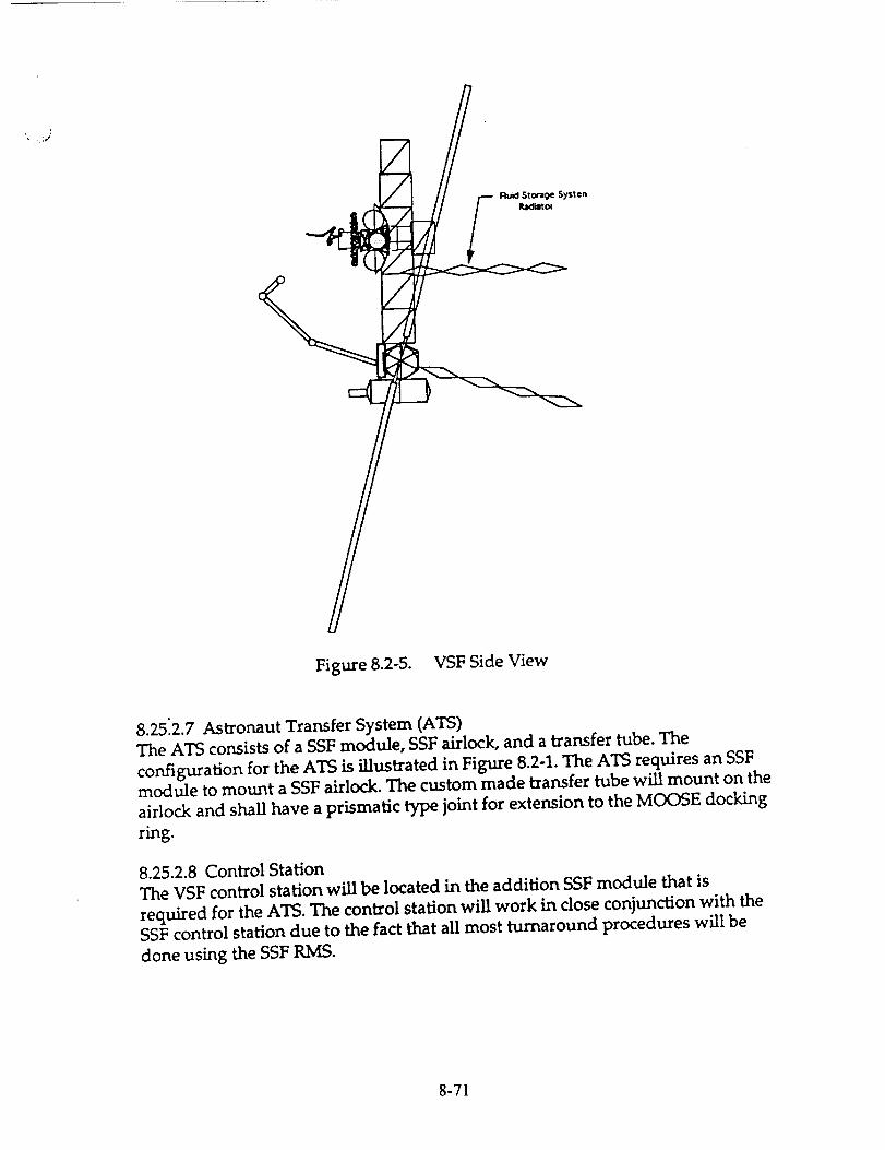
Figure 8.2-5. VSFSide View
8.2512.7Astronaut Transfer System (ATS)
The ATS consists of a SSF module, SSF airlock, and a transfer tube. The
configuration for the ATS is illustrated in Figure 8.2-1. The ATS requires an SSFmodule to mount a SSF airlock. The custom made transfer tube will mount on the
airlock and shall have a prismatic type joint for extension to the MOOSE dockingring.
8.25.2.8 Control Station
The VSF control station will be located in the addition SSF module that is
required for the ATS. The control station will work in close conjunction with the
SSF control station due to the fact that all most turnaround procedures will be
done using the SSF RMS.
8-71

8.25.3 VSF Power Requirements
The VSF power requirements will stem from the Huids Storage System and theMaintenance Dock interface. The FSS will draw a large amount of power to store
the cryogenic liquids. The Maintenance Dock interface will supply power to the
MOOSE during turnaround operations.
The maximum power requirement should be on the order of 5-10 kW. This
sizable requirement probably will require the addition of a solar array pair to SSF
(see Figure 8.1-1). This would supply the station with an additional 18.75 kW of
power, more than enough to support the VSF.
8.25.4 Vehicle Maintenance Guidelines
Three-level maintenance hierarchy based on level-of-rapair analyses.
- Level I consists of vehicle local maintenance; such as removal and
replacement (R/R) activities using components that are stocked in the
spare storage area. These repairs are accomplished directly with mannedEVA or telerobotics.
- Level II consists of maintenance at SSF of components removed during
level I maintenance.
- Level UI maintenance incorporates sending unrepairable components
back to earth via the logistics module that is returned to earth from SSF
on every shuttle flight.
Spare parts will be stocked based on reliability, criticality and cost. Shuttle flights
are scheduled for every 90 days to resupply SSF. Modular construction of the
MOOSE was stressed to simplify vehicle turnaround.
8-72

Bibliography (sections 8.9-10 & A8.2-4)
1) "Space Mission Analysis and Design, 2nd. edition," Wiley Larson & James
Wertz, editors; Kluwer Academic Publishers, Netherlands & Microsm,
Inc,Torrance, Califorr_a; 1992, Pg 764.
2) "Rendezvous/ Proximity operations Workbook," NASA, LBJSC, March,
1983, RNDZ 2102, pg 4-2.
3) "Orbital Mechanics," Chobotov, editor, AIAA, 1992, pgs 179-180
4) "Orbital Mechanics," Chobotov, editor, AIAA, 1992,
5) "The Human Role in Space:Technology, Economics, Optimization,"
Stephen Hall, editor; Noyes Publications, Park Ridge, NJ, 1985.
6) "Reliability Prediction for Spacecraft," Hecht, H. & M., Dec, 1985, RADC
report RADC-TR-85-229.
7) "Accessing Space: a catalogue of process, equipment and resources for
commercial users," Office of Commercial Programs, NASA, 1990.
8) "Proposed Design for On-Orbit Servicing Handbook," AIAA, 1992
9) "Space Mission Analysis and Design, 2nd. edition," Wiley Larson & James
Wertz, editors; Kluwer Academic Publishers, Netherlands & Microsm,
Inc,Torrance, California; 1992, pgs 331-335.
8-73

References (sections 8.9-10 & A8.2-4)
1) AIAA, "Proposed Design for On-Orbit Servicing Handbook," 1992
2) Chobotov;"Orbital Mechanics," editor, AIAA, 1992, pgs 179-180
3) Hall, Stephen;"The Human Role in Space:Technology, Economics,
Optimization," editor; Noyes Publications, Park Ridge, NJ, 1985.
4) Hecht, H. & M; "Reliability Prediction for Spacecraft," , Dec, 1985, RADC
report RADC-TR-85-229.
5)Larson, Wiley & James Wertz, editors;"Space Mission Analysis and Design,
2nd. edition," Kluwer Academic Publishers, Netherlands & Microsm,
Inc,Torrance, California; 1992, Pg 764.
6) NASA,"Accessing Space: a catalogue of process, equipment and resources
for commercial users," Office of Commercial Programs, 1990.
7) NASA, "Rendezvous/ Proximity operations Workbook," LBJSC, March,
1983, RNDZ 2102, pg 4-2.
8-74

7.4 MOOSE MISSION MODELS
Jason Budinoff, Operations & Production
7.4.1 Location of Target Spacecraft
Artificial Satellites are generally located in 5 orbit types:
(1) LEO in-plane
(2) GEO
(3) LEO mid-latitude
(4) HEO mid-latitude(5) LEO Polar/Synchronous
I:
I
%4. HFO M;d-to±i±ude
5. Polar/Synchronous
Lea
_1. LED 2B.5
_c,
AL "t ;'l uOI¢', kr',
2. 0E0
Figure 7.4.1
Figure 7.4.1 shows the orbits by region. The MOOSE vehicle can rendezvous with spacecraft
in type (1) orbits with negligible amounts of propellant. The vehicle separates and relies onattitude control thrusters for impulse on these missions. Local missions (which do not leave
the SSF proximity operations zone) also do not require primary propulsion and use little
propellant. Type (1) spacecraft include NASA science/application spacecraft (GRO, HST,
UARS, XTE, Space Station).
8-75

Type (2) orbitsare Geosynchronous and includeDoD (Milstar,FLTSATCOM), NASA and
commercial spacecraft(TDRSS, Intelsat,COMSAT).
Type (3) orbits are low-altitude mid-range inclination orbits. Primarily DoD ELINT and
surveillance satellites are in this orbit.
Type (4) orbits contain older Soviet communication satellites (Molniya) and DoD surveillance
spacecraft.
Type (5) orbits are repeating and/or synchronous. Survey spacecraft (Landsat, SEASTAR,
TOPEX/Poseidon) and DoD ELINT and surveillance satellites are in LEO type 5 orbits.
The type (5) orbit is not attainable by the MOOSE vehicle.
Orbits requiring inclination change (type (2), (3), (4)) are reached via trans-GEO plane
change trajectories. Aerobraking is used to decelerate only and 2 aerobraking passes must be
made for each inbound transfer. See figure 7.4.2.
Earth
MOOSE DnboundAerobrakingGeometry
Figure 7.4.2
7.4.1.1 Spacecraft Density Per Orbit Type
The tonnage launched into each type of orbit for the 1991-2000 period is approximately
400/500/91/304/291 thousand kg for type 1/2/3/4/5 orbits respectively, based upon the
8-76
Rockwell "Medium" model. It canbe inferred that the frequencyof servicing missions to the
various orbits will follow these ratios. The MOOSE Medium and High mission models were
constructed using these ratios.
Servicing 2 (or more) spacecraft in a single sortie is possible, but restricted and subject to
many conditions. Double servicing missions will be rare at best and propellant requirements
may exceed the MOOSE maximum load. While significant customer cost savings result,
double servicing missions will be transient opportunities; considered exceptions to normal
operating modes. Double servicing missions have not been included in typical mission
modelling and must be considered on a case-by-case basis.
All costing models in this section reflect 85% learning curve effects and yearly discounting of
10%.
7.4.2 Mission Models
3 mission models have been analyzed reflecting differing levels of MOOSE mission tempos.
7.4.2.1 LOW Mission Model (ENAE 412 CDR)
The LOW mission model represents the mission frequency presented at CDR and reflects a
sortie rate of 1/4 months. 3 GEO (type (2)) missions are performed. This model is not based
upon orbit mass ratios.
7.4.2.2 MEDIUM Mission Model
The MEDIUM mission model entails 6 MOOSE sorties per year (1/2 months). The missions
are divided into: 2 type (2) GEO in-plane, 2 type (2) GEO, 1 type (3) LEO mid-latitude, and
1 type (4) HEO mid-latitude.
7.4.2.3 HIGH Mission Model
This model represents the maximum operational tempo for a single MOOSE vehicle without
significant expansion of current space support infrastructure. The High mission model entails
13 MOOSE sorties per year (1/4 weeks). This is the minimum time acceptable for mission
planning, training and preparation. The missions are divided into: 4 type (2) GEO in-plane, 5
type (2) GEO, 2 type (3) LEO mid-latitude, and 2 type (4) HEO mid-latitude.
7.4.3 MOOSE Flight Operational Launch Support
MOOSE Flight Operations Launch Support is divided into 3 phases:
(1) Delivery, Assembly, and Verification
(2) Flight Engineering Evaluation
(3) Servicing Operations
8-77

(1) and (2)will utilize US launchvehiclesonly in order to preparedomesticmanufacturersfor future internationalopen-bidcompetition,and to allow maximum communicationsduringcritical assemblyand testing.The 2-year phase1 and 2 processrequiresa block purchaseof 4dedicatedSTS,2 Titan IV SRMU (ETR) and 4 Delta 7920 (ETR) vehicles. See figure 7.4.3.
Costs represent 2--yeor block pmchose 8_ ;eornin9
ASr 1 _E 2 uOOSE DEU/VALPropellonts
Phase 2 Flight Engineering Evaluation
I SI"S $150u1 l"iton IV ETR $131M4 Dello ErR $153M
!,otol $434M
MOOSE Propellont$ & Consumoble$
F'liOnt Vehicie
figure 7.4.3
7.4.3.1 Phase (l) Delivery, Assembly, and Verification
Phase 1 is the assembly stage of MOOSE verification. Phase 1 requires 1 year. An
Engineering Test Vehicle (ETV) is delivered to space station after ASE (Airborne Support
Equipment, including berthing facilities and cryogenic propellant depot) is assembled and
checked-out. The ETV verifies assembly, vehicle handling, sating, docking/release, and
berthing schemes. Phase 1 launch vehicle support requires:
(1) 2 STS delivery flights of ASE
(2) 1 STS Delivery of MOOSE Engineering Test Vehicle
(3) 1 Titan IV delivery of cryogenic propellants and consumables for ASE checkout &verification
8-78

7.4.3.2Phase (2) Flight Engineering Evaluation
Upon successful completion of Phase (1), Phase (2) is initiated. This phase is 1 year long and
provides flight testing of the unmanned, instrumented ETV. The ETV is flight-prepared and
undergoes a battery of orbit transfer and flight mechanics verification tests. Any residual
problems are accounted for. The MOOSE Flight Vehicle is delivered and assembled, run
through "shakedown" trials and prepared for Phase (3), MOOSE Servicing Operations.
ETV flight testing entails 3 "local" systems verification flights of the cab-separated vehicle, 3
type (1) LEO in-plane missions, 2 type (2) GEO missions, and 2 type (3) LEO mid-latitude
missions. The propellant required is delivered from Delta PMV's and the left-over from ASE
demonstration/validation (DEM/VAL) testing. This phase will also validate SSF Terminal
Control Zone traffic management protocols, and command dynamics.
Phase 2 requires 1 STS, 1 Titan IV, and 4 Delta launches. The first STS flight delivers the
MOOSE flight vehicle. The Delta and Titan IV (ETR) deliver Propellant/Consumables to
support flight test operations. See figure 7.4.3.
7.4.3.3 Phase (3) Servicing Operations
The third phase covers operational deployments of the MOOSE flight vehicle. 3 models of
Phase (3) operations reflect different mission tempos, and each require varying levels of ELV
support.
Cost per delivered kg is too simplistic of a model for MOOSE lift requirements. The nature
of the mission requires frequent delivery of specific satellite components to SSF. The Shuttle
will support MOOSE operations with 4 deliveries of payloads and consumables per year,
during regular SSF support missions. Individual launch vehicles are limited in terms of
availability and long-lead times (years); therefore a large degree of foresight is required in
ELV support procurement.
The trade-off is between 4 factors:
(1) ELV $/kg
(2) ELV dedicated availability
(3) Many small deliveries (rapid mission response requiring special payloads)
(4) Infrequent bulk load delivery (cost savings)
The ELV models are described in section 7.4.4.1.
MEDIUM/HIGH mission models will be the largest single consumer of ELV's. Open bids
industry-wide and purchase of large ELV lots will be required and drive launch costs down.
The US-only support requirement is dropped after completion of phase 1 and 2.
7.4.4 MOOSE Operations Launch Support
Launch support considers vehicles operational in the 1998-2005 timeframe. Surveyed
8-79
vehiclesinclude:
(1) Titan IV SRMU (Martin Marietta)
(2) Delta 7920 (General Dynamics)
(3) Ariane AR 44L (Arianespace)
(4) Ariane 5 (Arianespace)
(5) H-II (Rocket Systems Corporation/NASDA)
(6) Proton SL-13 (Lockheed/Khrunichev/Energia (LKE))
(7) Energiya (Energia USA)
Atlas is not surveyed due to high specific cost ($/kg delivered to SSF), dated nature of design
and current string of failures threaten program cancellation
The STS is currently prohibited from carrying large quantities of propellants (Centaur G-
prime restriction) and therefore not considered in propellant support models.
7.4.4.1 Support Model
Based upon MOOSE propellant usage of 12,000 kg of cryogenic LO2/LH2 per type (2), (3),
and (4) mission, the LOW, MEDIUM, and HIGH models require delivery of 36,000, 72,000,
and 156,000 kg to SSF, respectively. Propellant delivery is containerized in Propellant
Maneuvering Vehicles's (PMV) for orbit correction and controlled proximity operations in the
SSF Proximity Operations Zone. PMV's exhibit typical payload mass fractions of 0.85 - 0.9.
The PMV mass has been accounted for in lift capacity required.
7.4.4.2 Mixed Manifest
Bulk propellant delivery shall not be centered around any single ELV. Opening the launch
requirements to industry bids induces competitive market practice and enhances the reliability
of propellant delivery. Using a variety of systems avoids bottlenecks should any single
system become grounded, similar to the Challenger incident and current Atlas grounding.
Contingency planning must foresee lift requirements and factor in launch vehicle failures.
7.4.4.2.1 Assumptions
In determining which ELV's would contribute to each model's support requirement, many
factors were considered. The model assumes:
(1) STS delivery of mission-specific payloads to SSF 4 times per year in ALL models.
Normal SSF support operations require delivery of resource nodes and crew rotations
every 90 days. MOOSE mission specific payloads are relatively small and low mass
(> 1000 kg) and can accompany SSF support payloads without jeopardizing STS
mission success.
(2) 100% of servicing missions require dedicated payload deliveriesAll MOOSE missions are assumed to require special payloads: Hydrazine products,
8-80
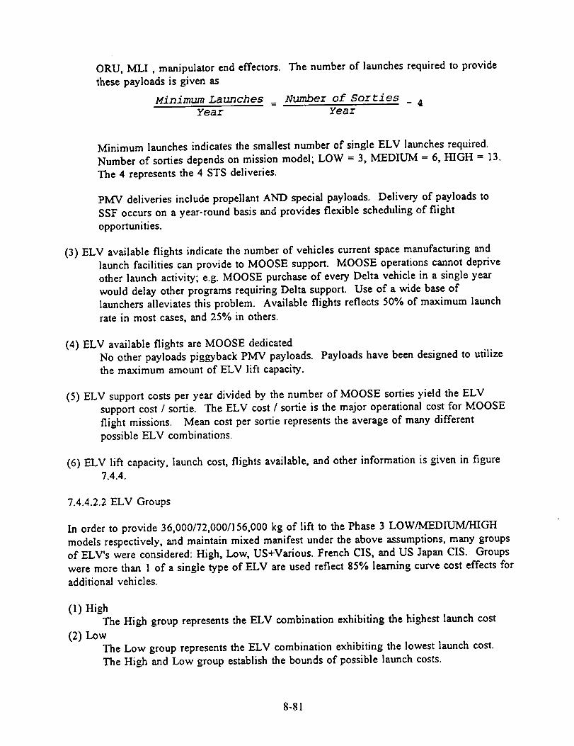
ORU, MLI, manipulator end effectors.
these payloads is given as
Minimum Launches
Year
The number of launches required to provide
Number of Sorties
Year-4
Minimum launches indicates the smallest number of single ELV launches required.
Number of sorties depends on mission model; LOW = 3, MEDIUM = 6, HIGH = 13.
The 4 represents the 4 STS deliveries.
PMV deliveries include propellant AND special payloads. Delivery of payloads to
SSF occurs on a year-round basis and provides flexible scheduling of flight
opportunities.
(3) ELV available flights indicate the number of vehicles current space manufacturing and
launch facilities can provide to MOOSE support. MOOSE operations cannot deprive
other launch activity; e.g. MOOSE purchase of every Delta vehicle in a single year
would delay other programs requiring Delta support. Use of a wide base of
launchers alleviates this problem. Available flights reflects 50% of maximum launch
rate in most cases, and 25°/, in others.
(4) ELV available flights are MOOSE dedicated
No other payloads piggyback PMV payloads.
the maximum amount of ELV lift capacity.
Payloads have been designed to utilize
(5) ELV support costs per year divided by the number of MOOSE sorties yield the ELV
support cost / sortie. The ELV cost / sortie is the major operational cost for MOOSE
flight missions. Mean cost per sortie represents the average of many different
possible ELV combinations.
(6) ELV lift capacity, launch cost, flights available, and other information is given in figure
7.4.4.
7.4.4.2.2 ELV Groups
In order to provide 36,000/72,000/156,000 kg of lift to the Phase 3 LOW/MEDIUM/HIGH
models respectively, and maintain mixed manifest under the above assumptions, many groups
of ELV's were considered: High, Low, US+Various. French CIS, and US Japan CIS. Groups
were more than 1 of a single type of ELV are used reflect 85°/, learning curve cost effects for
additional vehicles.
(1)High
The High group represents the ELV combination exhibiting the highest launch cost
(2) Low
The Low group represents the ELV combination exhibiting the lowest launch cost.
The High and Low group establish the bounds of possible launch costs.
8-81

'1II
f
Ii
TI_ DV8_U17,800 k 9 to SSF ETR15,000 k 9 to SSF WTR$154M/Iounch1 ovoilable flight/yeor ETR1 ovoilable flight/yeor WTR$8.7K/kg ETR$10.SK/kg WTR
Ii)ell_ 711115100 kg to SSF ETR4000 kg to SSF WTR$48M/Iounch5 ovoiloble flights/.yeor ETR2 available flights/year WTRS9.SK/kg ETR
$12K/kg WTR
8i"8 #ASR_20,100 kg to SSF$245M/Iounch.3 ovoilable flights/year$12.2K/kg
}1f_
i
"!m,-t
1
Pr¢l¢_ 8L-I]815,000 k9 to SSF$70M/Iounch5 ovoilable flights/year$SK/kg
N]-_29,800 kg to SSF$120M/Iounch1 avoilable flight/year$12.SK/kg
18,000 kg to SSF$110M/launch
4 ovailable flights/yeor$6.1K/kg
8500 kg to SSF$1 lOM/launch5 avoiloble flights/yeor$1`3.2K/k 9
/x
u
Illl
F
52,800 kg to SSF$1 lOM/launch1 ovoiloble flight/year
$2.1K/kg
8-82

@
%© -i-© __
"7-
@
@
_m
@
@
o
m_@©©
_9
®
r< o_J
©°__
0
_-.00_-00
w
, It--- 7
(D
o
t._ o_
o
O0cDw')t_,--
-l-0
7-
0o9
O_0Or--
Q)°_
o
_p
o
O_
0_J
-c0b9
uUu300_)
q)
%._
oO9
twOco,-
o
a) o0ow)
cl • -
,.C---]
bO
+0
n-bq<(D>
g-83
_D
"U_Oo9
tD "_-
<zlg
k...
o
O_r,.'3 t.f)_,'3 t.o
.m
k--
oto
O_o31"--t'q _'_
-r-(..)zw_
L(D
S,_
0o9
O_oh,--r--. co
0
00<-
0
cq_ob I-...oqob
Z<
"do
0¢.0
o
Oqr-.
oO3
00
2<

(3) US+Various
The US+ Various group reflects using the maximum US ELV available support with
supplemental support from the lowest cost foreign ELV's (if required).
(4) French CIS
The French CIS model incorporates using at least 1 CIS ELV and 1 French vehicle
and supplementing remaining lift with appropriate lowest-cost combinations of French
and CIS launchers. This tends to be among the lower cost alternatives.
(5) US Japan CIS
The US Japan CIS group utilizes 1 H-2, 1 US, and 1 CIS vehicle and supplements
remaining lift with additional US and CIS launches.
Other groups are possible; Detailed combinatoric analysis may be done at a later date. The
mean cost/sortie of the above groups represents the resulting cost/sortie. Figure 7.4.5. Shows
the results of the 5 groups in support of the mission models.
7.4.4.3 Cost summary (Cost/sortie)
The resulting cost / sortie of the MOOSE ELV Support Models are given as:
Mission Model Cost / Sortie in Millions
LOW $98
MEDIUM $72
HIGH $60
7.4.4.3.1 Discounting Effects
Applying a 10% discount to future MOOSE ELV operations support models show significant
cost effects after 3 years of phase 3 operations and drastic reductions after 6 years.
tO0
MOOSE Colt per Sortie
+0
0.1
.__._.__.._it¢ou ete II 10_ _/es fljm _
Yllrl Iron llrol i111|,
8-84

BIBLIOGRAPHY
COLD-SAT Cryogenic On-Orbit Liquid Depot-Storage, Acquisition, and TransferNASA TM-102308 July 1989
Cole, E.G.Service Role of a Space Station: System Approach to Requirements at the Transportation NodeShuttle Integration and Satellite Systems Division, Rockwell Internationalfrom
Space Station Policy Planning and UtilizationAIAA Aerospace Assesment Series Volume 10Proceedings of the NASA/AIAA Symposium on the Space StationArlington, VA, July 1983
de Ste. Croix
Space TechnologySecond Edition
Orion Books, NY, NY, 1989
Definition of Satellite Servicing Technology Development Missions for Early Space StationsFinal Report Volume 1I - Technical
TRW Space and Technology GroupNASA CR-170844 May 1983
Fisher, H.T.Satellite Platform Service and Maintenence
Lockheed Missiles and SpaceSunnyvale, CAfrom
Space Station Policy Planning and UtilizationAIAA Aerospace Assesment Series Volume 10Proceedings of the NASA/AIAA Symposium on the Space StationArlington" VA, July 1983
Iskawitz, Steven J.Inernational Guide to Space Launch Systems 1991 Edition
AIAA, Washington D.C. 1991
Jezewski, DJ.A Survey of Rendezvous Trajectory PlanningAAS 91-505
McHenry, Stern T, and Yost, James M.COLD-SAT Feas_ility Study Safety AnalysisNASA CR-187042 January 1991
OTV Concept Definition and Evaluation - Subsystem Trade StudiesVolume II, Book 3, Orbital Transfer Vehicle Concept Definition and System Analysis StudyMartin Marietta AerospaceNASA CR 183.544
Repa, ICP.
8-85
Trajectory Design for Design Reference Missions of Space-Based VehiclesTM-FMS-EE-11, Mcdonnel Douglas Astronautics Company Engineering Services, June 1988
Space Launch - Cost Increases and schedule delays in the Air Force's Titan IV ProgramReport to the Chairman, Subcommitee on Defense, Commitee on Appropriations, House of RepresentativesGovernment Accounting OfficeGAO/NSIAD-90-113 May 1990
Space Station Definition and Preliminary Design Work Package 3Automation and Robotics PlanContract No. NAS5-29300
General Eie_ric Space Systems Division Philidelphia, PA, January 1987
Space Station Freedom User's GuideOffice of Space FlightSpacelab/Space Station Utilization ProgramUser Integrstion DivisionCode MG
NASA Washington D.C. August 1992
A study of Concept Options for the Evolution of Space Station FreedomLangley Research CenterNASA TM 102675 May 1990
Turnaround Operations Analysis for OTV
Final Report Volume III Technology Development PlanGeneral Dynamics Space Systems DivisionNASA CR 179318 Febuary 1988
Turnaround Operations Analysis for OTV
Final Report Volume IV WBS,Dictionary, and Cost MethodologyGeneral Dynamics Space Systems DivisionNASA CR 179319 Febuary 1988
Woodcock, GordonSpace Stations and PlatformsOrbit Books 1990
8-86

Appendix 1.1.5 AV - Vehicle Mass Trade Study
Sample Calculation
Assumptions:
AV mission
Isp
Mdry o
Mass Estimation
= 6 568m/s
-- 450 sec
- 3000 kg
Baseline one sattellite at GEO mission
dry vehicle, mass budget ceiling
does not include propellant tank dry ma
Initial dry mass, Mdry o , is plugged into the rocket equation,
6V _ Mdry0
(1) e I.pgo Mi.i _
to yield Minitial o. From this relation the propellant mass is found:
MpmpcUant= ( 1- Mdr/_ ) Miaiti_
(2) Minitialo
Tank mass is estimated using the empirical equation given in ENAE 488D:
(3) Mink0 = 0.1 (Mprope]m_) °'9
A new dry mass is calcualated by adding Mdry o to Mtank o, Mdry n+l
(4) Md_"= Mdry"+ Mink"
The new value is then plugged back into equation (1), and the procedure isrepeated. A final value is decided as reached when the n+l value is within
e = 0.001 kg of the n value. A full iteration yields the following results:
Mdryfinal - 4247 kg
Mtank = 1145 kg
Mvehicl e = 18806 kg
Mpropellant = 14559 kg

Appendix 1.2
(m/s)High Low
Event Energy Spiral Thrust Hohmann AerobrakeSeparate 3 3 3 3 3GEO Transfer Inject 3000 6052 592x4 burns 2400 2400Midcourse 15 - 60+75 15 15
GEO Circ 2514 550x5 bums 1762 1762Orbit Trim 9 9 9 9 9
GEOOps 2O8 2O8 2O8 2O8 2O8LEO Transfer Inject 2514 6052 550x5 burns 1762 1844Midcourse 20 75+60 20 20
Aeromaneuver - - - 67
LEO Circ 3000 - 592x4 burns 2400 122
Rend & Dock 18 18 18 18 18
Reserves 565 616 537 532 532
Total AV 11866 12958 11281 9129 7000
Total Transfer
Times(hours) 8.4 686 165 10.6 15.2
The high energy transfer offers the shortest mission transfer times and the lowest
total radiation exposure to the astronaut. However, there are high h loads placed on
the astronaut. It can be seen that the energy expenditure is not worth the few hours
saved from the mission time. Both the spiral and low thrust transfers have
considerably less g loads but it can be seen that both of these transfers have
prohibitive mission transfer times at no energy savings. The hohmann transfer
offers one of the best solutions by having low mission times, minimal energy
expenditure, and g loads in the range of I to 2g's. Further energy savings can be
obtained if an aerobrake is used for one to the transfer burns. Utilizing a
hohmnann transfer to GEO and then using the aerobrake for one of the transfer
burns back to LEO will minimize both the total AV and mission times.

Appendix 1.2.6
Phasing Orbit Study
0 = 45 °
co = 4.166 E-3 °/sec
Ix = 398604 km3/sec2
- Sample Calculation
(angular rate of Earth)
(GM of Earth)
AT = Difference between GEO circular and Transfer Orbit periods
AT = _IL= 450 = 10800 secco 4.166E-3
TGEO = GEO circular Orbit period
TG_ = q-_ = 85661 sec
T transfer = TGEO - AT = 85661 - 10800 = 74861 sec = 20.8 hours
a transfer = semi-major axis of transfer orbit
atr_-asfer= tr_sfer4---_ = 748612Ix = 38391 km4g 2
AV = AV required for the transfer orbit
AV = 2AVtr_f,r = 2_[42. R(3_. 1] = 2_/398604 [_/ 2 - 42000_ 1] = -0.297 km/secatr.nsfer . 42000 38391


Phasing Study III
IAppendix= = 0.004166667
_= 398604
(°)
-360
-345
-330
-315
-300
-285
-270
-255-240
-225
-210
-195
-180
1.2.6 continued
:=/sec
km^3/sec^2
(=ec) (aoc)& T T t_nafor
-86400 172061
-82800 168461
-79200 164861
-75600 161261
-72000 157661
-68400 154061
-64800 150461
-61200 146861-57600 143261
-54000 139661-50400 136061
-46800 132461
-43200 128861
I"geo =
R geo =
(hra)T trans.
85660.97 sac
42000 km
(km)a transfer
(km/aac)&V transfer
(km)perigee alt.
9172547.8 66862 1.055
46.8 65927 1.032 89853
45.8 64984 1.007 87968
44.8 64034
43.8 63078
42.8 62114;
41.8 6114340.6 60163
39.8 59176
38.8
37.8
58181
57176
56163
55141
36.8
35.8
-165 -39600 125261 34.8 54109-150 -36000 121661 33.6 53067
-135 -32400 118061 32.8
-28800 114461 31.8
-25200 110861 30.8 49878
-21600 107261 29.8 48793
-120
-105-901
5201550953
4769528.8-75 -18000 103661
-60 -14400 100061 27.8 46584
-45 -10800 96461 26.8 45460-30 -7200 92861 25.8 44322-15
0
15
30
-3600 89261 24.6 43169
0 85661 23.8 42000
3600 82061 22.8 40815
784617200
10800 74861
21.8
20.8
39612
3839145
14400 71261 19.8 37150
18000 67661 18.8 35888
21600 64061 17.8 34604
25200 60461 16.8 33295
28800 56861 15.8 31960
32400 53261 14.8 30596
36000 49661 13.8 29201
12.846061
60
75
90
105
120
135
150
165 39600 27773:
43200 42461 11.8 26306
46800 38861 10.8 24797!
50400 35261 9.8 23241
180
195
210
225 54000 31661 8.8 21631240 57600 28061 7.8 19959
255 61200 24461 6.8
270
285
20861
17261
64800
68400
1821316379
14436
5.8
0.982 86069
0.955 84156
0.928 82228
0.8990.869
0.837
0.804
0.770
0.733
0.695
0.655
0.612
0.567
0.51910.469
0.415
80285
78327
76352
74361
72353
70327
4.8
68282
66218
64135
62031
59905
57757
55586
0.357 53390
0.296 51168
0.230 48920
0.159 466430.083
0.000
44337
42000
-0.090 39630
-0.189 37225
-0.297 34782
-0.416 32301
-0.549 29777
-0.698 27208
-0.666 24590
-1.059 21920
-1.282 19192
-1.544 16403
-1.858 13545
-2.248 10612
-2.752 7594
-3.456 4482
-4.673 1262
#NUM! -2083
#NUMI -5574
#NUM!
#NUM!
-9242
-13129
300 72000 13661 3.8 12351 #NUMI -17297
315 75600 10061 2.8 10073 #NUM! -21854
330 79200 6461 1.8 7498 #NUM! -2700_ =
Page 1
PhasingStudyIII
34sJ36ol
82800 2861 0.8 4356 #NUM!86400 -739 -0.2 1767 #NUM!
-33288 I-38467J
Page 2

Appendix 1.3.1: NASA JSC Cost Model Summary (revised to FY92 and metric system)
ome,mECLSS/Crew Accomodations
Avionics
Control Moment GyrosStructures/TPS
Electrical Power
Docking Module
RCS/Propulsion System
Cryogen Tanks
RDT&E Costs
B32.691 0.414
24.817 0.579
5.553 0.468
5.226 0.491
1.821 0.584
1.366 0.524
0.411 0.876
0.120 0.885
_arameter
system mass (kg)
system mass (kg)
system mass (kg)
system mass (kg)
system mass (kg)
system mass (kg)
dry mass (kg)
dry mass (kg)
Software
Systems Engineering & Integration
Project Management
Subsystems Development Test
Support Equipment
Integration, Assembly and Checks
0.576 1.000
0.084 1.000
0.030 1.000
0.073 1.000
0.090 1.000
0.596 0.832
kloc
RDT&E Costs ($M91)
Total Direct Costs ($M91)
Total Direct Costs ($M91)
Total Direct Costs ($M91)
First Unit Costs ($M91)
ECLSS/Crew Accomodations
Avionics
Control Moment Gyros
Structures/TPS
Electrical Power
Docking Module
RCS/Propulsion System
Cryogen Tanks
First Unit Costs
A SM92) B2.373 0.502
0.212 0.917
0.256 0.531
1.204 0.440
0.150 0.784
0.167 0.508
0.342 0.550
0.060 0.625
parameter
system mass (kg)
system mass (kg)
system mass (kg)
system mass (kg)
system mass (kg)
system mass (kg)
dry mass (kg)dry mass (kg)
Cost ($M92)=A*ParameterAB
Cost ($M93)=Cost ($M92)'1.043 (from DoD standard inflation factor tables)

Modifications to NASA JSC Model
Cabin Insulation and Shielding
Aerobrake Structure
Aerobrake TPS
Aerobrake Truss (Lower Truss)
Grappler & Robotic Arm
Reference System Complexity Factor
Structures 1.25
Structures 1.50
Structures 1.50
Structures 1.25
Structures 2.50
Component Cost ($M93) = Reference System Cost ($M93)*Complexity Factor
Note: The complexity factors were derived from judgements about relative system
complexity and technology level.

Appendix 1.3.2: Cost Discounting Analysis
Annual Cost Discounted Annual CostYear % _M93 % $M93
1993 6.4 166.0 8.2 166.0
1994 17.6 452.6 20.3 411.4
1995 23.8 612.8 25.0 506.5
1996 23.7 610.7 22.6 458.8
1997 17.9 461.6 15.6 315.3
1998 9.0 232.6 7.1 144.4
1999 1.6 42.3 1.2 23.9
Totals 100.0 2578.6 100.0 2026.3
Cumulative Annual Cost Cumulative Discount Cost
Year1993 6.4 166.0 8.2 166.0
1994 24.0 618.6 28.5 577.5
1995 47.8 1231.4 53.5 1083.9
1996 71.4 1842.1 76.1 1542.7
1997 89.3 2303.7 91.7 1858.0
1998 98.4 2539.3 98.8 2002.4
1999 100.0 2578.6 100.0 2026.3
Totals 100.0 2578.6 100.0 2026.3
Cumulative and annual costs and their respective percentages were
computed using the time spreading of cost algorithm developed by Wyaholds
and Skratt (1977). The relevant equation is:
F(s) = As 2 [10+s((15-4s)s-20)] + Bs 3 [10+s(6s-15)] + [1-(A+B)]s 4 (5-4s)
where A = 0.32
B = 0.68
s - fraction of total time elapsed
F(s) = fraction of cost consumed in time s
The values for the constants A and B were selected such that 60% of the costs
will be incurred during the first three to four years. These values are
consistent with typical projects in industry today. In order to obtain
discounted costs, the following correction equation is necessary:
P = (l+d)-(n-1)

Then:
where P = discount factor
d = discount rate
n = year of the project
Discount Cost = Annual Cost * P
A standard discount rate of 10% was utilized in these calculations. As
expected, costs are front loaded due to heavy RDT&E spending in the early
stages of the project. Finally, since there is only one vehicle currently being
considered for production and operation learning curve effects were not
considered. Figures 1.3.1 and 1.3.2 present a graphical comparison of
discounted and regular cost distributions.

CL

PINIDiEMNI PAGI( IH..&NK NOT F'It,.MEID

0
i

I111'11III'll'llllll]J,Iljllllll
I1,1
mlll'llliIIIII11II
Illllllllllll
Q.

I!i!!':Ii!! !
'"' " ! !,,,,,,,,00,,.0 ._!!_!i!i!_°l°ll'l'l:l"l"l'l<i'i=.... -°-+ °'+_" _"_1_1:-.... !
!.i.!_!l,l,il, Iiii!!'"'/ili1!1!1!1!111illilili.,i_.. 0, !!ii i
I_l!l!l!lilll!lll!lil!rl'":" "':"'IPl"lflfl'l'l'l:l:l'l-'" _.'.°71flfl_l'l=l'l'.;" ,"_/llll_lll#lllmlllllllll I I I _ 111111111111_11_ • I I _ 1
tllll Ildlll! ",-_!i!_ !!!! i!!i!!i!!.i.!!!il!!itlilli
°,,,ol01 lolol,l,lololol.,,.,
l!!'illliill© . ,,;li, i'_'¢i'li'a_'ti'¢i'¢i
i_i_,_,iiiii_!ii_iiiii,i o li li',,_'i",i',,_l,,_l_ ltl 7 _ll _ ,,,,-",,-";',,_t,,_l;l;'l_ _ o o
,o..,,o.,.ooo.oo,,o:!,oo!!oo!!oo.,.o. .... o;ooo,.!t_ i( ' ._ ,ix
r!,,!
Ili

Appendix A2.1 Robotic Terminology
A2.1.1 Basic Parameters
There are several basic parameters that can be used to define the capabilities of
a robotic manipulator. These are
• Payload
• Mobility
• Workspace
• Agility
• Accuracy
• Structural Dynamics• Economics
Payload is the maximum mass that the manipulator can handle in any
configuration of its linkages. This mass is likely to be less than the maximum
load-carrying capacity of the system, which can be much higher in certain
configurations. The payload capacity of the arm is a function of the size and
shape (moments of inertia) of the payload, as well as its mass. Therefore,
wrist interface torques are sometime specified instead of, or in addition to, the
payload rating.
Mobility is determined by the total number of independent "degrees of
freedom" (DOF), or motions, that can be performed by all the links. The
degree of mobility of the end effector is equal to the sum of independent
degrees of freedom all the intermediate links. However, because of possible
"degeneracies" of major and minor wrist linkages, some link configurations
may have a reduced number of guaranteed degrees of mobility. Six DOF is
needed (theoretically) for an arm to reach any point within its three-
dimensional workspace. Despite programming and control problems, a
seventh DOF is sometimes added to help deal with degeneracy issues.
The workspace of a manipulator is the space composed of all points that can
be reached by the end of the arm, or some point on the wrist, but not by the
the end effector or tool tip. This is because the size and shape of different end
effectors can significantly alter the dimensions of the workspace. Some
segments of the theoretical workspace can be excluded if required velocity,
payload, etc., specifications can not be performed in these regions. Degeneracy
in the major and minor wrist linkages can also eliminate workspace points.
As stated above, redundant DOFs can help overcome degeneracy problems.
Agility is the speed at which prescribed motions can be executed. To
accurately characterize robot performance, the maximum speed and the
maximum rates of acceleration and deceleration have to be specified. These

may not be enough to accurately characterize a system, since, typically, the
more deceleration a link experiences, the longer the required settling time is,
thus reducing the effective speed.
Accuracy can be defined as the difference between the desired coordinate and
actual coordinate. Repeatability can be characterized by the deviation of the
actual coordinate from the desired coordinate in multiple instances.
Typically, one sees either: 1 good accuracy, high repeatability, 2 high accuracy,
poor repeatability, or 3 poor accuracy, high repeatability. Both of these factors
can be influenced by friction, hysteresis, backlash, compliance in links, joints,
or drives, settling times, etc.
Structural dynamics is characterized as having many components and
considerations. For instance, large inertia values lead to a need for high-
torque (thus heavy, not very responsive) motors, and for high forces to
execute a motion with a given speed and acceleration/deceleration profile,
thus resulting in lower performance. Low stiffness (or high compliance)
values lead to low natural frequencies, resulting in longer stabilization times
and reduced speed, accuracy, and repeatability, and may cause large path
deviations, and induce dynamic instabilities. Natural frequencies should be
the highest possible, in order to reduce the transient times and overshootfactors.
Basic economic factors include investment cost and operating expense. These
factors are largely dependent on structural design. Operating expense
includes power requirements, ratio between operating time and down time,
and difficulty of maintenance.
A2.1.2 Structural Configurations
Robot motion can be broken down into three different parts. Global motions
involve traveling distances that exceed the overall dimensions of the
manipulator (i.e. traversing of the spacecraft). Regional motions involves the
placement of an end effector into various points of the workspace. Local
motions cover the fine or small adjustment movements of the end effector.
A mechanism needs to have at least six degrees of freedom to move and
orient a body in three-dimensional space: three DOF to place the object in the
proper region of space (execute regional motions by the arm), and three DOF
to properly orient the body (execute local motions by wrist/end effector).
Robotic arms are characterized by the first three elementary joints of the arm.
There are two types of elementary joints: prismatic and revolute joints. A
prismatic joint translates along an axis, while a revolute joint rotates around
an axis. In order to move the end point of the arm in three-dimensional
space, at least one of the following obvious conditions have to be satisfied:

There are two revolute joints with non-parallel axes.
There are two revolute joints with parallel axes, and one prismatic
joint whose axis is not perpendicular to the revolute joint axes.
There are two prismatic joints with nonparallel axes and one
revolute joint whose axis is not perpendicular to the plane
containing axes of the prismatic joints or the third prismatic
joint whose axes is nonparallel to thaf plane.
A2.1.3 Coordinate Frame Selection
Robots moving in the rectangular or cartesian frame are used for relatively
simple applications. These robots have three main joints that are prismatic.
Rectangular frame robots are the easiest to program because the joint
coordinates are completely independent. However, it is difficult to protect the
sliding surfaces, the structure is very large and bulky, as it must completely
encompass the workspace, and it is difficult to access enclosed areas.
Cylindrical coordinate system robotic arms have two translational motions
(radial and vertical), with telescopic radial motion. These robots are more
versatile then cartesian frame robots. They require relatively small space, and
can have faster transients and reduced dynamic loads. One disadvantage of
the cylindrical frame robots is their reduced work zone, since the arm cannotreach below the bed of the structure.
Many robotic arms are designed to work in spherical coordinate frames.
These arms are very complicated and require more sophisticated control
systems, but they have the advantage of servicing a larger workspace.
Anthropomorphic robot designs have only revolute joints (RRR), and are
called jointed or articulated. The Space Shuttle Remote Manipulator System
(RMS) is an example of a jointed manipulator.
Jointed arms have large workspaces in comparison to the required hardware.
They have a high degree of accessibility, and have no sliding surfaces. Rotary
bearings are easier to seal then sliding bearings, and have lower inertia and
friction losses. Jointed robots have lower energy requirements and lower
required joint force (torques).
One disadvantage to jointed arms is the degenerate behavior of the near the
workspace boundaries. Another is that conventional jointed robots have
shoulder and elbow joint axes that are parallel and orthogonal to the waist
axes, which results in relatively low stiffness.
Another significant disadvantage of the jointed configuration is the need to
move the elbow joint motor when the upper arm or waist is moving.
Conventional motor-transmission units or direct-drive motors are very

heavy, impairing system dynamics. One way to overcome this problem is tolocate the motors closer to the base and use a special light transmission
system to transmit power to the shoulder joint. But, transmission systems
introduce compliances, backlashes, and energy losses.

Appendix A2.2 Jointed Manipulator Models
A2.2.1 Simplified Jointed Manipulator (2D)
To simplify the initial analysis, first consider a 2D (planar) jointed
manipulator.
Fe
p2
T1
P2=pl+p2
T2
MI,I1
M2,I2,,f
Figure A2.2.a A 2D Jointed Manipulator
A2.2.1.1 Statics
Each link has to be in equilibrium under the influence of action and reaction
forces and joint torques. So, one vector equation for the balance of forces and
one equation for the balance of torques can be made for each link.
for link 1:
Fle= F2e
T1-T 2 -_lXF2e = 0
for link 2:
F2e = F e
r2 -_2xFe= 0
So,
Fle = F2e=F'e
_ =C_,+P2)X_e
To analyze the roles of T1 and T2, first assume T2=0. This means that
T2=P2xFe=0

or that p2 and Fe are parallel. So, the motor at joint 1, creating torque T1, can
only create a force Fe which is directed along link 2.
Now, assume that T1 = 0. Then
= =o
or Fe is parallel to pl+p2.
Analytically, this can be represented by the equations
T 1 = [11cI + 12c2]Fey- [lls 1 + 12s2]Fex
T 2 = 12c12Fey - 12s12Fex
or
Fey ]
From the above equations, the torques required from each motor joint to
develop the needed force at the arm's end point can be determined for each
linkage (assuming that the friction forces in the joints are zero...).
The reverse can be done easily, as well. The magnitudes and directions of the
arm end force can be determined from given torques, via the following
equations
_ 1 [12c12T1 _ (llC 1 + 12c12)T2Fex "1112s2
=___1__ [12s12T1 _ (lls 1 + 12s12)T2Fey 1112s2
To figure out the torques required for an arm to move 6000 kg at an
acceleration of lm/s/s in all points of 2-d space, one would use the equations
Fex =mac12
Fey =mas12
Note that when links 1 and 2 are parallel 02=0 or p, or sinJ2=0), the joint
motors do not have any control over the radial (link 2) force component.
This cooresponds to a degeneracy condition.
If gravity forces need to be accounted for, they can be handled in a manner
similar to the arm-end force. Payload gravity force is treated exactly like the
force Fe, and can be considered to be part of this force. Because of the linear
relationship of force and torque in the equations above, superposition applies.
So, only gravity forces of links are considered.

The equilibrium equations for two links considered as free bodies loaded withgravity forces W1 and W2, and reation forces and driving torques Fg and Tgare as follows:
or
Tlg
__ -- m
Flg- F28 - W 1 = 0
F2g - W 2 = 0
+ WlllcC 1 - T2g + F2g]lC 1 = 0
T2g + W212cC12 = 0
Tlg
Flg = (m 1 + m2) _
F2g = m2g
= -mlll_gc I - m2g[llc I + 12cq2]
T2g = -m212egc12
It is assumed that the effects of gravity is negligible on the arm (for now, at
least). If it becomes a factor, the gravity forces can be reduced by shifting the
locations of the center of gravity closer to the joint pivots.
A2.2.1.2 Dynamics
These equations allow for the computation of acceleration and velocity when
the forces are known (direct), or of forces when the acceleration and velocities
are specified (indirect).
The kinetic and potential energy expressions for the first link are:
- 1,-,, ,2 A"2 _-I1(__K1 - _*"1"1c"1 +
V 1 = mlglllc
Note that the potential energy of the links equals zero, since it is assumed that
gravity has a negligible effect on the system.
For the second link, the coordinates and velocities of the center of gravity
must first be determined. First, the coordinates:
X2c = IlC 1 + 12cC12
Y2c = 11sl + 12cS12

Now, the velocities:
X2c = -1101Sl - 12c(01+02)S12
Y2c = 1101Cl + 12c(01+02)C12
The angular velocity of link 2 is 01+02. So, the kinetic and potential energies
for link 2 are:
and
21 -_'. 2- " "
K 2 = _m 2[X2c+Y2c} + 112(01+ 02)
2 "2 • • "2 "2 • • • "2m21112(01+0102)c 2 +lm212c(01 +20102+02) + 21-I2(01+20102+02)
V 2 = m2gllS 1 + m2g12cS12
Note, again, that the potential energy V2 = 0 for this case.
Therefore, the kinetic energy of the payload is
Ko=lmol_0_ 2 "2 • • "2 "2+ lm012(01+20102+02) + m01112(01+0102)c 2
The Lagrangian L = K - V can be constructed easily, since there is no V term.
1 2 "2 .- "2
lm ,2 a'2 1110"21+ lm2110"_ + 2m212c(01+20102+02 )L = _--,lllc,, 1 +
• "2 ° " ° "
+ m21112c(01+0102)c2 + 1molto _
2 "2 .. "2 "2+ m01112(01+0102)c2m012(01+20102+02) +
The derivative of the Lagrangian are as follows:
• 2 " "
OL 2 " i101 + m21101 + m212c(01+02)- mlllc01 +
301• " • " 2 °
+ m21112c(201+02)c 2 + I2(01+02) + moll01
+ m01 (61+62)+ m01112(201+02)c 2

0 3L 2 "_t -(mlllc+ I1 + m211 + m21_¢ + 2m21112cc2 + 12 + m°l_ + m°l_ + 4m°1112c2)01
3O 1• •
+ (m21_c + m21112cC 2 + 12 + m0122 + mol,12 + 2m01,12c2)0 2
3Lm=O
3L 2 ........-- = m212c(01+02) + m21112c01C 2 + I2(01+0 2) + mol_(01+O 2) + m0111201c 2
002
0 OL 2& - (m212_ + m21112_c 2 + 12 + mol ] + m01112c2)01
30 2
(m21_c " . .+ + 12 + mol_)02 - (m21112+moll12)0102s
OL
002
• 2 "2
- [m21112c(01+0102) + m01112(01+0102)]s 2
Using the above equations, it is possible to determine expressions for joint
motor torques:
0 OL OL
T1 = Ot001 i)01
0 OL OL
T2 = Ot202 202
Note: These equations do not take the force Fe into account. The appropriate
expressions can be added to the above torque equations.
The torque equations can be rewritten as:
.2 .2
T l = D1101 +D1202 +Dl1101 +D12202 +Dl120102 +D1210102 + D 1
.2 .2
T 2 = Dn01 +D220 2 +D21101 +D2220 2 +D212010 2 +D2210102 + D 2
Dii is the "effector inertia" of link i, since angular acceleration 0i at the
proximal joint i causes torque Dii0i. A coefficient of the form Dij is the

o°.°
"coupling inertia", since acceleration at joint j on i causes torque DijOj or DjiOi
at joint i or j respectively. A term of form DijjOj or DiiiOi is the "centripetal
force" acting at joint i due to rotation at joint j and i respectively.

Appendix A2.3 Telerobotic Manipulator Arm (TMA) Appendix
A2.3.1 Materials Selection
Materials for the TMA were selected based on the following criteria: stiffness,
strength, density (weight), thermal expansion, thermal conductivity, and
corrosive resistance.
Beryllium was eliminated due to its toxic nature. This material would have
been unsafe to use in conjunction with the Manned Manipulation System
(MMS).
Magnesium was also eliminated due to its susceptibility to corrosion. Many of
the fluids the TMA will be transferring to satellites will be of a very corrosivenature. The other materials listed in Table A2.2.a were all considered as
materials for the TMA.
Graphite/Epoxy was chosen as the link material due to its large strength to
density ratio. Another factor was that it has one of the higher Young's
Modulus (E) values, which lends to a good stiffness (EI) for the link. A
resistance to corrosion is a factor due to the corrosive fluids (hydrazine) that
will be transferred to satellites. This composite also has no thermal
conductivity and a very small negative thermal expansion coefficient. No
thermal conductivity means that less insulation will be needed. The minimal
thermal expansion coupled with a low equilibrium temperature will avert
any material expansion problems.
Material
Aluminum7075-T6
Beryllium
Boron/epoxy
Graphite/
epoxyMagnesium
Steel
Ult. tensile
strensth(x e_
N/sq. m)
523
Density
(x e3 kg/
cub.m)
2.8
620! 1.85
1337 2.01
Specific(E/rhol
stiffness(x e3
N,m/kg)
25.4
158.4
102.9
Thermal
Expansion
(x e6)/K
28.9
iEguilibriumTemperature
(K)
7OO
1 1.5 N/A
4.2
101.7 -0.361337 1.49
221 1.77 25.3 25.2 N/A
Ph15-7 MO 1309 7.6
Titanium 1034 4.43
26.3
24.9
11
8.8
300
300
5o'o
450
Table A2.3.a. Properties of Spacecraft Materials

The next material selection was for the arm joints. The critical factor in this
choice was thermal expansion compatibility with the Graphite/Epoxy.
Titanium was selected mainly because it has a small coefficient of thermal
expansion (see Table A2.3.a above). This will allow the links and joints to be
designed with minimum tolerances for material expansion. If expansion is
not allowed for, then the temperature gradients the arm will experience could
cause the mechanics of the arm to bind. Titanium also has a very large
strength to density ratio for robustness.
A2.3.2 TMA Mechanical Drive Analysis
In designing the TMA two drive methods were explored, geared drive and
direct drive. Direct drive consist of motors using no gears to drive the arm.
This results in a much larger torque being required from the motors,
resulting in more massive motors and larger housing for the motors. Geared
drive on the other hand uses gears to multiply its supplied torque and gives a
considerable mass savings over direct drive (see Figure A2.3.a).
To estimate the mass of the TMA and its components a computer program
was formed from a manipulator scaling model (Lecture 2/18/93. Dr. R.
Howard). The model allows the calculation of total manipulator mass given
the desired payload mass, tip acceleration, link length, and an estimated massof the outer-most link.
Another input parameter that was necessary was the transmission ratio of the
gear system; this parameter was set at a ratio of 500:1. The model consisted of a
3 link arm with one degree of freedom at each joint. An adaptation of the 2link Shuttle RMS to this model was illustrated in Dr. Howard's lecture. A
similar adaptation was done for the 2 link TMA. The computer programs
containing the models for both direct drive and geared drive are listed at the
end of this appendix section in Tables A2.3.c and A2.3.d.
The first analysis done with this program was to compare the model for
geared drive to that for direct drive. The graph of total arm mass vs. tip
acceleration (Fig. A2.3.a) shows the mass savings gained by using a geared
drive system.

A
Omm
EID
OI-"
4OO
3OO
2OO
100
Total Arm Mass(DD)
s Total Arm Mass(G)
0 I I " l " i
0.00 0.02 0.04 0.06 0.08 0.10
Tip Acceleration(m/sq m)
Figure A2.3.a Drive Mechanism Comparison
It is readily apparent that constructing the TMA using a geared drive
mechanism was the best way to work toward meeting the total arm mass
requirement of 50 kg.
A2.3.3 Application of Manipulator Arm Model
The first analysis done with the manipulator arm model was to set 3 of the
independent parameters (payload mass, tip acceleration, link length), and to
explore the relationship between total arm mass and outer link mass. This
analysis would give us an estimate of outer link mass related to keeping the
total arm mass below 50 kg. The results shown in Figure A2-2 are based on a
the following set independent parameters: payload mass = 425 kg, tip
acceleration = .05 m/s/s, and link length = 1.33 m. The trade-off between total
arm mass and outer link mass shows that to keep the total arm mass below 50
kg, the outer link mass will have to be approximately 3 kg or less.

100
75
="
E SO<
2s
0
/• I " I " I
0 1 2 3
Mass of
/• I " I " l "
4 5 6
outer link(kg)
Figure A2.3.b Results of Total Arm Mass vs. Outer Link Mass Trade-off
The next step taken with the arm model was to determine the optimum tip
acceleration. To determine this quantity the total arm mass was plotted
against tip acceleration, seen in Figure A2.3.c. The initial tip acceleration usedin the last

52
48
E,_ 46
44
42
0.00 0.02 0.04 0.06 0.08 0.10
Tip Acceleration(m/sq m)
Figure A2.3.c Results of Total Arm Mass vs. Tip Acceleration Trade-off
step (0.05 m/s/s) is located in the optimum range just below 50 kg total armmass.
A2.3.4 Structural Analysis of Link 2
The next step in the arm design was to determine the radius of link 2 (outer
link). Factors affecting this parameter were: link skin thickness, longitudinal
stress, tip deflection, and space available inside link. The decision on what
skin thickness to use was also dependent on longitudinal stress and tip
deflection, evident in Figures A2.3.c, A2.3.d, and A2.3.e, as well as on
buckling strength of the link. The goal is to minimize skin thickness, as this
in turn minimizes mass as well as maximizes space in the link due to anincrease in link diameter for the same amount of mass. The link radius
should be as large as possible to increase the moment of inertia (I), and thus
have maximum stiffness (EI). A range of link radii from 0.05 m to 0.09 m
was considered as a range with appropriate inner link space. A final choice of.
link radius = .07 m and skin thickness = .002 m was made after iterating the
analysis. This analysis included link 2 mass vs. link 2 radius, shown in Figure
2.3.c, which considered several skin thicknesses. It is

A
v
mmm
=E
Oi
.J
9=--- t = .002 m _1[
/• t = .003 m
=oy/
00.00 0.02 0.04 0.06 0.08 0.10 0.12
Radius(m)
Figure A2.3.d Results of Link 2 Mass vs. Link 2 Radius Trade-off
evident from this graph that link 2 mass decreases as skin thickness decreases
and link 2 mass increases as the radius increases. The analysis of longitudinal
stress vs. link 2 radius, illustrated in Figure A2.4.d, showed that our radius
and

_" _Critical Stress = 1.337 e+9
\_ 8e÷7• \ o ,--002m: \ \ • ,=O0_m
4e+7 - =. m
2e+7
3le+6 • , • , , I , i • i , ,
0.04 0.05 0.06 0.07 0.08 0.09 0.10 O.
Radius(m)
Figure A2.3.e Results of Longitudinal Stress vs. Link 2 Radius Analysis
skin thickness were easily within safe stress levels; having a factor of safety ofmore than 10. The next factor considered in our link radius decision was the
tip deflection of link 2 in relation to link 2 radius. The analysis is shown in
Figure A2.3.e, where we can see that the

A
E
o
omt=,=
Q
O.
I--
0.003
0.002
0.001
0.000
0.03
_ t = .002 m_- t = .003 m-- t = .004 m
•0.05 0.07 0.09
Radius(m)
Figure A2.3.f Results of Tip Deflection vs. Link Radius Trade-off
tip deflection will be less than 0.0005 m for a radius of 0.07 m. A tip
deflection of 0.0005 m is well within acceptable limits.
The equations and the basic parameters used in the above structural analysis
are listed in the following paragraph.
Manipulator Link Structural Analysis
Graphite/EpoxyE = 151 x e9
Ultimate Tensile Strength = sigma cr. = 1337 x e6 N/m sq.
Density = rho = 1490 kg/cu, m
Mass payload = Mpay = 425 kg
mass of largest ORU + 3 dof wrist + end effector
Tip accel. = Ay = .05 m/s sq.
Length of link = L = 2
Angular accel. = wdot = Ay/2 = .025 rad/s sq.
Max Angular velocity = 1 rad/sec
Angular velocity = w = wdot * time = .025 * 40 = 1 rad/sec
Radial accel. = Ax = w^2 ° L = 2 m/s sq.
Moment about z-axis = Mz = Mpay°AyoL = 42.5 Nom

Axial Load = Px = MpayoAx = 850 N
Model: circular thin wall beam
r = radius of beam
t = thickness of beam wall
Moment of Inertia = I = pi ° R^3 ° t
Tensile Stress = P/A + M.y / I
Deflection = d = LA3 • (.333 • Mpay) / (E • I)
The last factor checked was the danger of the link buckling. The following is
the list of equations and the order of their analysis to determine the
maximum compressive load the link can take.
Buckling AnalysisR = radius of link = .07 m
t = thickness of link wall = .002 m
o = geometric parameter = 1/16 * sqrt(R/t) = 0.370
gam = reduction factor = 1.0 - 0.901 * (1.0 - e(-o)) = 0.722
E = Young's Modulus = 151 x e9 N/m sq.
Critical Stress = sigcr = 0.6 * gam * E *t / R = 1.86 x e9 N/m sq.Cross Sectional Area = A = 0.000879
Critical Load = Pcr = A * sigcr = 1,641,677 N (ultimate)
The critical load of 1.641 x e6 N is well above any expected compressive loadsthat act on link 2 of the arm.
So the parameters that result are:Link 2 radius =
Link 2 skin thick. =
0.07 m
0.002 m
A2.3.5 Link I Sizing
The sizing of link 1 of the TMA was done by matching the stiffnesses of links
1 and 2. The basic process that this was done by was to increase the skin
thickness by a large amount (to approx. 0.01m ) and to set the radius of the
link at about 0.08 m. Then iteration was done with the equations presented in
the structural analysis of link 2 until the tip deflection was similar to that forlink 2.
The parameters that resulted for link 1 are:Link 1 radius = 0.08 m
Link 1 skin thick. = 0.01 m

A2.3.6 Manipulator Arm Model
The model that was used to estimate the parameters of the TMA is given in
Tables A.2.3.c and A2.3.d. There is a model for direct drive system (A2.3.b) as
well as for a geared drive system (A2.3.c). The two model have been
formulated in the C computer language. The programs give the estimated
masses of arm links, motor masses, and gearbox masses for the geared case.
Torques to be supplied by the motors are computed as well. A sample output
of the geared manipulator model is given in Table A2.3.2 below.
Total arm mass is 50.715729 kgMotor I mass is 1.525671 kgMotor 2 mass is 1.145030 kgMotor 3 mass is 0.706037 kgLink 1 mass is 27.316391 kgLink 2 mass is 12.042868 kgLink 3 mass is 3.000000 kg
Gearbox I mass is 2.170088 kgGearbox 2 mass is 1.694247 kgGearbox 3 mass is 1.115397 kg
Torque M3 is 0.113316 kgTorque M2 is 0.227441 kg
Table A2.3.b Sample output from Geared Drive Manipulator Model
/* this program calculates the parameters for a direct drive robotic arm using four independent
input variables. These input variables are the link length, mass of arm payload, tipacceleration, and the mass of the outer-most link. The program calculates the other link
masses, and the motor masses. "/#include <math.h>
#include <stdio.h>
main 0
float L, Mpay, A, Ml3, Ml2, Mll, K, wdotl, wdot2, wdot3, N1, N2,N3;float Tml, Tm2, Tin3, M1, M2, M3, T1, T2, T3, Mtot;
float Aa, Ba, Am, Bm, Ag, Bg, expol, expo2;
FILE *datafile_ptr;
/* Given input parameters */
L = 133;
Mpay = 425;A =.05;
MI3 = 3;
/* Direct drive motor parameters */
Aa = .000111;
Ba = 1.33;
Am = 3.2;

Bm = .694;
Ag = .15;
Bg = .6;
expol = (1-Ba) / (2-Ba);
expo2 = 1 / (2-Ba);
datafile_ptr = fopen("launch.dat","w");
fprinff(datafile ptr,"\ntime of transfer\t\n");
K = Mpay / MI3 +333;
wdotl = A / (3 * L);
wdot2 = A / (2 * L);wdot3 = A / L;
/* Values for LINK 3
..................... • /
T3 =A*L*K*MI3;
M3 = Am* pow(T3, Bm);
Ml2 = Ml3/Mpay *(4*Mpay + 7/3 * MI3 + M3);
/* Values for LINK 2
..................... • /
T2 =.5*A*L*K*MI2;
M2 = Am * pow(T2, Bm);
Mll = Ml3/Mpay *(9*Mpay + 19/3"M13 + 7/3"M12 + 4 * M3 + M2);
/* Values for LINK 1
*/
T1 =.333*A*L*K*MI1;
M1 = Am* pow(T1, Bm);
/* Total all component masses to get Mtot...................................... • /
Mtot = M1 + M2 + M3 + Mll + Ml2 + Ml3;
fprintf(datafile_ptr,"%f\n",Mtot);
printf ("total arm mass is %f kg \n", Mtot);
printf ("Motor I mass is %f kg \n", M1);
printf ("Motor 2 mass is %f kg \n", M2);
printf ("Motor 3 mass is %f kg \n", M3);
printf ("Link I mass is %f kg \n", Mll);
printf ("Link 2 mass is %f kg \n", Ml2);

printf ("Link 3 mass is %f kg \n", MI3);
printf ("Gearbox I mass is %f kg \n", Mgl);
printf ("Gearbox 2 mass is %f kg \n", Mg2);
printf ("Gearbox 3 mass is %f kg \n", Mg3);
printf ("torque M3 is %f kg \n", Tm3);
printf ('Torque M2 is %f kg \n", Tm2);
fclose( datafile_ptr );
Table A2.3.c Computer Program Modeling a Geared Drive Manipulator
/* this program calculates calculates the parameters for a geared robotic arm using fourindependent input variables. These input variables are the link length, mass of arm payload,
tip acceleration, and the mass of the outer-most link. The program calculates the other link
masses, the motor masses, and the gearbox masses. */#include <math.h>
#include <stdio.h>
main 0
float L, Mpay, A, M13, Ml2, Mll, K, wdotl, wdot2, wdot3, N1, N2,N3;
float Tml, Tm2, Tm3, M1, M2, M3, T1, T2, T3, Mgl, Mg2, Mg3;
float Aa, Ba, Am, Bm, Ag, Bg, expol, expo2,Mtot;
FILE *datafile_ptr;
/* Given input parameters */
L = 133;
Mpay = 425;A = .05;
Ml3 = 3;
/* Geared drive motor parameters "/
Aa = .000111;
Ba = 1.33;
Am = 3.2;
Bm = .694;
Ag = .15;Bg = .6;
/* Transmission Ratios */
N1 = 500;
N2 = 50O;
N3 = 500;
expol = (1-Ba) / (2-Ba);
expo2 = 1 / (2-Ba);
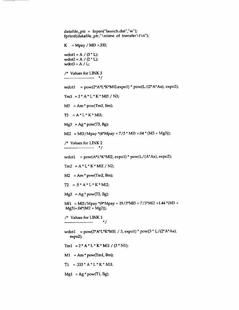
datafile_ptr = fopen("launch.dat","w");
fprintf(datafile_ptr,"\ntime of transfer\t\n");
K -- Mpay / Ml3 +_333;
wdotl = A / (3 * L);
wdot2 = A / (2 * L);wdot3 = A / L;
/* Values for LINK 3..................... • /
wdotl = pow(2*A*L*K*Ml3,expol) * pow(L/(2*A*Aa), expo2);
Tin3 = 2 * A * L * K * MI3 / N3;
M3 = Am * pow(Tm3, Bm);
T3 = A'L* K* Ml3;
Mg3 = Ag * pow(T3, Bg);
MI2 = Ml3/Mpay *(4*Mpay + 7/3 * MI3 +.04 * (M3 + Mg3));
/* Values for LINK 2..................... • /
wdotl = pow(A*L*K*MI2, expol) * pow(L/(A*Aa), expo2);
Tm2 =A*L*K*MI2/N2;
M2 = Am* pow(Tm2, Bin);
T2 =.5*A*L*K*M12;
Mg2 = Ag * pow(T2, Bg);
MI1 = Ml3/Mpay *(9*Mpay + 19/3"M13 + 7/3"M12 +1.44 *(M3 +
Mg3)+.04*(M2 + Mg2));
/* Values for LINK 1..................... • /
wdotl = pow(2*A*L*K*MI1 / 3, expol) * pow(3 * L/(2*A*Aa),
expo2);
Tml
M1
T1
Mgl
= 2" A* L* K* Mll / (3" N1);
= Am * pow(Tml, Bm);
= .333 * A * L * K * MI1;
= Ag * pow(T1, Bg);

/* Total all component masses to get Mtot
Mtot = M1 + M2 + M3 + Mgl + Mg2 + Mg3 + Mll + M12 + M13;
fprintf(datafile_ptr,"%f\n",Mtot);
printf ("total arm mass is %f kg \n", Mtot);printf ("Motor I mass is %f kg \n", M1);
printf ("Motor 2 mass is %f kg \n", M2);
printf ("Motor 3 mass is %f kg \n", M3);
printf ("Link 1 mass is %f kg \n", Mll);
prinff ("Link 2 mass is %f kg \n", Ml2);printf ("Link 3 mass is %f kg \n", Ml3);
printf ("Gearbox 1 mass is %f kg \n", Mgl);
printf ("Gearbox 2 mass is %f kg \n", Mg2);
printf ("Gearbox 3 mass is %f kg \n", Mg3);printf ("torque M3 is %f kg \n", Tm3);
printf ("Torque M2 is %f kg \n", Tm2);
fclose( datafile_ptr );
Table A2.3.d Computer Program Modeling Direct Drive Manipulator

AppendixA2.4 Simulation Code
A2.4.1 Power Transmission
/* Program: TransRatioTS *//* File Name: TransRatioTS2.c *//* Author: Rommel *//* Creation Date: 4.26.93 *//* Last Modification: 4.27.93 *//* *//* Modules: *//* */
/* Notes: TransRatioTS is a trade study to compare masses of direct-drive *//* arms versus geared arms. *//* */
/* This program builds upon TransRatioTSl.c. It writes the *//* calculated values out to *.out files, and does iterative *//* calculations. *//* */
/* This program iterates arm mass values based upon varying *//* tip accelerations. */
#include <stdio.h>#include <math.h>
#define LINKLGTH_FILE_NAME "LinkLength.out"#define ACCTIP_FILE_NAME "AccTip.out"#define AMASSDD_FILE_NAME "ArmMassDD.out"#define AMASSG_FILE_NAME "ArmMassG.out"#define PARAM_FILE_NAME "ArmParam.out"
main 0{
FILE *out_file1;FILE *out_file2;FILE *out_file3;FILE *out_file4;FILE *out_file5;
/* Output file number one. */
float aA,aG,aM; /* Some inertial scaling parameters. */
float acctip;float bA,bG,bM;float k;
float In;float maxacc,minacc;
float accinc;
float mGl,mG2,mG3;float mLl,mL2,mL3;
float mLlg,mL2g, mL3g;
/* Accel. at end-effector.
/* More inertial scaling parameters./* Some sort of constant.
/* Length of links./* Tip acceleration maximum and minimum
value.
/* Tip acceleration increment./* Mass of gear boxes for motors 1, 2, & 3/* Mass of links 1, 2, & 3 (direct-drive).
/* Mass of links 1, 2, & 3 (geared).
*/*/*/*/
*/*/*/*/*/

floatfloatfloatfloatfloatfloatfloat
mMl,_,mM3;
rnMlg, mM2g, mM3g;mTot, mTotg;massPL;
nl,n2,n3;tml,tm2,tm3;
tmlg, tm2g, tm3g;
/* Mass of motor one (direct-drive). */
/* Mass of motor one (geared). *//* Mass of whole arm (direct-drive and geared)*//* Mass of payload (kg). *//* Gear ratios for motors 1, 2, & 3 (geared). *//* Torques of motors 1, 2, & 3 (direct-drive). *//* Torques of motors 1, 2, & 3 (geared). */
int accval; /* Counter value to increment tip accel. */
out_file1out_file2out_file3out_file4out_file5
= fopen(LINKLGTH_FILE NAME, "w");= fopen(ACCTIP_FILE_NAME, "w");= fopen(AMASSDD_FILE_NAME, "w");= fopen(AMASSG_FILE_NAME, "w");= fopen(PARAM_FILE_NAME, "w");
In = 4;massPL = 4000;
acctip = 0.0;mL3 = 10;
mL3g = 10;aA = 0.000111;bA = 1.33;aM = 3.2;bM = 0.694;aG = 0.15;bG = 0.6;nl -- 5000;n2 -- 5000;n3 = 5000;
minacc = 0.0;maxacc = 0.10;accinc = 0.002;
// Calculate the values for the constant, k.
k = massPL/mL3 + 1/3;
fprintffprintffprintffprintffprintffprintffprintffprinfffprinff
(ouLfile5, "Length of each link %f.\n", In);(out_file5, "Mass of payload %f.\n", massPL);(out_fileS, "Mass of link 3 %f.\n", mL3);(outfile5, "Gear ratio for motor 1%f.\n", nl);(out_file5, "Gear ratio for motor 2 %f.\n", n2);(out_file5, "Gear ratio for motor 3 %f.\n", n3);(out_file5, "Minimum tip acceleration %f.\n",minacc);(out_file5, "Maximum tip acceleration %f.\n",maxacc);(out_fileS, "Acceleration increment %f.\n",accinc);
fprintf (out_file2, "Mass of payload %f.\n", massPL);
fprintf (outfile2, "Mass of link 3 %f.\n", mL3);
fprintf (ouLfile3, "Mass of payload %f.\n", massPL);fprintf (outfile3, "Mass of link 3 %f.\n", mL3);

fprintf (out_file4, "Mass of payload %f.\n", massPL);
fprintf (out_file4, "Mass of link 3 %f.\n", mL3);
for (accval = minacc; accval <= maxacc/accinc; accval++)!
// Do the calculations for a direct-drive arm first.
// Calculate the required torque for motor 3...
tm3 = acctip * In * k * mL3;
// Calculate the mass for motor 3...
mM3 = aM * pow(tm3,bM);
// Calculate the mass of link 2...
mL2 = mL3/massPL * (4*massPL + 7/3"mL3 + mM3);
// Calculate the required torque for motor 2...
tm2 = acctip * In * k * mL2 / 2;
// Calculate the mass for motor 2...
raM2 = aM * pow(tm2,bM);
// Calculate the mass for link 1...
mL1 = mL3/massPL * (9*massPL + 19/3"mL3 + 7/3"mL2 + 4*raM3 + raM2);
// Calculate the required torque for motor 1...
tml = acctip * in * k * mL1 / 3;
// Calculate the mass for motor 1...
mM1 = aM * pow(tml,bM);
// Calculate the total mass for the direct-drive arm...
mTot = mM1 + mL1 + raM2 + _ + mM3 + mL3;
// Now, calculate the equivalent for the geared arm.
// Calculate the torque that motor 3 must supply...
tm3g = 2" tin3/n3;
// Calculate the mass of motor 3...
mM3g = aM * pow(tm3g, bM);

// Calculate the mass of motor 3 gear box...
mG3 = aG * pow(tm3,bG);
// Calculate the mass of link 2...
mL2g = (mL3g / massPL) * (4*massPL + 7/3*mL3g + 0.04*(mM3g+mG3));
// Calculate the torque that motor 2 must supply...
tm2g = tm2 / n2;
// Calculate the mass of motor 2...
mM2g = aM * pow(tm2g, bM);
// Calculate the mass of motor 2 gear box...
mG2 = aG * pow(tm2,bG);
// Calculate the mass of link 1...
mLlg = (mL3g/massPL) * (9*massPL + 19/3*mL3g + 7/3*mL2g +
1.44*(mM3g+mG3) + 0.04*(mM2g+mG2));
// Calculate the torque that motor I must supply...
tmlg = 2 * tml / 3 / nl;
// Calculate the mass of motor 1...
mMlg = aM * pow(tmlg,bM);
// Calculate the mass of motor 1 gear box...
mG1 = aG * pow(tm3,bG);
// Calculate the total mass for the geared arm...
mTotg = mLlg + mMlg + mG1 + mL2g + mMlg + mG2 + mL3g + mM3g + mG3;
// Print the results to file...
fprintf (out_file2, "%f\n", acctip);
fprintf (out_file3, "%f\n", mTot);
fprintf (out_file4, "%f\n", mTotg);
/ / Increment acctip to the next value...
acctip = acctip + accinc;

} /* end for */
fclose(out_filel);
fclose(out_file2);
fclose(out_file3);
fclose(out_file4);fclose(out_file5);
} /* end main */
A2.4.2 Joint Motor Torque Requirement
/* Program: StaticTorquel */
/* File Name: StaticTorquel.c *//* Author: Rommel */
/* Creation Date: 4.16.93 */
/* Last Modification: 4.16.93 *//. .//* Modules: */
/, .//* Notes: */
#include <stdio.h>#include <math.h>
#define THETAI_FILE_NAME "CalcThetal.out"
#define THETA2_FILE_NAME "CalcTheta2.out"
#define TORQI_FILE_NAME "CalcSTorqsl.out"
#define TORQ2_FILE_NAME "CalcSTorqs2.out"
#define PI 3.14159265359
float lenl, len2;
float thetal, theta2;
float forcex, forcey;float torql, torq2;
/* Constant value for pi.
/* Lengths of links 1 and 2 (meters).
/* Angles of links 1 and 2 (degrees).
/* Forces in x and y direction at end-eft (N).
/* Torques at joints I and 2.
*/
*/*/*/*/
main 0{
FILE *out_file1;
FILE *out_file2;
FILE *out_file3;
FILE *out_file4;
/* Output file number one. */
float accx, accy;float plmass;
/* Accel. at end-effector in x & y direction.
/* Mass of payload (kg).
*/*/
int numangl;
int numang2;
int anginc;
/* Number of angles to calculate for joint 1.
/* Number of angles to calculate for joint 2.
/* Incremental value of angles.
*/*/*/

int maxan_
int minang;
/* Maximum angle to be used in calculations. */
/* Minimum angle to be used in calculations. */
ouLfilel = fopen(THETAI_FILE_NAME, "w");
out_file2 = fopen(THETA2_FILE_NAME, "w");
ouLfile3 = fopen(TORQ1 FILE_NAME, "w");
out file4 = fopen(TORQ2_FILE_NAME, "w");
lenl = 2.5;
len2 = 2.5;
plmass = 6000;accx = 1;
accy = 1;
anginc = 5;maxang = 90;minang = 0;
// Calculate x- and y- forces at end-effector from payload mass and//acceleration values.
forcex = plmass * accx;
forcey = plmass * accy;
for (numangl = minang; numangl <= maxang/anginc; numangl++)
{for (numang2 = minang; numang2 <= maxang/anginc; numang2++)
{
// Convert angles from degrees to radians.
thetal = 2*PI * (anginc * (numangl - 1)) / 360;
theta2 = 2*PI * (anginc * (numang2 - 1)) / 360;
// Calculate static torques at joints 1 and 2.
torql = (lenl*cos(thetal) + len2*cos(thetal+theta2))*forcey -(lenl*sin(thetal) + len2*sin(thetal+theta2))*forcex;
torq2 = len2*cos(thetal+theta2)*forcey -len2*sin(thetal+theta2)*forcex;
// Print the calculated values.
fprintf (out_file1, "%f\n", thetal);
fprintf (out_file2, "%f\n", theta2);
fprintf (out_file3, "%fXn", torql);
fprintf (out_file4, "%fXn", torq2);
/* end for */
} /* end for */
fclose(out_filel);

fclose(out_file2);fclose(out_file3);fclose(out_file4);
} /" end main "/


Appendix A2.5 Other Trade Studies
A2.5.1 Target Satellites
. Advanced X-Ray Astrophysics Facility (AXAF)
• 4.5m diameter
• 15m long
• 8650 kg• LEO
• 2 solar arrays, 10'x32', on traverse axis
• 2 antennae, 6' long, on axis perpendicular to arrays.
• Designed for in-orbit servicing by Shuttle
2. Cosmic Background Explorer (COBE)• 13' diameter
• 18' length• 10000 lbs
• 12 solar arrays form perimeter
• antennae & propulsion subsystems extend outward
3. X-Ray Timing Explorer (EXP)• 4.5m wide
• 2.5m high
• 1.5m long
• 3000 kg• altitude = 400 km
• 2 solar arrays, 7'x8'
• Mandatory payload changeout every 2 years
. Gravity Probe-B
• Conical geometry, 6' diameter to <1' diameter• 2900 lbs
• 4 solar arrays, attached symmetrically. Diameter -> 15'
5. Gamma Ray Observatory (GRO)
• 4.6 m diameter
• 7.3 m length
• 15000 kg• altitude = 4450 km
• 2 solar arrays, 70' tip-to-tip• 21' antenna
• Designed for Shuttle servicing. Irregular surface.
. GeoPotential Research Mission (GRM)
• 1 m diameter
• 6.4 m length

• 2800 kg
• LEO, altitude=4450 km
• 2 satellites, large fuel consumption to maintain odd orbit.
6. Hubble Space Telescope (HTS)• 4.2 m diameter
• 13.1 m length
• 11360 kg
• LEO, altitude = 590 km
• Designed for Shuttle servicing
, INTELSAT VI
• 4.0 m diameter
• 6.4 m length
• 2255 kg
• LEO, altitude = 460 km
• covered with "solar drums"
• spin stabilized, 30 to 55 rpm
° LANDSAT
• 2.1 m diameter
• 4.0 m length
• 2000 kg
• LEO, altitude = 709km
• On-board propulsion system can boost the LANDSAT D from anominal Shuttle orbit to 709 km and back
A2.5.2. Survey of Satellite Failures (Shockey 1984)
Spacecraft Subsystem Anomaly Number Percent
Timing, Control and Command
Telemetry and Data Handling
Power SupplyAttitude Control and Stabilization
PropulsionEnvironmental Control
Structure
Payload/ExperimentTOTAL
55 9.1
112 19.1
56 9.2
123 20.3
26 4.3
16 2.6
6 1.0
208 34.3
602 100%
De_ree of Failurev
Number Percent
Negligible EffectNoticeable Effect
1/3 to 2/3 Loss
447 74.3
117 19.4
32 5.3

2/3 to Nearly Total LossTotal Mission Loss
TOTAL
5
1
6O2
1
B_
100%
A2.5.3 Typical Mission Parameters
GEO (immediately after circularization maneuver)
LEO
delta i = 20.5 degreesaltitude = 42000 km
payload mass = 200 kg
vehicle mass -- 7216 kg
delta i = 0 degreesaltitude = 500 km
payload mass = 400 kg
vehicle mass -- 1600 kg

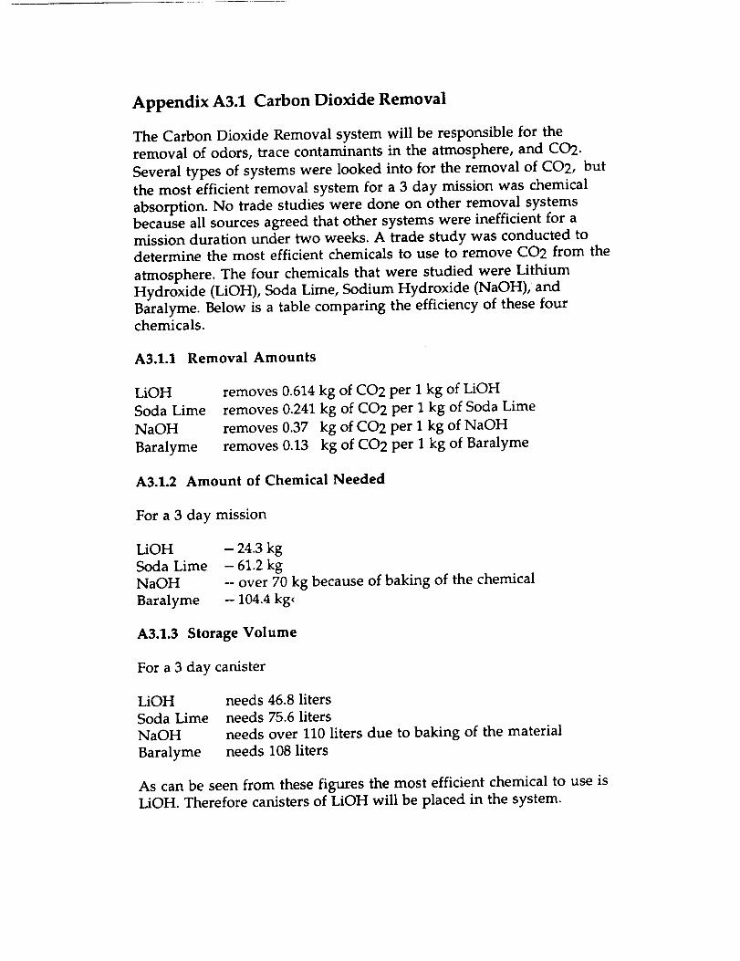
Appendix A3.1 Carbon Dioxide Removal
The Carbon Dioxide Removal system will be responsible for the
removal of odors, trace contaminants in the atmosphere, and CO2.
Several types of systems were looked into for the removal of CO2, but
the most efficient removal system for a 3 day mission was chemical
absorption. No trade studies were done on other removal systems
because all sources agreed that other systems were inefficient for a
mission duration under two weeks. A trade study was conducted todetermine the most efficient chemicals to use to remove CO2 from the
atmosphere. The four chemicals that were studied were Lithium
Hydroxide (LiOH), Soda Lime, Sodium Hydroxide (NaOH), and
Baralyme. Below is a table comparing the efficiency of these fourchemicals.
A3.1.1 Removal Amounts
LiOH
Soda Lime
NaOH
Baralyme
removes 0.614 kg of CO2 per I kg of LiOH
removes 0.241 kg of CO2 per I kg of Soda Lime
removes 0.37 kg of CO2 per I kg of NaOH
removes 0.13 kg of CO2 per I kg of Baralyme
A3.1.2 Amount of Chemical Needed
For a 3 day mission
LiOH
Soda Lime
NaOH
Baralyme
- 24.3 kg
- 61.2 kg
-- over 70 kg because of baking of the chemical
-- 104.4 kg_
A3.1.3 Storage Volume
For a 3 day canister
LiOH
Soda Lime
NaOH
Baralyme
needs 46.8 liters
needs 75.6 liters
needs over 110 liters due to baking of the materialneeds 108 liters
As can be seen from these figures the most efficient chemical to use is
LiOH. Therefore canisters of LiOH will be placed in the system.

Appendix A3.2 Radiation Environment
The radiation environment of Earth orbit include three major areas: galactic
cosmic radiation, trapped particle radiation, and solar particle event radiation.
A3.2.1 Galactic Cosmic Radiation (Cosmic Rays)
Cosmic rays consist of extremely high energy particles that have traveled
trillions of light years to reach Earth. Most particles are of such high energy,
that they pass through a human body without doing appreciable damage.
However, some cosmic ray radiation is harmful and should be shielded
against, but this radiation is only damaging when accumulated, and is not
dangerous in a single dose. 5-10% of effective radiation doses in all Earth
orbits are due to cosmic rays.
A.3.2.2 Trapped Particle Radiation (Van Allen Belts)
The Van Allen belts consist of trapped proton and electron particles caught in
the Earth's magnetic field. These particles form an inner belt reaching 2.8
Earth radii (17,500km) and an outer belt stretching to 12 Earth radii
(75,000kin). The inner belt is made up of Mev protons and kev electrons. The
outer belt only contains charged electrons. The largest radiation doses are
received between 1,000 to 10,000kin altitude, especially around the South
American Anomaly. The belts only concentrate around the central orbits of
the Earth, and do not exist in any intensity at polar orbits.
A3.2.3 Solar Particle Events (Solar Flares)
Solar flares are composed of proton, helium, and some heavier ions. They are
the most unsteady form of Earth orbit radiation, varying with the sun's
eleven year cycle. The largest solar flares can deliver more than 10,000 rem in
24 hours. It is because of this massive dosage that solar flares are usually the
limiting factor in determining radiation shielding. With 3 gm/cm 2, two large
flares delivered the following doses:October 1989- 73.29 rein
August 1972- 113.5 rem
A3.2.4 Radiation Dosage
The standard unit of measuring radiation damage in humans is the rem. The
rem is equivalent to the dose (usually measured in rads) multiplied by the
RBE coefficient (relative biological effectiveness). The RBE accounts for the
varying degrees of damage inflicted by different forms of radiation.
When considering the acceptable dosage limits for an astronaut, these factors
should be studied. One, the dose should not affect the astronaut's immediate
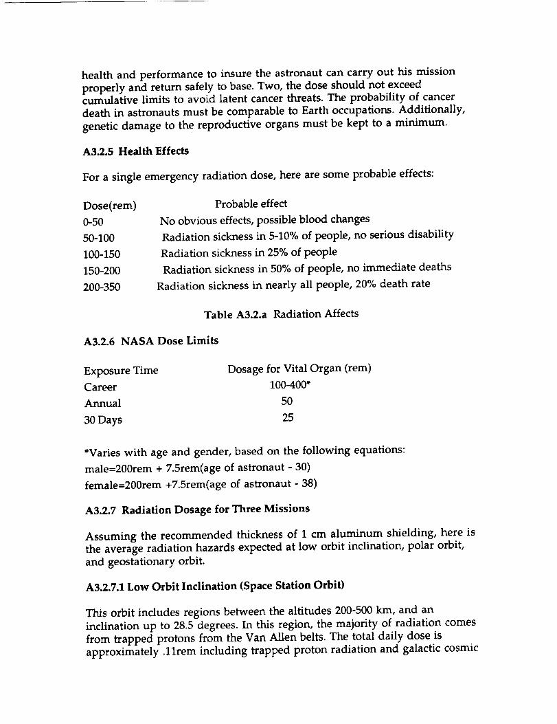
health and performance to insure the astronaut can carry out his mission
properly and return safely to base. Two, the dose should not exceed
cumulative limits to avoid latent cancer threats. The probability of cancer
death in astronauts must be comparable to Earth occupations. Additionally,
genetic damage to the reproductive organs must be kept to a minimum.
A3.2.5 Health Effects
For a single emergency radiation dose, here are some probable effects:
Dose(rem)
0-50
50-100
100-150
150-200
200-350
Probable effect
No obvious effects, possible blood changes
Radiation sickness in 5-10% of people, no serious disability
Radiation sickness in 25% of people
Radiation sickness in 50% of people, no immediate deaths
Radiation sickness in nearly all people, 20% death rate
Table A3.2.a Radiation Affects
A3.2.6 NASA Dose Limits
Exposure Time Dosage for Vital Organ (rem)
Career 100-400"
Annual 50
30Days 25
*Varies with age and gender, based on the following equations:
male=200rem + 7.5rem(age of astronaut - 30)
female=200rem +7.5rem(age of astronaut - 38)
A3.2.7 Radiation Dosage for Three Missions
Assuming the recommended thickness of 1 cm aluminum shielding, here is
the average radiation hazards expected at low orbit inclination, polar orbit,
and geostationary orbit.
A3.2.7.1 Low Orbit Inclination (Space Station Orbit)
This orbit includes regions between the altitudes 200-500 kin, and an
inclination up to 28.5 degrees. In this region, the majority of radiation comes
from trapped protons from the Van Allen belts. The total daily dose is
approximately .llrem including trapped proton radiation and galactic cosmic

radiation. The Earth's geomagnetic field effectively shields most solar particleevents,so the dosage does not reach significant levels.
A.3.2.7.2 High Orbit Inclination (Polar Orbit)
Including regions from 450-1000 km, this region stretches from 85-90 degrees
orbit inclination. Since the Earth' s magnetic field is not very strong here, the
dosage received from trapped particles is much less significant. However,
because of the weak magnetic field, solar flares and cosmic rays can cause
much more significant radiation doses in humans. For large solar flares the
dosage will reach 30-50 rem. The average daily dose including trapped protons
and cosmic rays amounts to about .082 rem.
A3.2.7.3 Mission to Geostationary Earth Orbit (GEO)
The approximate altitude of the satellite belt MOOSE will be servicing is
around 36,000 km. The majority of the daily radiation at this altitude will be
from trapped electrons and cosmic rays. Additionally, the radiation incurred
in traveling through the Van Allen belts must be figured in. For a two day
mission, the average total dose including all these factors can be from 4 to 8
rem. However, the most serious radiation threat at GEO is the random large
solar flare. The largest flares can deliver between 130-200 rem at the shielding
recommended without considering evasive maneuvers.

Appendix A3.3 Smoke Detector Trade Study
In considering a smoke detector for the MOOSE, special needs must be
addressed due to the small size of the craft. In the MOOSE, open fires or a
rapid rise in heat will almost instantly be detected by the astronaut in his shirt
sleeve surroundings. Also, temperature and humidity will probably fluctuate
to some extent because the vehicle is not a large craft, therefore a smoke
detector must be relatively insensitive to these changes to avoid excessive
false alarms. Also, the largest fire threat aboard MOOSE will be smoldering
fires, because these cannot be readily detected by human sense. Finally, cost,
size, and ease of installation should be considered on a cost conscious project
like MOOSE.
Type of Detector Characteristics
Thermal Uses a heat expansion metal sensor that closes a contact
when the sensor is heated, setting off the alarm. This
device will not detect a smoldering fire that does not put
out a lot of heat.
Ionization Has an internal fan to blow air particles to detector. Asmall amount of radioactive material in the device
ionizes the air and the level of conductive of the air is
then measured. Smoke particles lower the conductance of
air and set off the alarm. However, other airborne
particles can also lower conductance such as dust particles,halon, etc. This device can also be set off by electrical
equipment, humidity and temperature changes, and
radiation exposure that changes the conductance of the
air.
Photoelectric Uses light sources and photodetectors to measure the light
scattering and obscuration levels in the air. When smoke
particles affect these levels enough, the alarm is set off.Because this device uses light detection, it is insensitive to
other environmental changes. This device can be made
very sensitive to smoldering fires.

Appendix A3.4 Fire Extinguisher Trade Study
A fire extinguisher aboard the MOOSE must be small, light, and easily used. It
should put out the fire immediately, and not allow it to rekindle later. The
extinguishing agent should be relatively safe to the astronaut, or a system
should be in place so as to avoid prolonged exposure to a toxic extinguishing
agent. Additionally, the agent should not damage sensitive electrical
equipment while still being effective in extinguishing chemical fires.
Substance Amount Needed Characteristics
Water 3-5 kg Quickly extinguishes flame, but is not only
ineffective in extinguishing chemical and
electrical fires, but also damaging to electrical
equipment. Mass necessary to extinguish
fires is larger than other agents
Carbon 3.75 kgDioxide
Non-conductive, so effectively smotherselectrical and chemical fires. Does not leave a
residue, so it will not damage equipment.
However, after CO2 dissipates, flame may
reignite because the agent does not cool a fire
effectively. Also prevents oxygen from
reaching lungs in addition to smothering
flames. Produces a thick white fog during use
that may obscure vision
Halon 1301 1.13 kg Effective for chemical, electrical fires, will not
damage equipment. Works quickly, cools and
smothers fires. Lightest of the three agents.Semi-toxic to humans. Breathable for five
minutes at 7% concentration without ill
health effects. Can cause dizziness and
nausea from 5-10 minutes and fainting after
10 minutes.

Appendix A3.5 Waste Management Options
The necessity to collect, treat and store/dispose solid waste is as
important as providing oxygen. A simple bag is not acceptable because
microorganisms, within the waste, produce gas unless controlled. The
controlling methods are given below.
A3.5.1 Incineration
The incineration of waste will not only destroy microorganisms, but
will bring down the volume of waste stored or expelled. The compact
waste can then be expelled easier or stored taking very little space.
However the cost burning oxygen for this process is its major
disadvantage. Also the carbon dioxide and other residues from the
process will have to be treated, filtered, or eliminated in some other
way.
A3.5.2 Heat Sterilization
The microorganisms can be controlled by applying heat. Wet-heat
sterilization occurs for 15 minutes when the waste is exposed to 121°C
steam. Dry heat can also be used. However the process is longer, one
hour, and occurs at higher temperature, 160°C. Once sterilized the
waste will remain stable unless somehow microorganisms are againintroduced. Therefore non sterilized and treated waste can not be
stored together. Also, the treated waste should be occasionally checked
making sure of its condition.
A3.5.3 Freezing
Materials can be controlled by keeping it at a temperature of -10 C. For
the duration of the mission, the containment facility will have to be
keep at this level. A monitoring system would be needed to insure
that freezing is maintained.
A3.5.4 Desiccation or Expulsion
Waste can be dumped into space or a chamber can expel all current
waste a few times a day. This will lower the total mass of the vehicle
negligibly, but during long duration a sufficient mass can be eliminated
this way. Desiccation merely exposes the waste to the vacuum of space.
Without moisture the microorganisms can not grow. The treated
waste can be held on the vehicle and used as radiation shielding. The
major disadvantage is the part of the cabin atmosphere will be vented
every time the waste is desiccated or expelled.

A3.5.5 Chemical Treatment
Destroying the microorganisms with chemicals has been used in many
space missions. Chemicals needed are not exotic, therefore this system
is very simple. The treatment can be ongoing; introduction of new
waste to the past treated waste is standard procedure. Bio-oxidation is
an idea used on earth, which with development may be adapted to
space. Bacteria are used, which feeds of the microorganisms in the
waste, thus treating it. Part of the waste is consumed by the bacteria,
and the rest can be stored safely. However, this process needs a
gravitational force not easily available in space missions.

Appendix A4.1 TrajectoryProgram to determine aer_raki_ toads
dimension y(4,401)
double precisio_ y,drd,decet,p,po,hs,g,slt,k,q
teger nl ,m
.,_uble precision ganna,b
common/b t k/gamma, b
ni=401
Program
* INITIAL CONDITIONS *
write (*,*) 'Enter initial velocity (m/s) ,
read (*,*) y(1,1)
write (*,*) 'Enter initial attitude (m) '
read (*,*) y(2,1)
write (*,*) 'Enter initial flight path angle (deg) '
read 4*,*) gamma
y(3,1)=-gm*3.141592654/180.O
write (*,*) 'Enter ballistic coefficient (kg/m/m) '
read (*,*) b
y(4,1)=0.0
k=0.0
drd= 0.0
I=O=1.22
hs=7100.O
p=po*exp(( -y(2,1 )/hs))
q=O. 5*p*(y( 1,1 )*'2 )
g=9.81
at t--y(2,1 )/1000.0
".=( - O. 5*p* (y(1,1)*'2) )/b- g*dsi n(y(3,1 ) )
.el =-acc
write 4",1) k,att,y(1,1),gm,q,decet
format (fa.4,2x,flO.4,2x,f14.8,2x,fa.4,2x,f10.4,2x,f14.8)
call runkut(y,nl,4)
stop
end
double precision function f(y,m,p,g,r)
dimension y(4)
double precision y,p,po,hs,pi,g,r,a,rl
integer m
double precision gamma,b
common/blk/gamma,b
po=1.22
g=9.81
hs=7100.O
pi=3.1415927
r1=6378000.0
r=y(2)+rl
p=po*dexp((-y(2)/hs))
if (m.eq.1) then
f=(-O.5*p*(y(1)**2)/b)-g*dsin(y(3))
else
if (m.eq.2) then
f=y(1)*dsin(y(3))
else
if (m.eq.3) then
a=l-(y(1)**2)/(g*r)
f=((O.122*p*y(1))/b)-(g*cos(y(3))/y(1))*e
else
if (m.eq.4) then
f=(-y(1)*cos(y(3)))/(r)

end if
end if
endif
end if
,turn
10
subroutine runkut(y,nl,m)
dimension y(m, nl),v(4),t(4,4)
double precision dettat,y,v,t,f,p,g0acc,r,dr,drd,alt
double precision decel,time,q
integer j,i
double precision gamma,b
common/blk/gamma,b
deltat=l.25
n1=401
do 1 i=2,n1
do 2 j=l,m
v(j)=y(j,i-1)
cont inue
do 3 j=l,m
t(j,1)=f(v,j,p,g,r)
cont ihue
do 4 j=l,m
v(j)=v(j) + 0.5*deltat*t(j,1)
continue
do 5 j=l,m
t(j,2)=f(v,j,p,g,r)
continue
do 6 j=l,m
v(j)=y(j,i-1)+O.5*dettat*t(j,2)
contirvJe
do 7 j=l,m
t(j,3)=f(v,j,p,g,r)
cont i hue
do 8 j=l,m
v( j )=y( j, i - 1 )+det tat*t( j ,3)
cont i hue
do 9 j=l,m
t(j,4)=f(v,j,p,g,r)
continue
do 10 j=l,m
y(j,i)=y(j,i-1)+deLtat*(t(j,1)+2.0*t(j,2)÷2.0_t(j,3)+t(J,4))/(6-0)
continue
if (y(2,i).le.O) go to 60
acc =(-0.5*p*(y(1,i)**2))/b-g*dsin(y(3,i))
decet=-acc
q=O.5*p*(y(1,i)**2)
gatmB =(y(3, i)'180.0)/3.1415927
dr=-(y(4,i)/]60.O)*2.0*3.1415927*r
drd=dr/lO00.O

att=y(2,i)/lO00.Otime=((real(i-1))*deltat)/60.Owrite (*,50) time,alt,y(1,i),gamma,q,decel
format (f8.4,2x, f10.4,2x,f14.8,2x,f8.4,2x,f10.4,2x,f14.8)
_tir_Je
._turn
end


Appendix A4.2 Aerobrake Structural Analysis
Hexcel Aerospace's Mechanical Properties of Hexcel Honeycomb Material was
used for all of the following honeycomb structural analysis.
At a temperature of 300 deg F (the back surface temperatue of the TPS)
aluminum retains only approximately 70% of its original room temperature
strength. This was taken into account when sizing the structural members
against failure.
A4.2.1 Plates
Each of the curved trapezoidal plates was modeled as a fiat rectangular plate
subjected to a distributed normal load. The model had the followingcharacteristics:
simply supported plate • 9.3 ft x 16 ft
distributed load : w = 0.215 psi
The selected materials are as follows :
Honeycomb face sheets :
7075-T6 A1 alloy Ef = 9.5 x 10⁶ psi
Fy = 67000 psi wf = .101-lbin 3
Honeycomb core :
3in. 5052H39-.001P Hexagonal Honeycomb16
wc = 0.00179 lb/in 3
Gca = 22000 psi
Gcb= 41800 psi
Fs = 124 psi
Fc = 282 psi
Through successive iterations, the thickness of the face sheets (tf) and the
thickness of the core (tc) were obtained. Only the final results are presented
here.

The maximum bending moments that would occur for a given distributed
loading were given by the handbook to be
lanh 2Ma = -C-CK_,- C3 + _tC2) =
/t 4
16(.215)(12454.56) (.15 + .3(.52)) = 134.60 in-lb/in_4
la h2Mb = -t-'C_,_ C2 +/.tC3) = 248.50 in-lb/in.
/t 't
The stresses in the face sheets are determined by
fa = 2Ma = 2(134.60) = 3.58 x 10⁴ psit(d+tc) .006(.632 + .62)
fb = 2Mb _6.61x104 psi.t(d+tc)
These stresses are both below the yield stress for aluminum 7075-T6.
The shear forces in the honeycomb plates are determined by
Sb - 16_b_0.75) = 16(.215)(111.6)_3 = 8.79 lb/in
Sa = 16-_3b .84) = 10.40 lb/in.
The stresses due to the shear forces in the core are determined by
fa = 2Sa _ 16.61 psid+tc
fb = 2Sb _ 14.04 psi.d+tc
These stresses are also well below the maximum allowable shear stress of 124
psi.

A4.2.2 Arches
The 4.88m long curved arches were modeled as straight beams subjected to
both the distributed load and the g-loads. From a free body diagram, the
following loads were determined.
Dynamic Pressure :
Maximum moment = 2.75 x 10⁴ lb-in
Maximum shear -- 685.13 lbs
Acceleration loads :
Maximum moment = 2.31 x 10⁴ lb-in
Maximum shear = 238.71 lbs
Try solid aluminum I-beams ( $3 x 5.7)
My 2.75 x 10⁴ (1.5) = 16369.05 psic_- I - 2.52
This is well below the limit for aluminum. However, the weight is calculated
as follows : w = Alp = 316.27 lbs/10 beams. This is well beyond the mass budget.
Try honeycomb beam with the following characteristics •
Face sheets :
7075-T6 A1
Fy = 67000psi
wf =. 101 lb/in 3
Core :
3/16 cell 5052-.003 A1
Wc = .00179 lb/in 3
Gc = 40000 psi
Fs = 180 psi
Fc = 250 psi
After several iterations, the following dimensions were decided upon
beam width (b) = 6 in
face sheet thickness (tt) = .055 in
core thickness (tc) = 3.172 in.

The stress in the face sheets due to the moment is given by
ff = M - 2.6 x 10⁴ psi.btf(d-tf)
This is well below the yield stress for 7075-T6 A1.
The shear stress in the core is given by
f,= 2S =35.56psi.b(d+t¢)
The compressive stress in the core is given by
fc- 2f2 - 2.47 psi.
Ef(_- 1/
These stresses are also well below the stress limits for the core material.
A4.2.3 Rods
From a free body diagram, it was seen that the rods would be subjected to both
tensile and compressive loads.
(_< fly
Maximum compressive load = 2051.73 NMaximum tensile load = 699.38 N
Compressive test
Try aluminum rod of radius .018 m
I = 17tr4 = 8.24 x 10-Sm 4"-it
Per -- --x2EI = 2320.0 NL 2
Maximum compressive load < Per Buckling will not occur
Tensile test
P = 699.38 N
A = nr 2 = 1.02 x 10 -3 m 2
_=P=6.9x10 5 Nm 2
: Rod will not fail in tension

A4.2.4 Deflections
Since both the rods and arches are pinned at both ends, the deflection of these
members was not considered to be a major problem. However, the plates will
have a tendency to deflect under the dynamic pressure loading. Thisdeflection is found as follows
D -- --Ed--(d3 - t_) = 30803.7512_.
16p b4('5) _ 2.7 X 10⁸
_6D 961.4(30803.75)
8=9in.
This is a somewhat large deflection. It is hoped that the TPS will provide
some additional stiffness. If not, the plates may have to be thickened which
will produce additional weight.


Appendix A4.3 Torque Spreadsheet
__._r... qD 0)'e'J _ o o o o o o o ...: OlO o o o o o o o o o o OlO o o o o OlO--_._,¢o _ o o o o o o o o o o "-' o,o o o o o o o o o o o OlO o o o o OlO
co _i_ l_ I-- 0 m _ Oll_l _ _11_- _ _olq, llml_l_l_rl(olm I... mlO m m _- _ OI m O_
u_:(M _r ,i. r,. m r.,. r,,. r., _.11_1_ I*,-;_,O eO m _')l_'-Iml_'_l_l-'-Im 0 r,. _ _o m ,i. o m oco m {Oli,., luD _ _ {_la_ll,,. m,_l. o o _ll_l_l_r-l_l_lO o o_o o o o o o ,..: o
_° _ _ _ ®_ _,_-oooo,_,_ ooooooo_ oo ooo _o_oI.-
v
LU
tO
E =-
,.oLO.9o,
0.o.o.o.o.o.o.o.o.o.o.o.o.o.oIFIIIiIi :
!-coco co e0 co Io m ¢0 Io ¢0 _0i¢0 _D co i0 Io ¢0 coJ_O m _m m m m _lm _ Oi_o _ ¢_'*_'o'*c;'ol_'o'_lo'*c;'o'_'o'_'ol,n'o'_c_'_'c_'_'c_ _'o ,ai ....
o
{ =oOOOoOoOOOoOO_OOOOOOOOOOiOO._lO!OOOioO!..-.;_=-..._.;_ _ _.:- ;-..:"0
el"
]
I.

'_i __'_'_'_-_'_'__i_0___1_01__ ____0
!O000_iO00_O000000000100jOiO0000__ _ __
o oo oo]oloo ooooooo_i_ 0 _ 0 0 o 0 0 0:0 0 0 0 0 0 0 0 0 0 o 00lO OlOiO_O 0 O0 O0 0 0 0 01010 0 0 0 0 0 o 0 O0
o o o o o:O o o o o,o o,o,o,o,o,o,o °,°l°L°,°,°,°,° o o o o o OlOlO o o o o o o o o o"o°_ oo'o'o oooooooooooooiooooioooo o'o'o'o'ooo'o o'o'o'o'o'o'o
O0000000JO00 000_0000000!000000000_'_o_o_ool ooooooooo:ooo oooiooooooo,oooooooooO0001 0000oooo ooo oooo o ooooooooiooo "ooooooooooooooooooooo.oo,OO o o o ., . ._., .............................ooo oooo o o'o'o'o'o'o'o'o'_o'o'o ooI_oooooooooooooooo
.... ........ i ;,,_ ol_.,_.,_.,_.,_-,_,_ _- . . . . .,- _:l_I
_ii:o]_._._.[._o_-_o_o_o_oli_olllo_o_o.;_-_o_o_o_

_ _ _ _ _,
°p"
_ _. _ _ _. _, _ _. _.,_. _ _
_;_ o,v_ c_ .'; o ._o ,,_'(_
)000010'00000¢)_0000'000000¢


Appendix A.5
A.5.1 Choosing the Optimum Propulsion System
Five different propulsion systems were considered for the MOOSE project. These
propulsion systems included three different chemical propulsion systems (liquid,
solid, and hybrid), a nuclear fission reactor, and a laser absorption process. It has been
determined by the design group that the optimum propulsion system for the MOOSE
project is a chemical system with liquid propellants. This section of the appendix
details the four propulsion systems that were analyzed but not chosen for the MOOSE
project. In addition to this section, Section 5.1.2 (Propellant Transport Cost for
Chemical Propulsion Systems) details the major factor in determining the optimum
propulsion system for the MOOSE project.
A.5.1.1 Solid Rocket Systems
Solid rocket motors provide a wide range of applications with a relatively simple
design, as compared to liquid rocket systems. A typical solid motor assembly consists
of a propellant grain, igniter, motor case, and exhaust nozzle. The propellant grain is
typically bonded to the motor case and once ignited the propellant burns to
completion. Some degree of thrust variation can be achieved by selecting an
appropriate grain configuration or by bonding propellants of different burn rates in the
motor. Typical solid rocket motors deliver Isp values of 180-300 seconds which is
lower than typical liquid rocket engines which deliver Isp's of 300-450 seconds.
In addition to the operational simplicity of the solid rocket systems, solid propellants
have storability advantages over other systems, usually lasting from 5-25 years. Also,
the higher densities associated with solid propellants result in reduced overall volume
for a given design. Solid rocket systems are generally reliable systems available at low
cost compared to other rocket systems. One major problem associated with solid
systems is the possibility of spontaneous ignition or even detonation in some
propellants; for manned applications this is a critical safety issue which would dismiss
the use of that particular propellant. Also, the tendency of solid systems to produce
smoky and caustic exhaust products is extremely undesirable for the MOOSE as the
exhaust may contaminate the satellites to be serviced.
Various general types of propellant grains are available depending on the desired
thrust-time history of the rocket. Neutral grain configurations, such as the common

star shaped grain, provide thrust which is relatively constant with time. Progressive
grain configurations, such as a simple circular bore, offer increasing thrust with time.
Regressive grain configurations, such as a solid core that burns from the outside,
provide decreasing thrust with time. Pulse rockets have two or more distinct burning
periods separated by an off time. Step thrust rockets have two or more thrust levels;
this can be done by having fuels of different types or by allowing a drastic change in
burn area at a given point in the mission.
Solid propellants are available in several general categories: Double Base (DB),
Composite Modified Double Base (CMDB), and Composite (C). The DB propellants
were common in the early solid rockets, generally a homogeneous combination of
nitrocellulose (NC) dissolved in nitroglycerin (NG). DB propellants are typically low
performance, Isp < 200 seconds, but have relatively smokeless and non-toxic exhaust.
The CMDB propellants are DB propellants improved by adding composites such as
crystalline oxidizers like ammonium perchlorate (AP) and aluminum fuel.
Performance of CMDB systems is higher than DB, Isp - 250 seconds, higher density is
also achieved; however the CMDB propellants can have smoky and toxic exhaust.
Composite propellants are heterogeneous mixtures of oxidizer crystals and powdered
aluminum fuel held in a matrix of plastic binder material. Conventional composites
are reliable, perform as well as CMDB but have toxic and smoky exhaust. The best
performing solid fuels, the modified composites, have crystalline nitramines
(explosives) such as RDX, HMX added to boost the Isp to 270 and above. However,
these systems are expensive, have toxic, smoky exhaust, and are dangerous due to their
explosive contents.
A.5.1.2 Chemical Propulsion with Hybrid Propellants
A chemical system with hybrid propellants has many advantages over other
propulsion systems. A few of these advantages include: storable propellants which are
readily available, stop - start - restart capabilities, operation without the possibility of
explosion or detonation, and the need for only half of the pumps and plumbing of a
liquid propellant system. A hybrid propulsion system also has several disadvantages.
These disadvantages include nominal steady-state combustion efficiencies ranging
from 93% to 97 %, which are slightly lower than liquid or solid systems, and the
performance level of a hybrid system is typically 21% lower than that of a liquid
system.
The following analysis was completed on both hybrid and liquid propellant propulsion
systems to determine the optimum system for the following design criteria:
Note: The following criteria was determined based on the initial design of the MOOSE
project. This criteria was changed as the design of the vehicle changed.
• single stage design
• structural mass of 10,000 kg
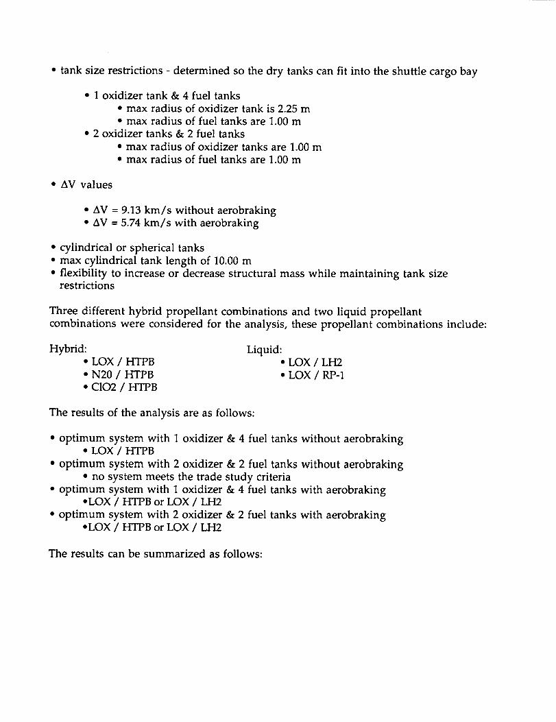
• tank size restrictions - determined so the dry tanks can fit into the shuttle cargo bay
• 1 oxidizer tank & 4 fuel tanks
• max radius of oxidizer tank is 2.25 m
• max radius of fuel tanks are 1.00 m
• 2 oxidizer tanks & 2 fuel tanks
• max radius of oxidizer tanks are 1.00 m
• max radius of fuel tanks are 1.00 m
• aV values
• diV = 9.13 km/s without aerobraking
• AV -- 5.74 km/s with aerobraking
• cylindrical or spherical tanks
• max cylindrical tank length of 10.00 m
• flexibility to increase or decrease structural mass while maintaining tank sizerestrictions
Three different hybrid propellant combinations and two liquid propellant
combinations were considered for the analysis, these propellant combinations include:
Hybrid:
• LOX / HTPB
• N20 / HTPB
• C102 / HTPB
Liquid:• LOX / LH2
• LOX / RP-1
The results of the analysis are as follows:
• optimum system with 1 oxidizer & 4 fuel tanks without aerobraking• LOX / HTPB
• optimum system with 2 oxidizer & 2 fuel tanks without aerobraking
• no system meets the trade study criteria
• optimum system with 1 oxidizer & 4 fuel tanks with aerobrakingoLOX / HTPB or LOX / LH2
• optimum system with 2 oxidizer & 2 fuel tanks with aerobraking• LOX / HTPB or LOX / LH2
The results can be summarized as follows:

• single stage mission is possible with both hybrid & chemical systems
• hybrid system can be efficient with or without aerobraking
• chemical system can only be efficient with aerobraking design
• LOX is the optimum oxidizer for both hybrid and chemical systems
• LH2 is the optimum fuel for the chemical systems
• two different tank configurations can be considered
• if aerobraking design is not considered then limited to hybrid systemwith I oxidizer & 4 fuel tanks
• if aerobraking design is considered then plenty of flexibility in increasing
or decreasing structural mass while maintaining tank size restrictions
Data for the 2 LOX tanks and 2 HTPB tanks are tabulated below, these results give a good
representation of the propulsion characteristics calculated in this analysis. Based on
the current design requirements, it is apparent from these figures that this system is no
longer feasible.
AV 5.74 Km/s Mi 62000 Kg
Isp 340 s Mf 11092 Kgmass ratio 5.59 Mpl 1000 Kg
mixture ratio 2.2 Mst 10092 Kg
1ST Unit Cost 57.4 $M93 Mprop 50908 Kg
LOX HTPB
density 1140 Kg/m^3 density 913 Kg/m^3
mass 34999 Kg mass 15909 Kg
# of cyl. tanks 2 # of cyl. tanks 2
mass of each tank 260 Kg mass of each tank 167 Kgvolume 15.4 m^3 volume 8.7 m^3
surface area 37.2 ma2 surface area 23.9 ma2
radius .99 m radius 0.96 m
length 5.00 m length 3.00 m
The two tank configurations considered are shown below in Figure A.5.1.a.

f/ \
/ \
I
I
I
\\
f
/J
Fuel Tanks
1 Oxidizer Tank
___$2 Oxidizer Tanks2 Fuel Tanks
Truss Structure
Figure A.5.1.a Schematic of Two Different Tank Configurations
Used in an Analysis for Hybrid and Liquid Propulsion.
A.5.1.3 Nuclear Propulsion
A nuclear propulsion system, like every propulsion system, has several advantages
and disadvantages when compared to other propulsion systems. A couple of these
advantages include high specific impulse and high thrust to weight ratio. In addition,
a nuclear system doesn't need any oxidizing propellants. The major disadvantage of a
nuclear system is that proven technology is unavailable at this time and therefore
doesn't meet the 1993 technology cut-off date. Other disadvantages include the
massive radiation shield that is necessary to protect the astronaut, the expensive core
construction, and that there is no instantaneous engine shut down since the working
fluid is used to help cool the core.
An analysis was completed on the nuclear propulsion system. The results from this
analysis, which are tabulated below, give a good representation of the propulsion
characteristics for a nuclear system. It is apparent from the results that a nuclear

system will one day be a feasible system for space flight, however, the design group has
decided to enforce the 1993 technology cut off date for the main propulsion system of
the MOOSE project.
This analysis was based upon a vehicle structural mass of 50,000 kg and cylindrical tanksizes shorter than 10 meters.
Isp 750 s # of Tanks 3
mass ratio 3.459 mass of each tank 1247 kg
Mpl 1000 kg volume 105.8 m^3
Mi 50000 kg radius 2.034 m
Mf 14455 kg length 8.136 m
Mst 13455 kg
Mprop 35545 kg
A.5.1.4 Laser Propulsion
A laser propulsion system can be divided into four main components; beam collection
optics, propellant tanks, a thrust chamber, and one or more laser beam generators. The
advantages of using a laser propulsion system include: no on board prime power
system, no conditioning systems with corresponding weight penalties, a low vehicle
mass allowing for higher payload mass, and high exhaust velocities. The major
disadvantage, as explained with the nuclear system, is that proven technology is
unavailable at this time and therefore doesn't meet the 1993 technology cut-off date.
Other disadvantages include: combustion chamber must withstand temperatures at
20,000 K, space rated technology is unavailable for space or ground based transmitting
stations, proven technology is unavailable for the precise accuracy needed to orient the
laser beam to the combustion chamber, and it is a low thrust system so travel time to
GEO exceeds 2 days.
An analysis was completed on the laser propulsion system. The results from this
analysis, which are tabulated below, give a good representation of the propulsion
characteristics for a laser system. Even though the results may demonstrate a feasible
system, it is apparent from the statements above that a laser propulsion system is not
an optimum propulsion system at this time. The design group has decided to enforce
the 1993 technology cut-off date for the main propulsion system.
This analysis was based on an initial mass of 50,000 kg and the flexibility of a one or
two tank system for the fuel.
mass ratio 1.86 Cylindrical Tanks
Mi 50000 kg 1 Tank
Mf 26885 kg radius 2.00 m
Mst 25885 kg height 16.42 m
Mpl 1000 kg 2 Tanks
Mprop 23115 kg radius 2.00 m
3.00 m
7.30 m
3.00 m

Tank mass
Tank volume2539 kg
206 m^3height 8.21 m 0.91 m
Spherical Tanks1 Tank
radius 3.67 m
2 Tanks
radius 2.91 m
A.5.2 Cooling Schemes
Regenerative Cooling
Regenerative cooling, the most widely applied method, utilizes one or possibly both of
the propellants fed through passages in the thrust-chamber wall for cooling, before
being injected into the combustion chamber.
Dump Cooling
With this principle, a small percentage of the propellant, such as the hydrogen in a
LOX/LH 2 engine, is fed through passages in the thrust chamber wall for cooling and is
subsequently dumped overboard through openings at the rear end of the nozzle skirt.
due to performance losses, this method has only limited application.
Film Cooling
The exposed combustion chamber wall surfaces are protected from excessive heat by a
thin film of coolant or propellant introduced through orifices around the injector or
through orifices in the chamber wall near the injector. This method has been used,
particularly for high heat fluxes, either alone or in combination with regenerative
cooling.
Transpiration Cooling
Transpiration cooling introduces a coolant (either gaseous or liquid propellant )
through porous chamber walls at a rate sufficient to maintain the desired temperature
of the chamber wall. This method is essentially a special type of film cooling.
Ablative Cooling
In an ablative cooling scheme, the combustion-gas-side wall material is melted,
vaporized, and chemically altered to dissipate the heat load. Ablative cooling has been
used in numerous designs, mainly for solid-propellant systems, or for short duration
and or low chamber pressure liquid systems.

Radiation Cooling
The heat is radiated away from the surface of the outer chamber wall. It has been
applied to very small, high temperature material combustion chambers and to low
heat flux regions, such as nozzle extensions.
A.5.3 Conical vs. Bell Shaped Nozzles
The following analysis is to determine whether or not the losses produced by a conical
nozzle are negligible compared to a bell nozzle. For the conical nozzle I will assume a
uniform exit velocity, Ue. That is, the flow down the centerline of the nozzle is Ue
and the flow tangent to the nozzle wall is also Ue. This assumption will result in aworse case scenario because the viscous effects at the wall will actually slow the flow
down, that is, the flow near the wall is actually less than Ue. Therefore, the conical
nozzle will perform slightly better than what is determined by this analysis. A
schematic of the conical nozzle is shown below in Figure A.5.3.a.
Control Volum(
R
Centerlinc
Ue
Figure A.5.3.a Schematic of a Conical Nozzle.
The force component parallel to the centerline is:
= f= P(U'n-_UxdAF×
Using a spherical geometry the cross sectional area can be divided into concentric rings
and the incremental area can be determined by:
dA = 2_Rsin 0Rd0
where R is a constant due to the geometry.

By substituting into the force equation the thrust can be determined by:
T = PUe'UeCOS e 2_R2sin e de
:The exit area of the nozzle as determined from the geometry is:
A e = 2_R 2 (1-cos 0t)
The mass flow rate is defined and rearranged by the equation for the exit area:
rfi = pUA = pU e 2nR2 (1-cos or)
From trigonometry:
1-cos2ot = ( 1-cos or) (1 +cos or)
By substituting the mass flow rate into the thrust equation and applying the
trigonometry identity:
T=rnUe II+c°s0t)2
The thrust for an ideal bell nozzle is defined as:
T = fiaU e
Therefore the ratio of conical nozzle thrust to ideal bell nozzle thrust is:
Tconical = i l+cos 0t )Tbell _ 2
Table A.5.3.a lists the percent losses of a conical nozzle compared to an ideal bell nozzle
for various half angles of the conical nozzle.

o_ (l+cos 0_) %Loss2
10° 0.992 0.8%
15° 0.983 2.0%
20 ° 0.970 3.0%
Table A.5.3.a Percent Losses of a Conical Nozzle Compared to an Ideal Bell Nozzlefor Various Half Angles of the Conical Nozzle
At a conical half angle of 10 ° the losses are negligible, however, a longer and thus
heavier nozzle would be needed for such a small half angle in order to avoid
overexpansion. At a conical half angle of 20 ° the nozzle must be shorter and thus
lighter in order to avoid underexpansion, however, the thrust losses at this half angle
are of concern. At a conical half angle of 15 ° the losses can be neglected for the ease of
fabrication. Even though conical nozzles are easier and cheaper to fabricate than bell
shaped nozzles, the cost of a bell shaped nozzle is not significant when compared to
the entire vehicle cost. In fact, a bell shaped nozzle would not represent more than 5%of the entire vehicle cost.
The material for this section has been referenced from a Rocket Propulsion Lecture,
ENAE 462, by Dr. Mark Lewis.
A.5.4 Results of the Method of Characteristics
The following data gives a good representation of the data calculated from the method
of characteristics technique. Only the properties for the first 33 grid points are shown
below. The properties at 152 grid points were calculated when developing the contourof the nozzle.
Point # K - K + o v M !1 Comments
1 2.868 0.000 1.434 1.434 1.102 8.868 0.000 4.434 4.434 1.223 14.868 0.000 7.434 7.434 1.324 20.868 0.000 10.434 10.434 1.415 26.868 0.000 13.434 13.434 1.506 32.868 0.000 16.434 16.434 1.587 38.868 0.000 19.434 19.434 1.668 44.868 0.000 22.434 22.434 1.759 50.868 0.000 25.434 25.434 1.83
1 0 56.868 0.000 28.434 28.434 1.921 1 62.868 0.000 31.434 31.434 2.00
1 2 68.868 0.000 34.434 34.434 2.081 3 74.868 0.000 37.434 37.434 2.171 4 80.868 0.000 40.434 40.434 2.26
65.455.149 345 241 8
39 337 034 833 131.430.0
28.727.426.3

151617181920212223242526272829
3031
3233
86.86892.86892.868
8.86814.868
20.86826,86832.86838.86844.86850.86856.86862.86868.86874.8688O.86886.86892.86892.868
0.0000.0000.000
-8.868-8.868-8.868-8.868-8.868-8.868-8.868-8.868-8.868-8 868-8 868-8 868-8 868-8 868-8 868-8 868
43.434 43.434 2.3546.434 46.434 2.4446.434 46.434 2.44
0.000 8.868 1.363.000 11.868 1.456.000 14.868 1.549.000 17.868 1.62
12.000 20.868 1.715.000 23.868 1.7918.000 26.868 1.8721.000 29.868 1.9624.000 32.868 2.0427.000 35.868 2.1330,000 38.868 2.2133.000 41.868 2.336.000 44.868 2.3939.000 47.868 2.4842.000 50.868 2.5742.000 50.868 2.57
25.224.224.247.343.640.538.136.034.032.330.729.428.026.925.824.723.822.922.9
Wall Pt.
Wall Pt.
Table A.5.4.a Results of the Method of Characteristics,
Properties for the First 33 Grid Points
A.5.5 Engine Materials ]5
Material Applications Temp. Range Comments
Austeniticstainless steels
Martensiticstainless steels
Nozzle tubing, ductsbolts, bellows, hydraulictubing, washers, shims,turbine discs, injectors.
Bearing-balls, races.
-423F to 600F
-423F to 300F
Susceptible to pittingand stress corrosion.
Susceptible to all formsof corrosion.
PH stainless
steelsValve parts-stems. -110F to 200F Susceptible to
Hydrogen environmentembrittlement. Stress
corrodes in high strengthtempers, marginal forcryogenic applications.
Nickel base
superailoys
Impellers, inducerspump housing, valves,ducts, manifolds, bolts,turbine blades, turbinediscs, shafts, bellows,
stators, injectors.
-423F to 1500F Susceptible toHydrogen environmentembrittlement.

Iron base
superalloys
Aluminum
alloys
Copper
alloys
Titanium
alloys
Beryllium
Cobalt
alloys
Low alloysteels
Fluorocarbon
polymers
Elastomers
Nickel
Carbon
Ceramics
Struts, ducts, bellows,
bolts, turbine, discs.
Pump housings,
impellers, injectors,
gear cases, brackets,valve bodies.
Thrust chambers,
injector rings, baffles.
Impellers, inducers,
pump housings, valve
bodies, ducts, gimbal
blocks, pressure bottles,
hydraulic tubing.
Small thrust chambers
Injector posts, ducts,
springs, turbine blades.
Thrust mounts, frames
reinforcing bands, gears,
shafts, bolts, bearings.
Seals, coatings,electrical insulation
O-rings, gaskets,sealants, electrical
insulation, adhesives.
Nozzle tubing,
electrodeposited closeouts of coolant channels
for combustion chambers.
Combustion chamber
throat inserts, dynamicturbine seals.
Protective coatingson turbine blades,
nozzles, thrust chambers.
-423F to ll00F
-423F to 200F
-423F to 1000F
-423F to 600F
70F to 1200F
-320F to 2100F
70F to 300F
-423F to 200F
70F to 300F
-423F to 1000F
-423F to 600F
-423F to 1500F
Resistant to Hydrogenenvironment
embrittlement.
Often used as castings.
High oxygen grades
susceptible to
hydrogen reactionenvironment.
Pyrophoric reaction in
LOX, pure GOX, red
fuming nitric acid. Mayabsorb hydrogen above-110F.
Brittle, avoid all notches
in design. Hazardousmaterial, not weldable.
Vary in susceptibility to
hydrogen environmentembrittlement.
Susceptible to
corrosion, marginal for
cryogenic applications.
Generally compatible
with liquid oxygen.
Not compatible with
liquid oxygen.
Susceptible to
hydrogen environmentembrittlement.
Brittle Material
High temperatures,brittle materials.

A.5.6 Representative LOX/LH 2 Engines 16 l?
System Manufacturer T(kN) Isp(s) O/F ratio Mass(kg)
SSM E Rocketdyne 2296 455 6.0 3150
J2S Rocketdyne 1180 435 5.5 1560
LE-5A MHI (Japan) 127 452 5.0 242
HM-7B SEP (France) 62.7 444 4.8 155
RL10A3-3 Pratt & Whitney 67.0 444 5.0 132
RL10A3-3A Pratt & Whitney 73.4 446 5.0 138
A.5.7 Structural Analysis
A finite element model using ANSYS version 44a was constructed to calculate the
critical buckling and vibration loads for the main propulsion tanks. ANSYS STIF 63
shell elements were used to model the tanks. A plot of the finite element model and
its boundary conditions is show below in Figure A.5.7.a.
• .4-.- ........... _ .......... . ........ :'._
I I .......... ,L "" ;" .... """ _ "'"
/. _ , ", • . ._, - • ,
• , _ ........ , -.), ,,
• " ,,- \?. ,
o,° - • _ -;
.. ". .' ;_, /
lll_., i............................! ............. t / _
Y y .................'" ",. i J/
-.>-o .....................i......... ._'./°e a
°-"..: .' ............. -_.... "._"'i-;:"
Figure A.$.7.a ANSYS Finite Element with Constraints
The ANSYS/BUCKLE routine was used to determine the critical G-load that the tanks
could withstand without buckling. The ANSYS free vibration modal analysis routine
was used to determine the fundamental frequency of the tanks. For safe operation the

fundamental frequency of the tanks should meet or exceed the natural frequency of the
launch vehicle. Factors of safety were not applied to the G-Load and vibration values
because of the use of pressure to stiffen the tanks upon launch. Figure A.5.7.b and
Figure A.5.7.c below show the trade study between A1-1100 and Ti-6A1-4V respectively
in the form of allowable G-load versus tank thickness. The following plots were used
at an earlier design iteration to determine the critical loading for tanks of 0.410 meters
in radius. The results of these analyses have been used in later iterations as the basis
for which load and material to analyze in a more detailed manner for the final design
presentation as found in section 5.10.
Load
Factor
(G's)
10
8
6
4
2
00 0.001 0.002
Tank Thickness (meters
Figure A.5.7.b Load Factor versus Tank Thickness (A1-1100 Alloy)
Load
Factor
(G's)
8
6
4
2
0
0 0.0005 0.001 0.0015
Tank Thickness (meters
0.002
Figure A.5.7.c Load Factor versus Tank Thickness (Ti-6AI-4V Alloy)
Figures A.5.7.b and A.5.7.c show that for launch load buckling the A1 alloy only lags
behind that of the Ti alloy by very little. Although the graphs of load factor versus
tank thickness are not linear, a linear interpolation was used to get a tank thickness for
the upper load limit of 6.5 g's by using a reiterative process through which two points
closely surrounding this upper limit were found. From Figures A.5.7.b and A.5.7.c, the
interpolation yields a required tank thickness for the Ti alloy of 1.65 mm while the
required tank thickness for the A1 alloy is only slightly larger at 1.67 mm. Because A1
1100-0's density is smaller than Ti-6AI-4V's density by nearly a factor of two, it is clear

that A1 1100-0 offers a significant mass savings. Mass for the 1.65 mm thick Ti alloy
tank was 16 kg and the mass for the 1.67 mm thick A1 alloy tank was 10 kg. Although
the numbers are small, this is over a 25% savings.
After starting the vibration analysis for the tank configurations, it was soon found that,
in fact, vibration launch loads will drive the thicknesses of the tanks. A comparison of
the two candidate materials used in the above analysis showed that (although
extremely close) an A1 1100-0 tank had a higher natural frequency than a Ti-6AI-4V
tank of equal thickness and radius. Figures A.5.7.d and A.5.7.e show the plots of
fundamental frequency versus tank thickness for the AI-100 Alloy and the Ti-6A1-4V
Alloy respectively. Figure A.5.7.d shows that the necessary thickness to achieve a
frequency of 35 Hz is 4 mm. A A1 1100-0 tank of this thickness has a mass of 24 kg. An
equivalent tank constructed of our Ti alloy would have a mass of 39 kg. The mass
savings seen here is much more significant than that realized in the buckling analysis
because the numbers are now larger and the percent savings has risen to about 40%.
These results were used to provide a starting point for the final tank design iteration.
The results showed the best material selection to continue analysis with, and they
showed that in fact the vibration load induced by the launch platform is the critical
load for the MOOSE main propulsion tanks. Tank structures for these types of systems
are generally higher. It is thought that because of the empty configuration at launch,
the MOOSE design has seen considerable tank mass savings since buckling is more of a
critical load with full tanks. Because of the large propellant masses used in such
systems, high G-loads imposed by launch platforms can create large tank thicknesses to
withstand buckling. Because of the relatively low G-loading during MOOSE operation
(2 g's maximum) and the near empty configuration of the tank at this time, it is clear
that launch vibration loading is still the critical load for the tank structures.
,,=$ lO,
0 0.001 0.002 0.003 0.004
Tank Thickness (meters
Figure A.5.7.d Fundamental Frequency versus Tank Thickness (Al-] 100 Alloy)

u. 0
0 0.001 0.002 0.003 0.004
Tank Thickness (meters
Figure A.5.7.e Fundamental Frequency versus Tank Thickness (Ti-6AI-4V)
A.5.8 Slew Torque Calculations
Calculations of worst case torques showed that slew torques would apply the largest
magnitude torques on the MOOSE vehicle. The figures listed below show the
calculations made along each principal axis.
Figure A.5.8.a Worst Case Slew Torques about Ixx, prior to GEO Transfer Injection BurnFigure A.5.8.b Worst Case Slew Torques about lyy, prior to GEO Transfer Injection BurnFigure A.5.8.c Worst Case Slew Torques about Izz, prior to GEO Transfer Injection Burn
Figure A.5.8.d Worst Case Slew Torques about Ixx, after GEO Satellite Servicing OperationsFigure A.5.8.e Worst Case Slew Torques about Iyy, after GEO Satellite Servicing OperationsFigure A.5.8.f Worst Case Slew Torques about Izz, after GEO Satellite Servicing Operations

• [] • 0 ,_ <:1 • 0 X X + '
I..¢3
E
e.-.o.0,.*
r_
¢.!
0ira
.,9o
x"
0
o[.-
¢d3
d
0
<
m
nnm
m
m
I I I
G_ Qo d d0 0 0L_ 0 t_
m
m
m
mm
m
I I I
Q Q
0 0 00 t._ 0
(tUN) anb_o.L
[]
[]
m
mm
iN
lt O"q (-)-
[] • 0,_ ¢+
/
[] * O_c+
[] • Oq_+
[] _1,Oql_-
[] _Oq'-
[] _,<::x,-
m • _(1
m • _or)+
U3
v
X
°_,,_
<
X

.o
o_
r,-r_
[..o
ot._
o°_
>%
.2r_
o[-,
o
L,
[]
[]
[]
[]
[]
[]
[]
[]
[]
I I I I I
o 0 0 0 oo o o o od d c5 d d0 0 0 0 0
(tUN) enb.to L
I• 0 ,e<l i-_
• 0 4q_ T
• O,4K]
• 0 ,¢:],-
• O_d,-
• 0,¢3-
[] • 0'¢_ t
[] • O_q
[] • O_q
[] • O<.q
• [] ,_<xq
• [] _
mE)(-
o oo o
o
(,r)
l.r)r,,i
(',4
l.r)
0
v
0(jr)
XF.r.l
om--q
<
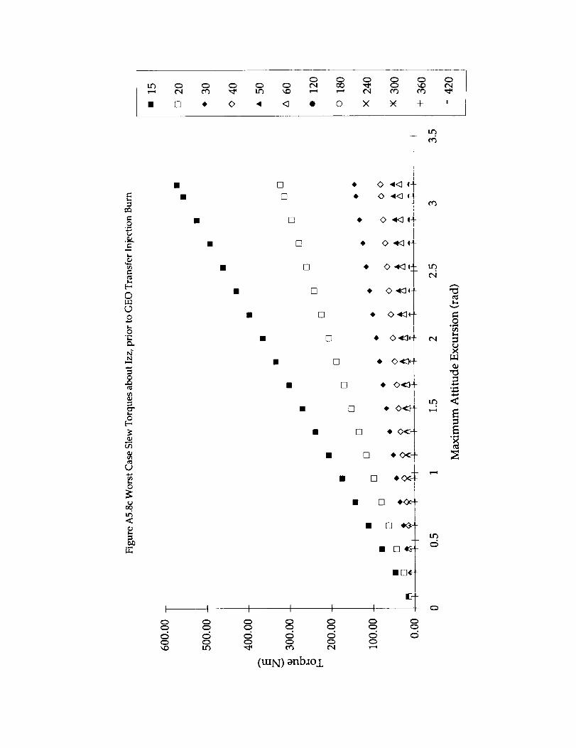
• [] • O _1 ,q • O X X + '
E
=o
I-,
t'_I,..
Ol....q{D.9oI-,,OI-,
N"
.g
¢)
I,,.o
[.-,
U
O
t,,.I
[]
[]
[]
[]
[]
[]
[]
[]
I I I I I
do
,0 O '_<:] t I-O 4<:] q+
t• 0 _1,+
• , O '_<::]qJ
• 0 _CI(-
I.Ib
IN
• [] )_-
• [] $<_-
c_ c_
(tUN) anb=o±
• D,c-
Q
I,.t')
v
.o
(,,.b),.<
°,,.,.(,..I,-)
<
o_,.qX

0
0
o
0
_3
2
o"
LJ
o
,<
[]
[]
[]
[]
[]
• []
• []
[]
[]
[]
I l I I I I
0 0 0 0 0 0o 0 0 0 0 0
c5 o c5 c5 c5 d
(tUN) enb_o,L
f]
• 0 .*::1 q_
• 0 _Klq± t¢3
t• 0 _KIG+
• 0 ._t+
[]
[]
• 0 "_::I'-
• 0_-
[] eO<-
[] e(_-
• [] _.
<5
0 0o 0
X
°_,,i×

• [] • o • <) • o x _ + '
,r.-o
_L0
e_
0
lw
oe,-,
oE-,
o
Lt)
I
c>
o
I
Q0
[]
[]
[]
[]
[]
[]
[]
• 0 .qm<:Iq]
• 0 ',_<:Iq-"
[]
[]
• 0 '_<:::]q_
• 0 ._<)q-
er')
er_
(',4
• • o ,,,K:)o_
I• 0 "CJ,-
[] • O_-
[] ¢' 0<: ,.-.
[] $0<:_
• • Di- l ¢,ocT
• [] _
• DD_ d
i 0 i i i i mm_1 o
(tUN) _nb._o±
¢/)
X
xr_

o
0
0
I_
N
0E--
0
I.
&
I I I
o o
Cm _
[]
[]
[]
[]
[]
[]
[]
[]
• []
•
• []
I I I I
0 _ _ Q
(tUN) anb_oi
<> 4<] e_t-r
0 4<] et/
• 0 .qK] IJ
• 0 '_<:] qJ
0 .qm<l,+
+ 0 ._c:h-
$. 0 _Idq-
_' 0"¢3 I
• [][] $0<x_<><I-
)• [] _"
• [] _3"
• De --j
mE.-J
I Io o oo o o,5 ,5
,.qorb
t'4
t'4
!-13
U3
v
.oc_
X
. ,,.,.,q,.¢..,m
° _-,.0X

A.5.9 Propellant Mass Calculations
Utilizing the baseline AV budget shown in Table 5.11.a with the main propulsion
system consisting of LOX/LH2, a mass budget was derived for the potential primary
RCS propellants consisting of a single monopropellant and five bipropellants. The
potential cold gases for the secondary RCS were helium and nitrogen. The mass
calculations were a two step process with the cold gas utilized in the secondary RCS
varied for each process.
A.5.9.1
A.5.9.2
A.5.9.3
A.5.9.4
A.5.9.5
Hydrazine and Helium
Oxygen / UDMH and Helium
Oxygen / N2H4 and HeliumN204 / 50-50 UDMH & N2H4 and Helium
Fluorine / Hydrogen and Helium
A.5.9.6
A.5.9.7
A.5.9.8
A.5.9.9
A.5.9.10
Hydrazine and Nitrogen
Oxygen / UDMH and Nitrogen
Oxygen / N2H4 and Nitrogen
N204 / 50-50 UDMH & N2H4 and Nitrogen
Fluorine / Hydrogen and Nitrogen

A.5.9.1 Hydrazine and Helium
Assumptions All of the reserved fuel is usedAll of the reserved _V is used
Isp MAIN LOX/LH2 450 secrcs HYDRAZINE 240 sec
COLD HEUUM 1 79 secFinal Mass 30O0 _Kg
Maneuvers A V Final Initial Propellantmass mass mass used
(m/s)10
18
(ko)3000
3017
Attitude Control Reserve(kg)
3017
3048Rendezvous & Docking
(kg)17
31
Propulsion
Systemused
COLDCOLD
Attitude Control Reserve 20 3048 3074 26 rcsLEO Circularization 122 3074 3160 86 MAIN
_Attitude Control Reserve 20 3160 3187 27 rcs
9267 3187 3279
5 3279 3286 7
20
301844
54
5O54
9
30
1762
Aerobraking ManeuverAttitude Control ReserveMid Course Correction
5
3286
3314
33375067
51855334
5458
5479
5516
8222
8240
8293
834914380
m/s
Main Propulsion ReserveLEO Transfer Injection
GEO Operation
GEO OperationGEO OperationOrbit Trim
Main Propulsion ReserveGEO Circularization
15
3314
3337
50675185
53345458
5479
5516
8222
8240
82938349
1438014404
Attitude Control Reserve
Mid Course Correction
Main Propulsion ReserveGEO Transfer Injection
Separation from Station
Total &V
Initial Mass
Total Propellant Mass
Total Main Propellant Mass
Total RCS Propellant Mass
Total Cold Gas Propellant Mass
3O
28
231730
118150
124
21
37
2706
17
5357
603125
14404
11404
10669
kg
24003
6568
rcs
rcs
rcsMAIN
MAIN
rcs
COLD
rcs
rcsMAIN
MAIN
rcs
rcs
MAIN
MAIN
COLD
kgkg
512 kg
223 kg

A.5.9.2 Oxygen
Assumptions
Isp
and UDMH
MAIN
All of the reserved fuel is used
:All of the reserved AV is used
LOX/LH2rcs !OXYGEN/UDMH
COLD HEUUMFinal Mass
Maneuvers A V Final
Attitude Control Reserve
Rendezvous & DockingAttitude Control Reserve
Mid Course Correction
(m/s)10
18
mass
(kg)3000
3017
450 sec
295 sec
179 sec
3000
Initial
mass
(kg)3017
3048
Kg
Propellantmass used
2O
(kg)17
3257
31
328O
21
Propulsion
Systemused
COLD
COLD
20 3048 3069 rcs
LEO Circularization 122 3069 3155 8 6 MAIN
Attitude Control Reserve 20 3155 3177 22 rcs
Aerobraking Maneuver 67 3177 3252 74 rcsAttitude Control Reserve 5 3252 3257 6 rcs
rcs
Main Propulsion Reserve 3O 3280
23
2233O2
5355
MAIN
1844 3302 5014 1712
54 5014 5109 94 rcs
50 5109 5256 148 COLD
54 5256 5355 99 rcsrcs
5372
LEO Transfer Injection
GEO OperationGEO Operation
GEO OperationOrbit Trim
Main Propulsion ReserveGEO Circularization
Attitude Control Reserve
Mid Course Correction
Main Propulsion Reserve
30
1762
5372
5409
80628076
8118
8173
14077
14101
15
GEO Transfer Injection
3O
2400
5409
8062
8076
17
372653
14
42
55
5904
24
8118
Separation from Station
Initial Mass
8173
14077
Total AV 6568 m/s
14101
Total Propellant MassTotal Main Propellant Mass
Total RCS Propellant MassTotal Cold Gas Propellant Mass
11101
10469412
MAIN
MAIN
MAIN
rcs
rcs
MAIN
MAIN
COLD
kgkg
kg
kg220 kg
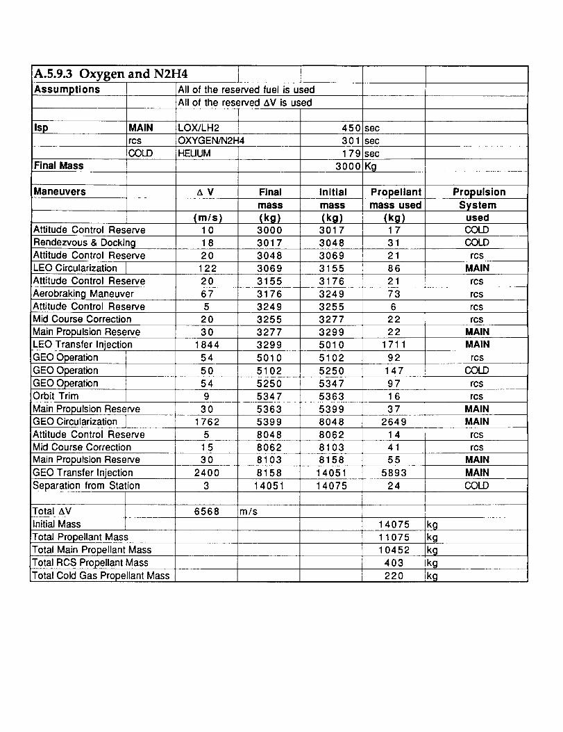
A.5.9.3 Oxygen and N2H4
Assumptions
Isp
All of the reserved
All of the reserved
Final Mass
Maneuvers
MAIN
rcsCOLD
Attitude Control Reserve
Rendezvous & DockingAttitude Control Reserve
fuel is used
AV is used
LOX/LH2
OXYGEN/N2H4
HEUUM
AV
(m/s)1018
Final
mass
(ko)30003017
450
301
179
3OOO
Initial
mass
secsec
sec
Kg
Propellantmass used
(kg) (kg301 7 1 73048 31
Propulsion
SystemusedCOLD
COLD
20 3048 3069 21 rcs
LEO Circularization 122 3069 3155 86 MAIN
Attitude Control Reserve 2 0 3155 3176 21 rcs
3249 7367 3176Aerobraking ManeuverAttitude Control Reserve
rcs
5 3249 3255 6 rcsMid Course Correction 20 3255 3277 22 rcs
Main Propulsion Reserve 30 3277 3299 22 MAIN3299 5010 1711
5102 92
1844LEO Transfer Injection
GEO Operation
GEO Operation
54 5010
MAIN
Total Main Propellant MassTotal RCS Propellant Mass
Total Cold Gas Propellant Mass
Total Propellant Mass
14075
11075
10452
403
220
kgkg
kg
IkgIkg
m/s
Initial Mass
Total AV 6568
rcs
50 5102 5250 147 COLD
GEO Operation 54 5250 5347 97 rcsOrbit Trim 9 5347 5363 1 6 rcs
Main Propulsion Reserve 30 5363 5399 3 7 MAINGEO Circularization 1762 5399 8048 2649 MAIN
Attitude Control Reserve 5 8048 8062 1 4 rcsMid Course Correction 1 5 8062 8103 41 rcs
Main Propulsion Reserve 30 8103 8158 55 MAIN
GEO Transfer Injection 2400 8158 14051 5893 MAIN
Separation from Station 3 14051 14075 24 COLD

A.5.9.4 N204 and 50-50 UDMH and N2H4
Assumptions
Isp
Final Mass
MAIN
rcs
COLD
Maneuvers
Attitude Control Reserve
Rendezvous & DockingAttitude Control Reserve
LEO Circularization
Attitude Control Reserve
Aerobraking ManeuverAttitude Control Reserve
Mid Course Correction
Main Propulsion ReserveLEO Transfer Injection
GEO Operation
GEO Operation
GEO OperationOrbit Trim f
Main Propulsion ReserveGEO Circularization
Attitude Control Reserve
Mid Course Correction
Main Propulsion Reserve
GEO Transfer InjectionSeparation from Station
All of the reserved fuel is used
All of the reserved ,W is used
LOX/LH2
N204/50-50UDMHHEUUM
Z_V
(m/s)10
18
20
12220
67
Final
mass
(kg)3000
45o!288
179
3000
Initial
mass
sec
sec
sec
Kg
Propellantmass used
PropulsionSystem
usedCOLD
301 7 COLD
3048 rcs3070 MAIN
3156
3178
rcs
rcs
Total Cold Gas Propellant MassTotal RCS Propellant Mass
Total Propellant Mass
Total Main Propellant Mass
Initial Mass
3 14109
Total AV 6568 m/s
8136
81922400
3015
5
1762
3O
9
80938079
5420
5383
(kg) (kg)3017 17
3O48 31
3070 22
3156 86
3178 22
3255 763260 6
3284 23
3306 225020 1714
5117 97
5265 148
5366 1 02
5383 175420 37
8079 2659
8093 14
8136 43
8192 55
14109 591714133 24
14133
11133
10490422
220
kg
kg
kg
kg
kg
5366
1844 3306
54 5020
50 5117
54 5265
MAIN
rcs
COLDrcs
rG5
MAIN
MAIN
rcs
rcs
MAIN
MAIN
COLD
5 3255 rcs
20 3260 rcs30 3284 MAIN

A.5.9.5 Fluorine and Hydrogen
Assumptions All of the reserved fuel is usedAll of the reserved t_V is used
Isp MAIN LOX/LH2rcs FWORINE/HYDROGEN
COLD HEUUM
Final Mass
Maneuvers z_ V Final
mass
Attitude Control Reserve
Rendezvous & DockingAttitude Control Reserve
(m/s)10
18
20
(kg)3000
3017
3048
3064LEO Circularization 122
Attitude Control Reserve 20 3150
675
20
301844
Aerobraking ManeuverAttitude Control ReserveMid Course Correction
Main Propulsion ReserveLEO Transfer Injection
GEO Operation 545O
54
3O
1762
GEO Operation
GEO OperationOrbit Trim
Main Propulsion ReserveGEO Circularization
Attitude Control Reserve 5Mid Course Correction 1 5
Main Propulsion Reserve 30GEO Transfer Injection
Separation from Station
Total ,_V
24O0
6568
Initial Mass
Total Propellant MassTotal Main Propellant Mass
Total RCS Propellant Mass
Total Cold Gas Propellant Mass
31663221
32253241
3263
4956
5025
5170
52425254
45O
398
179
3000
Initial
mass
(kg)3017
3048
m/s
sec
secsec
Kg
Propellantmass used
(kg)17
31
Propulsion
Systemused
COLD
COLD
3064 1 6 rcs
3150 86 MAIN
3166 1 6 rcs
3221 55 rcs
3225 4 rcs3241 1 7 rcs
3263 22 MAIN
4956 1692 MAIN
5025 69 rcs5170 145 COLD
5242 72 rcs
5254 1 2 rcs365290 MAIN
MAIN5290 7884 2595
7884 7895 10 rcs
7895 7925 30 rcs7925 7979 54 MAIN
5763
23
13766
10766
13742
137667979
13742
kg
MAIN
COLD
kg10248 kg
301 kg
217 kg

A.5.9.6 Hydrazine and Nitrogen
Assumptions tAil of the reservedAll of the reserved
Isp MAIN LOX/LH2rcsCOLD
Final Mass
Maneuvers
Attitude Control Reserve
Rendezvous & DockingAttitude Control Reserve
fuel is used
Aerobraking Maneuver
AV is used
450 sec
HYDRAZ]NE 240 secNITROGEN 76 sec
3000
AV
(m/s)1018
20
Final
mass
(kg)30003041
3115
Initial
mass
(kg)3041
31153141
Kg
Propellantmass used
(kg)41
74
27
Propulsion
Systemused
COLD
COLD
rcs
LEO Circularization 122 3141 3229 8 8 MAIN
Attitude Control Reserve 20 3229 3257 28 rcs
67 3257 3351 94 rcs
5 3358Attitude Control Reserve
Mid Course Correction
Main Propulsion ReserveLEO Transfer Injection
GEO Operation
GEO Operation
GEO OperationOrbit Trim
3387
Main Propulsion ReserveGEO Circularization
20
30
33513358
3387
29
233410
Attitude Control Reserve
Mid Course Correction
Main Propulsion ReserveGEO Transfer Injection
Initial Mass
9
rcs
rcsMAIN
5819
MAIN1844 3410 5178 176854 5178 5298 120 rcs50 5298 5665 I 367 COLD
54 5665 5797 131 rcs22 rcs
5859
8733
8751
30
5797
5819
1762 5859
8733
8751
4O2874
19
56608807
515
30
88O78867
MAIN
MAIN
rcs
rcsMAIN
MAIN2400 8867 15272 6405
Separation from Station 3 15272 15334 62 COLD
Total&V 6568 m/s15334
12334
11258
532
Total Propellant Mass
Total Main Propellant Mass
Total RCS Propellant MassTotal Cold Gas Propellant Mass
kg
kgkgkg
544 k 9

A.5.9.7 Oxygen and UDMH
Assumptions All of the reserved fuel is usedAll of the reserved t_V is used
Isp MAIN LOX/LH2 450 secrcs OXYGEN/UDMH 295 sec
COLD 76 secFinal Mass
Maneuvers
Attitude Control Reserve
Final
mass
(ko)3000
3O00
Initial
mass
Kg
Propellantmass used
Propulsion
Systemused
COLD
Rendezvous & Docking 3041 COLDAttitude Control Reserve 3115 rcs
LEO Circularization 3136 MAIN
Attitude Control Reserve 3224 rcs
Aerobraking ManeuverAttitude Control Reserve
Main Propulsion Reserve
NITROGEN
AM
(m/s)10
1820
122
20
67
5
2030
1844
5450
54
9
30
1762
5
1530
2400
3
6568 m/s
(kg) (kg)3041 41
3115 743136 22
3224 88
3247 22
3323 763247 rcs
Total Cold Gas Propellant Mass
33523374 5124 1750 MAIN
5124 5220 97 rcs
5220 5583 362 COLD
5583 5688 105 rcs
5688 5705 18 rcs5705 5744 39 MAIN
5744 8562 2818 MAIN
8562 8577 15 rcs
8577 8622 45 rcs
8622 8680 59 MAIN
8680 14950 6270 MAIN
14950 15010 60 COLD
Total RCS Propellant Mass
Total Propellant Mass
Total Main Propellant Mass
Initial Mass I
Total AV
GEO Transfer Injection
Separation from Station
Main Propulsion ReserveGEO Circularization
Attitude Control Reserve
Mid Course Correction
Main Propulsion Reserve
3374 23
1501012010
11046 kg
428 kg537
kg
kg
kg
LEO Transfer InjectionGEO Operation
GEO Operation
GEO OperationOrbit Trim
3323 3328 6 rcsMid Course Correction 3328 3352 23 rcs
MAIN
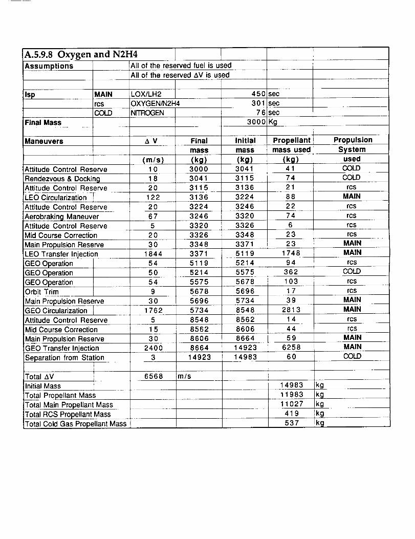
A.5.9.8 Oxygen
Assumptions
and N2H4
All of the reserved fuel is used
All of the reserved AV is used
Isp MAIN LOX/LH2 450 secrcs OXYGEN/N2H4 301 sec
COLD NITROGEN 76 sec
iFinal Mass 3O0O Kg
Maneuvers _ V Final Initial Propellantmass mass mass used
iAttitude Control Reserve
Rendezvous & DockingAttitude Control Reserve
LEO Circularization
(m/s)10
18
20122
20
67
(kg)3000
30413115
3136
3224
3246Attitude Control Reserve
5 3320
Mid Course Correction 20 3326
30 3348
iAerobraking ManeuverAttitude Control Reserve
Main Propulsion Reserve
LEO Transfer Injection
GEO Operation
GEO Operation
GEO OperationOrbit Trim
3371184454 5119
50 5214
54
9
5575
56785696
5734Main Propulsion ReserveGEO Circularization
30
1762
Attitude Control Reserve 5 8548
Mid Course Correction 1 5 8562
Main Propulsion Reserve 30 86068664GEO Transfer Injection
Separation from Station
2400
(kg)3041
(kg)41
3115 74
3136 21
3224 88
3246 22
3320 74
Propulsion
Systemused
COLD
COLD
rcsMAIN
rcs
rcs
Total Propellant Mass
3326 6 rcs
3348 23 rcs3371 23 MAIN
MAIN5119 1748
5214 94 rcs5575 362 COLD
5678 103 rcs
5696 1 7 rcs
5734 39 MAIN
8548 2813 MAIN
8562 1 4 rcs
8606 44 rcs8664 59 MAIN
625814923
3 14923 14983 60
Total_V 6568 m/sInitialMass 14983 kg
11983
Total Main Propellant MassTotal RCS Propellant Mass
Total Cold Gas Propellant Mass
11027
419
MAIN
COLD
ikgkg
kg537 kcj

A.5.9.9 N204 and 50-50 UDMH and N2H4
Assumptions All of the reserved fuel is usedAll of the reserved AV is used
Isp MAIN LOX/LH2 450 secrcs N204/50-50U DM H 288 secCOLD NITROGEN 7 6 sec
Final Mass 3000 Kg
Maneuvers
Attitude Control Reserve
Rendezvous & DockingAttitude Control Res,_rve
LEO Circularization
Attitude Control Reserve
Aerobraking ManeuverAttitude Control Reserve
Mid Course Correction
Main Propulsion Reserve
LEO Transfer InjectionGEO Operation
GEO Operation
GEO OperationOrbit Trim
Main Propulsion ReserveGEO Circularization
Attitude Control Reserve
Mid Course Correction
Main Propulsion Reserve
GEO Transfer Injection
Separation from Station
Total AV
Initial Mass
Total Propellant Mass
Total Main Propellant Mass
Total RCS Propellant MassTotal Cold Gas Propellant Mass
Z_V
(m/s)1018
20122
20
67
2O
30
184454
50
54
30
1762
1530
2400
Final
mass
(kg)30003041
3115
31373225
3248
3326
3332
3355
33785130
5229
5591
5699
57175756
858O8595
8641
8700
Initial
mass
(kg)3041
3115
31373225
3248
3326
3332
3355
33785130
5229
5591
5699
57175756
858O
85958641
8700
14984
Propellantmass used
(kg)41
7422
88
2378
624
23
1752
99
363108
18
39
2824
15
4659
6284
Propulsion
Systemused
COLD
COLD
rcs
MAIN
rcsrcs
rcs
rcs
MAIN
MAIN
rcsCOLD
rcs
rcs
MAINMAIN
rcs
rcsMAIN
MAIN
3 14984 15044 60 COLD
6568 m/s
15044
12044
11068
439538
kg
kgkgkg
kg

A.5.9.10 Fluorine and HydrogenAll of the reserved fuel is usedAssumptions
Isp
All of the reserved AV is used
MAIN
rcsCOLD
LOX/LH2
FWORINE/HYDROGEN
Nr]RCX3ENFinal Mass 30
Maneuvers
Attitude Control Reserve
Rendezvous & DockingAttitude Control Reserve
LEO Circularizat onAttitude Control Reserve
Aerobraking ManeuverAttitude Control Reserve
t_ V Final
mass mass
(m/s)10
18
20122
20
67
(kg)3000
3041
31153131
3219
3235
3291
Initial
(kg)3041
31153131
3219
3235
3291
32955Mid Course Correction 20 3295 3312
331230 3335
1844 3335 5064
54 5064 5134
50 5134 54905490
5567
54
9
Main Propulsion Reserve
LEO Transfer Injection
GEO Operation
GEO OperationGEO OperationOrbit Trim
Main Propulsion ReserveGEO Circularization
30
1762
5580
5618
5567
5580
5618
8374
Attitude Control Reserve 5 8374 8384
IMid Course Correction 1 5 8384 8417
m/s
Main Propulsion ReserveGEO Transfer Injection
Separation from Station
Total AV
Initial Mass
Total Propellant MassTotal Main Propellant Mass
30
2400
3
6568
Total RCS Propellant MassTotal Cold Gas Propellant Mass
8417
8474
14595
8474
14595
14654
450
398
7600
sec
secsec
K0
Propellantmass used
(kg)41
74
16
8817
56
Propulsion
Systemused
COLD
COLD
rcsMAIN
rcs
rcs
rcs17 rcs
23 MAIN1729 MAIN
71 rcs356
76
1338
2756
COLD
rcs
rcsMAIN
MAIN
1 1 rcs
32 rcs5 7 MAIN
6121 MAIN
59 COLD
14654
11654
10811
31253O
kg
kgkgkg
kg


A.5.10
Primary RCS Thrusters
Total Impulse & Mass Calculations for
Assume 20 hours on-time
20 hours=
Pulse time on
Pulse interval
On time/Pulse Intervals
72000 sec
1 sec
33 sec
2182 pulses
Two thrusters firing at any given time
Pulses per firing thruster 1091
M=Mass
T=Thrust
t=on time
Isp=Specific Impulse
g=Acceleration of gravity
500 N
1091 sec
223 N
9.81 m/s^2
M=T*t/Isp/g 249 kg
Two thrusters firing at any
time requires a mass of 499 kg
366 N
1091 sec
Average Thrust
Time
Total Impulse 399273 Nsec

A.5.11 Total Impulse & Mass Calculations for
Secondary RCS Thrusters
Assume 10hours on-time
10 hours= 36000 sec
Pulse Rise/Decay
Pulse time on
Total Pulse time on
Pulse interval
On time/Pulse Intervals
9.87 msec
1 sec
1.00987 sec
10 sec
3600 pulses
Two thrusters firing at any given time
Pulses per firing thruster 1800
M=Mass
T=Thrust
t=on time
Isp=Specific Impulse
g=Acceleration of gravity
89N
1800 sec
179N
9.81m/s^2
M=T*t/Isp/g 91 kg
Two thrusters firing at any
time requires a mass of 182 kg
Average Thrust
Time
89N
1800 sec
Total Impulse 160200 Nsec

A.5.12 Hydrazine Tank Volume Calculations
Blowdown Ratio R
Pressurant Gas Volume Vgi
Propellant Volume Vp
R=(Vgi + Vp)/Vgi
R
Propellant Mass
Propellant Density
Propellant Volume
Pressurant Gas Volume
Pressurant Gas Density
Pressurant Gas Mass
Total Volume
Total Mass
Radius-1 Tank
Radius-2 Tanks
4.2000
512 kg
1.0230 g/cm^3
0.5005 ma3
0.1564m^3
69.2600 kg/ma3
10.8325 kg
0.6569ma3
522.83 kg
0.5393m
0.4280m
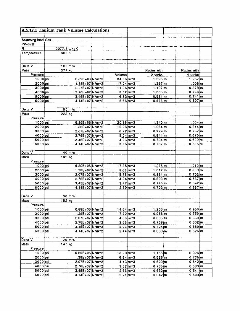
A.5.12.1 Helium Tank Volume Calculations
Assuming Ideal GasPV=mRT
R
Temperature
Delta V
Mass
Pressure
1 000 psi
2000 psi3000 psi
40001psi5000psi
6000 psi
Delta V
Mass
Pressure
1 000 psi
2000 psi
3000 psi4000 psi
5000 psi
6000 psi
Delta V
Mass
Pressure
1 000 psi
2000 psi
3000 psi
4000 psi
5000 psi6000 psi
Delta V
Mass
Pressure
1 000 psi
2000 psi
3000 psi
4000 psi
5000 psi
6000 psi
Delta V
Mass
Pressure
1 000 psi
2000 psi3000 osi
4000 _si
5000 _si
6000 osi
2077.3
300J/kgKK
1 O0 m/s
377 kg
50
223
40
192
30
162
25
147
6.89E+06 N/m^2
1.38E+07 N/m^2
2.07E+07 N/m^2
2.76E+07 N/m^2
3.45E+07 N/m^2
4.14E+07 N/m^2
m/s
kg
6.89E+06 N/m^2
1.38E+07 N/m^2
2.07E+07 N/m^2
2.76E+07 N/m^2
3.45E+07 Nlm^24.14E+07 N/m^2
m/s
[kg
6.89E+06 N/m^2
1.38E+07 N/m^2
2.07E+07 N/m^2
2.76E+07 Nlm^2
3.45E+07 N/m^2
4.14E+07 N/m^2
m/s
!kg
6.89E+06 N/m^2
1.38E+07 N/m^2
2.07E+07 N/m^22.76E+07 N/m^2
3.45E+07 N/m*2
4.14E+07 N/m^2
m/s
kg
6.89E+06 N/m^2
1.38E+07 N/m^2
2.07E+07 N/m^2
2.76E+07 N/m^2
3.45E+07!N/m^2
4.14E+07!N/m^2
Volume
34.08 m^3
17.04 m^3
11.36 m^3
8.52 m^3
6.82 m^3
5.68 m*3
20.16 m^3
10.08 m^3
6.72 m*3
5.04 m*3
4.03 m*33.36 m^3
17.35 m^3
8.68 m^3
5.78 m^3
4.34 m*3
3.47 m*3
2.89 m^3
14.64 m*3
7.32 m*3
4.88 m^3
3.66 m^3
2.93 m^3
2.44 m^3
13.29 m*3
6.64 m*3
4.43 m*3
3.32 m^3
2.66 m*32.21 m*3
Radius with
2 tanks
1.596 m
1.267 m
1.107 m
1.006 m
0.934 m
0.878 m
1.340 m
1.064 m
0.929 m
0.844 m
0.784 m
0.737 m
1.275 m
1.012 m
0.884 m
0.803 m
0.745 m
0.702 m
1.205 m
0.956 m
0.835 m
0.759 m
0.704 m
0.663 m
1.166 m
0.926 m
0.809 m
0.735 m
0.682 m0.642 m
Radius with
4 tanks;
1.267 m
1.006 m
0.878 m
0.798 m
0.741 m0.697 m
1.064 m
0.844 m
0.737 m
0.670 m
0.622_m
0.585 m
1.012!m
0.803 m
0.702 m
0.637 m
0.592m
0.557 m
0.956 m
0.759 m
0.663 m
0.602 m
0.559 m
0.526 m
0.926 m
0.735 m
0.642 m
0.583 m
0.541 m
0.509 m

A.5.13 Spider Truss Analysis
Trade studies for the spider truss configuration began with selection of the appropriate
cross section for the spider truss members. Through fairly lengthy spread sheet
calculations, circular and quadrilateral tubing cross sections were analyzed. It was
found that the circular cross section tube is more efficient because of its smaller C/Ixx
ratio and comparable mass to that of a quadrilateral cross section tube.
A starting point was developed by placing a circular cross section tube in a cantilever
configuration and submitting it to a load that the entire spider truss would encounter
during actual MOOSE operations. At the time of these trade studies, the spider truss
had an overall length of 1.5 m. It was found that for such a beam a C/Ixx ratio of
approximately 326x103 m -3 was needed to bring the beam near the ultimate strength of
the graphite composite (158 MPa). From the previous cross section trade study, a cross
section of outer radius 2.5 cm and inner radius of 2.2 cm was chosen to begin the cross
section configuration trade study. The following four configurations were then
analyzed:
In configuration #1, all the spider truss beams were modeled with outer radius 2.5 cm
and inner radius 2 cm. Configuration #2 consisted of all members with an outer
radius of 1.25 cm and an inner radius of I cm. In configuration #3, all the beams of the
inner cross member were modeled as in configuration #2 and the rest of the beams
had an outer radius of 7 mm and an inner radius of 5 mm. And finally, configuration
#4 saw the removal of the outer cross member and cross sections exactly as described
for configuration #3.
The loading diagram and the loading table for these trade studies are shown in Figure
A.5.13.a and Table A.5.13.a respectively. The results from these four configurations led
to the single analysis done in section 5.11.8.2. As will be seen, configuration #3
provided an excellent model from which analyses could take place despite design
changes in RCS configuration or operation. Table A.5.13.b shows the results from the
analyses of these four configuration in the form of maximum stress and maximum tipdeflection.
After preliminary estimations were made for the configurations, ANSYS models were
constructed for comparative purposes and to nail down the more difficult maximum
tip displacement number.

Figure A.5.13.a Trade Study Loading Diagram
F1
F2
F3
Inertia
Loads
25,310 N
250 N
136 N
6 g's
Source
RCS tank (3 g's)
RCS nozzle firing
RCS nozzle (3 g's)
Brake Maneuver 18
Table A.5.13.a Trade Study Loading Table
Configuration1
s max
.49E8 PaEnd Displacement
.304E-3 m
2 .113E9 Pa .753E-3 m
3 .114E9 Pa .775E-3 m
4 .122E9 PA 8.8 mm
Table A.5.13.b Trade Study Results
Based on results shown in Table A.5.13.b, it was clear that at this iteration
configuration #3 was the best choice for the MOOSE RCS Spider Truss. The stress
results were right around the two-thirds stipulation mentioned earlier and the
displacement requirement. Both of these points were introduced in section 5.11.8.2.
Finally, a vibration check was made under the assumption that the four main spider
truss beams of 1.5 meters in length were modeled together as one beam with a tip mass
simulated by the RCS nozzles. The following equation was used to calculate a natural
frequency of 315 Hz.

NaturalFrequency = .27
It is recommended that a full vibration analysis be conducted for the spider truss.
A.5.14 Helium Tank Material and Mass Analysis
Tank Pressure (Ptanks)= 4.137 x 10⁷ N/m 2
Radius (R) = 0.585 m
Surface Area = 4_R 2
Stress = (PtanksR)/2t
Material Stress (1.1 Safety Thickness (m)Factor)
A1 6061 - T6 2.806 x 10⁸ .04312 502
A1 7075 -T6 4.689 x 10⁸ .0258 307
Ti 6 % A1, 4% V 8.97 x 10⁸ .0169 243
Ti 8-1-1 10.91 x 10⁸ .0166 234
Mass (kg)
Table A.5.14.a Secondary RCS Tank Materials Study


Appendix A6.1 ADCS
Torques from cyclic and secular disturbances
Cyclic disturbances
• Gravity gradient torque at GEO
Tg: IIzz-=yyloR 3
I_ = earths gravity constant
O = off-axis from nadir = 5 deg.
R = orbital radius = 46028 km
Tg = 9.168x10 "5 N m
3.9x10 3 km 32
s
• Solar Radiation Torque at GEO
Tsp = PsAsLs(l+q) cos q
Ps = solar constant = 4.617x10 "6 N m
As = Area of surface = 10 m 2
Ls = center of press, to center of-mass
offset = I m
q = angle of incidence of sun = 90 deg.
q = reflective factor" .6
Tsp = 7.38 x 10^-5 N m
Note: solar radialion press. Tsp is highly dependent
on the surface being illuminated. For our vehicle
it will be mostly reflective surfaces.

SecularTorqueDisturbances
• AerodynamicTorqueatGEO
n
Ta = S Fil ii=1
F i =0._rCdAV 2]
C d = coefficient of drag of each part
A = effected area of each part
V = velocity of spacecraft
r = at GEO ° 0
so
Ta'0
li = dist. from c.g. of part
to c.g. of spacecraft.
,f

Appendix A6.2 Navigation and Tracking
A6.2.1 Linear Navigation and Velocity Update Systems
Ground Tracking / TDRSS - Provides accuracy from 50m to several hundred meters
when tracking objects in LEO. This system, however requires a full ground crew
during each vehicle mission and does not work for objects in GEO.
Space Sextant - Provides 250m accuracy. The unit however is large compared to
other units (25 kg, 0.4 cubic meters) and requires more power (50 W) than other
systems. The unit also requires a 24 hour scan time to achieve the stated accuracy.
Global Positioning System - Provides 25 m accuracy at LEO. The system is ideal for
use in LEO (9.72 x 5 x 2 cubic inches, 1.37 kg, 3 W) however this system is not
designed to work above 8000 nmi altitude. According to Marc Crotti, product
manager for the TANS GPS receiver for Trimmble Navigation, there was talk of aGPS receiver that would work in GEO. However, if such a receiver is developed,
such a receiver would not work in LEO and would be GEO specific. If this receiver is
developed, the software and hardware interface will already be in place on board the
vehicle and a more accurate navigational update system could be implemented.
Microcosm Autonomous Navigation System (MANS) - This system provides 600m
to 1.5 km accuracies in GEO using 2 sensors. (The added accuracy comes from using
the moon as a source, and any additional GEO accuracy requirements would require
the mission to be planned during a week where the moon can be used as a
reference.) The system works from LEO to GEO (and beyond). The system uses a
dual sun angle/earth horizon sensor that also provides attitude determination. The
sensor is a good compromise for mass and power (4.3 kg, 11 W per sensor). In
addition, these sensors will also return orientation information. Using two sensors,
the system will provide accurate coverage up to 84% of the time at GEO. (The other
16% of the time accounts for eclipses of the moon and the sun which provide
navigational information discussed later.)
A6.2.2 Orientation Update Systems
MANS Sensors (Modified Dual Cone Sensor) - These sensors return the
information of both sun angle sensor and a horizon sensor. The sun angle
information will determine the vehicle's orientation to an accuracy of 0.01 degrees.
The horizon sensors information will determine the vehicle's orientation to an
accuracy of 0.1 to 0.25 degrees. In addition, these modified sensors will detect the
moon's angle and can be used to return navigational information.
Star Trackers - These sensors can determine a vehicle's orientation to an accuracy of
0.01 degrees. These sensors can also be utilized to determine the angle to a
rendezvous target to an accuracy of 0.02 degrees.

Appendix A6.1 ADCS
Torques from cyclic and secular disturbances
Cyclic disturbances
• Gravity gradient torque at GEO
Tg: 3- -IIzz-ly eR 3
_L : earths gravity constant
O : off-axis from nadir = 5 deg.
R = orbital radius = 46028 km
Tg = 9.168x10 "5 N m
3.9x10³ km 32
s
• Solar Radiation Torque at GEO
Tsp = PsAsLs(l+q) cos q
Ps ,: solar constant = 4.617x10 "6 N m
As = Area of surface: 10 m 2
Ls = center of press, to center of-mass
offset= lm
q = angle of incidence of sun : 90 deg.
q = reflective factor" .6
Tsp : 7.38 x 10^-5 N m
Note: solar radiation press. Tsp is highly dependent
on the surface being illuminated. For our vehicle
it will be mostly reflective surfaces.

SecularTorqueDisturbances
• AerodynamicTorqueatGEO
n
Ta = S Fil ii--1
C d z coefficient of drag of each part
A = effected area of each part
V = velocity of spacecraft
r _- at GEO ° 0
80
Ta'O
li = dist. from c.g. of part
to c.g. of spacecraft.


Appendix A6.2 Navigation and Tracking
A6.2.1 Linear Navigation and Velocity Update Systems
Ground Tracking / TDRSS - Provides accuracy from 50m to several hundred meters
when tracking objects in LEO. This system, however requires a full ground crew
during each vehicle mission and does not work for objects in GEO.
Space Sextant - Provides 250m accuracy. The unit however is large compared to
other units (25 kg, 0.4 cubic meters) and requires more power (50 W) than other
systems. The unit also requires a 24 hour scan time to achieve the stated accuracy.
Global Positioning System - Provides 25 m accuracy at LEO. The system is ideal for
use in LEO (9.72 x 5 x 2 cubic inches, 1.37 kg, 3 W) however this system is not
designed to work above 8000 nmi altitude. According to Marc Crotti, product
manager for the TANS GPS receiver for Trimmble Navigation, there was talk of a
GPS receiver that would work in GEO. However, if such a receiver is developed,
such a receiver would not work in LEO and would be GEO specific. If this receiver is
developed, the software and hardware interface will already be in place on board the
vehicle and a more accurate navigational update system could be implemented.
Microcosm Autonomous Navigation System (MANS) - This system provides 600m
to 1.5 km accuracies in GEO using 2 sensors. (The added accuracy comes from using
the moon as a source, and any additional GEO accuracy requirements would require
the mission to be planned during a week where the moon can be used as a
reference.) The system works from LEO to GEO (and beyond). The system uses a
dual sun angle/earth horizon sensor that also provides attitude determination. The
sensor is a good compromise for mass and power (4.3 kg, 11 W per sensor). In
addition, these sensors will also return orientation information. Using two sensors,
the system will provide accurate coverage up to 84% of the time at GEO. (The other
16% of the time accounts for eclipses of the moon and the sun which provide
navigational information discussed later.)
A6.2.2 Orientation Update Systems
MANS Sensors (Modified Dual Cone Sensor) - These sensors return the
information of both sun angle sensor and a horizon sensor. The sun angle
information will determine the vehicle's orientation to an accuracy of 0.01 degrees.The horizon sensors information will determine the vehicle's orientation to an
accuracy of 0.1 to 0.25 degrees. In addition, these modified sensors will detect the
moon's angle and can be used to return navigational information.
Star Trackers - These sensors can determine a vehicle's orientation to an accuracy of
0.01 degrees. These sensors can also be utilized to determine the angle to a
rendezvous target to an accuracy of 0.02 degrees.

Orientation Determination with GPS- Using 4 GPSantennas, this can beaccomplished, however it would only be useful in LEO and useless in GEO.
A6.2.3 Performance of MANS
MANS performance is based on:
- Mounting Angle
- Availability of the Moon as a Reference- Altitude of Orbit
A6.2.3.1 Performance Based on Mounting Angle
\\\
\\\\
\\\
Sun Sensor Cone, 180 Degrees /I
"_,.,_ iII
Aerobrake Shadow
//
/ ,/ ,,
/ / /
J
/
/
/
65"Degree IR FOV2/
/
/
/
\\ MANS Sensor /l \Spin Axis ii \ \
\\
\\ /1/ \_
\ /\ /\ /
\ /\ /\ /
\
\
\
\
30 Degree IR FOV I\
NADIR
Figure A6.2.a Sensor Mounting and Scan Angles
Two MANS sensors are mounted with the head perpendicular to a 69.5 degree line
with respect to the aerobrake shadow. This configuration will allow maximum sun
sensor coverage while allowing the horizon sensor (FOV2) to scan the horizon of
the earth. The combination of sensors gives 4 horizon crossings. The sensors heads
must be mounted so they are outside this 69.5 degree cone to ensure the aerobrakeshadow does not increase the blackout time; the shadow should fall outside the sun

sensing cone.
/ 20.5 Degree Half AngleBlackout due to Mounting Angle
MOOSE
_8.5 Degree Half Angle
Blackout due to Eclipse of Sun by Earth
Figure A6.2.b Sun Blackout Regions in GEO
With the vehicle orbiting at GEO, the problem of detecting the sun can be
approximated as a 2-D problem. In this problem, 2 blackout regions occur. The
eclipse of the sun by the earth accounts for a region of 17 degrees lost. The sun
sensor blind spot accounts for 41 degrees lost. This gives a total of 16% blackout
time. In GEO this results in a blackout of 1.2 hours due to earth eclipsing and 2.6
hours of blackout due to the sun sensor blind spot. However, this blackout time
results in a loss of precision, not a total loss of navigation. The altitude accuracy
returned by the optical sensors will degrade to an accuracy of over 6 km. The
vehicle can rely on inertial navigation until after the blackout, however, the
accuracy of re-entry can not be met unless the vehicle can begin before inertial
navigation degrades to an unacceptable error level.
The mission can also be planned to minimize the blackout time. The transfer to
GEO can be timed such that the sun sensor blind spot is just past the sun when the
vehicle switches from GPS to MANS at just under 8000nmi. The transfer orbit will
have already been determined at this time by GPS and should be fairly accurate. The
next sensor blind spot is then over 10 hours away. This is enough time to accurately
compute the vehicle's orbit in GEO using Kalman filtering software.

A6.2.3.2Availability of the Moon as a Reference
The MANS system's accuracy can be improved from 1.5km to 600 m if the moon is
available as a reference. The MANS system computes the vehicles orbit by utilizing
two scans of the sun or by using one scan of the sun and one scan of the moon. The
latter is more accurate, providing 32m accuracy at LEO and 500 - 600 m accuracy at
GEO. If greater accuracy is ever required at GEO, the mission could be limited to aweek of the month when the moon is available as a reference.
A6.2.3.3 Effects of Vehicle Altitude on Accuracy
The accuracy of the vehicle's measured altitude decreases in GEO, causing a loss of
accuracy overall. The altitude as determined by a horizon sensor can be found using
the following equation:
cos p = E
where p is the angular radius of the earth as measured by the sensor, Re is the actualradius of the earth, and E is the distance of the sensor from the center of the earth.
Using 2 MANS sensors, the error in p is 0.023 degrees. At GEO, therefore, an error
in altitude of 12.5 km is given from one reading. To gain extra accuracy, the MANS
system uses kalman filtering, along with sun angle readings to improve accuracy. If
navigational course information and current IMU information is used to improve
the accuracy, an accuracy of 1.5 km can be achieved. This is assuming that kalman
filtering can improve the accuracy by a factor of between 5 and 10. Microcosm claims
that a kalman filtering update can be provided every 25 seconds, while still
achieving this accuracy.
It is apparent that the navigation system at GEO will be dependent on kalman
filtering, and therefore it will be heavily software dependent.

Appendix A6.3 Communications
A6.3.1 Computer Program for Link Budget
Program downlink
real frequency,trpw,trlogpw,trU,trabeam,ptrgain, trapo
real trapl,tragain, pploss,propoloss,rad,prag,raploss
real rag,snt, datarate, eirp,rho, lambda,ebno, cno,reqebno
real imploss,margin, trad,rape,ber,rab,spaceloss,re
open (unit=8,file="downl",status="new")
write (8,49)
49 format (lx,'downlink worst case')
write (8,50)
write (9,50)
50 format(lx,'frequency')
read (9,*) frequency
write (8,65) frequency
65 format (Ix,f10.5)
write (8,51)
write (9,51)
51 format(lx,'transmit power')
read (9,*) trpw
write (8,66) trpw
66 format (Ix,f10.5)
write (8,52)
write (9,52)
52 format(lx,'transmit line loss')
read (9,*) trll
write (8,67) trll
67 format (Ix,f10.5)
write (8,54)
write (9,54)
54 format(lx,'transmit antenna pointing offset')
read (9,*) trapo
write (8,69) trapo
69 format (Ix,f10.5)
write (8,56)
write (9,56)
56 format(lx,'propagation path loss')
read (9,*) altitude
write (8,71) altitude
71 format (Ix,f15.5)
write (8,57)
write (9,57)

57 format(lx,'propagation and polarization loss')
read (9,*) propoloss
write (8,72) propoloss
72 format (1x,f10.5)
write (8,58)
write (9,58)
58 format(lx,'receive antenna diameter')
read (9,*) rad
write (8,73) rad
73 format (lx,flO.5)
write (8,59)
write (9,59)
59 format(lx,'receive antenna pointing error')
read (9,*) rape
write (8,74) rape
74 format (lx,flO.5)
write (8,60)
write (9,60)
60 format(lx,'system noise temp')
read (9,*) snt
write (8,75) snt
75 format (Ix,f10.5)
write (8,61)
write (9,61)
61 format(lx,'data rate')
read (9,*) datarate
write (8,76) datarate
76 format (lx,f15.5)
write (8,62)
write (9,62)
62 format(lx,'bit error rate')
read (9,*) ber
write (8,77) ber
77 format (Ix,f15.5)
write (8,63)
write (9,63)
63 format(lx,'required Eb/No')
read (9,*) reqebno
write (8,78) reqebno
78 format (1x,f15.5)
write (8,64)
write (9,64)
64 format(lx,'implementation loss')
read (9,*) imploss
write (8,79) imploss
79 format (Ix,f10.5)

do 150trabeam= 1.0,3.1,0.1
re = 6378.0
trad = ( 21.0/( frequency * trabeam ))
trlogpw = 10.0*alogl0(trpw)
ptragain = 44.3 - 10.0*alogl0(trabeam**2)
trapl = -12.0" (trapo**2/trabeam**2)
tragain = ptragain + trapl
eirp = trlogpw + trll + tragain
find path length from altitude
rho = asin ( re / ( re + altitude ))
rho = 57.29577951 * rho
lambda = 90.0 - rho
lambda = lambda*.017453292
pploss = re*tan(lambda)
+
+
100
+
spaceloss = -92.44 - 20.0*ALOG10(pploss) -
20.0*ALOG10(frequency)
prag = 20.40+ 20*alogl0(rad)+ 20*alogl0(frequency)- 2.5964
tab = 21.0/(frequency * rad)
raploss = -12.0*(rape**2/rab**2
rag = prag + raploss
ebno = trlogpw + trU + tragain + propoloss + spaceloss
+ rag +228.6 - 10*alogl0(snt) - 10*alogl0(datarate)
cno = eirp + pploss + propoloss + rag/snt + 228.
margin = ebno - reqebno + imploss
write (8,100) trabeam,ptragain,margin, trad
write (9,100) trabeam,ptragain,margin, trad
format(lx,'trabeam',fl0.5,1x,'ptragain',fl0.5,1x,'margin',
fl0.5,1x,'trad',fl0.5)
150 continue
close (unit=8)
pauseend
A6.3.2 Solution for Downlink
downlink worst case
frequency12.00000
transmit power20.00000

transmit line loss
-1.00000
transmit antenna pointing offset.20000
propagation path loss38756.00000
propagation and polarization loss-.50000
receive antenna diameter5.30000
receive antenna pointing error.20000
system noise temp552.00000
data rate
6400000.00000
bit error rate
0.00000
required Eb/No
15.00000
implementation loss-2.OOOOO
trabeam 1.00000 ptragain 44.30000 margin 13.89308 trad 1.75000
trabeam 1.10000 ptragain 43.47215 margin 13.14854 trad 1.59091
trabeam 1.20000 ptragain 42.71637 margin 12.45613 trad 1.45833
trabeam 1.30000 ptragain 42.02113 margin 11.81020 trad 1.34615
trabeam 1.40000 ptragain 41.37744 margin 11.20563 trad 1.25000
trabeam 1.50000 ptragain 40.77817 margin 10.63792 trad 1.16667
trabeam 1.60000 ptragain 40.21760 margin 10.10320 trad 1.09375
trabeam 1.70000 ptragain 39.69102 margin 9.59802 trad 1.02941
trabeam 1.80000 ptragain 39.19455 margin 9.11949 trad .97222
trabeam 1.90000 ptragain 38.72493 margin 8.66505 trad .92105
trabeam 2.00000 ptragain 38.27940 margin 8.23248 trad .87500
trabeam 2.10000 ptragain 37.85561 margin 7.81985 trad .83333
trabeam 2.20000 ptragain 37.45155 margin 7.42546 trad .79545
trabeam 2.30000 ptragain 37.06544 margin 7.04781 trad .76087
trabeam 2.40000 ptragain 36.69578 margin 6.68553 trad .72917
trabeam 2.50000 ptragain 36.34120 margin 6.33749 trad .70000
trabeam 2.60000 ptragain 36.00053 margin 6.00261 trad .67308
trabeam 2.70000 ptragain 35.67273 margin 5.67998 trad .64815
trabeam 2.80000 ptragain 35.35684 margin 5.36870 trad .62500
trabeam 2.90000 ptragain 35.05204 margin 5.06805 trad .60345
trabeam 3.00000 ptragain 34.75758 margin 4.77733 trad .58333

A6.3.3 Power Consumption of various data rates at different altitudes
/_fltitude _ Voice Telemetry Video
1.50e+04 4.17 0.0417 0.19802 3.9100
1.60e+04 4.61 0.0461 0.22110 4.3210
1.70e+04 5.07 0.0507 0.24309 4.7510
1.80e+04 5.55 0.0555 0.26604 5.1994
1.90e+04 6.04 0.0604 0.28995 5.6667
2.00e+04 6.56 0.0656 0.31482 6.1520
2.10e+04 7.10 0.0710 0.34065 6.6578
2.20e+04 7.66 0.0766 0.36745 7.1810
2.30e+04 8.24 0.0824 0.39520 7.7240
2.40e+04 8.84 0.0884 0.42392 8.2850
2.50e+04 9.46 0.0946 0.45360 8.8650
2.60e+04 10.1 0.101 0.48423 9.4630
2.70e+04 10.8 0.108 0.51583 10.081
2.80e+04 11.4 0.114 0.54839 10.720
2.90e+04 12.1 0.121 0.58191 11.373
3.00e+04 12.8 0.128 0.61640 12.047
3.10e+04 13.6 0.136 0.65184 12.740
3.20e+04 14.3 0.143 0.68824 13.450
3.30e+04 15.1 0.151 0.72561 14.181
3.40e+04 15.9 0.159 0.76394 14.930
3.50e+04 16.7 0.167 0.80323 15.698
3.60e+04 17.6 0.176 0.84348 16.484
3.70e+04 18.4 0.184 0.88468 17.290
3.80e+04 19.3 0.193 0.92686 18.110
3.88e+04 20.0 0.200 0.96129 18.787
A6.3.4 Sensor Rates
Sensors, sometimes called transducers, are sensing devices which measure a
physical parameter. The sensors used on MOOSE are local environment sensors thatmeasure internal measurements. Sensors can either be sensors that measure
internal measurements or scientific data. Sensors can either be self-generating or
those that need an external voltage supply. Thermocouples are an example of self-
generating sensors. Potentiometers, strain gauges, and variable capacitors are
examples of dependent sensors.

Sensorswill give constant data and the computer will sample the data at certainrates. Therefore the data will not be read sequentially, and any excessdata memoryon a particular sampling will be allocated to the next sampling This assumption is
made so that data that is not sampled every second can be averaged so it can be
combined with data rates that are in bits per second. Navigation and tracking data
rates are an example.
These are the data rates for all of the sensors on MOOSE. The data rates are read by
the computer. The computer then sends the data to either storage, the cockpit, orearth. Some data will be sent to two or three of these areas. These are the estimated
sensor data rates by subsection:
A 6.3.4.1 Structure
1. Back Surface Heat Sensor for Aerobrake
{ Thermocouple }
• sample only during aerobrake maneuvers
• range 0°-350°; resolution = .085 °• 12 Bits at 100/s
• 4 sensors - 1 for each quadrant of aerobrake 4800 bps
2. Angle Attack Indicator
{ Potentiometer}
• sample only during aerobrake maneuvers
• range 0 °- 20 ° ; resolution .078 °• 8 Bits at 100/s
• 2 sensors - 1 for each side of spacecraft 1600 bps
Total : 6400 bps
A6.3.4.2 Life Support
1. Temperature { Thermocouple }
• range 60 °- 80 °• 8 Bits at 1/s
• 2 sensors for redundancy 16 bps
2. Oxygen Tank Pressure { Pressure Transducer }• 8 Bits at 1/s
• 2 sensors for redundancy 16 bps
3. Nitrogen Tank Pressure { Pressure Transducer }
• 8 Bits at 1/s
• 2 sensors for redundancy 16 bps
4. Radiation { high-impedance voltmeter monitors ion
flow between electrodes }
• range 10E-6 - 10E-4 ampsM • _, .... •

A6.3.4.3 Man/Grap
1. Load Sensor
* 12 Bits at 2/s
* 6 for arm
2. Strain Gauges* 12 Bits at 2/s
• 6 for arm
3. Motor Decoders { measure rpm digitally }
• 16 Bits at 20/s
• 7 sensors
4. Power Consumption { Voltmeter }
• 12 Bits at 1/s
144 bps
144 bps
2240 bps
• multiply by two for both manipulators and grappling arms
Total : 2540 bps
Total : 5080 bps
A6.3.4.4 Propulsion
1. Hydrogen Fuel Pump { Pressure Transducer }• 12 Bits at 100/s
2. Hydrogen Fuel Turbine• Blade Housing { Thermocouple }
• 12 Bits at 1000/s
• Shaft { Strain gauge }
• 12 Bits at 100/s
• Motor Decoders
• 12 Bits at 100/s
3. Oxidizer Fuel Pump { Pressure Transducer }
• 12 Bits at 100/s
4. Oxidizer Fuel Turbine
• Blade Housing { Thermocouple }
• 12 Bits at 1000/s
• Shaft { Strain gauge }
• 12 Bits at 100/s
• Motor Decoders
• 12 Bits at 100/s
1200 bps
12000 bps
1200 bps
1200 bps
1200 bps
12000 bps
1200 bps
1200 bps

5. Three Shut Off Valves
• On/Off { Switch }
• 1 Bit at 100/s x 3
• Redundancy
• Up Flow { Pressure Transducer }• 8 Bits at 100/s x 3
• Down Flow { Pressure Transducer }
6. Nozzle Heat { Thermocouple }• 12 Bits at 1000/s
7. Combustion Chamber
• Chamber Pressure { Pressure Transducer }
• 12 Bits at 10,000/s
• Chamber Temperature { Thermocouple }
• 12 Bits at 10,000/s
8. Tank Pressure { Pressure Transducer }
• 12 bits at 10/s
• 4 tanks ( 2 fuel & 2 oxidizer )
9. Tank Level
12 bits at 10/s
4 tanks ( 2 fuel & 2 oxidizer )
A6.3.4.5 Navigation/Tracking
1. Dual Cone Sensor
• 56 Bits at once every 25 seconds• 2 sensors
2. GPS Receiver
• 80 Bits at 2/s
3. Rendezvous Radar { used only during rendezvous }
• 48 Bits once every 300 seconds
4. Star Tracker
• 30 Bits once every 60 seconds
300 bps
2400 bps
2400 bps
12000 bps
120,000 bps
120.000 bps
480 bps
480 bps
= 288060 bps
Total : 288 kbps
5 bps
160 bps
I bps
I bps

5. Power Consumption { Volt Meter }• 12 Bits at 1/s
A6.3.4.6 Attitude Control System
1. Rate Gyro
• 16 Bits at 100/s
2. Accelerometers
• 16 Bits at 100/s
3. Temperature { Thermocouple }
• Gyros
• 8 Bits at 10/s
• Inertial Measurement Unit
• 8 Bits at 10/s
4. Power Consumption { Volt Meter }• 12 Bits at 1/s
A6.3.4.7 Reaction Control System
° Tank Pressure { Pressure Transducer }
• 12 Bits at 10/s
• 4 Tanks x 2 sensors each for redundancy
2. Thruster Temperature
• 12 Bits at 10/s• 16 Thrusters
{ Thermocouple }
3. Power Consumption { Volt Meter }• 12 Bits at 1/s
12i
= 179 bps
Total: 180 bps
1600 bps
1600 bps
80 bps
80 bps
= 3372 bps
Total: 3380 bps
960 bps
1920 bps
= 2892 bps
Total: 2900 bps


Appendix A6.4 CDMS
A6.4.1 Analogy from the Automotive Industry
The automotive industry faces many of the same challenges that the space systems
industry faces. More and more sophisticated electronics must be integrated together
as cars become increasingly computerized. Automotive systems have to coordinate
the activities of microprocessors, microcontrollers, digital signal processing chips
(DSPs), application specific ICs (ASICs), and smart sensors and actuators.
The increasing number of wiring cables and connector contacts is leading to long
production times, higher labor costs, cramped body space, and decreased reliability.
Another concern is the reliability of complex, interacting functions, which can not
be exposed to the weakness of point-to-point wiring.
The obvious solution is to multiplex data through one serial line or bus tied to the
vehicle Electronic Control Units (ECUs). Multiplexing allows data from different
sources-sensors, switches, and ECUs, to be be sent over a common bus, typically
consisting of four wires. Two conductors are used for signal transmission, the other
two for power and ground.
Limitations of ring and star networks has led the auto industry to select a linear bus
structure for high-speed networking. This scheme gives every network node the
same right to access the bus. Arbitration among nodes is done by prioritizing the
addresses of the messages.
The Multiplexing Standards Committed of the Society of Automotive Engineers
(SAE) has partitioned the data-rate requirements for automotive serial
communications into three segments.
Class A defines parameters for body control applications where high data speed and
accuracy levels are not critical. These include turn signal, headlights, entertainment
systems, etc. Data rates of up to 1 kbit/s are handled, with up to 100 nodes. Latency
time between transmission request and transmission initiation is 50 ms.
Class B refers to information shared systems with moderate speed (up to 100 kbits/s)
and accuracy requirements that consist of up to 50 nodes. Applications includecommunication between sensors and instrumentation clusters. Class B data does
not control the automotive subsystems, and is not transmitted in real time.
Class C protocols are for real-time control applications with critical speed and
accuracy requirements, such as communication between engine and transmission,
or between ABS sensors and brake actuators. The higher data rates of Class C (up to
1Mbit/s) reduce the maximum number of nodes allowed to 10, and latency timedecreases to under 5 ms.

Appendix
8.1 Acronyms
ACS
AFB
ASE
ASP
CAM
CAP
CCTC
CCZ
CFP
CPCB
CSOCC
CSR
Attitude Control System
Air Force Base
Airborne Support Equipment
Assessment Flight Profile
Collision Avoidance Maneuvers
Crew Activity Plan
Common Cryogenic Transfer Coupling
Command and Control Zone
Conceptual Flight Profile
Crew Procedures and Control Board
Client Spacecraft Operations Control Center
Customer Support Room
DEM/VAL
DoD
ELV
ENAE
EVA
FCO
FCR
FDF
GC
GCT
GEO
GNAC
GN2
GPS
GSFC
GSTDN
GTO
I-Loads
IMU
Demonstration & Validation
Department of Defense
Expendable Launch Vehicle
Department of Aerospace Engineering
Extra-Vehicular Activity
Flight Control Officer
Flight Control Room
Flight Data Files
Ground Control
Ground Configuration Terminal
Geosynchronous Orbit
Guidance/Navigation/Control
Gaseous Nitrogen
Global Positioning System
Goddard Space Flight Center
Ground Spacecraft Tracking & Data Network
Geosynchronous Transfer Orbit
Initial Software Loads
Inertial Measurement Unit

IVA
jscKSC
LH2
LiO2
LO2
MAP
MCC
_C
MOC
MOSC
MSC
MSSS
MSSSPO
MSSSTY
NASA
NASCOM
NTO
OFP
OMV
ORU
OTF
PDA
PMC
PI_Z
POCC
PROXO
PROXOPS
RDZ
RMS
SSCC
SSL
SSF
SSFMS
SSFPO
Intra-Vehicular Activity
Johnson Spaceflight Center
Kennedy Spaceflight Center
Liquid Hydrogen
Lithium Dioxide
Liquid Oxygen
Mission Activity Plan
Mission Control Center
MSSS Flight Computers
Mission Operations Center
MSSS Operations Support Center
MSSS Flight Computer
Manned Satellite Servicing System
MSSS Project Office
MSSS Training Facility
National Aeronautics and Space Administration
NASA Communications Network
Nitrogen Tetroxide
Operational Flight Profile
Orbital Maneuvering Vehicle
Orbital Replacement Unit
Orbiter Training Facility
Pressurized Docking Assembly
Permanently Manned Capability
Propellant Maneuvering Vehicle
PMV Operations Control Center
Proximity Operations Officer
Proximity Operations
Rendezvous/Departure Zone
Remote Manipulator System
Space Station Control Center
Space Systems Laboratory
Space Station Freedom
Space Station Freedom Mission Simulator
Space Station Freedom Program Office

SSPOZ
TDRS
TDRSS
UMCP
VAFB
V-bar
WETF
WTR
Space Station Proximity Operations Zone
Tracking and Data Relay Satellite
Tracking and Data Relay Satellite System
University of Maryland, College Park
Vandenberg Air Force Base
Velocity Vector Direction
Weightless Environment Training Facility
Western Test Range
8.2 Example Final Approach
Figures A8.1 to A8.3 represent the AV's for various times at different points
during the final approach, based upon equations 8.1.1-4. The satellite is
assumed to be in a geosynchronous orbit (42160 km) and MOOSE is initilally
^ A A
at P0 = [580i "580j + 580k]m. The initial relative velocity is assumed to be zero
for figure A8.1a, but for figures A8.1b, A8.1c & A8.1d, the velocities are
assumed to be the chosen velocities of the previous gates. Choice of AV= 10.02
m/s is based on the lowest AV in figure A8.1a, while in figure A8.1b, the
choice AV= -9.99 m/s is the limit (approximately) as the AV values level off
over time. A AV of -0.33 m/s was chosen from figure A8.1c since, although
there are lesser values, 300s (5 min) should give the pilot whatever time
he/she needs before executing the next maneuver. In figure A8.1d, a AV= -
0.11 was chosen since this was the lowest AV. Once the pilot is within
grappling range fie. within 5m of the target satellite), he/she uses the cold gas
thrusters to bring the vehicle to zero velocity relative to the target satellite.

A8.1a: 1000m to 400m gate
_" 6 0 0 Components of best velocity:500400
> 300
2OO
1000
O O O O O O O O O O O O Oi.'3 It) M3 ¢¢3 I.O I_D 143 I.r) I_D I/J ID tD M3
04 O0 04 04 O4 04 04 04 O4 04 ¢O 03
Time (s)
8.1b: 400m to 200m gate
1 0.8 -Components of best velocity:E 10.6
v 10.4 _10.2..
> 10-
9.8-"3 9.6-
9.4 : : : : : : : ' : : :: : : :: : : : : : : , : : : :0 0 0 0 (:_ 0 0 0 0 0 0 0 0O O O O O O O O O O O O O
_" _'- _ 04 04 03 03 03 _" _1" t/J
Time ($)
0.80.6
• 0.4
0.2m
9)
•o 0
8.1c: 200m to 20m gate
m/s
:::::::::::::::::::::::::O O O O O O O O O O O O OO i/_ O I_ O M3 O _ O ¢O O I_ O03 _ tad I_ O O 04 03 tD CaD ¢O O_ T-
Time (s)
Figure 8.1a-c
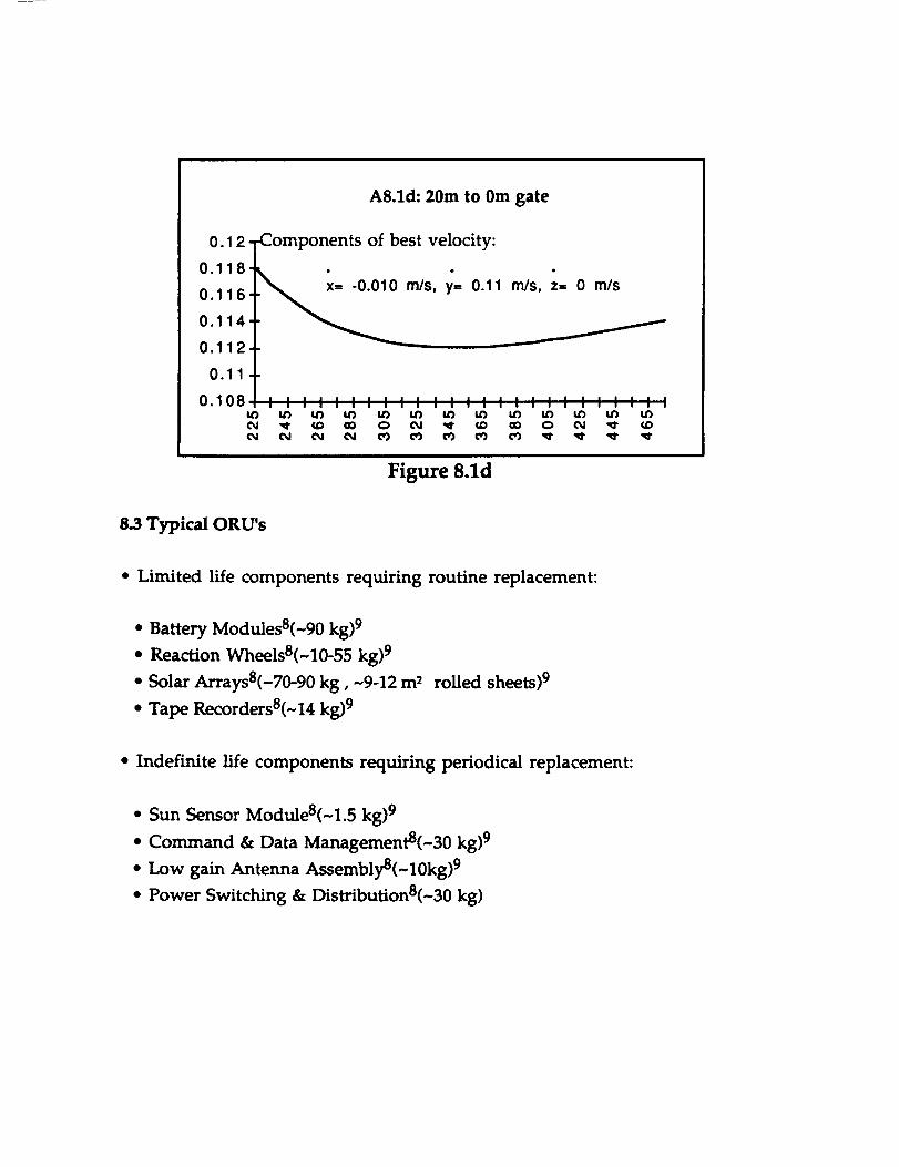
A8.1d: 20m to 0m gate
0.1 2 Components of best velocity:
0.118 _ .
0.116 m/s, y= 0.11
0"114 t
0.112
0.11
0.108 I I I I I I ; : ', : ', ', ', : ',I.O rid t_ tO tO tO tO tOOJ _1" CaD OO 0 ¢_1 _" cadOJ O_ Od ¢_1 ¢0 O3 O3 O3
m/s, z= 0 m/s
,,, : , : ....ill I Illl
tO tO tO tO tO
Figure 8.1d
8.3 Typical ORU's
* Limited life components requiring routine replacement:
• Battery Modules8(~90 kg) 9
• Reaction Wheels8(~10-55 kg) 9
• Solar ArraysS(-70-90 kg, -9-12 m 2 rolled sheets) 9
• Tape RecordersS(~14 kg) 9
• Indefinite life components requiring periodical replacement:
• Sun Sensor ModuleS(~1.5 kg) 9
• Command & Data ManagementS(~30 kg) 9
• Low gain Antenna AssemblyS(~10kg) 9
• Power Switching & Distribution8(-30 kg)

A8.4 Typical Consumables
• Liquids 8 (-80-140 kg)9:
• Earth Temperature St.rabies:
• N20 4
• MMH
•Water
• Space Temperature St.rabies:
• Oxidizers
• Fuels
• Cryogenic Temperature St,rabies:
-02• H 2
• Helium
• Gases 8 (~4kg)8:
• Earth Temperature st.rabies:
• Oxygen
• Air
• Nitrogen
• Cryogenic Temperature St.rabies:
• Oxygen
• Hydrogen

References
Asada, Haruhiko and Kamal Youcef-Toumi. Direct Drive Robots:
Theory and Practice. MIT Press. Cambridge, MA. 1987.
Ault, Norman and Zarobsky. Fundamentals of Flywheel Design.. 1958.
Avallone, Eugene A. and Theodore Baumeister III.
Handbook for Mechanical Engineers, ninth edition.
Book Company. 1987.
Marks" Standard
McGraw-Hill
Barnes, Robert and Frank Tai, "The Dual Cone Sensor: An Enhanced
Performance, Low Cost Earth Sensor", Advances in the Astronautical
Sciences, Guidance and Control, 1989
Bleazard, G.B., Introducing Satellite Communications. NCC.
Publications, England,1985.
Bzibziak, R. "Miniature Cold Gas Thrusters," AIAA Paper 92-3256.
July 1992, 8 pages.
Cantafio, Leopold J., Space-Based Radar Handbook, Artech House, Inc,1989.
Cherty, P.R.K., Satellite Technology and its Applications. Tab Books,
Germantown, Maryland, 1988.
Craig, John J. Introduction to Robotics: Mechanics & Control.
Addison-Wesley. Reading, MA. 1986.
Elbert, Bruce R., Introduction To Satellite Communication. Artech
House, Massachusetts,1987.
Foster, LeRoy E., Telemetry Systems.. John Wiley and Sons, Inc.London. 1965.

Greensite, Arthur L. Control Theory: Volume II -- Analysis and
Design of Space Vehicle Flight Control Systems. Spartan Books.Washington. 1970.
Handbook of Batteries and Fuel Cells. McGraw-Hill. 1984.
Holzbock, Werner G. Robotic Technology: Principles and Practices.Reinhold Co. New York. 1986.
Howle, D.H. "Man in Space" The Space Environment. University ofLondon Press Ltd., London, 1969.
Jensen, Jurgen, et. al. Design Guide to Orbital Flight. McGraw-Hill.NewYork. 1962.
Lopes, Roberto V.F. and Helio K. Kuga, "Optimal Estimation of Local
Orbit from GPS Measurements", AIAA, Feb. 26, 1987.
McKerrow, Phillip John. Introduction to Robotics. Addison-Wesley.New York. 1991.
Merril, Grayson.Handbook of Satellites and Space Vehicles. D. Van
Nostrand Company,Inc. Princeton, NJ. 1965.
Navtech Seminars, Inc., "Fundamentals of GPS", Course 101, TysonsCorner, May 18,1992.
Noerdlinger, Peter D. and Frank Tai, "A Low Cost Autonomous
Navigation System", Advances in the Astronautical Sciences,
Guidance and Control, 1989.
"OTV Concept Definition + Evaluation - Subsystem Trade Studies" Vol
II, Book 3, paper NAS8-36108, 1985.
Pitman, George R., Inertial Guidance, Wiley & Sons, New York, 1962.
Rivin, Eugene I. Mechanical Design of Robots. McGraw-Hill, Inc. NewYork. 1988.
Rocket Research Company. Hydrazine Handbook. Aerospace
Division, Olin Defense Systems Group.
Sciulli, Joseph A., and Wilbur L. Pritchard, " Satellite Communication
Systems Engineering," Prentice-Hall, Englewood Cliffs, N.J.,1986.

Stark, John and Peter Fortescue, eds. " Spacecraft Systems Engineering,"
John Wiley and Sons, England.
Sutton, George P. Rocket Propulsion Elements: An Introduction to the
Engineering of Rockets. John Wiley & Sons, Inc. New York. 1992.
Van Wylen, Gordon J. and Richard E. Sonntag. Fundamentals of
Classical Thermodynamics. John Wiley & Sons, Inc. New York. 1986.
Wertz, James R. Spacecraft Attitude Determination and Control.Kluwer Academic Publishers. Boston. I978.
Wertz, James R. and Wiley J. Larson, ed. Space Mission Analysis andDesign. Kluwer Academic. Boston. 1991.