Electronic Servicing - World Radio History
68
October, 1978 L] $2.25 Electronic Servicing GE Horizontal Sweep Stopping Or Resetting Counters Sales Or Service Profit NATESA, NESDA and ISCET 1978 Conventions
-
Upload
khangminh22 -
Category
Documents
-
view
1 -
download
0
Transcript of Electronic Servicing - World Radio History

October, 1978 L] $2.25
Electronic Servicing
GE Horizontal Sweep
Stopping Or Resetting Counters
Sales Or Service Profit
NATESA, NESDA andISCET 1978 Conventions

"General Electricis your most complete sourcefor general line and industrialE
electronic components.
_ isrepu ation s our reputationTube Products Department Owensboro, Kentucky 42301
GENERAL ELECTRIC

October, 1978 L Volume 28, No. 10
Electronic Servicing,
Contents19 National Service Conventions...A Brief Report-Pictures and
information from the NESDA, ISCET, and NATESA nationalconventions are presented-Carl Babcoke, Editor.
23 Servicing GE 13" Color TV, Part 2-Horizontal-sweep circuitryin the AA chassis is analyzed, including some troubleshootinghints and DC voltages powered by the sweep-Gill Grieshaber.
31 The Basics of Industrial Electronics, Part 16-Here is additionalinformation about programming "ripple" counters-J. A."Sam" Wilson.
38 Curing Horizontal Oscillator Drift, Part 3-More componentsthat cause drift in AFPC and horizontal oscillator circuits areidentified. Also, a handy chart shows the steps for pinpointingthe origin of drift-Wayne Lemons.
44 Service Managment Seminar, Part 10-Our business consultantexplains how to figure the separate profits (or losses) from bothsales and service-Dick Glass.
47 Sam Wilson's Technical Notebook-Basic magnet -memory coresand more "in situ" resistance measurements are the subjectsthis month-J. A. "Sam" Wilson.
54 Servicing Betamax Videotape Recorders, Part 6-Specificcircuits and functions of the head and capstan servos arediscussed-Harry Kybett.
About the Cover-These pictures were taken at the NESDA, ISCET,and NATESA conventions. Bob Villont is the new president ofNESDA (far left); Jesse Leach became the 1978-79 ISCET chairman(lower right); new officers of NATESA were sworn in (color pictureat the top); and Art Hoist entertained at all three conventions, withhis humorous stories and jokes (lower center).
DEPARTMENTS
4 Electronic Scanner8 Publisher's Note
12 Readers' Exchange16 Troubleshooting Tips60 Puzzle
61 Symcure62 Test Equipment64 Product Report66 Audio Systems67 Catalogs & Literature
Second class postage paid at Shawnee Mission, Kansas and additional mailing offices.Published monthly at 9221 Ouivira Road, Overland Park, Kansas 66212 by Intertec PublishingCorp., 9221 Outyke Road, Overland Park, Kansas 68212. Send Form 3579 to 9221 Oulvira Road,P.O. Box 12901, Overland Park, Kansas 88212.
ideal,
all-around
iron
FOR ELECTRONIC SOLDERING
Model WP -25. Popular 25 -watt, pencil -type iron for general purpose work.Handy size: 77/8" long. Lightweight:134 oz. Comfortable to hold. Perfectfor crowded areas. Easily stored. Long -life, double -coated, K6" screwdrivertip quickly changed to other availablestyles and sizes. Rugged stainlesssteel barrel. Use with or without op-tional, mounted or free-standing benchstand PH -25.
Ask your local distributor or write...
41COOPERINDUSTRIES
TheCooperGroupElectronics Division le
WELLER"WISS' XCELITE2PO BOX 728. APEX. NORTH CAROLINA 27502. 9191362-7511
©Copyright, 1978, Howard W. Sams 8 Co., Inc. All rights reserved. Material may not bereproduced or photocopied In any form without written permission of publisher.
Circle (2) on Reply Card
October, 1978 1

You can be suremore times in more circuits in more places
than with any other multimeters on the market today
Each Sencore DVM is backed with 15 Megohm input impedance forone third less circuit loading on every measurement. That means50% higher accuracy than other DVMs.
DVM38 $3953.4 DIGIT .1% DCV ACCURACYAUTO -RANGING DVMA "prime" standard at your fingertips formeasurements you can trust. Auto -rangingfor extended low-level range and ease ofoperation. 15 Megohm input impedanceassures .1% reading accuracy is maintainedin solid state circuits. Highly sensitive, yetfully protected to 2000 VDC overloads. Hi -Lo Power Ohms circuit simplifies in -circuitresistance measurements.
DVM37 New $2683% DIGIT .1% DCV ACCURACYPORTABLE DVMPrime standard .1% accuracy on the benchor in the field for less than $250. The
DVM37 is the most accurate portable DVMyou can buy, with 15 Megohm input imped-ance for 50% more accuracy. Includes auto-matic features-Auto Zero, Polarity, Deci-mal, Overrange. Fully protected inside toover 2000V on all functions, includingOhms, and protected outside with super -rugged case. Full ranges for every test.Fingertip "Push -On" switch in probe savesbatteries as power is applied only whenneeded.
In stock at your favorite localSencore Full Line Distributor.
DVM32 $2253% DIGIT .5% DCV ACCURACYPORTABLE DIGITAL MULTIMETERBench and field master for digital accuracymeasurements anywhere. 0.5% DCV accur-acy, backed with 15 Megohm input imped-ance. Exclusive battery -saving Auto -Displayturns the display on automatically when youmake a measurement. 2000V input protect-ion on all functions and ranges-includingOhms.
DVM36 $15831A DIGIT .5% DCV ACCURACYPOCKET PORTABLE DVMPocket portable lab accurate performancethat fits every budget with highest perform-ance -to -price benefits of any meter..5% DCVaccuracy, backed with 15 Megohm input im-pedance for lowest circuit loading. Full pro-tection to 1000 V on all functions andranges-including ohms. Drop -proof case.Battery -saving "Push On" button in probe.
DVM35 $1343 DIGIT 1% DCV ACCURACYPOCKET PORTABLE DVMFast, direct reading digital accuracy for theman on the go. Same features as DVM36,except 3 -digit, 1% DCV accuracy, backedby 15 Megohm input impedance that is tentimes more accurate than analog meters.
SNCOREDIGITAL MULTIMETER SPECIALISTS3200 Sencore Dr.,Sioux Falls,SD 57107 (6051339-0100
Electronic Servicing
Editorial, advertising and circulation corre-spondence should be addressed to: 9221Quivira Road, P.O. Box 12901, Overland Park,KS 66212 (a suburb of Kansas City, MO, (913)888-4664.
EDITORIAL
Bill Rhodes, Editorial DirectorCarl Babcoke, Editor
Cindy Nelson, Managing EditorBeth Brugman, Editorial AssistantJoAnn Vella, Editorial Assistant
Dudley Rose, Art Director
EDITORIAL ADVISORY BOARD
Les Nelson, Chairman
Howard W. Sams & Co., IndianapolisJoe A. Groves, Technical ConsultantHoward W. Sams & Co., Indianapolis
CIRCULATION
John C. Arnst, DirectorEvelyn Rogers, Manager
ADMINISTRATION
George H. Seterovich, PresidentGeorge Laughead, Publisher
ADVERTISING SALES
Marilyn Carroll, ProductionRegional and Advertising Sales Office
with Advertising Index
ELECTRONIC SERVICING (with which iscombined PF Reporter) is published monthlyby Intertec Publishing Corp., 9221 QuiviraRoad, Overland Park, KS 66212.
ELECTRONIC SERVICING is edited for tech-nicians who repair home -entertainment elec-tronic equipment (such as TV, radio, tape,stereo and record players) and for industrialtechnicians who repair defective production -line merchandise, test equipment, or indus-trial controls in factories.
Subscription prices to qualified subscribers:1 year-$10, 2 years-$16, 3 years-$20, inthe USA and its possessions. All otherforeign countries: 1 year-$13, 2 years-$22.Subscription prices to all others: 1 year-$25, 2 years-$50, in the USA and itspossessions. All other foreign countries: 1
year-$34, 2 years-$68. Single copy price$2.25; back copies $3.00. Adjustment neces-sitated by subscription termination to singlecopy rate. Allow 6 to 8 weeks delivery forchange of address. Allow 6 to 8 weeks fornew subscriptions.
IAZABPo
evil,
INTERTEC PUBLISHING CORP.Subsidiary of HOWARD W SAMS & CO INC
2
Circle (3) on Reply CardELECTRONIC SERVICING

Let's face it. The longer a setsits in yoJr shop, the less profityou make. And call backs hurteven more. If you have to workon a set again because areplacement part failed, yourprofit is gone. Maybe evenyour customer.
We've oeen working withtechnicians for years to helpsolve these problems. So whenyou order WEP semiconductors,we make you two simplepromises:
1. No back orders. Your
distributor won't do that toyou, because we won't doit to him. And you'll get setsout faster.
2. Fewer call backs. Whenyou install WEP semi-conductors, you'ireinstalling the best qualitypar -s available. We knowthey're good, so wepromise you fewer part-faiPure related call backswith WEP.
In add tion you get greatmargins, and complete
technical information on everypackage.
Next time you needsemiconductors, or anyreplacement parts, ask forWEP/Workman. You'll mostlikely end up with a few lesssets "waiting on parts," and afew more happy customers.
Your business card or letterhead will bringimmediate response from one of our
Fla.8113-3711-4242
MIPO. Box 3828 Luzip8113-3711-4242 WORKMANTWX 810-864-0401 ELECTRONIC PRODUCTS INC
Semiconductors FromThe Parts Specialists
WEP REPLACEMENTSEMICONDUCTORS:
THEY HELP YOU TURNJOBS AROUND FASTER.
AND KEEP THEM TURNED AROUND.
Circle (4) on Reply Card
Arrit6 .C44 ors

gmtllmilscaniernews of the industry
Admiral's United States television business has been discontinued by RockwellInternational Corporation. Admiral appliances, and television sales in Mexico andCanada, are not affected. Without prospective buyers for the division, Rockwellexpects to close the Admiral plant in Harvard, Illinois, and accept an after-taxwrite-off of about $25 million for the fiscal year. Losses of the Admiral divisionsince 1974 are said to total $73.7 million, while last year's losses were $19 million.
Can electrical power be stored in a magnet? Scientists believe it can be donepractically and economically. Such a system would have a stadium -sized magneticcoil that is cooled to near absolute zero and buried far underground. Excesselectricity generated during times of low demand would be stored in the coil by theinductor -converter process, and withdrawn later when needed. A team at theUniversity of Wisconsin -Madison is designing a $200 -million unit to store 10 giga-watts of power per hour. As stated in Machine Design, one important advantage isthat larger units provide lower per -watt storage than do batteries or flywheels.
Magnavox is scheduled to demonstrate its videodisc system this month in NewYork. Probably, the demonstration is the beginning cf videodisc retail sales.
Ray Guichard has been appointed as directorof Service and Consumer Affairs for theMagnavox Consumer Electronics Company. Hesucceeds Ray Yeranko, who retired August 31after 44 years with the company. Guichardjoined Magnavox in March of 1956. asnational service manager for Magnavox'sSpartan Division. He has a BS degree inelectronic engineering from Tri-State Univer-sity, and is a member of the Institute ofElectronic Engineers, in addition to beingactive in several EIA committees.
Heavy-duty batteries that don't require charging or recharging are in anexperimental stage. Aluminum, water and atmospheric oxygen react inside thebattery to produce electricity. Aluminum hydroxide is the byproduct, and it can beprocessed to salvage the aluminum. A lab prototype produces 500 watts of power.Larger versions could be used to operate electric autos, according to ElectronicDesign. Operating costs are predicted to be lower than for gasoline. When thepower is exhausted, conventional service stations could add water and newaluminum anode plates, allowing another 500 miles of operation.
Memory magnetic -bubble ICs having chip capacities of 254,688 bits in 224 loopsare offered by Texas Instruments for $500 each. Power required is 900 milliwatts,as explained in Electronic Design. The 20 -pin DIP dimensions are 1.2 inchessquare by 0.4 inch high.
Illegal copying of copyrighted cassette videotapes has become serious. Someindustry sources, according to Retailing Home Furnishings, say the bootleggedtapes are outselling the genuine tapes. Movies such as "Patton" and "M*A*S*H"are very popular, but one source reported that 40% of his sales were X-rated orpornographic. Almos: 500,000 legitimate tapes of movies are expected to be soldduring 1978, along with another 450,000 pornographic tapes, and nearly as manyillegal copies of "Star Wars," and other popular movies.
The Federal Trade Commission (FTC) has made its first complaint against aretailer, under the Magnuson -Moss Warranty Act. According to Retailing HomeFurnishings, several complaints have been issued against George's Radio &Television Company, a major retailer in the Washington, D.C. area.
4 ELECTRONIC SERVICING

The world's biggest parts cataloghas the one your customer needs.
The new 1978 Sylvania MasterReplacement Guide, completewith supplements, is a gold mineof semiconductors for the enter-tainment, industrial and commer-cial markets. No other catalogeven comes close to our total of2,000 devices cross referenced toreplace more than 142,000 partsfor 139 brand names.
And that's just for openers.The technical data section has
been enlarged and completely up-dated. You'll find over 500 new de-vices have been added including
SYLVANIA
E semiconductors
master replacement guideeatertainment industrial commercial
SYLVANIA
bridge rectifiers, varistors, SCR'sand zener diodes.
There's a brand new digital ICsection complete with logic dia-grams, pinouts, package drawingsand descriptions for 340 ICdevices.
You can even turn to new sec-tions on linear IC applications andsolid state component testing.
Get your copy from your localSylvania distributor. You may nothave to order 142,000 parts. But it'snice to know you could satisfy thatmany customers.
ElectronicComponents
Circle (5) on Reply Card
October, 1978 5
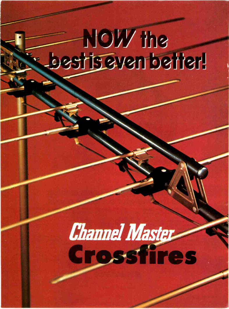

Channel Master improveson the world'sbest sellingTVantenna...For years, Channel Master's Crossfire series has outsoldcompetition because of its outstanding performancefeaturing exceptionally high gain and superior interferencerejection. Now, new construction features give Crossfiregreater strength and durability, plus increased ease ofhandling for faster installation.
FOR YOU AND YOUR CUSTOMER!A new one-piece heavy duty nest on all models eliminateswindmilling and fastens quickly to the mast by tighteningone set of bolts. Larger models feature a re-inforced trussconstruction double boom that keeps the entire lengthof the Crossarm rigid, and allows a rotor to be placed within6" of the antenna for greater turning power. This new trussconstruction replaces cumbersome and time consumingboom braces, and eliminates the possibility of misalignmentof elements due to boom "droop."
Crossfire's unequalled reception features combine witheasier handling and greater durability to make the best aneven better buy....for you and your customer!
Channel Master DIVISION OF AVNET, INC.ES10/E, L. York 12428
Model 3617Deepest Fringe1941/2" Long
Model 3672Fringe VHFDeep Fringe UHF154" Long
CROSSFIREANTENNACROSSFIREANTENNA 3673
Nij
Circle (6) on Reply Card
October, 1978 7

Publisher's Note: Electronic Servicing.New editorial director named for Electronic Servicing
Electronic Servicing features with this issue a new name on the masthead. Bill Rhodes, formereditor of Electro-Technology, a magazine previously owned by Industrial Research, Inc., and absorbedby Dun -Donnelley Publishing Corporation, joined our staff in late August. Rhodes brings to ElectronicServicing, as editorial director, a broad background in RF communications, radio wave propagationand technical journalism.
Rhodes holds a MS degree in physics with an emphasis in solid-state electronics and wavepropagation. His undergraduate work was in both physics and mathematics. His career, in addition tohis experience in technical publishing, has encompassed virtually every facet of communications andincludes the development of an all solid-state mobile broadcast system.
Organizations and companies that Rhodes has worked for include B&K Instruments, InternationalRectifier, Indiana University, Midwest Research Institute and Boeing Aircraft. Rhodes has beeninvolved in engineering and research in various areas, including computers, minicomputers andmicroprocessors; the selection of servomotors and servo systems; and the evolution of recorders,oscilloscopes and counters.
In addition, he has conducted pioneering studies on the magnetic properties of ferrite materials.Rhodes also developed the first application of the LASER in the area of cryogenic research.
If Bill or Carl Babcoke, Electronic Servicing's Editor, can be of any help, contact them directly.
Gar
NTEGRATED CIRCUITS49115 125AN:28 4 65
49272 3 90
AN313 4 85
49321 2 25
3 30
2 70
2 49
4 50
270' 50
50
85505 30
85672 40
861310, 34
HA1125 10
HAI329 45
HA1366W 30
H51386INR 30
HA1388 35
1151406 20
LA1222 59
LA1365 20
LA1368 42
LA310, 75
L54220 55
LA4430 70
L03000 25
L03080 70
L031105 75
L03150 95
M5109P 30
M51i2Y 70
M51181. 50
M5130P 12
M5135P 40
M5142P 70
M53407 55
M5930P 85
M5935P 20
M5946P 85
M59537 2 55
M59627 85
NEW -TONE ELECTRONICS INTERNATIONALSpecializing in Japanese Semiconductors, withTHE LARGEST INVENTORY AND LOWEST PRICES ANYWHERE
AND YOU CAN ORDER TOLL FREE 800-631-1250Check the prices in this partial list
Dealers send or our complete volume discount Ride dst
INTEGRATED CIRCUITS
115I202 1 55
11532167 1 80
M53273P 1 60
M58473P 7 90
1183710 2 95
M88719 7 70
NIN3006 5 90
1193007 M 95
NPC5107 IA 55
71203A 14 m
06264A 7 81
06609 4 5950629 -3 3 411
S06523 17 50
Sl1010 6 90
SI1020 13 95
S11030 19 00
011050 27 80
S115104 8 90
SKA5107C 11 95
S1K013 it 25
STK014 1185
S16041 17 40
STK075 8 22
STK413 6 75
1570927 6 50
1571177 3 60
1;;:722Z
3 06
1" 5 15
TA7217AP 3 30
TA7222P 3 50
T47521M 3 55
1676077 9 90
1476097 4 80
18681040 3 30
W81005 3 30
T808105 3 30
1808105H 3 30
186820 2 10
0061190Z 6 50
1062002 4 60
UPC141C 2 50
UPC572C 4 10
INTEGRATED CIRCUITS
0074UPC583C
UPCI028UPCI03,
UPC1032,,
TRANS,STORS
2SA772 89205786 39
205811 54
20018 1 05
250835 t 35
2S0840 168250841 39
250842 43
250861 12925A879 93
2S0880 75
25891t 6 33
254915 77
250922 3 98
2S4923 4 50
250940 96
250991 58
258509 2 79
258528 99
258549 79
258560. 2 30
258618 2 65
25C3520 2 55
25C356 95
2SC583C 81
2SC895 4 90
2SC983 89
25CI056 5 50
250424 2 98
N J Residents add 5", Sales Tax COD's WELCOMEWe pay postage for prepaid orders of 550 00 or more. Hours - Daily 8 AM 7 PM ES.T., Sal B AM . 5 PM
under S50 00 add S1 00 Canada S1 50 Air 76915 GuAPAN,(1.0 ARAMS1 FACnafir DEM
TRANSISTORS.1429 149452 40
2 7474 96
1548 79
71583 68
,622 49
1630 3 60
-21681 39
-1682 39
:r781 1 58
,762 4 85
-'775 541778 45
1787 62
21811 I 29
21844 54
50IE185 79
2SC1906 48
25C1923 39
25C1940 64
250945 6 75
25C1951 I 59
25C1959 39
2SC1963 3 30
2SC1981 2 60
25CI982 3 30
2SC2009 85
25C2021 65
25C2072 3 95
25C2120 45
25C2212 1 65
25C2213 1 45
25C2214 2 95
250388 3 65
250477 1 65
250528 3 30
20658 4 45
25K97 4 85
25K107 I 15
25K120 I 20
251021 I 20
256125 i 75
2541300
AP'
INTEGRATED CIRCUITSAN214 2 75
AN217 t 70
08239 6 50
AN24i 2 10
UHIC004UHIC005UH1C006uPC20C
AN247 4 10 UPC555HAN315 2 80 UPC563R2E65114 2 65 uPC566H I 15
84521 2 75 0PC575C2 2 35
CX101G 6 20 UPC592H2 1 05
1101306W 3 50 uPC100IH2 3 40
11013390 3 75 uPC1008C 5 75
LA1366 3 60 uPC1020H 3 05
1040511, 2 70 UPC1025H 2 85
104400 3 10 UPCi1526 3 25
LD3I41 1 BO UPC1156H 2 80
N151151, 4 90 UPD857C 9 99
11515131. 3 90 UPD858C 7 20
NIN3001 19 50
NIN3002 11 70
MN3003 11 70
P11016 8 60P1.1.02A 8 40 TRANSISTORSP11028 -G 8 40
$7011 5 80 250102 39
5011015 6 15 250473 655TK032 13 80 250484 2 25
5TK050 23 75 250496 89
STK056 10 90 250497 1 39
STK415 8 10 2505640 39
STK439 10 10 250634 65
TA7045M 2 80 250636 t 25
TA7060P 1 05 250643 55
TA7063P 1 10 250678 55
1670747 2 90 250682 1 35
1670897 2 75 250683 45
TA7092P 5 45 250684 45
1671207 1 05 2$06990 80
TA7153P 6 75 250706 I 25
T072011, 3 15 2SA733 35
107203P 3 60 25822 45
TA7204P 3 20 25854 35
TA7205P 2 60
TA7310P 2 95
INTEGRATED CIRCUITS
5 60
5 60
6 40
3 65
1 80
3 65
NTERNATIONAL
A division of New -Tone Electronics
TRANSISTORS25E1175 39
258324 55
?S8337 1 35
258370 62
2S0405 45
2S8407 1 20
258435 1 25
258463 I 40
208474 85
258492 85
25C372 35
25C373 35
25C380 35
25C387A 45
25C394 39
2SC458 45
25C460 45
25C481 14525C482 1 35
.2SC495 79
25C509 45
2SC517 3 25
2SC535 45250627 1 35
25C634A 45
250710 37
25C730 3 95
2SC732 35
25C735 35
25C7560 2 40
2SC778 3 35
25C781 2 50
25C784 45
25C789 85
250793 2 45
26C799 2 65
2SC828 3525C839 43
25C8670 3 95
2SC930 35
2SC945 35
25C1014 83
2SCtOr8 85
TRANSISTORS2SC1034 5 45
2SCI061 1 00
2SCI079 3 95
2SC1096 75
2SC1166 40
2SC1172 4 80
2SC1173 70
2SC1226A 70
2SC1237 2 15
25C1239 3 15
2$C1306 2 45
2SC1307 3 85
250383 45
25CI384 55
2SC1675 40
2501678 I 90
25C1728 I 00
2SC1760 1 05
25C1909 2 75
2SCI957 95
25C1973 55
2SC2028 74
2$C2029 3 35
25C2091 2 40
2SC2092 3 10
2SC2098 3 40
25072 78
25092 1 75
250I80 2 35
2$D218 3 45
250234 80
2S0235 80
250261 49
250313 90
200315 1052S0325 85
2$D330 8925109 6825633 85
251155 89
36K22 I 803SK .0 I 90
301145 2 10
NEW TONE ELECTRONICS INTERNATIONALP.O. Box 1738 Bloomfield. N.J.07003
New Jersey Phone: 201/748.6171
Circle (7) on Reply Card
8 ELECTRONIC SERVICING

Reach for Sprague partsinstead of running for them.
Now it's easy for you to build practical -sized inventory ofcapacitors, resistors, transistors, diodes, and switches for service work.
You don't have to buy huge quan-tities of electronic components tokeep on hand the parts you need.With these assortments, you'llsave valuable time by having re-placement parts within an arm'sreach.
All assortments come in 6- or 9-
drawer attractive, durable, com-pact, blue plastic cabinets. Pre -labeled drawer fronts identifycontents of each drawer. Clearplastic drawers are compartment-alized with adjustable dividers,letting you check your stock inseconds. And you pay for the com-ponents only . . time-saver cab-inets are yours at no extra cost!
Component Assortment Number of Number ofNumber Components Ratings/Types
NetPrice
Aluminum Electrolytic Tubular Capacitors KE-10 25 18Aluminum Electrolytic Tubular Capacitors KE-11 61 27 ForAluminum Electrolytic Tubular CapacitorsAluminum Electrolytic Tubular CapacitorsVertical -mounting Tubular Electrolytic Capacitors
KE-13KE-14KE-16
181827
181818
current
prices,
Vertical -mounting Tubular Electrolytic Capacitors KE-17 61 27 writeMiniature Aluminum Electrolytic Tubular CapacitorsMiniature Aluminum Electrolytic Tubular Capacitors
KE-19KE-20
2761
1827
Or
Dipped Tubular Radial -lead Film Capacitors KF-10 80 15 call
Dipped Tubular Radial -lead Film Capacitors KF-11 104 21 WoodyDipped Tubular Radial -lead Film CapacitorsDipped Tubular Radial -lead Film Capacitors
KF-13KF-14
4920
1011
Boillet,
Dipped Tubular Radial -lead Film Capacitors KF-16 20 9 SpragueDipped Tubular Radial -lead Film CapacitorsDipped Tubular Radial -lead Film CapacitorsMylar-sleeved Axial -lead Film Capacitors
KF-18KF-19KF-21
9613645
131817
Products
Company,
Polypropylene/Polycarbonate Film Capacitors KF-28 43 20 NorthUltra -miniature Single -ended Film CapacitorsFilm -wrapped Tubular Film Capacitors
KF-30KF-31
11552
2326
Adams,
General Application & High -K Ceramic Disc Capacitors KC -20 110 18 Mass.
General Application & High -K Ceramic Disc Capacitors KC -21 167 27 01247.Temperature -stable Ceramic Disc CapacitorsDipped Radial -lead Mica Capacitors
KC -22KM -10
8528
1814
Tel.
Radial -lead Solid Tantalum Capacitors KT -10 70 16 AreaCarbon -film Resistors, 'A Watt KR -10 130 23 CodeCarbon -film Resistors, 1/2 WattZener Diodes, One -Watt
KR -15KS -20
12737
2418 413
Small -signal and Power Transistors KS -25 40 27 664-4481.Toggle & Push-button Switches KX-11 18 18
See these assortments at your Sprague Distributor today...or...writefor Assortment Brochure M-9468 to Sprague Products Company,71 Marshall St., North Adams, Mass. 01247.
SPRAGUE PRODUCTS COMPANY Distributors' Division of Sprague Electric Co.
THE FOREMOST SUPPLIER OF ELECTRONIC COMPONENTSCircle (8) on Reply Card
October, 1978 9
65.810281
SPRAGUE®THE MARK OF RELIABILITY
G@neralcableci
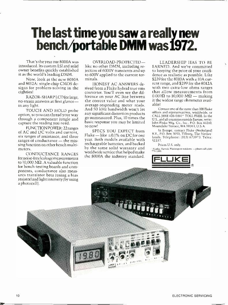
The last timeyou saw a really newbench/portable DMM was 1972.
That's the year our 8000A wasintroduced. Its custom LSI and solidowner benefits quickly establishedit as the world's leading DMM.
Now, look at the new 8010Aand 8012A: single -chip CMOS de-signs for problem -solving in theeighties!
RAZOR- SHARP LCD for large,no -strain answers at first glance-in any light.
TOUCH AND HOLD probeoption, so you can thread your waythrough a component jungle andcapture the reading you need.
FUNCTION POWER: 22rangesof AC and DC volts and current,six ranges of resistance, and threeranges of conductance - the mis-sing function on other bench multi -meters.
CONDUCTANCE RANGESfornoise-free leakage measurementsto 10,000 MCI. A valuable functionfor bench -testing boards and com-ponents, conductance also meas-ures transistor beta (using a biasresistor) and light intensity (by usinga photocell).
OVERLOAD -PROTECTED -like no other DMM, including re-jection of 6000V transients and upto 600V applied to the current ter-minals.
HONEST AC ANSWERS de-rived from a Fluke hybrid true rmsconverter. You'll even see the dif-ference on your AC line betweenthe correct value and what youraverage -responding meter reads.And 50 kHz bandwidth won't letany significant distortion productsgo unmeasured. Plus, 10 times thebasic response you may be limitedto now!
SPECS YOU EXPECT fromFluke - like ±0.1% on DC for oneyear. Both models available withrechargeable batteries, and backedby the same solid warranty andworldwide service that helped makethe 8000A the industry standard.
LEADERSHIP HAS TO BEEARNED. And we're committedto keeping the price of your confi-dence as realistic as possible. Like$239 for the 8010A with a 10A cur-rent range, and $299 for the 8012Awith two extra -low ohms rangesthat allow measurements from0.0010 to 10,000 MCI - makingit the widest range ohmmeter avail-able!
Contact one of the more than 100 Flukeoffices and representatives, worldwide, orCALL (800) 426-0361* TOLL FREE. In theU.S., and all countries outside Europe, write:John Fluke Mfg. Co., Inc., P.O. Box 43210,Mountlake Terrace, WA 98043, U.S.A.
In Europe, contact Fluke (Nederland)B.V., P.O. Box 5053, Tilburg, The Nether-lands. Telephone: (013) 673973. Telex:52237.
Prices U.S. only.'Alaska, Hawaii, Washington residents - please call (206)774-2481.
FLUKE
10 ELECTRONIC SERVICING

AUTHORIZED FLUKE DISTRIBUTORSFor immediate stock availability of these and other precision Fluke instruments and acces-sories, please contact the Fluke distributor in the following cities. For the location of Flukeoffices and representatives in other areas, please CALL (800) 426-0361 TOLL FREE (Alaska,Hawaii, Washington residents-call (206) 774-2481).
ARIZONAPhoenixLiberty Electronics(602) 249-2232Metermaster(602) 243-4111ScottsdaleBarnhill Assoc., Inc.(602) 947-7841
CALIFORNIAEl SegundoLiberty Electronics(213) 322-8100Los AngelesMetermaster(213) 685-4340Sun ValleyLeasametric(213) 768-4200Mt. ViewElmar Electronics(415) 961-3611Palo AltoMetermaster(415) 968-0313San DiegoLiberty Electronics(714) 565-9171Metermaster(714) 560-4841
COLORADOCommerce CityElmar Electronics(303) 287-9611DenverBarnhill Assoc., Inc.(303) 750-1222
CONNECTICUTMiddletonThe Mancib Company(203) 346-6646FLORIDAOrlandoBrownell Electro, Inc.(305) 843-6770GEORGIAAtlantaBrownell Electro, Inc.(404) 762-5181
HAWAIIHonoluluEMC Corporation(808) 847-1138
ILLINOISChicagoJoseph Electronics(312) 297-4200Elk Grove VillageMetermaster(312) 593-8650
KANSASWichitaRadio Supply Co., Inc.(316) 267-5216
MARYLANDGaithersburgPioneer/Instrumentation(301) 424-3300
MASSACHUSETTSBillericaMetermaster(617) 667-8346BurlingtonThe Mancib Company(617) 272-9450FraminghamCalcotron(617) 879-7650
MISSOURISt. LouisOlive Electronics(314) 426-4500NEBRASKALincolnScott Electronic Supply Co.(402) 466-8221OmahaScott Electronic Supply Co.(402) 734-6750NEW JERSEYMidland ParkLeasametrics(201) 444-0662TotowaAmpower(201) 790-6750NEW MEXICOAlbuquerqueBarnhill Assoc., Inc.(505) 299-7658NEW YORKCorningCorning Electronics(607) 962-0555FarmingdaleAmpower(516) 752-1078Long IslandHarvey Electronics(516) 921-8700New York CityAdvance Electronics(212) 687-2224Thorn woodElectronic Tool Company(914) 769-8070VestalHarvey Electronics(607) 748-8211
NORTH CAROLINACharlotteBrownell Electro, Inc.(704) 394-4341Dixie Electronics(704) 377-5413
OHIOClevelandPioneer/Instrumentation(216) 587-3600DaytonN.I.D.I.(513) 434-7500
OREGONEugeneUnited Radio & Supply, Inc.(503) 342-3381MedfordUnited Radio & Supply, Inc.(503) 779-7933PortlandLiberty Electronics(503) 292-9234United Radio & Supply, Inc.(503) 233-5341
PENNSYLVANIAPhiladelphiaSunshine Scientific(215) 673-5600PittsburghPioneer/Instrumentation(412) 782-2300Plymouth MeetingTechni-Tool(215) 825-4990
SOUTH CAROLINAColumbiaDixie Electronics(803) 779-5332GreenvilleDixie Electronics(803) 229-4554TEXASAustinBarnhill III(512) 451-0217REDCO(214) 653-1041DallasBarnhill III(214) 231-9012HoustonBarnhill III(713) 688-9971
UTAHSalt Lake CityBarnhill Assoc., Inc.(801) 484-4496
For Literature Only Circle (10) on Reply CardFor Demonstration Only Circle (11) on Reply Card
VIRGINIAChesapeakeI.T.R.(804) 424-5121RichmondI.T.R.(804) 275-1431
WASHINGTONBellevueApplied Engineering(206) 455-4922Liberty Electronics(206) 453-8300SeattleWestern Electronics(206) 284-0200
WISCONSINGreen BayNorthern Radio & TV Corp.(414) 435-8331
CANADAALBERTACalgaryACA Electronics CentreAllan Crawford Assoc., Ltd.(403) 276-9658EdmontonCardinal IndustrialElectronics, Ltd.(403) 455-4122
BRITISH COLUMBIAVancouverACA Electronics CentreAllan Crawford Assoc., Ltd.(604) 294-1326VernonInterior Electronics, Ltd.(604) 545-2394MANITOBAWinnipegW.E.S. Ltd.(204) 632-1260
NOVA SCOTIADartmouthAllan Crawford Assoc., Ltd.(902) 469-7865
ONTARIOTorontoACA Electronics CentreAllan Crawford Assoc., Ltd.(416) 678-1500OttawaAllan Crawford Assoc., Ltd.(613) 829-9651
QUEBECMontrealACA Electronics CentreAllan Crawford Assoc., Ltd.(514) 670-1212
October, 1978 11

When Is ATuner ServiceTOO Big?
When it gets too big for its britches and is scattered out allover the country like the fellow above.Too big is too big...Put yourself in the same situation withyour own TV shop - being at one location you know yourcustomers and their particular needs...You know what yourtechnicians are doing and there isn't much they can "sweepunder the rug" with you keeping an eye on them.Now let's say you have many TV shops that are strung outall over the nation...COULD YOU KEEP THAT SAME"EAGLE EYE" ON EACH AND EVERY SHOP??? Ofcourse, not. No one can!Here at TEXAS TUNER SERVICE we have it all togetherunder one roof and that GUARANTEES better service.If you have a problem - give us a call from anywhere in thecontinental United States (except Texas) and it won't costyou a penny...We are as close as your phone.At TEXAS TUNER SERVICE we are serious about tuneroverhauls - It's not just a gimmic to make money.
GIVE US A TRY -YOU WILL LIKE THE WAY WE DO BUSINESS!!!
CALL TOLL FREE 1-800-433-7124
TEXAS TUNER SERVICE4210 N.E. 28TH STREET,
FORT WORTH, TEXAS 76117
Circle (24) on Reply Card
THE ENDOF THE TOOL BOX.
The tool box is obsolete. It's being replaced by Platt's tool case.Here's why. In a tool box, tools and parts are hard to find. They get lost.
Dirty.With a Platt tool case, that doesn't happen. There's a patented one-piece
pallet with pockets for each tool. Tools can be picked out and replaced withoutsearching. Work can be done quickly and efficiently.
Platt's tool case also helps you look more professional. It comes in hand-some, lightweight ABS Thermoplastic. Or nch looking vinyl reinforced byABS Thermoplastic.
What's more, it has a 5 year guarantee.Contact us for complete information on Platt's
full line of tool cases and your nearest distributor.
Pat. No. 3,880,285 Cases for business and industry.2301 S. Prairie Ave , Chicago, Ill. 60616 (312) 225-6670
pmnirlexchanoeThere is no charge for listing in Reader's Exchange, butwe reserve the right to edit all copy. If you can help witha request, write direct to the reader, not to ElectronicServicing.
Needed: Schematic for model 811K RCA radio (has 11tubes). Martin's Radio & TV Service, 1101 Magnolia,Natchez, Mississippi 39120.
For Sale: B&K-Precision 415 sweep/marker alignmentgenerator, $325; B&K 1076 television Analyst, $150;Sencore YF33 yoke and flyback Ringer, $115;Heathkit IM -12 distortion meter, $35. All in first classcondition with manual and cables. Long's TV Service,720 Goshen, Salt Lake City, Utah 84104.
For Sale: B&K-Precision 415 sweep -marker generator,$320; and model 466 CRT tester rejuvenator, $120.Also, Sencore CB -42 CB analyzer, $795. Add $5shipping each item. Bob Begun, 1056 Fraser, Aurora,Colorado 80011.
For Sale: Heath IM -48 audio analyzer, $45; and HeathIM -58 harmonic distortion meter, $45. Both like new,used twice with manuals and leads. Will ship COD, orsend certified check and we'll pay shipping. DuPontElectronics, Ltd., 1222 Norton, Rochester, New York14621.
Needed: Schematic for old Radio City Products VOMmodel 410. Will buy, or copy and return. Charles R.Wells, 16029 14 Mile Road, Fraser, Michigan 48026.
For Sale: Precision model 960 transistor and diodechecker with roll chart and complete instruction,never used, in original carton, $20. Jag's Radio & TVService, 14 Rudolph Road, Forestville, Connecticut06010.
Needed: Power transformer for 1964 Philco radio-phono model M-1666, part number 32-10006-3. C. L.Durkin, Homestead 7, Decatur, Indiana 46733.
Needed: One horizontal/vertical board in workingcondition for model 4-203UW, 4 -inch B&W Sony. Sendprice. The TV Shop, 5820 E. 32, Tucson, Arizona85711.
Needed: Heath IG57A sweep/marker generator. Statecondition and price. Jack Field, 531 Falcon, MiamiSprings, Florida 33166.
Needed: Acrosound output transformer, type TO -330,in good working order. Dexter Seymour, DC TechnicalLaboratory, 1012 Colonial Road, Franklin Lakes, NewJersey 07417.
For Sale: Leader LS -5 solid state electronic switch,like new, $65; EICO 950 R/C bridge capacitor tester,$40. Richard Sanderford, 6400 Andy Drive, Raleigh,North Carolina 27610.
For Sale or Trade: 100 TV tuners for test equipmentor Riders radio manuals. Troch's, 290 Main, Spots -weed, New Jersey 08884.
12
Circle (12) on Reply Cardcontinued on page 14
ELECTRONIC SERVICING

161,000tooneWe'veGotYouCovered
You want the odds in your favor when you need semiconductor replacements.Thordarson's pace setting expertise and experience in cross referencing
replacement parts information have been the industry standard for over 20 years. Nowwe have used that experience to produce the mostcomprehensive, accurate and up to datesemiconductor cross reference guide. . . a new industry standard. Thereare over 161,000 listings in our newTech -Mater' Semiconductor Guide. ow
You probably are familiar with our to
universal part numbers. They are the 0same as the most widely used in theservice industry. And technicalspecifications are clearly marked oneach package.
Get our winning combination. Seeyour distributor and pick up a copy of ournew Guide and start using ThordarsonTech -Mate semiconductors today!
Guides are available direct from Thordarson. Enclose acheck or money order for $1.50, specify catalog#TSH2and send to: Thordarson Meissner, Inc. / ElectronicCenter / Mt. Carmel, IL 62863.
Thordarson Meissner, Inc.Electronic Center
Mt. Carmel, Illinois 62863
Circle (13) on Reply Card
October, 1978 13

inexchanuecontinued from page 12
For Sale: Heathkit scope model 10-102, $100; Heathkitpost-marker/sweep generator model IG-57A, $135;subber Mark 1V -C TV Analyst, $35; RCA stereo needssome work, $70. Glen E. Maples, P.O. Box 503,Flippen, Georgia 30215.
Needed: General Electric television transformer,OH1G 12493 -EN 241-520, #23D230315, E1A-413-6915,EU88X1. Send condition and price. R. J. Duba, 14475Huron Trail, Reno, Nevada 89511.
For Sale: B&K 1470 dual -trace triggered scope with 2direct/X10 probes and 1 demodulator probe, $400;and Hewlett-Packard 331A distortion analyzer and ACVTVM $550. Both with original cartons and manuals.George Echohawk, The Turntable, 723 West Broad-way, Enid, Oklahoma 73701.
Needed: Power transformer for EICO model 425 scope.Alfred Llorens, 605 East Rock Creek Drive, Columbia,Missouri 65201.
For Sale: EICO 666 tube tester with new 610-Aadapter, manual and latest chart, $100. KennethMiller, 10027 Calvin, Pittsburg, Pennsylvania 15207.
Needed: Schematic and manuals for Allied RadioKnight kit, "Magic -eye" capacitor checker number83Y1195 and a Jackson dynamic tube tester model 715.Warren L. Simpson, 371 Beagle Lane, Redding,California 96001.
Needed: New or good used output transformer forBogen monaural high-fidelity amplifier model DB 130,series A 95. White Electronic Service, 202 Central,Winchendon, Massachusetts 01475.
Needed: Manuals and cables for Hickok models 288-Xsignal generator, 650C video generator, 532 tubetester and RCA scope WO -88A. Kenneth Miller, 10027Calvin, Pittsburg, Pennsylvania 15207.
For Sale: Sam's Photofact numbers 300 through 800with cabinets; make offer; you pay freight. Steve'sRadio & TV, 3160 East Main Sp. 116, Mesa, Arizona85203.
Needed: Schematic and/or manual for Tektronix511AD scope. B. D. Young, 102 Jumping Brook Road,Lincroft, New Jersey 07738.
For Sale: B&K-Precision Scope model 1474 30 -MHzdual trace, triggered -sweep, like new with 2 probesand instructions, $500. C. W. Hume, 108 HillcrestCircle, Greenville, South Carolina 29609.
For Sale: EICO 460 Scope, 4 probes, never used, $140:Conar model 280 signal generator, never used, $30;Elenco Electronics _precision crosshatch generatorSG -100, never used, $25. Randolph Wilson, Box 6,
/Whitelaw, Wisconsin 54247.
14 ELECTRONIC SERVICING

RCA will replace any defective SKwithout question, within one year ofpurchase by you - the dealer. Justreturn the SK to your RCA Distributor.
We can make this offer because we believeour malfunction rate is one of the lowest in theindustry-less than 1%.
Part of the reason for this record is the RCASolid State Division with its extensive engineeringand manufacturing facilities. They develop andtest the quality and performance of every SK typeRCA sells before it is introduced into the line.
At RCA, we manufacture over half of our SK's,and all other SK's come from original solid statemanufacturers who must meet RCA's high stan-dard of quality.
As a result, every RCA SK meets or exceeds theOEM standards and specifications. You can't find amore reliable replacement. RCA's vast electronicexperience stands behind the entire line.
This line consists of over 750 RCA replacementtransistors, rectifiers, thyristors, integrated circuits,and high voltage triplers that will replace 143,000domestic or foreign semiconductors.
See your RCA SK Distributor and start savingtime and money (no costly "call backs"). Or
contact RCA Distributor and Special ProductsDivision, Deptford, N.J. 08096, Attn: Sales Promo-tion Services.
SK Solid State Replacement
Needed: Meter, complete with face plate, for MercuryVTVM model 1700A. Earl Rivers, Sr., 333 CrimminsAvenue, Bronx, New York 10454.
For Sale: 5867 germanium and 1300 silicon general-purpose diodes, 1000/0 tested good and packed 100 ineach ziploc bag, for $65 post paid. Also, have over1000 integrated circuits all series, for $100 plus $5postage. William W. Hyatt, 473 DeSoto Drive, MiamiSprings, Florida 33166.
Needed: RCA Victor red or maroon 3 -ring looseleafbinders for service data. C. E. Sarver, 256 West 88thStreet, New York, New York 10024.
For Sale: Simpson model 488 field strength meter, $50;Sencore CR128 color and B&W CRT tester, $25;Sencore TR110A transistor tester and signal genera-tor, $20; Hickok model 650 signal generator includingvertical and horizontal drive signals, $25; EICOVTVM, model 221 without leads, $15; Precision sweepgenerator model E400 with crystal marker, $15;Hallicrafters S-85 all -band receiver, $25; Hickok color -bar generator, $18; EICO 955 capacitor checker, $20;Hickok model 610A alignment generator, $20; EICOmodel 232 VTVM, like new, factory wired andcalibrated, $40. All items shipped prepaid. FessendenTV & Appliances, 116 North 3rd, Ozark, Missouri,65721.
Needed: Instruction book and set of leads for aPrecision VTVM, model EV10-S. Also, would beinterested in buying another, complete and in goodcondition. W. Hitchcock, Tri-City TV, Sales andService, Route 3, Birch Tree, Missouri 65438.
Needed: Instruction book and schematic for a model7008 Precision visual -alignment generator, for TV andFM; instruction book and adapter kit for B&K-Precision tube tester Dyna-Quik model 550; and sourceof parts for Candle TV sets. Raymond J. McClellan,961 West 8th, Santa Rosa, California 95401.
Needed: Part number 7-55 power transformer for Bell& Howell model 34 scope. Richard 0. Greenman, 9719BaIlin David, Spring, Texas 77379.
Needed: Stock of audio printed circuits used severalyears ago, made by OPCO, CRL, Sprague, etc. Also,need a cross reference for them. Lawrence T.Anderson, Radio Activity, 3453 Balsam NE, GrandRapids, Michigan 49505.
Needed: Operation and service manual for Berkeleyuniversal counter and timer model 5510. Will buy, orcopy and return. Tyler Audio Service, P.O. Box 1019,Lomita, California 90717.
Needed: Schematic and/or operating manual for aFirst Dimension model FD -3000-W video game. Willpay or copy and return. David Valencia, 7241Tuolumne Drive, Goleta, California 93017.
For Sale: Hickok model 517, 15 -MHz dual -trace scope,brand new, $550. You pay transportation andinsurance. Clifford E. Randall, Rd. #1 Box 47, Arkport,New York 14807.
Needed: Book about repairing volt/ohm meters.Lawrence Gaylord, P.O. Box- 1387, 336 Whittley,Avalon, California 90704. El
October, 1978 15

The next time you needa tuner repaired or module rebuilt:
RememberFAST SERVICE
RememberPROFESSIONAL QUALITY
RememberONE-YEAR LIMITED WARRANTY
RememberPTS ELECTRONICS
MOOelenMS
61111111MENSIO
PTS ELECTRONICS, INC.SEE THE YELLOW PAGES FOR THE
PTS SERVICENTER LOCATION NEAREST YOU
Circle (14) on Reply Card
"I CAN HELP CHANGE YOUR LIFE.BUT I CAN'T HELP CHANGE YOUR
SPARK PLUGS:'If you want to lind inner peace.
come see me. But to fix a car. you must seekknowledge somewhere else.
The Consumer Information Cata-log is put out by the Federal Governmentand lists over 200 consumer booklets thatone can send away for. Most are free. Andthey can help you in many areas, from rais-ing tomatoes to lowering your fuel costs.
So send for the free catalog. Write:Consumer Information Center, Dept. A,Pueblo, Colorado 81009. That way youwon't have to climb a mountain to gainknowledge. You can merely go to yourmailbox.
THE CONSUMER INFORMATIONCATALOG
A catalog of over 200 helpful publications.111411., ...neva' tier, we, Adrnmniratron Calmumer Intormat Cerver
IroubleshoolinuraCircuit breaker tripsRCA CTC7IAB(Photofact 1552-2)
When the color TV was brought to the shop, thecomplaint was that the circuit breaker tripped atrandom times. A time test on the bench verified theproblem, but there were no visible symptoms on thescreen before the breaker tripped.
Of course, breakers sometimes become "weak" andtrip with rated current, so we installed a new breakerof the correct type and current. At the time, wenoticed the line -voltage switch was in the "high"position, and we slid it to the "normal" position tomatch the line voltage in our shop.
The set was powered -up for a time test, and wasignored as we worked on other sets. After about 10minutes, we smelled something hot, and found thepower transformer was almost burning.
Our first reaction was that the replacement breakerwas faulty, so a 3 -ampere fuse was wired in serieswith the breaker, and the set operated again. Well,the fuse didn't blow, but the transformer overheated.A new power -supply module made no change. In fact,with the module removed and the CRT socket pulledoff, the transformer continued running too hot.
This called for a coffee break, while I studied theschematic for any "sneak" paths. There seemed to beno untested transformer loads, but I remembered anarticle in Electronic Servicing about a service switchcausing vertical foldover. I decided to check thenormal/high line -voltage switch, 5102. The trans-former wires at the switch were cut off, andohmmeter tests showed continuity between commonand both lugs, when the switch was in the normal -
voltage position.A closer look at the switch revealed a blob of
solder between the common and high terminals. Withthe switch in the high -voltage position, there was noproblem, because the switch and solder short were inparallel. But, in the normal -voltage position, thesolder blob shorted across the part of the primarywinding that is between the two terminals. This gavethe effect of many shorted turns, and causedexcessive line current.
We considered this case to be one "for the recordbook," and marked on our schematic.
George RiceAshland, Massachusetts
16 ELECTRONIC SERVICING

National Service Conventions...
A Brief Report
Benefits resulting from activities of the various serviceassociations are not confined solely to the members of thoseorganizations. Instead, all technicians and electronic -shopowners indirectly receive valuable help and support from theassociation efforts. Therefore, the editors and management ofELECTRONIC SERVICING urge you to join one or more of theservice associations and assist them in improving the conditionsof our industry. This condensed report of the conventions showsyou some of the day-to-day activities of these organizations. Ofcourse, conventions also have their lighter moments; and a fewof those will be spotlighted. By Carl Babcoke, Editor
At the Portland convention, M. L. Finneburgh gave the oath of office to thesenewly -elected NESDA officers (listed left to right): George Simpson, treasurer;West Correll, secretary; Warren Baker, national vice-president; and Bob Villont,president.
Robert A. (Bob) Villont of Tacoma, Washington was unanimously elected as thePresident of NESDA.
NESDA ConventionPortland, Oregon was chosen for
the August 7-13 convention of theNational Electronic Service DealersAssociation. (NESDA).
Association business matters, in-cluding reports from officers andcommittees, were followed by theelection of these 1978-79 newofficers: Robert A. (Bob) Villont,president; Warren Baker, national
continued on page 20
In a regal and colorful ceremony, M.L. Finneburgh (an honorary lifetimemember of NESDA) became a knightof the Portland Royal Rosarians.
A combination of mail and in -personballots elected Jesse Leach (of Linthi-cum Maryland) to the chairmanship ofISCET.
October, 1978 19

Conventionscontinued from page 19
vice-president; West Correll, secre-tary; and George Simpson, treas-urer. Ten regional vice-presidentsalso were selected.
Two business -management semi-nars were held. One clarified therelationship between service dealerand the law, and the other taughtthe skills necessary for successfulselling. Technical seminars wereconducted by factory representativesand J. A. "Sam" Wilson.
Six hours were given to theNational Electronics Trade Showand Exposition, where products,test equipment and association in-formation were displayed. Prizeswere given away during the exposi-tion.
Most meals were sponsored byvarious TV manufacturers, whichalso furnished after -dinner speakers.
Recognition and plaques werepresented to many worthy indivi-duals. For example, outgoing -Presi-dent LeRoy Ragsdale received twoawards. Two names were 'added tothe Electronics Hall of Fame (EHF)roster. They are Enos Rice, and the
late Ralph Johonnot (accepted byAnn Johonnot).
Another EHF member received aunique honor. Mr. M. L. Finne-burgh was dubbed a knight byorder of the Portland Royal Rosar-ians. During the colorful and regalceremony, he became "Sir MorrisL. Finneburgh, Sr., EHF, Knight ofthe Rose Tropicana."
A practical bonus for NESDAmembers is the new low discountrates (down to 1.1%) for thoseparticipating in the bankcard pro-gram.
Tucson, Arizona was selected asthe convention site for next August.Attendance of NESDA, ISCET,OPEA, and WSEC totaled about600.Background
NESDA is said to be the onlyshop -owner association of stateorganizations in the electronicsfield. A few of the benefits tomembers include: Service Shopmagazine; an insurance program,technical tips, reports of legislationand lobbying; and business schools.
continued on page 22
Enos Rice (CES/CET of Seattle, Washington) wasinducted into the "Electronics Hall Of Fame" at theNESDA convention.
From left to right,are the new NATESA1978-79 officers:Paul F. Kelley, presi-dent; Leo EdmondCloutier, vice-presi-dent; Richard Ebare,treasurer; Lelia A u n s -paw, secretary; andFrank J. Moch, Exe-cutive Director.
LeRoy Ragsdale, immediate past pres-ident of NESDA, received two awardsat the convention.
Ray Yeranko, Magnavox directorService And Consumer Affairs,showed that he was a good sport by"playing" the harmonica with the RudyJarju Family at the NATESA grandbanquet.
of
J. A. "Sam" Wilson, who writes regularly for ElectronicServicing, conducted the NESDA digital seminars.
20 ELECTRONIC SERVICING

Tibor Komoroczy,Service Manager
Howard Roach TV & Appliance300 East Valley Blvd.
San Gabriel, CA 91776
41.114z MC la
i`Dont' throw away that GE tube flapand lose award points. Get yourBottoms Up Catalog and win!"
Your reputation is our reputationTube Products Depw-tment Owensboro, Kentucky 42301
GENERAL ELECTRIC

aily&araii
Miles Sterling of
Carl Babcoke, editorof Electronic Servic-ing served as moder-ator of the NATESATechnology Overviewpanel, which dis-cussed the trendsand servicing ofpresent-day electron-ic technology.
Garden Grove, Cali-fornia explained to the NATESA mem-bers the status of his lawsuit againstseveral electronic manufacturers.
Joe Groves, manager of the HowardSams Photofact Division, received the"Friends Of Service" 1978 award as arepresentative of Howard W. Sams &Co.
Humorist Art Hoist, who moonlightsas a referee at many National FootballLeague games, was the star entertain-er at both the NESDA and NATESAconventions. He was sponsored byRCA.
Conventionscontinued from page 20
NESDA is located a 1715 ExpoLane, Indianapolis, Indiana 46224,and the phone number is 317/271-8160.
ISCET ConventionThe International Society of
Certified Electronic Technicians(ISCET) held its 1978 convention inPortland with NESDA. New ISCETofficers (elected mainly by mailballot) are: Jesse B. Leach, Jr.,chairman; Forest H. Belt, vice-chairman; Leon Howland, secretary;and George Sopocko, treasurer.
ISCET is a permanent committeeof NESDA. However, many of theISCET members are strongly infavor of becoming independent ofNESDA. It is said that suchindependence would allow ISCETto become the technical -certificationagent for many other branches ofelectronics. Jesse Leach views hiselection as a mandate for autonomy.In a series of official motions,ISCET members who were presentvoted for close cooperation withNESDA, and for mailings to ISCETmembers detailing the advantagesand disadvantages of independence.This vital issue is to be settled byballot, after all members are in-formed.
BackgroundISCET is an electronic honor
society. To become a CET, eachtechnician must meet the require-ments and pass a two-part test ofelectronic theory and practicalknowledge. All CETs of goodcharacter are offered the oppor-tunity of joining ISCET. A chargeof $20 is made for taking the CETtest, and ISCET dues are $25 peryear.
For more information, write toISCET at 1715 Expo Lane, Indian-apolis, Indiana 46224.
NATESA ConventionThe National Association of Tele-
vision & Electronic Servicers ofAmerica (NATESA) held its 28thannual convention August 24through 27 at the Chateau LouiseResort in Dundee, Illinois (nearChicago).
Total convention registration was438, with representation from 22states and Australia.
Officers elected for 1978-79include: Paul F. Kelley, president;Leo Edmond Cloutier, vice-presi-dent; Richard Ebare, treasurer; andLelia Aunspaw, secretary. LeliaAunspaw is the first woman electedto the NATESA council. Past -Presi-dent George J. Weiss will serve asex -officio member of the council,and Frank J. Moch & Associatescontinues as executive director.
Other activities were: NATESAofficial -business sessions; a business -practices panel, with Richard Layas moderator; a technology over-view panel, with Carl Babcoke,Electronic Servicing editor, actingas moderator; sponsored meals withspeakers; a microwave -oven semi-nar; many hospitality rooms; andthe Grand Banquet, with the pre-sentation of awards and profes-sional entertainment.
Miles Sterling reported on hislitigation against some manufac-turers and marketers (for allegedviolation of servicer's rights tocompete), and many individualNATESA members contributed to afund for continuation of the law-suit.
Howard W. Sams was named asthe 1978 NATESA Friends ofService Award winner. Next year,the convention will return to NordicHills in Itasca, Illinois.
BackgroundLast year, NATESA changed
from operation as an alliance ofstate and local associations to anassociation of individual shop own-ers and managers. Membership(and convention attendance) hasincreased since then.
NATESA has defended ethically -operating electronic businessesagainst unfair exposes by themedia, and against some below -costwarranty practices. In addition,NATESA provides its memberswith extensive advice about oper-ating at a profit.
NATESA can be contacted at5908 South Troy Street, Chicago,Illinois 60629, or by phone at312/476-6363.
22 ELECTRONIC SERVICING

Horizontal sweep and high voltageServicing GE 13" Color TV, Part 2 By Gill Grieshaber, CET
Horizontal sweep in the General Electric AA -D chassis provides ACpower for several vital DC -voltage supplies, in addition to the usualdeflection and high -voltage functions. Therefore, this importantknowledge about the horizontal -sweep system is necessary for efficienttroubleshooting in any stage or circuit.
Horizontal SweepIn the General Electric AA -D
chassis, the horizontal -sweep systemhas several different features. Theseinclude a high -voltage rectifierassembly mounted inside the insula-tion of the flyback transformer,encapsulated focus resistors with acase resembling that of a HVtripler, and a horizontal oscillatorwithout a coil of any kind. (Mostoscillators have either an oscillatorcoil or a stabilizing coil.)
However, you will feel comfort-able servicing the AA chassis, sincemost of the circuits are somewhatconventional.
One IC contains much of thehorizontal phase -detector and oscil-lator stages. This oscillator IC isfollowed by a medium -power drivertransistor, which is transformer -coupled to a power -type horizontal -output transistor.
Several low -voltage DC suppliesare powered by horizontal -sweepwaveforms from the output stageand the flyback. So, if the horizon-tal -sweep system ever goes dead,many of the DC voltages in othercircuits of the receiver will bemissing. These DC supplies werediscussed last month.
Oscillator and driver componentsare mounted on the large module,while the flyback transformer, out-put transistor, focus resistors, andother large components are mount-ed on the upright end panel.Locations of many main parts andstages are pointed out in Figures 1and 2.
Horizontal Oscillator and AFCFigure 3 shows the entire
horizontal -sweep system (minus onlythe side -pincushion and B -boost
continued on page 24 Figure 2 Many horizontal -sweep parts are mounted on the large module.
Figure 1 Locations of several horizontal -sweep components are pointed out in aGeneral Electric AA -D portable chassis.
October, 1978 23
General Electriccontinued from page 23
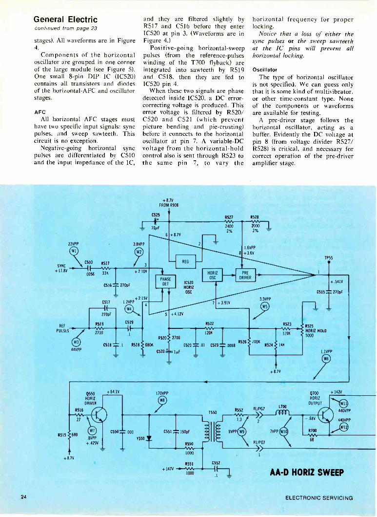
stages). All waveforms are in Figure4.
Components of the horizontaloscillator are grouped in one cornerof the large module (see Figure 5).One small 8 -pin DIP IC (IC520)contains all transistors and diodesof the horizontal -AFC and oscillatorstages.
AFCAll horizontal AFC stages must
have two specific input signals: syncpulses, and sweep sawteeth. Thiscircuit is no exception.
Negative -going horizontal syncpulses are differentiated by C510and the input impedance of the IC,
and they are filtered slightly byR517 and C516 before they enterIC520 at pin 3. (Waveforms are inFigure 4.)
Positive -going horizontal -sweeppulses (from the reference -pulseswinding of the T700 flyback) areintegrated into sawteeth by R519and C518, then they are fed toIC520 pin 4.
When these two signals are phasedetected inside IC520, a DC error -correcting voltage is produced. Thiserror voltage is filtered by R520/C520 and C521 (which preventpicture bending and pie -crusting)before it connects to the horizontaloscillator at pin 7. A variable -DCvoltage from the horizontal -holdcontrol also is sent through R523 tothe same pin 7, to vary the
horizontal frequency for properlocking.
Notice that a loss of either thesync pulses or the sweep sawteethat the IC pins will prevent allhorizontal locking.
OscillatorThe type of horizontal oscillator
is not specified. We can guess onlythat it is some kind of multivibrator,or other time -constant type. Noneof the components or waveformsare available for testing.
A pre -driver stage follows thehorizontal oscillator, acting as abuffer. Evidently the DC voltage atpin 8 (from voltage divider R527/R528) is critical, and necessary forcorrect operation of the pre -driveramplifier stage.
22VPP
C510 R517SYNC
+ 17 8V0056 33K
3 8VPP
3
+ 8 7V
FROM R908
C525
10µF
C516- 270pF
C517
270pF
REFR519
PULSES S 2700
44VPP
1 2VPP
C518
C519
1
+ 2.10V
+ 2 15V
R527
6 + 8 7V
REG
PHASE
DET
4
5 + 4 12V
IC520HORIZ
OSC
R520 2700
851816800
C520 L-ri
HORIZ
OSC
C521 01
7
24002%
+ 3.91V
R528
8
20002%
1.6VPP
+ 3.6V
PRE
DRIVER
TP55
R5221M"-120K
3.3VPP
+ 541V
C523 0068 R526
R523
1206
2006R524 146
+8 7V
C515
R525
HORIZ HOLD5000
1 1VPP
270pF
Q550HORIZ
DRIVER
R516
R515 680
+8 7V
8VPP
+.429V
+ 64 IV 170VPP
C550- 001 C551= 150pF
R550
1000
R551
+ 147V1000
1550
C552
R552 RL/PG7
RL/PG7
+ 142V
1700
Q700
HORIZ
OUTPUT
AA -D HORIZ SWEEP
24 ELECTRONIC SERVICING

Output of the pre -driver is madeup of distorted square waves (seeFigure 4) at pin 1, and the squarewaves go through R516 to the baseof 0550, the horizontal -driver tran-sistor.
Horizontal DriverQ550, the medium -power hori-
zontal driver transistor, and theinterstage driver transformer (T550)are diagonally across the chassisfrom the oscillator IC, as shown inFigure 6.
Diode Y550 and resistor R550prevent the driver transformer fromringing. An open diode probablywould cause the driver transistor tofail, and a shorted diode willeliminate the sweep and highvoltage.
For troubleshooting this driver
stage, rely on the base and collectorDC voltages and scope waveformsto locate any defects. For example,be suspicious of an open diode, ifthe collector waveform has excessiveamplitude with ringing.
The T550 secondary drives thebase/emitter junction of thehorizontal -output transistor.Output Transistor And Flyback
A single power transistor (Q700)supplies all of the deflection andhigh voltage. Incidentally, there area few differences between the AAchassis for the 10 -inch sets and theAA -D that's found in this 13 -inchversion.
In the 10 -inch TVs, the emitterand low end of the driver trans-former secondary are grounded.However, the AA -D chassis has the
emitter and the transformer bothgoing to an extra winding on theflyback (terminals 4 and 6). Evi-dently, the extra winding is re-quired for the increased sweep andHV power.
This floating emitter changes thewaveforms drastically. For example,the base, the emitter, and thecollector all have very high horizon-tal pulses relative to the chassis.Positive pulses are found at thecollector, and negative -going pulsesof about the same amplitude andwaveform are scoped at both baseand emitter of the output transistor.Of course, when measured toground, both the damper diode andthe 4 -wire safety capacitor havesweep waveforms at all terminals.
For fast tests, scope emitter tocontinued on page 26
Y704 +8000 8701 +6700-../SAISP120K
TO SCREENS
C701""' C702 '"' C703 '"' '0107 T500 'T' 1000V160160V
TO POINT AFLYBACK
+ 1470
R920
C920 220µF
6
FB700
a
TO IIYOKE
C700
Y700 = DAMPER SAFETY .0068CAPACITOR
fB701
0
Will
POINT A
Y954
1454
0022 C942
13
15
TO BEAM LIMITER
Y730 R730 R731
3300 3300
R702
16K
TO CONVERGENCE
6
C=' 11
10
8942 0022
Y946
C946
0022
REFERENCE
PULSES
R705
200MD
40M0
C955 47µF
C943 T. 1000µF
C947.i
HV TO CRT
CRT FOCUS
R710FOCUS
15M11
+ 22 2V
SUPPLY
-12.8VTO VERT
+ 13.8V
TO VERT
1000µF
Figure 3 This schematic ofthe GE AA -D horizontal -sweep circuit is completewith measured DC andpeak -to -peak AC voltages.
October, 1978 25

General Electriccontinued from page 25
ground and collector to ground,while noticing the waveforms. Then,if there is a question about theactual B/E drive at Q700, the scopeshould be connected between baseand emitter (not to ground). Re-member that your scope will haveabout 440 VPP between it andchassis ground, so take precautions.
Q700 base waveformsThe "normal" base -to -emitter
waveform of any horizontal -outputtransistor defies any detailed analy-sis. You must accept it, merelybecause all correctly -operating setshave similar waveforms. But, as wehave pointed out in previous arti-cles, the B/E waveform changes atremendous amount when the B/Ejunction opens, or if the transistoris removed from its socket.
For example, when the B/Ejunction of this GE AA -D chassis isopen, the waveform becomes plainsquare waves of about 5 volts PP.Figure 7 shows both the normal
waveform and the square wavespresent when the transistor isremoved.
Flyback and DC suppliesFigure 3 also shows the many
other DC power supplies thatrectify horizontal waveforms.
The B -boost supply and diodeY704 operate with the full pulseamplitude from collector to emitterof Q700, because the C701 filtercapacitor returns to the Q700emitter, and not to ground.
Two opposite -polarity DC sup-
WINEGARD WORKS...
26 ELECTRONIC SERVICING

plies provide power to the vertical -output transistors.
Probably the most important ofthese auxiliary supplies is the onemarked +22.2 volts DC, for it splitsto feed most of the IF, video, audioand chroma stages. If that supplygoes dead while the others areokay, there is no sound or picture,although the high voltage is normal.
Notice the connection at pin 12,that goes to the beam -limitercircuit. Defects in this part of thecircuit can cause excessive bright-ness or none at all. A black raster
can be caused by many moredefects than just a loss of highvoltage!
Yoke wiringThe yoke coils are series -connec-
ted (see Figure 8). In turn, they arein series with one winding of theside -pincushion -correction trans-former (T740) and the C710 yoke -coupling capacitor; then all receivesweep power between a tap of T700and the emitter of Q700, the outputtransistor.
Safety capacitor C700 has four
leads. This is designed to preventoperation of the receiver if thecapacitor is cut out of the circuit,or following an open circuit of theinternal foil in the capacitor.
Capacitor C700 is the maintuning capacitor for the flybackportion of the horizontal cycle, andthus It has a major effect on theamount of high voltage. If it opens(or is removed) the high voltagemight reach 40 KV, or higher (I'mnot about to remove one and testthe symptoms, which have included
continued on page 28
in the Horse Heaven Hills.When Gary Solie puts up a TV
antenna installation he is likely toleave his shop at 6 A.M. and drive50 or 60 miles to the job site. Onhis way he doesn't encounter a singletraffic light. He drives carefully overthe old wagon roads to avoid thesharp outcroppings of volcanic rock.As he walks across the semi -arid foot-hills Gary watches carefully wherehe steps. "I don't exactly like to tanglewith those buzztails:' he said, andexplained that buzztail is the localname for rattlesnake.
Gary Solie is not your typicalantenna installer. He owns andoperates Gary's TV and Appliancesin Goldendale, a small town in south-central Washington state. In businessfor 19 years, he provides service forfarmers and ranchers as far as 60miles in all directions.
(Above) Gary Solie's favorite combination for weaksignal UHF reception is Winegard's CH -9095 an-tenna with AC -4990 preamplifier. (Left) One ofSolie's C.L.A. (constant level amplifier) installationson a ranch in the Horse Heaven Hills. Here he pushes3 UHF channels through 2,600 feet of cable withsurprisingly excellent picture quality.
One of the challenges Gary facesalmost daily is to provide good TVreception in seemingly impossiblelocations in canyons and valleys, oftenwell over 100 miles from the nearestVHF transmitters and up to 70 milesfrom the nearest UHF stations. ButGary does get the job done. And herelies on Winegard equipment to do it.
Frequently working with signalstrengths below 100 microvolts andcable runs up to a mile long, Garybrings in good TV reception wheremost people would give up. "I don'tknow what we'd do without Winegardpreamps and C.L.A.'s;' he said."Winegard products are superior,there's no doubt about that. I've beenusing your antennas and amplifiersfor over 10 years and there's hardlya reception problem I haven't beenable to solve by using the rightcombination:'
"I really enjoy antenna work': Garyvolunteered, "it gives me a lot ofsatisfaction to pull in good picturesfor people who live in such remoteareas as the Horse Heaven Hills.There isn't exactly much night lifearound here and TV entertainmentis very important:'
While long distance reception over
mountainous terrain is not unique,it is unusual and one of the areasin which Winegard products excel.When you can work with as littleas 30 microvolts, push it througha mile of cable and end up with adecent picture, that makes ordinaryreception problems "duck soup:'
This Winegard MATV headend on a different ranchwas installed by Gary Solie (above) in a field about4,500 feet from the house. In this case, WinegardUltra-Plex equipment converts UHF signals to VHFand sends them through a C.L.A. system.
Gary Solie has been a long timecustomer of United Radio Supply,Inc. in Portland, Oregon. He relieson the systems department of UnitedRadio to help him with MATV layoutsand to keep him up-to-date on newWinegard products.
WINEGARD WORKS... Everywhere!
WINEGARDThe Winegard Company 3000 Kirkwood Street Burlington, Iowa 52601
Circle (16) on Reply Card
October, 1978 27
W1
W2
W8
W3
W4
W9
W10
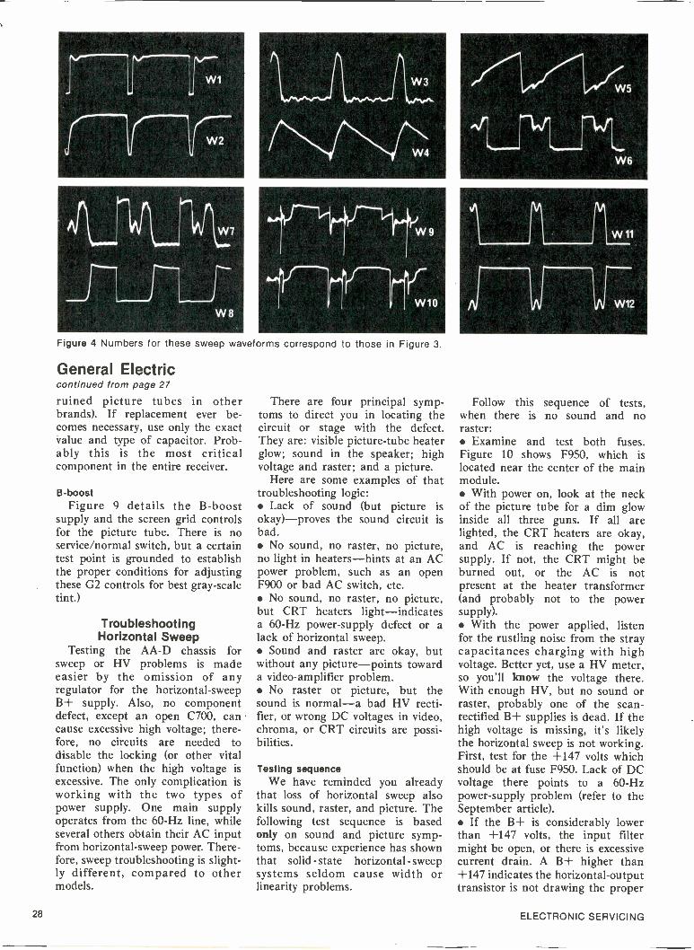
Figure 4 Numbers for these sweep waveforms correspond to those in Figure 3.
General Electriccontinued from page 27
ruined picture tubes in otherbrands). If replacement ever be-comes necessary, use only the exactvalue and type of capacitor. Prob-ably this is the most criticalcomponent in the entire receiver.
B -boostFigure 9 details the B -boost
supply and the screen grid controlsfor the picture tube. There is noservice/normal switch, but a certaintest point is grounded to establishthe proper conditions for adjustingthese G2 controls for best gray -scaletint.)
TroubleshootingHorizontal Sweep
Testing the AA -D chassis forsweep or HV problems is madeeasier by the omission of anyregulator for the horizontal -sweepB+ supply. Also, no componentdefect, except an open C700, cancause excessive high voltage; there-fore, no circuits are needed todisable the locking (or other vitalfunction) when the high voltage isexcessive. The only complication isworking with the two types ofpower supply. One main supplyoperates from the 60 -Hz line, whileseveral others obtain their AC inputfrom horizontal -sweep power. There-fore, sweep troubleshooting is slight-ly different, compared to othermodels.
There are four principal symp-toms to direct you in locating thecircuit or stage with the defect.They are: visible picture -tube heaterglow; sound in the speaker; highvoltage and raster; and a picture.
Here are some examples of thattroubleshooting logic: Lack of sound (but picture isokay)-proves the sound circuit isbad. No sound, no raster, no picture,no light in heaters-hints at an ACpower problem, such as an openF900 or bad AC switch, etc. No sound, no raster, no picture,but CRT heaters light-indicatesa 60 -Hz power -supply defect or alack of horizontal sweep. Sound and raster are okay, butwithout any picture-points towarda video -amplifier problem. No raster or picture, but thesound is normal-a bad HV recti-fier, or wrong DC voltages in video,chroma, or CRT circuits are possi-bilities.
Testing sequenceWe have reminded you already
that loss of horizontal sweep alsokills sound, raster, and picture. Thefollowing test sequence is basedonly on sound and picture symp-toms, because experience has shownthat solid - state horizontal - sweepsystems seldom cause width orlinearity problems.
14.11
W5
W6
Follow this sequence of tests,when there is no sound and noraster: Examine and test both fuses.Figure 10 shows F950, which islocated near the center of the mainmodule. With power on, look at the neckof the picture tube for a dim glowinside all three guns. If all arelighted, the CRT heaters are okay,and AC is reaching the powersupply. If not, the CRT might beburned out, or the AC is notpresent at the heater transformer(and probably not to the powersupply). With the power applied, listenfor the rustling noise from the straycapacitances charging with highvoltage. Better yet, use a HV meter,so you'll know the voltage there.With enough HV, but no sound orraster, probably one of the scan -rectified B+ supplies is dead. If thehigh voltage is missing, it's likelythe horizontal sweep is not working.First, test for the +147 volts whichshould be at fuse F950. Lack of DCvoltage there points to a 60 -Hzpower -supply problem (refer to theSeptember article). If the B+ is considerably lowerthan +147 volts, the input filtermight be open, or there is excessivecurrent drain. A B+ higher than+147 indicates the horizontal -outputtransistor is not drawing the proper
28 ELECTRONIC SERVICING

amount of current. Check for suffi-cient B/E drive at Q700, and lookfor an open in Q700. Use scope andDC meter for these tests. Rememberthat an open Q700 B/E junctioncauses square waves between baseand emitter. A blown F950 and a shorted Q700warn you to use caution. Installinga new Q700 each time you applypower can be expensive. Instead,test at reduced power by removingF950 and connecting an ordinary
100 -watt incandescent light bulbacross the fuse -holder terminals.Now, when you apply power, anormal TV will show a picture(perhaps small) and have soundwhile the bulb glows with partialbrightness. In that case, remove thebulb and reinstall the fuse; the setshould be okay now. If the bulb lights with fullbrilliance, some kind of overloadstill is there, and you have prevent-ed a ruined Q700. Unplug both
vertical -output transistor sockets,and repeat the test. Partial bright-ness of the bulb and a horizontalline across the screen prove thevertical circuit has a short, whichmust be found and repaired. If the overload is not in thevertical, but persists after theprevious test, disconnect as manywires from the flyback as possiblewhile keeping the primary and HVwiring intact. After each wire is
continued on page 30
;11.4 'rat I
AFCSW
R525HORIZHOLD
Figure 5 Arrows pointout 10520 and otherhorizontal -oscillatorcomponents.
0560
T560
RL-1
R652
Y560
R551
Figure 6 Driver transistor,the driver transformer, andother driver parts aremounted near the right -frontcorner of the large module.
01,04
Figure 7 When the base -to -emitterjunction of Q700 (horizontal output) isopen, the complex waveform betweenbase and emitter (top trace) becomessquare waves (bottom trace). This is agood tip for fast troubleshooting.Remember the 440 VPP between groundand both base and emitter.
October, 1978 29

Q700
HORIZ
OUTPUT
1700
FLYBACK
13
HORIZ
YOKE
COILSVERT
0-- 2
co.C700 of ,=0068
B
3 aVERT &
15 HORIZ
CONVERGE
HORIZ T740
DRIVE - 4 1SIDE PC
\ POINT A YOKE R740 430 0CAP \C710 2W
4 `="
7o Cy04EV
-10
68
YOKE AND PINCUSHION CIRCUITS
Figure 8 The horizontal -yoke wiring is clarified, along with its connection to the side -pincushioncircuitry. (Chassis for 10 -inch sets don't have T740, the value of C710 is larger, and the top end of theyoke connects to the cathode of the damper diode.)
FROM0704
Q700 -1"-÷1-COLLECTOR
800VR701
670V
120K
C702 150p1
- .047C701
1600V
POINT
3 SCREEN CONTROLS
IC750 .001 0752 001
R752R7501M
B -BOOST AND G2CIRCUITS
IMR754
C754 ^ .001
300V
R756 2 210K
BLUE G2
GREEN G2
r. RED G2
Figure 9 The total signal amplitude between collector and emitter of Q700 is rectified by the B -boostdiode, because peak -reading capacitor C701 returns to the emitter, and not to ground.
General Electriccontinued from page 29
disconnected, apply the AC power,and notice the brightness of thebulb. The last wire BEFORE thebulb went dim is the one producingthe overload. Check there. Don't unplug the yoke to testfor shorted turns, for that opens theB+ circuit. Instead, unsolder a wiresomewhere in the yoke circuit,noticing if the overload is gonewhen the yoke continuity is open.Don't apply power for very longwith the yoke open. These yokesand flybacks can be tested by ring-ing, but they must be disconnectedcompletely.
Keep the light bulb connectedduring all your tests and parts re-placements, until it glows dimlywhile the receiver has both soundand a picture. Only then removethe bulb and install the correctfuse.
This list does not test every hori-zontal component or all possibledefects, but it should locate about95% of the horizontal -sweep defects.
For NovemberAnalysis of the vertical -sweep cir-
cuit plus troubleshooting tips arescheduled for next month.
Figure 10 F950, the 1 -ampere sweepfuse, is located near the center of thelarge module. During tests to findoverloads, remove the fuse and con-nect a 100 -watt incandescent lightbut across the fuse socket.
30 ELECTRONIC SERVICING

The Basics Of IndustrialElectronics, Part 16
ProgrammingRipple CountersBy J. A. "Sam" Wilson, CET
Answer To Homework ProblemAt the end of last month's article,
I described a problem for you tosolve. You were to design a ripplecounter that can count to decimal11 (binary 1011), reset to zero(binary 0000), count again to 11,reset again to zero, etc. Also, Iasked you to use a 4 -input NANDgate to reset the toggles, and toavoid including any NOT gates.
Figure 1 shows the finishedcircuit. When the count reaches 12(binary 1100), these are the togglestates: flip flop toggle 1 is low; 01 ishigh. toggle 2 is low; Q2 is high. toggle 3 is high; Q3 is high. toggle 4 is high; Q4 is high.
Because two inputs come fromthe Q outputs and the other twocome from Q outputs, the 12 countbrings highs to all four NANDinputs, rapidly switching the NANDoutput and all four preset terminalsof the toggles to low state. Thus,the toggle outputs become lowsimultaneously for another begin-ning binary count of 0000. TheNAND inputs then are 0011, theNAND output goes high, and theupward count can proceed again.
Notice that all reset terminalsshould be made high or low at thesame time. That's the only certainway of resetting all of the toggles.As just one of many possibleexamples, if a low were to beapplied only to toggle #1 when theQ output already was low, therewould be no change, and the othertoggles would not clear.
Reset after the last countThe correct programming of this
ripple counter brings up a veryimportant point. Reset MUST oc-cur when the counter first reachesthe next count BEYOND the oneyou have selected as the last count.
For example, suppose you mis-understood the "count to decimal11" instruction, and instead youprogrammed the counter to reset atdecimal 11 (binary 1011). When thecounter reached binary 1011, the1011 readout would be displayed asa LED blink so short your eyescould not see it. In fact, the 1011display would be present onlyduring the few nanoseconds neces-sary for the NAND output to golow and all of the toggles to go low.Visibly, the circuit would countfrom decimal 0 to decimal 10 andreset to zero.
That's why the short "count"that triggers any kind of change isnot listed as a count. So, in Figure1, the count can proceed as usualfrom zero to decimal 11 inclusive,with the instantaneous reset occur-ring at the beginning of what other-wise would have been the decimal12 count.
Stopping The CountIf the circuit of Figure 1 is
changed so the reset terminals allhave logic 1 permanently, and theNAND output is connected toeither J, or K, or J -and -K of toggle1, the count will STOP at decimal12 (binary 1100).
Probably, you remember that aJ -K flip flop is made to toggle byconnecting both J and K terminalsto a constant high. Therefore, ifeither or both is supplied with alogic 0 signal, the flip flop freezesin the last output state. Flip flops
won't change unless the input isnegative -going. Without an inputsignal any toggle stays in the laststate.
Therefore, the count of all fourtoggles can be frozen by stoppingonly the first flip flop of a ripplecounter.Other counts
By using a NAND with an inputfor each toggle, you can program acounter to reset or to stop at anynumber from decimal 0 (binary0000) to decimal 15 (binary 1111).(Of course, a limited few numberscan be programmed without anyNAND, by connecting the Q oroutput of one toggle to all resetterminals. The NAND gives morechoices.)
Use the logic states shown inTable 1 to help you select thecorrect programming.
Experiment 1Construct the circuit of Figure 1,
and test it by noting that it countsfrom 0000 to 1011, resets to 0000,and counts up again.
Experiment 2Rewire the Figure 1 circuit so it
will count to 1100 (decimal 12) andthen stop at 1100 until reset. Figure2 gives the schematic. After beingreset, the circuit should count up to1100 again and stop there.
The reset of Figure 1 is ac-complished automatically, when thecount reaches the programmednumber. In Figure 2, the resettingis done by a manually -operatedswitch.
In Figure 1, the NAND output isconnected to all of the reset
continued on page 32
October, 1978 31

3 2
112 7446
Q
#4
RESET
112 7476
0
#3
RESET
21
112 7476
RESET
112 7476
#1
RESET
CLOCK
C ^11- INPUT
SQUARE WAVES
NAND
112 7420
HOMEWORK SOLUTIONCOUNT TO 11 AND RESET
Figure 1 This circuit will begin counting at 0000 (decimal 0), and count up to display 1011 (decimal 11) before it resets to0000 and begins counting up again. The sequence is repeated as long as the circuit has power and input signals.
IndustrialTable 1 Use this handy table to help you design, program, or test these 4 -digit continued from page 31counters.
DECIMAL Q Q
0 0000 1111
1 0001 1110
2 0010 1101
3 0011 1100
4 0100 1011
5 0101 1010
6 0110 1001
7 0111 1000
8 1000 0111
9 1001 0110
10 1010 0101
11 1011 0100
12
_
1100 0011
13 1101 0010
14 1110 0001
15 1111 0000
terminals, while Figure 2 has theNAND output feeding only the Kterminal of toggle 1. Therefore,when the 1100 count is reached, thecounter is stopped, but is not resetuntil the manual switch is turned tologic 0.
Test the modified circuit by ob-serving that the count proceeds upto decimal 12, where it stops.Changing the switch to the logic 0position should reset the counter to0000, then after the switch isreturned to the logic 1 position, theupward count should resume untilit stops at 12. Verify that theseactions do occur.
Counting DownTable 1 also shows another
important fact about ripple coun-ters. The Q column counts up fromdecimal zero to decimal 15, as it isread from top to bottom.
Notice that the Q column (fromtop to bottom) counts DOWN fromdecimal 15 to decimal zero.
Therefore, the basic circuit ofFigure 1 can be used to countdown, if the LEDs are connected tothe 0- outputs of the toggles,rather than the Q outputs.
32 ELECTRONIC SERVICING

112 7446
#4
RESET
22
112 7476
#3
RESET
112 1476
#2
RESET
112 7476
#1
RESET
CLOCK
INPUT
SQUARE WAVES
NAND
112 7420
COUNT TO 12 AND STOP
' V
Figure 2 Rewire the Figure 1 circuit as shown here so it will count up to 12 and stop until the manual switch is turned tologic zero and back to logic 1. After the switching, the circuit again counts to 12 and stops.
Wire the Figure 3 circuit. But,before you apply power to it,determine at which decimal numberthe counter will reset to decimalzero.
Check your answer at the end ofthis article, then verify the oper-ation by watching the circuit count.
Troubleshooting Question 1Answer the following questions
about the circuit of Figure 4:(1) Does the circuit count up or
down?(2) Is the counter designed to
stop at a certain number, or startagain at 0000 after a certainnumber is displayed?
(3) If it resets after a certainnumber is displayed, what is thatnumber?
Experiment 4Construct the circuit of Figure 4,
and verify the answers to Trouble-shooting Question I.
Don't disconnect the wiring, forthe counter is part of the nextexperiment.
Decoders And ReadoutsAll counters operate by binary
numbers (highs and lows in combi-nation), but such numbers are notconvenient for many uses.
Decoders can be used to translatethe binary count into some desira-ble decimal -number count. Thetype of decoder that's used mostoften incorporates a 7 -segment de-coder which controls the individualbars of a 7 -segment display (LEDsor liquid crystal).
The block diagram of Figure 5shows a decoder with a display.Toggled flip flops (such as those inFigure 1, except programmed tocount only between decimal 0 to 9)furnish the four input signals to thedecoder. From the decoder, sevenoutput lines control which of the 7readout segments are activated.
Figure 6 shows how decimalnumbers from zero to nine areformed by combining segments ofthe display.
Typical Decoder And ReadoutThe wiring diagram for a 7447
decoder and a typical 7 -segmentLED readout is shown in Figure 7.The inputs marked 1, 2, 4, and 8are to be connected to the samenumbers at the top of Figure 4.
Output terminals of the decoder
num-bers, and the corresponding seg-ments of the display are given thesame numbers. The resistors arerequired to limit the current to asafe value.
When the output terminal of thedecoder goes low, the correspondingreadout segment lights. All of theLED anodes are paralleled andwired to +5 volts.
Test the readout by momentarilygrounding the "lamp test" termi-nal. All 7 segments should light,forming the number 8. If any failsto light, the wiring is wrong, or oneof the devices is defective.
Experiment 5Wire the circuit of Figure 7, and
connect it to the Figure 4 counter.Note: it is not necessary to discon-nect the LEDs.
When power is applied, the totalcircuit should count from decimal 0to decimal 6, then reset to 0 andcount to 6 again, etc.
Answer to Experiment 3As it is wired, the circuit of
Figure 3 should count down fromdecimal 15, then reset instantly
continued on page 36
October, 1978 33

Two of RCA's newXtendedLife Chassishave been awarded thehighest serviceabilityratings ever givento color televisionchassis.
When youservice one,you'llknow why.
34 ELECTRONIC SERVICING

Sooner or later, every television setrequires service by a professional. So RCAdesigned two new XtendedLife Chassis tomake servicing easier for any professionalservice technician. These new chassis areeasily accessible and clearly marked.
To prove it, we invited NESDA/ISCET(the International Society of CertifiedElectronics Technicians) to send a team toinspect and evaluate our new CTC88ACand CTC93D chassis. And they gave themthe highest serviceability ratings of anycolor television chassis they have evertested.
RCA CTC88AC chassis 93.90%RCA CTC93D chassis 91.92%Two new RCA color chassis receive "excel-lent" ratings-highest in NESDA/ISCEThistory.
Here are a few of the reasons: The wire pattern is printed on bothsides of the circuit board, making it easy totrace out individual circuits. Schematic symbols identify eachcomponent on the board. All power supply source voltages and keypulse voltages are identified. All key test points are marked on thechassis, with their functions on the CabinetLayout Chart. An Active Device Location Guide in thecabinet reduces the need for service booksor diagrams. The chassis slides back for better acces-sibility in normal field servicing.
These new chassis earned their highratings from some of the toughest judgesaround-professional, independent servicetechnicians. And when the testing was done,and scores were in, here's what the leaderof the ISCET team had to say:
"The scores are important, and they arevery good; but of greater importance is theresult of RCA's efforts in making sets easierto service, which will earn the recommen-dation of thousands of technicians whowill be working with these chassis foryears to come:' -Dean R. Mock, Chairman,NESDA/ISCET Serviceability Committee.
RCARCA is makirg television better and better.
Circle (15) on Reply Card
October, 1978 35
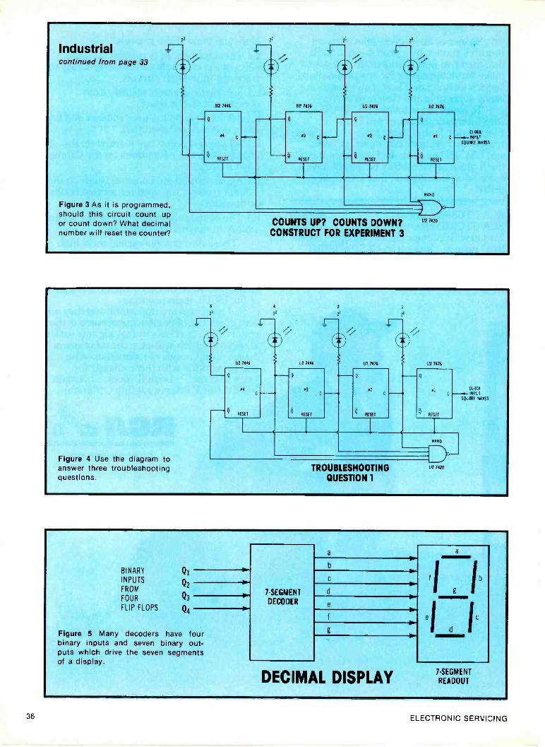
Industrialcontinued from page 33
Figure 3 As it is programmed,should this circuit count upor count down? What decimalnumber will reset the counter?
112 7446 112 7476
od
SET
#3
RESET
112 7176
#2
KS1T
112 7476
AI
RESET
NAND
COUNTS UP? COUNTS DOWN?CONSTRUCT FOR EXPERIMENT 3
112 7420
-SQUARE *MS
Figure 4 Use the diagram toanswer three troubleshootingquestions.
1
2
I112 7446 7446 P IL' 7076 112 7476
#4
RESE1
#3
RESET asn
CLACK
--Ad- 00'11SQUARE REAVES
RESET
TROUBLESHOOTINGQUESTION 1
NAND
112 7420
BINARY QiINPUTS
FROM
FOUR Q3
FLIP FLOPS
Q2
Q4
Figure 5 Many decoders have fourbinary inputs and seven binary out-puts which drive the seven segmentsof a display.
7 -SEGMENT
DECODER
a
b
d
e
DECIMAL DISPLAY
e
a
d
7 -SEGMENT
READOUT
36 ELECTRONIC SERVICING

BINARY DECIMAL
INPUT DISPLAY
7I
0010
0011
01011
BINARY DECIMALINPUT DISPLAY
OM!
1001
BINARY INPUTSVERSUS READOUT
when the count reaches binary1100.
Figure 8 shows that, starting atdecimal 15, only three counts occurbefore 1100. They are: 1111(decimal 15); 1110 (decimal 14);and 1101 (decimal 13). The nextdown count is 1100 (decimal 12),and the counter will reset todecimal 15 before the 1100 binaryreadout can be seen.
Answers ToTroubleshooting Question 1
(1) The circuit will count up,because the LEDs are connected tothe Q -output terminals of thetoggles.
(2) The counter is designed to resetto 0000, when the count reaches theprogrammed number. Notice thatthe NAND output goes to all four Figure 8 These are the binary counts for the circuit of Figure 3.reset terminals.
Figure 6 Readout segments can be lighted to form simulations of all decimalnumbers from 0 to 9.
INPUTS
FROM
FIGURE 4
CIRCUIT FOR EXPERIMENT 5
DECODER
4
LAMP
IISi
PLANA
8
GAD
5L
tl
vCOMMON ANODE
SY*
*SERIES CURRENT -LIMITINGRESISTORS OF 3300 EACH MUST BE USED
DISPLAY
Figure 7 Wire this decoder and display system to the counting circuit of Figure4.
(3) Reset will occur when the binarynumber 0111 (decimal 7) is reached.Thus the highest number that canbe displayed is binary 0110 (deci-mal 6).
DECIMAL 1 Q Q NANDAND
OUTPUT
0 0000 1111 1000 1
1 0001 1110 1001 1
2 0010 1101 1010 1
3 0011 1100 1011 1
4 0100 1011 1100 1
:, 0101 1010 1101 1
6 0110 1001 1110
7 0111 1000 1111
LAST COUNT RESETS
COUNT FOR DISPLAYED COUNTER
TO 0000
FIGURE 4
October, 1978 37

CuringHorizontal
Oscillator DriftPart 3, By Wayne Lemons, CET
Four more basic types of AFPC and horizontal oscillator circuits areidentified, along with the parts most likely to cause drift. Finally,a handy troubleshooting chart for the sequence of tests is given.
Continuing with methods of find-ing the components that causehorizontal -frequency drift, we willexamine several more basic circuits.
Perhaps you are wondering whyso much space is being devoted toidentifying the type of horizontaloscillator. That kind of thingusually is confined to courses andtextbooks. Well, it's because youcan save much time and be morecertain the trouble is cured.
Each basic type of oscillator hasonly a few different parts that cancause horizontal drift or a radicalout -of -frequency condition. Often,the same components are capable
of doing either, depending on theseverity of the defect. Your knowl-edge of these components andwhere they are located in thevarious circuits can make yourtroubleshooting much easier.
Cathode -CoupledBlocking Oscillator
In Figure 1, the usual AFPC duo -diode circuit produces an error -correcting DC voltage, which isamplified by the "horizontal con-trol" tube, and goes from that platethrough the 2.2M resistor to thetime -constant capacitor, Cl, whereit controls the frequency by varying
the negative voltage at the oscillatorgrid. Also, the resistance betweenoscillator grid and ground (includ-ing the R1 82K resistor, the 10Kresistor-when the jumper is opened-and the resistance of the horizon-tal -hold control) determines theapproximate frequency. Of course,the AFPC control voltage shifts thefrequency slightly, as needed, toprovide solid horizontal locking.
Type of oscillatorA high negative bias is measured
at the oscillator grid, and the Lloscillator coil is tapped but not
continued on page 40
150pF
82pF
SYNC
INPUT220K
+ 4V
0012
Figure 1 A high negative oscillatorgrid bias, and an oscillator coil thatis tapped but not tuned prove it isa time -constant type of blocked -grid oscillator. The most criticalcomponents for frequency are C1and R1. The double plate -loadpaths (R5 /R6 and R7 /R8) cancause extra problems.
6.8K
6GH8
HORIZ CONTROL 145V
270K
0012
0012
R3
HORIZ50K
+635V
33K R6
a
+265V
6
OV 21=-
7
1200 150K
265V
B/ R2.R4
6GH8 HORIZ OSC
- 500
003
i 82K 270pF
RI
10K f R2 ....."
CUT /IWHEN
REQUIRED
FOR
HORIZ
RANGE
Cl
62 Sl
25 SI
LI
1 225V
_LC4
I390pF
47 D27K R5
01
I FO-U PUT
R7 220K
R8 220K
CATHODE -COUPLED OSC
RCA CTC41A CHASSISPHOTOFACT 1112-2
38 ELECTRONIC SERVICING

HORIZ
SYNC
82pF
100pF
330K
330K
12200
301 0022
.01
47K
IORIZCOLD
500K
27pF
05
111
+2754
RI330K
CI 470pF
68K
HORIZ
FREQ
PULSES FROM
82K FLYBACK
6CL8
HORIZ OSC
6 +205J
+3V
9
8
+8.2V35V PP
1 C3A0033
C3B
0068
SYLVANIA D05-14PHOTOFACT 1051-2
2200
7
+ 150V
27K
275V
0047 240V PP
(-el. TO HORIZOUTPUT GRID
390pF
27K
Figure 2 A low negative oscillator grid biasand an oscillator coil with a dividing tuningcapacitor indicate this is a tuned "sine -wave" type of oscillator. L1, C3A, and C3Bmainly determine the frequency, while thegrid bias and the value of other componentshave a smaller effect. Point A can beshorted to ground to test for oscillator driftseparate from the phase diodes.
CHECK
SYNC
INPUTCAP
HORIZSYNC
5.86
TP
AF PC
61W8IECFE102
+ 190V
C3
IOMF
ISV PPSAWTOOTH
PULSES
I FROM
47IpF FLYBACK
SAMPLEPULSE RETURNCAPACITOR
Ll80u Z'
=1
6800
240V
50V PP
820pF-211i
Cl
120K RI
HORIZHOLD
1911
HORIZ OSC61W8IECF802
160V
6
3
ADMIRAL 6H1065PHOTOFACT 1113-1
1958
30
+240V
0047250V PP
IF+ DRIVE TOOUTPUT
36K
220pF
Figure 3 A moderate negative oscillator gridbias and a tapped/tuned oscillator coilprove the oscillator is a tuned type. C3parallels L1, the oscillator coil. The triodeAFPC tube is wired as a reactance stage,varying the frequency (for lockong) by phaseand the capacitance changes. The holdcontrol is the adjustable core of theoscillator coil.
October, 1978 39

Horizontal Driftcontinued from page 38
tuned. These characteristics prove itis a time -constant type of blockingoscillator.
The tuned stabilizing or ringingcoil (L2) is in the cathode circuit. Inthis case, however, it doesn't go toground, but to the tap of theoscillator coil.
If we add all of these separatedesignations together, we have thisjawbreaker: It's a cathode -coupled -feedback, time -constant, cathode -stabilized type of blocking horizon-tal oscillator. Memorize that, anduse it to impress your customers!
Adjustment procedureBecause this circuit has two
frequency adjustments plus theringing coil, we are repeating thesequence of adjusting a non -defective circuit.
The method is as follows: Connect a short jumper wireacross the L2 stabilizing coil. Defeat the sync, or ground eitherpoint A or the pin 2 grid of theoscillator -control tube. Preset the horizontal -hold controlto the center of its range. Adjust the core of the Lloscillator coil for zero beat, with anupright picture that drifts sidewaysslowly. Remove the jumper from L2stabilizing coil.
Adjust L2 for the same degree ofzero beat, as before. Remove the AFPC jumper orrestore the sync. Adjust the horizontal -hold controlfor best locking on all stations.Only a slight adjustment should berequired.
Frequency from oscillator coil?If you have been following the
theoretical discussion carefully, youprobably have a question about theoscillator coil. Since the coil isuntuned, how can the core adjust-ment affect the frequency?
Previously, the functions of time -constant grid resistance and capaci-tance have been explained. Theydetermine the unlocked oscillatorfrequency by controlling the amountof time the grid is cut off. Thisalso explains how a DC voltagefrom the AFPC can vary thefrequency (it changes the negativegrid voltage).
And, you probably already knowabout the reason the core adjust-ment of a tuned oscillator coilchanges the oscillator frequency.
But, we have explained that ablocking oscillator coil is not tuned.So, how does a different inductancechange the oscillator frequency?
The waveform from the oscillator -tube cathode that drives the tap of
the oscillator coil is a fairly narrowpulse of positive current for eachcycle. But, the coil and the variouscircuit capacitances ring from thisexcitation. Therefore, the waveformat the top of Ll oscillator coil is adecaying wave trail (ringing wave-form) for each cycle. (Ringing wave-forms usually have much greateramplitude than the exciting signaldoes.)
Simply stated, different inductan-ces of the oscillator coil change theamplitude of the exciting pulses;and in turn the amplitude of theringing waveform is changed. Inci-dentally, the ringing doesn't botherthe grid rectification, because con-duction occurs on the first positivering, and following ones are ig-nored.
There we have it! Tuning thecore of the oscillator coil changesthe inductance, and the inductancechanges the positive -feedback am-plitude. Then, the amplitude varia-tion changes the time -constant dis-charge time to change the oscillatorfrequency.
In part 2, we mentioned feedbackamplitude as being the disguisedfactor in determining the frequencyof time -constant oscillators. This isone example of a planned adjust-ment.
Another component that indirect-
HORIZ SYNC
82pF
120pF
330K
0015
120K
22K
1W
0047
047
0022
ISpF
I 1KV
HORIZ
HOLD
IK
4 PULSES FROM
FLYBACK
I 47
HORIZ AFC
15K
2W
390
68L8
CHECK
01
6.8K
+ 160V
16 Ll
HORIZ OSC
COIL
47 OD F
PHILCO 2091'88PHOTOFACT 1119-2
HORIZ OSC
CI6 160V
RI 0'&150K -40
7
0047
+.2V
+ 160V
39K
+ 2 5V
18K
680pF
HORIZ DRIVE
TO OUTPUT GRID
Figure 4 Although the negative gridbias of the oscillator is moderatelyhigh, the oscillator coil is both tapped
C38 and tuned, so it is a tuned type. 1_1,
C3A, and C3B are the critical compo-nents. A reactance tube varies thefrequency for locking, and the cathodevoltage change is used for a holdcontrol.
40 ELECTRONIC SERVICING

ly affects the signal amplitude isC4, which bypasses the oscillatorplate, forming the sawteeth whichare needed to drive the output tube.An open C4 forces the oscillator farout of frequency.
TroubleshootingA few shortcuts for finding the
cause of wrong horizontal frequencyare possible. However, if these don'tfind the bad part right away, it'sbetter to use the entire procedure.
For example, suppose the oscilla-tor is badly out of frequency(perhaps 10 or 12 diagonal bars).First, ground the pin 2 grid of the6GH8. If the frequency is notice-ably better, perhaps the duo -diodeportion of the AFPC is bad. If thefrequency change is small, measurethe pin 6 plate of the 6GH8 controltube. A DC voltage within 10% ofthe schematic value is an indicationthat the AFPC circuit is okay, andthe defect is in the oscillator.
Before wasting much time, it'swise to jumper the L2 stabilizingcoil. Any frequency improvementpoints to a defective or misadjustedstabilizing circuit.
If these two fast tests indicate anoscillator defect, then it's usuallysafe to start detailed tests in theoscillator circuit.
Peculiar problemsOpen filter capacitors can pro-
duce hard -to -analyze symptoms.Make a practice of using yourscope to check for abnormal wave-forms (including horizontal pulseswhere weak hum should be) at eachfilter. Then, correct any suchpower -supply problems before wast-ing excessive time testing thehorizontal -oscillator circuit.
Other weird symptoms comefrom defects that greatly increasethe amplitude of the sawteethsupplied to the duo-dides. Perhapsthe frequency might drift excessive-ly, and drop out of lock with atearing action. Especially check theresistors bringing in pulses or saw -teeth.
Plate resistors of the oscillatoroften are responsible for otherobscure problems. The circuit ofFigure 1 has two separate B+ pathsto the oscillator plate. Resistors R5
and R6 provide sufficient voltagefrom the +265 -volt supply to startthe oscillation. (Lower values wouldgive higher DC voltage, but woulddistort the drive to the outputtube.) Then, after the boost voltagecomes up, more voltage is broughtto the plate through R7 and R8.
Generally, a drastic decrease in
any of the four resistors brings thepossibility of instability or a com-pressed raster at the right edge. Ifany of the four resistors increase invalue, the drive to the output gridis reduced, causing excessive currentin the horizontal -output tube.
Also, R5 and R6 form a voltagecontinued on page 42
PRO/COMM: THE #1Lc-t-E_WO TUBE SOURCE
of -
ot ilf"" fi:11141
44 te
Dist-ibutor3 require morereceiving tube types tran anyone conpary manufactures orsupplies The Pro/Comm line wasspecially designed to fi I in thegaps.
Pro/Comm offers realbackup insurance With acomplete range of 500 tubetypes that cover more than 3000U S /foreigr entertainment andindustrial repacementapplications. Discounted forgreater profits. And ready forimmediate celivery frominventories of over 4 million tubes.
Ind Jstrial Grade Pro/Commtubes are manufactured to themost rigid original equipmentspecificatiors.With coiledheaters. Frame grid construction.And hich GM characteristics.They make expensive electronicequipment perform as it wasdesigned to. So they move offthe shelf fast And carry anunconditional tube for tubereplacement warranty
Want to know more? Foradditional information, or toplace your oroer, writePro/Comm Tubes, ElectronTubes Internals:Dna' Inc.,25 Dubon Court,Farmingdale, NY 11735or call 800-645-9512 toll -free.
/COnVnrx.i GRADE
youi No 1 second source
October, 1978Circle (17) on Reply Card
41

Horizontal Driftcontinued from page 41
VTVM
OR DMM
DC VOLTS
DISCONNECT
X
CHECK DC VOLTS OFLEAKAGE
LEAKY?
+ VOLTAGE
Figure 5 A frequent cause of drift (where resistance tubes are used) is theplate -to -grid capacitor. The slightest leakage causes drift or wrong horizontalfrequencies. Test these capacitors with the power turned on, as shown here.For example, with an 11-megohm meter impedance, a leakage of 11 megohmswould produce a capacitor voltage reading just half of that at the plate. Theslightest voltage reading indicates excessive leakage, and the capacitor shouldbe replaced.
CORRECT FREQ.
BUT WITH DRIFT
DEFEAT AFPC
ICHECX FREQUENCYI
FREQ ALMOST OA
'HI NORMAL DRIFT I
I REPAIR AFPC I
EXCESSIVE
DRIFT
I DEFEAT RINGER I
NORMAL DRIFT
ADJUST RINGER
REPAIR OSC
WORSE DRIFT =OSC DEFECT
BAD FREQ
REPAIR ORCHANGE OSC
CIRCUIT
LOCATING HORIZOSC DRIFT
11=1112=1
TEST FOR DRIFT
NO
OSC
TRANSISTOR TYPE
REQUIRING ADC VOLTAGE
WORSE=
REPAIR OSC
BETTER=NORMAL
Chart 1 Here is a handy chart to guide you in locating the causes of horizontal -oscillator frequency drift.
divider to reduce the amplitude ofsawteeth applied to the duo -diodes.As explained before, any excessiveamplitude of these sawteeth canoverload the AFPC circuit, causingloose locking, and other erraticsymptoms.
Hot and cold testsComponents that cause drift often
can be identified by alternateheating and cooling of each indi-vidual component. Or, the generalarea can be heated moderately byan incandescent bulb, then cannedcoolant should be sprayed throughthe small tubing to one part at atime. Almost all of these compo-nents can change the frequencyslightly when heated. You shouldsuspect those which react excessivelyto temperature variations.
Check the specs of any capacitorsin the oscillator circuit. Don'treplace a mica type with anythingelse, and don't use a plain ceramicto replace a negative -temperaturecoefficient type.
Note: Observe one precautionwith these hot/cold tests. Thesecomponents are moderately sensitiveto heat changes, so don't overdo it.Don't apply excessive heat, anddon't cool them too much.
Tuned OscillatorOur first example of a tuned
oscillator is diagrammed in Figure2. The LI oscillator coil is nottapped, but the paralleling capaci-tance is in two capacitors, C3A andC3B. Feedback from the oscillator -tube cathode produces the oscilla-tion.
Notice that the grid bias is only-5.2 volts (+8.2V at cathode minus+3V at the grid). The tuned oscil-lator coil and the low grid biasprove it is a tuned sinewave type.At least, the oscillator coil has anear sine waveform. However, theoutput at the plate is a kind ofpulse that's filtered to a roundedsawtooth-plus-pulse.
There is no control tube. Instead,the output from the AFPC diodesgoes through two resistors to theoscillator grid. The horizontal -holdcontrol varies the positive voltage atthe oscillator grid.
42 ELECTRONIC SERVICING

Here is the simpler adjustmentprocedure:
Ground the grid of the syncseparator, and pre-set the holdcontrol to the mechanical center ofthe rotation. Adjust the core of the oscillatorcoil for zero bead. Remove the sync -separatorground, and slightly adjust the holdcontrol, if necessary, for best hori-zontal locking.
In this circuit, the only compo-nents likely to change the horizontalfrequency drastically are the gridcapacitor (C1), the oscillator coil,and the two tuning capacitors (C3Aand C3B). Other components andthe exact grid bias can have onlyminor effects on the frequency.
Reactance TubeOther models include a reactance
tube, which can change the fre-quency slightly to maintain good
locking. See Figure 3.The Ll oscillator coil is tapped,
and the feedback signal comes fromthe screen grid, which functions asa plate.
It's not easy to see how Ll istuned by C3, until you notice thatthe resistor from the bottom end ofC3 to the coil tap has a value ofonly 150 ohms. So, for purposes ofoscillation, the top winding of theoscillator coil is paralleled by the.003 microfarad capacitor.
The reactance -tube operation isvery similar to those found formerlyin color -oscillator circuits. The fre-quency is changed by a combinationof phase shift and capacitancevariation.
No leakage at all can be toleratedin the .001 grid capacitor. Test it asshown in Figure 4 by disconnectingthe grid end and using a VTVM,FET meter, or digital DC voltmeter.Any reading above a volt or twoindicates excessive leakage, and a
new capacitor should be installed.
Troubleshooting ChartChart 1 shows the basic steps for
efficient troubleshooting of thosehorizontal-oscillator/AFPC circuitsthat have duo -diodes with an error -
correcting DC output voltage cen-tered around zero volts, and fol-lowed by a time -constant oscillatorwith a stabilizing coil.
Most of the steps were explainedin these articles, and they should belargely self-explanatory.
CommentsIf all facts and tips about
horizontal oscillators and methodsof locking them were ever compiledin one publication, it's likely thebook would be as large as adictionary. This is not practical.
Therefore, we have tried to giveyou some of the landmarks to lookfor, in hopes you can adapt thesemethods to similar circuits.
Looking for Original Japanese Replacement Parts for CB, TV and Stereo ?iTYPE 25 -up 10-24 1.9 TYPE 25-tet 10-24 1-9 TYPE 25 -up 10-24 1.9 TYPE 25 -up 10-24 1.9 TYPE 25 -up 1024 1.9 TYPE 25 -up 10-24 1.9
V 1 I 1 V I2SA 234 .45 .53 .59 2SC 372 20 .27 30 2SC 100081 .35 .40 .45 25C 1945 4.50 500 5.60 250 61 1.10 1.25 1.40 UHIC 005 5.00 520 5.802SA 473 45 55 .60 2SC 373 20 27 .30 2SC 1013 .50 .64 .70 2SC 1957 .60 .70 .50 250 68 .40 .45 .50 UPC 20C 2,10 250 2802SA 484 1.33 2.10 240 2SC 380 10 27 .30 2SC 1014 .50 64 70 25C 1969 3.80 4.00 440 200 229 1.40 1.50 1 90 UPC 563 110 110 2.402SA 485256 489
1101.10
2.10125
2.401.40
2SC 38125C 382
30 4030 40
A5A5
2SC 101825C 1030C
.70100
202.10
.90240
2SC 19732SC 1974
.70110
.801/0
.901.90
350 35350 37
1.30110
1.452.10
1.60240
UPC575CUPC 576
1.301.90
1.452.10
100240
2SA 49525A 497
.251.00
.35120
.401.30
2SC 3137AZSC 394
30 AO30 40
45A5
.250 1080250 1061
.70.70
.8000
90.90
2550 19752SC 2028
1.3050
1.70.64
1.90.70
356 39350 40
.901.30
1.101.45
1201.60
UPC 592442UPC 100111
AO190
.902.10
I 002 40
256 509 .30 .35 .40 25C 458 20 .27 .30 ZSC 1079 140 155 190 2SC 2029 1.50 110 2.00 3514 41 1.30 1.45 1.60 UPC 1008C 500 5.30 50025A 537A 1.50 1.70 1.90 2SC 481 130 140 150 2SC 1060 3.40 155 3.90 25C 2076 .50 .64 .70 350 45 1.30 1.45 1.60 UPC 102061 1.90 2.10 2.40256 561 .30 15 AO 2SC 1166 30 .40 AS 25C 1099 .45 .55 60 2SC 2091 .03 1.10 1.20 350 48 140 3.55 3.90 UPC 1025 1.90 2 10 2.4025A 562 .30 .35 .40 2SC 482 1.10 125 1.40 2SC 1090 .50 .64 .70 25C 2092 1.80 2.00 2.25 360 49 1.30 1.45 1.60 UPC 1156 190 2 10 2 40256 634 .40 .45 .50 2550 485 1 35 1.40 1.50 2SC 1111 2.10 2.50 2.80 25C 2098 3.20 3.40 3.70 AN 2140 1.30 1.70 1.90 UPD 857C 800 8.40 9.5025A 643 .30 AO 45 2SC 495 45 05 .60 250 1114 4.20 4.40 4.90 250 72 .50 .64 70 AN 239 4.20 4.40 4.90 UPD 850C 8.00 8.00 9.5025A 673 30 AO .45 25C 497 1 10 125 140 2SC 1115 2.50 2.70 100 250 90 1.30 1.45 100 AN 247 2.50 2.70 3.00 PLL 01A 300 4.20 4.60?SA 683 AO 53 59 2SC 509 30 AO 45 2SC 1116 120 3.40 170 2613 91 1.30 185 100 AN 274 1.50 1.75 1.95 PLL 02A 500 5.30 5 902SA 684 AO .53 .59 2SC 517 300 3.20 3.40 2SC 1116A 3.40 3.55 3.90 250 92 1.45 1.60 1.60 AN 315 1.90 2.00 225 011 030 760 8.00 88025A 695 40 53 59 2SC 535 30 40 A5 25C 1124 .80 .90 1.80 no 93 1.60 1.80 2.00 HA 511A 110 2.00 225 5 84 45 55 .602SA 699A 50 .64 70 2550 627 1 30 145 1.60 25C 1127 .80 00 100 no 180 1.60 1.80 2.00 BA 521 110 2.10 240 5 EN 16 18 .20ZSA 706 85 100 1 10 2SC 696 100 1.20 1.30 2SC 1162 .70 .60 .90 250 187 .30 .40 .45 HA 1151 1.50 1/5 1.95 5 332 35 40 4525A 7192SA 770
2525
3535
4040
2SC 710250 711
20 1720 .27
30.30
200 117282SC 1173
3.20.50
3.60.64
3.95.70
ZSD 188no 201
1.1302.30
2.102.40
2.40295
HA 1156HA 1306W
1.602.00
1.1102.20
2002.50
S 9535 1007
1635
1840
20A52SA 733 20 27 30 ZSC 712 20 27 .30 2SC 1177 11.00 12.60 14.00 no 202 3.40 3.55 3.90 HA 1322 2.50 2.70 3.00 S 1209 35 AO .452SA 744 4.20 4.40 4.90 2SC 717 3 .40 .45 2SC 1/09 .25 .35 .40 no 226A 1.30 1.45 1.60 HA 1339 2.50 2.70 3.00 5 1211 35 .40 .452SA 745R 3 60 4 00 4 40 2SC 730 3 3.20 3.40 2SC 1226 .041 .64 .70 2S0 234 .60 .70 .00 HA 133941 2.50 2.70 3.00 S 1555 20 22 .252SA 747
256 8474.20
404.40
53490
5925C 7322SC 733
2 .27.27
.3030
2SC 1226A250 1237
501.00
.642.00
.702.25
250 235250 236
.601.30
.70 .
1.45.80
1.60HA 1342ALA 4031P
2.501.00
2.702.00
3.002.75
S 15885 1885
2016
2218
.25
.20256 54 - 30 00 45 25C 734 .27 .30 200 1239 2.20 2.70 2.90 250 261 .30 .40 .46 LA 4032P 1.80 2.00 225 S 2076 20 22 25258 55 40 53 59 2SC 735 27 .30 25C 1306 1.30 1.70 1.90 no 267 2.50 2.70 2.90 LA 4400 1.90 2.10 240 5 2093 35 .40 A5ne 75ne 77
3030
4040
4545
2SC 75625C 75614
1
1501.110
1802.00200
25C 13072SC 1318
2.20.30
2.70.40
2.90.45
250 291ED 313
2.10AO
2.59.70
2.90.90
M 515131.STK 011
2.003.60
2204.00
250440
5 7473re 34
16.12
.18.13
2015
2513 186 20 27 30 2SC 775 1 40 1.60 1.80 EC 1364 .30 .40 .45 no 315 .60 .70 .90 STK 015 4.20 4.40 4.90 N 60 12 13 .152S8 187 20 27 30 25C 776 200 2.20 2.50 2SC 1383 .30 .40 .45 no 325 .60 .70 .80 STK 435 4.50 5.00 5.60 1001 .25 .35 402S8 324 25 35 40 2SC 777 300 3.25 3.50 250 1384 .30 .40 .45 2S0 3560 .70 .80 .90 TA 7414548 200 2.20 250 ODIO .45 .55 AO2S0 367 1 10 1.25 1 40 75C 778 1 90 3.20 340 2SC 1400 .30 .40 .45 2S0 3570 .70 .80 .90 TA 70555 2.00 220 2.50 VO 613 .25 35 .402513 405 E 35 40 25C 781 200 2.20 2.50 2SC 1403 3.20 3.40 3.70 260 358 .70 .80 .90 TA 7011014 90 1.10 1.20 VO 60 .25 .35 .40206 407 70 90 1 00 7SC 784 35 AO A5 2SC 1419 .60 .70 .80 2S0 359 .80 .90 1.00 TA 70131P .90 1.10 1.20 W2 050 20 12 25208 434ne 473
.8070
9090
1 00I 00
2SC 78925C 793
802.00
.90220
1 00150
nc 14752SC 1067A
.70
.60.90.70
1.0080
2S0 381no 427
.1W1.90
1.002.00
1.102.25
TA 7062PTA 700166
1.102.00
1.252.20
140200
192 052492 061
.20
.20.22.22
25.25ne 474 70 00 90 75C 799 2.00 2.20 210 2SC 1667 3.00 320 3.40 200 525 00 1.10 1.20 TA 7129P 1.30 1.70 lao lila 071 .20 22 .25
2511 507 70 90 100 2SC 828 20 27 30 250 1975 25 .35 AO 2S0 526 AO .70 .90 TA 7203 250 2.70 210 W2 075 .20 12 25ZSB 511 70 80 90 2SC 829 20 27 30 2SC 1678 110 145 1.60 2SK 1961 45 .55 .613 TA 7204P 2.00 2.20 2.50 W2 091 20 22 25200 536 1 00 120 110 2SC 838 .35 .40 45 2SC 1887 .40 .46 50 2519 23 .85 1.00 1.10 TA 72059 160 110 2.00 492 090 .20 22 25MB 5572S8 595
2.101.10
2.501 40
2801.54
2SC 8392SC 867
.303.20
.403.40
.453.70
2SC 17282SC 1730
1.00.45
1.20.53
110.59
200 30250 33
.40
.60.45.70
.59 TA 7310PTBA 810514
1.301.90
1.452.10
1602 ao
W2 120PiT 192
.2020
.22
.2225.25259 596 1.10 1.40 1 50 2SC 897 2.00 2.20 2.50 2550 1760 .90 1.10 1.20 2SK 34 .50 .64
.80
.70 TC 5080P 5.00 520 5.80 viT 260 20 .22 .25259 600EC 183
5.00.40
6.00.53
060.59
2SC 900250 930
2020
27.27
.3030
2SC 17752SC 1816
.301.50
.401.75
A51.95
2519 40200 41
10.50
.64
.64/0 TC 5081P
IC 0082141003.40
3.20355
140190
812 280SG 613
.20520
225.40
255.952SC 184 .40 53 59 2550 945 20 27 .30 WC 1908 .25 .35 AO 2019 49 .40 .45
.7050 UHIC 002 5.00 5.20 5.80 MPS U31 130 1/0 1 902SC 281 25 35 40 2SC 959 1.00 1.20 1.30 2SC 1909 2.20 2.70 2.90 2SK 55 .60 .70 .60 : : UH1C 004 5.00 5.20 5.80 78105 00 100 1 to
PRICES MAY CHANGE WITHOUT NOTICE COD ORDERS WELCOMEDMinimum Order 95 00 OHIO ritaIdente 544 45, saIrre 164 Ltd 51 00 70911191 end handling
Ouaintity discount prices Ask For Our Complete Priv!, Manufacturer InquIrlee WelcomedALL PARTS GUARANTEED AGAINST FACTORY DEFECT
TOLL FREE TELEPHONENationwld 800 543-1807
- Ohio 800 582-1830
Hours Mon Fri 10-7 Sal 11-5
LOCAL 513/874-0220
874-0223
IMMEDIATE DELIVERY WITHIN 48 HOURS
(IN ALL TRANSISTORS IN STOCK
FUJI-SVEA ENTERPRISEa Division ql Fuji Svea Incorporated
Dept. ESP.O. Box 40325. Cincinnati. Ohio 45240
Telex 21-4732
October, 1978 43

Calculating Sales Profitsservice Management
Seminar,Part 10
By Dick Glass, CET
How can you figure salesexpenses and profitsseparately from yourservice department costsand profits? This articletells how.
Service Losses?A retailer recently told me that
he was considering closing his elec-tronic -repair department. However,he intended to continue his presentsales of furniture, appliances, andTV receivers. The reason: his salesoperation was profitable, but lastyear he lost $10,000 in his serviceshop. So, he knew that drasticchanges were necessary or hecouldn't continue to suffer such afinancial drain on his business.
As we analyze the wisdom of hisdecision, we need to considerseveral important questions, such asthese: Did his service operation actuallylose $10,000? If his service did lose that muchmoney, was one important factorthe below -cost labor rates he es-tablished in an effort to attractmore customers for his sales oper-ation? Did the service technicians regu-larly make deliveries of appliances,TVs, and furniture for the salesdepartment, but without propercredit? Did the technicians repair thefloor -stock TVs without charge, orperform warranty repairs for below -cost prices?
Business EvolutionOne business owner started with
a small electronic repair shop,where nothing but parts and laborwere sold. With gradual growththrough the years, the operationexpanded by stocking small radios,toasters, and other small appli-ances. Later, one or more full linesof TV receivers, stereos, refrigera-tors, and automatic washers wereadded.
Finally, a business that started as"all service" developed into onethat is "mostly sales." Both salesand service were handled in onebuilding. For accounting purposes,the owner lumped all income (fromsales, parts, and labor) together andsubtracted the total expenses.Therefore, this owner finds itimpossible to even estimate theindividual profits from sales andservice.
Probably the owner justifies hislack of itemized profits and ex-penses by thinking that he is doingthe best possible. Knowing aboutindividual profits-he rationalizes-would not increase them. After all,he's selling merchandise at com-petitive prices. Service labor ispriced below the point where hiscustomers might rebel. He pricesparts at the manufacturer's sug-gested -list price. Warranty work isdone for whatever each manu-facturer agrees to pay. What morecan he do?
Most store managers, when facedwith this question, try to increasethe efficiency in making repairs,and to expand the volume of partsand merchandise sales.
What's Wrong?Here are some things this typical
dealer is doing wrong.Parts prices
Probably his shop is sellingcomponent parts at too little mark-up. Fewer parts are being requiredper repair, thus increasing theoverhead. A 50% (or larger) grossprofit from parts is not out of line,at this time. In fact, it might bemandatory, if you expect to makeany profit.
Labor ratesIf you base your labor rates on
those being charged by others inyour area, you probably are losingmoney. It's likely your competitor isbasing his rates on yours! Perhapsall of you are losing money.
Instead, you need to calculateyour profit or loss from labor, andadjust your rates until they bring inthe return you need to stay inbusiness.
Merchandise sales costsThe most common mistake of
sales/service firms is wrong alloca-tion of some TV, stereo, and appli-ance sales costs.
Usually, the service techniciansare required to help deliver thelarge merchandise after delivery, touncrate it, and to check theperformance. Also, they oftenanswer phoned questions aboutperformance of new sets. In someorganizations, the technicians areexpected to attend sales seminars,learn the features of each product,and even sell it at times.
Sometimes trade-in machines are
44 ELECTRONIC SERVICING

/PROFIT
DICK'S
& LOSS STATEMENT(combined operation)
TV SALES AND SERVICE
COMBINED SERVICE PRODUCT SALESTOTAL SALES
Merchandise 100,000 10,000 90,000Parts 40,000 40,000 0Labor 60,000 60,000 0
$200,000 $110,000 $90,000COST OF SALES
Merchandise sales 100,000 10,000 90,000Direct merch. cost 80,000 8,000 72,000Merch. gross profit 20,000 2,000 18,000
Parts sales 40,000 40,000 0Parts costs 20,000 18,000 2,000Parts gross profit 20,000 22,000 ( 2,000)
Labor sales 60,000 60,000 0Labor wage costs 40,000 30,000 10,000Labor gross profit 20,000 30,000 (10,000)
Total Direct Costs 140,000 56,000 84,000
GROSS PROFIT $60,000 $54,000 $ 6,000
OVERHEAD EXPENSES
Advertising 5,000 1,000 4,000Insurance 4,000 1,000 3,000Truck expenses 7,000 4,000 3,000Utilities 3,000 1,000 2,000Clerical salary 8,000 4,000 4,000Other expenses 25,000 12,500 12,500Total Overhead Expenses 52,000 23,500 28,500
NET PROFIT $8,000 $30,500 $(22,500) loss
repaired by the service crew. In theworst cases, the service departmentreceives no credit for labor andparts used on trade-ins, while theincome from trade-in sales is listedunder "merchandise sold."
Many sales/service stores fail tocredit the service department forany of these expenses made to helpthe sales department. At best, onlya fraction of the actual costs arecharged against sales. The result is
a constant showing of poor serviceproductivity, and a large loss onpaper. Of course, this is demoral-izing to the technicians, and con-tributes to low wages for them.
continued on page 46
October, 1978 45

Service Managementcontinued from page 45
A SolutionEven if you are resigned to the
poor performance of your business,you would do well to take a realisticlook at the relative profitability ofeach segment of your business.Product sales, parts, and servicelabor must be examined separately.
Parts profitThe industry average of profit
from parts sales is between 40%and 60%. If your gross parts profitis found to be 34% (for example),this might influence you to changeyour parts -pricing formula.
Service profitIf you properly credit your service
department for work done to helpthe sales branch, and then separateservice expenses and income fromthat of parts sales and productsales, you just might find to yoursurprise that your service depart-ment is doing very well.
Service supports salesSome sales/service firms deliber-
ately operate their service depart-ment at a loss in the belief that thiswill enhance their image and allowconsiderably more profit from mer-chandise sales. Usually, this is afalse premise.
If your philosophy is to offercheap service and recover the lostprofit from increased sales, youshould calculate what this "salesincentive" is costing you. Perhapsit's worthwhile as a sales -promotionexpense, but it is an unknown one,in most cases.
For example, assume that youfigured your service rates (as ex-plained previously), and found themto be 25% low. Therefore, they pro-duced a service loss of $10,000 lastyear. But, your "gut feeling" tellsyou that the "cheap -service" in-centive brought in an extra $50,000in sales. These extra product salesproduced a gross margin of $10,000.Therefore, the increased sales grossprofit just cancelled the grossservice loss.
Was this a smart decision?Probably not, when the net profitfigures are in. But, knowing the
true figures can help you plan forthe future.
Next, we'll show you how tocalculate the profits separately.
Dividing The P&LFigure 1 shows a typical profit -
and -loss statement (P&L) showingthe income and expenses for a firmwhich sells merchandise and alsooperates a service department.Column "C" gives listings in theusual way, with all income and ex-penses combined. Column "S"shows only the income and expenseitems applying directly or indirectlyto the service department, whilefigures for the product sales aregiven in the "P" column. Noticethat the "S" and "P" columnstogether total the same as the "C"column.
This P&L might be similar indollars to that of a large firm for amonth, or for a year with a smallstore. Of course, P&Ls for a yearpermit better accuracy in sepa-rating sales and service figures.
Combined figures are okayAccording to the combined "C"
column, the business doesn't ap-pear to have any serious problems.Merchandise gross profit is 20%,parts are being sold at 100%markup (50% discount from list),and the 60% figure for direct -laborcosts is not excessive since itincludes some unlisted repairs oftrade-in sets and deliveries of newmerchandise.
However, by separating the twodepartments and allocating thecosts accurately, we find this hypo-thetical business actually lost$22,500 in its sales department, andthe service shop produced a profitof $30,500.
Of course, the example has beenexaggerated to make the point, butit might not be far from reality withsome stores.
AllocationsWhen you construct your own
split P&L, you might want to followthese allocations: We attributed $10,000 of sales tothe service department, since thetechs made 10% of the total saleswhile on service calls. So, 10% ofthe merchandise cost ($8,000) wascharged against the service depart-ment.
10% of the total parts cost wascharged to sales, because manyparts were used in repairing trade-in sets for resale-a large part ofthis store's sales business. About 25% of total technician'stime was charged to sales, becauseof trade-in repairs, delivery of salesmerchandise, and other jobs insupport of the sales effort. Overhead expenses were allocatedaccording to the percentage in-curred by each department. Forexample, advertising usually is100% for product sales, but theservice department was assumed tohave benefited. Therefore, 20% ofadvertising cost was listed againstservice. Insurance covers salesmerchandise primarily. But, thetrucks were used more for servicethan for sales deliveries; thus, alarge proportion was charged toservice. You must decide thesepercentages for your own firm.
ConclusionsIf you were the owner of Dick's
TV, and only used a combinedP&L, you might be satisfied withthe $8,000 profit for the period.However, if you split the P&L andrecognize the real costs and profitsfor each department, you probablywould consider strong actions toimprove the results.
For one thing, the margin forproduct sales is too small. Whileimproving on the 20% gross profitfor new merchandise might bedifficult, the sales of used machinesoften bring in 25% or more.
The 50% direct -labor cost versuslabor -sales percentage is too highfor most service businesses, evenallowing for the $10,000 in laborcosts listed against the sales depart-ment. Probably the service ratesshould be raised.
Other items are not so easy todecide. There are many trade-offsand considerations to be taken intoaccount before you take any drasticactions, such as the elimination ofeither the sales or the service.
However, the beginning of anyintelligent decision should begin, aswe have done here, by listing all ofthe known facts.
Next SeminarInstructions about pricing com-
ponent parts-profitably-will begiven next month.
46 ELECTRONIC SERVICING

0,EmMIlAcm*IN©havgl_ HEA@l_amik
By J. A. "Sam" Wilson, CET
Your comments or questionsare welcome. Please give uspermission to quote fromyour letters. Write to Sam at:
J. A. "Sam" Wilsonc/o Electronic ServicingP.O. Box 12901Overland Park, Kansas 66212
DIRECTION OF
ELECTRON FLOW
DIRECTION OF
MAGNETIC FIELD
ELECTRON FLOWVERSUS THERESULTINGMAGNETIC FIELD
More Magnetic MemoryIn a previous article, I showed
how coils could be wound aroundferrite cores, and the device used asa magnetic memory. This informa-tion is an extension of the sameprinciple.
Any motion of electrons througha conductor ALWAYS produces amagnetic field at right angles to theconductor. No exceptions ever havebeen found for the rule. Even incases where the electron flow is notconfined to a conductor (such as anelectron stream in a cathode-raytube), there is an accompanyingmagnetic field.
The direction of any magneticfield is defined as the direction thata "unit" north pole would move, ifplaced in that field. Of course, aunit north pole is an imaginarynorth magnetic pole without anaccompanying south magnetic pole.
Left-hand ruleDirection of the magnetic field
around an electron current flow canbe determined by the "left-hand"rule. Imagine that you are graspingthe wire with your left hand (seeFigure 1), with your thumb pointingin the direction of electron flow.Then, your fingers are pointing inthe direction of the magnetic field.
Magnetizing a coreFigure 2 shows electron current
flowing in a single wire that passes
Figure 1 The "left-hand" rule showsthe direction of magnetic field pro-duced by this direction of electroncurrent flow.
through the center of a ferrite core.If the electron current has enoughamperage, the core will becomemagnetized, and the flux will be inthe direction shown by the arrowson the core. This flux remains, evenafter the current flow stops.
By definition, if the core has amagnetic flux, a logic 1 level hasbeen memorized. On the otherhand, the lack of any magnetic fluxindicates a logic 0 level. Those arethe only two conditions permittedwith this simple system.
In Figure 3, a second wire isthreaded through the core. It willbe used to determine the logic stateof the flux.
Reading the fluxSuppose the core flux of Figure 3
has been established previously byan electron current pulse flowingfrom A to B. A second pulse, alsofrom A to B, will not change oraffect the flux stored in the core,but an equal pulse from B to A willeliminate the core flux. When theflux is cancelled, the resultingchange of flux will induce a voltagein the wire between C and D.
Now, notice that inducing avoltage in a wire doesn't necessarilymean that current MUST flow. Ifwire C -D is part of a closed circuit(that is, has continuity external tothe wire), current will flow. If anopen circuit is across the C -D wire,no current will flow. These simplefacts are important for understand-ing how only one core can beoperated in a memory systemhaving many thousands of cores.This will be explained later.
continued on page 48
October, 1978 47

Technical Notebookcontinued from page 47
DIRECTION OF THE
RESULTING MAGNETIC
FLUX IN THE CORE
WIRE
DIRECTION OF
ELECTRON FLOW
FERRITE
CORE
ELECTRON CURRENT MAGNETIZESTHE CORE
Figure 2 Electron current in a wire through a ferrite core produces a flux in thecore of the same direction as the previous "left-hand" rule. Sufficient currentmagnetizes the core.
Figure 3 Addition of a second wire through the core provides a method ofdetermi ling if the core originally was in the logic 1 or the logic 0 condition.
C -D SENSE WIRE DETERMINESIF A 1 OR 0 HAS BEEN MEMORIZED
Refreshing the stateThe simple memory described in
a previous article had three con-ventional coils on one core. Thefirst two coils performed the samefunctions as wires A -B and C -D inFigure 3. A third coil was added tore-establish the core flux, when itwas eliminated by the sensingcurrent.
In the same way, a third wire isadded to the core, as shown inFigure 4. Wire E -F is used torefresh the memory. In other words,it re-establishes the original flux.
I'm not finished with my discus-sion of applied magnetics. Theprinciples of magnetic memory willbe extended in a future issue.
Welding ProblemIn a recent letter, Mr. Earl
Swallow writes, "Some years ago, Ibought a Craftsman AC welder (40amps to 230 amps), but never washappy with it. With 3/32 -inch#6013 30-80 ampere rod and #308stainless 60-90 amp, it took a longtime to strike an arc, and I had alot of trouble holding it. Using ahigher amperage might burn holesin the material.
"Recently, I bought a 100 -volt250 -ampere stud rectifier, andmounted it on a suitable heatsinkthat was cooled by the transformerfan. I connected it between the tapsand the ground cable (Figure 5),trying both polarities. Next, I wiredan electrolytic capacitor across therod holder and the ground clamp.The capacitor gave it a better sparkfor starting the weld, but theimprovement was slight.
"Then, the capacitor exploded ina cloud of smoke. I figured therectifier had failed, and a resistancetest proved it was shorted. Idecided to try welding without thecapacitor, and to my surprise, itwelded beautifully! With 3/32 -inch#6013 rod at 40 amperes, I wasable to strike an arc easily andproduce a nice bead. I was amazed!The rectifier was shorted, thecapacitor was open, but it weldedgreat. According to my voltmeter,the voltage was the same as before,and my scope showed the frequencystill was 60 Hz of the usualnear -sine waves. Regardless of whatcaused the change, I hope it staysthis way.
48 ELECTRONIC SERVICING

E F
E -F REFRESH WIRE RE-ESTABLISHESTHE ORIGINAL FLUX
Figure 4 Read-out of the core's condition reverses a logic 1 to a logic 0 state.Therefore, a third wire carries current to re-establish the former logic 1 state,following a logic 1 read-out (and cancellation). This is called "refreshing" thestored logic state.
"But, I am puzzled. What causedthe improvement? Have you anyideas?"
Mr. Swallow, I doubt that I cansolve this completely. But, bystudying long hours, attendingmany classes, interviewing tech-nicians, and working for years inelectronics, I now have arrived atthe point where I am qualified toguess. So, here goes.
Probably the electrolytic capaci-tor exploded because you accident-ally reversed the polarity of voltageacross it when experimenting withthe diode. Next, the diode wasdestroyed because the shortedcapacitor connected the diodeACROSS the secondary winding ofthe transformer.
Part of the welding improvementmight be caused by current nowflowing during both peaks of theAC voltage. (The rectifier allowedcurrent to flow for only one-halfcycle. The capacitor increased theDC voltage slightly, but was muchtoo small in capacitance-com-pared to the arc resistance-tomake the rectification true peak -reading.)
I can't even guess what happenedto make it better now (with ashorted series diode) than it wasoriginally. Perhaps the overloadcaused shorted turns in one wind-ing of the transformer, thuschanging the turns ratio and theoutput AC voltage. Or, perhaps theshorted diode added a slightamount of DC resistance thathelped the performance at this oneset of conditions, by limiting thecurrent.
Those are my guesses, and I'llopen the discussion to include youreaders.
More "In Situ"An "in situ" method of measur-
ing just one of several intercon-nected resistors was described lastMarch. These in situ measurementsare made without disconnecting thecomponent or the wires in a circuit.
With the series parallel arrange-ment of Figure 6, the ohmmeterconnected across RI will give awrong reading, until the metervoltage across R2 is bucked out byan external voltage applied across
continued on page 50
Urgent.Other phone answeringmachines only take calls.Ours calls you.
Dictaphone announces asystem that not only recordsmessages, but calls you anddelivers them.
It's our new Ansafone 696telephone answering system.
After it records a message,t will ring any number you tell itto - including a beeper ser-vice, if you have one.
Ansafone 696 means younever need to miss an urgentcall - no matter where you are.
For more informationon Ansafone 696, fill in
the coupon or call toll -free:800-431-1710
(In New York call 914-967-3810)
Name
Title
Phone
Company
Address
City State lipMail to: Dictaphone Corporation
105 Oak StreetNorwood, New Jersey 07648
Dictaphone and Ansafone are trademarks of DictaphoneCorporation, Rye, N.Y. IES-010
IL,
Circle (18) on Reply Card
October, 1978 49

GROUND
CLAMP
WELDER
Technical Notebookcontinued from page 49
R3. When the same voltage isapplied to BOTH ends of R2, thecircuit behaves as though R2 isopen. This gives the effect of dis-connecting R3. Therefore, the ohm-meter reads the resistance of RIalone.
It is necessary to observe a fewconditions to make the test ac-curate and fast. A center -zerometer range allows the balance tobe checked by one meter, andwithout re -connecting any leads.Many VTVMs can be operated thisway, by adjusting the "zero bal-ance" control to place the zeroreading (without any voltage input)at the center of the voltage cali-brations. Negative voltages read tothe left, and positive voltages readto the right of the center zero. Thepower supply must have an adjusta-ble output voltage, and have regu-lation over the whole output range.Select the most -likely ohmmeterrange at the beginning, sincechanging ranges requires a newzero balance.
After the equipment is connectedas shown in Figure 6, vary thepower -supply voltage in whicheverdirection moves the meter pointer
Figure 5 This welder schematic shows the modifications made by a reader.
nearer the zero mark. When theDC voltmeter reads a practicalzero, you stop varying the power -supply voltage, and then read theohmmeter. The ohmmeter willmeasure only RI, the readingdoesn't require any correction ormathematics, and the accuracy willbe as good as that of the ohmmeterand the zero -center DC voltmeter.
In most cases, a precise zero -voltage reading is not necessary.This would waste too much time. A10% deviation from perfect zerocan cause no more than a 10%resistance error. Of course, manyresistors are rated at ±20%, andohmmeters often have errors of 5%or more. The method is notproposed as one giving accuracy tothree decimal places. Rather, it is aquick test that can give in -situreadings of "sufficient" accuracy.
Alternate methodThe popularity of inexpensive
hand-held calculators makes possi-ble a combination measurementand calculation of the Figure 6 RIresistance.
First, the in -circuit resistance ofRI paralleled by R2 and R3 in
series is measured. Then, theohmmeter reading is placed in thissimple equation:
R1 = ohmmeter reading times (R2 + R3)(R2 + R3) minus ohmmeter reading
For example, in Figure 7, therated values are: RI is 270 ohms,R2 is 680 ohms, and R3 is 330ohms. The ohmmeter readingacross R1 is 210 ohms. Is RI withintolerance?
Using the previous formula, theseare the three additional steps:
R2 ± R3 = 680 ± 330 = 1010 ohms
therefore,
RI = 210 X 1010
1010 - 210
RI = 265 ohms
Since R1 is rated at 270 ohms,this is an accuracy of about -2%,which is better than required (inmost circuits).
Notice also, that actual wrong
50 ELECTRONIC SERVICING

CtlT
iifvt","
"IN -SITU" RESISTANCEMEASUREMENTS
CENTER ZERO
0I ,
IDC
VOLTMETER
C2
ADJUSTABLE
POWER
SUPPLY
0 5VDC
Figure 6 Here is the method of connecting the equipment to measure F11 in situ (in -circuit), when R2 and R3 in series areparalleled. The power -supply voltage is increased from zero until the center -zero DC meter reads zero volts across R2.With the same voltage at each end of R2, the effect is an open in R2; thus, opening the R2/R3 path.
resistances of R2 or R3 will makethe answer wrong. So, in a way, themethod checks all three resistors.
Derivation of the equationFor those of you who enjoy a bit
of math, here is the way theformula for finding the resistanceof R1 was evolved. The resistancemeasured by the ohmmeter is calledRx, and the formula becomes:
Rx = (R2 ± R3)
RI R2 + R3
Then, the equation is solved forR1, which produces:
RI = Rx (R2 ± R3)
(R2 R3)- Rx
This is the same as the firstformula given for solving Figure 7.Notice that the same technique canbe used to check the ohmmeterreading for any series -parallel ar-rangement of resistances.
Figure 7 Given these conditions, does R1 have the correct rated resistance?
DOES R1 HAVE CORRECT RESISTANCE?
October, 1978

30Hz
PG COIL
TP2501
30Hz
PG COIL
A E
PLAYBACK
VIDEO
30HzAMP
30HzAMP
SYNC
SEPARATOR
DELAYMMV # 3
DELAY
MMV #2
INTEGRATOR
FLIP
FLOP
#1
LOCK PG
DELAY
MMV #1
30Hz
RF SWITCHING
PULSES
CONTROL
REC/PLAYBACK HEAD REC
NOISE
REJECTION
MMV #5
SQUARE WAVE
MMV #4 INTEGRATOR
30Hz
SQUARE WAVES
FLIP FLOP #2DIVIDER
00-IPB
TO
CAPSTAN
SERVO
CONTROL
RECORDING
AMP
30HzRAMPS1
REC
I PB
INTERNAL
REFERENCE
Servicing Betamax Videotape Recorders
BetamaxServo Circuits By Ha y Cybett
Details of the Betamax headphase, capstan speed, capstanphase, speed sensing, andmuting circuits are explained.
Betamax Head ServoGeneral principles and typical
circuits of servos were discussed lastmonth. This article gives specificinformation about the Betamaxhead and capstan servos.
Although it does control bothspeed and phase of the head -wheelrotation, the Betamax head -servosystem (see Figure 1) is not verycomplicated. Much of the circuitryis inside the ICs, and thus can't beexplained in detail.
All servos must have two inputsignals. One is the standard (orreference) signal. The frequency ofthis signal does not change duringoperation (either good or bad) ofthe machine. The other signal oftenis called "feedback," although it's
not like negative or positive feed-back in amplifiers. Instead, thefeedback information revealswhether or not the device beingcontrolled is obeying the controlcommands.
ReferenceFor recording, the reference sig-
nal is the vertical interval, which isextracted from the incoming video.It is processed to minimize noise,then divided down to 30 -Hz.
During playback, the referencesignal is produced by the internalvertical -drive circuit (to be de-scribed later). The 30 -Hz squarewaves are locked to the 60 -Hz linefor stability.
In both cases, the 30 -Hz squarewaves are processed into pulsesbefore they are sent to the samplinggate.
FeedbackThe feedback signal for both
recording and playback consists ofprocessed pulses from the A headpulse -generator coil in the headwheel. Part of the processing is tomake symmetrical 50% duty cyclesquare waves out of the pulses.Then, integration changes thesquare waves to rounded rampsthat are needed for the sampling.
SamplingDuring both recording and play-
back, ramps are applied to thefeedback input of the samplinggate, and pulses are applied to thereference input.
From the sampling gate comes asignal of pulses that vary in heightaccording to any difference betweenthe reference signal and the truemotor speed. After integration inthe "hold" capacitor, the signal is aDC voltage which is amplified andthen used to power the brake coilof the head drum.
Any deviation from perfect syn-
54 ELECTRONIC SERVICING

TP2502
TP2504
SAMPLING
GATEHOLDHOLD
CAPACITORAMP
GATE PULSE
DELAY
MMV H6
LOCK
PHASE
GATE PULSE
DELAY
MMV #7
DRIVER
BETAMAX HEAD-
SERVO CIRCUIT
DRUM
BRAKE
COIL
chronism between the standard andthe feedback signal from the head -drive motor causes the brake to beactuated to slow down or speed upthe head drum, as needed forcorrect head phase.
(The abbreviation "MMV" in theFigure 1 block diagram stands forMonostable-MultiVibrator, or aone-shot.)
Most of the major circuit func-tions occur inside the ICs, and thusare not accessible for testing or forobtaining waveforms. Althoughthese hidden operations do limitknowledge of the circuit, the systemis economical of components andprovides good reliability. Testpoints are provided, and the volt-ages or waveforms there are shownin the service manual to helpduring repairs.
Betamax Capstan ServoThe capstan -servo system in the
Betamax is more complex thanthose usually found in small VTRs,because separate circuits (or"loops") are furnished to controlphase and speed separately.
Stated simply, the speed loopprovides the main drive for themotor, and it is fine-tuned by theDC output of the phase loop. Bothloops are shown in the blockdiagram of Figure 2.
Pulses from the frequency -gener-ator (FG) coils in the capstan motor
are the feedback signal for bothloops. These pulses are amplifiedsufficiently to change them intosquare waves.
Capstan -speed loopBecause the speed loop has major
responsibility for establishing thecorrect capstan speed, it will bedescribed first (see Figure 3).
(This loop is similar to the single -
input servo described last month.To refresh your memory, we'll givea brief summary of the operation.The signal from the motor frequen-cy generator (FG) coil is split intotwo branches. One produces anarrow pulse for each cycle of theFG signal, while the other branchmanufactures a ramp that varies inposition with changes of motorspeed. These two processed signalsare fed to the sampling circuit,which has an error -correcting signalat the output. This error signal isfiltered, amplified, and finally usedto operate the motor at a speeddetermined by the speed loop.)
In the Betamax capstan -speedloop (Figure 3), the input FG signalhas an approximate sine waveshape,and is amplified excessively to formsquare waves. This square -wavesignal is sent to three points: thephase loop; the start -delay one-shot(MMV6); and the speed loop.
Negative -going falling edges ofthe square waves trigger one-shot
Figure 1 Operation of the Beta -max head -servo circuit is shownonly by a block diagram, be-cause much of the circuitry isinside various ICs. A DC rampprocessed from the PG signal issampled by a pulse from thefrequency -reference signal. DCvoltage from the sampling oper-ates an eddy -current brake thatreduces the speed of the headrotation, as needed for correctspeed and head phase.
MMV5, and it emits narrow pulsesto the comparator. This is thereference input.
Also, the square waves triggertwo cascaded one -shots (MMV3and MMV4) which establish a typeof square -cornered signal having afixed time duration (non -varyingwaveform width) at the output ofMMV4. The square -cornered wave-form is integrated by C605 to forma rounded ramp, which is the feed-back input to the comparator(sampler) mentioned before. Thecomparator now has both necessaryinputs.
Each recording time must have adifferent ramp. C605 alone is theintegrator capacitance for one hour.A larger value is needed for the2 -hour speed. Positive voltagecomes from the speed sense circuit,and it biases Q603 into saturation.The Q603 low C/E resistanceeffectively grounds C606, whichnow is in parallel with C605, thuschanging the slope of the ramp.
DC pulses at the output of thecomparator are filtered by C607,amplified, and used to drive the DCcapstan motor. Any variation fromthe correct speed moves the rampsideways relative to the fixed pulses,causing the pulses to sample eachramp at a different DC level. Thisproduces a different average DCvoltage at the comparator output,
continued on page 56
October, 1978 55

o P
TO
CONTROL BetamaxVERT SYNC AMP
TRACE
FROM INPUTVIDEO
NEAO continued from page 55
PHASE
SERVO
CONTROL
TRACK
PULSES
60Hi
LINE
DIVIDEE6
INTERNAL
VERT
DRIVE
RAP
VIBRATOR
,RAC75TR'Or
ONE
SHOT
RAMP
SHIP NG
COMPARATOR
DCV
-"" AMP
H01.0 -"" 0634
CA
MOTOR
FREQUENCY AMP
GENERATOR/TT
SQUARE
WAVES
AMP AMPf:i)LLATY, REFE ENCE
PROC SSING
DC FROM
SPEED SENSE
SPEED
SERVO
START DELAY
(STAND BY1
SAMPLE
PULSE
DELAY
OC VOL TS
1111CTION
SWITCH
DC FROM
SPEED SENSE
COMPARATOR
DC VOLTS
CAPSTANPHASE AND SPEED CIRCUITS
MOTOR
AMP
i HOLD
mai CAPACITOR
Figure 2 The Betamax capstan servo system is in two parts: the speed servo;and the phase servo. These are explained in the next two figures.
Figure 3 In the Betamax capstan -speed loop, a singie signal from the motorfrequency -generator coils is processed into a feedback ramp that changesposition according to motor speed, and into a reference fixed pulse thatsamples the DC ramp. The resulting DC voltage from the sampling eventuallydrives the DC capstan motor. Two ramp -forming capacitances are required fortwo -speed operation. This loop operates at 360 Hz for 1-H, or at 180 Hz for 2-Hspeed, and a DC voltage from the capstan -phase servo varies the triggering ofMMV4, thus changing the position of the sampling ramp, and controlling thephase of rotation.
F OMFREQUENCY
GENERATOR
PIN13
AMP
TH 360H
211 180H
T0. 6 IN
PHASE CIRCUIT
MAT
DC IA1
FROM PHASE
CIRCUIT
ONnIflo
AMP
t604
SQUARE
WAVES
MMV6
ONE SHOT
ONE SHOT
START
DELAY
PULSE --
11111/
ONE SHOT
PROCESS
+ FROM
SP ED SENS.:
Q606
Q603
RAMP
IC606 TI
C605
CAPACITOR
SWITCH
INPUTS
1H 360HzOH 180Hz
-Ow
COMPARATOR
DC VOLTS
6TO
PIN 3
csog; FROM
STANDBY
LAMP
Q601
CAPSTAN SPEEDLOOP
1ZV
STANDBY
DISABLE
Q602
C607
and thus changes the motor voltageand speed until it is correct.
This circuit can hold the capstanspeed with the required accuracy,but additional circuitry is requiredto lock the capstan phase. Acontrol DC voltage coming frompoint A of the phase loop is fed toMMV4, where it determines howlong the output of the one-shotremains high after triggering. Sincethis affects the starting point of theramp, it causes the ramp to besampled at a different point, asneeded for proper capstan phase.
Two other functions are shown inFigure 3: the start delay; and thestandby disable.
Start delayWhen power first is applied to
the VTR, the capstan motor is notrotating, and no FG waveformsreach the speed loop. Therefore,C608 charges and forces the outputof the one-shot MMV6 to go high.This high is connected to theoutput of the comparator, and ittemporarily increases the DC volt-age fed to the motor above normal,and thus bringing the motor up tospeed more rapidly.
As the motor approaches thecorrect speed, the FG frequency ishigh enough to discharge thecapacitor below the threshold point,which prevents the output of theone-shot going high. So, the startdelay becomes inactive, and re-mains that way until next time themachine is started.
Standby disableIf the machine is turned on, but
is in the standby mode, a DCvoltage from the standby lamp isapplied to the base of Q601. Thissaturates Q601, which in turnapplies a large forward bias toQ602, causing a low C/E resistance.Because the collector of Q602 iswired to the comparator output, thelow C/E resistance shorts out theerror voltage, and eliminates themotor DC voltage, thus preventingthe motor from running duringstandby operation (such as cassetteloading or unloading).
Phase loopThe capstan -phase loop operates
56 ELECTRONIC SERVICING

during both record and play modes,but the inputs are different for each(see Figure 4).
For recording, the vertical inter-val from the input video signal isintegrated into a pulse that's usedas the reference signal.
The FG square wave from thespeed loop is divided in frequencyby 6; and, after timing and shapingby an amplifier and a one-shot, it isintegrated into a rounded rampwhich is the feedback signal for thecomparator.
Time constant of the one-shot isabout 22 milliseconds, so duringoperation in the 1 -hour mode, itignores alternate 60 -Hz differenti-ated square waves from the X6divider. Therefore, the output ofthe one-shot (and the ramp at thecomparator) always is 30 Hz, re-gardless of the mode.
DC pulses at the comparatoroutput are filtered, amplified, andthen applied to the speed loop forfine control of the phase. However,different control voltages areneeded at the speed loop for the1-H and 2-H modes. Electronicswitching selects whether the con-trol voltage goes through the 1-H orthe 2-H adjustment pot to thespeed -servo circuit. DC voltagesfrom the speed -sensing circuit bias -on either Q28 or Q30, and theactive one of these transistors inturn applies saturation bias toeither Q27 or Q29. When Q27 isbiased to saturation, the controlvoltage passes through the emitter -to -collector path and to the 1-Hcontrol. When Q29 has saturationbais, the control voltage passesthrough it and to the 2-H control.
Therefore, the error -correctingDC voltage is sent to the referencegenerator (MMV6) in the speedservo circuit, where it produces thecorrect phase of the capstan.
Internal Vertical -Drive CircuitSimply stated, the internal
vertical -drive circuit (Figure 5) is a300 -Hz multivibrator oscillator,with a frequency that's controlledby the frequency of the incomingpower line voltage. An unusualfeature is that it works equally wellwith a 50 -Hz line frequency.
Q36 and Q37 are the transistorsfor the 300 -Hz oscillator. Q35amplifies the output of Q36, and itdrives the divide -by -ten circuit, pro-ducing 30 -Hz square waves for theservo reference source.
SamplingPulse sampling of a sawtooth
voltage yields a DC voltage thatcontrols the 300 -Hz frequency. A60 -Hz pulse and a 300 -Hz sawtoothmust be formed.
A sample of the line voltage isclipped, amplified, and differenti-ated. Positive -going pulses pro-duced by differentiation of thesquare waves come from the Q40collector, and they are directcoupled to the base of Q39. There-fore, Q39 can conduct throughcollector resistor R697 ONLY whenthese positive pulses are at thebase. These are the reference pulsesneeded for sampling. Next thesampling sawteeth must be formed.
A signal from the collector ofQ37 is coupled to the Q38 base.Across R697, the Q38 collectorresistor, square waves normallywould be formed. But, C647 inte-grates them into rounded sawteeth.These comprise the feedback saw -tooth waveform needed for samp-ling.
Notice carefully that both Q38and Q39 share the same collectorresistor, R697.
Present at the Q39 collector are300 -Hz DC sawteeth (from the Q38operation), but Q39 can conductONLY during the 60 -Hz positivepulses at its base. Therefore, samp-ling of the sawteeth occurs duringevery fifth sawtooth (every sixthsawtooth, for 50 -Hz line voltage).
When a transistor is biased tosaturation (by excessive forwardbias), there is less than 0.1 voltdrop between collector and emitter.During each of the 60 -Hz (50 -Hz inother countries) pulses, the DC levelof the collector sawtooth (at thatone time, only) is conducted to theQ39 emitter, where it charges C648to a certain DC voltage. Afteramplification in the Darlington -connected Q41 and Q42, the DCvoltage is applied to Q37 and Q36through the base resistors. Any
continued on page 58
Measureresistanceto .01,11...
at a price that hasno resistance at all. 31/2 digit bright LED display 100µ V, .0111 resolution 0.5% accuracy typical Autozeroing Completely overload pro-
tected on all 29 ranges RFI shielded for use in RF
fields 100% overrange reading Selectable high -/low -power
ohms Full range of optional acces-
sories available
At $130.00, the 2810 is a "bestbuy" among DMM's currentlyavailable. Its 10 ohms rangeallows you to check the lowcontact resistance of switches,relays, breaker points or con-nectors. Poor solder connec-tions can also be spotted. Placeyour order now...contact yourlocal distributor for immediatedelivery.
:PRECISIONDYNASCANCORPORATION
6460 West Cortland StreetChicago, Illinois 60635 312/889-9087
In Canada: Atlas Electronics, OntarioIntl. Sls: Empire Exp., 270 Newtown Rd.
Plainview, U, NY 11800
October. 1978Circle (19) on Reply Card
5'

Betamaxcontinued from page 57
v
FROM VERT0632
DRIVE AND -.-1(-H-804-TRACKING
C633
'X: ILE FROMDE r..-/ F.-. 1I "
EH 3 OIL/
?HI OH,SQUARE WAVES
FREQUENCY
GENERATOR
PULSES
CONTROL
TRACE v.
PULSES
AMP
IN 60H2OH 30H/
20
SAMPLE
PULSE
2
COMPARATOR
RAW 0634
V -4.----FNAN--.-,102--1
12V
026
23
FROM
SPEED SENSE
5606
PULSE
AMP
I?.
QI9 4811ONE SHOT
Q20
CAPSTAN PHASE LOOP
Q46
DC TO
SPEEN SERVO FROM
SPEED SENSE
Q609
RAMP
631
Figure 4 Pulse sampling of a DC ramp also is used in the Betamax capstan -phase loop. Operation always occurs at 30 Hz. DO voltage from thesampler/comparator goes through either the 1-H or the 2-H speed controls(switched by Q27/Q28 or Q29/Q30) to the speed -servo circuit of Figure 3, whereit controls the capstan phase.
12v -L.-
2V FROM -60H/ E,NE
INTERNALVERTICAL DRIVE
Q38
HJOH/
REFERENCE
OR SF VLSI
Figure 5 For the Betamax internal vertical -drive signal, a 300 -Hz oscillator isfrequency -stabilized by the 60 -Hz line, and the output is divided to produce30 -Hz square waves for use by the servos.
variation of this DC voltage changesthe oscillator frequency.
If the 300 -Hz oscillator frequencychanges for any reason, pulsesampling of the sawtooth occurs atanother point on the DC ramp.Thus a different DC voltage isstored in C648, and in turn thisrestores the correct frequency at theoscillator.
The 30 -Hz square waves at theoutput of the vertical drive circuitare used in the servos, and forother switching operations.
Speed SensingSuppose a tape has some sections
that were recorded at the 1 -hourspeed, and others recorded at the2 -hour speed. The peculiar patternsobtained by attempted playback atthe wrong speed would be veryconfusing. So, circuitry is includedto switch the playback speed tomatch the recording speed. Aspeed -select on the front paneldetermines the speed during re-cording, and the playback speed isselected automatically.
For playback, the repetition rateof the control -track pulses issensed, and the speed is adjustedfrom this rate (see Figure 6). Whenpower first is applied, the circuitautomatically is in the 1 -hour (fastspeed) mode. If a 2 -hour section isplayed, the control -track pulses willbe 60 Hz, rather than the correct30 Hz. This causes the 2-H detector(Q15, Q16, and Q17) to develop anoutput pulse, which flips the speed -memory circuit and mutes theaudio and video signals. The speed -memory flip flop changes outputstate, thus making the requiredchanges in the speed servos andswitching the video and audioequalizers. The mute eliminatesboth audio and video until the tapespeed has settled. The control -trackpulses now are at 30 Hz, and thecircuit rests, with the flip flop inthe 2 -hour mode.
If the tape has a 1 -hour sectionfollowing a 2-H section, the control -track pulses will be 15 Hz, whilethe machine is still in the 2-Hmode. This low frequency trips the1-H detector circuit, which flips thememory flip flop back to the 1-H
58 ELECTRONIC SERVICING

Q15, Q16, Q17 Q13,Q14
speed and activates the mutestemporarily.
If the 2-H tape is removed (or ifblank tape is played following a2-H recorded section), there will beno control -track pulses, and thecircuit automatically selects the 1-Hmode.
A complete circuit descriptioncan be found in the Betamaxmanual, but this brief descriptionshould give a general idea of theoperation.
MutingSeveral seconds are required for
the tape speed to stabilize, follow-ing turn -on or a speed change. Thevarying sound and picture symp-toms during each settling periodare eliminated by the mutingsignals.
In Figure 7, Q613 and Q614 areDC amplifiers that control the twomuting transistors, Q604 and Q7. Apositive pulse from the 1-H speed -sensing circuit comes through oneof the isolation diodes and reachesthe base of Q613 (a positive pulsefrom the 2-H circuit goes throughthe other diode to the base). Q613is biased into conduction, and thisin turn produces a saturation biasat the base of Q614. Full conduc-tion of Q614 brings +12 volts tothe record/play muting switch, andin the play position, the +12 voltsreaches the muting "rail."
The pulse of +12 volts at themuting rail charges the basecapacitor of Q7, and also providessaturation bias to both Q604 andQ7. These transistors short outtheir respective audio and videosignals, causing muting of both.
Following each speed -changepulse, the capacitor holds sufficientvoltage charge to maintain thetransistors in a saturated condition(with video and sound muted) forabout 3 seconds, which should belong enough for the tape to reachnormal speed. Thus, after 3 secondsthe playback picture and soundboth are restored.
Notice that Q616 receives satura-tion bias during all operatingmodes except playback. The satura-tion bias forces Q616 to ground outany positive voltage at the mutingrail, so muting can't occur exceptduring playback. This allows Elec-tronic -to -Electronic (EE) monitoring
CONTROL
TRACK
PULSES
2H
DETECTOR
Q10, Q11, Q12
1H
DETECTOR
AUDIO/VIDEO
MUTEMUTING
OUTPUT
SPEED
MEMORY
(FLIP LOP)
Q6, Q7, Q8, Q9
RECORDING
SPEED
SELECTOR
SPEED CONTROL
OUTPUT
SPEED SENSING AND SELECTION
Figure 6 During Betamax playback, the control -track pulse frequency ismonitored to provide automatic selection of the correct speed during playback,according to whichever speed was used during recording.
FROM
OUTPUT OF TO
AUDIO AU010
PRE AMP AMP
RAIl
VOLUME
AD -I. AUDIO BOARD
MUTE ".-04-
2Ei
MUTE
SL DE
SNITCH
I2V
Q613 Q614
-I- 2V
ALL MODESEXCEPT PLAYBACKI
VIDEO
VIDEO BOARD
+ 11V
VIDEO AND AUDIO MUTING
PLAYBACK 1
DV NOT MUTED
I2V MUTED
VIDEO
OUTPUT
Figure 7 Audio and video muting in the Betamax is arranged so it can occuronly during the playback. Even then, these signals are muted only followingturn -on or a speed change.
for all other functions, and permitsmuting during playback.
TroubleshootingServo problems can be seen as
periodic sequences of good and badpictures. Therefore, they are entire-
ly different from other difficultiesin the luminance or chroma cir-cuits.
Other troubleshooting informa-tion will be presented at the end ofthis series.
Next month the subject will bemechanical and system controls. 0
October, 1978 59

BRAIN STRAIN?by Edmund A. Braun.
1 Distortion seen as blurred images.2 A notch.3 Voltage developed across an
inductance by sudden collapse of amagnetic field when currentthrough inductance is cut off.
4 Also called a double or a Thomsonbridge.
5 Abstract mathematical symbol forexpressing quantity.
6 Pertaining to the price the publicpays for an item.
7 Unit of visible radiation on surface1' square located 1' from source of1 candlepower.
8 Process of directing an airplane orship toward its destination.
9. Relatively very small.10 Instrument that automatically
scans certain quantities in acontrolled process and recordsreadings for the future.
11 Change in the direction oftransmission or polarity.
12 Devices soldered or crimped to endof wire to provide an eye or forkfor placing under head of a bindingscrew.
13 A cgs electrostatic unit ofresistance.
14 Term describing something used toassist human memory.
15 Packaged recording tape used inits container.
16 Hypothetical medium that pervadesall space.
17 Pertaining to upward or downwardmovement of a TV picture.
18 Type of holder.19 Pertaining to a relay actuated by
heating effect of current flow.20 General term for an artificial
source of light.21 Tool driven against a surface to
produce a hole.22 Instrument for measuring the
specific gravity of a liquid.23 Vertical frame on which
equipment, relays, etc., aremounted.
24 Prefix denoting 1000 in metric
Even though you know ElectronicS from E through S, this PinwheelPuzzle is guaranteed to have you going wound in circles! The lastletter of each word is the first letter of the next word. Each correctanswer is worth 4 points; a perfect score is 128. It shouldn't bedifficult to get a high rating except perhaps for someone who thinks"tint" is a temporary home for campers, or :hat "wrench" is a farm inthe west! So take your pencil and this puzzle in hand and start goingaround together. Ready? Then (BANG!) GO!
units.25 In terms of printed wiring, the
inverted shelf of plating formedwhen conductor material isselectively removed from under theplating.
26 To mechanically couple two ormore components together topermit operation from a singleknob.
27 Early term for current resultingfrom chemical action.
28 A hard, metallic chemical elementresistant to corrosion.
29 The smallest quantity possible orperm issable.
30 Pertaining to an 11 pin base orsocket for a CRT.
31 Deviice for transforming incoherentlight of various frequencies ofvibration into a narrow, intensebeam of coherent light.
32 A long-distance, low -frequencynavigational system.
Any attempt to peek at the solution on page 66 will be considered shrewd, smart, canry, adept, wily, astute, and clever;especially if you don't know an answer.
60 ELECTRONIC SERVICING

carelSymptoms and curescompiled from field reportsof recurring troubles
Chassis-Sylvania E01PHOTOFACT-1251-3
+20V Q508
RIPPLE AMP
R526
2700
R528
10K
TO
Q506
BASE
REPLACE
SC514
Symptom-Horizontal bendingCure-Replace hum amplifier Q508, and checkperformance
Chassis-Sylvania D14PHOTOFACT-1168-3
IF
FROM
L208
OPEN
C224
Q204
3RD IF
IF TO
T200A
Symptom-No picture, acts like bad AGCCure-Check coupling capacitor C224, and replace itif open
Chassis-Sylvania E03PHOTOFACT-1414-3
Q406
1.BEAD
HORIZ
OUTPUT %
SHORTED
SC445
R445
C440
I.O11.2KV
150K
+880V
TO SCREEN
CONTROLS
Symptom-Low brightness, looks like bad CRTCure-Check SC445 boost rectifier, and replace it ifshorted
I
Chassis-Sylvania D14PHOTOFACT-1168-3
V3A
6LN8
HORIZ AFC
9
C416
47
OPEN =R424
1000
R418
120
15K
HORIZ
HOLD
g+
C420
TO L400
01
Symptom-Weave in picture, like bad filterCure-Check bypass C416, and replace it if opensection is open
ti
Chassis-Sylvania E04PHOTOFACT-1425-3
R462
33K
REPLACE
SC465
135V
ZENER
+ 175V
Q408
REF AMP
TO R468
HV CONTROL
Symptom-Snow only on the right edge of thepictureCure-As a test, replace SC465 zener, and checkperformance
Chassis-Sylvania E04PHOTOFACT-1425-3
1.5
82
+ 34V
Q308
VERT OUT
REPLACE
C338
Q310
VERT
OUTPUT
TO YOKE
Symptom-On UHF, a bar of interference is at top ofthe pictureCure-As a test, replace 0308 vertical output, andcheck performance
October, 1978 61

NEW &DAZZLING!!!MS -15 Miniscope
With RechargeableBatteries & Charger Unit $318
15 -megahertz bandwidth.
External & internal trigger.
Auto or line sync modes.
Power usage -<15 W. Battery or line operation.
2.9" H x 6.4" W x 8.0" D.
Non -Linear Systems, Inc.Originator of the digital voltmeter.Box N, Del Mar, California 92014Telephone (710) 755-1134 TWX 910-322-1132
Circle (20) on Reply Card
FREE CATALOG
For a free government cataloglisting more than 200 helpfulbooklets, write:Consumer InformationCenter, Dept. A, Pueblo,Colorado 81009.
test equipment ygm
15 -MHz Dual -Trace ScopeA compact, portable, 15 -MHz
dual-trace/X-Y scope, model 0S255,has been added to the line of GouldInstruments Division.
The 0S255 uses 8- x 10 -cmrectangular CRT, 2 mV/cm verticalsensitivity over the full bandwidth,and time -base speeds to 500 nano-seconds, plus a 5X -Expand button.In the TV mode, an active syncseparator automatically selects lineor field triggering according to thetime base chosen.
Additional features of the 0S255are: the sum -and -difference displays;switched X -Y displays; a 1 -volt,1 -kHz square wave calibrate output;a 4 -volt positive ramp output; and a1 -volt Z -mod input, useful in hand-ling logic -analyzer outputs.
Price for the Gould 0S255 scopeis $795, including probes.
Circle (35) on Reply Card
Dual -Trace MiniscopeModel MS -215 from Non- Linear
Systems is a dual -trace, 15 -MHzscope that is battery or line oper-ated, and weighs only three pounds.Chopped and alternate dual -tracesweep modes are included, as wellas provisions for internal and exter-
PRg
CIRCUIT coo
H,g IIL III Tr,ultr/lork
FIND COMPONENT PROBLEMS . . .
quickly and cheaply with
SUPER FREEZE100% FREON 126 The best chilling agent
Locate Thermal Intermittents * Shrink parts from press fit
Chill leads of transistors and phono cartridges tominimize solder heat damage
Find Cracked P C boards Safe - No residue
SPECIAL PRICE FOR DEALERS
$210 18 oz can xx ith extension tube
($3 min order plus postage)
411PreNei
PHONE 0501 RX. ICE
1-800-558-9572
('ROTE C TOR -RE CORN R BE ET CORE'(fox 1761/, hitt, ater Vs, I -,11,111
nal sync. The time -base controlsprovide 21 settings from 0.1 micro-seconds -per -division to 0.5 seconds -per -division. There are 12 verticalgain settings for each channel,providing a range from 0.01 to 50volts -per -division.
Size is 2.9"x6.4"x8".
The MS -215 is furnished with twoinput cables, battery charger andrechargeable batteries.
Options include a leather carryingcase with neck strap and belt loop,for hands -free operation, and a10 -to -1 10-Megohm probe.
Price of MS -215 scope is $395.Circle (36) on Reply Card
Four -digit MultimetersTwo new model PM2517 multi -
meters with four -digit readouts and.010/0 resolution have been intro-duced by Philips Test & MeasuringInstruments.
These multimeters are availablewith a choice of LED or LCDreadouts, and have both manualand automatic ranging. They alsoprovide true-RMS measurements forAC signals, are protected againstoverloading on all ranges, and havea current range up to 10 amperes.
With an optional probe the PhilipsPM2517 multimeter can measuretemperature from -60 degrees C to+200 degrees C. Another option,the data hold, permits measurementdata to be frozen.
These multimeters run on fourstandard 1.5 V dry cells for 200 to300 hours. Rechargeable batteriesor an external line adapter also canbe accommodated.
62
Circle (21) on Reply CardELECTRONIC SERVICING

OurAmerican,Economic
isgood glad.
Most Americans (about80%) believe that oureconomic system-with itsindividual freedom-is thebest in the world, yet somechanges are needed. Tohelp give you a clearerpicture of our system onwhich to base decisions, aspecial booklet has beenprepared. For a free copy,write: "Booklets': P.O. Box1887, New York, N.Y. 10001.
4\ A public service of The AdvertisingCouncil & U.S.Department of Commerce
Jpresented by this Magazine.
The Philips PM2517 multimetersells for $295. The optional temper-ature probe, PM9248, is priced at$80.
Circle (37) on Reply Card
Color Pattern GeneratorMK -Precision offers model 1210
portable IC color pattern generatorwhich has 10 stable patterns,including those required for staticand dynamic convergence of anycolor TV. Other patterns includecrosshatch, gated and ungated rain-bow, and purity. Video, color andsync signals are synchronized to acrystal -controlled master oscillatorfor stable, jitter -free patterns. Acolor -level control is included.
Five different output channels canbe selected. A front panel battery -check indicator lamp shows whenthe battery should be replaced.
Price of model 1210 is $97.50.Circle (38) on Reply Card
Probe KitContinental Specialties Corpora-
tion introduces the LPK-1 logicprobe kit which sells for $19.95.
The new probe features: separ-ately -driven high, low and pulseindicator LEDs; .3-Megohm inputimpedance; input overload protec-tion; pulse stretching and indicationfor pulses as fast as 300 nano-seconds; and reverse -voltage pro-tection.
Complete assembly instructionsare included, as well as an owner'smanual describing operation of theprobe.
Circle (39) on Reply Card
cordlesssolderingiron forheavy -useapplications.
Completerecharge in anhour;
partial rechargefor use in afew minutes.
Up to 125 electronic joints or moreper charge. Low voltage, batterypowered, ground free isolated tipdesign. Ask your electronics dealer.
16 snap -in tipsto fit any jobplus a PC Drill.
WAHL CLIPPER CORPORATIONOriginators of Practical Cordless SolderingSterling, Illinois 61081 (815) 625-6525"Manufacturing Excellence Since 1919"
Circle (22) on Reply Card
IncludesFunctional
Tilt Stand!
NEW EKO 27034 DIGIT DMM KIT
ONV1 79"Introductory Offer-FREE AC ADAPTOR
The first and only lab accuracy por-table DMM Kit featuring MOS/LSIIC economy and reliability. Mea-sures DC/AC Volts, Kilohms, DC/AC milliamps in 21 ranges. Polarityindicators and overload protectionare provided, and 0.5 inch LED dis-plays give easiest -to -read digitalreadout to 1999. The 270 features abasic 0.5% DC accuracy, 10 Meg -ohm input impedance, low voltagedrop in all current ranges anc auto-matically -flashing overrange indi-cator. Assembled $109.95
FREE '78 EICO CATALOGCheck reader service card or write onyour letterhead for first class mail. Seeyour local EICO Dealer or call (516)681-9300, 9:00 a.m.-5:00 p.m. EST.Major credit cards accepted./7E/COL;EICO-108 New South RdHicksville, N.Y. 11801
October, 1978Circle (23) on Reply Carc
63

SERIOUS ABOUTYOUR FUTURE IN HOMEELECTRONIC SERVICE?
The Sign ofProfessional
Service
... a not for profit associationchampioning independents' rightto compete, and delivering valu-able benefits continuously since1950.
NATESA offers low cost groupinsurance, discounts on everythingfrom eyeglasses to motor vehicles,individual consultation on particu-lar problems, representation togovernment and industry at alllevels and a place to unite to pro-tect each individual member withthe strength of all.
Send this ad with your card orletterhead to:
NATESA, Dept. ES5908 S. Troy St.Chicago, II. 60629
0 Membership. $60.00 enclosed.As our member premium, pleasesend free . . .
0 Practical Business Manual- OR -
CI Service Contract Manual
aroducin
High -leverage Cable CutterKlein Tools announces a handy
cable cutter. High -leverage designof the 63050 gives it amazing cuttingcapability for its size. It's only 91/2
inches long, but will cut up to 4/0aluminum or 2/0 soft copper com-munication cable, battery cable orheavy rope. Supplied with com-fortable red plastic -dipped handles.
Circle (40) on Reply Card
Video CameraA lightweight modular video cam-
era, designed for use with allexisting videotape and videocassettesystems now on the market, hasbeen introduced by Akai America.
The new model VC -8300 camera isa high resolution, monochrome videocamera of modular design. Thebasic camera includes a 16mm lens,attached to the unit by a universalC -mount, permitting the user toutilize a variety of lenses. An 8:1zoom lens (11.5 to 90mm) is offeredby Akai as an option.
An optical viewfinder is includedwith the basic VC -8300, but thecamera's modular design permitschanging to an electronic viewfinderif desired.
Weighing only 1.75 pounds, thecamera is said to be the lightest unitavailable in the U.S. It carries asuggested retail price of $393.
Circle (53) on Reply Card
Powered Breadboard KitContinental Specialties Corpora-
tion offers model PB-203A solderlessbreadboard as the model 203 -AKProto Board Kit.
The three on -board voltage sup-plies deliver 5 VDC (with 10/oregulation at 1 amp) and separately -adjustable plus and minus 15 VDCat 1/2 ampere. All parts are fur-nished, and assembly is easy.
Price of model 203 -AK kit is$99.95.
Circle (41) on Reply Card
Magnifier lampA 3-dioptor magnifier with a
circular 22 -watt fluorescent lamp isoffered by Dremel ManufacturingCompany, a division of EmersonElectric. Tension adjustments areprovided at all pivot points on the45 -inch reach, 360 -degrees rotatablepivot arms.
Suggested retail price of theDremelite model 1320 is $79.95.
Circle (42) on Reply Card
Aerosol Dust RemoverProjector Recorder Belt has intro-
duced Dust -Away for removing dust,lint or other foreign particles fromany delicate surface.
Dust -Away is a safe, nontoxic,nonflammable aerosol gas and in-cludes an extension tube for hard -to -reach places. About 21 to 25minutes of one -second blasts can be
64 ELECTRONIC SERVICING

expected per container.The cost is $1.55 per 10 -ounce
can.Circle (43) on Reply Card
Thread -locking AdhesiveMaster Bond has introduced a
versatile single -component polymeradhesive called GP14, for threadlocking, bonding and sealing metal
fasteners and rigid assemblies of alltypes. It cures readily at roomtemperature, only in contact with
surfaces, and has low shrink-age upon cure.
Circle (44) on Reply Card
Field Tool CaseA new two -pallet tool case de-
signed by Jensen Tools and Alloysfor the traveling field engineer ismade of high -density but lightweightpolyethylene. The permanent graycolor won't fade, chip or rub -off.
Other features include a full-length piano hinge, a tongue -and -groove aluminum closure, chrome -plated latches, a leatherette handle,two removable tool pallets, docu-ment pouch and two keys. Insidedimensions of the case are 173/4" x141/2" x 61/4".
The case sells for $110 in singlequantities.
Circle (45) on Reply Card
Tool OrganizerThis Platt pallet is molded of
tough urethane and holds a largeselection of small tools. It is made inone piece, without stitches, seams,flaps, or rivets. The organizer has afive-year guarantee.
Circle (46) on Reply Card
Circuit Board Protective CoatingMulticore Solders has introduced
PC -52, a protective coating forapplication to PC Boards aftersoldering. This coating will protectthe circuit and soldered joints fromfinger acids, atmospheric oxidationand extreme humidity.
Multicore PC 52 is applied byspraying or brushing. It easily canbe soldered through, should modifi-cations or repairs be necessary ata later date.
Circle (47) on Reply Card
High Voltage MultipliersThordarson Meissner offers a
complete new line of high -voltagemultipliers for service repairs. Allof the items are exact replacementsthat previously were said to beavailable only from original equip-ment manufacturers. There are 21catalog numbers in this Tech -Mateline. Each high -voltage multiplierpackage contains clear technicalinformation.
Circle (48) on Reply Card
APPLIANCEREPAIRBOOKS
Thirteen Handbooks written in easy -to -under-stand language by experts in the service fieldwith illustrations and diagrams! Acclaimed byinstructors and professionals alike! How todiagnose and repair air conditioners, refrigera-tors, washers, dryers, ranges, microwaveovens, dishwashers, vacuum cleaners electro-static air cleaners, RV gas appliances, hairdryers, motors, water heaters, coffeemakers,can openers, floor polishers, steam irons, foodmixers, lawn care appliances, electric knives,electric and digital clocks and many others.Also fundamentals of solid state, setting up ashop, using test instruments and more. Only$2.65 to $4.90 ea.
SEND FOR FREE PRICE LIST
Gamit, Dept. ES5841 W. Montrose Avenue
Chicago, Illinois 60634Circle (25) on Reply Card
Want to Switchto Land Mobile
Servicing?WE CAN HELP YOU SWITCH
. by providing professionalHOME STUDY
training for you and yourtechnicians. MTI has been
providing specialized trainingin land mobile servicing
for 18 years. We would liketo help you also. For moreinformation, cut out this
coupon.
NO SALESMAN WILL CALL!
Name
AddressCity
State/Zip
M711X8
Mobile Training Institute
q
Sumnverdaki, Pennsylvania 17093- - - - - - - - - - - - aCircle (26) on Reply Card
October, 1978 65
Catalog Tool CasePlatt's catalog tool case is a new
way to carry and store largenumbers of tools and parts con-veniently. Inside the case with themolded pallet are three sections forPlatt's tool pallets and a 3 -level tooland parts tray.
Circle (49) on Reply Card

Solution to:
BRAIN STRAIN?1 HalatioN 17 RoIIS2 NicK 18 SockeT3 KickbacK 19 ThermaL4 KelviN 20 LamP5 NumbeR 21 PuncH6 RetaiL 22 HydrometeR7 LumeN 23 RacK8 NavigatioN 24 KilO9 NominaL 25 OverhanG
10 LoggeR 26 GanG11 ReversaL 27 GalvaniC12 LugS 28 ChromiuM13 StatohM 29 MinimuM14 MnemoniC 30 MagnaL15 CassettE 31 LaseR16 EtheR 32 Radux
Your rating:
Start with 128 points and deduct4 points for any part you maynot have answered correctly.
60 - 72 Passable.76 - 84 Prime.88 - 96 Proficient.
100 - 124 Super-duper128 PERFECT! You've been
awarded our FirstAnnual Imaginary Trophy!
Electronic ServicingAdvertising Sales Offices
KANSAS CITY, MISSOURIHome office, P.O. Box 12901,Overland Park, KS 66212;Phone: (913) 888-4664
NEW YORK, NEW YORKChuck Horner, P.O. Box 175,Greenlawn, NY 11740;Phone: (516) 757-7863
CHICAGO, ILLINOISHelen Hull, P.O. Box 12901,Overland Park, KS 66212;Phone: (913) 888-4664
SAN FRANCISCO, CALIFORNIAJohn MacKay, 703 Market St., Room 1109,San Francisco, CA 90403Phone: (415) 546-1040
LONDON, ENGLANDJohn Ashcraft & Co., 12 Bear St.,Leicester Square, London W.C.2, England;Phone: 930-0525
AMSTERDAM, HOLLANDJohn Ashcraft & Co., John J. Lucassen,Sloterweg 303, 1171 VC-Badhoevedorp,Holland;Phone: 2968-6226
TOKYO, JAPANInternational Media Representatives, Ltd.,2-29, Toranomon 1-chome, Minato-ku,Tokyo 105, Japan;Phone: 502-0656
audio systemsPrivate Intercom
Intercom master stations of thenew IP Series by Bogen lock outeavesdroppers and interruptions forcomplete master -to -master privacy.Each can answer hands -free whencalled by another master, and canhave a separate line to its ownremote station for a secretary orassistant.
Lighted LEDs indicate to all othermasters when the main talk path isbusy.
The IP Series has two mastermodels. IP-11 allows up to 11masters, or 10 masters where eachhas a dedicated remote. The IP-6allows up to six masters in asystem, or five masters and theirdedicated remotes. They can bewired into a public address systemfor paging.
Circle (50) on Reply Card
20 -Ounce Magnet SpeakersAcoustic Fiber Sound Systems
(AFS) now offers its popular 4 x 10and 51/4 -inch coaxial speakers with20 -ounce magnets.
The 4 X 10 model 8072 speakersare for installation behind the backseat on the rear deck, and the51/4 -inch model 8272 round size isamong the most popular for mount-ing in the front door of a car,truck, van or recreational vehicle.Both are rated at 30 -watts.
Circle (51) on Reply Card
Thebillion -dollarconnection.
jERVJOrr11°NpuRNE
This no -cost, no-nonsensefolder from the National Minor-ity Purchasing Council is the bestconnection to minority suppliersa corporate purchasing agentcould have.
It will give you access to acomputerized directory of morethan 8,000 minority venders -where they are and what theysupply, along with data on plantsize, service area, and sales volume;credit and customer references;plus a narrative descriptionof product lines, special featuresand areas of concentration.
The National MinorityPurchasing Council is a not -for -profit corporation formedto promote increased purchasesfrom minority -owned firms.Chief executive officers of abouta thousand major corporationsare involved and actively sup-port the Council's efforts, withpredictably practical results.Purchases by member corpora-tions from minority suppliersare up from $86 million in 1972to $700 million in 1976.
This year our goal is a billiondollars, and we've only justbegun. All we need is moretop-level connections.
Call (312) 346-4511, or write:National Minority PurchasingCouncil, Inc., 36 South WabashAvenue, Chicago, IL 60603.
National MinorityPurchasing Council, Inc.Our strongest recommendationis a business recommendation
A Public Service of This Magazine& The Advertising Council ati-K1
66 ELECTRONIC SERVICING
catalogs N [170. GTE Sylvania-ECG212H-2, the20 -page supplement to the 1978Sylvania ECG Semiconductor MasterReplacement Guide, supersedes onepublished earlier this year andcontains information on 31 new ECGdevices. Approximately 3,500 indus-try part numbers also have beenadded to the cross-reference section,and separate listings give recom-mended changes in ECG replace-ments and deletions from the line.The Sylvania ECG line containsmore than 2,000 solid-state devices,which are cross-referenced to morethan 142,000 foreign and domesticpart numbers.
71. Heath-A 96 -page catalog de-scribing the latest in electronic kitsis now available from the HeathCompany. Product categories for thekit builder include: amateur radio;color television; high-fidelity compo-nents; test instruments; digitalclocks; weather instruments; per-sonal -computer systems; auto, mar-ine and aircraft accessories; and
other products for home improve-ment and family entertainment.
72. Kole Enterprises-An 84 -pagecolor catalog incorporates "Manu-facturer -to -User" quantity discountson sorting, filing, retrieval systemsand mailing/shipping cartons andsupplies.
74. Radio Shack-A new 1979, 176 -page catalog includes 112 full -colorpages describing the latest in elec-tronic items, parts and accessories.
77. Vaco-SD-268, a new merchan-dising -idea catalog is available fromVaco Products. It contains full -colorillustrations and descriptions ofVaco's merchandising displays forscrewdrivers, nutdrivers, pliers,wrenches, measuring tapes, fasten-ers and solderless terminals. Inaddition, the SD -268 catalog con-tains a full description of Vaco'sexpanded line of super cases, thenew super tool set, empty toolcases and several pouched tool kits.
advertiserentB & K Precision, Dynascan Corp....57
Channel Master 6-7
The Cooper Group 1
Dictaphone Corp 49
Dynascan Corp., B & K Precision...57
EICO 63
Electron Tubes, Intl 41
Enterprise Development Corp 67
John Fluke Mfg. Co., Inc. 10-11
Fuji-Svea Enterprise 43
Gamit Enterprises, Inc 65
General Electric Co., TelevisionBusiness Div.....Inside Back Cover
General Electric Co.Tube Div.....Inside Front Cover, 21
MTI - Mobile Training Institute 65
NATESA 64
NESDA 67
New -Tone Electronics
October, 1978
8
Non -Linear Systems, Inc 62
Oelrich Publications 68
PTS Electronics 16
Platt Luggage 12
Projector -Recorder Belt Corp .62
RCA 34-35
RCA Distributor andSpecial Products 14-15
Sencore, Inc. 2
Sprauge Products Co 9
GTE Sylvania 5
Texas Tuner Service 12
Texas Tuner Supply 68
Thordarson Meissner, Inc .13
Wahl Clipper Corp. 63
Winegard Co. 26-27
Workman Electronics 3
Zenith Radio Corp. Back Cover
9 reasons whythe real pros
N.--prefer Endecodesolderingirons
1. Operates at 120v,40w. Idles at 20wfor longer tip life
3. Cool,unbreakablepolycarbonatehandle
4. Exclusivebracketinsuresalignment,preventsdamage
2. Flexible,burn resistantNeoprenecord set
MODEL510
6. Stainlesssteelconstruction
5. Safety lightin handle
\ tells when\ it's on
7. Temperature8. Eight tip sizes. control.
Comes with Low, high.063 I.D. or off.
9. Converts to soldering ironwith V4" shank type tip
See your distributor or write . . .
Enterprise Development Corp.5127 E. 65th St Indianapolis Ih 46220
PHONE (317) 251-1231
Circle (27) on Reply Card
You Are Not
ALONE!IRS OSHA FCC
STATEGOV'T
= .
LOCALGOV'T
EEOC CONSUMER FTCADVOCATES
If you think that being in businessmakes you INDEPENDENT, think again!
Consumerists and government agenciesare your silent - but greedy - partners;AND THEIR SHARE COMES FIRST;pven if you don't make a profit.WELL, YOU DON'T HAVE TOFACE THEM BY YOURSELF
JOIN NESDAAND YOUR LOCAL &STATE ASSOCIATIONS
Send for more information to:NESDA, 1715 Expo Lane
Indianapolis, IN 46224
67

NEW TUNERSNOT universal or customized. NOT seconds,culls, dogs, or oddballs. Only $24.95 for ANYnew tuner. Over 5,000 in stock including PhilcoTT192.
CALL TOLL FREE 1-800-433-7124
TEXAS TUNER SUPPLY4210 N.E. 28th St., Ft. Worth, TX 76117
Circle (29) on Reply Card
IT'S NO PUZZLETO ORDER
OELRICH SERVICE FORMSFOR TV -RADIO A 2 WAY RADIO SERVICE LEGAL FORMS FOR CALIF. FLA.UTAH NOW AT YOUR PARTS JOBBER OR WRITE FOR CATALOG B64
OELRICH PUBLICATIONS4040 N NASHVILLE AVE. CHICAGO. ILLINOIS 60534
Circle (30) on Reply Card
nmarkeiplaceAdvertising rates. in the Classified Section are 35cents per word, each insertion, and must beaccompanied by cash to insure publication.Each initial or abbreviation counts a full word.Minimum classified charge $3.00.For ads on which replies are sent to us forforwarding (blind ads), there is an additionalcharge of $3.00 per insertion to cover departmentnumber, processing of replies, and mailing costs.Classified columns are not open to advertising ofany products regularly produced by manufacturers unless used and bo longer owned by themanufacturer or a distributor.
For SaleREPLACEMENT COLOR YOKES -DEALERS ONLY.Zenith 95-2501-2532-2638-2667-S-89633 etc. 16.95,Magnavox 361380-1 18.95, Sylvania, GE etc. 14.95to 19.95. Request for price list on your Letter-head. David Sims Enterprises, Inc., 665 JerichoTurnpike, Huntington Station, N.Y. 11746.12-76-tf
TV & RADIO TUBES 36c EA!! Free color catalog.Cornell, 4221 University, San Diego, California92105. 8-76-tf
ELECTRONIC SURPLUS, CLOSEOUTS, LIQUIDA-TIONS! Parts, equipment stereo, industrial,educational. Amazing values! Fascinating itemsunavailable in stores or catalogs anywhere.Unusual FREE catalog. ETCO-011, Box 762,Plattsburgh, N.Y. 12901. 6-78-tf
MOVING TO FLORIDA? TV SERVICE AND RENT-AL BUSINESS FOR SALE ON FLORIDA'S WESTCOAST. DOING $40,000-$50,000 PER YEAR. ALLREASONABLE OFFERS CONSIDERED, ALSOBUILDING AVAILABLE. CONTACT: MR.SOTHERN, 1-813-535-2026 AFTER 7 PM ORWRITE: 1834 SUNRISE BLVD., CLEARWATER,FLORIDA 33520. 9-78-tf
TUBES -RECEIVING, Industrial and Semiconduc-tors Factory Boxed. Free price sheet includingTV, Radio and audio parts list. Low, low prices.Transleteronic, Inc., 1365 39th St., Brooklyn,New York 11218. Telephone: (212) 633-2800. Tollfree: 800-221-5802. 5-78-12t
TUNER SUB, $19.95, wired, tested, completewith batteries and ready to use on tube ortransistor sets. Tunes all VHF channels. This unitis without knobs or cabinet but very compactwith no wires or controls dangling. Easy to use,simply connect set's coax to sub and viewpicture (Instructions provided). Only $19.95 andwe pay shipping or will ship C.O.D. ($1.85C.O.D. charge). Phone Toll Free 1-800-433-7124.MASTER CHARGE and VISA accepted. This isnot a gimmick. If not COMPLETELY satisfied,return within 10 days for full refund. TEXASTUNER SUPPLY, 4210 N.E. 28th Street, FortWorth, Texas 76117. 10-78-3t
SEEKING ORIGINAL JAPANESE TRANSISTORS,IC'S, FET AND DIODES FOR CB, TV ANDSTEREO REPAIR? See our full page ad In thisissue for listing of parts and prices. Write or callTOLL FREE for our complete list and compareprices. FUJI-SVEA ENTERPRISE, Dept. ES, P.O.Box 40325, Cincinnati, OH 45240. Nationwide:(800) 543-1607. Ohio: (800) 582-1630. 8-78-4t
For Sale (Cont.) Education -InstructionCOMPLETE COLOR B/W PICTURE TUBE Re-building Equipment, never used. Phone (212)387-2744. 616 Grand St., Brooklyn, N.Y. 11211.
10-78-2t
ELECTRONIC TECHNICIAN/DEALER 1966-1978,PF Reporter/Electronic Servicing 1965-1978. $35each or best offer, plus freight. Moraga TV, 1480Moraga Rd., Moraga, CA 94556. 10-78-2t
R.C.A. T.V. & STEREO Sales & Service. Wellestablished 70K Gross & Growing NorthernCalifornia Retirement Community. ElectronicServicing, Dept. 518, P.O. Box 12901, OverlandPark, KS 66212. 8-78-3t
GOING OUT OF BUSINESS: Sams Photofacts #1through #1200 in the cabinets, for only $900. Youpay shipping. (201) 887-0750. 10-78-1t
TUNER CLEANING PADS. Stick -on backing foamnot lubricated. TRIAL PACKAGE 5/$1.25 Post-paid. TUNCO, DEPT. A, P.O. BOX 4381,SCOTTSBURG, IN 47170. 10-78-1t
EQUIPMENT AND STOCK for a Radio &Television Repair Shop, $2500. Will accept bestoffer. Contact Mrs. Robert Relue, 505 E. SecondSt., Defiance, Ohio 43512. 10-78-1t
TV AND APPLIANCE BUSINESS for sale. RCA,Whirlpool, Roper and Amana dealer. Establishedand grossing $100,000 in a friendly, progressivetown in northern part of Indiana. Owner madeenough to retire. Electronic Servicing, Dept. 519,P.O. Box 12901, Overland Park, KS 66212.
113-78-1t
BOSTON'S MOST REPUTABLE service shop.Four complete benches -servicing stereo and TV.Gross of $80,000. Asking $20,000. Test equip-ment and stock alone worth this. Call 617-566-8358 Days. 10-78-1t
Help WantedELECTRONIC TECHNICIANS -MOTOROLA, lead-er in two-way radio communication, presentlyhas openings throughout the U.S. for techniciansand supervisors experienced in the installationand maintenance of communications systems(two-way, paging, microwave and CCTV). Ifinterested in good salary and excellent fringebenefits send your resume and geographicalpreference to: BOB CLENDENIN, MOTOROLA,COMMUNICATIONS & ELECTRONICS, INC., 1821N. Office Square, Room 200C, Schaumburg, IL60196. Equal employment opportunity/affirmativeaction employer. 7-78-3t
EARNINGS OVER $20,000 YEARLY to top outsidetechnicians. Qualifications: 15 years experience,absolute honesty, non-drinker, non-smoker.Benefits: group hospital plan, paid vacations,reimbursement for moving, excellent area to raisefamilies, outdoor sports paradise. Send resumeto American Television, 1032 South State, Orem,Utah 84057. 10-78-4t
ELECTRONIC TECHNICIANS -MOTOROLA, lead-er in two-way radio communication, presentlyhas openings throughout the U.S. for techniciansand supervisors experienced in the Installationand maintenance of communications systems(two-way, paging, microwave and CCTV). Ifinterested in good salary and excellent fringebenefits send your resume and geographicalpreference to: BOB CLENDENIN, MOTOROLA,COMMUNICATIONS & ELECTRONICS, INC., 1821N. Office Square, Room 2000, Schaumburg, IL60196. Equal employment opportunity/affirmativeaction employer. 10-78-3t
TUNER TECHNICIAN NEEDED to live in Dallas,Texas. $7.00 per hour starting wage. Call toll free1-800-433-7124. 10-78-21
Professionals AccreditedPROFESSIONAL BACHELOR DEGREE...earnedwith 4 or more years of Electronic BusinessManagement, Sales, or Servicing Experience. ForFREE information write: EBERT PROFESSION-ALS INSTITUTE, Box 1651, Dept. R., Columbia,Missouri 62501. 5-78-61
Advertising ServicesNO WAITING! Ads in by Wednesday airmailedFriday. Results possible by Monday! Just 20cents a word! Receive next 5 Issues $2.Subscribe 24 ispues $7.50, get one ad free!"Electronics Trader" ad sheets, Box 73 -ES, FollyBeach, SC 29439. 10-78-1t
REPAIR TV TUNERS -High Earnings. CompleteCourse Details, 12 Repair Tricks, Many Plans,Two Lessons, all for $2. Refundable. FrankBocek, Box 3236 Enterprise, Redding, Calif.96001. 8-76-tf
ADD $12 TO $25 AN HOUR to your businessincome by installing and servicing CB trans-ceivers and antennas. To find out how you cancash in on this additional income, call us tollfree at 1-800-654-6785 and ask for details onSection 2 and 3 of our repair course, or write: CBRadio Repair Course, 531 N. Ann Arbor, Dept.ES -098, Oklahoma City, OK 73127. 9-78-3t
Business OpportunityMECHANICALLY INCLINED INDIVIDU-ALS -BUILD ELECTRONIC DEVICESIN YOUR HOME. GET STARTED INYOUR SPARE TIME. $300 TO $600/WKPOSSIBLE. EXPERIENCE NOT NECES-SARY. WRITE FOR FREE LITERA-TURE. ELECTRONIC DEVELOPMENTLAB., BOX 1535A, PINELLAS PARK,FLA., 33565.
8-78-tfTV SHOPS: Increased profits with NO IN-CREASED overhead. Patented system. Send$2.00. P.O. Box 809, Boynton Beach, Fla. -434-15.
10-78-eom
C. B. SERVICES -Make extra Income doingLEGAL, HIGH PROFIT, HIGH DEMAND modifi-cation. Works on all radios. "How to do it"Information packet, $9.50 Ppd. Larsen Elec-tronics, P.O. Box 82152, Okla. City, Okla. 73148.
10-78-3t
TV SALES AND SERVICE, shopping center,suburb near San Francisco Bay, seven years.Completely equipped including late Dodge van.Excellent growth potential. Owner retiring.$18,000 buys lease and all. Principals only, noshoppers please. Mornings (415) 376-3796.
HELPAMERICA
WORK.Hire
needy youth.Give young people
a chance, by giving thema future. If you have a jobto give, call the NationalAlliance of Businessmen.
Get people off thewelfare rolls, and on
the payrolls.
Abe NationalAllianceof Businessmen
Ono
RI A Public Service of This Publicationea & The Advertising Council
68 ELECTRONIC SERVICING

General Electric has the magicnumber. Atoll -free hotline con-necting you directly with the GEParts Center in most all areas. Andthe simple key to using it is charg-ing your order to VISA, MasterCharge or an approved GE OpenCredit Account.
That's one way we're makingyour business easier. But it's notthe only way. We're continuing tolIncrease stocks throughout ournational computer-linked partsdistribution system. And strivingto fill orders fasterthan ever before.
To make GE Performance Tele-vision even easier to service, we'repacking a new Mini Manual intothe back of every color set. It gives
you the right schematic diagram,parts list, symptom repair infor-mation and safety features for theset you're working on.Whichmakes your job a lot easier.
For our list of toli-free numbersand everything you need to orderGE TV parts fast fill out and send inthe coupon below. It's our businessto make your business easier.
ES -78"DUTCH" MEYERGENERAL ELECTRIC TELEVISIONONE COLLEGE BOULEVARDPORTSMOUTH, VIRGINIA 23705
Please send the following: Brochure covering GE toll -free ordering numbers. Listing of Parts Distributors. Master Charge and VISA information. GE Open Credit Account information.
Name
Service Company
Address
City State Zip
GENERAL ELECTRIC

IEN
N1
with 18
ways you can
count onfor optim
um picture quality!
Transm
ission LineA
luminum
Con-
High -Im
pactT
ermination
struction of allP
lastic Insulatorsbleeds off static
key metal parts
double -lock eachcharges thru
works to elim
i-elem
ent to theantenna system
nate rusting-boom
for extraground. T
erminal
provides long life.bracing and
stub improves
Golden -C
olordurability.
front to back ratioA
lodine Finish is
on lower channels.
conductive-helpsim
prove electricalperform
ance!
FM
Block reduces
FM
gain upto12dB
. Rem
ove toreceive full F
Mgain.
Corner R
eflectorB
racket improved
with larger tabs.
(Com
binationm
odels 3n ly.)
Zenith D
ipole on
UH
F.(C
ombination
models only.)
VH
F C
olinearLoading S
traps-R
ugged 1" Square
Directors provide
metal plates close
Boom
providesextra signal
to first VH
Fextra strength
boost on bothelem
ent insulatorscom
pared tolow
and highprovide com
pen-m
any round -typeband V
HF
.sation for Lo and
booms.
High band by
tuning the firstdriven e em
entw
ith extra capacity.
VH
F/U
HF
/FM
Model 973-217illustrated.
Chrom
atenna IIcom
es in sevencom
binationV
HF
/UH
F/F
M...
six VH
F/F
Mm
odels.
Wide -S
paced,S
leeved Elem
ents
Heavy -D
uty Feed
of heavy-dutyLines help prevent
construction
shorting fromafford extra
heavy build-upsbracing and
of snow or ice.
protection.
Hi -B
racket with
angled ends foradded strength.
U -B
olt Mounting
provides a largerclam
ping area;larger locking nutw
ith teeth anintegral partassures a m
orerugged U
-BO
LTarrangem
ent.
Zenith has quality do-it-yourself
antenna kits-UH
F only, V
HF
YA
GI and
Stereo F
M antennas as w
ell as acom
plete line of reception aid equipment.
Dual Isolator
Bars insure no
loss of U -IF
toV
HF
signal trans-fer. (C
ombination
models oily.)
Proxim
ity Spaced
Signal B
alanceriZ
elements)
provides automat-
ic taper controlof periodic driver,im
proves imped-
ance matching
and signal level-ing on both Loand H
igh bandchannels. Im
-proves C
hannel 7pattern.
Electrically
Matched T
ermi-
nals With S
tainlessS
teel Screw
selim
inate mis-
match... protect
against rusting,and providepositive electricalcontact w
ithim
proved no -stripstainless steelserrated w
ashersfor the take offterm
inals.
The quality goes In before the nam
e goes one
Strain R
eliefInsulator accom
-m
odates either300 -O
HM
twin -
lead, Foam
lead orC
oax downlead.
Optional B
reak-aw
ay UH
F W
ingD
irectors providem
aximum
gainof standard U
HF
channels with
optional coverageof H
i UH
F channels
and translatorfrequencies w
henbroken off.(C
ombination
models only.)
Zenith R
adio Corporation / S
ervice, Parts &
Accessories D
ivision / 11000 Seym
our Avenue / F
ranklin Park, Illinois 60131
Circle (1) on R
eply Card