SERVICE MANUAL XV-Z3300 XV-Z3100 DT-510 XV-Z3100U
140
SAFETY PRECAUTION IMPORTANT SERVICE SAFETY NOTES .............i Precautions for using lead-free solder ............. vi CHAPTER 1. OPERATION MANUAL [1] Specifications ................................................ 1-1 [2] Parts Name and Basic Operation.................. 1-2 [3] DIMENSIONS ............................................... 1-7 [4] Regarding the lamp ....................................... 1-8 CHAPTER 2. REMOVING OF MAJOR PARTS [1] Removing the lamp door and the lamp unit ........ 2-1 [2] Removing the top body ................................. 2-1 [3] Removing the main PWB unit and rear RC receiver PWB Unit ......................................... 2-2 [4] Removing the fan and power/ballast ass'y ........ 2-2 [5] Removing the optical mechanism unit and front RC receiver PWB .................................. 2-3 [6] Removing the photosensor PWB unit, blower fan, DMD PWB, and DMD ................. 2-3 CHAPTER 3. THE OPTICAL UNIT OUTLINE [1] THE OPTICAL UNIT OUTLINE..................... 3-1 CHAPTER 4. ELECTRICAL ADJUSTMENT [1] ELECTRICAL ADJUSTMENT ....................... 4-1 [2] Adjustment mode process menu................... 4-4 CHAPTER 5. TROUBLE SHOOTING TABLE [1] TROUBLE SHOOTING TABLE ..................... 5-1 CHAPTER 6. BLOCK DIAGRAM/OVERALL WIRING DIAGRAM [1] BLOCK DIAGRAM......................................... 6-1 [2] OVERALL WIRING DIAGRAM ...................... 6-3 CHAPTER 7. PRINTED WIRING BOARD [1] MAIN Unit ...................................................... 7-1 [2] DMD Unit ....................................................... 7-9 [3] BALLAST POWER Unit ............................... 7-11 [4] BALLAST CONTROL Unit ........................... 7-17 [5] PHOTOSENSOR Unit ................................. 7-19 [6] FRONT R/C RECEIVER Unit ...................... 7-20 [7] REAR R/C RECEIVER Unit ......................... 7-22 CHAPTER 8. WAVEFORMS [1] WAVEFORMS ............................................... 8-1 CHAPTER 9. SCHEMATIC DIAGRAM [1] DESCRIPTION OF SCHEMATIC DIA- GRAM ............................................................ 9-1 [2] SCHEMATIC DIAGRAM ................................ 9-2 Parts Guide SERVICE MANUAL CONTENTS Parts marked with " " are important for maintaining the safety of the set. Be sure to replace these parts with specified ones for maintaining the safety and performance of the set. This document has been published to be used for after sales service only. The contents are subject to change without notice. TopPage XV-Z3100U/XV-Z3100/XV-Z3300/DT-510 PROJECTOR XV-Z3300 XV-Z3100 DT-510 MODELS No. SX6Y3XVZ3100U XV-Z3100U In the interests of user-safety (Required by safety regulations in some countries) the set should be restored to its orig- inal condition and only parts identical to those specified should be used.
-
Upload
khangminh22 -
Category
Documents
-
view
1 -
download
0
Transcript of SERVICE MANUAL XV-Z3300 XV-Z3100 DT-510 XV-Z3100U
SAFETY PRECAUTIONIMPORTANT SERVICE SAFETY NOTES.............iPrecautions for using lead-free solder ..............vi
CHAPTER 1. OPERATION MANUAL[1] Specifications ................................................. 1-1[2] Parts Name and Basic Operation................... 1-2[3] DIMENSIONS ................................................ 1-7[4] Regarding the lamp........................................ 1-8
CHAPTER 2. REMOVING OF MAJOR PARTS[1] Removing the lamp door and the lamp unit........ 2-1[2] Removing the top body .................................. 2-1[3] Removing the main PWB unit and rear RC
receiver PWB Unit.......................................... 2-2[4] Removing the fan and power/ballast ass'y........ 2-2[5] Removing the optical mechanism unit and
front RC receiver PWB................................... 2-3[6] Removing the photosensor PWB unit,
blower fan, DMD PWB, and DMD.................. 2-3
CHAPTER 3. THE OPTICAL UNIT OUTLINE[1] THE OPTICAL UNIT OUTLINE...................... 3-1
CHAPTER 4. ELECTRICAL ADJUSTMENT[1] ELECTRICAL ADJUSTMENT........................ 4-1[2] Adjustment mode process menu.................... 4-4
CHAPTER 5. TROUBLE SHOOTING TABLE[1] TROUBLE SHOOTING TABLE .....................5-1
CHAPTER 6. BLOCK DIAGRAM/OVERALL WIRING DIAGRAM[1] BLOCK DIAGRAM.........................................6-1[2] OVERALL WIRING DIAGRAM......................6-3
CHAPTER 7. PRINTED WIRING BOARD[1] MAIN Unit ......................................................7-1[2] DMD Unit .......................................................7-9[3] BALLAST POWER Unit ............................... 7-11[4] BALLAST CONTROL Unit ...........................7-17[5] PHOTOSENSOR Unit .................................7-19[6] FRONT R/C RECEIVER Unit ......................7-20[7] REAR R/C RECEIVER Unit.........................7-22
CHAPTER 8. WAVEFORMS[1] WAVEFORMS ...............................................8-1
CHAPTER 9. SCHEMATIC DIAGRAM[1] DESCRIPTION OF SCHEMATIC DIA-
GRAM............................................................9-1[2] SCHEMATIC DIAGRAM................................9-2
Parts Guide
SERVICE MANUAL
CONTENTS
Parts marked with " " are important for maintaining the safety of the set. Be sure to replace these parts with specified ones for maintaining thesafety and performance of the set.
This document has been published to be used forafter sales service only.The contents are subject to change without notice.
TopPage
XV-Z3100U/XV-Z3100/XV-Z3300/DT-510
PROJECTOR
XV-Z3300XV-Z3100
DT-510MODELS
No. SX6Y3XVZ3100U
XV-Z3100U
In the interests of user-safety (Required by safety regulations in some countries) the set should be restored to its orig-inal condition and only parts identical to those specified should be used.
XV-Z3100U/XV-Z3100/XV-Z3300/DT-510
XV-Z3100U Service ManualSAFETY PRECAUTION
IMPORTANT SERVICE SAFETY NOTES
IMPORTANT SERVICE SAFETY NOTES (for USA)Service work should be performed only by qualified service technicians who arethoroughly familiar with all safety checks and servicing guidelines as follows:
WARNING1. For continued safety, no modification of any circuitshould be attempted.
2. Disconnect AC power before servicing.
BEFORE RETURNING THE PROJECTOR:(Fire & Shock Hazard)Before returning the projector to the user, performthe following safety checks:1. Inspect lead wires are not pinched between the chassisand other metal parts of the projector.
2. Inspect all protective devices such as non-metalliccontrol knobs, insulating materials, cabinet backs,adjustment and compartment covers or shields,isolation resistor-capacity networks, mechanicalinsulators, etc.
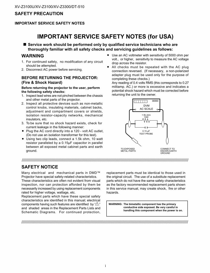
3. To be sure that no shock hazard exists, check forcurrent leakage in the following manner:Plug the AC cord directly into a 120 - volt AC outlet,(Do not use an isolation transformer for this test).Using two clip leads, connect a 1.5k ohm, 10 wattresistor paralleled by a 0.15µF capacitor in parallelbetween all exposed metal cabinet parts and earthground.
Use an AC voltmeter with sensitivity of 5000 ohm pervolt., or higher, sensitivity to measure the AC voltagedrop across the resistor.All checks must be repeated with the AC plugconnection reversed. (If necessary, a non-polarizedadapter plug must be used only for the purpose ofcompleting these checks.)Any reading of 0.4 volts RMS (this corresponds to 0.27milliamp. AC.) or more is excessive and indicates apotential shock hazard which must be corrected beforereturning the unit to the owner.
SAFETY NOTICEMany electrical and mechanical parts in DMD™Projector have special safety-related characteristics.These characteristics are often not evident from visualinspection, nor can protection afforded by them benecessarily increased by using replacement componentsrated for higher voltage, wattage, etc.Replacement parts which have these special safetycharacteristics are identified in this manual; electricalcomponents having such features are identified by “ ”and shaded areas in the Replacement Parts Lists andSchematic Diagrams. For continued protection,
replacement parts must be identical to those used inthe original circuit. The use of a substitute replacementparts which do not have the same safety characteristicsas the factory recommended replacement parts shownin this service manual, may create shock, fire or otherhazards.
WARNING: The bimetallic component has the primaryconductive side exposed. Be very careful inhandling this component when the power is on.
DVMAC SCALE
1.5k ohm10W
TO EXPOSEDMETAL PARTS
CONNECT TOKNOWN EARTHGROUND
0.15 µFTEST PROBE
/////////////////////////////////////////////////////////////////////////////////////////////////////////////////////////////////////////////////
/////////////////////////////////////////////////////////////////////////////////////////////////////////////////////////////////////////////////
i
XV-Z3100U/XV-Z3100/XV-Z3300/DT-510
PRECAUTIONS A PRENDRE LORS DE LA REPARATIONNe peut effectuer la réparation qu' un technicien spécialisé qui s'est parfaitementaccoutumé à toute vérification de sécurité et aux conseils suivants.
AVERTISSEMENT
1. N'entreprendre aucune modification de tout circuit.C'est dangereux.
2. Débrancher le récepteur avant toute réparation.
VERIFICATIONS CONTRE L'INCEN-DIE ETLE CHOC ELECTRIQUE
Avant de rendre le récepteur à l'utilisateur, effectuerles vérifications suivantes.1. Inspecter tous les faisceaux de câbles pour s'assurerque les fils ne soient pas pincés ou qu'un outil ne soitpas placé entre le châssis et les autres piècesmétalliques du récepteur.
2. Inspecter tous les dispositifs de protection comme lesboutons de commande non-métalliques, les isolants, ledos du coffret, les couvercles ou blindages de réglageet de compartiment, les réseaux de résistance-capacité,les isolateurs mécaniques, etc.
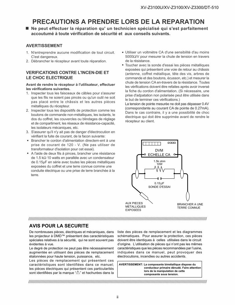
3. S'assurer qu'il n'y ait pas de danger d'électrocution envérifiant la fuite de courant, de la facon suivante:Brancher le cordon d'alimentation directem-ent à uneprise de courant de 120 - V. (Ne pas utiliser detransformateur d'isolation pour cet essai).A l'aide de deux fils à pinces, brancher une résistancede 1.5 kΩ 10 watts en parallèle avec un condensateurde 0.15µF en série avec toutes les pièces métalliquesexposées du coffret et une terre connue comme uneconduite électrique ou une prise de terre branchée à laterre.
Utiliser un voltmètre CA d'une sensibilité d'au moins5000Ω/V pour mesurer la chute de tension en traversde la résistance.Toucher avec la sonde d'essai les pièces métalliquesexposées qui présentent une voie de retour au châssis(antenne, coffret métallique, tête des vis, arbres decommande et des boutons, écusson, etc.) et mesurer lachute de tension CA en-travers de la résistance. Toutesles vérifications doivent être refaites après avoir inverséla fiche du cordon d'alimentation. (Si nécessaire, uneprise d'adpatation non polarisée peut être utilisée dansle but de terminer ces vérifications.)La tension de pointe mesurèe ne doit pas dépasser 0.4V(correspondante au courant CA de pointe de 0.27mA).Dans le cas contraire, il y a une possibilité de chocélectrique qui doit être supprimée avant de rendre lerécepteur au client.
DVMECHELLE CA
1.5k ohm10W
0.15µFSONDE D'ESSAI
AUX PIECESMETALLIQUESEXPOSEES
BRANCHER A UNETERRE CONNUE
AVIS POUR LA SECURITEDe nombreuses pièces, électriques et mécaniques, dansles projecteur à DMD™ présentent des caractéristiquesspéciales relatives à la sécurité, qui ne sont souvent pasévidentes à vue.Le degré de protection ne peut pas être nécessairementaugmentée en utilisant des pièces de remplacementétalonnées pour haute tension, puissance, etc.Les pièces de remplacement qui présentent cescaractéristiques sont identifiées dans ce manuel;les pièces électriques qui présentent ces particularitéssont identifiées par la marque “ ” et hachurées dans la
liste des pièces de remplacement et les diagrammesschématiques. Pour assurer la protection, ces piècesdoivent être identiques à celles utilisées dans le circuitd’origine. L’utilisation de pièces qui n’ont pas les mêmescaractéristiques que les pièces recommandées par l’usine,indiquées dans ce manuel, peut provoquer desélectrocutions, incendies ou autres accidents.
AVERTISSEMENT: La composante bimétallique dispose duconducteur primaire dénudé. Faire attentionlors de la manipulation de cettecomposante sous tension.
/////////////////////////////////////////////////////////////////////////////////////////////////////////////////////////////////////////////////////
/////////////////////////////////////////////////////////////////////////////////////////////////////////////////////////////////////////////////////
ii
XV-Z3100U/XV-Z3100/XV-Z3300/DT-510
NOTE POUR LE PERSONNELD’ENTRETIEN
PRECAUTION POUR LES RADIATIONS UV
La source de lumière, la lampe, dans le projecteurémet de petites quantités de radiation UV.
EVITEZ TOUTE EXPOSITION DIRECTE DESYEUX ET DE LA PEAU.Pour votre sécurité, nous vous prions de respecterles points suivants:
1. Toujours porter des lunettes de soleil lors d’un entretiendu projecteuravec la lampe alluméeet le haut du coffret retiré.
2. Ne pas faire fonctionner la lampe à l’extérieur du boîtierde lampe.
3. Ne pas faire fonctionner plus de 2 heures avec le coffretretiré.
Précautions pour les radiations UVet la lampe moyenne pression1. Toujours débrancher la fiche AC lors du remplacementde la lampe.
2. Laisser l’unité refroidir pendant une heure avant deprocéder à l’entretien.
3. Ne remplacer qu’avec une lampe du même type. TypeAN-XR10L2, caractéristique 220 W-DC.
4. La lampe émet de petites quantités de radiation UV-éviter tout contact direct avec les yeux.
5. La lampe moyenne pression implique un risqued’explosion. Toujours suivre les instructionsd’installation décrites ci-dessous et manipuler la lampeavec soin.
NOTE TO SERVICEPERSONNEL
UV-RADIATION PRECAUTION
The light source, lamp, in the projector emits small
amounts of UV-Radiation.
AVOID DIRECT EYE AND SKIN EXPOSURE.
To ensure safety please adhere to the following:
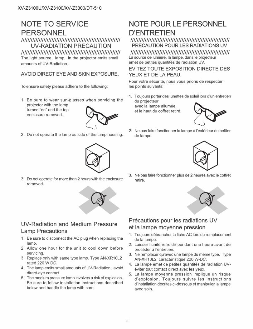
1. Be sure to wear sun-glasses when servicing theprojector with the lampturned “on” and the topenclosure removed.
2. Do not operate the lamp outside of the lamp housing.
3. Do not operate for more than 2 hours with the enclosureremoved.
UV-Radiation and Medium PressureLamp Precautions1. Be sure to disconnect the AC plug when replacing thelamp.
2. Allow one hour for the unit to cool down beforeservicing.
3. Replace only with same type lamp. Type AN-XR10L2rated 220 W DC.
4. The lamp emits small amounts of UV-Radiation, avoiddirect-eye contact.
5. Themedium pressure lamp involves a risk of explosion.Be sure to follow installation instructions describedbelow and handle the lamp with care.
//////////////////////////////////////////////////////////////
//////////////////////////////////////////////////////////////
//////////////////////////////////////////////////////////////
//////////////////////////////////////////////////////////////
iii
XV-Z3100U/XV-Z3100/XV-Z3300/DT-510
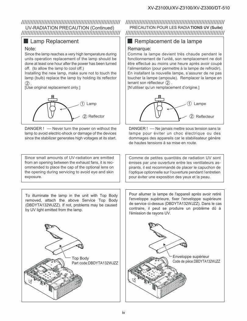
Remplacement de la lampeRemarque:Comme la lampe devient très chaude pendant lefonctionnement de l’unité, son remplacement ne doitêtre effectué au moins une heure après avoir coupél’alimentation (pour permettre à la lampe de refroidir).En installant la nouvelle lampe, s’assurer de ne pastoucher la lampe (ampoule). Remplacer la lampe entenant son réflecteur .[N’utiliser qu’un remplacement d’origine.]
1
2
2
Lamp
Reflector
Comme de petites quantités de radiation UV sontémises par une ouverture entre les ventilateurs as-pirants, il est recommandé de placer le capuchon del’optique optionnelle sur l’ouverture pendant l’entretienpour éviter une exposition des yeux et la peau.
Since small amounts of UV-radiation are emittedfrom an opening between the exhaust fans, it is rec-ommended to place the cap of the optional lens onthe opening during servicing to avoid eye and skinexposure.
DANGER ! –– Never turn the power on without thelamp to avoid electric-shock or damage of the devicessince the stabilizer generates high voltages at its start.
UV-RADIATION PRECAUTION (Continued)
Lamp ReplacementNote:Since the lamp reaches a very high temperature duringunits operation replacement of the lamp should bedone at least one hour after the power has been turnedoff. (to allow the lamp to cool off.)Installing the new lamp, make sure not to touch thelamp (bulb) replace the lamp by holding its reflector
.[Use original replacement only.]
DANGER ! –– Ne jamais mettre sous tension sans lalampe pour éviter un choc électrique ou desdommages des appareils car le stabilisateur génèrede hautes tensions à sa mise en route.
1
2
2
PRECAUTION POUR LES RADIATIONS UV (Suite)
Lampe
Reflecteur
Top BodyPart code:DBDYTA132WJZZ
To illuminate the lamp in the unit with Top Bodyremoved, attach the above Service Top Body(DBDYTA132WJZZ). If not, problems may be causedby UV light emitted from the lamp.
Enveloppe supérieurCode de pièce:DBDYTA132WJZZ
Pour allumer la lampe de l'appareil après avoir retirél'enveloppe supérieure, fixer l'enveloppe supérieurede service ci-dessus (DBDYTA132WJZZ). Dans le cascontraire, il peut se produire un problème dû àl'émission de rayons UV.
////////////////////////////////////////////////////////////////
////////////////////////////////////////////////////////////////
////////////////////////////////////////////////////////////////
////////////////////////////////////////////////////////////////
iv
XV-Z3100U/XV-Z3100/XV-Z3300/DT-510
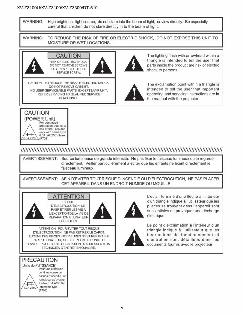
WARNING: High brightness light source, do not stare into the beam of light, or view directly. Be especiallycareful that children do not stare directly in to the beam of light.
WARNING: TO REDUCE THE RISK OF FIRE OR ELECTRIC SHOCK, DO NOT EXPOSE THIS UNIT TOMOISTURE OR WET LOCATIONS.
CAUTION: TOREDUCETHERISKOFELECTRIC SHOCK,DONOTREMOVECABINET.
NOUSER-SERVICEABLE PARTS EXCEPT LAMPUNIT.REFERSERVICINGTOQUALIFIEDSERVICE
PERSONNEL.
The lighting flash with arrowhead within atriangle is intended to tell the user thatparts inside the product are risk of electricshock to persons.
The exclamation point within a triangle isintended to tell the user that importantoperating and servicing instructions are inthe manual with the projector.
CAUTION
AVERTISSEMENT: Source lumineuse de grande intensité. Ne pas fixer le faisceau lumineux ou le regarderdirectement. Veiller particulièrement à éviter que les enfants ne fixent directement lefaisceau lumineux.
AVERTISSEMENT: AFIN D’EVITER TOUT RISQUE D’INCENDIE OU D’ELECTROCUTION, NE PAS PLACERCET APPAREIL DANS UN ENDROIT HUMIDE OU MOUILLE.
L’éclair terminé d’une flèche à l’intérieurd’un triangle indique à l’utilisateur que lespi‘eces se trouvant dans l’appareil sontsusceptibles de provoquer une déchargeélectrique.
Le point d’exclamation à l’intérieur d’untriangle indique à l’utilisateur que lesinstruct ions de fonctionnement etd’entretien sont détaillées dans lesdocuments fournis avec le projecteur.
RISQUED’ÉLECTROCUTION. NEPASRETIRER LESVIS ÁL’EXCEPTIONDE LAVIS DEREPARATIONUTILISATEUR
SPECIFIEES
ATTENTION
ATTENTION: POUREVITER TOUTRISQUED’ELECTROCUTION, NE PASRETIRER LECAPOT.
AUCUNEDES PIECES INTERIEURESN’EST REPARABLEPARL’UTILISATEUR, A L’EXCEPTIONDEL’UNITEDE
LAMPE. POUR TOUTEREPARATION, S’ADRESSERAUNTECHNICIEND’ENTRETIENQUALIFIE.
RISK OF ELECTRIC SHOCK.DONOTREMOVE SCREWSEXCEPT SPECIFIED USER
SERVICESCREW.
CAUTION(POWER Unit)
For continuedprotection against arisk of fire, replaceonly with same type6.3A, AC250V fuse.(F701)
PRECAUTION(Unité de PUTSSANCE)
Pour une protectioncontinue contre unrisques d’incendie, neremplacer qu’avec unfusible 6.3A,AC250Vdumême type.(F701)
6.3A 250V
6.3A 250V
//////////////////////////////////////////////////////////////////////////////////////////////////////////////////////////////////
v
XV-Z3100U/XV-Z3100/XV-Z3300/DT-510
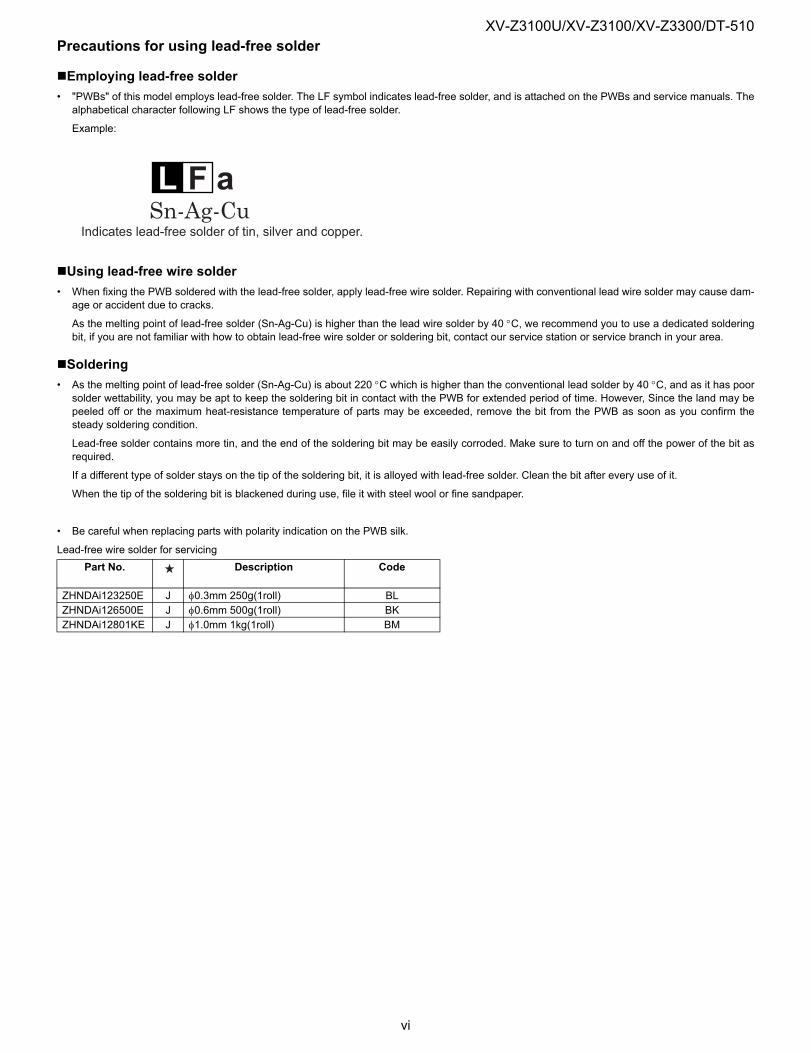
Precautions for using lead-free solderEmploying lead-free solder• "PWBs" of this model employs lead-free solder. The LF symbol indicates lead-free solder, and is attached on the PWBs and service manuals. The
alphabetical character following LF shows the type of lead-free solder.
Example:
Using lead-free wire solder• When fixing the PWB soldered with the lead-free solder, apply lead-free wire solder. Repairing with conventional lead wire solder may cause dam-
age or accident due to cracks.
As the melting point of lead-free solder (Sn-Ag-Cu) is higher than the lead wire solder by 40 °C, we recommend you to use a dedicated solderingbit, if you are not familiar with how to obtain lead-free wire solder or soldering bit, contact our service station or service branch in your area.
Soldering• As the melting point of lead-free solder (Sn-Ag-Cu) is about 220 °C which is higher than the conventional lead solder by 40 °C, and as it has poor
solder wettability, you may be apt to keep the soldering bit in contact with the PWB for extended period of time. However, Since the land may bepeeled off or the maximum heat-resistance temperature of parts may be exceeded, remove the bit from the PWB as soon as you confirm thesteady soldering condition.
Lead-free solder contains more tin, and the end of the soldering bit may be easily corroded. Make sure to turn on and off the power of the bit asrequired.
If a different type of solder stays on the tip of the soldering bit, it is alloyed with lead-free solder. Clean the bit after every use of it.
When the tip of the soldering bit is blackened during use, file it with steel wool or fine sandpaper.
• Be careful when replacing parts with polarity indication on the PWB silk.
Lead-free wire solder for servicing
L F a
Indicates lead-free solder of tin, silver and copper.
Part No. Description Code
ZHNDAi123250E J φ0.3mm 250g(1roll) BLZHNDAi126500E J φ0.6mm 500g(1roll) BKZHNDAi12801KE J φ1.0mm 1kg(1roll) BM
vi
XV-Z3100U/XV-Z3100/XV-Z3300/DT-510
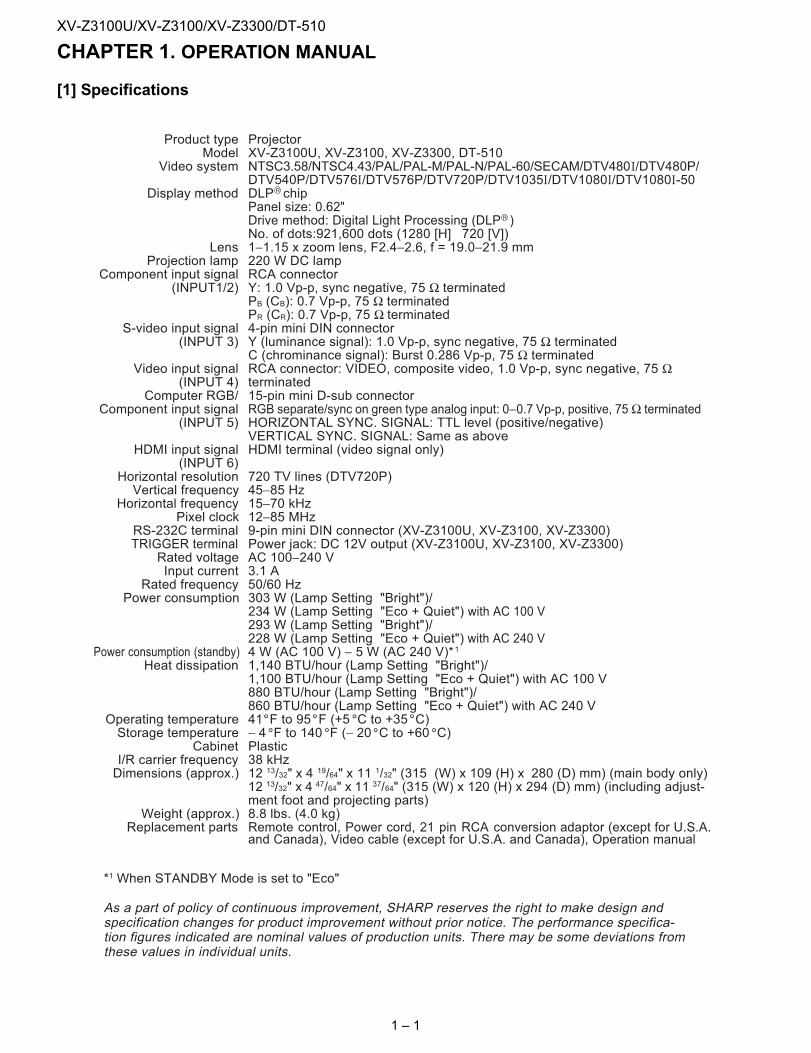
XV-Z3100U Service Manual CHAPTER 1. OPERATION MANUAL[1] Specifications
ProjectorXV-Z3100U, XV-Z3100, XV-Z3300, DT-510NTSC3.58/NTSC4.43/PAL/PAL-M/PAL-N/PAL-60/SECAM/DTV480 /DTV480P/DTV540P/DTV576 /DTV576P/DTV720P/DTV1035 /DTV1080 /DTV1080 -50DLP chipPanel size: 0.62"ıDrive method: Digital Light Processing (DLP )No. of dots:921,600 dots (1280 [H] 720 [V])1−1.15 x zoom lens, F2.4−2.6, f = 19.0−21.9 mm220 W DC lampRCA connectorY: 1.0 Vp-p, sync negative, 75 Ω terminatedPB (CB): 0.7 Vp-p, 75 Ω terminatedPR (CR): 0.7 Vp-p, 75 Ω terminated4-pin mini DIN connectorY (luminance signal): 1.0 Vp-p, sync negative, 75 Ω terminatedC (chrominance signal): Burst 0.286 Vp-p, 75 Ω terminatedRCA connector: VIDEO, composite video, 1.0 Vp-p, sync negative, 75 Ωterminated15-pin mini D-sub connectorRGB separate/sync on green type analog input: 0−0.7 Vp-p, positive, 75Ω terminatedHORIZONTAL SYNC. SIGNAL: TTL level (positive/negative)VERTICAL SYNC. SIGNAL: Same as aboveHDMI terminal (video signal only)
720 TV lines (DTV720P)45−85 Hz15−70 kHz12−85 MHz9-pin mini DIN connector (XV-Z3100U, XV-Z3100, XV-Z3300)Power jack: DC 12V output (XV-Z3100U, XV-Z3100, XV-Z3300)AC 100−240 V3.1 A50/60 Hz303 W (Lamp Setting "Bright")/234 W (Lamp Setting "Eco + Quiet") with AC 100 V293 W (Lamp Setting "Bright")/228 W (Lamp Setting "Eco + Quiet") with AC 240 V4 W (AC 100 V) − 5 W (AC 240 V)*11,140 BTU/hour (Lamp Setting "Bright")/1,100 BTU/hour (Lamp Setting "Eco + Quiet") with AC 100 V880 BTU/hour (Lamp Setting "Bright")/860 BTU/hour (Lamp Setting "Eco + Quiet") with AC 240 V41 F to 95 F (+5 C to +35 C)− 4 F to 140 F (− 20 C to +60 C)Plastic38 kHz12 13/32" x 4 ı19/64" xı11 1/32" (315 (W) x 109 (H) x 280 (D) mm) (main body only)ı12 13/32" xı4 47/64" xı11 37/64" (315 (W) x 120 (H) x 294 (D) mm) (including adjust-ıment foot and projecting parts)8.8 lbs. (4.0 kg)Remote control, Power cord, 21 pin RCA conversion adaptor (except for U.S.A.and Canada), Video cable (except for U.S.A. and Canada), Operation manual
Product typeModel
Video system
Display method
LensProjection lamp
Component input signal(INPUT1/2)
S-video input signal(INPUT 3)
Video input signal(INPUT 4)
Computer RGB/Component input signal
(INPUT 5)
HDMI input signal(INPUT 6)
Horizontal resolutionVertical frequency
Horizontal frequencyPixel clock
RS-232C terminalTRIGGER terminal
Rated voltageInput current
Rated frequencyPower consumption
Power consumption (standby)Heat dissipation
Operating temperatureStorage temperature
CabinetI/R carrier frequencyDimensions (approx.)
Weight (approx.)Replacement parts
*1 When STANDBY Mode is set to "Eco"
As a part of policy of continuous improvement, SHARP reserves the right to make design andspecification changes for product improvement without prior notice. The performance specifica-tion figures indicated are nominal values of production units. There may be some deviations fromthese values in individual units.
R
R
1 – 1
XV-Z3100U/XV-Z3100/XV-Z3300/DT-510
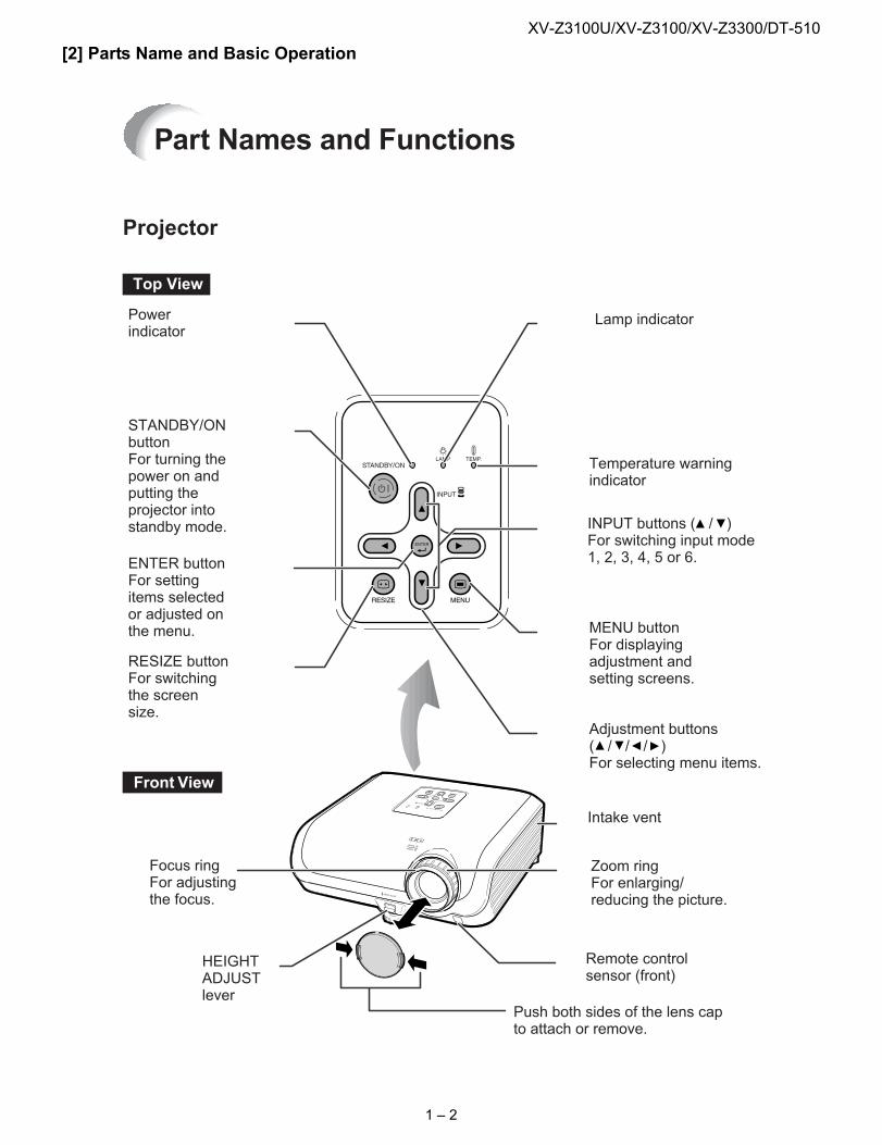
[2] Parts Name and Basic OperationTop View
STANDBY/ONbuttonFor turning thepower on andputting theprojector intostandby mode.
Lamp indicator
Temperature warningindicator
Adjustment buttons( / / / )For selecting menu items.
ENTER buttonFor settingitems selectedor adjusted onthe menu. MENU button
For displayingadjustment andsetting screens.
Front View
Focus ringFor adjustingthe focus.
INPUT buttons ( / )For switching input mode1, 2, 3, 4, 5 or 6.
Remote controlsensor (front)
HEIGHTADJUSTlever
Projector
RESIZE buttonFor switchingthe screensize.
Intake vent
Powerindicator
Zoom ringFor enlarging/reducing the picture.
Push both sides of the lens capto attach or remove.
Part Names and Functions
1 – 2
XV-Z3100U/XV-Z3100/XV-Z3300/DT-510
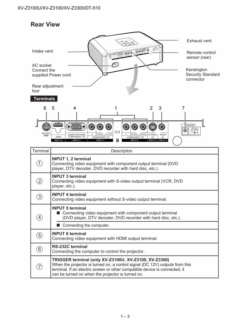
Rear View
Remote controlsensor (rear)
Rear adjustmentfoot
KensingtonSecurity Standardconnector
AC socketConnect thesupplied Power cord.
Intake vent
Exhaust vent
6 5 4 1 2 3 7
Terminals
Terminal Description
1
2
3
INPUT 3 terminalConnecting video equipment with S-video output terminal (VCR, DVDplayer, etc.).
4
INPUT 4 terminalConnecting video equipment without S-video output terminal.
ı Connecting the computer.
5
INPUT 5 terminalConnecting video equipment with component output terminal(DVD player, DTV decoder, DVD recorder with hard disc, etc.).
TRIGGER terminal (only XV-Z3100U, XV-Z3100, XV-Z3300)When the projector is turned on, a control signal (DC 12V) outputs from thisterminal. If an electric screen or other compatible device is connected, itcan be turned on when the projector is turned on.
RS-232C terminalConnecting the computer to control the projector.6
7
INPUT 6 terminalConnecting video equipment with HDMI output terminal.
INPUT 1, 2 terminalConnecting video equipment with component output terminal (DVDplayer, DTV decoder, DVD recorder with hard disc, etc.).
1 – 3
XV-Z3100U/XV-Z3100/XV-Z3300/DT-510
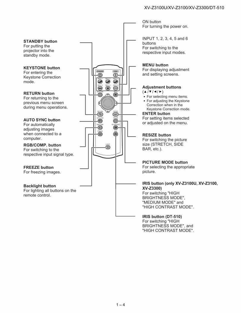
STANDBY buttonFor putting theprojector into thestandby mode.
KEYSTONE buttonFor entering theKeystone Correctionmode.
RETURN buttonFor returning to theprevious menu screenduring menu operations.
RGB/COMP. buttonFor switching to therespective input signal type.
PICTURE MODE buttonFor selecting the appropriatepicture.
ON buttonFor turning the power on.
Adjustment buttons( / / / )For selecting menu items.For adjusting the KeystoneCorrection when in theKeystone Correction mode.
MENU buttonFor displaying adjustmentand setting screens.
ENTER buttonFor setting items selectedor adjusted on the menu.
RESIZE buttonFor switching the picturesize (STRETCH, SIDEBAR, etc.).
FREEZE buttonFor freezing images.
INPUT 1, 2, 3, 4, 5 and 6buttonsFor switching to therespective input modes.
IRIS button (only XV-Z3100U, XV-Z3100,XV-Z3300)For switching "HIGHBRIGHTNESS MODE","MEDIUM MODE" and"HIGH CONTRAST MODE".
IRIS button (DT-510)For switching "HIGHBRIGHTNESS MODE", and"HIGH CONTRAST MODE".
AUTO SYNC buttonFor automaticallyadjusting imageswhen connected to acomputer.
Backlight buttonFor lighting all buttons on theremote control.
1 – 4
XV-Z3100U/XV-Z3100/XV-Z3300/DT-510
Danger of explosion if battery is incorrectly replaced.Replace only with the same or equivalent type.Insert the batteries making sure the polarities correctly match the and marks inside the batterycompartment.Batteries of different types have different properties, therefore do not mix batteries of different types.Do not mix new and old batteries.This may shorten the life of new batteries or may cause old batteries to leak.Remove the batteries from the remote control once they have run out, as leaving them in can cause themto leak.Battery fluid from leaked batteries is harmful to skin, therefore ensure you wipe them first and then removethem using a cloth.
The batteries included with this projector may run down in a short period, depending on how they are kept.Be sure to replace them as soon as possible with new batteries.Remove the batteries from the remote control if you will not be using the remote control for a long time.Comply with the rules (ordinance) of each local government when disposing of worn-out batteries.
Incorrect use of the batteries may cause them to leak or explode. Pleasefollow the precautions below.
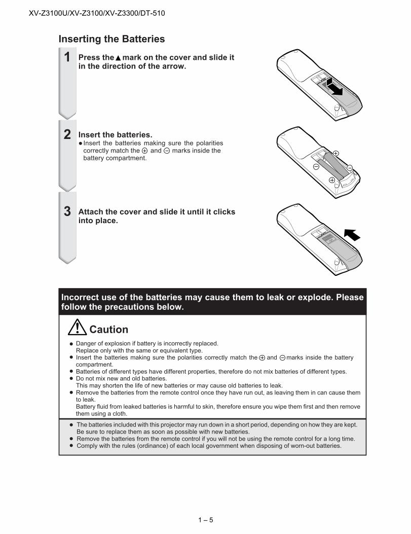
Inserting the Batteries
Attach the cover and slide it until it clicksinto place.
Insert the batteries.Insert the batteries making sure the polaritiescorrectly match the and marks inside thebattery compartment.
Press the mark on the cover and slide itin the direction of the arrow.
1
2
3
Caution
1 – 5
XV-Z3100U/XV-Z3100/XV-Z3300/DT-510
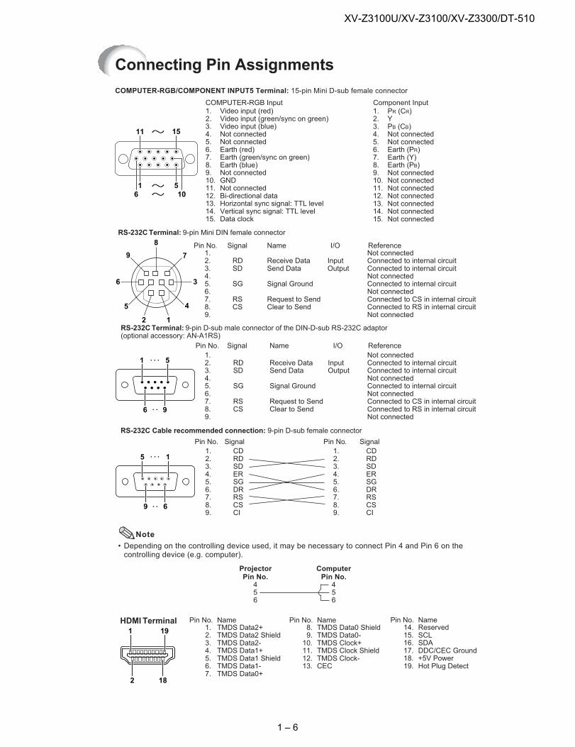
Connecting Pin Assignments
COMPUTER-RGB Input
COMPUTER-RGB/COMPONENT INPUT5 Terminal: 15-pin Mini D-sub female connector
1. Video input (red)2. Video input (green/sync on green)3. Video input (blue)4. Not connected5. Not connected6. Earth (red)7. Earth (green/sync on green)8. Earth (blue)9. Not connected10. GND11. Not connected12. Bi-directional data13. Horizontal sync signal: TTL level14. Vertical sync signal: TTL level15. Data clock
RS-232CTerminal: 9-pin Mini DIN female connector
Component Input
510
15
1
11
6
1. PR (CR)2. Y3. PB (CB)4. Not connected5. Not connected6. Earth (PR)7. Earth (Y)8. Earth (PB)9. Not connected10. Not connected11. Not connected12. Not connected13. Not connected14. Not connected15. Not connected
RDSD
SG
RSCS
Signal Name8
9
6
5
2 1
4
3
7Pin No.
1.2.3.4.5.6.7.8.9.
I/O ReferenceNot connectedConnected to internal circuitConnected to internal circuitNot connectedConnected to internal circuitNot connectedConnected to CS in internal circuitConnected to RS in internal circuitNot connected
Receive DataSend Data
Signal Ground
Request to SendClear to Send
InputOutput
RS-232CTerminal: 9-pin D-sub male connector of the DIN-D-sub RS-232C adaptor(optional accessory: AN-A1RS)
RDSD
SG
RSCS
Signal NamePin No.1.2.3.4.5.6.7.8.9.
I/O ReferenceNot connectedConnected to internal circuitConnected to internal circuitNot connectedConnected to internal circuitNot connectedConnected to CS in internal circuitConnected to RS in internal circuitNot connected
Receive DataSend Data
Signal Ground
Request to SendClear to Send
InputOutput
1 5
6 9
CDRDSDERSGDRRSCSCI
SignalPin No.1.2.3.4.5.6.7.8.9.
RS-232C Cable recommended connection: 9-pin D-sub female connector
CDRDSDERSGDRRSCSCI
SignalPin No.1.2.3.4.5.6.7.8.9.
5 1
9 6
• Depending on the controlling device used, it may be necessary to connect Pin 4 and Pin 6 on thecontrolling device (e.g. computer).
Note
ProjectorPin No.456
ComputerPin No.456
1 19
2 18
HDMI Terminal NamePin No.1.2.3.4.5.6.7.
TMDS Data2+TMDS Data2 ShieldTMDS Data2-TMDS Data1+TMDS Data1 ShieldTMDS Data1-TMDS Data0+
NamePin No.TMDS Data0 ShieldTMDS Data0-TMDS Clock+TMDS Clock ShieldTMDS Clock-CEC
8.9.10.11.12.13.
NamePin No.ReservedSCLSDADDC/CEC Ground+5V PowerHot Plug Detect
14.15.16.17.18.19.
1 – 6
XV-Z3100U/XV-Z3100/XV-Z3300/DT-510
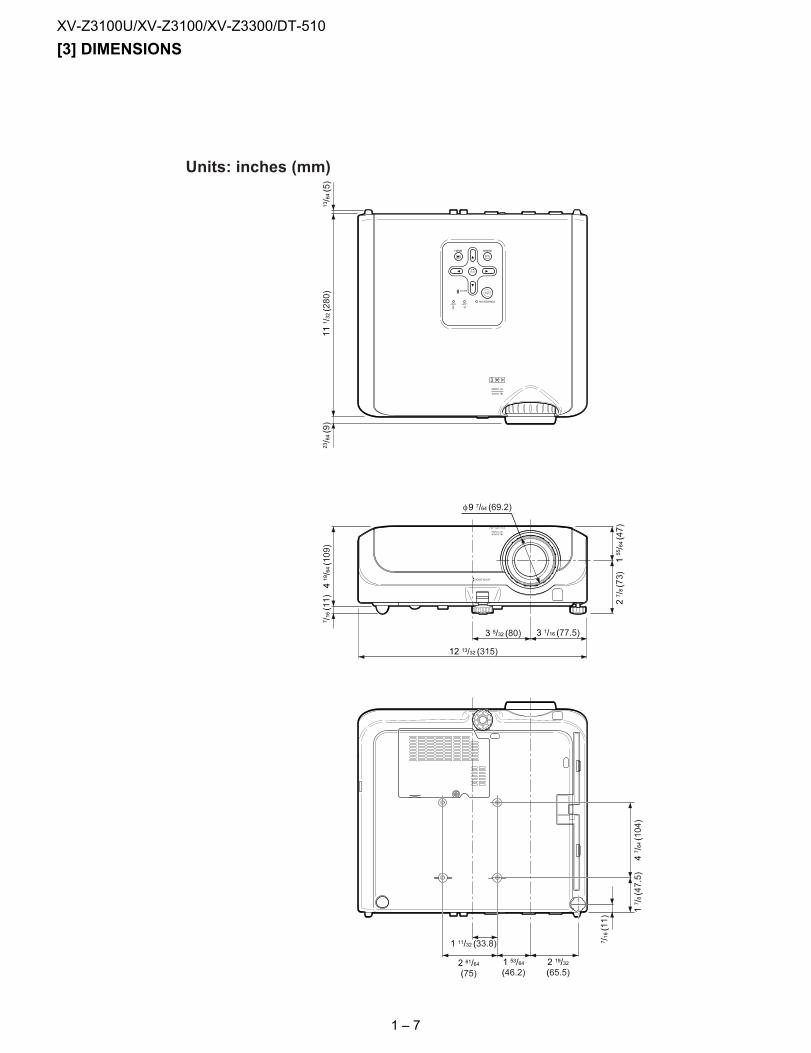
[3] DIMENSIONSUnits: inches (mm)
12 13/32 (315)
3 1/16 (77.5)
2 19/32(65.5)
1 53/64(46.2)
3 5/32 (80)
155/64(47)
27/8(73)
2 61/64(75)
1 11/32 (33.8)
419/64(109)
17/8(47.5)
47/64(104)
7/16(11)
111/32(280)
23/64(9)
13/64(5)
7/16(11)
φ9 7/64 (69.2)
1 – 7
XV-Z3100U/XV-Z3100/XV-Z3300/DT-510
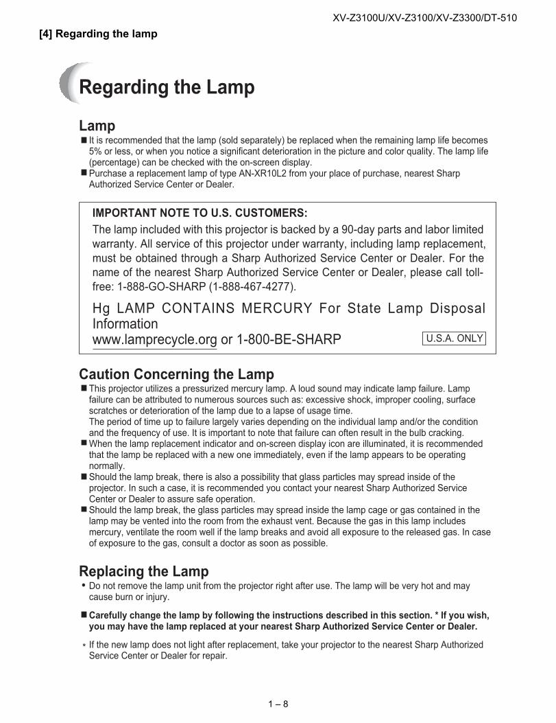
[4] Regarding the lampRegarding the Lamp
Lampı It is recommended that the lamp (sold separately) be replaced when the remaining lamp life becomes5% or less, or when you notice a significant deterioration in the picture and color quality. The lamp life(percentage) can be checked with the on-screen display.
ı Purchase a replacement lamp of type AN-XR10L2 from your place of purchase, nearest SharpAuthorized Service Center or Dealer.
Caution Concerning the LampThis projector utilizes a pressurized mercury lamp. A loud sound may indicate lamp failure. Lampfailure can be attributed to numerous sources such as: excessive shock, improper cooling, surfacescratches or deterioration of the lamp due to a lapse of usage time.The period of time up to failure largely varies depending on the individual lamp and/or the conditionand the frequency of use. It is important to note that failure can often result in the bulb cracking.
ı When the lamp replacement indicator and on-screen display icon are illuminated, it is recommendedthat the lamp be replaced with a new one immediately, even if the lamp appears to be operatingnormally.
ı Should the lamp break, there is also a possibility that glass particles may spread inside of theprojector. In such a case, it is recommended you contact your nearest Sharp Authorized ServiceCenter or Dealer to assure safe operation.
ı Should the lamp break, the glass particles may spread inside the lamp cage or gas contained in thelamp may be vented into the room from the exhaust vent. Because the gas in this lamp includesmercury, ventilate the room well if the lamp breaks and avoid all exposure to the released gas. In caseof exposure to the gas, consult a doctor as soon as possible.
Replacing the LampDo not remove the lamp unit from the projector right after use. The lamp will be very hot and maycause burn or injury.
ı Carefully change the lamp by following the instructions described in this section. * If you wish,you may have the lamp replaced at your nearest Sharp Authorized Service Center or Dealer.
* If the new lamp does not light after replacement, take your projector to the nearest Sharp AuthorizedService Center or Dealer for repair.
IMPORTANT NOTE TO U.S. CUSTOMERS:
The lamp included with this projector is backed by a 90-day parts and labor limitedwarranty. All service of this projector under warranty, including lamp replacement,must be obtained through a Sharp Authorized Service Center or Dealer. For thename of the nearest Sharp Authorized Service Center or Dealer, please call toll-free: 1-888-GO-SHARP (1-888-467-4277).
Hg LAMP CONTAINS MERCURY For State Lamp DisposalInformationwww.lamprecycle.org or 1-800-BE-SHARP U.S.A. ONLY
1 – 8
XV-Z3100U/XV-Z3100/XV-Z3300/DT-510
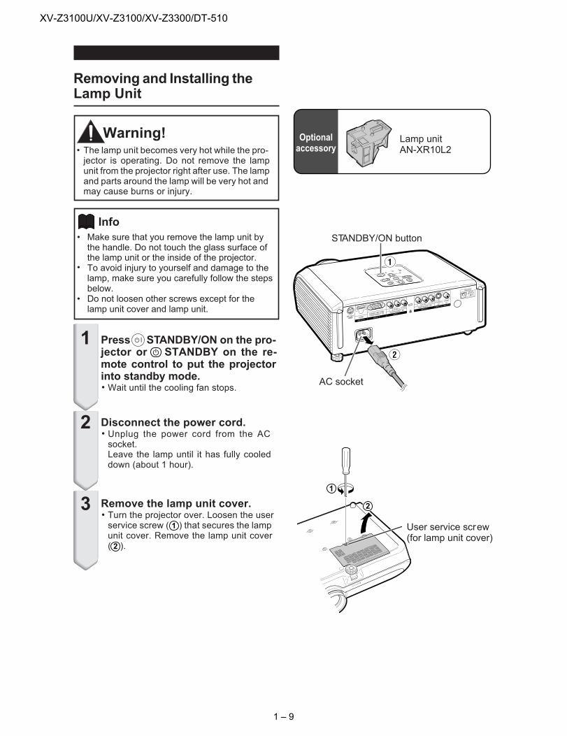
Removing and Installing theLamp Unit
•
•
•
Make sure that you remove the lamp unit bythe handle. Do not touch the glass surface ofthe lamp unit or the inside of the projector.To avoid injury to yourself and damage to thelamp, make sure you carefully follow the stepsbelow.Do not loosen other screws except for thelamp unit cover and lamp unit.
Press STANDBY/ON on the pro-jector or STANDBY on the re-mote control to put the projectorinto standby mode.Wait until the cooling fan stops.
Warning!• The lamp unit becomes very hot while the pro-jector is operating. Do not remove the lampunit from the projector right after use. The lampand parts around the lamp will be very hot andmay cause burns or injury.
Disconnect the power cord.Unplug the power cord from the ACsocket.Leave the lamp until it has fully cooleddown (about 1 hour).
Remove the lamp unit cover.Turn the projector over. Loosen the userservice screw ( ı ) that secures the lampunit cover. Remove the lamp unit cover(ˇ ).
1
1
2
2
Lamp unitAN-XR10L2
Info
Optionalaccessory
AC socket
User service screw(for lamp unit cover)
1
2
3
STANDBY/ON button
1 – 9
XV-Z3100U/XV-Z3100/XV-Z3300/DT-510
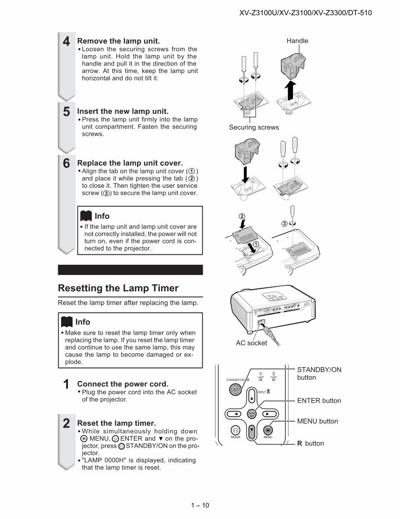
Remove the lamp unit.Loosen the securing screws from thelamp unit. Hold the lamp unit by thehandle and pull it in the direction of thearrow. At this time, keep the lamp unithorizontal and do not tilt it.
Resetting the Lamp Timer
Reset the lamp timer after replacing the lamp.
Insert the new lamp unit.Press the lamp unit firmly into the lampunit compartment. Fasten the securingscrews.
Replace the lamp unit cover.Align the tab on the lamp unit cover ( )and place it while pressing the tab ( )to close it. Then tighten the user servicescrew ( ) to secure the lamp unit cover.
4
5
6
Connect the power cord.Plug the power cord into the AC socketof the projector.
Reset the lamp timer.While simultaneously holding downMENU, ENTER and on the pro-
jector, press STANDBY/ON on the pro-jector."LAMP 0000H" is displayed, indicatingthat the lamp timer is reset.
Make sure to reset the lamp timer only whenreplacing the lamp. If you reset the lamp timerand continue to use the same lamp, this maycause the lamp to become damaged or ex-plode.
1
2
Info
AC socket
Securing screws
Handle
ENTER button
MENU button
R button
If the lamp unit and lamp unit cover arenot correctly installed, the power will notturn on, even if the power cord is con-nected to the projector.
Info 2
2
1
1
3
3
STANDBY/ONbutton
1 – 10
XV-Z3100U/XV-Z3100/XV-Z3300/DT-510
Maintenance Indicators
About the lamp indicator
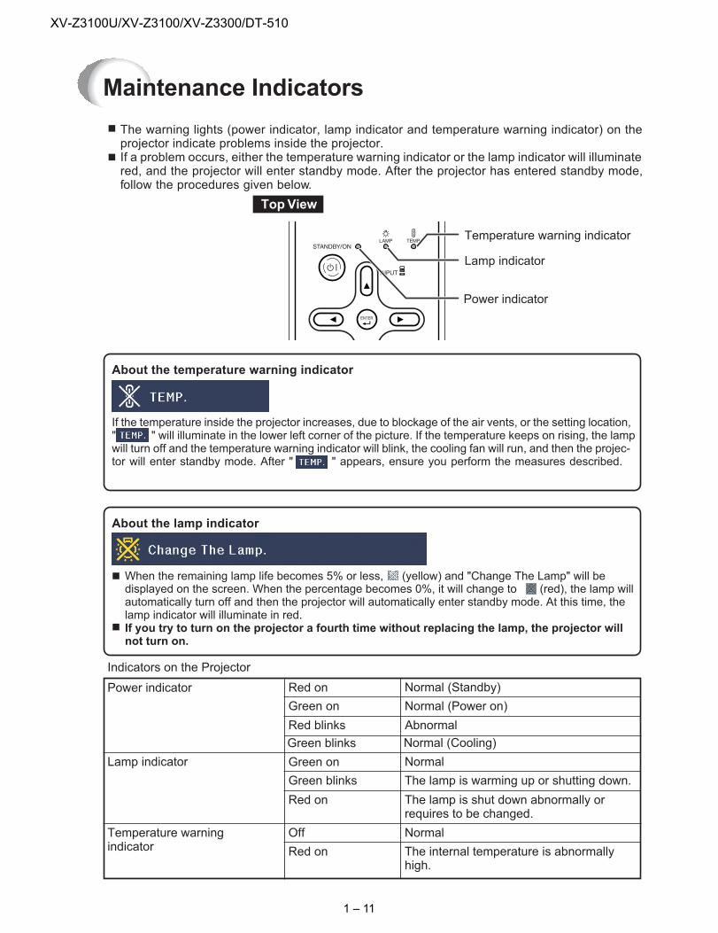
ı When the remaining lamp life becomes 5% or less, (yellow) and "Change The Lamp" will bedisplayed on the screen. When the percentage becomes 0%, it will change to (red), the lamp willautomatically turn off and then the projector will automatically enter standby mode. At this time, thelamp indicator will illuminate in red.
ı If you try to turn on the projector a fourth time without replacing the lamp, the projector willnot turn on.
About the temperature warning indicator
If the temperature inside the projector increases, due to blockage of the air vents, or the setting location," " will illuminate in the lower left corner of the picture. If the temperature keeps on rising, the lampwill turn off and the temperature warning indicator will blink, the cooling fan will run, and then the projec-tor will enter standby mode. After " " appears, ensure you perform the measures described.
Lamp indicator
The warning lights (power indicator, lamp indicator and temperature warning indicator) on theprojector indicate problems inside the projector.If a problem occurs, either the temperature warning indicator or the lamp indicator will illuminatered, and the projector will enter standby mode. After the projector has entered standby mode,follow the procedures given below.
Temperature warning indicator
Power indicator
Lamp indicator
Red onPower indicator
Indicators on the Projector
Green on
Normal (Standby)
Normal (Power on)
Green on
Green blinks
Normal
The lamp is warming up or shutting down.
Temperature warningindicator
Off
Red on
Normal
The internal temperature is abnormallyhigh.
Red blinks Abnormal
Red on The lamp is shut down abnormally orrequires to be changed.
Green blinks Normal (Cooling)
TopView
1 – 11
XV-Z3100U/XV-Z3100/XV-Z3300/DT-510
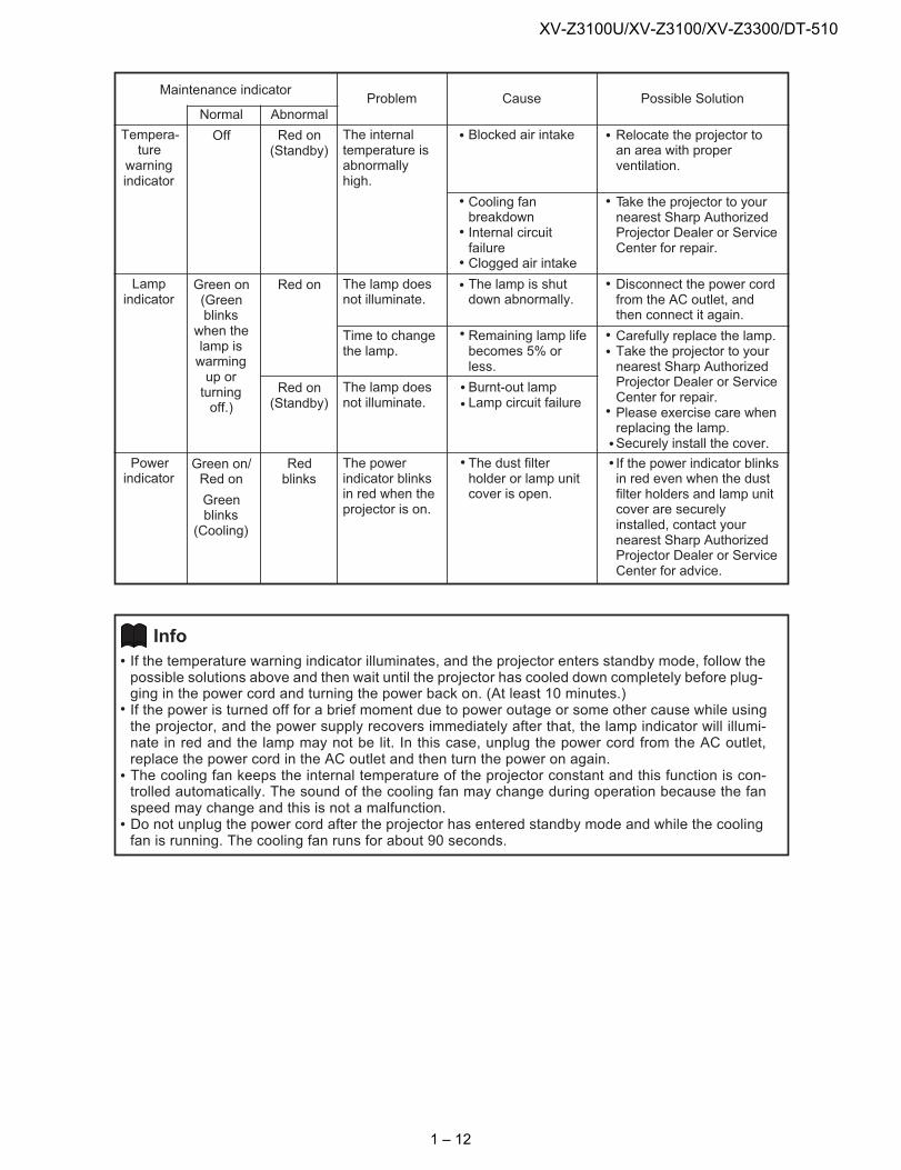
Maintenance indicatorProblem
The internaltemperature isabnormallyhigh.
The lamp doesnot illuminate.
Time to changethe lamp.
The lamp doesnot illuminate.
The powerindicator blinksin red when theprojector is on.
Cause
Blocked air intake
Cooling fanbreakdownInternal circuitfailureClogged air intake
The lamp is shutdown abnormally.
Remaining lamp lifebecomes 5% orless.
Burnt-out lampLamp circuit failure
The dust filterholder or lamp unitcover is open.
Possible Solution
Relocate the projector toan area with properventilation.
Take the projector to yournearest Sharp AuthorizedProjector Dealer or ServiceCenter for repair.
Disconnect the power cordfrom the AC outlet, andthen connect it again.
Carefully replace the lamp.Take the projector to yournearest Sharp AuthorizedProjector Dealer or ServiceCenter for repair.Please exercise care whenreplacing the lamp.Securely install the cover.
If the power indicator blinksin red even when the dustfilter holders and lamp unitcover are securelyinstalled, contact yournearest Sharp AuthorizedProjector Dealer or ServiceCenter for advice.
Abnormal
Red on(Standby)
Red on
Red on(Standby)
Redblinks
Tempera-ture
warningindicator
Lampindicator
Powerindicator
Normal
Off
Green on(Greenblinkswhen thelamp iswarmingup orturningoff.)
Green on/Red on
Greenblinks
(Cooling)
If the temperature warning indicator illuminates, and the projector enters standby mode, follow thepossible solutions above and then wait until the projector has cooled down completely before plug-ging in the power cord and turning the power back on. (At least 10 minutes.)If the power is turned off for a brief moment due to power outage or some other cause while usingthe projector, and the power supply recovers immediately after that, the lamp indicator will illumi-nate in red and the lamp may not be lit. In this case, unplug the power cord from the AC outlet,replace the power cord in the AC outlet and then turn the power on again.The cooling fan keeps the internal temperature of the projector constant and this function is con-trolled automatically. The sound of the cooling fan may change during operation because the fanspeed may change and this is not a malfunction.Do not unplug the power cord after the projector has entered standby mode and while the coolingfan is running. The cooling fan runs for about 90 seconds.
Info
1 – 12
XV-Z3100U/XV-Z3100/XV-Z3300/DT-510
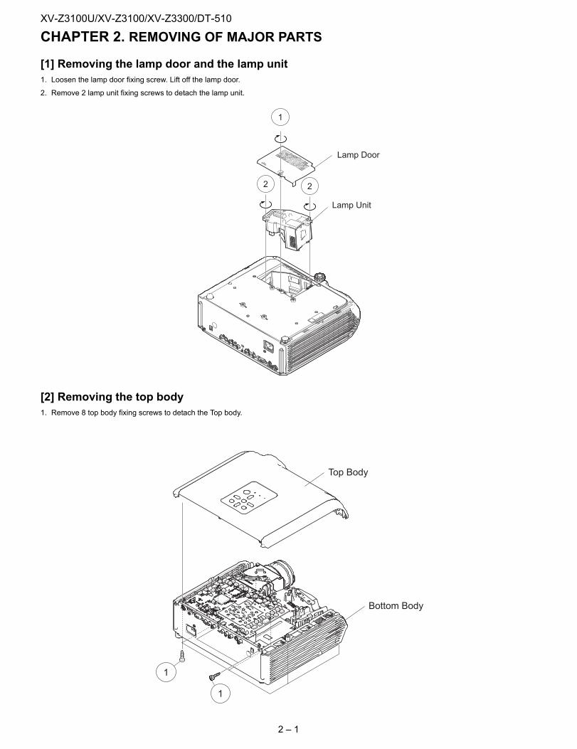
XV-Z3100U Service Manual CHAPTER 2. REMOVING OF MAJOR PARTS[1] Removing the lamp door and the lamp unit1. Loosen the lamp door fixing screw. Lift off the lamp door.
2. Remove 2 lamp unit fixing screws to detach the lamp unit.
[2] Removing the top body1. Remove 8 top body fixing screws to detach the Top body.
1
2 2
Lamp Door
Lamp Unit
1
1
Top Body
Bottom Body
2 – 1
XV-Z3100U/XV-Z3100/XV-Z3300/DT-510
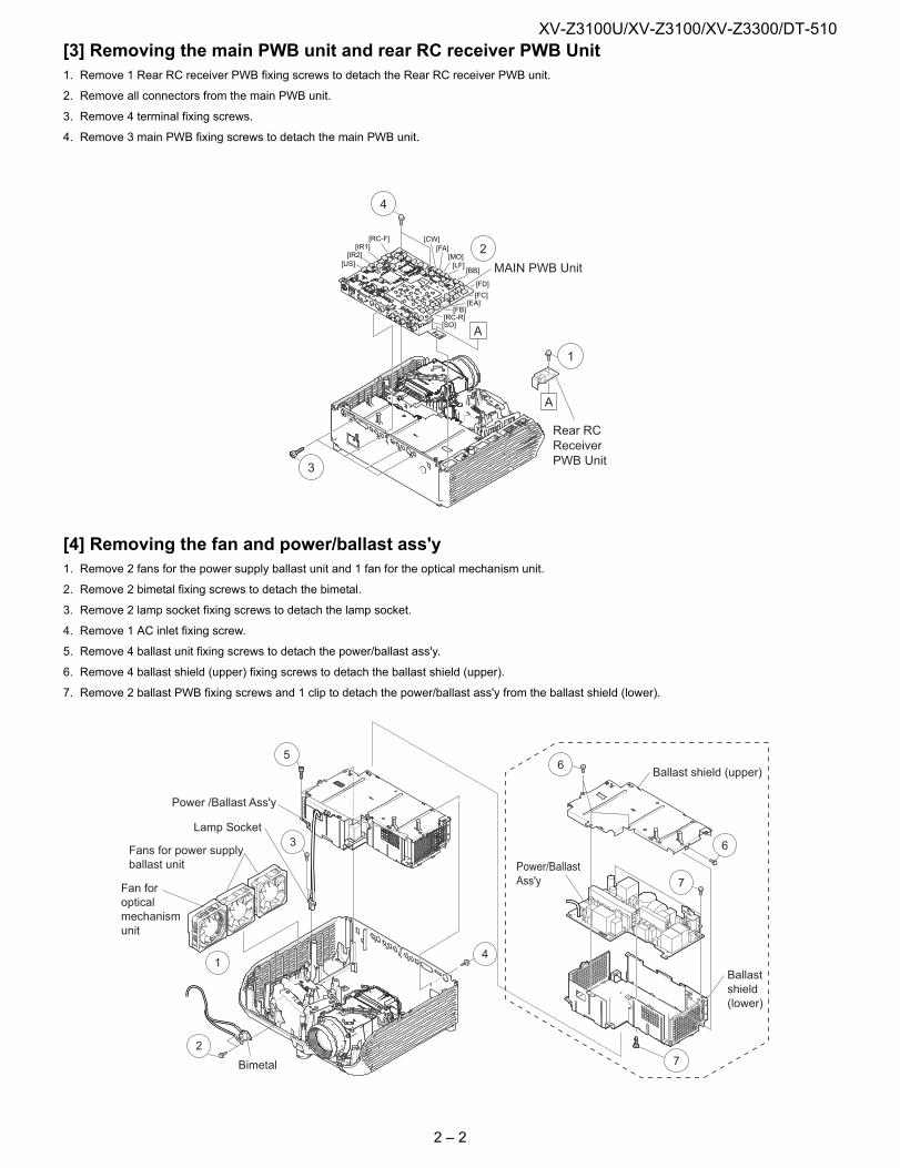
[3] Removing the main PWB unit and rear RC receiver PWB Unit1. Remove 1 Rear RC receiver PWB fixing screws to detach the Rear RC receiver PWB unit.2. Remove all connectors from the main PWB unit.
3. Remove 4 terminal fixing screws.
4. Remove 3 main PWB fixing screws to detach the main PWB unit.
[4] Removing the fan and power/ballast ass'y1. Remove 2 fans for the power supply ballast unit and 1 fan for the optical mechanism unit.
2. Remove 2 bimetal fixing screws to detach the bimetal.
3. Remove 2 lamp socket fixing screws to detach the lamp socket.
4. Remove 1 AC inlet fixing screw.
5. Remove 4 ballast unit fixing screws to detach the power/ballast ass'y.
6. Remove 4 ballast shield (upper) fixing screws to detach the ballast shield (upper).
7. Remove 2 ballast PWB fixing screws and 1 clip to detach the power/ballast ass'y from the ballast shield (lower).
[RC-F][IR1]
[IR2][US]
[SO]
[FB][EA]
[RC-R]
[FC]
[FD]
4
2[CW]
[FA]
[LF][MO]
[BB]
3
1
A
A
MAIN PWB Unit
Rear RCReceiverPWB Unit
7
6
6
7
Power/BallastAss'y
Ballast shield (upper)
Ballastshield(lower)
14
3
5
2
Bimetal
Fan foropticalmechanismunit
Fans for power supplyballast unit
Lamp Socket
Power /Ballast Ass'y
2 – 2
XV-Z3100U/XV-Z3100/XV-Z3300/DT-510
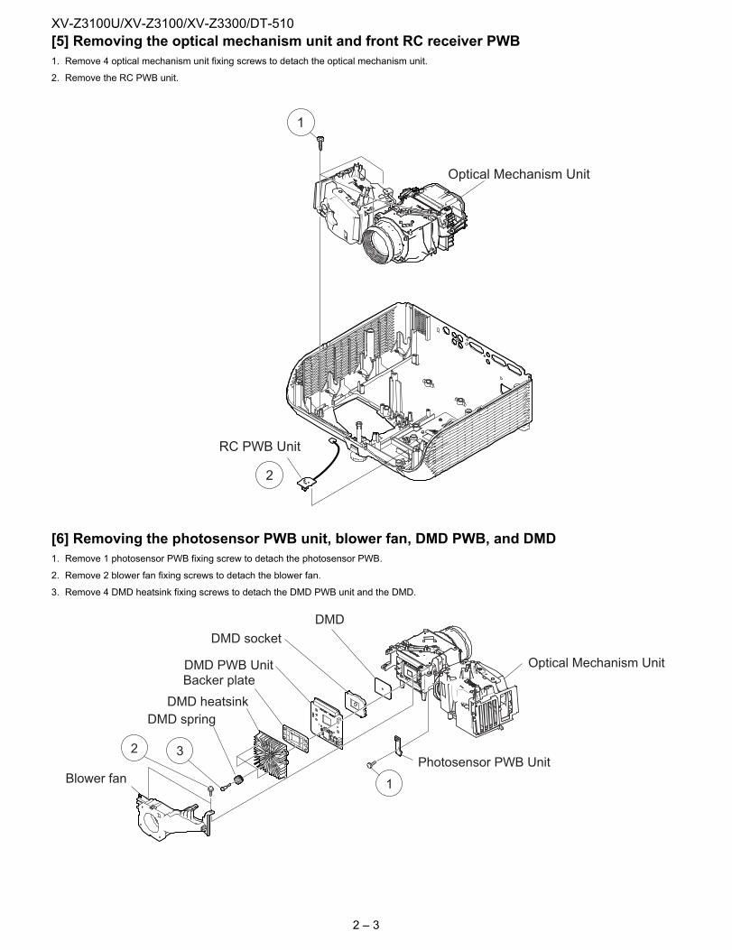
[5] Removing the optical mechanism unit and front RC receiver PWB1. Remove 4 optical mechanism unit fixing screws to detach the optical mechanism unit.2. Remove the RC PWB unit.
[6] Removing the photosensor PWB unit, blower fan, DMD PWB, and DMD1. Remove 1 photosensor PWB fixing screw to detach the photosensor PWB.
2. Remove 2 blower fan fixing screws to detach the blower fan.
3. Remove 4 DMD heatsink fixing screws to detach the DMD PWB unit and the DMD.
1
2
RC PWB Unit
Optical Mechanism Unit
1
2 3
Optical Mechanism Unit
Photosensor PWB Unit
DMD
DMD heatsinkDMD spring
Backer plateDMD PWB Unit
DMD socket
Blower fan
2 – 3
XV-Z3100U/XV-Z3100/XV-Z3300/DT-510
XV-Z3100U Service Manual CHAPTER 3. THE OPTICAL UNIT OUTLINE[1] THE OPTICAL UNIT OUTLINE
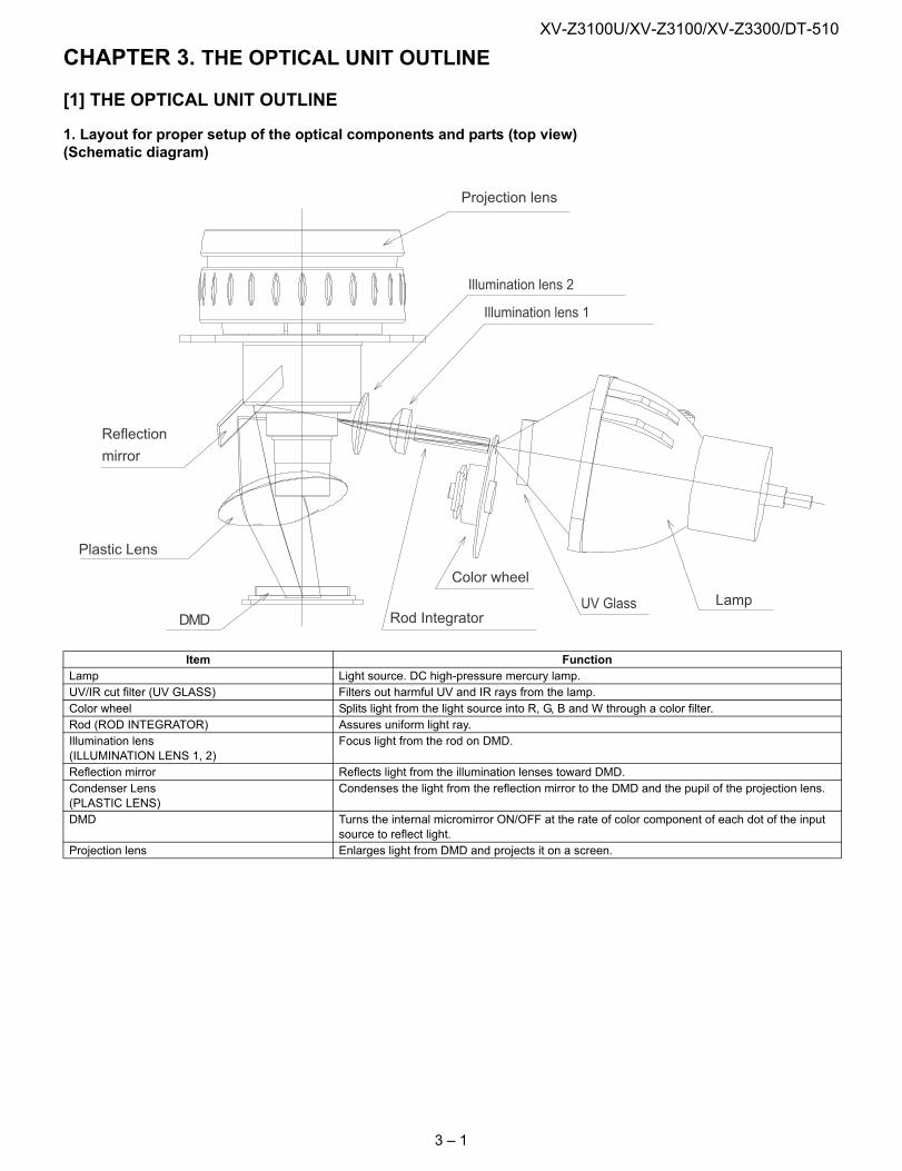
1. Layout for proper setup of the optical components and parts (top view)(Schematic diagram)
Item FunctionLamp Light source. DC high-pressure mercury lamp.UV/IR cut filter (UV GLASS) Filters out harmful UV and IR rays from the lamp.Color wheel Splits light from the light source into R, G, B and W through a color filter.Rod (ROD INTEGRATOR) Assures uniform light ray.Illumination lens(ILLUMINATION LENS 1, 2)
Focus light from the rod on DMD.
Reflection mirror Reflects light from the illumination lenses toward DMD.Condenser Lens(PLASTIC LENS)
Condenses the light from the reflection mirror to the DMD and the pupil of the projection lens.
DMD Turns the internal micromirror ON/OFF at the rate of color component of each dot of the input source to reflect light.
Projection lens Enlarges light from DMD and projects it on a screen.
DMD
Plastic Lens
Rod IntegratorLamp
Reflection
mirror
Color wheel
Illumination lens 2
Projection lens
Illumination lens 1
UV Glass
3 – 1
XV-Z3100U/XV-Z3100/XV-Z3300/DT-510
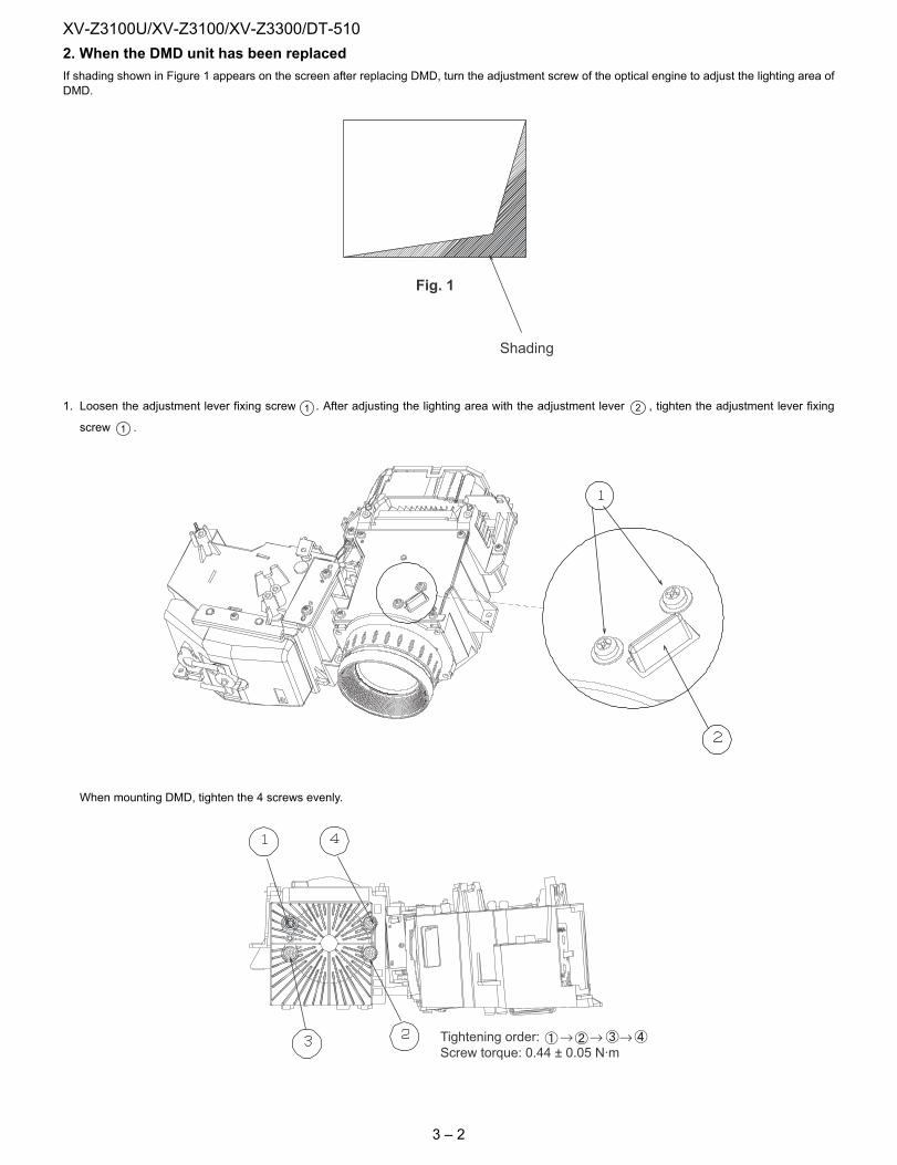
2. When the DMD unit has been replacedIf shading shown in Figure 1 appears on the screen after replacing DMD, turn the adjustment screw of the optical engine to adjust the lighting area ofDMD.1. Loosen the adjustment lever fixing screw . After adjusting the lighting area with the adjustment lever , tighten the adjustment lever fixing
screw .
When mounting DMD, tighten the 4 screws evenly.
Fig. 1
Shading
1 2
1
Tightening order: → → →Screw torque: 0.44 ± 0.05 N·m
3 – 2
XV-Z3100U/XV-Z3100/XV-Z3300/DT-510
XV-Z3100U Service Manual CHAPTER 4. ELECTRICAL ADJUSTMENT[1] ELECTRICAL ADJUSTMENT
Check items
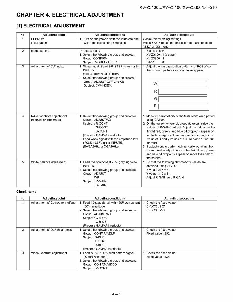
No. Adjusting point Adjusting conditions Adjusting procedure1 EEPROM
initialization1. Turn on the power (with the lamp on) and warm up the set for 15 minutes.
•Make the following settings.Press S6213 to call the process mode and execute "SS2" on SS menu.
2 Model setting (Process menu)1. Select the following group and subject. Group: CONFIRM Subject: MODEL-SELECT
1. Set as below. XV-Z3100 : 1 (default) XV-Z3300 : 2 DT-510 : 0
3 Adjustment of CW index 1. Signal input: Send 256 STEP color bar to INPUT5. (SVGA60Hz or XGA60Hz)2. Select the following group and subject. Group: ADJUST CW/Auto KS Subject: CW-INDEX.
1. Adjust the lamp gradation patterns of RGBW so that smooth patterns without noise appear.
4 R/G/B contrast adjustment (manual or automatic)
1. Select the following group and subjects. Group : ADJUST/AD Subject : R-CONT G-CONT B-CONT (Process GAMMA interlock)2. Feed white signal with the amplitude level of 96% (0.67Vpp) to INPUT5. (SVGA60Hz or XGA60Hz)
1. Measure chromaticity of the 96% white wind pattern using CA100.2. On the screen where bit dropouts occur, raise the values of R/G/B-Contrast. Adjust the values so that bright red, green, and blue bit dropouts appear on a black background; and amounts of change in x value of R and y values of G/B become 100/1000 or more.3. If adjustment is performed manually watching the screen, make adjustment so that bright red, green, and blue bit dropouts appear on more than half of the screen.
5 White balance adjustment 1. Feed the component 75% gray signal to INPUT5.2. Select the following group and subjects. Group : ADJUST WB Subject : R-GAIN B-GAIN
1. So that the following chromaticity values are obtained using CL200. X value: 298 ± 5 Y value: 319 ± 5 Adjust R-GAIN and B-GAIN
No. Adjusting point Adjusting conditions Adjusting procedure1 Adjustment of Component offset 1. Feed 10-step signal with 480P component
100% amplitude.2. Select the following group and subjects. Group : ADJUST/AD Subject : C-R-OS C-B-OS (Process GAMMA interlock)
1. Check the fixed value. C-R-OS : 257 C-B-OS : 256
2 Adjustment of DLP Brightness 1. Select the following group and subject. Group : CONFIRM/DLP Subject :R-BLK G-BLK B-BLK (Process GAMMA interlock)
1. Check the fixed value. Fixed value : 252
3 Video Contrast adjustment 1. Feed NTSC 100% wind pattern signal. (Signal with burst)2. Select the following group and subjects. Group : CONIRM/VIDEO Subject : V-CONT
1. Check the fixed value. Fixed value : 134
R
G
B
W
4 – 1
XV-Z3100U/XV-Z3100/XV-Z3300/DT-510
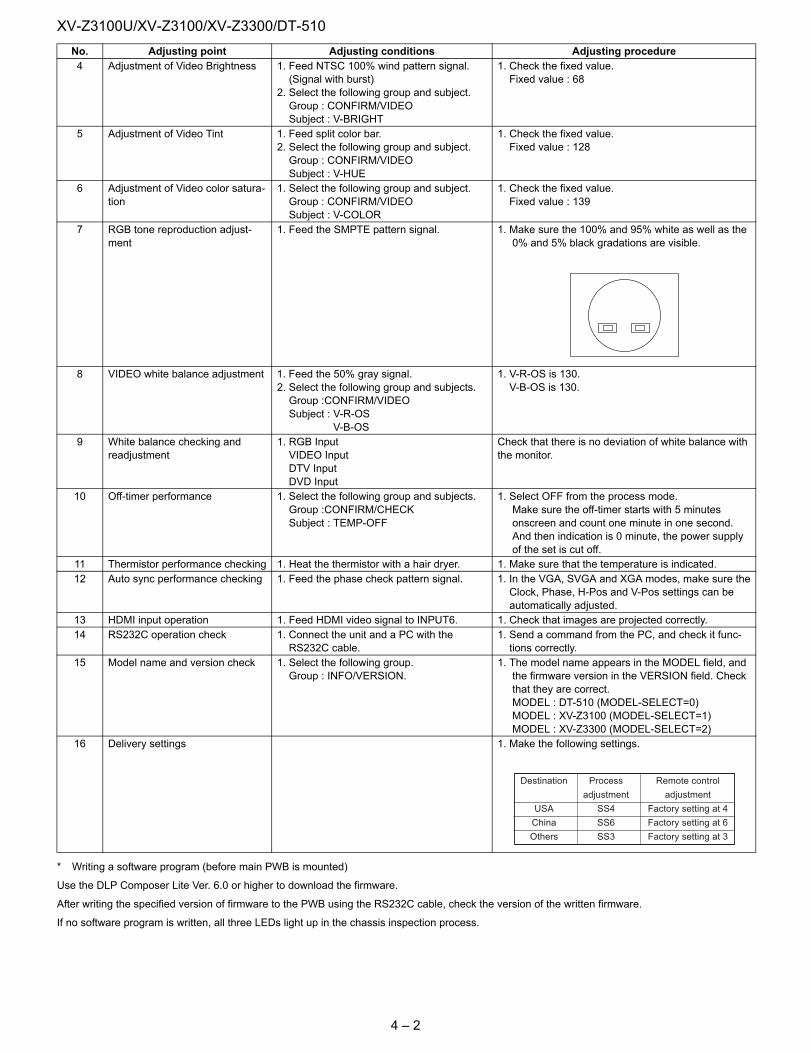
* Writing a software program (before main PWB is mounted)
Use the DLP Composer Lite Ver. 6.0 or higher to download the firmware.
After writing the specified version of firmware to the PWB using the RS232C cable, check the version of the written firmware.
If no software program is written, all three LEDs light up in the chassis inspection process.
4 Adjustment of Video Brightness 1. Feed NTSC 100% wind pattern signal. (Signal with burst)2. Select the following group and subject. Group : CONFIRM/VIDEO Subject : V-BRIGHT
1. Check the fixed value. Fixed value : 68
5 Adjustment of Video Tint 1. Feed split color bar.2. Select the following group and subject. Group : CONFIRM/VIDEO Subject : V-HUE
1. Check the fixed value. Fixed value : 128
6 Adjustment of Video color satura-tion
1. Select the following group and subject. Group : CONFIRM/VIDEO Subject : V-COLOR
1. Check the fixed value. Fixed value : 139
7 RGB tone reproduction adjust-ment
1. Feed the SMPTE pattern signal. 1. Make sure the 100% and 95% white as well as the 0% and 5% black gradations are visible.
8 VIDEO white balance adjustment 1. Feed the 50% gray signal.2. Select the following group and subjects. Group :CONFIRM/VIDEO Subject : V-R-OS V-B-OS
1. V-R-OS is 130. V-B-OS is 130.
9 White balance checking and readjustment
1. RGB Input VIDEO Input DTV Input DVD Input
Check that there is no deviation of white balance with the monitor.
10 Off-timer performance 1. Select the following group and subjects. Group :CONFIRM/CHECK Subject : TEMP-OFF
1. Select OFF from the process mode. Make sure the off-timer starts with 5 minutes onscreen and count one minute in one second. And then indication is 0 minute, the power supply of the set is cut off.
11 Thermistor performance checking 1. Heat the thermistor with a hair dryer. 1. Make sure that the temperature is indicated.12 Auto sync performance checking 1. Feed the phase check pattern signal. 1. In the VGA, SVGA and XGA modes, make sure the
Clock, Phase, H-Pos and V-Pos settings can be automatically adjusted.
13 HDMI input operation 1. Feed HDMI video signal to INPUT6. 1. Check that images are projected correctly.14 RS232C operation check 1. Connect the unit and a PC with the
RS232C cable.1. Send a command from the PC, and check it func- tions correctly.
15 Model name and version check 1. Select the following group. Group : INFO/VERSION.
1. The model name appears in the MODEL field, and the firmware version in the VERSION field. Check that they are correct. MODEL : DT-510 (MODEL-SELECT=0) MODEL : XV-Z3100 (MODEL-SELECT=1) MODEL : XV-Z3300 (MODEL-SELECT=2)
16 Delivery settings 1. Make the following settings.
No. Adjusting point Adjusting conditions Adjusting procedure
Destination Process Remote control
adjustment adjustment
USA SS4 Factory setting at 4
China SS6 Factory setting at 6
Others SS3 Factory setting at 3
4 – 2
XV-Z3100U/XV-Z3100/XV-Z3300/DT-510
Calling and quitting the process mode with the control keys on this model.* Although it is possible for the process OUT to exit using the process menu, the IN/OUT toggle command is also available considering the existingspecification.
1) Calling and quitting
With the menu not displayed, press the "ENTER", "ENTER", "Right", "Left", "ENTER", "ENTER" and "MENU" keys on the remote control or on themain unit.
2) Others
Press the S6213 process key (toggle) on the main PWB to call and quit the process menu.
NOTE: When adjusting in the process mode, set a signal with a vertical frequency of 60 Hz or no signal. (May not be properly adjusted with other sig-nals.)
Resetting the lamp timer for this model1) Resetting procedure
In Stand-by, run this command to clear the operating time of the lamp to 0 and turn on the power.
Press and hold " ", "ENTER", and "MENU", and then press the "STANDBY/ON" key of the set.
4 – 3
XV-Z3100U/XV-Z3100/XV-Z3300/DT-510
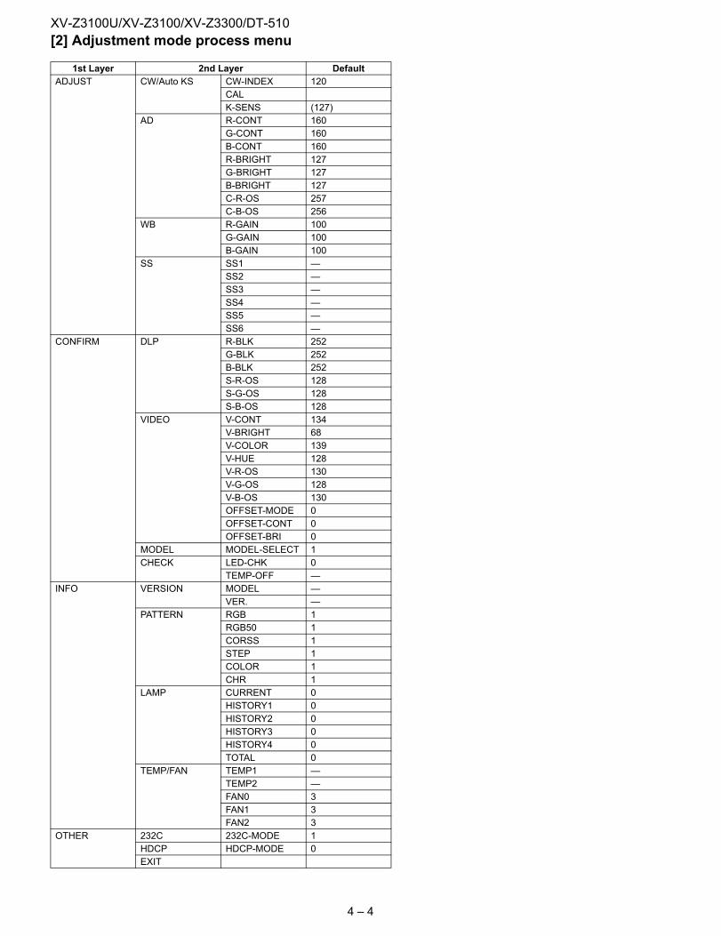
[2] Adjustment mode process menu1st Layer 2nd Layer DefaultADJUST CW/Auto KS CW-INDEX 120
CALK-SENS (127)
AD R-CONT 160G-CONT 160B-CONT 160R-BRIGHT 127G-BRIGHT 127B-BRIGHT 127C-R-OS 257C-B-OS 256
WB R-GAIN 100G-GAIN 100B-GAIN 100
SS SS1 —SS2 —SS3 —SS4 —SS5 —SS6 —
CONFIRM DLP R-BLK 252G-BLK 252B-BLK 252S-R-OS 128S-G-OS 128S-B-OS 128
VIDEO V-CONT 134V-BRIGHT 68V-COLOR 139V-HUE 128V-R-OS 130V-G-OS 128V-B-OS 130OFFSET-MODE 0OFFSET-CONT 0OFFSET-BRI 0
MODEL MODEL-SELECT 1CHECK LED-CHK 0
TEMP-OFF —INFO VERSION MODEL —
VER. —PATTERN RGB 1
RGB50 1CORSS 1STEP 1COLOR 1CHR 1
LAMP CURRENT 0HISTORY1 0HISTORY2 0HISTORY3 0HISTORY4 0TOTAL 0
TEMP/FAN TEMP1 —TEMP2 —FAN0 3FAN1 3FAN2 3
OTHER 232C 232C-MODE 1HDCP HDCP-MODE 0EXIT
4 – 4
XV-Z3100U/XV-Z3100/XV-Z3300/DT-510
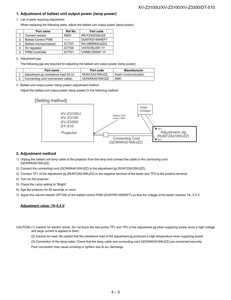
1. Adjustment of ballast unit output power (lamp power)1. List of parts requiring adjustmentWhen replacing the following parts, adjust the ballast unit output power (lamp power).
2. Adjustment jigs
The following jigs are required for adjusting the ballast unit output power (lamp power).
3. Ballast unit output power (lamp power) adjustment method
Adjust the ballast unit output power (lamp power) in the following method.
2. Adjustment method1) Unplug the ballast unit lamp cable of the projector from the lamp and connect the cable to the connecting cord
(QCNWKA016WJZZ).
2) Connect the connecting cord (QCNWKA016WJZZ) to the adjustment jig (RUNTZA018WJZZ).
3) Connect TP1 of the adjustment jig (RUNTZA018WJZZ) to the negative terminal of the tester and TP2 to the positive terminal.
4) Turn on the projector.
5) Check the Lamp setting to “Bright”.
6) Age the projector for 60 seconds or more.
7) Adjust the volume resistor (R7728) of the ballast control PWB (DUNTKD148WEF7) so that the voltage of the tester reaches 74± 0.5 V.
Adjustment value: 74±0.5 V
CAUTION: (1) Caution for electric shock: Do not touch the test points TP1 and TP2 of the adjustment jig when supplying power since a high voltageand large current is applied to them.
(2) Caution for heat: Be careful that the resistance load of the adjustment jig produces a high temperature when supplying power.
(3) Connection of the lamp cable: Check that the lamp cable and connecting cord (QCNWKA016WJZZ) are connected securely.
Poor connection may cause smoking or ignition due to arc discharge.
Part name Ref No. Part code1 Cement resistor R905 RR-FZA002WJZZ2 Ballast Control PWB —— DUNTKD148WEF73 Ballast microprocessor IC7707 RH-iXB996WJZZQ4 5V regulator IC7704 VHITA78L05F-1Y5 PWM Controller IC7701 VHIM51995AF-1Y
Part name Part code Manufacturer1 Adjustment jig (resistance load 25 Ω) RUNTZA018WJZZ Asahi Communication2 Connecting cord (conversion cable) QCNWKA016WJZZ SMK
Ballast UnitLamp Cable
Adjustment Jig(RUNTZA018WJZZ)
Connecting Cord(QCNWKA016WJZZ)
XV-Z3100XV-Z3100U
XV-Z3300DT-510
ProjectorTP1
TP2
[Setting method]
Tester(Voltage)
4 – 5
XV-Z3100U/XV-Z3100/XV-Z3300/DT-510
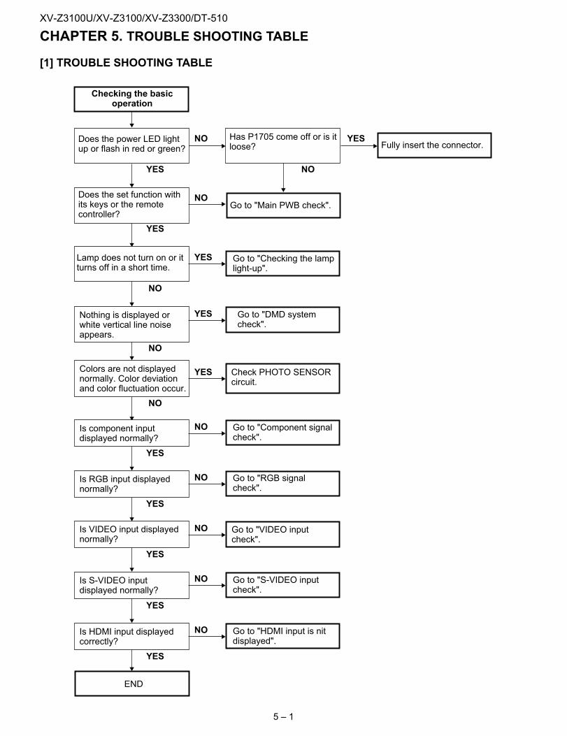
XV-Z3100U Service Manual CHAPTER 5. TROUBLE SHOOTING TABLE[1] TROUBLE SHOOTING TABLE
YES
YES
NO
NO
YES
Checking the basicoperation
Does the power LED lightup or flash in red or green? Fully insert the connector.
Go to "Main PWB check".
Go to "Checking the lamplight-up".
Go to "DMD systemcheck".
NODoes the set function withits keys or the remotecontroller?
Has P1705 come off or is itloose?
YES
END
YES
Go to "RGB signalcheck".
NO
Go to "VIDEO inputcheck".
NO
Go to "HDMI input is nitdisplayed".
NO
Check PHOTO SENSORcircuit.
YES
Lamp does not turn on or itturns off in a short time.
Nothing is displayed orwhite vertical line noiseappears.
Colors are not displayednormally. Color deviationand color fluctuation occur.
NO
NO
NO
Is RGB input displayednormally?
YES
Go to "Component signalcheck".
NOIs component inputdisplayed normally?
YES
Is VIDEO input displayednormally?
YES
Is HDMI input displayedcorrectly?
Go to "S-VIDEO inputcheck".
NO
YES
Is S-VIDEO inputdisplayed normally?
YES
5 – 1
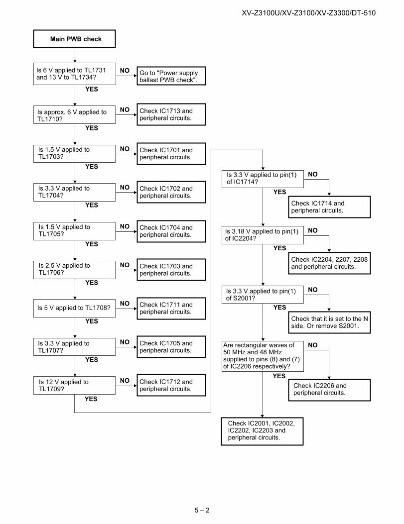
XV-Z3100U/XV-Z3100/XV-Z3300/DT-510
YES
NOIs 6 V applied to TL1731and 13 V to TL1734?
Is approx. 6 V applied toTL1710?
YES
Is 1.5 V applied toTL1703?
Go to "Power supplyballast PWB check".
NO Check IC1713 andperipheral circuits.
NO Check IC1701 andperipheral circuits.
YES
Is 3.3 V applied toTL1704?
NO Check IC1702 andperipheral circuits.
Is 2.5 V applied toTL1706?
NO Check IC1703 andperipheral circuits.
YES
Is 1.5 V applied toTL1705?
NO Check IC1704 andperipheral circuits.
YES
Is 5 V applied to TL1708?NO Check IC1711 and
peripheral circuits.
YES
Is 3.3 V applied toTL1707?
NO Check IC1705 andperipheral circuits.
YES
Is 12 V applied toTL1709?
NO Check IC1712 andperipheral circuits.
YES
Main PWB check
YES
Is 3.3 V applied to pin(1)of IC1714?
NO
Check IC1714 andperipheral circuits.
YES
Is 3.18 V applied to pin(1)of IC2204?
NO
Check IC2204, 2207, 2208and peripheral circuits.
YES
Is 3.3 V applied to pin(1)of S2001?
NO
Check that it is set to the Nside. Or remove S2001.
YES
Are rectangular waves of50 MHz and 48 MHzsupplied to pins (8) and (7)of IC2206 respectively?
NO
YES
Check IC2001, IC2002,IC2202, IC2203 andperipheral circuits.
Check IC2206 andperipheral circuits.
5 – 2
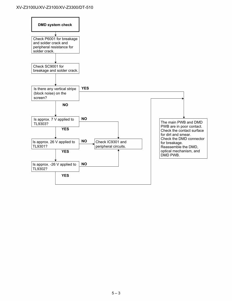
XV-Z3100U/XV-Z3100/XV-Z3300/DT-510
Check P6001 for breakageand solder crack andperipheral resistance forsolder crack.
Check SC9001 forbreakage and solder crack.
Is there any vertical stripe(block noise) on thescreen?
NO
Is approx. 7 V applied toTL9303?
YES
YES
Is approx. 26 V applied toTL9301?
YES
YES
Is approx. -26 V applied toTL9302?
NO
NO
NO
The main PWB and DMDPWB are in poor contact.Check the contact surfacefor dirt and smear.Check the DMD connectorfor breakage.Reassemble the DMD,optical mechanism, andDMD PWB.
Check IC9301 andperipheral circuits.
DMD system check
5 – 3
XV-Z3100U/XV-Z3100/XV-Z3300/DT-510
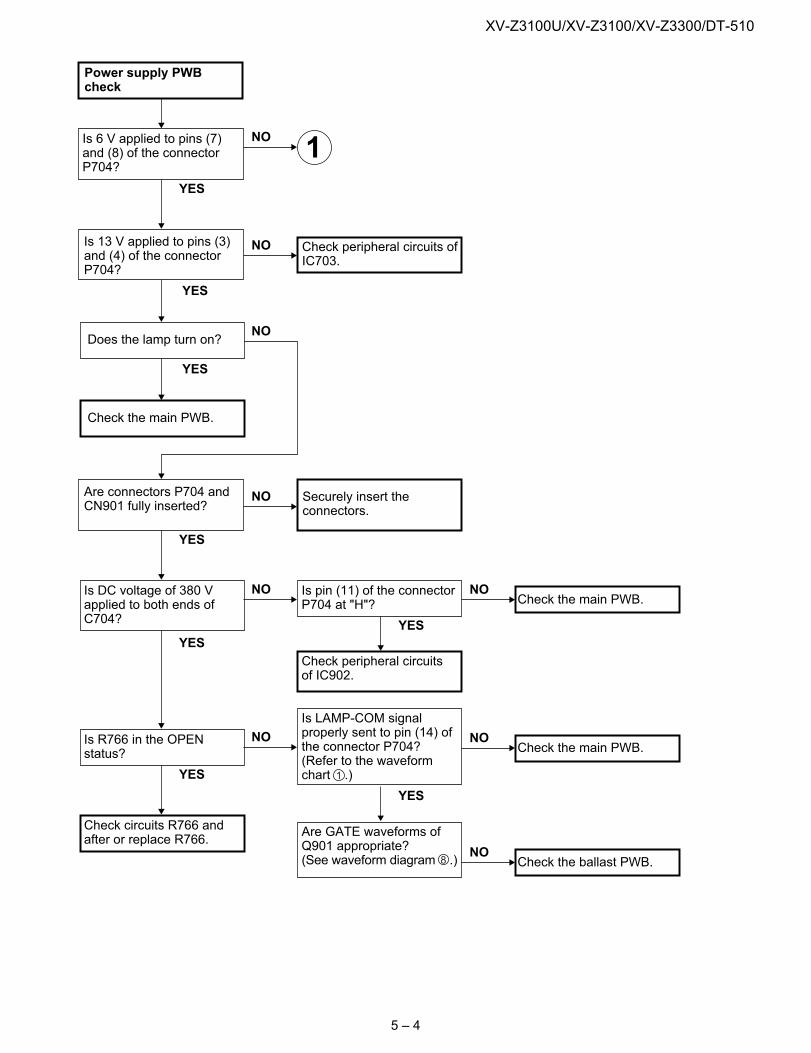
YES
Check peripheral circuits ofIC703.
YES
Is 13 V applied to pins (3)and (4) of the connectorP704?
YES
YES
Is DC voltage of 380 Vapplied to both ends ofC704?
YES
Check circuits R766 andafter or replace R766.
YES
Is R766 in the OPENstatus?
Is pin (11) of the connectorP704 at "H"?
Are connectors P704 andCN901 fully inserted?
Is 6 V applied to pins (7)and (8) of the connectorP704?
NO
NO
NO
Securely insert theconnectors.
Check peripheral circuitsof IC902.
YES
NO
NO
Is LAMP-COM signalproperly sent to pin (14) ofthe connector P704?(Refer to the waveformchart .)
Are GATE waveforms ofQ901 appropriate?(See waveform diagram .)
NO
Does the lamp turn on?
YES
Check the main PWB.
Check the main PWB.NO
Check the main PWB.NO
Check the ballast PWB.NO
Power supply PWBcheck
1
8
1
5 – 4
XV-Z3100U/XV-Z3100/XV-Z3300/DT-510
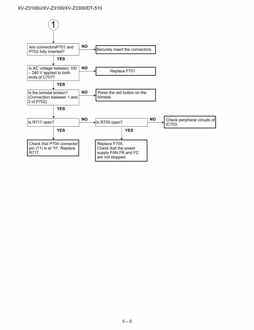
YES
YES
YES
Securely insert the connectors.NO
Replace F701.NO
Press the red button on thebimetal.
NO
YES
NO
YES
NO
Are connectorsP701 andP702 fully inserted?
Is AC voltage between 100− 240 V applied to bothends of C707?
Is the bimetal broken?(Connection between 1 and2 of P702)
Is R717 open?
Check that P704 connectorpin (11) is at "H". ReplaceR717.
Is R705 open?
Replace F705.Check that the powersupply FAN FB and FCare not stopped.
Check peripheral circuits ofIC703.
1
5 – 5
XV-Z3100U/XV-Z3100/XV-Z3300/DT-510
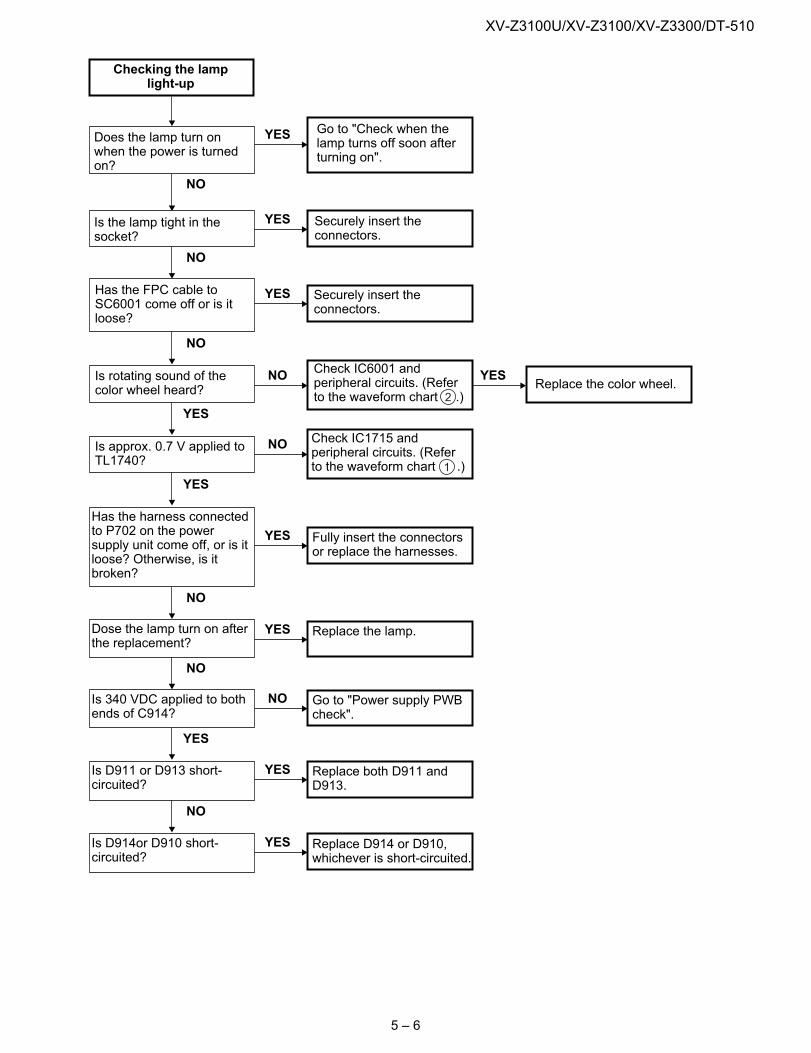
NO
Go to "Check when thelamp turns off soon afterturning on".
YES
Securely insert theconnectors.
YES
Securely insert theconnectors.
YES
Check IC6001 andperipheral circuits. (Referto the waveform chart .)
NO
Check IC1715 andperipheral circuits. (Referto the waveform chart .)
NO
Fully insert the connectorsor replace the harnesses.
YES
Replace the lamp.YES
Go to "Power supply PWBcheck".
NO
Replace both D911 andD913.
YES
Replace D914 or D910,whichever is short-circuited.
YES
Replace the color wheel.YES
2
1
Checking the lamplight-up
Does the lamp turn onwhen the power is turnedon?
Is the lamp tight in thesocket?
NO
Has the FPC cable toSC6001 come off or is itloose?
Is rotating sound of thecolor wheel heard?
NO
Is approx. 0.7 V applied toTL1740?
YES
NO
Has the harness connectedto P702 on the powersupply unit come off, or is itloose? Otherwise, is itbroken?
NO
Dose the lamp turn on afterthe replacement?
YES
Is 340 VDC applied to bothends of C914?
NO
Is D911 or D913 short-circuited?
Is D914or D910 short-circuited?
YES
5 – 6
XV-Z3100U/XV-Z3100/XV-Z3300/DT-510
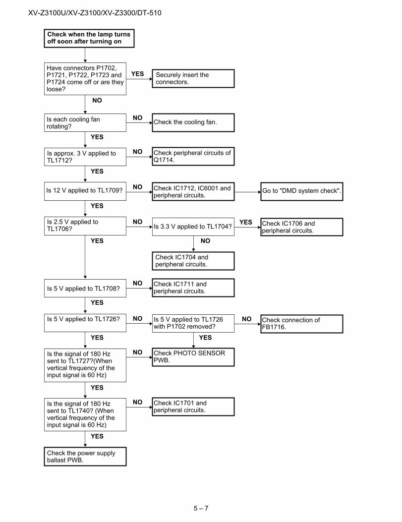
NO
Securely insert theconnectors.
YES
Check the cooling fan.NO
Check peripheral circuits ofQ1714.
NO
Check IC1712, IC6001 andperipheral circuits.
NOGo to "DMD system check".
Is 3.3 V applied to TL1704?NO
Check IC1711 andperipheral circuits.
NO
Check PHOTO SENSORPWB.
NO
Check IC1701 andperipheral circuits.
NO
Check IC1706 andperipheral circuits.
YES
Is 5 V applied to TL1726with P1702 removed?
NO Check connection ofFB1716.
NO
Check when the lamp turnsoff soon after turning on
Have connectors P1702,P1721, P1722, P1723 andP1724 come off or are theyloose?
Is each cooling fanrotating?
Is approx. 3 V applied toTL1712?
YES
Is 12 V applied to TL1709?
YES
Is 2.5 V applied toTL1706?
YES
Check IC1704 andperipheral circuits.
NO
Is 5 V applied to TL1726?
YES
Is the signal of 180 Hzsent to TL1727?(Whenvertical frequency of theinput signal is 60 Hz)
YES
Is the signal of 180 Hzsent to TL1740? (Whenvertical frequency of theinput signal is 60 Hz)
YES
YES
Is 5 V applied to TL1708?
YES
Check the power supplyballast PWB.
YES
5 – 7
XV-Z3100U/XV-Z3100/XV-Z3300/DT-510
YES
EndYES
Check Q4003, Q4004,Q4005 and the peripheralcircuits.
NO
Check IC1705 andperipheral circuits.
NO
Check IC1702 andperipheral circuits.
NO
Check Q3002 andperipheral circuits.
NO
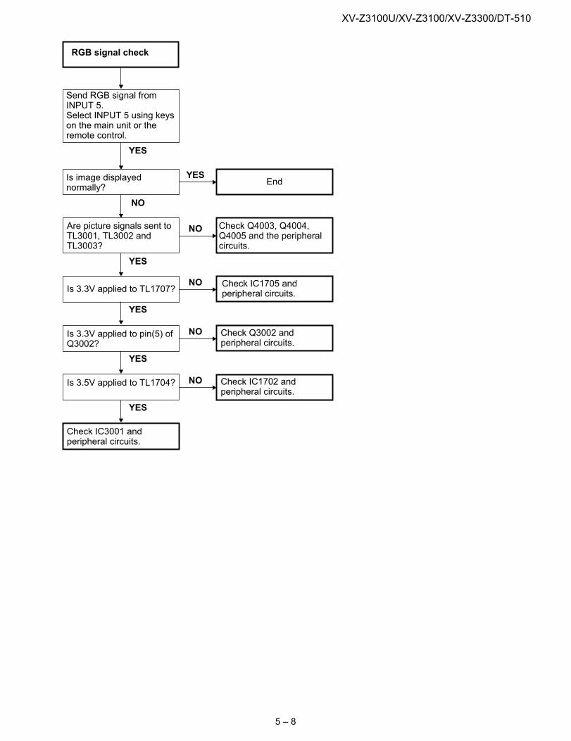
RGB signal check
Send RGB signal fromINPUT 5.Select INPUT 5 using keyson the main unit or theremote control.
Is image displayednormally?
Are picture signals sent toTL3001, TL3002 andTL3003?
NO
YES
Is 3.3V applied to TL1707?
Is 3.5V applied to TL1704?
YES
Check IC3001 andperipheral circuits.
YES
Is 3.3V applied to pin(5) ofQ3002?
YES
5 – 8
XV-Z3100U/XV-Z3100/XV-Z3300/DT-510
YES
EndYES
Check IC4002 and theperipheral circuits.
NO
Check IC1705 andperipheral circuits.
NO
Check IC1702 andperipheral circuits.
NO
Check Q3002 andperipheral circuits.
NO
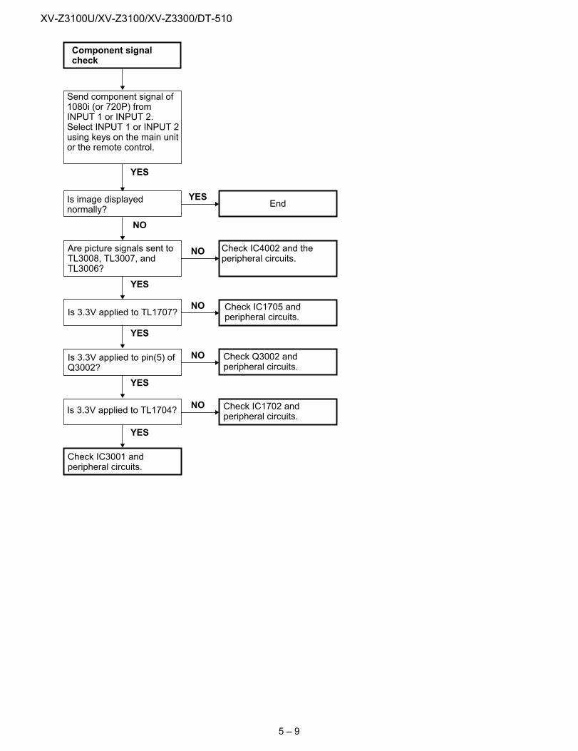
Component signalcheck
Send component signal of1080i (or 720P) fromINPUT 1 or INPUT 2.Select INPUT 1 or INPUT 2using keys on the main unitor the remote control.
Is image displayednormally?
Are picture signals sent toTL3008, TL3007, andTL3006?
NO
YES
Is 3.3V applied to TL1707?
Is 3.3V applied to TL1704?
YES
Check IC3001 andperipheral circuits.
YES
Is 3.3V applied to pin(5) ofQ3002?
YES
5 – 9
XV-Z3100U/XV-Z3100/XV-Z3300/DT-510
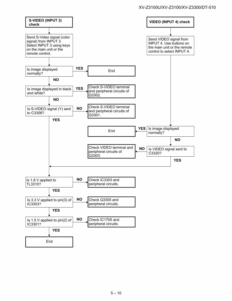
EndYES
Check S-VIDEO terminaland peripheral circuits ofQ3302.
YES
EndYES
YES
Check VIDEO terminal andperipheral circuits ofQ3303.
NO
Check S-VIDEO terminaland peripheral circuits ofQ3301.
NO
Check IC3303 andperipheral circuits.
NO
Check Q3305 andperipheral circuits.
NO
Check IC1705 andperipheral circuits.
NO
S-VIDEO (INPUT 3)check
Send S-Video signal (colorsignal) from INPUT 3.Select INPUT 3 using keyson the main unit or theremote control.
Is image displayednormally?
Is image displayed in blackand white?
NO
VIDEO (INPUT 4) check
Send VIDEO signal fromINPUT 4. Use buttons onthe main unit or the remotecontrol to select INPUT 4.
Is image displayednormally?
Is VIDEO signal sent toC3320?
NO
Is S-VIDEO signal (Y) sentto C3306?
NO
Is 1.8 V applied toTL3310?
YES
Is 3.3 V applied to pin(3) ofIC3303?
YES
Is 1.5 V applied to pin(2) ofIC3301?
YES
End
YES
5 – 10
XV-Z3100U/XV-Z3100/XV-Z3300/DT-510
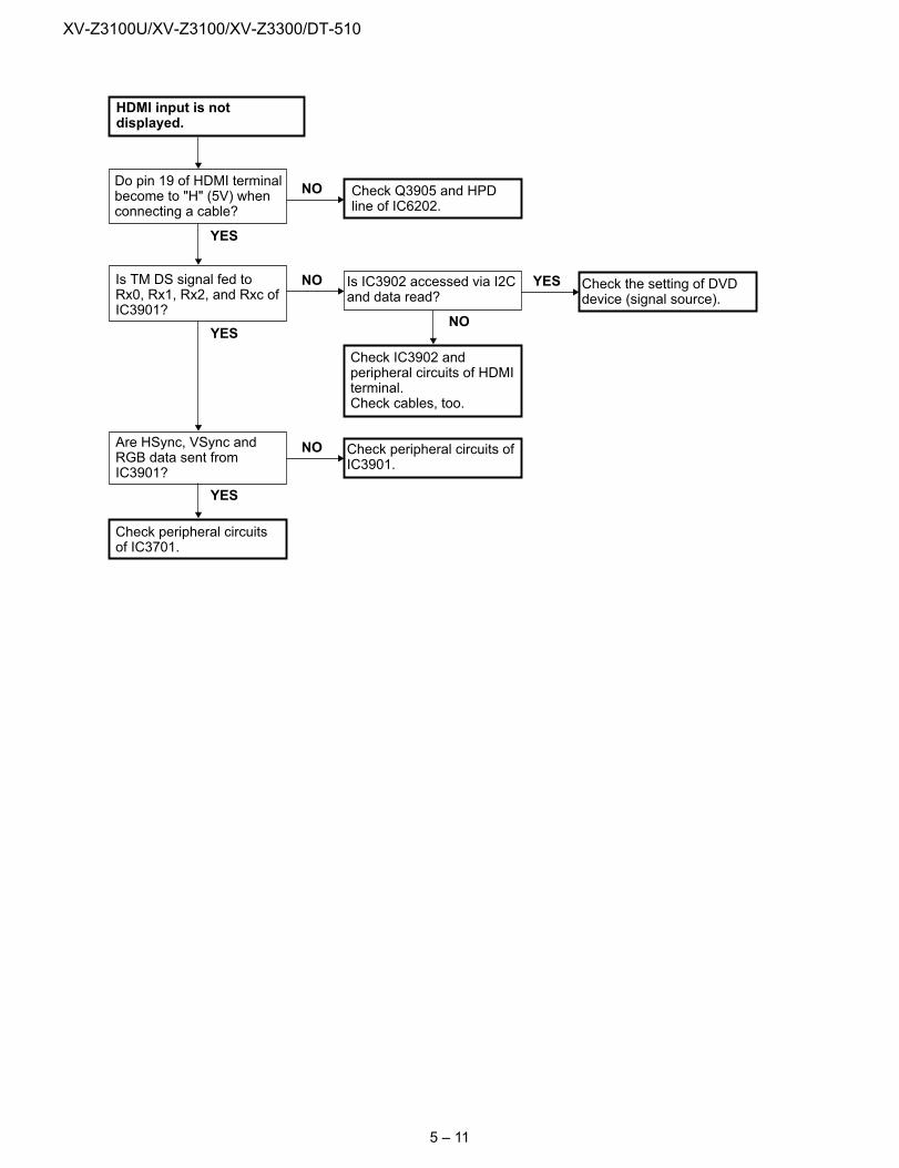
YES
Check Q3905 and HPDline of IC6202.
NO
Is IC3902 accessed via I2Cand data read?
NO
Check peripheral circuits ofIC3901.
NO
Check the setting of DVDdevice (signal source).
YES
HDMI input is notdisplayed.
Do pin 19 of HDMI terminalbecome to "H" (5V) whenconnecting a cable?
Is TM DS signal fed toRx0, Rx1, Rx2, and Rxc ofIC3901?
Check IC3902 andperipheral circuits of HDMIterminal.Check cables, too.
NO
Are HSync, VSync andRGB data sent fromIC3901?
YES
Check peripheral circuitsof IC3701.
YES
5 – 11

XV-Z3100U/XV-Z3100/XV-Z3300/DT-510
— MEMO —5 – 12
XV-Z3100U/XV-Z3100/XV-Z3300/DT-510
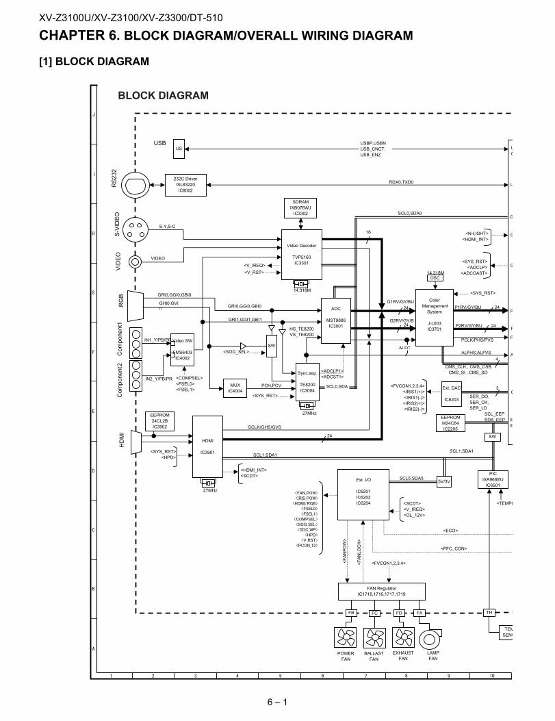
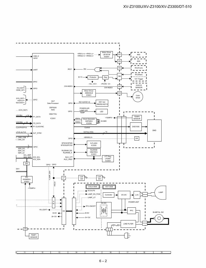
XV-Z3100U Service Manual CHAPTER 6. BLOCK DIAGRAM/OVERALL WIRING DIAGRAM[1] BLOCK DIAGRAM
BLOCK DIAGRAM
6 – 1
XV-Z3100U/XV-Z3100/XV-Z3300/DT-510
6 – 2
XV-Z3100U/XV-Z3100/XV-Z3300/DT-510
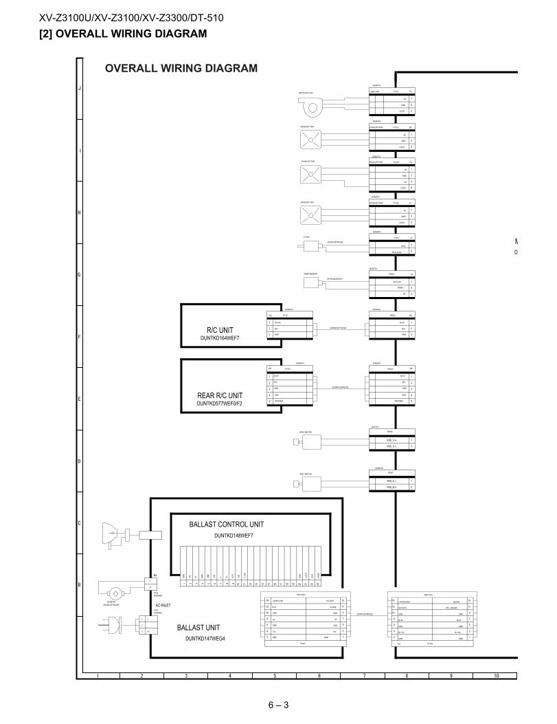
[2] OVERALL WIRING DIAGRAM1
2
3
L
N
P1721
N0364TA
FALAMP FAN
1+B
2GND
3LOCK
P1722
N0364TA
FBEXHAUST FAN
1+B
2GND
3LOCK
P1723
N0464TA
FDEXHAUST FAN
1+B
2GND
3NC
4LOCK
P1724
N0364TA
FCEXHAUST FAN
1+B
2GND
3LOCK
P1701
N0263TA
LF
1RCS
2RCS_PULL
P6503
N0364TA
RA
1B+5V
2R/C
3GND
P1121
N0364TA
RC
1 B+5VA
2 R/C
3 GND
P1705
NA071WJ
EA
1GND
2GND
3B+13V
4B+13V
5GND
6GND
7B+6V
8B+6V
9GND10GND
11PFC_ON/OFF12 ECO/LPS
13NLIGHT14
L-POW/SYNC
P704
MA114WJ
1GND2 GND
313V4 13V
5GND6 GND
76V8 6V
9GND10 GND
11P-CON12 ECO
13N-LIGHT14 LAMP-COM
P702N0269GE
BA
1
2
P701AA004WJ
1GND
220V
3PT
4GND
5TMP
6VIN
7IL
8VL
9SCP
10CST
11P_SW
12 13 14 15 16 17 18 19 20GND
21LIGHT
22ECO
23LAMP
P6507
N0264TA
1IRIS_2(-)
2IRIS_2(+)
P6506
N0174FJ
1IRIS_1(+)
2IRIS_1(-)
P6504
N0564TA
RB
1B+5V
2R/C
3GND
4GND
5TRIGGER
P1551
N0564TA
RB
1 B+5V
2 R/C
3 GND
4 GND
5 TRIGGER
P6502
N0363TA
TH
1B+3.3VA
2TEMP1
NC 3
EXHAUST FAN
VENTILATE FAN
EXHAUST FAN
QCNW-D575WJPZ
BI-METAL
LF-SW
QCNW-D518WJQZ
QCNW-D515WJQZ
EXHAUST FAN
QCNW-D517WJQZ
QCNW-E299WJQZ
IRIS1 MOTOR
IRIS1 MOTOR
TEMP SENSOR
RH-HXA025WJPZ
D
DUNTKD147WEG4
DUNTKD148WEF7
AC-INLET
DUNTKD164WEF7
DUNTKD577WEF0/F2
BALLAST UNIT
M
R/C UNIT
BALLAST CONTROL UNIT
REAR R/C UNIT
OVERALL WIRING DIAGRAM
6 – 3
XV-Z3100U/XV-Z3100/XV-Z3300/DT-510
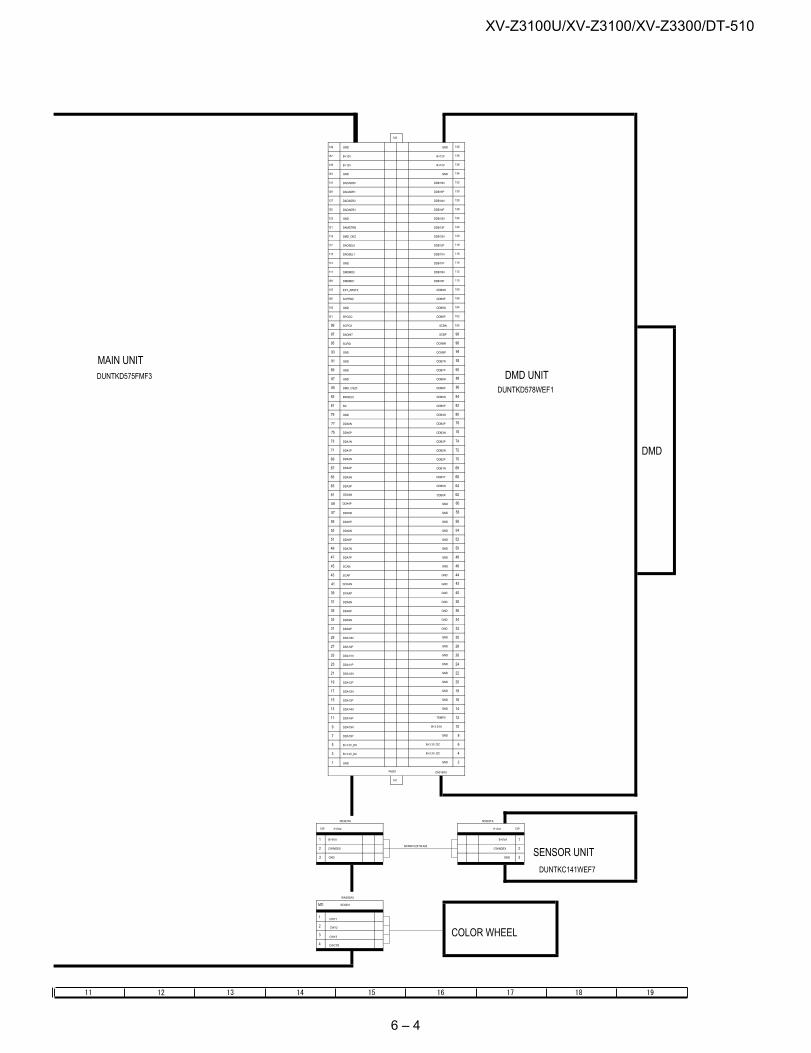
P1702
N0363TA
CW
1 B+5VA
2 CWINDEX
3 GND
SC6001
WA500WJ
MO
1CWY1
2 CWY2
3 CWY3
4 CWCTR
P1101
N0363TA
CW
1B+5VA
2CWINDEX
3GND
P6001 ZA018WJ
1 GND 2GND
3 B+3.3V_DC 4B+3.3V_DC
5 B+3.3V_DC 6B+3.3V_DC
7 DDA15P 8GND
9 DDA15N 10B+3.3VA
11 DDA14P 12TEMP0
13 DDA14N 14GND
15 DDA13P 16GND
17 DDA13N 18GND
19 DDA12P 20GND
21 DDA12N 22GND
23 DDA11P 24GND
25 DDA11N 26GND
27 DDA10P 28GND
29 DDA10N 30GND
31 DDA9P 32GND
33 DDA9N 34GND
35 DDA8P 36GND
37 DDA8N 38GND
39 DCKAP 40GND
41 DCKAN 42GND
43 SCAP 44GND
45 SCAN 46GND
47 DDA7P 48GND
49 DDA7N 50GND
51 DDA6P 52GND
53 DDA6N 54GND
55 DDA5P 56GND
57 DDA5N 58GND
59 DDA4P 60GND
61 DDA4N 62DDB0P
63 DDA3P 64DDB0N
65 DDA3N 66DDB1P
67 DDA2P 68DDB1N
69 DDA2N 70DDB2P
71 DDA1P 72DDB2N
73 DDA1N 74DDB3P
75 DDA0P 76DDB3N
77 DDA0N 78DDB4P
79 GND 80DDB4N
81 NC 82DDB5P
83 BINSEL0 84DDB5N
85 DMD_CSZ0 86DDB6P
87 GND 88DDB6N
89 GND 90DDB7P
91 GND 92DDB7N
93 GND 94DCKBP
95 SCPDI 96DCKBN
97 DADINT 98SCBP
99 SCPCK 100SCBN
101 SPCDO 102DDB8P
103 GND 104DDB8N
105 SCPENZ 106DDB9P
107 EXT_ARSTZ 108DDB9N
109 DMDMD1 110DDB10P
111 DMDMD0 112DDB10N
113 GND 114DDB11P
115 DADSEL1 116DDB11N
117 DADSEL0 118DDB12P
119 DMD_OEZ 120DDB12N
121 DAMSTRB 122DDB13P
123 GND 124DDB13N
125 DADADR3 126DDB14P
127 DADADR2 128DDB14N
129 DADADR1 130DDB15P
131 DADADR0 132DDB15N
133 GND 134GND
135 B+12V 136B+12V
137 B+12V 138B+12V
139 GND 140GND
141
142
QCNW-C221WJQZ
DUNTKD575FMF3
DUNTKD578WEF1
DUNTKC141WEF7
COLOR WHEEL
DMD
DMD UNIT
SENSOR UNIT
MAIN UNIT
6 – 4
XV-Z3100U/XV-Z3100/XV-Z3300/DT-510
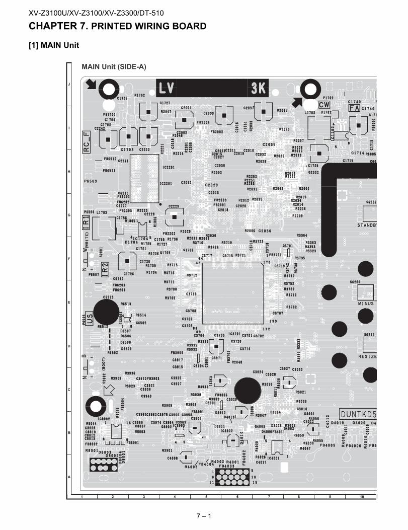
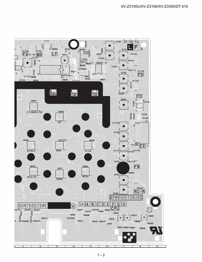
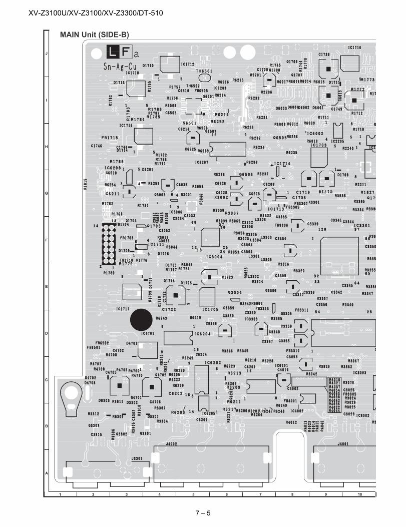
XV-Z3100U Service Manual CHAPTER 7. PRINTED WIRING BOARD[1] MAIN Unit
MAIN Unit (SIDE-A)
1 2 3 4 5 6 7 9 108
J
A
B
C
D
E
F
G
H
I
7 – 1
XV-Z3100U/XV-Z3100/XV-Z3300/DT-510
11 1312 14 15 16 18 1917
7 – 2
XV-Z3100U/XV-Z3100/XV-Z3300/DT-510
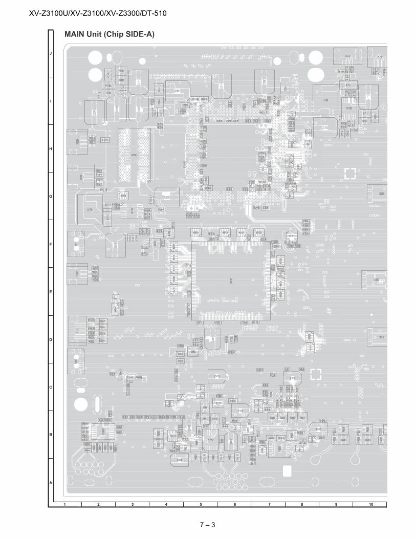
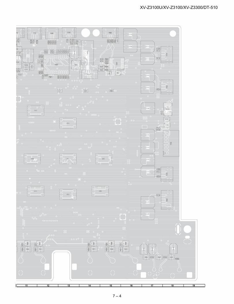
MAIN Unit (Chip SIDE-A)
1 2 3 4 5 6 7 9 108
J
A
B
C
D
E
F
G
H
I
7 – 3
XV-Z3100U/XV-Z3100/XV-Z3300/DT-510
11 1312 14 15 16 18 1917
7 – 4
XV-Z3100U/XV-Z3100/XV-Z3300/DT-510
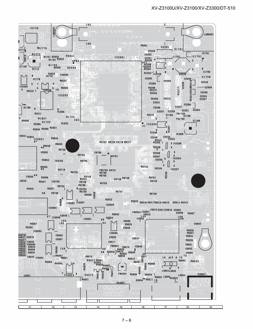
MAIN Unit (SIDE-B)
1 2 3 4 5 6 7 9 108
J
A
B
C
D
E
F
G
H
I
7 – 5
XV-Z3100U/XV-Z3100/XV-Z3300/DT-510
11 1312 14 15 16 18 1917
7 – 6
XV-Z3100U/XV-Z3100/XV-Z3300/DT-510
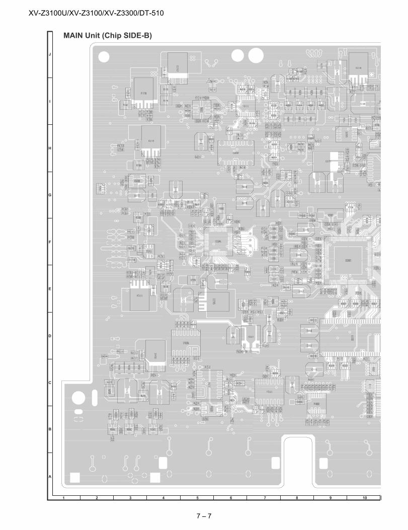
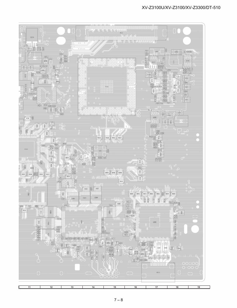
MAIN Unit (Chip SIDE-B)
1 2 3 4 5 6 7 9 108
J
A
B
C
D
E
F
G
H
I
7 – 7
XV-Z3100U/XV-Z3100/XV-Z3300/DT-510
11 1312 14 15 16 18 1917
7 – 8
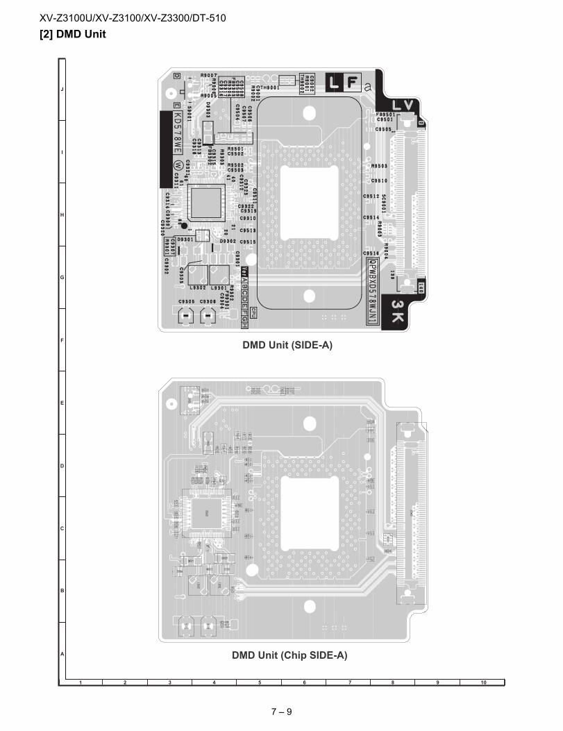
XV-Z3100U/XV-Z3100/XV-Z3300/DT-510
[2] DMD UnitDMD Unit (Chip SIDE-A)
DMD Unit (SIDE-A)
1 2 3 4 5 6 7 9 108
J
A
B
C
D
E
F
G
H
I
7 – 9
XV-Z3100U/XV-Z3100/XV-Z3300/DT-510
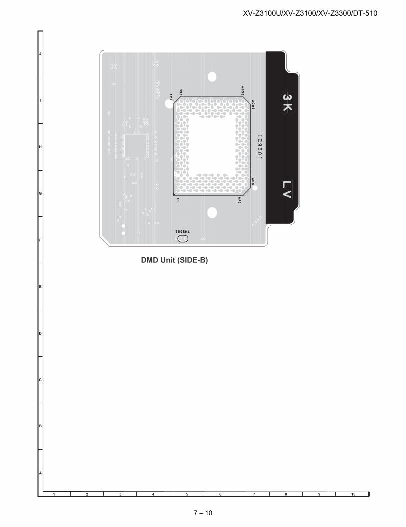
DMD Unit (SIDE-B)
1 2 3 4 5 6 7 9 108
J
A
B
C
D
E
F
G
H
I
7 – 10
XV-Z3100U/XV-Z3100/XV-Z3300/DT-510
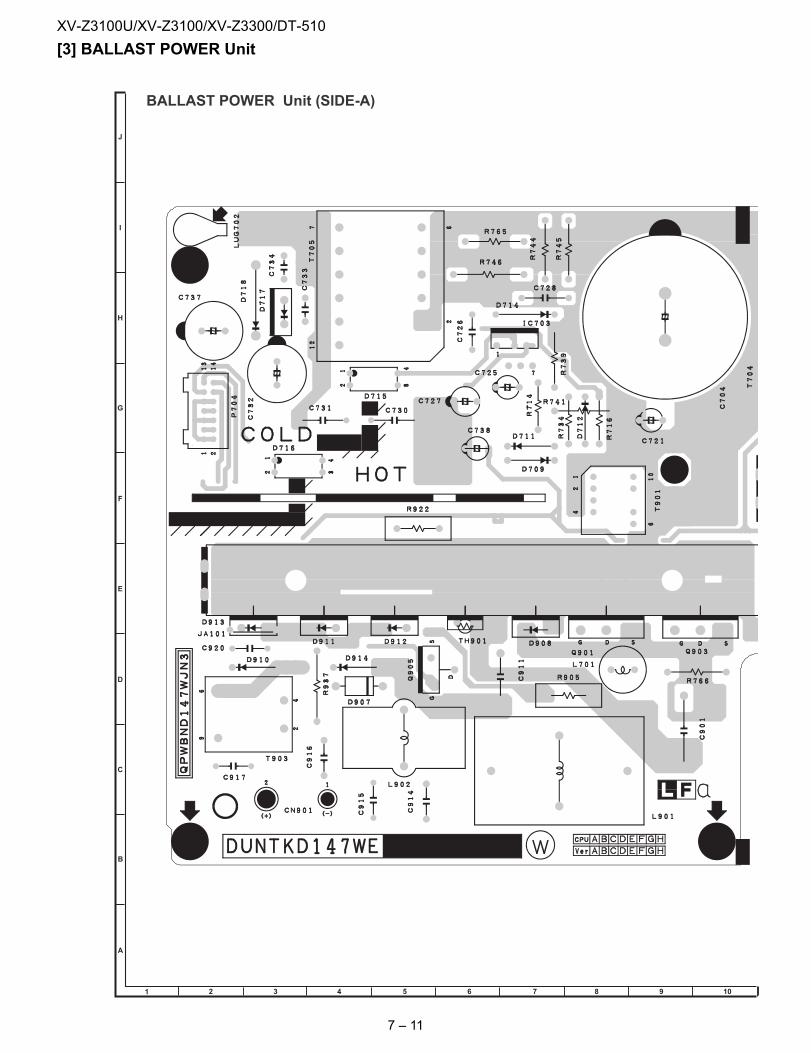
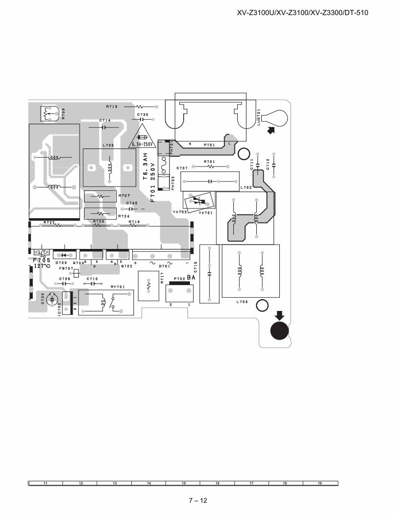
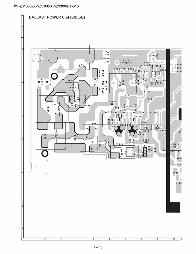
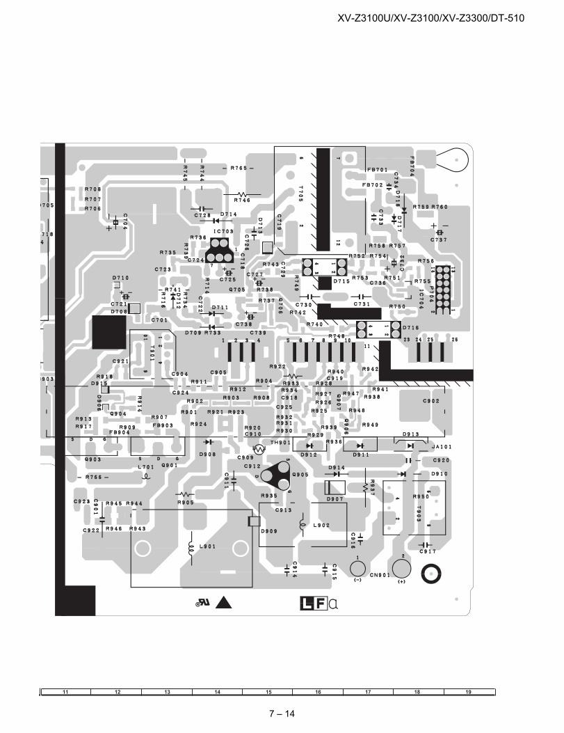
[3] BALLAST POWER UnitBALLAST POWER Unit (SIDE-A)
1 2 3 4 5 6 7 9 108
J
A
B
C
D
E
F
G
H
I
7 – 11
XV-Z3100U/XV-Z3100/XV-Z3300/DT-510
11 1312 14 15 16 18 1917
7 – 12
XV-Z3100U/XV-Z3100/XV-Z3300/DT-510
BALLAST POWER Unit (SIDE-B)
1 2 3 4 5 6 7 9 108
J
A
B
C
D
E
F
G
H
I
7 – 13
XV-Z3100U/XV-Z3100/XV-Z3300/DT-510
11 1312 14 15 16 18 1917
7 – 14
XV-Z3100U/XV-Z3100/XV-Z3300/DT-510
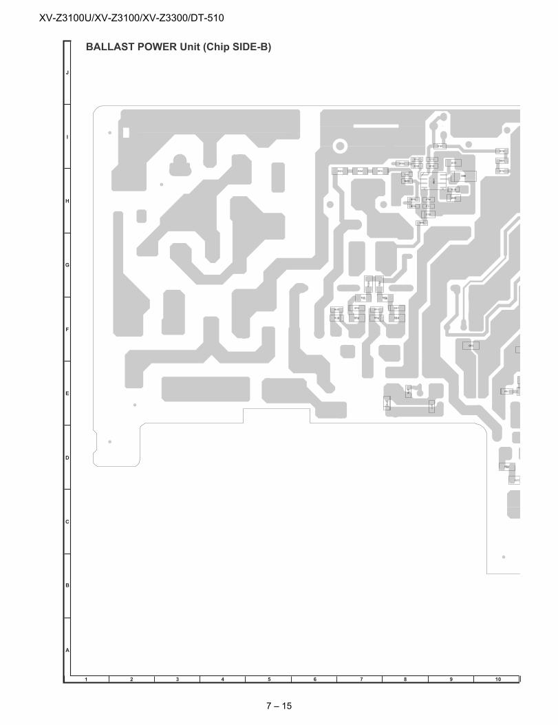
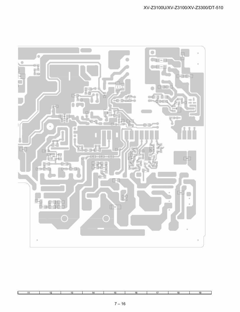
BALLAST POWER Unit (Chip SIDE-B)
1 2 3 4 5 6 7 9 108
J
A
B
C
D
E
F
G
H
I
7 – 15
XV-Z3100U/XV-Z3100/XV-Z3300/DT-510
11 1312 14 15 16 18 1917
7 – 16
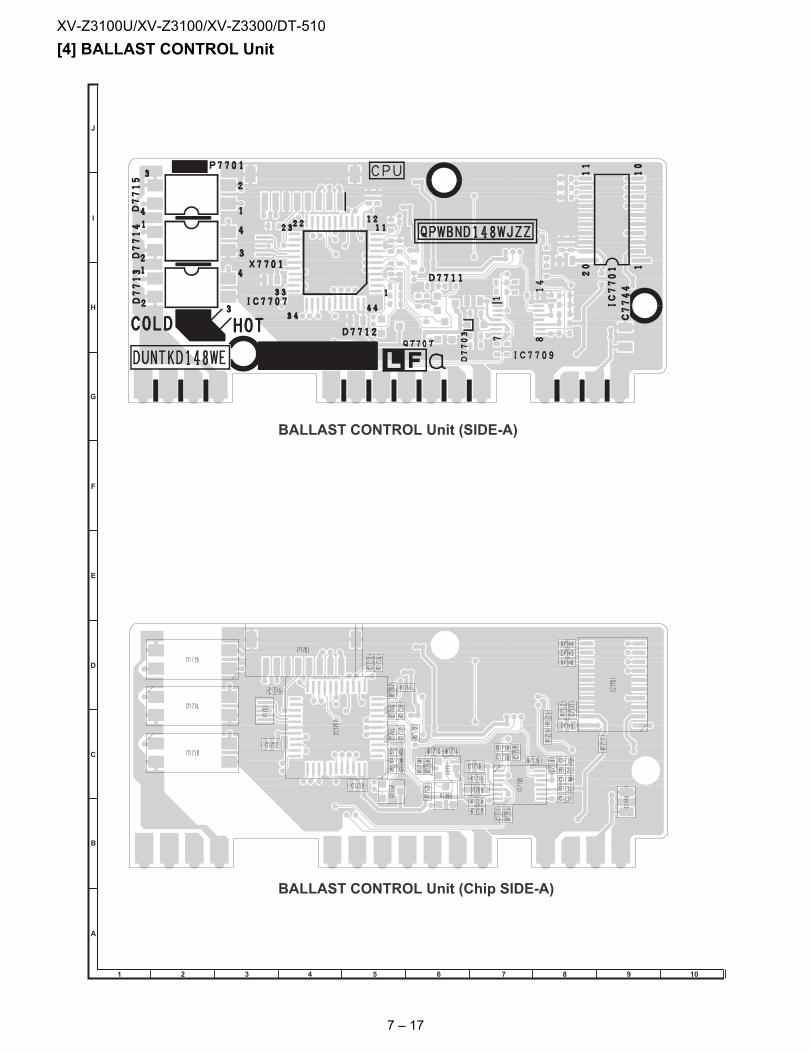
XV-Z3100U/XV-Z3100/XV-Z3300/DT-510
[4] BALLAST CONTROL UnitBALLAST CONTROL Unit (Chip SIDE-A)
BALLAST CONTROL Unit (SIDE-A)
1 2 3 4 5 6 7 9 108
J
A
B
C
D
E
F
G
H
I
7 – 17
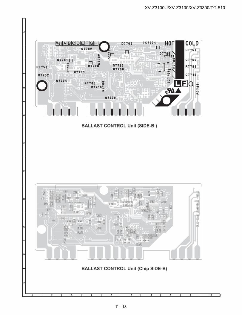
XV-Z3100U/XV-Z3100/XV-Z3300/DT-510
BALLAST CONTROL Unit (Chip SIDE-B)
BALLAST CONTROL Unit (SIDE-B )
1 2 3 4 5 6 7 9 108
J
A
B
C
D
E
F
G
H
I
7 – 18
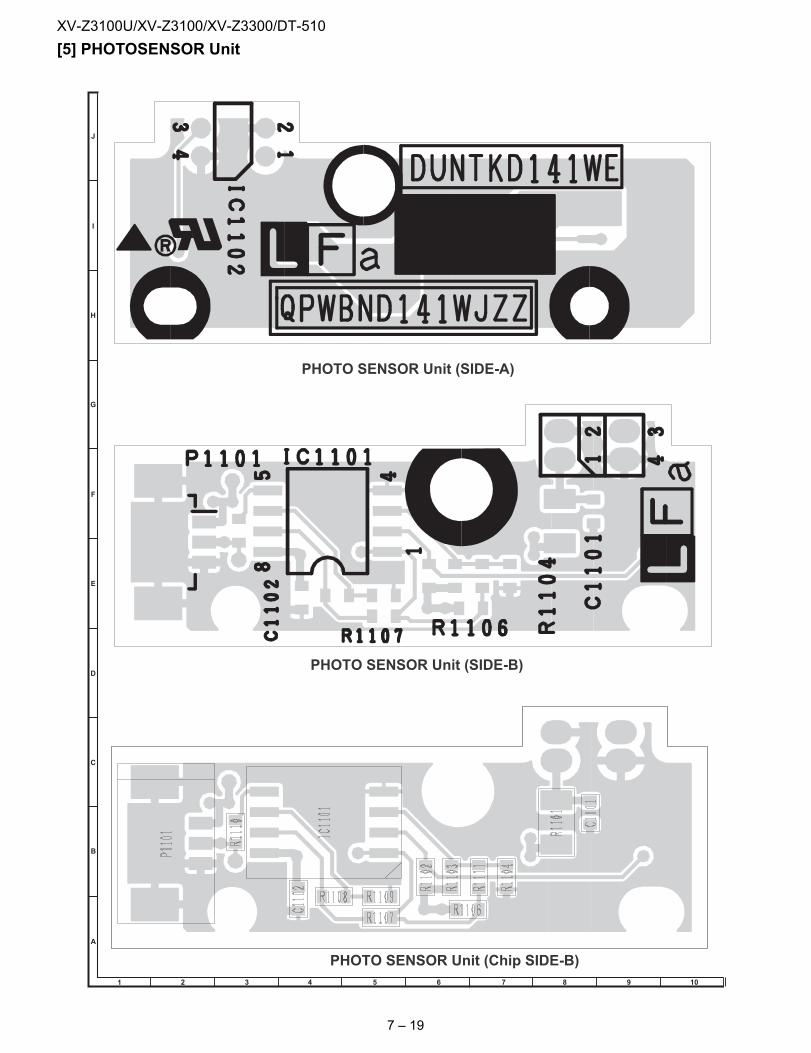
XV-Z3100U/XV-Z3100/XV-Z3300/DT-510
[5] PHOTOSENSOR UnitPHOTO SENSOR Unit (Chip SIDE-B)
PHOTO SENSOR Unit (SIDE-B)
PHOTO SENSOR Unit (SIDE-A)
1 2 3 4 5 6 7 9 108
J
A
B
C
D
E
F
G
H
I
7 – 19
XV-Z3100U/XV-Z3100/XV-Z3300/DT-510
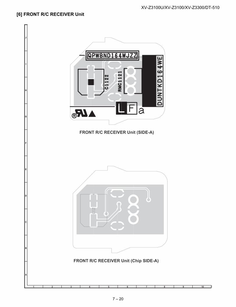
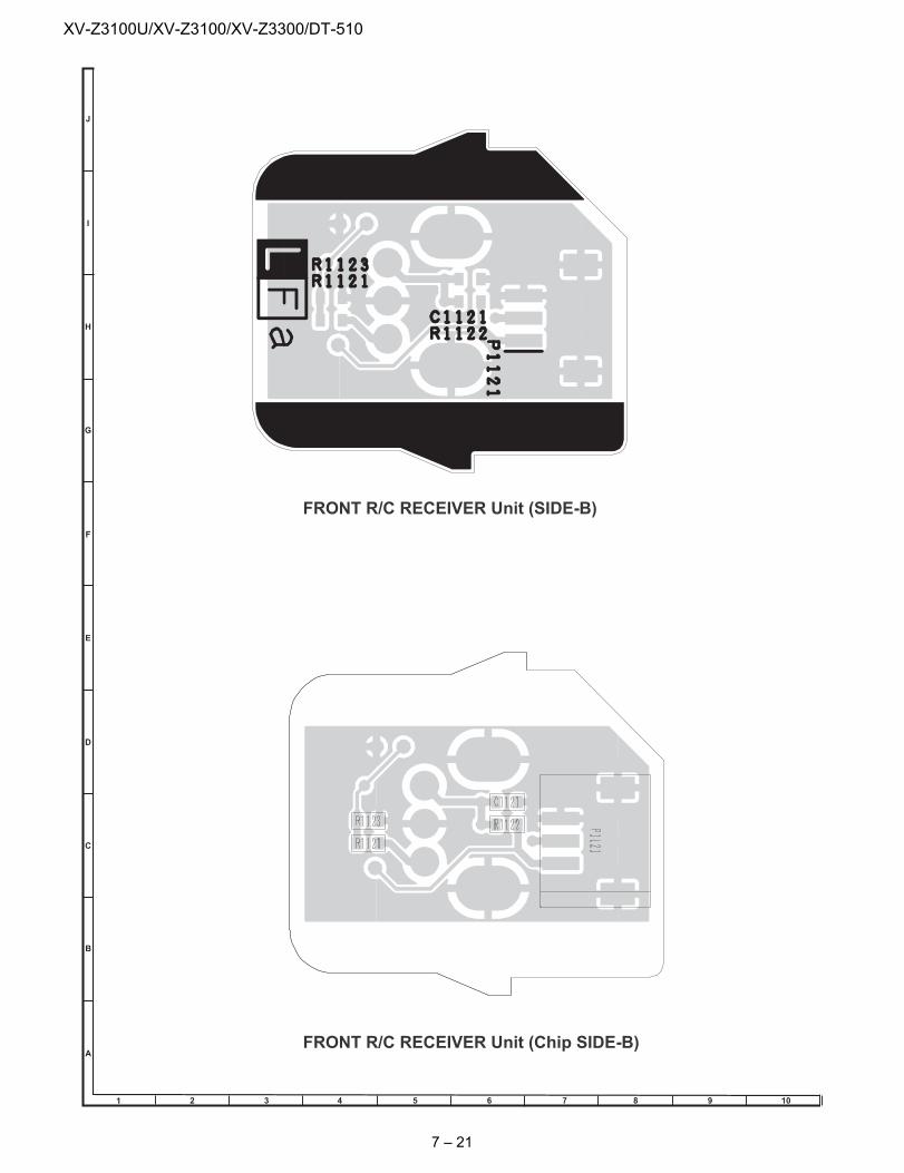
[6] FRONT R/C RECEIVER UnitFRONT R/C RECEIVER Unit (Chip SIDE-A)
FRONT R/C RECEIVER Unit (SIDE-A)
1 2 3 4 5 6 7 9 108
J
A
B
C
D
E
F
G
H
I
7 – 20
XV-Z3100U/XV-Z3100/XV-Z3300/DT-510
FRONT R/C RECEIVER Unit (Chip SIDE-B)
FRONT R/C RECEIVER Unit (SIDE-B)
1 2 3 4 5 6 7 9 108
J
A
B
C
D
E
F
G
H
I
7 – 21
XV-Z3100U/XV-Z3100/XV-Z3300/DT-510
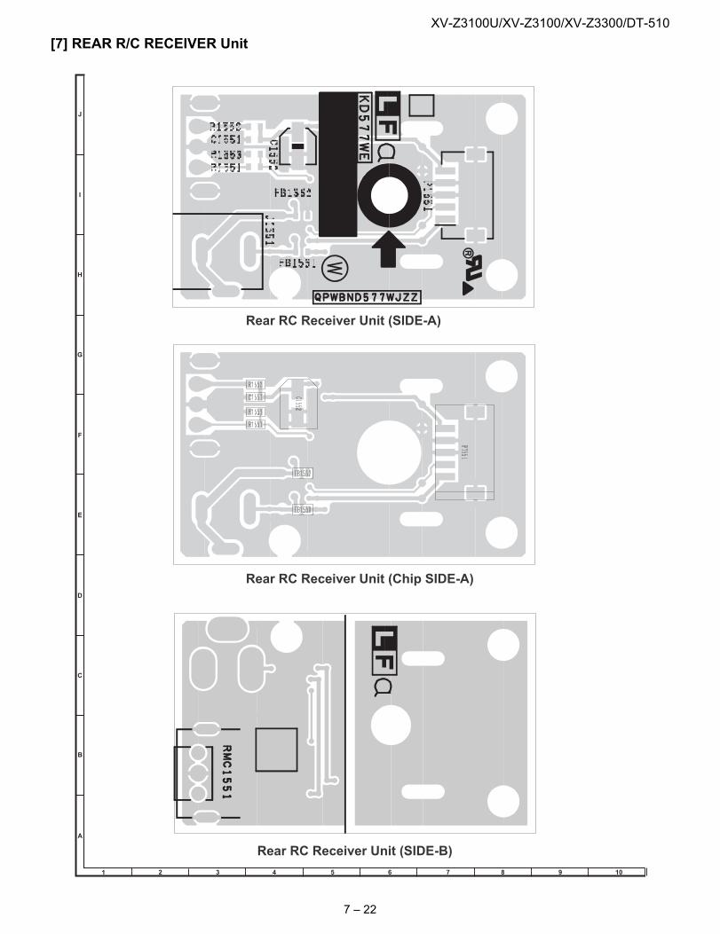
[7] REAR R/C RECEIVER UnitRear RC Receiver Unit (Chip SIDE-A)
Rear RC Receiver Unit (SIDE-B)
Rear RC Receiver Unit (SIDE-A)
1 2 3 4 5 6 7 9 108
J
A
B
C
D
E
F
G
H
I
7 – 22
XV-Z3100U/XV-Z3100/XV-Z3300/DT-510
8 – 1
XV-Z3100U Service Manual CHAPTER 8. WAVEFORMS
[1] WAVEFORMS
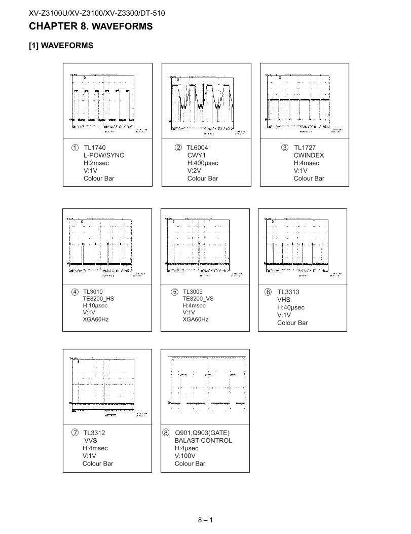
1 TL1740L-POW/SYNCH:2msecV:1VColour Bar
2 TL6004CWY1H:400µsecV:2VColour Bar
3 TL1727CWINDEXH:4msecV:1VColour Bar
4 TL3010TE8200_HSH:10µsecV:1VXGA60Hz
5 TL3009TE8200_VSH:4msecV:1VXGA60Hz
6 TL3313VHSH:40µsecV:1VColour Bar
7 TL3312VVSH:4msecV:1VColour Bar
8 Q901,Q903(GATE)BALAST CONTROLH:4µsecV:100VColour Bar
XV-Z3100U/XV-Z3100/XV-Z3300/DT-510
XV-Z3100U Service Manual CHAPTER 9. SCHEMATIC DIAGRAM[1] DESCRIPTION OF SCHEMATIC DIAGRAM
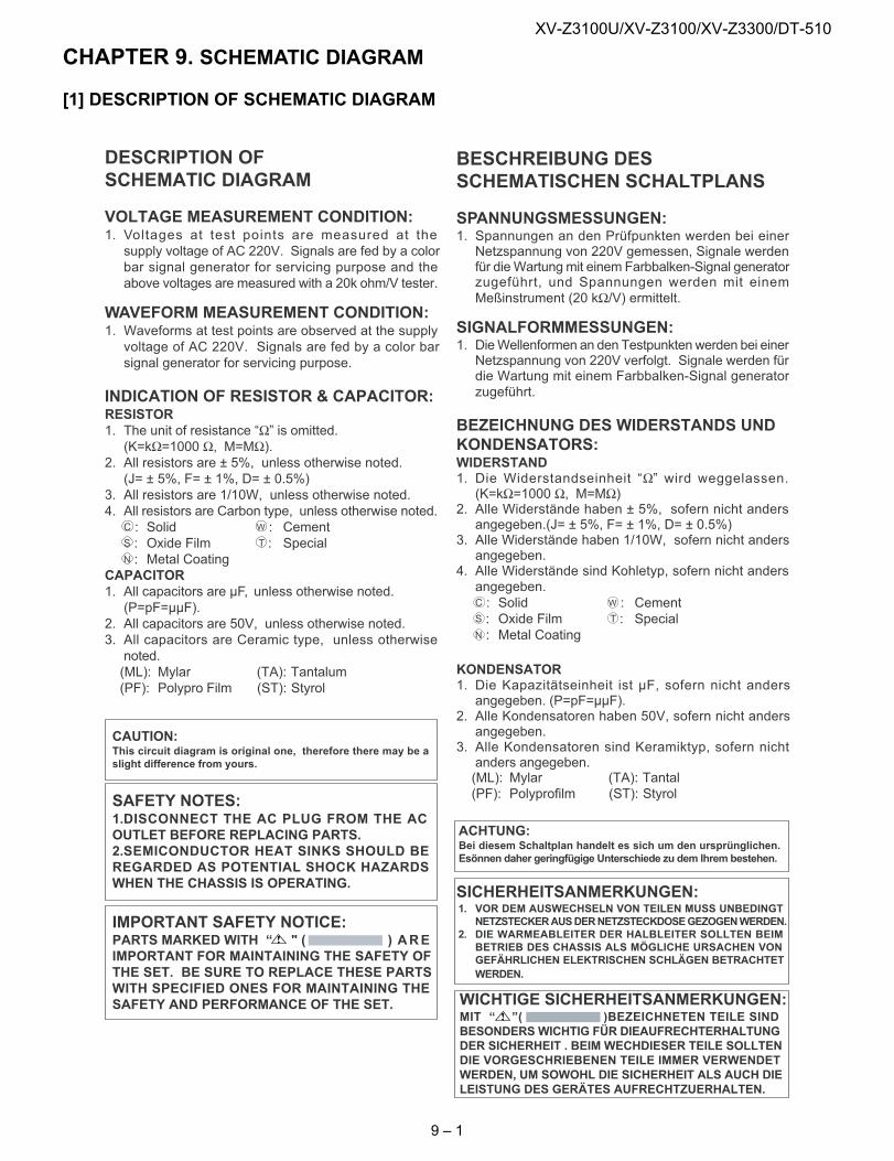
DESCRIPTION OFSCHEMATIC DIAGRAM
VOLTAGE MEASUREMENT CONDITION:1. Voltages at test points are measured at thesupply voltage of AC 220V. Signals are fed by a colorbar signal generator for servicing purpose and theabove voltages are measured with a 20k ohm/V tester.
WAVEFORM MEASUREMENT CONDITION:1. Waveforms at test points are observed at the supplyvoltage of AC 220V. Signals are fed by a color barsignal generator for servicing purpose.
INDICATION OF RESISTOR & CAPACITOR:RESISTOR1. The unit of resistance “Ω” is omitted.(K=kΩ=1000 Ω, M=MΩ).
2. All resistors are ± 5%, unless otherwise noted.(J= ± 5%, F= ± 1%, D= ± 0.5%)
3. All resistors are 1/10W, unless otherwise noted.4. All resistors are Carbon type, unless otherwise noted.
C : Solid W : CementS : Oxide Film T : SpecialN : Metal Coating
CAPACITOR1. All capacitors are µF, unless otherwise noted.(P=pF=µµF).
2. All capacitors are 50V, unless otherwise noted.3. All capacitors are Ceramic type, unless otherwisenoted.(ML): Mylar (TA): Tantalum(PF): Polypro Film (ST): Styrol
CAUTION:This circuit diagram is original one, therefore there may be aslight difference from yours.
SAFETY NOTES:1.DISCONNECT THE AC PLUG FROM THE ACOUTLET BEFORE REPLACING PARTS.2.SEMICONDUCTOR HEAT SINKS SHOULD BEREGARDED AS POTENTIAL SHOCK HAZARDSWHEN THE CHASSIS IS OPERATING.
IMPORTANT SAFETY NOTICE:PARTS MARKED WITH “ " ( ) AREIMPORTANT FOR MAINTAINING THE SAFETY OFTHE SET. BE SURE TO REPLACE THESE PARTSWITH SPECIFIED ONES FOR MAINTAINING THESAFETY AND PERFORMANCE OF THE SET.
BESCHREIBUNG DESSCHEMATISCHEN SCHALTPLANS
SPANNUNGSMESSUNGEN:1. Spannungen an den Prüfpunkten werden bei einerNetzspannung von 220V gemessen, Signale werdenfür dieWartungmit einem Farbbalken-Signal generatorzugeführt, und Spannungen werden mit einemMeßinstrument (20 kΩ/V) ermittelt.
SIGNALFORMMESSUNGEN:1. DieWellenformen an den Testpunkten werden bei einerNetzspannung von 220V verfolgt. Signale werden fürdie Wartung mit einem Farbbalken-Signal generatorzugeführt.
BEZEICHNUNG DES WIDERSTANDS UNDKONDENSATORS:WIDERSTAND1. Die Widerstandseinheit “Ω” wird weggelassen.(K=kΩ=1000 Ω, M=MΩ)
2. Alle Widerstände haben ± 5%, sofern nicht andersangegeben.(J= ± 5%, F= ± 1%, D= ± 0.5%)
3. Alle Widerstände haben 1/10W, sofern nicht andersangegeben.
4. Alle Widerstände sind Kohletyp, sofern nicht andersangegeben.C : Solid W : CementS : Oxide Film T : SpecialN : Metal Coating
KONDENSATOR1. Die Kapazitätseinheit ist µF, sofern nicht andersangegeben. (P=pF=µµF).
2. Alle Kondensatoren haben 50V, sofern nicht andersangegeben.
3. Alle Kondensatoren sind Keramiktyp, sofern nichtanders angegeben.(ML): Mylar (TA): Tantal(PF): Polyprofilm (ST): Styrol
ACHTUNG:Bei diesem Schaltplan handelt es sich um den ursprünglichen.Esönnen daher geringfügige Unterschiede zu dem lhrem bestehen.
SICHERHEITSANMERKUNGEN:1. VOR DEM AUSWECHSELN VON TEILEN MUSS UNBEDINGT
NETZSTECKERAUSDERNETZSTECKDOSEGEZOGENWERDEN.2. DIE WARMEABLEITER DER HALBLEITER SOLLTEN BEIM
BETRIEB DES CHASSIS ALS MÖGLICHE URSACHEN VONGEFÄHRLICHEN ELEKTRISCHEN SCHLÄGEN BETRACHTETWERDEN.
WICHTIGE SICHERHEITSANMERKUNGEN:MIT “ ”( )BEZEICHNETEN TEILE SINDBESONDERSWICHTIG FÜR DIEAUFRECHTERHALTUNGDER SICHERHEIT . BEIM WECHDIESER TEILE SOLLTENDIE VORGESCHRIEBENEN TEILE IMMER VERWENDETWERDEN, UM SOWOHL DIE SICHERHEIT ALS AUCH DIELEISTUNG DES GERÄTES AUFRECHTZUERHALTEN.
9 – 1
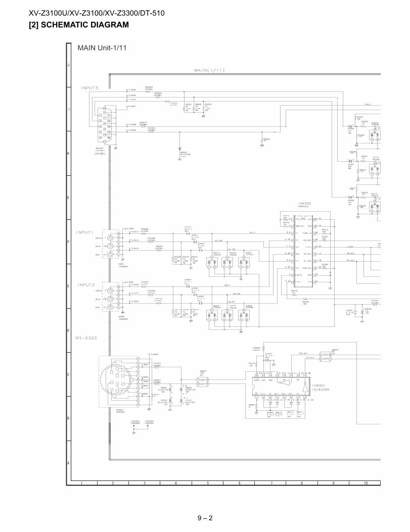
XV-Z3100U/XV-Z3100/XV-Z3300/DT-510
[2] SCHEMATIC DIAGRAMMAIN Unit-1/11
9 – 2
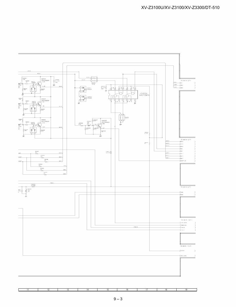
XV-Z3100U/XV-Z3100/XV-Z3300/DT-510
9 – 3
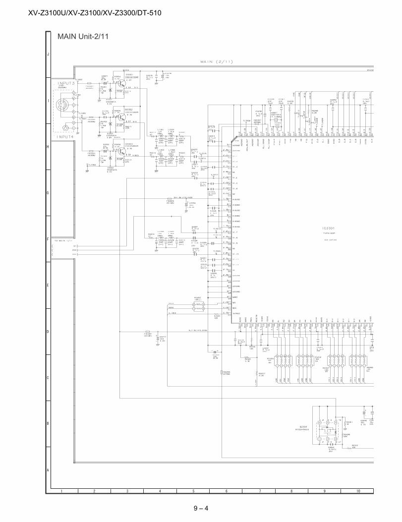
XV-Z3100U/XV-Z3100/XV-Z3300/DT-510
MAIN Unit-2/11
9 – 4
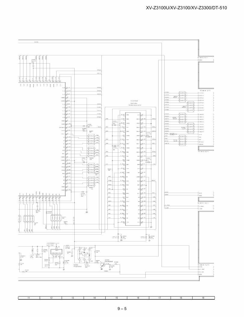
XV-Z3100U/XV-Z3100/XV-Z3300/DT-510
9 – 5
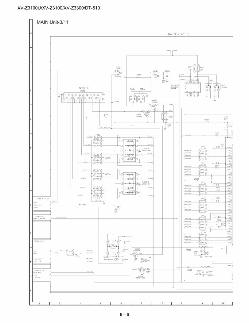
XV-Z3100U/XV-Z3100/XV-Z3300/DT-510
MAIN Unit-3/11
9 – 6
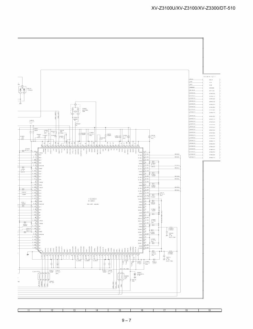
XV-Z3100U/XV-Z3100/XV-Z3300/DT-510
9 – 7
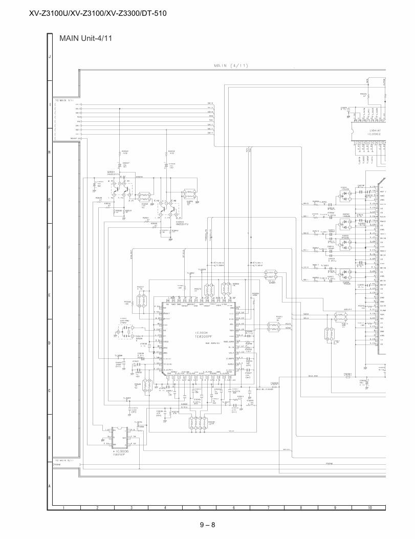
XV-Z3100U/XV-Z3100/XV-Z3300/DT-510
MAIN Unit-4/11
9 – 8
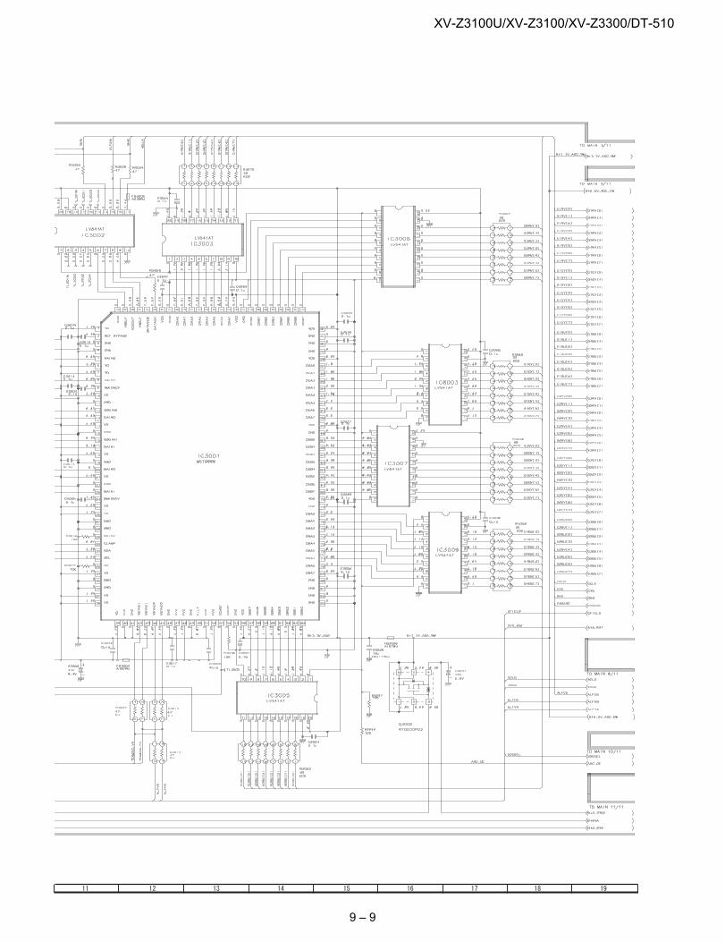
XV-Z3100U/XV-Z3100/XV-Z3300/DT-510
9 – 9
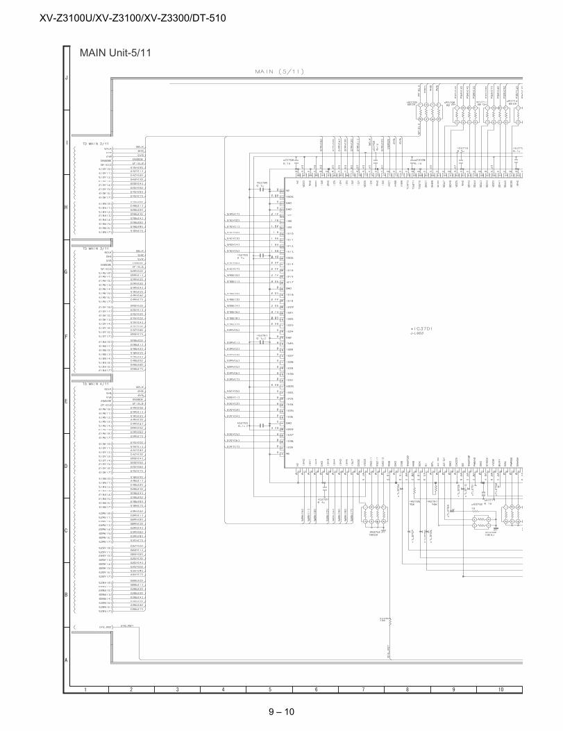
XV-Z3100U/XV-Z3100/XV-Z3300/DT-510
MAIN Unit-5/11
9 – 10
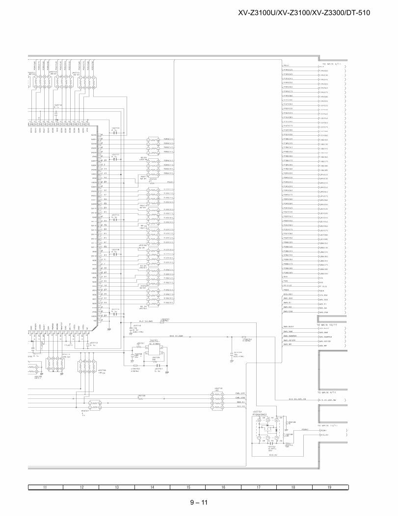
XV-Z3100U/XV-Z3100/XV-Z3300/DT-510
9 – 11
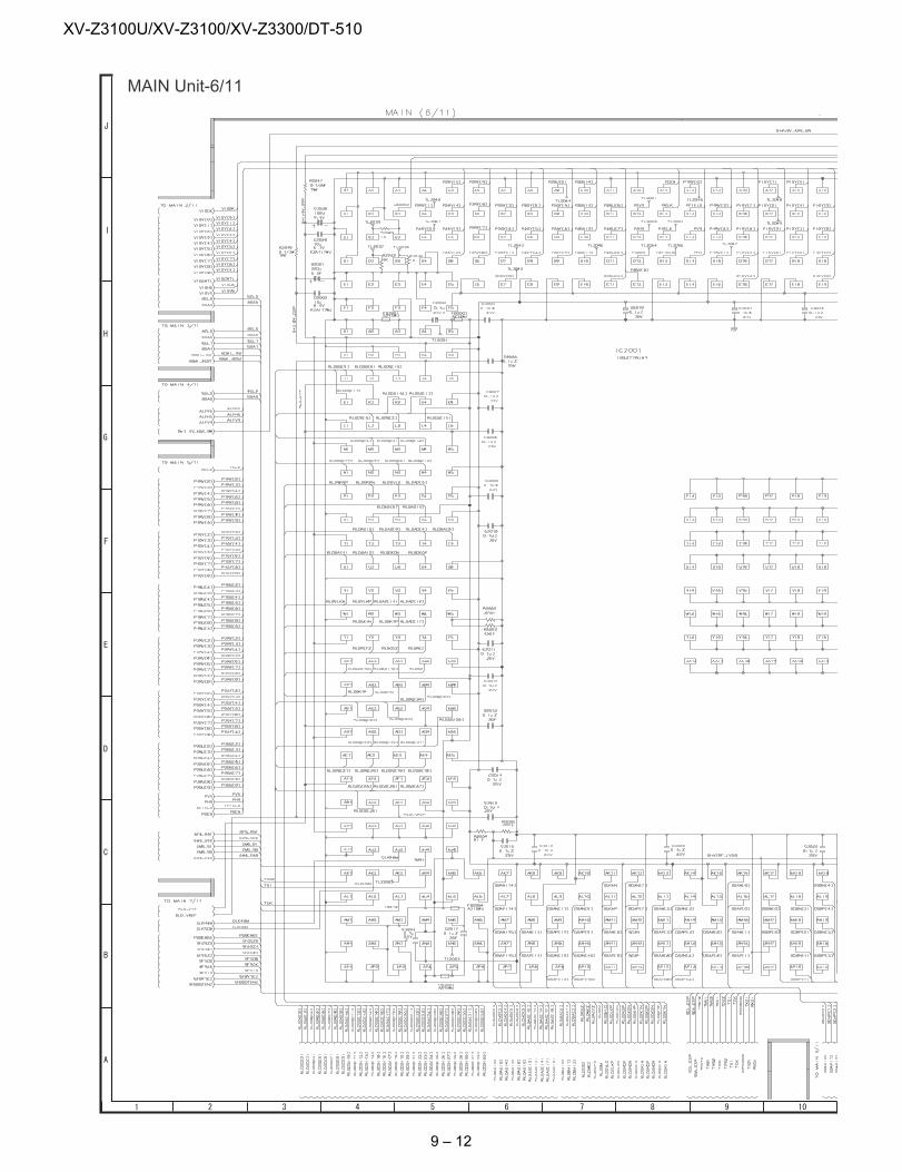
XV-Z3100U/XV-Z3100/XV-Z3300/DT-510
MAIN Unit-6/11
9 – 12
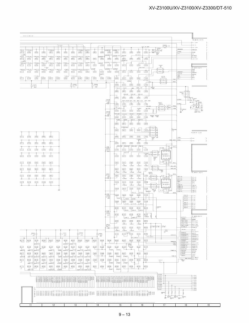
XV-Z3100U/XV-Z3100/XV-Z3300/DT-510
9 – 13
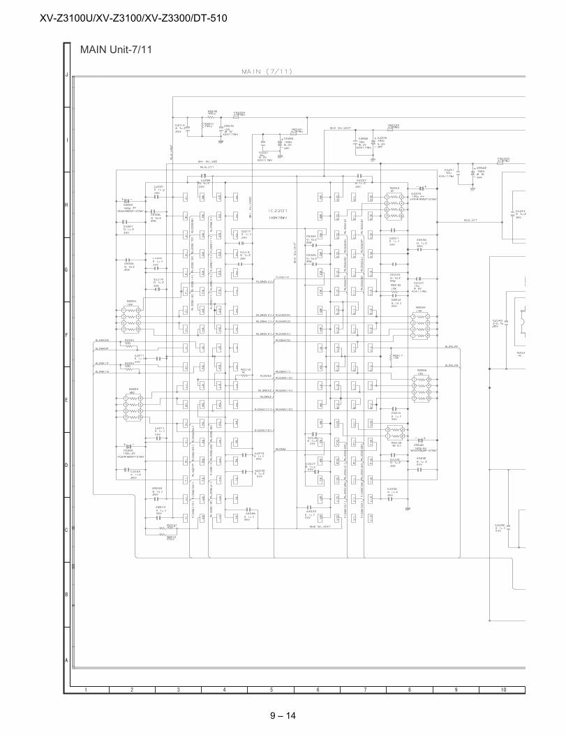
XV-Z3100U/XV-Z3100/XV-Z3300/DT-510
MAIN Unit-7/11
9 – 14
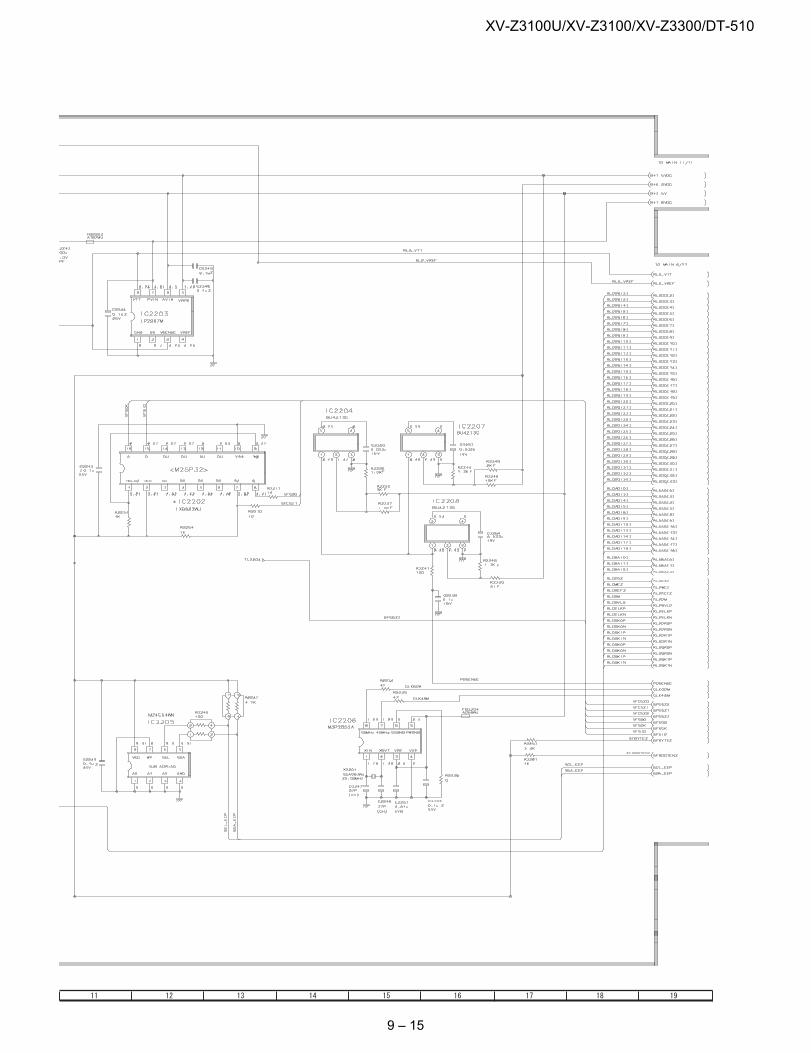
XV-Z3100U/XV-Z3100/XV-Z3300/DT-510
9 – 15
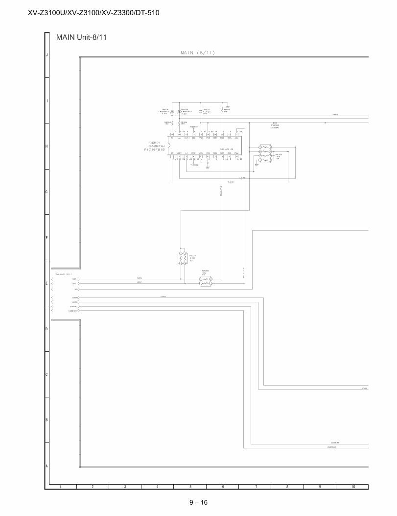
XV-Z3100U/XV-Z3100/XV-Z3300/DT-510
MAIN Unit-8/11
9 – 16
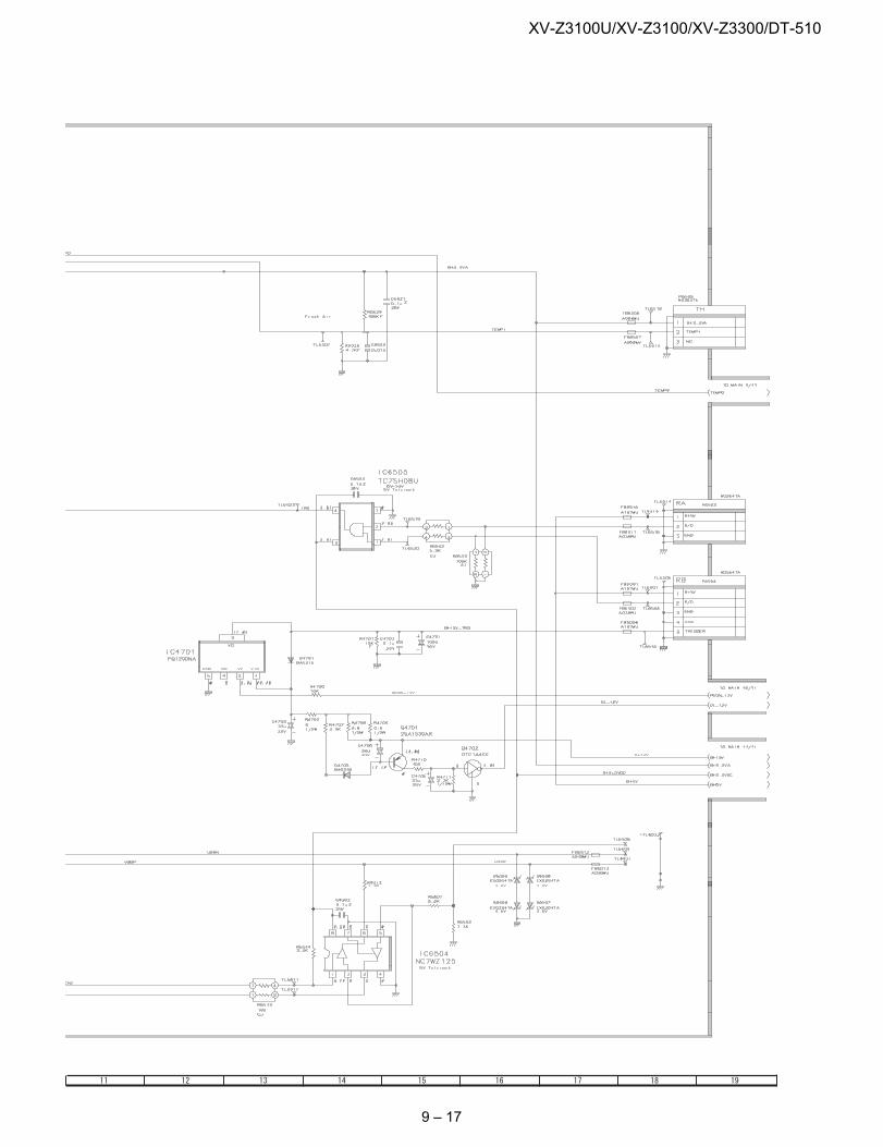
XV-Z3100U/XV-Z3100/XV-Z3300/DT-510
9 – 17
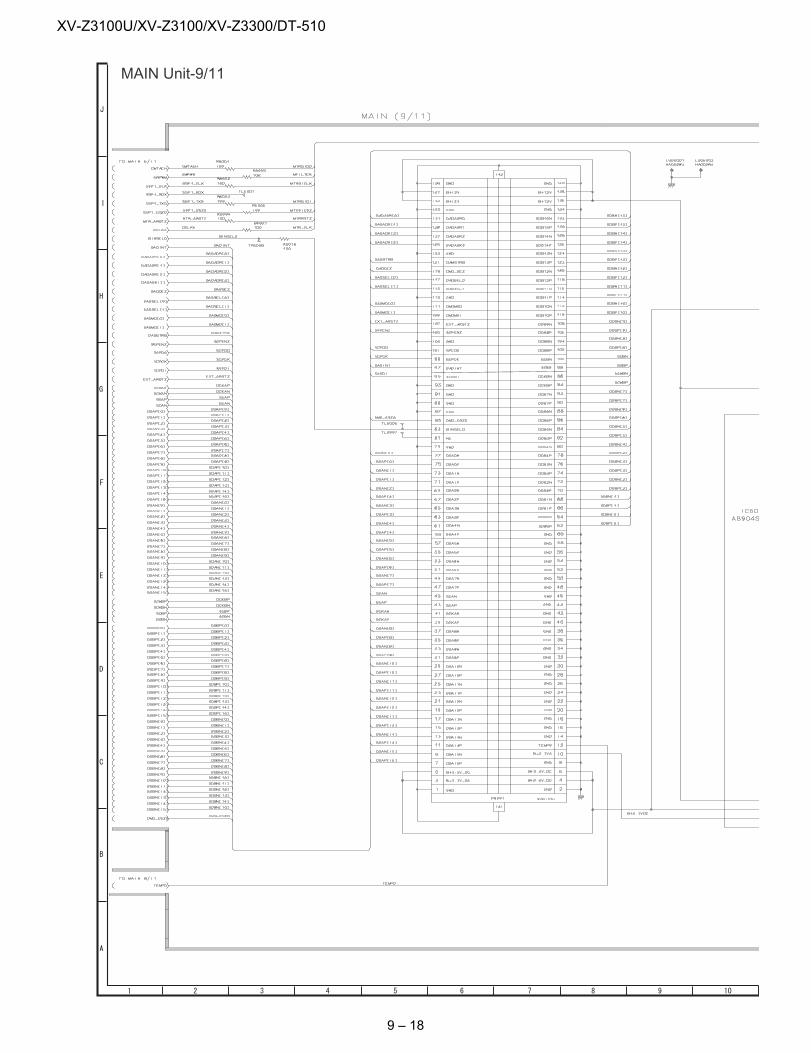
XV-Z3100U/XV-Z3100/XV-Z3300/DT-510
MAIN Unit-9/11
9 – 18
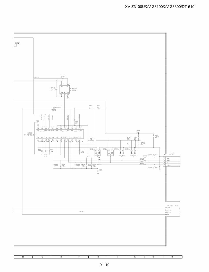
XV-Z3100U/XV-Z3100/XV-Z3300/DT-510
9 – 19
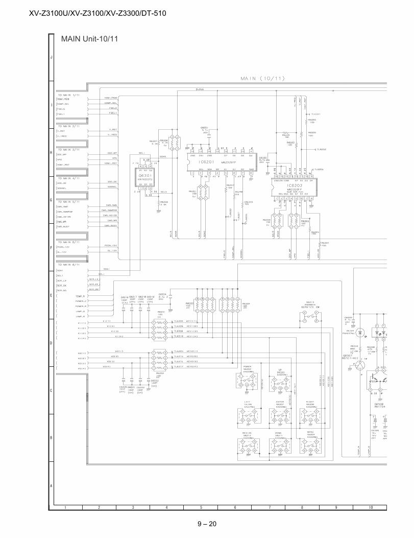
XV-Z3100U/XV-Z3100/XV-Z3300/DT-510
MAIN Unit-10/11
9 – 20
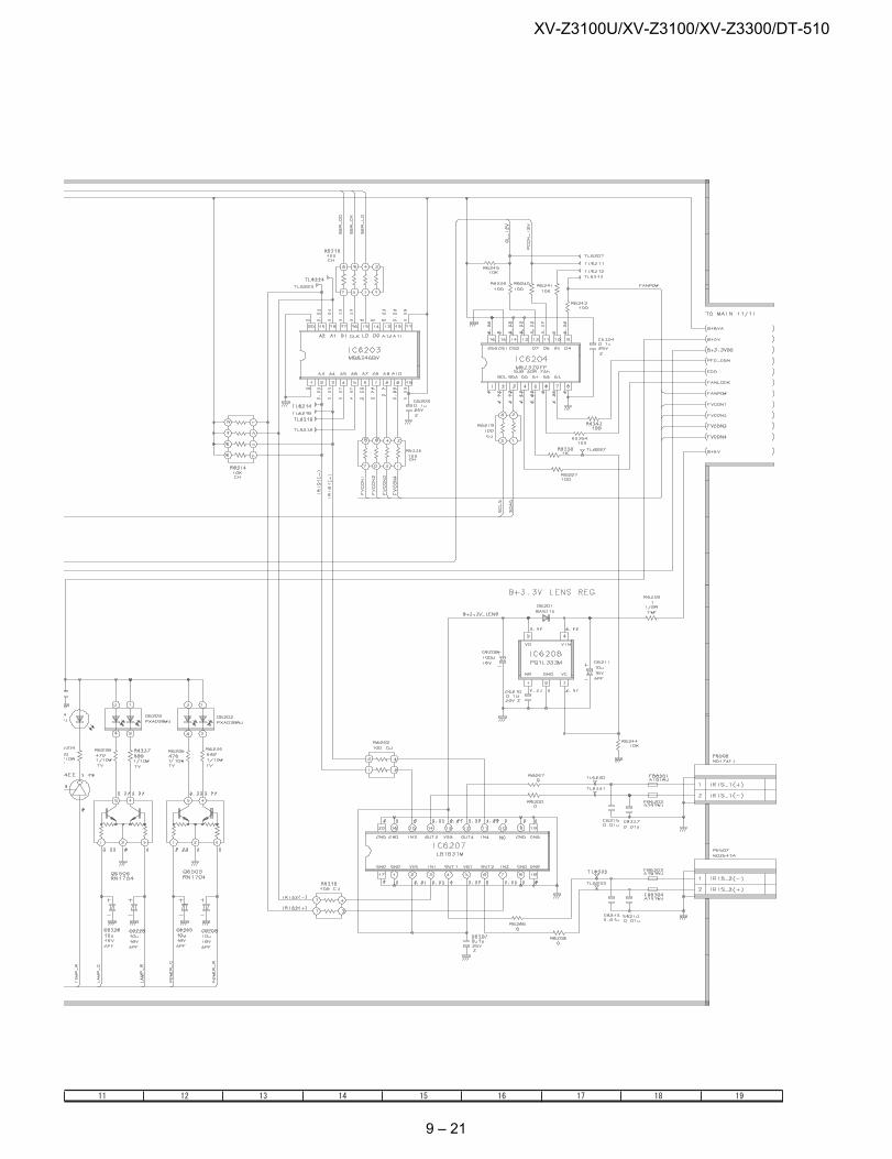
XV-Z3100U/XV-Z3100/XV-Z3300/DT-510
9 – 21
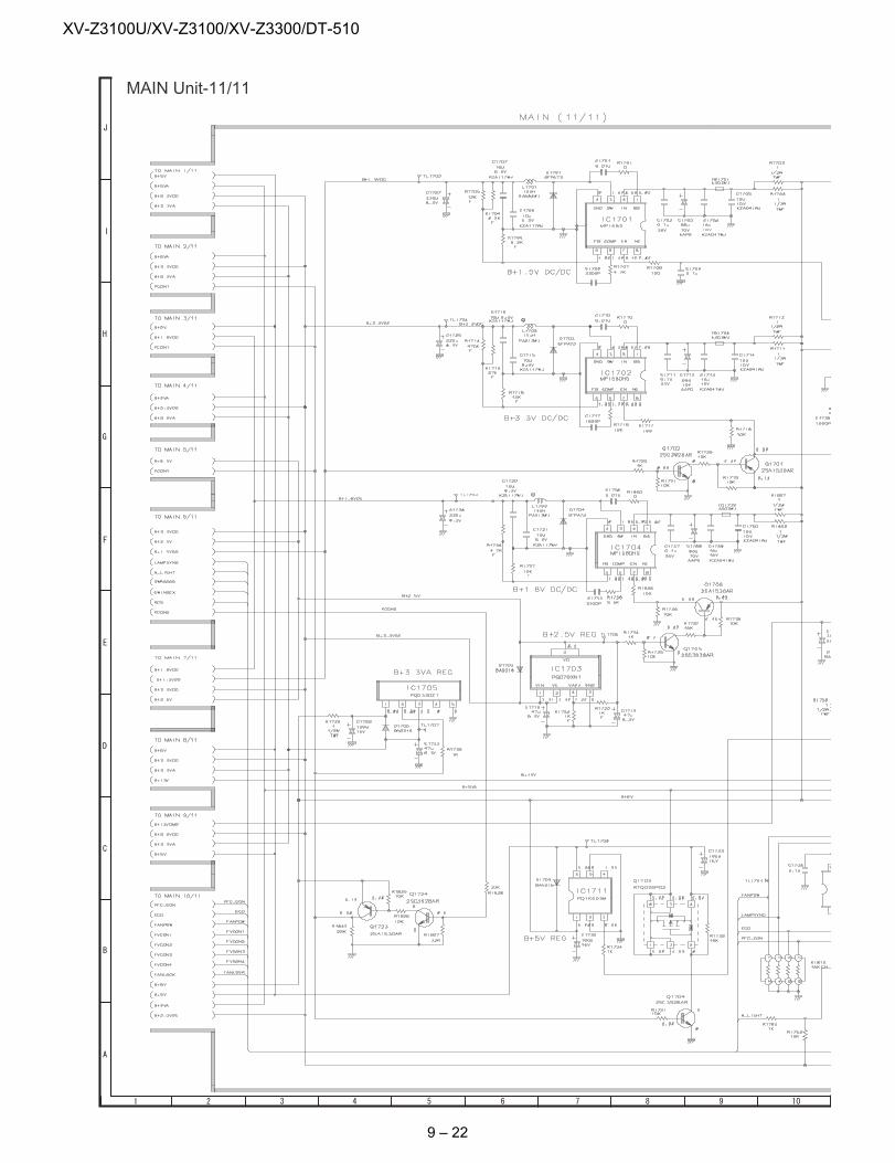
XV-Z3100U/XV-Z3100/XV-Z3300/DT-510
MAIN Unit-11/11
9 – 22
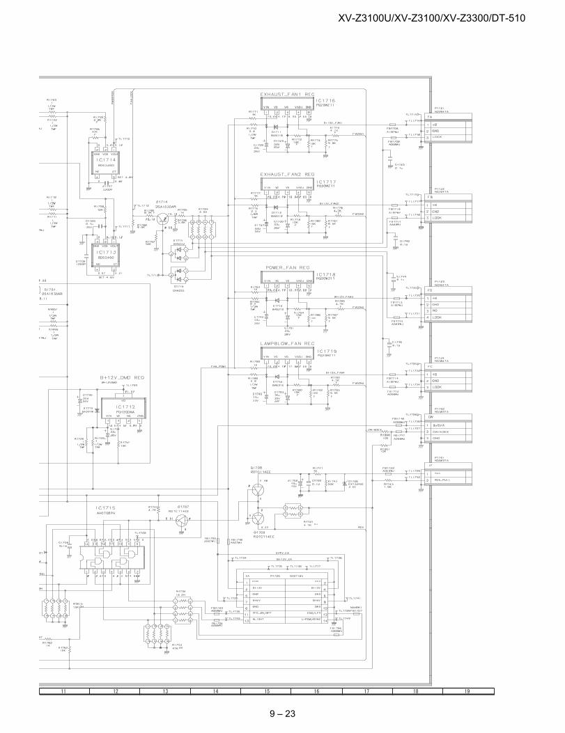
XV-Z3100U/XV-Z3100/XV-Z3300/DT-510
9 – 23
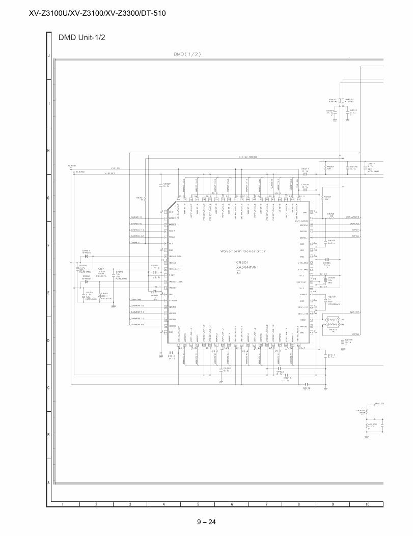
XV-Z3100U/XV-Z3100/XV-Z3300/DT-510
DMD Unit-1/2
9 – 24
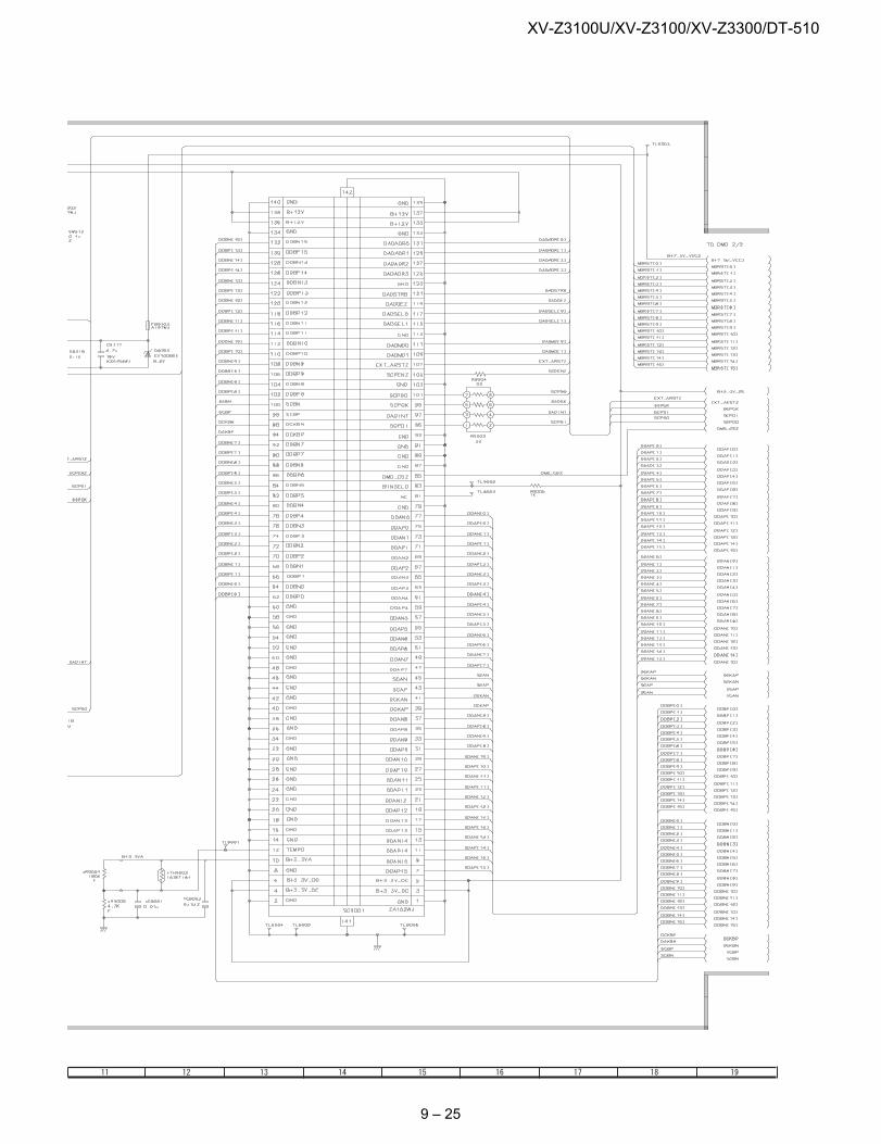
XV-Z3100U/XV-Z3100/XV-Z3300/DT-510
9 – 25
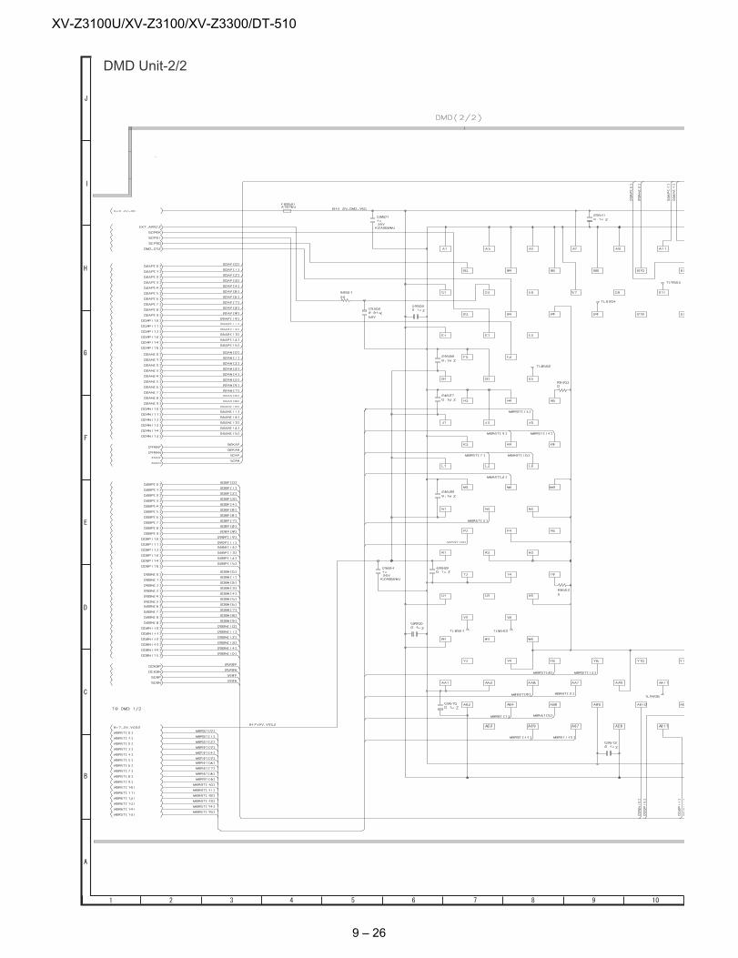
XV-Z3100U/XV-Z3100/XV-Z3300/DT-510
DMD Unit-2/2
9 – 26
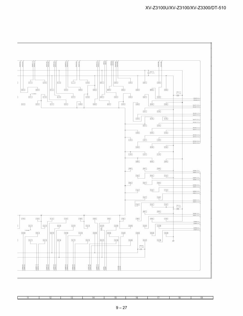
XV-Z3100U/XV-Z3100/XV-Z3300/DT-510
9 – 27
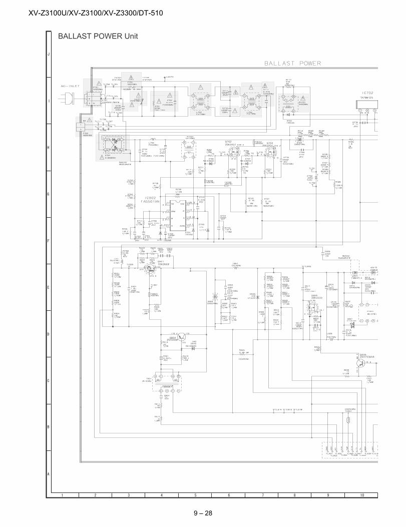
XV-Z3100U/XV-Z3100/XV-Z3300/DT-510
BALLAST POWER Unit
9 – 28
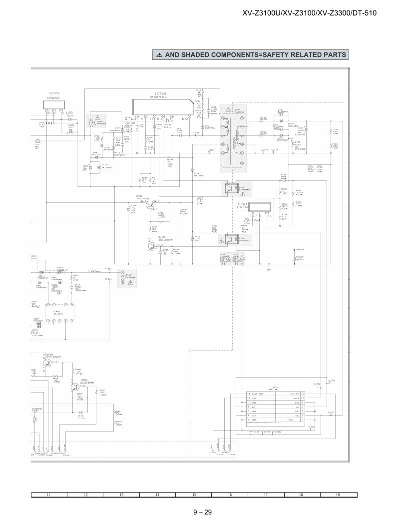
XV-Z3100U/XV-Z3100/XV-Z3300/DT-510
AND SHADED COMPONENTS=SAFETY RELATED PARTS
9 – 29
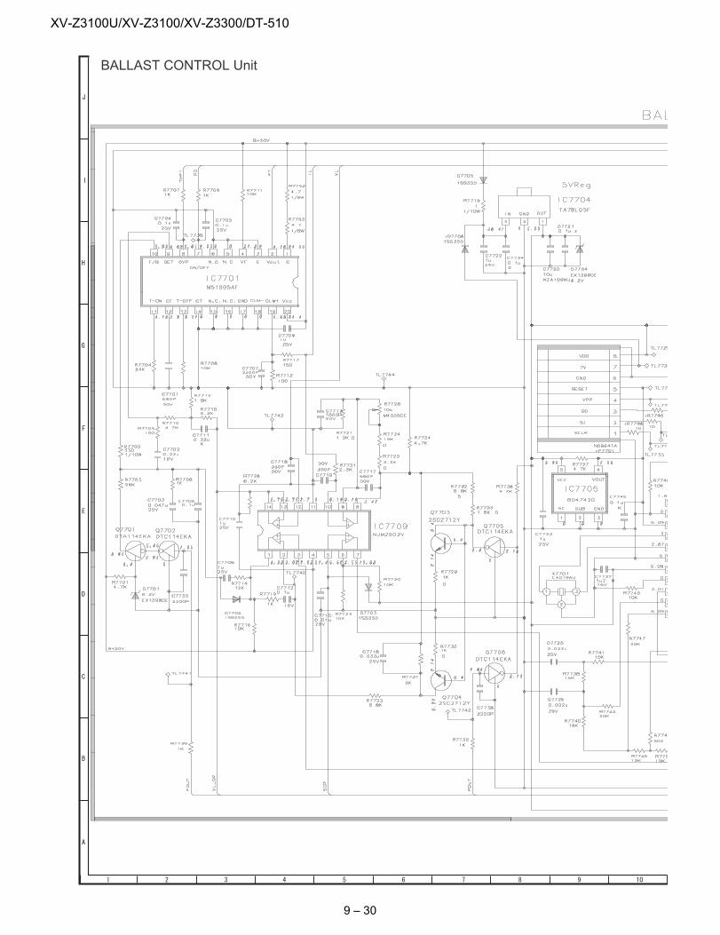
XV-Z3100U/XV-Z3100/XV-Z3300/DT-510
BALLAST CONTROL Unit
9 – 30
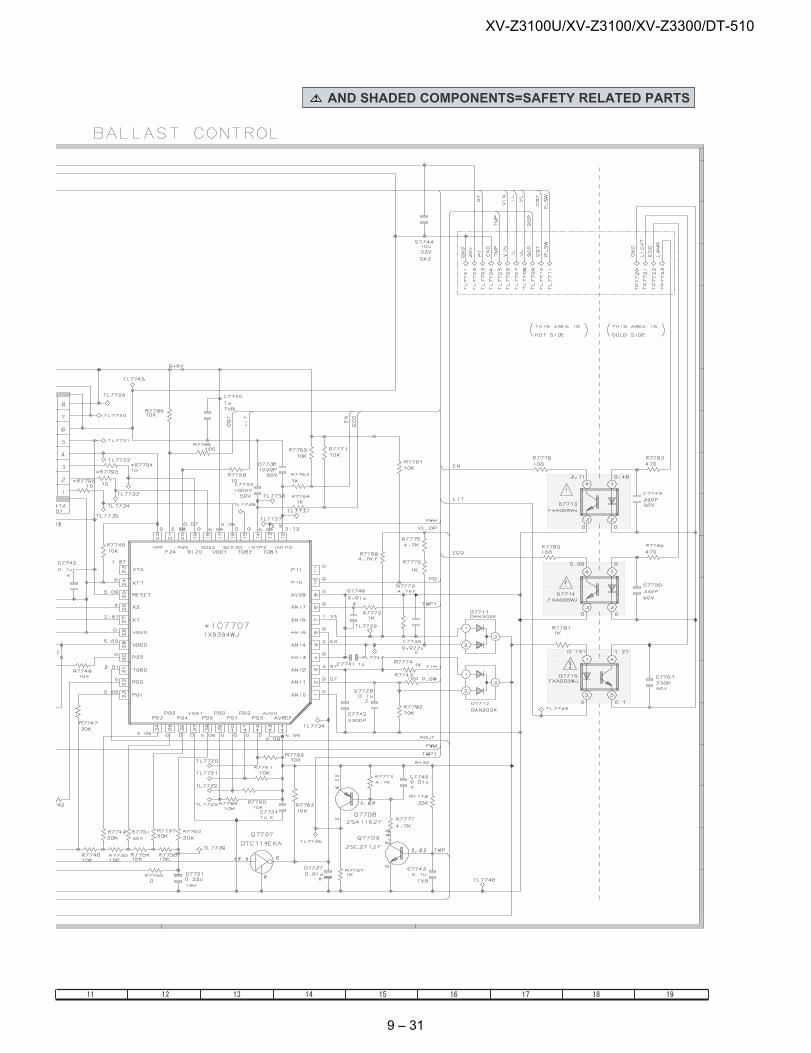
XV-Z3100U/XV-Z3100/XV-Z3300/DT-510
AND SHADED COMPONENTS=SAFETY RELATED PARTS
9 – 31
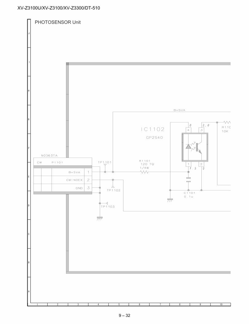
XV-Z3100U/XV-Z3100/XV-Z3300/DT-510
PHOTOSENSOR Unit
9 – 32
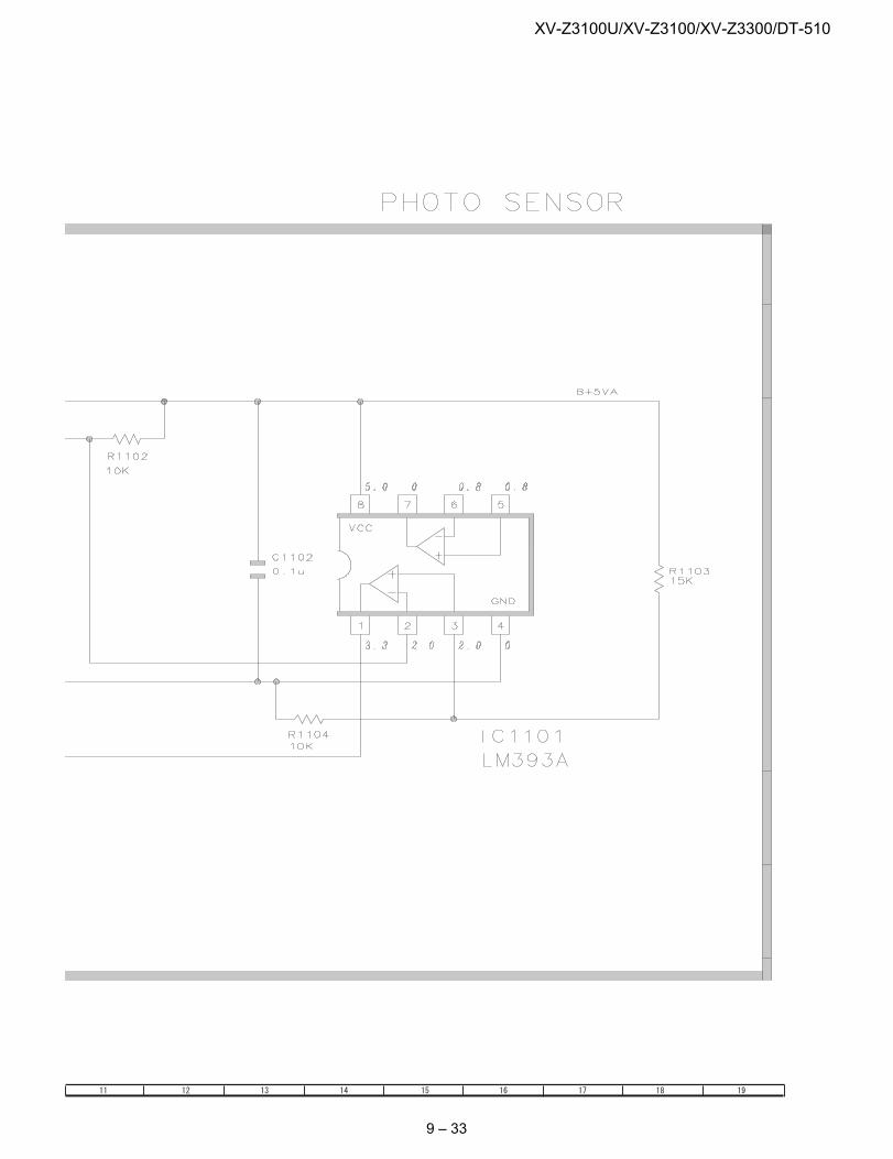
XV-Z3100U/XV-Z3100/XV-Z3300/DT-510
9 – 33
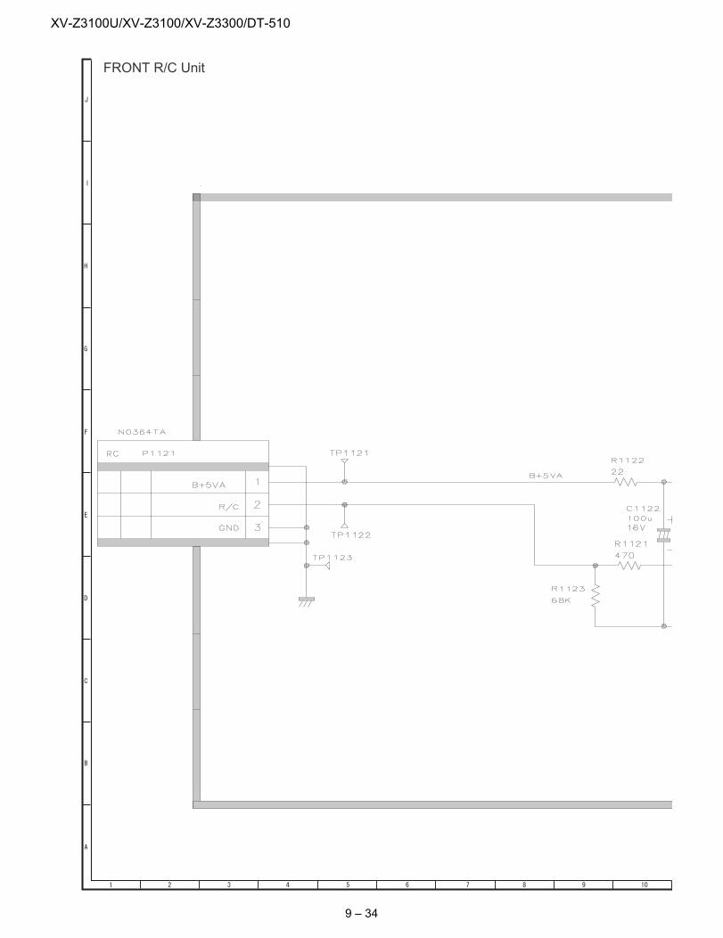
XV-Z3100U/XV-Z3100/XV-Z3300/DT-510
FRONT R/C Unit
9 – 34
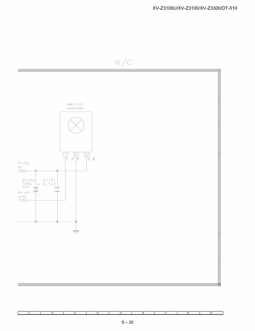
XV-Z3100U/XV-Z3100/XV-Z3300/DT-510
9 – 35
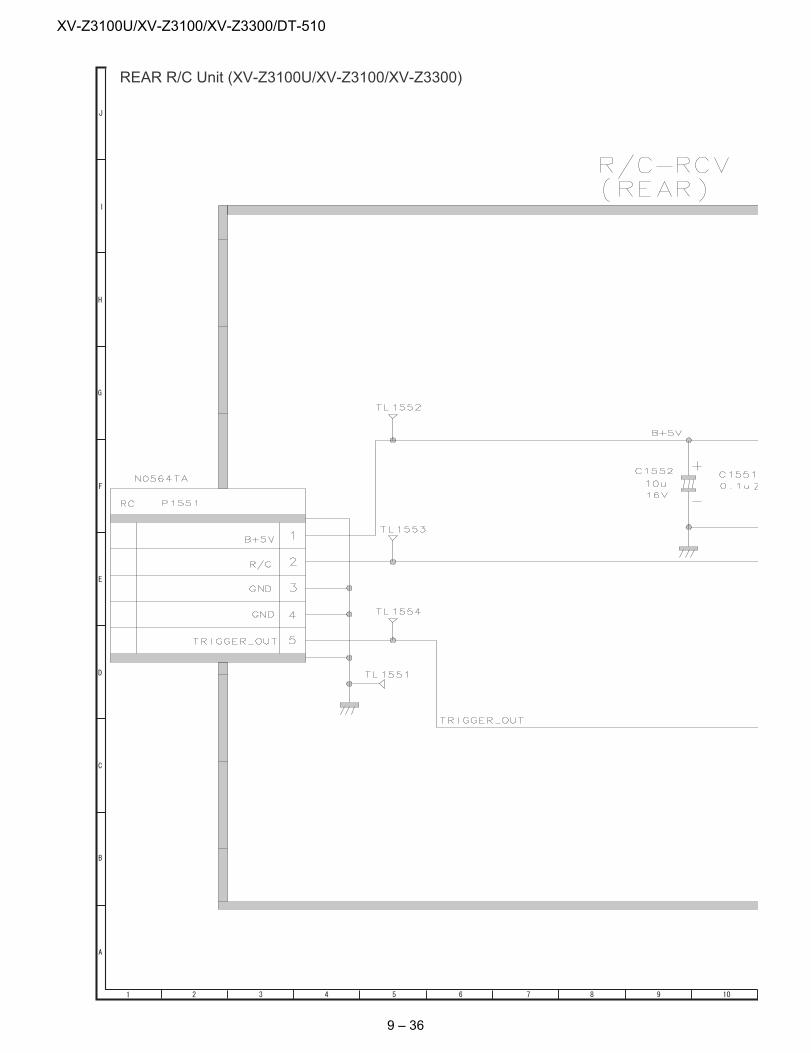
XV-Z3100U/XV-Z3100/XV-Z3300/DT-510
REAR R/C Unit (XV-Z3100U/XV-Z3100/XV-Z3300)
9 – 36
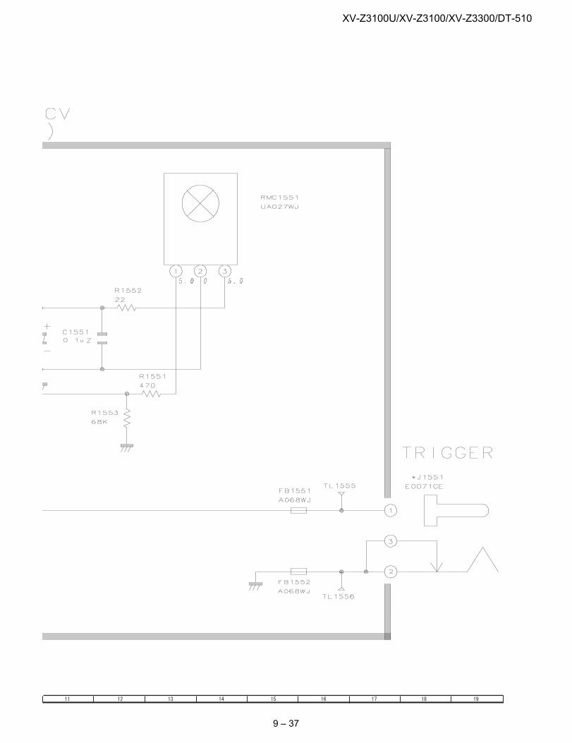
XV-Z3100U/XV-Z3100/XV-Z3300/DT-510
9 – 37
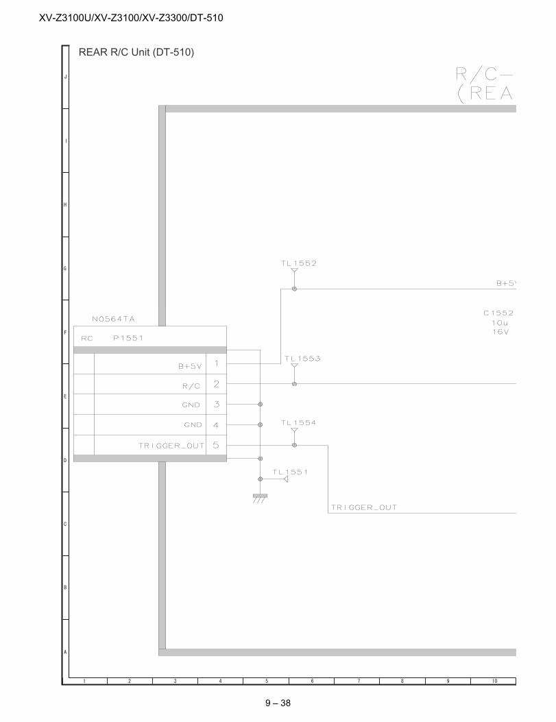
XV-Z3100U/XV-Z3100/XV-Z3300/DT-510
REAR R/C Unit (DT-510)
9 – 38
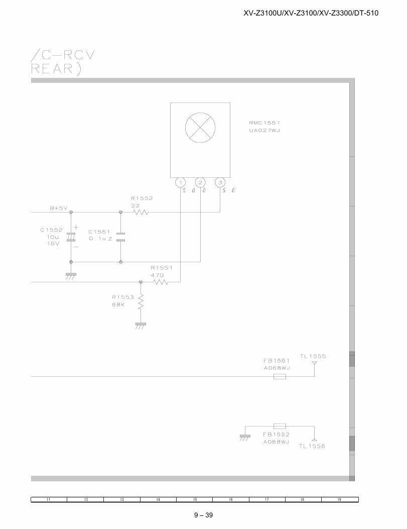
XV-Z3100U/XV-Z3100/XV-Z3300/DT-510
9 – 39

XV-Z3100U/XV-Z3100/XV-Z3300/DT-510
— MEMO —9 – 40
XV-Z3100U/XV-Z3100/XV-Z3300/DT-510
PartsGuidePARTS GUIDE
CONTENTS
PROJECTOR
XV-Z3100U
DT-510MODELSXV-Z3300XV-Z3100
[1] PRINTED WIRING BOARD ASSEMBLIES
[2] DUNTKD575FMF3 (MAIN Unit)
[3] DUNTKD578WEF1 (DMD Unit)
[4] DUNTKD141WEF7 (PHOTO SENSOR Unit)
[5] DUNTKD147WEG4 (BALLAST POWER Unit)
[6] DUNTKD148WEF7 (BALLAST CONTROL Unit)
[7] DUNTKD164WEF7 (FRONT R/C RECEIVER Unit)
[8] DUNTKD577WEF0/2 (REAR R/C RECEIVER Unit)
[9] CABINET AND MECHANICAL PARTS
[10] OPTICAL MECHANISM PARTS
[11] SUPPLIED ACCESSORIES
[12] PACKING PARTS (NOT REPLACEMENT ITEM)
[13] SERVICE JIGS AND EQUIPMENT(USE FOR SERVICING)
Parts marked with " " are important for maintaining the safety of the set. Be sure to replace theseparts with specified ones for maintaining the safety and performance of the set.
This document has been published to be usedfor after sales service only.The contents are subject to change without notice.
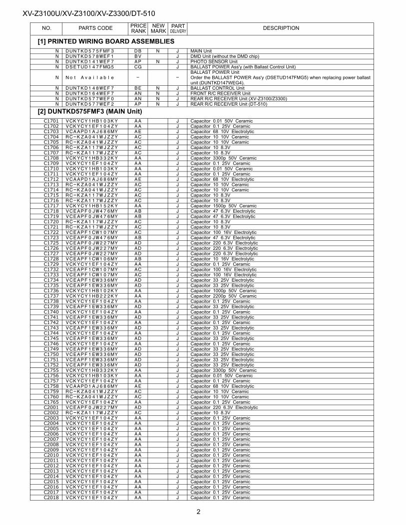
XV-Z3100U/XV-Z3100/XV-Z3300/DT-510PRICE NEW PART
NO. PARTS CODE RANK MARK DELIVERY DESCRIPTION[1] PRINTED WIRING BOARD ASSEMBLIESN DUNTKD575FMF3 DB N J MAIN UnitN DUNTKD578WEF1 BV J DMD Unit (without the DMD chip)N DUNTKD141WEF7 AP N J PHOTO SENSOR UnitN DSETUD147FMG5 CG J BALLAST POWER Ass'y (with Ballast Control Unit)
N Not Available - -BALLAST POWER Unit Order the BALLAST POWER Ass'y (DSETUD147FMG5) when replacing power ballastunit (DUNTKD147WEG4).
N DUNTKD148WEF7 BE N J BALLAST CONTROL UnitN DUNTKD164WEF7 AN N J FRONT R/C RECEIVER UnitN DUNTKD577WEF0 AN N J REAR R/C RECEIVER Unit (XV-Z3100/Z3300)N DUNTKD577WEF2 AP N J REAR R/C RECEIVER Unit (DT-510)
[2] DUNTKD575FMF3 (MAIN Unit)C1701 VCKYCY1HB103KY AA J Capacitor 0.01 50V CeramicC1702 VCKYCY1EF104ZY AA J Capacitor 0.1 25V CeramicC1703 VCAAPD1AJ686MY AE J Capacitor 68 10V ElectrolyticC1704 RC-KZA041WJZZY AC J Capacitor 10 10V CeramicC1705 RC-KZA041WJZZY AC J Capacitor 10 10V CeramicC1706 RC-KZA117WJZZY AC J Capacitor 10 8.3VC1707 RC-KZA117WJZZY AC J Capacitor 10 8.3VC1708 VCKYCY1HB332KY AA J Capacitor 3300p 50V CeramicC1709 VCKYCY1EF104ZY AA J Capacitor 0.1 25V CeramicC1710 VCKYCY1HB103KY AA J Capacitor 0.01 50V CeramicC1711 VCKYCY1EF104ZY AA J Capacitor 0.1 25V CeramicC1712 VCAAPD1AJ686MY AE J Capacitor 68 10V ElectrolyticC1713 RC-KZA041WJZZY AC J Capacitor 10 10V CeramicC1714 RC-KZA041WJZZY AC J Capacitor 10 10V CeramicC1715 RC-KZA117WJZZY AC J Capacitor 10 8.3VC1716 RC-KZA117WJZZY AC J Capacitor 10 8.3VC1717 VCKYCY1HB152KY AA J Capacitor 1500p 50V CeramicC1718 VCEAPF0JW476MY AB J Capacitor 47 6.3V ElectrolyticC1719 VCEAPF0JW476MY AB J Capacitor 47 6.3V ElectrolyticC1720 RC-KZA117WJZZY AC J Capacitor 10 8.3VC1721 RC-KZA117WJZZY AC J Capacitor 10 8.3VC1722 VCEAPF1CW107MY AC J Capacitor 100 16V ElectrolyticC1723 VCEAPF0JW476MY AB J Capacitor 47 6.3V ElectrolyticC1725 VCEAPF0JW227MY AD J Capacitor 220 6.3V ElectrolyticC1726 VCEAPF0JW227MY AD J Capacitor 220 6.3V ElectrolyticC1727 VCEAPF0JW227MY AD J Capacitor 220 6.3V ElectrolyticC1728 VCEAPF1CW106MY AB J Capacitor 10 16V ElectrolyticC1729 VCKYCY1EF104ZY AA J Capacitor 0.1 25V CeramicC1732 VCEAPF1CW107MY AC J Capacitor 100 16V ElectrolyticC1733 VCEAPF1CW107MY AC J Capacitor 100 16V ElectrolyticC1734 VCEAPF1EW336MY AD J Capacitor 33 25V ElectrolyticC1735 VCEAPF1EW336MY AD J Capacitor 33 25V ElectrolyticC1736 VCKYCY1HB102KY AA J Capacitor 1000p 50V CeramicC1737 VCKYCY1HB222KY AA J Capacitor 2200p 50V CeramicC1738 VCKYCY1EF104ZY AA J Capacitor 0.1 25V CeramicC1739 VCEAPF1EW336MY AD J Capacitor 33 25V ElectrolyticC1740 VCKYCY1EF104ZY AA J Capacitor 0.1 25V CeramicC1741 VCEAPF1EW336MY AD J Capacitor 33 25V ElectrolyticC1742 VCKYCY1EF104ZY AA J Capacitor 0.1 25V CeramicC1743 VCEAPF1EW336MY AD J Capacitor 33 25V ElectrolyticC1744 VCKYCY1EF104ZY AA J Capacitor 0.1 25V CeramicC1745 VCEAPF1EW336MY AD J Capacitor 33 25V ElectrolyticC1746 VCKYCY1EF104ZY AA J Capacitor 0.1 25V CeramicC1749 VCEAPF1EW336MY AD J Capacitor 33 25V ElectrolyticC1750 VCEAPF1EW336MY AD J Capacitor 33 25V ElectrolyticC1751 VCEAPF1EW336MY AD J Capacitor 33 25V ElectrolyticC1752 VCEAPF1EW336MY AD J Capacitor 33 25V ElectrolyticC1755 VCKYCY1HB332KY AA J Capacitor 3300p 50V CeramicC1756 VCKYCY1HB103KY AA J Capacitor 0.01 50V CeramicC1757 VCKYCY1EF104ZY AA J Capacitor 0.1 25V CeramicC1758 VCAAPD1AJ686MY AE J Capacitor 68 10V ElectrolyticC1759 RC-KZA041WJZZY AC J Capacitor 10 10V CeramicC1760 RC-KZA041WJZZY AC J Capacitor 10 10V CeramicC1765 VCKYCY1EF104ZY AA J Capacitor 0.1 25V CeramicC2001 VCEAPF0JW227MY AD J Capacitor 220 6.3V ElectrolyticC2002 RC-KZA117WJZZY AC J Capacitor 10 8.3VC2003 VCKYCY1EF104ZY AA J Capacitor 0.1 25V CeramicC2004 VCKYCY1EF104ZY AA J Capacitor 0.1 25V CeramicC2005 VCKYCY1EF104ZY AA J Capacitor 0.1 25V CeramicC2006 VCKYCY1EF104ZY AA J Capacitor 0.1 25V CeramicC2007 VCKYCY1EF104ZY AA J Capacitor 0.1 25V CeramicC2008 VCKYCY1EF104ZY AA J Capacitor 0.1 25V CeramicC2009 VCKYCY1EF104ZY AA J Capacitor 0.1 25V CeramicC2010 VCKYCY1EF104ZY AA J Capacitor 0.1 25V CeramicC2011 VCKYCY1EF104ZY AA J Capacitor 0.1 25V CeramicC2012 VCKYCY1EF104ZY AA J Capacitor 0.1 25V CeramicC2013 VCKYCY1EF104ZY AA J Capacitor 0.1 25V CeramicC2014 VCKYCY1EF104ZY AA J Capacitor 0.1 25V CeramicC2015 VCKYCY1EF104ZY AA J Capacitor 0.1 25V CeramicC2016 VCKYCY1EF104ZY AA J Capacitor 0.1 25V CeramicC2017 VCKYCY1EF104ZY AA J Capacitor 0.1 25V CeramicC2018 VCKYCY1EF104ZY AA J Capacitor 0.1 25V Ceramic
2
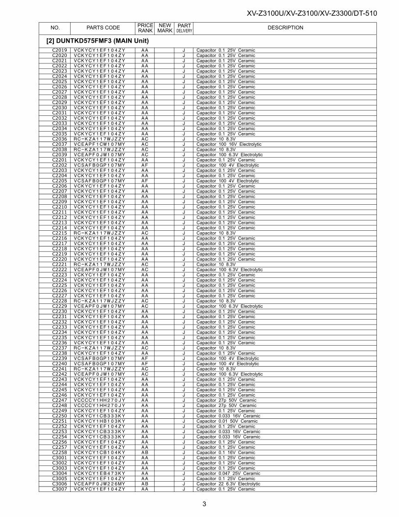
XV-Z3100U/XV-Z3100/XV-Z3300/DT-510PRICE NEW PART
NO. PARTS CODE RANK MARK DELIVERY DESCRIPTIONC2019 VCKYCY1EF104ZY AA J Capacitor 0.1 25V CeramicC2020 VCKYCY1EF104ZY AA J Capacitor 0.1 25V CeramicC2021 VCKYCY1EF104ZY AA J Capacitor 0.1 25V CeramicC2022 VCKYCY1EF104ZY AA J Capacitor 0.1 25V CeramicC2023 VCKYCY1EF104ZY AA J Capacitor 0.1 25V CeramicC2024 VCKYCY1EF104ZY AA J Capacitor 0.1 25V CeramicC2025 VCKYCY1EF104ZY AA J Capacitor 0.1 25V CeramicC2026 VCKYCY1EF104ZY AA J Capacitor 0.1 25V CeramicC2027 VCKYCY1EF104ZY AA J Capacitor 0.1 25V CeramicC2028 VCKYCY1EF104ZY AA J Capacitor 0.1 25V CeramicC2029 VCKYCY1EF104ZY AA J Capacitor 0.1 25V CeramicC2030 VCKYCY1EF104ZY AA J Capacitor 0.1 25V CeramicC2031 VCKYCY1EF104ZY AA J Capacitor 0.1 25V CeramicC2032 VCKYCY1EF104ZY AA J Capacitor 0.1 25V CeramicC2033 VCKYCY1EF104ZY AA J Capacitor 0.1 25V CeramicC2034 VCKYCY1EF104ZY AA J Capacitor 0.1 25V CeramicC2035 VCKYCY1EF104ZY AA J Capacitor 0.1 25V CeramicC2036 RC-KZA117WJZZY AC J Capacitor 10 8.3VC2037 VCEAPF1CW107MY AC J Capacitor 100 16V ElectrolyticC2038 RC-KZA117WJZZY AC J Capacitor 10 8.3VC2039 VCEAPF0JW107MY AC J Capacitor 100 6.3V ElectrolyticC2201 VCKYCY1EF104ZY AA J Capacitor 0.1 25V CeramicC2202 VCSAFB0GP107MY AF J Capacitor 100 4V ElectrolyticC2203 VCKYCY1EF104ZY AA J Capacitor 0.1 25V CeramicC2204 VCKYCY1EF104ZY AA J Capacitor 0.1 25V CeramicC2205 VCSAFB0GP107MY AF J Capacitor 100 4V ElectrolyticC2206 VCKYCY1EF104ZY AA J Capacitor 0.1 25V CeramicC2207 VCKYCY1EF104ZY AA J Capacitor 0.1 25V CeramicC2208 VCKYCY1EF104ZY AA J Capacitor 0.1 25V CeramicC2209 VCKYCY1EF104ZY AA J Capacitor 0.1 25V CeramicC2210 VCKYCY1EF104ZY AA J Capacitor 0.1 25V CeramicC2211 VCKYCY1EF104ZY AA J Capacitor 0.1 25V CeramicC2212 VCKYCY1EF104ZY AA J Capacitor 0.1 25V CeramicC2213 VCKYCY1EF104ZY AA J Capacitor 0.1 25V CeramicC2214 VCKYCY1EF104ZY AA J Capacitor 0.1 25V CeramicC2215 RC-KZA117WJZZY AC J Capacitor 10 8.3VC2216 VCKYCY1EF104ZY AA J Capacitor 0.1 25V CeramicC2217 VCKYCY1EF104ZY AA J Capacitor 0.1 25V CeramicC2218 VCKYCY1EF104ZY AA J Capacitor 0.1 25V CeramicC2219 VCKYCY1EF104ZY AA J Capacitor 0.1 25V CeramicC2220 VCKYCY1EF104ZY AA J Capacitor 0.1 25V CeramicC2221 RC-KZA117WJZZY AC J Capacitor 10 8.3VC2222 VCEAPF0JW107MY AC J Capacitor 100 6.3V ElectrolyticC2223 VCKYCY1EF104ZY AA J Capacitor 0.1 25V CeramicC2224 VCKYCY1EF104ZY AA J Capacitor 0.1 25V CeramicC2225 VCKYCY1EF104ZY AA J Capacitor 0.1 25V CeramicC2226 VCKYCY1EF104ZY AA J Capacitor 0.1 25V CeramicC2227 VCKYCY1EF104ZY AA J Capacitor 0.1 25V CeramicC2228 RC-KZA117WJZZY AC J Capacitor 10 8.3VC2229 VCEAPF0JW107MY AC J Capacitor 100 6.3V ElectrolyticC2230 VCKYCY1EF104ZY AA J Capacitor 0.1 25V CeramicC2231 VCKYCY1EF104ZY AA J Capacitor 0.1 25V CeramicC2232 VCKYCY1EF104ZY AA J Capacitor 0.1 25V CeramicC2233 VCKYCY1EF104ZY AA J Capacitor 0.1 25V CeramicC2234 VCKYCY1EF104ZY AA J Capacitor 0.1 25V CeramicC2235 VCKYCY1EF104ZY AA J Capacitor 0.1 25V CeramicC2236 VCKYCY1EF104ZY AA J Capacitor 0.1 25V CeramicC2237 RC-KZA117WJZZY AC J Capacitor 10 8.3VC2238 VCKYCY1EF104ZY AA J Capacitor 0.1 25V CeramicC2239 VCSAFB0GP107MY AF J Capacitor 100 4V ElectrolyticC2240 VCSAFB0GP107MY AF J Capacitor 100 4V ElectrolyticC2241 RC-KZA117WJZZY AC J Capacitor 10 8.3VC2242 VCEAPF0JW107MY AC J Capacitor 100 6.3V ElectrolyticC2243 VCKYCY1EF104ZY AA J Capacitor 0.1 25V CeramicC2244 VCKYCY1EF104ZY AA J Capacitor 0.1 25V CeramicC2245 VCKYCY1EF104ZY AA J Capacitor 0.1 25V CeramicC2246 VCKYCY1EF104ZY AA J Capacitor 0.1 25V CeramicC2247 VCCCCY1HH270JY AA J Capacitor 27p 50V CeramicC2248 VCCCCY1HH270JY AA J Capacitor 27p 50V CeramicC2249 VCKYCY1EF104ZY AA J Capacitor 0.1 25V CeramicC2250 VCKYCY1CB333KY AA J Capacitor 0.033 16V CeramicC2251 VCKYCY1HB103KY AA J Capacitor 0.01 50V CeramicC2252 VCKYCY1EF104ZY AA J Capacitor 0.1 25V CeramicC2253 VCKYCY1CB333KY AA J Capacitor 0.033 16V CeramicC2254 VCKYCY1CB333KY AA J Capacitor 0.033 16V CeramicC2256 VCKYCY1EF104ZY AA J Capacitor 0.1 25V CeramicC2257 VCKYCY1EF104ZY AA J Capacitor 0.1 25V CeramicC2258 VCKYCY1CB104KY AB J Capacitor 0.1 16V CeramicC3001 VCKYCY1EF104ZY AA J Capacitor 0.1 25V CeramicC3002 VCKYCY1EF104ZY AA J Capacitor 0.1 25V CeramicC3003 VCKYCY1EF104ZY AA J Capacitor 0.1 25V CeramicC3004 VCKYCY1EB473KY AA J Capacitor 0.047 25V CeramicC3005 VCKYCY1EF104ZY AA J Capacitor 0.1 25V CeramicC3006 VCEAPF0JW226MY AB J Capacitor 22 6.3V ElectrolyticC3007 VCKYCY1EF104ZY AA J Capacitor 0.1 25V Ceramic
[2] DUNTKD575FMF3 (MAIN Unit)
3
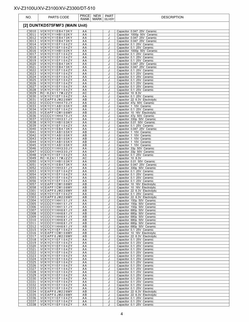
XV-Z3100U/XV-Z3100/XV-Z3300/DT-510PRICE NEW PART
NO. PARTS CODE RANK MARK DELIVERY DESCRIPTIONC3010 VCKYCY1EB473KY AA J Capacitor 0.047 25V CeramicC3011 VCKYCY1HB102KY AA J Capacitor 1000p 50V CeramicC3012 VCKYCY1EB473KY AA J Capacitor 0.047 25V CeramicC3013 VCKYCY1EB473KY AA J Capacitor 0.047 25V CeramicC3014 VCKYCY1EF104ZY AA J Capacitor 0.1 25V CeramicC3015 VCKYCY1EF104ZY AA J Capacitor 0.1 25V CeramicC3016 VCKYCY1HB102KY AA J Capacitor 1000p 50V CeramicC3017 VCKYCY1EF104ZY AA J Capacitor 0.1 25V CeramicC3018 VCKYCY1EF104ZY AA J Capacitor 0.1 25V CeramicC3019 VCKYCY1EF104ZY AA J Capacitor 0.1 25V CeramicC3020 VCKYCY1EB473KY AA J Capacitor 0.047 25V CeramicC3021 VCKYCY1EB473KY AA J Capacitor 0.047 25V CeramicC3022 VCKYCY1EF104ZY AA J Capacitor 0.1 25V CeramicC3023 VCKYCY1EF104ZY AA J Capacitor 0.1 25V CeramicC3024 VCKYCY1EF104ZY AA J Capacitor 0.1 25V CeramicC3025 VCKYCY1EF104ZY AA J Capacitor 0.1 25V CeramicC3026 VCKYCY1EF104ZY AA J Capacitor 0.1 25V CeramicC3027 VCKYCY1EF104ZY AA J Capacitor 0.1 25V CeramicC3028 VCKYCY1EF104ZY AA J Capacitor 0.1 25V CeramicC3029 RC-KZA117WJZZY AC J Capacitor 10 8.3VC3030 VCKYCY1EF104ZY AA J Capacitor 0.1 25V CeramicC3031 VCEAPF0JW226MY AB J Capacitor 22 6.3V ElectrolyticC3032 VCCCCY1HH470JY AA J Capacitor 47p 50V CeramicC3033 VCKYCY1AB105KY AB J Capacitor 1 10V CeramicC3034 VCKYCY1EF104ZY AA J Capacitor 0.1 25V CeramicC3035 VCEAPF1CW106MY AB J Capacitor 10 16V ElectrolyticC3036 VCCCCY1HH470JY AA J Capacitor 47p 50V CeramicC3037 VCCCCY1HH331JY AA J Capacitor 330p 50V CeramicC3038 VCKYCY1HB103KY AA J Capacitor 0.01 50V CeramicC3039 VCKYCY1EF104ZY AA J Capacitor 0.1 25V CeramicC3040 VCKYCY1EB473KY AA J Capacitor 0.047 25V CeramicC3041 VCKYCY1AB105KY AB J Capacitor 1 10V CeramicC3042 VCKYCY1AB105KY AB J Capacitor 1 10V CeramicC3043 VCKYCY1AB105KY AB J Capacitor 1 10V CeramicC3044 VCKYCY1AB105KY AB J Capacitor 1 10V CeramicC3045 VCKYCY1AB105KY AB J Capacitor 1 10V CeramicC3046 VCCCCY1HH330JY AA J Capacitor 33p 50V CeramicC3047 VCCCCY1HH330JY AA J Capacitor 33p 50V CeramicC3048 VCKYCY1EF104ZY AA J Capacitor 0.1 25V CeramicC3049 RC-KZA117WJZZY AC J Capacitor 10 8.3VC3050 VCKYCY1HB103KY AA J Capacitor 0.01 50V CeramicC3051 VCKYCY1EB473KY AA J Capacitor 0.047 25V CeramicC3052 VCCCCY1HH331JY AA J Capacitor 330p 50V CeramicC3053 VCKYCY1EF104ZY AA J Capacitor 0.1 25V CeramicC3054 VCKYCY1EF104ZY AA J Capacitor 0.1 25V CeramicC3055 VCKYCY1EF104ZY AA J Capacitor 0.1 25V CeramicC3056 VCKYCY1EF104ZY AA J Capacitor 0.1 25V CeramicC3057 VCEAPF1CW106MY AB J Capacitor 10 16V ElectrolyticC3058 VCEAPF1CW106MY AB J Capacitor 10 16V ElectrolyticC3301 VCEAPF0JW226MY AB J Capacitor 22 6.3V ElectrolyticC3302 VCKYCY1EF104ZY AA J Capacitor 0.1 25V CeramicC3303 VCEAPF0JW226MY AB J Capacitor 22 6.3V ElectrolyticC3304 VCCCCY1HH151JY AA J Capacitor 150p 50V CeramicC3305 VCCCCY1HH151JY AA J Capacitor 150p 50V CeramicC3306 VCCCCY1HH151JY AA J Capacitor 150p 50V CeramicC3307 VCCCCY1HH681JY AB J Capacitor 680p 50V CeramicC3308 VCCCCY1HH681JY AB J Capacitor 680p 50V CeramicC3309 VCCCCY1HH681JY AB J Capacitor 680p 50V CeramicC3310 VCCCCY1HH681JY AB J Capacitor 680p 50V CeramicC3311 VCCCCY1HH681JY AB J Capacitor 680p 50V CeramicC3312 VCCCCY1HH681JY AB J Capacitor 680p 50V CeramicC3315 VCKYCY1EF104ZY AA J Capacitor 0.1 25V CeramicC3316 VCEAPF1CW106MY AB J Capacitor 10 16V ElectrolyticC3317 VCEAPF0JW226MY AB J Capacitor 22 6.3V ElectrolyticC3318 VCKYCY1EF104ZY AA J Capacitor 0.1 25V CeramicC3319 VCKYCY1EF104ZY AA J Capacitor 0.1 25V CeramicC3320 VCKYCY1EF104ZY AA J Capacitor 0.1 25V CeramicC3321 VCKYCY1EF104ZY AA J Capacitor 0.1 25V CeramicC3322 VCKYCY1EF104ZY AA J Capacitor 0.1 25V CeramicC3323 VCKYCY1EF104ZY AA J Capacitor 0.1 25V CeramicC3324 VCKYCY1EF104ZY AA J Capacitor 0.1 25V CeramicC3325 VCKYCY1EF104ZY AA J Capacitor 0.1 25V CeramicC3326 VCKYCY1EF104ZY AA J Capacitor 0.1 25V CeramicC3327 VCKYCY1EF104ZY AA J Capacitor 0.1 25V CeramicC3328 VCKYCY1EF104ZY AA J Capacitor 0.1 25V CeramicC3329 VCKYCY1EF104ZY AA J Capacitor 0.1 25V CeramicC3330 VCKYCY1EF104ZY AA J Capacitor 0.1 25V CeramicC3331 VCKYCY1EF104ZY AA J Capacitor 0.1 25V CeramicC3332 VCKYCY1EF104ZY AA J Capacitor 0.1 25V CeramicC3333 VCKYCY1EF104ZY AA J Capacitor 0.1 25V CeramicC3334 VCEAPF0JW226MY AB J Capacitor 22 6.3V ElectrolyticC3335 VCEAPF0JW226MY AB J Capacitor 22 6.3V ElectrolyticC3336 VCKYCY1EF104ZY AA J Capacitor 0.1 25V CeramicC3337 VCKYCY1EF104ZY AA J Capacitor 0.1 25V CeramicC3338 VCKYCY1EF104ZY AA J Capacitor 0.1 25V Ceramic
[2] DUNTKD575FMF3 (MAIN Unit)
4

XV-Z3100U/XV-Z3100/XV-Z3300/DT-510PRICE NEW PART
NO. PARTS CODE RANK MARK DELIVERY DESCRIPTIONC3339 VCCCCY1HH270JY AA J Capacitor 27p 50V CeramicC3340 RC-KZA117WJZZY AC J Capacitor 10 8.3VC3341 VCCCCY1HH270JY AA J Capacitor 27p 50V CeramicC3342 VCKYCY1EF104ZY AA J Capacitor 0.1 25V CeramicC3343 VCKYCY1EF104ZY AA J Capacitor 0.1 25V CeramicC3344 VCKYCY1EF104ZY AA J Capacitor 0.1 25V CeramicC3345 VCKYCY1EF104ZY AA J Capacitor 0.1 25V CeramicC3346 VCEAPF0JW226MY AB J Capacitor 22 6.3V ElectrolyticC3347 VCKYCY1EF104ZY AA J Capacitor 0.1 25V CeramicC3348 VCEAPF0JW226MY AB J Capacitor 22 6.3V ElectrolyticC3349 VCKYCY1EF104ZY AA J Capacitor 0.1 25V CeramicC3350 VCKYCY1EF104ZY AA J Capacitor 0.1 25V CeramicC3351 VCKYCY1EF104ZY AA J Capacitor 0.1 25V CeramicC3352 VCKYCY1EB223KY AA J Capacitor 0.022 25V CeramicC3353 VCKYCY1EF104ZY AA J Capacitor 0.1 25V CeramicC3354 VCKYCY1EF104ZY AA J Capacitor 0.1 25V CeramicC3355 VCEAPF0JW226MY AB J Capacitor 22 6.3V ElectrolyticC3356 VCKYCY1EF104ZY AA J Capacitor 0.1 25V CeramicC3357 VCKYCY1EF104ZY AA J Capacitor 0.1 25V CeramicC3358 VCEAPF0JW226MY AB J Capacitor 22 6.3V ElectrolyticC3359 VCKYCY1EB473KY AA J Capacitor 0.047 25V CeramicC3360 VCKYCY1EF104ZY AA J Capacitor 0.1 25V CeramicC3701 VCKYCY1EF104ZY AA J Capacitor 0.1 25V CeramicC3702 VCKYCY1EF104ZY AA J Capacitor 0.1 25V CeramicC3703 VCKYCY1EF104ZY AA J Capacitor 0.1 25V CeramicC3704 VCKYCY1EF104ZY AA J Capacitor 0.1 25V CeramicC3705 VCCCCY1HH220JY AA J Capacitor 22p 50V CeramicC3706 VCKYCY1EF104ZY AA J Capacitor 0.1 25V CeramicC3707 VCKYCY1EF104ZY AA J Capacitor 0.1 25V CeramicC3708 VCKYCY1EF104ZY AA J Capacitor 0.1 25V CeramicC3709 VCKYCY1EF104ZY AA J Capacitor 0.1 25V CeramicC3710 VCKYCY1EF104ZY AA J Capacitor 0.1 25V CeramicC3711 VCKYCY1EF104ZY AA J Capacitor 0.1 25V CeramicC3712 VCKYCY1EF104ZY AA J Capacitor 0.1 25V CeramicC3713 VCKYCY1EF104ZY AA J Capacitor 0.1 25V CeramicC3714 VCKYCY1EF104ZY AA J Capacitor 0.1 25V CeramicC3715 VCKYCY1EF104ZY AA J Capacitor 0.1 25V CeramicC3716 VCKYCY1EF104ZY AA J Capacitor 0.1 25V CeramicC3717 VCKYCY1EF104ZY AA J Capacitor 0.1 25V CeramicC3718 VCKYCY1EF104ZY AA J Capacitor 0.1 25V CeramicC3719 RC-KZA117WJZZY AC J Capacitor 10 8.3VC3720 RC-KZA117WJZZY AC J Capacitor 10 8.3VC3721 VCKYCY1EF104ZY AA J Capacitor 0.1 25V CeramicC3722 VCKYCY1EB473KY AA J Capacitor 0.047 25V CeramicC3901 VCKYCY1EB473KY AA J Capacitor 0.047 25V CeramicC3902 VCKYCY1EF104ZY AA J Capacitor 0.1 25V CeramicC3903 VCKYCY1EF104ZY AA J Capacitor 0.1 25V CeramicC3905 RC-KZA117WJZZY AC J Capacitor 10 8.3VC3906 RC-KZA117WJZZY AC J Capacitor 10 8.3VC3907 VCEAPF0JW226MY AB J Capacitor 22 6.3V ElectrolyticC3908 VCKYCY1EF104ZY AA J Capacitor 0.1 25V CeramicC3909 VCKYCY1EF104ZY AA J Capacitor 0.1 25V CeramicC3910 VCKYCY1HB102KY AA J Capacitor 1000p 50V CeramicC3911 VCKYCY1HB102KY AA J Capacitor 1000p 50V CeramicC3912 VCKYCY1HB102KY AA J Capacitor 1000p 50V CeramicC3913 VCKYCY1EF104ZY AA J Capacitor 0.1 25V CeramicC3914 VCKYCY1HB102KY AA J Capacitor 1000p 50V CeramicC3915 RC-KZA117WJZZY AC J Capacitor 10 8.3VC3916 VCKYCY1EF104ZY AA J Capacitor 0.1 25V CeramicC3917 RC-KZA117WJZZY AC J Capacitor 10 8.3VC3918 RC-KZA117WJZZY AC J Capacitor 10 8.3VC3919 RC-KZA117WJZZY AC J Capacitor 10 8.3VC3920 VCKYCY1EF104ZY AA J Capacitor 0.1 25V CeramicC3921 VCKYCY1HB102KY AA J Capacitor 1000p 50V CeramicC3923 VCKYCY1EF104ZY AA J Capacitor 0.1 25V CeramicC3925 VCKYCY1HB102KY AA J Capacitor 1000p 50V CeramicC3927 VCKYCY1EF104ZY AA J Capacitor 0.1 25V CeramicC3938 VCKYCY1HB102KY AA J Capacitor 1000p 50V CeramicC3940 VCKYCY1EF104ZY AA J Capacitor 0.1 25V CeramicC3944 VCKYCY1HB102KY AA J Capacitor 1000p 50V CeramicC3947 VCKYCY1HB102KY AA J Capacitor 1000p 50V CeramicC3948 VCKYCY1EF104ZY AA J Capacitor 0.1 25V CeramicC3951 VCKYCY1HB102KY AA J Capacitor 1000p 50V CeramicC3952 VCKYCY1EF104ZY AA J Capacitor 0.1 25V CeramicC3956 VCKYCY1EF104ZY AA J Capacitor 0.1 25V CeramicC3957 VCKYCY1EF104ZY AA J Capacitor 0.1 25V CeramicC3958 VCKYCY1EF104ZY AA J Capacitor 0.1 25V CeramicC3960 VCKYCY1EF104ZY AA J Capacitor 0.1 25V CeramicC3961 VCKYCY1HB102KY AA J Capacitor 1000p 50V CeramicC3962 VCKYCY1HB102KY AA J Capacitor 1000p 50V CeramicC3964 VCKYCY1HB102KY AA J Capacitor 1000p 50V CeramicC3966 VCKYCY1EF104ZY AA J Capacitor 0.1 25V CeramicC3969 VCKYCY1HB102KY AA J Capacitor 1000p 50V CeramicC3971 VCEAPF0JW476MY AB J Capacitor 47 6.3V ElectrolyticC3974 VCKYCY1EF104ZY AA J Capacitor 0.1 25V Ceramic
[2] DUNTKD575FMF3 (MAIN Unit)
5
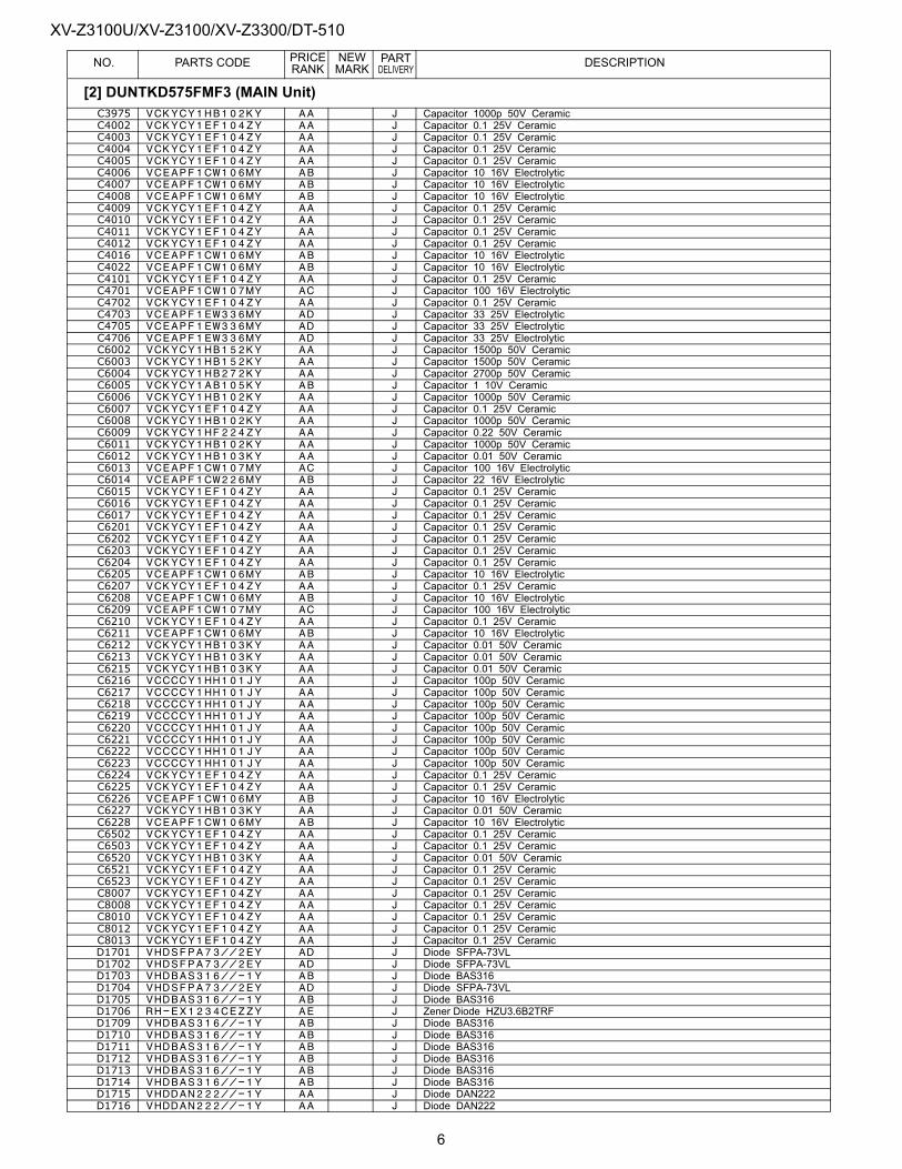
XV-Z3100U/XV-Z3100/XV-Z3300/DT-510PRICE NEW PART
NO. PARTS CODE RANK MARK DELIVERY DESCRIPTIONC3975 VCKYCY1HB102KY AA J Capacitor 1000p 50V CeramicC4002 VCKYCY1EF104ZY AA J Capacitor 0.1 25V CeramicC4003 VCKYCY1EF104ZY AA J Capacitor 0.1 25V CeramicC4004 VCKYCY1EF104ZY AA J Capacitor 0.1 25V CeramicC4005 VCKYCY1EF104ZY AA J Capacitor 0.1 25V CeramicC4006 VCEAPF1CW106MY AB J Capacitor 10 16V ElectrolyticC4007 VCEAPF1CW106MY AB J Capacitor 10 16V ElectrolyticC4008 VCEAPF1CW106MY AB J Capacitor 10 16V ElectrolyticC4009 VCKYCY1EF104ZY AA J Capacitor 0.1 25V CeramicC4010 VCKYCY1EF104ZY AA J Capacitor 0.1 25V CeramicC4011 VCKYCY1EF104ZY AA J Capacitor 0.1 25V CeramicC4012 VCKYCY1EF104ZY AA J Capacitor 0.1 25V CeramicC4016 VCEAPF1CW106MY AB J Capacitor 10 16V ElectrolyticC4022 VCEAPF1CW106MY AB J Capacitor 10 16V ElectrolyticC4101 VCKYCY1EF104ZY AA J Capacitor 0.1 25V CeramicC4701 VCEAPF1CW107MY AC J Capacitor 100 16V ElectrolyticC4702 VCKYCY1EF104ZY AA J Capacitor 0.1 25V CeramicC4703 VCEAPF1EW336MY AD J Capacitor 33 25V ElectrolyticC4705 VCEAPF1EW336MY AD J Capacitor 33 25V ElectrolyticC4706 VCEAPF1EW336MY AD J Capacitor 33 25V ElectrolyticC6002 VCKYCY1HB152KY AA J Capacitor 1500p 50V CeramicC6003 VCKYCY1HB152KY AA J Capacitor 1500p 50V CeramicC6004 VCKYCY1HB272KY AA J Capacitor 2700p 50V CeramicC6005 VCKYCY1AB105KY AB J Capacitor 1 10V CeramicC6006 VCKYCY1HB102KY AA J Capacitor 1000p 50V CeramicC6007 VCKYCY1EF104ZY AA J Capacitor 0.1 25V CeramicC6008 VCKYCY1HB102KY AA J Capacitor 1000p 50V CeramicC6009 VCKYCY1HF224ZY AA J Capacitor 0.22 50V CeramicC6011 VCKYCY1HB102KY AA J Capacitor 1000p 50V CeramicC6012 VCKYCY1HB103KY AA J Capacitor 0.01 50V CeramicC6013 VCEAPF1CW107MY AC J Capacitor 100 16V ElectrolyticC6014 VCEAPF1CW226MY AB J Capacitor 22 16V ElectrolyticC6015 VCKYCY1EF104ZY AA J Capacitor 0.1 25V CeramicC6016 VCKYCY1EF104ZY AA J Capacitor 0.1 25V CeramicC6017 VCKYCY1EF104ZY AA J Capacitor 0.1 25V CeramicC6201 VCKYCY1EF104ZY AA J Capacitor 0.1 25V CeramicC6202 VCKYCY1EF104ZY AA J Capacitor 0.1 25V CeramicC6203 VCKYCY1EF104ZY AA J Capacitor 0.1 25V CeramicC6204 VCKYCY1EF104ZY AA J Capacitor 0.1 25V CeramicC6205 VCEAPF1CW106MY AB J Capacitor 10 16V ElectrolyticC6207 VCKYCY1EF104ZY AA J Capacitor 0.1 25V CeramicC6208 VCEAPF1CW106MY AB J Capacitor 10 16V ElectrolyticC6209 VCEAPF1CW107MY AC J Capacitor 100 16V ElectrolyticC6210 VCKYCY1EF104ZY AA J Capacitor 0.1 25V CeramicC6211 VCEAPF1CW106MY AB J Capacitor 10 16V ElectrolyticC6212 VCKYCY1HB103KY AA J Capacitor 0.01 50V CeramicC6213 VCKYCY1HB103KY AA J Capacitor 0.01 50V CeramicC6215 VCKYCY1HB103KY AA J Capacitor 0.01 50V CeramicC6216 VCCCCY1HH101JY AA J Capacitor 100p 50V CeramicC6217 VCCCCY1HH101JY AA J Capacitor 100p 50V CeramicC6218 VCCCCY1HH101JY AA J Capacitor 100p 50V CeramicC6219 VCCCCY1HH101JY AA J Capacitor 100p 50V CeramicC6220 VCCCCY1HH101JY AA J Capacitor 100p 50V CeramicC6221 VCCCCY1HH101JY AA J Capacitor 100p 50V CeramicC6222 VCCCCY1HH101JY AA J Capacitor 100p 50V CeramicC6223 VCCCCY1HH101JY AA J Capacitor 100p 50V CeramicC6224 VCKYCY1EF104ZY AA J Capacitor 0.1 25V CeramicC6225 VCKYCY1EF104ZY AA J Capacitor 0.1 25V CeramicC6226 VCEAPF1CW106MY AB J Capacitor 10 16V ElectrolyticC6227 VCKYCY1HB103KY AA J Capacitor 0.01 50V CeramicC6228 VCEAPF1CW106MY AB J Capacitor 10 16V ElectrolyticC6502 VCKYCY1EF104ZY AA J Capacitor 0.1 25V CeramicC6503 VCKYCY1EF104ZY AA J Capacitor 0.1 25V CeramicC6520 VCKYCY1HB103KY AA J Capacitor 0.01 50V CeramicC6521 VCKYCY1EF104ZY AA J Capacitor 0.1 25V CeramicC6523 VCKYCY1EF104ZY AA J Capacitor 0.1 25V CeramicC8007 VCKYCY1EF104ZY AA J Capacitor 0.1 25V CeramicC8008 VCKYCY1EF104ZY AA J Capacitor 0.1 25V CeramicC8010 VCKYCY1EF104ZY AA J Capacitor 0.1 25V CeramicC8012 VCKYCY1EF104ZY AA J Capacitor 0.1 25V CeramicC8013 VCKYCY1EF104ZY AA J Capacitor 0.1 25V CeramicD1701 VHDSFPA73//2EY AD J Diode SFPA-73VLD1702 VHDSFPA73//2EY AD J Diode SFPA-73VLD1703 VHDBAS316//-1Y AB J Diode BAS316D1704 VHDSFPA73//2EY AD J Diode SFPA-73VLD1705 VHDBAS316//-1Y AB J Diode BAS316D1706 RH-EX1234CEZZY AE J Zener Diode HZU3.6B2TRFD1709 VHDBAS316//-1Y AB J Diode BAS316D1710 VHDBAS316//-1Y AB J Diode BAS316D1711 VHDBAS316//-1Y AB J Diode BAS316D1712 VHDBAS316//-1Y AB J Diode BAS316D1713 VHDBAS316//-1Y AB J Diode BAS316D1714 VHDBAS316//-1Y AB J Diode BAS316D1715 VHDDAN222//-1Y AA J Diode DAN222D1716 VHDDAN222//-1Y AA J Diode DAN222
[2] DUNTKD575FMF3 (MAIN Unit)
6
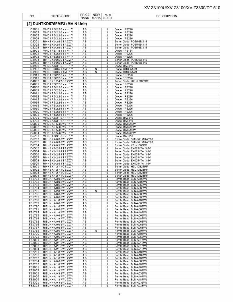
XV-Z3100U/XV-Z3100/XV-Z3300/DT-510PRICE NEW PART
NO. PARTS CODE RANK MARK DELIVERY DESCRIPTIOND3001 VHD1PS226++-1Y AB J Diode 1PS226D3002 VHD1PS226++-1Y AB J Diode 1PS226D3003 VHD1PS226++-1Y AB J Diode 1PS226D3004 VHD1PS226++-1Y AB J Diode 1PS226D3301 RH-EX0259TAZZY AB J Zener Diode PDZ5.6B,115D3302 RH-EX0259TAZZY AB J Zener Diode PDZ5.6B,115D3303 RH-EX0259TAZZY AB J Zener Diode PDZ5.6B,115D3901 VHD1PS184++-1Y AB J Diode 1PS184D3902 VHD1PS226++-1Y AB J Diode 1PS226D3903 VHD1PS226++-1Y AB J Diode 1PS226D3904 RH-EX0259TAZZY AB J Zener Diode PDZ5.6B,115D3905 RH-EX0259TAZZY AB J Zener Diode PDZ5.6B,115D3906 VHDBAS316//-1Y AB J Diode BAS316D3907 VHDSRC0514M-1Y AG N J Diode SRC0514MD3908 VHDSRC0514M-1Y AG N J Diode SRC0514MD3911 VHD1PS226++-1Y AB J Diode 1PS226D3912 VHD1PS226++-1Y AB J Diode 1PS226D4003 RH-EX1247CEZZY AB J Zener Diode HZU5.6B2TRFD4007 VHD1PS226++-1Y AB J Diode 1PS226D4008 VHD1PS226++-1Y AB J Diode 1PS226D4009 VHD1PS226++-1Y AB J Diode 1PS226D4011 VHD1PS226++-1Y AB J Diode 1PS226D4012 VHD1PS226++-1Y AB J Diode 1PS226D4013 VHD1PS226++-1Y AB J Diode 1PS226D4014 VHD1PS226++-1Y AB J Diode 1PS226D4015 VHD1PS226++-1Y AB J Diode 1PS226D4019 VHD1PS226++-1Y AB J Diode 1PS226D4020 VHD1PS226++-1Y AB J Diode 1PS226D4021 VHD1PS226++-1Y AB J Diode 1PS226D4701 VHDBAS316//-1Y AB J Diode BAS316D4702 VHDBAS316//-1Y AB J Diode BAS316D6001 VHDBAT54SW+-1Y AC J Diode BAT54SWD6002 VHDBAT54SW+-1Y AC J Diode BAT54SWD6003 VHDBAT54SW+-1Y AC J Diode BAT54SWD6004 VHDBAT54SW+-1Y AC J Diode BAT54SWD6201 VHDBAS316//-1Y AB J Diode BAS316D6202 RH-PXA038WJZZY AC J Photo Diode SML-521MUWT86D6203 RH-PXA038WJZZY AC J Photo Diode SML-521MUWT86D6204 RH-PXA097WJZZY AC J Photo Diode KPH-1608ECD6503 RH-EX0254TAZZY AB J Zener Diode EX0254TA 3.6VD6504 RH-EX0254TAZZY AB J Zener Diode EX0254TA 3.6VD6506 RH-EX0254TAZZY AB J Zener Diode EX0254TA 3.6VD6507 RH-EX0254TAZZY AB J Zener Diode EX0254TA 3.6VD6508 RH-EX0254TAZZY AB J Zener Diode EX0254TA 3.6VD6509 RH-EX0254TAZZY AB J Zener Diode EX0254TA 3.6VD8001 RH-EX1271CEZZY AB J Zener Diode HZU12B2TRFD8002 RH-EX1271CEZZY AB J Zener Diode HZU12B2TRFD8003 RH-EX1271CEZZY AB J Zener Diode HZU12B2TRFD8004 RH-EX1271CEZZY AB J Zener Diode HZU12B2TRFFB1701 RBLN-A303WJZZY AB J Ferrite Bead BLN-A303WJFB1702 RBLN-A303WJZZY AB J Ferrite Bead BLN-A303WJFB1703 RBLN-A068WJZZY AB J Ferrite Bead BLN-A068WJFB1704 RBLN-A068WJZZY AB J Ferrite Bead BLN-A068WJFB1705 RBLN-A207WJZZY AB N J Ferrite Bead BLN-A207WJFB1706 RBLN-A068WJZZY AB J Ferrite Bead BLN-A068WJFB1707 RBLN-A068WJZZY AB J Ferrite Bead BLN-A068WJFB1708 RBLN-A187WJZZY AB J Ferrite Bead BLN-A187WJFB1709 RBLN-A068WJZZY AB J Ferrite Bead BLN-A068WJFB1710 RBLN-A187WJZZY AB J Ferrite Bead BLN-A187WJFB1711 RBLN-A068WJZZY AB J Ferrite Bead BLN-A068WJFB1712 RBLN-A187WJZZY AB J Ferrite Bead BLN-A187WJFB1713 RBLN-A068WJZZY AB J Ferrite Bead BLN-A068WJFB1714 RBLN-A187WJZZY AB J Ferrite Bead BLN-A187WJFB1715 RBLN-A068WJZZY AB J Ferrite Bead BLN-A068WJFB1716 RBLN-A068WJZZY AB J Ferrite Bead BLN-A068WJFB1717 RBLN-A068WJZZY AB J Ferrite Bead BLN-A068WJFB1718 RBLN-A207WJZZY AB N J Ferrite Bead BLN-A207WJFB1720 RBLN-A303WJZZY AB J Ferrite Bead BLN-A303WJFB1722 RBLN-A068WJZZY AB J Ferrite Bead BLN-A068WJFB2001 RBLN-A215WJZZY AB J Ferrite Bead BLN-A215WJFB2002 RBLN-A215WJZZY AB J Ferrite Bead BLN-A215WJFB2003 RBLN-A215WJZZY AB J Ferrite Bead BLN-A215WJFB2004 RBLN-A215WJZZY AB J Ferrite Bead BLN-A215WJFB2201 RBLN-A187WJZZY AB J Ferrite Bead BLN-A187WJFB2202 RBLN-A187WJZZY AB J Ferrite Bead BLN-A187WJFB2203 RBLN-A187WJZZY AB J Ferrite Bead BLN-A187WJFB2204 RBLN-A068WJZZY AB J Ferrite Bead BLN-A068WJFB2205 RBLN-A187WJZZY AB J Ferrite Bead BLN-A187WJFB3001 RBLN-A187WJZZY AB J Ferrite Bead BLN-A187WJFB3002 RBLN-A187WJZZY AB J Ferrite Bead BLN-A187WJFB3005 RBLN-A038WJZZY AB J Ferrite Bead BLN-A038WJFB3006 RBLN-A187WJZZY AB J Ferrite Bead BLN-A187WJFB3009 RBLN-A187WJZZY AB J Ferrite Bead BLN-A187WJFB3301 RBLN-A038WJZZY AB J Ferrite Bead BLN-A038WJFB3302 RBLN-A038WJZZY AB J Ferrite Bead BLN-A038WJ
[2] DUNTKD575FMF3 (MAIN Unit)
7
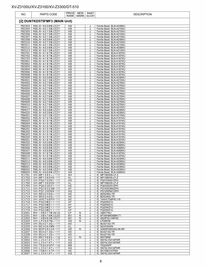
XV-Z3100U/XV-Z3100/XV-Z3300/DT-510PRICE NEW PART
NO. PARTS CODE RANK MARK DELIVERY DESCRIPTIONFB3303 RBLN-A038WJZZY AB J Ferrite Bead BLN-A038WJFB3304 RBLN-A215WJZZY AB J Ferrite Bead BLN-A215WJFB3305 RBLN-A215WJZZY AB J Ferrite Bead BLN-A215WJFB3306 RBLN-A215WJZZY AB J Ferrite Bead BLN-A215WJFB3307 RBLN-A215WJZZY AB J Ferrite Bead BLN-A215WJFB3308 RBLN-A038WJZZY AB J Ferrite Bead BLN-A038WJFB3310 RBLN-A215WJZZY AB J Ferrite Bead BLN-A215WJFB3311 RBLN-A215WJZZY AB J Ferrite Bead BLN-A215WJFB3312 RBLN-A038WJZZY AB J Ferrite Bead BLN-A038WJFB3313 RBLN-A215WJZZY AB J Ferrite Bead BLN-A215WJFB3701 RBLN-A187WJZZY AB J Ferrite Bead BLN-A187WJFB3702 RBLN-A187WJZZY AB J Ferrite Bead BLN-A187WJFB3703 RBLN-A187WJZZY AB J Ferrite Bead BLN-A187WJFB3901 RBLN-A187WJZZY AB J Ferrite Bead BLN-A187WJFB3902 RBLN-A187WJZZY AB J Ferrite Bead BLN-A187WJFB3903 RBLN-A187WJZZY AB J Ferrite Bead BLN-A187WJFB3904 RBLN-A187WJZZY AB J Ferrite Bead BLN-A187WJFB3906 RBLN-A187WJZZY AB J Ferrite Bead BLN-A187WJFB3908 RBLN-A187WJZZY AB J Ferrite Bead BLN-A187WJFB3909 RBLN-A038WJZZY AB J Ferrite Bead BLN-A038WJFB4001 RBLN-A215WJZZY AB J Ferrite Bead BLN-A215WJFB4002 RBLN-A276WJZZY AB J Ferrite Bead BLN-A276WJFB4003 RBLN-A276WJZZY AB J Ferrite Bead BLN-A276WJFB4004 RBLN-A276WJZZY AB J Ferrite Bead BLN-A276WJFB4005 RBLN-A276WJZZY AB J Ferrite Bead BLN-A276WJFB4006 RBLN-A276WJZZY AB J Ferrite Bead BLN-A276WJFB4007 RBLN-A276WJZZY AB J Ferrite Bead BLN-A276WJFB4008 RBLN-A276WJZZY AB J Ferrite Bead BLN-A276WJFB4009 RBLN-A276WJZZY AB J Ferrite Bead BLN-A276WJFB4010 RBLN-A276WJZZY AB J Ferrite Bead BLN-A276WJFB4011 RBLN-A215WJZZY AB J Ferrite Bead BLN-A215WJFB4017 RBLN-A038WJZZY AB J Ferrite Bead BLN-A038WJFB4025 RBLN-A038WJZZY AB J Ferrite Bead BLN-A038WJFB6001 RBLN-A215WJZZY AB J Ferrite Bead BLN-A215WJFB6002 RBLN-A191WJZZY AB J Ferrite Bead BLN-A191WJFB6003 RBLN-A191WJZZY AB J Ferrite Bead BLN-A191WJFB6004 RBLN-A191WJZZY AB J Ferrite Bead BLN-A191WJFB6005 RBLN-A191WJZZY AB J Ferrite Bead BLN-A191WJFB6201 RBLN-A191WJZZY AB J Ferrite Bead BLN-A191WJFB6202 RBLN-A191WJZZY AB J Ferrite Bead BLN-A191WJFB6203 RBLN-A191WJZZY AB J Ferrite Bead BLN-A191WJFB6204 RBLN-A191WJZZY AB J Ferrite Bead BLN-A191WJFB6501 RBLN-A187WJZZY AB J Ferrite Bead BLN-A187WJFB6502 RBLN-A038WJZZY AB J Ferrite Bead BLN-A038WJFB6503 RBLN-A068WJZZY AB J Ferrite Bead BLN-A068WJFB6506 RBLN-A068WJZZY AB J Ferrite Bead BLN-A068WJFB6507 RBLN-A068WJZZY AB J Ferrite Bead BLN-A068WJFB6508 RBLN-A187WJZZY AB J Ferrite Bead BLN-A187WJFB6510 RBLN-A187WJZZY AB J Ferrite Bead BLN-A187WJFB6511 RBLN-A038WJZZY AB J Ferrite Bead BLN-A038WJFB6512 RBLN-A038WJZZY AB J Ferrite Bead BLN-A038WJFB6513 RBLN-A038WJZZY AB J Ferrite Bead BLN-A038WJFB8001 RBLN-A038WJZZY AB J Ferrite Bead BLN-A038WJFB8002 RBLN-A038WJZZY AB J Ferrite Bead BLN-A038WJFB8004 RBLN-A068WJZZY AB J Ferrite Bead BLN-A068WJIC1701 VHiMP1583++-1Y AH J IC MP1583DN-LF-ZIC1702 VHiMP1580HS-1Y AL J IC MP1580HS-LF-ZIC1703 VHiPQ070XN1-1Y AG J IC PQ070XN01ZPHIC1704 VHiMP1580HS-1Y AL J IC MP1580HS-LF-ZIC1705 VHiPQ033DZ1-1Y AE J IC PQ033DZ01ZPHIC1711 VHiPQ1K503M-1Y AF J IC PQ1K503M2ZPHIC1712 VHiPQ120DNA-1Y AG J IC PQ120DNA1ZPHIC1713 VHiBD5246G+-1Y AE J IC BD5246G-TRIC1714 VHiBD5246G+-1Y AE J IC BD5246G-TRIC1715 VHiAHCT08PH-1Y AE J IC 74AHCT08PW,118IC1716 VHiPQ20WZ11-1Y AF J IC PQ20WZ1UIC1717 VHiPQ20WZ11-1Y AF J IC PQ20WZ1UIC1718 VHiPQ20WZ11-1Y AF J IC PQ20WZ1UIC1719 VHiPQ20WZ11-1Y AF J IC PQ20WZ1UIC2001 RH-iXB477WJN1Q CF N J IC iXB477WJIC2201 RH-iXB478WJZZQ BV N J IC MT49H8M36BM-T1IC2202 RH-iXB982WJZZY BC N J IC iM25P32-VMF6GIC2203 VHiLP2997M+-1Y AN N J IC LP2997MIC2204 VHiBU4213G+-1Y AD J IC BU4213G-TRIC2205 VHiM24C64WN-1Y AL J IC M24C64WNIC2206 VHiM3P2853A-1Y AR N J IC ASM3P2853AG-08-SRIC2207 VHiBU4213G+-1Y AD J IC BU4213G-TRIC2208 VHiBU4213G+-1Y AD J IC BU4213G-TRIC3001 VHiMST9888+-1Q AV N J IC MST9888IC3002 VHiLV541AT+-1Y AG J IC SN74LV541APWRIC3003 VHiLV541AT+-1Y AG J IC SN74LV541APWRIC3004 VHiTE8200PF-1Q BB J IC TE8200PFIC3005 VHiLV541AT+-1Y AG J IC SN74LV541APWRIC3006 VHi7SB3157P-1Y AE J IC NC7SB3157P6XIC3007 VHiLV541AT+-1Y AG J IC SN74LV541APWR
[2] DUNTKD575FMF3 (MAIN Unit)
8
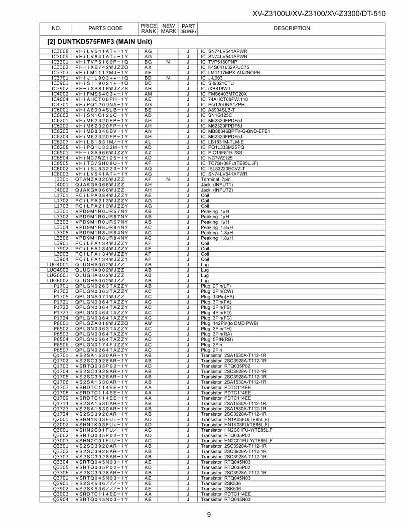
XV-Z3100U/XV-Z3100/XV-Z3300/DT-510PRICE NEW PART
NO. PARTS CODE RANK MARK DELIVERY DESCRIPTIONIC3008 VHiLV541AT+-1Y AG J IC SN74LV541APWRIC3009 VHiLV541AT+-1Y AG J IC SN74LV541APWRIC3301 VHiTVP5160P-1Q BG N J IC TVP5160PNPIC3302 RH-iXB742WJZZQ AX J IC K4S641632K-UC75IC3303 VHiLM1117MJ-1Y AF J IC LM1117MPX-ADJ/NOPBIC3701 VHiJ-L003++-1Q BD N J IC J-L003IC3901 VHiSii9021+-1Q BC J IC SII9021CTUIC3902 RH-iXB816WJZZS AH J IC iXB816WJIC4002 VHiFMS6403+-1Y AM J IC FMS6403MTC20XIC4004 VHiAHCT08PH-1Y AE J IC 74AHCT08PW,118IC4701 VHiPQ120DNA-1Y AG J IC PQ120DNA1ZPHIC6001 VHiA8904SLB-1Y BE J IC A8904SLB-TIC6002 VHiSN1G125C-1Y AD J IC SN1G125CIC6201 VHiM62320FP-1Y AH J IC M62320FPDF5JIC6202 VHiM62320FP-1Y AH J IC M62320FPDF5JIC6203 VHiMB8346BV-1Y AN J IC MB88346BPFV-G-BND-EFE1IC6204 VHiM62320FP-1Y AH J IC M62320FPDF5JIC6207 VHiLB1831M/-1Y AL J IC LB1831M-TLM-EIC6208 VHiPQ1L333M-1Y AD J IC PQ1L333M2SPQIC6501 RH-iXA966WJZZY AZ J IC PIC16F819-I/SSIC6504 VHiNC7WZ125-1Y AD J IC NC7WZ125IC6505 VHiTC7SH08U-1Y AF J IC TC7SH08FU(TE85L,JF)IC8002 VHiiSL83220-1Y AQ J IC ISL83220ECVZ-TIC8003 VHiLV541AT+-1Y AG J IC SN74LV541APWRJ3301 QTANZA020WJZZ AF N J Terminal 7pinJ4001 QJAKGA066WJZZ AH J Jack (INPUT1)J4002 QJAKGA066WJZZ AH J Jack (INPUT2)L1701 RCiLPA084WJZZY AE J CoilL1702 RCiLPA213WJZZY AG J CoilL1703 RCiLPA213WJZZY AG J CoilL3301 VPD9M1R0JR57NY AB J Peaking 1µHL3302 VPD9M1R0JR57NY AB J Peaking 1µHL3303 VPD9M1R0JR57NY AB J Peaking 1µHL3304 VPD9M1R8JR84NY AC J Peaking 1.8µHL3305 VPD9M1R8JR84NY AC J Peaking 1.8µHL3306 VPD9M1R8JR84NY AC J Peaking 1.8µHL3901 RCiLFA134WJZZY AF J CoilL3902 RCiLFA134WJZZY AF J CoilL3903 RCiLFA134WJZZY AF J CoilL3904 RCiLFA134WJZZY AF J Coil
LUG4001 QLUGHA002WJZZ AB J LugLUG4002 QLUGHA002WJZZ AB J LugLUG6001 QLUGHA002WJZZ AB J LugLUG6002 QLUGHA002WJZZ AB J LugP1701 QPLGN0263TAZZY AB J Plug 2Pin(LF)P1702 QPLGN0363TAZZY AC J Plug 3Pin(CW)P1705 QPLGNA071WJZZ AC J Plug 14Pin(EA)P1721 QPLGN0364TAZZY AC J Plug 3Pin(FA)P1722 QPLGN0364TAZZY AC J Plug 3Pin(FB)P1723 QPLGN0464TAZZY AC J Plug 4Pin(FD)P1724 QPLGN0364TAZZY AC J Plug 3Pin(FC)P6001 QPLGZA018WJZZQ AW J Plug 142Pin(to DMD PWB)P6502 QPLGN0363TAZZY AC J Plug 3Pin(TH)P6503 QPLGN0364TAZZY AC J Plug 3Pin(RA)P6504 QPLGN0564TAZZY AC J Plug 5PIN(RB)P6506 QPLGN0174FJZZY AC J Plug 2PinP6507 QPLGN0264TAZZY AC J Plug 2PinQ1701 VS2SA1530AR-1Y AB J Transistor 2SA1530A-T112-1RQ1702 VS2SC3928AR-1Y AB J Transistor 2SC3928A-T112-1RQ1703 VSRTQ035P02-1Y AD J Transistor RTQ035P02Q1704 VS2SC3928AR-1Y AB J Transistor 2SC3928A-T112-1RQ1705 VS2SC3928AR-1Y AB J Transistor 2SC3928A-T112-1RQ1706 VS2SA1530AR-1Y AB J Transistor 2SA1530A-T112-1RQ1707 VSRDTC114EE-1Y AA J Transistor PDTC114EEQ1708 VSRDTC114EE-1Y AA J Transistor PDTC114EEQ1709 VSRDTC114EE-1Y AA J Transistor PDTC114EEQ1714 VS2SA1530AR-1Y AB J Transistor 2SA1530A-T112-1RQ1723 VS2SA1530AR-1Y AB J Transistor 2SA1530A-T112-1RQ1724 VS2SC3928AR-1Y AB J Transistor 2SC3928A-T112-1RQ2001 VSHN1K03FU+-1Y AD J Transistor HN1K03FU(TE85L,F)Q2002 VSHN1K03FU+-1Y AD J Transistor HN1K03FU(TE85L,F)Q3001 VSHN2C01FU/-1Y AC J Transistor HN2C01FU-Y(TE85L,FQ3002 VSRTQ035P02-1Y AD J Transistor RTQ035P02Q3003 VSHN2C01FU/-1Y AC J Transistor HN2C01FU-Y(TE85L,FQ3301 VS2SC3928AR-1Y AB J Transistor 2SC3928A-T112-1RQ3302 VS2SC3928AR-1Y AB J Transistor 2SC3928A-T112-1RQ3303 VS2SC3928AR-1Y AB J Transistor 2SC3928A-T112-1RQ3304 VSRTQ045N03-1Y AE J Transistor RTQ045N03Q3305 VSRTQ035P02-1Y AD J Transistor RTQ035P02Q3306 VS2SC3928AR-1Y AB J Transistor 2SC3928A-T112-1RQ3701 VSRTQ045N03-1Y AE J Transistor RTQ045N03Q3901 VS2SK536///-1Y AE J Transistor 2SK536Q3902 VS2SK536///-1Y AE J Transistor 2SK536Q3903 VSRDTC114EE-1Y AA J Transistor PDTC114EEQ3904 VSRTQ045N03-1Y AE J Transistor RTQ045N03
[2] DUNTKD575FMF3 (MAIN Unit)
9
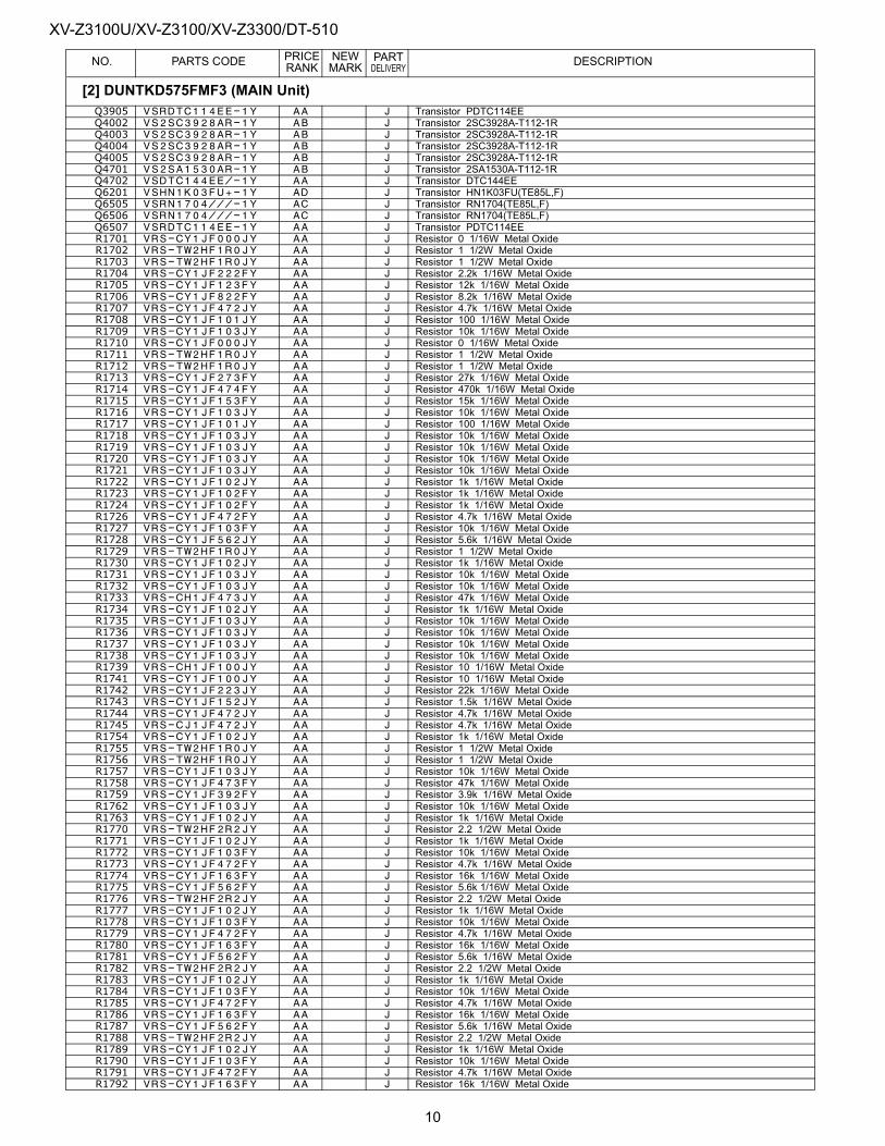
XV-Z3100U/XV-Z3100/XV-Z3300/DT-510PRICE NEW PART
NO. PARTS CODE RANK MARK DELIVERY DESCRIPTIONQ3905 VSRDTC114EE-1Y AA J Transistor PDTC114EEQ4002 VS2SC3928AR-1Y AB J Transistor 2SC3928A-T112-1RQ4003 VS2SC3928AR-1Y AB J Transistor 2SC3928A-T112-1RQ4004 VS2SC3928AR-1Y AB J Transistor 2SC3928A-T112-1RQ4005 VS2SC3928AR-1Y AB J Transistor 2SC3928A-T112-1RQ4701 VS2SA1530AR-1Y AB J Transistor 2SA1530A-T112-1RQ4702 VSDTC144EE/-1Y AA J Transistor DTC144EEQ6201 VSHN1K03FU+-1Y AD J Transistor HN1K03FU(TE85L,F)Q6505 VSRN1704///-1Y AC J Transistor RN1704(TE85L,F)Q6506 VSRN1704///-1Y AC J Transistor RN1704(TE85L,F)Q6507 VSRDTC114EE-1Y AA J Transistor PDTC114EER1701 VRS-CY1JF000JY AA J Resistor 0 1/16W Metal OxideR1702 VRS-TW2HF1R0JY AA J Resistor 1 1/2W Metal OxideR1703 VRS-TW2HF1R0JY AA J Resistor 1 1/2W Metal OxideR1704 VRS-CY1JF222FY AA J Resistor 2.2k 1/16W Metal OxideR1705 VRS-CY1JF123FY AA J Resistor 12k 1/16W Metal OxideR1706 VRS-CY1JF822FY AA J Resistor 8.2k 1/16W Metal OxideR1707 VRS-CY1JF472JY AA J Resistor 4.7k 1/16W Metal OxideR1708 VRS-CY1JF101JY AA J Resistor 100 1/16W Metal OxideR1709 VRS-CY1JF103JY AA J Resistor 10k 1/16W Metal OxideR1710 VRS-CY1JF000JY AA J Resistor 0 1/16W Metal OxideR1711 VRS-TW2HF1R0JY AA J Resistor 1 1/2W Metal OxideR1712 VRS-TW2HF1R0JY AA J Resistor 1 1/2W Metal OxideR1713 VRS-CY1JF273FY AA J Resistor 27k 1/16W Metal OxideR1714 VRS-CY1JF474FY AA J Resistor 470k 1/16W Metal OxideR1715 VRS-CY1JF153FY AA J Resistor 15k 1/16W Metal OxideR1716 VRS-CY1JF103JY AA J Resistor 10k 1/16W Metal OxideR1717 VRS-CY1JF101JY AA J Resistor 100 1/16W Metal OxideR1718 VRS-CY1JF103JY AA J Resistor 10k 1/16W Metal OxideR1719 VRS-CY1JF103JY AA J Resistor 10k 1/16W Metal OxideR1720 VRS-CY1JF103JY AA J Resistor 10k 1/16W Metal OxideR1721 VRS-CY1JF103JY AA J Resistor 10k 1/16W Metal OxideR1722 VRS-CY1JF102JY AA J Resistor 1k 1/16W Metal OxideR1723 VRS-CY1JF102FY AA J Resistor 1k 1/16W Metal OxideR1724 VRS-CY1JF102FY AA J Resistor 1k 1/16W Metal OxideR1726 VRS-CY1JF472FY AA J Resistor 4.7k 1/16W Metal OxideR1727 VRS-CY1JF103FY AA J Resistor 10k 1/16W Metal OxideR1728 VRS-CY1JF562JY AA J Resistor 5.6k 1/16W Metal OxideR1729 VRS-TW2HF1R0JY AA J Resistor 1 1/2W Metal OxideR1730 VRS-CY1JF102JY AA J Resistor 1k 1/16W Metal OxideR1731 VRS-CY1JF103JY AA J Resistor 10k 1/16W Metal OxideR1732 VRS-CY1JF103JY AA J Resistor 10k 1/16W Metal OxideR1733 VRS-CH1JF473JY AA J Resistor 47k 1/16W Metal OxideR1734 VRS-CY1JF102JY AA J Resistor 1k 1/16W Metal OxideR1735 VRS-CY1JF103JY AA J Resistor 10k 1/16W Metal OxideR1736 VRS-CY1JF103JY AA J Resistor 10k 1/16W Metal OxideR1737 VRS-CY1JF103JY AA J Resistor 10k 1/16W Metal OxideR1738 VRS-CY1JF103JY AA J Resistor 10k 1/16W Metal OxideR1739 VRS-CH1JF100JY AA J Resistor 10 1/16W Metal OxideR1741 VRS-CY1JF100JY AA J Resistor 10 1/16W Metal OxideR1742 VRS-CY1JF223JY AA J Resistor 22k 1/16W Metal OxideR1743 VRS-CY1JF152JY AA J Resistor 1.5k 1/16W Metal OxideR1744 VRS-CY1JF472JY AA J Resistor 4.7k 1/16W Metal OxideR1745 VRS-CJ1JF472JY AA J Resistor 4.7k 1/16W Metal OxideR1754 VRS-CY1JF102JY AA J Resistor 1k 1/16W Metal OxideR1755 VRS-TW2HF1R0JY AA J Resistor 1 1/2W Metal OxideR1756 VRS-TW2HF1R0JY AA J Resistor 1 1/2W Metal OxideR1757 VRS-CY1JF103JY AA J Resistor 10k 1/16W Metal OxideR1758 VRS-CY1JF473FY AA J Resistor 47k 1/16W Metal OxideR1759 VRS-CY1JF392FY AA J Resistor 3.9k 1/16W Metal OxideR1762 VRS-CY1JF103JY AA J Resistor 10k 1/16W Metal OxideR1763 VRS-CY1JF102JY AA J Resistor 1k 1/16W Metal OxideR1770 VRS-TW2HF2R2JY AA J Resistor 2.2 1/2W Metal OxideR1771 VRS-CY1JF102JY AA J Resistor 1k 1/16W Metal OxideR1772 VRS-CY1JF103FY AA J Resistor 10k 1/16W Metal OxideR1773 VRS-CY1JF472FY AA J Resistor 4.7k 1/16W Metal OxideR1774 VRS-CY1JF163FY AA J Resistor 16k 1/16W Metal OxideR1775 VRS-CY1JF562FY AA J Resistor 5.6k 1/16W Metal OxideR1776 VRS-TW2HF2R2JY AA J Resistor 2.2 1/2W Metal OxideR1777 VRS-CY1JF102JY AA J Resistor 1k 1/16W Metal OxideR1778 VRS-CY1JF103FY AA J Resistor 10k 1/16W Metal OxideR1779 VRS-CY1JF472FY AA J Resistor 4.7k 1/16W Metal OxideR1780 VRS-CY1JF163FY AA J Resistor 16k 1/16W Metal OxideR1781 VRS-CY1JF562FY AA J Resistor 5.6k 1/16W Metal OxideR1782 VRS-TW2HF2R2JY AA J Resistor 2.2 1/2W Metal OxideR1783 VRS-CY1JF102JY AA J Resistor 1k 1/16W Metal OxideR1784 VRS-CY1JF103FY AA J Resistor 10k 1/16W Metal OxideR1785 VRS-CY1JF472FY AA J Resistor 4.7k 1/16W Metal OxideR1786 VRS-CY1JF163FY AA J Resistor 16k 1/16W Metal OxideR1787 VRS-CY1JF562FY AA J Resistor 5.6k 1/16W Metal OxideR1788 VRS-TW2HF2R2JY AA J Resistor 2.2 1/2W Metal OxideR1789 VRS-CY1JF102JY AA J Resistor 1k 1/16W Metal OxideR1790 VRS-CY1JF103FY AA J Resistor 10k 1/16W Metal OxideR1791 VRS-CY1JF472FY AA J Resistor 4.7k 1/16W Metal OxideR1792 VRS-CY1JF163FY AA J Resistor 16k 1/16W Metal Oxide
[2] DUNTKD575FMF3 (MAIN Unit)
10

XV-Z3100U/XV-Z3100/XV-Z3300/DT-510PRICE NEW PART
NO. PARTS CODE RANK MARK DELIVERY DESCRIPTIONR1793 VRS-CY1JF562FY AA J Resistor 5.6k 1/16W Metal OxideR1794 VRS-CH1JF562JY AB J Resistor 5.6k 1/16W Metal OxideR1795 VRS-CY1JF102JY AA J Resistor 1k 1/16W Metal OxideR1796 VRS-CY1JF392JY AA J Resistor 3.9k 1/16W Metal OxideR1797 VRS-CY1JF563JY AA J Resistor 56k 1/16W Metal OxideR1798 VRS-CY1JF822FY AA J Resistor 8.2k 1/16W Metal OxideR1799 VRS-CY1JF682JY AA J Resistor 6.8k 1/16W Metal OxideR1800 VRS-CY1JF101JY AA J Resistor 100 1/16W Metal OxideR1801 VRS-CY1JF103JY AA J Resistor 10k 1/16W Metal OxideR1805 VRS-CY1JF000JY AA J Resistor 0 1/16W Metal OxideR1806 VRS-CY1JF101JY AA J Resistor 100 1/16W Metal OxideR1807 VRS-TW2HF1R0JY AA J Resistor 1 1/2W Metal OxideR1808 VRS-TW2HF1R0JY AA J Resistor 1 1/2W Metal OxideR1815 VRS-CH1JF103JY AA J Resistor 10k 1/16W Metal OxideR1822 VRS-CY1JF223JY AA J Resistor 22k 1/16W Metal OxideR1825 VRS-CY1JF103JY AA J Resistor 10k 1/16W Metal OxideR1826 VRS-CY1JF103JY AA J Resistor 10k 1/16W Metal OxideR1827 VRS-CY1JF223JY AA J Resistor 22k 1/16W Metal OxideR1828 VRS-CY1JF223JY AA J Resistor 22k 1/16W Metal OxideR2002 VRS-CY1JF471FY AA J Resistor 470 1/16W Metal OxideR2003 VRS-CY1JF431FY AA J Resistor 430 1/16W Metal OxideR2004 VRS-CY1JF910FY AA J Resistor 91 1/16W Metal OxideR2005 VRS-CY1JF361FY AA J Resistor 360 1/16W Metal OxideR2007 VRS-CY1JF000JY AA J Resistor 0 1/16W Metal OxideR2008 VRS-CY1JF102JY AA J Resistor 1k 1/16W Metal OxideR2009 VRS-CJ1JF470JY AA J Resistor 47 1/16W Metal OxideR2010 VRS-CY1JF332JY AA J Resistor 3.3k 1/16W Metal OxideR2011 VRS-CY1JF332JY AA J Resistor 3.3k 1/16W Metal OxideR2013 VRS-CY1JF102JY AA J Resistor 1k 1/16W Metal OxideR2014 VRS-CY1JF103DY AA J Resistor 10k 1/16W Metal OxideR2015 VRS-CJ1JF101JY AA J Resistor 100 1/16W Metal OxideR2016 VRS-CJ1JF101JY AA J Resistor 100 1/16W Metal OxideR2017 VRS-CY1JF103JY AA J Resistor 10k 1/16W Metal OxideR2018 VRS-CJ1JF101JY AA J Resistor 100 1/16W Metal OxideR2019 VRS-CY1JF332JY AA J Resistor 3.3k 1/16W Metal OxideR2020 VRS-CY1JF470JY AA J Resistor 47 1/16W Metal OxideR2021 VRS-CJ1JF101JY AA J Resistor 100 1/16W Metal OxideR2022 VRS-CY1JF102JY AA J Resistor 1k 1/16W Metal OxideR2023 VRS-CY1JF102JY AA J Resistor 1k 1/16W Metal OxideR2025 VRS-CY1JF102JY AA J Resistor 1k 1/16W Metal OxideR2027 VRS-CJ1JF103JY AA J Resistor 10k 1/16W Metal OxideR2028 VRS-CY1JF470JY AA J Resistor 47 1/16W Metal OxideR2029 VRS-CY1JF102JY AA J Resistor 1k 1/16W Metal OxideR2030 VRS-CY1JF102JY AA J Resistor 1k 1/16W Metal OxideR2031 VRS-CH1JF103JY AA J Resistor 10k 1/16W Metal OxideR2032 VRS-CY1JF102JY AA J Resistor 1k 1/16W Metal OxideR2033 VRS-CJ1JF103JY AA J Resistor 10k 1/16W Metal OxideR2034 VRS-CY1JF103DY AA J Resistor 10k 1/16W Metal OxideR2035 VRS-CY1JF102JY AA J Resistor 1k 1/16W Metal OxideR2037 VRS-CY1JF101JY AA J Resistor 100 1/16W Metal OxideR2039 VRS-CY1JF102JY AA J Resistor 1k 1/16W Metal OxideR2040 VRS-CY1JF102JY AA J Resistor 1k 1/16W Metal OxideR2041 VRS-CY1JF102JY AA J Resistor 1k 1/16W Metal OxideR2042 VRS-CY1JF102JY AA J Resistor 1k 1/16W Metal OxideR2043 VRS-CJ1JF101JY AA J Resistor 100 1/16W Metal OxideR2045 VRS-TW2HF000JY AA J Resistor 0 1/2W Metal OxideR2046 VRS-TW2HF000JY AA J Resistor 0 1/2W Metal OxideR2047 VRS-TW2HF000JY AA J Resistor 0 1/2W Metal OxideR2048 VRS-CY1JF000JY AA J Resistor 0 1/16W Metal OxideR2049 VRS-CY1JF103JY AA J Resistor 10k 1/16W Metal OxideR2202 VRS-CY1JF101JY AA J Resistor 100 1/16W Metal OxideR2203 VRS-CY1JF101JY AA J Resistor 100 1/16W Metal OxideR2205 VRS-CH1JF151JY AA J Resistor 150 1/16W Metal OxideR2209 VRS-CH1JF151JY AA J Resistor 150 1/16W Metal OxideR2210 VRS-CY1JF100JY AA J Resistor 10 1/16W Metal OxideR2211 VRS-CY1JF100JY AA J Resistor 10 1/16W Metal OxideR2212 VRS-CY1JF102JY AA J Resistor 1k 1/16W Metal OxideR2213 VRS-CY1JF431FY AA J Resistor 430 1/16W Metal OxideR2214 VRS-CY1JF471FY AA J Resistor 470 1/16W Metal OxideR2215 VRS-CY1JF101FY AA J Resistor 100 1/16W Metal OxideR2216 VRS-CY1JF101FY AA J Resistor 100 1/16W Metal OxideR2217 VRS-CY1JF101JY AA J Resistor 100 1/16W Metal OxideR2218 VRS-CJ1JF102JY AA J Resistor 1k 1/16W Metal OxideR2219 VRS-CY1JF103JY AA J Resistor 10k 1/16W Metal OxideR2220 VRS-CH1JF102JY AA J Resistor 1.0k 1/16W Metal OxideR2224 VRS-CH1JF151JY AA J Resistor 150 1/16W Metal OxideR2228 VRS-CH1JF151JY AA J Resistor 150 1/16W Metal OxideR2231 VRS-CY1JF102JY AA J Resistor 1k 1/16W Metal OxideR2233 VRS-CY1JF132FY AA J Resistor 1.3k 1/16W Metal OxideR2234 VRS-CY1JF470JY AA J Resistor 47 1/16W Metal OxideR2235 VRS-CY1JF470JY AA J Resistor 47 1/16W Metal OxideR2236 VRS-CY1JF202FY AA J Resistor 2k 1/16W Metal OxideR2237 VRS-CY1JF182FY AA J Resistor 1.8k 1/16W Metal OxideR2239 VRS-CY1JF000JY AA J Resistor 0 1/16W Metal OxideR2240 VRS-CJ1JF101JY AA J Resistor 100 1/16W Metal Oxide
[2] DUNTKD575FMF3 (MAIN Unit)
11
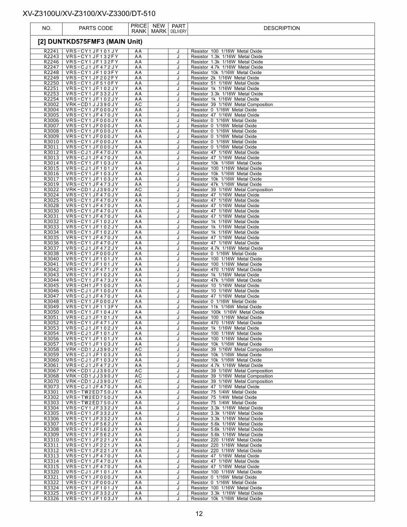
XV-Z3100U/XV-Z3100/XV-Z3300/DT-510PRICE NEW PART
NO. PARTS CODE RANK MARK DELIVERY DESCRIPTIONR2241 VRS-CY1JF101JY AA J Resistor 100 1/16W Metal OxideR2243 VRS-CY1JF132FY AA J Resistor 1.3k 1/16W Metal OxideR2246 VRS-CY1JF132FY AA J Resistor 1.3k 1/16W Metal OxideR2247 VRS-CJ1JF472JY AA J Resistor 4.7k 1/16W Metal OxideR2248 VRS-CY1JF103FY AA J Resistor 10k 1/16W Metal OxideR2249 VRS-CY1JF202FY AA J Resistor 2k 1/16W Metal OxideR2250 VRS-CY1JF510FY AA J Resistor 51 1/16W Metal OxideR2251 VRS-CY1JF102JY AA J Resistor 1k 1/16W Metal OxideR2253 VRS-CY1JF332JY AA J Resistor 3.3k 1/16W Metal OxideR2254 VRS-CY1JF102JY AA J Resistor 1k 1/16W Metal OxideR3002 VRK-CD1JJ390JY AC J Resistor 39 1/16W Metal CompositionR3004 VRS-CY1JF000JY AA J Resistor 0 1/16W Metal OxideR3005 VRS-CY1JF470JY AA J Resistor 47 1/16W Metal OxideR3006 VRS-CY1JF000JY AA J Resistor 0 1/16W Metal OxideR3007 VRS-CY1JF000JY AA J Resistor 0 1/16W Metal OxideR3008 VRS-CY1JF000JY AA J Resistor 0 1/16W Metal OxideR3009 VRS-CY1JF000JY AA J Resistor 0 1/16W Metal OxideR3010 VRS-CY1JF000JY AA J Resistor 0 1/16W Metal OxideR3011 VRS-CY1JF000JY AA J Resistor 0 1/16W Metal OxideR3012 VRS-CJ1JF470JY AA J Resistor 47 1/16W Metal OxideR3013 VRS-CJ1JF470JY AA J Resistor 47 1/16W Metal OxideR3014 VRS-CY1JF103JY AA J Resistor 10k 1/16W Metal OxideR3015 VRS-CJ1JF101JY AA J Resistor 100 1/16W Metal OxideR3016 VRS-CY1JF103JY AA J Resistor 10k 1/16W Metal OxideR3017 VRS-CY1JF103JY AA J Resistor 10k 1/16W Metal OxideR3019 VRS-CY1JF473JY AA J Resistor 47k 1/16W Metal OxideR3022 VRK-CD1JJ390JY AC J Resistor 39 1/16W Metal CompositionR3024 VRS-CY1JF470JY AA J Resistor 47 1/16W Metal OxideR3025 VRS-CY1JF470JY AA J Resistor 47 1/16W Metal OxideR3028 VRS-CY1JF470JY AA J Resistor 47 1/16W Metal OxideR3030 VRS-CY1JF470JY AA J Resistor 47 1/16W Metal OxideR3031 VRS-CY1JF470JY AA J Resistor 47 1/16W Metal OxideR3032 VRS-CY1JF102JY AA J Resistor 1k 1/16W Metal OxideR3033 VRS-CY1JF102JY AA J Resistor 1k 1/16W Metal OxideR3034 VRS-CY1JF102JY AA J Resistor 1k 1/16W Metal OxideR3035 VRS-CY1JF470JY AA J Resistor 47 1/16W Metal OxideR3036 VRS-CY1JF470JY AA J Resistor 47 1/16W Metal OxideR3037 VRS-CJ1JF472JY AA J Resistor 4.7k 1/16W Metal OxideR3038 VRS-CY1JF000JY AA J Resistor 0 1/16W Metal OxideR3040 VRS-CY1JF101JY AA J Resistor 100 1/16W Metal OxideR3041 VRS-CY1JF101JY AA J Resistor 100 1/16W Metal OxideR3042 VRS-CY1JF471JY AA J Resistor 470 1/16W Metal OxideR3043 VRS-CY1JF102JY AA J Resistor 1k 1/16W Metal OxideR3044 VRS-CY1JF473JY AA J Resistor 47k 1/16W Metal OxideR3045 VRS-CH1JF100JY AA J Resistor 10 1/16W Metal OxideR3046 VRS-CJ1JF100JY AA J Resistor 10 1/16W Metal OxideR3047 VRS-CJ1JF470JY AA J Resistor 47 1/16W Metal OxideR3048 VRS-CY1JF000JY AA J Resistor 0 1/16W Metal OxideR3049 VRS-CY1JF113FY AA J Resistor 11k 1/16W Metal OxideR3050 VRS-CY1JF104JY AA J Resistor 100k 1/16W Metal OxideR3051 VRS-CJ1JF101JY AA J Resistor 100 1/16W Metal OxideR3052 VRS-CY1JF471JY AA J Resistor 470 1/16W Metal OxideR3053 VRS-CJ1JF102JY AA J Resistor 1k 1/16W Metal OxideR3054 VRS-CJ1JF101JY AA J Resistor 100 1/16W Metal OxideR3056 VRS-CY1JF101JY AA J Resistor 100 1/16W Metal OxideR3057 VRS-CY1JF103JY AA J Resistor 10k 1/16W Metal OxideR3058 VRK-CD1JJ390JY AC J Resistor 39 1/16W Metal CompositionR3059 VRS-CJ1JF103JY AA J Resistor 10k 1/16W Metal OxideR3060 VRS-CJ1JF103JY AA J Resistor 10k 1/16W Metal OxideR3061 VRS-CJ1JF472JY AA J Resistor 4.7k 1/16W Metal OxideR3067 VRK-CD1JJ390JY AC J Resistor 39 1/16W Metal CompositionR3068 VRK-CD1JJ390JY AC J Resistor 39 1/16W Metal CompositionR3070 VRK-CD1JJ390JY AC J Resistor 39 1/16W Metal CompositionR3073 VRS-CJ1JF470JY AA J Resistor 47 1/16W Metal OxideR3301 VRS-TW2ED750JY AA J Resistor 75 1/4W Metal OxideR3302 VRS-TW2ED750JY AA J Resistor 75 1/4W Metal OxideR3303 VRS-TW2ED750JY AA J Resistor 75 1/4W Metal OxideR3304 VRS-CY1JF332JY AA J Resistor 3.3k 1/16W Metal OxideR3305 VRS-CY1JF332JY AA J Resistor 3.3k 1/16W Metal OxideR3306 VRS-CY1JF332JY AA J Resistor 3.3k 1/16W Metal OxideR3307 VRS-CY1JF562JY AA J Resistor 5.6k 1/16W Metal OxideR3308 VRS-CY1JF562JY AA J Resistor 5.6k 1/16W Metal OxideR3309 VRS-CY1JF562JY AA J Resistor 5.6k 1/16W Metal OxideR3310 VRS-CY1JF221JY AA J Resistor 220 1/16W Metal OxideR3311 VRS-CY1JF221JY AA J Resistor 220 1/16W Metal OxideR3312 VRS-CY1JF221JY AA J Resistor 220 1/16W Metal OxideR3313 VRS-CY1JF470JY AA J Resistor 47 1/16W Metal OxideR3314 VRS-CY1JF470JY AA J Resistor 47 1/16W Metal OxideR3315 VRS-CY1JF470JY AA J Resistor 47 1/16W Metal OxideR3320 VRS-CJ1JF101JY AA J Resistor 100 1/16W Metal OxideR3321 VRS-CY1JF000JY AA J Resistor 0 1/16W Metal OxideR3322 VRS-CY1JF000JY AA J Resistor 0 1/16W Metal OxideR3324 VRS-CY1JF101JY AA J Resistor 100 1/16W Metal OxideR3325 VRS-CY1JF332JY AA J Resistor 3.3k 1/16W Metal OxideR3326 VRS-CY1JF103JY AA J Resistor 10k 1/16W Metal Oxide
[2] DUNTKD575FMF3 (MAIN Unit)
12
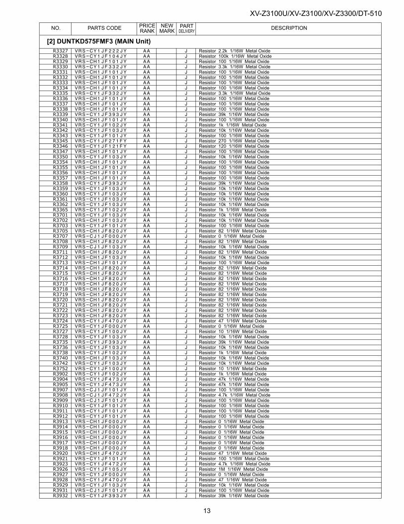
XV-Z3100U/XV-Z3100/XV-Z3300/DT-510PRICE NEW PART
NO. PARTS CODE RANK MARK DELIVERY DESCRIPTIONR3327 VRS-CY1JF222JY AA J Resistor 2.2k 1/16W Metal OxideR3328 VRS-CY1JF104JY AA J Resistor 100k 1/16W Metal OxideR3329 VRS-CH1JF101JY AA J Resistor 100 1/16W Metal OxideR3330 VRS-CY1JF332JY AA J Resistor 3.3k 1/16W Metal OxideR3331 VRS-CH1JF101JY AA J Resistor 100 1/16W Metal OxideR3332 VRS-CH1JF101JY AA J Resistor 100 1/16W Metal OxideR3333 VRS-CH1JF101JY AA J Resistor 100 1/16W Metal OxideR3334 VRS-CH1JF101JY AA J Resistor 100 1/16W Metal OxideR3335 VRS-CY1JF332JY AA J Resistor 3.3k 1/16W Metal OxideR3336 VRS-CH1JF101JY AA J Resistor 100 1/16W Metal OxideR3337 VRS-CH1JF101JY AA J Resistor 100 1/16W Metal OxideR3338 VRS-CH1JF101JY AA J Resistor 100 1/16W Metal OxideR3339 VRS-CY1JF393JY AA J Resistor 39k 1/16W Metal OxideR3340 VRS-CH1JF101JY AA J Resistor 100 1/16W Metal OxideR3341 VRS-CY1JF102JY AA J Resistor 1k 1/16W Metal OxideR3342 VRS-CY1JF103JY AA J Resistor 10k 1/16W Metal OxideR3343 VRS-CY1JF101JY AA J Resistor 100 1/16W Metal OxideR3345 VRS-CY1JF271FY AA J Resistor 270 1/16W Metal OxideR3346 VRS-CY1JF121FY AA J Resistor 120 1/16W Metal OxideR3347 VRS-CH1JF101JY AA J Resistor 100 1/16W Metal OxideR3350 VRS-CY1JF103JY AA J Resistor 10k 1/16W Metal OxideR3354 VRS-CH1JF101JY AA J Resistor 100 1/16W Metal OxideR3355 VRS-CH1JF101JY AA J Resistor 100 1/16W Metal OxideR3356 VRS-CH1JF101JY AA J Resistor 100 1/16W Metal OxideR3357 VRS-CH1JF101JY AA J Resistor 100 1/16W Metal OxideR3358 VRS-CY1JF393JY AA J Resistor 39k 1/16W Metal OxideR3359 VRS-CY1JF103JY AA J Resistor 10k 1/16W Metal OxideR3360 VRS-CY1JF103JY AA J Resistor 10k 1/16W Metal OxideR3361 VRS-CY1JF103JY AA J Resistor 10k 1/16W Metal OxideR3362 VRS-CY1JF103JY AA J Resistor 10k 1/16W Metal OxideR3365 VRS-CY1JF102JY AA J Resistor 1k 1/16W Metal OxideR3701 VRS-CY1JF103JY AA J Resistor 10k 1/16W Metal OxideR3702 VRS-CH1JF103JY AA J Resistor 10k 1/16W Metal OxideR3703 VRS-CY1JF101JY AA J Resistor 100 1/16W Metal OxideR3705 VRS-CH1JF820JY AA J Resistor 82 1/16W Metal OxideR3707 VRS-CJ1JF000JY AA J Resistor 0 1/16W Metal OxideR3708 VRS-CH1JF820JY AA J Resistor 82 1/16W Metal OxideR3709 VRS-CJ1JF103JY AA J Resistor 10k 1/16W Metal OxideR3711 VRS-CH1JF820JY AA J Resistor 82 1/16W Metal OxideR3712 VRS-CH1JF103JY AA J Resistor 10k 1/16W Metal OxideR3713 VRS-CH1JF101JY AA J Resistor 100 1/16W Metal OxideR3714 VRS-CH1JF820JY AA J Resistor 82 1/16W Metal OxideR3715 VRS-CH1JF820JY AA J Resistor 82 1/16W Metal OxideR3716 VRS-CH1JF820JY AA J Resistor 82 1/16W Metal OxideR3717 VRS-CH1JF820JY AA J Resistor 82 1/16W Metal OxideR3718 VRS-CH1JF820JY AA J Resistor 82 1/16W Metal OxideR3719 VRS-CH1JF820JY AA J Resistor 82 1/16W Metal OxideR3720 VRS-CH1JF820JY AA J Resistor 82 1/16W Metal OxideR3721 VRS-CH1JF820JY AA J Resistor 82 1/16W Metal OxideR3722 VRS-CH1JF820JY AA J Resistor 82 1/16W Metal OxideR3723 VRS-CH1JF820JY AA J Resistor 82 1/16W Metal OxideR3724 VRS-CY1JF470JY AA J Resistor 47 1/16W Metal OxideR3725 VRS-CY1JF000JY AA J Resistor 0 1/16W Metal OxideR3727 VRS-CY1JF100JY AA J Resistor 10 1/16W Metal OxideR3728 VRS-CY1JF103JY AA J Resistor 10k 1/16W Metal OxideR3735 VRS-CY1JF393JY AA J Resistor 39k 1/16W Metal OxideR3736 VRS-CY1JF103JY AA J Resistor 10k 1/16W Metal OxideR3738 VRS-CY1JF102JY AA J Resistor 1k 1/16W Metal OxideR3740 VRS-CH1JF103JY AA J Resistor 10k 1/16W Metal OxideR3742 VRS-CY1JF103JY AA J Resistor 10k 1/16W Metal OxideR3752 VRS-CY1JF100JY AA J Resistor 10 1/16W Metal OxideR3902 VRS-CY1JF102JY AA J Resistor 1k 1/16W Metal OxideR3904 VRS-CY1JF473JY AA J Resistor 47k 1/16W Metal OxideR3905 VRS-CY1JF473JY AA J Resistor 47k 1/16W Metal OxideR3907 VRS-CJ1JF101JY AA J Resistor 100 1/16W Metal OxideR3908 VRS-CJ1JF472JY AA J Resistor 4.7k 1/16W Metal OxideR3909 VRS-CJ1JF101JY AA J Resistor 100 1/16W Metal OxideR3910 VRS-CY1JF101JY AA J Resistor 100 1/16W Metal OxideR3911 VRS-CY1JF101JY AA J Resistor 100 1/16W Metal OxideR3912 VRS-CY1JF101JY AA J Resistor 100 1/16W Metal OxideR3913 VRS-CH1JF000JY AA J Resistor 0 1/16W Metal OxideR3914 VRS-CH1JF000JY AA J Resistor 0 1/16W Metal OxideR3915 VRS-CH1JF000JY AA J Resistor 0 1/16W Metal OxideR3916 VRS-CH1JF000JY AA J Resistor 0 1/16W Metal OxideR3917 VRS-CH1JF000JY AA J Resistor 0 1/16W Metal OxideR3918 VRS-CH1JF000JY AA J Resistor 0 1/16W Metal OxideR3920 VRS-CH1JF470JY AA J Resistor 47 1/16W Metal OxideR3921 VRS-CY1JF101JY AA J Resistor 100 1/16W Metal OxideR3923 VRS-CY1JF472JY AA J Resistor 4.7k 1/16W Metal OxideR3926 VRS-CY1JF105JY AA J Resistor 1M 1/16W Metal OxideR3927 VRS-CY1JF000JY AA J Resistor 0 1/16W Metal OxideR3928 VRS-CY1JF470JY AA J Resistor 47 1/16W Metal OxideR3929 VRS-CY1JF103JY AA J Resistor 10k 1/16W Metal OxideR3931 VRS-CJ1JF101JY AA J Resistor 100 1/16W Metal OxideR3932 VRS-CY1JF393JY AA J Resistor 39k 1/16W Metal Oxide
[2] DUNTKD575FMF3 (MAIN Unit)
13
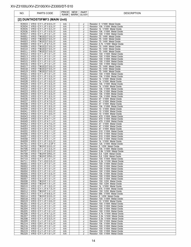
XV-Z3100U/XV-Z3100/XV-Z3300/DT-510PRICE NEW PART
NO. PARTS CODE RANK MARK DELIVERY DESCRIPTIONR3933 VRS-CY1JF000JY AA J Resistor 0 1/16W Metal OxideR3934 VRS-CY1JF103JY AA J Resistor 10k 1/16W Metal OxideR3935 VRS-CY1JF102JY AA J Resistor 1k 1/16W Metal OxideR3936 VRS-CY1JF103JY AA J Resistor 10k 1/16W Metal OxideR3937 VRS-CY1JF101JY AA J Resistor 100 1/16W Metal OxideR4001 VRS-TW2ED750JY AA J Resistor 75 1/4W Metal OxideR4002 VRS-TW2ED750JY AA J Resistor 75 1/4W Metal OxideR4003 VRS-TW2ED750JY AA J Resistor 75 1/4W Metal OxideR4004 VRS-CY1JF472JY AA J Resistor 4.7k 1/16W Metal OxideR4009 VRS-TW2ED750JY AA J Resistor 75 1/4W Metal OxideR4010 VRS-TW2ED750JY AA J Resistor 75 1/4W Metal OxideR4011 VRS-TW2ED750JY AA J Resistor 75 1/4W Metal OxideR4012 VRS-CY1JF101JY AA J Resistor 100 1/16W Metal OxideR4013 VRS-CY1JF101JY AA J Resistor 100 1/16W Metal OxideR4014 VRS-CY1JF101JY AA J Resistor 100 1/16W Metal OxideR4015 VRS-CY1JF101JY AA J Resistor 100 1/16W Metal OxideR4016 VRS-CY1JF101JY AA J Resistor 100 1/16W Metal OxideR4017 VRS-TW2ED750JY AA J Resistor 75 1/4W Metal OxideR4018 VRS-TW2ED750JY AA J Resistor 75 1/4W Metal OxideR4019 VRS-TW2ED750JY AA J Resistor 75 1/4W Metal OxideR4021 VRS-CY1JF101JY AA J Resistor 100 1/16W Metal OxideR4022 VRS-CY1JF103JY AA J Resistor 10k 1/16W Metal OxideR4025 VRS-CY1JF102JY AA J Resistor 1k 1/16W Metal OxideR4028 VRS-CJ1JF102JY AA J Resistor 1k 1/16W Metal OxideR4029 VRS-CY1JF103JY AA J Resistor 10k 1/16W Metal OxideR4030 VRS-CJ1JF102JY AA J Resistor 1k 1/16W Metal OxideR4032 VRS-CY1JF103JY AA J Resistor 10k 1/16W Metal OxideR4033 VRS-CY1JF103JY AA J Resistor 10k 1/16W Metal OxideR4034 VRS-CY1JF103JY AA J Resistor 10k 1/16W Metal OxideR4035 VRS-CY1JF103JY AA J Resistor 10k 1/16W Metal OxideR4036 VRS-CY1JF470JY AA J Resistor 47 1/16W Metal OxideR4037 VRS-CY1JF470JY AA J Resistor 47 1/16W Metal OxideR4038 VRS-CY1JF470JY AA J Resistor 47 1/16W Metal OxideR4039 VRS-CY1JF103JY AA J Resistor 10k 1/16W Metal OxideR4040 VRS-CY1JF100JY AA J Resistor 10 1/16W Metal OxideR4041 VRS-CY1JF100JY AA J Resistor 10 1/16W Metal OxideR4042 VRS-CY1JF100JY AA J Resistor 10 1/16W Metal OxideR4043 VRS-CY1JF471JY AA J Resistor 470 1/16W Metal OxideR4045 VRS-CY1JF471JY AA J Resistor 470 1/16W Metal OxideR4049 VRS-CY1JF471JY AA J Resistor 470 1/16W Metal OxideR4052 VRS-CY1JF470JY AA J Resistor 47 1/16W Metal OxideR4053 VRS-CY1JF470JY AA J Resistor 47 1/16W Metal OxideR4054 VRS-CY1JF470JY AA J Resistor 47 1/16W Metal OxideR4055 VRS-CY1JF511JY AA J Resistor 510 1/16W Metal OxideR4056 VRS-CY1JF511JY AA J Resistor 510 1/16W Metal OxideR4057 VRS-CY1JF511JY AA J Resistor 510 1/16W Metal OxideR4058 VRS-CY1JF511JY AA J Resistor 510 1/16W Metal OxideR4059 VRS-CY1JF102JY AA J Resistor 1k 1/16W Metal OxideR4701 VRS-CY1JF123FY AA J Resistor 12k 1/16W Metal OxideR4702 VRS-TW2HF000JY AA J Resistor 0 1/2W Metal OxideR4706 VRS-CY1JF103JY AA J Resistor 10k 1/16W Metal OxideR4707 VRS-CY1JF392JY AA J Resistor 3.9k 1/16W Metal OxideR4708 VRS-TW2HF5R6JY AA J Resistor 5.6 1/2W Metal OxideR4709 VRS-TW2HF5R6JY AA J Resistor 5.6 1/2W Metal OxideR4710 VRS-CY1JF101JY AA J Resistor 100 1/16W Metal OxideR4711 VRS-TV1JD222JY AA J Resistor 2.2k 1/10W Metal OxideR6001 VRS-CY1JF101JY AA J Resistor 100 1/16W Metal OxideR6002 VRS-CY1JF101JY AA J Resistor 100 1/16W Metal OxideR6003 VRS-CY1JF101JY AA J Resistor 100 1/16W Metal OxideR6004 VRS-CY1JF101JY AA J Resistor 100 1/16W Metal OxideR6005 VRS-CY1JF103JY AA J Resistor 10k 1/16W Metal OxideR6006 VRS-CY1JF101JY AA J Resistor 100 1/16W Metal OxideR6007 VRS-CY1JF101JY AA J Resistor 100 1/16W Metal OxideR6008 VRS-TW2HF151JY AA J Resistor 150 1/2W Metal OxideR6009 VRS-TW2HF151JY AA J Resistor 150 1/2W Metal OxideR6010 VRS-CY1JF102JY AA J Resistor 1k 1/16W Metal OxideR6011 VRS-CY1JF473JY AA J Resistor 47k 1/16W Metal OxideR6012 VRS-TW2HF151JY AA J Resistor 150 1/2W Metal OxideR6013 VRS-CY1JF683JY AA J Resistor 68k 1/16W Metal OxideR6014 VRS-TW2HF000JY AA J Resistor 0 1/2W Metal OxideR6018 VRS-CY1JF101JY AA J Resistor 100 1/16W Metal OxideR6019 VRS-CY1JF100JY AA J Resistor 10 1/16W Metal OxideR6201 VRS-CJ1JF101JY AA J Resistor 100 1/16W Metal OxideR6202 VRS-CJ1JF101JY AA J Resistor 100 1/16W Metal OxideR6204 VRS-CY1JF101JY AA J Resistor 100 1/16W Metal OxideR6205 VRS-CY1JF101JY AA J Resistor 100 1/16W Metal OxideR6206 VRS-CJ1JF472JY AA J Resistor 4.7k 1/16W Metal OxideR6207 VRS-CY1JF332JY AA J Resistor 3.3k 1/16W Metal OxideR6208 VRS-CY1JF332JY AA J Resistor 3.3k 1/16W Metal OxideR6209 VRS-CJ1JF101JY AA J Resistor 100 1/16W Metal OxideR6214 VRS-CH1JF103JY AA J Resistor 10k 1/16W Metal OxideR6216 VRS-CH1JF101JY AA J Resistor 100 1/16W Metal OxideR6218 VRS-CJ1JF101JY AA J Resistor 100 1/16W Metal OxideR6219 VRS-CJ1JF101JY AA J Resistor 100 1/16W Metal OxideR6220 VRS-CY1JF101JY AA J Resistor 100 1/16W Metal Oxide
[2] DUNTKD575FMF3 (MAIN Unit)
14
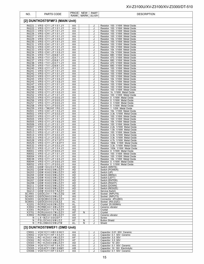
XV-Z3100U/XV-Z3100/XV-Z3300/DT-510PRICE NEW PART
NO. PARTS CODE RANK MARK DELIVERY DESCRIPTIONR6221 VRS-CY1JF101JY AA J Resistor 100 1/16W Metal OxideR6222 VRS-CY1JF101JY AA J Resistor 100 1/16W Metal OxideR6223 VRS-CY1JF101JY AA J Resistor 100 1/16W Metal OxideR6226 VRS-CH1JF101JY AA J Resistor 100 1/16W Metal OxideR6227 VRS-CY1JF101JY AA J Resistor 100 1/16W Metal OxideR6229 VRS-CY1JF103JY AA J Resistor 10k 1/16W Metal OxideR6230 VRS-CY1JF101JY AA J Resistor 100 1/16W Metal OxideR6231 VRS-CH1JF101JY AA J Resistor 100 1/16W Metal OxideR6232 VRS-CH1JF101JY AA J Resistor 100 1/16W Metal OxideR6233 VRS-CH1JF103JY AA J Resistor 10k 1/16W Metal OxideR6234 VRS-CH1JF103JY AA J Resistor 10k 1/16W Metal OxideR6235 VRS-TV1JD681JY AA J Resistor 680 1/16W Metal OxideR6236 VRS-TV1JD471JY AA J Resistor 470 1/16W Metal OxideR6237 VRS-TV1JD681JY AA J Resistor 680 1/16W Metal OxideR6238 VRS-TV1JD471JY AA J Resistor 470 1/16W Metal OxideR6239 VRS-TV1JD681JY AA J Resistor 680 1/16W Metal OxideR6240 VRS-CY1JF101JY AA J Resistor 100 1/16W Metal OxideR6241 VRS-CY1JF101JY AA J Resistor 100 1/16W Metal OxideR6242 VRS-CY1JF101JY AA J Resistor 100 1/16W Metal OxideR6243 VRS-CY1JF101JY AA J Resistor 100 1/16W Metal OxideR6244 VRS-CY1JF103JY AA J Resistor 10k 1/16W Metal OxideR6245 VRS-CY1JF103JY AA J Resistor 10k 1/16W Metal OxideR6247 VRS-CY1JF101JY AA J Resistor 100 1/16W Metal OxideR6248 VRS-CY1JF101JY AA J Resistor 100 1/16W Metal OxideR6249 VRS-CY1JF101JY AA J Resistor 100 1/16W Metal OxideR6250 VRS-CY1JF102JY AA J Resistor 1k 1/16W Metal OxideR6252 VRS-CJ1JF101JY AA J Resistor 100 1/16W Metal OxideR6255 VRS-CY1JF000JY AA J Resistor 0 1/16W Metal OxideR6256 VRS-CY1JF000JY AA J Resistor 0 1/16W Metal OxideR6257 VRS-CY1JF000JY AA J Resistor 0 1/16W Metal OxideR6258 VRS-CY1JF000JY AA J Resistor 0 1/16W Metal OxideR6259 VRS-TW2HF1R0JY AA J Resistor 1 1/2W Metal OxideR6501 VRS-CH1JF103JY AA J Resistor 10k 1/16W Metal OxideR6502 VRS-CY1JF332JY AA J Resistor 3.3k 1/16W Metal OxideR6503 VRS-CY1JF101JY AA J Resistor 100 1/16W Metal OxideR6504 VRS-CY1JF101JY AA J Resistor 100 1/16W Metal OxideR6505 VRS-CY1JF103JY AA J Resistor 10k 1/16W Metal OxideR6506 VRS-CJ1JF101JY AA J Resistor 100 1/16W Metal OxideR6507 VRS-CY1JF222JY AA J Resistor 2.2k 1/16W Metal OxideR6512 VRS-CY1JF152JY AA J Resistor 1.5k 1/16W Metal OxideR6513 VRS-CJ1JF101JY AA J Resistor 100 1/16W Metal OxideR6514 VRS-CY1JF332JY AA J Resistor 3.3k 1/16W Metal OxideR6515 VRS-CJ1JF332JY AA J Resistor 3.3k 1/16W Metal OxideR6528 VRS-CY1JF472FY AA J Resistor 4.7k 1/16W Metal OxideR6529 VRS-CY1JF184FY AA J Resistor 180k 1/16W Metal OxideR6532 VRS-CJ1JF332JY AA J Resistor 3.3k 1/16W Metal OxideR6533 VRS-CJ1JF104JY AA J Resistor 100k 1/16W Metal OxideR8001 VRS-CY1JF000JY AA J Resistor 0 1/16W Metal OxideR8002 VRS-CJ1JF101JY AA J Resistor 100 1/16W Metal OxideR8004 VRS-CJ1JF101JY AA J Resistor 100 1/16W Metal OxideR8038 VRS-CY1JF103JY AA J Resistor 10k 1/16W Metal OxideR8044 VRS-CY1JF000JY AA J Resistor 0 1/16W Metal OxideR8052 VRS-CY1JF000JY AA J Resistor 0 1/16W Metal OxideS2001 QSW-S0203TAZZY AD J Switch (WRITE)S6202 QSW-KA029WJZZY AD J Switch (POWER)S6203 QSW-KA029WJZZY AD J Switch (UP)S6204 QSW-KA029WJZZY AD J Switch (MENU)S6206 QSW-KA029WJZZY AD J Switch (LEFT)S6207 QSW-KA029WJZZY AD J Switch (ENTER)S6208 QSW-KA029WJZZY AD J Switch (RIGHT)S6211 QSW-KA029WJZZY AD J Switch (DOWN)S6212 QSW-KA029WJZZY AD J Switch (RESIZE)S6213 QSW-K0099TAZZY AC J Service SwitchSC3901 QSOCZA117WJZZQ AK J Socket (INPUT6)SC4001 QSOCNA529WJZZ AH J Socket (INPUT5)SC6001 QCNCWA500WJZZY AC J Connector 4Pin(MO)SC8001 QSOCD0902CEZZ AL J Socket (RS-232C)X2201 RCRSCA082WJZZY AL J Crystal 25.000MHzX3002 RCRMCA016WJZZY AD J Ceramic vibratorX3301 RCRSC0170TAZZY AG J CrystalX3701 RCRUAA057WJZZY AP N J CrystalX3902 RCRMCA016WJZZY AD J Ceramic vibrator
N LX-BZ3100CEF7 AA J ScrewN PSLDCA026WJZZ AF N J Button ShieldN PSLDMA929WJFW AL N J Shield
[3] DUNTKD578WEF1 (DMD Unit)C9001 VCKYCY1HB103KY AA J Capacitor 0.01 50V CeramicC9002 VCKYCY1HF104ZY AA J Capacitor 0.1 50V CeramicC9301 RC-KZA514WJZZY AF J Capacitor 3.3 50VC9302 RC-KZA514WJZZY AF J Capacitor 3.3 50VC9303 RC-KZA048WJZZY AD J Capacitor 10 25VC9304 VCKYCY1HF104ZY AA J Capacitor 0.1 50V CeramicC9305 VCEAPF1CW106MY AB J Capacitor 10 16V ElectrolyticC9306 VCKYCY1HF104ZY AA J Capacitor 0.1 50V Ceramic
[2] DUNTKD575FMF3 (MAIN Unit)
15
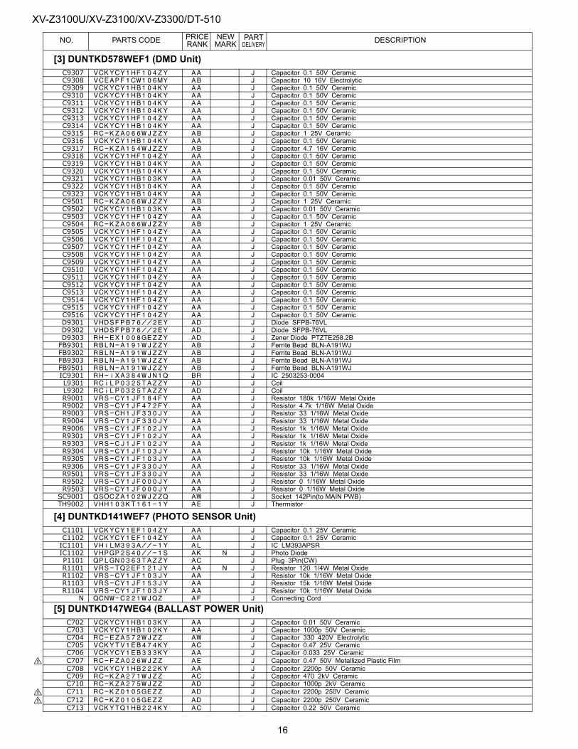
XV-Z3100U/XV-Z3100/XV-Z3300/DT-510PRICE NEW PART
NO. PARTS CODE RANK MARK DELIVERY DESCRIPTIONC9307 VCKYCY1HF104ZY AA J Capacitor 0.1 50V CeramicC9308 VCEAPF1CW106MY AB J Capacitor 10 16V ElectrolyticC9309 VCKYCY1HB104KY AA J Capacitor 0.1 50V CeramicC9310 VCKYCY1HB104KY AA J Capacitor 0.1 50V CeramicC9311 VCKYCY1HB104KY AA J Capacitor 0.1 50V CeramicC9312 VCKYCY1HB104KY AA J Capacitor 0.1 50V CeramicC9313 VCKYCY1HF104ZY AA J Capacitor 0.1 50V CeramicC9314 VCKYCY1HB104KY AA J Capacitor 0.1 50V CeramicC9315 RC-KZA066WJZZY AB J Capacitor 1 25V CeramicC9316 VCKYCY1HB104KY AA J Capacitor 0.1 50V CeramicC9317 RC-KZA154WJZZY AB J Capacitor 4.7 16V CeramicC9318 VCKYCY1HF104ZY AA J Capacitor 0.1 50V CeramicC9319 VCKYCY1HB104KY AA J Capacitor 0.1 50V CeramicC9320 VCKYCY1HB104KY AA J Capacitor 0.1 50V CeramicC9321 VCKYCY1HB103KY AA J Capacitor 0.01 50V CeramicC9322 VCKYCY1HB104KY AA J Capacitor 0.1 50V CeramicC9323 VCKYCY1HB104KY AA J Capacitor 0.1 50V CeramicC9501 RC-KZA066WJZZY AB J Capacitor 1 25V CeramicC9502 VCKYCY1HB103KY AA J Capacitor 0.01 50V CeramicC9503 VCKYCY1HF104ZY AA J Capacitor 0.1 50V CeramicC9504 RC-KZA066WJZZY AB J Capacitor 1 25V CeramicC9505 VCKYCY1HF104ZY AA J Capacitor 0.1 50V CeramicC9506 VCKYCY1HF104ZY AA J Capacitor 0.1 50V CeramicC9507 VCKYCY1HF104ZY AA J Capacitor 0.1 50V CeramicC9508 VCKYCY1HF104ZY AA J Capacitor 0.1 50V CeramicC9509 VCKYCY1HF104ZY AA J Capacitor 0.1 50V CeramicC9510 VCKYCY1HF104ZY AA J Capacitor 0.1 50V CeramicC9511 VCKYCY1HF104ZY AA J Capacitor 0.1 50V CeramicC9512 VCKYCY1HF104ZY AA J Capacitor 0.1 50V CeramicC9513 VCKYCY1HF104ZY AA J Capacitor 0.1 50V CeramicC9514 VCKYCY1HF104ZY AA J Capacitor 0.1 50V CeramicC9515 VCKYCY1HF104ZY AA J Capacitor 0.1 50V CeramicC9516 VCKYCY1HF104ZY AA J Capacitor 0.1 50V CeramicD9301 VHDSFPB76//2EY AD J Diode SFPB-76VLD9302 VHDSFPB76//2EY AD J Diode SFPB-76VLD9303 RH-EX1008GEZZY AD J Zener Diode PTZTE258.2BFB9301 RBLN-A191WJZZY AB J Ferrite Bead BLN-A191WJFB9302 RBLN-A191WJZZY AB J Ferrite Bead BLN-A191WJFB9303 RBLN-A191WJZZY AB J Ferrite Bead BLN-A191WJFB9501 RBLN-A191WJZZY AB J Ferrite Bead BLN-A191WJIC9301 RH-iXA384WJN1Q BR J IC 2503253-0004L9301 RCiLP0325TAZZY AD J CoilL9302 RCiLP0325TAZZY AD J CoilR9001 VRS-CY1JF184FY AA J Resistor 180k 1/16W Metal OxideR9002 VRS-CY1JF472FY AA J Resistor 4.7k 1/16W Metal OxideR9003 VRS-CH1JF330JY AA J Resistor 33 1/16W Metal OxideR9004 VRS-CY1JF330JY AA J Resistor 33 1/16W Metal OxideR9006 VRS-CY1JF102JY AA J Resistor 1k 1/16W Metal OxideR9301 VRS-CY1JF102JY AA J Resistor 1k 1/16W Metal OxideR9303 VRS-CJ1JF102JY AA J Resistor 1k 1/16W Metal OxideR9304 VRS-CY1JF103JY AA J Resistor 10k 1/16W Metal OxideR9305 VRS-CY1JF103JY AA J Resistor 10k 1/16W Metal OxideR9306 VRS-CY1JF330JY AA J Resistor 33 1/16W Metal OxideR9501 VRS-CY1JF330JY AA J Resistor 33 1/16W Metal OxideR9502 VRS-CY1JF000JY AA J Resistor 0 1/16W Metal OxideR9503 VRS-CY1JF000JY AA J Resistor 0 1/16W Metal OxideSC9001 QSOCZA102WJZZQ AW J Socket 142Pin(to MAIN PWB)TH9002 VHH103KT161-1Y AE J Thermistor
[4] DUNTKD141WEF7 (PHOTO SENSOR Unit)C1101 VCKYCY1EF104ZY AA J Capacitor 0.1 25V CeramicC1102 VCKYCY1EF104ZY AA J Capacitor 0.1 25V CeramicIC1101 VHiLM393A//-1Y AL J IC LM393APSRIC1102 VHPGP2S40//-1S AK N J Photo DiodeP1101 QPLGN0363TAZZY AC J Plug 3Pin(CW)R1101 VRS-TQ2EF121JY AA N J Resistor 120 1/4W Metal OxideR1102 VRS-CY1JF103JY AA J Resistor 10k 1/16W Metal OxideR1103 VRS-CY1JF153JY AA J Resistor 15k 1/16W Metal OxideR1104 VRS-CY1JF103JY AA J Resistor 10k 1/16W Metal Oxide
N QCNW-C221WJQZ AF J Connecting Cord
[5] DUNTKD147WEG4 (BALLAST POWER Unit)C702 VCKYCY1HB103KY AA J Capacitor 0.01 50V CeramicC703 VCKYCY1HB102KY AA J Capacitor 1000p 50V CeramicC704 RC-EZA572WJZZ AW J Capacitor 330 420V ElectrolyticC705 VCKYTV1EB474KY AC J Capacitor 0.47 25V CeramicC706 VCKYCY1EB333KY AA J Capacitor 0.033 25V Ceramic
! C707 RC-FZA026WJZZ AE J Capacitor 0.47 50V Metallized Plastic FilmC708 VCKYCY1HB222KY AA J Capacitor 2200p 50V CeramicC709 RC-KZA271WJZZ AC J Capacitor 470 2kV CeramicC710 RC-KZA275WJZZ AD J Capacitor 1000p 2kV Ceramic
! C711 RC-KZ0105GEZZ AD J Capacitor 2200p 250V Ceramic! C712 RC-KZ0105GEZZ AD J Capacitor 2200p 250V Ceramic
C713 VCKYTQ1HB224KY AC J Capacitor 0.22 50V Ceramic
[3] DUNTKD578WEF1 (DMD Unit)
16
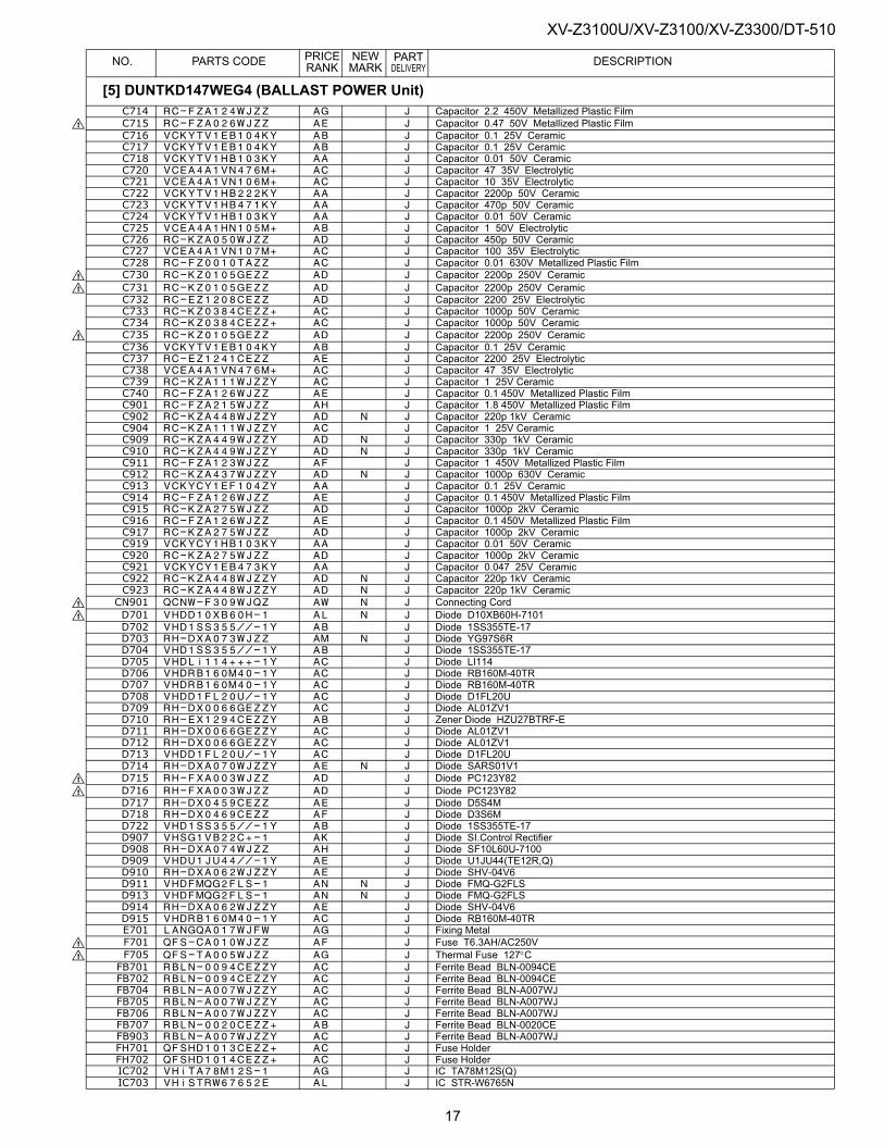
XV-Z3100U/XV-Z3100/XV-Z3300/DT-510PRICE NEW PART
NO. PARTS CODE RANK MARK DELIVERY DESCRIPTIONC714 RC-FZA124WJZZ AG J Capacitor 2.2 450V Metallized Plastic Film! C715 RC-FZA026WJZZ AE J Capacitor 0.47 50V Metallized Plastic Film
C716 VCKYTV1EB104KY AB J Capacitor 0.1 25V CeramicC717 VCKYTV1EB104KY AB J Capacitor 0.1 25V CeramicC718 VCKYTV1HB103KY AA J Capacitor 0.01 50V CeramicC720 VCEA4A1VN476M+ AC J Capacitor 47 35V ElectrolyticC721 VCEA4A1VN106M+ AC J Capacitor 10 35V ElectrolyticC722 VCKYTV1HB222KY AA J Capacitor 2200p 50V CeramicC723 VCKYTV1HB471KY AA J Capacitor 470p 50V CeramicC724 VCKYTV1HB103KY AA J Capacitor 0.01 50V CeramicC725 VCEA4A1HN105M+ AB J Capacitor 1 50V ElectrolyticC726 RC-KZA050WJZZ AD J Capacitor 450p 50V CeramicC727 VCEA4A1VN107M+ AC J Capacitor 100 35V ElectrolyticC728 RC-FZ0010TAZZ AC J Capacitor 0.01 630V Metallized Plastic Film
! C730 RC-KZ0105GEZZ AD J Capacitor 2200p 250V Ceramic! C731 RC-KZ0105GEZZ AD J Capacitor 2200p 250V Ceramic
C732 RC-EZ1208CEZZ AD J Capacitor 2200 25V ElectrolyticC733 RC-KZ0384CEZZ+ AC J Capacitor 1000p 50V CeramicC734 RC-KZ0384CEZZ+ AC J Capacitor 1000p 50V Ceramic
! C735 RC-KZ0105GEZZ AD J Capacitor 2200p 250V CeramicC736 VCKYTV1EB104KY AB J Capacitor 0.1 25V CeramicC737 RC-EZ1241CEZZ AE J Capacitor 2200 25V ElectrolyticC738 VCEA4A1VN476M+ AC J Capacitor 47 35V ElectrolyticC739 RC-KZA111WJZZY AC J Capacitor 1 25V CeramicC740 RC-FZA126WJZZ AE J Capacitor 0.1 450V Metallized Plastic FilmC901 RC-FZA215WJZZ AH J Capacitor 1.8 450V Metallized Plastic FilmC902 RC-KZA448WJZZY AD N J Capacitor 220p 1kV CeramicC904 RC-KZA111WJZZY AC J Capacitor 1 25V CeramicC909 RC-KZA449WJZZY AD N J Capacitor 330p 1kV CeramicC910 RC-KZA449WJZZY AD N J Capacitor 330p 1kV CeramicC911 RC-FZA123WJZZ AF J Capacitor 1 450V Metallized Plastic FilmC912 RC-KZA437WJZZY AD N J Capacitor 1000p 630V CeramicC913 VCKYCY1EF104ZY AA J Capacitor 0.1 25V CeramicC914 RC-FZA126WJZZ AE J Capacitor 0.1 450V Metallized Plastic FilmC915 RC-KZA275WJZZ AD J Capacitor 1000p 2kV CeramicC916 RC-FZA126WJZZ AE J Capacitor 0.1 450V Metallized Plastic FilmC917 RC-KZA275WJZZ AD J Capacitor 1000p 2kV CeramicC919 VCKYCY1HB103KY AA J Capacitor 0.01 50V CeramicC920 RC-KZA275WJZZ AD J Capacitor 1000p 2kV CeramicC921 VCKYCY1EB473KY AA J Capacitor 0.047 25V CeramicC922 RC-KZA448WJZZY AD N J Capacitor 220p 1kV CeramicC923 RC-KZA448WJZZY AD N J Capacitor 220p 1kV Ceramic
! CN901 QCNW-F309WJQZ AW N J Connecting Cord! D701 VHDD10XB60H-1 AL N J Diode D10XB60H-7101
D702 VHD1SS355//-1Y AB J Diode 1SS355TE-17D703 RH-DXA073WJZZ AM N J Diode YG97S6RD704 VHD1SS355//-1Y AB J Diode 1SS355TE-17D705 VHDLi114+++-1Y AC J Diode LI114D706 VHDRB160M40-1Y AC J Diode RB160M-40TRD707 VHDRB160M40-1Y AC J Diode RB160M-40TRD708 VHDD1FL20U/-1Y AC J Diode D1FL20UD709 RH-DX0066GEZZY AC J Diode AL01ZV1D710 RH-EX1294CEZZY AB J Zener Diode HZU27BTRF-ED711 RH-DX0066GEZZY AC J Diode AL01ZV1D712 RH-DX0066GEZZY AC J Diode AL01ZV1D713 VHDD1FL20U/-1Y AC J Diode D1FL20UD714 RH-DXA070WJZZY AE N J Diode SARS01V1
! D715 RH-FXA003WJZZ AD J Diode PC123Y82! D716 RH-FXA003WJZZ AD J Diode PC123Y82
D717 RH-DX0459CEZZ AE J Diode D5S4MD718 RH-DX0469CEZZ AF J Diode D3S6MD722 VHD1SS355//-1Y AB J Diode 1SS355TE-17D907 VHSG1VB22C+-1 AK J Diode SI.Control RectifierD908 RH-DXA074WJZZ AH J Diode SF10L60U-7100D909 VHDU1JU44//-1Y AE J Diode U1JU44(TE12R,Q)D910 RH-DXA062WJZZY AE J Diode SHV-04V6D911 VHDFMQG2FLS-1 AN N J Diode FMQ-G2FLSD913 VHDFMQG2FLS-1 AN N J Diode FMQ-G2FLSD914 RH-DXA062WJZZY AE J Diode SHV-04V6D915 VHDRB160M40-1Y AC J Diode RB160M-40TRE701 LANGQA017WJFW AG J Fixing Metal
! F701 QFS-CA010WJZZ AF J Fuse T6.3AH/AC250V! F705 QFS-TA005WJZZ AG J Thermal Fuse 127°C
FB701 RBLN-0094CEZZY AC J Ferrite Bead BLN-0094CEFB702 RBLN-0094CEZZY AC J Ferrite Bead BLN-0094CEFB704 RBLN-A007WJZZY AC J Ferrite Bead BLN-A007WJFB705 RBLN-A007WJZZY AC J Ferrite Bead BLN-A007WJFB706 RBLN-A007WJZZY AC J Ferrite Bead BLN-A007WJFB707 RBLN-0020CEZZ+ AB J Ferrite Bead BLN-0020CEFB903 RBLN-A007WJZZY AC J Ferrite Bead BLN-A007WJFH701 QFSHD1013CEZZ+ AC J Fuse HolderFH702 QFSHD1014CEZZ+ AC J Fuse HolderIC702 VHiTA78M12S-1 AG J IC TA78M12S(Q)IC703 VHiSTRW67652E AL J IC STR-W6765N
[5] DUNTKD147WEG4 (BALLAST POWER Unit)
17
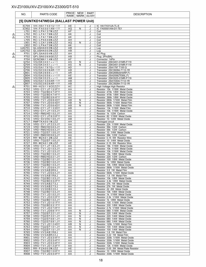
XV-Z3100U/XV-Z3100/XV-Z3300/DT-510PRICE NEW PART
NO. PARTS CODE RANK MARK DELIVERY DESCRIPTIONIC704 VHiHA17431U-1Y AE J IC HA17431UA-TL-EIC902 VHiFA5501AN-1Y AQ N J IC FA55501AN-D1-TE1L701 RCiLPA137WJZZ AF J Coil
! L702 RCiLFA178WJZZ AK J Coil! L703 RCiLFA178WJZZ AK J Coil
L705 RCiLPA546WJZZ AH J CoilL901 RCiLCA126WJZZ AQ N J CoilL902 RCiLPA475WJZZ AK J Coil
LUG701 QLUGHA002WJZZ AB J LugLUG702 QLUGHA002WJZZ AB J Lug
! P701 QPLGAA004WJZZ AH J AC Plug! P702 QPLGN0269GEZZ AB J Plug 2Pin(BA)
P704 QCNCMA114WJZZ AF J Connector 14PinQ702 VS2SK3451++-1 AS N J Transistor 2SK3451-01MR-F119Q704 VS2SK3451++-1 AS N J Transistor 2SK3451-01MR-F119Q705 VS2SA1797Q+-1Y AD J Transistor 2SA1797 T100 QQ706 VS2SC3928AR-1Y AB J Transistor 2SC3928A-T112-1RQ901 VS2SK2699++-1 AR J Transistor 2SK2699(SHARP,F)Q904 VS2SA2056++-1Y AE J Transistor 2SA2056(TE85L,F)Q905 VS2SK3525++-1 AM J Transistor 2SK3525-01MR-F119Q906 VS2SA1530AR-1Y AB J Transistor 2SA1530A-T112-1RQ907 VS2SC3928AR-1Y AB J Transistor 2SC3928A-T112-1R
! R701 RR-HZ0119CEZZY AC J High Voltage High ResistorR702 VRS-CY1JF153FY AA J Resistor 15k 1/16W Metal OxideR703 VRS-TQ2BD474FY AA J Resistor 470k 1/8W Metal OxideR704 VRS-TQ2BD474FY AA J Resistor 470k 1/8W Metal OxideR705 VRS-TQ2BD394FY AA J Resistor 390k 1/8W Metal OxideR706 VRN-TV1JD684DY AB N J Resistor 680k 1/16W Metal FilmR707 VRN-TV1JD564DY AB N J Resistor 560k 1/16W Metal FilmR708 VRN-TV1JD564DY AB N J Resistor 560k 1/16W Metal FilmR710 VRN-CY1JF133DY AB J Resistor 13k 1/16W Metal FilmR711 VRS-CY1JF103JY AA J Resistor 10k 1/16W Metal OxideR714 VRD-RM2HD102JY AA J Resistor 1k 1/2W CarbonR715 VRS-CY1JF820FY AA J Resistor 82 1/16W Metal OxideR716 VRS-SV2HC100JY AB J Resistor 10 1/2W Metal OxideR717 RMPTKA001WJZZ AH J Packaged circuitR718 VRS-CY1JF223JY AA J Resistor 22k 1/16W Metal OxideR719 VRD-RM2HD563JY AA J Resistor 56k 1/2W CarbonR720 VRD-RM2HD563JY AA J Resistor 56k 1/2W CarbonR721 VRS-TQ2EF100JY AA J Resistor 10 1/4W Metal OxideR722 VRD-RM2HD563JY AA J Resistor 56k 1/2W CarbonR724 RR-WZA012WJZZ AE J Resistor 0.15 5W Resistor WireR725 VRS-TQ2EF100JY AA J Resistor 10 1/4W Metal OxideR727 RR-WZA012WJZZ AE J Resistor 0.15 5W Resistor WireR728 VRS-CY1JF183JY AA J Resistor 18k 1/16W Metal OxideR730 VRS-TV1JD103JY AA J Resistor 10k 1/16W Metal OxideR731 VRS-TV1JD103JY AA J Resistor 10k 1/16W Metal OxideR733 VRS-TQ2BD153JY AA J Resistor 15k 1/8W Metal OxideR734 VRD-RM2HD221JY AA J Resistor 220 1/2W CarbonR735 VRS-TQ2BD101JY AA J Resistor 100 1/8W Metal OxideR736 VRS-TQ2BD102JY AA J Resistor 1k 1/8W Metal OxideR737 VRS-TQ2BD103JY AA J Resistor 10k 1/8W Metal OxideR738 VRS-TV1JD564JY AA J Resistor 560k 1/16W Metal OxideR739 VRN-VV3AB3R9J AA J Resistor 3.9 1W Metal FilmR740 VRS-TV1JD564JY AA J Resistor 560k 1/16W Metal OxideR741 VRN-VV3AB1R8J AA J Resistor 1.8 1W Metal FilmR742 VRS-TQ2BD103JY AA J Resistor 10k 1/8W Metal OxideR743 VRS-TQ2BD332FY AA J Resistor 3.3k 1/8W Metal OxideR744 VRS-VV3AB273J AA J Resistor 27k 1W Metal OxideR745 VRS-VV3AB273J AA J Resistor 27k 1W Metal OxideR746 VRS-VV3DB220J AA J Resistor 22 2W Metal OxideR748 VRS-TQ2BD103JY AA J Resistor 10k 1/8W Metal OxideR750 VRS-TV1JD102JY AA J Resistor 1k 1/16W Metal OxideR751 VRS-TV1JD222FY AA J Resistor 2.2k 1/16W Metal OxideR752 VRS-TQ2BD102JY AA J Resistor 1k 1/8W Metal OxideR753 VRS-TV1JD101FY AA J Resistor 100 1/16W Metal OxideR754 VRS-TQ2BD331FY AA J Resistor 330 1/8W Metal OxideR755 VRS-TV1JD272FY AA J Resistor 2.7k 1/16W Metal OxideR756 VRS-TV1JD681FY AA N J Resistor 680 1/16W Metal OxideR757 VRS-TQ2EF221JY AA N J Resistor 220 1/4W Metal OxideR758 VRS-TQ2EF221JY AA N J Resistor 220 1/4W Metal OxideR759 VRS-TQ2EF681JY AA N J Resistor 680 1/4W Metal OxideR760 VRS-TQ2EF681JY AA N J Resistor 680 1/4W Metal OxideR762 VRN-TV1JD124DY AB N J Resistor 120k 1/16W Metal FilmR763 VRS-TQ2EF101JY AA N J Resistor 100 1/4W Metal OxideR764 VRS-TQ2EF101JY AA N J Resistor 100 1/4W Metal OxideR765 VRN-VV3AB1R8J AA J Resistor 1.8 1W Metal FilmR766 VRN-VV3ABR22J AA J Resistor 0.22 1W Metal FilmR901 VRS-TV1JD334FY AA J Resistor 330k 1/16W Metal OxideR902 VRS-TV1JD334FY AA J Resistor 330k 1/16W Metal OxideR903 VRS-TV1JD334FY AA J Resistor 330k 1/16W Metal OxideR904 VRS-TV1JD123FY AA J Resistor 12k 1/16W Metal OxideR905 RR-FZA002WJZZ AE J Resistor 0.05 3W Metal Plate ResistorR907 VRS-TQ2BD100FY AA J Resistor 10 1/8W Metal OxideR908 VRS-TV1JD334FY AA J Resistor 330k 1/16W Metal Oxide
[5] DUNTKD147WEG4 (BALLAST POWER Unit)
18
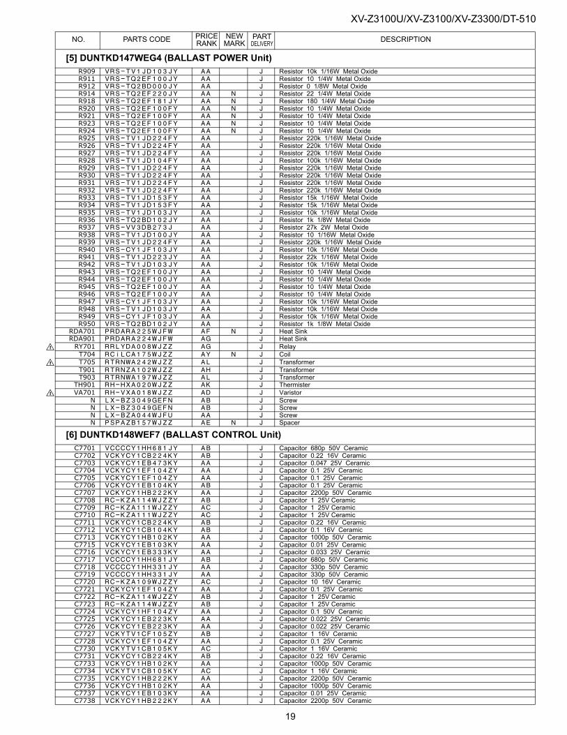
XV-Z3100U/XV-Z3100/XV-Z3300/DT-510PRICE NEW PART
NO. PARTS CODE RANK MARK DELIVERY DESCRIPTIONR909 VRS-TV1JD103JY AA J Resistor 10k 1/16W Metal OxideR911 VRS-TQ2EF100JY AA J Resistor 10 1/4W Metal OxideR912 VRS-TQ2BD000JY AA J Resistor 0 1/8W Metal OxideR914 VRS-TQ2EF220JY AA N J Resistor 22 1/4W Metal OxideR918 VRS-TQ2EF181JY AA N J Resistor 180 1/4W Metal OxideR920 VRS-TQ2EF100FY AA N J Resistor 10 1/4W Metal OxideR921 VRS-TQ2EF100FY AA N J Resistor 10 1/4W Metal OxideR923 VRS-TQ2EF100FY AA N J Resistor 10 1/4W Metal OxideR924 VRS-TQ2EF100FY AA N J Resistor 10 1/4W Metal OxideR925 VRS-TV1JD224FY AA J Resistor 220k 1/16W Metal OxideR926 VRS-TV1JD224FY AA J Resistor 220k 1/16W Metal OxideR927 VRS-TV1JD224FY AA J Resistor 220k 1/16W Metal OxideR928 VRS-TV1JD104FY AA J Resistor 100k 1/16W Metal OxideR929 VRS-TV1JD224FY AA J Resistor 220k 1/16W Metal OxideR930 VRS-TV1JD224FY AA J Resistor 220k 1/16W Metal OxideR931 VRS-TV1JD224FY AA J Resistor 220k 1/16W Metal OxideR932 VRS-TV1JD224FY AA J Resistor 220k 1/16W Metal OxideR933 VRS-TV1JD153FY AA J Resistor 15k 1/16W Metal OxideR934 VRS-TV1JD153FY AA J Resistor 15k 1/16W Metal OxideR935 VRS-TV1JD103JY AA J Resistor 10k 1/16W Metal OxideR936 VRS-TQ2BD102JY AA J Resistor 1k 1/8W Metal OxideR937 VRS-VV3DB273J AA J Resistor 27k 2W Metal OxideR938 VRS-TV1JD100JY AA J Resistor 10 1/16W Metal OxideR939 VRS-TV1JD224FY AA J Resistor 220k 1/16W Metal OxideR940 VRS-CY1JF103JY AA J Resistor 10k 1/16W Metal OxideR941 VRS-TV1JD223JY AA J Resistor 22k 1/16W Metal OxideR942 VRS-TV1JD103JY AA J Resistor 10k 1/16W Metal OxideR943 VRS-TQ2EF100JY AA J Resistor 10 1/4W Metal OxideR944 VRS-TQ2EF100JY AA J Resistor 10 1/4W Metal OxideR945 VRS-TQ2EF100JY AA J Resistor 10 1/4W Metal OxideR946 VRS-TQ2EF100JY AA J Resistor 10 1/4W Metal OxideR947 VRS-CY1JF103JY AA J Resistor 10k 1/16W Metal OxideR948 VRS-TV1JD103JY AA J Resistor 10k 1/16W Metal OxideR949 VRS-CY1JF103JY AA J Resistor 10k 1/16W Metal OxideR950 VRS-TQ2BD102JY AA J Resistor 1k 1/8W Metal Oxide
RDA701 PRDARA225WJFW AF N J Heat SinkRDA901 PRDARA224WJFW AG J Heat Sink
! RY701 RRLYDA008WJZZ AG J RelayT704 RCiLCA175WJZZ AY N J Coil
! T705 RTRNWA242WJZZ AL J TransformerT901 RTRNZA102WJZZ AH J TransformerT903 RTRNWA197WJZZ AL J TransformerTH901 RH-HXA020WJZZ AK J Thermister
! VA701 RH-VXA018WJZZ AD J VaristorN LX-BZ3049GEFN AB J ScrewN LX-BZ3049GEFN AB J ScrewN LX-BZA044WJFU AA J ScrewN PSPAZB157WJZZ AE N J Spacer
[6] DUNTKD148WEF7 (BALLAST CONTROL Unit)C7701 VCCCCY1HH681JY AB J Capacitor 680p 50V CeramicC7702 VCKYCY1CB224KY AB J Capacitor 0.22 16V CeramicC7703 VCKYCY1EB473KY AA J Capacitor 0.047 25V CeramicC7704 VCKYCY1EF104ZY AA J Capacitor 0.1 25V CeramicC7705 VCKYCY1EF104ZY AA J Capacitor 0.1 25V CeramicC7706 VCKYCY1EB104KY AB J Capacitor 0.1 25V CeramicC7707 VCKYCY1HB222KY AA J Capacitor 2200p 50V CeramicC7708 RC-KZA114WJZZY AB J Capacitor 1 25V CeramicC7709 RC-KZA111WJZZY AC J Capacitor 1 25V CeramicC7710 RC-KZA111WJZZY AC J Capacitor 1 25V CeramicC7711 VCKYCY1CB224KY AB J Capacitor 0.22 16V CeramicC7712 VCKYCY1CB104KY AB J Capacitor 0.1 16V CeramicC7713 VCKYCY1HB102KY AA J Capacitor 1000p 50V CeramicC7715 VCKYCY1EB103KY AA J Capacitor 0.01 25V CeramicC7716 VCKYCY1EB333KY AA J Capacitor 0.033 25V CeramicC7717 VCCCCY1HH681JY AB J Capacitor 680p 50V CeramicC7718 VCCCCY1HH331JY AA J Capacitor 330p 50V CeramicC7719 VCCCCY1HH331JY AA J Capacitor 330p 50V CeramicC7720 RC-KZA109WJZZY AC J Capacitor 10 16V CeramicC7721 VCKYCY1EF104ZY AA J Capacitor 0.1 25V CeramicC7722 RC-KZA114WJZZY AB J Capacitor 1 25V CeramicC7723 RC-KZA114WJZZY AB J Capacitor 1 25V CeramicC7724 VCKYCY1HF104ZY AA J Capacitor 0.1 50V CeramicC7725 VCKYCY1EB223KY AA J Capacitor 0.022 25V CeramicC7726 VCKYCY1EB223KY AA J Capacitor 0.022 25V CeramicC7727 VCKYTV1CF105ZY AB J Capacitor 1 16V CeramicC7728 VCKYCY1EF104ZY AA J Capacitor 0.1 25V CeramicC7730 VCKYTV1CB105KY AC J Capacitor 1 16V CeramicC7731 VCKYCY1CB224KY AB J Capacitor 0.22 16V CeramicC7733 VCKYCY1HB102KY AA J Capacitor 1000p 50V CeramicC7734 VCKYTV1CB105KY AC J Capacitor 1 16V CeramicC7735 VCKYCY1HB222KY AA J Capacitor 2200p 50V CeramicC7736 VCKYCY1HB102KY AA J Capacitor 1000p 50V CeramicC7737 VCKYCY1EB103KY AA J Capacitor 0.01 25V CeramicC7738 VCKYCY1HB222KY AA J Capacitor 2200p 50V Ceramic
[5] DUNTKD147WEG4 (BALLAST POWER Unit)
19
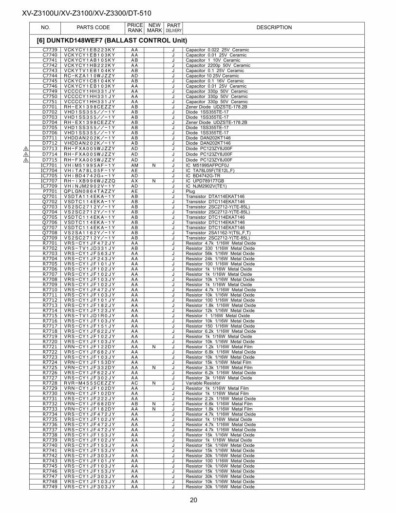
XV-Z3100U/XV-Z3100/XV-Z3300/DT-510PRICE NEW PART
NO. PARTS CODE RANK MARK DELIVERY DESCRIPTIONC7739 VCKYCY1EB223KY AA J Capacitor 0.022 25V CeramicC7740 VCKYCY1EB103KY AA J Capacitor 0.01 25V CeramicC7741 VCKYCY1AB105KY AB J Capacitor 1 10V CeramicC7742 VCKYCY1HB222KY AA J Capacitor 2200p 50V CeramicC7743 VCKYTV1EB104KY AB J Capacitor 0.1 25V CeramicC7744 RC-KZA110WJZZY AD J Capacitor 10 25V CeramicC7745 VCKYCY1CB104KY AB J Capacitor 0.1 16V CeramicC7746 VCKYCY1EB103KY AA J Capacitor 0.01 25V CeramicC7749 VCCCCY1HH331JY AA J Capacitor 330p 50V CeramicC7750 VCCCCY1HH331JY AA J Capacitor 330p 50V CeramicC7751 VCCCCY1HH331JY AA J Capacitor 330p 50V CeramicD7701 RH-EX1398CEZZY AB J Zener Diode UDZSTE-178.2BD7702 VHD1SS355//-1Y AB J Diode 1SS355TE-17D7703 VHD1SS355//-1Y AB J Diode 1SS355TE-17D7704 RH-EX1398CEZZY AB J Zener Diode UDZSTE-178.2BD7705 VHD1SS355//-1Y AB J Diode 1SS355TE-17D7706 VHD1SS355//-1Y AB J Diode 1SS355TE-17D7711 VHDDAN202K/-1Y AB J Diode DAN202KT146D7712 VHDDAN202K/-1Y AB J Diode DAN202KT146
! D7713 RH-FXA005WJZZY AD J Diode PC123ZY8J00F! D7714 RH-FXA005WJZZY AD J Diode PC123ZY8J00F! D7715 RH-FXA005WJZZY AD J Diode PC123ZY8J00F
IC7701 VHiM51995AF-1Y AM N J IC M51995AFPCF0JIC7704 VHiTA78L05F-1Y AE J IC TA78L05F(TE12L,F)IC7705 VHiBD4742G+-1Y AD J IC BD4742G-TRIC7707 RH-iXB996WJZZQ AX N J IC UPD789177GBIC7709 VHiNJM2902V-1Y AD J IC NJM2902V(TE1)P7701 QPLGN0864TAZZY AE J PlugQ7701 VSDTA114EKA-1Y AB J Transistor DTA114EKAT146Q7702 VSDTC114EKA-1Y AB J Transistor DTC114EKAT146Q7703 VS2SC2712Y/-1Y AB J Transistor 2SC2712-Y(TE-85L)Q7704 VS2SC2712Y/-1Y AB J Transistor 2SC2712-Y(TE-85L)Q7705 VSDTC114EKA-1Y AB J Transistor DTC114EKAT146Q7706 VSDTC114EKA-1Y AB J Transistor DTC114EKAT146Q7707 VSDTC114EKA-1Y AB J Transistor DTC114EKAT146Q7708 VS2SA1162Y/-1Y AB J Transistor 2SA1162-Y(T5L,F,T)Q7709 VS2SC2712Y/-1Y AB J Transistor 2SC2712-Y(TE-85L)R7701 VRS-CY1JF472JY AA J Resistor 4.7k 1/16W Metal OxideR7702 VRS-TV1JD331JY AB J Resistor 330 1/16W Metal OxideR7703 VRS-CY1JF563JY AA J Resistor 56k 1/16W Metal OxideR7704 VRS-CY1JF243JY AA J Resistor 24k 1/16W Metal OxideR7705 VRS-CY1JF101JY AA J Resistor 100 1/16W Metal OxideR7706 VRS-CY1JF102JY AA J Resistor 1k 1/16W Metal OxideR7707 VRS-CY1JF102JY AA J Resistor 1k 1/16W Metal OxideR7708 VRS-CY1JF103JY AA J Resistor 10k 1/16W Metal OxideR7709 VRS-CY1JF102JY AA J Resistor 1k 1/16W Metal OxideR7710 VRS-CY1JF472JY AA J Resistor 4.7k 1/16W Metal OxideR7711 VRS-CY1JF103JY AA J Resistor 10k 1/16W Metal OxideR7712 VRS-CY1JF101JY AA J Resistor 100 1/16W Metal OxideR7713 VRS-CY1JF182JY AA J Resistor 1.8k 1/16W Metal OxideR7714 VRS-CY1JF123JY AA J Resistor 12k 1/16W Metal OxideR7715 VRS-TV1JD1R0JY AA J Resistor 1 1/16W Metal OxideR7716 VRS-CY1JF103JY AA J Resistor 10k 1/16W Metal OxideR7717 VRS-CY1JF151JY AA J Resistor 150 1/16W Metal OxideR7718 VRS-CY1JF622JY AA J Resistor 6.2k 1/16W Metal OxideR7719 VRS-CY1JF102JY AA J Resistor 1k 1/16W Metal OxideR7720 VRS-CY1JF103JY AA J Resistor 10k 1/16W Metal OxideR7721 VRN-CY1JF122DY AA N J Resistor 1.2k 1/16W Metal FilmR7722 VRS-CY1JF682JY AA J Resistor 6.8k 1/16W Metal OxideR7723 VRS-CY1JF103JY AA J Resistor 10k 1/16W Metal OxideR7724 VRN-CY1JF153DY AA J Resistor 15k 1/16W Metal FilmR7725 VRN-CY1JF332DY AA N J Resistor 3.3k 1/16W Metal FilmR7726 VRS-CY1JF622JY AA J Resistor 6.2k 1/16W Metal OxideR7727 VRS-CY1JF302JY AA J Resistor 3k 1/16W Metal OxideR7728 RVR-M4555CEZZY AC N J Variable ResistorR7729 VRN-CY1JF102DY AA J Resistor 1k 1/16W Metal FilmR7730 VRN-CY1JF102DY AA J Resistor 1k 1/16W Metal FilmR7731 VRS-CY1JF222JY AA J Resistor 2.2k 1/16W Metal OxideR7732 VRN-CY1JF682DY AB N J Resistor 6.8k 1/16W Metal FilmR7733 VRN-CY1JF182DY AA N J Resistor 1.8k 1/16W Metal FilmR7734 VRS-CY1JF472JY AA J Resistor 4.7k 1/16W Metal OxideR7735 VRS-CY1JF102JY AA J Resistor 1k 1/16W Metal OxideR7736 VRS-CY1JF472JY AA J Resistor 4.7k 1/16W Metal OxideR7737 VRS-CY1JF472JY AA J Resistor 4.7k 1/16W Metal OxideR7738 VRS-CY1JF153JY AA J Resistor 15k 1/16W Metal OxideR7739 VRS-CY1JF102JY AA J Resistor 1k 1/16W Metal OxideR7740 VRS-CY1JF153JY AA J Resistor 15k 1/16W Metal OxideR7741 VRS-CY1JF153JY AA J Resistor 15k 1/16W Metal OxideR7742 VRS-CY1JF303JY AA J Resistor 30k 1/16W Metal OxideR7743 VRS-CY1JF101JY AA J Resistor 100 1/16W Metal OxideR7745 VRS-CY1JF103JY AA J Resistor 10k 1/16W Metal OxideR7746 VRS-CY1JF153JY AA J Resistor 15k 1/16W Metal OxideR7747 VRS-CY1JF303JY AA J Resistor 30k 1/16W Metal OxideR7748 VRS-CY1JF103JY AA J Resistor 10k 1/16W Metal OxideR7749 VRS-CY1JF303JY AA J Resistor 30k 1/16W Metal Oxide
[6] DUNTKD148WEF7 (BALLAST CONTROL Unit)
20
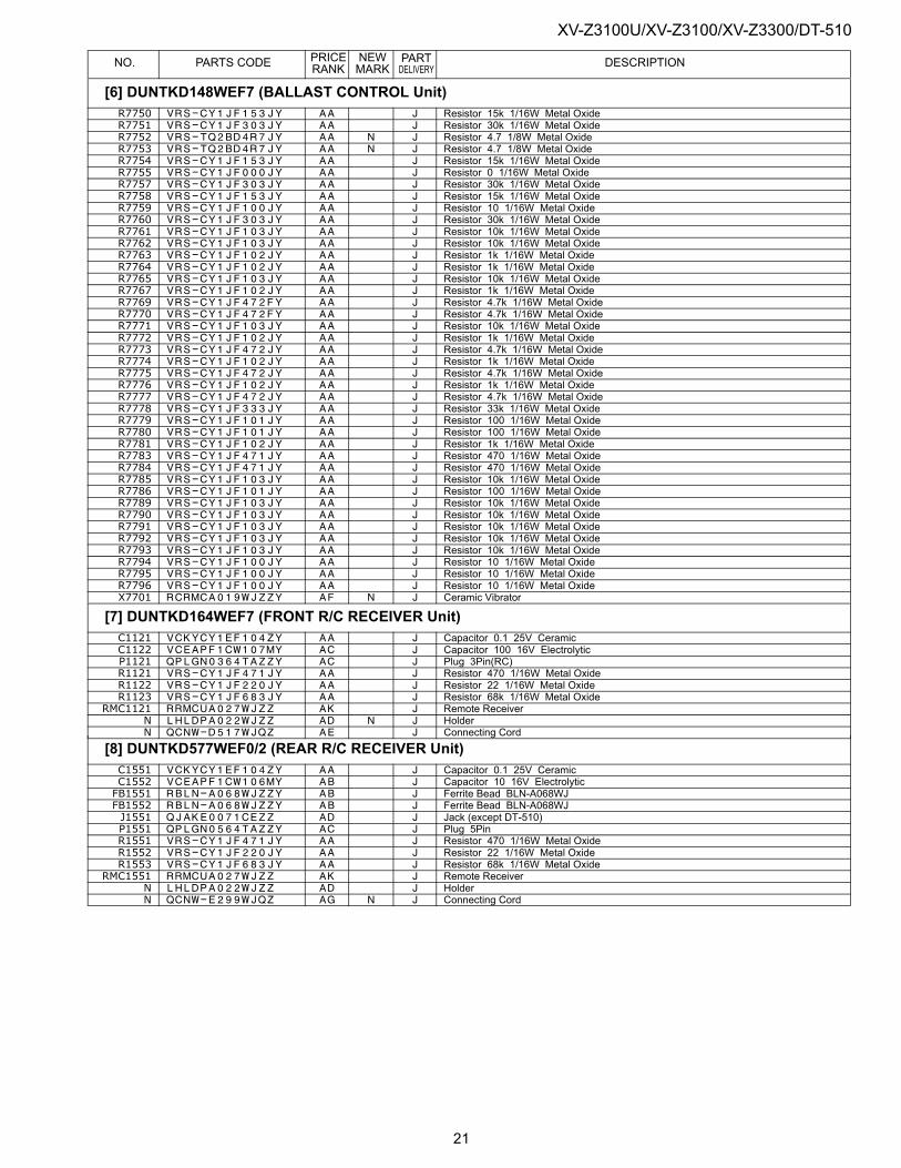
XV-Z3100U/XV-Z3100/XV-Z3300/DT-510PRICE NEW PART
NO. PARTS CODE RANK MARK DELIVERY DESCRIPTIONR7750 VRS-CY1JF153JY AA J Resistor 15k 1/16W Metal OxideR7751 VRS-CY1JF303JY AA J Resistor 30k 1/16W Metal OxideR7752 VRS-TQ2BD4R7JY AA N J Resistor 4.7 1/8W Metal OxideR7753 VRS-TQ2BD4R7JY AA N J Resistor 4.7 1/8W Metal OxideR7754 VRS-CY1JF153JY AA J Resistor 15k 1/16W Metal OxideR7755 VRS-CY1JF000JY AA J Resistor 0 1/16W Metal OxideR7757 VRS-CY1JF303JY AA J Resistor 30k 1/16W Metal OxideR7758 VRS-CY1JF153JY AA J Resistor 15k 1/16W Metal OxideR7759 VRS-CY1JF100JY AA J Resistor 10 1/16W Metal OxideR7760 VRS-CY1JF303JY AA J Resistor 30k 1/16W Metal OxideR7761 VRS-CY1JF103JY AA J Resistor 10k 1/16W Metal OxideR7762 VRS-CY1JF103JY AA J Resistor 10k 1/16W Metal OxideR7763 VRS-CY1JF102JY AA J Resistor 1k 1/16W Metal OxideR7764 VRS-CY1JF102JY AA J Resistor 1k 1/16W Metal OxideR7765 VRS-CY1JF103JY AA J Resistor 10k 1/16W Metal OxideR7767 VRS-CY1JF102JY AA J Resistor 1k 1/16W Metal OxideR7769 VRS-CY1JF472FY AA J Resistor 4.7k 1/16W Metal OxideR7770 VRS-CY1JF472FY AA J Resistor 4.7k 1/16W Metal OxideR7771 VRS-CY1JF103JY AA J Resistor 10k 1/16W Metal OxideR7772 VRS-CY1JF102JY AA J Resistor 1k 1/16W Metal OxideR7773 VRS-CY1JF472JY AA J Resistor 4.7k 1/16W Metal OxideR7774 VRS-CY1JF102JY AA J Resistor 1k 1/16W Metal OxideR7775 VRS-CY1JF472JY AA J Resistor 4.7k 1/16W Metal OxideR7776 VRS-CY1JF102JY AA J Resistor 1k 1/16W Metal OxideR7777 VRS-CY1JF472JY AA J Resistor 4.7k 1/16W Metal OxideR7778 VRS-CY1JF333JY AA J Resistor 33k 1/16W Metal OxideR7779 VRS-CY1JF101JY AA J Resistor 100 1/16W Metal OxideR7780 VRS-CY1JF101JY AA J Resistor 100 1/16W Metal OxideR7781 VRS-CY1JF102JY AA J Resistor 1k 1/16W Metal OxideR7783 VRS-CY1JF471JY AA J Resistor 470 1/16W Metal OxideR7784 VRS-CY1JF471JY AA J Resistor 470 1/16W Metal OxideR7785 VRS-CY1JF103JY AA J Resistor 10k 1/16W Metal OxideR7786 VRS-CY1JF101JY AA J Resistor 100 1/16W Metal OxideR7789 VRS-CY1JF103JY AA J Resistor 10k 1/16W Metal OxideR7790 VRS-CY1JF103JY AA J Resistor 10k 1/16W Metal OxideR7791 VRS-CY1JF103JY AA J Resistor 10k 1/16W Metal OxideR7792 VRS-CY1JF103JY AA J Resistor 10k 1/16W Metal OxideR7793 VRS-CY1JF103JY AA J Resistor 10k 1/16W Metal OxideR7794 VRS-CY1JF100JY AA J Resistor 10 1/16W Metal OxideR7795 VRS-CY1JF100JY AA J Resistor 10 1/16W Metal OxideR7796 VRS-CY1JF100JY AA J Resistor 10 1/16W Metal OxideX7701 RCRMCA019WJZZY AF N J Ceramic Vibrator
[7] DUNTKD164WEF7 (FRONT R/C RECEIVER Unit)C1121 VCKYCY1EF104ZY AA J Capacitor 0.1 25V CeramicC1122 VCEAPF1CW107MY AC J Capacitor 100 16V ElectrolyticP1121 QPLGN0364TAZZY AC J Plug 3Pin(RC)R1121 VRS-CY1JF471JY AA J Resistor 470 1/16W Metal OxideR1122 VRS-CY1JF220JY AA J Resistor 22 1/16W Metal OxideR1123 VRS-CY1JF683JY AA J Resistor 68k 1/16W Metal Oxide
RMC1121 RRMCUA027WJZZ AK J Remote ReceiverN LHLDPA022WJZZ AD N J HolderN QCNW-D517WJQZ AE J Connecting Cord
[8] DUNTKD577WEF0/2 (REAR R/C RECEIVER Unit)C1551 VCKYCY1EF104ZY AA J Capacitor 0.1 25V CeramicC1552 VCEAPF1CW106MY AB J Capacitor 10 16V ElectrolyticFB1551 RBLN-A068WJZZY AB J Ferrite Bead BLN-A068WJFB1552 RBLN-A068WJZZY AB J Ferrite Bead BLN-A068WJJ1551 QJAKE0071CEZZ AD J Jack (except DT-510)P1551 QPLGN0564TAZZY AC J Plug 5PinR1551 VRS-CY1JF471JY AA J Resistor 470 1/16W Metal OxideR1552 VRS-CY1JF220JY AA J Resistor 22 1/16W Metal OxideR1553 VRS-CY1JF683JY AA J Resistor 68k 1/16W Metal Oxide
RMC1551 RRMCUA027WJZZ AK J Remote ReceiverN LHLDPA022WJZZ AD J HolderN QCNW-E299WJQZ AG N J Connecting Cord
[6] DUNTKD148WEF7 (BALLAST CONTROL Unit)
21
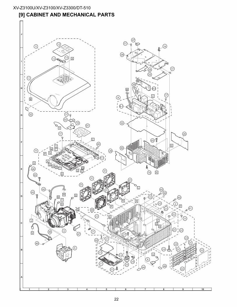
XV-Z3100U/XV-Z3100/XV-Z3300/DT-510
[9] CABINET AND MECHANICAL PARTS
2-2-1
43
50
2
41
2-4
2-1-4
2-1-2
92-6
43
2-1-1 2-5
2-2
49
2-3
2-7
2-2-2
44
5
17
10
31
31
21
20
31
2142
4
43
36
40
43
46
8-1
2630
33
15
23
17
17
1714
29
25
43
24
8-2
47
35
43
17
45
11-1
11
51
11
1-1
1-3
1-2 1-4
8
52
47
2-12
2-11
2-10
2-1-3
2-1
2-2-3
2-8
2-9
2-2-4
2-9-2
2-9-1
2-8-1
2-8-2
53
22
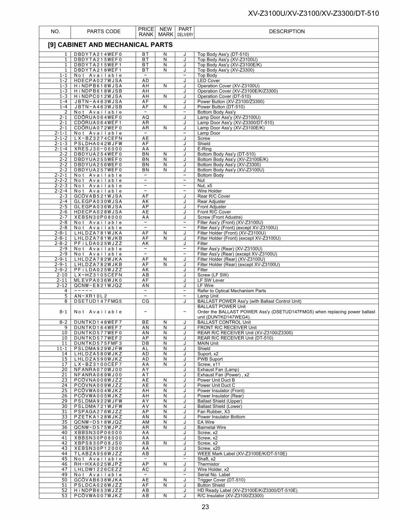
XV-Z3100U/XV-Z3100/XV-Z3300/DT-510
NO. PARTS CODE PRICE RANK
NEW MARK
PART DELIVERY DESCRIPTION
[9] CABINET AND MECHANICAL PARTS1 DBDYTA214WEF0 BT N J Top Body Ass'y (DT-510)1 DBDYTA215WEF0 BT N J Top Body Ass'y (XV-Z3100U)1 DBDYTA215WEF1 BT N J Top Body Ass'y (XV-Z3100E/K)1 DBDYTA218WEF1 BT N J Top Body Ass'y (XV-Z3300)
1-1 Not Available - - Top Body1-2 HDECPA027WJSA AD J LED Cover1-3 HiNDPB618WJSA AH N J Operation Cover (XV-Z3100U)1-3 HiNDPB618WJSB AH J Operation Cover (XV-Z3100E/K/Z3300)1-3 HiNDPC012WJSA AH N J Operation Cover (DT-510)1-4 JBTN-A463WJSA AF J Power Button (XV-Z3100/Z3300)1-4 JBTN-A463WJSB AF N J Power Button (DT-510)2 Not Available - - Bottom Body Ass'y
2-1 CDORUA064WEF0 AQ J Lamp Door Ass'y (XV-Z3100U)2-1 CDORUA064WEF1 AR J Lamp Door Ass'y (XV-Z3300/DT-510)2-1 CDORUA072WEF0 AR N J Lamp Door Ass'y (XV-Z3100E/K)
2-1-1 Not Available - - Lamp Door2-1-2 LX-BZ3274CEFN AE J Screw2-1-3 PSLDHA042WJFW AF J Shield2-1-4 XRESJ30-06000 AA J E-Ring2-2 DBDYUA254WEF0 BN N J Bottom Body Ass'y (DT-510)2-2 DBDYUA255WEF0 BN N J Bottom Body Ass'y (XV-Z3100E/K)2-2 DBDYUA256WEF0 BN N J Bottom Body Ass'y (XV-Z3300)2-2 DBDYUA257WEF0 BN N J Bottom Body Ass'y (XV-Z3100U)
2-2-1 Not Available - - Bottom Body2-2-2 Not Available - - Nut2-2-3 Not Available - - Nut, x52-2-4 Not Available - - Wire Holder2-3 GCOVAB521WJSA AF J Rear R/C Cover2-4 GLEGPA030WJSA AK J Rear Adjuster2-5 GLEGPA036WJSA AP J Front Adjuster2-6 HDECPA028WJSA AE J Front R/C Cover2-7 XEBSN30P08000 AA J Screw (Front Adustre)2-8 Not Available - - Filter Ass'y (Front) (XV-Z3100U)2-8 Not Available - - Filter Ass'y (Front) (except XV-Z3100U)
2-8-1 LHLDZA781WJKA AF N J Filter Holder (Front) (XV-Z3100U)2-8-1 LHLDZA781WJKB AF N J Filter Holder (Front) (except XV-Z3100U)2-8-2 PFiLDA025WJZZ AK J Filter2-9 Not Available - - Filter Ass'y (Rear) (XV-Z3100U)2-9 Not Available - - Filter Ass'y (Rear) (except XV-Z3100U)
2-9-1 LHLDZA782WJKA AF N J Filter Holder (Rear) (XV-Z3100U)2-9-1 LHLDZA782WJKB AF N J Filter Holder (Rear) (except XV-Z3100U)2-9-2 PFiLDA025WJZZ AK J Filter2-10 LX-HZ3105CEFN AB J Screw (LF SW)2-11 MLEVPA036WJK0 AF J LF SW Lever2-12 QCNW-E821WJQZ AN J LF Wire4 ----- - - Refer to Optical Mechanism Parts5 AN-XR10L2 - - Lamp Unit8 DSETUD147FMG5 CG J BALLAST POWER Ass'y (with Ballast Control Unit)
8-1 Not Available - -BALLAST POWER Unit Order the BALLAST POWER Ass'y (DSETUD147FMG5) when replacing power ballastunit (DUNTKD147WEG4).
8-2 DUNTKD148WEF7 BE N J BALLAST CONTROL Unit9 DUNTKD164WEF7 AN N J FRONT R/C RECEIVER Unit10 DUNTKD577WEF0 AN N J REAR R/C RECEIVER Unit (XV-Z3100/Z3300)10 DUNTKD577WEF2 AP N J REAR R/C RECEIVER Unit (DT-510)11 DUNTKD575FMF3 DB N J MAIN Unit
11-1 PSLDMA929WJFW AL N J Shield14 LHLDZA580WJKZ AD N J Suport, x215 LHLDZA590WJKZ AD N J PWB Suport17 LX-BZ3100CEF7 AA N J Screw, x1120 NFANRA070WJ00 AY J Exhaust Fan (Lamp)21 NFANRA069WJ00 AT J Exhaust Fan (Power) , x223 PCOVNA008WJZZ AE N J Power Unit Duct B24 PCOVNA009WJZZ AE N J Power Unit Duct C25 PCOVWA004WJKZ AH N J Power Insulator (Front)26 PCOVWA005WJKZ AH N J Power Insulator (Rear)29 PSLDMA922WJFW AY N J Ballast Shield (Upper)30 PSLDMA721WJFW AV N J Ballast Shield (Lower)31 PSPAGA276WJZZ AP N J Fan Rubber, X333 PZETKA128WJKZ AN N J Power Insulator Bottom35 QCNW-D518WJQZ AM N J EA Wire36 QCNW-D575WJPZ AR N J Baimetal Wire40 XBBSN30P06000 AA J Screw, x241 XBBSN30P08000 AA J Screw, x242 XBPS830P08JS0 AB N J Screw, x243 XEBSN30P12000 AA J Screw, x2044 TLABZA956WJZZ AB J WEEE Mark Label (XV-Z3100E/K/DT-510E)45 Not Available - - Shaft, x246 RH-HXA025WJPZ AP N J Thermistor47 LHLDW1226CEZZ AC J Wire Holder, x249 Not Available - - Serial No. Label50 GCOVAB638WJKA AE N J Trigger Cover (DT-510)51 PSLDCA026WJZZ AF N J Button Shield52 HiNDPB653WJZZ AB J HD Ready Label (XV-Z3100E/K/Z3300/DT-510E)53 PCOVWA007WJKZ AB N J R/C Insulator (XV-Z3100/Z3300)
23
XV-Z3100U/XV-Z3100/XV-Z3300/DT-510PRICE NEW PART
NO. PARTS CODE RANK MARK DELIVERY DESCRIPTION53 PCOVWA008WJKZ AB N J R/C Insulator (DT-510)
[9] CABINET AND MECHANICAL PARTS
24
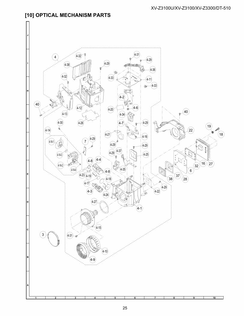
XV-Z3100U/XV-Z3100/XV-Z3300/DT-510
[10] OPTICAL MECHANISM PARTS
4-313
4-10
4-9
4-15
4-27
4-1
4-224-29
3837
28
632
16 27
18
1922
40
4-14-1
4-14-3
4-14-24-14-4
4-14
4-23
4-3
4-4
4-24
4-19
4-8
4-184-17
4-297
4-29
4-35
4-29
4-21
4-11
4-374-25
4-34
4-29
4-29
4-16
4-7
4-6
4-2
4-20
4-33
4-114-33
4-36
4-29
4-31
4-12
4-13
4-38
4-32
40
4-32
4-26
4
4-29
4-30
4-8
25
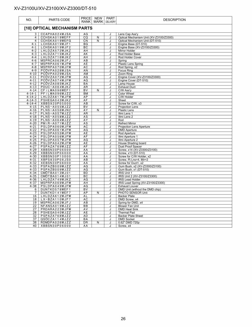
XV-Z3100U/XV-Z3100/XV-Z3300/DT-510
NO. PARTS CODE PRICE RANK
NEW MARK
PART DELIVERY DESCRIPTION
[10] OPTICAL MECHANISM PARTS3 CCAPHA024WJSA AG J Lens Cap Ass'y4 CCHSKA019WEFF CQ N J Optical Mechanism Unit (XV-Z3100/Z3300)4 CCHSKA019WEFG CN N J Optical Mechanism Unit (DT-510)
4-1 LCHSKA019WJF1 BG J Engine Base (DT-510)4-1 LCHSKA019WJF2 BC J Engine Base (XV-Z3100/Z3300)4-2 LHLDZA572WJKZ AH J Mirror Holder4-3 LHLDZA715WJKZ AK J Rod Holder Base4-4 LHLDZA716WJKZ AH J Rod Holder Cover4-6 MSPRCA062WJFJ AB J Spring4-7 MSPRPA061WJFW AE J Plastic Lens Spring4-8 MSPRPA070WJFW AC J Rod Spring, x24-9 PCOVPA028WJSA AN J Focus Ring4-10 PCOVPA029WJSA AM J Zoom Ring4-11 PCOVZA072WJFW AG J Engine Cover (XV-Z3100/Z3300)4-11 PCOVZA074WJFW AG J Engine Cover (DT-510)4-12 PCOVZA085WJKZ BA J Lamp House4-13 PDUC-A064WJKZ AR J Exhaust Duct4-14 CFiLWA096WEF1 BV N J C/W Ass'y
4-14-1 PFiLWA096WJZZ BM J Color Wheel4-14-2 LHLDZA817WJFW AP J C/W Holder4-14-3 PSHEGA043WJKZ AF J Sheet4-14-4 XBBS920P05000 AB J Screw for C/W, x34-15 PLNS-A055WJZZ BV J Projection Lens4-16 PLNS-A056WJN2 AY N J Plastic Lens4-17 PLNS-A057WJZZ AR J Illmi Lens 14-18 PLNS-A058WJZZ AS J Illmi Lens 24-19 PLNS-A064WJZZ AY J Rod4-20 PMiR-A071WJZZ AS J Refrect Mirror4-21 PSLDPA060WJFW AC J Projection Lens Aperture4-22 PSLDPA061WJFW AG J DMD Aperture4-23 PSLDPA055WJFW AE J Rod Aperture4-24 PSLDPA056WJFW AF J Illmi Aperture 14-25 PSLDPA057WJFW AG J Illmi Aperture 24-26 PSLDPA042WJFW AE J House Shading board4-27 PSPAZA769WJZZ AF J Dust Proof Spacer4-29 XBBSN30P06000 AA J Screw, x14 (XV-Z3300/Z3100)4-29 XBBSN30P06000 AA J Screw, x13 (DT-510)4-30 XBBSN30P10000 AA J Screw for C/W Holder, x24-31 XBPS830P08JS0 AB J Screw, Pj Lns=4, Mir=24-32 XEBSN30P08000 AA J Screw for Duct1, x24-33 PSPAZB009WJZZ AG J Gum Bush, x2 (XV-Z3300/Z3100)4-33 PSPAZB009WJZZ AG J Gum Bush, x1 (DT-510)4-34 CMOTBA013WJ01 BD J IRIS Unit 14-35 CMOTBA014WJ01 BC J IRIS Unit 2 (XV-Z3100/Z3300)4-36 LHLDZA749WJKZ AG J IRIS Lead Holder4-37 MSPRPA069WJFW AH J IRIS Lead Spring (XV-Z3100/Z3300)4-38 PSLDPA049WJFW AG J Exhaust Louver6 DUNTKD578WEF1 BV J DMD Unit (without the DMD chip)7 DUNTKD141WEF7 AP N J PHOTO SENSOR Unit16 LHLDZA612WJFW AL J Backer Plate18 LX-BZA110WJF7 AC J DMD Screw, x419 MSPRCA062WJFJ AB J Spring for DMD, x422 NFANSA019WJZZ BB J Blower Fan Unit27 PRDARA223WJFW AV J DMD Heat Sink28 PSHEGA040WJZZ AE J Thermal Pad32 PSPAZA768WJZZ AD J Backer Plate Sheet37 QSOCZA114WJZZ BA J DMD Socket38 RDMDPA026WJZZ DR N J 0.62" DMD 720p40 XBBSN30P06000 AA J Screw, x4
26
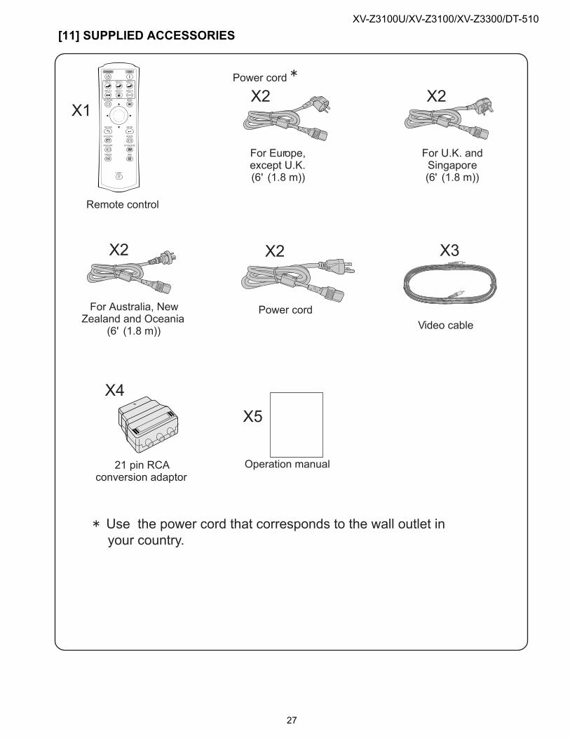
XV-Z3100U/XV-Z3100/XV-Z3300/DT-510
[11] SUPPLIED ACCESSORIES
X6 X7
X1
X4
X3
X5
X2
X2
X2
X2
X8
27
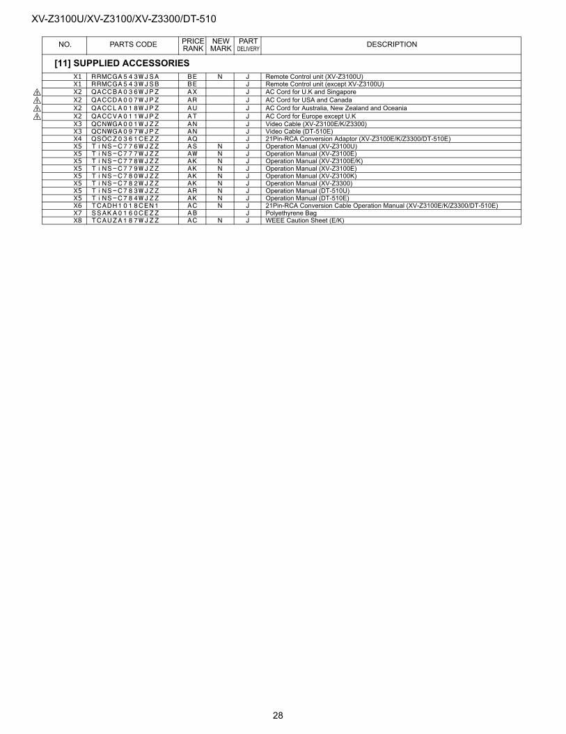
XV-Z3100U/XV-Z3100/XV-Z3300/DT-510
NO. PARTS CODE PRICE RANK
NEW MARK
PART DELIVERY DESCRIPTION
[11] SUPPLIED ACCESSORIESX1 RRMCGA543WJSA BE N J Remote Control unit (XV-Z3100U)X1 RRMCGA543WJSB BE J Remote Control unit (except XV-Z3100U)
! X2 QACCBA036WJPZ AX J AC Cord for U.K and Singapore! X2 QACCDA007WJPZ AR J AC Cord for USA and Canada! X2 QACCLA018WJPZ AU J AC Cord for Australia, New Zealand and Oceania! X2 QACCVA011WJPZ AT J AC Cord for Europe except U.K
X3 QCNWGA001WJZZ AN J Video Cable (XV-Z3100E/K/Z3300)X3 QCNWGA097WJPZ AN J Video Cable (DT-510E)X4 QSOCZ0361CEZZ AQ J 21Pin-RCA Conversion Adaptor (XV-Z3100E/K/Z3300/DT-510E)X5 TiNS-C776WJZZ AS N J Operation Manual (XV-Z3100U)X5 TiNS-C777WJZZ AW N J Operation Manual (XV-Z3100E)X5 TiNS-C778WJZZ AK N J Operation Manual (XV-Z3100E/K)X5 TiNS-C779WJZZ AK N J Operation Manual (XV-Z3100E)X5 TiNS-C780WJZZ AK N J Operation Manual (XV-Z3100K)X5 TiNS-C782WJZZ AK N J Operation Manual (XV-Z3300)X5 TiNS-C783WJZZ AR N J Operation Manual (DT-510U)X5 TiNS-C784WJZZ AK N J Operation Manual (DT-510E)X6 TCADH1018CEN1 AC N J 21Pin-RCA Conversion Cable Operation Manual (XV-Z3100E/K/Z3300/DT-510E)X7 SSAKA0160CEZZ AB J Polyethyrene BagX8 TCAUZA187WJZZ AC N J WEEE Caution Sheet (E/K)
28
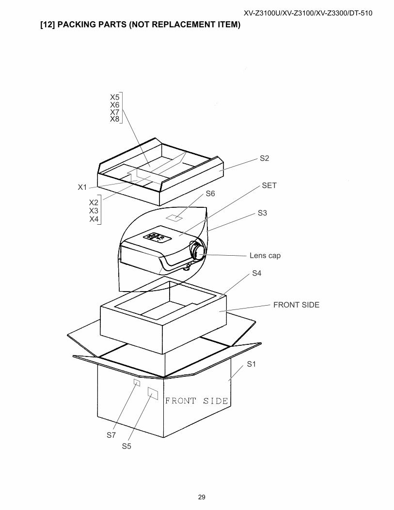
XV-Z3100U/XV-Z3100/XV-Z3300/DT-510
[12] PACKING PARTS (NOT REPLACEMENT ITEM)
S2
S3
S4
S1
S5
S6
S7
29
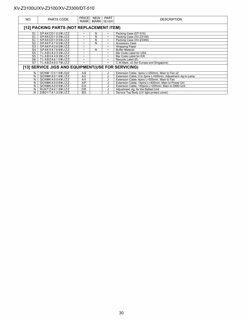
XV-Z3100U/XV-Z3100/XV-Z3300/DT-510
NO. PARTS CODE PRICE RANK
NEW MARK
PART DELIVERY DESCRIPTION
[12] PACKING PARTS (NOT REPLACEMENT ITEM)S1 SPAKCD102WJZZ - N - Packing Case (DT-510)S1 SPAKCD103WJZZ - N - Packing Case (XV-Z3100)S1 SPAKCD105WJZZ - N - Packing Case (XV-Z3300)S2 SPAKFA792WJZZ - N - Accessory CaseS3 SPAKPA360WJZZ - - Wrapping PaperS4 SPAKXA768WJZZ - N - Buffer MaterialS5 TLABVA333WJZZ - - Bar Code Label for USAS5 TLABVA493WJZZ - - Bar Code Label for E/KS6 TLABZA610WJZZ - - Recycle Label (E)S7 TLABZA957WJZZ - - C.W.Mark, x2 (for Europe and Singapore)
[13] SERVICE JIGS AND EQUIPMENT(USE FOR SERVICING)N QCNW-C516WJQZ AG J Extension Cable, 3pins L=200mm, Main to Fan x2N QCNWKA016WJZZ AU J Extension Cable, 3 to 2pins L=600mm, Adjustment Jig to LampN QCNWKA006WJZZ AX J Extension Cable, 4pins L=500mm, Main to FanN QCNWKA008WJZZ AP J Extension Cable, 14pins L=400mm, Main to Power UniN QCNWKA009WJZZ DA J Extension Cable, 140pins L=200mm, Main to DMD UnitN RUNTZA018WJZZ DR J Adjustment Jig, for the Ballast UnitN DBDYTA132WJZZ BS J Service Top Body (UV light protect cover)
30

XV-Z3100U/XV-Z3100/XV-Z3300/DT-510
XV-Z3100U/XV-Z3100/XV-Z3300/DT-510
Dec. 2006 Printed in Japan
TQ2088-S YK. DS
COPYRIGHT © 2005 BY SHARP CORPORATION
ALL RIGHTS RESERVED.
No Part of this publication may be reproduced,stored in a retrieval system, or transmitted inany from or by any means, electronic, mechanical,photocopying , recording, or otherwise, withoutprior written permission of the publisher.
2006
SHARP CORPORATIONAV Systems GroupCS Promotion CenterYaita,Tochigi 329-2193, Japan