Service Manual Nissan Cedric Model 31 Series
205
T h o f If t f L 1 SERVICE MANUAL NISSAN CEDRIC MODEL 31 SERIES NISSANI A NISSAN MOTOR CO LTD c OTEMACHI BLDG OT CHI CHIYODA KU TOKYO JAPAN CAlLES ADDRESS NISMO TOKTO PHONES 211 5211 9
-
Upload
khangminh22 -
Category
Documents
-
view
0 -
download
0
Transcript of Service Manual Nissan Cedric Model 31 Series

Th
of Ift
f
L
1 SERVICE MANUALNISSAN CEDRIC
MODEL 31 SERIES
NISSANI
A
NISSAN MOTOR CO LTD c
OTEMACHI BLDG OT CHI CHIYODA KU
TOKYO JAPAN
CAlLES ADDRESS NISMO TOKTO
PHONES 211 5211 9

oj
1
I
fk
i
r Ii
iJ
1 w
4J
1
l

J
V vJ
vJ
vvJJ
J
I
NISSAN CEDRIC Model 31
f

ill
1373 1420
15051070
I
J
r
f
11
790
o
4
i
2025
1100
2630
1170
4590L
G31SU
LIG31U
P
L
31
U
VPL
450
L
H31U
4490L
31
U
1100
elMENSIONSOF
NISSANCEDRIC

Il
INTRODUCTION
Th1S manual has been complied for pourpose of aSS1sting our d1stn
butors and dealers for e fective serV1ce and ma1nta1nance of the moael
31 Senes Each assembly of the major components 1S descnbed 1n
deta1l In add1tion comprehens1ve 1nstructlons are glven for complete
d1smantling assembling and 1nspectlon of these assemblies
It 1S emphas1sed that only genu1ne Spare Parts should be used as re
placements
l
f7
r
I

DIMENSIONS
Overall lengthOverall Wldth
Overall helght
GENERAL SPECIFICAliON
L G31S U
L G31 U
Delux
4590rnrn
1690rnm1505mm
Wheel base 2630rnmTread front I338rnmTread rear 1373mmRoad clearance 190mmRoom or Rear Body
lntenor length 1885mm
lnterlor wldth
lntenor helght
WEIGHT
Vehlcle welght
Seatlng capacltypersons
Max loadage
Gross vehlcle
welght
PERFORMANCE
maXlmum speed
Fuel consump
tlon
Grade ablhtysm 9
Mlmrnurn turmngradlus
Stoppmg dlstanceImtlal speed
50 krn h
l390mm
1180mm
L31 U
4490mf1
1690mmI505mm
2530mm
1338mm
1373mm
190mm
1785mm
1390mmIl 80mm
1210kg 1180kg1240kg
6 6
1540kg 1510kg1570kg
I40km h
88m h
ISkm hter
o 506
0 496S 6m
14 3mm
130km h
81m h
17km hter
o 420
5 4m
143m
WP L 3l U L H31 U
VP L 3l U
4690mm1690mm1520mm
1530mm
2530mm
1338mm
1373mm
190mm
200mm
2730mm 1945mm1750 990mm
3 persons 6 persons
500kg 400kg1390mm
I185mm
950mm
4650mm
I690mml1505mm
2690mm1338mm
1373mm
I90mm
1390mm
1180mm
1350kg 1260kg1315kg
8 3 I 6 6t r
500 400kg1790kg 1590kg
1980 2045kg
143m 143m

CONTENTS
ENGINE
GENERAL SPECIFICA TIONS
LUBRICA TION
SERVICE OPERATIONS WITH ENGINE
IN POSITIONROCKER MECHANISM
ADJUSTING THE IGNITION TIMING
2 FUEL SYSTEM
FUEL SYSTEM
CARBURETORFUEL PUMP
ADJUSTMENT AND INSPECTION OF
ENGINE kREMOVING R rf1 NG OF ENGINE
lr
ASSEMBLY t
3 COOLING SYSTEM i4 IGNITION SYSTEM
5 ELECTRICAL SYSTEM
6
GENERA TOR REGURA
T40R
BATTERY
CLUTCH
DESCRIPTION OF CLUTCH CONTROL
7 TRANSMISSION f
DISASSEMBLING THE CASE
ASSEMBLING THE TRANSMISSION
SELECTOR INER OPERA TING
LEVER CROSS SHAFT
8 PROPELLER SHAFT UNIVERSAL
JOINTS
h tLr Joi 1
llc
ir fo1if
Page1
N
f1
t l F
IifiI1937
t
40
t40
45
50
55
1I
1
61
62
69
4
l
731J74f 98
1105113 J
t
11
118
I2Ir1
1 29l

ENGINE
ENGINE
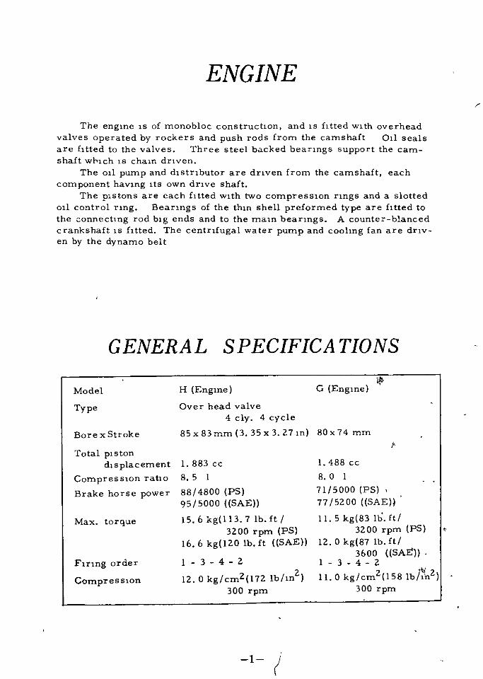
The engIne IS of monobloc construction and IS htted WIth overhead
valves operated by rockers and push rods from the camshaft 011 seals
are f1 tted to the valves Three steel backed beanngs support the cam
shaft wP1ch IS cham dnven
The 011 pump and d1stnbutor are dnven from the camshaft each
component haVing ItS own dnve shaft
The pIstons are each fItted wIth two compreSSIOn nngs and a slotted
011 control nng Beanngs of the thm shell preformed type are htted to
the onnectIng rod bIg ends and to the maInbeanngs A counter blancedcrankshaft IS fItted The centnfugal water pump and coohng fan are dnv
en by the dynamo belt
GENERAL SPECIFICA TIONS
Model
Type
Bore x Stroke
Total pistondIsplacement
CompreSSIon ratio
Brake horse power
Max torque
F1nng order
CompreSSIon
H Engme
Over head valve
4 c1y 4 cycle85x83mm 3 35x3 27m
1 883 cc
8 5 I
88 4800 PS
95 5000 SAE
15 6 kgl13 7 lb ft
3200 rpm PS
16 6 kgl20 lb ft SAE
1 3 4 2
12 0 kg cm2l72 Ib m2300 rpm
1G Engme
80x74 mm
f
I 488 cc
8 0 I
71 5000 PS
77 5200 SAEH
11 5 kg 83 Ib ftl3200 rpm PS
12 0 kg 87 Ib ft
3600 SAEI 3 4 2
2 1t1211 0 kg cm l581bln300 rpm
1

Engme RIgnt SIde
f
Engme Left SIde
2
Draining the OilThe 011 pan IS a metal pressIng WIth the draIn plugOn new and recondll1oned engmes the 011 must be draIned and refIlled
wIth new 011 after the first I 000 km and subsequently at Intervals of5 000 km
DraIn the 011 when the engine IS hot SInce warm 011 flows freely andtakes wIth It any sludge or sedIment WhICh may have accumulatted
Never use petrol or paraffm for flushIng purposes Such cleamng me
dIums are never completely dispersed from the engIne lubncatlOn systemand WIll remaIn to contamInate any fresh 011 ThIS may cause prematurebearIng faIlure
0 I Pressure
The normal operatmg 011 pressure IS I kg cm21 rpm 14 22lb m2550 rpm at IdlIng speed and 3 4 kg cm2 2000 rp d 56 81b m2 2000
rpm
Ref lingWhen refillIng the sump do not pour the 011 In too qUIckly as Itmay
overflow from the fIller onfIce and mIslead the operator as to the quanl1tyof lubncant In the engIne
Before testIng the level of the 011 ensure that the vehIcle IS as near
level as possIble Always WIpe the dlpsl1ck clean wIth a non ffuffy clothf
before takIng the readmg It should be remembered that l1me must be
allowed for new 011 to reach to sump before readmg the dlpsl1ck
Check for Low Oil Pressure
The 011 pressure gage IS Installed at the Instrument panel The Igm
tJon sWItch IS turned on and when the engIne started fInng and the 011 pres
sure Increase normally as before menl1oned
Should It keep normal pres sure dunng the engIne runnIng It IS
resultof the 011 pressure down too low or the shortage of 011 In the 011 pan
Check the level of 011 m the 011 pan by means of the level gage and top up
If necessary If the pressure IS stdl too low after refIllIng the 011 sWItch
3

off and ascertaIn that the straIner IS clean and not choked wIth sludgealso that no aIr leakage eXIsts at the straIner unIon on the suC110 side of
the pumpIn the case of 011 pump being defecl1ve remove the umt to recl1fy the
fault
If the engme beanngs are worn the 011 pressure WIll be reduced A
complete beanng overhaul and the fltl1ng of replacement parts IS the only
remedy necess1tal1ng the removal of the engIne from the chassIs
1jr
2r
4

LUBRICA TIONCirculation
Pressure lubncatlon lS used throughout the umt and lS provlded bygear pump nondralnlng
The 011 pump lS bolted under the crankcase and lS dnven from the
camshaft gear by a short vertical shaft 011 drawn lnto the pump throughthe stralner and lS dehvered through lnternal 011 ways
The flow then passes through dnlhngs ln the crankshaft The con
nechng rod lends are dnlled for Jet lubncatlon to the cyhnder walls
From the rear camshaft beanng the 011 passes upward through a dnlhngln the cyhnder block and the rear rocker shaft bracket to lubncate the
rockers and then dralns back lnto the 011 pan Vla the push rod aperatures011 from the center camshaft beanng enters a gallery on the left hand
side of the englne and lubncates the tappets through Indlvldual dnlhngsAs the camshaft rotates groove ln the front Journal reglster wlth a
small hole In the camshaft locating plate thus all oWing a small amount
of 011 to pass lnto the tlmlng case durlng each revolution of the camshaft
to provlde lubncation for the tlmlng chaln and gears
From the tlmlng case the 011 returnes Vla a draln hole back to the 011
pan
Flg
5
t
3r

r
1
11
en
Th
1u
h
flowo
ml
omhoO
l
pan
OUghh
01
pumPh
m
n
gallerybeanng
andoverhead
rockerarm
Flg2
011Lubncatlon
System

TJl
FIg 3 Component of 011 fIlter or
Removmg the By pass Frlter
A new fIlter element should be fItted every 15 000 km
The fIlter forms part of the maIn all gallery of the engme
To remove the fIlter It IS only necessary to unscrew the center bolt when
the bowl can be removed from the crankcase complete with the element
Take care not to lose the rubber seahng rIng Remove the element and
note the assembly of the componentsWash out the bowl wIth pettol so that It IS clean It is Important to
thoroughly dry the bowl to obViate any contammatIon of the lubrIcatmg 011
Replacing the FilterWIth the center bolt the washer and the sprIng together wIth the
collar in posItIon In the bowl Insert a new element Place the dIstance
pIece over the center bolt wIth the flanged end towards the element The
bowl of fIlter must now be fIlled wIth 011 Offer up the complete assemblyto the engIne and secure mto posItIon by means of the center DOft
Removmg the 01 Pan ffjft
The sump capaCIty IS 3 I htres DraIn the 011 and replace the draIn
plugRemove the set screw bolts whIch are Inserted from the underside of
the securIng flange and the lower bolts from the bottom edge of the bell
hOUSIng Lower the 011 pan from the engIne takIng care not to damage
the JOInt washers In the process
7

iii1 IJlI
Dlt
o
1
Flg 4
Removmg the Oil PumpRemove the 011 pan and
plck up stralner The
bolts secunng the 011 pumpbottom cover are long l
enough to secure the pump f
to the crankcase
Flg 4 lllustrates the pumpIn explosed form Unscrewthe bolts and remove the
pump wlth Its dnve shaftif
7 j
f
y
H
11
S F
1 tY f
l
t Itf
f
Fig 5
8
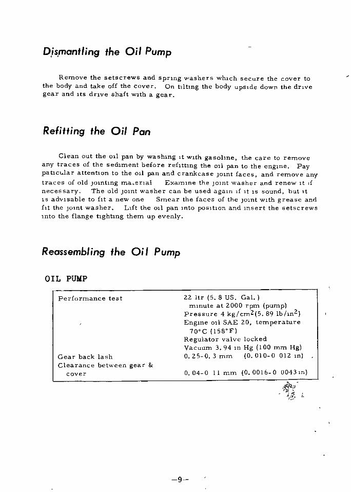
Dis mant ing the Oil Pump
Remove the setscrews and sprIng ashers whIch secure the cover to
the body and take off the cover On tIltmg the body upsIde down the dnve
gear and Its dnve shaft wIth a gear
Refitting the Oil Pan
Clean out the 011 pan by washIng ItwIth gasohne the care to remove
any traces of the sedIment before refIttIng the 011 pan to the engIne Paypatlcular attentIon to the 011 pan and crankcase JOInt faces and remove anytraces of old JOIntIng ma enal Exalnlne the JOInt washer and renew It If
necessary The old jOlnt washer can be used again 1f It IS sound but It
IS advIsable to fIt a new one Smear the faces of the JOInt WIth grease and
fIt the JOInt washer LIft the 011 pan Into pOSItIon and lnsert the setscrews
mto the flange tlghtmg them up evenly
Reassemblmg the Oil Pump
OIL PUMP
Performance test 22 ltr 5 8 US Gal
mmute at 2000 rpm pumppressure 4 kg cm2 5 891b m2Engme 011 SAE 20 temperature
700C 158 F
Regulator valve locked
Vacuum 3 94 m Hg 100 mm Hg0 25 0 3 mm 0 010 0 012 mGear back lash
Clearance between gearcover o 04 0 11 mm 0 0016 0 0043m
n
9

150Z8 3ZZ0
Regurator valve
OlI5I3Z 5800
15133 58000
Req valve spnng
1
r I
011 Pump 6 St ra I ner Assemb
Part No 150 I 0 32200
10

SERVICE OPERATIONS WITHENGINE IN POSITION
Removmg Startmg Nut and PulleyRemove the radIator Sl k th dac en e ynamo attachment bolts and re
move the fan belt
Bend back the tab on the startlng bolt lockIng washer Unscrew the
startlng nut by USIng heavy duty Shock type spannerA few sharp blows m an antl clockwlse directIOn WIll slacken the nutPull off the crankshaft pulley
Removing the Timing Cover
The tlmlng cover s secured
by set screw bolts each haVInga shakeproof washer
The spnng washers are Im
medIately below the bolt heads
Take out the set screw
bolts remove the cover and Its
JOInt washer Care should be
taken not to damage the washer
when breakmg the omt If
damage does occur ht a new
wahser cleamng of the faces
of the JOint surfaces beforehand
RemOVing the TIming Gear
FIg I
Heavy duty Shock type Spanner
j
The tlmlng chaIn IS endless and It IS necessary to remove both the
crankshaft and camshaft gears together Before dOIng thIS notIce the
tlmlng marks on both gears and theIr relal10nshlp to each other
Draw off both the gears a httle at a tIme fIrst removIng the crank
shaft gear retaInIng nut
As the gears are WIthdrawn care must be taken not to lose theiack
lng washers from behind the crankshaft gear Between the camshaft
gear teeth IS a rubber nng whIch acts as a tensloner and ensures SI
lent operation of the cham dnve ExamIne the felt washer and renew ItJ
If 011 has been los tby seepage
11

CHAIN MARK
F1g 2 Poslhon of rehthng gears with the cham
Refitting the Timing Gear
ReplaClng the components of the ttmmg gear 1S largely a reversal ofthe d1smanthng process but speClal attentton should be pa1d to the follow
mg pomtsTurn the eng1ne crankshaft unbl the keyway IS at T D C and the cam
shaft w1th 1tS keywayFit the crankshaft and camshaft gears mto thelr respechve shafts hnd
mg the key ways aga1nst each posltlOn of key as shown m F1g 2 Ensurethe timing marks are Oppos1te along 1n hne
Place the gears 1nto posihon ensunng that the keys are present in
keyways on the shafts Ensure agam that the tl1nmg marks on the gearsare Oppos1te to each other and in hne
The same number of shims taken from front of the crankshaft must be
replaced unles a new crank or camshaft has been htted Ip this case the
ahgnment of the gear faces and measunng the ahgnment with a feeler
gauge To adJust the ahgnment it Will be necessary to vary the numberof shims
12

ft
f i
1i 1
0
Fig 3
Valve Rocker Cover Removal
Remove the aIr cleaner Unscrew the cap nuts secunng the engIne
lIfhng brackets Remove the rocker cover and the cork JOInt washer
Removing the Rocker AssemblyDraIn the colhng system If antI freeze IS In use use a clean
contaIner for the flUid If It IS to be used again
It IS necessary to draIn the system and slacken the cylInder head
bolts because four of the rocker shaft hXlllg bolts also secure the
cyl111der head
If the cyllllder head bolts arenot slackened dlstonatIon may result
and allow water to hnd ItS way from the cooohng system lllto the cylIndders and pump
NotIce that under the nght hand rear rocker stud nut IS a speCiallocklllg plate Completely unscrew the rocker shaft blacket nuts and
remove the rocker assembly Complete wIth brackets and rockers
13

CYLINDER
Dlameter of cyld bore
Grade number dupenslons STD bore
Grade No I 2 3 4 5
Dlameter of 85 000 85 010 85 020 85 030 85 040
cyld bore 85 009 85 019 85 029 85 039 85 049mm 3 34645 3 34684 3 34724 3 34763 3 34802
m 3 34680 3 34720 3 34759 3 34799 3 34838
Cyhnder bore taper Less than 0 02 mm O 0008 m
Dlfference of each cyhnder bore Less than 0 02 mm O 0008 m
OveI Slze plston avallable 0 25 o 50 o 7J I 00 mm
0 010 0 020 0 030 0 040 m
Cyhnder head surface warpagehmlt 0 Imm 0 004 m
PISTONMatenal LO EX Alun l1num AlloyDlameter of plston Skl rt Measured at nght angles to the plston
pIn
Standard Slze
Grade No I 2 3 4 5
Dlameter of 84 975 84 985 81 995 85 005 85 015
pl ston 3 34547 3 34585 3 34625 3 34665 3 34704
mm 84 966 84 976 84 986 84 996 85 006
m 3 34511 3 3455 3 34590 3 34629 3 34669
Ove Slze avaIlable 0 010 0 020 0 030 0 040 0 050
o 25 0 50 0 75 I 00 I 25
o 060 m
I 50 mm
Clearance cyld wall and
o 025 0 043 mm 0 001 0 0017 mtplstonCheckmg by feeler gauge 1 2 kg wlth 0 04 mm feeler gauge
2 2 4 4 lb wlth 0 0015 m feeler
gaugeAllowable dIfference of gros s
welght wIth connectlng rod Wlthm 5 grDIameter of plston pm hole 21 987 22 000 mm 0 8656 0 8661 m
Plston pm hole off set I 05 0 95 mm 0 0414 0 0374 m
Width of nng grooves
Compresslon 2 030 2 055 mm 0 0800 0 0809 m
011 control 4 015 4 040 mm 0 1580 0 1591 m
14

13216S8000
1325232200
Valverocker132sa
322OORHl
Rockershaftass
132S932
lHf
fiI
IM70
13212322OO
K
111
I
Cn
1325558000
j
ED
o
1320908000
ChaIn
1320704100
JI
1
tenslonerassy
1l438
r13070
3220013203
321oo
13078
32200
lIEGasket
OCkwaSher
1307932200
earnshaft
cha
1302832200
13202
32203
1320132203
13032
30000
Csmshaftgear
l
1302432200
Lock8sh
N
1303008000li
@
ocatlngplate
1301032200
9
t5114
J308208000
1
11418
CamshaftValve6
RockerParts
CDBalt@Lockwasher
IDPlanewasher
CD1808208000
@
9
16316
@1303008000
I en 1
Valverocker
adjustscrew
1328758000
Pushrod
1323832200
1300232200 Set
1504t32200

VALVE
Matenal
Inlet
Exhaust
Valve timlng
Inlet opensInlet closes
Exhaust opensExhaust closes
Valve clearance Inlet
Exhaust
Dowel angleHead dlameter
Inlet valve
Exhaust valve
Valve seat angle lnlet
exhaust
Valve face angle mlet
exhaust
Valve length overall
Lift
Chrome steel
Umlloy 2 I12
14
50
52
12
B T D CA B D C
B B D CA T D C
o 43 mm
0 525 mm
50 54
0 017 m Hot0 0207 m Cold
40mm
32 mm
1 57 m
1 26 m
45
44 30
109 mm
8 5 mm
4 30 m
0 335 m
D srIJontlmg the AssemblyTo dismantle the rocker shaft assembly flrst remove the grub screw
and locking plate from the rear rocker bracket
Remove the pht pms flat washers and spnng washers from each end
of the shaft Shde the rockers brackets and spnngs from the shaft
Unscrew the plug from the end of the shaft and clean out the 011 way
The two end rockers may be dIsmantled wlthout the whole rocker assem
bly bmg drawn out Thls may be achlved by turnmg the engme by hand
until No 1 push rod reaches ltS lowest pOSltionUnlock the tappet adJustlng screw and screw lt back as far as lt wlll go
Wlthdraw the spht pm flat and spnng washers and shde the rocker off
the shaft
Sometimes the valve spnng Wlll have to be shghtly compressed by lever
Ing a screwdnver under No 2 rocker thus allowlng the end rocker to shde
off the shaft easlly Repeat the procedure for No 8 rocker
16

Reassembling the Rocker
On reassembly hghten the pedestal bracket secunng nuts a httle ata time worklng dlagonally from nut to nut left nut of No 1 pedestalbracket nght nut of No 2 left of No 3 and so on returmng from theleft nut of No 4 bracket and repeatmg the process until they are alltight If the rocker assembly has been completely stnpped down andrebushed the 011 holes wlll have to be rednlled and the bushes reameddown to Slze before assembly on the shaft
The rockers and spnng must be replaced In thelr onglnal posItionon the ends of the shaft Remember to replace the rocker shaft Iocatmg screw and lock plate
Replace the spnng and flat washers wlth the spht pinS On the endsof the shaft Replace the rocker COver and gasket The vent plpeshould be at the front of the engme Secure the cover by means of thetwo cap nuts ensunng that the rubber bushed and englne hftmg platesare In posItion If the rocker cover gasket or the rubber bushes are
found to be faulty they must be renewed otherwlse ad leaks Will re
sult
Push Rod RemovalIf the valve rocker assembly has already been removed all that re
malns IS for the push rods to be hfted out They may on the other handbe taken out wlthout detachlng the rocker assembly
Remove the alr cleaner and rocker cover
Slacken all the tappet adJusting sc rews to their full extent then uSlnga screwdnver wlth the rocker shaft as a fulcrum depress the valve
spnng shde the rocker slde ways and hft out the push rod
All but the end push rods can be wlthdrawn m th S way These w llhave to be wlthdrawn after the removal of the two end rockers from the
shaft When replacmg push rods ensure that the ball ends reglster In
the tappet cups From here onwards reassembly IS a stralghtforwardreversal of the dlsmanthng process
Adjustmg Valve Rocker ClearancesRemove the alr cleaner and rocker cover
There should be a clearance of 0 43 mm 0 017 m between the faceof the rocker and the base of the valve stem Whllst checklng the clearances It IS Important to malntaln pressure wlth a screwdnver on the tappet adJustlng screw to dlsperse the hIm of 011 from the push rod cupFallure to follow thls procedure wlll result In a wrong readlng being taken
w
17

Turn the engme over by hand Startmg handle until the push rod stopsfalhng the valve is fully closed
To adjust Fig 4 insert a screwdnver in the adjusting screw slotand slaken the lock nut Then msert 0 017 m feeler gauge between the
face of the rocker and the valve stem Raise or lower the adjustingscrew untll the correct clearance is obtained
Tighten the lock nut and recheck the clearance
c
fl
r iL
Fig 4 Adjusting the rocker clearance
It is important to note that while the clearance is being set the tappetof the valve bemg adjusted must be on the back of the cam OppOSite to itS
peak
18

ROCKER MECHANISM
TAPPETS
MaushroomTypeDIameter
Hole dIameter for tappet
Tappet length
12 673 12 684 mm O 4988 0 4993 lll
12 700 12 718 mm O 4990 0 5006 lll
57 mm 2 24 lll
ROCKER MECHANISM
Push rod
Overall lengthrun out at center of rod
DIameter
Rocker shaft lengthRocker shaft dIameter
Rocker arm hole dIameter
Arm shaft clearance
Arm lever raho
CYLINDER HEAD
196 6 197 4mm 7 74 7 77 m
Not to exceed 0 2 mm 0 008 lll
6 35 5 36 mm 0 2500 0 2504 lll
398 mm 15 67 lll
0 7865 0 7874 m
20 020 20 033mm 0 7882 0 7887 n
0020 0 054mm 00008 0 0021m
1 46 1
RemOVing the Cylinder Head
Dram the coolmg system by opemng the radIator and cylmder block
draIn tapsOne IS sItuated Inlet tube at the backsIde of the radIator and other at
the rear nght hand sIde of the engIne If anh freeze mIxture IS In use
It should be draIned Into a sUItable contaIner and retaIned for futur e use
DIsconnect the negahve cable from the battery by extrachng the ter
mInal screw and removIng the lug from the battery termInal post
Slacken both the retaInIng cl1ps on the hose connechng the radIator
to the thermostat hOUSIng and remove the hose
Extract the thermostat housmg secunng nuts and remove the housIng
and thermostat
19

Remove the alrcleaner carburetor rocker cover and the Inlet and
exhaust mamfolds
Detach the hlgh tensIOn cables and remove the sparklng plugs also
dlsconnect the vater temperature gauge connection from the thermostat
houslngTake off the rocker assembly not forgetting to slacken the external
cyhnder head bolts at the same time
Wlthdraw the push rods keep10g them In the order of removalThe cyhnder head can now be hfted off the cylmder block To facl
htate bread10g the cyh der head Jo1Ot tap each slde of the head wlth a
hammer uSlng a plece of wood 1Oterposed to take the blow Do not use
exceSSlve force When hft10g the head a dIrect pull should be glven so
that the head IS pulled evenly up the studs Remove the cyl10der head
gasket
Decarbonism9Remove the cyhnder head W th the valves stlll 10 posltIon remove
the carbon from the combustion chambers and the valve faces Leavlngthe valves In posltIon for th S operation ensures that damage cannot be
caused to the seats by the wue brush whlch should be used for the removal
of carbon
If the exhaust valve heads are coated Wlth a very hard deposlt th S maybe removed by uSlng a chlsel shaped plece of hardwood
Remove the valves and uSlng the Wlre brush clean out the carbon from
the 10 let and exhaust portsBlowout all traces of carbon dust wlth compressed aIr or type pump
and finally clean the ports wlth gasohne and dry them out The cabon
should now be removed from the plston crowns Rotate the eng10e until
the plStOn to be worked on lS at T D C Protect the other cyl10der bore
from the entry of carbon particles by pushing a non fluffy rag Into them
USlng a chlsel shaped plece of hardwood Carefully remove the car
bon from the plston crowns A r10g of carnon should be left round the
penpherY of each plston and the deposlt round the top of the cyhnder bore
should not be touched An IndlcatIon as to when decarbonl satIon IS requlred IS generally glven by an all round loss of power Cars used malnly on
short runs wlll requlre th S attention more often than those used for longruns
Removal and Replacement of a ValveWhllst the cyhnder head IS removed the valves can be taken out
To do th S compress the valve spnng wlth the speclal valve spnng compressor
4
t
20

RemovalRemove the two cap reta1nlng collets Release the valve spnng the
valve spnng cap valve 011 seals and 1tS reta1ner Wlthdraw the valve
from the gUldeKeep the valves 1n the1r relative pos1tions when removed from the
eng1ne to ensure replacement 1n the1r ong1nal valve gU1des
ReplacementNote that the d1ameter of the exhaust valve heads are smaller than the
Inlet valve To rplace the valves 1nsert each valve 1nto 1tS gU1de and
replace the spnng 011 seal and reta1ner F1t 011 seal chamfered slde down
wards The 011 seals are more easlly f1tted 1f they have been soaked 1n
eng1ne 011 for a short penod before use To replace the valve spnng com
press the valve spnngRefit the cap retainers and secure them by means of the valve cotters
Remove the Compressor
VALVE SPRINGS
Compressed length load
48 7 49 3 mm I 917 1 931 In
39 mm at 30 I 5 kg5354 In at 663 31b
4
Free lengthF1tted length load
30 4 mm at 61 kg3
I 198 m at 134 7 8 8 Ib6 6
Effective turns of Call
D1ameter of cOlI W1re
COlI 1ns1de dlameter
7
4 3 mm
25 2 mm
0 169 m
1 992 In
CYLINDER HEAD
Torque wrench sett1ng 6 2 6 9 kgm 45 50ft Ib
Cyllllder head nuts 4 15 4 84 kgm 30 35ft Ib
Connecting rod bolts 4 8 6 2 kgm 35 45ft Ib
Ma1n beanng cap 9 75 II 06 kgm 71 81ft Ib
21

rr11t
Fig I
Valve GrindingBefore replacement of the cyl1nder head the valves and theu seats
should be examIned for sIgns of pIttIng or burnt patches and cllstortlon
If these condltlOns are present the valve seats must be recut before
attemptlng to gnnd In the valves whilst dIstorted valve heads should be
trued or the valve renewed Only the minImum amount of metal should
be removed In the trueIng proces s
When grmdlng a valve onto ItS sealmg the valve face should be
smeared l1ghtly wIth grmdmg paste and then lapped n wIth a suctIon typegnndlng tool The valve must be ground to Its seat w th a semI rotarymotIon A l1ght cOlI spnng Interposed between the valve head and the
port w ll assIst considerably when l1ftlng the valve in order to rotate the
face to a different posItIon ThIS should be done frequently to spreadthe gnndlng compound evenly
It IS necessary to contInue the gnndlng process untIl an even mattedsurface IS produced on the seatlng and the valve face
On completIon the valve seats and ports should be throughly clean
ed w th gasol1ne soaked rag and dned and the subJected to a compressed au blast The valves should be washed In gasol1ne and all traces of
gnnd ng compound removed
VALVES
Valve head dlametel
Intake valve 40 mm I 57 m
Exhaust valve 32 mm I 26 m
Valve seat angle Inlet exhaust 45
Valve face angle mlet 8 exhaust 44 30
Valve length overall I 09 mm 4 30 m
LIft 8 5 mm 0 335 m
22

Reset the valve clearances and fInally check them when the engIne IS
not hot or cold The cylInder head bolts may pull down slIghtly more afterthe engIne has attaIned ItS normal workIng temperature In whIch case thevalve clearances WIll have to be checked agaIn and reset If necessary
RefIt the Inlet and exhaust manIfoldsFIt the carburetor and reconnect the control lInkage RefIt the IgnItion
advance Suction pIpe to the connection on the carburetter but do not at thISstage refIt the aIr cleaner or ItWIll have to be removed later to check thevalve clearances Replace the rocker cqver takIng care to fIt the corkgasket correctly
Place the thermostat and ItS housIng In pOSItion and secure With thethree nuts Reconnect the water temperature gauge Wlre and ftt the radIator hose to the thermostat hOUSIng Connect the cables to the batteryEnsure that the radIator and cylInder block draIn tapes are closed and re
fill the radIator
Clean and adJust the sparkIng plugs and refIt them clIppmg on the hIghtensIOn leads The fInng order of the engIne IS 1 3 4 2 Replace the clIpwhIch secures part of the electncal whlnng harness to the SIde of the head
The Ignition can now be SWItched on and the engIne started When thenormal operating tempreTature has been reached SWItch off and remove therocker cover so that the valve clearances may be recheked Replace therocker cover and ftt the aIr cleaner when the fInal check has been made
WhIlst the engIne IS runnIng check that the water hose connections andfuel lIne umons do not leak TIghten them If necessary
OVER SIZE VALVES STEM AVAILABLE
Intake Valve Stem dIameter GUIde hole dIa
Standard 13201 32200 7 985 7 970 mm 8 018 8 000 mm
0 3144 0 3138 In 0 3157 0 3150 In
Ovel SIze 13201 32201 8 185 9 170 mm 8 218 8 200 mm
0 2mm 0 008 In 0 3223 0 3217 In o 3235 0 3229 In
0 4mm 0 016 m 13202 322J2 8 385 8 370 mm 8 418 8 400 mm
0 3301 0 3295 In o 3314 0 3307 In
Exhaust Valve Stem dIameter GUide hole dIa
Standard 13202 32200 7 960 7 945 mm 8 018 8 000 mm
0 3134 0 3128 In 0 3157 0 3150 m
Over SIze 13202 32201 8 160 8 145 mm 8 218 8 200 mm
0 2mm 0 008 In 0 3213 0 3207 In 0 3235 0 3229 In
0 4mm 0 016 m 13202 32202 8 360 8 345 mm 8 418 8 400 mm
0 3291 0 3285 In 0 3314 0 3307 In
23
1

Refitting the Cylinder Head
Ensure that the cyl1nder healq and cyl1nder block JOInt faces are clean
The cyl1nder head gasket IS marked Top so that 1t w1l1 be placedhead In correctly Place the gasket 1nto posItion and 10wE r the cyl1nder
Into place F1t the seven cylmder head securing nuts fmger tightInsert the push rods replacmg them 1n the pOS1tions from wh1ch they
were taken
Screw bak all the tappet adJust1ng screws Replace the rocker
assembly and screw down the secunng nuts hnger tight Evenly hghtenthe cylmder head bolts a l1ttle at a time fmally pull1ng them down w1th a
torque wrench set to 45 50 lbs ft 6 2 6 9 kgm
Removmg and Replacing the TappetsRemove the cyl1nder head assembly and W1thdraw the push rod keep
mg them m then respective positions so that they w11l be replaced on the
same tappetsTake out the camshaft from eng1ne block then push out the tappet from
the top of the cyl1nder block w1th one of push rods also keepmg them m
same locahons
Assembly IS a reversal of above procedure It may be necessary to
1nsert the tappets from 1ns1de of cyl1nder block keep1ng ups1de down or laydo n
ua
I I
8 fllZMla
1 EngIne sl1ngbracket
2 011 hller cap3 Valve locker
cover
4 Washer Cover
Jomt5 Thermostat
6 Cyl1nder head
7 Cylmder head
gasket
Cyl1nder Head
24

4I
ififjJ
i irri
t
N
r r
K2
1
Flg 2
P ston and Connecting Rod Removal
Draln the collIng water from the englne and radlator Draln and r
move the 011 pan from the engIne then disconnect and remove the 0 1
stramer Take out the pal nuts and cap nuts from the blg ends and wlth
draw the caps When used parts are replaced after dlsmantlIng It IS
essentlal they are htted Into thelr onglnal posltlonsTo ensure correct rehttlng mark the caps and connecting rods on the
sldes to Identlfy then togetherThe pIston and connecting rods must be withdrawn upwards through
the cy ltnder bores
Release the connectmg rod from the crankshaft SIde and slowly pushthe piston and rod upwards through the cylInder bore wIth the wooden
bar
Note It may be necessary to rmove the nng of carbon or IIp from
the top of the cylInder bore with a hand scraper to avold nsk of piston
nng breakage
4 25

Remove the assembly from the top of the cylmder block
Check the crankpms for ovahty wIth a pan of mIcro meter cahpersand examIne the beanng surface for sconng eIther defect WIll necessI
tate the removal of the crankshaft for regrmdmg
CONNECTING ROD
Matenal
Length center to center
BIg end beanngMatenal
WIdth
ThIckness
DIameter of bIg end housmg
BIg end wIdth
End play
Steel forgmg144 mm 5 67 m
Thmwall
24mm
1 5 mm
steel backed white metal
0 945 m
0 059 m
2 1653 m
11024m
0008 0012m
55 000 mm
28mm
o 2 0 3 mm
Clearance crank pIn and
beanng 0 02 0 03 mm 0 001 m
PIston pm bushmg reamed
m posItion 22 mm 0 8661 m
CRANKSHAFT
Matenal
DIameter of Journals
DIameter of crank pm
End plyMaIn eanng clearance
DeflectIOn RUN OUT at
intermedIate Journal
Steel forgmg59 94 59 95 mm
51 96 51 97 mm
o 05 0 15 mm
o 03 0 07 mm
2 3598 2 3602 m
2 0457 2 046 m
0 002 0 006 m
0 001 0 0027 m
MAIN BEARINGS
o 03 mm under 0 0012 m
Matenal ThInwall steel backed whIte metal
Number of beanngsWIdth
Front and rear
Center
Beanng thIckness
3
28 mm I 10 m
33 90 33 95 mm I 3346 1 3366 m
1 83 1 84 mm 0 0720 0 0724 m
26

g
c
l
U
UOlSd
5ootttott9ttU
0001l5t
t
toS
oooottottt
A
toIIootttO
tt
QOOo
t
tt
tf
r
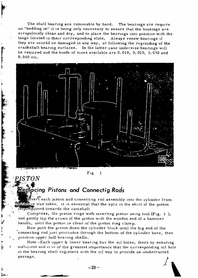
The shell beanng are removable by hand The beanngs are reqUireno beddIng In It IS beIng only necessary to ensure that the housIngs are
scrupulously clean and dry and to place the beanngs mto pOSIl1on wIth the
tangs located In then correspondIng slots Always renew beanngs If
they are scored or damaged m any way or followIng the regnndmg of the
crankshaft bearmg surfaces In the latter case undersIze bearmgs wIll
be reqUired and the kmds of SIzes avaIlable are 0 010 0 020 O 030 and
o 040 etc
FIg 3
t
PIS TONJ
Rerr ng P stons and Connect g Rods
Insert each pIston and connecl1ng rod as sembly mto the cylInder fromYhGIl m was taken It IS essenl1al that the splIt In the sknt of the pIston
IS posItIoned towards the camshaft
Compress the pIston nngs WIth Insertmg pIston uSIng tool FIg 3and gently tap the crown of the pIston WIth the wooden end of a hammer
handle untIl the pIston IS clear of the pIston nng clampNow push the p ston down the cylInder block un111 the bIg end of the
connecl1ng rod Just protrudes through the bottom of the cylInder bore then
posll1on upper half bearIng shells
Note Each upper lower bearIng has the 011 holes there by ensurIngsuffICIent and It IS of the greatest Importance that the correspondIng 011 hole
In the bearmg shell regIsters wIth the oil way to provIde an unobstructed
pas sage
l
0
r
w
i 28j
Ief

Pull the connectlng rod onto the crankpln takmg care not to lnJure the
beanng surface Insert the shelllnto the connecting rod cap pOSltion the
cap and the locklng washers Insert the setscrews and tighten wlth a
torque wrench to 35 45 lbs ft 4 8 6 2 kgmFmally set wlth the pal
nut
Check thconnectmg rod
blg end for slde clearance
7 1000 m and see that the
shell beanngs are not blndmgon the crankpin when rotatingthe crankshaft If 1 t lS dlfft
cult to turn undo the blg end
and examine the shell and seat
for dlrt or gntBefore reassembhng al
ways apply a httle clean 011 to
the plston surfaces and lnto
the cyhnder bore Never ftle
the connecting rod caps or thelr
mal1ng surfaces as thlS creates
uvahty ln the beanng
RemOVing a P ston
Fig 4
Remove the clamplng bolt from the small end of the connecting rod and
push out the gudgeon pln The gudgeon pln IS a push ftt ln plston at 300 400C
When reassembhng ensure the gadgeon pin lS posltloned ln the connect
mg rod so that ltS groove lS mIme wlth the clamp screw hole Check that
the spnng washer fttted under the head of the pltch bolt lS not damaged
29

PISTON PIN
Type
Pm fIt to pIston pIn hole
DIameter
LengthFIt clearance pm and
connectIng rod
Full floatmgSnap nngs at both end of pIn m
pIstonThumb fIt at 30 40 C
86 104 F
2199 22 Omm 0 8657 0 8661 m
73 mm 2 8740 In
TIGHT 0 01 mm TIGHT 0 0004 m
LOOSE 0 018 mm LOOSE 0 0007 m
PISTON RINGS
Type of nngs
Rmg wIdth
CompressIonall control
RIng clearance In groove
CompreSSIon011 control
Rmg gap m bore
CompressIon No I
No 2
all control
RIng tensIon
Comp esslOn No I
No 2
all control
Top rmg Plane type chrome plated2nd nng Tape red typeall control nng Slot type chrome
plated
1 98 1 99mm 0 0780 0 0783 m
3 98 3 99mm 0 1565 0 1570 m
0 04 0 08mm 0 0016 0 0030 m
0 03 0 06 mm 0 0012 0 0024 m
0 25 0 40 mm 0 010 0 016 In
0 15 0 30 mm 0 006 0 012 m
0 15 0 30mm 0 006 0 012 m
I 8t0 2 kg 4 00 0 441b
I 95t0 2 4 33t0 441b
2 1t0 2 kg 4 67t0 44
PISTON AND BORES
There should be a clearance of 0 0010 0 0016 m 0 025 0 040 mm
PIS TON RINGS
The top piston rmg gap should be 0 010 0 016 m 0 25 0 40 mm
when checked In the cyhnder bore The clearance of the second and 011
control compre SlOn nngs In then grooves should amount to 0 006 0 012
m 0 15 0 30 mm
30

If the p1ston nngs do not travel to the end of the cyhnder bores a hp1S eventually formed due to wear This may be checked w1th a dIal gaugeand must be removed If th1S 1S not done there w1ll be a tendency to nOlcy
operation or a fractured nng caused by the top p1ston nng stnk1ng the
hp PISton and nngs re ava1lable m 0 010 m 0 254 mm 0 020 m
0 508 mm 0 030 m 0 762 mm 0 040 m l 016 mm and 0 050 In
1 270 mm overS1zes
The piston nngs should
always be fttted from the
crown of the p1ston and
never pushed upwards over
the skirt Before ftthngthe nngs remove any
carbon deposIt from the
grooves 1n the pistonWhen flttmg note that
the second compress1on 1S
tapered type and 011 control
nng IS s10t type processedby chrom1um plating
F1g 5
Withdrawing Camshaft
The camshaft 1S pOS1t1oned by a locattng plate held by three screws and
shakeproof washers Note the pOiHtlOn of the smalllubncatlng 011 hole 1n
the locating plate when replac1ng should be to the nght of the eng1ne
End play of 0 08 0 28 mm 0 003 0 011 m 1S controlled by the thIck
ness of the locating plate and can be checked w1th a d1al mdlcator set a
ga1nst the camshaft gear
Before w1thdraw1ng the camshaft the dlstnbutor and 1tS dnvmg spmdlepush rods w1ll have to be removed Remove the oIl pump and 1tS dnve
shaft and take off the tlmmg cover and gears The eng1ne front mountmg
plate 1S now access1ble and may be removed by w1thdrawmg the setscrewand lockmg plates The dynamo swmglng hnk must be removedl
Take out the setscrews secunng the camshaft locating plat when the
camshaft can be w1thdrawn from the cyhnder block
CAMSHAFT BEARINGS j
WhIte metal beanngs w1th steel hmng are
They can be taken out renewed when necessary
when the cyhnder block 1S being recond1tloned
The beanngs can be removed by dnftng them out of their housmgs
used for the camshaft1t bemg usual to do thiS
31

I wlI
1
31880
1112132200
1
318809
151144
1
114141
t
111032200
1102630000
CyIInde
r
B
I
0
Ck
1112030000

When fIthng new beanngs care must be taken to l1ne up the 011 holes
with the corresponding holes in the cylmder block
Tap the new bearings into posihon and ream them to give a runnIng
clearance of 0 001 0 002 m 0 025 0 051 mm
RefittlOg the Camshaft
ThIs IS a reversal of the lntruchons for removal Care should be
taken however to al1gn and engage the dnve pm In the rear end of the
camshaft wIth the slot In the 011 pump dnve shaft
MaIO beari ng caps 1
If
tTake off the hmlng chaIn the 011 pan and the engme rear plate Unlock
and remove the bolts secunng the maIn beanng caps of the cyl1nder block
also the bolts secunng the hmlng cham cover at front of cyl1nder block
When fIttIng new beanngs no scrapIng IS required as they are machined
to gIve the correct runmng clearance of 0 001 0 0027 m 0 03 0 07 mm
Handle the new beanngs carefully so as not to damage the fIne surface
fInIsh
Remove the flywheel and clutch
33
r c ffjJ rr c
tr
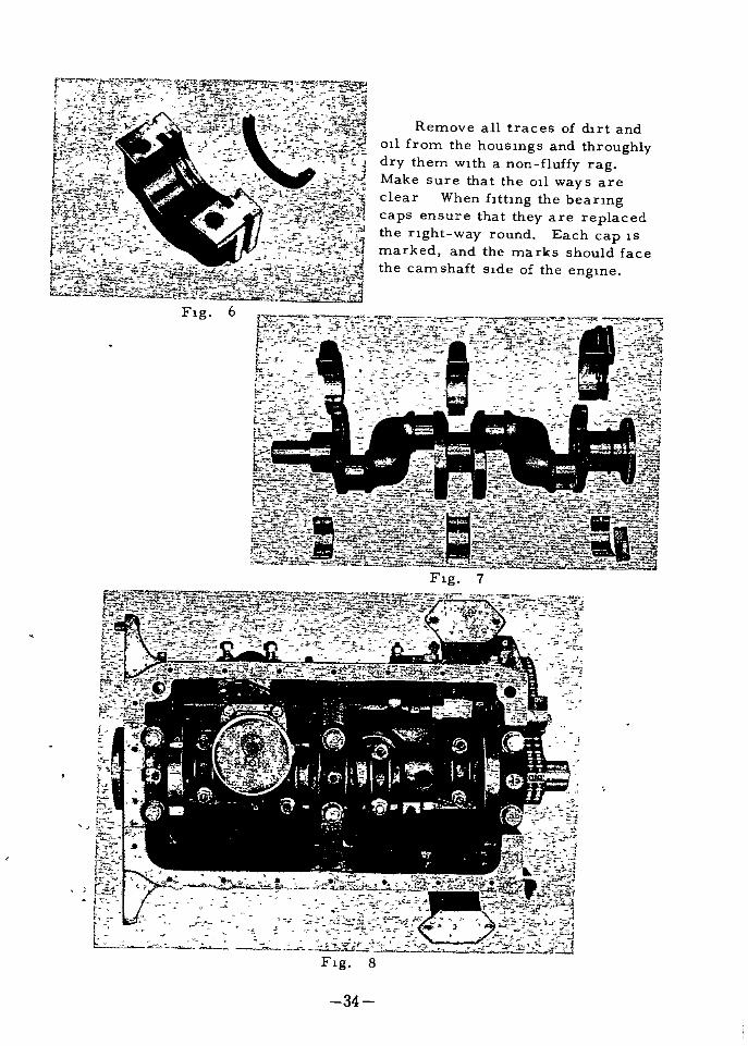
Remove all traces of dnt and011 from the housmgs and throughlydry them w1th a non fluffy ragMake sure that the 011 ways are
clear When fitting the beanngcaps ensure that they are replacedthe nght way round Each cap 1S
marked and the marks should facethe camshaft s1de of the eng1ne
F1g 6
F1g 7
I11t c1E
o
i1
I
LfL d
1
F1g 8
34

CAUTION
Never hle the beanng caps to take up exceSSlve playas thlS wlll cause
ovahtyAlways cover the beanng surfaces wlth englne 011 when they are re
placedDo not forget to reht the thrust washer The maln beanng caps are
held In posltIon by set screws and lock washers Pull the set screw up
tight wlth a torque wrench set to a loadmg of 75 80 lbs ft IO 36 I 1 05 kgmWhen rehttIng the maln beanng caps tighten the center one fust After
each cap IS tighten rotate the crankshaft to ascertaln that It revolues freelyIf It IS tight remove the last cap tightened and examlne the beanng and
Its seating for forelgn matter
Check the crankshaft end play by means of a dlal gauge ThlS should
be 0 002 m O 006 m O 05 mm O 15 mm
If a beanng has run It IS essential to clean out all ollways In the
crankshaft and block Wash out the engme sump and the stralner
The 011 pump should be dismantled and cleaned Ensure that no particles of beanng metal are left wlthln the englne lubncatIon system
t
Flg 9 Removlng a Maln Bearing Cap Extractor
35

Adjustmg the Brake Points
To adjust the breaker pOlnts turn he engIne crankshaft WIth the crankhandle untIl the breaker IS fully open I Then loosen the breaker pOlnt fIx
Ing screw Next by turnIng the adJustIng screw move the pla e untIl a
feeler gauge of 0 45 to 0 55 mm 0 018 to 0 022 InS thickness shdes
easIly between the breaker pOlnts Then tIghten the fIXIng screw securelyFInally check the gap once more then reInstall thr rotor The In
terIor and extenor of the cap IS WIped clean WIth a soft dry pIece of clothextra attentIOn beIng paid to the areas between the termInals Clean thecenter electrode on the InSIde of the cap also
The vacuum type tImIng advancer IS functIonIng properly can be determIned by the InspectIon pOlnter located at the dIaphragm If as the
engIne IS beIng run thIS pOInter moves when the engine speed IS suddenlychanged the advancer IS satIsfactory
Fig 10 AdJustIng the POInt Gap
36

ADJUSTING THE IGNITION TIMING
The IgnItIon tImIng IS adjusted to 10 degrees before top dead centerwIth the engIne stopped as shown m FIg WIth thIS adjustment theautomatIc tImIng advancer of the dIstnbutor advances the IgnItIon tImIngeven further at the tIme the engIne starts to rotate and the tImmg IS
maintaIned constantly at valves sUItable for the rotatIonal speedWIth the engIne stopped adjust so that the dIstnbutor breaker pOInt
Just breaks when the pIston of the No 1 cylInder IS In ItS 10 degrees before top dead center pOSItIon for compressIon If a tImIng lamp IS usedthe standard IgnItIon tImIng IS 12 degrees before top dead center at IdlIng600 rpm speed
In the case of marks whIch are not evenly spaced pOInters IndIcate10 deg 15 deg and 20 deg pOSItIons before top dead center
DISTRIBUTOR
Type D410 01 D415 01
IgmtIon tImmg IdlIng B T D C 120 550 rpm lOOwIth tImmg
lIght engme 600 rpm
Adjust tImmg angle by the kmds of gasolmeoctane value
IgnItIon tImIng advance AutomatIc advance by the centnfugal weIghtand vacuum tImIng control
AutomatIc advance by the centnfugalweIght and vacuum tImIng control
AutomatIc advance Governor start advance at 00 375 525 rpmGover nor start advance at 400 550 rpm
MaxImum advance angle 140 160 at
1800 rpm
Vacuum advance Start advance at 90 110 mm
3 54 4 33 m HgMaxImum advance angle
330 mm Hg 6 5 8 50
Startadvanceat4 7 5 SIn l20 140mm HgMaxImum advance angle at crank shaft
9 120 at 126m 320 mm HgFlnng order I 3 4 2 I 3 4 2
Pomt gap o 45 0 55 mm
0 45 0 55 mm
500 540 HItachI
o 018 0 022 m
o 018 0 022 m
560 610 MItsubIShI1
Contact arm spnngtensIon 500 650 gram 18 6 23 oz
Capacity of condenser o 20 0 24 mfd o 20 0 24 mfd
37

fi
j
l
I
twv i
r 7l f 7
Fig Checkmg the Igmhon Timmg
Adjustment IS made by the follOWing procedure
FlTst adJust the distnbuter to the correct gap as descnbed pre
vIOusly2 Turn the crankshaft gradually unhl the top dead center mark
Fig 1 I on the pulley penfery comcides with the mark for 12
deg before top dead center on the timmg gear cover as the
crankshaft approaches itS posihon somewhat before that cores
pondmg to the end of the compression stroke of the No I pistonStop the crankshaft m this posihon The compressiOn stroke of
the No I piston can be determIned If the spark of the No I
cylinder is removed the hole plugged with a fmger and the
crankshaft turned With the crankshaft In the previOusly men
tioned positIOn the No I piston is in its posihon of 10 deg before
top dead center of compression
3 Next Insertmg the dnvmg shaft of the distnbutor at an angle to
the engme engage the gear on 1 ts lower and With the gear on the
camshaft Dunng thiS assembly place the slot of the distnbutordnve of the upper end of the shaft somewhat to the left At thiS
hme the smaller of the seml ClTcles is placed toward the front
4 AdJustmg the dlTectlon of the rotor so that It engages the dnve
shaft slot mount the dlstnbutor to the engIne At the same hme
the breaker must be In ItS pOSItion when It IS Just beglning to open
If these cond tions do not comCIde they are made to do so by
38

shghtly turnmg the dlstnbutor body only To determme the POSltIon when the breaker pOInt IS Just beglnlng to open turn on the
IgmtlOn key hold the end of the No I spark cord about 1 4 mch
away from the cyhnder head and turn the body untIl spark Jumpsacross the gap
The off set slot posItIon of the dnve shaft when the No I pIston IS m
ItS compressIon top dead center pOSItIon IS shown here
5 Next put the hstnbutor cap on and clamp It securely wIth the chp
6 To the No 1 spark plug connect the cord from the termInal to
whIch the arm of the rotor IS pOlntIng Thereafter connect the
termInal cords to theIr spark plugs In the counter clock WIse
order so as to obtaIn a 1 3 4 2 fInng order
7 Upon completIon of the wlnng cover the dlstnbutor wIth a rubber
cap The engme should now start properly
Ordlnanly the pOlnter of the octane selector IS set at ItS zero readIngdunng the IgmtIon tImIng adJustment If the octane number of the fuel be
Ing used IS low and the engme knocks the pOlnter IS adJusted to the nght R
to the optImum advance angle Conversely If the octane number IS hIghthe pOInter IS adJusted to the left A One umt of cahbratlOn of the selec
tor corresponds to 2 deg of the dlstnbutor angle and to 4 deg of the crank
shaft angleWhen a tImmg lamp IS used the standard settIng IS 12 deg before top
dead center wIth the engme Idhng 600 620 In any case the optImum
adjustment IS that In whIch a shght knockIng IS heard when wIth the car
runnIng at low speed In HIGH TOP gear acceleratIon IS apphed sudden
ly
it
39

FUEL SYSTEM
The fuel tank has a capac1ty of 44 l1tres and 1S sltuated at the rear of
the luggage compartmentThe fuel pump operated off the camshaft draws fuel from the tank
and forces 1t mto the carburetor float chamber A large and eff1c1ent au
cleaner ftlters the au supply to the carburetor
FUEL SYSTEM
GASOLINE TANK
I Capac1ty 44 ltr 12 US Gal
F1g I
40
9 1S41S 1
9 151l5 1
1 14522 1 @l
I
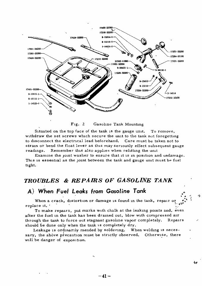
FIg 2 Gasoline Tank MountingS tuated on the top face of the tank IS the gauge unIt To remove
wIthdraw the set screws whIch secure the unIt to the tank not foregettIngto dIsconnect the electncal lead beforehand Care must be taken not to
straIn or bend the float lever as thIS may senously effect subsequent gauge
readIngs Remember thIS also applies when refIttIng the umt
ExamIne the JOInt washer to ensure that It IS In pOSItion and undamageThIS IS essential as the JOInt between the tank and gauge unIt must bp fuel
tight
TROUBLES REPAIRS OF GASOLINE TANK
A When Fuel Leaks from Gasoline Tank
When a crack dIstortion or damage IS found In the tank
replace It t
To make repaIrs put marks wIth chalk at the leakIng pOInts and even
after the fuel In the tank has been draIned out blow WIth compressed aIr
through the tank to force out stagnant gasoline vapor completely Repairsshould be done only when the tank IS completely dry
Leakage IS ordlnanly mended by soldenng When weldJng IS neces
sary the above precaution must be stnctly observed OtherwIse there
wIll be danger of expoSItion
repaIr o
w
41

B When gasoline Fails to Reach Gasoline StrainerIf the fuel falls to reach the gasolIne straIner when there IS some fuel
left In the gasolIne tank and the operatIon of fuel pump IS known to be satIsfac tory check the followIng pOInts
When It IS dIffIcult to confum the dehvery of fuel at the straInerloosen the connector at the fuel Intake of the carburetor
I Check to see If gasolme pIpe IS clogged WIth dust and dut Thiscan be easIly checked by dlsconnectmg the connector of the pIpe and blow
Ing WIth compressed au toward the duectIon of the tank Then from thetank end blow the pIpe agam and clean the pIpe
In many cases the tIp of gasohne Intake pIpe of tank unIt IS cloggedwIth dust and water
Therefore together wIth cleamng of the pIpe the Intenor of the tankshould be cleaned by removmg the dram plug at the bottom of the tank
Check to see If the gasolIne pIpe of the tank umt IS so bent as to fall
to reach the fuel surface
The standard posItIon of the bottom end of the pIpe IS about 3 4 m
apart from the bottom uorder to prevent ItS suckIng up sed ments on the
tank bottom
G
FIg 3 Wlnng of Fuel Gauge
1 Umt gauge2 Fuse
3 Fuel gauge
4 IgmtlOn SWItch
5 Ammeter
6 Battery
If not normal remove tank unIt
and adjust the bend of the pIpeCheck to see If the vent hole of
the fIller cap IS clogged wIth dustand dut not Supply ng au to the
tank
Accordmg to the degree of vac
uum WIthIn the tank fuel cannot
be drawn up even by the operatIonof fuel pump
So be sure to clean the air vent
of the capIf you should lose the cap and
substItute a wooden plug for It a
measure whIch IS sometImes WIt
nessed the cond tIon InsIde of the
tank becomes the same as thoughIt were sealed up Always use
only the standard cap
42

Operahon and Repa rs of Fuel GaugeAs shown In Flg 3 the fuel gauge conslsts of the dash unlt and tank
unlt
The dash unlt WhlCh IS Installed on the mstrument panel has two cOlIs
that cross each other at right angles whose magnebc forces control the
movement of a keeper Hon plece with a hand lndlcator
On the tank unlt a contact arm shdes over a reslstance In response to
the float level
As shown In Flg 3 If the Ignlbon sWltch IS turned on when the tank IS
empty elecbc current w1ll flow from the battery through the ammeter Into
cOlI A and then through the contact arm to the groundCOlI A IS then magnebzed attracts the lron plece and the Indlcator
pOlnts to E
As the float IS ralsed and the contact arm moves tank unlt Increases
reslstance In the Clrcult and thus the current whlch traveled through COlI A
then flows th S hme both contact arm and cOlI B and finally to the groundAs both A and B COlIs are so wound as to have theH magnehc poles m
the same dlrecbon the lron plece wlll rotate to the dlrechon where the
magnetlc power of the two cOlIs can be balanced wlth the nchcator deflect
Ing 1ll the dHectlOn of F
That IS th S IS a gauge of electric reslstance control type E slgmfIesFrrpty level and F Full level
Troubles with Fuel Gauge and their Remedies
When someth1ng IS wrong wlth the readlngs of the fuel gauge fHst chs
connect the WlrIng at the unlt and turnlng on the Ignlhon sW1tch groundand unground the termlnal end of the sa1d wHmg to the body of the car
If the lndlcator of the dash umt sWlngs achvely between E and F the
WlrIng between the dash unlt and the sald termlnal end IS In good conchtlOn
wlth the defect eX1shng elther m tank unlt 1tself or In poor ground of th S
un1t4
In the test menhoned 1n the preceedlng sechon 1f the Indlcator d e
not sW1ng but 1t moves moves to E when the dash umt end of the wHmg I
from the tank umt IS grounded the wHmg between the dash un1t and tank
umt 1S defechve
Therefore reWlrIng or repa1rIng IS requ1redIf when Indlcator falls to sW1ng but sparklng IS observed when the
WlrIng connechng the battery w1th the termlnal on the dash umt IS dlscon
nected at the dash unlt end and grounded It proves the wHmg IS sahsfac
tory and the trouble 1S 1n the dash umt Itself
If spark1ng does not occur the w1rmg whlch IS thus Indlcated to be
out of order should be repalred or replaced
43

Incorrect readmgs of the 1nd1cator probably means that the heightof the float of the tank un1t 1S 1n error
In this case adJust the he1ght of the float by bendmg the rod
Trouble w1th the umt are d1fficult to repair so 1t should be replacedby a new un1t
In check1ng the tank un1t be sure to 1nsert a fuel gauge 1n the CirCUl
between the battery and the umt
o
l
44

FUEL SYSTEM
SpecIfIcahon of carburetor used for G type engIne D3032A IA
Pnmary Secondary
Bore dIa mm 30 32Ventun dla mm 21 8 8 27 8 8
MaIn Jet 100 170Mam au bleed 60 60Power Jet 40
Slow Jet 48 80Slow au bleed
FIrst 140Second 140 150
Slow economIzer 160I
Inlet dIa mm Inner dIa 75
Oute r dIa 80
Used for H type engIne D3234A IA
Pnmary Secondary
Bore dIa mm 32 34
Ventun dIa mm 24 8 8 30 16 8Mam Jet 110 180MaIn au bleed 60 60Power Jet 70
Slow Jet 58 80
Slow aIr bleed
Fast 160
Second 150 100
Slow economIzer 180
Inlet dIa mm Inner dIa 75
Oute r dIa 80
45

ConstructIon and FunctIon
CARBURETOR
A dual type carburetor w1th new mechanism 1S adopted dla
gragm type operated by negative pressure accordlngly h1gh power
can be obta1ned w1th suchon res1Stance
Acceleratlng system 1S separated from power system to get
more sufflC1ent operatlon of accelerating pump sImultaneously
power system 15 automatically operation by negative pressure res
pondmg to tJte engme load 50 that the economIcal fuel consumphon
WIll be obtained In hIgh speed or accelerahng The needle valve 15
located vertically but honzontally for the rel1able operahon
a Float Chamber
Needle valve IS located vertically as mentioned above
accordmgly over flow caused by parhal wearmg w1ll be prevented
b Choke System
Sem1 automatlc eccentnc choke valve 1S adopted for only pn
mary barrel and combmed w1th the throttle valve accord1ngly 1n
case of fully closmg of choke valve the throttle valve 1S httle openedfor the easy starting
c Slow System
Slow system 1S almost same w1th former one Ie after pass1ng
through the ma1n Jet proper fuel w1ll be ready by slow Jet and
vaponzed WIth mlJC1ng the au commg from 1st slow au bleed and
the above mIXture 1S properly ready by lnd Jet wh1ch 1S so called
slow economIzer then th1s mIXed fuel w111 be re mIXed w1th the
au taken m by lnd slow au bleed thus the more suffICIent vapour
WIll be gaIn and 1nJected mto slow port
d MaIn System
The mlXture used In normal cond1t1on 1S ma1nly prov1dedfrom prImary barrel thus system 1S Just same w1th former typeof dual barrel Ie the fuel w1ll be properly prepared by mam Jet
and mIXed WIth a1r com1ng from ma1n a1r bleed Th1s vaponzable
46

mlxture lS nhaled lnto double ventun by negatlve pressure and
mor perfectly vaponzed to be led lt mto the cyhnder But dla
meter of Jet lS dlffered from former one to be matched wlth per
formance of englne
e Acceleratmg System
Due to adoptlon of separate type of acceleratlng system and
power valve system lnstead of unlt type reasonable acceleratlngsystem wlll be glven
The dumper sprlng lS set ln the acceleratlng pump plston WhlCh
lS double unlt type In case that the plston reaches to lower end of
cyhnder when pump rod lS pushed by pump arm dumper sprmg lS
pressed then pump plston wlll operate up to fully opemng of throttle
valve 0 6 mmp hole lS provlded at the top of acceleratlng nozzle
the pump arm have three holes to be get correct amount of gasohnealr mlxture caused by englne condltlon le the connectlng rod
should be lnserted to lnslde hole ln wlnter and to outslde hole in
sUInmer
f Secondary Barrel
Changmg to Secondary Slde
The throttle valve of secondary barrel wlll be opened by dla
phragm wluch lS operated by negatlve pressure of ventun At the
most narrow part of venturl placed ln lower slde of both carburetor
prlmary secondary 1 3 mmp ntake hole of negatlve pres sure
lS prepared and from WhlCh the passage of negatlve pressure lS led
to outslde of dlaphragmThe dlaphragm lS made from rubber be ng added oll proof
nylon and flXed to dlaphragm rod other end of the rod lS connected
to throttle valve of secondary barrel
On the secondary barrel throttle shaft lS eccentncally flxed JtPagamst the bore so that the throttle valve wlll be tend to close when
negatlve pressure occurs beneath the valve then the throttle valve 1 trentlrely closed and results no operatlon
Y l
After opemng the throttle valve on prlmary barrel and au
suctlon lS lncreased the negatlve pressure of venturllS accordlngly lncreased but no au ventllatlon to secondary barrells made and
negatlve pressure at the port of secondary barrells not down
Both negatlve pressure pnmaryand secondary should be i
operated to the dlaphragm accordmgly the negatlve pressure of
ventun at pnmary barrells not lncreased untll throttle valve of
47

secondary barrel1s operated because the secondary barrel negahveI
pressure port w1ll operate as a1r bleed On the other hand the
d1aphragm Jr1ll not operate unless regular pressure w1ll be glven
out to operatlon of spnng at negatlve pressure slde
The throttle valve on the pnmary slde 1S largely opened and
more au 1S supphed Accord1ngly negahve pressure to be effected
to the d1aphragm w1ll attam beyond the tenslOn of sprmg and the
power agamst openmg the throttle valve and 1t results that the
d1aphragm 1S pulled to outs1de then the throttle valve 15 open
When the au flow 1n the secondary barrel the au bleed
eff1c1ency at the port 1n most narrow part of ventur1 tend downward
then the he1gher pegat1ve pressure to the maphragm 15 glven
accordmgly the d aphragm 1S more pulled to outs1de and secondarythrottle valye 1S largely opened fmally opened perfectly
Generally pnmary barrel have no res1stance up to 50 of
valve open1ng angle and nO neces Slty operate secondary barrel 50
that the secondary throttle valve w1ll not open due to cam mechan1sm
Th1s cam mechan1sm 1S expla1ned that the throttle valve arm
p1n fIxed to throttle valve shaft 1n secondary barrel w1ll be preventedby cam mstalled at pnmary throttle valve armuntll 50 openmg of
pnmary throttle valve 1S obta1ned so that the secondary throttle
valve cannot openThe pnmary throttle valve 15 more opened then secondary
throttle valve w111 become free by puthng cam off from the p1n
accord1ngly secondary throttle valve w1ll operate freely by d1aphragmand fully opemng of pnmary throttle valve w1ll result fully openmg
of secondary throttle valve
In th1S cond1tlon clos1ng the pnmary throttle valve the se
condary throttle valve 1S closed by the operatlOn of carrt then negatlVe
pressure 1n mamfold 15 1ncreased and secondary throttle valve 15
enhrely closed therefore rotat10n of eng1ne w1ll smoothly reducedr
g Secondary Fuel System
There 1S a head between the top of nozzle and float chamber
therefore to spout the fuel from the ma1n nozzie secondary throttle
valve 1S remarkably opened To adJust th1S d1screpancy of gasohnealT m1xture a step port 15 ready at the top of secondary throttle
valveTh1S k1nd of step port was prepared 1n former type carburetor
wh1ch 1S uhhzed such as choke valve and ma1n nozzle but th1S new
type carburetor have no aWClhary valve so that the un1que step port1S necessary
48

The fuel In thIs step system IS separated from maIn systemalter passIng the secondary mamJet properly ready at step Jetvaponzed wIth au from the step au bleed and reaches to the stepport
The maIn system IS almost same wIth the system of pnmarysIde and maIn Jet IS prepared on the wall of float chamber It IS
to say that In case of hIgh speed pnmary SIde system IS utlhzed so
that the severe operatlon or bad effect by lnchnatlon In sharp turn
Ing are out of conslderatlonD1ameter of bore and venturI are rather enlarged to take In
plenty of au because of power barrel
h Power System
The power valve IS In the center of float chamber and the
push spIndle connected wIth pIston IS Just on the power valve
At the upper sIde of pIston the negatlve pressure In manIfold
sIde IS led from the throttle valve
When the negatlve pressure attaIns more than 110 mm of
mercury thermometer the push spIndle IS hfted by pIston beyond the
tensIon of pIston spnng located between push spIndle and au horn
accordmgly power valve IS luted up by valve sprmg and the valve
comes m contact wIth valve seat then fuel path IS cut off
When the negahve pressure IS down to 110 mm a head of
boost valve IS pressed by push spmdIe whIch IS operated from
exceedIng sprIng tenSIOn then the fuel passed between valve and
valve seat IS properly ready at power Jet placed at sIde wall of
valve and meet wIth fuel1n pnmary maIn system
Idle Ad ustment
Idle adJustInent is carrIed out WIth the throttle adJust screw and
the Idle adJust screw The throttle adJust screw adJusts the slow
running speed Screw In to Increase speed or turn out to reduce
speed The idle adJust screw adJusts the densIty of air fuel mIxture
Screw In for lean mIxture and screw out for rIch mIxture Therefore
the Idle adJustInent IS to be done WIth these two screws In correla
tIOn Too much screw In of Idle adJust screw wIll damage the pOIntof It and cause chsorder In Idle runnIng If there IS no effect on the
engIne however screw In the screw that IS not a normal condltlon
when It is necessary to check whether or not the slow aIrbleed IS
clogged the slow Jet slackens or the fuel level IS abnormally hIghDo the Idle adJustInent after the engme warmed up AdJust the Idle
runmng to 600 r p m
t
49

Adjustment of Fuel Level In CarburetorOn the transparent cover of the float chamber drawn IS a line
marked LEVEL whIch stands for the standard fuel level The fuellevel should agree wIth thIs l1ne The fuel level IS adjusted WIth theadJust shIms That IS remove the float needle valve carner fromoutsIde and adjust the shIms at the root of It Increase or decreaseof two shIms makes the fuel level up or down about 0 39 mch 1 m
When the fuel level IS wrong denSIty of the mIxture gas will become
Improper and the engIne WIll get In d1sorder
FUEL STRAINER AND FUEL PUMPNewly designed unlbzmg WIth the stramer Remove the glass
bowl by slackemng the nut on the top to clean the Interior Remove
the dram cock to el1mmate deposits at the bottom
Fuel pwnp
TypeMethod dnven
PerformanceOut putMax out let pressure
DIaphragmDnven by camshaft
Mm 1 5 per mmute at carn I 000 r p m
o 3 kg cm2 4 3 Ib m2
The fuel pwnp whIch IS ofthe dIaphragm type IS mecha
nIcally dnven by the eccentnc
part of the camshaft of the
engIneIt draws gasol1ne from the
tank and del1vers It under pressure to the carburetor
Fuel pwnp fuel
straIner ass y
50

l
The fuel pump Wh1Ch 1S of the d1aphrgm type 1S mechamcally dnven
by the eccentnc part of the camshaft of the eng1ne
It draws gasohne from the tank and dehvers 1t under pressure to the
carburetor
Even when the eng1ne 1S not runn1ng fuel can be dehvered under pressure by movmg the hand pnmer up and down
By the rotahon of camshaft rocker arm 1S pushed and pull rod of d1a
phragm 1S pulled down
At the same hme d1aphragm goes down aga1nst d1aphragm spnng and
then 1S pushed up aga1n by 1tS spnngBy the movements of the d1aphragm andifunctlOn1ng of the valves at
the 1nlet and outlet of the pump chamber gasohne 1S drawn up from the
tank to the carburetorIf the float chamber of the carburetor conta1ns enough gasohne and the
needle valve 1S closed gasohne 1S not allowed 1nto the carburetor
Thus gasohne 1S stored 1n the pump chamber and due to 1tS pressurethe diaphragm 1S kept down and cannot return
Under th1S cond1 hon the rocker arm works 1n va1n as the rod remains
low
The rocker arm spnng serves to prevent n01se keep1ng the rocker arm
pushed aga1nst the eccentnc of the camshaft
51

Class bowl
2 2200
IIMI1 UZOQ
18401 1SOSO
11410 36200
llter eller Iemerll
11403 32200
m
@17
17QT2 322001710301300
D1aphr gm SPrt g iiI11015 5210017052 3UOO g
r
17075 50000
@Otaptlregm
lt 17053 32200
Rock r rm spring
Jr@
11 s JOIS moo
17011
001
FIg 3 Components of fuel pump
D sassembling InspectionCheckmg wIth fuel pump Installed on engmeSWItch off and stop the engme DIsconnect the fuel pIpe at the mlet
unIon of the carburetor and then turn the engIne WIth the crank handleNow the gasolIne should be ejected vIgorously from the tip of the pIpe
once every two rotations of the crankshaft
To tes t the functIOn of the pump alone operation of the hand pnmerand checkIng the fuel eJection IS enough
Removal from engIne
Fuel pump can be easIly removed by dIsconnecting the Inlet and outlet
unIons and loosemng the 2 attachment nuts
52

I
InspectIon prIor to dlsassembhngPnor to dlsassembhng of the removed pump measure the dIstance
between the rocker arm and flange of the lower body by means of a scaleand see If the rocker arm rocker hnk and pI s are worn
Method of dlsassembhngFIrst wIpe dIrt off the outer surface of the pump and put marks on both
the upper and lower bodIes to make theIr reassemblIng easyIt IS easIly separated Into two when the SIX screws around the upper
body are loosened
Take great care not to damage the dIaphragm dunng thIS dIsassembly
Checking Reparres of PartsWash the dIsassembled parts well In gasolIne then Inspect them
Replace the dIaphragm If any damage ImpregnatlOn by gasohneReplace a valve assembly If any wear or faulty operatlOns IS detectedEven If repaIrs are unavoldlble requIred the hmlt for repaIrs of warp
or wear of the valve IS 0 00I In
When the surface of the valve seat or valve IS found Irregular remove
the valve seat of the outlet and dress the surface WIth a hne OIlstone
In case of Irregulanty fo the seat surface of the Inlet valve WhICh can
not be taken off from the body recondItIon It WIth a cutter and gnndlng tool
When the surface of the valve IS faulty place sOne very hne gnndlngcompound on the surface of a flat pIece of glass plate and gnnd It lIghtlyWIth
the tIp of a hngerThe hole of the JOInt parts of dIaphragm shaft and lInk may be worn to
some extent ThIs IS not senous but when senous eccentnc wear crack
or breakage IS found the part must be replacedAs a remedIal measure such wear can be compensated for at the tIme
of dIsmantlIng and reassemblIng of the body by msertIng a packIng made of
thIck paper between the lower body and dIaphragm to raIse the relatlve POSItIon of dIaphragm shaft WIth repsect to the lower body
The rocker arm should be replace when ItS contact face WIth the cam and
that WIth the lInk and ItS pIn hole are senously worn
When ItS reemployment by recondltIonmg IS unavoIdable add matenal to
the rocker arm and hnk by weldIng and fmlsh them WIth a hIe but thIS can
not last long and IS no more than a temporary measure
Renew the arm pIn when It IS found worn excessIvelyThe dIaphragm spnng arm spnng seldon become faulty but when weak
ened replace them always With standard ones
If the dIaphragm spnng IS too strong It rsults In overflow of the float lchamber of the carburetor
The tenSIon of the spnng must not be strengthened or weakened arbltra
nly by hand
Check to see If there IS any warp on the JOlnt surfaces of the cap and
body and after dlsas emblmg IS over renew the gasket to keep ItS aIrtIghtness
I
r
53

I
Reassembling InstallingEmploy standard spnngs for the vanous uses as stated beforeInstall valves preC1sely for close contact w1th the1r respechve seatsIn screwmg 1n of upper and lower bod1es and d1aphragm f1t them to
gether accord1ng to the marks wh1ch were put before the d1sassembhngand ahgn one screw1ng hole to 1tS mate and then screw 1n at the pos1tionwhere the d1aphragm 1S fully pulled down w1th the rocker arm pushed towards the slde of the body by and pressure
Do not screw 1n hght one Py one Slnce 1t causes warp1ng Instead
clamp all the screws round loosely and umformlyThen hghten them d1agonally and lastly rehghten all of them m order
to make sure
As a general rule
Installahon on the
assemblyBe sure to set the rocker arm so that 1t 1S contachng the eccentnc of
camshaft properly not the rear slde or to one slde Replace the gasketbetween the cyhnder block and pump w1th a new standard one
gaskets should be replaced by new ones
eng1ne 1S done 1n the reverse order to that for d1S
Checkmg Fund on
When repairs of the pump 1S over or before It 1S 1nstalled on the
eng1ne make a check to see
When a Vdcuum gauge 1S connected to the pump 1nlet port and the pumpIS mounted on a tester the rocker arm 1S act1vated by the eccentnc of thecamshaft Mm 1 2 Lper m1nute at I 000 rpm Then the gauge pressureshould be 0 22 kg cm2 3 150 lb m2 4 50 mm Hg Max vacuum andeven 1f operahon 1S d1sconhnued th S cond1hon should rema1n for more
than 3 secondsr t
When a gauge or tester 1S not ava1lable test 1n the follow1ng wayClost the mlet port and outlet port w1th finger hps Then after ope
rahng the rocker arm severalhmes suddenly release the fmgers The
pump 1S 1n good cond1hons 1f 3 to 5 seconds thence there can be heard
strong mlet and outlet n01se respechvelyr The pump IS mechamcally fit for use when by connechng a hose toVthe mlet port It IS able to draw up gasohne from a he1ght of more than
o 5 m After mstalhng the pump test 1tS funchons dunng operahqllA Connect the gasohnp1pe on the mlet post slde only Leave that
on the outlet port Side as It 1S and turn the eng1ne 6 to 7 rotahons bymeans of the crank handle and make sure that there 1S sure outflow of gasohne from the outlet port
B Connect the gasohne pipe to the outlet port Side and hghten all the
plpmg Jomts Then turn the eng1ne again several hmes to see 1f there 1S
any leakage of air or gasohne from each connechon
54

ADJUSTMENT AND INSPECTIONOF ENGINE
The engIne must always be operated In the best possIble condItIonand for thIS purpose penodlc InspectIon and adjustment must be maIn
taIned In a certain order whIle In USe as well as after overhaul
Order of InspectIon and Ad ustmet of EngineI Check the coohng water water level and extent of fIlthmes s
2 Inspect the battery all connectIons level of electrolyte specIfIc gravlty of electrolyte and voltage
3 Inspect the 011 amount f lth ness clasSIfIcatIon and VISCOSity
4 Cleamng of spark plugs and adJustment of theIr gaps
5 Measurement of compresSIon pressure of cyltndersThe standard compressIon
pressure of the engIne IS
approx 172 Ibs per sq
m 12 0 kg cm2 at 350
r p m
Measurement of pressureIS made In the followlngmanner see FIg I
FIrst warm up the engIne
temperature of coohngwater 70 BOoC then re
move all spark plungs and
pull out the throttle knob
all the way that IS m the
carburetor the throttle
valve and choke valve are FIg 1
fully opened press a com Measunng CompreSSIOn Pressure
pressIon gauge agamst each by Means of a CompreSSIOn Gaugespark plug hole and run
mng the starter motor wIth a fully charged battery read the maXI
mum pressure obtamed wIthIn 5 8 rotatlons of the motor ThIS meas
urement must be made as qmckly as possIbleIt the compresslOn pressure of anyone cylmder d ffers by 10 Ib sq
In or more from that of another the cause must be InvestIgated
6 Check and adjust the d strIbutor
If the breaker contact pOInts have defectlve contact surfaces dressthem abd adJust the gap to 0 45 0 55 mm
55

Also turn the cam of the d1stnbutor clockwise and check to see 1f
the governor can carry out advanc1ng funchon
7 1dJust 19mhon hmmg corectlyBy uhliz1ng a power hmmg light the funchon of the governor can
be checked together w1th the 19n1hon hmmg lllummatlOn of crank
pulley w1ll enable to lnspect the condlhons of runnmg and advanClngof the hmmgB T D C 12 550 rpm
8 Inspechon of fuel pump and gasoline stra1ner
9 AdJust the slow settmg of carburetor
10 Checkmg operahon of generatorCheck the generahng cond1hon and funchomng of the cutout relayby means of 1nd1cahons of the ammeter
11 AdJus tment of slack m fan belt
12 AdJustment of valve tappet clearance
D agnoslng of Engine by means of Vacuum Gaugeand Combustion Tester
In d1agnos1ng the eng1ne the cond1
hon of each cylinder can be assumed bymeasur1ng 1tS compress1on
For employment of a vacuum gauge
connect 1t to the engine ntake man1fold
and refer to Fig 2
The use of a master motor tester
as show1ng 1n Fig 1S conven1ent
When a combushon tester 1S used
1nstall a spec1al1ntake p ck up m the
exhaust tube and after the engme has
been started analyze by means of a
spec1al gauge the combustlOn gas which
flOWb through the connechng hose mto
the tester and Judge the combushon
c ond1hon accord1ng to the m1xture raho
of fuel and aH When measurement
15 to be made 1n ra1nyor cold weather
use an aux1hary condenser between the
pick up and the meter otherw1se the
exceSS1ve mOlsture In the exhaust gasw1l1 damage the functlOnmg of the
meter 1f perm1tted to enter 1t
56
Motorfor 4
F1g 2
Master Tester Avallable6 and 8 Cyhnder Engme

When a tester IS to be used make adJustments accordIng to the
gollowmg table
Condltions SUltable WeIght RatioWIthout load of MIxture
Low Speed Runnmg600 r p m 70i 2
HIgh Speed Runnmg 5
2 000 r p m85 2
Engine Trouble ShootingFIg 3 IS Intended to be of assIstance In the systematic analysIs
and Isolation of symptoms of engIne troubles so that the defective pOIntsmay be accurately traced and economically repaIred
1
Normal condItIOnSettles between 18 20 ID
2
Normal condItIOnWhen IndIcator fluctuatesbetween a range of 0 25 m
3S engine 18 raced rIngs
and valves are m goodconditiOns
3
Even If IDdlcator settlesd readmg IS low rings or
011 are ID faulty condItIOn
57
4
When above 3 condItIOn
eXIsts Indicator wIll swmg
to 0 10 If engme IS raced
5
When Indicator sometimesI
drops by 4 m or so vaivestIcking eXists
6
When IDdlcatpr drops bysevual Inches at certain
time valves are burnt

F g
7
When Ind cator drops byabout 2 In valves leak
Faulty stating of valvea
8
When mdleator osell1ates
achvely between 14 and18 In valve stem g1ude IS
worn out
9
When wIth a slight speedmg up mdlcator moves
between 10 22 m andwith mcrease of speed the
range becomes largervalve sprIDgs are weak
10
When md cator remaIDs
still between 8 15 m t
IS because elther valvebmmg IS retarded orvalveclearances are notcorrect
11
When IndIcator settles between 14 17 m IgnitIontlmmg IS retarded
3
12
Wben md cator moves
slowly between 14 16 m
lt IS because eIther electrode gaps of plugs are toonarrow Or breaker pomtIS defecbve
13
When mdlcator POIDts to
5 In or below there is
leakage at IDtake manlfoldor gasket of carburetor
Faulty c1arnpIDg of gas
ket
14
When mdlcator osc llates
regularly between 5 19 m
there IS leakage at cylinder head gasket FaultyctarnpIDg of gasket
15
When mdleator first Tlses
high drops down to zero
and then returns to 16 m
muffler IS clogged
16
When mdleator moves
slowly between 13 17 m
carburetor IS poorly adJusted
Diagnos ng eng ne by means of a vacuum gauge
58

90
is
o
Battery dlsclilfgeii or COnnecl1011S poor
TIming poojY dJUsted
jAir being sucked In
Plug s rk Plug sparking weakto
ijS Wiring IDcorrectlD
l Plugs dIrtySparking at terminals
Tlmmg Incorrect
8v ShPlugs do ort In CIrcUIt
lil not spark N k
LIgDll10n cOil or condenser defeehve
cIJ osparC
Ing at ter
EContact pomt dIrty
mlnals Breaker POint contact poort
defectIveBreaker arm Insulal10n defeCl1ve
JJo shorted
ijoVgasollne lD tank
St l er defectivePIpe cloggedFloat valve sheklng fNo aIr canenter tank
Fuel Wmp not operating
No gasoline or gas hne supply stoppedI 0
Garburetor Engine seIZed
troubleCompres J 1W f Alr hemg Bucked In
S10n good Jet or pIpe clogged
Carburetor Float suuk
defectIve Float m hIgh pOSItIOn wIll not deseend
Carburetor attachment not secure
EP ston rmg or valve sticky
ompresslon poor Piston or connecting rod broken
Valve seatmg poor
Breaker arm spring defective
No sparkcontact pOlDt poor
Ing from Rotor shortedco 1 line
Breaker IgDll10n cOIl or condenser defeetlvearm good Dlstrlbutor wet
Cap msutal10n defechve
Cord shorted or cbnnectlOn poor
C Wmng shorted or cut
SparkIng form COIl hne PI d rt b kugs I y or ro en
1
o
Cl
iCl
i
No gasoline In carburetor
tl
o
Cl
iPlugs
spark
j
Flg 4 A Trouble shooting chart
i
tt
59

EngIne operatIondefectIve during
runnmg
ICompresslon weak
Valve clearance Incorrect
Valve spring weak
Valve deformed
Muffler cloggedContmuous V
lack of poweralve hmlng Incorrect
Igmhon retarded too much
Carburetor adjustment poor
Power weak Gasoline supplied InsulliclentlyCarbon deposits excessive
Gasoline of poor grade
Icarburetor defectIveI IntermIttent
lack of power Valves stickingPre IgnitIOn
Engine gIves off abnormal nOIse Overheating
Bearing worn
I Plugs dIrtySparking i Breaker pOint defectIve
IrregularIntermlttent shortIng
MIsfiring M xture too rich
InsufficIent gasoline supply to carburetor
Sparking normal Water In gasolineNozzle clogged
F g 4 B Trouble Bhoot ng chart
60

REMOVING REFITTINGENGINE ASSEMBLY
OF
Operations wIth the Engme Removed
The following operations are best performed wlth the enpne removed
from the car
Although lt may be found posslble to carry out certaln attentions wlth
the englne ln posItion lt lS more convenlent to do the work on the bench
Expenence has shown that lt lS much eaSler to remove the englne
and transmlSSlon as a slngle unlt than to detach the englne by ltself
To remove the englne and transmlSSlon upwards proceed as follows
Completely drain the cooling system and the transmlSSlon dlaconnect
and remove the battery and ltS supporl1ng trayRemove the upper and lower raglator hoses by undonng the retalnlng
clipsDlsconnect the capacltor lead at the dlstnbutor also the hlgh tenslon
and sWltch Wlres at the COlI
Take off the dynamo lead and dlsconnect the starter motor cable at the
motor end
Remove the 011 gauge and water
termlnals on the engine
The throttle and choke controls must be dlsconnected from the carbu
rator Disconnect the fuel plpe from the fuel pump
Next remove the ex
haust plpe from the mamfold
From below the vehlcle
remove the gear change se
lector rod from the lever on
the transmlSSlon caslng
Dlsconnect the earth
strap from the starter motor
Remove the hand brake con
trol rod supporting from
transmlSSlon
Disconnect the speedmeter cabl e from the trans
mlSSlOn Uncouple the pro
peller shaft plmon franges at
rear axle and draw the shaft
out of the transmlSSlon
To allow the englne and
transmlSSlon to be drawn for
ward the radlator must be
removed by undomg the four
secunng bolts
temperature gauge leads from then
Englne TransmlssIon
assembly bemg bfted from
chassls
61

COOLINGRADIATOR
SYSTEM
TypePressuhsed
Total capaClty of coohng water
Maccord closed typeo 3 0 4 kg cm2 0 4 0 61b m28 4 ltr 2 2 US Gal
THERllOSTAT
TypeStart to open temperatureFully open temperatureValve hft
Bellows type721 50C
801 50C
9 5 mm
16l 6 30F1761 30F
o 374 In
An eff1Clent coohng system IS of major Importance to ensure the
satisfactory runnlng ot the englne and 1t IS therefore necessary to paypahcular attenhon to ItS malntenance Attenhon IS especlally drawnto the procedure for w1nter months 1f damage 1S to be avolded
The col1ng system 1S
maIntalned by water pumpClrculahon combIned wIth
an eff1c1ent fan caoled rad1
ator and thermostat
The system 1S pressun sed and the rehef valve
Incorporated In the rad1ator
fIller cap controls the pre s
sure at approx1mately 0 4
kg per sq cm Do not re
move the fIller cap 1f the
temperature of the coolant
IS above bOll1ng p01nt or If
the eng1ne 1S runn1ng
Toppmg up should only be
reqU1red occas1onally to re
place water lost through the
overflow p1pe Top up when
the eng1ne 1S cold and If
poss1ble use clean soft water
F1ll to w1thm 1 2 of the
bottom of the hller plug well Overf111mg when the engme IS cold maycause water to flow through the overflow p1pe The capaClty of the system 1S approx1mately 8 4 htres
DescriptIon
i
frt 4 T i JF1g Rad1ator
62

ThermostatIn order to ensure maXImum efhClency lt IS essentlal to keep the
engIne operatlng temperatures wIthIn certaIn hm1ts To assIst thIS a
bellows type thermostat IS htted beIng located In the water outlet at the
front of the cyhnderhead The devIce consIsts of metallIc bellows
hlled with a volatlle hqUled whIch controls a mushroom valve When
the engme IS cold th S valve IS closed and on startmg the engIne the flow
of water to the rad ator IS temporanly restncatedDue to thIS the temperature of the water m the cylinder head and
cyhnder Jackets WIll qUIckly nse thus ensunng rapId warmmg up The
heat so generated wIll gradually expand the bellows so opemng the valve
and ultlmatelly permIttIng a full flow of water to the radIator
The thermostat Itself IS detachable therfore should the occaSIOn
anse It can be removed from ItS hOUSIng and the hose reconnected to
a old lay ng up the car Should the thermostat be tlght there are two
tapped holes on the top WhICh may be utlhzed to ease If from castlngWhen the system has been completely emptied It IS essentlal to allow
air to escape through the thermostat valve and tnen hnally tOp up The
thermostat opemng IS set by the manufacturer and cannot be altered It
opens at a temperature of 72tl SOC Dunng decarbomsmg It IS pohcyto test thIS opening by ImmerSing the thermostat In water raIsed to the
reqUISIte temperature The valve should open under these cond tlons
but If It falls to open a new unIt should be fitted
OverheatingOverheatlng may be caused by a slack fan belt excessive carbon
depOSIt In the cyhnders runnIng WIth the Ignltlon too far retarded In
correct carburetor adJustment faIhre of the water to CIrculate or loss
of wdter
Fan Belt AdjustmentThe fan IS dnven from the crankshaft by a V belt thIS also dnv
Ing the dynamoA new belt can be htted by fIrst loosemng the clamp bolts FIg 2
whIch hold the dynamo In posItIOn and movIng the dynamo towards the
engme Sl1de the belt over the fan and onto the fan pulleyAdjustment IS then made by bnngmg the dynamo away from the
engme The belt should be suffICIently tIght to prevent slip yet the
belt should have 15 to 20 mm 5 8 3 4 slace between the generator
and crankshaft pulley when the mIdspan IS pushed fumlyAs the dnve IS taken on the V of the pulleys It IS not necessary to
have t le fan belt tlght to do so may cause exceSSIve wear to the dynamoand water pump beanngs After the correct tenSIon has been obtaIned
securely lock the dynamo In pOSItIon agaIn
63

Frost
Fig 2
Fan belt adJustment
Precautions 7
hrst at the bottom ot the radlator or In the lowerFreezIng may occur
hos e connectlons
Ice ln the hose wlll stop water cHculatlon and may cause bOlling A
muff can be used to advantage but care must be taken not to run wIth the
muff fully closed or bOlhng wlll result When frost l expecte or when
the car lS to be uSfd ln a very low temperature make sure that the
strength of the solutlon IS m fact up to the strength advised by the manu
facturers The strength of the solutlon must be malntalned by toppmg upwlth antlfreeze solul1on as necessary Excesslve topping up wlth water
reduces the degree of protectlon afforded SolutlOn must be made up m
accordance wlth lnstructlons applied vlth the contalner
Relatlons of freezlng temperatures of alchol water and glycenne mIX
ture s ratio
v
t
1
f
1
1
I
co
5
10
i5
10
15
JJ
J5
Iq
5
co
5
10
15
1025
30
35
ItO
45
102030 40 50 60J 0 10 JJI5060 70 80
Alcohol water Glycenne water mD ture
64

Top up when the system IS cold
If the coohng system has to be draIned run the mIxture Into a clearcontaIner and use agaIn
ProtectIon by DrainingOn cars where antIfreeze IS not used the followIng precautIons must
be taken dunng frosty water to obvIate any damage due to free71ng of the
coohng sy stern
When heavy frost IS ImmInent the coohng sy stem must be completely draIned It IS not suffIcIent merely to cover the radIator and engIneWIth rugs and musfs There are two drain cocks one on the left hand
sIde of the cyhnder block and the other at the base of the rad ator block
Both taps must be opened to draIn the system and the car must be on level
ground whde draInIngThe draIn taps should be tested at frequent mtervals by InsertIng a
pIece of WIre to ensure that they are clear ThIS should be done Imme
dIately the taps are opened so that any obHructlon freed by the WIre
may be flushed out by the water The drammg should be carned out
when the engIne IS hot
When completely draIned the engIne should be run for a tImed Tnmute
to ensure that all water has been cleaned from the systemA sUItable notlce should bE then aff xed to the radIatur IndIcatIng
that the water has been draIned
F ushmg the Radiator
To ensure effIcIent clTculatIon of the coolant and to reduce the forma
tIon of scale and sediment In the radIator the system should be penodIcally flushed wIth clear runmng water preferably before puttmg 10 anti
freeze In the WInter and agaIn when takIng It out In the spnng The water
should be allowed to run through untll It comes out clear from the dram
taps At Intervals a stIff pIece of WIre should be Inserted Into the taps
dunng draInIng to enSure that they are not becomIng clogged wIth sedI
ment
ThIS method of radIator flushIng may serve well but In cases where
the furnng up IS excessIve the operator wIll f nd It more effICIent prac
tlce to remove the radIator completely and flush In the reverse way to thE
flow turn the rad ator upsIde down and let the water flow In through the
bottom hose connechon and out of the top connectIon
WATER PUMPAfter draInIng the water from the rad ator
the cylmder block by takmg off the fan belt and
spnng washers and hInge bolts to dynamo
remove the pump unIt from
releasmg the setbolts wIth
65

FIg 3 Water pump
Cover
Removing the pump Shoft AssemblyD sconnect the fan blades pulley and cover
The shaft and ball beanngs IS combIned wIth one Ulllt
Put the pulley hub on the bench
FIrst press or knock the shaft end wIth a dnft hard bar and draw
out the pulley hub on the U typebench
Take out the set pm from the
sht whIch locked the shaft assem
bly to the pump body See FIgNext turn the body upsIde
down and press out the shaft
assembly from the vane SIde on
the U type bench
The shaft and
bal beanng assem
bly can be drewout
from the bodyThus take out
rthe vane floatlngseal and seal whIch
remaIned In the
pump body
66
Jl1 11y
r1It
4al14
J

Se81
1
cLL
a
BodySJde
G8Sltet cover
B1ocltSJde
G8Sltet
W9
2200
v
s
t
oo
V
of
th
t
pun
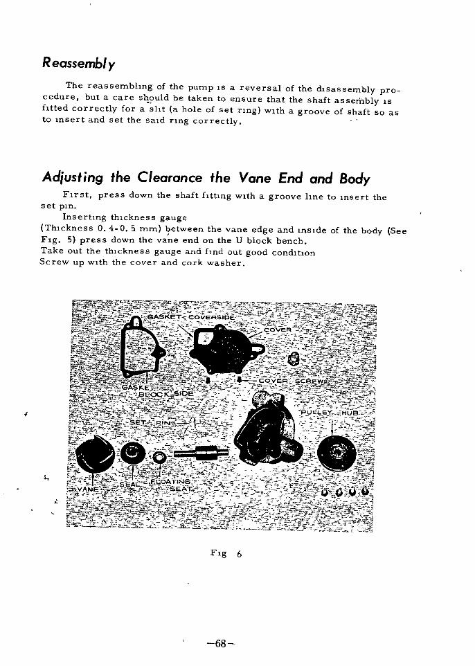
Reassembl yThe reassembhng of the pump lS a reversal of the dlsassembly pro
cedure but a care sq Uld be taken to ensure that the shaft assembly lS
fltted correctly for a sht a hole of set nng wlth a groove of shaft so as
to lnsert and set the sald nng correctly
Adiustm9 the Clearance the Vane End and BodyFust press down the shaft flttlng wlth a groove hne to lllsert the
set pln
Inserhng thlckness gaugeThlckness 0 4 0 5 mm between the vane edge and lllslde of the body See
Flg 5 press down theva
e end on the U block bench
Take out the thlckness gauge and fmd out good condltIon
Screw up wlth the cover and cork washer
t
l
Flg 6
68

IGNITION SYSTEM
The 19n1uon system lS a system whlch lS necessary for 19n1hng the
compressed fuel aH mlxture wlthln the englne cyhndersThe electnc current from the electnc power source battery and
generator as shown III Flg I flows through ammeter 5 and 19n1tIonsWltch 6 lllto 19mtIon COli 7
The low voltage current through the pnmary COli 14 lS lllter
rupted by contact breaker 9 of the dlstnbutor Thls charges the magnetlc held wlthln the 19mtIon cOli lntermlttently thus lllduClllg hlgh vol
tageThe hlgh voltage current lS dlstnbuted by the dlstrubutor 10 through
the hlgh tenslOn cord 16 to the spark plugs lllstalled ln the conbustIon
chambers of the cyhnder head The spark plugs are made to spark to
19n1te the fuel alr mlxture In the cyhndersTo dlagnose defects of the 19mtlOn system always have thlS dlstn
butlOn pnnClple In mllld and check the low and hlgh voltage CHC1l1tS se
paratelyAs shown III Flg 2 The 19mhon COli has two Calls wlth pnmary
current whlch lS sent through the prlmary cord lS sent and cut the magnehc fleld wlthln the pnmary Call changes and by mutural lnductIon a vol
tage of 10 000 volts or more lS created In the secondary call
At thlS moment self lnduchon voltage In the pnmary Call causes
sparklng at the contact pOlnts of the dlstnbutor contact breaker resultIngIn a decrease ln the lnduced voltage of the secondary Call and plthng of
the contact pOlntsTherefore the pnmary ClrCUlt lS provlded wlth condenser to prevent
drop of secondary voltage and absorb the sparks at make and break con
tac ts
69

10
9
4
3
12 V 1
Flg I Wlnng dlagram of 19n1hon system
I Battery 9 Contact pOlnt2 MagnetIc sWltch 10 Dlstnbutor
3 Starter motor II Cyhnder head
4 Starter button 12 Voltage regulator5 Ammeter 13 Generator
6 IgmtlOn sWltch 14 Pnmary cord
7 IgmtlOn COli 15 Secondary cord
8 Condenser 16 Hlgh tenslOn cord
IGNITION COIL
Type Hltachl CIZ Ol Hanshm HU 13C
Pnmary voltage 12 volts
Pnrnary current 1 8 ampers Check cause lf current
lS less than one ampere or more than
three amperes7 mm 0 275 lll or more at 1800 rpm
800C temperature of cOli
Gap test
70

Flg 2 SectIon of 19n1tIOn Call
I nspect on
I Pnmary cord termlnal
2 Pnmary cord termlnal
3 Secondary cord termlnal
4 Pnmary cOli
5 Secondary COli
6 Core non
Most troubles wlth the 19n1tlon cOli can be attnbuted to shortCHcult
of pnmary or secondary COlis caused by thelr defectIve lnsulahon over
heatIng or lntenor damageWlth such a faulty 19n1tIon Call lt does not generate sufflclent second
ary voltage and the englne wlll ml shre
But as repalrs of troubles are very dlfhcult except In cleanlng terml
nal connechon replace a defectIve 19n1tlon Call
Check of functlOnlng of cOli
Remove the cap of the dlstnbutor and turn the crankshaft untIl the
contact pOlnt of the contact arm closes
Then sWltch on the 19n1tIon sWltch draw out the secondary cord from
the central electrode on the dlstnbutor cap and holdlng ltS tIp about 6 mm
away from a metal portlon of the englne open and close the pOlllt by mov
lng the contact arm by hand
71

If blush whlte and strong spark are created between the tIp of the cord
and tj1e medii portIon the cOli may be consldered to be all nghtWhen the sparks are feeble and reddlsh or when sparklng does not
take place unless the gap wlth the IWetal portIon lS extremely reduced the
cOli must be defectIveSlnce these are cases when the condenser and 19n1tIon sWltch are all
nght to be exact employ a cod tester
To check by means of an ammeter connect the pnmary Call and bat
h htery t en f11easure t e current
If there lS no current at all thlS slgmfles a break ln the CHC1l1t
In such cases the coq must be renewed
For thorough lnspectIon a call tester should be employed
flro1
l vt
72

MODEL31
WIRINGDIAGRAM
I w I
rjSA tsx
h
H
IIlOlor
NOTE12V
ellth
Ipm
order1
3
4
2
l
1ndt131for
ILl3111dd1I1onal
Step1
I n Stwll
u
j tcr

JJ GENERA TOR REGURA TORTrouble Shooting Generator Equipped with Voltage Regulator
oJt
ndl LocatIon Cause of tr uble Remedytron
ofHitachi MltsublSh Hitachi MltsublShltrobles IICK SCRDi ecA DF Nl RH IICA SCRDI fCCA DF N RR
1 WJrIng almost I Replace wlrmg or
broken or grounded repair grounded Same asWJrlng Same as part at left2 Loose terminal at left 2 TIghten termmaldefectIve ground securely or correct
ground
I Cunstant voltage I Adjust byI Voltage regulator turnmgvoltage too low relay operates P screw
Regulator 2 Resistance at low voltage 2 Replace resistance1 Re adJustc In
Temperature stavoltage regulator blltzer 7 ohms stashortedblhzer 25 ohms
is Cut out I Cut out relay pOints Same as at left 1 Dress pOint with Same asill relay dIrty or damaged sandpaper at left
I Commutator surface I Dress with sanddIrty or damaged paper and clean
Generator 2 Poorbrush contact Same as
Ioff 011 Same as
at left Reseat or replace at left3 Armature field COIl brush
Ishorted broken
Repair or replacewire
I WJrmg termmalI Re hghtenloose or d Iscan Same as Same as
WirIng nectedat left at left
2 Wiring broken or 2 Replace wirIngshorted
COil lead Constant voltage 1 Repair or replace I Re adJustc I Wires IJ
shorted or broken relay operatesRegulator at low voltage 2 Replace carbon0 2 Carbon diSC dama11 ged diSC
1 Cut out relay WIll LharglDg switCh1 AdJu t cut m vol I Re ad ustrelay cuts In at0 not close or points tage or replace theCut out Vibrate blgh voluge cut out relay 2 He placerelay 2 Yoltage COIl of
chargingcharging currrht
SWItch relay Is currentSWitch relayc
broken1 Short or broken
1 R pair or replace0
Z WIre In armatureGenerator field cod Same as Same as
It2 Poor brush contact al left 2 Repair commutator at left
IrClt nt replace brush1 and hTltolJ holder
t e Same as I Chec k and orrect Same asWlrlng 1 Poor groundmgtat left grounrlll1K at kit
1 Yoltag regulator I Constant voltagr 1 Adjut lousenmg 1 He adjustvoltage too hIgh relay adjusted 10 P t Tl
operated al too1 RlplclCc hlSh oltage
on td nlRegulatoc 2 Broken Wire on 2 Broken Wire In 2 RepldCL volt WtCOIl voltage Call of conrtl0 slant voltage relay
3 A and B terJ A and B 3 Repair anSl1tltlon 3 RLpclrmlnals contactlOg
ter
mlnals contactmg InslIlallOl1
Note When chargmg Insufficltlntly It IS neccessary to check not only the charKlng CirCUitbut also to see If the ammeter needle IS stuck and to check for broken wire 10 colilow flUid level In battery difference an sptlclfic RravltlCs anternal hort clrcu t or
damaged plates In battery l nd other cause
pfi
74

1ji
@2310a 42200 a@ 23122 mOO
@23m mo 7
@ 23120 as
@3118 3U
ID23ISI32200
1
Flg Generator
I Nut
2 Washer
3 Pulley4 Spacer5 packmg6 Retalller
7 Spring8 Ball beanng9 Chp
10 011 cover
11 Key12 Armature
13 Flied cOli
14 Yoke ass y
15 Brush
16 Brush holder
17 Brush spnng18 Front cover
19 Rear cover
20 Brush cover
1
AI
l
1
fJ
i
75
iIIIiiIIL J

JJ
GENERATOR
G123 03Type
VoltageOut put
Length of brush
Outer dlameter of commutator
Rotahon ratio to crankshaft
pully
12 volts
300 watt 2500 rpm
20 mm 0 78 m
45 mm 177m
I 46
The generator lS mounted on
the front left slde of the englne
and lS dnven by a fan belt at I 46
times the speed of the crankshaft
As shown m the dlagram of the
generatmg system Flg 2 the gene
rator termlnalls groulded to
the car body and the CUCUlt
hne goes through the voltage regu
lator and ammeter to charge the
battery The generator lS a con
stant voltage type equlpped wlth
a crabon plle typeFlg 2 Dlagrarn of generating
sy stern
1 Generator 5 Fuse The constant voltage type
2 Voltage regu 6 Llghtmg generator when charglng mam
I lator sWltchtalns a flxed voltage at the gene
3 Ammeter 7 Lamprator termmals regardleds of the
4tBatteryvehlcle speed that 15 over a wlde
A range of englne speeds and also
Iproduces an output conformmg to the load In other words conformlng to
the state of battery charge the charglng current lS automatically regulated1
preventing exceSSlve charglng or dlscharglng When the load lS lncreased
s uddenly the output wdllncrease correspondmgly so that the l1fe of the
S battery wlll be prolonged
76

H
Gfmerafor nstruction
As showntiJlFlg 3 the generishunt wound nd ventllated by a
called enclosed ventllated type u brush part coverea Wlth
removable band to faclhtate lnspectlon and cleanlng
ServIcIng Generator
J
Care should be taken to see that the exterlor and the ntenor of the
generator always kept clean
@t
1it
La
FIg 3 Generator sectloral Vlew
I Frame
2 Armature
3 Fleld cOli
4 Commutator
5 Brush sVprmg6 Ball beanngs
7 Fan pulley
A IIf
SlT
77
1
rS

To dlsassemble fust remove the dnve pulley Then after removlngthe b nd cover press the brush sprmg back and pull out the brush fromthe holder Then by unscrewlng the two through bolts connectmg the endcovers the generator can be dlsassembled as shown m Flg 3
All dlsassembled parts wlth the exception of the fleld cOli and the armature cOli arewashed wlth gasol1ne before belng lnspected and reassembled
When reassembhng the front beanng bemg of the ball beanng typelS fllled wlth magneto grease whlle the rear beanng lS lubncated wlth a feYI
drops of hght engme OllWhen lnstalhng the generator on to the engIne care should be taken to
see that the fan belt lS properly tenslOned
After lnstalhng all electrical connections are securely tightened and
cleaned
T rouble Shoot ng
Dlagnosls through motonng testbefore dlsassembhng the generatorfor lnspection an overall check upcna be made through the motonngtest The constant voltage generator operates together wlth the vol
tage regulator whlch bemg a comphcated unlt makes lt dlfhcult to
dlscover troubles ln the generatorThus by checkmg the performanceof the generator alone through motor
lng test makes thlS an efflClent re
pau operatlOn For the motonngtest a fully charged battery 12
volts and about 50 ampere capacltyammeter are requlred
Wlth the unlts connected for the tester The generator lS turned as
a motor and from the condlbon of the current and speed troubles occurmgln the generator can be checked
F
A
Flg 4
A The generator lS ln normal condltion 1f the ammeter mdlc tes from5 to 7 amperes and the generator rotates smoothly wlth only a famt humIf the generator falls to rotate there lS trouble m the electncal cnCUltTh rated currents are 8 amperes at 750 r p m
B If the ammeter mdlcates hlgher than the rated values there lS a
short or grounded connection provlded there are no mechanlcal defectsIt should be noted that a fanly large current wlll flow 1f the fnctional re
slstance of the rotating parts lS greatIf the rotation lS lrregular then lS a short or ground m the armature
78

and 1f the rotatlOn lS slow the trouble may be due to short or ground ln
the fleld calls Furthermore lf the rotation lS normal but the ammeter
pomter vlbrates exceedlngly the trouble wlll also be due to short or
ground ln the lntenor parts
C If the ammeter lndlcated below the rated values or lf the rotatlOn
lS uneven or slow there lS a defect lve connection ln the lntenor parts or
a hlgh fnctional part In thls case repalrs or replacement of defective
parts are made
Dlagnoslng troubles wlth a
tester Wlth the above motonng
test the generator can be check
ed to see lf lt lS faulty and the
troubles approxlmately located
but lt would be more advanta
geous to use a multltype tester
shown In Flg 5
Furthermore by uSlng a
portable dynamo tester test can
easlly be made wlthOlt removlng
the generator from the car In
maklng these tests the A and F
termlnals of the generator are
connected together the voltmeter
IS connected between generatorA termmal and the ground and
the ammeter lS connected between
regulator B termlnal and the
battery The engme lS turned
over at medlum speed generatorspeed about 2 000 rpm If the
ammeter pOlntet falls to move
or lf current lS belng generatedbut when the load lS mcreased to
20 amperes the voltmeter lndl
cated below 13 volts the generator lS defective and requlres repalnng
When the generator lS dlsassembled and the parts are to be lnspectedP0
the armature growler lS used for thlS purpose m the followmg mahnerc rft 1 ji
Jitp
Flg 5
Generator and Regulator tester
Testmg for Grounding in Field Co
The ground termlnal of the held COli lS removed one lead from the
growler lS grounded whlle the other lead lS contracted wlth the other held
call termlnal
If the test lamp on the growlerlt should be replaced wlth new COli
held cOlI1S free from groundlng
hghts the fleld call lS grounded so that
If the test lamp falls to hght the
79

Testing for Shorts In Field Coil
The fleld cOli lS placed ln senes wlth an ammeter between the poslbveand negabve termlnals of a 12 volt electrical source If the mmeter showsan exceedlngly hlgh readlng the held cOli lS shorted and should be replaced
Rated currents are Hltachl 10 5 amperes
Lead Wire Test Circuit Test
To test the lead wue that lS the wlnng from the plus brush holder tothe generator A termlnal the two leads from the growler are contacted wlth
both ends of the lead wue If the test lamp hghts there are no defects butlf lt falls to hght there lS a break ln the lead Wlre whlch should be replacedIf one test lead lS contacted Wlth one end of the lead WH7 and the other testlead contacted to the body and the test lamp hghts the l ad wue lS grounded
Plus Brush TestOne lead from the growler lS grounded and the
wlth the plus brush holder If the test lamp hghtsgrounded and should be replaced
other lead lS contactedI
the brush holder lS
Testing for Grounding in Armature
To test If the armature lS grounded or not one lead from the growler lSI
contacted wlth the armature shaft and the other lead wlth the commutator
segment If the test lamp hghts the armature IS grounded and should be
replaced
Testing for Shorts In Armature
To test for shorts ln armature call the armature lS placed on top of the
growler and wlth lron plece held over the armature call the armature lS
rotated by hand If the uon plece lS attracted to the armature call the
armature cOlI1S shorted and should replaced
Ch cking Armature Shaft and BushingThe clearance btween the armature shaft and beanng bushlng lS checked
and If the shaft lS found to be worn or badly bent lt should be replaced Ifthere lS exceSSlve looseness between the armature and the core becomesnon unlform dunng rotatlOn so that not only wlll the output be reduced and
the smoothness of rotabon be destroyed but thls wlll cause the shaft to bendand cause the parts to touch The speclflcabons should be referred to anddefecbve parts should be replaced or repalred
80

Checking Armature Coil
ThlS lS a vlsual check up The connectlOn between the armature cOliand the commutator are lnspected and all loose or defechve soldered con
nechons are corrected
When the commutator becomes worn so that the ovahty of O 4 mm
dlfference ln dlameters between the largest and smallest dlmenslOns lS
exceeded or the depth of the mlca segments from the surface of the commu
tator becomes less than the allowable hmlt of 0 2 mm correchons shouldbe made When the commutator surface dlrty or rough or lS worn so thatIt lS elhphcal or stepped lt wlll not only result ln the brushes contachngpoorly and causmg decreaslng output and further the burmng damage on the
commutator surface but wlll also hasten the wear of the brushes If the
commutator surface lS only oXldlzed lt can be corrected wlth No 00 sand
paper but lf lt lS worn as descnbed above correctlons can be made onlyby supportlng both ends of the armature shaft and machlnmg as shown ln
FIg 6 However lf worn over 3 mm lt should be replacedConhnued use of a commutator
whlch lS worn so that the depth of the
segment mlca lS shallow may result
ln part of the mlca becomlng hlgherthan the surface of the commutator
ThlS condltlon wlll make the brushes
Jump and produce sparks to burn and
damage the commutator surface
The depth of the mlca lS correct
ed by under cuthng the cuts bemgcarefully made wlth a hacksaw to the
condltlon shown m Flg 6 The
commutator surface lS then hnlshed
by smoothmg lt wlth sandpaper or
commutator stone
Checking Commutator
I 0
8
Flg 6 Undercuttmg commutator
l
A
B
I
2
Correct hnlsh
Incorrect hnlsh
Mlca lnsulahon
Commutator segment
Checking Brush and Brush SpringI r
I
A If the brush does not seat properly agalnst the commutator surface
corrections are made by reseahng However 1f the brush lS worn beyondthe wear hmlt or lS broken It should be replaced To reseat the brush a
plece of sandpaper of about No 150 flneness 18 wrapped around the commu
tator and wlth the brush lnstalled ln the holder over the sandpaper the hold
er lS revolved For hnlshlng sandpaper of about No 320 rahng lS used
After reseatlng lt should be blown wlth compressed au and after c1eamngthe dust off thoroughly the brush lS wlped wlth a dry cloth
81

The max permlsslble wear of the brush 18 1 3 the length over whlch the
brush should be replaced
B If the brush sprmg does not have the proper tenslOn lt should be
replacedSlnce the brush spring has conslderable effect on the proper contact
lng between the brush and the commutator lt lS necessary to determlne
the tenslOn by the tester of spnng tenslon wlth brush lstalled A weak
spnng wllllncrease the electrlcal reslstance causlng sparking and plttlng on the commutator whlle too strong a spnng wlll hasten wear ln the
brush and commutator Thus when replacIng a good grade brush and
correct Slze spnng should be used
VOLTAGE REGULATOR
On the voltage regulators lS the crabon plleHltachl Model R123 02
used Hltachl generator
F Screw P Screw
Cl r4
F e
Flg I Carbon Plle Type Voltage Regulator
1
Model
11ype
Voltage settmg no load
Cut m voltage relay
Release current
R123 02
Carbon PIle
14 5 15 5 volts 2500 rpm generator
12 5 13 5 volts 1300 rpm generator
Less e an 5 amp
82

Construction and OperationAs shown m the above hgure the regulator conslsts of the carbon
Plle magnet call movlng core spnng and flxed res stances
The pnnclpal part lS the carbon plle whlch conslsts of several
dozen layers of thln carbon dlscs By applYlng pressure to both ends
of the carbon plle as shown ln Flg A the reslstance Wlll change The
uhl1zahon of thlS charactenshc lS the carbon Plle voltage regulatorthe wumg dlagram of whlch lS shown ln Flg B
Wlthout a voltage regulator the generated voltage wlll vary wlth
the speed load and other factors but a carbon plle regulator wlll maln
taln constant voltage by the followlng actlOn
Flg A
Sectlonal Vlew of carbon plleregulator
1 Plle pressure screw
2 Carbon plle3 Plle holder
4 Movlng core
5 Compresslon spnng6 Compresslon spnng7 Magnet call
8 Flux adJustmg screw
83
aUJ
l
RESISTANCE
ILaUJ
lIII
Flg B
Charactenshcs of carbon plle
f
isI
Flg 2 Wumg dlagram
B
12
3
4
5 Stablhzer
6 Cut out relayCarbon plleSpnngMagnet call
Temperaturereslstance
compensahng

When used ln conJuchon wlth the generator and the voltage becomes
hlgh the current through the magnet cOllmcreases and makes the attrachve force greater Thls lncreases the carbon reslstance so that the
current through the held COlI1S decreased and also decreases the generated current Conver ely when the voltage becomes low the generated current mcreases Thus by properly matchlng the carbon pile requlator hmlts the current by means of the current call there lS no need of
speclally provldlng a current cut out Also the cOllln senes wlth theheld lS for lmprovlng the chargmg charactenshcs at low speed whlle the
flxed reslstances are for prevenhng vanahons ln charactenshcs due to
temperature changes
Wiring Precautions
Fig 3
Voltage regulahng pnnClples
I Generator
2 Fleld call
3 Carbon plle4 CompresslOn spnng55r ovmg core
f6 Voltage COli
In connectlng up the generator and
the voltage regulator care should be
taken to note the slgns on the termlnals
shown ln Flg 4 to make the connec
hons hght and to make sure not to for
get to connect the ground termlnals
However cauhon should be taken not to
damage the termlnals screws andother parts by hghtemng more than ne
cessary For wlnng heavy Wlres are
used between A A and B B because of
large currents flowlng between these
p nnts and hght Wlre lS used between
F F Care should be taken not to mlS
take the Slze of these Wires When the
Wlres have been ln serVlce for a longpenod of hme they are repaired or re
placed In these cases the same or lar
ger Slze Wlres should be used to replacethe wires formerly used and WHe to wlre
connechons should be amply soldered and
wound wIth black tape to preserve the In
sulahon1
RepBris d ustment InspectIon4ir J
T e oltage regulatmg part of the voltage regulator has been subjected tv
ngld mspectlOn so that there should be prachcally no change whlle m use andno necesslty for adjustments If trouble should occur however the regulator should not be touched Wl thout prevlOus preparahons or thlS dll on the
contrary lead to blgger troubles Before adJushng the prmClple s outlmed
above should be thoroughly understood and wlth a voltmeter and other lnstru
ments on hand adjustments should be made correctly
84

When adJustmg the gap between the ad
Justlng core and the movlng core lt lS
dlfflCUlt to deterdnne thls dlstance dl
menslonally so that lt lS of lmportanceto make thlS adjustment electncally as
shown ln Flg A
Flg 4 Wumg dlagram
Ad usting when Voltage Changes after
long Period of ServIce
Flg 5
E D C Voltmeter
Wlnng durIng
adJustmgC P Reeu1ator
7tJ
f
I
In thlS case adjustments are made through the plle compreSSlOrli1ciewtonly As shown In Flg 5 to the A termlnal of the regulator a vo1tmt YlS connected TermInal B lS connected Vla an ammeter to the
ClrCUl SWdtch
Tt
of the battery and vanable reslstance 7
WIth the generator runnlng at no load battery and reslstance CHC llt CUt
out and rated speed generator 2 500 rpm engme I 860 rpm the volt
meter lS read
As shown ln Flg 5 tlghtenmg the plle compresslOn spnng wlll ralse the
voltage so that 1f the voltage lS low screw ln and conversely 1f the vol
tage lS hlgh unscrew
85

To measure the cut ln
voltage and cut out current
connect the voltmenter as
shown wlth the dotted hne
ln Flg 5 to term mal Band
make measurements throughthe CUCUlt of termlnal BandA fully charged batteryMeasurement of the outputlS made by readmg the volt
meter and ammeter throughthe vanable reslstance Clr
CUlt wlth the battery CUCUlt
cut out Dunng the meas
urement of the no load regu
latlng voltage the termlnal
A voltage and termlnal B
voltage should be practlcally the same If there two voltages dlffer conslderably thlS lndlcated a re
slstance ln the charglng ClrCUlt In thlS case check the cut out relay forsuch defects as burnt contact pOlnts and repaIr as necessary
P Screw
Flg 6
Ad ustmg Regulator after Reassembly
When reassembl1ng adjustmentsare made throught the adjusting core
and the plle pressure screw The
regulator lS connected up to the ge
nerator at no load and revolvlng at
sp fifled speed 2 500 rpm thet tt
ad ltmg core F screw lS tlghtenedoby turmng lt ln clockwlse dl
rectlon as shown ln Flg 7
ThlS wlll cause the voltage to
drop at fast but lt wlll nse agaln
86
t
Ito
15VQ
SET PoSITION
T1GHTEN
PILE ADJUSTlNII
Flg 8
Posltlon of Plle pressurescrew and no load termlnal
voltage

Lock Screw
Thls lS due to the fact thatat fust the gap between the
F screw and the movlng core
to Increase the contaclng re
slstance of the plle sheetsand lower the termlnal vol
tage As the F screw lS
tIghtened further the gap to
the movlng core reaches 0
and the termlnal voltageshows a mlnlmum value
Wlth further nghtemng the
flux adjustIng screw belngto push the duectly and the
voltage nses rapldly Thls
as the push up voltageThe voltage lS measured byconnectIng a voltmeter be
tween the A and E terrrlnals
as shown m Flg 9Flg 8 AdjustIng core
The procedure outhned below
should be followed In maklng ne
cessary adjustments from thIS sta
ge on
Z Set the plle pressure screw
pOSltIon
1 Wlth the connections made
as shown ln Flg 9 have the gene
rator at no load B termlnal dlscon
nected and rotatIng at speclfledspeed Z 500 rpm
3 Tlghten the adjusting core
F screw and determme the push Flg 9 Wumg hook up
up voltage If the F screw lS tight for measunng push up vp age J
ened beyond the push up voltage fr1fl10 5 volts 2 500 rpm the voltage nses extremely fast so that cJr liould
0be taken to tighten as slowly as posslble when near the push up voltag I
J
4 If by adJustmg the F screw the speClfled push up voltage cannot be
obtamed but lS less than 10 5 volts Case AZ the F screw lS unscrewed back
nearly to the noload voltage and the P screw lS shghtly tIghtened If more
than 10 5 volts Case AI the P screw lS hghtly loosened Then by followmgthe procedure shown ln lll the push up voltage lS redetermlned
87

5 When the reqUlred voltage lS obtamed the P screw lS flxed and the
pile lS glven a l1ght shock to settle the plles after whlch the push up voltageIS rechecked
6 After rechecking the F screw lS unscrewed lmtil the speclfled no
load voltage 15 16 volts 2 500 rpm lS shown The F screw lS then flXed
7 After the P and F screws are flxed the generator lS stopped It lS
then restarted until lt reaches the speclfled speed and the no load voltagelS checked to see that lS has the speClfled value It lS lmportant that be
fore maklng thlS test the plle be glven a l1ght shock ln order to bnng lt to
a stable condltion
When the above adjustments have been completed the output should
automatically conform to the speclfled value ThlS IS checked by rotatmgthe generator at the speclfled speed and lmpresslng a load
The voltage at whlch the cut
out relay pOlnts close lS checked
ThiS voltage lS determlned by slow
ly lncreaslng the speed of the gene
rator and readlng the voltmeter con
nected as shown ln Flg 10 until the
pOlnts close The proper cut ln
voltage lS from 12 7 13 3 volts at
I 250 rpm If the voltage checkedlS found to be too hlgh when the
pomts close the relay adjustingarm shown m Flg 10 lS lowered to
weaken the flat spnng and lf too
low the adjusting arm lS ralsed
tt strengthen the spnng However
lt hould be noted that the proper
gap dlstance of the relay parts are
Relay pomt gap 0 9 mm
Arm to core gap pomts open 0 7 0 8 mm
Arm to core gap pOlnts closed 0 4 0 5 mm
The cut out relay pOlnts should be lnspected about once ln every twoonths Burnt Pltted and other poorly contaclng pOlnts should be dressed
with a flne hie No 000 sandpaper or pOlnt dresser but pOlnts found to be
badly worn should be replacedAfter dresslng lt wlll be necessary to readjust the pOlnt gap to the cor
rect dlmenslOn If the actuating voltage of the cut out relay lS found to be
correct but the meter needle vIbrates when the englne lS ldhng the pOlntswlll be qUlckly damaged so that In thlS case the ldhng speed should be low
ered by adJustlng the englne
Checking Cut out Relay
AdJust SpnngRelayp01nt gapL
rGapto
Arm
Flg 10
Cut out relay Upper left shows
cut out relay wlndmg detall
88

Checking through Ammeter Indications
1 Those famllar Wlth the third brush type when changmg over to the
plle type may thlnk that there lS lnsufflClent chargmg when the ammeter
lndlcahon lS small durlng dayhght However there lS no need to worry
Slnce the battery lS fully charged Reversely 1f after dnvmg for seve
ral hours durlng the day and the ammeter pOlnteshll lndlcated around
15 amperes on the plug slde lt shows trolble In thlS case check the
flU1d level and speClflc gravIty of the battery Also check for lncorrect
Wl ring and see lf any Wlrlng paired ImmedIately
2 Dunng mght the ammeter pOlnter sholld lndlcate arol ld 0 when
dnvlng at 30 to 40 km per hour If the lndlcahon lS more han mlnus 10
ampers check up sholld be made ln the manner as descrlbed in
3 Dunng the d y even wlth the battery fully charged abolt 30 am
peres charglng current may be lndlcated lmmedlately after operahng the
starting motor There lS no need to worry SInce th s lS to restore the
temporanly consumed battery and lt wlll return to the normal charpng
condlhon wlthln 5 mlnlltes
STARTER MOTOR
Model
VoltageHorse power
TorqueBrush sprlng tenslon
Length of brush
Dlameter of commutator
Number of plnlon gear teeth
Starhng current
voltageLock torque
Type of pmlOn gear
Number of tooth on
plnlon gear
Number of tooth on nng gear
Amendment l1mlt of short
dlmenslon on shaft dla
pmlOn slde
MA I 4 12 NRD 9 S1l4 03
12 volts
1 4 HP
I 8 kgm mlnlmum
o 91 0 I kg I
14 mm 0
34 mm I
13 3
Less than 500 amps
9 5 volts
Over 0 9 kg m
Bendex type
9810 2 Ib
551 m
340 m i4
lf f
4 fr9
120
o I mm 0 004 m
89
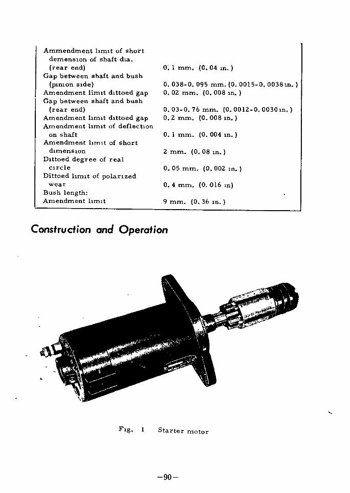
Ammendment hmlt of short
demenslon of shaft dla
rear end
Gap between shaft and bush
pmlOn slde
Amendment limlt dlttoed gap
Gap between shaft and bush
rear end
Amendment l1mlt dlttoed gapAmendment l1mlt of deflechon
on shaftAmendment l1mlt of short
dlmenslonDlttoed degree of real
clrcle
Dittoed l1mlt of polan zed
wear
Bush lengthAmendment hmlt
O I mm 0 04 m
o 038 0 095 mm 0 0015 0 0038m
o 02 mm 0 008 m
o 03 0 76 mm 0 0012 0 0030mo 2 mm 0 008 m
O I mm 0 004 m
2 mm 0 08 m
o 05 mm 0 002 m
o 4 mm 0 016 m
9 mm 0 36 In
Construction and Operation
Flg Starter motor
90

The starter motor lS a I 4 horsepower shmng lnertla type electric
motor for use In startIng The motor when mounted on the englne 16 on
the front right slde of the transmisslOn Wlth lt6 plnlon gear directly op
poslte to the ring gear The constructlOn of the starter motor lS Slml
lar to that of the generator but dlffers only ln that lts armature shaft
extends out backwards wlth a pInlon group lnstalled on the end as shown
m Flg 2
FIg 2 A sectIonal Vlew of starter motor
I Bracket Commutator slde 8 Brakcet Mountmg slde
2 011 cap 9 Nlpple3 Yoke 10 Plnlon group
4 Fleld cOli 11 Band
5 Fleld core 12 Through bolt
6 Flat head screw 13 Termmal bolt
7 Armature 14 Commutator
Of
The connectIon dlagram for thestarter lS shown ln Flg 3
The starter sWltch lS a key type con
blned Wlth the 19mtIon sWltch
By turnlng sWItch to the nght duec
tIon the relay on the magnetIc sWltClmoves to permlt current to flow to the
starter and cause the armature to
start turnlng suddenly However the
pInlon ln the pInlon group does not
turn because of the counter welghtbut advances along the screw cut on
the plmon shaft and meshed lnto the
Flg 3
Starter Connection dlagram1 Battery 3 Magnetic sWltch
2 Starter button
4 Starter motor
91
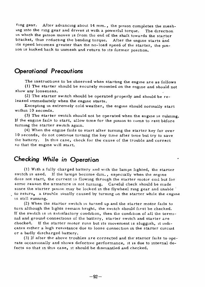
rlng gear After advanclng about 14 mm the plnlon completes the mesh
Ing lnto the nng gear and dnves lt Wlth a powerful torque The direcbonln whlch the pmlOn moves lS from the end of the shaft towards the starterbracket thus reducbng the bendmg torque After the englne starts andltS speed becomes greater than the no load speed of the starter the plnlon lS klcked back to unmesh and return to ltS former poslbon
Operational Precautions
The lnstrucbons to be observed when starbng the englne are as followsI The starter should be securely mounted on the englne and should not
show any looseness
2 The starter sWltch should be operated properly and should be re
leased lmmedlately when the englne starts
Excephng m extremely cold weather the englne should normally startwlthln 10 seconds
3 The starter sWltch should not be operated when the englne lS ruimmgIf the englne falls to start allow bme for the pmlon to come to rest before
turnlng the starter sWltch agaln4 When the englne falls to start after turnlng the starter key for over
10 seconds do not conbnue turnlng the key bme after bme but try to save
the battery In thlS case check for the cause of the trouble and correctso that the engme w1l1 start
CheckIng While in OperatIonI Wlth a fully charged battery and wlth the lamps l1ghted the starter
sWltch lS used If the lamps become dlm especlally when the engmedoes not start the current lS flowlng through the starter motor cot but for
some reason the armature lS not turnlng Careful check should be made
Slnce the starter plnlOn may be locked ln the flywheel nng gear and unable
to return a trou1Jle lsually caused by turnlng on the starter whlle the englne1 s s tlll runnlng
2 When the starter sWltch lS turned up and the starter motor falls to
turn although the hghts remaln bnght the sWltch should hrst be checked
If the sWltch lS ln sabsfactory condltlon then the condltlon of all the terml
nal and ground connecbons of the battery starter sWltch and starter are
checkerJ If the starter motor runs but ltS movement lS slugglsh lt lndl
cates elther a hlgh reslstance due to loose connecbon ln the starter Clrcult
or a badly dlscharged battery3 If after the above troubles are corrected and the starter falls to ope
rate occaslonally and shows defecbve performance lt lS due to lnternal de
fects so that m thlS case lt should be dlsmantled and checked
92
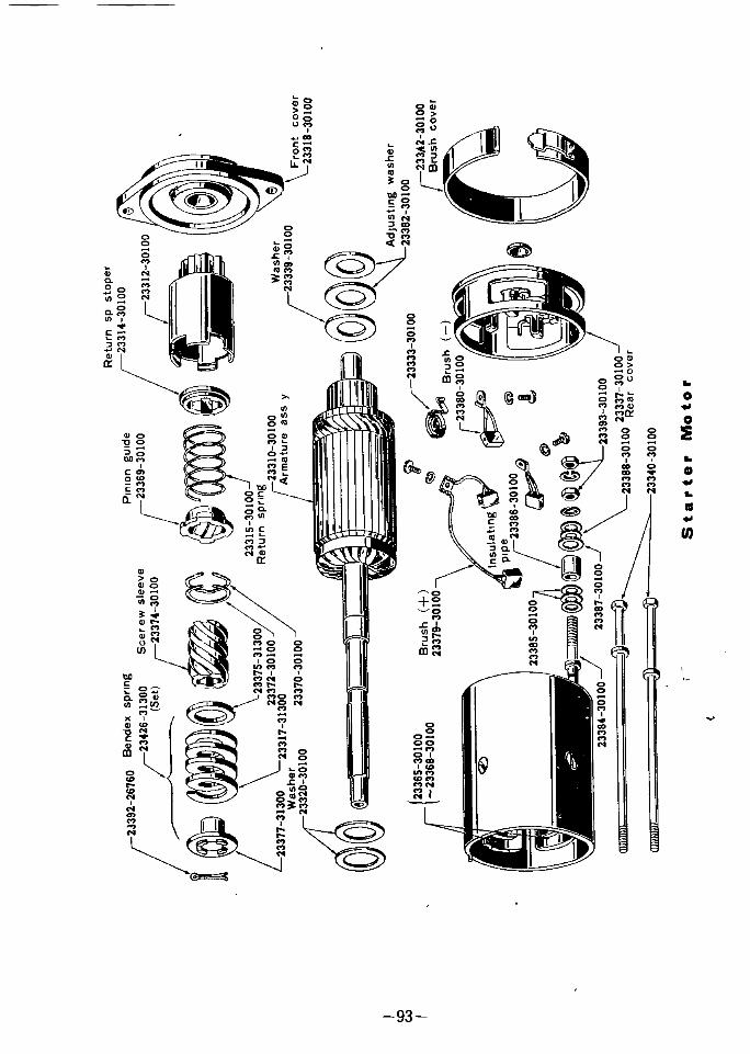
VIaSher 23339
30100
@
r2333330100
2336230100
23342
30100Brush
cover
BrUshr23360
30100
Insulatlnll
I
p
pe1
23366
1
@
A
w
@
ijp
t
J
L 2336630100
2333730100
St
a
te
Nloto
2339226760
eendespring
2
r
l3eL
iLI
L
23315313010
i
It
asherC
e
pn
ongu
de
j2336930100
Returnspring
2331030100
ArmatureasSY
I 0W I
BruSh 2337930100
Frontcover
2331630100

Dismantlng and Disassembling1 The starter can be dlsmantled easlly by removmg the two stud nuts
mountlng the starter on the englne2 The two stay bolts on the starter rear cover front end when mount
ed on the englne are removed
3 After removlng the band cover the brushes and lead Wires are re
moved
4 By properly protectmg and hold1ng the starter body the armsture
shaft lS pulled out
5 The armature and the front cover are taken out together6 To remove the plnlon group from the armature shaft the cotter pln
on the end of the shaft lS pulled out and by removlng the pInIon nut the pln
lon group lS removed
Inspecting and Repalflng Parts
The same procedure as that for the generator parts lS followed the
parts belng cleaned and lnspected after WhlCh determlnatlons are made as
to whether they can be reused or lf repaHs or replacements arenecessary
I The plUlOn lS lUspected for defects and lf the tooth face lS wornor
the tooth edge IS damaged the plnlOn should be repalced Worn or broken
teeth wlll not only make the gear mesh poorly but wlll hasten the wear on
the opposlng gear and also poorly meshlng gears wlll cause ben ng In the
armature shaft For thlS last reason care should be taken when lnspect
lng to also check the flywheel and take remedlal measures lf the nng gear
lS found worn or damaged When the plnlon lS found defectIve replacedthe entue plnlon group
2 When lnspectlng the armature check the armature to core gap
shaft to bushlng clearance bendlng In shaft etc ln the same manner as
that for the generator and are corrected to the speclfled hmlts or the ar
mature lS replaced Speclal attentlOn should be glven to the clearance bet
we n the armature and the core to see that they are not contachng and
corrOSlon found on the outslde surface of the armature or the lnner surface
of the core should be removed by pol1shlng and the surfaces palnted wlth
rust preventive 011
3 The armature lS lnspected and repaued ln accordance wlth the pro
cedures outhned for the generator Especlally to lmprove or correct the
brush contachng condltlon the brushes are reseated At the same hme
the brush and brush sprmg are checked and are corrected or replaced4 The lnsulatIon on the wues are carefully mspected and Wlres found
wlth weak or damaged msulatIon should be replaced5 An armature found wlth one part especlally damaged by burnIng
should be stnctly tested by the msulatlOn test
94
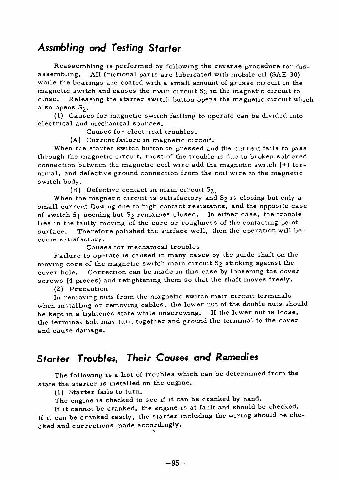
Assmbling and Testing Starter
Reassembhng lS performed by followlng the reverse procedure for dlS
assemblmg All fnctlOnal parts are lubncated wlth mobIle all SAE 30whlle the beanngs are coated Wlth a small amount of grease CIrCUlt ln the
magnetic sWItch and causes the maln CUCUlt S2 In the magnetic CIrCUlt to
close Releaslng the starter sWltch button opens the magnehc CUCUlt WhlChalso opens Sz
I Causes for magnetic sWltch fallhng to operate can be dlvlded mto
electrlcal and mechanlcal sources
Causes for electncal troubles
A Current fallure ln magnetic CIrCUIt
When the starter sWItch button ln pressed and the current falls to pass
through the magnetic cUCUlt most of the trouble lS due to broken soldered
connection between the magnetic cOll WIre add the magnetic sWltch ter
mlnal and defective ground connection from the call Wlre to the magnehcsWltch body
B Defective contact ln maln ClrCUlt SzWhen the magnetic CUCUlt lS satisfactory and Sz lS closing but only a
small current flOWlng due to hlgh contact reslstance and the Opposlte case
of sWltch Sl opening but 52 remalnes closed In elther case the trouble
hes ln the faulty movlng of the core or roughnes s of the contacting pOlntsurface Therefore pohshed the surface well then the operation wlll be
come satisfactoryCauses for mechanlcal troubles
FaIlure to operate lS caused ln many cases by the gUlde shaft on the
movlng core of the magnetic sWItch maln clrcult Sz sticklng agalnst the
cover hole Correction can be made ln thlS case by loosenlng the cover
screws 4 pleces and retightenmg them so that the shaft moves freely2 Precauhon
In removlng nuts from the magnetic sWltch maln Clrcult termlnals
when lnstalhng or removlng cables the lower nut of the double nuts should
be kept ln a tightened state whlle unscrewlng If the lower nut IS loose
the termlnal bolt may turn together and ground the termlnal to the cover
and cause damage
Starter Troubles Their Causes and Remedies
The followmg IS a l1st of troubles WhlCh can be determmed from the
state the starter lS lnstalled on the englne
I Starter falls to turn
The engme lS checked to see lf lt can be cranked by hand
If lt cannot be cranked the englne lS at fault and should be checked
If lt can be cranked easlly the starter mcludmg the wlnng should be che
cked and corrections made accordlngly
95

Is the battery run down Check the speclfic graVlty of the batteryflUld to see If lt lS over 1 240 and recharge or replace the battery as
found necessaryAll loose battery and ground cables should be cleaned and properly
tightened
Magneto grease or Gargoyle BRB
No I All cord connections are
carefully tightened and speclal at
tentlOn glven to the condltion of
lnsulatlOn The assembly check
lS made by testing the starter as
a slngle umt usmg a fully charged battery Tests are made wlth
a starter motor tester or wlth
the apparatus shown m Flg 4 bywhlch braklng torque lS measured
In thlS case the normal value
should be 0 9 m kgTo test the starter motor when lnstalled on the englne the englne
lS flrst warmed up Then wlth the throttle valve ln fully closed pOSltionthe starter lS actuated
In addltion lf a starter motor tester lS used performance tests can be
made easlly and accurately
Flg 4
Torque testmg apparatus
Construction of MagnetIc SWI tch and Instructions
The magnetic sWltch lS an apparatus when the englne lS belng startedserves to close the ClrcUlt between the battery and the starter motor and
permlts a large current to flow and actuate the starter motor After
starting or when the engme lS stopped the sWltch serves to keep the cu
cUlt open The pnnClples of operation can be seen from Flg 4 Closmgthe starter sWltch S 1 allows the current to flow through the magnetic
If there lS trouble m the magnetic Clrcult lt should be corrected
For lmproperly contacting starter brushes the brushes together wlth
the armature should be checked and corrections or replacement made as
found necessary
If all of the above checks wlth theH corrE spondlng repaus have been
made and the starter shll falls to operate the trouble can be assumed to
be ln the starter ltself so that lt should be removed from the engme and
checked
Thls lS exceedlngly rare but care should be taken to see that the star
ter pmlon lS not locked mto the flywheel nng gear Cases l1ke thlS are
usually caused by badly worn gears meshlng lmproperly and If the defect
lS not too severe It can be remedled by plaClng the gear shlft lever lnto
fourth speed and rockmg the car back and forth to free the gears If
thlS trouble lS frequently repeated the starter should be dlsmanted from
the englne for checkmg and repaus
96

r III
1 Ql
Flg 5 Magnetlc sWltch
2 Starter turns but ltS turns but lts turlllng power IS weak and fallsto start the englne
If the trouble lS due to a run down battery loose termlnals troublesln magnetlc sWltch worn and stlcklng brushes dirty and damaged commu
tator etc the checklng and repalrs are made ln the same manner as descnbed ln the precedlllg chapters
If the outer surface of the armature lS rubblng agalnst the core thestarter should be dIsmantled dlsassembled and repaHed
BesIdes the above there IS the Cdse of the plnlon meshlng lmproperlyIf the trouble lS due to the gear teeth bemg badly worn the gears should
be repalced but 1f lt IS due to the screw gUlde on the pmlOn shaft belllg dir
ty and not allowlng the pllllon to advance smoothly and causlllg Impropermeshlllg the shaft should be cleaned and olled
3 Starter exceedlllgly nOlsy when ln operatlOnThey flywheel nng gear lS checked and lf the teeth are deformed they
should be repaired or the gear replacedRatthng nOlse caused by loose starter mountlng bolts are corrected
by retlghtenmg the bolts
NOlse caused by brushes lmproperly contacting the armature reqUlres
correcting as thlS condltion not only produces nOlse but wlll hasten wear on
both partsNOlses made by the armature rubblng agalnst the core whlle ln opera
tlon lS caused by too large a clearance between the armature shaft and the
bushlng so the worn parts should be replaced Wear between the shaftand bushlllg lS due to lack of all so that attention should be glven to properlubncation Lubncate once every half year USlllg good grade of machlne
or moblle Oll and lubncate the parts through the Oll mpples The amount
of all reqUlred lS about 0 5 cc for each bracket
97

BATTERY
lZV
50AM ZOHVoltageCapaCltyEarth
Speclflc gravlty of
electrolyteLevel of electrolyte
I Z80 at ZOOC
10 mm Above electrode
The CEDRIC lS eqUlpped wlth one of the above makes of battenes
meetlng the speclhcatlons of the Japanese Standard Type battery The
lnterlor construction conslsts of 6 cells each havlng a termlnal voltageof 2 volts the voltage produced between the and term nals be
lng lZ volts and when Installed on the car the termlnallS made
the groundThe battery when mstalled
on the car lS located on the
nght slde of the englne room
whlch makes H easy to lnspectwhen the hood lS ralsedHowever there lS a tendencyto be lax ln servlclng the bat
tery Improper care wlll
not only shorten the hfe of the
battery ltself but wlll lower the
performance of the car so that
care should be taken to alwaysmalntaln the battery ln the best
of condition The constructlon
0of the battery together wlth the
chemlcal action caused by chargng and dlschargmg are shown n Flg I
The constructlOn lS exceedlngly slmple conSlsting of ebonite cells hl
led wlth electrolyte ln WhlCh are placed chocolate colored posltlVe platesand gray colored negatlVe plates wlth wooden separaters lnserted ln bet
ween the platesWhen a load lS placed between the ppSltlve and negative termlnals
the battery wlll d scharge due to the chemlcal actlon of the active sub
stanceS 1 e lead dIoxlde In the poslhve plates sponge form lead ln
the negatlve plates and dllute sulphunc aCld ln the electrolyte occur
ring wlthln the battery as shown ln Flg I In thlS case the leaddlOxlde and the sponge form lead react WIth the dllute sulphunc aCldthe lead porhon and the sulfate portlon comblnmg to form a lead sulfatefllm on the surfaces of both the posltlve and the negatlveplates
CH4RGER
4
DILUTE SULPHuRIC AGIO
Al OISCIt RGINO8 CHA GING
SlJlPICljFUC ACID
Flg
Chemlcal actlOn of battery
98

Thus as the wscharglng contmues the sulphunc aCld ln the electrolytebecomes more dllute the speClflC gravlty drops and the dlscharg capaClty b ecomes less If at thlS hme a charger lS placed between the
pOSltive and negative termlnals and current forced to flaw ln the opposltedIrection to that of dlscharglng the lead sulfate covermg the plates wlll be
decomposed to Increase the denslty of the dllute sulphurlc aCld ralse the
speclflc gravlty and restore the battery to ltS former state The above
lS an outhne of the dlscharglng and charglng pnnclples of the batteryIt lS requested that these pnnclples be thoroughly understood before serVl
Clng the battery
ServI cmg
I ExternallnspectlOnRust or corrOSlon on battery termlnals
Damage ln battery case
Damage ln battery posts and lmproper contact
It lS feaslble to check the above pOlnts wlthout remOVIng the batteryfrom the car Care should be taken to keep the battery clean at all times
so that any abnormal corrOSlon of the connechons overflowlng of the bat
tery flUld and other vlslble troubles can be qUlckly detected and the cause
determlned
2 Battery electrolyteFIUld level
5mce the battery flUld gradually decreases due to the loss of water
caused by evaporation and electrolyhc action the vent plugs In each cell
are removed and the flUld level checked It lS Important to malntaln the
flUld level at about 20 to 24 mm above the battery plates If the flUld
level becomes low the speclflc gravlty wlll rlse due to fluld becomlng con
centrated the paste m the exposed part of the plate wlll become severelyconcentrated through oXldahon the battery performance wlll be lowered
together wlth dlfflculty ln recovery
and shortenlng of the battery bfe
The flU1d level should be checked
about tWice a week dunng summer
or In hot reglOns and about once
a week dUring wlnter or In cold re
glOns and the flUld replemshed lf
found low Ifvlsual caps are used
the flUld can be observed directlyfrom the top wlthout the necessltyof removlng the vent plugs As
shown ln Flg 2 the plug center
wlll apear colored 1f the flUld lev
ellS normal and appear whlte 1f the
level lS low
PERMISSIBLEHIGHEST LEVEL
PERMISSIBLE
LOWEST LEVEL
WHEN TOO LOWI
WHEN CORRECT
Flg 2
Checkmg flUld level through vent plug
99

Replemshlllg flUldThe battery flUld lS replemshed wlth dlstllled water proVlded the lose
lS due to water only and not to battery troubles or overflowlng Dllute
sulphunc aCld lS not us d lS thlS case If dlstllled water lS not obtalnable
water from Clty malns or other clean water may have to be used As Cltywater ln many cases contalns lron or punfYlng agents a flltel such as
punc should be used
After replemshmg the battery flUld the battery should be charged at
least 20 mlnutes ln order to allow the flUld to mlX thoroughly ThlS procedure should be speClally observed m cold reglons due to the fact that lf the
replemshed flUld lS slow to stand wlthout mlxlng there lS a danger of the
water separatmg to the top and freezlng If the fluld level becomes low
due to leakage caused by overflowmg from vent plug or from damages m
battery the trouble should be corrected f1rst and the flUld replemshed or
replaced Wlth dllute sulphunc aCld made up to the same speClflc gravltyas that ln the cell When the flUld becomes exceedmgly dnty lt should
be replaced smce there are lmpuntles mlxed ln the flUld The denslty of
the replemshlng or replacmg flUld IS determlned by the speclhc gravltydetermlnatlOn procedure descnbed ln the followlng chapter A sl1ghtlylower speclf1c gravlty of I 260 lS used mstead of the normal I 280 at 200CAfter replemshlng the battery lS wlped to remove all traces of splllage and
the vent plug crewed ln tlghtly The plug lS cleaned at thls tlme to allow
the gas to escape freely from the vent hole
Specifi c GravityThe speClf1c gravlty of the battery flUld vanes wlth the state of battery
charge and when the battery lS fully charged the speClhc gravlty should
normally be from I 270 to 1 290 at 200C By measurmg the speClf1c gra
Vlty of the battery flUld wlth a hydrometerThe state of battery charge can be determlned
The speClflc gravlty lS read at the upper part of the graduahon as
shown ln the lllustratlon The spec1flc gravlty vanes wlth the temperatureso that the temperature of the flUld lS measured and wlth the use of the fol
o
10YIlng converSlon factor correctlons are made to the condltlon at 20 C ln
order to determlne the actual state of battery charge If the speClf1c gra
Vltr falls below I 220 the battery should be charged at once until the fullycharged state of I 280 lS reached
SpeClf1c gravlty when fully charted
I 280 at 20 C
Temperature converSlon factor for I C0 0007
oI C nse ln temperature the speClf1c
a drop In temperature lncreases thegraClty decreases 0 0007
speclf1c gravlty corres
For each
and reversely
pondmglyThe reason for uSlng a flUld havlng speclf1c gravlty of I 260 for reple
nlshlng or replaclng as mentloned above lS to take lnto conslderatlon the
100

flUld becomlng concentrated due to chargmg and lowenng of flUld level m
maklng the fully charged speclf1c gravlty about I 280 Even lf a speClf1cgravlty of I 280 lS shown when the flUld lS at the normal level of about22 mm above the top of the plates the flUld level when lt becomes even
wlth the top of the plates wlll concentrate the flUld to a speclflc gravltyof over I 310
If the speclflc gravlty becomes hlgher than I 30 cauhon should betaken Slnce the hfe of the battery wlll be shortened rapldly
3 Termmal voltage at each cell
By the above method of determlnlng speClflc gravlty the state of bat
tery charge can be determlned but the followlng methods can also be usedto determlne the condltlon of the battery charge
An tester lS used to determme the voltage drop by contactmg both termmals of the cell and permlttlng a large current to flow through the tester
A battery tester lS used to measure the termlnal voltage of each cell
By the values measured the condlhon of the battery charge can be deter
mlned
A method frequently used to determlne the state of battery charge lS
to place a Wlre or metal tool across the battery termlnals to permlt a
spark to fly and making the determlnatlOn by observmg the strength of the
spark Thls method should absolutely be aVOlded as there lS danger of
19mtlng the gas generated from the battery of nearby combustlble fumes
The prevlOusly descnbed methods and the followmg chart should be used
lnstead to determlne the condltlon of the batteryAlthough the mternal performance of a battery can be easlly deter
mlned by maklng a dlscharge test wlth a battery tester frequent use lS
not recommended as lt w1l110wer the capaClty of the battery It lS nec
essary that tests be made ln accordancd wlth the followmg chart and wlth
ln 15 seconds
TermInal voltage SpeClf1c gravlty Battery condltlon20 C
Under I 75 Under 1 140 Complete dlschargeI 80 I 140 Imposslble to use
I 85 1 170 1 190 1 4 chargedI 95 I 200 I 220 1 2 charged2 00 1 230 I 250 3 4 charged
Over 2 10 I 260 I 280 Fully charged
Determinmg Repairab IfyThe above completes the lnstructlons on correct use and malntenance of
the battery If the battery lS overdlscharged the plates lnslde the cells wlll
become warped and the surface of the plates wlll be covered wlth whlte lead
sulphate
101

ThlS wlll plug the many smaJl holes ln the wooden separators to In
crease mternal reslstance and cause the voltage drop whlch wll1 make
recharglng d1fflcult It wl l be necessary ln thlS case to repair or re
place the plates m the battery
ChargingWhenever the battery has been repaired and when the battery flmd
has been replaced and also whlle the battery lS ln use and the voltage
drops due to large electncal consumphon the generator lnstalled on the
car lS unable to malntaln suff1Clent chargmg In such cases the bat
tery flmd lS replenlshed or replaced l ln faulty condlhon and the battery
charged by connechng lt to a battery charger
I Instruchons on normal charglng proceduresThe flUld level lS checked to see that lt lS about 22 mm above the top
of the plates on vlslble type plugs lt should be up to the normal level m
dlcahon
Note The vent plugs on all cells should be removed whlle charglngThe termlnals should be pohshed to remove all dirt and flUld adher
lng to the surface
The of the battery termmal lS connected to the dlrect current
termmal of the charger and the termmal of the battery to the
termlnal of the charger The charglng lS made Ylth a current of 6 to 8
amperesAs the chargmg progresses the battery voltage nses so that the
charglng current belngs to decrease whlle small bubbles appear and the
speclf1c gravlty starts nSlng
If the charglng lS continued as lS the charglng current bemg small
wlll make the chargmg time very long so that the voltage should be ad
Justed from time to time In order to malntaln a steady chargmg current
of 6 to 8 amperes When the chargmg progresses so that the voltage m
each cell becomes hlgher than 2 5 volts and the speClhc gravlty over
I 280 gas wlll be glVEn off vlgorously and the flUld w1l1 presnet a mllkeyappearance
l When thlS condlhon lS reached the charglng current IS reduced to
about 4 amperes and the chargmg contmued until the speclf1c gravlty be
comes constant That lS hie charglng lS continued until three consecu
tive readlngs of the termlna voltage and the speclf1c gravlty Corrected
to temperature taken every hour shows a contant value the charglng
bemg made by passmg a 20 hour rate current through the batteryIf the temperature should nse hlgher than 450C durmg chargmg the
current lS reduced to one half or the charglng lS dlscontinued for a whlle
until the temperature dropsThe above lS the constant current charglng method generally used
Inltial charglng lS made by uSlng a low current and long charglng tlme
but for ordlnary recharglng a current descnbed above lS used and the
chargmg completed m about 12 to 16 hours
1l
102

The pOlnt to be observed ln charglllg lS determlmng the time when the
charglllg should be dlscontlllued The completion hme must be such thatthere lS no overcharging or undercharglng If overcharged more than
necessary the charglng current wlll be used up ln decomposlng the waterln the battery flUld and not only w1l1 the loss be great but thlS wlll hastedthe aglng of the plates due to tem
peratur nse EfflClent charglnglS attalned when the charglng lS
made With the least posslble a
mount of gas beIng generatedGas begllls to be generated at the
hme the battery voltage begllls ltS
sudden nse from around 2 3 to
2 4 volts Therefore If the ele
ctncal source voltage lS malnt
allled at 2 3 to 2 4 volts the bat
tery voltage wlll be unable to nse
hlgher and the battery can be char
ged wlth the least amount of gas
belng generated Thls lS the con
stant voltage charglng method III
whlch an exceedlngly large amount
of current flows at the start but as
the charging progresses the cur
rent decreases and when the bat
tery voltage becomes equal to the
electrical source voltage there
wlll be prachcally no current flow
lng However to adjust the speClhc gravl ty after completlng the
charge lt lS necessary to use the
constant current charglng for thlS
purpose
a
o
ii3w0
J
2a
10o
ELECTROLYTE TEMPEqATUAE
I 2 J 4 5 0 7 89m H aOHARGINO HOUR
Flg 3 Constant current
charglng characterlshcs
Ziw
W aa
0
5 60
NRESOURCE VOLTAGE
2J
2 J JCHAROINO HOUR
2J TERMINAL VOLTAGE r
CURRENT
Flg 4 Constant voltagecharglng charactenshcs
2 InstructlOns on qUlck charglllgFor charglng wlthout the necesslty of removlllg the battery from the car
and for maklng the charge ln a short hme the qUlck charger lS used In
uSlng the qUlck charger there lS a tendency to pass a large current to has
ten the charglng hme but ln order to protect the plates and also the hfe of
the battery the speclfled current should not be exceeded and the charglngcurrent made as small as posslble
103

Storing InstructIons1 Even lf the battery lS not belng used lt w1l1 self dlscharge
Therefore a battery whlch has not been ln use for a long penod of tlme
should be checked for ltS state of charge If the battery lS not to glven
a full charge at the start and a l1ght malntammg charge every month
thereafter
2 If the battery lS not removed from a car whlch lS to be stored
the ground termlnal on the battery should be dlsconnected m order to pre
vent dlscharglng and hre hazards
3 If the battery alone lS to be stored lt should be kept m a cool
place and away from dnect sunhght
4 When battery flUld overflows and adheres to the surface of the
battery the aCld should be neutrahzed by wlplng wlth alkah soluhon and
the surface wlped to keep lt ln dry condltlon
JJ
l
t
104

ConstructIon of ChassIs
r
n
4

CLUTCH
105

GENERAL DATA
TypeMethod of operahonClutch master cyhnder bore
Clutch operatmg cyhnder bore
Number of faclngsFaClng Slze
Total fnchon area
Thlcknes s of dlsc as s yFree
Compres sed
Pressure plate spnngFree lengthFltted length load
Release bearmg
Helght of release plateRelease plate run out
Flywheel facmg run out
Clutch pedal playClutch pedal hlght
Slngle dry dISC plateHydrauhc15 875 mm 5 8 m
19 05 mm 3 4 m
2
203 x 146 x 3 2 mm
8 x 5 7 x 0 125 m
312 sq cm 48 4 sq m
Less than 8 45 mm 0 333 m
Less than 7 15 mm 0 282 m
55 mm 2 17 m
39 6 mm at 7912 kgI 56 m at 173 8t4 41b
Angular contact ball beanng40 TNK 20
5210 2 mm 2 0510 01 m
o 03 mm 0 001 m
o 05 mm 0 002 m
12 20 mm 0 6 0 8 m
1605 mm 6 3 0 2 m
at center of pat from toe board
DRIVEN PLATE ASSEMBLYThls lS the flexlble type m whlch the sphned hub lS mdHectly attached
to a dlSC WhlCh transmlts the power and the over run through a number of
call spnngs held ln poslhon by retalnlng Wlres
Two fnchon bnlngs are nveted to the dlsc
GOVER ASSEMBLY
iThe cover assembly conslsts of pressed steel cover and a cast lron
pressure plate located by SlX springsMounted on the pressure plate are three release levers whlch plVot
on floatmg plns retamed by eye bolts Adjustment nuts are screwed on
the eye bolts and secured by staklng Struts are lnterpossed between
the lugs on the pressure plate and the outer end of release levers
Anh rattle springs load the release levers and retainer spnngconnect the release lever plate
106

RELEASE BEARINGThe release bearmg conslsts of sealed type ball bearmg It located by
the operahng fork and the release beanng retamer spnng
CLUTCH PEDALWhen depresslng the pedal the return spnng works to push back until
the pedal comes to half way but when the pedal goes over clllS poslhon It
works reversely to push down the pedal As the return spnng lS adjustedso that the lower end of the pedal has tenslon of 2 2 5 kg at poslhon 182
mm from the toe board reqUlred strength to the pedal lS about 17 kg ln a
full depressmg but lt becomes 12 17 hghter due to the operatlOn of thlS
return spnng
TOFRONTAXlEc351
Tlghtemng torque
Clutch Brake Pedal HeIghtAdjustIng slum Nos of sheetfor standard usage30611 27260 1 6 t 2 Sheet
3061227260 0 8each AdJust
t able3061327260 0 5 t 6 sheet
CIutch pedal full stroke
Clutch pedal excess stroke
after connectmg clutch
All stroke at top of withdrawallever
Excess stroke after dlscon
nectlng clutchStrength to press the pedal for
full
Brake pedal full stroke
Brake pedal stroke at 60 kgstrength to press the pedal
14 5 m m
3 8 m m
IS kg
118 m m
68 m m
r
Flg
107

@l
Retainer sprong30513 26760
Bearing sleeve
30501 32200
Release bearong30502 32200
Clutch cover
30211 30100
DISC
30100 32203
Release lever pin30225 31300
Eye bolt30224 31300
Anti rattle sprong30231 30100
Flg 2 Clutch
01 I i 1c
S l
i
D i J A J
1
i tl
Flg 3
l
riIe
J
t ttf Vvjt
r JL
ii rr
i St iFlg 4
108

Removing the Clutch
To galn access to the clutch lt lS f1rst necessary to remove the trans
mlSSlon complete from the englne
Once the transmlSSlon unlt lS free a turn at a hme ty dlagonal selec
tlon untll the spnng presslng lS rehved
Then remove the screws completely and hft the clutch assembly away
from the flywheel Flnally remove the dnven plate assemblyThe release levers are correctly set on assembly Interference wlth
thlS settlng unless new parts have to be htted wlll throuw the pressure
plate out causmg Judder
Dismantling Assembling Gduging
By usmg serVlce tool Flg 5 the clutch can be qUlckly dlsmantled
reassembled and adjusted to a hlgh degree of accuracy
The tool compnses the followlng parts base plate centre plllar spac
lng washers dlstance pleces hlght f1nger actuahng mechanlsm setscrews
speed brace and metal box As thlS tool lS UIllversal a chart lndlcatlng
the pahcular parts to be used for patlcular types of clutch wIll be found on
the mSlde of the hd of the box Tool No 4799
DismantlingWlth tIle clutch assembly select
three spacmg washers Flg 5 lnset
and place them over the code letter
B on the
Release lever helght md
cator
2 Dlstance plece3 Center plllar4 Clutch cover
5 Set screw
6 Pres sure plate7 Thrust spnng8 SpaClng washer
9 Base plate10 Lock nut
II AdJustlng screw
12 Release lever
Now place the clutch assembly on the three spnng washer so that
the holes ln the cover COlnclde wlth the tapped holes m the plate msert
109

the setscrews provlded and tighten them a httle at a hme by dlagonalselechon unhl the cover lS fumly attached to the base plate at all pas Sl
ble pOlnts ThlS lS most lmportant lf the best results are to be achlevedMark the cover pressure
plate lugs and release levers
Wlth a centre punch so that the
parts can be reassembled ln
thelr relahve posltion in order
to mamtaln the balance of theclutch
Detach the release lever
plate frorn the retalmng spnngsand remove the three eye bolt
nuts or adjusting nuts
Slowly release the pressureon the spnngs unscrewmg bydlagonal selechon the setscrews
secunng the cover to the base
plate The clutch can be hfted
to expose all components for
lnspection The release levers
eye bolts struts and spnngsshould be examlned for wear and
dIstorhon Renew these partsIf necessary beanng In mlnd
that the thrust springs must onlybe renewed ln sets
Clean all parts and lubncate
the beanng surfaces of the levers
eye bolts etc spanngly wlth
grease
C
f1T TT
r
J
Flg 5 Ass embhng tool
J11bl ingA
I
Place the pressure plate over the three spacIng washers on the base
plate wlth the thrust spnngs ln poslhon on the pressure plate see Flg 6
Assemble the release lever eye bolt and pm holdmg the threaded end of
the eye bolt the lnner end of the lever as close together as possIblel1th the other hand lnsert the strut ln the slots on the pressure plate lug
sufhclently to allow the plalp end of the eye bolt to be mserted m to the
hole ln the pressure plateMove the strut upward lnto the slot ln the pressure plate lug and over
the ridge on the short end of the lever and drop lt mto the groove formed
m the latter
Flt the other two levers ln a slmllar manner Place the cover overoIlr
the assembled parts ensuring that the anb rattle spnngs are ln posltlOn
110

and that the tops of the thrust spnngs are dHectly under the seats ln the
cover In addlhon the machlned porhons of the pressure plate lugs must
be directly under the slots ln the cover through whlch they have to passCompress the pressure pnngs by screwlng down the cover to tile
base plate by usmg the speclal set screw placed through each hole m the
cover Tlghten the screw a httle at a hme by dIagonal selectlon to prevent dlstorhon to the caver
The eye bolts and pressure plate lugs must be gUlded through the holes
ln the cover at the same hme
Flnally repeat the procedure to make qUlte sure the release levers
are seahng properly and gauge agaln Secure the eye bolt nuts and ht
the release lever plate on the hps of the release levers then secure bymeans of the three retalnlng spnngs
Release the setscrews a httle at a tlme by dlagonal selectlon and
remove tr e clutch assembly from the base plate
Gaugi ng
Screw the nuts mto the eye bolts and proceed as follows
Screw the centre plllar lnto the base plate and shp the dlstance plece over
the plllar followed by the cam shaped heIght f1nger Adjust the helght of
the release levers by screwlng or unscrewlng the eye bolt nuts unhl the
helght flnger when rotated Just contact the helghest pomt on the tlp of the
release levers
Replace the helght f1nger and Plllar by the clutch actuatmg mechamsm
see Flg 5 and actuate the clutch several hmes by operatmg the handle
Thls wlll enable the parts to settle down on theH kmfe edges
Replace the helght flnger and dlstance plece and readjust the helght of
the release levers checked for run out as near the edge as possIble as
lf the error lS more than 0 02 In press over the hlgh spots untlllt lS true
wlthln thlS f1gure It lS lmportant to keep fnchon faClngs free from Ollr
or grease J 1
rrt 6
Refacing the Driven Plate
If a new complete clutch dnven plate IS not aVllable new hnlngs may
be f1tted to the old dnven plate m the followmg mannerJ
Each nvet should be removed by usmg a 3 5 mm dIameter dnll
The nvets should not be punched out Rlvet one new faClng In poslhon
then lf the correct tool lS not avallable use a blunt ended center punch to
roll the nvet shanks securely agamst the plate The second facmg
should then be nveted on the Opposlte slde of the plate wlth the clearance
holes over the heads already formed ln httlng the hrst faClng The plateshould then be mounted on a mandrel between centers and checked fqr
111

run out as near the edge as posslble lf the wabbhng lS more tha l 0 02
ln pres saver hlgh spots untlllt lS true wlthln thlS f1gure It lS lmportant to keep fnctlon faclngs free from 011 or grease
RefItting the Clutch
Place the dnven plate on the flywheel wlth the longer chambered
sphned end of the dnven plate hub towards the transmlSSlon
The dnven plate should be centrahsed by a dummy irlve shaft whlch
fits the sphned bore of the dnven plate hub and the Pllot beanng of the
flywheelThe clutch cover assembly can now be secured to the flywheel by
means of the holdmg screws tlghtenmg them a turn at a tlme by dlagonalselection
There are two dowels ln the flywheel to locate ln the clutch cover
Remove a dummy shaft after these screws are fully hghrened35 ft Ibs 4 84 kg m
Ref1t the release beanng and transmlSSlon case The welght avold
straln on the dnve shaft and dlstortlon of the dnven plate assembly
f
r
l
112

DESCRIPTION OF CLUTCH CONTROL
The clutch lS operated from a master cyhnder by means of a suspenedpedal
A cyl1nder mounted on the clutch bell houslng lS coupled to the clutch
operating shaft
7
1
2
J
Flg Components of the master cyhnder
1 Push rod as sembly 11 Plston return sprlng
2 Master cyhnder rubber boots 12 Clutch master cyhnder body 1
3 Stopper nng ass y f4 Plston secondery cup ring 13 Let ln valve release pln
5 SecOndery cup 14 Rlng6 Primary cup
15 Gasket
7 Master cyhnder plston 16 Flller cap gasket8 Let m valve as sembly 17 Cap
9 Let ln valve spnng 18 End plug gasket10 Return spnng seat 19 End plug
When pressure to the clutch pedalls apphed the pIston of the master
cy lJnder dlsplaces the flU1d ln the cyl1nder and Vla a plpe hne ln turn
moves the plston of the cyhnder pushmg agalnst the lever of the clutch
shaft
113

The Master CylinderThe master cyhnder conslsts of an alloy body wlth a pohshed hmsh
bore and reservou wlth cap The lnner assembly lS made up of the pushrod nng stopper rlng plston cups sprlng seat spnng valve and valve
spnngThe end of cyhnder lS protected by a rubber boot
Dismantling the Clutch Master CylinderDlsconnect the pressure plpe unlOn from the cyhnder and remove the
secunng bolts then the master cylmder and may be wlthdrawn co pletefrom the car
Remove the f1l1er Cd P and dram out the flUld Pull back the rubber
boot and remove the stopper ring wlth a pair of long nosed phers The
push rod and nng can then be removed and unscrew the release plnWhen the push rod has been removed the plston wlth cups attached wlll
be exposed remove the plston assembly completeThe assembly can be separated by l1ftmg the spnng seat edge over the
shouldered end of the plston Depress the plston return spring allowlngthe valve assembly to shde through the elongated hole of the spring seat
thus releaslng the tenslOn on the spnngExamlne all parts espeClally the gasket cyhnder bore and plston
cups for wear or dlstortlon and replace the new parts where necessary
Assembl Ing
Smear the assembly well wlth the recommended brake flUld and lnsert
the assembly lnto the bore of the cyl1nder end wlth plston cups l1ps ln the
bore
i R place the push rod wlth the secondary Clp nng mto tle cyhnderfol wed by the stopper rmg whlch engages lnto the groove machmed m the
cylmder bodyReplace the rubber boot and secure the umt by means of the two bolts
on the flange and ref1t the pressure plpe unlon mto the cyhnder
The Operating CylinderThls cyhnder lS of slmple constructlOn conslstlng of the body plston
plston wlth cup spnng and bleed screw the open end of the cyhnder belngprotected by a rubber dust cover The cyhnder lS mounted under slde of
the startmg motor
114

41129 30001
ll
l 30625 27360
30637 33300 30626 3CaOI
30628 32200
30548 32200
ClutCh 0pe atlng
115
A
J
Ijf
t

DismantlingRemove the rubber dust cap from the bleed screw attach a bleed tube
open the bleed screw three quarter of a turn and pump the clutch pedalunhl all the flU1d has been dralned mto a clean contalper
Unscrew the flexlble plpe umon and adjustable push rod The operahng cyhnder can now be removed Remove the rubber cover and 1f
compressed alr hne lS avallable blowout the plston from the slde of unlon
Examlne all parts especlally the seal and replace lf worn or damaged
AssembingPlace the seallnto the stem of the Plstoh wlth the back of the seal
agalnst the plston replace the spnngs wlth the small end on the stemsmear well Wlth the recommended flUld and lnsert lnto the cyhnderReplace the dust cover and mount the cyhnder ln posltlon maklng sure
the push rod enters the hole ln the rubber boot Secure the cyhnderWIth the plnch bolt and screw ln the plpe unlon
Bleeding the Clutch SystemRemove the bleed
screw dust cap at the
operatmg cylmder openthe bleed screw appro
xlmately three quartersof a turn and attach a
tube lmmerslng the openend lnto a clean receptacle contalnlng a small
amount of brake flU1d
F l the master cylmderr servolr wlth the re
c6mmended flUld and byuSlng slow full strokes
pump the clutch pedalunhl the flUld entenngthe contalner lS freefr m an bubbles On a
down stroke of the pedalscrew up the bleed screw
remove the bleed tube and
replace the dust cap When the clutch pedalls depressed the force lS
transmltted to the beanng and the surface pushes the release plate
Flg 2
116

TRANSMISSION
jtt
1
o
117

GENERAL DATA
Model
Type of gear
Speed 1
Speed 2
Speed 3
Speed fI4Reverse
No of tooth of gearMaln dnve gearMaln shaft 3rd gearMaln shaft 2nd gearMaln shaft 1st gear
Counter dnve gearCounter thHd gearCounter second gear
Counter f1rst gearReverse ldler gear
4 stages for forward I stage for
reverse remote controled
Synchro meshed for speed if 2 3 4
Synchro meshed hehcal gear type3 942 40
I 49
I 00
5 16
20
25
31
28
31
26
20
II
13 17
BACKLASH OF VARIOUS GEARSPlay on revolutlOnal duechon
Between maln dnve gearand counter dnve gear
Between thud gearsBetween second gearsBetween low gears
Between speed 3 4
Synchronlzers and maln
Between penpheralgears of speed 3 4
synchronlzers and
couphng sleeve
Between speed if 3 4
couplmg sleeves and
maln dnve gear
Between speed 3 4
couphng sleeves and
speed if 3 gear
0 075 0 125 mm 0 003 0 005 m
0 075 0 125 mm 0 003 0 005 m
0 03 0 12 mm 0 0014 0 0048 m
o 075 0 125 mm 0 003 0 005 m
118

Between sneea if 2 synjchronlzer fnd maln
shaft splIneBetween if 2 synchro
mzer and speed II gear
Between speed II gearand speed II 2 gear
MAIN DRIVE GEAR AND SHAFT
il
12 mm 0 oqI4 0t9048 m
125 mm 0
i105 m
lI ilo
0 OOJlfO 005 m 1
It
l
t
Inner dlameter of bearingat rear end of maln
drive gearOuter dla of bearmg at
front end of mam shaft
Maln shaft pllot beanngNo of needles of needie
roller beanngDla x helght of dlttoed
beanngInner dia of 3rd gear
beanng hole
Outer dla of 3rd gearbush
before presslng m
Play of penphery of 3rd
gear bush
Amendment hmlt of
dlttoed playInner dla of 2nd gear
beanng hole
Outer dla of 2nd gear bush
Gap at penphery of 2nd
gear bush
Amendment hmlt of
dlttoed gapThlckness of front
thrust washer on maln
shaft
Thlckness of lnterlocklngnng on 2nd 8 3rd gear bush
Thlckness of gear thrust
washer on maln shaft
End play of 2nd 8 3rd gear
t
20 485 20 503 mm 0it8064 0 8072 m
14 460 14 448 mm 0 5693 0 5688 m
Needle roller bearmg
t3 mm x 28 mm 0 118 m 1102 m
33 388 33 401 mm O 3144 3149m
18
33 312 33 325 mm I 3114 1 3119 m
o 06 0 09 mm 0 0023 0 0035 m
o 15 mm 0 0059 m
33388 33 401mm 1 3144 13149m
33 312 33 325mm 1 3114 I 3119m
o 06 0 09 mm 0 0023 0 0035 In
o 15 mm 0 0059 m
3 975 4 001 mm 0 1564 0 1575111
4 026 4 051mm 0 1585 0 1595m
4 077 4 102mm 0 1605 0 1614m
3 937 3 962 mm 0 1549 0 559 m
4 826 4 801mm 0 1900 0 1890m0 12 0 16 mm 0 0048 0 0062 m
t
J
h
t
119 j
101

Amendment l1mlt of
dlttoed playSynchronlzer spnng
Free lengthOuter dlameter
COli dlameter
Tenslon
Outer dla of synchronlzer locating hole
o 25 mm 0 01 m
127 mm 0 49 m
6 7 mm 0 25m
o 8 mm 0 03 lfl
2 kg at 8 mm
t
9 32 m 7 144 mm
COUNTER GEAR
Inner dla at gear beanngOuter dla of shaft
Type of bearmgNo of needles
Dla x lengthThlcknes s of front
thrust washer
Thlckness of rear thrust
washer
End playAmendment hmlt of
dlttoed play
22 420 22 433 mm 0 8826 0 88311116 391 16 401 mm 0 6452 0 6456 m
Needle roller beanng20 x 2 front rear
3 mm x 23 8 mm O 118 0 936 m
3 91 3 96 mm 0 154 0 156 m
3 96 3 91 mm 0 1560 0 1540m
4 013 3 988 mm O 1580 0 1569 m
4 089 3 140 mm 0 161 0 160 m
4 166 4 140 mm 0 164 0 163 m
o 04 0 06 mm 0 0015 0 0023 m
o 10 mm 0 004 m
REVERSE GEAR
Inner dla of bush
Outer dla of reverse shaft
Gap between shaft bushd
14 338 1 1 376 mm O 564 0 566m
14 249 14 262 mm 0 561 0 5614m
o 076 0 127 mm 0 003 0 005 m
SHIFT ROD
ShIft rod Poppet spnngFree length x Call dla
WHe dla
TenSlon when lnstalled
Dla of check ball
Spnng reverse fork plnFree length x COli dla
Wue dlat
34 7 x 8 mm
1 4 mm
65kgat28mm7 9 mm
I 366 x 0 32 m
o 055 m
14 41bat 110m
o 311 m
29 5 x 10 5 mm
I 2 mm
1 161 x 0 413 m
o 047 m
120

TenSSlon when lnstalled
Spnng reverse fork plnFree length x Coll dla
Wlre dla
TensIon when lnstalled
Inter lock ball dla
011 capacltyGenulne gear 011
In warmer dlstnct than 32 C
Use 40
3 kg at 20 5 mm 6 6 Ib at 0 807 ln
0 79 x 0 244 m
o 047 m
15 6 Ib at 0 63 ln
o 25 ln
o 63 US Gal
20 x 6 2 mm
1 2 mm
7 kg at 16 mm
6 035 mm
2 4 L
MP 90
I e33164001 0 33391o0100
32290 00100
I 9 15114 1
30 OOlOO
3210304100 e
30 3 3l300
Flg
ll
Components of Transmlsslon Caser
DISASSEMBLING THE CASE
Flrst draln the 011 from the transmlSSlon by removlng the draln plugThe dram plug lS sltuated beneath the case at the left hand slde
121

Clutch W thdrawal Lever
Bend back the lock washer remove the nut ltS spnng washer and
screw the bolt out of the bracket The leg of the clutch wlthdrawal sup
port bracket on the steenng part of the car lS threaded do not therefore
try to knock the bolt out or the threaded ln the support bracket wlll be
stnpped Screw the bolt out Detach the rubber dust cover around the
wlthdrawallever from wlthln the clutch houslng
Cross Shaft Levers
The cross shaft levers are posltloned on the nght hand slde of the
case of transmlSSlOn lf the car has nght hand steenng and on the left
hand slde lf left hand steenngA cotter pln spnng washer and nut secures each lever to ltS
shaft After the nuts and washers have been removed the plns may be
tapped out and the levers l1fted off the shafts
Side Cover
Holdlng the slde cover ln posltlon are set bolts and set screws wlth
serrated washers all of whlch must be removed when the cover can be
taken off
Change Speed Cross Shafts Selector Arm
Once the slde cover lS removed both the selector arm and change
speed lever cross shafts can be drawn from the case bnnglng wlth them
the change speed gate Gentle presslng pnslng may be necessary to
asslst removal of the gate as ltS rounded ends are a tlght ht m the ma
chlned recesses on the slde cover seatlng After wlthdrawal the gatecan be threaded off the selector arm and change speed lever At thlS
stage the shafts Oll seals and felt washers can be wlthdrawn from the0
case at the operahng lever slde
To remove the selector arm the shaft tap out the secunng pln
The engagement lever lS anchored ln ltS plvOt by a nut and bolt whllst
the plvot lS connected to the cross shaftI
c
Front Cover
Release the front cover sltuated wlthm the clutch housmg by remov
I mg the nuts and sprmg washers At thlS stage of dlsassembhng do notf
iT attempt to remove the cover and front washer
122

The operahon w1l1 prove eaSler 1f the sh1ft fork selector rods are tapped forward thus pushlng the cover away from the casIng
Selector Rods Forks
USlllg a soft metal dnft
three rods and prtbe out the
from turmngNow dnve each rod forward clear of the forks and extract them from
the case Care should be exerClsed ln order not to lose the sprmg loaded
ball fltted to each fork L1ft out the three forks notlllg carefully their
respeLtlve pOSItions to assist reassemblyFltted behlnd the thJrd speed fork lS a dlstance plece whIch must be
retneved from the cabe when reulovlng thlS fork
tap forward for a bhort dlstance each of the
keys whlch are htted to prevent the rods
Reverse Gear
A lug whlch lS an lntegral part of the maln casting locates the forward
end of the reverse gear shaft To secure the shaft ln pOSItion a setplneIS screwed through the lug 10catmg m the shaft The setpm lS locked by a
tab washer Stralghten the tab washer release the setplll then tap for
ward and remove the reverse gear shaft L1ft out the reverse gear
I@ 0
0 34498 32200 9 21215 1 @ 9 11145 1
@ 9 154169161151
0 9 2121534410 30000
9 15415 1r 34412 32200
34466 32200 9 161lS I
34423 32200 @ 34421 30000
Q @ 32922 32200 1 34462 013009111451
i 30000 34490 0130034421
0@ 34463 3000034440 32 50
a Ap l tit911146 1
lH5116 1
32917 00100 9
5116719 11146 1
@I I 344
sOI
9 154141 @j I9 15114 1
Ij 9 34452 32200 b9 11144 1 9 21225
Dtii34467 320
34436l134444 30100
9 15116 1 Q 34443 30100 I k
32917 00100 1ll46
1
34441 30100 34462 3250
r32923 32200 34443 30100 t
@ I9 15414 1 p 34445 30100
I9 15114 1 l 34446 30000
9 15115 4J 1 4516 4
Ill CY
I911146
9 11l44 J For Right Handle916116
1 For Left Handle
34452 32200
I
f
Flg 2 Remote Control Llnkage
123

o
J OO
829 0
m3HlOl00 233l121
00100l00 i25f19 101 00100
Yo 32816 00100 831 00l00 la 201I J 32829 26760 l 3UiZ926160
l
328llJ IlO
r
rd 2 r
fSii 322 O
m I
a10a2883 3288IlOI00
6329iT
1 J 82 00100 1 132923 32200
lr 29lo0081lO
S OOIIlO 8 @@C AM 32814OO100
rr4l21I 300I00 i
U911 00101
jj i1 1 24
4
IX A
210208 ItlI J 911144
I17 I
I III 3291 0011lO9 154151 S
329 HOIIlO 9 Il 1
2112 00800 3I
2613ZBIHXlIOO
32a0S OOJDJ
24
7f
Jr t Flg 3 Fork Shaft
Operatmg change speed fork 14
as s embly 15
2 Change speed cross shaft 16
3 Change speed operating fork 17
4 Change speed operatmg fork 18
5 Fulcrum pin 196 Lever change speed cross 20
shaft 21
1 Lock pm 22
8 Selector shaft assembly 23
9 Selector shaft 24
10 Taper pm 2511 Selector cross shaft lnner lever 26
12 Cross shaft ad seal 27
13 Felt ring
124
Selector cross shaft lever
Lock pm
Plane lock washer 8 plane nut
Change speed gate assemblyReverse fork
Reverse fork rod
Check ball
Lockmg ball spnngFork rod lockmg stnp blgFork rod lockmg stnp small
First 8 second speed fork
First second speed fork rod
Third fourth speed fork
Thud fourth speed rod

Counter Shaft Gear
USlng Soft metal dHt dnve the counter shaft forward and out of
clse when the counter gear cluster and
two thrust washers wlll drop to the bottomof the case
These gears can only be hfted fromthe casting when the maln and dnve shafts
together wlth thelr respective gears have
been removed
To remove the needle roller beanngwlthln the counter gear cluster lt lS nec
essary to break the retalnlng Clrchps be
fore dnvlng out the beanng wlth a SUlta
ble plece of metal tubmg
Main Shaft
Il
I itiJ
t
I
l 2l
Flg 4
The maln shaft can now be wIthdrawn from the transmlS Slon caslngTo remove the gears from the maIn shaft fust shde off the thud and fourth
speed synchronlzer assembly then wlth a plece of Wlre lnserted throughthe hole m the gear cone depress the small spnng loaded plunger whlch lo
cates the sphned washer at the forward end of the maln shaft turmng the
washer lnto hne wlth the sphnes The thlrd and second speed constant mesh
gears together wIth thelr common phosphor bronze sleeve can now be pulled over the steel plunger and so clear of the maln shaft As the phosphorbronze sleeves and theH common dnvlng washer are a tight f1t on the shaft
the shaft should be lmmersed ln warm ollln order to expand the sleeves so
that they wlll shde off the shaft when the second speed gear can be removed
Take out the steel plunger and spnng forNext remove the sphned washer separating the second speed constant Wi
mesh gear assembly from the fust gear umt and then shde the fHst gear tas sembly free of the mam shaft To release the speedometer wheel from the
maln shaft stralghten the tab washer and unscrew ltS secunng nut then shde
the speedometer wheel off the shaft Do not lose the key Take off the dIs
tance plece and the maln shaft beanng can be separated from ltS houslngafter the nut has been pnsed from the shaft
If lt lS desued to dlsmantle the fourtheand thud speed couphng sleeve
or the fust speed gear these can be pressed clear of theu sphned synchronlzers but care must be taken to retneve the three balls and spnngs ln each
assembly Take out the mam shaft front needle roller beanngs from the end
of the dnve gear shaft j
Rear Oil SealThlS all sealls sltuated m the end of the rear cover and should not be
dlsmantled unless suspected of leaklng It lS almost lmposslble to take off
125

1
r
p
4
la
Gear

Flg 5 Components of the Transmlsslon
I Gear case front cover
2 Front cover gasket3 Maln drlve gear nut4 Lock washer5 Mam dnve gear beanng6 Maln dnve gear7 Maln shaft pllot bearmg8 Thud fourth speed synchromzer sleeve9 Thud fourth speed synchromzer nng
10 Thud fourth speed synchromzer hubII Thud fourth speed synchromzer nng12 Mam shaft
13 Fust speed gear14 Mam shaft second speed gear15 Malu shaft thnd speed gear16 Mam shaft front thrust washer17 Mam shaft gear thud speed bush18 Mam shaft cotter throust washer
19 Mam shaft gear second speed bush20 Second speed synchromzer nng21 Mam shaft rear thrust washer
22 Second speed synchromzer hub23 Synchromzer spnng24 Second speed Shlftll g msert25 Maln shaft bearing retamer assembly26 Beanng retamer locator
27 Key28 Mam shaft spacer29 Speed meter dnve gear30 Mam shaft lock washer
31 Mam shaft nut
32 Lockmg peg33 Lockmg peg spnng34 Counter shaft gear35 Counter shaft needle roller
36 Counter shaft front thrust washer
37 Counter shaft snap rmg38 Counter shaft spacer39 Counter shaft
40 Snap nng41 Rear thrust washer
42 Needle roller
43 Reverse shaft44 Reverse gear bush
45 Reverse gear assembly
1Ifl
r
0
yi
t
1
127

the seal wlthout damaglllg lt consequently a new all seal should be f1tted1f the old one has been moved It Wlll be seen that the Oll seal houslng lS
plnched lnto poslhon Thls can be removed by uSlng a punch and hammer
On ve Gear ShaftBefore dnvlng the dnve shaft from ltS poslhon tllt the counter gears
now m the bottom of the case to clear the dnve shaft gear Usmg a longdnft Inserted through the maln shaft opemng dnve the dnve shaft forward complete wlth beanng and Clrchp from the case
The counter gears may now be removed from the case
To remove the bearmg from shaft knock back the tab lockmg washer
and unscrew the shaft nut Thls nut has a left hand thread
The bearing can now be dnven from the shaft preferably by restmgthe cnchp of the outer race on the Jaws of an open Vlce and dnvlng theshaft downward
Use a hlde or lead hammer for the operahon as great case must beexerClsed to prevent the end of the gear shaft from spreadlng
I Vl
9
JY
128

ASSEMBLING THE TRANSMISSION
Syncbromesh Sub Assembly
Dunng manufacture2nd speed gear the
thnd and fourth speedcouphng sleevs are each
paned wlth then res
pechve synchronlzersOnly mated pans of
these parts should there
fore f1tted
Flg I
11il5
J
4
Q
3rd 4th Synchromzer1
tri
129

t
LJ
l
9 kl
ti
fl7f
Cc 1
j
7 4 t T
n
t
j
iW
1
g 1rO
i
h it l i tFlg 2 Assembly order of TransmlSSlon Gears
ii 700
II
f till l
1I O OC
0 tU 0
f0
rA 01
0
1 W
ot0 0
lQL
Co4t
FI
for
fl
F
iIf
j
lIto
I
d1
I jJ
r
Flg 3 Components fo Gears Synchronlzer
130

Counter Shaft GearsFirst locate the two thrust washers to the counter gears
that the larger washer lS at the front and then place the gearthe gear case
Check that there IS end
o 06 mm 0 0015 0 0023
or thInner rear washer
ensunngcluster In
play for the cluster gears of between 0 04
and remedy lf necessa y by f1ttlng a thlrker
ThIckness of front thrust washer
3 91 3 96 mm 0 154 0 156 m
ThIckness of rear thrust washer
3 96 3 91 mm 0 156 0 154 m
4 013 3 988 mm 0 1580 0 1569 ln
4 089 4 064 mm 0 161 0 160 ln
4 166 4 140 mm 0 164 0 163 ln
0 04 0 06 mm 0 0015 0 0023 ln
Temporanly replace the counter shaft wlth a thln rod whlch wlll permIt the gear cluster to remaln out of mesh wlth the maln and dnve shaft
gears
Ori ve Gear ShaftThe ball Journal beanng should now be dnfted on to the shaft Wlth
Its spnng ring away from the geared end Poslhon the geared end of the
dnve shaft ln a dummy 3rd and 4th speed couphng sleeve put the washer
over the beanng tlghten the nut and lock lt ln poslhonSmear grease ln the end of the shaft where the maln shaft locates
then load the 18 needle rollers so that they adhere ln posltlOn by means of
the grease
Turn the gear caslng to ensure that the counter teeth are below the
dnve shaft beanng housmg Fvllure to do thlS w1l1 result m damage to
both the counter gear and dnve shaft geared ends
The drlve shaft can now be dnfted lnto poslhon from the clutch hous
mg end
Ensure that the spnng nng reslsters properly ln the
gear case
racess on theJr i
tC
i
Main Shaftpress the maln shaft center beanng complete wlth houslng on to the
shaft from the rear The beanng must be pressed firmly agalnst the
shoulder of the centt r sphned portlOn of the shaft
131

Llghtly Oll the shaft forward of the bearmg and reht the fust speedwheel assembly wlth the synchrOlllzer pomtlng forward
Reflt the thrust washer on to the shaft followed by the baulkmg nng
The phosphor bronze sleeve WhlCh carnes the second speed lS a hghtf1t on the shaft there lt must be f1rst lmmersea ln warm Oll and then shd
mto pOSltlon on the shaft Flt the second speed wheel over the sleeve
then the dnvlng washer and the second bronze sleeve whlch carrles the
thud speed wheel The two sleeves are locked together by the dnvlngwasher Now posltlon the thud gear over ltS sleeve Place the spnngand plunger lnto the hole ln the maln shaft and shde the sphned washer
Depress the plunger wlth a plece of wue through the hole ln the thud
speed and shde the spnned washer over the plunger Then turn the
washer for the plunger to engage wlth a groove ln the washer
The gears are now assembled on the maln shaft and there should be
end movement for the fust speed gear between the center beanng and the
keyed washer at the rear of the second speed gear A s semble the two
baulkmg nngs to the thud and top speed synchromzer and couphng sleeve
When f1tted to the shaft the large boss of the mner sphnes of the
synchrolllzer must face towards the front of the box Also note that ln
each case the pomted ends of the baulkmg nng lugs face lnwards to the
synchrolllzers Sl1de the thud and fourth synchromzers shghtly forward
on the shaft to clear the counter gears and then carefully gUlde the maln
shaft assembly mto the gear caslng When the houslng surroundmg the
maln shaft bearmg lS flush wlth the gear caslng the counter shaft gear
cluster should be ralsed lnto mesh wlth the gears and counter shaft Olledand f1tted lnto pOSltlon The hpped entl must be flush wlth the gear cas
mg
FRONT THR US T WASHER THICKlESS
3226426761 3 975 4 001 mm 0 1564 0 1575m
3226526761 4 02b J31 mm 0 1585 0 1595m
3226626761 4 077 4 i07 mm 0 1605 0 1614m
Reyerse Gear
Rtft the reverse gear lnto the gear caslng wlth the large gear to the rearf
Oll the reverse gear shaft before lnserhng and secure the shaft wlth locatI
M g pm and tab washer
132

Sel ector Rods Forks
Before commenclng to locate the selector forks wlthln the gear case
It lS advIsable to pre load the spnng and ball lnto each fork and wlth the
ald of a Pllot bar retaln the sprmg and ball ln pOSltlon untll each fork rod
has entered ltS correlatlve forkWlth the gear ln the neutral posltlon fust ht the first speed se ector
fork and then locate the thud and fourth speed fork Now tap the thud
and fourth fork rod through the casmg Contmue tapplng the rod throughltS fork untll lt reaches ltS f1nal pOSltlon Next locate the reverse gear
fork and then enter the f1rst and second selector fork rod and the reverse
gear fork rod through the caslng and lnto theu respechve forks When
dnvlng the fork rods hole remember to retneve the Pllot bars as theyleave the forks The key ways m the rod ends are offset and when fltted
the narrow face should be at the bottom
or
Ii
JI
Flg 4 Selector Rods 8 Forks i
t
5r
w
133

SELECTORLEVER
INNER OPERATINGCROSS SHAFT
Wlth the selector lever Flg 4 plnned to ltS respechve cross shaftalso change speed cross shaft lever assembly cottered to ltS own cross
shaft the two shafts should be poslhoned ln the case wlth the respectlvelevers nearest to the slde cover openlng Note that the selector cross
shaft takes the forward poslhon ln the case At the same hme that theshafts are placed lf the case the change speed gate should be threaded
over the levers and the whole assembly put mto the case as one unltThe gate lS located ln pOSltlon by ltS rounded ends ln the machlned neces
ses of the slde cover seatlngBefore flthng the levers the all seal and felt rmg must be htted to
each shaft ln that order The levers are cottered to theu respectlveshaft
S de CoverSecure the sIde cover lnto pOSltlon by means of the bolts and screws
ensunng that the slde cover lS lntact
Front CoverThe front cover and gasket should now be posltloned over the secur
mg studs and attached by means of the seven nuts and lock washers
134

1iC
is
V1
0 1co
i j t
t
V
l
2
Xcc
135
CDCII
C
l
o
CoU
CD
o
ECD
It
CII
Ii

PROPELLERUNIVERSAL
SHAFTJOINTS
8
1l 12
Flg I Propeller shaft Jomt
I Dust cover 8 Propeller shaft assembly2 Sleeve yoke 9 Flang yoke3 Journal 10 Compamon flange4 retalner 11 Bolt
12 Nut
mg assembly 13 Plane washer
14 Dnve pinlon nut
15 Cotter pm
136

PROPELLER SHAFT UNIVERSAL JOINTS
DlmenSlons Length x Outslde dlameter x Insldedlameter
1124 x 63 5 x 60 25
44 25 x 2 50 x 2 372 m
Unlversal JOlntJournal dlameter
Beanng race lnslde dlameter
Number of needle roller
beanngsNeedle beanng outer
dlameter
14 7019 5
o 579 m
o 769 m
22
2 4 o 095 m
Lubr cationAn all mpple lS fItted to each center splder for lubncahng the
beanngsThe central all chamber lS connected to the four all reserVOlrs and
to the needle roller beanng assembl1es Flg I
The needle roller beanngs are f111ed wlth Oll on assembly all from
the transmlSSlon
Lubncates the shdlng spl1nded Jomt between propeller shaft and the
transmlSSlon
Before ref1hng the propeller shaft to the transmlSSlon case smear
the sphnes wlth the all
RemovalRemove the rear propeller shaft flange from the plmon flange of the
near axle by taklng out the secunng nuts bolts and lock washers
Place a clean tray under the r ar end of the gear box to collect any
surplus all that may dram off The operator should now take the welghtof the propeller shaft and then draw the sphned end out of the transmlSSlon
O smantl ngto
lt e
1r t 1 f
togeth rahdpnse outt r t fX
tap the beanng fa cel
Hold the splmed end of the shaft m one hand and tap the radlUs of the 4
yoke wlth a lead or copper hammer when teh beanng wlll begln to emerge
If dlff1culty lS expenenced use a small bar to tap the beanng from
the lnslde takmg care not to damage the race ltse1f belng careful not to
loss any of the needles
Clean away the palnts from all the snap nngsensure easy extraCltlOn of the beanngs
Remove the snap nngs by presslng these ends
Wlth screw dnver If the nng done not come out
hghtly to reheve the pres sure agalnst the nng
137

Repeat thlS operahon the other beanngand the sphned yoke can
be removed from the
spIder The same procedure can be uhhzed to
detach the other splderfrom ltS yoke
EXAMINATION CHECKINGFOR WEAR
When the propeller shaft has been
ln use for a long hme the parts most
hkely to show sIgns of wear are the
beanng races and the splder journalsThe complete assembly should be
renewed lf looseness or stress marks
tre observed as no overSlze Journalsjr r be
C
re provlded It lS essen
tlal g races are a hght dnveflt unlons
ln the trunlon bearlngthe httmg of newyokestness of the shaft lS
deter G by measunng the offcenter
deflechon of the shaft ln rotatlOn wlthI
a dlal gauge apphed both ends If the
deflectlorl exceeds clearance hmlt
Les s than 0 4 mm correct or replace the shaft
I
138

Reassemling
Inspect that the dnlled holes ln the hournals are cleaned out and
f111ed wlth Oll Assemble the needle rollers ln the beanng races and f1ll
wlth the Oll Should dlff1culty be expenenced ln assembly smear the
walls of the races wlth petroleum Jelly to retaln the needle rollers
22 Nosln place Insert the splder m the yoke and tap the bearmgln pOSltlon wlth a foot nosed dnft smaller ln dlameter than the hole ln
the yoke It lS essentlal that the beanng races are a l1ght dnve ht
ln the yoke trunnlons Repeat thlS operatlon for the other beanngsThe splder Journal shoulder should be coated wlth shellac pnor
to f1ttlng the retalners to ensure a good seal
If the Jomt appears to bmd tap hghtly wlth a wooden mallet whlch
w1l1 rehve any pressure of the beanngs on the end of the JournalsIt lS advlsable to renew cork washers and washer retalners on spederJournals usmg a tublar dnft
Replacing the Shaft Assemblm9Smear the propeller shaft sphnes wlth all and sl1de the sphnes lnto
mesh wlth those of transmlSSlon maln shaft
Wlpe the rear compamon flange and flange yoke faces clean to en
sure that the pllot flange reglsters properly and the JOInt faces bed
evenly all around and securely lock them ln posltlon It lS advlsable to
lse new lock ln posltlOn It lS advlsable to use new lock washers
t
lJi tP11l ttlot
it SyJ
1y
F j1J 1
it
rr
ir5 10l
4
l
139

S YEERINGSTEERING GEAR
TypeGear raho
Steenng wheel out dla
TurnIng torque of worm shaft
Back lash of worm 8 roller
Play of turmng duectlOn at wheel
Off set worm and rollercenter standard
Center cllstance betweenworm ller
Lockmg le
End play of worm roller
Tlghtemng torque Cover bolts
Roller shaft bolts
Gear box fIx bolts
011 capaCltThIckness of adJustmg shlm
fOI housmg end playShlm for adJushng front end play
Slum for adJushng rear end play
Hlndley worm 8 roller
19 7 I
430 mm 16 93 m
o 08 0 15 kgm 0 58 1 09 ft Ib
at outer r9und of steenng wheel
o 0 2 mm 0 0 01 m
at the top of gear arm of center
posltlOn35 40 mm I 38 1 57 m
4 5 mm 0 177 m
52 mm 2 05 m
t400
o 02 0 04 mm 0 0008 0 0016 m
2 5 kg m 18 2 ft lb
14 kg m 102 I ft lb
4 5 kg m 328ft Ib
0 3 1 0 008 U S Gal
o 62 mm 0 030 m
o 254 mm 0 010 m
0 127 mm 0 005 m
0 075 mm 0 003 m
0 050 mm 0 002 m
0 254 mm 0 010 m
0 127 mm 0 005 m
0 075 mm 0 003 III
0 050 mm 0 002 m
teenng gear lS worm and roller and has the drum type of
iVo m west end of maln steenng shaft
lng shaft IS lncased ln the Jacket tube and the steenngthe top end of lt
rlnter locks wlth the roller WhlCh lS f1xed on the roller
pan It to turn and through WhlCh turns the steenng arm
around to eJof shaft at the operahon of steenng wheelI
w
The mohon of the steenng arm lS that of back and forth ln front of drag1hnk and turns the spmdle around the kmg pln Wlth the connectmg knuckle
arm throill iowhlch changes the bushmgs of front wheels
Tile roller shaft ltse1f lS supported by the two beanngs both sldes m the
gear houslng
R IiJ w
l1jrt
140

b
141

r
4
0
W
lete ColumnComp0048050 322
9 11245
j4802 8 00
48035 32200 1 2
48037 32200271648064
Y
F
h
r
at
7
roller shaftSteeringL H type4810033500R H type4810032200
48121 2 3 2
t
l48102 32201Set t4812 8 i200
48135 32200
48206 30800q
9 15422
9 11052
9 210
Fig 1 GearSteering
1l142

Assembling and InspectionIn case the replacement of parts lS requued due to the defacements
and damages of steenng gear and hOUSlng bush dlsassemble and adjustm the followlng order
Dismounting of the SteeringI Take off the steermg wheel
Pull out the three screws of the back slde of steenng wheel boss
then take off the horn button retalner as well as horn buttonAfter unscrewlng and taklng off the wheel nut pull out the steermgwheel wlth the steenng wheel puller
2 Dlisconnect the clamp on and under the remote control rod whlch lS
hxed on the Jacket tube after unscrewmg the steenng Jacket clampbolt under the lnstrument panel and dlsconnect the horn cord
3 Dlsconnect the steermg gear armwlth the drag llnk unscrewmg the
end plug at the slde of steermg gear arm of drag hnk thus lS taken
off from the gear arm
4 Take off the flxmg bolt of steenng gear box WhlCh lS hxed wlth the
slde member of frame
5 Pull out the steenng assembly to the downward duechon
Disassembling and InspectIon of the Steering GearAfter the steenng assembly lS dlsmounted and the gear all lS com
pletely dralned the steenng gear box should be hxed on the Vlce settingthe steenng tube on level
13 Takmg off the housmg end plate i fC
Unscrew the three nuts at the front end of the housmg and th y should
also the handled carefully not to loose them
t
I Takmg off the steenng gear arm
Take off the nut of gear am and roller shaft cover and
hghtly the bolt then pull he gear armout of roller JiI 1
I2 Dlsmountlng the houslng cover and roller shaft as sl
In dlsmountlng the cover the column Jacket and roll
after unscrewlng the three nuts the adjusting shlm Of
must be handled wlth care not to loose them
143

4 Dlsnountmg and lnspectlOn of the worm shaft and beanngThe maln shaft could be dlsmounted together wIth the roller beanng
assembly and upper beanng corn by f1xmg the wheel nut on the tipof mam shaft and stnking out hghtly wlthout damage
5 Take the column Jacket out of the gear housmg thus the outer lace
of upper beanng can easlly be dIsmounted
The adjust shlm must be carefully handled not to loose them ln tak
mg off the houslng gear
6 Inspection and adjustment of dear housmg column Jacket and front
cover Adjust the steermg gear by changlng the total thIckness of
the adjust shlms of the worm beanng so that the starting torque for
revolvmg worm shaft lS 0 08 0 15 kg at the Circumference of
steenng wheel In thlS case tighten lt wIth the end cover by applymg the 0 ring Use the sald nng 0 3 1 I mm thlcker than the
J used shlms And further adjust by changmg the thlckness of the
worm beanng adjust shlms exchanglng the rear and front shlms
7 Inspection and adjustment of the roller shaft
The shaft Itself should be check and replaced wlth new one when lt
lS worn out The oller shaft assembly should be replaced ln a umt
ln case the roller pln becomes loose and damages or defacement of
surface of roller lS found The replacement can be hmlted to the
worn out parts after dlsassembhng Flt the roller shaft to the gear
houslng after lnserting the adjust shlrls to the adjust screw and
adjustIng sald screw so as the end clearance along the roller shaft
lS to be 0 01 0 03 mm wIth the shlms The back lash at the top of
Jgear arm lS to be 0 0 2 mm ln the vertical rolhng center of the roll
J haft and lock the nut up after comf1rmmg that the roller lS smooth
We1firolhng over the worm gearrb
j t l tto 1t HItytrot 7dv lrt f t
8 Assemble and Dlsassemble of the Imkager 1j
Tlig J1J 1iarts of the Imkage are constructed wlth the spnng sheet
s pj ng RIJg and so forth and thIs order must be conformed wltht t 1PlIi assem15lmg the umt Otherwlse the spnng would not action be
slde glvlng a shock to the every part of the umt weanng out both5
thesteenng gear arm and hnkage of the steenng whlch furtherly
w l h lly pulled off endangenng the operationIt iill efore Important to check and to set aSlde the parts ln
J f flit
1 sse
rvng ord r when dIsassembled
9
144t
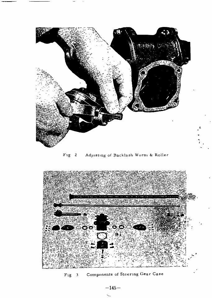
A 43
f i
t
Flg 2 AdJustmg of Backlash Worm Roller
Flg 3 Components of Steenng Gear Case
145

g 0i e l
r
Flg 4
Il Inspection and Adiustment after Assembling
M
JIt lS lmportant that the center of lnterlocklng roller lS located In the
cln r of worm gear
AThe lnspectlon for thlS should be made In a way as to make sure of
the equal condlhons of backlash at the pOSltlon of steenng wheel when
turrteg fully to left and nght In case the backlash dlffers greatly the
lnterlocklng posltlon of worm gear must to adjusted agalnThe correct backlash at the both ends J worm gear should be made
sure of after puttlng the more shlm In the slde of larger backlash at the
l ge r arrn d f f equahzmg pull out the sh m on the Opposlte slde and
tlghten u h bolt agam adJustlng wlth the shlm In front of and the shlm
behlIldiH ear housmgrl
r 10
Thp lash at the center locklng should also be checked and adJustr1
ed lftne aTyttJ f
1
Installdt on of Steeflng WheelYff
Inspe y steenng wheellTt
g yheells celatlOn locked wlth the shaft and lt may as be
f1xed t3i rwardmg dHection tightened may as well be hxed to the
forwardlldlrectlod tlghtened wlth nuts
1 i t
l
f1 146

The standard revolvlng welght gravlty of the wheelan the wheel nm
Clrc1e as for as lt lS nghtly assembled lS 0 08 0 15 kgm 0 58 1 09 it
Ib measured by the spnng scale
The play allowed on the cncle of wheells 35 40 mm
InstallatlOn and adjustment of horn button
The horn button should be lnstalled m a reverse order of dlsmountmg
I nspection and Ad ustment of Steering Fixed on Car
The lnspectlOn and adjustment of the steenng sy stem lnstalled ln the
car should be made m followmg order
I Set the car on the levelhng place wlth the front wheels hxed to the for
wardlng dlrechon
Take measure of the poslhon of lower part of wheel and tube wlth the
flnger of one hand spln the wheel to left and nght to the extent of
wheel s play by another hand When the wheel moves up and down
there shou d be found a play ln the worm beanng to the dnechon of
axle
In thlS case the hXlng bolts ln front and rear upper or lower of gear
houslng are loose on the bearlng lS worn out
The shlm should be pull off ln a way as explalned m the ltem of worm
beanng and the adjustment should be made as explalned ln the ltem of
lnspechon and adjustment after assembl1ng1
2 In case the roller shaft moves to the duectlOn of axle shaft as the
wheel splned hardly to left and nght the roller shaft adJushng screw
lS loose The adjustment should be carned In a way as explalned ln
adjustment of the poslhon of steenng roller
3 In case the roller shaft shakes to left and nght the roller shaft or
the bush lS worn out therefore they should be replaced wlth new one
and adjusted
f
5 In case the roller shaft moves to the axle shaft by returmng thewheell iI oitl
to left and nght the roller shaft adJushng screw lS laos rwlpdia
the adjustment should be made ln a way as explamed ln triie of
the poslhon of steenng roller 1
147

6 In case the roller shaft trembles to left and nght the roller shaft or
the bush lS worn out and they should be replaced wlth new one and
adjusted
7 Take off the drag Imk at the end of steermg gear arm In cas the
play should be found by holdmg the arm and move lt strongly b lck and
forth the backlash of roller and worm gear lS too large The adJustment for thlS should be done ln a way as explalned m the above section
setbng the steenng wheel at the center of turnlng to left and nght
8 In case the operatlOn of steenng wheel felt heavy and becomes hghtwhen the front axle lS Jacked up the trouble lS wlth the front axle
sy stem
In case the wheel lS still felt heavy even when the front axle lS Jackedup the trouble lS connectec wlth the front axle
9 When the front axle lS Jacked up the lnspechon of contactlng and tlghtemng parts of tle rod socket nackle arm drag hnk and the steenng
arm should be posslble
t
4DJUSTING IDLERIn the standard adjustment pressure lS not glven on the rubber
sprmg When the ldler arm lS posltlOned m parallel WIth the ldler bodyscre m the shaft so that It protrudmg from the body top lS 34 mm
Then flt the rubber spnng to lt and bghten the nut at the top to the extent
that the rubber lS sl1ghtly compressed and cl1nch the nut In thlS case
overalLhelght of the rubber spnng lS 20 7 mm approx In the next
after lt is mounted to the car and toe m lS adjusted tighten the rubber
spnng 1lth bolt to el1mmate resldual dlmentlons on lt by utll1zlng the
long hole m the rubber spnng httmg plate
r
rrOtlj 1Jlll t
i
c1f1
1if
il ffrJ I
tI
y
r
11
ifYo J
l J
f f
148

I 0 I
Jf
l
9
iA
H 1
ft
n1
T1I1TEITHEIlII
1141155II1IIlIP
TOTHIIOIIEIIIII
B
I
30
4853132200i48533 148545
4l
Flg
5

48546 32200
1 24518
9 16215 l@
648544 32100
48521 32200
ll
f
9 1Y22f
9 11052
f rct
f
SteeringFig 6t
f
48405 58000
48541 32200
48539 32200
I I
6 ArmIdrer
150

THE CAUSE OF TROUBLE
The cause of the trouble caused ln regards wlth therabon lS closely connected wlth those of the front axlehard to Judge then Separately
The followlng are maln troubles caused ln steenng
steenng ln opetherefore lt lS
Heavy and d1ff1cult opera bon of handle
I The all m gear box
2 Adjustment of worm and roller lS poor
3 Damage on corn of worm beanng
4 Hard locklllg of column Jacket bush
5 Steenng shaft or tube lS bended
Insuff cient Amount of TurningI Adjustment of worm and roller 15 poor
2 Flxmg port of gear housmg Wl th frame lS loose
3 Locking poslhon of roller shaft and steermg arm lS bad
Unsteady or Trembling Handle in Motion1 Too much backlash of worm and roller wheel play lS too large
2 Worm beanng and roller shaft bush 15 worn out
3 Looseness of each bolts on gear hOUSlllg
4 Looseness of f1xmg bolts for frameIif
Insufficient Return of Handle
I Tlghtnes s of each parts
2 Worn out parts parbal defacementtlt
arJri
NOIse In the Gear HousingI Backlash of worm and roller
2 Insuff1clent gear all
t
151

1
iJ P
e
i t t
l
l
FRONT AXLE
iA
152

FRONT AXLE
Type
Hub beanngInner typeSlze mm
Outer typeSlze mm
Toe ln
Camber
Caster
Angle of lllchnatlOn
of SWIvel axle
Tread
TurnIng angle of front wheel
InsldeOutsIde
Wheel bearing adjustment
Independent suspenhon wlth doublewlshbones ball JOlllt Call spnng
telescoplc shock absobers Stablhz
lng bar
Tapper roller
Outer dla x Inner dla x Wldth
65 x 32 x 18 25 2 55x I 26xO
Taper roller
52x20x16 2 05xO 79xO 6j2 3 mm 0 08 0 12 m
1 30
1 30
6 30
7185m
1330 mm 52 36 lll
35
29 30
Tlghten wheel bearmg nut WIth wrenchturnlllg wheel at the same hme pull upthe adjust nut unhl reSIstance agaInst
beanng lS felt then turn back nut 1 8
turn and lnsert cotter pln
FRONT SPRINGtl
l
54010 32201 668 688 225 8 8610 37714 84m 382 15 04m Red tape WIth 1 whIte itne86m 386 15
J
5401032202 688 708 225 8 382115 04m 20m Red tape WIth 2 l li e hnes
5401032203 703 728 225 8 86m 38615 20 m 391 15 40m Red tape WIth 3 hItt hnes
54010 32204 728 748 225 8 86m 39115 40m 39515 56m Red tape wlth 4 whIte 11l es
5401032205 668 688 217 5 8 957m 366 14 42m 37114 62m YeHow tape lth l Whl hoe
54010 32206 688 708 217 518 957m 371I4 62 m 375 14 76m yel1otape wlth 2 whItehoes
5401032207 708 728 217 5 8 957m 37514 76m 379 14 92 m YeHow tape WIth 3whlte hnes
54010 32208 728 748 217 5 8 957 m 37914 92 m 38415 12m Yellow tape lth 4 whte lUles
s
153

FRONT AXLE SUSPENSION
The front axle lS equlpped wlth the mdependent suspenslOn wlth call
spnng and telescoplc shock absorber and connection of the upper and lower
sWlvel axles wlth the double transverse hnks lS of a ball Jomt type and the
sWlvel pln lS not used for It
The upper splndle bracket lS bolted to the front suspenslOn member wlth
caster shlms and the lower splndle lS connected to the lower bracket of the
suspenslon member wlth the shlms
Flg I
r 1 il r t
J
1
Flg 2
1f1i154
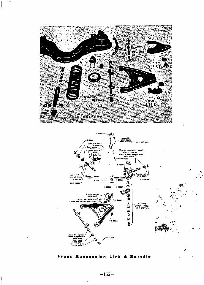
rAt
rU Z3A CIW I emb r h A
Q
tJtIIvnC
knuckpond
G
h 140015
Ie left nd
K ekle s
32250
4OCIIOldl rCht nd
rn
ryU P k
sp dleboltb
lUlleubbbumpr
4S3I 3DX1
mbty
FrontU200spen on u rb IIJot
lt
J s
J
rrtJty
FO tsl on
f bAil Jot
1
jjjl
tijjjl
ft
Lawn hnkfrontsu
pnd
441n
LoJkJ fj
31m2
S J
1
rj r
Front Suspension Link 6 Sp Ind Ie
155

Body center hne
ThIS drawma MWUIat standard load
c
6725
Front Suspension Section
l
tr ro t
Ci I r
f
j of1J
t
r
156

DIsassembling the front hub
Dismanthng of the front hub flrst Jack up the car untll the wheellsclear of the ground and then place under mdependent suspenslOn spnng
plateLower the car on to the blocks Remove the wh el If the drum
appears to blnd on the brake shoe the adjuster should be slackenedLever off the hub cap and then extract the spht pln from the spln
die nut
USlng a box spanner remove the splndle nut and ease flat washer
under the nut clear of the axle thread by carefully uSlng a narrow rod
mto small holes ln turn each slde of the splndle and tappmg the race
hghtlyWlth the hub removed outer beanng can be dlsmantled and by In
sertlng a dnft through the lnner beanng and tapplng the out beanngclear of the hub
The lnner beanng and all seal can then be removed by lnsertlng the
dnft from the Opposlte slde of the hub
Assembling the front hubIj
When assembl1ng the hub and the lnner beanng race should first be
lnserted lnto the hub
Pack the hub wlth recommended grease
Replace the hub all seal over the lnner beanng Renew the seal
lf lt lS damaged any way The hub can now be replaced on the sP1IJdleGently tap the hub lnto pOSltlon untll the lnner race bear agai st the
shoulder on the spmdlePlace the splndle flat washer lnto pOSltlon and screw the nut down
I
fmger tlght i
Spln the wheel and examlne the reslstanceI t
I
Tlghten the nut jf lie lir i II hA sl1ghtly lncreased reslstance to the splnnlng 0 tae IN mn
wl t en SItJ L
be notlced The beanng are now preloaded and thepht m ld be
mserted to lock the nutt l j
Tap the hub cap to the hub after packmg the cap wlth e
Replace the brake drum and secure wlth machlne scfe It lS
lmportant that the drum lS fully home before thlS screws lS tlghtenedand If necessary the drum should be pressed ln pOSltlon by tlghtenlng
two wheel nut
Reflt the wheel and nuts are best fmally tlghtened when the car lS
off the packmg blocks but readjust the brake shoes lf necessary the car
lS lowered to the ground
f1
j
157

REAR AXLE
TypeHouslngDnvIng method
Number of teeth on dnve
gear plmon
Seml floatmg typeBanjo type wlth steel plate welded
Hypold bevel gear
35 8 4 375 UP31 UG31 UH31 UWP3141 8 5 125 U31 U
DRIVE PINION
11
Tlghtenlng torque of plnlon nut
Pre load for plnlon beanngwlthout all seal
Thlckness of adjusting shlm
on plnlon bearlngThlckness of adJushng shlm
on plnlon beanngThlckness of beanng
adjusting shlm
Tlilckness of beanngadJu ting shlm
Standard posltion to lnstall
wIth dnve plnlonDlmenslon from center of drlve
gear to rear slde of plnlonOff set dlmenslOn upper
lo er
Thlckness oCIllmon adjustingshlm
DiuVE Gy
Ba l h iana plmon
Thlckness of slde beanng i1filladJushng shlm
Thlckness of slde beanngadjusting shlm
Thlckness of slde beanngadJustmg shlm
13 8 16 6 kg cm 100 120 ft lb
7 10 kg cm 0 07 0 10 Ib ft
0 75 mm 0 030 m
0 25 mm 0 010 m
0 125 mm 0 005 m
0 075 mm 0 003 m
61 0 mm 2 401 m
25 4 mm
o 75 mm 0 030 m
o 25 mm 0 010 m
o 125 mm 0 005 m
o 075 mm 0 003 m
o 10 0 15 mm 0 004 0 OO m
o 75 mm 0 030 m
o 25 mm 0 010 m
o 125 mm 0 005 m
158

Thlckness of slde beanngadjusting shlm
Thlckness of slde beanngadjusting shlm
Tlghtenlng torque for clampbolt of slde bearmg cap
Run out of OppOSlt slde of
dnve gear
Tlghtenlng torque for clampbolt of dnve gear
0 075 mm 0 003 m
0 050 mm 0 002 ln
4 1 4 8 kgm 30 35 Ib ft
0 05 mm 0 002 m
4 8 5 5 kgm 35 40 Ib ft
BEVEL SIDE GEAR AND PINION MATE
Number of tooth on slde gearThlckness of thrust
washer on slde gearNumber of tooth on plnlOn
mate
ThIckness of plnlon mate
thrust washer
Backlash between slde gear
plnlon mate
Clearance between slde gear
case
Amendment hmlt of dlttoed
clearance
Tlghtenlng torque for wheel
beanng nut
18
o 76 0 81 mm 0 030 0 031 m
10
0 76 0 81 0 030 0 031 m
0 1 0 2 mm 0 004 0 008 m
0 2 0 4 mm 0 008 0 016 m
0 5 mm 0 020 m
12 kgm 87 5ft ll tl
If
OIL USED
Standard of all
OIl quantity necessary
Gear all MP 90
f
159

Flg I
THE CONSTRUCTION HANDLING
The rear axle lS seml floahng and the hypOld bevel gear lS used for
slowmg down the speed The englne power lS transmltted through the
transmlSSlon to the propeller shaft then to the dnve plmon and flnallyyonves the left and nght rear axle wlth the dlfferenhal gear whlch lS
housed m the axle housmg The axle housmg lS made out of the ress
ed 3teel plate m the form of Banjo and lS construchonally strong enough1st the torslOn or the bendlng for lts l1ght welght wlth ltS rear cover
oel g welded
ne gear carner 15 made out of hght and strong alloy of alummum
and the dlfferenclal gear ass y lS so constructed as to make easy dlS
mountmg and the adjustment of each gear carner The rear axle shaft
lS matenally made out of molybdenum chrome steel of hlghly strengthand the spl1ne lS of the lnvolute gear type
Inslde the houslng the dnve pmlOn dnves the bevel gear WhlCh lS
closely conrec ted wlth the dlfferenhal gear case The each two plmonsand slae gears are hxed ln thlS case and locked each other The plmon
lock wlth the pmlOn shaft whlch lS supported by the gear case whlle
the slde gear whlch lS so supported as to funchon freely lnslde the gear
cas lS connec
1d wlth the sphne at the top end of rear axle shaft
Thus tructlOn of d1fferenhal gear conblned wlth these gearshas the f controlhng the d1fference of revoluhon of the rear
wheels urnlng to the vanous dlrectlons The plnlon as lt
stays 0 shaft dnve equally the side gear on left and nght and
dnVeS a i j the rear axle on the stralght l1ne In case of turn
lng or J e reslstance of some obstacles on the ground the
P nlon re o ve self on the plmon shaft and dnves dlfferenhally the sldein
gear as well as the rear axlelshen the revoluhon of left and nght wheels
dlffrsT
The external slde of axle s1taftWhlCh locks wlth the i lde gear lS
lncl1ned and f1xed to axle houslng wlth the brake dlsct
160

The shaft lS supported by the taper roller bearmg to the axle tubewlth the brake dlSC f1xed by the four bolts together wlth the adJustmgshlm
It lS not necessary to check the lubncahon to the beanng but needto feed the new wheel beanng grease ln proper quanhty when dlsassembled The proper lubncahon to the gear houslng lS also necessary otherWlse lt would shorten the durablhty of the gear to cause the trouble
The followlng pOlnts must be taken lnto conslderatlOn
1 Nommated HypOld gear Oll No MP 90 must be used
Temperature over 32 C SAE MP 140
11 It lS prohlblted to use any other kmds of gear ollar any Oll of dl
fferent V1SCOClty The same brand must always be selected
The standard capaclty of OlllS about 0 9 The method of feedmg all
should be done by takmg off the feeler plug at the rear cover of the hous
mg and f1l1 m full up to the feedmg hole
The brake system would not work lf over feed the all by CaUSlng lt to1flow out of the bath end of the rear axle houslng lnto brake drum
Dlsmounhng Dlsassembhng of Dlfferentlal Gear Carner
I Take off and dram out the gear Oll
2 At the hme of dlsmountmg the gear carner pull out the bot left and
and nght axle shaft or pull out for at least 4 lnches
3 Take off the Jomt flange from the slde of propeller shaft
4 Pull off the nuts of the housmg and dlsmount forward the arner ass y
5 Take off the slde beanng cap of cariler and pry wlth a lever the d1ffer
enhal gear case and the beanng
jk J11
lAs lllustrated m Flg 2 wltb the ald of slde beanng puN r OlV the
beanng The puller should be handled wlth care m c tJ4 f edgeof beanng mner race WhlCh s hard to hook Both theilef l rlghtIl1lo I
beanng should be arranged separately Is t1t
If7 Dlsmount the dlfferenhal dnve gear by tqosenlng the scrE WS on the
dlfferenhal gear case and spreadlng out1the lock washer asherLoosen them ln a dlagonal h e consldenng to keep from the gear bend
lng
6 Dlsmount the dlfferenhal side beanng jt
161

10 Take out the dnve pmlOn of
gear carner by stnklng out
hghtly to the backwards the
font end at the slde of com
allOn fla of dnve pmlOn Wlth the dnft of soft metal
Thl would be taken out together wlth the lnner race of
droller dlstance plece and the adJustlng shlm and
er race and plnlon of front and rear beanng as well
Justlng shlm left ln the carner
f
l Take out the dlfferentlal
plmon as well as the slde
gear The plnlon mate
shaft should flrst be pulled out by stnkmg out the
plmon mate shaft locklngpln whlch lS hxed on the
dlfferentlal case from
left slde from the slde
of nng gear f1xed to the
nght before pulhng out
the plnlon slde gear and
the thrust washer The
gear as well as the thrust
washer should be arrangedseparately as left and nghtfront and rear
9 After takmg the nut of the
carner pull out the com
pamon flange The dnve
pUllOn flange wrench should
be employed settmg ltS
four pOlnts ln the holes of
flange to keep lt from mov
lng take off the nuts wlth
the box wrench
01
234
Flg Usmg of slde beanng puller2
e rear beanng lnner race of the dnve plnlon The drlve
plmon rear beanng lnner race replacer and the adaptor should be
employed ln thlS case The adaptor ln the round form lS for f1xlngand the other for taklng off 11 lS easy to handle wlth the Vlce flxlng
t
one end ofJreplacer
162

Assembly gear carner Wlth gear
38300 3700038300 37800
38300 37001
38300 36800
41 8
35 8
39 7
37 8
5 125
4 375
5 572
4 625
3 illO 30800
2 215201169 1 1145 T20 22Kq lL159 1 5 I I 5 1438UO 25660
I3
12
3noD
3 JJJ
9
Flglo
t i1rL1
t l4
I Cv uq Io
aPmlOn shaft t1 r
1 I YD1ff slde bearm OJRear axle shaft
Gear carrier pWasher
Nut
Stud
Drlve plnion nut
3 D1fferentlal gear carrler
I
2
3
4
5
6
7
8
9
Compamon flange 10
Carrler assembly II
Drive pinlOn front bearing 12
Drlve plnion rear bearlng 13
HypOld drive plnlon 14
Hypold drive gear 15
D1ff gear case 16
D1ff bevel slde gear 17
D1ff bevel pinlon mate
163
v
i
Itt

12 Taking out the rear bearmg outer race of gear carner
The dnve pmlOn beaqng outer race replacer should be employed ln
thlS case In other upon the stud so as to make the screw at the
center of carner and set the adapter at the lower fnm of the race
Supportmg the tommy bar and screw up tlll the corn closely touches
the adapter then screw the wlng nut to take out the rear outer race
13 To pull out the front beanng outer race from the gear carner set
the tool body pull lt out wlth adapter m the way of rear race
INSPECTION REPAIRING OFDISASSEMBLED PARTS
Every parts after they are dIsassembled should be cleaned and clean
ed by the compressed an before makmg an mspectlOn and adjustment
I Each beanng should be lnspected m every umt of ass y ln regard wlth
the defect and defacement before dlcldmg to reused them
2 Every gear should be mspected as to the locklng condltlon defacement
or any defects on the surface to s ee 1f they can be reused
In case of lnsuff1clent standard h cklash deformatlon or found re
o placement lS necessary
Speclally the dnve plmon and dnv JI gear should be replaced m a set
wnenever the lockmg condltlon gets worse and the defacement lS alreadylr progress because lt would caus he nOlse ln later operatlon and be
drff1cult to adjust even wlth proper to Jstment lS made
CT
The perfect dnvlng condltlon at the surface of dnve plmon gear shoulde about from 3 mm to 3 4 m unloaded dnvmg whlle the gear surface
Ishoufd sta rfouch from tlp to full surface ln an ordlnary loaded dnvmg
The fulOn of thlS condltlon can be made as lt lS
I lnspect them as lt lS do otherWlse by cleamng the both
Wlth tl1e tnjfore dlsassembl1ng and palnt thlnly and evenly Wlth the mlxed1P
wlththl orj the gear surface dnve slde then turn the pmlOn wlth hand toj
PririLth tra1 of lt on the gear Whlch shows the sltuahons of conslderablyV t lworn ou geaf tIn casE of unloaded test It lS perfect that the gears contact for about
three quarter at the center of 1 4 of whole gear length from tooth mtenor
hp nd of gear on the pltch hne if
do
kP
r
t
164

3 Lock the sIde gear wIth pIllion together wIth respective thrust 10 the
gear case
In case of the backlash over 0 2 mm and the clearance between thesIde gear and thrust washer exceeds 0 5 mm replace the thrustwasher
The else worn out parts should also be replacedThe contact when nng gear IS too close to pInIon center In case of
backlash should be adjusted closely or It gIves much nOlse
4 Put the dnve gear rmg gear on the buoy block as It IS flxed 10 the
differential gear case and measure wIth the d al nd cator Revolve the dnve gear to turn around the d fferential gear case as the
beanng do not move on the buoy block
Measure the shake at the rear sIde of gear by the scale and the shake
should be w th n 0 5 mm In mountmg the gear clean well the flt
tmg face and rear face measured face of It and flx correctly then
there should not be any shakIng
ASSEMBLING
Assembling differentIal Gear
ADJUSTMENT 1
1 Assemble the pIllion and sIde gear 10 the dIfferential case
Every parts should be clear ed and OIled wIth new gear 011
then the pInIon mate sIde gear and t hrust washer should be assembled
by the mentioned InspectIon and sel k lOn before pushIng In the pInIon mate
to shaft Inspection should be m e agam In the clearance of between the
washer or the backlash Adjustment must be made In case any abnormal
IS foundStnke 10 the pIllion shaft J mg pm from the nght sIde of the case
OpposIte sIde of dnve gear a d must be flxed by settmg well the str klll
hole of It after puttmg It to the reljUlred pIston so as the pIn shuld noloosen l
f If
f
2 F x the dnve gear nng gear wIth the dIffereti
The dnve gear as well as tr e dnve pIllion shouled or they must be replaced as a set whenever the repla1
iOtherwIse they would not properly lock after assembhiigIn rnountmg In the case the fltt1ng surface must specIally a1e ld
l
flxed WIth 8 Nos screws as well as lock washer Bend t h 1iTW1th
sureness after the dnve gear shake IS adjusted In tightenIng up Hie screw
It should be set and supported by VIce or any other setting tools so as lotto damage It and screw up In a dIagonal hne wIth a wrench wh ch flt co rec
ly wIth the head of the screws Th standard screwmg torue for th s IS
35 ft lbs to 40 ft lbs Screw 10 for sure stnkmg hghtly the head of screw
by one quarter pund hammer
165

3842625660
3842500100
3842725660
L3842300100
38424
25560
Q
3842500100
3842625660
3831001301 A
y
3812725660
HO
50
@@
I 00 I
r
jCJ
13440
2S660
I
I
il
v
I
t
1
i
iO
4YsrAJ
3815327
i60
l
3816127160
Fi9
4
Gea

3 Mount the sIde beanng 10 the d fferential case
Press 10 the both sIde of the beanng by uSIng the dnft
It IS Important 10 thIS case to assemble by putting the sIde beanng adJustIng shIm to gIve the beanng a proper preload In flx1ng wIth the carner
ASSEMBLING ADJUSTMENT BYGEAR CARRIER ASS Y
It IS to decIde the assembhng adjustment of gear whIch IS most Im
portant In an rear axle ass y and should be carned In accordance wIth the
exact sample shown by the manufacture The cons ructIon and mechanIsm
must well be comprehended refernng to FIg 5 8 11 and the adJustment
repaInng exactly accordIng to the cond tion of practical use based on the
adJustment by exact calculatIon
A The Preparation for Mounfig me Drive Pinion
in the Gear Carrier
I If the dnve gear dnve pIllion and beanng are to the reused theyare as a result of dIsassembhng and InspectIOn they should be
assembled In order of dlsassembhng at the prevIous cond tion of
adJusting shIm
In case any Item should be replacedor requlTed to reuse even 1f
any Item IS worn out prepare the vanous sh ms as mentIoned
later because the pOSItion of dnve pInIon to be f xed WIth carner
must be adJusted by the adJusting shIm between the carner ald
p1nlOn rear beanng outer race
2 There are few numbers WIth 0 or besIdes set number marked
by an electnc pen on the tIp head surface of dnve Rlli n tThey show the manufactunng error In a flgure unIt oeo 001
10 0 025 mm to deClde the th1ckne ss of adJ for adJustment of standard pOSItIOn The stanqard p1lliO l nmfrom axle center as shown If FIg 6 If the flculf to
d scnm1nate due to the corOOS10n scrape off t 1 ze substancep
on the surface by a some what narrow gnnd stone th car not to
scrape off even the mark
1
167

4r
FIg 5 AdJustment of PmIOn heIght
AdJust to the d rection of an arrow In accordance wIth the pInIon mark
3 The th ckness of dnve pIllion adJusting sh m are arranged as follow
mg
1
t4 fad Standard
l7P tN Part No
tar o lil Th1ckne s s
Leaf Nosr
t i z
y Jt
Jb l
Dnve p1nlon1 38153 2660 0 75 mm 0 03 III 1 38127 25660
adJustmg sblm l lf
38128 2566038154 2660 0 25mm 0 Ollll 2
38155 2660 0 125 mntSO 0510 2 38129 25660
f3815 6 2660 0 075 mm 0 03 III 2 38130 25660f
Hls

The use of the adJusting sh m w1l1 be explaIned 10 the followIng paragraph of adJustment SupposIng the dnve gear and the dnve pInIOn were
replaced as a new set and the heIght of dnve pInIon prevIously used was
nght prepare the sh m of th ckness whIch equals to the d fference of fIgures on the new and thIS pInIon Deduct the prevIously used shIm In case
It It plus Increase In case of mInus and have the general Idea of requIredthIckness of the shIm for assembhng to prepare
It IS convenIent to Inspect the cond1tlon before d1sassembhng In a wayas mentloned later In the measurement of pInIon heIght BesIdes the con
d tlon of defacement on the carner the pInIon beanng must be taken Into
cons1deratlOn though It WIll be explamed In detaIl later
B Fixing and Adiustment of Drive Pinion
I Dnve pInIon rear beanng outer lace should be mounted In the car
ner In th s case after 1nsertlng the properly selected adJustingsh m as prevIously mentioned between the carner and beanng race
mount the outer lace by the specIal tool of dnve pInIon front rear
beanng outer race replacerFor adJustment of prevIOusly mentloned pIllion heIght the sh m at
the rear sIde of thIs outer race IS Increased or decreased and the
race also must be taken off In each tlme for th s adJustmenttherefore the tools must be handled properly to aVOId such a sItua
tIon as to make the beanng hole of carner In an oval Refernngto handhng method of tool set the adaptor nng on the corn to gUldethe body of tool at the small hole of carner put the rear outer lace
on the corn as beanng surface faces InSIde at the tlp eJd of screw
and put the spl1t adaptor InSIde race At the same time supportIng It by the bar tW1S up the corn tlll the adaptor and lace come to
the setted pOSItIon then screw up the wIng nut so as the race be
housed properly at the set ed pOSItIon
2 Mount the front beanng outer lace In the carner
For mountlng the front outer lace take off at hrst tli adapter from
the front end of the carner and fIx the tool at the s e f stud 10 opl 1i
pos1te sIde tIghten the screw as to be h e ntel r then
mount It by uSIng adaptor as In a way of mountlng tlte1 outer race
The race IS scarcely necessary to be taken off unlliss aged
3 Mount the rear beanng Inner race and roller to the dnve pInIon
By uSIng the round adaptor attached to the dnve pInIOn rear beanngInner race replacer wh ch was employed at d1sassellbhng press In
the dnve pIllion Th s mIght as well be done In pr ssmg In by the
use of a certaIn dnft
69

4 Mount the dnve pIllion In the
carner and adJust by measu
nng the pos1tlonThe pInIon heIght must
be adJusted as mentlOne d In
the prevIOUS paragraph bymounttng temperanlly the
pInIon In the carner and the
beanng be gIven a regular pre
load On the other hand the
beanng of drIve pInIon should
be newly oIled after the pmIOn
IS Inserted from the InSIde of
the carner the Inserted end FIg 6
of pInIon should be locked wIth front beanng corn and tlghtened up
by the pmIOn nut fIxIng WIth the companlOn flange ttll the regularrevolVIng torque IS required As th s IS not yet at the f nal assem
bltng the beanng spacer dIstance pIece beanng adJustIng shun
and 011 seal are not mounted
r
2a9
At the tlme of InsertIng the front brar1ng as pushIng In the Inner race
by pulhng out the dnve pInIon from the rear sIde of the carner Put the
rear sIde of the carner downward and set the tool under It then support
mg the end surface of dnve pmlOn pre ln the beanng by usmg the dnft
The operatIon would be eaSIer by uSIng dnve pInIon front bearIng Inner
lace Inserter as shown l
3
t
r
r
11
FIg 7 PlllIOn Bearmg Preload Gauge
170

TIghten up the p11110n nut by turlling It slowly wIth hands wIth the use
of pre load gauge as FIg 9 to the degree that support the beanng preload at 7 10 kg cm
When the dnve pInIon IS mounted In the prevIously mentioned condtlon It IS necessary to measure the heIght of rear surface of the pInIonwhether It IS hIgher or lower than thestanda rd Make use of the speClaldnve pInIon arrangement gaugeThe standard heIght of the pIllion IS
21 mm from the bottom of the sIde
beanng f xed wIth the carner The
flxlng posItIon can be measured bysetting an arc of clTcle On both sIdes
of arrangement gauge at the POSItIon of sIde beanng and Insert the
th ckness gauge In the clearance bet
ween the tIp of gauge bar and the
pinIon such as to push In by scraplngof the carner In d agonal otherwIse
preload and the pllllOn height of the
beanng would comeout of order and
tend to cause an unexpected trouble
In future
The formal adJustment qJ dnve plll10n bearmg and preloadAfter the fIxIng pos1tlon ve pInIon IS deClded as mentioned In
the preVIOUS paragraph ff the pInIon nut companIon flangeto mount agaIn the dnve wn beanng spacer dlstance pIece andnut TIghten up the nut FIg 8 by USlllg the torque wrench atthe regular torque of 100 20 ft lbs 13 83 16 62 kg cm
The preload supportedly the beanng In thIS case IS d fferent aCC T
dlllg to the cond tion of the beanng adJustlllg shIm InsertedThe more of the shIm Inserted much the play of pIllion to the d
rectIon of axle IS Increased
The less of the sh ms Inserted the more the bearlllg tIghtened bythe prevIously mentioned nuts and cause It to be burned If lefVandturned as It IS Therefore for re d Justmentof thebbanng pre
I
f Iiload In th s case Itmust be adJusted by IncreasIng or decreas1ngthe number of four kmds of adJusting shim as shown rn w fQllowmg hst and measunng wIth the u s of the dnve p11110n beanng preload gauge as FIg 7 so as to make the revolvlllg torque of pmlOnat 7 10 kg cm f there should not by any error III the pllllOry wIth
the head mark at 0 and the clearance should be seled at 0 2 mm
0 008 10 by the feeler gauge
5
171
c
rf
Fig 8 Use of dnve pInIonbeanng Pre load Gauge
18t11
241
L

IIIII
I4
Y
1F QlII
FIg 9
I
JI
J
2431i
II
Remarks
When measunng the heIghtof the pInIon head set the semI
cIrcular sIde portlons of the
gauge on the sIde beanng seatsInsert a feeler gauge mto the
clearance between the tIp of the
gauge center rod and the pIllionhead and adJust the pIllion
The guage rod IS made 0 2
mm 8100010 shorter than
the standard measurement 21
mm Therefore adJustmentIS made by selecting a feeler
gauge In accordance wIth the
plus or mInus valve marked on
the plllIOn head
thus pmIOn IS regarded as at the correct poS1tlon because the heIght of the
gauge IS made shorter for D 2 mm than the standard SIze 2 I 0 mm
If It IS necessary to adJust the pmlOn heIght take off the dnve pIllion as
well as pInIon rear beanng outer lace from the carrIer to adJust by In
crea lllg or decreaslllg the number of the adJustIng sh m In other wordsread the mark on the head of the dnve p1111on before adJustIng by mcreas
1ng or decreaSIng the number of deVIce pInIon adJustIng shIm to Insert thefeeler gauge wh ch IS deducted for the number of mark from 0 008 10 III
case of mInus SIde added for the number of mark to 0 008 In Increase of
plusFor nstance the mark shows adJust the posItion of dnve p1nlOnr
rr
by deduChng th number of sh m so as to make the clearance at 0 008 InI
o 002 In 0 010 In It IS necessary to gIve the bearmg a nght pre loadAt the tIme of pushIng the outer lace Into the carner It must be done InJ if fa nght way otherwIse
SpeClally when the old beanng IS to be used agaIn 10 assembhng theI
adJustment should be made at theJot r torque than standard 10 accordance wIth the cond1tlons of practIcalise so as not to gIve It an over preload
6 When the mer adJustment of pre load of the beanng IS completed as 1ll the prevIous paragraph lllspect the pIllion heIght agaIn
172

Unless any thIng wrong IS found loosen the pInIon nut take off the
flange Insert the new 011 seal In the rear of the carner and for
merly fIx the flange washer and pInIOn nut The nut should be
tlghtened up at the standard torque In case the cotter plll hole
fItted the adJustment should be made not by tlghtelling the nut but
by fllhng the washer
c Mounting the Differential Gear Ass yin the Carner
1 Mount the complete unIt of dIfferentIal gear In the carner and fIx
the beanng cap There IS a engraved mark on the SIde of capwhIch should be fl tted WIth mark on the leg of beanng hOUSlllg when
mountIng It IS Important to note that the flxlng part of the cap of
each beanng hOUSIng IS machlnerly fln1shed up
The differentIal gear case IS lllserted by the beanng adJustingshIm WIth the SIde beanng as explaIned and by hOUSIng In the bear
Ing hOUSIng of carner the beanng must be glVen the regular pre
load The screwlllg torque of the fIXIng nut of the SIde beanng cap
IS at 30 35 ftlbs 420 490 kg cm and should be equally locyed
WIth fiXIng cotter pInSo far only the dIfferentIal unIt IS mounted and the dnve gear
IS locked WIth the drIve pInIon therefore the follOWIng adJustmentrr ust be made to acqulTe the regular suie beanng pre load the
gear backlash
J
Z Adjustment of SIde beanng pre load backlash
To gIve the nght pre load on the SIde beanng of d1fferentlal
gear case and In pressing the beanng In the dIfferentlal case adJust
by lllSertlllg lllslde the beanng adJustlllg shIm of th1cknes s cflcplated In accordance WIth the follOWIng method of compUtatIOn
There IS a marked numeral of adJusting bases on the beannghousIng of the gear carner and dlfferentlal case The numeral IS
the manufactunng error In a unit of 1 1000 In agaInst each stand
ard measurement of ABC D III FIg 10
To measure the WIdth of the SIde beanng ore left andIQglt use
the standard gauge 20 0 mm thIckness and d al gauge on a fYat
board In th s case place the load on the beanng WIth the a1kofweIght block for about Z 5 kg to acqUlre the steady fIgures LIlJ
Calculate the error on mInus SIde agaInst the each sta dard
measurement of 20 0 mm on the ufllt basIs of 1 1060 and assume
each of them as E F Take the left SIde beanng for exampleWhen the measured WIdth IS 19 8 mm It IS 0 2 mm O 008 10
agamst the standard measurement and the E IS jy excludlllg the
mInus sIgn 0 008 In
jl
173

The thIckness of the shIm IS acqUlred by applYIng the numerals
to the followlllg method of computatlon
FIg 10
LlIl
I 0IjlJ
rI
I
Tl A D C
0 007 m E
T2 B D O 006
In F
ThIckness of sh m
on left sIde
Th ckness of sh m
on nght sIde
Example of calculatIOn
Left A 1
D 2
C 2
E 0 2 mm 0 008 III
lc
RIght B 2
D 3 therefore
f 0 25 mm
o 0101ll111
f TI A b c o 007 E
0 001 0 002 0 002
0 ri6 1 0 008 0 01oj
j t
fq kriess of left sIde shIm
T2 B D 0 06 F
0 002 0 003 0 006I
0 010 0 015I
ThIcknessTh1cknes s of nght sIde sh m
t
It may as well be aqsembled by uSlllg the shIm of th ckness wh ch IS
In accordance wIth above method of computation The left and nght bear
Ing must be well pressed In otherwIse the pre load changesMeasure the backlash of the dnve pIllion nng gear as FIg by us
Ing the d al Ind cator to make sure that It IS wIth n 0 1 mm O 2 mm O 004I
0 008 If It 1 much move to left by taklllg off the nght shIm and a
VIce versa for adJustment
174
I
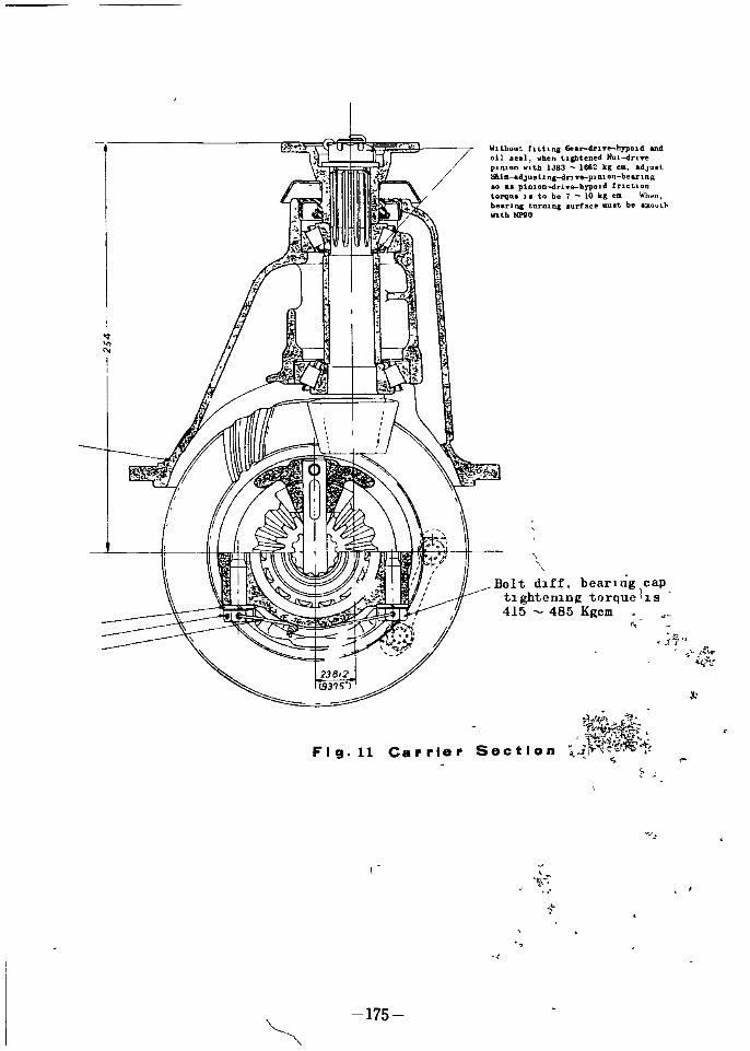
II
II
WlthQut htt1n Gardrlyebypo1d andoil I hen tlbtened Nutdnn
puuon with IJ83 162 kg em adJultIhiI adJ I ItI ng drJTeplDlon beIlrIng
piDIODdriTe hypoJd lnctlon
tOrqUI to be 7 10 kg ell Wht n
bearll1C turnlna lurface Jlnt be allo tlo
V1th NPlO
Bo1t d1ff bearIng capt1ghten1n torque 1s
415 485 Kllcm
t7
4
i l
J
irP Jif rt l
Ji i tS
Fig 11 Carrier Section
175
of

The numeral marked by the electnc pen on the sIde of the
dnve gear shows that of the recommended backlash besIdes the
set number For example 6 6 means the backlash of 0 006 In
D al gauge
2 S T D gauge 20 0 mm
thIckness
3 WeIght block
4 The beanng measured
r I
t
J
w4
1
C
1
II
I
II
L
J
p Iof
176

After the OperationIf It IS necessary to use the beanng agaIn at the tlme of repaIrIng
the thIckness of each shIm of left nght must be reduced for 0 001
o 003 on the basIs of 8010 or 600 agaInst standard pre load III accor
dance wIth the practlcal cond1tlon of use because over pre load IS
glVen to the bearlllg WIth the sh m of thIckness calculated from above
method of computatIon
ktr
J1
FIg 12 Measurment of Backlash for the
Dnven P n on RIng Gear
177

Ij
J1
Ii
r
FIg 13 USIng the dIfferentIal sIde beanng cap gauge
178

ldJut 8hiaadjGatl aldrln p1D 10D aad8bbtlldJ1Ud1D tt bfl riDcap and
rrect tooth coatact ot par lrJpoidIIIMal backluh 0 I 0 l
Od seal
38140 04100PmlOn front bearl ng
Supply chassIs grease to 011 seal lip when ass y
shuns
Drive pmlotJ adjust shimsDrive pImon
bearing
Shaft
gear
Side gear
Suie gear thrust washer
41 un par ti phu1lJ torqve484 M3 kleJI hphnb7 tapp01 bolt hud vitb 14 Ib r
Idc bearing t
ootb Dtut of diffenlltial Pilion tbm a 4of f t widtb aDd
b ctlh i 0 1 0 U
i
J
Il
MhrU t7 ol iepar ad u cbnet d 17Qp17 ah1 djunlDI clrJ I tasl53 4UUa 81HIO
38111 2110 laththicb ellilpate4 UlnIlP theeqaatua Qd cin bNriD bIt ai4 prel
Fig 14 Differential Gear Carrier Section
L
179

Thus the adJustment IS completed By way of precautIon measure
the L measurement wh ch IS wlthlll 198 40 198 55 mm as FIg 13
If It IS msufhc1ent add an add tlonal sh m of 0 002 lllS 0 05 mm In left
and nght In th s case the large SIze of m1chrometer as FIg 13 or
speClal gauge should be emoloyed for scahng
The shake of the back of drIve gear wh1th has been flxed w th the
carner should be measured by dIal nd cator to conhrm that It IS w th n
o 1 0 2 rom
Mounting the Gear Carrier Ass y on the RearAxle Housing
Inten ro of the axle housmg should be cleaned well
The carner packing should also be replaced wIth new one
Mount the gear carner ass y wIthout mIstakIng ItS upper sIde wIth
down sIde and through 10 studs then fIX wIth the lock washer nut
The nut must be tightened In a dIagonal hne so as not to cause the 011 leaks
When It IS mounted on the vehIcle feed the gear 011 ImmedIatelyThe 011 of the desIgnated hYPOld gear 011 No 90 should be feed Feed the
otl tlll lt comes up to the down sIde of the feedIng hole
f
Ififo
5 eOfI i 0000 0
t FIg 14I
When r placlllg the d fferential axle shaft do not forget the adjust sh m
Ietween tne end of the axre flange and the shaft wIth the brake d sc assemblyso as to keep the end play of the axle shafts
r t J
Axle Shaft Removal
Jack up the axle on the blocks Unscrew and remove the brake drum
USIng a screw dnver
If the brake hllings should hold the d um when the hand brake IS released
slack off the brake shoe adJuster a few notches
Tak off the f1Xcbolts of the brake dISC and remove the axle shaft assemblyas shown FIg Tal out wIth swmg hummer holdmg the wheel stud bolts wlth
180

Beanng cage b t12446
0225 0 100
I
Fig 15 Rear Axle Shaft 1
181

the rear axle shaft Draw out the shaft and d sc assembly by gTlppmg It
outsIde of the brake d sc
C
FIg 16 Assembly for Axle Tube
iferTlng to FIg 17 assemble to the axle tube wIth the axle shaft wIth
brak d1sc assembly Brake d sc Grease catcher packIng Grease catcher1 W
Bear npcag Grease seal Spacer tapper roller beanng Lock washert1 H
O
and eanng lock nut In th s case the shaft must be glVen a regular end
play whIch IS the end play of dlTectIon to the sphne of shaft by the th1ck
nes s of adJusting sh ms Inserted at the tlme of as sembhngIn adJustment for thIs end play select the adJustIng sh ms for one sIde
Leftor RIght at the fIrst4v
ri6ert selected sh ms between the axle tube and the shaft as semblyF t tne end play of axle shaft 0 85 1 10 mm
Secondary attach the other sIde of axle shaft assembly and adJust end
play 0 05 0 10 mm by selectmg adJust shIms
182

THE INSPECTION WHENTHE CAR STOPS
1 Operatmg the sIde brake and s ettmg the revolvIng of axle shaftthe gear backlash and the defacement of the sphne In the housmg can befound by 1nspectmg the motlon of the propeller shaft as movIng It to leftand nght
SpeClally In case of the dnve pInIon comes out and In the pInIonbeanng IS worn out or the adJustment IS necessary
2 Another mspectIon should be carned m a way by JackIng up one ofthe wheels and spm It back and forth
3 Holdmg the tHe of the wheels Jacked up and spm and move to everydnectIOn When the shock IS felt mspect the degree of tIghtness and
adJust 1 t
4 Inspect and confnm the volume and quahty of the 011 m the housmg
Inspection in Motion
I In case of gIvIng the hIgh meta C nOIse when speedIng up the back
lash IS at the least or too much at the dnve gear and theJdnve pIllIon
2 GIvIng any abnormal n01se In speedIng up or slowIng down
pInIon beanng IS worn out or damagedtre dnve
3 It IS the beanng that gIves the constant hummmg nOIse at hIgh speedand the gear that makes a penod1c nose at low speed In case there IS
any damage of the gear It must be ImmedIately d sassembled and repanedbecause If It IS used as It IS the broken gear cause to breake t e other gear
and another and so forth fInally to the bIg aCCldent
xI
I
fi
i
183

BRAKE
GENERAL DATE
Type operated by foot
operated by hand
Inner d a of master cyhnderInner d a of wheel cyhnder
ResIdual pressure of brake 011
Four wheel brakIng by 011
pressureMechallical brakIng for rear
wheels
22 23 mm 7 810
Front wheel Rear wheel
19 05 mm 19 05 mm
o 5 0 8 kg sq cm
BRAKE DRUM
Inner d1a of drum both front
rear
Degree of real CIrcle of drum
Amendment hm1t of d ttoed degreeAllowable hm1t of mner d1a of
drum
254 mm 10 m
Less than 0 05 mm 0 002 m
o 20 mm 0 008 10
BRAKE SHOE
a 80 x 2 mm 0 032 m x 2
L1lling d menslOn both front
ear wheel
Length x wIdth x th1cknes s
LInIng area per brake shoe
Adjustment of shoe clearancer Ts
ifront Rear brake
Play for pedal if
244 mm x 45 mm x 4 5 mm
1 10 sq cm
Fasten adJustmg gear notch
completely and then make 12
turnIngs back
10 14mm
The Drakes on all four wheels are hydrauhcally operated by foot pedalappl lc1 on dlTectly coupled to a master cyhnder 10 wh ch the hydrauhc
pressre of the brake operatmg flUld IS ongmated A supply tank case
Integrally wIth the master cyhn er provIdes a reserVOlT by wh ch the flUld
IS replellished and a pIpe hne c onS1stIng of tube flexIble hose and nUlon
Inter connected the master cyhnder and the wheel cyhndersTJle pressure generated m the master cyhnder by apphcahon wIth the
foat pedal1s transmItted wIth equal and und m1llished force to all wheel
cyhndeq s multaneously Th s moves the pIstons outwards wh ch In turn
expand the brake shes thus producmg automatlc equahzatlon and effIcIencyIII dlTect proportIOn to the effort supphed at the pedal When the pedal IS
released the brake shoe spnngs return the shoes wh ch then return the
184

AdJuster screw
41146 32200 a H
F wheel cyl
RetaIner 44113 31700
AdJuster
AdJuster
IL9 1l147 1
Front
41021 32200
Front hrake shoe return sprIng
Front brake shoeAfter 41031 32202
41039 32202J
Oomponent of F ont Brake
185

tt
t
L tlIt
ff ZIjV 1O
l f
f Vf1
ree
j
t
186 J

wheel cyhnder pIstons and therefore the flUld back llltO the pIpe hnes and
master cyhnder
An Independent mechallical llllkage actuated by a hand brake mounted
dnvers seat sIde left or nght sIde operates the rear wheels by mechanI
cal expanders attached to the rear wheel cyhnder bod es
FRONT BRAKESThe front brakes are operated by each one wheel cyhnder
Each wheel cyhnder consIsts of a body contaInIng spnng
pIstons pIston cups cyhnder cover lock wheel cyhnder cover
screw
The shoes are allowed to shde and centrahse dunng the actual brakmg
operatIon whIch d stnbutes the brakIng force qually over the hnlng area en
sunng hIgh effec1ency and even hn1ng wear
AdJustment for the brake shoes IS by means the teeth of the gear typedcovers connecting wIth the adJustIng screws and each adJustIng screw for
brake shoes
The brake shoes rest on the dImples formed In the back plate and are
held In posItIon by one return spnng Wh1 ch connectIng wIth the hole of shoes
spnng seats
and adJust
l
I
I tj
FIg 1
REARThe rear brake shoes are not flxed but are allowed to shde and centra
hse wIth the same effect as III the front brakes They are hydraullcally
operated by wheel cyhnder and llldependent hand brake mechn1sm
BRAKES
187

HAN D BRA KECABLE
if
JBRAKE DRUM SIDE
q el
BRAKE DISC BACK
188 J

ROQU
OCOo
o
0 0
j
tI 0 Ic
1iW
tar
tJt
C
FIg 2
Q
1dtl
HAND BRAKE
1The hand brake operates on the rear wheels only and IS appl fi by a
pull up type of lever sItuated along sIde the dnver s seat
The cable from the control IS attached to the toggle lever connected WIth
the rear brake d sc The hand brake hnkage IS set when leaVIng the
works and should not requ1 e any attentIon under normal maIntenance
Only when a complete overhaul IS necessary should the hand brake hnkage
requIre resetlngWhen th s IS correct the rear shoes should be locked to the drums
the hand brake control Just shghtly apphed and the WlTe rope set WIth thel
slackness Just removed by means of a nu at the center rod of tpe equahzer drag hnk
J
f
y
189

tlti i
7pt
1 cylInder44112 32200
r wheel cyl
r whee
Spacer rea
l1ston rea4410S 32200
44109 3220044135 32200
Jscrew
n
HhlL
r
114732200
4110 32200
@ 9 11145rbod
fi l5
41206 322 0W l cyl
GLock spr g
YISJ
NJ tJ41208 r203 32200
04100
h
sprln
4115S
i f N00k pldt
44128 3
SprIng l04 214 04100
4112S 30oolAdJuster
s
n
r 1 fffiOOO22JOO I
4432201 L B
Togg
on
m
3
h
1 032200 PPTfIUTlI pnnK
I
R
402l 32200 IXUnll nHan ntl
r 4084 32200
@S3 32200
440S2 32200
440S1 32200
H
44108 322000
cylwheelpiston rear
44135 32210
Cover dust
t shieldcover dus
I
i fJom springRear retu
44071 32200Lowe0 3 00 R H41 0
00 L BAdJuster 41201 322
41023 32200
44060 322f2
assIybrake shoeRear
Componets of Rear Brake
l
190

r
Front brake adJustment
Rear brake adJustment
191
IIK
i l c
T
jiff
1

r
ADJUSTING BRAKES
RaIse the truck and place stand Jacks front and rear so that allfour wheels rotate freely
DIsconnect the parkIng brake cables at the cross shaft leverThIS precauhon should be taken to ehm1nate the poss1b1hty of brake shoe
drag due to mIs adJusted parking brakes
Remove the adJuster boot and msert a screw drlyer through adJustIng hole and engage the teeth on the wheel
Turn the adJuster wheel down upward dnecbon untl the shoe becomeslocked on the brake druI11 then turn It up approxImately 12 notches untllthe wheel turns hghtly
MASTER CYLINDERThIs IS consIsts of an alloy body WIth a pohshed hmshed bore and
reservOir WIth capThe Inner assembly IS mad f the push rod stoper plate nng pIston
secondary cap return spnng let valve and check valve seatI
The open end of the cyllllder IS tected by a rubber boot as shown
FIg 1 Desassembhng the Brdke Master cyhnderD1sconnect the pressure pIpe unIon from the cyhnder and remove the
secunng bolts then the master cyhnder and fltlld reserVOlT may WIthdrawn
complete from the can Remove the flller cap and dram out flUld Pull
bacjilie r p eI boot and remove the stoPPECr nng WIth a palT of long nosed
ph e Pllsp r09 as sembly can then removed When the push rod
ha rem v g thrplston WIth the secona ry cap WIll be exposed therefl e 1ston assembly complete1Jy n be separated by taklllg outother small parts
parts espeClally the rubber pnmary cap for wear or d1stor
ce WIth nev parts where necessary
1q
1
192

5 13
41 1223 Jl
a Ill
I IJt
r J i tl1
7 6
6
FIg 3 Components of Bralr master cyhnder
8 eturn spnngLet out valve as semblyCheck valve eat
Brake master cyhnder bodyF1l1er cap gasketF1l1er cap
t
k J
1 I1 I
1 1
CI t4
1 Push rod assembly2 Master cyhnder rubber boot
3 Stopper plate nng4 P1stnn secondary cup5 Master cylmder pIston6 P ston pnmary cup7 Return spnng seat
Bleeding the Hydraulic System
10
11
12
13
A
tt I 4fo
f1 1 r
BleedIng IS necessary any tlme a portIOn bf the hydrauhc system fi s
been d sconnected or If the level of the brake fiUld has been llowed to fallso low that au has entered the master cyhnder WIth all the h dratil1c con
nections secure and the supply tank topped up wIth the flUld re ove the capfrom the bleed valve and ht the bleed tube over the bleed valve ImmerSIngthe free end of the tube III a clean Jar conta1lling a llttle brake f1 ld
Unscrew the bleed valve cap about three quarters of a turn and then operate the brake pedal wIth a slow full stroke untIl thef lId ente ng the Jar iscompletely free of au bubble s Then dunng a downstroke 01 the brake
pedal tIghten the bleed screw cap suffIcIently to seat remove bleed tube
Th s process must now be repeated for each of the other wheel cyhnder
193
lc

r7
Always keep a careful check on the supply tank dunng bleedmg SInce
It IS most Important that a full level IS maIntaIned
Should aIr reach the master cyhnder from the supply tank the wholeof the bleedmg operation must be repeated
After bleedmg top up the supply tank to ItS correct level of approxImately three quaters full Never use flUld that has been bleed from a
brake system for toppmg up the supply tank as thIS brake flUld may be to
some extent areated Such flUld must be allowed to stand for at leastone day before It IS used agaIn Th s WIll allow the alT bubbles m thefluId hme to dIsperse Great cleanhness IS essenClal when deahng wIth
any part of the hydrauhc system and espeClally so where the brake flUldIS concerned DITty flUld must never be added to the system
I
s
tJ c
yLf cIi r ol
Jli f iJ
J
i0rItt c Ii d
tlf
II L
ltf7
r
J
r1
oJ
f1
j
194

wJ
f
I
IIJ
r
fi
IP
1t
lI
k i
1Ifer
r
l
f
to0
t 1
Iri
i l
r
nb lCanonto 423 B02305
pnnted 11 apalv

v
19tf rSoiOi1
litr A
Tit
1
i
jt
j
aI