NISSAN ALMERA Getting The Most From Your
276
NISSAN ALMERA Getting The Most From Your OWNER’S MANUAL
-
Upload
khangminh22 -
Category
Documents
-
view
2 -
download
0
Transcript of NISSAN ALMERA Getting The Most From Your

NISSAN ALMERAGetting The Most From Your
OWNER’S MANUAL

CONTENTSIllustrated table of contents 0
Safety — seats, seat belts and supplemental restraint system 1
Instruments and controls 2
Pre-driving checks and adjustments 3
Heater and air conditioner, and audio system 4
Starting and driving 5
In case of emergency 6
Appearance and care 7
Maintenance and do-it-yourself 8
Technical information 9
Index 10
WELCOME TO YOUR NEW NISSAN ALMERA


(4,1)
[ Edit: 2018/ 12/ 21 Model: N17-A ]
Air bag warning labels (if equipped):GUID-9E14C2E6-2E9C-4731-980B-C45B899B977B
JVR0243X
“NEVER use a rearward facing child restraint ona seat protected by an ACTIVE AIRBAG in frontof it, DEATH or SERIOUS INJURY to the CHILDcan occur.”Be sure to read “Air bag warning label” (P.1-22).
NOS1617
Bluetooth® is a trademarkowned by Bluetooth SIG,Inc., and licensed to VisteonCorporation.
© 2018 NISSAN MOTOR CO., LTD.
Condition: 'Except for China'/

(5,1)
[ Edit: 2018/ 12/ 21 Model: N17-A ]
0 Illustrated table of contents
Seats, seat belts and supplemental restraintsystem (SRS) ......................................................................................................... 0-2Exterior front ........................................................................................................ 0-3Exterior rear .......................................................................................................... 0-4Passenger compartment ........................................................................... 0-5Instrument panel .............................................................................................. 0-6
Left-Hand Drive (LHD) model ........................................................... 0-6Right-Hand Drive (RHD) model ....................................................... 0-7
Meters and gauges ........................................................................................ 0-8Engine compartment ............................................................................... 0-10
HR15DE engine model .................................................................... 0-10HR12DE engine model .................................................................... 0-11K9K engine model .............................................................................. 0-12
Condition: 'Except for China'/

(6,1)
[ Edit: 2018/ 12/ 21 Model: N17-A ]
0-2 Illustrated table of contents
GUID-1D373A12-1F5E-4A48-99FF-411F065633CD
JVC0495X
1. Child restraint anchor points* (for toptether strap child restraint) (Page 1-13)
2. Rear seat belts (P.1-6)3. Supplemental curtain side-impact air
bags* (P.1-19)4. Front seat belts (P.1-6)5. Head restraints (P.1-4)6. Supplemental front-impact air bags*
(P.1-19)7. ISOFIX child restraint system* (P.1-12)
8. Rear seats— Child restraints (P.1-10)
9. Armrest* (P.1-3)10. Supplemental side-impact air bags*
(P.1-19)11. Pre-tensioner seat belt system* (P.1-27)12. Front seats (P.1-2)*: if equipped
SEATS, SEAT BELTS AND SUPPLEMENTALRESTRAINT SYSTEM (SRS)
Condition: 'Except for China'/

(7,1)
[ Edit: 2018/ 12/ 21 Model: N17-A ]
GUID-4BC28D80-CD14-4322-B12B-E3CFD8DDA3EE
JVC1031X
1. Engine hood (P.3-18)2. Windshield wiper and washer
— Switch operation (P.2-22)— Blade replacement (P.8-19)— Window washer fluid (P.8-20)
3. Antenna* (P.4-21)4. Windows (P.2-25)5. Recovery hook (P.6-12)6. Front turn signal lights
— Switch operation (P.2-21)
— Bulb replacement (P.8-26)7. Front fog lights*
— Switch operation (P.2-21)— Bulb replacement (P.8-26)
8. Headlights— Switch operation (P.2-19)— Bulb replacement (P.8-26)
9. Clearance lights— Switch operation (P.2-19)— Bulb replacement (P.8-26)
10. Tires— Tire Pressure Monitoring System(TPMS)* (P.2-14, P.5-4)— Tires and wheels (P.8-32, P.9-8)— Flat tire (P.6-2)
11. Side turn signal lights (on the front fenderor the outside rearview mirror)— Switch operation (P.2-21)— Bulb replacement (P.8-26)
12. Outside rearview mirrors (P.3-22)13. Doors
— Keys (P.3-2)— Door locks (P.3-5)— Remote keyless entry system* (P.3-7)— Intelligent Key system* (P.3-8)— Security system* (P.3-17)
14. Child safety rear door lock (P.3-6)15. Daytime running light* (P.2-20)*: if equipped
Illustrated table of contents 0-3
EXTERIOR FRONT
Condition: 'Except for China'/

(8,1)
[ Edit: 2018/ 12/ 21 Model: N17-A ]
0-4 Illustrated table of contents
GUID-0A3C947A-C6EE-4C29-934B-54BEEB253623
JVC0651X
1. Antenna* (P.4-21)2. Rear window
— Rear window defogger* (P.2-24)3. Stop/tail lights (P.8-27)4. Turn signal lights
— Switch operation (P.2-21)— Bulb replacement (P.8-27)
5. High-mounted stop light (model withoutrear spoiler) (P.8-27)
6. Trunk— Remote keyless entry system* (P.3-8)— Trunk request switch (Intelligent Keysystem*) (P.3-15)— Opening (P.3-19)— Trunk light* (P.2-31, P.8-27)
7. High-mounted stop light (model with rearspoiler) (P.8-27)
8. Fuel-filler lid— Fuel-filler lid (P.3-20)
— Fuel information (P.9-4)9. Reverse light/Rear fog light*
— Switch operation (P.2-22)— Bulb replacement (P.8-27)
10. License plate light (P.8-27)/Rearview cam-era* (P.4-2)
11. Sonar (parking sensor) system* (P.5-29)*: if equipped
EXTERIOR REAR
Condition: 'Except for China'/

(9,1)
[ Edit: 2018/ 12/ 21 Model: N17-A ]
GUID-54560482-68F9-470A-B71C-FCCB7A3F2D1E
JVC0666X
1. Rear reading lights* (P.2-31, P.8-27)2. Room light (P.2-30, P.8-27)3. Door armrest
— Power window switch* (P.2-25)— Power door lock switch* (P.3-6)
4. Microphone* (P.4-53)5. Map lights* (P.2-30, P.8-27)6. Sun visor (P.2-30)7. Inside rearview mirror (P.3-21)
8. Rear cup holder* (P.2-29)9. Rear comfort fan* (P.4-12)10. Power outlet* (P.2-28)11. Parking brake (P.3-24, P.8-15)12. Trunk lid release handle* (P.3-20)13. Shift lever
— Automatic Transmission (AT) (P.5-13)— Continuously Variable Transmission(CVT) (P.5-16)— Manual Transmission (MT) (P.5-19)
14. Glove box (P.2-29)*: if equipped
Illustrated table of contents 0-5
PASSENGER COMPARTMENT
Condition: 'Except for China'/

(10,1)
[ Edit: 2018/ 12/ 21 Model: N17-A ]
0-6 Illustrated table of contents
GUID-B8CEAAB5-8CF4-42F1-8B33-A65C4B1B62B0
LEFT-HAND DRIVE (LHD) MODELGUID-1702AE62-FE89-4A01-8709-1815A676D6F6
JVC0996X
1. Headlight, fog light* and turn signalswitch— Headlight (P.2-19)— Fog light* (P.2-21)— Turn signal (P.2-21)
2. Steering-wheel-mounted controls* (leftside)— Audio control steering switch (P.4-43)
— Hands-free phone system switch*(P.4-49, P.4-53, P.4-58)
3. Steering wheel— Electric power steering system (P.5-30)— Horn (P.2-24)— Driver’s supplemental front-impact airbag (P.1-19)
4. Meters and gauges (P.2-4)
5. Steering-wheel-mounted controls* (rightside)— Cruise control switches* (P.5-25)
6. Wiper and washer switch (P.2-22)7. Hazard indicator flasher switch (P.6-2)8. Center ventilator (P.4-5)9. Passenger’s front-impact air bag (P.1-19)10. Side ventilator (P.4-5)11. Vehicle Dynamic Control (VDC) OFF
switch* (P.5-25)12. Fuel-filler lid release handle (P.3-20)13. Hood lock release handle (P.3-18)14. Outside rearview mirror control switch*
(P.3-22)15. Tilting steering wheel lock lever (P.3-21)16. Ignition switch/steering lock (P.5-7)17. Audio system* (P.4-13)18. Cup holder (P.2-29)19. Cigarette lighter* (P.2-28)20. Heater and air conditioner control (P.4-6)21. Rear window defogger switch (P.2-24)22. USB/AUX connector*
— USB connection port (P.4-34, P.4-40)— Auxiliary input jack (P.4-36, P.4-42)
23. Glove box (P.2-29)*: if equipped
INSTRUMENT PANEL
Condition: 'Except for China'/

(11,1)
[ Edit: 2018/ 12/ 21 Model: N17-A ]
RIGHT-HAND DRIVE (RHD) MODELGUID-6EA8B9D6-3096-41A2-B386-0A43E7B2E982
JVC1032X
1. Side ventilator (P.4-5)2. Passenger’s front-impact air bag* (P.1-19)3. Center ventilator (P.4-5)4. Hazard indicator flasher switch (P.6-2)5. Wiper and washer switch or Headlight, fog
light* and turn signal switch— Wiper and washer (P.2-22)— Headlight (P.2-19)— Fog light* (P.2-21)
— Turn signal (P.2-21)6. Steering-wheel-mounted controls*
— Audio control steering switch (P.4-43)— Hands-free phone system switch*(P.4-45, P.4-53, P.4-58)
7. Meters and gauges (P.2-4)8. Steering wheel
— Electric power steering system (P.5-30)— Horn (P.2-24)
— Driver’s supplemental front-impact airbag (P.1-19)
9. Headlight, fog light* and turn signalswitch or Wiper and washer switch— Wiper and washer (P.2-22)— Headlight (P.2-19)— Fog light* (P.2-21)— Turn signal (P.2-21)
10. Fuse box cover (P.8-25)11. Glove box (P.2-29)12. Audio system* (P.4-13)13. USB/AUX connector*
— USB connection port (P.4-34, P.4-40)— Auxiliary input jack (P.4-36, P.4-42)
14. Heater and air conditioner control (P.4-6)15. Power outlet* (P.2-28)16. Cup holder (P.2-29)17. Rear window defogger switch* (P.2-24)18. Push-button ignition switch (model with
Intelligent Key system) (P.5-8)19. Tilting steering wheel lock lever (P.3-21)20. Idling stop OFF switch (for Hong Kong) (P.
5-23)21. Ignition switch (model without Intelligent
Key system)/steering lock (P.5-7)22. Hood lock release handle (P.3-18)23. Fuel-filler lid release handle (P.3-20)24. Idling stop OFF switch* (for Thailand)
(P.5-22) orVehicle Dynamic Control (VDC) OFF switch(for Australia and Hong Kong) (P.5-25)
25. Headlight aiming control switch* (P.2-20)26. Outside rearview mirror control switch*
(P.3-22)*: if equipped
Illustrated table of contents 0-7
Condition: 'Except for China'/
(12,1)
[ Edit: 2018/ 12/ 21 Model: N17-A ]
0-8 Illustrated table of contents
GUID-06DC6E0D-81F3-474C-973D-05529C4D25CB
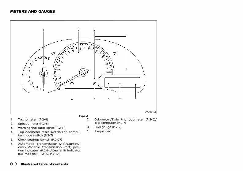
JVC0541XType A
1. Tachometer* (P.2-8)2. Speedometer (P.2-5)3. Warning/indicator lights (P.2-11)4. Trip odometer reset switch/Trip compu-
ter mode switch (P.2-7)5. Clock settings switch (P.2-27)6. Automatic Transmission (AT)/Continu-
ously Variable Transmission (CVT) posi-tion indicator* (P.2-9) /Gear shift indicator(MT models)* (P.2-10, P.5-19)
7. Odometer/Twin trip odometer (P.2-6)/Trip computer (P.2-7)
8. Fuel gauge (P.2-9)*: if equipped
METERS AND GAUGES
Condition: 'Except for China'/

(13,1)
[ Edit: 2018/ 12/ 21 Model: N17-A ]
JVI0165XType B
1. Tachometer (P.2-8)2. Engine coolant temperature gauge (P.2-8)3. Vehicle information display (P.2-5)
— Odometer/Twin trip odometer (P.2-6)— Trip computer (P.2-7)— Clock (P.2-27)— Outside air temperature* (P.2-7)— Instrument brightness control display(P.2-10)
4. Fuel gauge (P.2-9)5. Speedometer (P.2-5)6. Warning/indicator lights (P.2-11)7. Instrument brightness control knob
(P.2-10)8. Automatic Transmission (AT)/Continu-
ously Variable Transmission (CVT) posi-tion indicator* (P.2-9)
9. Trip odometer reset switch/Trip compu-ter mode switch (P.2-6)
*: if equipped
Illustrated table of contents 0-9
Condition: 'Except for China'/

(14,1)
[ Edit: 2018/ 12/ 21 Model: N17-A ]
0-10 Illustrated table of contents
GUID-FA71B07C-1CF7-4DF1-990E-05A8376762F0
HR15DE ENGINE MODELGUID-F9F74C9C-F548-4FBF-8553-42572F564989
JVC0118X
1. Engine drive belts (P.8-14)2. Brake and clutch* fluid reservoir (P.8-16,
P.8-17)— Right-Hand Drive (RHD) model
3. Engine oil filler cap (P.8-10)4. Air cleaner (P.8-18)5. Brake and clutch* fluid reservoir (P.8-16,
P.8-17)— Left-Hand Drive (LHD) model
6. Fuse/fusible link box (P.8-24)7. Window washer fluid reservoir (P.8-20)8. Engine oil dipstick (P.8-10)9. Radiator cap (P.8-8)
— Vehicle overheat (P.6-11)10. Battery (P.5-34, P.8-21)
— Jump starting (P.6-9)
11. Engine coolant reservoir (P.8-9)*: For Manual Transmission (MT) Model
ENGINE COMPARTMENT
Condition: 'Except for China'/

(15,1)
[ Edit: 2018/ 12/ 21 Model: N17-A ]
HR12DE ENGINE MODELGUID-F978D4F1-0830-4A38-B742-722BCDA9D97C
JVC0240X
1. Engine drive belts (P.8-14)2. Brake and clutch* fluid reservoir (P.8-16,
P.8-17)3. Engine oil filler cap (P.8-10)4. Air cleaner (P.8-18)5. Fuse/fusible link box (P.8-24)6. Window washer fluid reservoir (P.8-20)7. Engine oil dipstick (P.8-10)
8. Radiator cap (P.8-8)— Vehicle overheat (P.6-11)
9. Battery (P.5-34, P.8-21)— Jump starting (P.6-9)
10. Engine coolant reservoir (P.8-9)*: For Manual Transmission (MT) Model
Illustrated table of contents 0-11
Condition: 'Except for China'/

(16,1)
[ Edit: 2018/ 12/ 21 Model: N17-A ]
0-12 Illustrated table of contents
K9K ENGINE MODELGUID-E51EA618-3F2F-439D-AF9B-F175F5B26F7E
SDI2711
1. Brake and clutch fluid reservoir (P.8-16,P.8-17)
2. Air cleaner (P.8-18)3. Fuse/fusible link box (P.8-24)4. Priming pump (P.8-13)5. Window washer fluid reservoir (P.8-20)6. Engine drive belts (P.8-14)7. Engine oil filler cap (P.8-10)
8. Engine oil dipstick (P.8-10)9. Engine coolant reservoir (P.8-9)
— Vehicle overheat (P.6-11)10. Battery (P.5-34, P.8-21)
— Jump starting (P.6-9)
Condition: 'Except for China'/

(17,1)
[ Edit: 2018/ 12/ 21 Model: N17-A ]
1 Safety — seats, seat belts and supplementalrestraint system
Seats ........................................................................................................................... 1-2Front seats ..................................................................................................... 1-2Armrest (if equipped) ............................................................................. 1-3
Head restraints ................................................................................................... 1-4Adjustable head restraint components .................................. 1-4Non-adjustable head restraint components ...................... 1-4Remove ............................................................................................................. 1-4Install ................................................................................................................... 1-5Adjust .................................................................................................................. 1-5
Seat belts ................................................................................................................ 1-6Precautions on seat belt usage .................................................... 1-6Child safety .................................................................................................... 1-7Pregnant women ...................................................................................... 1-8Injured persons ........................................................................................... 1-8Three-point type seat belts .............................................................. 1-8Two-point type seat belts (if equipped) ................................. 1-9Center mark on seat belts ............................................................. 1-10Seat belt maintenance ...................................................................... 1-10
Child restraints ............................................................................................... 1-10Precautions on child restraint usage .................................. 1-10Universal child restraints for front seat and rearseats (for India) ..................................................................................... 1-11ISOFIX child restraint system (if equipped) .................... 1-12Child restraint anchorage (if equipped) ............................ 1-13Child restraint installation using ISOFIX(if equipped) ............................................................................................. 1-13Installation of child restraint system ................................... 1-15
Supplemental Restraint System (SRS) ......................................... 1-19Precautions on Supplemental RestraintSystem (SRS) ........................................................................................... 1-19Supplemental air bag systems ................................................. 1-24SRS air bag deployment conditions .................................... 1-25Pre-tensioner seat belt system (if equipped) ............... 1-27Repair and replacement procedure ..................................... 1-28
Condition: 'Except for China'/

(18,1)
[ Edit: 2018/ 12/ 21 Model: N17-A ]
1-2 Safety — seats, seat belts and supplemental restraint system
GUID-0E4D48F2-87EB-41C3-92CE-212C2CB24BDC
SSS0133A
WARNING:. Do not drive and/or ride in the vehicle
with the seatback reclined. This can bedangerous. The shoulder belt will not beproperly against the body. In an accident,you and your passengers could bethrown into the shoulder belt and receiveneck or other serious injuries. You andyour passengers could also slide underthe lap belt and receive serious injuries.
. For the most effective protection whilethe vehicle is in motion, the seatbackshould be upright. Always sit well backand upright in the seat and adjust theseat belt properly. (See “Seat belts” (P.1-6).)
. Do not leave children unattended insidethe vehicle. They could unknowingly acti-vate switches or controls. Unattendedchildren could become involved in ser-ious accidents.
. To help avoid risk of injury or deaththrough unintended operation of thevehicle and/or its systems, do not leavechildren, people who require the assis-
tance of others or pets unattended inyour vehicle. Additionally, the tempera-ture inside a closed vehicle on a warmday can quickly become high enough tocause a significant risk of injury or deathto people and pets.
CAUTION:When adjusting the seat positions, be surenot to contact any moving parts to avoidpossible injuries and/or damages.
FRONT SEATSGUID-42A7490D-1067-4CAC-9A39-544D84F10BB7WARNING:
Do not adjust the driver’s seat while drivingso that full attention may be given to vehicleoperation.
Manual seat adjustmentGUID-4630BA8F-468A-4657-ABF6-27A2A17D208D
WARNING:After adjusting a seat, gently shake the seatto confirm that the seat is locked securely. Ifthe seat is not locked securely, it may movesuddenly and could cause the loss of controlof the vehicle.
SEATS
Condition: 'Except for China'/

(19,1)
[ Edit: 2018/ 12/ 21 Model: N17-A ]
SSS0660
Forward and backward:GUID-9E14C2E6-2E9C-4731-980B-C45B899B977B
1. Pull up the adjusting lever .2. Slide the seat to the desired position.3. Release the adjusting lever to lock the seat
in position.Reclining:
GUID-9E14C2E6-2E9C-4731-980B-C45B899B977B
1. Pull up the adjusting lever .2. Tilt the seatback to the desired position.3. Release the adjusting lever to lock the
seatback in position.The reclining feature allows the adjustment ofthe seatback for occupants of different sizes tohelp obtain the proper seat belt fit. (See “Seatbelts” (P.1-6).)The seatback may be reclined to allow occu-pants to rest when the vehicle is parked.Seat lifter (if equipped):
GUID-9E14C2E6-2E9C-4731-980B-C45B899B977B
Pull up or push down the adjusting lever toadjust the seat height until the desired positionis achieved.
ARMREST (if equipped)GUID-0D483ADC-82D8-447F-BDBC-3C51B0B77FE8
Front (driver’s seat)GUID-E6344C7F-FEBB-40F8-B983-5545E9FC93C5
SSS0787
Pull the armrest down until it is horizontal.
Rear GUID-93866274-495E-42DF-A608-4662C6C92B29
SSS0963
Pull the armrest down until it is horizontal.
Safety — seats, seat belts and supplemental restraint system 1-3
Condition: 'Except for China'/

(20,1)
[ Edit: 2018/ 12/ 21 Model: N17-A ]
1-4 Safety — seats, seat belts and supplemental restraint system
GUID-F4A07253-770E-4F4C-BCB1-5E2D1740FDC6
WARNING:Head restraints supplement the other vehiclesafety systems. They may provide additionalprotection against injury in certain rear endcollisions. Adjustable head restraints must beadjusted properly, as specified in this section.Check the adjustment after someone elseuses the seat. Do not attach anything to thehead restraint stalks or remove the headrestraint. Do not use the seat if the headrestraint has been removed. If the headrestraint was removed, reinstall and properlyadjust the head restraint before an occupantuses the seating position. Failure to followthese instructions can reduce the effective-ness of the head restraint. This may increasethe risk of serious injury or death in acollision.
. Your vehicle is equipped with a headrestraint that may be integrated, adjustableor non-adjustable.
. Adjustable head restraints have multiplenotches along the stalk to lock them in adesired adjustment position.
. The non-adjustable head restraints have asingle locking notch to secure them to theseat frame.
. Proper Adjustment:— For the adjustable type, align the head
restraint so the center of your ear isapproximately level with the center ofthe head restraint.
— If your ear position is still higher than therecommended alignment, place thehead restraint at the highest position.
. If the head restraint has been removed,ensure that it is reinstalled and locked inplace before riding in that designated
seating position.
ADJUSTABLE HEAD RESTRAINT COM-PONENTS GUID-6D22BBB3-8D36-417E-878D-360F870ACF1B
SSS0992
1. Removable head restraint2. Multiple notches3. Lock knob4. Stalks
NON-ADJUSTABLE HEAD RESTRAINTCOMPONENTSGUID-3C330412-A135-42D9-8C25-A0498232AE96
JVR0203X
1. Removable head restraint
2. Single notch3. Lock knob4. Stalks
REMOVE GUID-B081657A-4F54-4CA6-A963-5A52ECD0821C
SSS1037
Use the following procedure to remove theadjustable head restraints.1. Pull the head restraint up to the highest
position.2. Push and hold the lock knob.3. Remove the head restraint from the seat.4. Store the head restraint properly in a
secure place so it is not loose in the vehicle.5. Reinstall and properly adjust the head
restraint before an occupant uses theseating position.
HEAD RESTRAINTS
Condition: 'Except for China'/

(21,1)
[ Edit: 2018/ 12/ 21 Model: N17-A ]
INSTALL GUID-91036F61-0D7F-464E-AB13-F169A8170985
SSS1038
1. Align the head restraint stalks with theholes in the seat. Make sure that the headrestraint is facing the correct direction. Thestalk with the adjustment notch must beinstalled in the hole with the lock knob .
2. Push and hold the lock knob and push thehead restraint down.
3. Properly adjust the head restraint before anoccupant uses the seating position.
ADJUST GUID-7F4FA002-0E43-41BC-A558-14805BD05E20
SSS0997
For adjustable head restraintAdjust the head restraint so the center is levelwith the center of your ears. If your ear positionis still higher than the recommended align-ment, place the head restraint at the highestposition.
JVR0259X
For non-adjustable head restraintMake sure the head restraint is positioned fromthe stored position or any non-latch position sothe lock knob is engaged in the notch beforeriding in that designated seating position.
Raise GUID-9BCA1908-1A87-454B-AFD2-9BFE3120F799
SSS1035
To raise the head restraint, pull it up.
Make sure the head restraint is positioned fromthe stored position or any non-latch position sothe lock knob is engaged in the notch beforeriding in that designated seating position.
Lower GUID-5FCBF5C0-907E-493B-9449-3D124814C97B
SSS1036
To lower, push and hold the lock knob andpush the head restraint down.Make sure the head restraint is positioned sothe lock knob is engaged in the notch beforeriding in that designated seating position.
Safety — seats, seat belts and supplemental restraint system 1-5
Condition: 'Except for China'/

(22,1)
[ Edit: 2018/ 12/ 21 Model: N17-A ]
1-6 Safety — seats, seat belts and supplemental restraint system
GUID-54FABC2C-16D2-472D-959C-EC961EDBAC13
PRECAUTIONS ON SEAT BELT USAGEGUID-E0B9589F-74A9-4DB5-8A5A-40333BC200D2If you are wearing the seat belt properlyadjusted and sitting upright and well back inthe seat, chances of being injured or killed in anaccident and/or the severity of injury may begreatly reduced. NISSAN strongly encouragesyou and all of your passengers to buckle upevery time you drive, even if your seatingposition includes the supplemental air bagsystems.
SSS0134A
SSS0136A
SSS0014 SSS0016
SEAT BELTS
Condition: 'Except for China'/

(23,1)
[ Edit: 2018/ 12/ 21 Model: N17-A ]
WARNING:. Seatbelts are designed to bear upon the
bony structure of the body, and should beworn low across the front of the pelvis orthe pelvis, chest and shoulders, as applic-able; wearing the lap section of the beltacross the abdominal area must beavoided. Serious injury may occur if aseat belt is not worn properly.
. Position the lap belt as low and snug aspossible around the hips, not the waist. Alap belt worn too high could increase therisk of internal injuries in an accident.
. Do not allowmore than one person to usethe same seat belt. Each belt assemblymust only be used by one occupant; it isdangerous to put a belt around a childbeing carried on the occupant’s lap.
. Never carry more people in the vehiclethan there are seat belts.
. Never wear seat belts inside out. Beltsshould not be worn with straps twisted.Doing so may reduce their effectiveness.
. Seatbelts should be adjusted as firmly aspossible, consistent with comfort, to pro-vide the protection for which they havebeen designed. A slack belt will greatlyreduce the protection afforded to thewearer.
. Every person who drives or rides in thisvehicle should use a seat belt at all times.Children should be properly restrained inthe rear seat and, if appropriate, in a childrestraint system.
. Do not put the belt behind your back orunder your arm. Always route theshoulder belt over your shoulder andacross your chest. The belt should be
away from your face and neck, but notfalling off your shoulder. Serious injurymay occur if a seat belt is not wornproperly.
. No modifications or additions should bemade by the user which will either pre-vent the seat belt adjusting devices fromoperating to remove slack, or prevent theseat belt assembly from being adjustedto remove slack.
. Care should be taken to avoid contam-ination of the webbing with polishes, oilsand chemicals, and particularly batteryacid. Cleaning may safely be carried outusing mild soap and water. The beltshould be replaced if webbing becomesfrayed, contaminated or damaged.
. All seat belt assemblies including retrac-tors and attaching hardware should beinspected after any collision by a NISSANdealer. NISSAN recommends that all seatbelt assemblies in use during a collisionbe replaced unless the collision wasminor and the belts show no damageand continue to operate properly. Seatbelt assemblies not in use during acollision should also be inspected and,when necessary, replaced if either da-mage or improper operation is noted.
. It is essential to replace the entire as-sembly after it has been worn in a severeimpact even if damage to the assembly isnot obvious.
. Once the pre-tensioner seat belt (ifequipped) has activated, it cannot bereused. It must be replaced together withthe retractor. Contact a NISSAN dealer.
. Removal and installation of the pre-ten-sioner seat belt system components (ifequipped) should be done by a NISSAN
dealer.CHILD SAFETYGUID-BEF39E00-83A9-46E4-A6CD-4E7837159442
WARNING:. Infants and children need special protec-
tion. The vehicle’s seat belts may not fitthem properly. The shoulder belt maycome too close to the face or neck. Thelap belt may not fit over their smallhipbones. In an accident, an improperlyfitted seat belt could cause serious orfatal injury.
. Always use an appropriate child restraintsystem.
Children need adults to help protect them.They need to be properly restrained. Theproper restraint depends on the child’s size.
Infants and small childrenGUID-2CB554A6-70F8-4EA5-AD1F-1A1CD0569FC1
SSS0099
NISSAN recommends that infants and smallchildren be seated in a child restraint system.You should choose a child restraint system thatfits your vehicle and the child, and alwaysfollow the manufacturer’s instructions for in-stallation and use.
Safety — seats, seat belts and supplemental restraint system 1-7
Condition: 'Except for China'/

(24,1)
[ Edit: 2018/ 12/ 21 Model: N17-A ]
1-8 Safety — seats, seat belts and supplemental restraint system
Large childrenGUID-D60D6D89-020F-4F38-8877-C70FB3DDBA25
WARNING:. Never allow children to stand or kneel on
any seats.. Never allow children in the luggage area
while the vehicle is moving. A child couldbe seriously injured in an accident orsudden stop.
Children who are too large for a child restraintsystem should be seated and restrained by theseat belts that are provided.If the child’s seating position has a shoulderbelt that fits close to the face or neck, the useof a booster seat (commercially available) mayhelp overcome this. The booster seat shouldraise the child so that the shoulder belt isproperly positioned across the top, middleportion of the shoulder and the lap belt is lowon the hips. The booster seat should also fit thevehicle seat. Once the child has grown so thatthe shoulder belt is no longer on or near theface or neck of the child, use the shoulder beltwithout the booster seat. In addition, there aremany types of child restraint systems availablefor larger children that should be used formaximum protection.
PREGNANT WOMENGUID-FE869D3B-B8B4-419B-873A-F34B364C8C1ANISSAN recommends that pregnant womenuse seat belts. The seat belt should be wornsnug, and always position the lap belt as low aspossible around the hips, not the waist. Placethe shoulder belt over your shoulder andacross your chest. Never run the lap/shoulderbelt over your abdominal area. Contact yourdoctor for specific recommendations.
INJURED PERSONSGUID-82EBCAFA-39DD-4B24-9916-C91E3A86FE59NISSAN recommends that injured persons useseat belts. Contact your doctor for specificrecommendations.
THREE-POINT TYPE SEAT BELTSGUID-984D2E17-E07E-4F94-97BF-E5B1D1F3D930
Fastening seat beltsGUID-421AB629-E53A-4541-8D10-C0D57422D757
SSS0292
WARNING:The seatback should not be in a reclinedposition any more than needed for comfort.Seat belts are most effective when thepassenger sits well back and straight up inthe seat.
1. Adjust the seat. (See “Seats” (P.1-2).)2. Slowly pull the seat belt out of the retractor
and insert the tongue into the buckle untilyou hear and feel the latch engage.. The retractor is designed to lock during
a sudden stop or on impact. A slowpulling motion permits the belt tomove, and allows you some freedomof movement in the seat.
. If the seat belt cannot be pulled fromits fully retracted position, firmly pullthe belt and release it. Then smoothlypull the belt out of the retractor.
SSS0467
3. Position the lap belt portion low and snugon the hips as shown.
4. Pull the shoulder belt portion toward theretractor to take up extra slack. Be sure theshoulder belt is routed over your shoulderand is snug across your chest.
Shoulder belt height adjustment (ifequipped) GUID-A13270E2-267F-495D-8674-287DC107D8B3
SSS0351A
Condition: 'Except for China'/

(25,1)
[ Edit: 2018/ 12/ 21 Model: N17-A ]
WARNING:. The shoulder belt anchor height should
be adjusted to the position best for you.Failure to do so may reduce the effec-tiveness of the entire restraint systemand increase the chance or severity ofinjury in an accident.
. The shoulder belt should rest on themiddle of the shoulder. It must not restagainst the neck.
. Be sure that the seat belt is not twisted inany way.
. Be sure that the shoulder belt anchor issecured by trying to move the shoulderbelt anchor up and down after adjust-ment.
The shoulder belt anchor height should beadjusted to the position best for you.The belt should be away from your face andneck, but not falling off your shoulder.To adjust, pull the release button and movethe shoulder belt anchor to the proper position, so that the belt passes over the center of the
shoulder.Release the button to lock the shoulder beltanchor into position.
Unfastening seat beltsGUID-1BF0DC09-9D66-448C-8B28-6F14CFC40A17Push the button on the buckle. The seat beltautomatically retracts.
Checking seat belt operationGUID-145A1CB5-9B55-4D1A-A8C0-CCED3409D28DSeat belt retractors are designed to lock seatbelt movement:. When the seat belt is pulled quickly from
the retractor.. When the vehicle slows down rapidly.To increase your confidence in the seat belts,check the operation by grasping the shoulderbelt and pulling forward quickly. The retractorshould lock and restrict further belt movement.If the retractor does not lock during this check,contact a NISSAN dealer immediately.
TWO-POINT TYPE SEAT BELTS (ifequipped) GUID-D22413D4-BF49-4D45-994E-2EA638DE79EC
Fastening seat beltsGUID-6258C427-15E5-465B-918B-6CF5DD74179A
JVR0035X
WARNING:Seat belts are most effective when thepassenger sits well back and straight up inthe seat.
1. Insert the tongue into the buckle markedCENTER until you hear and feel the latchengage.
JVR0036X
2. Adjust the seat belt length. To shorten, holdthe tongue and pull the upper belt asillustrated . To lengthen, hold the tongueand pull the under belt as illustrated .
JVR0037X
3. Position the lap belt portion low and snugon the hips as shown.
Safety — seats, seat belts and supplemental restraint system 1-9
Condition: 'Except for China'/

(26,1)
[ Edit: 2018/ 12/ 21 Model: N17-A ]
1-10 Safety — seats, seat belts and supplemental restraint system
Unfastening seat beltsGUID-F1DEE74D-1574-468C-AD0E-4B39EDD29A76Push the button on the buckle.
CENTER MARK ON SEAT BELTSGUID-DE981F0D-8B58-47D8-8132-009A1F299182
Selecting correct set of seat beltsGUID-854F5578-B270-4D1E-91F7-C1DD2F46C56E
SSS0616
The center seat belt buckle or both thebuckle and the tongue are identified by theCENTER mark. The center seat belt tongue canbe fastened only into the center seat beltbuckle.
SEAT BELT MAINTENANCEGUID-B0F298CD-913B-46BF-8E46-89902A89FA3BPeriodically check that the seat belt and all themetal components, such as buckles, tongues,retractors, flexible wires and anchors, workproperly. If loose parts, deterioration, cuts orother damage on the seat belt webbing isfound, the entire seat belt assembly should bereplaced.If dirt builds up in the shoulder belt guide of theseat belt anchors, the seat belts may retractslowly. Wipe the shoulder belt guide with aclean, dry cloth.To clean the seat belt webbing, apply a mildsoap solution or any solution recommendedfor cleaning upholstery or carpet. Then wipe
with a cloth and allow the seat belts to dry inthe shade. Do not allow the seat belts to retractuntil they are completely dry.
GUID-1A220BAA-203F-42A3-BB0A-DDFDA8E06122
PRECAUTIONS ON CHILD RESTRAINTUSAGE GUID-9396FD2F-E533-4EB3-A047-B6D92A4A219A
SSS0099
WARNING:. Infants and small children should never
be carried on your lap. It is not possiblefor even the strongest adult to resist theforces of a severe accident. The childcould be crushed between the adult andparts of the vehicle. Also, it is dangerousto put a seat belt around a child beingcarried on the occupant’s lap.
. Infants and children need special protec-tion. The vehicle’s seat belts may not fitthem properly. The shoulder belt maycome too close to the face or neck. Thelap belt may not fit over their small hipbones. In an accident, an improperlyfitting seat belt could cause serious orfatal injury.
. Infants and small children should alwaysbe placed in an appropriate child re-straint system while riding in the vehicle.Failure to use a child restraint system canresult in serious injury or death.
CHILD RESTRAINTS
Condition: 'Except for China'/

(27,1)
[ Edit: 2018/ 12/ 21 Model: N17-A ]
. Child restraint systems specially de-signed for infants and small children areavailable from several manufacturers.When selecting any child restraint sys-tems, place your child in the child re-straint system and check the variousadjustments to be sure that the childrestraint system is compatible with yourchild. Always follow the manufacturer’sinstructions for installation and use.
. NISSAN recommends that the child re-straint system be installed in the rearseat. According to accident statistics,children are safer when properly re-strained in the rear seat rather than inthe front seat.
. Follow all of the child restraint systemmanufacturer’s instructions for installa-tion and use. When purchasing a childrestraint system, be sure to select onewhich will fit your child and vehicle. Itmay not be possible to properly installsome types of child restraint systems inyour vehicle.
. For a front-facing child restraint system,check to make sure the shoulder beltdoes not fit close to child’s face or neck. Ifit does, put the shoulder belt behind thechild restraint system.
. Never install a rear-facing child restraintsystem in the front seat when the frontpassenger’s air bag is equipped. An in-flating supplemental front-impact air bagcould seriously injure or kill your child. Arear-facing child restraint system mustonly be used in the rear seat.
. Adjustable seatbacks should be posi-tioned to fit a child restraint system, butas upright as possible.
. If the seat belt in the position where achild restraint system is installed requiresa locking clip and if it is not used, injuriescould result from a child restraint systemtipping over during normal vehicle brak-ing or cornering.
. After attaching a child restraint system,test it before you place the child in it. Tiltit from side to side. Try to tug it forwardand check if it is held securely in place.The child restraint system should notmove more than 25 mm (1 in). If therestraint is not secure, tighten the beltas necessary, or install the restraint inanother seat and test it again.
. Check the child restraint system in yourvehicle to be sure that it is compatiblewith the vehicle’s seat belt system.
. If a child restraint system is not anchoredproperly, the risk of a child being injuredin a collision or a sudden stop greatlyincreases.
. Improper use of a child restraint systemcan increase the risk or severity of injuryfor both the child and other occupants inthe vehicle.
. Always use an appropriate child restraintsystem. An improperly installed childrestraint system could lead to seriousinjury or death in an accident.
. When the child restraint system is not inuse, keep it secured with the ISOFIX childrestraint system (if equipped) or a seatbelt to prevent it from being thrownaround in case of a sudden stop oraccident.
NISSAN recommends that infants and smallchildren be seated in a child restraint system.You should choose a child restraint system that
fits your vehicle and always follow the manu-facturer’s instructions for installation and use.In addition, there are many types of childrestraint systems available for larger childrenthat should be used for maximum protection.
CAUTION:Remember that a child restraint system leftin a closed vehicle can become very hot.Check the seating surface and buckles beforeplacing your child in a child restraint system.
UNIVERSAL CHILD RESTRAINTS FORFRONT SEAT AND REAR SEATS (forIndia) GUID-27F75C7B-B2C4-4E53-AF30-E01323F41B37When selecting any child restraint, keep thefollowing points in mind:. Choose a child restraint that complies with
AIS 072-2009.. Place your child in the child restraint and
check the various adjustments to be surethe child restraint is compatible with yourchild. Always follow all of the recommendedprocedures.
. Check the child restraint in your vehicle tobe sure it is compatible with vehicle’s seatbelt system.
. Refer to the table later in this section for alist of the recommended fitment positions.
Safety — seats, seat belts and supplemental restraint system 1-11
Condition: 'Except for China'/

(28,1)
[ Edit: 2018/ 12/ 21 Model: N17-A ]
1-12 Safety — seats, seat belts and supplemental restraint system
Approved child restraint positionsGUID-6052DD5F-27C1-4D0C-8273-DF15A430BCF9
The following restriction is applied when using child restraints varying by infants weight andinstallation position.
Mass groupSeating position
Front passenger Rear Outboard Rear CenterGroup 0 up to 10 kg × U ×Group 0+ up to 13 kg × U ×Group I 9 to 18 kg UF U ×Group II 15 to 25 kg UF U ×Group III 22 to 36 kg UF U ×
U: Suitable for “universal” category restraints approved for use in this mass group.UF: Suitable for forward-facing “universal” category restraints approved for use in this mass
group.X: Seat position not suitable for children in this mass group.ISOFIX CHILD RESTRAINT SYSTEM (ifequipped) GUID-52E0ED42-273F-40BB-93AA-7F2F3D103563Your vehicle is equipped with special anchorpoints that are used with ISOFIX child restraintsystems.
ISOFIX lower anchor point locationsGUID-4CA362C7-65B9-4BF5-AF53-B0793163382AThe ISOFIX anchor points are provided to installchild restraints in the rear outboard seatingpositions only. Do not attempt to install achild restraint in the center position using theISOFIX anchors.
SSS1046ISOFIX label location
SSS0637ISOFIX lower anchor location
The ISOFIX anchors are located at the rear ofthe seat cushion near the seatback. A label isattached to the seatback to help you locate theISOFIX anchors.
ISOFIX child restraint anchor attach-ments GUID-3CE88358-EB93-4D4D-8BEB-569F5DE91FF4
SSS0644Anchor attachment
ISOFIX child restraints include two rigid attach-ments that can be connected to two anchorslocated in the seat. With this system, you do nothave to use a vehicle seat belt to secure thechild restraint. Check your child restraint for alabel stating that it is compatible with theISOFIX child restraints. This information may
Condition: 'Except for China'/

(29,1)
[ Edit: 2018/ 12/ 21 Model: N17-A ]
also be in the instructions provided by the childrestraint manufacturer.ISOFIX child restraints generally require the useof a top tether strap or other anti-rotationdevices such as support legs. When installingISOFIX child restraints, carefully read and followthe instructions in this manual and thosesupplied with the child restraints. (See “Childrestraint installation using ISOFIX” (P.1-13).)
CHILD RESTRAINT ANCHORAGE (ifequipped) GUID-961BAD1A-211D-4323-B754-5E12137C28ABYour vehicle is designed to accommodate achild restraint system on the rear seat. Wheninstalling a child restraint system, carefully readand follow the instructions in this manual andthose supplied with the child restraint system.
WARNING:Child restraint anchorages are designed towithstand only those loads imposed bycorrectly fitted child restraints. Under nocircumstances are they to be used for adultseat belts, harnesses or for attaching otheritems or equipment to the vehicle. Doing socould damage the child restraint anchorages.The child restraint will not be properlyinstalled using the damaged anchorage,and a child could be seriously injured orkilled in a collision.
Anchorage locationGUID-E7B5F4AB-1328-4E20-B669-B64DEF0C01CD
JVR0061X
The anchor points are located on the rearparcel shelf for the center (if equipped), rightand left outboard seating positions of the rearseat.
CHILD RESTRAINT INSTALLATION USINGISOFIX (if equipped)GUID-860C9B60-EFAB-467E-B530-D534A63A26A8
WARNING:. Attach ISOFIX child restraints only at the
specified locations. For the ISOFIX loweranchor locations, see “ISOFIX child re-straint system” (P.1-12). If a child restraintis not secured properly, your child couldbe seriously injured or killed in an acci-dent.
. Do not install child restraints that requirethe use of a top tether strap to seatingpositions that do not have a top tetheranchor.
. Do not secure a child restraint in thecenter rear seating position using theISOFIX lower anchors. The child restraintwill not be secured properly.
. Inspect the lower anchors by insertingyour fingers into the lower anchor areaand feeling to make sure there are noobstructions over the ISOFIX anchors,such as seat belt webbing or seat cushionmaterial. The child restraint will not besecured properly if the ISOFIX anchorsare obstructed.
. Child restraint anchorages are designedto withstand only those loads imposedby correctly fitted child restraints. Underno circumstances are they to be used foradult seat belts, harnesses or for attach-ing other items or equipment to thevehicle. Doing so could damage the childrestraint anchorages. The child restraintwill not be properly installed using thedamaged anchorage, and a child could beseriously injured or killed in a collision.
Installation on rear outboard seatsGUID-71362521-F3A0-413F-9537-40392E82E5FB
Front-facing:GUID-9E14C2E6-2E9C-4731-980B-C45B899B977B
Be sure to follow the manufacturer’s instruc-tions for the proper use of your child restraint.Follow these steps to install a front-facing childrestraint on the rear outboard seats usingISOFIX:
Safety — seats, seat belts and supplemental restraint system 1-13
Condition: 'Except for China'/

(30,1)
[ Edit: 2018/ 12/ 21 Model: N17-A ]
1-14 Safety — seats, seat belts and supplemental restraint system
SSS0646ASteps 1 and 2
1. Position the child restraint on the seat .2. Secure the child restraint anchor attach-
ments to the ISOFIX lower anchors .3. The back of the child restraint should be
secured against the vehicle seatback. Ifnecessary, adjust or remove the headrestraint to obtain the correct child re-straint fit. (See “Head restraints” (P.1-4).) Ifthe head restraint is removed, store it in asecure place. Be sure to install the headrestraint when the child restraint is re-moved. If the seating position does nothave an adjustable head restraint and it isinterfering with the proper child restraintfit, try another seating position or a differ-ent child restraint.
SSS0754AStep 4
4. Shorten the rigid attachment to have thechild restraint firmly tightened; press down-ward and rearward firmly in the centerof the child restraint with your knee tocompress the vehicle seat cushion andseatback.
5. If the child restraint is equipped with a toptether strap, route the top tether strap andsecure the tether strap to the tetheranchor point. (See “Child restraint ancho-rage” (P.1-13).)
6. If the child restraint is equipped with otheranti-rotation devices such as support legs,use them instead of the top tether strapfollowing the child restraint manufacturer’sinstructions.
SSS0755AStep 7
7. Test the child restraint before you place thechild in it . Push the child restraint fromside to side and tug it forward to make surethat it is held securely in place.
8. Check to make sure that the child restraintis properly secured prior to each use. If thechild restraint is loose, repeat steps 3through 7.
Rear-facing:GUID-9E14C2E6-2E9C-4731-980B-C45B899B977B
Be sure to follow the manufacturer’s instruc-tions for the proper use of your child restraint.Follow these steps to install a rear-facing childrestraint on the rear outboard seats usingISOFIX:
Condition: 'Except for China'/

(31,1)
[ Edit: 2018/ 12/ 21 Model: N17-A ]
SSS0649ASteps 1 and 2
1. Position the child restraint on the seat .2. Secure the child restraint anchor attach-
ments to the ISOFIX lower anchors .
SSS0756AStep 3
3. Shorten the rigid attachment to have thechild restraint firmly tightened; press down-ward and rearward firmly in the centerof the child restraint with your hand tocompress the vehicle seat cushion andseatback.
4. If the child restraint is equipped with a toptether strap, route the top tether strap andsecure the tether strap to the tetheranchor point. (See “Child restraint ancho-rage” (P.1-13).)
5. If the child restraint is equipped with otheranti-rotation devices such as support legs,use them instead of the top tether strapfollowing the child restraint manufacturer’sinstructions.
SSS0757AStep 6
6. Test the child restraint before you place thechild in it . Push the child restraint fromside to side and tug it forward to make surethat it is held securely in place.
7. Check to make sure that the child restraintis properly secured prior to each use. If thechild restraint is loose, repeat steps 3through 6.
INSTALLATION OF CHILD RESTRAINTSYSTEM GUID-9A049A6B-E06E-4BB1-8F3A-67F406B7024E
Installation on rear seats (three-pointtype seat belt)GUID-A26D65AA-AF3D-47A6-BCFC-7BD2C0D6125A
WARNING:The direction of the child restraint systemdepends on the type of the child restraintsystem and the size of the child.
Front-facing:GUID-9E14C2E6-2E9C-4731-980B-C45B899B977B
SSS0374A
If you must install a front-facing child restraintsystem on the rear seat, follow these steps:1. Position the front-facing child restraint
system on the rear seat.Always follow the child restraint systemmanufacturer’s instructions for installationand use.
2. Route the seat belt tongue through thechild restraint system and insert it into thebuckle until you hear and feel the latchengage.
SSS0513
To prevent slack in the lap belt, it is
Safety — seats, seat belts and supplemental restraint system 1-15
Condition: 'Except for China'/

(32,1)
[ Edit: 2018/ 12/ 21 Model: N17-A ]
1-16 Safety — seats, seat belts and supplemental restraint system
necessary to secure the shoulder belt inplace with a locking clip . Use the lockingclip attached to the child restraint systemor one which is equivalent in dimensionand strength.Be sure to follow the child restraint systemmanufacturer’s instructions for belt rout-ing.
3. Test the child restraint system before youplace the child in it. Tilt it from side to side.Try to tug it forward and check if it is heldsecurely in place.
4. Make sure that the child restraint system isproperly secured prior to each use.
Rear-facing:GUID-9E14C2E6-2E9C-4731-980B-C45B899B977B
SSS0375A
If you must install a rear-facing child restraintsystem on the rear seat, follow these steps:1. Position the rear-facing child restraint sys-
tem on the rear seat.Always follow the child restraint systemmanufacturer’s instructions for installationand use.
2. Route the seat belt tongue through thechild restraint system and insert it into thebuckle until you hear and feel the latch
engage.
SSS0513
To prevent slack in the lap belt, it isnecessary to secure the shoulder belt inplace with a locking clip . Use the lockingclip attached to the child restraint systemor one which is equivalent in dimensionand strength.Be sure to follow the child restraint systemmanufacturer’s instructions for belt rout-ing.
3. Test the child restraint system before youplace the child in it. Tilt it from side to side.Try to tug it forward and check if it is heldsecurely in place.
4. Make sure that the child restraint system isproperly secured prior to each use.
Installation on rear center seat (two-point type seat belt) (if equipped)GUID-873B405B-3F91-470C-A259-891ABC1F515C
WARNING:The direction of the child restraint systemdepends on the type of the child restraintsystem and the size of the child.
Front-facing:GUID-9E14C2E6-2E9C-4731-980B-C45B899B977B
SSS0512
If you must install a front-facing child restraintsystem on the rear center seat, follow thesesteps:1. Position the front-facing child restraint
system on the rear center seat.Always follow the child restraint systemmanufacturer’s instructions for installationand use.
2. Route the seat belt tongue through thechild restraint system and insert it into thebuckle until you hear and feel the latchengage.
SSS0513
Condition: 'Except for China'/

(33,1)
[ Edit: 2018/ 12/ 21 Model: N17-A ]
3. To prevent slack in the lap belt, it isnecessary to secure the lap belt in placewith a locking clip . Use the locking clipattached to the child restraint system, orone which is equivalent in dimensions andstrength.Be sure to follow the child restraint systemmanufacturer’s instructions for belt rout-ing.
4. Test the child restraint system before youplace the child in it. Tilt it from side to side.Try to tug it forward and check if it is heldsecurely in place.
5. Make sure that the child restraint system isproperly secured prior to each use.
Rear-facing:GUID-9E14C2E6-2E9C-4731-980B-C45B899B977B
SSS0514
If you must install a rear-facing child restraintsystem on the rear center seat, follow thesesteps:1. Position the rear-facing child restraint sys-
tem on the rear center seat.Always follow the child restraint systemmanufacturer’s instructions for installationand use.
2. Route the seat belt tongue through thechild restraint system and insert it into thebuckle until you hear and feel the latchengage.
SSS0513
3. To prevent slack in the lap belt, it isnecessary to secure the lap belt in placewith a locking clip . Use the locking clipattached to the child restraint system, orone which is equivalent in dimensions andstrength.Be sure to follow the child restraint systemmanufacturer’s instructions for belt rout-ing.
4. Test the child restraint system before youplace the child in it. Tilt it from side to side.Try to tug it forward and check if it is heldsecurely in place.
5. Make sure that the child restraint system isproperly secured prior to each use.
Safety — seats, seat belts and supplemental restraint system 1-17
Condition: 'Except for China'/

(34,1)
[ Edit: 2018/ 12/ 21 Model: N17-A ]
1-18 Safety — seats, seat belts and supplemental restraint system
Installation on front seatGUID-87AAD441-F551-4F9E-8861-F522CD21959E
SSS0300A
WARNING:. Never install a rear-facing child restraint
on the front passenger’s seat when thefront passenger’s air bag is equipped.Supplemental front-impact air bags in-flate with great force. A rear-facing childrestraint could be struck by the supple-mental front-impact air bags in an acci-dent and could seriously injure or kill yourchild.
. Never install a child restraint with a toptether strap on the front seat.
. NISSAN recommends that a child re-straint system be installed on the rearseat. However, if you must install a front-facing child restraint system on the frontpassenger’s seat, move the passenger’sseat to the rearmost position.
. Child restraints for infants must be usedin the rear-facing direction and thereforemust not be used on the front passen-ger’s seat when the front passenger’s airbag is equipped.
Front-facing:GUID-9E14C2E6-2E9C-4731-980B-C45B899B977B
SSS0627
If you must install a front-facing child restraintsystem on the front seat, follow these steps:1. Move the seat to the rearmost position .2. Adjust the head restraint to its highest
position .3. Position the front-facing child restraint
system on the front passenger’s seat. Itshould be placed in the front-facing direc-tion only.Always follow the child restraint system
manufacturer’s instructions for installationand use.
SSS0515
4. Route the seat belt tongue through thechild restraint system and insert it into thebuckle until you hear and feel the latchengage.
SSS0513
5. To prevent slack in the lap belt, it isnecessary to secure the shoulder belt inplace with a locking clip . Use the lockingclip attached to the child restraint system,or one which is equivalent in dimensionsand strength.Be sure to follow the child restraint systemmanufacturer’s instructions for belt rout-
Condition: 'Except for China'/

(35,1)
[ Edit: 2018/ 12/ 21 Model: N17-A ]
ing.6. Slide the seat forward so that the seat belt
fully tightens the child restraint system.7. Test the child restraint system before you
place the child in it. Tilt it from side to side.Try to tug it forward and check if it is heldsecurely in place.
8. Make sure that the child restraint system isproperly secured prior to each use.
GUID-C9565E22-C501-4988-950F-1FA89677EC38
PRECAUTIONS ON SUPPLEMENTAL RE-STRAINT SYSTEM (SRS)GUID-7F89D46B-E3E8-4C41-B2DD-E8AD6CC5FD5DThis Supplemental Restraint System (SRS) sec-tion contains important information concern-ing the driver’s and passenger’s (if equipped)supplemental front-impact air bags, supple-mental side-impact air bags (if equipped),supplemental curtain side-impact air bags (ifequipped) and pre-tensioner seat belts (ifequipped).
Supplemental front-impact air bagsystem (if equipped)GUID-F7C7E093-7D60-4532-B0A1-4F797E6C7E45This system can help cushion the impact forceto the head and chest area of the driver and/orfront passenger (if equipped) in certain frontalcollisions. The supplemental front-impact airbag is designed to inflate on the front wherethe vehicle is impacted.
Supplemental side-impact air bag sys-tem (if equipped)GUID-D066B082-8428-4503-80B4-57F62BF2B8E4This system can help cushion the impact forceto the chest and pelvis areas of the driver andfront passenger in certain side-impact colli-sions. The supplemental side-impact air bag isdesigned to inflate on the side where thevehicle is impacted.
Supplemental curtain side-impact airbag system (if equipped)GUID-83E98776-EF16-4A70-9F02-E8790DEB5FB7This system can help cushion the impact forceto the head of the driver and passengers infront and rear outboard seating positions incertain side-impact collisions. The supplemen-tal curtain side-impact air bag is designed toinflate on the side where the vehicle is im-pacted.The SRS is designed to supplement the acci-
dent protection provided by the driver’s seatbelt and is not designed to substitute for it.The SRS can help save lives and reduce seriousinjuries. However, inflating air bags may causeabrasions or other injuries. Air bags do notprovide protection to the lower body. Seat beltsshould always be correctly worn and theoccupants should always be seated a suitabledistance away from the steering wheel. (See“Seat belts” (P.1-6).) The air bags inflate quicklyin order to help protect the occupants. Theforce of the air bags inflating can increase therisk of injury if the occupants are too close to,or are against, the air bag modules duringinflation.The air bags will deflate quickly after deploy-ment.The SRS operates only when the ignitionswitch is in the “ON” position.When the ignition switch is in the “ON”position, the SRS air bag warning lightilluminates for about 7 seconds and thenturns off. This indicates that the SRS isoperational. (See “SRS air bag warning light”(P.1-23).)
Safety — seats, seat belts and supplemental restraint system 1-19
SUPPLEMENTAL RESTRAINT SYSTEM (SRS)
Condition: 'Except for China'/

(36,1)
[ Edit: 2018/ 12/ 21 Model: N17-A ]
1-20 Safety — seats, seat belts and supplemental restraint system
SSS0131A
SSS0132A
WARNING:. The supplemental front-impact air bags
ordinarily will not inflate in the event of aside impact, rear impact, rollover, or low-er severity frontal collision. Always wearthe seat belts to help reduce the risk orseverity of injury in accidents.
. The seat belts and the supplementalfront-impact air bags are most effectivewhen you are sitting well back and up-right in the seat. The front-impact airbags inflate with great force. If you areunrestrained, leaning forward, sittingsideways, or out of position in any way,
you are at greater risk of injury or deathin an accident. You may also receiveserious or fatal injuries from the supple-mental front-impact air bag if you are upagainst it when it inflates. Always sit backagainst the seatback and as far away aspractical from the steering wheel. Alwaysuse the seat belts.
SSS0006
SSS0007
SSS0008
Condition: 'Except for China'/

(37,1)
[ Edit: 2018/ 12/ 21 Model: N17-A ]
SSS0009
SSS0099
SSS0100
WARNING:. Never let children ride unrestrained or
extend their hands or face out of thewindow. Do not attempt to hold them inyour lap or arms. Some examples ofdangerous riding positions are shown inthe illustrations.
. Children may be severely injured or killedwhen the air bags inflate if they are notproperly restrained.
. Never install a rear-facing child restraintsystem in the front seat. An inflatingsupplemental front-impact air bag couldseriously injure or kill your child. (See“Child restraints” (P.1-10).)
SSS0059A
SSS0140
SSS0159
SSS0162
Safety — seats, seat belts and supplemental restraint system 1-21
Condition: 'Except for China'/

(38,1)
[ Edit: 2018/ 12/ 21 Model: N17-A ]
1-22 Safety — seats, seat belts and supplemental restraint system
WARNING:. The supplemental side-impact air bags
and supplemental curtain side-impact airbags ordinarily will not inflate in theevent of a front impact, rear impact,rollover, or lower severity side collision.Always wear the seat belts to help reducethe risk or severity of injury in accidents.
. The seat belts and the supplementalside-impact air bags and supplementalcurtain side-impact air bags are mosteffective when you are sitting well backand upright in the seat. The supplementalside-impact air bags and supplementalcurtain side-impact air bags inflate withgreat force. If you and your passengersare unrestrained, leaning forward, sittingsideways, or out of position in any way,you and your passengers are at greaterrisk of injury or death in an accident.
. Do not allow anyone to place their hands,legs, or face near the supplemental side-impact air bags and supplemental cur-tain side-impact air bags on the sides ofthe seatback of the front seats or nearthe side roof rails. Do not allow anyonesitting in the front seats or rear outboardseats to extend their hands out of thewindows or lean against the doors. Someexamples of dangerous riding positionsare shown in the illustrations.
. When sitting in the rear seats, do not holdonto the seatback of the front seats. Ifthe supplemental side-impact air bagsand supplemental curtain side-impact airbags inflate, you may be seriously in-jured. Be especially careful with children,who should always be properly re-strained.
. Do not use seat covers on the frontseatbacks. They may interfere with thesupplemental side-impact air bag infla-tions.
Pre-tensioner seat belt system (ifequipped) GUID-4FBEBA10-36FA-4E99-8BF3-2B28ED3E9427The pre-tensioner seat belt system may acti-vate with the supplemental air bag system incertain types of collisions.Working with the seat belt retractor andanchor, it helps tighten the seat belt the instantthe vehicle becomes involved in certain typesof collisions, helping to restrain front seatoccupants. (See “Pre-tensioner seat belt sys-tem” (P.1-27).)
Air bag warning label (if equipped)GUID-2019023B-9AC7-47BC-AAEC-B047F92FBAF4
SSS1029Label location
Warning labels about the supplemental front-impact air bag system are placed in the vehicleas shown in the illustration.The warning label is located on the surfaceof the driver’s and/or passenger’s sun visor.The warning label (if equipped) is located onthe side of the passenger’s side instrumentpanel.
The label(s) warn you not to fit a rear-facingchild restraint system on the front passengerseat as such a restraint system used in thisposition could cause serious injury to the infantin case of air bag deployment during a collision.Type A:
GUID-9E14C2E6-2E9C-4731-980B-C45B899B977B
JVR0260XAir bag warning label (sample)
The label design varies depending on themodel.The label warns:“Extreme Hazard! Do not use a rearward facingchild restraint on a seat protected by an airbagin front of it!”
Condition: 'Except for China'/

(39,1)
[ Edit: 2018/ 12/ 21 Model: N17-A ]
Type B:GUID-9E14C2E6-2E9C-4731-980B-C45B899B977B
JVR0243XAir bag warning label
The label warns:“NEVER use a rearward facing child restraint ona seat protected by an ACTIVE AIRBAG in frontof it, DEATH or SERIOUS INJURY to the CHILDcan occur.”In vehicles equipped with a front-impact pas-senger air bag system, use a rear-facing childrestraint system only on the rear seats.When installing a child restraint system in yourvehicle, always follow the child restraint systemmanufacturer’s instructions for installation. Foradditional information, see “Child restraints”(P.1-10).
SRS air bag warning lightGUID-936E937B-913F-4715-BE98-7F165F18DF0A
SPA1097
The SRS air bag warning light, displaying inthe instrument panel, monitors the circuits forthe air bag systems, pre-tensioner seat beltsystem and all related wiring.When the ignition switch is in the “ON” position,the SRS air bag warning light illuminates forabout 7 seconds and then turns off. Thisindicates that the SRS air bag systems areoperational.If any of the following conditions occur, the airbag and/or pre-tensioner seat belt systemsneed servicing:. The SRS air bag warning light remains on
after approximately 7 seconds.. The SRS air bag warning light flashes
intermittently.. The SRS air bag warning light does not
illuminate at all.Under these conditions, the air bag and/or pre-tensioner seat belt systems may not operateproperly. They must be checked and repaired.Contact a NISSAN dealer immediately.
Safety — seats, seat belts and supplemental restraint system 1-23
Condition: 'Except for China'/

(40,1)
[ Edit: 2018/ 12/ 21 Model: N17-A ]
1-24 Safety — seats, seat belts and supplemental restraint system
SUPPLEMENTAL AIR BAG SYSTEMSGUID-4FFFFCA9-E3E1-4843-9D2E-B8B2F779059B
JVR0262X
1. Crash zone sensor (if equipped)2. Supplemental front-impact air bag mod-
ules (if equipped for front passenger)3. Supplemental side air bag modules (if
equipped)4. Supplemental curtain side-impact air
bags (if equipped)5. Supplemental curtain side-impact air bag
inflators (if equipped)
6. Satellite sensors (if equipped)7. Seat belt pre-tensioner retractors (if
equipped)8. Air bag Control Unit (ACU)
WARNING:. Do not place any objects on the steering
wheel pad. Do not place any objectsbetween the driver and steering wheelpad. Such objects may become danger-
ous projectiles and cause injury if asupplemental air bag inflates.
. Immediately after inflation, several sup-plemental air bag system componentswill be hot. Do not touch them: you mayseverely burn yourself.
. No unauthorized changes should bemade to any components or wiring ofthe supplemental air bag systems. This isto prevent accidental inflation of thesupplemental air bags or damage to thesupplemental air bag systems.
. Do not make unauthorized changes toyour vehicle’s electrical system, suspen-sion system or front end structure. Thiscould affect proper operation of thesupplemental air bag systems.
. Tampering with the supplemental air bagsystems may result in serious personalinjury. Tampering includes changes tothe steering wheel by placing materialsover the steering wheel pad and above,and by installing additional trim materi-als around the supplemental air bagsystems.
. Work around and on the supplemental airbag systems should be done by a NISSANdealer. The SRS wiring should not bemodified or disconnected. Unauthorizedelectrical test equipment and probingdevices should not be used on the sup-plemental air bag systems.
. The SRS wiring harness connectors areyellow and/or orange for easy identifica-tion.
When the air bags inflate, a fairly loud noisemay be heard, followed by the release ofsmoke. This smoke is not harmful and doesnot indicate a fire. Care should be taken not to
Condition: 'Except for China'/

(41,1)
[ Edit: 2018/ 12/ 21 Model: N17-A ]
inhale it, as it may cause irritation and choking.Those with a history of a breathing conditionshould get fresh air promptly.
Supplemental front-impact air bagsystem (if equipped)GUID-9D893C45-DE18-4EDC-A5C2-BB2E0A3E017FThe driver’s supplemental front-impact air bagis located at the center of the steering wheel.The passenger’s supplemental front-impact airbag (if equipped) is located at the instrumentpanel above the glove box.The supplemental front-impact air bag systemis designed to inflate in higher severity frontalcollisions, although it may inflate if the forces inanother type of collision are similar to those ofa higher severity frontal impact. It may notinflate in certain frontal collisions. Vehicledamage (or lack of it) is not always an indica-tion of proper supplemental front-impact airbag system operation.
Supplemental side-impact air bag sys-tem (if equipped)GUID-9A51A9B4-7DF9-4DAC-9110-B8C5EFD03189
SSS0978
The supplemental side-impact air bag is lo-cated at the outside of the front seats’ seat-backs.The supplemental side-impact air bag system
is designed to inflate in higher severity sidecollisions, although it may inflate if the forces inanother type of collision are similar to those ofa higher severity side impact. It may not inflatein certain side collisions. Vehicle damage (orlack of it) is not always an indication of propersupplemental side-impact air bag system op-eration.
Supplemental curtain side-impact airbag system (if equipped)GUID-F74F6D98-D686-4B7A-8D7F-87C20FCCF64CThe supplemental curtain side-impact air bag islocated at the roof rails.The supplemental curtain side-impact air bagsystem is designed to inflate in higher severityside collisions, although it may inflate if theforces in another type of collision are similar tothose of a higher severity side impact. It maynot inflate in certain side collisions. Vehicledamage (or lack of it) is not always an indica-tion of proper supplemental curtain side-im-pact air bag system operation.
SRS AIR BAG DEPLOYMENT CONDI-TIONS GUID-B2935F18-BD1D-4569-BE69-70C167403FBBThe SRS air bags activate in the event of a frontor side impact in which the vehicle occupantsmay be severely injured even if they arewearing the seat belts properly.They may not activate when the crash energyis absorbed and/or distributed by the vehiclebody. Vehicle damage (or lack of it) is notalways an indication of proper SRS air bagsystem operation.
When the SRS air bag will deployGUID-A10682F2-BA8D-4894-BED4-12B46DF61E52
Supplemental front-impact air bags (ifequipped for front passenger):
GUID-9E14C2E6-2E9C-4731-980B-C45B899B977B
The supplemental front-impact air bag systemis designed to inflate in higher severity frontalcollisions. Some examples are shown in thefollowing illustrations.
JVR0070X
The supplemental front-impact air bag systemwill deploy in the event of an impact whichexceeds a 25 km/h (16 MPH) frontal collisionwith a solid wall that does not move or deform.The supplemental front-impact air bag systemmay also deploy when the vehicle receivessevere damage to the undercarriage.
Safety — seats, seat belts and supplemental restraint system 1-25
Condition: 'Except for China'/

(42,1)
[ Edit: 2018/ 12/ 21 Model: N17-A ]
1-26 Safety — seats, seat belts and supplemental restraint system
JVR0071X
. Hitting a curb, pavement edge or hardsurface at high speed
. Falling into a deep hole or ditch
. Landing hard on the ground after jumpingSupplemental side-impact and curtain side-impact air bags (if equipped):
GUID-9E14C2E6-2E9C-4731-980B-C45B899B977B
The supplemental side-impact and curtainside-impact air bag systems are designed toinflate in higher severity side collisions. Someexamples are shown in the following illustra-tions.
JVR0072X(supplemental side-impact air bag system)
JVR0073X(supplemental curtain side-impact air bag system). The supplemental side-impact and curtain
side-impact air bags will deploy in the eventof a side impact with a normal passengervehicle that exceeds at a speed of 25 km/h(16 MPH).
When the SRS air bag is unlikely todeploy GUID-78E82B1C-3232-404F-85FA-2F75C2968FA6The SRS air bags may not deploy in caseswhere the impact is not forceful enough toinflate the SRS air bags.For example, if the vehicle strikes an object,such as a parked vehicle or sign pole, which canmove or deform on impact, the SRS air bags are
unlikely to deploy.Supplemental front-impact air bags (ifequipped for front passenger):
GUID-9E14C2E6-2E9C-4731-980B-C45B899B977B
JVR0074X
. Striking a vehicle of the same class that isparked
. Crashing into a solid utility pole
JVR0075X
. Running under the tail gate of a truck
. A frontal offset impact to the guard rails
Condition: 'Except for China'/

(43,1)
[ Edit: 2018/ 12/ 21 Model: N17-A ]
Supplemental side-impact and curtain side-impact air bags (if equipped):
GUID-9E14C2E6-2E9C-4731-980B-C45B899B977B
JVR0076X
. A collision from the side at an angle
. A side impact with a two-wheeled vehicle
JVR0077X
. A collision from the side impacting thevehicle engine room (trunk)
. Vehicle rollover
JVR0078X
. A frontal offset impact to the guard rails
. A collision with a pole
When the SRS air bag will not deployGUID-8121BC91-75E7-4744-92A2-4A66EA5B0689Once the SRS air bag has inflated, the air bagmodule will not function again if your vehiclecollides with another vehicle or an object.Other examples where the SRS air bag will notdeploy are shown in the following illustrations.Supplemental front-impact air bags (ifequipped for front passenger):
GUID-9E14C2E6-2E9C-4731-980B-C45B899B977B
JVR0079X
. A collision from the side or rear
. Vehicle rolloverSupplemental side-impact and curtain side-impact air bags (if equipped):
GUID-9E14C2E6-2E9C-4731-980B-C45B899B977B
JVR0080X
. A frontal collision with a parked or movingvehicle
. A rear collision
PRE-TENSIONER SEAT BELT SYSTEM (ifequipped) GUID-B99CD8AE-7A91-4B2C-9ACA-0A9FE047F386
WARNING:. The pre-tensioner seat belt cannot be
reused after activation. It must be re-placed together with the retractor andbuckle as a unit.
. If the vehicle becomes involved in acollision but the pre-tensioner is notactivated, be sure to have the pre-ten-sioner system checked and, if necessary,replaced by a NISSAN dealer.
. No unauthorized changes should bemade to any components or wiring ofthe pre-tensioner seat belt system. Thisis to prevent accidental activation of thepre-tensioner seat belt or damage to thepre-tensioner seat belt system.
Safety — seats, seat belts and supplemental restraint system 1-27
Condition: 'Except for China'/

(44,1)
[ Edit: 2018/ 12/ 21 Model: N17-A ]
1-28 Safety — seats, seat belts and supplemental restraint system
. Work around or on the pre-tensioner seatbelt system should be done by a NISSANdealer. The SRS wiring should not bemodified or disconnected. Unauthorizedelectrical test equipment and probingdevices should not be used on the pre-tensioner seat belt system.
. If you need to dispose of the pre-ten-sioner seat belt system, or scrap thevehicle, contact a NISSAN dealer. Correctpre-tensioner disposal procedures areset forth in the appropriate NISSAN Ser-vice Manual. Incorrect disposal proce-dures could cause personal injury.
The pre-tensioner seat belt system may acti-vate with the supplemental air bag system incertain types of collisions.Working with the seat belt retractor, it helpstighten the seat belt when the vehicle becomesinvolved in certain types of collisions, helping torestrain front seat occupants.The pre-tensioner is encased with the frontseat belt’s retractor and anchor. These seatbelts are used the same as conventional seatbelts.When the pre-tensioner seat belt activates, afairly loud noise may be heard, followed by therelease of smoke. This smoke is not harmfuland does not indicate a fire. Care should betaken not to inhale it, as it may cause irritationand choking. Those with a history of a breath-ing condition should get fresh air promptly.
REPAIR AND REPLACEMENT PROCE-DURE GUID-7B3FE17B-4DA6-477D-B10E-33AE5B1A0563
WARNING:. Once the air bags have been inflated, the
air bag modules will not function andmust be replaced. The air bag modulesmust be replaced by a NISSAN dealer. Theinflated air bag modules cannot be re-paired.
. The air bag systems should be inspectedby a NISSAN dealer if there is any damageto the front end or side portion of thevehicle.
. If you need to dispose of the SRS or scrapthe vehicle, contact a NISSAN dealer.Correct disposal procedures are set forthin the appropriate NISSAN Service Man-ual. Incorrect disposal procedures couldcause personal injury.
The air bags are designed to activate on a one-time-only basis. As a reminder, unless the SRSair bag warning light is damaged, the SRS airbag warning light remains illuminated afterinflation has occurred. The repair and replace-ment of the SRS should be done only by aNISSAN dealer.When maintenance work is required on thevehicle, information about the air bags andrelated parts should be pointed out to theperson performing the maintenance. The igni-tion switch should always be in the “LOCK”position when working under the hood orinside the vehicle.
Condition: 'Except for China'/

(45,1)
[ Edit: 2018/ 12/ 21 Model: N17-A ]
2 Instruments and controls
Instrument panel .............................................................................................. 2-2Left-Hand Drive (LHD) model ........................................................... 2-2Right-Hand Drive (RHD) model ....................................................... 2-3
Meters and gauges ......................................................................................... 2-4Vehicle information display (for Type B) ................................ 2-5Speedometer and odometer ........................................................... 2-5Trip computer .............................................................................................. 2-7Tachometer (if equipped) ................................................................... 2-8Engine coolant temperature gauge (for Type B) ............ 2-8Fuel gauge ...................................................................................................... 2-9Automatic Transmission (AT)/Continuously VariableTransmission (CVT) position indicator(if equipped) ................................................................................................... 2-9Gear shift indicator (if equipped) ............................................... 2-10Instrument brightness control (for Type B) ...................... 2-10
Warning lights, indicator lights andaudible reminders ......................................................................................... 2-11
Checking lights ........................................................................................ 2-12Warning lights ........................................................................................... 2-12Indicator lights ......................................................................................... 2-15Audible reminders ................................................................................. 2-18
Headlight and turn signal switch ..................................................... 2-19Headlight switch ..................................................................................... 2-19Battery saver system (if equipped) .......................................... 2-20Headlight aiming control (if equipped) ................................. 2-20Turn signal switch ................................................................................. 2-21
Fog light switch (if equipped) ............................................................. 2-21Front fog lights (if equipped) ..................................................... 2-21Rear fog light (if equipped) .......................................................... 2-22
Wiper and washer switch ....................................................................... 2-22Windshield wiper and washer switch ................................. 2-22
Defogger switch (if equipped) ............................................................ 2-24Horn ......................................................................................................................... 2-24Windows ............................................................................................................... 2-25
Manual windows (if equipped) .................................................. 2-25Power windows (if equipped) .................................................... 2-25
Clock ....................................................................................................................... 2-27Adjusting time ........................................................................................ 2-27
Power outlet (if equipped) ..................................................................... 2-28Cigarette lighter (if equipped) ............................................................ 2-28Storage .................................................................................................................. 2-29
Glove box ................................................................................................... 2-29Card holder (if equipped) .............................................................. 2-29Cup holders .............................................................................................. 2-29Soft bottle holder ................................................................................ 2-30
Sun visors ............................................................................................................ 2-30Interior lights .................................................................................................... 2-30
Map light (if equipped) / Room light ................................... 2-30Rear reading lights (if equipped) ............................................ 2-31Trunk light (if equipped) ................................................................ 2-31
Condition: 'Except for China'/
>

(46,1)
[ Edit: 2018/ 12/ 21 Model: N17-A ]
2-2 Instruments and controls
GUID-1F958390-6C8F-4C1F-8910-CE08A3E243F1
LEFT-HAND DRIVE (LHD) MODELGUID-5C86CB03-22B0-4DF3-8C88-DBCB863DCD1C
JVC0996X
1. Headlight, fog light* and turn signalswitch— Headlight— Fog light*— Turn signal
2. Steering-wheel-mounted controls* (leftside)— Audio control steering switch— Hands-free phone system switch*
3. Steering wheel— Electric power steering system— Horn— Driver’s supplemental front-impact airbag
4. Meters and gauges5. Steering-wheel-mounted controls* (right
side)— Cruise control switches*
6. Wiper and washer switch7. Hazard indicator flasher switch8. Center ventilator9. Passenger’s front-impact air bag10. Side ventilator11. Vehicle Dynamic Control (VDC) OFF
switch*12. Fuel-filler lid release handle13. Hood lock release handle14. Outside rearview mirror control switch*15. Tilting steering wheel lock lever16. Ignition switch/steering lock17. Audio system*18. Cup holder19. Cigarette lighter*20. Heater and air conditioner control21. Rear window defogger switch22. USB/AUX connector*
— USB connection port— Auxiliary input jack
23. Glove box*: if equipped
INSTRUMENT PANEL
Condition: 'Except for China'/

(47,1)
[ Edit: 2018/ 12/ 21 Model: N17-A ]
RIGHT-HAND DRIVE (RHD) MODELGUID-249512B7-807E-438A-94B2-065142865AA9
JVC1032X
1. Side ventilator2. Passenger’s front-impact air bag*3. Center ventilator4. Hazard indicator flasher switch5. Wiper and washer switch or Headlight, fog
light* and turn signal switch— Wiper and washer— Headlight— Fog light*
— Turn signal6. Steering-wheel-mounted controls*
— Audio control steering switch— Hands-free phone system switch*
7. Meters and gauges8. Steering wheel
— Electric power steering system— Horn— Driver’s supplemental front-impact air
bag9. Headlight, fog light* and turn signal
switch or Wiper and washer switch— Wiper and washer— Headlight— Fog light*— Turn signal
10. Fuse box cover11. Glove box12. Audio system*13. USB/AUX connector*
— USB connection port— Auxiliary input jack
14. Heater and air conditioner control15. Power outlet*16. Cup holder17. Rear window defogger switch*18. Push-button ignition switch (model with
Intelligent Key system)19. Tilting steering wheel lock lever20. Idling stop OFF switch (for Hong Kong)21. Ignition switch (model without Intelligent
Key system)/steering lock22. Hood lock release handle23. Fuel-filler lid release handle24. Idling stop OFF switch* (for Thailand) or
Vehicle Dynamic Control (VDC) OFF switch(for Australia and Hong Kong)
25. Headlight aiming control switch*26. Outside rearview mirror control switch**: if equipped
Instruments and controls 2-3
Condition: 'Except for China'/

(48,1)
[ Edit: 2018/ 12/ 21 Model: N17-A ]
2-4 Instruments and controls
GUID-907734FC-12DD-47F2-8AC5-A3DE1D56A157
JVC0541XType A
1. Tachometer*2. Speedometer3. Warning/indicator lights4. Trip odometer reset switch/Trip compu-
ter mode switch5. Clock settings switch6. Automatic Transmission (AT)/Continu-
ously Variable Transmission (CVT) posi-tion indicator*/Gear shift indicator (MTmodels)*
7. Odometer/Twin trip odometer/Trip com-puter
8. Fuel gauge*: if equippedThe needle indicators may move slightlyafter the ignition switch is placed in the“OFF” or “LOCK” position. This is not a mal-function.
METERS AND GAUGES
Condition: 'Except for China'/

(49,1)
[ Edit: 2018/ 12/ 21 Model: N17-A ]
JVI0165XType B
1. Tachometer2. Engine coolant temperature gauge3. Vehicle information display
— Odometer/Twin trip odometer— Trip computer— Clock— Outside air temperature*— Instrument brightness control display
4. Fuel gauge
5. Speedometer6. Warning/indicator lights7. Instrument brightness control knob8. Automatic Transmission (AT)/Continu-
ously Variable Transmission (CVT) posi-tion indicator*
9. Trip odometer reset switch/Trip compu-ter mode switch
*: if equippedThe needle indicators may move slightlyafter the ignition switch is placed in the
“OFF” or “LOCK” position. This is not a mal-function.
VEHICLE INFORMATION DISPLAY (forType B) GUID-4C2A94FC-C599-4034-9065-F83A94183241
JVI0180X
When the ignition switch is placed in the “ON”position, the vehicle information display showsthe following information.. Odometer/twin trip odometer. Trip computer. Clock. Outside air temperature (if equipped). Instrument brightness control display. Maintenance information (if equipped)
SPEEDOMETER AND ODOMETERGUID-A922885E-959F-4662-B3C0-896EEF5BDDD6
SpeedometerGUID-67581E68-5C70-473C-B8AE-F4FA2308A076The speedometer indicates the vehicle speed.
Instruments and controls 2-5
Condition: 'Except for China'/

(50,1)
[ Edit: 2018/ 12/ 21 Model: N17-A ]
2-6 Instruments and controls
JVI0171XType A
JVI0172XType B
Odometer/Twin trip odometerGUID-4EE9921B-8A6E-4E9A-8B7C-611F0EC62C0D
JVI0264XType A
JVI0791XType B
JVI0173XType C
The odometer/twin trip odometer is displayedwhen the ignition switch is in the “ON” position.The odometer displays the total distance thevehicle has been driven.The twin trip odometer displays the distanceof individual trips.Changing twin trip odometer display:
GUID-9E14C2E6-2E9C-4731-980B-C45B899B977B
Push the reset switch to change the displayas follows:ODO? TRIP A? TRIP B? Trip computer mode? ODOFor trip computer information, see “Trip com-puter” (P.2-7).Resetting twin trip odometer:
GUID-9E14C2E6-2E9C-4731-980B-C45B899B977B
Push the reset switch for more than 1 secondto reset the trip odometer to zero.
Condition: 'Except for China'/

(51,1)
[ Edit: 2018/ 12/ 21 Model: N17-A ]
TRIP COMPUTERGUID-112A0104-A2E2-4526-A029-F83A367F1514
JVI0265XType A
JVI0174XType B
The switch for the trip computer is located onthe meter panel .Trip computer appears on the display .When the ignition switch is placed in the “ON”position, the trip computer can be selected bypushing the trip computer mode switch .Each time the trip computer mode switch ispushed, the display will change as follows:ODO ? (TRIP A ? TRIP B) ? Current fuelconsumption ? Average fuel consumption ?Distance to empty (dte — km)? Outside airtemperature (if equipped for Type B)? Clock
settings mode (Type B)
Current fuel consumptionGUID-0716F973-6A80-44EB-98C9-B19D4E40532DThe current fuel consumption mode shows thecurrent fuel consumption.
Average fuel consumption (l/100 km orkm/l) GUID-D0600C67-9472-4ABF-B9A0-CEA0B7CCAA1EThe average fuel consumption mode showsthe average fuel consumption since the lastreset. Resetting is done by pushing the tripcomputer mode switch for longer than 1second.The display is updated every 30 seconds. Atabout the first 500 m (1/3 miles) after a reset,the display shows “---”.
Distance to empty (dte — km)GUID-CBB1BCDD-3623-4772-A7ED-B82E7159A26FThe distance to empty (dte) mode provides youwith an estimation of the distance that can bedriven before refueling. The dte is constantlybeing calculated, based on the amount of fuelin the fuel tank and the actual fuel consump-tion.The display is updated every 30 seconds.The dte mode includes a low range warningfeature: when the fuel level is low, the dte modeis automatically selected and the digits blink inorder to draw the driver’s attention. Push thetrip computer mode switch to return to themode that was selected before the warningoccurred.When the fuel level drops even lower, the dtedisplay will change to “----”.. If the amount of fuel added is small, the
display just before the ignition switch isturned off may continue to be displayed.
. When driving uphill or rounding curves,the fuel in the tank shifts, which maymomentarily change the display.
Outside air temperature (if equippedfor Type B) GUID-1F5D3B98-0A21-4C77-9ABE-37BFAA94E41EThe outside air temperature is displayed in °C .When the outside air temperature decreases to3 °C (37 °F) or lower, the outside air temperaturedisplay blinks to give a warning.The display will stop blinking after 1 minute orwhen the outside air temperature increases to4°C (39°F) or above.
Clock settings mode (Type B)GUID-6DA75A70-8A09-4385-9CB1-2C37EB8D7763For clock adjustment, see “Clock” (P.2-27).
Resetting displaysGUID-9A22C714-4885-436B-BB9A-5B716671193CWhen the average fuel consumption or TRIP Bis displayed, push the trip computer modeswitch for longer than 3 seconds. The displayof average fuel consumption and trip odometer(TRIP B only) will be reset at the same time.
Maintenance information (if equippedfor Type B) GUID-C72C2B26-BFFE-41A3-B205-EE96A0C477A1
JVI0536X
When the ignition switch is placed in the “ON”
Instruments and controls 2-7
Condition: 'Except for China'/

(52,1)
[ Edit: 2018/ 12/ 21 Model: N17-A ]
2-8 Instruments and controls
position, maintenance information (the wrenchsymbol and distance to change a main-tenance item) comes on for about 5 secondsand then turns off.The wrench symbol appears when the setdistance comes for changing an item, such asengine oil.To set the distance to change an item:
GUID-9E14C2E6-2E9C-4731-980B-C45B899B977B
1. Place the ignition switch in the “ON” posi-tion.Push the trip computer mode switch for3 seconds while the wrench symboland maintenance information are dis-played. The symbol and distance displaywill start flashing and the display shows thecurrent interval.
2. Push the switch to increase the intervaldistance.Each step increases the interval distance by1,000 km (500 miles). The interval distancecan be set up to 30,000 km (18,000 miles)after the display returns to 0 (zero).
3. If no further action is made, the displayreturns to the previous mode and the newinterval is set.
If the interval distance is set to 0, the displaywill skip the maintenance information whenthe ignition switch is placed in the “ON” posi-tion.
TACHOMETER (if equipped)GUID-F01CE1CD-E218-43A5-BB30-B5BEDEE6E743
JVI0175XType A
JVI0176XType B
The tachometer indicates the engine speed inrevolutions per minute (rpm).Do not rev the engine into the red zone .
ENGINE COOLANT TEMPERATUREGAUGE (for Type B)GUID-A7B78993-7E79-4AFC-BDE0-E59D4D95BC83
JVI0177X
The engine coolant temperature gaugeindicates the engine coolant temperature.The engine coolant temperature is normalwhen the gauge is within the zone shownin the illustration.The engine coolant temperature will vary withthe outside air temperature and driving condi-tions.
CAUTION:. If the gauge indicates engine coolant
temperature near the hot (H) end of thenormal range, reduce vehicle speed todecrease temperature.
. If the gauge is over the normal range,stop the vehicle as soon as safely possi-ble.
. If the engine is overheated, continuedoperation of the vehicle may seriouslydamage the engine. (See “If your vehicleoverheats” (P.6-11) for immediate actionrequired.)
Condition: 'Except for China'/

(53,1)
[ Edit: 2018/ 12/ 21 Model: N17-A ]
FUEL GAUGEGUID-3B5182A9-CC28-468E-87BB-E2BF5A06BF4FThe arrow, , indicates that the fuel-filler lid islocated on the left side of the vehicle.
CAUTION:Refuel before the gauge reads 0 (empty).
There is a small reserve of fuel in the tank whenthe fuel gauge reads 0 (empty).
Type A GUID-1B0D3F48-2B52-4892-BB73-5E9E6AF19839
JVI0728XExample
The fuel gauge indicates the approximate fuellevel in the tank when the ignition switch is inthe “ON” position.The gauge may move slightly during braking,turning, accelerating, or going up and downhills due to movement of fuel in the tank.The low fuel warning light blinks when thefuel level in the tank is getting low. Refuel assoon as it is convenient, preferably before thegauge reads 0.
Type B and Type CGUID-5C242FE2-8E0E-4268-A6A1-52D788E162D6
JVI0789XType B
JVI0178XType C
The fuel gauge indicates the approximatefuel level in the tank when the ignition switch isin the “ON” position.The gauge may move slightly during braking,turning, accelerating, or going up and downhills due to movement of fuel in the tank.Type C: The low fuel warning light illuminateswhen the fuel level in the tank is getting low.Refuel as soon as it is convenient, preferablybefore the gauge reads 0.
AUTOMATIC TRANSMISSION (AT)/CON-TINUOUSLY VARIABLE TRANSMISSION(CVT) POSITION INDICATOR (ifequipped) GUID-BB579205-D15A-4DE2-9FE2-D071104AD638
JVC0031XType A
JVI0179XType B
The Automatic Transmission (AT)/ContinuouslyVariable Transmission (CVT) position indicator
indicates the shift lever position when theignition switch is in the “ON” position.
Instruments and controls 2-9
Condition: 'Except for China'/

(54,1)
[ Edit: 2018/ 12/ 21 Model: N17-A ]
2-10 Instruments and controls
GEAR SHIFT INDICATOR (if equipped)GUID-7C7862B4-C0E2-4BCE-9289-769D54248A88The indicator appears when upshifting ordownshifting is recommended. The up or downarrow indicates the recommended shifting. See“Gear shift indicator” (P.5-19).
INSTRUMENT BRIGHTNESS CONTROL(for Type B) GUID-F42EBC67-A714-4510-8DD2-549B9739B5E3
JVI0181X
The instrument brightness control operateswhen the ignition switch is in the “ON” position.Push the control knob to decrease thebrightness of the meter panel lights. Thebrightness indicator will be shown briefly inthe display when the control knob is pushed.If the brightness mode reaches the minimumlevel, the next time the switch is pressed, thebrightness will return to the maximum level.When the brightness level reaches the max-imum or minimum, a beep will sound.
Condition: 'Except for China'/

(55,1)
[ Edit: 2018/ 12/ 21 Model: N17-A ]
GUID-BAA97314-9A1C-4CC9-B3E6-8F876AC2D7D7
Anti-lock Braking System (ABS) warn-ing light* Seat belt warning light* Idling Stop System indicator light*
Brake warning light Speed [120 km/h (75 MPH)] warninglight*
Low temperature indicator light(green)*
Charge warning light Supplemental Restraint System (SRS)air bag warning light Malfunction Indicator Light (MIL)
Door open warning light Vehicle Dynamic Control (VDC) warn-ing light* Overdrive off indicator light*
Electric power steering warning light Water-in-fuel-filter warning light (die-sel engine model) Rear fog light indicator light*
Engine oil pressure warning light Cruise control on indicator light* Security indicator light*
High temperature warning light (red)* Cruise control set indicator light* Small light indicator light*
Intelligent Key system warning light* Engine start operation indicator light* SPORT mode indicator light*
Low fuel warning light* Front fog lights indicator light* Turn signals/hazard indicator lights
Low tire pressure warning light* Glow plug indicator light (diesel enginemodel)
Vehicle Dynamic Control (VDC) off in-dicator light*
P position selecting warning light* High beam indicator light *: if equipped
Instruments and controls 2-11
WARNING LIGHTS, INDICATORLIGHTS AND AUDIBLE REMINDERS
Condition: 'Except for China'/

(56,1)
[ Edit: 2018/ 12/ 21 Model: N17-A ]
2-12 Instruments and controls
CHECKING LIGHTSGUID-F937479D-33AA-4167-9E28-4A6211A42863With all doors closed, apply the parking brake,fasten the seat belts and place the ignitionswitch in the “ON” position without starting theengine. The following lights (if equipped) willilluminate: , , , , .The following lights (if equipped) will illuminatebriefly and then turn off: , , , ,
. (red), (green), , , , .If any light does not come on or operates in away other than described, it may indicate aburned-out bulb and/or a system malfunction.Have the system checked, and if necessaryrepaired, by a NISSAN dealer promptly.
WARNING LIGHTSGUID-E0FF291B-185D-4A5A-AB17-1267283D18F4
Anti-lock Braking System (ABS)warning light (if equipped)
GUID-5BE9956F-572D-4251-97F3-EB1B3610C134When the ignition switch is in the “ON” position,the Anti-lock Braking System (ABS) warninglight illuminates and then turns off. This in-dicates the ABS is operational.If the ABS warning light illuminates while theengine is running, or while driving, it mayindicate the ABS is not functioning properly.Have the system checked by a NISSAN dealerpromptly.If an ABS malfunction occurs, the anti-lockfunction is turned off. The brake system thenoperates normally, but without anti-lock assis-tance. (See “Anti-lock Braking System (ABS)”(P.5-32).)
Brake warning lightGUID-5AB86BD3-FF13-4A3A-96DC-97A93020EE64
WARNING:. If the brake fluid level is below the
minimum mark on the brake fluid reser-voir, do not drive the vehicle until thebrake system has been checked by aNISSAN dealer.
. Even if you judge it to be safe, have yourvehicle towed because driving it could bedangerous.
. Depressing the foot brake pedal withoutthe engine running and/or with a lowbrake fluid level could increase the stop-ping distance and require greater pedaltravel distance and effort.
The brake warning light indicates the parkingbrake system operation, a low brake fluid levelof the brake system and an Anti-lock BrakingSystem (ABS) malfunction.Parking brake warning indicator:
GUID-9E14C2E6-2E9C-4731-980B-C45B899B977B
When the ignition switch is in the “ON” position,and the parking brake is applied, the brakewarning light illuminates. When the engine isstarted and the parking brake is released, thebrake warning light turns off.If the parking brake is not fully released, thebrake warning light remains on. Be sure thatthe brake warning light has turned off beforedriving. (See “Parking brake” (P.3-24).)Low brake fluid warning indicator:
GUID-9E14C2E6-2E9C-4731-980B-C45B899B977B
If the brake warning light illuminates while theengine is running, or while driving, and theparking brake is released, it may indicate thebrake fluid level is low.When the brake warning light illuminates while
driving, stop the vehicle safely as soon aspossible. Stop the engine and check the brakefluid level. If the brake fluid level is below theminimummark on the reservoir, add brake fluidas necessary. (See “Brake fluid” (P.8-16).)If the brake fluid level is sufficient, have thebrake system checked by a NISSAN dealerpromptly.Anti-lock Braking System (ABS) warning in-dicator (if equipped):
GUID-9E14C2E6-2E9C-4731-980B-C45B899B977B
When the parking brake is released and thebrake fluid level is sufficient, if both the brakewarning light and the Anti-lock Braking System(ABS) warning light illuminate, it may indicatethe ABS is not functioning properly. Have thebrake system checked, and if necessary re-paired, by a NISSAN dealer promptly. (See “Anti-lock Braking System (ABS) warning light” (P.2-12).)
Charge warning lightGUID-E94F9BD7-CE98-4064-9208-A955C7402B45
When the ignition switch is in the “ON” position,the charge warning light illuminates. Afterstarting the engine, the charge warning lightturns off. This indicates the charging system isoperational.If the charge warning light illuminates while theengine is running, or while driving, it mayindicate the charging system is not functioningproperly and may need servicing.When the charge warning light illuminateswhile driving, stop the vehicle safely as soonas possible. Stop the engine and check thealternator belt. If the alternator belt is loose,broken or missing, the charging system needsrepair. (See “Drive belts” (P.8-14).)If the alternator belt appears to be functioningcorrectly but the charge warning light remains
Condition: 'Except for China'/

(57,1)
[ Edit: 2018/ 12/ 21 Model: N17-A ]
illuminated, have the charging system checkedby a NISSAN dealer promptly.
CAUTION:Do not continue driving if the alternator beltis loose, broken or missing.
Door open warning lightGUID-3B9FB7E3-A064-4CF4-A0E3-D03691F1419D
When the ignition switch is in the “ON” position,the door open warning light illuminates if anyof the doors are open or not closed securely.
Electric power steering warninglight
GUID-23DA4F88-2C00-4E7D-A28A-186AC475C1F8When the ignition switch is in the “ON” position,the electric power steering warning light illu-minates. After starting the engine, the electricpower steering warning light turns off. Thisindicates the electric power steering system isoperational.If the electric power steering warning lightilluminates while the engine is running, it mayindicate the electric power steering system isnot functioning properly and may need servi-cing. Have the electric power steering systemchecked by a NISSAN dealer.When the electric power steering warning lightilluminates with the engine running, the powerassist to the steering will cease operation butyou will still have control of the vehicle. At thistime, greater steering efforts are required tooperate the steering wheel, especially in sharpturns and at low speeds.(See “Electric power steering system” (P.5-30).)
Engine oil pressure warning lightGUID-8BD634C4-8D62-47F8-9B18-FB18B5067E7F
When the ignition switch is in the “ON” position,the engine oil pressure warning light illumi-nates. After starting the engine, the engine oilpressure warning light turns off. This indicatesthat the oil pressure sensors in the engine areoperational.If the engine oil pressure warning light illumi-nates or blinks while the engine is running, itmay indicate that the engine oil pressure is low.Stop the vehicle safely as soon as possible.Stop the engine immediately and call a NISSANdealer.
CAUTION:. Running the engine with the engine oil
pressure warning light illuminated couldcause serious damage to the engine.
. The engine oil pressure warning light isnot designed to indicate a low oil level.The oil level should be checked using thedipstick. (See “Engine oil” (P.8-10).)
High temperature warning light(red) (if equipped)
GUID-DBEEB663-F200-45A0-9662-3B1D52EF599BWhen the ignition switch is in the “ON” position,the high temperature warning light illuminatesand then turns off. This indicates that the hightemperature sensor in the engine coolantsystem is operational.
CAUTION:. If the high temperature warning light
illuminates while the engine is running,it may indicate the engine temperature isextremely high.
. Stop the vehicle safely as soon as possi-ble.
. If the vehicle is overheated, continuingvehicle operation may seriously damagethe engine. (See “If your vehicle over-heats” (P.6-11) for the immediate actionrequired.)
Intelligent Key system warninglight (if equipped)
GUID-01F1323F-CB53-43E4-87E8-3A89786AE29EAfter the ignition switch is placed in the “ON”position, this light comes on for about 2seconds and then turns off.This light illuminates or blinks as follows:. The light blinks in yellow when the door is
closed with the Intelligent Key left outsidethe vehicle and the ignition switch in the“ACC” or “ON” position. Make sure that theIntelligent Key is inside the vehicle.
. The light blinks in green when the Intelli-gent Key battery is running out of power.Replace the battery with a new one. See“Intelligent Key battery” (P.8-23).
. The light illuminates in yellow when itwarns of a malfunction with the electricalsteering lock system or the Intelligent Keysystem.
If the warning light illuminates in yellow whilethe engine is stopped, it may be impossible tofree the steering lock or to start the engine. Ifthe light comes on while the engine is running,you can drive the vehicle. However in thesecases, contact a NISSAN dealer for repair assoon as possible.
Instruments and controls 2-13
Condition: 'Except for China'/

(58,1)
[ Edit: 2018/ 12/ 21 Model: N17-A ]
2-14 Instruments and controls
Low fuel warning light (ifequipped)
GUID-873D7089-BB17-4FF0-B9F7-84C05C607FE4The low fuel warning light illuminates when thefuel level in the tank is getting low. Refuel assoon as it is convenient, preferably before thefuel gauge reaches the empty (0) position.There will be a small reserve of fuel remainingin the tank when the fuel gauge reaches theempty (0) position.
Low tire pressure warning light (ifequipped)
GUID-911CC0D6-C851-451A-9672-F938517E7E47When the ignition switch is in the “ON” position,the low tire pressure warning light illuminatesand then turns off. This indicates that the lowtire pressure warning system is operational.This light illuminates if there is low tire pressureor a tire pressure warning system malfunction.The Tire Pressure Monitoring System (TPMS)monitors the tire pressure of all tires except thespare.Low tire pressure warning:
GUID-9E14C2E6-2E9C-4731-980B-C45B899B977B
If the vehicle is being driven with low tirepressure, the low tire pressure warning lightwill illuminate.When the low tire pressure warning lightilluminates, you should stop and adjust the tirepressure to the recommended COLD tire pres-sure shown on the tire placard. The low tirepressure warning light does not automaticallyturn off when the tire pressure is adjusted. Afterthe tire is inflated to the recommended pres-sure, the vehicle must be driven at speedsabove 25 km/h (16 MPH) to activate the TPMSand turn off the low tire pressure warning light.Use a tire pressure gauge to check the tirepressure.
For additional information, see “Tire PressureMonitoring System (TPMS)” (P.5-4) and “TirePressure Monitoring System (TPMS)” (P.6-2).TPMS malfunction:
GUID-9E14C2E6-2E9C-4731-980B-C45B899B977B
If the TPMS is not functioning properly, the lowtire pressure warning light will flash for ap-proximately 1 minute when the ignition switchis placed in the “ON” position. The light willremain on after the 1 minute. Have the systemchecked by a NISSAN dealer.For additional information, see “Tire PressureMonitoring System (TPMS)” (P.5-4).
WARNING:. If the light does not illuminate with the
ignition switch placed in the “ON” posi-tion, have the vehicle checked by aNISSAN dealer as soon as possible.
. If the light illuminates while driving, avoidsudden steering maneuvers or abruptbraking, reduce vehicle speed, pull offthe road to a safe location and stop thevehicle as soon as possible. Driving withunder-inflated tires may permanentlydamage the tires and increase the like-lihood of tire failure. Serious vehicledamage could occur and may lead to anaccident and could result in seriouspersonal injury. Check the tire pressurefor all four tires. Adjust the tire pressureto the recommended COLD tire pressureshown on the tire placard to turn the lowtire pressure warning light off. If the lightstill illuminates while driving after adjust-ing the tire pressure, a tire may be flat orthe TPMS may be malfunctioning. If youhave a flat tire, replace it with a spare tireas soon as possible. If no tire is flat and alltires are properly inflated, have the ve-
hicle checked by a NISSAN dealer.. Since the spare tire is not equipped with
the TPMS, when a spare tire is mountedor a wheel is replaced, the TPMS will notfunction and the low tire pressure warn-ing light will flash for approximately 1minute. The light will remain on after the1 minute. Contact your NISSAN dealer assoon as possible for tire replacementand/or system resetting.
. Replacing tires with those not originallyspecified by NISSAN could affect theproper operation of the TPMS.
CAUTION:. The TPMS is not a substitute for the
regular tire pressure check. Be sure tocheck the tire pressure regularly.
. If the vehicle is being driven at speeds ofless than 25 km/h (16 MPH), the TPMSmay not operate correctly.
. Be sure to install the specified size of tiresto all four wheels correctly.
P position selecting warning light(if equipped)
GUID-04F63909-FA92-40BE-8846-C2249425457DThe warning light blinks in red when theignition switch is pushed to stop the enginewith the shift lever in any position except the “P”(Park) position.If this warning appears, move the shift lever tothe “P” (Park) position or push the ignitionswitch to the “ON” position.An inside warning chime will also sound.(See “Intelligent Key system” (P.3-8).)
Condition: 'Except for China'/

(59,1)
[ Edit: 2018/ 12/ 21 Model: N17-A ]
Seat belt warning light (ifequipped)
GUID-905907A4-9945-4F2E-A6AA-336F37383C75
Type A:GUID-9E14C2E6-2E9C-4731-980B-C45B899B977B
When the ignition switch is in the “ON” position,the seat belt warning light illuminates. The lightwill continue to illuminate until the driver’s and/or the front passenger’s (if equipped) seat beltis fastened. (See “Seat belts” (P.1-6).)When the vehicle speed exceeds 15 km/h (10MPH), the light will blink and the chime (ifequipped) will sound unless the driver’s and/or the front passenger’s (if equipped) seat beltis securely fastened. The chime (if equipped)will continue to sound for about 90 secondsuntil the seat belt is fastened.Type B:
GUID-9E14C2E6-2E9C-4731-980B-C45B899B977B
When the ignition switch is in the “ON” position,the seat belt warning light illuminates. The lightwill continue to illuminate until the driver’s seatbelt is fastened. (See “Seat belts” (P.1-6).)
Speed [120 km/h (75 MPH)] warn-ing light (if equipped)
GUID-B1868479-D35C-4C22-852F-996F8E9FD7D9This light blinks when the vehicle speed goesover approximately 120 km/h (75 MPH). Be sureto observe the speed limit in the area whereyou are driving.
Supplemental Restraint System(SRS) air bag warning light
GUID-F6A2270F-8C94-4E75-A8E8-C6AC3FE6063FWhen the ignition switch is in the “ON” position,the Supplemental Restraint System (SRS) airbag warning light illuminates for about 7seconds and then turns off. This indicates thatthe SRS air bag system is operational.
If any of the following conditions occur, the SRSair bag system and pre-tensioner seat beltneed servicing. Have the system checked, and ifnecessary repaired, by a NISSAN dealerpromptly.. The SRS air bag warning light remains
illuminated after about 7 seconds.. The SRS air bag warning light flashes
intermittently.. The SRS air bag warning light does not
illuminate at all.Unless checked and repaired, the SRS air bagsystem and/or pre-tensioner seat belt may notfunction properly. (See “Supplemental air bagsystems” (P.1-24).)
Vehicle Dynamic Control (VDC)warning light (if equipped)
GUID-C5AC2AFB-ADC4-4DCD-A019-8C3615F2531AWhen the ignition switch is in the “ON” position,the Vehicle Dynamic Control (VDC) warninglight illuminates and then turns off. This in-dicates the VDC system is operational.The warning light blinks when the VDC systemis operating.When the warning light blinks while driving, thedriving condition is slippery and the vehicle’straction limit is about to be exceeded.If the warning light illuminates when theignition switch is placed in the “ON” position, itmay indicate that the VDC system is notfunctioning properly and may need servicing.Have the system checked, and if necessaryrepaired, by a NISSAN dealer promptly.If a malfunction occurs in the system, the VDCsystem function will be cancelled but thevehicle is still driveable. (See “Vehicle DynamicControl (VDC) system” (P.5-24).)
Water-in-fuel-filter warning light(diesel engine model)
GUID-35DEB554-AFA3-4216-B7C8-8701EBBAC83CIf the water-in-fuel-filter warning light illumi-nates while the engine is running, drain thewater from the fuel filter promptly. See “Fuelfilter (diesel engine model)” (P.8-13).
CAUTION:Continuing vehicle operation without prop-erly draining could cause serious damage tothe engine.
INDICATOR LIGHTSGUID-09B38E16-00AE-4261-814F-BFACCE95D422
Cruise control on indicator light (ifequipped)
GUID-F906E126-A9AA-4440-837C-402EFD06A1BEThe cruise control on indicator light indicatesthe activation of the cruise control system.When the cruise control main switch is turnedon, the indicator light will illuminate, indicatingthe cruise control system is in the standbymode. (See “Cruise control” (P.5-25).)
Cruise control set indicator light(if equipped)
GUID-AE30D47C-A156-4819-B6CF-957B6EB08D16The cruise control set indicator light indicatesthe status of the cruise control system.When the vehicle speed is controlled by thecruise control system, the indicator light illumi-nates.If the cruise control set indicator light blinkswhile the engine is running, or while driving, itmay indicate the cruise control system is notfunctioning properly and may need servicing.Have the system checked, and if necessary
Instruments and controls 2-15
Condition: 'Except for China'/

(60,1)
[ Edit: 2018/ 12/ 21 Model: N17-A ]
2-16 Instruments and controls
repaired, by a NISSAN dealer promptly. (See“Cruise control” (P.5-25).)
Engine start operation indicatorlight (if equipped)
GUID-2D3757AC-781B-442B-87A1-5752C0E7B5ADThis light appears when the shift lever is in the“P” (Park) position (Automatic Transmission/Continuously Variable Transmission model) or“N” (Neutral) position (Manual Transmissionmodel). This light means that the engine willstart by pushing the ignition switch with thebrake pedal (AT/CVT model) or the clutch pedal(MT model) depressed. You can start the enginedirectly in any position.
Front fog lights indicator light (ifequipped)
GUID-43717DE8-BA4C-4479-8130-BBC0676CD8A0The front fog lights indicator light illuminateswhen the front fog lights are on. (See “Fog lightswitch” (P.2-21).)
Glow plug indicator light (dieselengine model)
GUID-869DF67E-36E6-4BB1-AB60-CC7935E3452DWhen the ignition switch is in the “ON” position,the glow plug indicator light illuminates andturns off after the glow plugs have warmed up.If the glow plugs have already warmed up, theglow plug indicator flashes briefly and thenturns off.
High beam indicator lightGUID-3DDEAD02-756A-4757-9483-78381AEB1179
The high beam indicator light illuminates whenthe headlight high beam is “ON”. The indicatorturns off when the low beam is selected. (See“Headlight and turn signal switch” (P.2-19).)
Idling Stop System indicator light(if equipped for Thailand)
GUID-DCC70FD7-684A-4AB1-9D08-70586A580398The Idling Stop System indicator light illumi-nates in the meter when the Idling Stop Systemis activated.The Idling Stop System indicator light blinks ata high speed, when the driver’s door or theengine hood is open.The Idling Stop System indicator light blinks ata low speed, when the Idling Stop System ismalfunctioning.
NOTE:. When the Idling Stop System indicator
light blinks at a high speed (twice ap-proximately every one second):— Be sure to check if the driver’s door is
open.— Be sure to check if the engine hood is
open. When the engine hood is openedthe engine will be in the normalstopped state. In this case, restart theengine with the ignition switch.
. When the Idling Stop System indicatorlight blinks at a low speed (once approxi-mately every two seconds), have thesystem checked, and if necessary re-paired, by a NISSAN dealer promptly.
Idling Stop System indicator light(for Hong Kong)
GUID-0DB2F03D-575D-4A77-BB80-B3F42F946FD3The Idling Stop System indicator light illumi-nates in the meter when the Idling Stop Systemis activated or is in the ready state.The Idling Stop System indicator light blinks ata high speed when the engine hood is open.The Idling Stop System indicator light blinks ata low speed, when the Idling Stop System ismalfunctioning.
NOTE:. When the Idling Stop System indicator
light blinks at a high speed (twice ap-proximately every one second), be sure tocheck if the engine hood is open. Whenthe engine hood is opened the engine willbe in the normal stopped state. In thiscase, restart the engine with the ignitionswitch.
. When the Idling Stop System indicatorlight blinks at a low speed (once approxi-mately every two seconds), have thesystem checked, and if necessary re-paired, by a NISSAN dealer promptly.
. Even if the Idling Stop System indicatorlight illuminates before stopping yourvehicle, the Idling Stop System may notactivate when you are driving on an uphillor downhill grade, or when the steeringwheel is operated, etc.
Condition: 'Except for China'/

(61,1)
[ Edit: 2018/ 12/ 21 Model: N17-A ]
Low temperature indicator light(green) (if equipped)
GUID-FAEE3A22-2F45-4A6D-9989-33932E0D3C7AThe low temperature indicator light illuminateswhen the engine coolant temperature is low.When the ignition switch is in the “ON” position,the low temperature indicator light illuminatesand then turns off after the engine coolant haswarmed up.If the low temperature indicator light staysilluminated after the engine has sufficientlywarmed up, it may indicate the low tempera-ture sensor in the engine coolant system is notfunctioning properly and may need servicing.Have the system checked, and if necessaryrepaired, by a NISSAN dealer promptly.
Malfunction Indicator Light (MIL)GUID-4108685A-575B-4FCF-86A5-54D1CB89594F
CAUTION:. Continuing vehicle operation without
proper servicing of the engine controlsystem could lead to poor driveability,reduced fuel economy, and damage tothe engine control system, which mayaffect the vehicle’s warranty coverage.
. Incorrect setting of the engine controlsystem may lead to non-compliance oflocal and national emission laws andregulations.
When the ignition switch is in the “ON” position,the Malfunction Indicator Light (MIL) illumi-nates. After starting the engine, the MIL turnsoff. This indicates that the engine controlsystem is operational.If the MIL illuminates or blinks (if equipped)while the engine is running, it may indicate that
the engine control system is not functioningproperly and may need servicing. Have thesystem checked, and if necessary repaired, by aNISSAN dealer promptly.Malfunction Indicator Light (MIL) on steady:
GUID-9E14C2E6-2E9C-4731-980B-C45B899B977B
An engine control system malfunction hasbeen detected. Have the vehicle checked, andif necessary repaired, by a NISSAN dealerpromptly. You do not need to have your vehicletowed to the dealer.Malfunction Indicator Light (MIL) blinking (ifequipped):
GUID-9E14C2E6-2E9C-4731-980B-C45B899B977B
An engine misfire has been detected whichmay damage the engine control system. Havethe vehicle checked, and if necessary repaired,by a NISSAN dealer promptly.Precautions:
GUID-9E14C2E6-2E9C-4731-980B-C45B899B977B
To reduce or avoid possible damage to theengine control system when the MIL illumi-nates or blinks:. Avoid driving at speeds above 70 km/h (43
MPH).. Avoid sudden acceleration or deceleration.. Avoid going up steep uphill grades.. Avoid carrying or towing unnecessary
loads.
Overdrive off indicator light (ifequipped)
GUID-244C5345-FDDA-4C33-833A-648148B24D5FWhen the ignition switch is in the “ON” position,the overdrive off indicator light illuminates andthen turns off.The overdrive off indicator light illuminateswhen the overdrive is turned OFF. (See “Drivingwith Automatic Transmission (AT)” (P.5-13) forthe use of the overdrive off switch.)
Rear fog light indicator light (ifequipped)
GUID-1F5B6DAC-A658-4B14-B687-F0DFE761CFD6The rear fog light indicator light illuminateswhen the rear fog light is on. (See “Fog lightswitch” (P.2-21).)
Security indicator light (ifequipped)
GUID-6737FA7E-C7CA-4C05-981E-34875BDC66B2The security indicator light blinks when theignition switch is in the “LOCK”, “OFF” or “ACC”position. This function indicates the securitysystem equipped on the vehicle is operational.If the security system is malfunctioning, thislight will remain on while the ignition switch isin the “ON” position. (See “Security system” (P.3-17) for additional information.)
Small light indicator light (ifequipped)
GUID-E36ED1F8-2782-4AFF-AD7F-C0EE4329B180The small light indicator light illuminates whenthe front clearance lights, instrument panellights, rear combination lights and license platelights are on. The indicator light turns off whenthese lights are turned off.
SPORT mode indicator light (ifequipped)
GUID-9070A2CE-6F32-4BE0-9D0D-9B5378CDB880When the ignition switch is in the “ON” position,the SPORT mode indicator light illuminates andthen turns off.The SPORT mode indicator light illuminateswhen the SPORT mode is turned “ON”. (See“Driving with Continuously Variable Transmis-sion (CVT)” (P.5-16) for the use of the SPORTmode switch.)
Instruments and controls 2-17
Condition: 'Except for China'/

(62,1)
[ Edit: 2018/ 12/ 21 Model: N17-A ]
2-18 Instruments and controls
Turn signals/hazard indicatorlights
GUID-0C08F9BE-1259-4C32-A5CE-565955DD4D37The turn signals/hazard indicator lights blinkwhen the turn signal switch lever or hazardindicator flasher switch is “ON”. (See “Headlightand turn signal switch” (P.2-19) or “Hazardindicator flasher switch” (P.6-2).)
Vehicle Dynamic Control (VDC) offindicator light (if equipped)
GUID-25535B06-DD4B-40D0-A31A-92B5F12BA576When the ignition switch is in the “ON” position,the Vehicle Dynamic Control (VDC) off indicatorlight illuminates and then turns off.The VDC off indicator light illuminates when theVDC off switch is pushed to the “OFF” position.When the VDC off switch is pushed to the “OFF”position, the VDC system is turned off. (See“Vehicle Dynamic Control (VDC) system” (P.5-24).)
AUDIBLE REMINDERSGUID-25FC9D17-6455-4813-AF47-458687DA2DE8
Brake pad wear warningGUID-42101CDF-43F6-4D32-B9D2-ACD007C7F0D4The disc brake pads have audible wear warn-ings. When a brake pad requires replacement, itwill make a high pitched scraping sound whenthe vehicle is in motion. This scraping soundwill first occur only when the brake pedal isdepressed. After more wear of the brake pad,the sound will always be heard even if thebrake pedal is not depressed. Have the brakeschecked as soon as possible if the wearwarning sound is heard.Have the system checked, and if necessaryrepaired, by a NISSAN dealer promptly. (See“Brakes” (P.8-15).)
Key reminder chimeGUID-B0650CF7-195A-446D-B67C-5A71CDF5E373The key reminder chime will sound if any of thefollowing operations are detected:Model with Intelligent Key system:. The driver’s door is opened while the
ignition switch is in the “ACC” position.Model without Intelligent Key system:. The driver’s door is opened while the key is
left in the ignition switch and the ignitionswitch is in the “ACC”, “OFF” or “LOCK”position (Type A).
. The driver’s door is locked with the powerdoor lock switch with the door open whilethe key is left in the ignition switch and theignition switch is in the “ACC”, “OFF” or“LOCK” position (Type B).
Be sure that the ignition switch is switched tothe “LOCK” position when the door is opened,and carry the Intelligent Key with you whenleaving the vehicle.For the Intelligent Key system, an inside oroutside chime will sound under some condi-tions. When a chime sounds, be sure to checkboth the vehicle and the Intelligent Key. (See“Intelligent Key system” (P.3-8).)
Light reminder chimeGUID-28B837DE-A230-45E3-9A43-5D64A24A7C76The light reminder chime will sound if thedriver’s door is opened while the headlightswitch is in the or position and theignition switch is in the “ACC”, “OFF” or “LOCK”position.Be sure to turn the light switch to the “OFF”position when you leave the vehicle.
Parking brake reminder chimeGUID-B80A3D8C-224E-48DA-A89C-D15FFA961236The parking brake reminder chime will sound ifthe vehicle is driven at speeds more than 7km/h (4 MPH) with the parking brake applied.Stop the vehicle and release the parking brake.
Seat belt warning chime (if equipped)GUID-B99FE89D-3C9F-4A4C-AB65-E1DD2FF63913When the vehicle speed exceeds 15 km/h (10MPH), the chime will sound unless the driver’sand/or the front passenger’s (if equipped) seatbelt is securely fastened. The chime will con-tinue to sound for about 90 seconds until theseat belt is fastened.
Idling Stop System reminder buzzer (ifequipped for Thailand)GUID-6F29B31F-BD3F-4055-9001-73813E632261The Idling Stop System reminder buzzer willsound if the driver’s door or the engine hood isopened while the Idling Stop System is acti-vated.
Idling Stop System reminder buzzer (forHong Kong)GUID-20B34648-74B3-43D5-AEE0-7A72FE54F044The Idling Stop System reminder buzzer willsound if the engine hood is opened while theIdling Stop System is activated.
Reverse reminder chime (if equipped)GUID-3902358A-0734-4C39-8B69-1037E7FAF766The chime will sound inside the vehicle toremind the driver if the shift lever is in the “R”(Reverse) position while the ignition switch is inthe “ON” position. This is not a chime to remindpeople outside the vehicle.
Condition: 'Except for China'/

(63,1)
[ Edit: 2018/ 12/ 21 Model: N17-A ]
Speed warning chime (for India)GUID-39793345-503E-4811-A7D2-787A5B959A85Primary warning:When vehicle speed exceeds 80 km/h (50 MPH),a chime will sound intermittently until thedriver reduces the speed to less than 80km/h (50 MPH).Secondary warning:When vehicle speed exceeds 120 km/h (75MPH), a chime will sound continuously untilthe driver reduces the speed to less than 120km/h (75 MPH), after which it will switch to theprimary warning.
GUID-6CE214B9-19DE-4159-84D8-2460178800A4
HEADLIGHT SWITCHGUID-2E6B824B-C09F-4F4C-A942-556DF911636C
JVI0370XType A
JVI0343XType B
NISSAN recommends that you consult the localregulations concerning the use of lights.
positionGUID-7647D991-88A6-4CB7-AA85-C2350DF02974The position turns on the front clearancelights, instrument panel lights, rear combina-tion lights and other lights.
positionGUID-15242FF5-B58E-467A-A6D4-12842D922048The position turns on the headlights inaddition to the other lights.
Headlight beamGUID-FF3A6707-E274-4312-8981-40177FA61E39
JVI0371XType A
JVI0344XType B
To turn on the high beam, push the levertowards the front position .To turn off the high beam, return the lever tothe neutral position .To flash the headlights, pull the lever towardsthe rearmost position . The headlights can beflashed even when the headlights are not on.When the lever is pulled towards the rearmost
Instruments and controls 2-19
HEADLIGHT AND TURN SIGNAL SWITCH
Condition: 'Except for China'/

(64,1)
[ Edit: 2018/ 12/ 21 Model: N17-A ]
2-20 Instruments and controls
position after the ignition switch is placed inthe “OFF” or “LOCK” position, the headlight willturn on and stay on for 30 seconds. The levercan be pulled 4 times for up to 2 minutes (ifequipped).
Daytime running light system (ifequipped) GUID-B4C6E4FB-36B4-4E00-8D30-1385A7D57F85The daytime running lights will come on afterstarting the engine.When the light switch is turned to theposition, the daytime running lights will turn off.
BATTERY SAVER SYSTEM (if equipped)GUID-0FAA45A8-83CB-4312-9D07-3B9EAF123306The light reminder chime will sound if thedriver’s door is opened while the followingimproper operations are found:. The headlight switch is in either the or
position, and the ignition switch in the“ACC”, “OFF” or “LOCK” position.
Be sure to turn the headlight switch to the“OFF” position when you leave the vehicle.
Type A GUID-A80A0396-DEF2-4959-B77B-6E7726AE7AE8When the headlight switch is in the orposition while the engine is running, the lightswill automatically turn off after placing theignition switch in the “ACC”, “OFF” or “LOCK”position and opening the driver’s side door.When the headlight switch remains in eitherthe or position after the lightsautomatically turn off, the lights will turn onwhen the ignition switch is placed in the “ON”position or the engine is started.
Type B GUID-F113CC49-0989-4DA0-B376-FD9597F8B3E4If the doors are closed and locked with theremote controller, the Intelligent Key or thedoor request switch (if equipped) while theheadlight switch is in either the orposition, the battery saver function will turn offthe lights to prevent the battery from beingdischarged. The lights will turn on when thedoors are being opened.
CAUTION:Do not leave the lights on when the engine isnot running for extended periods of time toprevent the battery from being discharged.
HEADLIGHT AIMING CONTROL (ifequipped) GUID-F6B313F5-3338-4533-ADF9-2EB54D27B875
SIC2275
The headlight aiming control operates whenthe ignition switch is in the “ON” position andthe headlight is on to allow the headlight axisto be adjusted according to the driving condi-tion.When driving with no heavy load/luggage ordriving on a flat road, select the normal position“0”.If the number of occupants and load/luggage
in the vehicle changes, the headlight axis maybecome higher than normal.If the vehicle is traveling on a hilly road, theheadlights may directly shine on the rearviewand outside mirrors of a vehicle ahead or thewindshield of an oncoming vehicle, which mayobscure other drivers’ vision.To adjust to the proper aiming height, turn theswitch accordingly. The higher the numberdesignated on the switch, the lower the head-light axis.For Hong Kong:Select the switch position by referring to thefollowing samples.
Switchposi-tion
Numberof frontseat oc-cupants
Numberof rearseat oc-cupants
Weight of loadin luggage
compartment
0 1 or 2 No oc-cupants No load
1 2 3 No load
2 2 3 Approximately85 kg (187 lb)
3 1 No oc-cupants
Approximately301 kg (664 lb)
For the Middle East:Select the switch position by referring to thefollowing samples.
Condition: 'Except for China'/

(65,1)
[ Edit: 2018/ 12/ 21 Model: N17-A ]
Switchposi-tion
Numberof frontseat oc-cupants
Numberof rearseat oc-cupants
Weight of loadin luggage
compartment
0 1 or 2 No oc-cupants No load
1 2 3 No load
1 2 3 Approximately24 kg (53 lb)*1
2 2 3 Approximately65 kg (143 lb)*2
3 1 No oc-cupants
Approximately258 kg (569 lb)
*1: For mid grade models*2: Except for mid grade models
TURN SIGNAL SWITCHGUID-4ADE663B-AD64-4741-B0F4-B89959A0DD95
JVI0372XType A
JVI0345XType B
CAUTION:The turn signal switch will not be cancelledautomatically if the steering wheel turningangle does not exceed the preset amount.After the turn or lane change, make sure thatthe turn signal switch is returned to itsoriginal position.
Turn signalGUID-2A2EA500-A3AA-499B-8E53-BC04AC2D4B00To turn on the turn signals, move the lever up
or down towards the desired direction.When the turn is completed, the turn signalcancels automatically.
Lane change signalGUID-DB1475AD-64F8-4B52-93BF-FCFFF5FE8D8BTo turn on the lane change signals, move thelever up or down towards the desireddirection.To cancel the flashing, move the lever to theopposite direction.If the lever is moved back right after moving up
or down , the light will flash 3 times (ifequipped).
GUID-FE79A320-47DF-4BDB-966F-1094CB387D99
FRONT FOG LIGHTS (if equipped)GUID-A395DC1B-CCDC-453E-970E-5625857EB212
SIC3811Type A
SIC3813Type B
To turn on the front fog lights, turn the fog lightswitch to the position with the headlightswitch in the or position.To turn off the fog lights, turn the fog lightswitch to the “OFF” position.
Instruments and controls 2-21
FOG LIGHT SWITCH (if equipped)
Condition: 'Except for China'/

(66,1)
[ Edit: 2018/ 12/ 21 Model: N17-A ]
2-22 Instruments and controls
REAR FOG LIGHT (if equipped)GUID-2994023E-9B4D-46E6-A5A5-8285353A8CEC
SIC3812Type A (front and rear fog lights)
SIC4066Type B (rear fog light)
The rear fog light should be used only whenvisibility is seriously reduced. [Generally, to lessthan 100 m (328 ft)]For Type A: To turn on the rear fog light, turnthe fog light switch to the position. Theswitch returns to the position automati-cally, and the rear fog light will illuminate withthe front fog lights. Make sure the indica-tor light on the instrument panel illuminates.To turn off the rear fog light, turn the fog lightswitch to the position again. Make sure the
indicator light on the instrument panel
turns off.To turn off both the front and rear fog lights,turn the fog light switch to the “OFF” position.For Type B: To turn on the rear fog light, turnthe headlight switch to the position, thenturn the fog light switch to the position.The switch returns to the “OFF” position auto-matically, and the rear fog light will illuminate.Make sure the indicator light on theinstrument panel illuminates.To turn off the rear fog light, turn the fog lightswitch to the position again. Make sure the
indicator light on the instrument panelturns off.
GUID-78CEE670-06F4-4BD5-9E81-EFC68202A59F
WARNING:In freezing temperatures, the washer fluidmay freeze on the windshield and obscureyour vision. Warm the windshield with thedefogger before you wash the windshield.
CAUTION:. Do not operate the washer continuously
for longer than 30 seconds.. Do not operate the washer if the window
washer fluid reservoir is empty.. If the wiper operation is interrupted by
snow or ice, the wiper may stop movingto protect its motor. If this occurs, turnthe wiper switch to the “OFF” position andremove the snow or ice on and aroundthe wiper arms. In approximately 1 min-ute, turn the switch on again to operatethe wiper.
WINDSHIELD WIPER AND WASHERSWITCH GUID-5CA3AD80-E072-4B97-943D-CF6B722C6853The windshield wiper and washer operatewhen the ignition switch is in the “ON” position.
WIPER AND WASHER SWITCH
Condition: 'Except for China'/

(67,1)
[ Edit: 2018/ 12/ 21 Model: N17-A ]
Wiper operationGUID-D1A8F556-AA65-44A7-B0AC-0CF3008D7E30
Type A and Type B:GUID-9E14C2E6-2E9C-4731-980B-C45B899B977B
SIC3922Type A
SIC3926Type B
The lever position “INT” operates the wiperintermittently.. The intermittent operation can be adjusted
by turning the adjustment control knob,(longer) or (shorter) .
. The intermittent operation speed varies inaccordance with the vehicle speed. (Forexample, when the vehicle speed is high,the intermittent operation speed will befaster.)
The lever position “LO” operates the wiper at
low speed.The lever position “HI” operates the wiper athigh speed.To stop the wiper operation, move the lever upto the “OFF” position.The lever position “MIST” operates the wiperone sweep. The lever automatically returns toits original position.Type C and Type D:
GUID-9E14C2E6-2E9C-4731-980B-C45B899B977B
JVI0349XType C
JVI0026XType D
The lever position “INT” operates the wiperintermittently.The lever position “LO” operates the wiper at
low speed.The lever position “HI” operates the wiper athigh speed.To stop the wiper operation, move the lever upto the “OFF” position.The lever position “MIST” operates the wiperone sweep. The lever automatically returns toits original position.
Washer operationGUID-AC0D5C6D-91CC-4578-BC19-51AEC13399E2To operate the washer, pull the lever towardthe back of the vehicle until the desiredamount of washer fluid is spread on the wind-shield. The wiper will automatically operateseveral times.
Instruments and controls 2-23
Condition: 'Except for China'/

(68,1)
[ Edit: 2018/ 12/ 21 Model: N17-A ]
2-24 Instruments and controls
GUID-B393BDEA-8F6E-4372-81E4-AE63BFD3945D
SIC4127Type A
SIC4145Type B
The rear window defogger switch operateswhen the ignition switch is in the “ON” position.The defogger is used to reduce the moisture,fog or frost on the rear window surface toimprove the rear view.When the defogger switch is pushed, theindicator light illuminates and the defoggeroperates for approximately 15 minutes. Afterthe preset time has passed, the defogger willturn off automatically.To turn off the defogger manually, push thedefogger switch again.
CAUTION:. When operating the defogger continu-
ously, be sure to start the engine. Other-wise, it may cause the battery todischarge.
. When cleaning the inner side of thewindow, be careful not to scratch ordamage the electrical conductors on thesurface of the window.
GUID-B2FF5DD3-CD6B-4EA8-A885-A186CC9CFD4F
SIC4434Type A
JVI1008XType B
DEFOGGER SWITCH (if equipped) HORN
Condition: 'Except for China'/

(69,1)
[ Edit: 2018/ 12/ 21 Model: N17-A ]
JVI0442XType C
JVI1531XType D
The horn switch operates regardless of theignition switch position except when the bat-tery is discharged.When the horn switch is pushed and held, thehorn will sound. Releasing the horn switch willcease the horn sound.
GUID-FBA7CD71-3B24-4A68-86F1-856C726917D8
MANUAL WINDOWS (if equipped)GUID-A68B64ED-1401-4D7B-B442-A1A8CA4C62DA
SIC4435
The side windows can be opened or closedby turning the hand crank on each door.
POWER WINDOWS (if equipped)GUID-0425354A-A743-48F4-A2DE-EF938744F47B
WARNING:. Make sure that all passengers have their
hands, etc. inside the vehicle beforeoperating the power windows.
. To help avoid risk of injury or deaththrough unintended operation of thevehicle and or its systems, includingentrapment in windows or inadvertentdoor lock activation, do not leave chil-dren, people who require the assistanceof others or pets unattended in yourvehicle. Additionally, the temperature in-side a closed vehicle on a warm day canquickly become high enough to cause asignificant risk of injury or death topeople and pets.
The power windows operate when the ignitionswitch is in the “ON” position.To open a window, push down the power
window switch.To close a window, pull up the power windowswitch.
Driver’s window switchGUID-61797734-5E0A-48F1-ABDF-79E42088B189
SIC3815
The driver’s switch, which is the main switch,can control all windows.Locking passengers’ windows:
GUID-9E14C2E6-2E9C-4731-980B-C45B899B977B
When the lock button is pushed in, thepassengers’ windows cannot be operated.To cancel the passengers’ windows lock, pushthe lock button again.
Passenger’s window switchGUID-879E902B-8E84-46FE-B067-9F3C3196E063
SIC2311
Instruments and controls 2-25
WINDOWS
Condition: 'Except for China'/

(70,1)
[ Edit: 2018/ 12/ 21 Model: N17-A ]
2-26 Instruments and controls
The passenger’s switch can control its corre-sponding window.When the passenger’s windows lock button onthe driver’s switch is pushed in, the passenger’sswitch cannot be operated.
Automatic functionGUID-59DEB010-99BC-4D3C-AA84-8DCBB2545293
SIC3509
Automatic function is available for the switchthat has an mark on its surface.The automatic function enables a window tofully open or close (if equipped) without holdingthe switch down or up.To fully open the window, push the powerwindow switch down to the second detent andrelease the switch. To fully close (if equipped)the window, pull the power window switch upto the second detent and release the switch.The switch does not have to be held duringwindow operation.To stop the window open/close operationduring the automatic function, push down orpull up the switch in opposite directions.
Auto-reverse function (if equipped):GUID-9E14C2E6-2E9C-4731-980B-C45B899B977B
WARNING:There is a small distance just before theclosed position which cannot be detected.Make sure that all passengers have theirhands, etc. inside the vehicle before closingthe windows.
The auto-reverse function enables a window toautomatically reverse when something iscaught in the window as it is closing by theautomatic function. When the control unitdetects an obstacle, the window will be low-ered immediately.Depending on the environment or drivingconditions, the auto-reverse function mayactivate if an impact or load similar to some-thing being caught in the window occurs.
When power window switch does notoperate GUID-955BEF18-311C-4AF0-8E6C-BE60F57D555FSome power window functions (automaticclose function, auto-reverse function) will notoperate as described after the battery cable isdisconnected and the electrical supply is inter-rupted. Perform the following procedure toinitialize the power window functions.1. Start the engine.2. If the driver’s window is closed, open it
completely by operating the driver’s win-dow switch.
3. After starting the engine, pull up and holdthe driver’s window switch to close thedriver’s window. Hold the switch for ap-proximately 3 seconds after the windowhas been fully closed, and then release it.
4. Check if the power window functionsoperate properly.
If you open or close the power windowcontinuously, it may cause the power windownot to operate properly. Perform the aboveprocedure.If the power window functions do not operateproperly after performing the above procedure,repeat the steps. See a NISSAN dealer, ifnecessary, for checking the power windowsystem.
Condition: 'Except for China'/

(71,1)
[ Edit: 2018/ 12/ 21 Model: N17-A ]
GUID-660FF281-6C8B-4DF2-AF40-962E6417D2CDIf the battery cable is disconnected, the clockwill be reset and the correct time will not beindicated. Readjust the time.For the clock adjustment in the audio unit see“Audio system” (P.4-13).
ADJUSTING TIMEGUID-D0AE35B7-5D04-459E-8287-66DD94138341
Type A GUID-077570E3-FA3C-4C93-ACF4-58B57E807FD2
JVI0730XExample
The digital clock in the meter displays thetime when the ignition switch is in the “ON”position.To display the clock, push the clock settingsswitch . To adjust the time, perform thefollowing procedure.1. Push the clock settings switch for more
than 1.5 seconds or 3 seconds to enterclock adjusting mode.The hours display will start to flash.
2. Push the clock settings switch to adjustthe hour.To advance the time, hold down the switch.
3. Wait at least 3 seconds or 5 seconds for theminute display to flash.
4. Push the clock settings switch to adjustthe minutes.To advance the time, hold down the switch.
Wait at least 3 seconds or 5 seconds for thesecond display “:” to flash.
5. Push the clock settings switch to resetthe second counter.
The selected values will be stored if no userinput is detected for 60 seconds, or can bereset by using the clock settings switch .
Type B GUID-63AA03EA-DB36-419B-87C0-B60A2574B78D
JVI0186X
The digital clock in the meter displays thetime when the ignition switch is in the “ON”position. To adjust the time, perform thefollowing procedure:1. If the trip computer mode switch is
pushed while the distance to empty oroutside air temperature (if equipped) isdisplayed, the clock display will blink.
2. Push the clock settings switch for morethan 1.5 seconds or 3 seconds. The hoursdisplay will start to flash.
3. Push the clock settings switch to adjustthe hour. To advance the time, hold downthe switch .
4. Wait at least 3 seconds or 5 seconds for theminute display to flash.
5. Push the clock settings switch to adjustthe minutes. To advance the time, holddown the switch . Wait at least 3 secondsor 5 seconds for the second display “:” toflash.
6. Push the clock settings switch to resetthe second counter.
Instruments and controls 2-27
CLOCK
Condition: 'Except for China'/

(72,1)
[ Edit: 2018/ 12/ 21 Model: N17-A ]
2-28 Instruments and controls
GUID-B787B9C4-9391-4868-B834-53E7E1F541DB
JVI1000XType A
JVI1001XType B
The power outlet is for powering electricalaccessories such as cellular telephone.
CAUTION:. The outlet and plug may be hot during or
immediately after use.. This power outlet is not designed for use
with a cigarette lighter unit.. Do not use with accessories that exceed a
12 volt, 120W (10A) power draw. Do notuse double adapters or more than oneelectrical accessory.
. Use power outlet with the engine runningto avoid discharging the vehicle battery.
. Avoid using power outlet when the airconditioner, headlights or rear windowdefogger is on.
. Before inserting or disconnecting a plug,be sure to turn off the power switch ofelectrical accessory being used and theignition switch.
. Push the plug in as far as it will go. If goodcontact is not made, the plug may over-heat or the internal temperature fusemay open.
. Do not allow water to contact the outlet.
. When not in use, be sure to close the cap.
GUID-19B838DA-5C38-4979-8B62-84D4D2D8ED77
JVI0260X
WARNING:The cigarette lighter should not be usedwhile driving so that full attention may begiven to vehicle operation.
CAUTION:. The cigarette lighter socket is a power
source for the cigarette lighter elementonly. The use of the cigarette lightersocket as a power source for any otheraccessory is not recommended.
. Do not use any other power outlet for anaccessory lighter.
The cigarette lighter operates when the igni-tion switch is in the “ACC” or “ON” position. Toheat the cigarette lighter, push it in until itlatches. When the lighter is heated, it will springout automatically.Return the cigarette lighter to its originalposition after use.
POWER OUTLET (if equipped) CIGARETTE LIGHTER (if equipped)
Condition: 'Except for China'/

(73,1)
[ Edit: 2018/ 12/ 21 Model: N17-A ]
GUID-06B59626-1E6A-42AC-AB4D-575DE0F40B40
WARNING:. The storages should not be used while
driving so full attention may be given tovehicle operation.
. Keep the storage lids closed while drivingto help prevent injury in an accident or asudden stop.
GLOVE BOX GUID-589D5762-590C-485B-BF53-8171BB7A9152
JVI0187X
To open the glove box, pull the handle.To close, push the lid in until the lock latches.
CARD HOLDER (if equipped)GUID-AE1089FF-BCD6-4FEC-B235-150064202C06
JVI0188X
Slide a card in the card holder .
CUP HOLDERSGUID-19691200-1B1F-4D2D-9506-5179C614CF6CCAUTION:
Avoid abrupt starting and braking especiallywhen the cup holder is being used to preventspilling the contents. If the contents are hot,they could scald you or your passengers.
Front GUID-B7EEB801-7286-4FDD-881F-D3CA671C7C54
JVI0168XFront of center console
SIC4409Rear of center console (Type A)
JVI0347XRear of center console (Type B)
Rear (if equipped)GUID-DE59E54B-5B33-4230-8975-AFE8F9A65C8D
JVI0193X
Pull the armrest forward until it is horizontal.
Instruments and controls 2-29
STORAGE
Condition: 'Except for China'/

(74,1)
[ Edit: 2018/ 12/ 21 Model: N17-A ]
2-30 Instruments and controls
SOFT BOTTLE HOLDERGUID-65326B42-670C-4D99-9F1B-97D68EF1592D
JVI0189X
CAUTION:. Do not use bottle holder for any other
objects that could be thrown about in thevehicle and possibly injure people duringsudden braking or an accident.
. Do not use bottle holder for open liquidcontainers.
GUID-CC4906A6-2759-4E26-B758-AA8982212CA4
SIC2872
1. To block out glare from the front, swingdown the sun visor .
2. To block glare from the side, remove thesun visor from the center mount and swingit to the side .
GUID-08B7A8D3-8B72-49E3-8FDA-30A428F63828
CAUTION:. Do not leave the light switch on when the
engine is not running for extended peri-ods of time to prevent the battery frombeing discharged.
. Turn off the lights when you leave thevehicle.
MAP LIGHT (if equipped) / ROOM LIGHTGUID-260A14C1-F9AD-4CE5-A510-9CAB64FAA04D
JVI0190X
The map light (if equipped) or room lightcontrol switch has three positions: ON , OFF
and center .
ON position GUID-F4866831-16DD-4A40-A882-B279A93C8FC1When the switch is in the ON position , themap light (if equipped) or room light willilluminate.
SUN VISORS INTERIOR LIGHTS
Condition: 'Except for China'/

(75,1)
[ Edit: 2018/ 12/ 21 Model: N17-A ]
OFF positionGUID-39B97031-E67C-4B4F-8B8E-866760E3C6D9When the switch is in the OFF position , themap light (if equipped) or room light will notilluminate, regardless of the condition.
Center positionGUID-BDF74C0C-FA58-4DEE-9D5F-DEC6B95AC1B1When the switch is in the center position , themap light (if equipped) or room light willilluminate under the following conditions:. ignition switch is placed in the “OFF” posi-
tion (models with Intelligent Key system)— remain on for about 15 seconds.
. the key is removed from the ignition switch(models without Intelligent Key system)— remain on for about 15 seconds.
. doors are unlocked by pushing the “UN-LOCK” button (on the remote controlleror Intelligent Key) or the request switch(models with Intelligent Key system), withthe ignition switch in the “LOCK” position— remain on for about 15 seconds.
. any door is opened and then closed withthe ignition switch in the “LOCK” positionand without the key in the ignition switch(models without Intelligent Key system)— remain on for about 15 seconds.
. any door is opened with the ignition switchin the “ACC” or “ON” position— remain on while the door is opened.
When the door is closed, the lights turnoff.
Battery saver systemGUID-4C305DD2-959A-4745-9897-0B7530A4EAD0If any door is left open for a period of time withthe map light (if equipped) or room light switchplaced horizontally or the map light (ifequipped) or room light switch in the centerposition , the map light (if equipped) or roomlight will automatically turn off.
REAR READING LIGHTS (if equipped)GUID-8C47AAE6-C12C-4756-AF19-CD1685E9491A
JVI1040X
The rear reading light has a three-positionswitch.
: OFF: NEUTRAL: ON
When the rear reading light switch is in the “ON”position , the rear reading lights illuminate,regardless of any condition.When the switch is in the position or , therear reading lights do not illuminate, regardlessof any condition.
TRUNK LIGHT (if equipped)GUID-236C7943-D48E-45DD-BB20-4986E18DB755The trunk light illuminates when the trunk lid isopened. When the trunk is closed, the light willturn off.
Instruments and controls 2-31
Condition: 'Except for China'/

(76,1)
[ Edit: 2018/ 12/ 21 Model: N17-A ]
2-32 Instruments and controls
MEMO
Condition: 'Except for China'/

(77,1)
[ Edit: 2018/ 12/ 21 Model: N17-A ]
3 Pre-driving checks and adjustments
Keys ............................................................................................................................. 3-2Key (if equipped) ........................................................................................ 3-2NISSAN Anti-Theft System (NATS) key(if equipped) ................................................................................................... 3-3Intelligent Key (if equipped) .............................................................. 3-3
Doors .......................................................................................................................... 3-5Locking with key ........................................................................................ 3-5Locking with inside lock knob ........................................................ 3-5Locking with power door lock switch (if equipped) ......... 3-6Vehicle speed sensing door lock mechanism(if equipped) ................................................................................................... 3-6Auto door lock releasing mechanism (if equipped) ......... 3-6Impact sensing door lock releasing mechanism(if equipped) ................................................................................................... 3-6Child safety rear door lock ................................................................ 3-6
Remote keyless entry system (if equipped) ................................ 3-7Using remote keyless entry system ........................................... 3-7
Intelligent Key system (if equipped) .................................................. 3-8Operating range ..................................................................................... 3-10Using Intelligent Key system ......................................................... 3-10Battery saver system .......................................................................... 3-12Warning and audible reminders ................................................. 3-12Troubleshooting guide ...................................................................... 3-13Using remote keyless entry system ........................................ 3-15Hazard indicator and outside chime operation ............ 3-16
Security system (if equipped) .............................................................. 3-17Theft warning system (if equipped) ..................................... 3-17NISSAN Anti-Theft System (NATS) .......................................... 3-17
Hood ........................................................................................................................ 3-18Opening hood ........................................................................................ 3-19Closing hood ........................................................................................... 3-19
Trunk lid ............................................................................................................... 3-19Opening trunk lid (if equipped) ................................................ 3-20Trunk button on remote controller(if equipped) ............................................................................................. 3-20Trunk button on intelligent key (if equipped) .............. 3-20Trunk open request switch (if equipped) ........................ 3-20Key operation (if equipped) ......................................................... 3-20
Fuel-filler lid ....................................................................................................... 3-20Opening fuel-filler lid ........................................................................ 3-20Fuel-filler cap .......................................................................................... 3-21
Steering wheel ................................................................................................ 3-21Mirrors .................................................................................................................... 3-21
Inside rearview mirror ..................................................................... 3-21Outside rearview mirrors .............................................................. 3-22Vanity mirror (if equipped) ........................................................... 3-23
Parking brake ................................................................................................... 3-24Lever type .................................................................................................. 3-24
Condition: 'Except for China'/

(78,1)
[ Edit: 2018/ 12/ 21 Model: N17-A ]
3-2 Pre-driving checks and adjustments
GUID-474CE877-D8D3-4CC0-A477-C8DD76387FDFYour vehicle can only be driven with the keysspecific to your vehicle. A key number plate issupplied with your key. Record the key numberand keep the key number plate in a safe place,except in the vehicle, in case of the need toduplicate the keys.The key can only be duplicated using anoriginal key or the original key number. Thekey number is required when you have lost allof the keys and do not have the original key toduplicate from. If the key is lost, or you needextra keys, provide an original key or the keynumber to a NISSAN dealer.
CAUTION:Do not leave the keys inside the vehicle whenleaving the vehicle.
KEY (if equipped)GUID-AF59ECF0-A9AD-4E54-8C46-033CFD154761
SPA2342Type A
Your vehicle is equipped with the following setof keys:1. Master key (Molded)2. Master key (Plate)3. Key number plate
SPA2385Type B
JVP0119XType C
1. Master key2. Master key (Plate)3. Key number plateAs many as 5 master keys with remotecontroller can be registered and used withone vehicle.
KEYS
Condition: 'Except for China'/

(79,1)
[ Edit: 2018/ 12/ 21 Model: N17-A ]
NISSAN ANTI-THEFT SYSTEM (NATS*)KEY (if equipped)GUID-C6E36851-6D6B-4E41-8520-8B2E43D44C2E
JVC0018XType A
Your vehicle is equipped with the following setof keys:1 NATS key (Molded) (2)2 Key number plate
JVP0078XType B
JVP0118XType C
1 NATS key2 NATS key (Molded)3 Key number plate
JVP0195XType D
1 NATS key (2)2 Key number plateYour vehicle can only be driven with the NATSkeys, which are registered to your vehicle’sNATS components. As many as 5 NATS keyscan be registered and used with one vehicle.The new keys must be registered by a NISSANdealer prior to use with the NATS of yourvehicle. Since the registration process requireserasing all memory in the NATS components
when registering new keys, be sure to take allNATS keys that you have to the NISSAN dealer.
CAUTION:Do not allow the NATS key, which contains anelectrical transponder, to come into contactwith water or salt water. This could affect thesystem function.
*: Immobilizer
INTELLIGENT KEY (if equipped)GUID-5FD42458-6A24-40D2-B1D3-A32FE801BA4E
SPA2222Type A (with panic alarm)
SPA2201Type B (without panic alarm)
Pre-driving checks and adjustments 3-3
Condition: 'Except for China'/

(80,1)
[ Edit: 2018/ 12/ 21 Model: N17-A ]
3-4 Pre-driving checks and adjustments
1. Intelligent Key (2)2. Mechanical key (inside the Intelligent Key)
(2)3. Key number plateYour vehicle can only be driven with theIntelligent Keys, which are registered to yourvehicle’s Intelligent Key system componentsand NISSAN Anti-Theft System (NATS*) compo-nents. As many as 4 Intelligent Keys can beregistered and used with one vehicle. The newkeys must be registered by a NISSAN dealerprior to use with the Intelligent Key system andNATS of your vehicle. Since the registrationprocess requires erasing all memory in theIntelligent Key components when registeringnew keys, be sure to take all Intelligent Keysthat you have to the NISSAN dealer.*: Immobilizer
CAUTION:. Be sure to carry the Intelligent Key with
you. Do not leave the vehicle with theIntelligent Key inside.
. Be sure to carry the Intelligent Key withyou when driving. The Intelligent Key is aprecision device with a built-in transmit-ter. To avoid damaging it, please note thefollowing.— The Intelligent Key is water resistant;
however, wetting may damage theIntelligent Key. If the Intelligent Keygets wet, immediately wipe until it iscompletely dry.
— Do not bend, drop or strike it againstanother object.
— If the outside temperature is below−10°C (14 °F), the battery of the In-telligent Key may not function prop-
erly.— Do not place the Intelligent Key for an
extended period in a place wheretemperatures exceed 60°C (140°F).
— Do not change or modify the Intelli-gent Key.
— Do not use a magnet key holder.— Do not place the Intelligent Key near
equipment that produces a magneticfield such as a TV, audio equipmentand personal computers or cellularphones.
— Do not allow the Intelligent Key tocome into contact with water or saltwater, and do not wash it in a wash-ing machine. This could affect thesystem function.
. If an Intelligent Key is lost or stolen,NISSAN recommends erasing the ID codeof that Intelligent Key. This will preventthe Intelligent Key from unauthorized useto unlock the vehicle. For informationregarding the erasing procedure, pleasecontact a NISSAN dealer.
Mechanical keyGUID-EEBAD230-0E28-4899-AF64-47F4AA1A0FCB
SPA2033
To remove the mechanical key, release the lockknob at the back of the Intelligent Key.To install the mechanical key, firmly insert itinto the Intelligent Key until the lock knobreturns to the lock position.Use the mechanical key to lock or unlock thedoors. (See “Doors” (P.3-5).)
Condition: 'Except for China'/

(81,1)
[ Edit: 2018/ 12/ 21 Model: N17-A ]
GUID-9B82D15B-F84B-4FEE-9E79-03D9C1B618C3
WARNING:. Always look before opening any doors, to
avoid an accident with oncoming traffic.. To help avoid risk of injury or death
through unintended operation of thevehicle and/or its systems, including en-trapment in windows or inadvertent doorlock activation, do not leave children,people who require the assistance ofothers or pets unattended in your vehicle.Additionally, the temperature inside aclosed vehicle on a warm day can quicklybecome high enough to cause a signifi-cant risk of injury or death to people andpets.
LOCKING WITH KEYGUID-157AA271-1627-4938-89D6-48139C4D38A5
SPA2602
Type A GUID-BF00CBE6-364E-4B51-AF72-B79B6F7A7415To lock the driver’s door, insert the key in to thedoor key cylinder located on the driver’s sidedoor and turn the key to the front of the vehicle.
For locking other doors, use the power doorlock switch. (See “Locking with power door lockswitch” (P.3-6).)To unlock the driver’s door, turn the key to therear of the vehicle .For unlocking other doors, use the power doorlock switch. (See “Locking with power door lockswitch” (P.3-6).)
Type B GUID-82469266-78D1-4021-A955-1F513CF0C0C4To lock the driver’s door, insert the key to thedoor key cylinder located on the driver’s sidedoor, and turn the key to the front of thevehicle .For locking other doors, use the inside lockknob. (See “Locking with inside lock knob” (P.3-5).)To unlock the driver’s door, turn the key to therear of the vehicle .For unlocking other doors, use the inside lockknob. (See “Locking with inside lock knob” (P.3-5).)
Type C GUID-83EA35E9-2919-4169-B802-C4098C30614FTo lock the doors, insert the key to the door keycylinder located on the driver’s side door, andturn the key to the front of the vehicle . Alldoors will lock.To unlock the doors, turn the key to the rear ofthe vehicle . All doors will unlock.
LOCKING WITH INSIDE LOCK KNOBGUID-0CC1AA36-156F-4E54-AB2B-84A084E86C52
SPA2603
CAUTION:When locking the doors using the inside lockknob, be sure not to leave the key in thevehicle.
To lock the front doors, push the inside lockknob to the lock position , and then close thedoor while pulling the door handle.To lock the rear doors, push the inside lockknob to the lock position and then close thedoor.To unlock, pull the inside lock knob to theunlock position .When the driver’s door is locked, pulling thedriver’s side door handle will unlock the door.
Pre-driving checks and adjustments 3-5
DOORS
Condition: 'Except for China'/

(82,1)
[ Edit: 2018/ 12/ 21 Model: N17-A ]
3-6 Pre-driving checks and adjustments
LOCKING WITH POWER DOOR LOCKSWITCH (if equipped)GUID-0FB5E404-5394-4CE4-B1E5-0E49FB73A06F
JVP0012X
CAUTION:When locking the doors using the power doorlock switch, be sure not to leave the key inthe vehicle.
To lock the doors, push the power door lockswitch to the lock position .To unlock, push the power door lock switch tothe unlock position .
VEHICLE SPEED SENSING DOOR LOCKMECHANISM (if equipped)GUID-FB282723-13BF-4B14-A8E6-B66EE196DAEBAll doors will be locked automatically when thevehicle speed reaches 10 km/h (6 MPH). Oncethe lock has been unlocked, while driving, thevehicle speed sensing door lock mechanismwill not lock the door again unless one of thefollowing is performed.. Opening any doors.. Placing the ignition switch in the “OFF”
position.
To activate or deactivate vehicle speedsensing door lock mechanismGUID-A6052EF8-A6C1-421C-BF78-D9304607A63CTo activate or deactivate the door lock me-chanism, perform the following procedures.The function is set to deactivated as the factorydefault setting.1. Place the ignition switch in the “ON” posi-
tion.2. Within 20 seconds, push and hold the
power door lock switch to the “LOCK”position for 5 seconds.
3. The hazard indicator light will flash asfollows if the switching operation is suc-cessful:
. Twice — activated
. Once — deactivated
AUTO DOOR LOCK RELEASING ME-CHANISM (if equipped)GUID-B2647450-904B-440F-BFB9-6CB6A02F7365All doors will be unlocked automatically whenthe ignition switch moved from “ON” to “OFF”position (models with Intelligent Key system).All doors will be unlocked automatically whenthe key is removed from the ignition switch(models without Intelligent Key system).
To activate or deactivate auto doorlock releasing mechanismGUID-5872BA2B-129C-4386-9675-982E6E1E451BTo activate or deactivate the auto door lockreleasing mechanism, perform the followingprocedures.The function is set to deactivated as the factorydefault setting.1. Place the ignition switch in the “ON” posi-
tion.
2. Within 20 seconds, push and hold thepower door lock switch to the “UNLOCK”position for 5 seconds.
3. The hazard indicator light will flash asfollows if the switching operation is suc-cessful:
. Twice - activated
. Once - deactivated
IMPACT SENSING DOOR LOCK RELEAS-ING MECHANISM (if equipped)GUID-93A86110-710F-4504-B7A1-8085F84B4451All doors will be unlocked automatically in theevent of frontal or rear impact while theignition switch is in the “ON” position.The impact sensing door lock releasing me-chanism may not function depending on theforce of the impact.
CHILD SAFETY REAR DOOR LOCKGUID-9F6A8E00-458C-40FD-8AB2-74A4A066142C
SPA2037
The child safety rear door locks help preventrear doors from being opened accidentally,especially when small children are in thevehicle.When the levers are in the lock position , thechild safety rear door locks engage and therear doors can only be opened by the outside
Condition: 'Except for China'/

(83,1)
[ Edit: 2018/ 12/ 21 Model: N17-A ]
door handles.To disengage, move the levers to the unlockposition .
GUID-37F6AEB0-0D7B-4E4C-A863-36E7A4128BF0The remote keyless entry system can operateall door locks using the remote controller. Theremote controller can operate at a distance ofapproximately 1 m (3.3 ft) away from thevehicle. The operating distance depends uponthe conditions around the vehicle.As many as 5 remote controllers can be usedwith one vehicle. For information about thepurchase and use of additional remote con-trollers, contact a NISSAN dealer.The remote controller will not function underthe following conditions:. When the distance between the remote
controller and vehicle is more than approxi-mately 1 m (3.3 ft).
. When the remote controller battery isdischarged.
. When the key is in the ignition switch.
CAUTION:. When locking the doors using the remote
controller, be sure not to leave the key inthe vehicle.
. Do not allow the remote controller, whichcontains electrical components, to comeinto contact with water or salt water. Thiscould affect the system function.
. Do not drop the remote controller.
. Do not strike the remote controller shar-ply against another object.
. Do not place the remote controller for anextended period in an area where tem-peratures exceed 60°C (140°F).
. When the outside temperature is extre-mely low, the remote keyless entry sys-tem may not function properly.
If a remote controller is lost or stolen, NISSAN
recommends erasing the ID code of thatremote controller from the vehicle. This mayprevent the unauthorized use of the remotecontroller to unlock the vehicle. For informationregarding the erasing procedure, contact aNISSAN dealer.For information regarding the replacement of abattery, see “Remote controller battery” (P.8-22).
USING REMOTE KEYLESS ENTRY SYS-TEM GUID-8287647C-B851-4A53-869E-07C61CE4FFC3
JVP0120XType A (with panic alarm)
JVP0073XType B (without panic alarm)
Pre-driving checks and adjustments 3-7
REMOTE KEYLESS ENTRY SYSTEM(if equipped)
Condition: 'Except for China'/

(84,1)
[ Edit: 2018/ 12/ 21 Model: N17-A ]
3-8 Pre-driving checks and adjustments
Locking doorsGUID-3EDA15FE-6B90-4C05-832A-8A24AC5278EF1. Remove the key from the ignition switch.2. Close all doors.3. Push the “LOCK” button on the
remote controller.4. All doors will be locked.5. Operate door handles to confirm that the
doors have been securely locked.
CAUTION:After locking the doors using the remotecontroller, be sure that the doors have beensecurely locked by operating the door han-dles.
Unlocking doorsGUID-13E7D7B4-B5A3-4810-AD9B-4CAE2FC739361. Push the “UNLOCK” button on the
remote controller.2. All doors will be unlocked.All doors will be locked automatically unlessone of the following operations is performedwithin 30 seconds after pushing the “UNLOCK”
button on the remote controller whilethe doors are locked.. Opening any doors.. Inserting the key into the ignition switch.If during this 30-second time period, the“UNLOCK” button on the remote controller ispushed, all doors will be locked automaticallyafter another 30 seconds.
Opening trunk lidGUID-BA1ED9B8-9ACD-408E-B6D1-534641A08BB41. Push and hold the “TRUNK” / but-
ton on the remote controller for longerthan 1 second with the key removed fromthe ignition switch.
2. The trunk lid opens.
Using panic alarm (if equipped)GUID-00D95FFA-156C-4DC9-BF9A-D5B570CC2F37If you are near your vehicle and feel threatened,you may activate the alarm to call attention asfollows:1. Push the “PANIC” button (Type A) on
the remote controller for more than 1second.
2. The theft warning alarm will stay on for 25seconds.
3. The panic alarm stops when:. It has run for 25 seconds, or. Any of the buttons on the remote controller
are pushed. (Note: Panic or trunk buttonshould be pushed for more than 1 second.)
Battery indicator lightGUID-20033071-DCC1-4CC4-8D8A-BD641B6B2AA3The battery indicator light (Type A) or(Type B) illuminates when you push any button.If the light does not illuminate, the battery isweak or needs replacement. For informationregarding replacement of a battery, see “Re-mote controller battery” (P.8-22).
Hazard indicator operationGUID-37307261-3B9E-4812-8862-DDF036F823F0When you lock or unlock the doors, the hazardindicator will flash as a confirmation.. “LOCK”: The hazard indicator flashes once.. “UNLOCK”: The hazard indicator flashes
twice.
GUID-AA8F2495-E4F4-4D68-87E4-C0AF32CFFA15
SPA2222Type A (with panic alarm)
SPA2201Type B (without panic alarm)
1. Intelligent Key (2)2. Mechanical key (inside the Intelligent Key)
(2)3. Key number plate
WARNING:. Radio waves could adversely affect elec-
tric medical equipment. Those who use apacemaker should contact the electricmedical equipment manufacturer forthe possible influences before use.
INTELLIGENT KEY SYSTEM (if equipped)
Condition: 'Except for China'/

(85,1)
[ Edit: 2018/ 12/ 21 Model: N17-A ]
. The Intelligent Key transmits radio waveswhen the buttons are pushed. The radiowaves may affect aircraft navigation andcommunication systems. Do not operatethe Intelligent Key while on an airplane.Make sure the buttons are not operatedunintentionally when the unit is storedduring a flight.
The Intelligent Key system can be used tooperate all the doors and the trunk with theremote controller function or by pushing therequest switch on the vehicle without takingthe key out from a pocket or purse. Theoperating environment and/or conditionsmay affect the Intelligent Key system opera-tion.Be sure to read the following before using theIntelligent Key system.
CAUTION:. Be sure to carry the Intelligent Key with
you when operating the vehicle.. Never leave the Intelligent Key in the
vehicle when you leave the vehicle.. When the outside temperature is extre-
mely low, the Intelligent Key system maynot function properly.
The Intelligent Key is always communicatingwith the vehicle as it receives radio waves. TheIntelligent Key system transmits weak radiowaves. Environmental conditions may interferewith the operation of the Intelligent Key systemunder the following operating conditions.. When operating near a location where
strong radio waves are transmitted, suchas a TV tower, power station and broad-casting station.
. When in possession of wireless equipment,such as a cellular telephone, transceiver,and CB radio.
. When the Intelligent Key is in contact withor covered by metallic materials.
. When any type of radio wave remotecontrol is used nearby.
. When the Intelligent Key is placed near anelectric appliance such as a personal com-puter.
. When the vehicle is parked near a parkingmeter.
In such cases, correct the operating conditionsbefore using the Intelligent Key function or usethe mechanical key.Although the life of the battery varies depend-ing on the operating conditions, the battery’slife is approximately 2 years. If the battery isdischarged, replace it with a new one.For information regarding replacement of abattery, see “Intelligent Key battery” (P.8-23).Since the Intelligent Key is continuously receiv-ing radio waves, if the key is left near equip-ment which transmits strong radio waves, suchas signals from a TV and personal computer,the battery life may become shorter.When the battery is discharged, firmly apply thefoot brake and touch the ignition switch withthe Intelligent Key. Then push the ignitionswitch while depressing the brake pedal (CVTmodel) or the clutch pedal (MT model) within 10seconds after the chime sound. (See “Push-button ignition switch (model with IntelligentKey system)” (P.5-8).)Because the steering wheel is locked electri-cally, unlocking the steering wheel with theignition switch in the “LOCK” position is im-possible when the vehicle battery is completelydischarged. Pay special attention that the
vehicle battery is not completely discharged.As many as 4 Intelligent Keys can be used withone vehicle. For information about the pur-chase and use of additional Intelligent Keys,contact a NISSAN dealer.
CAUTION:. Do not allow the Intelligent Key, which
contains electrical components, to comeinto contact with water or salt water. Thiscould affect the system function.
. Do not drop the Intelligent Key.
. Do not strike the Intelligent Key sharplyagainst another object.
. Do not change or modify the IntelligentKey.
. Wetting may damage the Intelligent Key.If the Intelligent Key gets wet, immedi-ately wipe until it is completely dry.
. If the outside temperature is below −10°C(14 °F), the battery of the Intelligent Keymay not function properly.
. Do not place the Intelligent Key for anextended period in an area where tem-peratures exceed 60°C (140°F).
. Do not attach the Intelligent Key with akey holder that contains a magnet.
. Do not place the Intelligent Key nearequipment that produces a magneticfield, such as a TV, audio equipment andpersonal computers or cellular phones.
If an Intelligent Key is lost or stolen, NISSANrecommends erasing the ID code of thatIntelligent Key from the vehicle. This mayprevent the unauthorized use of the IntelligentKey to operate the vehicle. For informationregarding the erasing procedure, contact a
Pre-driving checks and adjustments 3-9
Condition: 'Except for China'/

(86,1)
[ Edit: 2018/ 12/ 21 Model: N17-A ]
3-10 Pre-driving checks and adjustments
NISSAN dealer.The Intelligent Key function can be disabled.For information about disabling the IntelligentKey function, contact a NISSAN dealer.
OPERATING RANGEGUID-A9822084-FCCA-4961-BD67-E66D6C3F7EE5
SPA1744
The Intelligent Key functions can only be usedwhen the Intelligent Key is within the specifiedoperating range from the request switch .When the Intelligent Key battery is dischargedor strong radio waves are present near theoperating location, the Intelligent Key system’soperating range becomes narrower, and theIntelligent Key may not function properly.The operating range is within 80 cm (31.50 in)from each request switch .If the Intelligent Key is too close to the doorglass, handle or rear bumper the requestswitches may not function.When the Intelligent Key is within the operatingrange, it is possible for anyone, even someonewho does not carry the Intelligent Key, to pushthe request switch and lock/unlock the doorsand the trunk.
USING INTELLIGENT KEY SYSTEMGUID-603A4822-3ADD-4574-A869-D1EAAE15987B
SPA2506
The request switch will not function under thefollowing conditions:. When the Intelligent Key is left inside the
vehicle. When the Intelligent Key is not within the
operational range. When any door is open or not closed
securely. When the Intelligent Key battery is dis-
charged
Condition: 'Except for China'/

(87,1)
[ Edit: 2018/ 12/ 21 Model: N17-A ]
. When the ignition switch is in the “ACC” or“ON” position
SPA2407
. Do not push the door handle requestswitch with the Intelligent Key held in yourhand as illustrated. The close distance tothe door handle will cause the IntelligentKey system to have difficulty recognizingthat the Intelligent Key is outside thevehicle.
. After locking the doors using the doorhandle request switch, make sure that thedoors have been securely locked by oper-ating the door handles.
. When locking the doors using the doorhandle request switch, make sure to havethe Intelligent Key in your possessionbefore operating the door handle requestswitch to prevent the Intelligent Key frombeing left in the vehicle.
. The door handle request switch is opera-tional only when the Intelligent Key hasbeen detected by the Intelligent Key sys-tem.
. To prevent the Intelligent Key from beingleft inside the vehicle or the trunk, makesure you are carrying the key with you andthen lock the doors or the trunk.
. Do not pull the door handle before pushingthe door handle request switch. The doorwill be unlocked but will not open. Releasethe door handle once and pull it again toopen the door.
Locking doorsGUID-60182580-5440-44A1-88FA-8AFB2E2FB922
JVP0015X
When you carry the Intelligent Key with you,you can lock or unlock all doors by pushing thedoor handle request switch (driver’s or frontpassenger’s) within the range of operation.When you lock or unlock the doors, the hazardindicator will flash and the outside chime willsound as a confirmation. For details, see“Hazard indicator and outside chime operation”(P.3-16).1. Push the ignition switch to the “OFF”
position.2. Carry the Intelligent Key with you.3. Close all doors.4. Push the door handle request switch
(driver’s or front passenger’s).5. All doors will be locked.6. Operate door handles to confirm that the
doors have been securely locked.
Lockout protection:GUID-9E14C2E6-2E9C-4731-980B-C45B899B977B
To prevent the Intelligent Key from beingaccidentally locked in the vehicle, lockoutprotection is equipped with the Intelligent Keysystem.. When the Intelligent Key is left in the vehicle
and you try to lock the door using thedriver’s inside lock knob after getting out ofthe vehicle, all the doors will unlock auto-matically and a chime will sound after thedoor is closed.
. When the Intelligent Key is left in the vehiclewhile the driver’s door is opened and youtry to lock the door using the power doorlock switch after getting out of the vehicle,all the doors will unlock automatically afterthe power door lock switch or the driver’sinside lock knob is operated.
CAUTION:The lockout protection may not functionunder the following conditions:. When the Intelligent Key is placed on top
of the instrument panel.. When the Intelligent Key is placed on the
top of the rear parcel.. When the Intelligent Key is placed inside
of the glove box.. When the Intelligent Key is placed inside
of the door pockets.. When the Intelligent Key is placed on or
under the spare tire area.. When the Intelligent Key is placed on the
outer side of the trunk area.. When the Intelligent Key is placed inside
or near metallic materials.The lockout protection may function when
Pre-driving checks and adjustments 3-11
Condition: 'Except for China'/

(88,1)
[ Edit: 2018/ 12/ 21 Model: N17-A ]
3-12 Pre-driving checks and adjustments
the Intelligent Key is outside the vehicle butis too close to the vehicle.
Unlocking doorsGUID-8A729769-E50A-470D-90F0-50D1ED3D9CE21. Carry the Intelligent Key with you.2. Push the door handle request switch .3. All doors will be unlocked.If a door handle is pulled while unlocking thedoors, that door may not be unlocked. Return-ing the door handle to its original position willunlock the door. If the door does not unlock,after returning the door handle, push the doorhandle request switch to unlock the door.Automatic relock:
GUID-9E14C2E6-2E9C-4731-980B-C45B899B977B
All doors will be locked automatically unlessone of the following operations is performedwithin 30 seconds after pushing the requestswitch while the doors are locked.. Opening any doors.. Pushing the ignition switch.If during the preset time period the “UNLOCK”
button on the Intelligent Key is pushed, alldoors will be locked automatically after thenext preset time.
Opening trunk lidGUID-23A6AE5D-C000-4E67-9A74-F571B0377246
JVP0016X
1. Carry the Intelligent Key.2. Push the trunk open request switch .3. The trunk will be unlatched.4. The outside chime sounds 4 times.5. Raise the trunk lid to open the trunk.
CAUTION:When closing the trunk, make sure to havethe Intelligent Key in your possession beforeclosing the trunk to prevent the IntelligentKey from being left in the trunk.
Lockout protection:GUID-9E14C2E6-2E9C-4731-980B-C45B899B977B
To prevent the Intelligent Key from beingaccidentally locked in the trunk, the IntelligentKey system is equipped with lockout protec-tion.When the trunk lid is closed with all the doorslocked and the Intelligent Key inside the trunk,a chime will sound and the trunk lid will open.
CAUTION:The lockout protection may not functionunder the following conditions.
. When the Intelligent Key is placed on orunder the spare tire area.
. When the Intelligent Key is placed at theouter side of the trunk area.
. When the Intelligent Key is placed inside ornear metallic materials.
BATTERY SAVER SYSTEMGUID-EF22DB72-8E0F-4042-85EE-C74B27CF57A3When all the following conditions are met for aperiod of time, the battery saver system will cutoff the power supply to prevent battery dis-charge.. The ignition switch is in the “ACC” position. All doors are closed, and. The shift lever is in the “P” (Park) position
(Automatic Transmission/ContinuouslyVariable Transmission model).
WARNING AND AUDIBLE REMINDERSGUID-DBC95260-A433-44BB-8274-FB23C167BDC8The Intelligent Key system is equipped with afunction that is designed to minimize improperoperations of the Intelligent Key and to helpprevent the vehicle from being stolen. A chimeor beep sounds inside and outside the vehicleand a warning light illuminates or blinks.See the troubleshooting guide on the nextpage and “Warning lights, indicator lights andaudible reminders” (P.2-11).Intelligent Key system warning light:P position selecting warning light: (Auto-matic Transmission/Continuously VariableTransmission model)
CAUTION:When the chime or beep sounds or thewarning light illuminates or blinks, be sureto check both the vehicle and the IntelligentKey.
Condition: 'Except for China'/

(89,1)
[ Edit: 2018/ 12/ 21 Model: N17-A ]
TROUBLESHOOTING GUIDEGUID-58C5B64D-A753-47F0-BFED-49A4CA13C329
Symptom Possible cause Action to take
When pushing the ignition switch tostop the engine
The P position selecting warninglight in the meter and the insidewarning chime sounds continu-ously (Automatic Transmission/Continuously Variable Transmis-sion model).
The shift lever is not in the “P” (Park)position.
Shift the shift lever to the “P” (Park)position.
When shifting the shift lever to the“P” (Park) position (AutomaticTransmission/Continuously Vari-able Transmission model).
The inside warning chime soundscontinuously.
The ignition switch is in the “ACC” or“ON” position.
Push the ignition switch to the“OFF” position.
When opening the driver’s door toget out of the vehicle
The inside warning chime soundscontinuously.
The ignition switch is in the “ACC”position.
Push the ignition switch to the“OFF” position.
When closing the door after gettingout of the vehicle
The Intelligent Key system warninglight in the meter blinks in yellow,the outside chime sounds 3 timesand the inside warning chimesounds for a few seconds.
The ignition switch is in the “ACC” or“ON” position.
Push the ignition switch to the“OFF” position.
The P position selecting warninglight in the meter illuminates andthe outside chime sounds continu-ously (Automatic Transmission/Continuously Variable Transmis-sion model).
The ignition switch is in the “ACC” or“OFF” position and the shift lever isnot in the “P” (Park) position.
Move the shift lever to the “P” (Park)position and push the ignitionswitch to the “OFF” position.
When closing the door with theinside lock knob turned to the“LOCK” position
The outside chime sounds for a fewseconds and all the doors unlock.
The Intelligent Key is inside thevehicle or trunk. Carry the Intelligent Key with you.
When pushing the request switchor the “LOCK” button on theIntelligent Key to lock the door
The outside chime sounds for a fewseconds and all the doors unlock.
The Intelligent Key is inside thevehicle or trunk. Carry the Intelligent Key with you.
The ignition switch is in the “ACC” or“ON” position.
Push the ignition switch to the“OFF” position.
A door is not closed securely. Close the door securely.
When closing the trunk lidThe outside chime sounds for ap-proximately 10 seconds and thetrunk lid opens.
The Intelligent Key is inside thetrunk. Carry the Intelligent Key with you.
Pre-driving checks and adjustments 3-13
Condition: 'Except for China'/

(90,1)
[ Edit: 2018/ 12/ 21 Model: N17-A ]
3-14 Pre-driving checks and adjustments
Symptom Possible cause Action to take
When pushing the door handlerequest switch to lock the door
The outside chime sounds for a fewseconds.
The Intelligent Key is inside thevehicle. Carry the Intelligent Key with you.
A door is not closed securely. Close the door securely.
When pushing the ignition switch tostart the engine
The Intelligent Key system warninglight in the meter blinks in green. The battery charge is low.
Replace the battery with a new one.(See “Intelligent Key battery” (P.8-23).)
The Intelligent Key system warninglight in the meter blinks in yellow.
The Intelligent Key is not in thevehicle. Carry the Intelligent Key with you.
Condition: 'Except for China'/

(91,1)
[ Edit: 2018/ 12/ 21 Model: N17-A ]
USING REMOTE KEYLESS ENTRY SYS-TEM GUID-0AA6AB2D-1803-4545-8021-62938F31370F
SPA2100Type A (with panic alarm)
SPA2130Type B (without panic alarm)
Operating rangeGUID-CF56AA5D-7CC5-40D3-A020-1F95217406E7The remote keyless entry system allows you tolock/unlock all doors and to unlock the trunklid. It also provides the panic alarm (ifequipped). The operating distance dependsupon the conditions around the vehicle. Tosecurely operate the lock and unlock buttons,approach the vehicle to about 1 m (3.3 ft) fromthe door.The remote keyless entry system will not
function under the following conditions:. When the Intelligent Key is not within the
operational range.. When the Intelligent Key battery is dis-
charged.For information regarding the replacement of abattery, see “Intelligent Key battery” (P.8-23).
Locking doorsGUID-B1DB975F-A1CE-45AD-8F47-8BB503896891When you lock or unlock the doors, the hazardindicator will flash and the outside chime willsound as a confirmation.1. Place the ignition switch in the “OFF”
position and carry the Intelligent Key.2. Close all doors.3. Push the “LOCK” button on the
Intelligent Key.4. All doors will be locked.5. Operate the door handles to confirm that
the doors have been securely locked.
CAUTION:After locking the doors using the IntelligentKey, be sure that the doors have beensecurely locked by operating the door han-dles.
Unlocking doorsGUID-78F80551-B2BF-42BF-BBAE-1937525C1C0E1. Push the “UNLOCK” button on the
Intelligent Key.2. All doors will be unlocked.
Automatic relock :GUID-9E14C2E6-2E9C-4731-980B-C45B899B977B
All doors will be locked automatically unlessone of the following operations is performedwithin 30 seconds after pushing the “UNLOCK”
button on the Intelligent Key while thedoors are locked. If during this 30-second timeperiod, the “UNLOCK” button on theIntelligent Key is pushed, all doors will be lockedautomatically after another 30 seconds.. Opening any doors.. Pushing the ignition switch.
Opening trunk lidGUID-CE222837-90C1-4247-863E-CC730F278DFB1. Push the “TRUNK” / button on
the Intelligent Key for more than 1 second.2. The trunk will be unlatched.3. Raise the trunk lid to open the trunk.
Using panic alarm (if equipped)GUID-2F23BF1C-0AF3-4621-83AB-5ED261205A9AIf you are near your vehicle and feel threatened,you may activate the alarm to call attention asfollows:1. Push the “PANIC” button on the
Intelligent Key for more than 1 second.2. The theft warning alarm will stay on for 25
seconds.3. The panic alarm stops when:. It has run for 25 seconds, or. Any of the buttons on the Intelligent Key
are pushed. (Note: Panic or trunk buttonshould be pushed for more than 1 second.)
Pre-driving checks and adjustments 3-15
Condition: 'Except for China'/

(92,1)
[ Edit: 2018/ 12/ 21 Model: N17-A ]
3-16 Pre-driving checks and adjustments
HAZARD INDICATOR AND OUTSIDE CHIME OPERATIONGUID-4D14C69A-7CFE-4599-A334-6FBCB4DBDF61
When you lock or unlock the doors with the request switch or the remote keyless entry function,the hazard indicator will flash and the outside chime will sound as a confirmation.The following descriptions show how the hazard indicator and outside chime will activate whenlocking or unlocking the doors.Hazard indicator and horn mode
GUID-F6572ADF-43CC-4763-954D-740C221AA7BE
DOOR LOCK DOOR UNLOCK TRUNK UNLOCK
Intelligent Key system(using request switch)
HAZARD - onceOUTSIDE CHIME -once
HAZARD - twiceOUTSIDE CHIME -twice
HAZARD - noneOUTSIDE CHIME - 4times
Remote keyless entrysystem
(using orbutton)
HAZARD - onceOUTSIDE CHIME -once
HAZARD - twiceOUTSIDE CHIME -twice
HAZARD - noneOUTSIDE CHIME - 4times
Condition: 'Except for China'/

(93,1)
[ Edit: 2018/ 12/ 21 Model: N17-A ]
GUID-795B77A4-4A83-4387-8945-085E58CCCF5E
WARNING:. Do not change or modify the security
system. Doing so could affect the properoperation of the system.
. Changes or modifications not expresslyapproved by the party responsible forcompliance could void the user’s author-ity to operate the equipment.
Your vehicle is equipped with the followingsecurity systems:. Theft warning system (if equipped). NISSAN Anti-Theft System (NATS)*(* immobilizer)The security condition will be shown by thesecurity indicator light.
THEFT WARNING SYSTEM (if equipped)GUID-393A0BC3-1476-4A2E-B75F-4E81E18CFE3DThe theft warning system provides visual andaudio alarm signals if parts of the vehicle aredisturbed.
Security indicator lightGUID-46151388-ED71-481D-B58A-063EBCF1888C
SIC2045
The security indicator light is located in themeter panel.
This light operates whenever the ignitionswitch is in the “ACC”, “OFF” or “LOCK” position.This is normal.How to activate the system:
GUID-9E14C2E6-2E9C-4731-980B-C45B899B977B
1. Close all windows and push the ignitionswitch to the “OFF” position.The system can be activated even if thewindows are open.
2. Carry the Intelligent Key with you and getout of the vehicle.
3. Make sure the hood and the trunk areclosed. Close and lock all doors with thedoor handle request switch, LOCK buttonon the Intelligent Key or power door lockswitch.. If the door is locked using the inside lock
knob, the system will not be activated.4. Confirm that the security indicator light
comes on. The security indicator light stayson for approximately 30 seconds. Thevehicle security system is now pre-armed.After approximately 30 seconds the vehiclesecurity system automatically shifts intothe armed phase. The security light beginsto flash once every approximately 3 sec-onds.If, during this 30-second pre-arm timeperiod, the door is unlocked with the doorhandle request switch, the “UNLOCK”button on the Intelligent Key, the powerdoor lock switch, or the ignition switch ispushed to the “ACC” or “ON” position, thesystem will not arm.
Even when the driver and/or passengers arein the vehicle, the systemwill activate with alldoors locked and ignition switch in the“LOCK” position. Push the ignition switch tothe “ACC” or “ON” position to turn the system
off.Theft warning system operation:
GUID-9E14C2E6-2E9C-4731-980B-C45B899B977B
The warning system will give the followingalarm:. The hazard indicator blinks and the horn
sounds intermittently for approximately 30seconds.
. The alarm automatically turns off afterapproximately 30 seconds. However, thealarm reactivates if the vehicle is tamperedwith again.
The alarm is activated by:. Operating the door or the trunk without
using the Intelligent Key system.. Opening the hood.How to stop alarm:
GUID-9E14C2E6-2E9C-4731-980B-C45B899B977B
. The alarm will stop by unlocking a doorwith the door handle request switch or“UNLOCK” button on the IntelligentKey.
. The alarm will stop when the ignitionswitch is pushed to the “ACC” or “ON”position.
If the system does not operate as describedabove, have it checked by a NISSAN dealer.
NISSAN ANTI-THEFT SYSTEM (NATS)GUID-D69AC017-542A-4B88-926A-95A54AD52D45The NISSAN Anti-Theft System (NATS) will notallow the engine to start without the use of theregistered NATS key.If the engine does not start using the registeredNATS key, it may be due to interference causedby:. Another NATS key.. Automated toll road device.
Pre-driving checks and adjustments 3-17
SECURITY SYSTEM (if equipped)
Condition: 'Except for China'/

(94,1)
[ Edit: 2018/ 12/ 21 Model: N17-A ]
3-18 Pre-driving checks and adjustments
. Automated payment device.
. Other devices that transmit similar signals.Start the engine using the following procedure:1. Remove any items that may be causing the
interference away from the NATS key.2. Leave the ignition switch in the “ON” posi-
tion for approximately 5 seconds.3. Place the ignition switch in the “OFF” or
“LOCK” position, and wait approximately 10seconds.
4. Repeat steps 2 and 3 again.5. Start the engine.6. Repeat the steps above until all possible
interferences are eliminated.If this procedure allows the engine to start,NISSAN recommends placing the registeredNATS key separate from other devices to avoidinterference.
Security indicator lightGUID-D6C9B044-69BA-4091-8735-E3068867E3CE
SIC2045
The security indicator light is located on themeter panel. It indicates the status of NATS.The light operates whenever the ignitionswitch is in the “LOCK”, “OFF” or “ACC” position.The security indicator light indicates that the
security systems on the vehicle are operational.If NATS is malfunctioning, this light will remainon while the ignition switch is in the “ON”position.If the light remains on and/or the enginedoes not start, contact a NISSAN dealer forNATS service as soon as possible. Be sure tobring all NATS keys that you have whenvisiting a NISSAN dealer for service.
GUID-875A1922-A297-4969-8CC7-BA8882725C1E
WARNING:. The hood must be closed and latched
securely before driving. Failure to do socould cause the hood to fly open andresult in an accident.
. Never open the hood if steam or smoke iscoming from the engine compartment toavoid injury.
HOOD
Condition: 'Except for China'/

(95,1)
[ Edit: 2018/ 12/ 21 Model: N17-A ]
OPENING HOODGUID-A03D3982-C98B-4C2A-B61D-A669C570C6D2
JVP0017X
1. Pull the hood lock release handle locatedbelow the instrument panel until the hoodsprings up.
2. Locate the lever in between the hoodand grille and push the lever sideways withyour fingertips.
3. Raise the hood .4. Remove the support rod and insert it into
the slot .Hold the coated parts when removing orresetting the support rod. Avoid direct con-tact with the metal parts, as they may be hotimmediately after the engine has beenstopped.
CLOSING HOODGUID-9564ED64-C15A-44B3-B4A6-4E130D1D67E31. While supporting the hood, return the
support rod to its original position.2. Slowly lower the hood to about 20 to 30 cm
(8 to 12 in) above the hood lock, then let itdrop.
3. Make sure it is securely latched.
GUID-1368C23C-5BFB-4CCB-BC01-10613DBDA0C5
WARNING:. The trunk lid must be closed securely
before driving. An open trunk lid couldallow dangerous exhaust gases to bedrawn inside the vehicle.
. Closely supervise children when they arearound your vehicle to prevent themfrom playing and becoming locked inthe trunk where they could be seriouslyinjured. Keep the vehicle locked, with thetrunk lid closed when not in use, and keepaccess to vehicle keys away from chil-dren.
The trunk lid can be opened by performing oneof the following operations.. Using the trunk lid release handle (if
equipped). Using the remote controller (if equipped). Using the Intelligent Key remote keyless
entry function (if equipped). Using the Intelligent Key trunk open re-
quest switch (if equipped). Using the key (if equipped)
JVP0018X
To close the trunk lid, push the trunk lid down
Pre-driving checks and adjustments 3-19
TRUNK LID
Condition: 'Except for China'/

(96,1)
[ Edit: 2018/ 12/ 21 Model: N17-A ]
3-20 Pre-driving checks and adjustments
until it securely locks.
OPENING TRUNK LID (if equipped)GUID-05029FA1-9C86-4BB4-B523-56F3B80DFA1B
JVP0019X
Pull the trunk lid release handle locatedbelow the driver’s seat until the trunk lidsprings up.
TRUNK BUTTON ON REMOTE CON-TROLLER (if equipped)GUID-06576367-F07A-46F1-8630-8ACC388CE092To open the trunk lid, push the “TRUNK”
/ button on the remote controller.(See “Remote keyless entry system” (P.3-7).)
TRUNK BUTTON ON INTELLIGENT KEY (ifequipped) GUID-8BF859A6-0705-4A45-BD6E-7E4DD87DDDF7To open the trunk lid, push the “TRUNK”
/ button on the Intelligent Key. (See“Intelligent Key system” (P.3-8).)
TRUNK OPEN REQUEST SWITCH (ifequipped) GUID-2B881F65-F5A5-407B-BD32-FA33F5899EB3To open the trunk lid, push the trunk openrequest switch while carrying the IntelligentKey. (See “Intelligent Key system” (P.3-8).)
KEY OPERATION (if equipped)GUID-F2AE9D84-B359-4970-801C-ED568D645868
JVP0020X
To open the trunk lid, insert the key to the keycylinder and turn the clockwise .The trunk lid will be released .
GUID-D62826F9-535D-41D4-8DE9-C84CC2669783
WARNING:. Gasoline is extremely flammable and
highly explosive under certain conditions.You could be burned or seriously injuredif it is misused or mishandled. Alwaysstop the engine and do not smoke orallow open flames or sparks near thevehicle when refueling.
. Fuel may be under pressure. Turn the capa half of a turn, and wait for any “hissing”sound to stop to prevent fuel fromspraying out and possibly causing perso-nal injury. Then remove the cap.
. Use only an original equipment type fuel-filler cap as a replacement. It has a built-in safety valve needed for proper opera-tion of the fuel system and emissioncontrol system. An incorrect cap canresult in a serious malfunction and pos-sible injury.
OPENING FUEL-FILLER LIDGUID-95A82A38-55CE-4E0A-9F7A-10CBD38B4CE7
SPA2336
To open the fuel-filler lid, pull the fuel-filler lidrelease handle.
FUEL-FILLER LID
Condition: 'Except for China'/

(97,1)
[ Edit: 2018/ 12/ 21 Model: N17-A ]
FUEL-FILLER CAPGUID-98BFD1BD-43B1-45EB-936E-C2CB4B4F180B
JVP0021X
The fuel-filler cap is a ratcheting type. Turn thecap counterclockwise to remove. Tighten thecap clockwise until ratchet clicks, more thantwice, after refueling.
CAUTION:If fuel is spilled on the vehicle body, flush itaway with water to avoid paint damage.
GUID-31CC0B0E-A592-42F3-A713-0D2C8E3E5286
WARNING:Never adjust the steering wheel while drivingso that full attention may be given to vehicleoperation.
JVP0258X
While pushing the lock lever down , adjust thesteering wheel up or down until the desiredposition is achieved.Pull the lock lever up firmly to lock thesteering wheel in place.
GUID-5038B67E-268C-4E89-A6CC-3B5C68E9E345
WARNING:Adjust the position of all mirrors beforedriving. Do not adjust the mirror positionswhile driving so that full attention may begiven to vehicle operation.
INSIDE REARVIEW MIRRORGUID-CB11A31B-45AF-4241-8CB2-8985B2B463E3
SPA2447
While holding the inside rearview mirror, adjustthe mirror angles until the desired position isachieved.
SPA2143
Pull the adjusting lever when the glare fromthe headlights of the vehicle behind youobstructs your vision at night.
Pre-driving checks and adjustments 3-21
STEERING WHEEL MIRRORS
Condition: 'Except for China'/

(98,1)
[ Edit: 2018/ 12/ 21 Model: N17-A ]
3-22 Pre-driving checks and adjustments
Push the adjusting lever during the day forthe best rearward visibility.For Hong Kong:Do not attach any accessories or electricaldevices to or around the inside rearviewmirror. Otherwise, the Intelligent Key system(if equipped) and remote keyless entry sys-tem may not function properly.
OUTSIDE REARVIEW MIRRORSGUID-3127D178-EAE0-4880-9AE1-F4CF22E75964
WARNING:. Never touch the outside rearview mirrors
while they are in motion. Doing so maypinch your fingers or damage the mirror.
. Never drive the vehicle with the outsiderearviewmirrors folded. This reduces rearview visibility and may lead to an acci-dent.
. Objects viewed in the outside mirror arecloser than they appear. (if equipped)
. The picture dimensions and distance inthe outside mirrors are not real.
Adjusting GUID-152D1E7C-5BE7-453F-879C-BF882A11BE18
Remote control type (if equipped):GUID-9E14C2E6-2E9C-4731-980B-C45B899B977B
SPA2214
The outside rearview mirror remote controloperates when the ignition switch is in the“ACC” or “ON” position.1. Move the switch to select the right or left
mirror.2. Adjust each mirror until the desired posi-
tion is achieved .Lever control type (if equipped):
GUID-9E14C2E6-2E9C-4731-980B-C45B899B977B
SPA2772
Adjust the mirror angles with the inside leveruntil the desired position is achieved.
Folding GUID-74594297-61BE-4E06-BD9F-A851B67E0BD3
Remote control type (if equipped):GUID-9E14C2E6-2E9C-4731-980B-C45B899B977B
SPA1732A
The outside rearview mirror remote controloperates when the ignition switch is in the“ACC” or “ON” position.The outside rearview mirrors automatically foldwhen the outside rearview mirror foldingswitch is pushed to the “CLOSE” position .To unfold, push to the “OPEN” position .
CAUTION:. Continuously performing the fold/unfold
operation of the outside rearview mirrormay cause the switch to stop the opera-tion.
. Do not touch the mirrors while they aremoving. Your hand may be pinched, andthe mirror may malfunction.
. Do not drive with the mirrors stored. Youwill be unable to see behind the vehicle.
. If the mirrors were folded or unfolded byhand, there is a chance that the mirrorwill move forward or backward duringdriving. If the mirrors were folded orunfolded by hand, be sure to adjust themagain electrically before driving.
Automatic folding function with interlockingdoor lock (if equipped):
GUID-9E14C2E6-2E9C-4731-980B-C45B899B977B
JVC0025X
Condition: 'Except for China'/

(99,1)
[ Edit: 2018/ 12/ 21 Model: N17-A ]
The outside rearview mirrors fold automaticallyby interlocking door lock. This function can beused while the outside rearview mirror foldingswitch is in the “AUTO” position .. The outside rearview mirrors fold automa-
tically when the door is locked by the doorhandle request switch or the remote key-less entry system.
. The outside rearview mirrors do not foldautomatically when the switch is in theintermediate position.
. The outside rearview mirrors unfold whenthe ignition switch is placed in the “ACC” or“ON” position.
WARNING:. When the outside rearview mirror is
folded/unfolded manually, dependingon the switch position, the outside rear-view mirror may start operation by pla-cing the ignition switch in the “ACC” or“ON” position.
. When unfolding the outside rearviewmirror with the switch being in the“AUTO” position, the mirror will be un-folded further by placing the ignitionswitch in the “ACC” or “ON” position.
To return its original position, fold theoutside rearview mirror once.
The outside rearview mirror remote controloperates when the ignition switch is in the“ACC” or “ON” position.The outside rearview mirrors automatically foldwhen the outside rearview mirror foldingswitch is pushed to the “CLOSE” position .To unfold, push to the “AUTO” position .
CAUTION:. Continuously performing the fold/unfold
operation of the outside rearview mirrormay cause the switch to stop the opera-tion.
. Do not touch the mirrors while they aremoving. Your hand may be pinched, andthe mirror may malfunction.
. Do not drive with the mirrors stored. Youwill be unable to see behind the vehicle.
. If the mirrors were folded or unfolded byhand, there is a chance that the mirrorwill move forward or backward duringdriving. If the mirrors were folded orunfolded by hand, be sure to adjust themagain electrically before driving.
Manual control type (if equipped):GUID-9E14C2E6-2E9C-4731-980B-C45B899B977B
SPA1829
Fold the outside rearview mirror by pushing ittoward the rear of the vehicle.
VANITY MIRROR (if equipped)GUID-70A201BA-7C99-4BC9-92CA-57EDBEC40918
SIC3869
To access the vanity mirror, pull the sun visordown and pull up the mirror cover.
Pre-driving checks and adjustments 3-23
Condition: 'Except for China'/

(100,1)
[ Edit: 2018/ 12/ 21 Model: N17-A ]
3-24 Pre-driving checks and adjustments
GUID-55BC4E88-F9E4-45DC-8314-9D4B96ED1433
WARNING:. Never drive the vehicle with the parking
brake applied. The brake will overheatand fail to operate and will lead to anaccident.
. Never release the parking brake fromoutside the vehicle. If the vehicle moves,it will be impossible to push the footbrake pedal and will lead to an accident.
. Never use the shift lever in place of theparking brake. When parking, be sure theparking brake is fully applied.
. To help avoid risk of injury or deaththrough unintended operation of thevehicle and/or its systems, do not leavechildren, people who require the assis-tance of others or pets unattended inyour vehicle. Additionally, the tempera-ture inside a closed vehicle on a warmday can quickly become high enough tocause a significant risk of injury or deathto people and pets.
LEVER TYPEGUID-BBA8DC55-32CE-4CD6-A059-51B0AFFB718D
SPA2110
To apply the parking brake, pull the parkingbrake lever up .
To release the parking brake, firmly depressand hold the foot brake pedal. Pull up theparking brake lever slightly, push the buttonand lower the lever completely .Before driving, be sure that the brake warninglight has turned off.
PARKING BRAKE
Condition: 'Except for China'/

(101,1)
[ Edit: 2018/ 12/ 21 Model: N17-A ]
4 Heater and air conditioner, and audio sys-tem
Safety precautions ........................................................................................... 4-2Rear view monitor (if equipped) ........................................................... 4-2
How to read the displayed lines ................................................... 4-2Difference between predictive andactual distances ......................................................................................... 4-3Adjusting the screen ............................................................................. 4-4Operating tips .............................................................................................. 4-4
Ventilators .............................................................................................................. 4-5Side ventilators ........................................................................................... 4-5Center ventilators ..................................................................................... 4-5Rear ventilators (if equipped) .......................................................... 4-6
Heater and air conditioner ........................................................................ 4-6Operating tips (for automatic air conditioner) .................. 4-6Manual air conditioner .......................................................................... 4-7Automatic air conditioner ............................................................... 4-10Servicing air conditioner .................................................................. 4-11Rear comfort fan (if equipped) .................................................... 4-12
Audio system (if equipped) .................................................................... 4-13Audio operation precautions ........................................................ 4-13Antenna ......................................................................................................... 4-21FM-AM radio with Compact Disc (CD) player(Type A) .......................................................................................................... 4-22FM-AM radio with Compact Disc (CD) player(Type B) .......................................................................................................... 4-27FM-AM radio with Compact Disc (CD) player(Type C) .......................................................................................................... 4-30
FM-AM radio with Compact Disc (CD) player(Type D) ....................................................................................................... 4-37CD/USB memory care and cleaning .................................... 4-43Steering wheel switch for audio control (ifequipped) ................................................................................................. 4-43
Car phone or CB radio ............................................................................. 4-45Bluetooth® Hands-Free Phone System (if equippedfor type A audio) ............................................................................................ 4-45
Regulatory information .................................................................. 4-46Control buttons and microphone ......................................... 4-46
Bluetooth® Hands-Free Phone System (if equippedfor type B audio) ............................................................................................ 4-49
Regulatory information .................................................................. 4-50Control buttons and microphone ......................................... 4-50
Bluetooth® Hands-Free Phone System (if equippedfor type C audio) ........................................................................................... 4-53
Regulatory information .................................................................. 4-53Control buttons and microphone ......................................... 4-53Bluetooth® settings ........................................................................... 4-54Using the system ................................................................................. 4-55
Bluetooth® Hands-Free Phone System (if equippedfor type D audio) ........................................................................................... 4-58
Regulatory information .................................................................. 4-59Control buttons and microphone ......................................... 4-59Using the system ................................................................................. 4-59Bluetooth® settings ........................................................................... 4-61
Condition: 'Except for China'/

(102,1)
[ Edit: 2018/ 12/ 21 Model: N17-A ]
4-2 Heater and air conditioner, and audio system
GUID-76877965-5961-4899-987A-424E87209057
WARNING:. Do not adjust the heater and air condi-
tioner controls or audio controls (ifequipped) while driving so that full atten-tion may be given to vehicle operation.
. If you noticed any foreign objects enter-ing the system hardware, spilled liquid onthe system, or noticed smoke or fumescoming out from the system, or any otherunusual operation is observed, stop usingthe system immediately and contact thenearest NISSAN dealer. Ignoring suchconditions may lead to an accident, fireor electric shock.
. Do not disassemble or modify this sys-tem. If you do, it may lead to an accident,fire, or electric shock.
CAUTION:Do not use the systemwhen the engine is notrunning for extended periods of time toprevent battery discharge.
GUID-9C8A368E-2751-4CFA-B8AC-E6443BFCDDDCWhen the shift lever is shifted into the R(Reverse) position, the monitor display showsthe view to the rear of the vehicle.The system is designed as an aid to the driverin situations such as slot parking or parallelparking.
WARNING:Failure to follow the warnings and instruc-tions for proper use of the rear view monitorcould result in serious injury or death.. The rear view monitor is a convenience
but it is not a substitute for properbacking. Always turn and look out thewindows, and check mirrors to be surethat it is safe to move before operatingthe vehicle. Always back up slowly.
. The system is designed as an aid to thedriver in showing large stationary objectsdirectly behind the vehicle, to help avoiddamaging the vehicle.
. The system cannot completely eliminateblind spots and may not show everyobject.
. Underneath the bumper and the cornerareas of the bumper cannot be viewed onthe rear view monitor because of itsmonitoring range limitation. The systemwill not show small objects below thebumper, and may not show objects closeto the bumper or on the ground.
. Objects viewed in the rear view monitordiffer from actual distance because awide-angle lens is used.
. Objects in the rear view monitor willappear visually opposite than whenviewed in the rear view and outsidemirrors.
. Make sure that the trunk lid is securelyclosed when backing up.
. Do not put anything on the rear viewcamera. The rear view camera is installedabove the license plate.
. When washing the vehicle with high-pressure water, be sure not to spray itaround the camera. Otherwise, watermay enter the camera unit causing watercondensation on the lens, a malfunction,fire or an electric shock.
. Do not strike the camera. It is a precisioninstrument. Otherwise, it may malfunc-tion or cause damage resulting in a fire oran electric shock.
CAUTION:Do not scratch the camera lens when clean-ing dirt or snow from the lens.
HOW TO READ THE DISPLAYED LINESGUID-5CEAB573-5DA2-4833-BD16-1EA38D46EDF6
SAA2776
Guiding lines which indicate the vehicle widthand distances to objects with reference to thebumper line are displayed on the monitor.
SAFETY PRECAUTIONS REAR VIEW MONITOR (if equipped)
Condition: 'Except for China'/

(103,1)
[ Edit: 2018/ 12/ 21 Model: N17-A ]
Distance guide lines:Indicate distances from the bumper.. Red line : approx. 0.5 m (1.5 ft). Yellow line : approx. 1 m (3 ft). Green line : approx. 2 m (7 ft). Green line : approx. 3 m (10 ft)Vehicle width guide lines :Indicate the vehicle width when backing up.
DIFFERENCE BETWEEN PREDICTIVE ANDACTUAL DISTANCESGUID-281135B6-55DB-4587-AF4D-15633EE4959E
Backing up on a steep uphillGUID-AD06334E-BD14-4CCE-B4FC-73312D545643
JVH0295X
When backing up the vehicle up a hill, thedistance guide lines and the vehicle widthguide lines are shown closer than the actualdistance. For example, the display shows 1 m (3ft) to the place , but the actual 1 m (3 ft)distance on the hill is the place . Note that anyobject on the hill is viewed in the monitorfurther than it appears.
Backing up on a steep downhillGUID-FC35BDC3-4DFD-44B1-A1E9-6E175F0E7DB0
SAA2243
When backing up the vehicle down a hill, thedistance guide lines and the vehicle widthguide lines are shown further than the actualdistance. For example, the display shows 1 m (3ft) to the place , but the actual 1 m (3 ft)distance on the hill is the place . Note that anyobject on the hill is viewed in the monitor closerthan it appears.
Heater and air conditioner, and audio system 4-3
Condition: 'Except for China'/

(104,1)
[ Edit: 2018/ 12/ 21 Model: N17-A ]
4-4 Heater and air conditioner, and audio system
Backing up near a projecting objectGUID-C504A976-ADB9-4247-B507-6633138AFAF9
SAA3440
The vehicle may seem to nearly clear the objectin the display. However, the vehicle may hit theobject if it projects over the actual backing upcourse.
Backing up behind a projecting objectGUID-8A1C4CBC-5CB7-402C-8036-E1F403F9EFE0
JVH0296X
The position is shown further than theposition in the display. However, the position
is actually at the same distance as theposition . The vehicle may hit the objectwhen backing up to the position if the objectprojects over the actual backing up course.
ADJUSTING THE SCREENGUID-42822A05-9833-445C-91F6-F0485D4E519BFor detailed information, see “Audio mainoperation” (P.4-38).
OPERATING TIPSGUID-34DDB4A0-7ADE-446A-B7DC-ABC56193F9F7. When the shift lever is shifted to the R
(Reverse) position, the monitor screenautomatically changes to the rear viewmonitor mode. However, the radio can beheard.
. When the view is switched, the displayimages on the screen may be displayedwith some delay.
. When the temperature is extremely high orlow, the screen may not clearly displayobjects. This is not a malfunction.
. When strong light is directly coming on thecamera, objects may not be displayedclearly. This is not a malfunction.
. Vertical lines may be seen in objects on thescreen. This is due to strong reflected lightfrom the bumper. This is not a malfunction.
. The screen may flicker under fluorescentlight. This is not a malfunction.
. The colors of objects on the rear viewmonitor may differ somewhat from theactual color of objects. This is not a mal-function.
. Objects on the monitor may not be clear ina dark environment. This is not a malfunc-tion.
. If dirt, rain or snow accumulates on thecamera, the rear view monitor may notdisplay objects clearly. Clean the camera.
. Do not use alcohol, benzine or thinner toclean the camera. This will cause discolora-tion. To clean the camera, wipe with a clothdampened with diluted mild cleaning agentand then wipe with a dry cloth.
Condition: 'Except for China'/

(105,1)
[ Edit: 2018/ 12/ 21 Model: N17-A ]
. Do not damage the camera as the monitorscreen may be adversely affected.
. Do not use wax on the camera window.Wipe off any wax with a clean clothdampened with mild detergent diluted withwater.
GUID-EB190C39-347D-4242-AFC2-BE84C8BA6A11
SIDE VENTILATORSGUID-EF43B71F-049E-4B3C-87B5-D2287DCC2B25
SAA3126
Adjust the air flow direction of the ventilatorsby opening, closing or rotating.The side ventilators can be used for the sidewindow defogger.
CENTER VENTILATORSGUID-FCB219A6-71B4-4304-A89F-639DAF04214C
Square typeGUID-C4AB4A06-4975-4AE0-BECE-979B7210862A
JVH0018X
Open/close the ventilators by moving thecontrol in either direction (if equipped).
: This symbol indicates that the venti-lators are closed. Moving the sidecontrol in this direction will close theventilators.
: This symbol indicates that the venti-lators are open. Moving the side con-trol in this direction will open theventilators.
Adjust the air flow direction of the ventilatorsby moving the center knob (up/down/left/right) until the preferred position is achieved.
Heater and air conditioner, and audio system 4-5
VENTILATORS
Condition: 'Except for China'/

(106,1)
[ Edit: 2018/ 12/ 21 Model: N17-A ]
4-6 Heater and air conditioner, and audio system
Circle type GUID-B7B91F84-F2EC-4C4A-98B9-EAEE77676BA9
SAA3126
Adjust the air flow direction of the ventilatorsby opening, closing or rotating.
REAR VENTILATORS (if equipped)GUID-321B226B-75D2-48E2-9C77-054AB5F27E3A
SAA3126
Adjust the air flow direction of the ventilatorsby opening, closing or rotating.
GUID-5422E9B6-6A77-4C50-B8F9-B410766DA859
WARNING:. The heater and air conditioner operate
only when the engine is running.. Never leave children or adults who would
normally require the support of othersalone in the vehicle. Pets should not beleft alone either. They could unknowinglyactivate switches or controls and inad-vertently become involved in a seriousaccident and injure themselves. On hot,sunny days, temperatures in a closedvehicle could quickly become high en-ough to cause severe or possibly fatalinjuries to people or animals.
. Do not use the recirculation mode forlong periods as it may cause the interiorair to become stale and the windows tofog up.
. Do not adjust the heating and air con-ditioning controls while driving so thatfull attention may be given to vehicleoperation.
The heater and air conditioner operate whenthe engine is running. The air blower willoperate when the ignition switch is in the“ON” position even if the engine is turned off.For models with Idling Stop SystemWhen the engine is stopped by the Idling StopSystem, heating, cooling and dehumidifyingfunctions will be deactivated. To avoid the airconditioning functions from being deactivated,turn off the Idling Stop mode by pressing theIdling Stop OFF switch. For more details, see“Idling Stop System (if equipped for Thailand)”(P.5-21) or “Idling Stop System (for Hong Kong)”(P.5-22) .
NOTE:. Odors from inside and outside the vehicle
can build up in the air conditioner unit.Odor can enter the passenger compart-ment through the vents.
. When parking, set the heater and airconditioner controls to turn off air recir-culation to allow fresh air into the pas-senger compartment. This should helpreduce odors inside the vehicle.
OPERATING TIPS (for automatic airconditioner)GUID-B1B053C1-41BC-4E32-8C53-EB9EDAD52303
JVH0234X
JVH1162XRight-Hand Drive (RHD) model*
When the engine coolant temperature and
HEATER AND AIR CONDITIONER
Condition: 'Except for China'/

(107,1)
[ Edit: 2018/ 12/ 21 Model: N17-A ]
outside air temperature are low, the air flowfrom the foot outlets may not operate for amaximum of 150 seconds. However, this is not amalfunction. After the coolant temperaturewarms up, the air flow from the foot outletswill operate normally.The sensors and , located on the instru-ment panel, help maintain a constant tempera-ture. Do not put anything on or around thesensors.*: The illustration is for the Right-Hand Drive(RHD) model. For the Left-Hand Drive (LHD)model, the layout will be the opposite.
MANUAL AIR CONDITIONERGUID-25D13BD8-07C1-48BA-B9F7-D1C519548620
JVH0675XType A
JVH0712XType B
Heater and air conditioner, and audio system 4-7
Condition: 'Except for China'/

(108,1)
[ Edit: 2018/ 12/ 21 Model: N17-A ]
4-8 Heater and air conditioner, and audio system
JVH0816XType C
1. Rear window defogger switch ( i fequipped) (See “Defogger switch” (P.2-24).)
2. Fan speed control “ ” dial3. “A/C” (Air Conditioner) button (if equipped)4. Air flow control dial5. Temperature control dial6. Air intake lever (Outside air circulation
“ ” /Air recirculation “ ”)To turn off the heater and air conditioner, turnthe fan speed control “ ” dial to the “OFF” (0)position.
NOTE:For models with Idling Stop SystemThe Idling Stop System will not activateunder the following conditions:. When the air flow control dial knob is in
the front defogger position and the fanspeed control dial is on
. When rear window defogger switch isturned on
Controls GUID-5F776D11-132F-4EB4-A15D-58854D597199
Air intake control:GUID-9E14C2E6-2E9C-4731-980B-C45B899B977B
. Move the air intake lever to the “ ”position. The air flow is drawn from outsidethe vehicle.
. Move the air intake lever to the “ ”position. The air flow is circulated insidethe vehicle.
Air flow control:GUID-9E14C2E6-2E9C-4731-980B-C45B899B977B
Turn the air flow control dial to change the airflow mode.
— Air flows from the center and sideventilators.
— Air flows from the center and sideventilators and foot outlets.
— Air flows mainly from the foot out-lets.
— Air flows from the defogger andfoot outlets.
— Air flows mainly from the defoggeroutlets.
Fan speed control:GUID-9E14C2E6-2E9C-4731-980B-C45B899B977B
Turn the fan speed control “ ” dial clockwiseto increase the fan speed.Turn the fan speed control “ ” dial counter-clockwise to decrease the fan speed.Temperature control:
GUID-9E14C2E6-2E9C-4731-980B-C45B899B977B
Turn the temperature control dial to set thedesired temperature. Turn the dial between themiddle and the right position to select the hottemperature. Turn the dial between the middleand the left position to select the cool tem-perature.
Heater operationGUID-BC21EB54-322E-4FD9-8651-6D9EEE148487
Heating:GUID-9E14C2E6-2E9C-4731-980B-C45B899B977B
This mode is used to direct heated air to thefoot outlets.1. Move the air intake lever to the “ ”
position for normal heating.2. Turn the air flow control dial to the “ ”
position.3. Turn the fan speed control “ ” dial to the
desired position.4. Turn the temperature control dial to the
desired position between the middle andthe hot (right) position.
Ventilation:GUID-9E14C2E6-2E9C-4731-980B-C45B899B977B
This mode directs outside air to the side andcenter ventilators.1. Move the air intake lever to the “ ”
position.2. Turn the air flow control dial to the “ ”
position.3. Turn the fan speed control “ ” dial to the
desired position.
Condition: 'Except for China'/

(109,1)
[ Edit: 2018/ 12/ 21 Model: N17-A ]
4. Turn the temperature control dial to thedesired position.
Defrosting or defogging:GUID-9E14C2E6-2E9C-4731-980B-C45B899B977B
This mode directs the air to the defoggeroutlets to defrost/defog the windows.1. Move the air intake lever to the “ ”
position.2. Turn the air flow control dial to the “ ”
position.3. Turn the fan speed control “ ” dial to the
desired position.4. Turn the temperature control dial to the
desired position between the middle andthe hot (right) position.
5. Turn the side ventilators to the side win-dows to defrost or defog for a clear view tothe side mirrors.
. To remove frost from the outside surface ofthe windshield quickly, turn the tempera-ture control dial to the maximum hotposition and the fan speed control “ ”dial to the maximum position.
. If it is difficult to defog the windshield, turnthe “A/C” button (if equipped) on.
Bi-level heating:GUID-9E14C2E6-2E9C-4731-980B-C45B899B977B
This mode directs cool air from the side andcenter vents and warm air from the footoutlets. When the temperature control dial isturned to the maximum hot or cool position,the air between the ventilators and the footoutlets is the same temperature.1. Move the air intake lever to the “ ”
position.2. Turn the air flow control dial to the “ ”
position.
3. Turn the fan speed control “ ” dial to thedesired position.
4. Turn the temperature control dial to thedesired position.
Heating and defogging:GUID-9E14C2E6-2E9C-4731-980B-C45B899B977B
This mode heats the interior and defogs thewindows.1. Move the air intake lever to the “ ”
position.2. Turn the air flow control dial to the “ ”
position.3. Turn the fan speed control “ ” dial to the
desired position.4. Turn the temperature control dial to the
maximum hot (right) position.5. Turn the side ventilators to the side win-
dows to defrost or defog for a clear view tothe side mirrors.
Air conditioner operation (if equipped)GUID-5CBB1ABC-29AC-463F-85E8-D74A08F31F6DThe air conditioner system should be operatedfor approximately 10 minutes at least once amonth. This helps prevent damage to the airconditioner system due to the lack of lubrica-tion.Cooling:
GUID-9E14C2E6-2E9C-4731-980B-C45B899B977B
This mode is used to cool and dehumidify theair.1. Move the air intake lever to the “ ”
position.2. Turn the air flow control dial to the “ ”
position.3. Turn the fan speed control “ ” dial to the
desired position.
4. Push the “A/C” button on. (The “A/C”indicator light will illuminate.)
5. Turn the temperature control dial to thedesired position between the middle andthe cool (left) position.
. For quick cooling when the outside tem-perature is high, move the air intake leverto the “ ” position. Be sure to move theair intake lever to the “ ” position fornormal cooling.
. A visible mist may be seen coming from theventilators in hot, humid conditions as theair is cooled rapidly. This does not indicatea malfunction.
Dehumidified heating:GUID-9E14C2E6-2E9C-4731-980B-C45B899B977B
This mode is used to heat and dehumidify theair.1. Move the air intake lever to the “ ”
position.2. Turn the air flow control dial to the “ ”
position.3. Turn the fan speed control “ ” dial to the
desired position.4. Push the “A/C” button on. (The “A/C”
indicator light will illuminate.)5. Turn the temperature control dial to the
desired position between the middle andthe hot (right) position.
Dehumidified defogging:GUID-9E14C2E6-2E9C-4731-980B-C45B899B977B
This mode is used to defog the windows anddehumidify the air.1. Move the air intake lever to the “ ”
position.2. Turn the air flow control dial to the “ ”
position.
Heater and air conditioner, and audio system 4-9
Condition: 'Except for China'/

(110,1)
[ Edit: 2018/ 12/ 21 Model: N17-A ]
4-10 Heater and air conditioner, and audio system
3. Turn the fan speed control “ ” dial to thedesired position.
4. Push the “A/C” button on. (The “A/C”indicator light will illuminate.)
5. Turn the temperature control dial to thedesired position.
6. Turn the side ventilators to the side win-dows to defrost or defog for a clear view tothe side mirrors.
AUTOMATIC AIR CONDITIONERGUID-CB216132-D470-42B7-A745-DA32B2A523C0
SAA2592
1. Front defogger “ ” button2. Display3. Rear window defogger “ ” button (See
“Defogger switch” (P.2-24).)4. “AUTO” button5. Temperature control “ ”/“ ” buttons6. Fan speed control “ +” and “ -”
buttons7. “OFF” button8. “MODE” (air flow control) button9. Air recirculation “ ” button10. Outside air circulation “ ” button11. “A/C” (Air Conditioner) button
NOTE:For models with Idling Stop SystemThe Idling Stop System will not activate whenthe front defogger button or rear windowdefogger button is turned on.
Automatic operation (AUTO)GUID-F00C956F-A865-4F7B-9FC3-20E19AF9A943The AUTO mode may be used year-round asthe system automatically controls constanttemperature, air flow distribution and fanspeed after the desired temperature is setmanually.To turn off the heater and air conditioner, pushthe “OFF” button.Cooling and dehumidified heating:
GUID-9E14C2E6-2E9C-4731-980B-C45B899B977B
1. Push the “AUTO” button. (“AUTO” will appearon the display.)
2. If the “A/C” indicator light does not illumi-nate, push the “A/C” button. (The “A/C”indicator light will illuminate.)
3. Push the temperature control “ ”/“ ”button to set the desired temperature.
4. If the indicator light on either the outsideair circulation “ ” button or the airrecirculation “ ” button is illuminated,push and hold the button with the lightilluminated to switch to the automatic airintake control mode. (Both air recirculationand outside air circulation buttons will blinktwice.)
Condition: 'Except for China'/

(111,1)
[ Edit: 2018/ 12/ 21 Model: N17-A ]
A visible mist may be seen coming from theventilators in hot, humid conditions as the air iscooled rapidly. This does not indicate a mal-function.Heating (A/C off):
GUID-9E14C2E6-2E9C-4731-980B-C45B899B977B
1. Push the “AUTO” button. (“AUTO” will appearon the display.)
2. If the “A/C” indicator light illuminates, pushthe “A/C” button. (The “A/C” indicator lightwill turn off.)
3. Push the temperature control “ ”/“ ”button to set the desired temperature.
. Do not set the temperature lower than theoutside air temperature. Doing so maycause the temperature to not be controlledproperly.
. If the windows fog up, use dehumidifiedheating instead of the A/C off heating.
Dehumidified defrosting/defogging:GUID-9E14C2E6-2E9C-4731-980B-C45B899B977B
1. Push the front defogger “ ” button. (The“ ” indicator light will illuminate.)
2. Push the temperature control “ ”/“ ”button to set the desired temperature.
. To remove frost from the outside surface ofthe windshield quickly, set the temperatureto a high temperature and the fan speed tothe maximum level.
. After the windshield is cleared, push thefront defogger “ ” button again. (Theindicator light will turn off.)
. When the front defogger “ ” button ispushed, the air conditioner will automati-cally turn on when the outside air tem-perature is above −2°C (28°F) to defog thewindshield. The air recirculation mode willautomatically turn off. The outside aircirculation mode “ ” will be selected toimprove the defogging performance.
Manual operationGUID-5ED40235-9A58-40C0-9B7C-8F726571211FThe manual mode can be used to control theheater and air conditioner to your desiredsettings. (“MANUAL” will appear on the display.)To turn off the heater and air conditioner, pushthe “OFF” button.Fan speed control:
GUID-9E14C2E6-2E9C-4731-980B-C45B899B977B
Push the fan speed control “ ”/“ ” button.Push the “ ” button to increase the fanspeed. Push the “ ” button to decrease thefan speed.Push the “AUTO” button to change the fanspeed to the automatic mode.Air flow control:
GUID-9E14C2E6-2E9C-4731-980B-C45B899B977B
Push the “MODE” button to change the air flowmode.
— Air flows from the center and sideventilators.
— Air flows from the center and sideventilators and foot outlets.
— Air flows mainly from the foot outlets— Air flows from the defogger outlets
and foot outlets.
Temperature control:GUID-9E14C2E6-2E9C-4731-980B-C45B899B977B
Push the temperature control “ ”/“ ”button to set the desired temperature. Pushthe “ ” button to increase the temperature.Push the “ ” button to decrease the tem-perature.Air intake control:
GUID-9E14C2E6-2E9C-4731-980B-C45B899B977B
. Push the air recirculation button torecirculate interior air inside the vehicle.The indicator light on the button willcome on.
. Push the outside air circulation buttonto draw outside air into the passengercompartment. The indicator light onthe button will come on.
. To control the air intake automatically,push and hold either the air recirculation
button or the outside air circulationbutton (whichever indicator light is
illuminated). The indicator lights (both airrecirculation and outside air circulationbuttons) will flash twice, and then the airintake will switch to automatic control.
SERVICING AIR CONDITIONERGUID-A452163A-6EF2-497F-8D8E-005E91C99A28
WARNING:The air conditioner system contains refriger-ant under high pressure. To avoid personalinjury, any air conditioner service should bedone only by an experienced technician withthe proper equipment.
The air conditioner system in your vehicle ischarged with a refrigerant designed with theenvironment in mind.This refrigerant will not harm the earth’sozone layer. However, it may contribute in asmall part to global warming.Special charging equipment and lubricant arerequired when servicing your vehicle’s air con-ditioner. Using improper refrigerants or lubri-cants will cause severe damage to the airconditioner system.See “Air conditioner system refrigerant andlubricant” (P.9-5).A NISSAN dealer will be able to service yourenvironmentally friendly air conditioner system.
Heater and air conditioner, and audio system 4-11
Condition: 'Except for China'/

(112,1)
[ Edit: 2018/ 12/ 21 Model: N17-A ]
4-12 Heater and air conditioner, and audio system
Air conditioner filter (if equipped)GUID-709F1360-AC81-4947-8F6C-C019F2B30E38The air conditioner system is equipped with anair conditioner filter. To make sure the airconditioner heats, defogs, and ventilates effi-ciently, replace the filter according the specifiedmaintenance intervals listed in the separatemaintenance booklet. To replace the filter,contact a NISSAN dealer.The filter should be replaced if the air flowdecreases significantly or if windows fog upeasily when operating the heater or air condi-tioner.
REAR COMFORT FAN (if equipped)GUID-FFFDB273-0524-4610-9DC6-E65E03F84A04
JVH0149X
The rear comfort fan improves the comfortlevel of the rear passengers by sending air-conditioned air from the front seats area to therear seats.
Using rear comfort fanGUID-1024C122-8CDF-495F-A066-5E11884FD3F4
JVH0131X
1. Turn on the air conditioner located on theinstrument panel. Wait for the front seatsarea to reach the preferred temperature.
2. Turn on the rear comfort fan.The fan speed of the rear comfort fan canbe adjusted with the control dial located
in front of the rear seats. Turn the dial toset the preferred fan speed.: Fan off: Minimum fan speed: Maximum fan speed
3. The air from the front center ventilators isdrawn in and blown out of the rearventilators . Adjust the amount and thedirection of the air flow by opening, closingor rotating the rear ventilators.
NOTE:. When using the air conditioner (cooler),
by directing the air from the front centerventilators downward toward the RearComfort Fan, cooled air from the frontcenter ventilators will flow more effec-tively to the rear seats, allowing better in-cabin air circulation while providing therear passengers with the cool feel of thewind .
. The temperature in the front seats needsto be air-conditioned (this may take up to10 minutes after turning on the air con-ditioner) before the rear comfort fan
Condition: 'Except for China'/

(113,1)
[ Edit: 2018/ 12/ 21 Model: N17-A ]
effectively cools/warms the rear seats.GUID-C632DA94-F715-4DE3-9A27-6DCC7CB2EDB1
AUDIO OPERATION PRECAUTIONSGUID-48034462-02B5-4770-8218-11DE9015C5F4
WARNING:Do not adjust the audio system while drivingso that full attention may be given to vehicleoperation.
The audio system operates when the ignitionswitch is in the “ACC” or “ON” position.
Radio GUID-B47CCA32-F597-4DDB-AA2C-0A5F669E5174. Radio reception is affected by station signal
strength, distance from radio transmitter,buildings, bridges, mountains and otherexternal influences. Intermittent changesin reception quality normally are caused bythese external influences.
. Using a cellular phone in or near the vehiclemay influence radio reception quality.
Compact Disc (CD) player (if equipped)GUID-C38CE18A-7DAB-41A4-B310-15A8FAD8031D. During cold weather or rainy days, the
player may malfunction due to the humid-ity. If this occurs, remove the CD from CDplayer and dehumidify or ventilate theplayer completely.
. The player may skip while driving on roughroads.
. The CD player sometimes may not functionwhen the passenger compartment tem-perature is extremely high. Lower thetemperature before use.
. Do not expose the CD to direct sunlight.
. CDs that are of poor quality, or are dirty,scratched, covered with fingerprints, orthat have pin holes may not work properly.
. The following CDs may not work properly.
— Copy control compact discs (CCCD)— Recordable compact discs (CD-R)— Rewritable compact discs (CD-RW)
SAA0480
. Do not use the following CDs as they maycause the CD player to malfunction.— 8 cm (3.1 in) discs— CDs that are not round— CDs with a paper label— CDs that are warped, scratched or have
unusual edges.
Heater and air conditioner, and audio system 4-13
AUDIO SYSTEM (if equipped)
Condition: 'Except for China'/

(114,1)
[ Edit: 2018/ 12/ 21 Model: N17-A ]
4-14 Heater and air conditioner, and audio system
. This audio system can only play prere-corded CDs. It has no capabilities to recordor burn CDs.
. If the CD cannot be played, one of thefollowing messages will be displayed.Check disc:— Confirm that the CD is inserted correctly
(the label side is facing up, etc.).— Confirm that the CD is not bent or
warped and it is free of scratches.CD reading error (if equipped):After this message is displayed, the beepsounds and then the CD in the unit will beejected.— Confirm that the CD is inserted correctly
(the label side is facing up, etc.).— Confirm that the CD is not bent or
warped and it is free of scratches.Push eject:This is a malfunction due to the tempera-ture inside the player is too high. Removethe CD by pushing the EJECT button, andafter a short time reinsert the CD. The CDcan be played when the temperature of theplayer returns to normal.Unplayable:The file is unplayable in this audio system.
USB (Universal Serial Bus) ConnectionPort (if equipped)GUID-EA95B7A7-45E6-4261-A92D-F3217AA4ED71
WARNING:Do not connect, disconnect or operate theUSB device while driving. Doing so can be adistraction. If distracted you could lose con-trol of your vehicle and cause an accident orserious injury.
CAUTION:. Do not force the USB device into the USB
connection port. Inserting the USB devicetilted or up-side-down into the port maydamage the port. Make sure that the USBdevice is connected correctly into the USBconnection port.
. Do not grab the USB connection portcover (if equipped) when pulling the USBdevice out of the port. This could damagethe port and the cover.
. Do not leave the USB cable in a placewhere it can be pulled unintentionally.Pulling the cable may damage the port.
The vehicle is not equipped with a USB device.USB devices should be purchased separately asnecessary.This system cannot be used to format USBdevices. To format a USB device, use a personalcomputer.In some states/area, the USB device for thefront seats plays only sound without images forregulatory reasons, even when the vehicle isparked.This system supports various USB memorydevices, USB hard drives (if equipped) and iPodplayers. Some USB devices may not be sup-ported by this system.. Partitioned USB devices may not be played
correctly.. Some characters used in other languages
(Chinese, Japanese, etc.) are not displayedproperly on display. Using English languagecharacters with a USB device is recom-mended.
General notes for USB use:Refer to your device manufacturer’s ownerinformation regarding the proper use and careof the device.Notes for iPod use:“Made for iPod”, “Made for iPhone”, and “Madefor iPad” mean that an electronic accessory hasbeen designed to connect specifically to iPod,iPhone, or iPad, respectively, and has beencertified by the developer to meet Appleperformance standards.Apple is not responsible for the operation ofthis device or its compliance with safety andregulatory standards.Please note that the use of this accessory withiPod, iPhone, or iPad may affect wirelessperformance.iPad, iPhone, iPod, iPod classic, iPod nano, iPodshuffle, and iPod touch are trademarks of AppleInc., registered in the U.S. and other countries.Lightning is a trademark of Apple Inc.. Improperly plugging in the iPod may cause
a checkmark to be displayed on and off(flickering). Always make sure that the iPodis connected properly.
. An iPod nano (1st Generation) may remainin fast forward or rewind mode if it isconnected during a seek operation. In thiscase, please manually reset the iPod.
. An iPod nano (2nd Generation) will continueto fast-forward or rewind if it is discon-nected during a seek operation.
. An incorrect song title may appear whenthe Play Mode is changed while using aniPod nano (2nd Generation).
. Audiobooks may not play in the same orderas they appear on an iPod.
Condition: 'Except for China'/

(115,1)
[ Edit: 2018/ 12/ 21 Model: N17-A ]
. Large video files cause slow responses inan iPod. The vehicle center display maymomentarily black out, but will soon re-cover.
. If an iPod automatically selects large videofiles while in the shuffle mode, the vehiclecenter display may momentarily black out,but will soon recover.
Bluetooth® Audio player (if equipped)GUID-792C9AF3-FE67-45FB-AB1D-E6E6626A4B56. Some Bluetooth® audio devices may not be
used with this system. For detailed infor-mation about Bluetooth® audio devicesthat are available for use with this system,contact a NISSAN dealer.
. Before using a Bluetooth® audio system,the initial registration process for the audiodevice is necessary.
. Operation of the Bluetooth® audio systemmay vary depending on the audio devicethat is connected. Confirm the operationprocedure before use.
. The playback of Bluetooth® audio will bepaused under the following conditions. Theplayback will be resumed after the follow-ing conditions are completed.— while using a hands-free phone— while checking a connection with a cell
phone. The in-vehicle antenna for Bluetooth® com-
munication is built in the system. Do notplace the Bluetooth® audio device in anarea surrounded by metal, far away fromthe system or in a narrow space where thedevice closely contacts the body or theseat. Otherwise, sound degradation orconnection interference may occur.
. While a Bluetooth® audio device is con-nected through the Bluetooth® wirelessconnection, the battery power of the device
may discharge quicker than usual.. This system is compatible with the Blue-
tooth® AV profile (A2DP and AVRCP).
NOS1617 Bluetooth® is a trademarkowned by Bluetooth SIG,Inc. and licensed to VisteonCorporation.
Compact Disc (CD) (if equipped)/USBdevice with MP3/WMA/AAC (ifequipped) GUID-AF3A395C-57D2-4323-813C-321051C4B33A
Explanation of terms:GUID-9E14C2E6-2E9C-4731-980B-C45B899B977B
. MP3 — MP3 is short for Moving PicturesExperts Group Audio Layer 3. MP3 is themost well known compressed digital audiofile format. This format allows for near “CDquality” sound, but at a fraction of the sizeof normal audio files. MP3 conversion of anaudio track from CD can reduce the file sizeby approximately 10:1 ratio (Sampling: 44.1kHz, Bit rate: 128 kbps) with virtually noperceptible loss in quality. MP3 compres-sion removes the redundant and irrelevantparts of a sound signal that the human eardoesn’t hear.
. WMA — Windows Media Audio (WMA) is acompressed audio format created by Mi-crosoft as an alternative to MP3. The WMAcodec offers greater file compression thanthe MP3 codec, enabling storage of moredigital audio tracks in the same amount ofspace when compared to MP3s at thesame level of quality.This product is protected by certain intel-lectual property rights of Microsoft Cor-poration and third parties. Use ordistribution of such technology outside ofthis product is prohibited without a licensefrom Microsoft or an authorized Microsoftsubsidiary and third parties.
. AAC (if equipped) — Advanced Audio Coding(AAC) is a compressed audio format. AACoffers greater file compression than MP3and enables music file creation and storageat the same quality as MP3.
. Bit rate — Bit rate denotes the number ofbits per second used by a digital music files.The size and quality of a compressed digitalaudio file is determined by the bit rate usedwhen encoding the file.
. Sampling frequency — The rate at whichthe samples of a signal are converted fromanalog to digital (A/D conversion) persecond.
. Multisession — Multisession is one of themethods for writing data to media. Writingdata once to the media is called a singlesession, and writing more than once iscalled a multisession.
. ID3/WMA Tag — The ID3/WMA tag is thepart of the encoded MP3 or WMA file thatcontains information about the digital mu-sic file such as song title, artist, album title,encoding bit rate, track time duration, etc.ID3 tag information is displayed on theAlbum/Artist/Song title line on the display.
* Windows® and Windows Media® are registeredtrademarks and trademarks in the UnitedStates of America and other countries ofMicrosoft Corporation of the USA.
Heater and air conditioner, and audio system 4-15
Condition: 'Except for China'/

(116,1)
[ Edit: 2018/ 12/ 21 Model: N17-A ]
4-16 Heater and air conditioner, and audio system
Playback order:GUID-9E14C2E6-2E9C-4731-980B-C45B899B977B
SAA1025Playback order chart
The music playback order of the CD with MP3or WMA is as illustrated.. The names of folders not containing MP3 or
WMA files are not shown in the display.. If there is a file in the top level of the disc,
“Root Folder” is displayed.. The playback order is the order in which
the files were written by the writing soft-ware. Therefore, the files might not play inthe desired order.
Condition: 'Except for China'/

(117,1)
[ Edit: 2018/ 12/ 21 Model: N17-A ]
Specification chart (for Type A and B audio):GUID-9E14C2E6-2E9C-4731-980B-C45B899B977B
Supported media CD, CD-R, CD-RW
Supported file systems
ISO9660 LEVEL1, ISO9660 LEVEL2, Romeo, JolietISO9660 Level 3 (packet writing) is not supported.Files saved using the Live File System component (on a Windows Vista-basedcomputer) are not supported.
Supported versions*1
MP3Version MPEG1, MPEG2, MPEG2.5Sampling frequency 8 kHz - 48 kHzBit rate 8 kbps - 320 kbps, VBR*4
WMA*2Version WMA7, WMA8, WMA9 (WMA9 Pro, WMA9 Lossless, WMA9 Voice may not be
supported)Sampling frequency 32 kHz - 48 kHzBit rate 32 kbps - 192 kbps, VBR*4
Tag information (Song title and Artist name)ID3 tag VER1.0, VER1.1, VER2.2, VER2.3, VER2.4 (MP3 only)WMA tag (WMA only)
Folder levels Folder levels: 8, Folders: 255 (including root folder), Files: 512
Displayable character codes*301: ASCII, 02: ISO-8859-1, 03: UNICODE (UTF-16 BOM Big Endian), 04: UNICODE(UTF-16 Non-BOM Big Endian), 05: UNICODE (UTF-8), 06: UNICODE (Non-UTF-16BOM Little Endian)
*1 Files created with a combination of 48 kHz sampling frequency and 64 kbps bit rate cannot be played.*2 Protected WMA files (DRM) cannot be played.*3 Available codes depend on what kind of media, versions and information are going to be displayed.*4 When VBR files are played, the playback time may not be displayed correctly. WMA7 and WMA8 are not applied to VBR.
Heater and air conditioner, and audio system 4-17
Condition: 'Except for China'/

(118,1)
[ Edit: 2018/ 12/ 21 Model: N17-A ]
4-18 Heater and air conditioner, and audio system
Specification chart (for Type C audio):GUID-9E14C2E6-2E9C-4731-980B-C45B899B977B
Supported media CD, CD-R, CD-RW, USB2.0
Supported file systems
ISO9660 LEVEL1, ISO9660 LEVEL2, Romeo, JolietISO9660 Level 3 (packet writing) is not supported.Files saved using the Live File System component (on a Windows Vista-basedcomputer) are not supported.USB memory: FAT16, FAT32
Supported versions*1
MP3
Version MPEG1, MPEG2, MPEG2.5
Sampling frequency 32kHz - 44.1 kHz - 48kHz (model with Bluetooth® function)8 kHz - 48 kHz (model without Bluetooth® function)
Bit rate 32 kbps - 320 kbps VBR*4
WMA*2Version WMA7, WMA8, WMA9Sampling frequency 32 kHz - 48 kHzBit rate 48 kbps - 320 kbps, VBR*4
AACVersion MPEG-4 AACSampling frequency 8 kHz - 48 kHzBit rate 32 kbps - 192 kbps, VBR*4
Tag information (Song title and Artist name)
ID tag VER1.0, VER1.1, VER2.2, VER2.3 (MP3 only) (model with Bluetooth®function)ID3 tag VER1.0, VER1.1, VER2.2, VER2.3, VER2.4 (MP3 only) (model withoutBluetooth® function)WMA tag (WMA only)
Folder levelsCD, CD-R, CD-RW Folder levels: 8, Folders: 255 (including root folder), Files: 512 (Max. 255 files for
one folder)
USB Folder levels: 8, Folders 255, Files: 2500 (Max. 255 files for one folder)Memory size: 4GB
Displayable character codes*301: ASCII, 02: ISO-8859-1, 03: UNICODE (UTF-16 BOM Big Endian), 04: UNICODE(UTF-16 Non-BOM Big Endian), 05: UNICODE (UTF-8), 06: UNICODE (Non-UTF-16BOM Little Endian), 07:SHIFT-JIS
*1 Files created with a combination of 48 kHz sampling frequency and 64 kbps bit rate cannot be played.*2 Protected WMA files (DRM) cannot be played.*3 Available codes depend on what kind of media, versions and information are going to be displayed.*4 When VBR files are played, the playback time may not be displayed correctly. WMA7 and WMA8 are not applied to VBR.
Condition: 'Except for China'/

(119,1)
[ Edit: 2018/ 12/ 21 Model: N17-A ]
Specification chart (for Type D audio):GUID-9E14C2E6-2E9C-4731-980B-C45B899B977B
Supported media CD, CD-R, CD-RW, USB2.0
Supported file systems
CD, CD-R, CD-RW: ISO9660 LEVEL1, ISO9660 LEVEL2, Romeo, Joliet* ISO9660 Level 3 (packet writing) is not supported.* Files saved using the Live File System component (on a Windows Vista-basedcomputer) are not supported.USB memory: FAT16, FAT32
Supported versions*1
MP3Version MPEG1 Audio Layer 3Sampling frequency 32 kHz - 48 kHzBit rate 32 kbps - 320 kbps, VBR*4
WMA*2Version WMA7, WMA8, WMA9Sampling frequency 32 kHz - 48 kHzBit rate 32 kbps - 192 kbps, VBR4, 32 kbps - 320 kbps (WMA9 only)
Tag information (Song title and Artist name)ID3 tag VER1.0, VER1.1, VER2.2, VER2.3, VER2.4 (MP3 only)WMA tag (WMA only)
Folder levelsCD, CD-R, CD-RW Folder levels: 8, Folders: 255, Files: 999 (Max. 255 files for one folder)
USB Folder levels: 8, Folders 255, Files: 2500 (Max. 255 files for one folder)Memory size: 4GB
Displayable character codes*3 01: ASCII, 02: ISO-8859-1, 03: UNICODE (UTF-16 BOM Big Endian), 04: UNICODE (UTF-16 Non-BOM Big Endian), 05: UNICODE (UTF-8)
*1 Files created with a combination of 48 kHz sampling frequency and 64 kbps bit rate cannot be played.*2 Protected WMA files (DRM) cannot be played.*3 Available codes depend on what kind of media, versions and information are going to be displayed.*4 When VBR files are played, the playback time may not be displayed correctly.
Heater and air conditioner, and audio system 4-19
Condition: 'Except for China'/

(120,1)
[ Edit: 2018/ 12/ 21 Model: N17-A ]
4-20 Heater and air conditioner, and audio system
Troubleshooting guide:GUID-9E14C2E6-2E9C-4731-980B-C45B899B977B
Symptom Cause and Countermeasure
Cannot play
Check if the disc was inserted correctly.Check if the disc is scratched or dirty.Check if there is condensation inside the player, and if there is, wait until the condensation is gone (about 1 hour)before using the player.If there is a temperature increase error, the CD player will play correctly after it returns to the normal temperature.If there is a mixture of music CD files (CD-DA data), MP3/WMA files on a CD, only the music CD files (CD-DA data) willbe played.Files with extensions other than “.MP3”, “.WMA”, “.mp3” or “.wma” cannot be played. In addition, the character codesand number of characters for folder names and file names should be in compliance with the specifications.Check if the disc or the file is generated in an irregular format. This may occur depending on the variation or thesetting of MP3/WMA writing applications or other text editing applications.Check if the finalization process, such as session close and disc close, is done for the disc.Check if the disc is protected by copyright.
Poor sound quality Check if the disc is scratched or dirty.It takes a relatively long timebefore the music starts playing.
If there are many folder or file levels on the MP3/WMA disc, or if it is a multisession disc, some time may be requiredbefore the music starts playing.
Music cuts off or skips The writing software and hardware combination might not match, or the writing speed, writing depth, writingwidth, etc., might not match the specifications. Try using the slowest writing speed.
Skipping with high bit rate files Skipping may occur with large quantities of data, such as for high bit rate data.
Move immediately to the nextsong when playing.
When a non-MP3/WMA file has been given an extension of “.MP3”, “.WMA”, “.mp3, “.wma”, or when play is prohibitedby copyright protection, there will be approximately 5 seconds of no sound and then the player will skip to the nextsong.
The songs do not play back inthe desired order.
The playback order is the order in which the files were written by the writing software, so the files might not play inthe desired order.
Condition: 'Except for China'/

(121,1)
[ Edit: 2018/ 12/ 21 Model: N17-A ]
ANTENNA GUID-BB7B16F5-20BF-4B93-8225-E6468736C3E3
JVH0143XType A
The angle of the antenna can be changed forType A antenna.
SAA2102Type B
Removing antennaGUID-26161325-BFDB-40F9-AEB3-9EE09F6634B6You can remove the antenna if necessary.Hold the bottom of the antenna and remove itby turning it counterclockwise.To install the antenna, turn the antenna clock-wise and tighten.
CAUTION:. Be sure to fold down (for Type A) or
remove the antenna before the vehicleenters a garage with a low ceiling.
. Be sure that the antenna is removedbefore the vehicle enters an automaticcar wash.
. Be sure that the antenna is folded down(for Type A) or removed before coveringthe vehicle with a cover.
Heater and air conditioner, and audio system 4-21
Condition: 'Except for China'/

(122,1)
[ Edit: 2018/ 12/ 21 Model: N17-A ]
4-22 Heater and air conditioner, and audio system
FM-AM RADIO WITH COMPACT DISC (CD) PLAYER (Type A)GUID-F281EBCD-EA78-4B87-87DE-3B67FB64182D
JVH0011X
1. MUTE button2. FM·AM radio band select button3. CD button4. Radio memory buttons5. AUX button6. CD EJECT button7. DISP button8. SEEK/TRACK/FILE button
9. SCAN button10. RDM (Random) button11. RPT (Repeat) button12. Power button/Volume control knob13. AUX IN (auxiliary input) jack14. AUTO.P (Automatic Preset) button15. SCRL (Scroll) button16. TUNE/FF (Forward)·REW (Rewind)/FOLDER
button
17. MENU button
Condition: 'Except for China'/

(123,1)
[ Edit: 2018/ 12/ 21 Model: N17-A ]
Audio main operationGUID-C54D1675-12DF-48C9-B28F-4F27FA6D1B53The audio system operates when the ignitionswitch is in the “ACC” or “ON” position.POWER button:
GUID-9E14C2E6-2E9C-4731-980B-C45B899B977B
To turn on the audio system, push the Powerbutton.. The system will turn on in the mode, which
was used immediately before the systemwas turned off.
. If there is no CD loaded, the radio will beturned on.
To turn off the audio system, push the PWRbutton.Volume control:
GUID-9E14C2E6-2E9C-4731-980B-C45B899B977B
To control the volume, turn the VOLUMEcontrol knob.Turn the knob clockwise to make the soundlouder.Turn the knob counterclockwise to make thesound quieter.
MENU button:GUID-9E14C2E6-2E9C-4731-980B-C45B899B977B
To change the audio settings, push thebutton to select the mode while the CD or radiois on.Push the button until the desired modeappears on the display.BASS? TREBLE? FADE? BALANCE? BEEP?CLOCK ? BASSPush the SEEK/TRACK/FILE button ( or
) or TUNE/FF·REW/FOLDER button (or ) to adjust the audio settings.
: (−) to decrease / (+) to increase: (−) to decrease / (+) to increase: (F) to adjust fade to the front/ (R)
to adjust fade to the rear: (R) to adjust balance to the right/
(L) to adjust balance to the left
Once the audio settings are set to the desiredlevel, push the button until the radio or CDdisplay appears.If no action is performed for approximately 5seconds, the audio settings mode will auto-matically return to the normal mode.Beep tones:
GUID-9E14C2E6-2E9C-4731-980B-C45B899B977B
To turn the beep sound off or on, push theSEEK/TRACK/FILE button or or TUNE/FF·REW/FOLDER button or untilthe desired mode is displayed. This turns on oroff the beep sound when audio buttons arepushed.Clock display:
GUID-9E14C2E6-2E9C-4731-980B-C45B899B977B
To display the clock on the screen, perform thefollowing operations.1. Push the button repeatedly until
CLOCK ON or OFF appears on the displaywhile the audio system is on.
2. Push the SEEK/TRACK/FILE buttonor or TUNE/FF·REW/FOLDER button
or to select CLOCK ON.Clock adjustment:
GUID-9E14C2E6-2E9C-4731-980B-C45B899B977B
To adjust the clock, turn the clock display onand perform the following operations.1. Push the button while CLOCK ON is on
the display. The hour and minute digitsblink.
2. To adjust the hours, push the SEEK/TRACK/FILE button or .
3. To adjust the minutes, push the TUNE/FF·REW/FOLDER button or .
If no user input is detected for 10 seconds, orwhen the “MENU” button is pushed, the clocksetting mode will automatically return to thenormal mode.
MUTE button:GUID-9E14C2E6-2E9C-4731-980B-C45B899B977B
Press the button to mute the sound. Pressagain to restore the sound.
AUX button:GUID-9E14C2E6-2E9C-4731-980B-C45B899B977B
The AUX IN jack is located on the audio unit.The AUX IN audio input jack accepts anystandard analog audio input such as from aportable cassette tape, CD player, MP3 player orlaptop computer.Push the AUX button to play a compatibledevice when it is plugged into the AUX IN jack.NISSAN strongly recommends using a stereomini plug cable when connecting your musicdevice to the audio system. Music may not playproperly when a monaural cable is used.
WARNING:Do not allow the cable or an external deviceconnected to the AUX terminal to affect yourdriving.
NOTE:. Depending on the external device, please
note that the volume may be louder orquieter than that of the external device.
Heater and air conditioner, and audio system 4-23
Condition: 'Except for China'/

(124,1)
[ Edit: 2018/ 12/ 21 Model: N17-A ]
4-24 Heater and air conditioner, and audio system
. When the AUX contacts the plug of theconnector cable, noise may be heard.
. The connected external device cannot beoperated with the main audio system.The volume and sound quality can beadjusted.
. The song title in the external devicecannot be displayed on the audio display.
. For the power source of the externaldevice, use the special battery. The ex-ternal device cannot be charged with theAUX terminal. Noise may be heard if theCD, radio etc. is operated while chargingthe battery with the power socket of thevehicle.
FM-AM radio operationGUID-28C69204-9228-450B-8BAE-72DCA8C26DEF
JVH0012X
The audio system operates when the ignitionswitch is in the “ACC” or “ON” position.
button:GUID-9E14C2E6-2E9C-4731-980B-C45B899B977B
When the button is pushed while the audiosystem is off, the audio system will turn on andthe radio will turn on.When the button is pushed while anotheraudio source is playing, the other audio source
will turn off and the radio will turn on.To change the radio bands, push thebutton until the desired band is displayed.AM ? FM1 ? FM2The FM stereo indicator, “ST” will display duringFM stereo reception. When the stereo broad-cast signal is weak, the radio will automaticallychange from stereo to monaural reception.
TUNE/FF·REW/FOLDER button:GUID-9E14C2E6-2E9C-4731-980B-C45B899B977B
When adjusting the broadcasting station fre-quency manual ly , push the or
button until the desired frequency isachieved.When adjusting the broadcasting station fre-quency automatically, push the orbutton. When the system detects a broad-casting station, it will stop at the station.
SEEK button:GUID-9E14C2E6-2E9C-4731-980B-C45B899B977B
When adjusting the broadcasting station fre-quency automatically, push the orbutton. When the system detects a broad-casting station, it will stop at the station.
button:GUID-9E14C2E6-2E9C-4731-980B-C45B899B977B
When the button is pushed, the system willseek and stop at the detected broadcastingstation for 5 seconds, and then it will start toseek for the next broadcasting station.Push the button in this 5-second period tostop seeking.
Radio memory button:GUID-9E14C2E6-2E9C-4731-980B-C45B899B977B
The audio system can store up to 12 FM stationfrequencies (for FM1 and FM2) and 6 AM stationfrequencies.To store the station frequency:1. Tune to the desired broadcasting station
frequency by using the orbutton.
2. Push and hold a memory button (1 - 6) untila beep sounds.
3. The switch number and frequency willappear on the display when the memoryis stored properly.
4. Perform steps 1 - 3 for all other memorybuttons.
Push a memory button (1 - 6) to select amemory.If the battery cable is disconnected or if theaudio fuse blows, the radio memory will beerased. In such a case, reset the desiredstations.
(Automatic Preset) button:GUID-9E14C2E6-2E9C-4731-980B-C45B899B977B
The audio system can store up to 6 FM stationfrequencies and 6 AM station frequencies.To store the station frequency automatically,push and hold the button until a beepsounds. The station will be automaticallystored in the “AUTO.P” memory. The displayindicates “AP-**”.Push the button to select a memory.
Condition: 'Except for China'/

(125,1)
[ Edit: 2018/ 12/ 21 Model: N17-A ]
CD player operationGUID-FD0EFEF3-2D2B-4FF0-B74D-AA7A7F48CFC9
JVH0012X
The audio system operates when the ignitionswitch is in the “ACC” or “ON” position.Loading:
GUID-9E14C2E6-2E9C-4731-980B-C45B899B977B
Insert a CD into the slot with the label sidefacing up. The CD will be guided automaticallyinto the slot and will start playing. To stopplaying, push the Power button.
CAUTION:Do not force the compact disc into the slot.This could damage the player.
button:GUID-9E14C2E6-2E9C-4731-980B-C45B899B977B
When the button is pushed while a CD isloaded, the CD will start playing automatically.
button:GUID-9E14C2E6-2E9C-4731-980B-C45B899B977B
When the button is pushed while a CD witha title is being played, the display will change asfollows:
CD:
NOS2417
CD with MP3 or WMA:
NOS2418
SEEK/TRACK/FILE button:GUID-9E14C2E6-2E9C-4731-980B-C45B899B977B
When the button (located on the left side) ispushed while a CD is being played, the presenttrack will be advanced and move to the nexttrack. Push the button several times to skipforward tracks. The CD will advance the num-ber of times the button is pushed. When thelast track of the CD is forwarded, the first trackwill be played.When the button is pushed while a CD isbeing played, the present track will start overfrom the beginning of the current track. Pushthe button several times to skip backtracks. The CD will rewind the number of timesthe button is pushed. When the first track of theCD is rewound, the last track will be played.
TUNE/FF·REW/FOLDER button:GUID-9E14C2E6-2E9C-4731-980B-C45B899B977B
When the or button (located onthe right side) is pushed and held while a CD isbeing played, the CD will be played whileforwarding or rewinding. When the button isreleased, the CD will return to the normal playspeed.When the or button is pushedwhile a CD with MP3 or WMA is being played,the first track in the next or the previous folder
will be played.
button:GUID-9E14C2E6-2E9C-4731-980B-C45B899B977B
When the button is pushed while a CD isbeing played, the first 10 seconds of all thetracks will be played.When the button is pushed again, the CDwill return to normal play from the track whichis playing.
(Repeat) button:GUID-9E14C2E6-2E9C-4731-980B-C45B899B977B
To change the play settings, push thebutton to select the mode.CD:RPT DISC ? RPT TRACKCD with MP3 or WMA:RPT DISC ? RPT FOLDER ? RPT TRACK. RPT DISC:
All the tracks of the CD will be playedcontinuously in sequential order. The dis-play indicates no symbol mark. While the
button is pushed, the display indicates“RPT DISC”.
. RPT TRACK:The selected track of the CD will be playedcontinuously. While the button ispushed, the display indicates “RPT TRACK”.
. RPT FOLDER:All the tracks of selected folder will beplayed continuously in sequential order(CD with MP3 or WMA only). While thebutton is pushed, the display indicates “RPTFOLDER”.
Heater and air conditioner, and audio system 4-25
Condition: 'Except for China'/

(126,1)
[ Edit: 2018/ 12/ 21 Model: N17-A ]
4-26 Heater and air conditioner, and audio system
(Random) button:GUID-9E14C2E6-2E9C-4731-980B-C45B899B977B
To change the play sequence, push thebutton to select the mode.CD:RDM DISC ? RPT DISCCD with MP3 or WMA:RDM DISC ? RDM FOLDER ? RPT DISC. RPT DISC:
All the tracks of the CD will be playedcontinuously in sequential order. The dis-play indicates no symbol mark. While the
button is pushed, the display indicates“RPT DISC”.
. RDM DISC:All the tracks or folders (CD with MP3 orWMA only) of the CD will be played con-tinuously in random order. While thebutton is pushed, the display indicates“RDM DISC”.
. RDM FOLDER:All the tracks of the selected folder will beplayed continuously in random order (CDwith MP3 or WMA only). While thebutton is pushed, the display indicates“RDM FOLDER”.
(Scroll) button:GUID-9E14C2E6-2E9C-4731-980B-C45B899B977B
When the title is displayed but it is a long one,the whole title is not shown in the display. Inthis case, push the button to scroll the title.When the title is scrolled to the end of it, thedisplay will stop moving and return to the firstcondition.
CD EJECT button:GUID-9E14C2E6-2E9C-4731-980B-C45B899B977B
To eject a CD, push the CD EJECT button.If a CD is ejected by pushing the button,and it is not taken out from the loading slot, theCD will automatically be reloaded to the slot toprotect the CD.
Condition: 'Except for China'/

(127,1)
[ Edit: 2018/ 12/ 21 Model: N17-A ]
FM-AM RADIO WITH COMPACT DISC (CD) PLAYER (Type B)GUID-B4712E8E-13CF-45B0-BC23-DBF8EB626D99
JVH0335X
1. SEEK/TRACK/Rewind button2. SEEK/TRACK/Fast Forward button3. CD EJECT button4. Display5. Radio memory buttons6. SCAN button7. DISP (Display) button8. RPT (Repeat)·RDM (Random) button
9. Power button/Volume control knob10. FM button11. AM button12. CD button13. AUX (Auxiliary) button14. AUX (Auxiliary) IN jack15. TUNE·FOLDER/MENU button
Audio main operationGUID-8EFBCDBE-94B3-467E-84AF-09555FAD058AThe audio system operates when the ignitionswitch is in the “ACC” or “ON” position.POWER ON/OFF:
GUID-9E14C2E6-2E9C-4731-980B-C45B899B977B
To turn on the audio system, push the VOL/Power button.. The system will turn on in the mode (radio
or CD) which was used immediately beforethe system was turned off.
. If no CD is loaded, the radio will be turnedon.
To turn on and off the audio system, push theVOL/Power button.Volume control:
GUID-9E14C2E6-2E9C-4731-980B-C45B899B977B
To control the volume, turn the VOL/Powerbutton.Turn the VOL/Power button clockwise toincrease the volume.Turn the VOL/Power button counterclockwiseto decrease the volume.Adjusting sound preference:
GUID-9E14C2E6-2E9C-4731-980B-C45B899B977B
1. To adjust the sound settings, push theTUNE·FOLDER/MENU button until the item(Bass, Treble, Balance, Fade, Spd Sen Vol(speed sensitive volume) or AUX IN Volume)to be adjusted is displayed.
2. Turn the TUNE·FOLDER/MENU button toadjust the settings.
When no action is taken for 5 seconds, thedisplay will automatically return to the originalmode.
Heater and air conditioner, and audio system 4-27
Condition: 'Except for China'/

(128,1)
[ Edit: 2018/ 12/ 21 Model: N17-A ]
4-28 Heater and air conditioner, and audio system
Clock setting:GUID-9E14C2E6-2E9C-4731-980B-C45B899B977B
Turning the clock ON/OFF:1. Push the TUNE·FOLDER/MENU button until
“Clock: ON” or “Clock: OFF” is displayed.2. Turn the TUNE·FOLDER/MENU button to
toggle between “Clock: ON” and “Clock:OFF”.
Adjusting the clock:1. Turn on the clock.2. Push the TUNE·FOLDER/MENU button until
“Adjust Clock: No” is displayed.3. Turn the TUNE·FOLDER/MENU button until
“Adjust Clock: Yes” is displayed.4. Push the TUNE·FOLDER/MENU button. Ad-
just the hour digits by turning the TUNE·-FOLDER/MENU button while the digits areflashing and “Change Hour” is displayed.
5. Push the TUNE·FOLDER/MENU button. Ad-just the minutes by turning the TUNE·-FOLDER/MENU button while the digits areflashing and “Change Minute” is displayed.
When no action is taken for 5 seconds, thedisplay will automatically return to the originalmode.
AUX button:GUID-9E14C2E6-2E9C-4731-980B-C45B899B977B
The AUX IN jack is located on the audio unit.The AUX IN audio input jack accepts anystandard analog audio input such as from aportable cassette tape player, CD player, digitalaudio player or laptop computer.Push the button to play a compatibledevice when it is plugged into the AUX IN jack.NISSAN strongly recommends using a stereomini plug cable when connecting your musicdevice to the audio system. Music may not play
properly when a monaural cable is used.
Radio operationGUID-E941C0AF-B5BA-45DB-93FC-F56DDBFD4EB7The audio system operates when the ignitionswitch is in the “ACC” or “ON” position.
FM/AM buttons:GUID-9E14C2E6-2E9C-4731-980B-C45B899B977B
When the button is pushed while theaudio system is off, the audio system will turnon and the radio will turn on.When the button is pushed whileanother audio source is playing, the otheraudio source will turn off and the radio willturn on.To change the radio bands (FM1, FM2, or AM),push the buttons.TUNE·FOLDER/MENU button:
GUID-9E14C2E6-2E9C-4731-980B-C45B899B977B
When adjusting the broadcasting station fre-quency manually, turn the TUNE·FOLDER/MENUbutton until the preferred frequency isachieved.
SEEK/TRACK buttons:GUID-9E14C2E6-2E9C-4731-980B-C45B899B977B
To adjust the broadcasting station frequencyautomatically, push and release the orbutton. When the system detects a broad-casting station, it will stop at the station.Detected stations are skipped while the or
button is pushed and held.
SCAN button:GUID-9E14C2E6-2E9C-4731-980B-C45B899B977B
When the button is pushed, the system willseek and stop at the detected broadcastingstation for 5 seconds, and then it will start toseek for the next broadcasting station.Push the button in this 5-second period to
stop seeking.Radio memory buttons:GUID-9E14C2E6-2E9C-4731-980B-C45B899B977B
The audio system can store up to 12 FM stationfrequencies (for FM1 and FM2) and 6 AM stationfrequencies.During radio reception, pushing the radiomemory button for less than 1.5 seconds willplay the stored radio station.To store the station frequency manually:1. Tune to the desired broadcasting station
frequency using the buttons.2. Push and hold one of the radio memory
buttons - until a beep sounds.3. The frequency of the selected station will
appear on the display when the memory isstored properly.
4. Perform steps 1 - 3 for all other memorybuttons.
CD player operationGUID-8772122B-1B13-43F5-987A-1AF186A9EAC0
Loading:GUID-9E14C2E6-2E9C-4731-980B-C45B899B977B
Insert a CD into the slot with the label sidefacing up. The CD will be guided automaticallyinto the slot and will start playing. After the discis loaded, track information will appear on thedisplay.
CAUTION:Do not force the CD into the slot. This coulddamage the player.
Condition: 'Except for China'/

(129,1)
[ Edit: 2018/ 12/ 21 Model: N17-A ]
CD button:GUID-9E14C2E6-2E9C-4731-980B-C45B899B977B
When the button is pushed while a CD isloaded, the CD will start playing.
DISP button:GUID-9E14C2E6-2E9C-4731-980B-C45B899B977B
When the button is pushed while a CD withtitle information is playing, the information texton the display will change as follows:CD:Track time ? Album Title ? Artist Name ?Song Title ? Track timeCD with MP3/WMA:Track time? Folder Title? Album Title? ArtistName ? Song Title ? Track time
SEEK/TRACK (Rewind/Fast For-ward) buttons:
GUID-9E14C2E6-2E9C-4731-980B-C45B899B977B
Fast forward/Rewind:Push and hold the or button for morethan 1.5 seconds to rewind or fast forwardthrough the track. Release the button to playthe CD at normal speed.Track up/down:To play the next track, push the Fast Forwardbutton for less than 1.5 seconds while a CD isplaying.To play the previous track, push the Rewindbutton for less than 1.5 seconds within 2seconds after the current track started playing.To return to the beginning of the current track,push the Rewind button for less than 1.5seconds after 2 seconds from when the currenttrack started playing.
TUNE·FOLDER/MENU button (CD with MP3/WMA):
GUID-9E14C2E6-2E9C-4731-980B-C45B899B977B
To skip to the next folder, turn the TUNE·-FOLDER/MENU button.To skip to the next or previous track within thefolder, push the button.
RPT·RDM button:GUID-9E14C2E6-2E9C-4731-980B-C45B899B977B
When the button is pushed while a CD isplaying, the play mode will change as follows:CD:DISC REPEAT ? TRACK REPEAT ? DISC RAN-DOM ? DISC REPEATCD with MP3/WMA:DISC REPEAT ? FOLDER REPEAT ? TRACKREPEAT ? DISC RANDOM ? FOLDER RANDOM? DISC REPEATDISC REPEAT:All the tracks on the selected CD will playrepeatedly in sequential order.FOLDER REPEAT (CD with MP3 or WMA only):All the tracks in the selected folder will playrepeatedly in sequential order.TRACK REPEAT:The selected track will play repeatedly.DISC RANDOM:All the tracks on the selected CD will play inrandom order.FOLDER RANDOM (CD with MP3 or WMA only):All the tracks in the selected folder will playrepeatedly in random order.
SCAN button:GUID-9E14C2E6-2E9C-4731-980B-C45B899B977B
When the button is pushed while a CD isbeing played, the first 10 seconds of all thetracks will be played.When the button is pushed again, the CDwill return to the regular play mode.
CD EJECT button:GUID-9E14C2E6-2E9C-4731-980B-C45B899B977B
The CD in the unit will be ejected when thebutton is pushed. If the CD is not removed andleft ejected in the unit for 20 seconds, it will bereloaded into the slot for protection.
Heater and air conditioner, and audio system 4-29
Condition: 'Except for China'/

(130,1)
[ Edit: 2018/ 12/ 21 Model: N17-A ]
4-30 Heater and air conditioner, and audio system
FM-AM RADIO WITH COMPACT DISC (CD) PLAYER (Type C)GUID-B1A5CFB8-327A-44D0-9FA5-8B2D4549C9AF
JVH0677XModel without Bluetooth® Hands- Free Phone System
Condition: 'Except for China'/

(131,1)
[ Edit: 2018/ 12/ 21 Model: N17-A ]
JVH0882XModel with Bluetooth® Hands- Free Phone System
1. DISP (Display) button2. RADIO button3. Day/Night button4. MIX button5. SEEK button/Rewind button6. SEEK button/Fast forward button7. SETUP button8. Back button9. CD eject button
10. MEDIA button11. MUTE button12. Power button /Volume control knob13. RPT (repeat) button14. Radio memory buttons15. A-Z button16. ENTER button/MENU knob17. Phone button
Audio main operationGUID-31B1BD1F-2F9B-4DF8-9A8E-BE0348B21C83The audio system operates when the ignitionswitch is in the “ACC” or “ON” position.
Power button/Volume control knob:GUID-9E14C2E6-2E9C-4731-980B-C45B899B977B
Power ON/OFF:To turn on the audio system, push the Powerbutton.. The system will turn on in the mode that
was used immediately before the systemwas turned off.
. If the system was turned on with the CDejected and the devices disconnected, theradio will turn on.
To turn off the audio system, push the Powerbutton.Volume control:To control the volume, turn the Volume controlknob.Turn the knob clockwise to make the soundlouder.Turn the knob counterclockwise to make thesound quieter.
SETUP button:GUID-9E14C2E6-2E9C-4731-980B-C45B899B977B
To configure Audio, Clock, Radio or Language,perform the following procedure.1. Push the button.2. Turn the MENU knob clockwise or counter-
clockwise, the display will appear in thefollowing order.Audio ? Clock ? Radio ? Language ?Audio
Heater and air conditioner, and audio system 4-31
Condition: 'Except for China'/

(132,1)
[ Edit: 2018/ 12/ 21 Model: N17-A ]
4-32 Heater and air conditioner, and audio system
3. Push the ENTER button to select the item.Audio adjustments:
GUID-9E14C2E6-2E9C-4731-980B-C45B899B977B
Push the button and then select “Audio”.Turn the MENU knob, and the mode will changeas follows.Sound ? AUX In ? Speed Vol.Push the ENTER button to select the settingyou want to change. Turn the MENU knob toadjust the selected item.Sound:Adjust Bass, Treble, Balance and Fade. Turn theMENU knob and then push the ENTER button toselect the setting item. Turn the MENU knob toadjust the setting.. Bass:
Enhances or attenuates the bass responsesound.
. Treble:Enhances or attenuates the treble.
. Bal. (Balance):Adjusts the balance of the volume betweenthe left and right speakers.
. Fade:Adjusts the balance of the volume betweenthe front and rear (if equipped) speakers.
AUX In:Adjusts the volume output from the auxiliarysource.Speed Vol. (Speed Volume) :Set the audio system to automatically adjustthe volume level in relation to vehicle speed.This mode controls the volume output from thespeakers automatically in relation to vehiclespeed. When “Speed Vol” is displayed, turn theMENU knob clockwise or anticlockwise toadjust the volume level.
Adjusting the setting to 0 (zero) turns off thespeed volume feature. Increasing the speedvolume setting results in the audio volumeincreasing more rapidly with vehicle speed.Once chosen, push ENTER button to save thesetting.Clock setting:
GUID-9E14C2E6-2E9C-4731-980B-C45B899B977B
Push the button to enter the setup menuscreen and then select “Clock”.Turn the MENU knob, and the mode will changeas follows.Set Time ? ON/OFF ? FormatSet Time:Select “Set Time” and then adjust the clock asfollows.The hour display will start flashing. Turn theMENU knob to adjust the hour and push theENTER button. The minute display will startflashing. Turn the MENU knob to adjust theminute and push the ENTER button to finishthe clock adjustment.ON/OFF:Set the clock display between on or off whenthe audio unit is turned off. If set in the “ON”, theclock will be displayed when the audio unit isturned off by pushing the Power button.Format:Switch the clock display between 24-hourmode and 12-hour clock mode.Radio setting:
GUID-9E14C2E6-2E9C-4731-980B-C45B899B977B
Push the button to enter the setup menuscreen and then select “Radio”.This function is used to select the FM frequencyband.
Language setting:GUID-9E14C2E6-2E9C-4731-980B-C45B899B977B
Push the button to enter the setup menuscreen and then select “Language”.Select the appropriate language and push theENTER button. Upon completion, the screen willautomatically adapt the language setting.
Day/Night button:GUID-9E14C2E6-2E9C-4731-980B-C45B899B977B
Push the button to switch the displaybrightness between the daytime and nighttimemodes.
MUTE button (if equipped):GUID-9E14C2E6-2E9C-4731-980B-C45B899B977B
Push the button to mute the audio system.Push the button again to unmute.
Phone button (if equipped):GUID-9E14C2E6-2E9C-4731-980B-C45B899B977B
For operation on how to use button, see“Bluetooth® Hands-Free Phone System (ifequipped for type C audio)” (P.4-53).
MEDIA button:GUID-9E14C2E6-2E9C-4731-980B-C45B899B977B
Push the button to play a compatibledevice when it is connected.Each time the button is pushed, the audiosource will change as follows.CD ?AUX ? USB/iPod ? Bluetooth audio (ifequipped)A source that is not available will be skipped.
Condition: 'Except for China'/

(133,1)
[ Edit: 2018/ 12/ 21 Model: N17-A ]
Radio operationGUID-58F18843-7DE5-4C58-B435-3BCE6E192C95The audio system operates when the ignitionswitch is in the “ACC” or “ON” position.
RADIO button:GUID-9E14C2E6-2E9C-4731-980B-C45B899B977B
When the button is pushed while anotheraudio source is playing, the other audio sourcewill turn off and the radio will turn on.To change the radio bands, push thebutton until the desired band appears.FM 1 ? FM 2 ? AM ? FM 1During FM reception, push and hold thebutton to update FM list.Turn the MENU knob to select a station fromthe FM list.
SEEK buttons:GUID-9E14C2E6-2E9C-4731-980B-C45B899B977B
When adjusting the broadcasting station fre-quency manually, push the or buttonuntil the desired frequency is achieved.When adjusting the broadcasting station fre-quency automatically, push and hold theor button. When the system detects abroadcasting station, it will stop at the station.
to Radio memory buttons:GUID-9E14C2E6-2E9C-4731-980B-C45B899B977B
During radio reception, pushing the radiomemory button will select the stored radiostation.The audio system can store up to 12 FM stationfrequencies (6 in each of FM 1, FM 2) and 6 AMstation frequencies.To store the station frequency manually:1. Tune to the desired broadcasting station
frequency by using the buttons.
2. Push and hold a radio memory buttonto until a beep sounds. (The radiomutes when the memory button ispushed.)
3. The channel indicator will display and theradio mute disengages, indicating that thememory is stored properly.
4. Perform steps 1 - 3 for all other memorybuttons.
If the battery cable is disconnected, or if theaudio fuse blows, the radio memory will beerased. In such a case, reset the desiredstations.
CD player operationGUID-FA95939A-AF26-414A-BFAF-904E5B83EC9EThe audio system operates when the ignitionswitch is in the “ACC” or “ON” position.Loading:
GUID-9E14C2E6-2E9C-4731-980B-C45B899B977B
Insert a CD into the slot with the label sidefacing up. The CD will be guided automaticallyinto the slot and will start playing. After loadingthe CD, the number of tracks and the play timewill appear on the display.
CAUTION:Do not force the CD into the slot. This coulddamage the player.
NOTE:. The CD player accepts normal audio CDs
or CDs containing MP3/WMA files.. The audio unit will automatically detect if
a CD containing MP3/WMA files is in-serted, and “MP3CD” will be indicated.
. An error notification message will bedisplayed when inserting an incompati-ble disc type (e.g., DVD), or if the playercannot read the CD. Eject the disc and
insert another disc.
MEDIA button:GUID-9E14C2E6-2E9C-4731-980B-C45B899B977B
To change to the CD mode, push thebutton with a CD inserted until the CD mode isselected.List view:
GUID-9E14C2E6-2E9C-4731-980B-C45B899B977B
While the track is being played, push the ENTERbutton to display the available tracks in a listedview mode. To select a track from the list, or atrack to start listening to, turn the MENU knoband then push the ENTER button.Quick search:
GUID-9E14C2E6-2E9C-4731-980B-C45B899B977B
In the list view mode, a quick search can beperformed to find a track from the list. Push theA-Z button, turn the MENU knob to the firstalphabetic letter of the song title, and thenpush the ENTER button. When found, a list ofthe available songs will be displayed. Select,and push the ENTER button to play thepreferred track.
Fast forward/Rewind buttons:GUID-9E14C2E6-2E9C-4731-980B-C45B899B977B
Push and hold the or button to fastforward or rewind through the track. When thebutton is released, the track will play at normalplaying speed.Track up/down:By pushing the or button once, thetrack will skip forward to the next track orbackward to the beginning of the current track.Push the or button more than once toskip through the tracks.
Heater and air conditioner, and audio system 4-33
Condition: 'Except for China'/

(134,1)
[ Edit: 2018/ 12/ 21 Model: N17-A ]
4-34 Heater and air conditioner, and audio system
Folder browsing:If the recorded media contains folders withmusic files, pushing the or button willplay the tracks of each folder in sequence.To select a preferred folder:1. Push the ENTER button or the button
and a list of tracks in the current folder isdisplayed.
2. Push the button.3. Turn the MENU knob for the preferred
folder.4. Push the ENTER button to access the
folder. Push the ENTER button again tostart playing the first track or turn theMENU knob, and push the ENTER button toselect another track.
If the current selected folder contains subfolders, push the ENTER button, and a newscreen with a list of sub folders will bedisplayed. Turn the MENU knob for the subfolder and then push the ENTER button toselect. Select the root folder item when songsare recorded additionally in the root folder.
RPT button:GUID-9E14C2E6-2E9C-4731-980B-C45B899B977B
Push the button and the current track willbe played continuously.
MIX button:GUID-9E14C2E6-2E9C-4731-980B-C45B899B977B
Push the button and all the tracks will beplayed in a random order.
DISP button:GUID-9E14C2E6-2E9C-4731-980B-C45B899B977B
While a CD with title information is beingplayed, the title of the played track is displayed.When the button is pushed repeatedlywhile a CD with MP3/WMA/AAC is playing,further information about the track can bedisplayed along with the track title as follows.Track time ? Artist ? Album ? Track timeTrack details:Pushing and holding the button will turnthe display into a detailed overview. Push the
button to return to the display for the maindisplay mode.
CD Eject button:GUID-9E14C2E6-2E9C-4731-980B-C45B899B977B
When the button is pushed while a CD isloaded, the CD will be ejected.When the ignition switch is in the “OFF” or“LOCK” position it is possible to eject the CDcurrently being played. However the audio unitwill not be activated.If a CD is ejected by pushing the button,and it is not taken out from the loading slotwithin 20 seconds, the CD will automatically bereloaded to the slot in order to protect the CD.
USB (Universal Serial Bus) ConnectionPort GUID-0377BEF5-C500-4BE1-AFA5-701D857D1CBC
USB main operation:GUID-9E14C2E6-2E9C-4731-980B-C45B899B977B
JVH0518XRight-Hand Drive (RHD) model*
*: The illustration is for the Right-Hand Drive(RHD) model. For the Left-Hand Drive (LHD)model, the layout will be the opposite.
WARNING:Do not connect, disconnect or operate theUSB device while driving. Doing so can be adistraction. If distracted you could lose con-trol of your vehicle and cause an accident orserious injury.
CAUTION:. Do not force the USB device into the USB
connection port. Inserting the USB devicetilted or upside- down into the port maydamage the port. Make sure that the USBdevice is connected correctly into the USBconnection port.
. Do not grab the USB connection portcover (if equipped) when pulling the USBdevice out of the port. This could damage
Condition: 'Except for China'/

(135,1)
[ Edit: 2018/ 12/ 21 Model: N17-A ]
the port and the cover.. Do not leave the USB cable in a place
where it can be pulled unintentionally.Pulling the cable may damage the port.
Refer to your device manufacturer’s ownerinformation regarding the proper use and careof the device.The USB connection port is located above theglove box. Open the lid and connect a USBmemory device into the port. When the audiosystem operates, the system will switch to theUSB memory device mode automatically.If the system has been turned off while the USBmemory device was playing, pushing the Powerbutton will start the USB memory device.The following operations are identical to theaudio main operation of the Compact Disc (CD)operation. For details, see “CD player operation”(P.4-33).. List view. Quick search.. MIX (Random play). RPT (Repeat track). Folder browsing
MEDIA button:GUID-9E14C2E6-2E9C-4731-980B-C45B899B977B
To change to the USB mode, push thebutton with a USB connected until the USBmode is selected.
DISP button:GUID-9E14C2E6-2E9C-4731-980B-C45B899B977B
While a track with recorded music informationtags (ID3-tags) is being played, the title of theplayed track is displayed. If the tags are notprovided then a notification message is dis-played.When the button is pushed continuously,further information about the track can bedisplayed along with the track title as follows.Track time ? Artist ? Album ? Track timeTrack details:Pushing and holding the button will turnthe display into a detailed overview. Push the
button to return to the display for the maindisplay mode.
iPod player operationGUID-4800DF2D-4A9B-4A90-84DD-2A20D2F1F54A
Connecting iPod:GUID-9E14C2E6-2E9C-4731-980B-C45B899B977B
The USB connection port is located above theglove box. See “USB (Universal Serial Bus)Connection Port” (P.4-34).When the iPod is connected to the vehicle, theiPod music library can only be operated by thevehicle audio controls.Compatibility:
GUID-9E14C2E6-2E9C-4731-980B-C45B899B977B
The system unit shall be compatible with alldevices (past and future) supporting AppleAccessory Protocol on USB link.It includes (and not limited to):. iPod mini (1st to current generation). iPod shuffle (1st to current generation). iPod nano (1st to current generation). iPod touch (1st to current generation). iPod classic (1st to current generation)
. iPhone (1st to current generation)
. iPad (1st to current generation)
NOTE:This audio system does not support iPadcharging.
MEDIA button:GUID-9E14C2E6-2E9C-4731-980B-C45B899B977B
To operate the iPod, push the buttonrepeatedly until the USB/iPod mode is selectedand then push the ENTER button.iPod main operation:
GUID-9E14C2E6-2E9C-4731-980B-C45B899B977B
Interface:The interface for iPod operation shown on theaudio system display is similar to the iPodinterface. Use the ENTER button/MENU knob toplay a track on the iPod.The following items can be chosen from themenu list screen.. Playlists. Artist. Albums. SongsFor further information about each item, seethe iPod owner’s manual.The following operations are identical to theaudio main operation of the Compact Disc (CD)operation. For details, see “CD player operation”(P.4-33).. List view. Quick search.. MIX (Random play). RPT (Repeat track)
Heater and air conditioner, and audio system 4-35
Condition: 'Except for China'/

(136,1)
[ Edit: 2018/ 12/ 21 Model: N17-A ]
4-36 Heater and air conditioner, and audio system
. Folder browsing
DISP button:GUID-9E14C2E6-2E9C-4731-980B-C45B899B977B
While a track with recorded music informationtags (ID3-tags) is being played, the title of theplayed track is displayed.When the button is pushed repeatedly,further information about the track can bedisplayed along with the track title as follows:Track time ? Artist ? Album ? Track timeTrack details:Pushing and holding the button will turnthe display into a detailed overview. To returnto the main display, push the button.
Bluetooth® audio player operation (ifequipped) GUID-B9E4C483-0951-4C46-B28A-AA037FDB3C9A
Regulatory information:GUID-9E14C2E6-2E9C-4731-980B-C45B899B977B
. Bluetooth® trademarkBluetooth® is a trademarkowned by Bluetooth SIG, Inc.and licensed to Visteon Cor-poration.
. CE statementHereby Visteon Corp. declares that thissystem is in compliance with the essentialrequirements and other relevant provisionsof Directive 1999/5/EC.
NSY0105
NOTE:The audio system only supports Bluetooth®devices with AVRCP (Audio Video RemoteControl Profile) version 1.3, or 1.0 or earlier.Bluetooth® audio player main operation:
GUID-9E14C2E6-2E9C-4731-980B-C45B899B977B
JVH0848X
To play Bluetooth® audio, the Bluetooth® audiodevice needs to be paired to the in-vehiclesystem. For the pairing operation, see “Pairingdevice” (P.4-54).
MEDIA button:To operate the Bluetooth® audio streaming,push the button repeatedly until “BT Audio”is shown.The type of display, or , shown on theaudio system can vary depending on the Blue-tooth® version of the device.
Fast forward/Rewind buttons:When or button is pushed continu-ously, the track will be played at high speed.When the button is released, the track will beplayed at normal playing speed.
Track up/down:By pushing the or button once, thetrack will skip forward to the next track orbackward to the beginning of the current track.Push the or button more than once toskip through the tracks.
DISP button:If the song contains music information tags(ID3– tags), the title of the played song will bedisplayed. If tags are not provided then thedisplay will not show any messages.When the button is pushed repeatedlyfurther information about the song can bedisplayed along with the song title.A long push on button will turn the displayinto a detailed overview which after a fewseconds returns to the main display; or push
button briefly.
Auxiliary input jackGUID-E8D6768D-53F6-4315-B5EF-0657BAE064E9
JVH0711XRight-Hand Drive (RHD) model*
*: The illustration is for the Right-Hand Drive(RHD) model. For the Left-Hand Drive (LHD)model, the layout will be the opposite.The AUX input jack is located above the glovebox. The AUX input jack accepts any standard
Condition: 'Except for China'/

(137,1)
[ Edit: 2018/ 12/ 21 Model: N17-A ]
analog audio input such as from a portablecassette tape/CD player, MP3 player or laptopcomputer.Push the button repeatedly until the AUXmode is selected, to play a compatible devicewhen it is plugged into the AUX input jack.NISSAN strongly recommends using a stereomini plug cable when connecting your musicdevice to the audio system. Music may not playproperly when a monaural cable is used.
WARNING:Do not allow the cable or an external deviceconnected to the AUX terminal to affect yourdriving.
NOTE:. Depending on the external device, please
note that the volume may be louder orquieter than that of the external device.
. When the AUX contacts the plug of theconnector cable, noise may be heard.
. The connected external device cannot beoperated with the main audio system.The volume and sound quality can beadjusted.
. The song title in the external devicecannot be displayed on the audio display.
. For the power source of the externaldevice, use the special battery. The ex-ternal device cannot be charged with theAUX terminal. Noise may be heard if theCD, radio etc. is operated while chargingthe battery with the power socket of thevehicle.
FM-AM RADIO WITH COMPACT DISC (CD) PLAYER (Type D)GUID-E22611D5-1942-4B1D-91F1-A666065B8892
JVH1577X
1. DISP (display) button2. MEDIA button3. CD eject button4. FM·AM button5. CD button6. Color display7. iPod MENU button8. SEEK TRACK (rewind) button
9. SCAN button10. SEEK TRACK (forward) button11. BACK button12. Power button/Volume control knob13. RPT (repeat) button14. RDM (random) button15. Radio memory buttons16. TUNE FOLDER knob
Heater and air conditioner, and audio system 4-37
Condition: 'Except for China'/

(138,1)
[ Edit: 2018/ 12/ 21 Model: N17-A ]
4-38 Heater and air conditioner, and audio system
17. ENTER/SETTING button
Audio main operationGUID-175443E4-A04C-4FBB-A430-DDA3A35E12FE
Head unit:GUID-9E14C2E6-2E9C-4731-980B-C45B899B977B
The auto loudness circuit enhances the lowand high frequency ranges automatically inboth radio reception and CD playback.
Power button/Volume control knob:GUID-9E14C2E6-2E9C-4731-980B-C45B899B977B
Push the Power button to turn the audiosystem on and off while the ignition switch isplaced in the “ON” or “ACC” position.Turn the Volume control knob to adjust thevolume.Audio settings:
GUID-9E14C2E6-2E9C-4731-980B-C45B899B977B
The settings screen will appear when theENTER/SETTING button is pushed.The following items are available in the settingsscreen.. Bluetooth (if equipped)
It is possible to set the Bluetooth® settings.. Bass, Treble, Balance and Fade
Controls the sound of the audio system.Balance adjusts the sound between the leftand right speakers. Fade adjusts the soundbetween the front and rear speakers.Select the “Bass”, “Treble”, “Balance” or“Fade” using the TUNE FOLDER knob, andthen push the ENTER/SETTING button.Turn the TUNE FOLDER knob to adjust theBass, Treble, balance and Fade of thescreen to the preferred level.
. Speed Sensitive Vol.To change the Speed Sensitive Volume(Speed Sensitive Vol.) level from off (0) to5, turn the TUNE FOLDER knob.
. AUX Vol.Controls the volume level of incomingsound when an auxiliary device is con-nected to the system. Choose a settingbetween 1 and 3 or choose 0 to disable thefeature entirely.
. Brightness and ContrastAdjust the brightness and contrast of thescreen.Select “brightness” or “contrast” using theTUNE FOLDER knob and then push theENTER/SETTING button. Turn the TUNEFOLDER knob to adjust the brightness andcontrast of the screen to the preferredlevel.
. Clock AdjustAdjust the clock according to the followingprocedure.
JVH1578X
1) Select “Clock Adjust” using the TUNEFOLDER knob and then push theENTER/SETTING button .
2) Adjust the hour with the TUNE FOLDERknob and then push the ENTER/SETTING button .
3) Adjust the minute with the TUNEFOLDER knob and then push theENTER/SETTING button .
24 hour clock is not available.. On-Screen Clock
When this item is turned on, a clock isalways displayed in the upper right cornerof the screen.Select the “On-Screen Clock” using theTUNE FOLDER knob and then push theENTER/SETTING button. You can togglebetween ON and OFF using the TUNEFOLDER knob.
. RDS DisplayRDS (radio data system) information can beshown on the display. Select “RDS Display”using the TUNE FOLDER knob and thenpush the ENTER/SETTING button. You cantoggle between ON and OFF using theTUNE FOLDER knob.
. Language SelectThe language settings can be changed.Select “Language Select” using the TUNEFOLDER knob and then push the ENTER/SETTING button. Use the TUNE FOLDERknob to select the preferred language.
DISP button:GUID-9E14C2E6-2E9C-4731-980B-C45B899B977B
Display of the screen can be canceled bypushing the button. You can still listen tomusic that is being played back even while thescreen display is turned off. If you want todisplay the screen again, either push thebutton once more or push the , , or
button.
MEDIA button:GUID-9E14C2E6-2E9C-4731-980B-C45B899B977B
Pushing the button will switch the displaysas follows:USB/iPod? Bluetooth (if equipped)? AUX?USB/iPod
Condition: 'Except for China'/

(139,1)
[ Edit: 2018/ 12/ 21 Model: N17-A ]
Radio operationGUID-2ED40C64-A821-4952-8533-ED9282D6BB87
FM·AM button:GUID-9E14C2E6-2E9C-4731-980B-C45B899B977B
Push the button to change the band asfollows:AM ? FM1 ? FM2? AMTUNE (Tuning):
GUID-9E14C2E6-2E9C-4731-980B-C45B899B977B
Turn the radio TUNE FOLDER knob for manualtuning.Radio Data System (RDS) :
GUID-9E14C2E6-2E9C-4731-980B-C45B899B977B
RDS stands for Radio Data System, and is adata information service transmitted by someradio stations on the FM band (not AM band)encoded within a regular radio broadcast.Currently, most RDS stations are in large cities,but many stations are now considering broad-casting RDS data.RDS can display:. Station name, such as “The Groove”.. Music or programming type such as “Clas-
sical”, “Country” or “Rock”.
SEEK TRACK buttons:GUID-9E14C2E6-2E9C-4731-980B-C45B899B977B
Push the or button to tune from low tohigh or high to low frequencies and to stop atthe next broadcasting station.
SCAN buttons:GUID-9E14C2E6-2E9C-4731-980B-C45B899B977B
Push the button to tune from low to highfrequencies and stop at each broadcastingstation for 5 seconds. Pushing the button againduring this 5 seconds period will stop SCANtuning and the radio will remain tuned to thatstation.If the button is not pushed within 5
seconds, SCAN tuning moves to the nextstation.
to Radio memory buttons:GUID-9E14C2E6-2E9C-4731-980B-C45B899B977B
Up to 12 stations can be set for the FM band (6each for FM1 and FM2) and 6 stations can be setfor the AM band.1. Choose the radio band using the
button.2. Tune to the desired station using the
button or the TUNE FOLDER knob.3. Push and hold the desired station preset
button to until a beep sounds.4. The station indicator will then come on and
the sound will resume. The station is nowset to the button memory.
5. Other buttons can be set in the samemanner.
If the battery cable is disconnected, or if thefuse opens, the station memory will be erased.In that case, reset the desired stations.
CD player operationGUID-0B824927-79F4-4C90-8BF8-A3BD9C4B1F64Place the ignition switch in the “ON” or “ACC”position, and insert the compact disc (CD) intothe slot with the label side facing up. The CDwill be guided automatically into the slot andstart playing.After loading the CD, the number of tracks onthe CD and the play time will appear on thedisplay.If the radio is already operating, it will auto-matically turn off and the CD will play.If the system was turned off while the CD wasplaying, pushing the Power button will start theCD.
button:GUID-9E14C2E6-2E9C-4731-980B-C45B899B977B
When the button is pushed with thesystem off and the CD loaded, the system willturn on and the CD will start to play.When the button is pushed with the CDloaded and the radio playing, the radio willautomatically be turned off and the CD willstart to play.
SEEK TRACK (rewind/forward)buttons:
GUID-9E14C2E6-2E9C-4731-980B-C45B899B977B
When the or button is pushed andheld while the CD is being played, the CD willplay while fast forwarding or rewinding. Whenthe button is released, the CD will return tonormal play speed.When the or button is pushed for lessthan 1.5 seconds while the CD is being played,the next track or the beginning of the currenttrack on the CD will be played.
RPT (REPEAT) button:GUID-9E14C2E6-2E9C-4731-980B-C45B899B977B
When the button is pushed while the CD isplayed, the play pattern can be changed asfollows:(CD)(Normal) � 1 Track Repeat(CD with compressed audio files)(Normal)? 1 Folder Repeat? 1 Track Repeat?(Normal)
Heater and air conditioner, and audio system 4-39
Condition: 'Except for China'/

(140,1)
[ Edit: 2018/ 12/ 21 Model: N17-A ]
4-40 Heater and air conditioner, and audio system
RDM (RANDOM) button:GUID-9E14C2E6-2E9C-4731-980B-C45B899B977B
When the button is pushed while a CD isbeing played, the play pattern can be changedas follows:(CD)(Normal) � 1 Disc Random(CD with compressed audio files)(Normal) ? 1 Disc Random ? 1 Folder Random? (Normal)
CD eject button:GUID-9E14C2E6-2E9C-4731-980B-C45B899B977B
When the button is pushed with the CDloaded, the CD will be ejected.When this button is pushed while the CD isbeing played, the CD will be ejected.If the CD comes out and is not removed, it willbe pulled back into the slot to protect it.
USB (Universal Serial Bus) ConnectionPort GUID-14A036F8-AB2F-493B-AB5E-97C7E591FE99
USB main operation:GUID-9E14C2E6-2E9C-4731-980B-C45B899B977B
JVH0518XRight-Hand Drive (RHD) model*
*: The illustration is for the Right-Hand Drive(RHD) model. For the Left-Hand Drive (LHD)
model, the layout will be the opposite.
WARNING:Do not connect, disconnect or operate theUSB device while driving. Doing so can be adistraction. If distracted you could lose con-trol of your vehicle and cause an accident orserious injury.
CAUTION:. Do not force the USB device into the USB
connection port. Inserting a USB devicetilted or upside-down into the port maydamage the port. Make sure that the USBdevice is connected correctly to the USBconnection port.
. Do not grab the USB connection portcover (if equipped) when pulling a USBdevice out of the port. This could damagethe port and the cover.
. Do not leave a USB cable in a place whereit can be pulled unintentionally. Pullingthe cable may damage the port.
Refer to your device manufacturer’s ownerinformation regarding the proper use and careof the device.The USB connection port is located above theglove box. Open the lid and connect a USBmemory device into the port. When the audiosystem operates, the system will switch to theUSB memory device mode automatically.If the system has been turned off while the USBmemory device was playing, pushing theENTER/SETTING button will start the USBmemory device.
The following operations are identical to theaudio main operation of the Compact Disc (CD)operation. For details, see “CD player operation”(P.4-39)... RDM (Random play). RPT (Repeat track)
MEDIA button:GUID-9E14C2E6-2E9C-4731-980B-C45B899B977B
To change to the USB mode, push thebutton with a USB connected until the USBmode is selected.
DISP button:GUID-9E14C2E6-2E9C-4731-980B-C45B899B977B
While a track with recorded music informationtags (ID3-tags) is being played, the title of theplayed track is displayed. If the tags are notprovided then a notification message is dis-played.When the button is pushed continuously,further information about the track can bedisplayed along with the track title as follows.Track time ? Artist ? Album ? Track timeTrack details:Pushing and holding the button will turnthe display into a detailed overview. Push theBACK button to return to the display for themain display mode.
Condition: 'Except for China'/
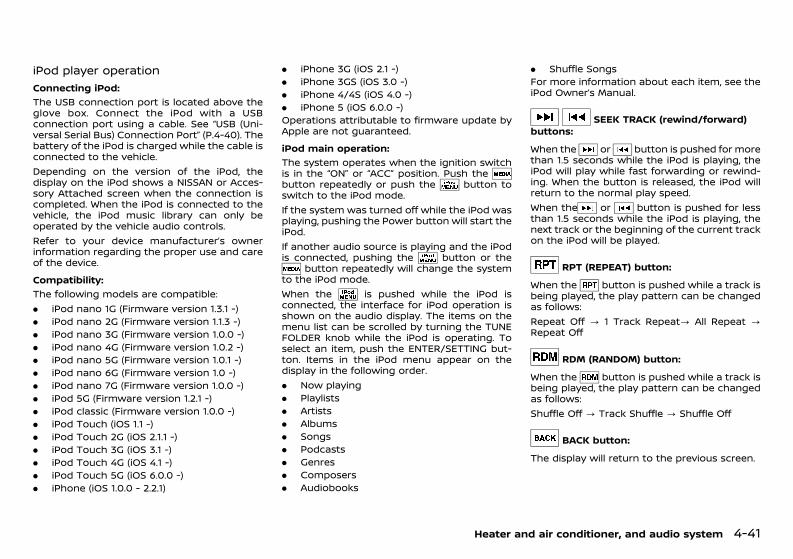
(141,1)
[ Edit: 2018/ 12/ 21 Model: N17-A ]
iPod player operationGUID-BFDC30D0-3565-4CD5-8146-C988E3A96B50
Connecting iPod:GUID-9E14C2E6-2E9C-4731-980B-C45B899B977B
The USB connection port is located above theglove box. Connect the iPod with a USBconnection port using a cable. See “USB (Uni-versal Serial Bus) Connection Port” (P.4-40). Thebattery of the iPod is charged while the cable isconnected to the vehicle.Depending on the version of the iPod, thedisplay on the iPod shows a NISSAN or Acces-sory Attached screen when the connection iscompleted. When the iPod is connected to thevehicle, the iPod music library can only beoperated by the vehicle audio controls.Refer to your device manufacturer’s ownerinformation regarding the proper use and careof the device.Compatibility:
GUID-9E14C2E6-2E9C-4731-980B-C45B899B977B
The following models are compatible:. iPod nano 1G (Firmware version 1.3.1 -). iPod nano 2G (Firmware version 1.1.3 -). iPod nano 3G (Firmware version 1.0.0 -). iPod nano 4G (Firmware version 1.0.2 -). iPod nano 5G (Firmware version 1.0.1 -). iPod nano 6G (Firmware version 1.0 -). iPod nano 7G (Firmware version 1.0.0 -). iPod 5G (Firmware version 1.2.1 -). iPod classic (Firmware version 1.0.0 -). iPod Touch (iOS 1.1 -). iPod Touch 2G (iOS 2.1.1 -). iPod Touch 3G (iOS 3.1 -). iPod Touch 4G (iOS 4.1 -). iPod Touch 5G (iOS 6.0.0 -). iPhone (iOS 1.0.0 - 2.2.1)
. iPhone 3G (iOS 2.1 -)
. iPhone 3GS (iOS 3.0 -)
. iPhone 4/4S (iOS 4.0 -)
. iPhone 5 (iOS 6.0.0 -)Operations attributable to firmware update byApple are not guaranteed.iPod main operation:
GUID-9E14C2E6-2E9C-4731-980B-C45B899B977B
The system operates when the ignition switchis in the “ON” or “ACC” position. Push thebutton repeatedly or push the button toswitch to the iPod mode.If the system was turned off while the iPod wasplaying, pushing the Power button will start theiPod.If another audio source is playing and the iPodis connected, pushing the button or the
button repeatedly will change the systemto the iPod mode.When the is pushed while the iPod isconnected, the interface for iPod operation isshown on the audio display. The items on themenu list can be scrolled by turning the TUNEFOLDER knob while the iPod is operating. Toselect an item, push the ENTER/SETTING but-ton. Items in the iPod menu appear on thedisplay in the following order.. Now playing. Playlists. Artists. Albums. Songs. Podcasts. Genres. Composers. Audiobooks
. Shuffle SongsFor more information about each item, see theiPod Owner’s Manual.
SEEK TRACK (rewind/forward)buttons:
GUID-9E14C2E6-2E9C-4731-980B-C45B899B977B
When the or button is pushed for morethan 1.5 seconds while the iPod is playing, theiPod will play while fast forwarding or rewind-ing. When the button is released, the iPod willreturn to the normal play speed.When the or button is pushed for lessthan 1.5 seconds while the iPod is playing, thenext track or the beginning of the current trackon the iPod will be played.
RPT (REPEAT) button:GUID-9E14C2E6-2E9C-4731-980B-C45B899B977B
When the button is pushed while a track isbeing played, the play pattern can be changedas follows:Repeat Off ? 1 Track Repeat? All Repeat ?Repeat Off
RDM (RANDOM) button:GUID-9E14C2E6-2E9C-4731-980B-C45B899B977B
When the button is pushed while a track isbeing played, the play pattern can be changedas follows:Shuffle Off ? Track Shuffle ? Shuffle Off
BACK button:GUID-9E14C2E6-2E9C-4731-980B-C45B899B977B
The display will return to the previous screen.
Heater and air conditioner, and audio system 4-41
Condition: 'Except for China'/

(142,1)
[ Edit: 2018/ 12/ 21 Model: N17-A ]
4-42 Heater and air conditioner, and audio system
Bluetooth® audio player operation (ifequipped) GUID-CC439B52-D252-4835-BEF6-AE0DF3395981If you have a compatible Bluetooth® audiodevice that is capable of playing audio files,the device can be connected to the vehicle’saudio system so that the audio files on thedevice play through the vehicle’s speakers.Regulatory information:
GUID-9E14C2E6-2E9C-4731-980B-C45B899B977B
Bluetooth® trademark:Bluetooth® is a trademarkowned by Bluetooth SIG, Inc.and licensed to Visteon Cor-poration.
Connecting Bluetooth® device:GUID-9E14C2E6-2E9C-4731-980B-C45B899B977B
To connect your Bluetooth® device to thevehicle, follow the procedure below:1. Push the ENTER/SETTING button.
JVH0620X
2. Select “Bluetooth” .3. Select “Add Phone or Device” . This same
screen can be accessed to remove, replaceor select a different Bluetooth® device.
4. The system acknowledges the commandand asks you to initiate a connection fromthe Bluetooth® device. The procedure for
connecting a Bluetooth® device varies ac-cording to the cellular phone model. Seethe Owner’s manual of the Bluetooth®device for details.
Bluetooth® audio main operation:GUID-9E14C2E6-2E9C-4731-980B-C45B899B977B
JVH1012X
To switch to the Bluetooth® audio mode, pushthe button repeatedly until the Bluetooth®audio mode is displayed on the screen.The controls for the Bluetooth® audio aredisplayed on the screen. Use the Presetbutton to play and use the Preset buttonto pause.
Auxiliary input jackGUID-18FBE0BA-C306-4E1A-9F9E-E2D62E5091B5
JVH0711XRight-Hand Drive (RHD) model*
*: The illustration is for the Right-Hand Drive(RHD) model. For the Left-Hand Drive (LHD)model, the layout will be the opposite.The AUX input jack is located above the glovebox. The AUX input jack accepts any standardanalog audio input such as from a portablecassette tape/CD player, MP3 player or laptopcomputer.Push the button to play a compatibledevice when it is plugged into the AUX inputjack.NISSAN strongly recommends using a stereomini plug cable when connecting your musicdevice to the audio system. Music may not playproperly when a monaural cable is used.
WARNING:Do not allow the cable or an external deviceconnected to the AUX terminal to affect yourdriving.
Condition: 'Except for China'/

(143,1)
[ Edit: 2018/ 12/ 21 Model: N17-A ]
NOTE:. Depending on the external device, please
note that the volume may be louder orquieter than that of the external device.
. When the AUX contacts the plug of theconnector cable, noise may be heard.
. The connected external device cannot beoperated with the main audio system.The volume and sound quality can beadjusted.
. The song title in the external devicecannot be displayed on the audio display.
. For the power source of the externaldevice, use the special battery. The ex-ternal device cannot be charged with theAUX terminal. Noise may be heard if theCD, radio etc. is operated while chargingthe battery with the power socket of thevehicle.
CD/USB MEMORY CARE AND CLEANINGGUID-2A993BFB-C332-4B64-B184-5EAB43509150
CD GUID-C21429B4-CD0C-45D2-9884-3508764289BC
SAA0451
. Handle a disc by its edges. Never touch thesurface of the disc. Do not bend the disc.
. Always place the discs in the storage casewhen they are not being used.
. To clean a disc, wipe the surface from thecenter to the outer edge using a clean, softcloth. Do not wipe the disc using a circularmotion.Do not use a conventional record cleaneror alcohol intended for industrial use.
. A new disc may be rough on the inner andouter edges. Remove the rough edges byrubbing the inner and outer edges with theside of a pen or pencil as illustrated.
USB memory device (if equipped)GUID-FA91671C-7F42-4A20-B2A1-BE3D359EE963. Do not touch the terminal portion of the
USB memory device.. Do not place heavy objects on the USB
memory device.. Do not store the USB memory device in
highly humid locations.. Do not expose the USB memory device to
direct sunlight.. Do not spill any liquids on the USB memory
device.Refer to the USB memory device Owner’sManual for the details.
STEERING WHEEL SWITCH FOR AUDIOCONTROL (if equipped)GUID-ADDB0565-4BE6-4B8E-BA8C-E9DFEA81F877
JVH0005XType A
JVH0189XType B
Heater and air conditioner, and audio system 4-43
Condition: 'Except for China'/

(144,1)
[ Edit: 2018/ 12/ 21 Model: N17-A ]
4-44 Heater and air conditioner, and audio system
JVH0670XType C
JVH0817XType D
WAE0012XType E
1. SOURCE select switch2. VOLUME control switch3. Tuning switchThe audio system can be operated using thecontrols on the steering wheel.
SOURCE select switchGUID-6D0465BB-4C94-4B46-A2E6-DA3F2F22377BPush the SOURCE select switch to change themode to available audio source.
VOLUME control switchGUID-E03541E9-1079-4729-9D2E-AC9BB52348C3Push + or - side of the VOLUME control switchto increase or decrease the volume.
Tuning switch (except for type E)GUID-D69C36B4-0185-42FE-9741-DC91EF695EAF
For type A audio:GUID-9E14C2E6-2E9C-4731-980B-C45B899B977B
Memory change (radio):Push the / switch for less than 1.5seconds to change the next or previous radiopreset.SEEK tuning (radio):Push the / switch for more than 1.5seconds to seek the next or previous radiostation.APS (Automatic Program Search) FF, APSREW (CD):Push the / switch for less than 1.5seconds to return to the beginning of thepresent program or skip to the next program.Push several times to skip back or skip throughprograms.For type B, C and D audio:
GUID-9E14C2E6-2E9C-4731-980B-C45B899B977B
Memory change (radio):Tilt the / switch for less than 1.5seconds to select the next or previous radiopreset station.SEEK tuning (radio):
Tilt the / switch for more than 1.5seconds to seek for the next or previousavailable radio station.APS (Automatic Program Search) FF, APSREW (CD, USB/iPod*, Bluetooth® audio*):Tilt the / switch for less than 1.5seconds to return to the beginning of thepresent program or skip to the next program.Push several times to skip back or skip throughprograms.FF, REW (CD, Bluetooth® audio*):Tilt the / switch for more than 1.5seconds to fast forward or rewind the track.Folder change (CD with MP3/WMA, USB/iPod*):Tilt the / switch for more than 1.5seconds to select the next or previous folder.*: if equipped
Tuning switch (for type E)GUID-6BBE4449-A20A-4DD9-861D-BED098FBF02APush the tuning switch to operate the audiosystem, etc. Functional availability may varydepending on the system.
Condition: 'Except for China'/

(145,1)
[ Edit: 2018/ 12/ 21 Model: N17-A ]
GUID-C4FD2A6E-3A99-4141-A76F-EFE3E3E25990When installing a CB, ham radio or a car phonein your vehicle, be sure to observe the followingcautions, otherwise the new equipment mayadversely affect the Engine Control System andother electronic parts.
CAUTION:. Keep the antenna as far away as possible
from the Electronic Control Module.. Keep the antenna wire at least 20 cm (8
in) away from the Engine Control har-nesses. Do not route the antenna wirenext to any harnesses.
. Adjust the antenna standing wave ratioas recommended by the manufacturer.
. Connect the ground wire from the radiochassis to the body.
. For details, consult a NISSAN dealer.
GUID-68FECA3B-A347-481B-8DE3-BAE555DF5B79
WARNING:. Use a phone after stopping your vehicle
in a safe location. If you have to use aphone while driving, exercise extremecaution at all times so full attention maybe given to vehicle operation.
. If you find yourself unable to devote fullattention to vehicle operation while talk-ing on the phone, pull off the road to asafe location and stop your vehicle be-fore doing so.
CAUTION:To avoid draining the vehicle battery, use aphone after starting the engine.
Your vehicle is equipped with Bluetooth®Hands-Free Phone System. If you are an ownerof a Bluetooth® enabled cellular phone, you canset up the wireless connection between yourcellular phone and the in-vehicle phone mod-ule. With Bluetooth® wireless technology, youcan make or receive a telephone call with yourcellular phone in your pocket.Once your cellular phone is paired to the in-vehicle phone module, no phone connectingprocedure is required. Your phone is automa-tically connected with the in-vehicle phonemodule when the audio system is turned onwith the registered cellular phone turned onand carried in the vehicle.You can register up to 5 different Bluetooth®cellular phones in the in-vehicle phone module.However, you can talk on only one cellularphone at a time.When a call is active, the audio system andmicrophone (located in the ceiling in front ofthe rearview mirror) are used for the handsfree
communications.If the audio system is being used at the time,the audio mode will mute and will stay muteduntil the active call is ended.Before using the Bluetooth® Hands-Free PhoneSystem, refer to the following notes.. Wireless LAN (Wi-Fi) and the Bluetooth®
functions share the same frequency band(2.4 GHz). Using the Bluetooth® and thewireless LAN functions at the same timemay slow down or disconnect the commu-nication and cause undesired noise. It isrecommended that you turn off the wire-less LAN (Wi-Fi) when using the Bluetooth®functions.
. Set up the wireless connection between acellular phone and the in-vehicle phonemodule before using the Bluetooth®Hands-Free Phone System.
. Some Bluetooth® enabled cellular phonesmay not be recognized by the in-vehiclephone module.
. You will not be able to use a hands-freephone under the following conditions:— Your vehicle is outside of the telephone
service area.— Your vehicle is in an area where it is
difficult to receive radio waves; such asin a tunnel, in an underground parkinggarage, behind a tall building or in amountainous area.
— Your cellular phone is locked in order notto be dialed.
. When the radio wave condition is not idealor ambient sound is too loud, it may bedifficult to hear the other person’s voiceduring a call.
Heater and air conditioner, and audio system 4-45
CAR PHONE OR CB RADIO Bluetooth® HANDS-FREE PHONESYSTEM (if equipped for type A audio)
Condition: 'Except for China'/

(146,1)
[ Edit: 2018/ 12/ 21 Model: N17-A ]
4-46 Heater and air conditioner, and audio system
. Immediately after the audio system isturned on, it may be impossible to receivea call for a short period of time.
. Do not place the cellular phone in an areasurrounded by metal or far away from thein-vehicle phone module to prevent tonequality degradation and wireless connec-tion disruption.
. While a cellular phone is connectedthrough the Bluetooth® wireless connec-tion, the battery power of the cellularphone may discharge quicker than usual.
. If the Bluetooth® Hands-Free Phone Systemseems to be malfunctioning, please contacta NISSAN dealer.
. Some cellular phones or other devices maycause interference or a buzzing noise tocome from the audio system speakers.Storing the device in a different locationmay reduce or eliminate the noise.
. Refer to the cellular phone Owner’s Manualregarding the telephone pairing procedurespecific to your phone, battery charging,cellular phone antenna, etc.
. The antenna display on the audio displaywill not coincide with the antenna displayof some cellular phones.
. Keep the interior of the vehicle as quiet aspossible to hear the caller’s voice clearly aswell as to minimize its echoes.
. If reception between callers is unclear,adjusting the incoming or outgoing callvolume may improve the clarity.
. This wireless hands free car kit is based onBluetooth® technology,— Frequency: 2402 MHz - 2480 MHz— Output Power: 4.14 dBm E.I.R.P
— Modulation: FHSS GFSK 8DPSK, π/4DQPSK
— Number of Channel: 79— This wireless equipment can’t be used
for any services related to safety be-cause there is the possibility of radiointerference.
REGULATORY INFORMATIONGUID-6C2A5A01-0DA7-428D-988C-5E2FD1C0CD39
Bluetooth® TrademarkGUID-04A2A972-EEBA-42FC-BCEE-FABE340CAB67
Bluetooth® is a trademarkowned by Bluetooth SIG, Inc.and licensed to Visteon Cor-poration.
CE statementGUID-00B700C8-668D-4426-AA52-138F763DC0B1Hereby “Yangfeng Visteon Automotive Electro-nics Co., Ltd.” declares that this Bluetooth carkit AV System is in compliance with theessential requirements and other relevantprovisions of Directive 1999/5/EC.
NSY0105
CONTROL BUTTONS AND MICROPHONEGUID-0D833467-0A10-4B22-9FA7-843566EDBDA8Steering wheel mounted control:
JVH0885X
1. SEEK button2. PHONE SEND button3. Volume control button4. PHONE END buttonMicrophone:Microphone is located near the map light.
Bluetooth® settingsGUID-3305DDD3-85FE-4E4A-9D93-7E05FF302A9B
Choosing a language:GUID-9E14C2E6-2E9C-4731-980B-C45B899B977B
You can interact with the Bluetooth® Hands-Free Phone System using English, Arabic, Man-darin, Russian or Korean. To change thelanguage, perform the following.1. Push the PHONE SEND button for more
than 5 seconds.2. The system announces: “Press the PHONE
END button to select a different language.”3. Push the PHONE END button.4. The system announces the current lan-
guage and gives you the option to changethe language. Push the SEEK button toselect a different language.
Condition: 'Except for China'/

(147,1)
[ Edit: 2018/ 12/ 21 Model: N17-A ]
NOTE:You must push the PHONE SEND buttonor the PHONE END button within 5 sec-onds to change the language.
5. If you decide not to change the language,do not push either button. After 5 seconds,the VR session will end, and the languagewill not be changed.
Pairing procedure:GUID-9E14C2E6-2E9C-4731-980B-C45B899B977B
1. Push the PHONE SEND button. The systemasks you to pair a new phone.
2. Initiate pairing from the cellular phone andenter a PIN code for pairing your Blue-tooth® cellular phone. Operate it to enterthe code “1234”. The code is always “1234”regardless of the number of phones paired.The pairing procedure of the cellular phonevaries according to each cellular phonemanufacturer. See the cellular phone Own-er’s Manual for details.
3. After the prompt “Please say a name for thephone.” by the system, say a name for thephone. If the name is too long, it will not befully registered.
4. The system will inform you that the cellularphone is successfully registered.
Registering an additional phone:GUID-9E14C2E6-2E9C-4731-980B-C45B899B977B
You can register up to 5 different Bluetooth®cellular phones in the in-vehicle phone module.However, you can talk on only one cellularphone at a time.1. Push the PHONE SEND button and the SEEK
button to select “Connect Phone”, and thenpush the PHONE SEND button.
2. Push the SEEK button to select “AddPhone”, and then push the PHONE SENDbutton.
3. The system asks you to initiate pairing fromyour Bluetooth® cellular phone and enter aPIN code for pairing the phone. Operate itto enter the code “1234”.The pairing procedure of the cellular phonevaries according to each cellular phonemanufacturer. See the cellular phone Own-er’s Manual for details.
4. After the prompt “Please say a name for thephone.” by the system, say a name for thephone. If the name is too long, it will not befully registered.
5. The system will inform you that the cellularphone is successfully registered.
Selecting a registered phone:GUID-9E14C2E6-2E9C-4731-980B-C45B899B977B
1. Push the PHONE SEND button and the SEEKbutton to select “Connect Phone”, and thenpush the PHONE SEND button.
2. Push the SEEK button to select “SelectPhone”, and then push the PHONE SENDbutton.
3. Push the SEEK button. Each time thebutton is operated, the system announcesthe names of the phones. Select the phoneyou wish to use.
4. Push the PHONE SEND button to completethe selection.
Deleting a registered phone:GUID-9E14C2E6-2E9C-4731-980B-C45B899B977B
1. Push the PHONE SEND button and the SEEKbutton to select “Connect Phone”, and thenpush the PHONE SEND button.
2. Push the SEEK button to select “DeletePhone”, and then push the PHONE SENDbutton.
3. Push the SEEK button. Each time thebutton is operated, the system announcesthe name of the phones. Select the phone
you wish to delete.4. When the system asks if you want to delete,
push the PHONE SEND button. To cancelthe deletion, push the PHONE END button.
5. The system asks you to confirm the dele-tion. To delete the desired phone, push thePHONE SEND button again.
NOTE:When you delete a phone, the associatedphonebook for the phone will also be de-leted.Bluetooth® on/off:
GUID-9E14C2E6-2E9C-4731-980B-C45B899B977B
1. Push the PHONE SEND button until thesystem announces “Settings menu”.
2. Push the SEEK button to select Bluetooth®on or off.
3. To turn on/off the Bluetooth® hands-freephone system, push the PHONE SENDbutton.
When Bluetooth® is off, you will not be able tomake or receive calls by the hands-free mode.Also, you will not have access to the phone-book.
Phonebook GUID-E88723C3-7182-4F9D-9545-6DFFBEFD063AThe phonebook stores up to 40 names for eachphone paired with the system.
NOTE:Each phone has its own separate phonebook.You cannot access Phone A’s phonebook ifyou are currently connected with Phone B.
Heater and air conditioner, and audio system 4-47
Condition: 'Except for China'/

(148,1)
[ Edit: 2018/ 12/ 21 Model: N17-A ]
4-48 Heater and air conditioner, and audio system
New entry:GUID-9E14C2E6-2E9C-4731-980B-C45B899B977B
This function is not available while driving.1. Push the PHONE SEND button and SEEK
button to select “PHONEBOOK”, and thenpush the PHONE SEND button.
2. Push the SEEK button to select “TransferEntry”, and then push the PHONE SENDbutton.
3. When the system says “Please transfer thephone number from your handset.”, oper-ate your cellular phone to send the phone-book to the system.The memory sending procedure from theBluetooth® cellular phone varies accordingto each cellular phone manufacturer. Seethe cellular phone Owner’s Manual for moredetails.
4. When prompted by the system, say thename that you would like to give for thenew entry.Speak in a natural voice without pausingbetween words.
5. When the system requires you to repeat thename, say the name again.
6. Push the PHONE SEND button to continuethe entry, or push the PHONE END buttonto finish the phone mode.
Delete:GUID-9E14C2E6-2E9C-4731-980B-C45B899B977B
This function is not available while driving.1. Push the PHONE SEND button and SEEK
button to select “PHONEBOOK”, and thenpush the PHONE SEND button.
2. Push the SEEK button to select “DeleteEntry”, and then push the PHONE SENDbutton.
3. Push the SEEK button and choose thephonebook entry you wish to delete.
4. When the system asks if you want to deletethe contact, push the PHONE SEND button.To cancel the deletion, push the PHONEEND button.
5. The system asks you to confirm the dele-tion.
6. To delete the desired contact, push thePHONE SEND button again.
7. Push the PHONE SEND button to continuethe deletion or push the PHONE END buttonto finish the phone mode.
Making a callGUID-56BA45DF-CBB4-48C4-A1D5-DC38DC7B40F5
Phonebook:GUID-9E14C2E6-2E9C-4731-980B-C45B899B977B
1. Push the PHONE SEND button and SEEKbutton to select “CALL”, and then push thePHONE SEND button.
2. Push the SEEK button to select “List Name”,and then push the PHONE SEND button.
3. Push the SEEK button, and choose thephonebook entry you wish to call. Thesystem acknowledges the name and be-gins the call.
Redial:GUID-9E14C2E6-2E9C-4731-980B-C45B899B977B
1. Push the PHONE SEND button and the SEEKbutton to select “CALL”, and then push thePHONE SEND button.
2. Push the SEEK button to select “Redial”, andthen push the PHONE SEND button.
3. Push the PHONE SEND button, and then thesystem begins the call.
Bluetooth® cellular phone keypad:GUID-9E14C2E6-2E9C-4731-980B-C45B899B977B
You can also make a call by operating thecellular phone that is registered to the in-vehicle phone module to use the hands-freephone system.Ending a call:
GUID-9E14C2E6-2E9C-4731-980B-C45B899B977B
Push the PHONE END button on the steeringwheel or the off button on the cellular phone.
Receiving or rejecting a callGUID-5CAF0371-5E05-443F-98FD-8680AFE14F46When you hear the ring tone, push the PHONESEND button on the steering wheel.If you do not wish to answer the call when youhear the ring tone, push the PHONE ENDbutton.
Transferring a callGUID-9CFAA1C3-65D9-4592-8BD7-71DB685D9974During a call, push the PHONE SEND button toswitch the call from the Bluetooth® Hands-FreePhone System to the cellular phone whenprivacy is desired.Push the PHONE SEND button again to returnto the hands-free mode.Some Bluetooth® cellular phones may not beable to return to the hands-free mode. Refer tothe cellular phone Owner’s Manual for informa-tion about reconnection.Once the audio system is turned off and thenturned on again, the system will automaticallychange to the hands-free mode as the defaultsetting.
Condition: 'Except for China'/

(149,1)
[ Edit: 2018/ 12/ 21 Model: N17-A ]
GUID-09064561-43BF-4926-8B3C-BAAFC2173DB5
WARNING:. Use a phone after stopping your vehicle
in a safe location. If you have to use aphone while driving, exercise extremecaution at all times so full attention maybe given to vehicle operation.
. If you find yourself unable to devote fullattention to vehicle operation while talk-ing on the phone, pull off the road to asafe location and stop your vehicle be-fore doing so.
CAUTION:To avoid draining the vehicle battery, use aphone after starting the engine.
Your vehicle is equipped with Bluetooth®Hands-Free Phone System. If you are an ownerof a Bluetooth® enabled cellular phone, you canset up the wireless connection between yourcellular phone and the in-vehicle phone mod-ule. With Bluetooth® wireless technology, youcan make or receive a telephone call with yourcellular phone in your pocket.Once your cellular phone is paired to the in-vehicle phone module, no phone connectingprocedure is required. Your phone is automa-tically connected with the in-vehicle phonemodule when the audio system is turned onwith the registered cellular phone turned onand carried in the vehicle.You can register up to 5 different Bluetooth®cellular phones in the in-vehicle phone module.However, you can talk on only one cellularphone at a time.When a call is active, the audio system andmicrophone (located in the ceiling in front ofthe rearview mirror) are used for the handsfree
communications.If the audio system is being used at the time,the audio mode will mute and will stay muteduntil the active call is ended.Before using the Bluetooth® Hands-Free PhoneSystem, refer to the following notes.. Wireless LAN (Wi-Fi) and the Bluetooth®
functions share the same frequency band(2.4 GHz). Using the Bluetooth® and thewireless LAN functions at the same timemay slow down or disconnect the commu-nication and cause undesired noise. It isrecommended that you turn off the wire-less LAN (Wi-Fi) when using the Bluetooth®functions.
. Set up the wireless connection between acellular phone and the in-vehicle phonemodule before using the Bluetooth®Hands-Free Phone System.
. Some Bluetooth® enabled cellular phonesmay not be recognized by the in-vehiclephone module.
. You will not be able to use a hands-freephone under the following conditions:— Your vehicle is outside of the telephone
service area.— Your vehicle is in an area where it is
difficult to receive radio waves; such asin a tunnel, in an underground parkinggarage, behind a tall building or in amountainous area.
— Your cellular phone is locked in order notto be dialed.
. When the radio wave condition is not idealor ambient sound is too loud, it may bedifficult to hear the other person’s voiceduring a call.
. Immediately after the audio system isturned on, it may be impossible to receivea call for a short period of time.
. Do not place the cellular phone in an areasurrounded by metal or far away from thein-vehicle phone module to prevent tonequality degradation and wireless connec-tion disruption.
. While a cellular phone is connectedthrough the Bluetooth® wireless connec-tion, the battery power of the cellularphone may discharge quicker than usual.
. If the Bluetooth® Hands-Free Phone Systemseems to be malfunctioning, please contacta NISSAN dealer.
. Some cellular phones or other devices maycause interference or a buzzing noise tocome from the audio system speakers.Storing the device in a different locationmay reduce or eliminate the noise.
. Refer to the cellular phone Owner’s Manualregarding the telephone pairing procedurespecific to your phone, battery charging,cellular phone antenna, etc.
. Keep the interior of the vehicle as quiet aspossible to hear the caller’s voice clearly aswell as to minimize its echoes.
. If reception between callers is unclear,adjusting the incoming or outgoing callvolume may improve the clarity.
. This wireless hands free car kit is based onBluetooth® technology,— Frequency: 2402 MHz - 2480 MHz— Output Power: 4.14 dBm E.I.R.P— Modulation: FHSS GFSK 8DPSK, π/
4DQPSK— Number of Channel: 79
Heater and air conditioner, and audio system 4-49
Bluetooth® HANDS-FREE PHONESYSTEM (if equipped for type B audio)
Condition: 'Except for China'/

(150,1)
[ Edit: 2018/ 12/ 21 Model: N17-A ]
4-50 Heater and air conditioner, and audio system
— This wireless equipment can’t be usedfor any services related to safety be-cause there is the possibility of radiointerference.
REGULATORY INFORMATIONGUID-BF26EAE4-CCB5-420E-B6C5-49A8A58884CA
Bluetooth® TrademarkGUID-1B3718CB-01AD-48E8-8C65-FE44F5932057
Bluetooth® is a trademarkowned by Bluetooth SIG, Inc.and licensed to Visteon Cor-poration.
CE statementGUID-3073418F-0528-44BB-BAE5-E3433EEE2EB4Hereby “Yangfeng Visteon Automotive Electro-nics Co., Ltd.” declares that this Bluetooth carkit AV System is in compliance with theessential requirements and other relevantprovisions of Directive 1999/5/EC.
NSY0105
CONTROL BUTTONS AND MICROPHONEGUID-3087CCC7-0855-49B0-B32B-31B63CFED1B7Steering wheel mounted control:
JVH0886X
1. SEEK button
2. PHONE SEND button3. Volume control button4. PHONE END buttonMicrophone:Microphone is located near the map light.
Bluetooth® settingsGUID-23194FF7-4709-40D1-A3B4-C438978080FA
Choosing a language:GUID-9E14C2E6-2E9C-4731-980B-C45B899B977B
You can interact with the Bluetooth® Hands-Free Phone System using English, Arabic, Man-darin, Russian or Korean. To change thelanguage, perform the following.1. Push the PHONE SEND button for more
than 5 seconds.2. The system announces: “Press the PHONE
END button to select a different language.”3. Push the PHONE END button.4. The system announces the current lan-
guage and gives you the option to changethe language. Push the SEEK button toselect a different language.
NOTE:You must push the PHONE SEND buttonor the PHONE END button within 5 sec-onds to change the language.
5. If you decide not to change the language,do not push either button. After 5 seconds,the VR session will end, and the languagewill not be changed.
Pairing procedure:GUID-9E14C2E6-2E9C-4731-980B-C45B899B977B
1. Push the PHONE SEND button. The systemasks you to pair a new phone.
2. Initiate pairing from the cellular phone andenter a PIN code for pairing your Blue-tooth® cellular phone. Operate it to enterthe code “1234”. The code is always “1234”
regardless of the number of phones paired.The pairing procedure of the cellular phonevaries according to each cellular phonemanufacturer. See the cellular phone Own-er’s Manual for details.
3. After the prompt “Please say a name for thephone.” by the system, say a name for thephone. If the name is too long, it will not befully registered.
4. The system will inform you that the cellularphone is successfully registered.
Registering an additional phone:GUID-9E14C2E6-2E9C-4731-980B-C45B899B977B
You can register up to 5 different Bluetooth®cellular phones in the in-vehicle phone module.However, you can talk on only one cellularphone at a time.1. Push the PHONE SEND button and the SEEK
button to select “Connect Phone”, and thenpush the PHONE SEND button.
2. Push the SEEK button to select “AddPhone”, and then push the PHONE SENDbutton.
3. The system asks you to initiate pairing fromyour Bluetooth® cellular phone and enter aPIN code for pairing the phone. Operate itto enter the code “1234”.The pairing procedure of the cellular phonevaries according to each cellular phonemanufacturer. See the cellular phone Own-er’s Manual for details.
4. After the prompt “Please say a name for thephone.” by the system, say a name for thephone. If the name is too long, it will not befully registered.
5. The system will inform you that the cellularphone is successfully registered.
Condition: 'Except for China'/

(151,1)
[ Edit: 2018/ 12/ 21 Model: N17-A ]
Selecting a registered phone:GUID-9E14C2E6-2E9C-4731-980B-C45B899B977B
1. Push the PHONE SEND button and the SEEKbutton to select “Connect Phone”, and thenpush the PHONE SEND button.
2. Push the SEEK button to select “SelectPhone”, and then push the PHONE SENDbutton.
3. Push the SEEK button. Each time thebutton is operated, the system announcesthe names of the phones. Select the phoneyou wish to use.
4. Push the PHONE SEND button to completethe selection.
Deleting a registered phone:GUID-9E14C2E6-2E9C-4731-980B-C45B899B977B
1. Push the PHONE SEND button and the SEEKbutton to select “Connect Phone”, and thenpush the PHONE SEND button.
2. Push the SEEK button to select “DeletePhone”, and then push the PHONE SENDbutton.
3. Push the SEEK button. Each time thebutton is operated, the system announcesthe name of the phones. Select the phoneyou wish to delete.
4. When the system asks if you want to delete,push the PHONE SEND button. To cancelthe deletion, push the PHONE END button.
5. The system asks you to confirm the dele-tion. To delete the desired phone, push thePHONE SEND button again.
NOTE:When you delete a phone, the associatedphonebook for the phone will also be de-leted.
Bluetooth® on/off:GUID-9E14C2E6-2E9C-4731-980B-C45B899B977B
To turn off the Bluetooth®, follow the proce-dure below.1. Push the PHONE SEND button and the SEEK
button to select “Connect Phone”, and thenpush the PHONE SEND button.
2. Push the SEEK button to select “BluetoothOff”, and then push the PHONE SENDbutton.
To turn on the Bluetooth®, push the PHONESEND button twice.When Bluetooth® is off, you will not be able tomake or receive calls by the hands-free mode.Also, you will not have access to the phone-book.
Phonebook GUID-3CAECB45-B254-48DA-A327-7268164788C8The phonebook stores up to 40 names for eachphone paired with the system.
NOTE:Each phone has its own separate phonebook.You cannot access Phone A’s phonebook ifyou are currently connected with Phone B.New entry:
GUID-9E14C2E6-2E9C-4731-980B-C45B899B977B
This function is not available while driving.1. Push the PHONE SEND button and SEEK
button to select “PHONEBOOK”, and thenpush the PHONE SEND button.
2. Push the SEEK button to select “TransferEntry”, and then push the PHONE SENDbutton.
3. When the system says “Please transfer thephone number from your handset.”, oper-ate your cellular phone to send the phone-book to the system.The memory sending procedure from theBluetooth® cellular phone varies according
to each cellular phone manufacturer. Seethe cellular phone Owner’s Manual for moredetails.
4. When prompted by the system, say thename that you would like to give for thenew entry.Speak in a natural voice without pausingbetween words.
5. When the system requires you to repeat thename, say the name again.
6. Push the PHONE SEND button to continuethe entry, or push the PHONE END buttonto finish the phone mode.
Delete:GUID-9E14C2E6-2E9C-4731-980B-C45B899B977B
This function is not available while driving.1. Push the PHONE SEND button and SEEK
button to select “PHONEBOOK”, and thenpush the PHONE SEND button.
2. Push the SEEK button to select “DeleteEntry”, and then push the PHONE SENDbutton.
3. Push the SEEK button and choose thephonebook entry you wish to delete.
4. When the system asks if you want to deletethe contact, push the PHONE SEND button.To cancel the deletion, push the PHONEEND button.
5. The system asks you to confirm the dele-tion.
6. To delete the desired contact, push thePHONE SEND button again.
7. Push the PHONE SEND button to continuethe deletion or push the PHONE END buttonto finish the phone mode.
Heater and air conditioner, and audio system 4-51
Condition: 'Except for China'/

(152,1)
[ Edit: 2018/ 12/ 21 Model: N17-A ]
4-52 Heater and air conditioner, and audio system
Making a callGUID-20765511-70A5-4DC0-8A3F-1EBCD0088603Phonebook:
GUID-9E14C2E6-2E9C-4731-980B-C45B899B977B
1. Push the PHONE SEND button and SEEKbutton to select “CALL”, and then push thePHONE SEND button.
2. Push the SEEK button to select “List Name”,and then push the PHONE SEND button.
3. Push the SEEK button, and choose thephonebook entry you wish to call. Thesystem acknowledges the name and be-gins the call.
Redial:GUID-9E14C2E6-2E9C-4731-980B-C45B899B977B
1. Push the PHONE SEND button and the SEEKbutton to select “CALL”, and then push thePHONE SEND button.
2. Push the SEEK button to select “Redial”, andthen push the PHONE SEND button.
3. Push the PHONE SEND button, and then thesystem begins the call.
Bluetooth® cellular phone keypad:GUID-9E14C2E6-2E9C-4731-980B-C45B899B977B
You can also make a call by operating thecellular phone that is registered to the in-vehicle phone module to use the hands-freephone system.Ending a call:
GUID-9E14C2E6-2E9C-4731-980B-C45B899B977B
Push the PHONE END button on the steeringwheel or the off button on the cellular phone.
Receiving or rejecting a callGUID-B1869D78-6A77-4FE4-B75C-CF19D7490C6BTo receive a call, push the PHONE SEND buttonon the steering wheel when you hear the ringtone.If you do not wish to answer the call when youhear the ring tone, push the PHONE ENDbutton.
Turning mute on/offGUID-CDE42F58-D521-48CB-92E5-ECAFDE41EA5CPush the PHONE SEND button if you wish tomute an active call.Push the PHONE SEND button again to turn offthe mute mode.
Transferring a call between hands-freeand handset modeGUID-0DD934AD-5F8E-4B4F-9F50-0DF101F64764During a call in the hands-free mode, you canswitch to use the handset mode in cases whereprivacy is required.Switching to handset mode:
GUID-9E14C2E6-2E9C-4731-980B-C45B899B977B
1. During a call in the hands-free mode, pushthe PHONE SEND button to turn on themute mode.
2. Push the SEEK button to select “TransferCall”, and then push the PHONE SENDbutton.
Switching back to hands-free mode:GUID-9E14C2E6-2E9C-4731-980B-C45B899B977B
1. During a call in handset mode, push thePHONE SEND button.
2. When asked by the system if you wish toswitch to the hands-free mode, push theSEEK button to select “Yes”, and then pushthe PHONE SEND button.
Some Bluetooth® cellular phones may not beable to return to the hands-free mode. Refer tothe cellular phone Owner’s Manual for informa-tion about reconnection.
Once the audio system is turned off and thenturned on again, the system will automaticallychange to the hands-free mode as the defaultsetting.
Condition: 'Except for China'/

(153,1)
[ Edit: 2018/ 12/ 21 Model: N17-A ]
GUID-4CF5C870-BACE-4CDD-8EE9-B1E1DFAB1F8F
WARNING:. Use a phone after stopping your vehicle
in a safe location. If you have to use aphone while driving, exercise extremecaution at all times so full attention maybe given to vehicle operation.
. If you find yourself unable to devote fullattention to vehicle operation while usingthe phone, pull off the road to a safelocation and stop your vehicle beforedoing so.
CAUTION:To avoid draining the vehicle battery, use aphone after starting the engine.
Bluetooth® is a wireless radio communicationstandard. This system offers a hands-freefacility for your cellular phone to enhancedriving comfort.To use the Bluetooth® Hands-Free PhoneSystem, your cellular phone must first be setup.For details, see “Bluetooth® settings” (P.4-54).Once it has been setup, the hands-free mode isautomatically activated on the registered cel-lular phone (via Bluetooth®) when it comes intorange.A notification message appears on the audiodisplay when the phone is connected, when anincoming call is being received, as well as whena call is initiated.When a call is active, the audio system, micro-phone, and steering wheel mounted controlbuttons enable hands-free communication.If the audio system is in use at the time, theradio, CD, iPod, USB audio, Bluetooth® audio orAUX source mode will be muted and will staymuted until the active call has ended.
The Bluetooth® system may not be able toconnect with your cellular phone for thefollowing reasons:. The cellular phone is too far away from the
vehicle.. The Bluetooth® mode on your cellular
phone has not been activated.. Your cellular phone has not been paired
with the Bluetooth® system of the audiounit.
. The mobile phone does not support Blue-tooth® technology.
NOTE:. For details, see your cellular phone’s
Owner’s Manual.. For assistance with your cellular phone
integration, please visit your local NISSANdealer.
REGULATORY INFORMATIONGUID-F538DF71-C8E4-49C4-9F87-C92814881EA1
Bluetooth® TrademarkGUID-04CF2A8D-EA5D-4E3A-A187-234E82DF9EB0
Bluetooth® is a trademarkowned by Bluetooth SIG, Inc.and licensed to Visteon Cor-poration.
CE statementGUID-79F80538-3F06-4307-96DD-16A0AA602EF5Hereby Visteon Corp. declares that this systemis in compliance with the essential require-ments and other relevant provisions of Direc-tive 1999/5/EC.
NSY0105
NOTE:The audio system only supports Bluetooth®devices with AVRCP (Audio Video RemoteControl Profile) version 1.3, or 1.0 or earlier.CONTROL BUTTONS AND MICROPHONEGUID-9F3AB654-59D5-44EA-A1ED-1589B56A0DA7Instrument panel:
JVH0913X
1. A-Z button
Heater and air conditioner, and audio system 4-53
Bluetooth® HANDS-FREE PHONESYSTEM (if equipped for type C audio)
Condition: 'Except for China'/

(154,1)
[ Edit: 2018/ 12/ 21 Model: N17-A ]
4-54 Heater and air conditioner, and audio system
2. Back button3. Phone button4. ENTER buttonSteering wheel mounted control:
JVH0886X
1. SEEK button2. PHONE SEND button3. Volume control button
Increases or decreases the volume fromthe system.
4. PHONE END buttonMicrophone:Microphone is located near the map light.
Bluetooth® SETTINGSGUID-72860E5C-8A38-42B7-9CF3-E607EFF89FF6
Pairing deviceGUID-57014E9A-4ABA-4628-9061-AD19A17F9608Enter the phone setup menu via thebutton on the instrument panel, select the“Bluetooth” key, and then check if the Blue-tooth® is set to on. (If not push the ENTERbutton to turn it on.)To setup the Bluetooth® system to pair (con-nect or register) your preferred cellular phone,follow the following procedure.
1. To pair a device, use “Scan device” key orthe “Pair device” key on the display.
2. A notification message will be displayedwhen the phone is successfully paired.
3. The display will return to the current audiosource status after the connection is com-plete.
. While the Bluetooth® connection is active,the following icons will appear on thedisplay.— : Signal strength indicator— : Battery status indicator*— : Bluetooth® connection ON indica-
tor*: If low battery is indicated, the Blue-tooth® device must be recharged soon.
. Up to 5 different Bluetooth® devices can beconnected. However, only one device canbe used at a time. If 5 different Bluetooth®registered devices are registered, a newdevice can only replace one of the 5existing paired devices.
. The pairing procedure and operation mayvary according to device type and compat-ibility. See the Bluetooth® device Owner’sManual for further details.
Setting itemsGUID-8EC7557D-4BDB-4085-A273-01E3EA895BF8To set up the Bluetooth® system with a device,the following items are available:
JVH0847X
. Scan devicesBluetooth® devices can be paired with thesystem. A maximum of 5 Bluetooth® de-vices can be registered.
. Pair deviceBluetooth® devices can be paired with thesystem. A maximum of 5 Bluetooth® de-vices can be registered.
. Sel. devicePaired Bluetooth® devices are listed andcan be selected for connection.
. Del. deviceA registered Bluetooth® device can bedeleted.
. SettingsVolume and Ringtone options are listedand can be selected for the Bluetooth®hands-free phone.
. BluetoothIf this setting is turned off, the connectionbetween the Bluetooth® devices and the in-vehicle Bluetooth® module will be can-celled.
Condition: 'Except for China'/

(155,1)
[ Edit: 2018/ 12/ 21 Model: N17-A ]
Scan devices:GUID-9E14C2E6-2E9C-4731-980B-C45B899B977B
1. Push the button on the instrumentpanel. Select “Scan devices” key. The audiounit searches for the Bluetooth® devicesand shows all devices that were found.Make sure your Bluetooth® device is avail-able at this time.
2. Select the device to be paired using theMENU knob.
3. The pairing procedure depends on thedevice to be connected:a. Device without PIN code:The Bluetooth® connection will be auto-matically connected without any furtherinput.b. Device with PIN code:Two different ways of pairing are possibledepending on the device:. Type A:
The message “To pair” and “Enter Pin”0000 will be displayed.Confirm the PIN code on the device. TheBluetooth® connection will be made.
. Type B:The message “Pairing request” and “Con-firm password” together with a 6 digitcode will be displayed. The unique andidentical code should be displayed onthe device. If the code is identical confirmon the device.The Bluetooth® connection will be made.
Pair device:GUID-9E14C2E6-2E9C-4731-980B-C45B899B977B
. Turn on the Bluetooth® on the audio unit.See “Bluetooth” (P.4-55).
. Use the audio unit to pair:Push the button on the instrumentpanel. Select the “Pair Device” key.The pairing procedure depends on theBluetooth® device to be connected:1) Device without PIN code:The Bluetooth® connection will be auto-matically connected without any furtherinput.2) Device with PIN code:Two different ways of pairing are possibledepending on the device. For the correctprocedure details, see “Scan devices” (P.4-55).
. Use the Bluetooth® audio/cellular phonedevice to pair:1) Switch on the search mode for Blue-
tooth® devices.If the search mode finds the audio unit itwill be shown on the device display.2) Select the unit device shown as “My
Car”.3) Enter the number code shown on the
relevant device with the device’s ownkeypad, and push the confirmation keyon the Bluetooth® device.
Refer to the relevant Bluetooth® device Owner’sManual for further details.Sel. device:
GUID-9E14C2E6-2E9C-4731-980B-C45B899B977B
The paired device list shows which Bluetooth®audio or cellular phone devices have beenpaired or registered to the system. Select theappropriate device to connect to the system.The following symbols (if equipped) indicate thecapability of the registered device:
. : Cellular phone integration
. : Audio streaming (A2DP – AdvancedAudio Distribution Profile)
Del. device:GUID-9E14C2E6-2E9C-4731-980B-C45B899B977B
A registered device can be removed fromBluetooth® system registration. Select a regis-tered device and push the ENTER button toconfirm to deletion.Bluetooth:
GUID-9E14C2E6-2E9C-4731-980B-C45B899B977B
Turn the vehicle’s Bluetooth ® system on or off.Push the button to return to the phonesetup menu.
USING THE SYSTEMGUID-1A7865B9-D762-448D-8C9D-C1A2E9259521The hands-free mode can be operated usingthe button on the instrument panel.
Receiving a callGUID-74512CCE-7F86-4315-B7C6-C4F6B296E43A
JVH0857X
When receiving an incoming call, the display onthe audio unit will show the caller’s phonenumber (or a notification message that thecaller’s phone number cannot be shown) andthree operation icons as illustrated. To high-light different icons, turn the MENU knob. Pushthe ENTER button to select the highlightedicon.
Heater and air conditioner, and audio system 4-55
Condition: 'Except for China'/

(156,1)
[ Edit: 2018/ 12/ 21 Model: N17-A ]
4-56 Heater and air conditioner, and audio system
Answering and during a call:GUID-9E14C2E6-2E9C-4731-980B-C45B899B977B
Answer the call by selecting .During the call, the following icons are avail-able:. :
Select this item to end the call.. :
Select this item to put the call on hold.. :
Select this item to transfer the call from thehands-free phone system to your cellularphone.
. :Select this item to transfer the call back tothe hands-free phone system from thecellular phone.
. #123:Select this item to enter numbers during acall. For example, use this function whendirected by an automated phone system todial an extension number.
Putting a call on hold:GUID-9E14C2E6-2E9C-4731-980B-C45B899B977B
To put a call on hold, select . Push ENTERbutton again to take the call. To reject the callselect .
Rejecting a call:GUID-9E14C2E6-2E9C-4731-980B-C45B899B977B
To reject an incoming call, select or bypushing on the steering wheel.
Initiating a callGUID-D8116D85-7CF2-45F1-B627-53F973F2209A
WARNING:Park the vehicle in a safe location, and applythe parking brake before making a call.
JVH0863X
A call can be initiated using one of the followingmethods:. Making a call from the phonebook. Manually dialing a phone number. Redialing. Using call history (Call List menu)
— Dialled— Received— Missed
Making a call from the phonebook:GUID-9E14C2E6-2E9C-4731-980B-C45B899B977B
Once the Bluetooth® connection has beenmade between the registered cellular phoneand the hands-free phone system, phonebookdata will be transferred automatically to thehands-free phone system. The transfer maytake a while before completion.
NOTE:Phone book data will be erased when:. Switching to another registered cellular
phone.. Cellular phone is disconnected.. The registered cellular phone is deleted
from the audio system.
1. Push the button on instrumentpanel.
2. Turn the MENU knob to highlight “PhoneBook” and push the ENTER button.
3. Scroll down through the list, select theappropriate contact name (highlighted),and push the ENTER button.
4. The screen will show the number to bedialled. Push the ENTER button to dial thenumber.If more than one number is registered,select an appropriate icon.. : Home. : Cellular phone. : Office
Quick searching the phonebook:
JVH0858X
The quick search mode can be used as follows:
Condition: 'Except for China'/

(157,1)
[ Edit: 2018/ 12/ 21 Model: N17-A ]
1. Push the A-Z button.2. Turn the MENU knob for the first alphabetic
or numerical letter of the contact name.Once highlighted, push the ENTER buttonto select the letter.
3. The display will show the correspondingcontact name(s). Where necessary, use theMENU knob to scroll further for the appro-priate contact name to call.
4. The screen will show the number to bedialled. Push the ENTER button to dial thenumber.
Manually dialling a phone number:GUID-9E14C2E6-2E9C-4731-980B-C45B899B977B
JVH0859X
To dial a phone number manually, perform thefollowing operation:1. Push the button on the instrument
panel and turn the MENU knob to highlight“Dial Number”.
2. Push the ENTER button to select “DialNumber”.
3. Turn the MENU knob to scroll along andhighlight each number of the phone num-ber. Push the ENTER button to select thehighlighted number.To delete the last number entered, scroll to
the “/” (Backspace symbol) and once high-lighted, push the ENTER button. The lastnumber will be deleted. Pushing the ENTERbutton repeatedly will delete each subse-quent number.
4. After entering the last number, scroll to thesymbol and push the ENTER button
to dial the number.Redial:
GUID-9E14C2E6-2E9C-4731-980B-C45B899B977B
To redial or call the last number dialled, pushand hold the button on the instrumentpanel or button on steering wheel formore than 2 seconds.Using call history (Call list menu):
GUID-9E14C2E6-2E9C-4731-980B-C45B899B977B
JVH0860X
A number from the dialled, received, or missedcall lists can also be used to make a call.1. Push the button on the instrument
panel and select “Call List” on the display.2. Turn the MENU knob and scroll to an item,
and push the ENTER button to select anitem.Available items:. Dialed
Use the dialled call mode to make a callwhich is based on the list of outgoing
(dialled) calls.. Received
Use the received call mode to make a callwhich is based on the list of receivedcalls.
. MissedUse the missed call mode to make a callwhich is based on the list of missed calls.
3. Scroll to the preferred phone number andpush the ENTER button or button onthe instrument panel.
Second incoming callGUID-150FEEBC-45AC-4678-841D-6AAEEC550327
JVH0861X
Whenever there is a second incoming call isshown in the display. By selecting the iconthe call is accepted and the current call is puton hold.Selecting the icon using the MENU knob /ENTER button rejects the second incoming call.When this is done during the conversation itends the call.Selecting the icon using the MENU knob /ENTER button switches the call on line betweenthe first and the second call.
Heater and air conditioner, and audio system 4-57
Condition: 'Except for China'/

(158,1)
[ Edit: 2018/ 12/ 21 Model: N17-A ]
4-58 Heater and air conditioner, and audio system
General settingsGUID-103CAEDF-986A-4451-81D3-C6320BFDAF44
JVH1202X
Using the MENU knob/ENTER button, select“Settings” from the phone menu.Volume settings and manually downloadingthe phonebook can be done using this menu.Menu operation:
GUID-9E14C2E6-2E9C-4731-980B-C45B899B977B
Turn the MENU knob to change the highlighteditem and to change the volume settings.Push the ENTER button to select the high-lighted item and to apply the setting.Menu items:
GUID-9E14C2E6-2E9C-4731-980B-C45B899B977B
. Volume— Ring
Set the phone ringing volume.— Call
Set the volume of the conversationduring a call.
. Ringtone— Car
Switch the ringtone to ring from thevehicle or the cellular phone.
— PhoneSwitch the phone ringing volume on oroff.
. PB downloadDownload the phonebook of the mobiledevice to the audio unit manually.
GUID-21D7E91E-E836-46A9-BE26-F656180046D8
WARNING:. Use a phone after stopping your vehicle
in a safe location. If you have to use aphone while driving, exercise extremecaution at all times so full attention maybe given to vehicle operation.
. If you find yourself unable to devote fullattention to vehicle operation while talk-ing on the phone, pull off the road to asafe location and stop your vehicle be-fore doing so.
CAUTION:To avoid draining the vehicle battery, use aphone after starting the engine.
Your NISSAN is equipped with the Bluetooth®Hands-Free Phone System. If you have acompatible Bluetooth® enabled cellular phone,you can set up the wireless connection be-tween your cellular phone and the in-vehiclephone module. With Bluetooth® wireless tech-nology, you can make or receive a hands-freetelephone call with your cellular phone in thevehicle.Once your cellular phone is connected to thein-vehicle phone module, no other phoneconnecting procedure is required. Your phoneis automatically connected with the in-vehiclephone module when the audio system isturned on with the previously connected cel-lular phone turned on and carried in thevehicle.
NOTE:Some devices require the user to acceptconnections to other Bluetooth® devices. Ifyour phone does not connect automaticallyto the system, consult the phone’s Owner’s
Bluetooth® HANDS-FREE PHONESYSTEM (if equipped for type D audio)
Condition: 'Except for China'/

(159,1)
[ Edit: 2018/ 12/ 21 Model: N17-A ]
Manual for details on device operation.You can connect up to 5 different Bluetooth®cellular phones to the in-vehicle phone module.However, you can talk on only one cellularphone at a time.Before using the Bluetooth® Hands-Free PhoneSystem, refer to the following notes.. Set up the wireless connection between a
compatible cellular phone and the in-vehi-cle phone module before using the hands-free phone system.
. Some Bluetooth® enabled cellular phonesmay not be recognized or work properly.For details, consult a NISSAN dealer.
. You will not be able to use a hands-freephone under the following conditions:— Your vehicle is outside of the cellular
service area.— Your vehicle is in an area where it is
difficult to receive a cellular signal; suchas in a tunnel, in an undergroundparking garage, near a tall building orin a mountainous area.
— Your cellular phone is locked to preventit from being dialed.
. When the radio wave condition is not idealor ambient sound is too loud, it may bedifficult to hear the other person’s voiceduring a call.
. Do not place the cellular phone in an areasurrounded by metal or far away from thein-vehicle phone module to prevent tonequality degradation and wireless connec-tion disruption.
. While a cellular phone is connectedthrough the Bluetooth® wireless connec-tion, the battery power of the cellularphone may discharge quicker than usual.The Bluetooth® Hands-Free Phone System
cannot charge cellular phones.. Some cellular phones or other devices may
cause interference or a buzzing noise tocome from the audio system speakers.Storing the device in a different locationmay reduce or eliminate the noise.
. Refer to the cellular phone Owner’s Manualregarding the telephone charges, cellularphone antenna and body, etc.
REGULATORY INFORMATIONGUID-C1BC055E-01CA-48C5-B3EE-966F877FCE38
Bluetooth® TrademarkGUID-104F751C-1D78-4D3C-BB59-BC59CD6309C0
Bluetooth® is a trademarkowned by Bluetooth SIG, Inc.and licensed to Visteon Cor-poration.
CONTROL BUTTONS AND MICROPHONEGUID-17183063-B413-4B7E-A951-F660341B351BSteering wheel mounted control:
JVH0886X
1. SEEK button2. PHONE SEND button3. Volume control button
Increases or decreases the volume fromthe system.
4. PHONE END button
Microphone:Microphone is located near the map light.
USING THE SYSTEMGUID-9AA601FB-2361-4AD0-AB7F-83E92239158CThe hands-free mode can be operated usingthe button on the steering wheel.
Choosing a languageGUID-4FD5B207-B64E-469A-A89A-749E31B62FE4You can interact with the Bluetooth® Hands-Free Phone System using several languagesthat are available. For operations to change thelanguage, see “Audio main operation” (P.4-38).
Changing voice feedback volumeGUID-7BD74A5B-40D1-49CA-93F5-1E4460E3D9E4If you want to adjust the volume of the voicefeedback, push the volume control button (+ or- side of the volume control switches) whilebeing provided with feedback. You can also usethe volume control knob on the audio unit.
InitializationGUID-6AA340CF-3296-4921-85BF-F4063331BD80When the audio system is turned on, theBluetooth® Hands-Free Phone System is initi-alized which takes a few seconds. If thebutton is pushed before the initialization com-pletes, the system will announce that thehands-free phone system is not ready.
Connecting procedureGUID-D560E885-F47F-432C-8CC3-6EC19591C0EEYou can register up to 5 different Bluetooth®cellular phones in the in-vehicle phone module.However, you can talk on only one cellularphone at a time.To connect a phone to the Bluetooth® Hands-Free Phone System;1. Push the ENTER/SETTING button.2. Use the TUNE FOLDER knob to select
“Bluetooth” and then push the ENTER/SETTING button.
Heater and air conditioner, and audio system 4-59
Condition: 'Except for China'/

(160,1)
[ Edit: 2018/ 12/ 21 Model: N17-A ]
4-60 Heater and air conditioner, and audio system
3. Select “Add Phone or Device” and then pushthe ENTER/SETTING button.
4. When a message with a PIN appears on thescreen, operate the Bluetooth® phone toenter the PIN.
5. The connecting procedure varies accordingto each phone. See the phone’s Owner’sManual for details.
List of commandsGUID-50F5A33E-88AD-4A45-8D61-0065E1B01DAFCommands can be used to operate the Blue-tooth® Hands-Free Phone System. Push the
button to bring up the phone commandmenu. The available options are:. Phonebook. Record Name (if equipped). Recent Calls. Select PhonePhonebook:
GUID-9E14C2E6-2E9C-4731-980B-C45B899B977B
The following commands are available under“Phonebook”.
NOTE:Each phone has its own separate phonebook.You cannot access Phone A’s phonebook ifyou are currently connected with Phone B.. List Names
Select this command to have the systemlist the names in the phonebook one byone in alphabetical order. Select “Dial” todial the number of the currently selectedname. Push the button to movethrough the list and select the person youwish to call. Select “Record Name” to recorda name for the current phonebook entry.Select “Delete Recording” to delete a re-corded name for the current phonebookentry.
. Transfer EntryThis command can be used to transfermultiple contacts at a time. This feature isnot available with automatic “PhonebookDownload” setting turned on. To enablemanual contact transfer capability, turn offthe “Phonebook Download” setting in theSetting menu. See “Bluetooth® settings”(P.4-61) for more information.The ability to transfer contacts via the OPPBluetooth® profile depends on your mobilephone. See your phone’s Owner’s Manualfor details and instructions.
NOTE:The “Transfer Entry” command is notavailable when the vehicle is in motion.
. Delete EntrySelect this command to delete an entry inthe phonebook. Choose an entry to delete.
Record Name (if equipped):GUID-9E14C2E6-2E9C-4731-980B-C45B899B977B
The system allows you to record custom voicetags for contact names in the phonebook. Upto 40 voice tags can be recorded to the system.Recent Calls:
GUID-9E14C2E6-2E9C-4731-980B-C45B899B977B
The following commands are available under“Recent Calls”:. Incoming Calls
Select this command to list the last fiveincoming calls to the vehicle. If the call isfrom an entry in the phonebook, the namewill be displayed. Otherwise, the phonenumber of the incoming call will be dis-played.Select “Dial” to call the number. Select “NextEntry” or “Previous Entry” to move throughthe list of incoming calls.
. Missed CallsSelect this command to list the last fivemissed calls to the vehicle. If the call is froman entry in the phonebook, the name willbe displayed. Otherwise, the phone numberof the missed call will be displayed. Select“Dial” to call the number. Select “Next Entry”or “Previous Entry” to move through the listof missed calls.
. Outgoing CallsSelect this command to list the last fiveoutgoing calls from the vehicle. If the callwas to an entry in the phoebook, the namewill be displayed. Otherwise, the phonenumber of the outgoing call will be dis-played. Select “Dial” to call the number.Select “Next Entry” or “Previous Entry” tomove through the list of outgoing calls.
. RedialSelect this command to call the last num-ber dialed.
. Call BackSelect this command to call the number ofthe last incoming call to the vehicle.
Select Phone:GUID-9E14C2E6-2E9C-4731-980B-C45B899B977B
Select this command to select a phone to usefrom a list of those phones connected to thevehicle.
Making a call from the phonebookGUID-9EDDBA64-DA00-469E-B0C3-C159A6F752CF1. Push the button on the steering wheel
and push the button to select the“Phonebook” .
2. Push the button on the steering wheelto select the “List Names” .
3. Push the button to select the personyou wish to call.
Condition: 'Except for China'/

(161,1)
[ Edit: 2018/ 12/ 21 Model: N17-A ]
4. Push the button to accept the selec-tion. The system acknowledges the selec-tion and starts dialing.
Redialing GUID-8CE40D3C-FB45-452F-B4A5-CCF26D2BE3141. Push the button on the steering wheel
and push the button to select “Call”.2. Push the button and select “Redial” to
call the last number dialed.
Receiving a callGUID-27067953-89BE-4B6B-BC42-211C45F0D854When a call is received by the phone connectedto the vehicle’s Bluetooth® Hands-Free PhoneSystem, the call information is displayed oneither the vehicle information display or boththe vehicle information display and the controlpanel display.Push the button to accept the call. Pushthe button to reject the call.
During a callGUID-D35F830F-ABDE-4D98-9AF3-25B7AC694CBFWhile a call is active, push the button toaccess additional options. Select one of thefollowing commands:. “Mute On” / “Mute Off”
Select the command to mute or unmutethe system.
. “Transfer Call”Select this command to transfer the call tothe handset. To transfer the call back fromthe handset to the Bluetooth® Hands-FreePhone System, push the button andconfirm when prompted.
If supported by the phone, the Bluetooth®Hands-Free Phone System allows for call wait-ing functionality. If a call is received whileanother call is already active, a message willbe displayed on the screen. Push thebutton to hold the active call and switch to
the second call. Push the button to rejectthe second call.While the second call is active, pushing thebutton will allow the same commands that areavailable during any call as well as two addi-tional commands:. “Switch Call”
Select this command to hold the secondcall and switch back to the original call.
. “End Other Call”Select this command to stay with thesecond call and end the original call.
Push the button to accept the call. Pushthe button to reject the call.
Ending a callGUID-806CF507-E147-49BB-8ED8-FCA4B105461BTo end an active call, push the button.
Bluetooth® SETTINGSGUID-8D435D0A-5347-424E-B088-CB273B6A2DD5To access and adjust the settings for theBluetooth® Hands-Free Phone System;1. Push the ENTER/SETTING button.2. Use the TUNE FOLDER knob to select
“Bluetooth” and then push the ENTER/SETTING button.
Available setting items:. Bluetooth
Select “On” or “Off” to turn the vehicle’sBluetooth® system on or off.
. Add Phone or DeviceFor operation to connect a phone to thesystem, see “Connecting procedure” (P.4-59).
. Delete Phone or DeviceSelect to delete a phone from the displayedlist. The system will ask to confirm beforedeleting the phone.
NOTE:When you delete a phone, the associatedphonebook for the phone will also bedeleted.
. Replace PhoneSelect to replace a phone from the dis-played list. When a selection is made, thesystem will ask to confirm before proceed-ing. The recorded phonebook for the phonebeing deleted will be saved as long as thenew phone’s phonebook is the same as theold phone’s phonebook.
. Select Phone or DeviceSelect to connect to a previously con-nected phone from the displayed list.
. Phonebook DownloadSelect to turn on or off the automaticdownload of a connected phone’s phone-book.
. Show Incoming CallsSelect “Driver Only” to have incoming callinformation displayed only in the vehicleinformation display. Select “Both” to haveincoming call information displayed in boththe vehicle information display and thecenter display screen.
Heater and air conditioner, and audio system 4-61
Condition: 'Except for China'/

(162,1)
[ Edit: 2018/ 12/ 21 Model: N17-A ]
4-62 Heater and air conditioner, and audio system
MEMO
Condition: 'Except for China'/

(163,1)
[ Edit: 2018/ 12/ 21 Model: N17-A ]
5 Starting and driving
Break-in schedule ............................................................................................. 5-3Before starting engine .................................................................................. 5-3Precautions when starting and driving .......................................... 5-3
Exhaust gas (carbon monoxide) ................................................... 5-4Three-way catalyst (gasoline engine model) ..................... 5-4Tire Pressure Monitoring System (TPMS)(if equipped) ................................................................................................... 5-4
Care when driving ............................................................................................ 5-6Engine cold start period ...................................................................... 5-6Loading luggage ........................................................................................ 5-6Driving in wet conditions .................................................................... 5-6Driving in winter conditions ............................................................. 5-6
Ignition switch (model without IntelligentKey system) ........................................................................................................... 5-7
Automatic Transmission (AT)/Continuously VariableTransmission (CVT) .................................................................................. 5-7Manual transmission (MT) .................................................................. 5-7Steering lock ................................................................................................. 5-7Key positions ................................................................................................ 5-7
Push-button ignition switch (model with IntelligentKey system) ........................................................................................................... 5-8
Precautions on push-button ignitionswitch operation ........................................................................................ 5-8Intelligent Key system ........................................................................... 5-8Steering lock ................................................................................................. 5-9Ignition switch positions ..................................................................... 5-9Intelligent Key battery discharge .............................................. 5-10
Starting engine (model without IntelligentKey system) ........................................................................................................ 5-10
Gasoline engine ....................................................................................... 5-10Diesel engine .............................................................................................. 5-11
Starting engine (model with Intelligent Key system) ......... 5-11Gasoline engine .................................................................................... 5-11Diesel engine ........................................................................................... 5-12
Driving vehicle ................................................................................................. 5-13Driving with Automatic Transmission (AT) ..................... 5-13Driving with Continuously VariableTransmission (CVT) ............................................................................ 5-16Driving with Manual Transmission (MT) ............................ 5-19
Idling Stop System (if equipped for Thailand) ....................... 5-21Operating Idling Stop System ................................................... 5-21Idling Stop OFF switch .................................................................... 5-22
Idling Stop System (for Hong Kong) .............................................. 5-22Operating Idling Stop System ................................................... 5-23Idling Stop OFF switch .................................................................... 5-23
Vehicle Dynamic Control (VDC) system(if equipped) ...................................................................................................... 5-24
Vehicle Dynamic Control (VDC) OFF switch ................... 5-25Cruise control (if equipped) .................................................................. 5-25
Precautions on cruise control ................................................... 5-25Cruise control operations ............................................................. 5-25
Fuel Efficiency and Carbon Dioxide Reductiondriving tips .......................................................................................................... 5-27Increasing fuel economy and reducing CarbonDioxide emissions ......................................................................................... 5-27Parking .................................................................................................................. 5-28Sonar (parking sensor) system (if equipped) ......................... 5-29Trailer towing ................................................................................................... 5-30Electric power steering system ......................................................... 5-30Brake system ................................................................................................... 5-31
Brake precautions .............................................................................. 5-31Brake assist (if equipped) ............................................................. 5-32
Condition: 'Except for China'/

(164,1)
[ Edit: 2018/ 12/ 21 Model: N17-A ]
Anti-lock Braking System (ABS) (if equipped) ......................... 5-32Using system ............................................................................................. 5-32Self-test feature ....................................................................................... 5-32Normal operation ................................................................................... 5-33
Vehicle security ............................................................................................... 5-33Cold weather driving .................................................................................. 5-33
Battery ............................................................................................................ 5-34
Engine coolant ...................................................................................... 5-34Tire equipment ...................................................................................... 5-34Special winter equipment ............................................................ 5-34Parking brake ......................................................................................... 5-34Corrosion protection ........................................................................ 5-34
Condition: 'Except for China'/

(165,1)
[ Edit: 2018/ 12/ 21 Model: N17-A ]
GUID-9D7B988A-7AAC-4994-A4EC-3E5AFC2009B4During the first 1,600 km (1,000 miles), followthese recommendations to obtain maximumengine performance and ensure the futurereliability and economy of your new vehicle.Failure to follow these recommendations mayresult in shortened engine life and reducedengine performance.. Do not drive at a constant speed, either fast
or slow, for long periods of time.. Do not run the engine over 4,000 rpm.
(HR12DE or HR15DE engine). Do not run the engine over 2,500 rpm. (K9K
engine). Do not accelerate at full throttle in any
gear.. Do not start quickly.. Do not brake hard as much as possible.
GUID-FB3F1F63-B2DF-4823-B4E2-00BC901A3876
WARNING:The driving characteristics of your vehicle willchange remarkably by any additional loadand its distribution, as well as by addingoptional equipment (trailer coupling, roofracks, etc.). Your driving style and speedmust be adjusted according to the circum-stances. Especially when carrying heavyloads, your speed must be reduced ade-quately.
. Make sure the area around the vehicle isclear.
. Visually inspect tires for their appearanceand condition. Measure and check the tirepressure for proper inflation.
. Check that all windows and lights are clean.
. Adjust the seat and head restraint posi-tions.
. Adjust the inside and outside rearviewmirror positions.
. Fasten your seat belt and ask all passen-gers to do the same.
. Check that all doors are closed.
. Check the operation of the warning lightswhen the ignition switch is placed in the“ON” position.
. Maintenance items in the “8. Maintenanceand do-it-yourself” section should bechecked periodically.
GUID-0DDFA1BA-0E4D-4D8D-914D-F8C260F36890
WARNING:. Never leave children or adults who would
normally require the support of othersalone in your vehicle. Pets should not beleft alone either. They could unknowinglyactivate switches or controls and inad-vertently become involved in a seriousaccident and injure themselves. On hot,sunny days, temperatures in a closedvehicle could quickly become high en-ough to cause severe or possibly fatalillness to people or animals.
. Closely supervise children when they arearound your vehicle to prevent themfrom playing and becoming locked inthe trunk where they could be seriouslyinjured. Keep the vehicle locked with thetrunk closed when not in use, and preventchildren’s access to vehicle keys.
NOTE:During the first few months after purchasinga new vehicle, if you smell strong odors ofVolatile Organic Compounds (VOCs) insidethe vehicle, ventilate the passenger compart-ment thoroughly. Open all the windowsbefore entering or while in the vehicle. Inaddition, when the temperature in the pas-senger compartment rises, or when thevehicle is parked in direct sunlight for aperiod of time, turn off the air recirculationmode of the air conditioner and/or open thewindows to allow sufficient fresh air into thepassenger compartment.
Starting and driving 5-3
BREAK-IN SCHEDULE BEFORE STARTING ENGINE PRECAUTIONS WHEN STARTINGAND DRIVING
Condition: 'Except for China'/

(166,1)
[ Edit: 2018/ 12/ 21 Model: N17-A ]
5-4 Starting and driving
EXHAUST GAS (carbon monoxide)GUID-046A8C36-D5E5-4D69-ADC8-229087CE51D8
WARNING:. Do not breathe exhaust gas; it contains
colorless and odorless carbon monoxide.Carbon monoxide is dangerous. It cancause unconsciousness or death.
. If you suspect that exhaust fumes areentering the vehicle, drive with all win-dows fully open, and have the vehicleinspected immediately.
. Do not run the engine in closed spacessuch as a garage.
. Do not park the vehicle with the enginerunning for an extended period of time.
. Keep the trunk lid closed while driving,otherwise exhaust gas could be drawninto the passenger compartment. If youmust drive with the trunk lid open, followthese precautions:— Open all the windows.— Turn the air recirculation mode off
and set the fan speed control to thehighest level to circulate the air.
. If a special body or other equipment isadded for recreational or other usage,follow the manufacturer’s recommenda-tion to prevent carbon monoxide entryinto the vehicle. (Some recreational vehi-cle appliances such as stoves, refrigera-tors, heaters, etc. may also generatecarbon monoxide.)
. The exhaust system and body should beinspected by a qualified mechanic when-ever:— Your vehicle is raised while being
serviced.
— You suspect that exhaust fumes areentering into the passenger compart-ment.
— You notice a change in the sound ofthe exhaust system.
— You have had an accident involvingdamage to the exhaust system, un-derbody, or rear of the vehicle.
THREE-WAY CATALYST (gasoline enginemodel) GUID-1F4D37F1-C9FA-4A7B-BB0D-FF7FDFDD7B71
WARNING:. The exhaust gas and the exhaust system
are very hot. Keep people, animals andflammable materials away from the ex-haust system components.
. Do not stop or park the vehicle overflammable materials such as dry grass,wastepaper or rags. They may ignite andcause a fire.
The three-way catalyst is an emission controldevice installed in the exhaust system. Exhaustgas in the three-way catalyst is burned at hightemperatures to help reduce pollutants.
CAUTION:. Do not use leaded gasoline. (See “Recom-
mended fluids/lubricants and capacities”(P.9-2).) Deposits from leaded gasolineseriously reduce the ability of the three-way catalyst to help reduce exhaustpollutants and/or damage the three-way catalyst.
. Keep your engine tuned up. Malfunctionsin the ignition, fuel injection, or electricalsystems may cause overrich fuel to flowinto the three-way catalyst, causing it to
overheat. Do not keep driving if theengine misfires, or if noticeable loss ofperformance or other unusual operatingconditions are detected. Have the vehicleinspected promptly by a NISSAN dealer.
. Avoid driving with an extremely low fuellevel. Running out of fuel could cause theengine to misfire, damaging the three-way catalyst.
. Do not race the engine while warming itup.
. Do not push or tow your vehicle to startthe engine.
TIRE PRESSURE MONITORING SYSTEM(TPMS) (if equipped)GUID-F7FBDB9A-15F8-4382-8E2A-0BB539F41A44Each tire, including the spare (if provided),should be checked monthly when cold andinflated to the inflation pressure recommendedby the vehicle manufacturer on the vehicleplacard or tire inflation pressure label. (If yourvehicle has tires of a different size than the sizeindicated on the vehicle placard or tire inflationpressure label, you should determine the prop-er tire inflation pressure for those tires.)As an added safety feature, your vehicle hasbeen equipped with a Tire Pressure MonitoringSystem (TPMS) that illuminates a low tirepressure telltale when one or more of yourtires is significantly under-inflated. Accordingly,when the low tire pressure telltale illuminates,you should stop and check your tires as soonas possible, and inflate them to the properpressure. Driving on a significantly under-in-flated tire causes the tire to overheat and canlead to tire failure. Under-inflation also reducesfuel efficiency and tire tread life, and may affectthe vehicle’s handling and stopping ability.Please note that the TPMS is not a substitute
Condition: 'Except for China'/

(167,1)
[ Edit: 2018/ 12/ 21 Model: N17-A ]
for proper tire maintenance, and it is thedriver’s responsibility to maintain correct tirepressure, even if under-inflation has notreached the level to trigger illumination of theTPMS low tire pressure telltale.Your vehicle has also been equipped with aTPMS malfunction indicator to indicate whenthe system is not operating properly. The TPMSmalfunction indicator is combined with the lowtire pressure telltale. When the system detectsa malfunction, the telltale will flash for approxi-mately one minute and then remain continu-ously illuminated. This sequence will continueupon subsequent vehicle start-ups as long asthe malfunction exists. When the malfunctionindicator is illuminated, the system may not beable to detect or signal low tire pressure asintended. TPMS malfunctions may occur for avariety of reasons, including the installation ofreplacement or alternate tires or wheels on thevehicle that prevent the TPMS from functioningproperly. Always check the TPMS malfunctiontelltale after replacing one or more tires orwheels on your vehicle to ensure that thereplacement or alternate tires and wheelsallow the TPMS to continue to function prop-erly.
Additional informationGUID-A0D56F71-4497-490C-903B-1E9EBA8C3270. Since the spare tire is not equipped with
the TPMS, the TPMS does not monitor thetire pressure of the spare tire.
. The TPMS will activate only when thevehicle is driven at speeds above 25 km/h(16 MPH). Also, this system may not detect asudden drop in tire pressure (for example aflat tire while driving).
. The low tire pressure warning light doesnot automatically turn off when the tirepressure is adjusted. After the tire is inflatedto the recommended pressure, the vehicle
must be driven at speeds above 25 km/h(16 MPH) to activate the TPMS and turn offthe low tire pressure warning light. Use atire pressure gauge to check the tirepressure.
. Tire pressure rises and falls depending onthe heat caused by the vehicle’s operationand the outside temperature. Do not re-duce the tire pressure after driving becausethe tire pressure rises after driving. Lowoutside temperature can lower the tem-perature of the air inside the tire which cancause a lower tire inflation pressure. Thismay cause the low tire pressure warninglight to illuminate. If the warning lightilluminates in low ambient temperature,check the tire pressure for all four tires.
For additional information, see “Low tire pres-sure warning light” (P.2-14) and “Tire PressureMonitoring System (TPMS)” (P.6-2).
WARNING:. If the low tire pressure warning light
illuminates while driving, avoid suddensteering maneuvers or abrupt braking,reduce vehicle speed, pull off the road toa safe location and stop the vehicle assoon as possible. Driving with under-inflated tires may permanently damagethe tires and increase the likelihood oftire failure. Serious vehicle damage couldoccur and may lead to an accident andcould result in serious personal injury.Check the tire pressure for all four tires.Adjust the tire pressure to the recom-mended COLD tire pressure shown on thetire placard to turn the low tire pressurewarning light off. If the light still illumi-nates while driving after adjusting thetire pressure, a tire may be flat or the
TPMS may be malfunctioning. If you havea flat tire, replace it with a spare tire assoon as possible. If no tire is flat and alltires are properly inflated, have the ve-hicle checked by a NISSAN dealer.
. Since the spare tire is not equipped withthe TPMS, when a spare tire is mountedor a wheel is replaced, the TPMS will notfunction and the low tire pressure warn-ing light will flash for approximately 1minute. The light will remain on after the1 minute. Contact a NISSAN dealer assoon as possible for tire replacementand/or system resetting.
. Replacing tires with those not originallyspecified by NISSAN could affect theproper operation of the TPMS.
. Do not inject any tire liquid or aerosol tiresealant into the tires, as this may cause amalfunction of the tire pressure sensors.
CAUTION:. The TPMS may not function properly
when the wheels are equipped with tirechains or the wheels are buried in snow.
. Do not place metalized film or any metalparts (antenna, etc.) on the windows. Thismay cause poor reception of the signalsfrom the tire pressure sensors, and theTPMS will not function properly.
Some devices and transmitters may tempora-rily interfere with the operation of the TPMSand cause the low tire pressure warning lightto illuminate. Some examples are:. Facilities or electric devices using similar
radio frequencies are near the vehicle.
Starting and driving 5-5
Condition: 'Except for China'/

(168,1)
[ Edit: 2018/ 12/ 21 Model: N17-A ]
5-6 Starting and driving
. If a transmitter set to similar frequencies isbeing used in or near the vehicle.
. If a computer (or similar equipment) or aDC/AC converter is being used in or nearthe vehicle.
Low tire pressure warning light may illuminatein the following cases.. If the vehicle is equipped with a wheel and
tire without TPMS.. If the TPMS has been replaced and the ID
has not been registered.. If the wheel is not originally specified by
NISSAN.
GUID-887D0EDB-C957-4BEF-A5CD-CC47FFD725E0Driving your vehicle to fit the circumstances isessential for your safety and comfort. As adriver, you should be the one who knows besthow to drive in the given circumstances.
ENGINE COLD START PERIODGUID-D8912B0E-9CEB-44B6-B373-46C97DF8D3F4Due to the higher engine speeds, when theengine is cold, extra caution must be exercisedwhen selecting a gear during the engine warm-up period after starting the engine.
LOADING LUGGAGEGUID-22420696-7856-455C-B5B6-9AF607ACA45ELoads and their distribution and the attach-ment of equipment (coupling devices, roofbaggage carriers, etc.) will considerably changethe driving characteristics of the vehicle. Yourdriving style and speed must be adjustedaccording to the circumstances.
DRIVING IN WET CONDITIONSGUID-3EFD08C4-0BAA-429E-A767-3C3F141A9D4A. Avoid accelerating or stopping suddenly.. Avoid sharp turning or lane changing
suddenly.. Avoid following too close to the vehicle in
front.When water covers the road surface with waterpuddles, small water streams, etc., reducespeed to prevent hydroplaning which cancause skidding and loss of control. Worn tireswill increase this risk.
DRIVING IN WINTER CONDITIONSGUID-A9C142A5-700B-4FF2-994E-355F35D42625. Drive cautiously.. Avoid accelerating or stopping suddenly.. Avoid sharp turning or lane changing
suddenly.. Avoid sudden steering.. Avoid following too close to the vehicle in
front.
CARE WHEN DRIVING
Condition: 'Except for China'/

(169,1)
[ Edit: 2018/ 12/ 21 Model: N17-A ]
GUID-061F5539-0E0B-4F5E-8412-6DEB6FA97FBC
WARNING:Never remove the key or turn the ignitionswitch to the “LOCK” position while driving.The steering wheel will lock. This may causethe driver to lose control of the vehicle andcould result in serious vehicle damage orpersonal injury.
AUTOMATIC TRANSMISSION (AT)/CON-TINUOUSLY VARIABLE TRANSMISSION(CVT) GUID-2A58D1F2-FD0D-4485-9608-2233A77F431E
SSD0392
The ignition lock is designed so that theignition switch cannot be turned to the “LOCK”position until the shift lever is moved to the “P”(Park) position. When moving the ignitionswitch to the “LOCK” position, to remove thekey from the ignition switch, make sure theshift lever is in the “P” (Park) position.When the ignition switch cannot be turned tothe “LOCK” position:1. Move the shift lever to the “P” (Park)
position.2. Turn the ignition switch slightly to the “ON”
direction.
3. Turn the ignition switch to the “LOCK”position.
4. Remove the key.If the ignition switch is turned to the “LOCK”position, the shift lever cannot be moved fromthe “P” (Park) position. The shift lever can bemoved if the ignition switch is in the “ON”position with the foot brake pedal depressed.The “OFF” position is between the “LOCK” and“ACC” positions, although it is not marked onthe ignition switch.
MANUAL TRANSMISSION (MT)GUID-93665DA0-1679-4532-9E5E-814806D9C017
SSD0503
The ignition switch includes a device that helpsprevent accidental removal of the key whiledriving.The key can only be removed when the ignitionswitch is in the “LOCK” position.To turn the ignition switch to the “LOCK”position from the “ACC” or “ON” position, turnthe key to the “OFF” position, push the key in,then turn the key to the “LOCK” position.The “OFF” position is between the “LOCK” and“ACC” positions, although it is not labeled onthe ignition switch.
STEERING LOCKGUID-4FDD65E7-6635-4231-A2EB-756D4A2C9510
To lock steering wheelGUID-0B83B5BC-0505-4773-83AD-EFBD9AB64D0F1. Turn the ignition switch to the “LOCK”
position.2. Remove the key.3. Turn the steering wheel 1/6 of a turn
clockwise from the straight up position.
To unlock steering wheelGUID-66CA1D10-8C66-422A-8714-3196943F27141. Insert the key into the ignition switch.2. Gently turn the ignition switch while rotat-
ing the steering wheel slightly right and left.
KEY POSITIONSGUID-27190651-C7B9-479E-99BC-E963442B3EE0
LOCK (0) GUID-9CDA6886-A5F0-47B1-BF88-A208A89101EAThe ignition key can only be removed at thisposition.The steering lock can only be locked at thisposition.
OFF (1) GUID-519A419B-9E57-4F10-93A6-E3BE604C778EThe engine is turned off with the steering wheelunlocked.
ACC (2) GUID-2DC0E465-F863-49D5-A37A-B10C195E729EThe electrical accessory power activates with-out the engine turned on.
ON (3) GUID-D9BB44B7-6AD2-48D5-A3A4-499CC56AE027The ignition system and the electrical acces-sory power activate without the engine turnedon.
Starting and driving 5-7
IGNITION SWITCH (model withoutIntelligent Key system)
Condition: 'Except for China'/

(170,1)
[ Edit: 2018/ 12/ 21 Model: N17-A ]
5-8 Starting and driving
START (4) GUID-0EF30CCA-E626-45F6-A395-458E0EE4FF00The engine starter activates and the engine willstart. The ignition switch, when released, willautomatically turn to the “ON” position.
CAUTION:As soon as the engine has started, releasethe ignition switch immediately.
GUID-6AA64E4D-CF2A-4C55-B7FC-A807EBE1BCFB
PRECAUTIONS ON PUSH-BUTTON IGNI-TION SWITCH OPERATIONGUID-72610BF4-7A13-4F7C-9268-B1CD0D54F95F
WARNING:Do not operate the push-button ignitionswitch while driving the vehicle except in anemergency. (The engine will stop when theignition switch is pushed 3 consecutive timesor the ignition switch is pushed and held formore than 2 seconds.) The steering wheel willlock and could cause the driver to losecontrol of the vehicle. This could result inserious vehicle damage or personal injury.
Before operating the push-button ignitionswitch, be sure to move the shift lever to the“P” (Park) position (for Automatic Transmission/Continuously Variable Transmission model) orthe shift lever to the “N” (Neutral) position (forManual Transmission model).
INTELLIGENT KEY SYSTEMGUID-776CEBEB-E2AC-49C4-83E9-3B7C2C073CB7The Intelligent Key system can operate theignition switch without taking the key out fromyour pocket or bag. The operating environmentand/or conditions may affect the IntelligentKey system operation.
CAUTION:. Be sure to carry the Intelligent Key with
you when operating the vehicle.. Never leave the Intelligent Key inside the
vehicle when you leave the vehicle.. If the vehicle battery is discharged, the
ignition switch cannot be switched fromthe “LOCK” position, and if the steeringlock is engaged, the steering wheel can-not be moved. Charge the battery assoon as possible (See “Jump starting”
(P.6-9).)Operating rangeGUID-F4B305E6-5716-4B0A-8C41-A551B759EC8E
JVS0057X
The Intelligent Key can only be used for startingthe engine when the Intelligent Key is withinthe specified operating range as illustrated.When the Intelligent Key battery is almostdischarged or strong radio waves are presentnear the operating location, the Intelligent Keysystem’s operating range becomes narrowerand may not function properly.If the Intelligent Key is within the operatingrange, it is possible for anyone, even someonewho does not carry the Intelligent Key, to pushthe ignition switch to start the engine.. The trunk area is not included in the
operating range, but the Intelligent Keymay function.
. If the Intelligent Key is placed on theinstrument panel, rear parcel shelf, insidethe glove box, door pocket or the corner ofthe interior compartment, the IntelligentKey may not function.
. If the Intelligent Key is placed near the dooror window outside the vehicle, the Intelli-gent Key may function.
PUSH-BUTTON IGNITION SWITCH(model with Intelligent Key system)
Condition: 'Except for China'/

(171,1)
[ Edit: 2018/ 12/ 21 Model: N17-A ]
Automatic Transmission (AT)/Continu-ously Variable Transmission (CVT)model GUID-59D71E40-A758-4908-8674-FBC599D2EE34The ignition lock is designed so that theignition switch cannot be switched to the“LOCK” position until the shift lever is movedto the “P” (Park) position. When pushing theignition switch to the “OFF” position, make surethe shift lever is in the “P” (Park) position.When the ignition switch cannot be switched tothe “LOCK” position:1. Move the shift lever to the “P” (Park)
position.2. Push the ignition switch to the “OFF”
position.3. Open the door. The ignition switch will
change to the “LOCK” position.If the ignition switch is switched to the “LOCK”position, the shift lever cannot be moved fromthe “P” (Park) position. The shift lever can bemoved if the ignition switch is in the “ON”position with the foot brake depressed.
STEERING LOCKGUID-914D3B9D-F720-4504-9ED4-4E4F2DA374EDThe ignition switch is equipped with an anti-theft steering lock device.
To lock steering wheelGUID-2C665240-41B9-48F8-A9B2-CB4E268CB5631. Push the ignition switch to the “OFF”
position where the ignition switch positionindicator will not illuminate.
2. Open or close the door. The ignition switchturns to the “LOCK” position.
3. Turn the steering wheel 1/6 of a turn to theright or left from the straight up position.
To unlock steering wheelGUID-10918C66-44D9-4576-8607-B43EC7F70FFBPush the ignition switch, and the steeringwheel will be automatically unlocked.
CAUTION:. If the battery of the vehicle is discharged,
the push-button ignition switch cannotbe switched from the “LOCK” position.
. If the ignition switch position does notchange from the “LOCK” position, pushthe ignition switch again while rotatingthe steering wheel slightly to the rightand left.
IGNITION SWITCH POSITIONSGUID-AA2B6174-3D5C-4DE9-9C53-A53D678CD7E4
SSD0859
When the ignition switch is pushed withoutdepressing the brake pedal (Automatic Trans-mission/Continuously Variable Transmissionmodel) or the clutch pedal (Manual Transmis-sion model), the ignition switch position willchange as follows:. Push once to change to “ACC”.. Push two times to change to “ON”.. Push three times to change to “OFF”.
. Push four times to return to “ACC”.
. Open or close any door to return to “LOCK”when in the “OFF” position.
The indicator light on the ignition switchilluminates when the ignition switch is in the“ACC” or “ON” position.
LOCK positionGUID-7E1423E2-7422-4440-9375-4AEA6EB46A16The ignition switch and steering lock can onlybe locked at this position.The ignition switch will be unlocked when it ispushed to the “ACC” position while carrying theIntelligent Key.
ACC positionGUID-CD0CE57C-FF81-469E-9279-CAF30AF174B6The electrical accessory power activates at thisposition without the engine turned on.
ON positionGUID-01980C4B-628F-428D-8FD6-8D850DA23546The ignition system and the electrical acces-sory power activate at this position without theengine turned on.
OFF positionGUID-203DEC7B-A4ED-4E31-B25D-C4905353458AThe engine is turned off with the steering wheelunlocked.
WARNING:Never push the ignition switch to the “OFF”position while driving. The steering wheelmay lock and cause the driver to lose controlof the vehicle, resulting in serious vehicledamage or personal injury.
CAUTION:Do not leave the vehicle for extended periodsof time when the ignition switch is in the“ACC” or “ON” position and the engine is not
Starting and driving 5-9
Condition: 'Except for China'/

(172,1)
[ Edit: 2018/ 12/ 21 Model: N17-A ]
5-10 Starting and driving
running. This can discharge the battery.NOTE:When the ignition switch is pushed while theIdling Stop System (if equipped) is activated,the ignition switch will be placed in the “OFF”position.INTELLIGENT KEY BATTERY DISCHARGEGUID-61F208D1-B72D-419F-9E77-070B019F9F38
SSD0860
If the battery of the Intelligent Key is dis-charged, or environmental conditions interferewith the Intelligent Key operation, start theengine according to the following procedure:1. Automatic Transmission (AT)/Continu-
ously Variable Transmission (CVT) model:Move the shift lever to the “P” (Park) or “N”(Neutral) position.Manual Transmission (MT) model:Move the shift lever to the “N” (Neutral)position.
2. Firmly depress the brake pedal.3. Touch the ignition switch with the Intelli-
gent Key as illustrated. (A chime will sound.)4. Push the ignition switch while depressing
the brake pedal (AT/CVT model) or theclutch pedal (MT model) within 10 seconds
after the chime sounds. The engine willstart.
After step 3 is performed, when the ignitionswitch is pushed without depressing the brakepedal (AT/CVT model) or the clutch pedal (MTmodel), the ignition switch position will changeto “ACC”.
NOTE:. When the ignition switch is pushed to the
“ACC” or “ON” position or the engine isstarted by the above procedures, theIntelligent Key system warning lightmay blink in yellow (on the meter) evenif the Intelligent Key is inside the vehicle.This is not a malfunction. To stop thewarning light from blinking, touch theignition switch with the Intelligent Keyagain.
. If the Intelligent Key systemwarning lightin the meter is blinking in green, replacethe battery as soon as possible. (See“Battery” (P.8-21).)
GUID-306ADC48-BF46-4E84-BDD5-F438768A9DB7
GASOLINE ENGINEGUID-AC68A06E-3823-42B5-8506-C470A48375721. Apply the parking brake.2. Depress the foot brake pedal.3. Automatic Transmission (AT)/Continu-
ously Variable Transmission (CVT) model:Move the shift lever to the “P” (Park) or “N”(Neutral) position.The starter is designed to operate onlywhen the shift lever is in the properposition.Manual Transmission (MT) model:Move the shift lever to the “N” (Neutral)position, and depress the clutch pedal tothe floor while starting the engine.The starter is designed to not operateunless the clutch pedal is depressed.
4. Crank the engine with your foot off theaccelerator pedal by turning the ignitionswitch to the “START” position.
5. Immediately release the ignition switchwhen the engine starts. If the engine starts,but fails to run, repeat the above proce-dures.If the engine is very hard to start inextremely cold or hot weather, depressthe accelerator pedal and hold it to helpstart the engine.
CAUTION:. Do not operate the starter for more than
15 seconds at a time. If the engine doesnot start, turn the ignition switch off andwait 10 seconds before cranking theengine again. Otherwise, the starter couldbe damaged.
STARTING ENGINE (model withoutIntelligent Key system)
Condition: 'Except for China'/

(173,1)
[ Edit: 2018/ 12/ 21 Model: N17-A ]
. If it becomes necessary to start theengine with a booster battery and jumpercables, the instructions and cautionscontained in the “6. In case of emergency”section should be carefully followed.
6. Allow the engine to idle for at least 30seconds after starting the engine to warm-up. Drive at moderate speeds for a shortdistance first, especially in cold weather.
CAUTION:Do not leave the vehicle unattended whilethe engine is warming up.
DIESEL ENGINEGUID-42A0C120-07E9-4D78-843B-AEA3A6B557331. Apply the parking brake.2. Depress the foot brake pedal.3. Move the shift lever to the “N” (Neutral)
position, and depress the clutch pedal tothe floor while starting the engine.
4. Turn the ignition switch to the “ON” positionand wait until the glow plug indicator light
turns off.5. Crank the engine with your foot off the
accelerator pedal by turning the ignitionswitch to the “START” position.
6. Immediately release the ignition switchwhen the engine starts. If the engine starts,but fails to run, repeat the above proce-dures.
CAUTION:. Do not operate the starter for more than
20 seconds at a time. If the engine doesnot start, turn the ignition switch off andwait 20 seconds before cranking theengine again. Otherwise, the starter could
be damaged.. If it becomes necessary to start the
engine with a booster battery and jumpercables, the instructions and cautionscontained in the “6. In case of emergency”section should be carefully followed.
7. Allow the engine to idle for at least 30seconds after starting the engine to warm-up. Drive at moderate speeds for a shortdistance first, especially in cold weather.
CAUTION:Do not leave the vehicle unattended whilethe engine is warming up.
GUID-7836E316-5FAE-45D9-AF28-B95374DCA4D8
GASOLINE ENGINEGUID-61FEC34E-7815-4506-849B-CAA3BFB9A4281. Apply the parking brake.2. Automatic Transmission (AT)/Continu-
ously Variable Transmission (CVT) model:Move the shift lever to the “P” (Park) or the“N” (Neutral) position.The starter is designed to operate onlywhen the shift lever is in the properposition.Manual Transmission (MT) model:Move the shift lever to the “N” (Neutral)position.The starter is designed to not operateunless the clutch pedal is fully depressed.The Intelligent Key must be carried whenoperating the ignition switch.
3. Push the ignition switch to the “ON” posi-tion. Firmly depress the brake pedal (AT/CVT model) or the clutch pedal (MT model)and push the ignition switch to start theengine.To start the engine immediately, push andrelease the ignition switch while depressingthe brake pedal or clutch pedal with theignition switch in any position.
4. Immediately release the ignition switchwhen the engine starts. If the engine starts,but fails to run, repeat the above proce-dures.If the engine is very hard to start inextremely cold or hot weather, depressthe accelerator pedal and hold it. Push theignition switch for up to 15 seconds whileholding. Release the accelerator pedalwhen the engine starts.
Starting and driving 5-11
STARTING ENGINE (model withIntelligent Key system)
Condition: 'Except for China'/

(174,1)
[ Edit: 2018/ 12/ 21 Model: N17-A ]
5-12 Starting and driving
CAUTION:. As soon as the engine has started,
release the ignition switch immediately.. Do not operate the starter for more than
15 seconds at a time. If the engine doesnot start, push the ignition switch to the“OFF” position and wait 10 seconds be-fore cranking the engine again. Other-wise, the starter could be damaged.
. If it becomes necessary to start theengine with a booster battery and jumpercables, the instructions and cautionscontained in the “6. In case of emergency”section should be carefully followed.
5. Allow the engine to idle for at least 30seconds after starting the engine to warm-up. Drive at moderate speeds for a shortdistance first, especially in cold weather.
CAUTION:Do not leave the vehicle unattended whilethe engine is warming up.
6. To stop the engine, move the shift lever tothe “P” (Park) position (AT/CVT model) ormove the shift lever to the “N” (Neutral)position (MT model), apply the parkingbrake and push the ignition switch to the“OFF” position.
DIESEL ENGINEGUID-BF08C577-6391-4883-9E2B-64BB22D887011. Apply the parking brake.2. Move the shift lever to the “N” (Neutral)
position.The starter is designed to not operateunless the clutch pedal is fully depressed.The Intelligent Key must be carried whenoperating the ignition switch.
3. Push the ignition switch to the “ON” posi-tion and wait until the glow plug indicatorlight turns off. Depress the clutchpedal and push the ignition switch to startthe engine.To start the engine immediately, push andrelease the ignition switch while depressingthe clutch pedal with the ignition switch inany position.
4. Immediately release the ignition switchwhen the engine starts. If the engine starts,but fails to run, repeat the above proce-dures.If the engine is very hard to start inextremely cold or hot weather, depressthe accelerator pedal and hold it. Push theignition switch for up to 15 seconds whileholding. Release the accelerator pedalwhen the engine starts.
CAUTION:. As soon as the engine has started,
release the ignition switch immediately.. Do not operate the starter for more than
20 seconds at a time. If the engine doesnot start, push the ignition switch to the“OFF” position and wait 20 seconds be-fore cranking the engine again. Other-wise, the starter could be damaged.
. If it becomes necessary to start theengine with a booster battery and jumpercables, the instructions and cautionscontained in the “6. In case of emergency”section should be carefully followed.
5. Allow the engine to idle for at least 30seconds after starting the engine to warm-up. Drive at moderate speeds for a shortdistance first, especially in cold weather.
CAUTION:Do not leave the vehicle unattended whilethe engine is warming up.
6. To stop the engine, move the shift lever tothe “N” (Neutral) position, apply the parkingbrake and push the ignition switch to the“OFF” position.
Condition: 'Except for China'/

(175,1)
[ Edit: 2018/ 12/ 21 Model: N17-A ]
GUID-823B81B0-9920-4FBE-A8C7-A21047D18FCF
DRIVING WITH AUTOMATIC TRANSMIS-SION (AT) GUID-22DBD251-F073-4264-95C4-182C6BC6409FThe Automatic Transmission (AT) in your vehi-cle is electronically controlled to produce max-imum power and smooth operation.The recommended operating procedures forthis transmission are shown on the followingpages. Follow these procedures for maximumvehicle performance and driving enjoyment.
WARNING:Do not downshift abruptly on slippery roads.This may cause a loss of control.
CAUTION:. The cold engine idle speed is high, so use
caution when shifting the transmissioninto a forward or reverse position beforethe engine has warmed up.
. Avoid revving up the engine while thevehicle is stopped. This could cause un-expected vehicle movement.
. Never shift to either the “P” (Park) or “R”(Reverse) position while the vehicle ismoving forward and “P” (Park) or “D”(Drive) position while the vehicle is rever-sing. This could cause an accident ordamage to the transmission.
. Except in an emergency, do not shift tothe “N” (Neutral) position while driving.Coasting with the transmission in the “N”(Neutral) position may cause serious da-mage to the transmission.
. Start the engine in either the “P” (Park) or“N” (Neutral) position. The engine will notstart in any other position. If it does, haveyour vehicle checked by a NISSAN dealer.
. Shift into the “P” (Park) position and applythe parking brake when at a standstill forlonger than a short waiting period.
. Keep the engine at idling speed whileshifting from the “N” (Neutral) position toany driving position.
. When stopping the vehicle on an uphillgrade, do not hold the vehicle by depres-sing the accelerator pedal. The foot brakepedal should be depressed in this situa-tion.
Starting vehicleGUID-4E1E5CE5-5B3B-4DE3-94F0-F68A6DD2470A1. After starting the engine, fully depress the
foot brake pedal before shifting the shiftlever out of the “P” (Park) position.
2. Keep the foot brake pedal depressed andmove the shift lever to a driving position.
3. Release the parking brake, the foot brakepedal, and then gradually start the vehiclein motion.
The AT is designed so the foot brake pedalMUST be depressed before shifting from the“P” (Park) position to any driving positionwhile the ignition switch is in the “ON”position.The shift lever cannot be moved out of the“P” (Park) position and into any of the othergear positions if the ignition switch is placedin the “LOCK”, “OFF” or “ACC” position or if thekey is removed.
CAUTION:. DEPRESS THE FOOT BRAKE PEDAL - Shift-
ing the shift lever to “D”, “R”, “2” or “1”without depressing the foot brake pedalcauses the vehicle to move slowly whenthe engine is running. Make sure the foot
brake pedal is depressed fully and thevehicle is stopped before shifting theshift lever.
. MAKE SURE OF THE SHIFT LEVER POSI-TION - Make sure the shift lever is in thedesired position. “D”, “2” and “1” are usedto move forward and “R” to back up.
. WARM UP THE ENGINE - Due to the higheridle speeds when the engine is cold, extracaution must be exercised when shiftingthe shift lever into the driving positionimmediately after starting the engine.
Shifting gearGUID-A3AA3C8F-4A8C-4311-AE10-C55A5B5A953A
JVS0008XLeft-Hand Drive (LHD) model
Starting and driving 5-13
DRIVING VEHICLE
Condition: 'Except for China'/

(176,1)
[ Edit: 2018/ 12/ 21 Model: N17-A ]
5-14 Starting and driving
JVS0009XRight-Hand Drive (RHD) model
: Push the button while depressingthe foot brake pedal.
: Push the button .: Just move the shift lever.
WARNING:. Apply the parking brake if the shift lever
is in any position while the engine is notrunning. Failure to do so could cause thevehicle to move unexpectedly or rollaway and result in serious personal injuryor property damage.
. If the shift lever cannot be moved fromthe “P” (Park) position while the engine isrunning and the foot brake pedal isdepressed, the stop lights may not work.Malfunctioning stop lights could cause anaccident injuring yourself and others.
After starting the engine, fully depress the footbrake pedal, push the shift lever button andmove the shift lever out of the “P” (Park)position.If the ignition switch is the “OFF” or “ACC”position for any reason while the shift lever is
in any positions other than the “P” (Park)position, the ignition switch cannot be placedin the “LOCK” position.If the ignition switch cannot be placed in the“LOCK” position, perform the following steps:1. Apply the parking brake.2. Placed the ignition switch in the ON posi-
tion while depressing the foot brake pedal.3. Move the shift lever to the “P” (Park)
position.4. Place the ignition switch in the “LOCK”
position.P (Park):
GUID-9E14C2E6-2E9C-4731-980B-C45B899B977B
Use this position when the vehicle is parked orwhen starting the engine. Make sure that thevehicle is completely stopped and move theshift lever into the “P” (Park) position. Applythe parking brake. When parking on a hill, firstdepress the foot brake pedal, apply the parkingbrake, and then move the shift lever into the “P”(Park) position.R (Reverse):
GUID-9E14C2E6-2E9C-4731-980B-C45B899B977B
Use this position to back up. Make sure that thevehicle is completely stopped before selectingthe “R” (Reverse) position.N (Neutral):
GUID-9E14C2E6-2E9C-4731-980B-C45B899B977B
Neither the forward nor reverse gear is en-gaged. The engine can be started in thisposition. You may shift to the “N” (Neutral)position and restart a stalled engine while thevehicle is moving.
D (Drive):GUID-9E14C2E6-2E9C-4731-980B-C45B899B977B
Use this position for all normal forward driving.2 (Second gear):
GUID-9E14C2E6-2E9C-4731-980B-C45B899B977B
Use this position for climbing hills or enginebraking on downhill grades.1 (Low gear):
GUID-9E14C2E6-2E9C-4731-980B-C45B899B977B
Use this position when climbing steep hillsslowly or driving slowly through deep snow, orfor maximum engine braking on steep downhillgrades.Do not shift into the gears when the vehiclespeed exceeds the following limits, otherwisethe engine may over-rev and cause enginedamage.
Shift lever position1 2
55 km/h (34 MPH) 100 km/h (62 MPH)
Overdrive switchGUID-FC439F9B-3446-4965-8DB8-644C33A7BAAE
JVS0013XLeft-Hand Drive (LHD) model
Condition: 'Except for China'/

(177,1)
[ Edit: 2018/ 12/ 21 Model: N17-A ]
SSD1180Right-Hand Drive (RHD) model
Each time the engine is started, the overdrivefunction is automatically reset to “ON”.“ON” position:
GUID-9E14C2E6-2E9C-4731-980B-C45B899B977B
With the engine running and the shift lever inthe “D” (Drive) position, the transmission up-shifts into the overdrive as vehicle speedincreases.Overdrive does not engage until the enginehas reached operating temperature.“OFF” position:
GUID-9E14C2E6-2E9C-4731-980B-C45B899B977B
For driving up and down long slopes whereengine braking is necessary, push the overdriveswitch. The overdrive off indicator light inthe meter panel illuminates.When cruising at a low speed or climbing agentle slope, you may feel uncomfortable shiftshocks as the transmission shifts into and outof the overdrive repeatedly. In this case, pushthe overdrive switch to turn the overdrive “OFF”.When driving conditions change, push theoverdrive switch to turn the overdrive “ON”.The overdrive off indicator light will turn off.Remember not to drive at high speeds forextended periods of time with the overdrive“OFF”. This reduces fuel economy.
Accelerator downshift - in D (Drive)position - GUID-95305A6C-2EC2-4FBB-9B58-327096E1C036For passing or climbing hills, depress theaccelerator pedal to the floor. This shifts thetransmission down into a lower gear, depend-ing on the vehicle speed.
Shift lock releaseGUID-EFC95977-22E4-424B-BF3A-4756B84048F5If the battery is discharged, the shift lever maynot be moved from the “P” (Park) position evenwith the foot brake pedal depressed.To move the shift lever, release the shift lock.The shift lever can be moved to the “N” (Neutral)position. However, the steering wheel will belocked unless the ignition switch is placed inthe “ON” position. This allows the vehicle to bemoved if the battery is discharged.
JVS0112XLeft-Hand Drive (LHD) mode
JVS0014XRight-Hand Drive (RHD) model
To release the shift lock, perform the followingprocedure1. Models with Intelligent KEY system: Place
the ignition switch in the “OFF” or “LOCK”position.Models without Intelligent KEY system:Place the ignition switch in the “LOCK”position and remove the key.
2. Apply the parking brake.3. Depress the shift lock release button.4. Push and hold the shift lever button and
move the shift lever to the “N” (Neutral)position while holding down the shift lockrelease.
5. Place the ignition switch in the “ON” posi-tion to release the steering wheel lock.
The vehicle may be moved, by pushing, to thedesired location.If the shift lever cannot be moved out of the “P”(Park) position, have a NISSAN dealer check theAT system as soon as possible.
Starting and driving 5-15
Condition: 'Except for China'/

(178,1)
[ Edit: 2018/ 12/ 21 Model: N17-A ]
5-16 Starting and driving
Fail-safe GUID-9FFA5BBD-0E39-4725-8DEB-FF48AEFAF4DEWhen the fail-safe operation occurs, the AT willbe locked in third gear.If the vehicle is driven under extreme condi-tions, such as excessive wheel spinning andsubsequent hard braking, the fail-safe sys-tem may be activated. This will occur even ifall electrical circuits are functioning properly.In this case, place the ignition switch in the“OFF” position and wait for 3 seconds. Thenturn the ignition switch back to the “ON”position. The vehicle should return to itsnormal operating condition. If it does notreturn to its normal operating condition,have a NISSAN dealer check the transmissionand repair it if necessary.
DRIVING WITH CONTINUOUSLY VARI-ABLE TRANSMISSION (CVT)GUID-1000FFA4-47B6-473C-BD6E-147BEB14BE4FThe Continuously Variable Transmission (CVT)in your vehicle is electronically controlled toproduce maximum power and smooth opera-tion.The recommended operating procedures forthis transmission are shown on the followingpages. Follow these procedures for maximumvehicle performance and driving enjoyment.
WARNING:Do not downshift abruptly on slippery roads.This may cause a loss of control.
CAUTION:. The cold engine idle speed is high, so use
caution when shifting the transmissioninto a forward or reverse position beforethe engine has warmed up.
. Avoid revving up the engine while thevehicle is stopped. This could cause un-expected vehicle movement.
. Never shift to either the “P” (Park) or “R”(Reverse) position while the vehicle ismoving. This could cause serious damageto the transmission.
. Except in an emergency, do not shift tothe “N” (Neutral) position while driving.Coasting with the transmission in the “N”(Neutral) position may cause serious da-mage to the transmission.
. Start the engine in either the “P” (Park) or“N” (Neutral) position. The engine will notstart in any other position. If it does, haveyour vehicle checked by a NISSAN dealer.
. Shift into the “P” (Park) position and applythe parking brake when at a standstill forlonger than a short waiting period.
. Keep the engine at idling speed whileshifting from the “N” (Neutral) position toany driving position.
. When stopping the vehicle on an uphillgrade, do not hold the vehicle by depres-sing the accelerator pedal. The foot brakepedal should be depressed in this situa-tion.
Starting vehicleGUID-1C45BD5F-EADA-4D65-AECF-EE1D50F6B05E1. After starting the engine, fully depress the
foot brake pedal before moving the shiftlever out of the “P” (Park) position.
2. Keep the foot brake pedal depressed andmove the shift lever to a driving position.
3. Release the parking brake, the foot brakepedal, and then gradually start the vehiclein motion.
The CVT is designed so the foot brake pedal
MUST be depressed before shifting from the“P” (Park) position to any driving positionwhile the ignition switch is in the “ON”position.The shift lever cannot be moved out of the“P” (Park) position and into any of the otherpositions if the ignition switch is placed in the“LOCK”, “OFF” or “ACC” position or if the key isremoved.
CAUTION:. DEPRESS THE FOOT BRAKE PEDAL - Shift-
ing the shift lever to “D”, “R” or “L” withoutdepressing the foot brake pedal causesthe vehicle to move slowly when theengine is running. Make sure the footbrake pedal is depressed fully and thevehicle is stopped before shifting theshift lever.
. MAKE SURE OF THE SHIFT LEVER POSI-TION - Make sure the shift lever is in thedesired position. “D” and “L” are used tomove forward and “R” to back up.
. WARM UP THE ENGINE - Due to the higheridle speeds when the engine is cold, extracaution must be exercised when shiftingthe shift lever into the driving positionimmediately after starting the engine.
Condition: 'Except for China'/

(179,1)
[ Edit: 2018/ 12/ 21 Model: N17-A ]
JVC0026X
: Push the button while depressingthe foot brake pedal.
: Push the button .: Just move the shift lever.
Shifting GUID-810F9872-3389-490A-84B4-E6197F7CED03
WARNING:. Apply the parking brake if the shift lever
is in any position while the engine is notrunning. Failure to do so could cause thevehicle to move unexpectedly or rollaway and result in serious personal injuryor property damage.
. If the shift lever cannot be moved fromthe “P” (Park) position while the engine isrunning and the foot brake pedal isdepressed, the stop lights may not work.Malfunctioning stop lights could cause anaccident injuring yourself and others.
After starting the engine, fully depress the footbrake pedal, push the shift lever button andmove the shift lever out of the “P” (Park)position.If the ignition switch is placed in the “OFF” or“ACC” position for any reason while the shift
lever is in any positions other than the “P” (Park)position, the ignition switch cannot be placedin the “LOCK” position.If the ignition switch cannot be placed in the“LOCK” position, perform the following steps:1. Apply the parking brake.2. Place the ignition switch in the “ON” posi-
tion while depressing the foot brake pedal.3. Move the shift lever to the “P” (Park)
position.4. Models with Intelligent Key system:
Place the ignition switch in the “OFF”position.Models without Intelligent Key system:Place the ignition switch in the “LOCK”position.
P (Park):GUID-9E14C2E6-2E9C-4731-980B-C45B899B977B
Use this position when the vehicle is parked orwhen starting the engine. Make sure that thevehicle is completely stopped and move theshift lever into the “P” (Park) position. Applythe parking brake. When parking on a hill, firstdepress the foot brake pedal, apply the parkingbrake, and then move the shift lever into the “P”(Park) position.R (Reverse):
GUID-9E14C2E6-2E9C-4731-980B-C45B899B977B
Use this position to back up. Make sure that thevehicle is completely stopped before selectingthe “R” (Reverse) position.N (Neutral):
GUID-9E14C2E6-2E9C-4731-980B-C45B899B977B
Neither the forward nor reverse gear is en-gaged. The engine can be started in thisposition. You may shift to the “N” (Neutral)position and restart a stalled engine while thevehicle is moving.
D (Drive):GUID-9E14C2E6-2E9C-4731-980B-C45B899B977B
Use this position for all normal forward driving.L (Low):
GUID-9E14C2E6-2E9C-4731-980B-C45B899B977B
Use this position when climbing steep hillsslowly or driving slowly through deep snow,sand or mud, or for maximum engine brakingon steep downhill grades.
SPORT mode switchGUID-EF8D9E74-E172-43D4-A53C-44349251A3B5
JVC0027X
To select the SPORT mode, push the SPORTmode switch with the shift lever in the “D”(Drive) position. The SPORT mode indicatorlight in the meter panel illuminates. Toturn off the SPORT mode, push the SPORTmode switch again. The SPORT mode indicatorlight will turn off. When the shift lever is shiftedto any position other than “D”, the SPORT modewill be automatically turned off.“OFF” position:
GUID-9E14C2E6-2E9C-4731-980B-C45B899B977B
For normal driving and fuel economy, use the“OFF” position.
Starting and driving 5-17
Condition: 'Except for China'/

(180,1)
[ Edit: 2018/ 12/ 21 Model: N17-A ]
5-18 Starting and driving
“ON” position:GUID-9E14C2E6-2E9C-4731-980B-C45B899B977B
For driving up or down long slopes whereengine braking is necessary, or for powerfulacceleration, use the “ON” position. The trans-mission will automatically select a differentgear ratio, allowing the engine to provide highoutput.When driving conditions change, push theswitch to turn the SPORT mode off.Remember not to drive at high speeds forextended periods of time with the SPORT modein the “ON” position. This reduces fuel economy.
Accelerator downshift - in D (Drive)position - GUID-A74353CC-3E32-4DC7-A2C9-92561288DBDDFor passing or climbing hills, depress theaccelerator pedal to the floor. This shifts thetransmission down into a lower gear, depend-ing on the vehicle speed.
Shift lock releaseGUID-430E2C1B-EA42-44F6-B793-1D7EF02B6302
JVC0028X
If the battery charge is low or discharged, theshift lever may not be moved from the “P” (Park)position even with the brake pedal depressedand the shift lever button pushed.To move the shift lever, perform the following
procedure:1. Model with Intelligent Key system:
Place the ignition switch in the “OFF” or“LOCK” position.Model without Intelligent Key system:Place the ignition switch in the “LOCK”position, and remove the key.
2. Apply the parking brake.3. Depress the shift lock release button.4. Push the shift lever button and move the
shift lever to the “N” (Neutral) position whileholding down the shift lock release.
Place the ignition switch in the “ON” position tounlock the steering wheel. The vehicle may bemoved to the desired location.Replace the removed shift lock release coverafter the operation.For model with Intelligent Key system: If thebattery is discharged completely, the steeringwheel cannot be unlocked. Do not move thevehicle with the steering wheel locked.If the shift lever cannot be moved out of the “P”(Park) position, have a NISSAN dealer check theCVT system as soon as possible.
WARNING:If the shift lever cannot be moved from the“P” (Park) position while the engine is runningand the brake pedal is depressed, the stoplights may not work. Malfunctioning stoplights could cause an accident injuring your-self and others.
High fluid temperature protectionmode GUID-A85E3B39-5AD8-4A73-92F2-8C71C1164F44This transmission has a high fluid temperatureprotection mode. If the fluid temperaturebecomes too high (for example, when climbingsteep grades in high temperature with heavyloads), engine power and, under some condi-tions, vehicle speed will be decreased auto-matically to reduce the chance of transmissiondamage. Vehicle speed can be controlled withthe accelerator pedal, but engine and vehiclespeed may be limited.
Fail-safe GUID-432D849F-9460-4991-8CCE-2AE0948E0865When the fail-safe operation occurs, the CVTwill not be shifted to the selected drivingposition.If the vehicle is driven under extreme condi-tions, such as excessive wheel spinning andsubsequent hard braking, the fail-safe sys-tem may be activated. This will occur even ifall electrical circuits are functioning properly.In this case, place the ignition switch in the“OFF” position and wait for 10 seconds. Thenturn the ignition switch back to the “ON”position. The vehicle should return to itsnormal operating condition. If it does notreturn to its normal operating condition,have a NISSAN dealer check the transmissionand repair it if necessary.
WARNING:When the fail-safe operation occurs, vehiclespeed may be gradually reduced. The re-duced speed may be lower than other traffic,which could increase the chance of a colli-sion. Be especially careful when driving. Ifnecessary, pull to the side of the road at asafe place and allow the transmission toreturn to normal operation, or have it re-
Condition: 'Except for China'/

(181,1)
[ Edit: 2018/ 12/ 21 Model: N17-A ]
paired if necessary.DRIVING WITH MANUAL TRANSMISSION(MT) GUID-67D3C7C2-6A46-4EDF-A753-BE054BA1B9C9
WARNING:. Do not downshift abruptly on slippery
roads. This may cause a loss of vehiclecontrol.
. Do not over-rev the engine when shiftingto a lower gear. This may cause a loss ofvehicle control or engine damage.
CAUTION:. Do not rest your foot on the clutch pedal
while driving. This may damage theclutch system.
. Fully depress the clutch pedal beforeshifting to help prevent transmissiondamage.
. Stop the vehicle completely before shift-ing into the “R” (Reverse) position.
. When the vehicle is stopped for a periodof time, for example waiting at stoplights,shift to the “N” (Neutral) position andrelease the clutch pedal with the footbrake pedal depressed.
. Do not shift to the “N” (Neutral) positionwhile driving. Doing so may result in anaccident due to loss of engine braking.
Starting vehicleGUID-1C251660-F241-409A-A167-E46D77E723CF1. After starting the engine, depress the
clutch pedal to the floor and move the shiftlever to the “1” (1st) or “R” (Reverse) position.
2. Slowly depress the accelerator pedal, re-leasing the clutch pedal and parking brakeat the same time.
Shifting gearGUID-67D10D68-BA10-4510-B2D8-5D81F3CB6E5D
SSD0084
To change gears, or when upshifting or down-shifting, fully depress the clutch pedal, shift intothe appropriate gear, then slowly and smoothlyrelease the clutch pedal.To ensure smooth gear changes, fully depressthe clutch pedal before operating the shiftlever. If the clutch pedal is not fully depressedbefore the transmission is shifted, a gear noisemay be heard. Transmission damage couldoccur.Start the vehicle in the “1” (1st) position and shiftto the “2” (2nd), “3” (3rd), “4” (4th) and “5” (5th)gear in sequence according to the vehiclespeed.You cannot shift directly from the “5” (5th)position into the “R” (Reverse) position. Firstshift into the “N” (Neutral) position, then shift
into the “R” (Reverse) position.If it is difficult to move the shift lever into the “R”(Reverse) or “1” (1st) position, shift to the “N”(Neutral) position, and then release the clutchpedal once. Fully depress the clutch pedalagain and shift into “R” or “1”.
Gear shift indicator (if equipped)GUID-6AB0463C-C8BA-480A-BE3A-FC9E2AAFA65D
SSD1159
The manual transmission gear shift indicatorappears in the meter when the driver shouldshift into a higher or lower gear as indicated bythe up or down arrow. The use of the gear shiftindicator will help the driver to upshift ordownshift at a constant engine speed fromany gear according to the preferred operationor road condition.When the up arrow appears, upshifting isrecommended. When the down arrow appears,downshifting is recommended.
Starting and driving 5-19
Condition: 'Except for China'/

(182,1)
[ Edit: 2018/ 12/ 21 Model: N17-A ]
5-20 Starting and driving
Suggested maximum speed in eachgear GUID-18051D2F-5AD6-4FBC-B177-3864E8100F17Downshift to a lower gear if the engine is notrunning smoothly, or if you need to accelerate.Do not exceed the maximum suggested speed(shown below) in any gear. For level roaddriving, use the highest gear suggested forthat speed. Always observe posted speed limits,and drive according to the road conditionswhich will ensure safe operation. Do not over-rev the engine when shifting to a lower gear asit may cause engine damage or loss of vehiclecontrol.HR12DE engine model:
GUID-9E14C2E6-2E9C-4731-980B-C45B899B977B
km/h (MPH)1st 45 (28)2nd 82 (51)3rd 120 (75)4th 163 (101)5th — (—)
HR15DE engine model, 185/70 R14 tire:GUID-9E14C2E6-2E9C-4731-980B-C45B899B977B
km/h (MPH)1st 46 (29)2nd 84 (52)3rd 124 (77)4th 167 (104)5th — (—)
HR15DE engine model, 185/65 R15 tire:GUID-9E14C2E6-2E9C-4731-980B-C45B899B977B
km/h (MPH)1st 46 (29)2nd 83 (52)3rd 122 (76)4th 166 (103)5th — (—)
HR15DE engine model, 175/70 R14 tire (exceptfor Indonesia, Singapore, Mauritius, Lebanonand Jordan):
GUID-9E14C2E6-2E9C-4731-980B-C45B899B977B
km/h (MPH)1st 43 (27)2nd 79 (49)3rd 116 (72)4th 157 (98)5th — (—)
HR15DE engine model, 175/70 R14 tire (forIndonesia, Singapore and Mauritius):
GUID-9E14C2E6-2E9C-4731-980B-C45B899B977B
km/h (MPH)1st 45 (28)2nd 82(51)3rd 120 (75)4th 163 (101)5th — (—)
HR15DE engine model, 175/70 R14 tire (forLebanon and Jordan):
GUID-9E14C2E6-2E9C-4731-980B-C45B899B977B
km/h (MPH)1st 41 (25)2nd 74 (46)3rd 109 (68)4th 147 (91)5th — (—)
K9K engine model, 185/70 R14 tire:GUID-9E14C2E6-2E9C-4731-980B-C45B899B977B
km/h (MPH)1st 37 (23)2nd 66 (41)3rd 103 (64)4th 140 (87)5th — (—)
K9K engine model, 185/65 R15 tire:GUID-9E14C2E6-2E9C-4731-980B-C45B899B977B
km/h (MPH)1st 36 (22)2nd 66 (41)3rd 102 (63)4th 139 (86)5th — (—)
Condition: 'Except for China'/

(183,1)
[ Edit: 2018/ 12/ 21 Model: N17-A ]
GUID-CD756344-414D-4B5B-AD80-2E0EA8572EFCThe Idling Stop System activates to preventunnecessary fuel consumption, exhaust emis-sions and noise.. When you stop the vehicle, the engine is
turned off automatically.. When you start the vehicle again, the
engine is turned on automatically.
CAUTION:When the vehicle is moved (at approximately2 km/h or more) while the engine is stoppedby the system, such as on a downhill grade,the engine restarts automatically. To avoidan accident, be sure to depress the brakepedal.
NOTE:The Idling Stop System will not activateunder the following conditions:. when the engine is kept idling without any
driving after the engine is turned on.. when the engine coolant temperature is
low.. when the battery capacity is low.. when the battery temperature is low or
extremely high.. when the vehicle is moved.. when a negative pressure booster de-
creases.. when the engine hood is opened with the
engine running.. when the engine is turned on with the
engine hood open.. when the steering wheel is operated.. when the Idling Stop System indicator
blinks at a low speed.
. when the accelerator pedal is depressed.
. when the shift lever is in the “R” (Reverse)position.
. when the Idling Stop OFF switch is turnedon.
. when the electric power steering warninglight, the Anti-lock Braking System (ABS)warning light (if equipped) illuminate.
. when the brake pedal is not depressed.
. when stopping the vehicle on slopingroads.
. when the power consumption is large.
NOTE:It may take some time until the Idling StopSystem activates under the following condi-tions:. when the battery is discharged.. when the outside temperature is low.. when the battery is replaced or the battery
terminal is disconnected for extended per-iods and then reconnected.
NOTE:The engine will restart without releasing thebrake pedal while the Idling Stop System isactivated under the following conditions:. when the Idling Stop OFF switch is pushed.. when the accelerator pedal is depressed.. when the steering wheel is operated.. when the battery capacity is low.. when the power consumption is large.. when the brake pedal is released on slop-
ing roads and the vehicle is moved.. when the shift lever is placed in the “L”
(Low), “D” (Drive) or “R” (Reverse) positionfrom the “N” or “P” position.
. when the negative pressure of the brakesystem is not sufficiently applied by de-pressing the brake pedal several times.
Use this system while waiting at stoplight, etc.When the vehicle is stopped for long periods oftime, turn off the engine.When the engine hood is opened with the IdlingStop System on, the engine will be in thenormal stopped state with the buzzer sound-ing. In this case, restart the engine with theignition switch.When the driver’s door is opened with the IdlingStop System on, the Idling Stop System con-tinues to be activated although the buzzersounds and the Idling Stop System indicatorlight blinks.When the engine is stopped by the Idling StopSystem, heating, cooling and dehumidifyingfunctions will be deactivated. To avoid the airconditioning functions from being deactivated,turn off the Idling Stop mode by pressing theIdling Stop OFF switch.
OPERATING IDLING STOP SYSTEMGUID-BB404C5E-EED1-4C5C-85E6-24D29ADBA8E6
NOTE:. The engine stops automatically when the
brake pedal is depressed with the shiftlever in the “D” (Drive) position.
. When the brake pedal is released, theengine restarts automatically.
. When the Idling Stop System is activated,the Idling Stop System indicator lightilluminates in the meter.
. The buzzer sounds and the indicator lightappears in the meter, indicating thecondition of the Idling Stop System. Formore details, see “Idling Stop Systemindicator light (if equipped for Thailand)”(P.2-16) or “Idling Stop System reminder
Starting and driving 5-21
IDLING STOP SYSTEM (if equippedfor Thailand)
Condition: 'Except for China'/

(184,1)
[ Edit: 2018/ 12/ 21 Model: N17-A ]
5-22 Starting and driving
buzzer (if equipped for Thailand)” (P.2-18).
IDLING STOP OFF SWITCHGUID-A6C76514-CF63-43EB-B8F9-0C4973E0CEF1
JVS0072X
The system can be temporarily deactivated bypressing the Idling Stop System OFF switch.Pressing the switch a second time or restartingthe engine by using the ignition switch willreactivate the Idling Stop System.. When the Idling Stop System is deactivated
while the engine is running, the engine isprevented from automatically stopping.
. When the Idling Stop System is deactivatedafter the engine has been automaticallystopped by the Idling Stop System, theengine will immediately restart if suitableconditions are present. The engine will thenbe prevented from automatically stoppingduring the same journey.
. Whenever the Idling Stop System is deacti-vated the indicator light on the Idling StopSystem OFF switch illuminates. In thiscondition the Idling Stop System cannotprevent unnecessary fuel consumption,exhaust emissions, or noise during yourjourney.
GUID-5967F942-3E57-41B9-8847-6B9D5265605FThe Idling Stop System activates to preventunnecessary fuel consumption, exhaust emis-sions and noise.. When you stop the vehicle, the engine is
turned off automatically.. When you start the vehicle again, the
engine is turned on automatically.
CAUTION:When the vehicle is moved (at approximately2 km/h or more) while the engine is stoppedby the system, such as on a downhill grade,the engine restarts automatically. To avoidan accident, be sure to depress the brakepedal.
NOTE:The Idling Stop System will not activateunder the following conditions:. when the engine is kept idling without any
driving after the engine is turned on.. when the engine coolant temperature is
low.. when the battery capacity is low.. when the battery temperature is low or
extremely high.. when the vehicle is moved.. when a negative pressure booster de-
creases.. when the engine hood is opened with the
engine running.. when the engine is turned on with the
engine hood open.. when the driver’s seat belt is not fastened.. when the driver’s door is open.. when the steering wheel is operated.
. when the Idling Stop System indicatorblinks at a low speed.
. when the accelerator pedal is depressed.
. when the shift lever is in the “R” (Reverse)position.
. when the fan speed control dial is in anyposition other than “OFF” (0) while the airflow control dial is in the front defoggerposition (manual air conditioner).
. when the front defogger switch is on(automatic air conditioner).
. when the rear defogger switch is on.
. when the Idling Stop OFF switch is turnedon.
. when the electric power steering warninglight, the Anti-lock Braking System (ABS)warning light or the Vehicle Dynamic Con-trol (VDC) warning light illuminate.
. when the brake pedal is not fully depressed.
. when stopping the vehicle on slopingroads.
. when the power consumption is large.
. when the vehicle is traveling at altitudeshigher than 2,000 m (6,562 ft).
NOTE:It may take some time until the Idling StopSystem activates under the following condi-tions:. when the battery is discharged.. when the outside temperature is low.. when the battery is replaced or the battery
terminal is disconnected for extended per-iods and then reconnected.
IDLING STOP SYSTEM (for Hong Kong)
Condition: 'Except for China'/

(185,1)
[ Edit: 2018/ 12/ 21 Model: N17-A ]
NOTE:The engine will not restart even if the brakepedal is released while the Idling Stop Sys-tem is activated under the following condi-tion:. when the shift lever is in the “P” (Parking)
position.
NOTE:The engine will restart without releasing thebrake pedal while the Idling Stop System isactivated under the following conditions:. when the Idling Stop OFF switch is pushed.. when the accelerator pedal is depressed.. when the steering wheel is operated.. when the battery capacity is low.. when the power consumption is large.. when the brake pedal is released on slop-
ing roads and the vehicle is moved.. when the force to the brake pedal is
reduced while the shift lever is in the “D”(Drive) or “N” (Neutral) position.
. when the shift lever is placed in the “L”(Low), “D” (Drive) or “R” (Reverse) positionfrom the “N” or “P” position.
. when the negative pressure of the brakesystem is not sufficiently applied by de-pressing the brake pedal several times.
. when the fan speed control dial is in anyposition other than “OFF” (0) while the airflow control dial is in the front defoggerposition (manual air conditioner).
. when the front defogger switch is set to“ON” (automatic air conditioner).
. when the rear defogger switch is set to“ON”.
. when the driver’s seat belt is released orthe driver’s door is open.
Use this system while waiting at stoplight, etc.When the vehicle is stopped for long periods oftime, turn off the engine.When the engine hood is opened with the IdlingStop System on, the engine will be in thenormal stopped state with the buzzer sound-ing. In this case, restart the engine with theignition switch.When the engine is stopped by the Idling StopSystem, heating, cooling and dehumidifyingfunctions will be deactivated. To avoid the airconditioning functions from being deactivated,turn off the Idling Stop mode by pressing theIdling Stop OFF switch.
OPERATING IDLING STOP SYSTEMGUID-F552718C-0C5E-4E0C-997F-EA7B3FBC1275The Idling Stop System indicator light illumi-nates in the meter while driving if any of theIdling Stop System conditions are met.. When the brake pedal is depressed to stop
the vehicle with the shift lever in the “D”(Drive) position, the engine will stop auto-matically.
. When you release your foot from the brakepedal, the engine will start automatically.
NOTE:The Idling Stop System indicator light and abuzzer will inform you of the Idling StopSystem status. For more details, see “IdlingStop System indicator light (for Hong Kong)”(P.2-16) or “Idling Stop System reminderbuzzer (for Hong Kong)” (P.2-18).
IDLING STOP OFF SWITCHGUID-A4CC049E-4A2F-43E4-94B5-56841B4BAFE0
JVS0072X
The system can be temporarily deactivated bypressing the Idling Stop System OFF switch.Pressing the switch a second time or restartingthe engine by using the ignition switch willreactivate the Idling Stop System.. When the Idling Stop System is deactivated
while the engine is running, the engine isprevented from automatically stopping.
. When the Idling Stop System is deactivatedafter the engine has been automaticallystopped by the Idling Stop System, theengine will immediately restart if suitableconditions are present. The engine will thenbe prevented from automatically stoppingduring the same journey.
. Whenever the Idling Stop System is deacti-vated the indicator light on the Idling StopSystem OFF switch illuminates. In thiscondition the Idling Stop System cannotprevent unnecessary fuel consumption,exhaust emissions, or noise during yourjourney.
Starting and driving 5-23
Condition: 'Except for China'/

(186,1)
[ Edit: 2018/ 12/ 21 Model: N17-A ]
5-24 Starting and driving
GUID-D4CC1EBC-4D23-4CAD-99DD-63F59331DFEF
WARNING:. The Vehicle Dynamic Control (VDC) sys-
tem is designed to help the driver main-tain stability but does not preventaccidents due to abrupt steering opera-tion at high speeds or by careless ordangerous driving techniques. Reducevehicle speed and be especially carefulwhen driving and cornering on slipperysurfaces and always drive carefully.
. Do not modify the vehicle’s suspension. Ifsuspension parts such as shock absor-bers, struts, springs, stabilizer bars, bush-ings and wheels are not NISSANrecommended for your vehicle or areextremely deteriorated, the VDC systemmay not operate properly. This couldadversely affect vehicle handling perfor-mance, and the VDC warning lightmay illuminate.
. If brake related parts such as brake pads,rotors and calipers are not NISSAN re-commended or are extremely deterio-rated, the VDC system may not operateproperly and the VDC warning lightmay illuminate.
. If engine control related parts are notNISSAN recommended or are extremelydeteriorated, the VDC warning lightmay illuminate.
. When driving on extremely inclined sur-faces such as higher banked corners, theVDC system may not operate properlyand the VDC warning light mayilluminate. Do not drive on these typesof roads.
. When driving on an unstable surface suchas a turntable, ferry, elevator or ramp, the
VDC warning light may illuminate.This is not a malfunction. Restart theengine after driving onto a stable surface.
. If wheels or tires other than the NISSANrecommended ones are used, the VDCsystemmay not operate properly and theVDC warning light may illuminate.
. The VDC system is not a substitute forwinter tires or tire chains on a snowcovered road.
The Vehicle Dynamic Control (VDC) systemuses various sensors to monitor driver inputsand vehicle motion. Under certain driving con-ditions, the VDC system helps to perform thefollowing functions.. Controls brake pressure to reduce wheel
slip on one slipping drive wheel so power istransferred to a non slipping drive wheel onthe same axle.
. Controls brake pressure and engine outputto reduce drive wheel slip based on vehiclespeed (traction control function).
. Controls brake pressure at individualwheels and engine output to help the drivermaintain control of the vehicle in thefollowing conditions:— understeer (vehicle tends to not follow
the steered path despite increasedsteering input)
— oversteer (vehicle tends to spin due tocertain road or driving conditions).
The VDC system can help the driver to maintaincontrol of the vehicle, but it cannot prevent lossof vehicle control in all driving situations.When the VDC system operates, the VDCwarning light in the instrument panelflashes so note the following:
. The road may be slippery or the systemmay determine some action is required tohelp the vehicle on the steered path.
. You may feel a pulsation in the brake pedaland hear a noise or vibration from underthe hood. This is normal and indicates thatthe VDC system is working properly.
. Adjust your speed and driving to the roadconditions.
If a malfunction occurs in the system, the VDCwarning light illuminates in the instrumentpanel. The VDC system automatically turns off.The VDC OFF switch is used to turn off the VDCsystem. The VDC off indicator light illumi-nates to indicate the VDC system is off. Whenthe VDC OFF switch is used to turn off thesystem, the VDC system still operates to pre-vent one drive wheel from slipping by transfer-ring power to a non slipping drive wheel. TheVDC warning light flashes if this occurs. Allother VDC functions are off and the VDCwarning light will not flash. The VDC systemis automatically reset to on when the ignitionswitch is placed in the “OFF” position then backto the “ON” position.See “Vehicle Dynamic Control (VDC) warninglight” (P.2-15) and “Vehicle Dynamic Control(VDC) off indicator light” (P.2-18).The computer has a built-in diagnostic featurethat tests the system each time you start theengine and move the vehicle forward or inreverse at a slow speed. When the self-testoccurs, you may hear a “clunk” noise and/orfeel a pulsation in the brake pedal. This isnormal and is not an indication of a malfunc-tion.
VEHICLE DYNAMIC CONTROL (VDC)SYSTEM (if equipped)
Condition: 'Except for China'/

(187,1)
[ Edit: 2018/ 12/ 21 Model: N17-A ]
VEHICLE DYNAMIC CONTROL (VDC) OFFSWITCH GUID-028C22C4-9262-48D7-8D16-98DF3D36FC7C
JVS0022X
The vehicle should be driven with the VehicleDynamic Control (VDC) system ON for mostdriving conditions.When the vehicle is stuck in mud or snow, theVDC system reduces the engine output toreduce wheel spin. The engine speed will bereduced even if the accelerator is depressed tothe floor. If maximum engine power is neededto free a stuck vehicle, turn the VDC system off.To turn off the VDC system, push the VDC OFFswitch. The indicator light will illuminate.Push the VDC OFF switch again or restart theengine to turn ON the system.
GUID-122F4E33-F18E-4261-B006-A0778EB69D4C
WARNING:. Always observe the posted speed limits
and do not set the speed over them.. Do not use the cruise control when
driving under the following conditions.Doing so could cause a loss of vehiclecontrol and result in an accident.— When it is not possible to keep the
vehicle at a constant speed— When driving in heavy traffic— When driving in traffic that varies
speed— When driving in windy areas— When driving on winding or hilly roads— When driving on slippery (rain, snow,
ice, etc.) roads
CAUTION:On Manual Transmission (MT) models, do notshift into “N” (Neutral) without depressing theclutch pedal when the cruise control is set.Should this occur, depress the clutch pedaland turn the cruise control MAIN switch offimmediately. Failure to do so may causeengine damage.
PRECAUTIONS ON CRUISE CONTROLGUID-5B0D2D9E-8601-4F49-8141-4AF09823A4A4. If the cruise control system malfunctions, it
cancels automatically. The cruise controlset indicator light and the cruise control onindicator light will blink to warn the driver.
. If the engine coolant temperature becomesexcessively high, the cruise control systemwill be canceled automatically.
. If the cruise control set indicator light andcruise control on indicator light blink, turnoff the cruise control MAIN switch and havethe system checked by a NISSAN dealer.
. The cruise control set indicator light andcruise control on indicator light may blinkwhen the cruise control MAIN switch isturned on while pushing the ACCELERATE/RESUME or COAST/SET switch. To properlyset the cruise control system, use thefollowing procedures.
CRUISE CONTROL OPERATIONSGUID-45EC445B-C959-48AD-BC25-EF021189FBFFThe cruise control allows driving at speedsabove 40 km/h (25 MPH) without keeping yourfoot on the accelerator pedal.The cruise control will automatically be can-celed if the vehicle slows down more thanapproximately 10 km/h (6 MPH) below the setspeed.Moving the shift lever to the “N” (Neutral)position (Automatic Transmission models) ordepressing the clutch pedal (Manual Transmis-sion models) will cancel the cruise control.The cruise control switches are located on thesteering wheel.
Starting and driving 5-25
CRUISE CONTROL (if equipped)
Condition: 'Except for China'/

(188,1)
[ Edit: 2018/ 12/ 21 Model: N17-A ]
5-26 Starting and driving
JVS0786X
1. ACCELERATE/RESUME switch2. COAST/SET switch3. CANCEL switch4. Cruise control MAIN switch
Cruise control indicatorsGUID-753CE2A4-C73F-4156-99A9-248C699A44CCThe cruise control operating condition isshown on the instrument panel.
JVS0800X
1. Cruise control on indicator light2. Cruise control set indicator light
Turning on cruise controlGUID-7310AC3B-E305-40B2-B0AD-4E2E68152C23Push the cruise control MAIN switch. The cruisecontrol on indicator light illuminates.
Setting cruising speedGUID-C7950DBE-B2E3-44A0-BDB3-85F7CA1ED1371. Accelerate to the desired speed.2. Push the COAST/SET switch and release it.3. The cruise control set indicator light illumi-
nates on the instrument panel.4. Take your foot off the accelerator pedal.The vehicle will maintain the set speed.Passing another vehicle:
GUID-9E14C2E6-2E9C-4731-980B-C45B899B977B
Depress the accelerator pedal to accelerate.After releasing the accelerator pedal, the vehi-cle will return to the previously set speed.The vehicle may not maintain the set speedwhen going up or down steep hills. In suchcases, drive without the cruise control.Resetting to slower speed:
GUID-9E14C2E6-2E9C-4731-980B-C45B899B977B
Use any one of the following methods to resetto a slower speed.. Lightly tap the foot brake pedal. When the
vehicle reaches the desired speed, pushand release the COAST/SET switch.
. Push and hold the COAST/SET switch.When the vehicle reaches the desiredspeed, release the COAST/SET switch.
. Quickly push and release the COAST/SETswitch. This will reduce the vehicle speed byabout 1 km/h (0.6 MPH).
Resetting to faster speed:GUID-9E14C2E6-2E9C-4731-980B-C45B899B977B
Use any one of the following methods to resetto a faster speed.. Depress the accelerator pedal. When the
vehicle reaches the desired speed, pushand release the COAST/SET switch.
. Push and hold the ACCELERATE/RESUMEswitch. When the vehicle reaches the de-sired speed, release the ACCELERATE/RE-SUME switch.
. Quickly push and release the ACCELERATE/RESUME switch. This will increase thevehicle speed by about 1 km/h (0.6 MPH).
Resuming at preset speed:GUID-9E14C2E6-2E9C-4731-980B-C45B899B977B
Push and release the ACCELERATE/RESUMEswitch.The vehicle will resume the last set cruisingspeed when the vehicle speed is over 40 km/h(25 MPH).
Canceling cruising speedGUID-B3A5DDC2-2347-4A39-AB1D-1BA97D1AAC61Use any one of the following methods to cancelthe set speed.. Push the CANCEL switch. The cruise control
set indicator light turns off.. Tap the foot brake pedal. The cruise control
set indicator light turns off.. Push the cruise control MAIN switch. Both
the cruise control set indicator light andthe cruise control on indicator light turn off.
Condition: 'Except for China'/

(189,1)
[ Edit: 2018/ 12/ 21 Model: N17-A ]
GUID-4C378DF4-CB61-4D0D-B210-93058A4BBACBFollow these easy-to-use Fuel Efficiency andCarbon Dioxide Reduction Driving Tips to helpyou achieve the most fuel economy from yourvehicle and reduce carbon dioxide emissions.1. Use smooth accelerator and brake pedal
application.. Avoid rapid starts and stops.. Use smooth, gentle accelerator and
brake application whenever possible.. Maintain constant speed while commut-
ing and coast whenever possible.2. Maintain constant speed.
. Look ahead to try and anticipate andminimize stops.
. Synchronizing your speed with trafficlights allows you to reduce your numberof stops.
. Maintaining a steady speed can mini-mize red light stops and improve fuelefficiency.
3. Drive at economical speeds and distances.. Observing the speed limit and not ex-
ceeding 97 km/h (60 MPH) (where legallyallowed) can improve fuel efficiency dueto reduced aerodynamic drag.
. Maintaining a safe following distancebehind other vehicles reduces unneces-sary braking.
. Safely monitoring traffic to anticipatechanges in speed permits reduced brak-ing and smooth acceleration changes.
. Select a gear range suitable to roadconditions.
4. Use cruise control (if equipped).. Using cruise control during highway
driving helps maintain a steady speed.
. Cruise control is particularly effective inproviding fuel savings when driving onflat terrains.
5. Plan for the shortest route.. Utilize a map or navigation system (if
equipped) to determine the best route tosave time.
6. Avoid idling.. Shutting off your engine when safe for
stops exceeding 30-60 seconds savesfuel and reduces emissions.
7. Buy an automated pass for toll roads.. Automated passes permit drivers to use
special lanes to maintain cruising speedthrough the toll and avoid stopping andstarting.
8. Winter warm up.. Limit idling time to minimize impact to
fuel economy.. Vehicles typically need no more than 30
seconds of idling at start-up to effec-tively circulate the engine oil beforedriving.
. Your vehicle will reach its ideal operatingtemperature more quickly while drivingversus idling.
9. Keeping your vehicle cool.. Park your vehicle in a covered parking
area or in the shade whenever possible.. When entering a hot vehicle, opening the
windows will help to reduce the insidetemperature faster, resulting in reduceddemand on your A/C system.
10. Do not carry excessive weight.. Remove unnecessary objects from the
vehicle to reduce vehicle weight.
GUID-3A673CE1-8BCA-4685-9E59-EDD8979769F5. Keep your engine tuned up.. Follow the recommended scheduled main-
tenance.. Keep the tires inflated to the correct
pressure. Low tire pressure increases tirewear and lowers fuel economy.
. Keep the wheels in correct alignment.Improper alignment increases tire wearand lowers fuel economy.
. Use the recommended viscosity engine oil.(See “Recommended fluids/lubricants andcapacities” (P.9-2).)
Starting and driving 5-27
FUEL EFFICIENCY AND CARBONDIOXIDE REDUCTION DRIVING TIPS
INCREASING FUEL ECONOMY ANDREDUCING CARBON DIOXIDE EMISSIONS
Condition: 'Except for China'/

(190,1)
[ Edit: 2018/ 12/ 21 Model: N17-A ]
5-28 Starting and driving
GUID-D7D8E92A-5E6C-4376-B973-94D6D21D8B48
WARNING:. Do not stop or park the vehicle over
flammable materials such as dry grass,waste paper or rags. They may ignite andcause a fire.
. Safe parking procedures require thatboth the parking brake be applied andthe shift lever placed in the “P” (Park)position (Automatic Transmission/Con-tinuously Variable Transmission model)or the shift lever placed in an appropriategear (Manual Transmission model). Fail-ure to do so could cause the vehicle tomove unexpectedly or roll away andresult in an accident.
. When parking the vehicle, make sure theshift lever is moved to the “P” (Park)position. The shift lever cannot be movedout of the “P” (Park) position withoutdepressing the foot brake pedal (Auto-matic Transmission/Continuously Vari-able Transmission model).
. Never leave the engine running while thevehicle is unattended.
. Do not leave children unattended insidethe vehicle. They could unknowingly acti-vate switches or controls. Unattendedchildren could become involved in ser-ious accidents.
. To help avoid risk of injury or deaththrough unintended operation of thevehicle and/or its systems, do not leavechildren, people who require the assis-tance of others or pets unattended inyour vehicle. Additionally, the tempera-ture inside a closed vehicle on a warmday can quickly become high enough tocause a significant risk of injury or death
to people and pets.
SSD0488Left-Hand Drive (LHD) model
SSD0489Right-Hand Drive (RHD) model
1. Firmly apply the parking brake.2. Automatic Transmission (AT)/Continuously
Variable Transmission (CVT) model: Movethe shift lever to the “P” (Park) position.Manual Transmission (MT) model: Move theshift lever to the “R” (Reverse) position.When parking on an uphill grade, movethe shift lever to the “1” (1st) position.
3. To help prevent the vehicle from movinginto traffic when parked on an incline, it is agood practice to turn the wheels as illu-strated.
HEADED DOWNHILL WITH CURBTurn the wheels into the curb and movethe vehicle forward until the curb sidewheel gently touches the curb. Then applythe parking brake.HEADED UPHILL WITH CURBTurn the wheels away from the curb andallow the vehicle to move back until thecurb side wheel gently touches the curb.Then apply the parking brake.
PARKING
Condition: 'Except for China'/

(191,1)
[ Edit: 2018/ 12/ 21 Model: N17-A ]
HEADED UPHILL OR DOWNHILL, WITHOUTCURBTurn the wheels toward the side of theroad so the vehicle will move away from thecenter of the road if the vehicle moves.Then apply the parking brake.
4. Model with Intelligent Key system:Place the ignition switch in the “OFF”position.Model without Intelligent Key system:Place the ignition switch in the “LOCK”position and remove the key.
NOTE:For model with Idling Stop System:Use the Idling Stop System when the vehicleis stopped for a period of time, for examplewaiting at stoplights.Stop the engine with the ignition switchwhen parking, etc. for an extended periodof time.
GUID-6DE74363-0324-44E5-9256-A3FAD5D55ACE
JVS0141X
WARNING:. The sonar (parking sensor) system is a
convenience but it is not a substitute forproper parking. Always look around andcheck that it is safe to do so beforeparking. Always move slowly.
. Read and understand the limitations ofthe sonar (parking sensor) system ascontained in this section. Inclementweather may affect the function of thesonar (parking sensor) system; this mayinclude reduced performance or a falseactivation.
. This system is not designed to preventcontact with small or moving objects.
. The system is designed as an aid to thedriver in detecting large stationary ob-jects to help avoid damaging the vehicle.The system will not detect small objectsbelow the bumper, and may not detectobjects close to the bumper or on theground.
. If your vehicle sustains damage to thebumper fascia, leaving it misaligned orbent, the sensing zone may be altered
causing inaccurate measurement of ob-stacles or false alarms.
CAUTION:Keep the interior of the vehicle as quiet aspossible to hear the tone clearly.
The sonar (parking sensor) system sounds atone to warn the driver of obstacles near thebumper. The system detects rear obstacleswhen the shift lever is in the “R” (Reverse)position. The system may not detect objects atspeeds above 10 km/h (6 MPH) and may notdetect certain angular or moving objects.The sonar (parking sensor) system detectsobstacles up to 1.5 m (4.9 ft) from the bumperwith a decreased coverage area at the outercorners of the bumper, (refer to the illustrationfor approximate zone coverage areas). As youmove closer to the obstacle, the rate of thetone increases. When the obstacle is less than30 cm (11.8 in) away, the tone will soundcontinuously.Keep the sonar sensors (located on the bumperfascia) free from snow, ice and large accumula-tions of dirt (do not clean the sensors with
Starting and driving 5-29
SONAR (parking sensor) SYSTEM(if equipped)
Condition: 'Except for China'/

(192,1)
[ Edit: 2018/ 12/ 21 Model: N17-A ]
5-30 Starting and driving
sharp objects). If the sensors are covered, it willaffect the accuracy of the sonar (parkingsensor) system.If the sonar (parking sensor) system mal-functions, the beep sounds for 3 secondswhen the shift lever is moved to the “R”(Reverse) position. Have the system checkedby a NISSAN dealer.The beep which indicates a system malfunc-tion is activated by the corner left sensor. Thesystem may not indicate a malfunction if thecorner left sensor is not operating.
GUID-3D064F1A-CB44-4CAF-9A46-6E311458BF8FYour vehicle was designed to be used to carrypassengers and luggage. NISSAN does notrecommend trailer towing, because it placesadditional loads on your vehicle’s engine, drive-train, steering, braking, and other systems.
CAUTION:Vehicle damage resulting from towing atrailer is not covered by the warranty.
GUID-8CD46BF0-EE4B-4DD1-9A98-E04E0E6DF353
WARNING:. If the engine is not running or is turned
off while driving, the power assist for thesteering will not work. The steering willbe harder to operate.
. When the electric power steering warninglight illuminates with the engine running,the power assist for the steering willcease operation. You will still have controlof the vehicle but the steering will beharder to operate.
The electric power steering system is designedto provide power assist while driving to operatethe steering wheel with light force.When the steering wheel is operated repeat-edly or continuously while parking or driving ata very low speed, the power assist for thesteering wheel will be reduced. This is toprevent overheating of the electric powersteering system and protect it from gettingdamaged. While the power assist is reduced,steering wheel operation will become heavy.When the temperature of the electric powersteering system goes down, the power assistlevel will return to normal. Avoid repeating suchsteering wheel operations that could cause theelectric power steering system to overheat.You may hear a fricative sound when thesteering wheel is operated quickly. However,this is not a malfunction.If the electric power steering warning lightilluminates while the engine is running, it mayindicate the electric power steering system isnot functioning properly and may need servi-cing. Have the electric power steering systemchecked by a NISSAN dealer. (See “Electricpower steering warning light” (P.2-13).)When the electric power steering warning light
TRAILER TOWING ELECTRIC POWER STEERING SYSTEM
Condition: 'Except for China'/

(193,1)
[ Edit: 2018/ 12/ 21 Model: N17-A ]
illuminates with the engine running, the powerassist for the steering will cease operation. Youwill still have control of the vehicle. However,greater steering effort is needed, especially insharp turns and at low speeds.
GUID-F87C9514-9662-4C4E-BA5D-DFDDE6E7C253The brake system has two separate hydrauliccircuits. If one circuit malfunctions, you will stillhave braking ability at two wheels.
BRAKE PRECAUTIONSGUID-0CCD5B8E-1BA3-4C8B-81B1-799E2DC7C2DD
Vacuum assisted brakesGUID-1CF37C98-C9BB-4B10-801F-2197E35A2F32The brake booster aids braking by using enginevacuum. If the engine stops, you can stop thevehicle by depressing the foot brake pedal.However, greater foot pressure on the footbrake pedal will be required to stop the vehicle.The stopping distance will be longer.If the engine is not running or is turned offwhile driving, the power assisted brakes will notfunction. Braking will be harder.
WARNING:Do not coast with the engine stopped.
For model with Brake Assist: When the brakepedal is depressed slowly and firmly, you mayhear a clicking noise and feel a slight pulsation.This is normal and indicates that the BrakeAssist System is operating.
Using brakesGUID-D4734235-A7BF-41D0-A7B7-9066DF8A703AAvoid resting your foot on the foot brake pedalwhile driving. This will overheat the brakes,wear out the brake linings/pads faster, andincrease fuel consumption.To help reduce brake wear and to prevent thebrakes from overheating, reduce speed anddownshift to a lower gear before going down aslope or long grade. Overheated brakes mayreduce braking performance and could resultin loss of vehicle control.While driving on a slippery surface, be carefulwhen braking, accelerating or downshifting.Abrupt braking or acceleration could cause
the wheels to skid and result in an accident.
Wet brakes GUID-E6710D4E-D475-46A0-BFE4-D5262D71230CWhen the vehicle is washed or driven throughwater, the brakes may get wet. As a result, yourbraking distance will be longer and the vehiclemay pull to one side during braking.To dry the brakes, drive the vehicle at a safespeed while lightly depressing the foot brakepedal to heat up the brakes. Do this until thebrakes return to normal. Avoid driving thevehicle at high speeds until the brakes functioncorrectly.
Driving uphillGUID-41A89435-7C3A-4673-BF93-08DEB701171BWhen starting on a steep grade, it is sometimesdifficult to operate both the brake and clutch(for Manual Transmission model). Apply theparking brake to hold the vehicle. Do not slipthe clutch. When ready to start, slowly releasethe parking brake while depressing the accel-erator pedal and releasing the clutch pedal.
Driving downhillGUID-CED3929D-C80C-4EB2-B681-393BE16E7452The engine braking action is effective forcontrolling the vehicle while descending hills.For Manual Transmission (MT) model, the shiftlever should be placed in the lower speedposition prior to descending. For AutomaticTransmission (AT) model, the “1” or “2” positionshould be selected. For Continuously VariableTransmission (CVT) model, the “L” positionshould be selected.
Starting and driving 5-31
BRAKE SYSTEM
Condition: 'Except for China'/

(194,1)
[ Edit: 2018/ 12/ 21 Model: N17-A ]
5-32 Starting and driving
BRAKE ASSIST (if equipped)GUID-A3578D49-2E73-43B8-A1E8-DF975FD691DDWhen the force applied to the brake pedalexceeds a certain level, the Brake Assist isactivated, generating greater braking forcethan a conventional brake booster even withlight pedal force.
WARNING:The Brake Assist is only an aid to assistbraking operation and is not a collisionwarning or avoidance device. It is the driver’sresponsibility to stay alert, drive safely andbe in control of the vehicle at all times.
GUID-30E80BF1-533A-4362-9289-313A2F7C1B0A
WARNING:. The Anti-lock Braking System (ABS) is a
sophisticated device, but it cannot pre-vent accidents resulting from careless ordangerous driving techniques. It can helpmaintain vehicle control during brakingon slippery surfaces. Remember thatstopping distances on slippery surfaceswill be longer than on normal surfaceseven with ABS. Stopping distances mayalso be longer on rough, gravel or snowcovered roads, or if you are using tirechains. Always maintain a safe distancefrom the vehicle in front of you. Ulti-mately, the driver is responsible forsafety.
. Tire type and condition may also affectbraking effectiveness.— When replacing tires, install the spe-
cified size of tires on all four wheels.— When installing a spare tire, make
sure that it is the proper size andtype as specified on the tire placard.(See “Tire placard” (P.9-10).)
— For detailed information, see “Tiresand wheels” (P.8-32).
The Anti-lock Braking System (ABS) controlsthe brakes so the wheels do not lock duringhard braking or when braking on slipperysurfaces. The system detects the rotationspeed at each wheel and varies the brake fluidpressure to prevent each wheel from lockingand sliding. By preventing each wheel fromlocking, the system helps the driver maintainsteering control and helps to minimize swer-ving and spinning on slippery surfaces.
USING SYSTEMGUID-8684D14C-ECF0-4496-A135-E4A06B2BC662Depress the brake pedal and hold it down.Depress the brake pedal with firm steadypressure, but do not pump the brakes. TheABS will operate to prevent the wheels fromlocking up. Steer the vehicle to avoid obstacles.
WARNING:Do not pump the brake pedal. Doing so mayresult in increased stopping distances.
SELF-TEST FEATUREGUID-A040E3C0-15F6-4334-9CCB-2C40CB75B9C7The ABS includes electronic sensors, electricpumps, hydraulic solenoids and a computer.The computer has a built-in diagnostic featurethat tests the system each time you start theengine and move the vehicle at a low speed inforward or reverse. When the self-test occurs,you may hear a “clunk” noise and/or feel apulsation in the brake pedal. This is normal anddoes not indicate a malfunction. If the compu-ter senses a malfunction, it switches the ABSoff and illuminates the ABS warning light on theinstrument panel. The brake system thenoperates normally, but without anti-lock assis-tance.If the ABS warning light illuminates during theself-test or while driving, have the vehiclechecked by a NISSAN dealer.
ANTI-LOCK BRAKING SYSTEM(ABS) (if equipped)
Condition: 'Except for China'/

(195,1)
[ Edit: 2018/ 12/ 21 Model: N17-A ]
NORMAL OPERATIONGUID-7D9A14BF-E10E-404B-A6E7-2B1D2B717EABThe ABS operates at speeds above 5 to 10km/h (3 to 6 MPH). The speed varies accordingto road conditions.When the ABS senses that one or more wheelsare close to locking up, the actuator rapidlyapplies and releases hydraulic pressure. Thisaction is similar to pumping the brakes veryquickly. You may feel a pulsation in the brakepedal and hear a noise from under the hood orfeel a vibration from the actuator when it isoperating. This is normal and indicates that theABS is operating properly. However, the pulsa-tion may indicate that road conditions arehazardous and extra care is required whiledriving.
GUID-87419456-CFD8-4F08-8955-7CB88BEF7D09When leaving your vehicle unoccupied:. Always take the key with you - even when
leaving the vehicle in your own garage.. Close all windows completely and lock all
doors.. Always park your vehicle where it can be
seen. Park in a well lit area during the night.. If the security system is equipped, use it -
even for a short period.. Never leave children or pets in the vehicle
unattended.. Never leave valuables inside the vehicle.
Always take valuables with you.. Never leave the vehicle documents in the
vehicle.. Never leave articles on a roof rack. Remove
them from the rack and keep and lockthem in a safe place such as inside thetrunk.
. Never leave the spare key in the vehicle.
GUID-58FF1C17-5A9C-4675-8ED1-1CED0EAD428C
WARNING:. Whatever the condition, drive with cau-
tion. Accelerate and decelerate with greatcare. If accelerating or decelerating toofast, the drive wheels will lose even moretraction.
. Allow more stopping distance in coldweather driving. Braking should bestarted sooner than on dry pavement.
. Keep at a greater distance from thevehicle in front of you on slippery roads.
. Wet ice (0°C, 32°F and freezing rain), verycold snow and ice can be slick and verydifficult to drive on. The vehicle will havea lot less traction or grip under theseconditions. Try to avoid driving on wet iceuntil the road is salted or sanded.
. Watch for slippery spots (glaring ice).These may appear on an otherwise clearroad in shaded areas. If a patch of ice isseen ahead, brake before reaching it. Trynot to brake while actually on the ice, andavoid any sudden steering maneuvers.
. Do not use cruise control on slipperyroads.
. Snow can trap dangerous exhaust gasunder your vehicle. Keep snow clear ofthe exhaust pipe and from around yourvehicle.
Starting and driving 5-33
VEHICLE SECURITY COLD WEATHER DRIVING
Condition: 'Except for China'/

(196,1)
[ Edit: 2018/ 12/ 21 Model: N17-A ]
5-34 Starting and driving
BATTERY GUID-1CC3A814-9564-425F-9B01-061C4D1F333CIf the battery is not fully charged duringextremely cold weather conditions, the batteryfluid may freeze and damage the battery. Tomaintain maximum efficiency, the batteryshould be checked regularly. For details, see“Battery” (P.8-21).
ENGINE COOLANTGUID-1C571A6D-5F8E-4A5A-B705-EC21EDC043A3If the vehicle is to be left outside without anti-freeze, drain the cooling system, including theengine block. Refill before operating the vehicle.For details, see “Changing engine coolant” (P.8-9).
TIRE EQUIPMENTGUID-B817D58C-B774-4E2B-B601-645BBB90141A1. If you have snow tires installed on the
front/rear wheels of your vehicle, theyshould be of the same size, loading range,construction and type (bias, bias-belted orradial) as the rear/front tires.
2. If the vehicle is to be operated in severewinter conditions, snow tires should beinstalled on all four wheels.
3. For additional traction on icy roads,studded tires may be used. However, somecountries, provinces and states prohibittheir use. Check local, state and provinciallaws before installing studded tires.Skid and traction capabilities of studdedsnow tires, on wet or dry surfaces, maybe poorer than that of non-studded snowtires.
4. Snow chains may be used if desired. Makesure they are the proper size for the tires onyour vehicle and are installed according tothe chain manufacturer’s instructions. (See“Tire chains” (P.8-32).)
SPECIAL WINTER EQUIPMENTGUID-EE67A016-3CB8-4F16-8EF9-CAD7F659A1B6It is recommended that the following items becarried in the vehicle during the winter:. A scraper and stiff-bristled brush to remove
ice and snow from the windows.. A sturdy, flat board to be placed under the
jack to give it firm support.. A shovel to dig the vehicle out of snow-
drifts.
PARKING BRAKEGUID-B5358991-6FA5-4698-99B3-36E99605A64EWhen parking in the area where the outsidetemperature is below 0°C (32°F), do not applythe parking brake to prevent it from freezing.For safe parking:. Place the shift lever in the “P” (Park) position
(Automatic Transmission (AT)/Continu-ously Variable Transmission (CVT) model).
. Place the shift lever in the “1” (1st) or “R”(Reverse) position (Manual Transmission(MT) model).
. Securely block the wheels.
CORROSION PROTECTIONGUID-4803211D-F409-42AD-B6A8-FF482E1AD4EFChemicals used for road surface deicing areextremely corrosive and will accelerate corro-sion and the deterioration of underbody com-ponents such as the exhaust system, fuel andbrake lines, brake cables, floor pan and fenders.In the winter, the underbody must be cleanedperiodically. For additional information, see“Corrosion protection” (P.7-5).For additional protection against rust andcorrosion, which may be required in someareas, consult a NISSAN dealer.
Condition: 'Except for China'/

(197,1)
[ Edit: 2018/ 12/ 21 Model: N17-A ]
6 In case of emergency
Hazard indicator flasher switch ............................................................ 6-2Flat tire ...................................................................................................................... 6-2
Tire Pressure Monitoring System (TPMS)(if equipped) ................................................................................................... 6-2Stopping vehicle ........................................................................................ 6-2Preparing tools ........................................................................................... 6-3Changing flat tire (for model with spare tire) .................... 6-3Repairing flat tire (for model with emergency tirepuncture repair kit) .................................................................................. 6-6
Jump starting ..................................................................................................... 6-9Push starting .................................................................................................... 6-10If your vehicle overheats ........................................................................ 6-11Towing your vehicle ................................................................................... 6-11
Towing precautions .......................................................................... 6-11Towing recommended by NISSAN ........................................ 6-12
Condition: 'Except for China'/

(198,1)
[ Edit: 2018/ 12/ 21 Model: N17-A ]
6-2 In case of emergency
GUID-32D3CED8-FBE8-494D-BBBC-C319E5A30421
SIC2475
The hazard indicator flasher switch operateswith the ignition switch in any position exceptwhen the battery is discharged.The hazard indicator flasher is used to warnother drivers when you have to stop or parkunder emergency conditions.When the hazard indicator flasher switch ispushed, all turn signal lights will flash. To turnoff the hazard indicator flasher, push thehazard indicator flasher switch again.
GUID-942FB2F2-072E-4723-BF01-BA4234C73207If you have a flat tire, follow the instructions asfollows.
TIRE PRESSURE MONITORING SYSTEM(TPMS) (if equipped)GUID-F81B751E-57CC-46E2-BFAB-3A12B2751C91
WARNING:. If the low tire pressure warning light
illuminates while driving, avoid suddensteering maneuvers or abrupt braking,reduce vehicle speed, pull off the road toa safe location and stop the vehicle assoon as possible. Driving with under-inflated tires may permanently damagethe tires and increase the likelihood oftire failure. Serious vehicle damage couldoccur and may lead to an accident andcould result in serious personal injury.Check the tire pressure for all four tires.Adjust the tire pressure to the recom-mended COLD tire pressure shown on thetire placard to turn the low tire pressurewarning light off. If the light still illumi-nates while driving after adjusting thetire pressure, a tire may be flat or theTPMS may be malfunctioning. If you havea flat tire, replace it with a spare tire assoon as possible. If no tire is flat and alltires are properly inflated, have the ve-hicle checked by a NISSAN dealer.
. Since the spare tire is not equipped withthe TPMS, when a spare tire is mountedor a wheel is replaced, the TPMS will notfunction and the low tire pressure warn-ing light will flash for approximately 1minute. The light will remain on after the1 minute. Contact a NISSAN dealer assoon as possible for tire replacementand/or system resetting.
. Replacing tires with those not originallyspecified by NISSAN could affect theproper operation of the TPMS.
. Do not inject any tire liquid or aerosol tiresealant into the tires, as this may cause amalfunction of the tire pressure sensors.
The Tire Pressure Monitoring System (TPMS)monitors tire pressure of all tires except thespare. When the low tire pressure warning lightis lit, one or more of your tires is significantlyunder-inflated. If the vehicle is being drivenwith low tire pressure, the TPMS will activateand warn you of it by the low tire pressurewarning light (in the meter panel). This systemwill activate only when the vehicle is driven atspeeds above 25 km/h (16 MPH).For more details, see “Low tire pressure warn-ing light” (P.2-14) and “Tire Pressure MonitoringSystem (TPMS)” (P.5-4).
STOPPING VEHICLEGUID-DE5E7016-0DBA-4C5D-8058-CF0977425906
WARNING:. Be sure to apply the parking brake firmly.. Be sure to move the shift lever to the “R”
(Reverse) position (Manual Transmission(MT) model).
. Be sure to move the shift lever to the “P”(Park) position (Automatic Transmission(AT)/Continuously Variable Transmission(CVT) model).
. Never change or repair tires when thevehicle is on a slope, ice or slippery area.This is hazardous.
. Never change or repair tires when theoncoming traffic is close to your vehicle.Call for professional road assistance.
HAZARD INDICATOR FLASHER SWITCH FLAT TIRE
Condition: 'Except for China'/

(199,1)
[ Edit: 2018/ 12/ 21 Model: N17-A ]
1. Safely move the vehicle off the road awayfrom traffic.
2. Turn on the hazard indicator flasher lights.3. Park on a level surface.4. Apply the parking brake.5. Automatic Transmission (AT)/Continuously
Variable Transmission (CVT) model: Movethe shift lever to the “P” (Park) position.Manual Transmission (MT) model: Move theshift lever to the “R” (Reverse) position.
6. Turn off the engine.7. Open the hood and set up the warning
triangle (if equipped):. To warn other traffic.. To signal professional road assistance
personnel that you need assistance.8. Have all passengers get out from the
vehicle and stand in a safe place, awayfrom other traffic and clear of the vehicle.
PREPARING TOOLSGUID-B3D5DDAA-467B-46AE-A1BA-E7C421E9DA02
JVE0002X
Your vehicle is equipped with either a spare tireor an emergency tire puncture repair kit. Care-fully read the instructions provided in theappropriate section.. For model with spare tire: See “Changing
flat tire (for model with spare tire)” (P.6-3).. For model with emergency tire puncture
repair kit: See “Repairing flat tire (for modelwith emergency tire puncture repair kit)”(P.6-6).
CHANGING FLAT TIRE (for model withspare tire) GUID-CF29E302-F640-4F92-B7BA-95603F20B3D6
SCE0913
Remove the jack, necessary tools and the sparetire from the storage area.
Blocking wheelsGUID-41B66833-9FD4-45B0-837F-399B00D0B625
MCE0001A
WARNING:Be sure to block the appropriate wheel toprevent the vehicle from moving, which maycause personal injury.
Place suitable blocks at both the front andback of the wheel diagonally opposite the flat
In case of emergency 6-3
Condition: 'Except for China'/

(200,1)
[ Edit: 2018/ 12/ 21 Model: N17-A ]
6-4 In case of emergency
tire to prevent the vehicle from movingwhen it is jacked up.
Removing wheel cover (if equipped)GUID-8E2242A3-CFE7-45EA-98DC-98521CDD9D48
SCE0630Type A
SCE0637Type B
Type A:
WARNING:Never use your hands to remove the wheelcover. This may cause personal injury.
To remove the wheel cover, use the jack rodas illustrated.Apply cloth between the wheel and jack rod
to prevent damaging the wheel and wheelcover.Type B:Remove the center wheel cap as illustrated.
Jacking up vehicleGUID-AC68A6CF-654A-423F-89DE-7E36F85013B9
JVE0003Xjack-up points
SCE0914Floor jack-up point
For the rear, never jack up the vehicle at alocation other than the floor jack-up point thatis specified.
Condition: 'Except for China'/

(201,1)
[ Edit: 2018/ 12/ 21 Model: N17-A ]
SCE0504
WARNING:. Be sure to read and follow the instruc-
tions in this section.. DO NOT GET UNDER A VEHICLE THAT IS
SUPPORTED BY A JACK.. Never use a jack which was not provided
with your vehicle.. The jack, which is provided with your
vehicle, is designed only to lift yourvehicle during a tire change. Do not usethe jack provided with your vehicle onother vehicles.
. Never jack up the vehicle at a locationother than the jack-up point that isspecified.
. Never lift the vehicle more than neces-sary.
. Never use blocks on or under the jack.
. Never start or run the engine while thevehicle is on the jack. The vehicle maymove suddenly, and this may cause anaccident.
. Never allow passengers to remain in thevehicle while the tire is off the ground.
. Be sure to read the caution label attachedto the jack body before using.
. When jacking up the vehicle, be sure toapply the parking brake.
1. Place the jack directly under the jack-uppoint as illustrated so that the top of thejack contacts the vehicle at the jack-uppoint.The jack should be placed on firm levelground.
2. Align the jack head between the twonotches located at the jack-up point ofeither the front or the rear section.
3. Fit the groove of the jack head between thenotches as shown.
4. Loosen each wheel nut, counterclockwise,one or two turns with the wheel nutwrench.Do not remove the wheel nuts until thetire is off the ground.
5. Carefully raise the vehicle until the clear-ance between the tire and ground isachieved.
6. To lift the vehicle, securely hold the jacklever and rod with both hands and turn thejack lever.
Removing tireGUID-6FFE2489-C09E-413F-8479-73258FD517FD1. Remove the wheel nuts.2. Remove the damaged tire.
CAUTION:The tire is heavy. Be sure that your feet areclear from the tire and use gloves as neces-sary to avoid injury.
Installing spare tireGUID-668344AD-1C1E-4025-95D1-0996F1F16265
SCE0576
WARNING:. Never use wheel nuts which are not
provided with your vehicle. Incorrectwheel nuts or improperly tightenedwheel nuts may cause the wheel tobecome loose or come off. This couldcause an accident.
. Never use oil or grease on the wheelstuds or nuts. This may cause the wheelnuts to become loose.
In case of emergency 6-5
Condition: 'Except for China'/

(202,1)
[ Edit: 2018/ 12/ 21 Model: N17-A ]
6-6 In case of emergency
. The temporary-use spare tire ( ifequipped) is designed for emergencyuse only.
1. Clean any mud or dirt from the surfacebetween the wheel and hub.
2. Carefully put the spare tire on and tightenthe wheel nuts with your fingers. Checkthat all the wheel nuts contact the wheelsurface horizontally.
3. Tighten the wheel nuts alternately andevenly, more than 2 times in the sequenceillustrated ( - ), with the wheel nutwrench, until they are tight.
4. Lower the vehicle slowly until the tiretouches the ground.
5. Tighten the wheel nuts securely, with thewheel nut wrench, in the sequence illu-strated.
6. Lower the vehicle completely.Tighten the wheel nuts to the specifiedtorque with a torque wrench as soon aspossible.
Wheel nut tightening torque:108 N·m (11 kg-m, 80 ft-lb)
The wheel nuts must be kept tightened tospecification at all times. It is recommendedthat the wheel nuts be tightened to specifi-cation at each lubrication interval.
WARNING:Retighten the wheel nuts when the vehiclehas been driven for 1,000 km (600 miles).(also in cases of a flat tire, etc.)
Stowing damaged tire and toolsGUID-B2B0A35C-6454-4B5B-9314-6436213F1193
WARNING:. Be sure that the tire, jack and tools used
are properly stored after use. Such itemscan become dangerous projectiles in anaccident or sudden stop.
1. Securely store the jack and tools used inthe storage area.
2. Replace the floor cover.3. Close the trunk lid.
REPAIRING FLAT TIRE (for model withemergency tire puncture repair kit)GUID-508C606F-B6B7-4C7E-973F-D9A1C4BE437FThe emergency tire puncture repair kit issupplied with the vehicle instead of a sparetire. This repair kit must be used for temporarilyfixing a minor tire puncture. After using therepair kit, see a NISSAN dealer as soon aspossible for tire inspection and repair/replace-ment.
CAUTION:. NISSAN recommends using only Genuine
NISSAN Emergency Tire Sealant providedwith your vehicle. Other tire sealants maydamage the valve stem seal which cancause the tire to lose air pressure.
. Do not use the emergency tire puncturerepair kit provided with your vehicle onother vehicles.
. Do not use the emergency tire puncturerepair kit for a purpose other than toinflate and check the tire pressure for thevehicle.
. Use the emergency tire puncture repairkit only on DC12V.
. Keep water and dust off the emergencytire puncture repair kit.
. Do not disassemble or modify the emer-gency tire puncture repair kit.
. Do not galvanize the emergency tirepuncture repair kit.
. Do not use the emergency tire puncturerepair kit under the following conditions.Contact a NISSAN dealer or professionalroad assistance.
— when the sealant has passed itsexpiration date (shown on the labelattached to the bottle)
— when the cut or the puncture isapproximately 6 mm (0.25 in) or longer
— when the side of the tire is damaged
— when the vehicle has been driven witha considerable loss of air from the tire
— when the tire is completely displacedinside or outside the rim
— when the tire rim is damaged
— when two or more tires are flat
Condition: 'Except for China'/

(203,1)
[ Edit: 2018/ 12/ 21 Model: N17-A ]
Getting emergency tire puncture repairkit GUID-32497E16-8625-4426-94C1-F39F2BF551A6
JVE0182X
Take out the emergency tire puncture repair kitfrom the storage area under the trunk. Therepair kit consists of the following items:
Air compressor*Tire sealant bottleSpeed restriction sticker
*: The compressor shape may differ dependingon the models.
Before using emergency tire puncturerepair kit GUID-15A9E0CC-29F5-45A0-BAB3-D5FC6655DF3D. If any foreign object (for example, a screw
or nail) is embedded in the tire, do notremove it.
. Check the expiration date of the sealant(shown on the label attached to the bottle).Never use a sealant whose expiration datehas passed.
Repairing tireGUID-B1A96953-35DB-4FA0-BC8F-2135F3B09767WARNING:
Observe the following precautions whenusing the emergency tire puncture repair kit.. Swallowing the compound is dangerous.
Immediately drink as much water aspossible and seek prompt medical assis-tance.
. Rinse well with lots of water if thecompound comes into contact with skinor eyes. If irritation persists, seek promptmedical attention.
. Keep the repair compound out of thereach of children.
JVE0014X
1. Take out the speed restriction sticker fromthe air compressor*, then put it in a locationwhere the driver can see it while driving.*: The compressor shape may differ de-pending on the models.
CAUTION:Do not put the speed restriction sticker onthe steering wheel pad, the speedometer orthe warning light locations.
SCE0868
In case of emergency 6-7
Condition: 'Except for China'/

(204,1)
[ Edit: 2018/ 12/ 21 Model: N17-A ]
6-8 In case of emergency
2. Take the hose and the power plug outof the air compressor. Remove the cap ofthe bottle holder from the air compressor.
SCE0869
3. Remove the cap of the tire sealant bottle,and screw the bottle clockwise onto thebottle holder. (Leave the bottle seal intact.Screwing the bottle onto the bottle holderwill pierce the seal of the bottle.)
4. Remove the cap of the tire valve on the flattire.
SCE0870
5. Remove the protective cap of the hoseand screw the hose securely onto the tirevalve. Make sure that the pressure releasevalve is securely tightened. Make sure
that the air compressor switch is in the OFF(*) position, and then insert its power pluginto the power outlet in the vehicle.
SCE0871
6. Push the ignition switch to the “ACC”position. Then turn the compressor switchto the ON (−) position and inflate the tire upto the pressure that is specified on the tireplacard affixed to the driver’s side centerpillar if possible, or to the minimum of 180kPa (26 psi). Turn the air compressor offbriefly in order to check the tire pressurewith the pressure gauge. If the tire isinflated to higher than the specified pres-sure, adjust the tire pressure by releasingair with the pressure release valve. The coldtire pressures are shown on the tire placardaffixed to the driver’s side center pillar.
CAUTION:. An incomplete connection between the
hose and tire valve causes air leakage orsealant scatter.
. Do not stand directly beside the da-maged tire while it is being inflatedbecause of the risk of the rupture. If thereare any cracks or bumps, turn the com-pressor off immediately.
. There is a possibility that the pressurereaches 600 kPa (87 psi) while the tire isbeing inflated, but it is normal condition.Usually the pressure will drop in about 30seconds.
. Do not operate the compressor for morethan 10 minutes. If the tire pressure doesnot increase to 180 kPa (26 psi) within 10minutes, the tire may be seriously da-maged and the tire cannot be repairedwith this tire repair kit. Contact a NISSANdealer.
7. When the tire pressure is reaching thespecified pressure or is at the minimum of180 kPa (26 psi), turn the air compressor off.Remove the power plug from the poweroutlet and quickly remove the hose fromthe tire valve. Attach the protective cap andvalve cap.
CAUTION:Leave the tire sealant bottle on the bottleholder in order to prevent sealant fromspilling out.
8. Immediately drive the vehicle for 10 min-utes or 3 km (2 miles) at a speed of 80 km/h(50 MPH) or less.
9. After driving, make sure that the air com-pressor switch is in the OFF (*) position,then screw the hose securely onto the tirevalve. Check the tire pressure with thepressure gauge.
Condition: 'Except for China'/

(205,1)
[ Edit: 2018/ 12/ 21 Model: N17-A ]
If the tire pressure drops under 130 kPa (19psi):
GUID-9E14C2E6-2E9C-4731-980B-C45B899B977B
The tire cannot be repaired with this tirepuncture repair kit. Contact a NISSAN dealer.If the tire pressure is 130 kPa (19 psi) or morebut less than the specified pressure:
GUID-9E14C2E6-2E9C-4731-980B-C45B899B977B
Turn the compressor switch to the ON (−)position and inflate the tire up to the specifiedpressure. Then repeat the steps from 8.If the pressure drops again, the tire cannot berepaired with this tire puncture repair kit.Contact a NISSAN dealer.When the tire pressure is the specifiedpressure:
GUID-9E14C2E6-2E9C-4731-980B-C45B899B977B
The temporary repair is completed.See a NISSAN dealer for tire repair/replacementas soon as possible.
CAUTION:Do not reuse the tire sealant bottle or thehose.For a new tire sealant bottle and hose, see aNISSAN dealer.
After repairing tireGUID-A38994B2-1F1D-4A7B-99C3-76578E56BE78See a NISSAN dealer for tire repair/replacementas soon as possible.
GUID-B8B5660F-0F5F-43DE-B1A3-B4E89434CCE1
WARNING:. Incorrect jump starting can lead to a
battery explosion. The battery explosionmay result in severe injury or death. Itmay also result in damage to the vehicle.Be sure to follow the instructions in thissection.
. Explosive hydrogen gas is always presentin the vicinity of the battery. Keep allsparks and flames away from the battery.
. Always wear suitable eye protection andremove rings, bracelets, and any otherjewelry whenever working on or near abattery.
. Never lean over the battery while jumpstarting.
. Never allow battery fluid to come intocontact with eyes, skin, clothes or thevehicle’s painted surfaces. Battery fluid isa corrosive sulfuric acid which can causesevere burns. If the fluid comes intocontact with anything, immediately flushthe contacted area with plenty of water.
. Keep the battery out of the reach ofchildren.
. The booster battery must be rated at 12volts. Use of an incorrectly rated batterywill damage your vehicle.
. Never attempt to jump start a frozenbattery. It could explode and cause ser-ious injury.
JVE0004XGasoline engine model
JVE0030XDiesel engine model
1. If the booster battery is in another vehicle, position the two vehicles and to
bring the batteries into close proximity toeach other.
CAUTION:If the battery of vehicle equipped with theIntelligent Key system is discharged, theignition switch cannot be moved from the“LOCK” position and, if the steering lock isengaged, the steering wheel cannot bemoved. Connect the jumper cables to thebooster vehicle before turning the ignitionswitch and disengaging the steering lock.
In case of emergency 6-9
JUMP STARTING
Condition: 'Except for China'/

(206,1)
[ Edit: 2018/ 12/ 21 Model: N17-A ]
6-10 In case of emergency
2. Apply the parking brake.3. Automatic Transmission (AT)/Continuously
Variable Transmission (CVT) model: Movethe shift lever to the “P” (Park) position.Manual Transmission (MT) model: Move theshift lever to the “N” (Neutral) position.
4. Switch off all unnecessary electrical sys-tems (headlights, heater, air conditioner,etc.).
5. Place the ignition switch in the “LOCK”position.
6. Remove the vent caps, if equipped, on thebattery.
7. Cover the battery with a firmly wrung outmoist cloth to reduce the hazard of anexplosion.
8. Connect the jumper cables in the sequenceas illustrated ( , , , ).
CAUTION:. Always connect positive + to positive +
and negative 7 to body ground, NOT tothe battery’s negative 7.
. Be sure that the jumper cables do nottouch moving parts in the engine com-partment.
. Be sure that the jumper cable’s clamps donot contact any other metal.
9. Start the engine of the booster vehicleand let it run for a few minutes.
10. Depress the accelerator pedal of the boos-ter vehicle at about 2,000 rpm.
11. Start the engine of the jumped vehicle inthe normal manner.
CAUTION:. Never keep the starter motor engaged for
more than 10 seconds. If the engine doesnot start right away, place the ignitionswitch in the “OFF” position and wait atleast 10 seconds before trying again.
. If the starter motor does not start bypushing the ignition switch, push theignition switch to the OFF position beforetrying again.
12. After the engine is started, carefully dis-connect the jumper cables in the oppositesequence from that illustrated ( , , , ).
13. Remove and dispose of the cloth as it maybe contaminated with corrosive acid.
14. Replace the vent caps, if removed.
NOTE:. For model with Idling Stop System, use
the special battery that is enhanced inregard to the charge-discharge capacityand life performance. Avoid using a non-special battery for the Idling Stop system,as this may cause early deterioration ofthe battery or a malfunction of the IdlingStop system. For the battery, it is recom-mended to use Genuine NISSAN parts. Formore information, contact a NISSAN deal-er.
. For model with Idling Stop System, it maytake some time until the Idling StopSystem activates when the battery isreplaced or the battery terminal is dis-connected for extended periods and thenreconnected.
GUID-A115DED5-A50B-44C4-AB71-27BC09DBE76DDo not attempt to start the engine by pushingthe vehicle.
CAUTION:. Automatic Transmission (AT)/Continu-
ously Variable Transmission (CVT)/Man-ual Transmission (MT) model cannot bestarted by pushing. Attempting to do somay cause damage to the transmission.
. Three-way catalyst equipped modelshould not be started by pushing. At-tempting to do so may cause damage tothe three-way catalyst.
. Never try to start the engine by towing.When the engine starts, the forwardsurge could cause the vehicle to collidewith the towing vehicle.
PUSH STARTING
Condition: 'Except for China'/

(207,1)
[ Edit: 2018/ 12/ 21 Model: N17-A ]
GUID-4B576F2A-B3D0-4934-B593-69B78C611711
WARNING:. Never continue driving if your vehicle
overheats. Doing so could cause a vehiclefire.
. Never open the hood if steam is comingout.
. Never remove the radiator or coolantreservoir cap while the engine is hot. Ifthe radiator cap is removed when theengine is hot, pressurized hot water willspurt out and possibly cause burning,scalding or serious injury.
. If steam or coolant is coming from theengine, stand clear of the vehicle toprevent getting burned.
. Be careful not to allow your hands, hair,jewelry or clothing to come into contactwith, or to get caught in the cooling fan ordrive belts. The engine cooling fan willstart at any time.
If your vehicle is overheating (indicated by thehigh temperature indicator), or if you feel a lackof engine power, detect unusual noise, etc.,take the following steps:1. Safely move the vehicle off the road away
from traffic.2. Turn on the hazard indicator flasher lights.3. Apply the parking brake.4. Automatic Transmission (AT)/Continuously
Variable Transmission (CVT) model: Movethe shift lever to the “P” (Park) position.Manual Transmission (MT) model: Move theshift lever to the “N” (Neutral) position.DO NOT STOP THE ENGINE.
5. Open all windows.6. Turn off the air conditioner. Set the tem-
perature control to maximum hot and fancontrol to maximum speed.
7. Get out from the vehicle.8. Visually inspect and listen for steam or
coolant escaping from the radiator beforeopening the hood. Wait until no steam orcoolant can be seen before proceeding.
9. Open the engine hood.10. Visually inspect if the cooling fan is running.11. Visually inspect the radiator and radiator
hoses for leakage.If the cooling fan is not running or thecoolant is leaking, stop the engine.
12. After the engine cools down, check thecoolant level in the reservoir with theengine running. Do not open the radiatorcap (if equipped).
13. Add coolant to the reservoir if necessary.Have your vehicle inspected/repaired at aNISSAN dealer.
GUID-8028B3F0-1C2A-46CB-BF54-DDA5DE3AD2CFWhen towing your vehicle, local regulations fortowing must be followed. Incorrect towingequipment could damage your vehicle. Toassure proper towing and to prevent acciden-tal damage to your vehicle, NISSAN recom-mends that you have professional roadassistance personnel tow your vehicle. It isadvisable to have the professional road assis-tant carefully read the following precautions.
TOWING PRECAUTIONSGUID-85F0217C-D701-4C5D-A7B4-70519C933BFE. Be sure that the transmission, steering
system and powertrain are in workingcondition before towing. If any units aredamaged, the vehicle must be towed usinga dolly or flatbed tow truck.
. NISSAN recommends that your vehicle betowed with the driving (front) wheels offthe ground.
In case of emergency 6-11
IF YOUR VEHICLE OVERHEATS TOWING YOUR VEHICLE
Condition: 'Except for China'/

(208,1)
[ Edit: 2018/ 12/ 21 Model: N17-A ]
6-12 In case of emergency
TOWING RECOMMENDED BY NISSANGUID-848BC879-553C-4142-9743-5F93D6931FF3
Towing Two-Wheel Drive (2WD) modelGUID-24D82C6C-D6EA-4DBE-A633-4E99E4EE6B43
JVE0005X
NISSAN recommends that towing dollies beused under the front wheels when towing yourvehicle or the vehicle be placed on a flatbedtow truck as illustrated.Front wheels on the ground:
GUID-9E14C2E6-2E9C-4731-980B-C45B899B977B
CAUTION:Never tow Automatic Transmission (AT)/Con-tinuously Variable Transmission (CVT) modelwith the front wheels on the ground. Doingso will cause serious and expensive damageto the drivetrain.
Manual Transmission (MT) model:1. Place the ignition switch in the “OFF”
position.2. Secure the steering wheel in a straight
ahead position with rope or a similardevice.
3. Move the shift lever to the “N” (Neutral)position.
4. Release the parking brake.5. Attach safety chains whenever towing.Rear wheels on the ground:
GUID-9E14C2E6-2E9C-4731-980B-C45B899B977B
1. Place the ignition switch in the “OFF”position.
2. Secure the steering wheel in a straight-ahead position with rope or a similardevice.
3. Move the shift lever to the “N” (Neutral)position.
4. Release the parking brake.5. Attach safety chains whenever towing.All four wheels on the ground:
GUID-9E14C2E6-2E9C-4731-980B-C45B899B977B
NISSAN recommends that the vehicle be placedon a flatbed tow truck as illustrated.
CAUTION:Never tow Automatic Transmission (AT)/Con-tinuously Variable Transmission (CVT) modelwith all four wheels on the ground. Doing so
will cause serious and expensive damage tothe transmission.
Manual Transmission (MT) model:1. Place the ignition switch in the “OFF”
position.2. Move the shift lever to the “N” (Neutral)
position.3. Release the parking brake.
Freeing trapped vehicleGUID-603741EA-9A53-4769-B5D5-5A9C06C39584
WARNING:. Never allow anyone to stand near the
towing line during the pulling operation.. Never spin the tires at high speed. This
could cause them to explode and result inserious injury. Parts of the vehicle couldalso overheat and be damaged.
. Except for Indonesia: Do not pull thevehicle using the rear hook. The rearhook is not designed to pull the vehicleout in the event that the vehicle becomestrapped.
In the event that your vehicle’s tires becometrapped in sand, snow, or mud, and the vehicleis unable to free itself without being pulled, usethe recovery hooks.. Use the recovery hooks only. Do not attach
the pulling device to any other part of thevehicle body. Otherwise, the vehicle bodymay be damaged.
. Use the recovery hooks to free a vehicleonly. Never tow a vehicle using only therecovery hooks.
Condition: 'Except for China'/

(209,1)
[ Edit: 2018/ 12/ 21 Model: N17-A ]
. The recovery hooks are under tremendousstress when used to free a trapped vehicle.Always pull the pulling device straight outfrom the vehicle. Never pull on the recoveryhooks at an angle.
Front:GUID-9E14C2E6-2E9C-4731-980B-C45B899B977B
JVE0150XFront
SCE0833Front
Remove the hook cover from the bumperwith a suitable tool.Securely install the recovery hook asillustrated. (The hook is stored with thejacking tools.)
Make sure that the recovery hook is properlysecured in its storage area after use.
Rear (except for Indonesia):GUID-9E14C2E6-2E9C-4731-980B-C45B899B977B
JVE0007XRear
Do not use the hook to tow the vehicle.
In case of emergency 6-13
Condition: 'Except for China'/

(210,1)
[ Edit: 2018/ 12/ 21 Model: N17-A ]
6-14 In case of emergency
MEMO
Condition: 'Except for China'/

(211,1)
[ Edit: 2018/ 12/ 21 Model: N17-A ]
7 Appearance and care
Cleaning exterior ............................................................................................... 7-2Washing ............................................................................................................ 7-2Removing spots ......................................................................................... 7-2Waxing ................................................................................................................ 7-2Glass .................................................................................................................... 7-2Underbody ...................................................................................................... 7-3Wheels ................................................................................................................ 7-3Aluminum alloy wheels ........................................................................ 7-3Chrome parts ............................................................................................... 7-3
Cleaning interior ............................................................................................... 7-3Air fresheners ............................................................................................ 7-4Floor mats .................................................................................................... 7-4Glass ................................................................................................................. 7-4Seat belts ...................................................................................................... 7-4
Corrosion protection .................................................................................... 7-5Most common factors contributing tovehicle corrosion .................................................................................... 7-5Environmental factors influence rateof corrosion ................................................................................................ 7-5To protect your vehicle from corrosion .............................. 7-5
Condition: 'Except for China'/

(212,1)
[ Edit: 2018/ 12/ 21 Model: N17-A ]
7-2 Appearance and care
GUID-8DC9F596-195F-4BDF-BD51-E771E354FA2CIn order to maintain the appearance of yourvehicle, it is important to take proper care of it.Whenever possible, park your vehicle inside agarage or in a covered area to minimize thechances of damaging the paint surface of yourvehicle.When it is necessary to park outside, park in ashady area or protect the vehicle with a bodycover. Be careful not to scratch the paintsurface when putting on or removing thebody cover.
WASHING GUID-DA36BD65-9AC0-47F7-8496-3CA8A8FB8660In the following instances, wash your vehicle assoon as possible to protect the paint surface:. After a rainfall, which may cause the paint
surface damage from acid rain.. After driving on coastal roads, which may
cause rusting from the sea breeze.. When contaminants such as soot, bird
droppings, tree sap, metal particles or bugsget on the paint surface.
. When dust or mud builds up on the paintsurface.
1. Wash the vehicle surface with a wet spongeand plenty of water.
2. Clean the vehicle surface gently and thor-oughly using a mild soap, a special vehiclesoap or a general purpose dishwashingliquid mixed with clean, lukewarm (neverhot) water.
CAUTION:. Do not wash the vehicle with strong
household soap, strong chemical deter-gents, gasoline or solvents.
. Do not wash the vehicle in direct sunlightor while the vehicle body is hot, as thepaint surface may become water-spotted.
. Avoid using tight-napped or rough cloths,such as washing mitts. Care must betaken when removing caked-on dirt orother foreign substances so the paintsurface is not scratched or damaged.
3. Rinse the vehicle thoroughly with plenty ofclean water.
4. Use a dampened chamois to dry the paintsurface and avoid leaving water spots.
When washing the vehicle, take care of thefollowing:. Inside flanges, joints and folds on the doors,
hatches and hood are particularly vulner-able to the effects of road salt. Therefore,these areas must be cleaned regularly.
. Be sure that the drain holes in the loweredge of the doors are not clogged.
. Spray water to the underbody and in thewheel wells to loosen the dirt and/or washaway road salt.
REMOVING SPOTSGUID-6F9CC24A-719B-4612-9E5E-1E72F9237772Remove tar and oil spots, industrial dust,insects, and tree sap as quickly as possiblefrom the paint surface to avoid lasting damageor staining. Special cleaning products areavailable at a NISSAN dealer or any automotiveaccessory store.
WAXING GUID-08936D62-35DD-47F4-8D54-F681CB8B02DBRegular waxing protects the paint surface andhelps maintain a new vehicle appearance.After waxing, polishing is recommended toremove built-up residue and to avoid a weath-ered appearance.A NISSAN dealer can assist you in choosing theappropriate waxing products.
CAUTION:. Wash your vehicle thoroughly and com-
pletely before applying wax to the paintsurface.
. Always follow themanufacturer’s instruc-tions supplied with the wax.
. Do not use a wax containing any abra-sives, cutting compounds or cleanersthat may damage the vehicle finish.
Machine compounding or aggressive polishingon a base coat/clear coat paint finish may dullthe finish or leave swirl marks.
GLASS GUID-1C12768E-72CA-47FD-94DE-18F4EA8CD329Use glass cleaner to remove smoke and dustfilm from the glass surfaces. It is normal forglass to become coated with a film after thevehicle is parked in the hot sun. Glass cleanerand a soft cloth will easily remove this film.
CLEANING EXTERIOR
Condition: 'Except for China'/

(213,1)
[ Edit: 2018/ 12/ 21 Model: N17-A ]
UNDERBODYGUID-1F4B2CCA-0925-4D5F-B96D-C6EB7CA57E08In areas where road salt is used in the winter, itis necessary to clean the vehicle’s underbodyregularly in order to prevent dirt and salt frombuilding up and causing the acceleration ofcorrosion on the underbody and suspension.Before the winter and again in the spring, theunderseal must be checked and, if necessary,re-treated.
WHEELS GUID-15394D3E-ACE8-42A5-AA0D-B7814B947611. Wash the wheels when washing the vehicle
to maintain their appearance.. Clean the inner side of the wheels when the
wheel is changed or the underside of thevehicle is washed.
. Do not use abrasive cleaners when wash-ing the wheels.
. Inspect wheel rims regularly for dents orcorrosion. This may cause loss of pressureor damage the tire bead.
. NISSAN recommends that the road wheelsbe waxed to protect against road salt inareas where it is used during winter.
ALUMINUM ALLOY WHEELSGUID-D0221CFC-CCBC-4249-84B8-F02087A5AA5DWash the wheels regularly with a spongedampened in a mild soap solution, especiallyduring winter in areas where road salt is used.The salt residue from road salt could discolorthe wheels if it is not washed off regularly.
CAUTION:Follow the directions below to avoid stainingor discoloring the wheels:. Do not use a cleaner that uses strong acid
or alkali contents to clean the wheels.
. Do not apply wheel cleaners to thewheels when they are hot. The wheeltemperature should be the same asambient temperature.
. Rinse the wheel to completely removethe cleaner within 15 minutes after thecleaner is applied.
CHROME PARTSGUID-0C7A78D3-EBE4-41FE-9B83-A5824CC14A47Clean all chrome parts regularly with a non-abrasive chrome polish to maintain the finish.
GUID-F2FE1898-4AF6-4BCA-8E4C-F4CF1474E0A4Occasionally remove loose dust from the inter-ior trim, plastic parts and seats using a vacuumcleaner or soft bristled brush. Wipe the vinyland leather surfaces with a clean, soft clothdampened in mild soap solution, then wipeclean with a dry, soft cloth.Regular care and cleaning is required in orderto maintain the appearance of the leather.Before using any fabric protector, read themanufacturer’s recommendations. Some fabricprotectors contain chemicals that may stain orbleach the seat material.Use a soft cloth dampened only with water toclean the meter and gauge lens covers.
CAUTION:. Never use benzine, thinner or any similar
material.. Small dirt particles can be abrasive and
damaging to leather surfaces and shouldbe removed promptly. Do not use saddlesoap, car waxes, polishes, oils, cleaningfluids, solvents, detergents or ammonia-based cleaners as they may damage theleather natural finish.
. Never use fabric protectors unless re-commended by the manufacturer.
. Do not use glass or plastic cleaner onmeter or gauge lens covers. It maydamage the lens covers.
Appearance and care 7-3
CLEANING INTERIOR
Condition: 'Except for China'/

(214,1)
[ Edit: 2018/ 12/ 21 Model: N17-A ]
7-4 Appearance and care
AIR FRESHENERSGUID-CD0742CB-FDE5-4AB6-8374-73732285464DMost air fresheners use a solvent that couldaffect the vehicle interior. If you use an airfreshener, take the following precautions:. Hanging-type air fresheners can cause
permanent discoloration when they con-tact vehicle interior surfaces. Place the airfreshener in a location that allows it tohang free and not contact an interiorsurface.
. Liquid-type air fresheners typically clip onthe vents. These products can cause im-mediate damage and discoloration whenspilled on interior surfaces.
Carefully read and follow the manufacturer’sinstructions before using air fresheners.
FLOOR MATSGUID-86FBD144-59B2-4EC1-92EF-D1A294940CECThe use of genuine NISSAN floor mats (ifequipped) can extend the life of your vehiclecarpet and make it easier to clean the interior.Regardless of what mats are used, be sure theyare fitted for your vehicle and are properlypositioned in the foot well to prevent inter-ference with pedal operation. Mats should bemaintained with regular cleaning and replacedif they become excessively worn.
Floor mat positioning aid (driver’s side)GUID-400DA2F5-03B5-4188-8174-D52BE40CB771
SAI0034
This vehicle includes a front floor mat bracketto act as a floor mat positioning aid. NISSAN
floor mats have been specially designed foryour vehicle model. The driver’s floor mat has agrommet hole incorporated in it.Position the mat by placing the floor matbracket hook through the floor mat grommethole while centering the mat in the foot area.Periodically check that the mats are properlypositioned.
GLASS GUID-DB07944A-E17C-4A31-AB4B-F2ADFC4EB791Use glass cleaner to remove smoke and dustfilm from the glass surfaces. It is normal forglass to become coated with a film after thevehicle is parked in the hot sun. Glass cleanerand a soft cloth will easily remove this film.
CAUTION:When cleaning the inside of the windows, donot use sharp-edged tools, abrasive cleanersor chlorine-based disinfectant cleaners. Theycould damage the electrical conductors, suchas rear window defogger elements.
SEAT BELTSGUID-21B57068-4377-4B3B-8083-C967CCEB9C0E
WARNING:. Do not allow wet seat belts to roll up in
the retractor.. Never use bleach, dye or chemical sol-
vents to clean the seat belts, since thesematerials may severely weaken the seatbelt webbing.
The seat belts can be cleaned by wiping themwith a sponge dampened in a mild soapsolution.Allow the belts to dry completely in the shadebefore using them. (See “Seat belts” (P.1-6).)
Condition: 'Except for China'/

(215,1)
[ Edit: 2018/ 12/ 21 Model: N17-A ]
GUID-E92E77C9-08F4-418C-9E70-ADE0104EC4A4
MOST COMMON FACTORS CONTRI-BUTING TO VEHICLE CORROSIONGUID-BCE1EFC6-8E52-411A-8A65-BF8F2FA65E11. The accumulation of moisture-retaining
dirt and debris in body panel sections,cavities, and other areas.
. Damage to the paint surface and otherprotective coatings caused by gravel andstone chips or minor traffic accidents.
ENVIRONMENTAL FACTORS INFLUENCERATE OF CORROSIONGUID-D06CF72F-1731-48C7-BC55-3FAB2B3F4CCE
Moisture GUID-31C0265D-6FD3-43EE-ACEF-91E5E3F622F1The accumulation of sand, dirt and water onthe inside floor of the vehicle can acceleratecorrosion. Wet floor carpet/floor mats will notdry completely inside the vehicle. They shouldbe removed and completely dried to avoid floorpanel corrosion.
Relative humidityGUID-D0E49DE4-517D-4D9D-9B7C-4D660DB911BFCorrosion will be accelerated in areas of highrelative humidity.
TemperatureGUID-4992A777-1EC3-43E6-82A9-F3EC2C074A7AHigh temperatures accelerate the rate ofcorrosion to those parts which are not wellventilated.Corrosion will also be accelerated in areaswhere the temperatures stay above freezing.
Air pollutionGUID-A0EE1757-B200-49E6-97DA-77F0EDD84EF2Industrial pollution, the presence of salt in theair in coastal areas, or heavy road salt useaccelerates the corrosion process. Road saltalso accelerates the disintegration of paintsurfaces.
TO PROTECT YOUR VEHICLE FROMCORROSIONGUID-3D80D97E-D30A-4337-97C0-DC1E6D97C4E1. Wash and wax your vehicle often to keep
the vehicle clean.. Always check for minor damage to the
paint surface and if any exists, repair it assoon as possible.
. Keep the drain holes in the lower edge ofthe doors open to avoid water accumula-tion.
. Check the vehicle underbody for accumu-lation of sand, dirt or salt. If present, washwith water as soon as possible.
CAUTION:. Never remove dirt, sand or other debris
from the passenger compartment bywashing it out with a hose. Remove dirtwith a vacuum cleaner or broom.
. Never allow water or other liquids tocome in contact with electronic compo-nents inside the vehicle as this maydamage them.
Chemicals used for road surface deicing areextremely corrosive. They accelerate corrosionand deterioration of underbody componentssuch as the exhaust system, fuel and brakelines, brake cables, floor pan and fenders.In the winter, the underbody must be cleanedperiodically.For additional protection against rust andcorrosion, which may be required in someareas, consult a NISSAN dealer.
Appearance and care 7-5
CORROSION PROTECTION
Condition: 'Except for China'/

(216,1)
[ Edit: 2018/ 12/ 21 Model: N17-A ]
7-6 Appearance and care
MEMO
Condition: 'Except for China'/

(217,1)
[ Edit: 2018/ 12/ 21 Model: N17-A ]
8 Maintenance and do-it-yourself
Maintenance requirements ...................................................................... 8-3Scheduled maintenance ...................................................................... 8-3General maintenance ............................................................................ 8-3Where to go for service ........................................................................ 8-3
General maintenance .................................................................................... 8-3Explanation of general maintenance items ........................ 8-3Maintenance precautions .................................................................. 8-5
Engine compartment check locations ............................................ 8-6HR15DE engine model ......................................................................... 8-6HR12DE engine model ......................................................................... 8-7K9K engine model .................................................................................... 8-8
Engine cooling system ................................................................................. 8-8Checking engine coolant level ....................................................... 8-9Changing engine coolant ................................................................... 8-9
Engine oil .............................................................................................................. 8-10Checking engine oil level ................................................................. 8-10Changing engine oil and oil filter .............................................. 8-10Protect environment ........................................................................... 8-13
Fuel filter (diesel engine model) ......................................................... 8-13Draining water .......................................................................................... 8-13Bleeding fuel system ........................................................................... 8-13
Drive belts ............................................................................................................ 8-14HR12DE and HR15DE engine model ..................................... 8-14K9K engine model ................................................................................. 8-14
Spark plugs (gasoline engine model) ............................................ 8-14Iridium-tipped spark plugs (if equipped) ............................. 8-14Platinum-tipped spark plugs (if equipped) ........................ 8-15
Brakes ..................................................................................................................... 8-15Checking parking brake ................................................................... 8-15Checking foot brake pedal ............................................................. 8-15Brake booster ........................................................................................... 8-16
Brake fluid ........................................................................................................... 8-16Clutch fluid (if equipped) ......................................................................... 8-17Automatic Transmission Fluid (ATF) (if equipped) ............. 8-17Continuously Variable Transmission (CVT) fluid(if equipped) ...................................................................................................... 8-18Air cleaner filter .............................................................................................. 8-18
HR12DE and HR15DE engine model .................................. 8-18K9K engine model .............................................................................. 8-18
Wiper blades ..................................................................................................... 8-19Windshield wiper blades ................................................................ 8-19
Window washer fluid .................................................................................. 8-20Battery ................................................................................................................... 8-21
Vehicle battery ...................................................................................... 8-21Remote controller battery ........................................................... 8-22Intelligent Key battery ..................................................................... 8-23
Variable voltage control system (if equipped) ...................... 8-24Fuses ....................................................................................................................... 8-24
Engine compartment ....................................................................... 8-24Passenger compartment .............................................................. 8-25
Lights ...................................................................................................................... 8-26Headlights ................................................................................................. 8-26Exterior lights ......................................................................................... 8-27Interior lights ........................................................................................... 8-27Light locations ....................................................................................... 8-28
Tires and wheels ........................................................................................... 8-32Tire Pressure Monitoring System (TPMS)(if equipped) ............................................................................................. 8-32Tire inflation pressure ..................................................................... 8-32Types of tires .......................................................................................... 8-32Tire chains ................................................................................................. 8-32Tire rotation ............................................................................................. 8-33
Condition: 'Except for China'/

(218,1)
[ Edit: 2018/ 12/ 21 Model: N17-A ]
Tire wear and damage ...................................................................... 8-33Tire age .......................................................................................................... 8-33Changing tires and wheels ............................................................ 8-33
Wheel balance ........................................................................................ 8-34Spare tire ................................................................................................... 8-34Emergency tire puncture repair kit(if equipped) ............................................................................................. 8-35
Condition: 'Except for China'/

(219,1)
[ Edit: 2018/ 12/ 21 Model: N17-A ]
GUID-95AA0E30-2B0E-42F2-AAD2-29134C3E0B81Some day-to-day and regular maintenance isessential to maintain your vehicle’s good me-chanical condition, as well as its emission andengine performance.It is the owner’s responsibility to make sure thatthe specified maintenance, as well as generalmaintenance, is performed.As the vehicle owner, you are the only one whocan ensure that your vehicle receives theproper maintenance care.
SCHEDULED MAINTENANCEGUID-CE5AF5FB-6DD2-457C-8228-654737EB3356For your convenience, the required scheduledmaintenance items are described and listed ina separate Warranty Information and Mainte-nance booklet. You must refer to that bookletto ensure that necessary maintenance is per-formed on your vehicle at regular intervals.
GENERAL MAINTENANCEGUID-0A8C8821-F81C-4670-9BD0-A3F65DA87266General maintenance includes those itemswhich should be checked during normal day-to-day operation of the vehicle. They areessential if your vehicle is to continue tooperate properly. It is your responsibility toperform these procedures regularly as pre-scribed.Performing general maintenance checks re-quires minimal mechanical skill and a fewgeneral automotive tools.These checks or inspections can be done byyourself, a qualified technician, or if you prefer,your NISSAN dealer.
WHERE TO GO FOR SERVICEGUID-3E63375F-6450-4183-B765-CDB8D4FD34DFIf maintenance service is required or yourvehicle appears to malfunction, have the sys-tems checked and tuned by an authorizedNISSAN dealer.
GUID-DB4A20F4-8565-469E-BB2A-2FA209E16ABFDuring normal day-to-day operation of thevehicle, general maintenance should be per-formed regularly as prescribed in this section. Ifyou detect any unusual sounds, vibrations orsmells, be sure to check for the cause or have aNISSAN dealer do it promptly. In addition, youshould notify a NISSAN dealer if you think thatrepairs are required.When performing any checks or maintenancework, closely observe “Maintenance precau-tions” (P.8-5).
EXPLANATION OF GENERAL MAINTE-NANCE ITEMSGUID-BD6DE34E-C4B5-4781-97E8-C2510C8C914EAdditional information on the followingitems with “*” is found later in this section.
Outside vehicleGUID-05A42C89-023E-47B8-8037-93A64DFFB9FEThe maintenance items listed here should beperformed from time to time, unless otherwisespecified.Doors and hood:
GUID-9E14C2E6-2E9C-4731-980B-C45B899B977B
Check that all doors and the hood operatesmoothly as well as the back door, trunk lid andhatch. Also make sure that all latches locksecurely. Lubricate if necessary. Make sure thatthe secondary latch keeps the hood fromopening when the primary latch is released.When driving in areas using road salt or othercorrosive materials, check lubrication fre-quently.Lights*:
GUID-9E14C2E6-2E9C-4731-980B-C45B899B977B
Clean the headlights on a regular basis. Makesure that the headlights, stop lights, tail lights,turn signal lights and other lights are alloperating properly and installed securely. Alsocheck the aim of the headlights.
Maintenance and do-it-yourself 8-3
MAINTENANCE REQUIREMENTS GENERAL MAINTENANCE
Condition: 'Except for China'/

(220,1)
[ Edit: 2018/ 12/ 21 Model: N17-A ]
8-4 Maintenance and do-it-yourself
Tires*:GUID-9E14C2E6-2E9C-4731-980B-C45B899B977B
Check the pressure with a gauge often andalways prior to long distance trips. Adjust thepressure in all tires, including the spare, to thepressure specified. Check carefully for damage,cuts or excessive wear.Tire rotation*:
GUID-9E14C2E6-2E9C-4731-980B-C45B899B977B
In the case that Two-Wheel Drive (2WD) andfront and rear tires are same size; tires shouldbe rotated every 10,000 km (6,000 miles). Tiresmarked with directional indicators can only berotated between front and rear. Make sure thatthe directional indicators point in the directionof wheel rotation after the tire rotation iscompleted.In the case that Four-Wheel Drive and All WheelDrive (4WD/AWD) and front and rear tires aresame size; tires should be rotated every 5,000km (3,000 miles). Tires marked with directionalindicators can only be rotated between frontand rear. Make sure that the directional in-dicators point in the direction of wheel rotationafter the tire rotation is completed.In the case that front tires are different sizefrom rear tires; tires cannot be rotated.The timing for tire rotation may vary accordingto your driving habits and the road surfaceconditions.Tire Pressure Monitoring System (TPMS)transmitter components (if so equipped):
GUID-9E14C2E6-2E9C-4731-980B-C45B899B977B
Replace the TPMS transmitter grommet seal,valve core and cap when the tires are replaceddue to wear or age.
Wheel alignment and balance:GUID-9E14C2E6-2E9C-4731-980B-C45B899B977B
If the vehicle should pull to either side whiledriving on a straight and level road, or if youdetect uneven or abnormal tire wear, theremay be a need for wheel alignment. If thesteering wheel or seat vibrates at normalhighway speeds, wheel balancing may beneeded.Windshield:
GUID-9E14C2E6-2E9C-4731-980B-C45B899B977B
Clean the windshield on a regular basis. Checkthe windshield at least every six months forcracks or other damage. Repair as necessary.Wiper blades*:
GUID-9E14C2E6-2E9C-4731-980B-C45B899B977B
Check for cracks or wear if not functioningcorrectly. Replace as necessary.
Inside vehicleGUID-747021A6-C69F-4679-9DED-C10F1E4D183CThe maintenance items listed here should bechecked on a regular basis, such as whenperforming periodic maintenance, cleaningthe vehicle, etc.Accelerator pedal:
GUID-9E14C2E6-2E9C-4731-980B-C45B899B977B
Check the pedal for smooth operation andmake sure that the pedal does not catch orrequire uneven effort. Keep the floor mats awayfrom the pedal.Brake pedal*:
GUID-9E14C2E6-2E9C-4731-980B-C45B899B977B
Check the pedal for smooth operation andmake sure that it is the proper distance fromthe floor mat when depressed fully. Check thebrake booster function. Be sure to keep thefloor mats away from the pedal.
Parking brake*:GUID-9E14C2E6-2E9C-4731-980B-C45B899B977B
Check the parking brake operation regularly.Check that the lever (if so equipped) or thepedal (if so equipped) has the proper travel.Also make sure that the vehicle is held securelyon a fairly steep hill when only the parkingbrake is applied.Seat belts:
GUID-9E14C2E6-2E9C-4731-980B-C45B899B977B
Check that all parts of the seat belt system (forexample, buckles, anchors, adjusters and re-tractors) operate properly and smoothly, andare installed securely. Check the belt webbingfor cuts, fraying, wear or damage.Steering wheel:
GUID-9E14C2E6-2E9C-4731-980B-C45B899B977B
Check for changes in the steering condition,such as excessive play, hard steering or strangenoises.Warning lights and chimes:
GUID-9E14C2E6-2E9C-4731-980B-C45B899B977B
Make sure that all warning lights/lamps andchimes are operating properly.Windshield defogger:
GUID-9E14C2E6-2E9C-4731-980B-C45B899B977B
Check that the air comes out of the defoggeroutlets properly and in good quantity whenoperating the heater or air conditioner.Windshield wiper and washer*:
GUID-9E14C2E6-2E9C-4731-980B-C45B899B977B
Check that the wipers and washer operateproperly and that the wipers do not streak.
Under hood and vehicleGUID-F59F7197-A6D8-4DD2-ADBE-CB71B0FC849BThe maintenance items listed here should bechecked periodically (for example, each timeyou check the engine oil or refuel).
Condition: 'Except for China'/

(221,1)
[ Edit: 2018/ 12/ 21 Model: N17-A ]
Battery (except for maintenance free bat-teries)*:
GUID-9E14C2E6-2E9C-4731-980B-C45B899B977B
Check the fluid level in each cell. It should bebetween the UPPER and LOWER lines. Vehiclesoperated in high temperatures or under severeconditions require frequent checks of thebattery fluid level.Brake (and clutch) fluid level(s)*:
GUID-9E14C2E6-2E9C-4731-980B-C45B899B977B
For Manual Transmission (MT) model; makesure that the brake and clutch fluid levels arebetween the MAX and MIN lines on the reser-voirs.Except for Manual Transmission (MT) model;make sure that the brake fluid level is betweenthe MAX and MIN lines on the reservoir.Engine coolant level*:
GUID-9E14C2E6-2E9C-4731-980B-C45B899B977B
Check the coolant level when the engine iscold. Make sure that the coolant level isbetween the MAX and MIN lines on the reser-voir.Engine drive belt(s)*:
GUID-9E14C2E6-2E9C-4731-980B-C45B899B977B
Make sure that drive belt(s) is not frayed, worn,cracked or oily.Engine oil level*:
GUID-9E14C2E6-2E9C-4731-980B-C45B899B977B
Check the level after parking the vehicle (on alevel ground) and turning off the engine.Fluid leaks:
GUID-9E14C2E6-2E9C-4731-980B-C45B899B977B
Check under the vehicle for fuel, oil, water orother fluid leaks after the vehicle has beenparked for a while. Water dripping from the airconditioner after use is normal. If you shouldnotice any leaks or if fuel fumes are evident,check for cause and have it corrected immedi-ately.
Window washer fluid*:GUID-9E14C2E6-2E9C-4731-980B-C45B899B977B
Check that there is adequate fluid in thereservoir.
MAINTENANCE PRECAUTIONSGUID-8E8C7D33-D680-4F7E-ABBF-A3297EC3F706When performing any inspection or mainte-nance work on your vehicle, always take care toprevent serious accidental injury to yourself ordamage to the vehicle. The following aregeneral precautions which should be closelyobserved.
WARNING:. Park the vehicle on a level surface, apply
the parking brake securely and block thewheels to prevent the vehicle from mov-ing. Move the shift lever to the “P” (Park)position (Automatic Transmission model/Continuously Variable Transmissionmodel) or the “N” (Neutral) position (Man-ual Transmission model).
. Be sure the ignition switch is in the “OFF”or “LOCK” position when performing anyparts replacement or repairs.
. Do not work under the hood while theengine is hot. Always turn off the engineand wait until it cools down.
. If youmust work with the engine running,keep your hands, clothing, hair and toolsaway from moving fans, belts and anyother moving parts.
. It is advisable to secure or remove anyloose clothing and any jewelry, such asrings, watches, etc. before working onyour vehicle.
. If you must run the engine in an enclosedspace such as a garage, be sure there isproper ventilation for exhaust gases to
escape.. Never get under the vehicle while it is
supported by a jack.. Keep smoking materials, flame and
sparks away from fuel and the battery.. Never connect or disconnect either the
battery or any transistorized componentconnector while the ignition switch is inthe “ON” position.
. On gasoline engine models with theMultiport Fuel Injection (MFI) system, thefuel filter and fuel lines should be ser-viced by a NISSAN dealer because the fuellines are under high pressure even whenthe engine is turned off.
. Your vehicle is equipped with an auto-matic engine cooling fan. It may come onat any time without warning, even if theignition switch is in the “OFF” positionand the engine is not running. To avoidinjury, always disconnect the negativebattery cable before working near thefan.
. Always wear eye protection wheneveryou work on your vehicle.
. Never leave the engine or the transmis-sion related component harness connec-tor disconnected while the ignitionswitch is in the “ON” position.
. Avoid direct contact with used engine oiland coolant. Improperly disposed engineoil, engine coolant, and/or other vehiclefluids can hurt the environment. Alwaysconform to local regulations for disposalof vehicle fluids.
This “8. Maintenance and do-it-yourself” sectionprovides instructions regarding only thoseitems which are relatively easy for an owner
Maintenance and do-it-yourself 8-5
Condition: 'Except for China'/

(222,1)
[ Edit: 2018/ 12/ 21 Model: N17-A ]
8-6 Maintenance and do-it-yourself
to perform.You should be aware that incomplete orimproper servicing may result in operatingdifficulties or excessive emissions, and couldaffect your warranty coverage. If in doubtabout any servicing, have it done by a NISSANdealer.
GUID-B8F53376-1A49-4E45-B4B3-82E1CE6D05E5
HR15DE ENGINE MODELGUID-EF0C7758-B816-4C0C-8FF9-7322840D4A0F
JVC0118X
1. Engine drive belts2. Brake and clutch* fluid reservoir
— Right-Hand Drive (RHD) model3. Engine oil filler cap4. Air cleaner5. Brake and clutch* fluid reservoir
— Left-Hand Drive (LHD) model6. Fuse/fusible link box
7. Window washer fluid reservoir8. Engine oil dipstick9. Radiator cap10. Battery11. Engine coolant reservoir*: For Manual Transmission (MT) Model
ENGINE COMPARTMENT CHECK LOCATIONS
Condition: 'Except for China'/

(223,1)
[ Edit: 2018/ 12/ 21 Model: N17-A ]
HR12DE ENGINE MODELGUID-59856FC7-8D2B-4E75-8513-9344338D38DE
JVC0240X
1. Engine drive belts2. Brake and clutch* fluid reservoir3. Engine oil filler cap4. Air cleaner5. Fuse/fusible link box6. Window washer fluid reservoir7. Engine oil dipstick8. Radiator cap
9. Battery10. Engine coolant reservoir*: For Manual Transmission (MT) Model
Maintenance and do-it-yourself 8-7
Condition: 'Except for China'/

(224,1)
[ Edit: 2018/ 12/ 21 Model: N17-A ]
8-8 Maintenance and do-it-yourself
K9K ENGINE MODELGUID-2C738805-06BC-44FE-9B4C-0CBFB97CC51C
SDI2711
1. Brake and clutch fluid reservoir2. Air cleaner3. Fuse/fusible link box4. Priming pump5. Window washer fluid reservoir6. Engine drive belts7. Engine oil filler cap8. Engine oil dipstick
9. Engine coolant reservoir10. Battery
GUID-F658C1E8-2DC3-4431-97E9-F5C1EF86D06F
WARNING:. Never remove the radiator or coolant
reservoir cap when the engine is hot.Serious burns could be caused by high-pressure fluid escaping from the radiator.Wait until the engine and radiator cooldown.
. Engine coolant is poisonous and shouldbe stored carefully in marked containersout of the reach of children.
The engine cooling system is filled at thefactory with a high-quality, year-round, anti-freeze coolant solution. The anti-freeze solu-tion contains rust and corrosion inhibitors,therefore additional cooling system additivesare not necessary.
CAUTION:. Never use any cooling system additives
such as radiator sealer. Additives mayclog the cooling system and cause da-mage to the engine, transmission and/orcooling system.
. When adding or replacing coolant, besure to use only Genuine NISSAN EngineCoolant or equivalent in its quality withthe proper mixture ratio. Examples of themixture ratio of coolant and water areshown in the following table:
ENGINE COOLING SYSTEM
Condition: 'Except for China'/

(225,1)
[ Edit: 2018/ 12/ 21 Model: N17-A ]
Outside temperaturedown to Composition
°C °FEnginecoolant(concen-trated)
Deminer-alized ordistilledwater
−15 5 30% 70%−35 −30 50% 50%
The use of other types of coolant solutions maydamage the engine cooling system.For HR12DE or HR15DE engine model: Theradiator is equipped with a pressure cap. Toprevent engine damage, use only a GenuineNISSAN radiator cap or its equivalent whenreplacement is required.
CHECKING ENGINE COOLANT LEVELGUID-F8C49DE6-119A-4A1D-86FF-803E63E7E989
HR12DE and HR15DE engine modelGUID-C1ECD3B3-D0C8-40A2-816E-74D490AD4C2D
SDI2571
Check the coolant level in the reservoir whenthe engine is cold. If the coolant level is belowthe MIN level , add coolant up to the MAX level. If the reservoir is empty, check the coolant
level in the radiator when the engine is cold. Ifthere is insufficient coolant in the radiator, fillthe radiator with coolant up to the filler open-
ing and also add it to the reservoir up to theMAX level .If the cooling system frequently requirescoolant, have it checked by a NISSAN dealer.
K9K engine modelGUID-2395F3A5-115A-4C54-8541-7E23D923B4CB
SDI2712
Check the coolant level in the reservoir whenthe engine is cold. If the coolant level is belowthe MIN level , add coolant up to the MAX level.
If the cooling system frequently requirescoolant, have it checked by a NISSAN dealer.
CHANGING ENGINE COOLANTGUID-E7EB5328-DDC8-4F87-A59E-68ADD38FDE7FContact a NISSAN dealer if replacement isrequired.Major engine cooling system repair should beperformed by a NISSAN dealer. The serviceprocedures can be found in the appropriateNISSAN Service Manual.Improper servicing can result in reduced heaterperformance and engine overheating.
WARNING:. To avoid being scalded, never change the
coolant when the engine is hot.. Never remove the radiator cap when the
engine is hot. Serious burns could becaused by high pressure fluid escapingfrom the radiator.
. Avoid direct skin contact with used cool-ant. If skin contact is made, wash thor-oughly with soap or hand cleaner as soonas possible.
. Keep coolant out of reach of children andpets.
Engine coolant must be disposed of properly.Check your local regulations.
Maintenance and do-it-yourself 8-9
Condition: 'Except for China'/

(226,1)
[ Edit: 2018/ 12/ 21 Model: N17-A ]
8-10 Maintenance and do-it-yourself
GUID-FA4BC3FB-1D89-4597-BEDF-E448850975D0
CHECKING ENGINE OIL LEVELGUID-F18C00EA-0976-4457-8992-38C8B49F18EC
SDI2572HR12DE and HR15DE engine model
SDI2713K9K engine model
1. Park the vehicle on a level surface andapply the parking brake.
2. Start the engine and warm it up until theengine temperature reaches the normaloperating temperature (approximately 5minutes).
3. Stop the engine.4. Wait at least 10 minutes for the engine oil to
drain back to the oil pan.5. Remove the dipstick and wipe it clean.
6. Reinsert the dipstick all the way.7. Remove the dipstick and check the oil level.
It should be within the range .8. If the oil level is below , remove the oil filler
cap and pour the recommended oil into theopening. Do not overfill .When filling the engine oil, do not removethe dipstick.
9. Recheck the oil level with the dipstick.It is normal to add some oil between oilmaintenance intervals or during thebreak-in period, depending on the sever-ity of operating conditions.
CAUTION:The oil level should be checked regularly.Operating your vehicle with an insufficientamount of oil can damage the engine, andsuch damage is not covered by warranty.
CHANGING ENGINE OIL AND OIL FILTERGUID-F676738F-78D0-44E0-812A-370BFC28A398
WARNING:. Used oil must be disposed of properly.
Never pour or dump oil into the ground,canals, rivers, etc. It should be disposedof at proper waste facilities. NISSANrecommends having your oil changed bya NISSAN dealer.
. Be careful not to burn yourself, as theengine oil may be hot.
. Prolonged and repeated contact withused engine oil may cause skin cancer.
. Avoid direct skin contact with used oil. Ifcontacted, wash thoroughly with soap orhand cleaner and plenty of water as soonas possible.
. Store used engine oil in marked contain-ers out of the reach of children.
CAUTION:Waste oil must be disposed of properly.Check your local regulations.
Engine oil replacement (gasoline en-gine model) GUID-836BA4DA-5A7A-47C3-BF19-F79E582FC911
SDI2578HR12DE engine model
ENGINE OIL
Condition: 'Except for China'/

(227,1)
[ Edit: 2018/ 12/ 21 Model: N17-A ]
JVM0001XHR15DE engine model
Oil filler capOil drain plugOil filter
1. Park the vehicle on a level surface andapply the parking brake.
2. Start the engine and warm it up until theengine temperature reaches the normaloperating temperature (approximately 5minutes).
3. Stop the engine.
4. Wait at least 10 minutes for the engine oil todrain back to the oil pan.
5. Place a large drain pan under the drainplug.
6. Remove the drain plug with a wrench.7. Remove the oil filler cap and completely
drain the oil.If the oil filter is to be changed, remove andreplace it at this time. (See “Engine oil filterreplacement (gasoline engine model)” (P.8-11).)
8. Clean and reinstall the drain plug and newwasher. Securely tighten the drain plugwith a wrench. Do not use excessive force.Drain plug tightening torque:29 to 39 N·m(3.0 to 4.0 kg-m, 21 to 29 ft-lb)
9. Refill the recommended engine oil andquantity. (See “Recommended fluids/lubri-cants and capacities” (P.9-2).)When filling the engine oil, do not removethe dipstick.
10. Securely install the oil filler cap.11. Start the engine.12. Check the drain plug for any sign of
leakage.13. Check the engine oil level according to the
proper procedure. (See “Checking engine oillevel” (P.8-10).)
Engine oil filter replacement (gasolineengine model)GUID-0C934F20-BEF1-47BC-A126-84429F79D41E
SDI2578HR12DE engine model
Maintenance and do-it-yourself 8-11
Condition: 'Except for China'/

(228,1)
[ Edit: 2018/ 12/ 21 Model: N17-A ]
8-12 Maintenance and do-it-yourself
JVM0001XHR15DE engine model
Oil filler capOil drain plugOil filter
1. Park the vehicle on a level surface andapply the parking brake.
2. Turn the engine off.3. Drain the engine oil according to the proper
procedure. (See “Engine oil replacement(gasoline engine model)” (P.8-10).)
4. Loosen the oil filter with an oil filter wrench.Depending on the engine model, a special
cap type wrench may be required. See aNISSAN dealer for more information.
5. Remove the oil filter by turning it by hand.6. Wipe the engine oil filter mounting surface
with a clean cloth.Be sure to remove any old gasket remain-ing on the mounting surface.
7. Apply the new engine oil to the gasket ofthe new oil filter.
8. Screw in the oil filter until a slight resistanceis felt, and then tighten an additional 2/3 ofturn to secure the oil filter.Oil filter tightening torque:15 to 20 N·m (11 to 15 ft-lb)
9. Refill the engine oil. (See “Engine oil replace-ment (gasoline engine model)” (P.8-10).)
10. Start the engine and check for leakagearound the oil filter. Correct as required.
11. Turn the engine off and wait severalminutes.
12. Check the engine oil level according to theproper procedure. (See “Checking engine oillevel” (P.8-10).)
Engine oil and filter replacement (K9Kengine model)GUID-60214C5C-29FB-4E04-9955-A506AA521A8A
SDI2472
Oil drain plugOil filter
1. Place a large drain pan under the drainplug.
2. Remove the drain plug with a wrench.3. Remove the oil filler cap and completely
drain the oil.If the oil filter is to be changed, remove andreplace it at this time.
CAUTION:Waste oil must be disposed of properly.Check your local regulations.
4. Loosen the oil filter with an oil filter wrench.5. Remove the oil filter by turning it by hand.6. Wipe the entire oil filter mounting surface
with a clean cloth.Be sure to remove any old gasket remain-ing on the mounting surface.
Condition: 'Except for China'/

(229,1)
[ Edit: 2018/ 12/ 21 Model: N17-A ]
7. Apply new engine oil to the gasket on thenew oil filter.
8. Screw in the oil filter until a slight resistanceis felt, and then tighten an additional 3/4 ofa turn to secure the filter.Oil filter tightening torque:16 to 20 N·m (1.6 to 2.0 kg-m, 12 to 15 ft-lb)
9. Clean and reinstall the drain plug and newwasher. Securely tighten the drain plugwith a wrench. Do not use excessive force.Drain plug tightening torque:16 to 24 N·m (1.6 to 2.4 kg-m, 12 to 18 ft-lb)
10. Refill the recommended engine oil andquantity. (See “Recommended fluids/lubri-cants and capacities” (P.9-2).)
11. Securely install the oil filler cap.12. Start the engine.13. Check the drain plug and the oil filter for
any sign of leakage.14. Dispose of the used oil in the proper
manner. Check your local regulations.15. Check the engine oil level according to the
proper procedure. (See “Checking engine oillevel” (P.8-10).)
PROTECT ENVIRONMENTGUID-E61F90FA-EAEF-4870-9F1A-4748039A281FIt is illegal to pollute drains, watercourses andsoil. Use authorized waste collection facilities,including civil amenity sites and garages pro-viding facilities for disposal of used oil and usedoil filters. If in doubt, contact your local author-ity for advice on disposal.The regulations concerning the pollution ofthe environment will vary from country tocountry.
GUID-CBF85BE5-DE66-4B5C-9E4E-ADA0E6F5535D
DRAINING WATERGUID-3E08D917-6BC6-4557-BBA3-86158302258EDrain water in the fuel filter according to themaintenance log shown in a separate main-tenance booklet.If the water-in-fuel-filter warning lightilluminates while the engine is running, theremight be water in the fuel filter.The fuel filter can be accessed after removingthe fuse box and the battery from the vehicle.Therefore, NISSAN recommends that you con-tact a NISSAN dealer for servicing.
BLEEDING FUEL SYSTEMGUID-CE68D4B4-4E8A-4A4C-879D-D3134D2FE6AD
SDI2714
Bleed air out of the fuel system after refilling anempty fuel tank by the following action:1. Squeeze the priming pump located in the
engine compartment several times untilthere is a sudden resistance felt in thepressure, then stop.
2. Crank the engine until it starts. Do notcrank the engine for more than 30 seconds.
3. If the engine does not start, stop crankingand repeat step 1 above.
4. If the engine does not operate smoothlyafter it has started, race it two or threetimes.
Maintenance and do-it-yourself 8-13
FUEL FILTER (diesel engine model)
Condition: 'Except for China'/

(230,1)
[ Edit: 2018/ 12/ 21 Model: N17-A ]
8-14 Maintenance and do-it-yourself
GUID-B4EFFDAE-6C58-47F0-A6C6-C9F1CA299FD4
HR12DE AND HR15DE ENGINE MODELGUID-BD5B969E-7D27-4A47-B205-859B9CEE465C
SDI2573
1. Water pump2. Alternator3. Crankshaft pulley4. Air conditioner compressor!: Tension checking pointBe sure the ignition switch is in the “OFF”position.Visually inspect each belt for signs of unusualwear, cuts, fraying or looseness. Check regu-larly for condition and tension. If the belt is inpoor condition or loose, have it replaced oradjusted by a NISSAN dealer.
K9K ENGINE MODELGUID-F5D2881C-13DA-4EB7-B4C0-08731BFC701D
SDI2484
1. Crankshaft pulley2. Drive belt auto-tensioner3. Alternator4. Air conditioner compressorBe sure the ignition switch is in the “OFF”position.Visually inspect each belt for signs of unusualwear, cuts, fraying or looseness. Check regu-larly for condition and tension. If the belt is inpoor condition or loose, have it replaced oradjusted by a NISSAN dealer.
GUID-FD3705E1-F18E-4DA2-BA68-E6687EA3E629
WARNING:Be sure the engine and ignition switch are offand that the parking brake is applied.
Replace the spark plugs according to themaintenance log shown in a separate main-tenance booklet.If replacement is required, contact a NISSANdealer.
SDI1895
IRIDIUM-TIPPED SPARK PLUGS (ifequipped) GUID-2A3DE3CA-83EA-4EC3-8039-90F027C23863It is not necessary to replace the iridium-tipped
spark plugs as frequently as the conven-tional type of spark plugs. These spark plugsare designed to last much longer than theconventional type of spark plug.
CAUTION:. Do not reuse the iridium-tipped spark
plugs by cleaning or re-gapping.. Always replace with the recommended
iridium-tipped spark plugs.
DRIVE BELTS SPARK PLUGS (gasoline engine model)
Condition: 'Except for China'/

(231,1)
[ Edit: 2018/ 12/ 21 Model: N17-A ]
PLATINUM-TIPPED SPARK PLUGS (ifequipped) GUID-B8C8725B-9743-4BD5-8536-CB541F43D80FIt is not necessary to replace the platinum-tipped spark plugs as frequently as theconventional type of spark plugs. These sparkplugs are designed to last much longer thanthe conventional type of spark plugs.
CAUTION:. Do not reuse the platinum-tipped spark
plugs by cleaning or re-gapping.. Always replace with the recommended
platinum-tipped spark plugs.
GUID-8EB82ECA-95A7-4860-A7B2-91072E92C7FB
CHECKING PARKING BRAKEGUID-B3CC1234-BD79-484D-8569-F98C99F4509D
SDI1447A
From the released position, pull the parkingbrake lever up slowly and firmly. If the numberof clicks is out of the range listed, see a NISSANdealer.For Thailand, Indonesia, Singapore, Australiaand Hong Kong:
10 to 11 clicksPulling force 196 N (20 kg, 44 lb)
Except for Thailand, Indonesia, Singapore,Australia and Hong Kong:
8 to 9 clicksPulling force 196 N (20 kg, 44 lb)
CHECKING FOOT BRAKE PEDALGUID-A79F4863-6A82-4E1C-9F83-6593462D69A4
DI1020MR
WARNING:See a NISSAN dealer for a brake systemcheck if the foot brake pedal height doesnot return to normal.
With the engine running, check the distancebetween the upper surface of the pedal andthe metal floor. If it is out the range listed, see aNISSAN dealer.
: Depressing force490 N (50 kg, 110 lb)80 mm (3.15 in) or more
Self-adjusting brakesGUID-0E95CD39-EB93-404F-AED1-357297016E4BYour vehicle is equipped with self-adjustingbrakes. The brakes are adjusted by the footbrake pedal operation.
Maintenance and do-it-yourself 8-15
BRAKES
Condition: 'Except for China'/

(232,1)
[ Edit: 2018/ 12/ 21 Model: N17-A ]
8-16 Maintenance and do-it-yourself
Brake pad wear indicatorGUID-4BFEFDE9-5B31-4404-A9BB-8C45AFCB43FBThe disc brake pads on your vehicle haveaudible wear indicators. When a brake padrequires replacement, it will make a highpitched scraping or screeching sound whenthe vehicle is in motion. The noise will be heardwhether or not the foot brake pedal isdepressed. Have the brakes checked as soonas possible if the wear indicator sound is heard.Under some driving or climate conditions,occasional brake squeaks, squeals or othernoises may be heard. Occasional brake noiseduring light to moderate stops is normal anddoes not affect the function or performance ofthe brake system.Proper brake inspection intervals should befollowed. For additional information, see aseparate maintenance booklet.
BRAKE BOOSTERGUID-593F10C1-A010-4EC4-9B3F-4077D155EC79Check the brake booster function as follows:1. With the engine off, depress and release the
foot brake pedal several times. When thefoot brake pedal movement (distance oftravel) remains the same from one pedalapplication to the next, continue on to thenext step.
2. While depressing the foot brake pedal, startthe engine. The pedal height should drop alittle.
3. With the foot brake pedal depressed, stopthe engine. Keep the pedal depressed forabout 30 seconds. The pedal height shouldnot change.
4. Run the engine for 1 minute withoutdepressing the foot brake pedal, then turnit off. Depress the foot brake pedal severaltimes. The pedal travel distance will de-crease gradually with each depression as
the vacuum is released from the booster.If the brakes do not operate properly, have thebrakes checked by a NISSAN dealer.
GUID-08BA7AEC-14E9-429C-8825-21113111241B
WARNING:. Use only new fluid from a sealed contain-
er. Old, inferior, or contaminated fluidmay damage the brake system. The useof improper fluids can damage the brakesystem and affect the vehicle’s stoppingability.
. Clean the filler cap before removing.
. Brake fluid is poisonous and should bestored carefully in marked containers outof the reach of children.
CAUTION:Do not spill the fluid on painted surfaces. Thiswill damage the paint. If fluid is spilled, washit off with plenty of water immediately.
JVM0050X
Check the fluid level in the reservoir. If the brakefluid is below the MIN line, the brake warninglight will illuminate. Add brake fluid up to theMAX line. (See “Recommended fluids/lubricantsand capacities” (P.9-2) for recommended typesof brake fluid.)If the brake fluid must be added frequently, thebrake system should be thoroughly checked by
BRAKE FLUID
Condition: 'Except for China'/

(233,1)
[ Edit: 2018/ 12/ 21 Model: N17-A ]
a NISSAN dealer.GUID-3AED65F7-A24A-46C1-8C7A-A6DB62676565
WARNING:. Use only new fluid from a sealed contain-
er. Old, inferior, or contaminated fluidmay damage the clutch system.
. Clean the filler cap before removing.
. Clutch fluid is poisonous and should bestored carefully in marked containers outof the reach of children.
CAUTION:Do not spill the clutch fluid on paintedsurfaces. This will damage the paint. If clutchfluid is spilled, wash it off with plenty of waterimmediately.
JVM0050X
Check the fluid level in the reservoir. If the fluidis below the MIN line, add fluid up to the MAXline. (See “Recommended fluids/lubricants andcapacities” (P.9-2) for the recommended typesof fluid.)If the fluid must be added frequently, the clutchsystem should be thoroughly checked by aNISSAN dealer.
GUID-AEC1BF31-954D-4BA4-A9ED-6EF2ABD59A8AContact a NISSAN dealer if checking or replace-ment is required.
CAUTION:. Use only Genuine NISSAN Matic S ATF. Do
not mix with other fluids.. Using Automatic Transmission Fluid
other than Genuine NISSAN Matic S ATFwill cause deterioration in driveabilityand transmission durability, and maydamage the transmission, which is notcovered by the warranty.
Maintenance and do-it-yourself 8-17
CLUTCH FLUID (if equipped) AUTOMATIC TRANSMISSION FLUID(ATF) (if equipped)
Condition: 'Except for China'/

(234,1)
[ Edit: 2018/ 12/ 21 Model: N17-A ]
8-18 Maintenance and do-it-yourself
GUID-F4435ED2-1F0C-4B8F-A905-071A99324D3AContact a NISSAN dealer if checking or replace-ment is required.
CAUTION:. Use only the specified transmission fluid.
Do not mix with other fluids. (See “Re-commended fluids/lubricants and capa-cities” (P.9-2).)
. Using transmission fluid other than thespecified ones will cause deterioration indriveability and transmission durability,and may damage the transmission,which is not covered by the warranty.
GUID-BDC67E38-0D28-47B5-84B0-DF500B16B723
WARNING:Operating the engine with the air cleanerfilter off can cause you or others to beburned. The air cleaner filter not only cleansthe intake air, it also stops flame if the enginebackfires. If the air cleaner filter is notinstalled and the engine backfires, you couldbe burned. Never drive with the air cleanerfilter off. Be cautious working on the enginewhen the air cleaner filter is off.
HR12DE AND HR15DE ENGINE MODELGUID-EEE51A8F-10E9-4FB7-92F1-5E47C74618A9
JVM0052X
To remove the filter, release the lock pins andpull the unit upward.The viscous paper type filter element shouldnot be cleaned and reused.The dry paper type filter element may becleaned and reused.Replace the air cleaner filter according to themaintenance log shown in a separate main-tenance booklet.
K9K ENGINE MODELGUID-319324E1-E6A4-4FCD-9709-77E9C6907DA9Contact a NISSAN dealer if maintenance orreplacement is required.Replace the air cleaner filter according to themaintenance log shown in a separate main-tenance booklet.
CONTINUOUSLY VARIABLETRANSMISSION (CVT) FLUID (if equipped) AIR CLEANER FILTER
Condition: 'Except for China'/

(235,1)
[ Edit: 2018/ 12/ 21 Model: N17-A ]
GUID-42E74EAA-887B-4017-9BAA-F0811F2944D2
WINDSHIELD WIPER BLADESGUID-3B9A9372-F0BC-43C2-9B08-D93C0FD0B320
Cleaning GUID-47122101-9FA4-478A-BCC8-89CB6BAB7F3CIf the windshield does not become clear afterusing the windshield washer or if the wiperblades chatter when operating the windshieldwipers, wax or other materials may be on thewindshield and/or wiper blades.Clean the outside of the windshield surfacewith a washer solution or mild detergent. Yourwindshield is clean if beads do not form whenrinsing with water.Clean the blade by wiping it with a cloth soakedin a washer solution or a mild detergent. Rinsethe blade with water. If your windshield is stillnot clear after cleaning the blades and usingthe wipers, replace the blades.
JVM0037X
Be careful not to clog the washer nozzle . Thismay cause improper windshield washer opera-tion. If the nozzle is clogged, remove anyobjects with a needle or small pin . Be carefulnot to damage the nozzle.
Maintenance and do-it-yourself 8-19
WIPER BLADES
Condition: 'Except for China'/

(236,1)
[ Edit: 2018/ 12/ 21 Model: N17-A ]
8-20 Maintenance and do-it-yourself
ReplacingGUID-836CAB96-5F90-4106-96F1-6640B37189C3
SDI1803
1. Lift the wiper arm away from the wind-shield.
2. Push and hold the release tab , and thenmove the wiper blade down the wiper armto remove .
3. Remove the wiper blade.4. Insert the new wiper blade onto the wiper
arm until it clicks into place.
CAUTION:. After wiper blade replacement, return the
wiper arm to its original position. Other-wise the wiper arm or the engine hoodmay be scratched and may cause da-mage.
. Worn windshield wiper blades can da-mage the windshield and impair drivervision.
GUID-CA82CB44-F722-4620-B5CC-163B7294016F
JVM0021X
WARNING:Anti-freeze is poisonous and should bestored carefully in marked containers out ofthe reach of children.
Check the fluid level in the window washerreservoir. If the fluid level is low, add windowwasher fluid.Add a washer solvent to the water for bettercleaning. In the winter season, add a windshieldwasher anti-freeze. Follow the manufacturer’sinstructions for the mixture ratio.
WINDOW WASHER FLUID
Condition: 'Except for China'/

(237,1)
[ Edit: 2018/ 12/ 21 Model: N17-A ]
GUID-06B3EA2F-82D1-4678-9BC6-FFCC5BC93893
VEHICLE BATTERYGUID-CA87E284-774B-4E53-9289-40D2A58BDFC6
SDI1573
WARNING:Do not operate the vehicle if the fluid in thebattery is low. Low battery fluid can cause ahigher load on the battery which can gen-erate heat, reduce battery life, and in somecases lead to an explosion.
Maintenance and do-it-yourself 8-21
BATTERY
Condition: 'Except for China'/

(238,1)
[ Edit: 2018/ 12/ 21 Model: N17-A ]
8-22 Maintenance and do-it-yourself
Checking battery fluid levelGUID-47FFFBAB-1BC0-4DE1-9178-F4C1DD6AE5B8
DI0137MA
SDI1480
Check the fluid level in each cell. The batteryfluid level should be between the UPPER LEVEL
and LOWER LEVEL lines.If it is necessary to add fluid, add only deminer-alized/distilled water to bring the level to theindicator in each filler opening. Do not overfill.1. Remove the cell plugs , if equipped.2. Add demineralized/distilled water up to the
UPPER LEVEL line.3. Replace and tighten the cell plugs.
. Vehicles operated in high temperatures orunder severe conditions require frequentchecks of the battery fluid level.
. Keep the battery surface clean and dry.Clean the battery with a solution of bakingsoda and water.
. Make certain the terminal connections areclean and securely tightened.
. If the vehicle is not to be used for morethan 30 days, disconnect the negative (−)battery terminal cable to prevent batterydischarge.
For model with Idling Stop System, see “Jumpstarting” (P.6-9)
Jump startingGUID-E4F41EE9-38D0-4544-9847-FEF589C32D36If jump starting is necessary, see “Jump start-ing” (P.6-9). If the engine does not start by jumpstarting or the battery does not charge, thebattery may have to be replaced. Contact aNISSAN dealer for replacing the battery.
REMOTE CONTROLLER BATTERYGUID-FD00175F-9A8E-4B27-954F-B82B6756DE8E
Battery replacementGUID-1C9303CF-890C-4854-81E2-1BD5869A89DA
CAUTION:. Be careful not to allow children to swal-
low the battery and removed parts.. An improperly disposed battery can harm
the environment. Always confirm localregulations for battery disposal.
. When changing batteries, do not let dustor oil get on the components.
. There is danger of explosion if lithiumbattery is incorrectly replaced. Replaceonly with the same or equivalent type.
SDI2134A
To replace the battery:1. Remove the screw .2. Insert a small screwdriver into the slit of the
corner and twist it to separate the upperpart from the lower part. Use a cloth toprotect the casing.
3. Replace the battery with a new one.Recommended battery: CR1620 or equiva-lent. Do not touch the internal circuit and
electric terminals as doing so couldcause a malfunction.
Condition: 'Except for China'/

(239,1)
[ Edit: 2018/ 12/ 21 Model: N17-A ]
. Make sure that the + side faces thebottom of the case .
4. Close the lid and install the screw securely.5. Operate the buttons to check its operation.See a NISSAN dealer if you need assistance forreplacement.
INTELLIGENT KEY BATTERYGUID-54391E5B-56A2-4553-A297-5C68724A1416
Battery replacementGUID-0BBD5A11-27BD-4EA7-9405-79045676C1F0
CAUTION:. Be careful not to allow children to swal-
low the battery and removed parts.. An improperly disposed battery can harm
the environment. Always confirm localregulations for battery disposal.
. When changing batteries, do not let dustor oil get on the components.
. There is danger of explosion if lithiumbattery is incorrectly replaced. Replaceonly with the same or equivalent type.
SDI2451
To replace the battery:1. Release the lock knob at the back of the
Intelligent Key and remove the mechanicalkey.
2. Insert a small screwdriver into the slit of thecorner and twist it to separate the upperpart from the lower part. Use a cloth toprotect the casing.
3. Replace the battery with a new one.. Recommended battery: CR2025 or
equivalent
. Do not touch the internal circuit andelectric terminals as doing so couldcause a malfunction.
. Make sure that the + side faces thebottom of the case.
SDI2452
4. Align the tips of the upper and lower parts, and then push them together until it is
securely closed .5. Operate the buttons to check its operation.See a NISSAN dealer if you need assistance forreplacement.
Maintenance and do-it-yourself 8-23
Condition: 'Except for China'/

(240,1)
[ Edit: 2018/ 12/ 21 Model: N17-A ]
8-24 Maintenance and do-it-yourself
GUID-4652BFC0-1F3F-4937-9EAD-EAF2B6B66E96
CAUTION:. Do not ground accessories directly to the
battery terminal. Doing so will bypass thevariable voltage control system and thevehicle battery may not charge comple-tely.
. Use electrical accessories with the enginerunning to avoid discharging the vehiclebattery.
Your vehicle is equipped with a variable voltagecontrol system. This system measures theamount of electrical discharge from the batteryand controls voltage generated by the alter-nator.
GUID-D462645A-942E-42B3-B9BA-F3D5DF9A909B
ENGINE COMPARTMENTGUID-52370792-8D7A-41B4-B228-C58E2B1E2263
JVM0020X
For checking and/or replacing, see a NISSANdealer.
Fusible links GUID-0924A068-719F-4741-AE33-F91D4868E5DEIf any electrical equipment does not operateand the fuses are in good condition, check thefusible links. If any of these fusible links aremelted, replace only with genuine NISSANparts.
VARIABLE VOLTAGE CONTROLSYSTEM (if equipped) FUSES
Condition: 'Except for China'/

(241,1)
[ Edit: 2018/ 12/ 21 Model: N17-A ]
PASSENGER COMPARTMENTGUID-88B7F7E4-3C04-4D94-8D50-129C979801EF
SDI2576For all models
JVC0023XFor Idling Stop System (if equipped)
CAUTION:Never use a fuse of a higher or loweramperage rating than that specified on thefuse box cover. This could damage theelectrical system or cause a fire.
If any electrical equipment does not operate,check for an open fuse.1. Be sure the ignition switch is in the “OFF”
position.
2. Be sure the headlight switch is in the “OFF”position.
3. Remove the fuse box cover with asuitable tool.
4. Locate the fuse that needs to be replaced.5. Remove the fuse using the fuse puller .
SDI1754
6. If the fuse is open , replace it with a newfuse .
If the new fuse also opens, after installing, havethe electrical system checked, and if necessaryrepaired, by a NISSAN dealer.
Extended storage fuse switch (ifequipped) GUID-DF44F12D-46C6-498B-B663-8F02DA49C014
SDI2705
If any electrical equipment does not operate,remove the extended storage fuse switch andcheck for an open fuse.
Maintenance and do-it-yourself 8-25
Condition: 'Except for China'/

(242,1)
[ Edit: 2018/ 12/ 21 Model: N17-A ]
8-26 Maintenance and do-it-yourself
NOTE:If the extended storage fuse switch malfunc-tions, or if the fuse is open, it is not necessaryto replace the switch. In this case, remove theextended storage fuse switch and replace itwith a new fuse of the same rating.How to remove the extended storage fuseswitch:
GUID-9E14C2E6-2E9C-4731-980B-C45B899B977B
1. To remove the extended storage fuseswitch, be sure the ignition switch is in the“OFF” or “LOCK” position.
2. Be sure the headlight switch is in the “OFF”position.
3. Remove the fuse box cover.4. Pinch the storage fuse switch and pull it in
the direction illustrated.
GUID-7D2EF989-6D67-4FE6-94BF-AC7791FF0D89
HEADLIGHTSGUID-DDC173EA-AEF2-48B3-A529-4F7CD353C1D2Replacing halogen headlight bulbGUID-42735008-E71E-4523-B54C-470F66B0B402The halogen headlight is a semi-sealed beamtype which uses replaceable headlight (halo-gen) bulbs. They can be replaced from insidethe engine compartment without removing theheadlight assembly.
CAUTION:. High-pressure halogen gas is sealed in-
side the bulb. The bulb may break if theglass envelope is scratched or the bulb isdropped.
JVM0354X
1. Disconnect the battery negative cable.2. Disconnect the electrical connector from
the rear end of the bulb.3. Pull off the rubber cap .4. Push and turn the retaining pin to loosen
it.5. Remove the headlight bulb. Do not shake or
rotate the bulb when removing it.6. Install the new bulb in the reverse order of
removal.
LIGHTS
Condition: 'Except for China'/

(243,1)
[ Edit: 2018/ 12/ 21 Model: N17-A ]
CAUTION:. When handling the bulb, do not touch the
glass envelope.. Use the same number and wattage as
originally installed:
High beam bulb: 60W (H4)Low beam bulb: 55W (H4)
. Do not leave the bulb out of the headlightreflector for a long period of time as dust,moisture and smokemay enter the head-light body and affect the performance ofthe headlight.
Aiming adjustment is not necessary if only thebulbs are replaced. When aiming adjustment isnecessary, contact a NISSAN dealer.Fog may temporarily form inside the lens of theexterior lights in the rain or in a car wash. Atemperature difference between the inside andthe outside of the lens causes the fog. This isnot a malfunction. If large drops of watercollect inside the lens, contact a NISSAN dealer.
EXTERIOR LIGHTSGUID-6790B098-A6BD-424A-A0B9-8322BD741B1D
Item Wattage (W)Front turn signal light 21Front clearance light 5Front fog light (if equipped) 55Daytime running light (ifequipped)
LED
Side turn signal lightFender type 5
Outside rearview mirrortype*1
LED or 5
Rear combination lightsTurn signal light 21Stop/Tail light 21/5Reverse light 21
Rear fog light (ifequipped)
21
High-mounted stop light LED*216*3
License plate light 5
*1: See a NISSAN dealer for replacement.*2: For model with rear spoiler. See a NISSAN
dealer for replacement.*3: For model without rear spoiler.
INTERIOR LIGHTSGUID-5414BBD0-D8F7-44CE-AE53-0F2C238A4F58
Item Wattage (W)Map light (if equipped) 5Room light 5Rear reading light (ifequipped)
8
Trunk light (if equipped) 3.4
Maintenance and do-it-yourself 8-27
Condition: 'Except for China'/

(244,1)
[ Edit: 2018/ 12/ 21 Model: N17-A ]
8-28 Maintenance and do-it-yourself
LIGHT LOCATIONSGUID-12AF6ED8-1BE8-44E5-AB1C-F099A20C0C75
JVM0771X
1. Front turn signal light2. Headlight3. Clearance light4. Map light (if equipped)5. Room light6. Rear reading light (if equipped)7. Side turn signal light (on the front fender
or the outside rearview mirror)
8. Front fog light (if equipped)9. Daytime running light (if equipped)10. High-mounted stop light*111. Trunk light (if equipped)12. High-mounted stop light*213. Stop/tail light14. Rear turn signal light15. Reverse light or Rear fog light (if
equipped)*3
16. License plate light*1: For model without rear spoiler*2: For model with rear spoiler*3: For model with rear fog light (driver’s side)
Replacement proceduresGUID-1209D5DE-92BF-4DC5-BB17-FCB32E352D75
SDI1805
: REMOVE: INSTALL
All other lights are either type A, B, C or D. Whenreplacing a bulb, first remove the lens and/orcover.
Condition: 'Except for China'/

(245,1)
[ Edit: 2018/ 12/ 21 Model: N17-A ]
JVM0356XClearance light
JVM0004XFront turn signal light JVM0357X
Front fog light (if equipped)
JVM0100XSide turn signal light (fender type)
Maintenance and do-it-yourself 8-29
Condition: 'Except for China'/

(246,1)
[ Edit: 2018/ 12/ 21 Model: N17-A ]
8-30 Maintenance and do-it-yourself
JVM0027XRear combination light (Type A)
JVM0504XRear combination light (Type B)
JVM0102XLicense plate light
Condition: 'Except for China'/

(247,1)
[ Edit: 2018/ 12/ 21 Model: N17-A ]
JVM0029XHigh-mounted stop light (models without rear
spoiler)To replace the high-mounted stop light bulb:1. Open the trunk lid.2. Remove the bulb socket and then replace
the bulb.3. Install in the reverse order of removal.
SDI1858Rear reading light (if equipped)
JVM0051XMap light (if equipped) and Room light
SDI1258CTrunk light (if equipped)
Maintenance and do-it-yourself 8-31
Condition: 'Except for China'/

(248,1)
[ Edit: 2018/ 12/ 21 Model: N17-A ]
8-32 Maintenance and do-it-yourself
GUID-E157BB54-857B-4F07-81D8-84FC2CBD3489If you have a flat tire, see “Flat tire” (P.6-2).
TIRE PRESSURE MONITORING SYSTEM(TPMS) (if equipped)GUID-F50DE5B8-CCC6-4C54-9D89-BF188CC52CEFThe Tire Pressure Monitoring System (TPMS)monitors tire pressure of all tires except thespare. When the low tire pressure warning lightis lit, one or more of your tires is significantlyunder-inflated.The TPMS will activate only when the vehicle isdriven at speeds above 25 km/h (16 MPH). Also,this system may not detect a sudden drop intire pressure (for example a flat tire whiledriving).For more details about the TPMS, see “TirePressure Monitoring System (TPMS)” (P.5-4).For additional information, see “Low tire pres-sure warning light” (P.2-14).
TIRE INFLATION PRESSUREGUID-2FC6DE13-B87D-4422-A4F1-258621EC4B20Periodically check the pressure of the tires,including the spare. An incorrect tire pressuremay adversely affect tire life and vehicle hand-ling. The tire pressure should be checked whentires are COLD. Tires are considered COLD afterthe vehicle has been parked for 3 or morehours, or driven less than 1.6 km (1 mile). COLDtire pressures are shown on the tire placard.(See “Vehicle identification” (P.9-9) for the loca-tion of the tire placard.)Insufficient pressure can lead to an overheat-ing of the tire and subsequent internal damage.At high speeds, this could result in treadseparation and even bursting of the tire.
TYPES OF TIRESGUID-236E0FBB-F0E6-4721-B848-32CD2389968F
CAUTION:When changing or replacing tires, be sure allfour tires are of the same type (that is,summer, all season or snow) and construc-tion. A NISSAN dealer may be able to help youwith information about tire type, size, speedrating and availability.
Replacement tires may have a lower speedrating than the factory equipped tires, and theymay not match the potential maximum vehiclespeed. Never exceed the maximum speedrating of the tire.
All season tiresGUID-C231A919-7F10-4A46-9E7F-435DCC6F2470NISSAN specifies all season tires on somemodels to provide good performance all year,including snowy and icy road conditions. Allseason tires are identified by ALL SEASON and/or M&S on the tire sidewall. Snow tires havebetter snow traction than all season tires andmay be more appropriate in some areas.
Summer tiresGUID-27546683-1326-46CE-8F5D-660AE4649B78NISSAN specifies summer tires on some modelsto provide superior performance on dry roads.Summer tire performance is substantially re-duced in snow and ice. Summer tires do nothave the tire traction rating M&S on the tiresidewall.If you plan to operate your vehicle in snowy oricy conditions, NISSAN recommends the use ofsnow or all season tires on all four wheels.
Snow tires GUID-3530C0E0-D2EA-4565-9027-0B91353E6F85If snow tires are needed, it is necessary toselect tires equivalent in size and load rating tothe original equipment tires. If you do not, it canadversely affect the safety and handling of yourvehicle.Generally, snow tires have lower speed ratingsthan factory equipped tires and may not matchthe potential maximum vehicle speed. Neverexceed the maximum speed rating of the tire. Ifyou install snow tires, they must be the samesize, brand, construction and tread pattern onall four wheels.For additional traction on icy roads, studdedtires may be used. However, some states andprovinces prohibit their use. Check local, stateand provincial laws before installing studdedtires. Skid and traction capabilities of studdedsnow tires on wet or dry surfaces may bepoorer than that of non-studded snow tires.
TIRE CHAINSGUID-03DE8C69-C841-41D1-B952-89B1E93A44B0Use of tire chains may be prohibited accordingto location. Check the local laws before instal-ling tire chains. When installing tire chains,make sure that they are of proper size for thetires on your vehicle and are installed accord-ing to the chain manufacturer’s instructions.Use chain tensioners when recommended bythe tire chain manufacturer to ensure a tight fit.Loose end links of the tire chains must besecured or removed to prevent the possibilityof whipping action damage to the fenders orunderbody. If possible, avoid fully loading yourvehicle when using tire chains. In addition, driveat a reduced speed. Otherwise, your vehiclemay be damaged and/or vehicle handling andperformance may be adversely affected.Tire chains must be installed only on the frontwheels and not on the rear wheels. Never install
TIRES AND WHEELS
Condition: 'Except for China'/

(249,1)
[ Edit: 2018/ 12/ 21 Model: N17-A ]
tire chains on a temporary-use spare tire (ifequipped). Do not use the chains on dry roads.
TIRE ROTATIONGUID-970F9350-4D6B-4E9E-871D-329A7119386F
SDI1662
NISSAN recommends that tires be rotatedevery 10,000 km (6,000 miles). However, thetiming for tire rotation may vary according toyour driving habits and the road surfaceconditions. (See “Flat tire” (P.6-2) for the tirereplacement.)
WARNING:. After rotating the tires, adjust the tire
pressure.. Retighten the wheel nuts when the vehi-
cle has been driven for 1,000 km (600miles) (also in cases of a flat tire, etc.).
. Do not include the temporary-use sparetire (if equipped) in tire rotation.
. Incorrect tire selection, fitting, care ormaintenance can affect vehicle safetywith risk of accident and injury. If indoubt, consult a NISSAN dealer or the tiremanufacturer.
TIRE WEAR AND DAMAGEGUID-7D2359F7-2A51-45DF-AD8B-96584828DCA8
SDI1663
Wear indicatorWear indicator location marks. The loca-tions are shown by “ ”, “TWI”, etc.depending on tire types.
Tires should be periodically inspected for wear,cracking, bulging or objects caught in thetread. If excessive wear, cracks, bulging or deepcuts are found, the tire should be replacedimmediately.The original tires have a built-in tread wearindicator. When the wear indicator is visible, thetire should be replaced.Improper service of a spare tire may result inserious personal injury. If it is necessary torepair the spare tire, contact a NISSAN dealer.
TIRE AGE GUID-D530A140-BCA5-4AFA-9402-677BE2913733Never use a tire over six years old, regardless ofwhether it has been used or not.Tires degrade with age as well as with thevehicle usage. Have your tires checked andbalanced often by a repair shop or, if you prefer,a NISSAN dealer.
CHANGING TIRES AND WHEELSGUID-32466E30-240F-4FF5-AF94-9A6D1D7FBE76
WARNING:Do not install a deformed wheel or tire even ifit has been repaired. Such wheels or tirescould have structural damage and could failwithout warning.
When replacing a tire, use the same size, speedrating and load carrying capacity as originallyequipped. (See “Tires and wheels” (P.9-8) forrecommended types and sizes of tires andwheels.) The use of tires other than thoserecommended or the mixed use of tires ofdifferent brands, construction (bias, bias-belted, or radial), or tread patterns can ad-versely affect the ride, braking, handling,ground clearance, body-to-tire clearance, snowchain clearance, Tire Pressure Monitoring Sys-tem (TPMS) (if equipped), speedometer calibra-tion, headlight aim and bumper height. Some ofthese effects may lead to accidents and couldresult in serious personal injury.If the wheels are changed for any reason,always replace with wheels which have thesame offset dimension. Wheels of a differentoffset could cause early tire wear, possiblydegraded vehicle handling characteristicsand/or interference with the brake discs/drums. Such interference can lead to de-creased braking efficiency and/or early brakepad/shoe wear.
Maintenance and do-it-yourself 8-33
Condition: 'Except for China'/

(250,1)
[ Edit: 2018/ 12/ 21 Model: N17-A ]
8-34 Maintenance and do-it-yourself
Confirm the following for the TPMS (ifequipped).
WARNING:. Since the spare tire is not equipped with
the TPMS, when a spare tire is mountedor a wheel is replaced, the TPMS will notfunction and the low tire pressure warn-ing light will flash for approximately 1minute. The light will remain on after 1minute. Contact a NISSAN dealer as soonas possible for tire replacement and/orsystem resetting.
. Replacing tires with those not originallyspecified by NISSAN could affect theproper operation of the TPMS.
. The TPMS sensor may be damaged if it isnot handled correctly. Be careful whenhandling the TPMS sensor.
. When replacing the TPMS sensor, the IDregistration may be required. Contact aNISSAN dealer for ID registration.
. Do not use a valve stem cap that is notspecified by NISSAN. The valve stem capmay become stuck.
. Be sure that the valve stem caps arecorrectly fitted. Otherwise the valve maybe clogged up with dirt and cause amalfunction or loss of pressure.
WHEEL BALANCEGUID-582CC201-360F-462A-9287-0BB08BD0257EUnbalanced wheels may affect vehicle handlingand tire life. Even with regular use, wheels canget out of balance. Therefore, they should bebalanced as required.
SPARE TIRE GUID-400C4A57-3807-4E1F-A94B-D12A024251EAThe spare tire supplied with your vehicle variesdepending on the model. See “Tires andwheels” (P.9-8) for applicable spare tire.
Temporary-use spare tire (if equipped)GUID-0AFF89BB-CC36-4433-B406-83980BA9CE70
SDI1912Spare tire label (if equipped)
A temporary-use spare tire (different size fromthe original tire) is supplied with your vehicle.Observe the following precautions if the sparetire must be used, otherwise your vehicle couldbe damaged or involved in an accident.Since the spare tire is not equipped with theTire Pressure Monitoring System (TPMS) (ifequipped), when a spare tire is mounted, theTPMS will not function.
CAUTION:. The spare tire should be used only for
emergency. It should be replaced by thestandard tire at the first opportunity.
. Drive carefully while the spare tire isinstalled.
. Avoid sharp turns and abrupt brakingwhile driving.
. Periodically check the spare tire inflationpressure, and always keep it at 420 kPa(4.2 bar, 60 psi). (T125/70D15 95M tire)
. Do not drive your vehicle at speeds fasterthan 80 km/h (50 MPH).
. Do not use tire chains on a spare tire. Tirechains will not fit properly on the sparetire and may cause damage to thevehicle.
. When driving on roads covered with snowor ice, the spare tire should be used onthe rear wheel and the original tire usedon the front wheels (drive wheels). Usetire chains only on the front two originaltires.
. Tire tread of the spare tire will wear at afaster rate than the original tire. Replacethe spare tire as soon as the tread wearindicators appear. (T125/70D15 95M tire)
. Because the spare tire is smaller than theoriginal tire, ground clearance is reduced.To avoid damage to the vehicle do notdrive over obstacles. Also do not drive thevehicle through an automatic car washsince it may get caught.
. Do not use the spare tire on othervehicles.
. Do not use more than one spare tire atthe same time.
Condition: 'Except for China'/

(251,1)
[ Edit: 2018/ 12/ 21 Model: N17-A ]
Conventional spare tire (if equipped)GUID-D0F9D915-EE40-4316-BAB0-FEB85A3EB358A standard tire (the same size as the originaltire) is supplied with your vehicle.
EMERGENCY TIRE PUNCTURE REPAIRKIT (if equipped)GUID-07FCF548-0386-4AF0-80A8-AD67932B37ACSee “Repairing flat tire (for model with emer-gency tire puncture repair kit)” (P.6-6) for moredetails.
Maintenance and do-it-yourself 8-35
Condition: 'Except for China'/

(252,1)
[ Edit: 2018/ 12/ 21 Model: N17-A ]
8-36 Maintenance and do-it-yourself
MEMO
Condition: 'Except for China'/

(253,1)
[ Edit: 2018/ 12/ 21 Model: N17-A ]
9 Technical information
Recommended fluids/lubricants and capacities .................... 9-2Fuel information ......................................................................................... 9-4Recommended SAE viscosity number ..................................... 9-4Air conditioner system refrigerant and lubricant ........... 9-5
Engine ........................................................................................................................ 9-6Technical characteristics (for Gulf Standard models) ......... 9-7Tires and wheels ............................................................................................... 9-8Dimensions ............................................................................................................ 9-8When travelling or registering in another country ................ 9-9Vehicle identification ...................................................................................... 9-9
Vehicle identification plate ................................................................ 9-9Vehicle Identification Number (VIN) ............................................ 9-9Vehicle Identification Number (VIN) plate(if equipped) ................................................................................................... 9-9Engine serial number ............................................................................. 9-9Certification label (if equipped) ................................................... 9-10Tire placard ................................................................................................. 9-10Air conditioner specification label ............................................ 9-10
Uniform Tire Quality Grading (if equipped) .............................. 9-10Treadwear ................................................................................................. 9-10Traction AA, A, B and C .................................................................. 9-10Temperature A, B and C ................................................................ 9-11
Installation of an RF-transmitter ...................................................... 9-11Radio approval number and information ................................. 9-11
For Thailand ............................................................................................ 9-11For Singapore ......................................................................................... 9-11For Indonesia .......................................................................................... 9-12For Nigeria ................................................................................................ 9-12For Oman ................................................................................................... 9-13For South Africa ................................................................................... 9-13For Jordan ................................................................................................. 9-13For the United Arab Emirates ................................................... 9-13
Condition: 'Except for China'/

(254,1)
[ Edit: 2018/ 12/ 21 Model: N17-A ]
9-2 Technical information
GUID-ACAD99D7-9AFA-4050-956D-FDF14BDA1195The following are approximate capacities. The actual refill quantities may be slightly different. When refilling, follow the procedures instructed in the “8.Maintenance and do-it-yourself” section to determine the proper refill capacity.
Fluid typeCapacity (approximate)
Recommended Fluids/LubricantsMetricMeasure
USMeasure
ImperialMeasure
Fuel 41 L 10-7/8 gal 9 gal · See “Fuel information” (P.9-4).Engine oil* HR12DE
HR15DEwith oilfilterchange
3.0 L 3-1/8 qt 2-5/8 qt For Thailand and Hong KongDrain and refill*: For additional in-formation, see“Changing engineoil and oil filter”(P.8-10).
· Genuine “NISSAN Motor Oil 0W-20 SN” is recommended.· If the above motor oil is not available, use “NISSAN Motor Oil” or equivalent thatmatches the following grade and viscosity.· Oil grade: API SM or SN, ILSAC GF-4 or GF-5· SAE Viscosity: See “Recommended SAE viscosity number” (P.9-4).
For South Africa· Genuine “NISSAN Motor Oil 10W-30 SM or SN” is recommended.· If the above motor oil is not available, use “NISSAN Motor Oil” or equivalent thatmatches the following grade and viscosity.· Oil grade:– API SM or SN, ILSAC GF-4 or GF-5– ACEA: A3/B3, A3/B4, A5/B5, C2 or C3
· SAE Viscosity: See “Recommended SAE viscosity number” (P.9-4).withoutoil filterchange
2.8 L 3 qt 2-1/2 qt For Australia, Indonesia, Singapore, Brunei and Mauritius· Genuine “NISSAN Motor Oil 10W-30 SM or SN” is recommended.· If the above motor oil is not available, use “NISSAN Motor Oil” or equivalent thatmatches the following grade and viscosity.· Oil grade: API SL, SM or SN, ILSAC GF-3, GF-4 or GF-5· SAE Viscosity: See “Recommended SAE viscosity number” (P.9-4).
Except for Thailand, Hong Kong, South Africa, Australia, Indonesia, Singapore,Brunei and Mauritius· Genuine “NISSAN Motor Oil 10W-30 SM or SN” is recommended.· If the above motor oil is not available, use “NISSAN Motor Oil” or equivalent thatmatches the following grade and viscosity.· Oil grade: API SM or SN, ILSAC GF-4 or GF-5· SAE Viscosity: See “Recommended SAE viscosity number” (P.9-4).
K9K with oilfilterchange
4.4 L 4-5/8 qt 3-7/8 qt · Genuine NISSAN engine oil· Oil grade: ACEA A3/B4,· SAE Viscosity: See “Recommended SAE viscosity number” (P.9-4).
withoutoil filterchange
4.2 L 4-1/2 qt 3-3/4 qt
RECOMMENDED FLUIDS/LUBRICANTS AND CAPACITIES
Condition: 'Except for China'/

(255,1)
[ Edit: 2018/ 12/ 21 Model: N17-A ]
Fluid typeCapacity (approximate)
Recommended Fluids/LubricantsMetricMeasure
USMeasure
ImperialMeasure
Engine coolant (in-cluding reservoir tankcapacity 0.7 L)
HR12DE MT model 5.7 L 6 qt 5 qt · Genuine NISSAN Engine Coolant (blue) or equivalent· Use Genuine NISSAN Engine Coolant or equivalent in its quality, in order to avoidpossible aluminum corrosion within the engine cooling system caused by theuse of non-genuine engine coolant.Note that any repairs for the incidents within the engine cooling system whileusing non-genuine engine coolant may not be covered by the warranty even ifsuch incidents occurred during the warranty period.
CVT mod-el 5.8 L 6-1/8 qt 5-1/8 qt
HR15DE For Egypt MT model 5.6 L 5-7/8 qt 4-7/8 qtAT model 6.0 L 6-3/8 qt 5-1/4 qt
Except forEgypt
MT model 6.3 L 6-5/8 qt 5-1/2 qtAT model 6.1 L 6-1/2 qt 5-3/8 qtCVT mod-el 6.4 L 6-3/4 qt 5-5/8 qt
K9K 7.6 L 8 qt 6-3/4 qtAutomatic Transmission (AT) fluid — — — · Genuine NISSAN Matic S ATF
· NISSAN recommends using Genuine NISSAN Matic S ATF ONLY in NISSANautomatic transmissions. Do not mix with other fluids. Using fluids that are notequivalent to Genuine NISSAN Matic S ATF may damage the automatictransmission. Damage caused by the use of fluids other than as recommendedis not covered under the warranty.
Continuously Variable Transmission (CVT) fluid — — — · Genuine NISSAN CVT Fluid NS-3· Use only Genuine NISSAN CVT Fluid NS-3. Using transmission fluid other thanGenuine NISSAN CVT Fluid NS-3 will damage the CVT, which is not covered bythe warranty.
Manual Transmission(MT) gear oil
HR12DEHR15DE
— — — · Genuine NISSAN Manual Transmission Fluid (MTF) HQ Multi 75W-85, orequivalent
· If Genuine NISSAN Manual Transmission Fluid (MTF) HQ Multi is not available, APIGL-4, Viscosity SAE 75W-85 may be used as a temporary replacement. However,use Genuine NISSAN Manual Transmission Fluid (MTF) HQ Multi as soon as it isavailable.
K9K — — — · Manual Transmission Fluid (MTF) TRANSELF NFJ 75W-80, or equivalent· If Manual Transmission Fluid (MTF) TRANSELF NFJ is not available, API GL-4,Viscosity SAE 75W-80 may be used as a temporary replacement. However, useManual Transmission Fluid (MTF) TRANSELF NFJ as soon as it is available.
Brake and clutch fluid Refill to the proper fluid level according tothe instructions in the “8. Maintenance
and do-it-yourself” section.
For Brunei, Mauritius, Thailand, Indonesia, Singapore, Hong Kong and Australia· Genuine NISSAN Brake Fluid or equivalent DOT 3
Except for Brunei, Mauritius, Thailand, Indonesia, Singapore, Hong Kong andAustralia· Genuine NISSAN Brake Fluid or equivalent DOT 3 or DOT 4· Never mix different types of fluids (DOT 3 and DOT 4).
Multi-purpose grease — — — · NLGI No. 2 (Lithium soap base)Air conditioner system refrigerant — — — · HFC-134a (R-134a)Air conditioner system lubricants — — — · NISSAN A/C System Oil Type R or equivalent
Technical information 9-3
Condition: 'Except for China'/

(256,1)
[ Edit: 2018/ 12/ 21 Model: N17-A ]
9-4 Technical information
FUEL INFORMATIONGUID-AF4712DC-AF4B-429D-B506-018156019CBD
Gasoline engine (model with three–waycatalyst) GUID-C2CEEF81-4F44-4719-A071-99D42B048FAD
CAUTION:Do not use leaded gasoline. Using leadedgasoline will damage the three-way catalyst.
Except for Iraq and Thailand:GUID-9E14C2E6-2E9C-4731-980B-C45B899B977B
Use UNLEADED REGULAR gasoline with anoctane rating of at least 91 (RON).For Iraq:
GUID-9E14C2E6-2E9C-4731-980B-C45B899B977B
Use UNLEADED PREMIUM gasoline with anoctane rating of at least 91 (RON).For Thailand:
GUID-9E14C2E6-2E9C-4731-980B-C45B899B977B
Use UNLEADED REGULAR gasoline or gasohol(up to E20*) with an octane rating of at least 91(RON).*: Gasohol is alcohol blended gasoline. Forexample, “E20” is a mixture of approximately20% fuel ethanol and 80% unleaded gasoline.
Diesel engineGUID-1789F59E-0C1E-4FCC-B307-F90FF2149E6BDiesel fuel of at least 50 cetane.*: If two types of diesel fuel are available, usesummer or winter fuel properly according tothe following temperature conditions.. Above −7°C (20°F) ... Summer type diesel
fuel.. Below −7°C (20°F) ... Winter type diesel fuel.
CAUTION:. Do not use home heating oil, gasoline or
other alternate fuels in your diesel en-gine. The use of those or adding those to
diesel fuel can cause engine damage.. Do not use summer fuel at temperatures
below −7°C (20°F). The cold temperatureswill cause wax to form in the fuel. As aresult, it may prevent the engine fromrunning smoothly.
RECOMMENDED SAE VISCOSITY NUM-BER GUID-A10E3F2F-64E5-4170-8334-8A8234DD3261
Gasoline engine oilGUID-6145B14E-B36F-4647-A0EF-21BDFB786962
For Thailand and Hong Kong:GUID-9E14C2E6-2E9C-4731-980B-C45B899B977B
0W-20 is preferable.If 0W-20 is not available, select the viscosity,from the chart below, that is suitable for theoutside temperature range.
STI0732
Condition: 'Except for China'/

(257,1)
[ Edit: 2018/ 12/ 21 Model: N17-A ]
Except for Thailand and Hong Kong:GUID-9E14C2E6-2E9C-4731-980B-C45B899B977B
10W-30 is preferable.If 10W-30 is not available, select the vis-cosity, from the chart below, that is suitablefor the outside temperature range.
STI0589
Diesel engine oilGUID-4203A9EC-902D-407B-A2F7-B2E3057A51DE
5W-30 or 15W-40 is preferable.If 5W-30 or 15W-40 is not available, selectthe viscosity, from the chart below, that issuitable for the outside temperature range.
JVT0307X
AIR CONDITIONER SYSTEM REFRIGER-ANT AND LUBRICANTGUID-9EEF71BB-D47C-4DBC-A677-79EACB5C384AThe air conditioner system of your vehicle mustbe charged with the refrigerant HFC-134a(R134a) and the lubricant NISSAN A/C SystemOil Type R or equivalents. Use of any otherrefrigerants or lubricants will cause severedamage, and you may need to replace yourvehicle’s entire air conditioner system.The release of refrigerants into the atmosphereis prohibited in many countries and regions.The refrigerant HFC-134a (R-134a) in yourvehicle will not harm the Earth’s ozone layer.However, it may contribute in a small part tothe global warming effect. NISSAN recom-mends that the refrigerant be appropriatelyrecovered and recycled. Contact a NISSANdealer when servicing the air conditionersystem.
Technical information 9-5
Condition: 'Except for China'/
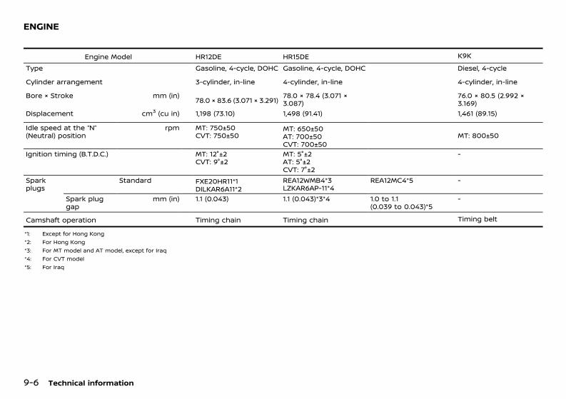
(258,1)
[ Edit: 2018/ 12/ 21 Model: N17-A ]
9-6 Technical information
GUID-067AB093-DD6D-4B9E-A99E-30BB937640BA
Engine Model HR12DE HR15DE K9KType Gasoline, 4-cycle, DOHC Gasoline, 4-cycle, DOHC Diesel, 4-cycle
Cylinder arrangement 3-cylinder, in-line 4-cylinder, in-line 4-cylinder, in-line
Bore × Stroke mm (in) 78.0 × 83.6 (3.071 × 3.291) 78.0 × 78.4 (3.071 ×3.087)
76.0 × 80.5 (2.992 ×3.169)
Displacement cm3 (cu in) 1,198 (73.10) 1,498 (91.41) 1,461 (89.15)
Idle speed at the “N”(Neutral) position
rpm MT: 750±50CVT: 750±50
MT: 650±50AT: 700±50CVT: 700±50
MT: 800±50
Ignition timing (B.T.D.C.) MT: 12°±2CVT: 9°±2
MT: 5°±2AT: 5°±2CVT: 7°±2
-
Sparkplugs
Standard FXE20HR11*1DILKAR6A11*2
REA12WMB4*3LZKAR6AP-11*4
REA12MC4*5 -
Spark pluggap
mm (in) 1.1 (0.043) 1.1 (0.043)*3*4 1.0 to 1.1(0.039 to 0.043)*5
-
Camshaft operation Timing chain Timing chain Timing belt
*1: Except for Hong Kong*2: For Hong Kong*3: For MT model and AT model, except for Iraq*4: For CVT model*5: For Iraq
ENGINE
Condition: 'Except for China'/

(259,1)
[ Edit: 2018/ 12/ 21 Model: N17-A ]
GUID-255AFD73-676B-4307-ACA2-8E0B6CD7EC80
Engine model HR15DE
Maximum net power kW/rpm 73/6,000
Maximum net torque N·m/rpm 134/4,000
Maximum speed*1 km/h (MPH) AT: 170 (106)MT: 183 (114)
*1: Gulf Standard requires automobile manufacturers to indicate the maximum vehicle speed forapplicable models. The maximum vehicle speed, listed above, is the measured speed undercertain testing conditions. The actual value may differ according to the vehicle usage androad and environmental conditions. NISSAN recommends you to ALWAYS observe postedspeed limits and never drive too fast for conditions.
Technical information 9-7
TECHNICAL CHARACTERISTICS (forGulf Standard models)
Condition: 'Except for China'/

(260,1)
[ Edit: 2018/ 12/ 21 Model: N17-A ]
9-8 Technical information
GUID-EA777738-D2DD-414E-A370-938D6FC5432D
Standard*1 Spare*2
Tire size 175/70 R14 84H T125/70 D15 95M*3185/65 R15 88H185/65 R15 88T 185/70 R14 88S*4
175/70 R14 84H175/70 R14 84T185/70 R14 88S185/65 R15 88H
175/70 R14 84H175/70 R14 84T185/70 R14 88S185/65 R15 88H
Size Offset mm (in)
Road wheel Steel 14× 5-1/2J15 ×5-1/2J15 ×5-1/2JJ
40 (1.57)40 (1.57)40 (1.57)
Aluminum alloywheel
15 ×5-1/2J 40 (1.57)
Spare Steel 14× 5-1/2J15 ×5-1/2J15 ×5-1/2JJ
15 ×4T
40 (1.57)40 (1.57)40 (1.57)40 (1.57)
*1: See the tire placard on your vehicle for the recommended cold tire pressure.*2: The emergency tire puncture repair kit is supplied except for model with spare tire.*3: Temporary use only, for Hong Kong*4: Temporary use only, for IndiaFor India:
Tires & tubes fitted in the vehicle, as per clause 3(c) & 3(e) meet the requirement of BIS andcomply with the requirements under the Central Motor Vehicle Rules (CMVR), 1989.
GUID-7338549B-44EE-43DE-ADA8-A394063FC1D8Unit: mm (in)
Overall length 4,455 (175.4)4,512 (177.6)*1
Overall width 1,695 (66.7)Overall height 1,495 (58.9)*2
1,510 (59.4)*31,515 (59.6)
Front tread 1,480 (58.3)Rear tread 1,485 (58.5)Wheelbase 2,590 (102.0)*4
2,600 (102.4)
*1: Model with daytime running light*2: For Hong Kong*3: Model with 175/70 R14 tire, except for
Thailand, Indonesia, Singapore and HongKong
*4: For the Middle East
TIRES AND WHEELS DIMENSIONS
Condition: 'Except for China'/

(261,1)
[ Edit: 2018/ 12/ 21 Model: N17-A ]
GUID-C95C57F5-7060-429B-925E-ED5D735D6508When planning to travel in another country orregion, find out whether the fuel required foryour vehicle is available in that country orregion. Using a low octane rated fuel maycause engine damage. Therefore, be sure thatthe required fuel is available wherever you go.For additional information regarding recom-mended fuel, see “Fuel information” (P.9-4).When transferring the registration of yourvehicle to another country, state, province ordistrict, contact the appropriate authorities tofind out that the vehicle complies with the locallegal requirements. In some cases, a vehiclecannot meet the legal requirements, and it maybe necessary to modify the vehicle to meetlocal laws and regulations. In addition, theremay be possibilities that a vehicle cannot beadapted in certain areas.The laws and regulations for motor vehicleemission control and safety standards varyaccording to the country, state, province ordistrict; therefore, the vehicle specification maydiffer.When any vehicles are to be taken intoanother country, state, province or district,its modification, transportation, registration,and any other expenses which may result,are the responsibility of the user. NISSAN isnot responsible for any inconveniences thatmay result.
GUID-01FF74DB-0858-4C45-89E1-E038CBD93AF0It is prohibited to cover, paint, weld, cut, drill,alter or remove Vehicle Identification Number(VIN).
JVT0023X
VEHICLE IDENTIFICATION PLATEGUID-5094365C-F7B0-4CF8-A0E4-986C059A2B47The plate is affixed as shown .
Built date (if equipped)GUID-2831B072-0118-4B3A-8942-0AFE8FFFEFAABuilt date is stamped on the vehicle identifica-tion plate.The built date means the calendar month andthe year in which the body shell and powertrain subassemblies are conjoined and thevehicle is driven or moved from the productionline.
VEHICLE IDENTIFICATION NUMBER (VIN)GUID-0B6D27D4-E79D-4116-A261-806050B6966DThe vehicle identification number is stampedas shown .
VEHICLE IDENTIFICATION NUMBER (VIN)PLATE (if equipped)GUID-F10896E5-C64F-42E3-B75B-749D435D8D99
JVT0352X
The vehicle identification number plate isaffixed as shown.
ENGINE SERIAL NUMBERGUID-DEFCA7F0-4BB7-42CD-856B-ABC89F81D3F8
STI0734HR12DE engine
Technical information 9-9
WHEN TRAVELLING OR REGISTERINGIN ANOTHER COUNTRY VEHICLE IDENTIFICATION
Condition: 'Except for China'/

(262,1)
[ Edit: 2018/ 12/ 21 Model: N17-A ]
9-10 Technical information
JVT0003XHR15DE engine
STI0662K9K engine
CERTIFICATION LABEL (if equipped)GUID-1B119096-D360-4C51-AC2A-DE0A1B7117B8
STI0441
TIRE PLACARDGUID-A6E9AF42-4A38-42F1-B9EA-7D6CDD29DABA
STI0494
The cold tire pressures are shown on the tireplacard affixed to the driver’s side center pillar.
AIR CONDITIONER SPECIFICATION LA-BEL GUID-5875BEAD-4AF9-4147-976E-83CBFCB9E920
JVT0024X
GUID-1F302990-8FB4-4D7B-B651-3200D276BC94Quality Grades: All passenger car tires mustconform to local safety requirements in addi-tion to these grades.Quality grades can be found where applicableon the tire sidewall between tread shoulderand maximum section width. For example:Treadwear 200 Traction AA Temperature A
TREADWEARGUID-83BCDC6B-0A85-4FB5-B9CC-63A1DF98D039The treadwear grade is a comparative ratingbased on the wear rate of the tire when testedunder controlled conditions on a specifiedgovernment test course. For example, a tiregraded 150 would wear one and one-half (1 1/2)times as well on the government course as atire graded 100. The relative performance oftires depends upon the actual conditions oftheir use, however, and may depart signifi-cantly from the norm due to variations indriving habits, service practices and differencesin road characteristics and climate.
TRACTION AA, A, B AND CGUID-B51A8AC3-7A7A-42AD-9C85-65F8434474D0The traction grades, from highest to lowest, areAA, A, B, and C. Those grades represent thetire’s ability to stop on wet pavement asmeasured under controlled conditions on spe-cified government test surfaces of asphalt andconcrete. A tire marked C may have poortraction performance.
WARNING:The traction grade assigned to this tire isbased on straight-ahead braking tractiontests, and does not include acceleration,cornering, hydroplaning, or peak tractioncharacteristics.
UNIFORM TIRE QUALITY GRADING(if equipped)
Condition: 'Except for China'/

(263,1)
[ Edit: 2018/ 12/ 21 Model: N17-A ]
TEMPERATURE A, B AND CGUID-D542E168-E212-47F8-8CDF-7F33C6EA414AThe temperature grades are A (the highest), B,and C, representing the tire’s resistance to thegeneration of heat and its ability to dissipateheat when tested under controlled conditionson a specified indoor laboratory test wheel.Sustained high temperature can cause thematerial of the tire to degenerate and reducetire life, and excessive temperature can lead tosudden tire failure. The grade C corresponds toa level of performance which all passenger cartires must meet under the local regulations.Grades B and A represent higher levels ofperformance on the laboratory test wheel thanthe minimum required by law.
WARNING:The temperature grade for this tire is estab-lished for a tire that is properly inflated andnot overloaded. Excessive speed, under-in-flation, or excessive loading, either sepa-rately or in combination, can cause heatbuild-up and possible tire failure.
GUID-F15F2DE8-CE98-4A8E-9410-261755D51D23For countries conforming to UN regulationNo.10 or equivalent:The installation of an RF transmitter in yourvehicle could affect electric equipment sys-tems. Be sure to check with your NISSAN dealerfor precautionary measures or special instruc-tions regarding installation. Upon request, yourNISSAN dealer will provide the detailed infor-mation (frequency band, power, antenna posi-tion, installation guide, etc.) regardinginstallation.
GUID-DD114A86-9C88-4B36-8844-08795EAD8361
FOR THAILANDGUID-B6A4C0E6-C956-448F-9562-B27A90644104This telecommunication equipment conformsto NTC technical requirement.. Remote keyless entry system (if equipped). Intelligent Key system (if equipped). NISSAN Anti-Theft System (NATS) (if
equipped)
FOR SINGAPOREGUID-2280329A-719B-415A-8142-9D9AC87E6425
STI0653
. NISSAN vehicle immobilizer system (ifequipped)
. Remote control keyless system (ifequipped)
. Intelligent Key system (if equipped)
JVT0138X
Technical information 9-11
INSTALLATION OF AN RF-TRANSMITTER RADIO APPROVAL NUMBER ANDINFORMATION
Condition: 'Except for China'/

(264,1)
[ Edit: 2018/ 12/ 21 Model: N17-A ]
9-12 Technical information
. Body Control Module (BCM)
FOR INDONESIAGUID-A7728E80-6B60-4A37-B64E-2586F0747A90
Intelligent Key system (if equipped)GUID-9260D9D1-C8E8-4B81-B7F5-46FCAA3BABAA
JVT0060X
Remote keyless entry system (ifequipped) GUID-28574E44-C07E-4C16-8F2E-0651F02BF765
JVT0013X
JVT0014X
NISSAN Anti-Theft System (NATS) im-mobilizer (if equipped)GUID-89EB3CC7-3A70-4C36-8C25-E3CBC5A47F05
JVT0061X
JVT0062X
Body Control Module (BCM)GUID-8D16DB25-F8B3-4DD4-8CFA-829D549F3DE4
JVT0139X
FOR NIGERIAGUID-E46CA0FD-167D-4F2B-AB3F-CA22F3406485
JVT0117X
. Remote control keyless system (ifequipped)
. NISSAN vehicle immobilizer system (ifequipped)
Condition: 'Except for China'/

(265,1)
[ Edit: 2018/ 12/ 21 Model: N17-A ]
FOR OMAN GUID-183CADE7-1DD4-4685-8996-0191E669ACE2
Intelligent Key system (if equipped)GUID-DAFAF460-CDE1-4357-937B-2CF08FEF65F9
JVT0265X
. Body Control Module
FOR SOUTH AFRICAGUID-EC91E14C-AE47-42EE-950D-77AAC7EEA4A8
Remote keyless entry system (ifequipped) GUID-F246D06A-61ED-4D59-8082-F57A5EBAC642
JVT0038X
JVT0039X
Bluetooth® Hands-Free Phone System(if equipped)GUID-08B71EAA-FEC9-4554-A3AB-2C4A5FEA06C2
JVT0310X
FOR JORDANGUID-18962E59-2E1C-44FD-B5E0-8B1FCF95250BIntelligent Key system (if equipped)GUID-61D89370-7A44-49B1-8CF2-89D8A4A85CFDContains Module approved by TRC/LPD/2010/34Contains Module approved by TRC/LPD/2013/206Contains Module approved by TRC/LPD/2013/3
Remote keyless entry system (ifequipped) GUID-3FB77BAE-C051-4D31-985B-D10DDDA1D346Contains Module approved by TRC/LPD/2009/109TunerContains Module approved by TRC/LPD/2008/125
Bluetooth® Hands-Free Phone System(if equipped for type D audio)GUID-D5174AC9-5630-42F9-A6D4-328C6FA2E813Contains approved Bluetooth ModuleVBTDC1.5.Type approval No. : TRC/LPD/2013/41
FOR THE UNITED ARAB EMIRATESGUID-E91330C1-98E8-41A4-B277-9F7B896991EB
Intelligent Key system (if equipped)GUID-47BA5E22-1AF6-4BE4-90C3-9BE00108DCFE
JVT0165X
. Intelligent Key
Technical information 9-13
Condition: 'Except for China'/

(266,1)
[ Edit: 2018/ 12/ 21 Model: N17-A ]
9-14 Technical information
JVT0264X
. Body Control Module
NISSAN Anti-Theft System (NATS) im-mobilizer and Intelligent Key system (ifequipped) GUID-3808BF4B-8288-4D8C-8AE2-97DE75DCAB0D
JVT0054X
WAJ0020X
Tire Pressure Monitoring System(TPMS) transmitterGUID-F18F0142-2803-4A74-B625-5DB4886C9ED9
JVT0492X
Condition: 'Except for China'/

(269,1)
[ Edit: 2018/ 12/ 21 Model: N17-A ]
10 IndexA
Adjusting the screen ........................................................ 4-4Adjusting time ................................................................... 2-27After repairing tire ............................................................. 6-9Air bag system
Side (See supplemental side-impact airbag system) ................................................................. 1-25Supplemental curtain side-impact airbag system ................................................................... 1-19Supplemental front-impact airbag system .................................................... 1-19, 1-25Supplemental side-impact airbag system ................................................................... 1-19
Air bag warning label .................................................. 1-22Air cleaner filter ................................................................ 8-18Air conditioner ...................................................................... 4-6
Air conditioner specification label .............. 9-10Air conditioner system refrigerantand lubricant .................................................................. 9-5Automatic air conditioner ................................ 4-10Manual air conditioner ........................................... 4-7Servicing air conditioner .................................... 4-11
Air conditioner filter ...................................................... 4-12Aluminum alloy wheels .................................................. 7-3Antenna .................................................................................. 4-21Anti-lock Braking System (ABS) .......................... 5-32Anti-lock braking system (ABS)warning light ...................................................................... 2-12Appearance care
Exterior appearance care .................................... 7-2Interior appearance care ...................................... 7-3
Audible reminders .......................................................... 2-18Audio operation precautions ................................ 4-13Audio system ..................................................................... 4-13
Steering wheel audio controls ...................... 4-43Automatic
Automatic Transmission Fluid (ATF) ........ 8-17Automatic Transmission ............................................... 5-7
Automatic Transmission positionindicator ..................................................................................... 2-9Auxiliary input jack ......................................... 4-36, 4-42
BBattery .......................................................................... 8-5, 8-21
Intelligent Key ............................................................. 8-23Intelligent Key battery discharge ............... 5-10Remote controller battery ................................ 8-22Variable voltage control system ................. 8-24Vehicle battery ........................................................... 8-21
Battery replacementIntelligent Key ............................................................. 8-23
Battery saver system .................................... 2-20, 2-31Before starting engine ................................................... 5-3Before using emergency tire puncturerepair kit ..................................................................................... 6-7Belts (See drive belts) .................................................. 8-14Bleeding fuel system ................................................... 8-13Blocking wheels ................................................................... 6-3Bluetooth® Hands-Free PhoneSystem ........................................ 4-45, 4-49, 4-53, 4-58Bluetooth® settings ......... 4-46, 4-50, 4-54, 4-61Brake
Brake booster ............................................................. 8-16Brake fluid ..................................................................... 8-16Brake precautions ................................................... 5-31Brake system .............................................................. 5-31Brakes ............................................................................... 8-15Checking foot brake pedal .............................. 8-15Checking parking brake ..................................... 8-15Parking brake ............................................................. 3-24Parking brake operation .................................... 5-34Warning light ............................................................... 2-12
Brake assist ......................................................................... 5-32Brake precautions .......................................................... 5-31Brakes ...................................................................................... 8-15Break-in schedule .............................................................. 5-3
Bulb replacement ................................................ 8-3, 8-26
CCar phone or CB radio ............................................... 4-45Card holder .......................................................................... 2-29Care when driving ............................................................. 5-6Catalytic converter, Three way catalyst .......... 5-4Center mark on seat belts ...................................... 1-10Center Ventilators .............................................................. 4-5Changing
Changing engine coolant .................................... 8-9Changing engine oil and oil filter ............... 8-10Changing tires and wheels .............................. 8-33
Changing flat tire ................................................................ 6-3Checking
Checking engine coolant level ......................... 8-9Checking engine oil level ................................... 8-10Checking foot brake pedal .............................. 8-15Checking lights .......................................................... 2-12Checking parking brake ..................................... 8-15
Child restraint anchorage ....................................... 1-13Child restraint installation using ISOFIX ....... 1-13Child restraints ................................................................. 1-10Child safety .............................................................................. 1-7Child safety rear door lock ......................................... 3-6Chimes, Audible reminders ..................................... 2-18Chrome parts ........................................................................ 7-3Cigarette lighter .............................................................. 2-28Circuit breaker, Fusible link .................................... 8-24Cleaning exterior and interior ...................... 7-2, 7-3Clock ......................................................................................... 2-27Closing hood ...................................................................... 3-19Clutch fluid ........................................................................... 8-17Cold weather driving ................................................... 5-33Continuously Variable Transmission .................. 5-7Continuously Variable Transmission(CVT) fluid .............................................................................. 8-18Continuously Variable Transmissionposition indicator ............................................................... 2-9
Condition: 'Except for China'/

(270,1)
[ Edit: 2018/ 12/ 21 Model: N17-A ]
10-2
ControlsSteering wheel audio controls ...................... 4-43
CoolantChanging engine coolant .................................... 8-9Checking engine coolant level ......................... 8-9High temperature warning light ................. 2-13
Corrosion protection ....................................................... 7-5Cruise control .................................................................... 5-25Cruise control indicators .......................................... 5-26Cup holders ......................................................................... 2-29
DDefogger switch .............................................................. 2-24Dimensions .............................................................................. 9-8Door open warning light .......................................... 2-13Doors ............................................................................................ 3-5Draining water .................................................................. 8-13Drive belts ............................................................................. 8-14Driving
Care when driving ..................................................... 5-6Cold weather driving ............................................ 5-33Driving in wet conditions ..................................... 5-6Driving in winter conditions ............................... 5-6Driving with AutomaticTransmission (AT) .................................................... 5-13Driving with Continuously VariableTransmission (CVT) ................................................ 5-16Driving with ManualTransmission (MT) ................................................... 5-19Precautions when startingand driving ....................................................................... 5-3
Driving vehicle ................................................................... 5-13
EEconomy, Fuel ................................................................... 5-27Electric power steering system ........................... 5-30Electric power steering warning light ........... 2-13Emergency tire puncture repair kit ........ 6-6, 8-35
EngineBefore starting engine ........................................... 5-3Break-in schedule ...................................................... 5-3Changing engine coolant .................................... 8-9Changing engine oil and oil filter ............... 8-10Checking engine coolant level ......................... 8-9Checking engine oil level ................................... 8-10Engine compartmentcheck locations ............................................................ 8-6Engine cooling system ........................................... 8-8Engine oil ........................................................................ 8-10Engine serial number .............................................. 9-9Engine specifications ............................................... 9-6High temperature warning light ................. 2-13If your vehicle overheats ................................... 6-11Spark plugs ................................................................... 8-14
Engine cold start period ............................................... 5-6Engine coolant temperature gauge .................... 2-8Engine start operation indicator light ........... 2-16Exhaust gas (carbon monoxide) ............................ 5-4Explanation of generalmaintenance items ........................................................... 8-3Extended storage fuse switch ............................. 8-25Exterior lights ..................................................................... 8-27
FFail-safe .................................................................................. 5-16Flat tire ........................................................................................ 6-2Floor mats ................................................................................ 7-4Fluid
Automatic Transmission Fluid (ATF) ........ 8-17Brake fluid ..................................................................... 8-16Clutch fluid .................................................................... 8-17Continuously Variable Transmission(CVT) fluid ....................................................................... 8-18Engine coolant .............................................................. 8-8Engine oil ........................................................................ 8-10Window washer fluid ................................ 8-5, 8-20
FluidsRecommended fluids/lubricantsand capacities ............................................................... 9-2
Fog light switch ............................................................... 2-21Front fog lights ................................................................. 2-21Front seats ............................................................................... 1-2Fuel
Fuel economy ............................................................. 5-27Fuel gauge ....................................................................... 2-9Fuel information .......................................................... 9-4Fuel octane rating ..................................................... 9-4Fuel-filler cap ............................................................... 3-21Fuel-filler lid .................................................................. 3-20Opening fuel-filler lid ............................................. 3-20
Fuel Efficiency and Carbon DioxideReduction driving tips ................................................. 5-27Fuel-filler cap ...................................................................... 3-21Fuel-filler lid ......................................................................... 3-20Fuses ......................................................................................... 8-24Fusible links ......................................................................... 8-24
GGauge ........................................................................................... 2-4
Fuel gauge ....................................................................... 2-9Odometer .......................................................................... 2-5Speedometer ................................................................. 2-5Tachometer ..................................................................... 2-8
Gear shift indicator ....................................................... 5-19General maintenance ...................................................... 8-3Getting emergency tire puncturerepair kit ..................................................................................... 6-7Glove box .............................................................................. 2-29
HHands-Free Phone System,Bluetooth® ............................... 4-45, 4-49, 4-53, 4-58Hazard indicator and outside chime .............. 3-16Hazard indicator flasher switch .............................. 6-2Head restraints ..................................................................... 1-4Headlight
Headlight and turn signal switch ............... 2-19
Condition: 'Except for China'/

(271,1)
[ Edit: 2018/ 12/ 21 Model: N17-A ]
HeadlightsBulb replacement .................................................... 8-26Headlight aiming control .................................. 2-20Headlight switch ...................................................... 2-19
Heater and air conditioner ......................................... 4-6High temperature warning light ........................ 2-13Hood release ...................................................................... 3-18Horn ........................................................................................... 2-24
IIdling Stop OFF switch ................................ 5-22, 5-23Idling Stop System .......................................... 5-21, 5-22Ignition switch
Key positions .................................................................. 5-7Ignition switch (model without IntelligentKey system) ............................................................................. 5-7Ignition switch positions .............................................. 5-9Impact sensing door lockreleasing mechanism ...................................................... 3-6Indicator lights .................................................................. 2-15Injured persons .................................................................... 1-8Inside rearview mirror ................................................. 3-21Installing spare tire ........................................................... 6-5Instrument brightness control ............................ 2-10Instrument panel ................................................................ 2-2Intelligent Key ........................................................................ 3-3Intelligent Key battery ................................................ 8-23Intelligent Key battery discharge ...................... 5-10Intelligent Key system ........................................ 3-8, 5-8
Intelligent Key system warning light ........ 2-13Interior lights ....................................................... 2-30, 8-27ISOFIX child restraint system ................................ 1-12
JJacking up vehicle .............................................................. 6-4Jump starting ........................................................................ 6-9
KKey .................................................................................................. 3-2
Ignition switch (model withoutIntelligent Key system) ........................................... 5-7Ignition switch positions ...................................... 5-9Intelligent Key battery ......................................... 8-23Intelligent Key battery discharge ............... 5-10Intelligent Key system ................................. 3-8, 5-8Keys ....................................................................................... 3-2Locking with key ......................................................... 3-5Mechanical key ............................................................. 3-4NISSAN Anti-Theft System(NATS*) key ....................................................................... 3-3Push-button ignition switch (modelwith Intelligent Key system) ............................... 5-8Remote keyless entry system .......................... 3-7Using Intelligent Key system .......................... 3-10Using remote keylessentry system .................................................... 3-7, 3-15
Key positions .......................................................................... 5-7
LLabels
Air conditioner specification label .............. 9-10Engine serial number .............................................. 9-9Vehicle identification number (VIN) .............. 9-9
LightBulb replacement ........................................ 8-3, 8-26Exterior lights .............................................................. 8-27Fog light switch ........................................................ 2-21Front fog lights .......................................................... 2-21Headlight aiming control .................................. 2-20Headlight and turn signal switch ............... 2-19Headlight switch ...................................................... 2-19Headlights ...................................................................... 8-26Indicator lights ........................................................... 2-15Interior lights ................................................ 2-30, 8-27Light locations ........................................................... 8-28Rear fog light .............................................................. 2-22
Rear reading light ................................................... 2-31Replacement ................................................... 8-3, 8-26Room light ..................................................................... 2-30Warning lights ............................................................ 2-12
LockAnti-lock Braking System (ABS) ................... 5-32Child safety rear door lock ................................. 3-6Doors .................................................................................... 3-5Locking with inside lock knob ......................... 3-5Locking with key ......................................................... 3-5Locking with power door lock switch ........ 3-6Steering lock ........................................................ 5-7, 5-9Vehicle speed sensing doorlock mechanism .......................................................... 3-6
Low tire pressure warning light ......................... 2-14Low tire pressure warning system(See Tire Pressure Monitoring System(TPMS)) ......................................................................................... 5-4
MMaintenance
Battery .............................................................................. 8-21Battery (except for maintenancefree batteries) ................................................................ 8-5Explanation of generalmaintenance items ................................................... 8-3General maintenance .............................................. 8-3Maintenance precautions .................................... 8-5Maintenance requirements ................................ 8-3Scheduled maintenance ....................................... 8-3Seat belt maintenance ........................................ 1-10
Malfunction Indicator Light (MIL) ....................... 2-17Manual air conditioner ................................................... 4-7Manual transmission ....................................................... 5-7Map light ................................................................................ 2-30Mechanical key ..................................................................... 3-4Meters and gauges ........................................................... 2-4Mirror
Inside rearview mirror .......................................... 3-21Mirrors .............................................................................. 3-21Outside rearview mirrors .................................. 3-22
10-3
Condition: 'Except for China'/

(272,1)
[ Edit: 2018/ 12/ 21 Model: N17-A ]
10-4
MonitorRear view monitor ..................................................... 4-2
NNew vehicle break-in ....................................................... 5-3NISSAN Anti-Theft System (NATS) ..................... 3-17NISSAN Anti-Theft System (NATS*) key ............. 3-3
OOdometer .................................................................................. 2-5Oil
Changing engine oil and oil filter ............... 8-10Checking engine oil level ................................... 8-10Engine oil ........................................................................ 8-10
Opening fuel-filler lid .................................................... 3-20Opening hood ................................................................... 3-19Outside rearview mirrors ......................................... 3-22Overdrive switch ............................................................. 5-14Overheat, If your vehicle overheats ................. 6-11
PPanic alarm ............................................................... 3-8, 3-15Parking
Parking brake ............................................................. 3-24Parking, Parking brake operation ...................... 5-34Passenger compartment ......................................... 8-25Phone
Bluetooth® Hands-Free PhoneSystem ................................. 4-45, 4-49, 4-53, 4-58Car phone or CB radio ........................................ 4-45
PowerElectric power steering system .................... 5-30Locking with power door lock switch ........ 3-6Power outlet ................................................................ 2-28Power windows ........................................................ 2-25
Pre-tensioner seat belt system ............ 1-22, 1-27Precautions
Audio operation ........................................................ 4-13
Brake precautions ................................................... 5-31Cruise control ............................................................. 5-25Maintenance ................................................................... 8-5Precautions on childrestraint usage .......................................................... 1-10Precautions on push-button ignitionswitch operation ......................................................... 5-8Precautions on SupplementalRestraint System (SRS) ........................................ 1-19Precautions when startingand driving ....................................................................... 5-3Safety precautions .................................................... 4-2Seat belt usage ............................................................ 1-6Towing precautions .............................................. 6-11
Precautions on push-button ignitionswitch operation ................................................................. 5-8Pregnant women ................................................................ 1-8Preparing tools and spare tire ................................. 6-3Push starting ...................................................................... 6-10Push-button ignition switch (model withIntelligent Key system) ................................................... 5-8
RRadio ......................................................................................... 4-13
Car phone or CB radio ........................................ 4-45Steering wheel audio controls ...................... 4-43
Radio FM-AM radio with Compact Disc(CD) player ............................... 4-22, 4-27, 4-30, 4-37Rear comfort fan ............................................................ 4-12Rear fog light ..................................................................... 2-22Rear reading light .......................................................... 2-31Rear Ventilators ................................................................... 4-6rear view monitor ............................................................... 4-2Recommended fluids/lubricantsand capacities ....................................................................... 9-2Recommended SAE viscosity number ............... 9-4Remote controller battery ....................................... 8-22Remote keyless entry system .................................. 3-7Removing spots ................................................................... 7-2Repair and replacement procedure ................ 1-28Repairing tire .......................................................................... 6-7
Reverse reminder chime ........................................... 2-18Room light ............................................................................ 2-30
SSafety
Child safety ...................................................................... 1-7Child safety rear door lock ................................. 3-6Safety precautions .................................................... 4-2
Scheduled maintenance ............................................... 8-3Seat
Center mark on seat belts ............................... 1-10Front seats ....................................................................... 1-2Precautions on seat belt usage ...................... 1-6Seat belt ............................................................................. 7-4Seat belts .......................................................................... 1-6Seats ..................................................................................... 1-2Three-point type seat belts ............................... 1-8
Seat belt ..................................................................................... 1-8Center mark on seat belts ............................... 1-10Precautions on seat belt usage ...................... 1-6
Seat belt warning light .............................................. 2-15Seat belt(s)
Child safety ...................................................................... 1-7Injured persons ............................................................ 1-8Pre-tensioner seatbelt system .................................................... 1-22, 1-27Pregnant women ........................................................ 1-8Seat belt maintenance ........................................ 1-10Shoulder belt height adjustment .................. 1-8
Seat beltsCleaning ............................................................................. 7-4
Security system ................................................................ 3-17Servicing air conditioner ........................................... 4-11Shift lever
Shift lock release ...................................................... 5-18Shift lock release ............................................................. 5-15
Transmission ............................................................... 5-18Shoulder belt height adjustment .......................... 1-8Side ventilators ..................................................................... 4-5Side-impact air bag system ................................... 1-25Soft bottle holder ........................................................... 2-30
Condition: 'Except for China'/

(273,1)
[ Edit: 2018/ 12/ 21 Model: N17-A ]
Sonar (parking sensor) system ........................... 5-29Spare tire ............................................................................... 8-34Spark plugs .......................................................................... 8-14Speed [120 km/h (75 MPH)]warning light ...................................................................... 2-15Speedometer ......................................................................... 2-5SRS air bag warning light ........................................ 1-23Starting
Before starting engine ........................................... 5-3Jump starting ................................................................ 6-9Precautions when startingand driving ....................................................................... 5-3Push starting ............................................................... 6-10
Starting engine (model with IntelligentKey system) ......................................................................... 5-11Starting engine (model without IntelligentKey system) ......................................................................... 5-10Starting vehicle ................................................................ 5-13Steering
Electric power steering system .................... 5-30Steering lock ........................................................ 5-7, 5-9Steering wheel ........................................................... 3-21Steering wheel switch foraudio controls ............................................................ 4-43
Stopping vehicle .................................................................. 6-2Storage ................................................................................... 2-29Stowing damaged tire and tools ........................... 6-6Sun visors ............................................................................. 2-30Supplemental air bag systems ............................ 1-24Supplemental curtain side-impact airbag system .......................................................................... 1-19Supplemental front-impact airbag system ........................................................... 1-19, 1-25Supplemental Restraint System (SRS) ........... 1-19Supplemental side-impact airbag system ........................................................... 1-19, 1-25Switch
Audio control steering wheel switch ........ 4-43Defogger switch ....................................................... 2-24Fog light switch ........................................................ 2-21Front fog lights .......................................................... 2-21Hazard indicator flasher switch ...................... 6-2
Headlight aiming control .................................. 2-20Headlight and turn signal switch ............... 2-19Headlight switch ...................................................... 2-19Ignition switch .............................................................. 5-7Power door lock switch ........................................ 3-6Rear fog light .............................................................. 2-22Turn signal switch .................................................. 2-21Wiper and washer switch ................................. 2-22
TTachometer ............................................................................. 2-8Technical characteristics .............................................. 9-7Theft warning system ................................................. 3-17Three-point type seat belts ....................................... 1-8Three-way catalyst ............................................................ 5-4Tire
Changing tires and wheels .............................. 8-33Installing spare tire ................................................... 6-5Preparing tools and spare tire ......................... 6-3Pressure, Low tire pressurewarning light ............................................................... 2-14Spare tire ........................................................................ 8-34Stowing damaged tire and tools ................... 6-6Tire age ............................................................................ 8-33Tire equipment .......................................................... 5-34Tire inflation pressure .......................................... 8-32Tire placard .................................................................. 9-10Tire wear and damage ....................................... 8-33Tires and wheels .......................................... 8-32, 9-8
Tires ............................................................................................... 6-6Flat tire ................................................................................ 6-2Low tire pressure warning system .............. 5-4Tire chains ..................................................................... 8-32Tire Pressure MonitoringSystem (TPMS) ................................................... 5-4, 6-2Tire rotation ..................................................... 8-4, 8-33Types of tires .............................................................. 8-32Uniform tire quality grading ........................... 9-10
TowingTowing precautions .............................................. 6-11Towing recommended by NISSAN ............ 6-12
Towing your vehicle .............................................. 6-11Trailer towing ............................................................. 5-30
TPMS, Tire Pressure Monitoring System .......... 5-4TPMS, Tire pressure warning system ................. 6-2Trailer towing .................................................................... 5-30Transferring a call .......................................................... 4-52Transmission
Automatic Transmission (AT) ............................ 5-7Automatic Transmission Fluid (ATF) ........ 8-17Continuously VariableTransmission (CVT) ................................................... 5-7Continuously Variable Transmission(CVT) fluid ....................................................................... 8-18Driving with AutomaticTransmission (AT) .................................................... 5-13Driving with Continuously VariableTransmission (CVT) ................................................ 5-16Driving with ManualTransmission (MT) ................................................... 5-19Manual transmission (MT) ................................... 5-7Transmission shift lever lock release ........ 5-18
Trip computer ....................................................................... 2-7Troubleshooting guide ............................................... 3-13Trunk lid ................................................................................. 3-19Trunk light ............................................................................ 2-31Turn signal switch ......................................................... 2-21Types of tires ..................................................................... 8-32
UUnderbody cleaning ......................................................... 7-3Uniform tire quality grading .................................. 9-10USB memory device operation ............ 4-34, 4-40Using Intelligent Key system ................................. 3-10Using remote keylessentry system ............................................................ 3-7, 3-15
VVariable voltage control system ........................ 8-24
10-5
Condition: 'Except for China'/

(274,1)
[ Edit: 2018/ 12/ 21 Model: N17-A ]
10-6
VehicleDimensions ...................................................................... 9-8Identification number (VIN) ................................. 9-9Speed sensing door lock mechanism ........ 3-6
Vehicle battery .................................................................. 8-21Vehicle Dynamic Control (VDC)OFF switch ........................................................................... 5-25Vehicle Dynamic Control (VDC) system ........ 5-24Vehicle Dynamic Control (VDC)warning light ...................................................................... 2-15Vehicle information display ........................................ 2-5Vehicle security ................................................................ 5-33Ventilators ................................................................................ 4-5
WWarning
Lights ................................................................................. 2-12Tire Pressure MonitoringSystem (TPMS) ................................................... 5-4, 6-2Warning and audible reminders .................. 3-12Warning lights ............................................................ 2-12Warning lights, indicator lights andaudible reminders ................................................... 2-11
Warning lightLow tire pressure warning light .................. 2-14Speed [120 km/h (75 MPH)]warning light ............................................................... 2-15
Washer switchWindshield wiper andwasher switch ............................................................ 2-22
Washing ...................................................................................... 7-2Waxing ......................................................................................... 7-2Wheels and tires, Care of wheels ........................... 7-3When travelling or registering inanother country .................................................................. 9-9Where to go for service ................................................. 8-3Window washer fluid ........................................ 8-5, 8-20Window(s)
Cleaning .................................................................. 7-2, 7-4Manual windows ...................................................... 2-25Power windows ........................................................ 2-25
Windows ................................................................................. 2-25Windshield wiper and washer switch ............. 2-22Wiper
Windshield wiper andwasher switch ............................................................ 2-22Wiper and washer switch ................................. 2-22Wiper blades ................................................................ 8-19
Condition: 'Except for China'/

(278,1)
[ Edit: 2018/ 12/ 21 Model: N17-A ]
11 EpilogueGUID-2A8D3CD7-1FE2-4A5C-93A8-149D19A22A11
FUEL INFORMATIONGUID-5EDB3853-A488-4589-9EC7-1909CE2B6EF9
Gasoline engine (model with three–waycatalyst) GUID-3DBBB9B9-2F89-4C35-90E9-3435D3DF7F1A
CAUTION:Do not use leaded gasoline. Using leadedgasoline will damage the three-way catalyst.
Except for Iraq and Thailand:GUID-9E14C2E6-2E9C-4731-980B-C45B899B977B
Use UNLEADED REGULAR gasoline with anoctane rating of at least 91 (RON).For Iraq:
GUID-9E14C2E6-2E9C-4731-980B-C45B899B977B
Use UNLEADED PREMIUM gasoline with anoctane rating of at least 91 (RON).For Thailand:
GUID-9E14C2E6-2E9C-4731-980B-C45B899B977B
Use UNLEADED REGULAR gasoline or gasohol(up to E20*) with an octane rating of at least 91(RON).*: Gasohol is alcohol blended gasoline. Forexample, “E20” is a mixture of approximately20% fuel ethanol and 80% unleaded gasoline.
Diesel engineGUID-4407F019-0257-4CA0-9F51-2FFA3DD520C2Diesel fuel of at least 50 cetane.*: If two types of diesel fuel are available, usesummer or winter fuel properly according tothe following temperature conditions.. Above −7°C (20°F) ... Summer type diesel
fuel.. Below −7°C (20°F) ... Winter type diesel fuel.
CAUTION:. Do not use home heating oil, gasoline or
other alternate fuels in your diesel en-gine. The use of those or adding those todiesel fuel can cause engine damage.
. Do not use summer fuel at temperaturesbelow −7°C (20°F). The cold temperatureswill cause wax to form in the fuel. As aresult, it may prevent the engine fromrunning smoothly.
RECOMMENDED ENGINE OILGUID-AFCF8C11-9051-4D2E-9607-F5019BB74CA2See “Recommended fluids/lubricants and ca-pacities” (P.9-2).
TIRE COLD PRESSUREGUID-903EA7A1-3376-4447-AFDA-4BC4F64F3036See the tire placard affixed to the driver’s sidecenter pillar.
GAS STATION INFORMATION
Condition: 'Except for China'/

(279,1)
[ Edit: 2018/ 12/ 21 Model: N17-A ]
GUID-BE21E327-074B-4336-8215-A311D4A25F56
JVT0362X
AIR BAG LABEL (if equipped)
Condition: 'Except for China'/

(280,1)
[ Edit: 2018/ 12/ 21 Model: N17-A ]
JVT0363X
Condition: 'Except for China'/

(281,1)
[ Edit: 2018/ 12/ 21 Model: N17-A ]
GUID-0FAA519E-81C6-415B-98D9-C40301E60A8D. In case of emergency ... (P.6-1)
(Flat tire, engine will not start, overheating,towing)
. How to start the engine ... (P.5-1)
. How to read the meters and gauges ...(P.2-1)
. Maintenance and do-it-yourself ... (P.8-1)
. Technical information ... (P.9-1)
QUICK REFERENCE
Condition: 'Except for China'/