2013 Nissan Sentra | Owner's Manual - Dealer E Process
372
→ 2013 SENTRA OWNER’S MANUAL For your safety, read carefully and keep in this vehicle.
-
Upload
khangminh22 -
Category
Documents
-
view
1 -
download
0
Transcript of 2013 Nissan Sentra | Owner's Manual - Dealer E Process

®
2013 SENTRAOWNER’S MANUAL
For your safety, read carefully and keep in this vehicle.
2013 N
ISS
AN
SE
NTR
AB
17-D
B17-D
Printing : January 2013 (3)
Publication No.: OM2E 0B16U3
Printed in U.S.A.
OM3E 0B17U2

Welcome to the growing family of new NISSANowners. This vehicle is delivered to you withconfidence. It was produced using the latesttechniques and strict quality control.
This manual was prepared to help you under-stand the operation and maintenance of yourvehicle so that you may enjoy many miles (kilome-ters) of driving pleasure. Please read through thismanual before operating your vehicle.
A separate Warranty Information Bookletexplains details about the warranties cov-ering your vehicle. The “NISSAN Serviceand Maintenance Guide” explains detailsabout maintaining and servicing your ve-hicle. Additionally, a separate CustomerCare/Lemon Law Booklet (U.S. only) willexplain how to resolve any concerns youmay have with your vehicle, as well asclarify your rights under your state’s lemonlaw.
Your NISSAN dealership knows your vehiclebest. When you require any service or have anyquestions, they will be glad to assist you with theextensive resources available to them.
In addition to factory installed options, your ve-hicle may also be equipped with additional ac-cessories installed by NISSAN or by yourNISSAN dealer prior to delivery. It is importantthat you familiarize yourself with all disclosures,
warnings, cautions and instructions concerningproper use of such accessories prior to operatingthe vehicle and/or accessory. See a NISSANdealer for details concerning the particular ac-cessories with which your vehicle is equipped.
Before driving your vehicle, please read thisOwner’s Manual carefully. This will ensure famil-iarity with controls and maintenance require-ments, assisting you in the safe operation of yourvehicle.
WARNING
IMPORTANT SAFETY INFORMATION RE-MINDERS FOR SAFETY!
Follow these important driving rules tohelp ensure a safe and comfortable tripfor you and your passengers!
● NEVER drive under the influence of al-cohol or drugs.
● ALWAYS observe posted speed limitsand never drive too fast for conditions.
● ALWAYS give your full attention to drivingand avoid using vehicle features or takingother actions that could distract you.
● ALWAYS use your seat belts and appro-priate child restraint systems. Preteenchildren should be seated in the rear seat.
● ALWAYS provide information about theproper use of vehicle safety features toall occupants of the vehicle.
● ALWAYS review this Owner’s Manualfor important safety information.
FOREWORD READ FIRST—THEN DRIVE SAFELY

MODIFICATION OF YOUR VEHICLE
This vehicle should not be modified.Modification could affect itsperformance, safety or durability, andmay even violate governmentalregulations. In addition, damage or per-formance problems resulting from modi-fications may not be covered underNISSAN warranties.
This manual includes information for all optionsavailable on this model. Therefore, you may findsome information that does not apply to yourvehicle.
All information, specifications and illustrations inthis manual are those in effect at the time ofprinting. NISSAN reserves the right to changespecifications or design without notice and with-out obligation.
IMPORTANT INFORMATION ABOUTTHIS MANUALYou will see various symbols in this manual. Theyare used in the following ways:
WARNING
This is used to indicate the presence of ahazard that could cause death or seriouspersonal injury. To avoid or reduce therisk, the procedures must be followedprecisely.
CAUTION
This is used to indicate the presence of ahazard that could cause minor or moder-ate personal injury or damage to your ve-hicle. To avoid or reduce the risk, the pro-cedures must be followed carefully.
If you see this symbol, it means “Do not do this”or “Do not let this happen.”
If you see a symbol similar to these in an illustra-tion, it means the arrow points to the front of thevehicle.
Arrows in an illustration that are similar to theseindicate movement or action.
Arrows in an illustration that are similar to thesecall attention to an item in the illustration.
APD1005
WHEN READING THE MANUAL

CALIFORNIA PROPOSITION 65WARNING
WARNING
Engine exhaust, some of its constituents,and certain vehicle components containor emit chemicals known to the State ofCalifornia to cause cancer and birth de-fects or other reproductive harm. In addi-tion, certain fluids contained in vehiclesand certain products of component wearcontain or emit chemicals known to theState of California to cause cancer andbirth defects or other reproductive harm.
CALIFORNIA PERCHLORATEADVISORYSome vehicle parts, such as lithium batter-ies, may contain perchlorate material. Thefollowing advisory is provided: “PerchlorateMaterial – special handling may apply, Seewww.dtsc.ca.gov/hazardouswaste/perchlorate/”.
BLUETOOTH® is atrademark owned byBluetooth SIG, Inc.and licensed toVisteon and Bosch.
SiriusXM SatelliteRadio requiressubscription, soldseparately. Notavailable in Alaska,Hawaii or Guam.For moreinformation, visitwww.siriusxm.com.
© Nissan Mexicana, S. A. de C. V.
All rights reserved. No part of this Owner’sManual may be reproduced or stored in a retrievalsystem, or transmitted in any form, or by anymeans, electronic, mechanical, photocopying,recording or otherwise, without the prior writtenpermission of Nissan Mexicana, S. A. de C. V.
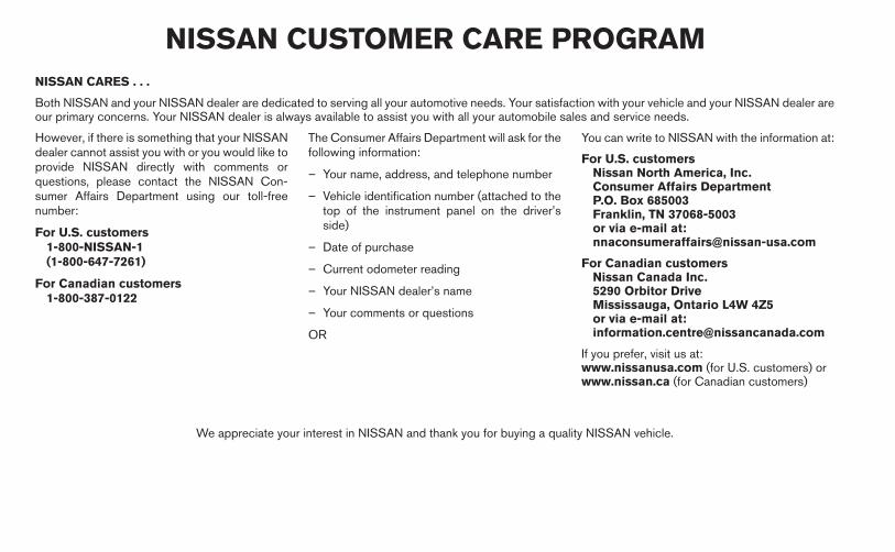
NISSAN CARES . . .
Both NISSAN and your NISSAN dealer are dedicated to serving all your automotive needs. Your satisfaction with your vehicle and your NISSAN dealer areour primary concerns. Your NISSAN dealer is always available to assist you with all your automobile sales and service needs.
However, if there is something that your NISSANdealer cannot assist you with or you would like toprovide NISSAN directly with comments orquestions, please contact the NISSAN Con-sumer Affairs Department using our toll-freenumber:
For U.S. customers1-800-NISSAN-1(1-800-647-7261)
For Canadian customers1-800-387-0122
The Consumer Affairs Department will ask for thefollowing information:
– Your name, address, and telephone number
– Vehicle identification number (attached to thetop of the instrument panel on the driver’sside)
– Date of purchase
– Current odometer reading
– Your NISSAN dealer’s name
– Your comments or questions
OR
You can write to NISSAN with the information at:
For U.S. customersNissan North America, Inc.Consumer Affairs DepartmentP.O. Box 685003Franklin, TN 37068-5003or via e-mail at:[email protected]
For Canadian customersNissan Canada Inc.5290 Orbitor DriveMississauga, Ontario L4W 4Z5or via e-mail at:[email protected]
If you prefer, visit us at:www.nissanusa.com (for U.S. customers) orwww.nissan.ca (for Canadian customers)
We appreciate your interest in NISSAN and thank you for buying a quality NISSAN vehicle.
NISSAN CUSTOMER CARE PROGRAM

Table ofContents
Illustrated table of contents
Safety—Seats, seat belts and supplemental restraint system
Instruments and controls
Pre-driving checks and adjustments
Monitor, climate, audio, phone and voice recognition systems
Starting and driving
In case of emergency
Appearance and care
Maintenance and do-it-yourself
Technical and consumer information
Index
0
1
2
3
4
5
6
7
8
9
10


0 Illustrated table of contents
Air bags, seat belts and child restraints . . . . . . . . . . . . . . 0-2Exterior front . . . . . . . . . . . . . . . . . . . . . . . . . . . . . . . . . . . . . . 0-3Exterior rear. . . . . . . . . . . . . . . . . . . . . . . . . . . . . . . . . . . . . . . 0-4Passenger compartment . . . . . . . . . . . . . . . . . . . . . . . . . . . 0-5
Instrument panel. . . . . . . . . . . . . . . . . . . . . . . . . . . . . . . . . . . 0-6Engine compartment check locations . . . . . . . . . . . . . . . . 0-7Warning/indicator lights . . . . . . . . . . . . . . . . . . . . . . . . . . . . 0-8

1. Top tether anchor (P. 1-30)2. Rear seat belts (P. 1-8)3. Roof-mounted curtain side-impact
supplemental air bag (P. 1-34)4. Head restraints (P. 1-5)5. Front seat belts (P. 1-8)6. Supplemental front-impact air bags
(P. 1-34)7. Front seats (P. 1-2)8. Occupant classification sensor (weight
sensor) (P. 1-41)9. Seat belt with pretensioner (P. 1-34)
10. Front seat-mounted side-impactsupplemental air bag (P. 1-34)
11. Rear seats (P. 1-4)12. LATCH (Lower Anchors and Tethers for
CHildren) system (P. 1-18)See the page number indicated in paren-theses for operating details.
LII2057
AIR BAGS, SEAT BELTS AND CHILDRESTRAINTS
0-2 Illustrated table of contents

1. Engine hood (P. 3-24)2. Windshield wiper and washer switch
(P. 2-23), Windshield (P. 8-18)3. Moonroof (if so equipped) (P. 2-40)4. Power windows (P. 2-37)5. Door locks, keyfob (if so equipped),
keys, NISSAN Intelligent Key®(if so equipped) (P. 3-4, 3-2, 3-2, 3-2)
6. Mirrors (P. 3-30)7. Tire pressure (P. 8-30)8. Flat tire (P. 6-3)9. Tire chains (P. 8-37)10. Replacing bulbs (P. 8-26)11. Headlight and turn signal switch
(P. 2-25)12. Fog light switch (if so equipped)
(P. 2-25)13. Tie down hook (if so equipped)
(P. 6-14)See the page number indicated in paren-theses for operating details.
LII2054
EXTERIOR FRONT
Illustrated table of contents 0-3

1. Trunk lid (P. 3-25)2. High mount stop light (P. 8-26)3. Replacing bulbs (P. 8-26)4. Rear window defroster switch (P. 2-24)5. Child safety rear door lock (P. 3-6)6. Fuel-filler door (P. 3-26), Fuel-filler cap,
fuel recommendation (P. 3-26, P. 9-3)7. Rear view camera (if so equipped)
(P. 4-9)8. Exterior trunk lid release
(if so equipped) (P. 3-16), Interior trunklid release (if so equipped) (P. 3-25)
See the page number indicated in paren-theses for operating details.
LII2052
EXTERIOR REAR
0-4 Illustrated table of contents

1. Grocery hook (P. 2-36)2. Interior lights (if so equipped) (P. 2-42)3. Power window switch, Power door lock
switch (P. 2-37, 3-6)4. Sun visors (P. 3-29)5. Moonroof switch (if so equipped)
(P. 2-40)6. Map lights (P. 2-43)7. Sunglasses holder (P. 2-33)8. Rearview mirror (P. 3-30)9. Rear armrest, cup holders
(P. 1-4, P 2-34)10. Console box (P. 2-35)11. Front cup holders (P. 2-34)
LII2053
PASSENGER COMPARTMENT
Illustrated table of contents 0-5

1. Headlight/fog light (if so equipped)/turnsignal switch (P. 2-25)
2. Steering wheel switch for tripcomputer, audio control andBluetooth® Hands-Free Phone System(if so equipped) (P. 4-64, 4-66, 4-81)
3. Driver’s supplemental air bag/Horn(P. 1-41, 2-28)
4. Meters and gauges (P. 2-3)5. Cruise control main/set switches
(if so equipped) (P. 5-24)
6. Windshield wiper/washer switch(P. 2-23)
7. Ventilator (P. 4-15)8. Hazard warning flasher switch (P. 6-2)9. Audio system (P. 4-26)10. Passenger’s supplemental air bag
(P. 1-41)11. Glove box (P. 2-35)12. Shift selector (P. 5-17)13. Climate control (P. 4-15, 4-23)14. Ignition switch (if so equipped) (P. 5-8)15. Tilt steering (P.3-28)16. Hood release (P. 3-24)17. Fuel filler door release (P. 3-26)18. ECO mode switch (if so equipped)
(P. 5-23); SPORT mode switch (if soequipped) (P.5-22); Vehicle dynamiccontrol (VDC) OFF switch (P.2-30)
19. Instrument brightness control (P. 2-27);Power mirror switch (if so equipped)(P.3-31); Trunk release (P.3-25)
* Refer to the separate Navigation System Own-er’s Manual (if so equipped).
See the page number indicated in paren-theses for operating details.
LIC2439
INSTRUMENT PANEL
0-6 Illustrated table of contents

MRA8DE engine
1. Engine oil filler cap (P. 8-9)2. Brake and clutch (if so equipped) fluid
reservoir (P. 8-12)3. Air cleaner (P. 8-17)4. Battery (P. 8-13)5. Fuse/fusible link box (P. 8-20)6. Engine coolant reservoir (P. 8-7)7. Radiator cap (P. 8-7)8. Engine oil dipstick (P. 8-9)9. Drive belt location (P. 8-16)10. Windshield-washer fluid reservoir
(P. 8-12)
LDI2166
ENGINE COMPARTMENT CHECKLOCATIONS
Illustrated table of contents 0-7

Warninglight
Name Page
or
Anti-lock BrakingSystem (ABS) warn-ing light
2-13
or
Brake warning light 2-13
Charge warning light 2-14
Door open warninglight
2-14
Engine oil pressurewarning light
2-14
Low fuel warninglight
2-14
Warninglight
Name Page
Low tire pressurewarning light
2-14
Low windshield-washer fluid warninglight
2-16
NISSAN IntelligentKey® lock warninglight (M/T models) (ifso equipped)
2-16
NISSAN IntelligentKey® warning light(if so equipped)
2-16
P position selectingwarning light (CVTmodels) (if soequipped)
2-16
Power steeringwarning light
2-16
Warninglight
Name Page
Seat belt warninglight and chime
2-17
Supplemental airbag warning light
2-17
Indicatorlight
Name Page
Continuously Vari-able Transmission(CVT) position indi-cator light (CVTmodels)
2-17
Cruise main switchindicator light (if soequipped)
2-18
ECO drive indicatorlight
2-18
Engine start opera-tion indicator light (ifso equipped)
2-18
WARNING/INDICATOR LIGHTS
0-8 Illustrated table of contents

Indicatorlight
Name Page
Front fog light indi-cator light (if soequipped)
2-18
Front passenger airbag status light
2-18
High beam indicatorlight (blue)
2-18
Malfunction Indica-tor Light (MIL)
2-18
Overdrive off indica-tor light (CVT mod-els)
2-19
Security indicatorlight
2-19
Side light and head-light indicator light(green)
2-19
Indicatorlight
Name Page
Slip indicator light 2-19
SPORT mode indi-cator light (if soequipped)
2-20
Turn signal/hazardindicator lights
2-20
Vehicle DynamicControl (VDC) offindicator light
2-20
Illustrated table of contents 0-9

MEMO
0-10 Illustrated table of contents

1 Safety—Seats, seat belts andsupplemental restraint system
Seats . . . . . . . . . . . . . . . . . . . . . . . . . . . . . . . . . . . . . . . . . . . . 1-2Front manual seat adjustment . . . . . . . . . . . . . . . . . . . . 1-2Folding rear seat . . . . . . . . . . . . . . . . . . . . . . . . . . . . . . . 1-4Head restraints. . . . . . . . . . . . . . . . . . . . . . . . . . . . . . . . . 1-5
Seat belts . . . . . . . . . . . . . . . . . . . . . . . . . . . . . . . . . . . . . . . . 1-8Precautions on seat belt usage. . . . . . . . . . . . . . . . . . . 1-8Pregnant women . . . . . . . . . . . . . . . . . . . . . . . . . . . . . . 1-11Injured persons. . . . . . . . . . . . . . . . . . . . . . . . . . . . . . . . 1-11Three-point type seat belt with retractor . . . . . . . . . . 1-11Seat belt extenders . . . . . . . . . . . . . . . . . . . . . . . . . . . . 1-14Seat belt maintenance . . . . . . . . . . . . . . . . . . . . . . . . . 1-14
Child safety . . . . . . . . . . . . . . . . . . . . . . . . . . . . . . . . . . . . . . 1-15Infants. . . . . . . . . . . . . . . . . . . . . . . . . . . . . . . . . . . . . . . . 1-15Small children . . . . . . . . . . . . . . . . . . . . . . . . . . . . . . . . . 1-16Larger children . . . . . . . . . . . . . . . . . . . . . . . . . . . . . . . . 1-16
Child restraints . . . . . . . . . . . . . . . . . . . . . . . . . . . . . . . . . . . 1-16Precautions on child restraints . . . . . . . . . . . . . . . . . . 1-16
LATCH (Lower Anchors and Tethers forCHildren) System . . . . . . . . . . . . . . . . . . . . . . . . . . . . . 1-18Rear-facing child restraint installation usingLATCH . . . . . . . . . . . . . . . . . . . . . . . . . . . . . . . . . . . . . . . 1-20Rear-facing child restraint installation usingthe seat belts . . . . . . . . . . . . . . . . . . . . . . . . . . . . . . . . . 1-22Forward-facing child restraint installationusing LATCH. . . . . . . . . . . . . . . . . . . . . . . . . . . . . . . . . . 1-25Forward-facing child restraint installationusing the seat belts . . . . . . . . . . . . . . . . . . . . . . . . . . . . 1-27Installing top tether strap . . . . . . . . . . . . . . . . . . . . . . . 1-30Booster seats . . . . . . . . . . . . . . . . . . . . . . . . . . . . . . . . . 1-30
Supplemental restraint system . . . . . . . . . . . . . . . . . . . . . 1-34Precautions on supplemental restraintsystem . . . . . . . . . . . . . . . . . . . . . . . . . . . . . . . . . . . . . . . 1-34Supplemental air bag warning labels . . . . . . . . . . . . . 1-49Supplemental air bag warning light . . . . . . . . . . . . . . 1-49

WARNING
● Do not ride in a moving vehicle whenthe seatback is reclined. This can bedangerous. The shoulder belt will notbe against your body. In an accident,you could be thrown into it and receiveneck or other serious injuries. Youcould also slide under the lap belt andreceive serious internal injuries.
● For the most effective protection whenthe vehicle is in motion, the seat shouldbe upright. Always sit well back in theseat with both feet on the floor andadjust the seat properly. See “Precau-tions on seat belt usage” later in thissection.
● After adjustment, gently rock in the seatto make sure it is securely locked.
● Do not leave children unattended insidethe vehicle. They could unknowingly ac-tivate switches or controls. Unattendedchildren could become involved in seri-ous accidents.
● The seatback should not be reclinedany more than needed for comfort. Seatbelts are most effective when the pas-senger sits well back and straight up inthe seat. If the seatback is reclined, therisk of sliding under the lap belt andbeing injured is increased.
CAUTION
When adjusting the seat positions, besure not to contact any moving parts toavoid possible injuries and/or damage.
FRONT MANUAL SEATADJUSTMENT
ARS1152
SEATS
1-2 Safety—Seats, seat belts and supplemental restraint system

Forward and backwardPull the center of the bar up and hold it while youslide the seat forward or backward to the desiredposition. Release the bar to lock the seat inposition.
RecliningTo recline the seatback, pull the lever up and leanback. To bring the seatback forward, pull the leverup and lean your body forward. Release the leverto lock the seatback in position.
The reclining feature allows adjustment of theseatback for occupants of different sizes foradded comfort and to help obtain proper seatbelt fit. See “Precautions on seat belt usage” laterin this section. Also, the seatback can be reclinedto allow occupants to rest when the vehicle isstopped and the shift selector (CVT) is in P (Park)or the manual transmission is in N (Neutral) withthe parking brake applied.
Seat lifter (driver’s seat)Pull up or push down the adjusting lever to adjustthe seat height until the desired position isachieved.
WRS0719 WRS0720 WRS0721
Safety—Seats, seat belts and supplemental restraint system 1-3

FOLDING REAR SEAT
Pull the knob �A to fold each seatback down.
WARNING
● Never allow anyone to ride in the cargoarea or on the rear seat when it is in thefold-down position. Use of these areasby passengers without proper restraintscould result in serious injury in an acci-dent or sudden stop.
● Properly secure all cargo with ropes orstraps to help prevent it from sliding orshifting. Do not place cargo higher thanthe seatbacks. In a sudden stop or col-lision, unsecured cargo could causepersonal injury.
● When returning the seatbacks to theupright position, be certain they arecompletely secured in the latched posi-tion. If they are not completely secured,passengers may be injured in an acci-dent or sudden stop.
● Closely supervise children when theyare around cars to prevent them fromplaying and becoming locked in thetrunk where they could be seriously in-jured. Keep the car locked, with the rearseatback and trunk lid securely latchedwhen not in use, and prevent children’saccess to car keys.
Center armrest
Pull the armrest down until it rests on the seatcushion.
LRS2194 LRS2217
1-4 Safety—Seats, seat belts and supplemental restraint system

HEAD RESTRAINTS
WARNING
Head restraints supplement the other ve-hicle safety systems. They may provideadditional protection against injury in cer-tain rear end collisions. Adjust the headrestraints properly, as specified in thissection. Check the adjustment aftersomeone else uses the seat. Do not attachanything to the head restraint stalks orremove the head restraint. Do not use theseat if the head restraint has been re-moved. If the head restraint was removed,reinstall and properly adjust the head re-straint before an occupant uses the seat-ing position. Failure to follow these in-structions can reduce the effectiveness ofthe head restraints. This may increase therisk of serious injury or death in acollision.
The illustration shows the seating positionsequipped with head restraints. The front seathead restraints are adjustable, the rear head re-straints are fixed.
� Indicates the seating position is equipped witha head restraint.
Components1. Head restraint
2. Adjustment notches
3. Lock knob
4. Stalks
LRS2218 LRS2197
Safety—Seats, seat belts and supplemental restraint system 1-5

AdjustmentAdjust the head restraint so the center is levelwith the center of the seat occupant’s ears.
To raise the head restraint, pull it up. To lower, push and hold the lock knob and pushthe head restraint down.
WRS0134 LRS2198 LRS2199
1-6 Safety—Seats, seat belts and supplemental restraint system

RemovalUse the following procedure to remove the ad-justable head restraints.
1. Pull the head restraint up to the highestposition.
2. Push and hold the lock knob.
3. Remove the head restraint from the seat.
4. Store the head restraint properly so it is notloose in the vehicle.
5. Reinstall and properly adjust the head re-straint before an occupant uses the seatingposition.
Install1. Align the head restraint stalks with the holes
in the seat. Make sure the head restraint isfacing the correct direction. The stalk withthe adjustment notches �1 must be installedin the hole with the lock knob �2 .
2. Push and hold the lock knob and push thehead restraint down.
3. Properly adjust the head restraint before anoccupant uses the seating position.
LRS2200 LRS2201
Safety—Seats, seat belts and supplemental restraint system 1-7

PRECAUTIONS ON SEAT BELTUSAGEIf you are wearing your seat belt properly ad-justed and you are sitting upright and well back inyour seat with both feet on the floor, your chancesof being injured or killed in an accident and/or theseverity of injury may be greatly reduced.NISSAN strongly encourages you and all of yourpassengers to buckle up every time you drive,even if your seating position includes a supple-mental air bag.
Most U.S. states and Canadian provincesor territories specify that seat belts be wornat all times when a vehicle is being driven.
SSS0136
SEAT BELTS
1-8 Safety—Seats, seat belts and supplemental restraint system

WARNING
● Every person who drives or rides in thisvehicle should use a seat belt at alltimes. Children should be properly re-strained in the rear seat and, if appro-priate, in a child restraint.
WARNING
● The seat belt should be properly ad-justed to a snug fit. Failure to do so mayreduce the effectiveness of the entirerestraint system and increase thechance or severity of injury in an acci-dent. Serious injury or death can occurif the seat belt is not worn properly.
SSS0134 SSS0016
Safety—Seats, seat belts and supplemental restraint system 1-9

WARNING
● Always route the shoulder belt overyour shoulder and across your chest.Never put the belt behind your back,under your arm or across your neck. Thebelt should be away from your face andneck, but not falling off your shoulder.
● Position the lap belt as low and snug aspossible AROUND THE HIPS, NOT THEWAIST. A lap belt worn too high couldincrease the risk of internal injuries inan accident.
● Be sure the seat belt tongue is securelyfastened to the proper buckle.
● Do not wear the seat belt inside out ortwisted. Doing so may reduce itseffectiveness.
● Do not allow more than one person touse the same seat belt.
● Never carry more people in the vehiclethan there are seat belts.
● If the seat belt warning light glows con-tinuously while the ignition is turnedON with all doors closed and all seatbelts fastened, it may indicate a mal-function in the system. Have the systemchecked by a NISSAN dealer.
● No changes should be made to the seatbelt system. For example, do not modifythe seat belt, add material, or installdevices that may change the seat beltrouting or tension. Doing so may affectthe operation of the seat belt system.Modifying or tampering with the seatbelt system may result in serious per-sonal injury.
● Once a seat belt pretensioner has acti-vated, it cannot be reused and must bereplaced together with the retractor.See your NISSAN dealer.
● Removal and installation of preten-sioner system components should bedone by a NISSAN dealer.
● All seat belt assemblies, including re-tractors and attaching hardware,should be inspected after any collisionby a NISSAN dealer. NISSAN recom-mends that all seat belt assemblies inuse during a collision be replaced un-less the collision was minor and thebelts show no damage and continue tooperate properly. Seat belt assembliesnot in use during a collision should alsobe inspected and replaced if eitherdamage or improper operation is noted.
● All child restraints and attaching hard-ware should be inspected after any col-lision. Always follow the restraintmanufacturer’s inspection instructionsand replacement recommendations.The child restraints should be replacedif they are damaged.
SSS0014
1-10 Safety—Seats, seat belts and supplemental restraint system

PREGNANT WOMEN
NISSAN recommends that pregnant women useseat belts. The seat belt should be worn snug andalways position the lap belt as low as possiblearound the hips, not the waist. Place the shoulderbelt over your shoulder and across your chest.Never run the lap/shoulder belt over your ab-dominal area. Contact your doctor for specificrecommendations.
INJURED PERSONS
NISSAN recommends that injured persons useseat belts. Check with your doctor for specificrecommendations.
THREE-POINT TYPE SEAT BELTWITH RETRACTOR
WARNING
● Every person who drives or rides in thisvehicle should use a seat belt at alltimes.
● Do not ride in a moving vehicle whenthe seatback is reclined. This can bedangerous. The shoulder belt will notbe against your body. In an accident,you could be thrown into it and receiveneck or other serious injuries. Youcould also slide under the lap belt andreceive serious internal injuries.
● For the most effective protection whenthe vehicle is in motion, the seat shouldbe upright. Always sit well back in theseat with both feet on the floor andadjust the seat belt properly.
● Do not allow children to play with theseat belts. Most seating positions areequipped with Automatic Locking Re-tractor (ALR) mode seat belts. If theseat belt becomes wrapped around achild’s neck with the ALR mode acti-vated, the child can be seriously injuredor killed if the seat belt retracts andbecomes tight. This can occur even ifthe vehicle is parked. Unbuckle the seatbelt to release the child. If the seat beltcannot be unbuckled or is already un-buckled, release the child by cutting theseat belt with a suitable tool (such as aknife or scissors) to release the seatbelt.
Fastening the seat belts1. Adjust the seat. See “Seats” earlier in this
section.
Manual front seat shownWRS0719
Safety—Seats, seat belts and supplemental restraint system 1-11

�2 Slowly pull the seat belt out of the retractorand insert the tongue into the buckle untilyou hear and feel the latch engage.
● The retractor is designed to lock dur-ing a sudden stop or on impact. Aslow pulling motion permits the seatbelt to move, and allows you somefreedom of movement in the seat.
● If the seat belt cannot be pulled fromits fully retracted position, firmly pullthe belt and release it. Thensmoothly pull the belt out of the re-tractor.
�3 Position the lap belt portion low and snugon the hips as shown.
�4 Pull the shoulder belt portion toward theretractor to take up extra slack. Be sure theshoulder belt is routed over your shoulderand across your chest.
The front passenger seat and the rear seatingpositions three-point seat belts have two modesof operation:
● Emergency Locking Retractor (ELR)
● Automatic Locking Retractor (ALR)
The Emergency Locking Retractor (ELR) modeallows the seat belt to extend and retract to allowthe driver and passengers some freedom ofmovement in the seat. The ELR locks the seat beltwhen the vehicle slows down rapidly or duringcertain impacts.
The Automatic Locking Retractor (ALR) mode(child restraint mode) locks the seat belt for childrestraint installation.
When the ALR mode is activated, the seat beltcannot be extended again until the seat belttongue is detached from the buckle and fullyretracted. The seat belt returns to the ELR modeafter the seat belt fully retracts. See “Child re-straints” later in this section for more information.
The ALR mode should be used only forchild restraint installation. During normalseat belt use by an occupant, the ALR modeshould not be activated. If it is activated, itmay cause uncomfortable seat belt ten-sion. It can also change the operation ofthe front passenger air bag. See “Frontpassenger air bag and status light” later inthis section.
WRS0137 WRS0138
1-12 Safety—Seats, seat belts and supplemental restraint system

WARNING
When fastening the seat belts, be certainthat the seatbacks are completely se-cured in the latched position. If they arenot completely secured, passengers maybe injured in an accident or sudden stop.
Unfastening the seat belts
�1 To unfasten the seat belt, press the button onthe buckle. The seat belt automatically re-tracts.
Checking seat belt operationSeat belt retractors are designed to lock seat beltmovement by two separate methods:
● When the seat belt is pulled quickly from theretractor.
● When the vehicle slows down rapidly.
To increase your confidence in the seat belts,check the operation as follows:
● Grasp the shoulder belt and pull forwardquickly. The retractor should lock and re-strict further belt movement.
If the retractor does not lock during this check orif you have any questions about seat belt opera-tion, see a NISSAN dealer.
WRS0139
Safety—Seats, seat belts and supplemental restraint system 1-13

Shoulder belt height adjustment (frontseats)
The shoulder belt anchor height should be ad-justed to the position best for you. See “Precau-tions on seat belt usage” earlier in this section. Toadjust, pull out the adjustment button �1 andmove the shoulder belt anchor to the desiredposition �2 , so the belt passes over the center ofthe shoulder. The belt should be away from yourface and neck, but not falling off your shoulder.Release the adjustment button to lock the shoul-der belt anchor into position.
WARNING
● After adjustment, release the adjust-ment button and try to move the shoul-der belt anchor up and down to makesure it is securely fixed in position.
● The shoulder belt anchor height shouldbe adjusted to the position best for you.Failure to do so may reduce the effec-tiveness of the entire restraint systemand increase the chance or severity ofinjury in an accident.
SEAT BELT EXTENDERS
If, because of body size or driving position, it isnot possible to properly fit the lap/shoulder beltand fasten it, an extender that is compatible withthe installed seat belts is available that can bepurchased. The extender adds approximately 8 in(200 mm) of length and may be used for eitherthe driver or front passenger seating position.See a NISSAN dealer for assistance with pur-chasing an extender if an extender is required.
WARNING
● Only NISSAN seat belt extenders, madeby the same company which made theoriginal equipment seat belts, shouldbe used with NISSAN seat belts.
● Adults and children who can use thestandard seat belt should not use anextender. Such unnecessary use couldresult in serious personal injury in theevent of an accident.
● Never use seat belt extenders to installchild restraints. If the child restraint isnot secured properly, the child could beseriously injured in a collision or a sud-den stop.
SEAT BELT MAINTENANCE● To clean the seat belt webbing, apply a
mild soap solution or any solution recom-mended for cleaning upholstery or carpet.Then wipe with a cloth and allow the seat beltsto dry in the shade. Do not allow the seat beltsto retract until they are completely dry.
● If dirt builds up in the shoulder beltguide of the seat belt anchors, the seatbelts may retract slowly. Wipe the shoulderbelt guide with a clean, dry cloth.
● Periodically check to see that the seatbelt and the metal components, such asbuckles, tongues, retractors, flexible wiresand anchors, work properly. If loose parts,deterioration, cuts or other damage on thewebbing is found, the entire seat belt as-sembly should be replaced.
LRS0242
1-14 Safety—Seats, seat belts and supplemental restraint system

WARNING
Do not allow children to play with the seatbelts. Most seating positions areequipped with Automatic Locking Retrac-tor (ALR) mode seat belts. If the seat beltbecomes wrapped around a child’s neckwith the ALR mode activated, the child canbe seriously injured or killed if the seatbelt retracts and becomes tight. This canoccur even if the vehicle is parked. Un-buckle the seat belt to release the child. Ifthe seat belt cannot be unbuckled or isalready unbuckled, release the child bycutting the seat belt with a suitable tool(such as a knife or scissors) to release theseat belt.
Children need adults to help protect them.They need to be properly restrained.
In addition to the general information in thismanual, child safety information is available frommany other sources, including doctors, teachers,government traffic safety offices, and communityorganizations. Every child is different, so be sureto learn the best way to transport your child.
There are three basic types of child restraintsystems:
● Rear-facing child restraint
● Forward-facing child restraint
● Booster seat
The proper restraint depends on the child’s size.Generally, infants up to about 1 year and lessthan 20 lbs (9 kg) should be placed in rear-facingchild restraints. Forward-facing child restraintsare available for children who outgrow rear-facing child restraints and are at least 1 year old.Booster seats are used to help position a vehiclelap/shoulder belt on a child who can no longeruse a forward-facing child restraint.
WARNING
Infants and children need special protec-tion. The vehicle’s seat belts may not fitthem properly. The shoulder belt maycome too close to the face or neck. Thelap belt may not fit over their small hipbones. In an accident, an improperly fit-ting seat belt could cause serious or fatalinjury. Always use appropriate childrestraints.
All U.S. states and Canadian provinces or terri-tories require the use of approved child restraintsfor infants and small children. See “Child re-straints” later in this section.
A child restraint may be secured in the vehicle byusing either the LATCH (Lower Anchor and Teth-ers for CHildren) system or with the vehicle seatbelt. See “Child restraints” later in this section formore information.
NISSAN recommends that all pre-teensand children be restrained in the rear seat.Studies show that children are safer whenproperly restrained in the rear seat than inthe front seat.
This is especially important because yourvehicle has a supplemental restraint sys-tem (air bag system) for the front passen-ger. See “Supplemental restraint system”later in this section.
INFANTSInfants up to at least 1 year old should be placedin a rear-facing child restraint. NISSAN recom-mends that infants be placed in child restraintsthat comply with Federal Motor Vehicle SafetyStandards or Canadian Motor Vehicle SafetyStandards. You should choose a child restraintthat fits your vehicle and always follow the manu-facturer’s instructions for installation and use.
CHILD SAFETY
Safety—Seats, seat belts and supplemental restraint system 1-15

SMALL CHILDREN
Children that are over 1 year old and weigh atleast 20 lbs (9 kg) should remain in a rear-facingchild restraint as long as possible up to the heightor weight limit of the child restraint. Children whooutgrow the height or weight limit of the rear-facing child restraint and are at least 1 year oldshould be secured in a forward-facing child re-straint with a harness. Refer to the manufactur-er’s instructions for minimum and maximumweight and height recommendations. NISSANrecommends that small children be placed inchild restraints that comply with Federal MotorVehicle Safety Standards or Canadian Motor Ve-hicle Safety Standards. You should choose achild restraint that fits your vehicle and alwaysfollow the manufacturer’s instructions for instal-lation and use.
LARGER CHILDRENChildren should remain in a forward-facing childrestraint with a harness until they reach the maxi-mum height or weight limit allowed by the childrestraint manufacturer.
Once a child outgrows the height or weight limitof the harness-equipped forward-facing child re-straint, NISSAN recommends that the child beplaced in a commercially available booster seat toobtain proper seat belt fit. For a seat belt to fit
properly, the booster seat should raise the childso that the shoulder belt is properly positionedacross the chest and the top, middle portion ofthe shoulder. The shoulder belt should not crossthe neck or face and should not fall off the shoul-der. The lap belt should lie snugly across thelower hips or upper thighs, not the abdomen. Abooster seat can only be used in seating posi-tions that have a three-point type seat belt. Thebooster seat should fit the vehicle seat and havea label certifying that it complies with FederalMotor Vehicle Safety Standards or Canadian Mo-tor Vehicle Safety Standards. Once the child hasgrown so the shoulder belt is no longer on or nearthe face and neck and the lap belt can be posi-tioned properly across the lower hips or upperthighs use the seat belt without the booster seat.
WARNING
Never let a child stand or kneel on anyseat and do not allow a child in the cargoarea. The child could be seriously injuredor killed in a sudden stop or collision.
PRECAUTIONS ON CHILDRESTRAINTS
ARS1098
CHILD RESTRAINTS
1-16 Safety—Seats, seat belts and supplemental restraint system

WARNING
● Failure to follow the warnings and in-structions for proper use and installa-tion of child restraints could result inserious injury or death of a child orother passengers in a sudden stop orcollision:
– The child restraint must be used andinstalled properly. Always follow allof the child restraint manufacturer’sinstructions for installation and use.
– Infants and children should never beheld on anyone’s lap. Even the stron-gest adult cannot resist the forces ofa collision.
– Do not put a seat belt around both achild and another passenger.
– NISSAN recommends that all childrestraints be installed in the rearseat. Studies show that children aresafer when properly restrained in therear seat than in the front seat. If youmust install a forward-facing childrestraint in the front seat, see“Forward-facing child restraint in-stallation using the seat belts” laterin this section.
– Even with the NISSAN Advanced AirBag System, never install a rear-facing child restraint in the frontseat. An inflating air bag could seri-ously injure or kill a child. A rear-facing child restraint must only beused in the rear seat.
– Be sure to purchase a child restraintthat will fit the child and vehicle.Some child restraints may not fitproperly in your vehicle.
– Child restraint anchor points are de-signed to withstand loads from childrestraints that are properly fitted.
– Never use the anchor points for adultseat belts or harnesses.
– A child restraint with a top tetherstrap should not be used in the frontpassenger seat.
– Keep seatbacks as upright as pos-sible after fitting the child restraint.
– Infants and children should alwaysbe placed in an appropriate child re-straint while in the vehicle.
● When the child restraint is not in use,keep it secured with the LATCH systemor a seat belt. In a sudden stop or colli-sion, loose objects can injure occu-pants or damage the vehicle.
CAUTION
A child restraint in a closed vehicle canbecome very hot. Check the seating sur-face and buckles before placing a child inthe child restraint.
WRS0256
Safety—Seats, seat belts and supplemental restraint system 1-17

This vehicle is equipped with a universal childrestraint anchor system, referred to as the LATCH(Lower Anchors and Tethers for CHildren) sys-tem. Some child restraints include rigid orwebbing-mounted attachments that can be con-nected to these anchors. For details, see “LATCH(Lower Anchors and Tethers for CHildren) sys-tem” later in this section.
If you do not have a LATCH compatible childrestraint, the vehicle seat belts can be used.
Several manufacturers offer child restraints forinfants and children of various sizes. When se-lecting any child restraint, keep the followingpoints in mind:
● Choose only a restraint with a label certifyingthat it complies with Federal Motor VehicleSafety Standard 213 or Canadian MotorVehicle Safety Standard 213.
● Check the child restraint in your vehicle to besure it is compatible with the vehicle’s seatand seat belt system.
● If the child restraint is compatible with yourvehicle, place your child in the child restraintand check the various adjustments to besure the child restraint is compatible withyour child. Choose a child restraint that isdesigned for your child’s height and weight.Always follow all recommended procedures.
All U.S. states and Canadian provinces orterritories require that infants and smallchildren be restrained in an approved childrestraint at all times while the vehicle isbeing operated. Canadian law requires thetop tether strap on forward-facing childrestraints be secured to the designated an-chor point on the vehicle.
LATCH (Lower Anchors and Tethersfor CHildren) SYSTEMYour vehicle is equipped with special anchorpoints that are used with LATCH (Lower Anchorsand Tethers for CHildren) system compatiblechild restraints. This system may also be referredto as the ISOFIX or ISOFIX compatible system.With this system, you do not have to use a vehicleseat belt to secure the child restraint.
The LATCH anchor points are provided to installchild restraints in the rear outboard seating posi-tions only. Do not attempt to install a child re-straint in the center position using the LATCHanchors.
LATCH system lower anchor locationsWRS0756
1-18 Safety—Seats, seat belts and supplemental restraint system

LATCH lower anchor
WARNING
Failure to follow the warnings and instruc-tions for proper use and installation ofchild restraints could result in serious in-jury or death of a child or other passen-gers in a sudden stop or collision:
– Attach LATCH system compatiblechild restraints only at the locationsshown in the illustration.
– Do not secure a child restraint in thecenter rear seating position usingthe LATCH lower anchors. The childrestraint will not be secured properly.
– Inspect the lower anchors by insert-ing your fingers into the lower anchorarea. Feel to make sure there are noobstructions over the anchors suchas seat belt webbing or seat cushionmaterial. The child restraint will notbe secured properly if the lower an-chors are obstructed.
LATCH lower anchor locationThe LATCH lower anchors are located at the rearof the seat cushion near the seatback. A label isattached to the seatback to help you locate theLATCH lower anchors.
Installing child restraint LATCH loweranchor attachments
LATCH compatible child restraints include tworigid or webbing-mounted attachments that canbe connected to two anchors located at certainseating positions in your vehicle. With this sys-tem, you do not have to use a vehicle seat belt tosecure the child restraint. Check your child re-straint for a label stating that it is compatible withLATCH. This information may also be in the in-structions provided by the child restraint manu-facturer.
LATCH lower anchor locationWRS0700
LATCH webbing-mounted attachmentLRS0661
Safety—Seats, seat belts and supplemental restraint system 1-19

When installing a child restraint, carefully readand follow the instructions in this manual andthose supplied with the child restraint.
Top tether anchor point locationsThe child restraint top tether strap must be usedwhen installing the child restraint with the LATCHlower anchor attachments or seat belts. See “In-stalling top tether strap” later in this section.
If you have any questions when installing atop tether strap child restraint, consult yourNISSAN dealer for details.
Anchor points �1 are located on the rear parcelshelf.
REAR-FACING CHILD RESTRAINTINSTALLATION USING LATCHRefer to all Warnings and Cautions in the “Childsafety” and “Child restraints” sections before in-stalling a child restraint.
Follow these steps to install a rear-facing childrestraint using the LATCH system:
1. Position the child restraint on the seat. Al-ways follow the child restraint manufactur-er’s instructions.
LATCH rigid-mounted attachmentLRS0662 LRS2195
1-20 Safety—Seats, seat belts and supplemental restraint system

2. Secure the child restraint anchor attach-ments to the LATCH lower anchors. Checkto make sure the LATCH attachment is prop-erly attached to the lower anchors.
3. For child restraints that are equipped withwebbing-mounted attachments, remove anyadditional slack from the anchor attach-ments. Press downward and rearward firmlyin the center of the child restraint with yourhand to compress the vehicle seat cushionand seatback while tightening the webbingof the anchor attachments.
Rear-facing web-mounted – step 2WRS0801
Rear-facing rigid-mounted – step 2WRS0802
Rear-facing – step 3LRS0673
Safety—Seats, seat belts and supplemental restraint system 1-21

4. After attaching the child restraint, test it be-fore you place the child in it. Push it from sideto side while holding the child restraint nearthe LATCH attachment path. The child re-straint should not move more than 1 inch(25 mm), from side to side. Try to tug itforward and check to see if the LATCH at-tachment holds the restraint in place. If therestraint is not secure, tighten the LATCHattachment as necessary, or put the restraintin another seat and test it again. You mayneed to try a different child restraint or tryinstalling by using the vehicle seat belt (ifapplicable). Not all child restraints fit in alltypes of vehicles.
5. Check to make sure the child restraint isproperly secured prior to each use. If thechild restraint is loose, repeat steps 1through 4.
REAR-FACING CHILD RESTRAINTINSTALLATION USING THE SEATBELTS
Rear-facing – step 4LRS0674 WRS0256
1-22 Safety—Seats, seat belts and supplemental restraint system

WARNING
The three-point seat belt with AutomaticLocking Retractor (ALR) must be usedwhen installing a child restraint. Failure touse the ALR mode will result in the childrestraint not being properly secured. Therestraint could tip over or be loose andcause injury to a child in a sudden stop orcollision. Also, it can change the opera-tion of the front passenger air bag. See“Front passenger air bag and status light”later in this section.
Refer to all Warnings and Cautions in the “Childsafety” and “Child restraints” sections before in-stalling a child restraint.
Follow these steps to install a rear-facing childrestraint using the vehicle seat belts in the rearseats:
1. Child restraints for infants must beused in the rear-facing direction andtherefore must not be used in the frontseat. Position the child restraint on the seat.Always follow the restraint manufacturer’sinstructions.
2. Route the seat belt tongue through the childrestraint and insert it into the buckle until youhear and feel the latch engage. Be sure tofollow the child restraint manufacturer’s in-structions for belt routing.
Rear-facing – step 1WRS0256
Rear-facing – step 2WRS0761
Safety—Seats, seat belts and supplemental restraint system 1-23

3. Pull the shoulder belt until the belt is fullyextended. At this time, the seat belt retractoris in the Automatic Locking Retractor (ALR)mode (child restraint mode). It reverts to theEmergency Locking Retractor (ELR) modewhen the seat belt is fully retracted.
4. Allow the seat belt to retract. Pull up on theshoulder belt to remove any slack in the belt.
5. Remove any additional slack from the seatbelt; press downward and rearward firmly inthe center of the child restraint to compressthe vehicle seat cushion and seatback whilepulling up on the seat belt.
Rear-facing – step 3LRS0669
Rear-facing – step 4LRS0670
Rear-facing – step 5WRS0762
1-24 Safety—Seats, seat belts and supplemental restraint system

6. After attaching the child restraint, test it be-fore you place the child in it. Push it from sideto side while holding the child restraint nearthe seat belt path. The child restraint shouldnot move more than 1 inch (25 mm), fromside to side. Try to tug it forward and checkto see if the belt holds the restraint in place.If the restraint is not secure, tighten the seatbelt as necessary, or put the restraint inanother seat and test it again. You may needto try a different child restraint. Not all childrestraints fit in all types of vehicles.
7. Check to make sure that the child restraint isproperly secured prior to each use. If theseat belt is not locked, repeat steps 1through 6.
After the child restraint is removed and the seatbelt fully retracted, the ALR mode (child restraintmode) is canceled.
FORWARD-FACING CHILDRESTRAINT INSTALLATION USINGLATCHRefer to all Warnings and Cautions in the “Childsafety” and “Child restraints” sections before in-stalling a child restraint.
Follow these steps to install a forward-facingchild restraint using the LATCH system:
1. Position the child restraint on the seat. Al-ways follow the child restraint manufactur-er’s instructions.
2. Secure the child restraint anchor attach-ments to the LATCH lower anchors. Checkto make sure the LATCH attachment is prop-erly attached to the lower anchors.
If the child restraint is equipped with a toptether strap, route the top tether strap andsecure the tether strap to the tether anchorpoint. See “Installing top tether strap” in thissection. Do not install child restraints thatrequire the use of a top tether strap in seat-ing positions that do not have a top tetheranchor.
Rear-facing – step 6WRS0763
Forward-facing web-mounted – step 2WRS0799
Safety—Seats, seat belts and supplemental restraint system 1-25

3. The back of the child restraint should besecured against the vehicle seatback.
If necessary, adjust or remove the head re-straint to obtain the correct child restraint fit. Ifthe head restraint is removed, store it in asecure place. Be sure to reinstall the headrestraint when the child restraint is re-moved. See “Head restraints” in this sectionfor head restraint adjustment information.
If the seating position does not have anadjustable head restraint and it is interferingwith the proper child restraint fit, try anotherseating position or a different child restraint.
4. For child restraints that are equipped withwebbing-mounted attachments, remove anyadditional slack from the anchor attach-ments. Press downward and rearward firmlyin the center of the child restraint with yourknee to compress the vehicle seat cushionand seatback while tightening the webbingof the anchor attachments.
5. Tighten the tether strap according to themanufacturer’s instructions to remove anyslack.
6. After attaching the child restraint, test it be-fore you place the child in it. Push it from sideto side while holding the child restraint nearthe LATCH attachment path. The child re-straint should not move more than 1 inch(25 mm), from side to side. Try to tug itforward and check to see if the LATCH at-tachment holds the restraint in place. If therestraint is not secure, tighten the LATCHattachment as necessary, or put the restraintin another seat and test it again. You mayneed to try a different child restraint. Not allchild restraints fit in all types of vehicles.
Forward-facing rigid-mounted – step 2WRS0800
Forward-facing – step 4LRS0671
Forward-facing – step 6WRS0697
1-26 Safety—Seats, seat belts and supplemental restraint system

7. Check to make sure the child restraint isproperly secured prior to each use. If thechild restraint is loose, repeat steps 1through 6.
FORWARD-FACING CHILDRESTRAINT INSTALLATION USINGTHE SEAT BELTS
WARNING
The three-point seat belt with AutomaticLocking Retractor (ALR) must be usedwhen installing a child restraint. Failure touse the ALR mode will result in the childrestraint not being properly secured. Therestraint could tip over or be loose andcause injury to a child in a sudden stop orcollision. Also, it can change the opera-tion of the front passenger air bag. See“Front passenger air bag and status light”later in this section.
Refer to all Warnings and Cautions in the “ChildSafety” and “Child Restraint” sections before in-stalling a child restraint.
Follow these steps to install a forward-facingchild restraint using the vehicle seat belt in therear seats or in the front passenger seat:
1. If you must install a child restraint inthe front seat, it should be placed in aforward-facing direction only. Movethe seat to the rearmost position. Childrestraints for infants must be used in
the rear-facing direction and, there-fore, must not be used in the front seat.
2. Position the child restraint on the seat. Al-ways follow the child restraint manufactur-er’s instructions.
The back of the child restraint should besecured against the vehicle seatback.
If necessary, adjust or remove the head re-straint to obtain the correct child restraint fit.If the head restraint is removed, store it in asecure place. Be sure to reinstall thehead restraint when the child restraintis removed. See “Head restraints” in thissection for head restraint adjustment, re-moval and installation information.
If the seating position does not have anadjustable head restraint and it is interferingwith the proper child restraint fit, try anotherseating position or a different child restraint.
Forward-facing (front passenger seat) –step 1
WRS0699
Safety—Seats, seat belts and supplemental restraint system 1-27

3. Route the seat belt tongue through the childrestraint and insert it into the buckle until youhear and feel the latch engage. Be sure tofollow the child restraint manufacturer’s in-structions for belt routing.
If the child restraint is equipped with a toptether strap, route the top tether strap andsecure the tether strap to the tether anchorpoint. See “Installing top tether strap” in thissection. Do not install child restraints thatrequire the use of a top tether strap in seat-ing positions that do not have a top tetheranchor.
4. Pull the shoulder belt until the belt is fullyextended. At this time, the seat belt retractoris in the Automatic Locking Retractor (ALR)mode (child restraint mode). It reverts toEmergency Locking Retractor (ELR) modewhen the seat belt is fully retracted.
5. Allow the seat belt to retract. Pull up on theshoulder belt to remove any slack in the belt.
Forward-facing – step 3WRS0680
Forward-facing – step 4LRS0667
Forward-facing – step 5LRS0668
1-28 Safety—Seats, seat belts and supplemental restraint system

6. Remove any additional slack from the seatbelt; press downward and rearward firmly inthe center of the child restraint with yourknee to compress the vehicle seat cushionand seatback while pulling up on the seatbelt.
7. Tighten the tether strap according to themanufacturer’s instructions to remove anyslack.
8. After attaching the child restraint, test it be-fore you place the child in it. Push it from sideto side while holding the child restraint nearthe seat belt path. The child restraint shouldnot move more than 1 inch (25 mm), fromside to side. Try to tug it forward and checkto see if the belt holds the restraint in place.If the restraint is not secure, tighten the seatbelt as necessary, or put the restraint inanother seat and test it again. You may needto try a different child restraint. Not all childrestraints fit in all types of vehicles.
9. Check to make sure the child restraint isproperly secured prior to each use. If theseat belt is not locked, repeat steps 2through 8.
Forward-facing – step 6WRS0681
Forward-facing – step 8WRS0698
Safety—Seats, seat belts and supplemental restraint system 1-29

10. If the child restraint is installed in the frontpassenger seat, place the ignition switch inthe ON position. The front passenger air bagstatus light should illuminate. If thislight is not illuminated, see “Front passengerair bag and status light” in this section.Move the child restraint to anotherseating position. Have the systemchecked by a NISSAN dealer.
After the child restraint is removed and the seatbelt is fully retracted, the ALR mode (child re-straint mode) is canceled.
INSTALLING TOP TETHER STRAP
First, secure the child restraint with the LATCHlower anchors (rear outboard seat positions only)or the seat belt, as applicable.
1. Flip up the anchor cover �1 from the anchorpoint which is located directly behind thechild seat.
2. Position the top tether strap over the top ofthe head rest.
3. Secure the tether strap to the tether anchorpoint on the rear parcel shelf.
4. Refer to the appropriate child restraint in-stallation procedure steps in this sectionbefore tightening the tether strap.
If you have any questions when installing atop tether strap, consult your NISSANdealer for details.
BOOSTER SEATS
Precautions on booster seats
WARNING
If a booster seat and seat belt are not usedproperly, the risk of a child being injuredin a sudden stop or collision greatlyincreases:
– Make sure the shoulder portion ofthe belt is away from the child’s faceand neck and the lap portion of thebelt does not cross the stomach.
– Make sure the shoulder belt is notbehind the child or under the child’sarm.
– A booster seat must only be installedin a seating position that has alap/shoulder belt.
Forward-facing — step 10WRS0475 LRS2195
1-30 Safety—Seats, seat belts and supplemental restraint system

Booster seats of various sizes are offered byseveral manufacturers. When selecting anybooster seat, keep the following points in mind:
● Choose only a booster seat with a labelcertifying that it complies with Federal MotorVehicle Safety Standard 213 or CanadianMotor Vehicle Safety Standard 213.
● Check the booster seat in your vehicle to besure it is compatible with the vehicle’s seatand seat belt system.
LRS0455 LRS0453 LRS0464
Safety—Seats, seat belts and supplemental restraint system 1-31

● Make sure the child’s head will be properlysupported by the booster seat or vehicleseat. The seatback must be at or above thecenter of the child’s ears. For example, if alow back booster seat �1 is chosen, thevehicle seatback must be at or above thecenter of the child’s ears. If the seatback islower than the center of the child’s ears, ahigh back booster seat �2 should be used.
● If the booster seat is compatible with yourvehicle, place the child in the booster seatand check the various adjustments to besure the booster seat is compatible with thechild. Always follow all recommended pro-cedures.
All U.S. states and Canadian provinces orterritories require that infants and smallchildren be restrained in an approved childrestraint at all times while the vehicle isbeing operated.
The instructions in this section apply to boosterseat installation in the rear seats or the frontpassenger seat.
Booster seat installation
CAUTION
Do not use the lap/shoulder belt in theAutomatic Locking Retractor mode whenusing a booster seat with the seat belts.
Refer to all Warnings and Cautions in the “Childsafety”, “Child restraints” and “Booster seats”sections before installing a child restraint.
Follow these steps to install a booster seat in therear seat or in the front passenger seat:
1. If you must install a booster seat in thefront seat, move the seat to the rear-most position.
2. Position the booster seat on the seat. Onlyplace it in a front-facing direction. Alwaysfollow the booster seat manufacturer’s in-structions.
WRS0699
1-32 Safety—Seats, seat belts and supplemental restraint system

3. The booster seat should be positioned onthe vehicle seat so that it is stable.
If necessary, adjust or remove the head re-straint o obtain the correct booster seat fit. Ifthe head restraint is removed, store it in asecure place. Be sure to reinstall thehead restraint when the booster seat isremoved. See “Head restraints” in this sec-tion for head restraint adjustment, removaland installation information.
If the seating position does not have anadjustable head restraint and it is interferingwith the proper booster seat fit, try anotherseating position or a different booster seat.
4. Position the lap portion of the seat belt lowand snug on the child’s hips. Be sure tofollow the booster seat manufacturer’s in-structions for adjusting the seat belt routing.
5. Pull the shoulder belt portion of the seat belttoward the retractor to take up extra slack.Be sure the shoulder belt is positionedacross the top, middle portion of the child’sshoulder. Be sure to follow the booster seatmanufacturer’s instructions for adjusting theseat belt routing.
6. Follow the warnings, cautions and instruc-tions for properly fastening a seat beltshown in “Three-point type seat belt withretractor” earlier in this section.
7. If the booster seat is installed in the frontpassenger seat, place the ignition switch inthe ON position. The front passenger air bagstatus light may or may not illuminate,depending on the size of the child and thetype of booster seat being used. See “Frontpassenger air bag and status light” later inthis section.
Front passenger positionLRS0454 WRS0475
Safety—Seats, seat belts and supplemental restraint system 1-33

PRECAUTIONS ON SUPPLEMENTALRESTRAINT SYSTEMThis Supplemental Restraint System (SRS) sec-tion contains important information concerningthe following systems:
● Driver and passenger supplemental front-impact air bag (NISSAN Advanced Air BagSystem)
● Front seat-mounted side-impact supple-mental air bag
● Roof-mounted curtain side-impact supple-mental air bag
● Seat belt with pretensioner
Supplemental front-impact air bag system:The NISSAN Advanced Air Bag System can helpcushion the impact force to the head and chest ofthe driver and front passenger in certain frontalcollisions.
Front seat-mounted side-impact supple-mental air bag system: This system can helpcushion the impact force to the chest area of thedriver and front passenger in certain side impactcollisions. The side air bags are designed toinflate on the side where the vehicle is impacted.
Roof-mounted curtain side-impact supple-mental air bag system: This system can helpcushion the impact force to the head of occu-pants in front and rear outboard seating positionsin certain side-impact collisions. The curtain airbags are designed to inflate on the side wherethe vehicle is impacted.
These supplemental restraint systems are de-signed to supplement the crash protection pro-vided by the driver and front passenger seat beltsand are not a substitute for them. Seat beltsshould always be correctly worn and the occu-pant seated a suitable distance away from thesteering wheel, instrument panel and door finish-ers. See “Seat belts” earlier in this section forinstructions and precautions on seat belt usage.
The supplemental air bags operate onlywhen the ignition switch is in the ON posi-tion.
After placing the ignition switch in the ONposition, the supplemental air bag warninglight illuminates. The supplemental air bagwarning light will turn off after about 7 sec-onds if the system is operational.
SUPPLEMENTAL RESTRAINTSYSTEM
1-34 Safety—Seats, seat belts and supplemental restraint system

WARNING
● The front air bags ordinarily will notinflate in the event of a side impact, rearimpact, rollover, or lower severity fron-tal collision. Always wear your seatbelts to help reduce the risk or severityof injury in various kinds of accidents.
● The front passenger air bag will notinflate if the passenger air bag statuslight is lit or if the front passenger seatis unoccupied. See “Front passenger airbag and status light” later in thissection.
● The seat belts and the front air bags aremost effective when you are sitting wellback and upright in the seat. The frontair bags inflate with great force. Evenwith the NISSAN Advanced Air Bag Sys-tem, if you are unrestrained, leaningforward, sitting sideways or out of posi-tion in any way, you are at greater risk ofinjury or death in a crash. You may alsoreceive serious or fatal injuries from thefront air bag if you are up against itwhen it inflates. Always sit back againstthe seatback and as far away as practi-cal from the steering wheel or instru-ment panel. Always use the seat belts.
● The driver and front passenger seat beltbuckles are equipped with sensors thatdetect if the seat belts are fastened. TheAdvanced Air Bag System monitors theseverity of a collision and seat belt us-age then inflates the air bags asneeded. Failure to properly wear seatbelts can increase the risk or severity ofinjury in an accident.
● The front passenger seat is equippedwith an occupant classification sensor(weight sensor) that turns the front pas-senger air bag OFF under some condi-tions. This sensor is only used in thisseat. Failure to be properly seated andwearing the seat belt can increase therisk or severity of injury in an accident.See “Front Passenger air bag and sta-tus light” later in this section.
● Keep hands on the outside of the steer-ing wheel. Placing them inside thesteering wheel rim could increase therisk that they are injured when the frontair bag inflates.
WRS0031
Safety—Seats, seat belts and supplemental restraint system 1-35

WARNING
● Never let children ride unrestrained orextend their hands or face out of thewindow. Do not attempt to hold them inyour lap or arms. Some examples ofdangerous riding positions are shownin the illustrations.
ARS1133 ARS1041
1-36 Safety—Seats, seat belts and supplemental restraint system

ARS1042 ARS1043 ARS1044
Safety—Seats, seat belts and supplemental restraint system 1-37

WARNING
● Children may be severely injured orkilled when the front air bags, side airbags or curtain air bags inflate if theyare not properly restrained. Pre-teensand children should be properly re-strained in the rear seat, if possible.
● Even with the NISSAN Advanced AirBag System, never install a rear-facingchild restraint in the front seat. An in-flating front air bag could seriously in-jure or kill your child. See “Child re-straints” earlier in this section fordetails.
WARNING
Front seat-mounted side-impact supple-mental air bags and roof-mounted curtainside-impact supplemental air bags:
● The side air bags and curtain air bagsordinarily will not inflate in the event ofa frontal impact, rear impact, rollover orlower severity side collision. Alwayswear your seat belts to help reduce therisk or severity of injury in various kindsof accidents.
ARS1045 WRS0256 WRS0431
1-38 Safety—Seats, seat belts and supplemental restraint system

WARNING
● The seat belts, the side air bags andcurtain air bags are most effective whenyou are sitting well back and upright inthe seat with both feet on the floor. Theside air bag and curtain air bag inflatewith great force. Do not allow anyone toplace their hand, leg or face near theside air bag on the side of the seatbackof the front seat or near the side roofrails. Do not allow anyone sitting in thefront seats or rear outboard seats toextend their hand out of the window orlean against the door. Some examplesof dangerous riding positions areshown in the previous illustrations. WARNING
● When sitting in the rear seat, do nothold onto the seatback of the front seat.If the side air bag inflates, you may beseriously injured. Be especially carefulwith children, who should always beproperly restrained. Some examples ofdangerous riding positions are shownin the illustrations.
● Do not use seat covers on the frontseatbacks. They may interfere with sideair bag inflation.
SSS0162 WRS0032
Safety—Seats, seat belts and supplemental restraint system 1-39

SSS0159 SSS0162
1-40 Safety—Seats, seat belts and supplemental restraint system

1. Top tether anchor2. Rear seat belts3. Roof-mounted curtain side-impact
supplemental air bag4. Head restraints5. Front seat belts6. Supplemental front-impact air bags7. Front seats8. Occupant classification sensor (weight
sensor)9. Seat belt with pretensioner
10. Front seat-mounted side-impactsupplemental air bag
11. Rear seats12. LATCH (Lower Anchors and Tethers for
CHildren) system
NISSAN Advanced Air Bag System(front seats)
WARNING
To ensure proper operation of the passen-ger’s advanced air bag system, please ob-serve the following items.
● Do not allow a passenger in the rearseat to push or pull on the seatbackpocket.
LII2057
Safety—Seats, seat belts and supplemental restraint system 1-41
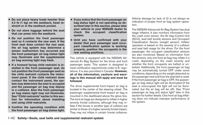
● Do not place heavy loads heavier than2.2 lb (1 kg) on the seatback, head re-straint or in the seatback pocket.
● Do not store luggage behind the seatthat can press into the seatback.
● Do not position the front passengerseat so it contacts the rear seat. If thefront seat does contact the rear seat,the air bag system may determine asensor malfunction has occurred andthe front passenger air bag status lightmay illuminate and the supplementalair bag warning light may flash.
● If a forward facing child restraint is in-stalled in the front passenger seat, donot position the front passenger seat sothe child restraint contacts the instru-ment panel. If the child restraint doescontact the instrument panel, the sys-tem may determine the seat is occupiedand the passenger air bag may deployin a collision. Also the front passengerair bag status light may not illuminate.See “Child restraints”earlier in this sec-tion for information about installingand using child restraints.
● Confirm the operating condition withthe front passenger air bag status light.
● If you notice that the front passenger airbag status light is not operating as de-scribed later in this section, please takeyour vehicle to your NISSAN dealer tocheck the occupant classificationsystem.
● Until you have confirmed with yourdealer that your passenger seat occu-pant classification system is workingproperly, position the occupants in therear seating positions.
This vehicle is equipped with the NISSAN Ad-vanced Air Bag System for the driver and frontpassenger seats. This system is designed tomeet certification requirements under U.S. regu-lations. It is also permitted in Canada. However,all of the information, cautions and warn-ings in this manual still apply and must befollowed.
The driver supplemental front-impact air bag islocated in the center of the steering wheel. Thepassenger supplemental front-impact air bag ismounted in the dashboard above the glove box.The front air bags are designed to inflate in higherseverity frontal collisions, although they may in-flate if the forces in another type of collision aresimilar to those of a higher severity frontal impact.They may not inflate in certain frontal collisions.
Vehicle damage (or lack of it) is not always anindication of proper front air bag system opera-tion.
The NISSAN Advanced Air Bag System has dualstage inflators. It also monitors information fromthe crash zone sensor, the Air bag Control Unit(ACU), seat belt buckle sensors and OccupantClassification Sensor (weight sensor). Inflatoroperation is based on the severity of a collisionand seat belt usage for the driver. For the frontpassenger, the occupant classification sensorsare also monitored. Based on information fromthe sensors, only one front air bag may inflate in acrash, depending on the crash severity andwhether the front occupants are belted or un-belted. Additionally, the front passenger air bagmay be automatically turned OFF under someconditions, depending on the weight detected onthe passenger seat and how the seat belt is used.If the front passenger air bag is OFF, the passen-ger air bag status light will be illuminated (if theseat is unoccupied, the light will not be illumi-nated, but the air bag will be off). See “Frontpassenger air bag and status light” later in thissection for further details. One front air bag inflat-ing does not indicate improper performance ofthe system.
1-42 Safety—Seats, seat belts and supplemental restraint system

If you have any questions about your air bagsystem, please contact NISSAN or your NISSANdealer. If you are considering modification of yourvehicle due to a disability, you may also contactNISSAN. Contact information is contained in thefront of this Owner’s Manual.
When a front air bag inflates, a fairly loud noisemay be heard, followed by the release of smoke.This smoke is not harmful and does not indicate afire. Care should be taken to not inhale it, as it maycause irritation and choking. Those with a historyof a breathing condition should get fresh airpromptly.
Front air bags, along with the use of seat belts,help to cushion the impact force on the face andchest of the front occupants. They can help savelives and reduce serious injuries. However, aninflating front air bag may cause facial abrasionsor other injuries. Front air bags do not providerestraint to the lower body.
Even with NISSAN advanced air bags, seat beltsshould be correctly worn and the driver and pas-senger seated upright as far as practical awayfrom the steering wheel or instrument panel. Thefront air bags inflate quickly in order to helpprotect the front occupants. Because of this, theforce of the front air bag inflating can increase therisk of injury if the occupant is too close to, or isagainst, the front air bag module during inflation.
The front air bags deflate quickly after a collision.
The front air bags operate only when theignition switch is placed in the ON position.
After placing the ignition switch in the ONposition, the supplemental air bag warninglight illuminates. The supplemental air bagwarning light will turn off after about 7 sec-onds if the system is operational.
Front passenger air bag and status light
WARNING
The front passenger air bag is designed toautomatically turn OFF under some con-ditions. Read this section carefully tolearn how it operates. Proper use of theseat, seat belt and child restraints is nec-essary for most effective protection. Fail-ure to follow all instructions in thismanual concerning the use of seats, seatbelts and child restraints can increase therisk or severity of injury in an accident.
WRS0475
Safety—Seats, seat belts and supplemental restraint system 1-43

Status light
The front passenger air bag status light islocated above the audio controls. After the igni-tion switch is placed in the �ON� position, thefront passenger air bag status light on the instru-ment panel illuminates for about 7 seconds andthen turns off or remains illuminated dependingon the front passenger seat occupied status. Thelight operates as follows:
● Unoccupied passenger’s seat: The isOFF and the front passenger air bag is OFFand will not inflate in a crash.
● Passenger’s seat occupied by a small adult,child or child restraint as outlined in thissection: The illuminates to indicatethat the front passenger air bag is OFF andwill not inflate in a crash.
● Occupied passenger seat and the passen-ger meet the conditions outlined in this sec-tion: The light is OFF to indicate thatthe front passenger air bag is operational.
Front passenger air bag
The front passenger air bag is designed to auto-matically turn OFF when the vehicle is operatedunder some conditions as described below inaccordance with U.S. regulations. If the frontpassenger air bag is OFF, it will not inflate in a
crash. The driver air bag and other air bags in yourvehicle are not part of this system.
The purpose of the regulation is to help reducethe risk of injury or death from an inflating air bagto certain front passenger seat occupants, suchas children, by requiring the air bag to be auto-matically turned OFF. Certain sensors are usedto meet the requirements.
The occupant classification sensors (weight sen-sors) are on the seat cushion frame under thefront passenger seat and are designed to detectan occupant and objects on the seat. For ex-ample, if a child is in the front passenger seat, theAdvanced Air Bag System is designed to turn thepassenger air bag OFF in accordance with theregulations. Also, if a child restraint of the typespecified in the regulations is on the seat, theoccupant classification sensors can detect it andcause the air bag to turn OFF.
The front passenger seat belt sensor is designedto detect if the seat belt is buckled. Based on theweight on the seat detected by the occupantclassification sensor and the buckle state, theAdvanced Air Bag System determines whetherthe front passenger air bag should be automati-cally turned OFF as required by the regulations.
Front passenger seat adult occupants who areproperly seated and using the seat belt as out-lined in this manual should not cause the passen-
ger air bag to be automatically turned OFF. Forsmall adults it may be turned OFF, however if theoccupant takes his/her weight off the seat cush-ion (for example, by not sitting upright, by sittingon an edge of the seat, or by otherwise being outof position), this could cause the sensor to turnthe air bag OFF. Always be sure to be seated andwearing the seat belt properly for the most effec-tive protection by the seat belt and supplementalair bag.
NISSAN recommends that pre-teens and chil-dren be properly restrained in a rear seat.NISSAN also recommends that appropriate childrestraints and booster seats be properly installedin a rear seat. If this is not possible, the occupantclassification sensor and seat belt sensors aredesigned to operate as described above to turnthe front passenger air bag OFF for specifiedchild restraints as required by the regulations.Failing to properly secure child restraints and touse the ALR mode (child restraint mode) mayallow the restraint to tip or move in an accident orsudden stop. This can also result in the passen-ger air bag inflating in a crash instead of beingOFF. See “Child restraints” earlier in this sectionfor proper use and installation.
If the front passenger seat is not occupied thepassenger air bag is designed not to inflate in acrash. However, heavy objects placed on theseat could result in air bag inflation, because of
1-44 Safety—Seats, seat belts and supplemental restraint system

the object’s weight detected by the occupantclassification sensor. Other conditions could alsoresult in air bag inflation, such as if a child isstanding on the seat, or if two children are on theseat, contrary to the instructions in this manual.Always be sure that you and all vehicle occupantsare seated and restrained properly.
Using the passenger air bag status light, you canmonitor when the front passenger air bag is au-tomatically turned OFF with the seat occupied.The light will not illuminate when the front pas-senger seat is unoccupied.
If an adult occupant is in the seat but the passen-ger air bag status light is illuminated (indicatingthat the air bag is OFF), it could be that theperson is a small adult, or is not sitting on the seatproperly or not using the seat belt properly.
If a child restraint must be used in the front seat,the passenger air bag status light may or may notbe illuminated, depending on the size of the childand the type of child restraint being used. If the airbag status light is not illuminated (indicating thatthe air bag might inflate in a crash), it could bethat the child restraint or seat belt is not beingused properly. Make sure that the child restraint isinstalled properly, the seat belt is used properlyand the occupant is positioned properly. If the airbag status light is not illuminated, reposition theoccupant or child restraint in a rear seat.
If the passenger air bag status light will not illu-minate even though you believe that the childrestraint, the seat belts and the occupant areproperly positioned, the system may be sensingan unoccupied seat (in which case the air bag isOFF). Your NISSAN dealer can check that thesystem is OFF by using a special tool. However,until you have confirmed with your dealer thatyour air bag is working properly, reposition theoccupant or child restraint in a rear seat.
The NISSAN Advanced Air Bag System andpassenger air bag status light will take a fewseconds to register a change in the passengerseat status. For example, if a large adult who issitting in the front passenger seat exits the ve-hicle, the passenger air bag status light will gofrom OFF to ON for a few seconds and then toOFF. This is normal system operation and doesnot indicate a malfunction.
If a malfunction occurs in the front passenger airbag system, the supplemental air bag warninglight , located in the meter and gauges areain the center of the instrument panel, will blink.Have the system checked by a NISSAN dealer.
Other supplemental front-impact air bagprecautions
WARNING
● Do not place any objects on the steer-ing wheel pad or on the instrumentpanel. Also, do not place any objectsbetween any occupant and the steeringwheel or instrument panel. Such ob-jects may become dangerous projec-tiles and cause injury if the front airbags inflate.
● Do not place objects with sharp edgeson the seat. Also, do not place heavyobjects on the seat that will leave per-manent impressions in the seat. Suchobjects can damage the seat or occu-pant classification sensors (weight sen-sors). This can affect the operation ofthe air bag system and result in seriouspersonal injury.
● Do not use water or acidic cleaners (hotsteam cleaners) on the seat. This candamage the seat or occupant classifica-tion sensors. This can also affect theoperation of the air bag system andresult in serious personal injury.
Safety—Seats, seat belts and supplemental restraint system 1-45

● Immediately after inflation, severalfront air bag system components will behot. Do not touch them; you may se-verely burn yourself.
● No unauthorized changes should bemade to any components or wiring ofthe supplemental air bag system. This isto prevent accidental inflation of thesupplemental air bag or damage to thesupplemental air bag system.
● Do not make unauthorized changes toyour vehicle’s electrical system, sus-pension system or front end structure.This could affect proper operation ofthe front air bag system.
● Tampering with the front air bag systemmay result in serious personal injury.Tampering includes changes to thesteering wheel and the instrumentpanel assembly by placing materialover the steering wheel pad and abovethe instrument panel or by installingadditional trim material around the airbag system.
● Removing or modifying the front pas-senger seat may affect the function ofthe air bag and result in serious per-sonal injury.
● Modifying or tampering with the frontpassenger seat may result in seriouspersonal injury. For example, do notchange the front seats by placing mate-rial on the seat cushion or by installingadditional trim material, such as seatcovers, on the seat that are not specifi-cally designed to assure proper air bagoperation. Additionally, do not stow anyobjects under the front passenger seator the seat cushion and seatback. Suchobjects may interfere with the properoperation of the occupant classifica-tion sensor (weight sensor).
● No unauthorized changes should bemade to any components or wiring ofthe seat belt system. This may affect thefront air bag system. Tampering withthe seat belt system may result in seri-ous personal injury.
● Work on and around the front air bagsystem should be done by a NISSANdealer. Installation of electrical equip-ment should also be done by a NISSANdealer. The Supplemental RestraintSystem (SRS) wiring should not bemodified or disconnected. Unauthor-ized electrical test equipment and prob-ing devices should not be used on theair bag system.
● A cracked windshield should be re-placed immediately by a qualified re-pair facility. A cracked windshield couldaffect the function of the supplementalair bag system.
*The SRS wiring harness connectors areyellow and orange for easy identification.
When selling your vehicle, we request that youinform the buyer about the supplemental front airbag system and guide the buyer to the appropri-ate sections in this Owner’s Manual.
1-46 Safety—Seats, seat belts and supplemental restraint system

Front seat-mounted side-impactsupplemental air bag and roof-mounted curtain side-impactsupplemental air bag systems
The side air bags are located in the outside of theseatback of the front seats. The curtain air bagsare located in the side roof rails. These systemsare designed to meet voluntary guidelines to helpreduce the risk of injury to out-of-position occu-pants. However, all of the information, cau-tions and warnings in this manual still ap-ply and must be followed. The side air bagsand curtain air bags are designed to inflate inhigher severity side collisions, although they may
inflate if the forces in another type of collision aresimilar to those of a higher severity side impact.They are designed to inflate on the side where thevehicle is impacted. They may not inflate in cer-tain side collisions.
Vehicle damage (or lack of it) is not always anindication of proper side air bag and curtain airbag operation.
When the side air bags and curtain air bagsinflate, a fairly loud noise may be heard, followedby release of smoke. This smoke is not harmfuland does not indicate a fire. Care should be takennot to inhale it, as it may cause irritation andchoking. Those with a history of a breathing con-dition should get fresh air promptly.
Side air bags, along with the use of seat belts,help to cushion the impact force on the chest ofthe front occupants. Curtain air bags help tocushion the impact force to the head of occu-pants in the front and rear outboard seating po-sitions. They can help save lives and reduceserious injuries. However, an inflating side air bagand curtain air bag may cause abrasions or otherinjuries. Side air bags and curtain air bags do notprovide restraint to the lower body.
The seat belts should be correctly worn and thedriver and passenger seated upright as far aspractical away from the side air bag. Rear seatpassengers should be seated as far away as
practical from the door finishers and side roofrails. The side air bags and curtain air bags inflatequickly in order to help protect the front and rearoutboard occupants. Because of this, the force ofthe side air bag and curtain air bag inflating canincrease the risk of injury if the occupant is tooclose to, or is against, these air bag modulesduring inflation. The side air bags and curtain airbags will deflate quickly after the collision is over.
The side air bags and curtain air bags op-erate only when the ignition switch is in theON position.
After placing the ignition switch in the ONposition, the supplemental air bag warninglight illuminates. The supplemental air bagwarning light will turn off after about 7 sec-onds if the system is operational.
WARNING
● Do not place any objects near the seat-back of the front seats. Also, do notplace any objects (an umbrella, bag,etc.) between the front door finisherand the front seat. Such objects maybecome dangerous projectiles andcause injury if a side air bag inflates.
LRS0259
Safety—Seats, seat belts and supplemental restraint system 1-47

● Right after inflation, several side air bagand curtain air bag system componentswill be hot. Do not touch them; you mayseverely burn yourself.
● No unauthorized changes should bemade to any components or wiring ofthe side air bag and curtain air bagsystems. This is to prevent damage to oraccidental inflation of the side air bagand curtain air bag or damage to theside air bag and curtain air bag systems.
● Do not make unauthorized changes toyour vehicle’s electrical system, sus-pension system or side panel. Thiscould affect proper operation of theside air bag and curtain air bag systems.
● Tampering with the side air bag systemmay result in serious personal injury.For example, do not change the frontseats by placing material near the seat-backs or by installing additional trimmaterial, such as seat covers, aroundthe side air bag.
● Work around and on the side air bagand curtain air bag systems should bedone by a NISSAN dealer. Installationof electrical equipment should also bedone by a NISSAN dealer. The SRS wir-ing harnesses* should not be modifiedor disconnected. Unauthorized electri-cal test equipment and probing devicesshould not be used on the side air bagor curtain air bag systems.
* The SRS wiring harness connectors areyellow and orange for easy identification.
When selling your vehicle, we request that youinform the buyer about the side air bag andcurtain air bag systems and guide the buyer tothe appropriate sections in this Owner’s Manual.
Seat belts with pretensioners (frontseats)
WARNING
● The pretensioners cannot be reused af-ter activation. They must be replacedtogether with the retractor and buckleas a unit.
● If the vehicle becomes involved in acollision but a pretensioner is not acti-vated, be sure to have the pretensionersystem checked and, if necessary, re-placed by your NISSAN dealer.
● No unauthorized changes should bemade to any components or wiring ofthe pretensioner system. This is to pre-vent damage to or accidental activationof the pretensioners. Tampering withthe pretensioner system may result inserious personal injury.
● Work around and on the pretensionersystem should be done by a NISSANdealer. Installation of electrical equip-ment should also be done by a NISSANdealer. Unauthorized electrical testequipment and probing devices shouldnot be used on the pretensioner system.
● If you need to dispose of a pretensioneror scrap the vehicle, contact a NISSANdealer. Incorrect disposal procedurescould cause personal injury.
The pretensioner system may activate with thesupplemental air bag system in certain types ofcollisions. Working with the seat belt retractor,the pretensioner helps tighten the seat belt when
1-48 Safety—Seats, seat belts and supplemental restraint system

the vehicle becomes involved in certain types ofcollisions, helping to restrain front seat occu-pants.
The pretensioner is encased within the seat beltretractor. These seat belts are used the same wayas conventional seat belts.
When a pretensioner activates, smoke is re-leased and a loud noise may be heard. Thissmoke is not harmful and does not indicate a fire.Care should be taken not to inhale it, as it maycause irritation and choking. Those with a historyof a breathing condition should get fresh airpromptly.
After pretensioner activation, load limiters allowthe seat belt to release webbing (if necessary) toreduce forces against the chest.
The supplemental air bag warning light isused to indicate malfunctions in the pretensionersystem. (See �SUPPLEMENTAL AIR BAGWARNING LIGHT� in this section for more de-tails.) If the operation of the supplemental air bagwarning light indicates there is a malfunction,have the system checked by a NISSAN dealer.
When selling your vehicle, we request that youinform the buyer about the pretensioner systemand guide the buyer to the appropriate sectionsin this Owner’s Manual.
1. SRS Front Air Bag Warning LabelsSUPPLEMENTAL AIR BAGWARNING LABELSWarning labels about the supplemental front-impact air bag system are placed in the vehicle asshown in the illustration.
SUPPLEMENTAL AIR BAGWARNING LIGHTThe supplemental air bag warning light,displaying in the instrument panel, moni-tors the circuits for the air bag systems, preten-sioners and all related wiring.
When the ignition switch is placed in the ON orSTART position, the supplemental air bag warn-ing light illuminates for about 7 seconds and thenturns off. This means the system is operational.
WRS0897 LRS0100
Safety—Seats, seat belts and supplemental restraint system 1-49

If any of the following conditions occur, the frontair bag, side air bag, curtain air bag and preten-sioner systems need servicing:
● The supplemental air bag warning light re-mains on after approximately 7 seconds.
● The supplemental air bag warning lightflashes intermittently.
● The supplemental air bag warning light doesnot come on at all.
Under these conditions, the front air bag, side airbag, curtain air bag or pretensioner systems maynot operate properly. They must be checked andrepaired. Take your vehicle to the nearestNISSAN dealer.
WARNING
If the supplemental air bag warning lightis on, it could mean that the front air bag,side air bag, curtain air bag and/or preten-sioner systems will not operate in an ac-cident. To help avoid injury to yourself orothers, have your vehicle checked by aNISSAN dealer as soon as possible.
Repair and replacement procedure
The front air bags, side air bags, curtain air bagsand pretensioners are designed to inflate on aone-time-only basis. As a reminder, unless it isdamaged, the supplemental air bag warning lightremains illuminated after inflation has occurred.Repair and replacement of these supplementalair bag systems should be done only by aNISSAN dealer.
When maintenance work is required on the ve-hicle, the front air bags, side air bags, curtain airbags, pretensioners and related parts should bepointed out to the person performing the mainte-nance. The ignition switch should always beplaced in the LOCK position when working underthe hood or inside the vehicle.
WARNING
● Once a front air bag, side air bag, orcurtain air bag has inflated, the air bagmodule will not function again andmust be replaced. Additionally, the ac-tivated pretensioner must also be re-placed. The air bag module and preten-sioner should be replaced by a NISSANdealer. The air bag module and preten-sioner cannot be repaired.
● The front air bag, side air bag, curtainair bag systems and the pretensionersystem should be inspected by aNISSAN dealer if there is any damage tothe front end or side portion of thevehicle.
● If you need to dispose of the supple-mental air bag or pretensioner systemsor scrap the vehicle, contact a NISSANdealer. Incorrect disposal procedurescould cause personal injury.
● If there is an impact to your vehicle fromany direction, your Occupant DetectionSensor (ODS) should be checked by aNISSAN dealer to verify it is still func-tioning correctly. The ODS should bechecked even if no air bags deploy as aresult of the impact. Failure to verifyproper ODS function may result in animproper air bag deployment resultingin injury or death.
1-50 Safety—Seats, seat belts and supplemental restraint system

MEMO
Safety—Seats, seat belts and supplemental restraint system 1-51

2 Instruments and controls
Instrument panel. . . . . . . . . . . . . . . . . . . . . . . . . . . . . . . . . . . 2-2Meters and gauges . . . . . . . . . . . . . . . . . . . . . . . . . . . . . . . . 2-3
Speedometer and odometer . . . . . . . . . . . . . . . . . . . . . 2-3Tachometer . . . . . . . . . . . . . . . . . . . . . . . . . . . . . . . . . . . . 2-5Engine coolant temperature gauge . . . . . . . . . . . . . . . 2-6Fuel gauge . . . . . . . . . . . . . . . . . . . . . . . . . . . . . . . . . . . . 2-6Trip computer . . . . . . . . . . . . . . . . . . . . . . . . . . . . . . . . . . 2-7Outside temperature display (if so equipped) . . . . . . 2-8
Compass display (if so equipped) . . . . . . . . . . . . . . . . . . . 2-8Compass display . . . . . . . . . . . . . . . . . . . . . . . . . . . . . . . 2-9
Warning/indicator lights and audible reminders . . . . . . 2-12Checking bulbs . . . . . . . . . . . . . . . . . . . . . . . . . . . . . . . 2-13Warning lights . . . . . . . . . . . . . . . . . . . . . . . . . . . . . . . . 2-13Indicator lights . . . . . . . . . . . . . . . . . . . . . . . . . . . . . . . . 2-17Audible reminders . . . . . . . . . . . . . . . . . . . . . . . . . . . . . 2-20
Security systems . . . . . . . . . . . . . . . . . . . . . . . . . . . . . . . . . 2-21Vehicle security system (if so equipped) . . . . . . . . . . 2-21NISSAN vehicle immobilizer system . . . . . . . . . . . . . 2-22
Windshield wiper and washer switch . . . . . . . . . . . . . . . 2-23Switch operation . . . . . . . . . . . . . . . . . . . . . . . . . . . . . . 2-23
Rear window and outside mirror (if so equipped)defroster switch . . . . . . . . . . . . . . . . . . . . . . . . . . . . . . . . . . 2-24Headlight and turn signal switch. . . . . . . . . . . . . . . . . . . . 2-25
Headlight control switch. . . . . . . . . . . . . . . . . . . . . . . . 2-25Daytime running light system (Canada only) . . . . . . 2-27Instrument brightness control . . . . . . . . . . . . . . . . . . . 2-27Turn signal switch . . . . . . . . . . . . . . . . . . . . . . . . . . . . . 2-28Fog light switch (if so equipped) . . . . . . . . . . . . . . . . 2-28
Horn . . . . . . . . . . . . . . . . . . . . . . . . . . . . . . . . . . . . . . . . . . . . 2-28Heated seats (if so equipped). . . . . . . . . . . . . . . . . . . . . . 2-29Vehicle Dynamic Control (VDC) off switch. . . . . . . . . . . 2-30Power outlet . . . . . . . . . . . . . . . . . . . . . . . . . . . . . . . . . . . . . 2-30Storage . . . . . . . . . . . . . . . . . . . . . . . . . . . . . . . . . . . . . . . . . 2-31
Map pockets . . . . . . . . . . . . . . . . . . . . . . . . . . . . . . . . . . 2-31Storage trays . . . . . . . . . . . . . . . . . . . . . . . . . . . . . . . . . 2-32Seatback pockets (if so equipped) . . . . . . . . . . . . . . 2-32Sunglasses holder . . . . . . . . . . . . . . . . . . . . . . . . . . . . . 2-33Cup holders . . . . . . . . . . . . . . . . . . . . . . . . . . . . . . . . . . 2-34Glove box . . . . . . . . . . . . . . . . . . . . . . . . . . . . . . . . . . . . 2-35Console box . . . . . . . . . . . . . . . . . . . . . . . . . . . . . . . . . . 2-35Grocery hooks (if so equipped) . . . . . . . . . . . . . . . . . 2-36Cargo net (if so equipped). . . . . . . . . . . . . . . . . . . . . . 2-37
Windows . . . . . . . . . . . . . . . . . . . . . . . . . . . . . . . . . . . . . . . . 2-37Power windows . . . . . . . . . . . . . . . . . . . . . . . . . . . . . . . 2-37
Moonroof (if so equipped) . . . . . . . . . . . . . . . . . . . . . . . . . 2-40Automatic moonroof . . . . . . . . . . . . . . . . . . . . . . . . . . . 2-40

Interior light . . . . . . . . . . . . . . . . . . . . . . . . . . . . . . . . . . . . . . 2-42Console light. . . . . . . . . . . . . . . . . . . . . . . . . . . . . . . . . . 2-43
Personal Lights. . . . . . . . . . . . . . . . . . . . . . . . . . . . . . . . . . . 2-43
Map lights . . . . . . . . . . . . . . . . . . . . . . . . . . . . . . . . . . . . . . . 2-43Trunk light . . . . . . . . . . . . . . . . . . . . . . . . . . . . . . . . . . . . . . . 2-44
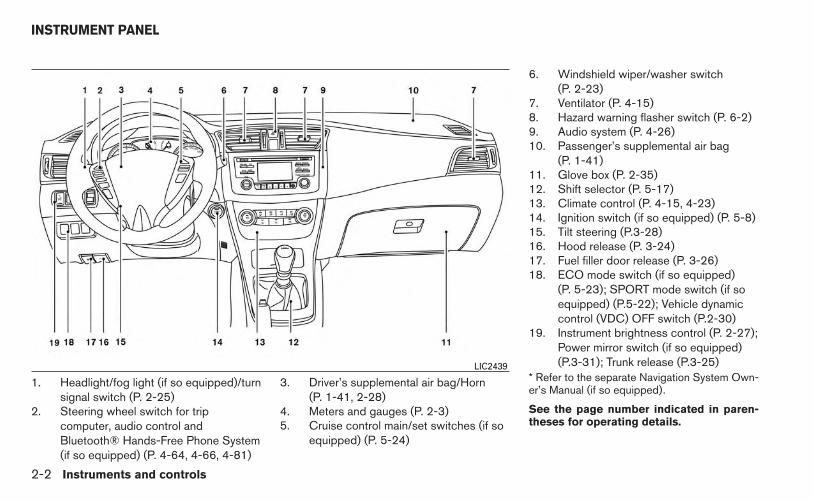
1. Headlight/fog light (if so equipped)/turnsignal switch (P. 2-25)
2. Steering wheel switch for tripcomputer, audio control andBluetooth® Hands-Free Phone System(if so equipped) (P. 4-64, 4-66, 4-81)
3. Driver’s supplemental air bag/Horn(P. 1-41, 2-28)
4. Meters and gauges (P. 2-3)5. Cruise control main/set switches (if so
equipped) (P. 5-24)
6. Windshield wiper/washer switch(P. 2-23)
7. Ventilator (P. 4-15)8. Hazard warning flasher switch (P. 6-2)9. Audio system (P. 4-26)10. Passenger’s supplemental air bag
(P. 1-41)11. Glove box (P. 2-35)12. Shift selector (P. 5-17)13. Climate control (P. 4-15, 4-23)14. Ignition switch (if so equipped) (P. 5-8)15. Tilt steering (P.3-28)16. Hood release (P. 3-24)17. Fuel filler door release (P. 3-26)18. ECO mode switch (if so equipped)
(P. 5-23); SPORT mode switch (if soequipped) (P.5-22); Vehicle dynamiccontrol (VDC) OFF switch (P.2-30)
19. Instrument brightness control (P. 2-27);Power mirror switch (if so equipped)(P.3-31); Trunk release (P.3-25)
* Refer to the separate Navigation System Own-er’s Manual (if so equipped).
See the page number indicated in paren-theses for operating details.
LIC2439
INSTRUMENT PANEL
2-2 Instruments and controls

1. Engine coolant temperature gauge2. Fuel gauge3. Speedometer4. Odometer/twin trip odometer/trip
computer/ECO gauge/transmissionposition indicator
5. Tachometer
SPEEDOMETER AND ODOMETER
SpeedometerThe speedometer indicates the vehicle speed.
LIC2410
LIC2255
METERS AND GAUGES
Instruments and controls 2-3

Odometer/Twin trip odometer
The odometer �2 and the twin trip odometer �1are displayed when the ignition switch is placedin the ON position.
The odometer records the total distance the ve-hicle has been driven.
The twin trip odometer records the distance ofindividual trips.
To switch between the odometer and the twin tripodometers press the button on the steer-ing wheel.
Changing the display:
Push the button on the steering wheel tochange the display as follows:
Accel guide/Average fuel economy → Instant fueleconomy/Average fuel economy → Average fueleconomy → Average speed → Distance to empty→ Trip A → Trip B
Resetting the trip odometer:
Push the button on the steering wheel formore than 1 second to reset the currently dis-played trip odometer to zero.
Loose fuel cap warning messagePush the reset button �A for more than 1 secondto reset the LOOSE FUEL CAP warning mes-sage �B after the fuel cap has been tightened.For additional information see “Fuel-filler cap” inthe “Pre-driving checks and adjustments”sectionof this manual.
LIC2411 LPD2124
2-4 Instruments and controls

Check tire pressure warning message(if so equipped)
The CHECK TIRE PRES warning message isdisplayed when the low tire pressure warninglight is illuminated and low tire pressure is de-tected. Check and adjust the tire pressure to therecommended COLD tire pressure shown on theTire and Loading Information label. The CHECKTIRE PRES warning message turns off when thelow tire pressure warning light turns off.
The low tire pressure warning light remains illu-minated until the tires are inflated to the recom-mended COLD tire pressure. The CHECK TIREPRES warning message is displayed each time
the ignition switch is placed in the ON position aslong as the low tire pressure warning light re-mains illuminated. For more information see “Lowtire pressure warning light” in the “Instrumentsand controls” section, “Tire Pressure MonitoringSystem (TPMS)” in the “Starting and driving” and“Wheels and tires” section in the “Maintenanceand do-it-yourself” section of this Owner’sManual.
TACHOMETERThe tachometer indicates engine speed in revo-lutions per minute (rpm). Do not rev engine intothe red zone �1 .
CAUTION
When engine speed approaches the redzone, reduce engine speed. Operating theengine in the red zone may cause seriousengine damage.
LIC2430 LIC2219
Instruments and controls 2-5
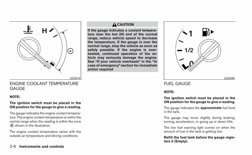
ENGINE COOLANT TEMPERATUREGAUGE
NOTE:
The ignition switch must be placed in theON position for the gauge to give a reading.
The gauge indicates the engine coolant tempera-ture. The engine coolant temperature is within thenormal range when the reading is within the zone�A shown in the illustration.
The engine coolant temperature varies with theoutside air temperature and driving conditions.
CAUTION
If the gauge indicates a coolant tempera-ture near the hot (H) end of the normalrange, reduce vehicle speed to decreasethe temperature. If the gauge is over thenormal range, stop the vehicle as soon assafely possible. If the engine is over-heated, continued operation of the ve-hicle may seriously damage the engine.See “If your vehicle overheats” in the “Incase of emergency”section for immediateaction required
FUEL GAUGE
NOTE:
The ignition switch must be placed in theON position for the gauge to give a reading.
The gauge indicates the approximate fuel levelin the tank.
The gauge may move slightly during braking,turning, acceleration, or going up or down hills.
The low fuel warning light comes on when theamount of fuel in the tank is getting low.
Refill the fuel tank before the gauge regis-ters 0 (Empty).
LIC2414 LIC2445
2-6 Instruments and controls

The indicates that the fuel-filler door islocated on the passenger’s side of the vehicle.
CAUTION
● If the vehicle runs out of fuel, theMalfunction Indicator Light (MIL) maycome on. Refuel as soon as possible.After a few driving trips. the lightshould turn off. If the light remains onafter a few driving trips, have the ve-hicle inspected by a NISSAN dealer.
● For additional information, see “Mal-function Indicator Light (MIL)” later inthis section.
TRIP COMPUTER
When the ignition switch is placed in the ONposition, the modes of the trip computer can beselected by pressing the button on thesteering wheel. The following modes can be se-lected:
● Trip A
● Trip B
● Eco pedal guide
● Instant fuel economy
● Average fuel consumption
● Average speed
● Distance to empty
● Trip computer reset
Trip AMeasures the distance of one specific trip.
Trip BMeasures the distance of a second specific trip.
ECO pedal guide
Use the Eco pedal guide �1 for improving fueleconomy.
When the Eco pedal guide bar is in the greenrange, it indicates that the vehicle is driven withinrange of economy drive.
If the Eco pedal guide bar is out of green range, itindicates that the accelerator pedal is depressedover the range of economy drive.
LIC2452
Instruments and controls 2-7

NOTE:
The Eco pedal guide bar is not displayedwhen the cruse control is in operation.
Instant fuel economy
The instant fuel economy mode shows the instantfuel consumption. The display updates instantlywhen driving.
Average fuel consumption
The average fuel consumption mode shows theaverage fuel consumption since the last reset.Resetting is done by pressing the buttonon the steering wheel for more than approxi-mately 1 second. The display is updated every30 seconds. At about the first 1/3 mile (500 m)after a reset, the display shows (----).
Average speed
The average speed mode shows the averagevehicle speed since last reset. Resetting is doneby pressing the button on the steeringwheel for more than approximately 1 second. Thedisplay is updated every 30 seconds. The first30 seconds after a reset, the display shows(----).
Distance to emptyThe distance to empty (dte) mode provides youwith an estimation of the distance that can bedriven before refueling. The dte is constantly be-ing calculated, based on the amount of fuel in thefuel tank and the actual fuel consumption.
The display is updated every 30 seconds.
NOTE:
When driving uphill or rounding curves, thefuel in the tank shifts, which may momen-tarily change the display.
Trip computer reset
Pressing the button on the steering wheelfor more than 3 seconds will reset Trip A, Trip B,Average fuel consumption or Average speed.
OUTSIDE TEMPERATURE DISPLAY(if so equipped)The outside temperature function provides a dis-play of the outside temperature when the ignitionswitch is placed in the ON position.
The display of positive temperatures is unsigned(blank), negative temperatures are prefixed with aminus sign.
This unit measures terrestrial magnetism and in-dicates heading direction of vehicle.
With the ignition switch in the ON position, pressthe button as described in the chart belowto activate various features of the automatic anti-glare rearview mirror.
Press and hold
thebutton for about:
Feature:(Press button again for about 1 sec-ond to change settings)
0 – 3 seconds Compass display toggles on/off
3 – 6 secondsAutomatic anti-glare/indicator lighttoggles on/off
6 – 9 secondsCompass zone can be changed tocorrect false compass readings
9 – 12 seconds Compass enters calibration mode
For more information about the automatic anti-glare feature, refer to “Automatic anti-glare rear-view mirror” in the “Pre-driving checks and ad-justments” section.
COMPASS DISPLAY (if so equipped)
2-8 Instruments and controls

COMPASS DISPLAY
Push the button for about 1 second whenthe ignition switch is placed in the ON position totoggle the compass direction display �1 on oroff. The display will indicate the direction that thevehicle is heading.
N: NorthE: EastS: SouthW: West
If the display reads “C”, calibrate the compass bydriving the vehicle in three complete circles atless than 5 MPH (8 km/h).
You can also calibrate the compass by drivingyour vehicle on your everyday route. The com-pass will be calibrated once it has tracked threecomplete circles.
WIC0904
Instruments and controls 2-9

Zone variation change procedureThe difference between magnetic north and geo-graphical north is known as variance. In someareas, this difference can sometimes be greatenough to cause false compass readings. Followthese instructions to set the variance for yourparticular location if this happens:
1. Press and hold the button for about11 seconds. The current zone number willappear in the display. Release the button.
2. Find your current location on the zone map.Refer to the illustration.
3. Press the button repeatedly to togglethrough the zone numbers until the desirednumber appears in the display. Once youhave selected a zone number, the displaywill show a compass direction within a fewseconds.
Inaccurate compass direction:
The compass display is equipped with automaticcorrection function. If the correct direction is notshown, follow this procedure.
1. With the display turned on, press and holdthe button for about 13 seconds. The“C” icon in the compass display will illumi-nate.WIC0355
2-10 Instruments and controls

2. Calibrate the compass by driving the vehiclein three complete circles at a maximumspeed of 5 MPH (8 km/h).
3. After completing the circles, the displayshould return to normal.
CAUTION
● Do not install a ski rack, antenna, etc.,which are attached to the vehicle bymeans of a magnet. They affect the op-eration of the compass.
● When cleaning the mirror, use a papertowel or similar material dampenedwith glass cleaner. Do not spray glasscleaner directly on the mirror as it maycause the liquid cleaner to enter themirror housing.
Instruments and controls 2-11

or Anti-lock Braking System (ABS)warning light
P position selecting warning light(CVT models) (if so equipped)
High beam indicator light (blue)
or Brake warning light Power steering warning light Malfunction Indicator Light (MIL)
Charge warning light Seat belt warning light Overdrive off indicator light (CVT models)
Door open warning light Supplemental air bag warning light Security indicator light
Engine oil pressure warning light Continuously Variable Transmission (CVT)position indicator light (CVT models)
Side light and headlight indicator light (green)
Low fuel warning light Cruise main switch indicator light(if so equipped)
Slip indicator light
Low tire pressure warning light(if so equipped)
ECO mode indicator light (if so equipped) SPORT mode indicator light (if so equipped)
Low windshield-washer fluid warning light Engine start operation indicator light (if soequipped)
Turn signal/hazard indicator lights
NISSAN Intelligent Key® lock warning light(M/T models) (if so equipped)
Front fog light indicator light (if so equipped) Vehicle Dynamic Control (VDC) off indicatorlight
NISSAN Intelligent Key® warning light (if soequipped)
Front passenger air bag status light
WARNING/INDICATOR LIGHTS ANDAUDIBLE REMINDERS
2-12 Instruments and controls

CHECKING BULBS
With all doors closed, apply the parking brakeand place the ignition switch in the ON positionwithout starting the engine. The following lightswill come on:
or , , , , ,
If equipped, the following lights come on brieflyand then go off:
or , , ,
If any light fails to come on, it may indicatean open circuit in the electrical system.Have the system repaired promptly.
WARNING LIGHTS
or Anti-lock BrakingSystem (ABS)warning light
When the ignition switch is placed in the ONposition, the Anti-lock Braking System (ABS)warning light illuminates and then turns off. Thisindicates the ABS is operational.
If the ABS warning light illuminates while theengine is running, or while driving, it may indicate
the ABS is not functioning properly. Have thesystem checked by a NISSAN dealer.
If an ABS malfunction occurs, the anti-lock func-tion is turned off. The brake system then operatesnormally, but without anti-lock assistance. See“Brake system” in the “Starting and driving” sec-tion.
or Brake warning light
This light functions for both the parking brake andthe foot brake systems.
Parking brake indicator
When the ignition switch is placed in the ONposition, the light comes on when the parkingbrake is applied.
Low brake fluid warning light
When the ignition switch is placed in the ONposition, the light warns of a low brake fluid level.If the light comes on while the engine is runningwith the parking brake not applied, stop the ve-hicle and perform the following:
1. Check the brake fluid level. Add brake fluidas necessary. See “Brake fluid” in the “Main-tenance and do-it-yourself” section of thismanual.
2. If the brake fluid level is correct, have thewarning system checked by a NISSANdealer.
WARNING
● Your brake system may not be workingproperly if the warning light is on. Driv-ing could be dangerous. If you judge itto be safe, drive carefully to the nearestservice station for repairs. Otherwise,have your vehicle towed because driv-ing it could be dangerous.
● Pressing the brake pedal with the en-gine stopped and/or a low brake fluidlevel may increase your stopping dis-tance and braking will require greaterpedal effort as well as pedal travel.
● If the brake fluid level is below theMINIMUM or MIN mark on the brakefluid reservoir, do not drive until thebrake system has been checked at aNISSAN dealer.
Instruments and controls 2-13

Anti-lock Braking System (ABS) warningindicator
When the parking brake is released and thebrake fluid level is sufficient, if both the brakewarning light and the Anti-lock Braking System(ABS) warning light illuminate, it may indicate theABS is not functioning properly. Have the brakesystem checked, and if necessary, repaired by aNISSAN dealer promptly. Avoid high-speed driv-ing and abrupt braking. (See “Anti-lock BrakingSystem (ABS) warning light” in this section.)
Charge warning light
If this light comes on while the engine is running,it may indicate the charging system is not func-tioning properly. Turn the engine off and checkthe generator belt. If the belt is loose, broken,missing, or if the light remains on, see a NISSANdealer immediately.
CAUTION
Do not continue driving if the generatorbelt is loose, broken or missing.
Door open warning light
This light comes on when any of the doors are notclosed securely while the ignition switch isplaced in the ON position.
Engine oil pressure warninglight
This light warns of low engine oil pressure. If thelight flickers or comes on during normal driving,pull off the road in a safe area, stop the engineimmediately and call a NISSAN dealer or otherauthorized repair shop.
The engine oil pressure warning light is notdesigned to indicate a low oil level. Use thedipstick to check the oil level. See “Engine oil” inthe “Maintenance and do-it-yourself” section ofthis manual.
CAUTION
Running the engine with the engine oilpressure warning light on could cause se-rious damage to the engine almost imme-diately. Such damage is not covered bywarranty. Turn off the engine as soon as itis safe to do so.
Low fuel warning light
This light comes on when the fuel level in the fueltank is getting low. Refuel as soon as it is conve-nient, preferably before the fuel gauge reaches 0(Empty). There will be a small reserve of fuelin the tank when the fuel gauge reaches 0(Empty).
Low tire pressure warning light(if so equipped)
Your vehicle is equipped with a Tire PressureMonitoring System (TPMS) that monitors the tirepressure of all tires except the spare.
The low tire pressure warning light warns of lowtire pressure or indicates that the TPMS is notfunctioning properly.
After the ignition switch is placed in the ONposition, this light illuminates for about 1 secondand turns off.
Low tire pressure warning:
If the vehicle is being driven with low tirepressure, the warning light will illuminate.A CHECK TIRE PRESSURE warning mes-sage is also displayed in the odometer.
When the low tire pressure warning lightilluminates, you should stop and adjust thetire pressure of all 4 tires to the recom-mended COLD tire pressure shown on theTire and Loading Information label locatedin the driver’s door opening. The low tirepressure warning light does not automati-cally turn off when the tire pressure is ad-justed. After the tire is inflated to the rec-ommended pressure, the vehicle must bedriven at speeds above 16 MPH (25 km/h)
2-14 Instruments and controls

to activate the TPMS and turn off the lowtire pressure warning light. Use a tire pres-sure gauge to check the tire pressure.
The low tire pressure warning light remains illu-minated until the tires are inflated to the recom-mended COLD tire pressure. The CHECK TIREPRESSURE warning message is displayed eachtime the ignition switch is placed in the ONposition as long as the low tire pressure warninglight remains illuminated.For additional information, see “Check tire pres-sure warning message” in the “Instruments andcontrols” section and “Tire Pressure MonitoringSystem (TPMS)” in the “Starting and driving” sec-tion and in the “In case of emergency” section.
TPMS malfunction:
If the TPMS is not functioning properly, the lowtire pressure warning light will flash for approxi-mately 1 minute when the ignition switch isplaced in the ON position. The light will remain onafter the 1 minute. Have the system checked by aNISSAN dealer. The CHECK TIRE PRESSUREwarning message is not displayed if the low tirepressure warning light illuminates to indicate aTPMS malfunction.
For additional information, see “Tire PressureMonitoring System (TPMS)” in the “Starting anddriving” section and “Tire pressure” in the “Main-tenance and do-it-yourself” section.
WARNING
● Radio waves could adversely affectelectric medical equipment. Those whouse a pacemaker should contact theelectric medical equipment manufac-turer for the possible influences beforeuse.
● If the light does not illuminate with theignition switch placed in the ON posi-tion, have the vehicle checked by aNISSAN dealer as soon as possible.
● If the light illuminates while driving,avoid sudden steering maneuvers orabrupt braking, reduce vehicle speed,pull off the road to a safe location andstop the vehicle as soon as possible.Driving with under-inflated tires maypermanently damage the tires and in-crease the likelihood of tire failure. Se-rious vehicle damage could occur andmay lead to an accident and could re-sult in serious personal injury. Checkthe tire pressure for all four tires. Adjustthe tire pressure to the recommendedCOLD tire pressure shown on the Tireand Loading Information label locatedin the driver’s door opening to turn the
low tire pressure warning light OFF. Ifthe light still comes on while drivingafter adjusting the tire pressure, a tiremay be flat. If you have a flat tire, re-place it with a spare tire as soon aspossible.
● When a spare tire is mounted or a wheelis replaced the TPMS will not functionand the low tire pressure warning lightwill flash for approximately 1 minute.The light will remain on after 1 minute-.Contact your NISSAN dealer as soon aspossible for tire replacement and/orsystem resetting.
● Replacing tires with those not originallyspecified by NISSAN could affect theproper operation of the TPMS.
CAUTION
● The TPMS is not a substitute for theregular tire pressure check. Be sure tocheck the tire pressure regularly.
● If the vehicle is being driven at speedsof less than 16 MPH (25 km/h), theTPMS may not operate correctly.
● Be sure to install the specified size oftires to the 4 wheels correctly.
Instruments and controls 2-15

Low windshield-washer fluidwarning light
This light comes on when the windshield-washerfluid is at a low level. Add windshield-washer fluidas necessary. See “Windshield-washer fluid” inthe “Maintenance and do-it-yourself” section ofthis manual.
NISSAN Intelligent Key® lockwarning light (M/T models) (ifso equipped)
When the ignition switch is left in the OFF posi-tion instead of completely placing it to the LOCKposition, the Intelligent Key lock warning lightblinks red and the Intelligent Key room buzzer willsound. The light will keep blinking until the igni-tion switch is placed in the LOCK or ACC posi-tion.
If the Intelligent Key lock warning light blinks andthe buzzer sounds, press the PUSH release but-ton next to ignition knob, then turn the ignitionknob to either the LOCK or ACC position.
See “NISSAN Intelligent Key®” in the “Pre-driving checks and adjustments” section.
NISSAN Intelligent Key®warning light (if so equipped)
The Intelligent Key warning light illuminates greenwhen the ignition switch can be turned. TheIntelligent Key warning light illuminates red whenthe ignition switch cannot be turned.
The Intelligent Key warning light blinks red if theIntelligent Key is taken outside of the vehiclewhile the ignition switch is placed in the ACC orON position.
● If the Intelligent Key warning light blinks,make sure of the location of the IntelligentKey as soon as possible. The Intelligent Keyshould be carried by the driver while operat-ing the vehicle.
● The Intelligent Key warning light turns offabout 10 seconds after the Intelligent Key isbrought inside the vehicle.
The Intelligent Key warning light blinks greenindicating that the Intelligent Key battery is almostdischarged.
See “NISSAN Intelligent Key®” in the “Pre-driving checks and adjustments” section.
P position selecting warninglight (CVT models) (if soequipped)
The light blinks red and the warning buzzersounds if you are outside of the vehicle with theIntelligent Key and the engine is off, but the shiftselector is not in the P (Park) position.
When the warning light blinks, place the ignitionswitch in the ON position, move the shift selectorto the P position, then place the ignition switch inthe LOCK position.
Power steering warning light
WARNING
● If the engine is not running or is turnedoff while driving, the power assist forthe steering will not work. Steering willbe harder to operate.
● When the power steering warning lightilluminates with the engine running,there will be no power assist for thesteering. You will still have control ofthe vehicle but the steering will beharder to operate. Have the powersteering system checked by a NISSANdealer.
2-16 Instruments and controls

When the ignition switch is placed in the ONposition, the power steering warning light illumi-nates. After starting the engine, the power steer-ing warning light turns off. This indicates thepower steering system is operational.
If the power steering warning light illuminateswhile the engine is running, it may indicate thepower steering system is not functioning properlyand may need servicing. Have the power steeringsystem checked by a NISSAN dealer.
When the power steering warning light illumi-nates with the engine running, there will be nopower assist for the steering but you will still havecontrol of the vehicle. At this time, greater steer-ing effort is required to operate the steeringwheel, especially in sharp turns and at lowspeeds.
See “Power steering” in the “Starting and driving”section.
Seat belt warning light andchime
The light and chime remind you to fasten yourseat belts. The light illuminates whenever theignition switch is placed in the ON or STARTposition and remains illuminated until the driver’sseat belt is fastened. At the same time, the chimesounds for about 6 seconds unless the driver’sseat belt is securely fastened.
The seat belt warning light may also illuminate ifthe front passenger’s seat belt is not fastenedwhen the front passenger’s seat is occupied . For7 seconds after the ignition switch is placed inthe ON position, the system does not activate thewarning light for the front passenger.
Refer to “Seat belts” in the “Safety—Seats, seatbelts and supplemental restraint system” sectionfor precautions on seat belt usage.
Supplemental air bag warninglight
When the ignition switch is placed in the ON orSTART position, the supplemental air bag warn-ing light illuminates for about 7 seconds and thenturns off. This means the system is operational.
If any of the following conditions occur, the frontair bag, side air bag, curtain air bag, and preten-sioner seat belt systems need servicing and yourvehicle must be taken to a NISSAN dealer:
● The supplemental air bag warning light re-mains on after approximately 7 seconds.
● The supplemental air bag warning lightflashes intermittently.
● The supplemental air bag warning light doesnot come on at all.
Unless checked and repaired, the supplementalrestraint system (air bag system) and/or the pre-tensioners may not function properly. For addi-tional details see “Supplemental restraint sys-tem” in the “Safety—Seats, seat belts andsupplemental restraint system” section of thismanual.
WARNING
If the supplemental air bag warning lightis on, it could mean that the front air bag,side air bag, curtain air bag systemsand/or pretensioner systems will not op-erate in an accident. To help avoid injuryto yourself or others, have your vehiclechecked by a NISSAN dealer as soon aspossible.
INDICATOR LIGHTS
Continuously VariableTransmission (CVT) positionindicator light (if so equipped)
When the ignition switch is placed in the ONposition, this indicator light shows the transmis-sion shift selector position. See “Driving the ve-hicle” in the “Starting and driving” section of thismanual.
Instruments and controls 2-17

Cruise main switch indicatorlight (if so equipped)
The light comes on when the cruise control mainswitch is pushed. The light goes out when themain switch is pushed again. When the cruisemain switch indicator light comes on, the cruisecontrol system is operational.
ECO mode indicator light (ifso equipped)
This light comes on when the ECO mode hasbeen selected. See “ECO mode” in the “Startingand driving” section for the use of the ECO modeswitch.
Engine start operationindicator (if so equipped)
For vehicles equipped with push button ignitionthis indicator illuminates when the ignition switchis in the LOCK, OFF, ACC or ON position.
This indicator means that the engine will start bypushing the push-button ignition switch with thebrake pedal and clutch pedal (if so equipped)depressed.
Front fog light indicator light (ifso equipped)
The front fog light indicator light illuminates whenthe front fog lights are ON. See “Fog light switch”later in this section.
Front passenger air bag statuslight
The front passenger air bag status light will be litand the passenger front air bag will be OFFdepending on how the front passenger seat isbeing used.
For front passenger air bag status light operation,see “Front passenger air bag and status light” inthe “Safety — Seats, seat belts and supplementalrestraint system” section of this manual.
High beam indicator light(blue)
This blue light comes on when the headlight highbeams are on and goes out when the low beamsare selected.
The high beam indicator light also comes onwhen the passing signal is activated.
Malfunction Indicator Light(MIL)
If this indicator light comes on steady or blinkswhile the engine is running, it may indicate apotential emission control malfunction.
The Malfunction Indicator Light may also comeon steady if the fuel-filler cap is loose or missing,or if the vehicle runs out of fuel. Check to makesure the fuel-filler cap is installed and closedtightly, and that the vehicle has at least 3 gallons(11.4 liters) of fuel in the fuel tank.
After a few driving trips, the light shouldturn off if no other potential emission controlsystem malfunction exists.
If this indicator light comes on steady for 20 sec-onds and then blinks for 10 seconds when theengine is not running, it indicates that the vehicleis not ready for an emission control systeminspection/maintenance test. See “Readiness forinspection/maintenance (I/M) test” in the “Tech-nical and consumer information” section of thismanual.
2-18 Instruments and controls

Operation
The Malfunction Indicator Light will come on inone of two ways:
● Malfunction Indicator Light on steady — Anemission control system malfunction hasbeen detected. Check the fuel-filler cap ifthe LOOSE FUEL CAP warning appears inthe vehicle information display. If the fuel-filler cap is loose or missing, tighten or installthe cap and continue to drive the vehicle.The light should turn off after a fewdriving trips. If the light does not turnoff after a few driving trips, have the vehicleinspected by a NISSAN dealer. You do notneed to have your vehicle towed to thedealer.
● Malfunction Indicator Light blinking — Anengine misfire has been detected which maydamage the emission control system. To re-duce or avoid emission control system dam-age:
– do not drive at speeds above 45 MPH(72 km/h).
– avoid hard acceleration or deceleration.
– avoid steep uphill grades.
– if possible, reduce the amount of cargobeing hauled or towed.
The Malfunction Indicator Light may stop blinkingand come on steady. Have the vehicle inspectedby a NISSAN dealer. You do not need to haveyour vehicle towed to the dealer.
CAUTION
Continued vehicle operation without hav-ing the emission control system checkedand repaired as necessary could lead topoor driveability, reduced fuel economy,and possible damage to the emission con-trol system.
Overdrive off indicator light(CVT models)
The overdrive off indicator light illuminates whenthe overdrive off mode is selected.
For additional information, see “ContinuouslyVariable Transmission (CVT)” in the “Starting anddriving” section of this manual.
Security indicator light
For vehicles without Intelligent Key: This lightblinks whenever the ignition switch is placed inthe LOCK, OFF or ACC position.
For vehicles with Intelligent Key: This light blinkswhen the ignition switch is placed in the LOCKposition with the key removed from the ignitionswitch.
The blinking security indicator light indicates thatthe security systems equipped on the vehicle areoperational.
For additional information, see “Security sys-tems” later in this section.
Side light and headlightindicator light (green)
The side light and headlight indicator light illumi-nates when the side light or headlight position isselected. See “Headlight and turn signal switch”later in this section for further details.
Slip indicator light
This indicator will blink when the VDC system orthe traction control system is operating, thusalerting that the vehicle is nearing its tractionlimits. The road surface may be slippery.
Instruments and controls 2-19

SPORT mode indicator light (ifso equipped)
The SPORT mode indicator light illuminateswhen the SPORT mode is turned ON. See “Sportmode” in the “Starting and driving” section for theuse of the SPORT mode switch.
Turn signal/hazard indicatorlights
The appropriate light flashes when the turn signalswitch is activated.
Both lights flash when the hazard switch is turnedon.
Vehicle Dynamic Control(VDC) off indicator light
This indicator light comes on when the VehicleDynamic Control off switch is pushed to OFF.This indicates the Vehicle Dynamic Control hasbeen turned off.
Push the Vehicle Dynamic Control off switchagain or restart the engine and the system willoperate normally. See “Vehicle Dynamic Control(VDC) system” in the “Starting and driving” sec-tion of this manual.
The Vehicle Dynamic Control light also comes onwhen you place the ignition switch in the ON
position. The light will turn off after about 2 sec-onds if the system is operational. If the light stayson or comes on along with the indicator lightwhile you are driving, have the Vehicle DynamicControl system checked by a NISSAN dealer.
While the Vehicle Dynamic Control system isoperating, you might feel slight vibration or hearthe system working when starting the vehicle oraccelerating, but this is normal.
AUDIBLE REMINDERS
Brake pad wear warningThe disc brake pads have audible wear warnings.When a disc brake pad requires replacement, itmakes a high pitched scraping sound when thevehicle is in motion, whether or not the brakepedal is depressed. Have the brakes checked assoon as possible if the warning sound is heard.
Key reminder chimeA chime sounds if the driver’s door is openedwhile the key is left in the ignition switch. Removethe key and take it with you when leaving thevehicle.
Light reminder chimeWith the ignition switch placed in the OFF posi-tion, a chime sounds when the driver’s door isopened if the headlights or parking lights are on.
Turn the headlight control switch off before leav-ing the vehicle.
NISSAN Intelligent Key® door buzzer(if so equipped)The Intelligent Key door buzzer sounds if any oneof the following improper operations is found.
● The ignition switch is not returned to theLOCK position when locking the doors.
● The Intelligent Key is left inside the vehiclewhen locking the doors.
● The Intelligent Key is taken outside the ve-hicle when operating the vehicle.
● Any doors are not closed securely whenlocking the doors.
When the buzzer sounds, be sure to check boththe vehicle and the Intelligent Key. See “NISSANIntelligent Key®” in the “Pre-driving checks andadjustments” section.
Parking brake reminder chimeA chime sounds if the parking brake is set and thevehicle is driven. The chime will stop if the parkingbrake is released or the vehicle speed returns tozero.
2-20 Instruments and controls

Your vehicle may have two types of security sys-tems:
● Vehicle security system (if so equipped)
● NISSAN Vehicle Immobilizer System
VEHICLE SECURITY SYSTEM (if soequipped)
The vehicle security system provides visual andaudible alarm signals if someone opens the doorswhen the system is armed. It is not, however, amotion detection type system that activates whena vehicle is moved or when a vibration occurs.
The system helps deter vehicle theft but cannotprevent it, nor can it prevent the theft of interior orexterior vehicle components in all situations. Al-ways secure your vehicle even if parking for abrief period. Never leave your keys in the ignition,and always lock the vehicle when unattended. Beaware of your surroundings, and park in secure,well-lit areas whenever possible.
Many devices offering additional protection, suchas component locks, identification markers, andtracking systems, are available at auto supplystores and specialty shops. Your NISSAN dealermay also offer such equipment. Check with yourinsurance company to see if you may be eligiblefor discounts for various theft protection features.
How to arm the vehicle securitysystem
1. Close all windows. (The system can bearmed even if the windows are open.)
2. Place the ignition switch in the LOCK posi-tion and remove the key.
3. Close all doors. Lock all doors. The doorscan be locked with:
● the power door lock switch (if the door isopened, locked and then closed).
● the key — master or mechanical (Intelli-gent Key models).
● any request switch (Intelligent Key models).
● the keyfob or Intelligent Key.
Keyfob and Intelligent Key operation:
● Push the button. All doors lock.The hazard lights flash twice and the hornbeeps once to indicate all doors arelocked.
● When the button is pushed withall doors locked, the hazard lights flashtwice and the horn beeps once as a re-minder that the doors are already locked.
The horn may or may not beep. Refer to“Silencing the horn beep feature” in the“Pre-driving checks and adjustments” sec-tion later in this manual.
4. Confirm that the indicator light comeson. The light stays on for about30 seconds. The vehicle security system isnow pre-armed. After about 30 seconds thevehicle security system automatically shiftsinto the armed phase. The light beginsto flash once every 3 seconds. If, during the30-second pre-arm time period, the driver’sdoor is unlocked by the key, a requestswitch, the keyfob or Intelligent Key, or if theignition switch is placed in the ACC or ONposition, the system will not arm.
LIC0301
SECURITY SYSTEMS
Instruments and controls 2-21

● If the key is turned slowly when lockingthe driver’s door, the system may notarm. Furthermore, if the key is turnedbeyond the vertical position toward theunlock position to remove the key, thesystem may be disarmed when the keyis removed. If the indicator light fails toglow for a period of time, unlock thedoor once and lock it again.
● Even when the driver and/or passen-gers are in the vehicle, the system willarm with all doors closed and lockedwith the ignition switch placed in theOFF position.
Vehicle security system activationThe vehicle security system will give the followingalarm:
● The headlights blink and the horn soundsintermittently.
● The alarm automatically turns off after a pe-riod of time.However, the alarm reactivates ifthe vehicle is tampered with again. The alarmcan be shut off by unlocking the driver’s doorwith the key, a request switch or by pressingthe button on the keyfob or IntelligentKey.
The alarm is activated by:
● opening a door without using the key, a re-quest switch, keyfob or Intelligent Key (even ifthe door is unlocked by using the inside lockknob or the power door lock switch).
How to stop an activated alarm
The alarm stops only by unlocking the driver’s doorwith the key, pressing the button on thekeyfob or Intelligent Key, or by unlocking all doorswith any request switch (Intelligent Key models).
NISSAN VEHICLE IMMOBILIZERSYSTEMThe NISSAN Vehicle Immobilizer System will notallow the engine to start without the use of aregistered key.
If the engine fails to start using a registered key(for example, when interference is caused byanother registered key, an automated toll roaddevice or automatic payment device on the keyring), restart the engine using the following pro-cedures:
1. Leave the ignition switch placed in the ONposition for approximately 5 seconds.
2. Place the ignition switch in the OFF orLOCK position and wait approximately10 seconds.
3. Repeat steps 1 and 2.
4. Restart the engine while holding the device(which may have caused the interference)separate from the registered key.
If the no start condition re-occurs, NISSAN rec-ommends placing the registered key on a sepa-rate key ring to avoid interference from otherdevices.
Statement related to Section 15 of FCCRules for NISSAN Vehicle Immobilizer Sys-tem (CONT ASSY — IMMOBILIZER, ANTASSY — IMMOBILIZER)
This device complies with part 15 of theFCC Rules and RSS-210 of IndustryCanada. Operation is subject to the follow-ing two conditions;
(1) This device may not cause harmful in-terference, and (2) this device must acceptany interference received, including inter-ference that may cause undesired opera-tion of the device.
CHANGES OR MODIFICATIONS NOT EX-PRESSLY APPROVED BY THE PARTY RE-SPONSIBLE FOR COMPLIANCE COULDVOID THE USER’S AUTHORITY TO OPER-ATE THE EQUIPMENT.
2-22 Instruments and controls

Security indicator light
For vehicles without Intelligent Key: This lightblinks whenever the ignition switch is placed inthe LOCK, OFF or ACC position.
For vehicles with Intelligent Key: This light blinkswhen the ignition switch is placed in the LOCKposition with the key removed from the ignitionswitch.
This function indicates the NISSAN Vehicle Im-mobilizer System is operational.
If the NISSAN Vehicle Immobilizer System is mal-functioning, the light will remain on while theignition switch is placed in the ON position.
If the light still remains on and/or the en-gine will not start, see a NISSAN dealer forNISSAN Vehicle Immobilizer System ser-vice as soon as possible. Please bring allregistered keys that you have when visitingyour NISSAN dealer for service.
SWITCH OPERATION
The windshield wiper and washer operates whenthe ignition switch is placed in the ON position.
Push the lever down to operate the wiper at thefollowing speed:
�1 Intermittent (INT) — intermittent operationcan be adjusted by turning the knob toward�A (Slower) or �B (Faster).
�2 Low (LO) — continuous low speed operation
�3 High (HI) — continuous high speed opera-tion
LIC0474 WIC1434
WINDSHIELD WIPER AND WASHERSWITCH
Instruments and controls 2-23

Push the lever up �4 to have one sweep opera-tion (MIST) of the wiper.
Pull the lever toward you �5 to operate thewasher. The wiper will also operate several times.
WARNING
In freezing temperatures the washer solu-tion may freeze on the windshield andobscure your vision which may lead to anaccident. Warm the windshield with thedefroster before you wash the windshield.
CAUTION
● Do not operate the washer continu-ously for more than 30 seconds.
● Do not operate the washer if thewindshield-washer fluid reservoir isempty.
● Do not fill the windshield-washer fluidreservoir with windshield-washer fluidconcentrates at full strength. Somemethyl alcohol based windshield-washer fluid concentrates may perma-nently stain the grille if spilled whilefilling the windshield-washer fluidreservoir.
● Pre-mix windshield-washer fluid con-centrates with water to the manufactur-er’s recommended levels before pour-ing the fluid into the windshield-washerfluid reservoir. Do not use thewindshield-washer fluid reservoir tomix the windshield-washer fluid con-centrate and water.
To defrost the rear window glass and outsidemirror (if so equipped), start the engine and pushthe rear window defroster switch on. The rearwindow defroster indicator light on the switchcomes on. Push the switch again to turn thedefroster off.
The rear window defroster automatically turns offafter approximately 15 minutes.
CAUTION
When cleaning the inner side of the rearwindow, be careful not to scratch or dam-age the rear window defroster.
LIC2324
REAR WINDOW AND OUTSIDEMIRROR (if so equipped)DEFROSTER SWITCH
2-24 Instruments and controls

HEADLIGHT CONTROL SWITCH
Lighting
�1 When turning the switch to the posi-tion, the front parking, tail, license plate andinstrument panel lights come on.
�2 When turning the switch to the posi-tion, the headlights come on and all the otherlights remain on.
CAUTION
Use the headlights with the engine run-ning to avoid discharging the vehiclebattery.
Autolight system (if so equipped)The autolight system allows the headlights to beset so they turn on and off automatically. Theautolight system can:
● Turn on the headlights, front parking, tail,license plate and instrument panel lights au-tomatically when it is dark.
● Turn off all the lights when it is light.
● Keep all the lights on a period of time afteryou turn the key to OFF and all doors areclosed.
Type AWIC1436
Type BWIC1435
Type CWIC1510
HEADLIGHT AND TURN SIGNALSWITCH
Instruments and controls 2-25

To turn on the autolight system:
1. Turn the headlight switch to the AUTO posi-tion �1 .
2. Turn the ignition key to ON.
3. The autolight system automatically turns theheadlights on and off.
Initially, if the ignition switch is turned OFF and adoor is opened and left open, the headlightsremain ON for a period of time. If another door isopened while the headlights are on, then thetimer is reset.
To turn the autolight system off, turn the switch to
the OFF, , or position.
Be sure you do not put anything on top ofthe autolight sensor located in the top sideof the instrument panel. The autolight sen-sor controls the autolight; if it is covered,the autolight sensor reacts as if it is darkout and the headlights will illuminate. Ifthis occurs while parked with the engineoff and the key in the ON position, yourvehicle’s battery could become discharged.
Headlight beam select
�1 To select the high beam function, push thelever forward. The high beam lights come onand the light illuminates.
�2 Pull the lever back to select the low beam.
�3 Pulling and releasing the lever flashes theheadlight high beams on and off.
Battery saver systemIf the ignition switch is placed in the OFF positionwhile the headlight switch is in theor position, the headlights will turn off aftera period of time.
Type DWIC1509 LIC2351 WIC1438
2-26 Instruments and controls

CAUTION
Even though the battery saver feature au-tomatically turns off the headlights after aperiod of time, you should turn the head-light switch to the OFF position when theengine is not running to avoid dischargingthe vehicle battery.
DAYTIME RUNNING LIGHT SYSTEM(Canada only)
The headlights automatically illuminate at a re-duced intensity when the engine is started withthe parking brake released. The daytime runninglights operate with the headlight switch in theOFF position or in the position. Turn theheadlight switch to the position for fullillumination when driving at night.
If the parking brake is applied before the engine isstarted, the daytime running lights do not illumi-nate. The daytime running lights illuminate whenthe parking brake is released. The daytime run-ning lights will remain on until the ignition switchis placed in the OFF position.
WARNING
When the daytime running light system isactive, tail lights on your vehicle are noton. It is necessary at dusk to turn on yourheadlights. Failure to do so could causean accident injuring yourself and others.
INSTRUMENT BRIGHTNESSCONTROLPush the “+” button �A to increase the bright-ness of instrument panel lights when driving atnight.
Push the “-” button �B to decrease the bright-ness of instrument panel lights when driving atnight.
LIC2418
Instruments and controls 2-27

TURN SIGNAL SWITCH
Turn signal
�1 Move the lever up or down to signal theturning direction. When the turn is com-pleted, the turn signals cancel automatically.
Lane change signal
�2 To signal a lane change, move the lever up ordown to the point where the indicator lightbegins to flash, but the lever does not latch.
The turn signal will flash three times automati-cally.
FOG LIGHT SWITCH (if so equipped)
To turn the fog lights on, turn the headlight switchto the position, then turn the fog lightswitch to the position.
To turn the fog lights on with the headlight switch inthe AUTO position, the headlights must be on, thenturn the fog light switch to the position.
To turn the fog lights off, turn the fog light switchto the OFF position.
The headlights must be on and the low beamsselected for the fog lights to operate. The foglights automatically turn off when the high beamheadlights are selected.
To sound the horn, push near the horn icon on thesteering wheel.
WARNING
Do not disassemble the horn. Doing socould affect proper operation of thesupplemental front air bag system. Tam-pering with the supplemental front air bagsystem may result in serious personalinjury.
WIC1439 WIC1440 LIC2419
HORN
2-28 Instruments and controls

The front seats are warmed by built-in heaters.
1. Start the engine.
2. Push the LO or HI position of the switch, asdesired. The indicator light in the switch willilluminate.
The heater is controlled by a thermostat,automatically turning the heater on and off.The indicator light will remain on as long asthe switch is on.
3. When the seat is warmed or before youleave the vehicle, be sure to turn the switchoff.
WARNING
Do not use or allow occupants to use theseat heater if you or the occupants cannotmonitor elevated seat temperatures orhave an inability to feel pain in body partsthat contact the seat. Use of the seatheater by such people could result in se-rious injury.
CAUTION
● The battery could run down if the seatheater is operated while the engine isnot running.
● Do not use the seat heater for extendedperiods or when no one is using theseat.
● Do not put anything on the seat whichinsulates heat, such as a blanket, cush-ion, seat cover, etc. Otherwise, the seatmay become overheated.
● Do not place anything hard or heavy onthe seat or pierce it with a pin or similarobject. This may result in damage to theheater.
● Any liquid spilled on the heated seatshould be removed immediately with adry cloth.
● When cleaning the seat, never usegasoline, benzine, thinner, or any simi-lar materials.
● If any malfunctions are found or theheated seat does not operate, turn theswitch off and have the system checkedby your NISSAN dealer.
LIC0136
HEATED SEATS (if so equipped)
Instruments and controls 2-29

The vehicle should be driven with the VehicleDynamic Control (VDC) system on for most driv-ing conditions.
If the vehicle is stuck in mud or snow, the VDCsystem reduces the engine output to reducewheel spin. The engine speed will be reducedeven if the accelerator is depressed to the floor. Ifmaximum engine power is needed to free a stuckvehicle, turn the VDC system off.To turn off the VDC system, push the VDC OFFswitch. The indicator will come on.
Push the VDC OFF switch again or restart theengine to turn on the system. See “Vehicle Dy-namic Control (VDC) system” in the “Starting anddriving” section.
The power outlets are for powering electricalaccessories such as cellular telephones. Theyare rated at 12 volt, 120W (10A) maximum.
The power outlets are powered only when theignition switch is in the ACC or ON position.
LIC1548
Center ConsoleLIC2420
Console Box (if so equipped)LIC2307
VEHICLE DYNAMIC CONTROL (VDC)OFF SWITCH
POWER OUTLET
2-30 Instruments and controls
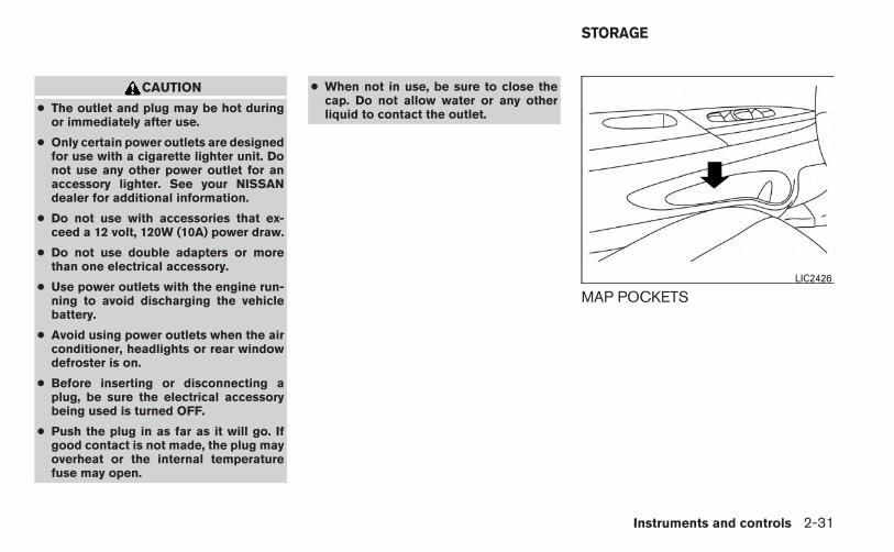
CAUTION
● The outlet and plug may be hot duringor immediately after use.
● Only certain power outlets are designedfor use with a cigarette lighter unit. Donot use any other power outlet for anaccessory lighter. See your NISSANdealer for additional information.
● Do not use with accessories that ex-ceed a 12 volt, 120W (10A) power draw.
● Do not use double adapters or morethan one electrical accessory.
● Use power outlets with the engine run-ning to avoid discharging the vehiclebattery.
● Avoid using power outlets when the airconditioner, headlights or rear windowdefroster is on.
● Before inserting or disconnecting aplug, be sure the electrical accessorybeing used is turned OFF.
● Push the plug in as far as it will go. Ifgood contact is not made, the plug mayoverheat or the internal temperaturefuse may open.
● When not in use, be sure to close thecap. Do not allow water or any otherliquid to contact the outlet.
MAP POCKETSLIC2426
STORAGE
Instruments and controls 2-31

STORAGE TRAYS
WARNING
Do not place sharp objects in the trays tohelp prevent injury in an accident or sud-den stop.
SEATBACK POCKETS (if soequipped)The seatback pockets are located on the back ofthe driver’s and passenger’s seats. The pocketscan be used to store maps.
Storage Tray (if so equipped)LIC2421 LIC2422 LIC1328
2-32 Instruments and controls

SUNGLASSES HOLDERTo open the sunglasses holder, push and release.
Only store one pair of sunglasses in the holder.
WARNING
Keep the sunglasses holder closed whiledriving to prevent an accident.
CAUTION
● Do not use for anything other thansunglasses.
● Do not leave sunglasses in the sun-glasses holder while parking in directsunlight. The heat may damage thesunglasses.
LIC2312
FrontLIC2424
Instruments and controls 2-33

CUP HOLDERS
CAUTION
● Avoid abrupt starting and braking whenthe cup holder is being used to preventspilling the drink. If the liquid is hot, itcan scald you or your passenger.
● Use only soft cups in the cup holder.Hard objects can injure you in anaccident.
CAUTION
● Do not use bottle holder for any otherobjects that could be thrown about inthe vehicle and possibly injure peopleduring sudden braking or an accident.
● Do not use bottle holder for open liquidcontainers.
RearLIC2212
FrontLIC2423
2-34 Instruments and controls

Soft bottle holder
CAUTION
● Do not use bottle holder for any otherobjects that could be thrown about inthe vehicle and possibly injure peopleduring sudden braking or an accident.
● Do not use bottle holder for open liquidcontainers.
GLOVE BOXOpen the glove box by pulling the handle.
WARNING
Keep glove box lid closed while driving tohelp prevent injury in an accident or asudden stop.
CONSOLE BOXTo open the console box, press in on the lever �1and raise the lid �2 .
To close, push the lid down until the lock latches.
RearLIC2425 LIC2429 LIC1026
Instruments and controls 2-35
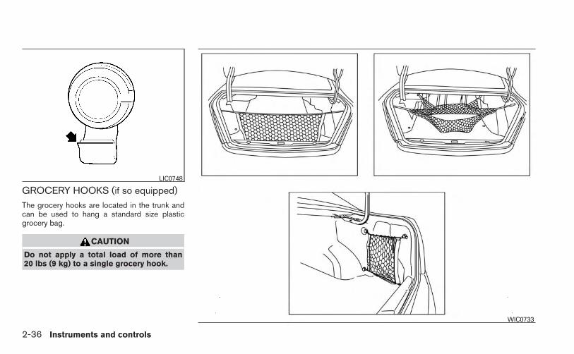
GROCERY HOOKS (if so equipped)The grocery hooks are located in the trunk andcan be used to hang a standard size plasticgrocery bag.
CAUTION
Do not apply a total load of more than20 lbs (9 kg) to a single grocery hook.
LIC0748
WIC0733
2-36 Instruments and controls

CARGO NET (if so equipped)
WARNING
● Properly secure all cargo with ropes orstraps to help prevent it from sliding orshifting. In a sudden stop or collision,unsecured cargo could cause personalinjury.
● Be sure to secure all four hooks into theretainers. The cargo restrained in thenet must not exceed 30 lbs. (13.6 kg) orthe net may not stay secured.
The cargo net helps keep packages in the cargoarea from moving around while the vehicle is inmotion. To install the cargo net, attach the net to the
retainers.
To remove the cargo net, detach the net from thecargo net retainers.
POWER WINDOWS
WARNING
● Make sure that all passengers havetheir hands, etc. inside the vehicle whileit is in motion and before closing thewindows. Use the window lock switchto prevent unexpected use of the powerwindows.
● Do not leave children unattended insidethe vehicle. They could unknowingly ac-tivate switches or controls and becometrapped in a window. Unattended chil-dren could become involved in seriousaccidents.
The power windows operate when the ignitionswitch is placed in the ON position, or for aperiod of time after the ignition switch is placed inthe OFF position. If the driver’s or passenger’sdoor is opened during this period of time, thepower to the windows is canceled.
LIC0802
WINDOWS
Instruments and controls 2-37

1. Window lock button2. Power door lock switch3. Front passenger side4. Right rear passenger side5. Left rear passenger side6. Driver side automatic switch
Driver’s side power window switchThe driver’s side control panel is equipped withswitches to open or close all of the windows.
To open a window, push the switch to the firstdetent and continue to hold down until the de-sired window position is reached. To close awindow, pull the switch to the first detent andcontinue to hold up until the desired windowposition is reached.
Front passenger’s power windowswitchThe passenger’s window switch operates onlythe corresponding passenger’s window. To openthe window, push the switch to the first detentand continue to hold it down until the desiredwindow position is reached �1 . To close thewindow, pull the switch to the first detent andcontinue to hold it up until the desired windowposition is reached �2 .
LIC2299 LIC2311
2-38 Instruments and controls

Rear power window switchThe rear power window switches open or closeonly the corresponding windows. To open thewindow, push the switch and hold it down �1 . Toclose the window, pull the switch up �2 .
Locking passengers’ windowsWhen the window lock button is depressed, onlythe driver’s side window can be opened orclosed. Push it again to cancel the window lockfunction.
Automatic operation
To fully open a window equipped with automaticoperation, press the window switch down to thesecond detent and release it; it need not be held.The window automatically opens all the way. Tostop the window, lift the switch up while thewindow is opening.
To fully close a window equipped with automaticoperation, pull the switch up to the second detentand release it; it need not be held. The windowautomatically closes all the way. To stop the win-dow, press the switch down while the window isclosing.
Auto-reverse function
The auto-reverse function can be activated whena window is closed by automatic operation.
Depending on the environment or drivingconditions, the auto-reverse function maybe activated if an impact or load similar tosomething being caught in the window oc-curs.
WARNING
There are some small distances immedi-ately before the closed position whichcannot be detected. Make sure that allpassengers have their hands, etc., insidethe vehicle before closing the window.
If the vehicle’s battery is disconnected, replaced,or jump started, the power window auto-reversefunction may not operate properly. If this occurs,please contact the dealer to re-initialize thepower window auto-reverse system.
If the control unit detects something caught in awindow equipped with automatic operation as itis closing, the window will be immediately low-ered.
LIC2311 LIC0410
Instruments and controls 2-39

When the automatic operation for thedriver’s power window switch doesnot operate
If the automatic operation for the driver’s powerwindow switch does not operate properly, per-form the following procedure to initialize thepower window switch.
1. Place the ignition switch in the ON position.
2. Press and hold the driver’s window switchdown until the window opens completely.
3. Release the switch.
4. Pull and hold the driver’s window switch upto the second detent until the window glasshas reached the full close position. Con-tinue to hold the window switch in theup position for 5 seconds after the win-dow glass has reached the full closeposition. (It is necessary for this entire stepto be completed with one continuous pull ofthe window switch.)
5. Release the switch.
Initialization is now complete. The automatic op-eration for the driver’s power window switchshould now operate.
If the automatic operation does not operate prop-erly after performing the above procedure, see aNISSAN dealer for assistance.
No initialization is required for all the other win-dow switches.
AUTOMATIC MOONROOF
The moonroof will only operate when the ignitionswitch is placed in the ON position. The auto-matic moonroof is operational for a period of time,even if the ignition switch is placed in the ACC orOFF position. If the driver’s door or the frontpassenger’s door is opened during this period oftime, the power to the moonroof is canceled.
Sliding the moonroof
To fully open or close the moonroof, push theswitch to the open �2 or close �1 position andrelease it; it need not be held. The roof will
LIC2313
MOONROOF (if so equipped)
2-40 Instruments and controls

automatically open or close all the way. To stopthe roof, push the switch once more while it isopening or closing.
Tilting the moonroof
To tilt up, first close the moonroof, then push theswitch to the tilt up position �1 and release it; itneed not be held. To tilt down the moonroof, pushthe switch to the tilt down position �2 .
Resetting the moonroof switch
If the moonroof does not operate properly, per-form the following procedure to initialize themoonroof operation system.
1. If the moonroof is open, close it fully byrepeatedly pushing the moonroof switch tothe close position �1 to tilt the moonroof up.
2. Push and hold the switch to the close posi-tion �1 .
3. Release the moonroof switch after themoonroof moves slightly up and down.
4. Push and hold the switch to the open posi-tion �2 to fully tilt the moonroof down.
5. Check if the moonroof switch operates nor-mally.
If the moonroof does not operate properly afterperforming the procedure above, have your ve-hicle checked by a NISSAN dealer.
Auto-reverse function (when closing ortilting down the moonroof)
The auto-reverse function can be activated whenthe moonroof is closed or tilted down by auto-matic operation when the ignition switch isplaced in the ON position or for a period of timeafter the ignition switch is placed in the OFFposition.
Depending on the environment or drivingconditions, the auto-reverse function maybe activated if an impact or load similar tosomething being caught in the moonroofoccurs.
WARNING
There are some small distances immedi-ately before the closed position whichcannot be detected. Make sure that allpassengers have their hands, etc., insidethe vehicle before closing the moonroof.
When closing:
If the control unit detects something caught in themoonroof as it moves to the front, the moonroofwill immediately open backward.
When tilting down:
If the control unit detects something caught in themoonroof as it tilts down, the moonroof will im-mediately tilt up.
If the auto-reverse function malfunctions and re-peats opening or tilting up the moonroof, keeppushing the tilt down switch within 5 secondsafter it happens; the moonroof will fully closegradually. Make sure nothing is caught in themoonroof.
WARNING
● In an accident you could be thrown fromthe vehicle through an open moonroof.Always use seat belts and childrestraints.
● Do not allow anyone to stand up orextend any portion of their body out ofthe moonroof opening while the vehicleis in motion or while the moonroof isclosing.
CAUTION
● Remove water drops, snow, ice or sandfrom the moonroof before opening.
● Do not place heavy objects on themoonroof or surrounding area.
Instruments and controls 2-41

SunshadeOpen and close the sunshade by sliding it for-ward or backward.
If the moonroof does not closeHave your NISSAN dealer check and repair themoonroof.
�1 The interior light can be turned ON regard-less of door position. The light will go off aftera period of time unless the ignition switch isplaced in the ON position when any door isopened.
�2 The interior lights can be set to operatewhen the doors are opened. To turn off theinterior lights when a door open, push theswitch, the interior lights will not illuminate,regardless of door position.The lights will go off when the ignition switchis placed in the ON position, or the driver’sdoor is closed and locked. The lights will alsogo off after a period of time when the doorsare open.
NOTE:
The step lights illuminate when the driverand passenger doors are opened regard-less of the interior light switch position.These lights will turn off automatically aftera period of time while doors are open toprevent the battery from becoming dis-charged.
CAUTION
Do not use for extended periods of timewith the engine stopped. This could resultin a discharged battery.
LIC2302
INTERIOR LIGHT
2-42 Instruments and controls

CONSOLE LIGHTThe console light will turn on whenever the park-ing lights or headlights are illuminated.
To turn the rear personal lights on, press theswitch. To turn them off, press the switch again.
Push the button to turn the map lights on. To turnthem off, press the button again.
CAUTION
Do not use for extended periods of timewith the engine stopped. This could resultin a discharged battery.
LIC2303Rear personal lights
LIC1083 LIC2304
PERSONAL LIGHTS MAP LIGHTS
Instruments and controls 2-43

The light illuminates when the trunk lid is opened.When the trunk lid is closed, the light goes off.
The light will go off after a period of time if thetrunk lid is left open, unless the ignition switch isplaced in the ON position.
For bulb replacement procedures, refer to “Exte-rior and interior lights” in the “Maintenance anddo-it-yourself” section of this manual.
TRUNK LIGHT
2-44 Instruments and controls

3 Pre-driving checks and adjustments
Keys . . . . . . . . . . . . . . . . . . . . . . . . . . . . . . . . . . . . . . . . . . . . . 3-2NISSAN Intelligent Key® (if so equipped) . . . . . . . . . 3-2NISSAN Vehicle Immobilizer System keys . . . . . . . . . 3-4
Doors . . . . . . . . . . . . . . . . . . . . . . . . . . . . . . . . . . . . . . . . . . . . 3-4Locking with key. . . . . . . . . . . . . . . . . . . . . . . . . . . . . . . . 3-5Locking with inside lock knob . . . . . . . . . . . . . . . . . . . . 3-5Locking with power door lock switch . . . . . . . . . . . . . 3-5Automatic door locks . . . . . . . . . . . . . . . . . . . . . . . . . . . 3-6Child safety rear door lock . . . . . . . . . . . . . . . . . . . . . . . 3-6
Remote keyless entry system (if so equipped). . . . . . . . . 3-7How to use remote keyless entry system . . . . . . . . . . 3-8
NISSAN Intelligent Key® (if so equipped) . . . . . . . . . . . 3-10Operating range. . . . . . . . . . . . . . . . . . . . . . . . . . . . . . . 3-12Door locks/unlocks precaution . . . . . . . . . . . . . . . . . . 3-13NISSAN Intelligent Key® Operation . . . . . . . . . . . . . 3-13How to use the remote keyless entryfunction . . . . . . . . . . . . . . . . . . . . . . . . . . . . . . . . . . . . . . 3-16Warning lights and audible reminders . . . . . . . . . . . . 3-20Warning signals . . . . . . . . . . . . . . . . . . . . . . . . . . . . . . . 3-20
Troubleshooting guide . . . . . . . . . . . . . . . . . . . . . . . . . 3-22Hood . . . . . . . . . . . . . . . . . . . . . . . . . . . . . . . . . . . . . . . . . . . 3-24Trunk lid . . . . . . . . . . . . . . . . . . . . . . . . . . . . . . . . . . . . . . . . . 3-25
Trunk lid release switch . . . . . . . . . . . . . . . . . . . . . . . . 3-25Interior trunk lid release . . . . . . . . . . . . . . . . . . . . . . . . 3-25
Fuel-filler door . . . . . . . . . . . . . . . . . . . . . . . . . . . . . . . . . . . 3-26Opener operation. . . . . . . . . . . . . . . . . . . . . . . . . . . . . . 3-26Fuel-filler cap . . . . . . . . . . . . . . . . . . . . . . . . . . . . . . . . . 3-26
Tilt/telescopic steering . . . . . . . . . . . . . . . . . . . . . . . . . . . . 3-28Tilt operation . . . . . . . . . . . . . . . . . . . . . . . . . . . . . . . . . . 3-28Telescopic operation . . . . . . . . . . . . . . . . . . . . . . . . . . . 3-29
Sun visors . . . . . . . . . . . . . . . . . . . . . . . . . . . . . . . . . . . . . . . 3-29Vanity mirrors . . . . . . . . . . . . . . . . . . . . . . . . . . . . . . . . . 3-30Card holder (driver’s side only) . . . . . . . . . . . . . . . . . . 3-30
Mirrors . . . . . . . . . . . . . . . . . . . . . . . . . . . . . . . . . . . . . . . . . . 3-30Rearview mirror (if so equipped). . . . . . . . . . . . . . . . . 3-30Automatic anti-glare rearview mirror(if so equipped) . . . . . . . . . . . . . . . . . . . . . . . . . . . . . . . 3-31Outside mirrors . . . . . . . . . . . . . . . . . . . . . . . . . . . . . . . 3-31

1. Integrated door lock keyfob2. Key number plate
CAUTION
Do not leave the ignition key inside thevehicle when you leave the vehicle.
A key number plate is supplied with your keys.Record the key number and keep it in a safe place(such as your wallet), not in the vehicle. If you loseyour keys, see a NISSAN dealer for duplicates byusing the key number. NISSAN does not recordkey numbers so it is very important to keep trackof your key number plate.
A key number is only necessary when you havelost all keys and do not have one to duplicatefrom. If you still have a key, your NISSAN dealercan duplicate it.
1. Two Intelligent Keys2. Mechanical keys (inside Intelligent
Keys)3. Key number plateNISSAN INTELLIGENT KEY® (if soequipped)Your vehicle can only be driven with the IntelligentKeys which are registered to your vehicle’s Intel-ligent Key components and NISSAN Vehicle Im-mobilizer System components.
Remote keyless entry keyfob (if soequipped)
LPD2027 WPD0427
KEYS
3-2 Pre-driving checks and adjustments

Never leave these keys in the vehicle.
As many as 4 Intelligent Keys can be registeredand used with one vehicle. The new keys must beregistered by a NISSAN dealer prior to use withthe Intelligent Key and NISSAN Vehicle Immobi-lizer System of your vehicle. Since the registra-tion process requires erasing all memory in theIntelligent Key components when registering newkeys, be sure to take all Intelligent Keys that youhave to the NISSAN dealer.
CAUTION
Listed below are conditions or occur-rences which will damage the IntelligentKey:
● Do not allow the Intelligent Key, whichcontains electrical components, tocome into contact with water or saltwater. This could affect the systemfunction.
● Do not drop the Intelligent Key.
● Do not strike the Intelligent Key sharplyagainst another object.
● Do not change or modify the IntelligentKey.
● Wetting may damage the IntelligentKey. If the Intelligent Key gets wet, im-mediately wipe until it is completely dry.
● Do not place the Intelligent Key for anextended period in an area where tem-peratures exceed 140°F (60°C).
● Do not attach the Intelligent Key with akey holder that contains a magnet.
● Do not place the Intelligent Key nearequipment that produces a magneticfield, such as a TV, audio equipment andpersonal computers.
If an Intelligent Key is lost or stolen,NISSAN recommends erasing the ID codeof that Intelligent Key from the vehicle.This may prevent the unauthorized use ofthe Intelligent Key to operate the vehicle.For information regarding the erasingprocedure, contact a NISSAN dealer.
Mechanical key
The Intelligent Key contains the mechanical key.
To remove the mechanical key, release the lockknob on the back of the Intelligent Key.
To install the mechanical key, firmly insert it intothe Intelligent Key until the lock knob returns tothe lock position.
Use the mechanical key to lock or unlock thedriver’s door.
SPA1951
Pre-driving checks and adjustments 3-3

CAUTION
Always carry the mechanical key installedin the Intelligent Key slot.
See “Doors” in this section.
NISSAN VEHICLE IMMOBILIZERSYSTEM KEYS
You can only drive your vehicle using the masterkeys which are registered to the NISSAN VehicleImmobilizer System components in your vehicle.These keys have a transponder chip in the keyhead.
The master key can be used for all the locks.
Never leave these keys in the vehicle.
Additional or replacement keys:
If you still have a key, the key number is notnecessary when you need extra NISSAN VehicleImmobilizer System keys. Your dealer can dupli-cate your existing key. As many as 5 NISSANVehicle Immobilizer System keys can be usedwith one vehicle. You should bring all NISSANVehicle Immobilizer System keys that you have toyour NISSAN dealer for registration. This is be-cause the registration process will erase thememory of all key codes previously registeredinto the NISSAN Vehicle Immobilizer System.After the registration process, these components
will only recognize keys coded into the NISSANVehicle Immobilizer System during registration.Any key that is not given to your dealer at the timeof registration will no longer be able to start yourvehicle.
CAUTION
Do not allow the immobilizer system key,which contains an electrical transponder,to come into contact with water or saltwater. This could affect system function.
When the doors are locked using one of thefollowing methods, the doors can not be openedusing the inside or outside door handles. Thedoors must be unlocked to open the doors.
WARNING
● Always have the doors locked whiledriving. Along with the use of seat belts,this provides greater safety in the eventof an accident by helping to preventpersons from being thrown from thevehicle. This also helps keep childrenand others from unintentionally open-ing the doors, and will help keep outintruders.
● Before opening any door, always lookfor and avoid oncoming traffic.
● Do not leave children unattended insidethe vehicle. They could unknowingly ac-tivate switches or controls. Unattendedchildren could become involved in seri-ous accidents.
DOORS
3-4 Pre-driving checks and adjustments

LOCKING WITH KEYThe power door lock system allows you to lock orunlock all doors at the same time.
Turning the key toward the front �1 of the vehiclelocks all doors.
Turning the key one time toward the rear �2 of thevehicle unlocks that door. From that position,returning the key to neutral �3 (where the key canonly be removed and inserted) and turning ittoward the rear again within 5 seconds unlocksall doors �4 .
LOCKING WITH INSIDE LOCKKNOBTo lock the door without the key, move the insidelock knob to the lock position �1 , then close thedoor.
To unlock the door without the key, move theinside lock knob to the unlock position �2 .
LOCKING WITH POWER DOORLOCK SWITCH
To lock all the doors without a key, push the doorlock switch (driver’s or front passenger’s side) tothe lock position �1 . When locking the door thisway, be certain not to leave the key inside thevehicle.
To unlock all the doors without a key, push thedoor lock switch (driver’s or front passenger’sside) to the unlock position �2 .
Driver’s sideLPD0461
Inside lockSPA2726
Door lock switchLPD2093
Pre-driving checks and adjustments 3-5

Lockout protection
When the power door lock switch is moved to thelock position and any door is open, all doors willlock and unlock automatically. With the IntelligentKey left in the vehicle and any door is open, alldoors will unlock automatically and a chime willsound after the door is closed.
These functions help to prevent the IntelligentKey from being accidentally locked inside thevehicle.
AUTOMATIC DOOR LOCKS
● All doors lock automatically when the vehiclespeed reaches 15 MPH (24 km/h).
● All doors unlock automatically when the ig-nition is placed in the OFF position (modelswith Intelligent Key system) or when the keyis removed from the ignition switch (modelswithout Intelligent Key system).
The automatic unlock function can be de-activated or activated.To deactivate or acti-vate the automatic door unlock system, performthe following procedure:
1. Close all doors.
2. Place the ignition switch in the ON position.
3. Within 20 seconds of performing Step 2,push and hold the power door lock switch tothe position (UNLOCK) for more than5 seconds.
4. When activated, the hazard indicator willflash twice. When deactivated, the hazardindicator will flash once.
5. The ignition switch must be placed in theOFF and ON position again between eachsetting change.
When the automatic door unlock system is deac-tivated, the doors do not unlock when the ignitionswitch is placed in the OFF position (models withIntelligent Key system) or when the key is re-moved from the ignition switch (models withoutIntelligent Key system). To unlock the door manu-ally, use the inside lock knob or the power doorlock switch (driver’s or front passenger’s side).
CHILD SAFETY REAR DOOR LOCKChild safety locks help prevent the rear doorsfrom being opened accidentally, especially whensmall children are in the vehicle.
The child safety lock levers are located on theedge of the rear doors.
When the lever is in the unlock position �2 , thedoor can be opened from the outside or theinside.
When the lever is in the LOCK position �1 ,the door can be opened only from the out-side.
LPD2117
3-6 Pre-driving checks and adjustments

WARNING
● Radio waves could adversely affectelectric medical equipment. Those whouse a pacemaker should contact theelectric medical equipment manufac-turer for the possible influences beforeuse.
● The remote keyless entry keyfob trans-mits radio waves when the buttons arepressed. The FAA advises radio wavesmay affect aircraft navigation and com-munication systems. Do not operate theremote keyless entry keyfob while onan airplane. Make sure the buttons arenot operated unintentionally when theunit is stored for a flight.
It is possible to lock/unlock all doors, turn theinterior lights on, and activate the panic alarm byusing the keyfob from outside the vehicle.
Be sure to remove the key from the vehiclebefore locking the doors.
The keyfob can operate at a distance of approxi-mately 33 ft (10 m) from the vehicle. The effectivedistance depends on the conditions around thevehicle.
As many as 5 keyfobs can be used with onevehicle. For information concerning the purchaseand use of additional keyfobs, contact a NISSANdealer.
The keyfob will not function when:
● the battery is discharged
● the distance between the vehicle and thekeyfob is over 33 ft (10 m)
The panic alarm will not activate when thekey is in the ignition switch.
CAUTION
Listed below are conditions or occur-rences which will damage the keyfob:
● Do not allow the keyfob, which containselectrical components, to come intocontact with water or salt water. Thiscould affect the system function.
● Do not drop the keyfob.
● Do not strike the keyfob sharply againstanother object.
● Do not change or modify the keyfob.
● Wetting may damage the keyfob. If thekeyfob gets wet, immediately wipe untilit is completely dry.
● Do not place the keyfob for an extendedperiod in an area where temperaturesexceed 140°F (60°C).
● Do not attach the keyfob with a keyholder that contains a magnet.
● Do not place the keyfob near equip-ment that produces a magnetic field,such as a TV, audio equipment and per-sonal computers.
If a keyfob is lost or stolen, NISSAN rec-ommends erasing the ID code of that key-fob. This will prevent the keyfob from un-authorized use to unlock the vehicle. Forinformation regarding the erasing proce-dure, please contact a NISSAN dealer.
REMOTE KEYLESS ENTRY SYSTEM(if so equipped)
Pre-driving checks and adjustments 3-7

HOW TO USE REMOTE KEYLESSENTRY SYSTEM
Locking the doors
1. Remove the ignition key.
2. Close all the doors.
3. Push the LOCK button on the key-fob.
● All the doors will lock.
● The hazard indicator flashes twice and thehorn beeps once .
NOTE:
An auto-relock function will operate after afull or partial unlock, when no further useraction occurs. The relock will operate ap-proximately 1 minute after full or partialunlock. The auto-relock function is can-celled when any door is opened or the keyis inserted into the ignition.
Unlocking the doors
1. Press the UNLOCK button on thekeyfob to unlock the drivers door.
2. The hazard warning lights flash once.
3. Press the UNLOCK button againwithin 5 seconds to unlock all doors.
LPD2028 LPD2029
3-8 Pre-driving checks and adjustments

Releasing the trunk lid
Press the button on the keyfob for longerthan 0.5 seconds to open the trunk lid. The trunkrelease button on the keyfob will not operatewhen the ignition switch is placed in the ONposition.
Using the panic alarmIf you are near your vehicle and feel threatened,you may activate the panic alarm to call attentionby pressing and holding the button on thekeyfob for longer than 0.5 seconds.
The panic alarm will stay on for a period of time.
The panic alarm stops when:
● it has run for a period of time, or
● any button is pressed on the keyfob.
Using the interior light
Press the button on the keyfob once toturn on the interior lights.
For additional information, refer to “Interior light”in the “Instruments and controls” section in thismanual.
LPD2030 LPD2031
Pre-driving checks and adjustments 3-9

Silencing the horn beep feature
If desired, the horn beep feature can be deacti-vated using the keyfob.
To deactivate: Press and hold theand buttons for at least 2 seconds.
The hazard warning lights will flash three times toconfirm that the horn beep feature has beendeactivated.
To activate: Press and hold theand buttons for at least 2 secondsonce more.
The hazard warning lights will flash once and thehorn will sound once to confirm that the hornbeep feature has been reactivated.
Deactivating the horn beep feature does not si-lence the horn if the alarm is triggered.
WARNING
● Radio waves could adversely affectelectric medical equipment. Those whouse a pacemaker should contact theelectric medical equipment manufac-turer for the possible influences beforeuse.
● The Intelligent Key transmits radiowaves when the buttons are pressed.The FAA advises the radio waves mayaffect aircraft navigation and communi-cation systems. Do not operate the In-telligent Key while on an airplane. Makesure the buttons are not operated unin-tentionally when the unit is stored for aflight.
The Intelligent Key system can operate all thedoor locks using the remote controller function orpushing the request switch on the vehicle withouttaking the key out from a pocket or purse. Theoperating environment and/or conditions may af-fect the Intelligent Key system operation.
Be sure to read the following before using theIntelligent Key system.
LPD2044
NISSAN INTELLIGENT KEY® (if soequipped)
3-10 Pre-driving checks and adjustments

CAUTION
● Be sure to carry the Intelligent Key withyou when operating the vehicle.
● Never leave the Intelligent Key in thevehicle when you leave the vehicle.
The Intelligent Key is always communicating withthe vehicle as it receives radio waves. The Intel-ligent Key system transmits weak radio waves.Environmental conditions may interfere with theoperation of the Intelligent Key system under thefollowing operating conditions:
● When operating near a location wherestrong radio waves are transmitted, such asa TV tower, power station and broadcastingstation.
● When in possession of wireless equipment,such as a cellular telephone, transceiver,and CB radio.
● When the Intelligent Key is in contact with orcovered by metallic materials.
● When any type of radio wave remote controlis used nearby.
● When the Intelligent Key is placed near anelectric appliance such as a personal com-puter.
● When the vehicle is parked near a parkingmeter.
In such cases, correct the operating conditionsbefore using the Intelligent Key function or usethe mechanical key.
Although the life of the battery varies dependingon the operating conditions, the battery’s life isapproximately 2 years. If the battery is dis-charged, replace it with a new one.
When the Intelligent Key battery is low, the Intel-ligent Key system warning light ( ) will blinkgreen for about 30 seconds after the ignitionswitch is placed in the ON position.
Since the Intelligent Key is continuously receivingradio waves, if the key is left near equipmentwhich transmits strong radio waves, such as sig-nals from a TV and personal computer, the bat-tery life may become shorter.
For information regarding replacement of a bat-tery, see “Battery replacement” in the “Mainte-nance and do-it-yourself” section.
As many as 4 Intelligent Keys can be registeredand used with one vehicle. For information aboutthe purchase and use of additional IntelligentKeys, contact a NISSAN dealer.
CAUTION
Listed below are conditions or occur-rences which will damage the IntelligentKey:
● Do not allow the Intelligent Key, whichcontains electrical components, tocome into contact with water or saltwater. This could affect the systemfunction.
● Do not drop the Intelligent Key.
● Do not strike the Intelligent Key sharplyagainst another object.
● Do not change or modify the IntelligentKey.
● Wetting may damage the IntelligentKey. If the Intelligent Key gets wet, im-mediately wipe until it is completely dry.
● Do not place the Intelligent Key for anextended period in an area where tem-peratures exceed 140°F (60°C).
● Do not attach the Intelligent Key with akey holder that contains a magnet.
● Do not place the Intelligent Key nearequipment that produces a magneticfield, such as a TV, audio equipment andpersonal computers.
Pre-driving checks and adjustments 3-11

If an Intelligent Key is lost or stolen, NISSANrecommends erasing the ID code of that Intelli-gent Key from the vehicle. This may prevent theunauthorized use of the Intelligent Key to operatethe vehicle. For information regarding the erasingprocedure, contact a NISSAN dealer.
OPERATING RANGE
The Intelligent Key functions can only be usedwhen the Intelligent Key is within the specifiedoperating range from the request switch �1 .
When the Intelligent Key battery is discharged orstrong radio waves are present near the operat-ing location, the Intelligent Key operating rangebecomes narrower, and the Intelligent Key maynot function properly.
The operating range is within 31.50 in (80 cm)from each request switch �1 .
If the Intelligent Key is too close to the door glass,handle or rear bumper, the request switches maynot function.
When the Intelligent Key is within the operatingrange, it is possible for anyone, even someonewho does not carry the Intelligent Key, to push therequest switch to lock/unlock the doors.
LPD2073
3-12 Pre-driving checks and adjustments

DOOR LOCKS/UNLOCKSPRECAUTION
● Do not push the door handle request switchwith the Intelligent Key held in your hand asillustrated. The close distance to the doorhandle will cause the Intelligent Key systemto have difficulty recognizing that the Intelli-gent Key is outside the vehicle.
● After locking with the door handle requestswitch, verify the doors are securely lockedby testing them.
● To prevent the Intelligent Key from being leftinside the vehicle, make sure you carry theIntelligent Key with you and then lock thedoors.
● Do not pull the door handle before pushingthe door handle request switch. The doorwill be unlocked but will not open. Releasethe door handle once and pull it again toopen the door.
NISSAN INTELLIGENT KEY®OPERATIONYou can lock or unlock the doors without takingthe Intelligent Key out of your pocket or bag.
When you carry the Intelligent Key with you, youcan lock or unlock all doors by pushing the doorhandle request switch within the range of opera-tion.
WPD0375 LPD2074
Pre-driving checks and adjustments 3-13

Locking doors
1. Move the shift selector to the P (Park) posi-tion, place the ignition switch in the LOCKposition and make sure you carry the Intelli-gent Key with you.
2. Close all doors.
3. Push any door handle request switch �1while carrying the Intelligent Key with you.
4. All doors and the trunk will lock.
5. The hazard warning lights flash twice andthe outside buzzer sounds twice.
NOTE:
● Doors lock with the door handle requestswitch while the ignition switch is not in theLOCK position.
● Doors do not lock by pushing the doorhandle request switch while any door isopen. However, doors lock with the me-chanical key even if any door is open.
● Doors do not lock with the door handlerequest switch with the Intelligent Key insidethe vehicle and a beep sounds to warn you.However, when an Intelligent Key is insidethe vehicle, doors can be locked with an-other Intelligent Key.
CAUTION
● After locking the doors using the re-quest switch, make sure that the doorshave been securely locked by operatingthe door handle or the trunk openerswitch.
● When locking the doors using the re-quest switch, make sure to have theIntelligent Key in your possession be-fore operating the request switch toprevent the Intelligent Key from beingleft in the vehicle.
● The request switch is operational onlywhen the Intelligent Key has been de-tected by the Intelligent Key system.
Lockout protection
To prevent the Intelligent Key from being acci-dentally locked in the vehicle, lockout protectionis equipped with the Intelligent Key.
When the driver’s side door is open, the doorsare locked, and then the Intelligent Key is putinside the vehicle and all the doors are closed;the lock will automatically unlock and the doorbuzzer sounds.
LPD2075 WPD0369
3-14 Pre-driving checks and adjustments

NOTE:
The doors may not lock when the Intelli-gent Key is in the same hand that is oper-ating the request switch to lock the door.Put the Intelligent Key in a purse, pocket oryour other hand.
CAUTION
The lockout protection may not functionunder the following conditions:
● When the Intelligent Key is placed ontop of the instrument panel.
● When the Intelligent Key is placed ontop of the rear parcel shelf.
● When the Intelligent Key is placed in-side the glove box or a storage bin.
● When the Intelligent Key is placed in-side the door pockets.
● When the Intelligent Key is placed on orunder the spare tire area.
● When the Intelligent Key is placed in-side or near metallic materials.
Unlocking doors1. Carry the Intelligent Key.
2. Push the door handle request switch �1 .
3. The hazard warning lights flash once and theoutside buzzer sounds once.
4. Push the door handle request switch �1again within 60 seconds to unlock all doors.
If a door handle is pulled while unlocking thedoors, that door may not be unlocked. Returningthe door handle to its original position will unlockthe door. If the door does not unlock after return-ing the door handle, push the door handle re-quest switch to unlock the door.
All doors will be locked automatically unless oneof the following operations is performed within1 minute after pushing the request switch.
● Opening any door.
● Pushing the ignition switch.
The interior light timer illuminates for a period oftime when a door is unlocked and the room lightswitch is in the DOOR position.
LPD2075 WPD0369
Pre-driving checks and adjustments 3-15

The interior light can be turned off without waitingby performing one of the following operations.
● Placing the ignition switch in the ON posi-tion.
● Locking the doors with the remote controller.
● Switching the room light switch to the OFFposition.
Opening the trunk lid
1. Push the trunk opener request switch �A formore than 1 second while carrying the Intel-ligent Key with you.
2. The trunk will unlatch. A chime will sound 4times.
3. Raise the trunk lid to open the trunk.
Lockout protection
To prevent the Intelligent Key from being acci-dentally locked in the trunk, lockout protection isequipped with the Intelligent Key.
When all doors are locked and the trunk lid isclosed with the Intelligent Key inside the trunk,the outside buzzer will sound and the trunk willopen.
HOW TO USE THE REMOTEKEYLESS ENTRY FUNCTIONThe remote keyless entry function can operate alldoor locks using the remote keyless function ofthe Intelligent Key. The remote keyless functioncan operate at a distance of 33 ft (10 m) awayfrom the vehicle. The operating distance de-pends upon the conditions around the vehicle.
The remote keyless entry function will not func-tion under the following conditions:
● When the Intelligent Key is not within theoperational range.
● When the doors or the trunk are open or notclosed securely.
● When the Intelligent Key battery is dis-charged.
CAUTION
When locking the doors using the Intelli-gent Key, be sure not to leave the key inthe vehicle.
LPD2122
3-16 Pre-driving checks and adjustments

Locking doors
1. Place the ignition switch in the LOCK posi-tion.
2. Close all doors.
3. Press the button on the IntelligentKey.
4. The hazard warning lights flash twice andthe horn beeps once.
5. All doors will be locked.
CAUTION
After locking the doors using the Intelli-gent Key, be sure that the doors have beensecurely locked by operating the doorhandles.
Unlocking doors
1. Press the button on the IntelligentKey.
2. The hazard warning lights flash once.
3. Press the button again within 60 sec-onds to unlock all doors.
All doors will be locked automatically unless oneof the following operations is performed within1 minute after pressing the button:
● Opening any doors.
● Pushing the ignition switch.
WPD0359 WPD0360
Pre-driving checks and adjustments 3-17
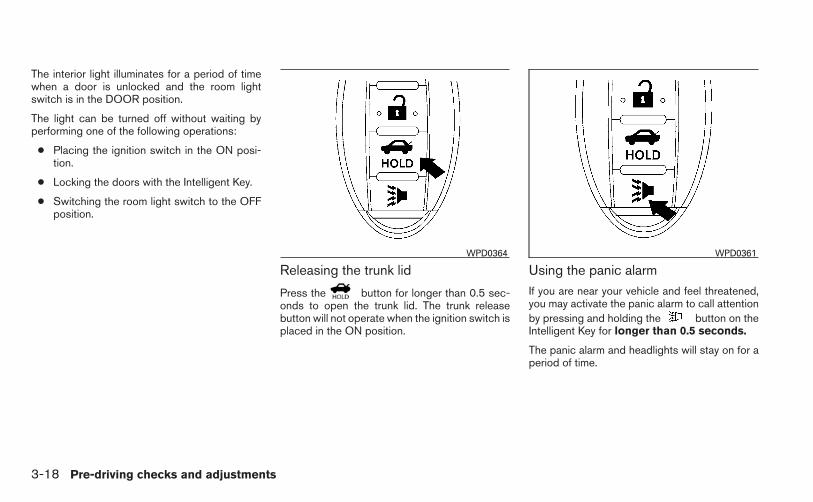
The interior light illuminates for a period of timewhen a door is unlocked and the room lightswitch is in the DOOR position.
The light can be turned off without waiting byperforming one of the following operations:
● Placing the ignition switch in the ON posi-tion.
● Locking the doors with the Intelligent Key.
● Switching the room light switch to the OFFposition.
Releasing the trunk lid
Press the button for longer than 0.5 sec-onds to open the trunk lid. The trunk releasebutton will not operate when the ignition switch isplaced in the ON position.
Using the panic alarmIf you are near your vehicle and feel threatened,you may activate the panic alarm to call attentionby pressing and holding the button on theIntelligent Key for longer than 0.5 seconds.
The panic alarm and headlights will stay on for aperiod of time.
WPD0364 WPD0361
3-18 Pre-driving checks and adjustments

The panic alarm stops when:
● It has run for a period of time, or
● Any button is pressed on the Intelligent Key.
● The request switch on the driver or passen-ger door has been pushed and the IntelligentKey is in range of the door handle.
Silencing the horn beep feature
If desired, the horn beep feature can be deacti-vated using the Intelligent Key.
To deactivate: Press and hold theand buttons for at least 2 seconds.
The hazard warning lights will flash 3 times toconfirm that the horn beep feature has beendeactivated.
To activate: Press and hold theand buttons for at least 2 secondsonce more.
The hazard warning lights will flash once and thehorn will sound once to confirm that the hornbeep feature has been reactivated.
Deactivating the horn beep feature does not si-lence the horn if the alarm is triggered.
WPD0362
Pre-driving checks and adjustments 3-19
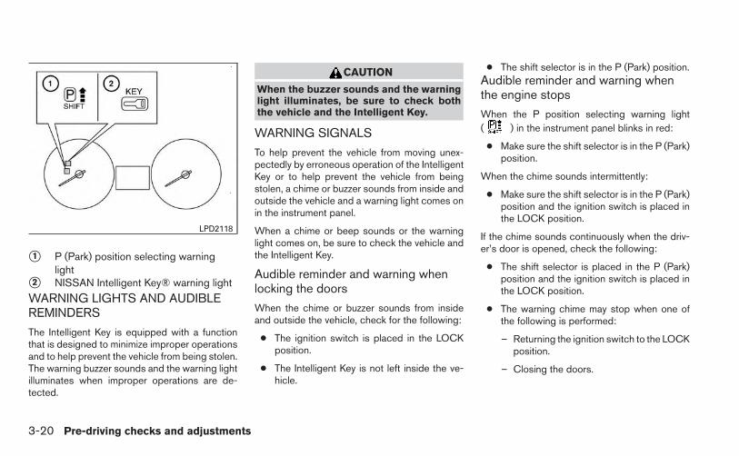
�1 P (Park) position selecting warninglight
�2 NISSAN Intelligent Key® warning light
WARNING LIGHTS AND AUDIBLEREMINDERS
The Intelligent Key is equipped with a functionthat is designed to minimize improper operationsand to help prevent the vehicle from being stolen.The warning buzzer sounds and the warning lightilluminates when improper operations are de-tected.
CAUTION
When the buzzer sounds and the warninglight illuminates, be sure to check boththe vehicle and the Intelligent Key.
WARNING SIGNALS
To help prevent the vehicle from moving unex-pectedly by erroneous operation of the IntelligentKey or to help prevent the vehicle from beingstolen, a chime or buzzer sounds from inside andoutside the vehicle and a warning light comes onin the instrument panel.
When a chime or beep sounds or the warninglight comes on, be sure to check the vehicle andthe Intelligent Key.
Audible reminder and warning whenlocking the doors
When the chime or buzzer sounds from insideand outside the vehicle, check for the following:
● The ignition switch is placed in the LOCKposition.
● The Intelligent Key is not left inside the ve-hicle.
● The shift selector is in the P (Park) position.Audible reminder and warning whenthe engine stops
When the P position selecting warning light( ) in the instrument panel blinks in red:
● Make sure the shift selector is in the P (Park)position.
When the chime sounds intermittently:
● Make sure the shift selector is in the P (Park)position and the ignition switch is placed inthe LOCK position.
If the chime sounds continuously when the driv-er’s door is opened, check the following:
● The shift selector is placed in the P (Park)position and the ignition switch is placed inthe LOCK position.
● The warning chime may stop when one ofthe following is performed:
– Returning the ignition switch to the LOCKposition.
– Closing the doors.
LPD2118
3-20 Pre-driving checks and adjustments

Alarm and warning when the enginestartsWhen the Intelligent Key system warning light( ) blinks red and the outside buzzersounds, make sure the Intelligent Key is inside thevehicle.
Warning for low battery powerWhen the Intelligent Key battery is low, the Intel-ligent Key system warning light ( ) will blinkgreen for about 30 seconds after the ignitionswitch is placed in the ON position. This warningis to let you know that the battery of the IntelligentKey will run down soon. Replace it with a newone. Refer to “Battery replacement” in the “Main-tenance and do-it-yourself” section.
NISSAN recommends replacing the battery at aNISSAN dealer.
Preventing the Intelligent Key frombeing left in the vehicleIf you lock all doors using the power door lockswitch with the Intelligent Key in the vehicle, all ofthe doors unlock immediately and the buzzer willwarn you when the door is closed.
Pre-driving checks and adjustments 3-21

TROUBLESHOOTING GUIDE
Symptom Possible Cause RemedyWhen pushing the ignition switch to stopthe engine
The P (Park) warning light in the instrumentpanel illuminates and the inside chimesounds continuously.
The shift selector is not in the P (Park)position.
Make sure that the shift selector is in the P(Park) position.
When placing the shift selector in the P(Park) position
The inside warning chime soundscontinuously.
The ignition switch is in the ACC or ONposition.
Place the ignition switch in the OFFposition.
When opening the driver’s door A warning chime sounds continuously. The ignition switch is in the ACC position.Place the ignition switch in the OFFposition.
When pushing the door handle requestswitch to lock the door
The outside chime sounds for a fewseconds.
The Intelligent Key is inside the trunk. Be sure to carry the Intelligent Key with you.The Intelligent Key is inside the vehicle. Be sure to carry the Intelligent Key with you.A door is not closed securely. Close the door securely.
When closing the doors
The key warning light in the instrumentpanel blinks in yellow, the outside chimesounds 3 times and the inside warningchime sounds for approximately 3 seconds.
The ignition switch is in the ACC or ONposition.
Place the ignition switch in the OFFposition.
The P (Park) warning light in the instrumentpanel illuminates and the outside chimesounds continuously.
The ignition switch is in the ACC or OFFposition and the shift selector is not in the P(Park) position.
Make sure that the shift selector is in the P(Park) position and place the ignition switchin the OFF position.
The outside chime sounds for approximately3 seconds and all doors unlock.
The Intelligent Key is in the vehicle or trunk. Be sure to carry the Intelligent Key with you.
When opening the driver’s door A warning chime sounds continuously. The ignition switch is in the ACC position.Place the ignition switch in the OFFposition.
When closing the trunk lidThe outside chime sounds for approximately10 seconds and the trunk lid opens.
The Intelligent Key is inside the trunk.Be sure to carry the Intelligent Key with you.
When pushing the ignition switch to startthe engine
The key warning light in the instrumentpanel blinks in green.
The battery charge is low. Replace the battery with a new one. See“Battery replacement” in the “Maintenanceand do-it-yourself” section.
3-22 Pre-driving checks and adjustments

Symptom Possible Cause RemedyWhen pushing the LOCK button on theIntelligent Key to the lock the door
The outside chime sounds for a few sec-onds and all the doors unlock.
The Intelligent Key is inside the trunk. Be sure to carry the Intelligent Key with you.The Intelligent Key is inside the vehicle. Be sure to carry the Intelligent Key with you.A door is not closed securely. Close the doors securely.
Pre-driving checks and adjustments 3-23
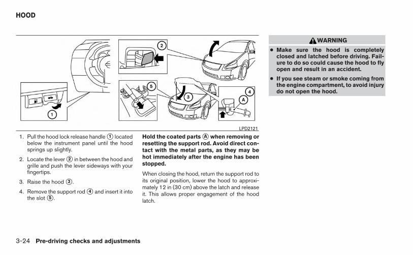
1. Pull the hood lock release handle �1 locatedbelow the instrument panel until the hoodsprings up slightly.
2. Locate the lever �2 in between the hood andgrille and push the lever sideways with yourfingertips.
3. Raise the hood �3 .
4. Remove the support rod �4 and insert it intothe slot �5 .
Hold the coated parts �A when removing orresetting the support rod. Avoid direct con-tact with the metal parts, as they may behot immediately after the engine has beenstopped.
When closing the hood, return the support rod toits original position, lower the hood to approxi-mately 12 in (30 cm) above the latch and releaseit. This allows proper engagement of the hoodlatch.
WARNING
● Make sure the hood is completelyclosed and latched before driving. Fail-ure to do so could cause the hood to flyopen and result in an accident.
● If you see steam or smoke coming fromthe engine compartment, to avoid injurydo not open the hood.
LPD2121
HOOD
3-24 Pre-driving checks and adjustments
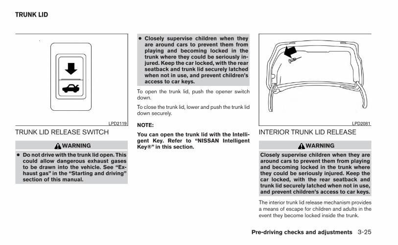
TRUNK LID RELEASE SWITCH
WARNING
● Do not drive with the trunk lid open. Thiscould allow dangerous exhaust gasesto be drawn into the vehicle. See “Ex-haust gas” in the “Starting and driving”section of this manual.
● Closely supervise children when theyare around cars to prevent them fromplaying and becoming locked in thetrunk where they could be seriously in-jured. Keep the car locked, with the rearseatback and trunk lid securely latchedwhen not in use, and prevent children’saccess to car keys.
To open the trunk lid, push the opener switchdown.
To close the trunk lid, lower and push the trunk liddown securely.
NOTE:
You can open the trunk lid with the Intelli-gent Key. Refer to “NISSAN IntelligentKey®” in this section.
INTERIOR TRUNK LID RELEASE
WARNING
Closely supervise children when they arearound cars to prevent them from playingand becoming locked in the trunk wherethey could be seriously injured. Keep thecar locked, with the rear seatback andtrunk lid securely latched when not in use,and prevent children’s access to car keys.
The interior trunk lid release mechanism providesa means of escape for children and adults in theevent they become locked inside the trunk.
LPD2119 LPD2081
TRUNK LID
Pre-driving checks and adjustments 3-25

To open the trunk from the inside, pull the illumi-nated release handle until the lock releases andpush up on the trunk lid. The release handle ismade of a material that glows in the dark after abrief exposure to ambient light.
The handle is located inside the trunk compart-ment on the interior of the trunk lid.
OPENER OPERATION
The fuel-filler lid release is located below theinstrument panel. To open the fuel-filler lid, pullthe release. To lock, close the fuel-filler lid se-curely.
FUEL-FILLER CAP
WARNING
● Gasoline is extremely flammable andhighly explosive under certain condi-tions. You could be burned or seriouslyinjured if it is misused or mishandled.Always stop the engine and do notsmoke or allow open flames or sparksnear the vehicle when refueling.
● Do not attempt to top off the fuel tankafter the fuel pump nozzle shuts offautomatically. Continued refueling maycause fuel overflow, resulting in fuelspray and possibly a fire.
● Use only an original equipment typefuel-filler cap as a replacement. It has abuilt-in safety valve needed for properoperation of the fuel system and emis-sion control system. An incorrect capcan result in a serious malfunction andpossible injury. It could also causethe Malfunction Indicator Light(MIL) to come on.
● Never pour fuel into the throttle body toattempt to start your vehicle.
LPD2022
FUEL-FILLER DOOR
3-26 Pre-driving checks and adjustments

● Do not fill a portable fuel container inthe vehicle or trailer. Static electricitycan cause an explosion of flammableliquid, vapor or gas in any vehicle ortrailer. To reduce the risk of seriousinjury or death when filling portable fuelcontainers:
– Always place the container on theground when filling.
– Do not use electronic devices whenfilling.
– Keep the pump nozzle in contactwith the container while you are fill-ing it.
– Use only approved portable fuel con-tainers for flammable liquid.
CAUTION
● Do not use E-15 or E-85 fuel in yourvehicle. For further information see the“Fuel Recommendation” in the “Techni-cal and consumer information” sectionof this manual.
● The LOOSE FUEL CAP warning mes-sage will be displayed if the fuel-fillercap is not properly tightened. It maytake a few driving trips for the messageto be displayed. Failure to tighten thefuel-filler cap properly after the LOOSEFUEL CAP warning message is dis-played may cause the Malfunc-tion Indicator Light (MIL) to illuminate.
● Failure to tighten the fuel-filler capproperly may cause the Malfunc-tion Indicator Light (MIL) to illuminate.If the light illuminates becausethe fuel-filler cap is loose or missing,tighten or install the cap and continueto drive the vehicle. The lightshould turn off after a few driving trips.If the light does not turn off after afew driving trips, have the vehicle in-spected by a NISSAN dealer.
● For additional information, see the“Malfunction Indicator Light (MIL)” inthe “Instruments and Controls” sectionin this manual.
● If fuel is spilled on the vehicle body,flush it away with water to avoid paintdamage.
To remove the fuel-filler cap:
1. Turn the fuel-filler cap counterclockwise toremove.
2. Put the fuel-filler cap on the cap holder �1while refueling.
To install the fuel-filler cap:
1. Insert the fuel-filler cap straight into the fuel-filler tube.
2. Turn the fuel-filler cap clockwise until asingle click is heard.
LPD2125
Pre-driving checks and adjustments 3-27

Loose Fuel Cap warning messageThe LOOSE FUEL CAP warning message dis-plays in the odometer when the fuel-filler cap isnot tightened correctly after the vehicle has beenrefueled. It may take a few driving trips for themessage to be displayed. To turn off the warningmessage, perform the following:
1. Remove and install the fuel-filler cap as pre-viously described as soon as possible.
2. Tighten the fuel-filler cap until it clicks.
3. Press the loose fuel cap warning reset but-ton �A in the meter for about 1 second toturn off the LOOSE FUEL CAP warningmessage �B after tightening the fuel-fillercap.
TILT OPERATIONPull the lock lever down �1 and adjust the steer-ing wheel up or down �2 to the desired position.
Push the lock lever up �1 firmly to lock thesteering wheel in place.
WARNING
Do not adjust the steering wheel whiledriving. You could lose control of yourvehicle and cause an accident.
LPD2124 LPD2123
TILT/TELESCOPIC STEERING
3-28 Pre-driving checks and adjustments

TELESCOPIC OPERATIONPull the lock lever down �1 and adjust the steer-ing wheel forward or backward �3 to the desiredposition.
Push the lock lever up �1 firmly to lock thesteering wheel in place.
WARNING
Do not adjust the steering wheel anycloser to you than is necessary for propersteering operation and comfort. The driv-er’s air bag inflates with great force. If youare unrestrained, leaning forward, sittingsideways or out of position in any way, youare at greater risk of injury or death in acrash. You may also receive serious orfatal injuries from the air bag if you are upagainst it when it inflates. Always sit backagainst the seatback and as far away aspractical from the steering wheel. Alwaysuse the seat belts.
�1 To block glare from the front, swing down thesun visor.
�2 To block glare from the side, remove the sunvisor from the center mount and swing thevisor to the side.
�3 Slide the extension sun visor in or out asneeded.
CAUTION
● Do not store the sun visor before return-ing the extension to its originalposition.
● Do not pull the extension sun visorforcedly downward.
WPD0315
SUN VISORS
Pre-driving checks and adjustments 3-29

VANITY MIRRORSTo access the vanity mirror, pull the sun visordown and flip open the mirror cover. Some vanitymirrors are illuminated and turn on when themirror cover is open.
CARD HOLDER (driver’s side only)To access the card holder, pull the sun visordown and slide card in the card holder �A . Do notview information while operating the vehicle.
REARVIEW MIRROR (if so equipped)The night position �1 reduces glare from theheadlights of vehicles behind you at night.
Use the day position �2 when driving in daylighthours.
WARNING
Use the night position only when neces-sary, because it reduces rear view clarity.
LPD2101 LPD2120 WPD0126
MIRRORS
3-30 Pre-driving checks and adjustments

AUTOMATIC ANTI-GLAREREARVIEW MIRROR (if so equipped)
The inside mirror is designed so that it automati-cally dims according to the intensity of the head-lights of the vehicle following you. The automaticanti-glare feature is activated when the ignitionswitch is in the ON position.
NOTE:
Do not hang any objects over the sensors�1 or apply glass cleaner to the sensors.Doing so will reduce the sensitivity of thesensors, resulting in improper operation.
The indicator light will illuminate when the auto-matic anti-glare feature is operating.
With the ignition switch in the ON position, pressthe button as described:
● To turn off the anti-glare feature, press andhold the button for 3-6 seconds. Theindicator light will turn off.
● To turn on the anti-glare feature, press andhold the button for 3-6 secondsagain. The indicator light will turn on.
For more information about the compass �2 andcompass features (if so equipped), refer to“Compass display” in the “Instruments and con-trols” section of this manual.
OUTSIDE MIRRORS
The outside mirror remote control will operateonly when the ignition switch is in the ACC or ONposition.
Move the small switch �1 to select the right or leftmirror. Adjust each mirror to the desired positionusing the large switch �2 .
LPD0446 LPD0237
Pre-driving checks and adjustments 3-31

WARNING
● Objects viewed in the outside mirror onthe passenger side are closer than theyappear. Be careful when moving to theright. Using only this mirror could causean accident. Use the inside mirror orglance over your shoulder to properlyjudge distances to other objects.
● Do not adjust the mirrors while driving.You could lose control of your vehicleand cause an accident.
Manual folding outside mirrorsPull the outside mirror toward the door to fold it.
Heated mirrors (if so equipped)Some outside mirrors can be heated to defrost,defog, or de-ice for improved visibility. For addi-tional information, see “Rear window and outsidemirror defroster switch” in the “Instruments andcontrols” section of this manual.
LPD2112
3-32 Pre-driving checks and adjustments

MEMO
Pre-driving checks and adjustments 3-33

4 Monitor, climate, audio, phone and voicerecognition systems
Control panel buttons — color screen withNavigation System (if so equipped) . . . . . . . . . . . . . . . . . . 4-2
How to use the touch screen . . . . . . . . . . . . . . . . . . . . 4-3How to use the BACK button . . . . . . . . . . . . . . . . . . . . 4-5How to use the MENU button . . . . . . . . . . . . . . . . . . . . 4-5
button. . . . . . . . . . . . . . . . . . . . . . . . . . . . . . . . . . . 4-9RearView Monitor (if so equipped). . . . . . . . . . . . . . . . . . . 4-9
How to read the displayed lines . . . . . . . . . . . . . . . . . 4-10Difference between predicted and actualdistances . . . . . . . . . . . . . . . . . . . . . . . . . . . . . . . . . . . . . 4-10Adjusting the screen . . . . . . . . . . . . . . . . . . . . . . . . . . . 4-13Operating tips. . . . . . . . . . . . . . . . . . . . . . . . . . . . . . . . . 4-14
Vents . . . . . . . . . . . . . . . . . . . . . . . . . . . . . . . . . . . . . . . . . . . 4-15Heater and air conditioner (manual)(if so equipped) . . . . . . . . . . . . . . . . . . . . . . . . . . . . . . . . . . 4-15
Controls . . . . . . . . . . . . . . . . . . . . . . . . . . . . . . . . . . . . . . 4-16Heater operation . . . . . . . . . . . . . . . . . . . . . . . . . . . . . . 4-17Air conditioner operation (if so equipped) . . . . . . . . 4-18Air flow charts. . . . . . . . . . . . . . . . . . . . . . . . . . . . . . . . . 4-19
Heater and air conditioner (automatic)(if so equipped) . . . . . . . . . . . . . . . . . . . . . . . . . . . . . . . . . . 4-23
Automatic operation . . . . . . . . . . . . . . . . . . . . . . . . . . . 4-24
Manual operation . . . . . . . . . . . . . . . . . . . . . . . . . . . . . . 4-24Operating tips. . . . . . . . . . . . . . . . . . . . . . . . . . . . . . . . . 4-25
Servicing air conditioner (if so equipped) . . . . . . . . . . . . 4-26Audio system . . . . . . . . . . . . . . . . . . . . . . . . . . . . . . . . . . . . 4-26
Radio . . . . . . . . . . . . . . . . . . . . . . . . . . . . . . . . . . . . . . . . 4-26FM radio reception . . . . . . . . . . . . . . . . . . . . . . . . . . . . 4-26AM radio reception . . . . . . . . . . . . . . . . . . . . . . . . . . . . 4-27Satellite radio reception (if so equipped) . . . . . . . . . 4-27Audio operation precautions . . . . . . . . . . . . . . . . . . . . 4-27FM/AM radio with compact disc (CD) player(if so equipped) . . . . . . . . . . . . . . . . . . . . . . . . . . . . . . . 4-35FM/AM/SAT radio with compact disc (CD)player (Type A) (if so equipped) . . . . . . . . . . . . . . . . . 4-40FM/AM/SAT radio with compact disc (CD)player (Type B) (if so equipped) . . . . . . . . . . . . . . . . . 4-45USB interface (models without NavigationSystem) (if so equipped) . . . . . . . . . . . . . . . . . . . . . . . 4-51USB interface (models with NavigationSystem) . . . . . . . . . . . . . . . . . . . . . . . . . . . . . . . . . . . . . . 4-53iPod®* player operation without NavigationSystem (if so equipped) . . . . . . . . . . . . . . . . . . . . . . . . 4-54iPod®* player operation with NavigationSystem (if so equipped) . . . . . . . . . . . . . . . . . . . . . . . . 4-57

Bluetooth® streaming audio withoutNavigation System (if so equipped) . . . . . . . . . . . . . . 4-60Bluetooth® streaming audio with NavigationSystem (if so equipped) . . . . . . . . . . . . . . . . . . . . . . . . 4-60Pandora® audio (if so equipped) . . . . . . . . . . . . . . . . 4-62CD care and cleaning . . . . . . . . . . . . . . . . . . . . . . . . . . 4-63Steering wheel switch for audio control(if so equipped) . . . . . . . . . . . . . . . . . . . . . . . . . . . . . . . 4-64Antenna . . . . . . . . . . . . . . . . . . . . . . . . . . . . . . . . . . . . . . 4-65
Car phone or CB radio . . . . . . . . . . . . . . . . . . . . . . . . . . . . 4-66Bluetooth® Hands-Free Phone System withoutNavigation System (if so equipped) . . . . . . . . . . . . . . . . . 4-66
Regulatory Information . . . . . . . . . . . . . . . . . . . . . . . . . 4-68Using the system . . . . . . . . . . . . . . . . . . . . . . . . . . . . . . 4-68Control buttons . . . . . . . . . . . . . . . . . . . . . . . . . . . . . . . 4-70Getting started . . . . . . . . . . . . . . . . . . . . . . . . . . . . . . . . 4-71List of voice commands . . . . . . . . . . . . . . . . . . . . . . . . 4-73Voice Adaptation (VA) mode . . . . . . . . . . . . . . . . . . . . 4-77Manual control . . . . . . . . . . . . . . . . . . . . . . . . . . . . . . . . 4-79Troubleshooting guide . . . . . . . . . . . . . . . . . . . . . . . . . 4-80
Bluetooth® Hands-Free Phone System withNavigation System (if so equipped) . . . . . . . . . . . . . . . . . 4-81
Regulatory Information . . . . . . . . . . . . . . . . . . . . . . . . . 4-82Voice commands . . . . . . . . . . . . . . . . . . . . . . . . . . . . . . 4-83Connecting procedure . . . . . . . . . . . . . . . . . . . . . . . . . 4-83Vehicle phonebook . . . . . . . . . . . . . . . . . . . . . . . . . . . . 4-84Making a call . . . . . . . . . . . . . . . . . . . . . . . . . . . . . . . . . . 4-85Receiving a call . . . . . . . . . . . . . . . . . . . . . . . . . . . . . . . 4-86During a call . . . . . . . . . . . . . . . . . . . . . . . . . . . . . . . . . . 4-86Ending a call . . . . . . . . . . . . . . . . . . . . . . . . . . . . . . . . . . 4-86Text messaging. . . . . . . . . . . . . . . . . . . . . . . . . . . . . . . . 4-87Bluetooth settings . . . . . . . . . . . . . . . . . . . . . . . . . . . . . 4-88Phone settings . . . . . . . . . . . . . . . . . . . . . . . . . . . . . . . . 4-90
NISSAN Voice Recognition System(if so equipped) . . . . . . . . . . . . . . . . . . . . . . . . . . . . . . . . . . 4-91
Using the system . . . . . . . . . . . . . . . . . . . . . . . . . . . . . . 4-91System features . . . . . . . . . . . . . . . . . . . . . . . . . . . . . . . 4-92Bluetooth® Hands-Free Phone Systemvoice commands . . . . . . . . . . . . . . . . . . . . . . . . . . . . . . 4-93Navigation System voice commands . . . . . . . . . . . . . 4-94Audio system voice commands. . . . . . . . . . . . . . . . . . 4-94Information voice commands. . . . . . . . . . . . . . . . . . . . 4-95Help voice commands . . . . . . . . . . . . . . . . . . . . . . . . . 4-95Troubleshooting guide . . . . . . . . . . . . . . . . . . . . . . . . . 4-96

WARNING
● Positioning of the heating or air condi-tioning controls and display controlsshould not be done while driving in or-der that full attention may be given tothe driving operation.
● Do not disassemble or modify this sys-tem. If you do, it may result in accidents,fire, or electrical shock.
● Do not use this system if you notice anyabnormality, such as a frozen screen orlack of sound. Continued use of thesystem may result in accident, fire orelectric shock.
● In case you notice any foreign object inthe system hardware, spill liquid on it,or notice smoke or smell coming fromit, stop using the system immediatelyand contact your nearest NISSANdealer. Ignoring such conditions maylead to accidents, fire or electricalshock.
1. Display screen
2. button**
3. MAP button*
4. NAV button*
5. MENU button
6. BACK button
7. TUNE knob / AUDIO button
8. (brightness control) button
LHA2516
CONTROL PANEL BUTTONS —COLOR SCREEN WITH NAVIGATIONSYSTEM (if so equipped)
4-2 Monitor, climate, audio, phone and voice recognition systems

9. Power button/VOL (volume) control knob
10. CAMERA button
* For information regarding the Navigation systemcontrol buttons, refer to the separate NavigationSystem Owner’s Manual.
** For information regarding the Bluetooth®Hands-Free Phone System control button, see“Bluetooth® Hands-Free Phone System” in thissection.
When you use this system, make sure the engineis running.
If you use the system with the engine notrunning (ignition ON or ACC) for a longtime, it will discharge the battery, and theengine will not start.
Reference symbols:
“Example” — Words marked in quotes refer to akey shown only on the display. These keys can beselected by touching the screen.
HOW TO USE THE TOUCHSCREEN
CAUTION
● The glass display screen may break if itis hit with a hard or sharp object. If theglass screen breaks, do not touch it.Doing so could result in an injury.
● To clean the display, never use a roughcloth, alcohol, benzine, thinner or anykind of solvent or paper towel with achemical cleaning agent. They willscratch or deteriorate the panel.
● Do not splash any liquid such as wateror car fragrance on the display. Contactwith liquid will cause the system tomalfunction.
To help ensure safe driving, some functions can-not be operated while driving.
The on-screen functions that are not availablewhile driving will be “grayed out” or muted.
Park the vehicle in a safe location and then oper-ate the navigation system.
WARNING
● ALWAYS give your full attention todriving.
● Avoid using vehicle features that coulddistract you. If distracted, you couldlose control of your vehicle and causean accident.
Monitor, climate, audio, phone and voice recognition systems 4-3

Touch screen operationSelecting the item:
Touch an item to select. For example, to selectthe “Audio” key, touch the “Audio” key �1 on thescreen.
Adjusting the item:
For screens where an item can be adjusted incre-mentally, such as when adjusting the bass andtreble for the audio system, touch the “+” key �1or the “�” key �2 to adjust the settings of an item.
When there are more items than can be dis-played on one screen, touch the up arrow �3 toscroll up the page or touch the down arrow �4 toscroll down the page.
Other items are adjusted by selecting one of a setnumber of conditions. For example, the DisplayMode can be set to “Automatic”, “Day” or “Night”.To adjust this type of item, touch the item �1 . Theitem will cycle through the available settings andthe red indicator lights to the left of the settingcondition �2 will come on or turn off accordingly.
LHA2245 LHA2246 LHA1478
4-4 Monitor, climate, audio, phone and voice recognition systems

Inputting characters:
Touch the letter key �1 .
There are some options available when inputtingcharacters.
● 123 / ABC:Changes the available character set to num-bers.
● Space:Inserts a space.
● Delete:Deletes the last inputted character with onetouch. Touch and hold the “Delete” key todelete all of the characters.
● OK:Completes the character input.
Touch screen maintenanceIf you clean the display screen, use a dry, softcloth. If additional cleaning is necessary, use asmall amount of neutral detergent with a softcloth. Never spray the screen with water or de-tergent. Dampen the cloth first and then wipe thescreen.
HOW TO USE THE BACK BUTTONPress the BACK button to return to the previousscreen.
HOW TO USE THE MENU BUTTON
For more information about the “POIs Poweredby Google™”, “Google™ Send-To-Car, “TrafficInformation” and “Weather” features, see theseparate Navigation System Owner’s Manual.
For more information about the “Voice Com-mands” key, see “NISSAN Voice RecognitionSystem” in this section.
To select and/or adjust several functions, fea-tures and modes that are available for your ve-hicle:
1. Press the MENU button.
2. Select the “Settings” key.
LHA2247 LHA2253
Monitor, climate, audio, phone and voice recognition systems 4-5

3. Select the desired item.
Audio
For audio setup, refer to “Audio system” in thissection.
Navigation
Refer to the separate Navigation System Own-er’s Manual for information regarding this item.
Phone & Bluetooth
For information regarding the Bluetooth®Hands-Free Phone System, see “Bluetooth®Hands-Free Phone System” in this section.
For information regarding Bluetooth® audio, see“Bluetooth® streaming audio with NavigationSystem” in this section.
SystemSelect the “System” key to select and/or adjustvarious functions of the system. A screen withadditional options will appear.
LHA2248 LHA2249
4-6 Monitor, climate, audio, phone and voice recognition systems

Display:
Select the “Display” key to adjust the appearanceof the display. The following settings can beadjusted:
BrightnessThe brightness of the display can be set to VeryBright, Bright, Default, Dark or Very Dark. Touchthe “Brightness” key to cycle through the options.
Display ModeThe display can be adjusted to fit the level oflighting in the vehicle. Touch the “Display Mode”key to cycle through the options. “Day” and
“Night” modes are suited for the respective timesof day, while “Automatic” controls the displayautomatically.
Scroll DirectionThe direction that menus scroll can be adjusted.Choose either “up” or “down”.
Clock Settings:
Select the “Clock Settings” key to adjust the timeand the appearance of the clock on the display.The following settings can be adjusted:
Time FormatThe clock can be set to 12 hours or 24 hours.
Date FormatSelect from five possible formats of displayingthe day, month and year.
LHA1482 LHA2250
Monitor, climate, audio, phone and voice recognition systems 4-7

Clock ModeSelect the mode for the clock. “Auto” uses thesystem’s GPS to automatically maintain the time.“Manual” allows you to set the clock using the“Set Clock Manually” key. “Time Zone” maintainsthe time based upon the zone selected whenselecting the “Time Zone” key.
Set Clock ManuallyWhen this setting is activated, the clock can beset manually. Touch the “+” or “-” keys to adjustthe hours, minutes, day, month and year up ordown. “Clock Mode” must be set to “Manual” forthis option to be available.
Daylight Savings TimeWhen this setting is activated, daylight savingstime is on. Touch the “Daylight Savings Time” keyto toggle the setting on or off.
Time ZoneChoose the applicable time zone from the list.
Language:
Select the “Language” key to adjust the languageused by the system. The language can be set toEnglish, Français or Español.
Touchscreen click:
Select the “Touchscreen Click” key to toggle thetouchscreen click feature on or off. When acti-vated, a click sound will be heard every time a keyon the screen is touched.
System Beeps:
Select the “System Beeps” key to toggle thesystem beep tones feature on or off. When acti-vated, a beep sound will be heard when a pop-up
LHA2251 LHA2252
4-8 Monitor, climate, audio, phone and voice recognition systems

message appears on the screen or a button onthe unit (such as the button) is pressedand held for two seconds.
Reset all settings/memory:
Select the “Reset All Settings/Memory” key toreturn all settings to default and to clear thememory.
InfoFor information about the “Info” key, see theseparate Navigation System Owner’s Manual.
XMFor XM setup, refer to “Audio system” in thissection.
BUTTON
To change the display brightness, pressthe button. Pressing the button again willchange the display to the day or the night display.
If no operation is performed within 5 seconds, thedisplay will return to the previous display.
Press and hold the button for more thantwo seconds to turn the display off. Press thebutton again to turn the display on.
When the shift selector is shifted into the R(Reverse) position, the monitor display shows arearward view from the vehicle.
WARNING
● The system is designed as an aid to thedriver in detecting large stationary ob-jects to help avoid damaging the ve-hicle. The system will not detect smallobjects below the bumper, and may notdetect objects close to the bumper oron the ground.
● The RearView Monitor is a conveniencebut it is not a substitute for proper back-ing. Always turn and check that it is safeto do so before backing up. Alwaysback up slowly.
● Objects viewed in the RearView Moni-tor differ from actual distance becausea wide-angle lens is used.
● Make sure that the trunk is securelyclosed when backing up.
● Do not put anything on the rearviewcamera. The rearview camera is in-stalled beside the license plate light.
● When washing the vehicle with high-pressure water, be sure not to spray itaround the camera. Otherwise, watermay enter the camera unit causing wa-ter condensation on the lens, a mal-function, fire or an electric shock.
● Do not strike the camera. It is a preci-sion instrument. Otherwise, it may mal-function or cause damage resulting in afire or an electric shock.
CAUTION
There is a plastic cover over the camera.Do not scratch the cover when cleaningdirt or snow from the cover.
REARVIEW MONITOR (if soequipped)
Monitor, climate, audio, phone and voice recognition systems 4-9

HOW TO READ THE DISPLAYEDLINESGuiding lines which indicate the vehicle widthand distances to objects with reference to thevehicle body line �A are displayed on the monitor.
Distance guide lines:
Indicate distances from the vehicle body.
● Red line �1 : approx. 1.5 ft (0.5 m)
● Yellow line �2 : approx. 3 ft (1 m)
● Green line �3 : approx. 7 ft (2 m)
● Green line �4 : approx. 10 ft (3 m)
The on-screen guidelines can be set to on or off.
With the shift selector in the R (Reverse)position:
Press the CAMERA button to toggle the featureon and off.
With the shift selector in any position otherthan the R (Reverse) position:
1. Press the CAMERA button.
2. Select the “Show Guidelines” key to togglethe feature on or off.
DIFFERENCE BETWEENPREDICTED AND ACTUALDISTANCESThe distance guide line and the vehicle widthguide line should be used as a reference onlywhen the vehicle is on a level, paved surface. Thedistance viewed on the monitor is for referenceonly and may be different than the actual distancebetween the vehicle and displayed objects.
LHA0437 LHA2278
4-10 Monitor, climate, audio, phone and voice recognition systems

Backing up on a steep uphill
When backing up the vehicle up a hill, the dis-tance guide lines and the vehicle width guidelines are shown closer than the actual distance.For example, the display shows 3 ft (1.0 m) to theplace �A , but the actual 3 ft (1.0 m) distance on
the hill is the place �B . Note that any object onthe hill is further than it appears on the monitor.
Backing up on a steep downhill
When backing up the vehicle down a hill, thedistance guide lines and the vehicle width guidelines are shown farther than the actual distance.For example, the display shows 3 ft (1.0 m) to theplace �A , but the actual 3 ft (1.0 m) distance on
WHA1504 WHA1505
Monitor, climate, audio, phone and voice recognition systems 4-11

the hill is the place �B . Note that any object onthe hill is closer than it appears on the monitor.
Backing up behind a projecting object
The position �C is shown farther than the position�B in the display. However, the position �C isactually at the same distance as the position �A .The vehicle may hit the object when backing up to
the position �A if the object projects over theactual backing up course.
WHA1506
4-12 Monitor, climate, audio, phone and voice recognition systems

ADJUSTING THE SCREEN
The procedure for adjusting the quality of thescreen differs depending on the type of screenpresent on the vehicle.
For vehicles without Navigation System:
1. Press the ENTER/SETTING button.
2. Turn the TUNE-SCROLL knob to highlightthe “Brightness” or “Contrast” key.
3. Press the ENTER/SETTING button.
4. Adjust the level using the TUNE-SCROLLknob and then press the ENTER/SETTINGbutton to apply the adjustment.
● Do not adjust the Brightness or Contrast ofthe RearView Monitor while the vehicle ismoving.
For vehicles with Navigation System:
1. Press the MENU button.
2. Select the “Settings” key.
3. Select the “System” key.
4. Select the “Display” key.
5. Touch the “Brightness key and adjust thelevel to the desired setting.
● Do not adjust the display of the RearViewMonitor while the vehicle is moving.
Without Navigation SystemLHA2254
With Navigation SystemLHA1482
Monitor, climate, audio, phone and voice recognition systems 4-13

OPERATING TIPS
CAUTION
● Do not use alcohol, benzine or thinnerto clean the camera. This will causediscoloration. To clean the camera,wipe with a cloth dampened with a di-luted mild cleaning agent and then wipewith a dry cloth.
● Do not damage the camera as the moni-tor screen may be adversely affected.
● When the shift selector is shifted to R (Re-verse), the monitor screen automaticallychanges to the RearView Monitor mode.However, the radio can be heard.
● It may take some time until the RearViewMonitor is displayed after the shift selectorhas been shifted to R (Reverse). Objectsmay be distorted momentarily until the Rear-View Monitor screen is displayed com-pletely. When the shift selector is returned toa position other than R (Reverse), it may takesome time until the screen changes. Objectson the screen may be distorted until they arecompletely displayed.
● When the temperature is extremely high orlow, the screen may not clearly display ob-jects. This is not a malfunction.
● When strong light directly enters the cam-era, objects may not be displayed clearly.
● Vertical lines may be seen in objects on thescreen. This is due to strong reflected lightfrom the bumper. This is not a malfunction.
● The screen may flicker under fluorescentlight. This is not a malfunction.
● The colors of objects on the RearView Moni-tor may differ somewhat from those of theactual object.
● When the contrast of objects is low at night,pressing the SETTING button or MENU but-ton may not change the brightness.
● Objects on the monitor may not be clear in adark place or at night.
● If dirt, rain or snow attaches to the camera,the RearView Monitor may not display ob-jects. Clean the camera.
● Do not use body wax on the camera window.If body wax does get on the camera window,wipe off the wax with a clean cloth damp-ened with mild detergent diluted with water.
4-14 Monitor, climate, audio, phone and voice recognition systems

Adjust air flow direction by moving the ventslides.
Open or close the vents by using the dial. Movethe dial toward the to open the vents ortoward the to close them.
WARNING
● The air conditioner cooling function op-erates only when the engine is running.
● Do not leave children or adults whowould normally require the assistanceof others alone in your vehicle. Petsshould also not be left alone. Theycould accidentally injure themselves orothers through inadvertent operation ofthe vehicle. Also, on hot, sunny days,temperatures in a closed vehicle couldquickly become high enough to causesevere or possibly fatal injuries topeople or animals.
● Do not use the recirculation mode forlong periods as it may cause the interiorair to become stale and the windows tofog up.
LHA2505
VENTS HEATER AND AIR CONDITIONER(manual) (if so equipped)
Monitor, climate, audio, phone and voice recognition systems 4-15

1. Fan speed control / system OFF dial /air conditioning (A/C) button (if soequipped)
2. Air flow control buttons3. Temperature control dial / MAX A/C
button
4. Air recirculation button5. Rear window defroster button6. Front windshield defrost button
CONTROLS
Fan control dial
The fan control dial turns the fan on and off, andcontrols fan speed.
Air flow control buttons
The air flow control buttons allow you to selectthe air flow outlets.
MAXA/C
— Air flows from center and sidevents with maximum cooling.
— Air flows from center and sidevents.
— Air flows from center and sidevents and foot outlets.
— Air flows mainly from foot outlets.— Air flows from defroster outlets
and foot outlets.— Air flows mainly from defroster
outlets.
Temperature control dial
The temperature control dial allows you to adjustthe temperature of the outlet air. To lower thetemperature, turn the dial to the left. To increasethe temperature, turn the dial to the right.
LHA2243
4-16 Monitor, climate, audio, phone and voice recognition systems

Air recirculation button
On position (Indicator light on):Interior air is recirculated inside the vehicle.
Press the button to the ON position when:
● driving on a dusty road.
● to prevent traffic fumes from entering pas-senger compartment.
● for maximum cooling when using the air con-ditioner.
The air recirculation function does not operate
when in the or air flow modes.
Off position (Indicator light off):Outside air is drawn into the passenger compart-ment and distributed through the selected outlet.
Use the off position for normal heater or air con-ditioner operation.
Air conditioner button
Start the engine, turn the fan control dial to thedesired position and press the button toturn on the air conditioner. The indicator lightcomes on when the air conditioner is operating.To turn off the air conditioner, push thebutton again.
The air conditioner cooling function oper-ates only when the engine is running.
Rear window and outside mirror (if soequipped) defroster switch
For more information about the rear window andoutside mirror (if so equipped) defroster switch,see “Rear window and outside mirror defrosterswitch” in the “Instruments and controls” sectionof this manual.
HEATER OPERATION
Heating
This mode is used to direct heated air to the footoutlets. Some air also flows from the defrostoutlets and the side vent outlets.
1. Press the button to the OFF positionfor normal heating.
2. Press the air flow control button.
3. Turn the fan control dial to the desired posi-tion.
4. Turn the temperature control dial to the de-sired position between the middle and thehot position.
Ventilation
This mode directs outside air to the side andcenter vents.
1. Press the button to the OFF position.
2. Press the air flow control button.
3. Turn the fan control dial to the desired posi-tion.
4. Turn the temperature control dial to the de-sired position.
Defrosting or defogging
This mode directs the air to the defrost outlets todefrost/defog the windows.
1. Press the defrost/defog button .
2. Turn the fan control dial to the desired posi-tion.
3. Turn the temperature control dial to the de-sired position between the middle and thehot position.
● To quickly remove ice or fog from the win-dows, turn the fan control dial to the highestsetting and the temperature control to thefull HOT position.
Monitor, climate, audio, phone and voice recognition systems 4-17

● When the position is selected, the airconditioner automatically turns on (the indi-cator light on the button will come on)if the outside temperature is more than 36°F(2°C). This dehumidifies the air which helpsdefog the windshield. The mode au-tomatically turns off, allowing outside air tobe drawn into the passenger compartmentto further improve the defogging perfor-mance.
Bi-level heating
The bi-level mode directs warmed air to the sideand center vents and to the front and rear flooroutlets.
1. Press the button to the OFF position.
2. Press the air flow control button.
3. Turn the fan control dial to the desired posi-tion.
4. Turn the temperature control dial to the de-sired position.
Heating and defogging
This mode heats the interior and defogs the wind-shield.
1. Press the air flow control button.
2. Turn the fan control dial to the desired posi-tion.
3. Turn the temperature control dial to the de-sired position between the middle and thehot position.
● When the position is selected, the airconditioner automatically turns on if the out-side temperature is more than 36°F (2°C).The indicator light on the A/C button willcome on. This dehumidifies the air whichhelps defog the windshield. Themode automatically turns off, allowing out-side air to be drawn into the passengercompartment to further improve the defog-ging performance.
Operating tips
Clear snow and ice from the wiper bladesand air inlet in front of the windshield. Thisimproves heater operation.
AIR CONDITIONER OPERATION (ifso equipped)
Start the engine, turn the fan control dial to thedesired position, and press the button toactivate the air conditioner. When the air condi-tioner is on, cooling and dehumidifying functionsare added to the heater operation.
The air conditioner cooling function oper-ates only when the engine is running.
CoolingThis mode is used to cool and dehumidify the air.
1. Press the button to the OFF position.
2. Press the air flow control button.
3. Turn the fan control dial to the desired posi-tion.
4. Push the button. The indicator lightcomes on.
5. Turn the temperature control dial to the de-sired position.
● For quick cooling when the outside tem-perature is high, push the button tothe ON position. Be sure to return theto the OFF position for normal cooling. MAXA/C may be used for quick cooling.
Dehumidified heatingThis mode is used to heat and dehumidify the air.
1. Press the button to the OFF position.
2. Press the air flow control button.
3. Turn the fan control dial to the desired posi-tion.
4-18 Monitor, climate, audio, phone and voice recognition systems

4. Push the button. The indicator lightcomes on.
5. Turn the temperature control dial to the de-sired position.
Dehumidified defogging
This mode is used to defog the windows anddehumidify the air.
1. Press the air flow control button.
2. Turn the fan control dial to the desired posi-tion.
● When the or are selected, theair conditioner automatically turns on (theindicator light may or may not illuminate) ifthe outside temperature is more than 36°F(2°C). This dehumidifies the air which helpsdefog the windshield. The mode au-tomatically turns off, allowing outside air tobe drawn into the passenger compartmentto further improve the defogging perfor-mance.
● The air conditioner is always on inmode, regardless of whether the indicatorlight is on or off.
3. Turn the temperature control dial to the de-sired position.
Operating tips● Keep the windows and moonroof closed
while the air conditioner is in operation.
● After parking in the sun, drive for 2 or 3 min-utes with the windows open to vent hot airfrom the passenger compartment. Then,close the windows. This allows the air con-ditioner to cool the interior more quickly.
● The air conditioning system should beoperated for approximately 10 minutesat least once a month. This helps pre-vent damage to the system due to lackof lubrication.
● A visible mist may be seen coming from theventilators in hot, humid conditions as the airis cooled rapidly. This does not indicate amalfunction.
● If the engine coolant temperaturegauge indicates engine coolant tem-perature over the normal range, turnthe air conditioner off. See “If yourvehicle overheats” in the “In case ofemergency” section of this manual.
AIR FLOW CHARTSThe following charts show the button and dialpositions for MAXIMUM AND QUICK heating,cooling or defrosting. The air recirculationbutton should always be in the OFF posi-tion for heating and defrosting.
Monitor, climate, audio, phone and voice recognition systems 4-19

LHA2511 LHA2512
4-20 Monitor, climate, audio, phone and voice recognition systems

LHA2513 LHA2514
Monitor, climate, audio, phone and voice recognition systems 4-21
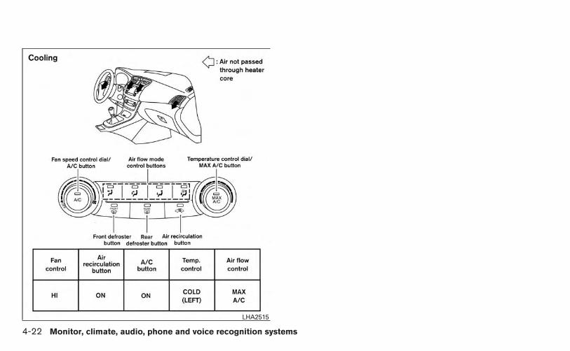
LHA2515
4-22 Monitor, climate, audio, phone and voice recognition systems

1. Temperature control buttons (driver’sside)
2. (front defroster) button3. (rear window defroster) button4. Display screen
5. MODE (manual air flow control) button6. Fresh air intake button7. Air recirculation button8. Temperature control buttons (passen-
ger’s side)
9. DUAL button10. A/C (air conditioner) button11. (fan speed control) buttons12. AUTO (automatic) button13. ON-OFF button
WARNING
● The air conditioner cooling function op-erates only when the engine is running.
● Do not leave children or adults whowould normally require the assistanceof others alone in your vehicle. Petsshould also not be left alone. Theycould accidentally injure themselves orothers through inadvertent operation ofthe vehicle. Also, on hot, sunny days,temperatures in a closed vehicle couldquickly become high enough to causesevere or possibly fatal injuries topeople or animals.
● Do not use the recirculation mode forlong periods as it may cause the interiorair to become stale and the windows tofog up.
Start the engine and operate the controls toactivate the air conditioner.
LHA2518
HEATER AND AIR CONDITIONER(automatic) (if so equipped)
Monitor, climate, audio, phone and voice recognition systems 4-23

AUTOMATIC OPERATIONCooling and/or dehumidified heating(AUTO)This mode may be used all year round as thesystem automatically works to keep a constanttemperature. Air flow distribution and fan speedare also controlled automatically.
1. Press the AUTO button on. (The indicator onthe button will illuminate and AUTO will bedisplayed.)
2. Use the temperature control buttons to setthe desired temperature.
● Adjust the temperature display to about75°F (24°C) for normal operation.
● The temperature of the passenger compart-ment will be maintained automatically. Airflow distribution and fan speed are also con-trolled automatically.
● A visible mist may be seen coming from thevents in hot, humid conditions as the air iscooled rapidly. This does not indicate a mal-function.
3. You can individually set driver’s and frontpassenger’s side temperature using eachset of temperature control buttons. Whenthe DUAL button or passenger’s side tem-perature control buttons are pressed, the
DUAL indicator will come on. To turn off thepassenger’s side temperature control, pressthe DUAL button.
Heating (A/C OFF)
The air conditioner does not activate. When youneed to heat only, use this mode.
1. Press the A/C button. (A/C OFF will bedisplayed and A/C indicator will turn off.)
2. Use the temperature control buttons to setthe desired temperature.
● The temperature of the passenger compart-ment will be maintained automatically. Airflow distribution and fan speed are also con-trolled automatically.
● Do not set the temperature lower than theoutside air temperature or the system maynot work properly.
● Not recommended if windows fog up.
Dehumidified defrosting or defogging
1. Press the front defroster button on.(The indicator light on the button will comeon.)
2. Use the temperature control buttons to setthe desired temperature.
● To quickly remove ice from the outside of thewindows, use the fan speed control dial toset the fan speed to maximum.
● As soon as possible after the windshield isclean, press the AUTO button to return tothe automatic mode.
● When the front defroster button ispressed, the air conditioner will automati-cally be turned on at outside temperaturesabove 36°F (2°C) (The indicator light may ormay not illuminate). The air recirculate modeautomatically turns off, allowing outside airto be drawn into the passenger compart-ment to further improve the defogging per-formance.
MANUAL OPERATION
Fan speed control
Press the fan control buttons to manuallycontrol the fan speed.
Press the AUTO button to return to automaticcontrol of the fan speed.
Air recirculation
Press the air recirculation button to recir-culate interior air inside the vehicle. Theindicator light on the button will come on.
4-24 Monitor, climate, audio, phone and voice recognition systems

The air recirculation cannot be activated whenthe air conditioner is in the front defrostingmode or the front defrosting and foot out-let mode.
Fresh air intake
Press the fresh air intake button to drawoutside air into the passenger compartment.The indicator light on the button will comeon.
Automatic intake air control
In the AUTO mode, the intake air will be con-trolled automatically. To manually control the in-take air, press the air recirculation button.To return to the automatic control mode, pressand hold the air recirculation button orpress and hold the fresh air intake buttonfor about 2 seconds. The indicator lights (both airrecirculation and fresh air intake buttons) willflash twice, and then the intake air will be con-trolled automatically.
Air flow controlPressing the MODE button manually controls airflow and selects the air outlet:
— Air flows from center and sidevents.
— Air flows from center and sidevents and foot outlets.
— Air flows mainly from foot outlets.— Air flows from defroster and foot
outlets.— Air flows from defroster outlets.
To turn system offPress the OFF button.
Rear window and outside mirror (if soequipped) defroster switchFor more information about the rear window andoutside mirror (if so equipped) defroster switch,see “Rear window and outside mirror defrosterswitch” in the “Instruments and controls” sectionof this manual.
OPERATING TIPS● When the engine coolant temperature and
outside air temperature are low, the air flowfrom the foot outlets may not operate for amaximum of 150 seconds. However, this isnot a malfunction. After the coolant tempera-ture warms up, air flow from the foot outletswill operate normally.
The sunload sensor (if so equipped), located onthe top passenger’s side of the instrument panel,helps the system maintain a constant tempera-ture. Do not put anything on or around this sen-sor.
LHA2510
Monitor, climate, audio, phone and voice recognition systems 4-25

The air conditioner system in your NISSAN ve-hicle is charged with a refrigerant designed withthe environment in mind.
This refrigerant does not harm the earth’sozone layer.
Special charging equipment and lubricant is re-quired when servicing your NISSAN air condi-tioner. Using improper refrigerants or lubricantswill cause severe damage to your air conditionersystem. See “Air conditioner system refrigerantand oil recommendations” in the “Technical andconsumer information” section of this manual.
A NISSAN dealer is able to service your “environ-mentally friendly” air conditioning system.
WARNING
The air conditioner system contains re-frigerant under high pressure. To avoidpersonal injury, any air conditioner ser-vice should be done only by an experi-enced technician with proper equipment.
RADIO
With the ignition placed in the ACC or ON posi-tion, press the PWR (power)/VOL (volume) knobto turn the radio on. If you listen to the radio withthe engine not running, the ignition should beplaced in the ACC position.
Radio reception is affected by station signalstrength, distance from radio transmitter, build-ings, bridges, mountains and other external influ-ences. Intermittent changes in reception qualitynormally are caused by these external influences.
Using a cellular phone in or near the ve-hicle may influence radio reception quality.
Radio reception
Your NISSAN radio system is equipped withstate-of-the-art electronic circuits to enhance ra-dio reception. These circuits are designed toextend reception range, and to enhance the qual-ity of that reception.
However, there are some general characteristicsof both FM and AM radio signals that can affectradio reception quality in a moving vehicle, evenwhen the finest equipment is used. These char-acteristics are completely normal in a given re-ception area and do not indicate any malfunctionin your NISSAN radio system.
Reception conditions will constantly change be-cause of vehicle movement. Buildings, terrain,signal distance and interference from other ve-hicles can work against ideal reception. De-scribed below are some of the factors that canaffect your radio reception.
Some cellular phones or other devices maycause interference or a buzzing noise to comefrom the audio system speakers. Storing the de-vice in a different location may reduce or elimi-nate the noise.
FM RADIO RECEPTIONRange: FM range is normally limited to 25 – 30 mi(40 – 48 km), with monaural (single channel) FMhaving slightly more range than stereo FM. Exter-nal influences may sometimes interfere with FMstation reception even if the FM station is within25 mi (40 km). The strength of the FM signal isdirectly related to the distance between thetransmitter and receiver. FM signals follow a line-of-sight path, exhibiting many of the same char-acteristics as light. For example, they will reflectoff objects.
Fade and drift: As your vehicle moves away froma station transmitter, the signals will tend to fadeand/or drift.
SERVICING AIR CONDITIONER (if soequipped)
AUDIO SYSTEM
4-26 Monitor, climate, audio, phone and voice recognition systems

Static and flutter: During signal interference frombuildings, large hills or due to antenna position(usually in conjunction with increased distancefrom the station transmitter), static or flutter canbe heard. This can be reduced by adjusting thetreble control to reduce treble response.
Multipath reception: Because of the reflectivecharacteristics of FM signals, direct and reflectedsignals reach the receiver at the same time. Thesignals may cancel each other, resulting in mo-mentary flutter or loss of sound.
AM RADIO RECEPTIONAM signals, because of their low frequency, canbend around objects and skip along the ground.In addition, the signals can be bounced off theionosphere and bent back to earth. Because ofthese characteristics, AM signals are also sub-ject to interference as they travel from transmitterto receiver.
Fading: Occurs while the vehicle is passingthrough freeway underpasses or in areas withmany tall buildings. It can also occur for severalseconds during ionospheric turbulence even inareas where no obstacles exist.
Static: Caused by thunderstorms, electricalpower lines, electric signs and even traffic lights.
SATELLITE RADIO RECEPTION (if soequipped)When the satellite radio is used for the first timeor the battery has been replaced, the satelliteradio may not work properly. This is not a mal-function. Wait more than 10 minutes with satelliteradio ON and the vehicle outside of any metal orlarge building for satellite radio to receive all ofthe necessary data.
No satellite radio reception is available and “NOSAT” is displayed when the SAT band option isselected unless optional satellite receiver andantenna are installed and a SiriusXM SatelliteRadio service subscription is active. Satellite ra-dio is not available in Alaska, Hawaii and Guam.
Satellite radio performance may be affected ifcargo carried on the roof blocks the satellite radiosignal.
If possible, do not put cargo over the satelliteantenna.
A build up of ice on the satellite radio antenna canaffect satellite radio performance. Remove theice to restore satellite radio reception. AUDIO OPERATION PRECAUTIONS
LHA0099
Monitor, climate, audio, phone and voice recognition systems 4-27

Compact disc (CD) player
CAUTION
● Do not force a compact disc into the CDinsert slot. This could damage the CDand/or CD player.
● Trying to load a CD with the CD doorclosed could damage the CD and/or CDplayer.
● Only one CD can be loaded into the CDplayer at a time.
● Only use high quality 4.7 in (12 cm)round discs that have the “COMPACTdisc DIGITAL AUDIO” logo on the discor packaging.
● During cold weather or rainy days, theplayer may malfunction due to the hu-midity. If this occurs, remove the CDand dehumidify or ventilate the playercompletely.
● The player may skip while driving onrough roads.
● The CD player sometimes cannot func-tion when the compartment tempera-ture is extremely high or low.Decrease/increase the temperaturebefore use.
● Do not expose the CD to direct sun-light.
● CDs that are in poor condition or aredirty, scratched or covered with finger-prints may not work properly.
● The following CDs may not work prop-erly:
● Copy control compact discs (CCCD)
● Recordable compact discs (CD-R)
● Rewritable compact discs (CD-RW)
● Do not use the following CDs as theymay cause the CD player to malfunc-tion:
● 3.1 in (8 cm) discs with an adapter
● CDs that are not round
● CDs with a paper label
● CDs that are warped, scratched, orhave abnormal edges
● This audio system can only play pre-recorded CDs. It has no capability torecord or burn CDs.
● If the CD cannot be played, one of thefollowing messages will be displayed.
CHECK DISC:
● Confirm that the CD is inserted cor-rectly (the label side is facing up,etc.).
● Confirm that the CD is not bent orwarped and it is free of scratches.
PRESS EJECT:
This is an error due to excessive tem-perature inside the player. Remove theCD by pressing the EJECT button. Aftera short time, reinsert the CD. The CDcan be played when the temperature ofthe player returns to normal.
UNPLAYABLE:
The file is unplayable in this audio sys-tem (only MP3 or WMA (if so equipped)CD).
4-28 Monitor, climate, audio, phone and voice recognition systems

Compact disc with MP3 or WMA (ifso equipped)
Terms:
● MP3 — MP3 is short for Moving PicturesExperts Group Audio Layer 3. MP3 is themost well-known compressed digital audiofile format. This format allows for near “CDquality” sound, but at a fraction of the size ofnormal audio files. MP3 conversion of anaudio track from CD-ROM can reduce thefile size by approximately a 10:1 ratio withvirtually no perceptible loss in quality. MP3compression removes the redundant andirrelevant parts of a sound signal that thehuman ear doesn’t hear.
● WMA — Windows Media Audio (WMA)* is acompressed audio format created by Micro-soft as an alternative to MP3. The WMAcodec offers greater file compression thanthe MP3 codec, enabling storage of moredigital audio tracks in the same amount ofspace when compared to MP3s at the samelevel of quality.
● Bit rate — Bit rate denotes the number ofbits per second used by a digital music file.The size and quality of a compressed digitalaudio file is determined by the bit rate usedwhen encoding the file.
● Sampling frequency — Sampling frequencyis the rate at which the samples of a signalare converted from analog to digital (A/Dconversion) per second.
● Multisession — Multisession is one of themethods for writing data to media. Writingdata once to the media is called a singlesession, and writing more than once is calleda multisession.
● ID3/WMA Tag — The ID3/WMA tag is thepart of the encoded MP3 or WMA file thatcontains information about the digital musicfile such as song title, artist, encoding bitrate, track time duration, etc. ID3 tag infor-mation is displayed on the Artist/song titleline on the display.
* Windows® and Windows Media® are regis-tered trademarks and trademarks in the UnitedStates of America and other countries of Micro-soft Corporation of the USA.
Playback order chartWHA1078
Monitor, climate, audio, phone and voice recognition systems 4-29

Playback order:
Music playback order of a CD with MP3 or WMAfiles is as illustrated.
● The names of folders not containing MP3 orWMA files are not shown in the display.
● If there is a file in the top level of the disc,“Root Folder” is displayed.
● The playback order is the order in which thefiles were written by the writing software.Therefore, the files might not play in thedesired order.
4-30 Monitor, climate, audio, phone and voice recognition systems

Specification chart:
Supported media CD, CD-R, CD-RWSupported file systems ISO9660 LEVEL1, ISO9660 LEVEL2, Apple ISO, Romeo, Joliet * ISO9660 Level 3 (packet writing) is not supported.
Supportedversions*1
MP3Version MPEG1, MPEG2, MPEG2.5Sampling frequency 8 kHz - 48 kHzBit rate 8 kbps - 320 kbps, VBR
WMA Version WMA7, WMA8, WMA9Sampling frequency 32 kHz - 48 kHzBit rate 48 kbps - 192 kbps, VBR
Tag information ID3 tag VER1.0, VER1.1, VER2.2, VER2.3 (MP3 only)Folder levels Folder levels: 8, Max folders: 255 (including root folder), Files: 512 (Max. 255 files for one folder)Text character number limitation 128 characters
Displayable character codes*201: ASCII, 02: ISO-8859-1, 03: UNICODE (UTF-16 BOM Big Endian), 04: UNICODE (UTF-16 Non-BOM Big Endian), 05:UNICODE (UTF-8), 06: UNICODE (Non-UTF-16 BOM Little Endian)
*1 Files created with a combination of 48 kHz sampling frequency and 64 kbps bit rate cannot be played.
*2 Available codes depend on what kind of media, versions and information are going to be displayed.
Monitor, climate, audio, phone and voice recognition systems 4-31

Troubleshooting guide:
Symptom Cause and Countermeasure
Cannot play
Check if the disc was inserted correctly.Check if the disc is scratched or dirty.Check if there is condensation inside the player. If there is, wait until the condensation is gone (about 1 hour) before using the player.If there is a temperature increase error, the CD player will play correctly after it returns to the normal temperature.If there is a mixture of music CD files (CD-DA data) and MP3/WMA files on a CD, only the music CD files (CD-DA data) will be played.Files with extensions other than “.MP3”,“.WMA”, “.mp3” or “.wma” cannot be played. In addition, the character codes and number of characters forfolder names and file names should be in compliance with the specifications.Check if the finalization process, such as session close and disc close, is done for the disc.Check if the disc is protected by copyright.
Poor sound qualityCheck if the disc is scratched or dirty.Bit rate may be too low.
It takes a relatively long timebefore the music startsplaying.
If there are many folders or file levels on the MP3/WMA disc, or if it is a multisession disc, some time may be required before the music starts playing.
Music cuts off or skipsThe writing software and hardware combination might not match, or the writing speed, writing depth, writing width, etc., might not match thespecifications. Try using the slowest writing speed.
Skipping with high bit ratefiles
Skipping may occur with large quantities of data, such as for high bit rate data.
Moves immediately to thenext song when playing
When a non-MP3/WMA file has been given an extension of “.MP3”, “.WMA”, .“mp3”or “.wma”, or when play is prohibited by copyright protection, therewill be approximately 5 seconds of no sound and then the player will skip to the next song.
Songs do not play back inthe desired order
The playback order is the order in which the files were written by the writing software. Therefore, the files might not play in the desired order.
4-32 Monitor, climate, audio, phone and voice recognition systems

USB (Universal Serial Bus) memory (ifso equipped)
WARNING
Do not connect or disconnect the USBdevice while driving. Doing so can be adistraction. If distracted you could losecontrol of your vehicle and cause an acci-dent or serious injury.
CAUTION
● Do not force the USB device into theUSB port. Inserting the USB devicetilted or up-side-down into the port maydamage the USB device and the port.Make sure that the USB device is con-nected correctly into the USB port.
● Do not grab the USB port cover (if soequipped) when pulling the USB deviceout of the port. This could damage theport and the cover.
● Do not leave the USB cable in a placewhere it can be pulled unintentionally.Pulling the cable may break the wire,USB device or the port.
● To avoid damage and loss of functionwhen using a USB device, note the fol-lowing precautions.
– Do not bend the cable excessively(1.6 in [40 mm]) radius minimum.
– Do not twist the cable excessively(more than 180 degrees).
– Do not pull or drop the cable.
– Do not hit or press the USB port orUSB device with hands, feet, orobjects.
– Do not store objects with sharpedges in the storage area where thecable is stored.
– Do not leave the USB device andattached devices in the vehicle com-partment. When not in use for ex-tended periods of time, store thecable and USB device in a clean, dustfree environment at room tempera-ture and without direct sun exposure.
– Do not use the cable for any otherpurposes than its intended use in thevehicle.
The vehicle is not equipped with a USB device.USB devices should be purchased separately asnecessary.
This system cannot be used to format USB de-vices. To format a USB device, use a personalcomputer.
In some states/area, the USB device for the frontseats plays only sound without images for regu-latory reasons, even when the vehicle is parked.
This system supports various USB memory de-vices, USB hard drives and iPod® players. SomeUSB devices may not be supported by this sys-tem.
● Partitioned USB devices may not play cor-rectly.
● Some characters used in other languages(Chinese, Japanese, etc.) may not appearproperly in the display. Using English lan-guage characters with a USB device is rec-ommended.
General notes for USB use:
● The USB device may not function when thepassenger compartment temperature is ex-tremely high. Lower the temperature beforeuse.
● During cold weather or rainy days, the playermay malfunction due to humidity. If this oc-curs, remove the USB device and dehu-midify or ventilate the USB player com-pletely.
Monitor, climate, audio, phone and voice recognition systems 4-33
● Do not connect a USB device if a connector,cable or USB port is wet. Allow the connector,cable, and USB port to dry completely beforeconnecting the USB device. (Wait for24 hours or more until it is dry.) If the connec-tor and USB port are exposed to fluids otherthan water, evaporative residue may cause ashort circuit between the connector pins andUSB port. In this case, replace the cable andUSB port. Otherwise damage to the USBdevice and a loss of function may occur.
● If the cable is damaged (insulation cut, con-nectors cracked, contamination such as liq-uids, dust, dirt, etc. in the connectors), donot use the cable. Replace the cable with anew one.
● Do not put a USB device in a location wherestatic electricity occurs, electrical noise isgenerated or hot air from the air conditionerblows directly on it. Doing so may cause thedata stored on the USB device to be cor-rupted.
Notes for iPod® use:
iPod® is a trademark of Apple Inc., registered inthe U.S. and other countries.
● Improperly plugging in the iPod may cause acheckmark to be displayed on and off (flick-ering). Always make sure that the iPod isconnected properly.
● An iPod® nano (1st Generation) may remainin fast forward or rewind mode if it is con-nected during a seek operation. In this case,please manually reset the iPod.
● An iPod® nano (2nd Generation) will con-tinue to fast-forward or rewind if it is discon-nected during a seek operation.
● An incorrect song title may appear when thePlay Mode is changed while using an iPod®nano (2nd Generation).
● Audiobooks may not play in the same orderas they appear on an iPod®.
● Large video files cause slow responses in aniPod®. The vehicle center display may mo-mentarily black out, but will soon recover.
● If an iPod® automatically selects large videofiles while in the shuffle mode, the vehiclecenter display may momentarily black out,but will soon recover.
Bluetooth® streaming audio (if soequipped)
● Some Bluetooth® audio devices may not berecognized by the in-vehicle audio system.
● It is necessary to set up the wireless con-nection between a compatible Bluetooth®audio device and the in-vehicle Bluetooth®module before using the Bluetooth® audio.
● Operating procedure of the Bluetooth® au-dio will vary depending on the devices. Makesure how to operate your audio device be-fore using it with this system.
● The Bluetooth® audio may be stopped un-der the following conditions:
● Receiving a call on the Hands-FreePhone System.
● Checking the connection to the hands-free phone.
● Do not place the Bluetooth® audio device inan area surrounded by metal or far away fromthe in-vehicle Bluetooth® module to preventtone quality degradation and wireless con-nection disruption.
● While an audio device is connected throughthe Bluetooth® wireless connection, thebattery power of the device may dischargequicker than usual.
● This system supports the Bluetooth® AudioDistribution Profile (A2DP, AVRCP).
BLUETOOTH® is atrademark owned byBluetooth SIG, Inc.and licensed toVisteon and Bosch.
4-34 Monitor, climate, audio, phone and voice recognition systems

1. CD eject button2. CD insert slot3. SCAN button4. DISP button5. RPT/RDM button6. TUNE/FOLDER knob / MENU button
7. AUX IN jack8. AUX button9. CD button10. AM button11. FM button
12. VOL (volume) control knob / power but-ton
13. Station select (1 - 6) buttons14. TRACK button15. SEEK button
FM/AM RADIO WITH COMPACTDISC (CD) PLAYER (if so equipped)
For all operation precautions, see “Audio opera-tion precautions” in this section.
Audio main operation
VOL (volume) control knob / power but-ton
Place the ignition switch in the ACC or ONposition, then press the VOL (volume) controlknob / power button. If you listen to the radio withthe engine not running, place the ignition in theACC position. The mode (radio or CD) that wasplaying immediately before the system wasturned off resumes playing.
When no CD is loaded, the radio comes on.Pressing the VOL (volume) control knob / powerbutton again turns the system off.
Turn the VOL (volume) control knob / powerbutton to the right to increase volume or to the leftto decrease volume.
LHA2241
Monitor, climate, audio, phone and voice recognition systems 4-35

MENU button (Bass, Treble, Balance,Fade, Speed Sensitive Volume andClock):
Press the MENU button to change the mode asfollows:
Bass → Treble → Balance → Fade → Spd. Sen.Vol. (Speed Sensitive Volume) → AUX IN Volume→ Clock → Clock Adjust
To adjust the Bass, Treble, Fade and Balance,press the MENU button until the desired modeappears in the display. Press the SEEK orTRACK button to adjust the setting to thedesired level (-5 to +5). Balance adjusts thesound between the right and left speakers. Fadeadjusts the sound between the front and rearspeakers.
Once you have adjusted the sound quality to thedesired level, press the MENU button repeatedlyuntil the radio or CD display reappears. Other-wise, the radio or CD display will automaticallyreappear after about 10 seconds.
Speed Sensitive Volume (SSV) adjusts the vol-ume of the audio system as the vehicle’s drivingspeed changes. It can be set as follows:
OFF → LOW → MID → HIGH
DISP (display) button:
Press the DISP (display) button while a CD isplaying to change the text shown in the audiodisplay as follows:
For CDs:
Running Time → Album Title: → Artist Name: →Song Title
For MP3 CDs:
Running Time → Folder Title: → Album Title: →Artist Name: → Song Title:
If the text information is too long to fully be dis-played on the screen; press and hold the DISPbutton for longer than 1.5 seconds to scrollthrough the rest of the text.
Press the DISP (display) button while the radio isplaying to toggle the audio display between sta-tion number and RDS.
Clock operation
To turn the clock display on or off, press theMENU button repeatedly until “Clock” appearson the display. Turn the TUNE/FOLDER knob totoggle the setting (ON or OFF).
Clock set
1. Press the MENU button repeatedly until“Adjust Clock” appears on the display.
2. Press the ENTER button.
3. “Change Hour” will appear on the screen.Turn the TUNE/FOLDER knob to adjust thehours and then press ENTER.
4. “Change Minute” will appear on the screen.Turn the TUNE/FOLDER knob to adjust theminutes and then press ENTER.
The display will return to the regular clock displayafter 10 seconds if no further adjustment is per-formed.
FM/AM radio operation
AM and FM buttons:
Press the AM button to change the band to AM.
If another audio source is playing when the AMbutton is pressed, the audio source playing willautomatically be turned off and the last radiostation played will begin playing.
Press the FM button to change the band asfollows:
FM1 → FM2 → FM1
If another audio source is playing when the FMbutton is pressed, the audio source playing willautomatically be turned off and the last radiostation played will begin playing.
4-36 Monitor, climate, audio, phone and voice recognition systems

The FM stereo indicator (ST) illuminates duringFM stereo reception. When the stereo broadcastsignal is weak, the radio automatically changesfrom stereo to monaural reception.
SEEK and TRACK (tuning)
buttons:
Press the SEEK button to tune from low tohigh frequencies and stop at the next broadcast-ing station.
Press the TRACK button to tune from highto low frequencies and stop at the next broad-casting station.
Press and hold either button to seek at a fasterspeed.
SCAN (tuning) button:
Press the SCAN button. SCAN illuminates in thedisplay window. Scan tuning begins from low tohigh frequencies. Scan tuning stops for 5 sec-onds at each broadcasting station that has suffi-cient signal strength. When scanning, SCANblinks in the display. Pressing the SCAN buttonagain during this 5 second period stops scantuning and the radio remains tuned to that station.
1 to 6 Station memory operations:
Twelve stations can be set for the FM band (6 forFM1, 6 for FM2) and six stations can be set forthe AM band.
1. Choose the radio band AM, FM1 or FM2using the AM or FM button.
2. Tune to the desired station using manual,SEEK or SCAN tuning. Press and hold anyof the desired station memory buttons (1 –6) until a beep sound is heard.
3. The channel indicator will then come on andthe sound will resume. Programming is nowcomplete.
4. Other buttons can be set in the same man-ner.
If the battery cable is disconnected or if the fuseopens, the radio memory will be canceled. In thatcase, reset the desired stations.
Compact disc (CD) player operationPlace the ignition switch in the ACC or ONposition, and carefully insert the compact discinto the slot with the label side up. The compactdisc is automatically pulled into the slot and startsto play.
If the radio is already operating, it automaticallyturns off and the compact disc begins to play.
CD button:
When the CD button is pressed with a compactdisc loaded and the radio playing, the radio turnsoff and the last used compact disc starts to play.
SEEK and TRACK
(Fast Forward, Rewind)
buttons:
When the SEEK button or TRACKbutton is pressed while the compact disc is play-ing, the compact disc plays at an increasedspeed while fast forwarding or rewinding. Whenthe button is released, the compact disc returnsto normal play speed.
SEEK and TRACK
buttons:
When the SEEK button is pressed whilethe compact disc is playing, the next track follow-ing the present one starts to play from the begin-ning. Press the SEEK button several timesto skip several tracks. Each time the button ispressed, the CD advances one additional track.The track number appears in the display window.(When the last track on the compact disc isskipped, the first track is played.)
Monitor, climate, audio, phone and voice recognition systems 4-37

When the TRACK button is pressed, thetrack being played returns to the beginning.Press the TRACK button several times toskip back several tracks. Each time the button ispressed the CD moves back one track.
RPT/RDM button:
Press the RPT/RDM button while a compact discis playing to change the play pattern as follows:
CD:
TRACK REPEAT → DISC RANDOM → DISCREPEAT
MP3/WMA CD:
FOLDER REPEAT → TRACK REPEAT → DISCRANDOM → FOLDER RANDOM → DISC RE-PEAT
TRACK REPEAT: The track that is currently play-ing will be repeated.
DISC RANDOM: The order of the tracks on thedisc will be mixed during play.
DISC REPEAT: The disc currently playing will berepeated.
FOLDER REPEAT: The tracks in the currentfolder will be repeated.
FOLDER RANDOM: The order of the tracks inthe folder will be mixed during play.
SCAN (CDs) button:
Press the SCAN button for less than 1.5 secondsto scan all tracks of the current disc for 10 sec-onds per track. The SCAN icon is flashed duringscan mode.
The scan mode is canceled once it scans throughall tracks on the disc, or if the SCAN button ispressed during scan mode.
CD EJECT:
When the button is pressed with a com-pact disc loaded, the compact disc will beejected.
When the button is pressed while thecompact disc is playing, the compact disc willeject and the system will turn off.
AUX (Auxiliary) button:
The AUX IN jack is located on the CD player. TheAUX IN audio input jack accepts any standardanalog audio input such as from a portable cas-sette tape/CD player, MP3 player or laptop com-puters.
Press the AUX button to play a compatible devicewhen it is plugged into the AUX IN jack.
Press the MENU button repeatedly until “AUX INVolume” appears on the screen to control theincoming volume level of the auxiliary input de-
vice. Turn the TUNE/FOLDER knob to adjust thelevel between 0 and +3.
Additional featuresFor more information about the Bluetooth® audiointerface available with this system, see“Bluetooth® streaming audio without NavigationSystem” in this section.
4-38 Monitor, climate, audio, phone and voice recognition systems

1. CD eject button2. XM button*3. CD insert slot4. Display screen5. SEEK button6. SCAN button
7. CAT button8. BACK button9. iPod MENU button10.TUNE/SCROLL knob, ENTER/SETTING
button11.AUX IN jack
12.Station select (1 - 6) buttons13.RDM button14.RPT button15.DISP button16.VOL (volume) knob / PWR (power)
button17.CD•AUX button18.FM•AM button
*No satellite radio reception is availablewhen the XM button is pressed to accesssatellite radio stations unless optionalsatellite receiver and antenna are installedand an SiriusXM Satellite Radio servicesubscription is active. Satellite radio isnot available in Alaska, Hawaii and Guam.
LHA2501
Monitor, climate, audio, phone and voice recognition systems 4-39

FM/AM/SAT RADIO WITHCOMPACT DISC (CD) PLAYER (TypeA) (if so equipped)For all operation precautions, see “Audio opera-tion precautions” in this section.
Audio main operationVOL (volume) knob / ON-OFF button:
Place the ignition switch in the ACC or ONposition and press the VOL (volume) knob /ON-OFF button while the system is off to call upthe mode that was playing immediately before thesystem was turned off.
To turn the system off, press the VOL (volume)knob / ON-OFF button.
Turn the VOL (volume) knob / ON-OFF button toadjust the volume.
SETTING button:
Press the SETTING button to show the Settingsscreen on the display. Turn the TUNE/SCROLLknob to navigate the options and then press theENTER button to make a selection.
Bass, Treble, Balance and Fade
Increase or decrease the level of bass, treble,balance or fade. Balance controls the level ofsound between the left and right speakers. Fadecontrols the level of sound between the front andrear speakers.
Speed Sens Vol. (Speed Sensitive Volume)
Speed Sensitive Volume adjusts the volume ofthe audio system as the vehicle’s driving speedchanges. The feature can be turned off or set to alevel of 1 to 5. Level 5 represents the highestdegree of volume adjustment.
AUX Vol.
Choose a setting from 0 to +3 to control theboost of the incoming auxiliary device volume. Asetting of 0 provides no additional boost in vol-ume. A setting of +3 provides the greatest boostin volume.
LHA2257 LHA2258
4-40 Monitor, climate, audio, phone and voice recognition systems

Brightness and Contrast
Adjust the brightness or contrast to adjust theappearance of the display screen.
Clock Adjust
Press the ENTER button to highlight the hours orminutes and then use the TUNE/SCROLL knobto adjust the value. Press the ENTER buttonagain to set the value.
On-Screen Clock
Select “ON” or “OFF” to control whether or notthe clock is shown in the upper right corner of thedisplay screen.
RDS Display
Select “ON” or “OFF” to control whether or notRDS information is displayed on the screen whilethe radio is playing.
Language Select
Select the desired language for the system. Eng-lish, Spanish and French are the available lan-guages.
iPod® MENU button
This button can only be used for iPod® opera-tions. See “iPod® player operation without Navi-gation System” later in this section for detailsabout the function of this button.
FM/AM/SAT radio operation
FM·AM button:
Press the FM·AM button to change the band asfollows:
AM → FM1 → FM2 → AM
If another audio source is playing when theFM·AM button is pressed, the audio source play-ing will automatically be turned off and the lastradio station played will begin playing.
The FM stereo indicator (STEREO) is shown onthe screen during FM stereo reception. When thestereo broadcast signal is weak, the radio auto-matically changes from stereo to monaural re-ception.
XM band select:
Press the XM button to change the band asfollows:
XM1* → XM2* → XM3* → XM1 (satellite, if soequipped)
LHA2259
Monitor, climate, audio, phone and voice recognition systems 4-41
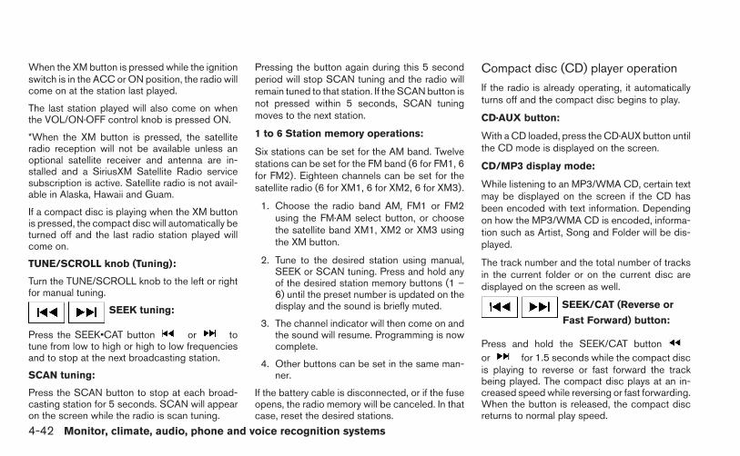
When the XM button is pressed while the ignitionswitch is in the ACC or ON position, the radio willcome on at the station last played.
The last station played will also come on whenthe VOL/ON·OFF control knob is pressed ON.
*When the XM button is pressed, the satelliteradio reception will not be available unless anoptional satellite receiver and antenna are in-stalled and a SiriusXM Satellite Radio servicesubscription is active. Satellite radio is not avail-able in Alaska, Hawaii and Guam.
If a compact disc is playing when the XM buttonis pressed, the compact disc will automatically beturned off and the last radio station played willcome on.
TUNE/SCROLL knob (Tuning):
Turn the TUNE/SCROLL knob to the left or rightfor manual tuning.
SEEK tuning:
Press the SEEK•CAT button or totune from low to high or high to low frequenciesand to stop at the next broadcasting station.
SCAN tuning:
Press the SCAN button to stop at each broad-casting station for 5 seconds. SCAN will appearon the screen while the radio is scan tuning.
Pressing the button again during this 5 secondperiod will stop SCAN tuning and the radio willremain tuned to that station. If the SCAN button isnot pressed within 5 seconds, SCAN tuningmoves to the next station.
1 to 6 Station memory operations:
Six stations can be set for the AM band. Twelvestations can be set for the FM band (6 for FM1, 6for FM2). Eighteen channels can be set for thesatellite radio (6 for XM1, 6 for XM2, 6 for XM3).
1. Choose the radio band AM, FM1 or FM2using the FM·AM select button, or choosethe satellite band XM1, XM2 or XM3 usingthe XM button.
2. Tune to the desired station using manual,SEEK or SCAN tuning. Press and hold anyof the desired station memory buttons (1 –6) until the preset number is updated on thedisplay and the sound is briefly muted.
3. The channel indicator will then come on andthe sound will resume. Programming is nowcomplete.
4. Other buttons can be set in the same man-ner.
If the battery cable is disconnected, or if the fuseopens, the radio memory will be canceled. In thatcase, reset the desired stations.
Compact disc (CD) player operation
If the radio is already operating, it automaticallyturns off and the compact disc begins to play.
CD·AUX button:
With a CD loaded, press the CD·AUX button untilthe CD mode is displayed on the screen.
CD/MP3 display mode:
While listening to an MP3/WMA CD, certain textmay be displayed on the screen if the CD hasbeen encoded with text information. Dependingon how the MP3/WMA CD is encoded, informa-tion such as Artist, Song and Folder will be dis-played.
The track number and the total number of tracksin the current folder or on the current disc aredisplayed on the screen as well.
SEEK/CAT (Reverse or
Fast Forward) button:
Press and hold the SEEK/CAT buttonor for 1.5 seconds while the compact discis playing to reverse or fast forward the trackbeing played. The compact disc plays at an in-creased speed while reversing or fast forwarding.When the button is released, the compact discreturns to normal play speed.
4-42 Monitor, climate, audio, phone and voice recognition systems
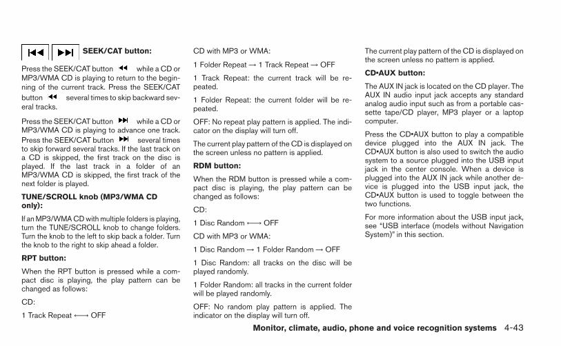
SEEK/CAT button:
Press the SEEK/CAT button while a CD orMP3/WMA CD is playing to return to the begin-ning of the current track. Press the SEEK/CATbutton several times to skip backward sev-eral tracks.
Press the SEEK/CAT button while a CD orMP3/WMA CD is playing to advance one track.Press the SEEK/CAT button several timesto skip forward several tracks. If the last track ona CD is skipped, the first track on the disc isplayed. If the last track in a folder of anMP3/WMA CD is skipped, the first track of thenext folder is played.
TUNE/SCROLL knob (MP3/WMA CDonly):
If an MP3/WMA CD with multiple folders is playing,turn the TUNE/SCROLL knob to change folders.Turn the knob to the left to skip back a folder. Turnthe knob to the right to skip ahead a folder.
RPT button:
When the RPT button is pressed while a com-pact disc is playing, the play pattern can bechanged as follows:
CD:
1 Track Repeat ←→ OFF
CD with MP3 or WMA:
1 Folder Repeat → 1 Track Repeat → OFF
1 Track Repeat: the current track will be re-peated.
1 Folder Repeat: the current folder will be re-peated.
OFF: No repeat play pattern is applied. The indi-cator on the display will turn off.
The current play pattern of the CD is displayed onthe screen unless no pattern is applied.
RDM button:
When the RDM button is pressed while a com-pact disc is playing, the play pattern can bechanged as follows:
CD:
1 Disc Random ←→ OFF
CD with MP3 or WMA:
1 Disc Random → 1 Folder Random → OFF
1 Disc Random: all tracks on the disc will beplayed randomly.
1 Folder Random: all tracks in the current folderwill be played randomly.
OFF: No random play pattern is applied. Theindicator on the display will turn off.
The current play pattern of the CD is displayed onthe screen unless no pattern is applied.
CD•AUX button:
The AUX IN jack is located on the CD player. TheAUX IN audio input jack accepts any standardanalog audio input such as from a portable cas-sette tape/CD player, MP3 player or a laptopcomputer.
Press the CD•AUX button to play a compatibledevice plugged into the AUX IN jack. TheCD•AUX button is also used to switch the audiosystem to a source plugged into the USB inputjack in the center console. When a device isplugged into the AUX IN jack while another de-vice is plugged into the USB input jack, theCD•AUX button is used to toggle between thetwo functions.
For more information about the USB input jack,see “USB interface (models without NavigationSystem)” in this section.
Monitor, climate, audio, phone and voice recognition systems 4-43

EJECT button:
When the button is pressed with a com-pact disc loaded, the compact disc will eject andthe last source will be played.
When the button is pressed twice with acompact disc loaded, the compact disc will beejected further for easier CD removal. If the discis not removed within 20 seconds, the disc willreload.
Additional featuresFor more information about the iPod® playeravailable with this system, see “iPod® playeroperation without Navigation System” in this sec-tion.
For more information about the USB interfaceavailable with this system, see “USB interface(models without Navigation System)” in this sec-tion.
For more information about the Bluetooth® audiointerface available with this system, see“Bluetooth® streaming audio without NavigationSystem” in this section. 1. CD eject button
2. FM-AM button3. AUX button4. CD insert slot5. BACK button
6. TUNE knob / AUDIO button7. Display screen8. ON-OFF button / VOL (volume)9. Backward seek button and
Forward seek button
Type BLHA2500
4-44 Monitor, climate, audio, phone and voice recognition systems

10.CD button11.XM button*
*No satellite radio reception is availablewhen the XM button is pressed to accesssatellite radio stations unless optionalsatellite receiver and antenna are installedand an SiriusXM Satellite Radio servicesubscription is active. Satellite radio isnot available in Alaska, Hawaii and Guam.
FM/AM/SAT RADIO WITHCOMPACT DISC (CD) PLAYER (TypeB) (if so equipped)
For all operation precautions, see “Audio opera-tion precautions” in this section.
Audio main operation
VOL (volume) / ON-OFF button:
Place the ignition switch in the ACC or ONposition and press the ON-OFF button while thesystem is off to call up the mode (radio, CD, AUX,Bluetooth® audio USB or iPod®) that was play-ing immediately before the system was turned off.
To turn the system off, press the ON-OFF button.
Turn the VOL (volume) control knob to adjust thevolume.
This vehicle may be equipped with Speed Sen-sitive Volume. When this feature is active, theaudio volume changes as the driving speedchanges.
Audio settings:
1. Press the MENU button.
2. Select the “Settings” key.
3. Select the “Audio” key.
Use the touchscreen to adjust the following itemsto the desired setting:
Bass, Treble, Balance and Fade:Controls the sound of the audio system. Balanceadjusts the sound between the left and rightspeakers. Fade adjusts the sound between thefront and rear speakers.
LHA2261
Monitor, climate, audio, phone and voice recognition systems 4-45
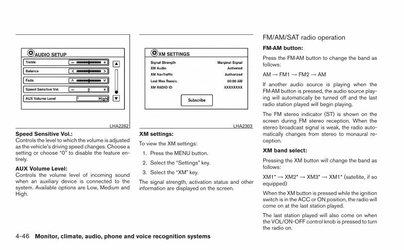
Speed Sensitive Vol.:Controls the level to which the volume is adjustedas the vehicle’s driving speed changes. Choose asetting or choose “0” to disable the feature en-tirely.
AUX Volume Level:Controls the volume level of incoming soundwhen an auxiliary device is connected to thesystem. Available options are Low, Medium andHigh.
XM settings:
To view the XM settings:
1. Press the MENU button.
2. Select the “Settings” key.
3. Select the “XM” key.
The signal strength, activation status and otherinformation are displayed on the screen.
FM/AM/SAT radio operation
FM·AM button:
Press the FM·AM button to change the band asfollows:
AM → FM1 → FM2 → AM
If another audio source is playing when theFM·AM button is pressed, the audio source play-ing will automatically be turned off and the lastradio station played will begin playing.
The FM stereo indicator (ST) is shown on thescreen during FM stereo reception. When thestereo broadcast signal is weak, the radio auto-matically changes from stereo to monaural re-ception.
XM band select:
Pressing the XM button will change the band asfollows:
XM1* → XM2* → XM3* → XM1* (satellite, if soequipped)
When the XM button is pressed while the ignitionswitch is in the ACC or ON position, the radio willcome on at the last station played.
The last station played will also come on whenthe VOL/ON-OFF control knob is pressed to turnthe radio on.
LHA2262 LHA2303
4-46 Monitor, climate, audio, phone and voice recognition systems

*When the XM button is pressed, the satelliteradio mode will be skipped unless an optionalsatellite receiver and antenna are installed and aSiriusXM Satellite Radio service subscription isactive. Satellite radio is not available in Alaska,Hawaii and Guam.
If a compact disc is playing when the XM buttonis pressed, the compact disc will automatically beturned off and the last radio station played willcome on.
While the radio is in XM mode, the operation canbe controlled through the touchscreen. Touchthe “Channels” key to display a list of channels.Touch a channel displayed on the list to changeto that channel. Touch the “Categories” key todisplay a list of categories. Touch a categorydisplayed on the list to display options within thatcategory.
Tuning with the touchscreen:
When in AM or FM mode, the radio can be tunedusing the touchscreen. To bring up the visualtuner, touch the “Tune” key on the lower rightcorner of the screen. A screen appears with a barrunning from low frequencies on the left to highfrequencies on the right. Touch the screen at thelocation of the frequency you wish to tune and thestation will change to that frequency. To return tothe regular radio display screen, touch the “OK”key.
LHA1492 LHA1489
Monitor, climate, audio, phone and voice recognition systems 4-47

Tuning with the TUNE knob:
The radio can also be manually tuned using theTUNE knob. When in FM or AM mode, turn theTUNE knob to the left for lower frequencies or tothe right for higher frequencies. When in XMmode, turn the TUNE knob to change the chan-nel.
SEEK tuning:
When in FM or AM mode, press the seek
buttons or to tune from low to highor high to low frequencies and to stop at the nextbroadcasting station.
When in XM mode, press the seek buttonsor to change the category. 1 to 6 Station memory operations:
Twelve stations can be set for the FM band (6 forFM1, 6 for FM2) and six stations can be set forthe AM band. Eighteen stations can be set for theXM band (6 for XM1, 6 for XM2, 6 for XM3).
1. Choose the radio band AM, FM1 or FM2using the FM·AM select button or choosethe radio band XM1, XM2 or XM3 using theXM button.
2. Tune to the desired station using manual orseek tuning. Press and hold any of the de-sired station memory buttons (1 – 6) until abeep sound is heard.
3. The channel indicator will then come on andthe sound will resume. Programming is nowcomplete.
4. Other buttons can be set in the same man-ner.
If the battery cable is disconnected or if the fuseopens, the radio memory will be canceled. In thatcase, reset the desired stations.
Presets can also be selected by touching thedesired preset number on the screen.
Compact disc (CD) player operationIf the radio is already operating, it automaticallyturns off and the compact disc begins to play.
CD button:
When the CD button is pressed with the systemoff and the compact disc loaded, the system willturn on and the compact disc will start to play.
When the CD button is pressed with a compactdisc loaded and the radio playing, the radio willautomatically be turned off and the compact discwill start to play.
LHA2263
4-48 Monitor, climate, audio, phone and voice recognition systems

CD/MP3 display mode
While listening to a CD or an MP3/WMA CD,certain text may be displayed (when a CD en-coded with text is being used). Depending onhow the CD or MP3/WMA CD is encoded, thetext is displayed listing the artist, album and songtitle.
There are other keys displayed on the screenwhen a CD is playing:
Random:Touch the “Random” key to apply a random playpattern to the CD. When the random mode isactive, the icon will be displayed to the leftof the song title. If an MP3 CD is playing, touch-ing “Random” alternates between randomly play-ing songs within the current folder and songsfrom the CD as a whole. The icon is dis-played to the left of the song title or folder nameto denote which pattern is applied. To cancelRandom mode, touch the “Random” key untilno icon is displayed.
Repeat:Touch the “Repeat” key to apply a repeat playpattern to the CD. When the repeat mode isactive, the icon will be displayed to the leftof the song title. If an MP3 CD is playing, touch-ing “Repeat” alternates between repeating thecurrent song and repeating the current folder.The icon is displayed to the left of the songtitle or folder name to denote which pattern isapplied. To cancel Repeat mode, touch the “Re-peat” key until no icon is displayed.
Browse:Touch the “Browse” key to display the titles onthe CD in list format. Touch the title of a song inthe list to begin playing that song. If an MP3 CD is
LHA1488 LHA1490 LHA1491
Monitor, climate, audio, phone and voice recognition systems 4-49

playing, touching the “Browse” key will also listthe folders on the disc. Follow the procedure forselecting a song with the touchscreen to choosea folder.
SEEK (Reverse or Fast
Forward) buttons:
Press and hold the seek buttons orfor 1.5 seconds while the compact disc is playingto reverse or fast forward the track being played.The compact disc plays at an increased speedwhile reversing or fast forwarding. When the but-ton is released, the compact disc returns to nor-mal play speed.
SEEK buttons:
Press the seek button while a CD orMP3/WMA CD is playing to return to the begin-ning of the current track. Press the seekbutton several times to skip backward sev-eral tracks.
Press the seek button while a CD orMP3/WMA CD is playing to advance one track.Press the seek button several times to skipforward several tracks. If the last track on a CD isskipped, the first track on the disc is played. If thelast track in a folder of an MP3/WMA CD isskipped, the first track of the next folder is played.
AUX button (if so equipped):
The AUX IN audio input jack is located in thecenter console �1 and accepts any standardanalog audio input such as from a portable cas-sette tape/CD player, MP3 player or a laptopcomputer.
Press the AUX button to play a compatible deviceplugged into the AUX IN jack.
EJECT button:
When the button is pressed with a com-pact disc loaded, the compact disc will eject andthe last source will be played.
When the button is pressed twice with acompact disc loaded, the compact disc will beejected further for easier CD removal. If the discis not removed within 10 seconds, the disc willreload.
LHA2508 LHA1493
4-50 Monitor, climate, audio, phone and voice recognition systems

Additional featuresFor more information about the iPod® playeravailable with this system, see “iPod® playeroperation with Navigation System” in this section.
For more information about the USB interfaceavailable with this system, see “USB interface(models with Navigation System)” in this section.
For more information about the Bluetooth® audiointerface available with this system, see“Bluetooth® streaming audio with NavigationSystem” in this section.
For more information about the Pandora® audiofeature available with this system, see “Pan-dora® audio” in this section. USB INTERFACE (models without
Navigation System) (if so equipped)
Connecting a device to the USB inputjack
CAUTION
● Depending on size and shape of USBdevice, the console lid may not fullyclose. Do not force console lid closedas this may damage USB device.
● Do not force the USB device into theUSB port. Inserting the USB devicetilted or up-side-down into the port maydamage the USB device and the port.Make sure that the USB device is con-nected correctly into the USB port.(Some USB devices come with amark as a guide. Make sure that themark is facing the correct direction be-fore inserting the device.)
● Do not locate objects near the USB de-vice to prevent the objects from leaningon the USB device and the port. Pres-sure from the objects may damage theUSB device and the port.
The USB input jack is located in the center con-sole �1 .
When a compatible storage device is pluggedinto the jack, compatible audio files on the stor-age device can be played through the vehicle’saudio system.
LHA2507
Monitor, climate, audio, phone and voice recognition systems 4-51

Audio file operation
CD•AUX button:
Place the ignition switch in the ON or ACCposition and press the CD•AUX button to switchto the USB input mode. If a CD is playing oranother audio source is plugged in through theAUX IN jack on the radio, the CD•AUX buttontoggles between the three sources.
Play information
Information about the audio files being playedcan be displayed on the display screen of thevehicle’s audio system. Depending on how theaudio files are encoded, information such asFolder, Song and Artist will be displayed.
The track number and number of total tracks inthe folder are displayed on the screen as well.
SEEK/CAT (Reverse or
Fast Forward) buttons:
Press and hold the SEEK/CAT buttonsor for 1.5 seconds while an audio file onthe USB device is playing to reverse or fastforward the track being played. The track plays atan increased speed while reversing or fast for-warding. When the button is released, the audiofile returns to normal play speed.
SEEK/CAT buttons:
Press the SEEK/CAT button while an au-dio file on the USB device is playing to return tothe beginning of the current track. Press theSEEK/CAT button several times to skipbackward several tracks.
Press the SEEK/CAT button while an au-dio file on the USB device is playing to advanceone track. Press the SEEK/CAT buttonseveral times to skip forward several tracks. If thelast track in a folder on the USB device isskipped, the first track of the next folder is played.
RDM button:
When the RDM button is pressed while an audiofile on the USB device is playing, the play patterncan be changed as follows:
All Random → 1 Folder Random → OFF
All Random: all tracks on the USB device will beplayed randomly.
1 Folder Random: all tracks in the current folderwill be played randomly.
OFF: No random play pattern is applied. Theindicator on the display will turn off.
The current play pattern of the USB device isdisplayed on the screen unless no pattern isapplied.
RPT button:
When the RPT button is pressed while an audiofile on the USB device is playing, the play patterncan be changed as follows:
1 Folder Repeat → 1 Track Repeat → OFF
1 Track Repeat: the current track will be re-peated.
1 Folder Repeat: the current folder will be re-peated.
OFF: No repeat play pattern is applied. The indi-cator on the display will turn off.
The current play pattern of the USB device isdisplayed on the screen unless no pattern isapplied.
TUNE/SCROLL knob:
If there are multiple folders with audio files on theUSB device, turn the TUNE/SCROLL knob tochange folders. Turn the knob to the left to skipback a folder. Turn the knob to the right to skipahead a folder. If there is only one folder of audiofiles on the USB device, turning theTUNE/SCROLL knob in either direction will re-turn to the first track on the USB device.
4-52 Monitor, climate, audio, phone and voice recognition systems

USB INTERFACE (models withNavigation System)
Connecting a device to the USB inputjack
CAUTION
● Depending on size and shape of USBdevice, the console lid may not fullyclose. Do not force console lid closedas this may damage USB device.
● Do not force the USB device into theUSB port. Inserting the USB devicetilted or up-side-down into the port maydamage the USB device and the port.Make sure that the USB device is con-nected correctly into the USB port.(Some USB devices come with amark as a guide. Make sure that themark is facing the correct direction be-fore inserting the device.)
● Do not locate objects near the USB de-vice to prevent the objects from leaningon the USB device and the port. Pres-sure from the objects may damage theUSB device and the port.
The USB input jack is located in the center con-sole �1 .
When a compatible storage device is pluggedinto the jack, compatible audio files on the stor-age device can be played through the vehicle’saudio system.
Audio file operationAUX button:
Place the ignition switch in the ON or ACCposition and press the AUX button to switch tothe USB input mode. If another audio source isplaying and a USB memory device is inserted,press the AUX button repeatedly until the centerdisplay changes to the USB memory mode.
If the system has been turned off while the USBmemory was playing, push the ON-OFF/VOLcontrol knob to restart the USB memory.
LHA2506
Monitor, climate, audio, phone and voice recognition systems 4-53

Play information:
Information about the audio files being played isshown on the display screen of the vehicle’saudio system. Touch “Browse” to display the listof folders and files on the USB device. Touch thename of a song on the screen to begin playingthat song.
Seeking buttons:
Press the button while an audio file on theUSB device is playing to return to the beginningof the current track. Press the button sev-eral times to skip backward several tracks.
Press the button while an audio file on theUSB device is playing to advance one track.Press the button several times to skip for-ward several tracks. If the last track in a folder onthe USB device is skipped, the first track of thenext folder is played.
Random and repeat play mode:
While files on a USB device are playing, the playpattern can be altered so that songs are repeatedor played randomly.
Random:Touch the “Random” key to apply a random playpattern to the USB device. When the randommode is active, the icon is displayed to theleft of the song title or album name to denotewhich random pattern is applied. To cancel Ran-dom mode, touch the “Random” key untilno icon is displayed.
Repeat:Touch the “Repeat” key to apply a repeat playpattern to the USB device. When the repeatmode is active, the icon is displayed to theleft of the song title or album name to denotewhich repeat pattern is applied. To cancel Repeatmode, touch the “Repeat” key until no iconis displayed.
iPod®* PLAYER OPERATIONWITHOUT NAVIGATION SYSTEM (ifso equipped)
Connecting iPod®
CAUTION
● Depending on size and shape of theiPod® and iPod® cable, the console lidmay not fully close. Do not force con-sole lid closed as this may damage theiPod® and iPod® cable.
LHA1496 LHA2507
4-54 Monitor, climate, audio, phone and voice recognition systems

● Do not force the iPod® cable into theUSB port. Inserting the USB devicetilted or up-side-down into the port maydamage the iPod® cable and the port.Make sure that the iPod® cable is con-nected correctly into the USB port.(Some iPod® cables come with amark as a guide. Make sure that themark is facing the correct direction be-fore inserting the iPod® cable.)
● Do not locate objects near the iPod®cable to prevent the objects from lean-ing on the iPod® cable and the port.Pressure from the objects may damagethe iPod® cable and the port.
To connect an iPod® to the vehicle so that theiPod® can be controlled with the audio systemcontrols and display screen, use the USB jacklocated in the center console �1 . Connect theiPod®-specific end of the cable to the iPod®and the USB end of the cable to the USB jack onthe vehicle. If your iPod® supports charging via aUSB connection, its battery will be charged whileconnected to the vehicle with the ignition switchin the ACC or ON position.
While connected to the vehicle, the iPod® canonly be o perated by the vehicle audio controls.
To disconnect the iPod® from the vehicle, re-move the USB end of the cable from the USBjack on the vehicle, then remove the cable fromthe iPod®.
* iPod® is a trademark of Apple Inc., registered inthe U.S. and other countries.
Compatibility
The following models are available:
● Fifth generation iPod® (Firmware version1.2.1 or later)
● First generation iPod Classic® (Firmwareversion 1.1 or later)
● Second generation iPod Classic® (Firm-ware version 2.0.3 or later)
● First generation iPod touch® (Firmware ver-sion 2.1.0 or later)
● Second and third generation iPod touch®(Firmware version 3.1.2 or later)
● First generation iPod nano® (Firmware ver-sion 1.3.1 or later)
● Second generation iPod nano® (Firmwareversion 1.1.3 or later)
● Third generation iPod nano® (Firmware ver-sion 1.0.2 or later)
● Fourth generation iPod nano® (Firmwareversion 1.0.4 or later)
● Fifth generation iPod nano® (Firmware ver-sion 1.0.1 or later)
The iPod touch® may not respond quickly withthe system in some cases.
Make sure that the iPod® firmware is updated.
Audio main operationPlace the ignition switch to the ACC or ONposition. Then, press the CD·AUX or iPod®MENU button repeatedly to switch to the iPod®mode.
If the audio system is turned off while the iPod® isplaying, the iPod® plays when the audio systemis turned back on.
If the audio system is off, pressing the CD·AUX oriPod® MENU button turns the audio system onand plays the iPod®.
If the audio system is on, the audio system auto-matically begins playing tracks from the iPod®when it is plugged into the jack.
iPod® MENU button:
Press the iPod® MENU button while the iPod®is connected to show the iPod® operation menuon the audio display. Scroll through the menu listusing the TUNE·SCROLL control dial. Press EN-
Monitor, climate, audio, phone and voice recognition systems 4-55

TER to select a menu item. Items in the iPod®menu appear on the display in the following or-der:
● Now playing
● Playlists
● Artists
● Albums
● Songs
● Podcasts
● Genres
● Composers
● Audiobooks
● Shuffle songs
For more information about each item, see theiPod® Owner’s Manual.
SEEK/CAT buttons:
Press the SEEK/CAT buttons or toskip backward or forward one track.
Press and hold the SEEK/CAT buttonsor for 1.5 seconds while a track is playingto reverse or fast forward the track being played.The track plays at an increased speed while
reversing or fast forwarding. When the button isreleased, the track returns to normal play speed.
REPEAT (RPT):
When the RPT button is pressed while a track isbeing played, the play pattern can be changed asfollows:
Repeat Off → 1 Track Repeat → All Repeat →Repeat Off
1 Track Repeat: the current track will be re-peated.
All Repeat: all songs in the current list are re-peated.
Repeat Off: no repeat play pattern is applied.
RANDOM (RDM):
When the RDM button is pressed while a track isbeing played, the play pattern can be changed asfollows:
Shuffle Off → Track Shuffle → Album Shuffle →Shuffle Off
Track Shuffle: the tracks in the current list will beplayed randomly.
Album Shuffle: the albums in the current list willbe played randomly.
Shuffle Off: no random play pattern is applied.
BACK button:
When the BACK button is pressed, it returns tothe previous menu.
4-56 Monitor, climate, audio, phone and voice recognition systems

iPod®* PLAYER OPERATION WITHNAVIGATION SYSTEM (if soequipped)
Connecting iPod®
CAUTION
● Depending on size and shape of theiPod® and iPod® cable, the console lidmay not fully close. Do not force con-sole lid closed as this may damage theiPod® and iPod® cable.
● Do not force the iPod® cable into theUSB port. Inserting the USB devicetilted or up-side-down into the port maydamage the iPod® cable and the port.Make sure that the iPod® cable is con-nected correctly into the USB port.(Some iPod® cables come with amark as a guide. Make sure that themark is facing the correct direction be-fore inserting the iPod® cable.)
● Do not locate objects near the iPod®cable to prevent the objects from lean-ing on the iPod® cable and the port.Pressure from the objects may damagethe iPod® cable and the port.
To connect an iPod® to the vehicle so that theiPod® can be controlled with the audio systemcontrols and display screen, use the USB jacklocated in the center console �1 . Connect theiPod®-specific end of the cable to the iPod®and the USB end of the cable to the USB jack onthe vehicle. If your iPod® supports charging via aUSB connection, its battery will be charged whileconnected to the vehicle with the ignition switchin the ACC or ON position.
While connected to the vehicle, the iPod® canonly be o perated by the vehicle audio controls.
To disconnect the iPod® from the vehicle, re-move the USB end of the cable from the USBjack on the vehicle, then remove the cable fromthe iPod®.
* iPod® is a trademark of Apple Inc., registered inthe U.S. and other countries.
Compatibility
The following models are compatible:
● iPod® 5th Generation (firmware version1.2.3 or later)
● iPod® Classic (firmware version 1.1.1 orlater)
● iPod® Touch (firmware version 2.0.0 orlater)*
● iPod® Nano - 1st generation (firmware ver-sion 1.3.1 or later)
● iPod® Nano - 2nd generation (firmware ver-sion 1.1.3 or later)
● iPod® Nano - 3rd generation (firmware ver-sion 1.1.3 or later)
● iPod® Nano - 4th generation (firmware ver-sion 1.0.4 or later)
● iPod® Nano - 5th generation (firmware ver-sion 1.0.1 or later)
LHA2506
Monitor, climate, audio, phone and voice recognition systems 4-57
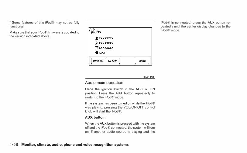
* Some features of this iPod® may not be fullyfunctional.
Make sure that your iPod® firmware is updated tothe version indicated above.
Audio main operation
Place the ignition switch in the ACC or ONposition. Press the AUX button repeatedly toswitch to the iPod® mode.
If the system has been turned off while the iPod®was playing, pressing the VOL/ON·OFF controlknob will start the iPod®.
AUX button:
When the AUX button is pressed with the systemoff and the iPod® connected, the system will turnon. If another audio source is playing and the
iPod® is connected, press the AUX button re-peatedly until the center display changes to theiPod® mode.
LHA1494
4-58 Monitor, climate, audio, phone and voice recognition systems

Interface:
The interface for iPod® operation shown on thevehicle’s audio system display screen is similar tothe iPod® interface. Use the touchscreen, BACKbutton or the scrolling knob to navigate themenus on the screen.
When the iPod® is playing, touch the “Menu” keyto bring up the iPod® interface.
Depending on the iPod® model, the followingitems may be available on the menu list screen.For further information about each item, see theiPod® Owner’s Manual.
● Playlists
● Artists
● Albums
● Genres
● Songs
● Composers
● Audiobooks
● Podcasts
Random and repeat play mode:
While the iPod® is playing, the play pattern canbe altered so that songs are repeated or playedrandomly.
Random:Touch the “Random” key to apply a random playpattern to the iPod®. When the random mode isactive, the icon is displayed to the left ofthe song title or album name to denote whichrandom pattern is applied. To cancel Randommode, touch the “Random” key until noicon is displayed.
Repeat:Touch the “Repeat” key to apply a repeat playpattern to the iPod®. When the repeat mode isactive, the icon is displayed to the left ofthe song title or album name to denote which
repeat pattern is applied. To cancel Repeatmode, touch the “Repeat” key until no iconis displayed.
Seek buttons:
Press the seek button or to skipbackward or forward one track.
Press and hold the seek button orfor 1.5 seconds while a track is playing to reverseor fast forward the track being played. The trackplays at an increased speed while reversing orfast forwarding. When the button is released, thetrack returns to normal play speed.
LHA1495
Monitor, climate, audio, phone and voice recognition systems 4-59

Scrolling menus:
While navigating long lists of artists, albums orsongs in the music menu, it is possible to scrollthe list by the first character in the name. Toactivate character indexing, touch and hold the“A-Z” key in the upper right corner of the screen.Turn the TUNE knob to choose the number orletter to jump to in the list and then press theENTER button.
If no character is selected after two seconds, thedisplay returns to normal.
BLUETOOTH® STREAMING AUDIOWITHOUT NAVIGATION SYSTEM (ifso equipped)
If you have a compatible Bluetooth® audio de-vice that is capable of playing audio files, thedevice can be connected to the vehicle’s audiosystem so that the audio files on the device playthrough the vehicle’s speakers.
Connecting Bluetooth® audio
To connect your Bluetooth® audio device to thevehicle, follow the procedure below:
1. Press the button. The system an-nounces the available commands.
2. Say “Connect Phone”. The system acknowl-edges the command and announces thenext set of available commands.
3. Say “Add Phone”. The system acknowl-edges the command and asks you to initiateconnecting from the phone handset. Theconnecting procedure of the cellular phonevaries according to each cellular phonemodel. See the cellular phone Owner’sManual for details. You can also visitwww.nissanusa.com/bluetooth for instruc-tions on connecting NISSAN recommendedcellular phones.
4. When prompted for a Passkey code, enter“1234” from the handset. The Passkey code“1234” has been assigned by NISSAN andcannot be changed.
Audio main operationTo switch to the Bluetooth® audio mode, pressthe AUX button repeatedly until the Bluetooth®audio mode is displayed on the screen.
Use the vehicle audio controls or the Bluetooth®device’s controls to play, pause, skip or reversetracks.
BLUETOOTH® STREAMING AUDIOWITH NAVIGATION SYSTEM (if soequipped)If you have a compatible Bluetooth® audio de-vice that is capable of playing audio files, thedevice can be connected to the vehicle’s audiosystem so that the audio files on the device playthrough the vehicle’s speakers.
LHA2279
4-60 Monitor, climate, audio, phone and voice recognition systems

Connecting Bluetooth® audioTo connect your Bluetooth® audio device to thevehicle, follow the procedure below:
1. Press the MENU button.
2. Select the “Settings” key.
3. Select the “Phone & Bluetooth” key. 4. Select the “Connect New Device” key.
5. The system acknowledges the commandand asks you to initiate connecting from thephone handset. The connecting procedureof the cellular phone varies according toeach cellular phone model. See the cellularphone Owner’s Manual for details. You canalso visit www.nissanusa.com/bluetooth forinstructions on connecting NISSAN recom-mended cellular phones.
LHA2253 LHA2248 LHA2265
Monitor, climate, audio, phone and voice recognition systems 4-61

Audio main operationTo switch to the Bluetooth® audio mode, pressthe AUX button repeatedly until the Bluetooth®audio mode is displayed on the screen.
The controls for the Bluetooth® audio are dis-played on the screen.
PANDORA® AUDIO (if so equipped)The vehicle’s audio system is capable of playingaudio streaming through a compatible, USB-connected audio device using the Pandora® mu-sic service.
Connecting a device for use withPandora® audioDevices capable of streaming Pandora® audiocan be connected to the vehicle’s audio systemvia the USB input jack. The USB input jack islocated in the center console.
Launch the Pandora® application on the phoneand then connect with the USB jack. Once con-nected, the Pandora® controls will be displayedon the control panel display screen.
CompatibilityThe following iPhone® models are compatiblewith the system:
● iPhone® 3GS
● iPhone® 4
● iPhone® 4S
The latest Pandora® application should be in-stalled on the phone.
Audio main operation
To switch to the Pandora® audio mode, pressthe AUX button repeatedly until the Pandora®audio mode is displayed on the screen.
The controls for the Pandora® audio are dis-played on the screen. Touch the keys on thescreen to play or pause the audio. Touch
the key to select “thumbs up” or thekey to select “thumbs down”.
LHA2269
4-62 Monitor, climate, audio, phone and voice recognition systems

NOTE:
There is a limit of six skips per station perhour. If a “ ” (thumbs down) is givenafter the skip limit has been reached, thecurrent track will continue to play but thefeedback will be saved.
Pandora® audio settingsTo adjust the Pandora® audio settings, select the“Menu” key.
● Station ListSelect to display a list of available Pandora®stations.
● BookmarkSelect to bookmark the current station.
● Delete StationSelect to remove the current station.
CD CARE AND CLEANING
● Handle a CD by its edges. Do not bend thedisc. Never touch the surface of the disc.
● Always place the discs in the storage casewhen they are not being used.
● To clean a disc, wipe the surface from thecenter to the outer edge using a clean, softcloth. Do not wipe the disc using a circularmotion.
● Do not use a conventional record cleaner oralcohol intended for industrial use.
LHA2270 LHA0049
Monitor, climate, audio, phone and voice recognition systems 4-63

● A new disc may be rough on the inner andouter edges. Remove the rough edges byrubbing the inner and outer edges with theside of a pen or pencil as illustrated.
1. Tuning switch2. Power on and SOURCE select switch3. Volume control button
STEERING WHEEL SWITCH FORAUDIO CONTROL (if so equipped)
The audio system can be operated using thecontrols on the steering wheel.
POWER on switch
With the ignition switch in the ACC or ON posi-tion, push the SOURCE switch to turn the audiosystem on.
SOURCE select switch
Push the source select switch to change themode in the following sequence:
AM → FM1 → FM2 → XM1 (satellite radio, if soequipped) → XM2 (satellite radio, if so equipped)→ XM3 (satellite radio, if so equipped) → CD* →USB/iPod®* (if so equipped) → Bluetooth® Au-dio* → AUX* → AM.
* These modes are only available when compat-ible media storage is inserted into the device orconnected to the system.
Volume control switch
Push the volume control switch to increase ordecrease the volume.
Tuning switch
While the display is showing a map or audioscreen, tilt the Menu Control switch upward ordownward to select a station, track, CD or folder.For most audio sources, tilting the switchup/down for more than 1.5 seconds provides adifferent function than a tilting up/down for lessthan 1.5 seconds.
AM and FM:
● Tilt up/down for less than 1.5 seconds toincrease or decrease the preset station.
LHA2498
4-64 Monitor, climate, audio, phone and voice recognition systems

● Tilt up/down for more than 1.5 seconds toseek up or down to the next station.
● Press the ENTER button to show the list ofpreset stations.
XM (if so equipped):
● Tilt up/down for less than 1.5 seconds toincrease or decrease the preset station.
● Tilt up/down for more than 1.5 seconds togo to the next or previous category.
● Press the ENTER button to show the XMMenu.
iPod® (if so equipped):
● Tilt up/down for less than 1.5 seconds toincrease or decrease the track number.
● Press the ENTER button to show the iPodMenu.
CD:
● Tilt up/down for less than 1.5 seconds toincrease or decrease the track number.
● Tilt up/down for more than 1.5 seconds toincrease or decrease the folder number (ifplaying compressed audio files).
● Press the ENTER button to show the CDMenu.
USB (if so equipped):
● Tilt up/down for less than 1.5 seconds toincrease or decrease the track number.
● Tilt up/down for more than 1.5 seconds toincrease or decrease the folder number.
● Press the ENTER button to show the USBMenu.
Bluetooth® Audio:
● Tilt up/down for less than 1.5 seconds toskip ahead or back to the next song.
● Tilt up/down for more than 1.5 seconds toreverse or fast forward the current song.
Pandora® Audio (if so equipped):
● Tilt up for less than 1.5 seconds to input“thumbs up” for the current song.
● Tilt down for less than 1.5 seconds to input“thumbs down” for the current song.
● Tilt up for more than 1.5 seconds to skip tothe next song (if the maximum of six skips perstation per hour has not been exceeded).
ANTENNAWindow antennaThe antenna pattern is printed inside the rearwindow.
CAUTION
● Do not place metalized film near therear window glass or attach any metalparts to it. This may cause poor recep-tion or noise.
● When cleaning the inside of the rearwindow, be careful not to scratch ordamage the rear window antenna.Lightly wipe along the antenna with adampened soft cloth.
Monitor, climate, audio, phone and voice recognition systems 4-65

When installing a CB, ham radio or car phone inyour vehicle, be sure to observe the followingprecautions; otherwise, the new equipment mayadversely affect the engine control system andother electronic parts.
WARNING
● A cellular phone should not be used forany purpose while driving so full atten-tion may be given to vehicle operation.Some jurisdictions prohibit the use ofcellular phones while driving.
● If you must make a call while your ve-hicle is in motion, the hands free cellu-lar phone operational mode is highlyrecommended. Exercise extreme cau-tion at all times so full attention may begiven to vehicle operation.
● If you are unable to devote full attentionto vehicle operation while talking onthe phone, pull off the road to a safelocation and stop your vehicle.
CAUTION
● Keep the antenna as far away as pos-sible from the electronic controlmodules.
● Keep the antenna wire more than 8 in(20 cm) away from the electronic con-trol system harnesses. Do not route theantenna wire next to any harness.
● Adjust the antenna standing-wave ratioas recommended by the manufacturer.
● Connect the ground wire from the CBradio chassis to the body.
● For details, consult a NISSAN dealer.
WARNING
● Use a phone after stopping your vehiclein a safe location. If you have to use aphone while driving, exercise extremecaution at all times so full attention maybe given to vehicle operation.
● If you are unable to devote full attentionto vehicle operation while talking onthe phone, pull off the road to a safelocation and stop your vehicle.
CAUTION
To avoid discharging the vehicle battery,use a phone after starting the engine.
CAR PHONE OR CB RADIO BLUETOOTH® HANDS-FREE PHONESYSTEM WITHOUT NAVIGATIONSYSTEM (if so equipped)
4-66 Monitor, climate, audio, phone and voice recognition systems

Your NISSAN is equipped with the Bluetooth®Hands-Free Phone System. If you have a com-patible Bluetooth® enabled cellular phone, youcan set up the wireless connection between yourcellular phone and the in-vehicle phone module.With Bluetooth® wireless technology, you can
make or receive a hands-free telephone call withyour cellular phone in the vehicle.
Once your cellular phone is connected to thein-vehicle phone module, no other phone con-necting procedure is required. Your phone isautomatically connected with the in-vehicle
phone module when the ignition switch is placedin the ON position with the previously connectedcellular phone turned on and carried in the ve-hicle.
NOTE:
Some devices require the user to acceptconnections to other Bluetooth® devices.If your phone does not connect automati-cally to the system, consult the phone’sOwner’s Manual for details on device op-eration.
You can connect up to 5 different Bluetooth®cellular phones to the in-vehicle phone module.However, you can talk on only one cellular phoneat a time.
Before using the Bluetooth® Hands-Free PhoneSystem, refer to the following notes.
● Set up the wireless connection between acompatible cellular phone and the in-vehiclephone module before using the hands-freephone system.
● Some Bluetooth® enabled cellular phonesmay not be recognized or work properly.Please visit www.nissanusa.com/bluetoothfor a recommended phone list and connect-ing instructions.
LHA2509
Monitor, climate, audio, phone and voice recognition systems 4-67

● You will not be able to use a hands-freephone under the following conditions:
– Your vehicle is outside of the cellular ser-vice area.
– Your vehicle is in an area where it isdifficult to receive a cellular signal; suchas in a tunnel, in an underground parkinggarage, near a tall building or in a moun-tainous area.
– Your cellular phone is locked to prevent itfrom being dialed.
● When the radio wave condition is not idealor ambient sound is too loud, it may bedifficult to hear the other person’s voice dur-ing a call.
● Do not place the cellular phone in an areasurrounded by metal or far away from thein-vehicle phone module to prevent tonequality degradation and wireless connectiondisruption.
● While a cellular phone is connected throughthe Bluetooth® wireless connection, thebattery power of the cellular phone may dis-charge quicker than usual. The Bluetooth®Hands-Free Phone System cannot chargecellular phones.
● If the hands-free phone system seems to bemalfunctioning, see “Troubleshooting guide”in this section. You can also visitwww.nissanusa.com/bluetooth for trouble-shooting help.
● Some cellular phones or other devices maycause interference or a buzzing noise tocome from the audio system speakers. Stor-ing the device in a different location mayreduce or eliminate the noise.
● Refer to the cellular phone Owner’s Manualregarding the telephone charges, cellularphone antenna and body, etc.
REGULATORY INFORMATIONFCC Regulatory information
– CAUTION: To maintain compliance withFCC’s RF exposure guidelines, use only thesupplied antenna. Unauthorized antenna,modification, or attachments could damagethe transmitter and may violate FCC regula-tions.
– Operation is subject to the following two con-ditions:
1. This device may not cause interference and
2. this device must accept any interference,including interference that may cause unde-sired operation of the device.
IC Regulatory information
– Operation is subject to the following two con-ditions: (1) this device may not cause interfer-ence, and (2) this device must accept anyinterference, including interference that maycause undesired operation of the device.
– This Class B digital apparatus meets all re-quirements of the Canadian Interference-Causing Equipment Regulations.
BLUETOOTH® is atrademark owned byBluetooth SIG, Inc.and licensed toVisteon.
USING THE SYSTEM
The NISSAN Voice Recognition system allowshands-free operation of the Bluetooth® PhoneSystem.
If the vehicle is in motion, some commands maynot be available so full attention may be given tovehicle operation.
Initialization
When the ignition switch is placed in the ONposition, NISSAN Voice Recognition is initialized,
4-68 Monitor, climate, audio, phone and voice recognition systems

which takes a few seconds. If the button ispressed before the initialization completes, thesystem will announce “Hands-free phone systemnot ready” and will not react to voice commands.
Operating tips
To get the best performance out of the NISSANVoice Recognition system, observe the following:
● Keep the interior of the vehicle as quiet aspossible. Close the windows to eliminatesurrounding noises (traffic noises, vibrationsounds, etc.), which may prevent the systemfrom recognizing voice commands correctly.
● Wait until the tone sounds before speaking acommand. Otherwise, the command will notbe received properly.
● Start speaking a command within 5 secondsafter the tone sounds.
● Speak in a natural voice without pausingbetween words.
Giving voice commands
To operate NISSAN Voice Recognition, pressand release the button located on thesteering wheel. After the tone sounds, speak acommand.
The command given is picked up by the micro-phone, and voice feedback is given when thecommand is accepted.
● If you need to hear the available commandsfor the current menu again, say “Help” andthe system will repeat them.
● If a command is not recognized, the systemannounces, “Command not recognized.Please try again.”Make sure the command issaid exactly as prompted by the system andrepeat the command in a clear voice.
● If you want to go back to the previous com-mand, you can say “Go back” or “Correc-tion” any time the system is waiting for aresponse.
● You can cancel a command when the sys-tem is waiting for a response by saying,“Cancel” or “Quit.” The system announces“Cancel” and ends the VR session. You canalso press and hold the button on thesteering wheel for 5 seconds at any time toend the VR session. Whenever the VR ses-sion is cancelled, a double beep is played toindicate you have exited the system.
● If you want to adjust the volume of the voicefeedback, press the volume control switches(+ or -) on the steering wheel while beingprovided with feedback. You can also usethe radio volume control knob.
● In most cases you can interrupt the voicefeedback to speak the next command bypressing the button on the steeringwheel.
● To use the system faster, you may speak thesecond level commands with the main menucommand on the main menu. For example,press the button and after the tonesay, “Call Redial.”
How to say numbers
NISSAN Voice Recognition requires a certainway to speak numbers in voice commands. Referto the following rules and examples.
● Either “zero” or “oh” can be used for “0”.
Example: 1-800-662-6200
– “One eight oh oh six six two six two ohoh”, or
– “One eight zero zero six six two six two ohoh”
● Words can be used for the first 4 digitsplaces only.
Monitor, climate, audio, phone and voice recognition systems 4-69

Example: 1-800-662-6200
– “One eight hundred six six two six two ohoh”,
– NOT “One eight hundred six six two sixtytwo hundred,” and
– NOT “One eight oh oh six six two sixty twohundred”
● Numbers can be spoken in small groups.The system will prompt you to continue en-tering digits, if desired.
Example: 1-800-662-6200
– “One eight zero zero”
The system repeats the numbers andprompts you to enter more.
– “six six two”
The system repeats the numbers andprompts you to enter more.
– “six two zero zero”
● Say “pound” for “#”. Say “star” for “*” (avail-able when using the “Special Number” com-mand and the “Send” command during acall).
See “List of voice commands” and “Specialnumber” in this section for more information.
Example: 1-555-1212 *123
– “One five five five one two one two starone two three”
● Say “plus” for “+” (available only when usingthe “Special Number” command).
● Say “pause” for a 2-second pause (availableonly when storing a phone book number).
NOTE:
For best results, say phone numbers assingle digits.
The voice command “Help” is available at anytime. Please use the “Help” command to getinformation on how to use the system. CONTROL BUTTONS
The control buttons for the Bluetooth® Hands-Free Phone System are located on the steeringwheel.
PHONE/SEND
Press the button to initiatea VR session or answer an incom-ing call.
LHA2499
4-70 Monitor, climate, audio, phone and voice recognition systems

You can also use the buttonto interrupt the system feedbackand give a command at once. See“List of voice commands” and“During a call” in this section formore information.
PHONE/ENDWhile the Voice Recognition sys-tem is active, press and holdthe button for 5 seconds toquit the Voice Recognition systemat any time.
Tuning switchWhile using the Voice Recogni-tion system, tilt the tuning switchup or down to manually controlthe phone system.
GETTING STARTED
The following procedures will help you getstarted using the Bluetooth® Hands-Free PhoneSystem with NISSAN Voice Recognition. For ad-ditional command options, refer to “List of voicecommands” in this section.
Choosing a language
You can interact with the Bluetooth® Hands-Free Phone System using English, Spanish orFrench.
To change the language, perform the following.
1. Press and hold the button for morethan 5 seconds.
2. The system announces: “Press thePHONE/SEND ( ) button for thehands-free phone system to enter the voiceadaptation mode or press the PHONE/END( ) button to select a different lan-guage.”
3. Press the button.
For information on voice adaptation, see“Voice Adaptation (VA) mode” in this sec-tion.
4. The system announces the current languageand gives you the option to change the lan-guage to Spanish (in Spanish) or French (inFrench). To select the current language,press the PHONE/SEND ( ) button. Toselect a different language, tilt the tuning
switch ( or ) up or down.
NOTE:
You must press the button within5 seconds to change the language.
5. If you decide not to change the language, donot press either button. After 5 seconds, theVR session will end, and the language willnot be changed.
Connecting procedure
NOTE:
The connecting procedure must be per-formed when the vehicle is stationary. If thevehicle starts moving during the procedure,the procedure will be cancelled.
Main Menu
“Connect phone” �A
“Add phone” �B
Initiate from handset �C
Name phone �D
1. Press the button on the steeringwheel. The system announces the availablecommands.
2. Say: “Connect phone” �A . The system ac-knowledges the command and announcesthe next set of available commands.
Monitor, climate, audio, phone and voice recognition systems 4-71

3. Say: “Add phone” �B . The system acknowl-edges the command and asks you to initiateconnecting from the phone handset �C .
The connecting procedure of the cellularphone varies according to each cellularphone model. See the cellular phone Own-er’s Manual for details. You can also visitwww.NissanUSA.com/bluetooth for in-structions on connecting NISSAN recom-mended cellular phones.
When prompted for a Passkey code, enter“1234” from the handset. The Passkey code“1234” has been assigned by NISSAN andcannot be changed.
4. The system asks you to say a name for thephone �D .
If the name is too long or too short, thesystem tells you, then prompts you for aname again.
Also, if more than one phone is connectedand the name sounds too much like a namealready used, the system tells you, thenprompts you for a name again.
Making a call by entering a phonenumber
Main Menu
“Call” �A
“Phone Number” �B
Speak the digits �C
“Dial” �D
1. Press the button on the steeringwheel. A tone will sound.
2. Say: “Call” �A . The system acknowledgesthe command and announces the next set ofavailable commands.
3. Say “Phone Number” �B . The system ac-knowledges the command and announcesthe next set of available commands.
4. Say the number you wish to call starting withthe area code in single digit format �C . If thesystem has trouble recognizing the correctphone number, try entering the number inthe following groups: 3-digit area code,3-digit prefix and the last 4-digits. For ex-ample, 555-121-3354 can be said as “fivefive five” as the 1st group, then “one twoone” as the 2nd group, and “three three fivefour” as the 3rd group. For dialing more than10 digits or any special characters, say
“Special Number”. See “How to say num-bers” in this section for more information.
5. When you have finished speaking the phonenumber, the system repeats it back and an-nounces the available commands.
6. Say: “Dial” �D . The system acknowledgesthe command and makes the call.
For additional command options, see “List ofvoice commands” in this section.
Receiving a call
When you hear the ring tone, press thebutton on the steering wheel.
Once the call has ended, press the buttonon the steering wheel.
NOTE:
If you do not wish to take the call when youhear the ring tone, press the buttonon the steering wheel.
For additional command options, see “List ofvoice commands” later in this section.
4-72 Monitor, climate, audio, phone and voice recognition systems

LIST OF VOICE COMMANDS
Main Menu
“Call”
“Phonebook”
“Recent Calls”
“Connect Phone”
When you press and release the button onthe steering wheel, you can choose from thecommands on the Main Menu. The followingpages describe these commands and the com-mands in each sub-menu.
Remember to wait for the tone beforespeaking.
After the main menu, you can say “Help” to hearthe list of commands currently available any timethe system is waiting for a response.
If you want to end an action without completing it,you can say “Cancel” or “Quit” at any time thesystem is waiting for a response. The system willend the VR session. Whenever the VR session iscancelled, a double beep is played to indicateyou have exited the system.
If you want to go back to the previous command,you can say “Go back” or “Correction” any timethe system is waiting for a response.
“Call”
Main Menu
“Call”
(Speak name) �A
“Phone Number”
(Speak Digits) �B
“Special Number” �C
“Redial” �D
“Call Back” �E
(Speak name) �A
If you have stored entries in the phonebook, youcan dial a number associated with a name andlocation.
See “Phonebook” in this section to learn how tostore entries.
When prompted by the system, say the name ofthe phone book entry you wish to call. The systemacknowledges the name.
If there are multiple locations associated with thename, the system asks you to choose the loca-tion.
Once you have confirmed the name and location,the system begins the call.
(Speak Digits) �B
When prompted by the system, say the numberyou wish to call. Refer to “How to say numbers”and “Making a call by entering a phone number”in this section for more details.
“Special Number” �C
For dialing more than 10 digits or any specialcharacters, say “Special Number”. When thesystem acknowledges the command, the systemwill prompt you to speak the number.
“Redial” �D
Use the Redial command to call the last numberthat was dialed.
The system acknowledges the command, re-peats the number and begins dialing.
If a redial number does not exist, the systemannounces, “There is no number to redial” andends the VR session.
“Call Back” �E
Use the Call Back command to dial the number ofthe last incoming call within the vehicle.
The system acknowledges the command, re-peats the number and begins dialing.
Monitor, climate, audio, phone and voice recognition systems 4-73

If a call back number does not exist, the systemannounces, “There is no number to call back”andends the VR session.
During a call
During a call there are several command optionsavailable. Press the button on the steeringwheel to mute the receiving voice and enter com-mands.
● “Help” — The system announces the avail-able commands.
● “Cancel/Quit” — The system announces“Cancel,” ends the VR session and returnsto the call.
● “Send” — Use the Send command to enternumbers, “*” or “#” during a call. For ex-ample, if you were directed to dial an exten-sion by an automated system:
Say: “Send one two three four.”
The system acknowledges the commandand sends the tones associated with thenumbers. The system then ends the VR ses-sion and returns to the call. Say “star” for “*”,Say “pound” for “#”.
● “Transfer call” — Use the Transfer Call com-mand to transfer the call from theBluetooth® Hands-Free Phone System tothe cellular phone when privacy is desired.
The system announces, “Transfer call. Calltransferred to privacy mode.” The systemthen ends the VR session.
To reconnect the call from the cellular phoneto the Bluetooth® Hands-Free System,press the button.
● “Mute” — Use the Mute command to muteyour voice so the other party cannot hear it.Use the mute command again to unmuteyour voice.
NOTE:
If a call is ended or the cellular phonenetwork connection is lost while the Mutefeature is on, the Mute feature will be resetto “off” for the next call so the other partycan hear your voice.
“Phonebook” (phones withoutautomatic phonebook downloadfunction)
NOTE:
The “Transfer Entry” command is not avail-able when the vehicle is moving.
Main Menu
“Phonebook”
“Transfer Entry” �A
“Delete Entry” �B
“List Names” �C
For phones that do not support automatic down-load of the phonebook (PBAP Bluetooth® pro-file), the “Phonebook”command is used to manu-ally add entries to the vehicle phonebook.
The phonebook stores up to 40 names for eachphone connected to the system.
NOTE:
Each phone has its own separate phone-book. You cannot access Phone A’s phone-book if you are currently connected withPhone B.
“Transfer Entry” �A
Use the Transfer Entry command to store a newname in the system.
When prompted by the system, say the name youwould like to give the new entry.
For example, say: “Mary.”If the name is too long or too short, the systemtells you, then prompts you for a name again.
4-74 Monitor, climate, audio, phone and voice recognition systems

Also, if the name sounds too much like a namealready stored, the system tells you, then promptsyou for a name again.
The system will ask you to transfer a phonenumber stored in the cellular phone’s memory.
Enter a phone number by voice command:
For example, say: “five five five one two one two.”See “How to say numbers” in this section formore information.
To transfer a phone number stored in the cellularphone’s memory:
Say “Transfer entry.” The system acknowledgesthe command and asks you to initiate the transferfrom the phone handset. The new contact phonenumber will be transferred from the cellularphone via the Bluetooth® communication link.
The transfer procedure varies according to eachcellular phone. See the cellular phone Owner’sManual for details. You can also visitwww.nissanusa.com/bluetooth for instructionson transferring phone numbers from NISSANrecommended cellular phones.
The system repeats the number and prompts youfor the next command. When you have finishedentering numbers or transferring an entry, choose“Store.”
The system confirms the name, location andnumber.
“Delete Entry” �B
Use the Delete Entry command to erase oneentry from the phonebook. After the system rec-ognizes the command, speak the name to deleteor say “List Names” to choose an entry.
“List Names” �C
Use the List Names command to hear all thenames in the phonebook.
The system recites the phonebook entries butdoes not include the actual phone numbers.When the playback of the list is complete, thesystem goes back to the main menu.
You can stop the playback of the list at any timeby pressing the button on the steeringwheel. The system ends the VR session.
“Phonebook” (phones with automaticphonebook download function)
NOTE:
The “Transfer Entry” command is not avail-able when the vehicle is moving.
Main Menu
“Phonebook”
Say a Name
“List Names” �A
“Record Name” �B
For phones that support automatic download ofthe phonebook (PBAP Bluetooth® profile), the“Phonebook” command is used to manage en-tries in the vehicle phonebook. You can say thename of an entry at this menu to initiate dialing ofthat entry.
The phonebook stores up to 1000 names foreach phone connected to the system.
When a phone is connected to the system, thephonebook is automatically downloaded to thevehicle. This feature allows you to access yourphonebook from the Bluetooth® system and callcontacts by name. You can record a customvoice tag for contact names that the system hasdifficulty recognizing. For more information see“Record name” in this section.
Monitor, climate, audio, phone and voice recognition systems 4-75

NOTE:
Each phone has its own separate phone-book. You cannot access Phone A’s phone-book if you are currently connected withPhone B.
“List Names” �A
Use the List Names command to hear all thenames and locations in the phone book.
The system recites the phone book entries butdoes not include the actual phone numbers.When the playback of the list is complete, thesystem goes back to the main menu.
You can stop the playback of the list at any timeby pressing the button on the steeringwheel. The system ends the VR session. See the“Record name” command in this section for infor-mation about recording custom voice tags for listentries that the system has difficulty pronounc-ing.
“Record Name” �B
The system allows you to record custom voicetags for contact names in the phonebook that thevehicle has difficulty recognizing. This feature canalso be used to record voice tags to directly dialan entry with multiple numbers. Up to 40 voicetags can be recorded to the system.
“Recent Calls”
Main Menu
“Recent Calls”
“Outgoing” �A
“Incoming” �B
“Missed” �C
Use the Recent Calls command to access out-going, incoming or missed calls.
“Outgoing” �A
Use the Outgoing command to list the outgoingcalls made from the vehicle.
“Incoming” �B
Use the Incoming command to list the incomingcalls made to the vehicle.
“Missed” �C
Use the Missed command to list the calls made tothe vehicle that were not answered.
“Connect Phone”
NOTE:
The Add Phone command is not availablewhen the vehicle is moving.
Main Menu
“Connect Phone”
“Add Phone” �A
“Select Phone” �B
“Delete Phone” �C
“Replace Phone” �D
“Bluetooth OFF” �E
“Phonebook Download OFF” �F
“Display Settings” �G
Use the Connect Phone commands to managethe phones connecting to the vehicle or to enablethe Bluetooth® function on the vehicle.
“Add Phone” �A
Use the Add Phone command to add a phone tothe vehicle. See “Connecting procedure” in thissection for more information.
4-76 Monitor, climate, audio, phone and voice recognition systems
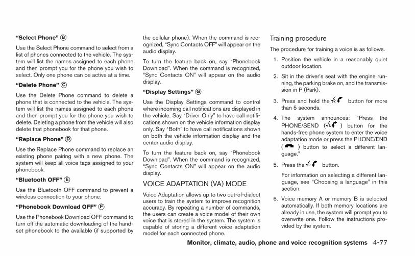
“Select Phone” �B
Use the Select Phone command to select from alist of phones connected to the vehicle. The sys-tem will list the names assigned to each phoneand then prompt you for the phone you wish toselect. Only one phone can be active at a time.
“Delete Phone” �C
Use the Delete Phone command to delete aphone that is connected to the vehicle. The sys-tem will list the names assigned to each phoneand then prompt you for the phone you wish todelete. Deleting a phone from the vehicle will alsodelete that phonebook for that phone.
“Replace Phone” �D
Use the Replace Phone command to replace anexisting phone pairing with a new phone. Thesystem will keep all voice tags assigned to yourphonebook.
“Bluetooth OFF” �E
Use the Bluetooth OFF command to prevent awireless connection to your phone.
“Phonebook Download OFF” �F
Use the Phonebook Download OFF command toturn off the automatic downloading of the hand-set phonebook to the available (if supported by
the cellular phone). When the command is rec-ognized, “Sync Contacts OFF” will appear on theaudio display.
To turn the feature back on, say “PhonebookDownload”. When the command is recognized,“Sync Contacts ON” will appear on the audiodisplay.
“Display Settings” �G
Use the Display Settings command to controlwhere incoming call notifications are displayed inthe vehicle. Say “Driver Only” to have call notifi-cations shown on the vehicle information displayonly. Say “Both” to have call notifications shownon both the vehicle information display and thecenter audio display.
To turn the feature back on, say “PhonebookDownload”. When the command is recognized,“Sync Contacts ON” will appear on the audiodisplay.
VOICE ADAPTATION (VA) MODE
Voice Adaptation allows up to two out-of-dialectusers to train the system to improve recognitionaccuracy. By repeating a number of commands,the users can create a voice model of their ownvoice that is stored in the system. The system iscapable of storing a different voice adaptationmodel for each connected phone.
Training procedure
The procedure for training a voice is as follows.
1. Position the vehicle in a reasonably quietoutdoor location.
2. Sit in the driver’s seat with the engine run-ning, the parking brake on, and the transmis-sion in P (Park).
3. Press and hold the button for morethan 5 seconds.
4. The system announces: “Press thePHONE/SEND ( ) button for thehands-free phone system to enter the voiceadaptation mode or press the PHONE/END( ) button to select a different lan-guage.”
5. Press the button.
For information on selecting a different lan-guage, see “Choosing a language” in thissection.
6. Voice memory A or memory B is selectedautomatically. If both memory locations arealready in use, the system will prompt you tooverwrite one. Follow the instructions pro-vided by the system.
Monitor, climate, audio, phone and voice recognition systems 4-77

7. When preparation is complete and you areready to begin, press the button.
8. The VA mode will be explained. Follow theinstructions provided by the system.
9. When training is finished, the system will tellyou an adequate number of phrases havebeen recorded.
10. The system will announce that voice adap-tation has been completed and the system isready.
The VA mode will stop if:
● The button is pressed for more than5 seconds in VA mode.
● The vehicle begins moving during VA mode.
● The ignition switch is placed in the OFF orLOCK position.
Training phrasesDuring the VA mode, the system instructs thetrainer to say the following phrases. (The systemwill prompt you for each phrase.)
● phonebook transfer entry
● dial three oh four two nine
● delete call back number
● incoming
● transfer entry
● eight pause nine three two pause seven
● delete all entries
● call seven two four zero nine
● phonebook delete entry
● next entry
● dial star two one seven oh
● yes
● no
● select
● missed
● dial eight five six nine two
● Bluetooth on
● outgoing
● call three one nine oh two
● nine seven pause pause three oh eight
● cancel
● call back number
● call star two zero nine five
● delete phone
● dial eight three zero five one
● record name
● four three pause two nine pause zero
● delete redial number
● phonebook list names
● call eight oh five four one
● correction
● connect phone
● dial seven four oh one eight
● previous entry
● delete
● dial nine seven two six six
● call seven six three oh one
● go back
● call five six two eight zero
● dial six six four three seven
4-78 Monitor, climate, audio, phone and voice recognition systems

MANUAL CONTROL
While using the voice recognition system, it ispossible to select menu options by using thesteering wheel controls instead of speaking voicecommands. This can be especially helpful if thenoise of driving makes it difficult for the voicerecognition system to accurately interpret com-mands. The manual control mode does not allowdialing a phone number by digits. The user mayselect an entry from the Phonebook or RecentCalls lists. To re-activate voice recognition, exitthe manual control mode by pressing and holdingthe PHONE/END ( ) button. At that time,pressing the PHONE/SEND ( ) button willstart the Hands Free Phone System.
Operating tips
● To enter manual control mode, start thevoice recognition system and tilt the tuning( ) switch up or down. The system willspeak �Showing Manual Options� whenmanual controls are initially activated.
● To browse the menu options, tilt the tuning( ) switch up or down. The system willalways speak the current menu option. De-pending on the audio display, it will alsoshow the current menu option.
● To select the current menu option, press thePHONE/SEND ( ) button.
● To go back to the previous menu, press thePHONE/END ( ) button. If the currentmenu is the Main Menu, pressing thePHONE/END ( ) button will exit thePhone system.
● To exit the manual control mode, press andhold the PHONE/END ( ) button for5 seconds.
Monitor, climate, audio, phone and voice recognition systems 4-79

TROUBLESHOOTING GUIDEThe system should respond correctly to all voicecommands without difficulty. If problems are en-countered, try the following solutions.
Where the solutions are listed by number, tryeach solution in turn, starting with number 1, untilthe problem is resolved.
Symptom Solution
System fails to interpret the command correctly.
1. Ensure that the command is valid. See “List of voice commands” in this section.2. Ensure that the command is spoken after the tone.3. Speak clearly without pausing between words and at a level appropriate to the ambient noise level in the vehicle.4. Ensure that the ambient noise level is not excessive (for example, windows open or defroster on). NOTE: If it is toonoisy to use the phone, it is likely that the voice commands will not be recognized.5. If more than one command was said at a time, try saying the commands separately.6. If the system consistently fails to recognize commands, the voice training procedure should be carried out to im-prove the recognition response for the speaker. See “Voice Adaptation (VA) mode” in this section.
The system consistently selects the wrong entry from thephone book.
1. Ensure that the phone book entry name requested matches what was originally stored. This can be confirmed byusing the “List Names” command. See “Phonebook” in this section.2. Replace one of the names being confused with a new name.
4-80 Monitor, climate, audio, phone and voice recognition systems

WARNING
● Use a phone after stopping your vehiclein a safe location. If you have to use aphone while driving, exercise extremecaution at all times so full attention maybe given to vehicle operation.
● If you are unable to devote full attentionto vehicle operation while talking onthe phone, pull off the road to a safelocation and stop your vehicle.
CAUTION
To avoid discharging the vehicle battery,use a phone after starting the engine.
Your NISSAN is equipped with the Bluetooth®Hands-Free Phone System. If you have a com-patible Bluetooth® enabled cellular phone, youcan set up the wireless connection between yourcellular phone and the in-vehicle phone module.With Bluetooth® wireless technology, you can
make or receive a hands-free telephone call withyour cellular phone in the vehicle.
Once your cellular phone is connected to thein-vehicle phone module, no other phone con-necting procedure is required. Your phone isautomatically connected with the in-vehicle
LHA2509
BLUETOOTH® HANDS-FREE PHONESYSTEM WITH NAVIGATION SYSTEM(if so equipped)
Monitor, climate, audio, phone and voice recognition systems 4-81

phone module when the ignition switch is placedin the ON position with the connected cellularphone turned on and carried in the vehicle.
You can register up to 5 different Bluetooth®cellular phones to the in-vehicle phone module.However, you can talk on only one cellular phoneat a time.
NISSAN Voice Recognition system supports thephone commands, so dialing a phone numberusing your voice is possible. For more details, see“NISSAN Voice Recognition System” in this sec-tion.
Before using the Bluetooth® Hands-Free PhoneSystem, refer to the following notes.
● Set up the wireless connection between acellular phone and the in-vehicle phonemodule before using the hands-free phonesystem.
● Some Bluetooth® enabled cellular phonesmay not be recognized by the in-vehiclephone module. Please visitwww.nissanusa.com/bluetooth for a recom-mended phone list and connecting.
● You will not be able to use a hands-freephone under the following conditions:
– Your vehicle is outside of the cellular ser-vice area.
– Your vehicle is in an area where it isdifficult to receive cellular signal; such asin a tunnel, in an underground parkinggarage, near a tall building or in a moun-tainous area.
– Your cellular phone is locked to prevent itfrom being dialed.
● When the radio wave condition is not idealor ambient sound is too loud, it may bedifficult to hear the other person’s voice dur-ing a call.
● Immediately after the ignition switch isplaced in the ON position, it may be impos-sible to receive a call for a short period oftime.
● Do not place the cellular phone in an areasurrounded by metal or far away from thein-vehicle phone module to prevent tonequality degradation and wireless connectiondisruption.
● While a cellular phone is connected throughthe Bluetooth® wireless connection, thebattery power of the cellular phone may dis-charge quicker than usual. The Bluetooth®Hands-Free Phone System cannot chargecellular phones.
● If the hands-free phone system seems to bemalfunctioning, see “Troubleshooting guide”in this section. You can also visitwww.nissanusa.com/bluetooth for trouble-shooting help.
● Some cellular phones or other devices maycause interference or a buzzing noise tocome from the audio system speakers. Stor-ing the device in a different location mayreduce or eliminate the noise.
● Refer to the cellular phone owner’s manualregarding the telephone charges, cellularphone antenna and body, etc.
● The signal strength display on the monitorwill not coincide with the signal strengthdisplay of some cellular phones.
REGULATORY INFORMATIONFCC Regulatory information
– CAUTION: To maintain compliance withFCC’s RF exposure guidelines, use only thesupplied antenna. Unauthorized antenna,modification, or attachments could damagethe transmitter and may violate FCC regula-tions.
– Operation is subject to the following two con-ditions:
1. This device may not cause interference and
4-82 Monitor, climate, audio, phone and voice recognition systems

2. this device must accept any interference,including interference that may cause unde-sired operation of the device.
IC Regulatory information
– Operation is subject to the following two con-ditions: (1) this device may not cause interfer-ence, and (2) this device must accept anyinterference, including interference that maycause undesired operation of the device.
– This Class B digital apparatus meets all re-quirements of the Canadian Interference-Causing Equipment Regulations.
BLUETOOTH® is atrademark owned byBluetooth SIG, Inc.and licensed toBosch.
VOICE COMMANDSYou can use voice commands to operate variousBluetooth® Hands-Free Phone System featuresusing the NISSAN Voice Recognition system. Formore details, see “NISSAN Voice RecognitionSystem” in this section.
CONNECTING PROCEDURE
NOTE:
The connecting procedure must be per-formed when the vehicle is stationary. If thevehicle starts moving during the procedure,the procedure will be cancelled.
1. Press the MENU button on the controlpanel.
2. Select the “Settings” key.LHA2253
Monitor, climate, audio, phone and voice recognition systems 4-83

3. Select the “Phone & Bluetooth” key. 4. Select the “Connect New Device” key.
5. Initiate the connecting process from thehandset. The system will display the mes-sage: “Is PIN XXXXXX displayed on yourBluetooth device?”. If the PIN is displayedon your Bluetooth® device, select “Yes” tocomplete the connecting process.
For more information, see the Bluetooth® de-vice’s Owner’s Manual.
VEHICLE PHONEBOOKTo access the vehicle phonebook:
1. Press the button on the control panel.
2. Select the “Phonebook” key.
LHA2248 LHA2265 LHA2297
4-84 Monitor, climate, audio, phone and voice recognition systems

3. Choose the desired entry from the displayedlist.
NOTE:
To scroll quickly through the list, touch the“A-Z” key in the upper right corner of thescreen. Turn the TUNE/SCROLL knob tochoose a letter or number and then pressENTER. The list will move to the first entrythat begins with that number or letter.
4. The number of the entry will be displayed onthe screen. Touch the number to initiate di-aling.
MAKING A CALL
To make a call, follow the procedure below:
1. Press the button on the instrumentpanel. The “Phone”screen will appear on thedisplay.
2. Select one of the following options to make acall:
● “Phonebook”: Select the name from an entrystored in the vehicle phonebook.
● “Call Lists”: Select the name from the in-coming, outgoing or missed call history.
● “Redial”: Dial the last outgoing call from thevehicle.
● “ ”: Input the phone number manuallyusing a keypad displayed on the screen. Forinformation on how to use the touchscreen,see “How to use the touchscreen” in thissection.
LHA2279 LHA2297
Monitor, climate, audio, phone and voice recognition systems 4-85

RECEIVING A CALLWhen a call is placed to the connected phone,the display will change to phone mode.
To accept the incoming call, either:
● Press the button on the steeringwheel, or
● Touch the green phone icon on the screen.
To reject the incoming call, either:
● Press the button on the steeringwheel, or
● Touch the red phone icon on the screen.
DURING A CALLWhile a call is active, the following options areavailable on the screen:
● “Handset”Select this option to switch control of thephone call over to the handset.
● “Mute Mic.”Select this option to mute the microphone.Select again to unmute the microphone.
● Red phone ( ) iconSelect to end the phone call.
ENDING A CALL
To end a phone call, select the red phone ( )icon on the screen or press the button onthe steering wheel.
LHA2298 LHA2299
4-86 Monitor, climate, audio, phone and voice recognition systems

TEXT MESSAGING
WARNING
● Use the text messaging feature afterstopping your vehicle in a safe location.If you have to use the feature whiledriving, exercise extreme caution at alltimes so full attention may be given tovehicle operation.
● If you are unable to devote full attentionto vehicle operation while using the textmessaging feature, pull off the road to asafe location and stop your vehicle.
The system allows for the sending and receivingof text messages through the vehicle interface.
Sending a text message:
1. Press the button.
2. Say “Send Text”.
3. The system will provide a list of availablecommands in order to determine the recipi-ent of the text message. Choose from thefollowing:
● (a name)
● Number
● Incoming Calls
● Outgoing Calls
● Missed Calls
For more information about these options,see “Voice commands” in this section.
4. Once a recipient is chosen, the systemprompts for which message to send. Fivepredefined messages are available as wellas three custom messages. To choose oneof the predefined messages, speak one ofthe following:
● “Driving, can’t text”
● “Call me”
● “On my way”
● “Running late”
● “Okay”
To send one of the custom messages, say“Custom Messages”. If more than one cus-tom message is stored, the system willprompt for the number of the desired cus-tom message. For more information on set-ting and managing custom text messages,see “Bluetooth® settings” in this section.
LHA2300
Monitor, climate, audio, phone and voice recognition systems 4-87

Reading a received text message:
1. Press the button.
2. Say “Read Text”.
The text message, sender and delivery time areshown on the screen. Use the tuning switch toscroll through all text messages if more than oneare available. Press the button to exit thetext message screen. Press the button toaccess the following options for replying to thetext message:
● Call BackSpeak this command to call the sender ofthe text message using the Bluetooth®Hands-Free Phone System.
● Send TextSpeak this command to send a text messageresponse to the sender of the text message.
● Read TextSpeak this command to read the text mes-sage again.
● Previous TextSpeak this command to move to the previ-ous text message (if available).
● Next TextSpeak this command to move to the next textmessage (if available).
NOTE:
Text messages are only displayed if thevehicle speed is less than 5 mph.
BLUETOOTH SETTINGSTo access the phone settings:
1. Press the MENU button.
2. Select the “Settings” key.
LHA2301 LHA2253
4-88 Monitor, climate, audio, phone and voice recognition systems

3. Select the “Phone & Bluetooth” key. ● Phone SettingsSee “Phone settings” in this section for moreinformation.
● Connect New DeviceSelect to connect a new Bluetooth® deviceto the Bluetooth® Hands-Free Phone Sys-tem.
● Select Connected DeviceSelect to choose a Bluetooth® device froma list of those devices connected to theBluetooth® Hands-Free Phone System.
● Replace Connected DeviceSelect to replace a Bluetooth® device froma list of those devices connected to theBluetooth® Hands-Free Phone System.
● Delete Connected DeviceSelect to delete a Bluetooth® device from alist of those devices connected to theBluetooth® Hands-Free Phone System.
● BluetoothSelect to toggle the Bluetooth® on and off.
LHA2248 LHA2265
Monitor, climate, audio, phone and voice recognition systems 4-89

PHONE SETTINGS
To access the phone settings:
1. Press the MENU button.
2. Select the “Settings” key.
3. Select the “Phone & Bluetooth” key.
4. Select the “Phone Settings” key and adjustthe following settings as desired:
● Sort Phonebook By:Select “First Name” or “Last Name” tochoose how phonebook entries are alpha-betically displayed on the screen.
● Use Phonebook From:Select “Handset” to use the phone’s phone-book. Select “SIM” to use the phonebook onthe SIM card. Select “Both” to use bothsources.
● Download Phonebook NowSelect to download the phonebook to thevehicle from the chosen source.
● Phone Notifications forSelect “Driver” to have phone notificationsshown in the vehicle information display. Se-lect “Both” to have phone notificationsshown in both the vehicle information displayand the center display screen.
● Record Name for Phonebook EntrySelect to record a name for a phonebookentry for use with the NISSAN Voice Recog-nition System.
● Text Message ServiceSelect to toggle the text message function-ality on or off.
● Show Incoming Text forSelect “Driver” to have text message notifi-cations shown in the vehicle information dis-play. Select “Both” to have text messagenotifications shown in both the vehicle infor-mation display and the center displayscreen. Select “None” to have text messagenotifications not displayed.
● SMS Auto Reply FunctionSelect to toggle the SMS auto reply func-tionality on or off.
● SMS Auto Reply MessageSelect to choose a message that is sentwhen the auto reply function is activated.
● Add Vehicle’s SignatureSelect to toggle on or off the addition of thevehicle signature to outgoing messages.
● Predefined SMS MessagesSelect the predefined SMS messages thatare used by the system.
LHA2302
4-90 Monitor, climate, audio, phone and voice recognition systems

The NISSAN Voice Recognition system allowshands-free operation of the systems equipped onthis vehicle, such as the phone and navigationsystems.
To operate NISSAN Voice Recognition, pressthe button located on the steering wheel.When prompted, speak the command for thesystem you wish to activate. The command givenis picked up by the microphone and performedwhen it is properly recognized. NISSAN VoiceRecognition will provide a voice response as wellas a message in the center display to inform youof the command results.
USING THE SYSTEM
InitializationWhen the ignition switch is in the ON position,NISSAN Voice Recognition is initialized, whichtakes a few seconds. When completed, the sys-tem is ready to accept voice commands. Ifthe button is pressed before the initializa-tion completes, the system will announce: “VoiceRecognition System not ready. Please wait.”
Giving voice commands
1. Press the button.
2. The system announces: “Please say a com-mand.” A list of available commands is spo-ken by the system.
3. After the tone sounds and the face icon onthe display changes, speak a command.Available commands are discussed later inthis section.
4. Voice and display feedback are providedwhen the command is accepted.
● If the command is not recognized, the sys-tem announces: “Command not recog-nized.”Repeat the command in a clear voice.
● If you want to cancel the command or goback to the previous menu of commands,press the button. The system will an-nounce: “Voice recognition canceled” or“Go back” depending on the current menulevel.
● Press the BACK button on the control panelto move back through the menus displayedon the screen.
● If you want to adjust the volume of the voicefeedback, use the volume control switcheson the steering wheel or the volume knob onthe control panel.
LHA2522
NISSAN VOICE RECOGNITIONSYSTEM (if so equipped)
Monitor, climate, audio, phone and voice recognition systems 4-91

● The voice command screen can also beaccessed using the control panel display:
1. Press the MENU button.
2. Select the “Voice Commands” key.
Operating tipsTo get the best performance out of NISSANVoice Recognition, observe the following:
● Keep the interior of the vehicle as quiet aspossible. Close the windows to eliminate thesurrounding noises (traffic noises, vibrationsounds, etc.), which may prevent the systemfrom recognizing the voice commands cor-rectly.
● Wait until a tone sounds before speaking acommand. Otherwise, the command will notbe received properly.
● Start speaking a command within 3.5 sec-onds after the tone sounds.
● Speak in a natural voice without pausingbetween words.
SYSTEM FEATURES
NISSAN Voice Recognition can activate the fol-lowing systems:
● Bluetooth Hands-Free Phone System
● Navigation
● Audio
● Information
For additional information on the navigation sys-tem, see the separate Navigation System Own-er’s Manual.
LHA2253 LHA2281
4-92 Monitor, climate, audio, phone and voice recognition systems
How to say numbersNISSAN Voice Recognition requires a certainway to speak numbers in voice commands. Referto the following examples.
General rule: Either “zero” or “oh” can be used for“0”.
Phone numbers
Speak phone numbers according to the followingexample. For 1-800-662-6200, say dial numberand then speak the phone number in any of thefollowing formats:
● “one eight oh oh six six two six two oh oh”
● “one eight hundred six six two six two oh oh”
● “one eight zero zero six six two six two oh oh”
For the best voice recognition phone dialing re-sults, say phone numbers as single digits. Also,full numbers can only be spoken for “800”. Forexample, you cannot say 555-6000 as “five fivefive six thousand”.
BLUETOOTH® HANDS-FREEPHONE SYSTEM VOICECOMMANDSTo access the Bluetooth® Hands-Free PhoneSystem voice commands:
1. Press the button.
2. Say “Call” and then a name in the vehiclephonebook to call that entry. Otherwise, say“Phone” to access various phone commands.
If the Bluetooth® has been set to “Off”, thesystem announces: “Bluetooth® is off. Wouldyou like to turn Bluetooth® on?”
If no phone is connected to the system and thevehicle is stationary, the system announces:“There is no phone connected. Would you like toconnect a phone now?” Say “Yes” to connect aphone. All further Bluetooth® Hands-Free PhoneSystem voice commands are only available if aphone is connected.If a phone is connected and Bluetooth® is set to“On”, the following voice commands are available:
● Dial Number
Allows for up to 24 digits to be dialed. Afterthe number is entered, say “Dial” to initiatedialing. Say “Correction” to correct the num-ber entered. Say “Go Back” to return to themain menu.
● List Phonebook
Starting with the first alphabetical entry inthe vehicle phonebook, the system promptsfor an additional command. Say “Dial” to callthe number of the phonebook entry. Say“Send Text” to send a text message to thenumber of the phonebook entry. Say “NextEntry” to skip to the next alphabetical entry inthe vehicle phonebook, where the same op-tions will then be available.
● Recent Calls
The system prompts for an additional com-mand. Say “Missed Calls”, “Incoming Calls”or “Outgoing Calls” to display a list of suchcalls on the screen.
Speak the number of the entry displayed onthe screen to dial that number or say “NextPage” to view entries on the next page (ifavailable).
● Redial
Redials the last called number.
● Read Text
Reads an incoming text message. For moreinformation about text messaging with theBluetooth® Hands-Free Phone System, see“Bluetooth® Hands-Free Phone Systemwith Navigation System” in this section.
Monitor, climate, audio, phone and voice recognition systems 4-93

● Send Text
Sends a text message. For more informationabout text messaging with the Bluetooth®Hands-Free Phone System, see“Bluetooth® Hands-Free Phone Systemwith Navigation System” in this section.
● Select Phone
The system replies “Please use manual con-trols to continue”. Use manual controls tochange the active phone from among thelisted phones connected to the vehicle.
For more information about the Bluetooth®Hands-Free Phone System, see “Bluetooth®Hands-Free Phone System with Navigation Sys-tem” in this section.
NAVIGATION SYSTEM VOICECOMMANDS
The following voice commands are available forthe Navigation System:
● Places
● Street Address
● Address Book
● Home
● Previous Destination
For more information about these commands,see the separate Navigation System Owner’sManual.
AUDIO SYSTEM VOICECOMMANDSTo access the audio system voice commands:
1. Press the button.
2. Say “Audio”
3. Speak a command from the following avail-able commands:
● FM
Switches the audio system to the FM mode.
● AM
Switches the audio system to the AM mode.
● XM (satellite radio, if so equipped)
Switches the audio system to the SiriusXMSatellite Radio mode.
● CD
Switches the audio system to the CD mode.A CD must be inserted for this command tobe functional.
● iPod®
Switches the audio system to the iPod®mode. An iPod® must be connected for thiscommand to be available and functional.
The following sub-commands are availablefor iPod®:
– Now Playing
– Menu
– Playlists
– Artists
– Albums
– Genres
– Songs
– Shuffle Songs*
– Composers*
– Audiobooks*
– Podcasts*
* Say “Next Page” to access these com-mands. Say “Previous Page” to return to thefirst page of commands.
4-94 Monitor, climate, audio, phone and voice recognition systems

● USB
Switches the audio system to the USBmode. A USB device must be inserted forthis command to be available and functional.
● Pandora®
Switches the audio system to the Pandora®audio mode. A compatible Bluetooth® au-dio device with a Pandora® applicationmust be connected to the system for thiscommand to be functional.
● Bluetooth®
Switches the audio system to theBluetooth® audio mode. A compatibleBluetooth® audio device must be con-nected to the system for this command to befunctional.
● AUX
Switches the audio system to the AUXmode. An AUX device must be connectedfor this command to be functional.
For more information about the audio system, see“Audio system” in this section.
INFORMATION VOICE COMMANDSThe following voice commands are available forthe information functions of the Navigation Sys-tem:
● Traffic
● Current Weather
● Weather Forecast
● Google™ Send-To-Car
● POIs Powered by Google™
For more information about these commands,see the separate Navigation System Owner’sManual.
HELP VOICE COMMANDSThe following voice commands can be spoken tohave the system provide instructions and tips forusing the NISSAN Voice Recognition system.
● List Commands
● What Can I Say?
● General Help
● Quit
● Exit
Monitor, climate, audio, phone and voice recognition systems 4-95

TROUBLESHOOTING GUIDEThe system should respond correctly to all voicecommands without difficulty. If problems are en-countered, follow the solutions given in this guidefor the appropriate error. Where the solutions arelisted by number, try each solution in turn, startingwith number one, until the problem is resolved.
Symptom/error message SolutionThe system responds “Command NotRecognized” or the system fails to rec-ognize the command correctly.
1. Ensure that the command format is valid. Use the “List Commands” or “What Can I Say?” command under the “Help” menu.2. Speak clearly without pausing between words and at a level appropriate to the ambient noise level.3. Ensure that the ambient noise level is not excessive (for example, with the windows open or the defroster on).
NOTE:
If it is too noisy to use the phone, it is likely that voice commands will not be recognized.4. If optional words of the command have been omitted, then the command should be tried with these in place.
4-96 Monitor, climate, audio, phone and voice recognition systems

MEMO
Monitor, climate, audio, phone and voice recognition systems 4-97

5 Starting and driving
Precautions when starting and driving. . . . . . . . . . . . . . . . 5-2Exhaust gas (carbon monoxide) . . . . . . . . . . . . . . . . . . 5-2Three-way catalyst. . . . . . . . . . . . . . . . . . . . . . . . . . . . . . 5-2Tire Pressure Monitoring System (TPMS)(if so equipped) . . . . . . . . . . . . . . . . . . . . . . . . . . . . . . . . 5-3Avoiding collision and rollover . . . . . . . . . . . . . . . . . . . . 5-6Off-road recovery. . . . . . . . . . . . . . . . . . . . . . . . . . . . . . . 5-6Rapid air pressure loss . . . . . . . . . . . . . . . . . . . . . . . . . . 5-7Drinking alcohol/drugs and driving. . . . . . . . . . . . . . . . 5-8
Ignition switch. . . . . . . . . . . . . . . . . . . . . . . . . . . . . . . . . . . . . 5-8Continuously Variable Transmission (CVT)(if so equipped) . . . . . . . . . . . . . . . . . . . . . . . . . . . . . . . . 5-8Manual transmission (if so equipped) . . . . . . . . . . . . . 5-9Key positions . . . . . . . . . . . . . . . . . . . . . . . . . . . . . . . . . . 5-9Ignition switch positions . . . . . . . . . . . . . . . . . . . . . . . . 5-10NISSAN vehicle immobilizer system . . . . . . . . . . . . . 5-10
Push-Button Ignition Switch (if so equipped) . . . . . . . . 5-11Operating range. . . . . . . . . . . . . . . . . . . . . . . . . . . . . . . 5-12Push-button ignition switch positions . . . . . . . . . . . . 5-12Emergency engine shut off . . . . . . . . . . . . . . . . . . . . . 5-13NISSAN Intelligent Key® battery discharge. . . . . . . 5-13NISSAN vehicle immobilizer system . . . . . . . . . . . . . 5-14
Before starting the engine . . . . . . . . . . . . . . . . . . . . . . . . . 5-14
Starting the engine . . . . . . . . . . . . . . . . . . . . . . . . . . . . . . . 5-14Starting the engine (model with NISSAN IntelligentKey® system) . . . . . . . . . . . . . . . . . . . . . . . . . . . . . . . . . . . . 5-15Driving the vehicle . . . . . . . . . . . . . . . . . . . . . . . . . . . . . . . . 5-16
Continuously Variable Transmission (CVT)(if so equipped) . . . . . . . . . . . . . . . . . . . . . . . . . . . . . . . 5-16Manual transmission (if so equipped) . . . . . . . . . . . . 5-20
Parking brake . . . . . . . . . . . . . . . . . . . . . . . . . . . . . . . . . . . . 5-21Sport mode . . . . . . . . . . . . . . . . . . . . . . . . . . . . . . . . . . . . . . 5-22ECO mode (if so equipped) . . . . . . . . . . . . . . . . . . . . . . . 5-23
Gear shift indicator (Manual transmissiononly) . . . . . . . . . . . . . . . . . . . . . . . . . . . . . . . . . . . . . . . . . 5-24
Cruise control (if so equipped) . . . . . . . . . . . . . . . . . . . . . 5-24Precautions on cruise control . . . . . . . . . . . . . . . . . . . 5-24Cruise control operations. . . . . . . . . . . . . . . . . . . . . . . 5-25
Break-in schedule . . . . . . . . . . . . . . . . . . . . . . . . . . . . . . . . 5-26Fuel efficient driving tips. . . . . . . . . . . . . . . . . . . . . . . . . . . 5-26Increasing fuel economy. . . . . . . . . . . . . . . . . . . . . . . . . . . 5-28Parking/parking on hills. . . . . . . . . . . . . . . . . . . . . . . . . . . . 5-28Power steering . . . . . . . . . . . . . . . . . . . . . . . . . . . . . . . . . . . 5-29Brake system . . . . . . . . . . . . . . . . . . . . . . . . . . . . . . . . . . . . 5-30
Brake precautions . . . . . . . . . . . . . . . . . . . . . . . . . . . . . 5-30Anti-lock Braking System (ABS). . . . . . . . . . . . . . . . . 5-31
Vehicle Dynamic Control (VDC) system . . . . . . . . . . . . . 5-32

Cold weather driving . . . . . . . . . . . . . . . . . . . . . . . . . . . . . . 5-34Freeing a frozen door lock . . . . . . . . . . . . . . . . . . . . . . 5-34Anti-freeze. . . . . . . . . . . . . . . . . . . . . . . . . . . . . . . . . . . . 5-34Battery . . . . . . . . . . . . . . . . . . . . . . . . . . . . . . . . . . . . . . . 5-34Draining of coolant water . . . . . . . . . . . . . . . . . . . . . . . 5-34
Tire equipment . . . . . . . . . . . . . . . . . . . . . . . . . . . . . . . . 5-34Special winter equipment. . . . . . . . . . . . . . . . . . . . . . . 5-34Driving on snow or ice . . . . . . . . . . . . . . . . . . . . . . . . . 5-34Engine block heater (if so equipped) . . . . . . . . . . . . . 5-35

WARNING
● Do not leave children or adults whowould normally require the assistanceof others alone in your vehicle. Petsshould also not be left alone. Theycould accidentally injure themselves orothers through inadvertent operation ofthe vehicle. Also, on hot, sunny days,temperatures in a closed vehicle couldquickly become high enough to causesevere or possibly fatal injuries topeople or animals.
● Closely supervise children when theyare around cars to prevent them fromplaying and becoming locked in thetrunk where they could be seriously in-jured. Keep the car locked, with the rearseatback and trunk lid securely latchedwhen not in use, and prevent children’saccess to car keys.
EXHAUST GAS (carbon monoxide)
WARNING
● Do not breathe exhaust gases; theycontain colorless and odorless carbonmonoxide. Carbon monoxide is danger-ous. It can cause unconsciousness ordeath.
● If you suspect that exhaust fumes areentering the vehicle, drive with all win-dows fully open, and have the vehicleinspected immediately.
● Do not run the engine in closed spacessuch as a garage.
● Do not park the vehicle with the enginerunning for any extended length of time.
● Keep the rear vent windows, lift gates,doors and trunk lids (if so equipped)closed while driving, otherwise exhaustgases could be drawn into the passen-ger compartment. If you must drive withone of these open, follow theseprecautions:
1. Open all the windows.
2. Set the air recirculation but-ton to off and the fan control dial tohigh to circulate the air.
● If electrical wiring or other cable con-nections must pass to a trailer throughthe seal on the trunk lid or the body,follow the manufacturer’s recommen-dation to prevent carbon monoxide en-try into the vehicle.
● The exhaust system and body should beinspected by a qualified mechanicwhenever:
a. The vehicle is raised for service.
b. You suspect that exhaust fumes areentering into the passengercompartment.
c. You notice a change in the sound ofthe exhaust system.
d. You have had an accident involvingdamage to the exhaust system, un-derbody, or rear of the vehicle.
THREE-WAY CATALYST
The three-way catalyst is an emission controldevice installed in the exhaust system. Exhaustgases in the three-way catalyst are burned athigh temperatures to help reduce pollutants.
WARNING
● The exhaust gas and the exhaust sys-tem are very hot. Keep people, animalsor flammable materials away from theexhaust system components.
PRECAUTIONS WHEN STARTINGAND DRIVING
5-2 Starting and driving

● Do not stop or park the vehicle overflammable materials such as dry grass,waste paper or rags. They may igniteand cause a fire.
CAUTION
● Do not use leaded gasoline. Depositsfrom leaded gasoline will seriously re-duce the three-way catalyst’s ability tohelp reduce exhaust pollutants.
● Keep your engine tuned up. Malfunc-tions in the ignition, fuel injection, orelectrical systems can cause overrichfuel flow into the three-way catalyst,causing it to overheat. Do not keep driv-ing if the engine misfires, or if notice-able loss of performance or other un-usual operating conditions aredetected. Have the vehicle inspectedpromptly by a NISSAN dealer.
● Avoid driving with an extremely low fuellevel. Running out of fuel could causethe engine to misfire, damaging thethree-way catalyst.
● Do not race the engine while warming itup.
● Do not push or tow your vehicle to startthe engine.
TIRE PRESSURE MONITORINGSYSTEM (TPMS) (if so equipped)
Each tire, including the spare (if provided),should be checked monthly when cold and in-flated to the inflation pressure recommended bythe vehicle manufacturer on the vehicle placardor tire inflation pressure label. (If your vehicle hastires of a different size than the size indicated onthe vehicle placard or tire inflation pressure label,you should determine the proper tire inflationpressure for those tires.)
As an added safety feature, your vehicle has beenequipped with a Tire Pressure Monitoring System(TPMS) that illuminates a low tire pressure telltalewhen one or more of your tires is significantlyunder-inflated. Accordingly, when the low tirepressure telltale illuminates, you should stop andcheck your tires as soon as possible, and inflateall your tires to the proper pressure. Driving on asignificantly under-inflated tire causes the tire tooverheat and can lead to tire failure. Under-inflation also reduces fuel efficiency and tire treadlife, and may affect the vehicle’s handling andstopping ability.
Please note that the TPMS is not a substitute forproper tire maintenance, and it is the driver’sresponsibility to maintain correct tire pressure,
even if under-inflation has not reached the level totrigger illumination of the TPMS low tire pressuretelltale.
Your vehicle has also been equipped with aTPMS malfunction indicator to indicate when thesystem is not operating properly. The TPMS mal-function indicator is combined with the low tirepressure telltale. When the system detects amalfunction, the telltale will flash for approxi-mately one minute and then remain continuouslyilluminated. This sequence will continue uponsubsequent vehicle start-ups as long as the mal-function exists. When the malfunction indicator isilluminated, the system may not be able to detector signal low tire pressure as intended. TPMSmalfunctions may occur for a variety of reasons,including the installation of replacement or alter-nate tires or wheels on the vehicle that preventthe TPMS from functioning properly. Alwayscheck the TPMS malfunction telltale after replac-ing one or more tires or wheels on your vehicle toensure that the replacement or alternate tires andwheels allow the TPMS to continue to functionproperly.
Additional information:
● The TPMS does not monitor the tirepressure of the spare tire.
Starting and driving 5-3
● The TPMS will activate only when the vehicleis driven at speeds above 16 MPH(25 km/h). Also, this system may not detect asudden drop in tire pressure (for example aflat tire while driving).
● The low tire pressure warning light does notautomatically turn off when the tire pressureof all your tires are adjusted. After the tiresare inflated to the recommended pressure,the vehicle must be driven at speeds above16 MPH (25 km/h) to activate the TPMS andturn off the low tire pressure warning light.Use a tire pressure gauge to check the tirepressure.
● The CHECK TIRE PRESSURE warningmessage is displayed in the odometer whenthe low tire pressure warning light is illumi-nated and low tire pressure is detected. TheCHECK TIRE PRESSURE warning mes-sage turns off when the low tire pressurewarning light turns off. The low tire pressurewarning light remains illuminated until thetires are inflated to the recommended COLDtire pressure. The CHECK TIRE PRES-SURE warning message is displayed eachtime the ignition switch is placed in the ONposition as long as the low tire pressurewarning light remains illuminated. See“Check tire pressure warning message” inthe “Instruments and controls” section.
● The CHECK TIRE PRESSURE warning isnot displayed if the low tire pressure warninglight illuminates to indicate a TPMS malfunc-tion.
● Tire pressure rises and falls depending onthe heat caused by the vehicle’s operationand the outside temperature. Low outsidetemperature can lower the temperature ofthe air inside the tire which can cause alower tire inflation pressure. This may causethe low tire pressure warning light to illumi-nate. If the warning light illuminates, checkthe tire pressure for all four tires.
● The Tire and Loading Information label (alsoreferred to as the vehicle placard or tireinflation pressure label) is located in thedriver’s door opening.
For additional information, see “Low tire pressurewarning light” in the “Instruments and controls”section and “Tire Pressure Monitoring System(TPMS)” in the “In case of emergency” section.
WARNING
● Radio waves could adversely affectelectric medical equipment. Those whouse a pacemaker should contact theelectric medical equipment manufac-turer for the possible influences beforeuse.
● If the low tire pressure warning lightilluminates while driving, avoid suddensteering maneuvers or abrupt braking,reduce vehicle speed, pull off the roadto a safe location and stop the vehicleas soon as possible. Driving with under-inflated tires may permanently damagethe tires and increase the likelihood oftire failure. Serious vehicle damagecould occur and may lead to an acci-dent and could result in serious per-sonal injury. Check the tire pressure forall four tires. Adjust the tire pressure tothe recommended COLD tire pressureshown on the Tire and Loading Informa-tion label to turn the low tire pressurewarning light OFF. If you have a flat tire,replace it with a spare tire as soon aspossible. (See “Flat tire” in the “In caseof emergency” section for changing aflat tire.)
5-4 Starting and driving

● When a spare tire is mounted or a wheelis replaced, the TPMS will not functionand the low tire pressure warning lightwill flash for approximately 1 minute.The light will remain on after 1 minute.Contact your NISSAN dealer as soon aspossible for tire replacement and/orsystem resetting.
● Replacing tires with those not originallyspecified by NISSAN could affect theproper operation of the TPMS.
● Do not inject any tire liquid or aerosoltire sealant into the tires, as this maycause a malfunction of the tire pressuresensors.
CAUTION
Do not place metalized film or any metalparts (antenna, etc.) on the windows. Thismay cause poor reception of the signalsfrom the tire pressure sensors, and theTPMS will not function properly.
Some devices and transmitters may temporarilyinterfere with the operation of the TPMS andcause the low tire pressure warning light to illu-minate.
Some examples are:
– Facilities or electric devices using similar radiofrequencies are near the vehicle.
– If a transmitter set to similar frequencies isbeing used in or near the vehicle.
– If a computer (or similar equipment) or aDC/AC converter is being used in or near thevehicle.
FCC Notice:
For USA:
This device complies with Part 15 of theFCC Rules. Operation is subject to the fol-lowing two conditions:
1. This device may not cause harmful in-terference, and
2. This device must accept any interfer-ence received, including interferencethat may cause undesired operation.Note: Changes or modification not ex-pressly approved by the party respon-sible for compliance could void the us-er’s authority to operate theequipment.
For Canada:
This device complies with RSS-210 of In-dustry Canada. Operation is subject to thefollowing two conditions:
1. This device may not cause interfer-ence, and
2. This device must accept any interfer-ence, include interference that maycause undesired operation of the de-vice.
3. The term “IC:” before the radio certifi-cation number only signifies that In-dustry Canada technical specificationswere met.
TPMS with Easy Fill Tire Alert (if soequipped)
When adding air to an under-inflated tire, theTPMS with Easy Fill Tire Alert provides visual andaudible signals outside the vehicle to help youinflate the tires to the recommended COLD tirepressure.
Vehicle set-up:
1. Park the vehicle in a safe and level place.
2. Apply the parking brake and place the shiftselector to the P (Park) position.
Starting and driving 5-5

3. Place the ignition switch to the ON position.Do not start the engine.
Operation:
1. Add air to the tire.
2. After a few seconds, the hazard indicatorswill start flashing.
3. When the designated pressure is reached,the horn beeps once and the hazard indica-tors stop flashing.
4. Perform the above steps for each tire.
● If the tire is over-inflated more than ap-proximately 4 psi (30 kPa), the hornbeeps and the hazard indicators flash 3times. To correct the pressure, push thecore of the valve stem on the tire briefly torelease pressure. When the pressurereaches the designated pressure, thehorn beeps once.
● If the hazard indicator does not flashwithin approximately 15 seconds afterstarting to inflate the tire, it indicates thatthe Easy Fill Tire Alert is not operating.
● The TPMS will not activate the Easy FillTire Alert under the following conditions:
– If there is interference from an externaldevice or transmitter.
– The air pressure from the inflation deviceis not sufficient to inflate the tire.
– There is a malfunction in the TPMS sys-tem.
– There is a malfunction in the horn or haz-ard indicators.
– The identification code of the tires pres-sure sensor is not registered to the sys-tem.
– The battery of the tire pressure sensor islow.
● If the Easy Fill Tire Alert does not operatedue to TPMS interference, move the ve-hicle about 3 ft (1 m) backward or forwardand try again.
If the Easy Fill Tire Alert is not working, use a tirepressure gauge.
AVOIDING COLLISION ANDROLLOVER
WARNING
Failure to operate this vehicle in a safeand prudent manner may result in loss ofcontrol or an accident.
Be alert and drive defensively at all times. Obeyall traffic regulations. Avoid excessive speed,
high speed cornering, or sudden steering ma-neuvers, because these driving practices couldcause you to lose control of your vehicle. As withany vehicle, loss of control could result in acollision with other vehicles or objects orcause the vehicle to roll over, particularly ifthe loss of control causes the vehicle toslide sideways. Be attentive at all times, andavoid driving when tired. Never drive when underthe influence of alcohol or drugs (including pre-scription or over-the-counter drugs which maycause drowsiness). Always wear your seat beltas outlined in the “Safety – Seats, seat belts andsupplemental restraint system” section of thismanual, and also instruct your passengers to doso.
Seat belts help reduce the risk of injury in colli-sions and rollovers. In a rollover crash, anunbelted or improperly belted person issignificantly more likely to be injured orkilled than a person properly wearing aseat belt.
OFF-ROAD RECOVERYIf the right side or left side wheels unintentionallyleave the road surface, maintain control of thevehicle by following the procedure below. Pleasenote that this procedure is only a general guide.The vehicle must be driven as appropriate basedon the conditions of the vehicle, road and traffic.
5-6 Starting and driving

1. Remain calm and do not overreact.
2. Do not apply the brakes.
3. Maintain a firm grip on the steering wheelwith both hands and try to hold a straightcourse.
4. When appropriate, slowly release the accel-erator pedal to gradually slow the vehicle.
5. If there is nothing in the way, steer the ve-hicle to follow the road while vehicle speedis reduced. Do not attempt to drive the ve-hicle back onto the road surface until vehiclespeed is reduced.
6. When it is safe to do so, gradually turn thesteering wheel until both tires return to theroad surface. When all tires are on the roadsurface, steer the vehicle to stay in the ap-propriate driving lane.
● If you decide that it is not safe to return thevehicle to the road surface based on vehicle,road or traffic conditions, gradually slow thevehicle to a stop in a safe place off the road.
RAPID AIR PRESSURE LOSS
Rapid air pressure loss or a “blow-out” can occurif the tire is punctured or is damaged due tohitting a curb or pothole. Rapid air pressure losscan also be caused by driving on under-inflatedtires.
Rapid air pressure loss can affect the handlingand stability of the vehicle, especially at highwayspeeds.
Help prevent rapid air pressure loss by maintain-ing the correct air pressure and visually inspectthe tires for wear and damage. See “Wheels andtires” in the “Maintenance and do-it-yourself”section of this manual. If a tire rapidly loses airpressure or “blows-out” while driving, maintaincontrol of the vehicle by following the procedurebelow. Please note that this procedure is only ageneral guide. The vehicle must be driven asappropriate based on the conditions of the ve-hicle, road and traffic.
WARNING
The following actions can increase thechance of losing control of the vehicle ifthere is a sudden loss of tire air pressure.Losing control of the vehicle may cause acollision and result in personal injury.
● The vehicle generally moves or pulls inthe direction of the flat tire.
● Do not rapidly apply the brakes.
● Do not rapidly release the acceleratorpedal.
● Do not rapidly turn the steering wheel.
1. Remain calm and do not over react.
2. Maintain a firm grip on the steering wheelwith both hands and try to hold a straightcourse.
3. When appropriate, slowly release the accel-erator pedal to gradually slow the vehicle.
4. Gradually steer the vehicle to a safe locationoff the road and away from traffic if possible.
5. Lightly apply the brake pedal to graduallystop the vehicle.
6. Turn on the hazard warning flashers andeither contact a roadside emergency serviceto change the tire or see “Changing a flattire” in the “In case of emergency” section ofthis manual.
Starting and driving 5-7

DRINKING ALCOHOL/DRUGS ANDDRIVING
WARNING
Never drive under the influence of alcoholor drugs. Alcohol in the bloodstream re-duces coordination, delays reaction timeand impairs judgement. Driving afterdrinking alcohol increases the likelihoodof being involved in an accident injuringyourself and others. Additionally, if youare injured in an accident, alcohol canincrease the severity of the injury.
NISSAN is committed to safe driving. However,you must choose not to drive under the influenceof alcohol. Every year thousands of people areinjured or killed in alcohol-related accidents. Al-though the local laws vary on what is consideredto be legally intoxicated, the fact is that alcoholaffects all people differently and most peopleunderestimate the effects of alcohol.
Remember, drinking and driving don’t mix! Andthat is true for drugs, too (over-the-counter, pre-scription, and illegal drugs). Don’t drive if yourability to operate your vehicle is impaired by alco-hol, drugs, or some other physical condition.
WARNING
● Never remove or turn the key to theLOCK position while driving. The steer-ing wheel will lock (for models with asteering lock mechanism). This maycause the driver to lose control of thevehicle and could result in serious ve-hicle damage or personal injury.
● Never place the ignition switch in theLOCK position while driving. The steer-ing wheel will lock (for models with asteering lock mechanism). This maycause the driver to lose control of thevehicle and could result in serious ve-hicle damage or personal injury. CONTINUOUSLY VARIABLE
TRANSMISSION (CVT) (if soequipped)
The ignition lock is designed so that the ignitionswitch cannot be turned to the LOCK positionuntil the shift selector is moved to the P (Park)position.
● When moving the ignition switch to theLOCK position, make sure the shift selectoris in the P (Park) position.
● When removing the key from the ignitionswitch, make sure the shift selector is in theP (Park) position.
WSD0041
IGNITION SWITCH
5-8 Starting and driving

When the ignition switch cannot be turned to theLOCK position:
1. Shift the shift selector to the P (Park) posi-tion.
2. Turn the ignition switch slightly in the ONdirection.
3. Turn the ignition switch to the LOCK posi-tion.
4. Remove the key if it is inserted in the ignitionswitch.
If the ignition switch is turned to the LOCK posi-tion, the shift selector cannot be moved from theP (Park) position.
The shift selector can be moved if the igni-tion switch is placed in the ON position andthe foot brake pedal is depressed.
There is an OFF position between theLOCK and ACC positions. The OFF positionis indicated by a “1” on the key cylinder.
MANUAL TRANSMISSION (if soequipped)
The ignition switch includes a device that helpsprevent accidental removal of the key while driv-ing.
The key can only be removed when the ignitionswitch is in the LOCK position.
On manual transmission models, to turn the igni-tion key to LOCK position from ACC or ONposition, turn the key to OFF, push the key in, thenturn the key to LOCK.
In order for the steering wheel to be locked, itmust be turned about 1/8 of a turn clockwisefrom the straight up position.
To lock the steering wheel, turn the key tothe LOCK position. Remove the key. Tounlock the steering wheel, insert the keyand turn it gently while rotating the steer-ing wheel slightly right and left.
KEY POSITIONSLOCK: Normal parking position (0)
OFF: (Not used) (1)
ACC: (Accessories) (2)
This position activates electrical accessoriessuch as the radio when the engine is not running.
ON: Normal operating position (3)
This position turns on the ignition system and theelectrical accessories.
START: (4)
This position starts the engine. As soon as theengine has started, release the key. It automati-cally returns to the ON position.
WSD0052
Starting and driving 5-9

IGNITION SWITCH POSITIONS
Push in the ignition switch to the �B positionwhen you turn it.
LOCK (Normal parking position) �A :
The ignition switch can only be locked in theLOCK position.
The ignition switch will be unlocked when it ispushed in, and turned to the ACC position �Cwhile carrying the Intelligent Key.
ACC (Accessories) �C :
This position activates electrical accessoriessuch as the radio, when the engine is not running.
ON (Normal operating position) �D :
This position turns on the ignition system and theelectrical accessories.
START �E :
This position starts the engine. As soon as theengine has started, release the ignition switchimmediately. It will automatically return to the ONposition.
The ignition switch cannot be turned back to theLOCK position unless the shift selector is in the P(Park) position. (It can be turned only to the �Bposition.)
CAUTION
Do not leave the vehicle with the ignitionswitch in ACC or ON positions when theengine is not running for an extended pe-riod. This can discharge the battery.
NISSAN VEHICLE IMMOBILIZERSYSTEM
The NISSAN Vehicle Immobilizer system will notallow the engine to start without the use of theregistered key.
If the engine fails to start using a registered key(for example, when interference is caused byanother registered key, an automated toll roaddevice or automatic payment device on the keyring), restart the engine using the following pro-cedure:
1. Leave the ignition switch in the ON positionfor approximately 5 seconds.
2. Place the ignition switch in the OFF orLOCK position, and wait approximately10 seconds.
3. Repeat steps 1 and 2.
4. Restart the engine while holding the device(which may have caused the interference)separate from the registered key.
If the no start condition re-occurs, NISSAN rec-ommends placing the registered key on a sepa-rate key ring to avoid interference from otherdevices.
5-10 Starting and driving

WARNING
Do not operate the push-button ignitionswitch while driving the vehicle except inan emergency. (The engine will stop whenthe ignition switch is pushed 3 consecu-tive times in quick succession or the igni-tion switch is pushed and held for morethan 2 seconds.) If the engine stops whilethe vehicle is being driven, this could leadto a crash and serious injury.
When the ignition switch is pushed without de-pressing the brake pedal or the clutch pedal(MT), the ignition switch position will illuminate asfollows:
Push center
● once to change to ACC.
● two times to change to ON.
● three times to return to OFF.
The ignition switch will automatically return to theLOCK position when any door is either opened orclosed with the switch in the OFF position.
The ignition lock is designed so that the ignitionswitch position cannot be switched to OFF untilthe shift selector is moved to the P (Park) positionor N (Neutral) position (MT).
When the ignition switch cannot be pushed to-ward the OFF position, proceed as follows:
1. Move the shift selector into the P (Park)position or N (Neutral) position (MT).
2. Push the ignition switch. The ignition switchposition will change to the ON position.
3. Push the ignition switch again to the OFFposition.
The shift selector can be moved from the P(Park) position if the ignition switch is inthe ON position and the brake pedal isdepressed.
If the battery of the vehicle is discharged,the push-button ignition switch cannot bemoved from the LOCK position.
Some indicators and warnings for operation aredisplayed in the meter. See “Warning/indicatorlights and audible reminders” in the “Instrumentsand controls” section.
LSD2014
PUSH-BUTTON IGNITION SWITCH (ifso equipped)
Starting and driving 5-11

OPERATING RANGE
The Intelligent Key functions can only be usedwhen the Intelligent Key is within the specifiedoperating range.
When the Intelligent Key battery is almost dis-charged or strong radio waves are present nearthe operating location, the Intelligent Key sys-tem’s operating range becomes narrower andmay not function properly.
If the Intelligent Key is within the operating range,it is possible for anyone, even someone who doesnot carry the Intelligent Key, to push the ignitionswitch to start the engine.
The operating range of the engine start functionis inside of the vehicle �1 .
● The luggage area is not included in the op-erating range, but the Intelligent Key mayfunction.
● If the Intelligent Key is placed on the instru-ment panel, inside the glove box, storage binor door pocket, the Intelligent Key may notfunction.
● If the Intelligent Key is placed near the dooror window outside the vehicle, the IntelligentKey may function.
PUSH-BUTTON IGNITION SWITCHPOSITIONSLOCK (Normal parking position):
The ignition switch can only be locked in thisposition.
The ignition switch will be unlocked when it ispushed to the ACC position while carrying theIntelligent Key or with the Intelligent Key insertedin the port.
The ignition switch will lock when any door isopened or closed with the ignition switched off.
OFF:
The ignition switch is in the OFF position whenthe engine is turned off using the ignition switch.No lights will illuminate on the ignition switch.
ACC (Accessories):
This position activates electrical accessories,such as the radio, when the engine is not running.
ACC has a battery saver feature that will turn theignition switch to the OFF position after 30 min-utes under the following conditions:
● all doors are closed.
● shift selection lever is in P (Park).
The battery saver feature will be cancelled if anyof the following occur:
● any door is opened.
● shift selection lever is moved out of P (Park).
● ignition switch changes position.
ON (Normal operating position):
This position turns on the ignition system andelectrical accessories.
LSD2089
5-12 Starting and driving

CAUTION
Do not leave the vehicle with the ignitionswitch in ACC or ON positions when theengine is not running for an extended pe-riod. This can discharge the battery.
EMERGENCY ENGINE SHUT OFFTo shut off the engine in an emergency situationwhile driving, perform the following procedure:
– Rapidly push the push-button ignition switch 3consecutive times in less than 1.5 seconds, or
– Push and hold the push-button ignition switchfor more than 2 seconds.
NISSAN INTELLIGENT KEY®BATTERY DISCHARGE
If the battery of the NISSAN Intelligent Key® isdischarged, or environmental conditions interferewith the Intelligent Key operation, start the engineaccording to the following procedure:
1. Place the shift selector in the P (Park) posi-tion.
2. Firmly apply the foot brake.
3. Touch the ignition switch with the IntelligentKey as illustrated. (A chime will sound.)
After step 3 is performed, when the ignitionswitch is pushed without depressing thebrake pedal, the ignition switch position willchange to ACC.
4. Push the ignition switch while depressingthe brake pedal within 10 seconds after thechime sounds. The engine will start.
NOTE:
● When the ignition switch is pushed to theACC or ON position or the engine is startedby the above procedure, the Intelligent Keybattery discharge indicator appears in thevehicle information display even when theIntelligent Key is inside the vehicle. This isnot a malfunction. To turn off the IntelligentKey battery discharge indicator, touch theignition switch with the Intelligent Key again.
● If the Intelligent Key battery discharge indi-cator appears, replace the battery as soonas possible. See “Battery Replacement” inthe “Maintenance and do-it-yourself” sec-tion.
SSD0860
Starting and driving 5-13

NISSAN VEHICLE IMMOBILIZERSYSTEMThe NISSAN Vehicle Immobilizer system will notallow the engine to start without the use of theregistered key.
If the engine fails to start using a registered key(for example, when interference is caused byanother registered key, an automated toll roaddevice or automatic payment device on the keyring), restart the engine using the following pro-cedure:
1. Leave the ignition switch in the ON positionfor approximately 5 seconds.
2. Place the ignition switch in the OFF orLOCK position, and wait approximately10 seconds.
3. Repeat steps 1 and 2.
4. Restart the engine while holding the device(which may have caused the interference)separate from the registered key.
If the no start condition re-occurs, NISSAN rec-ommends placing the registered key on a sepa-rate key ring to avoid interference from otherdevices.
● Make sure the area around the vehicle isclear.
● Check fluid levels such as engine oil, cool-ant, brake and clutch fluid(if so equipped),and windshield-washer fluid as frequently aspossible, or at least whenever you refuel.
● Check that all windows and lights are clean.
● Visually inspect tires for their appearanceand condition. Also check tires for properinflation.
● Lock all doors.
● Position seat and adjust head restraints.
● Adjust inside and outside mirrors.
● Fasten seat belts and ask all passengers todo likewise.
● Check the operation of warning lights whenthe ignition switch is placed in the ON posi-tion. See “Warning/indicator lights and au-dible reminders” in the “Instruments andcontrols” section of this manual.
1. Apply the parking brake.
2. Automatic transmission/CVT models:
Move the shift selector to P (Park) or N(Neutral). P (Park) is recommended.
The shift selector cannot be moved outof the P (Park) position and into any ofthe other gear positions if the ignitionswitch is placed in the OFF position orif the key is removed from the ignitionswitch.
The starter is designed not to operate ifthe shift selector is in any of the drivingpositions.
Manual transmission:
Move the shift selector to N (Neutral). De-press the clutch pedal to the floor whilecranking the engine.
3. Crank the engine with your foot off theaccelerator pedal by placing the ignitionswitch in the START position. Release thekey when the engine starts. If the enginestarts, but fails to run, repeat the aboveprocedure.
● If the engine is very hard to start in ex-tremely cold weather or when restarting,depress the accelerator pedal a little (ap-proximately 1/3 to the floor) and hold it
BEFORE STARTING THE ENGINE STARTING THE ENGINE
5-14 Starting and driving

and then crank the engine. Release thekey and the accelerator pedal when theengine starts.
● If the engine is very hard to start becauseit is flooded, depress the acceleratorpedal all the way to the floor and hold it.Crank the engine for 5-6 seconds. Aftercranking the engine, release the accel-erator pedal. Crank the engine with yourfoot off the accelerator pedal by plac-ing the ignition in the START position.Release the key when the engine starts. Ifthe engine starts, but fails to run, repeatthe above procedure.
CAUTION
Do not operate the starter for more than15 seconds at a time. If the engine doesnot start, turn the key off and wait 10 sec-onds before cranking again, otherwise thestarter could be damaged.
4. Allow the engine to idle for at least 30 sec-onds after starting. Do not race the enginewhile warming it up. Drive at moderatespeed for a short distance first, especially incold weather.
1. Apply the parking brake.
2. Automatic Transmission/CVT Models:
Move the shift selector to P (Park) or N(Neutral). P (Park) is recommended.
The starter is designed not to operate ifthe shift selector is in any of the drivingpositions.
Manual transmission:
Move the shift selector to N (Neutral). De-press the clutch pedal to the floor.
The starter is designed not to operateunless the clutch pedal is fully de-pressed.
3. Push the ignition switch to the ON position.Depress the brake pedal and the clutchpedal (if so equipped) and push the ignitionswitch to start the engine.
To start the engine immediately, push andrelease the ignition switch while depressingthe brake pedal with the ignition switch inany position.
● If the engine is very hard to start in ex-tremely cold weather or when restarting,depress the accelerator pedal a little (ap-proximately 1/3 to the floor) and whileholding, crank the engine. Release theaccelerator pedal when the engine starts.
● If the engine is very hard to start becauseit is flooded, depress the acceleratorpedal all the way to the floor and hold it.Push the ignition switch to the ON posi-tion to start cranking the engine. After 5 or6 seconds, stop cranking by pushing theignition switch to LOCK. After crankingthe engine, release the accelerator pedal.Crank the engine with your foot off theaccelerator pedal by depressing thebrake pedal and pushing the push-buttonignition switch to start the engine. If theengine starts, but fails to run, repeat theabove procedure.
CAUTION
Do not operate the starter for more than15 seconds at a time. If the engine doesnot start, push the ignition switch to theOFF position and wait 10 seconds beforecranking again, otherwise the startercould be damaged.
4. Warm-up
Allow the engine to idle for at least 30 sec-onds after starting. Do not race the enginewhile warming it up. Drive at moderatespeed for a short distance first, especially incold weather. In cold weather, keep the en-gine running for a minimum of 2 - 3 minutes
STARTING THE ENGINE (model withNISSAN Intelligent Key® system)
Starting and driving 5-15

before shutting it off. Starting and stoppingthe engine over a short period of time maymake the vehicle more difficult to start.
5. To stop the engine, shift the shift selector tothe P (Park) position or to N (Neutral) andapply the parking brake (M/T) and push theignition switch to the OFF position.
NOTE:
Care should be taken to avoid situationsthat can lead to potential battery dischargeand potential no-start conditions such as:
1. Installation or extended use of electronicaccessories that consume battery powerwhen the engine is not running (Phone char-gers, GPS, DVD players, etc.).
2. Vehicle is not driven regularly and/or onlydriven short distances. In these cases, thebattery may need to be charged to maintainbattery health.
CONTINUOUSLY VARIABLETRANSMISSION (CVT) (if soequipped)
WARNING
● Do not depress the accelerator pedalwhile shifting from P (Park) or N (Neu-tral) to R (Reverse), D (Drive) or L (Low).Always depress the brake pedal untilshifting is completed. Failure to do socould cause you to lose control andhave an accident.
● Cold engine idle speed is high, so usecaution when shifting into a forward orreverse gear before the engine haswarmed up.
● Do not downshift abruptly on slipperyroads. This may cause a loss of control.
● Never shift to P (Park) or R (Reverse)while the vehicle is moving. This couldcause an accident.
CAUTION
● Except in an emergency, do not shift tothe N (Neutral) position while driving.Coasting with the transmission in the N(Neutral) position may cause seriousdamage to the transmission.
● When stopping the vehicle on an uphillgrade, do not hold the vehicle by de-pressing the accelerator pedal. The footbrake should be used for this purpose.
The CVT in your vehicle is electronically con-trolled to produce maximum power and smoothoperation.
The recommended operating procedures for thistransmission are shown on the following pages.Follow these procedures for maximum vehicleperformance and driving enjoyment.
DRIVING THE VEHICLE
5-16 Starting and driving

NOTE:
Engine power may be automatically re-duced to protect the CVT if the enginespeed increases quickly when driving onslippery roads or while being tested onsome dynamometers.
Starting the vehicle1. After starting the engine, fully depress the
foot brake pedal before moving the shiftselector out of the P (Park) position.
2. Keep the foot brake pedal depressed andmove the shift selector into a driving gear.
3. Release the foot brake, then gradually startthe vehicle in motion.
4. Stop the vehicle completely before shiftingthe shift selector to the P (Park) position.
The CVT is designed so the foot brakepedal MUST be depressed before shiftingfrom P (Park) to any drive position whilethe ignition switch is in the ON position.
The shift selector cannot be moved out of P(Park) and into any of the other gear posi-tions if the ignition switch is turned to theLOCK or OFF position or if the key is re-moved.
To move the shift selector:
Push the button �A while depressing thebrake pedalPush the button �A to shift
Shift without pushing button �A
Shifting
After starting the engine, fully depress the brakepedal and move the shift selector from P (Park) toany of the desired shift positions.
WARNING
Apply the parking brake if the shift selec-tor is in any position while the engine isnot running. Failure to do so could causethe vehicle to move unexpectedly or rollaway and result in serious personal injuryor property damage.
If the key is turned to the OFF or ACC position forany reason while the vehicle is in N (Neutral), orany drive position, the key cannot be turned to theLOCK position and be removed from the ignitionswitch. If this occurs, perform the following steps:
1. Apply the parking brake when the vehicle isstopped.
2. Move the shift selector to P (Park) to park thevehicle and turn the ignition switch to theLOCK position to remove the key.
P (Park):
CAUTION
To prevent transmission damage, use theP (Park) or R (Reverse) position only whenthe vehicle is completely stopped.
LSD2131
Starting and driving 5-17

Use the P (Park) shift selector position when thevehicle is parked or when starting the engine.Make sure the vehicle is completely stopped.The brake pedal must be depressed andthe shift selector button pushed in to movethe shift selector from N (Neutral) or anydrive position to P (Park). Apply the parkingbrake. When parking on a hill, apply the parkingbrake first, then place the shift selector into the P(Park) position.
R (Reverse):
CAUTION
To prevent transmission damage, use theP (Park) or R (Reverse) position only whenthe vehicle is completely stopped.
Use the R (Reverse) position to back up. Makesure the vehicle is completely stopped beforeselecting R (Reverse) position. The brakepedal must be depressed and the shift se-lector button pushed in to move the shiftselector from P (Park), N (Neutral) or anydrive position to R (Reverse).
N (Neutral):
Neither forward nor reverse gear is engaged. Theengine can be started in this position. You mayshift to N (Neutral) and restart a stalled enginewhile the vehicle is moving.
D (Drive):
Use this position for all normal forward driving.
L (Low):
Use this position for maximum engine braking onsteep downhill gradients/climbing steep slopesand whenever approaching sharp bends. Do notuse the L (Low) position in any other circum-stances.
Shift lock release
If the battery charge is low or discharged, theshift selector may not be moved from the P (Park)position even with the brake pedal depressedand the shift selector button pressed.
It will be necessary to jump start or have yourbattery charged, see “Jump starting” in the “Incase of emergency” section. Contact yourNISSAN dealer or a professional towing service.
To move the shift selector, complete the followingprocedure:
1. Press the ignition switch to the LOCK posi-tion.
LSD2132
5-18 Starting and driving

2. Apply the parking brake.
3. Using a protective cloth on the tip of a 3 mmscrewdriver, remove the shift lock releasecover.
● If available, a plastic trim tool can also beused.
4. Insert the small screwdriver in the shift lockrelease slot and push down.
5. Move the shift selector to the N (Neutral)position while holding down the shift lockrelease.
6. Push the ignition switch to the ON positionto unlock the steering wheel. Now the ve-hicle may be moved to the desired location.
If the shift selector cannot be moved out of P(Park), have a NISSAN dealer check the trans-mission as soon as possible.
WARNING
If the shift selector cannot be moved fromthe P (Park) position while the engine isrunning and the brake pedal is depressed,the stop lights may not work. Malfunction-ing stop lights could cause an accidentinjuring yourself and others.
Overdrive (O/D) OFF switch
When the O/D OFF switch is pushed with theshift selector in the D (Drive) position, thelight in the instrument panel illuminates. See“Overdrive off indicator light (CVT models)” in the“Instruments and controls”section of this manual.
Use the Overdrive off mode when you need im-proved engine braking.
To turn off the Overdrive off mode, push the O/DOFF switch again. The indicator light willturn off.
Each time the engine is started, or when the shiftselector is shifted to any position other than D
(Drive), the Overdrive off mode will be automati-cally turned off.
Accelerator downshift— in D position —For passing or hill climbing, depress the accel-erator pedal to the floor. This shifts the transmis-sion down into a lower gear, depending on thevehicle speed.
Fail-safeWhen the fail-safe operation occurs, the CVT willnot be shifted into the selected driving position.
If the vehicle is driven under extreme con-ditions, such as excessive wheel spinningand subsequent hard braking, the fail-safesystem may be activated. The MIL maycome on to indicate the fail-safe mode isactivated, see “Malfunction Indicator Light(MIL)” in the “Instruments and controls”section. This will occur even if all electricalcircuits are functioning properly. In thiscase, place the ignition switch in the OFFposition and wait for 10 seconds. Thenplace the ignition switch back in the ONposition. The vehicle should return to itsnormal operating condition. If it does notreturn to its normal operating condition,have a NISSAN dealer check the transmis-sion and repair if necessary.
LSD2130
Starting and driving 5-19
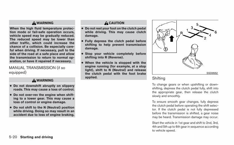
WARNING
When the high fluid temperature protec-tion mode or fail-safe operation occurs,vehicle speed may be gradually reduced.The reduced speed may be lower thanother traffic, which could increase thechance of a collision. Be especially care-ful when driving. If necessary, pull to theside of the road at a safe place and allowthe transmission to return to normal op-eration, or have it repaired if necessary.
MANUAL TRANSMISSION (if soequipped)
WARNING
● Do not downshift abruptly on slipperyroads. This may cause a loss of control.
● Do not over-rev the engine when shift-ing to a lower gear. This may cause aloss of control or engine damage.
● Do not shift to the N (Neutral) positionwhile driving. Doing so may result in anaccident due to loss of engine braking.
CAUTION
● Do not rest your foot on the clutch pedalwhile driving. This may cause clutchdamage.
● Fully depress the clutch pedal beforeshifting to help prevent transmissiondamage.
● Stop your vehicle completely beforeshifting into R (Reverse).
● When the vehicle is stopped with theengine running (for example, at a stoplight), shift to N (Neutral) and releasethe clutch pedal with the foot brakeapplied. Shifting
To change gears or when upshifting or down-shifting, depress the clutch pedal fully, shift intothe appropriate gear, then release the clutchslowly and smoothly.
To ensure smooth gear changes, fully depressthe clutch pedal before operating the shift selec-tor. If the clutch pedal is not fully depressedbefore the transmission is shifted, a gear noisemay be heard. Transmission damage may occur.
Start the vehicle in 1st gear and shift to 2nd, 3rd,4th and 5th up to 6th gear in sequence accordingto vehicle speed.
SSD0552
5-20 Starting and driving

To back up, lift up on the shift selector ring �1 andthen move it to the R (Reverse) position afterstopping the vehicle completely.
The shift selector ring �1 returns to its originalposition when the shift selector is moved to the N(Neutral) position.
If it is difficult to move the shift selector into R(Reverse) or 1 (1st), shift into N (Neutral), thenrelease the clutch pedal. Depress the clutchpedal again and shift into R (Reverse) or 1 (1st).
Suggested up-shift speeds
The following are suggested vehicle speeds forshifting into a higher gear. These suggestionsrelate to fuel economy and vehicle performance.Actual upshift speeds will vary according to roadconditions, the weather and individual drivinghabits.
GEAR CHANGE MPH (km/h)1st to 2nd 8 (13)2nd to 3rd 17 (27)3rd to 4th 25 (40)4th to 5th 36 (58)5th to 6th 51 (82)
Suggested maximum speed in eachgearDownshift to a lower gear if the engine is notrunning smoothly, or if you need to accelerate.
Do not exceed the maximum suggested speed(shown below) in any gear. For level road driving,use the highest gear suggested for that speed.Always observe posted speed limits, and driveaccording to the road conditions, which will en-sure safe operation. Do not over-rev the enginewhen shifting to a lower gear as it may causeengine damage or loss of vehicle control.MRA8DE engine models (6 M/T)
GEAR km/h (MPH)1st 48 (30)2nd 84 (52)3rd 117 (73)4th 152 (94)5th —6th —
WARNING
● Be sure the parking brake is fully re-leased before driving. Failure to do socan cause brake failure and lead to anaccident.
● Do not release the parking brake fromoutside the vehicle.
● Do not use the shift selector in place ofthe parking brake. When parking, besure the parking brake is fully engaged.
● Do not leave children unattended in avehicle. They could release the parkingbrake and cause an accident.
PARKING BRAKE
Starting and driving 5-21

To engage: Pull the lever up �A .
To release:
1. Firmly apply the foot brake.
2. Manual transmission models:
Place the shift selector in the N (Neutral)position.
CVT models:
Move the shift selector to the P (Park) posi-tion.
3. While pulling up on the parking brake leverslightly, push the button and lower com-pletely �B .
4. Before driving, be sure the brake warninglight goes out.
Adjusts the engine and transmission points toenhance performance. Press the SPORT buttonon the instrument panel to activate. “SPORT”appears in the speedometer for 2 seconds.
NOTE:
In the SPORT mode, fuel economy may bereduced.
LSD2133 LIC2417
SPORT MODE
5-22 Starting and driving

NOTE:
The ECO mode display will not displaywhen the cruise control is functioning, orunder re-acceleration while in cruise con-trol.
The ECO mode helps to enhance the fueleconomy by controlling the engine and CVT (ifequipped) operation automatically to avoid rapidacceleration.
To turn on the ECO mode, push the ECO modeswitch. The ECO mode indicator light (on thespeedometer) will illuminate.
To turn off the ECO mode, push the ECO modeswitch again. The ECO mode indicator light (onthe speedometer) will turn off.
The ECO mode cannot be turned off while theaccelerator pedal is depressed, even if the ECOmode switch is pushed to OFF. Release theaccelerator pedal to turn off the ECO mode.
The ECO mode will turn off automatically if amalfunction occurs in the system.
Turn off the ECO mode when acceleration isrequired, such as when:
● driving with a heavy load of passengers orcargo in the vehicle
● driving on a steep uphill slope
NOTE:
Selecting this drive mode will not neces-sarily improve fuel economy as many driv-ing factors influence its effectiveness.
Eco mode switchLIC2416
Eco mode displayLSD2144
ECO MODE (if so equipped)
Starting and driving 5-23

GEAR SHIFT INDICATOR (Manualtransmission only)
The Gear Shift Indicator (GSI) is used to supportthe suitable timing of gear change. It operatesonly when the ECO mode is in the “ON” state.
The shift indicator icon �2 and recommendedgear position �3 are displayed.
The shift indicator icon indicates when to upshiftor downshift for fuel economy.
NOTE:
● The shift indicator is a guide for fueleconomy. Always pay attention to road con-ditions and other traffic.
● Downshift indicator icon to the “1” (1st) po-sition is not displayed.
● If the downshifting icon is displayed whendecreasing your vehicle speed, it indicatesthat the engine speed is low compared tothe gear position.
1. ACCEL/RES switch2. COAST/SET switch3. CANCEL switch4. ON·OFF switch
PRECAUTIONS ON CRUISECONTROL
● If the cruise control system malfunctions, itcancels automatically. The SET indicatorlight in the vehicle information display thenblinks to warn the driver, see “Vehicle infor-mation display” in the “Instruments and con-trols” section.
LSD2143 LSD2003
CRUISE CONTROL (if so equipped)
5-24 Starting and driving

● If the SET indicator light blinks, push thecruise control ON·OFF switch off and havethe system checked by a NISSAN dealer.
● The SET indicator light may blink when thecruise control ON·OFF switch is pushed ONwhile pushing the ACCEL/RES,COAST/SET, or CANCEL switch. To prop-erly set the cruise control system, use thefollowing procedures.
WARNING
Do not use the cruise control when drivingunder the following conditions:
● When it is not possible to keep thevehicle at a set speed.
● In heavy traffic or in traffic that varies inspeed.
● On winding or hilly roads.
● On slippery roads (rain, snow, ice, etc.).
● In very windy areas.
Doing so could cause a loss of vehiclecontrol and result in an accident.
CRUISE CONTROL OPERATIONS
The cruise control allows driving at a speed be-tween 25 - 89 MPH (40 - 144 km/h) withoutkeeping your foot on the accelerator pedal.
To turn on the cruise control, push theON·OFF switch. The CRUISE indicator light inthe instrument panel comes on.
To set cruising speed, accelerate the vehicle tothe desired speed, push the COAST/SET switchand release it. The SET indicator light in theinstrument panel comes on. Take your foot off theaccelerator pedal. Your vehicle maintains the setspeed.
● To pass another vehicle, depress the ac-celerator pedal. When you release thepedal, the vehicle returns to the previouslyset speed.
● The vehicle may not maintain the set speedwhen going up or down steep hills. If thishappens, drive without the cruise control.
To cancel the preset speed, use one of thefollowing three methods.
● Push the CANCEL button; the SET indicatorlight in the instrument panel goes out.
● Tap the brake pedal; the SET indicator lightgoes out.
● Push the ON·OFF switch off. Both theCRUISE indicator light and SET indicatorlight in the instrument panel go out.
The cruise control is automatically canceled andthe SET light in the instrument panel goes out if:
● you depress the brake or clutch pedal whilepushing the ACCEL/RES or SET/COASTswitch. The preset speed is deleted frommemory.
● the vehicle slows down more than 8 MPH(13 km/h) below the set speed.
● you depress the clutch pedal (manual trans-mission), or move the shift selector to N(Neutral) (CVT).
To reset at a faster cruising speed, use oneof the following three methods.
● Depress the accelerator pedal. When thevehicle attains the desired speed, push andrelease the COAST/SET switch.
● Push and hold the ACCEL/RES switch.When the vehicle attains the speed you de-sire, release the switch.
● Push and release the ACCEL/RES switch.Each time you do this, the set speed in-creases by about 1 MPH (1.6 km/h).
Starting and driving 5-25
To reset at a slower cruising speed, use oneof the following three methods.
● Lightly tap the brake pedal. When the ve-hicle attains the desired speed, push theCOAST/SET switch and release it.
● Push and hold the COAST/SET switch. Re-lease the switch when the vehicle slows tothe desired speed.
● Push and release the COAST/SET switch.Each time you do this, the set speed de-creases by about 1 MPH (1.6 km/h).
To resume the preset speed, push and re-lease the ACCEL/RES switch. The vehicle re-turns to the last set cruising speed when thevehicle speed is over 25 MPH (40 km/h).
CAUTION
During the first 1,200 miles (2,000 km),follow these recommendations to obtainmaximum engine performance and en-sure the future reliability and economy ofyour new vehicle. Failure to follow theserecommendations may result in short-ened engine life and reduced engineperformance.
● Avoid driving for long periods at constantspeed, either fast or slow, and do not run theengine over 4,000 rpm.
● Do not accelerate at full throttle in any gear.
● Avoid quick starts.
● Avoid hard braking as much as possible.
● Do not tow a trailer for the first 500 miles(800 km). Your engine, axle or other partscould be damaged.
Follow these easy-to-use Fuel Efficient DrivingTips to help you achieve the most fuel economyfrom your vehicle.
1. Use Smooth Accelerator and BrakePedal Application
● Avoid rapid starts and stops
● Use smooth, gentle accelerator andbrake application whenever possible
● Maintain constant speed while commut-ing and coast whenever possible
2. Maintain Constant Speed
● Look ahead to try and anticipate and mini-mize stops
● Synchronizing your speed with trafficlights allows you to reduce your numberof stops
● Maintaining a steady speed can minimizered light stops and improve fuel efficiency
3. Use Air Conditioning (A/C) at HigherVehicle Speeds
● Below 40 MPH (64 km/h), it is moreefficient to open windows to cool thevehicle due to reduced engine load
BREAK-IN SCHEDULE FUEL EFFICIENT DRIVING TIPS
5-26 Starting and driving

● Above 40 MPH (64 km/h), it is moreefficient to use A/C to cool the vehicledue to increased aerodynamic drag
● Recirculating the cool air in the cabinwhen the A/C is on reduces cooling load
4. Drive at Economical Speeds and Dis-tances
● Observing the speed limit and not ex-ceeding 60 MPH (97 km/h) (where le-gally allowed) can improve fuel efficiencydue to reduced aerodynamic drag
● Maintaining a safe following distance be-hind other vehicles reduces unnecessarybraking
● Safely monitoring traffic to anticipatechanges in speed permits reduced brak-ing and smooth acceleration changes
● Select a gear range suitable to road con-ditions.
5. Use Cruise Control
● Using cruise control during highway driv-ing helps maintain a steady speed
● Cruise control is particularly effective inproviding fuel savings when driving on flatterrains
6. Plan for the Shortest Route
● Utilize a map or navigation system to de-termine the best route to save time
7. Avoid Idling
● Shutting off your engine when safe forstops exceeding 30–60 seconds savesfuel and reduces emissions
8. Buy an Automated Pass for Toll Roads
● Automated passes permit drivers to usespecial lanes to maintain cruising speedthrough the toll and avoid stopping andstarting
9. Winter Warm Up
● Limit idling time to minimize impact to fueleconomy
● Vehicles typically need no more than30 seconds of idling at start-up to effec-tively circulate the engine oil before driv-ing
● Your vehicle will reach its ideal operatingtemperature more quickly while drivingversus idling
10. Keeping your Vehicle Cool
● Park your vehicle in a covered parkingarea or in the shade whenever possible
● When entering a hot vehicle, opening thewindows will help to reduce the insidetemperature faster, resulting in reduceddemand on your A/C system
Starting and driving 5-27

● Keep your engine tuned up.
● Follow the recommended scheduled main-tenance.
● Keep the tires inflated to the correct pres-sure. Low tire pressure increases tire wearand lowers fuel economy.
● Keep the wheels in correct alignment. Im-proper alignment increases tire wear andlowers fuel economy.
● Use the recommended viscosity engine oil.See “Engine oil and oil filter recommenda-tions” in “Technical and consumer informa-tion” later in this manual.
WARNING
● Do not stop or park the vehicle overflammable materials such as dry grass,waste paper or rags. They may igniteand cause a fire.
● Safe parking procedures require thatboth the parking brake be set and thetransmission placed into P (Park) for CVTmodels or in an appropriate gear formanual transmission models. Failure todo so could cause the vehicle to moveunexpectedly or roll away and result in anaccident. Make sure the shift selectorhas been pushed as far forward as it cango and cannot be moved without de-pressing the foot brake pedal.
● Never leave the engine running whilethe vehicle is unattended.
SSD0488
INCREASING FUEL ECONOMY PARKING/PARKING ON HILLS
5-28 Starting and driving

● Do not leave children unattended insidethe vehicle. They could unknowingly ac-tivate switches or controls. Unattendedchildren could become involved in seri-ous accidents.
1. Firmly apply the parking brake.
2. Manual transmission models:
Place the shift selector in the R (Reverse)position. When parking on an uphill grade,place the shift selector in 1st gear.
Continuously Variable Transmission(CVT) models:
Move the shift selector to the P (Park) posi-tion.
3. To help prevent the vehicle from rolling intotraffic when parked on an incline, it is a goodpractice to turn the wheels as illustrated.
● HEADED DOWNHILL WITH CURB: �1
Turn the wheels into the curb and move thevehicle forward until the curb side wheelgently touches the curb.
● HEADED UPHILL WITH CURB: �2
Turn the wheels away from the curb andmove the vehicle back until the curb sidewheel gently touches the curb.
● HEADED UPHILL OR DOWNHILL, NOCURB: �3
Turn the wheels toward the side of the roadso the vehicle will move away from the cen-ter of the road if it moves.
4. Place the ignition switch in the LOCK posi-tion and remove the key.
WARNING
● If the engine is not running or is turnedoff while driving, the power assist forthe steering will not work. Steering willbe harder to operate.
● When the power steering warning lightilluminates with the engine running,there will be no power assist for thesteering. You will still have control ofthe vehicle but the steering will beharder to operate. Have the powersteering system checked by a NISSANdealer.
The power steering system is designed to pro-vide power assist while driving to operate thesteering wheel with light force.
When the steering wheel is operated repeatedlyor continuously while parking or driving at a verylow speed, the power assist for the steeringwheel will be reduced. This is to prevent over-heating of the power steering system and protectit from getting damaged. While the power assistis reduced, steering wheel operation will becomeheavy. When the temperature of the power steer-ing system goes down, the power assist level willreturn to normal. Avoid repeating such steeringwheel operations that could cause the powersteering system to overheat.
POWER STEERING
Starting and driving 5-29

You may hear a sound when the steering wheel isoperated quickly. However, this is not a malfunc-tion.
If the electric power steering warning light PSilluminates while the engine is running, it mayindicate the power steering system is not func-tioning properly and may need servicing. Havethe power steering system checked by aNISSAN dealer.
When the electric power steering warning lightilluminates with the engine running, there will beno power assist for the steering but you will stillhave control of the vehicle. At this time, greatersteering effort is required to operate the steeringwheel, especially in sharp turns and at lowspeeds.
For additional information see “Power steeringwarning light” in the “Instruments and controls”section.
The brake system has two separate hydrauliccircuits. If one circuit malfunctions, you will stillhave braking at 2 wheels.
BRAKE PRECAUTIONS
Vacuum assisted brakes
The brake booster aids braking by using enginevacuum. If the engine stops, you can stop thevehicle by depressing the brake pedal. However,greater foot pressure on the brake pedal will berequired to stop the vehicle and stopping dis-tance will be longer.
Using the brakes
Avoid resting your foot on the brake pedal whiledriving. This will overheat the brakes, wear out thebrake pads faster, and reduce gas mileage.
To help reduce brake wear and to prevent thebrakes from overheating, reduce speed anddownshift to a lower gear before going down aslope or long grade. Overheated brakes mayreduce braking performance and could result inloss of vehicle control.
WARNING
● While driving on a slippery surface, becareful when braking, accelerating ordownshifting. Abrupt braking or accel-erating could cause the wheels to skidand result in an accident.
● If the engine is not running or is turnedoff while driving, the power assist forthe brakes will not work. Braking will beharder.
Wet brakes
When the vehicle is washed or driven throughwater, the brakes may get wet. As a result, yourbraking distance will be longer and the vehiclemay pull to one side during braking.
To dry the brakes, drive the vehicle at a safespeed while lightly pressing the brake pedal toheat up the brakes. Do this until the brakes returnto normal. Avoid driving the vehicle at highspeeds until the brakes function correctly.
Parking brake break-in
Break-in the parking brake shoes whenever theeffect of the parking brake is weakened or when-ever the parking brake shoes and/or drum/rotorsare replaced, in order to assure the best brakeperformance.
BRAKE SYSTEM
5-30 Starting and driving

This procedure is described in the vehicle servicemanual and can be performed by a NISSANdealer.
ANTI-LOCK BRAKING SYSTEM(ABS)
WARNING
● The Anti-lock Braking System (ABS) is asophisticated device, but it cannot pre-vent accidents resulting from carelessor dangerous driving techniques. It canhelp maintain vehicle control duringbraking on slippery surfaces. Remem-ber that stopping distances on slipperysurfaces will be longer than on normalsurfaces even with ABS. Stopping dis-tances may also be longer on rough,gravel or snow covered roads, or if youare using tire chains. Always maintain asafe distance from the vehicle in frontof you. Ultimately, the driver is respon-sible for safety.
● Tire type and condition may also affectbraking effectiveness.
– When replacing tires, install thespecified size of tires on all fourwheels.
– When installing a spare tire, makesure that it is the proper size and typeas specified on the Tire and LoadingInformation label. See “Tire andLoading Information label” in the“Technical and consumer informa-tion” section of this manual.
– For detailed information, see“Wheels and tires” in the “Mainte-nance and do-it-yourself” section ofthis manual.
The Anti-lock Braking System (ABS) controls thebrakes so the wheels do not lock during hardbraking or when braking on slippery surfaces.The system detects the rotation speed at eachwheel and varies the brake fluid pressure to pre-vent each wheel from locking and sliding. Bypreventing each wheel from locking, the systemhelps the driver maintain steering control andhelps to minimize swerving and spinning on slip-pery surfaces.
Using the system
Depress the brake pedal and hold it down. De-press the brake pedal with firm steady pressure,but do not pump the brakes. The ABS will oper-ate to prevent the wheels from locking up. Steerthe vehicle to avoid obstacles.
WARNING
Do not pump the brake pedal. Doing somay result in increased stoppingdistances.
Self-test feature
The ABS includes electronic sensors, electricpumps, hydraulic solenoids and a computer. Thecomputer has a built-in diagnostic feature thattests the system each time you start the engineand move the vehicle at a low speed in forward orreverse. When the self-test occurs, you may heara “clunk”noise and/or feel a pulsation in the brakepedal. This is normal and does not indicate amalfunction. If the computer senses a malfunc-tion, it switches the ABS off and illuminates theABS warning light on the instrument panel. Thebrake system then operates normally, but withoutanti-lock assistance.
If the ABS warning light illuminates during theself-test or while driving, have the vehiclechecked by a NISSAN dealer.
Normal operation
The ABS operates at speeds above 3 - 6 MPH (5- 10 km/h). The speed varies according to roadconditions.
Starting and driving 5-31

When the ABS senses that 1 or more wheels areclose to locking up, the actuator rapidly appliesand releases hydraulic pressure. This action issimilar to pumping the brakes very quickly. Youmay feel a pulsation in the brake pedal and hear anoise from under the hood or feel a vibration fromthe actuator when it is operating. This is normaland indicates that the ABS is operating properly.However, the pulsation may indicate that roadconditions are hazardous and extra care is re-quired while driving.
The Vehicle Dynamic Control (VDC) system usesvarious sensors to monitor driver inputs and ve-hicle motion. Under certain driving conditions,the VDC System helps to perform the followingfunctions:
● Controls brake pressure to reduce wheelslip on one slipping drive wheel so power istransferred to a non slipping drive wheel onthe same axle.
● Controls brake pressure and engine outputto reduce drive wheel slip based on vehiclespeed (traction control function).
● Controls brake pressure at individual wheelsand engine output to help the driver maintaincontrol of the vehicle in the following condi-tions:
– understeer (vehicle tends to not followthe steered path despite increased steer-ing input)
– oversteer (vehicle tends to spin due tocertain road or driving conditions)
The VDC system can help the driver to maintaincontrol of the vehicle, but it cannot prevent loss ofvehicle control in all driving situations.
When the VDC system operates, the indi-cator in the instrument panel flashes so note thefollowing:
● The road may be slippery or the system maydetermine some action is required to helpkeep the vehicle on the steered path.
● You may feel a pulsation in the brake pedaland hear a noise or vibration from under thehood. This is normal and indicates that theVDC system is working properly.
● Adjust your speed and driving to the roadconditions.
See “Slip indicator light” and ”Vehicle DynamicControl (VDC) off indicator light” in the ”Instru-ments and controls” section.
If a malfunction occurs in the system, theindicator light comes on in the instrument panel.The VDC system automatically turns off when theindicator light is off.
The VDC OFF switch is used to turn off the VDCsystem. The indicator illuminates to indi-cate the VDC system is off.
When the VDC switch is used to turn off thesystem, the VDC system still operates to preventone drive wheel from slipping by transferringpower to a non slipping drive wheel. Theindicator flashes if this occurs. All other VDCfunctions are off and the indicator will notflash.
VEHICLE DYNAMIC CONTROL (VDC)SYSTEM
5-32 Starting and driving

The VDC system is automatically reset to onwhen the ignition switch is placed in the offposition then back to the on position.
The computer has a built in diagnostic featurethat tests the system each time you start theengine and move the vehicle forward or in reverseat a slow speed. When the self-test occurs, youmay hear a clunk noise and/or feel a pulsation inthe brake pedal. This is normal and is not anindication of a malfunction.
WARNING
● The VDC system is designed to help thedriver maintain stability but does notprevent accidents due to abrupt steer-ing operation at high speeds or by care-less or dangerous driving techniques.Reduce vehicle speed and be especiallycareful when driving and cornering onslippery surfaces and always drivecarefully.
● Do not modify the vehicle’s suspension.If suspension parts such as shock ab-sorbers, struts, springs, stabilizer bars,bushings and wheels are not NISSANrecommended for your vehicle or areextremely deteriorated, the VDC systemmay not operate properly. This couldadversely affect vehicle handling per-formance, and the indicator mayflash or the indicator light mayilluminate.
● If brake related parts such as brakepads, rotors and calipers are notNISSAN recommended or are extremelydeteriorated, the VDC system may notoperate properly and the indica-tor light may illuminate.
● If engine control related parts are notNISSAN recommended or are extremelydeteriorated, the indicator lightmay illuminate.
● When driving on extremely inclined sur-faces such as higher banked corners,the VDC system may not operate prop-erly and the indicator may flash orthe indicator light may illuminate.Do not drive on these types of roads.
● When driving on an unstable surfacesuch as a turntable, ferry, elevator orramp, the indicator may flash orthe indicator light may illuminate.This is not a malfunction. Restart theengine after driving onto a stablesurface.
● If wheels or tires other than the NISSANrecommended ones are used, the VDCsystem may not operate properly andthe indicator may flash orthe indicator light may illuminate.
● The VDC system is not a substitute forwinter tires or tire chains on a snowcovered road.
Starting and driving 5-33

FREEING A FROZEN DOOR LOCKTo prevent a door lock from freezing, apply de-icer through the key hole. If the lock becomesfrozen, heat the key before inserting it into the keyhole, or use the remote keyless entry keyfob (if soequipped) or the NISSAN Intelligent Key® (if soequipped).
ANTI-FREEZEIn the winter when it is anticipated that the tem-perature will drop below 32°F (0°C), check theanti-freeze to assure proper winter protection.For details, see “Engine cooling system” in the“Maintenance and do-it-yourself” section of thismanual.
BATTERYIf the battery is not fully charged during extremelycold weather conditions, the battery fluid mayfreeze and damage the battery. To maintain maxi-mum efficiency, the battery should be checkedregularly. For details, see “Battery” in the “Main-tenance and do-it-yourself” section of thismanual.
DRAINING OF COOLANT WATER
If the vehicle is to be left outside without anti-freeze, drain the cooling system, including theengine block. Refill before operating the vehicle.For details, see “Changing engine coolant” in the“Maintenance and do-it-yourself” section of thismanual.
TIRE EQUIPMENT
1. SUMMER tires have a tread designed toprovide superior performance on dry pave-ment. However, the performance of thesetires will be substantially reduced in snowyand icy conditions. If you operate your ve-hicle on snowy or icy roads, NISSAN recom-mends the use of MUD & SNOW or ALLSEASON TIRES on all four wheels. Pleaseconsult a NISSAN dealer for the tire type,size, speed rating and availability informa-tion.
2. For additional traction on icy roads, studdedtires may be used. However, some U.S.states and Canadian provinces prohibit theiruse. Check local, state and provincial lawsbefore installing studded tires.
Skid and traction capabilities of studdedsnow tires on wet or dry surfaces may bepoorer than that of non-studded snow tires.
3. Tire chains may be used. For details see“Tire chains” in the “Maintenance and do-it-yourself” section of this manual.
SPECIAL WINTER EQUIPMENT
It is recommended that the following items becarried in the vehicle during winter:
● A scraper and stiff-bristled brush to removeice and snow from the windows and wiperblades.
● A sturdy, flat board to be placed under thejack to give it firm support.
● A shovel to dig the vehicle out of snowdrifts.
● Extra washer fluid to refill the windshield-washer fluid reservoir.
DRIVING ON SNOW OR ICE
WARNING
● Wet ice (32°F, 0°C and freezing rain),very cold snow or ice can be slick andvery hard to drive on. The vehicle willhave much less traction or “grip” underthese conditions. Try to avoid driving onwet ice until the road is salted orsanded.
COLD WEATHER DRIVING
5-34 Starting and driving

● Whatever the condition, drive with cau-tion. Accelerate and slow down withcare. If accelerating or downshifting toofast, the drive wheels will lose evenmore traction.
● Allow more stopping distance underthese conditions. Braking should bestarted sooner than on dry pavement.
● Allow greater following distances onslippery roads.
● Watch for slippery spots (glare ice).These may appear on an otherwiseclear road in shaded areas. If a patch ofice is seen ahead, brake before reach-ing it. Try not to brake while on the ice,and avoid any sudden steeringmaneuvers.
● Do not use the cruise control (if soequipped) on slippery roads.
● Snow can trap dangerous exhaustgases under your vehicle. Keep snowclear of the exhaust pipe and fromaround your vehicle.
ENGINE BLOCK HEATER (if soequipped)
Engine block heaters are used to assist with coldtemperature starting.
The engine block heater should be used whenthe outside temperature is 20°F (-7°C) or lower.
WARNING
● Do not use your engine block heaterwith an ungrounded electrical systemor a 2-pronged adapter. You can be se-riously injured by an electrical shock ifyou use an ungrounded connection.
● Disconnect and properly store the en-gine block heater cord before startingthe engine. Damage to the cord couldresult in an electrical shock and cancause serious injury.
● Use a heavy-duty 3-wire, 3-pronged ex-tension cord rated for at least 10 A. Plugthe extension cord into a Ground FaultInterrupt (GFI) protected, grounded110-VAC outlet. Failure to use theproper extension cord or a groundedoutlet can result in a fire or electricalshock and cause serious personalinjury.
To use the engine block heater:
1. Turn the engine off.
2. Open the hood and unwrap the engine blockheater cord.
3. Plug the engine block heater cord into agrounded 3 wire, 3 pronged extension cord.
4. Plug the extension cord into a Ground FaultInterrupt (GFI) protected, grounded 110-volt AC (VAC) outlet.
5. The engine block heater must be plugged infor at least 2 - 4 hours, depending on outsidetemperatures, to properly warm the enginecoolant. Use an appropriate timer to turn theengine block heater on.
6. Before starting the engine, unplug and prop-erly store the cord to keep it away frommoving parts.
Starting and driving 5-35

MEMO
5-36 Starting and driving

6 In case of emergency
Emergency engine shut off (Push-button ignitionmodels only) . . . . . . . . . . . . . . . . . . . . . . . . . . . . . . . . . . . . . . 6-2Hazard warning flasher switch . . . . . . . . . . . . . . . . . . . . . . 6-2Flat tire . . . . . . . . . . . . . . . . . . . . . . . . . . . . . . . . . . . . . . . . . . . 6-3
Tire Pressure Monitoring System (TPMS)(if so equipped) . . . . . . . . . . . . . . . . . . . . . . . . . . . . . . . . 6-3Changing a flat tire . . . . . . . . . . . . . . . . . . . . . . . . . . . . . 6-3
Jump starting . . . . . . . . . . . . . . . . . . . . . . . . . . . . . . . . . . . . . 6-8Push starting. . . . . . . . . . . . . . . . . . . . . . . . . . . . . . . . . . . . . 6-10If your vehicle overheats . . . . . . . . . . . . . . . . . . . . . . . . . . . 6-10Towing your vehicle . . . . . . . . . . . . . . . . . . . . . . . . . . . . . . . 6-11
Towing recommended by NISSAN . . . . . . . . . . . . . . 6-12Vehicle recovery (freeing a stuck vehicle) . . . . . . . . . 6-14

To shut off the engine in an emergency situationwhile driving, perform the following procedure:
– Rapidly push the push-button ignition switch 3consecutive times in less than 1.5 seconds, or
– Push and hold the push-button ignition switchfor more than 2 seconds.
Push the switch on to warn other drivers whenyou must stop or park under emergency condi-tions. All turn signal lights flash.
WARNING
● If stopping for an emergency, be sure tomove the vehicle well off the road.
● Do not use the hazard warning flasherswhile moving on the highway unlessunusual circumstances force you todrive so slowly that your vehicle mightbecome a hazard to other traffic.
● Turn signals do not work when the haz-ard warning flasher lights are on.
The flashers will operate with the ignition switchplaced in any position.
Some state laws may prohibit the use ofthe hazard warning flasher switch whiledriving.
LIC0394
EMERGENCY ENGINE SHUT OFF(Push-button ignition models only)
HAZARD WARNING FLASHERSWITCH
6-2 In case of emergency

TIRE PRESSURE MONITORINGSYSTEM (TPMS) (if so equipped)
This vehicle is equipped with the Tire PressureMonitoring System (TPMS). It monitors tire pres-sure of all tires except the spare. When the lowtire pressure warning light is lit, and the CHECKTIRE PRES warning message is displayed in theodometer, one or more of your tires is significantlyunder-inflated. If the vehicle is being driven withlow tire pressure, the TPMS will activate andwarn you of it by the low tire pressure warninglight. This system will activate only when thevehicle is driven at speeds above 16 MPH(25 km/h). For more details, refer to“Warning/indicator lights and audible reminders”in the “Instruments and controls” section, and“Tire Pressure Monitoring System (TPMS)” in the“Starting and driving” section.
WARNING
● Radio waves could adversely affectelectric medical equipment. Those whouse a pacemaker should contact theelectric medical equipment manufac-turer for the possible influences beforeuse.
● If the low tire pressure warning lightilluminates while driving, avoid suddensteering maneuvers or abrupt braking,reduce vehicle speed, pull off the roadto a safe location and stop the vehicleas soon as possible. Driving with under-inflated tires may permanently damagethe tires and increase the likelihood oftire failure. Serious vehicle damagecould occur and may lead to an acci-dent and could result in serious per-sonal injury. Check the tire pressure forall four tires. Adjust the tire pressure tothe recommended COLD tire pressureshown on the Tire and Loading Informa-tion label to turn the low tire pressurewarning light OFF. If you have a flat tire,replace it with a spare tire as soon aspossible.
● When a spare tire is mounted or a wheelis replaced, the TPMS will not functionand the low tire pressure warning lightwill flash for approximately 1 minute.The light will remain on after 1 minute.Contact your NISSAN dealer as soon aspossible for tire replacement and/orsystem resetting.
● Replacing tires with those not originallyspecified by NISSAN could affect theproper operation of the TPMS.
● Do not inject any tire liquid or aerosoltire sealant into the tires, as this maycause a malfunction of the tire pressuresensors.
CHANGING A FLAT TIRE
If you have a flat tire, follow the instructions be-low:
Stopping the vehicle
1. Safely move the vehicle off the road andaway from traffic.
2. Turn on the hazard warning flashers.
3. Park on a level surface and apply the parkingbrake. Shift the manual transmission into R(Reverse), or the CVT into P (Park).
4. Turn off the engine.
5. Raise the hood to warn other traffic and tosignal professional road assistance person-nel that you need assistance.
6. Have all passengers get out of the vehicleand stand in a safe place, away from trafficand clear of the vehicle.
FLAT TIRE
In case of emergency 6-3

WARNING
● Make sure the parking brake is securelyapplied and the manual transmission isshifted into R (Reverse), or the CVT isshifted into P (Park).
● Never change tires when the vehicle ison a slope, ice or slippery areas. This ishazardous.
● Never change tires if oncoming traffic isclose to your vehicle. Wait for profes-sional road assistance.
Blocking wheelsPlace suitable blocks �1 at both the front andback of the wheel diagonally opposite the flat tire�2 to prevent the vehicle from moving when it isjacked up.
WARNING
Be sure to block the wheel as the vehiclemay move and result in personal injury.
WCE0044 LCE2058
6-4 In case of emergency

Getting the spare tire and tools1. Open the trunk. Lift the trunk floor carpeting
and spare tire cover �A . Remove the jackand the spare tire as indicated.
2. To remove the jack, take off the strap and liftout. If necessary, remove the spare tire firstto easily access the jack strap.
Removing the wheel cover (if soequipped)
CAUTION
Do not use your hands to pry off wheelcaps or wheel covers. Doing so could re-sult in personal injury.
To remove the wheel cover, use the jack rod �1as illustrated.
Apply cloth �2 between the wheel and jack rod toprevent damaging the wheel and wheel cover.
Use caution not to scratch the wheel cover orwheel surface.
Jacking up vehicle and removing thedamaged tire
WARNING
● Never get under the vehicle while it issupported only by the jack. If it is nec-essary to work under the vehicle, sup-port it with safety stands.
● Use only the jack provided with yourvehicle to lift the vehicle. Do not use thejack provided with your vehicle on othervehicles. The jack is designed for liftingonly your vehicle during a tire change.
WCE0203 SCE0630 CE1089
In case of emergency 6-5

● Use the correct jack-up points. Neveruse any other part of the vehicle for jacksupport.
● Never jack up the vehicle more thannecessary.
● Never use blocks on or under the jack.
● Do not start or run the engine whilevehicle is on the jack. It may cause thevehicle to move. This is especially truefor vehicles with limited slipdifferentials.
● Do not allow passengers to stay in thevehicle while it is on the jack.
● Never run the engine with a wheel(s) offthe ground. It may cause the vehicle tomove.
Always refer to the proper illustrations for thecorrect placement and jack-up points for yourspecific vehicle model and jack type.
Carefully read the caution label attached tothe jack body and the following instruc-tions.
1. Loosen each wheel nut one or two turns byturning counterclockwise with the wheel nutwrench. Do not remove the wheel nutsuntil the tire is off the ground.
2. Place the jack directly under the jack-uppoint as illustrated so the top of the jackcontacts the vehicle at the jack-up point.Align the jack head between the two
notches in the front or the rear as shown.Also fit the groove of the jack head betweenthe notches as shown.
The jack should be used on firm andlevel ground.
3. To lift the vehicle, securely hold the jack leverand rod with both hands. Carefully raise thevehicle until the tire clears the ground. Re-move the wheel nuts, and then remove thetire.
LCE2059
6-6 In case of emergency

Installing the spare tire
The spare tire is designed for emergencyuse. See specific instructions under theheading “Wheels and tires” in the “Mainte-nance and do-it-yourself” section of thismanual.
1. Clean any mud or dirt from the surface be-tween the wheel and hub.
2. Carefully put the spare tire on and tightenthe wheel nuts finger tight.
3. With the wheel nut wrench, tighten wheelnuts alternately and evenly as illustrated untilthey are tight.
4. Lower the vehicle slowly until the tiretouches the ground. Then, with the wheelnut wrench, tighten the wheel nuts securelyin the sequence illustrated (�A , �B , �C , �D ,�E ). Lower the vehicle completely.
WARNING
● Incorrect wheel nuts or improperlytightened wheel nuts can cause thewheel to become loose or come off.This could cause an accident.
● Do not use oil or grease on the wheelstuds or nuts. This could cause the nutsto become loose.
● Retighten the wheel nuts when the ve-hicle has been driven for 600 miles(1,000 km) (also in cases of a flat tire,etc.).
As soon as possible, tighten the wheel nutsto the specified torque with a torquewrench.
Wheel nut tightening torque:83 ft-lb (113 N·m)
The wheel nuts must be kept tightened tospecification at all times. It is recom-mended that wheel nuts be tightened tospecification at each lubrication interval.
Adjust tire pressure to the COLD pressure.
COLD pressure: After vehicle has beenparked for three hours or more or drivenless than 1 mile (1.6 km).
COLD tire pressures are shown on the Tireand Loading Information Label.
5. Securely store the flat tire in the vehicle.
WCE0056
In case of emergency 6-7

6. Install the jack in its storage area and tightenthe jack strap .
7. Place the spare tire cover and the trunk floorcarpeting over the damaged tire.
8. Close the trunk.
WARNING
● Always make sure that the spare tireand jacking equipment are properly se-cured after use. Such items can becomedangerous projectiles in an accident orsudden stop.
● The spare tire is designed for emer-gency use. See specific instructions un-der the heading “Wheels and tires” inthe “Maintenance and do-it-yourself”section of this manual.
To start your engine with a booster battery, theinstructions and precautions below must be fol-lowed.
WARNING
● If done incorrectly, jump starting canlead to a battery explosion, resulting insevere injury or death. It could alsodamage your vehicle.
● Explosive hydrogen gas is always pres-ent in the vicinity of the battery. Keep allsparks and flames away from thebattery.
● Do not allow battery fluid to come intocontact with eyes, skin, clothing orpainted surfaces. Battery fluid is a cor-rosive sulfuric acid solution which cancause severe burns. If the fluid shouldcome into contact with anything, imme-diately flush the contacted area withwater.
● Keep battery out of the reach ofchildren.
● The booster battery must be rated at12 volts. Use of an improperly ratedbattery can damage your vehicle.
LCE2060
JUMP STARTING
6-8 In case of emergency

● Whenever working on or near a battery,always wear suitable eye protectors (forexample, goggles or industrial safetyspectacles) and remove rings, metalbands, or any other jewelry. Do not leanover the battery when jump starting.
● Do not attempt to jump start a frozenbattery. It could explode and cause se-rious injury.
● Your vehicle has an automatic enginecooling fan. It could come on at anytime. Keep hands and other objectsaway from it.
WARNING
Always follow the instructions below.Failure to do so could result in damage tothe charging system and cause personalinjury.
1. If the booster battery is in another vehicle,position the two vehicles to bring their bat-teries near each other.
Do not allow the two vehicles to touch.
2. Apply the parking brake. Move the shift se-lector to P (Park). Switch off all unnecessaryelectrical systems (lights, heater, air condi-tioner, etc.).
3. Remove the vent caps on the battery (if soequipped). Cover the battery with an oldcloth to reduce explosion hazard.
4. Connect the jumper cables in the sequenceillustrated (�A , �B , �C , �D ).
WCE0054
In case of emergency 6-9

CAUTION
● Always connect positive (�) to positive(�) and negative (�) to body ground (forexample, strut mounting bolt, enginelift bracket, etc.) — not to the battery.
● Make sure the jumper cables do nottouch moving parts in the engine com-partment and that the cable clamps donot contact any other metal.
5. Start the engine of the booster vehicle andlet it run for a few minutes.
6. Keep the engine speed of the booster ve-hicle at about 2,000 rpm and start the en-gine of the vehicle being jump started.
CAUTION
Do not keep the starter motor engaged formore than 10 seconds. If the engine doesnot start right away, place the ignitionswitch in the OFF position and wait 3 to4 seconds before trying again.
7. After starting the engine, carefully disconnectthe negative cable and then the positive cable.
8. Replace the vent caps (if so equipped). Besure to dispose of the cloth used to coverthe vent holes as it may be contaminatedwith corrosive acid.
CAUTION
● Do not push start this vehicle. Thethree-way catalyst may be damaged.
● Continuously Variable Transmission(CVT) models cannot be push-started ortow-started. Attempting to do so maycause transmission damage.
● For manual transmission (M/T) models,never try to start the vehicle by towingit. When the engine starts, the forwardsurge could cause the vehicle to collidewith the tow vehicle.
If your vehicle is overheating (indicated by anextremely high temperature gauge reading), or ifyou feel a lack of engine power, detect abnormalnoise, etc., take the following steps.
WARNING
● Do not continue to drive if your vehicleoverheats. Doing so could cause enginedamage or a vehicle fire.
● To avoid the danger of being scalded,never remove the radiator cap while theengine is still hot. When the radiatorcap is removed, pressurized hot waterwill spurt out, possibly causing seriousinjury.
● Do not open the hood if steam is com-ing out.
1. Move the vehicle safely off the road, applythe parking brake and move the shift selectorto N (Neutral) (manual transmission) or to P(Park) (CVT).
Do not stop the engine.
2. Turn off the air conditioner (if so equipped).Open all the windows, move the heater or airconditioner temperature control to maximumhot and fan control to high speed.
PUSH STARTING IF YOUR VEHICLE OVERHEATS
6-10 In case of emergency
3. Get out of the vehicle. Look and listen forsteam or coolant escaping from the radiatorbefore opening the hood. (If steam or cool-ant is escaping, turn off the engine.) Do notopen the hood further until no steam orcoolant can be seen.
4. Open the engine hood.
WARNING
If steam or water is coming from the en-gine, stand clear to prevent gettingburned.
5. Visually check drive belts for damage orlooseness. Also check if the cooling fan isrunning. The radiator hoses and radiatorshould not leak water. If coolant is leaking,the water pump belt is missing or loose, orthe cooling fan does not run, stop the en-gine.
WARNING
Be careful not to allow your hands, hair,jewelry or clothing to come into contactwith, or get caught in, engine belts or theengine cooling fan. The engine coolingfan can start at any time.
6. After the engine cools down, check the cool-ant level in the engine coolant reservoir withthe engine running. Add coolant to the en-gine coolant reservoir if necessary. Haveyour vehicle repaired at a NISSAN dealer.
When towing your vehicle, all State (Provincial inCanada) and local regulations for towing must befollowed. Incorrect towing equipment could dam-age your vehicle. Towing instructions are avail-able from a NISSAN dealer. Local service opera-tors are generally familiar with the applicable lawsand procedures for towing. To assure propertowing and to prevent accidental damage to yourvehicle, NISSAN recommends having a serviceoperator tow your vehicle. It is advisable to havethe service operator carefully read the followingprecautions:
WARNING
● Never ride in a vehicle that is beingtowed.
● Never get under your vehicle after it hasbeen lifted by a tow truck.
CAUTION
● When towing, make sure that the trans-mission, axles, steering system andpowertrain are in working condition. Ifany of these conditions apply, dollies ora flatbed tow truck must be used.
● Always attach safety chains beforetowing.
TOWING YOUR VEHICLE
In case of emergency 6-11

For information about towing your vehicle behinda recreational vehicle (RV), refer to “Flat towing”in the “Technical and consumer information” sec-tion of this manual.
TOWING RECOMMENDED BYNISSANNISSAN recommends that your vehicle be towedwith the driving (front) wheels off the ground orplace the vehicle on a flat bed truck as illustrated.
�A (CVT) Continuously Variable Transmission�B (M/T) Manual transmission
WCE0194
6-12 In case of emergency

CAUTION
● Never tow Continuously Variable Trans-mission (CVT) models with the frontwheels on the ground or four wheels onthe ground (forward or backward), asthis may cause serious and expensivedamage to the transmission. If it is nec-essary to tow the vehicle with the rearwheels raised always use towing dolliesunder the front wheels.
● When towing Continuously VariableTransmission (CVT) models with thefront wheels on towing dollies, or whentowing manual transmission (M/T)models with the front wheels on theground:
– Place the ignition switch to the OFFposition, and secure the steeringwheel in a straight-ahead positionwith a rope or similar device. Neversecure the steering wheel by placingthe ignition switch in the LOCK posi-tion. This may damage the steeringlock mechanism (for models withsteering lock mechanism).
– Move the shift selector to the N (Neu-tral) position.
● When towing Continuously VariableTransmission (CVT) or manual trans-mission models (M/T) with the rearwheels on the ground (if you do not usetowing dollies): Always release theparking brake.
● Observe the following restricted towingspeeds and distances for manual trans-missions (M/T) only:
– Speed: Below 80 km/h (50 MPH)
– Distance: Less than 80 km (50 miles)
�A (CVT) Continuously Variable Transmission�B (M/T) Manual transmission
WCE0195
In case of emergency 6-13

VEHICLE RECOVERY (freeing a stuckvehicle)To remove the front tie down cover, follow theinstructions below:
● Place a protective cloth at the end of ascrewdriver to protect the bumper.
● Insert the screwdriver at the lower portion ofthe cover.
● Rotate the screwdriver as shown to removethe cover.
Front (if so equipped)LCE2065
Front (if so equipped)LCE2052
Rear (if so equipped)SCE0578
6-14 In case of emergency

Pulling a stuck vehicle
WARNING
To avoid vehicle damage, serious per-sonal injury or death when recovering astuck vehicle:
● Contact a professional towing serviceto recover the vehicle if you have anyquestions regarding the recoveryprocedure.
● Do not use the vehicle tie-downs to towor free a stuck vehicle.
● Only use devices specifically designedfor vehicle recovery and follow themanufacturer’s instructions.
● Always pull the recovery device straightout from the front of the vehicle. Neverpull at an angle.
● Route recovery devices so they do nottouch any part of the vehicle except theattachment point.
If your vehicle is stuck in sand, snow, mud, etc.,use a tow strap or other device designed specifi-cally for vehicle recovery. Always follow themanufacturer’s instructions for the recovery de-vice.
Do not use the tie-down hooks for towing orvehicle recovery.
Rocking a stuck vehicle
WARNING
● Stand clear of a stuck vehicle.
● Do not spin your tires at high speed.This could cause them to explode andresult in serious injury. Parts of yourvehicle could also overheat and bedamaged.
If your vehicle is stuck in sand, snow, mud, etc.,use the following procedure:
1. Turn off the Vehicle Dynamic Control System(if so equipped).
2. Make sure the area in front and behind thevehicle is clear of obstructions.
3. Turn the steering wheel right and left to clearan area around the front tires.
4. Slowly rock the vehicle forward and back-ward.
● Shift back and forth between R (Reverse)and D (Drive) (CVT models) or 1st (Low)and R (Reverse) (M/T models).
● Apply the accelerator as little as possibleto maintain the rocking motion.
● Release the accelerator pedal beforeshifting between R (Reverse) and D(Drive) (CVT models) or 1st (Low) and R(Reverse) (M/T models).
● Do not spin the tires above 35 MPH(55 km/h).
5. If the vehicle cannot be freed after a fewtries, contact a professional towing serviceto remove the vehicle.
In case of emergency 6-15

MEMO
6-16 In case of emergency

7 Appearance and care
Cleaning exterior . . . . . . . . . . . . . . . . . . . . . . . . . . . . . . . . . . 7-2Washing . . . . . . . . . . . . . . . . . . . . . . . . . . . . . . . . . . . . . . 7-2Waxing . . . . . . . . . . . . . . . . . . . . . . . . . . . . . . . . . . . . . . . . 7-2Removing spots . . . . . . . . . . . . . . . . . . . . . . . . . . . . . . . . 7-3Underbody . . . . . . . . . . . . . . . . . . . . . . . . . . . . . . . . . . . . 7-3Glass . . . . . . . . . . . . . . . . . . . . . . . . . . . . . . . . . . . . . . . . . 7-3Aluminum alloy wheels . . . . . . . . . . . . . . . . . . . . . . . . . . 7-3Chrome parts . . . . . . . . . . . . . . . . . . . . . . . . . . . . . . . . . . 7-3Tire dressings . . . . . . . . . . . . . . . . . . . . . . . . . . . . . . . . . . 7-3
Cleaning interior. . . . . . . . . . . . . . . . . . . . . . . . . . . . . . . . . . . 7-4
Air fresheners . . . . . . . . . . . . . . . . . . . . . . . . . . . . . . . . . . 7-4Floor mats . . . . . . . . . . . . . . . . . . . . . . . . . . . . . . . . . . . . . 7-4Seat belts . . . . . . . . . . . . . . . . . . . . . . . . . . . . . . . . . . . . . 7-5
Corrosion protection . . . . . . . . . . . . . . . . . . . . . . . . . . . . . . . 7-6Most common factors contributing to vehiclecorrosion . . . . . . . . . . . . . . . . . . . . . . . . . . . . . . . . . . . . . . 7-6Environmental factors influence the rate ofcorrosion . . . . . . . . . . . . . . . . . . . . . . . . . . . . . . . . . . . . . . 7-6To protect your vehicle from corrosion . . . . . . . . . . . . 7-6

In order to maintain the appearance of your ve-hicle, it is important to take proper care of it.
To protect the paint surfaces, please wash yourvehicle as soon as you can:
● after a rainfall to prevent possible damagefrom acid rain.
● after driving on coastal roads.
● when contaminants such as soot, bird drop-pings, tree sap, metal particles or bugs geton the paint surface.
● when dust or mud builds up on the surface.
Whenever possible, store or park your vehicleinside a garage or in a covered area.
When it is necessary to park outside, park in ashady area or protect the vehicle with a bodycover.
Be careful not to scratch the paint surfacewhen putting on or removing the bodycover.
WASHINGWash dirt off with a wet sponge and plenty ofwater. Clean the vehicle thoroughly using a mildsoap, a special vehicle soap or general purposedishwashing liquid mixed with clean, lukewarm(never hot) water.
CAUTION
● Do not use car washes that use acid inthe detergent. Some car washes, espe-cially brushless ones, use some acid forcleaning. The acid may react with someplastic vehicle components, causingthem to crack. This could affect theirappearance, and also could cause themnot to function properly. Always checkwith your car wash to confirm that acidis not used.
● Do not wash the vehicle with stronghousehold soap, strong chemical deter-gents, gasoline or solvents.
● Do not wash the vehicle in direct sun-light or while the vehicle body is hot, asthe surface may become water-spotted.
● Avoid using tight-napped or roughcloths, such as washing mitts. Caremust be taken when removingcaked-on dirt or other foreign sub-stances so the paint surface is notscratched or damaged.
Rinse the vehicle thoroughly with plenty of cleanwater.
Inside flanges, seams and folds on the doors,hatches and hood are particularly vulnerable to
the effects of road salt. Therefore, these areasmust be cleaned regularly. Take care that thedrain holes in the lower edge of the door areopen. Spray water under the body and in thewheel wells to loosen the dirt and wash awayroad salt.
A damp chamois can be used to dry the vehicle toavoid water spots.
WAXINGRegular waxing protects the paint surface andhelps retain new vehicle appearance. Polishing isrecommended to remove built-up wax residueand to avoid a weathered appearance beforere-applying wax.
A NISSAN dealer can assist you in choosing theproper product.
● Wax your vehicle only after a thorough wash-ing. Follow the instructions supplied with thewax.
● Do not use a wax containing any abrasives,cutting compounds or cleaners that maydamage the vehicle finish.
Machine compounding or aggressive polishingon a base coat/clear coat paint finish may dull thefinish or leave swirl marks.
CLEANING EXTERIOR
7-2 Appearance and care

REMOVING SPOTS
Remove tar and oil spots, industrial dust, insects,and tree sap as quickly as possible from thesurface of the paint to avoid lasting damage orstaining. Special cleaning products are availableat a NISSAN dealer or any automotive accessorystore.
UNDERBODY
In areas where road salt is used in winter, it isnecessary to clean the underbody regularly inorder to prevent dirt and salt from building up andcausing the acceleration of corrosion on the un-derbody and suspension. Before the winter pe-riod and again in the spring, the underseal mustbe checked and, if necessary, retreated.
GLASS
Use glass cleaner to remove smoke and dust filmfrom the glass surfaces. It is normal for glass tobecome coated with a film after the vehicle isparked in the hot sun. Glass cleaner and a softcloth will easily remove this film.
CAUTION
When cleaning the inside of the windows,do not use sharp-edged tools, abrasivecleaners or chlorine-based disinfectantcleaners. They could damage the electri-cal conductors, radio antenna elements orrear window defroster elements.
ALUMINUM ALLOY WHEELS
Wash the wheels regularly with a sponge damp-ened in a mild soap solution, especially duringwinter months in areas where road salt is used. Ifnot removed, road salt can discolor the wheels.
CAUTION
Follow the directions below to avoidstaining or discoloring the wheels:
● Do not use a cleaner that uses strongacid or alkali contents to clean thewheels.
● Do not apply wheel cleaners to thewheels when they are hot. The wheeltemperature should be the same as am-bient temperature.
● Rinse the wheel to completely removethe cleaner within 15 minutes after thecleaner is applied.
CHROME PARTSClean all chrome parts regularly with a non-abrasive chrome polish to maintain the finish.
TIRE DRESSINGSNISSAN does not recommend the use of tiredressings. Tire manufacturers apply a coating tothe tires to help reduce discoloration of the rub-ber. If a tire dressing is applied to the tires, it mayreact with the coating and form a compound. Thiscompound may come off the tire while driving andstain the vehicle paint.
If you choose to use a tire dressing, take thefollowing precautions:
● Use a water-based tire dressing. The coat-ing on the tire dissolves more easily thanwith an oil-based tire dressing.
● Apply a light coat of tire dressing to helpprevent it from entering the tiretread/grooves (where it would be difficult toremove).
● Wipe off excess tire dressing using a drytowel. Make sure the tire dressing is com-pletely removed from the tire tread/grooves.
● Allow the tire dressing to dry as recom-mended by the tire dressing manufacturer.
Appearance and care 7-3

This vehicle has new and unique surfaces on thecenter console and door pull finishers. If cleaningis required use mild soap and water. However ifmild soap and water won’t clean the center con-sole and door pull finishers, use NISSAN Vinyland Leather Cleaner (or equivalent).
Occasionally remove loose dust from the interiortrim, plastic parts and seats using a vacuumcleaner or soft bristled brush. Wipe the vinyl andleather surfaces with a clean, soft cloth damp-ened in mild soap solution, then wipe clean with adry, soft cloth.
Regular care and cleaning is required in order tomaintain the appearance of the leather.
Before using any fabric protector, read the manu-facturer’s recommendations. Some fabric pro-tectors contain chemicals that may stain orbleach the seat material.
Use a cloth dampened only with water to cleanthe meter and gauge lens.
WARNING
Do not use water or acidic cleaners (hotsteam cleaners) on the seat. This candamage the seat or occupant classifica-tion sensor. This can also affect the opera-tion of the air bag system and result inserious personal injury.
CAUTION
● Never use benzene, thinner, or any simi-lar material on the interior surfaces orsurface damage may occur. Such dam-age is not covered under the NISSANwarranty.
● Small dirt particles can be abrasive anddamaging to leather surfaces andshould be removed promptly. Do notuse saddle soap, car waxes, polishes,oils, cleaning fluids, solvents, deter-gents or ammonia-based cleaners asthey may damage the leather’s naturalfinish.
● Never use fabric protectors unless rec-ommended by the manufacturer.
● Do not use glass or plastic cleaner onmeter or gauge lens covers. It may dam-age the lens cover.
AIR FRESHENERS
Most air fresheners use a solvent that could affectthe vehicle interior. If you use an air freshener,take the following precautions:
● Hanging-type air fresheners can cause per-manent discoloration when they contact ve-hicle interior surfaces. Place the air fresh-ener in a location that allows it to hang freeand not contact an interior surface.
● Liquid-type air fresheners typically clip onthe vents. These products can cause imme-diate damage and discoloration whenspilled on interior surfaces.
Carefully read and follow the manufacturer’s in-structions before using the air fresheners.
FLOOR MATS
WARNING
To avoid potential pedal interference thatmay result in a collision or injury:
● NEVER place a floor mat on top of an-other floor mat in the driver frontposition.
● Use only genuine NISSAN floor matsspecifically designed for use in your ve-hicle model. See your NISSAN dealerfor more information.
● Properly position the mats in the floor-well using the floor mat positioning aid.See �Floor mat positioning aid� in thissection.
CLEANING INTERIOR
7-4 Appearance and care

The use of genuine NISSAN floor mats can ex-tend the life of your vehicle carpet and make iteasier to clean the interior. Mats should be main-tained with regular cleaning and replaced if theybecome excessively worn.
Floor mat positioning aid (driver’s sideonly)This vehicle includes a front floor mat bracket toact as a floor mat positioning aid. GenuineNISSAN floor mats have been specially designedfor your vehicle model. The driver’s side floor mathas a grommet hole incorporated in it. Positionthe mat by placing the floor mat bracket hookthrough the floor mat grommet hole while center-ing the mat in the floorwell.
Periodically check to make certain the mats areproperly positioned.
SEAT BELTSThe seat belts can be cleaned by wiping themwith a sponge dampened in a mild soap solution.Allow the belts to dry completely in the shadebefore using them. See “Seat belt maintenance”in the “Safety – Seats, seat belts and supplemen-tal restraint system” section of this manual.
WARNING
Do not allow wet seat belts to roll up in theretractor. NEVER use bleach, dye orchemical solvents to clean the seat belts,since these materials may severelyweaken the seat belt webbing.LAI2004
Appearance and care 7-5

MOST COMMON FACTORSCONTRIBUTING TO VEHICLECORROSION
● The accumulation of moisture-retaining dirtand debris in body panel sections, cavities,and other areas.
● Damage to paint and other protective coat-ings caused by gravel and stone chips orminor traffic accidents.
ENVIRONMENTAL FACTORSINFLUENCE THE RATE OFCORROSION
Moisture
Accumulation of sand, dirt and water on the ve-hicle body underside can accelerate corrosion.Wet floor coverings will not dry completely insidethe vehicle and should be removed for drying toavoid floor panel corrosion.
Relative humidity
Corrosion will be accelerated in areas of highrelative humidity, especially those areas wherethe temperatures stay above freezing and whereatmospheric pollution exists and road salt isused.
TemperatureHigh temperatures accelerate the rate of corro-sion to those parts which are not well ventilated.
Air pollutionIndustrial pollution, the presence of salt in the airin coastal areas, or heavy road salt use acceler-ates the corrosion process. Road salt also accel-erates the disintegration of paint surfaces.
TO PROTECT YOUR VEHICLEFROM CORROSION
● Wash and wax your vehicle often to keep thevehicle clean.
● Always check for minor damage to the paintand repair it as soon as possible.
● Keep drain holes at the bottom of the doorsopen to avoid water accumulation.
● Check the underbody for accumulation ofsand, dirt or salt. If present, wash with wateras soon as possible.
CAUTION
● NEVER remove dirt, sand or other de-bris from the passenger compartmentby washing it out with a hose. Removedirt with a vacuum cleaner or broom.
● Never allow water or other liquids tocome in contact with electronic compo-nents inside the vehicle as this maydamage them.
Chemicals used for road surface de-icing areextremely corrosive. They accelerate corrosionand deterioration of underbody componentssuch as the exhaust system, fuel and brake lines,brake cables, floor pan and fenders.
In winter, the underbody must be cleanedperiodically.
For additional protection against rust and corro-sion, which may be required in some areas, con-sult a NISSAN dealer.
CORROSION PROTECTION
7-6 Appearance and care

8 Maintenance and do-it-yourself
Maintenance requirements. . . . . . . . . . . . . . . . . . . . . . . . . . 8-2General maintenance . . . . . . . . . . . . . . . . . . . . . . . . . . . . . . 8-2
Explanation of general maintenance items . . . . . . . . . 8-2Maintenance precautions . . . . . . . . . . . . . . . . . . . . . . . . . . . 8-5Engine compartment check locations . . . . . . . . . . . . . . . . 8-6Engine cooling system . . . . . . . . . . . . . . . . . . . . . . . . . . . . . 8-7
Checking engine coolant level . . . . . . . . . . . . . . . . . . . 8-8Changing engine coolant . . . . . . . . . . . . . . . . . . . . . . . . 8-8
Engine oil. . . . . . . . . . . . . . . . . . . . . . . . . . . . . . . . . . . . . . . . . 8-9Checking engine oil level . . . . . . . . . . . . . . . . . . . . . . . . 8-9Changing engine oil . . . . . . . . . . . . . . . . . . . . . . . . . . . 8-10Changing engine oil filter . . . . . . . . . . . . . . . . . . . . . . . 8-11
Continuously Variable Transmission (CVT) fluid(if so equipped) . . . . . . . . . . . . . . . . . . . . . . . . . . . . . . . . . . 8-11Brake and clutch (if so equipped) fluid . . . . . . . . . . . . . . 8-12Windshield-washer fluid. . . . . . . . . . . . . . . . . . . . . . . . . . . 8-12
Windshield-washer fluid reservoir . . . . . . . . . . . . . . . 8-12Battery . . . . . . . . . . . . . . . . . . . . . . . . . . . . . . . . . . . . . . . . . . 8-13
Jump starting . . . . . . . . . . . . . . . . . . . . . . . . . . . . . . . . . 8-15Variable voltage control system. . . . . . . . . . . . . . . . . . . . . 8-15Drive belt . . . . . . . . . . . . . . . . . . . . . . . . . . . . . . . . . . . . . . . . 8-16Spark plugs. . . . . . . . . . . . . . . . . . . . . . . . . . . . . . . . . . . . . . 8-16
Replacing spark plugs . . . . . . . . . . . . . . . . . . . . . . . . . 8-16
Air cleaner . . . . . . . . . . . . . . . . . . . . . . . . . . . . . . . . . . . . . . . 8-17In-cabin microfilter . . . . . . . . . . . . . . . . . . . . . . . . . . . . . 8-17
Windshield wiper blades . . . . . . . . . . . . . . . . . . . . . . . . . . 8-18Cleaning . . . . . . . . . . . . . . . . . . . . . . . . . . . . . . . . . . . . . 8-18Replacing . . . . . . . . . . . . . . . . . . . . . . . . . . . . . . . . . . . . 8-18
Brakes . . . . . . . . . . . . . . . . . . . . . . . . . . . . . . . . . . . . . . . . . . 8-20Fuses . . . . . . . . . . . . . . . . . . . . . . . . . . . . . . . . . . . . . . . . . . . 8-20
Engine compartment . . . . . . . . . . . . . . . . . . . . . . . . . . . 8-21Passenger compartment . . . . . . . . . . . . . . . . . . . . . . . 8-22
Battery replacement . . . . . . . . . . . . . . . . . . . . . . . . . . . . . . 8-24Keyfob (if so equipped) . . . . . . . . . . . . . . . . . . . . . . . . 8-24NISSAN Intelligent Key® (if so equipped) . . . . . . . . 8-25
Lights . . . . . . . . . . . . . . . . . . . . . . . . . . . . . . . . . . . . . . . . . . . 8-26Headlights . . . . . . . . . . . . . . . . . . . . . . . . . . . . . . . . . . . . 8-26Fog lights (if so equipped) . . . . . . . . . . . . . . . . . . . . . . 8-27Exterior and interior lights. . . . . . . . . . . . . . . . . . . . . . . 8-28
Wheels and tires . . . . . . . . . . . . . . . . . . . . . . . . . . . . . . . . . 8-30Tire pressure. . . . . . . . . . . . . . . . . . . . . . . . . . . . . . . . . . 8-30Tire labeling. . . . . . . . . . . . . . . . . . . . . . . . . . . . . . . . . . . 8-33Types of tires. . . . . . . . . . . . . . . . . . . . . . . . . . . . . . . . . . 8-36Tire chains. . . . . . . . . . . . . . . . . . . . . . . . . . . . . . . . . . . . 8-37Changing wheels and tires . . . . . . . . . . . . . . . . . . . . . 8-37

Your NISSAN has been designed to have mini-mum maintenance requirements with long ser-vice intervals to save you both time and money.However, some day-to-day and regular mainte-nance is essential to maintain your NISSAN’sgood mechanical condition, as well as its emis-sions and engine performance.
It is the owner’s responsibility to make sure thatthe scheduled maintenance, as well as generalmaintenance, is performed.
As the vehicle owner, you are the only one whocan ensure that your vehicle receives propermaintenance. You are a vital link in the mainte-nance chain.
Scheduled maintenance
For your convenience, both required and optionalscheduled maintenance items are described andlisted in your “NISSAN Service and MaintenanceGuide”. You must refer to that guide to ensurethat necessary maintenance is performed on yourNISSAN at regular intervals.
General maintenance
General maintenance includes those items whichshould be checked during normal day-to-day op-eration. They are essential for proper vehicle op-eration. It is your responsibility to perform thesemaintenance procedures regularly as prescribed.
Performing general maintenance checks requiresminimal mechanical skill and only a few generalautomotive tools.
These checks or inspections can be done by you,a qualified technician, or, if you prefer, a NISSANdealer.
Where to go for service
If maintenance service is required or your vehicleappears to malfunction, have the systemschecked and corrected by a NISSAN dealer.
NISSAN technicians are well-trained specialistswho are kept up-to-date with the latest serviceinformation through technical bulletins, servicetips, and in-dealership training programs. Theyare completely qualified to work on NISSAN ve-hicles before they work on your vehicle, ratherthan after they have worked on it.
You can be confident that a NISSAN dealer’sservice department performs the best job to meetthe maintenance requirements on your vehicle —in a reliable and economical way.
During the normal day-to-day operation of thevehicle, general maintenance should be per-formed regularly as prescribed in this section. Ifyou detect any unusual sounds, vibrations orsmells, be sure to check for the cause or have aNISSAN dealer do it promptly. In addition, youshould notify a NISSAN dealer if you think thatrepairs are required.
When performing any checks or maintenancework, closely observe the “Maintenance precau-tions” later in this section.
EXPLANATION OF GENERALMAINTENANCE ITEMS
Additional information on the followingitems with “ * ” is found later in this section.
Outside the vehicle
The maintenance items listed here should beperformed from time to time, unless otherwisespecified.
Doors and engine hood Check that the doorsand engine hood operate properly. Also ensurethat all latches lock securely. Lubricate hinges,latches, latch pins, rollers and links as necessary.Make sure that the secondary latch keeps thehood from opening when the primary latch isreleased.
MAINTENANCE REQUIREMENTS GENERAL MAINTENANCE
8-2 Maintenance and do-it-yourself

When driving in areas using road salt or othercorrosive materials, check lubrication frequently.
Lights* Clean the headlights on a regular basis.Make sure that the headlights, stop lights, taillights, turn signal lights, and other lights are alloperating properly and installed securely. Alsocheck headlight aim.
Road wheel nuts (lug nuts)* When checkingthe tires, make sure no wheel nuts are missing,and check for any loose wheel nuts. Tighten ifnecessary.
Tire rotation* Tires should be rotated every7,500 miles (12,000 km).
Tires* Check the pressure with a gauge oftenand always prior to long distance trips. If neces-sary, adjust the pressure in all tires, including thespare, to the pressure specified. Check carefullyfor damage, cuts or excessive wear.
Tire Pressure Monitoring System (TPMS)transmitter components Replace the TPMStransmitter grommet seal, valve core and capwhen the tires are replaced due to wear or age.
Wheel alignment and balance If the vehicleshould pull to either side while driving on astraight and level road, or if you detect uneven orabnormal tire wear, there may be a need for wheel
alignment. If the steering wheel or seat vibrates atnormal highway speeds, wheel balancing may beneeded.
● For additional information regarding tires,refer to “Important Tire Safety Information”(US) or “Tire Safety Information” (Canada) inthe Warranty Information Booklet.
Windshield Clean the windshield on a regularbasis. Check the windshield at least every sixmonths for cracks or other damage. Have a dam-aged windshield repaired by a qualified repairfacility.
Windshield wiper blades* Check for cracks orwear if they do not wipe properly.
Inside the vehicle
The maintenance items listed here should bechecked on a regular basis, such as when per-forming periodic maintenance, cleaning the ve-hicle, etc.
Additional information on the followingitems with an “*” is found later in this sec-tion.
Accelerator pedal Check the pedal for smoothoperation and make sure the pedal does not bindor require uneven effort. Keep the floor mat awayfrom the pedal.
Brake pedal Check the pedal for smooth opera-tion. If the brake pedal suddenly goes down fur-ther than normal, the pedal feels spongy or thevehicle seems to take longer to stop, see aNISSAN dealer immediately. Keep the floor mataway from the pedal.
Brakes Check that the brakes do not pull thevehicle to one side when applied.
Continuously Variable Transmission (CVT)P (Park) position mechanism On a fairlysteep hill, check that the vehicle is held securelywith the shift selector in the P (Park) positionwithout applying any brakes.
Parking brake Check the parking brake opera-tion regularly. The vehicle should be securely heldon a fairly steep hill with only the parking brakeapplied. If the parking brake needs adjustment,see a NISSAN dealer.
Seats Check seat position controls such as seatadjusters, seatback recliner, etc., to ensure theyoperate smoothly and all latches lock securely inevery position. Check that the head restraints orheadrests move up and down smoothly and thelocks (if so equipped) hold securely in all latchedpositions.
Seat belts Check that all parts of the seat beltsystem (for example, buckles, anchors, adjustersand retractors) operate properly and smoothly,
Maintenance and do-it-yourself 8-3

and are installed securely. Check the belt web-bing for cuts, fraying, wear or damage.
Steering wheel Check for changes in the steer-ing system, such as excessive freeplay, hardsteering or strange noises.
Warning lights and chimes Make sure allwarning lights and chimes are operating properly.
Windshield wiper and washer* Check thatthe wipers and washer operate properly and thatthe wipers do not streak.
Windshield defroster Check that the aircomes out of the defroster outlets properly and insufficient quantity when operating the heater orair conditioner (if so equipped).
Under the hood and vehicle
The maintenance items listed here should bechecked periodically (for example, each time youcheck the engine oil or refuel).
Battery* Check the fluid level in each cell. Itshould be between the MAX and MIN lines. Ve-hicles operated in high temperatures or undersevere conditions require frequent checks of thebattery fluid level.
NOTE:
Care should be taken to avoid situationsthat can lead to potential battery dischargeand potential no-start conditions such as:1. Installation or extended use of electronicaccessories that consume battery powerwhen the engine is not running (Phonechargers, GPS, DVD players, etc.) 2. Vehicleis not driven regularly and/or only drivenshort distances. In these cases, the batterymay need to be charged to maintain batteryhealth.
Brake and clutch fluid levels* Make sure thatthe brake and clutch fluid level is between theMIN and MAX lines on the reservoir.
Engine coolant level* Check the coolant levelwhen the engine is cold.
Engine drive belts* Make sure the drive beltsare not frayed, worn, cracked or oily.
Engine oil level* Check the level after parkingthe vehicle on a level surface with the engine off.Wait more than 10 minutes for the oil to drainback into the oil pan.
Exhaust system Make sure there are no loosesupports, cracks or holes. If the sound of theexhaust seems unusual or there is a smell ofexhaust fumes, immediately have the exhaustsystem inspected by a NISSAN dealer. See the
carbon monoxide warning in the “Starting anddriving” section of this manual.
Fluid leaks Check under the vehicle for fuel, oil,water or other fluid leaks after the vehicle hasbeen parked for a while. Water dripping from theair conditioner (if so equipped) after use is nor-mal. If you should notice any leaks or if gasolinefumes are evident, check for the cause and haveit corrected immediately.
Radiator and hoses Check the front of theradiator and clean off any dirt, insects, leaves,etc., that may have accumulated. Make sure thehoses have no cracks, deformation, rot or looseconnections.
Underbody The underbody is frequently ex-posed to corrosive substances such as thoseused on icy roads or to control dust. It is veryimportant to remove these substances from theunderbody, otherwise rust may form on the floorpan, frame, fuel lines and exhaust system. At theend of winter, the underbody should be thor-oughly flushed with plain water, in those areaswhere mud and dirt may have accumulated. Seethe “Appearance and care” section of thismanual.
Windshield-washer fluid* Check that there isadequate fluid in the reservoir.
8-4 Maintenance and do-it-yourself

When performing any inspection or maintenancework on your vehicle, always take care to preventserious accidental injury to yourself or damage tothe vehicle. The following are general precau-tions which should be closely observed.
WARNING
● Park the vehicle on a level surface, ap-ply the parking brake securely andblock the wheels to prevent the vehiclefrom moving. For manual transmissionmodels, move the shift selector to N(Neutral). For CVT models, move theshift selector to P (Park).
● Be sure the ignition switch is in the OFFor LOCK position when performing anyparts replacement or repairs.
● If you must work with the engine run-ning, keep your hands, clothing, hairand tools away from moving fans, beltsand any other moving parts.
● It is advisable to secure or remove anyloose clothing and remove any jewelry,such as rings, watches, etc. beforeworking on your vehicle.
● Always wear eye protection wheneveryou work on your vehicle.
● If you must run the engine in an en-closed space such as a garage, be surethere is proper ventilation for exhaustgases to escape.
● Never get under the vehicle while it issupported only by a jack. If it is neces-sary to work under the vehicle, supportit with safety stands.
● Keep smoking materials, flame andsparks away from the fuel tank andbattery.
● On gasoline engine models, the fuelfilter or fuel lines should be serviced bya NISSAN dealer because the fuel linesare under high pressure even when theengine is off.
● Your vehicle is equipped with an auto-matic engine cooling fan. It may come onat any time without warning, even if theignition key is in the OFF position and theengine is not running. To avoid injury,always disconnect the negative batterycable before working near the fan.
CAUTION
● Do not work under the hood while theengine is hot. Turn the engine off andwait until it cools down.
● Avoid contact with used engine oil andcoolant. Improperly disposed engineoil, engine coolant and/or other vehiclefluids can damage the environment. Al-ways conform to local regulations fordisposal of vehicle fluid.
● Never leave the engine or the CVT re-lated component harness connectordisconnected while the ignition switchis in the ON position.
● Never connect or disconnect the batteryor any transistorized component whilethe ignition switch is in the ON position.
This “Maintenance and do-it-yourself” sectiongives instructions regarding only those itemswhich are relatively easy for an owner to perform.
A genuine NISSAN service manual is also avail-able. See “Owner’s Manual/Service Manual or-der information” in the “Technical and consumerinformation” section of this manual.
You should be aware that incomplete or improperservicing may result in operating difficulties orexcessive emissions, and could affect warrantycoverage. If in doubt about any servicing,have it done by a NISSAN dealer.
MAINTENANCE PRECAUTIONS
Maintenance and do-it-yourself 8-5

MRA8DE engine
1. Engine oil filler cap2. Brake and clutch (if so equipped) fluid
reservoir3. Air cleaner4. Battery5. Fuse/fusible link box6. Engine coolant reservoir7. Radiator cap8. Engine oil dipstick9. Drive belt location10. Windshield-washer fluid reservoir
LDI2166
ENGINE COMPARTMENT CHECKLOCATIONS
8-6 Maintenance and do-it-yourself

The engine cooling system is filled at the factorywith a pre-diluted mixture of 50% GenuineNISSAN Long Life Antifreeze/Coolant (blue) and50% water to provide year-round anti-freeze andcoolant protection. The antifreeze solution con-tains rust and corrosion inhibitors. Additional en-gine cooling system additives are not necessary.
WARNING
● Never remove the radiator or coolantreservoir cap when the engine is hot.Wait until the engine and radiator cooldown. Serious burns could be causedby high pressure fluid escaping fromthe radiator. See precautions in “If yourvehicle overheats” found in the “In caseof emergency” section of this manual.
● The radiator is equipped with a pres-sure type radiator cap. To prevent en-gine damage, use only a genuineNISSAN radiator cap.
CAUTION
● Never use any cooling system additivessuch as radiator sealer. Additives mayclog the cooling system and causedamage to the engine, transmissionand/or cooling system.
● When adding or replacing coolant, besure to use only Genuine NISSAN LongLife Antifreeze/Coolant (blue) orequivalent. Genuine NISSAN Long LifeAntifreeze/Coolant (blue) is pre-dilutedto provide antifreeze protection to -34°F (-37° C). If additional freeze protec-tion is needed due to weather whereyou operate your vehicle, add GenuineNISSAN Long Life Antifreeze/Coolant(blue) concentrate following the direc-tions on the container. If an equivalentcoolant other than Genuine NISSANLong Life Antifreeze/Coolant (blue) isused, follow the coolant manufacturer’sinstructions to maintain minimum anti-freeze protection to -34° F (-37° C). Theuse of other types of coolant solutionsother than Genuine NISSAN Long LifeAntifreeze/Coolant (blue) or equivalentmay damage the engine coolingsystem.
● The life expectancy of the factory-fillcoolant is 105,000 miles (168,000 km) or7 years. Mixing any other type of cool-ant other than Genuine NISSAN LongLife Antifreeze/Coolant (blue), includ-ing Genuine NISSAN Long LifeAntifreeze/Coolant (green), or the useof non-distilled water will reduce thelife expectancy of the factory-fill cool-ant. Refer to the Nissan Service andMaintenance Guide for more details.
ENGINE COOLING SYSTEM
Maintenance and do-it-yourself 8-7

CHECKING ENGINE COOLANTLEVELCheck the coolant level in the reservoir whenthe engine is cold. If the coolant level is belowthe MIN level �B , add coolant to the MAX level�A . If the reservoir is empty, check the coolantlevel in the radiator when the engine is cold. Ifthere is insufficient coolant in the radiator, fill theradiator with coolant up to the filler opening andalso add it to the reservoir up to the MAX level �A .
This vehicle contains Genuine NISSAN Long LifeAntifreeze/Coolant (blue). The life expectancy ofthe factory-fill coolant is 105,000 miles(168,000 km) or 7 years. Mixing any other type ofcoolant or the use of non-distilled water will re-duce the life expectancy of the factory-fill coolant.Refer to the NISSAN Service and MaintenanceGuide for more details.
If the cooling system frequently requirescoolant, have it checked by a NISSAN dealer.
CHANGING ENGINE COOLANT
A NISSAN dealer can change the engine coolant.The service procedure can be found in theNISSAN Service Manual.
Improper servicing can result in reducedheater performance and engine overheating.
WARNING
● To avoid the danger of being scalded,never change the coolant when the en-gine is hot.
● Never remove the radiator cap when theengine is hot. Serious burns could becaused by high pressure fluid escapingfrom the radiator.
● Avoid direct skin contact with usedcoolant. If skin contact is made, washthoroughly with soap or hand cleaneras soon as possible.
● Keep coolant out of the reach of chil-dren and pets.
Engine coolant must be disposed of properly.Check your local regulations.
LDI2167
8-8 Maintenance and do-it-yourself
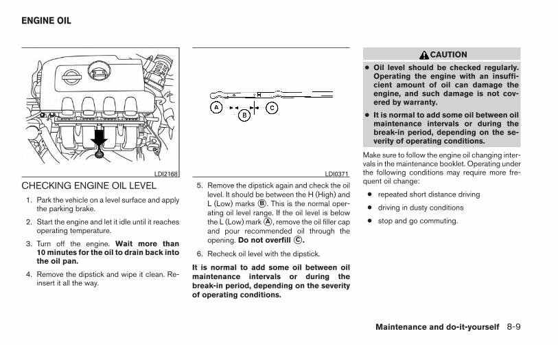
CHECKING ENGINE OIL LEVEL1. Park the vehicle on a level surface and apply
the parking brake.
2. Start the engine and let it idle until it reachesoperating temperature.
3. Turn off the engine. Wait more than10 minutes for the oil to drain back intothe oil pan.
4. Remove the dipstick and wipe it clean. Re-insert it all the way.
5. Remove the dipstick again and check the oillevel. It should be between the H (High) andL (Low) marks �B . This is the normal oper-ating oil level range. If the oil level is belowthe L (Low) mark �A , remove the oil filler capand pour recommended oil through theopening. Do not overfill �C .
6. Recheck oil level with the dipstick.
It is normal to add some oil between oilmaintenance intervals or during thebreak-in period, depending on the severityof operating conditions.
CAUTION
● Oil level should be checked regularly.Operating the engine with an insuffi-cient amount of oil can damage theengine, and such damage is not cov-ered by warranty.
● It is normal to add some oil between oilmaintenance intervals or during thebreak-in period, depending on the se-verity of operating conditions.
Make sure to follow the engine oil changing inter-vals in the maintenance booklet. Operating underthe following conditions may require more fre-quent oil change:
● repeated short distance driving
● driving in dusty conditions
● stop and go commuting.
LDI2168 LDI0371
ENGINE OIL
Maintenance and do-it-yourself 8-9

CHANGING ENGINE OIL
1. Park the vehicle on a level surface and applythe parking brake.
2. Start the engine and let it idle until it reachesoperating temperature, then turn it off.
3. Remove the oil filler cap �A by turning itcounterclockwise.
4. Place a large drain pan under the drain plug�B .
5. Remove the drain plug �B with a wrench byturning it counterclockwise and completelydrain the oil.
If the oil filter is to be changed, remove andreplace it at this time. See “Changing engineoil filter” later in this section.
WARNING
● Prolonged and repeated contact withused engine oil may cause skin cancer.
● Try to avoid direct skin contact withused oil. If skin contact is made, washthoroughly with soap or hand cleaneras soon as possible.
● Keep used engine oil out of reach ofchildren.
CAUTION
● Be careful not to burn yourself. The en-gine oil may be hot.
● Waste oil must be disposed of properly.
● Check your local regulations.
6. Clean and reinstall the drain plug and a newwasher. Securely tighten the drain plug witha wrench. Do not use excessive force.
Drain plug tightening torque:29 - 39 N·m (22 - 29 ft-lb)
7. Refill engine with recommended oil throughthe oil filler opening, then install the oil fillercap securely.
See “Capacities and recommendedfuel/lubricants” in the “Technical and con-sumer information” section of this manual fordrain and refill capacity.
The drain and refill capacity depends on theoil temperature and drain time. Use thesespecifications for reference only. Always usethe dipstick to determine when the properamount of oil is in the engine.
8. Start the engine. Check for leakage aroundthe drain plug and oil filter. Correct as re-quired.
9. Turn the engine off and wait more than10 minutes. Check the oil level with thedipstick. Add engine oil if necessary.
LDI2190
8-10 Maintenance and do-it-yourself

CHANGING ENGINE OIL FILTER
1. Park the vehicle on a level surface and applythe parking brake.
2. Turn the engine off.
3. Place a large drain pan under the oil filter �C .
4. Loosen the oil filter with an oil filter wrenchby turning it counterclockwise. Then removethe oil filter by turning it by hand.
CAUTION
Be careful not to burn yourself. The engineoil may be hot.
5. Wipe the engine oil filter sealing surface witha clean rag.
CAUTION
Be sure to remove any old gasket materialremaining on the sealing surface of theengine. Failure to do so could lead toengine damage.
6. Coat the gasket on the new filter with cleanengine oil.
7. Screw on the oil filter until a slight resistanceis felt, then tighten an additional 2/3 turn.
8. Start the engine and check for leakagearound the oil filter. Correct as required.
9. Turn the engine off and wait more than10 minutes. Check the oil level. Add engineoil if necessary.
CAUTION
● Use only Genuine NISSAN CVT FluidNS-3. Do not mix with other fluids.
● Using transmission fluid other thanGenuine NISSAN CVT Fluid NS-3 willdamage the CVT, which is not coveredby the warranty.
When checking or replacement of CVT fluid isrequired, we recommend your NISSAN dealer forservicing.
LDI2191
CONTINUOUSLY VARIABLETRANSMISSION (CVT) FLUID (if soequipped)
Maintenance and do-it-yourself 8-11

For further brake and clutch fluid specificationinformation, refer to “Capacities and recom-mended fuel/lubricants” in the “Technical andconsumer information” section of this manual.
WARNING
● Use only new fluid from a sealed con-tainer. Old, inferior or contaminatedfluid may damage the brake and clutch(if so equipped) systems. The use ofimproper fluids can damage the brakeand clutch system and affect the vehi-cle’s stopping ability.
● Clean the filler cap before removing.
● Brake and clutch fluid is poisonous andshould be stored carefully in markedcontainers out of reach of children.
CAUTION
Do not spill the fluid on any painted sur-faces. This will damage the paint. If fluid isspilled, immediately wash the surfacewith water.
Check the fluid level in the reservoir. If the level isbelow the MIN line�1 , or the brake warning lightcomes on, add Genuine NISSAN Super HeavyDuty Brake Fluid or equivalent DOT 3 fluid up tothe MAX line�2 . If fluid must be added frequently,the system should be checked by a NISSANdealer.
WINDSHIELD-WASHER FLUIDRESERVOIR
Fill the windshield-washer fluid reservoir periodi-cally.
To fill the windshield-washer fluid reservoir, liftthe cap off the reservoir and pour the windshield-washer fluid into the reservoir opening.
Add a washer solvent to the washer for bettercleaning. In the winter season, add a windshield-washer antifreeze. Follow the manufacturer’s in-structions for the mixture ratio.
LDI2169 LDI2170
BRAKE AND CLUTCH (if so equipped)FLUID
WINDSHIELD-WASHER FLUID
8-12 Maintenance and do-it-yourself

Refill the reservoir more frequently when drivingconditions require an increased amount ofwindshield-washer fluid.
Recommended fluid is Genuine NISSAN Wind-shield Washer Concentrate Cleaner & Anti-freeze or equivalent.
CAUTION
● Do not substitute engine anti-freezecoolant for windshield-washer fluid.This may result in damage to the paint.
● Do not fill the windshield-washer fluidreservoir with washer fluid concen-trates at full strength. Some methyl al-cohol based washer fluid concentratesmay permanently stain the grille ifspilled while filling the windshield-washer fluid reservoir.
● Pre-mix washer fluid concentrates withwater to the manufacturer’s recom-mended levels before pouring the fluidinto the windshield-washer fluid reser-voir. Do not use the windshield-washerreservoir to mix the washer fluid con-centrate and water.
● Keep the battery surface clean and dry.Clean the battery with a solution of bakingsoda and water.
● Make certain the terminal connections areclean and securely tightened.
● If the vehicle is not to be used for 30 days orlonger, disconnect the negative (-) batteryterminal cable to prevent discharge.
NOTE:
Care should be taken to avoid situationsthat can lead to potential battery dischargeand potential no-start conditions such as:
1. Installation or extended use of electronicaccessories that consume battery powerwhen the engine is not running (Phone char-gers, GPS, DVD players, etc.)
2. Vehicle is not driven regularly and/or onlydriven short distances. In these cases, thebattery may need to be charged to maintainbattery health.
WARNING
● Do not expose the battery to flames, anelectrical spark or a cigarette. Hydro-gen gas generated by the battery is ex-plosive. Explosive gases can causeblindness or injury. Do not allow batteryfluid to contact your skin, eyes, fabricsor painted surfaces. Sulfuric acid cancause blindness or injury. After touch-ing a battery or battery cap, do nottouch or rub your eyes. Thoroughlywash your hands. If the acid contactsyour eyes, skin or clothing, immediatelyflush with water for at least 15 minutesand seek medical attention.
● Do not operate the vehicle if the fluid inthe battery is low. Low battery fluid cancause a higher load on the batterywhich can generate heat, reduce bat-tery life, and in some cases lead to anexplosion.
● When working on or near a battery, al-ways wear suitable eye protection andremove all jewelry.
● Battery posts, terminals and related ac-cessories contain lead and lead com-pounds. Wash hands after handling.
BATTERY
Maintenance and do-it-yourself 8-13

● Keep battery out of the reach ofchildren.
● Do not tip the battery. Keep the ventcaps tight and the battery level.
1. Remove the vent caps with a screwdriver asshown. Use a cloth to protect the batterycase.
2. Check the fluid level in each cell. If it isnecessary to add fluid, add only distilledwater to bring the level up to the bottom ofthe filler opening. Do not overfill. Reinstallthe vent caps.
WDI0224
LDI0302
8-14 Maintenance and do-it-yourself

Vehicles operated in high temperatures or undersevere conditions require frequent checks of thebattery fluid level.
JUMP STARTINGIf jump starting is necessary, see “Jump starting”in the “In case of emergency” section of thismanual. If the engine does not start by jumpstarting, the battery may have to be replaced.Contact a NISSAN dealer.
CAUTION
● Do not ground accessories directly tothe battery terminal. Doing so will by-pass the variable voltage control sys-tem and the vehicle battery may notcharge completely.
● Use electrical accessories with the en-gine running to avoid discharging thevehicle battery.
Your vehicle is equipped with a variable voltagecontrol system. This system measures theamount of electrical discharge from the batteryand controls voltage generated by the generator.
The current sensor �A is located near the batteryalong the negative battery cable. If you add elec-trical accessories to your vehicle, be sure toground them to a suitable body ground such asthe frame or engine block area.
LDI2178
VARIABLE VOLTAGE CONTROLSYSTEM
Maintenance and do-it-yourself 8-15

1. Automatic tensioner2. Generator3. Water pump4. Air conditioner compressor5. Crankshaft pully
WARNING
Be sure the ignition switch is in the OFF orLOCK position before servicing drive belt.The engine could rotate unexpectedly.
1. Visually inspect the belt for signs of unusualwear, cuts, or fraying. If the belt is in poorcondition, have it replaced or adjusted by aNISSAN dealer.
2. Have the belt checked regularly for condi-tion.
REPLACING SPARK PLUGS
WARNING
Be sure the engine and ignition switch areoff and that the parking brake is engagedsecurely.
CAUTION
Be sure to use the correct socket to re-move the spark plugs. An incorrect socketcan damage the spark plugs.
WDI0638 SDI1895
DRIVE BELT SPARK PLUGS
8-16 Maintenance and do-it-yourself

Platinum-tipped spark plugs (exceptCalifornia models)It is not necessary to replace platinum-tipped �Aspark plugs as frequently as conventional typespark plugs because they last much longer. Fol-low the maintenance log shown in the “NISSANService and Maintenance Guide”. Do not serviceplatinum-tipped spark plugs by cleaning or re-gapping.
● Always replace spark plugs with rec-ommended or equivalent ones.
If replacement is required, see your NISSANdealer for assistance.
Iridium-tipped spark plugs (Californiamodels only)It is not necessary to replace iridium-tipped �Aspark plugs as frequently as conventional typespark plugs because they last much longer. Fol-low the maintenance log shown in the “NISSANService and Maintenance Guide”. Do not serviceiridium-tipped spark plugs by cleaning or regap-ping.
● Always replace spark plugs with rec-ommended or equivalent ones.
If replacement is required, see your NISSANdealer for assistance.
The air cleaner filter should not be cleaned andreused. Replace it according to the maintenancelog shown in the “NISSAN Service and Mainte-nance Guide.”
To remove the air cleaner filter:
1. Unlatch the retaining clips�A .
2. Pull up at points�B and remove.
3. Pull up and remove air cleaner housing�C .
4. Remove the air cleaner filter, Wipe the insideof the air cleaner filter housing and the coverwith a damp cloth, then replace air cleanerfilter.
NOTE:
After installing a new air cleaner, makesure the air cleaner cover is seated in thehousing and latch the clips.
WARNING
● Operating the engine with the aircleaner removed can cause you or oth-ers to be burned. The air cleaner notonly cleans the air, it stops the flame ifthe engine backfires. If it isn’t there, andthe engine backfires, you could beburned. Do not drive with the air cleanerremoved, and be careful when workingon the engine with the air cleanerremoved.
● Never pour fuel into the throttle body orattempt to start the engine with the aircleaner removed. Doing so could resultin serious injury.
IN-CABIN MICROFILTER
The in-cabin microfilter restricts the entry of air-borne dust and pollen particles and reducessome objectionable outside odors. The filter islocated behind the trim panel near the accelera-tor pedal. Refer to the “NISSAN Service andMaintenance Guide” for change intervals.
LDI2171
AIR CLEANER
Maintenance and do-it-yourself 8-17

If replacement is required, see your NISSANdealer.
CLEANINGIf your windshield is not clear after using thewindshield washer or if a wiper blade chatterswhen running, wax or other material may be onthe blade or windshield.
Clean the outside of the windshield with a washerfluid or a mild detergent. Your windshield is cleanif beads do not form when rinsing with clearwater.
Clean each blade by wiping it with a cloth soakedin a washer fluid or a mild detergent. Then rinsethe blades with clear water. If your windshield isstill not clear after cleaning the blades and usingthe wiper, install new windshield wiper blades.
CAUTION
Worn windshield wiper blades can dam-age the windshield and impair drivervision.
REPLACINGReplace the wiper blades if they are worn.
To replace the windshield wiper blades, followthe procedure below:
1. Ensure that the ignition switch is in the OFFposition.
2. Pull the windshield wiper and washer leverfor 5 seconds�2 . This action will cause thewipers to take the service position automati-cally.
3. Lift the wiper arm away from the windshield.
LDI2193
WINDSHIELD WIPER BLADES
8-18 Maintenance and do-it-yourself

4. Push the release tab�4 .
5. Move the wiper blade down�5 and remove.
6. Insert the new wiper blade onto the wiperarm until it clicks into place.
7. Rotate the wiper blade so the dimple is in thegroove.
8. Finally, pull the windshield wiper and washerlever for 5 seconds. This action will causethe wipers to resume the set position.
CAUTION
● After wiper blade replacement, returnthe wiper arm to its original position;otherwise it may be damaged when thehood is opened.
● Make sure the wiper blades contact theglass; otherwise the arms may be dam-aged from wind pressure.
If you wax the surface of the hood, be careful notto let wax get into the washer nozzle �A . This maycause clogging or improper windshield-washeroperation. If wax gets into the nozzle, remove itwith a needle or small pin �B .
LDI2194 LDI2195
LDI2182
Maintenance and do-it-yourself 8-19

If the brakes do not operate properly, have thebrakes checked by a NISSAN dealer.
Self-adjusting brakes
Your vehicle is equipped with self-adjustingbrakes.
The front (and rear– if so equipped) disc-typebrakes self-adjust every time the brake pedal isapplied. The rear drum-type brakes (if soequipped) self-adjust every time the parkingbrake is applied.
WARNING
See a NISSAN dealer for a brake systemcheck if the brake pedal height does notreturn to normal.
Brake pad wear indicatorsThe disc brake pads on your vehicle have audiblewear indicators. When a brake pad requires re-placement, a high pitched scraping or screech-ing sound will be heard when the vehicle is inmotion. The noise will be heard whether or not thebrake pedal is depressed. Have the brakeschecked as soon as possible if the wear indicatorsound is heard.
Under some driving or climate conditions, occa-sional brake squeak, squeal or other noise maybe heard. Occasional brake noise during light to
moderate stops is normal and does not affect thefunction or performance of the brake system.
Proper brake inspection intervals shouldbe followed. For more information regardingbrake inspections, see the appropriate mainte-nance schedule information in the “NISSAN Ser-vice and Maintenance Guide”.
Two types of fuses are used. Type �A is used inthe fuse boxes in the engine compartment. Type�B is used in the passenger compartment fusebox.
Type A fuses are provided as spare fuses. Theyare stored in the passenger compartment fusebox.
Type A fuses can be installed in the engine com-partment and passenger compartment fuseboxes.
LDI0455
BRAKES FUSES
8-20 Maintenance and do-it-yourself

If a type A fuse is used to replace a type B fuse,the type A fuse will not be level with the fusepocket as shown in the illustration. This will notaffect the performance of the fuse. Make sure thefuse is installed in the fuse box securely.
Type B fuses cannot be installed in the under-hood fuse boxes. Only use type A fuses in theunderhood fuse boxes.
ENGINE COMPARTMENT
CAUTION
Never use a fuse of a higher or loweramperage rating than specified on thefuse box cover. This could damage theelectrical system or cause a fire.
If any electrical equipment does not come on,check for an open fuse.
1. Be sure the ignition switch and the headlightswitch are OFF.
2. Open the engine hood.
3. Remove the fuse box cover by pushing thetab�A and lifting the cover up.
4. Remove the fuse with the fuse puller, whichis located in the center of the fuse block inthe passenger compartment.
LDI0457 LDI2172
Maintenance and do-it-yourself 8-21
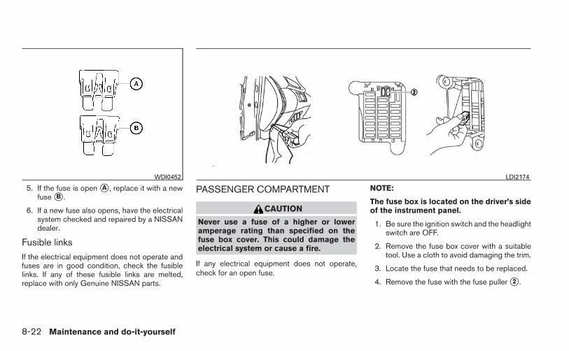
5. If the fuse is open �A , replace it with a newfuse �B .
6. If a new fuse also opens, have the electricalsystem checked and repaired by a NISSANdealer.
Fusible linksIf the electrical equipment does not operate andfuses are in good condition, check the fusiblelinks. If any of these fusible links are melted,replace with only Genuine NISSAN parts.
PASSENGER COMPARTMENT
CAUTION
Never use a fuse of a higher or loweramperage rating than specified on thefuse box cover. This could damage theelectrical system or cause a fire.
If any electrical equipment does not operate,check for an open fuse.
NOTE:
The fuse box is located on the driver’s sideof the instrument panel.
1. Be sure the ignition switch and the headlightswitch are OFF.
2. Remove the fuse box cover with a suitabletool. Use a cloth to avoid damaging the trim.
3. Locate the fuse that needs to be replaced.
4. Remove the fuse with the fuse puller �2 .
WDI0452 LDI2174
8-22 Maintenance and do-it-yourself

5. If the fuse is open �A , replace it with anequivalent good fuse �B .
6. Push the fuse box cover to install.
If a new fuse also opens, have the electricalsystem checked and repaired by a NISSANdealer.
Extended storage switchIf any electrical equipment does not operate,remove the extended storage switch and checkfor an open fuse.
NOTE:
The extended storage switch is used forlong term vehicle storage. Even if the ex-tended storage switch is broken it is notnecessary to replace it. Replace only theopen fuse in the switch with a new fuse.
How to replace the extended storage switch:
1. To remove the extended storage switch, besure the ignition switch is in the OFF orLOCK position.
2. Be sure the headlight switch is in the OFFposition.
3. Remove the fuse box cover.
4. Pinch the locking tabs�1 and�2 found oneach side of the storage switch.
5. Pull the storage switch straight out from thefuse box�3 .
LDI0456 LDI2175
Maintenance and do-it-yourself 8-23
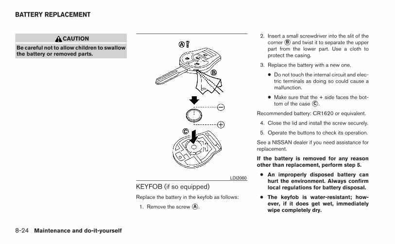
CAUTION
Be careful not to allow children to swallowthe battery or removed parts.
KEYFOB (if so equipped)
Replace the battery in the keyfob as follows:
1. Remove the screw �A .
2. Insert a small screwdriver into the slit of thecorner �B and twist it to separate the upperpart from the lower part. Use a cloth toprotect the casing.
3. Replace the battery with a new one.
● Do not touch the internal circuit and elec-tric terminals as doing so could cause amalfunction.
● Make sure that the + side faces the bot-tom of the case �C .
Recommended battery: CR1620 or equivalent.
4. Close the lid and install the screw securely.
5. Operate the buttons to check its operation.
See a NISSAN dealer if you need assistance forreplacement.
If the battery is removed for any reasonother than replacement, perform step 5.
● An improperly disposed battery canhurt the environment. Always confirmlocal regulations for battery disposal.
● The keyfob is water-resistant; how-ever, if it does get wet, immediatelywipe completely dry.
LDI2060
BATTERY REPLACEMENT
8-24 Maintenance and do-it-yourself

● The operational range of the keyfobextends to approximately 10 m (33 ft)from the vehicle. This range may varywith conditions.
Operation is subject to the following twoconditions: (1) This device may not causeharmful interference, and (2) this devicemust accept any interference received, in-cluding interference that may cause unde-sired operation of the device.
NISSAN INTELLIGENT KEY® (if soequipped)Replace the battery in the Intelligent Key as fol-lows:
1. Remove the mechanical key from the Intelli-gent Key.
2. Insert a small screwdriver �A into the slit �Bof the corner and twist it to separate theupper part from the lower part. Use a cloth toprotect the casing.
3. Replace the battery with a new one.
Recommended battery: CR2025 or equiva-lent.
● Do not touch the internal circuit and elec-tric terminals as doing so could cause amalfunction.
● Hold the battery by the edges. Holdingthe battery across the contact points willseriously deplete the storage capacity.
● Make sure that the + side faces the bot-tom of the case.
SDI1867
Maintenance and do-it-yourself 8-25
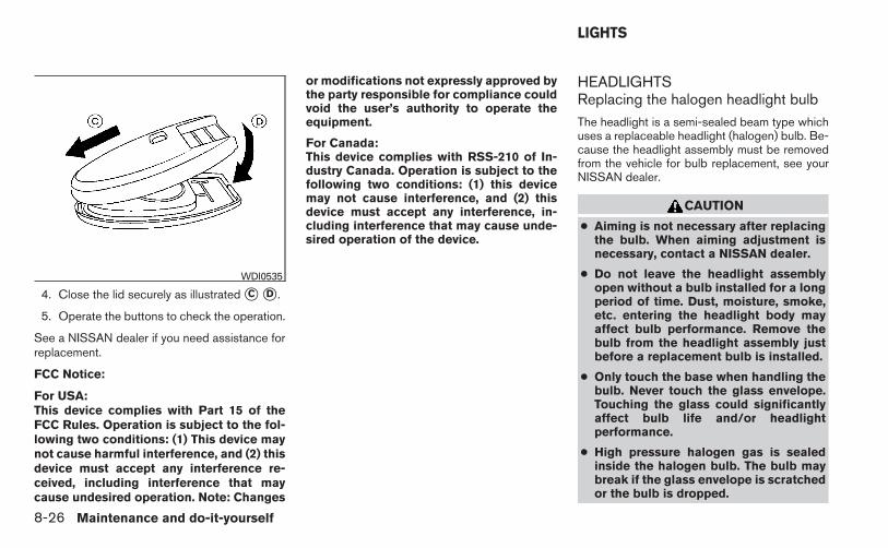
4. Close the lid securely as illustrated �C �D .
5. Operate the buttons to check the operation.
See a NISSAN dealer if you need assistance forreplacement.
FCC Notice:
For USA:This device complies with Part 15 of theFCC Rules. Operation is subject to the fol-lowing two conditions: (1) This device maynot cause harmful interference, and (2) thisdevice must accept any interference re-ceived, including interference that maycause undesired operation. Note: Changes
or modifications not expressly approved bythe party responsible for compliance couldvoid the user’s authority to operate theequipment.
For Canada:This device complies with RSS-210 of In-dustry Canada. Operation is subject to thefollowing two conditions: (1) this devicemay not cause interference, and (2) thisdevice must accept any interference, in-cluding interference that may cause unde-sired operation of the device.
HEADLIGHTSReplacing the halogen headlight bulbThe headlight is a semi-sealed beam type whichuses a replaceable headlight (halogen) bulb. Be-cause the headlight assembly must be removedfrom the vehicle for bulb replacement, see yourNISSAN dealer.
CAUTION
● Aiming is not necessary after replacingthe bulb. When aiming adjustment isnecessary, contact a NISSAN dealer.
● Do not leave the headlight assemblyopen without a bulb installed for a longperiod of time. Dust, moisture, smoke,etc. entering the headlight body mayaffect bulb performance. Remove thebulb from the headlight assembly justbefore a replacement bulb is installed.
● Only touch the base when handling thebulb. Never touch the glass envelope.Touching the glass could significantlyaffect bulb life and/or headlightperformance.
● High pressure halogen gas is sealedinside the halogen bulb. The bulb maybreak if the glass envelope is scratchedor the bulb is dropped.
WDI0535
LIGHTS
8-26 Maintenance and do-it-yourself
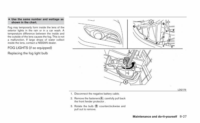
● Use the same number and wattage asshown in the chart.
Fog may temporarily form inside the lens of theexterior lights in the rain or in a car wash. Atemperature difference between the inside andthe outside of the lens causes the fog. This is nota malfunction. If large drops of water collectinside the lens, contact a NISSAN dealer.
FOG LIGHTS (if so equipped)
Replacing the fog light bulb
1. Disconnect the negative battery cable.
2. Remove the fasteners�A ; carefully pull backthe front fender protector .
3. Rotate the bulb �B counterclockwise andpull out to remove.
LDI2179
Maintenance and do-it-yourself 8-27

EXTERIOR AND INTERIOR LIGHTS
Item Wattage (W) Bulb No.*
Headlight assembly*Low 55 H11High 65 H9Turn/Park (non-LED version) 28/8 WY28/8WPark (LED version) — —Side marker 3.8 194
Front fog light* (if so equipped) 55 H11Front map lights* — —Room light 8 AL19Trunk light — 158High-mounted stop light*
Inside — —Spoiler (if so equipped) — —
Rear combination light*Turn signal light 21 WY21WStop/Tail — —Backup (reversing) 16 W16WRear side marker — —
License plate light* 5 W5W
* Always check with the Parts Department at a NISSAN dealer for the latest parts information.
LDI2173
8-28 Maintenance and do-it-yourself

1. Map light2. Interior light3. Door mirror turn signal light4. Headlight assembly5. Fog light (if so equipped)6. High-mount stop light7. Trunk light8. License plate light9. Rear combination light
Indicates bulb removalIndicates bulb replacement
Replacement proceduresAll other lights are either type A, B, C or D. Whenreplacing a bulb, first remove the lens and/orcover.
WDI0257
Maintenance and do-it-yourself 8-29

Use a cloth �1 to protect the interior light hous-ing.
If you have a flat tire, see “Flat tire” in the“In case of emergency” section of thismanual.
TIRE PRESSURE
Tire Pressure Monitoring System(TPMS) (if so equipped)
This vehicle is equipped with the TirePressure Monitoring System (TPMS). Itmonitors tire pressure of all tires exceptthe spare. When the low tire pressurewarning light is lit and the CHECK TIREPRES warning is displayed in the odom-eter, one or more of your tires is signifi-cantly under-inflated.
The TPMS will activate only when thevehicle is driven at speeds above 16 MPH(25 km/h). Also, this system may not de-tect a sudden drop in tire pressure (forexample a flat tire while driving).
For more details, refer to “Low tire pres-sure warning light” in the “Instruments andcontrols” section, “Tire Pressure Monitor-ing System (TPMS)” in the “Starting anddriving” section, and “Flat tire” in the “Incase of emergency” section.
Tire inflation pressure
Check the tire pressures (including thespare) often and always prior to long dis-tance trips. The recommended tire pres-sure specifications are shown on theF.M.V.S.S./C.M.V.S.S. certification labelor the Tire and Loading Information labelunder the “Cold Tire Pressure” heading.The Tire and Loading Information label isaffixed to the driver side center pillar. Tirepressures should be checked regularlybecause:
● Most tires naturally lose air over time.
● Tires can lose air suddenly whendriven over potholes or other objectsor if the vehicle strikes a curb whileparking.
The tire pressures should be checkedwhen the tires are cold. The tires areconsidered COLD after the vehicle hasbeen parked for 3 or more hours, or drivenless than 1 mile (1.6 km) at moderatespeeds.
Interior lightWDI0206
WHEELS AND TIRES
8-30 Maintenance and do-it-yourself

The “TPMS with Easy Fill Tire Alert” pro-vides visual and audible signals outsidethe vehicle for inflating tires to the recom-mended COLD tire pressure. For moreinformation, see “TPMS with Easy Fill TireAlert” in the “Starting and driving” section.
Incorrect tire pressure, including un-der inflation, may adversely affecttire life and vehicle handling.
WARNING
● Improperly inflated tires can failsuddenly and cause an accident.
● The Gross Vehicle Weight Rating(GVWR) is located on theF.M.V.S.S./C.M.V.S.S. certifica-tion label. The vehicle weight ca-pacity is indicated on the Tire andLoading Information label. Donot load your vehicle beyond thiscapacity. Overloading your ve-hicle may result in reduced tirelife, unsafe operating conditionsdue to premature tire failure, orunfavorable handling character-istics and could also lead to aserious accident. Loading be-yond the specified capacity mayalso result in failure of other ve-hicle components.
● Before taking a long trip, orwhenever you heavily load yourvehicle, use a tire pressure gaugeto ensure that the tire pressuresare at the specified level.
● For additional information re-garding tires, refer to “ImportantTire Safety Information” (US) or“Tire Safety Information”(Canada) in the Warranty Infor-mation Booklet.
Maintenance and do-it-yourself 8-31

Tire and loading information label
�1 Seating capacity: The maximum num-ber of occupants that can be seatedin the vehicle.
�2 Vehicle load limit: See “Vehicle load-ing information” in the “Technical andconsumer information” section.
�3 Original tire size: The size of the tiresoriginally installed on the vehicle atthe factory.
�4 Cold tire pressure: Inflate the tires tothis pressure when the tires are cold.Tires are considered COLD after thevehicle has been parked for 3 or morehours, or driven less than 1 mile(1.6 km) at moderate speeds. Therecommended cold tire inflation is setby the manufacturer to provide thebest balance of tire wear, vehiclehandling, driveability, tire noise, etc.,up to the vehicle’s GVWR.
�5 Tire size – refer to “Tire labeling” laterin this section.
�6 Spare tire size.
LDI2007
8-32 Maintenance and do-it-yourself

Checking tire pressure
1. Remove the valve stem cap from thetire.
2. Press the pressure gauge squarelyonto the valve stem. Do not press toohard or force the valve stem side-ways, or air will escape. If the hissingsound of air escaping from the tire isheard while checking the pressure,reposition the gauge to eliminate thisleakage.
3. Remove the gauge.
4. Read the tire pressure on the gaugestem and compare to the specifica-tion shown on the Tire and LoadingInformation label.
5. Add air to the tire as needed. If toomuch air is added, press the core ofthe valve stem briefly with the tip ofthe gauge stem to release pressure.Recheck the pressure and add orrelease air as needed.
6. Install the valve stem cap.
7. Check the pressure of all other tires,including the spare.
Size Cold Tire InflationPressure
Front Original Tire:P205/50R17P205/55R16
240 kPa, 35 PSI
Rear Original Tire:P205/50R17P205/55R16
240 kPa, 35 PSI
Spare Tire:T125/70D16 420 kPa, 60 PSI
TIRE LABELING
Federal law requires tire manufacturers toplace standardized information on thesidewall of all tires. This information iden-tifies and describes the fundamentalcharacteristics of the tire and also pro-vides the tire identification number (TIN)for safety standard certification. The TINcan be used to identify the tire in case of arecall.
LDI0393Example
WDI0394
Maintenance and do-it-yourself 8-33

�1 Tire size (example: P215/65R15 95H)
1. P: The “P” indicates the tire is de-signed for passenger vehicles (not alltires have this information).
2. Three-digit number (215): This num-ber gives the width in millimeters ofthe tire from sidewall edge to side-wall edge.
3. Two-digit number (65): This number,known as the aspect ratio, gives thetire’s ratio of height to width.
4. R: The “R” stands for radial.
5. Two-digit number (15): This numberis the wheel or rim diameter in inches.
6. Two- or three-digit number (95): Thisnumber is the tire’s load index. It is ameasurement of how much weighteach tire can support. You may notfind this information on all tires be-cause it is not required by law.
7. H: Tire speed rating. You should notdrive the vehicle faster than the tirespeed rating.
ExampleWDI0395
8-34 Maintenance and do-it-yourself

�2 TIN (Tire Identification Number) for anew tire (example: DOT XX XX XXXXXXX)
1. DOT: Abbreviation for the “Depart-ment Of Transportation”. The symbolcan be placed above, below or to theleft or right of the Tire IdentificationNumber.
2. Two-digit code: Manufacturer’sidentification mark.
3. Two-digit code: Tire size.
4. Three-digit code: Tire type code(Optional).
5. Three-digit code: Date of Manufac-ture.
6. Four numbers represent the weekand year the tire was built. For ex-ample, the numbers 3103 means the31st week of 2003. If these numbersare missing, then look on the othersidewall of the tire.
�3 Tire ply composition and material
The number of layers or plies of rubber-coated fabric in the tire. Tire manufactur-ers also must indicate the materials in thetire, which include steel, nylon, polyester,and others.
�4 Maximum permissible inflation pres-sure
This number is the greatest amount of airpressure that should be put in the tire. Donot exceed the maximum permissible in-flation pressure.
�5 Maximum load rating
This number indicates the maximum loadin kilograms and pounds that can be car-ried by the tire. When replacing the tireson the vehicle, always use a tire that hasthe same load rating as the factory in-stalled tire.
�6 Term of “tubeless” or “tube type”
Indicates whether the tire requires an in-ner tube (“tube type”) or not (“tubeless”).
ExampleWDI0396
Maintenance and do-it-yourself 8-35

�7 The word “radial”
The word “radial” is shown if the tire hasradial structure.
�8 Manufacturer or brand name
Manufacturer or brand name is shown.
Other Tire-related Terminology
In addition to the many terms that aredefined throughout this section, IntendedOutboard Sidewall is (1) the sidewall thatcontains a whitewall, bears white letteringor bears manufacturer, brand, and/ormodel name molding that is higher ordeeper than the same molding on theother sidewall of the tire, or (2) the out-ward facing sidewall of an asymmetricaltire that has a particular side that mustalways face outward when mounted on avehicle.
TYPES OF TIRES
WARNING
● When changing or replacing tires, besure all four tires are of the same type(i.e., Summer, All Season or Snow) andconstruction. A NISSAN dealer may beable to help you with information abouttire type, size, speed rating andavailability.
● Replacement tires may have a lowerspeed rating than the factory equippedtires, and may not match the potentialmaximum vehicle speed. Never exceedthe maximum speed rating of the tire.
● For additional information regardingtires, refer to “Important Tire Safety In-formation” (US) or “Tire Safety Informa-tion” (Canada) in the Warranty Informa-tion Booklet.
All season tires
NISSAN specifies All Season tires on some mod-els to provide good performance all year, includ-ing snowy and icy road conditions. All Seasontires are identified by ALL SEASON and/or M&Son the tire sidewall. Snow tires have better snowtraction than All Season tires and may be moreappropriate in some areas.
Summer tires
NISSAN specifies summer tires on some modelsto provide superior performance on dry roads.Summer tire performance is substantially re-duced in snow and ice. Summer tires do not havethe tire traction rating “M&S” on the tire sidewall.
If you plan to operate your vehicle in snowy or icyconditions, NISSAN recommends the use ofSNOW tires or ALL SEASON tires on all fourwheels.
Snow tiresIf snow tires are needed, it is necessary to selecttires equivalent in size and load rating to theoriginal equipment tires. If you do not, it canadversely affect the safety and handling of yourvehicle.
Generally, snow tires have lower speed ratingsthan factory equipped tires and may not matchthe potential maximum vehicle speed. Never ex-ceed the maximum speed rating of the tire.
If you install snow tires, they must be the samesize, brand, construction and tread pattern on allfour wheels.
For additional traction on icy roads, studded tiresmay be used. However, some U.S. states andCanadian provinces prohibit their use. Checklocal, state and provincial laws before installing
8-36 Maintenance and do-it-yourself

studded tires. Skid and traction capabilities ofstudded snow tires on wet or dry surfaces may bepoorer than that of non-studded snow tires.
TIRE CHAINS
CAUTION
Tire chains/cables should not be installedon P205/50R17 size tires. Installation ofthe tire chains/cables on P205/50R17 sizetires will cause damage to the vehicle. Ifyou plan to use tire chains/cables, youshould install P205/55R16 size tires onyour vehicle.
Use of tire chains may be prohibited according tolocation. Check the local laws before installingtire chains. When installing tire chains, make surethey are the proper size for the tires on yourvehicle and are installed according to the chainmanufacturer’s suggestions. Use only SAEclass “S” chains. Class “S” chains are used onvehicles with restricted tire to vehicle clearance.Vehicles that can use Class “S” chains are de-signed to meet the minimum clearances betweenthe tire and the closest vehicle suspension orbody component required to accommodate theuse of a winter traction device (tire chains orcables). The minimum clearances are determinedusing the factory equipped tires. Other types maydamage your vehicle. Use chain tensioners when
recommended by the tire chain manufacturer toensure a tight fit. Loose end links of the tire chainmust be secured or removed to prevent the pos-sibility of whipping action damage to the fendersor underbody. If possible, avoid fully loading yourvehicle when using tire chains. In addition, driveat a reduced speed. Otherwise, your vehicle maybe damaged and/or vehicle handling and perfor-mance may be adversely affected.
Tire chains must be installed only on thefront wheels and not on the rear wheels.
Never install tire chains on a TEMPORARY USEONLY spare tire.
Do not use tire chains on dry roads. Driving withchains in such conditions can cause damage tothe various mechanisms of the vehicle due tosome overstress.
CHANGING WHEELS AND TIRES
Tire rotation
NISSAN recommends rotating the tiresevery 7,500 miles (12,000 km).
See “Flat tire” in the “In case of emer-gency” section of this manual for tire re-placing procedures.
As soon as possible, tighten thewheel nuts to the specified torquewith a torque wrench.
WDI0258
Maintenance and do-it-yourself 8-37
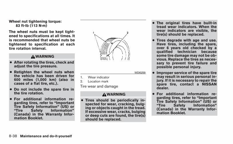
Wheel nut tightening torque:83 ft-lb (113 N·m)
The wheel nuts must be kept tight-ened to specifications at all times. Itis recommended that wheel nuts betightened to specification at eachtire rotation interval.
WARNING
● After rotating the tires, check andadjust the tire pressure.
● Retighten the wheel nuts whenthe vehicle has been driven for600 miles (1,000 km) (also incases of a flat tire, etc.).
● Do not include the spare tire inthe tire rotation.
● For additional information re-garding tires, refer to “ImportantTire Safety Information” (US) or“Tire Safety Information”(Canada) in the Warranty Infor-mation Booklet.
1. Wear indicator2. Location mark
Tire wear and damage
WARNING
● Tires should be periodically in-spected for wear, cracking, bulg-ing or objects caught in the tread.If excessive wear, cracks, bulgingor deep cuts are found, the tire(s)should be replaced.
● The original tires have built-intread wear indicators. When thewear indicators are visible, thetire(s) should be replaced.
● Tires degrade with age and use.Have tires, including the spare,over 6 years old checked by aqualified technician becausesome tire damage may not be ob-vious. Replace the tires as neces-sary to prevent tire failure andpossible personal injury.
● Improper service of the spare tiremay result in serious personal in-jury. If it is necessary to repair thespare tire, contact a NISSANdealer.
● For additional information re-garding tires, refer to “ImportantTire Safety Information” (US) or“Tire Safety Information”(Canada) in the Warranty Infor-mation Booklet.
WDI0259
8-38 Maintenance and do-it-yourself
Replacing wheels and tires
When replacing a tire, use the same size, treaddesign, speed rating and load carrying capacityas originally equipped. Recommended types andsizes are shown in “Wheels and tires” in the“Technical and consumer information” section ofthis manual.
WARNING
● The use of tires other than those recom-mended or the mixed use of tires ofdifferent brands, construction (bias,bias-belted or radial), or tread patternscan adversely affect the ride, braking,handling, VDC system, ground clear-ance, body-to-tire clearance, tire chainclearance, speedometer calibration,headlight aim and bumper height.Some of these effects may lead to acci-dents and could result in serious per-sonal injury.
● If your vehicle was originally equippedwith 4 tires that were the same size andyou are only replacing 2 of the 4 tires ,install the new tires on the rear axle.Placing new tires on the front axle maycause loss of vehicle control in somedriving conditions and cause an acci-dent and personal injury.
● If the wheels are changed for any rea-son, always replace with wheels whichhave the same off-set dimension.Wheels of a different off-set couldcause premature tire wear, degrade ve-hicle handling characteristics, affectthe VDC system and/or interferencewith the brake discs/drums. Such inter-ference can lead to decreased brakingefficiency and/or early brake pad/shoewear. Refer to “Wheels and tires” in the“Technical and consumer information”section of this manual for wheel off-setdimensions.
● When a spare tire is mounted or a wheelis replaced, the TPMS will not functionand the low tire pressure warning lightwill flash for approximately 1 minute.The light will remain on after 1 minute.Contact your NISSAN dealer as soon aspossible for tire replacement and/orsystem resetting.
● Replacing tires with those not originallyspecified by NISSAN could affect theproper operation of the TPMS (if soequipped).
● Do not install a damaged or deformedwheel or tire even if it has been re-paired. Such wheels or tires could havestructural damage and could fail with-out warning.
● The use of retread tires is notrecommended.
● For additional information regardingtires, refer to “Important Tire Safety In-formation” (US) or “Tire Safety Informa-tion” (Canada) in the Warranty Informa-tion Booklet.
Wheel balance
Unbalanced wheels may affect vehicle handlingand tire life. Even with regular use, wheels can getout of balance. Therefore, they should be bal-anced as required.
Wheel balance service should be per-formed with the wheels off the vehicle.Spin balancing the wheels on the vehiclecould lead to mechanical damage.
Maintenance and do-it-yourself 8-39

● For additional information regardingtires, refer to “Important Tire SafetyInformation” (US) or “Tire Safety Infor-mation” (Canada) in the Warranty In-formation Booklet.
Care of wheels
● Wash the wheels when washing the vehicleto maintain their appearance.
● Clean the inner side of the wheels when thewheel is changed or the underside of thevehicle is washed.
● Do not use abrasive cleaners when washingthe wheels.
● Inspect wheel rims regularly for dents orcorrosion. Such damage may cause loss ofpressure or poor seal at the tire bead.
● NISSAN recommends waxing the roadwheels to protect against road salt in areaswhere it is used during winter.
Spare tire (TEMPORARY USE ONLYspare tire)
Observe the following precautions if the TEM-PORARY USE ONLY spare tire must be used.Otherwise, your vehicle could be damaged orinvolved in an accident:
WARNING
● The spare tire should be used for emer-gency use only. It should be replacedwith the standard tire at the first oppor-tunity to avoid possible tire or differen-tial damage.
● Drive carefully while the TEMPORARYUSE ONLY spare tire is installed. Avoidsharp turns and abrupt braking whiledriving.
● Periodically check spare tire inflationpressure. Always keep the pressure ofthe TEMPORARY USE ONLY spare tireat 60 psi (420 kPa, 4.2 bar).
● With the TEMPORARY USE ONLY sparetire installed do not drive the vehicle atspeeds faster than 50 MPH (80 km/h).
● When driving on roads covered withsnow or ice, the TEMPORARY USEONLY spare tire should be used on therear wheels and the original tire usedon the front wheels (drive wheels). Usetire chains only on the front (original)tires.
● Tire tread of the TEMPORARY USEONLY spare tire will wear at a faster ratethan the standard tire. Replace thespare tire as soon as the tread wearindicators appear.
● Do not use the spare tire on othervehicles.
● Do not use more than one spare tire atthe same time.
● Do not tow a trailer when the TEMPO-RARY USE ONLY spare tire is installed.
CAUTION
● Do not use tire chains on a TEMPO-RARY USE ONLY spare tire. Tire chainswill not fit properly and may cause dam-age to the vehicle.
● Because the TEMPORARY USE ONLYspare tire is smaller than the originaltire, ground clearance is reduced. Toavoid damage to the vehicle, do notdrive over obstacles. Also, do not drivethe vehicle through an automatic carwash since it may get caught.
8-40 Maintenance and do-it-yourself

9 Technical and consumer information
Capacities and recommended fuel/lubricants . . . . . . . . . 9-2Fuel recommendation . . . . . . . . . . . . . . . . . . . . . . . . . . . 9-3Engine oil and oil filter recommendations . . . . . . . . . . 9-5Air conditioner system refrigerant and oilrecommendations . . . . . . . . . . . . . . . . . . . . . . . . . . . . . . 9-6
Specifications. . . . . . . . . . . . . . . . . . . . . . . . . . . . . . . . . . . . . 9-7Engine . . . . . . . . . . . . . . . . . . . . . . . . . . . . . . . . . . . . . . . . 9-7Wheels and tires . . . . . . . . . . . . . . . . . . . . . . . . . . . . . . . 9-8Dimensions and weights . . . . . . . . . . . . . . . . . . . . . . . . 9-8
When traveling or registering your vehicle inanother country . . . . . . . . . . . . . . . . . . . . . . . . . . . . . . . . . . . 9-9Vehicle identification . . . . . . . . . . . . . . . . . . . . . . . . . . . . . . . 9-9
Vehicle identification number (VIN) plate . . . . . . . . . . 9-9Vehicle identification number(chassis number) . . . . . . . . . . . . . . . . . . . . . . . . . . . . . . . 9-9Engine serial number. . . . . . . . . . . . . . . . . . . . . . . . . . . 9-10F.M.V.S.S./C.M.V.S.S. certification label . . . . . . . . . . 9-10
Emission control information label . . . . . . . . . . . . . . . 9-10Tire and loading information label. . . . . . . . . . . . . . . . 9-11Air conditioner specification label. . . . . . . . . . . . . . . . 9-11
Installing front license plate . . . . . . . . . . . . . . . . . . . . . . . . 9-11Vehicle loading information . . . . . . . . . . . . . . . . . . . . . . . . 9-12
Terms . . . . . . . . . . . . . . . . . . . . . . . . . . . . . . . . . . . . . . . . 9-12Vehicle load capacity . . . . . . . . . . . . . . . . . . . . . . . . . . 9-13Loading tips . . . . . . . . . . . . . . . . . . . . . . . . . . . . . . . . . . 9-15Measurement of weights . . . . . . . . . . . . . . . . . . . . . . . 9-15
Towing a trailer . . . . . . . . . . . . . . . . . . . . . . . . . . . . . . . . . . . 9-16Flat towing. . . . . . . . . . . . . . . . . . . . . . . . . . . . . . . . . . . . 9-16
Uniform tire quality grading . . . . . . . . . . . . . . . . . . . . . . . . 9-16Emission control system warranty . . . . . . . . . . . . . . . . . . 9-17Reporting safety defects . . . . . . . . . . . . . . . . . . . . . . . . . . 9-18Readiness for inspection/maintenance (I/M) test . . . . . 9-19Event Data Recorders (EDR). . . . . . . . . . . . . . . . . . . . . . . 9-19Owner’s Manual/Service Manual order information . . . 9-20

The following are approximate capacities. The actual refill capacities may be slightly different. When refilling, follow the proceduredescribed in the “Maintenance and do-it-yourself” section to determine the proper refill capacity.
Capacity (Approximate) Recommended Fluids and LubricantsUS measure Imp measure Liter
Fuel 13-1/4 gal 11 gal 50.0 See “Fuel recommendation” later in this section.Engine oil *6
Drain and RefillWith oil filter change 4-1/4 qt 3-1/2 qt 4.0
• Engine oil with API Certification Mark *1• Viscosity SAE 0W-20 *1, *8Without oil filter
change4 qt 3-3/8 qt 3.8
Cooling systemWith reservoir
1-3/4 gal 1-1/2 gal 6.6 Pre-diluted Genuine NISSAN Long Life Antifreeze/Coolant (blue) orequivalent
Continuously Variable Transmission (CVT) fluid — — — Genuine NISSAN CVT Fluid NS-3 *2Manual transmission gear oil — — — Genuine NISSAN Manual Transmission Fluid (MTF) TL/JR Type 75W-80,
or equivalent *3Brake and clutch fluid Refill to the proper level according to the instruc-
tions in the “Maintenance and do-it-yourself” sec-tion *7
Genuine NISSAN Super Heavy Duty Brake Fluid *4 or equivalent DOT 3
Multi-purpose grease — — — NLGI No. 2 (Lithium Soap base)Air conditioning system refrigerant — — — HFC-134a (R-134a) *5Air conditioning system oil — — — Genuine NISSAN A/C System Oil Type S or equivalent *5Windshield-washer fluid 1-1/4 gal 1 gal 4.5 Genuine NISSAN Windshield Washer Concentrate Cleaner & Antifreeze
or equivalent*1: For further details, see “Engine oil and oil filter recommendations” in this section.*2: Use only Genuine NISSAN CVT Fluid NS-3. Using transmission fluid other than Genuine NISSAN CVT Fluid NS-3 will damage the CVT, which is not covered by
the NISSAN new vehicle limited warranty.*3 If Genuine NISSAN Manual Transmission Fluid (MTF) TL/JR Type is not available, API GL-4+, Viscosity SAE 75W-80 may be used as a temporary replacement. However, use Genu-
ine NISSAN Manual Transmission Fluid (MTF) TL/JR Type as soon as it is available.*4: Available in mainland USA through a NISSAN dealer.*5: For further details, see “Air conditioner system refrigerant and oil recommendations” in this section.*6: For further details, see “Engine oil” in the “Maintenance and do-it-yourself” section of this manual.*7: See a NISSAN dealer for service.*8: As an alternative to this recommended oil, SAE 5W30 conventional petroleum based oil may be used and meets all specifications and requirements necessary to maintain the New
Vehicle Limited Warranty.
CAPACITIES AND RECOMMENDEDFUEL/LUBRICANTS
9-2 Technical and consumer information

FUEL RECOMMENDATION
Use unleaded regular gasoline with an octanerating of at least 87 AKI (Anti-Knock Index) num-ber (Research octane number 91).
CAUTION
● Only vehicles with the E-85 filler doorlabel can operate on E-85. Fuel systemor other damage can occur if E-85 isused in vehicles that are not designedto run on E-85.
● Using a fuel other than that specifiedcould adversely affect the emissioncontrol system, and may also affect thewarranty coverage.
● Under no circumstances should aleaded gasoline be used, because thiswill damage the three-way catalyst.
● Do not use E-15 or E-85 fuel in yourvehicle. Your vehicle is not designed torun on E-15 or E-85 fuel. Using E-15 orE-85 fuel in a vehicle not specificallydesigned for E-15 or E-85 fuel can ad-versely affect the emission control de-vices and systems of the vehicle. Dam-age caused by such fuel is not coveredby the NISSAN new vehicle limitedwarranty.
● U.S. government regulations requireethanol dispensing pumps to be identi-fied by a small, square, orange andblack label with the common abbrevia-tion or the appropriate percentage forthat region.
Gasoline specifications
NISSAN recommends using gasoline that meetsthe World-Wide Fuel Charter (WWFC) specifi-cations where it is available. Many of the automo-bile manufacturers developed this specificationto improve emission control system and vehicleperformance. Ask your service station manager ifthe gasoline meets the WWFC specifications.
Reformulated gasolineSome fuel suppliers are now producing reformu-lated gasolines. These gasolines are speciallydesigned to reduce vehicle emissions. NISSANsupports efforts towards cleaner air and sug-gests that you use reformulated gasoline whenavailable.
Gasoline containing oxygenatesSome fuel suppliers sell gasoline containing oxy-genates such as ethanol, MTBE and methanolwith or without advertising their presence.NISSAN does not recommend the use of fuels ofwhich the oxygenate content and the fuel com-
patibility for your NISSAN cannot be readily de-termined. If in doubt, ask your service stationmanager.
If you use oxygenate-blend gasoline, please takethe following precautions as the usage of suchfuels may cause vehicle performance problemsand/or fuel system damage.
● The fuel should be unleaded and havean octane rating no lower than thatrecommended for unleaded gasoline.
● If an oxygenate-blend other thanmethanol blend is used, it should con-tain no more than 10% oxygenate.(MTBE may, however, be added up to15%.)
● E-15 fuel contains more than 10% oxy-genate. E-15 fuel will adversely affectthe emission control devices and sys-tems of the vehicle and should not beused. Damage caused by such fuel isnot covered by the NISSAN new ve-hicle limited warranty.
Technical and consumer information 9-3

● If a methanol blend is used, it shouldcontain no more than 5% methanol(methyl alcohol, wood alcohol). Itshould also contain a suitable amountof appropriate cosolvents and corro-sion inhibitors. If not properly formu-lated with appropriate cosolvents andcorrosion inhibitors, such methanolblends may cause fuel system damageand/or vehicle performance problems.At this time, sufficient data is not avail-able to ensure that all methanol blendsare suitable for use in NISSAN ve-hicles.
If any driveability problems such as engine stall-ing and difficult hot-starting are experienced afterusing oxygenate-blend fuels, immediatelychange to a non-oxygenate fuel or a fuel with alow blend of MTBE.
Take care not to spill gasoline during refu-eling. Gasoline containing oxygenates cancause paint damage.
E–15 fuelE-15 fuel is a mixture of approximately 15% fuelethanol and 85% unleaded gasoline. E-15 canonly be used in vehicles designed to run on E-15fuel. Do not use E-15 in your vehicle. U.S. gov-ernment regulations require fuel ethanol dispens-ing pumps to be identified with small, square,
orange and black label with the common abbre-viation or the appropriate percentage for thatregion.
E–85 fuel
E-85 fuel is a mixture of approximately 85% fuelethanol and 15% unleaded gasoline. E-85 canonly be used in a Flexible Fuel Vehicle (FFV). Donot use E-85 in your vehicle. U.S. governmentregulations require fuel ethanol dispensingpumps to be identified by a small, square, orangeand black label with the common abbreviation orthe appropriate percentage for that region.
Aftermarket fuel additivesNISSAN does not recommend the use of anyaftermarket fuel additives (for example, fuel injec-tor cleaner, octane booster, intake valve depositremovers, etc.) which are sold commercially.Many of these additives intended for gum, varnishor deposit removal may contain active solvents orsimilar ingredients that can be harmful to the fuelsystem and engine.
Octane rating tipsUsing unleaded gasoline with an octanerating lower than recommended can causepersistent, heavy “spark knock.” (“Sparkknock” is a metallic rapping noise.) If se-vere, this can lead to engine damage. If you
detect a persistent heavy spark knock evenwhen using gasoline of the stated octanerating, or if you hear steady spark knockwhile holding a steady speed on levelroads, have a NISSAN dealer correct thecondition. Failure to correct the conditionis misuse of the vehicle, for which NISSANis not responsible.
Incorrect ignition timing may result in sparkknock, after-run and/or overheating, which maycause excessive fuel consumption or enginedamage. If any of the above symptoms are en-countered, have your vehicle checked at aNISSAN dealer.
However, now and then you may noticelight spark knock for a short time whileaccelerating or driving up hills. This is not acause for concern, because you get thegreatest fuel benefit when there is lightspark knock for a short time under heavyengine load.
9-4 Technical and consumer information

ENGINE OIL AND OIL FILTERRECOMMENDATIONS
Selecting the correct oil
It is essential to choose the correct grade, qualityand viscosity engine oil to ensure satisfactoryengine life and performance. See “Capacitiesand recommended fuel/lubricants” earlier in thissection. NISSAN recommends the use of anenergy conserving oil in order to improve fueleconomy.
Select only engine oils that meet the AmericanPetroleum Institute (API) certification or Interna-tional Lubricant Standardization and Approval
Committee (ILSAC) certification and SAE vis-cosity standard. These oils have the API certifica-tion mark on the front of the container. Oils whichdo not have the specified quality label should notbe used as they could cause engine damage.
Oil additives
NISSAN does not recommend the use of oiladditives. The use of an oil additive is not neces-sary when the proper oil type is used and main-tenance intervals are followed.
Oil which may contain foreign matter or has beenpreviously used should not be used.
Oil viscosityThe engine oil viscosity or thickness changeswith temperature. Because of this, it is importantto select the engine oil viscosity based on thetemperatures at which the vehicle will be oper-ated before the next oil change. Choosing an oilviscosity other than that recommended couldcause serious engine damage.
Selecting the correct oil filterYour new NISSAN vehicle is equipped with ahigh-quality genuine NISSAN oil filter. When re-placing, use a genuine NISSAN oil filter or itsequivalent for the reason described in “Changeintervals.”
Change intervalsThe oil and oil filter change intervals for yourengine are based on the use of the specifiedquality oils and filters. Using engine oil and filtersthat are not of the specified quality, or exceedingrecommended oil and filter change intervalscould reduce engine life. Damage to the enginecaused by improper maintenance or use of incor-rect oil and filter quality and/or viscosity is notcovered by the NISSAN new vehicle limited war-ranty.
LTI2051
Technical and consumer information 9-5
Your engine was filled with a high-quality engineoil when it was built. You do not have to changethe oil before the first recommended changeinterval. Oil and filter change intervals dependupon how you use your vehicle.
Operation under the following conditions mayrequire more frequent oil and filter changes:
● repeated short distance driving at cold out-side temperatures
● driving in dusty conditions
● extensive idling
● towing a trailer
● stop and go commuting
Refer to the “NISSAN Service and MaintenanceGuide” for the maintenance schedule.
AIR CONDITIONER SYSTEMREFRIGERANT AND OILRECOMMENDATIONS
The air conditioner system in your NISSANvehicle must be charged with the refriger-ant HFC-134a (R-134a) and NISSAN A/Csystem oil Type S or the exact equivalents.
CAUTION
The use of any other refrigerant or oil willcause severe damage to the air condition-ing system and will require the replace-ment of all air conditioner systemcomponents.
The refrigerant HFC-134a (R-134a) in yourNISSAN vehicle does not harm the earth’s ozonelayer. Although this refrigerant does not affect theearth’s atmosphere, certain government regula-tions require the recovery and recycling of anyrefrigerant during automotive air conditioner sys-tem service. A NISSAN dealer has the trainedtechnicians and equipment needed to recoverand recycle your air conditioner system refriger-ant.
Contact a NISSAN dealer when servicing your airconditioner system.
9-6 Technical and consumer information

ENGINE
Model MRA 8DE
Type Gasoline, 4-cycle, DOHCCylinder arrangement 4-cylinder, inlineBore x Stroke in (mm) 3.138 x 3.547 (79.7 x 90.1)Displacement cu in (cm3) 109.71 (1,798)Firing order 1–3–4–2
Idle speed
No adjustment is necessary.M/TCVT (in “N” position)Ignition timing (degree B.T.D.C. at idle speed)CO % at idle
Spark plugPLZKAR6A-11 (all except California models)
DILKAR6A-11 (California models)
Spark plug gap (Nominal) in (mm) 0.043 (1.1)
Camshaft operation Timing chainThis spark ignition system complies with the Canadian standard ICES-002.
SPECIFICATIONS
Technical and consumer information 9-7

WHEELS AND TIRES
Wheel type Size Offset mm (in)
Aluminum 17 x 6.5J16 x 6.5J
45 (1.77)45 (1.77)
Tire size P205/55R16P205/50R17
Spare tire T125/70D16
DIMENSIONS AND WEIGHTS
Unit: mm (in)Model
Overall length 4,625 (182.1)SR 4,635 (182.5)
Overall width 1,760 (69.3)Overall height 1,495 (58.9)Front Track 1,530 (60.2)Rear Track 1,530 (60.2)Wheelbase 2,700 (106.3)
Gross vehicle weight rating kg (lb)
See the “F.M.V.S.S./C.M.V.S.S. certification label” on the center pillarbetween the driver’s side front and rear doors.
Gross axle weight ratingFront kg (lb)Rear kg (lb)
9-8 Technical and consumer information

When planning to drive your NISSAN ve-hicle in another country, you should first findout if the fuel available is suitable for your vehi-cle’s engine.
Using fuel with an octane rating that is too lowmay cause engine damage. All gasoline vehiclesmust be operated with unleaded gasoline. There-fore, avoid taking your vehicle to areas whereappropriate fuel is not available.
When transferring the registration of yourvehicle to another country, state, provinceor district, it may be necessary to modify thevehicle to meet local laws and regulations.
The laws and regulations for motor vehicle emis-sion control and safety standards vary accordingto the country, state, province or district; there-fore, vehicle specifications may differ.
When any vehicle is to be taken into an-other country, state, province or districtand registered, its modifications, transpor-tation, and registration are the responsibil-ity of the user. NISSAN is not responsiblefor any inconvenience that may result.
VEHICLE IDENTIFICATION NUMBER(VIN) PLATEThe vehicle identification number (VIN) plate isattached as shown. This number is the identifica-tion for your vehicle and is used in the vehicleregistration.
VEHICLE IDENTIFICATION NUMBER(chassis number)The vehicle identification number is located asshown.
LTI2050 STI0465
WHEN TRAVELING OR REGISTERINGYOUR VEHICLE IN ANOTHERCOUNTRY
VEHICLE IDENTIFICATION
Technical and consumer information 9-9

ENGINE SERIAL NUMBERThe number is stamped on the engine as shown.
F.M.V.S.S./C.M.V.S.S.CERTIFICATION LABELThe Federal/Canadian Motor Vehicle SafetyStandard (F.M.V.S.S./C.M.V.S.S.) certification la-bel is affixed as shown. This label contains valu-able vehicle information, such as: Gross VehicleWeight Ratings (GVWR), Gross Axle WeightRating (GAWR), month and year of manufacture,Vehicle Identification Number (VIN), etc. Reviewit carefully.
EMISSION CONTROLINFORMATION LABELThe emission control information label is at-tached to the underside of the hood as shown.
LDI2189 WTI0058 WTI0189
9-10 Technical and consumer information

TIRE AND LOADING INFORMATIONLABELThe cold tire pressure is shown on the Tire andLoading Information label. The label is located asshown.
AIR CONDITIONER SPECIFICATIONLABELThe air conditioner specification label is affixed tothe underside of the hood as shown.
Use the following steps to mount the front licenseplate:
�1 Slide the metal mounting clips onto thelicense plate holder as indicated.
LTI0084 LTI2048
LTI2015
INSTALLING FRONT LICENSE PLATE
Technical and consumer information 9-11

�2 Attach the license plate bracket on the plas-tic finisher at the location mark (small dimple)using the two 6mm screws provided.
WARNING
● It is extremely dangerous to ridein a cargo area inside a vehicle. Ina collision, people riding in theseareas are more likely to be seri-ously injured or killed.
● Do not allow people to ride in anyarea of your vehicle that is notequipped with seats and seatbelts.
● Be sure everyone in your vehicleis in a seat and using a seat beltproperly.
TERMS
It is important to familiarize yourself withthe following terms before loading yourvehicle:
● Curb Weight (actual weight of yourvehicle) - vehicle weight including:standard and optional equipment, flu-ids, emergency tools, and spare tireassembly. This weight does not in-clude passengers and cargo.
● GVW (Gross Vehicle Weight) - curbweight plus the combined weight ofpassengers and cargo.
● GVWR (Gross Vehicle Weight Rat-ing) - maximum total combinedweight of the unloaded vehicle, pas-sengers, luggage, hitch, trailertongue load and any other optionalequipment. This information is lo-cated on the F.M.V.S.S./C.M.V.S.S.certification label.
● GAWR (Gross Axle Weight Rating) -maximum weight (load) limit specifiedfor the front or rear axle. This informa-tion is located on theF.M.V.S.S./C.M.V.S.S. certificationlabel.
● GCWR (Gross Combined Weightrating) - The maximum total weightrating of the vehicle, passengers,cargo, and trailer.
VEHICLE LOADING INFORMATION
9-12 Technical and consumer information

● Vehicle Capacity Weight, Load limit,Total load capacity - maximum totalweight limit specified of the load(passengers and cargo) for the ve-hicle. This is the maximum combinedweight of occupants and cargo thatcan be loaded into the vehicle. If thevehicle is used to tow a trailer, thetrailer tongue weight must be in-cluded as part of the cargo load. Thisinformation is located on the Tire andLoading Information label.
● Cargo capacity - permissible weightof cargo, the subtracted weight ofoccupants from the load limit.
VEHICLE LOAD CAPACITY
Do not exceed the load limit of your ve-hicle shown as “The combined weight ofoccupants and cargo” on the Tire andLoading Information label. Do not exceedthe number of occupants shown as“Seating Capacity” on the Tire and Load-ing Information label.
To get “the combined weight of occu-pants and cargo”, add the weight of alloccupants, then add the total luggageweight. Examples are shown in the follow-ing illustration.
Technical and consumer information 9-13

Steps for determining correct loadlimit
1. Locate the statement “The combinedweight of occupants and cargoshould never exceed XXX lbs or XXXkg” on your vehicle’s placard.
2. Determine the combined weight ofthe driver and passengers that will beriding in your vehicle.
3. Subtract the combined weight of thedriver and passengers from XXX lbsor XXX kg.
4. The resulting figure equals the avail-able amount of cargo and luggageload capacity. For example, if theXXX amount equals 1,400 lbs. andthere will be five 150 lb. passengersin your vehicle, the amount of avail-able cargo and luggage load capac-ity is 650 lbs. (1,400-750 (5 X 150)= 650 lbs) or (640-340 (5 X 70) =300 kg.)
ExampleLTI0152
9-14 Technical and consumer information

5. Determine the combined weight ofluggage and cargo being loaded onthe vehicle. That weight may notsafely exceed the available cargo andluggage load capacity calculated inStep 4.
6. If your vehicle will be towing a trailer,load from your trailer will be trans-ferred to your vehicle. Consult thismanual to determine how this re-duces the available cargo and lug-gage load capacity of your vehicle.
Before driving a loaded vehicle, confirmthat you do not exceed the Gross VehicleWeight Rating (GVWR) or the Gross AxleWeight Rating (GAWR) for your vehicle.See “Measurement of weights” later inthis section.
Also check tires for proper inflation pres-sures. See the Tire and Loading Informa-tion label.
LOADING TIPS
● The GVW must not exceed GVWRor GAWR as specified on theF.M.V.S.S./C.M.V.S.S. certificationlabel.
● Do not load the front and rear axle tothe GAWR. Doing so will exceed theGVWR.
WARNING
● Properly secure all cargo withropes or straps to help prevent itfrom sliding or shifting. Do notplace cargo higher than the seat-backs. In a sudden stop or colli-sion, unsecured cargo couldcause personal injury.
● Do not load your vehicle anyheavier than the GVWR or themaximum front and rear GAWRs.If you do, parts of your vehiclecan break, tire damage could oc-cur, or it can change the way yourvehicle handles. This could resultin loss of control and cause per-sonal injury.
● Overloading not only can shortenthe life of your vehicle and thetire, but can also cause unsafevehicle handling and longer brak-ing distances. This may cause apremature tire failure whichcould result in a serious accidentand personal injury. Failurescaused by overloading are notcovered by the vehicle’swarranty.
MEASUREMENT OF WEIGHTS
Secure loose items to prevent weightshifts that could affect the balance of yourvehicle. When the vehicle is loaded, driveto a scale and weigh the front and the rearwheels separately to determine axleloads. Individual axle loads should not ex-ceed either of the gross axle weight rat-ings (GAWR). The total of the axle loadsshould not exceed the gross vehicleweight rating (GVWR). These ratings aregiven on the vehicle certification label. Ifweight ratings are exceeded, move or re-move items to bring all weights below theratings.
Technical and consumer information 9-15
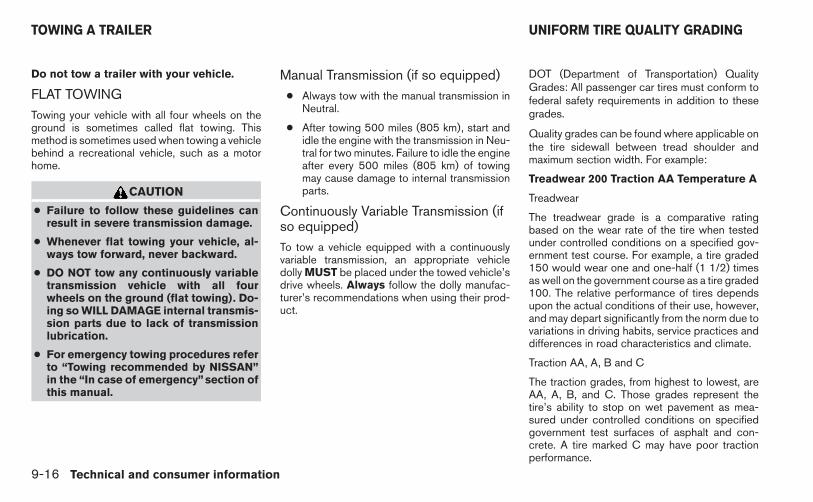
Do not tow a trailer with your vehicle.
FLAT TOWINGTowing your vehicle with all four wheels on theground is sometimes called flat towing. Thismethod is sometimes used when towing a vehiclebehind a recreational vehicle, such as a motorhome.
CAUTION
● Failure to follow these guidelines canresult in severe transmission damage.
● Whenever flat towing your vehicle, al-ways tow forward, never backward.
● DO NOT tow any continuously variabletransmission vehicle with all fourwheels on the ground (flat towing). Do-ing so WILL DAMAGE internal transmis-sion parts due to lack of transmissionlubrication.
● For emergency towing procedures referto “Towing recommended by NISSAN”in the “In case of emergency” section ofthis manual.
Manual Transmission (if so equipped)● Always tow with the manual transmission in
Neutral.
● After towing 500 miles (805 km), start andidle the engine with the transmission in Neu-tral for two minutes. Failure to idle the engineafter every 500 miles (805 km) of towingmay cause damage to internal transmissionparts.
Continuously Variable Transmission (ifso equipped)To tow a vehicle equipped with a continuouslyvariable transmission, an appropriate vehicledolly MUST be placed under the towed vehicle’sdrive wheels. Always follow the dolly manufac-turer’s recommendations when using their prod-uct.
DOT (Department of Transportation) QualityGrades: All passenger car tires must conform tofederal safety requirements in addition to thesegrades.
Quality grades can be found where applicable onthe tire sidewall between tread shoulder andmaximum section width. For example:
Treadwear 200 Traction AA Temperature A
Treadwear
The treadwear grade is a comparative ratingbased on the wear rate of the tire when testedunder controlled conditions on a specified gov-ernment test course. For example, a tire graded150 would wear one and one-half (1 1/2) timesas well on the government course as a tire graded100. The relative performance of tires dependsupon the actual conditions of their use, however,and may depart significantly from the norm due tovariations in driving habits, service practices anddifferences in road characteristics and climate.
Traction AA, A, B and C
The traction grades, from highest to lowest, areAA, A, B, and C. Those grades represent thetire’s ability to stop on wet pavement as mea-sured under controlled conditions on specifiedgovernment test surfaces of asphalt and con-crete. A tire marked C may have poor tractionperformance.
TOWING A TRAILER UNIFORM TIRE QUALITY GRADING
9-16 Technical and consumer information

WARNING
The traction grade assigned to this tire isbased on straight-ahead braking tractiontests, and does not include acceleration,cornering, hydroplaning, or peak tractioncharacteristics.
Temperature A, B and C
The temperature grades are A (the highest), B,and C, representing the tire’s resistance to thegeneration of heat, and its ability to dissipate heatwhen tested under controlled conditions on aspecified indoor laboratory test wheel. Sustainedhigh temperature can cause the material of thetire to degenerate and reduce tire life, and exces-sive temperature can lead to sudden tire failure.The grade C corresponds to a level of perfor-mance which all passenger car tires must meetunder the Federal Motor Safety Standard No.109. Grades B and A represent higher levels ofperformance on the laboratory test wheel thanthe minimum required by law.
WARNING
The temperature grade for this tire is es-tablished for a tire that is properly inflatedand not overloaded. Excessive speed,under-inflation, or excessive loading, ei-ther separately or in combination, cancause heat build-up and possible tirefailure.
Your NISSAN vehicle is covered by the followingemission warranties:
For USA
1. Emission Defects Warranty
2. Emissions Performance Warranty
Details of this warranty may be found with othervehicle warranties in your Warranty InformationBooklet which comes with your NISSAN vehicle.If you did not receive a Warranty InformationBooklet, or it is lost, you may obtain a replace-ment by writing to:
● Nissan North America, Inc.Consumer Affairs DepartmentP.O. Box 685003Franklin, TN 37068-5003
For Canada
Emission Control System Warranty
Details of this warranty may be found with othervehicle warranties in your Warranty InformationBooklet which comes with your NISSAN vehicle.If you did not receive a Warranty InformationBooklet, or it is lost, you may obtain a replace-ment by writing to:
● Nissan Canada Inc.5290 Orbitor DriveMississauga, Ontario, L4W 4Z5
EMISSION CONTROL SYSTEMWARRANTY
Technical and consumer information 9-17

For USA
If you believe that your vehicle has a de-fect which could cause a crash or couldcause injury or death, you should immedi-ately inform the National Highway TrafficSafety Administration (NHTSA) in addi-tion to notifying NISSAN.
If NHTSA receives similar complaints, itmay open an investigation, and if it findsthat a safety defect exists in a group ofvehicles, it may order a recall and remedycampaign. However, NHTSA cannot be-come involved in individual problems be-tween you, your dealer, or NISSAN.
To contact NHTSA, you may call the Ve-hicle Safety Hotline toll-free at 1-888-327-4236 (TTY: 1-800-424-9153); goto http://www.safercar.gov; or write to:Administrator, NHTSA, 400 SeventhStreet, SW., Washington, D.C. 20590.You can also obtain other informationabout motor vehicle safety fromhttp://www.safercar.gov.
You may notify NISSAN by contacting ourConsumer Affairs Department, toll-free, at1-800-NISSAN-1.
For Canada
If you believe that your vehicle has a de-fect which could cause a crash or couldcause injury or death, you should immedi-ately inform Transport Canada in additionto notifying NISSAN.
If Transport Canada receives complaints,it may open an investigation, and if it findsthat a safety defect exists in a group ofvehicles, it may request that NISSAN con-duct a recall campaign. However, Trans-port Canada cannot become involved inindividual problems between you, yourdealer, or NISSAN.
You may contact Transport Canada’s De-fect Investigations and Recalls Divisiontoll free at 1-800-333-0510. You mayalso report safety defects online at:https://wwwapps.tc.gc.ca/Saf-Sec-Sur/7/PCDB-BDPP/Index.aspx.
Additional information concerning motorvehicle safety may be obtained from Trans-port Canada’s Road Safety InformationCentre at 1-800-333-0371 or online atwww.tc.gc.ca/roadsafety (English speak-ers) or www.tc.gc.ca/securiteroutiere(French speakers).
To notify NISSAN of any safety concernsplease contact our Consumer InformationCentre toll free at 1-800-387-0122.
REPORTING SAFETY DEFECTS
9-18 Technical and consumer information

Due to legal requirements in some states andCanadian Provinces, your vehicle may be re-quired to be in what is called the “ready condi-tion” for an Inspection/Maintenance (I/M) test ofthe emission control system.
The vehicle is set to the “ready condition” when itis driven through certain driving patterns. Usually,the ready condition can be obtained by ordinaryusage of the vehicle.
If a powertrain system component is repaired or thebattery is disconnected, the vehicle may be reset toa “not ready” condition. Before taking the I/M test,check the vehicle’s inspection/maintenance testreadiness condition. Place the ignition switch in theON position without starting the engine. If theMalfunction Indicator Light (MIL) comes on steadyfor 20 seconds and then blinks for 10 seconds , theI/M test condition is “not ready”. If the MIL does notblink after 20 seconds, the I/M test condition is“ready”. Contact a NISSAN dealer to set the “readycondition” or to prepare the vehicle for testing.
This vehicle is equipped with an Event Data Re-corder (EDR). The main purpose of an EDR is torecord, in certain crash or near crash-like situa-tions, such as an air bag deployment or hitting aroad obstacle, data that will assist in understand-ing how a vehicle’s systems performed. The EDRis designed to record data related to vehicledynamics and safety systems for a short period oftime, typically 30 seconds or less. The EDR in thisvehicle is designed to record such data as:
● How various systems in your vehicle wereoperating;
● Whether or not the driver and passengersafety belts were buckled/fastened;
● How far (if at all) the driver was depressingthe accelerator and/or brake pedal; and,
● How fast the vehicle was traveling.
● Sounds are not recorded.
These data can help provide a better understand-ing of the circumstances in which crashes andinjuries occur. NOTE: EDR data are recorded byyour vehicle only if a nontrivial crash situationoccurs; no data are recorded by the EDR undernormal driving conditions and no personal data(e.g. name, gender, age and crash location) arerecorded. However, other parties, such as lawenforcement, could combine the EDR data withthe type of personally identifying data routinelyacquired during a crash investigation.
To read data recorded by an EDR, special equip-ment is required and access to the vehicle or theEDR is needed. In addition to the vehicle manu-facturer and NISSAN dealer, other parties, suchas law enforcement, that have the special equip-ment, can read the information if they have ac-cess to the vehicle or the EDR. EDR data will onlybe accessed with the consent of the vehicleowner or lessee or as otherwise required or per-mitted by law.
READINESS FOR INSPECTION/MAINTENANCE (I/M) TEST
EVENT DATA RECORDERS (EDR)
Technical and consumer information 9-19

Genuine NISSAN Service Manuals for this modelyear and prior can be purchased. A genuineNISSAN Service Manual is the best source ofservice and repair information for your vehicle.This manual is the same one used by the factory-trained technicians working at NISSAN dealer-ships. Genuine NISSAN Owner’s Manuals canalso be purchased.
For USA
For current pricing and availability of genuineNISSAN Service Manuals, contact:
1-800-450-9491www.nissan-techinfo.com
For current pricing and availability of genuineNISSAN Owner’s Manuals, contact:
1-800-247-5321
For Canada
To purchase a copy of a genuine NISSAN Ser-vice Manual or Owner’s Manual, for this modelyear and prior, please contact your nearestNISSAN dealer. For the phone number and loca-tion of a NISSAN dealer in your area, call theNISSAN Information Center at 1-800-387-0122and a bilingual NISSAN representative will assistyou.
OWNER’S MANUAL/SERVICEMANUAL ORDER INFORMATION
9-20 Technical and consumer information

10 IndexA
ABS (Anti-lock Braking System). . . . . . . .5-31Air bag (See supplemental restraintsystem) . . . . . . . . . . . . . . . . . . . . .1-34Air bag system
Front (See supplemental front impactair bag system) . . . . . . . . . . . . . . .1-41Side and curtain (See supplementalside air bag and curtain side-impactair bag system) . . . . . . . . . . . . . . .1-47
Air bag warning labels . . . . . . . . . . . . .1-49Air bag warning light. . . . . . . . . . .1-49, 2-17Air cleaner housing filter . . . . . . . . . . . .8-17Air conditioner
Air conditioner operation . . . . . . . . . .4-18Air conditioner service . . . . . . . . . . .4-26Air conditioner specification label . . . . .9-11Air conditioner system refrigerant andoil recommendations . . . . . . . . . . . . .9-6Heater and air conditionercontrols . . . . . . . . . . . . . . . .4-15, 4-24Servicing air conditioner . . . . . . . . . .4-26
Air flow charts. . . . . . . . . . . . . . . . . .4-19Alarm system(See vehicle security system) . . . . . . . . .2-21Anchor point locations . . . . . . . . . . . . .1-20Antenna . . . . . . . . . . . . . . . . . . . . .4-65Anti-lock brake warning light. . . . . . . . . .2-13Anti-lock Braking System (ABS). . . . . . . .5-31Armrests . . . . . . . . . . . . . . . . . . . . .1-4Audible reminders . . . . . . . . . . . . . . .2-20
Audio system . . . . . . . . . . . . . . . . . .4-26Bluetooth® audio. . . . . . . . . . . . . .4-60Compact disc (CD) player . .4-37, 4-42, 4-48FM-AM radio with compact disc(CD)player . . . . . . . . . . . . . . . . . . . .4-35FM/AM/SAT radio with compact disc(CD) player . . . . . . . . . . . . . .4-40, 4-45
Audio SystemiPod® Player . . . . . . . . . . . . .4-54, 4-57
Audio systemRadio . . . . . . . . . . . . . . . . . . . .4-26Steering wheel audio control switch . . .4-64USB interface . . . . . . . . . . . .4-51, 4-53
Autolight switch. . . . . . . . . . . . . . . . .2-25Automatic
Automatic power window switch . . . . .2-39Transmission shift selector lock release . .5-18
Automatic anti-glare inside mirror . . . . . . .3-31Automatic door locks . . . . . . . . . . . . . .3-6AUX jack. . . . . . . . . . . . . .4-38, 4-43, 4-50
B
Battery . . . . . . . . . . . . . . . . . . . . . .8-13Charge warning light . . . . . . . . . . . .2-14
Before starting the engine . . . . . . . . . . .5-14Belt (See drive belt) . . . . . . . . . . . . . .8-16Block heater
Engine . . . . . . . . . . . . . . . . . . . .5-35Bluetooth® audio. . . . . . . . . . . . . . . .4-60
Bluetooth® hands-free phonesystem . . . . . . . . . . . . . . . . . .4-66, 4-81Booster seats . . . . . . . . . . . . . . . . . .1-30Brake
Anti-lock Braking System (ABS). . . . . .5-31Brake fluid . . . . . . . . . . . . . . . . . .8-12Brake light (See stop light). . . . . . . . .8-28Brake system . . . . . . . . . . . . . . . .5-30Brake warning light . . . . . . . . . . . . .2-13Brake wear indicators . . . . . . . .2-20, 8-20Parking brake operation . . . . . . . . . .5-21Self-adjusting brakes . . . . . . . . . . . .8-20
Brakes . . . . . . . . . . . . . . . . . . . . . .8-20Break-in schedule . . . . . . . . . . . . . . .5-26Brightness/contrast button . . . . . . . . . . .4-9Brightness control
Instrument panel . . . . . . . . . . . . . .2-27Bulb check/instrument panel. . . . . . . . . .2-13Bulb replacement . . . . . . . . . . . . . . . .8-28
C
Capacities and recommendedfuel/lubricants. . . . . . . . . . . . . . . . . . .9-2Cargo net . . . . . . . . . . . . . . . . . . . .2-37Cargo (See vehicle loading information) . . .9-12Car phone or CB radio . . . . . . . . . . . . .4-66CD care and cleaning . . . . . . . . . . . . .4-63CD player (See audio system) . .4-37, 4-42, 4-48Child restraints . . . . . . .1-15, 1-15, 1-16, 1-18
Precautions on childrestraints . . . . . . . .1-16, 1-22, 1-27, 1-30

Top tether strap anchor point locations . .1-20Child safety rear door lock . . . . . . . . . . . .3-6Chimes, audible reminders . . . . . . . . . . .2-20Cleaning exterior and interior . . . . . . . . . . .7-2Clock . . . . . . . . . . . . . . . . . . . . . . .4-36
(models without navigation system) . . . .4-36Clock set . . . . . . . . . . . . . . . . . . . . .4-36C.M.V.S.S. certification label . . . . . . . . . .9-10Cold weather driving . . . . . . . . . . . . . .5-34Compact disc (CD) player . . . .4-37, 4-42, 4-48Console box . . . . . . . . . . . . . . . . . . .2-35Console light . . . . . . . . . . . . . . . . . . .2-43Continuously Variable Transmission (CVT). . .5-16
Continuously Variable Transmission(CVT) fluid . . . . . . . . . . . . . . . . . .8-11Driving with Continuously VariableTransmission (CVT) . . . . . . . . . . . . .5-16Transmission shift selector lock release . .5-18
Control panel buttons . . . . . . . . . . . . . . .4-2Brightness/contrast button . . . . . . . . . .4-9Enter button . . . . . . . . . . . . . . . . . .4-2Setting button . . . . . . . . . . . . . . . . .4-5
ControlsAudio controls (steering wheel). . . . . . .4-64Heater and air conditionercontrols . . . . . . . . . . . . . . . .4-15, 4-24
CoolantCapacities and recommendedfuel/lubricants . . . . . . . . . . . . . . . . .9-2Changing engine coolant . . . . . . . . . . .8-8Checking engine coolant level . . . . . . . .8-8Engine coolant temperature gauge . . . . .2-6
Corrosion protection . . . . . . . . . . . . . . .7-6Cruise control . . . . . . . . . . . . . . . . . .5-24Cup holders . . . . . . . . . . . . . . . .2-34, 2-35
Curtain side-impact air bag system(See supplemental side air bag and curtainside-impact air bag system). . . . . . . . . . .1-47
D
Daytime running light system (Canada only) . .2-27Defroster switch
Rear window defroster switch . . . . . . .2-24Dimensions and weights . . . . . . . . . . . . .9-8Dimmer switch for instrument panel . . . . . .2-27Display controls (see control panel buttons) . .4-2Door locks . . . . . . . . . . . . . . . . . . . . .3-4Door open warning light . . . . . . . . . . . . .2-14Drive belt . . . . . . . . . . . . . . . . . . . . .8-16Driving
Cold weather driving . . . . . . . . . . . .5-34Driving with Continuously VariableTransmission (CVT) . . . . . . . . . . . . .5-16Driving with manual transmission . . . . . .5-20Precautions when starting and driving . . . .5-2
E
Economy - fuel . . . . . . . . . . . . . . . . . .5-28Emission control information label . . . . . . .9-10Emission control system warranty . . . . . . .9-17Engine
Before starting the engine. . . . . . . . . .5-14Block heater . . . . . . . . . . . . . . . . .5-35Capacities and recommendedfuel/lubricants . . . . . . . . . . . . . . . . .9-2Changing engine coolant . . . . . . . . . . .8-8Changing engine oil . . . . . . . . . . . . .8-10
Changing engine oil filter . . . . . . . . . .8-11Checking engine coolant level . . . . . . . .8-8Checking engine oil level . . . . . . . . . . .8-9Engine compartment check locations . . . .8-6Engine coolant temperature gauge . . . . .2-6Engine cooling system . . . . . . . . . . . .8-7Engine oil . . . . . . . . . . . . . . . . . . .8-9Engine oil and oil filter recommendation . . .9-5Engine oil pressure warning light . . . . . .2-14Engine oil viscosity . . . . . . . . . . . . . .9-5Engine serial number . . . . . . . . . . . .9-10Engine specifications . . . . . . . . . . . . .9-7Starting the engine . . . . . . . . . .5-14, 5-15
Enter button . . . . . . . . . . . . . . . . . . . .4-2Event data recorders . . . . . . . . . . . . . .9-19Exhaust gas (Carbon monoxide) . . . . . . . . .5-2Extended storage switch . . . . . . . . . . . .8-23Eyeglass case . . . . . . . . . . . . . . . . . .2-33
F
Flashers (See hazard warning flasher switch) . .6-2Flat tire . . . . . . . . . . . . . . . . . . . . . . .6-3Floor mat positioning aid . . . . . . . . . . . . .7-5Fluid
Brake fluid . . . . . . . . . . . . . . . . . .8-12Capacities and recommendedfuel/lubricants . . . . . . . . . . . . . . . . .9-2Continuously Variable Transmission(CVT) fluid . . . . . . . . . . . . . . . . . .8-11Engine coolant. . . . . . . . . . . . . . . . .8-7Engine oil . . . . . . . . . . . . . . . . . . .8-9
F.M.V.S.S. certification label. . . . . . . . . . .9-10Fog light switch . . . . . . . . . . . . . . . . .2-28
10-2

Front air bag system(See supplemental restraint system) . . . . . .1-41Front seats . . . . . . . . . . . . . . . . . . . . .1-2Fuel
Capacities and recommendedfuel/lubricants . . . . . . . . . . . . . . . . .9-2Fuel economy . . . . . . . . . . . . . . . .5-28Fuel-filler door and cap . . . . . . . . . . .3-26Fuel-filler door lock opener lever . . . . . .3-26Fuel gauge . . . . . . . . . . . . . . . . . . .2-6Fuel octane rating . . . . . . . . . . . . . . .9-4Fuel recommendation . . . . . . . . . . . . .9-3Loose fuel cap warning . . . . . . . .2-4, 3-26
Fuses . . . . . . . . . . . . . . . . . . . . . . .8-20Fusible links . . . . . . . . . . . . . . . . . . .8-22
G
Gas cap . . . . . . . . . . . . . . . . . . . . .3-26Gauge
Engine coolant temperature gauge . . . . .2-6Fuel gauge . . . . . . . . . . . . . . . . . . .2-6Odometer . . . . . . . . . . . . . . . . . . .2-4Speedometer . . . . . . . . . . . . . . . . .2-3Tachometer . . . . . . . . . . . . . . . . . .2-5Trip computer . . . . . . . . . . . . . . . . .2-7Trip odometer . . . . . . . . . . . . . . . . .2-4
General maintenance . . . . . . . . . . . . . . .8-2Glove box. . . . . . . . . . . . . . . . . . . . .2-35Glove box lock . . . . . . . . . . . . . . . . . .2-35Grocery hooks . . . . . . . . . . . . . . . . . .2-36
H
Hands-free phone system,Bluetooth® . . . . . . . . . . . . . . . .4-66, 4-81Hazard warning flasher switch . . . . . . . . . .6-2Headlight and turn signal switch . . . . . . . .2-25Headlight control switch . . . . . . . . . . . .2-25Headlights . . . . . . . . . . . . . . . . . . . .8-26Heated seats . . . . . . . . . . . . . . . . . . .2-29Heater
Heater and air conditionercontrols . . . . . . . . . . . . . . . .4-15, 4-24Heater operation . . . . . . . . . . .4-17, 4-24
Hood release. . . . . . . . . . . . . . . . . . .3-24Horn . . . . . . . . . . . . . . . . . . . . . . .2-28
I
Ignition switch . . . . . . . . . . . . . . . . . . .5-8Ignition Switch
Push-Button Ignition Switch . . . . . . . .5-11Immobilizer system . . . . . .2-22, 3-4, 5-10, 5-14Important vehicle information label . . . . . . .9-10In-cabin microfilter . . . . . . . . . . . . . . . .8-17Increasing fuel economy. . . . . . . . . . . . .5-28Indicator lights and audible reminders(See warning/indicator lights and audiblereminders) . . . . . . . . . . . . . . . . . . . .2-12Inside automatic anti-glare mirror . . . . . . . .3-31Inside mirror . . . . . . . . . . . . . . . . . . .3-30Instrument brightness control . . . . . . . . . .2-27Instrument panel . . . . . . . . . . . . . . .0-6, 2-2Instrument panel dimmer switch . . . . . . . .2-27
Intelligent Key systemKey operating range . . . . . . . . . . . . .3-12Key operation . . . . . . . . . . . . . . . .3-13Mechanical key . . . . . . . . . . . . . . . .3-3Remote keyless entry operation. . . . . . .3-16Troubleshooting guide . . . . . . . . . . . .3-22Warning signals . . . . . . . . . . . . . . .3-22
Interior light. . . . . . . . . . . . . . . . . . . .2-42Interior trunk lid release . . . . . . . . . . . . .3-25iPod® Player . . . . . . . . . . . . . . .4-54, 4-57ISOFIX child restraints . . . . . . . . . . . . .1-18
J
Jump starting . . . . . . . . . . . . . . . . . . .6-8
K
Key . . . . . . . . . . . . . . . . . . . . . . . . .3-2Keyfob battery replacement . . . . . . . . . . .8-24Keyless entry
With Intelligent Key system(See Intelligent Key system). . . . . . . . .3-16
Keys, For Intelligent Key system . . . . . . . .3-10
L
LabelsAir conditioner specification label . . . . .9-11C.M.V.S.S. certification label . . . . . . . .9-10Emission control information label . . . . .9-10Engine serial number . . . . . . . . . . . .9-10F.M.V.S.S. certification label. . . . . . . . .9-10
10-3

Tire and Loading Information label . . . . .9-11Vehicle identification number (VIN) plate . .9-9Warning labels (for SRS) . . . . . . . . . .1-49
LATCH (Lower Anchors and Tethers for CHildren)System . . . . . . . . . . . . . . . . . . . . . .1-18License plate
Installing the license plate . . . . . . . . . .9-11Light
Air bag warning light . . . . . . . . .1-49, 2-17Brake light (See stop light) . . . . . . . . .8-28Bulb check/instrument panel . . . . . . . .2-13Bulb replacement . . . . . . . . . . . . . .8-28Charge warning light . . . . . . . . . . . .2-14Console light . . . . . . . . . . . . . . . . .2-43Fog light switch . . . . . . . . . . . . . . .2-28Headlight and turn signal switch . . . . . .2-25Headlight control switch . . . . . . . . . .2-25Headlights . . . . . . . . . . . . . . . . . .8-26Interior light. . . . . . . . . . . . . . . . . .2-42Light bulbs . . . . . . . . . . . . . . . . . .8-26Low tire pressure warning light . . . . . . .2-14Low windshield-washer fluid warninglight . . . . . . . . . . . . . . . . . . . . . .2-16Passenger air bag and status light . . . . .1-43Personal lights . . . . . . . . . . . . . . . .2-43Security indicator light. . . . . . . . . . . .2-19Spotlights (See map light) . . . . . . . . .2-43Trunk light . . . . . . . . . . . . . . . . . .2-44Warning/indicator lights and audiblereminders . . . . . . . . . . . . . . . . . . .2-12
LightsMap lights . . . . . . . . . . . . . . . . . .2-43
LockChild safety rear door lock . . . . . . . . . .3-6Door locks . . . . . . . . . . . . . . . . . . .3-4Fuel-filler door lock opener lever . . . . . .3-26
Glove box lock . . . . . . . . . . . . . . . .2-35Power door locks . . . . . . . . . . . . . . .3-5Trunk lid lock opener lever. . . . . . . . . .3-25
Loose fuel cap warning . . . . . . . . . .2-4, 3-26Low fuel warning light . . . . . . . . . . . . . .2-14Low tire pressure warning light . . . . . . . . .2-14Low windshield-washer fluid warning light. . .2-16Luggage (See vehicle loading information) . .9-12
M
MaintenanceGeneral maintenance . . . . . . . . . . . . .8-2Inside the vehicle . . . . . . . . . . . . . . .8-3Maintenance precautions . . . . . . . . . . .8-5Outside the vehicle . . . . . . . . . . . . . .8-2Seat belt maintenance. . . . . . . . . . . .1-14Under the hood and vehicle . . . . . . . . .8-4
Malfunction indicator light . . . . . . . . . . . .2-18Manual front seat adjustment . . . . . . . . . . .1-2Map lights . . . . . . . . . . . . . . . . . . . .2-43Map pocket. . . . . . . . . . . . . . . . . . . .2-31Meters and gauges . . . . . . . . . . . . . . . .2-3
Instrument brightness control . . . . . . . .2-27Mirror
Automatic anti-glare inside mirror. . . . . .3-31Inside mirror . . . . . . . . . . . . . . . . .3-30Outside mirror control . . . . . . . . . . . .3-31Outside mirrors . . . . . . . . . . . . . . .3-31Vanity mirror . . . . . . . . . . . . . . . . .3-30
Moonroof . . . . . . . . . . . . . . . . . . . . .2-40
N
NISSAN Intelligent Key® . . . . . . . . . . . . .3-2NISSAN vehicle immobilizersystem. . . . . . . . . . . . .2-22, 3-4, 5-10, 5-14NISSAN voice recognition system . . . . . . .4-91
O
Octane rating (See fuel octane rating). . . . . .9-4Odometer . . . . . . . . . . . . . . . . . . . . .2-4Oil
Capacities and recommendedfuel/lubricants . . . . . . . . . . . . . . . . .9-2Changing engine oil . . . . . . . . . . . . .8-10Changing engine oil filter . . . . . . . . . .8-11Checking engine oil level . . . . . . . . . . .8-9Engine oil . . . . . . . . . . . . . . . . . . .8-9Engine oil and oil filter recommendation . . .9-5Engine oil viscosity . . . . . . . . . . . . . .9-5
Outside mirror control . . . . . . . . . . . . . .3-31Outside mirrors . . . . . . . . . . . . . . . . .3-31Overheat
If your vehicle overheats . . . . . . . . . . .6-10Owner’s manual order form . . . . . . . . . . .9-20Owner’s manual/service manual orderinformation . . . . . . . . . . . . . . . . . . . .9-20
P
ParkingParking brake operation . . . . . . . . . . .5-21Parking/parking on hills . . . . . . . . . . .5-28
Personal lights . . . . . . . . . . . . . . . . . .2-43
10-4
Phone, Bluetooth® hands-freesystem . . . . . . . . . . . . . . . . . . .4-66, 4-81Power
Power door locks . . . . . . . . . . . . . . .3-5Power outlet . . . . . . . . . . . . . . . . .2-30Power rear windows . . . . . . . . . . . . .2-39Power steering system . . . . . . . . . . .5-29Power windows . . . . . . . . . . . . . . .2-37Rear power windows . . . . . . . . . . . .2-39
PrecautionsMaintenance precautions . . . . . . . . . . .8-5Precautions on childrestraints. . . . . . . . .1-16, 1-22, 1-27, 1-30Precautions on seat belt usage. . . . . . . .1-8Precautions on supplemental restraintsystem . . . . . . . . . . . . . . . . . . . .1-34Precautions when starting and driving . . . .5-2
Programmable features . . . . . . . . . . . . . .4-5Push starting . . . . . . . . . . . . . . . . . . .6-10
R
RadioCar phone or CB radio . . . . . . . . . . .4-66FM-AM radio with compact disc(CD) player . . . . . . . . . . . . . . . . . .4-35FM/AM/SAT radio with compact disc(CD) player . . . . . . . . . . . . . .4-40, 4-45Steering wheel audio control switch . . . .4-64
Readiness for inspection maintenance(I/M) test . . . . . . . . . . . . . . . . . . . . .9-19Rear power windows . . . . . . . . . . . . . .2-39Rear seat. . . . . . . . . . . . . . . . . . . . . .1-4RearView Monitor . . . . . . . . . . . . . . . . .4-9Rear window defroster switch . . . . . . . . .2-24
RecordersEvent data . . . . . . . . . . . . . . . . . .9-19
Refrigerant recommendation . . . . . . . . . . .9-6Registering your vehicle in another country . . .9-9Reporting safety defects (US only) . . . . . . .9-18
S
SafetyChild safety rear door lock . . . . . . . . . .3-6Child seat belts . . . . .1-16, 1-22, 1-27, 1-30Reporting safety defects (US only) . . . . .9-18
Seat adjustmentFront manual seat adjustment . . . . . . . .1-2Rear seat adjustment . . . . . . . . . . . . .1-4
Seatback pockets . . . . . . . . . . . . . . . .2-32Seat belt
Child safety. . . . . . . . . . . . . . . . . .1-15Infants and small children . . . . . . . . . .1-15Injured Person . . . . . . . . . . . . . . . .1-11Larger children . . . . . . . . . . . . . . . .1-16Precautions on seat belt usage. . . . . . . .1-8Pregnant women. . . . . . . . . . . . . . .1-11Seat belt extenders . . . . . . . . . . . . .1-14Seat belt maintenance. . . . . . . . . . . .1-14Seat belts . . . . . . . . . . . . . . . . . . .1-8Shoulder belt height adjustment . . . . . .1-14Three-point type with retractor . . . . . . .1-11
Seat belt warning light. . . . . . . . . . . . . .2-17Seats
Adjustment. . . . . . . . . . . . . . . . . . .1-2Front seats . . . . . . . . . . . . . . . . . . .1-2Heated seats . . . . . . . . . . . . . . . . .2-29Manual front seat adjustment . . . . . . . . .1-2Rear seat. . . . . . . . . . . . . . . . . . . .1-4
Security indicator light. . . . . . . . . . . . . .2-19Security system (NISSAN vehicle immobilizersystem), engine start . . . . .2-22, 3-4, 5-10, 5-14Self-adjusting brakes . . . . . . . . . . . . . .8-20Service manual order form . . . . . . . . . . .9-20Servicing air conditioner. . . . . . . . . . . . .4-26Setting button . . . . . . . . . . . . . . . . . . .4-5Shifting
Continuously Variable Transmission(CVT) . . . . . . . . . . . . . . . . . . . . .5-17Manual transmission . . . . . . . . . . . . .5-20
Shift lock release. . . . . . . . . . . . . . . . .5-18Shoulder belt height adjustment . . . . . . . .1-14Side air bag system (See supplementalside air bag and curtain side-impact airbag system) . . . . . . . . . . . . . . . . . . .1-47Spark plug replacement . . . . . . . . . . . . .8-16Speedometer . . . . . . . . . . . . . . . . . . .2-3Spotlights (See map light) . . . . . . . . . . .2-43SRS warning label . . . . . . . . . . . . . . . .1-49Starting
Before starting the engine. . . . . . . . . .5-14Jump starting . . . . . . . . . . . . . . . . .6-8Precautions when starting and driving . . . .5-2Push starting . . . . . . . . . . . . . . . . .6-10Starting the engine . . . . . . . . . .5-14, 5-15
SteeringPower steering system . . . . . . . . . . .5-29
Steering wheel audio control switch . . . . . .4-64Stop light . . . . . . . . . . . . . . . . . . . . .8-28Storage . . . . . . . . . . . . . . . . . . . . . .2-31Storage tray . . . . . . . . . . . . . . . . . . .2-32Sunglasses case. . . . . . . . . . . . . . . . .2-33Sunglasses holder . . . . . . . . . . . . . . . .2-33Sunroof (see Moonroof) . . . . . . . . . . . . .2-40Sun visors . . . . . . . . . . . . . . . . . . . .3-29
10-5

Supplemental air bag warning labels . . . . . .1-49Supplemental air bag warning light . . .1-49, 2-17Supplemental front impact air bag system . . .1-41Supplemental restraint system
Information and warning labels . . . . . . .1-49Precautions on supplemental restraintsystem . . . . . . . . . . . . . . . . . . . .1-34
Supplemental restraint system(Supplemental air bag system) . . . . . . . . .1-34Supplemental side and curtain side-impactair bag system . . . . . . . . . . . . . . . . . .1-47Switch
Autolight switch . . . . . . . . . . . . . . .2-25Automatic power window switch . . . . . .2-39Fog light switch . . . . . . . . . . . . . . .2-28Hazard warning flasher switch . . . . . . . .6-2Headlight and turn signal switch . . . . . .2-25Headlight control switch . . . . . . . . . .2-25Ignition switch . . . . . . . . . . . . . . . . .5-8Power door lock switch . . . . . . . . . . . .3-5Rear window defroster switch . . . . . . .2-24Turn signal switch . . . . . . . . . . . . . .2-28Vehicle dynamic control (VDC) offswitch. . . . . . . . . . . . . . . . . . . . .2-30Windshield wiper and washer switch . . .2-23
T
Tachometer . . . . . . . . . . . . . . . . . . . .2-5Temperature gauge
Engine coolant temperature gauge . . . . .2-6Theft (NISSAN vehicle immobilizer system),engine start . . . . . . . . . .2-22, 3-4, 5-10, 5-14Three-way catalyst . . . . . . . . . . . . . . . .5-2
TireFlat tire . . . . . . . . . . . . . . . . . . . . .6-3Spare tire . . . . . . . . . . . . . . . .6-5, 8-40Tire and Loading Information label . . . . .9-11Tire chains . . . . . . . . . . . . . . . . . .8-37Tire placard. . . . . . . . . . . . . . . . . .9-11Tire pressure . . . . . . . . . . . . . . . . .8-30Tire rotation. . . . . . . . . . . . . . . . . .8-37Types of tires . . . . . . . . . . . . . . . . .8-36Uniform tire quality grading . . . . . . . . .9-16Wheels and tires . . . . . . . . . . . . . . .8-30Wheel/tire size. . . . . . . . . . . . . . . . .9-8
Tire pressureLow tire pressure warning light . . . . . . .2-14
Tire Pressure Monitoring System (TPMS) . . . .5-3Towing
Flat towing . . . . . . . . . . . . . . . . . .9-16Tow truck towing. . . . . . . . . . . . . . .6-11Trailer towing . . . . . . . . . . . . . . . . .9-16
TransmissionContinuously Variable Transmission(CVT) fluid . . . . . . . . . . . . . . . . . .8-11Driving with Continuously VariableTransmission (CVT) . . . . . . . . . . . . .5-16Driving with manual transmission . . . . . .5-20Shift selector lock release. . . . . . . . . .5-18
Travel (See registering your vehicle in anothercountry) . . . . . . . . . . . . . . . . . . . . . .9-9Trip computer . . . . . . . . . . . . . . . . . . .2-7Trip odometer . . . . . . . . . . . . . . . . . . .2-4Trunk lid lock opener lever. . . . . . . . . . . .3-25Trunk light . . . . . . . . . . . . . . . . . . . .2-44Turn signal switch . . . . . . . . . . . . . . . .2-28
U
Uniform tire quality grading . . . . . . . . . . .9-16USB interface
Audio file operation . . . . . . . . . .4-52, 4-53
V
Vanity mirror . . . . . . . . . . . . . . . . . . .3-30Variable voltage control system . . . . . . . . .8-16Vehicle dimensions and weights . . . . . . . . .9-8Vehicle dynamic control (VDC) off switch . . .2-30Vehicle dynamic control (VDC) system. . . . .5-32Vehicle identification . . . . . . . . . . . . . . .9-9Vehicle identification number (VIN)(Chassis number) . . . . . . . . . . . . . . . . .9-9Vehicle identification number (VIN) plate . . . .9-9Vehicle loading information . . . . . . . . . . .9-12Vehicle recovery . . . . . . . . . . . . . . . . .6-14Vehicle security system . . . . . . . . . . . . .2-21Vehicle security system (NISSAN vehicle immobi-lizer system), engine start . .2-22, 3-4, 5-10, 5-14Ventilators . . . . . . . . . . . . . . . . . . . .4-15Visors . . . . . . . . . . . . . . . . . . . . . . .3-29Voice recognition system . . . . . . . . . . . .4-91
W
WarningAir bag warning light . . . . . . . . .1-49, 2-17Anti-lock brake warning light . . . . . . . .2-13Battery charge warning light . . . . . . . .2-14Brake warning light . . . . . . . . . . . . .2-13Door open warning light . . . . . . . . . . .2-14
10-6

Engine oil pressure warning light . . . . . .2-14Hazard warning flasher switch . . . . . . . .6-2Low fuel warning light . . . . . . . . . . . .2-14Low tire pressure warning light . . . . . . .2-14Low windshield-washer fluid warninglight . . . . . . . . . . . . . . . . . . . . . .2-16Passenger air bag and status light . . . . .1-43Seat belt warning light. . . . . . . . . . . .2-17Vehicle security system . . . . . . . . . . .2-21Warning/indicator lights and audiblereminders . . . . . . . . . . . . . . . . . . .2-12Warning labels (for SRS) . . . . . . . . . .1-49
Warning lights . . . . . . . . . . . . . . . . . .2-12Washer switch
Windshield wiper and washer switch . . .2-23Weights (See dimensions and weights) . . . . .9-8Wheels and tires . . . . . . . . . . . . . . . . .8-30Wheel/tire size. . . . . . . . . . . . . . . . . . .9-8When traveling or registering your vehiclein another country . . . . . . . . . . . . . . . . .9-9Windows
Locking passengers’ windows . . . . . . .2-39Power rear windows . . . . . . . . . . . . .2-39Power windows . . . . . . . . . . . . . . .2-37Rear power windows . . . . . . . . . . . .2-39
Windshield-washer fluid. . . . . . . . . . . . .8-12Windshield wiper and washer switch . . . . .2-23Wiper
Windshield wiper and washer switch . . .2-23Wiper blades. . . . . . . . . . . . . . . . .8-18
10-7

RECOMMENDED FUEL:
Use unleaded regular gasoline with an octanerating of at least 87 AKI (Anti-Knock Index) num-ber (Research octane number 91).
CAUTION
● Using a fuel other than that specifiedcould adversely affect the emissioncontrol system, and may also affect thewarranty coverage.
● Under no circumstances should aleaded gasoline be used, because thiswill damage the three-way catalyst.
● Do not use E-15 or E-85 fuel in yourvehicle. Your vehicle is not designed torun on E-15 or E-85 fuel. Using E-15 orE-85 fuel in a vehicle not specificallydesigned for E-15 or E-85 fuel can ad-versely affect the emission control de-vices and systems of the vehicle. Dam-age caused by such fuel is not coveredby the NISSAN new vehicle limitedwarranty.
● U.S. government regulations requireethanol dispensing pumps to be identi-fied by a small, square, orange andblack label with the common abbrevia-tion or the appropriate percentage forthat region.
For additional information, see “Capacities andrecommended fuel/lubricants” in the “Technicaland consumer information” section.
RECOMMENDED ENGINE OIL:● Engine oil with API Certification Mark
● Viscosity SAE 0W-20
See “Engine oil and oil filter recommendations” inthe “Technical and consumer information” sec-tion of this manual.
COLD TIRE PRESSURE:See Tire and Loading Information label.
The label is typically located on the driver sidecenter pillar or on the driver’s door. For additionalinformation, see “Wheels and tires” in the “Main-tenance and do-it-yourself” section of thismanual.
RECOMMENDED NEW VEHICLEBREAK-IN PROCEDURE:During the first 1,200 mi (2,000 km) of vehicleuse, follow the recommendations outlined in the“Break-in schedule” information found in the“Starting and driving” section of this manual. Fol-low these recommendations for the future reli-ability and economy of your new vehicle. Failureto follow these recommendations may result invehicle damage or shortened engine life.
GAS STATION INFORMATION

®
2013 SENTRAOWNER’S MANUAL
For your safety, read carefully and keep in this vehicle.
2013 N
ISS
AN
SE
NTR
AB
17-D
B17-D
Printing : January 2013 (3)
Publication No.: OM2E 0B16U3
Printed in U.S.A.
OM3E 0B17U2