SERVICE MANUAL - Early Television Foundation
32
'Emerson Radio SERVICE MANUAL MODELS 614-637-644-647 MODEL 614 -• . MODEL 644 MODEL 637 MODEL 647 Television Receivers EMERSON RADIO AND PHONOGRAPH CORPORATION 111 EIGHTH AVENUE NEW YORK 11 r N. Y,
-
Upload
khangminh22 -
Category
Documents
-
view
0 -
download
0
Transcript of SERVICE MANUAL - Early Television Foundation

'Emerson Radio
SERVICE MANUALMODELS 614-637-644-647
MODEL 614
-•
.
MODEL 644
MODEL 637
MODEL 647
Television Receivers
EMERSON RADIO AND PHONOGRAPH CORPORATION111 EIGHTH AVENUE NEW YORK 11r N. Y,

Emerson Radio
Par.
TABLE OF CONTENTS
SECTION 1—GENERAL DESCRIPTION
Page
1 Facilities 32 Specifications 4
SECTION 2—INSTALLATION
LIST OF TABLES
Table DESCRIPTION Page
I Tube Complements 3II Receiver Characteristics 4III Adjustments Control Settings 11IV Generator Frequencies _.._ 14V Audio I-F Alignment 15VI Video I-F Alignment 16VII Tuner Alignment .-. 17VIII Deflection Waveform Test Points 18
\
3
1
2
1
?
3
4
5
6
7
1
?
3
4
•>
6
7
8
ft
in11
T>
13
SECTION 3— OPERATION
SECTION 4 — CIRCUIT DESCRIPTION
General ...
Tuner
Video Section . _ _ ..
Deflection Section ,. — , _ _
Power Supplies
Intercarrier Sound —
Deflection Yoke and Focus Coil Assembly
SECTION 5— MAINTENANCE AND ALIGNMENT
Chassis Removal .„
Kinescope Replacement
Mechanical Deflection Adjustments ... ..«___,
Electrical Deflection Adjustments ...
Alignment Test Equipment -
Alignment ... ., . .
Voltage and Resistance Analysis ;
Deflection Circuit Waveforms
Production Changes
Secondary Area Reception
Cabinet Parts List
Chassis Parts List
4
4
5
5
5
78
8
9
9
10
10
10
10
10
10
11
14
14
17
17
19
21
21
22
Fig.
1-1
1-2
1-3
3-1
3-2
3-3
3-4
3-5
3-6
3-7
3-8
3-9
4-1
4-2
5-1
5-2
5-3
5-4
5-5
5-6
5-7
5-8
5-9
5-10
5-11
5-12
5-13
LIST OF ILLUSTRATIONS
DESCRIPTION Page
Front View of Chassis 120098B 3
Tube Location Diagram 4
Video, Audio, and Oscillator Frequencies 4
Front Panel Controls _. 5
Test Pattern, Correctly Adjusted 6
Test Pattern, Tuning Misadjusted 6
Test Pattern, Excessive Contrast 6
Test Pattern, Excessive Brightness 6
Test Pattern, Vertical Hold Misadjusted 6
Test Pattern, Horizontal Hold Misadjusted 6
Test Pattern, Focus Misadjusted 6
Test Pattern, Weak Signal 6
Block Diagram—Chassis 12O110B, 120113B 7
Schematic Diagram of Tuner 8
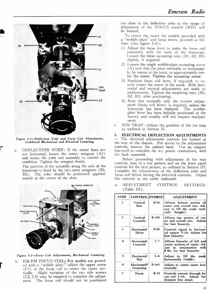
Deflection Yoke and Focus Coil AdjustmentsCombined Mechanical and Electrical Centering 11
Focus Coil Adjustments, Mechanical Centering 11
Schematic Diagram Chassis 120110B 12,13
Rear Deflection Adjustments 14
Generator Matching Network 14
Scope Detector Network — 14
Location of Alignment Points 15
Tuner Alignment Points 16
Side View of Tuner 17
Voltage and Resistance Diagram 18
Sweep Circuit Waveforms 19
High Voltage Power Supply, Chassis 120113B 20
Bottom View of Chassis 21

Emerson Radio
Section 1.
GENERAL DESCRIPTION1. FACILITIES—Emerson Models 614, 637, 644,and 647 are wide-band video receivers, providing di-reci-view high-definit ion pictures on ten or twelve-inchelectro-magnetic deflection kinescopes. All models in-corporate several design features including intercarriersound, AFC in the horizontal sync circuits, automaticgain control, a series-type transformer power supply,and internal antennas.
Models 614 and 637 employ Chassis 120110B;Models 644 and 647 use Chassis 120113B. Both chassisare basically alike; the latter is modified to accommo-date the larger kinescope, type 12LP4 or 12QP4.Model 614 is housed in a plastic cabinet, and Model637 is contained in a wooden cabinet; both are tablemodel receivers using a type 10BP4 picture tube.Model 644 is housed in a table model cabinet; Model647 uses a consolette-type of cabinet.2. SPECIFICATIONS—a. TUBE COMPLEMENTS: (Table 1).
NOT!1": The tube complements of both chassisare alike, except for the kinescope. Chassis 120113Buses type 12LP4 kinescope; some chassis may beequipped with a type 12QP4.
SYMBOL
VlV2V3V4V5V6
V7V8V9V10Vll
V12V13V14V15
V16V17V18V19
V25
V27V28V29
TT TRP1 . I M -
TYPE
6AG56AG56AU66AL56AU612AU7
6AU66AU66T86V6GT6SN7GT
6AL56SN7GT6SN7GT12AU7
6K6GT6BG6G1B3GT6W4GT) 10BP4* or112LP4#6J66AG5
FUNCTION
First video i-f amplifierSecond video i-f amplifierThird video i-f amplifierVideo detector and AGCFirst video amplifierSecond video amplifier; second
sync amplifierSound i-f amplifierSound limiterSound disc, and audio amp.Audio outputHor. phase invert.; horizontal
control (d.c. amp.)Hor. phase det. (sync disc.)Hor. oscillator and dischargeVert, oscillator and dischargeSync sep. and d.c. restorer;
first sync, amplifierVertical outputHorizontal outputHigh-voltage rectifierHorizontal damper
Kinescope
Oscillator and converterR-f amplifier
5U4G Low- voltage rectifier
* Chassis 120110B # Chassis 120113B
WOBBLE PLATELEVER
LOW VOLTAGEPOWER SUPPLY
PICTURE CENTERINGLEVER (FOCUS COII
DEFLECTION YOKE
C-2l,C-39,C-4l,C-74
HIGH VOLTAGEPOWER SUPPLY
ON-OFF VOLUMEAND CONTRAST
AUDIO I-SECTION
C-36.C-49C-75
VERTICAL HOLD
BRIGHTNESSAND HORIZONTAL HOLD
VIDEO I-FSECTION
TURRETTUNER
SELECTOR ANDFINE TUNING
Figude 1-1—Front View of Chassis 120110B

Emerson Radio
LOCATIONS
Figure 1-2 Tube Location Diagram
b. RECEIVER CHARACTERISES: (Table II ) .
ITEM
Voltage Rating
Power Consumption
Current Drain(At 117 volts a.c.)
Frequency Range
.IntermediateFrequencies
Input Impedance
Channel Selection
Chassis Models
Audio Output
DESCRIPTION
105-125 volts, 60 cycles a.c.
All models — 190 watts
All' models — 1.7 amps.
54-88 MC.; 174-216 MC.
Video — 25.75 MC.Audio — 4.5 MC.
300 ohms, balanced
Twelve position, rotary turret
Models 614, 637 — Chassis1201 10B
Models 644, 647 — Chassis120113B
2.5 watts
9S53ZO
OSCILLATOR FREQUENCY
CHANNEL LIMITS 54
CHANNEL
AUDIO CARRIER
VIDEO CARRIER
CH.2 CH.3 CH.481 67 93
7C 76 I
CHS CH.6103 109
3 . 1 ^ i ,59.75 Jr. 71.
I I s ! 6'5
I81.75 87.7
1 i5
LOW B A N D55.25 61 25 67.25 77.25 8325
OSCILLATOR FREQUENCY
CHANNEL LIMITS
CHANNEL
AUDIO CARRIER
VIDEO CARRIER
CY
174
I 7
179.
180
CH.7 CH.8
201 207CH.9213
CH.IO CH.M CH.I2 CKI3
219 225 231 2372O4 | 210 1 216 1
1 8 1 9 1 '°
75 185.75 J. 197.7
II 12
51
203.75 20!
I »
.75 215
I75
1 1J
HIGH B A N D175.25 18125 187.25 193.25 199.25 205.25 211.25
Figure 1-3—Video, Audio, and Oscillator Frequencies
Section 2.INSTALLATION
1. PREPARATION FOR INSTALLATION —All models are shipped complete, with the kinescopein place and all adjustments properly set. Presentmodels are equipped with internal antennas and me-chanical deflection centering. Initial production mod-els do not include the built-in antenna and make useof combined electrical and mechanical centering.2. ANTENNA INSTALLATION—Chassis 12011013and 120113B are designed to operate with high sensi-tivity and will provide excellent reception in manyareas with the internal antenna. If performance in aparticular locality is unsatisfactory disconnect theinternal antenna and install a portable or an outdoorantenna, depending on reception conditions.a. PORTABLE ANTENNA: Since surrounding
buildings and other objects can block out televi-4
sion signals, an indoor antenna should be triedin different locations before deciding on a perma-nent position. Uncoil the. transmission line fromthe antenna base and connect to the terminals atthe rear of the chassis. Tune the antenna, afterturning on the receiver and adjusting the con-trols, by rotating and varying the length of thetelescopic arms for best reception. Both armsshould be adjusted to the same angular positionand extended to the same length.
PERMANENT ANTENNA: For outdoor , an-tenna installations, use a dipole or an array witha combination of elements. An Emerson Tele-Rayantenna is recommended, for best results. A 300-ohm transmission line is required for connectionto the receiver.

Emerson Radio
3. RECEIVER INSTALLATION — Locate the re-ceiver where a minimum of bright light falls directlyon the screen, although complete darkness is not recom-mended. Provide adequate ventilation by keeping theback of the receiver away from the wall. Do not ob-struct the ventilating slots at the rear of the cabinet.
All models are provided with a protective enclos-ure for the end of. the kinescope. The enclosure isfastened to the rear of the chassis. Care should be ex-ercised during installation so as not to strike or jarthe enclosure.
After completion of antenna and power connec-tions, operate the receiver as outlined in Section III.If a receiver fails to operate, or if operation is unsat-isfactory, proceed with the following checks and ad-justments.
CAUTJONOnly experienced personnel should attempt to makethese adjustments, as high voltage of ten kilovoltsis present at the kinescope.
a. MECHANICAL ADJUSTMENTS: For allmodels, remove the chassis back and check alltubes to make certain they are firmly seated intheir sockets. Remove the kinescope enclosureand check the seating of the base plug. Inspectthe high-voltage anode connector.The deflection yoke and focus coil have been prop-erly positioned at the factory. The kinescope shouldbe seated back against the edges of the deflectionyoke assembly. Inspect the assembly to makecertain that all adjustment wingnuts are tight.The ion trap should be positioned approximatelyover the two internal flags near the base of thekinescope.
b. ELECTRICAL ADJUSTMENTS: An adapterline cord is required to operate the receiver forthe following preliminary adjustments.
1) Turn the OFF-VOLUME control a quarter-turn clockwise to turn on the receiver. Set theBRIGHTNESS control a half-turn clockwiseand turn the CONTRAST control countei-clockwise. Allow the tubes to warm up.
2) Set the SELECTOR control to an active chan-nel and adjust the TUNING control for bestpicture quality. A test pattern is preferablefor these adjustments.
3) Adjust the ion trap magnet by moving slowlyforward or backward while rotating slightlyaround the neck of -the kinescope to obtainmaximum picture brightness. Reduce theBRIGHTNESS control setting until the pat-tern is at7 approximately normal brilliancy. Ad-just the 'FOCUS control, at the rear oi thechassis, for maximum sharpness of raster lines.Then readjust the ion trap for maximum bril-liancy.
4) Adjustment of the deflection yoke assembly isrequired if the raster is not horizontal. Loosenthe. center wingnut and rotate the assemblyslightly to correct this condition.
5) Centering of the raster in the mask is con-trolled by both electrical and mechanical ad-justments, or by mechanical adjustments alone.If this adjustment is required, refer to SectionV for operation of the chassis controls and po-sitioning of the focus coil.
6) All electrical adjustments at the rear of thechassis have been set at the factory. If the set-tings have been disturbed or if the kinescoperequires replacement, they must be carefullyreadjusted in accordance with the procedureoutlined in Section V.
Section 3.O P E R A T I O N
1. OPERATING CONTROLS—The operation andfunction of the front-panel controls is identical for allmodels. Seven controls are provided, as shown in fig-ure 3-1.
2. TUNING—Tuning the receiver initially requiresoperation of the various controls as indicated.
a. STATION SELECTION:1) Turn the OFF-VOLUME control clockwise
approximately a quarter-turn. This turns thereceiver on and sets the sound volume to areasonable level.
2) Set the'SELECTOR control so that the desiredchannel number is indicated on the edge of thecontrol. This control may be rotated in eitherdirection.
3) Allow approximately IS seconds for warmup.(This time is necessary to allow the tubes toattain the proper temperature for operation.)
4) If the desired station is-broadcasting, music orspeech will be heard. Adjust the TUNINGcontrol for best picture quality. Readjust theVOLUME or desired sound level.
5) Rotate the CONTRAST control to its extremecounter-clockwise position.
CONTRAST CONTROL:ADJUSTS PICTURE CONTRAST,LIGHT OR DARK.
•OFF-VOLUME CONTROL:TURNS RECEIVER ON ANDADJUSTS SOUND VOLUME.
BRIGHTNESS CONTROL:—ADJUSTS PICTUREAVERAGE BRIGHTNESS.
HORIZONTAL HOLD CONTROLSTOPS HORIZONTAL MOTIONOF PICTURE.
VERTICAL HOLD CONTROL.STOPS VERTICAL MOTIONOF PICTURE
INDICATOR CONTROL;SELECTS STATIONS.
FINE TUNING CONTROLADUSTS RECEIVERFOR BEST PICTURE
Figure 3-1—front Panel Controls

Emerson Radio
Figure 3-2—Test PatternCorrectly Adjusted
Figure 3-4—Test PatternExcessive Contrast
I ,r' .,'V" '-f m _ . « . •
Figure 3-3—Test PatternTuning Misadjusted
Figure 3-5—Test PatternExcessive Brightness
Figure 3-6—Test PatternVertical Hold Misadjusted
Figure 3-7—Test PatternHorizontal Hold Misadjusted
Figure 3-8—Test PatternFocus Misadjusted
Figure 3-9—Test PatternWeak Signal

Emerson Radio
6) Rotate the BRIGHTNESS control to the max-imum counter-clockwise position and then ad-just slowly clockwise until light is just visibleon the screen. Rotate in reverse direction un-til light just vanishes.
7) Adjust the CONTRAST control until a pic-ture appears on the screen and desired con-trast is attained. A further reduction in theBRIGHTNESS control setting may improvethe apparent contrast of the picture.
8) If the picture moves vertically or horizontally,make the adjustment indicated in steps 9 and/or 10.
9).Adjust the VERTICAL HOLD control untilthe picture stops moving up or down. Properoperating setting of this control is in the cen-ter of the range over which the picture remainsstationary.
10) Adjust the HORIZONTAL HOLD controluntil picture stops moving from side to side.
1 1 ) Readjust the CONTRAST control until thedesired picture intensity is obtained. It maybe necessary o readjust the BRIGHTNESScontrol slightly at the same time for optimumbrilliance.
12) After the receiver has been operating for sometime, it may be necessary to readjust the TUN-ING control slightly for best picture quality.
1). CHANGING STATION DURING OPERA-TION :1) Set the SELECTOR control to the proper
channel number.2) Readjust the TUNING control if necessary to
obtain best picture quality.3) Readjust the CONTRAST control slowly un-
til the desired picture quality is obtained.4) Readjust VOLUME to suitable level.5) Readjust BRIGHTNESS control for desired
brilliancy.
c. CHECKING OPERATION: The use of auto-matic frequency control in the sync circuits ofthe receiver makes readjustments of the VER-TICAL HOLD and HORIZONTAL HOLDcontrols infrequent provided the control set-tings for proper operation are not disturbed.Figures 3-2 through 3-9 indicate correct andincorrect adjustment of the various controls.Proper operation may be obtained by operationof the associated control.
Section 4.
CIRCUIT DESCRIPTION
1. GENERAI^-Chassis 120110B and 120113B arebasically alike; the latter is modified to accommodatea 12-inch kinescope and contains some changes in thehigh-voltage power supply circuits. Both chassis con-tain twenty-three tubes including the kinescope andlow-voltage rectifiers. The chassis use the intercarrier
method of sound reception, with the 4.5 me. audio i-fproduced by heterodyning the video and audio carriersat the output of the video detector. The various stagesof the receivers are indicated in the block diagram, fig-ure 4-1.
I05-I25V
60~A C.
v ;R-F t
6AC
B
5
V-I5B1ST SYNC
AMP
I2AU7
V-2 9
L.V. RECT.
5U4G
V-2
CONVE6.
7A
6
V-2
6J
78
ATOR
B
T1
1
1
1
1_J
V -
AUDIO
7
I-F
AMP
64U6
I2575MC'I2I.25MC.
V-l1 ST VIO I-F
AMP
6AG5
V-6B
2ND SYNC.AMP.
I2AU7
EB1-
L_
B-
V-22ND VIO I-F
AMP
SAGS
V-33RD VID. I-F
AMP
S A U S
V-l
HOR
APH.
INV.SSMTOT
V - 1 4
VERT OSC.
6SN7GT•—
V-
VID.
4
DET.
AND AGC
SALS
rV - I Z
HOR.PH.DET.
6AL5
IV- IS
VERT. AMP
6 K 6 G T
V-8
AUDIO I-F
LIMITER
6AU6
V-51 ST VIDEO
AMP
6AU6
V - 9
DISC. AND
AUOIO AMP
•Ti
V - 6 A
2 NO VIDEO
AMP.
I 2 A U 7
V - M B
HOR CONT
6SN7GT
V-13
HOR. OSC.
6S N7
V-17
HOR AMP.
6 8 G 6 0
V-IO
AUDIO
OUTPUT
S V 6 0 T
V- I5ASYNC. SEP.
0 C RES.
12 AU7
_J
V -IB
H.V. RECT.
IB3GT
V-19
HOR. DAMP
6 W 4 G T
-<10 B
-tf
1
°4V - 2 5
OR IZLP*-
Kf
Figure 4-1—Block Diagram, Chassis 120110B, 120113B

Emerson Radio
2. TUNER — The r-f. unit constitutes a separatesub-chassis of the receiver. This sub-chassis con-tains the r-f amplifier, converter, and oscillatorstages. The channel switch, fine tuning control,tuned circuits, and first video i-f transformer arealso contained on this chassis. Tuning and track-ing adjustments for all twelve channels currentlyin use are provided. The tuner serves to selectand amplify the desired video and audio frequen-cies and convert them to the carrier i-f frequenciesof 25.75 me. for video and 21.25 me. for audio.No separation of these two intermediate frequen-cies is mads, and the complete signal is fed to thefirst video i-f stage.
The tuner uses a rotary turret carrying individ-ual coils for each tuned circuit, for each channelsetting. A type 6AG5 (V28) serves as the r-famplifier and a type 6J6 (V27) as the converterand oscillator. The r-f amplifier is a wideband,tuned stage whose output is inductively coupledto the converter (V27). The oscillator (V27B)operates in a Colpitts type circuit. Individualslugs provide for alignment of the oscillator on the
various channels. A variable-dielectric type ofcondenser is used for fine tuning of the oscillator.The output of the converter is conected to double-tuned first i-f transformer (Tl).
The center-tapped primary (LI) of the r-f coilis designed to match a balanced 300-ohm line. Thesecondary (L2) is tuned by the input capacity ofV28 in series with the parallel combination oftrimmer A14 and a 5 mmf. condenser. The outputof V28 is coupled to V27A by L3, which is tunedby trimmer A15 and 'the output capacity of thetube. A 10K resistor loads L3 to provide therequired band pass.
The input capacity of V27A and trimmer A16tune the converter coil (L4). The oscillator coil(L5) is wound on the same form with L3 and
L4, for inductive coupling. The initial oscillatorfrequency is fixed by permeability tuning of L5and the preset .5-3 mmf. trimmer. The frequencyis varied by means of the TUNING control (3-5mmf. trimmer) which consists of a spiral-shapeddielectric disc rotating between fixed stator plates.
950098
270
ALL RES. IN OHMS,CAP. IN MMF, UNLESSOTHERWISE SPECIFIED
6.3 AC
Figure 4-2 Schematic Diagram of Tuner
1. VIDEO SECTION—The video section consistsof the following sections: video i - f ; video detector andautomatic gain control; video amplifier and d.c. re-storer.
a. VIDEO I-F: Both the 25.75 me. video carrierand 21.25 me. audio carrier are amplified by threewide-band i-f stages. The four tuned cicruits are
peaked at .different frequencies, forming a stagger-tuned system of relatively flat overall response toproduce the required bandpass.
Self-resonant, slug-tuned coils are used in thei-f transformers. Two stagger-tuned i-f trans-formers (T2, T3) follow the overcouplscl first i-f(Tl ) . T2 is provided with a 21.25 me. trap to

Emerson Radio
attenuate the audio i - f . An overcoupled i-f (T4)completes the amplifier stages and feeds the videodetector (V4).
The audio level is maintained just below thepoint of intertcrence with the video i-t. However,the audio i-t is not completely rejected, as the audiosignal is recovered (ac the output ot the video de-tector) by heterodyning with the video i-f. The4.5 me. beat between me video and audio inter-mediate frequencies is obtained from the shunt-tuned circuit consisting of L2 and C79 and is fedto the first audio i-f amplifier (V7).
b. VIDEO DETECTOR AND A.G.C. :The videodetector (V4A) rectifies the negative portion ofthe video i-f. The resultant signal is coupledthrough peaking coil LI to the grid of the firstvideo amplifier (V5) . V5B acts as the automaticgain control and develops a delayed negative A.G.C.voltage which is used to bias the first two videoi-f stages and the r-f amplifier.
c. VIDEO AMPLIFIER: The video amplifier con-sists of two stages (V5 and V6A). The secondstage is series-peaked and is coupled to the gridof the kinescope (V25) and the sync separatorand d. c. restorer (VISA). The output signal ofV5 is varied by the CONTRAST control (R19)which varies the bias of VS, to control the signalinput to V6A.
d. D. C. RESTORER AND SYNC CLIPPER:The output of the video detector contains both a.c.and d.c. components of the video signal, as wellas the blanking and sync pulses. Since the videoamplifiers will not pass the d.c. component of thevideo signal, the background level of the picturewill vary. The d.c. restorer (VISA) develops abias voltage across R24 which varies with theaverage video signal level. This bias voltage isfed to the grid of the kinescope, thus maintainingthe proper brightness level. The video sync pulseoutput of VISA, developed across R28, is coupledthrough C22 to the first sync amplifier (V15B).
4. DEFLECTION SECTION—The sync and sweepstages produce and control the deflection of the elec-tron beam in the kinescope. The horizontal sweep cir-cuits incorporate a horizontal phase detector (syncdiscriminator) to maintain automatic sync with thehorizontal pulses of the video signal.a. SYNC AMPLIFIER AND INVERTER: The
sync pulse output of VISA is amplified by twotriode stages (VISE and V6B) and fed to thehorizontal phase inverter (V11A). The integrat-ing network of the vertical deflection circuit iscoupled to the output of VI1 A, which providespush-pull' output for I'le horizontal sync discrimi-nator (VI2) .
b. HORIZONTAL SWEEP: The horizontal de-flection circuits contain an automatic frequencystabilizing arrangement which improves stabilityand ease of operation. The phase inverter (V11A)feeds the horizontal sync pulses to the horizontalphase detector (V12). At the same time, V12receives voltages fed back from the horizontal output (V17) through CSS. Any phase shift betweenthe horizontal sync pulses and the horizontal os-cillator signal will cause the input voltage applied
to one diode section of V12 to differ from that ofthe other and result in a d.c. bias voltage on thegrid of the horizontal control tune (Vl l -b) . Thisbias voltage will be proportional to the phase dis-placement between the incoming sync pulses andthe horizontal oscillator voltage and of a polaritydetermined by the lead or lag of the oscillator fre-quency. The plate resistance of VHP) is part ofthe bias network of the grid circuit of the horizon-tal oscillator (Vlo) . The output of the phase de-tector (V12) will ihus synchronize the oscillatorto the horizontal pulses of the video signal.The horizontal blocking oscillator (V13) operates
at a frequency determined by C57, R75, R76, andthe plate resistance of VI IB . The horizontal syncpulses cause V13 to lock in at the sync frequencywhen the HORIZONTAL HOLD control \R75)is properly adjusted. The sweep voltage outputof V13 is developed across R79 and is ted to thehorizontal output tube (VI7 ) . The signal levelto the horizontal output tube is adjusted by theHORIZONTAL DRIVE control, R80.
V19 supplies the required driving power for thehorizontal deflection coils (L9). 'ihe output ofV17 is coupled to the horizontal deflection coilsthrough output transformer T9. A portion of theoutput transformer secondary is shunted by theHORIZONTAL SIZE control L6. By varyingthe inductance of L6, the horizontal sweep currentmay be controlled.
The horizontal damper tube (V19) acts to dampout oscillations which occur over part of the hori-zontal scanning cycle. The HORIZONTAL LIN-EARITY control (L7) helps provide a lineartrace. V19 is a type 6W4 to eliminate the needfor a separate damper filament winding,
c. VERTICAL SWEEP: Vertical oscillator V14 isfree-running and operates at a frequency determ-ined by C71, R95, and the VERTICAL HOLDcontrol (R94), in the absence of a vertical syncpulse. The integrated sixty-cycle sync pulse de-rived from the video signal reaches the grid ofV14 just before it would normally trip. This syncpulse is great enough to drive the tube to conduc-tion and cause it to lock-in at the sync frequency.The sync pulse thus maintains control of the verti-cal oscillator sweep frequency when R94 is cor-rectly adjusted.
The output of V14 is fed to the vertical outputstage (V16) through C72. The output of V14 iscontrolled by the VERTICAL SIZE control(R96). R100 varies the operating point of V16by varying the bias, acting as the VERTICALLINEARITY control The sweep voltage of V16is coupled to the vertical deflection coils (L8) bymeans of the vertical output transformer (Til) .
5. POWER SUPPLIES — Two power supplies areused to supply the required voltages. The low voltagesupply uses a transformer and full-wave rectifier. Thehigh voltage supply for the kinescope is of the fly-backlype and is energized by the horizontal output tube.a. HIGH VOLTAGE SUPPLY: The high voltage
power supply makes use of the energy supplied tothe horizontal output transformer by VI7. Whenthe plate current of VI7 is cut off at the instant

Emerson Radio
of retrace of horizontal scanning, the field builtup in the primary collapses and induces a high-voltage. This voltage is applied to the high-voltagerectifier (V18). From 8.5 to 10 kilovolts is pro-duced by the power supply. The rectified voltageis filtered by C63 and R89, and applied to thesecond anode of the kinescope. Chassis 120113Bdiffers from Chassis 1201 IB in that C63 is return-ed to B—, instead of the plate of VI9.
b. LOW VOLTAGE SUPPLY: The low-voltagesupply uses a full-wave rectifier (V29) and trans-former (T12). A series arrangement is used tosupply plate voltage, to reduce current require-ments. As a result, separate filament windingsare used to keep the heater-cathode potentialswithin ratings, and the electrolytic filter conden-sers are not grounded to the chassis. The center-tap of T12 is not grounded but is negative (B—)with respect to ground. The cathodes of the sweepcircuit and video amplifier tubes are negative toground (about -205 volts) and the heaters areconected to the ungrounded filament winding (Y).
6. INTERCARRIER SOUND—The audio circuitsare conventional. The 4.5 me. heterodyne between thevideo and audio, i-f carriers is taken from the shunt-tuned circuit (L2, C79) at the output of the video de-tector (V4). The 4.5 me. signal is amplified by theaudio i-f amplifier (V7), whose output is coupled tothe limiter (V8). V8 feeds the discriminator (V9A) ;
the output of the discriminator is amplified by V93,and the audio output (V10).
7y DEFLECTION YOKE AND FOCUS COILASSEMBLY: The deflection yoke and focus coilform a complete assembly. The yoke contains thevertical and horizontal deflection coils (L8 andL9). The focus coil (L10) combines a permanentmagnet with the electromagnet (PM and EM).The yoke and focus coil are independently ad-justable.
Vertical centering is accomplished by mechani-cal adjustment of the focus coil; horizontal center-ing is done electrically by the HOR. CENTER-ING control (R103). Later production of Chas-sis 120110B and 120113B makes use of a pivotedmounting for the EM-PM focus coil, togetherwith a "wobble plate" to provide for mechanicaladjustment of horizontal and vertical centering.
The "wobble plate" consists of a ring of perme-able material (steel) surrounding the neck of thekinescope, adjacent to the EM-PM focus coil.The plate may be moved in a plane at right-anglesto the axis of the kinescope, both vertically andhorizontally, by means of a slotted section andlever. In addition, the focus coil may be tilted inboth directions by means of a second lever whichis adjustable from the rear of the cabinet, withoutremoving the back. This enables precise mechani-cal control of centering.
Section 5.
MAINTENANCE AND ALIGNMENT1. GENERAL—All adjustments must be made onlyby qualified service technicians. Unsatisfactory oper-ation should be analyzed and circuits checked syste-matically to locate and correct sources of trouble.
WARNINGHigh voltages in excess of 8000 volts are presentin the chassis, during operation. Exercise care inservicing the receiver, when energized. Do notremove, handle, or replace the kinescope unlessgloves and goggles are worn.
2. CHASSIS REMOVAL—To remove the chassis,follow the outlined procedure.a. Pry off all control knobs.b. Remove the six screws which fasten the back in
place.c. Remove the speaker plug.d. Remove the four chassis bolts and carefully slide
the chassis from the cabinet. When inverting thechassis, place a supporting block under the powertransformer.
3. KINESCOPE REPLACEMENT —CAUTION
Before removing the kinescope, discharge the tubeby cdnnecting an insulated test prod to the chassisand to the high-voltage anode. Wear gloves andgoggles before handling the tube.To remove the tube, proceed as follows:
a. Disconnect the high-voltage lead at the top of thekinescope and discharge the tube.
b. Remove the enclosure which protects the base ofthe kinescope.
c. Remove the tube socket and slide off the ion trap.d. Loosen the hold-down strap at the front of the
tube and carefully withdraw the kinescope for-ward from the deflection yoke and focus coil as-sembly.To install a new kinescope, follow the above pro-cedure in reverse. Make certain that the tube isseated against the edges of the deflection yokeassembly, with the high-voltage anode connectionat the top. In replacing the ion trap, position theunit so that the arrow points towards the front ofthe chassis.
NOTEWhenever the kinescope is removed or replaced,the mask should be carefully cleaned with a soft,lintless cloth. Do not use carbon tetrachloride orany cleanser containing abrasive material. Theface of the kinescope should also be wiped clean,before replacing the chassis in the cabinet.
4. MECHANICAL DEFLECTION A D J U S T -MENTS — See figure 5-1. Replacement of the kine-scope or of any of the components of the deflectionsystem will require readjustment of the deflection yokeassembly, focus coil, and ion trap.
NOTEBefore making any deflection adjustments, makecertain that the enclosure is in place, coveringthe base of the kinescope, and is firmly fastened.The adjustments to the focus coil can be madethrough openings provided in the enclosure.
10
Emerson Radio
-,
C3
Figure 5-1—Deflection Yoke and focus Coil Adjustments,Combined Mechanical and Electrical Centering
a. DEFLECTION YOKE: If the raster lines arenot horizontal, loosen the center wingnut (Al)and rotate the yoke coil assembly to correct thecondition. Tighten the wingnut firmly.The position of the assembly along the axis of thekinescope is fixed by the two outer wingnuts (Bl,B2). The yoke should be positioned approxi-mately at the center of the slots.
ANODE CONNECTION
DEFLECTIONYOKE
ADJUSTMENT
FOCUS CONTROL-LEVER
Figure 5-2—Focus Coil Adjustments, Mechanical Centering
b. EM-PM FOCUS COIL: For models not provid-ed with a "wobble plate," adjust the upper screw(Cl) of the focus coil to center the raster ver-tically. Slight variation of the two side screws(C2, C3) may be required to complete the adjust-ment. The focus coil should not be positioned
c.
too close to the. deflection yoke as the range ofadjustment of the FOCUS control (R55) willbe limited.
To center the raster for models provided witha "wobble plate" and focus levers, proceed as fol-lows (See figure 5-2):
- 1 ) Adjust the focus lever to make the focus coilconcentric with the neck of the kinescope.Loosen the three mounting nuts (Bl, B2, B3)slightly, if required.
2) Loosen the single wobble-plate mounting screw(A) and slide the plate vertically or horizontal-ly, by means of the lever, to approximately cen-ter the raster. Tighten the mounting screw.
3) Readjust focus coil lever, if required, to ex-actly center the raster in the mask. Both hori-zontal and vertical adjustments are ma'de si-multaneously. Tighten the mounting nuts (Bl,B2, B3) after positioning.
4) Note that normally only the vernier adjust-ment (focus coil lever) is required, unless thekinescope has been replaced. The wobble-plate lever has been initially positioned at thefactory and usually will not require readjust-ment.
ION TRAP : Adjust the position of the ion trapas outlined in Section II.
5. ELECTRICAL DEFLECTION ADJUSTMENTS— The electrical adjustment controls are located atthe rear of the chassis. For access to the adjustmentcontrols, remove the cabinet back. Use an adapterline-cord to complete the a-c. power connections, withthe back removed.
Before proceeding with adjustment of the rearcontrols, tune in a test pattern and set the front panelcontrols for the best picture, as outlined in Section III.Complete the adjustments of the deflection yoke andfocus coil before setting the electrical controls. Adjustthe controls in the order indicated.
a. ADJUSTMENT(Table III).
CONTROL SETTINGS:
STEP
1
2
3
4
5
6
7
CONTROL
VerticalSize
VerticalLinearity
HorizontalDrive
HorizontalLinearity
HorizontalSize
Horizontal*Centering
Focus
SYMBOL
R-96
R-100
R-80
L-7
L-6
R-103
R-55
ADJUSTMENT
Affects bottom section ofraster and overall size. Ad-just to fill the mask verti-cally (height).
Affects top section of ras-ter and overall size. Adjustfor best linearity.
Controls signal to horizon-tal output V-19. Adjust forbest linearity.
Affects linearity of left andcenter sections of raster. Ad-just in conjunction withR-80, for best linearity.
Adjust to fill the maskhorizontally (width).
Adjust to center raster hor-izontally.
Controls current through fo-cus coil L-10. Adjust forsharpest line detail.

Emerson Radio
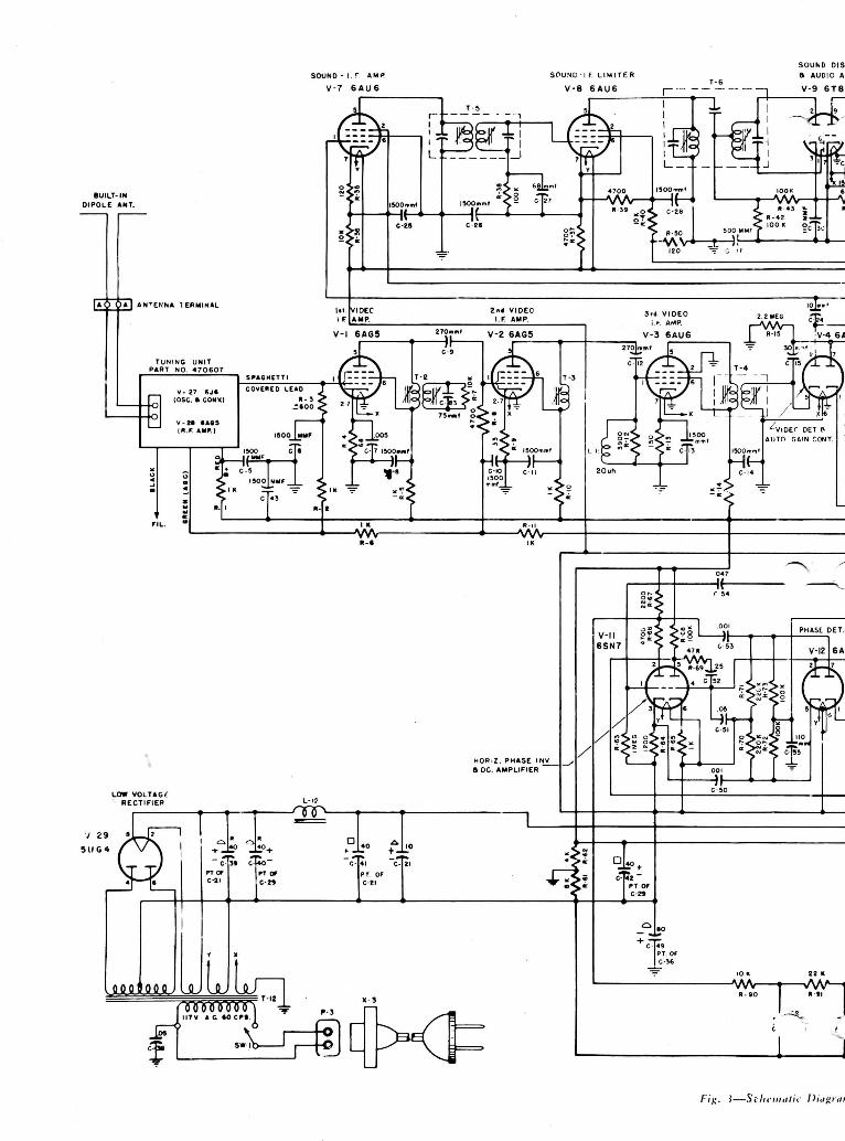
Figure 5-3—Schematic Diagr,

Emerson Radio
PART No. 950127
Diagram, Chassis 120110B13

Emerson Radio
Proper adjustment of the HORIZONTAL andVERTICAL LINEARITY controls, and the SIZEcontrols should result in test patterns in which thecircles are round and the wedges are linear and equal.The test pattern circles should be concentric with thecurved sides of the mask.
120
Figure 5-4—Rear Deflection Adjustments,*For chassis not equipped with wobble plate and
centering lever.
6. ALIGNMENT TEST EQUIPMENT — Properservicing and alignment of Chassis 120110B and 120-113B requires the equipment indicated.a. SWEEP GENERATOR:
1) Frequency ranges of 18 to 30 MC., 50 to 90MC., and 170 to 225 MC.
2) Sweep width variable to 10 MC.3) Output of at least 0.1 volt, with an attenuator
for adjustment of output.4) Constant output over sweep width, with flat
output on all ranges and at all attenuator posi-tions.
5) Output impedance of 300 ohms, for r-f align-ment, or matching network. See figure 5-5.
b. MARKER GENERATOR:1) Frequency ranges of 4 to 30 MC. and 50 to
225 MC., for i-f and r-f alignment. The mark-er generator must provide an accurate (crystalcalibrated) frequency of 4.5 MC. for audio i-falignment, and accurate frequencies from 21.25MC., to 25.75 MC., for video i-f alignment.The required r-f requencies from 50 to 225MC., as tabulated below, may be provided bya calibrated signal generator or a heterodynefrequency meter with crystal calibrator.
2) Output of at least 0.1 volt, with an attenuatorfor adjustment of output.
GENERATOR FREQUENCIES: (Table IV).
CHANNEL
23456789
10111213
VIDEOCARRIER
MC
55.2561.2567.2577.2583.25
175.25181.25187.25193.25199.25205.25213.25
AUDIOCARRIER
MC.
59.7565.7571.7581.7587.75
179.75185.75191.75197.75203.75209.75215.75
TO
GEN. 50/ OR HOR
OPENINGEXTEND
H V
CAN
®
[§T| L-6 L-7
J ® ®\ HOR. HOR.
SIZE LIN.
ZONTALLY IN FRONT --'' i*T"~""-, ADJUST THE LEVER | H>. SNG FROM BACK COVER. |H '-'JT"''*1
11 !PICTURE 1 I </fS\^ Wtr- ' '!
LEVER J& . J<^
fixx tx'_>^ NECK OF TUBE
?
f 1f*\) \.fU\ — :i : . — — : — :
/
I I I IINTERLOCK
(o o) @ SPEAKER
R-80 R-IOO R-9« R-38 R-103 *
o o o o AoHOR. VERT. VtRT. FOCUSZ_L_iMOR .*
DRIVE LIN. SIZE / CENT.
CODE NUMBER—/
955282
TO
RECEIVER
-AAA/ -120
USE CARBON RESSTORS ONLY.
Figure 5-5—Generator Matching Network
VACUUM-TUBE VOLTMETER:1) A diode probe for high-frequency measure-
ments is desirable.2) High input impedance with provision for low-
voltage measurement (three or five volt scale).
OSCILLOSCOPE:1) Vertical input should be provided with a cali-
brated attenuator and low-capacity probe.2) Flat vertical amplifier frequency response, with
good low frequency response.3) Adequate vertical sensitivity.
SCOPE DETECTOR: Required for alignment ofover-coupled first i-f Tl. See figure 5-6.
20K IN34 .005 MFD
100-MMF **
j IXU | /|
>IMEG. ^Z00y\: i Lr
TO TEST POINTSIN RECEIVER(KEEP LEADS SHORT)
Figure 5-6—Scope Detector Network
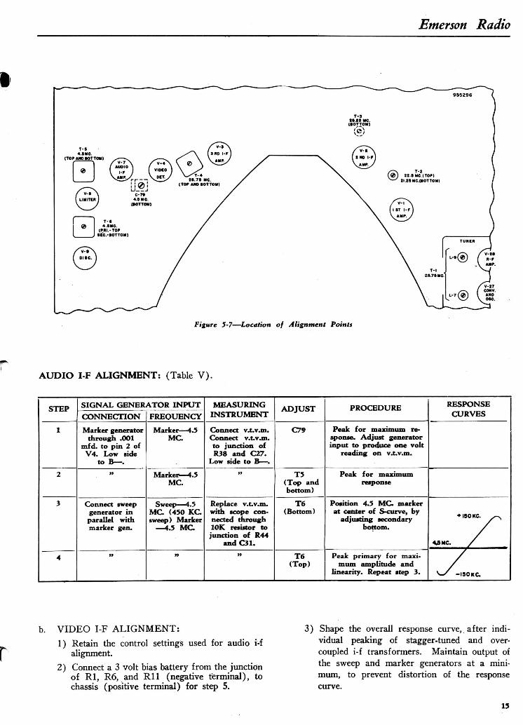
7. ALIGNMENT—
a. AUDIO I-F ALIGNMENT:1) Disconnect the antenna and remove the chas-
sis from the cabinet. Use an adaptor line cordto operate the receiver.
2) Set the CONTRAST control at the center ofrotation and retain at this setting for all i-fadjustments.
3) The waveforms shown in the response curvesmay be inverted depending on the number ofamplifying stages in the vertical amplifier ofthe scope being used.
4) When the marker signal is coupled in parallelwith the sweep generator, the signal should beUnmodulated and attenuated so that only asmall pip is visible. Use an accurate, crystal-controlled marker generator.
5) Connect the sync sweep voltage from the sweepsignal generator to the horizontal input of thescope for horizonal deflection.
6) Refer to figure 5-7 for location of alignmentpoints; figure 5-3 for the schematic diagram.
7) Set the receiver to Channel 3.
14
Emerson Radio
figure 5-7—Location of Alignment Points
AUDIO I-F ALIGNMENT: (Table V).
STEP
1
2
3
4
SIGNAL GENERATOR INPUT
CONNECTION
Marker generatorthrough .OO1
mfd. to pin 2 ofV4. Low aide
to B — .n
Connect sweepgenerator inparallel withmarker gen.
>>
FREQUENCY
Marker— 4.5MC.
Marker — 4.5MC.
Sweep — 4.5MC. (450 KC.sweep) Marker
— 4.5 MC.
n
MEASURINGINSTRUMENT
Connect v.t.v.m.Connect v.t.v.m.to junction ofR38 and C27.
Low side to B — .»
Replace v.t.v.m.with scope con-nected through10K resistor tojunction of R44
and C31.H
ADJUST
C79
T5(Top andbottom)
T6(Bottom)
T6(Top)
PROCEDURE
Peak for maximum re-sponse. Adjust generatorinput to produce one volt
reading on v.t.v.m.
Peak for maximumresponse
Position 4.S MC. markerat center of S-curve, by
adjusting secondarybottom.
Peak primary for maxi-mum amplitude and
linearity. Repeat step 3.
RESPONSECURVES
*ISOKC. ,~^
«*MC. /
^-/ -ISOKC.
b. VIDEO I-F ALIGNMENT:
1) Retain the control settings used for audio i-falignment.
2) Connect a 3 volt bias battery from the junctionof Rl, R6, and Rll (negative terminal), tochassis (positive terminal) for step 5.
3) Shape the overall response curve, after indi-vidual peaking of stagger-tuned and over-coupled i-f transformers. Maintain output ofthe sweep and marker generators at a mini-mum, to prevent distortion of the responsecurve.
15

Emerson Radio
VIDEO I-F ALIGNMENT: (Table VI) .
STEP
1
2
3
4
5
SIGNAI GENERCONNECTION
Lightly couplemarker gen. topin 1 of V3:
Sweep gen. frompin 1 to chassis,
:hrough .001 mfd.
Connect markerand sweep gener-ators to pin 1
of V2, through.001 mfd. Lowside to chassis.
Sweep generatorcoupled to con-verter (V27) in-put, using three
turn loop slippedover tube. Marker
gen. in parallel.Low side to
chassis.
TJ
»
Connect AGC
ATOR INPUTFREQUENCY
Sweep- 23.5 MC(10 MC. sweep)Marker-25.75
MC.
Sweep -23. SMC.(10 MC. sweep)Marker-25.25
MC.
Sweep- 23.5 MC.( 10 MC. sweep)Marker-25.75
MC.
Sweep -23. SMC.(10 MC. sweep)
Markers-22.8 and
21.25 MC.
Sweep - 23.5 MCbias battery as ( 10 MC. sweep)
indicated above. ! Markers-25.75 MC.and 22.25
MC.
MEASURINGINSTRUMENT
Connect verticalinput of scope
through 10K re-sistor to junction
of Ll, R16,and C16. Lowside to chassis.
»
Connect scopethrough detectornetwork to pin 1of V2. Low side
to chassis.
Connect scopethrough detectornetwork to pin 1of V3. Low side
to chassis.
Connect scopethrough 10K re-sistor to junctionof Ll, R16 andC16. Low side to
ciiassis.
ADJUST
T4(Top andbottom)
T3
Tl(L7 and
L9)
T2(Top andbottom)
T2,T3
PROCEDURE
Set marker as shown onresponse curve; marker
should be 10% down. Ad-just sweep generator in-put to produce one voltat junction of Ll, R16,
and C16.
Set 25.25 MC. marker asshown on response curve.
Set marker as shown onresponse curve.
Adjust primary of T2(top) to position 22.8MC. marker; adjust T2
trap (bottom) to position21.25 MC. marker.
Adjust T2 (top) and T3to give overall response
shown. T2 (tor>) adiustsbandwidth; T3 positions
video carrier (25.75 MC.)depending on accuracy ofadjustment of Tl (25.75
MC. marker).
RESPONSECURVES
25.75MC. MARK E R
^t"^" *~\ \ \ \ BAND WIDTH \ 4.7 MC \ 25.2SMC.
/ XI/ \ \ \N
J25.7SMC. \I MARKER \ \ \ BAND WIDTH \ 4 SMC \
/JlZZ.BO MC./l\Ry \ Vm
/ T ^ K
s~* — •"•>/ \y \ 2 2.2 SMC.
M A R K E R / ! I M A R K E R/ B A N D W I D T H \ 3.5 MC \O I-F ALIGNMENT: (Table VI).
c. TUNER ALIGNMENT:1) Set fine tuning control to center of rotation.
Retain tbis setting or entire r-f alignment.2) Retain control settings previously used.3) Couple marker generator in parallel with sweep
generator.4) Use 10 inc. sweep lor sweep generator. Couple
generator to antenna terminals of receiver. Ifthe sweep has a 50 ohm, unbalanced output,connect to the antenna terminals through net-work shown in figure 5-5.
5) Connect vertical input of scope in scries with10K resistor to junction of Ll, R16, and C16.
6) Refer to figure 5-8 for tuner alignment points,and figure 4-12 for the tuner schematic.
7) A14, A15, A16 are r-f amplifier and convertertrimmers and are adjusted on Channel 12;A13-A2 are oscillator slugs for the correspond-ing channels.
FIRST I-F TRANSFORMER T-l t-9 1 R^ AMPLIFIER(SEC.) *7 SAGS .
R-F AMP. INPUTTRIMMER A-14
figure ?-8—Tuner Alignment Points
16

Emerson Radio
TUNER ALIGNMENT: (Table VI I ) .
STEP
1
2
3
4
5
6
78
9
10
11
12
13
SIGNAL GENERATOR INPUT
SWEEP GEN.
207.0 MC.
»
213.0 MC.201.0 MC.195.0 MC189.0 MC.183.0 MC.
177.0 MC.85.0 MC.79.0 MC.69.0 MC.63.0 MC.57.0 MC.
MAR. GEN.209.75 MC.
ft
215.75 MC.
203.75 MC.
197.75 MC.
191.75 MC.
185.75 MC.
179.75 MC.
87.75 MC.
81.75 MC.71.75 MC.65.75 MC.
59.75 MC.
CHANNEL
12
12
13
11
10
98
76
5
4
3
2
ADJUST
A12
A14,A15,A16A13
AllA10
A9A8
A7A6A5
A4
A3
A2
PROCEDURE
Adjust for placement of 21.25 MC. markeras per overall response curve.
Adjust shape of overall response curve formaximum amplitude and bandwidth.
Adjust as in Step I.»
»>
»
»
»
j>
>»
»>
»
»
NOTE: The r-f response curve of the tuner, on each channel may be observed by connecting the scope in series with a 10Kresistor to the test point shown in figure 5-9. The curves should have maximum amplitude and flatness, consistent withproper placement of the 21.25 me. marker on the i-f response curve.
8. VOLTAGE AND RESISTANCE ANALYSIS—Voltage and resistance readings are indicated in figure5-10, to aid in servicing the chassis. The diagram indi-cates typical values obtained under the following con-ditions.
a. ANALYSIS CONDITIONS:
1) Line voltage maintained at 117 volts for volt-age readings.
2) Measurements made with voltohmyst or equiv-alent.
3) All voltage measurements are in + d.c. voltsand resistance in ohms, unless otherwise noted.
4) Socket connections are shown as boUom v'<"vs.Measured values are from socket pin to B—,unless otherwise stated.
5) Readings made with antenna disconnected, nosignal applied and controls at normal.
6) Readings marked * are measured to ground.
9. DEFLECTION CIRCUIT WAVE FORMS —See figure 5-11. The sweep voltages produced in thehorizontal and vertical sweep circuits may be used inlocating defects in the deflection section of the chassis.Two separate wave forms are shown at various testpoints up to the output of the second sync amplifier(V6B), as both horizontal and vertical pulses ar? pres-ent. Different sweep frequencies are required at thescope to distinguish between the sync pulses.a. ANALYSIS CONDITIONS:
1) Line voltage maintained at 117 volts.2) Controls at normal ; no signal input.3) Peak-to-peak values indicated may vary due
to component tolerances and response of scope.Readings are obtained by calibration of scope,prior to observation of waveforms.
OSC. AND CONV
TEST POINT
TRIMMER »-!«
R-F OUTPUT, CONV.,AND OSC. COILS
(L-S,L-4,L-5>
Figure 5-9—Side View Tuner
10. PRODUCTION CHANGES—Several changeshave been incorporated in the chassis used in Models614, 637, and 644, during production. These changesmay be identified by code markings consisting of a tri-angle containing a particular number, stamped at therear of the chassis. Presence of a particular markingindicates that the revisions described have been madein the chassis. The various revisions are summarizedbelow. Unless otherwise noted, the changes have beenadded to all subsequent models.
17

Emerson Radio
ALL VOLTAGE AND RESISTANCEMEASUREMENTS MADE TO B- (R-61)
Figure 5-10—Voltage and Resistance Diagram
DEFLECTION WAVEFORMS: (Table VIII).
TUBfi
Sync SeparatorV-15A
First Synci Amp.V-15B
Second Sync. Amp.V-6B
Hor. Phase Inv.V-11A
Phase Det.V-12
Hor. ControlV-11B
Hor. Osc.V-13
Vert. Osc.V-14
Vert. OutputV-16
TESTPOINT
Pin 3Pin 1Pin 6
Pin 6
Pin 2
Pin 5Pin 7Pin 5
Pin 5Pin 1Pin 4Pin 2
Pins 3, 4
HORIZONTALKEY
LETTERAHBHCH
DH
EH
GHHHIH
JHKH
PEAK to PEAKVOLTAGE
22.38.9
11.4
77.4
19.0
8.76.014.5
55.453.5
VERTICALKEY
LETTERAVBVCV
DV
EV
GVHV
LVMVNV
PEAK to PEAKVOLTAGE
36.611.318.5
117
40.2
9.79.2
178100303
18

Emerson Radio
Figure 5-11—Deflection Circuit Waveforms
a. CODE MARKING — E: Part No. 925162, C21,C36, and C49; C49 (80 mfd.) is marked A, andC21 (10 mfd.) is marked Q due to incorrect con-denser marking, instead of markings shown onschematic diagram.
b. CODE MARKING — C: No Pyramid papertubular condensers used.
c. CODE MARKING-TRIANGLE 1: Revisionsto correct picture flicker.1) Removed red lead from B+ 125-volt point on
terminal strip near fourth i-f and from pin 6of V-5 (6AC6). Removed red lead from the40 mfd. (O) terminal of C-42 and from pin6 of V-S (6AU6).
2) Inserted a jumper from the B+ 125-volt pointon the terminal strip near fourth i-f to the40 mfd. ( D ) terminal of C-42.
3) Removed one end of R-28 (47K) from pin6 of V-5 (6AU6) ; rewired to B+ 125-voltpoint on terminal strip near fourth i-f.
4) Removed R-27 (33K) from B+ 125-volt pointon terminal strip near V-12 and V-13, andfrom the junction of the blue lead with the10 mfd. (A) terminal of C-21, on the terminalstrip near V-6 and V-lS. Rewired R-27 be-tween pin 6 of V-5 (6AU6) and the empty
lug on the terminal strip adjacent to the powertransformer; added a wire from this point tothe junction of R-52, 470,000 ohms, and thegreen lead from the fuse holder.
5) Opened junction of blue lead from C-21 withR-26 (3900 ohms) on the terminal strip nearV-6 and V-15.
6) Rewired R-26 to chassis; rewired blue leadfrom C-21 to pin 6 of V-5.
d. CODE MARKING — TRIANGLE 1J: Includesrevisions covered by code marking Triangle 1, pluschanges to correct picture weave as detailed incode marking Triangle 4.
e. CODE; MARKING — TRIANGLE 2: Includesrevisions covered by code marking Triangle 2, pluschanges in vertical deflection circuit detailed un-der code marking Triangle 4.
f. CODE MARKING — TRIANGLE 3: Same asfor code marking Triangle 2, but includes bothhorizontal and vertical circuit revisions outlinedin code marking Triangle 4.
g. CODE MARKING — TRIANGLE 4: Includesrevisions covered by code marking Triangle 1, plusadditional changes to eliminate picture weave, asfollows:

Emerson Radio
1) Added a single lug terminal strip between soc-kets V-l and V-ll.
2) Transferred junction of R-66 (4.7K), R-67(2.2K), and C-53 (.001 mfd. mica) from dum-my lug under vertical output transformer tonew dummy lug terminal.
3) Transferred wiring from lug 8 of VI1 socketto the empty lug on terminal strip under verti-cal output transformer.
4) Removed jumper wire connecting lugs 3 and4 of V-6 socket.
5) Transferred jumper wire located between cen-ter shield pin and lug 4 of V-6 socket to lug3 of V-6 socket.
6) Transferred yellow lead from lug 5 to lug 3of V-6 socket.
7) Removed yellow lead between lug 3 of V-l3socket and lug 2 of V-l7 socket.
8) Transferred R-51 (270K) from lug 2 of V-17Socket to lug 3 of V-13 socket.
9) Cut jumper between center shield pin and lug4 of V-12 socket.
10) Transferred all wiring from lug 4 of V-12 soc-ket to lug 6 of V-12 socket.
11) Transferred yellow lead from lug 8 to lug 6of V-13 socket.
12) Removed spaghettied jumper between lugs 6and 8 of V-13 socket.
13) Removed jumper wire between "lugs 6 and 7of V-l4 socket.
14) Transferred yellow lead from lug 7 to lug 3of V-14 socket (lengthened wire).
15) Transferred jumper wire from lug 7 to lug 6of V-14 socket.
16) Removed wire between lug 2 of V-16 socketand lug 6 of V-14 socket.
17) Transferred R-99 (4.7 meg.) from lug 2 of V-.16 to lug 3 of V14 socket.
18) Transferred R-37 (4.7K), from lug V-8 soc-ket to the electrolytic shield lug (B-).
19) Transferred all wiring from lug 7 to lug 6 ofV-10 socket except the yellow lead betweenlug 3 of V-8 socket and lug 7 of V-10 socket.
20) Added a yellow lead between lug 6 of V-10socket and electrolytic shield lug (B-).
21) Removed jumper wire between lugs 6 and 7of V-10 socket.
22) Inserted new leads between the followingpoints:
a) Lugs 4 and 5 of V-6 socket to lug 8 of V-13socket.
b) Lug 8 of V-13 socket to lug 2 of V-17 socket.c) Lug 8 of V-13 socket to lug 4 of V-12 socket.d) -Lug 4 of V-12 socket to lug 8 of V-ll socket.e) Lug 8 of V-l socket to lug 7< of V-14 socket.f) Lug 7 of V-14 socket to lug 2 of V-16 socket.CODE MARKING — TRIANGLE 4A: Sameas for code marking Triangle 4, but includes built-in (internal) antenna and following revisions:1) Replaced jumper lead between pin 7 (cathode)
of V-9 and terminal strip with r . f . choke L-lpart no. 705002.
2) Inserted C-17 (1500 mmf.) between pin 7 ofV-8 and chassis.
CODE MARKING — TRIANGLE 4W: Sameas for code marking Triangle 4, but includes im-proved mechanical focus and centering using"wobble plate," and following revision?:1) Removed end of R-26 (3.9K) connected to
chassis; rewired to B+ 125-volt point.2) Transposed «rid resistors R-51 (270K) and
R-82 (470K) of V-17.3) Removed R-102 (10K) from B+ 180-volt
point; rewired to B+ 125-volt point.CODE MARKING — TRIANGLE 5: Includes
all revisions listed under code markings tri-angle 4, Triangle 4A, and Triangle 4W.
CODE MARKING — TRIANGLE 4N or 5N:Same as for code markings Triangle 4 or Trian-gle 5, but with different horizontal output trans-former T-9, part no. 738026, replacing part no.738038, and following change:1)R-102 (10K) wired to B+ 180-volt point.CODE MARKING — QP: Chassis 120113B,used in Models 644 and 647, may use a type 12-QP4 in place of the type 12LP4 kinescope. Theletters QP stamped next to the triangular codemarking denote the use of this tube. Ths compo-nens used in such receivers will differ to the ex-tent indicated below:
SYMBOL
L-10
L-8, L-9
V-25
1-1
C-36, C-49
C-81
PART
Focus coil
Deflection yoke
KinescopeAnode capIon trap
Filter condenser*(Electrolytic)
Condenser(.05 mfd.)
PART NO.
12LP4
708025708130 or708130R810003440011708086
(Double)925162
923062
12QP4
708033
708036
810O17470490708085(Single)925165
Not used
*Note that the markings on filter condenser C-36, C-49, part no.925165 differ from those used on part no. 925162, shown in theschematic diagram.Circuit changes include the following:
1. C-81 (.05 mfd.) disconnected from hor. size coil L-6.2. C-63 (.0005 mfd.) returned to pin 5 of V-l 9, instead of B—.
HIGH VOi-TAGERECTIFIER
V-18I B 3 G T / 8 0 I 6
955298
HORIZ. DAMPER
20 Fig. 5-12—High Voltage Power Supply—Chassis 120113B

Emerson Radio
11. SECONDARY AREA RECEPTION — Noiseconditions in secondary areas of signal reception(fringe areas), or in areas where noise is excessivecompared to signal level, give rise to problems of syncstability. For such areas only, the following simplechanges should be made in the circuit. References arelo the schematic diagram.
a. Remove end of R8 connected to CIO and the AGCbus; reconnect to chassis.
b. Remove end of R17 connected to pin 7 of V4; re-connect to junction of LI, C16, and R16.
c. Do not make this change for sets operating inprimary signal areas.
T-9-, C-64-, T-8 R-60 R-IOO R-96
it ii n n Jl
R-62(B+,I50V)
R-6l(B-,-l9SV)
TUNER
V-Z9
C-66T-12L-12
C-4O(20OV)C-42(I50V>C-74( I96V)0-21 (-I74V)
C-39(200V)C-4KI80V)C-S6(IOBV)C-291-I96V)
VIO. OET. OUTPUT (V-4)
AGC BUS(-?..8V, ANT. SHORTED)
T-7
V-IOV-9
C-80
R-94(VERT. MOLD)
INDICATED VOLTAGESMEASURED TO CHASSIS ,WITH ALL FRONT CONTROLSCOUNTER-CLOCKWISE ANDREAR CONTROLS NORMAL;NO SIGNAL INPUT.
Figure 5-13—Bottom View of Chassis
12. CABINET PARTS LIST (Models 614. 637. 644, 647).
ITEM
CabinetCabinet backSafety glassMuleMask extrusionPanel gasketCabinet feetSelector escutcheonBakehte frontKnob — Fine TuningKnob — SelectorKnob — ContrastKnob — BrighntessKnob — Vert. HoldKnob — Off- VolumeKnob — Hor. HoldSpring insert — 1/4 shaftSpring insert — 3/8 shaftSpring insert — 3/16 shaft
PART NO.
MODEL 614
140279560097635023410805
520103
45004445005 IS
450045450045
450046S450041S450O46S
587011587012587013
MODEL 637
140276560103635020
445008
45004445005 IS
45004545O045
450046S450041S450041S
587011587012587013
MODEL 644
140320560109520119410859591014445009
450044450045450045
450046S45004 IS45004 IS45005 IS
587011587012587013
MODEL 647
140325560115520119410859591014445009
450044450051S
450045450045
450046S450041S45004 IS
587011587012587013
21

Emerson Radio
13. PARTS LIST — Chassis 120110B, 120113B.
SYMBOL
C-4C-5C-6C-7C-8C-9C-10C-llC-12C-13C-14C-15C-16C-17C-18
C-19C-20C-21C-22C-23024C-25C-26C-27C-28C-29C-30C-31C-33C-34
C-35
C-36C-37C-38C-39C-40C-41C-42C-43C-44C-45C-46C-47C-48C-49C-50C-51C-52C-53
C-54
C-55C-56C-57
C-58
C-59C-60C-61C-62C-63
C-64
C-65
C-66C-67C-68C-69C-70C-71C-72C-73C-74
PART NO.
9280069280069280069281099280069100159280069280069100159280O6928006910290923062928006
j 923062 ot(922025923062923064925161923061923062910130928006928006910031928006925161910010923079923061923061
j 923062 or[922025925162923078922101
Pt. of C-21Pt. of C-29Pt. of C-21P.t. of C-29
928006923067923064910028910029928006
Pt. of C-36910027923068923080910027
j 923062 or1922025910010
Pt. of C-29910023
(923077 or(922027910017923079923067923073923003
j 923074 or{922024(923073 or{922023
923064923075923O66923078923078923085923073923073
Pt. of C-21
DESCRIPTION
1,500 mmf, 400V1,500 mmf, 400V1,500 mmf, 400V.005 mf, 400V1,500 mmf, 4OOV270 mmf, 400V1,500 mmf, 400V1,500 mmf, 400V270 mmf, 4OOV1,500 mmf, 400V1,50O mmf, 400V30 mmf, -+-10%.05, 400V1,500 mmf, 400V
.05 mf, 400V
.05 mf, 400V
.1 mf, 400V10 mf, 450V.01 mf, 4OOV.05 mf, 400V10 mmf, 400V1,500 mmf, 400V1,500 mmf, 400V68 mmf, -+-20%1,500 mmf, 400V25 mf, 50V110 mmf, -+-20%.001 mf, 600V.01 mf, 400V.01 mf, 400V
.05 mf, 400V
80 mf, 250V.005 mf, 400V.05 mf, 400V40 mf, 450V40 mf, 450V40 mf, 450V40 mf, 450V1,500 mmf, 400V1 mf, 200V
.1 mf, 400V220 mmf, -h!O%150 mmf, -1-10%1,500 mmf, 400V80 mf, 250V.001 mf, 500V.05 mf, 200V.25 mf, 200V.001 mf, 500V
.05 mf, 400V
llOmmf, -+-10%10 mf, 450V780 mmf, 400V
.005 mf, 600V
470 mmf, 400V.001 mf, 600V.1 mf, 200V.05 mf, 600V.0005 mf, 10KV
.035 mf, 600V
.05 mf, 600V
.1 mf, 400V
.01 mf. 600V
.25 mf, 400V
.005 mf, 400V
.005 mf, 400V
.003 mf, 600V
.05 mf, 600V
.05 mf, 600V25 mf, 50V
LISTPRICE
.30
.30
.30
.35
.30
.25
.30
.30
.25
.30
.30
.25
.25
.30
.25
.35
.25
.304.60
.25
.25
.30
.30
.30
.20
.304.6O.25.25.25.25.25.35
4.60.25.30
.30
.30
.30
.30
.30
.30
.35
.25
.35
.35
.25
.35
.25
.35
.25
.35
.25
.25
.30
.301.50.30.35.30.35.09.25.50.25.25.25.30.30
SYMBOL
C-75C-78C--/9C-80C-biC-83
F-l
M
L-lL-2L-3L-4L-5L-6L-7L-8{L-9J
L-19L-llL-12
P-2
P-3
R-lR-2R-3R-4R-5R-6R-7R-8R-9R-10R-llR-12R-13R-14R-15R-16R-17R-18R-19R-20R-21R-22R-23R-24R-25R-26R-27R-28R-29R-30R-31R-32R-33R-34R-35R-36R-3 7R-38R-39R-40R-41R-42R-43R-44
PART NO.
Pt. of C-36910O90900064923O67923062
Pt. of T-2
808050 or808170
708084
708096708097708095708095705009708082708003
708130 or708130-R
7080257O5014737011
5O5040 or505048505014
340492340492340672340212340492340492340732340652340132340492340492340632340292340492341292340652341212340932
Pt. of R-46341212330532341212340812341072341052370632370852340892341212341032340892370812370732340492340272397014397110340972340652397014340372330972340972340932
DESCRIPTION
10 mf, 450V50 mmf, 500V3-35 mmf, Trimmer.1 mf, 200V.05 mf, 400V75 mmf, 30OV
Fuse, !4A. 250VFuse |4A. 250V
Ion Trap — P.M.
Peaking Coil — 75 uhPeaking Coil — 45 uh -+-10%Peaking Coil — 180 uhPeaking Coil — IbO uhR.F. choke — 3.0 mh ±10%Size coilLinearity coilDeflection yoke — Vert, coiliDeflection yoke — Horiz.
coilsFocus coilR.F. choke — 20 uhFilter choke — 6h
Connector plug — SpeakerConnector plug—SpeakerPlug — Interlock switch
1,000 ohm, y2vf, H-10%1,000 ohm, y2w, ±10%5,600 ohm, y2w, -1-10%68 ohm, y2w, -+-10%1,000 ohm, y2w, -1-10%1,000 ohm, y2w, -+-10%10,000 ohm, y2w, -+-10%4,700 ohm, y2w, -+-10%33 ohm, y2w, -+-10%1,000 ohm, l/2w, ±10%.1,000 ohm, y2w, ±10/o3,900 ohm, ^w,±lO>o150 ohm, y2w, -+-10%1,OOO ohm, y2w, -l- 10%2.2 megohm, y2w, -1-10%4,700 ohm, l/2w, ±10%1 megohm, y2w, ±10%68,000 ohm, l/2w, ±10%1,500 ohm, Contrast contro1 megohm, y2w, -+-10%1,500 ohm, y2w, ±5%1 megohm, y2w, -+-1O%22,OOO ohm, J/2w, ±10%270,000 ohm, y2w, -1-10%220,000 ohm, l/2v/, ±10%3,900 ohm, Iw, -1-10%33,000 ohm, Iw, +10%47,000 ohm, y2w, ±10%1 megohm, l/2vt, -+-10%180,00 ohm, y2w, ±10%47,000 ohm, y2w, -+-10%22,000 ohm, Iw, ±10%10,OOO ohm, Iw, -+-10%1,OOO ohm, y2w, ±10%120 ohm, l/2w, -1-10%10,000 ohm, Iw, ±10%4,700 ohm, 2w, -t-20%100,000 ohm, y2w, -+-10%4,700 ohm, y2w, -1-10%10,000 ohm, 2w, +10%330 ohm, y2w, -+-10%100,000 ohm, l/2 w, ±5%100,000 ohm, y2w, -+-10%68,000 ohm, %v, + 10%
PRICE 'LIST
.30
.30
.30
.25
.20
.35
2.80
.45
.45
.50
.50
.601.401.50
16.30
7.OO.45
4.15
.15
.15
.30
.17
.17
.17
.14
.17
.17
.17
.17
.17
.17
.17
.17
.17
.17
.17
.17
.14
.14
.14
.17
.14
.17
.14
.17
.16
.16
.17
.14
.14
.17
.16
.19
.17
.17
.20
.20
.17
.17
.20
.17
.14
.17
.14
22

Emerson Radio
PARTS LIST — Chassis 120110B, 120113 B. (cont.)
6SYMBOL
R-45R-46
R-47R-48R-49R-51R-52R-55
R-61}R-62{R-63R-64R-65R-66R-67R-68R-69R-70R-71R-72R-73R-74R-75R-76R-77R-78R-79R-80
R-81R-82R-83R-84R-85R-86R-87R-88R-89R-90R-91R-92R-93R-94R-95R-96R-97R-98R-99R-100R-101R-102R-103R-105
PART NO.
351492390111
34113234113237049234107234113239O106
39407834121233051233049233065233057239702934089234105234105233097233097237065(2390075340892371132371132331132390102
340792341132370252397044394O66394007340652
Pt. of R-75371212340812340812340652370972390112331252390038341132340712341372390039340352397043390107340432
DESCRIPTION
15 megohm, J^w, -4-20%>1 megohm, Volume Control
&. Switch470,000 ohm, J^w, -4-10%470,000 ohm, y2w, ±10%1,000 ohm, Iw, -4-10%270,000 ohm, y2w, -4-10%470,000 ohm, ^w, ±10%1,500 ohm, w.w., Focus con-
trol (rear)8,000 ohm, w.w., lOw ± 10%4,000 ohm, w.w., lOw, ±10%1 megohm, J^w, -4-10%1,200 ohm, y2w, -4-5%1,000 ohm, y2w, -4-5%4,700 ohm, J^w, -4-5%2,200 ohm, y2w, +5%100,000 ohm, 2w, -4-5%47,000 ohm, y,w, -4-10%220,000 ohm, ^w, -4-10%220,000 ohm, y2v, -4-10%100,000 ohm, y2v, -4-5%100,000 ohm, y2w, -4-5%4,700 ohm, Iw, ±10%50,000 ohm, Hor. Hold cont.47,000 ohm, y2w, -4-10%470,000 ohm, Iw, -4-10%470,000 ohm, Iw, -4-lO%470,000 ohm, y2w, -4-5%20,000 ohm, Hor. Drive con-
trol18,000 ohm, yzvr, -1-10%470,000 ohm, J&w, -4-10%100 ohm, Iw, -4-10%10,000 ohm, 4w, -4-10%3.3 ohm w.w., ^w, -4-10%7,500 ohm, w.w., 25w. -4-5%4.700 ohm, y2w, -4-10%100.000 ohm, Brightness cont.1 megohm, Iw, -4-10%22,000 ohm, J^w, -4-10%22.000 ohm, y2vt, '-+-10%4,700 ohm, y2vt, -4-10%300,000 ohm, Iw, -4-10%1 megohm, Vert. Hold cont.1.5 megohm, J/2vf, -4-5%2 megohm. Vert. Size nnt.470.000 ohm. */2w, -4-10%8.200 ohm, y2v/, ±10%4.7 megohm. y2w, -4-10%5.000 ohm. Vert. Lin. cont.270 ohm. y2w, -4-10%10.000 ohm, 3w, ±10%^0 ohm. Horiz. Cent. cont.560 ohm, y2w, -4-10%
PRICELIST
.143.85
.17
.17
.16
.14
.172.30
1.55
.14
.14
.17
.14
.17
.55
.17
.17
.17
.14
.14. 162.20
.17
.16
.16
.14
.90
.14
.17
.19
.85
.101.25.17
.16
.17
.17
.17
.16
.95
.17
.85
.17
.14
.141.75.14.30
1.5O.14
SYMBOL
R-106R-108
Tuner*Tuner #
SP-1
SW-1
T-lT-2T-3T-4T-5
T-6
T-7T-8T-9T-10T-ll
T-12
V-lV-2V-3V-4V-5V-6V-7V-8V-9V-10V-llV-12V-13V-14V-15V-16V-17V-18V-19V-25*V-25#V-27V-28V-29
X-lX-2X-3
PART NO.
340432340572
470452470604
180047
Pt. of R-46
720056720042720109720057720081
708O17 or708018734051738008738028738004
738026 or738026a or
738027730018
800535800535800533800541800533800026800533800533800035£0027080038080054180038080038080002680001680O00480O45080003781000081000380053680O535800290
470232508010583206
DESCRIPTION
560 ohm, y2w, ±10%2,200 ohm, J4w, -4-10%
Tuner Assy. — StandardTuner Assy. — Standard
Speaker — 6" P.M.
On-of f Switch
1st video I.F. transformer2nd video I.F. transformer3rd video I.F. transformer4th video I.F. transformerSound I.F. transformer —
4.5 me.Discriminator coil — 4.5 me.Discriminator coil — 4.5 me.Sound output transformerHoriz. oscillator transformerHoriz. output transformerVert, oscillator transformerVert, output transformerVert, output transformerVert, outpu; transformerPower transformer
Vacuum tube, 6AG5Vacuum tube, 6AG5Vacuum tube, 6AU6Vacuum tube, 6AL5Vacuum tube, 6AU5Vacuum tube, 12AU7Vacuum tube, 6ALJ6Vacuum tube, 6AU5VacuuTi tube, 6T8Vacuum .ube, 6V6GTVacuum tube, 6SN7GTVacuum tube, 6AL5Vacuum tube, 6SN7GTVacuum tube, 6SN7GTVacuum tube, 12AU7Vacuum tube, 6K'>GTVacuum tube, 6BG6GVacuum tube, 183-GT/0016Vacuum tube, 6W4-GTKinescope, 10BP4Kinescope, 12LP4Vacuum tube, 6J6Vacuum tube, 6AG5Vacuum tube, 5U4-G
Socket — Cable assemblySocket — SpeakerSocket — Interlock switch
PRICELIST
.14
.14
50.0050.00
6.00
1.902.45
.901.901.75
4.103.351.403.00
11.405.505.705.70
30.00
3.05.20
1.00
"'Chassis 120110B #Chassis 120113B
23

Radio andTelevision

C A B L E A D D R E S S E M P H O N O C O NEW YORK CODES: BENTLEYS ABC 5TH EDITION IMP
R A D I O A N D P H O N O G R A P H C O R P O R A T I O N
111 EIGHTH AVENUE §™"J NEW YORK C|TY ] ]
January 30,1950
TO ALL aiERSON TEI£VISIQN DISTRIBUTORS i
Field Service Bulletin #5
Subject: Changes in Model 6U8 Chassis 120110E
Chassis coded with Triangle 1 incorporate the following changesto improve vertical linearity*
1. R98 changed to 1 Beg. \.
2. R106 has been transferred from the lug where R86 is tied,to the fl plus point on the terminal strip near the 3rd I.F.
3. R6? has been transferred from the junction of R60 and R90to the B plus point on terminal strip near VI.
U. Resistor R60 has been transferred from the B plus pointon terminal strip near Tube VI to the B sinus point of theterminal strip near Tube Vllu
5. Resistor R61* has been transferred from the B minus pointon terminal stip near vlU to the junction of R60 and R90on the terminal strip near the 2nd I.F.
The suffix letter "C" added to the Triangle 1 code indicates theuse of electrolytic condenser part #925165 in place of #925l62«The terminal markings of these condensers are as follows s
#925162 #925165
80 mfd. - 250 V DC80 mfd. - 250 V DC CD10 mfd. - U50 V DC
Very truly yours,
EMEKSON RADIO & PHOHOQR1PH CORPORATION
George CohenGeneral Manager of Parts
OCiVA Sales & Service DivisionAGREEMENTS AND SALES SUBJECT TO STRIKES. ACCIDENTS OR OTHER CAUSES BEYOND OUR CONTROL

I E C H E L S E A 2 - l f l o O C A B L E A D D R E S S . E M P H O N O C O N E W Y O R K C O D E S B E N T L t Y S A B C 5 T H E D I T l u N I m P
TftnersonR A D I O A N D P H O N O G R A P H C O R P O R A T I O N
111 EIGHTH AVENUE If A 1 NEW YORK CITY, 1 1
December 28, 1949
TO ALL EMERSON TELEVISION DISTRIBUTORSt
Field Service Bulletin #1
Subject! Revision to eliminate picture flutter causedby line voltage variatjficton.
Models 614C, 637C, 644C, 647C using chassis 1201 IOC and 120113C havingtriangle codes 1 and 2. (Sets already manufactured incorporating thischange will be identified by code triangle 3.)
Modeli 614B, 637B, 644B, 647B using chassis 12011OB and 120113B havingtriangle code number 8.
1. Cut wire between triangle lug andsquare lug of C-41, part #925166.
2. Remove lead (blue) from pin #6 of 6AU6 first video amplifier goingto the triangle lug of C21. Strip end of this (blue) lead and connectto the last empty lug on the terminal strip near C21.
3. Cut one end of R21 — 1500 ohm irom pin #6 and extend this resistor tothe same lug of terminal strip near C21 in step #2.
4. From this »n» empty lug, run a jumper lead, approximately 16" long toanother empty lug on the terminal strip near the 6W4. On this newterminal lug, connect a 10K, 1 watt resistor to the junction of the3300 ohm, 1 watt, R-102 and the resistor 7500 ohm, R86. (Boostered Bplus point.)
5. Connect pin #6 of the 6AU6 first video amplifier to the square of C41.
6. Replace .047, C-19 kinescope coupling with a .01 mf. condenser (400V).
Models 614B, 637B, 644B, 647B using chassis 120110B and 120113B havingtriangle codes 1, 4 and 5.
1. Remove 33K, 1 watt between pin #6 of V-5 and terminal board and replacewith a 10K, 1 watt resistor.
2. Remove all connections from pin #6 of V-5, 6AU6 leaving all connectionsintact but away from pin #6 (blue lead, 10K, 1500 ohm).
3. Connect a jumper wire from pin #6 of V-5 to C-41 (square terminal electrolytic),
4. Connect a jumper wire (16") from junction of lug on terminal board and10K ohm resistor from step #1 to junction of the damper resistor
AGREEMENTS AND SALES SUBJECT TO S T R I K E S . ACCIDENTS OR OTHER C A U S E S BEYOND OUR CONTROL

H O N E C H E L S E A 2 . I S O O C A B L E A D D R E S S . E M P H O N O C O N E W Y O R K C O O E S B E N T L E Y S A B C 5 T M ' E D I T I O N I M P
JynersonR A D I O A N D P H O N O G R A P H C O R P O R A T I O N
111 EIGHTH AVENUE ff \W YORK CITY, 1 1
September 13, I9k9
TO ALL EMERSON DISTRIBUTORS;
In order to keep you advised of circuit changes in Emerson TelevisionReceivers, a simple code identifying system has been put into effect.A triangle with a number inside it will be inked on the rear wall ofthe chassis next to the AC power input.
Each time any change is made in production, the number within thetriangle will change and, automatically, a field service bulletin willbe issued to you so that you may keep up to date on all such circuitchanges.
It is also important that you keep a record of these changes and filethem properly for future reference.
This bulletin is the first in this new series and pertains to the Model637 chassis model 110. Chassis bearing the code Triangle 1 have thefollowing revisions incorporated:
Circuit Revisions to Correct Picture FLICKER or BOUNCE
1. Remove red lead from the B plus 125 volt point on terminal stripnear hth I.F. and from Pin #6 of the 6AU6 (V-5).
2. Remove red lead from the r—i terminal of C-U2 and from Pin #6of the 6AU6 (V-5).
3. Insert a wire between the B plus 125 volt point and the *—* terminalof the C-U2 above.
ii. Remove the Ii7,000 ohm resistor (R-28) from Pin #6AU6 (V-5) then wire itto the B plus 125 point on terminal strip near the ij.th I.F.
5. Remove the 33,000 ohm resistor (R-2?) from the B plus 125 volt pointon terminal strip near V-12 and V-13 and from the junction of toe bluelead C-21 on terminal strip near V-6 and V-l5»
6. Wire the 33,000 ohm resistor (R-2?) between Pin 6 of 6AU6 (V-5) and theempty lug on terminal strip near the power transformer. Add a wire from
AGREEMENTS AND SALES SUBJECT TO S T R I K E S . ACCIDENTS OR OTHER CAUSES BEYOND OUR CONTROL

"Emerson RadioADDENDUM SERVICE NOTE
TELEVISION RECEIVERSMODELS 614, 637, 644, and 647
CHASSIS MODELS 1201 IOC and 1201 I3C
I. GENERALThe mode's listed have been revised both mechanically and electrically. The major mechanical change is the conversion
to two dual-controls in plnce of the original arrangement of four dual-controls. Such models and chassis are identified bythe subscript C or BC, as for example Model 644C. The major electrical change is the use of a multivibrator circuit in placeof a blocking oscillator, in the vertical deflection circuits. This revision applies to both B and C chassis.
The change in the arrangement of operating controls is illustrated in figure 1. The Vertical Hold control, and Brightnessand Horizontal Hold controls, are located at the rear of the chassis, as shown in figure 2. Mechanical centering is provided byi-se of a movable focus coil controlled by a lever. The centering lever may be tilted both up and down, and side to side.
O CONTRAST•OFF-VOLUME
LCONTRAST CONTROL:ADJUSTS PICTURE CONTRAST,LIGHT OR DARK.
-OFF-VOLUME CONTROL;TURNS RECEIVER ON 3ADJUSTS SOUND VOLUME
INDICATOR CONTROL:—'SELECTS STATIONS.
FINE TUNING CONTROL.ADJUSTS RECEIVERFOR BEST PICTURE.
HOR.SIZE
0
HOR.LIN.
0
HORIZONTAL HOLD CONTROL: , 3RIGHTNESS CONTROL 1STOPS HORIZONTAL MOTION \S PICTUREOF PICTURE \AVERAGE BRIGHTNESS.
REAR CONTROLS \R VERT VERT. FOCUS VERT\E LIN. SIZE HOLD \
O O O O O\
Fig. 2—Rear Adjustment Controls
Fig. 1—Operating Controls
2. VERTICAL MULTIVIBRATORChassis code marking Triangle 6, stamped at the rear of chassis 120110B or 120113B, includes the change of the vertical
sweep generator to the multivibrator type, with an auto-transformer in the output circuit. This revision is indicated in theschematic diagram, figure 3. All previous modifications, listed in the present service manual, are included.
3. MECHANICAL CENTERINGUse of mechanical centering controlled by the ''wobble'' plate and focus coil lever (picture centering lever) is indicated by
code marking Triangle 7. The Huri/ontal Centering control, R-105, par t no. 390107, is replaced by a 10 ohm, \-> wattresistor.
4. BC and C TYPE CHASSISMechanical revision of chassis 1201 10B and 120113B, to provide for the control arrangement previously outlined, re-
sulted in chassis 1201 IOC and 120115C. Note that the code markings applicable to the C-type chassis differ from those assignedto the B-type chassis. Chassis marked BC are identical in control arrangement with C chassis but make use of extension bracketsfor several controls.
5. TUNER REVISIONSThe "Standard" turret tuner, part no. 47060?, originally used in the models listed, has been modified as to shaft length,
and becomes part no. 470607, Tin- C-typo chassis may use an al ternate tuner , part no. 470605, produced by "Automatic.'*Such chassis are identified by code m a r k i n g Triangle O. No circuit modifications are entai led; however, the arrangement andlocatton of a l i gnmen t t r immers and oscil lator slugs differs , as shown in f igure 4.
EMERSON RADIO & PHONOGRAPH CORPORATION1 1 1 EIGHTH AVENUE NEW YORK I I, N. Y.
SOUND - I f »Mf>
V -7 6 A U 6
SOUND - I F L I W I T E R
V - 8 6 A U 6
SOUND DIS» AUDIO A
V-9 6T8
BUILT-INDIPOLE «NT.
r/i;. J—Sfl ic tnat i i '

SOUND DISCRAUDIO AMI-.
CHASSIS NO. IZOII3-C
\-VERT.MOLO '—VERT, LINEARITyPART NO. 950129-R <»««•*
rain—Chassis 12011 }C

Fig. 4—Automatic Tuner—Part No. 470605
6. PICTURE TEAR
Code markings, Triangle 8, on B series chassis, and Triangle 1 on C series chassis refer to the same circuit modifications toeliminate picture tear. These markings include all previous revisions, plus the following circuit changes:
a. Removed R-27 (33K, 1 watt).
b. Connected pin 6 of V-5 (screen) directly to B-j- (output side of filter choke connected to C-41, 40 mfd.,marked Q).
c. Replaced R-25 (220K) with 1 megohm, l/z watt resistor.
d. Removed lead between pin 4 of V-10 (screen) and junction of L-13, C-31, C-36, and low end of R-46 (Vol.control).
e. Disconnected L-13 from junction point (L-13, C-31, etc.) and rewired to pin 4 of V-10.
f. Added jumper wire between junction point (L-13, C-31, etc.) and pin 7 of V-9 (cathode).
7. PARTS LIST
The parts list included in this addendum note tabulates those components whose values have been changed as a result ofthe foregoing modifications, plus new components added to the original circuit.
SYMBOL
C-32C-37C-68C-69C-70C-71C-72C-73C-74R-7R-25R-50R-90
PART No.
928006923088923088923079923079922014922024910027
Pt. of C-21340732341212..340272340732
DESCRIPTION
1500 mmf., 400v.002 mf., 600v.002 mf., 600v.001 mf., 600 v.001 mf., 600v.1 mf., 200v.033 mf., 60Ov.001 mf., mica, 500v10O mf., elect., lOOv10,000 ohm, '/2w, ±10%I megohm, }4w, -t-10%120 ohm, J.jw, -t-10%10,000 ohm, ]Avt, -4-10%
SYMBOL
R-94R-95R-96R-97R-98R-99R-100R-101R-102R-103T-llTuner
PART No.
340972390132340872340572331392390138390135370612370612240012738029470605
DESCRIPTION
100,000 ohm, J.jw, ±10%100,000 ohm, Vert. Hold control39,000 ohm, s/>w, ±-10%2,200 ohm, l/2v, ±10%5.6 megohn, *4w, --4-10%3 megohm, Vert. Size control3,000 ohm, Vert. Lin. control3,300 ohm, Iw, ±10%3,300 ohm, Iw, ±10%
10 ohm, y2vt, ±10%Vert, output trans.Tuner ass'y. — Automatic
For best results replacements should be made with genuine Emerson parts and genuine Emerson tubes.
FOR REPLACEMENT PARTS — SEE YOUR NEAREST EMERSON DISTRIBUTOR OR WRITE DIRECTLY TO
EMERSON RADIO & PHONOGRAPH CORPORATION
1 1 1 EIGHTH AVENUE NEW YORK II, N. Y.. U. S. A.
8-241049-JiM

HELSCA 2- ISOO C A B L E A D O R E * * : E M P H O N O C O NEW Y O R K C O O E S : B E N T L E T S A B C S T M EDIT ION I
'EmersonR A D I O A N D P H O N O G R A P H C O R P O R A T I O N
111 EIGHTH AVENUE NEW Y O R K C I T Y , 11
December 16, 1949
Additions to Service Han.ual. Section 10. Production Changes HOB & 113B Chassis
Triangle 6
Identifying receivers with built-in antenna, improved mechanical focus with wobbleplate and included are revisions issued under Code notices Triangle 4 and Triangle 1,
1. Replace the jumper wire between cathode (lug 7) of V-9 and terminal boardwith R.P. choke, part #925002 between cathode (lug 7) of V-9 and chassis.
%, Insert a 1500 mmfd. condenser, part #928006, between cathode (lug 7) of V-9and ohassia.
Kg ioent_ Product ion Change on 12011QC and 12.Q115C Chassis
£
Identifying Receivers With Circuit Modification To Improve.. .Interlace and VerticalJitterParts to be changed.1. Change R-96 from 39K to 68K.2. Change R-93 from 100K ohms to 47K ohms.3. Change C-70 from .001 mfd. to .005 mf.
Circuit1. Transfer yellow wire from dummy lug strip near vertical blocking transformer,
junction of R63, R64, R65, R93 and R97 to junction of C51, C61 and C68.2. Remove yellow wire from the same dummy lug strip, junction of C51, C68, C61
and electrolytic can.3. Add new yellow wire between same dummy lug at junction of R63, R64, R65, R93,
R97, to electrolytic can C29, near V-4, 6AI.5 socket.4. Transfer lead of C68, .002 mfd. 600 volt condenser from same dummy lug,
junction of C51, C61, C68, to junction of R63, R64, R93 and R97.
The following Parta To The Addendum Parts ListR-51 341132 470,000 ohm, carbon, $ watt +/- 10%R-82 341072 270,000 ohm, carbon, i watt +/- 10%R-26 397039 3,900 ohm, carbon, 2 watt +/- 10%R-92 340872 39,000 ohm, carbon, \t +/- 10%R-93 340892 47,000 ohm, carbon, \t +/- lOjCC-67 923088 .002 mf . , paper, +/- 20%, 600 volt
Add The Following Corrections To The Addendum Parts; ListR-96 340932 68,000 ohm, carbon, i watt +/- 10%C-70 923110 .005 mf., paper, +/- 10%, 600 volts
In service note for 614, 637, 644, 647 page 20, item K, this should read verticaloutput transformer, (T-ll) instead of horizontal output transformer (T-9).
AGREEMENTS AND SALES SUBJECT TO STRIKES. ACCIDENTS OR OTHER CAUSES BEYOND OUR CONTROl