NATIONAL CABLE TELEVISION ASSOCIATION ANNUAL ...
36
June 10, 1970 8:00A.M. 22 NATIONAL CABLE TELEVISION ASSOCIATION ANNUAL CONVENTION "TECHNICAL "CABlE Ar-IPLIFIER PO'i\lERING METHODS" Munroe Room, Palmer House Hotel, Chicago, Illinois I. Switzer, P. Eng., Chief Engineer, Maclean-Hunter Cable TV Limited 27 Fasken Drive, Rexdale, Ontario, Ontario. Reprinted with permission of: National cable Television Institute 3022 N. W. Expressway Oklahoma city, Oklahoma 73112
-
Upload
khangminh22 -
Category
Documents
-
view
0 -
download
0
Transcript of NATIONAL CABLE TELEVISION ASSOCIATION ANNUAL ...
June 10, 1970 8:00A.M.
22
NATIONAL CABLE TELEVISION ASSOCIATION
ANNUAL CONVENTION
"TECHNICAL EYE-OPE~TER"
"CABlE Ar-IPLIFIER PO'i\lERING METHODS"
Munroe Room, Palmer House Hotel, Chicago, Illinois
I. Switzer, P. Eng., Chief Engineer, Maclean-Hunter Cable TV Limited 27 Fasken Drive, Rexdale, Ontario, Ontario.
Reprinted with permission of: National cable Television Institute 3022 N. W. Expressway Oklahoma city, Oklahoma 73112
23
CATV ADVANCED TECHNICIAN
CABLE POWERING
NATIONAL CABLE TELEVISION INSTITUTE
24
Table of Contents
CABLE POWERING
INTRODUCTION .••••••••••••••••••••••••.••• 1
I. CABLE POWERING CATV AMPLIFIERS ............ .4
II. DIPLEXING •.•.••••.••••••••.•••••••.••••• 14
Ill. AMPLIFIER POWER SUPPLIES ••••••••.••••••.•• 16
IV. Jo'ULL-WAVEPOWER •••••.••••••••••••••••••• 21
V. WAVEFORMS IN FULL-WAVE POWER SYSTEMS ••.•• 24
\'1. HUM AND VOLTAGE REGULATION IN CATV AMPLIFIERS •••••••••••••••••••••••• 26
\'11. SURGE PROTECTION •••••••••••••••••••••••• 30
\'Ill. POWER CIRCUIT PROTECTION •••••.••••.•.•••• 31
;;
25
CABLE POWERING
INTRODUCTION
As television signals travel on a cable, they are reduced in power because of the attenuation characteristics of the cable. A channel13 signal will lose 1/10 of its power in every 100 feet of typical trunk cable (3/4-inch foam-type). At the end of 1,000 feet of cable, the channel 13 signal will have only 10% of its original power, and at the end of 2,000 feet, the signal will have retained only 1% of its original power. If the signal were not reamplified at suitable intervals, it would virtually disappear. In order to reamplify the signal, amplifiers are placed at regular intervals along the cable. These amplifiers periodically bring the signal back to its original power level and make up for the signal power losses in the cable.
A typical trunkline amplifier receives signal at its input at a +12 dBmv level and amplifies the signal to a +32 dBmv level. Considering the amount of RF (radio frequency) power involved, the amplifier has magnified the signal power 100 times. An output level of +32 dBmv represents an RF power of 21.3 microwatts, as computed in the following equation:
y2 P=
R (from Ohm's Law)
V = +32 dBmv = 40 x 1o-3 volts
R = 75!2
40 X 10-3 X 40 X 10-3 P= 75
= 21.3 x 10⁻⁶ watts = 21.3 microwatts
If 21.3 microwatts of RF power were produced on each of twelve channels, the total RF power output from a typical trunk amplifier would only be 12 x 21.3 microwatts = 256 microwatts- which is only 1/4 of a thousandth of a watt. More energy must be supplied by
Cable Powering Copyright 1970, National Cable Televi1ion Institute
NOTES
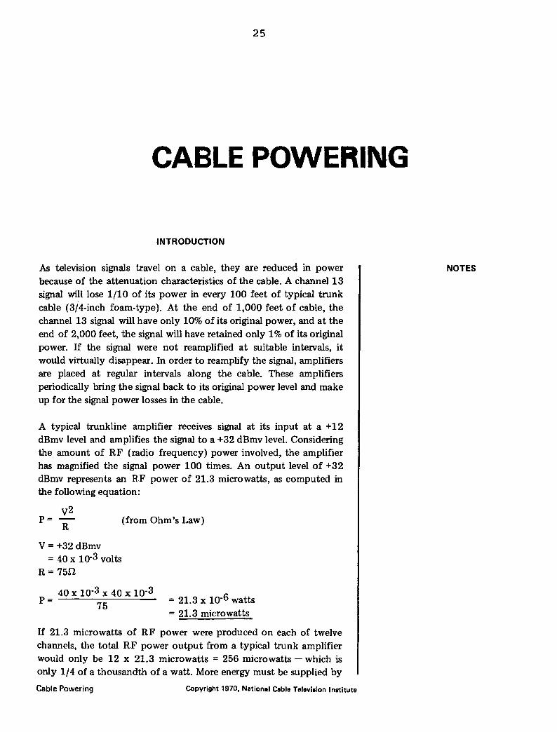
an amplifier from some kind of power supply. The function of the amplifier is to take some convenient form of electrical power, usually direct current or low frequency AC power, and convert it into RF power. The RF power output must, of course, be an amplified version of the RF power input.
ampli fied
RFin r -· ~~?~ )
:> .___A_M_P_l _l F-1-ER_..- ~~~--= "" -~
Electric power
in
Figure 1
If the amplifier were 100% efficient, that is, if it converted all of the imput electrical power into RF output, a CATV amplifier could operate for many years on the power of a small flashlight battery. CATV amplifiers are, however, very inefficient in power conversion. The electrical power input is usually many times more than the useful RF power output.
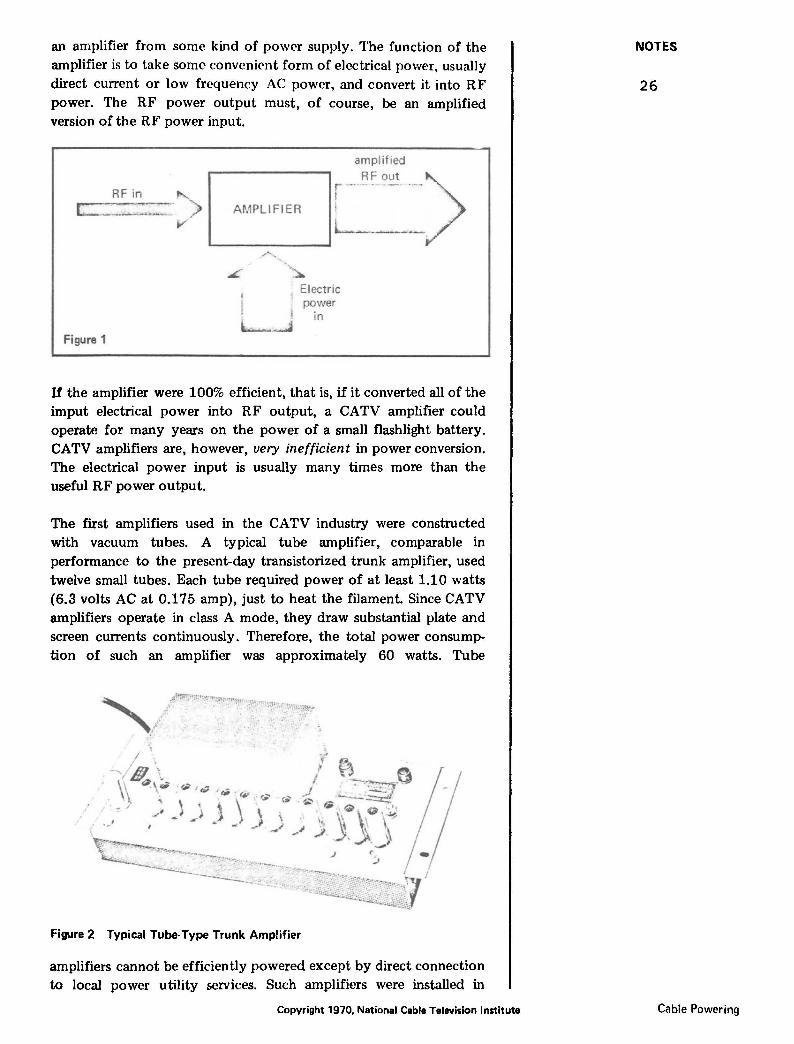
The first amplifiers used in the CATV industry were constructed with vacuum tubes. A typical tube amplifier, comparable in performance to the present-day transistorized trunk amplifier, used twelve small tubes. Each tube required power of at least 1.10 watts (6.3 volts AC at 0.175 amp), just to heat the filament. Since CATV amplifiers operate in class A mode, they draw substantial plate and screen currents continuously. Therefore, the total power consumption of such an amplifier was approximately 60 watts. Tube
Figure 2 Typical Tube-Type Trunk Amplifier
amplifiers cannot be efficiently powered except by direct connection to local power utility services. Such amplifiers were installed in
Copyright 1970, National Cable Television Institute
NOTES
26
Cable Powering

pole-mounted cahinets and were connected to the utility power system. A conventional 115-volt AC power source was required at each amplifier location.
The introduction of transistors into CATV amplifiers meant that the input electrical power requirement could be considerably reduced. Although transistors have no filament power requirement, their plate current (or the transistor equivalent of tube-plate current) requirement is still substantial. Transistors operated in linear, class A mode for CATV amplifiers use more current and lower voltages than tubes in similar applications.
.. l --~ -- I ~ r· -· -. '· ,___, - :~. 1!. ~ -. r ·. '·
~ .
Figure 3 Transistorized Trunk Amplifier (Cover Open)
The amplifier section of a modern, transistorized CATV trunk amplifier might use 20 volts DC at 200 milliamps. This is a power consumption of only 20 volts x (200/1000 amp) = 4 watts. This electrical power requirement is substantially less than the 60 watts which a comparable tube-type amplifier required, but is still too much to be supplied by a conveniently sized battery. A set of fifteen dry cells, size D, will power such an amplifier for only seventeen hours. Obviously, the electric power requirements for the CATV amplifiers must still come from the utility power lines.
Although a CATV amplifier might require only 4 watts of power (20 volts at 200 milliamps) to operate the amplifier itself, the overall power requirement for the amplifier is usually significantly higher. The DC voltage for the transistors must be well-regulated; amplifier gain and distortion characteristics depend critically on holding the internal DC voltage to a constant value. DC regulation requires a complex voltage-regulator circuit, which consumes additional power, inside each amplifier. Many regulator circuits waste as much electrical power- dissipating it as heat- as the entire amplifier section uses. CATV amplifiers receive their electrical power as .-\C. This AC power must be rectified, filtered and then regulated before it can be used in the amplifier sections. The actual electrical power input for Uw CATV trunk amplifier is usually l 5 watts (30 volts at 500 milliamps of AC power).
Cable Powering Copyright 1970, National Cable Television Institute
NOTES
27
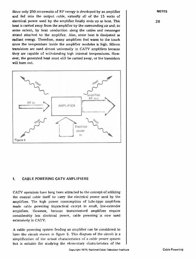
Since only 250 microwatts of RF energy is developed by an amplifier and fed into the output cable, virtually all of the 15 watts of electrical power used by the amplifier finally ends up as heat. This heat is carried away from the amplifier by the surrounding air and, to some extent, by heat conduction along the cables and messenger strand attached to the amplifier. Also, some heat is dissipated as radiant energy. Therefore, many amplifiers feel warm to the touch since the temperature inside the amplifier modules is high. Silicon transistors are used almost universally in CATV amplifiers because they are capable of withstanding high internal temperatures. However, the generated heat must still be carried away, or the transistors will burn out.
RFin > r:.:: : ~.
Figure 4
L--A-M-Pl _ _I_F_l E- R- ....... 1 il&..i· --·-·. --~-> ~
U Electr ical
power
in
I. CABLE POWERING CATV AMPLIFIERS
CATV operators have long been attracted to the concept of utilizing the coaxial cable itself to carry the electrical power used by the amplifiers. The high power consumption of tube-type amplifiers made cable powering impractical except in small, line-extender amplifiers. However, because transistorized amplifiers require considerably less electrical power, cable powering is now used extensively in CATV.
A cable powering system feeding an amplifier can be considered to have the circuit shown in figure 5. This diaf.,rram of the circuit is a simplification of the al'tual characteristics o( a cabk power system but is suitable for studying the elementary characteristics of the
Cop.,.·right 1970, National Callie Television Institute
NOTES
28
Cable Powering
Rc
G
Vs
Rs Figure 5
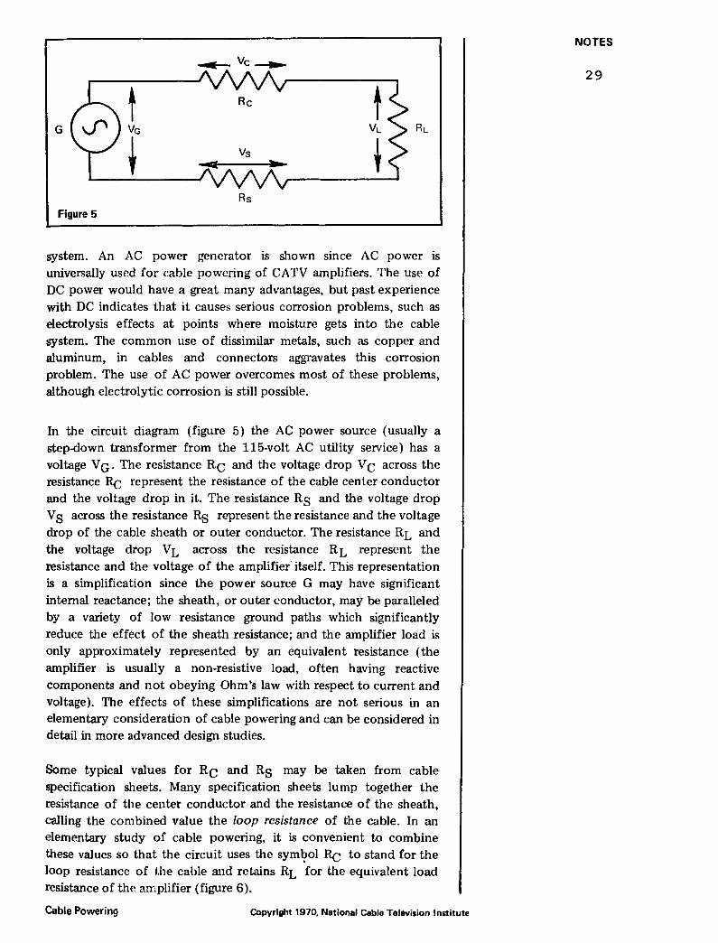
system. An AC power generator is shown since AC power is universally used for cable powering of CATV amplifiers. The use of DC power would have a great many advantages, but past experience with DC indicates that it causes serious corrosion problems, such as electrolysis effects at points where moisture gets into the cable system. The common use of dissimilar metals, such as copper and aluminum, in cables and connectors aggravates this corrosion problem. The use of AC power overcomes most of these problems, although electrolytic corrosion is still possible.
In the circuit diagram (figure 5) the AC power source (usually a step-down transformer from the 115-volt AC utility service) has a voltage V G. The resistance Rc and the voltage drop V c across the resistance Rc represent the resistance of the cable center conductor and the voltage drop in it. The resistance Rs and the voltage drop V s across the resistance Rs represent the resistance and the voltage drop of the cable sheath or outer conductor. The resistance RL and the voltage drop VL across the resistance RL represent the resistance and the voltage of the amplifier· itself. This representation is a simplification since the power source G may have significant internal reactance; the sheath, or outer conductor, may be paralleled by a variety of low resistance ground paths which significantly reduce the effect of the sheath resistance; and the amplifier load is only approximately represented by an equivalent resistance (the amplifier is usually a non-resistive load, often having reactive components and not obeying Ohm's law with respect to current and voltage). The effects of these simplifications are not serious in an elementary consideration of cable powering and can be considered in detail in more advanced design studies.
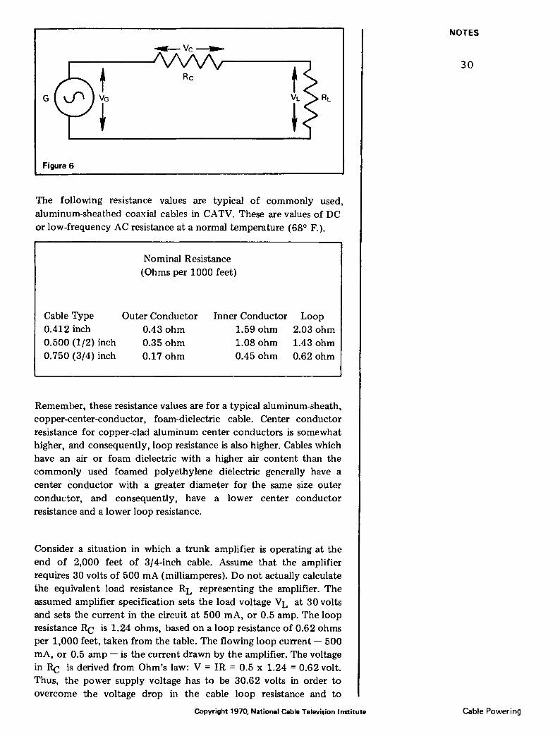
Some typical values for Rc and Rs may be taken from cable specification sheets. Many specification sheets lump together the resistance of the center conductor and the resistance of the sheath, calling the combined value the loop resistance of the cable. In an elementary study of cable powering, it is convenient to combine these values so that the circuit uses the sym~?ol Rc to stand for the loop resistance of the cable and retains RL for the equivalent load resistance of the amplifier (figure 6).
Cable Powering Copyright 1970. National Cable Television Institute
NOTES
29
~Vc~
t Rc t G VG VL RL
t t Figure 6
The following resistance values are typical of commonly used, aluminum-sheathed coa.xial cables in CATV. These are values of DC or low-frequency AC resistance at a normal temperature (68° F.).
Cable Type 0.412 inch 0.500 (1/2) inch 0.750 (3/4) inch
Nominal Resistance (Ohms per 1000 feet)
Outer Conductor 0.43 ohm 0.35 ohm 0.17 ohm
Inner Conductor 1.59 ohm 1.08 ohm 0.45 ohm
Loop 2.03 ohm 1.43 ohm 0.62 ohm
Remember, these resistance values are for a typical aluminum-sheath, copper-center-conductor, foam-dielectric cable. Center conductor resistance for copper-clad aluminum center conductors is somewhat higher, and consequently, loop resistance is also higher. Cables which have an air or foam dielectric with a higher air content than the commonly used foamed polyethylene dielectric generally have a center conductor with a greater diameter for the same size outer condudor, and consequently, have a lower center conductor resistance and a lower loop resistance.
Consider a situation in which a trunk amplifier is operating at the end of 2,000 feet of 3/4-inch cable. Assume that the amplifier requires 30 volts of 500 rnA (milliamperes). Do not actually calculate the equivalent load resistance RL representing the amplifier. The assumed amplifier specification sets the load voltage VL at 30 volts and sets the current in the circuit at 500 rnA, or 0.5 amp. The loop resistance Rc is 1.24 ohms, based on a loop resistance of 0.62 ohms per 1,000 feet, taken from the table. The flowing loop current- 500 rnA, or 0.5 amp- is the current drawn by the amplifier. The voltage in Rc is derived from Ohm's law: V = IR = 0.5 x 1.24 = 0.62 volt. Thus, the power supply voltage has to be 30.62 volts in order to overcome the voltage drop in the cable loop resistance and to
Copyright 1970, National Cable Television Institute
NOTES
30
Cable Powering

maintain 30 volts across the amplifier load. The resulting circuit will look like figure 7 with the actual values inserted.
1.24n
30V 0.5Amp
Figure 7
In actual practice the power source stays constant, and a drop in voltage at the amplifier occurs, due to the IR voltage drops in the cable loop resistance. To illustrate this more practical situation, figure 8 shows a redrawn circuit and a recalculation of the voltages.
1.24rl
0.5Amp
Figure 8
29.38 Volts
Most CATV amplifiers draw an almost constant current over their normal range of AC operating voltages. This is one of the less desirable characteristics of most CATV amplifiers and represents a departure from Ohm's law, which states that current flow is directly
proportional to applied voltage (I = E/R). This "constant current" type of behavior is due to the operation of the series regulato•· circuitry, commonly employed by CATV amplifiers.
The amplifier works well with only 29.38 volts instead of 30 volts. In fact, it could continue to work properly with only 22 volts. This wide range of AC-voltage input is handled by the regulating circuitry inside the amplifier. However, there is a minimum AC voltage at which the amplifier will operate properly. More practical examples illustrate that this minimum operating voltage is a sl'rious limiting factor in the design and operation of cable powering syst<'ms.
The preceding example (figure 8) represents the case of a CATV trunk amplifi£'r powered remotely through 2,000 feet of 3/4-inch
Cable Powering Copyright 1970, National Cable Television Institute
NOTES
31

trunk cable. This example of cable powering represents a useful and valuable application of cable powering principles. Presumably, one amplifier could be powered at the power feed point, and another amplifier could be powered a short distance away in the opposite
AMP
Figure 9
AMP
~ ELECTRIC
POWER CONNECTION
AMP
direction. Thus, three amplifiers could be powered from one utility power connection point, an advantage which would save the cost of additional circuit breakers, power meters, etc., and permit greater flexibility in system layout, since amplifiers can be located with very little regard for access to electrical utility power.
Consider a situation in which several amplifiers are powered from the same power feed point. Adding a second amplifier modifies the circuit diagram. Since most CATV amplifiers do not actually behave like resistors, their resistance symbol on the cable power circuit diagram is replaced with a triangular amplifier symbol, which represents the current consumed by an amplifier.
G
Figure 10
In figure 10, A1 and A2 are two amplifiers; I1 is the current drawn
by the first amplifier, and I 2 is the current drawn by the second amplifier; R C! is the loop resistance of the first cable section, and Rc2 is the loop resistance of the second cable section. Note that the first cable section carries the current drawn by both amplifiers. This is a v(>ry important feature of cable pow(>r systems. Cable sections closer to the power fe(>d point carry more curr(>nt than those S(>ctions further away. For a numerical example assume that both amplifiers
Copyright 1970, National Cable Television Institute
NOTES
32
Cable Powering
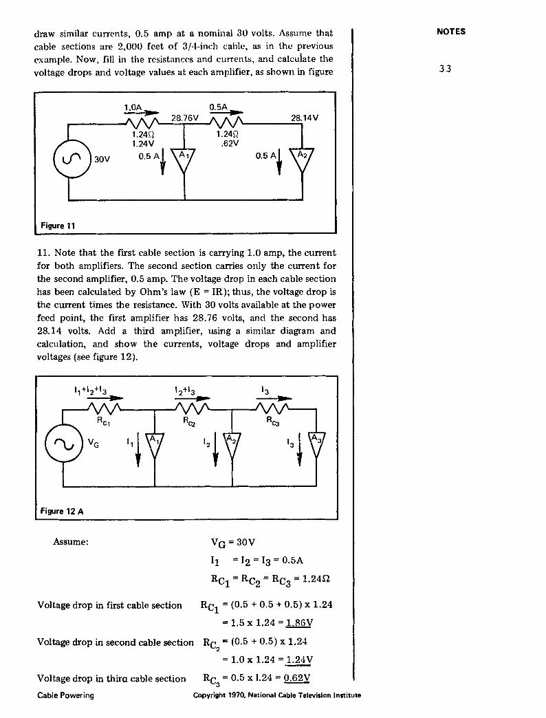
draw similar currents, 0.5 amp at a nominal 30 volts. Assume that cable sections are 2,000 feet of 3/4-inch cable, as in the previous example. Now, fill in the resistances and currents, and calcuiate the voltage drops and voltage values at each amplifier, as shown in figure
30V 0.5A~
Figure 11
11. Note that the first cable section is carrying 1.0 amp, the current for both amplifiers. The second section carries only the current for the second amplifier, 0.5 amp. The voltage drop in each cable section has been calculated by Ohm's law (E = IR); thus, the voltage drop is the current times the resistance. With ao volts available at the power feed point, the first amplifier has 28.76 volts, and the second has 28.14 volts. Add a third amplifier, using a similar diagram and calculation, and show the currents, voltage drops and amplifier voltages (see figure 12).
Figure 12 A
Assume: Va = aov 11 = 12 = Ia = 0.5A
Rcl = Rc2 =Rca= 1.24ll
Rc1
= (0.5 + o.5 + o.5) x 1.24
= 1.5 X 1.24 = 1.86V
Voltage drop in second cable section Rc = (0.5 + 0.5) x 1.24 2
Voltage drop in first cable section
Voltage drop in thira cable section
Cable Powering
= 1.0 X 1.24 = 1.24 V
Rc = o.5 x 1.24 = o.62V 3 -
Copyright 1970, National Cable Television Institute
NOTES
33

Voltage at first amplifier
Voltage at second amplifier
Voltage at third amplifier
1.5A
Figure 12 B
1.24 it
1.24V ~.
= 30.00-1.86 = 28.14V
= 28.14-1.24 = 26.90V
= 26.90-0.62 = 26.28V
Now try a more complicated situation involving several types of amplifiers and several types of cables, including feeder lines with line extender amplifiers. To simplifiy the diagram, do not show the return line from each amplifier, but use a ground symbol to show a
N ..... v
0 0 (0
Amplifiers A 1 and A 3 are trunk
amplifiers-current draw 0.5 amp. ~ Amplifier A 2 is a trunk/bridger ~ combination-current draw 1.0 g amp, Other amplifiers ate line co
extenders-current draw 0.2 amp
each. Loop resistance %-Inch ca
ble "' 0.62 ohm/1000 feet. Loop
resistance 0.412
ohms/1 000 feet.
Figure 13
ceble = 2.03 ~
~
0 0 (0
N ..... ~
8 (0
N ..... ~
8 (0
N ..... ~
0 0 (0
N ..... v
Copyright 1970, National Cable Television Institute
NOTES
34
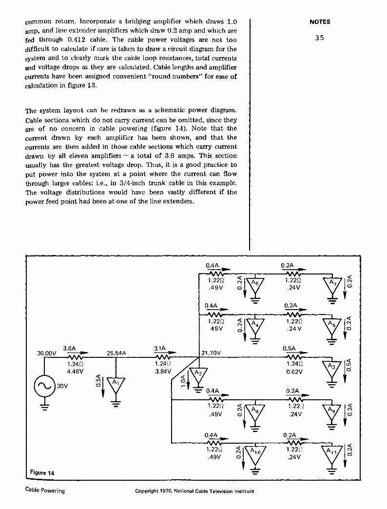
common return. Incorporate a bridging amplifier which draws 1.0 amp, and line extendN amplifiers which draw 0.2 amp and which are fed through 0.412 cable. The cable power voltages are not too difficult to calculate if care is taken to draw a circuit diagram for the system and to clearly mark the cable loop resistances, total currents and voltage drops as they are calculated. Cable lengths and amplifier currents have been ac;signed convenient "round numbers" for ease of calculation in figure 13.
The system layout can be redrawn as a schematic power diagram.
Cable sections which do not carry current can be omitted, since they are of no concern in cable powering (figure 14). Note that the current drawn by each amplifier has been shown, and that the currents are then added in those cable sections which carry current drawn by all eleven amplifiers - a total of 3.6 amps. This section usually has the greatest voltage drop. Thus, it is a good practice to put power into the system at a point where the current can flow through larger cables; i.e., in 3/4-inch trunk·cable in this example. The voltage distributions would have been vastly different if the power feed point had been at one of the line extenders.
3.6A 30.00V ... 25.54A
1.24f2 4.46V
30V ~!
Figure 14
Cable Powering Copyright 1970. National Cable Television Institute
NOTES
35
i~ --
~~ -
~~ --
~~
The techmquc for power calculation is simple and straightforward:
1. Prepare a detailed power tlow schematic diagwm showing all the amplifiers and cables which carry pow~r.
2. Mark in the cable section loop resistances and amplifier current
draws.
3. Calculate the current flow in each cable section, making sure to
sum up the currents of all the amplifiers fed through the cable for each cable section. Start from the furthest amplifiers and work back toward the power feed point.
4. Calculate the voltage drop in each cable section, and mark it on
the diagram.
5. Now, start at the power feed point and calculate the voltage at the end of each cable section by subtracting the voltage drop from the voltage at the input. Note that power often flows in a direction opposite to signal flow.
6. Check to see that each amplifier has an adequate operating voltage. Minimum operating voltage vruies among manufacturers and amplifier types. An amplifier designed for nominal
30-volt operation often performs adequately on a minimum
voltage of 22 volts.
If any amplifiers appear to be starved for voltage, some rearrange
ment is required. Low voltages will cause hum bars in the television picture and other operating problems. Thus, certain amplifiers may have to be transferred to another power feed point, taking care to avoid overloading power distribution facilities. Some power reserve must be allowed so that additional line extenders, active taps, amplified splitters, etc., can be accommodated at a future time
without overloading the cable power system.
Proceeding through the calculations for the power flow schematic diagram (figure 14), you will discover that the system will not work.
The cable power distribution system has been overloaded. There are only 21.7 volts available at amplifier A2; and if the calculation had been continued past this point, there would have been even less power available at the inputs to the line extenders. The remedy is obvious. There is a voltage drop of 4.46 volts in the first cable section. The power is reduced to 25.5 volts and has not even reached the point of connection of the heavy power load consisting of the trunk/bridger and the eight line extenders. If the power feed point were moved to amplifier At, the voltage drop in the first cable section could be saved. The cable section between the power feed point and the first amplifier would then carry power in a reverse direction to a portion of the system extending in that direction (and nor shown on these diagrams). Thus. in all of these examples, it may
Copyright 1970, National Cable Television Institute
NOTES
36
Cable Powering
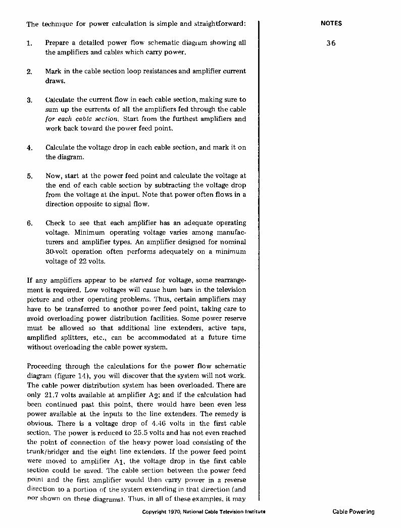
be assumed that an additional system is being powered on the other side of the power feed p()int, and possibly, another amplifier and section, directly at the feed point. A single power feed point will often send power in two, three or sometimes four directions. The type of system shown in figure 14 starves itself for voltage before it starts to run very high cun-ents. The cun-ent out of the power feed point is only 3.6 amps. Most "power feed points are capable of supplying 10 to 12 amps of power at a nominal 30 volts. In order to use the capabilities of a given power feed point efficiently, it must be placed so that it can feed power in more than one direction.
CURRENT TO ADJACENT PART OF SYSTEM
~ 30.00V
1. 24ri
3~
In figure 15 the power feed point has been relocated, as suggested by the results of calculation. The voltages of all amplifiers are now reasonable, and there is some reserve for additional power loading. Amplifier Al is now located directly at, or fairly near the power feed point. The At current drain does not affect voltage drops in the cable power system but must be added to the total current being drawn from the power feed point and taken into account when considering the total load that can be placed on this power feed point.
Thus far. we have studied the flow of electric power in CATV systems without regard to the details involved in the mixing and separation of power and RF energy, and how amplifier power supply design affects cable powering. Cable Powering Copyright 1970, National Cable Television Institute
NOTES
37
II. DIPLEXING
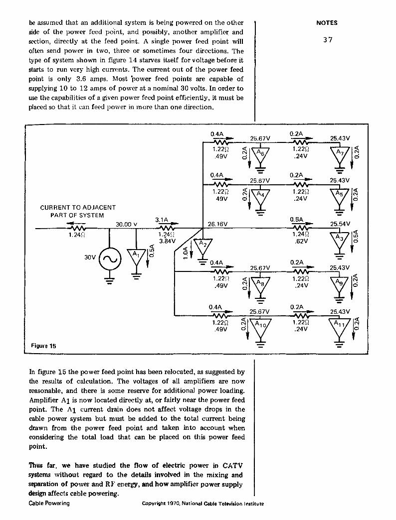
Diplexing occurs when a combination of low-pass and high-pass filters form from suitable inductances and capacitances in a simple arrangement which permits mixing (or separation) of low-frequency AC power and high-frequency RF energy.
RF 0 only ---------1
Figure 16
RF/AC
AC power only
The capacitor is chosen (usually O.Olp.F) to present a low impedance to RF, but to present a high impedance to 60 Hz power. A 0.01 p.F capacitor has a reactance of only 3.2 ohms at 5 l\.YHz, the lowest frequency that is ever expected to be handled in the RF section of a CATV system. At 50 MHz, which is a more likely lower frequency limit for CATV RF frequencies, the reactance of a O.Olp.F capacitor is only 0.32 ohms. The 0.01 p.F capacitor has a reactance of approximately 270,000 ohms at 60 Hz power line frequency. An inductance of 1 millihenry has a reactance of approximately 30,000 ohms at 5MHz, but only 0.37 ohms at power line frequency (60Hz). The reactance of this inductance rises to 300,000 ohms at the more common RF frequency of 50 MHz.
The diplexing arrangement (figure 17) can now be shown with typical values for the capacitor and inductor, with the reactance at 50 MHz and 60 Hz. The mixing and separation of RF and power can be more easily understood by following the behavior of the diplexing network at power and RF frequencies. Power will obviously follow the path of least resistance from the J;>WR to the RF/PWR terminals through the 0.37-ohm reactance of the inductor (RF choke). Power is kept from the RF terminal by the 270,000-ohm reactance of the capacitor. RF also follows the path of least resistanc.e, passing easily through the 0.32 ohm of the capacitor, but is blocked from the power terminal by the 300,000 ohms represented by the inductance. Thus, the diplexer effectively separates or combines RF and power.
Actual diplexer circuitry may differ slightly from the basic arrangement discussed here. The capacitor can be omitted, allowing RF and power to appear on both the through ports. Two inductors may be used with small capacitors to ground,' so that no RF can possibly
Copyright 1970, National Cable Television Institute
NOTES
38
Cable Powering

RF
01 pF ... RF/pwr
RF()~---~----------~~----~~----~
A
B
c
Figure 17
1mH
270,000:--1
60 Hl-
~--~-------RF--------~ .. .-
0.32~
50MH~
~ 0 0 0 a" 0 M
pwr
pwr
reach the power terminal. Such a combination may be used to permit separation of power from input and output connectors.
RF/PWR RF/PWR
I Figure 18 PWR
Cable Powering Copyright 1970, National Cable Television Institute
NOTES
39
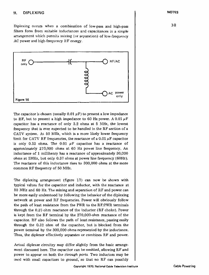
This arrangement permits greater flexibility in powering and is often used to mix power into a cable system. The two PWR connections may be joined together or fed separately.
.... IN OUT
Figure 19
The separation of power and RF at an amplifier is usually accomplished as shown in figure 19. The capacitors (usually 0.01pF) keep power from entering the RF amplifier circuitry. Power is directed through the inductors to terminals 2 and 3. A system of links or jumpers is usually provided so that the flow of power into and through the amplifier can be controlled. If terminals 1, 2 and 3 are connected, the power will flow through the amplifier housing in either direction and will energize the internal power supply through the fuse. If only terminals 1 and 2 are connected, power will flow from the input connector to the internal power supply. If only terminals 1 and 3 are connected, power will flow from the output connector to the internal power supply. Some amplifiers provide an additional connector which can be linked to terminals 1, 2 and 3 to permit power to be added from an external source at the amplifier location. The amplifier then serves to mix power into the cable system. Bypass capacitors are frequently added in the "power only" sections of the circuitry to effectively short out any RF that may have found its way through the inductors.
Ill. AMPLIFIER POWER SUPPLIES
The purpose of cable power is to provide the energy for the RF amplifier. The amplifier power supply must change the AC cable power to DC of the proper polarity and provide adequate filtering and regulation. Some amplifiers require DC voltages of both polarities. Most require voltages of only one polarity, either positive or negative with respect to ground, depending on the details of circuit design and the types of transistors usC'd. The DC supply for the amplifier must be well-regulated, since amplifier gain will change if the DC supply voltage changes. The DC supply must also be well-filtered; thus, for practical purposes, the DC is pure. A typical
Copyright 1970, National Cable Television Institute
NOTES
40
Cable Powering
well-filtered CATV amplifier power supply will have less than 5 millivolts (RMS) ripple in a 20-volt DC supply.
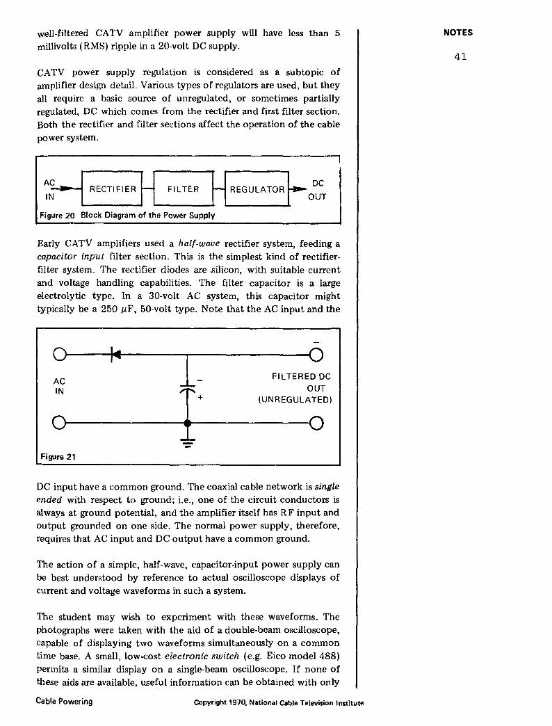
CATV power supply regulation is considered as a subtopic of amplifier design detail. Various types of regulators are used, but they all require a basic source of unregulated, or sometimes partially regulated, DC which comes from the rectifier and first filter section. Both the rectifier and filter sections affect the operation of the cable power system.
~~ -I RECTIFIER H FILTER H REGULATOR~ ODU~ Figure 20 Block Diagram of the Power Supply
Early CATV amplifiers used a half-wave rectifier system, feeding a capacitor input filter section. This is the simplest kind of rectifierfilter system. The rectifier diodes are .silicon, with suitable current and voltage handling capabilities. The filter capacitor is a large electrolytic type. In a 30-volt AC system, this capacitor might typically be a 250 J-LF, 50-volt type. Note that the AC input and the
0 , ...
I- 0 AC
FILTERED DC
IN I+ OUT (UNREGULATED)
0 0
Figure 21
DC input have a common ground. The coaxial cable network is single ended with respect to ground; i.e., one of the circuit conductors is always at ground potential, and the amplifier itself has RF input and output grounded on one side. The normal power supply, therefore, requires that AC input and DC output have a common ground.
The action of a simple, half-wave, capacitor-input power supply can be best understood by reference to actual oscilloscope displays of current and voltage waveforms in such a system.
The student may wish to experiment with these waveforms. The photographs were taken with the aid of a double-beam oscilloscope, capable of displaying two waveforms simultaneously on a common time base. A small, low-cost electronic switch (e.g. Eico model 488) permits a similar display on a single-beam oscilloscope. If none of these aids are available, useful information can be obtained with only
Cable Powering Copyright 1970, National Cable Television lnstitutl!
NOTES
41

a singlc-hf'am oscilloscope of moderate capability. The arrangement shown in figure 22 was used to observe voltage and current waveforms.
Figure 22
-coRF I
A conventional cable power transformer has been modified to permit observation of current waveforms. The low end of the transformer secondary is connected to ground through a 1-ohm resistor. The voltage appearing across this re~istor represents the cable power current. The voltage from the test point shown can be displayed on an oscilloscope as representing the cable power current. If a calibrated oscilloscope is used, the peak current can be determined, since the voltage is developed across a known resistance- 1 ohm in this case. A resistance is inserted in series with the main power feed to the amplifier being examined. Since these demonstrations are usually made without the presence of RF, this resistor can be a wire-wound power type. A value of 10 or 20 ohms is convenient. Although this value is greater than cable resistances in actual systems, it permits the effects of cable resistance to be more easily demonstrated by exaggeration. The two voltage test points, Vp and V A• permit observation of voltage at both the power supply and the an1plifier. Do not try to observe current waveforms across the resistance representing the cable. Both ends of this resistance are at a voltage above ground. Connecting this resistor to an oscilloscope will short out the cable power supply and blow the fuses. Using a current sensing resistor, as shown in the secondary ground return, permits observation of current at a point which has one side grounded. Current can also be observed by using a clip-on type of ammeter or current transformer in the power lead, but this type of current observation is difficult to calibrate.
The scope photograph (figure 23) shows the voltage from a cable power feed transformer, rated at a nominal 30 volts AC. Vertical calibration is 20 volts per division, and the voltage wave is seen to have negative and positive peaks of <10 volts with respect to ground. If the AC voltage were precisely 30 volts H!\1S (root mean square), Wf' would cxpc'ct peaks which arc 1AU limPs the R!\lS voltage, or 42.4 volts in this case.
Copyright 1970. National Cable Television Institute
NOTES
42
Cable Powering

~- · · · -
+40
+"11 c..~
- . I 0
j -2C
I -40
I
I L .· ~
Figure 23
It is the nature of capacitor input filter systems that current flows into the filter capacitor in short pulses. AC voltage is always present, but current flows in the cable for only short periods of time, during which the instantaneous voltage exceeds the capacitor voltage. For the remaining time no current, and hence, no energy, flows in the cable. In the case of half-wave powering, only half of each cycle is used to power the amplifier. In the example shown (figure 24) only the negative half cycle of AC voltage is used by the power supply. Current and waveform are shown in this photograph. The power
l
Figure 24
] ______ _j
CURRENT
VOLTAGE
supply is a negative, half-wave, capacitor input supply in a small, cable-powered active tap. Note that current flows only during the negative half cycle, and also that the current waveform is a narrow pulse. Since voltage drop in the cable can occur only when current
flows, the negative half cycle shows some observed distortion at the amplifier because of voltage drop in the cable during the current "pulst•". The positive half cycle is not affected, since no current
Cable Powering Copyright 1970, National Cable Television Institute
NOTES
43
flows during the positive half cycle. The current flow shows positive polarity because of the position of the current-monitoring resistor in the circuit.
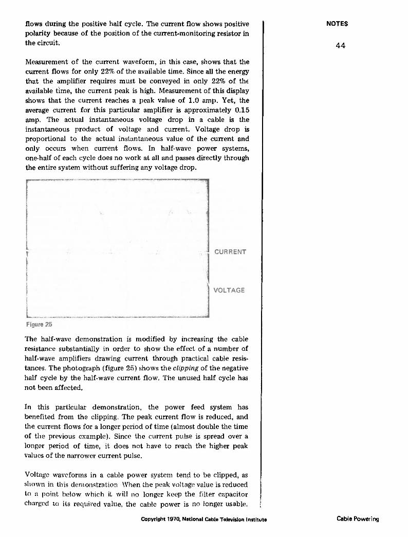
Measurement of the current waveform, in this case, shows that the current flows for only 22% of the available time. Since all the energy that the amplifier requires must be conveyed in only 22% of the available tlme, the current peak is high. Measurement of this display shows that the current reaches a peak value of 1.0 amp. Yet, the average current for this particular amplifier is approximately 0.15 amp. The actual instantaneous voltage drop in a cable is the instantaneous product of voltage and current. Voltage drop is proportional to the actual instantaneous value of the current and only occurs when current flows. In half-wave power systems, one-half of each cycle does no work at all and passes directly through the entire system without suffering any voltage drop.
~ I I L __ Figure 25
l CURRENT
~---·J VOLTAGE
The half-wave demonstration is modified by increasing the cable resistance substantially in order to show the effect of a number of half-wave amplifiers drawing current through practical cable resistances. The photograph (figure 25) shows the clipping of the negative half cycle by the half-wave current flow. The unused half cycle has not been affected.
In this particular demonstration, the power feed system has benefited from the clipping. The peak current flow is reduced, and lhe current flows for a longer period of time (almost double the time of the previous example). Since the current pulse is spread over a longer period of time, it does not have to reach the higher peak values of the narrower current pulse.
Voltage waveforms in a cable power system tenp to be clipped, as shown in this demonstration When the peak voltage value is reduced to a point below which it will no longer keep the filter capacitor charged to its required value, the cable power is no longer usable.
Copyright 1970, National Cable Television Institute
NOTES
44
Cable Powering
Amplifiers, at this point in the system, will start to show excessive hum in the television picture, and the regulators in the power supplies will not function property.
An ordinary AC voltmeter, used to check cable power in such a case, will not indicate the true situation. Most AC voltmeters are rectifier-type instruments which indicate average voltage. The average voltage in the clipped example is still high because of the presence of the unused, positive half cycles. If the voltmeter is a half-wave type, it might be reading either the positive or negative half cycle, depending on the way the leads are connected to the circuit. In such a case different readings are made; neither of which is correct.
IV. FULL-WAVE POWER
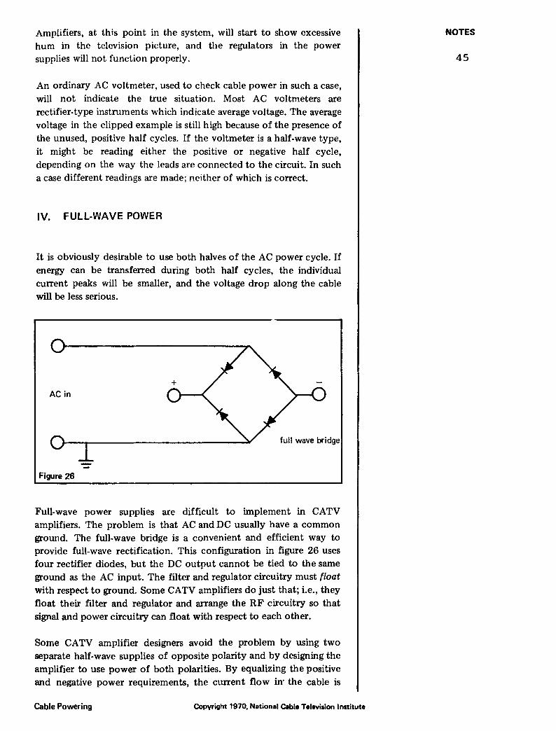
It is obviously desirable to use both halves of the AC power cycle. If energy can be transferred during both half cycles, the individual current peaks will be smaller, and the voltage drop along the cable will be less serious.
AC in
full wave bridge
Figure 26
Full-wave power supplies are difficult to implement in CATV amplifiers. The problem is that AC and DC usually have a common ground. The full-wave bridge is a convenient and efficient way to provide full-wave rectification. This configuration in figure 26 uses four rectifier diodes, but the DC output cannot be tied to the same ground as the AC input. The filter and regulator circuitry must float
with respect to ground. Some CATV amplifiers do just that; i.e., they float their filter and regulator and arrange the RF circuitry so that signal and power circuitry can float with respect to each other.
Some CATV amplifier designers avoid the problem by using two separate half-wave supplies of opposite polarity and by designing the amplifier to use power of both polarities. By equalizing the positive and negative power requirements, the current flow in· the cable is
Cable Powering Copyright 1970, National Cable Television Institute
NOTES
45
k0pt halanced. This approat:h is expensive, since it requires two complete power supplies- one for each polarity.
AC in +
+
Figure 27
+
reg. DC out
reg. DC out REGULATOR
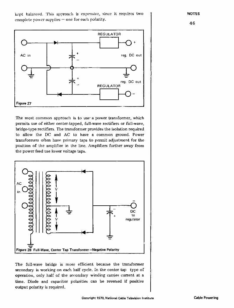
The most common approach is to use· a power transformer, which permits use of either center-tapped, full-wave rectifiers or full-wave, bridge-type rectifiers. The transformer provides the isolation required to allow the DC and AC to have a common ground. Power transformers often have primary taps to permit adjustment for the position of the amplifier in the line. Amplifiers further away from the power feed use lower voltage taps.
regulator
Figure 28 Full-Wave, Center Tap Transformer-Negative Polarity
The full-wave bridge is more efficient because the transformer secondary is working on each half cycle. In the center tap type of operation, only half of the secondary winding carries current at a
time. Diode and capacitor polarities can be reversed if positive
output polarity is required.
Copyright 1970, National Cable Television Institute
NOTES
46
Cable Powering
AC
f in
v to
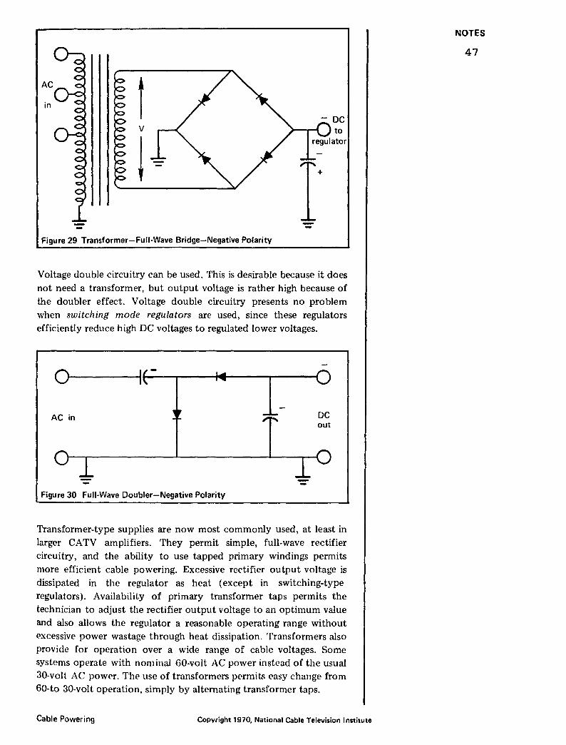
! Figure 29 Transformer-Full-Wave Bridge-Negative Polarity
Voltage double circuitry can be used. This is desirable because it does not need a transformer, but output voltage is rather high because of the doubler effect. Voltage double circuitry presents no problem when switching mode regulators are used, since these regulators efficiently reduce high DC voltages to regulated lower voltages.
o~----~1~---~--~--~--~
AC in DC out
Figure 30 Full-Wave Doubler-Negative Polarity
Transformer-type supplies are now most commonly used, at least in larger CATV amplifiers. They permit simple, full-wave rectifier circuitry, and the ability to use tapped primary windings permits more efficient cable powering. Excessive rectifier output voltage is dissipated in the regulator as heat (except in switching-type regulators). Availability of primary transformer taps permits the technician to adjust the rectifier output voltage to an optimum value and also allows the regulator a reasonable operating range without t:>xcessive power wastage through heat dissipation. Transformers also provide for operation over a wide range of cable voltages. Some systems operate with nominal 60-volt AC power instead of the usual 30-volt AC power. The use of transformers permits easy change from 60-to 30-volt operation, simply by alternating transformer taps.
Cable Powering Copyright 1970, National Cable Television Institute
NOTES
47
Full-wave operation of CATV amplifier power supplies has the advantages of permitting more efficient use of the cable for carrying power and guaranteeing the maintenance of symmetrical cable power waveform. If positive and negative cycles become different in voltage, there might be a tendency for corrosion to develop at splices and connectors.
Direct current would be the most efficient way to carry power on the cable, power would flow smoothly and continuously. Amplifiers would not need rectifiers and filters but would still require good voltage regulation. It would be easy to provide stand-by power in case of utility company power failure- a simple storage battery would be sufficient. However, DC powering is not used because of the great danger of corrosion at connectors and fittings, due to electrolytic effects. DC in the presence of moisture can act as an electroplating current and can cause serious damage to CATV plant.
V. WAVEFORMS IN FULL-WAVE POWER SYSTEMS
VOLTAGE / ' ' ',
CURRENT .. ·'·' .. ~
r ~, . .. "l
, I
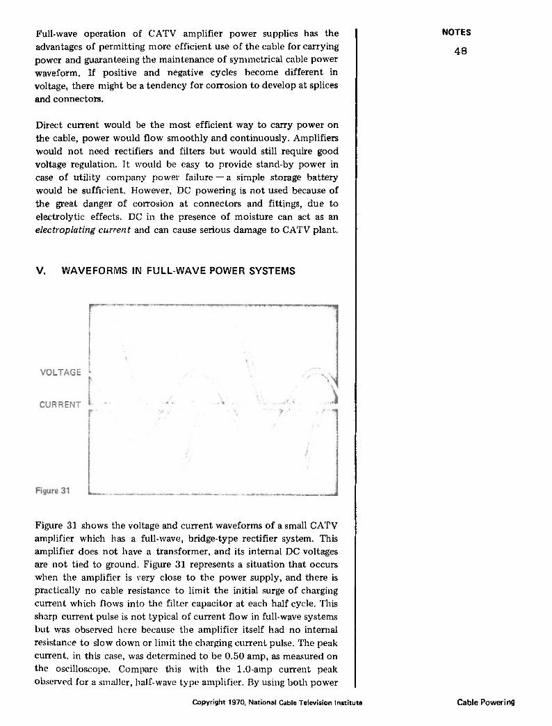
Figure 31
Figure 31 shows the voltage and current waveforms of a small CATV amplifier which has a full-wave, bridge-type rectifier system. This amplifier does not have a transformer, and its internal DC voltages are not tied to ground. Figure 31 represents a situation that occurs when the amplifier is very close to the power supply, and there is practically no cable resistance to limit the initial surge of charging current which flows into the filter capacitor at each half cycle. This sharp current pulse is not typical of current flow in full-wave systems but was observed here because the amplifier itself had no internal resistance to slow down or limit the charging current pulse. The peak current. in this case, was determined to be 0.50 amp, as measured on the oscilloscope. Compare this with the 1.0-amp current peak observed for a smaller, half-wave type amplifier. By using both power
Copyright 1970, National Cable Television Institute
NOTES
48
Cable Powering

half cycles, the power supply is more efficient, and individual current pulses are smallPr since there are twice as many of them. Since there is no significant cable resistance involved, there is no change in the voltage waveform.
When a resistor was used to simulate the effect of cable resistance, the waveforms changed somewhat. Note that the current pulse is smaller but wider, and that the voltage waveform is distorted by the effect of voltage drop in the cable resistance during the period of current flow. The waveforms are still symmetrical; i.e., positive and negative half cycles are the same. However, the current peak has been reduced to 0.26 amp.
.'
Figure 32
VOLTAGE
l CURRENT
When a transformer is used in a CATV amplifier, the current waveform shows two components. One component is the current which flows through the rectifier diodes into the amplifier and supplies energy to the amplifier. The other component is out-of-
VOLTAGE
CURRENT
Figure 33
Cable Powering
,· j
____ _._ ... __ ""'~-~--~--.... -- ----...111 Copyright 1970, National Cable Television Institute
NOTES
49
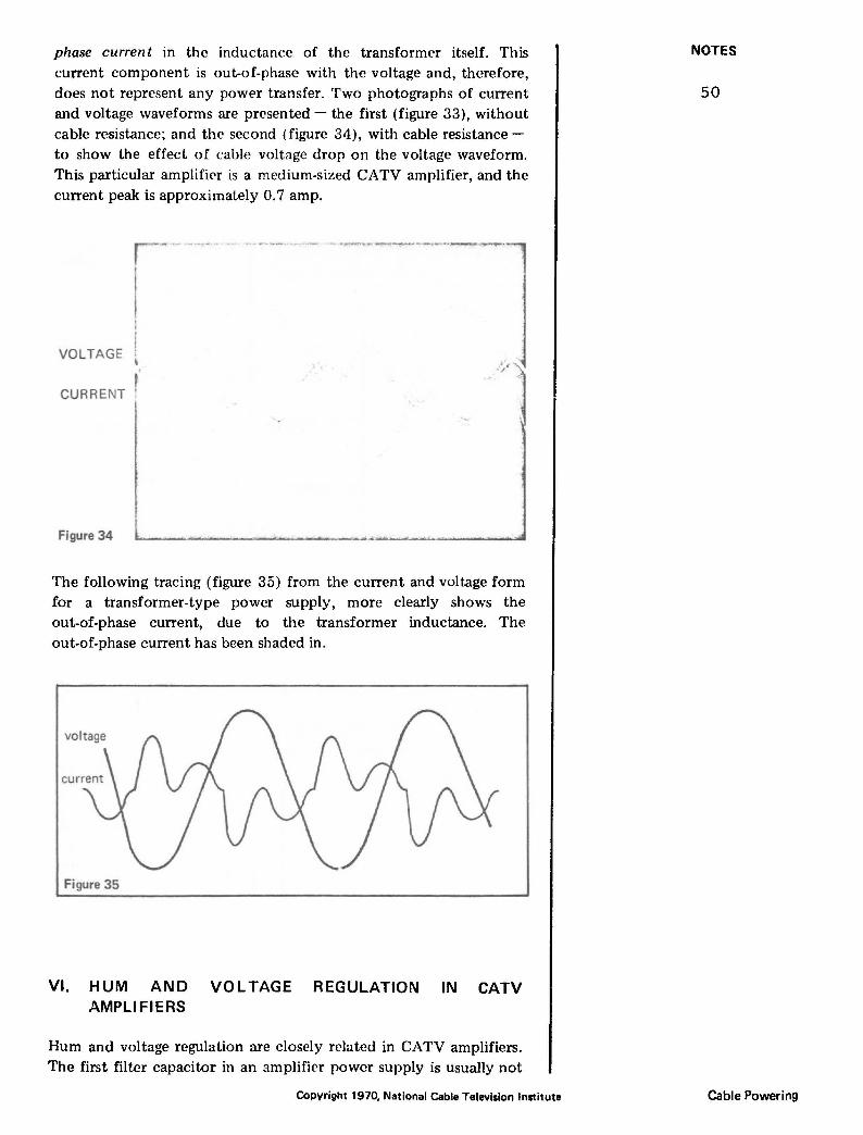
phase current in the inductance of the transformer itself. This current component is out-of-phase with the voltage and, therefore, does not represent any power transfer. Two photographs of current and voltage waveforms are presented- the first (figure 33), without cable resistance; and the second (figure 34), with cable resistance -to show the effect of cable voltage drop on the voltage waveform. This particular amplifier is a medium-sized CATV amplifier, and the current peak is approximately 0. 7 amp.
VOLTAGE
CURRENT
Figure 34
The following tracing (figure 35) from the current and voltage form for a transformer-type power supply, more clearly shows the out-of-phase current, due to the transformer inductance. The out-of-phase current has been shaded in.
Figure 35
VI. HUM AND VOLTAGE REGULATION IN CATV AMPLIFIERS
Hum and voltage regulation are closely related in CATV amplifiers. The first filter capacitor in an amplifier power supply is usually not
Copyright 1970. National Cable Television Institute
NOTES
50
Cable Powering

big enough to provide the required amount of hum filtering. Consider an amplifier whose internal power supply must provide 20 volts DC at 200 milliamps. A 250 p. F filter capacitor is typical in such a power supply. Reference to design charts, available for detailed study of capacitor input filter systems, shows that such a filter will still have 57c ripple, which is intolerable in a CATV amplifier. This 5% ripple is further reduced to a more acceptable 0.1% level by the action of the regulator section. The regulator holds the DC voltage to a desired level and reduces hum by treating it as a form of voltage irregularity that must be removed from the DC supply. The regulator follows the individual ripple cycles and smooths them out, just as it smooths out voltage irregularities from other causes.
The detailed study of voltage regulators in CATV amplifiers is
beyond the scope of this lesson, but the student will benefit from understanding the simplest and most common type of regulator, the series-controlled type. Figure 36 is a simplified schematic diagram of
AC
in
Figure 36
regulated r---.......: .... oc
output
part of a series-regulated power supply. This diagram shows a transformer feeding a full-wave, bridge-type rectifier and a large filter capacitor. The capacitor might typically be 250 p.F with a 50- or 75-volt rating. Ql is a large, power-type transistor which regulates the flow of current from the filter capacitor to the amplifier. Its base is controlled by circuitry, which senses the output voltage, compares it with a standard voltage (usually a zener diode), and develops an error voltage which controls the base of the series-control transistor Q1. The difference between the raw DC at the collector of Q1 and the regulated DC at the emitter, is dissipated as heat in the transistor. A lesser amount of heat is also generated in the transistors and circuitry in the regulator control section. The control transistor Q1 must have some working voltage between its collector and emitter in order to function properly. If the raw DC at the collector falls too low, the regulator will not effectively filter out the residual hum; thus, hum bars will appear in the television pictures passing through this amplifier. If the raw DC voltage at the collector is too great, the power dissipation capability of the control transistor will be exceeded and, thus, will burn out.
The most common problem is that the voltage at the collector of Ql
Cable Powering Copyright 1970. National Cable Television Institute
NOTES
51

falls too low because of excessive voltage drops in the cable system, usually caused by too many amplifiers or cable runs which are too long. This low voltage of Ql nearly always appears as hum bars in the television picture. The situation is difficult to check with AC voltmeters, since we have sC'en that ordinary AC voltmeters can be misleading because of the way in which voltage waveforms change in the cable power system. The most reliable check of the performance of the cable power system is to check the voltage available at the collector of. the regulator transistor. In many amplifiers this transistor is accessible for voltage measurements, and the collector is nearly always the outer covering of the transistor. A voltage check (DC) at this point is most meaningful. 1\lany manufacturers provide instructions for making this voltage check. The voltage of some amplifiers is read with respect to ground. In other types (floating power supplies), the voltage is read with respect to a B- (B minus) terminal (not ground). Most manufacturers recommend a minimum of 6 or 7 volts between the collector and emitter of the control transistor. This voltage can be read by direct measurement between these transistor terminals, if they are accessible, or by measurement of the collector voltage to the power supply ground and comparison to the regulated output voltage. High voltages across the transistor are permissible, but they represent wasted power, since the voltage difference is dissipated in the transistor. The manufacturer's recommendation should be observed in this respect. If the manufacturer has not provided recommendations or instructions for voltage check, a procedure should be set up by the system's chief technician.
Remember, the DC at the collector of the control transistor is
important; not the AC voltage that a meter might show on the cable test point. When in doubt, check the DC at the regulator section, which shows the peak DC that the available AC is capable of developing in the amplifier.
If the power supply in the amplifier is not accessible for checking DC voltage, the technician may wish to build a power supply simulator, using the same components that are used in the amplifier itself, but without the regulator, since the technician is interested in checking the DC available to the regulator. When an amplifier uses a transformer with primary taps, a full-wave bridge, and a filter capacitor, the circuitry might look like figure 37. This circuit (which
AC
in +
I Figure 37
Copyright 1970, National Cable Television Institute
NOTES
52
Cable Powering
happens to use +DC internally) is intended to duplicate the circuitry and components in an actual amplifier. A DC meter reads the DC voltage available when the AC input is connected by test jumpers to the available AC. "C" can actually be much smaller than the filter capacitor in the amplifier, since there is practically no load on this test power supply. "R" is intended only as a bleeder and can be as much as 100,000 ohms. The meter that is used will carry at least a 20,000-ohm load. "C" could then be approximately 1 J.LF, or even 0.25 p.F. Such a test jig would be used in cases where the amplifier power supply is not easily accessible for voltage measurement.
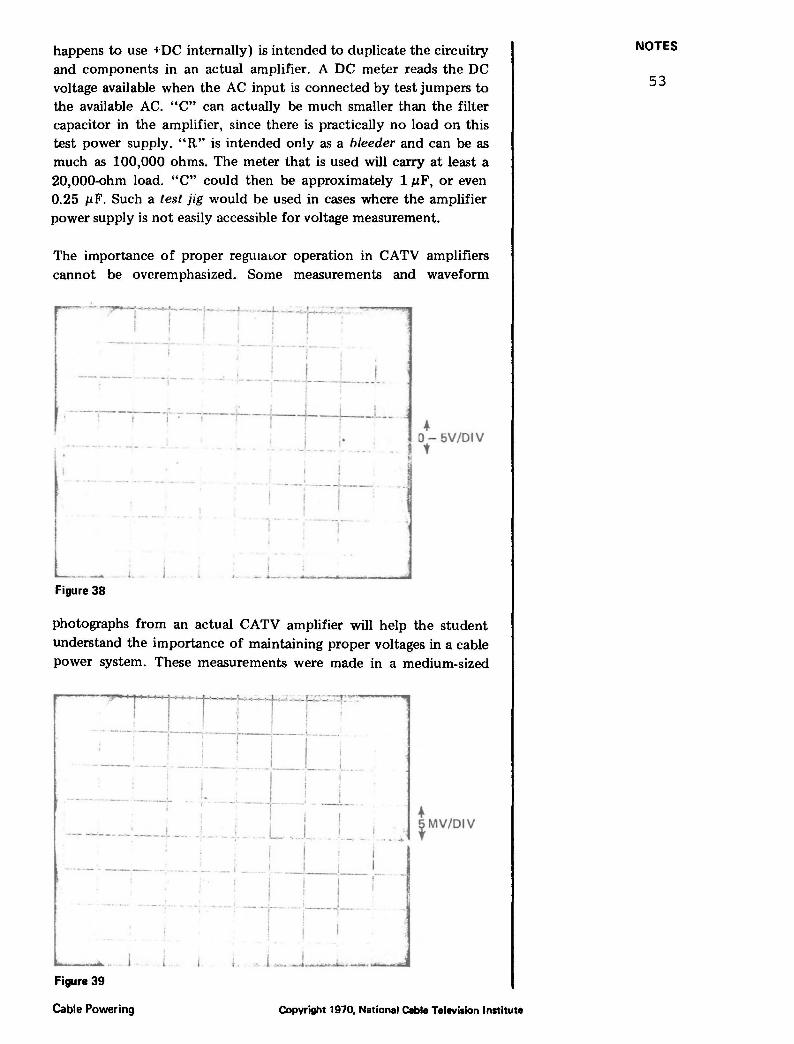
The importance of proper regmawr operation in CATV amplifiers cannot be overemphasized. Some measurements and waveform
.· -- ----'--· -------
~ . --·--,- --! T7 -.-- --i-- '--+ -+-- .:_ __ I
_L - r'
... 0- SV/DIV
' t
.. l
·-- ~--~-------~ Figure 38
photographs from an actual CATV amplifier will help the student understand the importance of maintaining proper voltages in a cable power system. These measurements were made in a medium-sized
, ~-~r--·-r-~-~~-·-:· · · I I ' i ;. ---·--!-··:---!-·--,---,·----;
----- -.- - --· I I I I -·· -,-- - -- ~ · ····
--·-- I . I ~ -,-·· --. I I
.L ... L -- ---- - ...... .._ ' _, ____ t ____ I
. - ... ... ~ MV/DIV
- I
I I I I ·- _. __ , __ ---1 I I ~ I
- ... :·--·- :~---~-- -j I
......... .. figure 39
Cable Powering Copyright 1970, National Cable Television Institute
NOTES
53
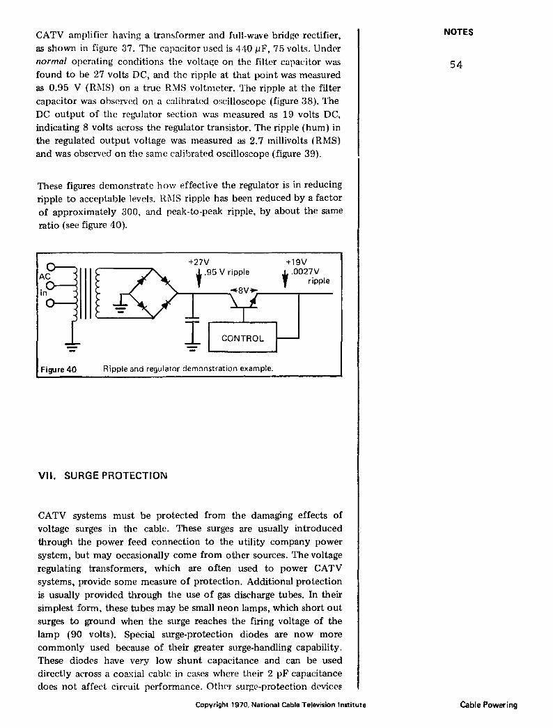
CATV amplifier having a transformer and full-wave bridge rectifier, as shown in figure 37. The capacitor used is 4-10 pF, 75 volts. Undcr normal operating conditions the voltage on the filter capacitor was found to be 27 volts DC, and the ripple at that point was measured as 0.95 V (Rl\lS) on a true RMS voltmeter. The ripple at the filter capacitor was observed on a calibrated oscilloscope (figure 38). The DC output of the regulator section was measured as 19 volts DC, indicating 8 volts across the regulator transistor. The ripple (hum) in the regulated output voltage wa<; measured as 2. 7 millivolts (RMS) and was observed on the same calibrated oscilloscope (figure 39).
These figures demonstrate how effective the regulator is in reducing ripple to acceptable levels. Rl\fS ripple has been reduced by a factor of approximately 300, and peak-to-peak ripple, by about the same ratio (see figure 40).
+27V
CONTROL
Figure 40 Ripple and regulator demonstration example.
VII. SURGE PROTECTION
+19V
t .0027V ripple
CATV systems must be protected from the damaging effects of voltage surges in the cable. These surges are usually introduced through the power feed connection to the utility company power system, but may occasionally come from other sources. The voltage regulating transformers, which are often used to power CATV systems, provide some measure of protection. Additional protection is usually provided through the use of gas discharge tubes. In their simplest form, these tubes may be small neon lamps, which short out surges to ground when the surge reaches the firing voltage of the lamp (90 volts). Special surge-protection diodes are now more commonly used because of their greater surge-handling capability. These diodes have very low shunt capacitance and can be used directly across a coa.xial cable in cases where their 2 pF capacitance does not affect circuit performance. OthC'r surge-protection devices
Copyright 1970, National Cable Television Institute
NOTES
54
Cable Powering
are sometimes used. These operate by shorting the surge to ground before it can harm the equipment.
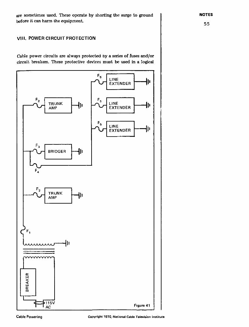
VIII. POWER CIRCUIT PROTECTION
Cable power circuits are always protected t>y a series of fuses and/or circuit breakers. These protective devices must be used in a logical
a: w ~ <( w a: co
F2
F 3
Cable Powering
TRUNK I• AMP
BRIDGER I•
TRUNK AMP h
Fs LINE EXTENDER I•
LINE I• EXTENDER
LINE EXTENDER I•
Figure 41
Copyright 1970, National Cable Television Institute
NOTES
55
manner in order for them to do their job properly. Generally speaking, fuse or circuit breaker values increase along the power circuitry from the most distant equipment back toward the power source. This gradual increase prevents a minor problem on a sub-distribution linl' from blowing fuses at critical points in the system, thus disrupting service to large portions of the system when it should have affected only a small part of the system.
Consider a simplified schematic diagram of a portion of a cable power layout (figure 41 ). The main fuse F1 must be capable of carrying all the current to be drawn from the power feed. This fuse is backed up by a circuit breaker or a fuse on the primary side of the cable power transformer. The primary breaker protects the utility company system against any kind of short circuit in the cable system or in the power feed transformer. Fuses F2 and F3 protect individual main line amplifiers. If any of these amplifiers develop a short, the fuse within the amplifier will blow. Obviously, these fuses must be lower in value than F1; otherwise, a short in the furthest trunk amplifier would blow F1, the main fuse, before it blows its own amplifier fuse. Everything connected to that power feed would then be off. If only F2 blew, then at least part of the system would still b.e
working.
F 4 is also considered to be a main fuse, since it protects a whole distlibution line with several line extenders. The fuses in each line extender (F5) must be lower in value than F4; otherwise, a short in the furthest line extender would blow the main distribution line fuse and then blow the rest of the fuses on the entire line.
Thus, we see that the size of the fuses must be carefully controlled and designed with regard to the nature of the device or system being protected. Fuses must be graded in size in order to provide a logical chain of protection to the system.
Tracing of short cucuits in a cable power system can be difficult and time consuming. If the fusing has been logically designed, knowing the position of the blown fuse in the system can be helpful. If the main fuse F1 has blown, it is unlikely that the short is in an individual amplifier or on one of the distribution legs, since these are all protected with fuses smaller than the main fuse F1. Similarly, if one of the distribution line fuses (F 4) has blown, it is unlikely to be
one of the line extenders, since these are individually protected by fuses smaller than F 4· If the fault had been in one of the line extenders, its own fuse should have blown before the next major fuse preceding it. This emphasizes the importance of proper planning of fusing, and the importance of replacing fuses with the proper values when they need replacement.
A lwlpful device for locating short circuits is a small light bulb attadwd to a dummy fusP. A 32-volt, 10-watt (or even lower
Copyright 1970, National Cable Television Institute
NOTES
56
Cable Powering
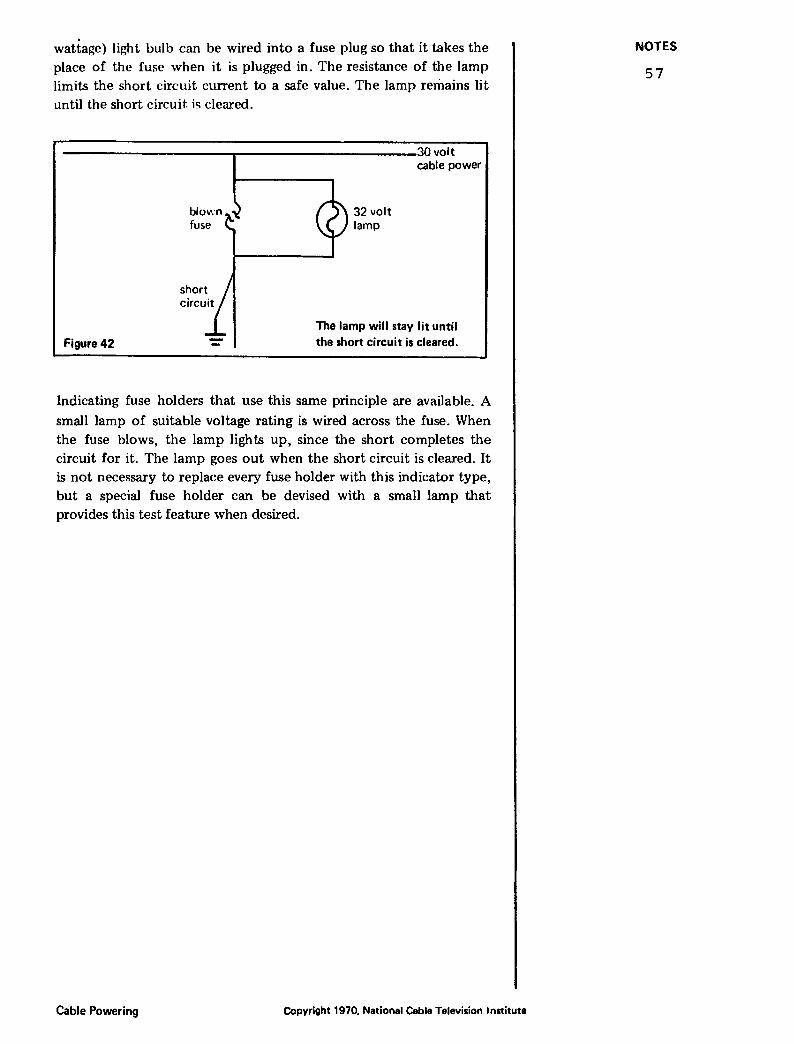
wattage) light bulb can be wired into a fuse plug so that it takes the place of the fuse when it is plugged in. The resistance of the lamp limits the short circuit current to a safe value. The lamp remains lit until the short circuit. ic; cleared.
----------------------~----------------------30volt
Figure 42
32 volt lamp
cable power
The lamp will stay lit until the short circuit is cleared.
Indicating fuse holders that use this same principle are available. A
small lamp of suitable voltage rating is wired across the fuse. When the fuse blows, the lamp lights up, since the short completes the circuit for it. The lamp goes out when the short circuit is cleared. It is not necessary to replace every fuse holder with this indicator type, but a special fuse holder can be devised with a small lamp that provides this test feature when desired.
Cable Powering Copyright 1970, National Cable Television Institute
NOTES
57