Service Manual, 40-65COZ, 33-50CFOZ (TP-5737)
148
Marine Generator Sets Models: 40COZ/33CFOZ, 40EOZ/33EFOZ 50COZ/40CFOZ, 50EOZ/40EFOZ 65COZ/50CFOZ, 65EOZ/55EFOZ 80EOZ/70EFOZ, 99EOZ/80EFOZ 125EOZ/100EFOZ, 150EOZ/125EFOZ Controllers: Decision-Makert 3+ Decision-Makert 1 Standard Decision-Makert 1 Expanded TP-5737 5/01b Service
-
Upload
khangminh22 -
Category
Documents
-
view
0 -
download
0
Transcript of Service Manual, 40-65COZ, 33-50CFOZ (TP-5737)

Marine Generator Sets
Models:
40COZ/33CFOZ, 40EOZ/33EFOZ50COZ/40CFOZ, 50EOZ/40EFOZ65COZ/50CFOZ, 65EOZ/55EFOZ80EOZ/70EFOZ, 99EOZ/80EFOZ
125EOZ/100EFOZ, 150EOZ/125EFOZ
Controllers:Decision-Maker� 3+
Decision-Maker� 1 StandardDecision-Maker� 1 Expanded
TP-5737 5/01b
Service

Product Identification Information
Product identification numbers determine service parts.
Record the product identification numbers in the spaces
below immediately after unpacking the products so that
the numbers are readily available for future reference.
Record field-installed kit numbers after installing the
kits.
Generator Set Identification Numbers
Record the product identification numbers from the
generator set nameplate(s).
Model Designation
Specification Number
Serial Number
Accessory Number Accessory Description
Engine Identification
Record the product identification information from the
engine nameplate.
Manufacturer
Model Designation
Serial Number

Table of Contents
TP-5737 5/01 Table of Contents
Product Identification Information Inside front cover. . . . . . . . . . . . . . . . . . . . . . . . . . . . . . . . . . . . . . . . . . . .
Safety Precautions and Instructions I. . . . . . . . . . . . . . . . . . . . . . . . . . . . . . . . . . . . . . . . . . . . . . . . . . . . . . . .
Introduction i. . . . . . . . . . . . . . . . . . . . . . . . . . . . . . . . . . . . . . . . . . . . . . . . . . . . . . . . . . . . . . . . . . . . . . . . . . . . . . .
Service Assistance i. . . . . . . . . . . . . . . . . . . . . . . . . . . . . . . . . . . . . . . . . . . . . . . . . . . . . . . . . . . . . . . . . . . . . . . .
Section 1 Specifications 1. . . . . . . . . . . . . . . . . . . . . . . . . . . . . . . . . . . . . . . . . . . . . . . . . . . . . . . . . . . . . . . . . . .
1.1 Introduction 1. . . . . . . . . . . . . . . . . . . . . . . . . . . . . . . . . . . . . . . . . . . . . . . . . . . . . . . . . .
1.2 Specifications 1. . . . . . . . . . . . . . . . . . . . . . . . . . . . . . . . . . . . . . . . . . . . . . . . . . . . . . . . .
1.3 Accessories 2. . . . . . . . . . . . . . . . . . . . . . . . . . . . . . . . . . . . . . . . . . . . . . . . . . . . . . . . . .
1.3.1 Remote Annunciator Kit 2. . . . . . . . . . . . . . . . . . . . . . . . . . . . . . . . . . . . . . . .
1.3.2 Safeguard Breaker 3. . . . . . . . . . . . . . . . . . . . . . . . . . . . . . . . . . . . . . . . . . . .
1.3.3 Line Circuit Breaker 3. . . . . . . . . . . . . . . . . . . . . . . . . . . . . . . . . . . . . . . . . . .
1.3.4 Run Relay Kit 3. . . . . . . . . . . . . . . . . . . . . . . . . . . . . . . . . . . . . . . . . . . . . . . . .
1.3.5 FASTCHECK Diagnostic Tester (Microprocessor Controller Only) 4. . . .
Section 2 Operation 5. . . . . . . . . . . . . . . . . . . . . . . . . . . . . . . . . . . . . . . . . . . . . . . . . . . . . . . . . . . . . . . . . . . . . . .
2.1 Fast-Response� II Concepts 5. . . . . . . . . . . . . . . . . . . . . . . . . . . . . . . . . . . . . . . . . . .
2.2 Short Circuit Performance 5. . . . . . . . . . . . . . . . . . . . . . . . . . . . . . . . . . . . . . . . . . . . . .
2.3 Prestart Checklist 6. . . . . . . . . . . . . . . . . . . . . . . . . . . . . . . . . . . . . . . . . . . . . . . . . . . . .
2.4 Marine Inspection 6. . . . . . . . . . . . . . . . . . . . . . . . . . . . . . . . . . . . . . . . . . . . . . . . . . . . .
2.5 Angular Operation 6. . . . . . . . . . . . . . . . . . . . . . . . . . . . . . . . . . . . . . . . . . . . . . . . . . . . .
2.6 Exercising the Generator Set 6. . . . . . . . . . . . . . . . . . . . . . . . . . . . . . . . . . . . . . . . . . .
2.7 Decision-Maker� 3+ 16-Light Microprocessor Controller Operation 7. . . . . . . . . .
2.7.1 Controls and Indicators 8. . . . . . . . . . . . . . . . . . . . . . . . . . . . . . . . . . . . . . . .
2.7.2 Fuses and Terminal Strips 9. . . . . . . . . . . . . . . . . . . . . . . . . . . . . . . . . . . . . .
2.7.3 Auxiliary Fault Lamp Conditions 10. . . . . . . . . . . . . . . . . . . . . . . . . . . . . . . . .
2.7.4 Starting the Generator Set 10. . . . . . . . . . . . . . . . . . . . . . . . . . . . . . . . . . . . . .
2.7.5 Stopping the Generator Set 10. . . . . . . . . . . . . . . . . . . . . . . . . . . . . . . . . . . . .
2.7.6 Prime Power Mode Operation 11. . . . . . . . . . . . . . . . . . . . . . . . . . . . . . . . . . .
2.7.7 Fault Shutdowns 11. . . . . . . . . . . . . . . . . . . . . . . . . . . . . . . . . . . . . . . . . . . . . .
2.7.8 Controller Resetting Procedure (Following Fault Shutdown) 12. . . . . . . . .
2.7.9 Resetting the Emergency Stop Switch 12. . . . . . . . . . . . . . . . . . . . . . . . . . . .
2.8 Expanded Decision-Maker� 1 Controller Operation 13. . . . . . . . . . . . . . . . . . . . . . . .
2.8.1 Controls and Indicators 13. . . . . . . . . . . . . . . . . . . . . . . . . . . . . . . . . . . . . . . .
2.8.2 Starting the Generator Set 14. . . . . . . . . . . . . . . . . . . . . . . . . . . . . . . . . . . . . .
2.8.3 Stopping the Generator Set 14. . . . . . . . . . . . . . . . . . . . . . . . . . . . . . . . . . . . .
2.8.4 Fault Shutdowns 14. . . . . . . . . . . . . . . . . . . . . . . . . . . . . . . . . . . . . . . . . . . . . .
2.8.5 Controller Resetting Procedure (Following Fault Shutdown) 14. . . . . . . . .
2.9 Standard Decision-Maker� 1 Controller Operation 15. . . . . . . . . . . . . . . . . . . . . . . . .
2.9.1 Controls and Indicators 15. . . . . . . . . . . . . . . . . . . . . . . . . . . . . . . . . . . . . . . .
2.9.2 Starting the Generator Set 15. . . . . . . . . . . . . . . . . . . . . . . . . . . . . . . . . . . . . .
2.9.3 Stopping the Generator Set 15. . . . . . . . . . . . . . . . . . . . . . . . . . . . . . . . . . . . .
2.9.4 Fault Shutdowns 16. . . . . . . . . . . . . . . . . . . . . . . . . . . . . . . . . . . . . . . . . . . . . .
2.9.5 Controller Resetting Procedure (Following Fault Shutdown) 16. . . . . . . . .
Section 3 Scheduled Maintenance 17. . . . . . . . . . . . . . . . . . . . . . . . . . . . . . . . . . . . . . . . . . . . . . . . . . . . . . . . . .
3.1 General Maintenance 17. . . . . . . . . . . . . . . . . . . . . . . . . . . . . . . . . . . . . . . . . . . . . . . . . .
3.2 Generator Bearing 18. . . . . . . . . . . . . . . . . . . . . . . . . . . . . . . . . . . . . . . . . . . . . . . . . . . .
3.3 Storage Procedure 18. . . . . . . . . . . . . . . . . . . . . . . . . . . . . . . . . . . . . . . . . . . . . . . . . . . .
3.3.1 Lubrication System 18. . . . . . . . . . . . . . . . . . . . . . . . . . . . . . . . . . . . . . . . . . . .
3.3.2 Cooling System 18. . . . . . . . . . . . . . . . . . . . . . . . . . . . . . . . . . . . . . . . . . . . . . .
3.3.3 Fuel System 18. . . . . . . . . . . . . . . . . . . . . . . . . . . . . . . . . . . . . . . . . . . . . . . . . .
3.3.4 Exterior 18. . . . . . . . . . . . . . . . . . . . . . . . . . . . . . . . . . . . . . . . . . . . . . . . . . . . . .
3.3.5 Battery 18. . . . . . . . . . . . . . . . . . . . . . . . . . . . . . . . . . . . . . . . . . . . . . . . . . . . . . .
Section 4 General Troubleshooting 19. . . . . . . . . . . . . . . . . . . . . . . . . . . . . . . . . . . . . . . . . . . . . . . . . . . . . . . . .

Table of Contents, continued
TP-5737 5/01Table of Contents
Section 5 Decision-Maker� 3+ Troubleshooting 23. . . . . . . . . . . . . . . . . . . . . . . . . . . . . . . . . . . . . . . . . . . . .
5.1 Decision-Maker� 3+ Controller 23. . . . . . . . . . . . . . . . . . . . . . . . . . . . . . . . . . . . . . . . .
5.1.1 Decision-Maker 3+ Circuit Board Terminal/Connector Identification 25. . .
5.1.2 Fault Shutdowns, Decision-Maker 3+ Controller 31. . . . . . . . . . . . . . . . . . .
5.2 Microprocessor Controller Relay Descriptions 32. . . . . . . . . . . . . . . . . . . . . . . . . . . . .
5.2.1 K1 Relay, Starter Solenoid 32. . . . . . . . . . . . . . . . . . . . . . . . . . . . . . . . . . . . . .
5.2.2 K2 Relay, Crank Relay on Main Circuit Board 32. . . . . . . . . . . . . . . . . . . . .
5.2.3 K3 Relay, Run Relay on Main Circuit Board 32. . . . . . . . . . . . . . . . . . . . . . .
5.2.4 K4 Relay, Emergency Stop Relay on Main Circuit Board 32. . . . . . . . . . . .
5.2.5 K5 Relay, Governor Control Relay 32. . . . . . . . . . . . . . . . . . . . . . . . . . . . . . .
5.3 Microprocessor Controller 32. . . . . . . . . . . . . . . . . . . . . . . . . . . . . . . . . . . . . . . . . . . . . .
5.3.1 Troubleshooting 33. . . . . . . . . . . . . . . . . . . . . . . . . . . . . . . . . . . . . . . . . . . . . . .
5.3.2 Fuses 34. . . . . . . . . . . . . . . . . . . . . . . . . . . . . . . . . . . . . . . . . . . . . . . . . . . . . . .
5.4 FASTCHECK Features and Operation 39. . . . . . . . . . . . . . . . . . . . . . . . . . . . . . . . . . .
5.4.1 Features 39. . . . . . . . . . . . . . . . . . . . . . . . . . . . . . . . . . . . . . . . . . . . . . . . . . . . .
5.4.2 Application 40. . . . . . . . . . . . . . . . . . . . . . . . . . . . . . . . . . . . . . . . . . . . . . . . . . .
5.4.3 Connect/Operate Procedure 40. . . . . . . . . . . . . . . . . . . . . . . . . . . . . . . . . . . .
5.4.4 Overcrank 41. . . . . . . . . . . . . . . . . . . . . . . . . . . . . . . . . . . . . . . . . . . . . . . . . . . .
5.4.5 Controller Speed Sensor Circuitry 41. . . . . . . . . . . . . . . . . . . . . . . . . . . . . . .
5.4.6 Generator Condition Indicator Terminal (TB1 Terminal Strip) 42. . . . . . . . .
Section 6 Decision-Maker� 1 Controller Troubleshooting 45. . . . . . . . . . . . . . . . . . . . . . . . . . . . . . . . . . . .
6.1 Decision-Maker� 1 and Decision-Maker� 1 Expanded Relay Controller 45. . . . . .
6.2 Relay Controller 52. . . . . . . . . . . . . . . . . . . . . . . . . . . . . . . . . . . . . . . . . . . . . . . . . . . . . . .
Section 7 Component Testing and Adjustment 57. . . . . . . . . . . . . . . . . . . . . . . . . . . . . . . . . . . . . . . . . . . . . .
7.1 Generator Troubleshooting 57. . . . . . . . . . . . . . . . . . . . . . . . . . . . . . . . . . . . . . . . . . . . .
7.2 Generator Testing 60. . . . . . . . . . . . . . . . . . . . . . . . . . . . . . . . . . . . . . . . . . . . . . . . . . . . .
7.2.1 No Output On Any Phase 60. . . . . . . . . . . . . . . . . . . . . . . . . . . . . . . . . . . . . . .
7.2.2 Overvoltage 62. . . . . . . . . . . . . . . . . . . . . . . . . . . . . . . . . . . . . . . . . . . . . . . . . .
7.2.3 Fluctuating Voltage 62. . . . . . . . . . . . . . . . . . . . . . . . . . . . . . . . . . . . . . . . . . . .
7.3 LED Circuit Board Test 62. . . . . . . . . . . . . . . . . . . . . . . . . . . . . . . . . . . . . . . . . . . . . . . . .
7.4 SCR Assembly and Photo Transistor Board 64. . . . . . . . . . . . . . . . . . . . . . . . . . . . . . .
7.4.1 Concept and Equipment 64. . . . . . . . . . . . . . . . . . . . . . . . . . . . . . . . . . . . . . . .
7.4.2 SCR Assembly and Photo Transistor Board Test 64. . . . . . . . . . . . . . . . . . .
7.5 Automatic Voltage Regulator (AVR) Operation and Adjustment 66. . . . . . . . . . . . . .
7.6 Stator 68. . . . . . . . . . . . . . . . . . . . . . . . . . . . . . . . . . . . . . . . . . . . . . . . . . . . . . . . . . . . . . . .
7.7 Generator Field 69. . . . . . . . . . . . . . . . . . . . . . . . . . . . . . . . . . . . . . . . . . . . . . . . . . . . . . .
7.8 Exciter Armature 70. . . . . . . . . . . . . . . . . . . . . . . . . . . . . . . . . . . . . . . . . . . . . . . . . . . . . .
7.9 End Bracket Removal and Replacement 72. . . . . . . . . . . . . . . . . . . . . . . . . . . . . . . . . .
7.10 Speed Sensor Test 73. . . . . . . . . . . . . . . . . . . . . . . . . . . . . . . . . . . . . . . . . . . . . . . . . . . .
7.11 Current Transformers 73. . . . . . . . . . . . . . . . . . . . . . . . . . . . . . . . . . . . . . . . . . . . . . . . . .
7.11.1 Function and Application 73. . . . . . . . . . . . . . . . . . . . . . . . . . . . . . . . . . . . . . .
7.11.2 Testing 74. . . . . . . . . . . . . . . . . . . . . . . . . . . . . . . . . . . . . . . . . . . . . . . . . . . . . . .
7.12 Reactive Droop Compensator 74. . . . . . . . . . . . . . . . . . . . . . . . . . . . . . . . . . . . . . . . . . .
7.12.1 Function and Application 74. . . . . . . . . . . . . . . . . . . . . . . . . . . . . . . . . . . . . . .
7.12.2 Initial Adjustment 74. . . . . . . . . . . . . . . . . . . . . . . . . . . . . . . . . . . . . . . . . . . . . .
7.12.3 Final Adjustment 75. . . . . . . . . . . . . . . . . . . . . . . . . . . . . . . . . . . . . . . . . . . . . .
7.12.4 Testing 75. . . . . . . . . . . . . . . . . . . . . . . . . . . . . . . . . . . . . . . . . . . . . . . . . . . . . . .
7.13 Gauge Senders 76. . . . . . . . . . . . . . . . . . . . . . . . . . . . . . . . . . . . . . . . . . . . . . . . . . . . . . .
7.13.1 Oil Pressure Sender Testing 76. . . . . . . . . . . . . . . . . . . . . . . . . . . . . . . . . . . .
7.13.2 Water Temperature Sender Testing 76. . . . . . . . . . . . . . . . . . . . . . . . . . . . . .
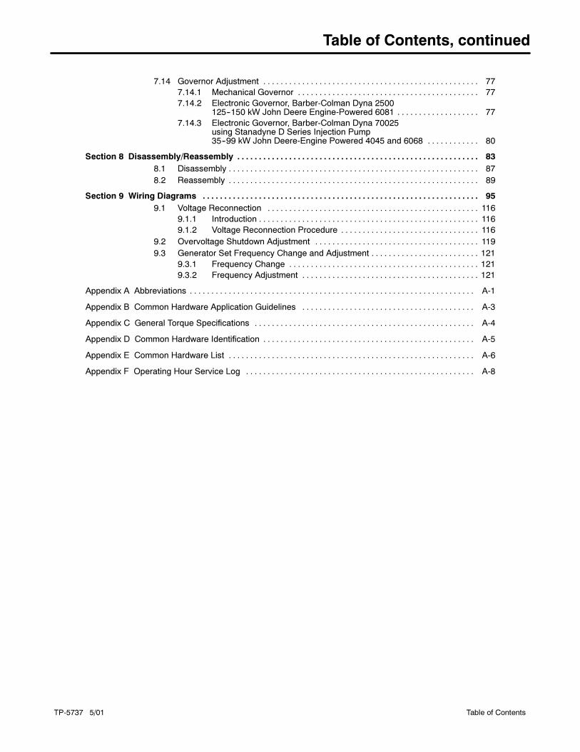
Table of Contents, continued
TP-5737 5/01 Table of Contents
7.14 Governor Adjustment 77. . . . . . . . . . . . . . . . . . . . . . . . . . . . . . . . . . . . . . . . . . . . . . . . . .
7.14.1 Mechanical Governor 77. . . . . . . . . . . . . . . . . . . . . . . . . . . . . . . . . . . . . . . . . .
7.14.2 Electronic Governor, Barber-Colman Dyna 2500125--150 kW John Deere Engine-Powered 6081 77. . . . . . . . . . . . . . . . . . .
7.14.3 Electronic Governor, Barber-Colman Dyna 70025using Stanadyne D Series Injection Pump35--99 kW John Deere-Engine Powered 4045 and 6068 80. . . . . . . . . . . .
Section 8 Disassembly/Reassembly 83. . . . . . . . . . . . . . . . . . . . . . . . . . . . . . . . . . . . . . . . . . . . . . . . . . . . . . . .
8.1 Disassembly 87. . . . . . . . . . . . . . . . . . . . . . . . . . . . . . . . . . . . . . . . . . . . . . . . . . . . . . . . . .
8.2 Reassembly 89. . . . . . . . . . . . . . . . . . . . . . . . . . . . . . . . . . . . . . . . . . . . . . . . . . . . . . . . . .
Section 9 Wiring Diagrams 95. . . . . . . . . . . . . . . . . . . . . . . . . . . . . . . . . . . . . . . . . . . . . . . . . . . . . . . . . . . . . . . .
9.1 Voltage Reconnection 116. . . . . . . . . . . . . . . . . . . . . . . . . . . . . . . . . . . . . . . . . . . . . . . . .
9.1.1 Introduction 116. . . . . . . . . . . . . . . . . . . . . . . . . . . . . . . . . . . . . . . . . . . . . . . . . . .
9.1.2 Voltage Reconnection Procedure 116. . . . . . . . . . . . . . . . . . . . . . . . . . . . . . . .
9.2 Overvoltage Shutdown Adjustment 119. . . . . . . . . . . . . . . . . . . . . . . . . . . . . . . . . . . . . .
9.3 Generator Set Frequency Change and Adjustment 121. . . . . . . . . . . . . . . . . . . . . . . . .
9.3.1 Frequency Change 121. . . . . . . . . . . . . . . . . . . . . . . . . . . . . . . . . . . . . . . . . . . .
9.3.2 Frequency Adjustment 121. . . . . . . . . . . . . . . . . . . . . . . . . . . . . . . . . . . . . . . . .
Appendix A Abbreviations A-1. . . . . . . . . . . . . . . . . . . . . . . . . . . . . . . . . . . . . . . . . . . . . . . . . . . . . . . . . . . . . . . . . .
Appendix B Common Hardware Application Guidelines A-3. . . . . . . . . . . . . . . . . . . . . . . . . . . . . . . . . . . . . . . .
Appendix C General Torque Specifications A-4. . . . . . . . . . . . . . . . . . . . . . . . . . . . . . . . . . . . . . . . . . . . . . . . . . .
Appendix D Common Hardware Identification A-5. . . . . . . . . . . . . . . . . . . . . . . . . . . . . . . . . . . . . . . . . . . . . . . . .
Appendix E Common Hardware List A-6. . . . . . . . . . . . . . . . . . . . . . . . . . . . . . . . . . . . . . . . . . . . . . . . . . . . . . . . .
Appendix F Operating Hour Service Log A-8. . . . . . . . . . . . . . . . . . . . . . . . . . . . . . . . . . . . . . . . . . . . . . . . . . . . .


TP-5737 5/01 ISafety Precautions and Instructions
Safety Precautions and Instructions
IMPORTANT SAFETY
INSTRUCTIONS. Electromechanical
equipment, including generator sets,
transfer switches, switchgear, and
accessories, can cause bodily harm
and pose life-threatening danger when
improperly installed, operated, or
maintained. To prevent accidents be
aware of potential dangers and act
safely. Read and follow all safety
precautions and instructions. SAVE
THESE INSTRUCTIONS.
Thismanual hasseveral typesofsafety
precautions and instructions: Danger,
Warning, Caution, and Notice.
DANGER
Danger indicates the presence of a
hazard that will cause severe
personal injury,death, orsubstantial
property damage.
WARNING
Warning indicates the presence of a
hazard that can cause severe
personal injury,death,orsubstantial
property damage.
CAUTION
Caution indicates the presence of a
hazard that will or can cause minor
personal injury or property damage.
NOTICE
Notice communicates installation,
operation, or maintenance information
that is safety related but not hazard
related.
Safety decals affixed to the equipment
in prominent places alert the operator
or service technician to potential
hazards and explain how to act safely.
The decals are shown throughout this
publication to improve operator
recognition. Replace missing or
damaged decals.
Accidental Starting
Accidental starting.
Can cause severe injury or death.
Disconnect the battery cables before
working on the generator set.
Remove the negative (--) lead first
when disconnecting the battery.
Reconnect the negative (--) lead last
when reconnecting the battery.
WARNING
Disabling the generator set.
Accidental starting can cause
severe injury or death. Before
working on the generator set or
connected equipment, disable the
generator set as follows: (1) Move the
generator set master switch to theOFF
position. (2) Disconnect the power to
the battery charger. (3) Remove the
battery cables, negative (--) lead first.
Reconnect the negative (--) lead last
when reconnecting the battery. Follow
these precautions to prevent starting of
the generator set by an automatic
transfer switch, remote start/stop
switch, or engine start command froma
remote computer.
Battery
Sulfuric acid in batteries.
Can cause severe injury or death.
Wear protective goggles and
clothing. Battery acid may cause
blindness and burn skin.
WARNING
Battery electrolyte is a diluted
sulfuric acid. Batteryacidcancause
severe injury or death. Battery acid
can cause blindness and burn skin.
Always wear splashproof safety
goggles, rubber gloves, and boots
when servicing the battery. Do not
open a sealed battery or mutilate the
battery case. If battery acid splashes in
the eyes or on the skin, immediately
flush the affected area for 15 minutes
with large quantities of clean water.
Seek immediatemedical aid in thecase
of eye contact. Never add acid to a
battery after placing the battery in
service, as thismay result inhazardous
spattering of battery acid.
Battery acid cleanup. Battery acid
can cause severe injury or death.
Battery acid is electrically conductive
and corrosive. Add 500 g (1 lb.) of
bicarbonate of soda (baking soda) to a
container with 4 L (1 gal.) of water and
mix the neutralizing solution. Pour the
neutralizing solution on the spilled
battery acid and continue to add the
neutralizing solution to the spilled
battery acid until all evidence of a
chemical reaction (foaming) has
ceased. Flush the resulting liquid with
water and dry the area.

TP-5737 5/01II Safety Precautions and Instructions
Battery gases. Explosion can cause
severe injury or death. Battery gases
can cause an explosion. Do not smoke
orpermit flamesor sparks to occurnear
a battery at any time, particularly when
it is charging. Do not dispose of a
battery in a fire. To prevent burns and
sparks that could cause an explosion,
avoid touching the battery terminals
with tools or other metal objects.
Removeall jewelrybefore servicing the
equipment. Discharge static electricity
from your body before touching
batteries by first touching a grounded
metal surfaceaway from thebattery. To
avoid sparks, do not disturb the battery
charger connections while the battery
is charging. Always turn the battery
charger off before disconnecting the
battery connections. Ventilate the
compartments containing batteries to
prevent accumulation of explosive
gases.
Battery short circuits. Explosion
can cause severe injury or death.
Short circuits can cause bodily injury
and/or equipment damage.
Disconnect the battery before
generator set installation or
maintenance. Remove all jewelry
before servicing the equipment. Use
tools with insulated handles. Remove
the negative (--) lead first when
disconnecting the battery. Reconnect
the negative (--) lead last when
reconnecting the battery. Never
connect the negative (--) battery cable
to the positive (+) connection terminal
of the starter solenoid. Do not test the
battery condition by shorting the
terminals together.
Engine Backfire/Flash
Fire
Fire.
Can cause severe injury or death.
Do not smoke or permit flames or
sparks near fuels or the fuel system.
WARNING
Servicing the fuel system. A flash
firecancausesevere injuryordeath.
Do not smoke or permit flames or
sparks near the carburetor, fuel line,
fuel filter, fuel pump, or other potential
sources of spilled fuels or fuel vapors.
Catch fuels in an approved container
when removing the fuel line or
carburetor.
Servicing the air cleaner. A sudden
backfire can cause severe injury or
death. Do not operate the generator
set with the air cleaner/silencer
removed.
Combustible materials. A sudden
flash fire can cause severe injury or
death. Do not smoke or permit flames
or sparks near the fuel system. Keep
the compartment and the generator set
clean and free of debris tominimize the
risk of fire. Wipe up spilled fuels and
engine oil.
Combustible materials. A fire can
cause severe injury or death.
Generator set engine fuels and fuel
vapors are flammable and explosive.
Handle these materials carefully to
minimize the risk of fire or explosion.
Equip the compartment or nearby area
with a fully charged fire extinguisher.
Select a fire extinguisher rated ABC or
BC for electrical fires or as
recommended by the local fire code or
an authorized agency. Train all
personnel on fire extinguisher
operation and fire prevention
procedures.
Exhaust System
Carbon monoxide.
Can cause severe nausea,
fainting, or death.
The exhaust system must be
leakproof and routinely inspected.
WARNING
Carbon monoxide symptoms.
Carbonmonoxide can cause severe
nausea, fainting, or death. Carbon
monoxide isapoisonousgaspresent in
exhaust gases. Carbon monoxide
poisoning symptoms include but are
not limited to the following:
� Light-headedness, dizziness
� Physical fatigue, weakness in
joints and muscles
� Sleepiness, mental fatigue,
inability to concentrate
or speak clearly, blurred vision
� Stomachache, vomiting, nausea
If experiencing any of these symptoms
and carbon monoxide poisoning is
possible, seek fresh air immediately
and remain active. Do not sit, lie down,
or fall asleep. Alert others to the
possibility of carbon monoxide
poisoning. Seek medical attention if
the condition of affected persons does
not improvewithinminutes of breathing
fresh air.
Copper tubing exhaust systems.
Carbonmonoxide can cause severe
nausea, fainting, or death. Do not
use copper tubing in diesel exhaust
systems. Sulfur in diesel exhaust
causes rapid deterioration of copper
tubing exhaust systems, resulting in
exhaust/water leakage.
Inspecting the exhaust system.
Carbonmonoxide can cause severe
nausea, fainting, or death. For the
safety of the craft’s occupants, install a
carbonmonoxidedetector. Consult the
boat builder or dealer for approved
detector location and installation.
Inspect the detector before each
generator set use. Inaddition to routine
exhaust system inspection, test the
carbon monoxide detector per the
manufacturer’s instructions and keep
the detector operational at all times.

TP-5737 5/01 IIISafety Precautions and Instructions
Operating thegenerator set. Carbon
monoxidecancauseseverenausea,
fainting, or death. Carbonmonoxide
is an odorless, colorless, tasteless,
nonirritating gas that can cause death if
inhaled for even a short time. Use the
following precautions when installing
andoperating thegenerator set. Donot
install theexhaustoutletwhereexhaust
can be drawn in through portholes,
vents, or air conditioners. If the
generator set exhaust discharge outlet
is near the waterline, water could enter
the exhaust discharge outlet and close
or restrict the flow of exhaust. Never
operate the generator set without a
functioning carbon monoxide detector.
Be especially careful if operating the
generator set when moored or
anchored under calm conditions
because gases may accumulate. If
operating the generator set dockside,
moor the craft so that the exhaust
discharges on the lee side (the side
sheltered from the wind). Always be
aware of others, making sure your
exhaust is directed away from other
boatsandbuildings. Avoidoverloading
the craft.
Fuel System
Explosive fuel vapors.
Can cause severe injury or death.
Use extreme care when handling,
storing, and using fuels.
WARNING
The fuel system. Explosive fuel
vapors can cause severe injury or
death. Vaporized fuels are highly
explosive. Use extreme care when
handling and storing fuels. Store fuels
in a well-ventilated area away from
spark-producing equipment and out of
the reach of children. Never add fuel to
the tank while the engine is running
because spilled fuel may ignite on
contact with hot parts or from sparks.
Do not smoke or permit flames or
sparks to occur near sources of spilled
fuel or fuel vapors. Keep the fuel lines
and connections tight and in good
condition. Do not replace flexible fuel
lines with rigid lines. Use flexible
sections to avoid fuel line breakage
causedbyvibration. Donotoperate the
generator set in the presence of fuel
leaks, fuel accumulation, or sparks.
Repair fuel systems before resuming
generator set operation.
Draining the fuel system. Explosive
fuel vapors can cause severe injury
or death. Spilled fuel can cause an
explosion. Useacontainer to catch fuel
whendraining the fuel system. Wipeup
spilled fuel after draining the system.
Installing the fuel system. Explosive
fuel vapors can cause severe injury
or death. Fuel leakage can cause an
explosion. Do not modify the tank or
the propulsion engine fuel system.
Equip the craft with a tank that allows
one of the two pickup arrangements
described in the installation section.
The tank and installation must conform
to USCG Regulations.
Pipe sealant. Explosive fuel vapors
can cause severe injury or death.
Fuel leakage can cause an explosion.
Usepipesealant onall threaded fittings
to prevent fuel leakage. Use pipe
sealant that resists gasoline, grease,
lubrication oil, common bilge solvents,
salt deposits, and water.
Hazardous Noise
Hazardous noise.
Can cause hearing loss.
Never operate the generator set
without a muffler or with a faulty
exhaust system.
CAUTION
Engine noise. Hazardous noise can
cause hearing loss. Generator sets
not equipped with sound enclosures
can produce noise levels greater than
105 dBA. Prolongedexposure tonoise
levels greater than 85 dBA can cause
permanent hearing loss. Wear hearing
protection when near an operating
generator set.

TP-5737 5/01IV Safety Precautions and Instructions
Hazardous Voltage/
Electrical Shock
Hazardous voltage.
Can cause severe injury or death.
Operate the generator set only when
all guards and electrical enclosures
are in place.
Moving rotor.
WARNING
Grounding electrical equipment.
Hazardous voltage can cause
severe injury or death. Electrocution
is possible whenever electricity is
present. Open the main circuit
breakers of all power sources before
servicing theequipment. Configure the
installation to electrically ground the
generator set, transfer switch, and
related equipment and electrical
circuits to complywithapplicablecodes
and standards. Never contact
electrical leads or appliances when
standing in water or on wet ground
because these conditions increase the
risk of electrocution.
Disconnecting the electrical load.
Hazardous voltage can cause
severe injury or death. Disconnect
the generator set from the load by
opening the line circuit breaker or by
disconnecting the generator set output
leads from the transfer switch and
heavily taping the ends of the leads.
High voltage transferred to the load
during testing may cause personal
injury and equipment damage. Do not
use the safeguard circuit breaker in
place of the line circuit breaker. The
safeguard circuit breaker does not
disconnect the generator set from the
load.
Short circuits. Hazardous
voltage/current can cause severe
injury or death. Short circuits can
cause bodily injury and/or equipment
damage. Do not contact electrical
connections with tools or jewelry while
making adjustments or repairs.
Removeall jewelrybefore servicing the
equipment.
Testing the voltage regulator.
Hazardous voltage can cause
severe injury or death. High voltage
is present at the voltage regulator heat
sink. To prevent electrical shock do not
touch the voltage regulator heat sink
when testing the voltage regulator.
(PowerBoost�, PowerBoost� III, and
PowerBoost� V voltage regulator
models only)
Electrical backfeed to the utility.
Hazardous backfeed voltage can
cause severe injury or death.
Connect the generator set to the
building/marina electrical system only
through an approved device and after
the building/marina main switch is
opened. Backfeed connections can
cause severe injury or death to utility
personnel working on power lines
and/or personnel near the work area.
Some states and localities prohibit
unauthorized connection to the utility
electrical system. Install a
ship-to-shore transfer switch toprevent
interconnection of the generator set
power and shore power.
Testing live electrical circuits.
Hazardous voltage or current can
cause severe injury or death. Have
trained and qualified personnel take
diagnostic measurements of live
circuits. Use adequately rated test
equipment with electrically insulated
probesand follow the instructionsof the
test equipment manufacturer when
performing voltage tests. Observe the
following precautions when performing
voltage tests: (1) Remove all jewelry.
(2)Standonadry, approvedelectrically
insulated mat. (3) Do not touch the
enclosure or components inside the
enclosure. (4) Be prepared for the
system to operate automatically.
(600 volts and under)
Hot Parts
Hot coolant and steam.
Can cause severe injury or death.
Before removing the pressure cap,
stop the generator set and allow it to
cool. Then loosen the pressure cap
to relieve pressure.
WARNING
Hot engine and exhaust system.
Can cause severe injury or death.
Do not work on the generator set until
it cools.
WARNING
Checking the coolant level. Hot
coolant can cause severe injury or
death. Allow the engine to cool.
Release pressure from the cooling
system before removing the pressure
cap. To release pressure, cover the
pressure capwith a thick cloth and then
slowly turn the cap counterclockwise to
the first stop. Remove the cap after
pressure has been completely
released and the engine has cooled.
Check the coolant level at the tank if the
generator set has a coolant recovery
tank.
Servicing the exhaust system. Hot
parts can cause severe injury or
death. Do not touch hot engine parts.
The engine and exhaust system
components become extremely hot
during operation.
TP-5737 5/01 VSafety Precautions and Instructions
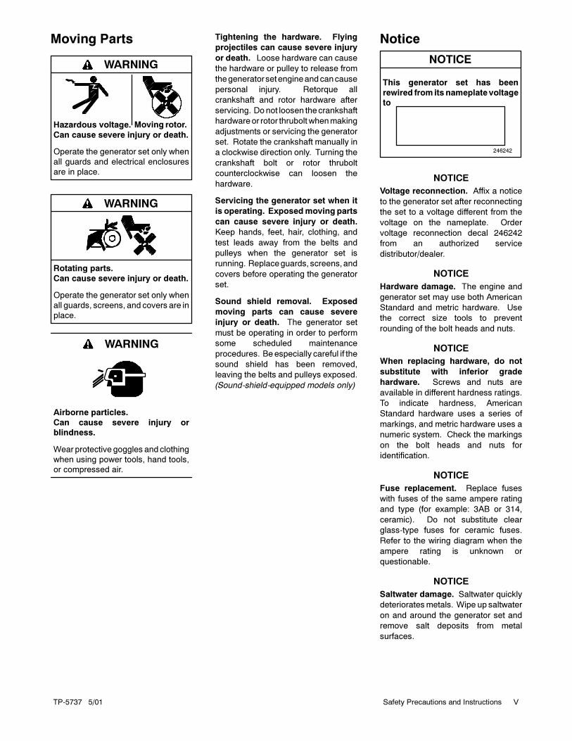
Moving Parts
Hazardous voltage.
Can cause severe injury or death.
Operate the generator set only when
all guards and electrical enclosures
are in place.
Moving rotor.
WARNING
Rotating parts.
Can cause severe injury or death.
Operate the generator set only when
all guards, screens, and covers are in
place.
WARNING
Airborne particles.
Can cause severe injury or
blindness.
Wear protective goggles and clothing
when using power tools, hand tools,
or compressed air.
WARNING
Tightening the hardware. Flying
projectiles can cause severe injury
or death. Loose hardware can cause
the hardware or pulley to release from
thegeneratorsetengineandcancause
personal injury. Retorque all
crankshaft and rotor hardware after
servicing. Donot loosen thecrankshaft
hardwareor rotor thrubolt whenmaking
adjustments or servicing the generator
set. Rotate the crankshaft manually in
a clockwise direction only. Turning the
crankshaft bolt or rotor thrubolt
counterclockwise can loosen the
hardware.
Servicing the generator set when it
is operating. Exposedmoving parts
can cause severe injury or death.
Keep hands, feet, hair, clothing, and
test leads away from the belts and
pulleys when the generator set is
running. Replaceguards, screens,and
covers before operating the generator
set.
Sound shield removal. Exposed
moving parts can cause severe
injury or death. The generator set
must be operating in order to perform
some scheduled maintenance
procedures. Beespecially careful if the
sound shield has been removed,
leaving the belts and pulleys exposed.
(Sound-shield-equipped models only)
Notice
NOTICE
This generator set has been
rewired from its nameplate voltage
to
246242
NOTICE
Voltage reconnection. Affix a notice
to the generator set after reconnecting
the set to a voltage different from the
voltage on the nameplate. Order
voltage reconnection decal 246242
from an authorized service
distributor/dealer.
NOTICE
Hardware damage. The engine and
generator set may use both American
Standard and metric hardware. Use
the correct size tools to prevent
rounding of the bolt heads and nuts.
NOTICE
When replacing hardware, do not
substitute with inferior grade
hardware. Screws and nuts are
available in different hardness ratings.
To indicate hardness, American
Standard hardware uses a series of
markings, and metric hardware uses a
numeric system. Check the markings
on the bolt heads and nuts for
identification.
NOTICE
Fuse replacement. Replace fuses
with fuses of the same ampere rating
and type (for example: 3AB or 314,
ceramic). Do not substitute clear
glass-type fuses for ceramic fuses.
Refer to the wiring diagram when the
ampere rating is unknown or
questionable.
NOTICE
Saltwater damage. Saltwater quickly
deterioratesmetals. Wipe up saltwater
on and around the generator set and
remove salt deposits from metal
surfaces.

TP-5737 5/01VI Safety Precautions and Instructions
Notes
TP-5737 5/01 iIntroduction
Introduction
This manual provides troubleshooting and repair
instructions for 40COZ/33CFOZ, 40EOZ/33EFOZ,
50COZ/40CFOZ, 50EOZ/40EFOZ, 65COZ/50CFOZ,
65EOZ/55EFOZ, 80EOZ/70EFOZ, 99EOZ/80EFOZ,
125EOZ/100EFOZ, and 150EOZ/125EFOZ model
generator sets, controllers, and accessories.
Refer to the engine service manual for generator set
engine service information.
x:in:001:001
This manual may be used for models not listed on the
front cover.
Information in this publication represents data available
at the time of print. Kohler Co. reserves the right to
change this publication and the products represented
without notice and without any obligation or liability
whatsoever.
Read this manual and carefully follow all procedures
and safety precautions to ensure proper equipment
operation and to avoid bodily injury. Read and follow the
Safety Precautions and Instructions section at the
beginning of this manual. Keep this manual with the
equipment for future reference.
The equipment service requirements are very important
to safe and efficient operation. Inspect the parts often
and perform required service at the prescribed intervals.
Obtain service from an authorized service
distributor/dealer to keep equipment in top condition.
x:in:001:002:a
Service Assistance
Please contact a local authorized distributor/dealer for
sales, service, or other information about Kohler Co.
Generator Division products.
� Look on the product or in the information included
with the product
� Consult the Yellow Pages under the heading
Generators—Electric
� Visit the Kohler Co. Generator Division web site at
www.kohlergenerators.com
� Inside the U.S.A. and Canada, call 1-800-544-2444
� Outside the U.S.A. and Canada, call the nearest
regional office
Africa, Europe, Middle East
London Regional Office
Langley, Slough, England
Phone: (44) 1753-580-771
Fax: (44) 1753-580-036
Australia
Australia Regional Office
Queensland, Australia
Phone: (617) 3893-0061
Fax: (617) 3893-0072
China
China Regional Office
Shanghai, People’s Republic of China
Phone: (86) 21-6482 1252
Fax: (86) 21-6482 1255
India, Bangladesh, Sri Lanka
India Regional Office
Bangalore, India
Phone: (91) 80-2284270
(91) 80-2284279
Fax: (91) 80-2284286
Japan
Japan Regional Office
Tokyo, Japan
Phone: (813) 3440-4515
Fax: (813) 3440-2727
Latin America
Latin America Regional Office
Lakeland, Florida, U.S.A.
Phone: (941) 619-7568
Fax: (941) 701-7131
South East Asia
Singapore Regional Office
Singapore, Republic of Singapore
Phone: (65) 264-6422
Fax: (65) 264-6455X:in:008:001

TP-5737 5/01ii Service Assistance
Notes

TP-5737 5/01 1Section 1 Specifications
Section 1 Specifications
1.1 Introduction
The spec sheets for each generator set provide specific
generator and engine information. Refer to the
respective spec sheet for data not supplied in this
manual. Consult the generator set operation manual,
generator installation manual, engine operation
manual, and engine service manual for additional
specifications.
1.2 Specifications
The generator set consists of a rotating-field generator
combined with a smaller rotating-armature generator
turned by a common shaft. The main rotating-field
generator supplies current to the load circuits while the
rotating-armature (exciter) generator supplies rectified
AC (DC) to excite the main generator’s field.
Engine
Engine Prealarm and
Shutdown Switches
Specification
COZ/CFOZ and EOZ/EFOZ
Models
Anticipatory high engine
temperature switch
96� C (205� F) �7
Anticipatory low oil
pressure switch
138 kPa �14 kPa
(20 psi �2)
High engine temperature
shutdown switch
103� C (218� F) �7
Low oil pressure
shutdown switch
103 kPa �14 kPa
(15 psi �2)
High exhaust
temperature switch (wet
exhaust only)
88--102� C
(190--215� F) �5
Controller Gauge
Senders
Specification
(in ohms)
COZ/CFOZ
Models
Specification
(in ohms)
EOZ/EFOZ
Models
Oil Pressure Sender
0 kPa (0 psi) 120 (+9/--8) 240 (+17/--15)
172 kPa (25 psi) 76.5 (+6/--7.5) 153 (+12/--15)
690 kPa (100 psi) 16.8 33.5
Water Temperature Sender
54� C (130� F) 100 �15 180 �12
82� C (180� F) 40 �6 71 �8
Generator
Component Specification Value
Controller/battery electrical system 12 or 24 volts DC
Generator field resistance (F+/ F--):
40/50COZ and 33/40CFOZ 2.0--2.9 ohms
65COZ and 50CFOZ 1.8--2.2 ohms
40EOZ and 33EFOZ 2.1--2.5 ohms
50EOZ and 40EFOZ 2.7--3.1 ohms
65/80EOZ and 55/70EFOZ 1.7--2.1 ohms
99EOZ and 80EFOZ 2.0--2.4 ohms
125EOZ and100EFOZ 1.4--1.8 ohms
150EOZ and 125EFOZ 1.6--2.0 ohms
Exciter armature resistance:
40/50COZ and 33/40CFOZ 0.13 ohms
65COZ and 50CFOZ 0.27 ohms
40EOZ and 33EFOZ 0.23 ohms
50EOZ and 40EFOZ 0.14 ohms
65/80EOZ and 55/70EFOZ 0.27 ohms
99EOZ and 80EFOZ 0.27 ohms
125EOZ and100EFOZ 0.27 ohms
150EOZ and 125EFOZ 0.27 ohms
SCR assembly terminal nut torque 1.4 Nm (12 in. lbs.)
Fan to rotor flange torque 29 Nm (260 in. lbs.)
Drive disks to rotor shaft torque 61 Nm (45 ft. lbs.)
Speed sensor air gap 0.36--0.71 mm
(0.014--0.028 in.)
Speed sensor voltage 2 (black) &
16 (white)
3--6 volts DC
2 (black) & 24 (red)
8--10 volts DC
Electronic governor magnetic pickup
air gap
0.36--0.71 mm
(0.014--0.028 in.)
Magnetic pickup output voltage
during cranking
2.5 volts AC min.
Flex plate to flywheel bolt torque
(3/8-16)
52.9 Nm
(39 ft. lbs.)
TP-5737 5/012 Section 1 Specifications
1.3 Accessories
Kohler Co. offers several accessories to finalize the
installation and to add convenience to operation and
service. Accessories vary with each generator set
model and controller. Kohler Co. offers accessories
factory-installed and/or shipped loose. Some
accessories are available only with microprocessor
controllers. Obtain current information by contacting
your local authorized service distributor/dealer.
Several accessories available at the time of print of this
publication are detailed in the following subsections.
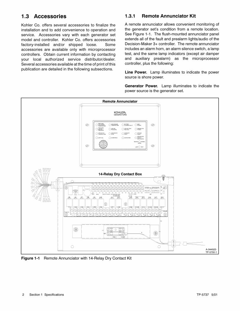
1.3.1 Remote Annunciator Kit
A remote annunciator allows convenient monitoring of
the generator set’s condition from a remote location.
See Figure 1-1. The flush-mounted annunciator panel
extends all of the fault and prealarm lights/audio of the
Decision-Maker 3+ controller. The remote annunciator
includes an alarm horn, an alarm silence switch, a lamp
test, and the same lamp indicators (except air damper
and auxiliary prealarm) as the microprocessor
controller, plus the following:
Line Power. Lamp illuminates to indicate the power
source is shore power.
Generator Power. Lamp illuminates to indicate the
power source is the generator set.
Remote Annunciator
14-Relay Dry Contact Box
A-344522-TP-5750-1
P
FBA--1
42B
10 AMP
NO C CNO CNO CNO CNO CNO CNO CNO CNO CNO CNO CNO CNO CNOK1 K2 K3 K4 K5 K6 K7 K8 K9 K10 K11 K12 K13 K14
INPUT CONTACT RATINGS: 10A@120VAC RES. LOAD
.01A@28VDC MIN.
10A@28VDC MAX.
PCB ASSY A--320639
LOT NO.
42A 2 K1 K2 K3 K4 K5 K6 K7 K8 K9 K10 K11 K13 K14K12
P
N
Figure 1-1 Remote Annunciator with 14-Relay Dry Contact Kit

TP-5737 5/01 3Section 1 Specifications
1.3.2 Safeguard Breaker
The safeguard breaker senses output current on each
generator phase and shuts off the AC voltage regulator
in the event of a sustained overload or short circuit. It is
not a line circuit breaker and does NOT disconnect the
generator from the load. See Figure 1-2.
X-796
Figure 1-2 Safeguard Breaker
1.3.3 Line Circuit Breaker
The line circuit breaker interrupts generator output in the
event of an overload or short circuit. Use the kit to
manually disconnect the generator set from the load
when servicing the generator set. See Figure 1-3.
TP-5352-1
Figure 1-3 Line Circuit Breaker
1.3.4 Run Relay Kit
The run relay kit energizes only when the generator set
is running. Typically, the three sets of contacts control
air intake and/or compartment ventilation fans.
However, alarms and other signalling devices can also
connect to the contacts. See Figure 1-4.
273705
Figure 1-4 Run Relay Kit

TP-5737 5/014 Section 1 Specifications
1.3.5 FASTCHECK Diagnostic Tester
(Microprocessor Controller Only)
The FASTCHECK� diagnostic tester simulates engine
operation to identify faults in the controller and engine
circuitry. Use the FASTCHECK� when troubleshooting
startup problems or to test and troubleshoot the
controller when the controller is removed from the
generator. Perform tests without starting the generator
set. Functions performed by the FASTCHECK� are
listed below; refer to Figure 1-5 to identify LEDs and
switches.
LEDs on the FASTCHECK� indicate the energizing of
the following circuits:
� Fuel solenoid (diesel)
� Engine crank
� AC voltage regulator
� Battery connection (correct polarity)
� Engine malfunction alarm and/or alarm shutdown
Switches on the FASTCHECK� simulate the following:
� Engine cranking
� Engine running
� Engine overspeed
� Low fuel
� Low engine coolant temperature
� Anticipatory low engine oil pressure
� Anticipatory high engine coolant temperature
� Low engine oil pressure
� High engine coolant temperature
B-291930
Figure 1-5 FASTCHECK� Diagnostic Tester

TP-5737 5/01 5Section 2 Operation
Section 2 Operation
2.1 Fast-Response� II Concepts
The generator excitation system uses a permanent
magnet exciter with a silicon controlled rectifier (SCR)
assembly that controls the amount of DC current fed to
the generator field. This type of system uses a voltage
regulator that signals the SCR assembly through an
optocoupler. The voltage regulator monitors generator
output voltage and engine speed and signals the SCR
assembly to turn on or off accordingly through the
optocoupler. The optical coupler consists of a light
emitting diode (LED) mounted on the stationary end
bracket and a photo transistor mounted on the rotating
shaft. The photo transistor picks up the infrared signal
from the LED and signals the SCR assembly to turn on
or off, depending upon the need, as dictated by the
voltage regulator. See Figure 2-1.
The voltage recovery period of this type of generator is
several times faster than the conventionally wound field
brushless generator because the generator set does not
have to contend with the inductance of the exciter field.
The generator set also has better recovery
characteristics than the static-excitedmachine because
it is not dependent upon the generator set output voltage
for excitation power. Possibly the greatest advantage of
this type of machine is its inherent ability to support
short-circuit current and allow system coordination for
tripping downstream branch circuit breakers.
The generator set systems deliver exciter current to the
main field within 50 milliseconds (0.050 seconds) of a
change in load demand.
2.2 Short Circuit Performance
When a short circuit occurs in the load circuit(s) being
served, output voltage drops and amperage
momentarily rises to 600--1000% of the generator set’s
rated current until removal of the short. The SCR
assembly sends full exciter power to the main field. The
generator then sustains up to 300% of its rated current.
Sustained high current causes correspondingly rated
load circuit fuses/breakers to trip. The safeguard
breaker kit shuts down the excitation system in the event
of a sustained heavy overload or short circuit.
1
2
3
4
67
8
9
1011
12
13
5
TP-5353-1
14
1516
1. Main armature
2. Main field3. Main generator
4. Stator
5. SCR assembly6. Exciter armature
7. Rotor
8. Exciter generator
9. Exciter field magnets10. Optical coupler
11. LED board (PCB assembly)
12. Photo transistor board (PCB assembly)13. AC voltage regulator
14. Starting battery
15. Safeguard breaker (optional)16. Main output leads
Figure 2-1 Alternator Schematic

TP-5737 5/016 Section 2 Operation
2.3 Prestart Checklist
To ensure continued satisfactory operation perform the
following checks or inspections before or at each
startup, as designated, and at the intervals specified in
the service schedule. In addition, some checks require
verification after the unit starts.
Air Cleaner. Check for a clean and installed air cleaner
element to prevent unfiltered air from entering the
engine.
Air Inlets. Check for clean and unobstructed air inlets.
Air Shrouding. Check for securely installed and
positioned air shrouding.
Battery. Check for tight battery connections. Consult
the battery manufacturer’s instructions regarding
battery care and maintenance.
Coolant Level. Check the coolant level according to
the cooling system maintenance information.
Drive Belts. Check the belt condition and tension of the
water pump and battery charging alternator belt(s).
Exhaust System. Check for exhaust leaks and
blockages. Check the silencer and piping condition and
check for tight exhaust system connections.
Inspect the exhaust system components (exhaust
manifold, mixing elbow, exhaust line, hose clamps,
silencer, and exhaust outlet) for cracks, leaks, and
corrosion.
� Check the hoses for softness, cracks, leaks, or dents.
Replace the hoses as needed.
� Check for corroded or brokenmetal parts and replace
them as needed.
� Check for loose, corroded, or missing clamps.
Tighten or replace the hose clamps as needed.
� Check that the exhaust outlet is unobstructed.
� Visually inspect for exhaust leaks (blowby). Check
for carbon or soot residue on exhaust components.
Carbon and soot residue indicates an exhaust leak.
Seal leaks as needed.
� Ensure that the carbonmonoxide detector is (1) in the
craft, (2) functional, and (3) energized whenever the
generator set operates.
Fuel Level. Check the fuel level and keep the tank(s)
full to ensure adequate fuel supply.
Oil Level. Maintain the oil level at or near, not over, the
full mark on the dipstick.
Operating Area. Check for obstructions that could
block the flow of cooling air. Keep the air intake area
clean. Do not leave rags, tools, or debris on or near the
generator set.
Seawater Pump Priming. Prime the seawater pump
before initial startup. To prime the pump: (1) close the
seacock, (2) remove the hose from the water-filter
outlet, (3) fill the hose and seawater pump with clean
water, (4) reconnect the hose to the water filter outlet,
and (5) open the seacock. Confirm sea water pump
operation on startup as indicated by water discharge
from the exhaust outlet.
2.4 Marine Inspection
Kohler Co. recommends that all boat owners have their
vessels—especially the exhaust system attached to the
generator set—inspected at the start of each boating
season by the local Coast Guard Auxiliary. If there is no
Coast Guard Auxiliary in the area, contact an authorized
Kohler distributor/dealer for the inspection.
m:op:001:003
2.5 Angular Operation
See Figure 2-2 for angular operation limits for units
covered in this manual.
ContinuousIntermittent—
3 minutes or less
25� 30�
Maximum value for all directions
Figure 2-2 Angular Operation
m:op:001:004
2.6 Exercising the Generator Set
Operate the generator set under load once each week
for one hour with an operator present.
The operator should perform all of the prestart checks
before starting the exercise procedure. Start the
generator set according to the starting procedure in the
controller section of this manual. While the generator
set is operating, listen for a smooth-running engine and
visually inspect the generator set for fluid or exhaust
leaks.
x:op:001:005
TP-5737 5/01 7Section 2 Operation
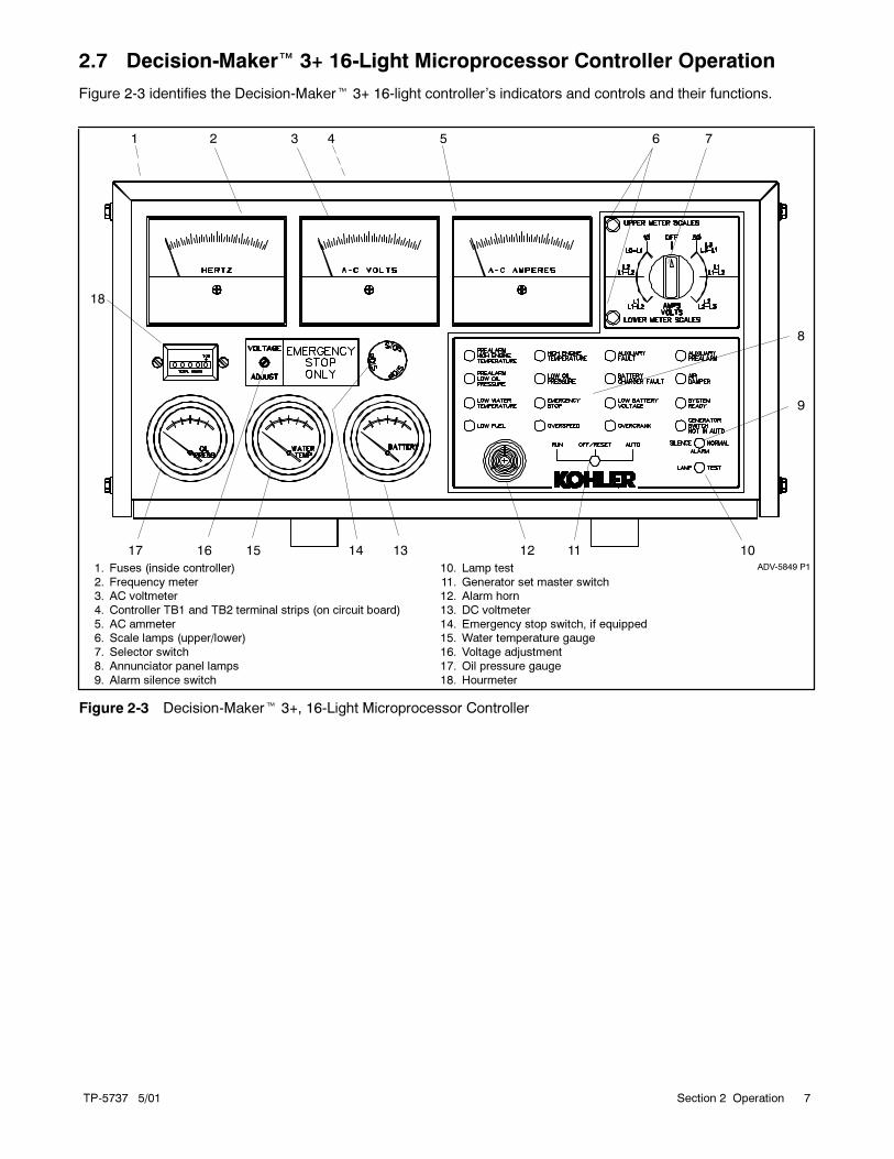
2.7 Decision-Maker� 3+ 16-Light Microprocessor Controller Operation
Figure 2-3 identifies the Decision-Maker� 3+ 16-light controller’s indicators and controls and their functions.
ADV-5849 P1
1 2 3 4 5 6
8
9
1011121314151617
18
1. Fuses (inside controller)
2. Frequency meter3. AC voltmeter
4. Controller TB1 and TB2 terminal strips (on circuit board)
5. AC ammeter6. Scale lamps (upper/lower)
7. Selector switch
8. Annunciator panel lamps
9. Alarm silence switch
10. Lamp test
11. Generator set master switch12. Alarm horn
13. DC voltmeter
14. Emergency stop switch, if equipped15. Water temperature gauge
16. Voltage adjustment
17. Oil pressure gauge
18. Hourmeter
7
Figure 2-3 Decision-Maker� 3+, 16-Light Microprocessor Controller

TP-5737 5/018 Section 2 Operation
2.7.1 Controls and Indicators
The following table describes the controls and indicators
located on the controller.
Name Description
AC ammeter The meter displays the AC outputamperage. Use the selectorswitch to choose the phasecurrent.
AC voltmeter The meter displays the AC outputvoltage. Use the selector switch tochoose the output lead circuits.
DC voltmeter The meter displays the voltage ofthe starting battery(ies).
Alarm horn The horn sounds if any fault oranticipatory condition exists.Place the generator set masterswitch in the AUTO position beforesilencing the horn. See theController Resetting Procedurelater in this section.
Alarm silence switch The switch disconnects the alarmduring service (place the generatorset master switch in the AUTOposition before silencing the alarmhorn). Restore the alarm hornswitches at all locations (controller,remote annunciator, andaudio/visual alarm) to normalpositions after correcting the faultshutdown to avoid reactivating thealarm horn. See the ControllerResetting Procedure later in thissection.
Auxiliary fault lamp The lamp flashes or lights whenthe controller detects a fault. Seethe lamp conditions sectionfollowing.
Frequency meter The meter displays the frequency(Hz) of the generator set outputvoltage.
Generator set masterswitch
The switch functions as thecontroller reset and generator setoperation switch.
High enginetemperature lamp
The lamp illuminates if thegenerator set shuts down becauseof high engine temperature.Shutdown occurs 5 seconds afterthe engine reaches temperatureshutdown range.
Hourmeter The hourmeter records thegenerator set total operating hoursfor reference in maintenancescheduling.
Lamp test switch The switch tests the controllerindicator lamps.
Low oil pressurelamp
The lamp illuminates if thegenerator set shuts down becauseof low oil pressure. Shutdownoccurs 5 seconds after the enginereaches oil pressure shutdownrange.
Overcrank lamp The lamp illuminates and crankingstops if the engine does not startafter 45 seconds of continuouscranking or 75 seconds of cycliccranking.
The cranking stops and overcranklamp lights after 15 seconds if thestarter or engine does not turn(locked rotor).
The overcrank lamp flashes if thespeed sensor signal is absentlonger than one second.
NOTE: The generator setcontroller’s automatic restartfunction attempts to restart thegenerator set if the engine speeddrops below 13 Hz (390 rpm).Continued decreased enginespeed causes an overcrankcondition.
Overspeed lamp The lamp illuminates if thegenerator set shuts down becausegoverned frequency on 50 and60 Hz models exceeds 70 Hz.
Water temperaturegauge
The gauge displays the enginecoolant temperature.
Oil pressure gauge The gauge displays the engine oilpressure.
Scale lamps(upper/lower)
The lamps indicate which ACvoltmeter and/or ammeter scalesto read.
Selector switch The switch selects the generatorset output circuits to measure.When switched to a position withtwo circuit labels, measureamperage on the lead shown inthe upper label and measurevoltage between the two leadsshown in the lower label. The ACammeter and voltmeter functiononly with the switch in the ONposition.
Voltage adjustmentpotentiometer
The potentiometer fine-tunes(±5%) the generator set outputvoltage.

TP-5737 5/01 9Section 2 Operation
Name Description
Auxiliary prealarmlamp
The lamp illuminates whencustomer-provided sensingdevices activate the pump.
Emergency stoplamp
The lamp illuminates and thegenerator set shuts down whenenergizing the optional emergencystop switch. The lamp needs theoptional emergency stop switch tofunction.
Generator switch notin auto lamp
The lamp illuminates when thegenerator set master switch is inthe RUN or OFF/RESET position.
Low fuel lamp The lamp illuminates when the fuellevel in the tank approachesempty. The lamp needs a low fuelsensor in the fuel tank to function.
High watertemperature lamp
The lamp illuminates when thewater temperature approachesshutdown range. The lamp needsan optional prealarm sender kit tofunction.
Prealarm high enginetemperature lamp
The lamp illuminates when theengine coolant temperatureapproaches shutdown range. Thelamp needs an optional prealarmsender kit to function.
Prealarm low oilpressure lamp
The lamp illuminates when theengine oil pressure approachesshutdown range. The lamp needsan optional prealarm sender kit tofunction.
System ready lamp The lamp illuminates when thegenerator set master switch is inAUTO position and the systemsenses no faults.
Emergency stopswitch
The switch, if activated, instantlyshuts down the generator set inemergency situations. Use theemergency stop switch foremergency shutdowns only. Usethe generator set master switch fornormal shutdowns.
2.7.2 Fuses and Terminal Strips
The following table describes the controller circuit board
fuses and controller terminal strips.
Name Description
3-amp remoteannunciator fuse
The fuse protects the remoteannunciator circuit, A/V alarm, andisolated alarm kit, if equipped.
3-amp controller fuse The fuse protects the controllercircuit board, speed sensor, andlamp circuit board.
15-amp engine andaccessories fuse
The fuse protects theengine/starting circuitry andaccessories.
Controller TB1terminal strip
The terminal strip providesconnection points forcustomer-supplied sensingdevices and generator setaccessories such as theemergency stop switch, remotestart stop/switch, audio/visualalarms, etc., to the controller.Figure 2-4 shows the location ofthe TB1 terminal strip on thecontroller circuit board. Refer tothe wiring diagrams for informationon connecting accessories to theTB1 terminal strip.
Controller TB2terminal strip
The terminal strip providesconnection points for crank modeselection (cyclic or continuous)and remote start/stop switch inputsof operation. Figure 2-4 shows thelocation of the TB2 terminal stripon the controller circuit board.Refer to the wiring diagrams forconnection information.
P1P2
A-336415-A
R41
LED4
1 2
3
1. TB1 terminal strip
2. TB2 terminal strip3. Fuses
Figure 2-4 TB1 and TB2 Terminal Strips on
Decision-Maker� 3+ Controller Circuit
Board

TP-5737 5/0110 Section 2 Operation
2.7.3 Auxiliary Fault Lamp Conditions
The following descriptions define the possible auxiliary
fault lamp conditions.
Flashing Lamp Conditions
No ACOutput. The auxiliary lamp flashes immediately
if the controller senses no AC output while the generator
set runs (except during the first 10 seconds after
startup). The flashing stops and the light goes out when
the controller senses AC output. The controller requires
no manual reset.
Low Battery Voltage. The auxiliary lamp flashes if the
battery power was reconnected or was low and then
restored while the generator set master switch was in
the RUN or AUTO position. A possible cause is a
temporary low battery condition when the battery is
weak or undersized for the application. To clear the low
battery voltage condition, place the generator set
master switch in the OFF/RESET position.
Continuous-On Lamp Conditions
Emergency Stop Switch Energized. Upon activation
of the emergency stop switch, if equipped, the auxiliary
lamp lights and the generator set shuts down
immediately.
Emergency Stop Switch Reset. Resetting the
optional emergency stop switch while the generator set
master switch is in the AUTO or RUN position causes
the auxiliary lamp to light. Place the generator set
master switch in the OFF/RESET position to clear the
auxiliary lamp ON condition.
Note: Auxiliary Delay Shutdown. The auxiliary lamp
lights and the engine shuts down 5 seconds after
the high oil temperature (P1-13) or auxiliary delay
shutdown (P1-15) fault, if equipped, occurs.
Auxiliary Delay Shutdown is inhibited during the
first 30 seconds after crank disconnect.
Note: Overvoltage Shutdown. If a generator set is
equipped with this kit, the auxiliary lamp lights
and the engine shuts down immediately when an
overvoltage condition occurs.
Note: Auxiliary Immediate Shutdown. The auxiliary
lamp lights and the engine shuts down
immediately when any customer-supplied
sensing devices connected to auxiliary
immediate shutdown ports (P1-17 and P1-18)
activate them.
x:op:005:004
2.7.4 Starting the Generator Set
The following procedures describe starting the
generator set.
Local Starting (Nonautomatic). Move the generator
set master switch to the RUN position to start the
generator set at the controller.
Note: The alarm horn sounds whenever the generator
set master switch is not in the AUTO position.
Automatic (Auto) Starting. Move the generator set
master switch to the AUTO position to allow startup by
the automatic transfer switch or remote start/stop switch
(connected to controller terminals TB1-3 and TB1-4).
Note: The transient start/stop function of the
Decision-Maker�3+ controller prevents
accidental cranking of the rotating engine. When
the generator set master switch is momentarily
placed in the OFF/RESET position, then quickly
returned to RUN, the generator set slows to
249 rpm and then recranks before returning to
rated speed.
Note: The Decision-Maker� 3+ controller’s automatic
restart function attempts to restart the generator
set if the engine speed drops below 390 rpm
(generator output frequency of 13 Hz).
Continued decreased engine speed causes an
overcrank fault condition.
Crank Mode Selection
TheDecision-Maker�3+ controller cranks continuously
for up to 45 seconds or cyclically for up to 75 seconds
(crank 15 seconds, rest 15 seconds, crank 15 seconds,
etc.) before overcrank shutdown. Select the crank
mode (cyclic or continuous) on the controller circuit
board terminal strip. For cyclic cranking, leave circuit
board terminal TB2-9 open. For continuous cranking,
attach a jumper between circuit board terminal TB2-9A
(ground) and terminal TB2-9.
2.7.5 Stopping the Generator Set
The following procedures describe stopping the
generator set.
Normal Stopping
1. Cooldown. Run the generator set at no load for
5 minutes to ensure adequate engine cooldown.
2. Stopping. Move the generator set master switch
to the OFF/RESET position. The engine stops.

TP-5737 5/01 11Section 2 Operation
Note: The generator set continues running during
a 5-minute cooldown cycle if a remote
switch or automatic transfer switch signals
the engine to stop.
Emergency Stopping
Move the generator set master switch to the
OFF/RESET position or activate the remote emergency
stop, if equipped, for immediate shutdown. The
controller AUXILIARY lamp lights and the generator set
shuts down on activation of the emergency stop switch.
The remote annunciator and/or A/V alarms, if equipped,
signal an emergency stop.
2.7.6 Prime Power Mode Operation
The Decision-Maker� 3+ controller operates in either
the normal mode or the prime power mode. In prime
power mode, the controller draws less current,
minimizing the battery drain. Consider using the prime
power mode for installations that do not have a battery
charger.
Moving the generator set master switch to the
OFF/RESET position disables all controller functions.
Moving the generator set master switch to the AUTO
position restores controller functions.
Enabling and Disabling the Prime Power Mode.
Enable the prime power mode by connecting jumpers
across the following terminals on terminal strip TB2 on
the controller circuit board:
� TB2-1P and TB2-2P
� TB2-3P and TB2-4P
� TB2-3 and TB2-4
See Figure 2-4. Remove the jumpers listed above to
disable the prime power mode.
Prime Power Starting. The prime power mode
provides local starting only at the controller. When the
generator set master switch is in the OFF/RESET
position, the controller functions are inoperative. Move
the generator set master switch to the AUTO position to
start the generator set. Do not start the generator set
with the master switch in the RUN position because the
alarm horn sounds.
Note: Move the generator set master switch to the
AUTO position to return controller functions to
normal.
Prime Power Stopping. Move the generator set
master switch to the OFF/RESET position to stop the
generator set and power down the controller.
2.7.7 Fault Shutdowns
The generator set shuts down automatically under the
following fault conditions and cannot be restarted until
the fault condition is corrected. The system
automatically resets when the problem is corrected or
the generator set cools (if high engine temperature was
the fault).
Name Description
High enginetemperature
Shutdown occurs 5 seconds afterthe fault. The high enginetemperature shutdown does notfunction during the first 5 secondsafter startup.
NOTE: The high temperatureshutdown functions only when thecoolant level is in the operatingrange.
High exhausttemperature
Shutdown occurs 5 seconds afterthe fault. The high exhausttemperature shutdown does notfunction during the first 5 secondsafter startup.
Low coolant level(water-cooledengines only)
Shutdown occurs 5 seconds afterfault. The low coolant levelshutdown does not function duringthe first 5 seconds after startup.
Low oil pressure Shutdown occurs 5 seconds afterthe fault. The low oil pressureshutdown does not function duringthe first 5 seconds after startup.
NOTE: The low oil pressureshutdown does not protect againstlow oil level. Check the engine oillevel.
Overcrank Shutdown occurs after 45 secondsof continuous cranking or 75seconds of cyclic cranking (crank15 seconds, rest 15 seconds,crank 15 seconds, etc.).
Overspeed Shutdown occurs immediatelywhen governed frequency on 50and 60 Hz models exceeds 70 Hz.
Overvoltage(optional)
The generator set shuts down andthe auxiliary lamp lights whenvoltage is 15% or more over thenominal voltage for 2 seconds orlonger.
NOTE: Overvoltage can damagesensitive equipment in less thanone second. Install separateovervoltage protection on on-lineequipment requiring fastershutdown.
x:op:005:007

TP-5737 5/0112 Section 2 Operation
2.7.8 Controller Resetting Procedure
(Following Fault Shutdown)
Use the following procedure to restart the generator set
after a fault shutdown. Refer to Resetting the
Emergency Stop Switch in this section to reset the
generator set after an emergency stop.
1. Place the controller alarmhorn silence switch in the
SILENCE position. Place the A/V annunciator
alarm switch, if equipped, in the SILENCE position
to stop the alarm horn. The A/V annunciator lamp
stays lit. (The A/V alarm uses one lamp to indicate
a fault shutdown; the respective fault lamp on the
remote annunciator lights to indicate a fault
condition.)
2. Disconnect the generator set from the load using
the line circuit breaker or automatic transfer switch.
3. Correct the cause of the fault shutdown. See the
Safety Precautions at the beginning of this section
before proceeding.
4. Place the generator set master switch in the
OFF/RESET position and then in the RUN position
to start the generator set. The A/V annunciator
alarm horn sounds and the lamp, if equipped,
darkens.
5. Test operate the generator set to verify that the
cause of the shutdown has been corrected.
6. Reconnect the generator set to the load via the line
circuit breaker or automatic transfer switch.
7. Place the generator set master switch in the AUTO
position for startup by a remote transfer switch or
remote start/stop switch. Place the A/V
annunciator alarm switch, if equipped, in the
NORMAL position.
8. Place the generator set master switch in the AUTO
position before silencing the alarm horn.
2.7.9 Resetting the Emergency Stop
Switch
Use the following procedure to restart the generator set
after an emergency stop switch shutdown. Refer to the
Controller Resetting Procedure in this section to restart
the generator set following a fault shutdown. The
generator set does not crank until the operator
completes the resetting procedure.
Note: The controller auxiliary lamp lights when the
generator set master switch is in the RUN or
AUTO position during the resetting procedure.
Procedure to Restart the Generator Set After an
Emergency Stop Shutdown:
1. Determine the cause of the emergency stop and
correct the problem(s).
2. Reset the controller emergency stop switch by
rotating the switch clockwise until the switch
springs back to the original position. See
Figure 2-3.
3. Toggle the generator set master switch to
OFF/RESET and then to RUN or AUTO to restart
the generator set.

TP-5737 5/01 13Section 2 Operation
2.8 Expanded Decision-Maker� 1 Controller Operation
For identification of the expanded controller’s indicators and controls and their functions, refer to Figure 2-5.
1
10111213ADV-5849E-B
789
2 3 4 5
6
1. Frequency meter
2. AC voltmeter3. AC ammeter
4. Scale lamps (upper/lower)
5. Selector switch6. Hourmeter
7. Generator set master switch
8. Voltage adjustment potentiometer
9. Fault lamp10. 10-amp controller fuse
11. DC voltmeter
12. Water temperature gauge13. Oil pressure gauge
Figure 2-5 Expanded Decision-Maker� 1 Controller
x:op:002:001
2.8.1 Controls and Indicators
The following table describes the controls and indicators
located on the controller.
Name Description
AC voltmeter The meter displays the AC outputvoltage. Use the selector switch tochoose the output lead circuits.
AC ammeter The meter displays the AC outputamperage. Use the selector switch tochoose the phase currents.
DC voltmeter The meter displays the voltage of thestarting battery(ies).
Fault lamp The lamp illuminates during engineshutdown if the engine shuts downbecause of one of the following faults:high engine temperature, low waterlevel, low oil pressure, overcrank, oroverspeed. See Section 2.8.4, FaultShutdowns, for additional shutdowninformation.
Frequency meter The meter displays the frequency (Hz)of the generator set output.
Generator setmaster switch
The switch functions as the controllerreset and generator set operationswitch.
Hourmeter The hourmeter records the generatorset total operating hours for referencein maintenance scheduling.
Oil pressuregauge
The gauge displays the engine oilpressure.
Scale lamps(upper/lower)
The lamps indicate which ACvoltmeter and/or ammeter scales toread.
Selector switch The switch selects the generator setoutput circuits to measure. Whenswitched to a position with two circuitlabels, measure amperage on thelead shown in the upper label andmeasure voltage between the twoleads shown in the lower label. TheAC ammeter and voltmeter functiononly with the switch in the ONposition.
Voltageadjustmentpotentiometer
The potentiometer fine-tunes (±5%)the generator set output voltage.
Watertemperaturegauge
The gauge displays the enginecoolant temperature.
10-amp controllerfuse
The fuse protects the controllercircuitry from short circuits andoverloads.
TP-5737 5/0114 Section 2 Operation
2.8.2 Starting the Generator Set
The following procedure describes the actions required
to start the generator set.
Local Starting. Move the generator set to the RUN
position to immediately start the generator set.
Auto (Automatic) Starting. Move the generator set
master switch to the AUTO position to allow startup by
the automatic transfer switch or the remote start/stop
switch (connected to controller terminals TB1-3 and
TB1-4).
Note: The controller provides up to 30 seconds of
continuous cranking before overcrank shutdown
occurs.
x:op:002:003
2.8.3 Stopping the Generator Set
The following procedure describe how to stop the
generator set.
Normal Stopping
1. Cooldown. Run the generator set at no load for
5 minutes to ensure adequate engine cooldown.
2. Stopping. Move the generator set master switch
to the OFF/RESET position. The engine stops.
x:op:002:004
2.8.4 Fault Shutdowns
The generator set shuts down automatically under the
following fault conditions and cannot be restarted until
the fault condition is corrected. The systemautomatically
resets when the problem is corrected or the generator
set cools (if high engine temperature was the fault).
The fault lamp does not stay lit after the generator set
shuts down on a fault condition.
2.8.5 Controller Resetting Procedure
(Following Fault Shutdown)
Use the following procedure to restart the generator set
after a fault shutdown.
1. Disconnect the generator set from the load using
the line circuit breaker or automatic transfer switch.
See the Safety Precautions at the beginning of this
section before proceeding.
2. Correct the cause of the fault shutdown. See the
Safety Precautions at the beginning of this section
before proceeding.
3. Start the generator set bymoving the generator set
master switch to RESET/OFF and then to RUN.
4. Verify that the cause of the shutdown has been
corrected by test operating the generator set.
5. Reconnect the generator set to the load using the
line circuit breaker or automatic transfer switch.
6. Move the generator set master switch to the AUTO
position for startup by remote transfer switch or
remote start/stop switch.
Fault Description
High enginetemperature
Shutdown occurs 5 seconds after thefault. The high engine temperatureshutdown does not function during thefirst 5 seconds after startup.
Note: The high temperatureshutdown functions only when thecoolant level is in the operating range.
High exhausttemperature
Shutdown occurs 5 seconds after thefault. The high exhaust temperatureshutdown does not function during thefirst 5 seconds after startup.
Low coolant level Shutdown occurs 5 seconds after thefault. The low coolant level shutdowndoes not function during the first5 seconds after startup.
Low oil pressure Shutdown occurs 5 seconds after thefault. The low oil pressure shutdowndoes not function during the first5 seconds after startup.
Note: The low oil pressure shutdowndoes not protect against low oil level.Check the oil level at the engine.
Overcrank Shutdown occurs after 30 seconds ofcontinuous cranking. Shutdownoccurs after 30 seconds if the engineor starter does not turn (locked rotor).
Overspeed Shutdown occurs immediately whenthe governed frequency on the 50 and60 Hz models exceeds 70 Hz.
x:op:002:006
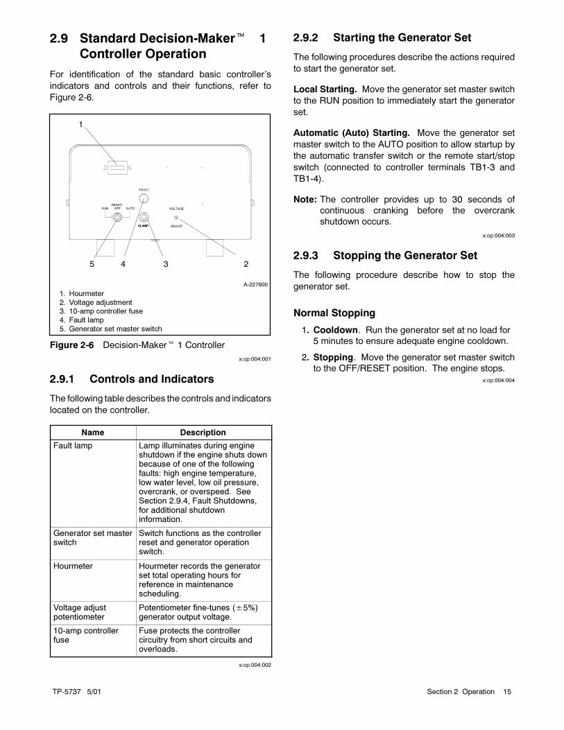
TP-5737 5/01 15Section 2 Operation
2.9 Standard Decision-Maker��1
Controller Operation
For identification of the standard basic controller’s
indicators and controls and their functions, refer to
Figure 2-6.
A-227600
1
345
1. Hourmeter
2. Voltage adjustment3. 10-amp controller fuse
4. Fault lamp
5. Generator set master switch
2
Figure 2-6 Decision-Maker� 1 Controller
x:op:004:001
2.9.1 Controls and Indicators
The following table describes the controls and indicators
located on the controller.
Name Description
Fault lamp Lamp illuminates during engineshutdown if the engine shuts downbecause of one of the followingfaults: high engine temperature,low water level, low oil pressure,overcrank, or overspeed. SeeSection 2.9.4, Fault Shutdowns,for additional shutdowninformation.
Generator set masterswitch
Switch functions as the controllerreset and generator operationswitch.
Hourmeter Hourmeter records the generatorset total operating hours forreference in maintenancescheduling.
Voltage adjustpotentiometer
Potentiometer fine-tunes (±5%)generator output voltage.
10-amp controllerfuse
Fuse protects the controllercircuitry from short circuits andoverloads.
x:op:004:002
2.9.2 Starting the Generator Set
The following procedures describe the actions required
to start the generator set.
Local Starting. Move the generator set master switch
to the RUN position to immediately start the generator
set.
Automatic (Auto) Starting. Move the generator set
master switch to the AUTO position to allow startup by
the automatic transfer switch or the remote start/stop
switch (connected to controller terminals TB1-3 and
TB1-4).
Note: The controller provides up to 30 seconds of
continuous cranking before the overcrank
shutdown occurs.
x:op:004:003
2.9.3 Stopping the Generator Set
The following procedure describe how to stop the
generator set.
Normal Stopping
1. Cooldown. Run the generator set at no load for
5 minutes to ensure adequate engine cooldown.
2. Stopping. Move the generator set master switch
to the OFF/RESET position. The engine stops.
x:op:004:004
TP-5737 5/0116 Section 2 Operation
2.9.4 Fault Shutdowns
The generator set shuts down automatically under the
following fault conditions and cannot be restarted until
the fault condition is corrected. The systemautomatically
resets when the problem is corrected or the generator
set cools (if high engine temperature was the fault).
Fault Description
High enginetemperature
Shutdown occurs 5 seconds afterthe fault. The high enginetemperature shutdown does notfunction during the first 5 secondsafter startup.
NOTE: The high temperatureshutdown functions only when thecoolant level is in the operatingrange.
High exhausttemperature
Shutdown occurs 5 seconds afterthe fault. The high exhausttemperature shutdown does notfunction during the first 5 secondsafter startup.
Low coolant level Shutdown occurs 5 seconds afterthe fault. Low coolant levelshutdown does not function duringthe first 5 seconds after startup.
Low oil pressure Shutdown occurs 5 seconds afterthe fault. Low oil pressureshutdown does not function duringthe first 5 seconds after startup.
NOTE: The low oil pressureshutdown does not protect againstlow oil level. Check the oil level atthe engine.
Overcrank Shutdown occurs after 30 secondsof continuous cranking. Shutdownoccurs after 30 seconds if theengine or starter does not turn(locked rotor).
Overspeed Shutdown occurs immediatelywhen the governed frequency on50 and 60 Hz models exceeds70 Hz.
x:op:004:005
2.9.5 Controller Resetting Procedure
(Following Fault Shutdown)
Use the following procedure to restart the generator set
after a fault shutdown.
1. Disconnect the generator set from the load using
the line circuit breaker or automatic transfer switch.
See the Safety Precautions at the beginning of this
section before proceeding.
2. Correct the cause of the fault shutdown. See the
Safety Precautions at the beginning of this section
before proceeding.
3. Start the generator set bymoving the generator set
master switch to RESET/OFF and then to RUN.
4. Verify that the cause of the shutdown has been
corrected by test operating the generator set.
5. Reconnect the generator set to the load using the
line circuit breaker or automatic transfer switch.
6. Move the generator set master switch to the AUTO
position for startup by remote transfer switch or
remote start/stop switch.
x:op:004:006

TP-5737 5/01 17Section 3 Scheduled Maintenance
Section 3 Scheduled Maintenance
3.1 General Maintenance
Accidental starting.
Can cause severe injury or death.
Disconnect the battery cables before
working on the generator set.
Remove the negative (--) lead first
when disconnecting the battery.
Reconnect the negative (--) lead last
when reconnecting the battery.
WARNING
Disabling the generator set. Accidental starting can
cause severe injury or death. Before working on the
generator set or connected equipment, disable the generator
set as follows: (1) Move thegenerator setmaster switch to the
OFFposition. (2) Disconnect thepower to thebattery charger.
(3) Remove the battery cables, negative (--) lead first.
Reconnect the negative (--) lead last when reconnecting the
battery. Follow these precautions to prevent starting of the
generator set by an automatic transfer switch, remote
start/stop switch, or engine start command from a remote
computer.
Hot engine and exhaust system.
Can cause severe injury or death.
Do not work on the generator set until
it cools.
WARNING
Servicing the exhaust system. Hot parts can cause
severe injury or death. Do not touch hot engine parts. The
engine and exhaust system components become extremely
hot during operation.
Rotating parts.
Can cause severe injury or death.
Operate the generator set only when
all guards, screens, and covers are in
place.
WARNING
Servicing thegenerator setwhen it is operating. Exposed
moving parts can cause severe injury or death. Keep
hands, feet, hair, clothing, and test leads away from the belts
and pulleys when the generator set is running. Replace
guards, screens, and covers before operating the generator
set.
See the Safety Precautions and Instructions at the
beginning of this manual before attempting to service,
repair, or operate the generator set. Have an authorized
distributor/dealer perform generator set service.
Engine Service. Perform generator set engine service
at the intervals specified by the engine operation
manual.
Generator Set Service. Perform generator set service
at the intervals specified by the generator set operation
manual.
If the generator set operates under dusty or dirty
conditions, use dry compressed air to blow dust out of
the alternator. With the generator set running, direct the
stream of air in through the cooling slots at the alternator
end.
Service Log. Use the Operating Hour Service Log
located in the back of this manual to document
performed services.
Service Schedule. Performmaintenance on each item
in the service schedule at the designated intervals for
the life of the generator set. For example, an item
requiring service every 100 hours or 3 months also
requires service after 200 hours or 6 months, 300 hours
or 9 months, and so on.
x:sm:004:001

TP-5737 5/0118 Section 3 Scheduled Maintenance
3.2 Generator Bearing
Replace the end bracket bearing every 10,000 hours of
operation. Servicemore frequently if bearing inspection
indicates excessive rotor end play or bearing damage
from corrosion or heat buildup. Replace the tolerance
ring, if equipped, if removing the end bracket. The end
bracket bearing is sealed and requires no additional
lubrication. Have all generator service performed by an
authorized service distributor/dealer.
3.3 Storage Procedure
Perform the following storage procedure before taking a
generator set out of service for three months or longer.
Follow the engine manufacturer’s recommendations, if
available, for fuel system and internal engine
component storage.
x:sm:002:001
3.3.1 Lubricating System
Prepare the engine lubricating system for storage as
follows:
1. Run the generator set for a minimum of 30 minutes
to bring it to normal operating temperature.
2. Stop the generator set.
3. With the engine still warm, drain the oil from the
crankcase.
4. Remove and replace the oil filter.
5. Refill the crankcase with oil suited to the climate.
6. Run the generator set for two minutes to distribute
the clean oil.
7. Stop the generator set.
8. Check the oil level and adjust, if needed.
x:sm:002:002
3.3.2 Cooling System
Prepare the cooling system for storage as follows:
1. Check the coolant freeze protection using a
coolant tester.
2. Add or replace coolant as necessary to ensure
adequate freezing protection. Use the guidelines
included in the engine operation manual.
3. Run the generator set for 30minutes to redistribute
added coolant.
x:sm:002:003
3.3.3 Fuel System
Prepare the fuel system for storage as follows:
Diesel-Fueled Engines
1. Fill the fuel tank with #2 diesel fuel.
2. Condition the fuel system with compatible
additives to control microbial growth.
3. Change the fuel filter/separator and bleed the fuel
system. See the engine service manual.
3.3.4 Exterior
Prepare the exterior for storage as follows:
1. Clean the exterior surface of the generator set.
2. Seal all engine openings except for the air intake
with nonabsorbent adhesive tape.
3. To prevent impurities from entering the air intake
and to allow moisture to escape from the engine,
secure a cloth over the air intake.
4. Mask electrical connections.
5. Spread a light film of oil over unpainted metallic
surfaces to inhibit rust and corrosion.
x:sm:002:006a
3.3.5 Battery
Perform battery storage after all other storage
procedures.
1. Place the generator set master switch in the
OFF/RESET position.
2. Disconnect the battery(ies), negative (--) lead first.
3. Clean the battery. Refer to the battery
manufacturer’s instructions for the battery cleaning
procedure.
4. Place the battery in a cool, dry location.
5. Connect the battery to a float/equalize battery
charger or charge it monthly with a trickle battery
charger. Refer to the battery charger
manufacturer’s recommendations.
6. Maintain a full charge to extend battery life.

TP-5737 5/01 19Section 4 General Troubleshooting
Section 4 General Troubleshooting
This section contains generator set troubleshooting,
diagnostic, and repair information.
Use the following chart as a quick troubleshooting
reference. The table groups generator set faults and
suggests likely causes and remedies. The table also
refers you to more detailed information including
sections of this manual, the generator set operation
manual (O/M), the generator set installation manual
(I/M), and the engine service manual (Engine S/M) to
correct the indicated problem.
Corrective action and testing often require knowledge of
electrical and electronic circuits. To avoid additional
problems caused by incorrect repairs, have an
authorized service distributor/dealer perform service.
NOTICE
Fuse replacement. Replace fuses with fuses of the same
ampere rating and type (for example: 3AB or 314, ceramic).
Do not substitute clear glass-type fuses for ceramic fuses.
Refer to the wiring diagram when the ampere rating is
unknown or questionable.
Maintain a record of repairs and adjustments performed
on the equipment. If the procedures in this manual do
not explain how to correct the problem, contact an
authorized distributor/dealer. Use the record to help
describe the problem and repairs or adjustments made
to the equipment.
x:gt:001:002a:
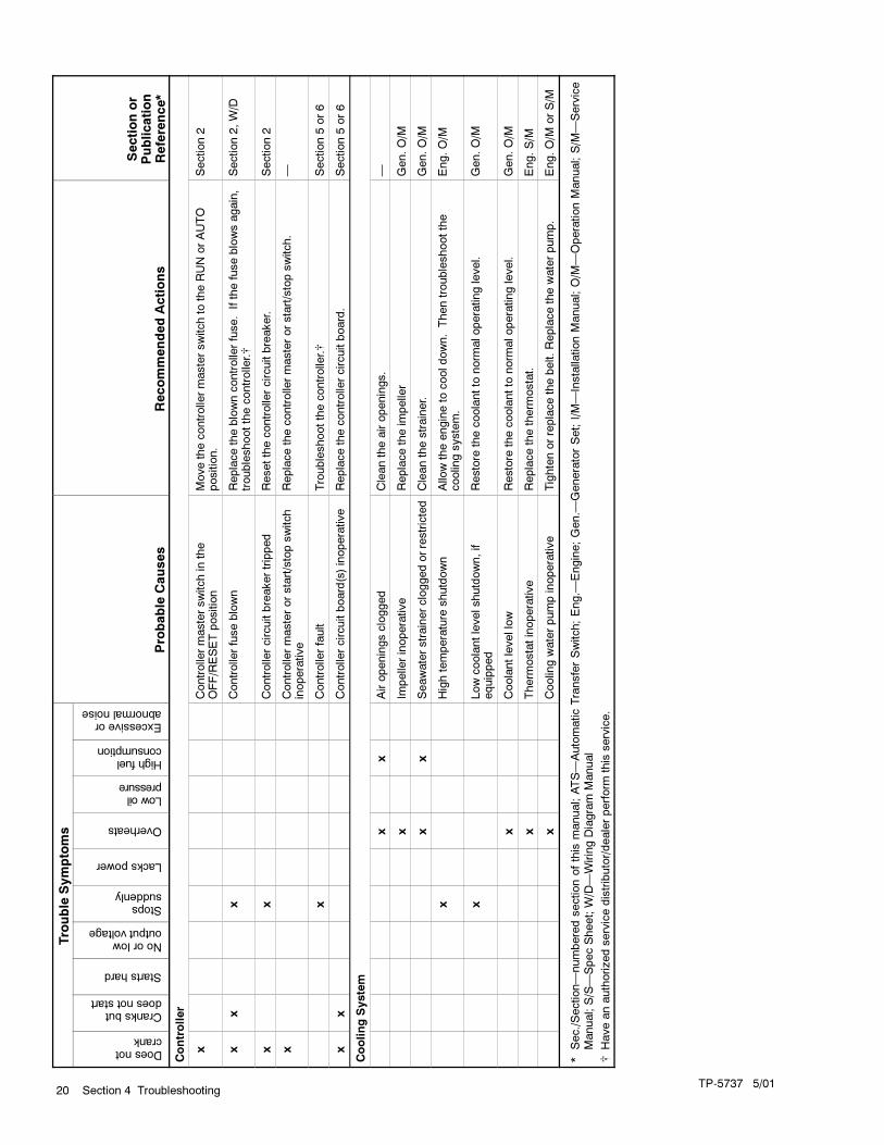
TP-5737 5/0120 Section 4 Troubleshooting
Trouble
Symptoms
Doesnotcrank
Cranksbutdoesnotstart
Startshard
Noorlowoutputvoltage
Stopssuddenly
Lackspower
Overheats
Lowoilpressure
Highfuelconsumption
Excessiveorabnormalnoise
Probable
Causes
RecommendedActions
Sectionor
Publication
Reference*
Controller
xControlle
rmasterswitchin
the
OFF/RESETposition
Movethecontrolle
rmasterswitchto
theRUNorAUTO
position.
Section2
xx
xControlle
rfuseblown
Replacetheblowncontrolle
rfuse.Ifthefuseblowsagain,
troubleshootthecontroller.�
Section2,W/D
xx
Controllercircuitbreakertripped
Resetthecontrollercircuitbreaker.
Section2
xControllermasterorstart/stopswitch
inoperative
Replacethecontrolle
rmasterorstart/stopswitch.
—
xControllerfault
Troubleshootthecontroller.�
Section5or6
xx
Controllercircuitboard(s)inoperative
Replacethecontrollercircuitboard.
Section5or6
CoolingSystem
xx
Airopeningsclogged
Cleantheairopenings.
—
xIm
pellerinoperative
Replacetheim
pelle
rGen.O/M
xx
Seawaterstrainercloggedorrestricted
Cleanthestrainer.
Gen.O/M
xHightemperature
shutdown
Allo
wtheengineto
cooldown.Thentroubleshootthe
coolin
gsystem.
Eng.O/M
xLowcoolantlevelshutdown,if
equipped
Restore
thecoolantto
norm
aloperatinglevel.
Gen.O/M
xCoolantlevellow
Restore
thecoolantto
norm
aloperatinglevel.
Gen.O/M
xTherm
ostatinoperative
Replacethetherm
ostat.
Eng.S/M
xCoolin
gwaterpumpinoperative
Tightenorreplacethebelt.Replacethewaterpump.
Eng.O/M
orS/M
*Sec./Section—numberedsectionofthis
manual;ATS—AutomaticTransferSwitch;Eng.—
Engine;Gen.—
GeneratorSet;I/M—InstallationManual;O/M
—OperationManual;S/M
—Service
Manual;S/S—SpecSheet;W/D—WiringDiagram
Manual
�Haveanauthorizedservicedistributor/dealerperform
this
service.
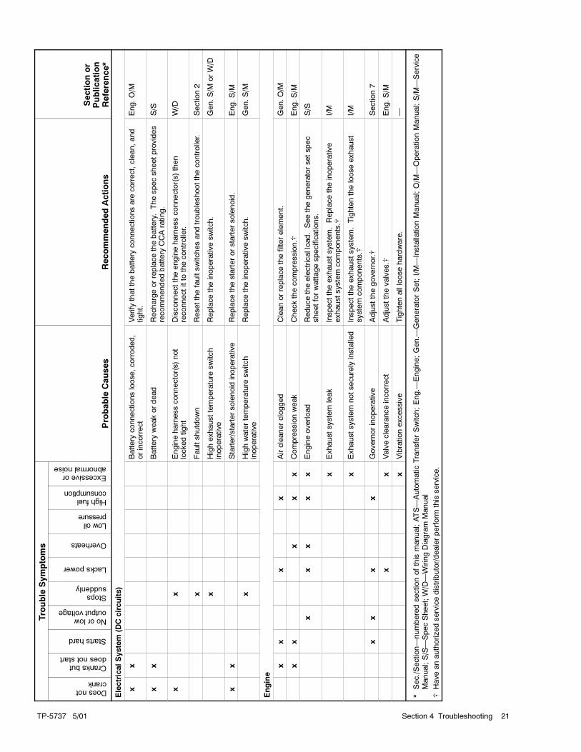
TP-5737 5/01 21Section 4 Troubleshooting
Sectionor
Publication
Reference*
RecommendedActions
Probable
Causes
Trouble
Symptoms
Sectionor
Publication
Reference*
RecommendedActions
Probable
Causes
Excessiveorabnormalnoise
Highfuelconsumption
Lowoilpressure
Overheats
Lackspower
Stopssuddenly
Noorlowoutputvoltage
Startshard
Cranksbutdoesnotstart
Doesnotcrank
ElectricalSystem
(DCcircuits)
xx
Battery
connectionsloose,corroded,
orincorrect
Verify
thatthebattery
connectionsare
correct,clean,and
tight.
Eng.O/M
xx
Battery
weakordead
Rechargeorreplacethebattery.Thespecsheetprovides
recommendedbattery
CCArating.
S/S
xx
Engineharnessconnector(s)not
lockedtight
Disconnecttheengineharnessconnector(s)then
reconnectitto
thecontrolle
r.W/D
xFaultshutdown
Resetthefaultswitchesandtroubleshootthecontrolle
r.Section2
xHighexhausttemperature
switch
inoperative
Replacetheinoperativeswitch.
Gen.S/M
orW/D
xx
Starter/startersolenoid
inoperative
Replacethestarterorstartersolenoid.
Eng.S/M
xHighwatertemperature
switch
inoperative
Replacetheinoperativeswitch.
Gen.S/M
Engine
xx
xx
Aircleanerclogged
Cleanorreplacethefilterelement.
Gen.O/M
xx
xx
xCompressionweak
Checkthecompression.�
Eng.S/M
xx
xx
xEngineoverload
Reducetheelectricalload.Seethegeneratorsetspec
sheetforwattagespecifications.
S/S
xExhaustsystem
leak
Inspecttheexhaustsystem.Replacetheinoperative
exhaustsystem
components.�
I/M
xExhaustsystem
notsecurely
installe
dInspecttheexhaustsystem.Tightenthelooseexhaust
system
components.�
I/M
xx
xx
Governorinoperative
Adjustthegovernor.�
Section7
xx
Valveclearanceincorrect
Adjustthevalves.�
Eng.S/M
xVibrationexcessive
Tightenallloosehardware.
—
*Sec./Section—numberedsectionofthis
manual;ATS—AutomaticTransferSwitch;Eng.—
Engine;Gen.—
GeneratorSet;I/M—InstallationManual;O/M
—OperationManual;S/M
—Service
Manual;S/S—SpecSheet;W/D—WiringDiagram
Manual
�Haveanauthorizedservicedistributor/dealerperform
this
service.
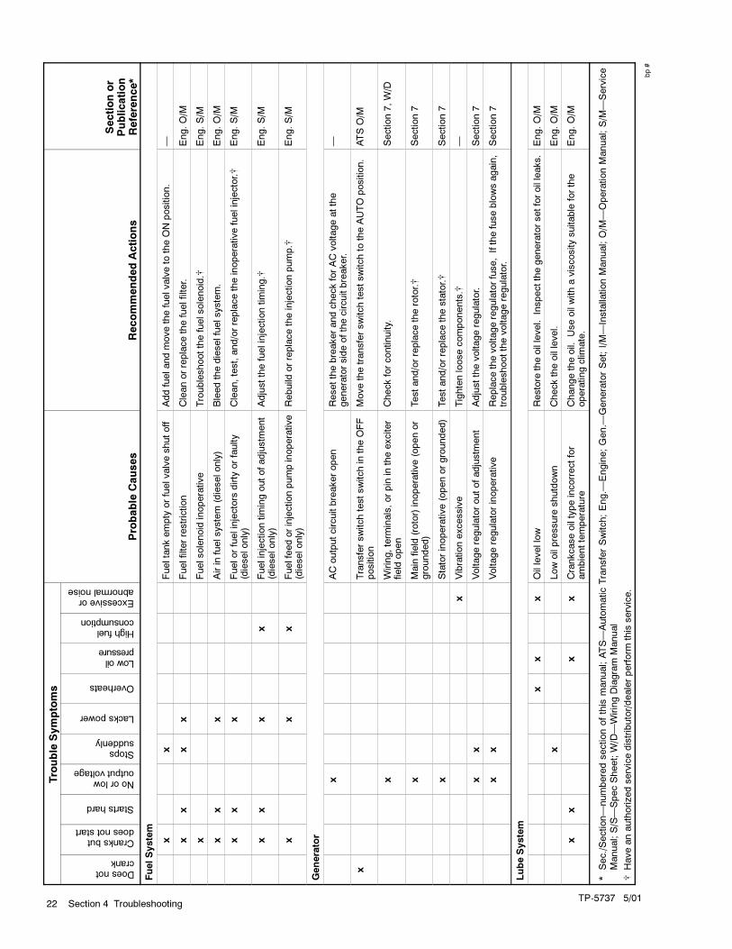
TP-5737 5/0122 Section 4 Troubleshooting
Sectionor
Publication
Reference*
RecommendedActions
Probable
Causes
Trouble
Symptoms
Sectionor
Publication
Reference*
RecommendedActions
Probable
Causes
Excessiveorabnormalnoise
Highfuelconsumption
Lowoilpressure
Overheats
Lackspower
Stopssuddenly
Noorlowoutputvoltage
Startshard
Cranksbutdoesnotstart
Doesnotcrank
FuelSystem
xx
Fueltankempty
orfuelvalveshutoff
Addfuelandmovethefuelvalveto
theONposition.
—
xx
xx
Fuelfilterrestriction
Cleanorreplacethefuelfilter.
Eng.O/M
xFuelsolenoid
inoperative
Troubleshootthefuelsolenoid.�
Eng.S/M
xx
xAirin
fuelsystem
(dieselonly)
Bleedthedieselfuelsystem.
Eng.O/M
xx
xFuelorfuelinjectors
dirty
orfaulty
(dieselonly)
Clean,test,and/orreplacetheinoperativefuelinjector.�
Eng.S/M
xx
xx
Fuelinjectiontimingoutofadjustm
ent
(dieselonly)
Adjustthefuelinjectiontiming.�
Eng.S/M
xx
xFuelfeedorinjectionpumpinoperative
(dieselonly)
Rebuild
orreplacetheinjectionpump.�
Eng.S/M
Generator
xACoutputcircuitbreakeropen
ResetthebreakerandcheckforACvoltageatthe
generatorsideofthecircuitbreaker.
—
xTransferswitchtestswitchin
theOFF
position
Movethetransferswitchtestswitchto
theAUTO
position.
ATSO/M
xWiring,term
inals,orpin
intheexciter
field
open
Checkforcontinuity.
Section7,W/D
xMain
field
(rotor)inoperative(openor
grounded)
Testand/orreplacetherotor.�
Section7
xStatorinoperative(openorgrounded)
Testand/orreplacethestator.�
Section7
xVibrationexcessive
Tightenloosecomponents.�
—
xx
Voltageregulatoroutofadjustm
ent
Adjustthevoltageregulator.
Section7
xx
Voltageregulatorinoperative
Replacethevoltageregulatorfuse,Ifthefuseblowsagain,
troubleshootthevoltageregulator.
Section7
LubeSystem
xx
xOillevellow
Restore
theoillevel.
Inspectthegeneratorsetforoilleaks.
Eng.O/M
xLowoilpressure
shutdown
Checktheoillevel.
Eng.O/M
xx
xx
Crankcaseoiltypeincorrectfor
ambienttemperature
Changetheoil.
Useoilwithaviscositysuitable
forthe
operatingclim
ate.
Eng.O/M
*Sec./Section—numberedsectionofthis
manual;ATS—AutomaticTransferSwitch;Eng.—
Engine;Gen.—
GeneratorSet;I/M—InstallationManual;O/M
—OperationManual;S/M
—Service
Manual;S/S—SpecSheet;W/D—WiringDiagram
Manual
�Haveanauthorizedservicedistributor/dealerperform
this
service.
bp#

TP-5737 5/01 23Section 5 Decision-Maker� 3+ Troubleshooting
Section 5 Decision-Maker� 3+ Troubleshooting
5.1 Decision-Maker� 3+ Controller
For external features, see Section 2, Operation.
Figure 5-1 through Figure 5-11 show the locations of
controller components and connections. Figure 5-12
contains the logic schematic showing input/output
circuits for reference in troubleshooting. This
information deals directly with the 16-light
microprocessor.
1
10 9
62 5
11 7
3
12
4
8A-328917-X
1. Selector switch
2. Lamp circuit board3. Panel lamps
4. Controller DC ground terminal
5. AC fuse terminal block (TB3)6. CT/meter scale terminal block (TB2)
7. Accessory wire guide loops
8. Controller fuses9. Lamp selection jumper
10. Control panel harness connector (P2)
11. Controller main circuit board12. P3/P4 harness
Figure 5-1 Decision-Maker� 3+ Controller

TP-5737 5/0124 Section 5 Decision-Maker� 3+ Troubleshooting
15
16
6
14
321
13 11 91012 8
5
A-336415-L
4
7
1. K2 relay: control relay (crank)
2. K3 relay: control relay (run)3. K4 relay: emergency stop
4. LED1
5. Microprocessor chip6. TB1 terminal strip
7. TB2 terminal strip
8. P3 connector (control panel harness) to P4 (LED indicator
panel assembly)
9. LED4 (K4 relay)
10. P1 connector (DC harness)11. LED3 (K3 relay)
12. P2 connector (AC harness)
13. LED2 (K2 relay)14. Fuse: 3 amp (F1) remote annunciator
15. Fuse: 3 amp (F2) controller
16. Fuse: 15 amp (F3) engine and accessories
Figure 5-2 Decision-Maker� 3+ Controller Circuit Board Components, Typical

TP-5737 5/01 25Section 5 Decision-Maker� 3+ Troubleshooting
5.1.1 Decision-Maker 3+ Circuit Board
Terminal/Connector Identification
Terminal Wire Description
1 1A Emergency stop relay (K4) coil
2 1 Ground—emergency stop relay (K4)
3 42A Battery voltage (fuse #1 protected)
4 2 Ground
5 70C Generator in cool-down mode signal
6 70R Generator in running mode signal
7 56 Air damper indicator, if equipped
8 48 Emergency stop indicator
9 32A Common fault/prealarm
10 26 Auxiliary indicator
11 12 Overcrank indicator
12 39 Overspeed indicator
13 38 Low oil pressure indicator
14 36 High engine temperature indicator
15 60 System ready indicator
16 80 Not-in-auto indicator
17 41 Prealarm low oil pressure indicator
18 62 Low battery volts (active low*)
19 32 Common fault/prealarm
20 35 Low water temperature
21 40 Prealarm high engine temperatureindicator
22 63 Low fuel (active low*)
23 61 Battery charger fault (active low*)
* Check the operation of active low circuits by placing ground onterminals so designated.
Figure 5-3 Terminal Strip TB1
Terminal Wire Description
1 1P Prime power operation (requiresoptional kit)
2 2P Prime power operation (requiresoptional kit)
3 3P Prime power operation (requiresoptional kit)
4 4P Prime power operation (requiresoptional kit)
5 9 Crank mode (open-cyclic groundcontinuous)
6 9A Crank mode ground
7 4 Remote start (active low*)
8 3 Remote start (ground)
* Check the operation of active low circuits by placing ground onterminals so designated.
Figure 5-4 Terminal Strip TB2
Pin Description
1 Output to K1 relay (crank relay), wire 71
2 Ground for speed sensor, wire 2
3 Output to safeguard breaker terminal, wire 70 (andK5 relay if equipped with electronic governor)
4 Not used
5 Ground (--), wire N
6 Speed sensor shield ground, wire S2
7 Output to fuel solenoid (FS), wire 70
8 Battery positive to speed sensor, wire 24
9 Input from speed sensor, wire 16
10 Not used
11 Not used
12 Input from battery positive (14P)
13 Not used
14 Input from high exhaust temperature switch,wire 31
15 Not used
16 Input from pre-high engine temperature switch, wire40A
17 Input from aux. immediate shutdown
18 Not used
19 Not used
20 Not used
21 Input from high engine temperature switch, wire 34
22 Input from low oil pressure switch, wire 13
23 Input from pre-low oil pressure switch, wire 41A
24 Not used
* Check the operation of active low circuits by placing ground onterminals so designated.
Figure 5-5 P1 Connector Pins
Pin Description
1 Output to engine gauge, wire 70
2 Not used
3 Input for AC crank disconnect & instrumentation,wire V7F
4 Not used
5 Input for AC crank disconnect & instrumentation,wire V0
6 Engine ground, wire 2
Figure 5-6 P2 Connector Pins

TP-5737 5/0126 Section 5 Decision-Maker� 3+ Troubleshooting
Pin Description
1 Ground (--), front panel, wire 2
2 Not used
3 Not used
4 Input from generator set master switch, autoposition, wire 46
5 Not used
6 Voltage (+) to front panel, wire 24
7 Output to low oil pressure indicator, wire 38
8 Output to overspeed indicator, wire 39
9 Output to overcrank indicator, wire 12
10 Output to auxiliary indicator, wire 26
11 Output to emergency stop lamp, wire 48
12 Output to pre-high engine temperature indicator,wire 40
13 Output to high engine temperature indicator, wire 36
14 Output to system ready indicator, wire 60
15 Output to not-in-auto indicator, wire 80
16 Output to low water temperature indicator, wire 35
17 Output to pre-low oil pressure indicator, wire 41
18 Output to air damper indicator, if equipped, wire 56
19 Output to low battery volts indicator, wire 62
20 Output to battery charger fault indicator, wire 61
21 Output to low fuel indicator, wire 63
22 Output to common alarm, wire 32
23 Input from generator master switch, off/resetposition, wire 43
24 Input from generator set master switch, run position,wire 47
Figure 5-7 P3 Connector Pins
Pin Description
1 Ground (--), front panel, wire 2
2 Not used
3 Not used
4 Output from generator set master switch, autoposition, wire 46
5 Not used
6 Voltage (+) to front panel, wire 24
7 Input to low oil pressure indicator, wire 38�
8 Input to overspeed indicator, wire 39�
9 Input to overcrank indicator, wire 12�
10 Input to auxiliary indicator, wire 26
11 Input to emergency stop lamp, wire 48
12 Input to pre-high engine temperature indicator, wire40�
13 Input to high engine temperature indicator, wire 36�
14 Input to system ready indicator, wire 60
15 Input to not-in-auto indicator, wire 80
16 Input to low water temperature indicator, wire 35�
17 Input to pre-low oil pressure indicator, wire 41�
18 Input to air damper indicator, if equipped, wire 56
19 Input to low battery volts indicator, wire 62
20 Input to battery charger fault indicator, wire 61
21 Input to low fuel indicator, wire 63�
22 Input to common alarm, wire 32�
23 Output from generator master switch, off/resetposition, wire 43
24 Output from generator set master switch, runposition, wire 47
� Commonalarm triggeredbyhighengine temp.,highengine temp.prealarm, low oil pressure, low oil pressure prealarm, low watertemp., overcrank, overspeed, low fuel, and auxiliary faults.
Figure 5-8 P4 Connector Pins

TP-5737 5/01 27Section 5 Decision-Maker� 3+ Troubleshooting
Emergency
Stop
B+
B--
E.STOP
AUX
OC
OS
LOP
HWT
Common Fault /Prealarm (Line 1)
LWT
System Ready
NIA
AWT
AOP
Low Fuel
Battery Charger Fault
Low Battery
(--)
Common Fault Indicator Activated By:HWTAWTLOPAOPLWTOCOSLFAUX
Connect AV Alarm orCommon Fault Relay Kit
Running Mode
Cool-Down Mode
(--)Common Fault /Prealarm (Line 2)
Prime Power Operation
Crank Mode
Remote Switch
A-336415-L
Figure 5-9 Decision-Maker� 3+ Controller Connections (TB1 and TB2 terminal strips)

TP-5737 5/0128 Section 5 Decision-Maker� 3+ Troubleshooting
A-336415-L
120 VAC forCrankDisconnect
V7
2
VO
70
3
4
5
Panel Lamps
BV HR
WTOP
2
1
6
P2
AOP Anticipatory (Low) Oil Pressure
AUX. Auxiliary
AUX PRE Auxiliary Prealarm
AWT Anticipatory (High) Water Temperature
BCF Battery Charger Fault
EAD Engine Air Damper
E. STOP Emergency Stop
FS Fuel Solenoid
HWT High Water Temperature
HXT High Exhaust Temperature
LBV Low Battery Volts
LF Low Fuel
LOP Low Oil Pressure
LWT Low Water Temperature
NIA Not In Auto
OC Overcrank
OS Overspeed
SG Safeguard Circuit Breaker
SYS RDY System Ready
WLS Water Level Switch
Input
Output
1
4
21
24
31HXT
K5
K1 71
BATTERY
20
+
--
FS
34
13
HETLOP
-- +14P
24
16
70
MagneticPickup
Auxiliary Immediate
Shutdown Switch
VoltageReg.
1B
Ign. B+
SafeguardCircuitBreaker
70
AlternatorFlash
41A
PLOP
40A
PHET
P1
14N
Figure 5-10 Decision-Maker� 3+ Controller Connections (P1 and P2)

TP-5737 5/01 29Section 5 Decision-Maker� 3+ Troubleshooting
SYS
RDY
Controller 16-Light LED Indicators
BC
A-336415-L
TB1--26
TB1--12
TB1--39
TB1--38
TB1--36
12VREG.
TB1--35
OC OS LOPHET
Alarm Horn
Lamp Test
HornSilence
Grd.
Run
Auto
Off/Reset
Generator ControlSwitch
Switch Logic
AUTO
OFF/
RESET
RUN
TB1--48
ES AUX
TB1--60
TB1--80
TB1--40
TB1--16
TB1--41
AOP LWTLBVLF NIA
TB1--62
TB1--61
TB1--63
TB1--32
AOP Anticipatory (Low) Oil Pressure
AUX. Auxiliary
AUX PRE Auxiliary Prealarm
AHET Anticipatory High Engine Temperature
AWT Anticipatory (High) Water Temperature
BC Battery Charger Fault
EAD Engine Air Damper
ES Emergency Stop
FS Fuel Solenoid
HET High Engine Temperature
HWT High Water Temperature
LBV Low Battery Volts
LF Low Fuel
LOP Low Oil Pressure
LWT Low Water Temperature
NIA Not-In-Auto
OC Overcrank
OS Overspeed
SG Safeguard Circuit Breaker
SYS RDY System Ready
WLS Water Level Switch
Input
Output
T27
AUX
PRE
Controller Circuit Board
P3
123456789101112131415161718192021222324
EAD
TB1--56
AHET
On
Figure 5-11 Decision-Maker� 3+ to 16-Light LED Indicator Panel Connections (P3)
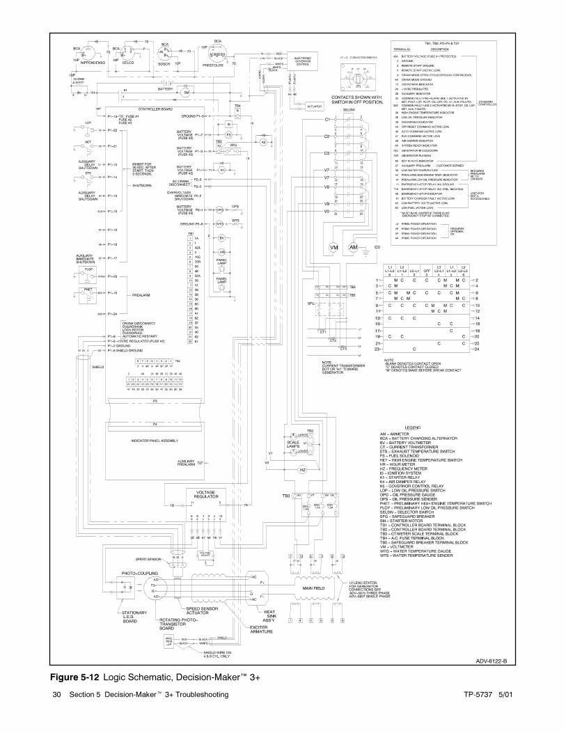
TP-5737 5/0130 Section 5 Decision-Maker� 3+ Troubleshooting
ADV-6122-B
Figure 5-12 Logic Schematic, Decision-Maker� 3+

TP-5737 5/01 31Section 5 Decision-Maker� 3+ Troubleshooting
5.1.2 Fault Shutdowns,
Decision-Maker 3+ Controller
If the generator set does not start or stops running
because of a fault shutdown (fault lamp lit), refer to
Figure 5-13 to identify fault conditions. Consult the
Engine Service Manual for detailed information on
correcting engine-related faults. To reset the set after a
fault shutdown, see Section 2, Operation.
Indicator Fault Condition/Causes
High engine temperature lamp Engine coolant temperature is above shutdown range; see Section 1, SpecificationsHigh engine temperature lamplights Cooling system malfunction
Low oil pressure lamp lights Engine oil pressure is below shutdown range, see Section 1, Specifications
Overspeed lamp lights Governed frequency is in excess of 70 Hz (2100 rpm)
Continuous cranking is more than 45 seconds
Overcrank lamp lights Cyclic cranking is more than 75 secondsp g
Locked rotor
Overcrank lamp flashes Speed sensor signal is absent longer than one second
No AC output is present
Auxiliary lamp flashes Battery power was reconnected or was low and then came back up again while generatorset master switch was in the RUN or AUTO position
Optional emergency stop switch is reset while the generator setmaster switch is in theRUNor AUTO position
Auxiliary lamp lights
Highexhaust temperature (P1-14)orauxiliarydelayshutdown(P1-15) faultsoccur, if sensorequipped
Auxiliary lamp lightsOvervoltage, if equipped, has occurred, voltage 15% greater than nominal voltage (forperiod longer than two seconds)
Activatedbycustomer-suppliedsensingdeviceconnected toauxiliary immediateshutdownports (P1-17 and P1-18)
Emergency stop if equippedEmergency stop switch is activated (local or remote)
Emergency stop, if equippedEmergency stop switch(es) are disconnected from controller terminals TB1-1 or 1A
Multiple lamps light (whereillumination may appear dim)
Main circuit board F1 (3-amp) fuse blown. F1 fuse supplies battery voltage to a remoteannunciator and/or dry contact kit.
Figure 5-13 Fault Shutdown Troubleshooting Chart

TP-5737 5/0132 Section 5 Decision-Maker� 3+ Troubleshooting
5.2 Microprocessor Controller
Relay Descriptions
A description of the controller and generator relays
follows. Use this information to troubleshoot the
generator set in conjunction with the troubleshooting
microprocessor controller flowcharts on the following
pages. Use the troubleshooting section following and
the respective wiring diagram for additional information.
5.2.1 K1 Relay, Starter Solenoid
The K1 relay, located on the engine, energizes the
starter.
5.2.2 K2 Relay, Crank Relay on Main
Circuit Board
The K2 relay energizes the K1 relay. The LED2 lights
when energized during crank mode. The K2 relay is
located on the controller circuit board. See Figure 5-14.
5.2.3 K3 Relay, Run Relay on Main
Circuit Board
The K3 relay energizes the fuel solenoid and
instrumentation.
The K3 relay also energizes the generator voltage
regulator. LED3 lights when energized during crank and
run modes. The K3 relay is located on the controller
circuit board.
5.2.4 K4 Relay, Emergency Stop Relay
on Main Circuit Board
The K4 relay is continuously energized except during
emergency stop. LED4 is lit at all times except during
emergency stop. The K4 relay is located on the
controller circuit board. If the emergency stop kit is
connected (local or remote), remove the jumper from
circuit board TB1-1 and 1A. If no emergency stop kit is
connected, a jumper must connect terminals TB1-1 and
1A. See Figure 5-14.
A-336415-L
1 2 3 4
57 6
1. K2 relay
2. K3 relay3. K4 relay
4. LED1
5. LED4
6. LED37. LED2
Figure 5-14 Main Circuit Board Relays
5.2.5 K5 Relay, Governor Control Relay
The K5 relay energizes the engine governor control
circuit. The K5 relay is located in the generator junction
box.
5.3 Microprocessor Controller
Hazardous voltage.
Can cause severe injury or death.
Operate the generator set only when
all guards and electrical enclosures
are in place.
Moving rotor.
WARNING
Grounding electrical equipment. Hazardous voltage can
cause severe injury or death. Electrocution is possible
whenever electricity is present. Open the main circuit
breakers of all power sources before servicing the equipment.
Configure the installation to electrically ground the generator
set, transfer switch, and related equipment and electrical
circuits to complywith applicable codesandstandards. Never
contact electrical leads or appliances when standing in water
or onwetgroundbecause theseconditions increase the riskof
electrocution.

TP-5737 5/01 33Section 5 Decision-Maker� 3+ Troubleshooting
Accidental starting.
Can cause severe injury or death.
Disconnect the battery cables before
working on the generator set.
Remove the negative (--) lead first
when disconnecting the battery.
Reconnect the negative (--) lead last
when reconnecting the battery.
WARNING
Disabling the generator set. Accidental starting can
cause severe injury or death. Before working on the
generator set or connected equipment, disable the generator
set as follows: (1) Move thegenerator setmaster switch to the
OFFposition. (2) Disconnect thepower to thebattery charger.
(3) Remove the battery cables, negative (--) lead first.
Reconnect the negative (--) lead last when reconnecting the
battery. Follow these precautions to prevent starting of the
generator set by an automatic transfer switch, remote
start/stop switch, or engine start command from a remote
computer.
5.3.1 Troubleshooting
Use the following charts as a quick reference in
troubleshooting individual problems. Consult the first
chart for aid in locating the cause of blown fuses. In the
successive charts, generator faults are listed by specific
groups and correlated with possible causes and
corrective action. Before beginning any troubleshooting
procedure, read all safety precautions at the beginning
of this manual and those included in the text. Do not
neglect these precautions.
Note: If starting the unit by remote switch, verify proper
operation of the remote switch before
troubleshooting the controller. Test the remote
switch operation by placing the generator set
master switch in the AUTOposition and running a
jumper between terminals 3 and 4 on the
controller circuit board. If the generator does not
start, proceed with the controller troubleshooting
procedure outlined in the following pages.
To quickly check the condition of the components
mentioned in the following flowcharts, use an ohmmeter
to read resistance between the designated terminal and
ground. See Figure 5-16. With the ohmmeter on the
R x 1 scale, a reading of less than one ohm (continuity)
indicates that the component may be inoperative.
Isolate the inoperative component and repair or replace
it.
ComponentConnect between
ground and terminal:
Engine gauges Connector P2, pin 1
Crank (K1 relay) circuit Connector P1, pin 1
(Diesel) fuel solenoid circuit Connector P1, pin 7
Figure 5-15 Checking P1 and P2 Connections
3-187
�
1
2
1. Ground connection
2. P2 connection
Figure 5-16 Checking P1 and P2 Connections
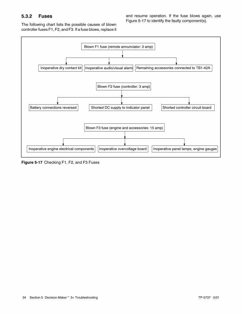
TP-5737 5/0134 Section 5 Decision-Maker� 3+ Troubleshooting
5.3.2 Fuses
The following chart lists the possible causes of blown
controller fuses F1, F2, and F3. If a fuse blows, replace it
and resume operation. If the fuse blows again, use
Figure 5-17 to identify the faulty component(s).
Inoperative audio/visual alarm
Blown F1 fuse (remote annunciator: 3 amp)
Blown F2 fuse (controller: 3 amp)
Battery connections reversed Shorted DC supply to indicator panel Shorted controller circuit board
Blown F3 fuse (engine and accessories: 15 amp)
Inoperative engine electrical components Inoperative overvoltage board Inoperative panel lamps, engine gauges
Inoperative dry contact kit Remaining accessories connected to TB1-42A
Figure 5-17 Checking F1, F2, and F3 Fuses

TP-5737 5/01 35Section 5 Decision-Maker� 3+ Troubleshooting
Check for DC voltage at the F2 fuse
(3 amp). See Figure 5-20. Voltage
at the fuse indicates the fuse is
good. Is voltage present?
Check the engine start circuit
(P1 harness, starter, solenoid,
battery connections, etc.). Is
the start circuit okay?
Engine does not crank with the generator
set master switch in the RUN position.
Is the battery fully charged? Yes
No
Charge the battery and attempt
restart. If the engine does not
crank, continue the troubleshooting
sequence.
Press the lamp test
button. Do lamps light?
No
Check the P3/P4 harness and
connections. Are the connections okay?
No
Replace the P3/P4
harness.
Replace the inoperative
indicator panel circuit board.
Yes
Is the controller LED4 lit? Yes
Is the emergency stop switch (controller
or remote) activated? See emergency
stopping in Section 2, Operation.
Do the controller’s LED2 and LED3 light
with the generator set master switch in
the RUN position?
Yes
Was there a fault shutdown?
Replace the
circuit board.
Correct the
fault.
Repair the
inoperative
component.
Replace the
circuit board.
Reset the emergency stop
switch (controller or remote). Is
LED4 lit?
Check the fuse.
Is the fuse okay?
Replace the fuse. If the fuse
blows again, refer to Section
5.3.2, Fuses.
Check the P1 connector/harness.
Check if the battery connections
are loose or reversed.
Replace the circuit board.
No Yes
No
No Yes
No
YesNo
Yes
No
No
Yes
Yes
Yes
Place the test jumper between TB1-1
and TB1-1A. Is LED4 lit? Remove
the test jumper before proceeding.
No
No
Yes
Repair/replace the
inoperative emergency
stop switch (controller or
remote.)
Figure 5-18 Engine Does Not Crank

TP-5737 5/0136 Section 5 Decision-Maker� 3+ Troubleshooting
Engine cranks but does not start.
Is fuel low? Yes
No
Is LED3 lit? No
Add fuel.
Yes
Yes
Replace the circuit board.
Check the circuit board
P2 harness and
connector pins. Is the
harness inoperative?
No
Yes
Repair or
replace the
harness.
Replace the circuit board.
Are the controller panel lights lit?
No
Repair or replace
the harness
and/or
components.
No
Yes
Check the P1 harness
and connector pins. Is
the harness inoperative?Yes
Repair or replace
the harness.
No
Replace the circuit
board.
Check the bulbs. Are
the bulbs burned out?Yes
Replace
the bulbs
No
Check the engine starting circuit.
Check for battery voltage at the fuel
solenoid/injector pump/electronic
governor
Does the engine starting circuit check out
okay? Check for battery voltage at the
governor controller (on diesel units).
Figure 5-19 Engine Cranks, But Does Not Start
3-187
V
1
1. Fuse terminal
Figure 5-20 Checking Condition of F2 Fuse
A-328917-X1
1. AC fuse terminal block
Figure 5-21 AC Fuse Terminal Block

TP-5737 5/01 37Section 5 Decision-Maker� 3+ Troubleshooting
Controller instrumentation not functioning properly.
Is there a loose input or component
lead connection at the AC fuse
terminal block or at the component?Yes
No
Is there a blown 1.5-amp fuse at the AC
fuse terminal block? See Figure 5-21.Replace the fuse.
Instrumentation is inoperative.
Replace or repair the component.
Secure the connection.
No
Yes
Figure 5-22 Controller Instrumentation
Press the lamp test button.
Do the lamps light?
Lamp circuit board not functioning or not functioning
properly (i.e., fault lamps and alarm horn only).
Improper input signal. The
main circuit board is
inoperative.
Is the lamp circuit board receiving
power? Check for input voltage at
P4-6 and P4-1 soldered
connections on the lamp circuit
board. See Figure 5-24.
The panel circuit board is
inoperative. Replace it.
Is the P3/P4 ribbon connector
undamaged and properly connected?
Replace the
ribbon connector.
Replace the
main circuit
board.
Yes
No
Yes
No
Yes
No
Figure 5-23 Lamp Circuit Board
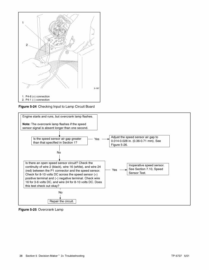
TP-5737 5/0138 Section 5 Decision-Maker� 3+ Troubleshooting
3-187
1
2
1. P4-6 (+) connection
2. P4-1 (--) connection
Figure 5-24 Checking Input to Lamp Circuit Board
Is there an open speed sensor circuit? Check the
continuity of wire 2 (black), wire 16 (white), and wire 24
(red) between the P1 connector and the speed sensor.
Check for 8-10 volts DC across the speed sensor (+)
positive terminal and (--) negative terminal. Check wire
16 for 3-6 volts DC, and wire 24 for 8-10 volts DC. Does
this test check out okay?
Is the speed sensor air gap greater
than that specified in Section 1?
Engine starts and runs, but overcrank lamp flashes.
Note: The overcrank lamp flashes if the speed
sensor signal is absent longer than one second.
Adjust the speed sensor air gap to
0.014-0.028 in. (0.36-0.71 mm). See
Figure 5-26.
Inoperative speed sensor.
See Section 7.10, Speed
Sensor Test.
Repair the circuit.
No
Yes
Yes
No
Figure 5-25 Overcrank Lamp
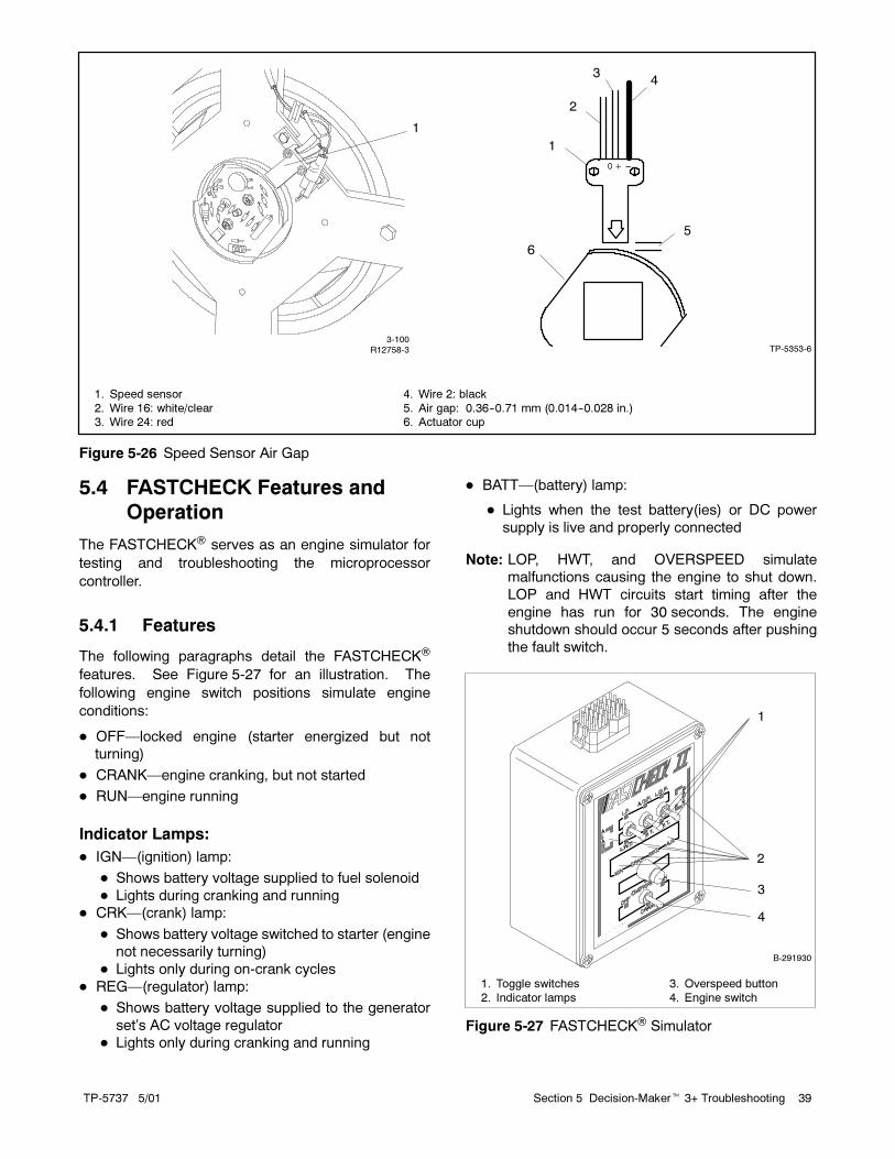
TP-5737 5/01 39Section 5 Decision-Maker� 3+ Troubleshooting
0 + ---
1
2
3
6
5
4
3-100R12758-3 TP-5353-6
1. Speed sensor
2. Wire 16: white/clear3. Wire 24: red
4. Wire 2: black
5. Air gap: 0.36--0.71 mm (0.014--0.028 in.)6. Actuator cup
1
Figure 5-26 Speed Sensor Air Gap
5.4 FASTCHECK Features and
Operation
The FASTCHECK� serves as an engine simulator for
testing and troubleshooting the microprocessor
controller.
5.4.1 Features
The following paragraphs detail the FASTCHECK�
features. See Figure 5-27 for an illustration. The
following engine switch positions simulate engine
conditions:
� OFF—locked engine (starter energized but not
turning)
� CRANK—engine cranking, but not started
� RUN—engine running
Indicator Lamps:
� IGN—(ignition) lamp:
� Shows battery voltage supplied to fuel solenoid
� Lights during cranking and running
� CRK—(crank) lamp:
� Shows battery voltage switched to starter (engine
not necessarily turning)
� Lights only during on-crank cycles
� REG—(regulator) lamp:
� Shows battery voltage supplied to the generator
set’s AC voltage regulator
� Lights only during cranking and running
� BATT—(battery) lamp:
� Lights when the test battery(ies) or DC power
supply is live and properly connected
Note: LOP, HWT, and OVERSPEED simulate
malfunctions causing the engine to shut down.
LOP and HWT circuits start timing after the
engine has run for 30 seconds. The engine
shutdown should occur 5 seconds after pushing
the fault switch.
1
2
3
4
B-291930
1. Toggle switches
2. Indicator lamps
3. Overspeed button
4. Engine switch
Figure 5-27 FASTCHECK� Simulator
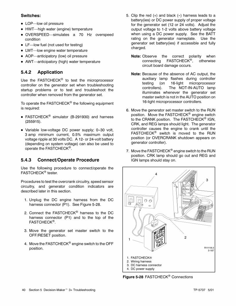
TP-5737 5/0140 Section 5 Decision-Maker� 3+ Troubleshooting
Switches:
� LOP—low oil pressure
� HWT—high water (engine) temperature
� OVERSPEED—simulates a 70 Hz overspeed
condition
� LF—low fuel (not used for testing)
� LWT—low engine water temperature
� AOP—anticipatory (low) oil pressure
� AWT—anticipatory (high) water temperature
5.4.2 Application
Use the FASTCHECK� to test the microprocessor
controller on the generator set when troubleshooting
startup problems or to test and troubleshoot the
controller when removed from the generator set.
To operate the FASTCHECK� the following equipment
is required:
� FASTCHECK� simulator (B-291930) and harness
(255915).
� Variable low-voltage DC power supply; 0--30 volt,
3 amp minimum current, 0.5% maximum output
voltage ripple at 30 volts DC. A 12- or 24-volt battery
(depending on system voltage) can also be used to
operate the FASTCHECK�.
5.4.3 Connect/Operate Procedure
Use the following procedure to connect/operate the
FASTCHECK� tester.
Procedures to test the overcrank circuitry, speed sensor
circuitry, and generator condition indicators are
described later in this section.
1. Unplug the DC engine harness from the DC
harness connector (P1). See Figure 5-28.
2. Connect the FASTCHECK� harness to the DC
harness connector (P1) and to the top of the
FASTCHECK�.
3. Move the generator set master switch to the
OFF/RESET position.
4. Move the FASTCHECK� engine switch to the OFF
position.
5. Clip the red (+) and black (--) harness leads to a
battery(ies) or DC power supply of proper voltage
for the generator set (12 or 24 volts). Adjust the
output voltage to 1-2 volts above battery voltage
when using a DC power supply. See the BATT
rating on the generator nameplate. Use the
generator set battery(ies) if accessible and fully
charged.
Note: Observe the correct polarity when
connecting FASTCHECK�, otherwise
circuit board damage occurs.
Note: Because of the absence of AC output, the
auxiliary lamp flashes during controller
testing (on 16-light microprocessor
controllers). The NOT-IN-AUTO lamp
illuminates whenever the generator set
master switch is not in the AUTO position on
16-light microprocessor controllers.
6. Move the generator set master switch to the RUN
position. Move the FASTCHECK� engine switch
to the CRANK position. The FASTCHECK� IGN,
CRK, and REG lamps should light. The generator
controller causes the engine to crank until the
FASTCHECK� switch is moved to the RUN
position (or OVERCRANK shutdown appears on
generator controller).
7. Move the FASTCHECK� engine switch to theRUN
position. CRK lamp should go out and REG and
IGN lamps should stay on.
12
3
4
R11118-23-187
1. FASTCHECK�
2. Wiring harness3. DC harness connector
4. DC power supply
Figure 5-28 FASTCHECK� Connections

TP-5737 5/01 41Section 5 Decision-Maker� 3+ Troubleshooting
8. Simulate engine malfunctions by pressing
FASTCHECK� fault switches. The corresponding
fault lamp on the controller should light during each
simulated engine malfunction.
Note: Leave the FASTCHECK� engine switch in
the RUN position for at least 30 seconds
before pushing toggle switches. Toggle the
generator set master switch to the
OFF/RESET position and the
FASTCHECK� engine switch to the OFF
position, then back to the RUN position after
simulated fault shutdowns.
5.4.4 Overcrank
Use the following procedure to test the controller’s
ability to detect a locked engine and to stop a startup
attempt if the starter locks or does not engage.
Overcrank Circuitry Test Procedure
1. Move the FASTCHECK� engine switch to the OFF
position.
2. Move the generator set master switch to the OFF
position and then move the switch to the RUN
position.
3. IGN, CRK, and REG lamps on FASTCHECK�
should light for approximately 5 seconds and then
go out. Five seconds later, the IGN,CRK, andREG
lamps should relight for 5 seconds before going out
again (15 seconds total elapsed time). The
controller OVERCRANK lamp lights. Check for
operating voltage between TB1-42A (+) and
TB1-12 (--).
4. This test verifies the proper operation of the engine
overcrank circuit. If the OVERCRANK shutdown
fails to function, check the speed sensor and
related circuitry. See Section 5.4.5, Controller
Speed Sensor Circuitry, and Section 7.10, Speed
Sensor Test.
5.4.5 Controller Speed Sensor Circuitry
To check the controller’s ability to respond to signals
from the speed sensor, perform the following test:
Speed Sensor Circuitry Test Procedure
1. Move the generator set master switch to the
OFF/RESET position.
2. Move the FASTCHECK� engine switch to the OFF
position.
3. Move the generator set master switch to the RUN
position. Observe the IGN, CRK, and REG lamps
light.
4. Within 5 seconds, move the FASTCHECK� engine
switch to the RUN position.
5. If the FASTCHECK� CRK lamp goes out, the
controller speed sensor circuitry is functioning
correctly.
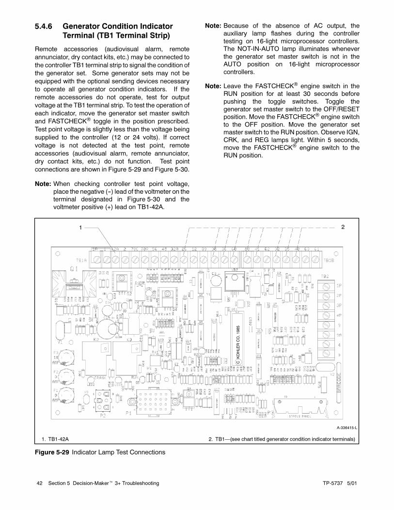
TP-5737 5/0142 Section 5 Decision-Maker� 3+ Troubleshooting
5.4.6 Generator Condition Indicator
Terminal (TB1 Terminal Strip)
Remote accessories (audiovisual alarm, remote
annunciator, dry contact kits, etc.) may be connected to
the controller TB1 terminal strip to signal the condition of
the generator set. Some generator sets may not be
equipped with the optional sending devices necessary
to operate all generator condition indicators. If the
remote accessories do not operate, test for output
voltage at the TB1 terminal strip. To test the operation of
each indicator, move the generator set master switch
and FASTCHECK� toggle in the position prescribed.
Test point voltage is slightly less than the voltage being
supplied to the controller (12 or 24 volts). If correct
voltage is not detected at the test point, remote
accessories (audiovisual alarm, remote annunciator,
dry contact kits, etc.) do not function. Test point
connections are shown in Figure 5-29 and Figure 5-30.
Note: When checking controller test point voltage,
place the negative (--) lead of the voltmeter on the
terminal designated in Figure 5-30 and the
voltmeter positive (+) lead on TB1-42A.
Note: Because of the absence of AC output, the
auxiliary lamp flashes during the controller
testing on 16-light microprocessor controllers.
The NOT-IN-AUTO lamp illuminates whenever
the generator set master switch is not in the
AUTO position on 16-light microprocessor
controllers.
Note: Leave the FASTCHECK� engine switch in the
RUN position for at least 30 seconds before
pushing the toggle switches. Toggle the
generator set master switch to the OFF/RESET
position. Move the FASTCHECK� engine switch
to the OFF position. Move the generator set
master switch to the RUN position. Observe IGN,
CRK, and REG lamps light. Within 5 seconds,
move the FASTCHECK� engine switch to the
RUN position.
A-336415-L
1 2
1. TB1-42A 2. TB1—(see chart titled generator condition indicator terminals)
Figure 5-29 Indicator Lamp Test Connections

TP-5737 5/01 43Section 5 Decision-Maker� 3+ Troubleshooting
Indicator Switch Position/Remarks Check For Voltage Between
System Ready Master switch in AUTO position; engine switch in OFF
position.
TB1-42A (+) and TB1-60 (--)
High (Engine) Water
Temperature (HWT)
Master switch in RUN position; engine switch in RUN
position; hold toggle switch to HWT for at least 5 seconds
TB1-42A (+) and TB1-36 (--)
Low Oil Pressure (LOP) Master switch in RUN position; engine switch in RUN
position; hold toggle switch to LOP for at least 5 seconds
TB1-42A (+) and TB1-38 (--)
Auxiliary Fault (16-light
controller)
Master switch in RUN position; engine switch in RUN
position; wait 10 seconds. A flashing AUX lamp indicates
proper operation of all auxiliary functions
TB1-42A (+) and TB1-26 (--)
Emergency Stop
(local/remote), if equipped
Master switch in RUN position; engine switch in RUN
position; remove switch lead connected to controller
terminals TB1-1 or 1A.
Not Applicable
Generator Switch Not-in-Auto Master switch in RUN or OFF/RESET; engine switch in any
position
TB1-42A (+) and TB1-80 (--)
Anticipatory (High Engine)
Water Temperature (AWT)
Master switch in RUN position; engine switch in RUN; hold
toggle switch to AWT
TB1-42A (+) and TB1-40 (--)
Anticipatory (Low Engine) Oil
Pressure (AOP)
Master switch in RUN position; engine switch in RUN; hold
toggle switch to AOP
TB1-42A (+) and TB1-41 (--)
Low Water Temperature
(LWT), if equipped
Master switch in RUN position; engine switch in RUN; hold
toggle switch to LWT
TB1-42A (+) and TB1-35 (--)
Low Fuel, if equipped Generator set master switch in OFF/RESET; engine switch in
RUN position
Ground controller terminal TB1-63 to test. If the Low Fuel
lamp lights, the circuit is functioning correctly
Not Applicable
Battery Charger Fault (if
battery charger equipped and
connected)
Generator set master switch in OFF/RESET; engine switch in
RUN position
Ground controller terminal TB1-61 to test. If the Battery
Charger lamp lights, the circuit is functioning correctly
Not Applicable
Low Battery Volts (if battery
charger equipped and
connected)
Generator set master switch in OFF/RESET; engine switch in
RUN position
Ground controller terminal TB1-62 to test. If the Low Battery
Volts lamp lights, the circuit is functioning correctly
Not Applicable
Overspeed See Section 5.4.5, Controller Speed Sensor Circuitry. Not Applicable
Overcrank See Section 5.4.4, Overcrank. Not Applicable
Auxiliary Prealarm (Common
Fault)
Master switch in RUN position; engine switch in RUN
position; hold toggle switch to LWT, HWT, or LOP
TB1-42 (+) and TB1-32 (--)
Figure 5-30 Generator Condition Indicator Terminals

TP-5737 5/0144 Section 5 Decision-Maker� 3+ Troubleshooting
Notes

TP-5737 5/01 45Section 6 Decision-Maker� 1 Controller Troubleshooting
Section 6 Decision-Maker� 1 Controller Troubleshooting
6.1 Decision-Maker� 1 and
Decision-Maker� 1
Expanded Relay Controller
The following text covers the relay controller sequence
of operation during generator start, run, stop, and fault
shutdown modes. Use this information as a starting
point for controller fault identification. See Section 2 to
identify controller external components. See Figure 6-1
and Figure 6-2 to identify internal components of the
relay controller. Use the LEDs on the controller circuit
board to assist in the troubleshooting process. An
illuminated LED indicates the respective relay is
receiving power; the LED does not indicate whether that
relay is energized. See Figure 6-3 and Figure 6-4.
A-336597A-D
1
23
4
5
6
78
9
1011
1. TB1 AC terminal block
2. Governor3. Controller main circuit board (E-254717 COZ models or
F-254717 EOZ models)
4. 15-amp fuse5. K5 relay
6. Ground strap
7. Hourmeter (front panel)
8. Fault lamp (front panel)9. Voltage adjust potentiometer (front panel)
10. 10-amp fuse (front panel)
11. Generator set master switch (front panel)
Figure 6-1 Decision-Maker� 1 Relay Controller
Internal Components
A-336598A-K
1 2 3 4 5
891011
7
6
1. TB2 terminal block
2. Governor3. K5 relay
4. Controller main circuit board (E-254717 COZ models or
F-254717 EOZ models)5. TB1 AC terminal block
6. Ground strap
7. Fault lamp (front panel)
8. Hourmeter (front panel)9. Generator set master switch (front panel)
10. Voltage adjust potentiometer (front panel)
11. 10-amp fuse (front panel)
Figure 6-2 Decision-Maker� 1 Expanded
Relay Controller Internal Components
A change in the circuit board affects the function of some
relays. Circuit board E-254717 has four internal relays
with an external K5 relay for engine run components.
Circuit board F-254717 has five relays with an external
K10 relay for engine run components. The fifth relay
designated K5 latches the fault lamp during fault
shutdown when in the auto/remote start mode.
Although the circuit boards are similar, the changes
relating to K5/K10 alter the troubleshooting information.

TP-5737 5/0146 Section 6 Decision-Maker� 1 Controller Troubleshooting
Function RelayRelay Contact
Normal Position
Relay Contact
Action Energizes/Action:
K2 relay and LED2 lights
St ti Cl th t t/ t it h
K2 Open Close
K10 relay (with F-254717) or K5relay (with E-254717, enginecomponents (fuel system, governor,ignition, etc.), K4 relay, and LED4lights
Starting: Close the start/stop switchbetween N and 47.Note: Fault shutdowns are inhibited duringstartup until K3 energizes. K10
or K5Open Close
Hourmeter on Decision-Maker� 1and Decision-Maker� 1 Expandedcontrollers and engine gauges(battery voltage, water temperature,and oil pressure) onDecision-Maker� 1 Expandedcontrollers
K4 Open Close K20 relay
K20 Open Close Starter motor
Running: Generator winding 7--10d AC t t
K3 relay and LED3 lightsg gproduces AC output.Note: K3 relay must obtain AC outputwithin 30 seconds or overcrank fault
K3 Closed OpenDeenergizes K4 relay and LED4deenergizes
within 30 seconds or overcrank faultoccurs. K4 Open Open Deenergizes starter motor
Stopping: Move the start/stop switch to
Deenergizes K2 relay and LED2deenergizesStopping: Move the start/stop switch to
open circuit between N and 47.K2 Open Open
Deenergizes engine components;generator set shuts down
Fault shutdowns: Low oil pressure (LOP),high engine temperature (HET) after theengine operating temperature reaches103�C (218�F), and high exhausttemperature (ETS) (wet exhaust only) afterthe exhaust temperature reaches
K1 relay, LED1 lights, and faultlamp
the exhaust temperature reaches88--102�C (190--215�F). Contacts close5--8 seconds after reaching shutdownlevel.Note: The fault shutdown latches to keepthe fault lamp lit. Move the generator setmaster switch to OFF/RESET.
K1 Closed OpenDeenergizes engine components;generator set shuts down
Fault shutdown: Overspeed (OS).Contacts close when engine speedreaches shutdown level. Factory set at70 Hz
K1 relay, LED1 lights, and faultlamp
70 Hz.Note: The fault shutdown latches to keepfault lamp lit. Move the generator setmaster switch to OFF/RESET.
K1 Closed OpenDeenergizes engine components;generator set shuts down
Fault shutdown: Overcrank (OC).Contacts close on overcrank (locked rotor)if the speed sensor signal is absent longerthan 30 seconds
K1 relay, LED1 lights, and faultlamp
than 30 seconds.Note: The fault shutdown latches to keepthe fault lamp lit. Move the generator setmaster switch to OFF/RESET.
K1 Closed OpenDeenergizes engine components;generator set shuts down
Figure 6-3 Relay Controller Sequence of Operation

TP-5737 5/01 47Section 6 Decision-Maker� 1 Controller Troubleshooting
9
F---
9
12
ADV-5353-6
+ --
K10
M
Starter
10 amp
K2
HET
LOP
HR
OP
WT
BV
70
K1
Fault
K4
Stator
BV Battery VoltsETS High Exhaust Temperature SwitchFS Fuel SystemGS Governor SystemHET High Engine Temperature SwitchHR HourmeterK1 Fault Shutdown RelayK2 Engine Run RelayK3 Crank Disconnect/
Flashing Control RelayK4 Crank Disconnect RelayK5 Fault Latch RelayK10 Auxiliary Run RelayK20 Starter Relay SolenoidLOP Low Oil Pressure SwitchLWL Low Water Level SenderM Starter MotorOP Oil Pressure GaugeWT Water Temperature Gauge
D5 Run
Auto
Off/Reset
Remote Start4 3
K4
K3
GS
K1
FaultShutdownOverspeed
K3
CrankDisconnect
Q2
Q3
SpeedSensor
SpeedPickup
Speed SensorActuator
K2
47
N
FS
Fault Latch Line
� Overcrank, Overspeed, LWL, HET, andLOP drive the fault shutdown circuit.
� Fault latch provided by K1 normally opencontacts.
� Overcrank shutdown is only driven byAC.
� Crank disconnect driven by AC andspeed sensor input.
� Relays K1, K2, K3, K4, and K5 are part ofthe controller circuit board and theirelectrical connections and circuits aresimplified in this diagram.
� Fault latch line, fault shutdown, crankdisconnect, overcrank, overspeed, andspeed sensor (dotted lines) are part of thecontroller circuit board and their electricalconnections and circuits are simplified inthis diagram.
NOTE
Overcrank
K20
4
1
6 3
7
118
2
5
11
2
4
10VoltageRegulator
AC
AC
F+
V0V7V7
V8
ExciterField
ExciterArmature
Main RotorField
F2F1
FP FN
10
15 amp
K5
K5
5 SecondShutdownReset
K20
K1
K10
K3
6
G
AC
AC
F3
G
Photo TransistorCircuit Board
LED Circuit Board
Photo-Coupling
SCR Assembly
16
ETS
Figure 6-4 Relay Controller Sequence of Operation with F-254717 and Later Circuit Boards
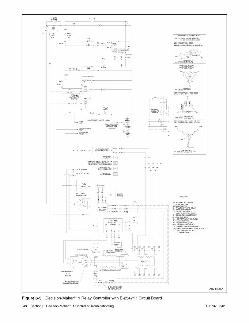
TP-5737 5/0148 Section 6 Decision-Maker� 1 Controller Troubleshooting
ADV-6120-A
Figure 6-5 Decision-Maker� 1 Relay Controller with E-254717 Circuit Board

TP-5737 5/01 49Section 6 Decision-Maker� 1 Controller Troubleshooting
ADV-6120-D
Figure 6-6 Decision-Maker� 1 Relay Controller with F-254717 Circuit Board
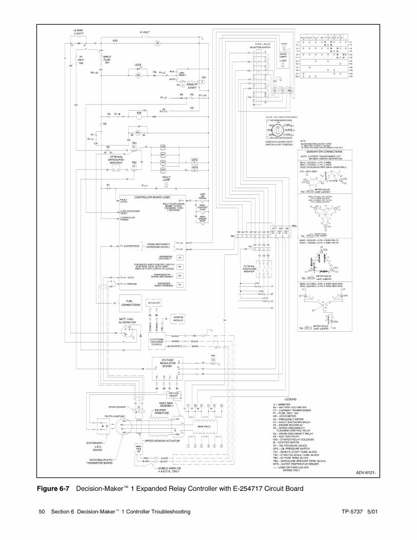
TP-5737 5/0150 Section 6 Decision-Maker� 1 Controller Troubleshooting
ADV-6121-
Figure 6-7 Decision-Maker� 1 Expanded Relay Controller with E-254717 Circuit Board

TP-5737 5/01 51Section 6 Decision-Maker� 1 Controller Troubleshooting
ADV-6121-C
Figure 6-8 Decision-Maker� 1 Expanded Relay Controller with F-254717 Circuit Board
TP-5737 5/0152 Section 6 Decision-Maker� 1 Controller Troubleshooting
6.2 Relay Controller
Use the following charts as a reference in
troubleshooting individual problems. Before beginning
any troubleshooting procedure, read all safety
precautions at the beginning of this manual and those
included in the text. Do not neglect these precautions.
Accidental starting.
Can cause severe injury or death.
Disconnect the battery cables before
working on the generator set.
Remove the negative (--) lead first
when disconnecting the battery.
Reconnect the negative (--) lead last
when reconnecting the battery.
WARNING
Disabling the generator set. Accidental starting can
cause severe injury or death. Before working on the
generator set or connected equipment, disable the generator
set as follows: (1) Move thegenerator setmaster switch to the
OFFposition. (2) Disconnect thepower to thebattery charger.
(3) Remove the battery cables, negative (--) lead first.
Reconnect the negative (--) lead last when reconnecting the
battery. Follow these precautions to prevent starting of the
generator set by an automatic transfer switch, remote
start/stop switch, or engine start command from a remote
computer.
Hazardous voltage.
Can cause severe injury or death.
Operate the generator set only when
all guards and electrical enclosures
are in place.
Moving rotor.
WARNING
Grounding electrical equipment. Hazardous voltage can
cause severe injury or death. Electrocution is possible
whenever electricity is present. Open the main circuit
breakers of all power sources before servicing the equipment.
Configure the installation to electrically ground the generator
set, transfer switch, and related equipment and electrical
circuits to complywith applicable codesandstandards. Never
contact electrical leads or appliances when standing in water
or onwetgroundbecause theseconditions increase the riskof
electrocution.
Use the following flowchart and Figure 6-9 and
Figure 6-10 as an aid in troubleshooting the main circuit
board and the generator set. If the prescribed remedy
does not correct the problem, replace the circuit board.
The controller circuit board includes light emitting
diodes (LEDs) indicating relay coil power and aids in
circuit board and generator fault detection. When the
K1, K2, K3, K4, or K5 relays receive power, the
corresponding LED lights. The LED does not indicate
whether the relay coil is energized. Determine if relay
coil is energized, by analyzing the generator faults and
performing a continuity test on the relay coil.
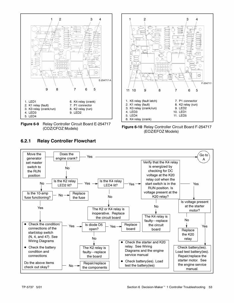
TP-5737 5/01 53Section 6 Decision-Maker� 1 Controller Troubleshooting
E-254717-A
1 2 3 4
56789
1. LED1
2. K1 relay (fault)3. K3 relay (crank/run)
4. LED3
5. LED4
6. K4 relay (crank)
7. P1 connector8. K2 relay (run)
9. LED2
Figure 6-9 Relay Controller Circuit Board E-254717
(COZ/CFOZ Models)
F-254717-
1 2 3 4
567891011
1. K5 relay (fault latch)
2. K1 relay (fault)3. K3 relay (crank/run)
4. LED3
5. LED46. K4 relay (crank)
7. P1 connector
8. K2 relay (run)9. LED2
10. LED1
11. LED5
Figure 6-10 Relay Controller Circuit Board F-254717
(EOZ/EFOZ Models)
6.2.1 Relay Controller Flowchart
Move the
generator
set master
switch to
the RUN
position
Does the
engine crank?
Is the K2 relay
LED2 lit?No Yes
Replace
the fuse
� Check the condition/
connections of the
start/stop switch
(N, 4, and 47). See
Wiring Diagrams
� Check the battery
condition and
connections
Do the above items
check out okay?
Yes
Is the 10-amp
fuse functioning?
Is the K4 relay
LED4 lit?
The K2 or K4 relay is
inoperative. Replace
the circuit board
Verify that the K4 relay
is energized by
checking for DC
voltage at the K20
relay coil when the
start switch is in the
RUN position. Is
voltage present at the
K20 relay?
The K4 relay is
faulty—replace
the circuit
board
� Check the starter and K20
relay. See Wiring
Diagrams and the engine
service manual
� Check battery(ies). Load
test the battery(ies)
Yes Go to
A
No
Yes
No
Yes
No
Is diode D5
open?
The K2 relay is
faulty—replace
the board
Replace
boardYes
Repair/replace
the components
Yes
No
No
No
Is voltage present
at the starter
motor?
Yes
Check battery(ies).
Load test battery(ies).
Repair/replace the
starter motor. See
the engine service
manual.
No
Replace
the K20
relay
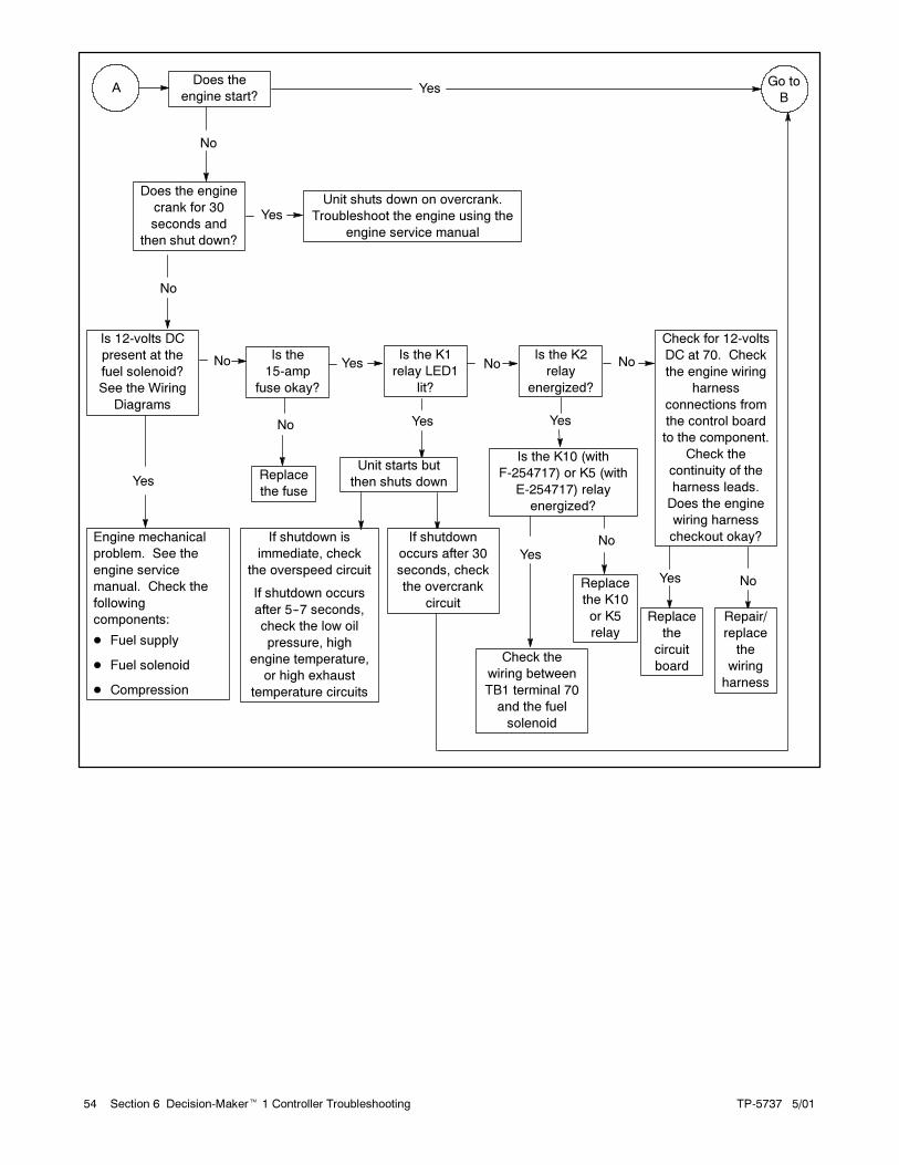
TP-5737 5/0154 Section 6 Decision-Maker� 1 Controller Troubleshooting
Does the
engine start?Yes
Is 12-volts DC
present at the
fuel solenoid?
See the Wiring
Diagrams
Is the K1
relay LED1
lit?
Engine mechanical
problem. See the
engine service
manual. Check the
following
components:
� Fuel supply
� Fuel solenoid
� Compression
AGo to
B
Yes
No
Yes
No
Check for 12-volts
DC at 70. Check
the engine wiring
harness
connections from
the control board
to the component.
Check the
continuity of the
harness leads.
Does the engine
wiring harness
checkout okay?
NoYes
Replace
the
circuit
board
Repair/
replace
the
wiring
harness
No
Unit starts but
then shuts down
Is the K2
relay
energized?
Yes
Is the K10 (with
F-254717) or K5 (with
E-254717) relay
energized?
No
Replace
the K10
or K5
relay
Yes
Check the
wiring between
TB1 terminal 70
and the fuel
solenoid
Is the
15-amp
fuse okay?
No
Replace
the fuse
Yes No
If shutdown is
immediate, check
the overspeed circuit
If shutdown occurs
after 5--7 seconds,
check the low oil
pressure, high
engine temperature,
or high exhaust
temperature circuits
If shutdown
occurs after 30
seconds, check
the overcrank
circuit
Does the engine
crank for 30
seconds and
then shut down?
YesUnit shuts down on overcrank.
Troubleshoot the engine using the
engine service manual
No

TP-5737 5/01 55Section 6 Decision-Maker� 1 Controller Troubleshooting
The engine starts but
shuts down after 30
seconds or more?
Replace the inoperative
start/stop switch
Replace the circuit board
(inoperative K2 relay).
B
No
Yes
The engine runs but
cannot be stopped by
the start/stop switch
Check the condition/connections
of the start/stop switch (local or
remote). See the Wiring
Diagrams. Does the start/stop
switch function correctly and the
wiring check out okay?
Yes
No
Yes
Is the K3 relay
LED3 lit?No
Check for 120-volts AC output
from the stator 10-7 winding at V0
and V7. See Section 7, Stator
Testing. Run the generator set
while performing this test
Test the speed sensor operation
as described in Section 7
If correct voltage is present and
the speed sensor tests okay,
replace the circuit board
Note: Allow a 60-second
cooldown between cranking
attempts if the set does not start
Is the K1
relay
LED1 lit?
No
Replace the
circuit board
Yes
Do the engine
systems including low
oil pressure, high
engine temperature,
and high exhaust
temperature circuits
checkout okay?
No
Repair/replace
the inoperative
engine system
Yes
Replace the
circuit board

TP-5737 5/0156 Section 6 Decision-Maker� 1 Controller Troubleshooting
Notes
TP-5737 5/01 57Section 7 Component Testing and Adjustment
Section 7 Component Testing and Adjustment
7.1 Generator Troubleshooting
Use the following flowchart to troubleshoot the
generator set when detecting no or high voltage. The
remaining parts of this section give additional and more
detailed information about the individual checks/tests
mentioned in the flowchart. Use the flowchart to initially
isolate the possible problem.
Accidental starting.
Can cause severe injury or death.
Disconnect the battery cables before
working on the generator set.
Remove the negative (--) lead first
when disconnecting the battery.
Reconnect the negative (--) lead last
when reconnecting the battery.
WARNING
Disabling the generator set. Accidental starting can
cause severe injury or death. Before working on the
generator set or connected equipment, disable the generator
set as follows: (1) Move thegenerator setmaster switch to the
OFFposition. (2) Disconnect thepower to thebattery charger.
(3) Remove the battery cables, negative (--) lead first.
Reconnect the negative (--) lead last when reconnecting the
battery. Follow these precautions to prevent starting of the
generator set by an automatic transfer switch, remote
start/stop switch, or engine start command from a remote
computer.
Hazardous voltage.
Can cause severe injury or death.
Operate the generator set only when
all guards and electrical enclosures
are in place.
Moving rotor.
WARNING
Grounding electrical equipment. Hazardous voltage can
cause severe injury or death. Electrocution is possible
whenever electricity is present. Open the main circuit
breakers of all power sources before servicing the equipment.
Configure the installation to electrically ground the generator
set, transfer switch, and related equipment and electrical
circuits to complywith applicable codesandstandards. Never
contact electrical leads or appliances when standing in water
or onwetgroundbecause theseconditions increase the riskof
electrocution.
Disconnecting theelectrical load. Hazardous voltagecan
cause severe injury or death. Disconnect the generator set
from the load by opening the line circuit breaker or by
disconnecting the generator set output leads from the transfer
switch and heavily taping the ends of the leads. High voltage
transferred to the load during testing may cause personal
injury and equipment damage. Do not use the safeguard
circuit breaker in place of the line circuit breaker. The
safeguard circuit breaker does not disconnect the generator
set from the load.

TP-5737 5/0158 Section 7 Component Testing and Adjustment
No output voltage is
detected
Is the safeguard circuit
breaker in the ON position?
Do a flashlight test on the
photo transistor board. (See
Section7.3, LEDCircuitBoard
Test)
Place the safeguard circuit
breaker to the ON position
If no voltage is detected,
remove the G and F+ (red)
leads from the SCR assembly.
Jumper G and AC on the SCR
assembly.
If high voltage is detected,
check for battery voltage at
the voltage regulator. Is
battery voltage present?
Check DC voltage at the
LED circuit board
If high voltage is
detected, replace the
photo transistor board
If no voltage is detected,
test the rotor. Do the
exciter armature and
main field windings
check out okay?
If no DC voltage is present,
unplug the connector at the
LED circuit board and check
voltage
If DC voltage of
6--12 volts is
present, replace the
LED circuit board.
(LED is open)
Replace the rotor Replace the SCR
assembly
If DCvoltageof 6--12volts
is present, replace the
LED circuit board. (LED
or flybackdiode is shorted
and/or grounded)
If noDCvoltage is present,
check the wiring between
the voltage regulator and
the LED circuit board.
Does wiring check out
okay?
Repair/replace
the wiring
Replace voltage
the regulator
YesNo
No
Yes
Yes
YesNo
Check the wiring to the
voltage regulatorNo
Figure 7-1 Troubleshooting Generator, No Output Voltage

TP-5737 5/01 59Section 7 Component Testing and Adjustment
High output voltage is
detected
Turn safeguard circuit breaker to
the OFF position. Does output
voltage remain high?
Remove G and F+ (red)
leads from the SCR
assembly. Does output
voltage remain high?
Turn the safeguard circuit
breaker to the ON position. Is
sensing voltage (190--277
volts) at leads V7 and V8
available at the regulator?
Check for open wiring between
the stator and the voltage
regulator
Replace the
SCR assembly
If no voltage is detected,
replace the photo
transistor board
Test the stator
windings
Replace
the
voltage
regulator
If the sensing voltage
is low, check the
voltage on all phases.
Isvoltagebalancedon
all windings?
If the sensing
voltage is high,
replace the
voltage regulator
YesNo
Yes
No
No
Yes
Yes
No
Figure 7-2 Troubleshooting Generator, High Output Voltage
Accidental starting.
Can cause severe injury or death.
Disconnect the battery cables before
working on the generator set.
Remove the negative (--) lead first
when disconnecting the battery.
Reconnect the negative (--) lead last
when reconnecting the battery.
WARNINGDisabling the generator set. Accidental starting can
cause severe injury or death. Before working on the
generator set or connected equipment, disable the generator
set as follows: (1) Move thegenerator setmaster switch to the
OFFposition. (2) Disconnect thepower to thebattery charger.
(3) Remove the battery cables, negative (--) lead first.
Reconnect the negative (--) lead last when reconnecting the
battery. Follow these precautions to prevent starting of the
generator set by an automatic transfer switch, remote
start/stop switch, or engine start command from a remote
computer.

TP-5737 5/0160 Section 7 Component Testing and Adjustment
Hazardous voltage.
Can cause severe injury or death.
Operate the generator set only when
all guards and electrical enclosures
are in place.
Moving rotor.
WARNING
Disconnecting theelectrical load. Hazardous voltagecan
cause severe injury or death. Disconnect the generator set
from the load by opening the line circuit breaker or by
disconnecting the generator set output leads from the transfer
switch and heavily taping the ends of the leads. High voltage
transferred to the load during testing may cause personal
injury and equipment damage. Do not use the safeguard
circuit breaker in place of the line circuit breaker. The
safeguard circuit breaker does not disconnect the generator
set from the load.
Follow all safety precautions located in the front of this
manual and the additional precautions found within the
text. Figure 7-3 lists the various generator output
conditions and component tests. Refer to Figure 7-4,
AC Voltage Control for assistance in troubleshooting.
7.2 Generator Testing
This section covers generator testing for the following
generator conditions:
� No output on any phase
� Overvoltage
� Fluctuating voltage
7.2.1 No Output On Any Phase
No Output On Any Phase Test Procedure
1. Check the safeguard breaker, if equipped. If the
safeguard breaker is open, close the breaker and,
with the set running, check the AC voltmeter for AC
output voltage.
2. If AC output is not present, then:
a. Check wire 1B from the safeguard breaker and
wire 7N (ground) to the voltage regulator.
b. Check for voltage to the safeguard breaker, if
equipped.
3. If all items in step 2 are functioning, proceed to
Section 7.3, LED Circuit Board Test, and
Section 7.5, Automatic Voltage Regulator (AVR)
Operation and Adjustment.
4. If tests indicate LED and AVR are functioning
correctly, proceed with the test of the photo
transistor board and SCR assembly (see
Section 7.4). Otherwise, continue with the AVR
test.
5. If the photo transistor board test indicates the
board is functioning correctly, proceed to the
exciter armature test as described later in
Section 7.8.
6. If the exciter armature test indicates the armature is
functioning correctly, proceed to the generator field
test as described later in Section 7.7.
7. If the generator field test indicates the field is
functioning correctly, replace the SCR assembly or
the photo transistor board as described later in
Section 7.4.
Components and Circuits to Test Under Certain Generator Output Conditions
GeneratorOutput
ConditionLEDBoard
PhotoTransistorBoard
AutomaticVoltage
Regulator (AVR)SCR
AssemblySafeguardBreaker
ExciterArmature
GeneratorField
GeneratorStator
VoltageAdjustment
Pot
NoOutput
� � � � � � � � �*
OverVoltage
�� � �
FluctuatingVoltage
� � � � � � �
* No output voltage if voltage adjustment potentiometer circuit is open or shorted to ground.
� Overvoltage may occur if an outside light source is present when the LED board and cover are removed.
Figure 7-3 Troubleshooting Guide

TP-5737 5/01 61Section 7 Component Testing and Adjustment
67 7N 68
3B
5B
1B V7
V9
V8
5B 3B
VOLTAGE ADJUSTMENT RHEOSTAT
AC VOLTAGE REGULATORCIRCUIT BOARD
STAB.
T2T1 T3
50 Hz
60 Hz
C
A
LED BOARD
PHOTOTRANSISTORBOARD
MAGNETS
MAGNETS
EXCITER ARMATURE
SCR ASSEMBLY
GENERATORFIELD
12 LEAD STATOR
BATTERY
--- +
STARTER
PS
P
HC
15AMP
CONTROLRELAY CONTACTS
SELECTORSWITCH
T3 T1
P4
T2AC AMPS
SAFEGUARDBREAKER
7N
1B
7012
11
10
9
8
7
6
5
4
3
2
1
D2
AC
F3
G
AC
AC
F+
F---
AC
G
V/HZ
SOLENOID
50 Hz
V/Hz60 Hz
TP-5353-7
Figure 7-4 AC Voltage Control, Typical

TP-5737 5/0162 Section 7 Component Testing and Adjustment
7.2.2 Overvoltage
Overvoltage Test Procedure
Note: If overvoltage occurs, disconnect the harness
plug at the voltage regulator. If overvoltage
continues, the problem lies in the photo transistor
circuit and/or SCR assembly; proceed through
the following troubleshooting steps. If output
voltage disappears, the problem is in the AVR,
including connections and/or wiring.
1. Remove the LED board and cover.
2. Examine the photo transistor board for visible signs
of damage (open foil patterns or heat
discoloration). Replace the photo transistor board
if it is visibly damaged. If overvoltage continues
after replacement of the photo transistor board,
proceed to step 3.
3. Remove the green (center) lead from the G
terminal and the red lead from the F+ terminal of
the SCR assembly. Tape each terminal end of
leads to prevent contact with adjacent metal
components.
4. With the safeguard breaker open, start the
generator set. The lack of AC output indicates the
SCR assembly is functioning properly. If
overvoltage continues, replace the SCR assembly.
Note: When replacing the SCR assembly do not
exceed a torque value of 0.9 Nm (8 in. lbs.)
when tightening the SCR mounting bolts.
5. If overvoltage is evident with the safeguard breaker
closed, check for an open circuit in leadsV7 andV8
to the AVR. If these circuits are open or shorted,
repair or replace. Check the voltage rheostat circuit
(leads 67 and 68). Repair or replace as necessary.
6. If all the circuits described in step 5 are functioning,
check the AVR as described in Section 7.5.
7.2.3 Fluctuating Voltage
Fluctuating Voltage Test Procedure
1. Check the generator output leads for proper
connections. See Section 9, Wiring Diagrams.
2. Check for loose connections to the AVR, LED
board, photo transistor board, or SCR assembly.
3. Check the stator for shorted or open windings; See
Section 7.6, Stator.
4. Verify the AVR adjustment. See Section 7.5,
Automatic Voltage Regulator Operation and
Adjustment.
7.3 LED Circuit Board Test
The following procedure provides testing information for
the LED circuit board. Certain steps require that the
generator set be running. While the generator set is not
running, disable the generator set. See the following
safety precautions. Disconnect all load from the
generator set during this test.
Accidental starting.
Can cause severe injury or death.
Disconnect the battery cables before
working on the generator set.
Remove the negative (--) lead first
when disconnecting the battery.
Reconnect the negative (--) lead last
when reconnecting the battery.
WARNING
Disabling the generator set. Accidental starting can
cause severe injury or death. Before working on the
generator set or connected equipment, disable the generator
set as follows: (1) Move thegenerator setmaster switch to the
OFFposition. (2) Disconnect thepower to thebattery charger.
(3) Remove the battery cables, negative (--) lead first.
Reconnect the negative (--) lead last when reconnecting the
battery. Follow these precautions to prevent starting of the
generator set by an automatic transfer switch, remote
start/stop switch, or engine start command from a remote
computer.
Hazardous voltage.
Can cause severe injury or death.
Operate the generator set only when
all guards and electrical enclosures
are in place.
Moving rotor.
WARNING
Disconnecting theelectrical load. Hazardous voltagecan
cause severe injury or death. Disconnect the generator set
from the load by opening the line circuit breaker or by
disconnecting the generator set output leads from the transfer
switch and heavily taping the ends of the leads. High voltage
transferred to the load during testing may cause personal
injury and equipment damage. Do not use the safeguard
circuit breaker in place of the line circuit breaker. The
safeguard circuit breaker does not disconnect the generator
set from the load.
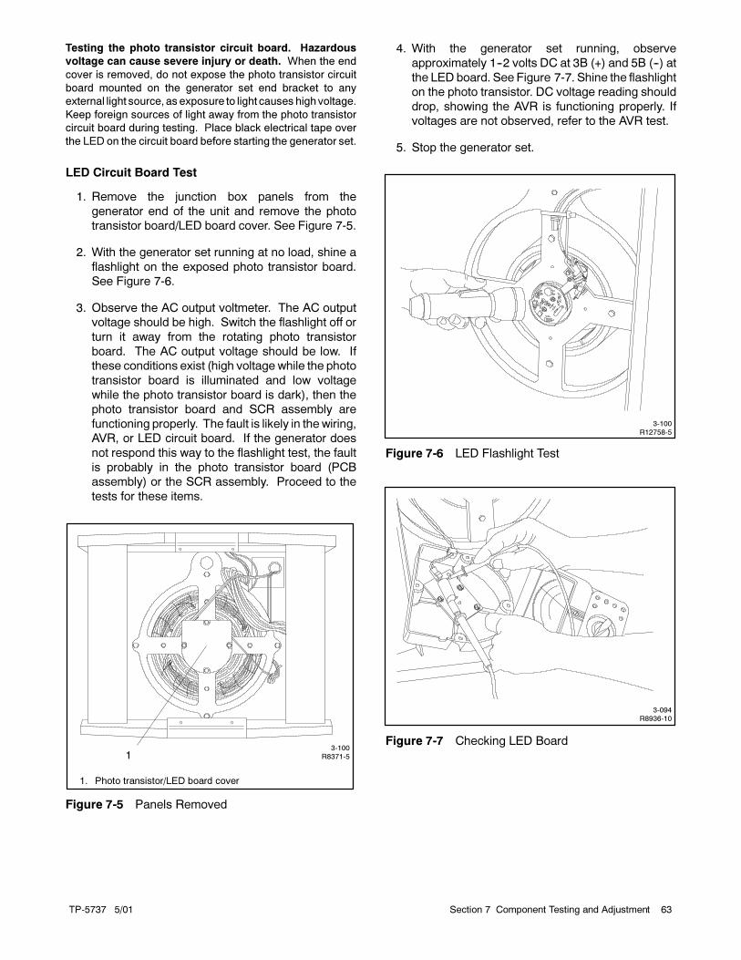
TP-5737 5/01 63Section 7 Component Testing and Adjustment
Testing the photo transistor circuit board. Hazardous
voltage can cause severe injury or death. When the end
cover is removed, do not expose the photo transistor circuit
board mounted on the generator set end bracket to any
external light source, as exposure to light causeshighvoltage.
Keep foreign sources of light away from the photo transistor
circuit board during testing. Place black electrical tape over
the LED on the circuit board before starting the generator set.
LED Circuit Board Test
1. Remove the junction box panels from the
generator end of the unit and remove the photo
transistor board/LED board cover. See Figure 7-5.
2. With the generator set running at no load, shine a
flashlight on the exposed photo transistor board.
See Figure 7-6.
3. Observe the AC output voltmeter. The AC output
voltage should be high. Switch the flashlight off or
turn it away from the rotating photo transistor
board. The AC output voltage should be low. If
these conditions exist (high voltage while the photo
transistor board is illuminated and low voltage
while the photo transistor board is dark), then the
photo transistor board and SCR assembly are
functioning properly. The fault is likely in thewiring,
AVR, or LED circuit board. If the generator does
not respond this way to the flashlight test, the fault
is probably in the photo transistor board (PCB
assembly) or the SCR assembly. Proceed to the
tests for these items.
3-100R8371-51
1. Photo transistor/LED board cover
Figure 7-5 Panels Removed
4. With the generator set running, observe
approximately 1--2 volts DC at 3B (+) and 5B (--) at
the LED board. See Figure 7-7. Shine the flashlight
on the photo transistor. DC voltage reading should
drop, showing the AVR is functioning properly. If
voltages are not observed, refer to the AVR test.
5. Stop the generator set.
3-100R12758-5
Figure 7-6 LED Flashlight Test
3-094R8936-10
Figure 7-7 Checking LED Board

TP-5737 5/0164 Section 7 Component Testing and Adjustment
7.4 SCR Assembly and Photo
Transistor Board
7.4.1 Concept and Equipment
The SCR assembly mounts behind the exciter armature
and controls current flow to the generator field. The
command and sensing circuitry mounts on the
shaft-mounted photo transistor board. See Figure 7-8.
The generator set only functions if both components are
functional. The following test determines which
component is faulty. Because the end bracket must be
removed from the set to correctly test these
components, do not begin this procedure unless there is
reasonable certainty that these components are
inoperative. See Section 7.1, Generator
Troubleshooting. Examine the photo transistor board
for visible signs of damage (open foil patterns and heat
discoloration) before removing the entire SCR
assembly for testing. See Section 7.9, End Bracket
Removal and Replacement, and Section 8,
Disassembly/ Reassembly, for end bracket removal.
Testing the SCR assembly and photo transistor board
requires the following components:
� Light bulb with socket, one 120-volt/110-watt.
� Switch, double-pole/single-throw (DPST), 120-volt
10-amp minimum.
� Fuse, 1 amp, in holder.
� Plug with cord, 120-volt AC.
� SCR assembly and photo transistor board (one must
be functioning)
7.4.2 SCR Assembly and Photo
Transistor Board Test
This test simulates the normal operation of the
components when the generator is running. In the test,
a knownworking component (example: photo transistor
board) is matched with a component of unknown quality
(example: SCR assembly). If the components do not
function normally during the test, the component of
unknown quality may be inoperative. Test either
component in this manner.
3-100R12758-8
B-292902
B-258545-A
2
1
1. SCR assembly 2. Photo transistor board
Figure 7-8 Component Locations

TP-5737 5/01 65Section 7 Component Testing and Adjustment
Hazardous voltage.
Can cause severe injury or death.
Operate the generator set only when
all guards and electrical enclosures
are in place.
Moving rotor.
WARNING
Hazardous voltage can cause severe injury or death.
Carefully follow instructions in the equipment manual when
testing or servicing generator set in the presence of voltage.
Grounding electrical equipment. Hazardous voltage can
cause severe injury or death. Electrocution is possible
whenever electricity is present. Open the main circuit
breakers of all power sources before servicing the equipment.
Configure the installation to electrically ground the generator
set, transfer switch, and related equipment and electrical
circuits to complywith applicable codesandstandards. Never
contact electrical leads or appliances when standing in water
or onwetgroundbecause theseconditions increase the riskof
electrocution.
SCR Assembly and Photo Transistor Board Test
1. Connect the components as illustrated in
Figure 7-9. If testing the photo transistor board, the
SCR assembly must beworking. If testing the SCR
assembly, the photo transistor board must be
working.
Note: When testing the SCR assembly, secure all
connections with nuts to ensure good
contact between the wire terminals and the
foil pattern. The threaded studs are
insulated from the foil pattern and are not in
contact except when secured by a nut. Do
not exceed 1.4 Nm (12 in. lbs.) when
tightening SCR assembly nuts.
2. With the cord switch in theOFF position, plug in the
electrical cord.
3. Turn the cord switch to the ON position.
4. Shield the photo transistor board from all other light
sources during this test. Direct the test light to the
photo transistor board. If both components are
working, the test fixture light bulb lights when the
external light source is applied to the photo
transistor board. Remove the light source; the
fixture light bulb should go out. If the test fixture
light bulb does not light or is lit prior to receiving the
external light source, the tested component is
inoperative (in this example the SCR). Replace the
SCR assembly.
Note: When replacing the SCR assembly, do not
exceed a torque value of 0.9 Nm (8 in. lbs.)
when tightening the SCR mounting bolts.
F+ AC
ACG
F---
243
5
6
9
10
11
1
8
7
TP-5353-7
1. SCR assembly
2. White wire3. Red wire
4. Green wire
5. Black wire6. Photo transistor board
7. Light source (flashlight)
8. 120-volt/100-watt lamp
9. Fuse (1 amp)10. Switch (DPST) S1
11. 120 volts AC
Figure 7-9 SCR Assembly and Photo Transistor
Board

TP-5737 5/0166 Section 7 Component Testing and Adjustment
7.5 Automatic Voltage Regulator
(AVR) Operation and
Adjustment
The AVR monitors output voltage amplitude and
frequency to supply current to the stationary LEDboard.
The AVR circuit board includes volts/Hz and stability
adjustment potentiometers. The factory sets the
volts/Hz adjustment and normally requires no further
adjustment. If replacement of the controller circuit board
or operation of the generator under extreme loads
results in voltage instability, adjust the potentiometers
according to the procedure following. See Figure 7-10.
C-255670-D
1
2
3
1. 60 Hz voltage adjustment
2. 50 Hz voltage adjustment3. Stability adjustment
Figure 7-10 AVR Adjustment
Stability Potentiometer. Fine tunes the voltage
regulator to reduce light flicker.
Volt/Hz Potentiometer. This adjustment determines
engine speed (Hz) at which the generator output voltage
begins to drop.
Voltage Regulator Adjustment
1. Place the generator set master switch in the
OFF/RESET position.
2. Set the stability potentiometer to the far
counterclockwise position.
3. Connect a 100-watt light bulb across terminals V0
and V7 on the controller terminal strip or across the
terminals on the controller frequency meter.
4. Start the generator set. With the generator running
at no load, observe light bulb flicker. Excessive light
bulb flicker indicates poor stability.
5. Adjust the stability potentiometer until minimum
flicker is obtained.
6. Use the controller voltage adjustment
potentiometer (or remote voltage adjustment
potentiometer) to make adjustments to the
generator while running under normal load, if
required.
7. Adjust the engine speed to the desired cut-in
frequency. Factory setting is 57.5--58.0 Hz for
60 Hzmodels or 47.5--48.0 Hz for 50 Hzmodels as
measured on the frequency meter. See Section
7.14, Governor Adjustment, for more information
on engine adjustment.
8. Rotate the Volts/Hz adjustment potentiometer
counterclockwise until the voltage level begins to
drop (as measured on the voltmeter). When set to
these specifications, the generator attempts to
maintain normal output until the engine speed
drops below the frequency set in the previous step
(as load is applied).
9. Adjust the engine speed to the appropriate
operating point. See Section 7.14.
10. Use the controller voltage adjustment
potentiometer (or remote voltage adjustment
potentiometer) to make final adjustments to the
generator while running under normal load.
11. Readjust the stability potentiometer, if necessary.
12. Check the AVR’s function by reducing the engine
speed (Hz) and watching for a corresponding drop
in AC voltage.
At 60 Hz operation, AC voltage remains constant
until the engine speed drops below 58 Hz
(approximately). If AC frequency drops below
58 Hz, AC voltage declines.
At 50 Hz operation, AC voltage remains constant
until the engine speed drops to 48 Hz
(approximately). If AC frequency drops below 48
Hz, AC voltage declines.
If the AVR does not function as described above,
refer to the following test for the cause of the
malfunction.

TP-5737 5/01 67Section 7 Component Testing and Adjustment
Voltage Regulator Test
1. Close the safeguard breaker, if equipped.
2. Disconnect the wiring harness connector from the
voltage regulator and check for continuity between
the voltage sensing leads V7 and V8 (pins 4 and
10). See Figure 7-11. If the circuit between V7 and
V8 is open, repair or replace it. An open circuit
normally results in a high voltage or overvoltage
condition.
3. Check the 15-amp fuse, if equipped.
4. If continuity exists between V7 and V8, check for
continuity in the voltage adjustment circuit (leads
67 and 68). Disconnect the voltage regulator
harness plug and check for resistance between
pins 1 and 3. Measured resistance should change
as the voltage adjust rheostat is turned. Repair or
replace inoperative components as necessary.
Note: An inoperative voltage adjust rheostat
usually results in a nonadjustable voltage.
5. Check the 15-amp fuse, if equipped, inside the
controller. If this circuit is open, repair or replace
the inoperative components and/or wiring.
6. Check for battery voltage at the voltage regulator
harness plug (pins 2 and 11) with the generator set
running. If there is no battery voltage between pins
2 and 11, check the safeguard circuit breaker.
Note: Lack of battery voltage to the voltage
regulator usually results in very low voltage
at the main output leads.
7. While the generator set is running, check for
approximately 1--2 volts DC output between
terminals 3B (+) and 5B (--) on the LED board or
disconnect the 3B/5B connector at the LED board
and check for 8 volts DC (approximately) at the
connector. If there is no DC voltage output present
between 3B and 5B, check for an open or short
circuit in thewiring back to the voltage regulator. If a
fault exists in the voltage regulator wiring, repair or
replace as necessary. If the voltage regulator
wiring appears functional, replace the voltage
regulator.
Note: Low or no voltage at the LED circuit board
may cause a low output voltage fault.
A-328917-X
3-101R8371-3
1
2
1. AVR board in junction box
2. Controller terminal strip
Figure 7-11 AVR and Connections
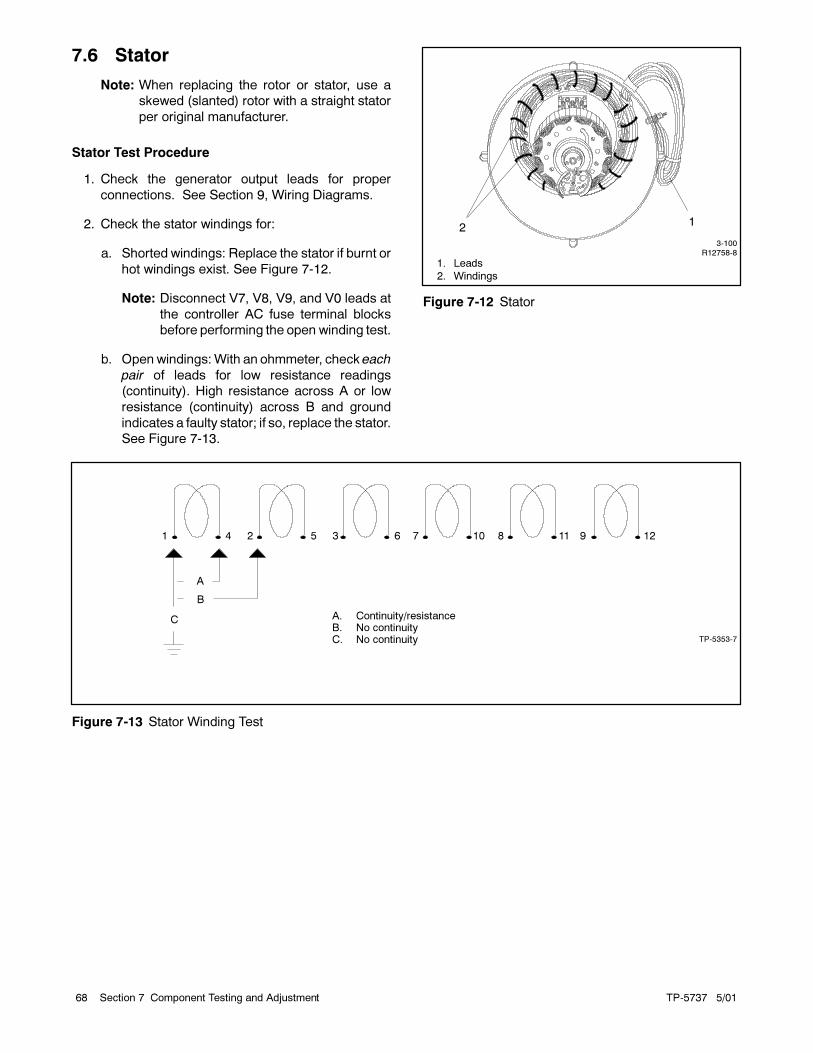
TP-5737 5/0168 Section 7 Component Testing and Adjustment
7.6 Stator
Note: When replacing the rotor or stator, use a
skewed (slanted) rotor with a straight stator
per original manufacturer.
Stator Test Procedure
1. Check the generator output leads for proper
connections. See Section 9, Wiring Diagrams.
2. Check the stator windings for:
a. Shorted windings: Replace the stator if burnt or
hot windings exist. See Figure 7-12.
Note: Disconnect V7, V8, V9, and V0 leads at
the controller AC fuse terminal blocks
before performing the open winding test.
b. Open windings:With an ohmmeter, check each
pair of leads for low resistance readings
(continuity). High resistance across A or low
resistance (continuity) across B and ground
indicates a faulty stator; if so, replace the stator.
See Figure 7-13.
3-100R12758-8
21
1. Leads
2. Windings
Figure 7-12 Stator
A
B
C
1 4 2 5 3 6 7 10 8 11 9 12
TP-5353-7
A. Continuity/resistanceB. No continuityC. No continuity
Figure 7-13 Stator Winding Test

TP-5737 5/01 69Section 7 Component Testing and Adjustment
7.7 Generator Field
Hazardous voltage.
Can cause severe injury or death.
Operate the generator set only when
all guards and electrical enclosures
are in place.
Moving rotor.
WARNING
High voltage test. Hazardous voltage can cause severe
injury or death. Follow the instructions of the test equipment
manufacturer when performing high-voltage tests on the rotor
or stator. An improper test procedure can damage equipment
or lead to generator set failure.
Hot engine and exhaust system.
Can cause severe injury or death.
Do not work on the generator set until
it cools.
WARNING
Servicing the generator. Hot parts can cause severe
injury or death. Avoid touching the generator set field or
exciter armature. When shorted, the generator set field and
exciter armature become hot enough to cause severe burns.
Generator Field Test
1. Disconnect the generator set engine starting
battery, negative (--) lead first.
2. Remove the end bracket. See Section 7.9, End
Bracket Removal and Replacement, and
Section 8, Disassembly/Reassembly.
3. Disconnect F+ and F-- from the SCR assembly.
4. With an ohmmeter, check for continuity across the
F+ and F-- leads (see Figure 7-14). Resistance
readings are shown in Section 1, Specifications,
Generator.
5. Check for a grounded generator field. No
continuity should exist between the field leads and
the rotor assembly.
6. Using a megohmmeter, apply 500 volts DC to the
F+ or F-- lead and the rotor shaft. See Figure 7-15.
Follow the instructions of the megohmmeter
manufacturer when performing this test. A reading
of approximately 5--7 kOhms and higher indicates
the field winding is functional. A reading of less
than 5--7 kOhms (approximately) indicates
deterioration of the winding insulation and possible
current flow to ground.
7. Repair or replace the rotor assembly.
Repair the F+ and F-- leads if this test shows the
leads are shorted to ground. If using splices, solder
and insulate the splices. Use new sleeving when
tying the leads to the shaft or the heat sink.
Replace the generator rotor assembly if this test
shows a shorted or grounded winding.
�
3-100R12758-8
TP-5353-7
1
1. Ohmmeter connections across F+ and F-- leads
Figure 7-14 Field Continuity Check

TP-5737 5/0170 Section 7 Component Testing and Adjustment
M
3-100R12758-8
TP-5353-7
1
1. Megohmmeter connections across F+ and F-- leads and
rotor shaft
Figure 7-15 High Voltage Test
7.8 Exciter Armature
Hazardous voltage.
Can cause severe injury or death.
Operate the generator set only when
all guards and electrical enclosures
are in place.
Moving rotor.
WARNING
High voltage test. Hazardous voltage can cause severe
injury or death. Follow the instructions of the test equipment
manufacturer when performing high-voltage tests on the rotor
or stator. An improper test procedure can damage equipment
or lead to generator set failure.
Hot engine and exhaust system.
Can cause severe injury or death.
Do not work on the generator set until
it cools.
WARNING
Servicing the generator. Hot parts can cause severe
injury or death. Avoid touching the generator set field or
exciter armature. When shorted, the generator set field and
exciter armature become hot enough to cause severe burns.
Exciter Armature Test
1. Disconnect the generator set engine starting
battery, negative (--) lead first.
2. Remove the end bracket. See Section 7.9, End
Bracket Removal and Replacement and Section 8,
Disassembly/Reassembly for end bracket
removal.
3. Disconnect the AC leads from the SCR assembly.
4. With an ohmmeter, check for continuity across the
AC leads. See Figure 7-16.
5. Repair the AC leads if they are damaged or open.
Solder and insulate any splices used. Use new
sleeving when tying the leads to the shaft or the
heat sink.
6. Visually check the exciter armature for shorted
winding(s); with an ohmmeter check for low
resistance readings. See Section 1,
Specifications, Generator, for designed resistance
readings. See Figure 7-16. Low resistance
readings indicate a faulty exciter armature
requiring replacement of the rotor assembly.

TP-5737 5/01 71Section 7 Component Testing and Adjustment
�
3-100R12758-8
TP-5353-7
1
1. Ohmmeter connections across AC leads
Figure 7-16 Exciter Armature Continuity Check
7. Using a megohmmeter, apply 500 volts DC to the
rotor shaft and either AC lead. See Figure 7-17.
Follow the instructions of the megohmmeter
manufacturer when performing this test. A reading
of approximately 5--7 kOhms and higher indicates
the fieldwinding is functional. A reading of less than
5--7 kOhms (approximately) indicates
deterioration of the winding insulation and possible
current flow to ground.
8. Repair or replace the rotor.
Repair the AC leads if this test indicates the leads
are shorted to ground. Solder and insulate any
splices used. Use new sleeving when tying the
leads to the shaft or the heat sink.
Replace the rotor assembly if this test shows the
armature is shorted to ground.
M
3-100R12758-8
TP-5353-7
1
1. Megohmmeter connections across either AC lead and
rotor shaft
Figure 7-17 Exciter Armature High Voltage Test
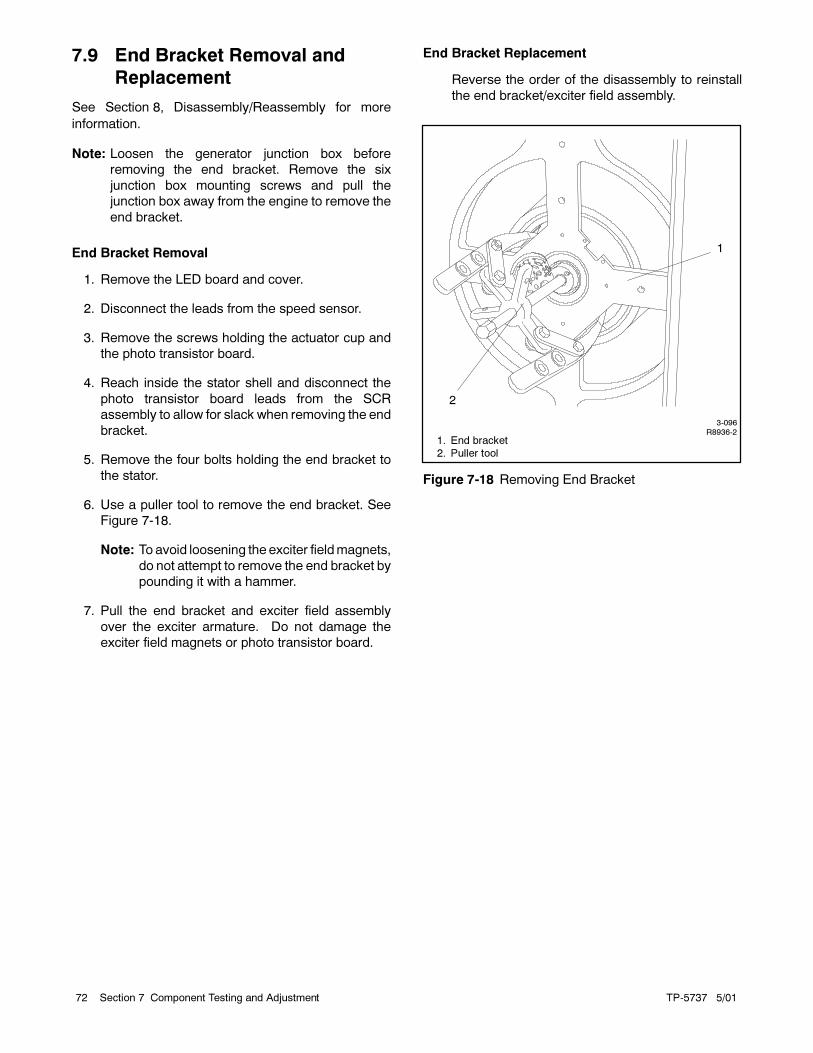
TP-5737 5/0172 Section 7 Component Testing and Adjustment
7.9 End Bracket Removal and
Replacement
See Section 8, Disassembly/Reassembly for more
information.
Note: Loosen the generator junction box before
removing the end bracket. Remove the six
junction box mounting screws and pull the
junction box away from the engine to remove the
end bracket.
End Bracket Removal
1. Remove the LED board and cover.
2. Disconnect the leads from the speed sensor.
3. Remove the screws holding the actuator cup and
the photo transistor board.
4. Reach inside the stator shell and disconnect the
photo transistor board leads from the SCR
assembly to allow for slack when removing the end
bracket.
5. Remove the four bolts holding the end bracket to
the stator.
6. Use a puller tool to remove the end bracket. See
Figure 7-18.
Note: To avoid loosening the exciter fieldmagnets,
do not attempt to remove the end bracket by
pounding it with a hammer.
7. Pull the end bracket and exciter field assembly
over the exciter armature. Do not damage the
exciter field magnets or photo transistor board.
End Bracket Replacement
Reverse the order of the disassembly to reinstall
the end bracket/exciter field assembly.
3-096R8936-2
1
1. End bracket
2. Puller tool
2
Figure 7-18 Removing End Bracket

TP-5737 5/01 73Section 7 Component Testing and Adjustment
7.10 Speed Sensor Test
The following procedure determines if the speed sensor
(overspeed fault) is emitting a signal.
Speed Sensor Signal Test
1. With the generator set master switch in the
OFF/RESET position, connect a DC voltmeter
between the positive (+) lead (wire 24) at the speed
sensor and the ground (wire 2). The voltmeter
should indicate approximately 8--10 volts DC.
2. With the generator set running, connect the DC
voltmeter negative probe to the 0 terminal (wire
16—white) on the speed sensor. Place the
voltmeter positive probe on the positive (+) terminal
(wire 24—red). The voltmeter should indicate
approximately 12 volts DC.
Note: During the test the controller leads must
remain connected to the speed sensor
terminals. Slide the leads from the speed
sensor terminals only enough to expose the
connection for the test leads. Do not
disconnect the leads.
If the speed sensor emits a signal, check the continuity
of the speed sensor leads (wires 2, 16, and 24) between
the controller P1 connector and the lead terminals at the
speed sensor.
If the speed sensor does not emit a signal, test the speed
sensor through the following procedure.
Speed Sensor Test
1. Connect the speed sensor, voltmeter, and DC
voltage source as shown in Figure 7-19.
o + ---
+
---
+1
2
3
TP-5353-71. DC voltmeter
2. 12-volt battery or DC power supply3. Speed sensor
Figure 7-19 Speed Sensor Test
2. Touch the sensing surfacewith a flat piece of iron or
steel at least 4.1 cm (1/4 cubic inch) in size. The
voltmeter test reading should equal the source
voltage.
3. Remove the iron or steel from the sensing surface.
Observe no test voltmeter reading.
7.11 Current Transformers
7.11.1 Function and Application
Current transformers provide several generator set
functions including signal/drive for:
� Controller AC voltmeter/ammeter
� Safeguard circuit breaker
� Reactive droop compensator.
Generator set models do not have current transformers
when they do not include the above items. The meters
and safeguard circuit breaker share the same current
transformer while the reactive droop compensator uses
a separate current transformer. See Figure 7-20. The
generator set junction box contains the stator leads and
the current transformers.
When replacing the current transformer or stator
assembly, install the current transformer according to
the generator reconnection decal on the generator set,
or see Section 9, Wiring Diagrams. Observe the correct
current transformer position when installing the stator
leads. The current transformer dot or HI mark position
and the stator lead direction are essential for correct
component function.

TP-5737 5/0174 Section 7 Component Testing and Adjustment
TT-1123/347058-D
Figure 7-20 Current Transformers
A current transformer contains a coil of wire that induces
a secondary voltage/current from the primary or stator
lead passing through the center. The number of coil
turns inside the current transformer determines the
ratio. Replacement current transformers must have the
same ratio as the original.
7.11.2 Testing
Use an ohmmeter to check the current transformer.
Perform this test with the current transformer
disconnected from the generator set. A resistance
reading of infinity or 0 ohms suggests anopen or shorted
current transformer that needs replacement. Consider
any other resistance reading acceptable.
7.12 Reactive Droop Compensator
7.12.1 Function and Application
The reactive droop compensator kit distributes the
generator set load evenly between two generator sets in
parallel. If the kit is not factory installed, use the
installation instructions supplied with the kit for field
installation. Use the following procedure for reactive
droop compensator adjustment.
Hazardous voltage.
Can cause severe injury or death.
Operate the generator set only when
all guards and electrical enclosures
are in place.
Moving rotor.
WARNING
Short circuits. Hazardous voltage/current can cause
severe injury or death. Short circuits can cause bodily injury
and/or equipment damage. Do not contact electrical
connections with tools or jewelry whilemaking adjustments or
repairs. Remove all jewelry before servicing the equipment.
7.12.2 Reactive Droop Compensator
Adjustment Procedure
Parallel the two generator sets using the following
procedure. Read and understand the entire procedure
before beginning.
1. Remove any load connected to the generator set.
Start each generator set by placing the generator
set master switch in the RUN position.
2. Set the reactive droop compensator rheostat on
generator set no. 1 to the minimum
counterclockwise (CCW) setting. Record the RPM
or frequency and voltage at 1/4 load steps to full
load on unit no. 1
3. Repeat step 2 for generator set no. 2.
4. Compare the readings and make final adjustments
so that the voltage is within 1 volt at each load step
and the speed is within three RPMor the frequency
is within 0.1 Hz for each unit. Adjust the voltage
using the controller or remote voltage adjustment
potentiometer. Adjust the speed at the electronic
governor or at the remote adjusting potentiometer.
5. Check the droop compensation on each unit as
follows:
a. With unit no. 1 operating at the desired speed
and voltage, apply an inductive load one half to
full load. Do not use a resistive load for this test.
b. Observe the voltmeter on unit no. 1 with the
reactive droop compensator rheostat set at
minimum. As the rheostat is turned clockwise
(CW), the voltmeter should show a decrease in
voltage. If observing a larger voltage, stop the

TP-5737 5/01 75Section 7 Component Testing and Adjustment
generator sets and reverse the direction of the
generator load line through the current
transformer or reverse the transformer leads
on unit no. 1.
c. Restart the generator sets and recheck the
droop on unit no. 1.
d. Set the reactive droop compensator rheostat to
a value at approximately 4% below rated
voltage at full load. As an example, the voltage
droops (decreases) 19.2 volts on a 480-volt
system at full load or 9.6 volts at one half load.
Use the following formula for loads other than
full load:
Rated Voltage x 0.04 x Actual Load (expressed
as a % of full load) = Voltage Droop
Note: With full load 0.8 power factor, a droop of
3--5% should be adequate for
paralleling.
6. Repeat step 5 for generator set no. 2. Adjust unit
no. 2 where the voltage droop is equal and at the
same point as on unit no. 1. The two units share
reactive currents proportionately after correctly
performing this procedure.
7. If reactive load is not available, go to
Section 7.12.3, Reactive Droop Compensator
Alternate Adjustment Procedure. If reactive load is
available, go to Section 7.12.4, Testing.
7.12.3 Reactive Droop Compensator
Alternate Adjustment Procedure
Initially calibrate each generator set using the following
procedure.
1. Turn the reactive droop compensator rheostat on
generator set no. 1 to the minimum setting.
2. Remove the controller cover. Move the voltage
sensing lead from V7 to V9 at the AC fuse terminal
block.
3. Remove any load connected to the generator set.
4. Start the generator set by placing the generator
master switch in the RUN position.
5. Use the controller or remote voltage adjusting
potentiometer on each generator set to fine adjust
voltage as necessary.
6. Apply resistive load (1.0 power factor) until
reaching rated current.
7. Adjust the reactive droop compensator rheostat to
achieve a 4% droop (decrease) in voltage.
8. Remove the resistive load.
9. Stop the generator set by placing the generator
master switch in the OFF position.
10. Return the voltage sensing lead from V9 to V7 at
the AC fuse terminal block.
11. Replace the controller cover.
12. Repeat steps 1--11 for generator set no. 2.
7.12.4 Testing
Use the following procedure to check that the generator
sets share the reactive load proportionately.
1. Parallel the units at one half to full load. Verify that
each unit carries equal kW load or a load
proportional to its capacity using the wattmeter
readings. If load unbalance exists, adjust and
recheck the electronic governor throttle control to
correctly balance loading. Engine speed
determines load sharing ability.
2. With the load balanced, check the ammeters for
equal current or proportional according to capacity.
If the currents are incorrect, adjust the reactive
droop compensator rheostat reducing the current
of the unit with the highest reading. Reduce the
current to an equal division or proportionately.
3. Stop each generator set by placing the generator
master switch in the OFF position.
Note: Step 1 balances the load using the electronic
governor and step 2 balances the current using
the reactive droop compensator. Consider these
settings optimum for parallel operation.
Note: Voltage must droop (decrease) on lagging power
factor loads (inductive loads). A small change in
voltage is acceptable on unity power factor loads
(resistive loads).

TP-5737 5/0176 Section 7 Component Testing and Adjustment
7.13 Gauge Senders
The resistance of the oil pressure and water
temperature sender output signals varies as the
respective pressure and temperature change. Use the
resistance change for verification of sender function.
Disconnect all leads from the sender before checking
resistance. If the sender functions and the gauge does
not function, check the engine wiring harness, leads,
and connectors before replacing the gauge.
Note: Some generator sets may have senders/
switches incorporated with the engine ECM
(electronic control module). Identify engine ECM
senders/switches by lead designations listed in
the following testing information. Refer to
Section 9, Wiring Diagrams for additional lead
identification information. Use the engine service
manual for troubleshooting ECM
senders/switches.
7.13.1 Oil Pressure Sender Testing
Disconnect the oil pressure sender lead 7C. See
Figure 7-21. Check the sender resistance with an
ohmmeter. Compare the resistance values when the
generator set is shut down and when it is running at
operating temperature to the values shown in
Section 1.2, Specifications.
Use a mechanical oil pressure gauge to further verify
correct readings.
TP-5353-7
Lead 7C
Figure 7-21 Oil Pressure Sender, Typical
7.13.2 Water Temperature Sender
Testing
The water temperature sender is a single function,
single-terminal type. See Figure 7-22.
TP-5353-7
Lead 5
Figure 7-22 Water Temperature Sender, Typical
Disconnect the water temperature sender lead 5. Check
the sender resistances with an ohmmeter. Compare the
resistance values when the generator set is shut down
and when it is running at operating temperature to the
values in Section 1.2, Specifications.

TP-5737 5/01 77Section 7 Component Testing and Adjustment
7.14 Governor Adjustment
7.14.1 Mechanical Governor
Note: Before checking and adjusting engine
speed, make sure the engine reaches its
normal operating temperature.
Note: All speed specs apply to an engine at
operating temperature under load
conditions. The maximum permissible
speed variation is 2--3 Hz or 50--90 rpm for
fast idle speed.
Mechanical Governor Adjustment Procedure
1. Disconnect the speed control from the fuel injection
pump lever and start the engine.
2. Verify that the injector pump lever holds in the fast
idle position against the fast idle adjusting screw.
See Figure 7-23.
3. Using a frequency meter, check the engine speed.
Adjust the engine speed at full load to 1800 rpm
(60 Hz) or 1500 rpm (50 Hz). To increase the
engine speed, turn the fast idle adjusting screw
counterclockwise; turn the fast idle adjusting screw
clockwise to decrease engine speed.
4. Reconnect the speed control to the fuel injection
pump lever.
5. Stop the generator set.
TP-5353-71 2
1. Injection pump lever
2. Fast idle adjusting screw
Figure 7-23 Governor Adjustments, Typical
7.14.2 Electronic Governor—Barber-
Colman Dyna 2500 125--150 kW
John Deere Engine-Powered 6081
Some sets are equipped with Barber-Colman Dyna
2500 electronic governors. Because this is an
electronic device, no mechanical drive or hydraulic
connection is required. The system consists of a
magnetic pickup, an electronic control unit, and an
actuator. The magnetic pickup monitors engine speed
and transmits this information to the electronic control
unit (see Figure 7-24 or Figure 7-25). The electronic
control unit interprets the signal from the magnetic
pickup to control current input to the throttle actuator.
The throttle actuator adjusts the throttle position on the
engine. See Figure 7-26.
KC250000B-A
1
2
3
456
7
1. Control unit
2. Magnetic pickup3. Actuator
4. Connect to safeguard breaker terminal strip
5. Connect to cranking solenoid, battery (+)6. Connect to 70 on safeguard breaker terminal block
7. Relay
Figure 7-24 Governor Control Unit,
Nonparalleling Generator Set

TP-5737 5/0178 Section 7 Component Testing and Adjustment
KC250000B-A
1
2
3
4
56
7
8
1. Controlunit: terminal#1—positive, terminal#2—negative
2. Magnetic pickup3. Optional remote speed potentiometer
4. Actuator
5. Connect to safeguard breaker terminal strip6. Connect to cranking solenoid, battery (+)
7. Relay
8. Connect to 70 on safeguard breaker terminal block
Figure 7-25 Governor Control Unit,
Paralleling Generator Set
Adjust the actuator shaft linkage to hold the fuel injection
pump lever in the stop position when the power is off.
The magnetic pickup air gap is 0.36--0.71 mm
(0.014--0.028 in.).
TP-5353-71
2
1. Actuator
2. Linkage
Figure 7-26 Throttle Actuator (Barber-Colman
Dyna 2500, John Deere 6076 Shown)
The Barber-Colman control unit is equipped with
switches S1 and S2. Before making governor
adjustments, verify that S1 and S2 are in the correct
positions for your application. See Figure 7-27. Switch
S1 selects the controller response range based upon
engine type. Place switch S2 tomatch the control unit of
the governor actuator. These generator sets use the
Dyna 2500 actuator.
Fuel Type S1 Switch Position
Diesel Off
Control Unit Type S2 Switch Position
Dyna 2500 On (in all cases)
Figure 7-27 Electronic Governor Switch Settings

TP-5737 5/01 79Section 7 Component Testing and Adjustment
Preliminary Adjustment Procedure
1. Place the generator set master switch in the OFF
position. Do not run the generator set.
2. Set the control unit “I” adjustment one division from
zero, the “D” adjustment four divisions from zero,
and the gain adjustment at the third division from
zero.
3. For isochronous operation, turn the droop
adjustment potentiometer counterclockwise
(CCW) to the minimum position. For droop
operation, turn the droop potentiometer to the
desired droop. Droop adjustment may be
necessary with parallel generator operation.
Note: If the governor uses the full stroke of the
actuator shaft and the linkage adjustment
uses only the active fuel range, the
maximum obtainable droop would be
approximately 12% at full load.
4. Position the actuator lever to hold the fuel pump
lever in the STOP position when the power is off.
Adjust the actuator linkage for smooth, non-binding
operation.
Final Adjustment Procedure
1. Place the generator set master switch in the RUN
or TEST position to start the generator set.
2. Adjust the control unit speed potentiometer until
the engine operates at the desired rpm (50 or
60 Hz on the frequency meter).
3. If governing is unstable, turn the “I” and gain
potentiometers slightly CCW.
Note: Except for the speed potentiometer, control
unit potentiometers have internal stops at 0
and 100%.
4. With the engine running at no load, finalize the “I”,
“D”, and gain adjustments.
5. Slowly turn the gain adjustment potentiometer
clockwise (CW) until the output shaft and linkage
oscillates. Slowly turn the gain adjustment
potentiometer CCW until the actuator lever
stabilizes.
6. Jog the actuator lever by hand. If the actuator lever
oscillates three to five times and then stabilizes, the
gain setting is correct.
7. Turn the gain potentiometer one division CCW.
8. Turn the “D” adjustment fully CW while observing
the actuator shaft. If the lever does not become
unstable, jog it by hand. When the lever oscillates,
turn the “D” adjustment CCW slowly until the
actuator shaft stabilizes. Jog the lever again, it
should oscillate 3--5 times and then becomestable.
If the system response to load changes is
satisfactory at this point, omit step 9 and proceed to
step 10.
9. Turn the “I” potentiometer fully CW and watch the
actuator shaft. If the actuator lever does not
become unstable, jog it by hand. When the
actuator lever slowly oscillates, slowly turn the “I”
potentiometer CCW until the lever stabilizes.
10. Jog the actuator lever by hand. It should oscillate
3--5 times before stabilizing. The governor is now
calibrated.
11. Stop the generator set.

TP-5737 5/0180 Section 7 Component Testing and Adjustment
7.14.3 Electronic Governor,
Barber-Colman Dyna 70025 using
Stanadyne D Series Injection
Pump 35--99 kW John Deere
Engine-Powered 4045 and 6068
Some sets are equipped with Barber-Colman Dyna
70025 electronic governor used in conjunction with a
Stanadyne D Series injection pump. This particular
setup uses different governor controllers for a
nonparalleling generator set or a paralleling generator
set. The system consists of a magnetic pickup, an
electronic control unit, and an actuator. The magnetic
pickup monitors engine speed and transmits this
information to the electronic control unit.
FT273B-X
1
2
3
5
6
7
8
4
1. Twistmagnetic pickup leads before connecting to control.
1 turn per 25 mm (1inch)2. Power cable
3. Relay
4. Connect to safeguard breaker terminal strip5. Connect to cranking solenoid, battery (+)
6. Connect to 70 on safeguard breaker terminal strip
7. Actuator
8. Magnetic pickup
Figure 7-28 Governor Control Unit, Nonparalleling
Generator Set
See Figure 7-28 for nonparalleling generator sets or
Figure 7-29 for paralleling generator sets. The
electronic control unit interprets the signal from the
magnetic pickup to control the current input to the
throttle actuator. The integrated throttle actuator adjusts
the throttle position internally in the fuel injection pump.
See Figure 7-30. The magnetic pickup air gap is
0.36--0.71 mm (0.014--0.028 in.).
FT273B-X
1
2
3
4
5
6
7
89
10
11
1. Droop potentiometer
2. Gain potentiometer3. Idle speed potentiometer
4. Run speed potentiometer
5. Magnetic pickup6. Power cable
7. Relay
8. Connect to safeguard breaker terminal strip
9. Connect to cranking solenoid, battery (+)10. Connect to 70 on safeguard breaker terminal strip
11. Actuator
Figure 7-29 Governor Control Unit, Paralleling
Generator Set
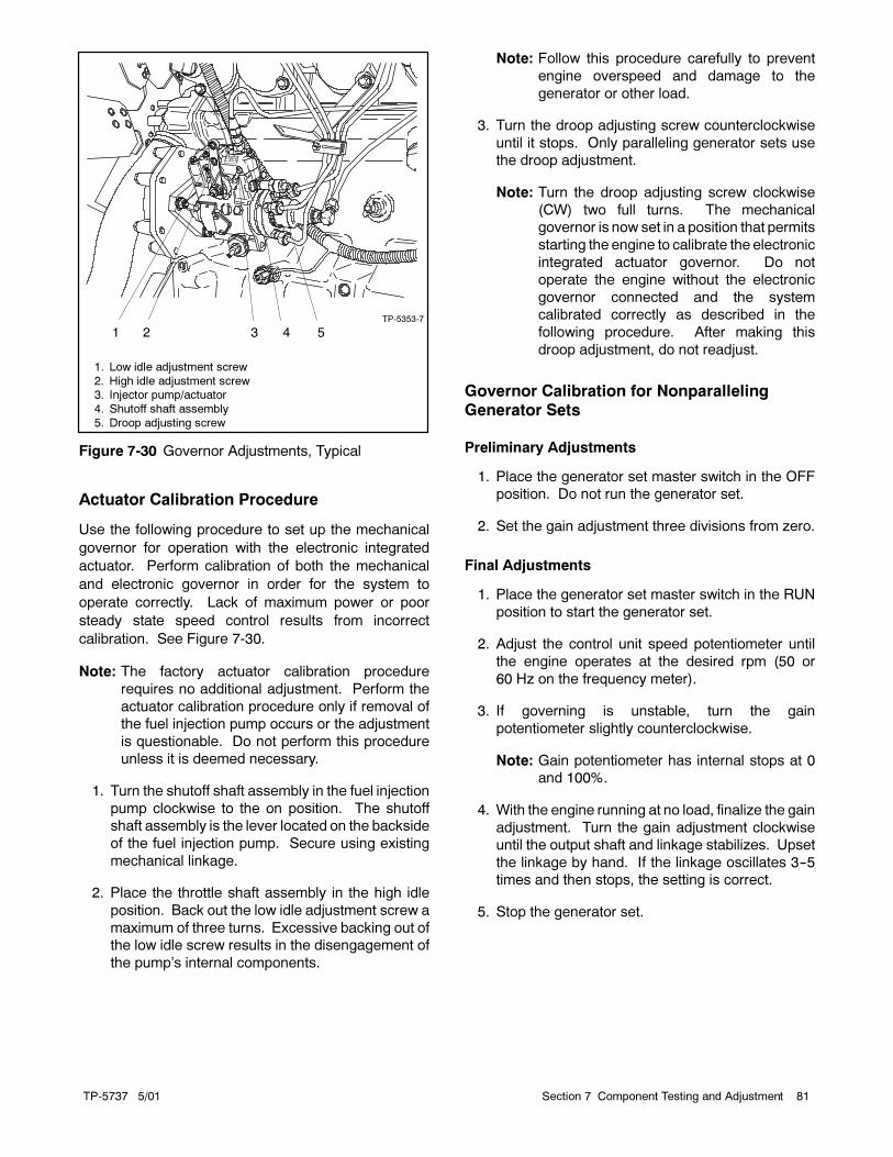
TP-5737 5/01 81Section 7 Component Testing and Adjustment
TP-5353-7
1 2 3 4 5
1. Low idle adjustment screw
2. High idle adjustment screw3. Injector pump/actuator
4. Shutoff shaft assembly
5. Droop adjusting screw
Figure 7-30 Governor Adjustments, Typical
Actuator Calibration Procedure
Use the following procedure to set up the mechanical
governor for operation with the electronic integrated
actuator. Perform calibration of both the mechanical
and electronic governor in order for the system to
operate correctly. Lack of maximum power or poor
steady state speed control results from incorrect
calibration. See Figure 7-30.
Note: The factory actuator calibration procedure
requires no additional adjustment. Perform the
actuator calibration procedure only if removal of
the fuel injection pump occurs or the adjustment
is questionable. Do not perform this procedure
unless it is deemed necessary.
1. Turn the shutoff shaft assembly in the fuel injection
pump clockwise to the on position. The shutoff
shaft assembly is the lever located on the backside
of the fuel injection pump. Secure using existing
mechanical linkage.
2. Place the throttle shaft assembly in the high idle
position. Back out the low idle adjustment screw a
maximum of three turns. Excessive backing out of
the low idle screw results in the disengagement of
the pump’s internal components.
Note: Follow this procedure carefully to prevent
engine overspeed and damage to the
generator or other load.
3. Turn the droop adjusting screw counterclockwise
until it stops. Only paralleling generator sets use
the droop adjustment.
Note: Turn the droop adjusting screw clockwise
(CW) two full turns. The mechanical
governor is now set in a position that permits
starting the engine to calibrate the electronic
integrated actuator governor. Do not
operate the engine without the electronic
governor connected and the system
calibrated correctly as described in the
following procedure. After making this
droop adjustment, do not readjust.
Governor Calibration for NonparallelingGenerator Sets
Preliminary Adjustments
1. Place the generator set master switch in the OFF
position. Do not run the generator set.
2. Set the gain adjustment three divisions from zero.
Final Adjustments
1. Place the generator set master switch in the RUN
position to start the generator set.
2. Adjust the control unit speed potentiometer until
the engine operates at the desired rpm (50 or
60 Hz on the frequency meter).
3. If governing is unstable, turn the gain
potentiometer slightly counterclockwise.
Note: Gain potentiometer has internal stops at 0
and 100%.
4. With the engine running at no load, finalize the gain
adjustment. Turn the gain adjustment clockwise
until the output shaft and linkage stabilizes. Upset
the linkage by hand. If the linkage oscillates 3--5
times and then stops, the setting is correct.
5. Stop the generator set.

TP-5737 5/0182 Section 7 Component Testing and Adjustment
Governor Calibration for ParallelingGenerator Sets
Calibration Procedure
1. Place the generator set master switch in the OFF
position. Do not run the generator set.
2. Set the gain potentiometer at 30% and turn the
droop potentiometer completely counterclockwise.
3. Turning the 20-turn potentiometer clockwise
increases idle speed and turning it
counterclockwise decreases idle speed.
4. Turning the 20-turn potentiometer clockwise
increases run speed and turning it
counterclockwise decreases run speed.
5. Place the generator set master switch in the RUN
or TEST position to start the generator set.
6. Slowly turn the gain potentiometer clockwise until
the engine becomes unstable. After the engine
becomes unstable, slowly turn the gain
potentiometer counterclockwise until stable.
Interrupt the governor by momentarily removing
power from the governor. The engine should
recover in 3--5 seconds with diminishing
oscillation.
7. Stop the generator set.
Droop Adjustment Procedure
1. Place the generator set master switch in the RUN
or TEST position to start the generator set.
2. Use the run speed potentiometer to set the engine
rpm to the desired no load speed (frequency) on
the frequency meter.
3. Apply full load to the generator set.
4. While observing the frequency meter, slowly turn
the droop potentiometer clockwise to the desired
droop percentage.
5. Remove full load from the generator set.
6. Using the run speed potentiometer, readjust the
engine rpm to the desired no load speed
(frequency) on the frequency meter.
7. Stop the generator set.
TP-5737 5/01 83Section 8 Disassembly/Reassembly
Section 8 Disassembly/Reassembly
Before beginning the generator set disassembly
procedure, carefully read all safety precautions at the
beginning of this manual. Please observe these
precautions and those included in the text during the
disassembly/ reassembly procedure.
The following procedures covermanymodels and some
steps may not apply to a particular engine. Use
Figure 8-1 and Figure 8-2 to help understand
component descriptions and general configuration of
the generator set.
Use the disassembly procedure as a step-by-step
means to help take apart the generator set. The
disassembly procedure provides important information
to minimize disassembly time and indicates where
special configurations exist which may require taking
notes. The reassembly procedure includes important
alignment steps and provides critical torque specs.
Accidental starting.
Can cause severe injury or death.
Disconnect the battery cables before
working on the generator set.
Remove the negative (--) lead first
when disconnecting the battery.
Reconnect the negative (--) lead last
when reconnecting the battery.
WARNING
Disabling the generator set. Accidental starting can
cause severe injury or death. Before working on the
generator set or connected equipment, disable the generator
set as follows: (1) Move thegenerator setmaster switch to the
OFFposition. (2) Disconnect thepower to thebattery charger.
(3) Remove the battery cables, negative (--) lead first.
Reconnect the negative (--) lead last when reconnecting the
battery. Follow these precautions to prevent starting of the
generator set by an automatic transfer switch, remote
start/stop switch, or engine start command from a remote
computer.

TP-5737 5/0184 Section 8 Disassembly/Reassembly
Hot engine and exhaust system.
Can cause severe injury or death.
Do not work on the generator set until
it cools.
WARNING
Servicing the exhaust system. Hot parts can cause
severe injury or death. Do not touch hot engine parts. The
engine and exhaust system components become extremely
hot during operation.
Explosive fuel vapors.
Can cause severe injury or death.
Use extreme care when handling,
storing, and using fuels.
WARNING
The fuel system. Explosive fuel vapors can cause severe
injury or death. Vaporized fuels are highly explosive. Use
extreme carewhen handling and storing fuels. Store fuels in a
well-ventilated area away from spark-producing equipment
and out of the reach of children. Never add fuel to the tank
while the engine is running because spilled fuel may ignite on
contact with hot parts or from sparks. Do not smoke or permit
flames or sparks to occur near sources of spilled fuel or fuel
vapors. Keep the fuel lines and connections tight and in good
condition. Donot replace flexible fuel lineswith rigid lines. Use
flexible sections to avoid fuel line breakage caused by
vibration. Do not operate the generator set in the presence of
fuel leaks, fuel accumulation, or sparks. Repair fuel systems
before resuming generator set operation.
Perform the following steps before disassembling the
generator set.
Remove the Generator Set from Service
1. Disconnect the generator set engine starting
battery, negative (--) lead first and remove the
starting batteries from the work area to prevent fire
hazard.
2. Disconnect the AC-powered accessories, such as
the battery charger, block heater, and fuel transfer
pump.
3. Shut off the fuel supply. Drain the fuel system as
necessary by emptying fuel into proper containers.
Remove any fuel containers from the work area to
prevent fire hazard. Ventilate the work area to clear
fumes.
4. Disconnect the fuel, cooling, and exhaust systems
as necessary to tilt the generator set. Disconnect
the output leads or load circuit cables at the
generator set.
5. Any cranes, hoists, or other lifting devices used in
the disassembly or reassembly procedure must be
rated for the weight of the generator set. Check the
generator set nameplate or spec sheet for weight.
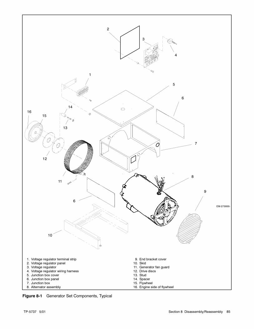
TP-5737 5/01 85Section 8 Disassembly/Reassembly
EM-273000-
1
2
3
4
5
6
7
8
9
10
11
12
13
14
1. Voltage regulator terminal strip
2. Voltage regulator panel3. Voltage regulator
4. Voltage regulator wiring harness
5. Junction box cover6. Junction box panel
7. Junction box
8. Alternator assembly
9. End bracket cover
10. Skid11. Generator fan guard
12. Drive discs
13. Stud14. Spacer
15. Flywheel
16. Engine side of flywheel
1516
6
Figure 8-1 Generator Set Components, Typical

TP-5737 5/0186 Section 8 Disassembly/Reassembly
F---
AC
G
F+
AC
B-257657-Y
1
2
3
45
6
7
8
9
10
11
12
13
14
1. LED circuit board cover
2. LED circuit board3. Photo transistor board
4. Insulating washer
5. Insulator6. Magnetic actuator
7. End bracket
8. Exciter field assembly
9. Rotor assembly10. SCR assembly
11. Generator set fan
12. Drive discs13. Stator assembly
14. Generator adapter
Figure 8-2 Generator Set Components, Typical
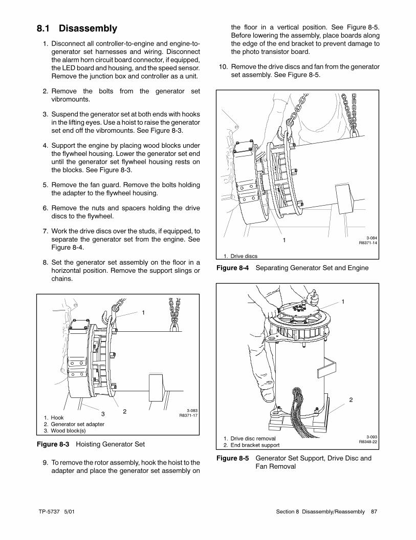
TP-5737 5/01 87Section 8 Disassembly/Reassembly
8.1 Disassembly
1. Disconnect all controller-to-engine and engine-to-
generator set harnesses and wiring. Disconnect
the alarm horn circuit board connector, if equipped,
the LED board and housing, and the speed sensor.
Remove the junction box and controller as a unit.
2. Remove the bolts from the generator set
vibromounts.
3. Suspend the generator set at both ends with hooks
in the lifting eyes. Use a hoist to raise the generator
set end off the vibromounts. See Figure 8-3.
4. Support the engine by placing wood blocks under
the flywheel housing. Lower the generator set end
until the generator set flywheel housing rests on
the blocks. See Figure 8-3.
5. Remove the fan guard. Remove the bolts holding
the adapter to the flywheel housing.
6. Remove the nuts and spacers holding the drive
discs to the flywheel.
7. Work the drive discs over the studs, if equipped, to
separate the generator set from the engine. See
Figure 8-4.
8. Set the generator set assembly on the floor in a
horizontal position. Remove the support slings or
chains.
3-083R8371-17
1
231. Hook
2. Generator set adapter3. Wood block(s)
Figure 8-3 Hoisting Generator Set
9. To remove the rotor assembly, hook the hoist to the
adapter and place the generator set assembly on
the floor in a vertical position. See Figure 8-5.
Before lowering the assembly, place boards along
the edge of the end bracket to prevent damage to
the photo transistor board.
10. Remove the drive discs and fan from the generator
set assembly. See Figure 8-5.
3-084R8371-14
1
1. Drive discs
Figure 8-4 Separating Generator Set and Engine
3-093R8348-22
1
2
1. Drive disc removal
2. End bracket support
Figure 8-5 Generator Set Support, Drive Disc and
Fan Removal

TP-5737 5/0188 Section 8 Disassembly/Reassembly
11. Fasten the lifting eye and hoist hook to the rotor
flange. Carefully hoist the rotor to avoid damaging
the exciter armature or exciter field magnets. See
Figure 8-6.
12. While the rotor is suspended, remove the photo
transistor board and actuator cup. Remove the F3,
G, and AC leads from the SCR assembly. Cut off
the photo transistor board terminals to remove the
circuit board. If the photo transistor board is
reused, leave the leads as long as possible.
13. Slowly lower the rotor to a horizontal position. Set
the rotor on a wooden surface. Take care not to
damage the windings, laminations, or bearing. See
Figure 8-7.
14. Place the generator set assembly on the generator
set adapter end in order to remove the generator
set adapter and end bracket from the stator. Fasten
chains to the generator set adapter and lower to a
horizontal position. Fasten the hook to the end
bracket eye and hoist to a vertical position. See
Figure 8-8.
3-090R8348-19
1
1. Hoist hook locations
Figure 8-6 Rotor Removal
3-088R8348-15
1
1. Rotor assembly
Figure 8-7 Lowering Rotor
3-084R8348-8
1
2
3
4
1. Hoist hook
2. Hoist hook3. End bracket
4. Adapter
Figure 8-8 Removing Generator Set Adapter

TP-5737 5/01 89Section 8 Disassembly/Reassembly
15. Remove the generator set adapter mounting bolts.
Fasten the hoist hooks to the end bracket and raise
the assembly slightly. Bump the generator set
adapter loose by using a rubber mallet.
16. Lower the stator assembly. Remove the end
bracket mounting bolts. Separate the end bracket
from the stator by bumping it loose with a rubber
mallet.
17. Remove the exciter magnets from the end bracket.
See Figure 8-9.
Note: Some early models are equipped with a
tolerance ring inside the end bracket bore.
3-080R8348-1
1
1. Exciter magnets
Figure 8-9 End Bracket View
8.2 Reassembly
1. Attach the exciter field to the end bracket with four
mounting screws. See Figure 8-9.
Note: Some early models are equipped with a
tolerance ring inside the end bracket bore.
Install a new tolerance ring when reinstalling
the end bracket.
2. Place the stator in a vertical position with the end
bracket side up.
Note: The end bracket side of the stator has four
mounting bosses.
3. Place the end bracket on the stator and use bolts to
align the holes. Use a rubber mallet to mount the
end bracket flush with the stator. See Figure 8-10.
Note: Position the end bracket housing eye
opposite the stator mounting bracket during
reassembly.
Note: Early models use a skewed (slanted) stator
with a straight rotor. When replacing either
the rotor or stator, be sure replacement is
the same as the original. Use dissimilar rotor
and stator styles (skewed rotor with straight
stator or straight rotor with skewed stator)
when reassembling the generator set.
4. Install bolts and washers to attach the end bracket
to the stator. Torque bolts to 47 Nm (35 ft. lbs.)
maximum.
3-082R8348-3
Figure 8-10 Mounting End Bracket on Stator
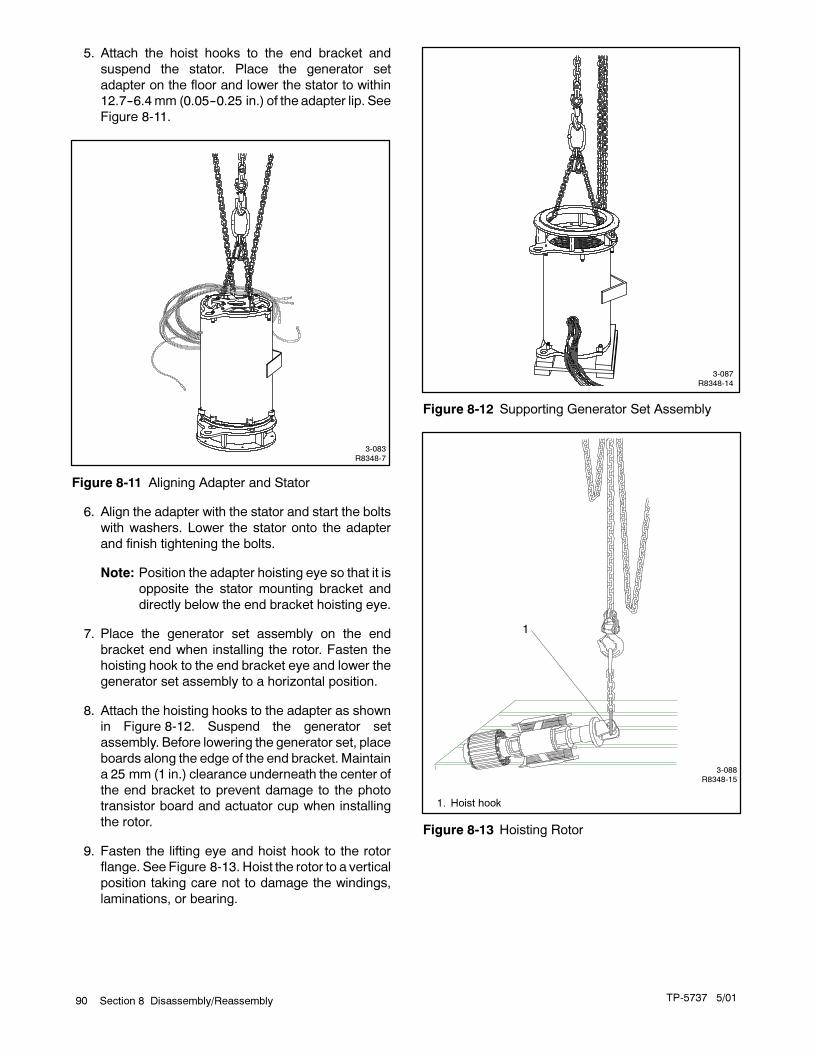
TP-5737 5/0190 Section 8 Disassembly/Reassembly
5. Attach the hoist hooks to the end bracket and
suspend the stator. Place the generator set
adapter on the floor and lower the stator to within
12.7--6.4mm (0.05--0.25 in.) of the adapter lip. See
Figure 8-11.
3-083R8348-7
Figure 8-11 Aligning Adapter and Stator
6. Align the adapter with the stator and start the bolts
with washers. Lower the stator onto the adapter
and finish tightening the bolts.
Note: Position the adapter hoisting eye so that it is
opposite the stator mounting bracket and
directly below the end bracket hoisting eye.
7. Place the generator set assembly on the end
bracket end when installing the rotor. Fasten the
hoisting hook to the end bracket eye and lower the
generator set assembly to a horizontal position.
8. Attach the hoisting hooks to the adapter as shown
in Figure 8-12. Suspend the generator set
assembly. Before lowering the generator set, place
boards along the edge of the end bracket. Maintain
a 25 mm (1 in.) clearance underneath the center of
the end bracket to prevent damage to the photo
transistor board and actuator cup when installing
the rotor.
9. Fasten the lifting eye and hoist hook to the rotor
flange. See Figure 8-13. Hoist the rotor to a vertical
position taking care not to damage the windings,
laminations, or bearing.
3-087R8348-14
Figure 8-12 Supporting Generator Set Assembly
3-088R8348-15
1
1. Hoist hook
Figure 8-13 Hoisting Rotor
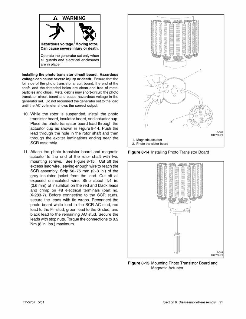
TP-5737 5/01 91Section 8 Disassembly/Reassembly
Hazardous voltage.
Can cause severe injury or death.
Operate the generator set only when
all guards and electrical enclosures
are in place.
Moving rotor.
WARNING
Installing the photo transistor circuit board. Hazardous
voltage can cause severe injury or death. Ensure that the
foil side of the photo transistor circuit board, the end of the
shaft, and the threaded holes are clean and free of metal
particles and chips. Metal debris may short-circuit the photo
transistor circuit board and cause hazardous voltage in the
generator set. Do not reconnect the generator set to the load
until the AC voltmeter shows the correct output.
10. While the rotor is suspended, install the photo
transistor board, insulator board, and actuator cup.
Place the photo transistor board lead through the
actuator cup as shown in Figure 8-14. Push the
lead through the hole in the rotor shaft and then
through the exciter laminations ending near the
SCR assembly.
11. Attach the photo transistor board and magnetic
actuator to the end of the rotor shaft with two
mounting screws. See Figure 8-15. Cut off the
excess lead wire, leaving enough wire to reach the
SCR assembly. Strip 50--75 mm (2--3 in.) of the
gray insulator jacket from the lead. Cut off all
exposed uninsulated wire. Strip about 1/4 in.
(0.6 mm) of insulation on the red and black leads
and crimp on #8 electrical terminals (part no.
X-283-7). Before connecting to the SCR studs,
secure the leads with tie wraps. Reconnect the
photo board white lead to the SCR AC stud, red
lead to the F+ stud, green lead to the G stud, and
black lead to the remaining AC stud. Secure the
leads with stop nuts. Torque the connections to 0.9
Nm (8 in. lbs.) maximum.
3-089R12758-29
1
2
1. Magnetic actuator
2. Photo transistor board
Figure 8-14 Installing Photo Transistor Board
3-089R12758-29
Figure 8-15 Mounting Photo Transistor Board and
Magnetic Actuator

TP-5737 5/0192 Section 8 Disassembly/Reassembly
12. Suspend the rotor over the generator set
assembly. Lower the rotor field into the stator. Be
extremely careful while lowering the rotor to avoid
damaging the exciter armature, field magnets,
stator windings, or rotor laminations. See
Figure 8-16. Carefully align the rotor bearing to the
end bracket. Check for an outer racemeasurement
of 0.6mm (0.25 in.) from the bracket to the bearing.
Make sure the photo transistor board and actuator
cup have clearance below the end bracket.
13. Place the fan over the rotor flange and torque the
bolts to 29 Nm (260 in. lbs.).
14. Attach the drive disc(s) to the end of the rotor shaft.
Torque the drive disc mounting bolts to 68 Nm
(50 ft. lbs.).
15. Attach the hoist to the adapter eye and place the
generator set assembly in a horizontal position.
Take care not to damage the rotor or stator.
Position the generator set so that the hoisting eyes
are to the top.
16. Apply Loctite�No. 271 red to the stud threads, if so
equipped, and thread the studs completely into the
flywheel as shown in Figure 8-17. Apply Loctite�
No. 242 blue to the stud threads on the nut side.
3-090R8348-19
Figure 8-16 Installing Rotor
3-098R8371-9
1
1. Flywheel studs
Figure 8-17 Flywheel Studs
17. Place the hoist hooks into the end bracket and the
adapter eye.Raise the generator set assembly and
align the studs with the drive discs by turning the
flywheel. Move the generator set as necessary to
work the drive discs over the studs.When the drive
discs are about 25 mm (1 in.) over the studs, install
the spacers, if equipped. See Figure 8-18.
Note: Some models mount the drive discs to the
flywheel using bolts. Some applications use
hardened washers.
3-097R8371-14
1 2 3
1. Drive discs
2. Studs3. Spacers
Figure 8-18 Installing Spacers
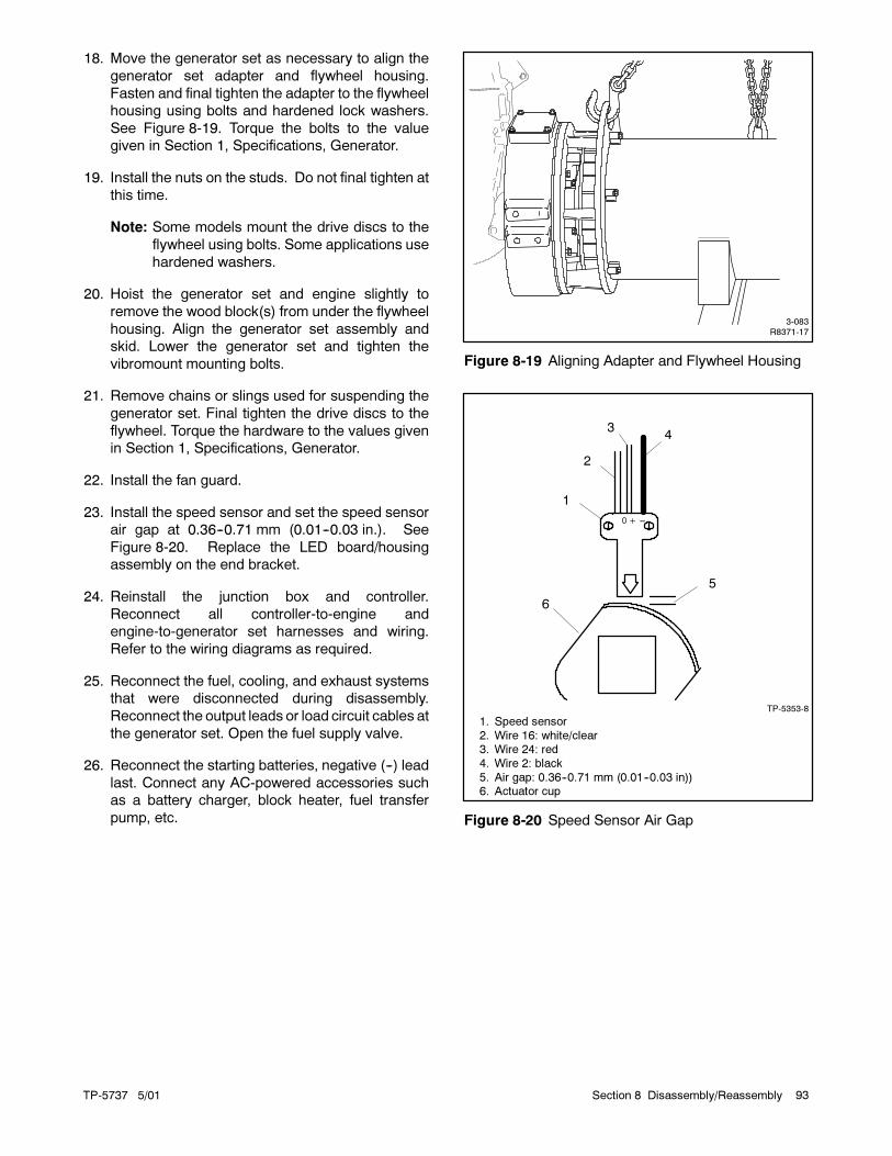
TP-5737 5/01 93Section 8 Disassembly/Reassembly
18. Move the generator set as necessary to align the
generator set adapter and flywheel housing.
Fasten and final tighten the adapter to the flywheel
housing using bolts and hardened lock washers.
See Figure 8-19. Torque the bolts to the value
given in Section 1, Specifications, Generator.
19. Install the nuts on the studs. Do not final tighten at
this time.
Note: Some models mount the drive discs to the
flywheel using bolts. Some applications use
hardened washers.
20. Hoist the generator set and engine slightly to
remove the wood block(s) from under the flywheel
housing. Align the generator set assembly and
skid. Lower the generator set and tighten the
vibromount mounting bolts.
21. Remove chains or slings used for suspending the
generator set. Final tighten the drive discs to the
flywheel. Torque the hardware to the values given
in Section 1, Specifications, Generator.
22. Install the fan guard.
23. Install the speed sensor and set the speed sensor
air gap at 0.36--0.71 mm (0.01--0.03 in.). See
Figure 8-20. Replace the LED board/housing
assembly on the end bracket.
24. Reinstall the junction box and controller.
Reconnect all controller-to-engine and
engine-to-generator set harnesses and wiring.
Refer to the wiring diagrams as required.
25. Reconnect the fuel, cooling, and exhaust systems
that were disconnected during disassembly.
Reconnect the output leads or load circuit cables at
the generator set. Open the fuel supply valve.
26. Reconnect the starting batteries, negative (--) lead
last. Connect any AC-powered accessories such
as a battery charger, block heater, fuel transfer
pump, etc.
3-083R8371-17
Figure 8-19 Aligning Adapter and Flywheel Housing
1. Speed sensor
2. Wire 16: white/clear3. Wire 24: red
4. Wire 2: black
5. Air gap: 0.36--0.71 mm (0.01--0.03 in))6. Actuator cup
0 + ---
1
2
3
6
5
4
TP-5353-8
Figure 8-20 Speed Sensor Air Gap

TP-5737 5/0194 Section 8 Disassembly/Reassembly
Notes

TP-5737 5/01 95Section 9 Wiring Diagrams
Section 9 Wiring Diagrams
Accidental starting.
Can cause severe injury or death.
Disconnect the battery cables before
working on the generator set.
Remove the negative (--) lead first
when disconnecting the battery.
Reconnect the negative (--) lead last
when reconnecting the battery.
WARNING
Disabling the generator set. Accidental starting can
cause severe injury or death. Before working on the
generator set or connected equipment, disable the generator
set as follows: (1) Move thegenerator setmaster switch to the
OFFposition. (2) Disconnect thepower to thebattery charger.
(3) Remove the battery cables, negative (--) lead first.
Reconnect the negative (--) lead last when reconnecting the
battery. Follow these precautions to prevent starting of the
generator set by an automatic transfer switch, remote
start/stop switch, or engine start command from a remote
computer.
Hazardous voltage.
Can cause severe injury or death.
Operate the generator set only when
all guards and electrical enclosures
are in place.
Moving rotor.
WARNING
Grounding electrical equipment. Hazardous voltage can
cause severe injury or death. Electrocution is possible
whenever electricity is present. Open the main circuit
breakers of all power sources before servicing the equipment.
Configure the installation to electrically ground the generator
set, transfer switch, and related equipment and electrical
circuits to complywith applicable codesandstandards. Never
contact electrical leads or appliances when standing in water
or onwetgroundbecause theseconditions increase the riskof
electrocution.
Short circuits. Hazardous voltage/current can cause
severe injury or death. Short circuits can cause bodily injury
and/or equipment damage. Do not contact electrical
connections with tools or jewelry whilemaking adjustments or
repairs. Remove all jewelry before servicing the equipment.

TP-5737 5/0196 Section 9 Wiring Diagrams
Notes

TP-5737
5/01
97
Section9
WiringDiagrams
344496A-E
Figure
9-1
WiringDiagram,Decision-M
aker�
1Standard
Controller(Sheet1of3)
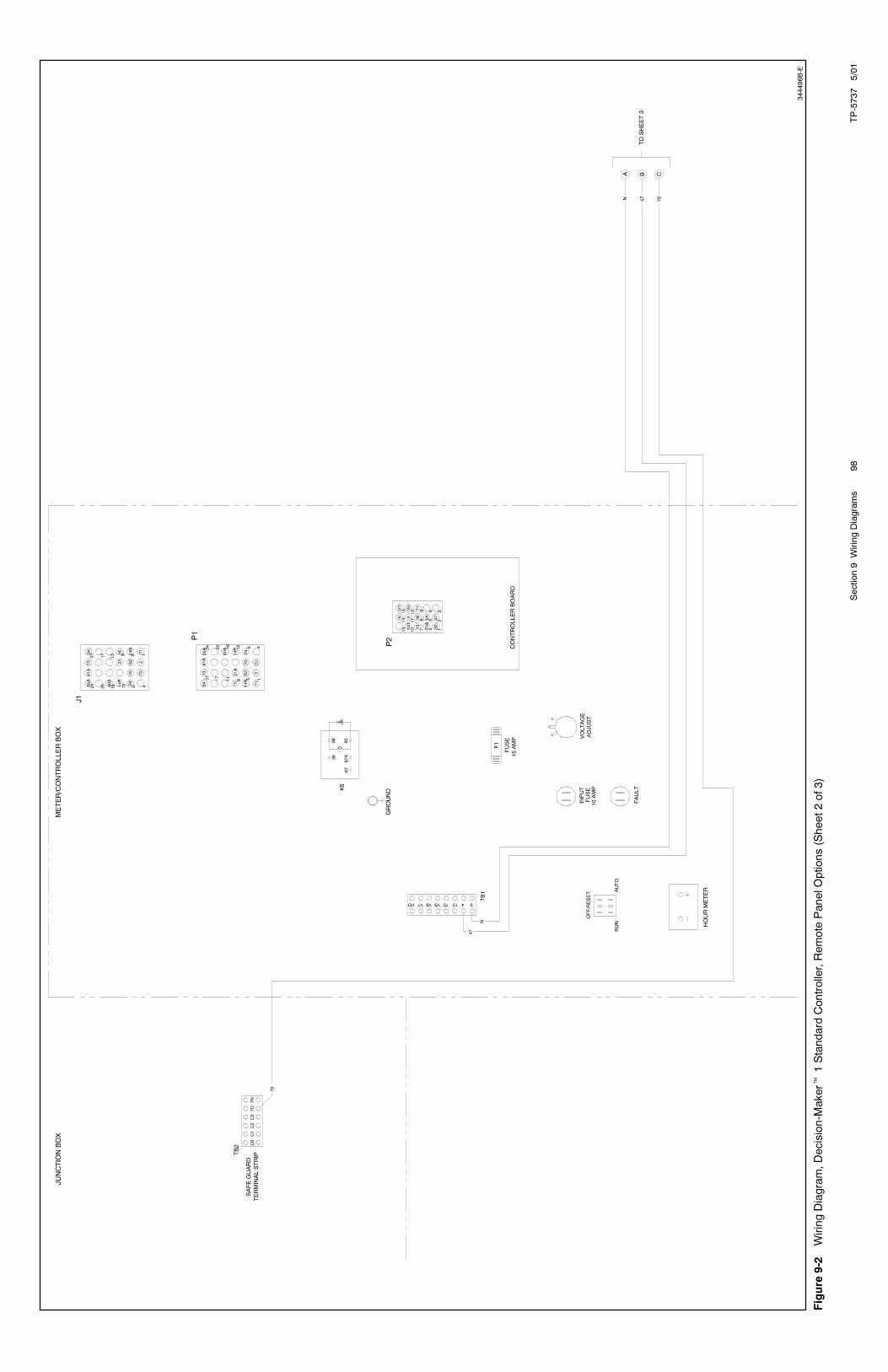
TP-5737
5/01
Section9
WiringDiagrams
98
344496B-E
Figure
9-2
WiringDiagram,Decision-M
aker�
1Standard
Controller,Remote
PanelOptions(Sheet2of3)

TP-5737
5/01
99
Section9
WiringDiagrams
344496C-E
Figure
9-3
WiringDiagram,Decision-M
aker�
1Standard
Controller,Remote
PanelOptions(Sheet3of3)
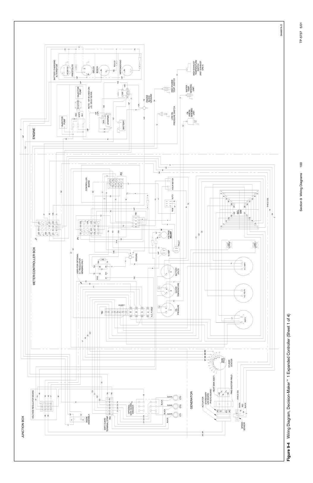
TP-5737
5/01
Section9
WiringDiagrams
100
344497A-D
Figure
9-4
WiringDiagram,Decision-M
aker�
1ExpandedController(Sheet1of4)

TP-5737
5/01
101
Section9
WiringDiagrams
344497B-D
Figure
9-5
WiringDiagram,Decision-M
aker�1ExpandedController,Remote
PanelOptions(Sheet2of4)
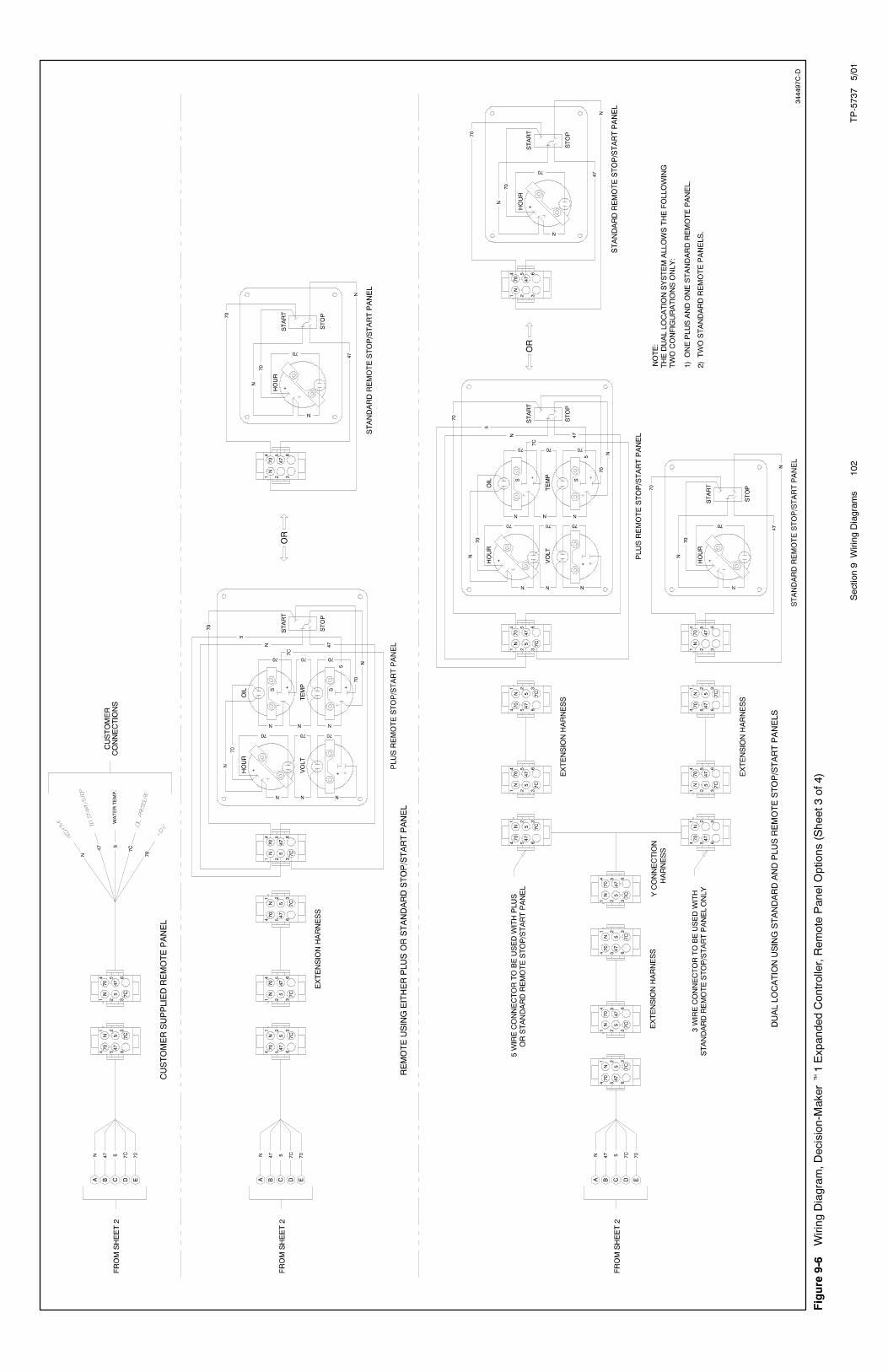
TP-5737
5/01
Section9
WiringDiagrams
102
344497C-D
Figure
9-6
WiringDiagram,Decision-M
aker�1ExpandedController,Remote
PanelOptions(Sheet3of4)
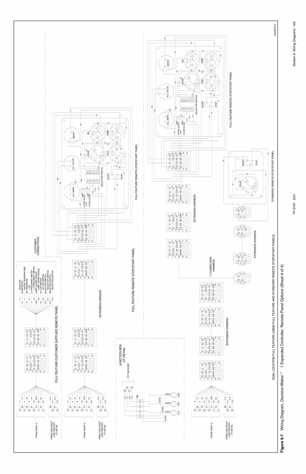
TP-5737
5/01
103
Section9
WiringDiagrams
344497D-D
Figure
9-7
WiringDiagram,Decision-M
aker�
1ExpandedController,Remote
PanelOptions(Sheet4of4)

TP-5737
5/01
Section9
WiringDiagrams
104
344498A-C
Figure
9-8
WiringDiagram,Decision-M
aker�
3+Controller(Sheet1of5)

TP-5737
5/01
105
Section9
WiringDiagrams
344498B-C
Figure
9-9
WiringDiagram,Decision-M
aker�
3+Controller,Remote
PanelOptions(Sheet2of5)

TP-5737
5/01
Section9
WiringDiagrams
106
344498C-C
Figure
9-10
WiringDiagram,Decision-M
aker�
3+Controller,Remote
PanelOptions(Sheet3of5)
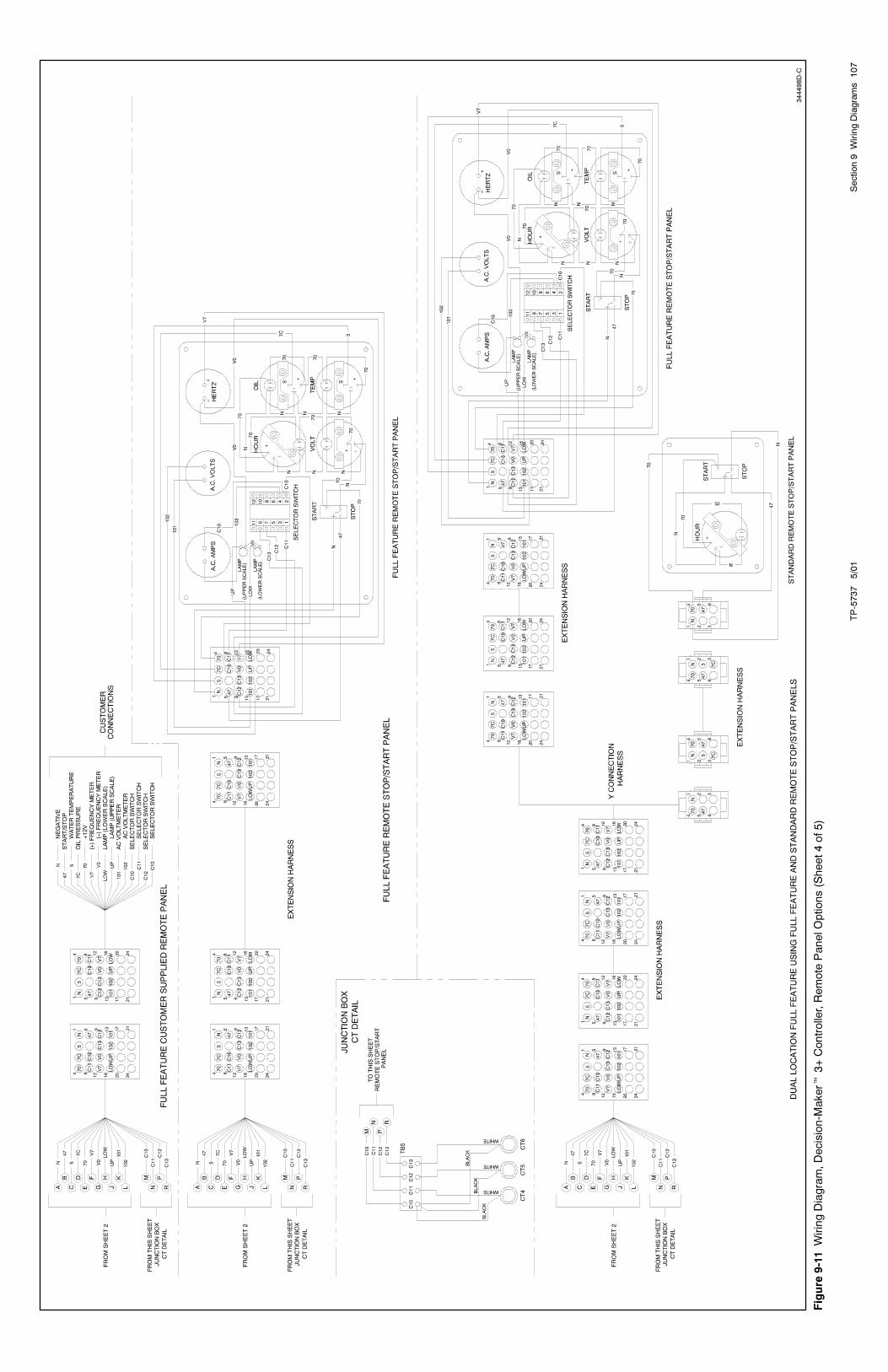
TP-5737
5/01
107
Section9
WiringDiagrams
344498D-C
Figure
9-11
WiringDiagram,Decision-M
aker�
3+Controller,Remote
PanelOptions(Sheet4of5)
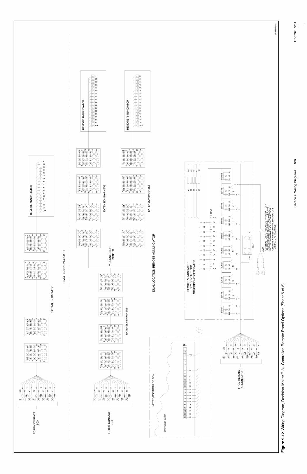
TP-5737
5/01
Section9
WiringDiagrams
108
-
344498E-C
Figure
9-12
WiringDiagram,Decision-M
aker�
3+Controller,Remote
PanelOptions(Sheet5of5)

TP-5737
5/01
109
Section9
WiringDiagrams
-
ADV-6120-A
Figure
9-13
Decision-M
aker�
1RelayControllerwithE-254717CircuitBoard

TP-5737
5/01
Section9
WiringDiagrams
110
-
ADV-6120-D
Figure
9-14
WiringDiagram,Decision-M
aker�
1Standard
ControllerwithF-254717CircuitBoard

TP-5737
5/01
111
Section9
WiringDiagrams
-
ADV-6121-
Figure
9-15
Decision-M
aker�
1ExpandedRelayControllerwithE-254717CircuitBoard

TP-5737
5/01
Section9
WiringDiagrams
112
-
ADV-6121-C
Figure
9-16
WiringDiagram,Decision-M
aker�
1ExpandedControllerwithF-254717CircuitBoard
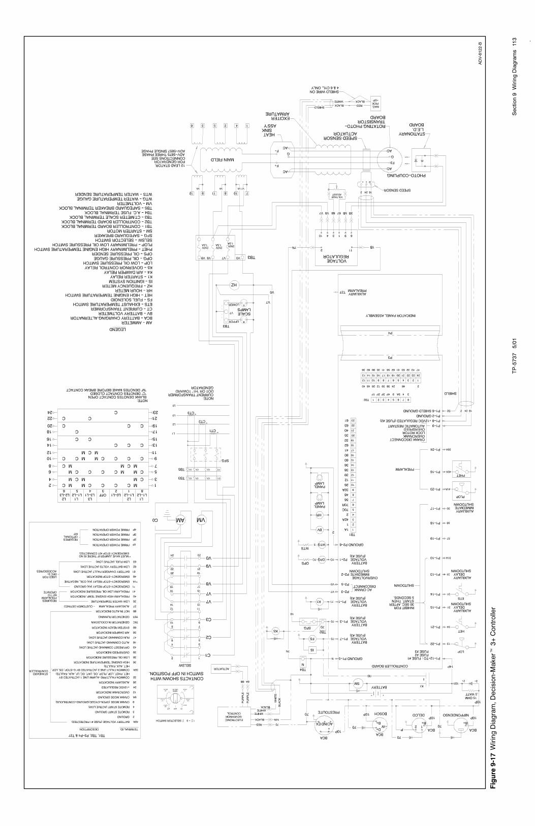
TP-5737
5/01
113
Section9
WiringDiagrams
-
ADV-6122-B
Figure
9-17
WiringDiagram,Decision-M
aker�
3+Controller

TP-5737
5/01
Section9
WiringDiagrams
114
Notes
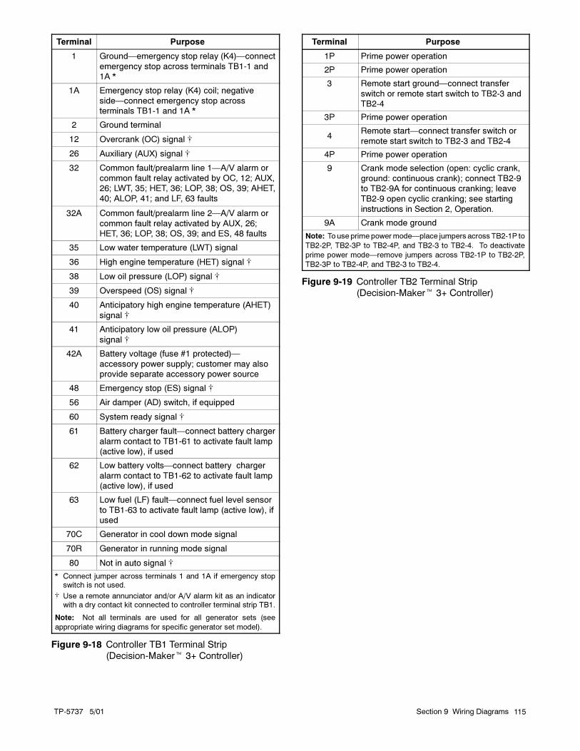
TP-5737 5/01 115Section 9 Wiring Diagrams
Terminal Purpose
1 Ground—emergency stop relay (K4)—connect
emergency stop across terminals TB1-1 and
1A *
1A Emergency stop relay (K4) coil; negative
side—connect emergency stop across
terminals TB1-1 and 1A *
2 Ground terminal
12 Overcrank (OC) signal �
26 Auxiliary (AUX) signal �
32 Common fault/prealarm line 1—A/V alarm or
common fault relay activated by OC, 12; AUX,
26; LWT, 35; HET, 36; LOP, 38; OS, 39; AHET,
40; ALOP, 41; and LF, 63 faults
32A Common fault/prealarm line 2—A/V alarm or
common fault relay activated by AUX, 26;
HET, 36; LOP, 38; OS, 39; and ES, 48 faults
35 Low water temperature (LWT) signal
36 High engine temperature (HET) signal �
38 Low oil pressure (LOP) signal �
39 Overspeed (OS) signal �
40 Anticipatory high engine temperature (AHET)
signal �
41 Anticipatory low oil pressure (ALOP)
signal �
42A Battery voltage (fuse #1 protected)—
accessory power supply; customer may also
provide separate accessory power source
48 Emergency stop (ES) signal �
56 Air damper (AD) switch, if equipped
60 System ready signal �
61 Battery charger fault—connect battery charger
alarm contact to TB1-61 to activate fault lamp
(active low), if used
62 Low battery volts—connect battery charger
alarm contact to TB1-62 to activate fault lamp
(active low), if used
63 Low fuel (LF) fault—connect fuel level sensor
to TB1-63 to activate fault lamp (active low), if
used
70C Generator in cool down mode signal
70R Generator in running mode signal
80 Not in auto signal �
* Connect jumper across terminals 1 and 1A if emergency stopswitch is not used.
� Use a remote annunciator and/or A/V alarm kit as an indicatorwith a dry contact kit connected to controller terminal strip TB1.
Note: Not all terminals are used for all generator sets (see
appropriate wiring diagrams for specific generator set model).
Figure 9-18 Controller TB1 Terminal Strip
(Decision-Maker� 3+ Controller)
Terminal Purpose
1P Prime power operation
2P Prime power operation
3 Remote start ground—connect transfer
switch or remote start switch to TB2-3 and
TB2-4
3P Prime power operation
4Remote start—connect transfer switch or
remote start switch to TB2-3 and TB2-4
4P Prime power operation
9 Crank mode selection (open: cyclic crank,
ground: continuous crank); connect TB2-9
to TB2-9A for continuous cranking; leave
TB2-9 open cyclic cranking; see starting
instructions in Section 2, Operation.
9A Crank mode ground
Note: To use prime powermode—place jumpers across TB2-1P to
TB2-2P, TB2-3P to TB2-4P, and TB2-3 to TB2-4. To deactivate
prime power mode—remove jumpers across TB2-1P to TB2-2P,
TB2-3P to TB2-4P, and TB2-3 to TB2-4.
Figure 9-19 Controller TB2 Terminal Strip
(Decision-Maker� 3+ Controller)

TP-5737 5/01116 Section 9 Wiring Diagrams
9.1 Voltage Reconnection
9.1.1 Introduction
Use the following voltage reconnection procedure to
change the voltage of 12-lead generator sets. See
Generator Set Frequency Change and Adjustment later
in this section for frequency adjustment information.
Refer to 9.1.2, VoltageReconnectionProcedure and the
connection schematics. Follow the safety precautions
at the front of this manual and in the procedure text and
observe National Electrical Code (NEC) guidelines.
NOTICE
Voltage reconnection. Affix a notice to the generator set
after reconnecting the set to a voltage different from the
voltage on the nameplate. Order voltage reconnection
decal 246242 from an authorized service distributor/
dealer.
NOTICE
This generator set has been
rewired from its nameplate voltage
to
246242
Note: Equipment damage. Verify that the voltage
ratings of the transfer switch, line circuit breakers,
and other accessories match the desired line
voltage.
Accidental starting.
Can cause severe injury or death.
Disconnect the battery cables before
working on the generator set.
Remove the negative (--) lead first
when disconnecting the battery.
Reconnect the negative (--) lead last
when reconnecting the battery.
WARNING
Disabling the generator set. Accidental starting can
cause severe injury or death. Before working on the
generator set or connected equipment, disable the generator
set as follows: (1) Move thegenerator setmaster switch to the
OFFposition. (2) Disconnect thepower to thebattery charger.
(3) Remove the battery cables, negative (--) lead first.
Reconnect the negative (--) lead last when reconnecting the
battery. Follow these precautions to prevent starting of the
generator set by an automatic transfer switch, remote
start/stop switch, or engine start command from a remote
computer.
Hazardous voltage.
Can cause severe injury or death.
Operate the generator set only when
all guards and electrical enclosures
are in place.
Moving rotor.
WARNING
Grounding electrical equipment. Hazardous voltage can
cause severe injury or death. Electrocution is possible
whenever electricity is present. Open the main circuit
breakers of all power sources before servicing the equipment.
Configure the installation to electrically ground the generator
set, transfer switch, and related equipment and electrical
circuits to complywith applicable codesandstandards. Never
contact electrical leads or appliances when standing in water
or onwetgroundbecause theseconditions increase the riskof
electrocution.
Short circuits. Hazardous voltage/current can cause
severe injury or death. Short circuits can cause bodily injury
and/or equipment damage. Do not contact electrical
connections with tools or jewelry whilemaking adjustments or
repairs. Remove all jewelry before servicing the equipment.
x:gr:001:001
9.1.2 Voltage Reconnection Procedure
1. Place the generator set master switch in the
OFF/RESET position.
2. Disconnect the generator set engine starting
battery, negative (--) lead first. Disconnect power to
the battery charger (if equipped).
3. Use Figure 9-20 or Figure 9-21 to determine the
generator set voltage configuration. Note the
original voltage and reconnect as needed. Route
leads through current transformers (CTs) and
connect them according to the diagram for desired
phase and voltage.
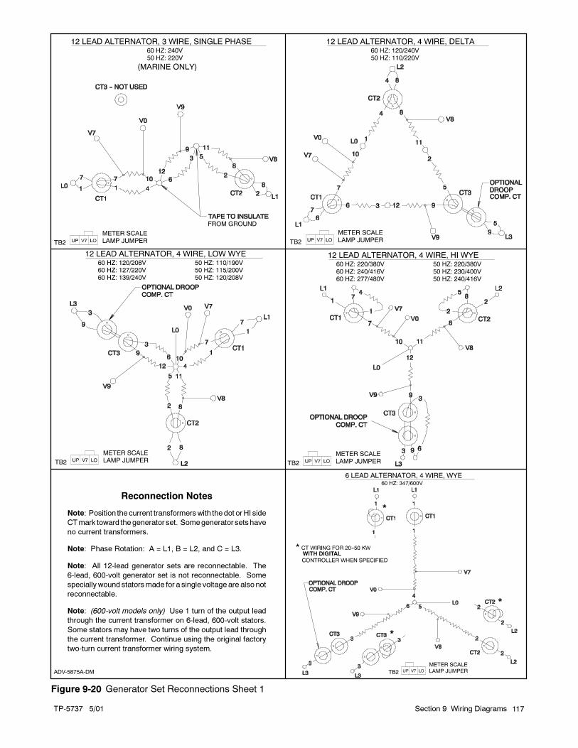
TP-5737 5/01 117Section 9 Wiring Diagrams
ADV-5875A-DM
WITH DIGITAL
Reconnection Notes
Note: Position the current transformerswith the dot orHI side
CTmark toward thegenerator set. Somegenerator setshave
no current transformers.
Note: Phase Rotation: A = L1, B = L2, and C = L3.
Note: All 12-lead generator sets are reconnectable. The
6-lead, 600-volt generator set is not reconnectable. Some
speciallywound statorsmade for a single voltage are also not
reconnectable.
Note: (600-volt models only) Use 1 turn of the output lead
through the current transformer on 6-lead, 600-volt stators.
Some stators may have two turns of the output lead through
the current transformer. Continue using the original factory
two-turn current transformer wiring system.
Figure 9-20 Generator Set Reconnections Sheet 1

TP-5737 5/01118 Section 9 Wiring Diagrams
EM-250000-G
Reconnection Notes
Note: Position the current transformerswith the dot orHI side
CTmark toward thegenerator set. Somegenerator setshave
no current transformers.
Note: Phase Rotation: A = L1, B = L2, and C = L3.
Note: All 12-lead generator sets are reconnectable. The
6-lead, 600-volt generator set is not reconnectable. Some
speciallywound statorsmade for a single voltage are also not
reconnectable.
Figure 9-21 Generator Set Reconnections Sheet 2

TP-5737 5/01 119Section 9 Wiring Diagrams
Note: Position the current transformers with the
dot or HI side CT marking toward the
generator set.
Note: Only generator sets equippedwith ACmeter
controllers and/or safeguard circuit
breakers require CTs.
4. If the controller has meters, remove the controller
cover and reposition the meter scale lamp jumper
(see Figure 9-22) matching the position of the
desired voltage (shown in Figure 9-20 or
Figure 9-21).
TP-5353-6
1
1. Lamp jumper
Figure 9-22 Meter Scale Lamp Jumper
5. The overvoltage shutdown is standard on
Decision-Maker� 3+ controllers. The 139/240
volt (low wye) and 277/480 volt (high wye),
3-phase, 4-wire, 60 Hz configurations use different
overvoltage shutdown settings than all other
configurations. Recalibrate the overvoltage
shutdown if the reconnection changes the voltage
to or from one of these configurations. See
Section 9.2, Overvoltage Shutdown Adjustment.
Do not recalibrate the overvoltage adjustment for
other voltage changes.
6. If the controller has meters, set the phase selector
switch to the L1-L2 position (1-phase or 3-phase
configuration depending on generator set
connection). Connect a voltmeter across leads L1
and L2 if the controller has no meters.
Note: Equipment damage. Verify that the voltage
ratings of the transfer switch, line circuit
breakers, and other accessories match the
desired line voltage.
7. Reconnect the starting battery, negative (--) lead
last. Place the generator set master switch in the
RUN position to start the generator set. Observe
the voltmeter and verify that the unit has the
desired line voltage.
Adjust the voltage using the voltage adjustment
potentiometer on the generator controller front
panel. See Figure 9-23.
8. Stop the generator set after completing the voltage
adjustment.
9. Disconnect the external voltmeter if used. Replace
the controller cover.
ADV-5849 P1
1. Voltage adjustment potentiometer
1
Figure 9-23 Voltage Adjustment Potentiometer on
Controller
x:gr:001:002:a
9.2 Overvoltage Shutdown
Adjustment
The 139/240 volt (low wye) and 277/480 volt (high wye),
3-phase, 4-wire, 60 Hz configurations use different
overvoltage shutdown settings than all other
configurations. Recalibrate the overvoltage shutdown if
the reconnection changes the voltage to or from one of
these configurations. Do not recalibrate the
overvoltage adjustment for other voltage changes.
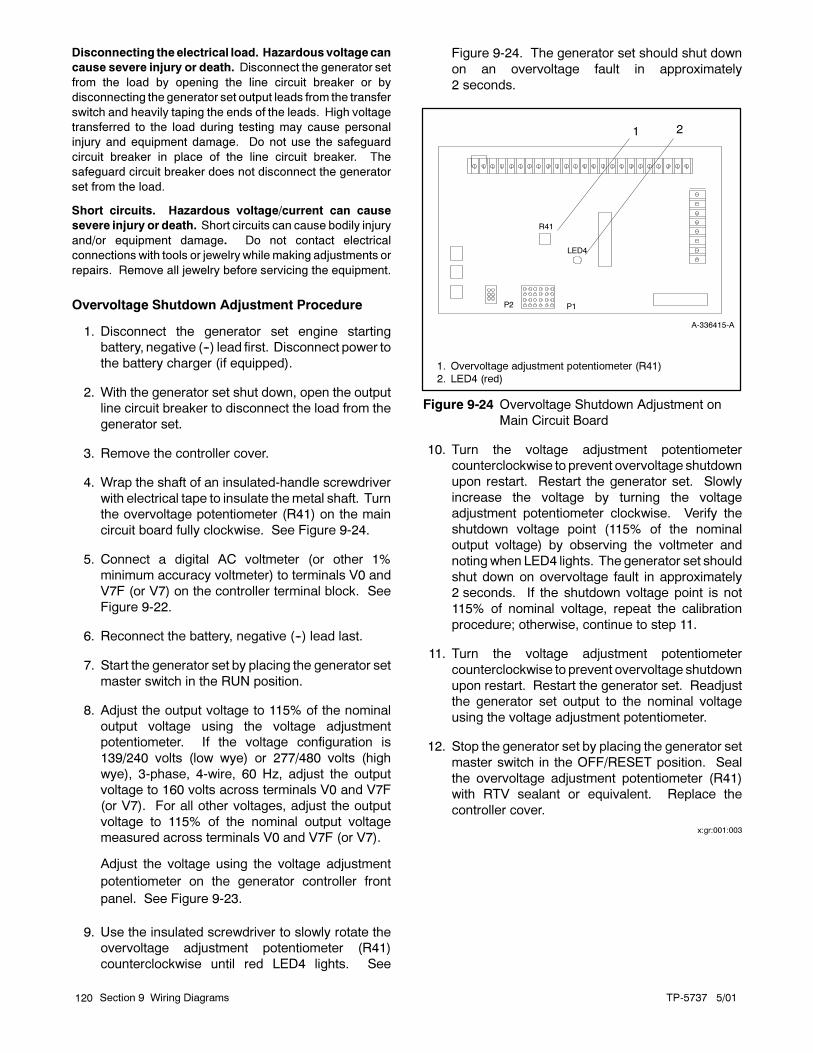
TP-5737 5/01120 Section 9 Wiring Diagrams
Disconnecting theelectrical load. Hazardous voltagecan
cause severe injury or death. Disconnect the generator set
from the load by opening the line circuit breaker or by
disconnecting the generator set output leads from the transfer
switch and heavily taping the ends of the leads. High voltage
transferred to the load during testing may cause personal
injury and equipment damage. Do not use the safeguard
circuit breaker in place of the line circuit breaker. The
safeguard circuit breaker does not disconnect the generator
set from the load.
Short circuits. Hazardous voltage/current can cause
severe injury or death. Short circuits can cause bodily injury
and/or equipment damage. Do not contact electrical
connections with tools or jewelry whilemaking adjustments or
repairs. Remove all jewelry before servicing the equipment.
Overvoltage Shutdown Adjustment Procedure
1. Disconnect the generator set engine starting
battery, negative (--) lead first. Disconnect power to
the battery charger (if equipped).
2. With the generator set shut down, open the output
line circuit breaker to disconnect the load from the
generator set.
3. Remove the controller cover.
4. Wrap the shaft of an insulated-handle screwdriver
with electrical tape to insulate themetal shaft. Turn
the overvoltage potentiometer (R41) on the main
circuit board fully clockwise. See Figure 9-24.
5. Connect a digital AC voltmeter (or other 1%
minimum accuracy voltmeter) to terminals V0 and
V7F (or V7) on the controller terminal block. See
Figure 9-22.
6. Reconnect the battery, negative (--) lead last.
7. Start the generator set by placing the generator set
master switch in the RUN position.
8. Adjust the output voltage to 115% of the nominal
output voltage using the voltage adjustment
potentiometer. If the voltage configuration is
139/240 volts (low wye) or 277/480 volts (high
wye), 3-phase, 4-wire, 60 Hz, adjust the output
voltage to 160 volts across terminals V0 and V7F
(or V7). For all other voltages, adjust the output
voltage to 115% of the nominal output voltage
measured across terminals V0 and V7F (or V7).
Adjust the voltage using the voltage adjustment
potentiometer on the generator controller front
panel. See Figure 9-23.
9. Use the insulated screwdriver to slowly rotate the
overvoltage adjustment potentiometer (R41)
counterclockwise until red LED4 lights. See
Figure 9-24. The generator set should shut down
on an overvoltage fault in approximately
2 seconds.
P1P2
A-336415-A
2
R41
LED4
1. Overvoltage adjustment potentiometer (R41)
2. LED4 (red)
1
Figure 9-24 Overvoltage Shutdown Adjustment on
Main Circuit Board
10. Turn the voltage adjustment potentiometer
counterclockwise to prevent overvoltage shutdown
upon restart. Restart the generator set. Slowly
increase the voltage by turning the voltage
adjustment potentiometer clockwise. Verify the
shutdown voltage point (115% of the nominal
output voltage) by observing the voltmeter and
notingwhen LED4 lights. The generator set should
shut down on overvoltage fault in approximately
2 seconds. If the shutdown voltage point is not
115% of nominal voltage, repeat the calibration
procedure; otherwise, continue to step 11.
11. Turn the voltage adjustment potentiometer
counterclockwise to prevent overvoltage shutdown
upon restart. Restart the generator set. Readjust
the generator set output to the nominal voltage
using the voltage adjustment potentiometer.
12. Stop the generator set by placing the generator set
master switch in the OFF/RESET position. Seal
the overvoltage adjustment potentiometer (R41)
with RTV sealant or equivalent. Replace the
controller cover.
x:gr:001:003

TP-5737 5/01 121Section 9 Wiring Diagrams
9.3 Generator Set Frequency
Change and Adjustment
9.3.1 Frequency Change
Set the voltage regulator circuit board for either 50 or
60 Hz application. See Figure 9-25. Connect a jumper
between terminals T1 and T2 for 60 Hz operation.
Connect a jumper between terminals T1 and T3 to
convert voltage regulator circuit board to 50 Hz
application.
This procedure changes the voltage regulator circuit
board for the desired frequency. See Frequency
Adjustment for changing generator set frequency and
speed.
C-255670-D
1
2
3
1. T2 terminal
2. T1 terminal3. T3 terminal
Figure 9-25 Jumper Location for 50 or 60 Hz
Operation
9.3.2 Frequency Adjustment
Check the frequency meter for a no-load reading of
63 Hz for 60 Hz operation and 53 Hz for 50 Hz operation
to determine correct frequency operation. Check for 50
and 60 Hz operation at no load if the generator set is
equipped with an isochronous governor. Connect a
frequency meter across V0 and V7 on the control board
terminal strip (generator set must not be running while
making connections) if the controller is not equipped
with a frequency meter. Refer to Figure 9-26.
To adjust governor speed, refer to Section 7,
Component Testing and Adjustment, Governors.
A-328917-X
1
1. Frequency meter connection points
Figure 9-26 Frequency Meter Connections

TP-5737 5/01122 Section 9 Wiring Diagrams
Notes
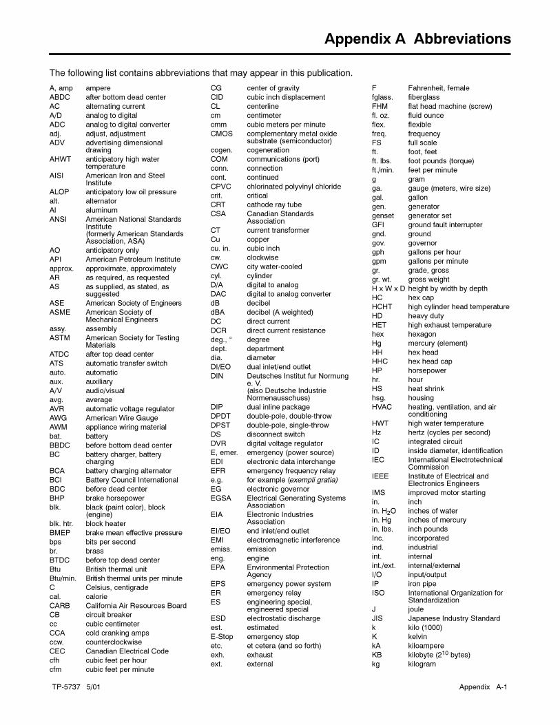
TP-5737 5/01 Appendix A-1
Appendix A Abbreviations
The following list contains abbreviations that may appear in this publication.
A, amp ampere
ABDC after bottom dead center
AC alternating current
A/D analog to digital
ADC analog to digital converter
adj. adjust, adjustment
ADV advertising dimensionaldrawing
AHWT anticipatory high watertemperature
AISI American Iron and SteelInstitute
ALOP anticipatory low oil pressure
alt. alternator
Al aluminum
ANSI American National StandardsInstitute(formerly American StandardsAssociation, ASA)
AO anticipatory only
API American Petroleum Institute
approx. approximate, approximately
AR as required, as requested
AS as supplied, as stated, assuggested
ASE American Society of Engineers
ASME American Society ofMechanical Engineers
assy. assembly
ASTM American Society for TestingMaterials
ATDC after top dead center
ATS automatic transfer switch
auto. automatic
aux. auxiliary
A/V audio/visual
avg. average
AVR automatic voltage regulator
AWG American Wire Gauge
AWM appliance wiring material
bat. battery
BBDC before bottom dead center
BC battery charger, batterycharging
BCA battery charging alternator
BCI Battery Council International
BDC before dead center
BHP brake horsepower
blk. black (paint color), block(engine)
blk. htr. block heater
BMEP brake mean effective pressure
bps bits per second
br. brass
BTDC before top dead center
Btu British thermal unit
Btu/min. British thermal units per minute
C Celsius, centigrade
cal. calorie
CARB California Air Resources Board
CB circuit breaker
cc cubic centimeter
CCA cold cranking amps
ccw. counterclockwise
CEC Canadian Electrical Code
cfh cubic feet per hour
cfm cubic feet per minute
CG center of gravity
CID cubic inch displacement
CL centerline
cm centimeter
cmm cubic meters per minute
CMOS complementary metal oxidesubstrate (semiconductor)
cogen. cogeneration
COM communications (port)
conn. connection
cont. continued
CPVC chlorinated polyvinyl chloride
crit. critical
CRT cathode ray tube
CSA Canadian StandardsAssociation
CT current transformer
Cu copper
cu. in. cubic inch
cw. clockwise
CWC city water-cooled
cyl. cylinder
D/A digital to analog
DAC digital to analog converter
dB decibel
dBA decibel (A weighted)
DC direct current
DCR direct current resistance
deg., � degree
dept. department
dia. diameter
DI/EO dual inlet/end outlet
DIN Deutsches Institut fur Normunge. V.(also Deutsche IndustrieNormenausschuss)
DIP dual inline package
DPDT double-pole, double-throw
DPST double-pole, single-throw
DS disconnect switch
DVR digital voltage regulator
E, emer. emergency (power source)
EDI electronic data interchange
EFR emergency frequency relay
e.g. for example (exempli gratia)
EG electronic governor
EGSA Electrical Generating SystemsAssociation
EIA Electronic IndustriesAssociation
EI/EO end inlet/end outlet
EMI electromagnetic interference
emiss. emission
eng. engine
EPA Environmental ProtectionAgency
EPS emergency power system
ER emergency relay
ES engineering special,engineered special
ESD electrostatic discharge
est. estimated
E-Stop emergency stop
etc. et cetera (and so forth)
exh. exhaust
ext. external
F Fahrenheit, female
fglass. fiberglass
FHM flat head machine (screw)
fl. oz. fluid ounce
flex. flexible
freq. frequency
FS full scale
ft. foot, feet
ft. lbs. foot pounds (torque)
ft./min. feet per minute
g gram
ga. gauge (meters, wire size)
gal. gallon
gen. generator
genset generator set
GFI ground fault interrupter
gnd. ground
gov. governor
gph gallons per hour
gpm gallons per minute
gr. grade, gross
gr. wt. gross weight
H x W x D height by width by depth
HC hex cap
HCHT high cylinder head temperature
HD heavy duty
HET high exhaust temperature
hex hexagon
Hg mercury (element)
HH hex head
HHC hex head cap
HP horsepower
hr. hour
HS heat shrink
hsg. housing
HVAC heating, ventilation, and airconditioning
HWT high water temperature
Hz hertz (cycles per second)
IC integrated circuit
ID inside diameter, identification
IEC International ElectrotechnicalCommission
IEEE Institute of Electrical andElectronics Engineers
IMS improved motor starting
in. inch
in. H2O inches of water
in. Hg inches of mercury
in. lbs. inch pounds
Inc. incorporated
ind. industrial
int. internal
int./ext. internal/external
I/O input/output
IP iron pipe
ISO International Organization forStandardization
J joule
JIS Japanese Industry Standard
k kilo (1000)
K kelvin
kA kiloampere
KB kilobyte (210 bytes)
kg kilogram
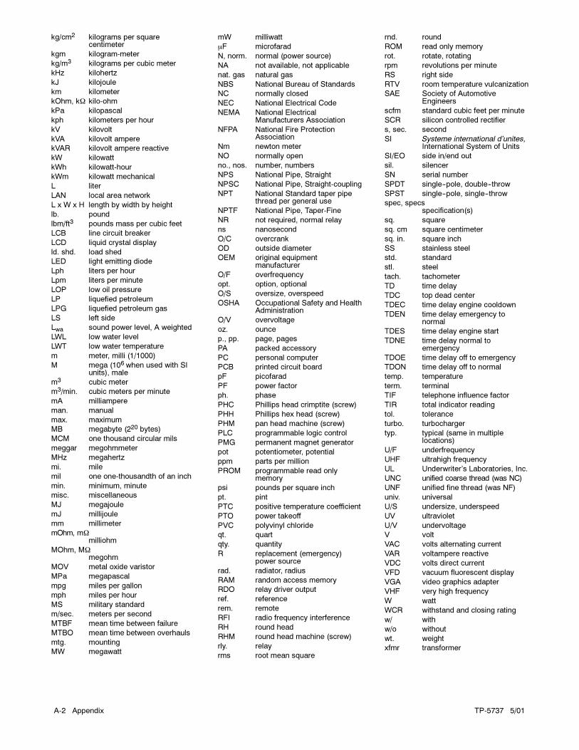
TP-5737 5/01A-2 Appendix
kg/cm2 kilograms per squarecentimeter
kgm kilogram-meter
kg/m3 kilograms per cubic meter
kHz kilohertz
kJ kilojoule
km kilometer
kOhm, k� kilo-ohm
kPa kilopascal
kph kilometers per hour
kV kilovolt
kVA kilovolt ampere
kVAR kilovolt ampere reactive
kW kilowatt
kWh kilowatt-hour
kWm kilowatt mechanical
L liter
LAN local area network
L x W x H length by width by height
lb. pound
lbm/ft3 pounds mass per cubic feet
LCB line circuit breaker
LCD liquid crystal display
ld. shd. load shed
LED light emitting diode
Lph liters per hour
Lpm liters per minute
LOP low oil pressure
LP liquefied petroleum
LPG liquefied petroleum gas
LS left side
Lwa sound power level, A weighted
LWL low water level
LWT low water temperature
m meter, milli (1/1000)
M mega (106 when used with SIunits), male
m3 cubic meter
m3/min. cubic meters per minute
mA milliampere
man. manual
max. maximum
MB megabyte (220 bytes)
MCM one thousand circular mils
meggar megohmmeter
MHz megahertz
mi. mile
mil one one-thousandth of an inch
min. minimum, minute
misc. miscellaneous
MJ megajoule
mJ millijoule
mm millimeter
mOhm, m�milliohm
MOhm, M�megohm
MOV metal oxide varistor
MPa megapascal
mpg miles per gallon
mph miles per hour
MS military standard
m/sec. meters per second
MTBF mean time between failure
MTBO mean time between overhauls
mtg. mounting
MW megawatt
mW milliwatt
�F microfarad
N, norm. normal (power source)
NA not available, not applicable
nat. gas natural gas
NBS National Bureau of Standards
NC normally closed
NEC National Electrical Code
NEMA National ElectricalManufacturers Association
NFPA National Fire ProtectionAssociation
Nm newton meter
NO normally open
no., nos. number, numbers
NPS National Pipe, Straight
NPSC National Pipe, Straight-coupling
NPT National Standard taper pipethread per general use
NPTF National Pipe, Taper-Fine
NR not required, normal relay
ns nanosecond
O/C overcrank
OD outside diameter
OEM original equipmentmanufacturer
O/F overfrequency
opt. option, optional
O/S oversize, overspeed
OSHA Occupational Safety and HealthAdministration
O/V overvoltage
oz. ounce
p., pp. page, pages
PA packed accessory
PC personal computer
PCB printed circuit board
pF picofarad
PF power factor
ph. phase
PHC Phillips head crimptite (screw)
PHH Phillips hex head (screw)
PHM pan head machine (screw)
PLC programmable logic control
PMG permanent magnet generator
pot potentiometer, potential
ppm parts per million
PROM programmable read onlymemory
psi pounds per square inch
pt. pint
PTC positive temperature coefficient
PTO power takeoff
PVC polyvinyl chloride
qt. quart
qty. quantity
R replacement (emergency)power source
rad. radiator, radius
RAM random access memory
RDO relay driver output
ref. reference
rem. remote
RFI radio frequency interference
RH round head
RHM round head machine (screw)
rly. relay
rms root mean square
rnd. round
ROM read only memory
rot. rotate, rotating
rpm revolutions per minute
RS right side
RTV room temperature vulcanization
SAE Society of AutomotiveEngineers
scfm standard cubic feet per minute
SCR silicon controlled rectifier
s, sec. second
SI Systeme international d’unites,International System of Units
SI/EO side in/end out
sil. silencer
SN serial number
SPDT single--pole, double--throw
SPST single--pole, single--throw
spec, specsspecification(s)
sq. square
sq. cm square centimeter
sq. in. square inch
SS stainless steel
std. standard
stl. steel
tach. tachometer
TD time delay
TDC top dead center
TDEC time delay engine cooldown
TDEN time delay emergency tonormal
TDES time delay engine start
TDNE time delay normal toemergency
TDOE time delay off to emergency
TDON time delay off to normal
temp. temperature
term. terminal
TIF telephone influence factor
TIR total indicator reading
tol. tolerance
turbo. turbocharger
typ. typical (same in multiplelocations)
U/F underfrequency
UHF ultrahigh frequency
UL Underwriter’s Laboratories, Inc.
UNC unified coarse thread (was NC)
UNF unified fine thread (was NF)
univ. universal
U/S undersize, underspeed
UV ultraviolet
U/V undervoltage
V volt
VAC volts alternating current
VAR voltampere reactive
VDC volts direct current
VFD vacuum fluorescent display
VGA video graphics adapter
VHF very high frequency
W watt
WCR withstand and closing rating
w/ with
w/o without
wt. weight
xfmr transformer

TP-5737 5/01 Appendix A-3
Appendix B Common Hardware Application Guidelines
Use the information below and on the following pages to
identify proper fastening techniques when no specific
reference for reassembly is made.
Bolt/Screw Length: When bolt/screw length is not given,
use Figure 1 as a guide. As a general rule, a minimum
length of one thread beyond the nut and a maximum
length of 1/2 the bolt/screw diameter beyond the nut is
the preferred method.
Washers and Nuts: Use split lock washers as a bolt
locking device where specified. Use SAE flat washers
with whiz nuts, spiralock nuts, or standard nuts and
preloading (torque) of the bolt in all other applications.
See Appendix C, General Torque Specifications, and
other torque specifications in the service literature.
G-585
Preferred Nut/Bolt Clearance
Unacceptable Nut/Bolt Clearance
1 2
3
1. 1/2 of bolt diameter
2. Min. 1 full thread beyond top of nut3. Below top of nut
Figure 1 Acceptable Bolt Lengths
Steps for common hardware application:
1. Determine entry hole type: round or slotted.
2. Determine exit hole type: fixed female thread
(weld nut), round, or slotted.
For round and slotted exit holes, determine if
hardware is greater than 1/2 inch in diameter, or
1/2 inch in diameter or less. Hardware that is
greater than 1/2 inch in diameter takes a standard
nut and SAE washer. Hardware 1/2 inch or less in
diameter can take a properly torqued whiz nut or
spiralock nut. See Figure 2.
3. Follow these SAE washer rules after determining
exit hole type:
a. Always use a washer between hardware and a
slot.
b. Always use a washer under a nut (see 2 above
for exception).
c. Use a washer under a bolt when the female
thread is fixed (weld nut).
4. Refer to Figure 2, which depicts the preceding
hardware configuration possibilities.
G-585
12
3
4
5
6
1. Cap screw
2. Entry hole types3. Standard nut and SAE washer
4. Whiz nut or spiralock: up to 1/2 in. dia. hardware
5. Weld nuts: above 1/2 in. dia. hardware6. Exit hole types
Figure 2 Acceptable Hardware Combinations

TP-5737 5/01A-4 Appendix
Appendix C General Torque Specifications
Use the following torque specifications when service
literature instructions give no specific torque values.
The charts list values for new plated, zinc phosphate, or
oiled threads. Increase values by 15% for nonplated
threads. All torque values are +0%/--10%.
American Standard Fasteners Torque Specifications
TorqueAssembled into Cast Iron or Steel Assembled into
AluminumSize
Torque
Measurement Grade 2 Grade 5 Grade 8AluminumGrade 2 or 5
8-32 Nm (in. lb.) 1.8 (16) 2.3 (20) — 1.8 (16)
10-24 Nm (in. lb.) 2.9 (26) 3.6 (32) — 2.9 (26)
10-32 Nm (in. lb.) 2.9 (26) 3.6 (32) — 2.9 (26)
1/4-20 Nm (in. lb.) 6.8 (60) 10.8 (96) 14.9 (132) 6.8 (60)
1/4-28 Nm (in. lb.) 8.1 (72) 12.2 (108) 16.3 (144) 8.1 (72)
5/16-18 Nm (in. lb.) 13.6 (120) 21.7 (192) 29.8 (264) 13.6 (120)
5/16-24 Nm (in. lb.) 14.9 (132) 23.1 (204) 32.5 (288) 14.9 (132)
3/8-16 Nm (ft. lb.) 24.0 (18) 38.0 (28) 53.0 (39) 24.0 (18)
3/8-24 Nm (ft. lb.) 27.0 (20) 42.0 (31) 60.0 (44) 27.0 (20)
7/16-14 Nm (ft. lb.) 39.0 (29) 60.0 (44) 85.0 (63) —
7/16-20 Nm (ft. lb.) 43.0 (32) 68.0 (50) 95.0 (70) —
1/2-13 Nm (ft. lb.) 60.0 (44) 92.0 (68) 130.0 (96) —
1/2-20 Nm (ft. lb.) 66.0 (49) 103.0 (76) 146.0 (108) —
9/16-12 Nm (ft. lb.) 81.0 (60) 133.0 (98) 187.0 (138) —
9/16-18 Nm (ft. lb.) 91.0 (67) 148.0 (109) 209.0 (154) —
5/8-11 Nm (ft. lb.) 113.0 (83) 183.0 (135) 259.0 (191) —
5/8-18 Nm (ft. lb.) 128.0 (94) 208.0 (153) 293.0 (216) —
3/4-10 Nm (ft. lb.) 199.0 (147) 325.0 (240) 458.0 (338) —
3/4-16 Nm (ft. lb.) 222.0 (164) 363.0 (268) 513.0 (378) —
1-8 Nm (ft. lb.) 259.0 (191) 721.0 (532) 1109.0 (818) —
1-12 Nm (ft. lb.) 283.0 (209) 789.0 (582) 1214.0 (895) —
Metric Fasteners Torque Specifications, Measured in Nm (ft. lb.)
Assembled into Cast Iron or Steel Assembled intoAluminum
Size (mm) Grade 5.8 Grade 8.8 Grade 10.9Aluminum
Grade 5.8 or 8.8
M6 x 1.00 5.6 (4) 9.9 (7) 14.0 (10) 5.6 (4)
M8 x 1.25 13.6 (10) 25.0 (18) 35.0 (26) 13.6 (10)
M8 x 1.00 21.0 (16) 25.0 (18) 35.0 (26) 21.0 (16)
M10 x 1.50 27.0 (20) 49.0 (35) 68.0 (50) 27.0 (20)
M10 x 1.25 39.0 (29) 49.0 (35) 68.0 (50) 39.0 (29)
M12 x 1.75 47.0 (35) 83.0 (61) 117.0 (86) —
M12 x 1.50 65.0 (48) 88.0 (65) 125.0 (92) —
M14 x 2.00 74.0 (55) 132.0 (97) 185.0 (136) —
M14 x 1.50 100.0 (74) 140.0 (103) 192.0 (142) —
M16 x 2.00 115.0 (85) 200.0 (148) 285.0 (210) —
M16 x 1.50 141.0 (104) 210.0 (155) 295.0 (218) —
M18 x 2.50 155.0 (114) 275.0 (203) 390.0 (288) —
M18 x 1.50 196.0 (145) 305.0 (225) 425.0 (315) —

TP-5737 5/01 Appendix A-5
Appendix D Common Hardware Identification
Screw/Bolts/Studs
Head Styles
Hex Head or Machine Head
Hex Head or Machine Headwith Washer
Flat Head (FHM)
Round Head (RHM)
Pan Head
Hex Socket Head Cap orAllen� Head Cap
Hex Socket Head or Allen�Head Shoulder Bolt
Sheet Metal Screw
Stud
Drive Styles
Hex
Hex and Slotted
Phillips�
Slotted
Hex Socket
Nuts
Nut Styles
Hex Head
Lock or Elastic
Square
Cap or Acorn
Wing
Washers
Washer Styles
Plain
Split Lock or Spring
Spring or Wave
External Tooth Lock
Internal Tooth Lock
Internal-External Tooth Lock
Hardness Grades
American Standard
Grade 2
Grade 5
Grade 8
Grade 8/9 (Hex SocketHead)
Metric
Number stamped onhardware; 5.8 shown
5.8
Allen� head screw is a trademark of Holo-Krome Co.
Phillips� screw is a registered trademark of Phillips Screw Company.
Sample Dimensions
1/4-20 x 1
Major Thread Diameter In Fractional Inches Or Screw Number Size
Length In Inches (Screws and Bolts)
Threads Per Inch
American Standard (Screws, Bolts, Studs, and Nuts)
Metric (Screws, Bolts, Studs, and Nuts)
M8-1.25 x 20
Major Thread Diameter In Millimeters
Length In Millimeters (Screws and Bolts)
Distance Between Threads In Millimeters
9/32 x 5/8 x 1/16
Plain Washers
Internal Dimension
Thickness
External Dimension
Lock Washers
Internal Dimension
5/8

TP-5737 5/01A-6 Appendix
Appendix E Common Hardware List
The Common Hardware List lists part numbers and dimensions for common hardware items.
American Standard
Part No. Dimensions
Hex Head Bolts (Grade 5)
X-465-17 1/4-20 x .38X-465-6 1/4-20 x .50X-465-2 1/4-20 x .62X-465-16 1/4-20 x .75X-465-18 1/4-20 x .88X-465-7 1/4-20 x 1.00X-465-8 1/4-20 x 1.25X-465-9 1/4-20 x 1.50X-465-10 1/4-20 x 1.75X-465-11 1/4-20 x 2.00X-465-12 1/4-20 x 2.25X-465-14 1/4-20 x 2.75X-465-21 1/4-20 x 5.00X-465-25 1/4-28 x .38X-465-20 1/4-28 x 1.00
X-125-33 5/16-18 x .50X-125-23 5/16-18 x .62X-125-3 5/16-18 x .75X-125-31 5/16-18 x .88X-125-5 5/16-18 x 1.00X-125-24 5/16-18 x 1.25X-125-34 5/16-18 x 1.50X-125-25 5/16-18 x 1.75X-125-26 5/16-18 x 2.00230578 5/16-18 x 2.25X-125-29 5/16-18 x 2.50X-125-27 5/16-18 x 2.75X-125-28 5/16-18 x 3.00X-125-22 5/16-18 x 4.50X-125-32 5/16-18 x 5.00X-125-35 5/16-18 x 5.50X-125-36 5/16-18 x 6.00X-125-40 5/16-18 x 6.50
X-125-43 5/16-24 x 1.75X-125-44 5/16-24 x 2.50X-125-30 5/16-24 x .75X-125-39 5/16-24 x 2.00X-125-38 5/16-24 x 2.75
X-6238-2 3/8-16 x .62X-6238-10 3/8-16 x .75X-6238-3 3/8-16 x .88X-6238-11 3/8-16 x 1.00X-6238-4 3/8-16 x 1.25X-6238-5 3/8-16 x 1.50X-6238-1 3/8-16 x 1.75X-6238-6 3/8-16 x 2.00X-6238-17 3/8-16 x 2.25X-6238-7 3/8-16 x 2.50X-6238-8 3/8-16 x 2.75X-6238-9 3/8-16 x 3.00X-6238-19 3/8-16 x 3.25X-6238-12 3/8-16 x 3.50X-6238-20 3/8-16 x 3.75X-6238-13 3/8-16 x 4.50X-6238-18 3/8-16 x 5.50X-6238-25 3/8-16 x 6.50
Part No. Dimensions
Hex Head Bolts, cont.
X-6238-14 3/8-24 x .75X-6238-16 3/8-24 x 1.25X-6238-21 3/8-24 x 4.00X-6238-22 3/8-24 x 4.50
X-6024-5 7/16-14 x .75X-6024-2 7/16-14 x 1.00X-6024-8 7/16-14 x 1.25X-6024-3 7/16-14 x 1.50X-6024-4 7/16-14 x 2.00X-6024-11 7/16-14 x 2.75X-6024-12 7/16-14 x 6.50
X-129-15 1/2-13 x .75X-129-17 1/2-13 x 1.00X-129-18 1/2-13 x 1.25X-129-19 1/2-13 x 1.50X-129-20 1/2-13 x 1.75X-129-21 1/2-13 x 2.00X-129-22 1/2-13 x 2.25X-129-23 1/2-13 x 2.50X-129-24 1/2-13 x 2.75X-129-25 1/2-13 x 3.00X-129-27 1/2-13 x 3.50X-129-29 1/2-13 x 4.00X-129-30 1/2-13 x 4.50X-463-9 1/2-13 x 5.50X-129-44 1/2-13 x 6.00
X-129-51 1/2-20 x .75X-129-45 1/2-20 x 1.25X-129-52 1/2-20 x 1.50
X-6021-3 5/8-11 x 1.00X-6021-4 5/8-11 x 1.25X-6021-2 5/8-11 x 1.50X-6021-1 5/8-11 x 1.75273049 5/8-11 x 2.00X-6021-5 5/8-11 x 2.25X-6021-6 5/8-11 x 2.50X-6021-7 5/8-11 x 2.75X-6021-12 5/8-11 x 3.75X-6021-11 5/8-11 x 4.50X-6021-10 5/8-11 x 6.00
X-6021-9 5/8-18 x 2.50
X-6239-1 3/4-10 x 1.00X-6239-8 3/4-10 x 1.25X-6239-2 3/4-10 x 1.50X-6239-3 3/4-10 x 2.00X-6239-4 3/4-10 x 2.50X-6239-5 3/4-10 x 3.00X-6239-6 3/4-10 x 3.50
X-792-1 1-8 x 2.25X-792-5 1-8 x 3.00X-792-8 1-8 x 5.00
Part No. Dimensions Type
Hex Nuts
X-6009-1 1-8 Standard
X-6210-3 6-32 WhizX-6210-4 8-32 WhizX-6210-5 10-24 WhizX-6210-1 10-32 Whiz
X-6210-2 1/4-20 SpiralockX-6210-6 1/4-28 SpiralockX-6210-7 5/16-18 SpiralockX-6210-8 5/16-24 SpiralockX-6210-9 3/8-16 SpiralockX-6210-10 3/8-24 SpiralockX-6210-11 7/16-14 SpiralockX-6210-12 1/2-13 SpiralockX-6210-15 7/16-20 SpiralockX-6210-14 Spiralock
X-85-3 5/8-11 StandardX-88-12 3/4-10 StandardX-89-2 1/2-20 Standard
Washers
Bolt/Part No. ID OD Thick. Screw
X-25-46 .125 .250 .022 #4X-25-9 .156 .375 .049 #6X-25-48 .188 .438 .049 #8X-25-36 .219 .500 .049 #10X-25-40 .281 .625 .065 1/4X-25-85 .344 .687 .065 5/16X-25-37 .406 .812 .065 3/8X-25-34 .469 .922 .065 7/16X-25-26 .531 1.062 .095 1/2X-25-15 .656 1.312 .095 5/8X-25-29 .812 1.469 .134 3/4X-25-127 1.062 2.000 .134 1
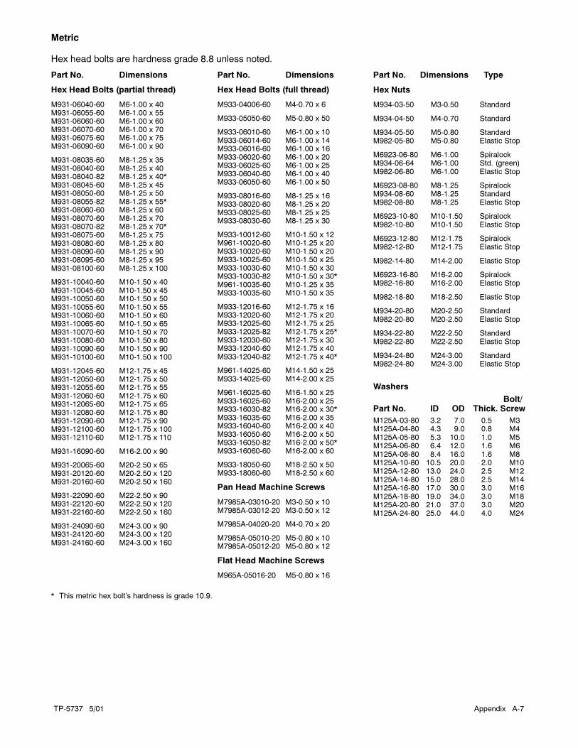
TP-5737 5/01 Appendix A-7
Metric
Hex head bolts are hardness grade 8.8 unless noted.
Part No. Dimensions
Hex Head Bolts (partial thread)
M931-06040-60 M6-1.00 x 40M931-06055-60 M6-1.00 x 55M931-06060-60 M6-1.00 x 60M931-06070-60 M6-1.00 x 70M931-06075-60 M6-1.00 x 75M931-06090-60 M6-1.00 x 90
M931-08035-60 M8-1.25 x 35M931-08040-60 M8-1.25 x 40M931-08040-82 M8-1.25 x 40*M931-08045-60 M8-1.25 x 45M931-08050-60 M8-1.25 x 50M931-08055-82 M8-1.25 x 55*M931-08060-60 M8-1.25 x 60M931-08070-60 M8-1.25 x 70M931-08070-82 M8-1.25 x 70*M931-08075-60 M8-1.25 x 75M931-08080-60 M8-1.25 x 80M931-08090-60 M8-1.25 x 90M931-08095-60 M8-1.25 x 95M931-08100-60 M8-1.25 x 100
M931-10040-60 M10-1.50 x 40M931-10045-60 M10-1.50 x 45M931-10050-60 M10-1.50 x 50M931-10055-60 M10-1.50 x 55M931-10060-60 M10-1.50 x 60M931-10065-60 M10-1.50 x 65M931-10070-60 M10-1.50 x 70M931-10080-60 M10-1.50 x 80M931-10090-60 M10-1.50 x 90M931-10100-60 M10-1.50 x 100
M931-12045-60 M12-1.75 x 45M931-12050-60 M12-1.75 x 50M931-12055-60 M12-1.75 x 55M931-12060-60 M12-1.75 x 60M931-12065-60 M12-1.75 x 65M931-12080-60 M12-1.75 x 80M931-12090-60 M12-1.75 x 90M931-12100-60 M12-1.75 x 100M931-12110-60 M12-1.75 x 110
M931-16090-60 M16-2.00 x 90
M931-20065-60 M20-2.50 x 65M931-20120-60 M20-2.50 x 120M931-20160-60 M20-2.50 x 160
M931-22090-60 M22-2.50 x 90M931-22120-60 M22-2.50 x 120M931-22160-60 M22-2.50 x 160
M931-24090-60 M24-3.00 x 90M931-24120-60 M24-3.00 x 120M931-24160-60 M24-3.00 x 160
Part No. Dimensions
Hex Head Bolts (full thread)
M933-04006-60 M4-0.70 x 6
M933-05050-60 M5-0.80 x 50
M933-06010-60 M6-1.00 x 10M933-06014-60 M6-1.00 x 14M933-06016-60 M6-1.00 x 16M933-06020-60 M6-1.00 x 20M933-06025-60 M6-1.00 x 25M933-06040-60 M6-1.00 x 40M933-06050-60 M6-1.00 x 50
M933-08016-60 M8-1.25 x 16M933-08020-60 M8-1.25 x 20M933-08025-60 M8-1.25 x 25M933-08030-60 M8-1.25 x 30
M933-10012-60 M10-1.50 x 12M961-10020-60 M10-1.25 x 20M933-10020-60 M10-1.50 x 20M933-10025-60 M10-1.50 x 25M933-10030-60 M10-1.50 x 30M933-10030-82 M10-1.50 x 30*M961-10035-60 M10-1.25 x 35M933-10035-60 M10-1.50 x 35
M933-12016-60 M12-1.75 x 16M933-12020-60 M12-1.75 x 20M933-12025-60 M12-1.75 x 25M933-12025-82 M12-1.75 x 25*M933-12030-60 M12-1.75 x 30M933-12040-60 M12-1.75 x 40M933-12040-82 M12-1.75 x 40*
M961-14025-60 M14-1.50 x 25M933-14025-60 M14-2.00 x 25
M961-16025-60 M16-1.50 x 25M933-16025-60 M16-2.00 x 25M933-16030-82 M16-2.00 x 30*M933-16035-60 M16-2.00 x 35M933-16040-60 M16-2.00 x 40M933-16050-60 M16-2.00 x 50M933-16050-82 M16-2.00 x 50*M933-16060-60 M16-2.00 x 60
M933-18050-60 M18-2.50 x 50M933-18060-60 M18-2.50 x 60
Pan Head Machine Screws
M7985A-03010-20 M3-0.50 x 10M7985A-03012-20 M3-0.50 x 12
M7985A-04020-20 M4-0.70 x 20
M7985A-05010-20 M5-0.80 x 10M7985A-05012-20 M5-0.80 x 12
Flat Head Machine Screws
M965A-05016-20 M5-0.80 x 16
Part No. Dimensions Type
Hex Nuts
M934-03-50 M3-0.50 Standard
M934-04-50 M4-0.70 Standard
M934-05-50 M5-0.80 StandardM982-05-80 M5-0.80 Elastic Stop
M6923-06-80 M6-1.00 SpiralockM934-06-64 M6-1.00 Std. (green)M982-06-80 M6-1.00 Elastic Stop
M6923-08-80 M8-1.25 SpiralockM934-08-60 M8-1.25 StandardM982-08-80 M8-1.25 Elastic Stop
M6923-10-80 M10-1.50 SpiralockM982-10-80 M10-1.50 Elastic Stop
M6923-12-80 M12-1.75 SpiralockM982-12-80 M12-1.75 Elastic Stop
M982-14-80 M14-2.00 Elastic Stop
M6923-16-80 M16-2.00 SpiralockM982-16-80 M16-2.00 Elastic Stop
M982-18-80 M18-2.50 Elastic Stop
M934-20-80 M20-2.50 StandardM982-20-80 M20-2.50 Elastic Stop
M934-22-80 M22-2.50 StandardM982-22-80 M22-2.50 Elastic Stop
M934-24-80 M24-3.00 StandardM982-24-80 M24-3.00 Elastic Stop
Washers
Bolt/Part No. ID OD Thick. Screw
M125A-03-80 3.2 7.0 0.5 M3M125A-04-80 4.3 9.0 0.8 M4M125A-05-80 5.3 10.0 1.0 M5M125A-06-80 6.4 12.0 1.6 M6M125A-08-80 8.4 16.0 1.6 M8M125A-10-80 10.5 20.0 2.0 M10M125A-12-80 13.0 24.0 2.5 M12M125A-14-80 15.0 28.0 2.5 M14M125A-16-80 17.0 30.0 3.0 M16M125A-18-80 19.0 34.0 3.0 M18M125A-20-80 21.0 37.0 3.0 M20M125A-24-80 25.0 44.0 4.0 M24
* This metric hex bolt’s hardness is grade 10.9.

TP-5737 5/01A-8 Appendix
Appendix F Operating Hour Service Log
Use the log below to keep a cumulative record of
operating hours on your generator set and the dates
required services were performed. Enter hours to the
nearest quarter hour.
OPERATING HOURS SERVICE RECORD
DATE
RUN
HOURS
RUN
TOTAL
HOURS
SERVICE
DATE SERVICE


� Kohler Co., 1997, 2001. All rights reserved.
TP-5737 5/01b
KOHLER CO. Kohler, Wisconsin 53044Phone 920-565-3381, Web site www.kohlergenerators.comFax 920-459-1646 (U.S.A. Sales), Fax 920-459-1614 (International)For the nearest sales and service outlet in U.S.A. and CanadaPhone 1-800-544-2444
Kohler� Power SystemsAsia Pacific Headquarters7 Jurong Pier RoadSingapore 619159Phone (65)264-6422, Fax (65)264-6455