
Series 90-30/70 SNP Driver - PRO-FACE
30
1 GE Intelligent Platforms Series 90-30/70 SNP Driver 1 System Configuration ....................................................................................................... 3 2 Selection of External Device ............................................................................................ 8 3 Example of Communication Setting ................................................................................. 9 4 Setup Items .................................................................................................................... 13 5 Cable Diagram ............................................................................................................... 17 6 Supported Device........................................................................................................... 27 7 Device Code and Address Code .................................................................................... 28 8 Error Messages .............................................................................................................. 29
-
Upload
khangminh22 -
Category
Documents
-
view
1 -
download
0
Transcript of Series 90-30/70 SNP Driver - PRO-FACE

1
GE Intelligent Platforms
Series 90-30/70 SNP Driver
1 System Configuration....................................................................................................... 3
2 Selection of External Device ............................................................................................ 8
3 Example of Communication Setting ................................................................................. 9
4 Setup Items .................................................................................................................... 13
5 Cable Diagram ............................................................................................................... 17
6 Supported Device........................................................................................................... 27
7 Device Code and Address Code.................................................................................... 28
8 Error Messages.............................................................................................................. 29

Series 90-30/70 SNP Driver
GP-Pro EX Device/PLC Connection Manual 2
IntroductionThis manual describes how to connect the Display and the External Device (target PLC).
In this manual, the connection procedure will be described by following the below sections:
1 System ConfigurationThis section shows the types of External Devices which can be connected and SIO type.
"1 System Configuration" (page 3)
2 Selection of External DeviceSelect a model (series) of the External Device to be connected and connection method.
"2 Selection of External Device" (page 8)
3 Example of Communication SettingsThis section shows setting examples for communicating between the Display and the External Device.
"3 Example of Communication Setting" (page 9)
4 Setup ItemsThis section describes communication setup items on the Display.Set communication settings of the Display with GP-Pro Ex or in offline mode.
"4 Setup Items" (page 13)
5 Cable DiagramThis section shows cables and adapters for connecting the Display and the External Device.
"5 Cable Diagram" (page 17)
Operation

Series 90-30/70 SNP Driver
GP-Pro EX Device/PLC Connection Manual 3
1 System Configuration
The system configuration in the case when the External Device of GE Intelligent Platforms and the Display are
connected is shown.
Series CPU Link I/F SIO TypeSetting
ExampleCable
Diagram
Series90-30
IC693CPU311IC693CPU313IC693CPU321IC693CPU323IC693CPU331IC693CPU340IC693CPU341IC693CPU350IC693CPU351IC693CPU352IC693CPU360IC693CPU363IC693CPU364IC693CPU374IC693CSE311IC693CSE313IC693CSE323IC693CSE331IC693CSE340
SNP serial port on power supply unit
RS422/485 (4wire)
Setting Example 1 (page 9)
Cable Diagram 1 (page 17)
Series90-70
IC697CPU731IC697CPU771IC697CPU772IC697CPU780IC697CPU781IC697CPU782IC697CPU788IC697CPU789IC697CPM790IC697CPM915IC697CPM925IC697CPX722IC697CPX782IC697CPX928IC697CPX935IC697CGR772IC697CGR935IC697CSE784IC697CSE924IC697CSE925
SNP serial port on CPU
RS422/485 (4wire)
Setting Example 2 (page 11)
• Do not use the logic function in the Display. If it is used, a communication error occurs.

Series 90-30/70 SNP Driver
GP-Pro EX Device/PLC Connection Manual 4
Connection ConfigurationSeries 90-30: SNP Serial Port on the PLC power supply
Series 90-70: SNP Serial Port on the PLC CPU Unit
• 1:1 Connection
• 1:n Connection
GP PLC
GP PLC
The max number of PLC : 16

Series 90-30/70 SNP Driver
GP-Pro EX Device/PLC Connection Manual 5
IPC COM PortWhen connecting IPC with an External Device, the COM port used depends on the series and SIO type. Please
refer to the IPC manual for details.
Usable port
SeriesUsable Port
RS-232C RS-422/485(4 wire) RS-422/485(2 wire)
PS-2000B COM1*1 , COM2, COM3*1, COM4
*1 The RI/5V can be switched. Use the IPC’s switch to change if necessary.
- -
PS-3450A, PS-3451A,PS3000-BA, PS3001-BD COM1, COM2*1*2 COM2*1*2 COM2*1*2
PS-3650A (T41 model),PS-3651A (T41 model) COM1*1 - -
PS-3650A (T42 model),PS-3651A (T42 model) COM1*1*2, COM2 COM1*1*2 COM1*1*2
PS-3700A (Pentium®4-M)PS-3710A
COM1*1, COM2*1, COM3*2 , COM4
*2 Set up the SIO type with the DIP Switch. Please set up as follows according to SIO type to be used.
COM3*2 COM3*2
PS-3711A COM1*1, COM2*2 COM2*2 COM2*2
PS4000*3
*3 When making communication between an External Device and COM port on the Expansion slot, only RS-232C is supported. However, ER (DTR/CTS) control cannot be executed because of the specification of COM port. For connection with External Device, use user-created cables and disable Pin Nos. 1, 4, 6 and 9. Please refer to the IPC manual for details of pin layout.
COM1, COM2 - -
PL3000 COM1*1*2, COM2*1, COM3, COM4 COM1*1*2 COM1*1*2
PE-4000B Atom N270 COM1, COM2 - -
PE-4000B Atom N2600 COM1, COM2 COM3*4 , COM4*4, COM5*4, COM6*4
*4 Set up the SIO type with the BIOS. Please refer to the IPC manual for details of BIOS.
COM3*4, COM4*4, COM5*4, COM6*4
PS5000 (Slim Panel Type Core i3 Model) *5 *6 COM1, COM2*4 COM2*4 COM2*4
PS5000 (Slim Panel Type Atom Model) *5 *6
COM1, COM2*7 COM2*7 COM2*7
PS5000 (Enclosed Panel Type)*8 COM1 - -
PS5000 (Modular Type PFXPU/PFXPP)*5 *6
PS5000 (Modular Type PFXPL2B5-6)
COM1*7 COM1*7 COM1*7
PS5000 (Modular Type PFXPL2B1-4) COM1, COM2*7 COM2*7 COM2*7
PS6000 COM1*9 *10 *10
Series 90-30/70 SNP Driver
GP-Pro EX Device/PLC Connection Manual 6
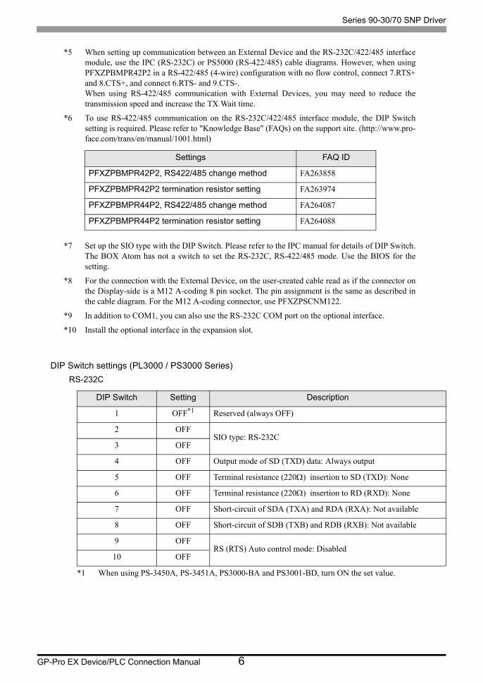
DIP Switch settings (PL3000 / PS3000 Series)RS-232C
*5 When setting up communication between an External Device and the RS-232C/422/485 interface module, use the IPC (RS-232C) or PS5000 (RS-422/485) cable diagrams. However, when using PFXZPBMPR42P2 in a RS-422/485 (4-wire) configuration with no flow control, connect 7.RTS+ and 8.CTS+, and connect 6.RTS- and 9.CTS-. When using RS-422/485 communication with External Devices, you may need to reduce the transmission speed and increase the TX Wait time.
*6 To use RS-422/485 communication on the RS-232C/422/485 interface module, the DIP Switch setting is required. Please refer to "Knowledge Base" (FAQs) on the support site. (http://www.pro- face.com/trans/en/manual/1001.html)
*7 Set up the SIO type with the DIP Switch. Please refer to the IPC manual for details of DIP Switch. The BOX Atom has not a switch to set the RS-232C, RS-422/485 mode. Use the BIOS for the setting.
*8 For the connection with the External Device, on the user-created cable read as if the connector on the Display-side is a M12 A-coding 8 pin socket. The pin assignment is the same as described in the cable diagram. For the M12 A-coding connector, use PFXZPSCNM122.
*9 In addition to COM1, you can also use the RS-232C COM port on the optional interface.
*10 Install the optional interface in the expansion slot.
DIP Switch Setting Description
1 OFF*1
*1 When using PS-3450A, PS-3451A, PS3000-BA and PS3001-BD, turn ON the set value.
Reserved (always OFF)
2 OFFSIO type: RS-232C
3 OFF
4 OFF Output mode of SD (TXD) data: Always output
5 OFF Terminal resistance (220Ω) insertion to SD (TXD): None
6 OFF Terminal resistance (220Ω) insertion to RD (RXD): None
7 OFF Short-circuit of SDA (TXA) and RDA (RXA): Not available
8 OFF Short-circuit of SDB (TXB) and RDB (RXB): Not available
9 OFFRS (RTS) Auto control mode: Disabled
10 OFF
Settings FAQ ID
PFXZPBMPR42P2, RS422/485 change method FA263858
PFXZPBMPR42P2 termination resistor setting FA263974
PFXZPBMPR44P2, RS422/485 change method FA264087
PFXZPBMPR44P2 termination resistor setting FA264088

Series 90-30/70 SNP Driver
GP-Pro EX Device/PLC Connection Manual 7
RS-422/485 (4 wire)
RS-422/485 (2 wire)
DIP Switch Setting Description
1 OFF Reserved (always OFF)
2 ONSIO type: RS-422/485
3 ON
4 OFF Output mode of SD (TXD) data: Always output
5 OFF Terminal resistance (220Ω) insertion to SD (TXD): None
6 OFF Terminal resistance (220Ω) insertion to RD (RXD): None
7 OFF Short-circuit of SDA (TXA) and RDA (RXA): Not available
8 OFF Short-circuit of SDB (TXB) and RDB (RXB): Not available
9 OFFRS (RTS) Auto control mode: Disabled
10 OFF
DIP Switch Setting Description
1 OFF Reserved (always OFF)
2 ONSIO type: RS-422/485
3 ON
4 OFF Output mode of SD (TXD) data: Always output
5 OFF Terminal resistance (220Ω) insertion to SD (TXD): None
6 OFF Terminal resistance (220Ω) insertion to RD (RXD): None
7 ON Short-circuit of SDA (TXA) and RDA (RXA): Available
8 ON Short-circuit of SDB (TXB) and RDB (RXB): Available
9 ONRS (RTS) Auto control mode: Enabled
10 ON

Series 90-30/70 SNP Driver
GP-Pro EX Device/PLC Connection Manual 8
2 Selection of External Device
Select the External Device to be connected to the Display.
Setup Items Setup Description
Number of Devices/PLCs
Enter an integer from 1 to 4 to define the number of Devices/PLCs to connect to the display.
Manufacturer Select the manufacturer of the External Device to connect. Select "GE Intelligent Platforms".
Series
Select the External Device model (series) and the connection method. Select "Series 90-30/70 SNP".In System configuration, make sure the External Device you are connecting is supported by "Series 90-30/70 SNP".
"1 System Configuration" (page 3)
Port Select the Display port to be connected to the External Device.
Use System Area
Check this option to synchronize the system data area of the Display and the device (memory) of the External Device. When synchronized, you can use the External Device’s ladder program to switch the display or display the window on the Display.
Cf. GP-Pro EX Reference Manual "LS Area (Direct Access Method Area)"This feature can also be set in GP-Pro EX or in the Display's offline mode.
Cf. GP-Pro EX Reference Manual "System Settings [Display Unit] - [System Area] Settings Guide"
Cf. Maintenance/Troubleshooting Guide "Main Unit - System Area Settings"

Series 90-30/70 SNP Driver
GP-Pro EX Device/PLC Connection Manual 9
3 Example of Communication Setting
Examples of communication settings of the Display and the External Device, recommended by Pro-face, are
shown.
3.1 Setting Example 1
Settings of GP-Pro EX
Communication Settings
To display the setup screen, from the [Project] menu, point to [System Settings] and select [Device/PLC].
Device Setting
To display the [Individual Device Settings] dialog box, from [Device-Specific Settings] in the [Device/PLC]
window, select the external device and click [Settings] .
To connect multiple External Devices, from [Device-Specific Settings] in the [Device/PLC] window, click [Add
Device] to add another External Device.

Series 90-30/70 SNP Driver
GP-Pro EX Device/PLC Connection Manual 10
Settings of External DeviceUse the ladder software for communication settings. (Check the operation in CIMPLICITY Machine Edition
V4.50)
1 Select "Add Target" -> "GE Fanuc PLC" among "Project" of tool bar and select the series to be connected.
The selected series is added as "Target" in the project.
2 Allocate the power supply module and the CPU module in "Hardware Configuration" -> "Main Rack" of added
Target.
3 Double-click the CPU module, display the setting window.
4 Click the [Settings] tab and set the communication settings.
5 Forward the communication settings to the external device and spend a power supply of the external device again.
Setup Items
Notes
• Please refer to the manual of the ladder software for more detail on other setting description.
• The Rack number and Slot number to allocate by environment using are different. Check the environment, and allocate the Rack number and Slot number.
Setup Items Setup Description
Data Rate [bps] 19200
Parity Odd
Stop Bits 1
Idle Time [Sec] 10
SNP ID 1
Series 90-30/70 SNP Driver
GP-Pro EX Device/PLC Connection Manual 11
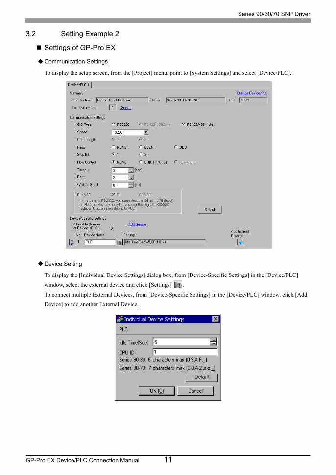
3.2 Setting Example 2
Settings of GP-Pro EX
Communication Settings
To display the setup screen, from the [Project] menu, point to [System Settings] and select [Device/PLC]..
Device Setting
To display the [Individual Device Settings] dialog box, from [Device-Specific Settings] in the [Device/PLC]
window, select the external device and click [Settings] .
To connect multiple External Devices, from [Device-Specific Settings] in the [Device/PLC] window, click [Add
Device] to add another External Device.

Series 90-30/70 SNP Driver
GP-Pro EX Device/PLC Connection Manual 12
Settings of External DeviceUse the ladder software for communication settings. (Check the operation in CIMPLICITY Machine Edition
V4.50)
1 Select "Add Target" -> "GE Fanuc PLC" among "Project" of tool bar and select the series to be connected.
The selected series is added as "Target" in the project.
2 Allocate the power supply module and the CPU module in "Hardware Configuration" -> "Main Rack" of added
Target.
3 Double-click the CPU module, display the setting window.
4 Click the [Settings] tab and set the communication settings.
5 Forward the communication settings to the external device and spend a power supply of the external device again.
Setup Items
Notes
Please refer to the manual of the ladder software for more detail on other setting description.
• The Rack number and Slot number to allocate by environment using are different. Check the environment, and allocate the Rack number and Slot number.
Setup Items Setup Description
Data Rate [bps] 19200
Data Bits 8
Parity Odd
Stop Bits 1
Idle Time [Sec] 5
SNP ID 1

Series 90-30/70 SNP Driver
GP-Pro EX Device/PLC Connection Manual 13
4 Setup Items
Set communication settings of the Display with GP-Pro EX or in offline mode of the Display.
The setting of each parameter must be identical to that of External Device.
"3 Example of Communication Setting" (page 9)
4.1 Setup Items in GP-Pro EX
Communication SettingsTo display the setup screen, from the [Project] menu, point to [System Settings] and select [Device/PLC].
Setup Items Setup Description
SIO Type Display the SIO type to communicate with the External Device.
Speed Select speed between the External Device and the Display.
Data Length Display data length.
Parity Select how to check parity.
Stop Bit Select stop bit length.
Flow Control Display the communication control method to prevent overflow of transmission and reception data.
Timeout Use an integer from 1 to 127 to enter the time (s) for which the Display waits for the response from the External Device.
Retry In case of no response from the External Device, use an integer from 0 to 255 to enter how many times the Display retransmits the command.
Wait To Send Use an integer from 0 to 255 to enter standby time (ms) for the Display from receiving packets to transmitting next commands.

Series 90-30/70 SNP Driver
GP-Pro EX Device/PLC Connection Manual 14
Device Setting
To display the [Individual Device Settings] dialog box, from [Device-Specific Settings] in the [Device/PLC]
window, select the external device and click [Settings] .
To connect multiple External Devices, from [Device-Specific Settings] in the [Device/PLC] window, click [Add
Device] to add another External Device.
• Refer to the GP-Pro EX Reference Manual for Indirect Device.
Cf. GP-Pro EX Reference Manual "Changing the Device/PLC at Runtime (Indirect Device)"
Setup Items Setup Description
Idle Time[Sec]Set the Idle Time of External Device.Please set same Idle Time as the setting of External Device.Use an integer from 1 to 60 to enter the time (Sec).
CPU ID
Set the CPU ID of External Device.Please set same CPU ID as the setting of External Device.CPU IDcan be set within the following ranges.Series 90-30: It is the maximum and is character of six characters. [‘0’-‘9’, ‘A’-‘F’, ‘_’]Series 90-70: It is the maximum and is character of seven characters. [‘0’-‘9’, ‘A’-‘Z’, ‘a’-‘z’, ‘_’]

Series 90-30/70 SNP Driver
GP-Pro EX Device/PLC Connection Manual 15
4.2 Setup Items in Offline Mode
Communication Settings
To display the setting screen, touch [Device/PLC Settings] from [Peripheral Settings] in offline mode. Touch the
External Device you want to set from the displayed list.
• Refer to the Maintenance/Troubleshooting guide for information on how to enter offline mode and how to operate offline mode.Cf. Maintenance/Troubleshooting Guide "Offline Mode"
• The number of the setup items to be displayed for 1 page in the offline mode depends on the Display in use. Please refer to the Reference manual for details.
Setup Items Setup Description
SIO Type
Display the SIO type to communicate with the External Device.
To make the communication settings correctly, confirm the serial interface specifications of Display unit for [SIO Type].We cannot guarantee the operation if a communication type that the serial interface does not support is specified.For details concerning the serial interface specifications, refer to the manual for Display unit.
Speed Select speed between the External Device and the Display.
Data Length Display data length.
Parity Select how to check parity.
Stop Bit Select stop bit length.
Flow Control Display the communication control method to prevent overflow of transmission and reception data.

Series 90-30/70 SNP Driver
GP-Pro EX Device/PLC Connection Manual 16
Device Setting
To display the setting screen, touch [Device/PLC Settings] from [Peripheral Settings]. Touch the External Device
you want to set from the displayed list, and touch [Device]..
Timeout Use an integer from 1 to 127 to enter the time (s) for which the Display waits for the response from the External Device.
Retry In case of no response from the External Device, use an integer from 0 to 255 to enter how many times the Display retransmits the command.
Wait To Send Use an integer from 0 to 255 to enter standby time (ms) for the Display from receiving packets to transmitting next commands.
Setup Items Setup Description
Device/PLC Name
Select the External Device for device setting. Device name is a title of External Device set with GP-Pro EX.(Initial value [PLC1])
Idle Time(Sec)Set the Idle Time of External Device.Please set same Idle Time as the setting of External Device.Use an integer from 1 to 60 to enter the time (Sec).
CPU ID
Set the CPU ID of PLC.Please set same CPU ID as the setting of External Device.CPU IDcan be set within the following ranges.Series 90-30: It is the maximum and is character of six characters. [‘0’-‘9’, ‘A’-‘F’, ‘_’]Series 90-70: It is the maximum and is character of seven characters. [‘0’-‘9’, ‘A’-‘Z’, ‘a’-‘z’, ‘_’]
• For GP-4100 series, an under bar character ("_") cannot be input. Input it using GP-Pro EX.
Setup Items Setup Description

Series 90-30/70 SNP Driver
GP-Pro EX Device/PLC Connection Manual 17
5 Cable Diagram
The cable diagram shown below may be different from the cable diagram recommended by GE Intelligent
Platforms. Please be assured there is no operational problem in applying the cable diagram shown in this manual.
• The FG pin of the External Device body must be D-class grounded. Please refer to the manual of the External
Device for more details.
• SG and FG are connected inside the Display. When connecting SG to the External Device, design the system
not to form short-circuit loop.
• Connect the isolation unit, when communication is not stabilized under the influence of a noise etc..
Cable Diagram 1
Display(Connection Port)
Cable Notes
GP3000*1 (COM1)AGP-3302B (COM2)GP-4*01TM (COM1)GP-Rear Module (COM1)ST3000*2 (COM2)IPC*3
*1 All GP models except AGP-3302B
1A
COM port conversion adapter by Pro-faceCA3-ADPCOM-01
+Terminal block conversion adapter by Pro-face
CA3-ADPTRM-01+
Your own cable
The cable length must be 1000m or less.
1B Your own cable
GP3000*4 (COM2)
1C
Online adapter by Pro-faceCA4-ADPONL-01
+Terminal block conversion adapter by Pro-face
CA3-ADPTRM-01+
Your own cable
The cable length must be 1000m or less.
1D
Online adapter by Pro-faceCA4-ADPONL-01
+Your own cable
GP4000*5 (COM2)GP-4201T (COM1)SP5000*6 (COM1/2)SP-5B00 (COM2)ST6000*7 (COM2)ST-6200 (COM1)STM6000 (COM1)
1E
RS-422 Terminal Block Conversion Adapter by Pro-facePFXZCBADTM1*8
+Your own cable The cable length
must be 1000m or less.
1B Your own cable
GP-4106 (COM1) GP-4116T (COM1) 1F Your own cable
The cable length must be 1000m or less.
PE-4000B*9
PS5000*9
PS6000*91G Your own cable
The cable length must be 1000m or less.

Series 90-30/70 SNP Driver
GP-Pro EX Device/PLC Connection Manual 18
*2 Except AST-3211A and AST-3302B
*3 Only the COM port which can communicate by RS-422/485 (4 wire) can be used. (Except PE-4000B, PS5000, and PS6000)
IPC COM Port (page 5)
*4 All GP models except GP-3200 series and AGP-3302B
*5 All GP4000 models except GP-4100 Series, GP-4*01TM, GP-Rear Module, GP-4201T and GP-4*03T
*6 Except SP-5B00
*7 Except ST-6200
*8 When using a Terminal Block Conversion Adapter (CA3-ADPTRM-01) instead of the RS-422 Terminal Block Conversion Adapter, refer to Cable Diagram 1A.
*9 Only the COM port which can communicate by RS-422/485 (4 wire) can be used. IPC COM Port (page 5)

Series 90-30/70 SNP Driver
GP-Pro EX Device/PLC Connection Manual 19
1A)
• 1:1 Connection
• 1:n Connection
*1: Notation of RD(A), RD(B), SD(A) and SD(B) are different by the external device. Please refer to the manual of the external device. In addition, note that Class A and Class B are reversely named for the Display and the External Device.
*2: Insert the termination resistance of the external device side. The 120Ω termination resistance is inserted between RDA - RDB by connecting the 9th pin to the 10th pin of serial interface at the external device side. But termination resistance is inserted in CPU731 and CPU771 by connecting the 9th pin to the 11th pin.
*3: FG of the external device ground the D class grounding. In addition, FG connection to a shield line select the external device side, either display side by location environment.
Terminationresistance
120Display
Terminationresistance
120
External DeviceD-Sub 15pin (Plug)Terminal block
RDA
Signal name Signal namePin
RDB
SDA
SDB
SG
FG
CA3-ADPTRM-01
CA3-ADPCOM-0113
12
11
10
7
9
6
15
14
8
1
SD(B)*1
SD(A)*1
RD(B)*1
RD(A)*1
SG
RT*2
RTS(A)
CTS(A)
RTS(B)
CTS(B)
Shield*3
Terminationresistance120
Your own cable
Terminationresistance
120Display
Terminationresistance
120
External DeviceD-Sub 15pin (Plug)Terminal block
RDA
Signal name Signal namePin
RDB
SDA
SDB
SG
FG
CA3-ADPTRM-01CA3-ADPCOM-01
13
12
11
10
7
9
6
15
14
8
1
SD(B)*1
SD(A)*1
RD(B)*1
RD(A)*1
SG
RT
RTS(A)
CTS(A)
RTS(B)
CTS(B)
Shield*3
Terminationresistance120
External DeviceD-Sub 15pin (Plug)
Signal namePin
13
12
11
10
7
9
6
15
14
8
1
SD(B)*1
SD(A)*1
RD(B)*1
RD(A)*1
SG
RT*2
RTS(A)
CTS(A)
RTS(B)
CTS(B)
Shield*3
Your own cable

Series 90-30/70 SNP Driver
GP-Pro EX Device/PLC Connection Manual 20
1B)
• 1:1 Connection
• 1:n Connection
*1: Notation of RD(A), RD(B), SD(A) and SD(B) are different by the external device. Please refer to the manual of the external device. In addition, note that Class A and Class B are reversely named for the Display and the External Device.
*2: Insert the termination resistance of the external device side. The 120 Ω termination resistance is inserted between RDA - RDB by connecting the 9th pin to the 10th pin of serial interface at the external device side. But termination resistance is inserted in CPU731 and CPU771 by connecting the 9th pin to the 11th pin.
*3: FG of the external device ground the D class grounding. In addition, FG connection to a shield line select the external device side, either display side by location environment.
Terminationresistance
120
Terminationresistance120
Display
Terminationresistance
120
External DeviceD-Sub 15pin (Plug)
Signal name Signal namePin
13
12
11
10
7
9
6
15
14
8
1
1
2
3
7
5
4
8
9
6
RDA
RDB
SDA
SDB
SG
ERA
CSA
ERB
CSB
SD(B)*1
SD(A)*1
RD(B)*1
RD(A)*1
SG
RT*2
RTS(A)
CTS(A)
RTS(B)
CTS(B)
Shield*3
Pin
Your own cable
DisplayD-Sub 9pin (Socket)
Terminationresistance
120Display
Terminationresistance
120
External DeviceD-Sub 15pin (Plug)
DisplayD-Sub 9pin (Socket)
Your own cable
Signal name Signal namePin
13
12
11
10
7
9
6
15
14
8
1
1
2
3
7
5
4
8
9
6
RDA
RDB
SDA
SDB
SG
ERA
CSA
ERB
CSB
SD(B)*1
SD(A)*1
RD(B)*1
RD(A)*1
SG
RT
RTS(A)
CTS(A)
RTS(B)
CTS(B)
Shield*3
Pin
Terminationresistance120
External DeviceD-Sub 15pin (Plug)
Signal namePin
13
12
11
10
7
9
6
15
14
8
1
SD(B)*1
SD(A)*1
RD(B)*1
RD(A)*1
SG
RT*2
RTS(A)
CTS(A)
RTS(B)
CTS(B)
Shield*3

Series 90-30/70 SNP Driver
GP-Pro EX Device/PLC Connection Manual 21
1C)
• 1:1 Connection
• 1:n Connection
*1: Notation of RD(A), RD(B), SD(A) and SD(B) are different by the external device. Please refer to the manual of the external device. In addition, note that Class A and Class B are reversely named for the Display and the External Device.
*2: Insert the termination resistance of the external device side. The 120 Ω termination resistance is inserted between RDA - RDB by connecting the 9th pin to the 10th pin of serial interface at the external device side. But termination resistance is inserted in CPU731 and CPU771 by connecting the 9th pin to the 11th pin.
*3: FG of the external device ground the D class grounding. In addition, FG connection to a shield line select the external device side, either display side by location environment.
Terminationresistance120
Display
Terminationresistance
120
External DeviceD-Sub 15pin (Plug)Terminal block
RDA
Signal name Signal namePin
RDB
SDA
SDB
SG
TERMRX
TERMTX
CA3-ADPTRM-01
CA4-ADPONL-01 13
12
11
10
7
9
6
15
14
8
1
SD(B)*1
SD(A)*1
RD(B)*1
RD(A)*1
SG
RT*2
RTS(A)
CTS(A)
RTS(B)
CTS(B)
Shield*3
Your own cable
Display
Terminationresistance
120
External DeviceD-Sub 15pin (Plug)Terminal block
RDA
Signal name Signal namePin
RDB
SDA
SDB
SG
TERMRX
TERMTX
CA3-ADPTRM-01CA4-ADPONL-01
13
12
11
10
7
9
6
15
14
8
1
SD(B)*1
SD(A)*1
RD(B)*1
RD(A)*1
SG
RT
RTS(A)
CTS(A)
RTS(B)
CTS(B)
Shield*3
Terminationresistance120
External DeviceD-Sub 15pin (Plug)
Signal namePin
13
12
11
10
7
9
6
15
14
8
1
SD(B)*1
SD(A)*1
RD(B)*1
RD(A)*1
SG
RT*2
RTS(A)
CTS(A)
RTS(B)
CTS(B)
Shield*3
Your own cable

Series 90-30/70 SNP Driver
GP-Pro EX Device/PLC Connection Manual 22
1D)
• 1:1 Connection
• 1:n Connection
*1: Notation of RD(A), RD(B), SD(A) and SD(B) are different by the external device. Please refer to the manual of the external device. In addition, note that Class A and Class B are reversely named for the Display and the External Device.
*2: Insert the termination resistance of the external device side. The 120 Ω termination resistance is inserted between RDA - RDB by connecting the 9th pin to the 10th pin of serial interface at the external device side. But termination resistance is inserted in CPU731 and CPU771 by connecting the 9th pin to the 11th pin.
*3: FG of the external device ground the D class grounding. In addition, FG connection to a shield line select the external device side, either display side by location environment.
Terminationresistance120
Display
Terminationresistance
120
External DeviceD-Sub 15pin (Plug)
DisplayD-Sub 9pin (Plug)
RDA
Signal name Signal namePin
RDB
SDA
SDB
SG
TERMRX
TERMTX
13
12
11
10
7
9
6
15
14
8
1
2
7
3
8
5
1
9
SD(B)*1
SD(A)*1
RD(B)*1
RD(A)*1
SG
RT*2
RTS(A)
CTS(A)
RTS(B)
CTS(B)
Shield*3
Pin
Your own cable
CA4-ADPONL-01
Display
Terminationresistance
120
External DeviceD-Sub 15pin (Plug)
DisplayD-Sub 9pin (Plug)
RDA
Signal name Signal namePin
RDB
SDA
SDB
SG
TERMRX
TERMTX
13
12
11
10
7
9
6
15
14
8
1
2
7
3
8
5
1
9
SD(B)*1
SD(A)*1
RD(B)*1
RD(A)*1
SG
RT
RTS(A)
CTS(A)
RTS(B)
CTS(B)
Shield*3
Pin
External DeviceD-Sub 15pin (Plug)
Signal namePin
13
12
11
10
7
9
6
15
14
8
1
SD(B)*1
SD(A)*1
RD(B)*1
RD(A)*1
SG
RT*2
RTS(A)
CTS(A)
RTS(B)
CTS(B)
Shield*3
Your own cable
CA4-ADPONL-01
Terminationresistance120

Series 90-30/70 SNP Driver
GP-Pro EX Device/PLC Connection Manual 23
1E)
• 1:1 Connection
• 1:n Connection
*1: Notation of RD(A), RD(B), SD(A) and SD(B) are different by the external device. Please refer to the manual of the external device. In addition, note that Class A and Class B are reversely named for the Display and the External Device.
*2: Insert the termination resistance of the external device side. The 120Ω termination resistance is inserted between RDA - RDB by connecting the 9th pin to the 10th pin of serial interface at the external device side. But termination resistance is inserted in CPU731 and CPU771 by connecting the 9th pin to the 11th pin.
*3: FG of the external device ground the D class grounding. In addition, FG connection to a shield line select the external device side, either display side by location environment.
Terminationresistance
120Display
Terminationresistance
120
External DeviceD-Sub 15pin (Plug)Terminal block
RDA
Signal name Signal namePin
RDB
SDA
SDB
SG
FG
PFXZCBADTM1
13
12
11
10
7
9
6
15
14
8
1
SD(B)*1
SD(A)*1
RD(B)*1
RD(A)*1
SG
RT*2
RTS(A)
CTS(A)
RTS(B)
CTS(B)
Shield*3
Terminationresistance120
Your own cable
Terminationresistance
120Display
Terminationresistance
120
External DeviceD-Sub 15pin (Plug)Terminal block
RDA
Signal name Signal namePin
RDB
SDA
SDB
SG
FG
PFXZCBADTM1
13
12
11
10
7
9
6
15
14
8
1
SD(B)*1
SD(A)*1
RD(B)*1
RD(A)*1
SG
RT
RTS(A)
CTS(A)
RTS(B)
CTS(B)
Shield*3
Terminationresistance120
External DeviceD-Sub 15pin (Plug)
Signal namePin
13
12
11
10
7
9
6
15
14
8
1
SD(B)*1
SD(A)*1
RD(B)*1
RD(A)*1
SG
RT*2
RTS(A)
CTS(A)
RTS(B)
CTS(B)
Shield*3
Your own cable
Series 90-30/70 SNP Driver
GP-Pro EX Device/PLC Connection Manual 24
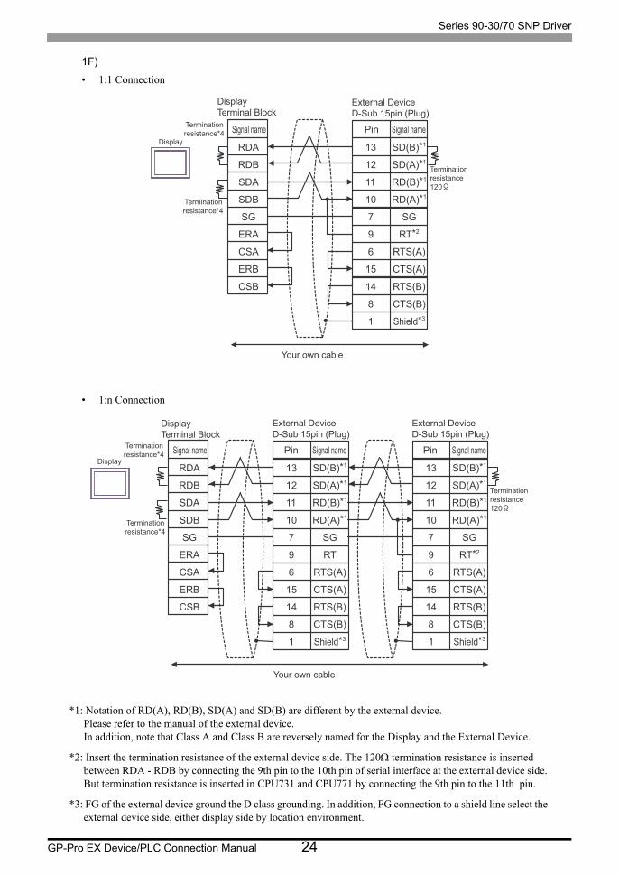
1F)
• 1:1 Connection
• 1:n Connection
*1: Notation of RD(A), RD(B), SD(A) and SD(B) are different by the external device. Please refer to the manual of the external device. In addition, note that Class A and Class B are reversely named for the Display and the External Device.
*2: Insert the termination resistance of the external device side. The 120Ω termination resistance is inserted between RDA - RDB by connecting the 9th pin to the 10th pin of serial interface at the external device side. But termination resistance is inserted in CPU731 and CPU771 by connecting the 9th pin to the 11th pin.
*3: FG of the external device ground the D class grounding. In addition, FG connection to a shield line select the external device side, either display side by location environment.
Terminationresistance*4
Terminationresistance120
Display
Terminationresistance*4
External DeviceD-Sub 15pin (Plug)
Signal name Signal namePin
13
12
11
10
7
9
6
15
14
8
1
RDA
RDB
SDA
SDB
SG
ERA
CSA
ERB
CSB
SD(B)*1
SD(A)*1
RD(B)*1
RD(A)*1
SG
RT*2
RTS(A)
CTS(A)
RTS(B)
CTS(B)
Shield*3
Your own cable
DisplayTerminal Block
Terminationresistance*4
Display
Terminationresistance*4
External DeviceD-Sub 15pin (Plug)
DisplayTerminal Block
Your own cable
Signal name Signal namePin
13
12
11
10
7
9
6
15
14
8
1
RDA
RDB
SDA
SDB
SG
ERA
CSA
ERB
CSB
SD(B)*1
SD(A)*1
RD(B)*1
RD(A)*1
SG
RT
RTS(A)
CTS(A)
RTS(B)
CTS(B)
Shield*3
Terminationresistance120
External DeviceD-Sub 15pin (Plug)
Signal namePin
13
12
11
10
7
9
6
15
14
8
1
SD(B)*1
SD(A)*1
RD(B)*1
RD(A)*1
SG
RT*2
RTS(A)
CTS(A)
RTS(B)
CTS(B)
Shield*3

Series 90-30/70 SNP Driver
GP-Pro EX Device/PLC Connection Manual 25
*4: The resistance in the Display is used as the termination resistance. Set the value of the DIP Switch on the rear of the Display as shown in the table below.
DIP Switch No. Set Value
1 ON
2 ON
3 ON
4 ON

Series 90-30/70 SNP Driver
GP-Pro EX Device/PLC Connection Manual 26
1G)
• 1:1 Connection
• 1:n Connection
*1: Notation of RD(A), RD(B), SD(A) and SD(B) are different by the external device. Please refer to the manual of the external device. In addition, note that Class A and Class B are reversely named for the Display and the External Device.
*2: Insert the termination resistance of the external device side. The 120 Ω termination resistance is inserted between RDA - RDB by connecting the 9th pin to the 10th pin of serial interface at the external device side. But termination resistance is inserted in CPU731 and CPU771 by connecting the 9th pin to the 11th pin.
*3: FG of the external device ground the D class grounding. In addition, FG connection to a shield line select the external device side, either display side by location environment.
Terminationresistance
120
Terminationresistance120
Display
Terminationresistance
120
External DeviceD-Sub 15pin (Plug)
Signal name Signal namePin
13
12
11
10
7
9
6
15
14
8
1
3
4
2
1
5
7
8
9
6
Rx+
Rx-
Tx+
Tx-
GND
NC
NC
NC
NC
SD(B)*1
SD(A)*1
RD(B)*1
RD(A)*1
SG
RT*2
RTS(A)
CTS(A)
RTS(B)
CTS(B)
Shield*3
Pin
Your own cable
DisplayD-Sub 9pin (Socket)
Terminationresistance
120Display
Terminationresistance
120
External DeviceD-Sub 15pin (Plug)
DisplayD-Sub 9pin (Socket)
Your own cable
Signal name Signal namePin
13
12
11
10
7
9
6
15
14
8
1
3
4
2
1
5
7
8
9
6
Rx+
Rx-
Tx+
Tx-
GND
NC
NC
NC
NC
SD(B)*1
SD(A)*1
RD(B)*1
RD(A)*1
SG
RT
RTS(A)
CTS(A)
RTS(B)
CTS(B)
Shield*3
Pin
Terminationresistance120
External DeviceD-Sub 15pin (Plug)
Signal namePin
13
12
11
10
7
9
6
15
14
8
1
SD(B)*1
SD(A)*1
RD(B)*1
RD(A)*1
SG
RT*2
RTS(A)
CTS(A)
RTS(B)
CTS(B)
Shield*3

Series 90-30/70 SNP Driver
GP-Pro EX Device/PLC Connection Manual 27
6 Supported Device
Range of supported device address is shown in the table below. Please note that the actually supported range of
the devices varies depending on the External Device to be used. Please check the actual range in the manual of
your connecting equipment.
This address can be specified as system data area.
Device Bit Address Word Address32bits
Notes
Discrete inputs %I00001 - %I12288 %I00001 - %I12273
Discrete outputs %Q00001 - %Q12288 %Q00001 - %Q12273
Discrete Globals %G00001 - %G07680 %G00001 - %G07665
Internal coils %M00001 - %M12288 %M00001 - %M12273
Temporary coils %T00001 - %T00256 %T00001 - %T00241
System status references
%S00001 - %S00128 %S00001 - %S00113 *1
*1 Write disable
%SA00001 - %SA00128 %SA00001 - %SA00113
%SB00001 - %SB00128 %SB00001 - %SB00113
%SC00001 - %SC00128 %SC00001 - %SC00113
System register references ----- %R00001 - %R32640
Analog inputs ----- %AI00001 - % AI32640
Analog outputs ----- %AQ00001 - %AQ32640
• Please refer to the GP-Pro EX Reference Manual for system data area.Cf. GP-Pro EX Reference Manual "LS Area (Direct Access Method Area)"
• Please refer to the precautions on manual notation for icons in the table.
"Manual Symbols and Terminology"

Series 90-30/70 SNP Driver
GP-Pro EX Device/PLC Connection Manual 28
7 Device Code and Address Code
Use device code and address code when you select "Device Type & Address" for the address type in data displays.
Device Device NameDevice Code
(HEX)Address Code
Discrete inputs %I 0080 (Word address - 1) / 16
Discrete outputs %Q 0081 (Word address - 1) / 16
Discrete Globals %M 0083 (Word address - 1) / 16
Internal coils %G 0082 (Word address - 1) / 16
Temporary coils %T 0084 (Word address - 1) / 16
System status references
%SA 0086 (Word address - 1) / 16
%SB 0087 (Word address - 1) / 16
%SC 0088 (Word address - 1) / 16
%S 0085 (Word address - 1) / 16
System register references %R 0000 Word address - 1
Analog inputs %AI 0001 Word address - 1
Analog outputs %AQ 0002 Word address - 1

Series 90-30/70 SNP Driver
GP-Pro EX Device/PLC Connection Manual 29
8 Error Messages
Error messages are displayed on the screen of Display as follows: "No. : Device Name: Error Message (Error
Occurrence Area)". Each description is shown below.
Display Examples of Error Messages
"RHAA035: PLC1: Error has been responded for device write command (Error Code: 2 [02H])"
Item Description
No. Error No.
Device Name Name of External Device where error occurs. Device name is a title of External Device set with GP-Pro EX. (Initial value [PLC1])
Error Message Displays messages related to the error which occurs.
Error Occurrence Area
Displays IP address or device address of External Device where error occurs, or error codes received from External Device.
• IP address is displayed such as "IP address (Decimal): MAC address (Hex)".• Device address is displayed such as "Address: Device address".• Received error codes are displayed such as "Decimal [Hex]".
• Refer to your External Device manual for details on received error codes.• Refer to "Display-related errors" in "Maintenance/Troubleshooting Guide" for details on the error
messages common to the driver.

Series 90-30/70 SNP Driver
GP-Pro EX Device/PLC Connection Manual 30
Error Code Peculiar to External DeviceThe error code characteristic of the external device is displayed in 2 Byte of "Major Error Status Code (1 Byte)"
and "Minor Error Status Code (1 Byte)".
When received the error code from the external device, add to the below message. "Major Error Status Code" is
displayed continuously "Major" and "Minor Error Status Code" is displayed continuously "Minor".
For details of the error code, please refer to the manual of the external device.
The error code peculiar to the external device is as follows.
Message ID Error Message Description
RHxx128 (Node Name): Error has been responded for device read command (Major:[%02Xh], Minor:[%02Xh])
Display the error message, when the error occurred by the reading demand.
RHxx129 (Node Name): Error has been responded for device write command (Major:[%02Xh], Minor:[%02Xh])
Display the error message, when the error occurred by the write demand.
RHxx130 (Node Name): Error has been responded for device write command (Major:[%02Xh], Minor:[%02Xh] There are read only devises)
Display the error message, when write for the read only device.