BELARUS 90/92 - BelLitProduct
221
BELARUS 90/92 90-0000010KDS CATALOGUE OF PARTS AND ASSEMBLY UNITS
-
Upload
khangminh22 -
Category
Documents
-
view
0 -
download
0
Transcript of BELARUS 90/92 - BelLitProduct

BELARUS 90/92
90-0000010KDS
CATALOGUE
OF PARTS AND ASSEMBLY UNITS

2
NOTE
Republican Unitary Enterprise “Minsk Tractor Works” constantly works on improving tractors Belarus and retains the right to change the design, technical data without prior notification of the cus-tomers.
Some designations, descriptions and figures in this catalog may differ from your tractor. Infor-mation on engineering changes by way of newsletters and regularly circulated among BELARUS trac-tor sales and service centres.
RUE “Minsk Tractor Works”, 2008

3
CONTENT
Introduction ............................................................................................................................ 4 How to use the catalogue ...................................................................................................... 4 Performance specifications ...................................................................................................... 7 Index of groups, subgroups of assembly units and parts of the catalogue .............................. 9 Assembly units and parts of tractors of basic configuration .................................................... 13
4
INTRODUCTION
Republican Unitary Enterprise “Minsk Tractor Works” constantly works on improving tractors Belarus and retains the right to change the design, technical data without prior notification of the cus-tomers.
Some designations, descriptions and figures in this catalog may differ from your tractor. To get detailed information, contact your dealer and use newsletters published by Minsk Tractor Works and regularly circulated among the consumers.
HOW TO USE THE CATALOG
The catalog consists of sections: Assembly units and parts are divided into groups and subgroups according to functional at-
tribute. Sections are illustrated with figures that makes easier to find a required part, get ac-quainted with the design of tractor, assembly units and it parts, and can serve as a manual for tractor disassembling and assembling.
Every group and subgroup contains constituent assembly units, original parts as well as parts, adopted from other BELARUS tractor groups.
Part numbers in every group and subgroup are arranged in accordance with order numbers of positions in the figures that makes mush easier to find parts in the catalogue.
Column “Quantity” specifies the number of assembly units and parts, used in the subgroup. Conventional seven-digit system of assembly unit and part designation (after prefix) is ap-
plied for the Belarus tractor. For example, according to this system rear axle assembly has number 70-2401010:
70 – first two digits before the dash mean tractor model, in this particular case it is “Tractor with one driving axle and electric starter startup of engine”. 24 – first two digits after the dash mean group number, in this particular case it is “Rear axle”. 01 – next two digits mean subgroup number, in this particular case it is “Rear axle case”. 010 – last three digits mean part or assembly unit number, in this particular case it is “Rear axle assembly”.
Position numbers of parts, which the assembly consists of, are given in brackets follow-ing seven-digit number of assembly unit.
Some part and assembly unit numbers have alphabetic, alphanumeric or digit prefixes at the end after the dash.
Prefixes A1, A2 and A3 that follow seven-digit part number mean that the design of these parts or assembly units has been changed, but is still interchangeable with the previously pro-duced designs.
Prefixes B, B1, B2, V, G, D, etc. mean that new part designs will not be interchangeable with the previously produced ones, but are interchangeable with each other within the range of one symbol.
Digit prefixes that follow the part or assembly unit number, e.g. 01, 02, 03, etc., describe part or assembly unit version (structural or climatic) and these parts are not interchangeable with each other.
Parts, used for repairing only, have alphabetic prefixes R1, R2, R3 etc. Materials of Minsk Motor Works, included in the present catalogue, are presented using
the system of indents. The largest assembly unit is given in the first line, followed by its constit-uent parts, e.g.:
Designation 1 2 3 4 5 6 7 Constituent element Fastenings Assembly units of the constituent element

5
Fastenings of the assembly unit Smaller indexing Fastenings Etc. Digits 1 2 3 4 5 6 7 indicate affiliation of assembly units and parts to products and are the ba-
sis for their search. Fastenings are listed directly under the product (assembly unit) for which fixing they are used; their citation precedes the citation of the parts being the constituent elements of this product. Fastenings are given in the same column as the products, which it is fixed with, titled “Fastenings”.

6
Latin symbols and designations used in catalogue And corresponding Russian (Cyrillic Alphabet) equivalents
Latin symbols and designations Russian (Cyrillic) equivalents
A; AR А; АР AUSh АУШ B; BP Б; БП BZA БЗА
V; VM; VK; VM В; ВМ; ВК; ВМ G; Gg; GV Г; Гг; ГВ
D Д DUMP ДУМП
E Е EMUSh ЕМУШ
Zh Ж Z; ZF; ZL З; ЗФ; ЗЛ
I И K; KG; KP; KL; KR; KM К; КГ; КП; КЛ; КР; КМ
KDS КДС KSP КСП KFA КФА
L Л M М
MKPV МКПВ N; NSh; NK Н; НШ; НК
P; PR; PK; PS П; ПР; ПК; ПС R; RD; RN; RP Р; РД; РН; РП S; ST; SSh; SU С; СТ; СШ; СУ
SBASN СБАСН T; TK; TH; TS Т; ТК; ТХ; ТС
TIIR ТИИР TsbN ТсбН TIIR ТИИР
U У UKF УКФ UTNI УТНИ
F; FT; FP Ф; ФТ; ФП H; Hr; HS Х; Хр; ХС
C; CS Ц; ЦС C…hr Ц…хр
Ch Ч Sh; ShCh; ShP Ш; ШЧ; ШП
ShCK ШЦК JeI; JeRP ЭИ; ЭРП

7
PERFORMANCE SPECIFICATIONS
GENERAL
Tractor type Wheeled, general-purpose, category 14 kN (1,4 ton-force)
Tractor trademark BELARUS Tractor model 90 92 Overall dimensions (allowable variation ± 50 mm), mm: length without ballast weights длина без грузов 3840 3930 length over the wheels 3650 3740 width 1970 cab height 2780 2800 Tractor base, mm 2370 Tractor track, mm: front wheels 1350 - 1850 1430 - 1990 rear wheels 1400 - 1600 1800 - 2100 Agrotechnical clearance, not less than, mm: 465 Minimal turning radius against the middle of the external front wheel track with slight braking of the inner rear wheel, m
Operating weight, kg 3460 3690
DIESEL
Trademark “MMZ” Model D-243 Type 4-stroke, without turbocharging Carburation method Direct fuel injection Number of Cylinders 4 Cylinder bore/Piston stroke, mm/mm 110/125 Compression ratio (estimated) 16±1 Displacement volume, l 4,75 Firing sequence 1 – 3 – 4 – 2 Rated power, kW (h.p.) 59,6 (81) Rated crankshaft speed, rpm 2200
ELECTRIC EQUIPMENT
Rated voltage, V: onboard electric network 12 startup system 12 Alternator 14В, 1150 Вт
POWER TRAIN
Clutch (type) Friction clutch, dry, single-plate, spring-loaded Gearbox (GB) 9/2, mechanical reducing gear
Rear axle Main gear: a pair of spiral bevel gears. Differential gear: bevel, with four satellites. Final drive: a pair of cylindrical gears.
FRONT DRIVING AXLE (FDA)
FDA Drive from transfer box by two cardan shafts with intermediate bearing
FDA Control mechanical
FRAME, RUNNING SYSTEM
Frame Semi-frame Tires:
front wheels 9,00-20 (9,00R20) with front axle; 11,2-20 (11,2R20) with FDA - 72

8
rear wheels 15,5R38; Steering hydraulic mechanical Brakes Two- or three-disk, dry, with mechanical servo
CAB
Type Canopy frame
REAR POWER TAKEOFF
Drive Mechanical Rated speed, rpm: independent I 540 rpm at 2081 rpm of diesel independent II 1000 rpm at 2302 rpm of diesel
synchronous drive, rev. per m of travel 3,4 rev. per m of travel at installation of rear tires 15,5R38

- 9 -
INDEX OF GROUPS, SUBGROUPS OF DIESEL ASSEMBLY UNITS AND PARTS
Group Subgroup Description Page
10 Diesel mechanisms 13
1001 Front support installation 13 1002 Cylinder block 13 3802 Drive and counter installation 13
1003, 1007 Cylinder head and intake line installation 15, 16 1004, 1005 Pistons and connecting rods. Crankshaft. Flywheel. 18
1005 Clutch coupling installation 20 1006 Distributing gear 20 1008 Exhaust manifold installation 21 1009 Oil crankcase installation 21 1022 Gear-type pump installation 22
11 Feed system 22
1109 Air cleaner installation 22 1111 Fuel equipment installation 23 1117 Fine fuel filter 24 1105 Coarse fuel filter 24
13 Cooling system 25
1306 Thermostat housing installation 25 1307 1308
Water pump installation Fan installation
25 25
14 Lubrication system 26
1400 Oil pump installation 26 1404 Centrifugal filter installation 27
35 Pneumatic compressor 28
3509 Pneumatic compressor installation 28
37 Electric equipment 29
3701 Alternator installation 29 3707 Electric torque preheater installation 29 3708 Starter installation 29

- 10 -
INDEX OF GROUPS, SUBGROUPS OF TRACTOR ASSEMBLY UNITS AND PARTS
Group Subgroup Fig. No. Description Page
11 Feed system 501101 11.1 Fuel tank 501108 11.2 Fuel supply control 521115 11.3 Diesel stop. Emergency diesel stop. 54
12 Exhaust system 451205 12.1 Muffler 56
13 Cooling system 581301,1302 13.1 Water radiator. Water radiator suspension 58
1309 13.2 Fan guard (optional) 6014 Lubrication system 62
1405 14.1 Oil cooler 6216 Clutch 64
1601 16.1 Clutch disks 64
1601 16.2 Clutch housing 66
1601 16.3 Clutch housing (release yoke) 68
1601 16.4 Clutch housing (PTO drive, pump drive of hydraulic lift system)
70
1601, 1721 16.5 Clutch housing (reducing gear) 721602 16.6 Clutch control 74
17 Gearbox 761701 17.1 Gearbox. Gearbox casing 761701 17.2 Main drive shaft. Main shaft 781701 17.3 Inner shaft. Idler shaft 801701 17.4 First gear and reverse shaft 82
1701, 1721 17.5 Reducer 84
1700, 1702 17.6 Gearbox with shift lever in the center (designation and short description)
86
1723 17.7 Reducer control 8818 Transfer box 90
1802 18.1 Transfer box of FDA drive (for tractor BELARUS-92)
90
22 Cardan drive 94
2203, 2209 22.1 Cardan shaft. Cardan shaft intermediate bearing (for tractor BELARUS-92)
94
2210 22.2 Cardan shaft guard (for tractor “BELARUS-92”)
96
23 Front driving axle 982300, 2301,
2303 23.1 Front driving axle assembly. Body and cover. Differential gear. (For tractor “BELARUS-92”)
98
2302 23.2 Main gear. (For tractor BELARUS-92) 102
2308 23.3 FDA final drive reducing gear (bevel gear speed reducer). (For tractor BELARUS-92)
104
24 Rear axle 1082401, 2407 24.1 Rear axle body. Final drive 108
2403 24.2 Differential gear. Bearing cage 1102409 24.3 Differential lock 112

- 11 -
Group Subgroup Fig. No. Description Page
28 Frame 1142801 28.1 Semi-frame 1142807 28.2 Hydraulic trailing hook 116
30 Front axle group 118
3000 30.1 Front axle and steering link (for tractor BELARUS-92)
118
31 Wheels and hubs 120
3101, 3103 31.1 Front driving wheels. Front wheel hubs. (For tractor BELARUS-90)
120
3101 31.2 Front driving wheels (for tractor BELARUS-92) 122
3104, 3107 31.3 Rear wheels. Rear wheel hubs 124
3109 31.4 Spacer (for doubling of rear wheels) 12634 Steering 128
3401 34.1 Steering drive 1283405, 3407 34.2 Hydraulic units and steering booster fittings 130
3405 34.3 Steering booster cylinder 1343406 34.4 Control valve of steering booster 136
35 Brakes 1383502, 3503 35.1 Service brakes. Brake control 138
3507 35.2 Parking brake 14037 Electrical equipment 142
3700 37.1 Engine electrical equipment 1423700 37.2 Cab electrical equipment 1443703 37.3 Storage battery installation 1463712 37.4 Front lamp installation 1483712 37.5 Working headlight and back lamp installation 1503717 37.6 Socket and license plate lamp installation 152
38 Instruments 1543801, 3805 38.1 Dashboard 154
39 Tools and accessories 1563901 39.1 Operator’s tools 1563912 39.2 First aid kit 1583919 39.3 Tool box 160
42 Power takeoff 1624202 42.1 Rear power takeoff shaft 1624211 42.2 Power pulley 1664216 42.3 PTO shaft control 1684235 42.4 Front ballast weight 170
46 Hydraulic lift linkage 1724605 46.1 Rear mounting mechanism 1724605 46.2 External interlock of lift links 1764607 46.3 Hydraulic units control 1784607 46.4 Fittings of hydraulic unit housing 1804607 46.5 Hydraulic units and fittings 182
4608 46.6 Housing of hydraulic units, filter and hydraulic pump drive
184
C 100 46.7 Hydraulic cylinder C 100x200 188R80-3/1-222-
ЗGg 46.8 Distributor R80-3/1-222-ЗGg 190

- 12 -
Group Subgroup Fig. No. Description Page
N.036 46.9 Locking device 194
4619 46.10
Retention mechanism 196 48 Rear axle differential-lock control and fittings 198
4801, 4802 48.1 Differential-lock sensor. Fittings of locking sensor
198
4803 48.2 Differential-lock control 20067 Tractor cab 297
6700 67.1 67.2 Cab (canopy frame) 202
68 Seat 2066800 68.1 Operator’s seat 2066800 68.2 Seat. Adjusting mechanism 208
82 Cab accessories 2108204 82.1 Sun visor 210
84 Empennage 2128401, 8402 84.1 Grille. Hood 212
8403 84.2 Front fenders 214
8403 84.384.4 Front fenders (version) 216
8405 84.5 Foot board 220

- 13 -
GROUP 10 DIESEL MECHANISMS Subgroup 1001. Front support installation
Subgroup 1002 Cylinder block Subgroup 3802 Drive and counter installation (Fig. 1)
Pos
. No.
Assembly unit, part identification.
Designation
Q-t
y in
gr
oup
1 2 3 4 5 6
1 2 3 4 5 6 7 8 9 10 11 12 13 14 15 16 17 18 19 20 21 22 23 24 25 26 27 28 29 30 31 32 33
240-1001000-А 240-1001010-А 240-1001015-А1 240-1001025 М8-6gХ16 8 65G 06 М10-6gХ30 10 65G 06 240-1002000-B-106 50-1002040-V 50-1002042-V 240-1002044 50-1002313-V 50-1002316-А2 50-1002340 240-1002030 240-1002033 240-1002046 240-1002049 240-1002060-А 240-1002044 240-1002055 240-1002065-А2 240-1002064-А 240-1002080-А 240-1002082-А1 240-1002085 240-1002115 240-1002088-V А19.01.003 А19.01.100 042-048-30-2-1 А19.01.001 М8-6gХ20 8 65G 06 240-1002310 240-1002300 240-1002311 240-1002315 240-1002305 240-1002314 240-1002320-V 240-1002328
Front support installation Engine front support Front engine support Cushion with arrester Bolt Washer Bolt Washer Cylinder block Oil crankcase support Oil crankcase support Pin Back sheet Oil seal housing gasket Detent Distribution board Distribution board gasket Pin Gasket Distribution cap Pin Cup Distribution cap Distribution cap gasket Neck installation Neck gasket Mesh Neck Branch Spring ring Cover Ring Plug Bolt Washer Sealing Oil seal housing with ring Slinger ring Oil seal housing Collar Back sheet gasket Oil dipstick End cap
1 1 1 4 4 2 2
1 1 2 1 1 1 1 1 2 2 1 2 1 1 1 1 1 1 1 1 1 1 1 1 2 2 1 1 1 1 1 1 1 2
- 14 -
Pos
. No.
Assembly unit, part identification.
Designation
Q-t
y in
gr
oup
1 2 3 4 5 6
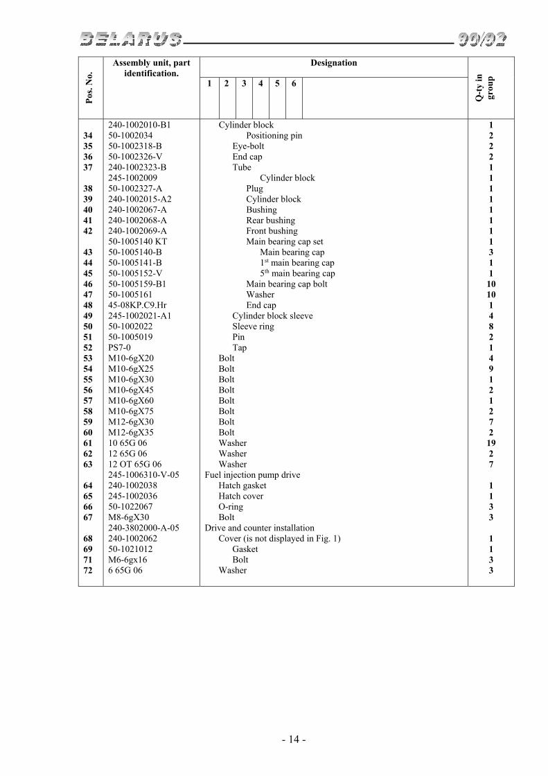
34 35 36 37 38 39 40 41 42 43 44 45 46 47 48 49 50 51 52 53 54 55 56 57 58 59 60 61 62 63 64 65 66 67 68 69 71 72
240-1002010-B1 50-1002034 50-1002318-B 50-1002326-V 240-1002323-B 245-1002009 50-1002327-А 240-1002015-А2 240-1002067-А 240-1002068-А 240-1002069-А 50-1005140 KT 50-1005140-B 50-1005141-B 50-1005152-V 50-1005159-B1 50-1005161 45-08KP.C9.Hr 245-1002021-А1 50-1002022 50-1005019 PS7-0 М10-6gХ20 М10-6gХ25 М10-6gХ30 М10-6gХ45 М10-6gХ60 М10-6gХ75 М12-6gХ30 М12-6gХ35 10 65G 06 12 65G 06 12 ОТ 65G 06 245-1006310-V-05 240-1002038 245-1002036 50-1022067 М8-6gХ30 240-3802000-А-05 240-1002062 50-1021012 M6-6gx16 6 65G 06
Cylinder block Positioning pin Eye-bolt End cap Tube Cylinder block Plug Cylinder block Bushing Rear bushing Front bushing Main bearing cap set Main bearing cap 1st main bearing cap 5th main bearing cap Main bearing cap bolt Washer End cap Cylinder block sleeve Sleeve ring Pin Tap Bolt Bolt Bolt Bolt Bolt Bolt Bolt Bolt Washer Washer Washer Fuel injection pump drive Hatch gasket Hatch cover O-ring Bolt Drive and counter installation Cover (is not displayed in Fig. 1) Gasket Bolt Washer
1 2 2 2 1 1 1 1 1 1 1 1 3 1 1
10 10 1 4 8 2 1 4 9 1 2 1 2 7 2
19 2 7
1 1 3 3
1 1 3 3

- 15 -
Subgroups 1003, 1007 Cylinder head and intake line installation (Fig. 2)
Pos
. No.
Assembly unit, part
identification. Designation
Q-t
y in
gr
oup
1 2 3 4 5 6
1 2 3 4 5 6 7 8 9 10 11 12 13 14 15 16 17 18 19 20 21 22 23 24 25 26 27 28 29 30 31 32 33 34 35 36 37 38 39 40 41 42
240-1003010-А 240-1002047 240-1002047-01 48-1002318 50-1003070-А (or 50-1003070-А3) 50-1003104-А 50-1003106 50-1003107-А 240-1003108 240-1003109 240-1003011 50-1003103-А 50-1003112 240-1003013-А2-06 240-1003027-А2 240-1003029 240-1003037 240-1003015-А1 245-1007032 D02-003-А 50-1007053-А2 240-1007015-B6 (or B7, or B9) 240-1007020 240-1007045-А3 (or А8, or А9, or А10) 240-1007046-А3 (or А5) 240-1007048 240-1007054 240-1007055 240-1007014-B7 (or B4, or B9) 240-1003030-А 240-1003031 240-1003032-А 240-1003033-14 240-1003264-А 243-1109210 242-3509213 242-3707220-А 240-3707200 242-3707140-А 50-1117028 D18-055-А KG 1/8". А12.016 2.5Х10 М8-6gХ20 М8-6gХ35 8 65G 06 240-1007100-B1 50-1007102-А1
Cylinder head installation Bolt Bolt Washer Cylinder head gasket Cap nut Washer Ring Cylinder head cover gasket Cylinder head cover cap gasket Cylinder head Sleeve Rest stud Cylinder head End cap Bushing End cap Cylinder head Valve guide bushing End cap Valve cotter Exhaust valve Valve sealing cup Outer valve spring Inner valve spring Valve spring disk Lower washer of valve spring Upper washer of valve spring Intake valve Cylinder head cover Gasket Cylinder head cover Intake manifold Gasket Branch pipe Pipe union Tank with plug Plug Tank Threaded plug O-ring Plug Pin Bolt Bolt Washer Rocker mechanism Rocker shaft
1 12 4
16 1
4 4 4 1 1 1 2 4 1 5 6 1 1 8 4
16 4
8 8
8
8 8 8 4
1 2 1 1 1 1 1 1 1 1 1 1 1 2 5 4 9 1 1

- 16 -
Pos
. No.
Assembly unit, part identification.
Designation
Q-t
y in
gr
oup
1 2 3 4 5 6
43 44 45 46 47 48 49 50 51 52 53 54 55 56 57 58 59 60 61 62 63 64 65 66 67 68 69 70 71 72 73 74
50-1007103-А 50-1007175-B1 50-1007182 50-1007183 50-1007212-А4 240-1007151-B 240-1007151-B-01 240-1007152-B 240-1007152-B-01 240-1007185 10 65G 06 D02-063 240-1007310-B1 240-1007375-А1 (or А2) 240-1002470 240-1002430-G 240-1002440 240-1002444-А1 240-1003122-B М8-6gХ16 8 65G 06 KG 3/8". А12.016 70-8115022-А 50-1015598 М12-6N М8-6gХ20 М8-6gХ30 М8-6gХ35 М8-6gХ80 (or 240-1022070-03) М12-6gХ85 8 65G 06 8.01.08KP 12.01.08KP 240-1111115-А 240-1111125-А1
Rocker shaft spring Adjusting screw Rocker shaft stopper Stopper washer Valve rocker with bushing Outer rocker shaft bracket Outer rocker shaft bracket Center rocker shaft bracket Center rocker shaft bracket Rocker shaft arrester Washer Nut Bar Valve lifter Breather installation Breather body Filter Gasket Cover cap Bolt Washer Plug Branch pipe Branch pipe gasket Nut Bolt Bolt Bolt Bolt Bolt Washer Washer Washer Bracket Bracket
3 8 2 2 8 1 1 1 1 1 1 8 8 8
1 1 1 1 1 4 4 2 1 1 4 2 1 2 1
2 5 1 2 1 1
Subgroup 1003, 1007 Cylinder head and intake line installation (Fig. 3 – for engines D-244)
Pos
. No.
Assembly unit, part identification.
Designation
Q-t
y in
gr
oup
1 2 3 4 5 6
1 2 3 4 5 6 7 8 9
240-1003010-А-23 240-1002047 240-1002047-01 48-1002318 50-1003070-А (or 50-1003070-А3) 50-1003104-А 50-1003106-01 50-1003107-А-01 240-1003108 240-1003109
Cylinder head installation Bolt Bolt Washer Cylinder head gasket Cap nut Washer Ring Cylinder head cover gasket Cylinder head cover cap gasket
1 12 4
16 1
4 4 4 1 1

- 17 -
Pos
. No.
Assembly unit, part identification.
Designation
Q-t
y in
gr
oup
1 2 3 4 5 6
10 11 12 13 14 15 16 17 18 19 20 21 22 23 24 25 26 27 28 29 30 31 32 33 34 34a 35 36 37 38 39 40 41 42 43 44 45 46 47 48 49 50 51 52 53 54
240-1003011 50-1003103-А 50-1003112 240-1003013-А2-06 240-1003027-А2 240-1003029 240-1003037 240-1003015-А1 245-1007032 D02-003-А 50-1007053-А2 240-1007015-B6 (or B7, or B9) 240-1007020 240-1007045-А3 (or А8, or А9, or А10) 240-1007046-А3 (or А5) 240-1007048 240-1007054 240-1007055 240-1007014-B7 (or B4, or B9) 240-1003030-А-07 240-1003031 240-1003032-А 240-1003033-16 240-1003264-А 243-1109210 240-1003034-01 240-3707115-А1 М6-6gX16 6 65G 06 50-1117028 D18-055-А KG 3/8" 2.5Х10 М8-6gХ20 М8-6gХ35 8 65G 06 240-1007100-B1 50-1007102-А1 50-1007103-А 50-1007175-B1 50-1007182 50-1007183 50-1007212-А4 240-1007151-B 240-1007151-B-01 240-1007152-B 240-1007152-B-01 240-1007185 10 65G 06 D02-063 240-1007310-B1 240-1007375-А1 or А2
Cylinder head Sleeve Rest stud Cylinder head End cap Bushing End cap Cylinder head Valve guide bushing End cap Valve cotter Exhaust valve Valve sealing cup Outer valve spring Inner valve spring Valve spring disk Lower washer of valve spring Upper washer of valve spring Intake valve Cylinder head cover Gasket Cylinder head cover Intake manifold Gasket Branch pipe End cap Gasket Bolt Washer Threaded plug O-ring Plug Pin Bolt Bolt Washer Rocker mechanism Rocker shaft Rocker shaft spring Adjusting screw Rocker shaft stopper Stopper washer Valve rocker with bushing Outer rocker shaft bracket Outer rocker shaft bracket Center rocker shaft bracket Center rocker shaft bracket Rocker shaft arrester Washer Nut Bar Valve lifter
1 2 4 1 5 6 1 1 8 4
16 4
8 8
8
8 8 8 4
1 2 1 1 1 1 1 1 2 2 1 1 1 2 3 4 7 1 1 3 8 2 2 8 1 1 1 1 1 1 8 8 8

- 18 -
Pos
. No.
Assembly unit, part identification.
Designation
Q-t
y in
gr
oup
1 2 3 4 5 6
55 56 57 58 59 60 61 62 63 64 65 66 67 68 69 70 71 72 73 74
240-1002470 240-1002430-G 240-1002440 240-1002444-А1 240-1003122-B М8-6gХ16 8 65G 06 KG 3/8". А12.016 70-8115022-А 50-1015598 М12-6N М8-6gХ20 М8-6gХ30 М8-6gХ35 М8-6gХ80 (or 240-1022070-03) М12-6gХ85 8 65G 06 8.01.08KP 12.01.08KP 240-1111115-А-01 240-1111125-А1-01
Breather installation Breather body Filter Gasket Cover cap Bolt Washer Plug Branch pipe Branch pipe gasket Nut Bolt Bolt Bolt Bolt Bolt Washer Washer Washer Bracket Bracket
1 1 1 1 1 4 4 2 1 1 4 2 1 2 1
2 5 1 2 1 1
Subgroups 1004, 1005. Pistons and connecting rods. Crankshaft. Flywheel (Fig. 4)
Pos
. No.
Assembly unit, part identification.
Designation
Q-t
y in
gro
up
1 2 3 4 5 6
1 2 3 4 5 6 7 8 9 10 11 12 13 14 15
240-1005015-B-04 50-1005021-А 50-1005043 50-1005157-V 50-1005191-А 240-1005014 240-1005017 240-1005018 240-1005020-B1 240-1005024 240-1005030-А1 4Х22 6Х9 50-1005019 А23.01-81-240 TsbN1 or А23.01-81-240SBASN1 А23.01-8116 or А23.01-81.037 А23.01-8117 or А23.01-81.038 А23.01-8118 or А23.01-81.040
Crankshaft End cap Rear crankshaft oil slinger End cap Crankshaft pipe Crankshaft Crankshaft counterweight Counterweight fastening bolt Crankshaft Lock plate Crankshaft distribution gear Lock pin Key Pin Crankshaft bearing liner set Crankshaft bearing liner Crankshaft bearing liner Crankshaft bearing liner
5 1 4 4 1 4 8 1 8 1 4 2 3
4
4
1

- 19 -
Pos
. No.
Assembly unit, part identification.
Designation
Q-t
y in
gro
up
1 2 3 4 5 6
16
17 18
19 20 21 22 23 24 25 26 27 28 29 30 31 32 33 34 35 36
А23.01-8119 or А23.01-81.039 А23.01-10401 А23.01-10403
240-1004010-А-18 or 240-1004010-А-19 or 240-1004010-А-20 or 240-1004010-А-21 or 240-1004010-А-22 or 240-1004010-А-23 or 240-1004010-А-24 or 240-1004010-А-25 or 240-1004010-А-26 or 240-1004010-А-27 or 240-1004010-А-28 or 240-1004010-А-29 or 240-1004010-А-30 or 240-1004010-А-31 or 240-1004010-А-32 or 240-1004010-А-33 or 240-1004010-А-34 or 240-1004010-А-35 50-1004042-А1 240-1004021-D-03 or 240-1004021-D or 240-1004021-D-01 or 240-1004021-D-02 or 240-1004021-D-04 or 240-1004021-D-05 240-1004022 240-1004100 50-1004182-А1 50-1004188 240-1004112 240-1004115-А 240-1004125 245-1004190 ST240-1004062 or 240-1004062 or 14-110-30-02 ST260-1004063 or 260-1004063 or 30-110-25-02 ST260-1004080 or 260-1004080 or 64-110-50-02 50-1005042 50-1005054 50-1005055-А 50-1005127-А 48-1002318 240-1005033-А-01 or 240-1005033-01
Crankshaft bearing liner Semi-ring Semi-ring
Piston with connecting rod
Piston pin Piston Piston pin circlip Connecting rod Connecting-rod bolt Nut of connecting-rod bolt Connecting rod Bushing of con-rod small end Connecting rod cap Washer Compression ring Compression ring Oil-scraper ring Front crankshaft oil slinger Crankshaft bolt Crankshaft bolt washer Flywheel fastening bolt Washer Oil pump drive pinion gear
1
2 2 4
1 1
2 1 2 2 1 1 1 2 1
1
1
1 1 1 7 7 1

- 20 -
Pos
. No.
Assembly unit, part
identification. Designation
Q-t
y in
gro
up
1 2 3 4 5 6
37 38 39 40 41
240-1005115 240-1005114-А 50-1005121-А 240-1005120 240-1005122 240-1005131-G А23.01-74-240 TsbN1 or А23.01-74-240 sbASN1 А23.01-7403 or А23.01-74.014
Flywheel Flywheel Flywheel ring gear Flywheel Pin Crankshaft pulley Connecting-rod insert set Connecting-rod insert
1 1 1 1 6 1 1
8
Subgroup 1005. Clutch coupling installation (Fig. 5)
Pos
. No.
Assembly unit, part identification.
Designation
Q-t
y in
gro
up
1 2 3 4 5 6
1 2 3 4 5
240-1005009 70-1601074 80-1601090 85-1601130-02 М12х1,25-6N 12.ОТ
Clutch coupling installation Bushing Clutch plate Driven plate Nut Washer
6 1 1 6 6
Subgroup 1006. Distributing gear (Fig. 6)
№ поз
.
Assembly unit, part identification.
Наименование
Кол
-во
в группе
1 2 3 4 5 6
1 2 3 4 5 6 7 8 9 10 11 12
50-1006250-V 50-1006252-V1 50-1005021-А 50-1006253 240-1006240-А1 240-1006244-B 240-1006246 50-1006254 M8-6gx16 8 65G 06 50-1006021-B 50-1006247 M10-6gx30 10 65G 06
Intermediate gear pin Intermediate gear pin End cap Thrust ring Intermediate gear with bushing Intermediate gear Bushing Strap Bolt Washer Thrust washer Special screw Bolt Washer
1 1 1 1 1 1 1 1 2 2 1 1 1 2

- 21 -
Pos
. No.
Assembly unit, part identification.
Designation
Q-t
y in
gro
up
1 2 3 4 5 6
13 14 15 16 17 18 19 20 21 22
240-1006010 240-1006015-А 6х9 50-1006017-B 240-1006214-А1 50-1006018 245-1006020 245-1006311-V1 50-1006315-B4 М10-6N.12.40H 260-1111208
Camshaft Camshaft Key Washer Camshaft gear Camshaft thrust washer Special bolt Fuel pump drive gear Gasket Nut Washer
1 1 1 1 1 1 1 1 1 3 3
Subgroup 1008. Exhaust manifold installation (Fig. 7)
Pos
. No.
Assembly unit, part identification.
Designation
Q-t
y in
gro
up
1 2 3 4 5 6
1 2 3 4 5 6 7 8 9 10 11 12 13 14
240-1008010-А2-02 50-1008026-B 50-1008027-B 240-1008015-А1 50-1008028 240-1008021-B1 240-1008025-А 245-1008023-А 12 65G 06 240-1306038-А 70-3407164 245-3701069 М12-6gх20 М12-6gх35 М12-6gх85 12 65G 06
Exhaust manifold installation Outer gasket of exhaust manifold Center gasket of exhaust manifold Manifold Gasket Adapter Exhaust manifold Bolt Washer End cap Bracket Washer Bolt Bolt Bolt Washer
2 1 1 1 1 1 4 4 1 1 3 1 5 1 1
Subgroup 1009. Oil crankcase installation (Fig. 8)
Pos
. No.
Assembly unit, part identification.
Designation
Q-t
y in
gro
up
1 2 3 4 5 6
1 2 3 4 5 6 7
245-1009000-G 245-1009104 245-1009110-V 50-1401063-V1 240-1401059-А1 240-1401065-А1 М8-6gх25 8Т 65G 06
Oil crankcase installation Plate Oil crankcase Oil crankcase gasket Front seal Rear seal Bolt Washer
2 1 2 1 1
22 22

- 22 -
Subgroup 1022. Gear-type pump installation (Fig. 9)
Pos
. No.
Assembly unit, part identification.
Designation
Q-t
y in
gro
up
1 2 3 4 5 6
1 2 3 4 5 6 7 8 9 10 11
240-1022040 240-1022030 240-1022061-B 240-1022069 240-1307064-01 Ring V25 205К 240-1022062 240-1022075-А1 М8-6gх30 М8-6gх70 8 65G 06 NSh 10Zh-З-04L or NSh 14, or NSh 16
Hydraulic pump installation Hydraulic pump drive Hydraulic pump drive gear Hydraulic pump body Retaining ring Ring Bearing Gasket Gasket Bolt Bolt Washer Gear-type pump
1 1 1 1 1 2 1 1 4 1 5 1
GROUP 11 FEED SYSTEM
Subgroup 1109. Air cleaner installation (Fig. 10)
Pos
. No.
Assembly unit, part identification.
Designation
Q-t
y in
gro
up
1 2 3 4 5 6
1 2 3 4 5 6 7 8 9 10 11 12 13 14 15 16 17 18 19 20
240-1109010-А-15 240-1109015-А-08 240-1109035-А2-09 240-1109095 240-1109096-B1 240-1109165 240-1109166-B 240-1109167-B 240-1109254-V 240-1109255 240-1109262 240-1109306 М6-6N.45L 6.01.08KP 240-1109280 50-1109296-B 240-1109290-B1 240-1109299 50-1401067 3.2Х18.019 50L-1109301-B 50-1401067 М8-6N
Air cleaner installation Air cleaner Air cleaner body Yoke Yoke stop Filter element Filter element Filter element Oil bath Pan Pinch bolt Gasket Knockoff Nut Washer Bracket Pin Air cleaner bracket Air cleaner retaining clamp Washer Cotter pin Pin Washer Nut
1 1 1 1 1 1 1 1 1 1 2 1 2 2 1 1 1 1 1 1 1 1 1

- 23 -
Pos
. No.
Assembly unit, part identification.
Designation
Q-t
y in
gro
up
1 2 3 4 5 6
21 22 23 24 25
М8-6gХ 45 RD 63-74-75-0,2 А53.21.000 А53.21.001 А53.21.002 HS-71.016
Bolt Hose Monocyclone Branch pipe Cap Tension shackle
1 1 1 1 1 2
Subgroup 1111. Fuel equipment installation (Fig. 11)
Pos
. No.
Assembly unit, part identification.
Designation
Q-t
y in
gro
up
1 2 3 4 5 6
1 2 3 4 5 6 7 8 9 10 11 12 13 14 15 16 17 18 19 20 21 22 23 24 25 26 27 28 29 30 31 32 33
240-1111000-А1 36-1104787 36-1104788 240-1104300-01 240-1104300-02 240-1104300-03 240-1104300-04 240-1104320-А2-02 245-1104180-А-02 245-1104180-А-06 245-1104180-А-10 240-1105010 240-1111036-B1 240-1111101-B 240-1111105 240-1111106 240-1111112 240-1111114 245-1111020 245-1111113 245-1117010-G 245-1117105 FT020-1117010 М6-6N М10-6gХ 20 М10-6gХ25 М10-6gХ 35 М10-6gХ120 6 65G 06 10 65G 06 171.1112010-02 4UTNI-1111007-420 D18-051-А D18-055-А
Fuel equipment installation Pipe union bolt Gasket High-pressure fuel pipe High-pressure fuel pipe High-pressure fuel pipe High-pressure fuel pipe Drain fuel piping Low-pressure fuel pipe Low-pressure fuel pipe Low-pressure fuel pipe Fuel coarse filter Guard ring Shackle Shoe Shoe Pipe union Shoe Screen-gasket Protective bushing Housing assembly Pipe union with plug Fuel fine filter Nut Bolt Bolt Bolt Bolt Washer Washer Injector Fuel pump Swinging angle joint bolt O-ring
3 8 1 1 1 1 1 1 1 1 1 4 2 1 2 1 1 4 1 1 1 1 5 3 2
10 2 5
11 4 1 1
12

- 24 -
Subgroup 1117. Fine fuel filter (Fig. 12)
Pos
. No.
Assembly unit, part identification.
Designation
Q-t
y in
gr
oup
1 2 3 4 5 6
1 2 3 4 5 6 7 8 9 10 11 12 13
245-1117010-G 245-1117075 245-1117079 245-1117081 D18-055-А 245-1117091-B М10-6N М10-6gх30 10 65G 06 245-1117105 240-1003281 36-1104788 D18-052 FT020-1117010 D18-051-А D18-055-А
Housing Housing Pipe union Cover O-ring Bracket Nut Bolt Washer Pipe union with plug Plug Gasket Pipe union Fuel purification filter Swinging angle joint bolt O-ring
1 1 1 1 1 1 2 2 2 1 1 1 1 1 1 4
Subgroup 1105. Coarse fuel filter
(Fig. 13)
Pos
. No.
Assembly unit, part identification.
Designation
Q-t
y in
gr
oup
1 2 3 4 5 6
1 2 3 4 5 6 7 8 9 10 11 12 13
240-1105010 М8-6gх25 М8-6N 8 65G 06 240-1105016 98-4-4-1b 240-1105011 240-1105025 240-1105020 240-1105030 260-1117134 D16-111-А D18-051-А D18-055-А
Fuel coarse filter Bolt Nut Washer Housing Ring Disperser Deflector Sleeve Plug O-ring Protective bushing Swinging angle joint bolt O-ring
4 4 4 1 1 1 1 1 1 1 2 2 4

- 25 -
GROUP 13 COOLING SYSTEM Subgroup 1306. Thermostat housing installation (Fig. 14)
P
os. N
o.
Assembly unit, part identification.
Designation
Q-t
y in
gro
up
1 2 3 4 5 6
1 2 3 4 5 6 7 8 9 10 11 12 13 14 15
245-1306030-А М8-6gх25 М8-6gх95 50-1401067 50-1306026 245-1306040 М8-6gх25 50-1401067 245-1306025 KG 3/8” TS107-1306100-04 245-1306023 245-1306021 245-1306027 80-3801092-B 50-1306028-B3 «Norma» 20-32
Thermostat housing installation Bolt Bolt Washer Thermostat housing gasket Thermostat housing Bolt Washer Housing cover Plug Wax thermostat Gasket Lower housing Pipe union Bracket Thermostat hose Clamp
2 2 4 1 1 4 4 1 1 1 1 1 1 1 1 2
Subgroup 1307. Water pump installation Subgroup 1308 Fan installation (Fig. 15)
Pos
. No.
Assembly unit, part identification.
Designation
Q-t
y in
gr
oup
1 2 3 4 5 6
1 2 3 4 5 6 7 8 9 10 11 12 13 14 15 16 17 18 19 20
240-1307000 50-1307048-B 240-1307012-А1 50-1307049-А 240-1307010-А1 50-1005161 SP/1341 240-1307064 240-1307070-B 240-1307074-V 240-1307075 245-1307025 245-1307052-G 245-1307084 245-1307094 М16х1,5-6N 1160305 KG 3/8″
5х7,5 245-1307060-01 245-1306027 50-1307044-B 50-1401067 М8-6gх45
Water pump installation Housing gasket Water pump Branch pipe gasket Water pump Washer Water pump packing seal Retaining ring Water pump pulley Impeller End cap Water pump housing Shaft Bushing Thrust ring Nut Ball radial single-row bearing Plug Key Water pump branch pipe Pipe union Water pump branch pipe Washer Bolt
1 1 1 1 1 1 1 1 1 1 1 1 1 1 1 2 1 1 1 1 1 2 2

- 26 -
Pos
. No.
Assembly unit, part identification.
Designation
Q-t
y in
gro
up
1 2 3 4 5 6
21 22 23 24 25 26 27
М10-6gх45 М10-6gх50 10 65G 06 245-1308000-E-01 245-1308010-А М8-6gх25 2KL.I-11H10-1250 or AVX 13-1250 or SPA-1250 8 65G 06
Bolt Bolt Washer Fan installation Fan Bolt Belt Washer
2 1 3 1 6 1 6
GROUP 14 LUBRICATION SYSTEM
Subgroup 1400. Oil pump installation (Fig. 16)
Pos
. No.
Assembly unit, part identification.
Designation
Q-t
y in
gro
up
1 2 3 4 5 6
1 2 3 4 5 6 7 8 9 10 11 12 13 14 15 16 17 18 19 20 21 22 23 24
240-1400010-B М12-6gх40 12Т 65G 06 240-1402000-А3 50-1402053 240-1402010-А3 М8-6gх50 8Т 65G 06 50-1403015-А М8-6gх20 8Т 65G 06 50-1403033 245-1403010 М8-6gх50 8Т 65G 06 240-1002044 50-1403110-B 50-1403115-B D08-002-А or А57.03.028-А 50-1403125-B 50-1403233 240-1403020 240-1403025 50-1403019-B or А57.03.026-А 240-1403120-А-02 50-1403052-V 50-1403075-V 240-1403150 240-1403155 50-1403012-B or А57.03.027-А 245-1403228
Oil pump installation Bolt Washer Oil pump receiver installation Flange gasket Oil receiver Bolt Washer Outlet branch Bolt Washer Flange gasket Oil pump Bolt Washer Pin Oil pump driven gear Oil pump driven gear Oil pump body bushing Intermediate gear bushing Driven gear pin Positioning pin Oil pump body Oil pump body Body bushing Shaft Oil pump shaft Oil pump drive gear Oil pump cover Oil pump cover Body bushing Gear of oil pump drive
2 2 1 1 1 2 2 1 4 4 2 1 4 4 2 1 1
1 1 2 1 1
1 1 1 1 1 1
1 1

- 27 -
Subgroup 1404. Centrifugal filter installation (Fig. 17)
Pos
. No.
Assembly unit, part
identification. Designation
Q-t
y in
gr
oup
1 2 3 4 5 6
1 2 3 4 5 6 7 8 9 10 11 12 13 14 15 16 17 18 19 20 21 22 23 24 25 26 27 28 29 30 31 32 33 34 35 36 37 38 39
240-1404000-А 36-1104788 50-1404068 240-1404010-А 50-1117028 50-1404059-B1 50-1404071-А 50-1404072 50-1404075 50-1404077-А or 240-1404096 50-1404081-А1 50-1404083-А1 50-1404085-А1 240-1404020-А2 240-1404017-B 240-1404030-А 240-1404023 240-1404033 240-1404035-А 240-1404049 240-1404080-А1 240-1404012-V 240-1404013-B 240-1404019-B 240-1404028 240-1404090-B 240-1404118 240-1404140 240-1404024 240-1404110 240-1404111 240-1404113 115-120-30-2-1 V2.М6-6gx14 М12H1,25-6N D37А-1407607-V 240-1404027 240-1404067-А 240-1404074 240-1404088 KG 1/4" KG 1/8" D09-035-А D18-055-А М10-6gХ30 М10-6gХ 50
Centrifugal filter installation Gasket Centrifugal filter housing gasket Centrifugal oil filter Threaded plug Cap gasket Centrifugal filter valve Adjusting plug Pressure reducing valve plug Plug End cap Centrifugal filter valve spring Drain valve spring Pressure reducing valve spring Rotor with shaft Rotor housing Rotor cup Rotor cup Thrust ring Special nut Inner cup Rotor shaft Rotor shaft Tube Rotor housing cover Pin Nozzle Ring Filter screen Rotor impeller Filter screen Screen Cover Ring Screw Nut Thrust washer Centrifugal filter cap Centrifugal filter housing Insert Cap nut Plug Plug Bypass valve plug gasket O-ring Bolt Bolt
4 1 1 1 1 3 1 3 2 2 1 1 1 1 1 1 1 1 1 1 1 1 1 1 1 1 1 1 1 1 1 1 1 3 1 1 1 1 1 1 1 1 3 1 2 2

- 28 -
GROUP 35 PNEUMATIC COMPRESSOR Subgroup 3509. Pneumatic compressor installation (Fig. 18)
Pos
. No.
Assembly unit, part
identification. Designation
Q-t
y in
gr
oup
1 2 3 4 5 6
1 2 3 4 5 6 7 8 9 10 11 12 13 14 15 16
240-3509030-A А29.05.000-BZA М10-6gх45 М10-6N 10 65G 06 36-1104788 240-3509037-А 240-3509150 36-1104787 240-3509232 240-3509158 240-3509159 М6-6gх16 М6-6N 6 65G 06 RD 18-29-300-1,3 HS-26.016
Pneumatic compressor installation Pneumatic compressor Bolt Nut Washer Gasket Gasket Oil piping Pipe union bolt Pipe union Clamp Buckle Bolt Nut Washer Hose Tension shackle
1 1 3 3 3 1 1 1 1 1 1 1 1 1 1 2

- 29 -
GROUP 37 ELECTRIC EQUIPMENT
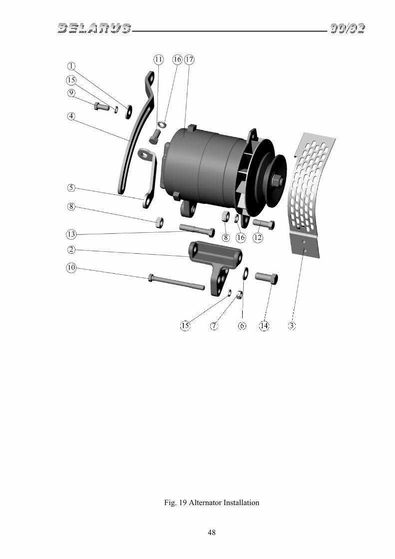
Subgroup 3701. Alternator installation (Fig. 19) P
os. N
o.
Assembly unit, part identification.
Designation
Q-t
y in
gr
oup
1 2 3 4 5 6
1 2 3 4 5 6 7 8 9 10 11 12 13 14 15 16 17
240-3701050-V-36 50-1002073 240-3701056-V 240-3701060-B 240-3701063 240-3701063-01 240-3701068-B 240-3701068-B-01 245-3701069 М8-6N М10-6N М8-6gХ20 М8-6gХ95 М10-6gХ20 М10-6gХ30 М10-6gХ55 М12-6gХ30 8 65G 06 10 65G 06 G9695.3701-1
Alternator installation Thrust washer Alternator bracket Board Strap Strap (D-244) Brace (D-243, D-242) Brace (D-244) Washer Nut Nut Bolt Bolt Bolt Bolt Bolt Bolt Washer Washer Alternator
1 1 1 1 1 1 1 2 1 3 1 1 1 1 1 2 2 2 1
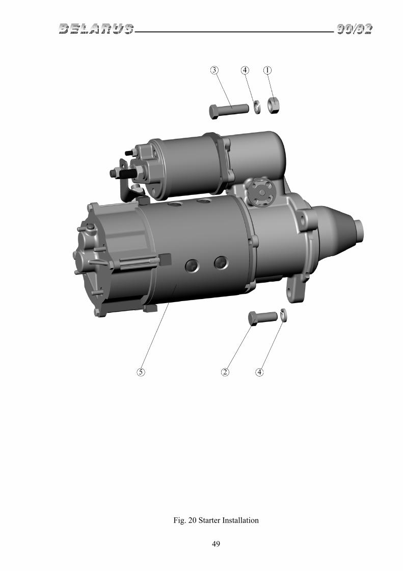
Subgroup 3708. Starter installation (Fig. 20)
Pos
. No.
Assembly unit, part identification.
Designation
Q-t
y in
gr
oup
1 2 3 4 5 6
1 2 3 4 5
245-3708030-12 М12-6N М12-6gх30 М12-6gх45 12 65G 06 ST142М
Starter installation Nut Bolt Bolt Washer Starter
1 2 1 3 1

30
Fig. 1 Front Support Installation. Cylinder Block. Drive and Counter Installation.

31
Fig. 2 Cylinder Head and Intake Line Installation.

32
Fig. 3 Cylinder Head and Intake Line Installation.

33
Fig. 4 Pistons and Connecting Rods. Crankshaft. Flywheel

34
Fig. 5 Clutch Coupling Installation

35
Fig. 6 Distributing Gear.

36
Fig. 7 Exhaust Manifold Installation

37
Fig. 8 Oil Crankcase Installation

38
Fig. 9 Gear-Type Pump Installation.

39
Fig. 10 Air Cleaner Installation

40
Fig. 11 Fuel Equipment Installation

41
Fig. 12 Fine Fuel Filter

42
Fig. 13 Coarse Fuel Filter

43
Fig. 14 Thermostat Housing Installation

44
Fig. 15 Water Pump and Fan Installation

45
Fig. 16 Oil Pump Installation

46
Fig. 17 Centrifugal Filter Installation

47
Fig. 18 Compressor Installation
48
Fig. 19 Alternator Installation
49
Fig. 20 Starter Installation

- 50 -
Fig. 11.1. Fuel Tank

- 51 -
Group 11. Feed system Subgroup 1101. Fuel tank
Fig. No Pos.
No. Assembly unit or part
No. Q-ty Description
11 70-1101005 1 Tanks
1 70-1101020 1 Tank 80-1101510 1 Tank (plastic)
2 70-1101070 4 Clamp 3 70-1101035-B 1 Sleeve 4 HS-66 2 Clamp
5 70-1101010 1 Tank 80-1101520 1 Plastic tank
6 VM 5х16 5 Screw 7 80-1101067 5 Washer 8 DUMP-21М 1 Fuel gauge 9 200-3806026 1 Lining 10 80-1101250-B 2 Right arm 11 М10х25 12 Bolt 12 ShP 10 12 Washer 13 М10 12 Nut 14 80-1101012-B 8 Lining 15 PR-36-01 8 Lining
16 85-1101002-02 1 Tube
80-8101015-02 1 Hose (for variant with plastic tank)
17 822- 1101081 2 Union 822- 1101081 1 Union (for variant with plastic tank) 11,113-100 1 Ball
18 KR-25 2 Crane 19 70-1101042 2 Bracket 20 50-1111102-01 2 Lining 21 70-1101345-B1 1 Pipeline 22 ShP 12 8 Washer 23 М12х30 8 Bolt 24 80-1101280-B 2 Left arm 25 36-1101070 1 Chain 26 082-1103010 1 Plug 27 36-1104787 1 Bolt 28 36-1104788 2 Lining 29 70-1104180 1 Pipeline

- 52 -
Fig. 11.2. Fuel Supply Control

- 53 -
Group 11. Feed system Subgroup 1108. Fuel supply control
Fig. No Pos.
No. Assembly unit or part
No. Q-ty Description
11.2 70-1108005-B1 1 Fuel supply control 1 М6х12 3 Bolt 2 ShP6 5 Washer 3 ShCh6 3 Washer 4 70-1108271 1 Handle 5 50-1108148 2 Washer 6 70-1108260 1 Roller 7 А20-245-B 1 Spring 8 50-1108146 1 Lever 9 М14х1,5 1 Nut 10 70-3401093 1 End 11 70-1108250 1 Arm 12 70-1108178 1 Washer 13 ShCh8 6 Washer 14 3,2х18 7 Split 15 70-1108167-B1 1 Drawbar 16 70-1108230 1 Roller 17 50-1108044 1 Seal 19 М8х25 1 Bolt 20 70-1108220 1 Pedal 21 ShP8 3 Washer 22 М6х16 2 Bolt 23 70-1108244 1 Case 24 М8х20 2 Bolt 25 70-1108063 1 Drawbar 26 70H-1108043 1 Lever 27 ShCh12 2 Washer 28 70-1115020 1 Blind control 29 А30.04.017 2 Cover 30 70-3723023 1 Bush 31 8х30 1 Pin 32 А20.213-А 1 Fork 33 М8 3 Nut 34 70-1108116 1 Drawbar 35 80-1108026 1 Arm 36 70-1310441 1 Clip 37 М4х10 1 Screw 38 80-1108317 1 Clamp 39 М12х1,25 1 Nut

- 54 -
Fig. 11.3. Diesel Stop. Emergency Diesel Stop

- 55 -
Group 11. Feed system Subgroup 1115. Diesel stop. Emergency diesel stop
Fig. No Pos. No.
Assembly unit or part No.
Q-ty Description
11.3 1 70-1310441 1 Clip 2 VM4x10 1 Screw 3 80-1108317 1 Clamp 4 3,2x18 1 Splint 5 80-1108126 1 Arm 6 80-1108630-А 1 Cable 7 М12х1,25 1 Nut 8 ShCh 12 1 Washer 9 80-1024211 1 Blind 10 ShP 6 2 Washer 11 VM6x12 2 Bolt 12 А30.04.017 2 Cap 13 70-3723023 2 Bush

- 56 -
Fig. 12.1. Muffler
- 57 -
Group 12. Exhaust system Subgroup 1205. Muffler
Fig. No Pos.
No. Assembly unit or part
No. Q-ty Description
12.1 1 60-1205015-01 1 Muffler 2 60-1205101 1 Bracket 3 60-1205103 1 Clip 4 ShCh10 2 Washer 5 80-1205136 2 Nut
- 58 -
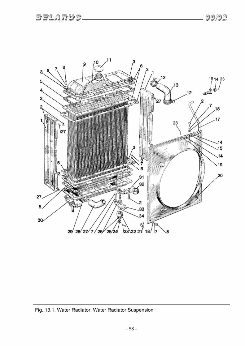
Fig. 13.1. Water Radiator. Water Radiator Suspension

- 59 -
Group 13. Cooling system Subgroup 1301, 1302. Water radiator. Water radiator suspension
Fig. No Pos.
No. Assembly unit or part
No. Q-ty Description
13.1 70U.13.01.010-01 1
Water radiator (1-11, 22-26, 29-31, 33, 34)
1 70U.13.01.126-1 2 Radiator rack 2 М8х25 56 Bolt 3 70U.13.01.255 8 Angular overlay 4 70U.13.01.020 1 Radiator core 5 70U.13.01.169 2 Lining 6 70U.13.01.256 8 Overlay 7 ShP 8 64 Washer 8 М8 64 Nut 9 70U-1301055-А7 1 Top tank 10 70-1301158 1 Pipe of vapor deliver 11 А21.01.270 1 Cover (type 1) 12 HS-46 4 Clip 13 70-1303001 1 Hose 14 ShCh 8 4 Washer 15 85-1302071 2 Shock absorber 16 1520-1302072 1 Arm 17 90-1302003-А 1 Extension 18 ShCh 8 4 Washer 19 80-1302012-А 1 Arm 20 70-1309080 1 Casing 21 48-1104016 1 Clip 22 70U.13.02.018 2 Shock absorber 23 3,2x18 2 Splint 24 М12 2 Nut 25 ShP 12 4 Washer 26 ShCh 12 4 Washer 27 М8х16 8 Bolt 28 50-1303062-B2 1 Hose 29 70U.13.01.075 1 Bottom tank 30 70U.13.01.190 1 Left support 31 70U.13.01.180 1 Right support 32 KG 1/4" 1 Plug 33 70U.13.02.016 2 Planck 34 70U.13.02.015 2 Bush

- 60 -
Fig. 13.2. Fan guard (optional)

- 61 -
Group 13. Cooling system Subgroup 1309. Fan guard (optional)
Fig. No Pos.
No. Assembly unit or part
No. Q-ty Description
13.2
1 М6х16 4 Bolt 2 ShP 6 3 Washer 3 ShCh 6 3 Washer 4 80-1309020 1 Right cheek 5 80-1309025 1 Grid
6 80-1309030 1 Casing (it is installed at the absence of compressor)
7 80-1309015 1 Left cheek

- 62 -
Fig. 14.1. Oil cooler

- 63 -
Group 14. Lubrication system Subgroup 1405. Oil cooler
Fig. No Pos.
No. Assembly unit or part
No. Q-ty Description
14.1 600-1405100 1 Oil pipeline (4, 5, 11, 23) 1 70-1405089 1 Union 2 40-4607038-А 3 Washer 3 70-1405120 1 Oil pipeline 4 HS-21-P29 10 Clip 5 70-1405013 5 Hose 6 70-3407146 1 Planck 7 70-3506027 3 Bush 8 70-3407144 4 Planck 9 М8х35 2 Screw 10 ShP 8 6 Washer 11 70-1406109 1 Oil pipeline 12 М8х45 4 Bolt 13 ShCh 8 4 Washing 14 М8 6 Nut 15 600-1405117 1 Oil pipeline 16 70-1405011 1 Pipe 17 70-1405112 1 Clip 18 70-1405230 1 Filter 19 245-1405010-А 1 Cooler 20 70-1405110 1 Oil pipeline 21 40-4607032 1 Bolt

- 64 -
Fig. 16.1. Clutch disks

- 65 -
Group 16. Clutch Subgroup 1601. Clutch disks
Fig. No Pos.
No. Assembly unit or part
No. Q-ty Description
16.1 80-1601090 1 Clutch disks (3-28) 85-1601120-B 1 Backing plate (10,17-22)
1 85-1601130-01 1 Driven disk 2 70-1601138-01 2 Overlay 3 80-1601093 1 Pressure plate 4 85-1601096 6 Pin 5 85-1601108 12 Washer 6 3,2x18 12 Splint 7 85-1601094 3 Pressing lever 8 85-1601097 3 Fork 9 85-1601083 3 Spring 10 85-1601125-B 1 Backing plate(18, 17, 85-1601122 - B) 11 85-1601109-А 3 Adjusting nut 12 85-1601086 3 Retainer 13 ShP 8 6 Washer 13а ShCh 8 6 Washer 14 М8х16 6 Bolt 15 ShP 12 9 Washer 16 М12х1,25 9 Nut 17 8х22 6 Rivet 18 70-1601051 1 Hub 19 70-1601091 12 Damper 20 70-1601053 1 Bush 21 6х30 3 Rivet 22 70-1601062 2 Washer 23 85-1601072-B 9 Cup 24 85-1601115 9 Spring 25 85-1601118-B 9 Isolating washer 26 85-1601121 6 Washer 27 85-1601126 6 Bolt 28 85-1601124 9 Board 29 70-1601074 6 Bush 30 2-4x8-32 24 Rivet

- 66 -
Fig. 16.2. Clutch housing

- 67 -
Group 16. Clutch Subgroup 1601. Clutch housing
Fig. No Pos.
No. Assembly unit or part
No. Q-ty Description
16.2 1 70-1601015 1
Clutch housing
(includes spare part no. 50-3503064) 2 D01-015 2 Set pin 3 ShCK 10x25 2 Pin 4 50-1601345 1 Lining 5 ShP 8 11 Washer 6 М8х20 7 Bolt 7 70-1601344 1 Cover 8 ShP 16 10 Washer 9 М16х50 10 Bolt 10 PK KG 1 1/4" 1 Plug 11
50-3503064 1 Bush (constituent element of part 70-
1601015) 12 50-1601352 2 Pin 13 50-1601215 1 Shaft of forks of inclusion 14 80-1601219-B 1 Lever 15 80-4608024 1 Ring 16 36-1601016 1 Dust reflector housing 17 70-1601140 1 Roller 18 80-1601099 1 Plate 19 ShCh 10 1 Washer 20 М12х35 1 Bolt 21 ShP 12 1 Washer 22 SSh 611 1 Connector 6x11 23 ShP 10 9 Washer 24 М10х20 1 Bolt 25 020-025-30-1-4 2 Ring 26 50-1601315 1 Bottom cover 27 М10х25 8 Bolt 28 70-1601314 2 Lining 29 50-1601341 1 Coupling cover 30 50-1601022 1 Plug 31 М8х16 4 Bolt

- 68 -
Fig. 16.3. Coupling housing (release yoke)

- 69 -
Group 16. Clutch Subgroup 1601. Clutch housing (release yoke)
Fig. No Pos.
No. Assembly unit or part
No. Q-ty Description
16.3 1 М10х25 3 Bolt 2 ShP 10 5 Washer 3 60210AUSh1 1 Bearing 4 50-1601319 1 Oil reflecting washer
5 240-1002055 1 Collar 50x70 (constituent element of part 50-1601172-А)
6 110-115-30-1-4 1 Ring
7 50-1601172-А 1 Release yoke bracket (includes detail 240-1002055)
8 1.1 C6hr 1 Greaser 9 50-1601203 2 Fork 10 50-1601218 2 Connector 11 М10х30 2 Bolt 12 50-1601185-А 1 Release yoke 13 986714 К1S23 1 Release yoke bearing

- 70 -
Fig. 16.4. Clutch housing (Power Take Off drive, Pump Drive of Hydraulic Lift System)

- 71 -
Group 16. Clutch Subgroup 1601. Clutch housing (Power Take Off Drive, Pump Drive of Hydraulic
Lift System) Fig. No Pos.
No. Assembly unit or part
No. Q-ty Description
16.4 1 942/40 1 Bearing 2 70-1601021-B 1 Shaft of Drive of Power Take Off 3 70-1601076 1 Ring 4 70-1601081 1 Clutch 5 2V50 1 Ring 6 70-1601086-B 1 Pinion of Drive of Power Take Off (II step) 7 70-1601083 1 Spacing Washer 8 2V90 1 Ring 9 70-1601088-B 1 Pinion of Drive of Power Take Off (I step) 10 70-1601082 1 Spacing Washer 11 KSP-72 1 Ring 12 50-1601038 1 Pressure Washer 13 50-1601091 1 Lining 14 50-1601089 1 Bearing Cover 15 М8х16 4 Bolt 16 ShP 8 4 Washer 17 М12х35 1 Bolt 18 ShP 12 1 Washer 19 6-50306К 1 Bearing 20 943/30 2 Bearing21 210 AUSh1 2 Bearing22 305 2 Bearing23 М10х30 1 Bolt 24 ShP 10 1 Washer 25 10x6.01.019 1 Washer 26 025-030-30-1-4 1 Ring 27 50-1601336 1 Stop bush 28 70-1601333 1 Ring 29 2V62 1 Ring 30 70-1601331 1 Idler pinion 31 70-1601335 1 Pinion axle 32 VM12х25 1 Screw

- 72 -
Fig. 16.5. Clutch housing (reducing gear)

- 73 -
Group 16. Clutch Subgroup 1601,1721. Clutch housing (reducing gear)
Fig. No Pos.
No. Assembly unit or part
No. Q-ty Description
16.5 1 70-1601026 1 Shaft of Drive of Power Take Off 2 50-1601321 1 Ring 3 50-1601027 1 Support Washer 4 70-1601028 1 Arm 5 М10х25 7 Bolt 6 ShP 10 7 Washer 7 307А 1 Bearing 8 210AUSh1 1 Bearing 9 2S55 2 Ring 10 2S100 1 Ring 11 211AUSh1 1 Bearing 12 70-1721022 1 Support Cover 13 70-1721023 1 Support Washer 14 70-1721031 1 Pinion 15 70-1721113-А 1 Power Shaft 16 4x34,8 47 Roller 17 70-1721045 1 Clutch

- 74 -
Fig. 16.6. Clutch control

- 75 -
Group 16. Clutch Subgroup 1602. Clutch Control
Fig. No Pos.
No. Assembly unit or part
No. Q-ty Description
16.6 50-1602110-B 1 Rod (5,7,8) 1 М12х35 1 Bolt 2 ShP 12 2 Washer 3 80-1601219-B 1 Lever 4 12x32 3 Pin 5 50-3502203 2 Fork 6 3,2x18 3 Splint 7 М12х1,25 2 Nut 8 85-1602112-V 1 Rod 9 М12х30 1 Bolt 10 80-3503158-А 1 Gasket 11 70-1602040 1 Ballast Core 12 А13.33.002 1 Overlay 13 70-1602020-B 1 Pedal 14 50-1602027 1 Arrester 15 50-1602032 1 Spring 16 50-1602029 1 Arrester 17 80-1602033 1 Arrester Bolt 18 М16 1 Nut 19 80-1602075-B 1 Arm

- 76 -
Fig7.1. Gearbox. Gearbox casing.

- 77 -
Group 17. Gearbox Subgroup 1701. Gearbox. Gearbox casing.
Fig. No Pos.
No. Assembly unit or part
No. Q-ty Description
17.1 70-1700010 1
Gearbox (for tractor Belarus-90)
72-1700010 1 Ger box (for tractor Blarus-92) 1 50-1701025-А 1 Gearbox casing 2 50-1701026 1 Lining 3 50-4605027 2 Pin 4 70-1701300 1 Plug 1 1/4" 5 KG-3/8" 1 Plug 6 ShP 10 8 Washer 7 М10х35 8 Bolt
8 50-1701458 1 Right Cover (for tractor Belarus-90)
9 50-1701459 1 Lining 10 М16х100 2 Bolt 11 ShP 16 11 Washer 12 М16х60 2 Bolt 13 М16х55 5 Bolt 14 М16х50 2 Bolt 15 ShP 12 7 Washer 16 М12х35 7 Bolt 17 011-015-25-1-4 2 Ring 18 70-1701454-А2 1 Cover 19 50-1701456-А 1 Lining 20 D01-015 2*/4** Pin 21 70-1701415-А 1 Oil meter
* For tractor Belarus-90 ** For tractor Belarus-92

- 78 -
Fig. 17.2. Main Drive Shaft. Main Shaft

- 79 -
Group 17. Gearbox Subgroup 1701. Main Drive Shaft. Main Shaft.
Fig. No Pos.
No. Assembly unit or part
No. Q-ty Description
17.2 48-1701030-А 1 Min Drive Shaft (3-9) 50-1701040 1 Main Shaft (10-13) 50-1701050 1 Bearing cup (15, 16)
1 2V60 1 Ring 2 70-1721025 1 Pinion of lowering reducer 3 50-1701034 1 Shaft cup 4 48-1701032-А 1 Main Drive Shaft 5 210 AUSh1 1 Bearing 6 2V50 1 Ring 7 2V90 1 Ring 8 50-1701048-А 1 Pinion of IV and V speed 9 50-1701045 1 Pinion of III speed 10 208А 1 Bearing 11 50-1701252 1 Main Shaft 12 6-67512ASh2 1 Bearing 13 50-1701312 1 Spacer 14 50-1701314 1 Pinion of II step of reducer 15 50-1701255 1 Cup 16 6-7610АSh2 1 Bearing
17 50-1701105-B 1 Pinion of main gear (it is supplied only in set of tools and accessories)
18 50-1701253 1 Nut М36х1,5 19 5x45-001 1 Splint 20 50-1701254 А 1 Washer 21 М12х35 4 Bolt 22 ShP 12 4 Washer 23 50-1701259 2 Adjustment gasket 0,5 mm 24 50-1701258 10 Adjustment gasket 0,2 mm 25 ShP 10 4 Washer 26 М10х25 4 Bolt

- 80 -
Fig. 17.3. Inner Shaft. Idler Shaft
- 81 -
Group 17. Gear box Subgroup 1701. Inner Shaft. Idler Shaft
Fig. No Pos.
No. Assembly unit or part
No. Q-ty Description
17.3 50-1701190-А 1 Pinion of II step of reducer (14-19) 50-1701200 1 Bearing housing (2-3) F50-1701065 1 Pinion (7-10)
1 50-1701181 1 Shaft nut 2 60210AUSh1 1 Bearing 3 50-1701184 1 Bearing housing 4 50-1701218 1 Pinion of V speed and reverse 5 50-1701216 1 Pinion of IV speed 6 70-1701182-B 1 Idler Shaft 7 50-1701214 1 Pinion of III speed 8 3КК 72x82x45 Е 1 Bearing 9 F50-1701056-B 1 Idler pinion 10 50-1701183 1 Thrust washer 11 50-1701187 1 Arrester 12 70-1701196 1 Pinion of I stage of reducer 13 50-1701185 1 Inner Shaft 14 2S75 1 Ring 15 50-1701401 1 Impeller 16 2S115 2 Ring 17 6-12115EMUSh1 2 Bearing 18 50-1701198-А 1 Pinion of II step of reducer 19 50-1701195 1 Cup 20 ShP 12 4 Washer 21 М12х35 4 Bolt

- 82 -
Fig. 17.4. First gear and reverse Shaft

- 83 -
Group 17. Gearbox Subgroup 1701. First gear and reverse Shaft
Fig. No Pos.
No. Assembly unit or part
No. Q-ty Description
17.4 70-1701080 1 Pinion (1, 2) 70-1701380 1 Shaft of I gear and reverse (9-15)
1 70-1701082 1 Idler gear of reverse 2 ЗКК 30x35x46 Е 1 Bearing 3 50-1701434-А 1 Axle 4 50-1702082-А 1 Strap 5 ShP 10 2 Washer 6 М10х25 2 Bolt 7 H4М-1701163 2 Ring 8 208А 1 Bearing 9 2S65 1 Ring 10 70-1701072 1 Pinion 11 70-1701224 1 Pinion 12 70-1701382 1 Shaft of I gear and reverse 13 70-1701226 1 Washer 14 2S50 1 Ring 15 50-1701212-А 1 Pinion 16 50308А 1 Bearing 17 90 1 Ring

- 84 -
Fig. 17.5. Reducer

- 85 -
Group 17. Gearbox Subgroup 1701,1721. Reducer
Fig. No Pos.
No. Assembly unit or part
No. Q-ty Description
17.5 70-1701170 1 Shaft receiver (1, 2, 11, 12) 70-1721040 1 Reducer pinion (7-10)
1 2S80 1 Ring 2 307 А 1 Bearing 3 А8х45 1 Spring pin 4 ShP 10 3 Washer 5 М10х35 3 Bolt 6 2S60 1 Ring 7 212AUSh1 2 Bearing 8 70-1721318 2 Oil reflector washer 9 2S110 2 Ring 10 70-1721041 1 Reducer Pinion 11 70-1701186 1 Housing 12 50-1701188 1 Bush

- 86 -
Fig. 17.6. Gear box with shift lever in the center (designation and short description)

- 87 -
Group 17. Gearbox Subgroup 1700. Gearbox with shift lever in the center
Designation Quantity of
gears forward/ reverse
Front driving axle drive
Drive of speed reducer
Guard of maximum speed
Tractor Model
70-1700010 18/4 absent provided absent 9072-1700010 18/4 provided provided absent 92 70-1700010-02 17/4 absent provided till 20...25 km/h 90 72-1700010-02 17/4 provided provided till 20...25 km/h 92 70-1700010-06 18/4 absent absent absent 90 72-1700010-06 18/4 provided absent absent 92
Group 17. Gearbox Subgroup 1702. Gear shift mechanism
Fig. No Pos.
No. Assembly unit or part
No. Q-ty Description
17.6
70-1702010 1 Cover of gearbox 3, 15-19, 21-24, 27-32) 50-1702080 1 Case of plugs (4-7, 9, 10, 12, 34-37)
1 50-1702028 1 Plug of switching of reducer 2 36-1702110 1 Adjusting screw 3 50-1702063 1 Roller 4 50-1702095-А1 1 Dog 5 50-1702116 1 Plug of switching of IV и V gears 6 50-1702081 3 Planck of plugs of switching 7 ShP 10 14 Washer 8 М10х25 18 Bolt 9 10,0-60 4 Ball 10 50-1702148-А 4 Spring of clamp 11 М10х18 4 Bolt 12 50-1702107-А 2 Lock plate 13 50-1702025-А 1 Cover 14 50-1702026 1 Lining 15 М12х25 1 Bolt 16 ShP 12 3 Washer 17 KG 1 1/4" 1 Plug 18 50-1702121 1 Lining 19 50-1702236 1 Cover 20 50-1702231 1 Press ring 21 ShP 8 8 Washer 22 М8х25 8 Bolt 23 70-1702020-А 1 Lever of switching 24 70-1702125 1 Handle 25 М10х60 2 Bolt 26 50-1702045 1 Lining 27 50-1702084 1 Restrictive plate 28 50-1702044 1 Bush 29 VK12-3 1 Switch 30 36-1301163 1 Spring 31 70-1702040-01 1 Frame 32 50-1702092 2 Fitter bolt (1M2х42) 33 50-1702083 3 Lock plank 34 50-1702085 1 Set of Plugs 35 50-1702096 1 Plug of switching of III gear 36 74-1702086 1 Plug of switching of I gear and reverse

- 88 -
Fig. 17.7. Reducer control

- 89 -
Group 17. Gear box Subgroup 1723. Reducer control
Fig. No Pos.
No. Assembly unit or part
No. Q-ty Description
17.7 80-1723010-B 1
Reducer control (1-3, 5, 6, 19 21, 23-26)
80-1723065 1 Lever (7, 12, 13, 18-20) 1 80-1721021 1 Plug 2 70-1723020 1 Axle with lever 3 50-1702148-А 1 Spring 4 50-1601347 1 Lining 5 70-1723012 1 Pin 6 70-1723024 1 Rod 7 70-1723063 1 Wedge piece 8 80-6700370 1 Case 9 80-6702291 1 Overlay 10 70-3723024 2 Bush 11 70-4605308-B 1 Bush 12 80-1723060 1 Lever 13 А61-01-014 1 Handle 14 М6х20 3 Bolt 15 ShP 6 5 Washer 16 М6х14 2 Bolt 17 ShCh 6 2 Washer 18 ShCh 10 1 Washer 19 ShP 10 7 Washer 20 М10 1 Nut 21 70-1723032 1 Bush 22 М10х30 6 Bolt 23 70-1723015 1 Cover 24 025-030-30-2-2 1 Ring 25 10,0-60 1 Ball 26 S16 1 Ring

- 90 -
Fig. 18.1. Transfer box of front driving axle drive (for tractor “Belarus-92”)

- 91 -
Group 18. Transfer box Subgroup 1802. Transfer box of front driving axle drive
(for tractor Belarus-92) Fig. No Pos.
No. Assembly unit or part
No. Q-ty Description
18.1 72-1802020 1 Transfer box(1-13, 34-61)
72-1802060 1 Pinion with overrunning clutch (38-40, 42-46)
52-1802094RN 1 Axle (47, 54) (only for spare parts) 52-1802095-B 1 Intermediate pinion 53) 52-1802100-А 1 Case (5, 6, 9)
52-1802110-А 1 Set of rollers (38-40, 42) (only for spare parts)
72-1802125RB 1 Pinion(41, 57, 61, 72-1802060) (only for spare parts)
1 4x25 2 Splint 2 70-3003032 2 Nut 3 52-1802079 1 Washer 4 52-1802078-А 1 Flange 5 2.2-38x58-1 1 Collar 6 72-1802108 1 Holder 7 М8х25 4 Bolt 8 ShP 8 7 Washer 9 52-1802073 1 Case 10 52-1802074 1 Lining 11 306К5 1 Bearing 12 72-1802082 1 Lever 13 10х40 1 Pin 14 8x30 1 Pin 15 952-1802012 1 Plug 16 М12х1,25 1 Nut 17 952-1802026 1 Drawbar 18 952-1802032 1 Bush 19 952-1802031-А 1 Arm 20 V20 1 Ring 21 952-1802027 1 Guide 22 М8 2 Nut 23 80-6702441 1 Case 24 952-1802011 1 Drawbar 25 3,2x18 2 Splint 26 50-4607082-А 1 Bush 27 952-1802020 1 Arm 28 ShCh 8 3 Washer 29 М8х30 2 Bolt 30 А13.11.000 1 Handle 31 952-1802015 1 Lever 32 10,0-60 1 Ball 33 50-1702148-А 1 Spring 34 52-1802065-А 1 Body

- 92 -
Fig. 18.1. Transfer box of front driving axle drive (for tractor Belarus-92)

- 93 -
Group 18. Transfer box Subgroup 1802. Transfer box of front driving axle drive
(for tractor Belarus-92) Fig. No Pos.
No. Assembly unit or part
No. Q-ty Description
18.1 35 305А 1 Bearing 36 72-1802064 1 Washer 37 52-1802076 1 Cover 38 52-1802069-B 16 Pin 39 52-1802066-А 16 Spring 40 52-1802111 16 Plug 41 70-1601082 2 Washer 42 52-1802077 8 Roller 43 72-1802131-B 1 Bush 44 943/30 2 Bearing 45 115 2 Bearing 46 52-1802102-А 2 Ring 47 72-1802128 1 Nut 48 52-1802093 1 Screw 49 ShP 12 1 Washer 50 52-1802092-V 1 Bush 51 7306К 2 Bearing 52 52-1802091 1 Pinion 53 52-1802097 2 Ring 54 52-1802094-А2 1 Axle 55 52-1802061-А 1 Pinion 56 52-1802067 2 Holder 57 72-1802068 1 Clutch 58 52-1802084 1 Fork 59 52-1802080-B1 1 Roller with lever 60 020-025-30-1-4 1 Ring 61 72-1802063 1 Shaft

- 94 -
Fig. 22.1. Cardan shaft. Cardan shaft intermediate bearing (for tractor Belarus-92)

- 95 -
Group 22. Cardan drive Subgroup 2203, 2209. Cardan shaft. Cardan shaft intermediate bearing (for tractor
Belarus-92)
Fig. No Pos. No.
Assembly unit or part No.
Q-ty Description
22.1 72-2203010-А2 2
Front and intermediate cardan shaft (34, 36-42)
72-2203025RN 4 Crossing with glands and bearings 37, 39, 40)
72-2209100 1 Set of glands (6, 8) 72-2209010-А 1 Intermediate bearing (1-18, 21-30)
1 72-2209014 1 Flange 2 055-065-58-1-4 1 Ring 3 М8х30 5 Bolt 4 ShP 8 5 Washer 5 72-2209026 1 Mud collector 6 72-2209022 1 Case 7 72-2209023 1 Lining 8 2.2-75x100-1 2 Collar 9 72-2209013 1 Shaft 10 72-2209017 1 Bush 11 72-2209019 3 Disc 12 72-2209025 10-11 Disc 13 72-2209027 10 Disc 14 115 2 Bearing 15 72-2209012 1 Bush 16 72-2209018 2 Holder 17 PK KG 3/8 2 Plug 18 72-2209011 1 Arm 19 M10x1 16 Nut 21 4x25 1 Splint 22 70-3003032 1 Nut 23 52-1802079 1 Washer 24 52-1802078-А 1 Flange 25 72-2209016-B 1 Washer 26 038-046-46-1-4 1 Ring 27 72-2209021 6 Spring 28 72-2209031 1 Holder 29 52-2308094 2 Pin 30 12-12-306 2 Ring 31 ShP 16 3 Washer 32 72-2203011 3 Bolt 33 20-2201024 4 Lining 34 72-2203023 4 Flange 35 52-2203012 16 Bolt М10x1 36 72-2203030-01 4 Crossing 37 3102-2201037 16 Reflector 38 72-2203043 16 Stopper ring 39 69-2201031-А 16 Collar 40 704702 KZS10 16 Bearing 41 72-2201018-02 2 Tube 42 72-2203022 4 Fork

- 96 -
Fig. 22.2. Cardan shaft guard (for tractor Belarus-92)

- 97 -
Group 22. Cardan drive Subgroup 2210. Cardan shaft guard
(for tractor Belarus-92)
Fig. No Pos. No.
Assembly unit or part No.
Q-ty Description
22.2 72-2203040 1 Cardan shaft guard (1-11) 1 52-2210040 1 Supporting arm 2 72-2210013 1 Rear case 3 ShP 8 8 Washer 4 М8 2 Nut 5 72-2210030 1 Clip 6 М8х40 1 Bolt 7 52-2210015 1 Arm 8 М8х16 6 Bolt 9 52-2210012-А 1 Front case 10 52-2210017-А 1 Case 11 72-2210020-А 1 Arm

- 98 -
Fig. 23.1. Front driving axle assembly. Body and cover. Differential gear. (For tractor Belarus-92)

- 99 -
Group 23. Front driving axle Subgroup 2300, 2301, 2303. Front driving axle assembly. Body and cover. Differential gear. (For tractor Belarus-92)
Fig. No Pos.
No. Assembly unit or part
No. Q-ty Description
23.1 72-2300020-А 1
Front driving axle, reducers 8 pins(1-46, 1-17 fig. 47, 1-68 fig. 48)
72-2300020-А-01 1 Front driving axle, reducers 5 pins (1-46, 1-17 fig. 47, 1-68 fig. 48)
52-2301040-B1 2 Holder with gland (11,12) 52-2303030 2 Pinion (31, 33, 34) 52-2303010-B 1 Differential gear (22, 25-31, 33-38)
1 50-3104051 2 Cover 2 82-2301051 2 Cover 3 150-155-36-1-4 2 Ring 4 SU-1/8"-А 1 Breather 5 72-2301055 1 Body 6 D01-015 6 Pin 7 KG 3/4" 2 Plug 8 52-2303027 16* Adjusting lining V=0,5 mm 9 52-2303026 16* Adjusting lining V=0,2 mm 10 263212А 2 Bearing 11 52-2301062-B1 2 Holder of glands 12 2.45x65-1 4 Collar 13 ShP 16 21 Washer 14 М8х14 8 Bolt 15 ShP 8 8 Washer 16 М16х40 17 Bolt 17 52-2301052 2 Screw 18 52-2301054-А 2 Axle 19 52-2301067 2 Plug 20 5x45 2 Splint 21 82-2301069 2 Pin 22 52-2303023-А1 2 Disc 23 52-2302038-А1 1 Nut 24 52-2302019 1 Driven gear 25 52-2203013 8 Nut 26 52-2303032 4 Plate 27 52-2303014-B 1 Right differential box 28 52-2303024-01 2 Disc 29 52-2303023-А1-01 2 Disc 30 52-2303021 2 Bowl 31 52-2303017 2 Pinion 32 82-2301074 2 Plug 33 52-2303034 2 Lining 34 35-10 2 Stopper 35 52-2303019 2 Satellite axle 36 52-2303018 4 Satellite 37 52-2303015-B 1 Left differential box 38 52-2303026-B 8 Bolt 39 52-2301058-А4 2 Axle
*Maximum quantity

- 100 -
Fig. 23.1. Front driving axle assembly. Body and cover. Differential gear. (For tractor Belarus-92)

- 101 -
Group 23. Front Driving Axle Subgroup 2300, 2301, 2303. Front Driving Axle Assembly.
Body and Cover. Differential Gear (for the tractor BELARUS-92)
Fig. No Pos. No.
Assembly unit or part No.
Q-ty Description
40 72-2301059-А1 2 Strip 41 ShP 12 4 Washer 42 М12х25 4 Bolt 43 52-2301056 4 Wedge 44 52-2301065 4 Washer 45 М6х1,5 4 Nut 46 102-2301023-01 1 Bracket

- 102 -
Fig. 23.2. Main gear. (For the tractor BELARUS-92)

- 103 -
Group 23. Front Driving Axle Subgroup 2302. Main gear. (For the tractor BELARUS-92)
Fig. No Pos.
No. Assembly unit or part
No. Q-ty Description
23.2 52-2302010 1 Driving gear (1-17)
52-2302030 1 Driving gear and follower gear complete (1 and 24 fig. 46,47) (for spare parts)
1 52-2302015-А 1 Driving gear 2 7607А 1 Bearing 3 52-2302026 * Adjusting washer 4 089-095-36-1-4 1 Ring 5 52-2302021 6(мах) Shim V=0,5 мм
6 52-2302022 10
(мах) Shim V=0,2 мм
7 ShP 12 6 Washer 8 М12х30 6 Bolt 9 52-2302016-А 1 Sleeve 10 7506А 1 Bearing 11 52-2302018 1 Ring 12 2.2-38x62-1/4 2 Collar 13 82-2302031 1 Stopper 14 52-1802078-А 1 Flange 15 52-1802079 1 Washer 16 70-3003032 1 Nut 17 4x25 1 Split pin
* Selection

- 104 -
Fig. 23.3. FDA Final Drive Reducing Gear (bevel gear speed reducer).
(For the tractor BELARUS-92)

- 105 -
Group 23. Front Driving Axle Subgroup 2308. FDA Final Drive Reducing Gear (bevel gear speed reducer).
(for the tractor BELARUS-92) Fig. No Pos.
No. Assembly unit or part No. Q-ty Description
23.3 72-2308005 1 Left reducing gear, 5 studs (1-68) 72-2308005-03 1 Left reducing gear, 8 studs (1-68) 72-2308010 1 Right reducing gear, 5 studs (1-68) 72-2308010-03 1 Right reducing gear, 8 studs (1-68) 72-2308020-B 2 Cover (3, 49, 59) 72-2308030-А 2 Pipe (18,19, 65) 82-2308050 2 Gear wheel(7,45-53, 56-60) 82-2308050-03 2 Gear wheel(7, 45-53, 56-60) 52-2308060 2 Gear wheel(35-37) 72-2308070 2 Flange (52, 53) 72-2308070-01 2 Flange (52, 53) 72-2308090-B 2 Housing (57, 58)
52-2308100-03 2 Upper bevel gear and pinion (1-19, 23, 24, 40, 65, 67, 68)
52-2308110-А1 1 Right reducing gear housing (32-34, 61-63) 52-2308115-А1 1 Left reducing gear housing (32-34, 61-63) 52-2308135 1 Shaft with bearings (1-4) 52-2308135-01 1 Shaft with bearings (1-3, 5)
1 52-2308097 4 Nut 2 7507 А 8 Bearing
3
72-2308121 2 Adjusting ring V=5,8 mm
It is
sel
ecte
d b
y
bear
ing
adju
stm
ent
72-2308121-01 2 Adjusting ring V=5,95 mm 72-2308121-02 2 Adjusting ring V=6,10 mm 72-2308121-03 2 Adjusting ring V=6,25 mm 72-2308121-04 2 Adjusting ring V=6,40 mm 72-2308121-05 2 Adjusting ring V=6,55 mm 72-2308121-06 2 Adjusting ring V=6,70 mm 72-2308121-07 2 Adjusting ring V=6,85 mm 72-2308121-08 2 Adjusting ring V=7,00 mm 72-2308121-09 2 Adjusting ring V=7,15 mm 72-2308121-10 2 Adjusting ring V=7,30 mm 72-2308121-11 2 Adjusting ring V=7,45 mm
4 52-2308063 2 Shaft 5 52-2308065 2 Axle shaft 6 М8х14 12 Bolt 7 ShP 8 12 Washer 8 52-2308030-А 2 Cover 9 52-2308028-А1 4 Gasket
10 52-2308025 2 Housing 11 М10 2 Nut 12 72-2308046 2 Screw 13 52-2308077 2 Gasket 14 52-2308038 12 Shim V=0,5 mm 15 52-2308039 8 Shim V=0,2 mm 16 095-100-30-2-4 2 Ring
17 2.2-30x52-1 8 Collar 18 52-2308054-А 2 Gasket 19 52-2308089-А 2 Casing 20 50-3001022-А1 2 Spring 21 72-2308098-А 2 Washer 22 8208 2 Bearing 23 ShP 12 18 Washer 24 М12х40 8 Bolt 25 М12 6 Nut

- 106 -
Fig. 23.3. FDA Final Drive Reducing Gear (bevel gear speed reducer).
(For the tractor BELARUS-92)

- 107 -
Group 23. Front Drive Axle Subgroup 2308. FDA Final Drive Reducing Gear (bevel gear speed reducer).
(for the tractor BELARUS-92)
Fig. No Pos. No.
Assembly unit or part No.
Q-ty Description
23.3 26 72-2308004 6 Stud 27 72-2308009 6 Bush 28 72-2308074 1 Right lever 29 М12х35 4 Bolt 30 72-2308075-01 1 Left lever 31 KG 1/4" 2 Plug 32 52-2308099 2 Pin 33 011-014-19-2-4 2 Ring
34 52-2308014-А2 1 Right housing 52-2308015-А2 1 Left housing
35 208 2 Bearing 36 52-2308061 2 Gear wheel 37 209 2 Bearing 38 52-2308024 2 Gasket 39 52-2308035 2 Cover 40 KG 3/8" 4 Plug 41 М10х25 28 Bolt 42 ShP 10 28 Washer
43 72-2308021-B 16 Shim V=0,5 mm 72-2308021-B-01 4 Shim V=0,8 mm
44 290-300-58-2-4 2 Ring 45 72-2308013 2 Plate 46 72-2308031 2 Washer 47 2310 КМ 2 Bearing 48 72-2308062 2 Gear wheel 49 263212А 4 Bearing 50 72-2308023-B 2 Gasket 51 72-2308029-B 2 Mud collector 52 40-3103016 16 Bolt
53 82-2308017 2 Flange (8 studs) 72-2308017 2 Flange (5 studs)
54 40-3103017 16 Washer 55 70-3104019-01 2 Special (technical) nut
56 М8х25 10 Bolt 57 72-2308066-B 2 Oil-seal housing 58 2.2-75x100-1 2 Collar 59 72-2308016-B 2 Cover 60 72-2308018 4 Bolt 61 52-2308084-А1 2 Bush 62 52-2308101 2 Housing 63 72-2308044 2 Washer 64 52-2308091-А 4 Ring 65 72-2308030-А 2 Pipe of centre pin 66 52-2308096 2 Gasket 67 М12х35 4 Bolt 68 72-2308011 4 Screw

- 108 -
Fig. 24.1. Rear Axle Body. Final Drive

- 109 -
Group 24. Rear Axle Subgroup 2401, 2407.Rear Axle Body. Final Drive
Fig. No Pos.
No. Assembly unit or part
No. Q-ty Description
24.1 70-2401010 1
Rear axle (1-10, 12-14, 18-23, 31, 32, 34-36) (fig. 24.2: 1-5, 8-20 )
50-2401015 1 Body (9, 10, 31, 32) 50-2401060-А 1 Cover with ventilation valve (24-27) 50-2407020-А 2 Axle shaft housing (1-6, 21,22, 37) 50-2401040 1 Control shaft (18-20) 50-2407030 2 Hose cover (1-3)
1 50-2407028 2 Cover 2 080-088-46-2-4 2 Ring 3 2.2-80x105-1 2 Collar 4 217А 4 Bearing 5 50-2407082-А-01 2 Axle shaft 6 50-2407018 2 Axle shaft housing 7 50-2407031-B 4 Gasket 8 50-2407122 2 Gear wheel 9 50-4605027 4 Pin 10 36-3502037-A 2 Shaft 11 50-2401016-B 2 Gasket 12 1,6x200 2 Gasket 13 36-1702110 2 Screw 14 50-2401020 1 Carrier 15 80-2401050 1 Shank 16 50-2401025-А 1 Gasket 17 70-2401024 1 Cover 18 50-2401019-B 1 Roller 19 020-025-30-1-4 1 Ring 20 50-2401031 2 Washer 21 ShP 12 17 Washer 22 М12х30 17 Bolt 23 52-2401027-А 1 Gasket 24 50-2401070-А 1 Cover 25 50-4608059 1 Ventilation valve plug 26 50-4608063 1 Filter 27 50-4608062 1 Washer 28 М8х16 4 Bolt 29 ShP 8 4 Washer 30 D01-015 2 Pin 31 50-2401032 2 Bush 32 50-2401015-1 1 Housing 33 70-1701300 1 Drain plug 1 1/4" 34 ShP 16 14 Washer 35 М16х50 13 Bolt 36 50-2407029 2 Gasket

- 110 -
Fig. 24.2. Differential Gear. Bearing Cage

- 111 -
Group 24. Rear Axle Subgroup 2403. Differential Gear. Bearing Cage
Fig. No Pos.
No. Assembly unit or part
No. Q-ty Description
24.2 85-2403020 1 Differential gear(1-5, 9-15) 50-2403014 1 Gear wheel set (6, 7) 50-2407050-А-01 2 Cage cover (19, 21,22) 85-2403015 1 Differential housing (10,15) 70-2407060 1 Left cage (24-29) 70-2407060-01 1 Right cage (24-27, 29, 30)
1 ShP 12 8 Washer 2 50-2403034-А 8 Bolt 3 50-2403049-B 2 Support washer 4 85-2403055 4 Planet wheel with bush 5 85-2403025 4 Planet wheel washer 6 50-1701105-B 1 Driving gear 7 50-2403021-B 1 Follower gear 8 7515А 1 Bearing 9 50-1702092 12 Dowel bolt 10 85-2403018 1 Housing 11 50-2403023 6 Locking Plate 12 М12 12 Nut 13 50-2403048 2 Axle shaft gear 14 50-2403062-А2 1 Spider 15 85-2403019 1 Cover 16 7215А 1 Bearing 17 50-2407056 14 Gasket 0,5 mm 18 50-2407057 10 Gasket 0,2 mm 19 КFА-50х70 4 Collar 50х70 20 М12х25 4 Bolt 21 85-2407059 2 Cage cover 22 CS110-1414045-4 2 Ring 23 50-1601352 4 Pin 24 50H-2407042 2 Cage 25 160-165-36-1-4 2 Ring 26 42212 KM 4 Bearing 27 035-040-30-1-4 4 Ring 28 70-2407053 1 Left gear wheel 29 85-2407043 2 Ring 30 70-2407053-01 1 Right gear wheel
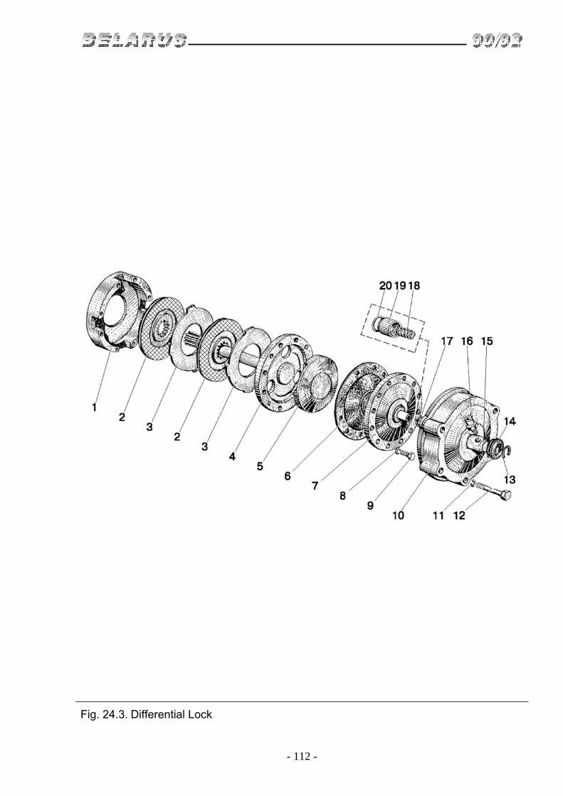
- 112 -
Fig. 24.3. Differential Lock

- 113 -
Group 24. Rear Axle Subgroup 2409. Differential Lock
Fig. No Pos.
No. Assembly unit or part
No. Q-ty Description
24.3 70-2409010-B 1 Lock clutch (1-9) 82R-2409050 1 Adapter(10, 13-20)
1 70-2409015-А 1 Clutch body
2 70-3502040-01 or 70-3502040-04
2 Brake disk
3 70-2409028 2 Release disk 4 70-2409020 1 Interlock shaft 5 70-2409018 1 Pressure disk 6 70-2409021 1 Diaphragm 7 70-2409030-B 1 Diaphragm cover 8 ShP 8 8 Washer 9 М8х40 8 Bolt 10 70-2409035-А6 1 Casing 11 ShP 12 5 Washer 12 М12х200 5 Bolt 13 S40 1 Ring 14 82R-2409036-А 1 Packing 15 70-2409026-B 1 Adapter 16 70-2409037 1 Connector 17 020-025-30-1-4 1 Ring 18 54-06-448-А 1 Spring 19 70-2409027-А 1 Bush 20 70-2409033-B 1 Ring

- 114 -
Fig. 28.1. Semi-Frame

- 115 -
Group 28. Frame Subgroup 2801. Semi-frame
Fig. No Pos.
No. Assembly unit or part
No. Q-ty Description
28.1 80-2800010 1 Semi-Frame(1, 2, 11-14, 17) 70-2801120-A1-01 1 Front beam (1, 17) 80-2806010* 1 Front tow (15, 16, 18, 19)
1 50-2801124-A2 1 Front beam 2 80-2801050 1 Right side member 3 M16x60 6 Bolt 4 ShP 16 25 Washer 5 70-2800016-01 2 Bolt 6 M16 1 Nut 7 70-2800016 2 Bolt 8 50-3913214 2 Clamp 9 M16x32 2 Bolt 10 80-3919106 2 Bracket 11 M16x32 8 Bolt 12 M16х45 4 Bolt 13 50-2800011 4 Bush 14 80-2801060 1 Right side member 15 M20* 2 Nut 16 ShP 20* 2 Washer 17 40-3001022 2 Bush 18 80-2806011* 1 Front tow 19 70-4605036* 2 Bolt 20 A61.07.001* 2 Split pin 21 50-4605079-B* 1 Center pin
* Are mounted if there is no front ballast

- 116 -
Fig. 28.2. Hydraulic Trailing Hook

- 117 -
Group 28. Frame Subgroup 2807. Hydraulic Trailing Hook
Fig. No Pos.
No. Assembly unit or part
No. Q-ty Description
28.2 70-2807010-А-01 1 Trailing hook (1-36) 80-2807040 1 Rod (31-33) 80-2807070 1 Hook (24, 25)
1 70-2807080-B 1 Handle 2 3,2x18 3 Split pin 3 70-2807079 1 Handle 4 М10х20 1 Bolt 5 ShP 10 1 Washer 6 50-1605152 1 Spring 7 70-1602120-B 1 Axle flange 8 М16х50 2 Bolt 9 ShP 16 2 Washer 10 70-2807081 1 Bracket 11 40-3104021 4 Bolt 12 70-2807044 4 Washer 13 80-2807014 1 Bracket
14 70-2807039 2 Plate 1,0 mm 70-2807039-01 1 Plate 0,5 mm 70-2807039-02 2 Plate 0,2 mm
15 70-2807051 2 Link 16 70-2807052-B 2 Screw 17 40-3405062 2 Nut 18 70-2807053-B 2 Tie rod nut 19 М20 2 Nut М20х1,5 20 4x36 2 Split pin 21 ShCh 20 2 Washer 22 ShP 18 2 Washer 23 80-2807026 2 Bolt 24 80-2807011 1 Hook 25 50-2807016 1 Hook pin 26 70-2807047 1 Axle 27 80-2807077 2 Grip 28 50-2807013-B 1 Axle 29 36-3503018 2 Washer 30 6,3x36 2 Split pin 31 70-2807043-B 1 Rod 32 М12х1,25 2 Nut 33 50-3502203 1 Fork plate 34 12x32 1 Pin 35 3,2x25 1 Splint pin 36 ShCh 16 1 Washer

- 118 -
Fig. 30.1. Front Axle and Steering Link (for the tractor BELARUS-90)

- 119 -
Group 30. Front Axle Subgroup 3000. Front Axle and Steering Link (for the tractor BELARUS-90)
Fig. No Pos.
No. Assembly unit or part
No. Q-ty Description
30.1 80-3000030-03 1 Front axle (1-7,15,18,19, 22-35) 1220-3003010 1 Steering link (8-14,16,17, 20, 21)
1 80-3001065-01 1 Right steering knuckle 2 070-080-58-2-2 2 Ring 3 70-3001101-А 2 Bush 4 80-3001070 2 Extended knuckle 5 70-3001102-А 2 Bush 6 80-3001032 4 Washer 7 80-3001031 2 Washer 8 50-3003018-B 2 Plug 9 1220-3003028 2 Lower shell 10 1220-3003027 2 Shell 11 1220-3003021 2 Ball pin 12 1220-3003023 2 Upper shall 13 1220-3003022 1 Hinge housing with right treat
1220-3003022-01 1 Hinge housing with left treat 14 1220-3003029 2 Ring
1220-3003025 2 Hood 15 70-3001040 1 Right lever 16 М20х1,5 4 Nut 17 4x36 7 Split nut 18 50-3001087 2 Nut 19 27L 2 Washer
20 1220-3003013 1 Check-nut with right treat 1220-3003013-01 1 Check-nut with left treat
21 1220-3003011 1 Pipe 22 50-3001010-А-01 1 Front axle 23 70-3001040-01 1 Left lever 24 80-3001065 1 Left steering knuckle 25 50-3000011 1 Fulcrum pin 26 16x80 1 Pin 27 F80-3001011 1 Bracket 28 M16x40 4 Bolt 29 F80-3001013 2 Plate 30 D01-015 2 Pin 31 6-20М 1x120 2 Axle 32 М18х100 4 Bolt 33 ShP 18 4 Washer 34 М18х1,5 4 Nut 35 1.3 C9hr 2 Oiler 36 2,0x270 2 Wire

- 120 -
Fig. 31.1 Front Driving Wheels. Front Wheel Hubs. (For the tractor BELARUS-90)

- 121 -
Group 31. Wheels and Hubs Subgroup 3101, 3103. Front Driving Wheels.
Front Wheel Hubs. (For the tractor BELARUS-90)
Fig. No Pos. No.
Assembly unit or part No.
Q-ty Description
31.1 70-3103010-А 2 Front wheel hub (1-6) 1 2.2-80x105-1 2 Cotter 2 А04.03.020 2 Washer 3 7609А 2 Bearing 4 А04.03.21 2 Hub 5 40-3103016 10 Bolt 6 7608А1 2 Bearing 7 А04.03.019 2 Washer 8 50-1701253-01 2 Nut 9 5x45 2 Split pin 10 А04.03.014 2 Shim 11 А04.03.013-А 2 Cover 12 ShP 8 6 Washer 13 М8х16 6 Bolt
70-3100210-02 2 Wheel 9,00-20 (wheel tire assy) (14, 15)
14 5,50F-20-3101020 or 40-3101010-АЗ
2 Wheel 5,50F-20 (disk and rim)
15
2 Tire 9,00-20 model VF-223 or 9,00R20 model Bel-311
16 70-3104019-01 2 Special nut (technical) 17 40-3103017-01 8 Nut

- 122 -
Fig. 31.2. Front Driving Wheels (for the tractor BELARUS-92)

- 123 -
Group 31. Wheels and Hubs Subgroup 3101. Front Driving Wheels (for the tractor BELARUS-92)
Fig. No Pos.
No. Assembly unit or part
No. Q-ty Description
31.2 82-3101015 2 Wheel 11,2-20 (wheel tire in assy) (1, 2)
1 W9-20-3101020-A 2 Wheel W9-20 (disk and rim, Wheel disk with 8 holes)
2 2 Tire 11,2-20 or 11,2R20
82-3101015-02 2 Wheel 11,2-20 (wheel tire in assy) (1, 2)
1 W9-20-3101020-А-01 2 Wheel W9-20 (disk and rim, Wheel disk with 5 holes)
2 2 Tire 11,2-20

- 124 -
Fig. 31.3.Rear Wheels. Rear Wheel Hubs.

- 125 -
Group 31. Wheels and Hubs Subgroup 3104, 3107. Rear wheels. Rear wheel hubs.
Fig. No Pos.
No. Assembly unit or part
No. Q-ty Description
31.3 70-3100220-А 2 Wheel 15,5R38 ( wheel tire in assy ) (4, 8) 1 70-3104025 2 Bush 2 50-3104015 2 Hub 3 40-3104021 16 Bolt 4 DW14L-38-3107020 2 Ring DW14L-38 (disk and rim) 5 М16 8 Nut 6 ShP 16 8 Washer 7 50-3107018-А 4 Load (optional) 8 2 Tire 15.5R38 9 70-3104019 2 Special nut (technical) 10 36-3104019 14 Nut 11 7-34-108 8 Bolt 12 50-3104028 8 Bolt 13 27L 8 Washer 14 50-3104029 8 Ball washer 15 50-3104016 2 Cotter

- 126 -
Fig. 31.4. Spacer (for doubling of rear wheels)

- 127 -
Group 31. Wheels and Hubs Subgroup 3109. Spacer (for doubling of rear wheels)
Fig. No Pos.
No. Assembly unit or part
No. Q-ty Description
31.4 70-3109030 2
Spacer (1-4) (for wheels 15,5R38; 9,5-42)
1 70-3109034 16 Bolt 2 70-3109035 2 Spacer (for wheels 15.5R38; 9,5-42) 3 40-3104021 16 Bolt 4 36-3104019 32 Nut

- 128 -
Fig. 34.1. Steering Drive

- 129 -
Group 34. Steering Subgroup 3401. Steering Drive
Fig. No Pos.
No. Assembly unit or part
No. Q-ty Description
34.1 50А-3401010 1
Steering column (3-19, 30-34, 36, 37, 39, 42-46, 48-51, 54)
70-3401050-B 1 Shaft (13-15) 50-3401060 1 Cardan (4-8, 34)
1 10L 2 Washer 2 М10 10 Nut 3 85-3401120-02 1 Bracket 4 50-3401061-А 2 Fork 5 V19 4 Ring 6 904700US17 4 Bearing 7 50-3401064 4 Gland 8 50-3401063 4 Casing 10 80-3401013 8 Washer 11 М10х45 5 Bolt 12 SSh-510 4 Key 13 70-3401055 1 Intermediate shaft 14 70-3401054-B 1 Tail 15 8x36 1 Pin 16 70-3401077-V 2 Shock absorber 17 70-3401076 2 Bush 18 70-3401078 1 Nut 19 70-3401079 1 Check nut 20 80-3401082 1 Cover 21 80-3401140 1 Clamp 22 М16х1,5 1 Nut 23 50-3401091 1 Washer 24 80-3402015 1 Ring 25 80-3709025 1 Bush 26 80-3709026 1 Bush 27 80-3709024 1 Cover 28 50-4608057 1 Spring 29 85-3401175 1 Shaft 30 600-3401012 1 Washer 31 70-3003032 2 Nut 32 8x28 2 Rivet 33 600-3401160 1 Quadrant 34 50-3401062 1 Spider 35 70-3709012-А 1 Handle 36 4x25 2 Split pin 37 85-3401011 2 Screw 38 80-3401001 1 Rod 39 50-1310158-V 1 Spring 40 ShCh 6 1 Washer 41 1,6x12 1 Split pin 42 V18 1 Ring 43 85-3401014 1 Stop 44 80-3401070 1 Bush 45 80-3401072 1 Shaft 46 50-3401060 1 Cardan 47 80-3401105 1 Post 48 80-3401104 1 Shock absorber 49 80-3401103 1 Clip 50 80-3401106 1 Bush

- 130 -
Fig. 34.2. Hydraulic Units and Steering Booster Fittings

- 131 -
Group 34. Steering Subgroup 3405, 3407. Hydraulic Units and Steering Booster Fittings
Fig. No Pos. No.
Assembly unit or part No.
Q-ty Description
34.2 72-3400015* 1
Steering booster (1-25, 52-3405042, 46-54 fig. 65, 1-16 fig. 66,1-38 fig. 67)
70-3400015** 1 Steering booster (1-25, 50-3405042, 46-54 fig. 65, 1-16 fig. 66, 1-38 fig. 67)
50-3405012-А1 1 Housing (1,3, 49) 50-3405020-А 1 Cover (7,8)
50-3405025-А1*** 1 Hydraulic booster cover (2, 50-3405012A/20A)
50-3405030 1 Shaft with sector segment (4-6, 50) 70-3407030 1 Oil pipe (34, 37, 38, 54) 70-3407040-А1 1 Oil pipe (6, 27, 31)
1 50-3405016-А 1 Housing 2 50-1601352 2 Pin 3 50-3405029-A 1 Bush 4 50-3405024 1 Sector 5 ShP З0L 2 Washer 6 50-3405052 1 Nut 7 50-3405031-B 1 Cover 8 40А-1119076 1 Neck 9 40-3405062 2 Nut 10 50-3405039 1 Adjusting bolt 11 50-3407050 1 Plug 12 50-4608015-А 1 Filling strainer 13 М8х25 13 Bolt 14 ShP 8 22 Washer 15 50-3407043-А 1 Gasket 16 50-3407064 2 Union 17 50-3407080 1 Oil pipe 18 50-3407010 1 Filling strainer 19 054-060-36-1-4 1 Ring 20 50-3405044 10 Gasket 0,2 mm 21 50-3405046 2 Gasket 0,5 mm 22 017-022-30-2-2 3 Ring 23 70-4302010 1 Valve 24 70-4801010 1 Skid sensor 25 70-3407130 1 Oil pipe 26 70-3407150-B 1 Oil pipe 27 N.036.83.150 1 Sleeve 28 70-3506027 1 Bush 29 70-3407163 1 Cramp 30 70-3407164 1 Bracket 31 70-3407140-B 1 Oil pipe 32 М8х35 4 Bolt 33 KG 1/8" 2 Plug 34 70-3407100 1 Oil pipe 35 NSh10-ЗL or NSh10G-ZL 1 Gear type pump 36 М8х20 1 Bolt 37 70-3407047-А 1 Hose 39 HS-26 2 Coupling clip
* For tractors BELARUS-92 ** For tractors BELARUS-90 *** Only for spare parts

- 132 -
Fig. 34.2. Hydraulic Units and Steering Booster Fittings

- 133 -
Group 34. Steering Subgroup 3405, 3407. Hydraulic Units and Steering Booster Fittings
Fig. No Pos.
No. Assembly unit or part
No. Q-ty Description
34.2 39 M16х50 4 Bolt 40 М16 2 Nut 41 ShP 16 6 Washer 42 ShCh16 4 Washer 43 50-3405041 2 Bush 44 М16х75 2 Bolt
45 50-3405042* 1 Plain arm 52-3405042** 1 Plain arm
46 50-3405053 1 Nut 47 2.2-38x58-1 1 Cotter 48 50-3405037 1 Ring 49 50-3405032 1 Bush 50 50-3405047 1 Ball 51 50-3407015 1 Oil pipe 52 N.0З6.05.003 1 Union 53 011-016-30-1-4 4 Ring 54 70-3407110 1 Oil pipe
* For the tractors BELARUS-90 **For the tractors BELARUS-92

- 134 -
Fig. 34.3. Steering Booster Cylinder

- 135 -
Group 34. Steering Subgroup 3405. Steering Booster Cylinder
Fig. No Pos.
No. Assembly unit or part
No. Q-ty Description
34.3 50-3405015 1 Cylinder (1-7, 11-15) 70-3405010 1 Cylinder with rack (50-3405015, 8-10)
1 50-3405018 1 Cover 2 085-090-30-1-4 3 Ring 3 50-3405019 1 Housing 4 50-3405049 1 Nut 5 C90-1212043-3 1 Ring 6 030-038-46-1-4 2 Ring 7 50-3405021 1 Rod 8 70-3405022 1 Rack 9 50-3405033-А 1 Pin 10 2V18 1 Ring 11 50-3405017 1 Cover 12 50-3405014 1 Piston 13 C90-1212042 2 Gasket 14 4x40 1 Split pin 15 50-3405043 4 Bolt 16 1.6-0-S 2 Wire

- 136 -
Fig. 34.4. Control Valve of Steering Booster

- 137 -
Group 34. Steering Subgroup 3406. Control Valve of Steering Booster
Fig. No Pos.
No. Assembly unit or part
No. Q-ty Description
34.4 50-3406015-А 1
Control valve of steering booster (3-7, 10-12, 27, 33, 35-38, 50-3406011-А)
50-3406011-А 1 Valve cover (8, 9, 11-21) 1 50-3406024 1 Cover 2 50-3406039 1 Nut 3 50-3406019-B 6 Slider 4 50-3406033 3 Spring 5 020-025-30-1-5 2 Ring 6 М8х50 2 Bolt 7 ShP 8 3 Washer 8 50-3406017-B 1 Cover 9 KG 1/8" 1 Plug 10 М8х25 1 Bolt 11 017-022-30-2-2 1 Ring 12 N.036.04.003 2 Union 13 R75-V-028А 1 Gasket 14 50-3406028 1 Socket 15 1 Ball 5,556 mm 16 50-3406027 1 Guide 17 50-3406026 1 Spring 18 R80-049 or 50-3406032 1 Screw 19 018-022-25-2-2 2 Ring 20 R75-058B 1 Nut 21 50-3406029 1 Cap 22 205К 2 Bearing 23 36-1702358 1 Spring collar 24 50-3405036 1 Ring 25 50-3405026 1 Bush 26 ShP10 1 Washer 27 ShP10 5 Washer 28 М10х30 1 Bolt 29 2.2-25x42-1 1 Collar 30 50-3406034 1 Endless screw 31 50-3406037 1 Washer 32 958705 2 Bearing 33 50-3406018-B 1 Valve 34 085-090-30-1-4 2 Ring 35 50-3406016-B 1 Housing 36 50-3406041 1 Washer 37 4x36 1 Split pin 38 М10х100 4 Bolt

- 138 -
Fig. 35.1. Service Brakes. Brake Control

- 139 -
Group 35. Brakes Subgroup 3502, 3503. Service Brakes. Brake Control
Fig. No Pos.
No. Assembly unit or part
No. Q-ty Description
35.1 85-3502010 2 Brake (1-12, 36, 37) 85-3502030 2 Pressure disks (4-12) 70-3503080 2 Brake rod (18, 20, 21)
1 1,6-S-200 2 Wire 2 85-3502035 2 Housing 3 85-3502040-01 4 Disk 4 85-3502036 4 Pressure disk 5 B22,225-100 10 Ball 6 77.38.163 6 Spring 7 М8 4 Nut 8 85-3502196 4 Rod 9 3,2x18 2 Split pin 10 50-3502203 2 Fork 11 12x32 2 Pin 12 50-3502198 4 Pin 13 ShP 12 4 Washer 14 2.2-25x42-1 2 Collar 15 50-3503071 3 Washer 16 5x36 2 Split pin 17 70-3503017-А 1 Lever 18 М12х1,25 2 Nut 19 SSh-611 2 Key 20 70-3503018 2 Washer 21 70-3503019 2 Bolt 22 М12х35 2 Bolt 23 50-3503015 1 Shaft 24 70-3503045 2 Extender 25 50-1605152 2 Spring 26 70-3503140 1 Left pedal 27 70-3503130 1 Right pedal 28 80-3503158-А 2 Gasket 29 М12х30 2 Bolt 30 50-3503067 1 Stop 31 70-3503050-B 1 Lever 32 70-3503060 1 Lever 33 50-3503064 2 Bush 34 36-1702358* 2 Spring collar 35 50-3502202 2 Cover
* Optional
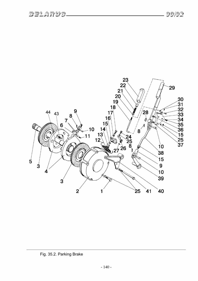
- 140 -
Fig. 35.2. Parking Brake

- 141 -
Group 35. Brakes Subgroup 3507. Parking Brake
Fig. No Pos.
No. Assembly unit or part
No. Q-ty Description
35.2 50-350210 1 Brake (2-4, 6-14, 43, 44) 50-3502030-А 1 Pressure disk (4, 6-11, 43, 44) 70-3503080 1 Brake rod (15, 17, 18) 70-3507050 1 Bracket (16, 24-27, 39-41) 70-3507020 1 Lever (19-23, 29-32) 70-3507040 1 Rod (9, 15, 38)
1 М12х180 3 Bolt 2 50-3502035 1 Housing
3 70-3502040-01 or 70-3502040-04
2 Disk
4 50-3502036-B 2 Pressure disk 5 70-3504055 1 Shaft 6 М8 2 Nut 7 50-3502196 2 Rod 8 3,2x18 3 Split pin 9 50-3502203 2 Fork 10 12x32 3 Pin 11 50-3502198 2 Pin 12 1,6-О-S 1 Wire 13 50-3502202 1 Cover 14 36-1702358* 1 Spring ring 15 М12х1,25 3 Nut 16 70-3503017-А 1 Lever 17 70-3503018 1 Washer 18 70-3503019 1 Bolt 19 70-3507022 1 Rod 20 ShCh 5 1 Washer 21 55-17-27 1 Spring 22 А13.19.002 1 Button 23 А13.19.001-А 1 Handle 24 М12х40 1 Bolt 25 ShP 12 7 Washer 26 70-3514107 1 Lever 27 SSh-611 1 Key 28 S15 1 Ring 29 70-3507030 1 Lever 30 50-1606026 1 Latch 31 2x12 1 Split pin 32 70-3507024 1 Axle 33 70-3507021 –B 1 Segment 34 ShP 10 2 Washer 35 М10 2 Nut 36 М10х35 2 Bolt 37 70-3507132-B-01 1 Axle 38 70-3507041 1 Rod 39 70-3507060-03 1 Lever 40 70-3507070 1 Bracket 41 М12х200 2 Bolt 42 77.38.163 3 Spring 43 22,225-100 3 Ball
* Optional

- 142 -
Fig. 37.1. Engine Electrical Equipment

- 143 -
Group 37. Electrical Equipment Subgroup 3700. Engine Electrical Equipment
Fig. No Pos.
No. Assembly unit or part
No. Q-ty Description
37.1
1 80-3747037 1 Bracket 2 70-4802060 1 Bracket with nut 3 80-3723037 2 Bracket 4 70-3723042-01 1 Bush 5 80-3723045 11 Collar 7 80-3829002 1 Hole fitting 9 70-1115012-03 2 Hoop 10 70-3506027 1 Bush 11 М2-14.13.238 2 Cover 12 М8x16 3 Bolt 13 V.М6х16 3 Screw 15 М6 2 Nut 17 S6 2 Washer 19 510-3724040 1 Braid 20 510-3724070 1 Braid 23 6Т 3 Washer 24 8Т 3 Washer 26 3722.40 1 Fuse block (BP-11) 27 3829.15 1 Oil level warning light (DADM-03) 28 3829.10 1 Engine oil pressure sensor (DD-6М)
29 3845.10 1 Engine Air Cleaner Clogging Sensor (DSF-65)
30 3828.10 1 Temperature gauge sensor (DUTZH-02) 31 3721.10 1 Alarm horn (20.3721-01) 32 1 Relay 73.3747 35 1 Figured nut 15.421.224 36 1 Cover 15.421.224

- 144 -
Fig. 37.2. Cab Electrical Equipment

- 145 -
Group 37. Electrical Equipment Subgroup 3700. Cab Electrical Equipment
Fig. No Pos.
No. Assembly unit or part
No. Q-ty Description
37.2
1 70-3724101-V-01 1 Harness 3 70-3710022 1 Bracket 4 70-3710024 1 Bracket 5 70-3710027 1 Spring 6 70-3710029 1 Cover 7 70-3723025-01 3 Duct 8 70-3723025-02 1 Duct 9 70-3723025-01 3 Duct 10 70-3723027 15 Clamp 11 70-3723028 1 Duct 12 70-3723029 1 Duct 13 70-3723033 11 Clamp 16 70-3724041-А1-01 1 Wire 19 36-3723024-B 2 Bush 22 80-3723045-01 1 Collar 24 VМ4х12 4 Screw 25 VМ4х16 2 Screw 26 VМ5х12 6 Screw 30 М4 2 Nut 31 М5 4 Nut 35 80-3724015-G 1 Harness 36 ShP.4 2 Washer 38 70-3724135 1 Harness 39 ShCh 4 6 Washer 40 ShCh 5 6 Washer 42 4-16 1 Cap 44 VК854-B-Т 1 Switch

- 146 -
Fig. 37.3. Storage Battery Installation

- 147 -
Group 37. Electrical Equipment Subgroup 3703. Storage Battery Installation
Fig. No Pos.
No. Assembly unit or part
No. Q-ty Description
37.3
70-3700080 1 Electrical Equipment 1 80-3724038-01 1 Wire 2 80-3724039-01 1 Wire 3 80-3724043-А 1 Wire 4 80V-3703020-01 2 Clamp 5 80V-3703020-02 2 Clamp 6 V50-3801048 2 Bush 7 70-3723042-01 1 Bush 8 3710.115 1 Battery disconnect switch VK 318B-О 9 М6х16 3 Bolt 10 ShCh 6 3 Washer 11 М8х30 4 Bolt 12 М8 12 Nut 13 ShCh 8 8 Washer 14 ShP 10 8 Washer 15 3703.16 2 Storage Battery 12/88

- 148 -
Fig. 37.4. Front Lamp Installation

- 149 -
Group 37. Electrical Equipment Subgroup 3712. Front Lamp Installation
Fig. No Pos.
No. Assembly unit or part
No. Q-ty Description
37.4
1 70-3712054 2 Bracket 2 М6х14 4 Bolt 3 V.М6х16 4 Screw 4 М6 8 Nut 5 ShCh.6 8 Washer 6 ShP.6 2 Washer 7 70-3723042-01 6 Bush 8 3703.3712 2 Front lamp

- 150 -
Fig. 37.5. Working Headlight and Back Lamp Installation
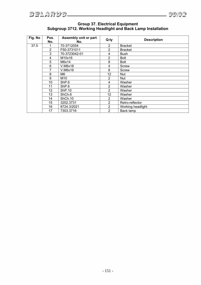
- 151 -
Group 37. Electrical Equipment Subgroup 3712. Working Headlight and Back Lamp Installation
Fig. No Pos.
No. Assembly unit or part
No. Q-ty Description
37.5
1 70-3712054 2 Bracket 2 F50-3731011 2 Bracket 3 70-3723042-01 4 Bush 4 М10х16 2 Bolt 5 М6х14 8 Bolt 6 V.М6х18 4 Screw 7 V.М6х16 8 Screw 8 М6 12 Nut 9 М10 2 Nut 10 ShP.6 4 Washer 11 ShP.6 2 Washer 12 ShP.10 2 Washer 13 ShCh.6 12 Washer 14 ShCh.10 2 Washer 15 3202.3731 2 Retro-reflector 16 8724.3/2021 2 Working headlight 17 7303.3716 2 Back lamp

- 152 -
Fig. 37.6. Socket and License Plate Lamp Installation

- 153 -
Group 37. Electrical Equipment Subgroup 3717. Socket and License Plate Lamp Installation
Fig. No Pos.
No. Assembly unit or part
No. Q-ty Description
37.6
1 70-3724110-B 1 Harness 2 70-3724120-B3 1 Harness 3 70-3724130-B3 1 Harness 4 80-3724112-01 1 Bridge 5 36-3723024-B 1 Bushing 6 50-3723025 3 Protective bushing 7 70-3723025 1 Chute 8 70-3723027 1 Cramp 9 70-3723034 1 Panel cover 10 70-3723035 1 Terminal 11 80-3723043 2 Cramp 12 V50-3801048 2 Bushing 13 М12х25 1 Bolt 14 V.М5х12 1 Screw 15 V.М6х20 4 Screw 16 V.М5х35 3 Screw 17 М6 4 Nut 18 М5 4 Nut 19 М6 2 Nut 20 70-3724028-B 1 Wire 21 FP 131 1 License plate lamp 22 ShCh.5 4 Washer 23 ShCh.6 6 Washer 24 ShCh.12 1 Washer 25 P14.3723 2 Panel 26 P15.3723 1 Panel 27 R9-1 1 Socket 28 112.00.05-01 1 License plate lamp

- 154 -
Fig. 38.1. Dashboard
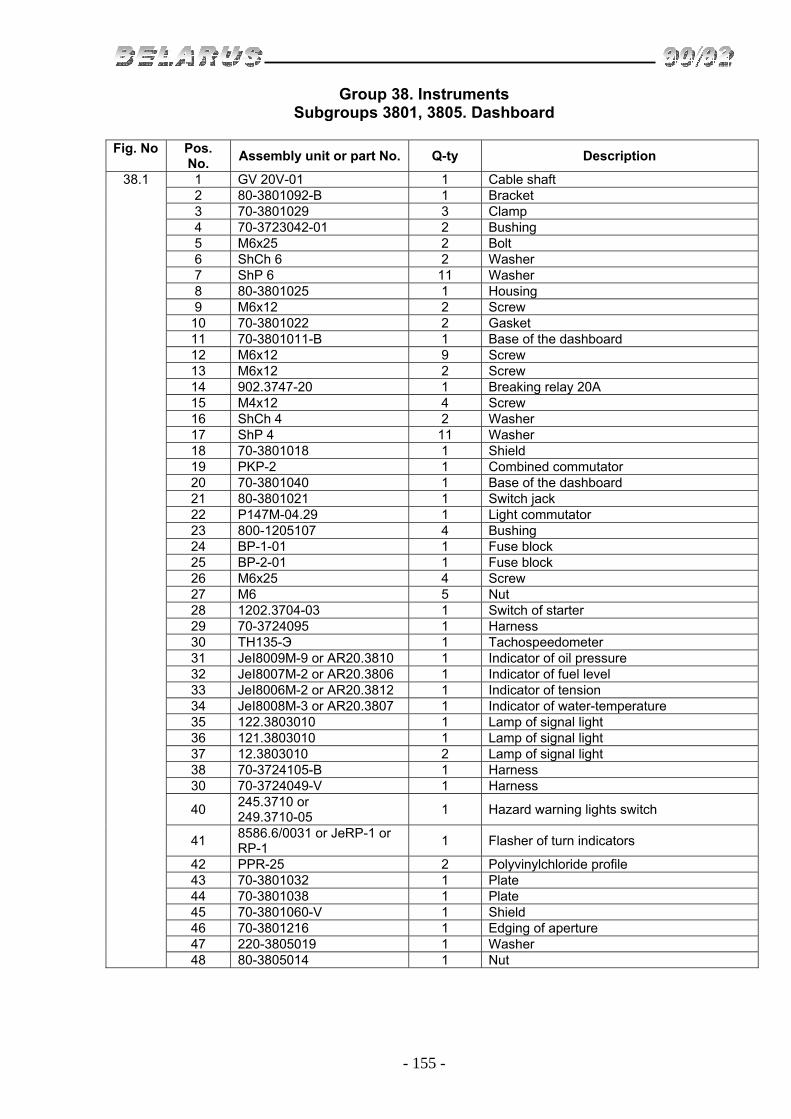
- 155 -
Group 38. Instruments Subgroups 3801, 3805. Dashboard
Fig. No Pos.
No. Assembly unit or part No. Q-ty Description
38.1
1 GV 20V-01 1 Cable shaft 2 80-3801092-B 1 Bracket 3 70-3801029 3 Clamp 4 70-3723042-01 2 Bushing 5 М6х25 2 Bolt 6 ShCh 6 2 Washer 7 ShP 6 11 Washer 8 80-3801025 1 Housing 9 М6х12 2 Screw 10 70-3801022 2 Gasket 11 70-3801011-B 1 Base of the dashboard 12 М6х12 9 Screw 13 М6х12 2 Screw 14 902.3747-20 1 Breaking relay 20А 15 М4х12 4 Screw 16 ShCh 4 2 Washer 17 ShP 4 11 Washer 18 70-3801018 1 Shield 19 PKP-2 1 Combined commutator 20 70-3801040 1 Base of the dashboard 21 80-3801021 1 Switch jack 22 P147М-04.29 1 Light commutator 23 800-1205107 4 Bushing 24 BP-1-01 1 Fuse block 25 BP-2-01 1 Fuse block 26 М6х25 4 Screw 27 M6 5 Nut 28 1202.3704-03 1 Switch of starter 29 70-3724095 1 Harness 30 TH135-Э 1 Tachospeedometer 31 JeI8009М-9 or AR20.3810 1 Indicator of oil pressure 32 JeI8007М-2 or AR20.3806 1 Indicator of fuel level 33 JeI8006М-2 or AR20.3812 1 Indicator of tension 34 JeI8008М-3 or AR20.3807 1 Indicator of water-temperature 35 122.3803010 1 Lamp of signal light 36 121.3803010 1 Lamp of signal light 37 12.3803010 2 Lamp of signal light 38 70-3724105-B 1 Harness 30 70-3724049-V 1 Harness
40 245.3710 or 249.3710-05
1 Hazard warning lights switch
41 8586.6/0031 or JeRP-1 or RP-1
1 Flasher of turn indicators
42 PPR-25 2 Polyvinylchloride profile 43 70-3801032 1 Plate 44 70-3801038 1 Plate 45 70-3801060-V 1 Shield 46 70-3801216 1 Edging of aperture 47 220-3805019 1 Washer 48 80-3805014 1 Nut

- 156 -
Fig. 39.1. Operator’s Tools

- 157 -
Group 39. Tools and accessories Subgroup 3901. Operator’s Tools
Fig. No Pos.
No. Assembly unit or part
No. Q-ty Description
39.1 1
Spare parts, tools and accessories of diesel engine D-243
1 70-3901038 1 Wrench 41x46 (optional) 2 1 Socket wrench S=32 3 1 Socket wrench S=27 4 1 Socket wrench S=12

- 158 -
Fig. 39.2. First Aid Kit

- 159 -
Group 39. Tools and accessories Subgroup 3912. First Aid Kit
Fig. No Pos.
No. Assembly unit or part
No. Q-ty Description
39.2 1 70-3912153-А 1 Bracket 2 70-3912152 1 Body 3 70-3912151 1 Cover 4 ShCh 6 3 Washer 5 70-3723033 3 Cramp

- 160 -
Fig. 39.3. Tool box

- 161 -
Group 39. Tools and accessories Subgroup 3919. Tool box
Fig. No Pos.
No. Assembly unit or part
No. Q-ty Description
39.3 1 50-8400018 4 Bumper 2 70-3919110 1 Box 3 М8х16 2 Bolt 4 80-3919106 2 Bracket 5 ShCh 8 2 Washer 6 ShP 8 2 Washer 7 М8 2 Nut

- 162 -
Fig. 42.1. Rear Power Takeoff Shaft (PTO Shaft)

- 163 -
Group 42. PTO Subgroup 4202. Rear Power Takeoff Shaft
Fig. No Pos.
No. Assembly unit or part
No. Q-ty Description
42.1 85-4202010 1 Rear power takeoff shaft 85-4202020 1 Cover (1-16, 20, 21, 25-31, 34-37, 46-56) 70-4202030-А 1 Crown gear (36, 38-45) 1 209А 2 Bearing 2 50-4202078 2 Pin 3 50-4202074 1 Lever 4 50-4202058 1 Bracket 5 85-4202074 1 Lever 6 ShCK 8х36 2 Pin 7 80-4202076 1 Shaft 8 54.38.619 1 Ring 9 70-4202072B 1 Axle 10 А.8x20.65G 1 Pin 11 014-018-25-2-2 1 Ring 12 80-4202082 1 Bush 13 S18 1 Ring 14 85-4202079 1 Plate 15 ShP 10 12 Washer 16 М10х40 1 Bolt 17 F70-4202095 1 Housing 18 F70-4202092 1 Cover
19
М8х16 4 Bolt М8 4 Nut ShP 8 4 Washer ShCh 8 4 Washer
20 80-4202081-А 1 Plate
21 80-4202019B 1 Tail (8 splines) 80-4202019B-01 1 Tail (6 splines) (optional) 80-4202019B-02 1 Tail (21 splines) (optional)
22 50-4202065-А 1 Cap 23 М8х16 2 Bolt 24 ShP 8 2 Washer 25 М10х18 6 Bolt 26 80-4202042-B 1 Cover 27 50-4202092А 1 Gasket 28 80-4202017-B 1 Shaft 29 2.2-80x105-1 1 Collar 30 60310А 1 Bearing 31 2S110 2 Ring 32 М12x1,25 1 Nut 33 50-4202068 1 Check screw
34 85-4202100 1 Band with lining 85-4202056 (TIIR 430)
35 85-4202100-01 or 85-4020100-02
1
Band with lining 85-4202057 (TIIR 430) or band with lining 85-4202057-А7 (ITB 2842)
36 2S50 2 Ring 37 2S85 1 Ring 38 7,938-100 1 Ball 39 50-4202046-B 1 Shift collar 40 А61.03.002 1 Ring

- 164 -
Fig. 42.1. Rear Power Takeoff Shaft

- 165 -
Group 42. PTO Subgroup 4202. Rear Power Takeoff Shaft
Fig. No Pos.
No. Assembly unit or part
No. Q-ty Description
42.1 41 80-4202044-B 1 PTO 42 2S90 1 Ring 43 210AUSh1 1 Bearing 44 50-4702066-А 1 Cup 45 70-4202043 1 Crown gear 46 70-4202083-А 1 Nut 47 208А 1 Bearing 48 КК20х26х34Е 3 Bearing 49 70-4202024 3 Satellite 40 85-4202065 1 Carrier 51 70-4202431 3 Pin 52 70-4202026 3 Spider pin 53 70-4202032 1 Center gear 54 85-4202033 1 Drum 55 2S68 1 Ring 56 70-4202077 1 Bush 57 М10x35 5 Bolt 58 М 16x1,5 4 Nut 59 ShP 16 4 Washer 60 ShCh 16 2 Washer

- 166 -
Fig. 42.2. Power Pulley

- 167 -
Group 42. PTO Subgroup 4211. Power Pulley
Fig. No Pos.
No. Assembly unit or part
No. Q-ty Description
42.2 40-4211010-01 1
Power pulley mounted on the tail of power shaft of 8 splines (1-34)
40-4211035 1 Body (12-22, 30-34) 40-4211040 1 Driving shaft 8 splines (3-6, 8, 10, 11) 40-4211050 1 Hose 8 splines (1-6, 8, 10, 11) 40-4211065 1 Shaft (16-13, 22) 1 40-4211052 1 Hose 2 KFA-50x70 1 Collar 3 40-4211043 1 Nut 4 36-1701061 1 Washer 5 211 AUSh1 1 Bearing 6 40-4211047 1 Bush 7 40-4211079 1 Gasket 8 311А 1 Bearing 9 40-4211081 1 Gasket 10 40-4211045 1 Shaft with the jack of 8 splines 11 40-4211082 1 Plug 12 PK KG 3/8" 1 Plug 13 PK KG 3/4" 2 Plug 14 40-4211037 1 Body 15 SU-1/8"-A 1 Breather 16 40-4211071 1 Shaft-gear 17 408 2 Bearing 18 40-4211072 1 Spacer 19 120-125-30-1-4 1 Ring 20 36-4211054B 6 Gasket (0,5 mm) 21 36-4211055 8 Gasket (0,2 mm) 22 36-4211048 1 Sleeve 23 4x36 1 Cotter pin 24 М20х1,5 1 Nut 25 40-3502084 1 Washer 26 40-3502083 1 Gasket 27 40-4211075 1 Ready-fitted pulley 28 М12х40 6 Bolt 29 2.2-65x90-1 1 Collar 30 ShP 12 10 Washer 31 36-4211073 1 Jack 32 36-4211057 1 Gasket

- 168 -
Fig. 42.3. PTO shaft control

- 169 -
Group 42. PTO Subgroup 4216. PTO shaft control
Fig. No Pos.
No. Assembly unit or part
No. Q-ty Description
42.3 70-4216010-B 1 Installation of PTO shaft control 70-4216040 1 Spring (4-6) 70-4216060-B 1 Trip rod (17, 18, 23) 70-4216065 1 Lever (17, 18, 25) 50-4216070-B 1 Shaft of control (20, 21) 1 70-4216048-B 1 Bolt 2 ShCh 16 1 Washer 3 4х36 2 Cotter pin 4 70-4216013 1 Ear 5 70-4216011 2 Spring 6 70-4216015 1 Cover 7 М10х60 1 Bolt 8 М16 1 Nut 9 70-4216023-А 1 Bolt 10 М12х35 1 Bolt 11 ShP 12 1 Washer 12 50-4216022-А 1 Lever 13 50-4216024 1 Bush 14 NSh10-0101037 1 Ring 15 50-3502203 3 Fork 16 3,2х18.016 3 Cotter pin 17 12х32 3 Pin 18 М12х1,25 3 Nut 19 50-4216028-B 2 Screw 20 50-4216034 2 Axle of screw 21 50-4216018 1 Shaft 22 6х11 1 Key 23 70-4216043-B 1 Rod 24 50-3406037 1 Washer 25 70-4216050-B 1 Lever 26 70-4216081-B 1 Rod 27 12-12sb-108 1 Handle 28 70-4216069 1 Shaft

- 170 -
Fig. 42.4. Front Ballast Weight

- 171 -
Group 42. PTO Subgroup 4235. Front Ballast Weight
Fig. No Pos.
No. Assembly unit or part
No. Q-ty Description
42.4 1 70-4235011 10 Weight 2 ShCh 16 1 Washer 3 ShP 16 3 Washer 4 М16 1 Nut 5 70-4235020 1 Bracket 6 М16х32 2 Bolt 7 М20 2 Nut 8 ShP 20 2 Washer 9 70-4605036 2 Bolt 10 80-4235015 1 String

- 172 -
Fig. 46.1. Rear Mounting Mechanism

- 173 -
Group 46. Hydraulic Lift Linkage Subgroup 4605. Rear Mounting Mechanism
Fig. No Pos.
No. Assembly unit or part
No. Q-ty Description
46.1 90-4605010 1 Rear mounting mechanism (1-81) 50-4605012 2 Drop link (1, 32, 63, 67) 80-4605150-02 1 Drop link (23-31, 38-47, 75-81) L=475 mm А61.05.100-01 1 Cotter (35, 37) А61.03.000-01 1 Upper rod (36-41, 87-89) А61.03.200-01 1 Screw (33-37, pin А61.03.001-01 Ø25) 80-4605025 1 Crossbeam (50-56) F50-4605030 1 Right rod (48, 50-52, 58-60, 68) F50-4605035 1 Left rod (50-52, 57-61) 50-4605105-А 1 Pivot of the trailer (50, 54) 1 А61.02.100 1 Screw 2 4x36 1 Cotter pin 3 70-3003032 2 Nut М18x1,5-61-1.6.019 4 50-4605076 2 Pin 5 50-4605027 2 Pin 6 54.38.619 2 Ring 7 М12х25 6 Bolt 8 ShP 12 7 Washer 9 40-4605023-А2 2 Washer 10 80-4605021 1 Lever 11 70-4605032 2 Bush 12 80-4605016-01 1 Bracket 13 70-4605024-А 1 Rotary lever 14 2V65 1 Ring 15 50-4605069 1 Bush 16 А61.07.002 1 Spring 17 М12х35 1 Bolt 18 ShCh 12 1 Washer 19 70-4605240-А 1 Bracket 20 М12 1 Nut 21 70-4605023 1 Rotary shaft 22 80-4605022 1 Lever 23 70-4605168 1 Link 24 А61.01.016-B 1 Axle 25 А61.01.400 1 Fork 26 А61.01.600 1 Shaft 27 А61.01.014 1 Handle 28 А61.01.017 2 Bush 29 016-021-30-2-4 1 Ring 30 8x45 1 Pin 31 А61.01.004 1 Pin 32 А61.02.003 1 Locknut 33 А61.03.002 2 Ring 34 А61.03.001-01 1 Pin Ø 25 35 А61.08.001 -01 1 Chain (9 links) 36 А61.02.100-05 1 Screw (hinge hole Ø 25,7) 37 А61.05.000 1 Cotter with the ring 38 А61.01.001 1 Gear 39 А61.01.005 1 Axle 40 А61.01.003 1 Gasket 41 1.3 C9hr 3 Oilier 42 А61.01.104 1 Body 43 А61.01.013 1 Bush 44 А61.01.008 1 Pipe

- 174 -
Fig. 46.1. Rear Mounting Mechanism

- 175 -
Group 46. Hydraulic Lift Linkage Subgroup 4605. Rear Mounting Mechanism
Fig. No Pos.
No. Assembly unit or part
No. Q-ty Description
46.1 45 А61.01.011 1 Cap 46 А61.01.009 1 Limiter 47 70-4605100 1 Fork 48 N50-4605040-А2 1 Rod 49 F50-4605084 2 Pin 50 А61.07.001 4 Spring cotter pin 51 А61.05.005 6 Cotter 52 А61.05.004 6 Ring 53 А61.10.002 2 Pin 54 50-4605079-B 1 Pin 55 А61.11.001 1 Fork 56 80-4605046 1 Crossbeam 57 N50-4605045-А2 1 Rod 58 70-4605048-А 2 Ear 59 50-4605049-B 2 Pin 60 5x36 2 Cotter pin 61 F70-4605055 1 Rod 62 ShCh 18 2 Washer 63 50-4605100-B 1 Fork 64 F50-4605047-А2 2 Bush 65 50-4605068-B1 2 Washer 66 F50-4605026 1 Axle 67 А61.02.001 1 Turnbuckle 68 F70-4605050 1 Rod 69 А61.03.102 1 Handle 70 А61.03.101 1 Pipe 71 А61.02.100-03 1 Screw (left thread) 72 А61.10.001 1 Pin 73 70-4605036 5 Bolt 74 ShP 20 5 Washer 75 А61.01.006 2 Bolt 76 М14х40 2 Bolt 77 ShP 14 4 Washer 78 А61.01.204 1 Cover 79 А61.01.012 1 Limiter 80 А61.01.300 1 Pipe 81 8109 1 Bearing

- 176 -
Fig. 46.2. External Interlock of Lift Links

- 177 -
Group 46. Hydraulic Lift Linkage Subgroup 4605. External Interlock of Lift Links
Fig. No Pos.
No. Assembly unit or part
No. Q-ty Description
46.2 А61.04.000 2 Turnbuckle (17-20) 1 40-4605098 2 Ring 2 F50-4605026 1 Axle 3 F50-4605097 2 Bush 4 F50-4605020 2 Bracket
5
F50-4605091 or 80-4605091
1 Left bracket
F50-4605092 or 80-4605092-01
1 Right bracket
6 50-4609082 8 Stud 7 M16x1,5 16 Nut 8 М16x40 8 Bolt 9 ShP 16 16 Washer 10 А61 07 001 2 Cotter pin 11 F50-4605084 2 Pin 12 ShCh 18 4 Washer 13 70-4605047 2 Bush 14 3,2х18 8 Studs 15 М12 8 Nut 16 50-4605086 8 Bolt 17 А61.04.002 2 Screw 18 М18 2 Nut 19 А61.04.003 2 Turnbuckle 20 А61.04.002-01 2 Screw 21 А61.09.002 8 Link

- 178 -
Fig. 46.3. Hydraulic Unit Control

- 179 -
Group 46. Hydraulic Lift Linkage Subgroup 4607. Hydraulic Unit Control
Fig. No Pos.
No. Assembly unit or part
No. Q-ty Description
46.3 70-4607040 1 Bracket (1-5, 8, 11, 13, 23-27) 1 70-4607220-B 1 Shaft 1 70-4607250 1 Shaft 3 5 0-4 60 70 78-А 4 Bush 4 70-4607240 1 Shaft 5 50-460779-А-1 2 Bush 6 М10х30 1 Bolt 7 ShP 10 1 Washer 8 70-4607017-B 1 Bracket 9 ShP 12 2 Washer 10 М12х35 2 Bolt 11 2S32 2 Ring 12 А61.01.014 4 Handle 13 70-4607076 1 Lever 14 2S18 1 Ring 15 70-4607087 4 Rod 16 А61-030-А1 8 Pin 17 А20-213-А 2 Fork 18 50-4607087 1 Rod 19 M8 2 Nut 20 50-4607086-А 3 Lever 21 3,2x18-001 8 Cotter pin 22 70-4607144 8 Washer 23 70-4607074 1 Lever 24 8х30 2 Pin 25 70-4607077 1 Lever

- 180 -
Fig. 46.4. Fittings of Hydraulic Unit Housing

- 181 -
Group 46. Hydraulic Lift Linkage Subgroup 4607. Fittings of Hydraulic Unit Housing
Fig. No Pos.
No. Assembly unit or part
No. Q-ty Description
46.4 1 70-4607130 1 Pipeline 2 70-4607120 1 Pipeline 3 70-4607410 1 Pipe 4 R50-4607075-А 1 Pipe 11 R80-3/4-222-3Gг 1 Hydraulic distributor 12 70H-4607010 1 Pipeline 5 40-4607032 3 Bolt 6 40-4607038-А 10 Washer 7 40-4607037 1 Bolt 8 40-4607033-А 2 Washer 9 50-4607031 2 Bolt 10 70-1310410-B 1 Control box 13 50-4607063-B2-01 1 Force hose 14 HS 31 2 Clamp 15 70-4607040-B 1 Bracket 16 50-4607110 1 Pipe 17 50-4607115 1 Pipe 18 М8х30 4 Bolt 19 ShP8 Washer 20 М8х20 4 Bolt 21 М8х25 12 Bolt 22 035-40-30-2-2 1 Ring
23 NSh32UKF-3 or NSh32D-3
1 Gear pump
24 50-4607097 4 Gasket 25 50-4607096-А 1 Connection 26 3057-4616330-А 4 Valve of the lock unit Ø12 27 017-022-30-2-2 5 Ring 28 50-4607039-А 4 Cap 29 40-3405061-А 1 Union 30 40-3405062 1 Nut
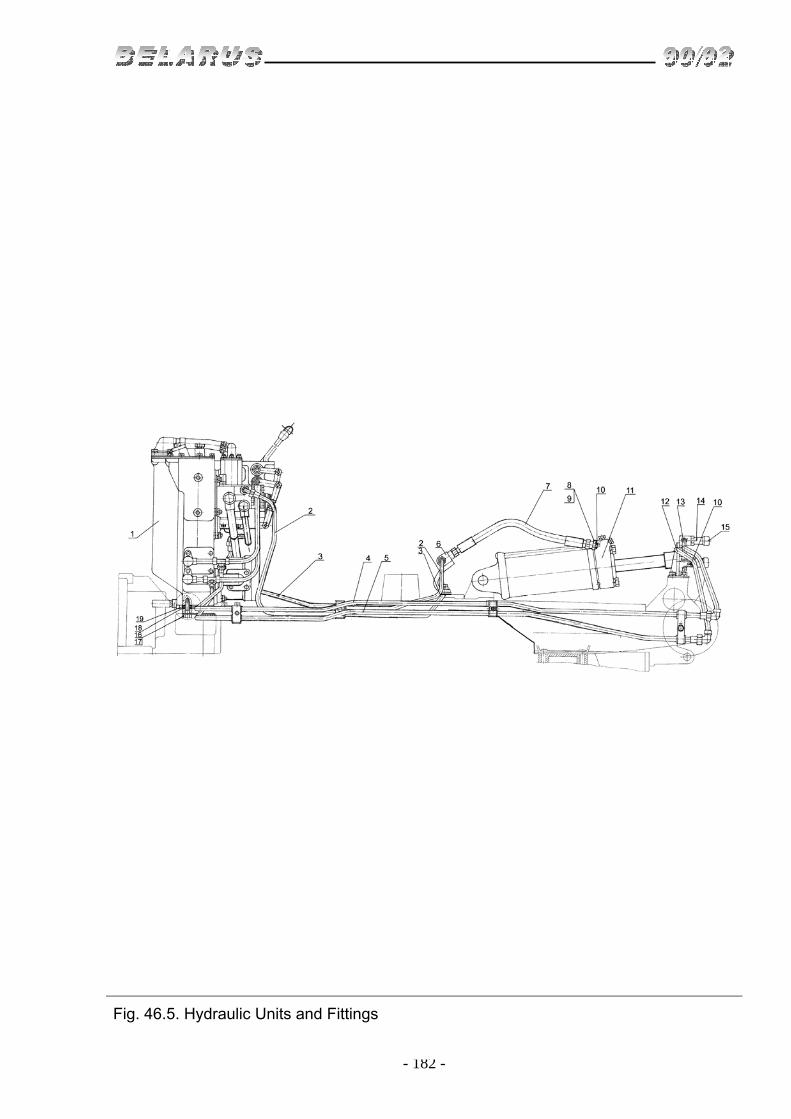
- 182 -
Fig. 46.5. Hydraulic Units and Fittings

- 183 -
Group 46. Hydraulic Lift Linkage Subgroup 4607. Hydraulic Units and Fittings
Fig. No Pos.
No. Assembly unit or part
No. Q-ty Description
46.5 1 R70-4600015 1 Body of hydraulic system 2 70-4607370 1 Pipe 3 70-4607380 1 Pipe 4 70-4607335 1 Pipe 5 70-4607340 1 Pipe 6 80-4605050 1 Bracket 7 N 036.83.140 2 High-pressure hose Ø12 8 70-1405089 1 Union 9 N 036.65.000А2-06 1 Slowing-down valve 10 017-022-30-2-2 4 Ring 11 C100х200-3 1 Hydraulic cylinder 12 70-4607400-B 1 Pipe 13 70-4607395-B 1 Pipe 14 3057-4616330-А 2 Valve of the lock unit Ø12 left 15 50-4607039-А 2 Valve 16 М14х1,5-6gх45 4 Bolt 17 70-4607168 2 Plate 18 50-4607049 2 Gasket 19 70-4608072 1 Plate

- 184 -
Fig. 46.6. Housing of Hydraulic Units, Filter and Hydraulic Pump Drive

- 185 -
Group 46. Hydraulic Lift Linkage Subgroup 4608. Housing of Hydraulic Units, Filter and Hydraulic Pump Drive
Fig. No Pos. No.
Assembly unit or part No.
Q-ty Description
46.6 50-4608010-B1 1 Body (1-17, 22-33) 80-4608011 1 Cover (3, 8-10) 80-4608012 1 Filter (24-33) 36-1022070 1 Handle (58-62) 1 80-4608016 1 Body of hydraulic system 1 80-4608031 1 Gasket 3 80-4608025 1 Cover 4 252135-P2 20 Washer ВТ 65G IG 5 ShP 8 14 Bolt M8х20х 6 011-015-25-2-2 2 Ring 7 70-4608065-A 1 Oil meter 8 5 0-46 08059 1 Plug of the breather 9 50-4608063 1 Filter 10 50-4608062 1 Washer 11 PK KG-1 1/4 " 1 Plug 12 F-61S06-А2 1 Filter 13 50-3723022 1 Cramp 14 10х20 6 Stud 15 М10х40 2 Bolt 16 70-4608019 2 Cover 17 70-46008033 2 Gasket 18 70-4608072 1 Plate 19 50-4608049 2 Gasket 20 70-4607168 2 Plate 21 М14х15 4 Bolt 22 50-468027-V 1 Plug 23 40-4607068 1 Ring 24 40-4608036 1 Body of the filter 25 80-4608024 2 Ring 26 80-4608074 1 Bush 27 54.57.020-A 12 Filter cartridge 28 80-4608013 1 Deflector 29 1,0-0-S 1 Wire L=90 30 80-4608014-B1 ] Pipe of the filter 31 54.06.413 1 Spring 32 1 Ball V 15,081 mm 33 80-4608036 1 Valve body 34 50-4608057 1 Spring 35 50-4608032-B 1 Gasket 36 50-4608039 1 Ring 37 50-4608018-B 1 Cover 38 М8хЗ0 4 Bolt 39 M8х25 2 Bolt 40 36-1022054-A I Gasket 41 50-4604036 1 Sleeve 42 50-4604048 I Ring 43 К-2V90 1 Ring 44 210 1 Bearing 45 NK-2V50 1 Ring 46 70-4604034 1 Shaft 47 50-4604032-A 1 Gear 48 208 1 Bearing 49 50-4604030 1 Fork 50 50-4604046 1 Bolt of the fork 51 1-0-S 1 Wire L=150 mm

- 186 -
Fig. 46.6. Housing of Hydraulic Units, Filter and Hydraulic Pump Drive

- 187 -
Group 46. Hydraulic Lift Linkage Subgroup 4608. Housing of Hydraulic Units, Filter and Hydraulic Pump Drive
Fig. No Pos.
No. Assembly unit or part
No. Q-ty Description
46.6 52 50-4604042 1 Shaft 54 50-4604047 1 Ring 55 50-4604044 1 Plate 56 ShP 8 2 Washer 57 M8x16 2 Bolt 58 36-1022073 1 Lock 59 36-1022074 1 Spring 60 4S3х16 1 Pin 61 36-1022071 1 Handle 62 36-1022072 1 Sleeve

- 188 -
Fig. 46.7. Hydraulic Cylinder C 100x200

- 189 -
Group 46. Hydraulic Lift Linkage Subgroup C 100. Hydraulic Cylinder C 100x200
Fig. No Pos.
No. Assembly unit or part
No. Q-ty Description
46.7 1 70-4605041 2 Bush 2 ShCh 20 2 Washer 3 70-4605036-01 2 Bolt 4 70-4605017-А 1 Bracket 5 70-4605034 2 Plate 6 70-4605036 2 Bolt 7 C100x200-3 1 Hydraulic cylinder 8 5x36 1 Cotter pin 9 70-4619042 1 Washer 10 C90-1212037М 1 Pin 11 50-34 06022А 1 Ring

- 190 -
Fig. 46.8. Distributor R80-3/1-222-ЗGg

- 191 -
Group 46. Hydraulic Lift Linkage Subgroup R80-3/1-222-ЗGg. Distributor R80-3/1-222-ЗGg
Fig. No Pos.
No. Assembly unit or part
No. Q-ty Description
46.8 R80-3/1-222-ЗGg 1 Hydrodistributor (1-74) 1 R80-23.30.421 1 Body 2 R75-V-028-А 7 Gasket 3 R80-23.20.063 1 Jack 4 MKPV-16/ZF-101 1 Needle 5 MKPV-16/ZF-104 1 Spring 6 R80-049 B 1 Adjusting screw 7 017-022-30-2-2 3 Ring 8 R75-058-B 1 Nut 9 R75-051-V 1 Cap 10 ShP 8 25 Washer 11 М8х110 3 Bolt 12 М8х100 6 Bolt
13 R80-23.20.123 or R80-23.20.123-B
1 Lower cover
14 R40/75-0708039-B 1 Gasket 15 KG 1/4" 1 Plug 16 50-4608027-V 1 Plug 17 14,288 3 Ball 18 R80-23.20.007 3 Guide 19 R80-23.20.002 3 Spring 20 R80-23.20.003 3 Washer 21 024-028-25-2-2 3 Ring 22 R80-23.20.004 2 Adapter 23 R75-090А 6 Plug (technological) 24 R75-3-038 1 Gasket 25 R75-3-057 1 Plate of the rings 26 M8x20 8 Bolt 27 R75-3-055-B 1 Plate of the duster 28 R75-056М 3 Duster 29 R80-23.20.353-G1 1 Plate 30 028-033-30-2-2 3 Ring 31 М12x1,25 3 Nut 32 ShP 12 3 Washer 33 R75-054-B 3 Lever 34 3x6,5 3 Key 35 R80-23.20.065 3 Ring 36 R80-23.20.064 3 Ring 37 2x6 2 Rivet 38 M8x55 8 Bolt 39 M10x25 2 Bolt 40 ShP 10 2 Washer 41 R80-23,20.071B 1 Stop
42 R80-23.20.022 or R80-23.20.022-А
1 Upper cover
43 032-037-30-2-2 1 Ring 44 R80-23.30.073 1 Guide

- 192 -
Fig. 46.8. Distributor R80-3/1-222-ЗGg

- 193 -
Group 46. Hydraulic Lift Linkage Subgroup R80-3/1-222-ЗGg. Distributor R80-3/1-222-ЗGg
Fig. No Pos.
No. Assembly unit or part
No. Q-ty Description
46.8 45 025-030-30-2-3 Ring 46 R75-072 1 Spring 50 R80-23.20.041 1 Overload relief valve 52 R80-23.20.043 1 Valve jack 53 85-4608021-B 1 Plug 54 025-029-25-2-2 1 Ring 55 М10 3 Nut 56 50-4607032-B 1 Bracket 57 M10x20 4 Bolt 58 R40/75-0808076 1 Seal 59 1,0x100 1 Wire 60 R80-23.20.137 3 Plug 61 R75-033 3 Lower sleeve 62 R80-23.20.035 3 Spring 63 R75-034 3 Upper sleeve 64 R80-23.20.031 3 Cartridge 65 R75-V-032 3 Spring 66 R75-V-029 3 Bush 67 6,35-100 9 Ball 68 R80-23.20-025 3 Booster 69 R80.23.20.046-B 3 Bush sleeve 70 R80-23.20.045 3 Plunger 71 R80-23.20.036 3 Spring 72 R80-23.20.027 3 Jack 73 R80-23.20.224 3 Valve

- 194 -
Fig. 46.9. Locking Device

- 195 -
Group 46. Hydraulic Lift Linkage Subgroup Н.036. Locking Device
Fig. No Pos.
No. Assembly unit or part
No. Q-ty Description
46.9 3057-4616320 2 Locking device (1-10)
3057-4616330-А 6 Valve of the locking device diameter 12 left (1-7)
3057-4616350-А 6 Valve of the locking device diameter 12 right (1-6, 8-10)
1057-4616340-А 2 Ready-fitted crossbar (3, 4) 1 1057-4616338-B 2 Union 2 017-021-25-2-2 2 Ring 3 1057-4616344-А 2 Lower crossbar 4 1057-4616342-А 2 Upper crossbar 5 А16-2530034-1 2 Spring 6 14,288-60 2 Ball 7 1057-4616332-B 1 Body of the locking device Ø12 left 8 1057-4616364-B 1 Captive nut 9 1057-4616352-А 1 Body of the locking device Ø12 right 10 022-027-30-2-3 1 Ring

- 196 -
Fig. 46.10. Retention Mechanism

- 197 -
Group 46. Hydraulic Lift Linkage Subgroup 4619. Retention Mechanism
Fig. No Pos.
No. Assembly unit or part
No. Q-ty Description
46.10 80-4605110 1 Retention mechanism (1-31) 1 M12x30 5 Bolt 2 70-4619016 2 Locking plate 3 85-4619017-01 2 Pin 4 80-4619012-B-01 1 Rod 5 3,2x18 5 Cotter pin 6 12x48 1 Pin 7 70-4619033 1 Bracket 8 50-4605069-01 1 Bush 9 12x32 1 Pin 10 70-4619029-B 1 Lever 11 80-4619019 1 Pin 12 80-4619134 1 Rod 13 85-4619035 1 Lever 14 ShCh 8 1 Washer 15 85-4619036 1 Handle 16 70-3401093 1 Tip of the lever 17 M6x14 1 Bolt 18 ShP 6 1 Washer 19 ShCh 6 1 Washer 20 50-4607082-А 1 Bush 21 А61.07.001 1 Cotter pin 22 70-4619042 2 Washer 23 85-4619014 2 Washer S=15 mm 24 80-4619128 1 Lever 25 50-1310158-B 1 Spring 26 80-4619105 1 Rod 27 80-4619011 1 Catch 28 5x36 1 Cotter 29 80-4619020 1 Plate 30 ShP 8 2 Washer 31 M8x16 2 Bolt

- 198 -
Fig. 48.1. Differential-lock Sensor. Fittings of Locking Sensor.

- 199 -
Group 48. Rear Axle Differential Lock Control and Fittings Subgroup 4801, 4802. Differential-lock Sensor. Fittings of Locking Sensor.
Fig. No Pos.
No. Assembly unit or part
No. Q-ty Description
48.1 70-4801010 1 Locking sensor (7, 9-19, 26, 28-31)
70-4802005 1 Fittings of locking sensor (1-8, 23-25, 27, 32-47)
70-4802010 1 Flow regulation valve (11, 20-22) 1 ShP 8 1 Washer 2 М8х25 1 Bolt 3 ShCh 8 1 Washer 4 70-4802046 2 Clamp 5 PR-32 5 Gland 6 70-4802030-B 1 Oil pipe 7 D18-051 1 Swinging angle joint bolt 8 D18-055-А 2 Ring 9 006-010-25-24 1 Ring 10 70-4801015 1 Feeler 11 70-4801045 2 Spring 12 70-4801011 1 Spool valve 13 70-4801020 1 Tappet 14 025-030-30-14 1 Ring 15 008-012-25-14 3 Ring 16 70-4801023 1 Housing 17 5,556-40 1 Ball 18 70-4801019 1 Bushing 19 70-4801016 1 Stop 20 70-3407147 1 Washer 21 70-4802013 1 Valve 22 70-4802011 1 Housing 23 36-1104788 4 Gasket 24 70-4802020 1 Oil pipe 25 36-1104787 2 Pipe union bolt 26 70-4801050 1 Cover 27 ShP 16 4 Washer 28 М12х50 2 Bolt 29 ShP 6 1 Washer 30 VM6х16 1 Screw 31 70-4801030-B 1 Cock 32 М12х40 2 Bolt 33 М10х18 1 Bolt 34 ShP 10 2 Washer 35 70-4802060 1 Bracket 36 ShCh 12 1 Washer 37 М10х25 1 Bolt 38 70-4802048 1 Clamp 39 70-4802050-B 1 Oil pipe 40 70-4802043 1 Clamp 41 70-4802062 1 Hose 42 6,3x36 2 Cotter pin 43 70-4802040 1 Oil pipe 44 287582-P8 2 Band 45 297580-P8 2 Buckle 46 70-4802045 1 Clamp 47 ShCh 16 1 Washer

- 200 -
Fig. 48.2. Differential Lock Control

- 201 -
Group 48. Rear Axel Differential Lock Control and Fittings Subgroup 4803. Differential Lock Control
Fig. No Pos.
No. Assembly unit or part
No. Q-ty Description
48.2 80-4803010 1 Control 1 70-4803018-B 1 Support 2 70-4803019 1 Spring 3 70-4803040 1 Control rope 4 70-4803022 2 Bushing 5 80-4803020-А 1 Support with rod 6 М8 1 Nut 7 70-4803060 1 Handle 8 М6х14 2 Bolt 9 ShP 6 2 Washer 10 70-1310441 2 Lock pin 11 VM4х8 2 Screw 12 VM5х12 2 Screw 13 70-4803023 1 Coupling 14 70-4803050 1 Control rope 15 70-4603027 1 Support 16 70-4803022 1 Bushing

- 202 -
Fig. 67.1. Cab (canopy frame)

- 203 -
Group 67. Cab Subgroup 6700. Cab (canopy frame)
Fig. No Pos.
No. Assembly unit or part
No. Q-ty Description
67.1 1 М12 18 Nut 2 ShCh12 32 Washer 3 70-6702306 4 Bushing 4 М16х50 4 Bolt 5 ShP16 4 Washer 6 130-5001364-V 4 Lower cushion 7 80-6702069 1 Support 8 80-6702068 1 Support 9 130-5001332 4 Upper cushion 10 ShP8 2 Washer 11 М8х16 2 Bolt 12 70-6702150 1 Cover 13 ShP12 10 Washer 14 М12х75 10 Bolt 15 70-6709140 1 Front crosspiece 16 М10х35 2 Bolt 17 ShCh10 2 Washer 18 ShP10 2 Washer 19 М10 2 Nut 20 70-6709120 1 Side frame 21 70-6709036 1 Cover 22 М6х20 8 Bolt 23 ShCh6 16 Washer 24 ShP6 8 Washer 25 М6 8 Nut 26 70-6709130 1 Rear crosspiece 27 70-6709120-01 1 Side frame 28 70-6702020-03 1 Base 29 М12х110 2 Bolt 30 70-6702078-B 1 Cover 31 М12х120 2 Bolt

- 204 -
Fig. 67.2. Cab (canopy frame)

- 205 -
Group 67. Cab Subgroup 6700. Cab (canopy frame)
Fig. No Pos. No.
Assembly unit or part No.
Q-ty Description
67.2 1 70-6702260 1 Hamper 2 ShCh6 4 Washer 3 М6х16 4 Bolt 4 ShCh8 5 Washer 5 ShP8 5 Washer 6 М8х20 5 Bolt 7 70-6702056 4 Clamp 8 40-8201010-А 1 Mirror 9 80P-8204010 1 Shield 10 М4х10 16 Bolt screw 12 70-6702188-01 1 Upholstery 13 70-6702189-01 1 Upholstery 14 70-6800000-А-02 1 Seat 15 70-6702088-01 1 Upholstery 16 70-6702074-B 1 Rug 17 М10х25 1 Bolt 18 70-8405114 1 Bushing 19 М10х20 2 Bolt 20 70-6702140 1 Pannel 21 ShP10 5 Washer 22 М10 5 Nut 23 70-8405112 1 Foot board 24 ShP16 1 Washer 25 70-8405113 1 End stop 26 ShP16 1 Washer 27 М16х32 1 Bolt
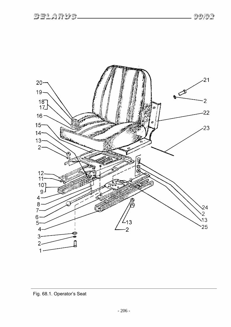
- 206 -
Fig. 68.1. Operator’s Seat

- 207 -
Group 68. Seat Subgroup 6800. Operator’s Seat
Fig. No Pos.
No. Assembly unit or part
No. Q-ty Description
68.1 1 М8х35 4 Bolt 2 ShP 8 22 Washer 3 ShCh 8 2 Washer 4 70-6804420 2 Guide rail 5 70-6804410 1 Guide rail 6 70-6804430 1 Stop 7 70-6804305 1 Draw bar 8 70-6804432 1 Stop 9 010-015-30-2-2 4 Ring 10 70-6804391 4 Roller 11 70-6804415 1 Guide rail 12 70-6804394-B 4 Bar 13 М8 7 Nut 14 70-6804393 1 Spring 15 70-6804014-А 1 Support 16 70-6803060 2 Base 17 ShCh 5 18 Washer 18 80-6809041 9 Rivet 19 80V-6804007 2 Cushion 20 70-6803020 2 Slipcover 21 М8х16 4 Bolt 22 50-6800030 1 Body 23 70-6803012 2 Axle 24 70-6804392 1 Axle 25 70-6804393 1 Spring

- 208 -
Fig. 68.2. Seat. Adjusting Mechanism
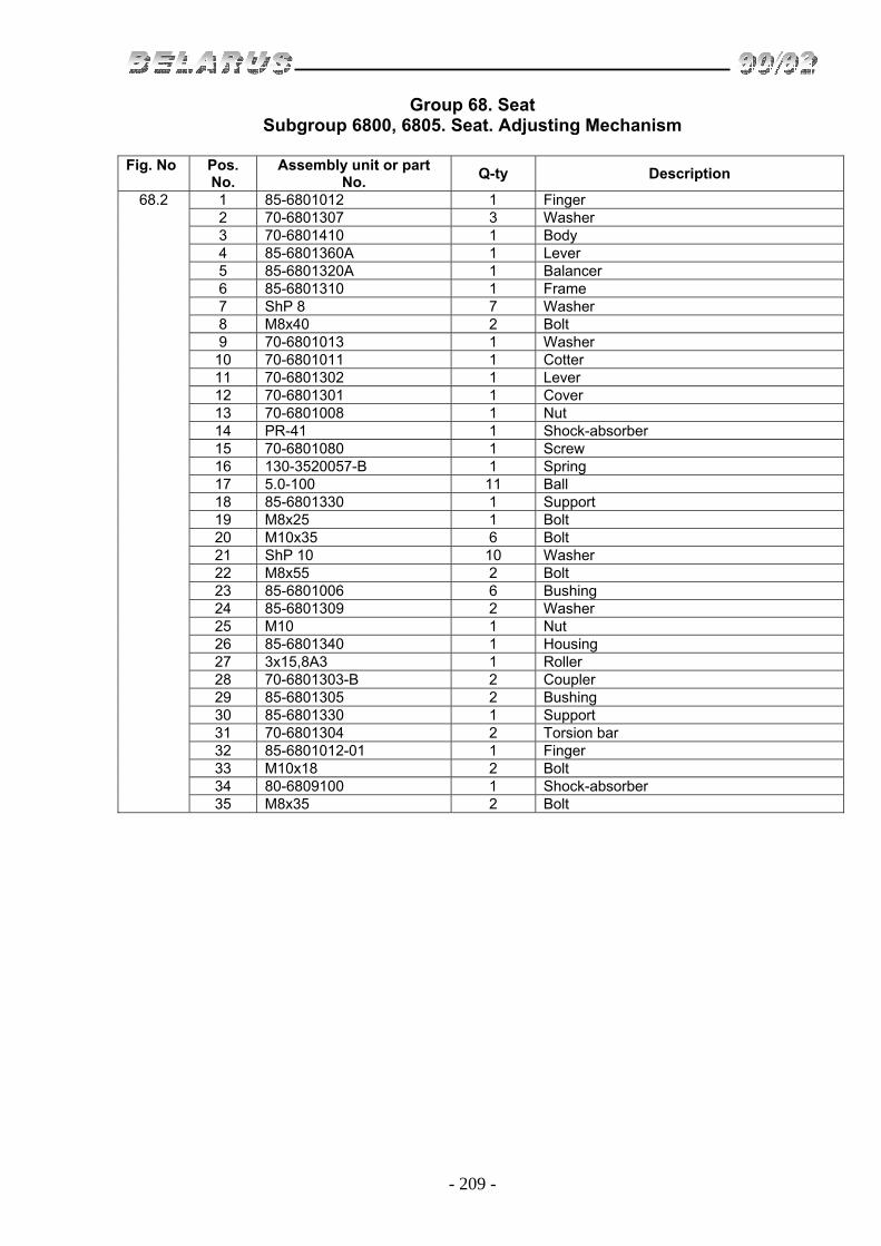
- 209 -
Group 68. Seat Subgroup 6800, 6805. Seat. Adjusting Mechanism
Fig. No Pos.
No. Assembly unit or part
No. Q-ty Description
68.2 1 85-6801012 1 Finger 2 70-6801307 3 Washer 3 70-6801410 1 Body 4 85-6801360А 1 Lever 5 85-6801320А 1 Balancer 6 85-6801310 1 Frame 7 ShP 8 7 Washer 8 М8х40 2 Bolt 9 70-6801013 1 Washer 10 70-6801011 1 Cotter 11 70-6801302 1 Lever 12 70-6801301 1 Cover 13 70-6801008 1 Nut 14 PR-41 1 Shock-absorber 15 70-6801080 1 Screw 16 130-3520057-B 1 Spring 17 5.0-100 11 Ball 18 85-6801330 1 Support 19 М8х25 1 Bolt 20 М10х35 6 Bolt 21 ShP 10 10 Washer 22 М8х55 2 Bolt 23 85-6801006 6 Bushing 24 85-6801309 2 Washer 25 М10 1 Nut 26 85-6801340 1 Housing 27 3х15,8А3 1 Roller 28 70-6801303-B 2 Coupler 29 85-6801305 2 Bushing 30 85-6801330 1 Support 31 70-6801304 2 Torsion bar 32 85-6801012-01 1 Finger 33 М10х18 2 Bolt 34 80-6809100 1 Shock-absorber 35 М8х35 2 Bolt

- 210 -
Fig. 82.1. Sun Visor

- 211 -
Group 82. Cabin Accessories Subgroup 8204. Sun Visor
Fig. No Pos.
No. Assembly unit or part
No. Q-ty Description
82.1
80P-8204010 1 Sun Visor (4-8) 1 М6 2 Nut 2 ShP 6 2 Washer 3 ShCh 6 2 Washer 4 70-8204011-А 1 Shade 5 VМ4х10 5 Screw 6 70-8204015 1 Holder 7 70-8204014 1 Holder 8 80P-8204011-01 1 Axle

- 212 -
Fig. 84.1. Grille. Hood

- 213 -
Group 84. Empennage Subgroup 8401, 8402. Grille. Hood
Fig. No Pos.
No. Assembly unit or part
No. Q-ty Description
84.1
80-8400005-08 1 Grille (1-33) 1 М6х35 6 Bolt 2 ShP 6 8 Washer 3 ShCh 6 10 Washer 4 80-8401070 1 Grill 5 50-8400016-А 1 Sector 6 80-8402020-01 1 Hood 7 80-8402060-V 1 Support 8 4x10 1 Bolt screw 9 80-6105056 1 Handle 10 М6х16 2 Bolt 11 80-8402410 1 Lock 12 М6 2 Nut 13 М8х20 2 Bolt 14 ShP 8 6 Washer 15 80-8402420-А 1 Buckle 16 80-8402065-V 1 Support 17 3,2x18 2 Splint 18 ShCh 8 9 Washer 19 50-8400017-А 1 Sector 20 50-1310158-B 1 Spring 21 80-8401004-01 1 Grip 22 ShCh 16 2 Washer 23 80-8400014 1 Lever 24 ShCh 10 6 Washer 25 ShP 10 6 Washer 26 50-8400024 2 Bolt 27 50-2401071 2 Plug 28 М10х25 4 Bolt 29 80-8401004 1 Grip 30 80-8402067-V-01 1 Support 31 80-8401080 1 Grill 32 М8х16 4 Bolt 33 80-8402067-V 1 Support

- 214 -
Fig. 84.2. Front Fenders

- 215 -
Group 84. Empennage Subgroup 8403. Front Fenders
Fig. No Pos.
No. Assembly unit or part
No. Q-ty Description
84.2
82R-8403010-B 1 Front fenders (1-19) 1 ShCh 12 2 Washer 2 82R-8403011-B 2 Plate 3 ShP 12 8 Washer 4 М12х100 6 Bolt 5 М12х110 2 Bolt 6 52-8403018 4 Steps 7 82R-8403015-B 1 Support 8 82R-8403015-B-01 1 Support 9 82R-8403025-B-01 1 Support 10 М10 22 Nut 11 ShP 10 10 Washer 12 ShCh 10 16 Washer
13 82R-8403014-B1 or 82R-8403014-B2
2 Fender
14 82R-8403012-B 4 Strip 15 М10х30 10 Bolt 16 82R-8403013-B 2 Strip 17 ShP 10 12 Washer 18 82R-8403020-B 1 Support 19 82R-8403021-B 8 Bushing

- 216 -
Fig. 84.3. Front Fenders (version)

- 217 -
Group 84. Empennage Subgroup 8403. Front Fenders (version)
Fig. No Pos.
No. Assembly unit or part
No. Q-ty Description
84.3
1 М16х32 4 Bolt 2 ShP 16 4 Washer 3 80-8403016-01 1 Support 4 М12 8 Nut 5 ShP 12 8 Washer 6 80-8403014 2 Support 7 80-8403041 2 Fender (metal) 8 М12х35 4 Bolt 9 ShCh 12 8 Washer 10 80-8403030 2 Hood 11 М12х30 4 Bolt 12 500А-8507096 8 Plug 13 50-8400018 2 Buffer 14 VM6х16 8 Screw 15 ShCh 6 8 Washer 16 М6 8 Nut 17 80-8403013 2 Batten 18 80-8403015 1 Support
Version 1 М16х32 4 Bolt 2 ShP 16 4 Washer 3 80-8403016-01 1 Support 4 М12 8 Nut 5 ShP 12 8 Washer 6 80-8403014 2 Support 7 80-8403041 2 Fender (plastic) 8 М12х35 4 Bolt 9 ShCh 12 8 Washer 11 М12х30 4 Bolt 18 80-8403015 1 Support

- 218 -
Fig. 84.4. Front Fenders (version)

- 219 -
Group 84. Empennage Subgroup 8403. Front Fenders (version)
Fig. No Pos.
No. Assembly unit or part
No. Q-ty Description
84.4
1 822-8403011 2 Base 2 М16x55 8 Bolt 3 ShP 12 6 Washer 4 М12x30 6 Bolt 5 822-8403015-01 1 Right pole 6 М10 10 Nut 7 ShP 10 10 Washer 8 ShCh 10 10 Washer (Ø=21) 9 80-4616017 10 Roller 10 ShCh 10 10 Washer (Ø=30) 11 М10x40 10 Bolt
12
822-8403020 or 822-8403020-B or 1221-8403014-B-02 or 1221-8403014-B1-02
2 Fender
13 822-8403015 1 Left pole

- 220 -
Fig. 84.5. Foot Board
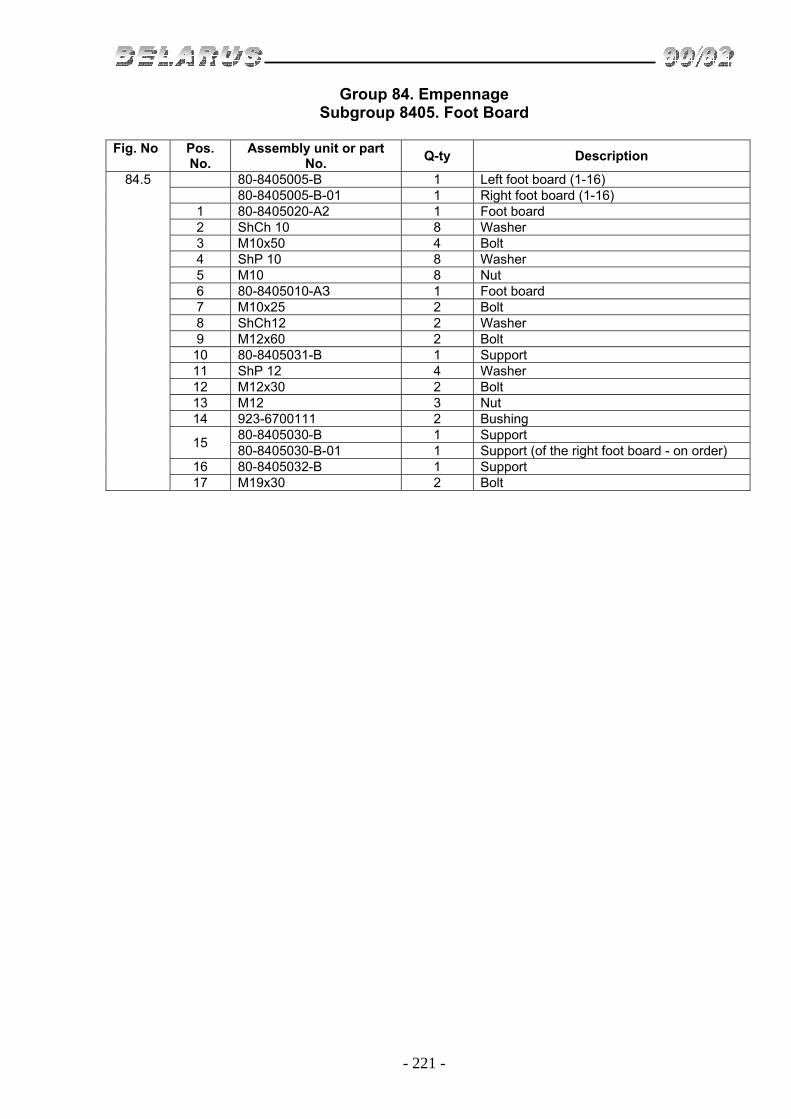
- 221 -
Group 84. Empennage Subgroup 8405. Foot Board
Fig. No Pos.
No. Assembly unit or part
No. Q-ty Description
84.5
80-8405005-B 1 Left foot board (1-16) 80-8405005-B-01 1 Right foot board (1-16)
1 80-8405020-А2 1 Foot board 2 ShCh 10 8 Washer 3 М10х50 4 Bolt 4 ShP 10 8 Washer 5 М10 8 Nut 6 80-8405010-АЗ 1 Foot board 7 М10х25 2 Bolt 8 ShCh12 2 Washer 9 М12х60 2 Bolt 10 80-8405031-B 1 Support 11 ShP 12 4 Washer 12 М12х30 2 Bolt 13 М12 3 Nut 14 923-6700111 2 Bushing
15 80-8405030-B 1 Support 80-8405030-B-01 1 Support (of the right foot board - on order)
16 80-8405032-B 1 Support 17 М19х30 2 Bolt