Separation of Alcohol-Water Mixtures by a Combination of ...
18
membranes Article Separation of Alcohol-Water Mixtures by a Combination of Distillation, Hydrophilic and Organophilic Pervaporation Processes Huyen Trang Do Thi 1 , Peter Mizsey 1,2 and Andras Jozsef Toth 1, * 1 Environmental and Process Engineering Research Group, Department of Chemical and Environmental Process Engineering, Budapest University of Technology and Economics, M˝ uegyetem rkp. 3, H-1111 Budapest, Hungary; [email protected] (H.T.D.T.); [email protected] (P.M.) 2 Institute of Chemistry, University of Miskolc, Egyetemváros C/1 108, H-3515 Miskolc, Hungary * Correspondence: [email protected]; Tel.: +36-1-463-1490 Received: 21 October 2020; Accepted: 10 November 2020; Published: 16 November 2020 Abstract: It can be stated that in the fine chemical industries, especially in the pharmaceutical industry, large amounts of liquid waste and industrial waste solvents are generated during the production technology. Addressing these is a key issue because their disposal often accounts for the largest proportion of the cost of the entire technology. There is need to develop regeneration processes that are financially beneficial to the plant and, if possible, reuse the liquid waste in the spirit of a circular economy, in a particular technology, or possibly elsewhere. The distillation techniqueproves to be a good solution in many cases, but in the case of mixtures with high water content and few volatile components, this process is often not cost-effective due to its high steam consumption, and in the case of azeotropic mixtures there are separation constraints. In the present work, the membrane process considered as an alternative; pervaporation is demonstrated through the treatment of low alcohol (methanol and ethanol) aqueous mixtures. Alcohol-containing process wastewaters were investigated in professional process simulator environment with user-added pervaporation modules. Eight different methods were built up in ChemCAD flowsheet simulator: organophilic pervaporation (OPV), hydrophilic pervaporation (HPV), hydrophilic pervaporation with recirculation (R-HPV), dynamic organophilic pervaporation (Dyn-OPV), dynamic hydronophilic pervaporation (Dyn-HPV), hybrid distillation-organophilic pervaporation (D + OPV), hybrid distillation-hydrophilic pervaporation (D + HPV), and finally hybrid distillation-hydrophilic pervaporation with recirculation (R-D + HPV). It can be stated the last solution in line was the most suitable in the terms of composition, however distillation of mixture with high water content has significant heat consumption. Furthermore, the pervaporation supplemented with dynamic tanks is not favourable due to the high recirculation rate in the case of tested mixtures and compositions. Keywords: process wastewater; ethanol-water separation; methanol-water separation; pervaporation; hybrid operation 1. Introduction Nowadays, one of the most important problems is the protection of the quality and quantity of our water resources. Unlimited amounts of water have been available since man’s appearance. On the other hand, water demand is increasing day by day, as the population, cultural and social needs are also increasing, as well as the rapid industrial development that is taking place. Pollution of natural waters is mainly caused by industrial plants and agricultural activities. Industrial wastewater is causing increasing difficulties, which is why regulations for wastewater treatment are also becoming Membranes 2020, 10, 345; doi:10.3390/membranes10110345 www.mdpi.com/journal/membranes
-
Upload
khangminh22 -
Category
Documents
-
view
0 -
download
0
Transcript of Separation of Alcohol-Water Mixtures by a Combination of ...
membranes
Article
Separation of Alcohol-Water Mixtures bya Combination of Distillation, Hydrophilicand Organophilic Pervaporation Processes
Huyen Trang Do Thi 1, Peter Mizsey 1,2 and Andras Jozsef Toth 1,*1 Environmental and Process Engineering Research Group, Department of Chemical and Environmental
Process Engineering, Budapest University of Technology and Economics, Muegyetem rkp. 3,H-1111 Budapest, Hungary; [email protected] (H.T.D.T.); [email protected] (P.M.)
2 Institute of Chemistry, University of Miskolc, Egyetemváros C/1 108, H-3515 Miskolc, Hungary* Correspondence: [email protected]; Tel.: +36-1-463-1490
Received: 21 October 2020; Accepted: 10 November 2020; Published: 16 November 2020 �����������������
Abstract: It can be stated that in the fine chemical industries, especially in the pharmaceutical industry,large amounts of liquid waste and industrial waste solvents are generated during the productiontechnology. Addressing these is a key issue because their disposal often accounts for the largestproportion of the cost of the entire technology. There is need to develop regeneration processes thatare financially beneficial to the plant and, if possible, reuse the liquid waste in the spirit of a circulareconomy, in a particular technology, or possibly elsewhere. The distillation technique proves to be agood solution in many cases, but in the case of mixtures with high water content and few volatilecomponents, this process is often not cost-effective due to its high steam consumption, and in thecase of azeotropic mixtures there are separation constraints. In the present work, the membraneprocess considered as an alternative; pervaporation is demonstrated through the treatment oflow alcohol (methanol and ethanol) aqueous mixtures. Alcohol-containing process wastewaterswere investigated in professional process simulator environment with user-added pervaporationmodules. Eight different methods were built up in ChemCAD flowsheet simulator: organophilicpervaporation (OPV), hydrophilic pervaporation (HPV), hydrophilic pervaporation with recirculation(R-HPV), dynamic organophilic pervaporation (Dyn-OPV), dynamic hydronophilic pervaporation(Dyn-HPV), hybrid distillation-organophilic pervaporation (D + OPV), hybrid distillation-hydrophilicpervaporation (D + HPV), and finally hybrid distillation-hydrophilic pervaporation with recirculation(R-D + HPV). It can be stated the last solution in line was the most suitable in the terms of composition,however distillation of mixture with high water content has significant heat consumption. Furthermore,the pervaporation supplemented with dynamic tanks is not favourable due to the high recirculationrate in the case of tested mixtures and compositions.
Keywords: process wastewater; ethanol-water separation; methanol-water separation; pervaporation;hybrid operation
1. Introduction
Nowadays, one of the most important problems is the protection of the quality and quantityof our water resources. Unlimited amounts of water have been available since man’s appearance.On the other hand, water demand is increasing day by day, as the population, cultural and socialneeds are also increasing, as well as the rapid industrial development that is taking place. Pollution ofnatural waters is mainly caused by industrial plants and agricultural activities. Industrial wastewateris causing increasing difficulties, which is why regulations for wastewater treatment are also becoming
Membranes 2020, 10, 345; doi:10.3390/membranes10110345 www.mdpi.com/journal/membranes
Membranes 2020, 10, 345 2 of 18
more stringent to protect the environment. These rules force emitters to reduce emissions of variousindustrial pollutants, to recycle, and use valuable by-products and waste using new technology.Separation of various organic substances used in industry, such as alcohol, from process wastewater isan important task of environmental protection.
Separation of liquid waste mixtures is a field that has been significantly and thoroughly studiednot only for environmental engineering but also for other engineering sciences. Liquid mixturesare often non-ideal, with very different behaviour from the ideal. In many cases, they form anazeotrope that cannot be separated by conventional distillation methods. Separation of non-idealazeotrope-containing mixtures is often complex and serious challenge. Therefore, there is needfor hybrid process that can efficiently and economically separate azeotropic mixtures, such aspressure change, extractive, homogeneous azeotropic and heterogeneous azeotropic distillation [1–9],hybrid distillation-pervaporation process [10–15] extractive heterogeneous azeotropic distillation(EHAD) [16–18] and hydrophilic or organophilic pervaporation (HPV, OPV) [19–24]. It can be mentionedthat volatile organic compounds (VOCs) [25,26] can be separated from wastewater by pervaporationmembranes and distillation processes, e.g., ethyl acetate-ethanol [27,28], acetone-butanol-ethanol [29],isobutanol [30,31], isopropanol [32–35], tetrahydrofuran (THF) [36], ethanol [37–39], methanol [35,40].
The hybrid distillation-pervaporation process is considered as a clean technology and it haspotential savings in energy because of reduced thermal and pressure requirements. This processallows using the heat of the distillation to increase the efficiency of the pervaporation process andleads consequently to potential savings in energy costs [41]. So, this hybrid separation process isenergetically more efficient compared to conventional distillation.
Tusel and Ballweg [42] examined a system combining distillation column followed by twopervaporation units with different types of hydrophilic membrane. The first step was a ‘high flux-lowselectivity’ membrane to split the azeotrope mixtures. The second step was a ‘low flux-highselectivity’ membrane as a polishing. In this separation process, the pervaporation membranemodules were operated at 72 ◦C, 3 bars. The feed at 15 ◦C contained 8.8% by weight ethanoland 12,720 kg/h. Ethanol was concentrated from 8.8 w% to 99.8 w%. The ethanol flow was1103 kg/h. In addition to the hybrid distillation-pervaporation process, pervaporation can alsobe combined with other systems to separate mixtures, e.g., pervaporation-crystallization (PC)process [43], pervaporation-microfiltration-osmotic distillation three-stage hybrid process [44],reverse osmosis-pervaporation hybrid process [45].
Pervaporation is a membrane operation where a phase change occurs. In the last ten years,pervaporation has been considered one of the most dynamically developing membrane separationoperations. The main advantage of pervaporation is the energy-saving operation. The pervaporationrequires lower energy consumption than other technologies, in many cases 50–70% less [46]. Further,this is an environmentally friendly operation because not require to use of additional chemicals ormaterials [47]. The pervaporation membrane can be used to separate azeotropic mixtures. Nowadays,within the more stringent requirements of sustainable development, the environmentally friendlytechnology of pervaporation can provide a concrete response and a real solution for many separationprocesses, even on a larger, industrial scale [48–51]. The pervaporation process is used to dehydrateorganic compounds [52–56], to remove small amounts of undesirable organic compounds fromwater-organic mixture [56–59], and to separate organic compounds from an organic mixture [60–63].The water-alcohol separation was first used to study and apply the pervaporation process in thechemical industry [64,65]. The main future trends can be structured in two research strategies [66]:
Approach I.: Improving the predictive power of mass flow models in pervaporation to extrapolateits operational performance under other conditions. These models can be implemented in the generalsimulation and optimization phase of hybrid processes that integrate pervaporation with otherseparation units (pervaporation-distillation).
Approach II.: Simulation and optimization of hybrid processes, calculation of the requiredmembrane performance. Empirical or semiempirical simple models can then be used under the
Membranes 2020, 10, 345 3 of 18
selected operating conditions to obtain the information needed to achieve the required membraneperformance (effect of temperature, material, microstructure, etc.).
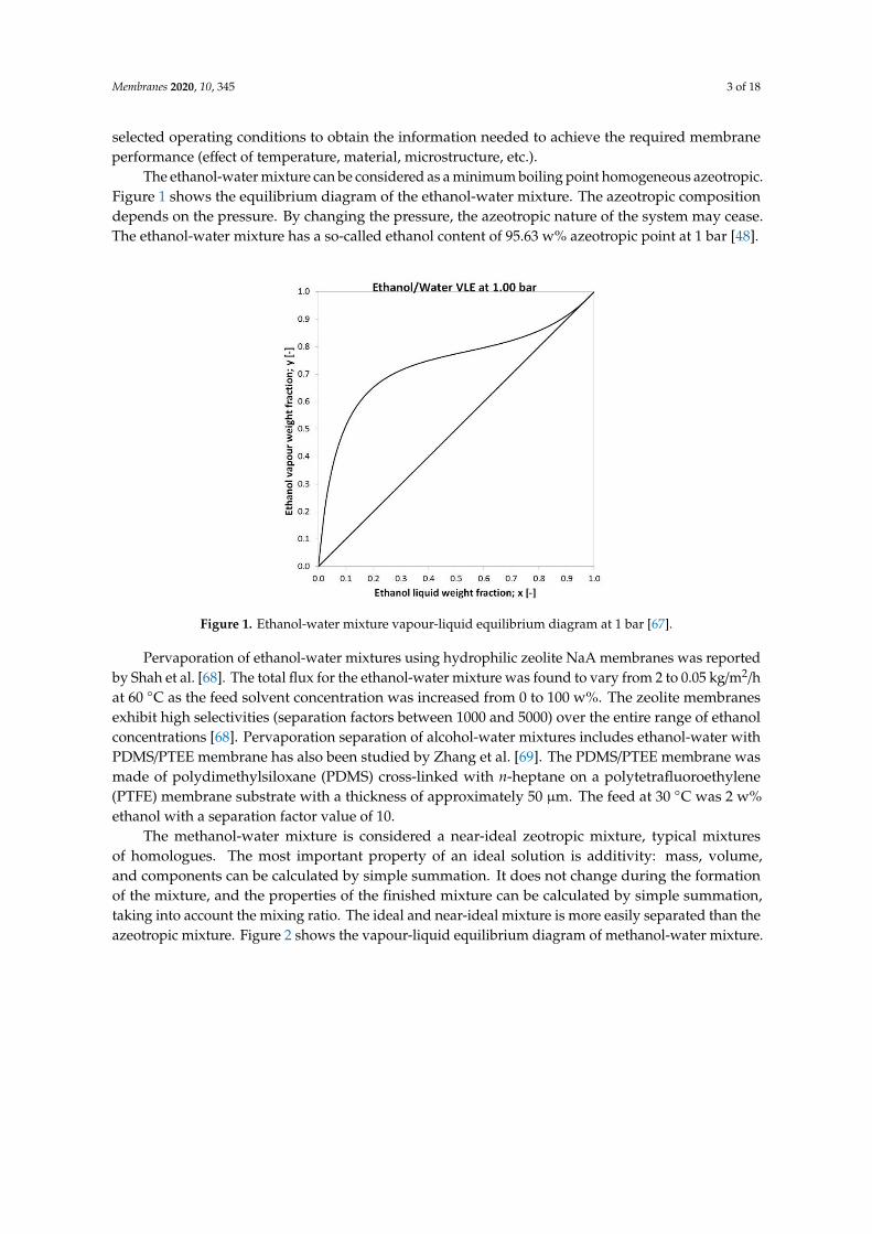
The ethanol-water mixture can be considered as a minimum boiling point homogeneous azeotropic.Figure 1 shows the equilibrium diagram of the ethanol-water mixture. The azeotropic compositiondepends on the pressure. By changing the pressure, the azeotropic nature of the system may cease.The ethanol-water mixture has a so-called ethanol content of 95.63 w% azeotropic point at 1 bar [48].
Membranes 2020, 10, x FOR PEER REVIEW 3 of 17
The ethanol-water mixture can be considered as a minimum boiling point homogeneous azeotropic. Figure 1 shows the equilibrium diagram of the ethanol-water mixture. The azeotropic composition depends on the pressure. By changing the pressure, the azeotropic nature of the system may cease. The ethanol-water mixture has a so-called ethanol content of 95.63 w% azeotropic point at 1 bar [48].
Figure 1. Ethanol-water mixture vapour-liquid equilibrium diagram at 1 bar [67].
Pervaporation of ethanol-water mixtures using hydrophilic zeolite NaA membranes was reported by Shah et al. [68]. The total flux for the ethanol-water mixture was found to vary from 2 to 0.05 kg/m2/h at 60 °C as the feed solvent concentration was increased from 0 to 100 w%. The zeolite membranes exhibit high selectivities (separation factors between 1000 and 5000) over the entire range of ethanol concentrations [68]. Pervaporation separation of alcohol-water mixtures includes ethanol-water with PDMS/PTEE membrane has also been studied by Zhang et al. [69]. The PDMS/PTEE membrane was made of polydimethylsiloxane (PDMS) cross-linked with n-heptane on a polytetrafluoroethylene (PTFE) membrane substrate with a thickness of approximately 50 μm. The feed at 30 °C was 2 w% ethanol with a separation factor value of 10.
The methanol-water mixture is considered a near-ideal zeotropic mixture, typical mixtures of homologues. The most important property of an ideal solution is additivity: mass, volume, and components can be calculated by simple summation. It does not change during the formation of the mixture, and the properties of the finished mixture can be calculated by simple summation, taking into account the mixing ratio. The ideal and near-ideal mixture is more easily separated than the azeotropic mixture. Figure 2 shows the vapour-liquid equilibrium diagram of methanol-water mixture.
Liu et al. have studied the membrane pervaporation of water from a methanol-water mixture with a polyvinyl alcohol (PVA) and nanometer SiO2 membrane [70]. In their study, PVA/SiO2
membranes were used to separate mixtures of methanol-water over the complete concentration range of 70–98 %. For the 98 % mixture at 60 °C, the separation factor is up to 1458 together with a permeate flux up to 325 g/(m2·h). The evaluation of PDMS (PERVAP-1060) membrane to separate methanol from aqueous solutions has been performed by Kujawski [71]. PERVAP-1060 is one of the organophilic membranes, which also showed prospective potential in selective and transport properties. In his work, the operating temperature was set at 30 °C together with the feed methanol concentration of 5 w%. The calculated permeate methanol concentration was 24 w% with a separation factor of 5.
Figure 1. Ethanol-water mixture vapour-liquid equilibrium diagram at 1 bar [67].
Pervaporation of ethanol-water mixtures using hydrophilic zeolite NaA membranes was reportedby Shah et al. [68]. The total flux for the ethanol-water mixture was found to vary from 2 to 0.05 kg/m2/hat 60 ◦C as the feed solvent concentration was increased from 0 to 100 w%. The zeolite membranesexhibit high selectivities (separation factors between 1000 and 5000) over the entire range of ethanolconcentrations [68]. Pervaporation separation of alcohol-water mixtures includes ethanol-water withPDMS/PTEE membrane has also been studied by Zhang et al. [69]. The PDMS/PTEE membrane wasmade of polydimethylsiloxane (PDMS) cross-linked with n-heptane on a polytetrafluoroethylene(PTFE) membrane substrate with a thickness of approximately 50 µm. The feed at 30 ◦C was 2 w%ethanol with a separation factor value of 10.
The methanol-water mixture is considered a near-ideal zeotropic mixture, typical mixturesof homologues. The most important property of an ideal solution is additivity: mass, volume,and components can be calculated by simple summation. It does not change during the formationof the mixture, and the properties of the finished mixture can be calculated by simple summation,taking into account the mixing ratio. The ideal and near-ideal mixture is more easily separated than theazeotropic mixture. Figure 2 shows the vapour-liquid equilibrium diagram of methanol-water mixture.

Membranes 2020, 10, 345 4 of 18
Membranes 2020, 10, x FOR PEER REVIEW 4 of 17
Figure 2. Methanol-water mixture vapour-liquid equilibrium diagram at 1 bar [72].
Pervaporation and hybrid distillation-pervaporation process are widely regarded as an attractive and efficient technology for various separation processes, therefore several combinations were examined to select the most efficient. The aim of this work is to model the hybrid distillation-pervaporation, hydrophilic and organophilic pervaporation processes in the ChemCAD professional flowsheet simulator. The main novelty of research is the investigation of pervaporation in a dynamic model environment too. The UNIQUAC thermodynamic model was used for modelling distillation processes. The separation of the binary alcohol-water mixtures was studied, the near-ideal methanol-water mixture and the homogeneous azeotropic ethanol-water mixture with minimum boiling point. This study aimed to compare the separation methods with the collected data, taking into account different aspects, indicating the obtained values.
2. Materials and Methods
The aim of the alcohol-water (ethanol-water and methanol-water) separation of the given composition was to achieve the purest possible products. Eight different methods were investigated in ChemCAD flowsheet simulator, which is listed in Table 1.
Table 1. Studied methods. Method Abbreviation Organophilic pervaporation OPV Hydrophilic pervaporation HPV Hydrophilic pervaporation with recirculation Recirc HPV Dynamic organophilic pervaporation Dyn OPV Dynamic hydronophilic pervaporation Dyn HPV Hybrid distillation-organophilic pervaporation D+OPV Hybrid distillation-hydrophilic pervaporation D+HPV Hybrid distillation-hydrophilic pervaporation with recirculation Recirc D+HPV
2.1. Modelling Schemes
The alcohol-water mixture separation methods are shown in Figures 3–9. The hydrophilic pervaporation membrane procedure is presented in Figure 3, the recirculating hydrophilic pervaporation procedure is presented in Figure 4. In Figures 5 and 6, the dynamic organophilic pervaporation method and dynamic hydrophilic pervaporation method are shown respectively. The hybrid distillation-organophilic pervaporation method and hybrid distillation-hydrophilic
Figure 2. Methanol-water mixture vapour-liquid equilibrium diagram at 1 bar [70].
Liu et al. have studied the membrane pervaporation of water from a methanol-water mixture witha polyvinyl alcohol (PVA) and nanometer SiO2 membrane [71]. In their study, PVA/SiO2 membraneswere used to separate mixtures of methanol-water over the complete concentration range of 70–98%.For the 98% mixture at 60 ◦C, the separation factor is up to 1458 together with a permeate flux upto 325 g/(m2
·h). The evaluation of PDMS (PERVAP-1060) membrane to separate methanol fromaqueous solutions has been performed by Kujawski [72]. PERVAP-1060 is one of the organophilicmembranes, which also showed prospective potential in selective and transport properties. In hiswork, the operating temperature was set at 30 ◦C together with the feed methanol concentration of5 w%. The calculated permeate methanol concentration was 24 w% with a separation factor of 5.
Pervaporation and hybrid distillation-pervaporation process are widely regarded as an attractiveand efficient technology for various separation processes, therefore several combinations were examinedto select the most efficient. The aim of this work is to model the hybrid distillation-pervaporation,hydrophilic and organophilic pervaporation processes in the ChemCAD professional flowsheetsimulator. The main novelty of research is the investigation of pervaporation in a dynamic modelenvironment too. The UNIQUAC thermodynamic model was used for modelling distillation processes.The separation of the binary alcohol-water mixtures was studied, the near-ideal methanol-water mixtureand the homogeneous azeotropic ethanol-water mixture with minimum boiling point. This studyaimed to compare the separation methods with the collected data, taking into account different aspects,indicating the obtained values.
2. Materials and Methods
The aim of the alcohol-water (ethanol-water and methanol-water) separation of the givencomposition was to achieve the purest possible products. Eight different methods were investigated inChemCAD flowsheet simulator, which is listed in Table 1.
Membranes 2020, 10, 345 5 of 18
Table 1. Studied methods.
Method Abbreviation
Organophilic pervaporation OPVHydrophilic pervaporation HPV
Hydrophilic pervaporation with recirculation Recirc HPVDynamic organophilic pervaporation Dyn OPV
Dynamic hydronophilic pervaporation Dyn HPVHybrid distillation-organophilic pervaporation D + OPVHybrid distillation-hydrophilic pervaporation D + HPV
Hybrid distillation-hydrophilic pervaporation with recirculation Recirc D + HPV
2.1. Modelling Schemes
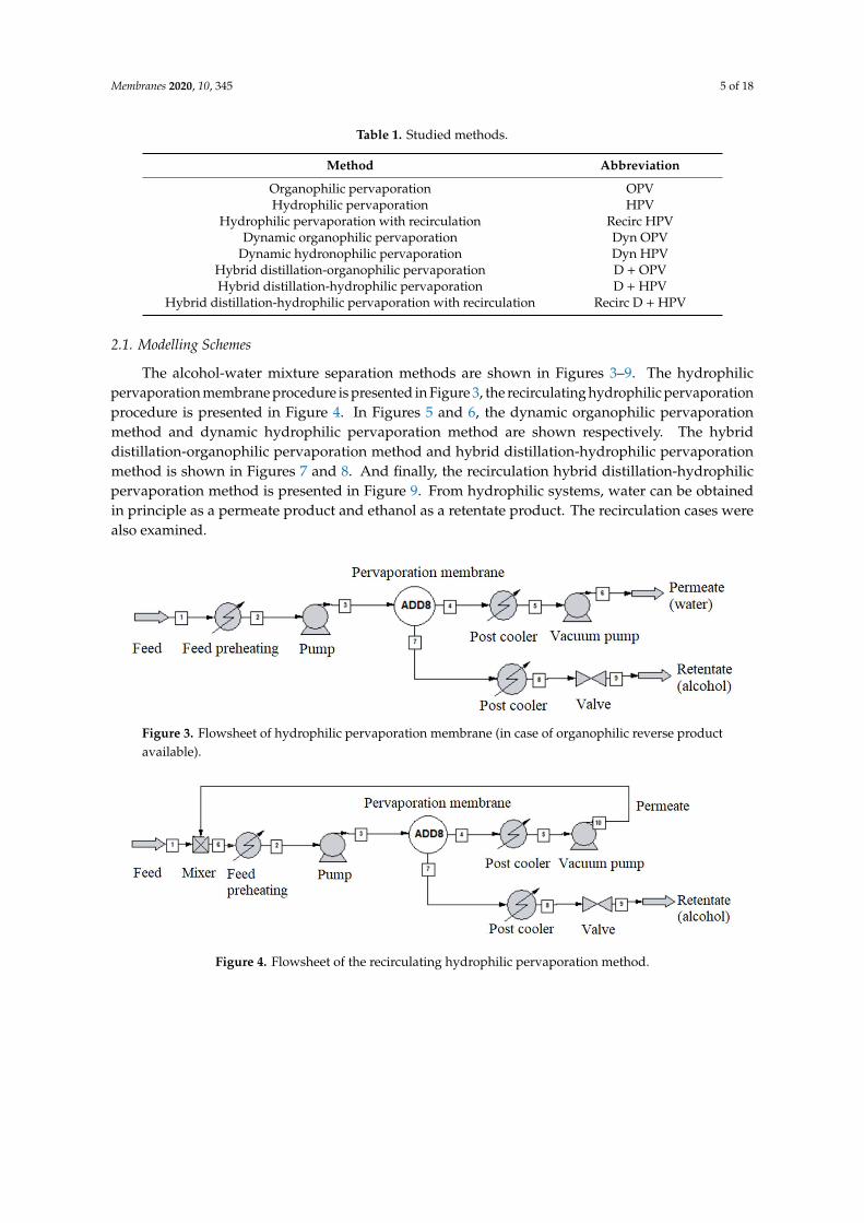
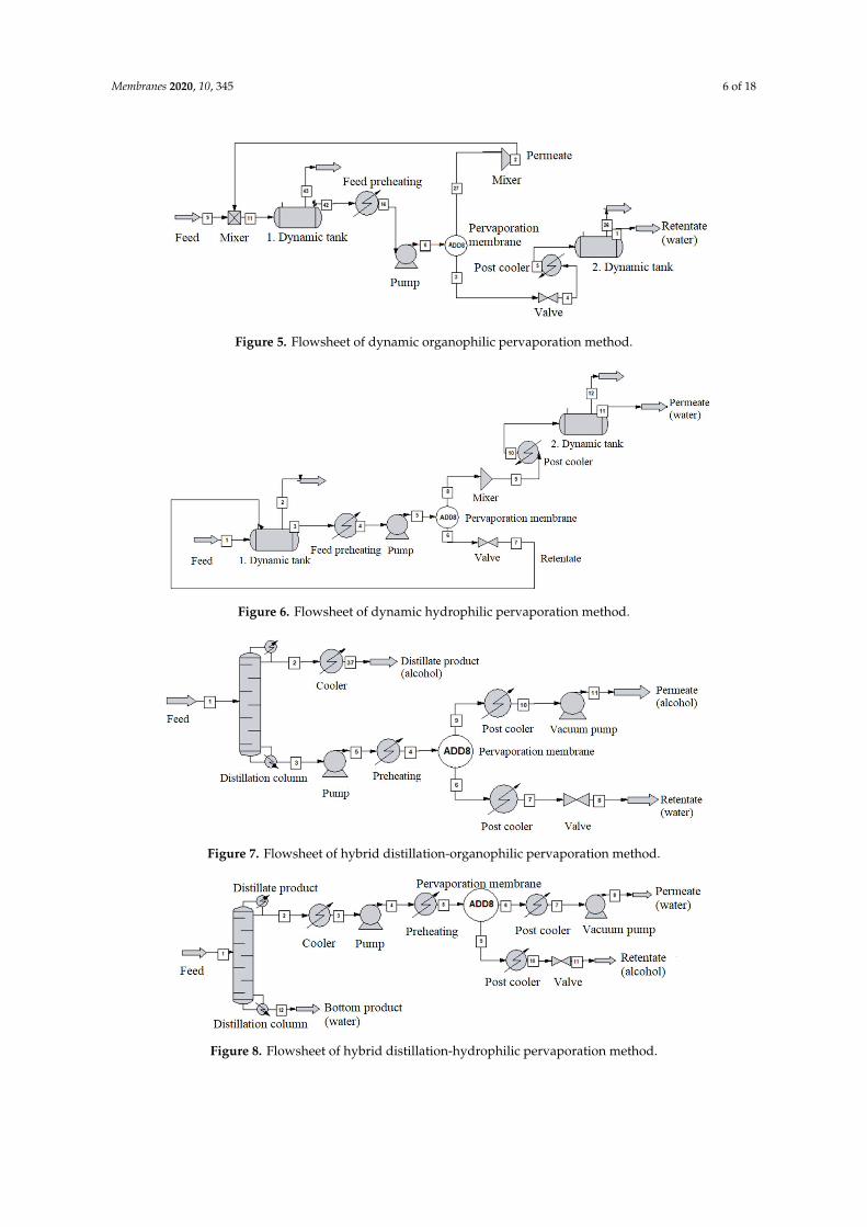
The alcohol-water mixture separation methods are shown in Figures 3–9. The hydrophilicpervaporation membrane procedure is presented in Figure 3, the recirculating hydrophilic pervaporationprocedure is presented in Figure 4. In Figures 5 and 6, the dynamic organophilic pervaporationmethod and dynamic hydrophilic pervaporation method are shown respectively. The hybriddistillation-organophilic pervaporation method and hybrid distillation-hydrophilic pervaporationmethod is shown in Figures 7 and 8. And finally, the recirculation hybrid distillation-hydrophilicpervaporation method is presented in Figure 9. From hydrophilic systems, water can be obtainedin principle as a permeate product and ethanol as a retentate product. The recirculation cases werealso examined.
Membranes 2020, 10, x FOR PEER REVIEW 5 of 17
pervaporation method is shown in Figures 7 and 8. And finally, the recirculation hybrid distillation-hydrophilic pervaporation method is presented in Figure 9. From hydrophilic systems, water can be obtained in principle as a permeate product and ethanol as a retentate product. The recirculation cases were also examined.
Figure 3. Flowsheet of hydrophilic pervaporation membrane (in case of organophilic reverse product available).
Figure 4. Flowsheet of the recirculating hydrophilic pervaporation method.
Figure 5. Flowsheet of dynamic organophilic pervaporation method.
Figure 6. Flowsheet of dynamic hydrophilic pervaporation method.
Figure 3. Flowsheet of hydrophilic pervaporation membrane (in case of organophilic reverse productavailable).
Membranes 2020, 10, x FOR PEER REVIEW 5 of 17
pervaporation method is shown in Figures 7 and 8. And finally, the recirculation hybrid distillation-hydrophilic pervaporation method is presented in Figure 9. From hydrophilic systems, water can be obtained in principle as a permeate product and ethanol as a retentate product. The recirculation cases were also examined.
Figure 3. Flowsheet of hydrophilic pervaporation membrane (in case of organophilic reverse product available).
Figure 4. Flowsheet of the recirculating hydrophilic pervaporation method.
Figure 5. Flowsheet of dynamic organophilic pervaporation method.
Figure 6. Flowsheet of dynamic hydrophilic pervaporation method.
Figure 4. Flowsheet of the recirculating hydrophilic pervaporation method.
Membranes 2020, 10, 345 6 of 18
Membranes 2020, 10, x FOR PEER REVIEW 5 of 17
pervaporation method is shown in Figures 7 and 8. And finally, the recirculation hybrid distillation-hydrophilic pervaporation method is presented in Figure 9. From hydrophilic systems, water can be obtained in principle as a permeate product and ethanol as a retentate product. The recirculation cases were also examined.
Figure 3. Flowsheet of hydrophilic pervaporation membrane (in case of organophilic reverse product available).
Figure 4. Flowsheet of the recirculating hydrophilic pervaporation method.
Figure 5. Flowsheet of dynamic organophilic pervaporation method.
Figure 6. Flowsheet of dynamic hydrophilic pervaporation method.
Figure 5. Flowsheet of dynamic organophilic pervaporation method.
Membranes 2020, 10, x FOR PEER REVIEW 5 of 17
pervaporation method is shown in Figures 7 and 8. And finally, the recirculation hybrid distillation-hydrophilic pervaporation method is presented in Figure 9. From hydrophilic systems, water can be obtained in principle as a permeate product and ethanol as a retentate product. The recirculation cases were also examined.
Figure 3. Flowsheet of hydrophilic pervaporation membrane (in case of organophilic reverse product available).
Figure 4. Flowsheet of the recirculating hydrophilic pervaporation method.
Figure 5. Flowsheet of dynamic organophilic pervaporation method.
Figure 6. Flowsheet of dynamic hydrophilic pervaporation method. Figure 6. Flowsheet of dynamic hydrophilic pervaporation method.
Membranes 2020, 10, x FOR PEER REVIEW 6 of 17
Figure 7. Flowsheet of hybrid distillation-organophilic pervaporation method.
Figure 8. Flowsheet of hybrid distillation-hydrophilic pervaporation method.
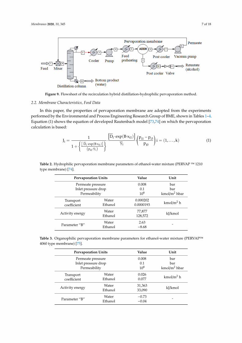
Figure 9. Flowsheet of the recirculation hybrid distillation-hydrophilic pervaporation method.
2.2. Membrane Characteristics, Feed Data
In this paper, the properties of pervaporation membrane are adopted from the experiments performed by the Environmental and Process Engineering Research Group of BME, shown in Tables 1–4. Equation (1) shows the equation of developed Rautenbach model [73,74] on which the pervaporation calculation is based:
J =1
1 + [D ∙ exp(B ∙ x )](p ∙ γ )
∙[D ∙ exp(B ∙ x )]
γ∙
p − pp
i = (1, … , k) (1)
Three different polymer membranes were experimentally examined for application of membrane flowsheet models. PERVAP™ 1210 (Table 2) and PERVAP™ 1510 (Table 4) are hydrophilic pervaporation membranes to separate ethanol-water or methanol-water mixtures. PERVAP™ 4060 (Tables 3 and 5) is an organophilic pervaporation membrane used to separate the alcohol-water mixtures. The experimental results have published in [72,74–76]. Tables 2–5 summarize the optimized parameters of experimental investigations. These parameters were used to build up the semi-empirical model (see Equation (1)) in the ChemCAD flowsheet program. The other major
Figure 7. Flowsheet of hybrid distillation-organophilic pervaporation method.
Membranes 2020, 10, x FOR PEER REVIEW 6 of 17
Figure 7. Flowsheet of hybrid distillation-organophilic pervaporation method.
Figure 8. Flowsheet of hybrid distillation-hydrophilic pervaporation method.
Figure 9. Flowsheet of the recirculation hybrid distillation-hydrophilic pervaporation method.
2.2. Membrane Characteristics, Feed Data
In this paper, the properties of pervaporation membrane are adopted from the experiments performed by the Environmental and Process Engineering Research Group of BME, shown in Tables 1–4. Equation (1) shows the equation of developed Rautenbach model [73,74] on which the pervaporation calculation is based:
J =1
1 + [D ∙ exp(B ∙ x )](p ∙ γ )
∙[D ∙ exp(B ∙ x )]
γ∙
p − pp
i = (1, … , k) (1)
Three different polymer membranes were experimentally examined for application of membrane flowsheet models. PERVAP™ 1210 (Table 2) and PERVAP™ 1510 (Table 4) are hydrophilic pervaporation membranes to separate ethanol-water or methanol-water mixtures. PERVAP™ 4060 (Tables 3 and 5) is an organophilic pervaporation membrane used to separate the alcohol-water mixtures. The experimental results have published in [72,74–76]. Tables 2–5 summarize the optimized parameters of experimental investigations. These parameters were used to build up the semi-empirical model (see Equation (1)) in the ChemCAD flowsheet program. The other major
Figure 8. Flowsheet of hybrid distillation-hydrophilic pervaporation method.
Membranes 2020, 10, 345 7 of 18
Membranes 2020, 10, x FOR PEER REVIEW 6 of 17
Figure 7. Flowsheet of hybrid distillation-organophilic pervaporation method.
Figure 8. Flowsheet of hybrid distillation-hydrophilic pervaporation method.
Figure 9. Flowsheet of the recirculation hybrid distillation-hydrophilic pervaporation method.
2.2. Membrane Characteristics, Feed Data
In this paper, the properties of pervaporation membrane are adopted from the experiments performed by the Environmental and Process Engineering Research Group of BME, shown in Tables 1–4. Equation (1) shows the equation of developed Rautenbach model [73,74] on which the pervaporation calculation is based:
J =1
1 + [D ∙ exp(B ∙ x )](p ∙ γ )
∙[D ∙ exp(B ∙ x )]
γ∙
p − pp
i = (1, … , k) (1)
Three different polymer membranes were experimentally examined for application of membrane flowsheet models. PERVAP™ 1210 (Table 2) and PERVAP™ 1510 (Table 4) are hydrophilic pervaporation membranes to separate ethanol-water or methanol-water mixtures. PERVAP™ 4060 (Tables 3 and 5) is an organophilic pervaporation membrane used to separate the alcohol-water mixtures. The experimental results have published in [72,74–76]. Tables 2–5 summarize the optimized parameters of experimental investigations. These parameters were used to build up the semi-empirical model (see Equation (1)) in the ChemCAD flowsheet program. The other major
Figure 9. Flowsheet of the recirculation hybrid distillation-hydrophilic pervaporation method.
2.2. Membrane Characteristics, Feed Data
In this paper, the properties of pervaporation membrane are adopted from the experimentsperformed by the Environmental and Process Engineering Research Group of BME, shown in Tables 1–4.Equation (1) shows the equation of developed Rautenbach model [73,74] on which the pervaporationcalculation is based:
Ji =1
1 +{[ Di· exp(B·xi1)]
(pi0·γi)
} · [Di· exp(B·xi1)]
γi·
(pi1 − pi3
pi0
)i = (1, . . . , k) (1)
Table 2. Hydrophilic pervaporation membrane parameters of ethanol-water mixture (PERVAP™ 1210type membrane) [74].
Pervaporation Units Value Unit
Permeate pressure 0.008 barInlet pressure drop 0.1 bar
Permeability 108 kmol/m2 hbar
Transportcoefficient
Water 0.000202kmol/m2 hEthanol 0.0000193
Activity energy Water 77,877 kJ/kmolEthanol 128,572
Parameter “B”Water 2.63 -
Ethanol −8.68
Table 3. Organophilic pervaporation membrane parameters for ethanol-water mixture (PERVAP™4060 type membrane) [75].
Pervaporation Units Value Unit
Permeate pressure 0.008 barInlet pressure drop 0.1 bar
Permeability 108 kmol/m2 hbar
Transportcoefficient
Water 0.026kmol/m2 hEthanol 0.077
Activity energy Water 31,363 kJ/kmolEthanol 33,090
Parameter “B”Water −0.73 -
Ethanol −0.04
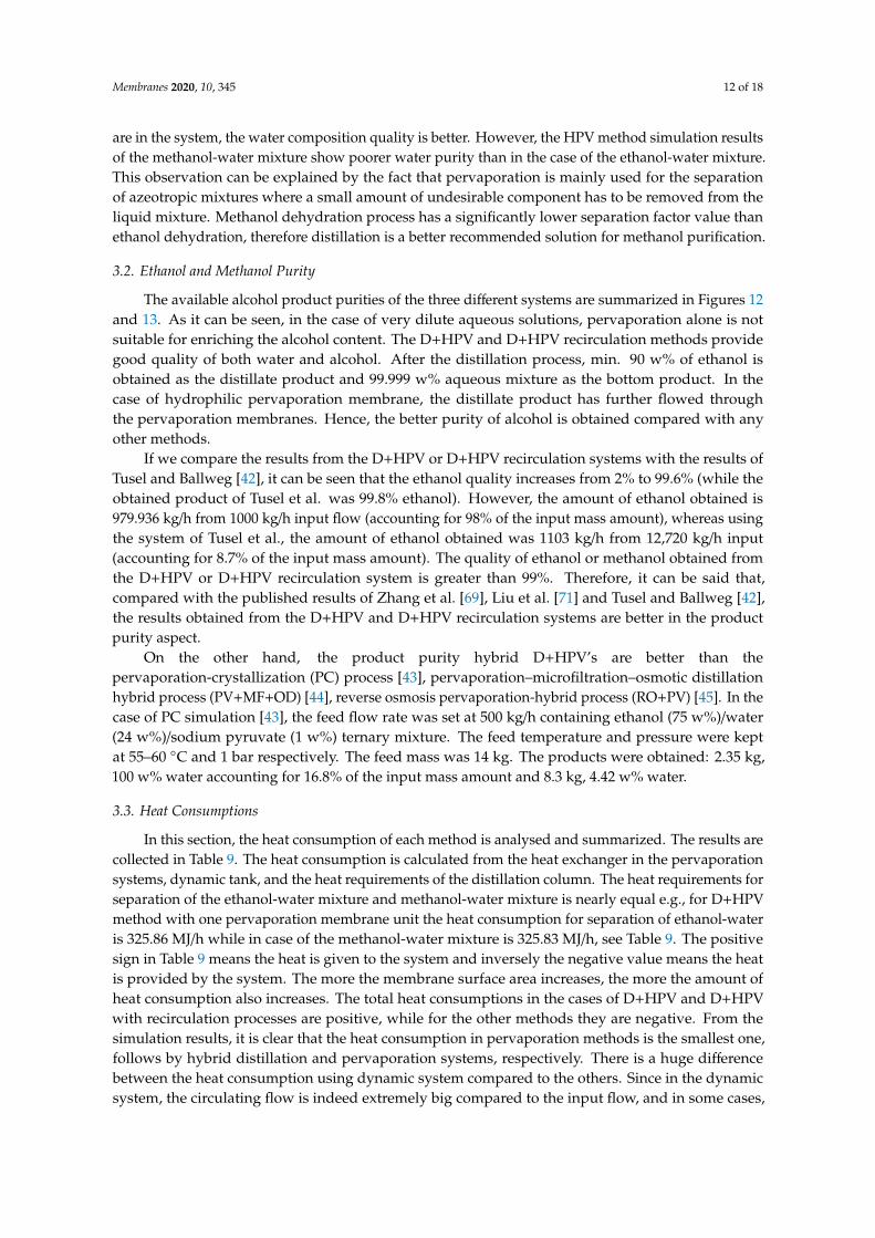
Membranes 2020, 10, 345 8 of 18
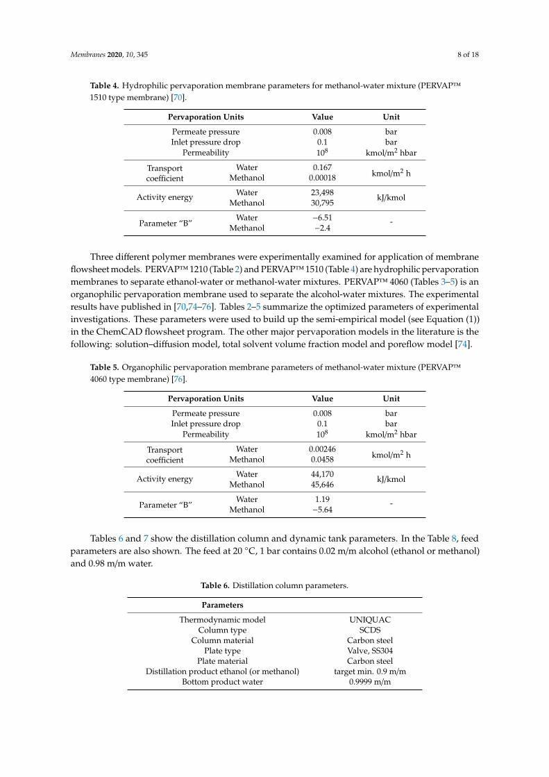
Table 4. Hydrophilic pervaporation membrane parameters for methanol-water mixture (PERVAP™1510 type membrane) [70].
Pervaporation Units Value Unit
Permeate pressure 0.008 barInlet pressure drop 0.1 bar
Permeability 108 kmol/m2 hbar
Transportcoefficient
Water 0.167kmol/m2 hMethanol 0.00018
Activity energy Water 23,498 kJ/kmolMethanol 30,795
Parameter “B”Water −6.51 -
Methanol −2.4
Three different polymer membranes were experimentally examined for application of membraneflowsheet models. PERVAP™ 1210 (Table 2) and PERVAP™ 1510 (Table 4) are hydrophilic pervaporationmembranes to separate ethanol-water or methanol-water mixtures. PERVAP™ 4060 (Tables 3–5) is anorganophilic pervaporation membrane used to separate the alcohol-water mixtures. The experimentalresults have published in [70,74–76]. Tables 2–5 summarize the optimized parameters of experimentalinvestigations. These parameters were used to build up the semi-empirical model (see Equation (1))in the ChemCAD flowsheet program. The other major pervaporation models in the literature is thefollowing: solution–diffusion model, total solvent volume fraction model and poreflow model [74].
Table 5. Organophilic pervaporation membrane parameters of methanol-water mixture (PERVAP™4060 type membrane) [76].
Pervaporation Units Value Unit
Permeate pressure 0.008 barInlet pressure drop 0.1 bar
Permeability 108 kmol/m2 hbar
Transportcoefficient
Water 0.00246kmol/m2 hMethanol 0.0458
Activity energy Water 44,170 kJ/kmolMethanol 45,646
Parameter “B”Water 1.19 -
Methanol −5.64
Tables 6 and 7 show the distillation column and dynamic tank parameters. In the Table 8, feedparameters are also shown. The feed at 20 ◦C, 1 bar contains 0.02 m/m alcohol (ethanol or methanol)and 0.98 m/m water.
Table 6. Distillation column parameters.
Parameters
Thermodynamic model UNIQUACColumn type SCDS
Column material Carbon steelPlate type Valve, SS304
Plate material Carbon steelDistillation product ethanol (or methanol) target min. 0.9 m/m
Bottom product water 0.9999 m/m
Membranes 2020, 10, 345 9 of 18
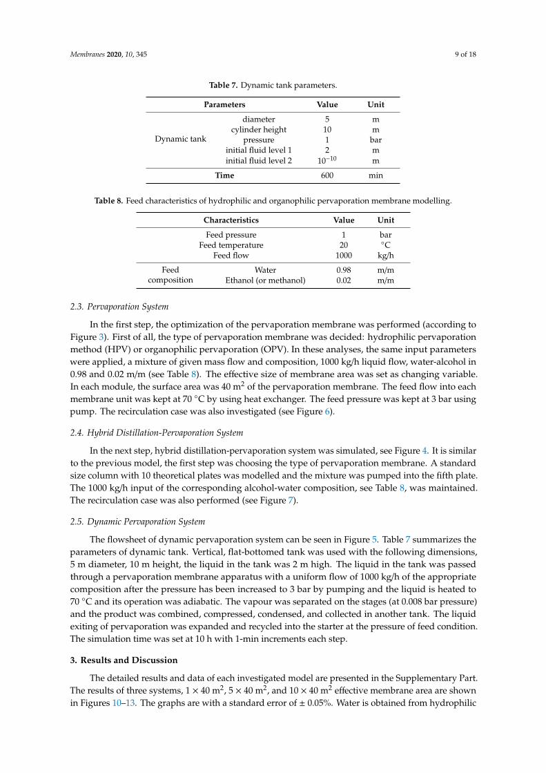
Table 7. Dynamic tank parameters.
Parameters Value Unit
Dynamic tank
diameter 5 mcylinder height 10 m
pressure 1 barinitial fluid level 1 2 minitial fluid level 2 10−10 m
Time 600 min
Table 8. Feed characteristics of hydrophilic and organophilic pervaporation membrane modelling.
Characteristics Value Unit
Feed pressure 1 barFeed temperature 20 ◦C
Feed flow 1000 kg/h
Feedcomposition
Water 0.98 m/mEthanol (or methanol) 0.02 m/m
2.3. Pervaporation System
In the first step, the optimization of the pervaporation membrane was performed (according toFigure 3). First of all, the type of pervaporation membrane was decided: hydrophilic pervaporationmethod (HPV) or organophilic pervaporation (OPV). In these analyses, the same input parameterswere applied, a mixture of given mass flow and composition, 1000 kg/h liquid flow, water-alcohol in0.98 and 0.02 m/m (see Table 8). The effective size of membrane area was set as changing variable.In each module, the surface area was 40 m2 of the pervaporation membrane. The feed flow into eachmembrane unit was kept at 70 ◦C by using heat exchanger. The feed pressure was kept at 3 bar usingpump. The recirculation case was also investigated (see Figure 6).
2.4. Hybrid Distillation-Pervaporation System
In the next step, hybrid distillation-pervaporation system was simulated, see Figure 4. It is similarto the previous model, the first step was choosing the type of pervaporation membrane. A standardsize column with 10 theoretical plates was modelled and the mixture was pumped into the fifth plate.The 1000 kg/h input of the corresponding alcohol-water composition, see Table 8, was maintained.The recirculation case was also performed (see Figure 7).
2.5. Dynamic Pervaporation System
The flowsheet of dynamic pervaporation system can be seen in Figure 5. Table 7 summarizes theparameters of dynamic tank. Vertical, flat-bottomed tank was used with the following dimensions,5 m diameter, 10 m height, the liquid in the tank was 2 m high. The liquid in the tank was passedthrough a pervaporation membrane apparatus with a uniform flow of 1000 kg/h of the appropriatecomposition after the pressure has been increased to 3 bar by pumping and the liquid is heated to70 ◦C and its operation was adiabatic. The vapour was separated on the stages (at 0.008 bar pressure)and the product was combined, compressed, condensed, and collected in another tank. The liquidexiting of pervaporation was expanded and recycled into the starter at the pressure of feed condition.The simulation time was set at 10 h with 1-min increments each step.
3. Results and Discussion
The detailed results and data of each investigated model are presented in the Supplementary Part.The results of three systems, 1 × 40 m2, 5 × 40 m2, and 10 × 40 m2 effective membrane area are shownin Figures 10–13. The graphs are with a standard error of ± 0.05%. Water is obtained from hydrophilic
Membranes 2020, 10, 345 10 of 18
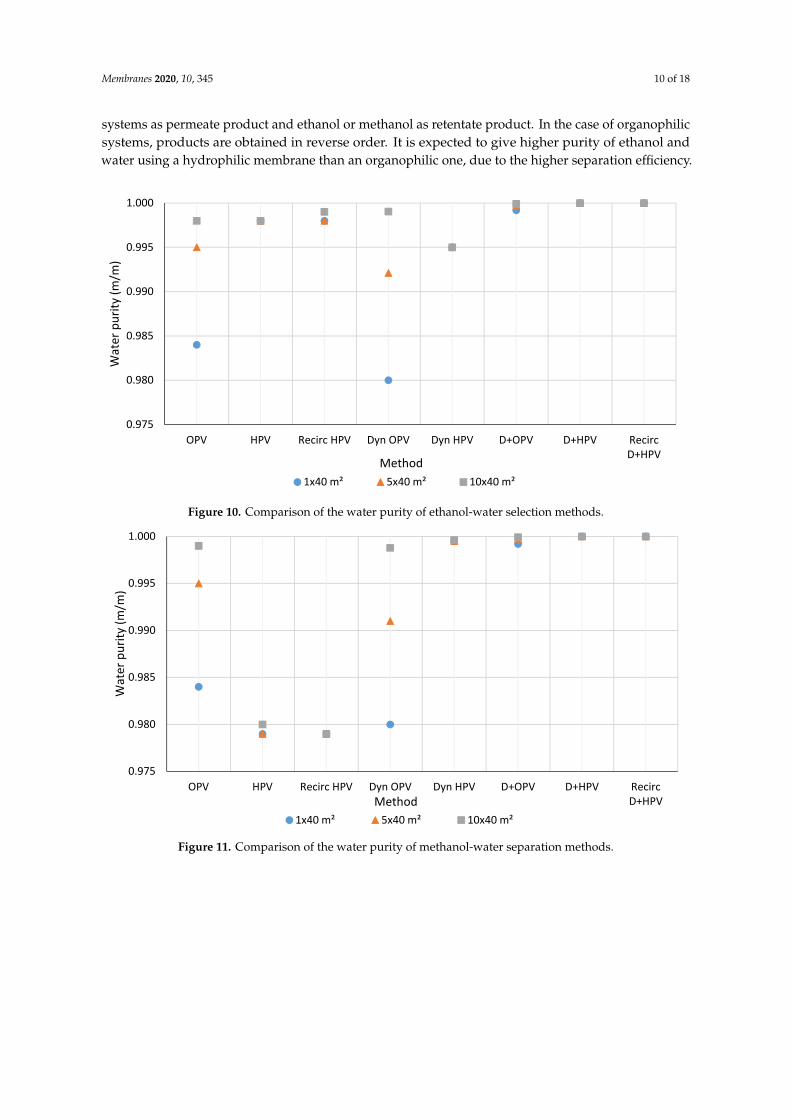
systems as permeate product and ethanol or methanol as retentate product. In the case of organophilicsystems, products are obtained in reverse order. It is expected to give higher purity of ethanol andwater using a hydrophilic membrane than an organophilic one, due to the higher separation efficiency.
Membranes 2020, 10, x FOR PEER REVIEW 9 of 17
through a pervaporation membrane apparatus with a uniform flow of 1000 kg/h of the appropriate composition after the pressure has been increased to 3 bar by pumping and the liquid is heated to 70 °C and its operation was adiabatic. The vapour was separated on the stages (at 0.008 bar pressure) and the product was combined, compressed, condensed, and collected in another tank. The liquid exiting of pervaporation was expanded and recycled into the starter at the pressure of feed condition. The simulation time was set at 10 h with 1-min increments each step.
3. Results and Discussion
The detailed results and data of each investigated model are presented in the Supplementary Part. The results of three systems, 1 × 40 m2, 5 × 40 m2, and 10 × 40 m2 effective membrane area are shown in Figure 10–13. The graphs are with a standard error of ± 0.05%. Water is obtained from hydrophilic systems as permeate product and ethanol or methanol as retentate product. In the case of organophilic systems, products are obtained in reverse order. It is expected to give higher purity of ethanol and water using a hydrophilic membrane than an organophilic one, due to the higher separation efficiency.
Figure 10. Comparison of the water purity of ethanol-water selection methods.
0.975
0.980
0.985
0.990
0.995
1.000
OPV HPV Recirc HPV Dyn OPV Dyn HPV D+OPV D+HPV RecircD+HPV
Wat
er p
urity
(m/m
)
Method1x40 m² 5x40 m² 10x40 m²
Figure 10. Comparison of the water purity of ethanol-water selection methods.Membranes 2020, 10, x FOR PEER REVIEW 10 of 17
Figure 11. Comparison of the water purity of methanol-water separation methods.
Figure 12. Comparison of the ethanol purity of ethanol-water purification methods.
0.975
0.980
0.985
0.990
0.995
1.000
OPV HPV Recirc HPV Dyn OPV Dyn HPV D+OPV D+HPV RecircD+HPV
Wat
er p
urity
(m/m
)
Method1x40 m² 5x40 m² 10x40 m²
0.0
0.2
0.4
0.6
0.8
1.0
OPV HPV Recirc HPV Dyn OPV Dyn HPV D+OPV D+HPV RecircD+HPV
Etha
nol p
urity
(m/m
)
Method1x40 m² 5x40 m² 10x40 m²
Figure 11. Comparison of the water purity of methanol-water separation methods.

Membranes 2020, 10, 345 11 of 18
Membranes 2020, 10, x FOR PEER REVIEW 10 of 17
Figure 11. Comparison of the water purity of methanol-water separation methods.
Figure 12. Comparison of the ethanol purity of ethanol-water purification methods.
0.975
0.980
0.985
0.990
0.995
1.000
OPV HPV Recirc HPV Dyn OPV Dyn HPV D+OPV D+HPV RecircD+HPV
Wat
er p
urity
(m/m
)
Method1x40 m² 5x40 m² 10x40 m²
0.0
0.2
0.4
0.6
0.8
1.0
OPV HPV Recirc HPV Dyn OPV Dyn HPV D+OPV D+HPV RecircD+HPV
Etha
nol p
urity
(m/m
)
Method1x40 m² 5x40 m² 10x40 m²
Figure 12. Comparison of the ethanol purity of ethanol-water purification methods.Membranes 2020, 10, x FOR PEER REVIEW 11 of 17
Figure 13. Comparison of the methanol purity of methanol-water purification methods.
3.1. Water Purity
The available water purity in the case of ethanol-water mixture is shown in the Figure 10 and the results of methanol-water binary mixture can be seen in Figure 11. Inferring from ethanol-water mixture selection systems, it can be said in general that the higher the number of pervaporation membranes in the system, the better the quality of water composition can be reached. The D+HPV and D+HPV recirculation methods provide the purest water (maximum achievable purity: 0.99999 m/m water). With the D+HPV method, ethanol-water separation is the most efficient way to separate water, followed by the D+HPV recirculation method, followed by the HPV, dynamic HPV method, and much worse with the organophilic membrane. In the case of the hydrophilic membrane, the water component is better separated on the permeate side.
In the methanol-water case, the D+HPV and D+HPV with recirculation methods provide even better water purity results. It can be observed, the more the number of pervaporation membranes that are in the system, the water composition quality is better. However, the HPV method simulation results of the methanol-water mixture show poorer water purity than in the case of the ethanol-water mixture. This observation can be explained by the fact that pervaporation is mainly used for the separation of azeotropic mixtures where a small amount of undesirable component has to be removed from the liquid mixture. Methanol dehydration process has a significantly lower separation factor value than ethanol dehydration, therefore distillation is a better recommended solution for methanol purification.
3.2. Ethanol and Methanol Purity
The available alcohol product purities of the three different systems are summarized in Figure 12 and Figure 13. As it can be seen, in the case of very dilute aqueous solutions, pervaporation alone is not suitable for enriching the alcohol content. The D+HPV and D+HPV recirculation methods provide good quality of both water and alcohol. After the distillation process, min. 90 w% of ethanol is obtained as the distillate product and 99.999 w% aqueous mixture as the bottom product. In the case of hydrophilic pervaporation membrane, the distillate product has further flowed through the pervaporation membranes. Hence, the better purity of alcohol is obtained compared with any other methods.
If we compare the results from the D+HPV or D+HPV recirculation systems with the results of Tusel and Ballweg [42],it can be seen that the ethanol quality increases from 2% to 99.6% (while the obtained product of Tusel et al. was 99.8% ethanol). However, the amount of ethanol obtained is
0.0
0.2
0.4
0.6
0.8
1.0
OPV HPV Recirc HPV Dyn OPV Dyn HPV D+OPV D+HPV RecircD+HPV
Met
hano
l pur
ity (m
/m)
Method
1x40 m² 5x40 m² 10x40 m²
Figure 13. Comparison of the methanol purity of methanol-water purification methods.
3.1. Water Purity
The available water purity in the case of ethanol-water mixture is shown in the Figure 10 andthe results of methanol-water binary mixture can be seen in Figure 11. Inferring from ethanol-watermixture selection systems, it can be said in general that the higher the number of pervaporationmembranes in the system, the better the quality of water composition can be reached. The D+HPV andD+HPV recirculation methods provide the purest water (maximum achievable purity: 0.99999 m/mwater). With the D+HPV method, ethanol-water separation is the most efficient way to separate water,followed by the D+HPV recirculation method, followed by the HPV, dynamic HPV method, and muchworse with the organophilic membrane. In the case of the hydrophilic membrane, the water componentis better separated on the permeate side.
In the methanol-water case, the D+HPV and D+HPV with recirculation methods provide evenbetter water purity results. It can be observed, the more the number of pervaporation membranes that
Membranes 2020, 10, 345 12 of 18
are in the system, the water composition quality is better. However, the HPV method simulation resultsof the methanol-water mixture show poorer water purity than in the case of the ethanol-water mixture.This observation can be explained by the fact that pervaporation is mainly used for the separationof azeotropic mixtures where a small amount of undesirable component has to be removed from theliquid mixture. Methanol dehydration process has a significantly lower separation factor value thanethanol dehydration, therefore distillation is a better recommended solution for methanol purification.
3.2. Ethanol and Methanol Purity
The available alcohol product purities of the three different systems are summarized in Figures 12and 13. As it can be seen, in the case of very dilute aqueous solutions, pervaporation alone is notsuitable for enriching the alcohol content. The D+HPV and D+HPV recirculation methods providegood quality of both water and alcohol. After the distillation process, min. 90 w% of ethanol isobtained as the distillate product and 99.999 w% aqueous mixture as the bottom product. In thecase of hydrophilic pervaporation membrane, the distillate product has further flowed throughthe pervaporation membranes. Hence, the better purity of alcohol is obtained compared with anyother methods.
If we compare the results from the D+HPV or D+HPV recirculation systems with the results ofTusel and Ballweg [42], it can be seen that the ethanol quality increases from 2% to 99.6% (while theobtained product of Tusel et al. was 99.8% ethanol). However, the amount of ethanol obtained is979.936 kg/h from 1000 kg/h input flow (accounting for 98% of the input mass amount), whereas usingthe system of Tusel et al., the amount of ethanol obtained was 1103 kg/h from 12,720 kg/h input(accounting for 8.7% of the input mass amount). The quality of ethanol or methanol obtained fromthe D+HPV or D+HPV recirculation system is greater than 99%. Therefore, it can be said that,compared with the published results of Zhang et al. [69], Liu et al. [71] and Tusel and Ballweg [42],the results obtained from the D+HPV and D+HPV recirculation systems are better in the productpurity aspect.
On the other hand, the product purity hybrid D+HPV’s are better than thepervaporation-crystallization (PC) process [43], pervaporation–microfiltration–osmotic distillationhybrid process (PV+MF+OD) [44], reverse osmosis pervaporation-hybrid process (RO+PV) [45]. In thecase of PC simulation [43], the feed flow rate was set at 500 kg/h containing ethanol (75 w%)/water(24 w%)/sodium pyruvate (1 w%) ternary mixture. The feed temperature and pressure were keptat 55–60 ◦C and 1 bar respectively. The feed mass was 14 kg. The products were obtained: 2.35 kg,100 w% water accounting for 16.8% of the input mass amount and 8.3 kg, 4.42 w% water.
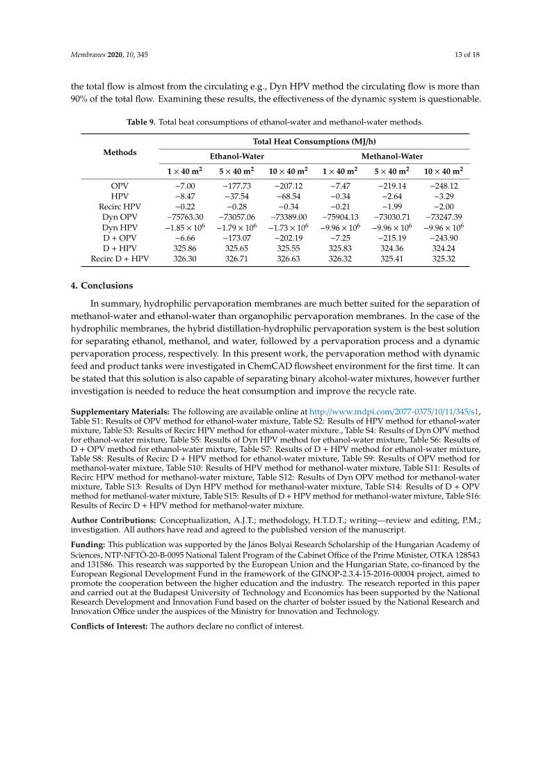
3.3. Heat Consumptions
In this section, the heat consumption of each method is analysed and summarized. The results arecollected in Table 9. The heat consumption is calculated from the heat exchanger in the pervaporationsystems, dynamic tank, and the heat requirements of the distillation column. The heat requirements forseparation of the ethanol-water mixture and methanol-water mixture is nearly equal e.g., for D+HPVmethod with one pervaporation membrane unit the heat consumption for separation of ethanol-wateris 325.86 MJ/h while in case of the methanol-water mixture is 325.83 MJ/h, see Table 9. The positivesign in Table 9 means the heat is given to the system and inversely the negative value means the heatis provided by the system. The more the membrane surface area increases, the more the amount ofheat consumption also increases. The total heat consumptions in the cases of D+HPV and D+HPVwith recirculation processes are positive, while for the other methods they are negative. From thesimulation results, it is clear that the heat consumption in pervaporation methods is the smallest one,follows by hybrid distillation and pervaporation systems, respectively. There is a huge differencebetween the heat consumption using dynamic system compared to the others. Since in the dynamicsystem, the circulating flow is indeed extremely big compared to the input flow, and in some cases,
Membranes 2020, 10, 345 13 of 18
the total flow is almost from the circulating e.g., Dyn HPV method the circulating flow is more than90% of the total flow. Examining these results, the effectiveness of the dynamic system is questionable.
Table 9. Total heat consumptions of ethanol-water and methanol-water methods.
MethodsTotal Heat Consumptions (MJ/h)
Ethanol-Water Methanol-Water
1 × 40 m2 5 × 40 m2 10 × 40 m2 1 × 40 m2 5 × 40 m2 10 × 40 m2
OPV −7.00 −177.73 −207.12 −7.47 −219.14 −248.12HPV −8.47 −37.54 −68.54 −0.34 −2.64 −3.29
Recirc HPV −0.22 −0.28 −0.34 −0.21 −1.99 −2.00Dyn OPV −75763.30 −73057.06 −73389.00 −75904.13 −73030.71 −73247.39Dyn HPV −1.85 × 10⁶
−1.79 × 10⁶−1.73 × 10⁶
−9.96 × 10⁶−9.96 × 10⁶
−9.96 × 10⁶
D + OPV −6.66 −173.07 −202.19 −7.25 −215.19 −243.90D + HPV 325.86 325.65 325.55 325.83 324.36 324.24
Recirc D + HPV 326.30 326.71 326.63 326.32 325.41 325.32
4. Conclusions
In summary, hydrophilic pervaporation membranes are much better suited for the separation ofmethanol-water and ethanol-water than organophilic pervaporation membranes. In the case of thehydrophilic membranes, the hybrid distillation-hydrophilic pervaporation system is the best solutionfor separating ethanol, methanol, and water, followed by a pervaporation process and a dynamicpervaporation process, respectively. In this present work, the pervaporation method with dynamicfeed and product tanks were investigated in ChemCAD flowsheet environment for the first time. It canbe stated that this solution is also capable of separating binary alcohol-water mixtures, however furtherinvestigation is needed to reduce the heat consumption and improve the recycle rate.
Supplementary Materials: The following are available online at http://www.mdpi.com/2077-0375/10/11/345/s1,Table S1: Results of OPV method for ethanol-water mixture, Table S2: Results of HPV method for ethanol-watermixture, Table S3: Results of Recirc HPV method for ethanol-water mixture., Table S4: Results of Dyn OPV methodfor ethanol-water mixture, Table S5: Results of Dyn HPV method for ethanol-water mixture, Table S6: Results ofD + OPV method for ethanol-water mixture, Table S7: Results of D + HPV method for ethanol-water mixture,Table S8: Results of Recirc D + HPV method for ethanol-water mixture, Table S9: Results of OPV method formethanol-water mixture, Table S10: Results of HPV method for methanol-water mixture, Table S11: Results ofRecirc HPV method for methanol-water mixture, Table S12: Results of Dyn OPV method for methanol-watermixture, Table S13: Results of Dyn HPV method for methanol-water mixture, Table S14: Results of D + OPVmethod for methanol-water mixture, Table S15: Results of D + HPV method for methanol-water mixture, Table S16:Results of Recirc D + HPV method for methanol-water mixture.
Author Contributions: Conceptualization, A.J.T.; methodology, H.T.D.T.; writing—review and editing, P.M.;investigation. All authors have read and agreed to the published version of the manuscript.
Funding: This publication was supported by the János Bolyai Research Scholarship of the Hungarian Academy ofSciences, NTP-NFTÖ-20-B-0095 National Talent Program of the Cabinet Office of the Prime Minister, OTKA 128543and 131586. This research was supported by the European Union and the Hungarian State, co-financed by theEuropean Regional Development Fund in the framework of the GINOP-2.3.4-15-2016-00004 project, aimed topromote the cooperation between the higher education and the industry. The research reported in this paperand carried out at the Budapest University of Technology and Economics has been supported by the NationalResearch Development and Innovation Fund based on the charter of bolster issued by the National Research andInnovation Office under the auspices of the Ministry for Innovation and Technology.
Conflicts of Interest: The authors declare no conflict of interest.
Membranes 2020, 10, 345 14 of 18
Nomenclature
Ji Partial flux [kg⁄(m2h)]Di Transport coefficient of component i [kmol⁄(m2h)]Q0 Permeability coefficient of the porous support layer of the membrane [kmol⁄(m2hbar)]pi0 Pure i component vapour pressure [bar]pi1 Partial pressure of component i on the vapor phase membrane side [bar]pi3 Partial pressure of component i. on the vapour phase membrane side [bar]γi Average activity coefficient of component ixi1 Concentration of component i in the feed [m⁄(m%)]Ei Activation energy of component i. in Equation (1) for temperature dependence of the transport
coefficient [kJ⁄mol]B Constant in pervaporation model [-]
References
1. Szanyi, A.; Mizsey, P.; Fonyo, Z. Novel hybrid separation processes for solvent recovery based onpositioning the extractive heterogeneous-azeotropic distillation. Chem. Eng. Process. Process Intensif.2004, 43, 327–338. [CrossRef]
2. Szanyi, A.; Mizsey, P.; Fonyo, Z. Optimization of Nonideal Separation Structures Based on ExtractiveHeterogeneous Azeotropic Distillation. Ind. Eng. Chem. Res. 2004, 43, 8269–8274. [CrossRef]
3. Tóth, A.J.; Szanyi, Á.; Koczka, K.; Mizsey, P. Enhanced separation of highly non-ideal mixtures with extractiveheterogeneous-azeotropic distillation. Sep. Sci. Technol. 2016, 51, 1238–1247. [CrossRef]
4. Toth, A.J.; Haaz, E.; Nagy, T.; Tari, R.; Tarjani, A.J.; Fozer, D.; Szanyi, A.; Koczka, K.-A.; Racz, L.;Ugro, G.; et al. Evaluation of the accuracy of modelling the separation of highly non-ideal mixtures:Extractive heterogeneous-azeotropic distillation. In Computer Aided Chemical Engineering; Espuña, A.,Graells, M., Puigjaner, L., Eds.; Elsevier: Amsterdam, The Netherlands, 2017; Volume 40, pp. 241–246.
5. Toth, A.J.; Szilagyi, B.; Haaz, E.; Solti, S.; Nagy, T.; Tarjani Ariella, J.; Valentinyi, N.; Mizsey, P. Separation ofMixture Containing Maximum Boiling Azeotrope with Extractive Heterogeneous-Azeotropic Distillation.Chem. Eng. Trans. 2018, 69, 571–576. [CrossRef]
6. Toth, A.J.; Fozer, D.; Nagy, T.; Haaz, E.; Nagy, J.; Mizsey, P. Modelling of extractive heterogeneous-azeotropicdistillation in dividing wall column. In Computer Aided Chemical Engineering; Kiss, A.A., Zondervan, E.,Lakerveld, R., Özkan, L., Eds.; Elsevier: Amsterdam, The Netherlands, 2019; Volume 46, pp. 235–240.
7. Toth, A.J.; Szilagyi, B.; Haaz, E.; Solti, S.; Nagy, T.; Szanyi, A.; Nagy, J.; Mizsey, P. Enhanced separation ofmaximum boiling azeotropic mixtures with extractive heterogeneous-azeotropic distillation. Chem. Eng.Res. Des. 2019, 147, 55–62. [CrossRef]
8. Laroche, L.; Andersen, H.W.; Morari, M.; Bekiaris, N. Homogeneous azeotropic distillation:Comparing entrainers. Can. J. Chem. Eng. 1991, 69, 1302–1319. [CrossRef]
9. Zhao, L.; Wang, W.; Shan, J.; Qiu, T. Comparison of Heterogeneous Azeotropic Distillation and ExtractiveDistillation Methods for Ternary Azeotrope Ethanol/Toluene/Water Separation. Comput. Chem. Eng.2017, 100. [CrossRef]
10. Toth, A.J.; Andre, A.; Haaz, E.; Mizsey, P. Modelling of organophilic pervaporation to compete withdistillation. In Computer Aided Chemical Engineering; Kravanja, Z., Bogataj, M., Eds.; Elsevier: Amsterdam,The Netherlands, 2016; Volume 38, pp. 343–348.
11. Tóth, A.J.; Haáz, E.; Nagy, T.; Tarjáni, A.J.; Fózer, D.; André, A.; Valentínyi, N.; Mizsey, P. Treatment ofpharmaceutical process wastewater with hybrid separation method: Distillation and hydrophilicpervaporation. Waste Treat. Recovery 2018, 3, 8–13. [CrossRef]
12. Fontalvo, J.; Keurentjes, J.T.F. A hybrid distillation–pervaporation system in a single unit for breakingdistillation boundaries in multicomponent mixtures. Chem. Eng. Res. Des. 2015, 99, 158–164. [CrossRef]
13. León, J.A.; Schuur, B.; Fontalvo, J. Hybrid distillation-pervaporation in a single unit: Experimental proof ofconcept in a batch operation. Sep. Purif. Technol. 2020, 252, 117464. [CrossRef]
Membranes 2020, 10, 345 15 of 18
14. León, J.A.; Fontalvo, J. Analysis of a hybrid distillation-pervaporation column in a single unit: Intermediatemembrane section in the rectifying and stripping section. Can. J. Chem. Eng. 2020, 98, 2227–2237. [CrossRef]
15. Ahmad, S.A.; Lone, S. Hybrid Process (Pervaporation-Distillation): A Review. Int. J. Sci. Eng. Res. 2012,3, 549–553.
16. Zhang, T.; Li, A.; Xu, X.; Ma, Y.; Xu, D.; Zhang, L.; Gao, J.; Wang, Y. Separation of azeotropic mixture(acetone + n-heptane) by extractive distillation with intermediate and heavy boiling entrainers: Vapour-liquidequilibrium measurements and correlation. J. Chem. Thermodyn. 2021, 152, 106284. [CrossRef]
17. Zhao, T.; Geng, X.; Qi, P.; Zhu, Z.; Gao, J.; Wang, Y. Optimization of liquid–liquid extraction combined witheither heterogeneous azeotropic distillation or extractive distillation processes to reduce energy consumptionand carbon dioxide emissions. Chem. Eng. Res. Des. 2018, 132, 399–408. [CrossRef]
18. Arifin, S.; Chien, I.L. Design and Control of an Isopropyl Alcohol Dehydration Process via ExtractiveDistillation Using Dimethyl Sulfoxide as an Entrainer. Ind. Eng. Chem. Res. 2008, 47, 790–803. [CrossRef]
19. Haáz, E.; Szilágyi, B.; Fózer, D.; Tóth, A.J. Combining extractive heterogeneous-azeotropic distillation andhydrophilic pervaporation for enhanced energetic separation of non-ideal ternary mixtures. Front. Chem.Sci. Eng. 2020, 14, 913–927. [CrossRef]
20. Eliceche, A.M.; Carolina Daviou, M.; Hoch, P.M.; Ortiz Uribe, I. Optimisation of azeotropic distillationcolumns combined with pervaporation membranes. Comput. Chem. Eng. 2002, 26, 563–573. [CrossRef]
21. Meng, J.; Li, P.; Cao, B. High-Flux Direct-Contact Pervaporation Membranes for Desalination. Acs Appl.Mater. Interfaces 2019, 11, 28461–28468. [CrossRef]
22. Khayet, M.; Matsuura, T. Pervaporation and vacuum membrane distillation processes: Modeling andexperiments. Aiche J. 2004, 50, 1697–1712. [CrossRef]
23. Verhoef, A.; Degrève, J.; Huybrechs, B.; van Veen, H.; Pex, P.; Van der Bruggen, B. Simulation of a hybridpervaporation–distillation process. Comput. Chem. Eng. 2008, 32, 1135–1146. [CrossRef]
24. Babaie, O.; Nasr Esfahany, M. Optimization of a new combined approach to reduce energy consumptionin the hybrid reactive distillation–pervaporation process. Chem. Eng. Process. Process Intensif. 2020,151, 107910. [CrossRef]
25. Tóth, A.J.; Szilágyi, B.; Do Thi, H.T.; Fózer, D.; Selim, A.; Haáz, E. Modelling of Hybrid Method for VOCRemoval from Process Wastewater: Distillation and Hydrophilic Pervaporation. Period. Polytech. Chem. Eng.2020, 64, 364–370. [CrossRef]
26. Sommer, S.; Melin, T. Design and Optimization of Hybrid Separation Processes for the Dehydration of2-Propanol and Other Organics. Ind. Eng. Chem. Res. 2004, 43, 5248–5259. [CrossRef]
27. Toth, A.J. Comprehensive evaluation and comparison of advanced separation methods on the separation ofethyl acetate-ethanol-water highly non-ideal mixture. Sep. Purif. Technol. 2019, 224, 490–508. [CrossRef]
28. Parvez, A.M.; Luis, P.; Ooms, T.; Vreysen, S.; Vandezande, P.; Degrève, J.; Van der Bruggen, B. Separation ofethyl acetate–isooctane mixtures by pervaporation and pervaporation-based hybrid methods. Chem. Eng. J.2012, 210, 252–262. [CrossRef]
29. Tóth, A.J.; Szilágyi, B.; Fózer, D.; Do Thi, H.T.; Selim, A.K.M.; Haáz, E. Separation of acetone-butanol-ethanol(ABE) fermentation products by pervaporation/Aceton-butanol-etanol (ABE) fermentációs termékekelválasztása pervaporáció segítségével. Circ. Econ. Environ. Prot. Körforgásos Gazdaság És Környezetvédelem2019, 3, 5–19.
30. Andre, A.; Nagy, T.; Toth, A.J.; Haaz, E.; Fozer, D.; Tarjani, J.A.; Mizsey, P. Distillation contra pervaporation:Comprehensive investigation of isobutanol-water separation. J. Clean. Prod. 2018, 187, 804–818. [CrossRef]
31. Omidali, M.; Raisi, A.; Aroujalian, A. Separation and purification of isobutanol from dilute aqueous solutionsby a hybrid hydrophobic/hydrophilic pervaporation process. Chem. Eng. Process. Process Intensif. 2014,77, 22–29. [CrossRef]
32. Cséfalvay, E.; Szitkai, Z.; Mizsey, P.; Fonyó, Z. Experimental data based modelling and simulation ofisopropanol dehydration by pervaporation. Desalination 2008, 229, 94–108. [CrossRef]
33. Kim, H.-G.; Na, H.-R.; Lee, H.R.; Kim, M.I.; Lim, C.-S.; Seo, B. Distillation-pervaporation membranehybrid system for epichlorohydrin and isopropyl alcohol recovery in epoxy resin production process.Sep. Purif. Technol. 2021, 254, 117678. [CrossRef]
Membranes 2020, 10, 345 16 of 18
34. Van Hoof, V.; Van den Abeele, L.; Buekenhoudt, A.; Dotremont, C.; Leysen, R. Economic comparisonbetween azeotropic distillation and different hybrid systems combining distillation with pervaporation forthe dehydration of isopropanol. Sep. Purif. Technol. 2004, 37, 33–49. [CrossRef]
35. Hassankhan, B.; Raisi, A. Separation of isobutanol/water mixtures by hybrid distillation-pervaporationprocess: Modeling, simulation and economic comparison. Chem. Eng. Process. Process Intensif. 2020,155, 108071. [CrossRef]
36. Koczka, K.; Manczinger, J.; Mizsey, P.; Fonyo, Z. Novel hybrid separation processes based on pervaporationfor THF recovery. Chem. Eng. Process. Process Intensif. 2007, 46, 239–246. [CrossRef]
37. Haelssig, J.B.; Thibault, J.; Tremblay, A.Y. Numerical investigation of Membrane Dephlegmation: A hybridpervaporation–distillation process for ethanol recovery. Chem. Eng. Process. Process Intensif. 2011,50, 1226–1236. [CrossRef]
38. Meng, D.; Dai, Y.; Xu, Y.; Wu, Y.; Cui, P.; Zhu, Z.; Ma, Y.; Wang, Y. Energy, economic and environmentalevaluations for the separation of ethyl acetate/ethanol/water mixture via distillation and pervaporation unit.Process Saf. Environ. Prot. 2020, 140, 14–25. [CrossRef]
39. Kunnakorn, D.; Rirksomboon, T.; Siemanond, K.; Aungkavattana, P.; Kuanchertchoo, N.; Chuntanalerg, P.;Hemra, K.; Kulprathipanja, S.; James, R.B.; Wongkasemjit, S. Techno-economic comparison of energy usagebetween azeotropic distillation and hybrid system for water–ethanol separation. Renew. Energy 2013,51, 310–316. [CrossRef]
40. Luis, P.; Amelio, A.; Vreysen, S.; Calabro, V.; Van der Bruggen, B. Simulation and environmental evaluation ofprocess design: Distillation vs. hybrid distillation–pervaporation for methanol/tetrahydrofuran separation.Appl. Energy 2014, 113, 565–575. [CrossRef]
41. Jyoti, G.; Keshav, A.; Anandkumar, J. Review on Pervaporation: Theory, Membrane Performance,and Application to Intensification of Esterification Reaction. J. Eng. 2015, 2015, 927068. [CrossRef]
42. Tusel, G.; Ballweg, A. Method and Apparatus for Dehydrating Mixtures of Organic Liquids and Water.US Patent 4405409A, 1983.
43. Zeng, W.; Li, B.; Li, H.; Jin, H.; Wu, D.; Li, Y. A pervaporation-crystallization (PC) process for simultaneousrecovery of ethanol and sodium pyruvate from waste centrifugal mother liquid. J. Membr. Sci. 2021,619, 118749. [CrossRef]
44. Johnson, R.A.; Sun, J.C.; Sun, J. A pervaporation–microfiltration–osmotic distillation hybrid process for theconcentration of ethanol–water extracts of the Echinacea plant. J. Membr. Sci. 2002, 209, 221–232. [CrossRef]
45. Rautenbach, R.; Herion, C.; Franke, M. Dehydration of multicomponent organic systems by a reverseosmosis pervaporation-hybrid process-module-, process design and economics. Desalination 1988,70, 445–453. [CrossRef]
46. Roza, M.; Maus, E. Industrial experience with hybrid distillation-pervaporation or vapor permeationapplications. Distillation & Absorption 2006.
47. Zarzo, D. 11-Beneficial uses and valorization of reverse osmosis brines. In Emerging Technologies for SustainableDesalination Handbook; Gude, V.G., Ed.; Butterworth-Heinemann: MS, USA, 2018; pp. 365–397. [CrossRef]
48. Cséfalvay, E.; Deák, A.; Farkas, T.; Hanák, L.; Mika, L.T.; Mizsey, P.; Sawinsky, J.; Simándi, B.; Szánya, T.;Székely, E.; et al. Vegyipari Muveletek II.: Anyagátadó muveletek és kémiai reaktorok; Budapest University ofTechnology and Economics, 2012; pp. 501–518.
49. Figoli, A.; Santoro, S.; Galiano, F.; Basile, A. Pervaporation membranes: Preparation, characterization,and application. In Pervaporation, Vapour Permeation and Membrane Distillation; Basile, A., Figoli, A.,Khayet, M., Eds.; Woodhead Publishing: Oxford, UK, 2015; pp. 19–63. [CrossRef]
50. Crespo, J.G.; Brazinha, C. Fundamentals of pervaporation. In Pervaporation, Vapour Permeation and MembraneDistillation; Basile, A., Figoli, A., Khayet, M., Eds.; Woodhead Publishing: Oxford, UK, 2015; pp. 3–17.[CrossRef]
51. Soriïn, M.; Ayotte-sauvé, E.; Sadeghiï, F.; Rheault, F. Thermodynamic Equipartition and Energy EfficientMembrane Networks. Int. J. Thermodyn. 2010, 13, 9–13.
52. Rhim, J.-W.; Park, H.B.; Lee, C.-S.; Jun, J.-H.; Kim, D.S.; Lee, Y.M. Crosslinked poly(vinyl alcohol) membranescontaining sulfonic acid group: Proton and methanol transport through membranes. J. Membr. Sci. 2004,238, 143–151. [CrossRef]
Membranes 2020, 10, 345 17 of 18
53. Hsueh, C.L.; Kuo, J.F.; Huang, Y.H.; Wang, C.C.; Chen, C.Y. Separation of ethanol–water solution bypoly(acrylonitrile-co-acrylic acid) membranes. Sep. Purif. Technol. 2005, 41, 39–47. [CrossRef]
54. Nik, O.G.; Moheb, A.; Mohammadi, T. Separation of Ethylene Glycol/Water Mixtures using NaA ZeoliteMembranes. Chem. Eng. Technol. 2006, 29, 1340–1346. [CrossRef]
55. Araki, S.; Gondo, D.; Imasaka, S.; Yamamoto, H. Permeation properties of organic compounds fromaqueous solutions through hydrophobic silica membranes with different functional groups by pervaporation.J. Membr. Sci. 2016, 514, 458–466. [CrossRef]
56. Kujawa, J.; Cerneaux, S.; Kujawski, W. Removal of hazardous volatile organic compounds from water byvacuum pervaporation with hydrophobic ceramic membranes. J. Membr. Sci. 2015, 474, 11–19. [CrossRef]
57. Ki Hong, Y.; Hi Hong, W. Influence of ceramic support on pervaporation characteristics of IPA/water mixturesusing PDMS/ceramic composite membrane. J. Membr. Sci. 1999, 159, 29–39. [CrossRef]
58. González-Velasco, J.R.; González-Marcos, J.A.; López-Dehesa, C. Pervaporation of ethanol—Water mixturesthrough poly(1-trimethylsilyl-1-propyne) (PTMSP) membranes. Desalination 2002, 149, 61–65. [CrossRef]
59. Liang, L.; Dickson, J.M.; Jiang, J.; Brook, M.A. Effect of low flow rate on pervaporation of 1,2-dichloroethanewith novel polydimethylsiloxane composite membranes. J. Membr. Sci. 2004, 231, 71–79. [CrossRef]
60. Mandal, S.; Pangarkar, V.G. Separation of methanol–benzene and methanol–toluene mixtures bypervaporation: Effects of thermodynamics and structural phenomenon. J. Membr. Sci. 2002,201, 175–190. [CrossRef]
61. Cunha, V.S.; Paredes, M.L.L.; Borges, C.P.; Habert, A.C.; Nobrega, R. Removal of aromatics frommulticomponent organic mixtures by pervaporation using polyurethane membranes: Experimental andmodeling. J. Membr. Sci. 2002, 206, 277–290. [CrossRef]
62. Smitha, B.; Suhanya, D.; Sridhar, S.; Ramakrishna, M. Separation of organic–organic mixtures bypervaporation—A review. J. Membr. Sci. 2004, 241, 1–21. [CrossRef]
63. Ghoreyshi, A.A.; Jahanshahi, M.; Peyvandi, K. Modeling of volatile organic compounds removal from waterby pervaporation process. Desalination 2008, 222, 410–418. [CrossRef]
64. Xu, Z.-K.; Dai, Q.-W.; Liu, Z.-M.; Kou, R.-Q.; Xu, Y.-Y. Microporous polypropylene hollow fiber membranes:Part II. Pervaporation separation of water/ethanol mixtures by the poly(acrylic acid) grafted membranes.J. Membr. Sci. 2003, 214, 71–81. [CrossRef]
65. Mohammadi, T.; Aroujalian, A.; Bakhshi, A. Pervaporation of dilute alcoholic mixtures using PDMSmembrane. Chem. Eng. Sci. 2005, 60, 1875–1880. [CrossRef]
66. Luis, P.; Van der Bruggen, B. Pervaporation modeling: State of the art and future trends. In Pervaporation,Vapour Permeation and Membrane Distillation; Basile, A., Figoli, A., Khayet, M., Eds.; Woodhead Publishing:Oxford, UK, 2015; pp. 87–106. [CrossRef]
67. Beebe, A.H.; Coulter, K.E.; Lindsay, R.A.; Baker, E.M. Equilibria in Ethanol-Water System at Pressures LessThan Atmospheric. Ind. Eng. Chem. 1942, 34, 1501–1504. [CrossRef]
68. Shah, D.; Kissick, K.; Ghorpade, A.; Hannah, R.; Bhattacharyya, D. Pervaporation of alcohol–waterand dimethylformamide–water mixtures using hydrophilic zeolite NaA membranes: Mechanisms andexperimental results. J. Membr. Sci. 2000, 179, 185–205. [CrossRef]
69. Zhang, W.-D.; Sun, W.; Yang, J.; Ren, Z.-Q. The Study on Pervaporation Behaviors of Dilute Organic SolutionThrough PDMS/PTFE Composite Membrane. Appl. Biochem. Biotechnol. 2009, 160, 156. [CrossRef]
70. Haaz, E.; Toth, A.J. Methanol dehydration with pervaporation: Experiments and modelling.Sep. Purif. Technol. 2018, 205, 121–129. [CrossRef]
71. Liu, X.; Sun, Y.; Deng, X. Studies on the pervaporation membrane of permeation water from methanol/watermixture. J. Membr. Sci. 2008, 325, 192–198. [CrossRef]
72. Kujawski, W. Pervaporative Removal of Organics from Water Using Hydrophobic Membranes.Binary Mixtures. Sep. Sci. Technol. 2000, 35, 89–108. [CrossRef]
73. Rautenbach, R.; Herion, C.; Meyer-Blumentoth, U. Pervaporation Membrane Separation Processes; Elsevier:New York, NY, USA, 1991; Volume 1, pp. 181–191.
74. Valentínyi, N.; Cséfalvay, E.; Mizsey, P. Modelling of pervaporation: Parameter estimation and modeldevelopment. Chem. Eng. Res. Des. 2013, 91, 174–183. [CrossRef]
Membranes 2020, 10, 345 18 of 18
75. Haáz, E.; Valentínyi, N.; Tarjáni, A.J.; Fózer, D.; André, A.; Selim, A.; Khaled, M.; Fuad, R.; Nagy, T.; Deák, C.;et al. Platform Molecule Removal from Aqueous Mixture with Organophilic Pervaporation: Experiments andModelling. Period. Polytech. Chem. Eng. 2019, 63, 138–146. [CrossRef]
76. Toth, A.J.; Mizsey, P. Methanol removal from aqueous mixture with organophilic pervaporation:Experiments and modelling. Chem. Eng. Res. Des. 2015, 98, 123–135. [CrossRef]
Publisher’s Note: MDPI stays neutral with regard to jurisdictional claims in published maps and institutionalaffiliations.
© 2020 by the authors. Licensee MDPI, Basel, Switzerland. This article is an open accessarticle distributed under the terms and conditions of the Creative Commons Attribution(CC BY) license (http://creativecommons.org/licenses/by/4.0/).