Sensitivity Investigation of Three-Cylinder Model of Human Knee Joint
10
33 Biomechanica Hungarica III. évfolyam, 1. szám 4. MAGYAR BIOMECHANIKAI KONFERENCIA – A-0024 SENSITIVITY INVESTIGATION OF THREE-CYLINDER MODEL OF HUMAN KNEE JOINT István Bíró 1 , Béla M. Csizmadia 2 , Gábor Katona 2 1 University of Szeged, Faculty of Engineering, Szeged, Hungary 2 Szent István University, Faculty of Mechanical Engineering, Gödöllő, Hungary [email protected] Abstract The operation is unavoidable in a certain part of patients suffering from arthrosis. The contact surfaces of wide-spread applied human knee joint prostheses can be described with simple geo- metrical elements. The relative motion realized by knee joint and as its results the stability of the whole body is harmonic ensured by complicated condyle surfaces. For this reason the implanted prostheses comply with requirements limited and it causes additional load on the diseased bony tissue. According to observations at the fastening of the prostheses the bony tissues become inflamed which after some years need new operation. At present it is a general aim in biomechanics to create a better mechanical model of human knee joint which can approach the natural motion and on its basis to make new prostheses. The motion of the human knee joint have been studying by many biomechanical research groups for decades. The problem is very complex and specific from technical point of view. The cause of complexity is partly the elaborateness of elements, partly the typical rheological properties of the components (bones, cartilages and other soft tissues). Authors as members of the Szent István University Biomechanical Research Group in order to describe the motion of knee joint at first joined coordinate-systems on the basis of anatomical landmarks to the femur and tibia moreover joined a three-cylindrical mechanism as mechanical model to the axes of coordinate-systems. The aim of the investigation is to determine the six independent kinematical parameters of tibia compared to the fixed femur during flexion and extension. The experimental examinations were carried out on cadaver knees in cooperation with doctors of Szent János Hospital. The position- ing was tracked by optical positioning appliance. Needed parameters can be obtained from the recorded data determined by the kinematical model. Considering the irregular shapes of femur and tibia the anatomical coordinate systems can be joined with more or less position mistake. The aim of this paper is the determination of the effects of position mistakes on kinematical parameters. Keywords: knee joint; kinematical model; optical positioning; accuracy; sensitivity investigation
-
Upload
independent -
Category
Documents
-
view
1 -
download
0
Transcript of Sensitivity Investigation of Three-Cylinder Model of Human Knee Joint
33
Biomechanica Hungarica III. évfolyam, 1. szám
4. M
AGYA
R B
IOM
EC
HA
NIK
AI
KO
NFE
RE
NC
IA –
A-0
024
SENSITIVITY INVESTIGATION OF THREE-CYLINDER MODEL OF HUMAN KNEE JOINT
István Bíró1, Béla M. Csizmadia2, Gábor Katona2
1 University of Szeged, Faculty of Engineering, Szeged, Hungary2 Szent István University, Faculty of Mechanical Engineering, Gödöllő, [email protected]
AbstractThe operation is unavoidable in a certain part of patients suffering from arthrosis. The contact surfaces of wide-spread applied human knee joint prostheses can be described with simple geo-metrical elements. The relative motion realized by knee joint and as its results the stability of the whole body is harmonic ensured by complicated condyle surfaces. For this reason the implanted prostheses comply with requirements limited and it causes additional load on the diseased bony tissue. According to observations at the fastening of the prostheses the bony tissues become infl amed which after some years need new operation.
At present it is a general aim in biomechanics to create a better mechanical model of human knee joint which can approach the natural motion and on its basis to make new prostheses. The motion of the human knee joint have been studying by many biomechanical research groups for decades. The problem is very complex and specifi c from technical point of view. The cause of complexity is partly the elaborateness of elements, partly the typical rheological properties of the components (bones, cartilages and other soft tissues).
Authors as members of the Szent István University Biomechanical Research Group in order to describe the motion of knee joint at fi rst joined coordinate-systems on the basis of anatomical landmarks to the femur and tibia moreover joined a three-cylindrical mechanism as mechanical model to the axes of coordinate-systems.
The aim of the investigation is to determine the six independent kinematical parameters of tibia compared to the fi xed femur during fl exion and extension. The experimental examinations were carried out on cadaver knees in cooperation with doctors of Szent János Hospital. The position-ing was tracked by optical positioning appliance. Needed parameters can be obtained from the recorded data determined by the kinematical model.
Considering the irregular shapes of femur and tibia the anatomical coordinate systems can be joined with more or less position mistake. The aim of this paper is the determination of the effects of position mistakes on kinematical parameters.
Keywords: knee joint; kinematical model; optical positioning; accuracy; sensitivity investigation

Biomechanica Hungarica III. évfolyam, 1. szám
34
4. M
AGYA
R B
IOM
EC
HA
NIK
AI
KO
NFE
RE
NC
IA –
A-0
024
Introduction
Different constraints enable relative motion of joined rigid bodies referring to each other. The constraints depending on their shapes have one or more degree of freedom. In case of joints the degree of freedom cannot be always determined. It is expedient to treat the human knee joint as six degree of freedom because of its complicated shape. In this case to the precise description of motion achieved by knee joint we need six independent position parameters1,7.
In recent years the number of kinematical models of anatomical joints has increased. In case of certain models so many researchers have measured and described joint motion with less than six degrees of freedom. Obvi-ously the treatment of six degree of freedom models is the most diffi cult. The motion of human knee joint can be described by follow-ing components: The fl exion-extension is defi ned around the medio-lateral axis, inter-nal-external rotation around the tibial axis and the abduction-adduction around the anterior-posterior (fl oating) axis. The medio-lateral translation is measured along the medio-lateral axis, proximal-distal translation along the tibial axis and antero-posterior translation along the mutually perpendicular fl oating axis.
Description of motion components in such a way a little bit subjective. In order to descript the motion components precisely it is needed to join coordinate-systems to the femur and tibia consequently.
In recent decades to measure kinematical parameters of human knee joint different methods have been developed. In these meth-ods it is measured and processed the motion of markers fastened to femur and tibia referring to each other. In vitro mechanical investigations are mainly phantom or simulated computer models or cadaver motion experiments7.
The visual examinations were based on marker technique to sign single points or axis of the extremities delineating their motion. In spite of that the newly introduced techniques devel-oped in an enormous numbers in the last decades e.g. the radiology, fl uoroscopy, three-dimensional CT, MRI, stereophotogramme-try, ultrasound, etc. most of the results were unreliable, inconsistent with other published data3,4,5,6. The range of the tibia out and in-rotation along the fl exion-extension motion of the knee had been established by different authors as between 5 up to 17 degrees, more-over the character of this diagram is variable8,9. On the basis of difference of published results it is quite diffi cult to establish exact character concerning the motion of knee joint.
Method
Authors developed a special appliance10,11,12 in order to make a serial experiments. The aim of them was the determination of change of six independent kinematical parameters of tibia (shin bone) compared to femur (thigh bone) during of motion of human knee joint. From recorded data needed parameters can be deter-mined by the aid of kinematical model.
To the presented sensitivity investigation it is necessary to determine anatomical landmarks on femur and tibia moreover coordinate-sys-tems joining to the determined anatomical landmarks. Details of this process can be found in paper of Katona et al13,14,15. Considering the biological characters of femur and tibia the optical positioning of anatomical landmarks can be achieved with more or less position mistakes. The aim of this paper is the determi-nation of the effects on kinematical parameters of position mistakes during fl exion-extension of human knee joint.
Authors on the basis of current international standards and conventions (e.g. from the Inter-

35
Biomechanica Hungarica III. évfolyam, 1. szám
4. M
AGYA
R B
IOM
EC
HA
NIK
AI
KO
NFE
RE
NC
IA –
A-0
024
national Society of Biomechanics)16 using the above mentioned anatomical landmarks joined coordinate-systems to femur and tibia.
At fi rst to the processing of recorded position-ing coordinates it is necessary to take the ana-tomical coordinate-system on anatomical land marks of femur in coordinate-system fs (fs in the appliance, joined to femur rigidly) (Figure 1).
Needed data determining anatomical coordi-nate-system XoYoZo (in coordinate-system fs):– centre of the femoral head (fh)– medial and lateral epicondyles (Pmcl , Plcl).
The origin of this anatomical coordinate-sys-tem (Ot) coincides with middle point of line between medial and lateral epicondyles. Axis Xo of coordinate-system is on the line pointed out by points Ot and fh (Figure 1). Vector vepi is between medial and lateral epicondyles.
Unit vectors of axes of coordinate-systems can be obtained as results of following vector oper-ations:
Determining coordinate-system joined to ana-tomical landmarks on tibia: Needed data for coordinate-system xsyszs (in appliance):– apex of the head of the fi bula (hf),– prominence of the tibial tuberosity (tt),– distal apex of the lateral and medial malleo-
lus (kb, bb).
The origin of the anatomical coordinate-sys-tem (Os) coincides with middle point of line between distal apex of the lateral and medial malleolus. Unit vectors of axes of coordinate-systems can be obtained as results of next vec-tor operations (Figure 2):
During motion investigation of knee joint we follow the change of position of coordinate-system ts joined to tibia compared to coordi-nate-system fs joined to femur. We had to describe anatomical coordinate-systems in coordinate-systems joined to femur and tibia for the sake of following: in this way the posi-
Ofs
xfs
yfs
zfs Ot
Xo
Zo
Yo
eXo
eYo
eZo
vepi
Pmcl
Plcl
Figure 1. Position of anatomical coordinate-system XoYoZo joined to femur in coordinate-system fs (cadaver lying on his back, investigated right leg, view from medial side)

Biomechanica Hungarica III. évfolyam, 1. szám
36
4. M
AGYA
R B
IOM
EC
HA
NIK
AI
KO
NFE
RE
NC
IA –
A-0
024
tion of anatomical coordinate-system joined to tibia in anatomical coordinate-system joined to femur will be known.
If the anatomical landmarks on femur and tibia are determined with some position mis-take the kinematical parameters of knee joint will be modifi ed. These kinematical parame-ters can be obtained by the aid of three-cylin-drical mechanism put in between the above defi ned anatomical coordinate-systems.
Three-Cylindrical mechanism
Putting the origin of coordinate-system X3Y3Z3 (without modifi cation of direction of axes) into the origin of coordinate-system xsyszs unit vectors will be the followings:
The position of coordinate-system X3Y3Z3 in the coordinate-system XoYoZo is described by the next matrix-equation:
[T0–3]=[Tts–3][Tabs–ts][Tabs–fs]–1[Tfs–0]–1
in which the transformation matrices– [Tts–3] which contains six position parame-
ters describing the position of anatomical coordinate-system (X3Y3Z3) joined to tibia in coordinate-system ts,
– [Tabs–ts] which contains six position param-eters describing the position of coordinate-system ts in absolute coordinate-system (XYZ),
– [Tabs–fs]–1 inverse transformation matrix which contains six position parameters describing the position of coordinate-system fs in absolute coordinate-system (XYZ),
– [Tfs–0]–1 inverse transformation matrix which contains six position parameters describing the position of anatomical coordinate-sys-tem XoYoZo joined to femur in coordinate-system fs.
Transformation matrix [T0–3] can be written down in another way:
Ots xts
yts
zts
Os
tt vkb-bb bb
hf
ekb-bb
ekb-hf vkb-hf
vOs-tt
kb
xs
exs zs
ezs
ys eys
Figure 2. Position of anatomical coordinate-system xsyszs joined to tibia in coordinate-system ts (cadaver lying on his back, investigated right leg, view from medial side)

37
Biomechanica Hungarica III. évfolyam, 1. szám
4. M
AGYA
R B
IOM
EC
HA
NIK
AI
KO
NFE
RE
NC
IA –
A-0
024
where eX 3, eY 3, eZ 3 are unit vectors of axes X3, Y3 , Z3 in coordinate-system XoYoZo and vector rO3 contains the coordinates of origin of coor-dinate-system X3Y3Z3 in coordinate-system XoYoZo.
In case of similar spatial structures the so-called Denavit–Hartenberg (HD) coordinates can be applied (Figure 4). The advantage of the application of HD coordinates: the trans-formation matrix contains – instead of six – four (Θi, di, li, αi) variable physical quantities joining to geometrical characters of bodies and their constraint.
In Figure 3 the HD coordinates can be seen in extended position of the leg. In the mechanism αi, li, (i=1,2,3) can be adjustable optionally
according to the special geometry of knee joint. On the basis of published recommendations next data are proper approaching: α1=α2=90º, α3=0º, l1=l2=l3=0.
Figure 3. Three-cylindrical mechanism with the defi ned coordinate-systems (extended position)
tíbia
Y3
Z3
l3=0 d3 α2
X2
Z2
X1
Y1
Y0
X0
Z0
Z1
d1
l1
α1 d2
l2
Y2
Θ2
Θ3
Θ1
femur-anatomical cs
a n
o
Ots
X3
xts
yts zts
Tibia-anatomical cs
xs
ys
zs
zfs yfs
xfs
Os
Ot
αi+1
Xi+1
Zi+1
Xi
Yi
Zi
di
li
αi di+1
li+1
Yi+1
Θi+1
Θi
Figure 4. Connection of ith and i+1th bodies and joined coordinate-systems

Biomechanica Hungarica III. évfolyam, 1. szám
38
4. M
AGYA
R B
IOM
EC
HA
NIK
AI
KO
NFE
RE
NC
IA –
A-0
024
The application of the model enables the cal-culation of following quantities:– Θ1 – fl exion, in drawn position 0 degree,– Θ2 – ab/adduction, in drawn position
90 degree,– Θ3 – rotation of the tibia, in drawn position
0 degree,– d1, d2, d3 – moving on accordant axes.
On the basis of approaching α1=α2=90°, α3=0°, l1=l2=l3=0 for the kinematical chain of Figure 3 the following matrix equation can be written down where n, o, a are unit vectors of coordinate-system X3Y3Z3 in coordinate-system X0Y0Z0 and Px, Py, Pz are coordinates of origin of coordinate-system X3Y3Z3 in coor-dinate-system X0Y0Z0.
Roots of equation system: Θ1, Θ2, Θ3, d1, d2, d3, which determine precisely the position of tibia compared to femur.
Sensitivity investigation of results
As results obtained kinematical parameters and diagrams depend partly on method of measurement and anatomical specialties cadaver however principally on determina-tion of coordinate-systems joined to femur and tibia.
Considering the irregular shapes of femur and tibia the anatomical landmarks can be deter-mined with more or less position mistake for
this reason the anatomical coordinate-systems joined to anatomical landmarks have more or less position mistake as well15. The following anatomical landmarks must be measured: – centre of the femoral head (fh),– medial and lateral epicondyles (Pmcl, Plcl),– apex of the head of the fi bula (hf),– prominence of the tibial tuberosity (tt),– distal apex of the lateral and medial malleo-
lus (kb, bb).
The optical positioning of above mentioned anatomical landmarks was made by a special appliance using pointer. The position mistakes of middle point of femur, apex of the head of the fi bula and prominence of the tibial tuber-osity cause small angular mistakes because these point are located relative far from origins of coordinate-systems.
The origins of coordinate-systems are deter-mined between epicondyles and apices of the lateral and medial malleolus therefore the effect of position mistakes on position and ori-entation of coordinate-systems is quite signifi -cant. Considering the different shapes of investigated cadaver femur and tibia and posi-tion mistakes of measurements – depending on cadaver ones – more or less different kine-matical functions can be obtained.
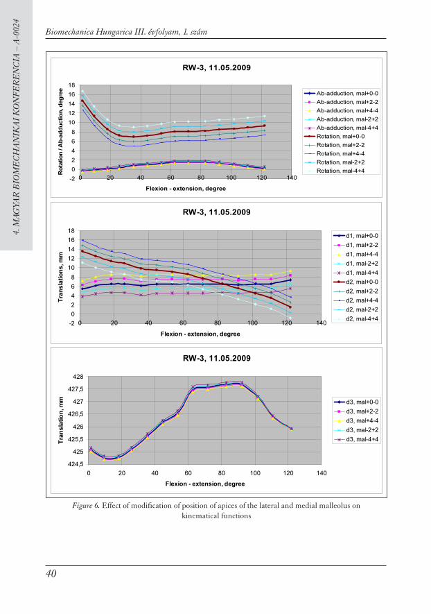
As fi rst step of sensitivity investigation the positions of epicondyles were modifi ed in coordinate-system fs step by step (±2 mm) approximately in the vertical plane (Figure 1). In second phase the position of apices of the lateral and medial malleolus were modifi ed in coordinate-system ts step by step (±2 mm) approximately in the vertical plane as well (Figure 2). Difference from basic function (thickened curve) can be seen in Figure 5–6. (The basic function contains some mistakes because it was calculated from measured data.)
∗
⎥
⎥
⎥
⎥
⎦
⎤
⎢
⎢
⎢
⎢
⎣
⎡
Θ−Θ
ΘΘ
∗
⎥
⎥
⎥
⎥
⎦
⎤
⎢
⎢
⎢
⎢
⎣
⎡
Θ−Θ
ΘΘ
1000
2
010
0
2
cos0
2
sin
0
2
sin0
2
cos
1000
1
010
0
1
cos0
1
sin
0
1
sin0
1
cos
dd
⎥
⎥
⎥
⎥
⎥
⎦
⎤
⎢
⎢
⎢
⎢
⎢
⎣
⎡
=
⎥
⎥
⎥
⎥
⎦
⎤
⎢
⎢
⎢
⎢
⎣
⎡
ΘΘ
Θ−Θ
∗
10001000
3
100
00
3
cos
3
sin
00
3
sin
3
cos
zP
za
zo
zn
yP
ya
yo
yn
xP
xa
xo
xn
d

39
Biomechanica Hungarica III. évfolyam, 1. szám
4. M
AGYA
R B
IOM
EC
HA
NIK
AI
KO
NFE
RE
NC
IA –
A-0
024
RW-3, 11.05.2009
-5
0
5
10
15
20
25
0 20 40 60 80 100 120 140
Flexion - extension, degree
Ro
ta
tio
n / a
b-a
dd
uc
tio
n,
de
gre
e
Ab-adduction, epi+0-0
Ab-adduction, epi+2-2
Ab-adduction, epi+4-4
Ab-adduction, epi-2+2
Ab-adduction, epi-4+4
Rotation, epi+0-0
Rotation, epi+2-2
Rotation, epi+4-4
Rotation, epi-2+2
Rotation, epi-4+4
RW-3, 11.05.2009
0
2
4
6
8
10
12
14
16
0 20 40 60 80 100 120 140
Flexion - extension, degree
Tran
la
tio
ns, m
m
d1, epi+0-0
d1, epi+2-2
d1, epi+4-4
d1, epi-2+2
d1, epi-4+4
d2, epi+0-0
d2, epi+2-2
d2, epi+4-4
d2, epi-2+2
d2, epi-4+4
RW-3, 11.05.2009
424,5
425
425,5
426
426,5
427
427,5
428
428,5
0 20 40 60 80 100 120 140
Flexion - extension, degree
Tra
nla
tio
n, m
m d3, epi+0-0
d3, epi+2-2
d3, epi+4-4
d3, epi-2+2
d3, epi-4+4
Figure 5. Effect of modifi cation of position of epicondyles on kinematical functions
Biomechanica Hungarica III. évfolyam, 1. szám
40
4. M
AGYA
R B
IOM
EC
HA
NIK
AI
KO
NFE
RE
NC
IA –
A-0
024
RW-3, 11.05.2009
-2
0
2
4
6
8
10
12
14
16
18
0 20 40 60 80 100 120 140
Flexion - extension, degree
Ro
tatio
n / A
b-ad
du
ctio
n, d
eg
ree
Ab-adduction, mal+0-0
Ab-adduction, mal+2-2
Ab-adduction, mal+4-4
Ab-adduction, mal-2+2
Ab-adduction, mal-4+4
Rotation, mal+0-0
Rotation, mal+2-2
Rotation, mal+4-4
Rotation, mal-2+2
Rotation, mal-4+4
RW-3, 11.05.2009
-2
0
2
4
6
8
10
12
14
16
18
0 20 40 60 80 100 120 140
Flexion - extension, degree
Tran
slatio
ns
, m
m
d1, mal+0-0
d1, mal+2-2
d1, mal+4-4
d1, mal-2+2
d1, mal-4+4
d2, mal+0-0
d2, mal+2-2
d2, mal+4-4
d2, mal-2+2
d2, mal-4+4
RW-3, 11.05.2009
424,5
425
425,5
426
426,5
427
427,5
428
0 20 40 60 80 100 120 140
Flexion - extension, degree
Tran
slatio
n, m
m
d3, mal+0-0
d3, mal+2-2
d3, mal+4-4
d3, mal-2+2
d3, mal-4+4
Figure 6. Effect of modifi cation of position of apices of the lateral and medial malleolus on kinematical functions

41
Biomechanica Hungarica III. évfolyam, 1. szám
4. M
AGYA
R B
IOM
EC
HA
NIK
AI
KO
NFE
RE
NC
IA –
A-0
024
Conclusion
As result of sensitivity investigation the follow-ings are established:
– The fl exion-rotation and fl exion-ab/adduc-tion diagrams depend strongly on position mistakes of determined coordinate-systems, for this reason it is important to determine the anatomical landmarks.
– The cause of modifi cation of diagrams is fi rst of all the position mistake in direction of Y axis of epicondyles. ° Its effect can be seen over 60 degree in fl exed
position. In this part the diagrams are approximately linear, their gradient vari-
able depending on position mistakes of epi-condyles.
° The shapes of ab/adduction diagrams are strongly deformed.
Summing up it can be established that the using of anatomical coordinate-systems enables the comparison and generalization of results of different motion investigation of human knee joints. On the basis of above mentioned it can be decided which parts of obtained results are acceptable certainly which parts and its conclusions need chary treatment. By more precise prescription of taking up of anatomical coordinate-system the comparison of results can be intensifi ed.
1. Grood ES, Suntay WJ. A joint coordinate system for the clinical description of three-dimensional motions: application to the knee. J. Biomech. Engng 1983;105: pp. 136–144.
2. Pennock GR, Clark KJ. An anatomybased coordi-nate system for the description of the kinematic displacements in the human knee. J. Biomechan-ics 1990; Vol. 23, No. 12: pp. 1209–1218.
3. Blankevoort L, Huiskes R, Lange A. Helical axes of passive knee joint motions. J. Biomechanics 1990; Vol. 23, No. 12, pp. 1219–1229.
4. Hollister AM, et al. The axes of rotation of the knee. Clinical Orthopaedics and Related Re-search 1993;(290): p. 259.
5. Fujie H, Livesay GA, Fujita M, Woo SLY. Forces and Moments in six-dof at the Human Knee Joint: Mathematical Description for Control. J. Biomechanics 1996; Vol. 29, No. 12:1577–1585.
6. Churchill DL, et al. The transepicondylar axis approximates the optimal fl exion axis of the knee. Clinical Orthopaedics and Related Research, 1998;(356): p. 111–118.
7. Bull AMJ, Amis AA. Knee joint motion: descrip-tion and measurement Proc Instn Mech Engrs 1998;Vol 212, Part H.
8. Iwaki H, Pinskerova V, Freeman MAR. Tibio-femoral movement 1: the shapes and relative movements of the femur and tibia in the unloaded cadaver knee. The Journal of Bone and Joint Surgery [Br] 2000;82-B:1189–1195.
9. Wilson DR, Feikes JD, Zavatsky AB, O’Connor JJ. The components of passive knee movement are coupled to fl exion angle. Journal of Biomechan-ics 2000;33:465–473.
10. Bíró I. Kinematical investigation of human knee joint. 21th Working Meeting of the IFToMM Permanent Commission for Standardization of Terminology, Proceedings of the sientifi c semi-nar, June 27–July 2, 2005. Bardejov Spa, Slova-kia, 91–96. p.
11. Szakál Z. Mérőberendezés térdízület mozgás-vizsgálatához. GÉP, 2006; LVII. évfolyam 1. szám: 37–40.
12. Katona G, M. Csizmadia B, Fekete G. Kísérleti vizsgálatok térd mechanikai modelljének meg-
REFERENCES
Biomechanica Hungarica III. évfolyam, 1. szám
42
4. M
AGYA
R B
IOM
EC
HA
NIK
AI
KO
NFE
RE
NC
IA –
A-0
024
alkotásához. 2. Magyar Biomechanikai konfe-rencia, Debrecen, 2006. június 30–július 1. p. 49–50.
13. Bíró I, M. Csizmadia B, Katona G. New approxi-mation of kinematical analysis of human knee joint. Bulletin of the Szent István University, ISSN 1586-4502 2008; p. 330–338
14. Bíró I. Az emberi térd három-hengeres kine-matikai modellje. Elektronikus Műszaki Füze-
tek VII. DAB Műszaki Szakbizottság, ISBN 978-963-7064-22-7, Debrecen 2009; p. 107–112.
15. Katona G, M. Csizmadia B, Bíró I, Andrónyi K, Krakovits G. Cadaver térdek mozgásának érté ke-lése anatómiai koordináta-rendszerek felhasz ná-lásával. Proceedings of 4th Hungarian Confer-ence on Biomechanics, Pécs, May 7–8, 2010.
16. http://www.ulb.ac.be/project/vakhum