Semantic Simulation Engine in Mobile Robot Operator Training Tool
15
Semantic simulation engine in mobile robot operator training tool Janusz Bedkowski and Andrzej Mas lowski Institute of Automation and Robotics, Warsaw University of Technology, Warsaw, Poland, Institute of Mathematical Machines, Warsaw, Poland [email protected] [email protected] Abstract. In the paper the semantic simulation engine and its role in multi level mobile robot operator training tool is described. Semantic simulation engine provides tools to implement mobile robot simulation based on real data delivered by robot observations in INDOOR envi- ronment. It is important to emphasize that real and virtual part of the training system is integrated. The supervision of real objects such as robots is performed by association with its virtual representation in the simulation, therefore events such as object intersection, robot pitch roll are defined. Semantic simulation engine is composed of data registration modules, semantic entities identification modules (data segmentation) and semantic simulation module. The data registration modules delivers 3D point clouds aligned with ICP (Iterative Closest Point) algorithm ac- celerated by parallel computation to obtain on-line processing. Semantic entities identification modules provide implementation of methods for obtaining semantic entities from robot observations (already registered). Semantic simulation module executes rigid body simulation with prede- fined simulation events. It is implemented using NVIDIA PhysX engine. The simulation can be easy integrated with real part of the system with an assumption of robust localization of real entities, therefore Augmented Reality capabilities are available. Keywords: Semantic mapping, operator training, mobile robot 1 Introduction and related work Semantic simulation engine is an extension of framework for designing tools for mobile robot operator training [1] and it is related to semantic mapping. Semantic information [2] extracted from 3D laser data [3] is recent research topic of modern mobile robotics. In [4] a semantic map for a mobile robot was described as a map that contains, in addition to spatial information about the environment, assignments of mapped features to entities of known classes. In [5] a model of an indoor scene is implemented as a semantic net. This approach is used in [6] where robot extracts semantic information from 3D models built from
-
Upload
independent -
Category
Documents
-
view
0 -
download
0
Transcript of Semantic Simulation Engine in Mobile Robot Operator Training Tool

Semantic simulation engine in mobile robotoperator training tool
Janusz Bedkowski and Andrzej Mas lowski
Institute of Automation and Robotics, Warsaw University of Technology, Warsaw,Poland,
Institute of Mathematical Machines, Warsaw, [email protected]
Abstract. In the paper the semantic simulation engine and its role inmulti level mobile robot operator training tool is described. Semanticsimulation engine provides tools to implement mobile robot simulationbased on real data delivered by robot observations in INDOOR envi-ronment. It is important to emphasize that real and virtual part of thetraining system is integrated. The supervision of real objects such asrobots is performed by association with its virtual representation in thesimulation, therefore events such as object intersection, robot pitch rollare defined. Semantic simulation engine is composed of data registrationmodules, semantic entities identification modules (data segmentation)and semantic simulation module. The data registration modules delivers3D point clouds aligned with ICP (Iterative Closest Point) algorithm ac-celerated by parallel computation to obtain on-line processing. Semanticentities identification modules provide implementation of methods forobtaining semantic entities from robot observations (already registered).Semantic simulation module executes rigid body simulation with prede-fined simulation events. It is implemented using NVIDIA PhysX engine.The simulation can be easy integrated with real part of the system withan assumption of robust localization of real entities, therefore AugmentedReality capabilities are available.
Keywords: Semantic mapping, operator training, mobile robot
1 Introduction and related work
Semantic simulation engine is an extension of framework for designing toolsfor mobile robot operator training [1] and it is related to semantic mapping.Semantic information [2] extracted from 3D laser data [3] is recent researchtopic of modern mobile robotics. In [4] a semantic map for a mobile robot wasdescribed as a map that contains, in addition to spatial information about theenvironment, assignments of mapped features to entities of known classes. In [5]a model of an indoor scene is implemented as a semantic net. This approach isused in [6] where robot extracts semantic information from 3D models built from

2 Lecture Notes in Computer Science: Authors’ Instructions
a laser scanner. In [7] the location of features is extracted by using a probabilistictechnique (RANSAC RANdom SAmple Consensus) [8]. Also the region growingapproach [9] extended from [10] by efficiently integrating k-nearest neighbor(KNN) search is able to process unorganized point clouds. The improvementof plane extraction from 3D Data by fusing laser data and vision is shown in[11]. The automatic model refinement of 3D scene is introduced in [12] wherethe idea of feature extraction (planes) is done also with RANSAC algorithm.The semantic map building is related to SLAM (Simultaneous Localization andMapping) problem [13]. Most of recent SLAM techniques use camera [14], lasermeasurement system [15] or even registered 3D laser data [16]. Concerning theregistration of 3D scans described in [17] [18] we can find several techniquessolving this important issue. The authors of [19] briefly describe ICP (IterativeClosest Point) algorithm. In [20] the mapping system that acquires 3D objectmodels of man-made indoor environments such as kitchens is shown. The systemsegments and geometrically reconstructs cabinets with doors, tables, drawers,and shelves, objects that are important for robots retrieving and manipulatingobjects in these environments.
In this paper new idea of semantic simulation engine is proposed. Semanticsimulation engine combines semantic map with rigid body simulation to performsupervision of its entities such as robots moving in INDOOR environment com-posed by floor, ceiling, walls, door etc. Automatic detection concerning theseentities are based on robot’s observations, the relations between them are de-fined by semantic net. A detailed description of computer based simulators forunmanned vehicles is shown in [21]. Also in [22] the comparison of real-timephysics simulation systems is given, where a qualitative evaluation of a num-ber of free publicly available physics engines for simulation systems and gamedevelopment is presented. Several frameworks are mentioned such as USARSimwhich is very popular in research society [23] [24], Stage, Gazebo [25], Webots[26], Matlab [27] and MRDS [28]. Some researchers found that there are manyavailable simulators that offer attractive functionality, therefore they proposeda new simulator classification system specific to mobile robots and autonomousvehicles [29]. A classification system for robot simulators will allow researchersto identify existing simulators which may be useful in conducting a wide vari-ety of robotics research from testing low level or autonomous control to humanrobot interaction. Another simulation engine - the Search and Rescue Game En-vironment (SARGE), which is a distributed multi-player robot operator traininggame, is described in [30]. To conclude this section it can be stated that thereare many available sophisticated mobile robotic systems, in the same time theergonomic solutions for HMI (Human Robot Interface) are necessary to performcomplex tasks. Based on this observation advanced training systems are neededto improve operators’ skills. It this paper multi level training is introduced andthe role of components of semantic simulation engine for each training level isdescribed.
The paper is organized as follows: section Semantic simulation engine de-scribes the structure of semantic simulation engine and its components, section

Semantic simulation engine in mobile robot operator training tool 3
Mobile robot operator training tool describes training tools in RISE (Risky In-tervention and Surveillance Environment) developed during project, named Aplatform for design of computer trainer-simulators for operators of inspection-intervention mobile robots. Section Role of semantic simulation engine in train-ing shows main experiments performed in real and simulated environment, andthe role of semantic simulation in multi level training is discussed, section Con-clusion and future work gives final discussion and shows areas of future work.
2 Semantic simulation engine
The concept of semantic simulation engine applied in mobile robot operatortraining is a new idea, and its strength lies on the semantic map integrationwith mobile robot simulator. Semantic simulation engine is composed of dataregistration modules, semantic entities identification (data segmentation) mod-ules and semantic simulation module. It provides tools to implement mobilerobot simulation based on real data delivered by robot and processed on-lineusing parallel computation. Semantic entities identification modules can classifydoor, walls, floor, ceiling, stairs in indoor environment. Data can be deliveredby robot observation based on modern sensors such as laser measurement sys-tem 3D and RGB-D cameras. Real objects are associated with virtual entitiesof simulated environment.
2.1 Data registration
Data registration performed on-line is very interesting research area, thereforemany researchers are focused on such studies. Alignment and merging of two3D scans, which are obtained from different sensor coordinates, with respect toa reference coordinate system is called 3D registration [31] [32] [33]. Rangeimages are defined as a model set M and data set D, where Nm and Nd denotesthe number of the elements in the respective set. The alignment of these twodata sets is solved by minimization of the following cost function:
E = (R, t) =
Nm∑i=1
Nd∑j=1
wij ‖mi − (Rdj + t)‖2 (1)
wij is assigned 1 if the i-th point of M correspond to the j-th point in D as inthe same bucket (or neighbor bucket). Otherwise wij=0. R is a rotation matrix,t is a translation matrix. mi and di corresponds to the i-th point from modelset M and D respectively.
Solving equation 1 is related to Nearest Neighborhood search. The distancebetween two points in Euclidean distance metric for point p1 = {x1, y1, z1} andp2 = {x2, y2, z2} is defined as:
distance(p1, p2) =[(x1 − x2)
2+ (y1 − y2)
2+ (z1 − z2)
2] 1
2
(2)

4 Lecture Notes in Computer Science: Authors’ Instructions
To find pairs of closest points between model set M and data set D the de-composition of XYZ space, where x,y,z ∈ < −1, 1 >, into 28x28x28 buckets isproposed. It should be noticed that in case of 28x28x28 buckets cubic subspacelength,width,height = 2/28,2/28,2/28. Each bucket that does not belong to bor-der has 26 neighbors. The 27 neighboring cubic subspaces are shown on figure 1where also the way of indexing in CUDA GPU is given. The approach is new ideathat differs from [34] [35] (improved ICP procedure fast searching algorithmssuch as the k-d tree) by no need of building complex data structure, thereforecomputation time is decreased. The ICP point to point algorithm using CUDA
Fig. 1. Cubic subspaces - neighboring buckets, the way of indexing.
parallel programming is shown in algorithm 1. It should be noted that all com-putation is implemented in CUDA architecture, therefore the time needed totransfer data between host and device is decreased.
Algorithm 1 ICP - point to point parallel computing approach
allocate the memorycopy data from the host(Mhost, Dhost) to the device(Mdevice, Ddevice)for iter = 0 to max iterations do
select closest points between Mdevice and Ddevice
calculate (R, t) that minimizes equation 1transform Ddevice by (R, t) and put the results into DdeviceRt
copy DdeviceRt to Ddevice
if Ddevice is aligned to Mdevice thenbreak
end ifend forcopy Ddevice to Dhost
free memory

Semantic simulation engine in mobile robot operator training tool 5
2.2 Data segmentation
Segmentation based on image processing methods. Figure 2 illustratesthe projection of 3D cloud of points obtained by RGB-D camera (kinect) ontoOXY and OXZ planes. During the preprocessing, the pitch and roll parameters
Fig. 2. Range image segmentation based on image processing techniques.
are compensated using 3DOF accelerometers integrated with mobile platform.Therefore projected wall, doors and stairs determine the line on the consideredbinary OXY image. The same assumption can be applied to ceiling and floordetection in case of 3D data projection onto OXZ plane.
We consider the region 10m x 10m because of the acceptable distance betweenclosest measured 3D points. Additional, in figure 2, the corresponding imagecoordinates in (x, y) and (u, v) coordinates are given. The image size is 512pixels width, 512 pixels height, therefore one pixel occupies the rectangle regionapproximately 20cm × 20cm. Line extraction algorithm depends on computingthe table of number of all projected points for each pixel (sumuv).
Computed sumuv (Input image see fig. 3) where values are normalized tothe range < 0, 1 > is used for prerequisites generation (segmentation) basedon image processing methods. The implementation is based on OpenCV imageprocessing library [36]. Procedure is presented in figure 3. Input image box rep-resents the computed sumuv image transformed into binary image using simple
Input image Filtering Dilation Skeletonization Hough transform
Fig. 3. Image processing methods used for prerequisites computation (input for seg-mentation)

6 Lecture Notes in Computer Science: Authors’ Instructions
thresholding. Filtering box reduces noise from image. The structuring elementused for this operation is
strel =
1 1 11 0 11 1 1
For each pixel pk,l from binary image, where k = 1 : 510, l = 1 : 510, following
equation is solved.
pres(k,l) =
1∑i=−1
1∑j=−1
streli,j · pk+i,l+j · (|i|+ |j|) (3)
if pres(k,l) > 0 and pk,l = 1 then pout(k,l) = 1, else pout(k,l) = 0. Dilationoperation increases the width of the binary objects in the image. The functioncvDilate [36] dilates the source image using the specified structuring element thatdetermines the shape of a pixel neighborhood over which the maximum is taken.Neighboring objects are connected to improve the accuracy of the hough trans-form. Skeletonization is based on classical Pavlidis [37][38] algorithm. It providesthin lines that are used by Hough transform box to obtain line segments. Theused Hough transform variant is CV HOUGH PROBABILISTIC - proba-bilistic Hough transform - more efficient in case of picture containing long linearsegments. It returns line segments rather than the whole lines. Every segment isrepresented by starting and ending points. At this stage we can consider each lineas prerequisite of wall, floor or ceiling, therefore segmentation of range pointscan be performed as shown on figure 2. Each line segments that are parallel andin defined distance are prerequisite of stairs.
Segmentation based on normal vectors computation. The procedure ofnormal vectors computation for registered range images uses CUDA for robustnearest neighbors search. The parameter maxnumberofplanes in algorithm 2 isassigned experimentally as 10. This value guarantee robust procedure executionwith satisfying heuristic of random planes generation.
2.3 Walls and stairs detection
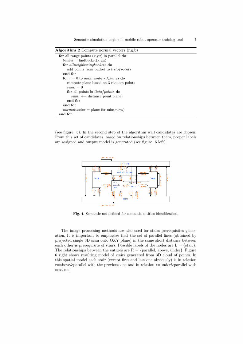
The procedure of prerequisites generation using image processing methods isused. The set of lines is used to obtain segmentation of 3D cloud of points, wheredifferent walls will have different labels. For each line segment the orthogonalplaneorth to planeOXY is computed. It should be noted that the intersectionbetween this two planes is the same line segment. All 3D points which satisfythe condition of distance to planeorth have the same label. In the first stepall prerequisites of walls were checked separately - it is data segmentation. Toperform the scene interpretation semantic net is used (figure 4). The featuredetection algorithm is composed by the method of cubes generation (see figure5 right), where each cube should contain measured 3D point after segmentation
Semantic simulation engine in mobile robot operator training tool 7
Algorithm 2 Compute normal vectors (r,g,b)
for all range points (x,y,z) in parallel dobucket = findbucket(x,y,z)for allneighboringbuckets do
add points from bucket to listofpointsend forfor i = 0 to maxnumberofplanes do
compute plane based on 3 random pointssumi = 0for all points in listofpoints do
sumi += distance(point,plane)end for
end fornormalvector = plane for min(sumi)
end for
(see figure 5). In the second step of the algorithm wall candidates are chosen.From this set of candidates, based on relationships between them, proper labelsare assigned and output model is generated (see figure 6 left).
Fig. 4. Semantic net defined for semantic entities identification.
The image processing methods are also used for stairs prerequisites gener-ation. It is important to emphasize that the set of parallel lines (obtained byprojected single 3D scan onto OXY plane) in the same short distance betweeneach other is prerequisite of stairs. Possible labels of the nodes are L = {stair}.The relationships between the entities are R = {parallel, above, under}. Figure6 right shows resulting model of stairs generated from 3D cloud of points. Inthis spatial model each stair (except first and last one obviously) is in relationr=above¶llel with the previous one and in relation r=under¶llel withnext one.

8 Lecture Notes in Computer Science: Authors’ Instructions
Fig. 5. Left - segmentation of 3D cloud of points, right - boxes that contain measuredpoints.
Fig. 6. Scene interpretation left - door, walls, right - stairs.
2.4 Semantic simulation
Assuming that we have accurate positioning of mobile robots, accurate encodersof inspection robot arm and satisfying tracking system we can update virtualentities position during real robots task execution. The semantic simulation en-gine from semantic map of INDOOR environment point of view is composedof: semantic map nodes(entities) Lsm={Wall, Wall above door, Floor, Ceiling,Door, Free space for door, Stairs...}, it is important to noticed that the Lsm setcan be extended by another objects, what is dependent on robust and accurate3D scene analysis, robot simulator nodes(entities) Lrs={robot, rigid body ob-ject, soft body object...}, semantic map relationships between the entities Rsm
= {parallel, orthogonal, above, under, equal height, available inside, connectedvia joint...}, robot simulator relationships between the entities Rrs = {connectedvia joint, position...}, semantic map events Esm = robot simulator events Ers ={movement, collision between two entities started, collision between two entitiesstopped, collision between two entities continued, broken joint...}. Our robotsimulator is implemented in NVIDIA PhysX. The entities from semantic mapcorrespond to actors in PhysX. Lsm is transformed into Lrs based on spatialmodel generated based on registered 3D scans i.e. walls, doors and stairs corre-spond to actors with BOX shapes. Rsm are transformed into Rrs with remarkthat doors are connected to walls via revolute joints. All entities/relations Rsm
has the same initial location in Rrs, obviously the location of each actor/entitymay change during simulation. The transformation from Esm to Ers effects thatevents related to entities from semantic map correspond to the events related toactors representing proper entities. It is important to emphasize that following
Semantic simulation engine in mobile robot operator training tool 9
events can be noticed during simulation: robot can touch each entity, open/closethe door, climb the stairs, enter empty space of the door, damage itself (brokenjoint between actors in robot arm), brake joint that connects door to the wall.It is noteworthy to mention that all robot simulator semantic events are usefulfor operator training, where computer has to monitor simulation events judgethem and report for the grading purpose.
3 Mobile robot operator training tool
Training tools in RISE (Risky Intervention and Surveillance Environment) isgiven by the project, named A platform for design of computer trainer-simulatorsfor operators of inspection-intervention mobile robots, realized by the authors ofthe paper in the Institute of Mathematical Machines, Warsaw, Poland. Develop-ment of such computer platform, intended to enable designing trainers-simulatorsfor training in operation of different types of mobile robots - finding their appli-cation in inspection-intervention missions conducted in municipal or industrialenvironment, as well as in missions of military or police character - and creationof software for them, is the aim of this project. One can anticipate that diversetypes of robots, differing by kind of traction, load capacity, range, manipulationability, equipment with sensors will be applied in these missions. A need to trainsignificant number of persons in operation of these robots, and obtaining highproficiency in operation, will come into being particularly in police and militaryforces for the sake of possible contact with explosives and toxic substances cre-ating dangers for operator, population, and environment. Training tasks requiremany hours of exercises with different types of robots. Conducting of such train-ing with use of real robots would be unprofitable, and probably unfeasible forthe technical and organizational reasons for difficulties of creation of all possi-ble situations and coincidences with which an operator of robots has to cope.The use of trainers, simulating robots behavior in different situations and cir-cumstances, will be a necessity. Such trainers, for different types and variants ofrobots, will have to be designed, manufactured, delivered to users and serviced,so establishing of an innovative enterprise of adequate profile will be justified.
3.1 Multi-level training
The first research task was drawing up a methodology of multi-level training withuse of trainers of different grade of perfection, taking advantages of technologiesof virtual reality (VR) and augmented reality (AR). Application of multi-leveltraining, introductory one with use of simplest and not so costly trainers, and atnext levels more and more complex, closing to real robot operation, will enablereduction of training costs and facilitate training organization. For multi-leveltraining the following types of trainers are to be used: Trainers of the Level 1built with use of typical PCs. VR technology is applied. Robot, its environmentand control console are simulated. Trainers of the Level 2 built with use of PCswith real robot control consoles connected. VR technology is applied. Robot and

10 Lecture Notes in Computer Science: Authors’ Instructions
its environment are simulated. Trainers of the Level 3 trainers of the Level 1 or2 with application of AR technology - real robot in the real environment withsimulated elements added. A trainee uses special helmet or advanced control basestation. Every program of training is a sequence of training tasks. An exemplarytraining task for mobile robots operators is lifting, with use of the robots gripper,of a certain object, and putting it in a certain container. At the beginning ofthe training session the trainee is informed on the task to perform, as well ason time limits, grading scale, and penalty points for causing wrong events (e.g.collisions of robot with objects in its environment). The trainee, using virtualor real control console, performs training tasks of the character of a computergame, and after finishing them is informed about the score obtained. Duringexecution of training tasks, the knowledge about trainees progress is gathered,and on this basis a choice of the next task, or decision on the end of training ismade.
4 Role of semantic simulation engine in training
The most important role of semantic engine is being the core of ranking system.Ranking system is based on events detected in the simulation. There are pre-defined events such as intersection, triggering and yaw pitch supervision. Alsotime is important during task execution. An extended role is related with level 3of training where augmented reality techniques are applied for merging real andvirtual agents during task execution where on-line processing is needed.
4.1 Level 1 and 2 - training based on computer simulation
The difference between level 1 and level 2 is the usage real control pane in trainingof level 2. The role of simulation engine is the same for both levels, where allentities are simulated. As an example the semantic simulation built based onautonomous robot observations (3D laser measurement system) is shown onfigure 7. It should be emphasized that semantic simulation engine was used tosimulate robot climbing stairs with pitch and roll supervision and robot enteringdoor. Operator will be punished when robot bump the wall or fall down fromstairs.
4.2 Level 3 - training with augmented reality
The proposed AR training system is composed by Augmented Reality agentsand Real agents that interact each other. The semantic simulation applied inNVIDIA PhysX engine is used to perform AR agents simulation. The funda-mental assumption is that the position of each agent is known, therefore datafusion from real sensors and simulated is possible. In the global localization ofthe real robot the SLAM algorithm based on LMS SICK 200 and odometry datais used. The global position of AR agent is given from simulation. To simulatelaser range finder the environment 3D model build from 3D data acquisition

Semantic simulation engine in mobile robot operator training tool 11
Fig. 7. Left - Climbing the stairs, pitch and roll supervision. Right - Entering openeddoor.
system is transferred into simulation engine. Figure 8 shows general idea ofproposed AR approach.
Fig. 8. General idea of AR approach in LEVEL 3 training. 1: real robot equippedwith laser range finder, 2: real obstacles, 3: virtual robot, 4: virtual robot equippedwith simulated laser range finder 5: virtual 3D model of the real obstacles obtained byreal robot, 6: augmented real laser range finder measurement with additional virtualmeasurement of virtual robot chassis (1+3).
The augmented reality system dedicated to mobile robotic system operatortraining is composed of real autonomous mobile robot equipped with 3D mapbuilding system, real base station with real remote control robot console, sim-ulation of remotely controlled robot with simulation of laser range finder. Thesystem composites real video feedback from mobile robot with simulation view.Figure 11 shows control base station where operator can control each robot, realand virtual one. It is important to emphasize that virtual robot is visible in au-tonomous robot main camera view. Another advantage of proposed approach isthe possibility of summarizing all system components in the main HMI programthat visualizes robots position and sensor data.

12 Lecture Notes in Computer Science: Authors’ Instructions
Fig. 9. Visualization of the mobile robot and 3D environment. Red points correspondto time of flight 3D camera measurement, green triangles - registered 3D map basedon vertically mounted LMS SICK laser range finder, gray triangles registered 3D maptransformed into PhysX model.
Fig. 10. Simulation of virtual laser range finder LMS SICK 200 in virtual environment.
Fig. 11. The augmented reality training system.

Semantic simulation engine in mobile robot operator training tool 13
5 Conclusion and future work
In the paper new concept of semantic simulation engine applied for multi levelmobile robot operator training, composed of data registration modules, seman-tic entities identification modules and semantic simulation module is proposed.Compared to the State of The Art new approaches of parallel computing appliedfor data registration is proposed. Semantic simulation engine provides tools toimplement mobile robot simulation based on real data delivered by robot andprocessed on-line using parallel computation. Semantic entities identificationmodules can classify door, walls, floor, ceiling, stairs in indoor environment.Data can be delivered by robot observation based on modern sensors such aslaser measurement system 3D and RGB-D cameras. Semantic simulation usesNVIDIA PhysX for rigid body simulation. By the association between real ob-jects and simulation entities it is possible to supervise them by prediction ofpossible collisions and dangerous motion (pitch, roll). Future work will be re-lated to AI techniques applied for semantic entities identification (furnitures,victims, cars, etc...), localization and tracking methods. The Augmented Realitysystem will be improved by using AR helmet. It should be noticed that the chal-lenge and still opened issue is the implementation of virtual camera of virtualrobot working in real environment, therefore it is new research problem.
References
1. J. Bedkowski, M. Kacprzak, A. Kaczmarczyk, P. Kowalski, P. Musialik,A. Maslowski, T. Pichlak, Rise mobile robot operator training design, in: 15thInternational Conference on Methods and Models in Automation and Robotics,23-26 August 2010, Miedzyzdroje, Poland, CD-ROM.
2. M. Asada, Y. Shirai, Building a world model for a mobile robot using dynamicsemantic constraints, in: Proc. 11 th International Joint Conference on ArtificialIntelligence, 1989, pp. 1629–1634.
3. A. Nuchter, O. Wulf, K. Lingemann, J. Hertzberg, B. Wagner, H. Surmann, 3dmapping with semantic knowledge, in: IN ROBOCUP INTERNATIONAL SYM-POSIUM, 2005, pp. 335–346.
4. A. Nuchter, J. Hertzberg, Towards semantic maps for mobile robots, Robot. Auton.Syst. 56 (11) (2008) 915–926.
5. O. Grau, A scene analysis system for the generation of 3-d models, in: NRC ’97:Proceedings of the International Conference on Recent Advances in 3-D DigitalImaging and Modeling, IEEE Computer Society, Washington, DC, USA, 1997, p.221.
6. A. Nuchter, H. Surmann, K. Lingemann, J. Hertzberg, Semantic scene analysis ofscanned 3d indoor environments, in: in: Proceedings of the Eighth InternationalFall Workshop on Vision, Modeling, and Visualization (VMV 03), 2003.
7. H. Cantzler, R. B. Fisher, M. Devy, Quality enhancement of reconstructed 3d mod-els using coplanarity and constraints, in: Proceedings of the 24th DAGM Sympo-sium on Pattern Recognition, Springer-Verlag, London, UK, 2002, pp. 34–41.
8. M. A. Fischler, R. Bolles, Random sample consensus. a paradigm for model fittingwith apphcahons to image analysm and automated cartography, in: Proc. 1980

14 Lecture Notes in Computer Science: Authors’ Instructions
Image Understandtng Workshop (College Park, Md., Apr i980) L. S. Baurnann,Ed, Scmnce Apphcatlons, McLean, Va., 1980, pp. 71–88.
9. M. Eich, M. Dabrowska, F. Kirchner, Semantic labeling: Classification of 3d entitiesbased on spatial feature descriptors, in: IEEE International Conference on Roboticsand Automation (ICRA2010) in Anchorage, Alaska, May 3, 2010.
10. N. Vaskevicius, A. Birk, K. Pathak, J. Poppinga, Fast detection of polygons in 3dpoint clouds from noise-prone range sensors, in: IEEE International Workshop onSafety, Security and Rescue Robotics, SSRR, IEEE, Rome, 2007, pp. 1–6.
11. H. Andreasson, R. Triebel, W. Burgard, Improving plane extraction from 3d databy fusing laser data and vision, in: Proceedings of the IEEE/RSJ InternationalConference on Intelligent Robots and Systems (IROS), 2005, pp. 2656–2661.
12. A. Nuchter, H. Surmann, J. Hertzberg, Automatic model refinement for 3D recon-struction with mobile robots, in: Fourth International Conference on 3-D DigitalImaging and Modeling 3DIM 03, 2003, p. 394.
13. A. Davison, Y. G. Cid, N. Kita, Real-time 3D SLAM with wide-angle vision, in:Proc. IFAC Symposium on Intelligent Autonomous Vehicles, Lisbon, 2004.
14. R. O. Castle, G. Klein, D. W. Murray, Combining monoslam with object recogni-tion for scene augmentation using a wearable camera 28 (11) (2010) 1548 – 1556.doi:DOI: 10.1016/j.imavis.2010.03.009.
15. S. Thrun, W. Burgard, D. Fo, A real-time algorithm for mobile robot mappingwith applications to multi-robot and 3d mapping, in: ICRA, 2000, pp. 321–328.
16. M. Magnusson, H. Andreasson, A. Nuchter, A. J. Lilienthal, Automaticappearance-based loop detection from 3D laser data using the normal distribu-tions transform, Journal of Field Robotics 26 (11–12) (2009) 892–914.
17. M. Magnusson, T. Duckett, A. J. Lilienthal, 3d scan registration for autonomousmining vehicles, Journal of Field Robotics 24 (10) (2007) 803–827.
18. H. Andreasson, A. J. Lilienthal, Vision aided 3d laser based registration, in: Pro-ceedings of the European Conference on Mobile Robots (ECMR), 2007, pp. 192–197.
19. P. J. Besl, H. D. Mckay, A method for registration of 3-d shapes, Pattern Anal-ysis and Machine Intelligence, IEEE Transactions on 14 (2) (1992) 239–256.doi:10.1109/34.121791.
20. R. B. Rusu, Z. C. Marton, N. Blodow, M. Dolha, M. Beetz, Towards 3d pointcloud based object maps for household environments, Robot. Auton. Syst. 56 (11)(2008) 927–941. doi:http://dx.doi.org/10.1016/j.robot.2008.08.005.
21. J. Craighead, R. Murphy, J. Burke, B. Goldiez, A survey of commercial and opensource unmanned vehicle simulators, in: Proceedings of ICRA, 2007.
22. A. Boeing, T. Braunl, Evaluation of real-time physics simulation sys-tems, in: GRAPHITE ’07: Proceedings of the 5th international con-ference on Computer graphics and interactive techniques in Australiaand Southeast Asia, ACM, New York, NY, USA, 2007, pp. 281–288.doi:http://doi.acm.org/10.1145/1321261.1321312.
23. J. Wang, M. Lewis, J. Gennari, Usar: A game-based simulation for teleoperation,in: Proceedings of the 47th Annual Meeting of the Human Factors and ErgonomicsSociety, Denver, CO, Oct. 13-17, 2003.
24. N. Greggio, G. Silvestri, E. Menegatti, E. Pagello, A realistic simulation of a hu-manoid robot in usarsim, in: Proceeding of the 4th International Symposium onMechatronics and its Applications (ISMA07), Sharjah, U.A.E., 2007.
25. R. B. Rusu, A. Maldonado, M. Beetz, I. A. Systems, T. U. Mnchen, Extendingplayer/stage/gazebo towards cognitive robots acting in ubiquitous sensor-equipped

Semantic simulation engine in mobile robot operator training tool 15
environments, in: in Accepted for the IEEE International Conference on Roboticsand Automation (ICRA) Workshop for Network Robot System, 2007, April 14,2007.
26. L. Hohl, R. Tellez, O. Michel, A. J. Ijspeert, Aibo and Webots: Simulation, WirelessRemote Control and Controller Transfer, Robotics and Autonomous Systems 54 (6)(2006) 472–485.
27. T. Petrinic, E. Ivanjko, I. Petrovic, Amorsim a mobile robot simulator for matlab,in: Proceedings of 15th International Workshop on Robotics in Alpe-Adria-DanubeRegion, June 15-17, Balatonfred, Hungary, 2006.
28. C. Buckhaults, Increasing computer science participation in the first robotics com-petition with robot simulation, in: ACM-SE 47: Proceedings of the 47th An-nual Southeast Regional Conference, ACM, New York, NY, USA, 2009, pp. 1–4.doi:http://doi.acm.org/10.1145/1566445.1566472.
29. J. Craighead, R. Murphy, J. Burke, B. Goldiez, A robot simulator classification sys-tem for hri, in: Proceedings of the 2007 International Symposium on CollaborativeTechnologies and Systems (CTS 2007), 2007, pp. 93–98.
30. J. Craighead, Distributed, game-based, intelligent tutoring systems the next stepin computer based training?, in: Proceedings of the International Symposium onCollaborative Technologies and Systems (CTS 2008), 2008.
31. D. Huber, M. Hebert, Fully automatic registration of multiple 3d data sets, Imageand Vision Computing 21 (1) (2003) 637–650.
32. A. W. Fitzgibbon, Robust registration of 2d and 3d point sets, in: In BritishMachine Vision Conference, 2001, pp. 411–420.
33. M. Magnusson, T. Duckett, A comparison of 3d registration algorithms for au-tonomous underground mining vehicles, in: In Proc. ECMR, 2005, pp. 86–91.
34. A. Nuchter, K. Lingemann, J. Hertzberg, Cached k-d tree search for icp algorithms,in: Proceedings of the Sixth International Conference on 3-D Digital Imaging andModeling, IEEE Computer Society, Washington, DC, USA, 2007, pp. 419–426.
35. S. Rusinkiewicz, M. Levoy, Efficient variants of the ICP algorithm, in: Third In-ternational Conference on 3D Digital Imaging and Modeling (3DIM), 2001.
36. http://opencv.willowgarage.com/wiki/.37. S.-W. Lee, Y. J. Kim, Direct extraction of topographic features for gray scale
character recognition, IEEE Trans. Pattern Anal. Mach. Intell. 17 (7) (1995) 724–729. doi:http://dx.doi.org/10.1109/34.391416.
38. L. Wang, T. Pavlidis, Direct gray-scale extraction of features for characterrecognition, IEEE Trans. Pattern Anal. Mach. Intell. 15 (10) (1993) 1053–1067.doi:http://dx.doi.org/10.1109/34.254062.