Semantic Knowledge-Based Framework to Improve the Situation Awareness of Autonomous Underwater...
15
Semantic Knowledge-Based Framework to Improve the Situation Awareness of Autonomous Underwater Vehicles Emilio Miguela ´n ˜ez, Member, IEEE, Pedro Patro ´n, Member, IEEE, Keith E. Brown, Member, IEEE, Yvan R. Petillot, Member, IEEE, and David M. Lane, Member, IEEE Abstract—This paper proposes a semantic world model framework for hierarchical distributed representation of knowledge in autonomous underwater systems. This framework aims to provide a more capable and holistic system, involving semantic interoperability among all involved information sources. This will enhance interoperability, independence of operation, and situation awareness of the embedded service-oriented agents for autonomous platforms. The results obtained specifically affect the mission flexibility, robustness, and autonomy. The presented framework makes use of the idea that heterogeneous real-world data of very different type must be processed by (and run through) several different layers, to be finally available in a suited format and at the right place to be accessible by high-level decision-making agents. In this sense, the presented approach shows how to abstract away from the raw real-world data step by step by means of semantic technologies. The paper concludes by demonstrating the benefits of the framework in a real scenario. A hardware fault is simulated in a REMUS 100 AUV while performing a mission. This triggers a knowledge exchange between the status monitoring agent and the adaptive mission planner embedded agent. By using the proposed framework, both services can interchange information while remaining domain independent during their interaction with the platform. The results of this paper are readily applicable to land and air robotics. Index Terms—Autonomous vehicles, ontology design, model-based diagnostics, mission planning. Ç 1 INTRODUCTION 1.1 Motivation W ITH the growing use of autonomous and semiautono- mous platforms and the increase data flows in modern maritime operations, it is critical that the data are handled efficiently across multiple platforms and domains. At present, knowledge representation is embryonic and targets simple monoplatform and monodomain applica- tions, therefore, limiting the potential of multiple coordi- nated actions between agents. Consequently, the main application for autonomous underwater vehicles is infor- mation gathering from sensor data. In a standard mission flow, data are collected during mission and then post- processed offline. However, as decision-making technologies evolve toward providing higher levels of autonomy, embedded service- oriented agents require access to higher levels of data representation. These higher levels of information will be required to provide knowledge representation for contextual awareness, temporal awareness, and behavioral awareness. Two sources can provide this type of information: the domain knowledge extracted from the original expert or the inferred knowledge from the processed sensor data. In both cases, it will be necessary for the information to be stored, accessed, and shared efficiently by the deliberative agents while performing a mission. These agents, providing different capabilities, might be distributed among the different platforms working in collaboration. 1.2 Contribution This paper focuses on the study of a semantic world model framework for hierarchical distributed representation of knowledge in autonomous underwater systems. The frame- work uses a pool of hierarchical ontologies for representa- tion of the knowledge extracted from the expert and the processed sensor data. Its major advantage is that service- oriented agents can gain access to the different levels of information and might also contribute to the enrichment of the knowledge. If the required information is unavailable, the framework provides the facility for requesting that information be generated by other agents with the necessary capabilities. At the decision level, an autonomous planner generates mission plans based on the representation of the mission goals in this semantic framework. As consequence, we claim that the proposed framework enhances interoper- ability, independence of operation, and situation awareness of the embedded service-oriented agents for autonomous IEEE TRANSACTIONS ON KNOWLEDGE AND DATA ENGINEERING, VOL. 23, NO. X, XXXXXXX 2011 1 . E.Miguela´n ˜ez is with SeeByte, the Orchard Brae House, 30 Queensferry Road, Edinburgh, EH4 2HS, Scotland, United Kingdom. E-mail: [email protected]. . P. Patro´n, K.E. Brown, Y.R. Petillot, and D.M. Lane are with the Ocean Systems Laboratory, Department of Electrical, Electronic and Computer Engineering, School of Engineering and Physical Sciences, Earl Mount- batten Building, Heriot-Watt University, Riccarton, Edinburgh, EH14 4AS Scotland. E-mail: {p.patron, k.e.brown, y.r.petillot, d.m.lane}@hw.ac.uk. Manuscript received 27 May 2009; revised 16 Dec. 2009; accepted 20 Feb. 2010; published online 3 Mar. 2010. Recommended for acceptance by Q. Li. For information on obtaining reprints of this article, please send e-mail to: [email protected], and reference IEEECS Log Number TKDE-2009-05-0467. Digital Object Identifier no. 10.1109/TKDE.2010.46. 1041-4347/11/$26.00 ß 2011 IEEE Published by the IEEE Computer Society
-
Upload
independent -
Category
Documents
-
view
1 -
download
0
Transcript of Semantic Knowledge-Based Framework to Improve the Situation Awareness of Autonomous Underwater...
Semantic Knowledge-Based Frameworkto Improve the Situation Awareness of
Autonomous Underwater VehiclesEmilio Miguelanez, Member, IEEE, Pedro Patron, Member, IEEE, Keith E. Brown, Member, IEEE,
Yvan R. Petillot, Member, IEEE, and David M. Lane, Member, IEEE
Abstract—This paper proposes a semantic world model framework for hierarchical distributed representation of knowledge in
autonomous underwater systems. This framework aims to provide a more capable and holistic system, involving semantic
interoperability among all involved information sources. This will enhance interoperability, independence of operation, and situation
awareness of the embedded service-oriented agents for autonomous platforms. The results obtained specifically affect the mission
flexibility, robustness, and autonomy. The presented framework makes use of the idea that heterogeneous real-world data of very
different type must be processed by (and run through) several different layers, to be finally available in a suited format and at the right
place to be accessible by high-level decision-making agents. In this sense, the presented approach shows how to abstract away from
the raw real-world data step by step by means of semantic technologies. The paper concludes by demonstrating the benefits of the
framework in a real scenario. A hardware fault is simulated in a REMUS 100 AUV while performing a mission. This triggers a
knowledge exchange between the status monitoring agent and the adaptive mission planner embedded agent. By using the proposed
framework, both services can interchange information while remaining domain independent during their interaction with the platform.
The results of this paper are readily applicable to land and air robotics.
Index Terms—Autonomous vehicles, ontology design, model-based diagnostics, mission planning.
Ç
1 INTRODUCTION
1.1 Motivation
WITH the growing use of autonomous and semiautono-mous platforms and the increase data flows in
modern maritime operations, it is critical that the data arehandled efficiently across multiple platforms and domains.
At present, knowledge representation is embryonic andtargets simple monoplatform and monodomain applica-tions, therefore, limiting the potential of multiple coordi-nated actions between agents. Consequently, the mainapplication for autonomous underwater vehicles is infor-mation gathering from sensor data. In a standard missionflow, data are collected during mission and then post-processed offline.
However, as decision-making technologies evolve towardproviding higher levels of autonomy, embedded service-oriented agents require access to higher levels of datarepresentation. These higher levels of information will be
required to provide knowledge representation for contextual
awareness, temporal awareness, and behavioral awareness.Two sources can provide this type of information: the
domain knowledge extracted from the original expert or the
inferred knowledge from the processed sensor data. In both
cases, it will be necessary for the information to be stored,
accessed, and shared efficiently by the deliberative agents
while performing a mission. These agents, providing
different capabilities, might be distributed among the
different platforms working in collaboration.
1.2 Contribution
This paper focuses on the study of a semantic world model
framework for hierarchical distributed representation of
knowledge in autonomous underwater systems. The frame-
work uses a pool of hierarchical ontologies for representa-
tion of the knowledge extracted from the expert and the
processed sensor data. Its major advantage is that service-
oriented agents can gain access to the different levels of
information and might also contribute to the enrichment of
the knowledge. If the required information is unavailable,
the framework provides the facility for requesting that
information be generated by other agents with the
necessary capabilities.At the decision level, an autonomous planner generates
mission plans based on the representation of the mission
goals in this semantic framework. As consequence, we
claim that the proposed framework enhances interoper-
ability, independence of operation, and situation awareness
of the embedded service-oriented agents for autonomous
IEEE TRANSACTIONS ON KNOWLEDGE AND DATA ENGINEERING, VOL. 23, NO. X, XXXXXXX 2011 1
. E. Miguelanez is with SeeByte, the Orchard Brae House, 30 QueensferryRoad, Edinburgh, EH4 2HS, Scotland, United Kingdom.E-mail: [email protected].
. P. Patron, K.E. Brown, Y.R. Petillot, and D.M. Lane are with the OceanSystems Laboratory, Department of Electrical, Electronic and ComputerEngineering, School of Engineering and Physical Sciences, Earl Mount-batten Building, Heriot-Watt University, Riccarton, Edinburgh, EH144AS Scotland.E-mail: {p.patron, k.e.brown, y.r.petillot, d.m.lane}@hw.ac.uk.
Manuscript received 27 May 2009; revised 16 Dec. 2009; accepted 20 Feb.2010; published online 3 Mar. 2010.Recommended for acceptance by Q. Li.For information on obtaining reprints of this article, please send e-mail to:[email protected], and reference IEEECS Log Number TKDE-2009-05-0467.Digital Object Identifier no. 10.1109/TKDE.2010.46.
1041-4347/11/$26.00 � 2011 IEEE Published by the IEEE Computer Society

platforms. The results obtained specifically affect themission flexibility, robustness, and autonomy.
To the best of our knowledge, this is the first time that anapproach to goal-based planning using semantic represen-tation is applied to the adaptation of an underwatermission, in order to maintain the operability of the platform.Furthermore, we have demonstrated on a set of sea trialsthe advantages of this approach in a real scenario.
This paper is structured as follows: Section 2 describesour evolved view of the sensing-decision-acting loop forautonomy for Autonomous Underwater Vehicles (AUVs).Section 3 provides an overview of previous related work inknowledge representation in robotics systems, fault detec-tion and diagnosis, and mission plan adaptation. Section 4presents the interaction of the diagnosis and planner agentsusing the framework. Section 5 presents an overview of therole of ontologies as knowledge representation, includingthe main features behind this approach. Section 6 describesthe framework focusing on the semantic representation ofthe vehicle’s knowledge. Section 7 describes the differentmodules involved in the test case scenario, considering thehorizontal flow of information. Section 8 demonstrates thebenefits of the proposed framework in a real scenario,where a hardware fault is simulated in a REMUS 100 AUVwhile performing a mission. This paper ends in Section 9with the conclusions and future work.
2 SITUATION AWARENESS FOR AUTONOMY
The human capability of dealing and understanding highlydynamic and complex environments is known as SituationAwareness (SAH). SAH breaks down into three separatelevels: perception of the environment, comprehension of thesituation, and projection of the future status.
According to Boyd, decision making occurs in a cycle ofobserve-orient-decide-act, known as OODA loop [1]. TheObservation component corresponds to the perception levelof SAH . The Orientation component contains the previouslyacquired knowledge and understanding of the situation.The Decision component represents the SAH levels ofcomprehension and projection. This last stage is the centralmechanism enabling adaptation before closing the loopwith the final Action stage. Note that it is possible to takedecisions by looking only at orientation inputs withoutmaking any use of observations.
Based on the autonomy levels and environmental char-acteristics, SAH definitions can be directly applied to thenotion of unmanned vehicle situation awareness SAV [2].The levels of situation awareness for individual unmannedvehicle systems (SAS) span from full human control to fullyautonomous unmanned capabilities (see Fig. 1).
In current implementations, the human operator con-stitutes the decision-making phase. When high-bandwidthcommunication links exist, the operator remains in the loopduring the mission execution. Examples of the implementa-tion of this architecture are existing Remote Operated Under-water Vehicles (ROVs). However, when the communicationis poor, unreliable or not allowed, the operator tries, basedonly on the initial orientation or expertise, to include allpossible behaviors to cope with execution alternatives. As aconsequence, unexpected and unpredictable situations cancause the mission to abort and might even cause the loss ofthe vehicle, as happened with Autosub2 which was lostunder the Fimbul ice sheet in the Antarctic [3]. Examples ofthis architecture are current implementations for AUVs.
In order to achieve an autonomous decision-makingloop, two additional components are required: a statusmonitor and a mission plan adapter. The status monitorreports any changes detected during the execution of a plan.These modifications might change the SAV perception.When the mission executive is unable to handle the changesdetected by the status monitor, the mission planner is called togenerate a new modified mission plan that agrees with theupdated knowledge of the world (see Fig. 2). The RAXarchitecture was the first attempt of implementing this typeof architecture on a real system [4]. However, tight timedeadlines, more restricted communications and differentenvironmental constraints existing in general, AUVs appli-cations have led us to the research of a new implementationof this approach based on ontological knowledge-basedsituation awareness.
3 RELATED WORK
3.1 Knowledge Representation
Current knowledge representation approaches are only ableto provide the perception or observation level of SAV . State-of-the-art embedded agents make use of different messagetransfer protocols, in order to stay updated with the currentstatus of the platform and the environment. Severalapproaches can be found in the literature implementinginformation transfer protocols for robotics.
For example, robotic libraries, such as Player [5] and YetAnother Robotic Platform (YARP) [6], support transmissionof data across various protocols—TCP, UDP, MCAST(multicast), and shared memory. They provide an interfaceto the robot’s sensors and actuators. This allows agents toread data from sensors to write commands to actuators, andto configure devices on the fly. These two approaches
2 IEEE TRANSACTIONS ON KNOWLEDGE AND DATA ENGINEERING, VOL. 23, NO. X, XXXXXXX 2011
Fig. 1. Human and AUV situation awareness levels across the levels ofautonomy.
Fig. 2. Required OODA-loop for SAS ¼ SAV . Decision stage foradaptation takes place on-board based on observations from the statusmonitor.

separate the agents from the details of the networktechnology used, but they do not provide any standardiza-tion about the meaning of the information transferred.
The Mission Oriented Operating Suite (MOOS) [7], [8]uses human readable ASCII messages for communication ofdata to a centralized database. This centralized topology isvulnerable to “bottle-necking” at the server as the ASCIImessages can generate considerable parsing overheads.
The OceanSHELL libraries [9] implement UDP broadcastprotocol to pass data information between agents. In thelatest version, abstraction messages are able to carrysemantic information. These libraries are the first attemptto standardize semantic information for unmanned under-water platforms in order to share knowledge betweendifferent multidisciplinary agents. However, the approachis still limited to the observation or perception level of SAV .
A more detailed review of these and other roboticknowledge representation approaches was published in [10].
As an extension of these libraries, the Battlespace Accessfor Unmanned Underwater Vehicles (BAUUV) program,sponsored by the United Kingdom (UK) Ministry ofDefence Directorate of Equipment Capability (UnderwaterBattlespace), showed the benefit of also including themental or orientation model component of SAV [11]. Adiagram describing the BAUUV dynamic multilayeredworld model architecture is shown in Fig. 3. The approachwas capable of integrating the capabilities of differentsoftware components and provide them with a commonpicture of the environment. This picture contained pro-cessed sensor data and a priori knowledge. Thus, itprovided a full SAV . However, the design was limited toAutonomous Target Recognition (ATR) applications in theunderwater domain. In order to provide a truly service-oriented architecture, an evolution from this approach isrequired providing a generic framework independent ofservice capability and domain of application.
The Joint Architecture for Unmanned Systems (JAUS),originally developed for the Unmanned Ground Vehiclesdomain only, has recently extended to all domains trying toprovide a common set of architecture elements andconcepts [12]. In order to handle the orientation andobservation phases, it classifies four different sets ofKnowledge Stores: Status, World map, Library, and Log.
Our experience has shown that overlap exists betweenthese different sets of knowledge stores. This overlap isprovided by the strong interconnection existing between theorientation and observation phases for SAV . The approachproposed in this project will make use of the concepts
proposed by JAUS, but will enhance the Knowledge Storeset by providing higher flexibility in the way the informa-tion can be handled and accessed.
Looking at related work on applying ontologies, recentpublications [13], [14], [15] show that there is a growinginclination to use semantic knowledge in several areas ofrobotic systems, playing a key role, in order to improve theinteroperability of the different robotic agents. Frommapping and localization using semantically meaningfulstructures to human-robot interaction trying to make therobot understand the human environment of words,gestures, and expressions, it has been clear that there aremany ways in which the technology behind ontologies maybe applied in robotics. However, there is yet a lack of welldefined architecture, which abstracts from low-level real-world information to higher-level information, which isenriched by semantics to output enhanced diagnostic andmission planning information.
3.2 Fault Detection and Diagnosis (FDD)
In the field of diagnostic, the gathering and processing ofknowledge in AUVs, as in most robotic systems, are classifiedinto two categories 1) model free and 2) model based.
Model-free methods, such as rule-based, use limitchecking of sensors for the detection of faults. Rule-baseddiagnostic is the most intuitive form of diagnostic, wherethrough a set of mathematical rules, observed parametersare assessed for conformance to anticipated system condi-tion. Knowledge gained is thus explicit as rules are eithersatisfied or not. Rule-based reasoning is an easy concept toemploy, and if kept simple requires little development time,provided that expert tacit knowledge (system behaviorawareness) can be straight forwardly transformed toexplicit knowledge (rules). However, these rules useknowledge gained outside observation of the system rathera representation of any internal mechanisms. In otherwords, they represent only the relationship betweensymptoms and failures, and cannot provide a coherentexplanation of the failure. Furthermore, they exhibit a lackof flexibility as only faults that have been explicitlydescribed can be diagnosed. The main advantage of arule-based system is that execution time is generally muchfaster than other methods using more sophisticated models.
Model-based diagnosis systems rely on the developmentof a model constructed from detailed in-depth knowledge(preferably from first principles) of the system. There is awide range of models available for diagnosis, includingmathematical, functional, and abstract [16]. The fault detec-tion and isolation (FDI) community has tackled the diag-nostic task by comparing simulated results to real results, anddetects abnormalities accordingly based mainly in analyticalredundancy. The main advantage of this approach is that itcan be adapted easily to changes in the system environmentby changing inputs to the model being simulated. However,the numerical models are based on behavior of the system,with little knowledge of the structure and functionality of thecomponents. Also, there is no mechanism to detect multiplefaults and it requires expensive computation.
Currently, there is an increasing move away from FDDmodel-based to structure and data-driven methods, becausecomplex dynamic systems are difficult to model, based on
MIGUEL�A~NEZ ET AL.: SEMANTIC KNOWLEDGE-BASED FRAMEWORK TO IMPROVE THE SITUATION AWARENESS OF AUTONOMOUS... 3
Fig. 3. World model architecture for the BAUUV MoD program(Battlespace access for unmanned underwater systems). Its databasehandles data inputs and queries from internal and external clients.

analytical redundancy alone. Uppal and Patton argue thatthe interesting combination of certain aspects of qualitativeand quantitative modeling strategies can be made [17]. Theyfurther state that qualitative methods alone should be used,if faults cause qualitative changes in system performanceand when qualitative information is sufficient for diagnosis.Qualitative methods are essential if measurements arerough or if the system cannot be described by differentialequations with known parameters.
3.3 Mission Planning
Declarative mission plan adaptation for unmanned vehiclesleverage from the research carried out on autonomousplanning generation [18]. Space operations, Mars rovers inparticular, have been the impetus behind autonomous planadaptability for unmanned vehicles.
The Remote Agent Experiment (RAX) [4], which flew onDeep Space-1, first demonstrated the ability to autono-mously control an active spacecraft. This project highlightedthe problem of using a batch planner on a reactive system. Ittook hours to replan after the updates had invalidated theoriginal plan.
Another system handling a certain level of planningadaptation in a real scenario was the Automated Schedule andPlanning Environment (ASPEN) [19]. This system classifiedconstraint violations and attempted to repair each byperforming a planning operation. However, the set ofrepair methods were predefined and the type of conflictdetermined the set of possible repair methods for any givenconflict. The system could not guarantee that it wouldexplore all possible combinations of plan modifications orthat it would not retry unhelpful modifications.
Van der Krogt later formalized two levels of handlingevents in what was called executive repair and planning repair[20]. His approach combined unrefinement and refinementstages in order to provide faster performance than planningfrom scratch. However, this approach might fail to producean optimal plan. This could be considered an issue indomains requiring optimality. This is not generally the casein unmanned vehicle mission plans where optimality can besacrificed for operability.
The approach was compared with GPG and Sherpasystems. In the GPG [21], based on the graphplan planner[22], the unrefinement stage is done only on the initial planand never on any of the plans produced by a refinementstep. The Sherpa [23], based on the LPA* algorithm that wepreviously used in [24] for adaptive trajectory planning,could only be applied to problems in which actions havebeen removed from the domain knowledge.
In the underwater domain, several challenges have beenidentified requiring adaptive planning solutions of themission [25], [26]. The potential benefits of the adaptiveplanning capabilities have been promoted by [27]. Togetherwith Fox and other authors, they have started using sensordata to adapt the decision making on the vehicle’s mission[28], [29].
4 FAULT TOLERANT ADAPTIVE MISSION PLANNING
In recent years, emphasis for increasing AUVs operabilityhas been focused in increasing AUVs survivability by
reducing the susceptibility and vulnerability of the platform[30]. Recent approaches in rules of collision [31] and wavepropagation techniques for obstacle avoidance [24], colli-sion avoidance and escape scenarios [32] have focused onreducing susceptibility by looking at the adaptation of thevehicles trajectory plan.
However, when the vehicle faces unforeseen events, suchas unexpected component failures or unplanned interac-tions with the surrounding environment, the focus of themission should shift to reconfigure itself to use alternativecombinations of the remaining resources. The underwaterdomain has scarce bandwidth and tight response con-straints to keep the operator in the loop. In such challengingenvironment, autonomous embedded recoverability, is a keycapability for vehicle’s endurance. This can be achieved viaadaptation of the vehicle’s mission plan.
Adapting of a mission on the fly in response to events isfeasible with embedded planners. However, they are limitedto the quality and scope of the available information. Forthem to be effective, the mission programmer must predictall possible situations, which is clearly impractical. There-fore, to adapt mission plans due to unforeseen and incipientfaults, it is required that accurate information is available torecognize that a fault has occurred and the root cause of thefailure. For example, if a propeller drive shaft developed toomuch shaft friction, then the added current load mayoverburden the drive motor. Identification of such acondition before the shaft bearing fails would allow rectifica-tion of the mission before a major breakdown occurs.
AUVs are generally equipped with FDD systems basedon damage control that results in the vehicle resurfacing inthe event of any fault in the system. But future industrialand military AUVs may require systems that operate evenwhile partially damaged. Hence, it is of importance todevelop a system which not only detects failure in theunderwater vehicle, but also provides meaningful andreliable information to counterpart modules, such as themission planner, to adapt to and recover from the failures.
4.1 Mission Plan Adaptation
Following classical planning problem representation, aninstance of a vehicle mission problem can be simply definedas � ¼ fP;A; I ;Gg, where P is the propositions defining theavailable resources in the vehicle, A is the set of actions, I isthe initial platform state, and G is the set of possible missionaccomplished states. D ¼ P [ A defines the mission domainand P ¼ I [ G the mission problem. Given and instance �,the mission generation problem consists in finding if thereexists a mission plan ðmpÞ, using ai 2 A, such that satisfiesany g 2 G.
Several approaches exist in the artificial intelligent (AI)literature capable of solving this problem. In a real environ-ment, where optimality can be sacrificed by operability,partial ordered planning (pp) is seen as a suitable approach,because it produces a flexible structure capable of beingadapted (see Fig. 4). The implemented approach can dealwith extensions from the classical representation. It canhandle durative actions, fluents, functions, and differentsearch metrics in order to minimize resource consumption,such as remaining vehicles battery, or total distance traveled.
4 IEEE TRANSACTIONS ON KNOWLEDGE AND DATA ENGINEERING, VOL. 23, NO. X, XXXXXXX 2011

Fig. 5 shows the benefits between replanning andrepairing a mission plan. At the initial loop, a partial orderedplan pp0 is generated satisfying the given mission domainand problem �0. The pp0 is then grounded into the minimalmission plan mp0 including all constraints in pp0. At aniteration i, the knowledge base is updated by the diagnosisinformation di providing a modified mission domain andproblem �0iþ1. The mission replan process generates a newpartial plan pp0iþ1, as done at the first stage, based only in the�0iþ1 information. On the other hand, the mission plan repairprocess revalidates the original plan by ensuring minimalperturbation of it. Given a mp to �i, the mission repairproblem produces a solution mission planmp0 than solves theupdated mission problem �0iþ1, by minimally modifyingmp.
When a mission failure occurs during the execution, twopossible repair levels can be identified: mission executionrepair and mission plan repair. Execution repair changes theinstantiation mp such that either: an action ai that waspreviously instantiated by some execution � is no longerinstantiated, or an action ai, that was previously instan-tiated is newly bound by an execution � already part of themp. Plan repair modifies the partial plan pp itself, so that ituses a different composition, though it still used some of thesame constraints between actions. It might also entail theelimination of actions which have already been instantiated.
Executive repair will be less expensive and it is expectedto be executed by the mission executive module. Planrepair, however, will be computationally more expensiveand requires action of the mission planner. The objective isto maximize the number of executions repairs over the planrepairs and, at the plan repair level, maximize the numberof decisions reused from the old mission.
4.2 Mission Plan Refinement
A practical approach following the previously describedconcepts has raised interest recently in the AI communityproviding a novel solution for all drawbacks identifiedduring the replanning process. This set of methods is
known as plan recovery methods. Plan recovery methodsare based on plan-space searches and are able to adapt theexistent plan to the new state of the world. They can bedivided into two stages.
The first stage, known as plan diagnosis, analyzes the effectsof the updated platform status on the current mission.According with the new updated constraints received fromthe status monitor, it identifies the failures and gaps existentin the current mission plan. These plan gaps are causing theinconsistency between the existent plan and the current statusof the platform and the environment. They are, therefore,preventing the correct execution of the mission. The approachdeveloped at this stage is based on unrefinement planningstrategies and uses the potential of the knowledge reasoningin order to identify the resources that remain available.
The second stage is known as plan repair. The strategyduring this stage is to repair with new partial plans the gapsor failures identified during the plan diagnosis stage. Theplan repair stage is based on refinement planning strategiesfor plan recovery.
In simple terms, when changes in the instances of theplanning ontology are sensed ðdÞ that affect the consistencyof the current mission plan ppi, the plan adaptabilityprocess is initiated. Based on the outputs of the planningreasoner, the plan diagnosis stage starts an unrefinementprocess that relaxes the constraints in the mission plan thatare causing the mission plan to fail. The remaining temporalmission partial plan ppt is now relaxed to be able to copewith the new sensed constraints. This will be the simpleststage of recovery necessary to continue with the executionof the plan but it does not guarantee that all the missiongoals will be achieved. The plan repair stage then executes arefinement process searching for a new mission plan pp0iþ1
that is consistent with the new world status D0 and P 0. Bydoing this, it can be seen that the new mission plan mp0 isnot generated again from D0 and P0 (replanned) butrecycled from ppi (repaired). This allows reuse of the partsof the plan ppi that were still consistent with D0 and P0.
5 OVERVIEW IN THE ROLE OF ONTOLOGIES AS
KNOWLEDGE REPRESENTATION
Many definitions and descriptions about ontologies can befound in the literature. From a philosophical point, theontology term has been defined as the study or concernabout what kinds of things exist and what entities or thingsthere are in the universe [33]. From a practical point,
MIGUEL�A~NEZ ET AL.: SEMANTIC KNOWLEDGE-BASED FRAMEWORK TO IMPROVE THE SITUATION AWARENESS OF AUTONOMOUS... 5
Fig. 4. Example of a partial ordered plan representation of anautonomously generated AUV mission for a similar scenario as theone described in the demonstration in Section 8. Ordering constraintsrepresented using the graph depth, interval preservation constraintsrepresented with black arrows, point truth constraints represented withPTC-labeled arrows and binding constraints represented in the top leftbox.
Fig. 5. Replan and repair processes for mission plan adaptation.
ontologies are viewed as the working model of entities andinteractions either generically (e.g., the SUMO ontology) orin some particular domain of knowledge or practice, suchas predictive maintenance or subsea operations.
A definition given by Gruber characterizes an ontologyas the specification of conceptualizations, which used tohelp programs and humans share knowledge [34]. Thecombination of these two terms embraces the knowledgeabout the world in terms of entities (things, the relation-ships they hold and the constraints between them), with itsrepresentation in a concrete form. One step in thisspecification is the encoding of the conceptualization in aknowledge representation language. Ultimately, the maingoal behind the concept of ontology is to create an agreed-upon vocabulary and semantic structure for exchanginginformation about that domain.
The main components of an ontology are concepts,axioms, instances, and relationships. A concept represents aset or class of entities or things within a domain. A fault isan example of a concept within the domain of diagnostic. Afinite set of definitions is called TBox, where is also includedthe set of terminological axioms for every atomic concept.Axioms are used to constrain the range and domain of theconcepts, such as the father is a man that has a child.
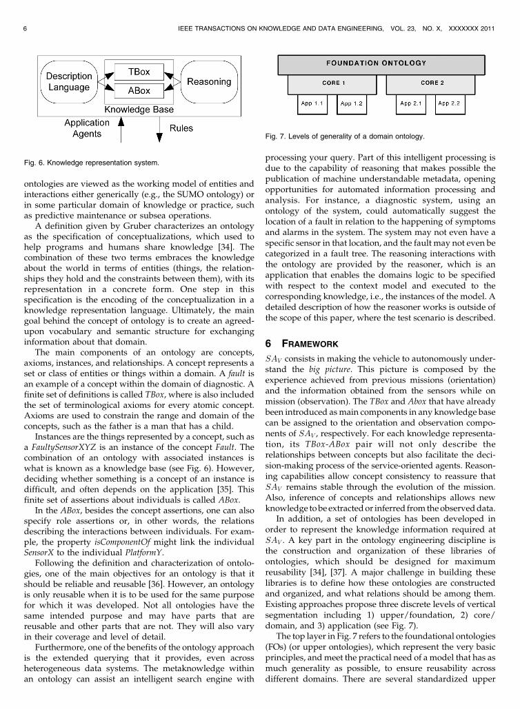
Instances are the things represented by a concept, such asa FaultySensorXYZ is an instance of the concept Fault. Thecombination of an ontology with associated instances iswhat is known as a knowledge base (see Fig. 6). However,deciding whether something is a concept of an instance isdifficult, and often depends on the application [35]. Thisfinite set of assertions about individuals is called ABox.
In the ABox, besides the concept assertions, one can alsospecify role assertions or, in other words, the relationsdescribing the interactions between individuals. For exam-ple, the property isComponentOf might link the individualSensorX to the individual PlatformY.
Following the definition and characterization of ontolo-gies, one of the main objectives for an ontology is that itshould be reliable and reusable [36]. However, an ontologyis only reusable when it is to be used for the same purposefor which it was developed. Not all ontologies have thesame intended purpose and may have parts that arereusable and other parts that are not. They will also varyin their coverage and level of detail.
Furthermore, one of the benefits of the ontology approachis the extended querying that it provides, even acrossheterogeneous data systems. The metaknowledge withinan ontology can assist an intelligent search engine with
processing your query. Part of this intelligent processing isdue to the capability of reasoning that makes possible thepublication of machine understandable metadata, openingopportunities for automated information processing andanalysis. For instance, a diagnostic system, using anontology of the system, could automatically suggest thelocation of a fault in relation to the happening of symptomsand alarms in the system. The system may not even have aspecific sensor in that location, and the fault may not even becategorized in a fault tree. The reasoning interactions withthe ontology are provided by the reasoner, which is anapplication that enables the domains logic to be specifiedwith respect to the context model and executed to thecorresponding knowledge, i.e., the instances of the model. Adetailed description of how the reasoner works is outside ofthe scope of this paper, where the test scenario is described.
6 FRAMEWORK
SAV consists in making the vehicle to autonomously under-stand the big picture. This picture is composed by theexperience achieved from previous missions (orientation)and the information obtained from the sensors while onmission (observation). The TBox and Abox that have alreadybeen introduced as main components in any knowledge basecan be assigned to the orientation and observation compo-nents of SAV , respectively. For each knowledge representa-tion, its TBox-ABox pair will not only describe therelationships between concepts but also facilitate the deci-sion-making process of the service-oriented agents. Reason-ing capabilities allow concept consistency to reassure thatSAV remains stable through the evolution of the mission.Also, inference of concepts and relationships allows newknowledge to be extracted or inferred from the observed data.
In addition, a set of ontologies has been developed inorder to represent the knowledge information required atSAV . A key part in the ontology engineering discipline isthe construction and organization of these libraries ofontologies, which should be designed for maximumreusability [34], [37]. A major challenge in building theselibraries is to define how these ontologies are constructedand organized, and what relations should be among them.Existing approaches propose three discrete levels of verticalsegmentation including 1) upper/foundation, 2) core/domain, and 3) application (see Fig. 7).
The top layer in Fig. 7 refers to the foundational ontologies(FOs) (or upper ontologies), which represent the very basicprinciples, and meet the practical need of a model that has asmuch generality as possible, to ensure reusability acrossdifferent domains. There are several standardized upper
6 IEEE TRANSACTIONS ON KNOWLEDGE AND DATA ENGINEERING, VOL. 23, NO. X, XXXXXXX 2011
Fig. 6. Knowledge representation system.
Fig. 7. Levels of generality of a domain ontology.
ontologies available for use, including Dublin Core, GFO,OpenCyc/ResearchCyc, SUMO, and DOLCE.
The second level of the ontology hierarchy represents thecore domain ontology, which is arguably another of thebuilding blocks to information integration. The goal of a coreontology is to provide a global and extensible model intowhich data originating from distinct sources can be mappedand integrated. This canonical form can then provide asingle knowledge base for cross-domain tools and services(e.g., vehicle resource/capabilities discovery, vehicle physi-cal breakdown, and vehicle status). A single model avoidsthe inevitable combinatorial explosion and applicationcomplexities that result from pair-wise mappings betweenindividual metadata formats and/or ontologies.
At the bottom of the stack, an application ontologyprovides a underlying formal model for tools that integratesource data and perform a variety of extended functions.Here, application concepts are handled at the executivelayer and are used to ground the abstract concepts managedby the software agents running in the system. As such,higher levels of complexity are tolerable and the designshould be motivated more by completeness and logicalcorrectness than human comprehension. In this paper,target areas of these application ontologies are found in thestatus monitoring system of the vehicle and the planning ofthe mission, which by making use of the proposed frame-work allows the transition from the deliberative to theaction phase of the OODA loop.
Fig. 8 represents the relationship between the foundationontologies (upper and utility), the core ontology, and theapplication ontology for each service-oriented agent. Rawdata gets parsed from sensors into assertions during themission using a series of adapter modules for each of thesensing capabilities. It also shows that the knowledgehandling by the agent during its decision making processis helped by the reasoner and the rule engine process.
In the work described in this paper, ontologies aredefined in Ontology Web Language (OWL) [38]. The OWLlanguage is a specialization of the Resource DescriptionFramework (RDF) standard [39], and therefore, a speciali-zation of the XML standard. These standards enable therepresentation of information in a structured format wherean abstraction model, known as an ontology, is combinedwith instance data in a repository.
6.1 Foundation and Core Ontology
To lay the foundation for the knowledge representation ofunmanned vehicles, JAUS concepts have been considered.
However, the core ontology developed in this work extendsthese concepts while remaining focused in the domain ofunmanned systems. Some of the knowledge conceptsidentified related with this domain are:
. Platform: Static or mobile (ground, air, underwatervehicles),
. Payload: Hardware with particular properties, sen-sors or modules,
. Module: Software with specific capabilities,
. Sensor: A device that receives and responds to asignal or stimulus,
. Driver: Module for interaction with a specificsensor/actuator,
. Waypoint: Position in space with coordinate andtolerance,
. Coordinate: Local frame, global frame, angular,
. Velocity: Linear and angular,
. Attitude: Roll, pitch, yaw, . . .
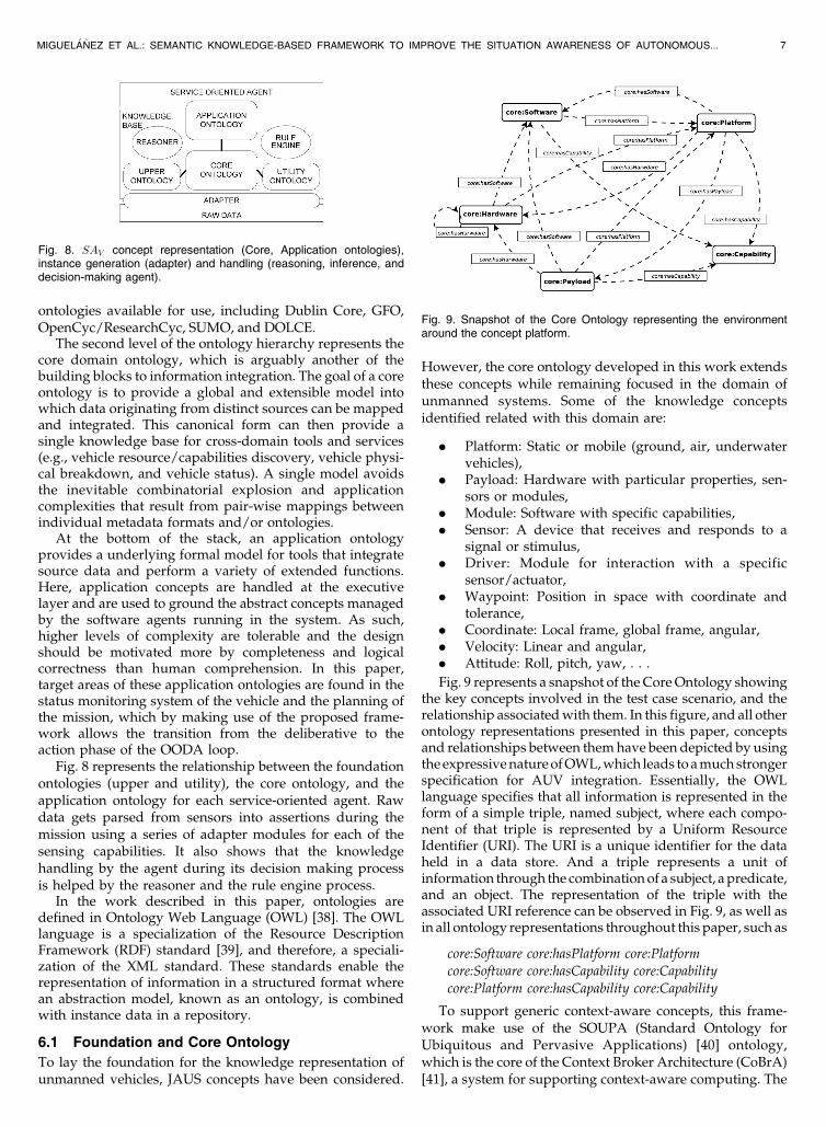
Fig. 9 represents a snapshot of the Core Ontology showingthe key concepts involved in the test case scenario, and therelationship associated with them. In this figure, and all otherontology representations presented in this paper, conceptsand relationships between them have been depicted by usingthe expressive nature of OWL, which leads to a much strongerspecification for AUV integration. Essentially, the OWLlanguage specifies that all information is represented in theform of a simple triple, named subject, where each compo-nent of that triple is represented by a Uniform ResourceIdentifier (URI). The URI is a unique identifier for the dataheld in a data store. And a triple represents a unit ofinformation through the combination of a subject, a predicate,and an object. The representation of the triple with theassociated URI reference can be observed in Fig. 9, as well asin all ontology representations throughout this paper, such as
core:Software core:hasPlatform core:Platform
core:Software core:hasCapability core:Capability
core:Platform core:hasCapability core:Capability
To support generic context-aware concepts, this frame-work make use of the SOUPA (Standard Ontology forUbiquitous and Pervasive Applications) [40] ontology,which is the core of the Context Broker Architecture (CoBrA)[41], a system for supporting context-aware computing. The
MIGUEL�A~NEZ ET AL.: SEMANTIC KNOWLEDGE-BASED FRAMEWORK TO IMPROVE THE SITUATION AWARENESS OF AUTONOMOUS... 7
Fig. 8. SAV concept representation (Core, Application ontologies),instance generation (adapter) and handling (reasoning, inference, anddecision-making agent).
Fig. 9. Snapshot of the Core Ontology representing the environmentaround the concept platform.

contribution of SOUPA ontology is the spatiotemporalrepresentation, which allows the representation of timeinstants, intervals, and temporal relations, as well as spaceenhanced by high-level concepts, such as movable spatialthing, geographical entity, or geometry concepts.
6.2 Application Ontology
Each service-oriented agent has its own ApplicationOntology. It represents the agent’s awareness of thesituation by including concepts that are specific to theexpertise or service provided by the SOA.
In the case study presented in this paper, these agents arethe status monitor and the mission planner. Together, theyprovide the status monitor and mission adapter componentsdescribed in Fig. 2, required for closing the OODA-loop andprovide on-board decision-making adaptation.
6.2.1 Status Monitor Application Ontology
The Status Monitor Agent considers all symptoms andobservations from environmental and internal data in orderto identify and classify events according to their priority andtheir nature (critical or incipient). Based on internal eventsand context information, this agent is able to infer newknowledge about the current condition of the vehicle withregard to the availability for operation of its components (i.e.,status). In a similar way, environmental data are alsoconsidered for detecting and classifying external events inorder to keep the situation awareness of the vehicle updated.
The Status Monitoring Application Ontology is used toexpress the SAV of the status monitor agent. Recentdevelopments in defining ontologies as a knowledge repre-sentation approach for a domain provide significant potentialin model design, able to encapsulate the essence of thediagnostic semantic into concepts and to describe the keyrelationships between the components of the system beingdiagnosed. To model the behavior of all components andsubsystems considering from sensor data to possible modeloutputs, the Status Monitoring Application Ontology isdesigned and built based on ontology design patterns [42].Ontology patterns facilitate the construction of the ontologyand promote reuse and consistency if it is applied to differentenvironments. In this work, the representation of themonitoring concepts are based on a system observationdesign pattern, which is shown in Fig. 10. Some of the mostimportant concepts identified for status monitoring are:
. Data: all internal and external variables (gain levels,water current speed),
. Observation: patterns of data (sequences, outliers,residuals, . . . ),
. Symptom: individuals related to interesting patternsof observations (e.g., low gain levels, high averagespeed),
. Event: represents a series of correlated symptoms (lowpower consumption, position drift), two subclasses ofevents are defined: CriticalEvent for high priorityevents and IncipientEvent for the remaining ones.
. Status: links the latest and most updated eventinformation to the systems being monitored (e.g.,sidescan transducer),
Please note how some of these concepts are related toconcepts of the Core Ontology (e.g., an observation comesfrom a sensor). These Core Ontology elements are theenablers for the knowledge exchange between service-oriented agents. This will be shown in the demonstrationscenario of Section 8.
Note that this knowledge representation of diagnosticconcepts are linked to concepts already described in thecore ontology, such as the status of the system, which is thekey component in the handshaking of information betweenthe status monitoring and mission planner agents.
6.2.2 Mission Planning Ontology
On the mission planning side, knowledge modeling isimplemented by using a language representation. Thislanguage is then used to express the input to the planner.Language vocabularies generally include the informationconcepts and the grammars are used for describing therelationships and constraints between these concepts.
The STRIPS language from [43] is generally acknowl-edged as the basis for classical planning. Basic concepts inthis language are: an initial state, a goal state (or set of goalstates), and a set of actions which the planner can perform.Each action consists of a set of preconditions, which must betrue for the action to be performed, and a set ofpostconditions, which will be true after the action has beencompleted. A classical planner then normally attempts toapply actions whose postconditions satisfy the goal,recursively applying other actions to meet the preconditionsuntil a complete plan (if available), which can be executedfrom the initial state and ends at the goal, is formed.
The PDDL language was originally created by [44] andstands for Planning Domain Definition Language. It is theplanning language used by the planning community duringthe biannual International Planning Competition that takesplace during the ICAPS Conference [45]. It can beconsidered as an extension of the original STRIPS languagewith extra functionality added. PDDL intends to express thephysics of a planning domain, which is, what predicatesthere are, what actions are possible, what the structure ofcompound actions is, and what the effects of actions are. Atits last version, it contains extensions for dealing withextended goals, where good quality plans are as valid asoptimal quality plans. It is a very complex language withcomplex syntactic features, such as specification of safetyconstraints or hierarchical actions. State-of-the-art plan
8 IEEE TRANSACTIONS ON KNOWLEDGE AND DATA ENGINEERING, VOL. 23, NO. X, XXXXXXX 2011
Fig. 10. Representation of the system observation pattern.

generators are not able to handle the entire set of PDDLlanguage features. In consequence, several versions of thelanguage have came out describing a subset of features,called requirements, that are extended every two yearswhen the competition takes place.
The adaptive decision-making process requires conceptsfor generating a mission following a declarative goal-basedapproach instead of a classic procedural waypoint-baseddescription. This can be achieved by looking at the conceptsdescribed by PDDL. However, in order to provide asolution to a mission failure, it also requires conceptscapable of representing incidents or problems occurringduring the mission. These concepts have been extractedfrom [20]. Some of the most important concepts identifiedfor mission plan adaptability are:
. Resource: State of an object (physical or abstract) inthe environment.(vehicle, position, release,..),
. Action: Collection of state of resources. Statechanges. (calibrate, classify, explore,..).
. Catalyst resource: Resources that are not consumedfor an action but needed for the proper execution ofthe action. (sensor activation),
. Plan gap: Actions that may no longer be applicable.At least two ways of achieving a subgoal but acommitment has not been taken yet,
. Gap: A nonexecutable action,
. Execution: When an action is executed successfully,
. Mission Failure: An unsuccessful execution.
The representation of the planning concepts related tothe mission plan and mission actions is shown in Fig. 11.
Note that this knowledge representation of planningconcepts are linked to concepts already described in thecore ontology, such as the list of capabilities required toperform each of the mission acts.
7 SYSTEM ARCHITECTURE
As described in Section 2, the system implements the fourstages of the OODA loop (see Fig. 12). The status monitorreports changes in the environment and the internal statusof the platform to the world model. The world model storesthe ontology-based knowledge provided by the a prioriexpert orientation and the observation of events receivedfrom the status monitor. A mission planner modulegenerates and adapts mission plans based on the notifica-
tions and capabilities reported by the mission executive andworld model. The mission executive module is in charge ofexecuting the mission commands in the functional layerbased on the actions received from the mission planner. Inorder to provide independency of the architecture with thevehicles functional layer, an Abstract Layer Interface (ALI)has been developed.
The translation from the mission planner to the missionexecution is done via a sequence of instances of actionexecutions. An action execution is described by the domainontology TBox and gets instantiated by the action groundedon mp. The instance contains the script of commandsrequired to perform the action. The action executioncontains a timer, an execution counter, a timeout register,and a register of the maximum number of executions. Thesuccess, failure or timeout outputs control the robustexecution of the mission and the executive repair process.
Once mp is obtained and the list of �i is generated formp, the mission plan gets transformed into a state machineof action execution instances. An action execution graphgets generated that contains all the possible options for thenew plan. This deals with the robustness of the executionand the execution repair process. This minimizes thenumber of calls to the mission planner, and therefore, theresponse time for adaptation.
8 TEST CASE SCENARIO
This section demonstrates the benefits of the approachinside the real mine counter measure (MCM) application.The demonstration shows the benefits of using an ontolo-gical representation to describe the SAV , and how the statusmonitoring and adaptive planner agents are capable ofinterchanging knowledge in order to dynamically adapt themission to the changes occurring in the platform and theenvironment.
In this scenario, AUVs support and provide solutions formine-hunting and neutralization. The operation involveshigh levels of uncertainty and risk of damage in the vehicle.Navigating in such a hazard environment is likely tocompromise the vulnerability of the platform. Additionally,if a vehicle is damaged or some of its components fail,mission adaptation will be required to cope with the newrestricted capabilities.
The performance of the system has been evaluated on aREMUS 100 AUV platform in a set of integrated in-water
MIGUEL�A~NEZ ET AL.: SEMANTIC KNOWLEDGE-BASED FRAMEWORK TO IMPROVE THE SITUATION AWARENESS OF AUTONOMOUS... 9
Fig. 12. Modules and interconnection messages implementing the threetier architecture of the system.
Fig. 11. Representation of the mission plan description.

field trial demonstration days at Loch Earn, Scotland
ð56�23:1N; 4�12:0WÞ. A PC/104 1.4 GHz payload running
Linux has been installed in the vehicle. The payload system
is capable of communicating with the vehicles control
module and taking control of it via the manufacturers
Remote Control protocol.Fig. 14 shows one of the original mission plan waypoints
as described by the operator following the vehicles proce-
dural waypoint-based mission description specification. The
mission plan consisted on a starting waypoint and two
waypoints describing a simple North to South pattern at an
approximate constant Longitude ð4�16:2WÞ. The mission leg
was approximately 250 meters long and it was followed by a
loiter recovery waypoint. This mission plan was loaded to the
vehicle control module. The track obtained after executing
this mission using the vehicle control module is shown in
Fig. 14 with a dark line. A small adjustment of the vehicles
location can be observed on the top trajectory after the aided
navigation module corrects its solution to the signals received
from the Long Baseline (LBL) transponders previously
deployed in the area of operations.On the other hand, the adaptive system in the payload
computer was oriented by the operator using a priori
information about the area of operation and a declarative
description of the mission plan. All this knowledge was
represented using concepts from the core ontology and the
planning ontology, respectively. The original scenario is
displayed in Fig. 13. Additionally, the a priori information
of the area was provided based on automatic computer
aided classification knowledge generated from previous
existent data [46]. These areas are shown in Fig. 14. For the
goal-oriented mission plan, the requirements of the mission,
where specified using the planning ontology in a way that
can be resumed as survey all known areas. The benefits of
the approach and its performance in this scenario are
described in the following sections.
10 IEEE TRANSACTIONS ON KNOWLEDGE AND DATA ENGINEERING, VOL. 23, NO. X, XXXXXXX 2011
Fig. 13. Instances in the knowledge base representing the demonstration scenario. The diagram represents the main platform, its components, and
their capabilities.
Fig. 14. Procedural mission uploaded to the vehicle control module anda priori seabed classification information stored in the knowledge base.

8.1 Premission Reasoning
One of the first contributions of the approach is that itallows to automatically answer some important questionsbefore starting the mission:
. Is this platform configuration suitable to successfullyperform this mission?
In order to answer this question, new knowledge can beinferred from the original information provided by theoperator. The core ontology rule engine is executedproviding with additional knowledge. A set of predefinedrules help orienting the knowledge base into inferring newrelationships between instances. An example of a ruledealing with the transfer of payload capabilities to theplatform is represented in (1).
core : isCapabilityOfð?Capability; ?PayloadÞ^core : isPayloadOfð?Payload; ?PlatformÞ! core : isCapabilityOfð?Capability; ?PlatformÞ:
ð1Þ
Once all the possible knowledge has been extracted, it ispossible to query the knowledge base in order to extract thelist of capabilities of the platform (see (2)) and the list ofrequirements of the mission (see (3)).
SELECT ?Platform?CapWHEREf rdf : typeð ?Platform; core : PlatformÞ ^
core : hasCapabilityð?Platform; ?CapÞ g;ð2Þ
SELECT ?Mission?ReqWHEREf plan : hasActionð?Mission; ?ActionÞ^
plan : hasRequirementð?Action; ?ReqÞ g:ð3Þ
This way, it is possible to autonomously extract that therequirements of the mission are:
. core:WaypointManeuver_Capability 2jaus:Maneuver_Capability
. core:ComputerAidedClassification_Capability 2jaus:Autonomous_RSTA-I_Capability
. core:ComputerAidedDetection_Capability 2jaus:Autonomous_RSTA-I_Capability
. core:SidescanSensor_Capability 2jaus:Environmental_Sensing_Capability,
which are a subset of the platform capabilities. Therefore,for this particular case, the platform configuration suits themission requirements.
8.2 In Mission Adaptation
The payload system is given a location, in which to takecontrol to the host vehicle. At this point, the missionplanner agent generates the mission based on the knowl-edge available, including the mission requirements. Theinstantiation of the mission with the list of actions to beexecuted is described in Fig. 15 using the planning ontologyelements. The mission is then passed to the executive agentthat takes control of the vehicle for its execution.
While the mission is being executed the status monitormaintains an update of the knowledge stored in the worldmodel. In this example, the status monitor reports status of
hardware components, such as batteries and sensors, and
external parameters such as water currents.When the executive is about to execute the next action in
the mission plan, it looks at the knowledge stored on theworld model in order to generate the adequate list of
commands to the vehicle. In this case, the list of waypointsgenerated for the lawnmower pattern survey of the areas isrelated to the measured water current at the moment ofinitiating the survey. Under this framework, information andknowledge are able to transfer between the status monitoring
system and the adaptive mission planner while on mission.When the observations coming from the environment beingmonitored by the status monitoring agent indicate that themission under execution is affected, the mission planner isactivated and the mission plan gets adapted. The transfer of
knowledge between agents is possible by providing asolution to answer the following question:
. Are the observations coming from the environmentaffecting the mission currently under execution?
In order to explain the reasoning process involved, ancomponent fault has been simulated in the vehicle whileperforming the mission. For this case, the gains of thestarboard transducer of the sidescan sonar of the vehicle
were modeled to drop to their minimum levels half waythrough the execution of the seabed survey action.
The first step is to deal with the information coming fromthe sensor, which are signalling a low gain in the starboard
transducer. This signal triggers a symptom instance, whichhas an associated event level. This event level, representedin the diagnostic ontology using a value partition pattern,plays a key role in the classification of the instances in theFault concept between being critical or incipient. This
classification is represented axiomatically in (4) and (5).
diag:CriticalFault v . . .
diag:Fault u 3 diag:causedBySymptom . . .
ðdiag:Symptom u 3 diag:hasEventLevel . . .
ðdiag:Level u diag:HighÞÞ
ð4Þ
diag:IncipientFault v . . .
diag:Fault u 3 diag : causedBySymptom . . .
ðdiag:Symptom u 3 diag:hasEventLevel . . .
ðdiag:Level u 3 diag:MedÞÞ
ð5Þ
Once the fault individuals are reclassified, the status of
the related system is instantiated using the most updated
fault information, which is represented by an annotation
property. Therefore, a critical status of the sidescan star-
board transducer is caused by a critical fault. However, due
to the fact that the sidescan sonar is composed of two
transducers, one malfunctioned transducer only causes an
incipient status of the sidescan sonar.The characteristics of the Status concepts and reusability
presented here, support the transfer of knowledge between
the two involved agents. Now, the mission planner agent is
responsible to adequate the mission according to this new
piece of information.
MIGUEL�A~NEZ ET AL.: SEMANTIC KNOWLEDGE-BASED FRAMEWORK TO IMPROVE THE SITUATION AWARENESS OF AUTONOMOUS... 11

SELECT ?Mission ?Action ?Param ?StatusWHEREf plan:hasActionð ?Mission; ?ActionÞ ^
plan:hasExecParamð ?Action; ?ParamÞ ^plan:hasStatusð ?Param; ?StatusÞ g:
ð6Þ
Equation (6) reports to the mission planner that the two
survey actions in the mission are affected by the incipient
status of the sidescan sonar. In this case, the sensor required
by the action is reporting an incipient fault. The action can be
therefore modified by only adapting the way it is being
executed, an execution repair. If both transducers were down
and the status monitoring agent would have been reported a
critical status of the sidescan sensor, a plan repair adaptation
of the mission plan would have been required instead. In that
case, it would have been necessary to look for redundant
components or platforms with similar capabilities in order to
be able to perform the action. The same procedure is used
once the transducer is reported as recovered and the mission
plan commands change back to the original pattern.The mission performance timeline is described in Fig. 16,
which shows the most representative subset of the variables
being monitored by the status monitor agent. Each of the
symbols �, ut, }, 4, and 5 on the aforementioned figures
represents a point during the mission, where an event has
occurred.
. Symbol � represents the point, where the payloadsystem takes control of the vehicle. Please note achange on the mission status flag that becomes 0x05,i.e., mission active and payload in control.
. Symbol ut represents the point, where the vehiclearrives to perform the survey of the area. At thispoint, the action survey gets instantiated, based onthe properties of the internal elements and externalfactors.
. Symbol } represents the point when the diagnosissystem reports an incipient status in the starboardtransducer of the sidescan sonar. It can be seen howthe lawnmower pattern was adapted to cope withthe change and use the port transducer to cover theodd and even spacing of the survey and avoidinggaps on the sidescan data (see Fig. 17). Thisadaptation allows maximizing sensor coverage forthe survey while the transducer is down.
. Symbol 4 indicates the point, where the diagnosissystem reports back the correct functionality of thestarboard transducer. It can be observed how thecommands executing the action are modified in orderto optimize the survey pattern and minimize distancetraveled. Although also being monitored, the powerstatus does not report any critical status during themission that requires modification of the actions.
. Symbol 5 shows the location, where all the missiongoals are considered achieved and the control isgiven back to the vehicle.
9 CONCLUSION AND FUTURE WORK
Nowadays, the autonomous vehicles in the underwaterdomain employs a knowledge representation that isembryonic and targets simple monoplatform and mono-domain applications, therefore, limiting the potential ofmultiple coordinated actions between agents.
In order to enhance interoperability, independence ofoperation, and situation awareness, we have presented asemantic-based framework that provides the core architec-ture for knowledge representation for embedded service-oriented agents in autonomous vehicles. The frameworkcombines the initial expert orientation and the observationsacquired during mission in order to improve the situationawareness of the vehicle. It has direct impact on theknowledge distribution between embedded agents at all
12 IEEE TRANSACTIONS ON KNOWLEDGE AND DATA ENGINEERING, VOL. 23, NO. X, XXXXXXX 2011
Fig. 15. Representation of the mission planning action execution parameters.

levels of representation, providing a more capable andholistic system, and involving semantic interoperabilityamong all involved information sources.
The fully integrated framework has achieved thefollowing:
. Formal platform view: Three different ontologymodels have been produced representing the con-cepts related to an underwater platform, and to thediagnostic and mission planning domain. And, as aconsequence, the ontological commitments made bythese interrelated domains are made explicit.
. Interoperability: The proposed framework supportsthe communication and cooperation between sys-tems, that are normally working in isolation.
. Model-based knowledge acquisition: Before andduring the mission, these ontology models are ableto acquire knowledge of a real world situation.Based on the data obtained during the mission, theservice-oriented agents provide to each other therequested information by the execution of prede-fined queries, in order to manage unforeseen events.
We have tested and evaluated this proposed frameworkto the problem of fault-tolerant adaptive mission planningin a MCM scenario, where the ontological representation ofknowledge, model-based diagnosis and adaptive missionplan repair techniques are combined. To demonstrate thebenefit of this approach, the mission adaptation capabilityand its cooperation with the diagnosis unit has been shownduring an in-water field trial demonstration. In thisscenario, the approach has shown how the status monitor-ing and the mission planner agents can collaborate togetherin order to provide a solution to mission action failureswhen component faults are detected in the platform.
As part of our future work, we are planning to apply theapproach to more complex scenarios involving other agents,such as agents for autonomous detection and classificationof targets. We are also planning to extend the single vehiclemission plan recovery to a mission plan recovery for agroup or team of vehicles performing a collaborativemission, improving local (agent level) and global (systemlevel) situation awareness. In this scenario, the agents aredistributed across the different platforms. We are currentlyworking for an SA for a team of vehicles (SAT ) to whichevery team member possesses the SAS required for itsresponsibilities. The main challenge for this will be to dealwith the acoustic communication limitations associated tothe underwater environment.
ACKNOWLEDGMENTS
The authors thank the members of the Ocean SystemsLaboratory for their inputs and helpful critique. Thanks alsoto all at SeeByte Ltd, Edinburgh for providing necessaryknowledge to run the experiments in the real world. Thework reported in this paper is partly funded by the ProjectSEAS-DTC-AA-012 from the Systems Engineering forAutonomous Systems Defence Technology Centre and bythe Project RT/COM/5/059 from the Competition of Ideas,both established by the UK Ministry of Defence.
REFERENCES
[1] J. Boyd, “OODA Loop,” technical report, Center for DefenseInformation, 1995.
[2] J.A. Adams, “Unmanned Vehicle Situation Awareness: A PathForward,” Proc. 2007 Human Systems Integration Symp., 2007.
MIGUEL�A~NEZ ET AL.: SEMANTIC KNOWLEDGE-BASED FRAMEWORK TO IMPROVE THE SITUATION AWARENESS OF AUTONOMOUS... 13
Fig. 17. Vehicle’s track during mission in North-East local coordinateframe.
Fig. 16. Status monitoring (a)-(e): direction of water current (degrees),battery power (Wh), sidescan sensor port, starboard transducersavailability (on/off), and mission status binary flag, all plotted againstmission time (s).

[3] J.E. Strutt, “Report of the Inquiry into the Loss of Autosub2 underthe Fimbulisen,” technical report, Nat’l Oceanography Centre,2006.
[4] B. Pell, E. Gat, R. Keesing, N. Muscettola, and B. Smith, “RobustPeriodic Planning and Execution for Autonomous Spacecraft,”Proc. 15th Int’l Conf. Artificial Intelligence (IJCAI ’97), pp. 1234-1239,1997.
[5] T.H. Collett, B.A. MacDonald, and B.P. Gerkey, “Player 2.0:Toward a Practical Robot Programming Framework,” Proc.Australasian Conf. Robotics and Automation (ACRA ’05), Dec. 2005.
[6] G. Metta, P. Fitzpatrick, and L. Natale, “YARP: Yet AnotherRobotic Platform,” Int’l J. Advanced Robotics Systems, special issueon software development and integration in robotics, vol. 3, no. 1,2006.
[7] P. Newman, “Introduction to Programming with MOOS,”technical report, Oxford Robotics Research Group, 2009.
[8] P. Newman, “Under the Hood of the MOOS CommunicationsAPI,” technical report, Oxford Robotics Research Group, 2009.
[9] “OceanSHELL: An Embedded Library for Distributed Applica-tions and Communications,”technical report, Ocean SystemsLaboratory, Heriot-Watt Univ., Aug. 2005.
[10] M. Somby, “A Review of Robotics Software Platforms,” http://www.windowsfordevices.com/c/a/Windows-For-Devices-Articles/A-review-of-robotics-software-platforms/, Aug. 2007.
[11] M. Arredondo, S. Reed, and Y.R. Petillot, “Battlespace Access forUnmanned Underwater Vehicles—Dynamic Multi-DymensionalWorld Modelling—Final Report,” technical report, SeeByteLtd.—Ministry of Defence, 2006.
[12] “Society of Automotive Engineers AS-4 AIR5665 JAUS Architec-ture Framework for Unmanned Systems,”technical report, SAEInt’l Group, http://www.jauswg.org/, 2008.
[13] A. Bouguerra, L. Karlsson, and A. Saffiotti, “Monitoring theExecution of Robot Plans Using Semantic Knowledge,” Roboticsand Autonomous Systems, pp. 942-954, http://www.sciencedirect.c o m / s c i e n c e / a r t i c l e / B 6 V 1 6 - 4 T 7 X G S M - 1 / 2 /04f9b80a1f7cdebb975141bc910cd594, 2008.
[14] C. Galindo, J.-A. Fern ~A¡ndez-Madrigal, J. Gonz ~A¡lez, and A.Saffiotti, “Robot Task Planning Using Semantic Maps,” Roboticsand Autonomous Systems, pp. 955-966, http://www.sciencedirect.c o m / s c i e n c e / a r t i c l e / B 6 V 1 6 - 4 T 9 C C W 6 - 2 / 2 /5bf373f40885a5995dbcf60b0a48ae80, 2008.
[15] J. Hertzberg and A. Saffiotti, “Using Semantic Knowledge inRobotics,” Robotics and Autonomous Systems, vol. 56, no. 11,pp. 875-877, http://www.sciencedirect.com/science/article/B6V16-4T72WWW-1/2/9edd0eb7357cb93ab0a7f0285979c469,2008.
[16] M. Chantler, G. Cogill, Q. Shen, and R. Leitch, “Selecting Toolsand Techniques for Model Based Diagnosis,” Artificial Intelligencein Eng., vol. 12, pp. 81-98, 1998.
[17] F.J. Uppal and R.J. Patton, “Fault Diagnosis of an Electro-Pneumatic Valve Actuator Using Neural Networks with FuzzyCapabilities,” Proc. European Symp. Artificial Neural Networks,pp. 501-506, 2002.
[18] M. Ghallab, D. Nau, and P. Traverso, Automated Planning: Theoryand Practice. Morgan Kaufmann, 2004.
[19] G. Rabideau, R. Knight, S. Chien, A. Fukunaga, and A. Govindjee,“Iterative Repair Planning for Spacecraft Operations in theASPEN Systems,” Proc. Fifth Int’l Symp. Artificial IntelligenceRobotics and Automation in Space, pp. 99-106, 1999.
[20] R. van der Krogt, “Plan Repair in Single-Agent and Multi-AgentSystems,” PhD dissertation, Netherlands TRAIL Research School,2005.
[21] A. Gerevini and I. Serina, “Fast Plan Adaptation through PlanningGraphs: Local and Systematic Search Techniques,” Proc. AAAIConf. AI Planning Systems, pp. 112-121, 2000.
[22] A.L. Blum and M.L. Furst, “Fast Planning through PlanningGraph Analysis,” Artificial Intelligence, vol. 90, pp. 281-300,1997.
[23] S. Koenig, M. Likhachev, and D. Furcy, “Lifelong Planning A*,”Artificial Intelligence, vol. 155, nos. 1/2, pp. 93-146, May 2004.
[24] C. Ptres, Y. Pailhas, P. Patron, Y.R. Petillot, J. Evans, and D.M.Lane, “Path Planning for Autonomous Underwater Vehicles,”IEEE Trans. Robotics, vol. 23, no. 2, pp. 331-341, Apr. 2007.
[25] R. Turner, “Intelligent Mission Planning and Control of Auton-omous Underwater Vehicles,” Proc. Workshop Planning underUncertainty for Autonomous Systems, 15th Int’l Conf. AutomatedPlanning and Scheduling (ICAPS ’05), 2005.
[26] J. Bellingham, B. Kirkwood, and K. Rajan, “Tutorial on Issues inUnderwater Robotic Applications,” Proc. 16th Int’l Conf. AutomatedPlanning and Scheduling (ICAPS ’06), 2006.
[27] K. Rajan, C. McGann, F. Py, and H. Thomas, “Robust MissionPlanning Using Deliberative Autonomy for AutonomousUnderwater Vehicles,” Proc. Workshop Robotics in Challengingand Hazardous Environments, Int’l Conf. Robotics and Automation(ICRA ’07), 2007.
[28] M. Fox, D. Long, F. Py, K. Rajan, and J. Ryan, “In Situ Analysis forIntelligent Control,” Proc. IEEE Int’l Conf. Oceans (Oceans ’07), Sept.2007.
[29] C. McGann, F. Py, K. Rajan, H. Thomas, R. Henthorn, and R.McEwen, “T-REX: A Model-Based Architecture for AUVControl,” Proc. Workshop in Planning and Plan Execution forReal-World Systems: Principles and Practices for Planning inExecution, Int’l Conf. Autonomous Planning and Scheduling (ICAPS’07), 2007.
[30] J. Thornton, “Survivability—Its Importance in the MaritimeEnvironment,” J. Defence Science, vol. 10, no. 2, pp. 57-60, May2005.
[31] M. Benjamin, J. Curcio, J. Leonard, and P. Newman, “Navigationof Unmanned Marine Vehicles in Accordance with the Rules ofthe Road,” Int’l Conf. Robotics and Automation (ICRA ’06), May2006.
[32] J. Evans, P. Patron, B. Smith, and D. Lane, “Design and Evaluationof a Reactive and Deliberative Collision Avoidance and EscapeArchitecture for Autonomous Robots,” J. Autonomous Robots,vol. 3, pp. 247-266, Dec. 2008.
[33] S. Blackburn, The Oxford Dictionary of Philosophy. Oxford Univ.Press, 1996.
[34] T.R. Gruber, “Towards Principles for the Design of OntologiesUsed for Knowledge Sharing,” Int’l J. Human-Computer Studies,vol. 43, pp. 907-928, 1995.
[35] R.J. Brachman, D.L. McGuinness, P.F. Patel-Schneider, L.A.Resnick, and A. Borgida, “Living with Classic: When and Howto Use a KL-ONE-Like Language,” Principles of Semantic Networks:Explorations in the Representation of Knowledge, pp. 401-456, 1991.
[36] M. Uschold, M. King, S. Moralee, and Y. Zorgios, “The EnterpriseOntology,” Knowledge Eng. Rev., vol. 13, no. 1, pp. 31-89, 1998.
[37] G. van Heijst, A. Schreiber, and B. Wielinga, “Using ExplicitOntologies in Kbs Development,” Int’l J. Human-Computer Studies,vol. 46, nos. 2/3, pp. 183-292, 1996.
[38] M.K. Smith, C. Welty, and D.L. McGuinness, “Owl Web OntologyLanguage Guide, w3c Recommendation,” http://www.w3.org/TR/owl-guide/, Feb. 2004.
[39] D. Becket and B. McBride, “Rdf Syntax Specification (Revised),Resource Description Framework,” http://www.w3.org/TR/rdf-syntax-grammar/, Feb. 2004.
[40] H. Chen, F. Perich, T. Finin, and A. Joshi, “Soupa: StandardOntology for Ubiquitous and Pervasive Applications,” Proc. Int’lConf. Mobile and Ubiquitous Systems: Networking and Services, 2004.
[41] H. Chen, T. Finin, and A. Joshi, “Using Owl in a PervasiveComputing Broker,” Proc. Workshop Ontologies in Open AgentSystems, pp. 9-16, 2003.
[42] E. Blomqvist and K. Sandkuhl, “Patterns in Ontology EngineeringClassification of Ontology Patterns,” Proc. Seventh Int’l Conf.Enterprise Information Systems, 2005.
[43] R. Fikes and N. Nilsson, “STRIPS: A New Approach to theApplication of Theorem Proving to Problem Solving,” ArtificialIntelligence, vol. 2, pp. 189-208, 1971.
[44] M. Ghallab, A. Howe, C. Knoblock, D. McDermott, A. Ram, M.Veloso, D. Weld, and D. Wilkins, “PDDL: The Planning DomainDefinition Language,” technical report, Yale Center for Computa-tional Vision and Control, 1998.
[45] ICAPS, http://www.icaps-conference.org/, 2008.[46] S. Reed, I. Ruiz, C. Capus, and Y. Petillot, “The Fusion of Large
Scale Classified Side-Scan Sonar Image Mosaics,” IEEE Trans.Image Processing, vol. 15, no. 7, pp. 2049-2060, July 2006.
14 IEEE TRANSACTIONS ON KNOWLEDGE AND DATA ENGINEERING, VOL. 23, NO. X, XXXXXXX 2011

Emilio Miguelanez (M’01) received the MPhysdegree in physics from the University of Man-chester in 2000. Then, he pursued the MScdegree in information technology systems andthe PhD degree on the application of evolu-tionary computation approaches to fault diag-nosis in the domain of semiconductor fromHeriot-Watt University. He started his profes-sional career working as a research engineer atTest Advantage Ltd., where he was involved in
developing intelligent systems and knowledge mining solutions for thesemiconductor manufacturing environment. Currently, he is a seniordevelopment engineer at Seebyte Ltd., responsible for the technicaldevelopment of RECOVERY and intelligent diagnostic tool-kit. Since, hejoined Seebyte Ltd., where he leads company’s technical developmentfor the European project InteGRail, tasked with the developing andimplementing several intelligent diagnostic on-board modules enabling acoherent information systems, in order to achieve higher levels ofperformance of the railway system. His research interests includeknowledge engineering and intelligent systems for diagnostics andprognostics. He is a member of the IEEE.
Pedro Patron is a specialist in embedded andplanning technologies for autonomous systems.Since 2004, he has been working on researchand development projects for ROVs and AUVsat the Ocean Systems Laboratory, Heriot-WattUniversity. As a research engineer, he has beenworking on various successful research projectsin the field of planning and system integration,such as (EU) AUTOTRACKER, (MoD) BAUUVthat involved collaboration between many aca-
demic and industry partners. He is the current investigator for missionplanning, decision making, and knowledge representation on thesemantic world modeling for distributed knowledge representation incooperative (autonomous) platforms project inside the (MoD) Competi-tion of Ideas Consortium. His research interests include autonomousdecision-making processes, such as real time on-board missionplanning, deliberative obstacle avoidance, and multirobot systems forautonomous vehicles. He is a member of the IEEE.
Keith E. Brown received the BSc degree inelectrical and electronic engineering in 1984 andthe PhD degree in the application of knowledge-based techniques to telecom equipment faultdiagnosis in 1988, from the University ofEdinburgh, Edinburgh, Scotland. He is currentlya senior lecturer at Heriot-Watt University andpart of the Edinburgh Research PartnershipsJoint Research Institute for Signal and ImageProcessing. His research interests include in-
telligent systems for diagnostics and prognostics and in bioinspiredwideband sonar systems. He is a member of the IEEE.
Yvan R. Petillot (M’03) received the engineer-ing degree in telecommunications with a specia-lization in image and signal processing, the MScdegree in optics and signal processing, and thePhD degree in real-time pattern recognitionusing optical processors from the Universit deBretagne Occidentale, Ecole Nationale Su-prieure des Tlcommunications de Bretagne(ENSTBr), Brest, France. He is a specialist insonar data processing (including obstacle avoid-
ance) and sensor fusion. He is currently a lecturer at Heriot-WattUniversity, Edinburgh, United Kingdom, where he leads the SensorProcessing Group of the Oceans Systems Laboratory, focusing onimage interpretation and mine and counter measures. He is a reviewerof various IEEE Transactions and a member of the IEEE.
David M. Lane (M’92) received the BSc degreein electrical and electronic engineering in 1980and the PhD degree for robotics work withunmanned underwater vehicles in 1986, fromHeriot-Watt University, Edinburgh, United King-dom. He was a visiting professor with theDepartment of Ocean Engineering, FloridaAtlantic University, Boca Raton, and also, he isa cofounder/director of See-Byte, Ltd., Edin-burgh, United Kingdom. Previously, he was with
the United Kingdom Defence and Offshore Industries. Currently, he is aprofessor with the School of Engineering and Physical Sciences, Heriot-Watt University, where he is the director of the Ocean SystemsLaboratory. He leads a multidisciplinary team that partners with UnitedKingdom, European, and United States industrial and research groupssupporting offshore, Navy, and marine science applications. He is anassociate editor of the International Journal of Systems Science. Hisresearch interests include oil companies, the United States Navy, theEuropean Union, and the United Kingdom Ministry of Defence. He haspublished more than 150 journal and conference papers on tethered andautonomous underwater vehicles, subsea robotics, computer vision,image processing, and advanced control. He is a member of theInstitution of Engineering and Technology (IET), London, UnitedKingdom; the Professional Network on Robotics; and the UnitedKingdom Society for Underwater Technology Underwater RoboticsCommittee. He is a member of the IEEE.
. For more information on this or any other computing topic,please visit our Digital Library at www.computer.org/publications/dlib.
MIGUEL�A~NEZ ET AL.: SEMANTIC KNOWLEDGE-BASED FRAMEWORK TO IMPROVE THE SITUATION AWARENESS OF AUTONOMOUS... 15