
Self-assembly and host-guest studies of heteronuclear ...
254
Self-assembly and host-guest studies of heteronuclear coordination complexes Alexander James Metherell A thesis submitted to The University of Sheffield in partial fulfilment of the requirements for the Degree of Doctor of Philosophy November 2014 Department of Chemistry, University of Sheffield, Sheffield S3 7HF, UK.
-
Upload
khangminh22 -
Category
Documents
-
view
0 -
download
0
Transcript of Self-assembly and host-guest studies of heteronuclear ...
Self-assembly and host-guest studies of
heteronuclear coordination complexes
Alexander James Metherell
A thesis submitted to The University of Sheffield in partial fulfilment of the
requirements for the Degree of Doctor of Philosophy
November 2014
Department of Chemistry, University of Sheffield, Sheffield S3 7HF, UK.


i
Author’s Declaration
Except where specific references have been made to other sources, the work within this thesis is the
orginal work of the author. It has not been submitted, in whole or in part, for any other degree.
Alexander James Metherell
September 2014
ii
Abstract
This thesis is primarily concerned with the synthesis and characterisation of heterometallic
polynuclear coordination structures, but also contains host-guest studies of mononuclear complexes.
Chapter One consists of an introduction to self-assembly and supramolecular chemistry. Recent
examples of coordination cages are given along with previous work from the Ward group. An
introduction to recent efforts in the field of heterometallic supramolecular chemistry is also given.
Chapter Two describes the use of a series of mononuclear Ru(II) complexes to act as models for the
vertices of coordination cages. A simple and general synthetic procedure is described which will
allow access to a wide range of substituted analogues of [Ru(LH)3]2+ as their pure fac and mer isomers.
It has been shown that the fac-[RuL3]2+ complexes bind to isoquinoline N-oxide more strongly than
the mer isomer, but much less strongly than the complete cage complex due to the presence of
competing anions, which are excluded from the cage cavity.
Chapter Three describes the formation of a series of heteronuclear coordination cages from inert and
labile subcomponents. The synthesis of a range of mononuclear [RuL2]2+ and [RuL3]2+ complexes as
either a mixture of mer and fac isomers or pure fac is discussed, followed by the self-assembly of two
heterometallic cubes [Ru4Cd4(L1,5-nap)12]16+ and [Ru4Co4(Lm-Ph)12]16+, a [Ru4Cd12(Lp-Ph)12(L1,4-nap)12]32+
cage, the adamantoid cage [{Ru(Lp-Ph)3}4Ag6]14+, and the trinuclear [{Ru(Lo-Ph)2}2Ag]5+.
Chapter Four describes the syntheses and characterisation of a family of asymmetric ligands based
upon pyrazolyl-pyridine and catecholamide binding moeties connected by aromatic spacers. The
synthesis and structural determination of a tetrameric hetero-octanuclear cyclic helicate
[Ti4Zn4(L1,3)8(μ–OMe)8] with the ligand H2L1,3 is described.
Chapter Five describes the efforts towards functionalising the exterior of M8L12 cages. The synthesis
of the aniline functionalised ligand Lan is discussed, which self-assembles with Co(II) to form a
[Co8(Lan)12]16+ cube. Functionalising the ligand with ferrocene to form LFc results in the self-assembly
process with Co(II) now forming a [Co6(LFc)9]12+ structure.

iii
Acknowledgements
First and foremost I would like to thank Professor Michael Ward for allowing me to work within his
research group. His guidance and enthusiasm throughout my time in the group have been important to
me, as well as his patience and understanding when things haven’t gone to plan. Thanks Mike.
I would like to thank Dr Andy Stephenson for his diligent and tireless work helping me solve my
crystal structures when I joined the group, and also his leadership and many assists he provided me on
the pitch for CPFC (the Plate was for you). Dr Dan Sykes was an inspirational role model to all during
his time in the group, and his ‘doom and gloom’ attitude helped me see the lighter side of things.
Thank you to all the other past Ward group members (Ben, Slugger, Ian, Martina, Shida and Adel)
and the current bunch (Will, Ash, AJ, Liz, Jerry, Chris, Atanu, Suad and Beth) for all the useful
advice and great lab (and pub) company over the years. A special mention is due for Will who has
been of invaluable help with NMR and various bits of software. The Brammer group have also been a
great bunch of guys to share the office, lab and pub with, so thanks to Lee (especially for the last
minute viva!), Jop, Jamie, Tom, Elliot, Craig, Inigo, Rebecca and Ramida.
The technicians in the department have been of great help over the course of my PhD, particularly
Harry Adams for a lot of help with X-ray crystallography; Simon and Sharon from mass spec; Jenny
and Mel from elemental, and; Sue, Peter, Brian and Dr Andrea Hounslow for NMR assistance.
I would also like to thank my friends inside and outside the department for being there for the good
and bad times throughout my PhD. Thanks for coming up to stay in Sheffield so much Dan, Craig,
Rob, James and Liz! I also had a great time with the guys and girls of CPFC (Ed 4 golden boots).
Finally, I would like to thank my family, particularly Mum, Dad and Victoria for their support
throughout my PhD, including but not limited to financial assistance, chauffeuring and cooking.
Thank you Vicki for being so understanding during my final year (and furnishing the flat).

iv
Table of Contents
Author’s Declaration..............................................................................................................................i
Abstract..................................................................................................................................................ii
Acknowledgements...............................................................................................................................iii
Table of Contents..................................................................................................................................iv
List of Publications.............................................................................................................................viii
Abbreviations........................................................................................................................................ix
1. Introduction........................................................................................................................1
1.1 Self-assembly................................................................................................................1
1.2 Self-assembly in nature.................................................................................................2
1.3 Self-assembly in inorganic synthesis............................................................................4
1.3.1 The emergence of supramolecular chemistry.....................................................4
1.3.2 From helicates to two-dimensional supramolecular structures..........................6
1.3.3 Three-dimensional coordination cages...............................................................9
1.3.4 Functional coordination cages..........................................................................15
1.4 Coordination cages in the Ward group........................................................................19
1.5 Mixed-metal coordination structures...........................................................................29
1.6 References................................................................................................................................35
2. Fac and mer isomers of Ru(II) tris(pyrazolylpyridine) complexes as models for the vertices
of coordination cages: structural characterisation and hydrogen-bonding
characteristics................................................................................................................................41
2.1 Introduction..............................................................................................................................41
2.2 Results and Discussion............................................................................................................46
v
2.2.1 Initial attempts to isolate fac- and mer-[Co(Lbz)3](BF4)2 by
crystallisation...............................................................................................................46
2.2.2 Isolation and structural characterisation of fac- and mer- [RuL3](PF6)2......................55
2.2.3 Measurement of guest binding to fac- and mer-[Ru(Lbz)3](BF4)2................................65
2.2.4 Control experiment (1): measurement of guest binding to fac- and mer-
[Ru(LMe)3](BF4)2..........................................................................................................70
2.2.5 Control experiment (2): measurement of guest binding to fac- and mer-
[Ru(Lbz)3](BPh4)2.........................................................................................................74
2.3 Conclusion...............................................................................................................................75
2.4 Experimental............................................................................................................................77
2.5 X-Ray crystallography.............................................................................................................82
2.6 References................................................................................................................................84
3. Stepwise synthesis of heterometallic coordination cages using inert and labile
subcomponents...............................................................................................................................88
3.1 Introduction..............................................................................................................................88
3.2 Results and discussion.............................................................................................................93
3.2.1 Preparation of mononuclear Ru(II) subcomponents....................................................93
3.2.1.1 [Ru(L1,5-nap)3](PF6)2.........................................................................................94
3.2.1.2 [Ru(Lm-Ph)3](PF6)2...........................................................................................97
3.2.1.3 [Ru(Lo-Ph)2](PF6)2............................................................................................98
3.2.1.4 [Ru(Lp-Ph)3](PF6)2..........................................................................................103
3.2.1.5 [Ru(L3-Py)3](PF6)2..........................................................................................109
3.2.2 Stepwise synthesis of heterometallic cubic coordination cages................................112
3.2.3 Stepwise assembly of an adamantoid Ru4Ag6 cage by control of metal coordination
geometry at specific sites...........................................................................................128
3.2.4 Three component assembly of a heterometallic tetra-capped truncated
tetrahedron.................................................................................................................136
vi
3.2.5 Two heterometallic assemblies using preformed Ru(II) species and Ag(I)
ions.............................................................................................................................141
3.3 Conclusion.............................................................................................................................149
3.4 Experimental..........................................................................................................................150
3.4.1 Ligand synthesis........................................................................................................150
3.4.2 Mononuclear complex synthesis................................................................................151
3.4.3 Cage synthesis............................................................................................................155
3.5 X-Ray crystallography...........................................................................................................158
3.6 References..............................................................................................................................161
4. A tetrameric hetero-octanuclear cyclic helicate formed from a bridging ligand with two
inequivalent binding sites...........................................................................................................165
4.1 Introduction............................................................................................................................165
4.2 Results and discussion...........................................................................................................168
4.2.1 Ligand design and synthesis......................................................................................168
4.2.2 A tetrameric hetero-octanuclear cyclic helicate.........................................................173
4.2.3 Analogous ligand and complex syntheses.................................................................181
4.3 Conclusion.............................................................................................................................190
4.4 Experimental..........................................................................................................................191
4.4.1 Ligand synthesis........................................................................................................191
4.4.2 Complex synthesis.....................................................................................................203
4.5 X-Ray crystallography...........................................................................................................204
4.6 References..............................................................................................................................206
5. Coordination chemistry of a 3,5-substituted aniline ligand: Towards exohedral
functionalisation of M8L12 coordination cages..........................................................................208
5.1 Introduction............................................................................................................................208
5.2 Results and discussion...........................................................................................................212
5.2.1 Ligand synthesis........................................................................................................212
5.2.2 Coordination chemistry of Lan...................................................................................214

vii
5.2.3 Functionalisation of the aniline group with a catecholamide....................................221
5.2.4 Functionalisation of the aniline group with ferrocene...............................................226
5.3 Conclusion.............................................................................................................................230
5.4 Experimental..........................................................................................................................230
5.4.1 Ligand synthesis........................................................................................................230
5.4.2 Complex synthesis.....................................................................................................237
5.5 X-Ray crystallography...........................................................................................................240
5.6 References..............................................................................................................................241

viii
List of Publications
1. A. J. Metherell and M. D. Ward, A tetrameric hetero-octanuclear cyclic helicate formed from
a bridging ligand with two inequivalent binding sites. RSC Advances, 2013, 3, 14281–14285.
2. A. J. Metherell, W. Cullen, A. Stephenson, C. A. Hunter and M. D. Ward, Fac and mer
isomers of Ru(II) tris(pyrazolylpyridine) complexes as models for the vertices of coordination
cages: structural characterisation and hydrogen-bonding characteristics. Dalton Trans.,
2014, 43, 71. (‘Hot Article’, featured on front cover).
3. A. J. Metherell and M. D. Ward, Stepwise synthesis of a Ru4Cd4 coordination cage using inert
and labile subcomponents: introduction of redox activity at specific sites. Chem. Commun.,
2014, 50, 6330.
4. A. J. Metherell and M. D. Ward, Stepwise assembly of an adamantoid Ru4Ag6 cage by control
of metal coordination geometry at specific sites. Chem. Commun., 2014, 50, 10979.
ix
Abbreviations
M Metal
L Ligand
fac Facial
mer Meridional
stat Statistical
NMR Nuclear Magnetic Resonance
δ Chemical shift
ppm Parts per million
J Coupling constant
Hz Hertz
s Singlet
d Doublet
t Triplet
m Multiplet
ArH Aromatic proton
ESMS Electrospray Mass Spectrometry
ES Electrospray
m/z Mass to charge ratio
EA Elemental Analysis
2θ Angles of the diffractometer
Ǻ Angstrom
a, b, c Unit cell dimensions
α, β, γ Unit cell angles
V Unit cell volume
Z Formula units per unit cell
μ Linear absorption correction
Fo, Fc Observed and calculated structure factors
R1, wR2 R-indices (based on F and F2 respectively)
x
CFSE Crystal field stabilisation energy
HSAB Hard-soft acid-base
AIBN Azobisisobutyronitrile
Boc tert-Butyloxycarbonyl
CBr4 Carbon tetrabromide
CCl4 Carbon tetrachloride
(CD3)2CO Deuterated acetone
(CD3)2SO Deuterated dimethylsulphoxide
CD3CN Deuterated acetonitrile
CD3NO2 Deuterated nitromethane
CDCl3 Deuterated chloroform
D2O Deuterium oxide
DCM Dichloromethane
DMF Dimethylformamide
DMSO Dimethylsulphoxide
Et3N Triethylamine
EtOAc Ethyl Acetate
H2bpp 2,6-bis(pyrazol-3-yl)pyridine
Me Methyl
MeCN Acetonitrile
MeNO2 Nitromethane
MeOD Deuterated methanol
MeOH Methanol
MgSO4 Magnesium sulphate
NBS N-Bromosuccinimide
PPh3 Triphenylphosphine
PyPz Pyrazolyl-pyridine
THF Tetrahydrofuran

1
1. Introduction
1.1 Self-assembly
Every chemist will be familiar with and have a good understanding of molecular, or covalent, synthesis.
By reacting molecules with certain functionalities, a product can be rationally predicted based on
centuries of accumulated chemical knowledge. Recently, a field concerning non-covalent chemistry has
come to prominence. This field is known as supramolecular chemistry, or ‘chemistry beyond the
molecule’.1 Whereas in molecular chemistry components are held together by covalent bonds, so-called
supermolecules are held together reversibly by weak intermolecular forces.2 The reversible formation
of a supermolecule from its constituent parts under appropriate conditions is known as self-assembly.
Intermolecular forces that are used in self-assembly include electrostatic interactions, hydrogen
bonding,3 stacking interactions,4 dispersion forces and hydrophobic effects.5,6 The coordination
between metals and ligands can also be included in the discussion of self-assembly when the interaction
is labile.
There are several classes of self-assembly, including strict self-assembly which occurs completely
reversibly under thermodynamic control, so that the supramolecular product represents a
thermodynamic minimum.6 There is also irreversible self-assembly which occurs under kinetic control,
where any ‘mistakes’ result in the irretrievable loss of product; this type of self-assembly is of little
interest in supramolecular chemistry.
2
1.2 Self-assembly in nature
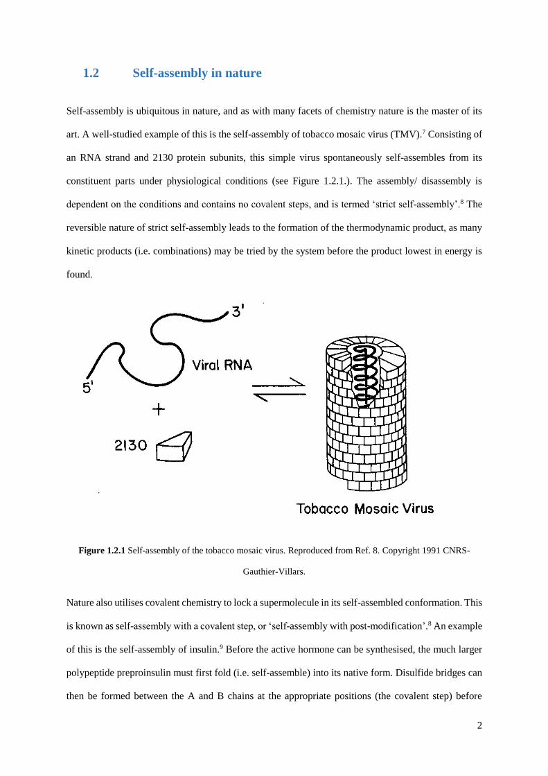
Self-assembly is ubiquitous in nature, and as with many facets of chemistry nature is the master of its
art. A well-studied example of this is the self-assembly of tobacco mosaic virus (TMV).7 Consisting of
an RNA strand and 2130 protein subunits, this simple virus spontaneously self-assembles from its
constituent parts under physiological conditions (see Figure 1.2.1.). The assembly/ disassembly is
dependent on the conditions and contains no covalent steps, and is termed ‘strict self-assembly’.8 The
reversible nature of strict self-assembly leads to the formation of the thermodynamic product, as many
kinetic products (i.e. combinations) may be tried by the system before the product lowest in energy is
found.
Figure 1.2.1 Self-assembly of the tobacco mosaic virus. Reproduced from Ref. 8. Copyright 1991 CNRS-
Gauthier-Villars.
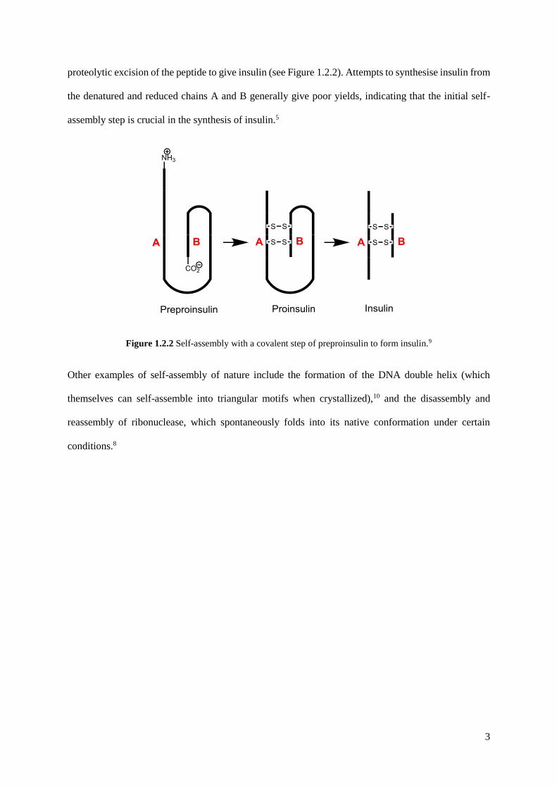
Nature also utilises covalent chemistry to lock a supermolecule in its self-assembled conformation. This
is known as self-assembly with a covalent step, or ‘self-assembly with post-modification’.8 An example
of this is the self-assembly of insulin.9 Before the active hormone can be synthesised, the much larger
polypeptide preproinsulin must first fold (i.e. self-assemble) into its native form. Disulfide bridges can
then be formed between the A and B chains at the appropriate positions (the covalent step) before
3
proteolytic excision of the peptide to give insulin (see Figure 1.2.2). Attempts to synthesise insulin from
the denatured and reduced chains A and B generally give poor yields, indicating that the initial self-
assembly step is crucial in the synthesis of insulin.5
Figure 1.2.2 Self-assembly with a covalent step of preproinsulin to form insulin.9
Other examples of self-assembly of nature include the formation of the DNA double helix (which
themselves can self-assemble into triangular motifs when crystallized),10 and the disassembly and
reassembly of ribonuclease, which spontaneously folds into its native conformation under certain
conditions.8
4
1.3 Self-assembly in inorganic synthesis
1.3.1 The emergence of supramolecular chemistry
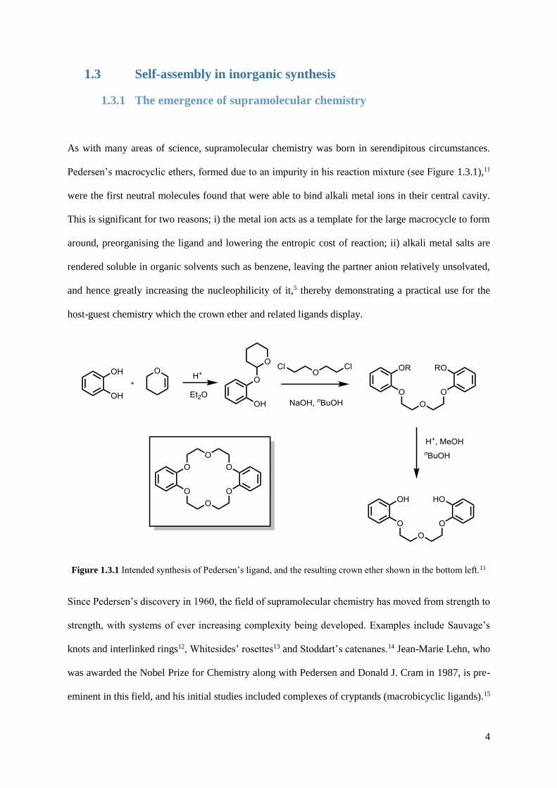
As with many areas of science, supramolecular chemistry was born in serendipitous circumstances.
Pedersen’s macrocyclic ethers, formed due to an impurity in his reaction mixture (see Figure 1.3.1),11
were the first neutral molecules found that were able to bind alkali metal ions in their central cavity.
This is significant for two reasons; i) the metal ion acts as a template for the large macrocycle to form
around, preorganising the ligand and lowering the entropic cost of reaction; ii) alkali metal salts are
rendered soluble in organic solvents such as benzene, leaving the partner anion relatively unsolvated,
and hence greatly increasing the nucleophilicity of it,5 thereby demonstrating a practical use for the
host-guest chemistry which the crown ether and related ligands display.
Figure 1.3.1 Intended synthesis of Pedersen’s ligand, and the resulting crown ether shown in the bottom left.11
Since Pedersen’s discovery in 1960, the field of supramolecular chemistry has moved from strength to
strength, with systems of ever increasing complexity being developed. Examples include Sauvage’s
knots and interlinked rings12, Whitesides’ rosettes13 and Stoddart’s catenanes.14 Jean-Marie Lehn, who
was awarded the Nobel Prize for Chemistry along with Pedersen and Donald J. Cram in 1987, is pre-
eminent in this field, and his initial studies included complexes of cryptands (macrobicyclic ligands).15

5
This early work focussed on the recognition of spherical metal cation guests. His work later developed
into designing more complicated hosts for complex guests such as adenosine triphosphate.1
In the late 80s and 90s Lehn was concerned with the self-assembly of helicates and grids, moving from
molecular recognition towards self-organisation.16 By combining strands of different oligobipyridine
ligands with 4-coordinate Cu(I) and 6-coordinate Ni(II), double and triple helicates can be selectively
formed (see Figure 1.3.2), a phenomenon that Lehn refers to as ‘programming’ the system.17
Fig 1.3.2 Self-recognition in the assembly of a double helicate and a triple helicate from a mixture of two
different ligands and two different types of metal ions.16
As supramolecular chemistry has developed, the ‘rules’ governing self-assembly have become more
fully understood through studying systems of low complexity such as this, enabling the designed
synthesis of higher order structures.18 Würthner describes these rules as ‘molecular codes’ which are
used in the process of ‘molecular programming’.19
6
1.3.2 From helicates to two-dimensional supramolecular structures
From these relatively simple helicates, a logical progression in the application of ‘molecular
programming’ would be to study the assembly of two-dimensional supramolecular structures. These
include squares, grids and racks, and many other structures based on simple polygons. Stang and co-
workers have utilized basic coordination chemistry to form highly symmetrical pre-designed shapes
from a mixture of rigid linking units.20 This work started with 2D polygons such as simple molecular
squares, but later moved on to 3D structures based on the Platonic and Archimedean solids (see Figure
1.3.3).21 This work shows how a mixture of different units can lead to the formation of discrete
supramolecular assemblies in which the shape is predetermined by the size and angle of the donor and
metal acceptors.
Fujita and co-workers were one of the first to create a molecular square.22 Using a cis-protected square
planar metal such as palladium(II) or platinum(II) with an inert bidentate ligand such as
ethylenediamine (en) as a 90o corner, and reacting with a linear bridging ligand such as 4,4’-bipyridine,
a near perfect square is formed (see Figure 1.3.4). When the pyridine rings are separated by a phenylene
spacer, the longer bridging ligand results in the square existing in equilibrium with molecular
triangles.23 Fujita extrapolated this idea and created hexagons, linked rings and eventually 3D
coordination cages.24
Both of the above examples employ the pre-design of a two-dimensional product by the use of particular
‘molecular codes’;19 in this case, the fixed coordination geometry of both the ligands and the metal ions.
It is the particular choice of a protected convergent metal and a divergent ligand that leads to the
formation of the desired polygons, rather than a coordination polymer (see Figure 1.3.5).6 Discrete
supramolecular structures are formed from complementary convergent/divergent pairs, whereas a
polymer would form from a divergent pair.

7
Figure 1.3.3 Representative example of Stang’s work, including 2D polygons (top) and 3D polyhedra
(bottom).21
Figure 1.3.4 Fujita’s molecular square.24

8
Figure 1.3.5 Design of discrete structures by choice of binding site.6

9
1.3.3 Three-dimensional coordination cages
The report of Saalfrank’s adamantanoidal cage in 1988 is thought to be one of the first 3D coordination
cage structures, in which a tetrahedral array of magnesium (II) ions are linked by bridging bis-enolate
ligands.25 Saalfrank expanded this idea by using transition metal dications (see Figure 1.3.6),26 and also
by extending the ligand with phenylene spacers.27
Figure 1.3.6 Saalfrank’s M4L6 ‘adamantanoid’ cage.24
In 1995, Fujita and co-workers extended their earlier work on the molecular square by synthesising a
nanosized 3D cage (1), capable of encapsulating four adamantyl carboxylate ions within its cavity.28 By
reacting the cis-protected metal with a trigonal tridentate ligand, a 3D octahedral coordination cage can
be formed quantitatively.24 Fujita has since shown that this coordination cage exhibits a range of
interesting properties, including host guest chemistry29 and the use as a catalyst,30 leading to these
interesting macromolecules being called ‘molecular flasks’.31 This behaviour is driven by the
hydrophobic effect, owing to the hydrophobic interior of the cage; hence in aqueous solvents,
hydrophobic guests will diffuse into the central cavity of the cage in order to maximise the favourable
interactions that water will have itself. This has facilitated some otherwise stubborn reactions, such as
the Diels-Alder reaction of naphthalene (see Figure 1.3.7).30 In addition to the hydrophobic effect, a
significant decrease in the entropic cost of reaction results from the preorganization of reactants inside
the cage.

10
Figure 1.3.7 Top: Assembly of the M6L4 octahedron (1). Bottom: Naphthalene Diels-Alder reaction in the self-
assembled molecular flask. Adapted with permission from Ref. 30. Copyright 2010 American Chemical Society.
Fujita’s method for synthesising his octahedral capsule utilises what Stang describes as the ‘molecular
panelling’ approach, in which the octahedron is prepared by bringing together eight triangular panels.32
By modifying the position of the coordinating nitrogen atoms on the triangular ligand, and thus the
connectivity of the panels, Fujita was able to form a hexahedron capsule, a square-pyramidal cone and
a closed-tetrahedron.33 His most recent work shows the formation of a staggering M24L48 series of cages,
although this used a different approach and ligand family to that above.34 These cages can be
functionalised on the exterior or interior surface via ligand modification, drastically altering the host-

11
guest chemistry of the cages.35-37 For example, with 24 inwardly directed sugar groups, precisely
monodisperse silica nanoparticles can be formed within the cage cavity.
The molecular panelling approach is one method used for designing coordination cages. Another
method used is the ‘symmetry interaction’ approach.32 This involves using multibranched chelating
ligands with rigid backbones and fixed geometries, along with labile transition metal ions or main group
metals. Raymond and co-workers have defined the requisites of this design principle, principally the
‘coordinate vector’ and the ‘chelate plane’.38 The vector that represents the interaction between a ligand
and metal is the coordinate vector (see Figure 3.3.3). When using chelating ligands, the plane orthogonal
to the major symmetry axis of a metal complex is the chelate plane, in which all of the coordinate
vectors of the chelating ligands lie. Any symmetric coordination complex cluster can be described in
terms of the relationships between these chelate planes.
Figure 1.3.8 Raymond’s definitions for coordination vectors and chelating planes.32
The M2L3 triple helicate formed in 1996 was one of the first examples from the Raymond group of a
structure formed by this design approach, consisting of two gallium(III) centres linked by three rigid
biscatecholamide ligands (see Figure 1.3.9).39 Later in the same year, Raymonds first M4L6 cage was
reported.40 The bis-bidentate bridging ligand incorporates two hydroxamate units separated by a

12
phenylene spacer; the method of creating ligands with chelating binding sites separated by a rigid
aromatic spacer is one that is used regularly in coordination cage chemistry.41-44
Figure 1.3.9 Raymond’s D3-symmetrical triple helicate.32
By changing the aromatic linker from a phenyl ring to a naphthyl unit in his biscatecholamide ligand,
Raymond was able to create a M4L6 cage that has since proved to have many remarkable properties (see
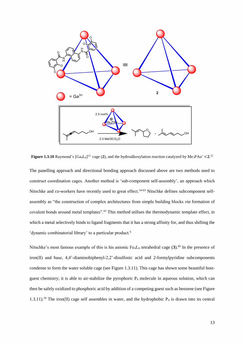
Figure 1.3.10).45-52 The self-assembled anionic [Ga4L6]12- cage (2) is able to stabilize reactive
intermediates such as tropylium, cationic phosphine-acetone adducts, and iminium ions due to its
hydrophobic interior, as well as augmenting the performance of encapsulated catalaysts through cavity
effects.31,53 A recent example shows that the catalytic activity of Me3PAuBr was increased 8-fold by
encapsulation, and up to 67 catalytic turnovers by Me3PAu+ encapsulated in 2 were observed.52
13
Figure 1.3.10 Raymond’s [Ga4L6]12- cage (2), and the hydroalkoxylation reaction catalyzed by Me3PAu+ ⊂2.52
The panelling approach and directional bonding approach discussed above are two methods used to
construct coordination cages. Another method is ‘sub-component self-assembly’, an approach which
Nitschke and co-workers have recently used to great effect.54-63 Nitschke defines subcomponent self-
assembly as “the construction of complex architectures from simple building blocks via formation of
covalent bonds around metal templates”.62 This method utilises the thermodynamic template effect, in
which a metal selectively binds to ligand fragments that it has a strong affinity for, and thus shifting the
‘dynamic combinatorial library’ to a particular product.6
Nitschke’s most famous example of this is his anionic Fe4L6 tetrahedral cage (3).60 In the presence of
iron(II) and base, 4,4’-diaminobiphenyl-2,2’-disulfonic acid and 2-formylpyridine subcomponents
condense to form the water soluble cage (see Figure 1.3.11). This cage has shown some beautiful host-
guest chemistry; it is able to air-stabilize the pyrophoric P4 molecule in aqueous solution, which can
then be safely oxidized to phosphoric acid by addition of a competing guest such as benzene (see Figure
1.3.11).59 The iron(II) cage self assembles in water, and the hydrophobic P4 is drawn into its central

14
cavity due to the hydrophobic effect. The cage is also able to encapsulate SF6, a potent greenhouse gas,
and release it again under defined conditions.56
Nitschke has also designed a cubic cage with porphyrin-based ligands occupying the six faces of the
cube, and iron(II) occupying the eight vertices.64 This cage is able to encapsulate large aromatic guests
such as buckminsterfullerene. Most recently, Nitschke has reported a Cu8L4 tube that is able to
selectively bind and release gold guests,65 a fluorophore incorporating M4L6 cage that allows nanomolar
guest sensing and white-light emission,66 and the formation of five discrete multinuclear metal-organic
assemblies from one ligand.67
Figure 1.3.11 Subcomponent self-assembly of tetrahedral cage 3 and subsequent incorporation of P4 followed
by its controlled release by substitution with benzene.59
15
1.3.4 Functional coordination cages
Coordination cages give a great test-bed for the understanding of supramolecular theory; by designing
cages methodically, the ‘rules’ we know concerning self-assembly become ever clearer, and new rules
may be learnt. The work of Fujita, Raymond and Nitschke discussed above are great examples of this.
The corollary of this is that functional structures may be formed as a result, thus propagating further
research in the field so that more applications of the host-guest chemistry become discovered.68 Their
use as ‘molecular flasks’, so termed by Fujita,69 is a well-known functionality of coordination cages.31
Fujita’s M6L4 octahedron has been shown to facilitate a number of reactions and trap reactive
intermediates, as described above.31 The catalytic activity of Raymond’s M4L6 tetrahedron and
molecular trapping abilities of Nitschke’s M4L6 tetrahedron have also been described.49,53
Kobayashi and Yamanaka have shown that a capsule complex formed from the self-assembly of two
cavitand and cis-protected platinum(II) units encapsulates guests that are of an appropriate molecular
size to fit the cavity.70 This builds on the earlier work of Rebek, who identified capsules that formed
from a variety of hydrogen-bonding dimers.71
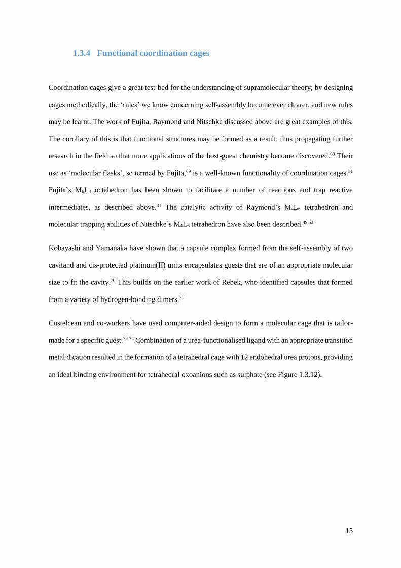
Custelcean and co-workers have used computer-aided design to form a molecular cage that is tailor-
made for a specific guest.72-74 Combination of a urea-functionalised ligand with an appropriate transition
metal dication resulted in the formation of a tetrahedral cage with 12 endohedral urea protons, providing
an ideal binding environment for tetrahedral oxoanions such as sulphate (see Figure 1.3.12).
16
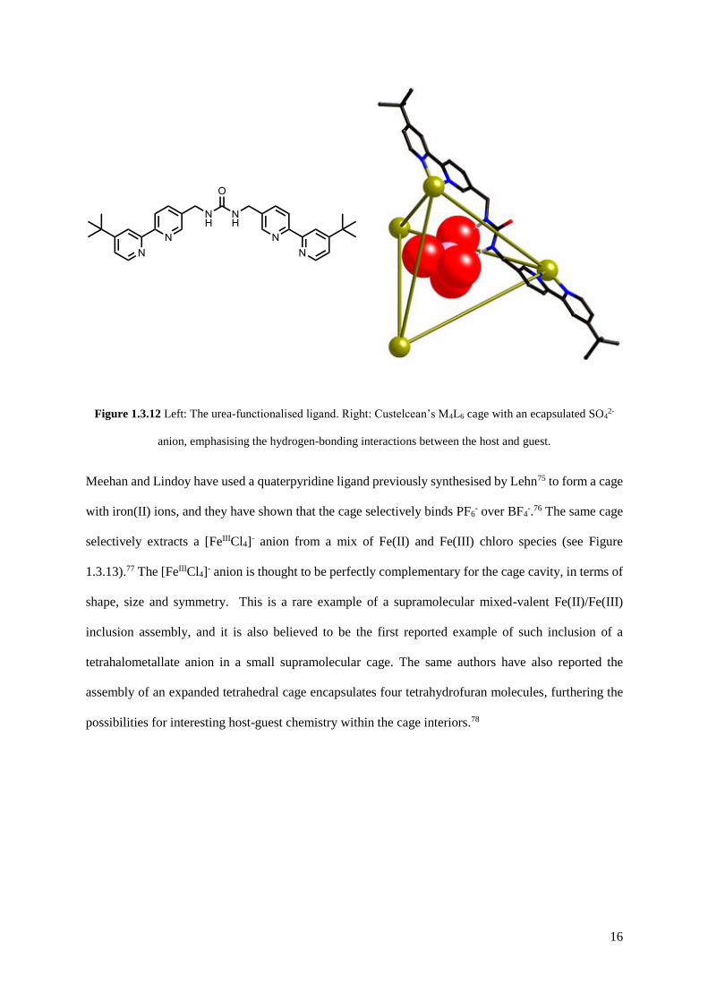
Figure 1.3.12 Left: The urea-functionalised ligand. Right: Custelcean’s M4L6 cage with an ecapsulated SO42-
anion, emphasising the hydrogen-bonding interactions between the host and guest.
Meehan and Lindoy have used a quaterpyridine ligand previously synthesised by Lehn75 to form a cage
with iron(II) ions, and they have shown that the cage selectively binds PF6- over BF4
-.76 The same cage
selectively extracts a [FeIIICl4]- anion from a mix of Fe(II) and Fe(III) chloro species (see Figure
1.3.13).77 The [FeIIICl4]- anion is thought to be perfectly complementary for the cage cavity, in terms of
shape, size and symmetry. This is a rare example of a supramolecular mixed-valent Fe(II)/Fe(III)
inclusion assembly, and it is also believed to be the first reported example of such inclusion of a
tetrahalometallate anion in a small supramolecular cage. The same authors have also reported the
assembly of an expanded tetrahedral cage encapsulates four tetrahydrofuran molecules, furthering the
possibilities for interesting host-guest chemistry within the cage interiors.78

17
Figure 1.3.13 Schematic representation of the assembly of the tetrahedral [Fe4L6]8+ host (4) incorporating a
guest [FeIIICl4]- anion.77
Therrien and co-workers have synthesised arene drug boxes; ruthenium(II) metalloprisms that bind
platinum(II) or palladium(II) bis(acetylacetonate) cations within the cage cavity (see Figure 1.3.14).79
This ‘complex within a complex’ approach greatly increases the cytotoxicity of the trapped complexes.
This is a result of the hydrophobicity of the [M(acac)2] complexes; their insolubility in water drives
them into the cage cavity. Once the box has reached the target cell, the hexaruthenium cage may open
and the [M(acac)2] complex is released to the biological target. Therrien’s group have also synthesised
ruthenium(II) cubes that bind to duplex and human telomeric quadruplex, leading to the possibility of
using octacationic arene ruthenium metalla-boxes as quadruplex DNA stabilisers.80

18
Figure 1.3.14 Therrien’s self-assembled arene drug box (5) and its encapsulation of a [M(acac)2] guest.79

19
1.4 Coordination cages in the Ward group
Ward and co-workers have been studying coordination cages for the last two decades since their initial
discoveries in 1995.42 An interest in polydentate ligands led to the study of the hexadentate ligand
[TpPy]- (see Figure 1.4.1a), a member of the ‘scorpionate’ family of ligands, so named due to their nature
of binding to metals.81 One might expect a six-coordinate metal ion to sit in the cavity and occupy a
trigonal prismatic binding geometry with the hexadentate ligand, and this is indeed the case with
cobalt(II), resulting in the mononuclear complex [Co(TpPy)]+ (see figure 1.4.1b).82 However, when the
same ligand is reacted with Mn(II) or Zn(II), a tetrahedral cage complex of the type [M4(TpPy)4]4+ is
formed (see Figure 1.4.1c), with each ligand chelating to three metal ions and capping a triangular face
of the tetrahedron (see Figure 1.4.1d). This tetrahedral cage arises due to the greater requirement for
Mn(II) and Zn(II) to adopt an octahedral coordination environment in comparison to Co(II). The rigid
ligand is unable to distort to provide this environment without considerable strain, and hence the
tetranuclear structure is adopted, which does allow all M(II) ions to be octahedral.
Figure 1.4.1 Anti-clockwise from top left: (a) The hexadentate ligand [TpPy]- ; (b) The mononuclear complex
[Co(TpPy)]+; (c) space-filling view of the tetrahedral complex [Zn4(TpPy)4]4+, and; (d) [Zn4(TpPy)4]4+ emphasizing
the face-capping nature of the ligand. Reproduced from Ref. 82 with permission from The Royal Society of
Chemistry.
20
These results led to further studies into the nature of ligands containing bidentate pyrazolyl-pyridine
units. A class of ligands combining two pyrazolyl-pyridine units separated by a rigid aromatic spacer
and linked by flexible methylene hinges was born. These ligands are easily synthesised, simply
requiring reaction of 3-(2-pyridyl)pyrazole under basic conditions with a (readily available)
bis(bromomethyl)aromatic compound.
The first ligand of this type that was synthesised was Lo-Ph (see Figure 1.4.2, left), which contains an
ortho-phenylene spacer.83 Reaction of this ligand with four-coordinate Cu(I) gave the double helical
[Cu2(Lo-Ph)2]2+, and with Ni(II) the dinuclear [Ni2(Lo-Ph)3]4+ was formed,84 in which one ligand acts as a
bridging bidentate linkage between the two metal ions, and the other two as tetradentate-chelates,
fulfilling the valence requirement of each metal. This ratio of 2M : 3L is required in all complexes of
bis-bidentate ligands and six-coordinate metal ions in order for coordinative saturation of all
components, an important concept in supramolecular chemistry.6
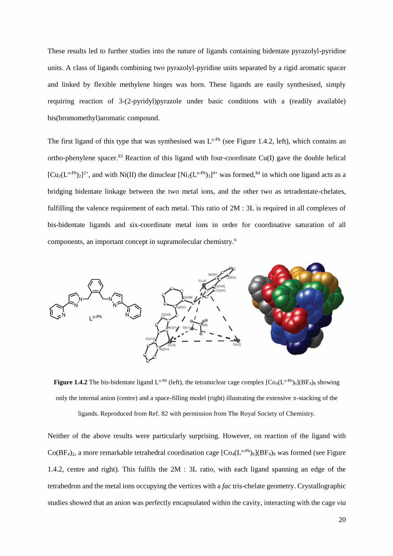
Figure 1.4.2 The bis-bidentate ligand Lo-Ph (left), the tetranuclear cage complex [Co4(Lo-Ph)6](BF4)8 showing
only the internal anion (centre) and a space-filling model (right) illustrating the extensive -stacking of the
ligands. Reproduced from Ref. 82 with permission from The Royal Society of Chemistry.
Neither of the above results were particularly surprising. However, on reaction of the ligand with
Co(BF4)2, a more remarkable tetrahedral coordination cage [Co4(Lo-Ph)6](BF4)8 was formed (see Figure
1.4.2, centre and right). This fulfils the 2M : 3L ratio, with each ligand spanning an edge of the
tetrahedron and the metal ions occupying the vertices with a fac tris-chelate geometry. Crystallographic
studies showed that an anion was perfectly encapsulated within the cavity, interacting with the cage via
21
hydrogen bonding with the methylene CH2 protons.86 Reaction in the absence of a suitably fitting anion
resulted in no cage formation, indicating that the central anion acts as a template for the cage to form
around.86 Another noteworthy point about the structure of the cage is that there is extensive -stacking
between different ligands. These factors all help in the formation and stabilisation of a structure of such
complexity from such simple components. It is thought that the smaller ionic radius of Ni(II) in
comparison to Co(II) would result in an unfavourable compression of the tetrahedral cage, thus the
simple dinuclear M2L3 complex forms preferentially.86
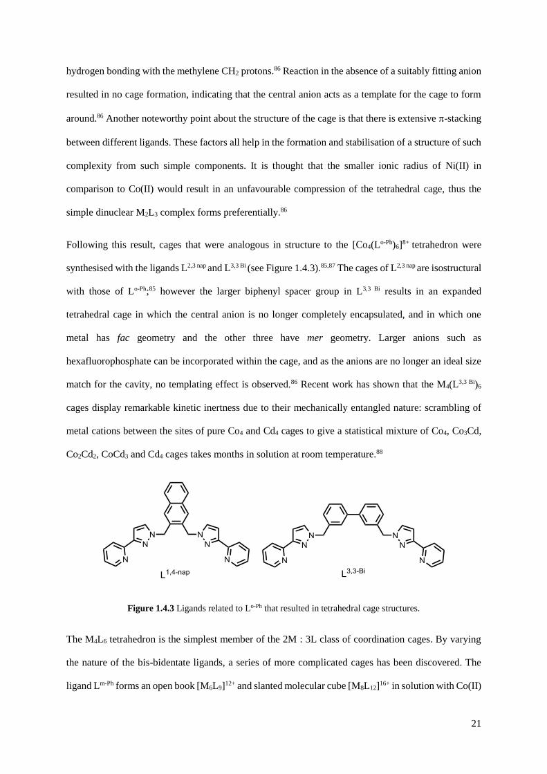
Following this result, cages that were analogous in structure to the [Co4(Lo-Ph)6]8+ tetrahedron were
synthesised with the ligands L2,3 nap and L3,3 Bi (see Figure 1.4.3).85,87 The cages of L2,3 nap are isostructural
with those of Lo-Ph;85 however the larger biphenyl spacer group in L3,3 Bi results in an expanded
tetrahedral cage in which the central anion is no longer completely encapsulated, and in which one
metal has fac geometry and the other three have mer geometry. Larger anions such as
hexafluorophosphate can be incorporated within the cage, and as the anions are no longer an ideal size
match for the cavity, no templating effect is observed.86 Recent work has shown that the M4(L3,3 Bi)6
cages display remarkable kinetic inertness due to their mechanically entangled nature: scrambling of
metal cations between the sites of pure Co4 and Cd4 cages to give a statistical mixture of Co4, Co3Cd,
Co2Cd2, CoCd3 and Cd4 cages takes months in solution at room temperature.88
Figure 1.4.3 Ligands related to Lo-Ph that resulted in tetrahedral cage structures.
The M4L6 tetrahedron is the simplest member of the 2M : 3L class of coordination cages. By varying
the nature of the bis-bidentate ligands, a series of more complicated cages has been discovered. The
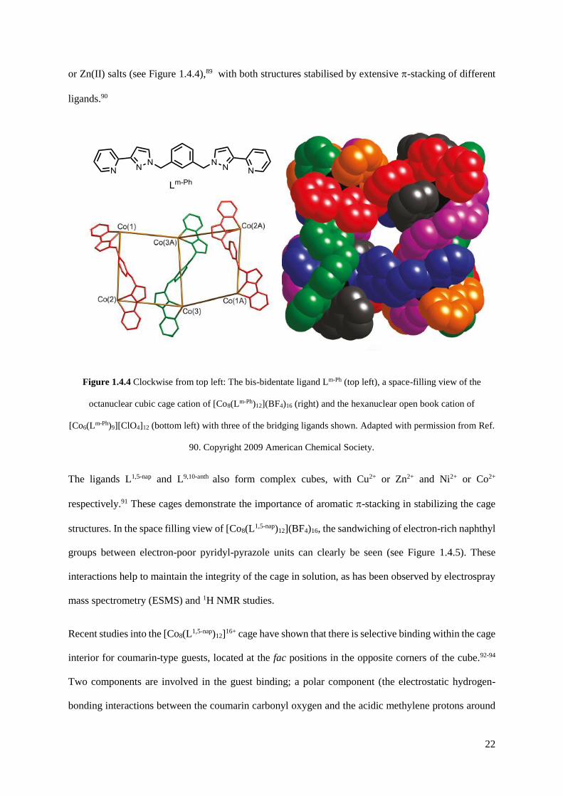
ligand Lm-Ph forms an open book [M6L9]12+ and slanted molecular cube [M8L12]16+ in solution with Co(II)
22
or Zn(II) salts (see Figure 1.4.4),89 with both structures stabilised by extensive -stacking of different
ligands.90
Figure 1.4.4 Clockwise from top left: The bis-bidentate ligand Lm-Ph (top left), a space-filling view of the
octanuclear cubic cage cation of [Co8(Lm-Ph)12](BF4)16 (right) and the hexanuclear open book cation of
[Co6(Lm-Ph)9][ClO4]12 (bottom left) with three of the bridging ligands shown. Adapted with permission from Ref.
90. Copyright 2009 American Chemical Society.
The ligands L1,5-nap and L9,10-anth also form complex cubes, with Cu2+ or Zn2+ and Ni2+ or Co2+
respectively.91 These cages demonstrate the importance of aromatic -stacking in stabilizing the cage
structures. In the space filling view of [Co8(L1,5-nap)12](BF4)16, the sandwiching of electron-rich naphthyl
groups between electron-poor pyridyl-pyrazole units can clearly be seen (see Figure 1.4.5). These
interactions help to maintain the integrity of the cage in solution, as has been observed by electrospray
mass spectrometry (ESMS) and 1H NMR studies.
Recent studies into the [Co8(L1,5-nap)12]16+ cage have shown that there is selective binding within the cage
interior for coumarin-type guests, located at the fac positions in the opposite corners of the cube.92-94
Two components are involved in the guest binding; a polar component (the electrostatic hydrogen-
bonding interactions between the coumarin carbonyl oxygen and the acidic methylene protons around

23
the vicinity of the cobalt(II) atom) and a non-polar component (the aromatic -stacking between
coumarin and the cage ligands).
Figure 1.4.5 The bis-bidentate ligand L1,5 nap (left), the octanuclear cubic cage [Co8(L1,5-nap)12](BF4)16 (centre)
showing only four ligands and six anions, and a space filling view of the complete cubic cage cation. Adapted
with permission from Ref. 91. Copyright 2010 American Chemical Society.
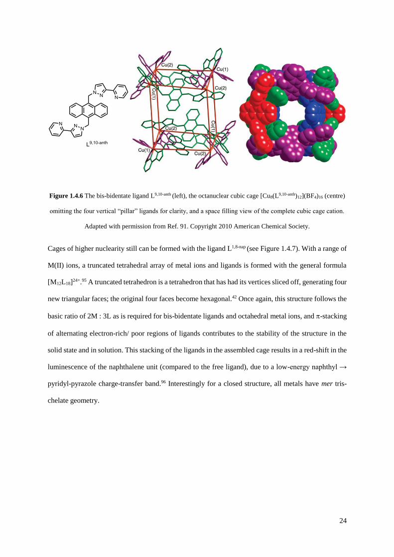
Comparison to the crystal structures of the cages formed with L9,10-anth show that although the cages are
of the type [M8L12]16+, they are far from isostructural with the cages of L1,5-nap (see Figure 1.4.6).91 Apart
from the obviously large central cavity, the other notable point about the cage is that there is no -
stacking between the anthryl groups and any other aromatic groups within the cage. Consequently, the
intact cage is not detected in solution by either 1H NMR or ESMS studies, and is only formed in the
solid state.91
24
Figure 1.4.6 The bis-bidentate ligand L9,10-anth (left), the octanuclear cubic cage [Cu8(L9,10-anth)12](BF4)16 (centre)
omitting the four vertical “pillar” ligands for clarity, and a space filling view of the complete cubic cage cation.
Adapted with permission from Ref. 91. Copyright 2010 American Chemical Society.
Cages of higher nuclearity still can be formed with the ligand L1,8-nap (see Figure 1.4.7). With a range of
M(II) ions, a truncated tetrahedral array of metal ions and ligands is formed with the general formula
[M12L18]24+.95 A truncated tetrahedron is a tetrahedron that has had its vertices sliced off, generating four
new triangular faces; the original four faces become hexagonal.42 Once again, this structure follows the
basic ratio of 2M : 3L as is required for bis-bidentate ligands and octahedral metal ions, and -stacking
of alternating electron-rich/ poor regions of ligands contributes to the stability of the structure in the
solid state and in solution. This stacking of the ligands in the assembled cage results in a red-shift in the
luminescence of the naphthalene unit (compared to the free ligand), due to a low-energy naphthyl →
pyridyl-pyrazole charge-transfer band.96 Interestingly for a closed structure, all metals have mer tris-
chelate geometry.

25
Figure 1.4.7 The bis-bidentate ligand L1,8-nap (left), the truncated tetrahedral cage [Cu12(L1,8-nap)18](ClO4)24
(centre) showing only one bridging ligand and a complete view of the complete cage cation (right) with three -
stacks highlighted in red, yellow and purple. Adapted with permission from Ref. 95. Copyright 2006 American
Chemical Society.
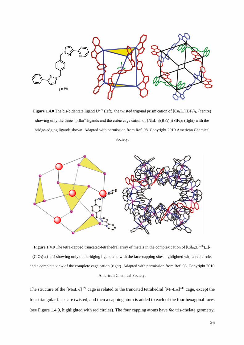
Recent work has been conducted using the ligand Lp-Ph, and using different M(II) ions can result in the
formation of three different coordination cage structures.97,98 Reaction of Lp-Ph with Ni(II) results in the
formation of a molecular cube [Ni8L12](BF4)12(SiF6)2, whereas reaction with Cu(II) results in the
formation of an unusual trigonal prism [Cu6L9](BF4)12 (see Figure 1.4.8). However, reaction with Zn(II)
or Cd(II) result in the largest homoleptic cage yet seen in this series, a tetra-capped truncated tetrahedron
[M16L24]32+. ESMS studies have shown that this cage interconverts with the hexanuclear trigonal prism
cage in solution, but it is thought that the hexadecanuclear cage is the kinetic product of crystallization
and thus only crystals of this product were afforded.98
26
Figure 1.4.8 The bis-bidentate ligand Lp-Ph (left), the twisted trigonal prism cation of [Cu6L9](BF4)12 (centre)
showing only the three “pillar” ligands and the cubic cage cation of [Ni8L12](BF4)12(SiF6)2 (right) with the
bridge-edging ligands shown. Adapted with permission from Ref. 98. Copyright 2010 American Chemical
Society.
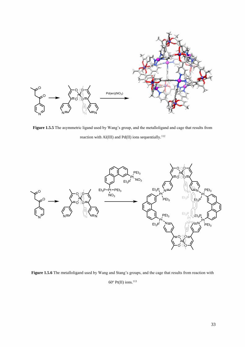
Figure 1.4.9 The tetra-capped truncated-tetrahedral array of metals in the complex cation of [Cd16(Lp-Ph)24]-
(ClO4)32 (left) showing only one bridging ligand and with the face-capping sites highlighted with a red circle,
and a complete view of the complete cage cation (right). Adapted with permission from Ref. 98. Copyright 2010
American Chemical Society.
The structure of the [M16L24]32+ cage is related to the truncated tetrahedral [M12L18]24+ cage, except the
four triangular faces are twisted, and then a capping atom is added to each of the four hexagonal faces
(see Figure 1.4.9, highlighted with red circles). The four capping atoms have fac tris-chelate geometry,

27
whereas the twelve metal atoms occupying the triangular faces have mer tris-chelate geometry. If one
were to control the geometry of the metal ions, the ability to select the geometry of the cage is made
possible, and the unprecedented realm of the mixed-metal cage is a potential target for this.
Most recent work in the Ward group has involved the study of ligands with new functionality within
the spacer unit. A new ligand class incorporating a furan or thiophene spacer has led to the isolation of
a series of molecular squares, cubes and chains, in which the oxygen or sulphur atoms can become
involved in interactions with the electron deficient coordinated pyrazole rings(see Figure 1.4.10, a).99
A new benzophenone ligand reacts with silver(I) to yield an infinite triple helix composed of molecular
double helicate subunits (see Figure 4.10, b).100 Finally, a ligand with a routine 1,4 naphthalene spacer
unit has led to an unprecedented coordination cage structure, a cuneane. This is the only possible 8-
vertex polyhedron other than a cube that will form a cage in which each metal is connected to three
others, i.e. a topological isomer of a cube.101
Figure 1.4.10 The furan or thiophene ligand and the cubic Cu8L12 cage structure it forms, with an oxygen →
pyrazole interaction highlighted (a); the benzophenone ligand and the hierarchical self-assembly of the triple
helix of double helices (b), and; the 1,4-naphthalene ligand, and the derivation of a cuneane which describes the
cage’s core (c). Reproduced from Ref. 99-101 with permission from The Royal Society of Chemistry.

28
Efforts within the Ward group are now being directed towards rendering existing cages water soluble,
as this will open up many new possibilities for host-guest chemistry. The water soluble ligand L1,5-nap-W
was prepared, which forms cages isostructural to the M8L12 cages prepared with L1,5-nap (see Figure
1.4.11).94 This cage binds hydrophobic guests very strongly due to the hydrophobic effect particularly
those which don’t have to undergo significant conformational change upon encapsulation with the
cavity. This has even enabled the determination of a host●guest crystal structure with cycloundecanone
in the cage cavity.102
Figure 1.4.11 (Left) The water soluble ligand L1,5-nap-W; (middle) schematic diagram of the cubic cage
[Co8(L1,5-nap-W)12]16+, emphasising the ligand connectivity; (right) crystal structure of the guest cycloundecanone
inside the host [Co8(L1,5-nap-W)12]16+. Adapted with permission from Ref. 102. Copyright 2010 American
Chemical Society.

29
1.5 Mixed-metal coordination structures
Structures of increased complexity are highly desirable, as this may lead to increased functionality. The
ability to create functional behaviour from controlled self-assembly is of course the ultimate challenge
of the supramolecular chemist.68 Two ways this may be achieved are by using more than one ligand so
that heteroleptic structures are formed, or by using more than one metal so that heterometallic structures
result. The use of more than one metal is particularly attractive because there is potential for variable
magnetic, photochemical or electrochemical properties, or even synergistic catalysis.103
Two principal strategies can be applied for the synthesis of heterometallic coordination structures, and
these are dependent on the kinetic stability of the metal ions in question. The first strategy is the kinetic
control approach. This can be used when one of the metal ions in question is kinetically inert, for
example Ru(II). By building a functionalisable framework around an inert [Ru(N)6]2+ scaffold,
heterometallic structures can be formed by a stepwise synthesis without the worry of the ruthenium
centre rearranging. This approach has been used within the Ward group, where the complex
[Ru(H2bpp)2]2+, which possesses functionalisable N-H groups, was alkylated to yield an inert [Ru(N)6]2+
core furnished with four pendant bidentate pyrazolyl-pyridyl sites.104 In the presence of Ag(I) ions, a
[RuAg2]4+ double helix results (see Figure 1.5.1). The post-coordination functionalisation of the ligand
is important in being able to form a single product, as this precludes the ruthenium(II) ion from being
scrambled across the different sites.

30
Figure 1.5.1 Crystal structure of the [Ru(H2bpp)2]2+ cation (left), and the complex cation of the resulting
[RuAg2L2]4+ double helix. Reproduced from Ref. 104 with permission from The Royal Society of Chemistry.
Fletcher’s group have also used ruthenium(II) cores as the basis of forming heterometallic structures.
The group have taken the approach of isolating the facial (fac) isomer of substituted tris-bipyridine
complexes of ruthenium(II).105-107 Whilst this is not a trivial procedure, the C3 symmetry of the fac-
isomer of such complexes is necessary to form polynuclear structures such as helicates. In this instance,
Fletcher’s group used a tripodal ligand in which the tether could be removed once the ligand was
coordinated to ruthenium(II). The resulting three bidentate ligands were functionalised with three
pendant bipyridyl binding sites, and reaction with Fe(II) ions resulted in the formation of a [RuFeL3]4+
helicate (see Figure 1.5.2). Such a helicate could not be selectively formed without the initial isolation
of the fac isomer; the kinetic control step.
Figure 1.5.2 The tripodal ligand prepared by Fletcher’s group and the reaction strategy for preparing the inert
heterometallic helicate.105

31
The Thomas group has also used a similar approach, in what they term the ‘complex as ligand’
approach.108 By preforming a protected ruthenium(II) complex to act as a divergent ligand, reaction
with protected convergent metal centres resulted in the formation of a series of kinetically labile or inert
heterometallic teteranuclear metallomacrocycles (see Figure 1.5.3). Host–guest studies carried out with
the Ru2Re2 macrocyle reveals that the complex functions as a luminescent sensor for anions in organic
solvents, and aromatic molecules in water.108,109
Figure 1.5.3 Crystal structure of the [Ru2Re2]4+ macrocyclic sensor with a hexafluorophosphate anion residing
in the central cavity. Reproduced with permission from Ref. 108. Copyright © 2006 WILEY-VCH Verlag
GmbH & Co. KGaA, Weinheim.
The second strategy that will enable the designed synthesis of heterometallic coordination structures is
the thermodynamic control approach. This strategy takes advantage of the different coordination
preferences of different metal ions, and can be approximately explained by considering hard-soft acid-
base (HSAB) theory: hard metals prefer hard ligand binding sites, and soft metals prefer soft ligand
binding sites. Alongside this, one must also take into consideration the preferred binding geometry of
each metal ion, and the corollary of this is that an unsymmetrical ligand is the main requirement for
forming a heterometallic structure based on the thermodynamic control approach.
There have been many examples in the literature where asymmetric ligands have been used with hard
and soft metal ions to create a complex heterometallic structure. Shionoya and co-workers have utilised

32
a ligand with a relatively soft pyridyl group and a relatively hard catecholate binding site to create a
coordination cage with hard Ti(IV) ions and soft Pd(II) ions (see Figure 1.5.4).110 Such systems have
been shown to be interconvertable depending on stoichiometry and reaction conditions. For example,
the [Pd3Ti2L6Cl6]4- cage shown in Figure 1.5.4 interconverts to a [Pd2Ti2(HL2)2(acac)2Cl4] ring on
addition of TiO(acac)2 and trifluoroacetic acid. The [TiL3]2- complex is the precursor to the cage, and it
has been shown that one of the bidentate ligands can be replaced by a series of acetylacetonates and
tropolonates, thus enabling site-selective ligand exchange as a facile route towards coordination cage
interconversion.111
Figure 1.5.4 The asymmetric ligand prepared by Shionoya’s group and the cage that results from reaction with
Ti(IV) and Pd(II) ions.110
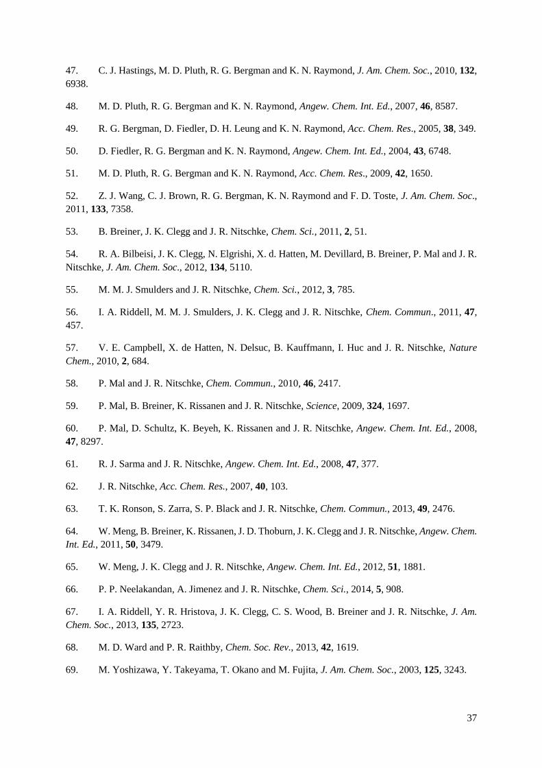
The method of using a hard metal tris-catecholate as a precursor to heterometallic coordination cages,
in effect a metalloligand, has not been exclusively used by Shionoya’s group. Wang and coworkers
have used a ligand furnished with a pyridyl and acetylacetonate binding sites to create an aluminium(III)
tris-catecholate metalloligand, which reacts with Pd(II) ions to form a [Pd6(AlL3)8](NO3)12 cube (see
Figure 1.5.5).112 Reaction with ZnBr2 yielded a trigonal pyramidal metallocage. In a collaboration with
Stang’s group, reaction of the metalloligand with a 60o diplatinum(II) acceptor yielded a structurally
similar trigonal cage, in this case making use of the more inert Pt(II) ion to increase the solution stability
of the cage once the desired product had been formed (see Figure 1.5.6).113
33
Figure 1.5.5 The asymmetric ligand used by Wang’s group, and the metalloligand and cage that results from
reaction with Al(III) and Pd(II) ions sequentially.112
Figure 1.5.6 The metalloligand used by Wang and Stang’s groups, and the cage that results from reaction with
60o Pt(II) ions.113

34
Nitschke’s group has recently elaborated on the subcomponent self-assembly approach that has allowed
them to synthesise a series of homonuclear cages with no preformed ligand.54,58,60,64,114 In each of these
cases the resulting ligand is symmetrical, with all metal ions having the same coordination mode
(however in some cases, differing tris-chelate geometries). By modifying the components so that a
symmetrical ligand cannot form, and introducing two metals that have differing coordination
preferences, Nitschke was able to isolate a Fe8Pt6L24 cubic cage from a one-pot synthesis in which 96
new bonds were formed.115 This is a great demonstration of the power of the thermodynamic control
approach, as such a complex structure can result from the one-pot reaction of such simple components.
Figure 1.5.7 The Fe8Pt6L24 cubic cage formed from subcomponent self-assembly, with one ligand indicating the
coordination mode of each metal. Reproduced with permission from Ref. 115. Copyright © 2012 WILEY-VCH
Verlag GmbH & Co. KGaA, Weinheim.

35
1.6 References
1. J. M. Lehn, Angew. Chem. Int. Ed., 1988, 27, 89.
2. G. R. Desiraju, Nature, 2001, 412, 397.
3. C. T. Seto and G. M. Whitesides, J. Am. Chem. Soc., 1993, 115, 905.
4. C. A. Hunter and J. K. M. Sanders, J. Am. Chem. Soc., 1990, 112, 5525.
5. P. D. Beer, P. A. Gale and D. K. and Smith, Supramolecular Chemistry, Oxford University
Press, Oxford, 1999.
6. J. W. Steed and J. L. Atwood, Supramolecular Chemistry, 2nd edn., Wiley, Chichester, 2009.
7. A. Klug, Phil. Trans. R. Soc. Lond. B., 1999, 354, 531.
8. J. S. Lindsey, New J. Chem., 1991, 15, 153.
9. D. Philp and J. F. Stoddart, Angew. Chem. Int. Ed., 1996, 35, 1155.
10. Y. Timsit and P. Varnai, J. Mol. Recognit., 2011, 24, 137.
11. C. J. Pedersen, Angew. Chem. Int. Ed., 1988, 27, 1021.
12. J. P. Sauvage and M. Ward, Inorg. Chem., 1991, 30, 3869.
13. J. P. Mathias, E. E. Simanek, J. A. Zerkowski, C. T. Seto and G. M. Whitesides, J. Am. Chem.
Soc., 1994, 116, 4316.
14. M. Asakawa, P. R. Ashton, S. E. Boyd, C. L. Brown, S. Menzer, D. Pasini, J. F. Stoddart, M.
S. Tolley, A. J. P. White, D. J. Williams and P. G. Wyatt, Chem. - Eur. J., 1997, 3, 463.
15. B. Dietrich, J. M. Lehn and J. P. Sauvage, Tet. Lett., 1969, 2885.
16. J. M. Lehn, Pure Appl. Chem., 1994, 66, 1961.
17. J. M. Lehn, Science, 2002, 295, 2400.
18. B. J. Holliday and C. A. Mirkin, Angew. Chem. Int. Ed., 2001, 40, 2022.
19. M. M. Safont-Sempere, G. Fernandez and F. Wuerthner, Chem. Rev., 2011, 111, 5784.
20. P. J. Stang and B. Olenyuk, Acc. Chem. Res., 1997, 30, 502.
21. S. R. Seidel and P. J. Stang, Acc. Chem. Res., 2002, 35, 972.
22. M. Fujita, J. Yazaki and K. Ogura, J. Am. Chem. Soc., 1990, 112, 5645.
23. M. Fujita, O. Sasaki, T. Mitsuhashi, T. Fujita, J. Yazaki, K. Yamaguchi and K. Ogura, Chem.
Commun., 1996, 1535.
24. M. Fujita, Chem. Soc. Rev., 1998, 27, 417.

36
25. R. W. Saalfrank, A. Stark, K. Peters and H. G. Vonschnering, Angew. Chem. Int. Ed., 1988, 27,
851.
26. R. W. Saalfrank, A. Stark, M. Bremer and H. U. Hummel, Angew. Chem. Int. Ed., 1990, 29,
311.
27. R. W. Saalfrank, B. Horner, D. Stalke and J. Salbeck, Angew. Chem. Int. Ed., 1993, 32, 1179.
28. M. Fujita, D. Oguro, M. Miyazawa, H. Oka, K. Yamaguchi and K. Ogura, Nature, 1995, 378,
469.
29. M. Fujita, M. Tominaga, A. Hori and B. Therrien, Acc. Chem. Res., 2005, 38, 369.
30. T. Murase, S. Horiuchi and M. Fujita, J. Am. Chem. Soc., 2010, 132, 2866.
31. M. Yoshizawa, J. K. Klosterman and M. Fujita, Angew. Chem. Int. Ed., 2009, 48, 3418.
32. R. Chakrabarty, P. S. Mukherjee and P. J. Stang, Chem. Rev., 2011, 111, 6810.
33. M. Fujita, K. Umemoto, M. Yoshizawa, N. Fujita, T. Kusukawa and K. Biradha, Chem.
Commun., 2001, 509.
34. J. Bunzen, J. Iwasa, P. Bonakdarzadeh, E. Numata, K. Rissanen, S. Sato and M. Fujita, Angew.
Chem. Int. Ed., 2012, 51, 3161.
35. K. Harris, D. Fujita and M. Fujita, Chem. Commun., 2013, 49, 6703.
36. T. Kikuchi, S. Sato, D. Fujita and M. Fujita, Chem. Sci., 2014, 5, 3257.
37. K. Suzuki, S. Sato and M. Fujita, Nature Chem., 2010, 2, 25.
38. D. L. Caulder and K. N. Raymond, Acc. Chem. Res., 1999, 32, 975.
39. B. Kersting, M. Meyer, R. E. Powers and K. N. Raymond, J. Am. Chem. Soc., 1996, 118, 7221.
40. T. Beissel, R. E. Powers and K. N. Raymond, Angew. Chem. Int. Ed., 1996, 35, 1084.
41. P. J. Steel, Acc. Chem. Res., 2005, 38, 243.
42. M. D. Ward, Chem. Commun., 2009, 4487.
43. C. R. K. Glasson, G. V. Meehan, C. A. Motti, J. K. Clegg, P. Turner, P. Jensen and L. F. Lindoy,
Dalton Trans., 2011, 40, 10481.
44. R. W. Saalfrank, H. Glaser, B. Demleitner, F. Hampel, M. M. Chowdhry, V. Schunemann, A.
X. Trautwein, G. B. M. Vaughan, R. Yeh, A. V. Davis and K. N. Raymond, Chem.-Eur. J., 2002, 8,
493.
45. D. L. Caulder, R. E. Powers, T. N. Parac and K. N. Raymond, Angew. Chem. Int. Ed., 1998,
37, 1840.
46. C. J. Brown, G. M. Miller, M. W. Johnson, R. G. Bergman and K. N. Raymond, J. Am. Chem.
Soc., 2011, 133, 11964.
37
47. C. J. Hastings, M. D. Pluth, R. G. Bergman and K. N. Raymond, J. Am. Chem. Soc., 2010, 132,
6938.
48. M. D. Pluth, R. G. Bergman and K. N. Raymond, Angew. Chem. Int. Ed., 2007, 46, 8587.
49. R. G. Bergman, D. Fiedler, D. H. Leung and K. N. Raymond, Acc. Chem. Res., 2005, 38, 349.
50. D. Fiedler, R. G. Bergman and K. N. Raymond, Angew. Chem. Int. Ed., 2004, 43, 6748.
51. M. D. Pluth, R. G. Bergman and K. N. Raymond, Acc. Chem. Res., 2009, 42, 1650.
52. Z. J. Wang, C. J. Brown, R. G. Bergman, K. N. Raymond and F. D. Toste, J. Am. Chem. Soc.,
2011, 133, 7358.
53. B. Breiner, J. K. Clegg and J. R. Nitschke, Chem. Sci., 2011, 2, 51.
54. R. A. Bilbeisi, J. K. Clegg, N. Elgrishi, X. d. Hatten, M. Devillard, B. Breiner, P. Mal and J. R.
Nitschke, J. Am. Chem. Soc., 2012, 134, 5110.
55. M. M. J. Smulders and J. R. Nitschke, Chem. Sci., 2012, 3, 785.
56. I. A. Riddell, M. M. J. Smulders, J. K. Clegg and J. R. Nitschke, Chem. Commun., 2011, 47,
457.
57. V. E. Campbell, X. de Hatten, N. Delsuc, B. Kauffmann, I. Huc and J. R. Nitschke, Nature
Chem., 2010, 2, 684.
58. P. Mal and J. R. Nitschke, Chem. Commun., 2010, 46, 2417.
59. P. Mal, B. Breiner, K. Rissanen and J. R. Nitschke, Science, 2009, 324, 1697.
60. P. Mal, D. Schultz, K. Beyeh, K. Rissanen and J. R. Nitschke, Angew. Chem. Int. Ed., 2008,
47, 8297.
61. R. J. Sarma and J. R. Nitschke, Angew. Chem. Int. Ed., 2008, 47, 377.
62. J. R. Nitschke, Acc. Chem. Res., 2007, 40, 103.
63. T. K. Ronson, S. Zarra, S. P. Black and J. R. Nitschke, Chem. Commun., 2013, 49, 2476.
64. W. Meng, B. Breiner, K. Rissanen, J. D. Thoburn, J. K. Clegg and J. R. Nitschke, Angew. Chem.
Int. Ed., 2011, 50, 3479.
65. W. Meng, J. K. Clegg and J. R. Nitschke, Angew. Chem. Int. Ed., 2012, 51, 1881.
66. P. P. Neelakandan, A. Jimenez and J. R. Nitschke, Chem. Sci., 2014, 5, 908.
67. I. A. Riddell, Y. R. Hristova, J. K. Clegg, C. S. Wood, B. Breiner and J. R. Nitschke, J. Am.
Chem. Soc., 2013, 135, 2723.
68. M. D. Ward and P. R. Raithby, Chem. Soc. Rev., 2013, 42, 1619.
69. M. Yoshizawa, Y. Takeyama, T. Okano and M. Fujita, J. Am. Chem. Soc., 2003, 125, 3243.

38
70. M. Yamanaka, M. Kawaharada, Y. Nito, H. Takaya and K. Kobayashi, J. Am. Chem. Soc.,
2011, 133, 16650.
71. M. M. Conn and J. Rebek, Chem. Rev., 1997, 97, 1647.
72. R. Custelcean, J. Bosano, P. V. Bonnesen, V. Kertesz and B. P. Hay, Angew. Chem. Int. Ed.,
2009, 48, 4025.
73. R. Custelcean, P. V. Bonnesen, N. C. Duncan, X. Zhang, L. A. Watson, G. Van Berkel, W. B.
Parson and B. P. Hay, J. Am. Chem. Soc., 2012, 134, 8525.
74. R. Custelcean, Chem. Soc. Rev., 2014, 43, 1813.
75. K. Warnmark, P. N. W. Baxter and J. M. Lehn, Chem. Commun., 1998, 993.
76. C. R. K. Glasson, G. V. Meehan, J. K. Clegg, L. F. Lindoy, P. Turner, M. B. Duriska and R.
Willis, Chem. Commun., 2008, 1190.
77. C. R. K. Glasson, J. K. Clegg, J. C. McMurtrie, G. V. Meehan, L. F. Lindoy, C. A. Motti, B.
Moubaraki, K. S. Murray and J. D. Cashion, Chem. Sci., 2011, 2, 540.
78. J. K. Clegg, F. Li, K. A. Jolliffe, G. V. Meehan and L. F. Lindoy, Chem. Commun., 2011, 47,
6042.
79. B. Therrien, G. Suess-Fink, P. Govindaswamy, A. K. Renfrew and P. J. Dyson, Angew. Chem.
Int. Ed., 2008, 47, 3773.
80. B. Therrien, Eur. J. Inorg. Chem., 2009, 2445.
81. S. Trofimenko, J. of Chem. Edu., 2005, 82, 1715.
82. R. L. Paul, A. J. Amoroso, P. L. Jones, S. M. Couchman, Z. R. Reeves, L. H. Rees, J. C. Jeffery,
J. A. McCleverty and M. D. Ward, J. Chem. Soc., Dalton Trans., 1999, 1563.
83. J. S. Fleming, K. L. V. Mann, S. M. Couchman, J. C. Jeffery, J. A. McCleverty and M. D. Ward,
J. Chem. Soc., Dalton Trans., 1998, 2047.
84. J. S. Fleming, K. L. V. Mann, C. A. Carraz, E. Psillakis, J. C. Jeffery, J. A. McCleverty and M.
D. Ward, Angew. Chem. Int. Ed., 1998, 37, 1279.
85. R. L. Paul, Z. R. Bell, J. C. Jeffery, J. A. McCleverty and M. D. Ward, Proc. Nat. Acad. Sci. of
U. S. A., 2002, 99, 4883.
86. R. L. Paul, Z. R. Bell, J. S. Fleming, J. C. Jeffery, J. A. McCleverty and M. D. Ward,
Heteroatom Chem., 2002, 13, 567.
87. R. L. Paul, S. M. Couchman, J. C. Jeffery, J. A. McCleverty, Z. R. Reeves and M. D. Ward, J.
Chem. Soc., Dalton Trans., 2000, 845.
88. B. R. Hall, L. E. Manck, I. S. Tidmarsh, A. Stephenson, B. F. Taylor, E. J. Blaikie, D. A. Vander
Griend and M. D. Ward, Dalton Trans., 2011, 40, 12132.
89. S. P. Argent, H. Adams, L. P. Harding and M. D. Ward, Dalton Trans., 2006, 542.

39
90. A. M. Najar, I. S. Tidmarsh, H. Adams and M. D. Ward, Inorg. Chem., 2009, 48, 11871.
91. I. S. Tidmarsh, T. B. Faust, H. Adams, L. P. Harding, L. Russo, W. Clegg and M. D. Ward, J.
Am. Chem. Soc., 2008, 130, 15167.
92. S. Turega, M. Whitehead, B. R. Hall, M. F. Haddow, C. A. Hunter and M. D. Ward, Chem.
Commun., 2012, 48, 2752.
93. S. Turega, M. Whitehead, B. R. Hall, A. J. H. M. Meijer, C. A. Hunter and M. D. Ward, Inorg.
Chem., 2013, 52, 1122.
94. M. Whitehead, S. Turega, A. Stephenson, C. A. Hunter and M. D. Ward, Chem. Science, 2013,
4, 2744.
95. S. P. Argent, H. Adams, T. Riis-Johannessen, J. C. Jeffery, L. P. Harding, O. Mamula and M.
D. Ward, Inorg. Chem., 2006, 45, 3905.
96. N. K. Al-Rasbi, H. Adams, L. P. Harding and M. D. Ward, Eur. J. Inorg. Chem., 2007, 4770.
97. S. P. Argent, H. Adams, T. Riis-Johannessen, J. C. Jeffery, L. P. Harding and M. D. Ward, J.
Am. Chem. Soc., 2006, 128, 72.
98. A. Stephenson, S. P. Argent, T. Riis-Johannessen, I. S. Tidmarsh and M. D. Ward, J. Am. Chem.
Soc., 2011, 133, 858.
99. A. Stephenson and M. D. Ward, Dalton Trans., 2011, 40, 10360.
100. A. Stephenson and M. D. Ward, Chem. Commun., 2012, 48, 3605.
101. A. Stephenson and M. D. Ward, Dalton Trans., 2011, 40, 7824.
102. S. Turega, W. Cullen, M. Whitehead, C. A. Hunter and M. D. Ward, J. Am. Chem. Soc., 2014,
136, 8475.
103. M. M. J. Smulders, I. A. Riddell, C. Browne and J. R. Nitschke, Chem. Soc. Rev., 2013, 42,
1728.
104. Q.-H. Wei, S. P. Argent, H. Adams and M. D. Ward, New J. Chem., 2008, 32, 73.
105. N. C. Fletcher, R. T. Brown and A. P. Doherty, Inorg. Chem., 2006, 45, 6132.
106. N. C. Fletcher, M. Nieuwenhuyzen, R. Prabarahan and A. Wilson, Chem. Commun., 2002,
1188.
107. R. T. Brown, N. C. Fletcher, M. Nieuwenhuyzen and T. E. Keyes, Inorg. Chim. Acta, 2005,
358, 1079.
108. P. de Wolf, P. Waywell, M. Hanson, S. L. Heath, A. Meijer, S. J. Teat and J. A. Thomas, Chem.-
Eur. J., 2006, 12, 2188.
109. P. de Wolf, S. L. Heath and J. A. Thomas, Chem. Commun., 2002, 2540.
110. S. Hiraoka, Y. Sakata and M. Shionoya, J. Am. Chem. Soc., 2008, 130, 10058.

40
111. Y. Sakata, S. Hiraoka and M. Shionoya, Chem.-Eur. J., 2010, 16, 3318.
112. H. B. Wu and Q. M. Wang, Angew. Chem. Int. Ed., 2009, 48, 7343.
113. M. Wang, V. Vajpayee, S. Shanmugaraju, Y.-R. Zheng, Z. Zhao, H. Kim, P. S. Mukherjee, K.-
W. Chi and P. J. Stang, Inorg. Chem., 2011, 50, 1506.
114. W. Meng, J. K. Clegg, J. D. Thoburn and J. R. Nitschke, J. Am. Chem. Soc., 2011, 133, 13652.
115. M. M. J. Smulders, A. Jimenez and J. R. Nitschke, Angew. Chem. Int. Ed., 2012, 51, 6681.

41
2. Fac and mer isomers of Ru(II) tris
(pyrazolyl-pyridine) complexes as
models for the vertices of coordination
cages: structural characterisation and
hydrogen-bonding characteristics
2.1 Introduction
Host–guest chemistry of hollow container molecules is an increasingly important field of study because
of the fundamental insights it can offer into molecular recognition processes,1-5 and because of potential
applications in areas such as alterations of reactivity of bound guests which allows novel synthetic
transformations;6-9 catalysis;10-12 and targeted drug delivery.13,14 Of these, all rely on highly selective
binding of specific guests, sometimes involving hydrogen-bond based recognition between the guest
and the cavity of the host.15-20
In most examples where hydrogen-bonds are used in guest binding within a cage cavity, the hydrogen
bond donor atoms are heteroatoms. Custelcean and co-workers have synthesised a series of ligands
which contain a urea linkage between two 2,2’-bipyridyl units. Combination of three equivalents of
ligand with two equivalents of nickel(II) or zinc(II) resulted in the formation of a tetrahedral cage with
12 endohedral urea protons; this provides an ideal binding environment for tetrahedral oxoanions such
as sulfate (see Figure 2.1.1).18 Computer-aided design has shown that each sulphate anion can accept
up to 12 N–H⋯O hydrogen-bonds in its solvation shell, and this is indeed the case in the crystal
structure of the [M4L6]8+ cages with encapsulated sulphate anions. This is an example of how a binding
pocket can be precisely tailored for a specific guest.
42
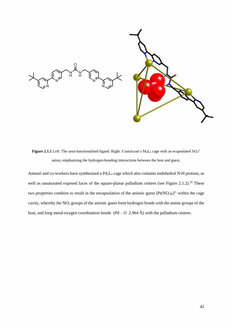
Figure 2.1.1 Left: The urea-functionalised ligand. Right: Custelcean’s M4L6 cage with an ecapsulated SO42-
anion, emphasising the hydrogen-bonding interactions between the host and guest.
Amouri and co-workers have synthesised a Pd2L4 cage which also contains endohedral N-H protons, as
well as unsaturated exposed faces of the square-planar palladium centres (see Figure 2.1.2).20 These
two properties combine to result in the encapsulation of the anionic guest [Pt(NO2)4]2- within the cage
cavity, whereby the NO2 groups of the anionic guest form hydrogen bonds with the amine groups of the
host, and long metal-oxygen coordination bonds (Pd – O 2.964 Å) with the palladium centres.
43
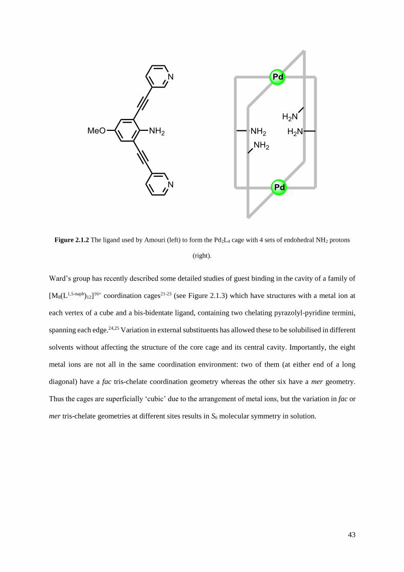
Figure 2.1.2 The ligand used by Amouri (left) to form the Pd2L4 cage with 4 sets of endohedral NH2 protons
(right).
Ward’s group has recently described some detailed studies of guest binding in the cavity of a family of
[M8(L1,5-naph)12]16+ coordination cages21-23 (see Figure 2.1.3) which have structures with a metal ion at
each vertex of a cube and a bis-bidentate ligand, containing two chelating pyrazolyl-pyridine termini,
spanning each edge.24,25 Variation in external substituents has allowed these to be solubilised in different
solvents without affecting the structure of the core cage and its central cavity. Importantly, the eight
metal ions are not all in the same coordination environment: two of them (at either end of a long
diagonal) have a fac tris-chelate coordination geometry whereas the other six have a mer geometry.
Thus the cages are superficially ‘cubic’ due to the arrangement of metal ions, but the variation in fac or
mer tris-chelate geometries at different sites results in S6 molecular symmetry in solution.

44
Figure 2.1.3 The general structure of the [M8(L1,5-naph)12]16+ coordination cage, with ligands coloured differently
for clarity (left); a sketch showing the likely mode of binding of hydrogen-bond accepting guests at one of the
two fac tris-chelate metal vertices (middle); structure of the L1,5-naph family of ligands used to make cubic
coordination cages (R’ = H, CH2OH) (right).
The formation of two fac tris-chelate sites results in assembly of convergent groups of inwardly-directed
methylene protons, which lie quite close to the Co(II) centre and are therefore in a region of high
electrostatic potential. This provides a binding pocket where electron-rich atoms can bind via a set of
charge-assisted C–H⋯X hydrogen-bonds (see Figure 2.1.3). At the remaining six mer tris-chelate
Co(II) centres there is no such convergent group of C–H protons, and additionally these metal ions are
more sterically protected by the ligand substituents such that no close approach of an electron-rich guest
atom to the metal centre is possible.21
These cages bind, with high shape and size selectivity, a range of hydrogen-bond-accepting bicyclic
organic molecules such as coumarin and isoquinoline-N-oxide, in which the exocyclic O atom acts as
the hydrogen-bond acceptor. 1H NMR studies on numerous host/guest combinations in MeCN showed
a strong correlation between guest binding strength and the hydrogen-bond acceptor ability of the guest,
confirming that a hydrogen-bonding interaction with the interior surface of the cage makes an important
contribution to complex formation.21 Molecular modelling studies showed that the minimum-energy
structures had the guests oriented such that their exocyclic oxygen atom did indeed lie in the pocket
defined by the convergent set of methylene protons at one of the two fac tris-chelate vertices, in the
regions of the cavity where electrostatic potential is most positive (cf. Figure 2.1.3, centre).
45
Up to the point at which this research was conducted, the Ward group have not been able to grow
crystals of a host M8L12 coordination cage containing a bound guest to confirm the binding mode.26 It
is important for this work however to have clear proof that the hypothesis – viz. that the fac tris-chelate
sites in the cages provide preorganised binding sites for recognition of hydrogen-bond acceptors – is
correct, particularly in the solution phase, as this knowledge will influence design and study of future
generations of host cages. It is noted that there are several examples of simple tris-chelate complexes
in which a convergent arrangement of three polar substituents such as amides or carboxylates on one
face of the complex provides a binding site for interacting with anions27-29 and even proteins.30 Although
the Ward group cage complexes only contain inwardly directed C–H groups as the hydrogen-bonding
sites it might be expected to see the same geometric discrimination between fac (convergent set of
hydrogen- bond donor atoms) and mer (non convergent hydrogen-bond donors) isomers.
The basis of this work therefore was to prepare simple, kinetically stable, mononuclear Ru(II)
complexes based on pyrazolyl-pyridine type ligands, as either their fac or mer isomers, to use as models
for the different metal vertices in the coordination cage. Structural characterisation of these has been
used to confirm their similarity to the metal centres in the cage superstructure, and 1H NMR
spectroscopic titrations have been performed to see if the coordination geometry of the metal complex
does influence how well a hydrogen-bonding guest interacts with it. From this has been found clear
evidence that the fac tris-chelate metal complex units do act as better hydrogen-bond donors than the
related mer tris-chelate complexes, and that this interaction is associated with the convergent group of
methylene protons in the fac complexes. There is therefore good evidence (beyond molecular
modelling) to support our understanding of how guest molecules interact with the interior surface of the
cage hosts.
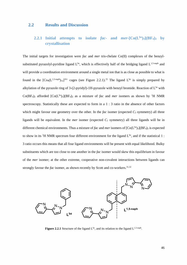
46
2.2 Results and Discussion
2.2.1 Initial attempts to isolate fac- and mer-[Co(Lbz)3](BF4)2 by
crystallisation
The initial targets for investigation were fac and mer tris-chelate Co(II) complexes of the benzyl-
substituted pyrazolyl-pyridine ligand Lbz, which is effectively half of the bridging ligand L1,5-naph and
will provide a coordination environment around a single metal ion that is as close as possible to what is
found in the [Co8(L1,5-naph)12]16+ cages (see Figure 2.2.1).25 The ligand Lbz is simply prepared by
alkylation of the pyrazole ring of 3-(2-pyridyl)-1H-pyrazole with benzyl bromide. Reaction of Lbz with
Co(BF4)2 afforded [Co(Lbz)3](BF4)2 as a mixture of fac and mer isomers as shown by 1H NMR
spectroscopy. Statistically these are expected to form in a 1 : 3 ratio in the absence of other factors
which might favour one geometry over the other. In the fac isomer (expected C3 symmetry) all three
ligands will be equivalent. In the mer isomer (expected C1 symmetry) all three ligands will be in
different chemical environments. Thus a mixture of fac and mer isomers of [Co(Lbz)3](BF4)2 is expected
to show in its 1H NMR spectrum four different environment for the ligand Lbz, and if the statistical 1 :
3 ratio occurs this means that all four ligand environments will be present with equal likelihood. Bulky
substituents which are too close to one another in the fac isomer would skew this equilibrium in favour
of the mer isomer; at the other extreme, cooperative non-covalent interactions between ligands can
strongly favour the fac isomer, as shown recently by Scott and co-workers.31,32
Figure 2.2.1 Structure of the ligand Lbz, and its relation to the ligand L1,5-naph.
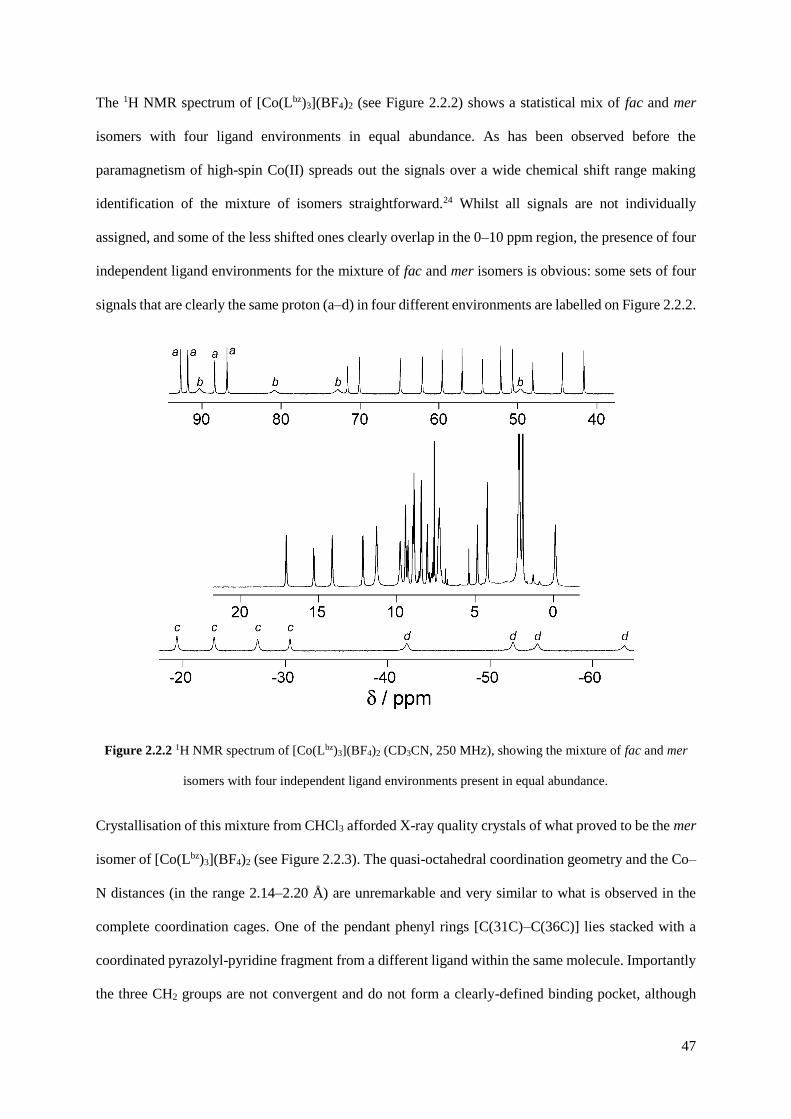
47
The 1H NMR spectrum of [Co(Lbz)3](BF4)2 (see Figure 2.2.2) shows a statistical mix of fac and mer
isomers with four ligand environments in equal abundance. As has been observed before the
paramagnetism of high-spin Co(II) spreads out the signals over a wide chemical shift range making
identification of the mixture of isomers straightforward.24 Whilst all signals are not individually
assigned, and some of the less shifted ones clearly overlap in the 0–10 ppm region, the presence of four
independent ligand environments for the mixture of fac and mer isomers is obvious: some sets of four
signals that are clearly the same proton (a–d) in four different environments are labelled on Figure 2.2.2.
Figure 2.2.2 1H NMR spectrum of [Co(Lbz)3](BF4)2 (CD3CN, 250 MHz), showing the mixture of fac and mer
isomers with four independent ligand environments present in equal abundance.
Crystallisation of this mixture from CHCl3 afforded X-ray quality crystals of what proved to be the mer
isomer of [Co(Lbz)3](BF4)2 (see Figure 2.2.3). The quasi-octahedral coordination geometry and the Co–
N distances (in the range 2.14–2.20 Å) are unremarkable and very similar to what is observed in the
complete coordination cages. One of the pendant phenyl rings [C(31C)–C(36C)] lies stacked with a
coordinated pyrazolyl-pyridine fragment from a different ligand within the same molecule. Importantly
the three CH2 groups are not convergent and do not form a clearly-defined binding pocket, although

48
three of them [H(26B), H(26D) and H(26F)] form close contacts with F atoms of the fluoroborate anions
or the O atom of a water molecule (H⋯X separations involving these H atoms, 2.49–2.93 Å).
Figure 2.2.3 Structure of the complex cation of mer-[Co(Lbz)3](BF4)2·CHCl3·H2O (thermal ellipsoids at 40%
probability level). One ligand is shown with paler colours for clarity.
Attempts to crystallise the fac isomer of [Co(Lbz)3](BF4)2 for comparison purposes were unsuccessful.
Only the mer isomer crystallised, and – given the kinetic lability of Co(II) – this likely resulted in re -
establishment of the 3 : 1 mer : fac equilibrium ratio in solution, such that the amount of fac isomer
present diminished as the crystallisation proceeded. This was confirmed by measuring the 1H NMR
spectrum of redissolved crystals of mer-[Co(Lbz)3](BF4)2 which was exactly the same as that in Figure
2.2.2: i.e. the pure mer isomer equilibrated to the 3 : 1 mer : fac equilibrium in the time it took to dissolve
the crystals and record the NMR spectrum.
It was then attempted to see if the use of different anions may template the formation of the fac isomer.
Thus, the reaction was repeated with tetraphenylborate, acetate and hexafluorophosphate salts of
cobalt(II). Reaction of Co(OAc)2 with Lbz followed by anion metathesis with sodium tetraphenylborate
in acetonitrile resulted in the complex as its tetraphenylborate salt. Slow evaporation of solvent resulted

49
in X-ray quality crystals of what also proved to be the mer isomer of [Co(Lbz)3](BPh4)2 (see Figure
2.2.4). The structure of the complex cation is similar to that of the tetrafluoroborate salt, with a quasi-
octahedral coordination geometry and similar Co–N distances (in the range 2.12–2.17 Å). The
associated anions make numerous CH⋯ contacts with the associated anions, which effectively wrap
around the complex cations (see Figure 2.2.4, bottom). Once formed, the crystals were extremely
insoluble, only dissolving in d6-dmso. This caused the dissociation of the complex, as the 1H NMR
spectrum was quite unlike that seen in Figure 2.2.2; the complex falls apart in very competitive solvents.
A deep purple solution of Co(OAc)2 and Lbz in acetonitrile described above yielded X-ray quality
crystals after slow evaporation of the solvent, even without additional anions being added. This proved
to be an unexpected product (see Figure 2.2.5). The structure was revealed to be the linear trimer
[Co3(Lbz)2(OAc)6] in which the central cobalt(II) atom [Co(1)] lies on an inversion centre, such that half
of the complex is crystallographically unique. Each pyridyl-pyrazolyl ligands chelate to one of the
terminal Co(2) atoms, and the six acetate anions bridge the cobalt(II) cations in two distinct ways. The
first acetate binding mode is a 2-1,3 bridging manner, in which each acetate oxygen [O(13B), O(14B),
O(13D) and O(14D)] is singly bonded to a different cobalt(II) cation. The second type of bridging
observed is slightly more unusual, in that the acetate acts as a chelating ligand for the terminal Co(2)
atoms with one of the oxygen atoms [O(13C)] also bridging Co(1) and Co(2).
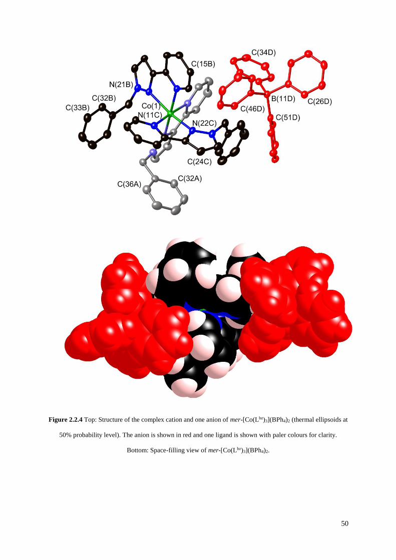
50
Figure 2.2.4 Top: Structure of the complex cation and one anion of mer-[Co(Lbz)3](BPh4)2 (thermal ellipsoids at
50% probability level). The anion is shown in red and one ligand is shown with paler colours for clarity.
Bottom: Space-filling view of mer-[Co(Lbz)3](BPh4)2.

51
Figure 2.2.5 Structure of the complex of [Co3(Lbz)2(OAc)6]·2MeCN (thermal ellipsoids at 50% probability
level).
The result of these bridging interactions is a central cobalt(II) atom with pseudo-octahedral geometry
as a result of six oxygen donor atoms provided by six different acetate anions (see Figure 2.2.6), with
bond lengths in the region of 2.06 – 2.13 Å, and cis-bond angles in the region of 86.9 – 93.1 º. The
terminal cobalt(II) atoms have a heavily distorted pseudo-octahedral geometry, with Co – O bond
lengths in the range of 2.01 – 2.19 Å [O(13B) and O(14C), respectively], and Co – N bond lengths of
2.15 and 2.22 Å [N(11A) and N(22A)]. The cis-bond angles are heavily distorted from 90 º, ranging
from 59.9 º for the angle between the two oxygen atoms of the chelating acetate [O(13C) and O(14C)],
and 104.4 º between O(13C) and N(22A). A similar structure has been reported recently by Mukherjee
and co-workers, in which two terminal cobalt(II) atoms with an N2O4 donor atom set and a central one
with an O6 donor set form a linear trimer.33
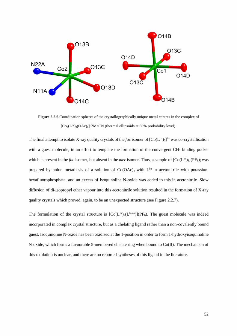
52
Figure 2.2.6 Coordination spheres of the crystallographically unique metal centres in the complex of
[Co3(Lbz)2(OAc)6]·2MeCN (thermal ellipsoids at 50% probability level).
The final attempt to isolate X-ray quality crystals of the fac isomer of [Co(Lbz)3]2+ was co-crystallisation
with a guest molecule, in an effort to template the formation of the convergent CH2 binding pocket
which is present in the fac isomer, but absent in the mer isomer. Thus, a sample of [Co(Lbz)3](PF6)2 was
prepared by anion metathesis of a solution of Co(OAc)2 with Lbz in acetonitrile with potassium
hexafluorophosphate, and an excess of isoquinoline N-oxide was added to this in acetonitrile. Slow
diffusion of di-isopropyl ether vapour into this acetonitrile solution resulted in the formation of X-ray
quality crystals which proved, again, to be an unexpected structure (see Figure 2.2.7).
The formulation of the crystal structure is [Co(Lbz)2(LN-ox)](PF6). The guest molecule was indeed
incorporated in complex crystal structure, but as a chelating ligand rather than a non-covalently bound
guest. Isoquinoline N-oxide has been oxidised at the 1-position in order to form 1-hydroxyisoquinoline
N-oxide, which forms a favourable 5-membered chelate ring when bound to Co(II). The mechanism of
this oxidation is unclear, and there are no reported syntheses of this ligand in the literature.

53
Figure 2.2.7 Structure of the complex cation of [Co(Lbz)2(LN-ox)](PF6) (thermal ellipsoids at 50% probability
level). The anion is shown in red and one ligand is shown with paler colours for clarity.
Two ligands Lbz make up the rest of the coordination sphere of the cobalt(II) ion, resulting in a distorted
quasi-octahedral geometry. The structure is stabilised by intramolecular – stacking between the
electron-rich pendant phenyl ring of one ligand and the electron-deficient isoquinoline (see Figure
2.2.7). There are also pairs of intermolecular CH⋯ interactions between the CH2 protons and phenyl
rings of neighbouring complexes (see Figure 2.2.8). There are also numerous C–H⋯F hydrogen-bonds
between the hexafluorophosphate anions and the coordinated and pendant aromatic rings, with H⋯F
distances in the range of 2.35 – 2.85 Å.
It is clear from these efforts that trying to isolate and study separately the fac and mer isomers of
[Co(Lbz)3]X2 as models for the separate types of cage vertex is not feasible, and we therefore changed
strategy to the use of a more kinetically inert metal centre.

54
Figure 2.2.8 Top: Stick representation of [Co(Lbz)2(LN-ox)](PF6) emphasising the hydrogen-bonding interactions
between the complex cations and anions. Bottom: Space-filling view from the same perspective.
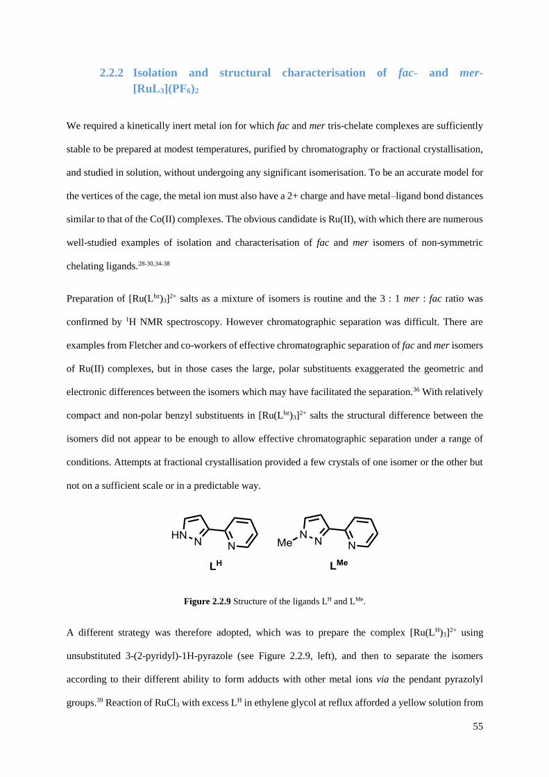
55
2.2.2 Isolation and structural characterisation of fac- and mer-
[RuL3](PF6)2
We required a kinetically inert metal ion for which fac and mer tris-chelate complexes are sufficiently
stable to be prepared at modest temperatures, purified by chromatography or fractional crystallisation,
and studied in solution, without undergoing any significant isomerisation. To be an accurate model for
the vertices of the cage, the metal ion must also have a 2+ charge and have metal–ligand bond distances
similar to that of the Co(II) complexes. The obvious candidate is Ru(II), with which there are numerous
well-studied examples of isolation and characterisation of fac and mer isomers of non-symmetric
chelating ligands.28-30,34-38
Preparation of [Ru(Lbz)3]2+ salts as a mixture of isomers is routine and the 3 : 1 mer : fac ratio was
confirmed by 1H NMR spectroscopy. However chromatographic separation was difficult. There are
examples from Fletcher and co-workers of effective chromatographic separation of fac and mer isomers
of Ru(II) complexes, but in those cases the large, polar substituents exaggerated the geometric and
electronic differences between the isomers which may have facilitated the separation.36 With relatively
compact and non-polar benzyl substituents in [Ru(Lbz)3]2+ salts the structural difference between the
isomers did not appear to be enough to allow effective chromatographic separation under a range of
conditions. Attempts at fractional crystallisation provided a few crystals of one isomer or the other but
not on a sufficient scale or in a predictable way.
Figure 2.2.9 Structure of the ligands LH and LMe.
A different strategy was therefore adopted, which was to prepare the complex [Ru(LH)3]2+ using
unsubstituted 3-(2-pyridyl)-1H-pyrazole (see Figure 2.2.9, left), and then to separate the isomers
according to their different ability to form adducts with other metal ions via the pendant pyrazolyl
groups.39 Reaction of RuCl3 with excess LH in ethylene glycol at reflux afforded a yellow solution from
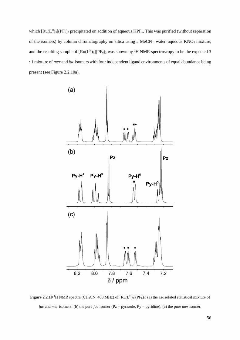
56
which [Ru(LH)3](PF6)2 precipitated on addition of aqueous KPF6. This was purified (without separation
of the isomers) by column chromatography on silica using a MeCN– water–aqueous KNO3 mixture,
and the resulting sample of [Ru(LH)3](PF6)2 was shown by 1H NMR spectroscopy to be the expected 3
: 1 mixture of mer and fac isomers with four independent ligand environments of equal abundance being
present (see Figure 2.2.10a).
Figure 2.2.10 1H NMR spectra (CD3CN, 400 MHz) of [Ru(LH)3](PF6)2: (a) the as-isolated statistical mixture of
fac and mer isomers; (b) the pure fac isomer (Pz = pyrazole, Py = pyridine); (c) the pure mer isomer.
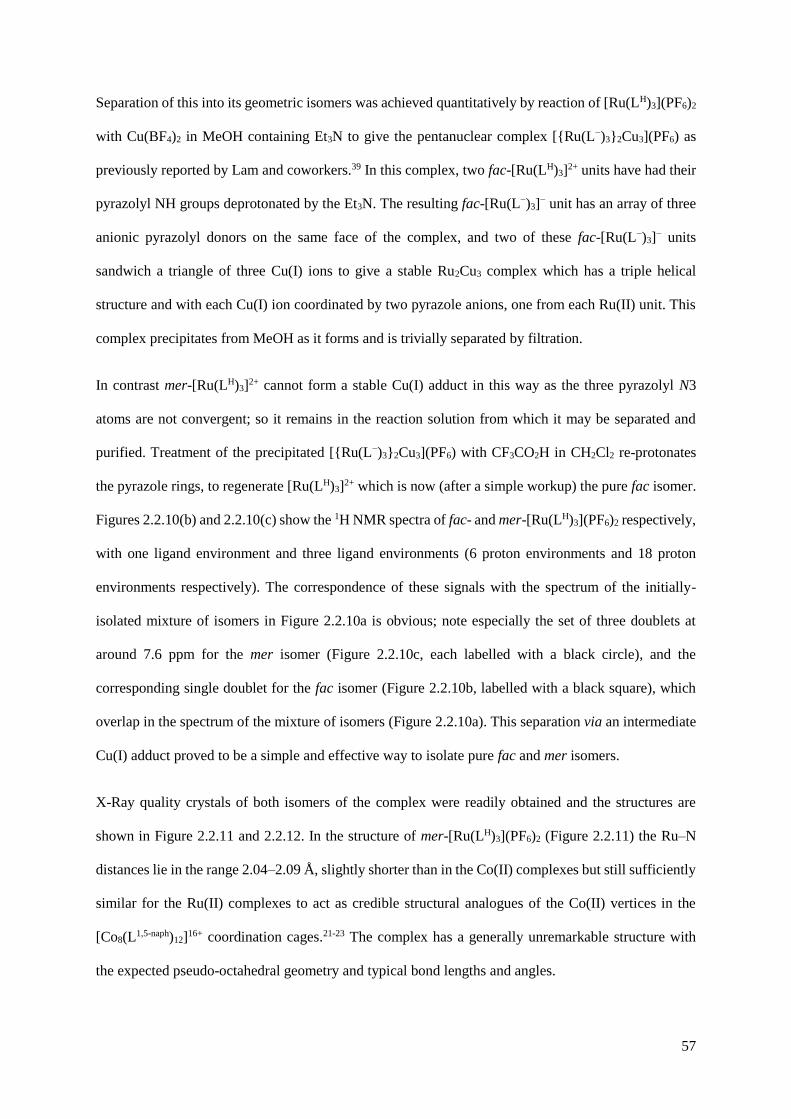
57
Separation of this into its geometric isomers was achieved quantitatively by reaction of [Ru(LH)3](PF6)2
with Cu(BF4)2 in MeOH containing Et3N to give the pentanuclear complex [{Ru(L−)3}2Cu3](PF6) as
previously reported by Lam and coworkers.39 In this complex, two fac-[Ru(LH)3]2+ units have had their
pyrazolyl NH groups deprotonated by the Et3N. The resulting fac-[Ru(L−)3]− unit has an array of three
anionic pyrazolyl donors on the same face of the complex, and two of these fac-[Ru(L−)3]− units
sandwich a triangle of three Cu(I) ions to give a stable Ru2Cu3 complex which has a triple helical
structure and with each Cu(I) ion coordinated by two pyrazole anions, one from each Ru(II) unit. This
complex precipitates from MeOH as it forms and is trivially separated by filtration.
In contrast mer-[Ru(LH)3]2+ cannot form a stable Cu(I) adduct in this way as the three pyrazolyl N3
atoms are not convergent; so it remains in the reaction solution from which it may be separated and
purified. Treatment of the precipitated [{Ru(L−)3}2Cu3](PF6) with CF3CO2H in CH2Cl2 re-protonates
the pyrazole rings, to regenerate [Ru(LH)3]2+ which is now (after a simple workup) the pure fac isomer.
Figures 2.2.10(b) and 2.2.10(c) show the 1H NMR spectra of fac- and mer-[Ru(LH)3](PF6)2 respectively,
with one ligand environment and three ligand environments (6 proton environments and 18 proton
environments respectively). The correspondence of these signals with the spectrum of the initially-
isolated mixture of isomers in Figure 2.2.10a is obvious; note especially the set of three doublets at
around 7.6 ppm for the mer isomer (Figure 2.2.10c, each labelled with a black circle), and the
corresponding single doublet for the fac isomer (Figure 2.2.10b, labelled with a black square), which
overlap in the spectrum of the mixture of isomers (Figure 2.2.10a). This separation via an intermediate
Cu(I) adduct proved to be a simple and effective way to isolate pure fac and mer isomers.
X-Ray quality crystals of both isomers of the complex were readily obtained and the structures are
shown in Figure 2.2.11 and 2.2.12. In the structure of mer-[Ru(LH)3](PF6)2 (Figure 2.2.11) the Ru–N
distances lie in the range 2.04–2.09 Å, slightly shorter than in the Co(II) complexes but still sufficiently
similar for the Ru(II) complexes to act as credible structural analogues of the Co(II) vertices in the
[Co8(L1,5-naph)12]16+ coordination cages.21-23 The complex has a generally unremarkable structure with
the expected pseudo-octahedral geometry and typical bond lengths and angles.
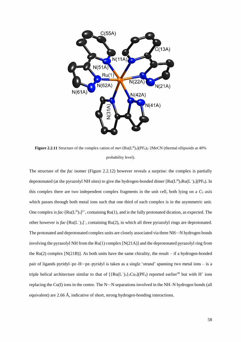
58
Figure 2.2.11 Structure of the complex cation of mer-[Ru(LH)3](PF6)2·2MeCN (thermal ellipsoids at 40%
probability level).
The structure of the fac isomer (Figure 2.2.12) however reveals a surprise: the complex is partially
deprotonated (at the pyrazolyl NH sites) to give the hydrogen-bonded dimer [Ru(LH)3Ru(L−)3](PF6). In
this complex there are two independent complex fragments in the unit cell, both lying on a C3 axis
which passes through both metal ions such that one third of each complex is in the asymmetric unit.
One complex is fac-[Ru(LH)3]2+, containing Ru(1), and is the fully protonated dication, as expected. The
other however is fac-[Ru(L−)3]−, containing Ru(2), in which all three pyrazolyl rings are deprotonated.
The protonated and deprotonated complex units are closely associated via three NH⋯N hydrogen bonds
involving the pyrazolyl NH from the Ru(1) complex [N(21A)] and the deprotonated pyrazolyl ring from
the Ru(2) complex [N(21B)]. As both units have the same chirality, the result – if a hydrogen-bonded
pair of ligands pyridyl–pz–H⋯pz–pyridyl is taken as a single ‘strand’ spanning two metal ions – is a
triple helical architecture similar to that of [{Ru(L−)3}2Cu3](PF6) reported earlier39 but with H+ ions
replacing the Cu(I) ions in the centre. The N⋯N separations involved in the NH–N hydrogen bonds (all
equivalent) are 2.66 Å, indicative of short, strong hydrogen-bonding interactions.

59
Figure 2.2.12 Structure of the hydrogen-bonded dinuclear complex cation of fac, fac-[Ru(LH)3Ru(L−)3]
(PF6)·3C7H8 (thermal ellipsoids at 40% probability level). Some of the ligands are shown in paler colours for
clarity; the hydrogen-bonds between the two complex units are indicated by the striped lines.
In addition this close association of the two complex units results in π-stacking between the pyrazolyl
rings of each, with an average interplanar separation of ca. 3.3 Å between overlapping ligand fragments.
This will be facilitated by the fact that one pyrazolyl ring in each stacked pair is deprotonated and
therefore electron-rich compared to the other, so the stack involves a donor–acceptor interaction. These
crystals grew from a solution containing fully protonated fac-[Ru(LH)3]- (PF6)2; presumably the loss of

60
three protons per two complex units is driven by the extra stability of the hydrogen-bonded and π-
stacked pair of cationic and anionic complex units in the crystal. Telfer and co-workers have reported
related examples of helicates formed from homochiral mononuclear units that assemble via inter-ligand
hydrogen-bonding interactions in exactly the same way.40
With fac- and mer-[Ru(LH)3](PF6)2 readily available by this route, conversion to the corresponding
isomers of [Ru(Lbz)3](PF6)2 was carried out by alkylation of the pyrazole groups with benzyl bromide
in CH2Cl2 at reflux, using solid Cs2CO3 as base and a catalytic amount of tetrabutylammonium iodide
(Finkelstein reaction). This straightforward reaction works under a range of conditions but conditions
as mild as possible were used to prevent any isomerisation of the Ru(II) complex which might be
facilitated by high temperatures, and by use of good donor solvents which would facilitate ligand
dissociation.
It was found that under these conditions conversion of [Ru(LH)3](PF6)2 to [Ru(Lbz)3](PF6)2 proceeded
cleanly and with no evidence (by NMR spectroscopy) of any of the alternate isomer forming (see
Figures 2.2.13 and 2.2.14). Chromatographic purification afforded good yields of fac- and mer-
[Ru(Lbz)3](PF6)2. By extrapolation we now have a potentially general method to prepare fac and mer
isomers of any complex-[Ru(LR)3]2+ where ‘R’ denotes a group that can be attached to a pyrazole ring
by alkylation, which is further demonstrated in Chapter 3.

61
Figure 2.2.13 Assigned 1H NMR spectrum (400 MHz, CD3CN) of fac-[Ru(Lbz)3](PF6)2 (Pz = pyrazole, Py =
pyridine, Ph = phenyl).
Figure 2.2.14 Partially assigned 1H NMR spectrum (400 MHz, (CD3)2CO) of mer-[Ru(Lbz)3](PF6)2 (Ph =
phenyl).
The X-ray crystal structure of fac-[Ru(Lbz)3](PF6)2 is shown in Figure 2.2.15. In the complex cation
(Figure 2.2.15a) the Ru–N bond distances all lie in the range 2.07–2.09 Å. In each ligand the pendant
phenyl ring lies stacked with the coordinated pyrazolyl-pyridine unit of another adjacent ligand, with a
separation between near-parallel overlapping groups of ca. 3.4 Å, exactly as is seen in the fac tris-
chelate vertices of the metal cages. This arrangement of ligands results in the formation of a set of three
methylene groups close together on the same face of the complex. The ‘inwardly’ directed member of
each pair [H(26A), H(26C) and H(26E)] lies ca. 3.3 Å from the Ru(II) centre and these are the closest
H atoms to the metal centre apart from the pyridyl H6 atoms (3.1–3.2 Å). This set of protons defines

62
what we believe to be the site where hydrogen-bonding to electron-rich atoms of guests occurs inside
the cage cavities.21
Evidence for this comes from the presence of an acetone solvent molecule in the lattice (Figure 2.2.15b)
which lies such that its oxygen atom is located in this pocket, where a guest would be expected to bind.
The O atom is not exactly symmetrically located in the pocket in the solid state but lies closer to C26(B)
and C26(C) (O⋯C non-bonded distances are 3.11 and 3.18 Å respectively, indicative of the presence
of CH⋯O hydrogen bonding; these are indicated by dashed lines in Figure 2.2.15b) than it does to
O(26C) (3.63 Å), with the result that there are four O⋯H–C hydrogen-bond separations in the range
2.51 to 2.80 Å. This solvent molecule rather nicely illustrates the presence of the binding site at the fac
tris-chelate vertices of the cages.
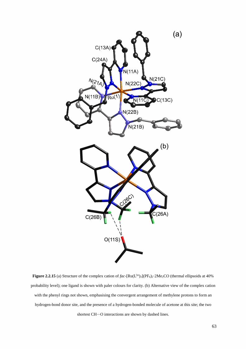
63
Figure 2.2.15 (a) Structure of the complex cation of fac-[Ru(Lbz)3](PF6)2·2Me2CO (thermal ellipsoids at 40%
probability level); one ligand is shown with paler colours for clarity. (b) Alternative view of the complex cation
with the phenyl rings not shown, emphasising the convergent arrangement of methylene protons to form an
hydrogen-bond donor site, and the presence of a hydrogen-bonded molecule of acetone at this site; the two
shortest CH⋯O interactions are shown by dashed lines.

64
The X-ray crystal structure of mer-[Ru(Lbz)3](PF6)2 (Figure 2.2.16) shows that the structure of the
complex cation is generally similar to that of mer-[Co(Lbz)3](BF4)2; the most obvious π-stacking
interaction between ligands involves the pendant phenyl ring of ligand B (according to the numbering
scheme of Figure 2.2.16) with the coordinated pyrazolyl-pyridine unit of ligand C. Compared to the fac
isomer the divergent arrangement of the methylene protons no longer results in a specific hydrogen-
bonding recognition site.
Figure 2.2.16 Structure of the complex cation of mer-[Ru(Lbz)3](PF6)2·Me2CO (thermal ellipsoids at 40%
probability level); one ligand is shown with paler colours for clarity.

65
2.2.3 Measurement of guest binding to fac- and mer-[Ru(Lbz)3](PF6)2
To measure the differential abilities of fac- and mer-[Ru(Lbz)3](PF6)2 to act as a hydrogen-bond donor
the equilibrium constant for adduct formation with isoquinoline- N-oxide was measured. On the basis
of previous measurements using complete cages as hosts, this was identified as one of the strongest-
binding guests in MeCN (K = 2100 M−1, cf. Figure 2.1.3).21 It was suggested that this is due to the high
partial negative charge on the oxygen atom (high value of the hydrogen-bond acceptor parameter β),
which interacts with the hydrogen-bond donor sites of the fac tris-chelate metal vertices of the cage,
which have a combined hydrogen-bond donor ability comparable to that of phenol.21
A 1H NMR titration (performed by Mr William Cullen) of fac-[Ru(Lbz)3](PF6)2 with isoquinoline- N-
oxide in MeCN showed a steady shift in one of the signals from the diastereotopic CH2 protons, but not
the other which was essentially invariant (Figure 2.2.17). This is emphasised in Figure 2.2.17b which
shows a series of superimposed 1H NMR spectra recorded during the titration: the methylene doublet
at 4.7 ppm does not move but the other signal at around 5.4 ppm shifts by ca. 0.1 ppm. No other proton
signals moved significantly during the titration. The shift of one methylene proton signal but not the
other is consistent with the O atom of the guest forming an hydrogen-bonding interaction with the
inwardly-directed proton from each methylene group but not with the other proton which is externally
directed. Free rotation about the C–C bonds of the benzyl substituents will be hindered by the aromatic
stacking (cf. the crystal structure), which would prevent the ‘inward’ and ‘outward’ H atoms of each
methylene group from exchanging position on the NMR timescale. The interaction with the
isoquinoline-N-oxide necessarily involves one of these two protons more than the other – as is observed.
Indeed the 1H NMR spectrum confirms that the conformation observed in the crystal structure (Figure
2.2.15) is preserved in solution, as the signals for the coordinated pyrazolyl-pyridine ligand units of fac-
[Ru(Lbz)3](PF6)2 are substantially shifted compared to those of fac-[Ru(LH)3](PF6)2 and fac-
[Ru(LMe)3](PF6)2 by π-stacking with the pendant phenyl rings (see Experimental section for details).

66
Figure 2.2.17 Changes in the 1H NMR chemical shift of the two inequivalent methylene proton signals of fac-
[Ru(Lbz)3](PF6)2 (0.23 mM) during titration with isoquinoline-N-oxide (up to 0.7 M) in CD3CN. (a) Stacked
plots; (b) overlaid plots to emphasise how one signal moves but the other does not.
67
It was apparent during the titration that complex formation was not complete even after a very large
excess of isoquinoline- N-oxide was added, which is indicative of a low binding constant. The plot of
chemical shift value for the methylene proton vs. (concentration of guest) gives a curve whose shape is
consistent with 1 : 1 host/guest binding (Figure 2.2.18, data points shown as circles), and the calculated
value of K from this is 1(±1) M−1.† Thus an obvious interaction of fac-[Ru(Lbz)3](PF6)2 with
isoquinoline-N-oxide that involves the methylene protons is seen, even if it is weak. Importantly
however no such change in chemical shift of the methylene protons could be observed using the mer
isomer; the change in chemical shift of a representative 1H signal from a methylene proton is also shown
in Figure 2.2.18 (data points shown as squares). Apart from the magnitude of the Δδ for this proton
during the titration being much smaller, there is no significant curvature to the line, with the result that
the association constant between mer-[Ru(Lbz)3](PF6)2 and isoquinoline-N-oxide in MeCN oxide is too
weak even to estimate. There is therefore clear evidence that the convergent set of methylene protons
associated with a fac tris-chelate site does act as an hydrogen-bond donor to isoquinoline- N-oxide,
which supports our understanding of guest binding inside the complete cage cavities. However this
binding constant is surprisingly low. Based on what was observed for binding inside the host cage (K =
2100 M−1), this type of hydrogen-bonding interaction associated with mononuclear fac-[Ru(Lbz)3](PF6)2
– if it is similar to what happens inside a cage cavity – should give a much larger K value than was
observed. For the [Co8(L1,5-naph)12](BF4)16/ isoquinoline-N-oxide complex that was reported earlier, the
binding constant of K = 2100 M−1 gives ΔG = −19 kJ mol−1.21
† Actually the curve-fitting software generates more precise values than these, of 0.8(±0.1) M−1 and 0.4(±0.1) M−1
for binding of isoquinoline-N-oxide to fac-[Ru(Lbz)3](PF6)2 and fac-[Ru(LMe)3](PF6)2 respectively. However, as
the binding is so weak, the curve fitting is based only on the early part of the binding curve, with <50% complex
formation even in the presence of guest concentrations of up to 1 M. This means in practice that the errors are
underestimated. Accordingly the value of K ≈ 1(±1) is quoted for both cases. Any difference in K between fac-
[Ru(Lbz)3](PF6)2 and fac-[Ru(LMe)3](PF6)2 is not significant for the purposes of this work; the important point is
that the behaviour of the fac isomers is clearly distinct from that of the mer isomers.

68
Figure 2.2.18 (a) 1H NMR binding curves showing shift of the methylene proton signals in fac-[Ru(Lbz)3](PF6)2
(circles, upper line) and mer-[Ru(Lbz)3](PF6)2 (squares, lower line) during titration with isoquinoline- N-oxide.
For fac-[Ru(Lbz)3](PF6)2 the data fit a 1 : 1 binding isotherm with K ≈ 1 M−1; for mer-[Ru(Lbz)3](PF6)2 the
binding constant is too weak to measure. (b) 19F NMR binding curve showing the change in environment of the
[PF6]− ion of fac-[Ru(Lbz)3](PF6)2 as it is displaced from the hydrogenbonding site when isoquinoline-N-oxide is
added. Again the data fit a 1 : 1 binding isotherm with K ≈ 1 M−1.

69
Some of this arises from van der Waals interactions between the guest and the walls of the cage, and
some from solvophobic effects, but even so the contribution from H-bonding alone was estimated to be
several kJ mol−1 and it would be expected that this would be similar in the mononuclear model complex
fac-[Ru(Lbz)3](PF6)2. Instead we see K ≈ 1 M−1, giving ΔG for guest binding of more or less zero despite
the same type of hydrogen-bonding interaction as occurs inside the cage cavity. One reason for this may
be that competition for the hydrogen-bonding site from the hexafluorophosphate anions is occurring,
which would weaken the K value for association with the neutral guest: but this competition of anions
for the binding site does not occur in the complete cages for some reason. In mononuclear fac-
[Ru(Lbz)3](PF6)2 the anions have free access to the relatively unhindered hydrogen-bonding site and
could therefore be competing with binding of isoquinoline-N-oxide in solution. In contrast, in all
structurally characterised examples of the [M8(L1,5-naph)12]X16 cages, anions are located outside the cage
cavities, with the H-bond donor sites occupied by small solvent molecules such as MeOH or water.25
This suggests the possibility (but does not of course prove) that the anions may also be excluded from
the cage cavity in solution. This would explain the much higher binding constants for guest binding in
the cage, as competition from anions would be absent.
To check for competing anion-binding in fac-[Ru(Lbz)3](PF6)2, the titration between fac-
[Ru(Lbz)3](PF6)2 and isoquinoline-N-oxide in MeCN was repeated but recording 19F NMR spectra to
see if there was any evidence for the hexafluorophosphate ion changing its environment. If there were
no change it could be said that there was no significant cation/anion association in solution. In contrast,
a shift of the 19F NMR signal would suggest that the anion was being displaced from the hydrogen-
bonding site by the added isoquinoline-N-oxide, and this is what is observed. The 19F NMR signal of
the [PF6]− anion of fac-[Ru(Lbz)3](PF6)2 appeared as a doublet at −73.0 ppm which steadily shifted to
−72.7 ppm as isoquinoline-N-oxide was titrated in. The resultant binding curve (Δδ vs. concentration
of isoquinoline-N-oxide; Figure 2.2.18b) fitted well to a 1 : 1 isotherm with a value of K the same within
error (≈1 M−1) as that derived from the 1H NMR titration (Figure 2.2.17 and 2.2.18).
Thus, binding of isoquinoline-N-oxide to the hydrogen-bond donor site of fac-[Ru(Lbz)3](PF6)2 is
accompanied by displacement of [PF6]−. As a control experiment, the change in the 19F NMR chemical

70
shift of the [PF6]− anion of mer-[Ru(Lbz)3](PF6)2 during titration with isoquinoline-N-oxide was also
measured; this resulted in a binding constant too small to measure accurately.
This confirms that there is ion-pairing between cation and anion in solution with PF6− interacting with
the hydrogen- bond donor site of the fac-[Ru(Lbz)3]2+ cation, and this competition provides one reason
for the low value of K observed for binding of isoquinoline-N-oxide. An obvious experiment to try and
mitigate this effect would be to use the anion tetraphenylborate which might be expected to form weaker
ion pairs with the fac-[Ru(Lbz)3]2+ cation; this experiment is described in the next section. A second
contribution to the weak interaction between fac-[Ru(Lbz)3](PF6)2 and isoquinoline-N-oxide could be
steric. The pendant benzyl groups of fac-[Ru(Lbz)3](PF6)2 may not be fully bent out of the way of the
binding site in solution, but could move around blocking access to the hydrogen-bonding site. In the
complete cages the hydrogen-bonding site is exposed because the bridging ligands have to stretch to an
adjacent metal ion and are therefore stretched away from the binding site which is exposed to the cavity
interior. However that may not be the case in fac-[Ru(Lbz)3](PF6)2 where steric interference from the
pendant benzyl groups is possible. A control experiment to test this is to replace the pendant phenyl
ring with an H atom which will remove any possible steric encumbrance, and this is also described in
the next section.
2.2.4 Control experiment (1): measurement of guest binding to fac- and
mer-[Ru(LMe)3](PF6)2
Reaction of fac- or mer-[Ru(LH)3](PF6)2 with MeI resulted in N-methylation of the pyrazolyl rings to
give fac- or mer-[Ru(LMe)3](PF6)2 respectively (see Figure 2.2.9 for ligand structure); again, by doing
this reaction under mild conditions, the individual isomers retained their structural integrity with none
of the alternate isomers forming (see Figure 2.2.19). Crystal structures are in Figure 2.2.20 and are as
expected. In fac-[Ru(LMe)3](PF6)2 there is no solvent molecule or other electron-rich atom occupying
the hydrogen-bonding site, but the convergence of the methyl groups and the position of the hydrogen-
bonding site is clear. Compared to fac-[Ru(Lbz)3](PF6)2, any possible steric hindrance to guest binding
arising from the phenyl rings is now removed. Conversely, any possibly favourable effects – e.g. guest

71
binding being facilitated by π-stacking with the pendant phenyl rings around the binding pocket – will
also be absent.
Figure 2.2.19 1H NMR spectra (CD3CN, 400 MHz) of [Ru(LMe)3](PF6)2: (top) fac isomer (Pz = pyrazole, Py =
pyridine); (bottom) mer isomer.

72
Figure 2.2.20 Structures of the complex cations of (a) fac-[Ru(LMe)3](PF6)2 (thermal ellipsoids at 40%
probability level) and (b) mer-[Ru(LMe)3](PF6)2 (thermal ellipsoids at 30% probability level). H atoms of the
methyl groups are shown in red to emphasise the binding pocket formed by convergence of the three methyl
groups in the former case.
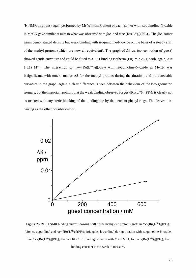
73
1H NMR titrations (again performed by Mr William Cullen) of each isomer with isoquinoline-N-oxide
in MeCN gave similar results to what was observed with fac- and mer-[Ru(Lbz)3](PF6)2. The fac isomer
again demonstrated definite but weak binding with isoquinoline-N-oxide on the basis of a steady shift
of the methyl protons (which are now all equivalent). The graph of Δδ vs. (concentration of guest)
showed gentle curvature and could be fitted to a 1 : 1 binding isotherm (Figure 2.2.21) with, again, K ≈
1(±1) M−1.† The interaction of mer-[Ru(LMe)3](PF6)2 with isoquinoline-N-oxide in MeCN was
insignificant, with much smaller Δδ for the methyl protons during the titration, and no detectable
curvature in the graph. Again a clear difference is seen between the behaviour of the two geometric
isomers, but the important point is that the weak binding observed for fac-[Ru(Lbz)3](PF6)2 is clearly not
associated with any steric blocking of the binding site by the pendant phenyl rings. This leaves ion-
pairing as the other possible culprit.
Figure 2.2.21 1H NMR binding curves showing shift of the methylene proton signals in fac-[Ru(LMe)3](PF6)2
(circles, upper line) and mer-[Ru(LMe)3](PF6)2 (triangles, lower line) during titration with isoquinoline-N-oxide.
For fac-[Ru(LMe)3](PF6)2 the data fit a 1 : 1 binding isotherm with K ≈ 1 M−1; for mer-[Ru(LMe)3](PF6)2 the
binding constant is too weak to measure.
74
2.2.5 Control experiment (2): measurement of guest binding to fac-
[Ru(Lbz)3](BPh4)2
For the second control experiment fac-[Ru(Lbz)3]2+ was isolated as its tetraphenylborate salt, by simple
anion metathesis starting from the hexafluorophosphate salt. The tetraphenylborate anion might be
expected to result in less competition than the hexafluorophosphate ion for the hydrogen-bonding site
of the cation. A 1H NMR titration with isoquinoline-N-oxide resulted in a steady shift of the signals for
one of the diastereotopic methylene protons of fac-[Ru(Lbz)3]2+ but not the other, exactly as before (cf.
Figure 2.2.17); again, the resulting binding curve fitted to a 1 : 1 binding isotherm with K ≈ 1(±1) M−1.†
However, during the titration the 1H NMR signals for the [BPh4]− anion also shifted steadily, consistent
with it being displaced as an ion-pair breaks up, in the same way as the [PF6]− anion. The K value
calculated from the shift of the most intense [BPh4]− 1H signal when it is displaced, is the same within
experimental error as that derived from the shift of the methylene proton of the complex cation when
the guest binds. Again, therefore, guest binding to the complex cation, and anion displacement, occur
together (Figure 2.2.22).
This is somewhat surprising as the tetraphenylborate anion is not a hydrogen-bond acceptor. However
ion-pairing with the fac-[Ru(Lbz)3]2+ cation could occur in solution via charge-assisted π–π or CH–π
interactions between electron-deficient pyrazolyl-pyridine groups that are coordinated to a 2+ metal
centre, and the electron-rich phenyl rings of the anion (c.f. figure 2.2.4). Examples of such ion pairs
involving tetraphenylborate as the anion are known.41,42 Thus although hydrogen-bonding is not
operative, the tetraphenylborate anion competes for binding to the complex cation just as much as does
the hexafluorophosphate anion, which means that the interaction with isoquinoline- N-oxide remains
weak.
The clear conclusion to be drawn from this is that the hydrogen-bonding recognition sites in the cubic
coordination cage (Figure 2.1.3) are effective at facilitating guest binding in the cavity in MeCN because
anions are excluded from the cavity which is consistent with all crystal structures of these cages with a

75
variety of anions and obtained from a variety of solvents.21-23,25 Exclusion of anions from the binding
site is therefore an important principle to take into account in design of new generations of cage hosts.
Figure 2.2.22 1H NMR binding curves obtained from titration of [Ru(LBz)3](BPh4)2 with isoquinoline-N-oxide
in MeCN: the shift of the methylene proton signal at ca. 5.4 ppm due to hydrogen-bonding with the guest (black
triangles/dashed line); (b) the shift of the most intense tetraphenylborate signal at 7.3 ppm as it is displaced from
the complex cation by the competing guest (black circles/solid line). Both sets of data fit a 1 : 1 binding
isotherm with K ≈ 1 M−1.
2.3 Conclusion
There are three main conclusions from this work. Firstly, a simple and general synthetic procedure has
been developed which will allow access to a wide range of substituted analogues of [Ru(LH)3]2+ as their
pure fac and mer isomers without tedious chromatographic separation or relying on fractional
crystallisation. The mixture of fac- and mer-[Ru(LH)3]2+ may be separated by reaction with a Cu(I) salt
which allows the deprotonated fac isomer to precipitate as its Cu(I) adduct whilst the mer isomer
remains in solution;39 decomposition of the fac-[Ru(L−)3]−/Cu(I) adduct with acid liberates pure fac-
76
[Ru(LH)3]2+. Alkylation of the pyrazolyl N3 positions under mild conditions allows substituted
analogues to be prepared with retention of isomeric integrity.
Secondly, it has been shown that fac-[Ru(Lbz)3]2+ and fac-[Ru(LMe)3]2+ act as better hydrogen-bond
donor sites to isoquinoline- N-oxide (via formation of C–H⋯O hydrogen bonds) than do their mer
isomers, because of the convergent group of weakly δ+ methylene protons in the former cases. Absolute
values of binding constants are low but the clear difference between the behaviour of the fac and mer
isomers confirms our earlier supposition21-23 that this specific recognition element – hydrogen bonding
to methylene protons at a fac tris-chelate binding site – is involved in guest binding in coordination
cages which incorporate metal complex vertices of this type.
Thirdly – and unexpectedly – in these simple mononuclear complexes the ability of the hydrogen-bond
donor site of fac-[Ru(Lbz)3]2+ or fac-[Ru(LMe)3]2+ to interact with the guest isoquinoline-N-oxide, which
binds more strongly in the cavity of the cubic cage host in MeCN, is reduced by competition from
anions – even those traditionally regarded as ‘weakly interacting’ such as hexafluorophosphate and
tetraphenylborate. The effectiveness of the cubic cages as hosts for hydrogen-bond accepting guests
therefore seems to rely not just on the presence of the two fac tris-chelate metal centres and their
convergent group of CH protons, but also on the exclusion of anions from the cage cavity. All crystal
structures of this family of cubic cages show that anions are located outside the cavity: although this
does not prove that they cannot enter the cavity in solution, the difference in guest binding between the
mononuclear model complexes reported in this work, and the same H-bonding site inside a cage cavity,
does imply that in the latter case competition from anions is prevented. Thus we have two important
design principles for future generations of host cages.
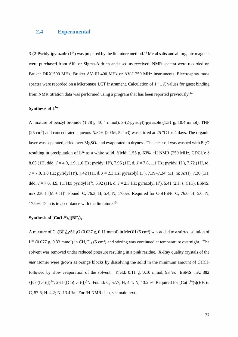
77
2.4 Experimental
3-(2-Pyridyl)pyrazole (LH) was prepared by the literature method.43 Metal salts and all organic reagents
were purchased from Alfa or Sigma-Aldrich and used as received. NMR spectra were recorded on
Bruker DRX 500 MHz, Bruker AV-III 400 MHz or AV-I 250 MHz instruments. Electrospray mass
spectra were recorded on a Micromass LCT instrument. Calculation of 1 : 1 K values for guest binding
from NMR titration data was performed using a program that has been reported previously.44
Synthesis of Lbz
A mixture of benzyl bromide (1.78 g, 10.4 mmol), 3-(2-pyridyl)-pyrazole (1.51 g, 10.4 mmol), THF
(25 cm3) and concentrated aqueous NaOH (20 M, 5 cm3) was stirred at 25 °C for 4 days. The organic
layer was separated, dried over MgSO4 and evaporated to dryness. The clear oil was washed with Et2O
resulting in precipitation of Lbz as a white solid. Yield: 1.55 g, 63%. 1H NMR (250 MHz, CDCl3): δ
8.65 (1H, ddd, J = 4.9, 1.9, 1.0 Hz; pyridyl H6), 7.96 (1H, d, J = 7.8, 1.1 Hz; pyridyl H3), 7.72 (1H, td,
J = 7.8, 1.8 Hz; pyridyl H4), 7.42 (1H, d, J = 2.3 Hz; pyrazolyl H5), 7.39–7.24 (5H, m; ArH), 7.20 (1H,
ddd, J = 7.6, 4.9, 1.1 Hz; pyridyl H5), 6.92 (1H, d, J = 2.3 Hz; pyrazolyl H4), 5.41 (2H, s; CH2). ESMS:
m/z 236.1 [M + H]+. Found: C, 76.3; H, 5.4; N, 17.6%. Required for C15H13N3: C, 76.6; H, 5.6; N,
17.9%. Data is in accordance with the literature.45
Synthesis of [Co(Lbz)3](BF4)2
A mixture of Co(BF4)2•6H2O (0.037 g, 0.11 mmol) in MeOH (5 cm3) was added to a stirred solution of
Lbz (0.077 g, 0.33 mmol) in CH2Cl2 (5 cm3) and stirring was continued at temperature overnight. The
solvent was removed under reduced pressure resulting in a pink residue. X-Ray quality crystals of the
mer isomer were grown as orange blocks by dissolving the solid in the minimum amount of CHCl3
followed by slow evaporation of the solvent. Yield: 0.11 g, 0.10 mmol, 93 %. ESMS: m/z 382
{[Co(Lbz)3]}2+; 264 {[Co(Lbz)2]}2+. Found: C, 57.7; H, 4.4; N, 13.2 %. Required for [Co(Lbz)3](BF4)2:
C, 57.6; H. 4.2; N, 13.4 %. For 1H NMR data, see main text.
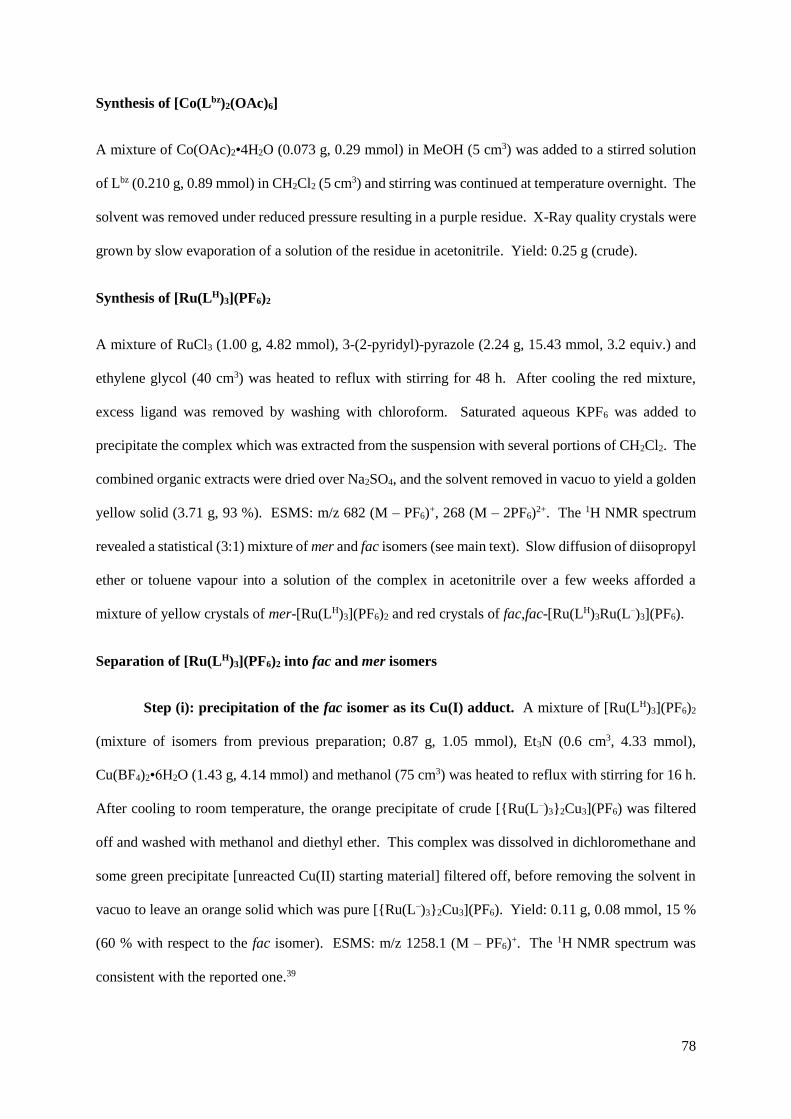
78
Synthesis of [Co(Lbz)2(OAc)6]
A mixture of Co(OAc)2•4H2O (0.073 g, 0.29 mmol) in MeOH (5 cm3) was added to a stirred solution
of Lbz (0.210 g, 0.89 mmol) in CH2Cl2 (5 cm3) and stirring was continued at temperature overnight. The
solvent was removed under reduced pressure resulting in a purple residue. X-Ray quality crystals were
grown by slow evaporation of a solution of the residue in acetonitrile. Yield: 0.25 g (crude).
Synthesis of [Ru(LH)3](PF6)2
A mixture of RuCl3 (1.00 g, 4.82 mmol), 3-(2-pyridyl)-pyrazole (2.24 g, 15.43 mmol, 3.2 equiv.) and
ethylene glycol (40 cm3) was heated to reflux with stirring for 48 h. After cooling the red mixture,
excess ligand was removed by washing with chloroform. Saturated aqueous KPF6 was added to
precipitate the complex which was extracted from the suspension with several portions of CH2Cl2. The
combined organic extracts were dried over Na2SO4, and the solvent removed in vacuo to yield a golden
yellow solid (3.71 g, 93 %). ESMS: m/z 682 (M – PF6)+, 268 (M – 2PF6)2+. The 1H NMR spectrum
revealed a statistical (3:1) mixture of mer and fac isomers (see main text). Slow diffusion of diisopropyl
ether or toluene vapour into a solution of the complex in acetonitrile over a few weeks afforded a
mixture of yellow crystals of mer-[Ru(LH)3](PF6)2 and red crystals of fac,fac-[Ru(LH)3Ru(L–)3](PF6).
Separation of [Ru(LH)3](PF6)2 into fac and mer isomers
Step (i): precipitation of the fac isomer as its Cu(I) adduct. A mixture of [Ru(LH)3](PF6)2
(mixture of isomers from previous preparation; 0.87 g, 1.05 mmol), Et3N (0.6 cm3, 4.33 mmol),
Cu(BF4)2•6H2O (1.43 g, 4.14 mmol) and methanol (75 cm3) was heated to reflux with stirring for 16 h.
After cooling to room temperature, the orange precipitate of crude [{Ru(L–)3}2Cu3](PF6) was filtered
off and washed with methanol and diethyl ether. This complex was dissolved in dichloromethane and
some green precipitate [unreacted Cu(II) starting material] filtered off, before removing the solvent in
vacuo to leave an orange solid which was pure [{Ru(L–)3}2Cu3](PF6). Yield: 0.11 g, 0.08 mmol, 15 %
(60 % with respect to the fac isomer). ESMS: m/z 1258.1 (M – PF6)+. The 1H NMR spectrum was
consistent with the reported one.39

79
Step (ii): isolation and purification of mer-[Ru(LH)3](PF6)2. The remaining filtrate after
precipitation of [Ru2Cu3(PyPz)6](PF6) [step (i), above] contains mer-[Ru(LH)3](PF6)2 which did not
precipitate. This solution was evaporated to dryness. The residue was redissolved in with CH2Cl2 (100
cm3) and a green solid by-product was filtered off and discarded. To the filtrate was added
trifluoroacetic acid (2 cm3, 1.44 mmol) to neutralise the Et3N and ensure that the mer-[Ru(LH)3](PF6)2
remained fully protonated at the pyrazolyl N3 positions. Excess trifluoroacetic acid was removed by
repeatedly dissolving the mixture in methanol/dichloromethane (1 : 1) and evaporation to dryness. The
residue was then dissolved in dichloromethane; aqueous KPF6 was added and the mixture shaken
vigorously. The organic layer was separated, dried over MgSO4, and the solvent removed in vacuo.
Chromatography on silica eluting with MeCN/water/saturated KNO3(aq) (100 : 10 : 1) on a silica column
resulted in a yellow band which was collected. After removing acetonitrile by rotary evaporation,
excess saturated aqueous KPF6 was added and the product was extracted into dichloromethane. The
organic layer was separated, dried over MgSO4, and the solvent removed in vacuo to yield mer-
[Ru(LH)3](PF6)2 as a yellow solid (Yield: 0.51 g, 59 %). 1H NMR (400 MHz, (CD3)2CO): 8.47 – 8.32
(3H, m; 3 x pyridyl H4), 8.18 – 8.01 (6H, m; 3 x pyridyl H6 and 3 x pyrazolyl H5), 7.92 - 7.79 (3H, m;
3 x pyridyl H3), 7.53 – 7.31 (6H, m; 3 x pyrazolyl H4 and 3 x pyridyl H5). ESMS: m/z 682 (M – PF6)+,
268 (M – 2PF6)2+.
Step (iii): isolation and purification of fac-[Ru(LH)3](PF6)2. To a solution of
[{Ru(L–)3}2Cu3](PF6) (0.11 g, 0.08 mmol) in CH2Cl2 (10 cm3) was added trifluoroacetic acid (1 cm3,
0.72 mmol), causing an immediate colour change from deep orange to yellow. Excess trifluoroacetic
acid was removed by repeatedly dissolving the mixture in methanol/dichloromethane (1 : 1) and
evaporation to dryness. The residue was then dissolved in dichloromethane; aqueous KPF6 was added
and the mixture shaken vigorously. The organic layer was separated, dried over MgSO4, and the solvent
removed in vacuo to leave pure fac-[Ru(LH)3](PF6)2 as a yellow solid. Yield: 0.14 g, 99 %. 1H NMR
(400 MHz, (CD3)2CO): 8.41 (1H, ddd, J = 8.0, 1.6, 0.8 Hz; pyridyl H4), 8.12 (1H, td, J = 7.9, 1.5 Hz;
pyridyl H6), 8.07 (1H, d, J = 2.9 Hz; pyrazolyl H5), 7.83 (1H, ddd, J = 5.7, 1.5, 0.8 Hz; pyridyl H3), 7.44

80
(1H, d, J = 2.9 Hz; pyrazolyl H4), 7.42 (1H, ddd, J = 7.9, 5.7, 1.5; pyridyl H5). ESMS: m/z 682 (M –
PF6)+, 268 (M – 2PF6)2+.
Synthesis of fac-[Ru(Lbz)3](PF6)2
A mixture of fac-[Ru(LH)3](PF6)2 (0.06 g, 0.07 mmol), benzyl bromide (0.1 cm3, 0.82 mmol), Cs2CO3
(0.33 g, 1.00 mmol), Bu4NI (0.12 g, 0.33 mmol) and CH2Cl2 (25 cm3) was heated to reflux in the dark
with stirring for 24 h. After cooling to room temperature, excess Cs2CO3 was filtered off and the solvent
removed by rotary evaporation, before purification of the yellow solid by column chromatography on
silica. Elution with MeCN/water/saturated aqueous KNO3 (100 : 10 : 2) resulted in a single yellow
band moving down the column which was collected. After removing acetonitrile by rotary evaporation,
excess saturated aqueous KPF6 was added and the product was extracted from the suspension into
dichloromethane. The organic layer was separated, dried over MgSO4, and the solvent removed in
vacuo to yield fac-[Ru(Lbz)3](PF6)2 as a yellow solid. Slow diffusion of di-isopropyl ether vapour into
a solution of the complex in acetone afforded the product as yellow needles. Yield: 0.01 g, 85 %. 1H
NMR (400 MHz, (CD3)2CO): 8.10 (1H, d, J = 2.9 Hz; pyrazolyl), 8.05 (1H, td, J = 7.8, 1.5 Hz; pyridyl
H4), 7.95 (1H, d, J = 8.0 Hz; pyridyl H), 7.52 (1H, d, J = 5.4 Hz; pyridyl H), 7.41 (1H, ddd, J = 7.4, 5.6,
1.5 Hz; pyridyl H), 7.21 (1H, t, J = 7.5 Hz; phenyl H4), 7.14 (1H, d, J = 2.9 Hz; pyrazolyl), 7.05 (2H, t,
J = 7.8 Hz; phenyl H3/H5), 6.22 (2H, d, J = 7.8 Hz; phenyl H2/H6), 5.73 (1H, d, J = 17.0 Hz; CH2), 5.06
(1H, d, J = 17.0 Hz; CH2). ESMS: m/z 952.2 (M – PF6)+, 403.6 (M – 2PF6)2+. Found: C, 48.1; H, 3.6;
N, 11.0. C45H39F12N9P2Ru•2H2O requires C, 47.7; H, 3.8; N, 11.1%. UV/Vis in MeCN [λmax/nm (10−3
ε/M−1 cm−1)]: 399 (15.4), 284 (52.0), 241 (41.6).
Synthesis of mer-[Ru(Lbz)3](PF6)2
This was prepared according to the method above for fac-[Ru(Lbz)3](PF6)2, but using mer-
[Ru(LH)3](PF6)2 (0.23 g, 0.27 mmol), benzyl bromide (0.5 cm3, 4.21 mmol), Cs2CO3 (0.49 g, 1.52 mmol)
and acetonitrile (50 cm3). Yield: 81%. Slow diffusion of di-isopropyl ether vapour into a solution of
the complex in acetone after two weeks affords the product as yellow blocks. 1H NMR (400 MHz,
(CD3)2CO): 8.42 (1H, d, J = 8.0 Hz), 8.22 (1H, d, J = 2.9 Hz), 8.11 (1H, td, J = 7.9, 1.5 Hz), 8.07 (1H,

81
d, J = 2.9 Hz), 8.02 – 7.97 (3H, m), 7.94 (1H, d, J = 5.6 Hz), 7.91 (1H, td, J = 7.9, 1.5 Hz), 7.75 (1H,
d, J = 5.6 Hz) 7.66 (1H, d, J = 8.0 Hz), 7.63 (1H, d, J = 2.9 Hz), 7.55 (1H, d, J = 5.6 Hz), 7.49 – 7.42
(2H, m), 7.34 (1H, ddd, J = 7.9, 5.6, 1.5 Hz), 7.30 – 7.12 (8H, m), 7.05 (2H, t, J = 7.7 Hz), 6.96 (1H, d,
J = 2.9 Hz), 6.53 (2H, d, J = 7.4 Hz), 6.39 (2H, d, J = 7.4 Hz), 6.21 (2H, d, J = 7.4 Hz), 5.44 (2H, d, J
= 16.7 Hz), 5.03 (1H, d, J = 16.7 Hz), 4.91 (1H, d, J = 16.7 Hz), 4.71 (2H, m). ESMS: m/z 952.2 (M –
PF6)+, 403.6 (M – 2PF6)2+. Found: C, 48.8; H, 3.8; N, 10.7. C45H39F12N9P2Ru·H2O·(acetone)0.5 requires
C, 48.8; H, 3.9; N, 11.0%. UV/Vis in MeCN [λmax/nm (10−3 ε/M−1 cm−1)]: 396 (13.9), 282 (49.8), 241
(38.5).
Synthesis of fac-[Ru(LMe)3](PF6)2
A mixture of fac-[Ru(LH)3](PF6)2 (0.06 g, 0.07 mmol), methyl iodide (0.2 cm3, 3.9 mmol), Cs2CO3 (0.16
g, 0.49 mmol) and CH2Cl2 (30 cm3) was heated to reflux in the dark with stirring for 14 h. Subsequent
workup and purification was as described above for fac-[Ru(Lbz)3](PF6)2. Yield: 0.05 g, 73%. Slow
diffusion of di-isopropyl ether vapour into a solution of the complex in acetone afforded the product as
yellow blocks. 1H NMR (400 MHz, (CD3)2CO): 8.43 (1H, ddd, J = 8.1, 5.0, 0.7 Hz; pyridyl H6), 8.15
(1H, td, J = 7.8, 1.4 Hz; pyridyl H4), 8.10 (1H, d, J = 2.8 Hz; pyrazolyl H5), 7.74 (1H, ddd, J = 5.6, 1.5,
0.7 Hz; pyridyl H3), 7.48 (1H, d, J = 2.8 Hz; pyrazolyl H4), 7.45 (1H, ddd, J = 7.8, 5.6, 1.5 Hz; pyridyl
H5), 3.52 (3H, s; CH3). ESMS: m/z 724 (M – PF6)+, 290 (M – 2PF6)2+. Found: C, 37.4; H, 3.1; N, 14.3.
C27H27F12N9P2Ru requires C, 37.3; H, 3.1; N, 14.5%. UV/Vis in MeCN [λmax/nm (10−3 ε/M−1 cm−1)]:
400 (15.5), 281 (49.2), 238 (40.4).
Synthesis of mer-[Ru(LMe)3](PF6)2
This was prepared using mer-[Ru(LH)3](PF6)2 (0.06 g, 0.07 mmol), methyl iodide (0.2 cm3, 3.9 mmol),
Cs2CO3 (0.16 g, 0.49 mmol) and CH2Cl2 (30 cm3) exactly as described above for the fac isomer. Yield:
0.05 g, 73%. Slow diffusion of di-isopropyl ether vapour into a solution of the complex in acetone
afforded the product as yellow blocks. 1H NMR (400 MHz, (CD3)2CO): 8.47 – 8.35 (3H, m), 8.16 –
8.06 (6H, m), 8.04 (1H, d, J = 5.6 Hz), 7.98 (1H, d, J = 5.6 Hz), 7.79 (1H, d, J = 5.6 Hz), 7.53 (1H, d,
J = 7.53 Hz), 7.51 – 7.40 (5H, m), 3.47 (3H, s; CH3), 3.41 (3H, s; CH3), 3.35 (3H, s; CH3). ESMS: m/z

82
724 (M – PF6)+, 290 (M – 2PF6)2+. Found: C, 37.4; H, 3.1; N, 14.3. C27H27F12N9P2Ru requires C, 37.3;
H, 3.1; N, 14.5%. UV/Vis in MeCN [λmax/nm (10−3 ε/M−1 cm−1)]: 397 (15.8), 281 (54.2), 239 (41.8).
2.5 X-ray crystallography
Crystals were removed from the mother liquor, coated with oil, and transferred rapidly to a stream of
cold N2 on the diffractometer (Bruker APEX-2) to prevent any decomposition due to solvent loss. In all
cases, after integration of the raw data, and before merging, an empirical absorption correction was
applied (SADABS)46 based on comparison of multiple symmetry-equivalent measurements. The
structures were solved by direct methods and refined by full-matrix least squares on weighted F2 values
for all reflections using the SHELX suite of programs.47
Most of the structural determinations were straightforward; the only problems were that mer-
[Ru(LH)3](PF6)2·2MeCN and mer-[Ru(LMe)3](PF6)2 required a large number of restraints to assist with
the refinement. Crystals of mer-[Ru(LH)3](PF6)2·2MeCN diffracted weakly and only data with 2θ < 46°
were used for the final refinement; global restraints (SIMU and DELU on all ligand C and N atoms)
were used to keep the displacement parameters reasonable. In mer-[Ru(LMe)3](PF6)2 one of the
hexafluorophosphate anions was disordered over two sites. Weak diffraction meant that global restraints
(SIMU and DELU on all C, F and N atoms) were used to keep the displacement parameters reasonable,
and in addition geometric restraints were applied to some of the ligand rings to prevent the geometries
from becoming too eccentric.
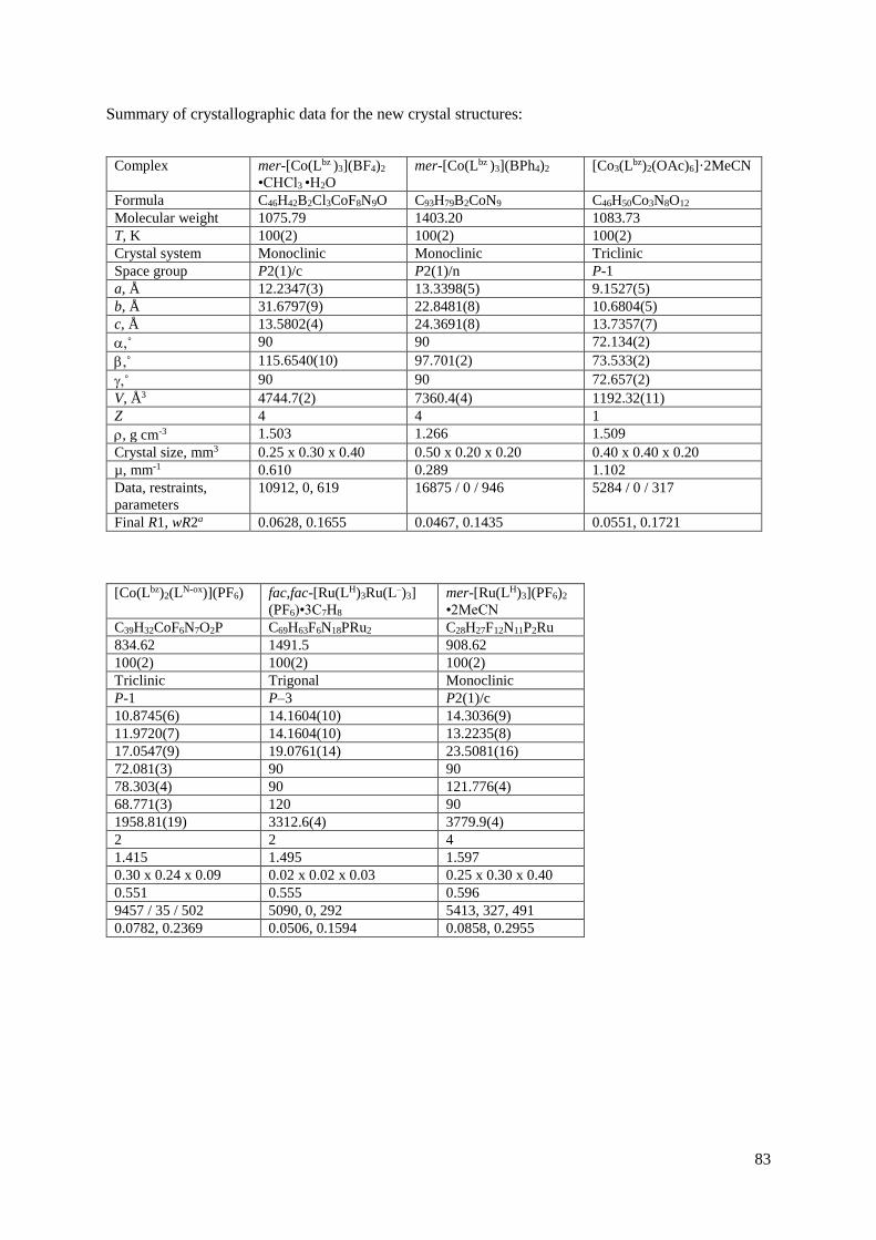
83
Summary of crystallographic data for the new crystal structures:
Complex mer-[Co(Lbz )3](BF4)2
•CHCl3 •H2O
mer-[Co(Lbz )3](BPh4)2 [Co3(Lbz)2(OAc)6]·2MeCN
Formula C46H42B2Cl3CoF8N9O C93H79B2CoN9 C46H50Co3N8O12
Molecular weight 1075.79 1403.20 1083.73
T, K 100(2) 100(2) 100(2)
Crystal system Monoclinic Monoclinic Triclinic
Space group P2(1)/c P2(1)/n P-1
a, Å 12.2347(3) 13.3398(5) 9.1527(5)
b, Å 31.6797(9) 22.8481(8) 10.6804(5)
c, Å 13.5802(4) 24.3691(8) 13.7357(7)
,˚ 90 90 72.134(2)
,˚ 115.6540(10) 97.701(2) 73.533(2)
,˚ 90 90 72.657(2)
V, Å3 4744.7(2) 7360.4(4) 1192.32(11)
Z 4 4 1
, g cm-3 1.503 1.266 1.509
Crystal size, mm3 0.25 x 0.30 x 0.40 0.50 x 0.20 x 0.20 0.40 x 0.40 x 0.20
µ, mm-1 0.610 0.289 1.102
Data, restraints,
parameters
10912, 0, 619 16875 / 0 / 946 5284 / 0 / 317
Final R1, wR2a 0.0628, 0.1655 0.0467, 0.1435 0.0551, 0.1721
[Co(Lbz)2(LN-ox)](PF6) fac,fac-[Ru(LH)3Ru(L–)3]
(PF6)•3C7H8
mer-[Ru(LH)3](PF6)2
•2MeCN
C39H32CoF6N7O2P C69H63F6N18PRu2 C28H27F12N11P2Ru
834.62 1491.5 908.62
100(2) 100(2) 100(2)
Triclinic Trigonal Monoclinic
P-1 P–3 P2(1)/c
10.8745(6) 14.1604(10) 14.3036(9)
11.9720(7) 14.1604(10) 13.2235(8)
17.0547(9) 19.0761(14) 23.5081(16)
72.081(3) 90 90
78.303(4) 90 121.776(4)
68.771(3) 120 90
1958.81(19) 3312.6(4) 3779.9(4)
2 2 4
1.415 1.495 1.597
0.30 x 0.24 x 0.09 0.02 x 0.02 x 0.03 0.25 x 0.30 x 0.40
0.551 0.555 0.596
9457 / 35 / 502 5090, 0, 292 5413, 327, 491
0.0782, 0.2369 0.0506, 0.1594 0.0858, 0.2955

84
fac-[Ru(Lbz)3](PF6)2
•2Me2CO
mer-[Ru(Lbz)3](PF6)2
•Me2CO
fac-[Ru(LMe)3](PF6)2 mer-[Ru(LMe)3](PF6)2
C51H51F12N9O2P2Ru2 C48H45F12N9OP2Ru C27H27F12N9P2Ru2 C27H27F12N9P2Ru2
1213.02 1154.94 868.59 868.59
100(2) 100(2) 100(2) 100(2)
Triclinic Triclinic Trigonal Monoclinic
P–1 P–1 P3c1 P21/c
11.1447(2) 11.7741(3) 10.3032(3) 13.8161(5)
12.2542(3) 12.1017(3) 10.3032(3) 13.2773(5)
20.6452(4) 17.9981(4) 17.0022(5) 20.7149(7)
93.7290(10) 99.8650(10) 90 90
95.9190(10) 96.3270(10) 90 117.692(2)
111.0040(10) 107.5040(10) 120 90
2602.28(9) 2373.61(10) 1563.08(8) 3364.7(2)
2 2 2 4
1.548 1.616 1.845 1.715
0.20 x 0.20 x 0.50 0.30 x 0.18 x 0.12 0.18 x 0.19 x 0.25 0.05 x 0.31 x 0.35
0.456 0.494 0.714 0.664
11756, 0, 698 10838, 0, 660 2421, 1, 156 7735, 391, 503
0.0465, 0.1346 0.0260, 0.0680 0.0464, 0.1263 0.0634, 0.1538
a The value of R1 is based on ‘observed’ data with I>2σ(I); the value of wR2 is based on all data.

85
2.6 References
1. B. Breiner, J. K. Clegg and J. R. Nitschke, Chem. Sci., 2011, 2, 51.
2. D. Ajami and J. Rebek, Jr., Acc. Chem. Res., 2013, 46, 990.
3. L. Adriaenssens and P. Ballester, Chem. Soc. Rev., 2013, 42, 3261.
4. M. Yoshizawa, J. K. Klosterman and M. Fujita, Angew. Chem. Int. Ed., 2009, 48, 3418.
5. S. Ma, M. M. J. Smulders, Y. R. Hristova, J. K. Clegg, T. K. Ronson, S. Zarra and J. R.
Nitschke, J. Am. Chem. Soc., 2013, 135, 5678.
6. Y. Fang, T. Murase and M. Fujita, Chem.-As. J., 2014, 9, 1321.
7. S. Horiuchi, T. Murase and M. Fujita, Chem.-As. J., 2011, 6, 1839.
8. T. Murase, S. Horiuchi and M. Fujita, J. Am. Chem. Soc., 2010, 132, 2866.
9. S. Horiuchi, Y. Nishioka, T. Murase and M. Fujita, Chem. Commun., 2010, 46, 3460.
10. C. J. Hastings, R. G. Bergman and K. N. Raymond, Chem.-Eur. J., 2014, 20, 3966.
11. Z. J. Wang, K. N. Clary, R. G. Bergman, K. N. Raymond and F. D. Toste, Nat. Chem., 2013,
5, 100.
12. C. J. Brown, G. M. Miller, M. W. Johnson, R. G. Bergman and K. N. Raymond, J. Am. Chem.
Soc., 2011, 133, 11964.
13. J. E. M. Lewis, E. L. Gavey, S. A. Cameron and J. D. Crowley, Chem. Sci., 2012, 3, 778.
14. B. Therrien, G. Suess-Fink, P. Govindaswamy, A. K. Renfrew and P. J. Dyson, Angew. Chem.
Int. Ed., 2008, 47, 3773.
15. R. Custelcean, Chem. Soc. Rev., 2014, 43, 1813.
16. R. Custelcean, Chem. Commun., 2013, 49, 2173.
17. R. Custelcean, P. V. Bonnesen, N. C. Duncan, X. Zhang, L. A. Watson, G. Van Berkel, W. B.
Parson and B. P. Hay, J. Am. Chem. Soc., 2012, 134, 8525.
18. R. Custelcean, J. Bosano, P. V. Bonnesen, V. Kertesz and B. P. Hay, Angew. Chem. Int. Ed.,
2009, 48, 4025.
19. S. Yi, V. Brega, B. Captain and A. E. Kaifer, Chem. Commun., 2012, 48, 10295.
20. C. Desmarets, G. Gontard, A. L. Cooksy, M. N. Rager and H. Amouri, Inorg. Chem., 2014, 53,
4287.
21. S. Turega, M. Whitehead, B. R. Hall, A. J. H. M. Meijer, C. A. Hunter and M. D. Ward, Inorg.
Chem., 2013, 52, 1122.
86
22. M. Whitehead, S. Turega, A. Stephenson, C. A. Hunter and M. D. Ward, Chem. Sci., 2013, 4,
2744.
23. S. Turega, M. Whitehead, B. R. Hall, M. F. Haddow, C. A. Hunter and M. D. Ward, Chem.
Commun., 2012, 48, 2752.
24. M. D. Ward, Chem. Commun., 2009, 4487.
25. I. S. Tidmarsh, T. B. Faust, H. Adams, L. P. Harding, L. Russo, W. Clegg and M. D. Ward, J.
Am. Chem. Soc., 2008, 130, 15167.
26. S. Turega, W. Cullen, M. Whitehead, C. A. Hunter and M. D. Ward, J. Am. Chem. Soc., 2014,
136, 8475.
27. S. G. Telfer, G. Bernardinelli and A. F. Williams, Dalton Trans., 2003, 435.
28. E. A. P. Armstrong, R. T. Brown, M. S. Sekwale, N. C. Fletcher, X. Q. Gong and P. Hu, Inorg.
Chem., 2004, 43, 1714.
29. N. C. Fletcher, M. Nieuwenhuyzen and S. Rainey, J. Chem. Soc., Dalton Trans., 2001, 2641.
30. M. H. Filby, J. Muldoon, S. Dabb, N. C. Fletcher, A. E. Ashcroft and A. J. Wilson, Chem.
Commun., 2011, 47, 559.
31. C. P. Sebli, S. E. Howson, G. J. Clarkson and P. Scott, Dalton Trans., 2010, 39, 4447.
32. S. E. Howson, L. E. N. Allan, N. P. Chmel, G. J. Clarkson, R. van Gorkum and P. Scott, Chem.
Commun., 2009, 1727.
33. A. K. Sharma, F. Lloret and R. Mukherjee, Inorg. Chem., 2013, 52, 4825.
34. N. C. A. Baker, N. McGaughey, N. C. Fletcher, A. V. Chernikov, P. N. Hortonb and M. B.
Hursthouse, Dalton Trans., 2009, 965.
35. N. C. Fletcher, R. T. Brown and A. P. Doherty, Inorg. Chem., 2006, 45, 6132.
36. R. T. Brown, N. C. Fletcher, M. Nieuwenhuyzen and T. E. Keyes, Inorg. Chim. Acta, 2005,
358, 1079.
37. N. C. Fletcher, M. Nieuwenhuyzen, R. Prabarahan and A. Wilson, Chem. Commun., 2002,
1188.
38. B. A. Wu, J. Yang, X. J. Huang, S. G. Li, C. D. Jia, X. J. Yang, N. Tang and C. Janiak, Dalton
Trans., 2011, 40, 5687.
39. M. H. W. Lam, S. T. C. Cheung, K. M. Fung and W. T. Wong, Inorg. Chem., 1997, 36, 4618.
40. S. G. Telfer, T. Sato and R. Kuroda, Angew. Chem. Int. Ed., 2004, 43, 581.
41. E. Solari, F. Musso, E. Gallo, C. Floriani, N. Re, A. Chiesivilla and C. Rizzoli,
Organometallics, 1995, 14, 2265.
42. P. A. W. Dean, M. Jennings, U. Rajalingam, D. C. Craig, M. L. Scudder and I. G. Dance,
Crystengcomm, 2002.

87
43. A. J. Amoroso, A. M. C. Thompson, J. C. Jeffery, P. L. Jones, J. A. McCleverty and M. D.
Ward, J. Chem. Soc.-Chem. Commun., 1994, 2751.
44. A. P. Bisson, C. A. Hunter, J. C. Morales and K. Young, Chem.-Eur. J., 1998, 4, 845.
45. X.-S. Shi, C.-S. Liu, J.-R. Li, Y. Guo, J.-N. Zhou, X.-H. Bu, J. Mol. Struct., 2005, 754, 71.
46. G. M. Sheldrick, SADABS: A program for absorption correction with the Siemens SMART
system, University of Göttingen, Germany, 1996.
47. G. M. Sheldrick, Acta Cryst. Sect. A, 2008, 64, 112.

88
3. Stepwise synthesis of
heterometallic coordination cages
using inert and labile
subcomponents
3.1 Introduction
The synthesis of heterometallic coordination complexes is currently the subject of intense research.1-5
Despite recent progress in this field, most cage complexes are based on just two types of component,
i.e. one type of metal ion and one type of bridging ligand. This limits the structural and functional and
complexity that may be achievable. Given that the metal ions which form the basis of cage assemblies
provide both structural information (via their preferences for specific coordination geometries) and
possible functionality properties (such as redox activity, magnetism, colour or luminescence),6-8 efforts
directed at assembling heterometallic cages – with control of which metal ions occupy which sites – are
surprisingly limited.
In order to construct heterometallic structures, one must consider the coordination preferences of each
metal, and particularly their kinetic labilities. When one does this, two options become evident. If both
metals are kinetically labile, then a one-pot synthesis becomes viable. When mixed with an
unsymmetrical ligand, the combination of metal ions and ligand will be able to rearrange, assembling
and disassembling in such a way that initial ‘mistakes’ are ‘corrected’, eventually resulting in a structure
that represents the thermodynamic minimum (see Figure 3.1.1). Such a method can be described as the
thermodynamic control approach towards forming heterometallic structures. The crucial aspect of
this approach is that the ligand contains binding sites which will be able to differentiate between the
two types of metal, based on the coordination preference of the metals. For example, the use of
unsymmetrical ligands possessing both hard and soft binding sites which will selectively bind to hard
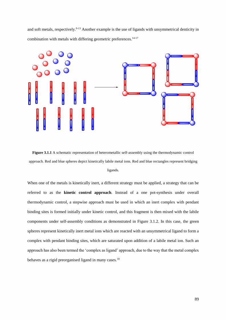
89
and soft metals, respectively.9-13 Another example is the use of ligands with unsymmetrical denticity in
combination with metals with differing geometric preferences.14-17
Figure 3.1.1 A schematic representation of heterometallic self-assembly using the thermodynamic control
approach. Red and blue spheres depict kinetically labile metal ions. Red and blue rectangles represent bridging
ligands.
When one of the metals is kinetically inert, a different strategy must be applied, a strategy that can be
referred to as the kinetic control approach. Instead of a one pot-synthesis under overall
thermodynamic control, a stepwise approach must be used in which an inert complex with pendant
binding sites is formed initially under kinetic control, and this fragment is then mixed with the labile
components under self-assembly conditions as demonstrated in Figure 3.1.2. In this case, the green
spheres represent kinetically inert metal ions which are reacted with an unsymmetrical ligand to form a
complex with pendant binding sites, which are saturated upon addition of a labile metal ion. Such an
approach has also been termed the ‘complex as ligand’ approach, due to the way that the metal complex
behaves as a rigid preorganised ligand in many cases.18
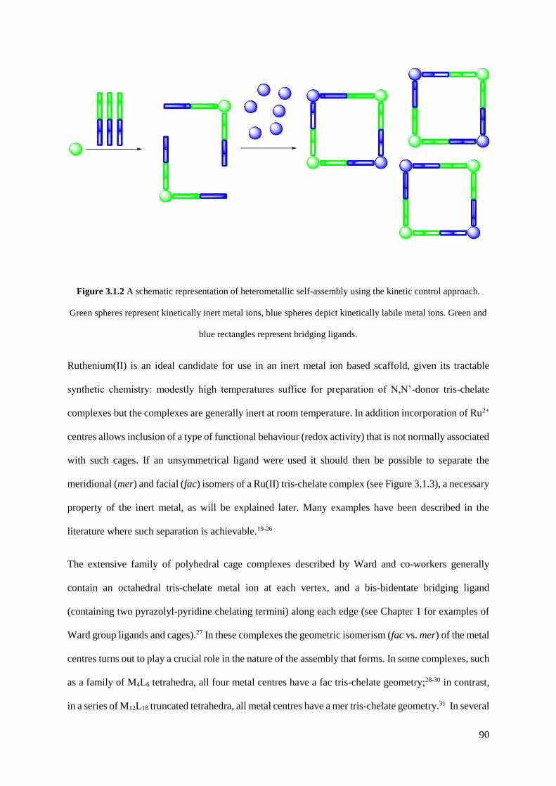
90
Figure 3.1.2 A schematic representation of heterometallic self-assembly using the kinetic control approach.
Green spheres represent kinetically inert metal ions, blue spheres depict kinetically labile metal ions. Green and
blue rectangles represent bridging ligands.
Ruthenium(II) is an ideal candidate for use in an inert metal ion based scaffold, given its tractable
synthetic chemistry: modestly high temperatures suffice for preparation of N,N’-donor tris-chelate
complexes but the complexes are generally inert at room temperature. In addition incorporation of Ru2+
centres allows inclusion of a type of functional behaviour (redox activity) that is not normally associated
with such cages. If an unsymmetrical ligand were used it should then be possible to separate the
meridional (mer) and facial (fac) isomers of a Ru(II) tris-chelate complex (see Figure 3.1.3), a necessary
property of the inert metal, as will be explained later. Many examples have been described in the
literature where such separation is achievable.19-26
The extensive family of polyhedral cage complexes described by Ward and co-workers generally
contain an octahedral tris-chelate metal ion at each vertex, and a bis-bidentate bridging ligand
(containing two pyrazolyl-pyridine chelating termini) along each edge (see Chapter 1 for examples of
Ward group ligands and cages).27 In these complexes the geometric isomerism (fac vs. mer) of the metal
centres turns out to play a crucial role in the nature of the assembly that forms. In some complexes, such
as a family of M4L6 tetrahedra, all four metal centres have a fac tris-chelate geometry;28-30 in contrast,
in a series of M12L18 truncated tetrahedra, all metal centres have a mer tris-chelate geometry.31 In several

91
other types of cage assembly however there is a 3:1 mixture of mer : fac tris-chelate vertices – these
include M4L6 tetrahedra, M8L12 cubes and M16L24 tetra-capped truncated tetrahedra.32-35 Therefore, the
ability to control the self-assembly of such cages – particularly mixed-metal versions – relies on the
ability to prepare kinetically stable, geometrically pure fac or mer tris-chelate subcomponents as starting
points to propagate a specific assembly.
Figure 3.1.3 Diagrams for the mer (left) and fac (right) isomers of a Ru(II) tris-chelate complex with pyrazolyl-
pyridine ligands.
There are examples in the literature where kinetically inert metal ions have been used as the basis of a
heterometallic structure, frequently resulting in helical or cyclic structures.22,36-40 However, the
examples where hollow heterometallic coordination cages with a defined cavity have resulted are very
scarce.14 Two methodologies have been used to achieve these types of structures; i) separation of fac-
ML3 tris chelates from a mixture of mer and fac isomers, and ii) functionalisation of an inert Ru(N)6
core to furnish it with pendant binding sites.
Piguet’s group has demonstrated the ability to separate fac-ML3 tris chelates possessing three pendant
binding sites by ion exchange chromatography when M = Cr(III), Os(II) or Ru(II).26,38,41 These fac-ML3
units have enabled the synthesis of a series of heterobimetallic d-f triple-stranded helicates when mixed

92
with lanthanide ions, which have led to some interesting functional behaviour such as Cr-Ln energy
transfer.
Fletcher’s group has been concerned with the separation of the fac-isomer of a series of Ru(II) tris-
bipyridines. Although having experienced successful separations by ion exchange chromatography, the
use of a tripodal ligand allowed the formation of a cage-like Ru(II) complex with fac tris-chelate
geometry. The tether could subsequently be removed, allowing functionalisation of the ligands in order
to introduce three pendant binding sites, and upon reaction with Fe(II) ions a RuFeL3 helicate was
formed.22
Previous work in the Ward group has also made use of the post-coordination functionalisation of
ligands.36 The complex [Ru(H2bpp)2]2+ (H2bpp = 2,6-bis(pyrazol-3-yl)pyridine), which possesses four
functionalisable N-H groups, can be synthesised as a single product with no geometrical isomerism
possible. This can then be alkylated to form an inert [Ru(N)6]2+ core furnished with four pendant
bidentate pyrazolyl-pyridyl sites. In the presence of Ag(I) ions, a [RuAg2]4+ double helix results.
Reaction of Ru(II) ions with the preformed multidentate ligand would not allow the formation of a
discrete trinuclear helicate.
The objective of this work is to synthesise heteronuclear coordination cages incorporating inert Ru(II)
tris-chelate complexes as either the pure fac- isomer or as a controlled mixture of the mer- and fac-
isomers at specific sites within heterometallic cage complexes, thus creating the potential for redox-
based switching of guest binding.42 The cages will be studied by 1H NMR spectroscopy, ESMS, X-ray
crystallography and electrochemical methods.

93
3.2 Results and discussion
3.2.1 Preparation of mononuclear Ru(II) subcomponents
The initial aim was for the synthesis of tris-chelates of Ru(II) in which the metal ion is coordinated to
one end of a bis-bidentate ligand (see Figure 3.2.1), such that there are three pendant bidentate groups.
These [RuL3]2+ complexes should then be isolated as either purely the fac isomer or as a statistical 3:1
mixture of the mer and fac isomers as starting points to propagate a specific assembly.
Figure 3.2.1 The ligands used in this work.

94
3.2.1.1 [Ru(L1,5-nap)3](PF6)2
The first mononuclear complex studied was [Ru(L1,5-nap)3](PF6)2, which uses a 1,5-substituted
naphthalene ligand (see Figure 3.2.1 for ligand structure). Previous work in the Ward group has shown
that reaction of L1,5-nap with a variety of transition metal dications in a 3 : 2 ratio leads to the formation
of cubic M8L12 coordination cages, in which two of the metal ions (at either end of the long diagonal)
have a fac tris-chelate geometry with the three pyridyl donors on one face of the octahedron and the
three pyrazolyl donors on the other. In contrast, the other six metal ions have a mer tris-chelate
geometry.32 Therefore, [Ru(L1,5-nap)3](PF6)2 can be introduced into the cage either as purely the fac-
isomer at opposite corners, or as a 3 : 1 mixture of the mer and fac isomers at alternating sites (see
Figure 3.2.2).
Figure 3.2.2 Schematic diagram of the cubic cage, showing the positions of the two fac (F) and six mer (M)
metal centres. In the homonuclear cages all metal ions are the same; in a heteronuclear cage the two types of
metal ion are split over the red [Ru(II)] and blue [M(II)] sites. (a) Ru2M6 arrangement, with Ru(II) occupying
the two fac centres and the other metal occupying all six mer centres. (b) Ru4M4 arrangement, with each ion
type occupying one fac and three mer centres.
[Ru(L1,5-nap)3](PF6)2 was prepared by reaction of RuCl2(dmso)4 with > 3 equiv. L1,5-nap in refluxing
ethylene glycol, and after work-up a yellow solid was isolated which analysed as [Ru(L1,5-nap)3](PF6)2
by elemental analysis and ESMS (see Figure 3.2.3). Given the non-symmetrical nature of the pyrazolyl-

95
pyridine chelates this course forms as a mixture of fac and mer isomers. If there is no specific factor
resulting in preference for one isomer over the other, a fac:mer ratio of 1:3 is expected. The 1H NMR
spectrum of [Ru(L1,5-nap)3](PF6)2 is consistent with this, showing four independent ligand environments
in equal abundance (see Figures 3.2.4 and 3.2.5). The mer isomer has no symmetry with all three ligands
inequivalent; the fac isomer provides the fourth ligand environment with all three ligands equivalent
due to the threefold symmetry but is only one-third as abundant. Hence we see signals for four
independent ligand environments in equal abundance. In the [Ru(L1,5-nap)3]2+ complex cation, each
ligand uses only one of its two chelating sites so there are three pendant pyrazolyl-pyridine binding
sites.
Figure 3.2.3 ESMS+ spectrum of [Ru(L1,5-nap)3][PF6]2. Peaks at 566 and 1130 (marked with an asterisk, *) are
due to fragmentation in the mass spectral conditions.
Conveniently for our purposes, this 1:3 fac:mer ratio of [Ru(L1,5-nap)3](PF6)2 isomers is precisely what
is required in the cage if every alternate site is occupied by a Ru(II) centre. This is not generally true
of other members of the cage family, which contains examples in which the metal tris-chelate centres
are all fac and other examples in which the metal centres are all mer.27 Thus, no separation of isomers
of [Ru(L1,5-nap)3](PF6)2 is needed: the as-prepared mixture can be used as it stands to provide the
necessary cage subcomponents in the correct proportions.

96
Figure 3.2.4 1H NMR spectrum (500 MHz, CD3CN) of [Ru(L1,5-nap)3](PF6)2.
Figure 3.2.5 Expansion of 1H NMR spectrum (500 MHz, CD3CN) of [Ru(L1,5-nap)3](PF6)2 showing the presence
of four signals in an approximately 1 : 1 : 1 : 1 ratio for one of the pyridyl-H6 protons, consistent with a 3:1 ratio
of mer to fac isomers.
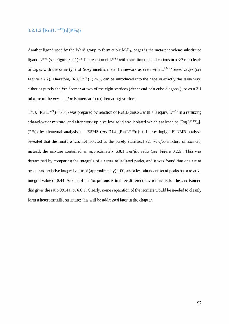
97
3.2.1.2 [Ru(Lm-Ph)3](PF6)2
Another ligand used by the Ward group to form cubic M8L12 cages is the meta-phenylene substituted
ligand Lm-Ph (see Figure 3.2.1).33 The reaction of Lm-Ph with transition metal dications in a 3:2 ratio leads
to cages with the same type of S6-symmetric metal framework as seen with L1,5-nap based cages (see
Figure 3.2.2). Therefore, [Ru(Lm-Ph)3](PF6)2 can be introduced into the cage in exactly the same way;
either as purely the fac- isomer at two of the eight vertices (either end of a cube diagonal), or as a 3:1
mixture of the mer and fac isomers at four (alternating) vertices.
Thus, [Ru(Lm-Ph)3](PF6)2 was prepared by reaction of RuCl2(dmso)4 with > 3 equiv. Lm-Ph in a refluxing
ethanol/water mixture, and after work-up a yellow solid was isolated which analysed as [Ru(Lm-Ph)3]-
(PF6)2 by elemental analysis and ESMS (m/z 714, [Ru(Lm-Ph)3]2+). Interestingly, 1H NMR analysis
revealed that the mixture was not isolated as the purely statistical 3:1 mer/fac mixture of isomers;
instead, the mixture contained an approximately 6.8:1 mer/fac ratio (see Figure 3.2.6). This was
determined by comparing the integrals of a series of isolated peaks, and it was found that one set of
peaks has a relative integral value of (approximately) 1.00, and a less abundant set of peaks has a relative
integral value of 0.44. As one of the fac protons is in three different environments for the mer isomer,
this gives the ratio 3:0.44, or 6.8:1. Clearly, some separation of the isomers would be needed to cleanly
form a heterometallic structure; this will be addressed later in the chapter.
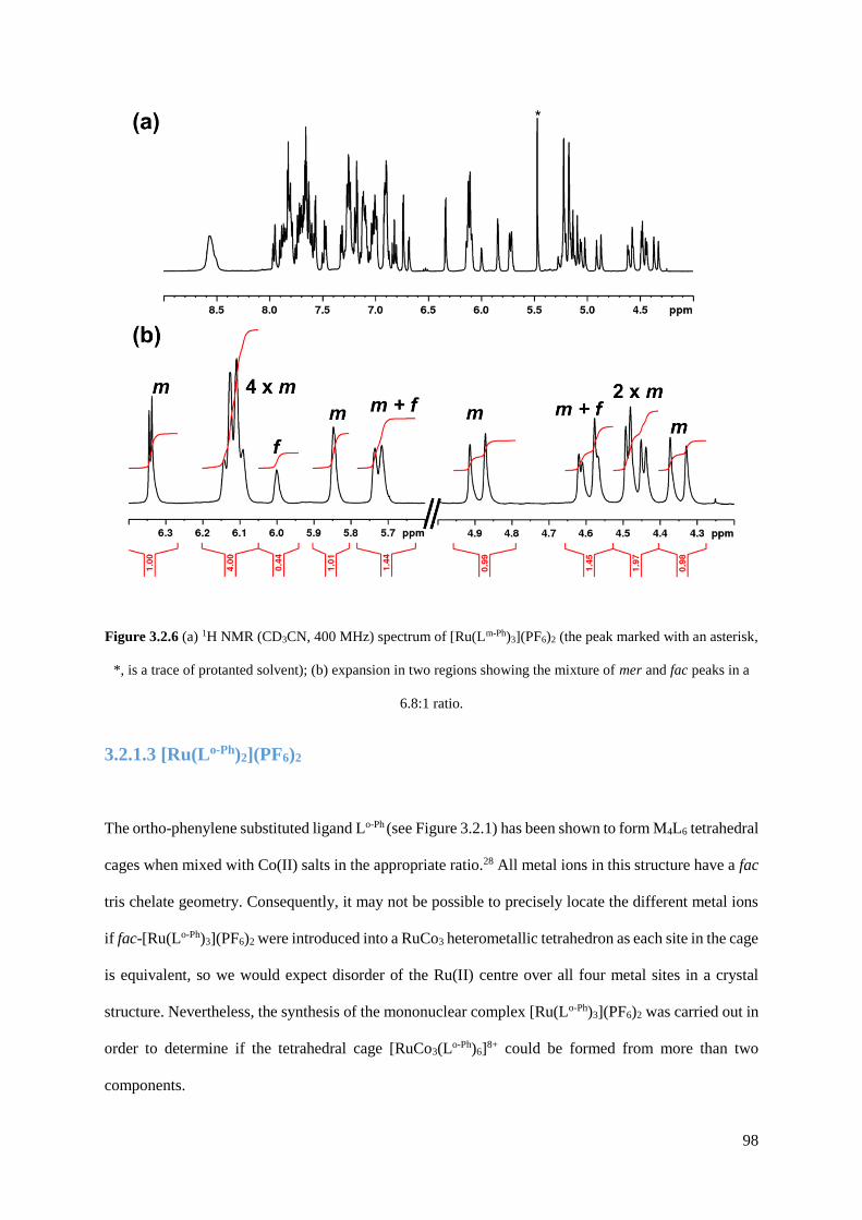
98
Figure 3.2.6 (a) 1H NMR (CD3CN, 400 MHz) spectrum of [Ru(Lm-Ph)3](PF6)2 (the peak marked with an asterisk,
*, is a trace of protanted solvent); (b) expansion in two regions showing the mixture of mer and fac peaks in a
6.8:1 ratio.
3.2.1.3 [Ru(Lo-Ph)2](PF6)2
The ortho-phenylene substituted ligand Lo-Ph (see Figure 3.2.1) has been shown to form M4L6 tetrahedral
cages when mixed with Co(II) salts in the appropriate ratio.28 All metal ions in this structure have a fac
tris chelate geometry. Consequently, it may not be possible to precisely locate the different metal ions
if fac-[Ru(Lo-Ph)3](PF6)2 were introduced into a RuCo3 heterometallic tetrahedron as each site in the cage
is equivalent, so we would expect disorder of the Ru(II) centre over all four metal sites in a crystal
structure. Nevertheless, the synthesis of the mononuclear complex [Ru(Lo-Ph)3](PF6)2 was carried out in
order to determine if the tetrahedral cage [RuCo3(Lo-Ph)6]8+ could be formed from more than two
components.

99
Reaction of RuCl2(dmso)4 with > 3 equiv. Lo-Ph in a refluxing ethanol/water mixture gave, after work-
up, a yellow solid which did not analyse as the expected [Ru(Lo-Ph)3](PF6)2 by elemental analysis or
ESMS. Instead, the bis-ligand species [Ru(Lo-Ph)2](PF6)2 was the only product observed by mass
spectrometry (see Figure 3.2.7). The 1H NMR spectrum of the recrystallized material revealed that there
were two independent ligand environments (see Figure 3.2.8); for example, 8 CH2 protons can be
identified in the COSY spectrum (see Figure 3.2.9). One of the CH2 groups appears as a singlet at 4.8
ppm with relative intensity 2H, whereas all other groups appear as 1H doublets (diastereotopic due to
coordination of the ligand to a chiral metal centre), with one proton remarkably shielded at 2.5 ppm.
Figure 3.2.7 ESMS+ spectrum of [Ru(Lo-Ph)2][PF6]2.
Figure 3.2.8 1H NMR spectrum (CD3CN, 400 MHz) of [Ru(Lo-Ph)2][PF6]2.

100
Figure 3.2.9 1H – 1H COSY spectrum (CD3CN, 400 MHz) of [Ru(Lo-Ph)2][PF6]2 (CH2 pairs are labelled a – d).
Given the complex formula and the fact there are the two independent ligand environments, the
connectivity of the ligands to the metal centre can be guessed with a reasonable degree of confidence.
Given that the ligand Lo-Ph has been shown to act as a tetradentate chelate for metals with a smaller ionic
radius than Co(II) [e.g. Ni(II)],43 it is quite likely that the ligand is acting as a tetradentate chelate here,
with another ligand filling the coordination sphere of Ru(II) and leaving a pendant pyrazolyl-pyridine
terminus. However, this does not explain the extremely shielded proton (2.5 ppm), therefore a crystal
structure was collected to elucidate the situation.
Slow diffusion of diethyl ether vapour into a solution of the complex in acetone/nitromethane afforded
X-ray quality yellow crystals of [Ru(Lo-Ph)2](PF6)2●0.5MeNO2 (see Figure 3.2.10). The asymmetric unit
contains two complete complex cations (and their respective anions) which have opposite optical
configurations. As predicted, one of the ligands acts as a tetradentate chelate, and the other as a mono-
bidentate ligand with a pendant pyrazolyl-pyridine terminus. The metal-nitrogen bond distances are
unremarkable, with all Ru-N distances in the range of 2.04 – 2.10 Å.
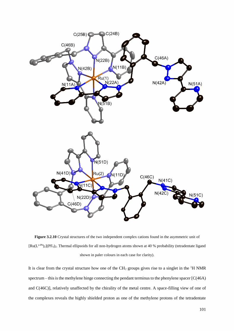
101
Figure 3.2.10 Crystal structures of the two independent complex cations found in the asymmetric unit of
[Ru(Lo-Ph)2](PF6)2. Thermal ellipsoids for all non-hydrogen atoms shown at 40 % probability (tetradentate ligand
shown in paler colours in each case for clarity).
It is clear from the crystal structure how one of the CH2 groups gives rise to a singlet in the 1H NMR
spectrum – this is the methylene hinge connecting the pendant terminus to the phenylene spacer [C(46A)
and C(46C)], relatively unaffected by the chirality of the metal centre. A space-filling view of one of
the complexes reveals the highly shielded proton as one of the methylene protons of the tetradentate

102
ligand (see figure 3.2.11). The proton H(46G) is directed towards the centre of one of the coordinated
pyrazolyl groups (average separation from the atoms of the ring: 2.44 Å) due to the rigid organisation
required for the ligand to bind in a tetradentate manner. The proton is consequently shielded (2.5 ppm)
from the external magnetic field in the 1H NMR experiment due to the ring-current effect.
Figure 3.2.11 Space-filling view of one of the cations in the crystal structure of [Ru(Lo-Ph)2](PF6)2, emphasising
the C-H ●●● interaction of one of the methylene protons and a coordinated pyrazolyl ring.
Whilst the desired complex [Ru(Lo-Ph)3](PF6)2 could not be synthesised, the product [Ru(Lo-Ph)2](PF6)2,
with one pendant binding site instead of three, may prove useful as a test-case for assembly of simple
heteronuclear complexes with pyrazolyl-pyridyl ligands.
103
3.2.1.4 [Ru(Lp-Ph)3](PF6)2
The para-phenylene substituted ligand Lp-Ph (see Figure 3.2.1) displays quite interesting supramolecular
chemistry when mixed with a range of transition metal dications.35 With Ni(II), it forms a M8L12 cube
structurally similar to the ones described previously; with Cu(II), a M6L9 trigonal prism is formed, in
which all metals have a mer tris-chelate geometry; with Cd(II) and Zn(II), a M16L24 tetra-capped
truncated tetrahedron is formed, in which four triangles of three metals with mer tris-chelate geometry
(which define the truncated tetrahedron) are face-capped by four metals with fac tris-chelate geometry.
As the largest cage prepared so far in the Ward group, a heterometallic version of this is quite a
tantalising prospect. However, this will require the isolation of fac-[Ru(Lp-Ph)3](PF6)2.
[Ru(Lp-Ph)3](PF6)2 was prepared by reaction of RuCl2(dmso)4 with > 3 equiv. Lp-Ph in a refluxing
ethanol/water mixture, and after work-up a yellow solid was isolated which analysed as [Ru(Lp-Ph)3]-
(PF6)2 by elemental analysis and ESMS (m/z 714, [Ru(Lp-Ph)3]2+). As when Lm-Ph was used, 1H NMR
analysis revealed that the mixture was not isolated as the purely statistical 3 : 1 mer/fac mixture of
isomers; instead, the mixture was isolated as an approximately 5 : 1 mer/fac mixture (see Figure 3.2.12),
as determined by the same method mentioned previously. It is clear at this point that isomeric
purification of these types of complexes is necessary in order to isolate the pure fac isomer or the 3 : 1
mer:fac ratio of isomers required to cleanly form the heterometallic structures, and this is when
significant efforts were devoted to separating the isomers, using [Ru(Lp-Ph)3](PF6)2 as the test-case to
devise a strategy.

104
Figure 3.2.12 (a) 1H NMR spectrum (500 MHz, (CD3)2CO) of stat-[Ru(Lp-Ph)3](PF6)2, showing the 80 proton
resonances for 4 inequivalent ligand environments for a mixture of mer and fac isomer; (b) Expansions of the
regions used to determine the approximate 5 : 1 ratio of mer/fac.
There exist many examples in the literature where a mixture of mer and fac isomers of unsymmetrical
bipyridine containing complexes have been separated into their geometrically pure forms. One of the
crudest methods is by fractional crystallisation; i.e. recrystallizing the mixture of isomers so that one
isomer crystallises out preferentially, and then manually separating the crystals.23, 24 This method is not
entirely reliable, as it is extremely dependent on the solvent and ambient conditions, and yielded no
separation of [Ru(Lp-Ph)3](PF6)2 after trying a range of crystallisation conditions. High-performance
liquid chromatography (HPLC) has been used by Ishida and co-workers to achieve the isomeric
separation of Ru(II) complexes with 5’-amino-2,2’-bipyridine-5-carboxylic acid derivatives, but their
method did not work for purifying [Ru(Lp-Ph)3](PF6)2.25
Fletcher’s group have reported many examples of isomeric separation of complexes with ester or amide
functionalised ligands by preparative thin-layer chromatography (TLC) or column chromatography on

105
silica eluting with dimethylformamide/ ethanol (4 : 1) saturated with ammonium chloride.21,44 The group
has also successfully separated a series of unsymmetrical Ru(II) tris-bipyridine complexes into their
respective mer and fac isomers on the basis of their interaction with the anion in ion exchange-
chromatography using SP C-25 Sephadex.45,46 Fletcher has reported that the chirality of the Sephadex
support has made it possible to separate and optical isomers, but in some instances this has
interfered with the separation of the geometrical isomers.45 Attempts to separate the isomers of
[Ru(Lp-Ph)3](PF6)2 were completely unsuccessful, so it is of course a possibility that this effect is
preventing separation of the mer and fac isomers in this instance. Piguet and co-workers have used
similar methodologies to separate the isomers of unsymmetrical Ru(II) and Os(II) tris-(benzimidazol-
2-yl)-pyridine complexes.26,38
Previous work in the Ward group has shown that alkylation is achievable on the symmetrical complex
[Ru(H2bpp)2]2+ (see chapter one, Figure 1.51), furnishing a RuN62+ core with pendant binding sites.36
Importantly, Fletcher has demonstrated that post-coordination functionalisation with retention of
isomeric integrity is possible.20-22 Therefore, this is the approach which was adopted, starting from fac-
[Ru(PyPzH)3]2+ [see Figure 3.2.13; PyPzH = 3-(2-pyridyl)-pyrazole] which can be readily separated
from the mer isomer using the method detailed in Chapter 2.47 In fac-[Ru(PyPzH)3]2+ the three pyrazole
rings, with their acidic NH protons, lie of course on the same face of the complex. Alkylation of these
with the bromomethyl compound Intp-Ph completed the formation of the Lp-Ph ligands coordinated to the
metal centre at one end, to give fac-[Ru(Lp-Ph)3]2+ which was isolated as the hexafluorophosphate salt,
as confirmed by elemental analysis and ESMS (see Figure 3.2.14). The 1H NMR spectrum showed 20
1H environments confirming the threefold symmetry with all three ligands equivalent (see Figure
3.2.15). Assignments (given with experimental details) were made on the basis of the COSY spectrum.
Notably the CH2 protons close to the Ru(II) chiral centre are diastereotopic, giving a coupled pair of
doublets at 5.5 and 4.8 ppm whereas the CH2 protons more remote from the Ru(II) centre give a singlet
at 5.3 ppm.
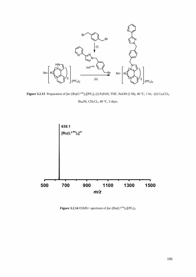
106
Figure 3.2.13 Preparation of fac-[Ru(Lp-Ph)3][PF6]2 (i) PyPzH, THF, NaOH (2 M), 40 oC, 1 hr; (ii) Cs2CO3,
Bu4NI, CH2Cl2, 40 oC, 5 days.
Figure 3.2.14 ESMS+ spectrum of fac-[Ru(Lp-Ph)3][PF6]2.

107
Figure 3.2.15 1H NMR spectrum of fac–[Ru(Lp-Ph)3][PF6]2 (CD3CN, 400 MHz). Top: complete spectrum.
Bottom: expansion of central region. (Py = pyridine, Pz = pyrazole, Ph = phenyl, p = pendant ring, c =
coordinated ring).
The crystal structure of the complex cation of fac-[Ru(Lp-Ph)3][PF6]2•acetone is shown in Figure 3.2.16.
The small crystals were weakly diffracting, and this dataset is the best of numerous attempts, but it is
clear how the three pendant pyrazolyl-pyridine arms are directed to the same face of the complex. The
phenyl group of each pendant arm forms a π-stacking interaction with a coordinated pyrazolyl-pyridine
group from another ligand, as we have observed in related complexes.

108
Figure 3.2.16 Structure of the complex cation of fac-[Ru(Lp-Ph)3][PF6]2•acetone with the three ligands coloured
differently for clarity.
The same alkylation strategy was also applied using mer-[Ru(PyPzH)3]2+ as the starting material
resulting in the isolation of pure mer-[Ru(Lp-Ph)3][PF6]2, as determined by ESMS and 1H NMR
spectroscopy (see Figure 3.2.17). The three inequivalent ligand arms are evidenced in the 1H NMR
spectrum by 60 1H environments. Within these peaks, sets of three can be seen for comparable protons
on different arms. For example, three phenyl doublets are observed in the region of 6.2 – 5.9 ppm
(labelled A in Figure 3.2.17), between 5.8 – 5.0 ppm the three diastereotopic CH2 groups and three
homotopic CH2 groups can be found (labelled a and b, respectively, in Figure 3.2.17), and three
pyrazolyl doublets are observed between 6.9 – 6.6 ppm.
Therefore, a method which can potentially be used to form any [RuL3]2+ complex based on a Ru(II) tris-
pyrazolyl-pyridine core with isomeric purity, providing the appropriate alkyl bromide can be readily
synthesised. Unfortunately, only the para-phenylene intermediate has been synthesised up to this point,
as the other intermediate alkyl bromides required have been found to decompose readily. Consequently,

109
[Ru(Lp-Ph)3]2+ is the only member of this series which has been isolated in an isomerically pure form
thus far.
Figure 3.2.17 1H NMR spectrum (acetone-d6, 400 MHz) of mer–[Ru(Lp-Ph)3][PF6]2. Labelled are three sets of
CH2 doublets (a), CH2 singlets (b), phenyl doublets (A), and pyrazolyl doublets (B).
3.2.1.5 [Ru(L3-Py)3](PF6)2
Using the same method as described for fac-[Ru(Lp-Ph)3][PF6]2, but using 3-(bromomethyl) pyridine
hydrobromide instead of Intp-Ph, resulted in the formation of the geometrically pure fac-[Ru(L3-Py)3]-
[PF6]2 with three pendant pyridyl groups (see Figure 3.2.1 for ligand structure). The 1H NMR spectrum
of the isolated yellow solid revealed twelve unique 1H resonances, consistent with a C3 symmetrical
structure in which all ligands are equivalent (see Figure 3.2.18). Assignments (given in the experimental
section) are made on the basis of the COSY spectrum. As observed in the 1H NMR spectrum of fac-
[Ru(Lp-Ph)3][PF6]2, the CH2 protons are diastereotopic due to their close proximity to the Ru(II) chiral
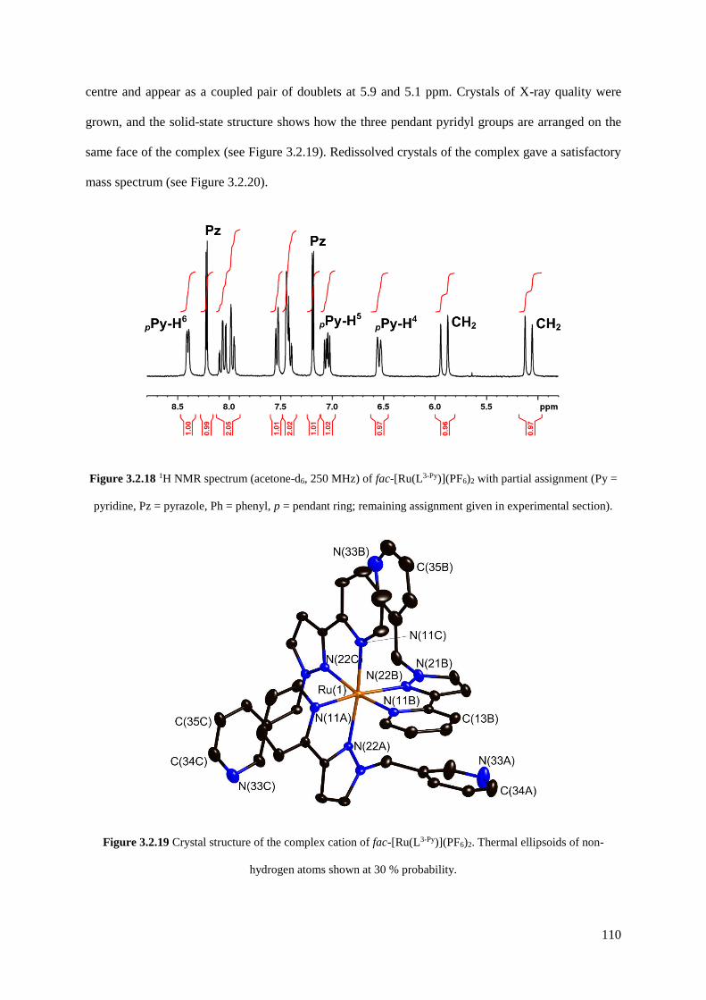
110
centre and appear as a coupled pair of doublets at 5.9 and 5.1 ppm. Crystals of X-ray quality were
grown, and the solid-state structure shows how the three pendant pyridyl groups are arranged on the
same face of the complex (see Figure 3.2.19). Redissolved crystals of the complex gave a satisfactory
mass spectrum (see Figure 3.2.20).
Figure 3.2.18 1H NMR spectrum (acetone-d6, 250 MHz) of fac-[Ru(L3-Py)](PF6)2 with partial assignment (Py =
pyridine, Pz = pyrazole, Ph = phenyl, p = pendant ring; remaining assignment given in experimental section).
Figure 3.2.19 Crystal structure of the complex cation of fac-[Ru(L3-Py)](PF6)2. Thermal ellipsoids of non-
hydrogen atoms shown at 30 % probability.

111
Figure 3.2.20 ESMS+ spectrum of redissolved crystals of fac-[Ru(L3-Py)3][PF6]2.
The ligand L3-Py has not been previously studied within the Ward group, so there is no basis to predict
which heterometallic complexes may be formed upon mixing fac-[Ru(L3-Py)3][PF6]2 with labile
transition metal cations. It is conceivable that upon reaction of the tris-monodentate ‘complex-ligand’
with 1.5 equivalents of a metal ion which can be 2-coordinate [e.g. Ag(I) or {Pd(en)}2+; en =
ethylenediamine], a heterometallic capsule may be formed (see Figure 3.2.21). However as discussed
later, no crystals of heterometallic complexes were obtained to confirm this hypothesis; nonetheless,
this could be a useful building block for heterometallic supramolecular assemblies.
Figure 3.2.21 Possible structure of heterometallic capsules incorporating fac-[Ru(L3-Py)3]2+ units.

112
3.2.2 Stepwise synthesis of heterometallic cubic coordination cages
Having described the synthesis of a series of mononuclear complexes, our attention is now turned to
the preparation of heterometallic coordination cages which, in the first instance, are based upon existing
cages prepared by the Ward group. The cage family first studied is the [M8(L1,5-nap)12]X16 octanuclear
‘cube’ [M = Co, Cd; X = a mono-anion such as BF4–, ClO4
– or BPh4–]. There are several examples of
such cages; all are based on a metal ion at each vertex of an approximate cube with the bridging ligand
L1,5-nap spanning each of the twelve edges, giving each metal ion a tris(pyrazolyl-pyridine) coordination
environment.32,42,48,49 Importantly, the assembly requires that two of the metal ions (at either end of the
long diagonal) have a fac tris-chelate geometry with the three pyridyl donors on one face of the
octahedron and the three pyrazolyl donors on the other; whereas the other six metal ions have a mer
tris-chelate geometry. With an inversion centre in the cage, this results in molecular S6 symmetry with
the C3/S6 axis through the two fac tris-chelate metal centres (see Figure 3.2.2).
The target of this work are the heterometallic analogues [Ru4M4(L1,5-nap)12](X)16 in which the Ru(II) and
M(II) centres alternate. Each type of metal ion occupies strictly one fac and three mer tris-chelate sites
in the cage superstructure. The fac / mer geometric isomerism could add another layer of complexity
to the problem of controlled preparation of a heterometallic cage, but in this particular case, it works
advantageously.
By starting with an inert [Ru(L1,5-nap)3]2+ unit as a pre-formed vertex, with three pendant sites at which
cage assembly can be propagated by binding to labile Cd2+ ions, it follows that it will not be possible to
have two Ru2+ ions adjacent to one another along one edge of the cube. The same is clearly true for the
Cd2+ ions. The result must be strict alternation of the metal sites around the cube: this can be achieved
in two ways which, due to the S6 symmetry of the cube, are degenerate (see Figure 3.2.2). Consequently,
a 3:1 mixture of mer:fac [Ru(L1,5-nap)3]2+ isomers would provide four pre-formed corners of the cube as
the correct isomers, as well as all twelve ligands necessary to complete the assembly. Addition of four
equivalents of a labile metal ion that forms octahedral tris-chelate complexes will complete the cube
assembly with each type of ion in predictable positions (see Figure 3.2.22).
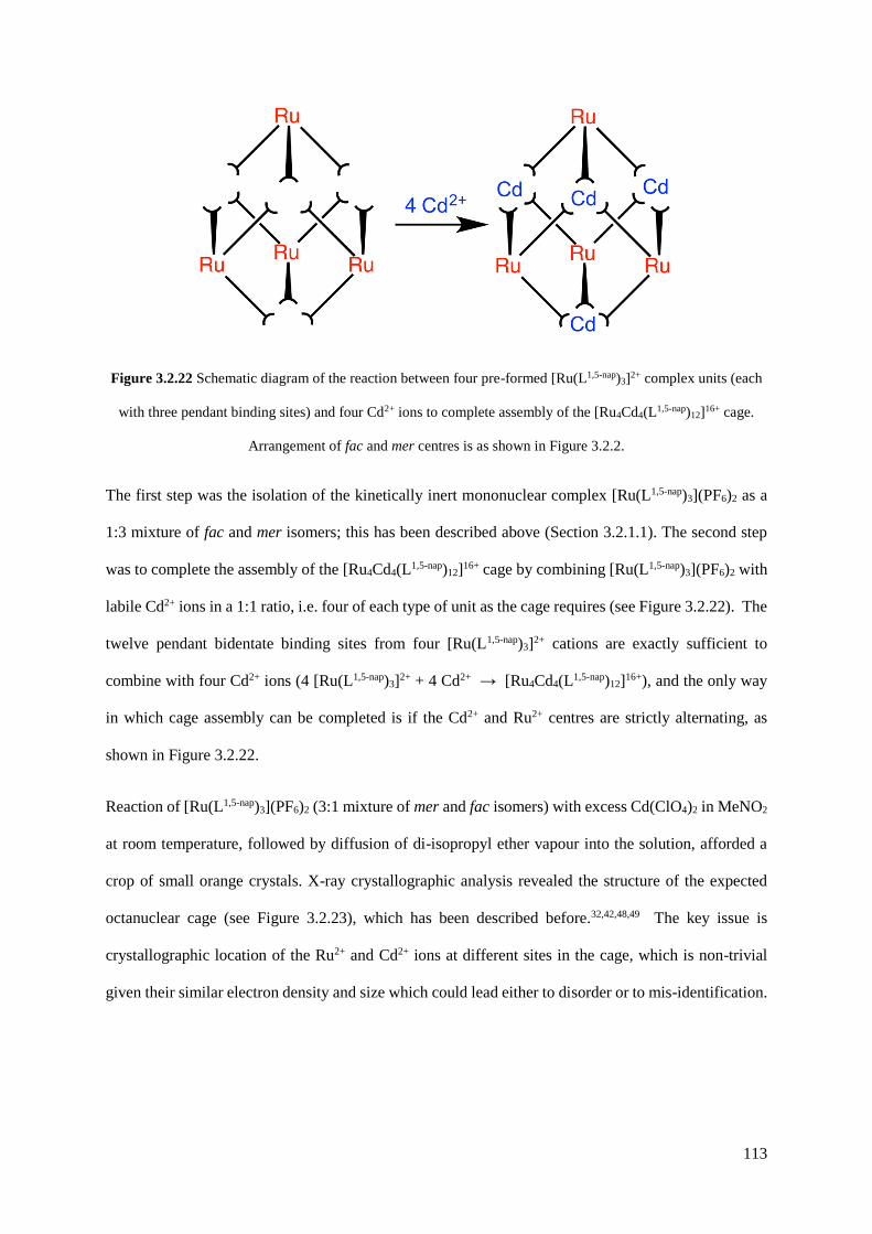
113
Figure 3.2.22 Schematic diagram of the reaction between four pre-formed [Ru(L1,5-nap)3]2+ complex units (each
with three pendant binding sites) and four Cd2+ ions to complete assembly of the [Ru4Cd4(L1,5-nap)12]16+ cage.
Arrangement of fac and mer centres is as shown in Figure 3.2.2.
The first step was the isolation of the kinetically inert mononuclear complex [Ru(L1,5-nap)3](PF6)2 as a
1:3 mixture of fac and mer isomers; this has been described above (Section 3.2.1.1). The second step
was to complete the assembly of the [Ru4Cd4(L1,5-nap)12]16+ cage by combining [Ru(L1,5-nap)3](PF6)2 with
labile Cd2+ ions in a 1:1 ratio, i.e. four of each type of unit as the cage requires (see Figure 3.2.22). The
twelve pendant bidentate binding sites from four [Ru(L1,5-nap)3]2+ cations are exactly sufficient to
combine with four Cd2+ ions (4 [Ru(L1,5-nap)3]2+ + 4 Cd2+ → [Ru4Cd4(L1,5-nap)12]16+), and the only way
in which cage assembly can be completed is if the Cd2+ and Ru2+ centres are strictly alternating, as
shown in Figure 3.2.22.
Reaction of [Ru(L1,5-nap)3](PF6)2 (3:1 mixture of mer and fac isomers) with excess Cd(ClO4)2 in MeNO2
at room temperature, followed by diffusion of di-isopropyl ether vapour into the solution, afforded a
crop of small orange crystals. X-ray crystallographic analysis revealed the structure of the expected
octanuclear cage (see Figure 3.2.23), which has been described before.32,42,48,49 The key issue is
crystallographic location of the Ru2+ and Cd2+ ions at different sites in the cage, which is non-trivial
given their similar electron density and size which could lead either to disorder or to mis-identification.
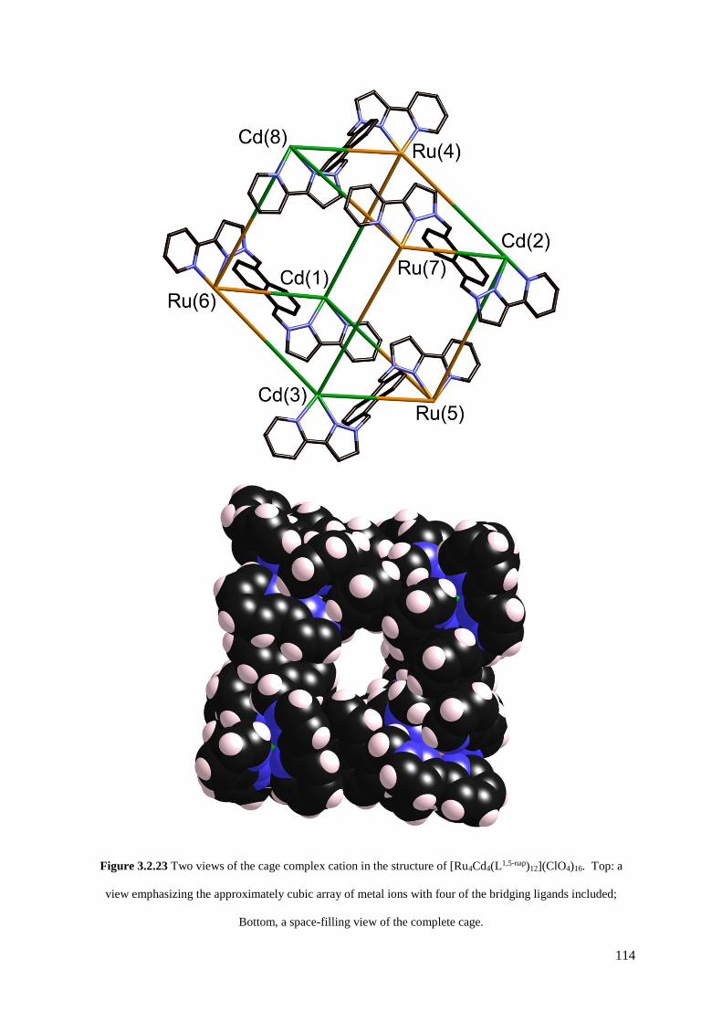
114
Figure 3.2.23 Two views of the cage complex cation in the structure of [Ru4Cd4(L1,5-nap)12](ClO4)16. Top: a
view emphasizing the approximately cubic array of metal ions with four of the bridging ligands included;
Bottom, a space-filling view of the complete cage.

115
Two distinct pieces of crystallographic evidence confirmed the presence of four Ru2+ and four Cd2+ ions
in the desired alternating arrangement. Firstly, these two ions should have different average M—N
distances, with Ru—N distances shorter than Cd—N. The four metal positions identified as Ru2+
consistently had significantly shorter bond distances (average, 2.17 Å; see Figure 3.2.24) than the four
positions identified as Cd2+ (average, 2.23 Å; see Figure 3.2.4). Secondly, correct assignment of Ru /
Cd positions resulted in all eight metal ions having comparable and reasonable isotropic displacement
parameters; inversion of the assignment, i.e. deliberately mis-labelling Ru as Cd and vice versa, resulted
in one set of displacement parameters being anomalously large and the other set being anomalously
small, as expected.
Cd(1) 2.22 Å Ru(4) 2.18 Å
Cd(3) 2.24 Å Ru(5) 2.17 Å
Cd(2) 2.22 Å Ru(6) 2.19 Å
Cd(8) 2.22 Å Ru(7) 2.16 Å
Figure 3.2.24 Average M—N bond distances around each metal centre in the complex cation of
[Ru4Cd4(L1,5-nap)12](ClO4)16.
The crystalline product was further analysed by ES mass spectrometry and 1H NMR spectroscopy. The
ES mass spectrum reveals a series of peaks at m/z [Ru4Cd4(L1,5-nap)12(ClO4)16-z]z+ (z = 4 – 9)
corresponding to the intact complex cation associated with varying numbers of anions (see Figure
3.2.25). High-resolution ES spectra give sets of peak clusters for the ions with z = 5, 6, 7 that match
exactly what is expected (see Figure 3.2.26). A 1H NMR spectrum of [Ru4Cd4(L1,5-nap)12](ClO4)16 in
CD3NO2 was not very informative as it contains 88 independent proton environments in the region 4.7
– 8.4 ppm;† even at 800 MHz the signals overlap too much for meaningful assignment (see Figure
† The homonuclear cages [M8L12]X16 contain 44 proton environments because the two different ligand
environments (connecting fac/mer and mer/mer metal centres, with six ligands in each environment) have no
internal symmetry.31 In this heterometallic complex the symmetry is reduced by a further factor of two due to loss
of the inversion centre.
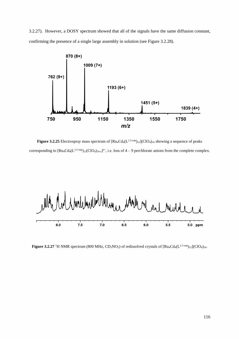
116
3.2.27). However, a DOSY spectrum showed that all of the signals have the same diffusion constant,
confirming the presence of a single large assembly in solution (see Figure 3.2.28).
Figure 3.2.25 Electrospray mass spectrum of [Ru4Cd4(L1,5-nap)12](ClO4)16 showing a sequence of peaks
corresponding to [Ru4Cd4(L1,5-nap)12(ClO4)16-z]z+, i.e. loss of 4 – 9 perchlorate anions from the complete complex.
Figure 3.2.27 1H NMR spectrum (800 MHz, CD3NO2) of redissolved crystals of [Ru4Cd4(L1,5-nap)12](ClO4)16.

117
Figure 3.2.26 Expansions of high-resolution ESMS+ mass spectra of redissolved crystals of [Ru4Cd4(L1,5-nap)12]-
(ClO4)16, showing theoretical (red) and experimental (grey) isotope patterns and accurate masses for the 5 and
7+ peak clusters.
5+
7+
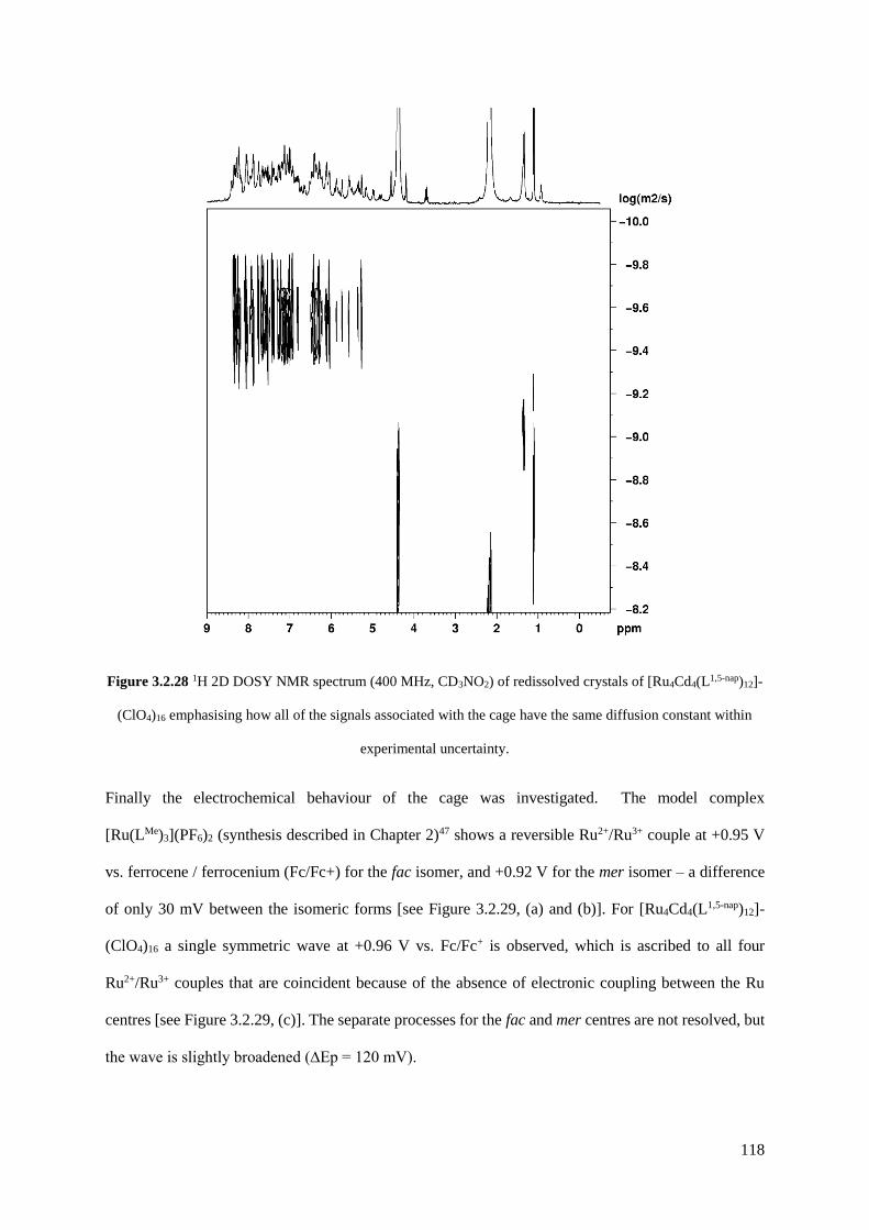
118
Figure 3.2.28 1H 2D DOSY NMR spectrum (400 MHz, CD3NO2) of redissolved crystals of [Ru4Cd4(L1,5-nap)12]-
(ClO4)16 emphasising how all of the signals associated with the cage have the same diffusion constant within
experimental uncertainty.
Finally the electrochemical behaviour of the cage was investigated. The model complex
[Ru(LMe)3](PF6)2 (synthesis described in Chapter 2)47 shows a reversible Ru2+/Ru3+ couple at +0.95 V
vs. ferrocene / ferrocenium (Fc/Fc+) for the fac isomer, and +0.92 V for the mer isomer – a difference
of only 30 mV between the isomeric forms [see Figure 3.2.29, (a) and (b)]. For [Ru4Cd4(L1,5-nap)12]-
(ClO4)16 a single symmetric wave at +0.96 V vs. Fc/Fc+ is observed, which is ascribed to all four
Ru2+/Ru3+ couples that are coincident because of the absence of electronic coupling between the Ru
centres [see Figure 3.2.29, (c)]. The separate processes for the fac and mer centres are not resolved, but
the wave is slightly broadened (∆Ep = 120 mV).

119
An important consequence of this redox activity is that the charge on the cage can be switched reversibly
between charges of 16+ and 20+. Given that recent work in the Ward group has demonstrated how
binding of electron-rich organic guests involves a substantial contribution from charge-assisted
hydrogen-bonding to the internal surface of the cage, at the position where the electrostatic potential is
most positive,42 a reversible redox swing should affect the strength of the host/guest interaction and
may provide a mechanism for controlling uptake and release of bound guests. Redox changes also offer
the possibility of reversible changes in luminescence6,40 or chromic8 properties of the cage.
This work has shown how the rational design and synthesis of a heterometallic Ru4Cd4 coordination
cage is possible via a combination of kinetically inert and labile metal ions, in which the four Ru2+ and
four Cd2+ ions occupy specific sites in the array. The synthesis of this cage was facilitated by the 3:1
ratio of mer/fac isomers present in the [Ru(L1,5-nap)3]2+ subcomponent. The next piece of work
investigated whether using a subcomponent with a ‘non-ideal’ ratio of isomers (i.e. not 3:1 mer/fac)
would lead to the expected heteronuclear cage product.

120
Figure 3.2.29 Cyclic voltammograms (MeCN / Bu4NPF6, Pt working electrode, scan rate 200 mV/sec) of (a)
fac-[Ru(LMe)3](PF6)2; (b) mer-[Ru(LMe)3](PF6)2; (c) [Ru4Cd4(L1,5-nap)12](ClO4)16. The reference electrode was a
silver wire pseudo-reference, hence ferrocene was used as in internal standard (wave labelled ‘Fc’) and the
potential of this is taken as zero in each case. The resulting calculated potentials for the Ru(II)/Ru(III) processes
(labelled ‘Ru’) are in the main text. On trace (c), the small shoulder before the Ru(II)/Ru(III) wave (labelled * in
the expansion) probably arises from the naphthyl groups in the ligands L as a similar feature occurs in the CV of
the free ligand.

121
As described in Section 3.2.1.2, cubic M8L12 cages are also formed with the ligand Lm-Ph, possessing an
identical metal framework as seen with L1,5-nap based cages with identical S6 symmetry.33 Therefore, a
synthesis analogous to that of [Ru4Cd4(L1,5-nap)12](ClO4)16 could be performed with the subcomponent
[Ru(Lm-Ph)3]2+. However, the synthesis of [Ru(Lm-Ph)3](PF6)2 gave the product not in the desired isomeric
ratio, but as an approximately 6.8:1 mer/fac mixture. With no method to separate the isomers, assembly
of a heterometallic cage was performed using the as-isolated 6.8:1 mer/fac mixture of the Ru(II)
components, in the hope that the self-assembly process would select the components necessary to
complete a stable cage structure.
Thus, a combination of [Ru(Lm-Ph)3](PF6)2 and 1 equivalent of Co(BF4)2 in dichloromethane/methanol
was mixed at room temperature overnight. After workup, a yellow solid was collected which was slowly
recrystallized from nitromethane by vapour diffusion with THF. The mixture was monitored by ESMS
over the course of two months whilst the recrystallization was occurring, revealing an interesting
product evolution. Initially the spectrum was dominated by a dinuclear species {[CoRu(Lm-Ph)3]X2}2+
peaks [m/z 751, 785, 814; X = PF6, BF4 or F; see Figure 3.2.30(a)], but after a week a series of peaks
corresponding to the tetranuclear {[Co2Ru2(Lm-Ph)6]X5}3+ grew in [m/z 1036, 1055, 1075, 1094; see
Figure 3.2.30(b)]. Finally, after several months, a series of peaks corresponding to the octanuclear
{[Co4Ru4(Lm-Ph)12]X16-n}n+ had grown in [e.g. m/z 806, 942, 1123, 1377, 1757 for n = 8 – 4, respectively;
see Figure 3.2.30(c) and Figure 3.2.31].
After several months, the recrystallization mixture yielded a crop of yellow blocks and orange shards.
The yellow blocks were more abundant and of excellent X-ray quality, and therefore a crystal structure
was determined. The structure revealed an octanuclear coordination cage cation, as expected on the
basis of the mass spectrum, but with the formulation [Ru4Co4(Lm-Ph)12{Na(BF4)4}](PF6)5(BF4)8 (see
Figures 3.2.32 and 3.2.33). The metal framework was approximately cubic, with alternating Ru(II) and
Co(II) ions at each metal site, as expected (Ru – Co separations along the edges lying in the range 9.79
– 10.63 Å; M – M – M angles between 80.0 º – 103.0 º). However, the structure revealed two surprises.
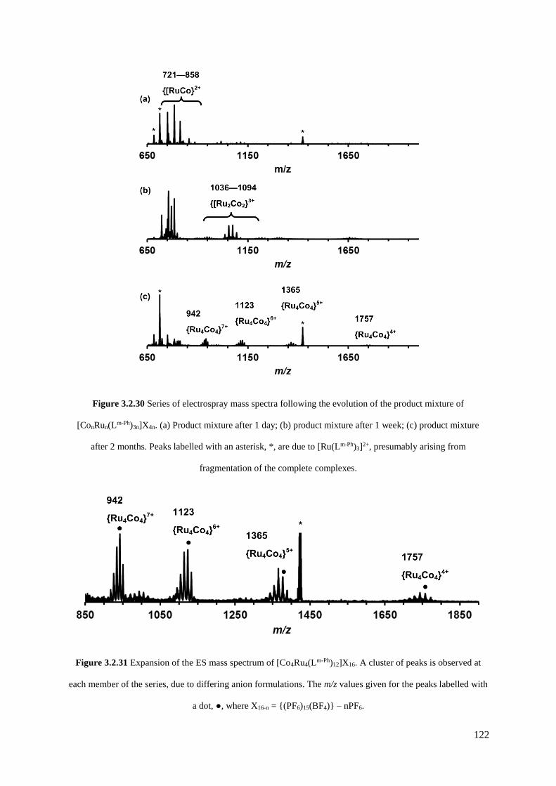
122
Figure 3.2.30 Series of electrospray mass spectra following the evolution of the product mixture of
[ConRun(Lm-Ph)3n]X4n. (a) Product mixture after 1 day; (b) product mixture after 1 week; (c) product mixture
after 2 months. Peaks labelled with an asterisk, *, are due to [Ru(Lm-Ph)3]2+, presumably arising from
fragmentation of the complete complexes.
Figure 3.2.31 Expansion of the ES mass spectrum of [Co4Ru4(Lm-Ph)12]X16. A cluster of peaks is observed at
each member of the series, due to differing anion formulations. The m/z values given for the peaks labelled with
a dot, ●, where X16-n = {(PF6)15(BF4)} – nPF6.
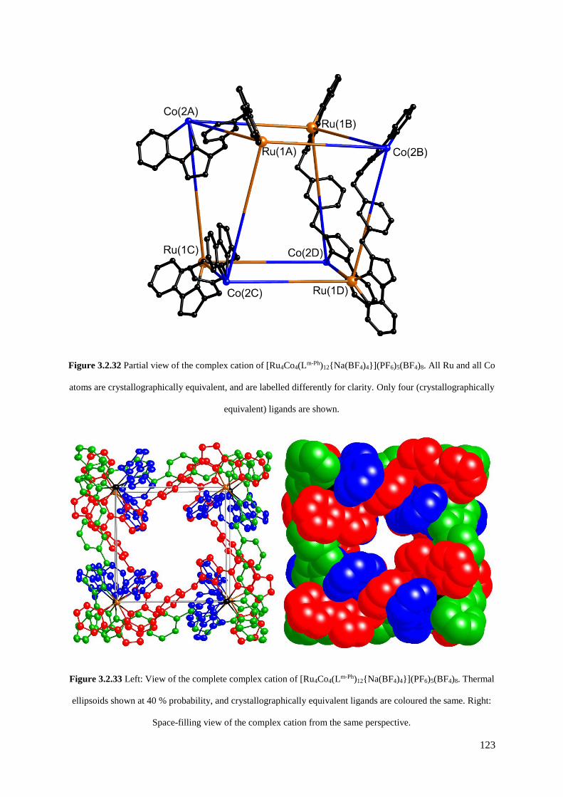
123
Figure 3.2.32 Partial view of the complex cation of [Ru4Co4(Lm-Ph)12{Na(BF4)4}](PF6)5(BF4)8. All Ru and all Co
atoms are crystallographically equivalent, and are labelled differently for clarity. Only four (crystallographically
equivalent) ligands are shown.
Figure 3.2.33 Left: View of the complete complex cation of [Ru4Co4(Lm-Ph)12{Na(BF4)4}](PF6)5(BF4)8. Thermal
ellipsoids shown at 40 % probability, and crystallographically equivalent ligands are coloured the same. Right:
Space-filling view of the complex cation from the same perspective.

124
The octanuclear cage crystallised in the tetragonal space group P-421m, with S4 symmetry (axis through
the centre of the face of the cube), such that one quarter of the complex cation is in the asymmetric unit,
comprising one metal centre with a fac tris-chelate geometry and the second with a mer tris-chelate
geometry. This has the consequence of the symmetry-expanded cube having alternating fac and mer
metal sites around the framework, an arrangement which has not occurred in any previous cages of this
family, even in the homonuclear analogues.33,50,51 Thus, the cubic cage is of a new structural type.
Identification of the metal at each site turned out to be trivial; widely different M – N bond lengths
[average 2.07 Å (mer) and 2.13 Å (fac)] and physically unreasonable thermal parameters upon
mislabelling reveal that the mer site is occupied by Ru, and the fac site by Co (see Figure 3.2.34). That
this product should crystallise out with exclusively mer-[Ru(Lm-Ph)3](PF6)2 can be rationalised on the
basis that a large excess of this isomer was used in the cage-forming reaction. It is possible that the less-
abundant orange shards contained fac-[Ru(Lm-Ph)3](PF6)2 in the more usual S6 cubic cage, with one
Ru(II) ion in the fac site and the other three at alternating mer positions (see Figure 3.2.2), in what
would be an eloquent display of self-sorting. Unfortunately, at the time of writing a crystal structure
has not been determined for the orange shards, so this hypothesis remains unproved, although the mass
spectrum is consistent with a [Co4Ru4(Lm-Ph)12]16+ cage.
Site Label
Isotropic
thermal
parameter,
U (Å2)
Average M-N
bond length
(Å)
mer Ru 0.033 2.07*
fac Co 0.038 2.14
mer Co 0.003 2.06**
fac Ru 0.086 2.14
Figure 3.2.34 Table summarising the key crystallographic information for correct* and deliberate mis-
assignment** of the different metal sites.
* Correct assignment of metals gives sensible thermal parameters. ** Deliberate mis-assignment of metals with physically unreasonable thermal parameters.
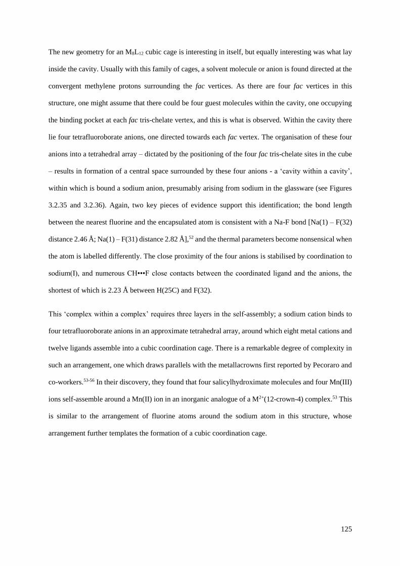
125
The new geometry for an M8L12 cubic cage is interesting in itself, but equally interesting was what lay
inside the cavity. Usually with this family of cages, a solvent molecule or anion is found directed at the
convergent methylene protons surrounding the fac vertices. As there are four fac vertices in this
structure, one might assume that there could be four guest molecules within the cavity, one occupying
the binding pocket at each fac tris-chelate vertex, and this is what is observed. Within the cavity there
lie four tetrafluoroborate anions, one directed towards each fac vertex. The organisation of these four
anions into a tetrahedral array – dictated by the positioning of the four fac tris-chelate sites in the cube
– results in formation of a central space surrounded by these four anions - a ‘cavity within a cavity’,
within which is bound a sodium anion, presumably arising from sodium in the glassware (see Figures
3.2.35 and 3.2.36). Again, two key pieces of evidence support this identification; the bond length
between the nearest fluorine and the encapsulated atom is consistent with a Na-F bond [Na(1) – F(32)
distance 2.46 Å; Na(1) – F(31) distance 2.82 Å],52 and the thermal parameters become nonsensical when
the atom is labelled differently. The close proximity of the four anions is stabilised by coordination to
sodium(I), and numerous CH•••F close contacts between the coordinated ligand and the anions, the
shortest of which is 2.23 Å between H(25C) and F(32).
This ‘complex within a complex’ requires three layers in the self-assembly; a sodium cation binds to
four tetrafluoroborate anions in an approximate tetrahedral array, around which eight metal cations and
twelve ligands assemble into a cubic coordination cage. There is a remarkable degree of complexity in
such an arrangement, one which draws parallels with the metallacrowns first reported by Pecoraro and
co-workers.53-56 In their discovery, they found that four salicylhydroximate molecules and four Mn(III)
ions self-assemble around a Mn(II) ion in an inorganic analogue of a M2+(12-crown-4) complex.53 This
is similar to the arrangement of fluorine atoms around the sodium atom in this structure, whose
arrangement further templates the formation of a cubic coordination cage.

126
Figure 3.2.35 Two views of the complex and bound guests of [Ru4Co4(Lm-Ph)12{Na(BF4)4}](PF6)5(BF4)8. (a)
View of the host-guest complex, with the guest [Na(BF4)4]3- shown in space-filling mode, and the cage shown in
ball-and-stick mode. (b) Thermal ellipsoid plot of the bound guest {Na(BF4)4}3-, ellipsoids shown at 40 %
probability.
(a)
(b)

127
Figure 3.2.36 Partial view of one of the fac-[Co(Lm-Ph)3]2+ vertices in the [Ru4Co4(Lm-Ph)12]16+ complex cation,
with numerous CH•••F interactions between coordinated ligands and the [Na(BF4)4]3- anion indicated by dashed
lines.
We have therefore shown how the rational design and synthesis of a heterometallic Ru4Cd4 coordination
cage is possible via a combination of kinetically inert and labile metal ions, in which the four Ru2+ and
four Cd2+ ions occupy specific sites in the array. We have also shown how an unexpected product can
arise from the self-assembly process when a ‘non-ideal’ ratio of isomers (i.e. not 3:1 mer/fac) in the
[RuL3]2+ subcomponent is used. It follows from this that the structure of the resultant coordination cage
can be possibly tailored by the isomeric identity of the [RuL3]2+ subcomponent, and further studies are
being carried out within the group to examine this.

128
3.2.3 Stepwise assembly of an adamantoid Ru4Ag6 cage by control of metal
coordination geometry at specific sites
As mentioned in Section 3.1, many of the cages described by the Ward group have a metal centre with
fac tris-chelate geometry at specific sites in the cage.32-35 By controlling geometric isomerism at specific
sites in a cage, one might be able to direct formation of specific assemblies. For example, a mixed-metal
hexadecanuclear [Ru4M12L24]32+ cage might be synthesised by combination of fac–[Ru(Lp-Ph)3][PF6]2
with the M(II) ions and additional ligand required to form the assembly, in which all Ru(II) ions would
occupy the face-capping fac tris-chelate sites (this is described in more detail later).
In order to test this theory of controlling geometric isomerism at specific sites in a cage, a simple
reaction was set up with the isomerically pure subcomponent fac–[Ru(Lp-Ph)3][PF6]2 and Ag(I) ions.
Ag(I) generally forms four-coordinate bis-chelate complexes with pyrazolyl-pyridine ligands of this
type, which have been shown to form high-quality crystals and thus facilitate X-ray analysis.57,58 On the
basis that three pendant bidentate sites are available for coordination in fac–[Ru(Lp-Ph)3][PF6]2, we
combined fac–[Ru(Lp-Ph)3][PF6]2 with 1.5 equivalents of AgPF6 to maximise the likelihood of a structure
forming that conforms to the principle of maximum site occupancy, with all metal ions coordinatively
saturated and all ligands fully coordinated.59 If each pendant ligand fragment coordinates to a different
Ag(I) ion, as is likely on steric grounds given the distance between the pendant pyrazolyl-pyridine units,
we expect a mixed-metal cage in which each [Ru(Lp-Ph)3]2+ unit caps a triangular array of Ag(I) ions.
Slow crystallisation of the reaction mixture afforded X-ray quality crystals of what proved to be a
decanuclear Ru4Ag6 cage [{Ru(Lp-Ph)3}4Ag6](PF6)14 (see Figures 3.2.37 – 3.2.39). The cage has an
adamantane-like structure, with a Ru(II) tris-chelate unit at each of the four three-connected vertices
which are arranged in an approximate tetrahedron. An Ag(I) bis-chelate unit occupies each of the six
two-connected vertices. Thus the structure can be described as a tetrahedral array of Ru(II) ions with
an Ag(I) ion lying in the centre of each Ru•••Ru edge (see Figure 3.2.37), with every adjacent
Ru(II)/Ag(I) pair connected by a bis-bidentate bridging ligand Lp-Ph.
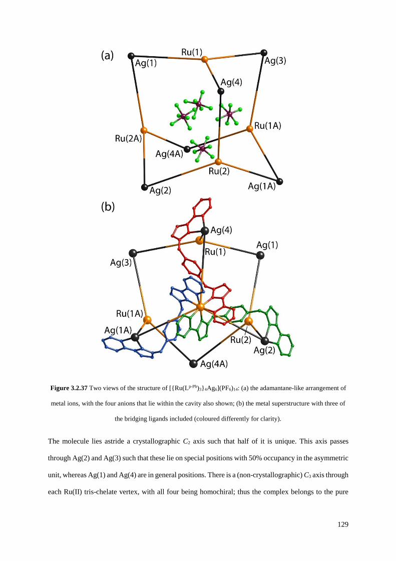
129
Figure 3.2.37 Two views of the structure of [{Ru(Lp-Ph)3}4Ag6](PF6)14: (a) the adamantane-like arrangement of
metal ions, with the four anions that lie within the cavity also shown; (b) the metal superstructure with three of
the bridging ligands included (coloured differently for clarity).
The molecule lies astride a crystallographic C2 axis such that half of it is unique. This axis passes
through Ag(2) and Ag(3) such that these lie on special positions with 50% occupancy in the asymmetric
unit, whereas Ag(1) and Ag(4) are in general positions. There is a (non-crystallographic) C3 axis through
each Ru(II) tris-chelate vertex, with all four being homochiral; thus the complex belongs to the pure
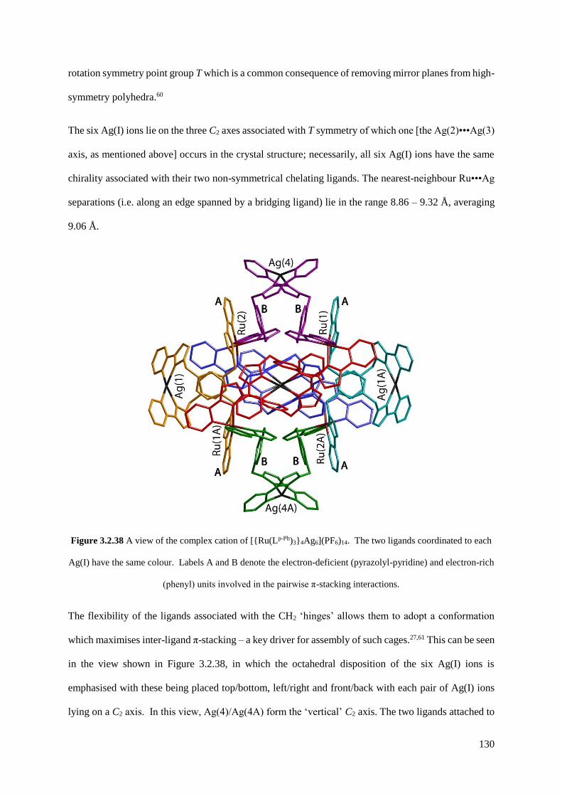
130
rotation symmetry point group T which is a common consequence of removing mirror planes from high-
symmetry polyhedra.60
The six Ag(I) ions lie on the three C2 axes associated with T symmetry of which one [the Ag(2)•••Ag(3)
axis, as mentioned above] occurs in the crystal structure; necessarily, all six Ag(I) ions have the same
chirality associated with their two non-symmetrical chelating ligands. The nearest-neighbour Ru•••Ag
separations (i.e. along an edge spanned by a bridging ligand) lie in the range 8.86 – 9.32 Å, averaging
9.06 Å.
Figure 3.2.38 A view of the complex cation of [{Ru(Lp-Ph)3}4Ag6](PF6)14. The two ligands coordinated to each
Ag(I) have the same colour. Labels A and B denote the electron-deficient (pyrazolyl-pyridine) and electron-rich
(phenyl) units involved in the pairwise π-stacking interactions.
The flexibility of the ligands associated with the CH2 ‘hinges’ allows them to adopt a conformation
which maximises inter-ligand π-stacking – a key driver for assembly of such cages.27,61 This can be seen
in the view shown in Figure 3.2.38, in which the octahedral disposition of the six Ag(I) ions is
emphasised with these being placed top/bottom, left/right and front/back with each pair of Ag(I) ions
lying on a C2 axis. In this view, Ag(4)/Ag(4A) form the ‘vertical’ C2 axis. The two ligands attached to

131
each Ag(I) ion have the same colour (i.e. the twelve ligands are coloured in six sets of two). The ligands
are disposed such that a central phenyl ring of a bridging ligand (denoted ‘B’ in Figure 3.2.38) lies
parallel to, and overlapping with, a pyrazolyl-pyridine unit of another ligand coordinated to the adjacent
Ru(II) ion (denoted ‘A’ in Figure 3.2.38), forming a charge-assisted π-stack between electron-rich
(phenyl) and electron-deficient (coordinated pyrazolyl-pyridine) ligands. In the view in Figure 3.2.38
there can be seen four such A/B stacked pairs; there are necessarily, therefore, twelve such interactions
overall – involving every phenyl group – as the orientations with Ag(1)/Ag(1A) and Ag(2)/Ag(3) as the
‘vertical’ axis are equivalent.
Figure 3.2.39 Space-filling views of the complex cation of [{Ru(Lp-Ph)3}4Ag6](PF6)14. (a) A view down one of
the threefold axes, through a Ru(II) tris-chelate centre; (b) a view from the opposite side of the complex looking
at one of the Ru3Ag3 faces, with one of the encapsulated [PF6]– anions (F atoms in green) visible through the
portal.
An alternative space-filling view, looking down one of the C3 axes associated with a Ru(II) tris-chelate
centre, is in Figure 3.2.39(a). The cage complex has an approximate cavity size of 178 Å3 (calculated
assuming that the windows are blocked; see Figure 3.2.40).62 The cavity is occupied by a tetrahedral
array of four [PF6]– anions (see Figure 3.2.37a), each one blocking the window in one of the Ru3Ag3
faces of the cage, as shown in Figure 3.2.39(b) in which three of the F atoms of the [PF6]– anion in that
window can be clearly seen. The P•••P separations between the four encapsulated anions are in the

132
range of 5.44 – 5.61 Å, resulting in peripheral F•••F contacts between anions of ≈ 3Å, which is the sum
of the van der Waals’ radii of two F atoms. Each anion is involved in a range of CH•••F interactions
with ligand H atoms. Figure 3.2.41(a) shows one of the anions embedded in the window in one of the
Ru3Ag3 faces, with dotted lines indicating some of the short non-bonded C•••F contacts (≤ 3.15 Å)
which are indicative of weak hydrogen-bonding interactions between anion and ligand. This view also
nicely shows how the array of six ligands around each Ru3Ag3 face forms a cyclic helicate with every
ligand in the cycle having the same sense of ‘under and over’ around the ring. Figure 3.2.41(b) shows
how the four anions fill the cavity.
Figure 3.2.40 A view of the cavity in the centre of [{Ru(Lp-Ph)3}4Ag6](PF6)14, shown in blue (generated with
Swiss-PDB viewer).62
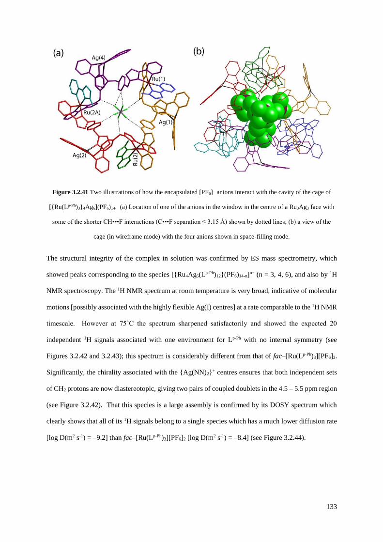
133
Figure 3.2.41 Two illustrations of how the encapsulated [PF6]– anions interact with the cavity of the cage of
[{Ru(Lp-Ph)3}4Ag6](PF6)14. (a) Location of one of the anions in the window in the centre of a Ru3Ag3 face with
some of the shorter CH•••F interactions (C•••F separation ≤ 3.15 Å) shown by dotted lines; (b) a view of the
cage (in wireframe mode) with the four anions shown in space-filling mode.
The structural integrity of the complex in solution was confirmed by ES mass spectrometry, which
showed peaks corresponding to the species [{Ru4Ag6(Lp-Ph)12}(PF6)14-n]n+ (n = 3, 4, 6), and also by 1H
NMR spectroscopy. The 1H NMR spectrum at room temperature is very broad, indicative of molecular
motions [possibly associated with the highly flexible Ag(I) centres] at a rate comparable to the 1H NMR
timescale. However at 75˚C the spectrum sharpened satisfactorily and showed the expected 20
independent 1H signals associated with one environment for Lp-Ph with no internal symmetry (see
Figures 3.2.42 and 3.2.43); this spectrum is considerably different from that of fac–[Ru(Lp-Ph)3][PF6]2.
Significantly, the chirality associated with the {Ag(NN)2}+ centres ensures that both independent sets
of CH2 protons are now diastereotopic, giving two pairs of coupled doublets in the 4.5 – 5.5 ppm region
(see Figure 3.2.42). That this species is a large assembly is confirmed by its DOSY spectrum which
clearly shows that all of its 1H signals belong to a single species which has a much lower diffusion rate
[log D(m2 s-1) = –9.2] than fac–[Ru(Lp-Ph)3][PF6]2 [log D(m2 s-1) = –8.4] (see Figure 3.2.44).

134
Figure 3.2.42 1H NMR spectrum of [{Ru(Lp-Ph)3}4Ag6](PF6)14 (CD3CN, 400 MHz, 75 ˚C).
Figure 3.2.44 DOSY 1H NMR spectra (400 MHz, CD3CN, 25 oC) of fac–[Ru(Lp-Ph)3][PF6]2 (left) and
[{Ru(Lp-Ph)3}4Ag6](PF6)14 (right).
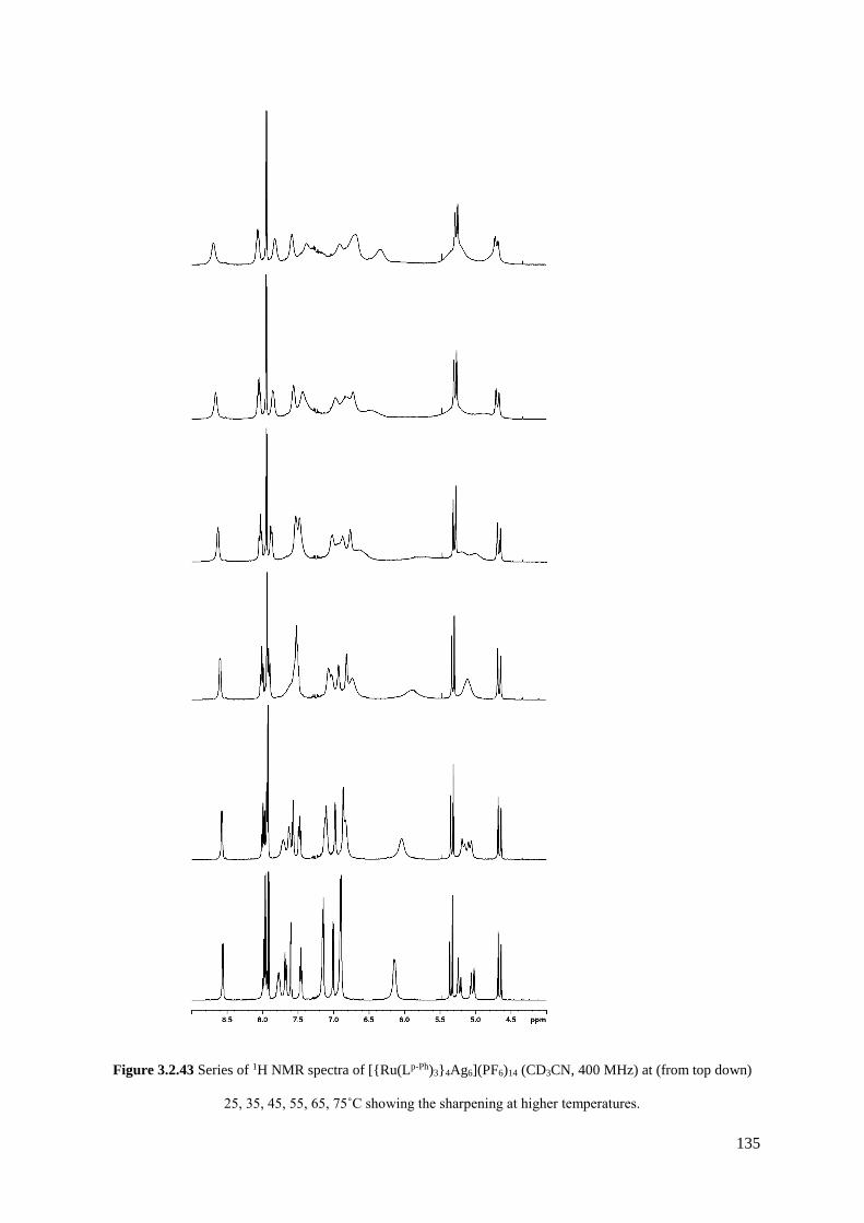
135
Figure 3.2.43 Series of 1H NMR spectra of [{Ru(Lp-Ph)3}4Ag6](PF6)14 (CD3CN, 400 MHz) at (from top down)
25, 35, 45, 55, 65, 75˚C showing the sharpening at higher temperatures.

136
Assembly of this cage with its adamantane-like structure thus relies on two different types of geometric
control at specific metal sites. Firstly it requires the appropriate combination of metal vertices that are
three-connected [each tris-chelate, Ru(II) ion is connected to three Ag(I) ions] and two connected [each
bis-chelate Ag(I) ion is connected to two Ru(II) ions]. This is achieved by using metal ions with
different stereoelectronic preference, i.e. a combination of 6-coordinate Ru(II) and 4-coordinate Ag(I)
ions at alternating sites. Secondly, the structure relies on exclusive use of pre-formed, kinetically inert
fac isomers of the [Ru(Lp-Ph)3]2+ unit. It is noted that there are a few other examples of mixed-metal
M6M’4(µ–L)10 complexes with an adamantane-like core structure,63-66 several of which (from Ishio and
co-workers) use cyanide bridges along the M–M’ edges.65,66
3.2.4 Three component assembly of a heterometallic tetra-capped truncated
tetrahedron
With satisfactory evidence that isomerically pure fac–[Ru(Lp-Ph)3][PF6]2 subcomponents can be used to
propagate formation of a heterometallic array, efforts were directed towards preparing more elaborate
structures that incorporate more than one component. As with the heterometallic cubes detailed in
Section 3.2.2, such structures can be rationally designed based on the existing homonuclear versions.
For example, if fac–[Ru(L3,3-Bi)3][PF6]2 were to be isolated (see Figure 3.2.1 for ligand structure), then
the synthesis of a heterometallic [RuM3(L3,3-Bi)3]X8 tetrahedron could be achieved with Ru(II) located
exclusively at the fac position, with labile metal dications occupying the remaining three mer vertices.67
However, this cage has a relatively small cavity, which may limit its useful host-guest chemistry.68
Consequently, the largest cage in this series, the M16L24 tetra-capped truncated tetrahedron, was
targeted.35,61
The M16L24 structure consists of three triangles of mer tris-chelate metals capped by four fac tris-chelate
metals, with either Lp-Ph or L1,4-nap as the 24 bridging ligands. Importantly, the fac positions are not
connected by the same edge. It follows therefore that four equivalents of fac–[Ru(Lp-Ph)3][PF6]2 will
provide the four fac face-capping metal centres and twelve of the ligands required for the assembly. In

137
addition, twelve equivalents of ligand (Lp-Ph or L1,4-nap) and twelve equivalents of a labile transition metal
dication [e.g. Cd(II) or Zn(II)] will be needed to complete the assembly (see Figure 3.2.45). The result
of this would be a structure in which each Ru(II) ‘complex-ligand’ provides a bidentate binding site to
three different M(II) ions.
Figure 3.2.45 Schematic diagram of the reaction between four pre-formed fac-[Ru(Lp-Ph)3]2+ complex units
(each with three pendant binding sites), twelve Cd2+ ions and twelve additional ligands (Lp-Ph or L1,4-nap) to
complete assembly of the [Ru4Cd12L24]32+ cage.
Thus, a reaction of fac–[Ru(Lp-Ph)3][PF6]2 and [Cd3(L1,4-nap)3](BF4)6 was dissolved in nitromethane at 90
oC and subsequently kept at room temperature (note: the additional ligand and metal dication was
introduced as a 1 : 1 ratio pre-isolated solid61 for ease of synthesis). The 1H NMR spectrum of the
mixture was recorded daily and the electrospray mass spectrum every week to detect any assemblies
taking form. After 1 day the 1H NMR spectrum was very poorly resolved, consistent with a slowly
equilibrating mixture of assemblies (see Figure 3.2.46a), and the mass spectrum showed no signs of any
large assemblies having already formed. After 1 month had passed, the 1H NMR spectrum was
considerably sharpened (see Figure 3.2.46b), although still too poorly resolved to distinguish all the
individual peaks; the mass spectrum recorded at the same time however revealed that this was the 1H
If the heterometallic assembly has the same symmetry as the homonuclear M16L24 cage, as expected, then there
will be 2 independent ligand environments with no internal symmetry, and consequently 42 1H environments in
the 1H NMR spectrum.
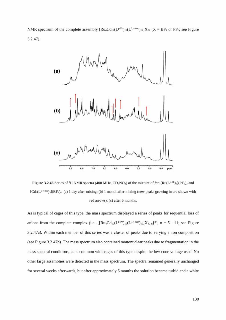
138
NMR spectrum of the complete assembly [Ru4Cd12(Lp-Ph)12(L1,4-nap)12]X32 (X = BF4 or PF6; see Figure
3.2.47).
Figure 3.2.46 Series of 1H NMR spectra (400 MHz, CD3NO2) of the mixture of fac-[Ru(Lp-Ph)3](PF6)2 and
[Cd3(L1,4-nap)3](BF4)6: (a) 1 day after mixing; (b) 1 month after mixing (new peaks growing in are shown with
red arrows); (c) after 5 months.
As is typical of cages of this type, the mass spectrum displayed a series of peaks for sequential loss of
anions from the complete complex (i.e. {[Ru4Cd12(Lp-Ph)12(L1,4-nap)12]X32-n}n+; n = 5 - 11; see Figure
3.2.47a). Within each member of this series was a cluster of peaks due to varying anion composition
(see Figure 3.2.47b). The mass spectrum also contained mononuclear peaks due to fragmentation in the
mass spectral conditions, as is common with cages of this type despite the low cone voltage used. No
other large assemblies were detected in the mass spectrum. The spectra remained generally unchanged
for several weeks afterwards, but after approximately 5 months the solution became turbid and a white
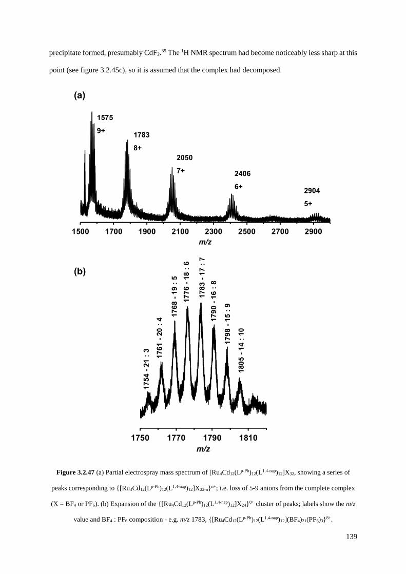
139
precipitate formed, presumably CdF2.35 The 1H NMR spectrum had become noticeably less sharp at this
point (see figure 3.2.45c), so it is assumed that the complex had decomposed.
Figure 3.2.47 (a) Partial electrospray mass spectrum of [Ru4Cd12(Lp-Ph)12(L1,4-nap)12]X32, showing a series of
peaks corresponding to {[Ru4Cd12(Lp-Ph)12(L1,4-nap)12]X32-n}n+; i.e. loss of 5-9 anions from the complete complex
(X = BF4 or PF6). (b) Expansion of the {[Ru4Cd12(Lp-Ph)12(L1,4-nap)12]X24}8+ cluster of peaks; labels show the m/z
value and BF4 : PF6 composition - e.g. m/z 1783, {[Ru4Cd12(Lp-Ph)12(L1,4-nap)12](BF4)21(PF6)3}8+.
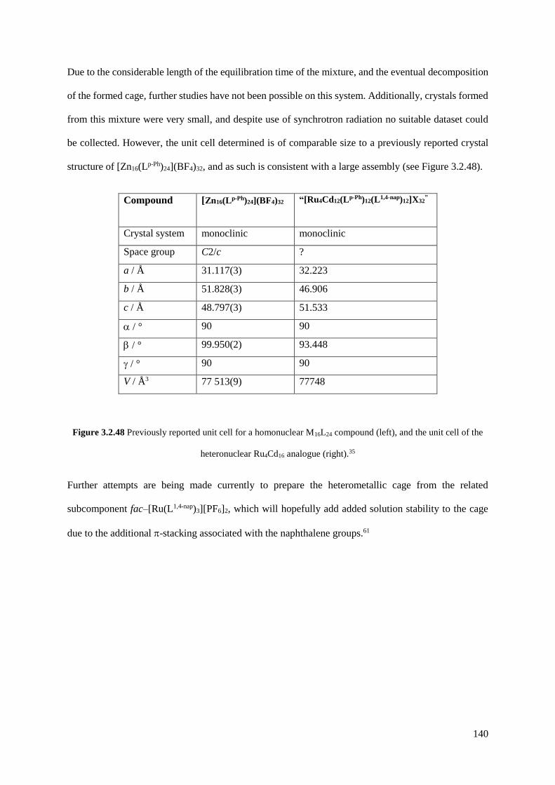
140
Due to the considerable length of the equilibration time of the mixture, and the eventual decomposition
of the formed cage, further studies have not been possible on this system. Additionally, crystals formed
from this mixture were very small, and despite use of synchrotron radiation no suitable dataset could
be collected. However, the unit cell determined is of comparable size to a previously reported crystal
structure of [Zn16(Lp-Ph)24](BF4)32, and as such is consistent with a large assembly (see Figure 3.2.48).
Compound [Zn16(Lp-Ph)24](BF4)32 “[Ru4Cd12(Lp-Ph)12(L1,4-nap)12]X32”
Crystal system monoclinic monoclinic
Space group C2/c ?
a / Å 31.117(3) 32.223
b / Å 51.828(3) 46.906
c / Å 48.797(3) 51.533
/ ° 90 90
/ ° 99.950(2) 93.448
/ ° 90 90
V / Å3 77 513(9) 77748
Figure 3.2.48 Previously reported unit cell for a homonuclear M16L24 compound (left), and the unit cell of the
heteronuclear Ru4Cd16 analogue (right).35
Further attempts are being made currently to prepare the heterometallic cage from the related
subcomponent fac–[Ru(L1,4-nap)3][PF6]2, which will hopefully add added solution stability to the cage
due to the additional -stacking associated with the naphthalene groups.61

141
3.2.5 Two heterometallic assemblies using preformed Ru(II) species and Ag(I)
ions
The mononuclear complex [Ru(Lo-Ph)2](PF6)2, described in Section 3.2.13, contains one pendant
bidentate binding site. This would theoretically preclude the formation of a hollow heterometallic array
using labile octahedral dications, which requires all of the bridging lignads to span the cage edges. For
example, [Ru(Lo-Ph)2](PF6)2 might react with Co(II) to form the heteronuclear species
[{Ru(Lo-Ph)2}3Co]8+, in which all ligands and metal ions will be coordinatively saturated. However, the
use of the more coordinatively flexible Ag(I) may allow the synthesis of some unexpected products,
particularly due to the propensity of Ag(I) to form argentophilic interactions when ligands of this type
are used.57,58
Reaction of [Ru(Lo-Ph)2](PF6)2 with AgPF6 or AgClO4 in methanol/dichloromethane solution gave in
both cases a yellow powder. These were expected to have the formulation [{Ru(Lo-Ph)3}2Ag]X5, in
which two mononuclear Ru(II) subcomponents are bound to a 4-coordinate Ag(I) ion; the 1H NMR
spectrum of each was consistent with this with the complexes giving nearly identical spectra, as
expected since they differ only in the type of anions (see Figure 3.2.49). Each spectrum shows 40 1H
resonances (two full independent ligand environments), as was the case with the mononuclear complex,
due to the C2 symmetry about the Ag(I) ion. Several of the peaks have shifted with respect to the starting
material, due to coordination to the Ag(I) centre and additonal -stacking, but the key difference
between these spectra and the mononuclear complex is the splitting of the ‘pendant’ CH2 singlet at 4.78
ppm into an approximate doublet (see Figure 3.2.50), highlighting the chirality imposed on the ligand
by coordination to Ag(I) – the {Ag(NN)2}+ unit is inherently chiral if the NN donors are asymmetric.
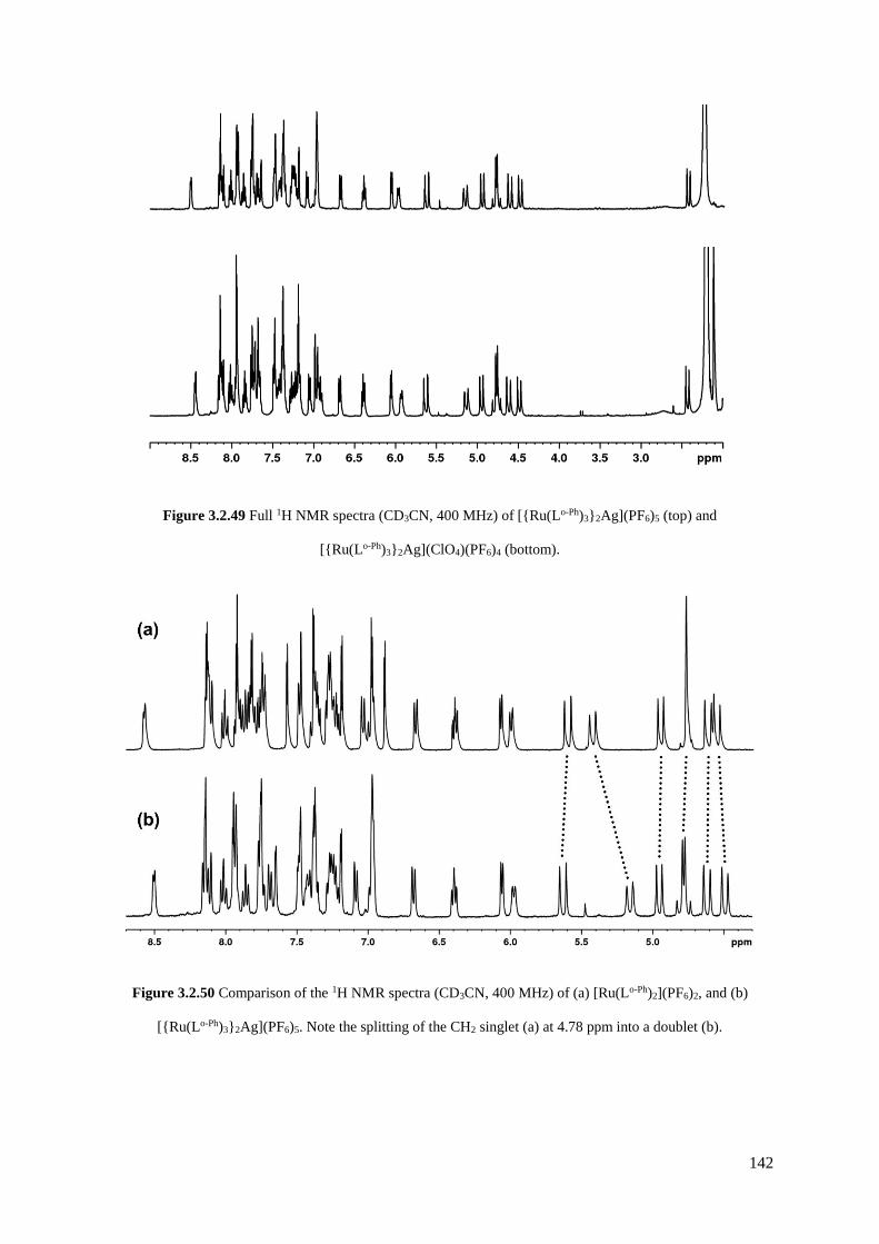
142
Figure 3.2.49 Full 1H NMR spectra (CD3CN, 400 MHz) of [{Ru(Lo-Ph)3}2Ag](PF6)5 (top) and
[{Ru(Lo-Ph)3}2Ag](ClO4)(PF6)4 (bottom).
Figure 3.2.50 Comparison of the 1H NMR spectra (CD3CN, 400 MHz) of (a) [Ru(Lo-Ph)2](PF6)2, and (b)
[{Ru(Lo-Ph)3}2Ag](PF6)5. Note the splitting of the CH2 singlet (a) at 4.78 ppm into a doublet (b).
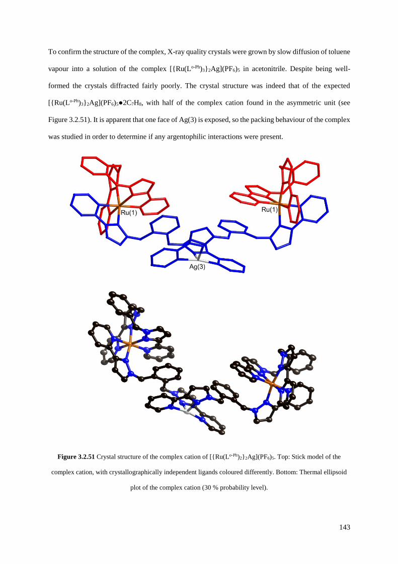
143
To confirm the structure of the complex, X-ray quality crystals were grown by slow diffusion of toluene
vapour into a solution of the complex [{Ru(Lo-Ph)3}2Ag](PF6)5 in acetonitrile. Despite being well-
formed the crystals diffracted fairly poorly. The crystal structure was indeed that of the expected
[{Ru(Lo-Ph)3}2Ag](PF6)5●2C7H8, with half of the complex cation found in the asymmetric unit (see
Figure 3.2.51). It is apparent that one face of Ag(3) is exposed, so the packing behaviour of the complex
was studied in order to determine if any argentophilic interactions were present.
Figure 3.2.51 Crystal structure of the complex cation of [{Ru(Lo-Ph)2}2Ag](PF6)5. Top: Stick model of the
complex cation, with crystallographically independent ligands coloured differently. Bottom: Thermal ellipsoid
plot of the complex cation (30 % probability level).

144
The trinuclear complex is found to assemble into a nonanuclear structure in the solid state, in which
three separate complexes are closely packed together, stabilised by three six-tiered -stacks lining the
exterior of the assembly made up of PyPz and phenylene groups (see Figure 3.2.52). The Ag•••Ag
separation between each of the three strands is 4.85 Å, a distance much larger than the sum of the van
der Waals’ radii for two Ag(I) ions, so there is clearly no argentophilic interaction present in this
structure. However, the metal ions are still held quite closely together, so it should be likely that there
is another stabilising factor in the formation of this assembly; this is provided by CH•••F hydrogen-
bonding interactions between the complex and two disordered PF6- anions [closest contact
F(53’)•••H(15A) = 2.19 Å], which bind in the ‘pockets’ provided by the hourglass shaped assembly in
close proximity to the metal centres [F(51) – Ag(3) separation 5.34 Å] (see Figure 3.2.53). A view down
the c-axis emphasises the three-fold rotational symmetry of the complex and the anions which lie on
the axis (see Figure 3.2.54).
Figure 3.2.52 Two views of the second level of self-assembly within the crystal structure of [{Ru(Lo-Ph)2}2Ag]-
(PF6)5. Left: Three [{Ru(Lo-Ph)2}2Ag]5+ strands (coloured differently) closely assemble. Right: View from a
similar perspective showing one of the three 6-tiered -stacks which stabilise the close proximity of the three
strands.

145
Figure 3.2.53 Two views of the crystal structure of [{Ru(Lo-Ph)2}2Ag](PF6)5. Top: A view highlighting the
interaction of two PF6 molecules with the nonanuclear array, with the PF6 molecules and silver atoms shown in
space-filling mode; (bottom) space-filling mode view from the same perspective.

146
Figure 3.2.54 View down the c axis in the crystal structure of [{Ru(Lo-Ph)2}2Ag](PF6)5, emphasising the three-
fold rotational symmetry of the complex and guest anions.
Evidence that this nonanuclear assembly persists in solution to some extent was provided by the
electrospray mass spectrum (see Figure 3.2.55). The spectrum is dominated by peaks for the
mononuclear [Ru(Lo-Ph)2(PF6)]+ (m/z 1031) and the trinuclear {[{Ru(Lo-Ph)2}2Ag](PF6)5-n}n+ (m/z 723,
1157; n = 3 and 2, respectively). A peak at m/z 2460 can be attributable to either the trinuclear or
nonanuclear assemblies, but the peak at m/z 1809 can only be attributed to {[{Ru(Lo-Ph)2}6Ag3]-
(PF6)11}4+ (see Figure 3.2.55c). Thus the -stacking and interactions of the anions with the well-matched
pockets in the structure observed in the solid state are strong enough to allow the assembly to be held
together in solution, without any coordinative interactions.
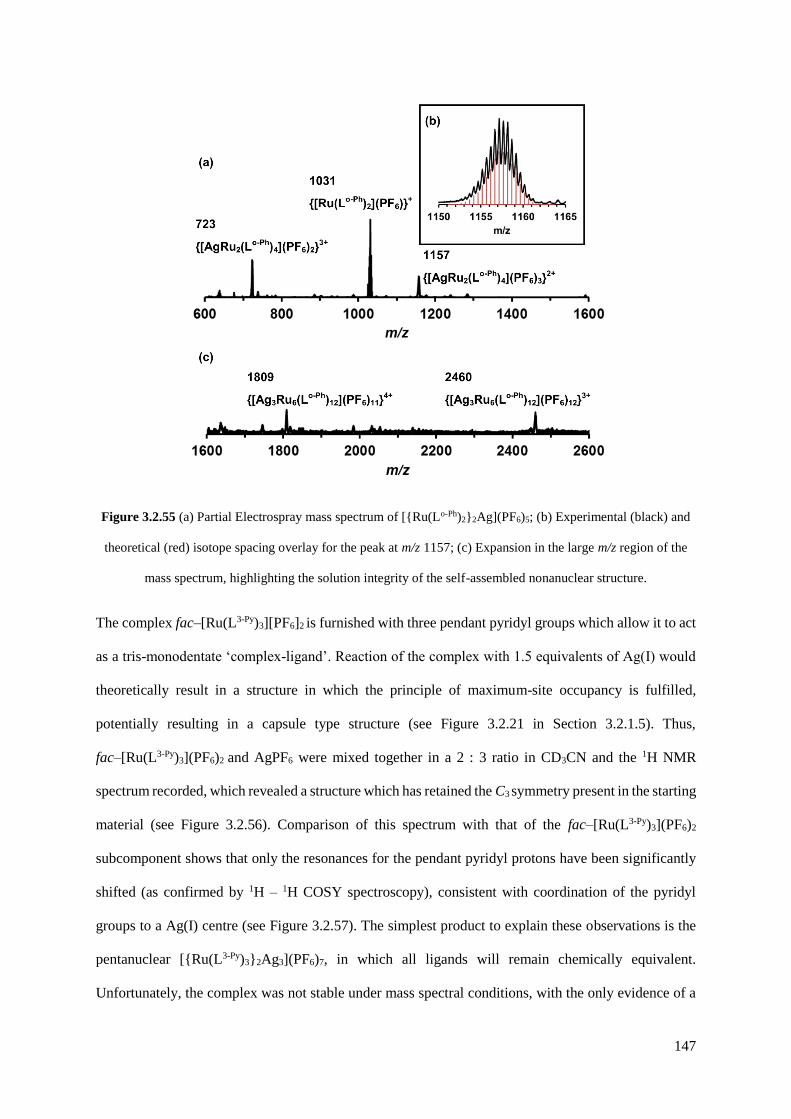
147
Figure 3.2.55 (a) Partial Electrospray mass spectrum of [{Ru(Lo-Ph)2}2Ag](PF6)5; (b) Experimental (black) and
theoretical (red) isotope spacing overlay for the peak at m/z 1157; (c) Expansion in the large m/z region of the
mass spectrum, highlighting the solution integrity of the self-assembled nonanuclear structure.
The complex fac–[Ru(L3-Py)3][PF6]2 is furnished with three pendant pyridyl groups which allow it to act
as a tris-monodentate ‘complex-ligand’. Reaction of the complex with 1.5 equivalents of Ag(I) would
theoretically result in a structure in which the principle of maximum-site occupancy is fulfilled,
potentially resulting in a capsule type structure (see Figure 3.2.21 in Section 3.2.1.5). Thus,
fac–[Ru(L3-Py)3](PF6)2 and AgPF6 were mixed together in a 2 : 3 ratio in CD3CN and the 1H NMR
spectrum recorded, which revealed a structure which has retained the C3 symmetry present in the starting
material (see Figure 3.2.56). Comparison of this spectrum with that of the fac–[Ru(L3-Py)3](PF6)2
subcomponent shows that only the resonances for the pendant pyridyl protons have been significantly
shifted (as confirmed by 1H – 1H COSY spectroscopy), consistent with coordination of the pyridyl
groups to a Ag(I) centre (see Figure 3.2.57). The simplest product to explain these observations is the
pentanuclear [{Ru(L3-Py)3}2Ag3](PF6)7, in which all ligands will remain chemically equivalent.
Unfortunately, the complex was not stable under mass spectral conditions, with the only evidence of a
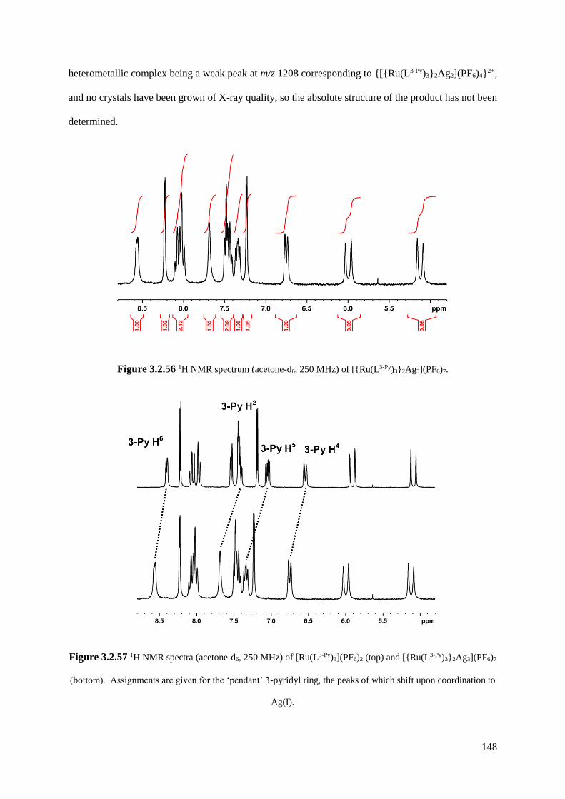
148
heterometallic complex being a weak peak at m/z 1208 corresponding to {[{Ru(L3-Py)3}2Ag2](PF6)4}2+,
and no crystals have been grown of X-ray quality, so the absolute structure of the product has not been
determined.
Figure 3.2.56 1H NMR spectrum (acetone-d6, 250 MHz) of [{Ru(L3-Py)3}2Ag3](PF6)7.
Figure 3.2.57 1H NMR spectra (acetone-d6, 250 MHz) of [Ru(L3-Py)3](PF6)2 (top) and [{Ru(L3-Py)3}2Ag3](PF6)7
(bottom). Assignments are given for the ‘pendant’ 3-pyridyl ring, the peaks of which shift upon coordination to
Ag(I).

149
3.3 Conclusion
A series of mononuclear Ru(II) complexes with pendant binding sites have been synthesised, either as
a mixture of mer/fac isomers or purely the fac isomer, and these have been used to propagate the
formation of supramolecular heterometallic arrays by combination with secondary metal ions.
The kinetically inert mononuclear complex [Ru(L1,5-nap)3](PF6)2 (1 : 3 mixture of fac and mer isomers),
with three pendant binding sites, reacts with labile Cd(II) ions to complete the assembly of a Ru4Cd4
cubic coordination cage in which reversible redox behaviour has been introduced at the Ru(II) sites.
The complex [Ru(Lm-Ph)3](PF6)2 (1 : 7 mixture of fac and mer isomers) reacts with labile Co(II) ions to
complete the assembly of a Ru4Co4 cubic coordination cage which exhibits a metal framework that is
different from that of the homonuclear cage, and is one that has not been seen previously. The crystal
structure revealed that this cage forms around a [Na(BF4)4]3- self-assembled core, such that the self-
assembly requires three ‘layers’.
The geometrically pure ‘complex ligand’ fac-[Ru(Lp-Ph)3]2+, in which the three pendant bidentate
binding sites are located on one face of the complex, reacts with Ag(I) ions to form the adamantoid
decanuclear cage [{Ru(Lp-Ph)3}4Ag6](PF6)14 which contains a 6-coordinate Ru(II) ion at each vertex of
a large tetrahedron and a 4-coordinate Ag(I) ion along each edge. The complex ligand also reacts with
Cd(II) and additional L1,4-nap to form a Ru4Cd12L24 assembly over a period of two months, which is stable
under mass spectral conditions.
The mono-bidentate ‘complex ligand’ [Ru(Lo-Ph)2]2+ reacts with Ag(I) ions to form a simple tri-nuclear
complex cation, which further self-assembles into a nonanuclear non-coordinatively bonded structure
via extensive -stacking and hydrogen-bonding interactions with the bound anions.

150
3.4 Experimental
Metal salts and all organic reagents were purchased from Alfa or Sigma-Aldrich and used as received.
NMR spectra were recorded on Bruker DRX 500 MHz, Bruker AV-III 400 MHz or AV-1 800 MHz
instruments. Electrospray mass spectra were recorded on a Micromass LCT instrument. UV/Vis
absorption spectra were measured on a Cary 50 spectrophotometer.
Cyclic voltammetric measurements were performed with an Ecochimie Autolab 100 potentiostat using
a conventional three-electrode cell with a Pt disc working electrode and Ag/AgCl electrode as reference;
the base electrolyte was 0.1 M Bu4NPF6 and the solvent was MeCN (purified by distillation over CaH2).
Ferrocene was added at the end of each experiment as an internal standard and all potentials are quoted
vs the ferrocene/ferricinium couple (Fc/Fc+).
3.4.1 Ligand Synthesis
3-(2-pyridyl)pyrazole, Lo-Ph, Lm-Ph, Lp-Ph, L1,5-nap, L3,3-Bi and L1,4-nap were prepared following the literature
procedures.28,32,51,67,69-71
Synthesis of Intp-Ph
A mixture of 1,4-bis(bromomethyl)benzene (1.5 g, 3.68 mmol), 3-(2-pyridyl)pyrazole (0.4 g, 2.75
mmol), tetrahydrofuran (THF, 70 cm3) and aqueous NaOH (7.5 M, 10 cm3) was stirred at 40oC for 1
hour. The resultant yellow solution was diluted with H2O (100 cm3) and the organic layer separated,
dried over MgSO4 and concentrated before purification by column chromatography on alumina (20 %
hexane / dichloromethane) to give Intp-Ph as a white solid (Yield: 0.20 g, 22.2%). 1H-NMR (400 MHz,
CDCl3): 8.66 (1H, ddd; pyridyl H6), 7.96 (1H, d; pyridyl H3), 7.74 (1H, td; pyridyl H4), 7.45 (1H, d;

151
pyrazolyl H5), 7.42–7.37 (2H, m; phenyl), 7.27–7.20 (3H, m; 2 x phenyl, and pyridyl H5), 6.93 (1H, d;
pyrazolyl H4), 5.42 (2H, s; CH2- pz), 4.50 (2H, s, CH2Br). EI MS: m/z 327 (M+). Found: C, 56.3; H,
4.3; N, 11.9%: Required for C16H14N3Br: C, 56.9; H, 4.5; N, 12.5%. Data is in accordance with the
literature.72
3.4.2 Mononuclear complex synthesis
Ru(DMSO)4Cl2 was prepared by the literature method;73 mix-, mer- and fac-[Ru(PyPzH)3](PF6)2 , and
mer and fac- [Ru(LMe)3](PF6)2 were made by the method detailed in Chapter 2.47
Synthesis of mix-[Ru(Lp-Ph)3](PF6)2
A mixture of Lp-Ph (0.41 g, 1.0 mmol), RuCl2(DMSO)4 (0.10g, 0.2 mmol), ethanol (48 cm3) and water
(12 cm3) were heated to reflux with stirring for 4 h. After cooling the red mixture, excess ligand was
removed by washing with chloroform. Addition of saturated KPF6 (aq) afforded a yellow precipitate,
which was collected by filtration and washed with diethyl ether and water (1:5 mixture of fac and mer
isomers). Yield: 0.24 g, 77.7%. ESMS m/z 1423 (M - PF6-)+, 639 (M - 2PF6
-)2+. Found: C, 54.2; H, 4.2;
N, 15.7%. Required for C72H60N18P2F12Ru•H2O: C, 54.5; H, 3.9; N, 15.9%.
Synthesis of mix-[Ru(L1,5 nap)3](PF6)2
A solution of L1,5-nap (0.20 g, 0.45 mmol, 5.4 eq) was stirred rapidly in refluxing ethylene glycol (40
cm3) until dissolved. To this was added a solution of RuCl2(dmso)4 (0.04 g, 0.08 mmol) in H2O /
ethylene glycol (12 : 1, 65 cm3) by dropping funnel over 3 hours, and then the orange mixture was
stirred at reflux in the dark for 14 h. The solution was cooled to 25 oC and excess saturated KPF6 (aq)
was added. The product was extracted with dichloromethane, dried over MgSO4 and evaporated to
dryness. The product was purified by column chromatography on silica. Elution with MeCN–water–
saturated aqueous KNO3 (100 : 10 : 1) resulted in a broad yellow band moving down the column which
was collected. After removing acetonitrile by rotary evaporation, excess saturated aqueous KPF6 was
added and the product was extracted from the suspension into dichloromethane. The organic layer was
separated, dried over MgSO4, and the solvent removed in vacuo to yield [Ru(L1,5-nap)3](PF6)2 as a yellow

152
solid (1:3 mixture of fac and mer isomers which were not separated). Yield: 0.11 g, 77 %. ESMS: m/z
1573 (M − PF6)+, 714 (M − 2PF6)2+. Found: C, 56.7; H, 4.1; N, 13.7. C84H66F12N18P2Ru•4H2O requires
C, 56.3; H, 4.2; N, 14.1%. UV/Vis in MeCN [λmax/nm (10−3ε / M−1 cm−1)]: 398 (16.6), 282 (103.1), 226
(196.0).
Synthesis of mix-[Ru(Lm-Ph)3](PF6)2
A solution of Lm-Ph (0.30 g, 0.76 mmol, 6.9 eq) in ethanol (100 cm3) and H2O (20 cm3) was stirred under
reflux until fully dissolved. To this was added a solution of RuCl2(dmso)4 (0.05 g, 0.11 mmol) in ethanol
/ H2O (7 : 5, 60 cm3) by dropping funnel over 3 hours, and then the yellow mixture was stirred at reflux
in the dark for 14 h. After cooling the red mixture and diluting with H2O, excess ligand was removed
by washing with chloroform. Addition of saturated KPF6 (aq) afforded a yellow precipitate, which was
purified by column chromatography on silica. Elution with MeCN–water–saturated aqueous KNO3 (100
: 10 : 1) resulted in a broad yellow band moving down the column which was collected. After removing
acetonitrile by rotary evaporation, excess saturated aqueous KPF6 was added and the product was
extracted from the suspension into dichloromethane. The organic layer was separated, dried over
MgSO4, and the solvent removed in vacuo to yield [Ru(Lm-Ph)3](PF6)2 as a yellow solid (1:7 mixture of
fac and mer isomers). Yield: 0.24 g, 77.7%. ESMS m/z 1423 (M+ - PF6-), 639 (M2+ - 2PF6
-). Found: C,
54.7; H, 4.1; N, 15.8%. Required for C72H60N18P2F12Ru: C, 55.1; H, 3.9; N, 16.1%.
Synthesis of [Ru(Lo-Ph)2](PF6)2
A mixture of Lo-Ph (0.60 g, 1.52 mmol, 6 eq) in EtOH/H2O (5 : 1, 60 cm3) was heated to reflux until the
ligand had dissolved. A solution of RuCl2(dmso)4 (0.12 g, 0.25 mmol) in in EtOH/H2O (1 : 1, 10 cm3)
was then added dropwise over 2 h, and the clear orange mixture was stirred under reflux in the dark for
16 h. After cooling to room temperature the solvent was removed by rotary evaporation and the resultant
crude yellow solid was partitioned between H2O and CHCl3. The aqueous layer was collected, and
excess saturated aqueous KPF6 was added to precipitate the product, before purification of the yellow
solid by column chromatography on silica. Elution with MeCN–water–saturated aqueous KNO3 (100 :
10 : 2) resulted in a single yellow band moving down the column which was collected. After removing

153
acetonitrile by rotary evaporation, excess saturated aqueous KPF6 was added and the product was
extracted from the suspension into dichloromethane. The organic layer was separated, dried over
MgSO4, and the solvent removed in vacuo to yield [Ru(Lo-Ph)2](PF6)2 as a yellow solid. Slow diffusion
of di-ethyl ether vapour into a solution of the complex in acetone/nitromethane afforded the product as
yellow shards. Yield: 0.20 g, 68 %. 1H NMR (400 MHz, CD3CN): δ 8.57 (1H, d, J = 4.9 Hz), δ 8.16 –
8.06 (3H, m), δ 8.01 (1H, td, J = 7.9, 1.4 Hz), δ 7.95 – 7.69 (8H, m), δ 7.57 (1H, d, J = 2.3 Hz; pyrazolyl),
δ 7.48 (2H, d, J = 6.7 Hz), δ 7.42 – 7.31 (3H, m), δ 7.31 – 7.20 (4H, m), δ 7.19 (1H, d, J = 2.9 Hz;
pyrazolyl), δ 7.04 (1H, d, J = 7.7 Hz), δ 7.01 – 6.94 (2H, m), δ 6.89 (1H, d, J = 2.3 Hz; pyrazolyl), δ
6.67 (1H, d, J = 7.9 Hz), δ 6.39 (1H, ddd, J = 7.9, 5.6, 1.4 Hz), δ 6.08 (1H, d, J = 5.6 Hz), δ 6.00 (1H,
d, J = 7.7 Hz), δ 5.60 (1H, d, J = 18.4 Hz; CH2), δ 5.43 (1H, d, J = 17.0 Hz; CH2), δ 4.95 (1H, d, J =
15.7 Hz; CH2), δ 4.77 (2H, s, 2 x CH2), δ 4.62 (1H, d, J = 18.4 Hz; CH2), δ 4.55 (1H, d, J = 17.0 Hz;
CH2), δ 2.47 (1H, d, J = 15.7 Hz; CH2). ESMS: m/z 1032 (M − PF6)+, 443 (M − 2PF6)2+. Found: C, 48.6;
H, 3.8; N, 13.8. C48H40F12N12P2Ru•H2O requires C, 48.3; H, 3.6; N, 14.1%. UV/Vis in MeCN [λmax/nm
(10−3 ε/M−1 cm−1)]: 399 (13.4), 282 (60.9), 243 (52.0).
Synthesis of fac-[Ru(Lp-Ph)3](PF6)2
A mixture of fac-[Ru(PyPzH)3](PF6)2 (0.05 g, 0.05 mmol) and Intp-Ph (0.11 g, 0.33 mmol), Cs2CO3 (0.15
g, 0.46 mmol), Bu4NI (0.10 g, 0.27 mmol) and CH2Cl2 (20 cm3) was heated to reflux in the dark with
stirring for 48 h. After cooling to room temperature, excess Cs2CO3 was filtered off and the solvent
removed by rotary evaporation, before purification of the yellow solid by column chromatography on
silica by elution with MeCN–water–saturated aqueous KNO3 (100:10:5 ratio by volume). After
removing acetonitrile by rotary evaporation, excess saturated aqueous KPF6 was added and the product
was extracted from the suspension into dichloromethane. The organic layer was separated, dried over
MgSO4, and the solvent removed in vacuo to yield fac–[Ru(Lp-Ph)3][PF6]2 as a yellow solid in 68% yield.
Slow diffusion of di-isopropyl ether vapour into a solution of the complex in acetone afforded the
product as yellow needles. 1H NMR (400 MHz, CD3CN): δ 8.58 (1H, ddd, J = 4.7, 1.8, 0.8 Hz; pendant
pyridyl H6), 8.00 (1H, td, J = 8.0, 1.0 Hz; pendant pyridyl H3), 7.83 (1H, d, J = 2.2 Hz; pendant
pyrazolyl), 7.79 (1H, td, J = 7.8, 1.8 Hz; pendant pyridyl H4), 7.71 (1H, d, J = 2.9 Hz; coordinated
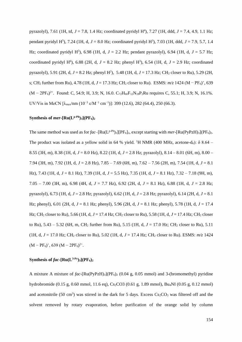
154
pyrazolyl), 7.61 (1H, td, J = 7.8, 1.4 Hz; coordinated pyridyl H4), 7.27 (1H, ddd, J = 7.4, 4.9, 1.1 Hz;
pendant pyridyl H5), 7.24 (1H, d, J = 8.0 Hz; coordinated pyridyl H3), 7.03 (1H, ddd, J = 7.9, 5.7, 1.4
Hz; coordinated pyridyl H5), 6.98 (1H, d, J = 2.2 Hz; pendant pyrazolyl), 6.94 (1H, d, J = 5.7 Hz;
coordinated pyridyl H6), 6.88 (2H, d, J = 8.2 Hz; phenyl H3), 6.54 (1H, d, J = 2.9 Hz; coordinated
pyrazolyl), 5.91 (2H, d, J = 8.2 Hz; phenyl H2), 5.48 (1H, d, J = 17.3 Hz; CH2 closer to Ru), 5.29 (2H,
s; CH2 further from Ru), 4.78 (1H, d, J = 17.3 Hz; CH2 closer to Ru). ESMS: m/z 1424 (M − PF6)+, 639
(M − 2PF6)2+. Found: C, 54.9; H, 3.9; N, 16.0. C72H60F12N18P2Ru requires C, 55.1; H, 3.9; N, 16.1%.
UV/Vis in MeCN [λmax/nm (10−3 ε/M−1 cm−1)]: 399 (12.6), 282 (64.4), 250 (66.3).
Synthesis of mer-[Ru(Lp-Ph)3](PF6)2
The same method was used as for fac–[Ru(Lp-Ph)3][PF6]2, except starting with mer-[Ru(PyPzH)3](PF6)2.
The product was isolated as a yellow solid in 64 % yield. 1H NMR (400 MHz, acetone-d6): δ 8.64 –
8.55 (3H, m), 8.38 (1H, d, J = 8.0 Hz), 8.22 (1H, d, J = 2.8 Hz; pyrazolyl), 8.14 – 8.01 (6H, m), 8.00 –
7.94 (3H, m), 7.92 (1H, d, J = 2.8 Hz), 7.85 – 7.69 (6H, m), 7.62 – 7.56 (2H, m), 7.54 (1H, d, J = 8.1
Hz), 7.43 (1H, d, J = 8.1 Hz), 7.39 (1H, d, J = 5.5 Hz), 7.35 (1H, d, J = 8.1 Hz), 7.32 – 7.18 (9H, m),
7.05 – 7.00 (3H, m), 6.98 (4H, d, J = 7.7 Hz), 6.92 (2H, d, J = 8.1 Hz), 6.88 (1H, d, J = 2.8 Hz;
pyrazolyl), 6.73 (1H, d, J = 2.8 Hz; pyrazolyl), 6.62 (1H, d, J = 2.8 Hz; pyrazolyl), 6.14 (2H, d, J = 8.1
Hz; phenyl), 6.01 (2H, d, J = 8.1 Hz; phenyl), 5.96 (2H, d, J = 8.1 Hz; phenyl), 5.78 (1H, d, J = 17.4
Hz; CH2 closer to Ru), 5.66 (1H, d, J = 17.4 Hz; CH2 closer to Ru), 5.58 (1H, d, J = 17.4 Hz; CH2 closer
to Ru), 5.43 – 5.32 (6H, m, CH2 further from Ru), 5.15 (1H, d, J = 17.0 Hz; CH2 closer to Ru), 5.11
(1H, d, J = 17.0 Hz; CH2 closer to Ru), 5.02 (1H, d, J = 17.4 Hz; CH2 closer to Ru). ESMS: m/z 1424
(M − PF6)+, 639 (M − 2PF6)2+.
Synthesis of fac-[Ru(L3-Py)3](PF6)2
A mixture A mixture of fac-[Ru(PyPzH)3](PF6)2 (0.04 g, 0.05 mmol) and 3-(bromomethyl) pyridine
hydrobromide (0.15 g, 0.60 mmol, 11.6 eq), Cs2CO3 (0.61 g, 1.89 mmol), Bu4NI (0.05 g, 0.12 mmol)
and acetonitrile (50 cm3) was stirred in the dark for 5 days. Excess Cs2CO3 was filtered off and the
solvent removed by rotary evaporation, before purification of the orange solid by column
155
chromatography on silica by elution with MeCN–water–saturated aqueous KNO3 (100:10:10 ratio by
volume); the second major yellow band was collected. After removing acetonitrile by rotary
evaporation, excess saturated aqueous KPF6 was added and the product was extracted from the
suspension into dichloromethane. The organic layer was separated, dried over MgSO4, and the solvent
removed in vacuo to yield fac–[Ru(L3-Py)3][PF6]2 as a yellow solid in 47% yield. Slow diffusion of di-
isopropyl ether vapour into a solution of the complex in acetone afforded the product as yellow needles.
1H NMR (250 MHz, acetone-d6): δ 8.40 (1H, dd, J = 4.7, 0.9 Hz; pendant pyridyl H6), 8.22 (1H, d, J =
3.0 Hz; pyrazolyl), 8.06 (1H, td, J = 7.8, 1.4 Hz; coordinated pyridyl H5), 7.97 (1H, ddd, J = 7.8, 1.4,
0.7 Hz; coordinated pyridyl H6), 7.54 (1H, d, J = 5.7 Hz; coordinated pyridyl H3), 7.47 – 7.38 (2H, m;
pendant pyridyl H2 and coordinated pyridyl H4), 7.19 (1H, d, J = 3.0 Hz; pyrazolyl), 7.05 (1H, dd, J =
7.9, 4.7 Hz; pendant pyridyl H5), 6.54 (1H, d, J = 7.9 Hz; pendant pyridyl H4), 5.90 (1H, d, J = 17.3 Hz;
CH2), 5.09 (1H, d, J = 17.3 Hz; CH2). ESMS: m/z 956 (M − PF6)+, 405 (M − 2PF6)2+. Found: C, 44.5;
H, 3.1; N, 14.6. C42H36F12N12P2Ru●0.5CH2Cl2 requires C, 44.7; H, 3.3; N, 14.7%. UV/Vis in MeCN
[λmax/nm (10−3 ε/M−1 cm−1)]: 398 (15.6), 281 (55.1), 241 (42.9).
3.4.3 Cage synthesis
[Cd3L1-4-nap3](BF4)6 was prepared by the literature method.29
Synthesis of [Ru4Cd4(L1,5-nap)12](ClO4)16
To a stirred solution of [Ru(L1,5-nap)3](PF6)2 (0.038 g, 0.022 mmol) in nitromethane (20 cm3) was added
an excess of Cd(ClO4)2.6H2O (0.091 g, 0.217 mmol) causing a colour change from yellow to orange.
After an overnight stir, the mixture was passed through a membrane filter and then precipitated with di-
isopropyl ether. The light orange solid was collected by filtration and washed thoroughly with
diisopropyl ether. X-ray quality crystals were grown by slow diffusion of di-isopropyl ether into a
solution of the complex in nitromethane. Yield: 0.032 g, 75 %. ESMS: m/z 1839 (M – 4ClO4)4+, 1451
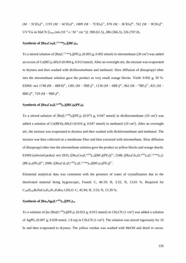
156
(M − 5ClO4)5+, 1193 (M − 6ClO4)6+, 1009 (M − 7ClO4)7+, 870 (M − 8ClO4)8+, 762 (M − 9ClO4)9+.
UV/Vis in MeCN [λmax/nm (10−3 ε / M−1 cm−1)]: 398 (61.5), 286 (366.3), 226 (707.0).
Synthesis of [Ru4Co4(L1,5-nap)12](BF4)16
To a stirred solution of [Ru(L1,5-nap)3](PF6)2 (0.003 g, 0.002 mmol) in nitromethane (20 cm3) was added
an excess of Co(BF4)2.6H2O (0.004 g, 0.013 mmol). After an overnight stir, the mixture was evaporated
to dryness and then washed with dichloromethane and methanol. Slow diffusion of diisopropyl ether
into the nitromethane solution gave the product as very small orange blocks. Yield: 0.002 g, 50 %.
ESMS: m/z 1748 (M – 4BF4)4+, 1381 (M − 5BF4)5+, 1136 (M − 6BF4)6+, 962 (M − 7BF4)7+, 831 (M −
8BF4)8+, 729 (M − 9BF4)9+.
Synthesis of [Ru4Co4(Lm-Ph)12](BF4)8(PF6)8
To a stirred solution of [Ru(Lm-Ph)3](PF6)2 (0.073 g, 0.047 mmol) in dichloromethane (10 cm3) was
added a solution of Co(BF4)2.6H2O (0.016 g, 0.047 mmol) in methanol (10 cm3). After an overnight
stir, the mixture was evaporated to dryness and then washed with dichloromethane and methanol. The
mixture was then collected on a membrane filter and then extracted with nitromethane. Slow diffusion
of diisopropyl ether into the nitromethane solution gave the product as yellow blocks and orange shards.
ESMS (selected peaks): m/z 2835, ([Ru4Co4(Lm-Ph)12](BF4)(PF6))5+; 2348, ([Ru4Cd12(Lp-Ph)12(L1,4-nap)12]-
(BF4)25(PF6))6+; 2000, ([Ru4Cd12(Lp-Ph)12(L1,4-nap)12](BF4)24(PF6))7+.
Elemental analytical data was consistent with the presence of water of crystallisation due to the
desolvated material being hygroscopic, Found: C, 46.19; H, 3.55; N, 13.03 %. Required for
C288H240B9NaCo4F84N72P8Ru4.12H2O: C, 45.94; H, 3.53; N, 13.39 %.
Synthesis of [Ru4Ag6(Lp-Ph)12](PF6)14
To a solution of fac-[Ru(Lp-Ph)3](PF6)2 (0.023 g, 0.015 mmol) in CH3CN (1 cm3) was added a solution
of AgPF6 (0.007 g, 0.028 mmol, 1.8 eq) in CH3CN (1 cm3). The solution was mixed vigorously for 16
hr and then evaporated to dryness. The yellow residue was washed with MeOH and dried in vacuo.

157
Slow diffusion of di-isopropyl ether vapour into a solution of the complex in acetonitrile afforded the
product as yellow blocks.
ESMS: m/z 2452 {(Ru4Ag6(Lp-Ph)12)(PF6)11}3+; 1803 {(Ru4Ag6(Lp-Ph)12)(PF6)10}4+; 1678
{(RuAg(Lp-Ph)3)(PF6)}+; 1154 {(Ru4Ag6(Lp-Ph)12)(PF6)8}6+; 892 {(RuAg2(Lp-Ph)3)(PF6)2}2+; 546
{(RuAg2(Lp-Ph)3)(PF6)}3+. The vacuum-dried material gave elemental analyses consistent with
absorption of large numbers of H2O molecules. Anal. Calcd for [Ru4Ag6(Lp-Ph)12](PF6)14•9H2O: C, 43.5;
H, 3.3; N, 12.7%. Found: C, 43.8; H, 3.6; N, 12.8%. Yield based on this formulation: ca. 80%.
Synthesis of [Ru4Cd12(Lp-Ph)12(L1,4-nap)12](PF6)n-32(BF4)32-n
A Teflon lined autoclave was charged with [Cd3L1-4-nap3](BF4)6 (11 mg, 0.005 mmol), [Ru(Lp-Ph)3](PF6)2
(7 mg, 0.005 mmol) and acetonitrile (10 cm3). Heating to 180 °C for twelve hours followed by slow
cooling to room temperature yielded a yellow solid which was recrystallised by slow diffusion of
diisopropyl ether into a solution of the complex in acetonitrile. (Yield: 16 mg, 0.004 mmol, 80 %).
ESMS (selected peaks): m/z 2835, ([Ru4Cd12(Lp-Ph)12(L1,4-nap)12](BF4)26(PF6))5+; 2348,
([Ru4Cd12(Lp-Ph)12(L1,4-nap)12](BF4)25(PF6))6+; 2000, ([Ru4Cd12(Lp-Ph)12(L1,4-nap)12](BF4)24(PF6))7+.
Synthesis of [Ag{Ru(Lo-Ph)2}2](PF6)5
A solution of AgPF6 (0.004 g, 0.015 mmol) in MeOH (5 cm3) was added to a stirring solution of [Ru(Lo-
Ph)2](PF6)2 (0.030 g, 0.026 mmol) in DCM (5 cm3) and the mixture was stirred in the dark for 16 h. The
solvent was removed by rotary evaporation to yield a crude yellow solid. Slow diffusion of toluene
vapour into a solution of the complex in acetonitrile afforded the product as yellow blocks. Yield:
0.027 g, 73 %. ESMS: m/z 2460 {[Ru6Ag3(Lo-Ph)12](PF6)12}3+; 1809 {[Ru6Ag3(Lo-Ph)12](PF6)11}4+; 1592
{[Ru4Ag2(Lo-Ph)8](PF6)7}3+; 1157 {[Ru2Ag(Lo-Ph)4](PF6)3}2+; 723 {[Ru2Ag(Lo-Ph)4](PF6) 2}3+.
Synthesis of [Ag3Ru2(L3-Py)6](PF6)7
A solution of fac–[Ru(L3-Py)3][PF6]2 (0.018 g, 0.016 mmol) in acetone-d6 (0.8 cm3) was treated with
AgPF6 (0.006 g, 0.024 mmol, 1.5 eq) and the mixture was left in the dark overnight. The solvent was
removed by rotary evaporation to give the product as a yellow solid. Yield: 0.024 g, quantitative. 1H
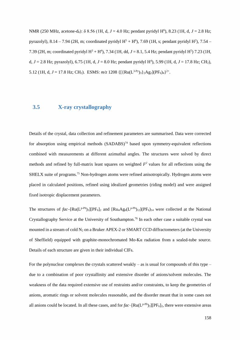
158
NMR (250 MHz, acetone-d6): δ 8.56 (1H, d, J = 4.0 Hz; pendant pyridyl H6), 8.23 (1H, d, J = 2.8 Hz;
pyrazolyl), 8.14 – 7.94 (2H, m; coordinated pyridyl H5 + H6), 7.69 (1H, s; pendant pyridyl H2), 7.54 –
7.39 (2H, m; coordinated pyridyl H3 + H4), 7.34 (1H, dd, J = 8.1, 5.4 Hz; pendant pyridyl H5) 7.23 (1H,
d, J = 2.8 Hz; pyrazolyl), 6.75 (1H, d, J = 8.0 Hz; pendant pyridyl H4), 5.99 (1H, d, J = 17.8 Hz; CH2),
5.12 (1H, d, J = 17.8 Hz; CH2). ESMS: m/z 1208 {[{Ru(L3-Py)3}2Ag2](PF6)4}2+.
3.5 X-ray crystallography
Details of the crystal, data collection and refinement parameters are summarised. Data were corrected
for absorption using empirical methods (SADABS)74 based upon symmetry-equivalent reflections
combined with measurements at different azimuthal angles. The structures were solved by direct
methods and refined by full-matrix least squares on weighted F2 values for all reflections using the
SHELX suite of programs.75 Non-hydrogen atoms were refined anisotropically. Hydrogen atoms were
placed in calculated positions, refined using idealized geometries (riding model) and were assigned
fixed isotropic displacement parameters.
The structures of fac–[Ru(Lp-Ph)3][PF6]2 and [Ru4Ag6(Lp-Ph)12](PF6)14 were collected at the National
Crystallography Service at the University of Southampton.76 In each other case a suitable crystal was
mounted in a stream of cold N2 on a Bruker APEX-2 or SMART CCD diffractometers (at the University
of Sheffield) equipped with graphite-monochromated Mo-Kα radiation from a sealed-tube source.
Details of each structure are given in their individual CIFs.
For the polynuclear complexes the crystals scattered weakly – as is usual for compounds of this type –
due to a combination of poor crystallinity and extensive disorder of anions/solvent molecules. The
weakness of the data required extensive use of restraints and/or constraints, to keep the geometries of
anions, aromatic rings or solvent molecules reasonable, and the disorder meant that in some cases not
all anions could be located. In all these cases, and for fac–[Ru(Lp-Ph)3][PF6]2, there were extensive areas
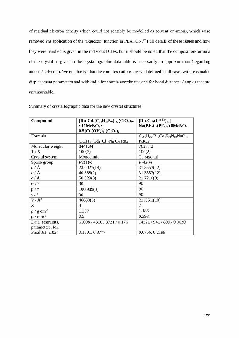
159
of residual electron density which could not sensibly be modelled as solvent or anions, which were
removed via application of the ‘Squeeze’ function in PLATON.77 Full details of these issues and how
they were handled is given in the individual CIFs, but it should be noted that the composition/formula
of the crystal as given in the crystallographic data table is necessarily an approximation (regarding
anions / solvents). We emphasise that the complex cations are well defined in all cases with reasonable
displacement parameters and with esd’s for atomic coordinates and for bond distances / angles that are
unremarkable.
Summary of crystallographic data for the new crystal structures:
Compound [Ru4Cd4(C28H22N6)12](ClO4)16
• 11MeNO2 •
0.5[Cd(OH2)6](ClO4)2
[Ru4Co4(Lm-Ph)12]
Na(BF4)12(PF6)5●8MeNO2
Formula
C347H309Cd4.5Cl17N83O96Ru4
C296H264B12Co4F78N80NaO16
P5Ru4
Molecular weight 8441.94 7627.42
T / K 100(2) 100(2)
Crystal system Monoclinic Tetragonal
Space group P2(1)/c P-421m
a / Å 23.0027(14) 31.3553(12)
b / Å 40.888(2) 31.3553(12)
c / Å 50.529(3) 21.7210(8)
/ ° 90 90
/ ° 100.989(3) 90
/ ° 90 90
V / Å3 46653(5) 21355.1(18)
Z 4 2
/ g cm-3 1.237 1.186
/ mm-1 0.5 0.398
Data, restraints,
parameters, Rint
61008 / 4310 / 3721 / 0.176 14221 / 941 / 809 / 0.0630
Final R1, wR2a 0.1301, 0.3777 0.0766, 0.2199
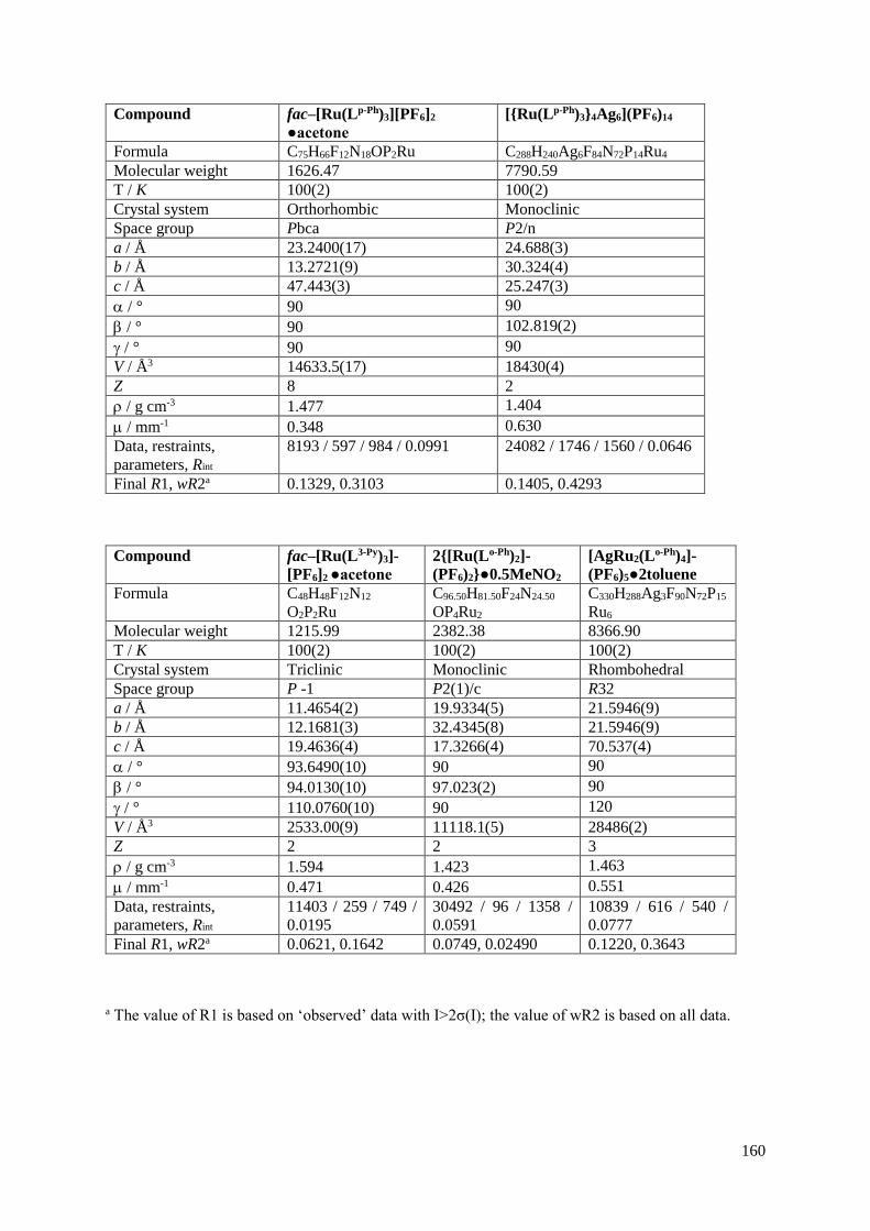
160
Compound fac–[Ru(Lp-Ph)3][PF6]2
●acetone
[{Ru(Lp-Ph)3}4Ag6](PF6)14
Formula C75H66F12N18OP2Ru C288H240Ag6F84N72P14Ru4
Molecular weight 1626.47 7790.59
T / K 100(2) 100(2)
Crystal system Orthorhombic Monoclinic
Space group Pbca P2/n
a / Å 23.2400(17) 24.688(3)
b / Å 13.2721(9) 30.324(4)
c / Å 47.443(3) 25.247(3)
/ ° 90 90
/ ° 90 102.819(2)
/ ° 90 90
V / Å3 14633.5(17) 18430(4)
Z 8 2
/ g cm-3 1.477 1.404
/ mm-1 0.348 0.630
Data, restraints,
parameters, Rint
8193 / 597 / 984 / 0.0991 24082 / 1746 / 1560 / 0.0646
Final R1, wR2a 0.1329, 0.3103 0.1405, 0.4293
Compound fac–[Ru(L3-Py)3]-
[PF6]2 ●acetone
2{[Ru(Lo-Ph)2]-
(PF6)2}●0.5MeNO2
[AgRu2(Lo-Ph)4]-
(PF6)5●2toluene
Formula C48H48F12N12
O2P2Ru
C96.50H81.50F24N24.50
OP4Ru2
C330H288Ag3F90N72P15
Ru6
Molecular weight 1215.99 2382.38 8366.90
T / K 100(2) 100(2) 100(2)
Crystal system Triclinic Monoclinic Rhombohedral
Space group P -1 P2(1)/c R32
a / Å 11.4654(2) 19.9334(5) 21.5946(9)
b / Å 12.1681(3) 32.4345(8) 21.5946(9)
c / Å 19.4636(4) 17.3266(4) 70.537(4)
/ ° 93.6490(10) 90 90
/ ° 94.0130(10) 97.023(2) 90
/ ° 110.0760(10) 90 120
V / Å3 2533.00(9) 11118.1(5) 28486(2)
Z 2 2 3
/ g cm-3 1.594 1.423 1.463
/ mm-1 0.471 0.426 0.551
Data, restraints,
parameters, Rint
11403 / 259 / 749 /
0.0195
30492 / 96 / 1358 /
0.0591
10839 / 616 / 540 /
0.0777
Final R1, wR2a 0.0621, 0.1642 0.0749, 0.02490 0.1220, 0.3643
a The value of R1 is based on ‘observed’ data with I>2σ(I); the value of wR2 is based on all data.
161
3.6 References
1. M. D. Ward and P. R. Raithby, Chem. Soc. Rev., 2013, 42, 1619.
2. M. M. J. Smulders, I. A. Riddell, C. Browne and J. R. Nitschke, Chem. Soc. Rev., 2013, 42,
1728.
3. M. Wang, V. Vajpayee, S. Shanmugaraju, Y.-R. Zheng, Z. Zhao, H. Kim, P. S. Mukherjee, K.-
W. Chi and P. J. Stang, Inorg. Chem., 2011, 50, 1506.
4. Y. Sakata, S. Hiraoka and M. Shionoya, Chem.-Eur. J., 2010, 16, 3318.
5. C. Piguet, G. Bernardinelli and G. Hopfgartner, Chem. Rev., 1997, 97, 2005.
6. O. Chepelin, J. Ujma, X. Wu, A. M. Z. Slawin, M. B. Pitak, S. J. Coles, J. Michel, A. C. Jones,
P. E. Barran and P. J. Lusby, J. Am. Chem. Soc., 2012, 134, 19334.
7. K. Suzuki, M. Tominaga, M. Kawano and M. Fujita, Chem. Commun., 2009, 1638.
8. K.-i. Yamashita, M. Kawano and M. Fujita, Chem. Commun., 2007, 4102.
9. W. J. Ramsay, T. K. Ronson, J. K. Clegg and J. R. Nitschke, Angew. Chem. Int. Ed., 2013, 52,
13439.
10. X. K. Sun, D. W. Johnson, D. L. Caulder, K. N. Raymond and E. H. Wong, J. Am. Chem. Soc.,
2001, 123, 2752.
11. S. Hiraoka, Y. Sakata and M. Shionoya, J. Am. Chem. Soc., 2008, 130, 10058.
12. H. B. Wu and Q. M. Wang, Angew. Chem. Int. Ed., 2009, 48, 7343.
13. A. J. Metherell and M. D. Ward, RSC. Adv., 2013, 3, 14281.
14. M. M. J. Smulders, A. Jimenez and J. R. Nitschke, Angew. Chem. Int. Ed., 2012, 51, 6681.
15. M. L. Saha and M. Schmittel, J. Am. Chem. Soc., 2013, 135, 17743.
16. F. Reichel, J. K. Clegg, K. Gloe, K. Gloe, J. J. Weigand, J. K. Reynolds, C.-G. Li, J. R. Aldrich-
Wright, C. J. Kepert, L. F. Lindoy, H.-C. Yao and F. Li, Inorg. Chem., 2014, 53, 688.
17. I. S. Tidmarsh, H. Fenton and M. D. Ward, Dalton Trans., 2010, 39, 3805.
18. P. de Wolf, P. Waywell, M. Hanson, S. L. Heath, A. Meijer, S. J. Teat and J. A. Thomas, Chem.-
Eur. J., 2006, 12, 2188.
19. G. Cooke, G. M. O. Maille, R. Quesada, L. S. Wang, S. Varughese and S. M. Draper, Dalton
Trans., 2011, 40, 8206.
20. N. C. Fletcher, M. Nieuwenhuyzen, R. Prabarahan and A. Wilson, Chem. Commun., 2002,
1188.

162
21. R. T. Brown, N. C. Fletcher, M. Nieuwenhuyzen and T. E. Keyes, Inorg. Chim. Acta., 2005,
358, 1079.
22. N. C. Fletcher, R. T. Brown and A. P. Doherty, Inorg. Chem., 2006, 45, 6132.
23. R. Hage, J. G. Haasnoot, J. Reedijk and J. G. Vos, Inorg. Chim. Acta., 1986, 118, 73.
24. Y. Luo, P. G. Potvin, Y. H. Tse and A. B. P. Lever, Inorg. Chem., 1996, 35, 5445.
25. M. Kyakuno, S. Oishi and H. Ishida, Inorg. Chem., 2006, 45, 3756.
26. S. Torelli, S. Delahaye, A. Hauser, G. Bernardinelli and C. Piguet, Chem.-Eur. J., 2004, 10,
3503.
27. M. D. Ward, Chem. Commun., 2009, 4487.
28. J. S. Fleming, K. L. V. Mann, C. A. Carraz, E. Psillakis, J. C. Jeffery, J. A. McCleverty and M.
D. Ward, Angew. Chem. Int. Ed., 1998, 37, 1279.
29. R. L. Paul, Z. R. Bell, J. C. Jeffery, J. A. McCleverty and M. D. Ward, Proc. Nat. Acad. Sci.
U.S.A, 2002, 99, 4883.
30. M. D. Ward, I. S. Tidmarsh, B. F. Taylor, M. J. Hardie, L. Russo and W. Clegg, New. J. Chem.,
2009, 33, 366.
31. Z. R. Bell, J. C. Jeffery, J. A. McCleverty and M. D. Ward, Angew. Chem. Int. Ed., 2002, 41,
2515.
32. I. S. Tidmarsh, T. B. Faust, H. Adams, L. P. Harding, L. Russo, W. Clegg and M. D. Ward, J.
Am. Chem. Soc., 2008, 130, 15167.
33. A. M. Najar, I. S. Tidmarsh, H. Adams and M. D. Ward, Inorg. Chem., 2009, 48, 11871.
34. B. R. Hall, L. E. Manck, I. S. Tidmarsh, A. Stephenson, B. F. Taylor, E. J. Blaikie, D. A. Vander
Griend and M. D. Ward, Dalton Trans., 2011, 40, 12132.
35. A. Stephenson, S. P. Argent, T. Riis-Johannessen, I. S. Tidmarsh and M. D. Ward, J. Am. Chem.
Soc., 2011, 133, 858.
36. Q.-H. Wei, S. P. Argent, H. Adams and M. D. Ward, New. J. Chem., 2008, 32, 73.
37. M. H. W. Lam, S. T. C. Cheung, K. M. Fung and W. T. Wong, Inorg. Chem., 1997, 36, 4618.
38. G. Canard and C. Piguet, Inorg. Chem., 2007, 46, 3511.
39. D. Ghosh, H. Ahmad and J. A. Thomas, Chem. Commun., 2009, 2947.
40. Y.-T. Chan, X. Li, J. Yu, G. A. Carri, C. N. Moorefield, G. R. Newkome and C. Wesdemiotis,
J. Am. Chem. Soc., 2011, 133, 11967.
41. L. Aboshyan-Sorgho, M. Cantuel, S. Petoud, A. Hauser and C. Piguet, Coord. Chem. Rev.,
2012, 256, 1644.

163
42. S. Turega, M. Whitehead, B. R. Hall, A. J. H. M. Meijer, C. A. Hunter and M. D. Ward, Inorg.
Chem., 2013, 52, 1122.
43. R. L. Paul, Z. R. Bell, J. S. Fleming, J. C. Jeffery, J. A. McCleverty and M. D. Ward,
Heteroatom Chem., 2002, 13, 567.
44. N. C. A. Baker, N. McGaughey, N. C. Fletcher, A. V. Chernikov, P. N. Hortonb and M. B.
Hursthouse, Dalton Trans., 2009, 965.
45. N. C. Fletcher, M. Nieuwenhuyzen and S. Rainey, J. Chem. Soc., Dalton Trans., 2001, 2641.
46. E. A. P. Armstrong, R. T. Brown, M. S. Sekwale, N. C. Fletcher, X. Q. Gong and P. Hu, Inorg.
Chem., 2004, 43, 1714.
47. A. J. Metherell, W. Cullen, A. Stephenson, C. A. Hunter and M. D. Ward, Dalton Trans., 2014,
43, 71.
48. M. Whitehead, S. Turega, A. Stephenson, C. A. Hunter and M. D. Ward, Chem. Sci., 2013, 4,
2744.
49. S. Turega, W. Cullen, M. Whitehead, C. A. Hunter and M. D. Ward, J. Am. Chem. Soc., 2014,
136, 8475.
50. Z. R. Bell, L. P. Harding and M. D. Ward, Chem. Commun., 2003, 2432.
51. S. P. Argent, H. Adams, L. P. Harding and M. D. Ward, Dalton Trans., 2006, 542.
52. B. Whittle, S. R. Batten, J. C. Jeffery, L. H. Rees and M. D. Ward, J. Chem. Soc., Dalton Trans.,
1996, 4249.
53. M. S. Lah and V. L. Pecoraro, J. Am. Chem. Soc., 1989, 111, 7258.
54. A. J. Stemmler, J. W. Kampf and V. L. Pecoraro, Inorg. Chem., 1995, 34, 2271.
55. A. J. Stemmler, A. Barwinski, M. J. Baldwin, V. Young and V. L. Pecoraro, J. Am. Chem. Soc.,
1996, 118, 11962.
56. B. R. Gibney, H. Wang, J. W. Kampf and V. L. Pecoraro, Inorg. Chem., 1996, 35, 6184.
57. A. Stephenson and M. D. Ward, Chem. Commun., 2012, 48, 3605.
58. A. Stephenson and M. D. Ward, RSC. Adv., 2012, 2, 10844.
59. J. M. Lehn and A. V. Eliseev, Science, 2001, 291, 2331.
60. F. A. Cotton, C. A. Murillo and R. M. Yu, Dalton Trans., 2005, 3161.
61. A. Stephenson, D. Sykes and M. D. Ward, Dalton Trans., 2013, 42, 6756.
62. N. Guex and M. C. Peitsch, Electrophoresis, 1997, 18, 2714.
63. L. Wang, Y. Li, Y. Peng, Z. Liang, J. Yu and R. Xu, Dalton Trans., 2012, 41, 6242.
64. X. Kuang, X. Wu, R. Yu, J. P. Donahue, J. Huang and C.-Z. Lu, Nature Chem., 2010, 2, 461.

164
65. T. Shiga, G. N. Newton, J. S. Mathieson, T. Tetsuka, M. Nihei, L. Cronin and H. Oshio, Dalton
Trans., 2010, 39, 4730.
66. T. Shiga, T. Tetsuka, K. Sakai, Y. Sekine, M. Nihei, G. N. Newton and H. Oshio, Inorg. Chem.,
2014, 53, 5899.
67. R. L. Paul, S. M. Couchman, J. C. Jeffery, J. A. McCleverty, Z. R. Reeves and M. D. Ward, J.
Chem. Soc., Dalton Trans., 2000, 845.
68. S. Turega, M. Whitehead, B. R. Hall, M. F. Haddow, C. A. Hunter and M. D. Ward, Chem.
Commun., 2012, 48, 2752.
69. A. J. Amoroso, A. M. C. Thompson, J. C. Jeffery, P. L. Jones, J. A. McCleverty and M. D.
Ward, J. Chem. Soc.-Chem. Commun., 1994, 2751.
70. S. P. Argent, H. Adams, T. Riis-Johannessen, J. C. Jeffery, L. P. Harding and M. D. Ward, J.
Am. Chem. Soc., 2006, 128, 72.
71. A. Stephenson and M. D. Ward, Dalton Trans., 2011, 40, 7824.
72. S. P. Argent, H. Adams, L. P. Harding, T. Riis-Johannessen, J. C. Jeffery and M. D. Ward,
New. J. Chem., 2005, 29, 904.
73. I. P. Evans, A. Spencer and Wilkinso.G, J. Chem. Soc., Dalton Trans., 1973, 204.
74. G. M. Sheldrick, SADABS: A program for absorption correction with the Siemens SMART
system, University of Göttingen, Germany, 1996.
75. G. M. Sheldrick, Acta Cryst. Sect. A, 2008, 64, 112.
76. S. J. Coles and P. A. Gale, Chem. Sci., 2012, 3, 683.
77. P. Vandersluis and A. L. Spek, Acta Cryst. Sect. A, 1990, 46, 194.

165
4. A tetrameric hetero-octanuclear
cyclic helicate formed from a
bridging ligand with two
inequivalent binding sites
4.1 Introduction
As discussed in Chapter 3, the synthesis of heterometallic coordination complexes is currently the
subject of intense research with the potential for very interesting and useful functional behaviour.1-5
Two methods that are used in the synthesis of heterometallic structures are described in Chapter 2; the
thermodynamic control approach, and the kinetic control approach. The research conducted using
Ru(II) focuses on the latter approach, with a kinetically inert ‘complex as ligand’6 used as the basis of
a supramolecular assembly. The Ru(II) complex functions as a pre-organised tris-bidentate
metalloligand due to its three pendant binding sites. The stepwise heterometallic complex synthesis
requires the initial isolation of the kinetically inert complex as a ‘sub-component’, before reaction with
the labile components under self-assembly conditions.
An alternative approach to the kinetic control approach is the aforementioned thermodynamic control
approach, a method which is applicable when all metal ions are sufficiently kinetically labile to allow
rearrangement. The differing coordination preferences of different metal ions are exploited using an
asymmetric bridging ligand which will have at least two different binding sites that exclusively bind to
one metal ion (see Figure 4.1.1). This system has been termed the thermodynamic control approach, as
the combination of metal ions and ligand are be able to rearrange, assembling and disassembling in such
a way that initial ‘mistakes’ are corrected, eventually resulting in a structure that represents the
thermodynamic minimum.

166
Figure 4.1.1 A schematic representation of heterometallic self-assembly using the thermodynamic control
approach. Red and blue spheres depict different kinetically labile metal ions. Red and blue rectangles represent
unsymmetrical bridging ligands.
Two different classes of unsymmetrical ligand have been used to achieve the synthesis of heterometallic
structures. The first of these consists of ligands which possess binding sites with differing denticities,
such that the affinity of each end of the ligand to bind to particular metals is primarily based on the
preferred coordination geometry of each metal. For example, Piguet and co-workers have prepared
heterometallic triple helicates which contain one transition metal ion and one lanthanide ion by using a
ligand which contains one tridentate binding site and one bidentate binding site (see Figure 4.1.2a).7
This is the only arrangement of ligands and metal ions which allows the Zn(II) ion to have its preferred
octahedral geometry, and the Eu(III) to be nine-coordinate. The Nitschke group have used
subcomponent self-assembly to form a cubic coordination cage containing six Pt(II) ions and eight
Fe(II) ions bridged by a pyridyl-bis-imine ligand (see Figure 4.1.2b); the ligand is formed in situ from
2-formyl pyridine and 4-(4-pyridyl)aniline. Again, this structure forms because each metal’s
coordination preferences are satisfied. The square planar Pt(II) ions are coordinated to four monodentate
pyridyl groups, and the octahedral Fe(II) ions are coordinated to three bientate imino-pyridyl groups.
The final example is from the Ward group, and consists of another ligand with bidentate and
monodentate binding groups (see Figure 4.1.2c). In this instance, the monodentate group is a
benzonitrile group which coordinates to pyramidal Ag(I) ions, and the bidentate group is a pyridine-
pyrazolyl (PyPz) unit which coordinates to octahedral Ni(II) ions.

167
Figure 4.1.2 Three examples of ligands with unsymmetrical denticity: (a) [EuZnL3]5+ triple helicate7; (b)
[Fe8Pt6L24]28+ cubic cage8, and; (c) [AgNiL3]3+ coordination network.9
The second class of unsymmetrical ligand used in the design of heterometallic structures is those
possessing hard and soft donor atoms at different binding sites. Recent examples in the literature where
this type of approach has been used typically rely on the differing coordination preferences of hard
donors (such as phenolates or catecholates) and soft donors (such as phosphine or pyridyl groups).
Shionoya and co-workers have utilised a ligand with a pyridyl group at one end and a catecholate at the
other, which bind to Pd(II) ions and Ti(IV) ions, respectively, to form a cage or ring, depending on the
reaction stoichiometry and reaction conditions (see Chapter 1, Figure 1.5.4).4,10 Further to this, the cage
and the ring are interconvertible with each other under appropriate conditions. For example, their
[Pd3Ti2L6Cl6]4- cage shown in Figure 1.5.4 interconverts to a [Pd2Ti2(HL2)2(acac)2Cl4] ring on addition
of TiO(acac)2 and trifluoroacetic acid.
A notable feature of Shionoya’s synthesis is that the [TiL3]2- unit can be isolated and used as a
metalloligand, a precursor to the heterometallic coordination cage. This method of using a metalloligand
to form heterometallic structures has also been used by Wang and co-workers, who used a ligand
furnished with a pyridyl and acetylacetonate binding sites to create an aluminium(III) tris-catecholate
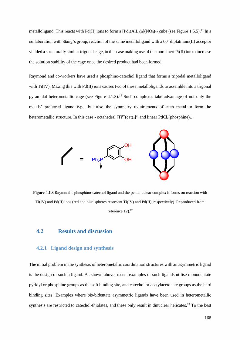
168
metalloligand. This reacts with Pd(II) ions to form a [Pd6(AlL3)8](NO3)12 cube (see Figure 1.5.5).11 In a
collaboration with Stang’s group, reaction of the same metalloligand with a 60o diplatinum(II) acceptor
yielded a structurally similar trigonal cage, in this case making use of the more inert Pt(II) ion to increase
the solution stability of the cage once the desired product had been formed.
Raymond and co-workers have used a phosphino-catechol ligand that forms a tripodal metalloligand
with Ti(IV). Mixing this with Pd(II) ions causes two of these metalloligands to assemble into a trigonal
pyramidal heterometallic cage (see Figure 4.1.3).12 Such complexes take advantage of not only the
metals’ preferred ligand type, but also the symmetry requirements of each metal to form the
heterometallic structure. In this case - octahedral [TiIV(cat)3]2- and linear PdCl2(phosphine)2.
Figure 4.1.3 Raymond’s phosphino-catechol ligand and the pentanuclear complex it forms on reaction with
Ti(IV) and Pd(II) ions (red and blue spheres represent Ti(IV) and Pd(II), respectively). Reproduced from
reference 12).12
4.2 Results and discussion
4.2.1 Ligand design and synthesis
The initial problem in the synthesis of heterometallic coordination structures with an asymmetric ligand
is the design of such a ligand. As shown above, recent examples of such ligands utilise monodentate
pyridyl or phosphine groups as the soft binding site, and catechol or acetylacetonate groups as the hard
binding sites. Examples where bis-bidentate asymmetric ligands have been used in heterometallic
synthesis are restricted to catechol-thiolates, and these only result in dinuclear helicates.13 To the best

169
of the author’s knowledge, no examples exist where a bis-bidentate asymmetric ligand has been used
to create a heterometallic cage structure with a defined cavity that may be used for host-guest chemistry.
With the idea of a bis-bidentate ligand, two binding sites became immediately obvious as candidates in
the prototype ligand; the PyPz binding site frequently used in the Ward group, and a catecholamide unit
frequently used by the Raymond group.14, 15 A prototype ligand might separate these two binding sites
with an aromatic spacer, which frequently form aromatic -stacks with the PyPz units, thus increasing
the stability of the resulting supramolecular structures.16
Both binding sites can be easily introduced into one ligand, as a simple disconnection of the 1,3-
phenylene substituted ligand reveals easily accessible synthetic equivalents (see Figure 4.2.1). The PyPz
unit can be introduced by an SN2 substitution of an alkyl bromide, whereas the catecholamide is
introduced by an amide condensation between an acid chloride and an amine.
Figure 4.2.1 Prototype asymmetric ligand H2L1,3, with two disconnections that reveal the three synthetic
building blocks.
With the simple disconnection strategy established, it is evident that there will be selectivity issues due
to the presence of many reactive functional groups in one reaction. The bromomethylaniline could
easily react with itself, and the catechol acid chloride would be difficult to prepare from the carboxylic
acid without first protecting the catechol oxygens. A synthetic route was devised that protects the aniline
group with the acid-labile butoxycarbonyl (Boc) protecting group, and the catechol was protected as
the methyl ether (see Figure 4.2.2).

170
Figure 4.2.2 Reaction scheme for the preparation of H2L1,3. (i) Boc2O, THF; (ii) CBr4, PPh3, DCM; (iii) PyPzH,
THF, NaOH(aq); (iv) TFA, DCM; (v) SOCl2, dmf; (vi) 5, DCM, Et3N; (vii) BBr3, DCM, H2O.
Starting from 3-aminobenzyl alcohol, the amine group was protected by a routine Boc protection with
Boc2O in tetrahyrofuran (THF), giving the carbamate 1 in nearly quantitative yield.17 The alcohol was
then converted to a leaving group by an Appel bromination with 1.5 equivalent of CBr4 and PPh3 in
dichloromethane (DCM) at 0 oC to give alkyl bromide 2. Once isolated by column chromatography as
a white solid, the alkyl bromide was substituted by reaction with PyPzH in THF and aqueous sodium
hydroxide at reflux to give 3. The Boc group was then removed by an overnight stir in dichloromethane
(DCM) with trifluoroacetic acid (TFA), and neutralised with potassium carbonate to give the amine 4.
The separate acid chloride 5 was prepared by refluxing the carboxylic acid in thionyl chloride with
catalytic dimethylformamide (dmf). This was then reacted with the de-protected amine 4 in dry DCM
with triethylamine in an amide condensation reaction that proceeded in excellent yield. The final step
was the deprotection of the catechol methyl ether by reaction with BBr3 in dry DCM at -78 oC followed
by solvolysis in boiling water, yielding the target ligand H2L1,3 as its HBr salt as a white solid.

171
Compounds 3, 4, 6 and H2L1,3 are new compounds and so were characterised by 1H NMR spectroscopy,
electrospray mass spectrometry (ESMS) and elemental analysis. The aromatic regions of the 1H NMR
spectra of 6 and H2L1,3 are relatively complicated with 13 closely overlapping signals; a 2D COSY
spectrum allows full assignment of these compounds (see Figure 4.2.3 for the assignment of compound
6). The demethylated ligand H2L1,3 is markedly less soluble than its precursor 6, and its 1H NMR
spectrum is shown below in deuterated dimethylsulfoxide (see Figure 4.2.4).
Figure 4.2.3 Part of the 1H COSY NMR (400 MHz, CDCl3) spectrum of 6, showing the full assignment of the
aromatic region. Py = pyridine, Pz = pyrazole, Ph = phenyl, cat = catechol.

172
Figure 4.2.4 Part of the 1H NMR (400 MHz, (CD3)2SO) spectrum of H2L1,3.HBr (Py = pyridyl; Pz = pyrazolyl).
Not shown are the NH and OH protons at > 10 ppm and the methylene protons at 5.53 ppm.
The ligand H2L1,3.HBr was recrystallised from methanol/chloroform solution by slow diffusion of
diethyl ether vapour. This resulted in the formation of very fine X-ray quality colourless needles, and
the crystal structure is shown below (Figure 4.2.5). There is one complete ligand (and one HBr) in the
asymmetric unit. The catechol oxygen atoms are arranged syn to the amide carbonyl, as this allows the
formation of a 6-membered hydrogen-bonded ring with the catechol O-H bonded to the carbonyl
oxygen. Raymond and co-workers have reported this effect with their catecholamide ligands.15 The
crystal structure also reveals that the bromide anion forms a variety of close contacts with protonated
ligand molecules (numerous H•••Br contacts of ca. 2.9 – 3 Å involving CH and NH bonds), with one
interaction being notably shorter than the others: this is an N+–H•••Br– hydrogen bond involving a
protonated pyridine ring [N(11)•••Br(1), 3.21 Å; H(11)•••Br(1), 2.41 Å].

173
Figure 4.2.5 Molecular structure of H2L1,3.HBr. Non-H atoms are shown with 50% thermal ellipsoids, the
hydrogen-bond between the protonated pyridine and the bromide anion is shown with a dotted line.
4.2.2 A tetrameric hetero-octanuclear cyclic helicate
With the synthesis and the characterisation of the ligand complete, the next step was the synthesis of
heterometallic complexes. Deprotonated catecholates will provide a relatively hard binding
environment, which will bind hard metal ions such as Ti(IV) and Ga(III) with a high affinity. The PyPz
unit presents a relatively soft binding environment, and binds strongly to relatively soft metal ions such
as transition metal dications. It is hoped that the bis-bidentate ligand will allow both metal ion types to
form tris-chelates, such that complexes of the type [TinMn(L1,3)3n] or [GanMn(L1,3)3n]n- will be formed,
where M = a soft metal dication. If the hard and soft binding sites exclusively bind to their intended
metal partners, then a polynuclear complex can not form with two of the equivalent metal ions
connected by the same ligand. Based on these assumptions and the principle of maximum site
occupancy,18 then one might predict a simple dinuclear helicate [TiML1,33] or [GaML1,3
3]-, or even an
octanuclear cube [Ti4M4L1,312] or [Ga4M4L1,3
12]4- which might be structurally similar to those seen with
PyPz ligands in the Ward group (see Figure 4.2.6).19 Of course, the actual structure of any complexes
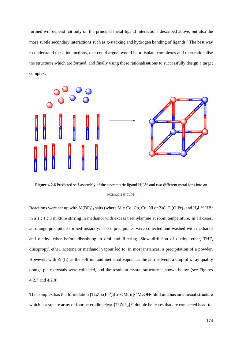
174
formed will depend not only on the principal metal-ligand interactions described above, but also the
more subtle secondary interactions such as -stacking and hydrogen bonding of ligands.2 The best way
to understand these interactions, one could argue, would be to isolate complexes and then rationalise
the structures which are formed, and finally using these rationalisations to successfully design a target
complex.
Figure 4.2.6 Predicted self-assembly of the asymmetric ligand H2L1,3 and two different metal ions into an
octanuclear cube.
Reactions were set up with M(BF4)2 salts (where M = Cd, Co, Cu, Ni or Zn), Ti(OiPr)4 and H2L1,3.HBr
in a 1 : 1 : 3 mixture stirring in methanol with excess triethylamine at room temperature. In all cases,
an orange precipitate formed instantly. These precipitates were collected and washed with methanol
and diethyl ether before dissolving in dmf and filtering. Slow diffusion of diethyl ether, THF,
diisopropyl ether, acetone or methanol vapour led to, in most instances, a precipitation of a powder.
However, with Zn(II) as the soft ion and methanol vapour as the anti-solvent, a crop of x-ray quality
orange plate crystals were collected, and the resultant crystal structure is shown below (see Figures
4.2.7 and 4.2.8).
The complex has the formulation [Ti4Zn4(L1,3)8(µ–OMe)8]•4MeOH•4dmf and has an unusual structure
which is a square array of four heterodinuclear {TiZnL2}2+ double helicates that are connected head-to-

175
tail [i.e. Zn(II) terminus to Ti(IV) terminus] by a pair of methoxide bridges. Each double helicate
fragment – an edge of the square assembly – has the two bridging ligands oriented in the same direction,
such that the Zn(II) ion is coordinated by two pzpy units at one end and the Ti(IV) ion is coordinated
by two cat2– units at the other, i.e. the ligands are arranged so as to define ‘hard’ and ‘soft’ binding
pockets.
Figure 4.2.7 A view of the complete tetrameric assembly of [Ti4Zn4(L1,3)8(µ–OMe)8]. The dinuclear double
helicate units are shown with the atoms of each ligand coloured green/blue or purple/gold; Zn = grey; Ti = cyan;
O = red; C = black.
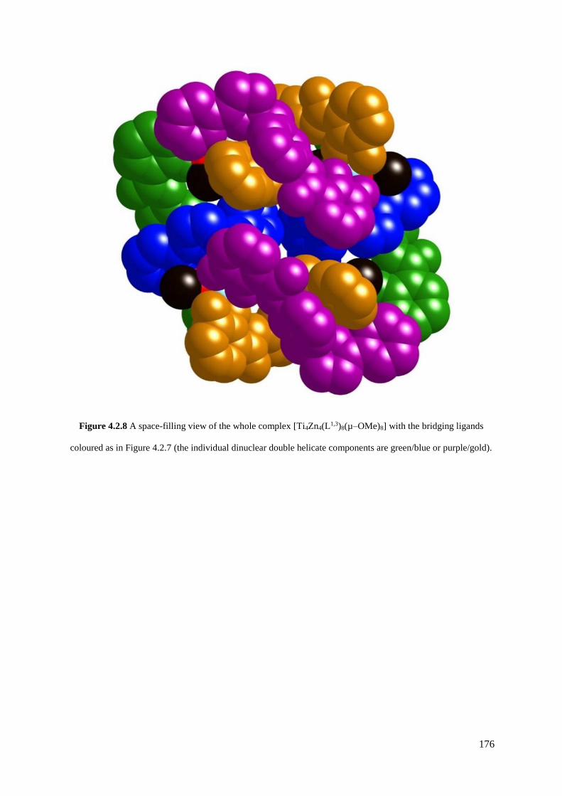
176
Figure 4.2.8 A space-filling view of the whole complex [Ti4Zn4(L1,3)8(µ–OMe)8] with the bridging ligands
coloured as in Figure 4.2.7 (the individual dinuclear double helicate components are green/blue or purple/gold).
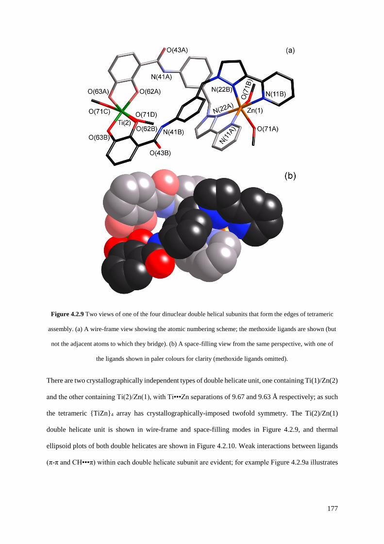
177
Figure 4.2.9 Two views of one of the four dinuclear double helical subunits that form the edges of tetrameric
assembly. (a) A wire-frame view showing the atomic numbering scheme; the methoxide ligands are shown (but
not the adjacent atoms to which they bridge). (b) A space-filling view from the same perspective, with one of
the ligands shown in paler colours for clarity (methoxide ligands omitted).
There are two crystallographically independent types of double helicate unit, one containing Ti(1)/Zn(2)
and the other containing Ti(2)/Zn(1), with Ti•••Zn separations of 9.67 and 9.63 Å respectively; as such
the tetrameric {TiZn}4 array has crystallographically-imposed twofold symmetry. The Ti(2)/Zn(1)
double helicate unit is shown in wire-frame and space-filling modes in Figure 4.2.9, and thermal
ellipsoid plots of both double helicates are shown in Figure 4.2.10. Weak interactions between ligands
(π-π and CH•••π) within each double helicate subunit are evident; for example Figure 4.2.9a illustrates
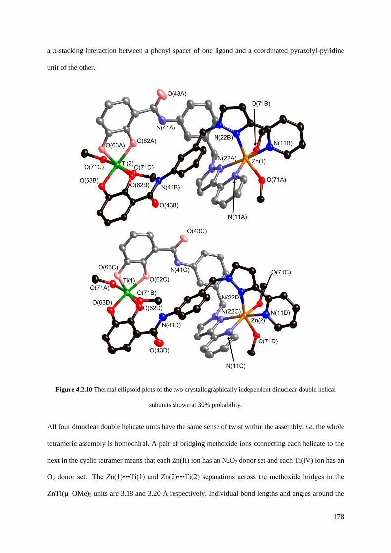
178
a π-stacking interaction between a phenyl spacer of one ligand and a coordinated pyrazolyl-pyridine
unit of the other.
Figure 4.2.10 Thermal ellipsoid plots of the two crystallographically independent dinuclear double helical
subunits shown at 30% probability.
All four dinuclear double helicate units have the same sense of twist within the assembly, i.e. the whole
tetrameric assembly is homochiral. A pair of bridging methoxide ions connecting each helicate to the
next in the cyclic tetramer means that each Zn(II) ion has an N4O2 donor set and each Ti(IV) ion has an
O6 donor set. The Zn(1)•••Ti(1) and Zn(2)•••Ti(2) separations across the methoxide bridges in the
ZnTi(µ–OMe)2 units are 3.18 and 3.20 Å respectively. Individual bond lengths and angles around the
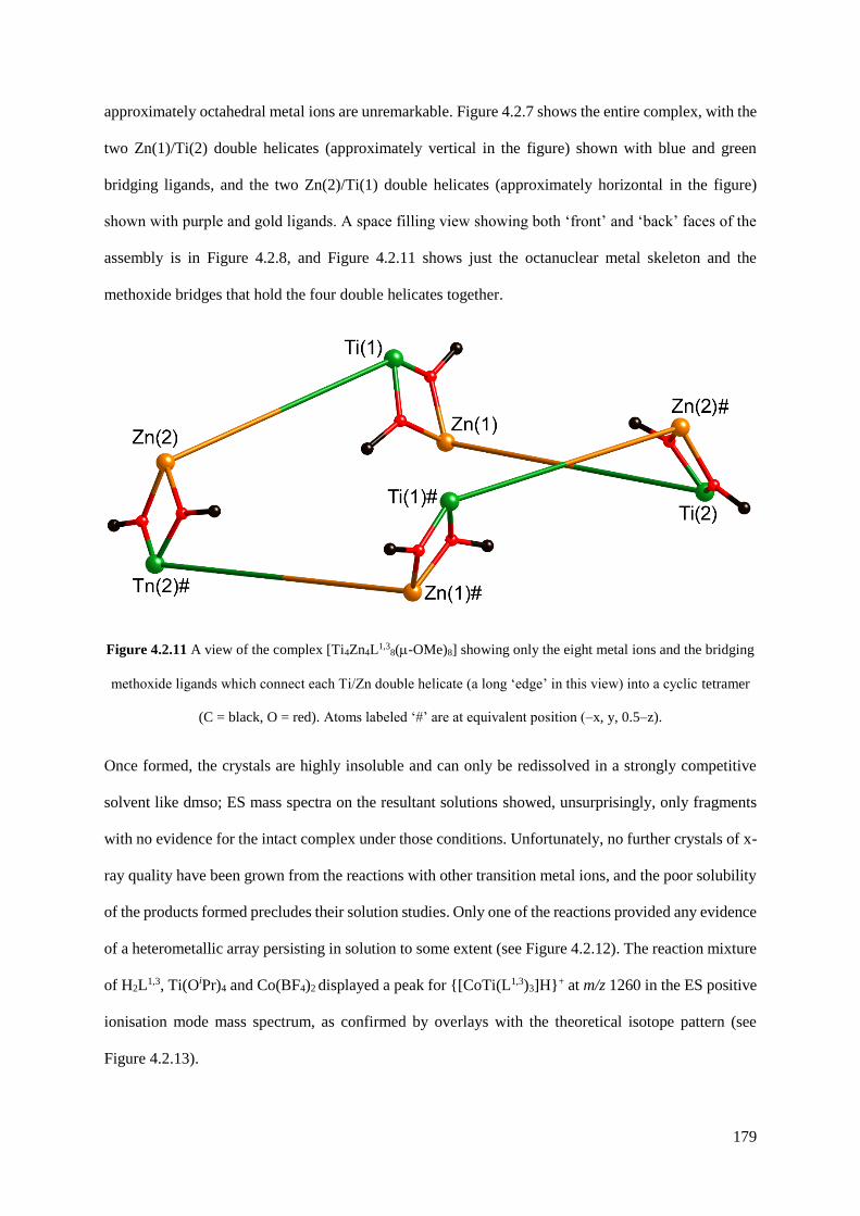
179
approximately octahedral metal ions are unremarkable. Figure 4.2.7 shows the entire complex, with the
two Zn(1)/Ti(2) double helicates (approximately vertical in the figure) shown with blue and green
bridging ligands, and the two Zn(2)/Ti(1) double helicates (approximately horizontal in the figure)
shown with purple and gold ligands. A space filling view showing both ‘front’ and ‘back’ faces of the
assembly is in Figure 4.2.8, and Figure 4.2.11 shows just the octanuclear metal skeleton and the
methoxide bridges that hold the four double helicates together.
Figure 4.2.11 A view of the complex [Ti4Zn4L1,38(-OMe)8] showing only the eight metal ions and the bridging
methoxide ligands which connect each Ti/Zn double helicate (a long ‘edge’ in this view) into a cyclic tetramer
(C = black, O = red). Atoms labeled ‘#’ are at equivalent position (–x, y, 0.5–z).
Once formed, the crystals are highly insoluble and can only be redissolved in a strongly competitive
solvent like dmso; ES mass spectra on the resultant solutions showed, unsurprisingly, only fragments
with no evidence for the intact complex under those conditions. Unfortunately, no further crystals of x-
ray quality have been grown from the reactions with other transition metal ions, and the poor solubility
of the products formed precludes their solution studies. Only one of the reactions provided any evidence
of a heterometallic array persisting in solution to some extent (see Figure 4.2.12). The reaction mixture
of H2L1,3, Ti(OiPr)4 and Co(BF4)2 displayed a peak for {[CoTi(L1,3)3]H}+ at m/z 1260 in the ES positive
ionisation mode mass spectrum, as confirmed by overlays with the theoretical isotope pattern (see
Figure 4.2.13).
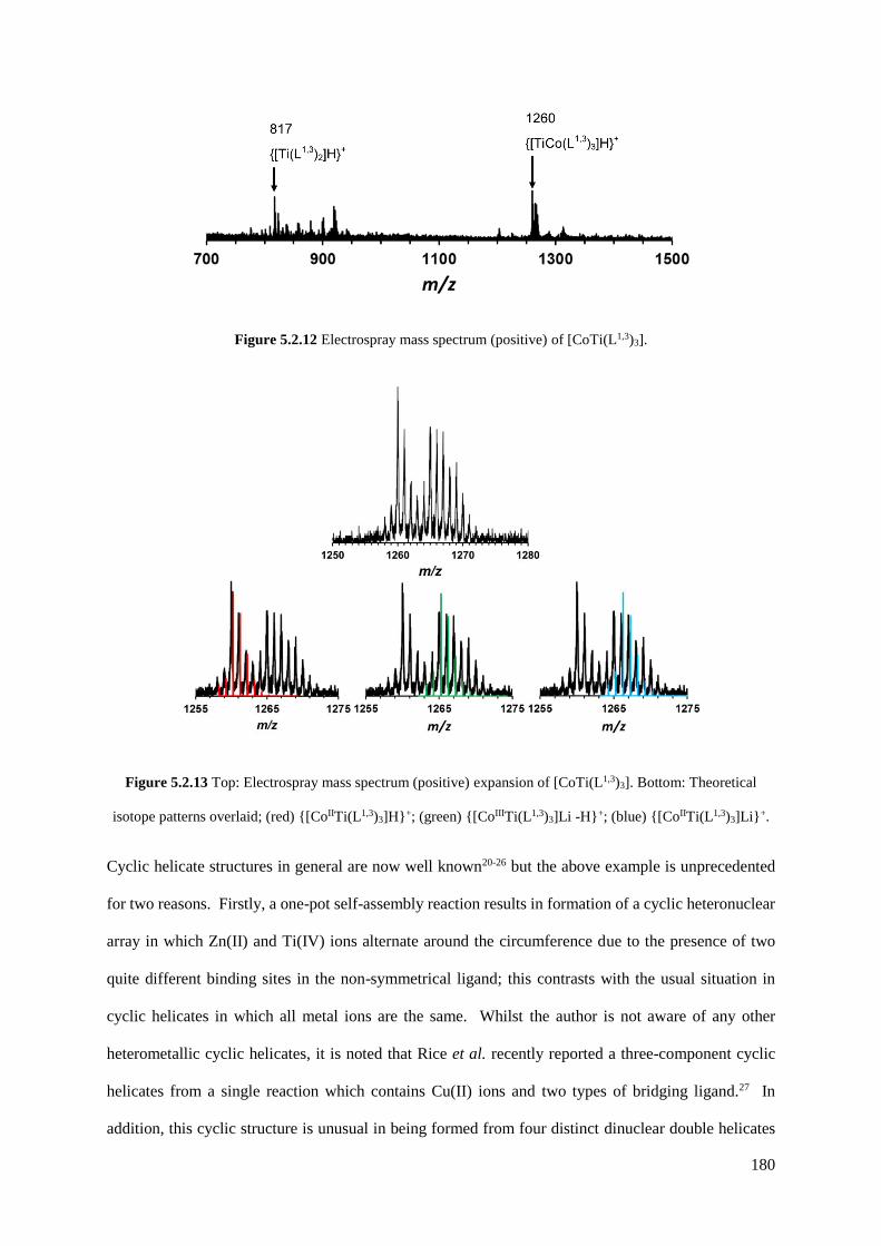
180
Figure 5.2.12 Electrospray mass spectrum (positive) of [CoTi(L1,3)3].
Figure 5.2.13 Top: Electrospray mass spectrum (positive) expansion of [CoTi(L1,3)3]. Bottom: Theoretical
isotope patterns overlaid; (red) {[CoIITi(L1,3)3]H}+; (green) {[CoIIITi(L1,3)3]Li -H}+; (blue) {[CoIITi(L1,3)3]Li}+.
Cyclic helicate structures in general are now well known20-26 but the above example is unprecedented
for two reasons. Firstly, a one-pot self-assembly reaction results in formation of a cyclic heteronuclear
array in which Zn(II) and Ti(IV) ions alternate around the circumference due to the presence of two
quite different binding sites in the non-symmetrical ligand; this contrasts with the usual situation in
cyclic helicates in which all metal ions are the same. Whilst the author is not aware of any other
heterometallic cyclic helicates, it is noted that Rice et al. recently reported a three-component cyclic
helicates from a single reaction which contains Cu(II) ions and two types of bridging ligand.27 In
addition, this cyclic structure is unusual in being formed from four distinct dinuclear double helicates

181
connected by methoxide bridges, rather than the more usual type of structure in which ditopic or tritopic
bridging ligands overlap in a continuous sequence around the periphery of the complex.20-26 Using the
same methodology as employed for H2L1,3 we can readily synthesise a wide range of heterotopic
catecholate / pyrazolyl-pyridine bridging ligands as a basis for self-assembled heterometallic arrays.
4.2.3 Analogous ligand and complex syntheses
Analogous syntheses were designed for the 1,2- and 1,4-substituted isomers of H2L1,3. The synthesis of
the ligand H2L1,2 was attempted first, but this proved more problematic than the original synthesis of
H2L1,3 (see Figure 4.2.14). The product of the bromination step 8 was found to degrade rapidly, and the
PyPz substitution step introduced an entirely new problem. Instead of cleanly converting the alkyl
bromide 8 to the desired product 9, 1H NMR spectroscopy revealed the presence of two products in a
1 : 1 ratio, with identical molecular weights, as determined by the HPLC trace of the ESMS spectrum.
It was assumed that the products were stereoisomers of each other, with the pyrazole ring substituted
on different nitrogen atoms (see Figure 4.2.15). The two products had very similar Rf values, but elution
with ethyl acetate/ dichloromethane (4 : 1) on silica allowed their separation, and their resultant 1H
NMR spectra helped confirm the identity of each component.

182
Figure 4.2.14 Reaction scheme for the preparation of H2L1,2. (i) Boc2O, THF; (ii) CBr4, PPh3, DCM; (iii)
PyPzH, THF, NaOH(aq); (iv) TFA, DCM; (v) SOCl2, dmf; (vi) 5, DCM, Et3N; (vii) BBr3, DCM, H2O.
Figure 4.2.15 Nucleophilic substitution of bromide with PyPz leads to two stereoisomers in an approximately
1 : 1 ratio. (i) PyPzH, THF, NaOH(aq).

183
All ligands containing 1-alkyl substituted 3-(2-pyridyl)pyrazole show two distinctive sharp doublets for
the pyrazole protons, and in most cases the two peaks are separated by approximately 0.5 ppm in CDCl3.
The first of the two fractions has a separation of approximately 1.0 ppm, and the second fraction
approximately 0.5 ppm (see Figure 4.2.16). This led us to assign the first fraction as the side product
10, and the second fraction as the desired compound 9. After the subsequent Boc deprotection of the
compound 9, the crystal structure of a colourless block of 11.H2O was collected, irrefutably confirming
the structure as the intended product (see Figure 4.2.17). The amine crystallised as a monohydrate, and
there are numerous H•••O and H•••N hydrogen-bonding interactions of ca. 2.0 – 2.1 Å between the
water molecule and the pyridyl and aniline groups of the ligand (see Figure 4.2.18). There is also an
intramolecular hydrogen bond between the pyrazolyl N(22) and the aniline H(41A) (H•••N 2.2 Å).
Figure 4.2.16 Partially assigned 1H NMR (400 MHz, CDCl3) spectra of compounds 10 (top) and 9 (bottom),
highlighting the characteristic splitting distance between the protons of di-substituted pyrazole rings (Py =
pyridine, Pz = pyrazole, Ph = phenyl).
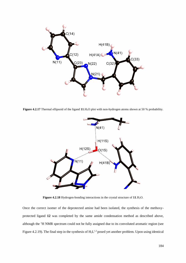
184
Figure 4.2.17 Thermal ellipsoid of the ligand 11.H2O plot with non-hydrogen atoms shown at 50 % probability.
Figure 4.2.18 Hydrogen-bonding interactions in the crystal structure of 11.H2O.
Once the correct isomer of the deprotected amine had been isolated, the synthesis of the methoxy-
protected ligand 12 was completed by the same amide condensation method as described above,
although the 1H NMR spectrum could not be fully assigned due to its convoluted aromatic region (see
Figure 4.2.19). The final step in the synthesis of H2L1,2 posed yet another problem. Upon using identical

185
conditions to those described above, the crude product isolated from the reaction mixture was not the
pure demethylated H2L1,2 as expected, but a mixture of the desired ligand and a mono-deprotected
HMeL1,2 (see Figure 4.2.20) in an approximate ratio of 0.7 : 1.0 (by 1H NMR integration of equivalent
protons, see Figure 4.2.21). Separation of these products by column chromatography proved
surprisingly difficult, with incomplete separation achieved. It was decided at this point that due to the
numerous synthetic difficulties associated with this synthesis that a different ligand should be targeted
which may prove to be easier to isolate on an acceptable scale.
Figure 4.2.19 Top: Full 1H NMR spectrum (400 MHz, CDCl3) of 12; Bottom: Expansion in the aromatic region
with partial assignment.
Py-H6
NH
CH2
2 x OMe
Py-H3 Py-H4
Pz
Pz
Py-H5
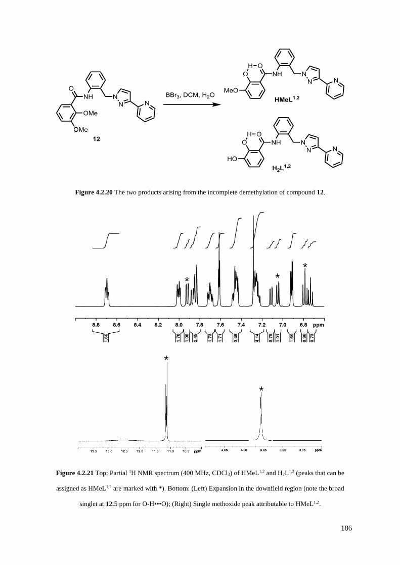
186
Figure 4.2.20 The two products arising from the incomplete demethylation of compound 12.
Figure 4.2.21 Top: Partial 1H NMR spectrum (400 MHz, CDCl3) of HMeL1,2 and H2L1,2 (peaks that can be
assigned as HMeL1,2 are marked with *). Bottom: (Left) Expansion in the downfield region (note the broad
singlet at 12.5 ppm for O-H•••O); (Right) Single methoxide peak attributable to HMeL1,2.
*
*
* * *

187
The analogous synthesis of H2L1,4 was therefore undertaken (see Figure 4.2.22), and it was hoped that
the distance between the two arms of the ligand would prevent problems in the alkylation step which
may have been caused by amide NH group directing the undesired reaction. Protection of the aniline
with Boc is routine,28 but it was again found that the bromination step in this synthesis is problematic,
with the alkyl bromide 14 appearing to degrade rapidly, making the next step difficult. However, the
PyPz substitution, Boc deprotection and amide condensation reactions were all performed successfully
affording the methoxy protected ligand 17 as a yellow oil. This was recrystallised from DCM and
diethyl ether, providing colourless needle crystals of x-ray quality. Despite the temperature failing
during collection, the crystal structure could be solved by integrating all the runs performed at room
temperature, revealing the structure of the ligand (see Figure 4.2.23). As expected, the catechol methoxy
groups are arranged in an anti fashion to the amide carbonyl, in contrast to the syn fashion displayed by
the deprotected ligand H2L1,3.15
Figure 4.2.22 Reaction scheme for the preparation of H2L1,4. (i) Boc2O, THF; (ii) CBr4, PPh3, DCM; (iii)
PyPzH, THF, NaOH(aq); (iv) TFA, DCM; (v) SOCl2, DMF; (vi) 5, DCM, Et3N; (vii) BBr3, DCM, H2O.

188
Figure 4.2.23 Thermal ellipsoid plot of the ligand 17 with non-hydrogen atoms shown at 30 % probability.
The methoxy-protected ligand 17 was deprotected successfully with BBr3 in this instance to yield an
off white solid after solvolysis in water. The ligand was found to be soluble in methanol with gentle
heating, and consequently the 1H NMR spectrum in deuterated methanol was obtained, with all acidic
proton environments absent due to fast exchange with the solvent (see Figure 4.2.24).
Figure 4.2.24 Fully assigned 1H NMR (400 MHz, MeOD) spectrum of H2L1,4.HBr (Py = pyridine, Pz =
pyrazole, Ph = phenyl, cat = catechol).
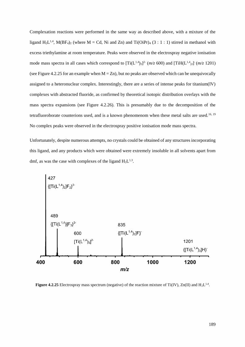
189
Complexation reactions were performed in the same way as described above, with a mixture of the
ligand H2L1,4, M(BF4)2 (where M = Cd, Ni and Zn) and Ti(OiPr)4 (3 : 1 : 1) stirred in methanol with
excess triethylamine at room temperature. Peaks were observed in the electrospray negative ionisation
mode mass spectra in all cases which correspond to [Ti(L1,4)3]2- (m/z 600) and [TiH(L1,4)3]- (m/z 1201)
(see Figure 4.2.25 for an example when M = Zn), but no peaks are observed which can be unequivocally
assigned to a heteronuclear complex. Interestingly, there are a series of intense peaks for titanium(IV)
complexes with abstracted fluoride, as confirmed by theoretical isotopic distribution overlays with the
mass spectra expansions (see Figure 4.2.26). This is presumably due to the decomposition of the
tetrafluoroborate counterions used, and is a known phenomenom when these metal salts are used.16, 19
No complex peaks were observed in the electrospray positive ionisation mode mass spectra.
Unfortunately, despite numerous attempts, no crystals could be obtained of any structures incorporating
this ligand, and any products which were obtained were extremely insoluble in all solvents apart from
dmf, as was the case with complexes of the ligand H2L1,3.
Figure 4.2.25 Electrospray mass spectrum (negative) of the reaction mixture of Ti(IV), Zn(II) and H2L1,4.

190
Figure 4.2.26 Theoretical isotopic distribution (red) and experimental mass spectra (black) for {[Ti(L1,4)2]F2}2-
(top left), {[Ti(L1,4)2]F3}2- (top right), {[Ti(L1,4)3]}2- (bottom left) and {[Ti(L1,4)2]F}2- (bottom right).
4.3 Conclusion
A potentially general synthetic route for a family of asymmetric ligands based on bromomethyl-
substitued aniline starting materials has been developed; two examples have been demonstrated based
on a meta- and para- substituted phenyl ring, and a third example based on the ortho- ring was partially
successful. A heterometallic square of double helicates has been synthesised with the meta- substituted
ligand H2L1,3 based on the orthogonality of the catecholamide and pyrazolyl-pyridine binding sites,
acting as proof-of-principle for this work. The poor solubility of the complexes formed precluded
detailed NMR and mass spectral studies; future designs of these complexes would need to improve their
solubility to enable any useful function.

191
4.4 Experimental
4.4.1 Ligand synthesis
3-(2-pyridyl)pyrazole was used as prepared.29 Dry dichloromethane was obtained by distillation over
calcium hydride.
Synthesis of 1
A mixture of 3-(hydroxymethy1)aniline (7.50 g, 60.90 mmol) and di-tert-butyl dicarbonate (13.50 g,
61.86 mmol) was stirred in THF (150 cm3) at 25 oC for 48 h. The resultant brown solution was reduced
to dryness before purification of the crude brown oil by purified by column chromatography on silica.
Elution with ethyl acetate/ 40:60 petroleum ether (1:2, Rf = 0.36) followed by sonication for 10 minutes
in hexane yielded 1 as a white solid (Yield: 13.01 g, 58.27 mmol, 96 %). 1H-NMR (400 MHz, CDCl3):
δ 7.48 (1H, s; ArH), 7.32 – 7.23 (2H, m; ArH), 7.08 – 7.06 (1H, m; ArH), 6.52 (1H, bs; NH), 4.69 (2H,
s; CH2), 1.75 (1H, s; OH), 1.54 (9H, s; tBu). ESMS: m/z 262 [M + K]+, 246 [M + Na]+, 150 [M - -OtBu]+;
Found: C, 64.60; H, 7.67; N, 6.17 %. Required for C12H17NO3: C, 64.55; H, 7.67; N, 6.27 %. Data is in
accordance with the literature.17
Synthesis of 2
A solution of 1 (3.22 g, 14.42 mmol) in DCM (70 cm3) was maintained at 0 oC with stirring. To this
was added PPh3 (6.10 g, 23.26 mmol) and CBr4 (7.94 g, 23.94 mmol) sequentially, and the resultant
yellow solution was stirred at 0 oC for 1.5 h. The reaction mixture was then diluted with EtOAc and

192
stirred for a further 0.5 h, before washing with brine. The organic layer was extracted with EtOAc, dried
over MgSO4 and concentrated before purification by column chromatography on silica. Elution with
ethyl acetate/ 40:60 petroleum ether (1:12, Rf = 0.55) yielded 2 as a white solid (Yield: 2.95 g, 10.31
mmol, 67 %). 1H-NMR (400 MHz, CDCl3): δ 7.54 (1H, s; ArH), 7.31 – 7.21 (2H, m; ArH), 7.10 – 7.07
(1H, m; ArH), 6.52 (1H, bs; NH), 4.48 (2H, s; CH2), 1.55 (9H, s; tBu). ESMS m/z 286 [M + H]+, 288
[M + H]+. Found: C, 50.53; H, 5.42; N, 4.77 %. Required for C12H16BrNO2, 50.37; H, 5.64; N, 4.89 %.
Data is in accordance with the literature.17
Synthesis of 3
A mixture of 2 (2.95 g, 10.29 mmol), 3-(2- pyridyl)pyrazole (1.50 g, 10.33 mmol), THF (120 cm3) and
aqueous NaOH (13 M, 7.5 cm3) was stirred at 75 oC for 24 h. The organic layer was separated, dried
over MgSO4 and concentrated before purification by column chromatography on silica. Elution with
EtOAc/ DCM (4:1, Rf = 0.70) yielded 3 as a white solid (Yield: 2.55 g, 71 %). 1H-NMR (400 MHz,
CDCl3): δ 8.65 (1H, ddd, J = 5.0, 1.8, 1.0 Hz; pyridyl H6), 7.97 (1H, dt, J = 8.0, 1.0 Hz; pyridyl H3),
7.73 (1H, td, J = 8.0, 1.8 Hz; pyridyl H4), 7.43 (1H, d, J = 2.4 Hz; pyrazolyl H5), 7.34 – 7.25 (3H, m;
ArH), 7.21 (1H, ddd, J = 7.5, 5.0, 1.0 Hz; pyridyl H5), 6.94 – 6.92 (2H, m; Ar-H and pyrazolyl H4), 6.55
(1H, bs; NH), 5.38 (2H, s; CH2), 1.52 (9H, s; tBu). ESMS: m/z 373 [M + Na]+, 351 [M + H]+. Found:
C, 68.46; H, 6.35; N, 15.78 %. Required for C20H22N4O2: C, 68.55; H, 6.33; N, 15.99 %.
Synthesis of 4

193
To a solution of 3 (1.51 g, 4.31 mmol) in DCM (20 cm3) was added TFA (20 cm3) and the resultant
yellow mixture was stirred at 25 oC for 14 h. The solvent was removed in vacuo and the clear brown oil
was repeatedly washed with DCM/ MeOH (1:1) and evaporated to dryness in order to remove traces of
TFA. The cream-coloured solid was washed with an aqueous solution of K2CO3 (2M) and the organic
layer extracted with DCM, dried over MgSO4 and evaporated to dryness, yielding 4 as a white solid
(Yield: 0.81 g, 75 %). 1H-NMR (400 MHz, CDCl3): δ 8.65 (1H, ddd, J = 4.9, 2.0, 0.8 Hz; pyridyl H6),
7.97 (1H, d, J = 8.0 Hz; pyridyl H3), 7.72 (1H, td, J = 7.8, 1.7 Hz; pyridyl H4), 7.42 (1H, d, J = 2.4 Hz;
pyrazolyl H5), 7.20 (1H, ddd, J = 7.4, 4.9, 1.2 Hz; pyridyl H5), 7.14 (1H, t, J = 7.8 Hz; Ar-H), 6.92 (1H,
d, J = 2.4 Hz; pyrazolyl H4), 6.68 – 6.61 (2H, m; Ar-H), 6.53 (1H, t, J = 1.7 Hz; Ar-H), 5.31 (2H, s;
CH2), 3.56 (2H, bs; NH2). ESMS: m/z 251 [M + H]+. Found: C, 70.70; H, 5.46; N, 21.64 %. Required
for C15H14N4: C, 71.98; H, 5.64; N, 22.38 %.
Synthesis of 5
2,3-dimethoxybenzoic acid (4.70 g, 25.8 mmol), SOCl2 (7 cm3, 96.5 mmol) and a drop of DMF were
heated to reflux with stirring for 6 h. The condenser was fitted with a CaCl2 drying tube to absorb
liberated SO2 and HCl. The resultant clear yellow solution was diluted with CHCl3 and evaporated to
dryness under reduced pressure three times. Drying under high vacuum yielded 5 as an off white solid,
which was used without any further purification, assuming quantitative yield (Yield: 5.10 g, 99 %). 1H-
NMR (250 MHz, CDCl3): δ 7.55 (1H, dd; Ar-H), 7.20-7.15 (2H, m; Ar-H), 3.94 (3H, s; OMe), 3.92
(3H, s; OMe). EIMS m/z 224 [M + Na]+, 165 [M - Cl-]+. Data is in accordance with the literature.30
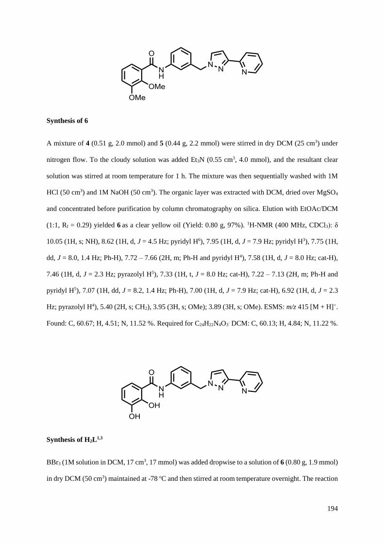
194
Synthesis of 6
A mixture of 4 (0.51 g, 2.0 mmol) and 5 (0.44 g, 2.2 mmol) were stirred in dry DCM (25 cm3) under
nitrogen flow. To the cloudy solution was added Et3N (0.55 cm3, 4.0 mmol), and the resultant clear
solution was stirred at room temperature for 1 h. The mixture was then sequentially washed with 1M
HCl (50 cm3) and 1M NaOH (50 cm3). The organic layer was extracted with DCM, dried over MgSO4
and concentrated before purification by column chromatography on silica. Elution with EtOAc/DCM
(1:1, Rf = 0.29) yielded 6 as a clear yellow oil (Yield: 0.80 g, 97%). 1H-NMR (400 MHz, CDCl3): δ
10.05 (1H, s; NH), 8.62 (1H, d, J = 4.5 Hz; pyridyl H6), 7.95 (1H, d, J = 7.9 Hz; pyridyl H3), 7.75 (1H,
dd, J = 8.0, 1.4 Hz; Ph-H), 7.72 – 7.66 (2H, m; Ph-H and pyridyl H4), 7.58 (1H, d, J = 8.0 Hz; cat-H),
7.46 (1H, d, J = 2.3 Hz; pyrazolyl H5), 7.33 (1H, t, J = 8.0 Hz; cat-H), 7.22 – 7.13 (2H, m; Ph-H and
pyridyl H5), 7.07 (1H, dd, J = 8.2, 1.4 Hz; Ph-H), 7.00 (1H, d, J = 7.9 Hz; cat-H), 6.92 (1H, d, J = 2.3
Hz; pyrazolyl H4), 5.40 (2H, s; CH2), 3.95 (3H, s; OMe); 3.89 (3H, s; OMe). ESMS: m/z 415 [M + H]+.
Found: C, 60.67; H, 4.51; N, 11.52 %. Required for C24H22N4O3. DCM: C, 60.13; H, 4.84; N, 11.22 %.
Synthesis of H2L1,3
BBr3 (1M solution in DCM, 17 cm3, 17 mmol) was added dropwise to a solution of 6 (0.80 g, 1.9 mmol)
in dry DCM (50 cm3) maintained at -78 oC and then stirred at room temperature overnight. The reaction
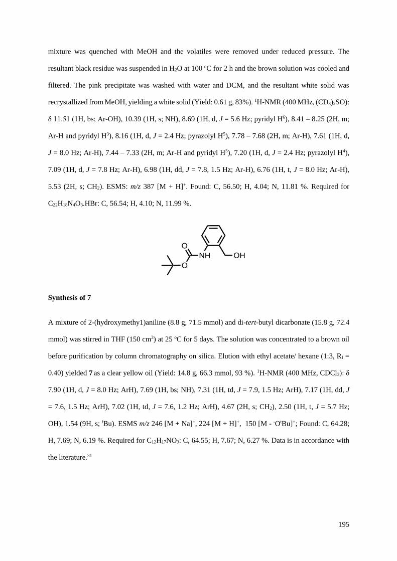
195
mixture was quenched with MeOH and the volatiles were removed under reduced pressure. The
resultant black residue was suspended in H2O at 100 oC for 2 h and the brown solution was cooled and
filtered. The pink precipitate was washed with water and DCM, and the resultant white solid was
recrystallized from MeOH, yielding a white solid (Yield: 0.61 g, 83%). 1H-NMR (400 MHz, (CD3)2SO):
δ 11.51 (1H, bs; Ar-OH), 10.39 (1H, s; NH), 8.69 (1H, d, J = 5.6 Hz; pyridyl H6), 8.41 – 8.25 (2H, m;
Ar-H and pyridyl H3), 8.16 (1H, d, J = 2.4 Hz; pyrazolyl H5), 7.78 – 7.68 (2H, m; Ar-H), 7.61 (1H, d,
J = 8.0 Hz; Ar-H), 7.44 – 7.33 (2H, m; Ar-H and pyridyl H5), 7.20 (1H, d, J = 2.4 Hz; pyrazolyl H4),
7.09 (1H, d, J = 7.8 Hz; Ar-H), 6.98 (1H, dd, J = 7.8, 1.5 Hz; Ar-H), 6.76 (1H, t, J = 8.0 Hz; Ar-H),
5.53 (2H, s; CH2). ESMS: m/z 387 [M + H]+. Found: C, 56.50; H, 4.04; N, 11.81 %. Required for
C22H18N4O3.HBr: C, 56.54; H, 4.10; N, 11.99 %.
Synthesis of 7
A mixture of 2-(hydroxymethy1)aniline (8.8 g, 71.5 mmol) and di-tert-butyl dicarbonate (15.8 g, 72.4
mmol) was stirred in THF (150 cm3) at 25 oC for 5 days. The solution was concentrated to a brown oil
before purification by column chromatography on silica. Elution with ethyl acetate/ hexane (1:3, Rf =
0.40) yielded 7 as a clear yellow oil (Yield: 14.8 g, 66.3 mmol, 93 %). 1H-NMR (400 MHz, CDCl3): δ
7.90 (1H, d, J = 8.0 Hz; ArH), 7.69 (1H, bs; NH), 7.31 (1H, td, J = 7.9, 1.5 Hz; ArH), 7.17 (1H, dd, J
= 7.6, 1.5 Hz; ArH), 7.02 (1H, td, J = 7.6, 1.2 Hz; ArH), 4.67 (2H, s; CH2), 2.50 (1H, t, J = 5.7 Hz;
OH), 1.54 (9H, s; tBu). ESMS m/z 246 [M + Na]+, 224 [M + H]+, 150 [M - -OtBu]+; Found: C, 64.28;
H, 7.69; N, 6.19 %. Required for C12H17NO3: C, 64.55; H, 7.67; N, 6.27 %. Data is in accordance with
the literature.31

196
Synthesis of 8
A solution of 7 (2.07 g, 9.27 mmol) in DCM (20 cm3) was maintained at 0 oC with stirring under
nitrogen flow. To this was added CBr4 (3.73 g, 11.25 mmol) and PPh3 (2.93 g, 11.17 mmol)
sequentially, and the resultant orange solution was stirred at 0 oC for 2.5 h. The reaction mixture was
concentrated by rotary evaporation before purification by column chromatography on silica. Elution
with ethyl acetate/ hexane (1:7, Rf = 0.41) yielded 8 as an off-white solid (Yield: 1.80 g, 6.29 mmol, 68
%). 1H-NMR (400 MHz, CDCl3): δ 7.86 (1H, d, J = 8.0 Hz; ArH), 7.36 (1H, td, J = 7.8, 1.5 Hz; ArH),
7.31 (1H, dd, J = 7.8, 1.5 Hz; ArH), 7.08 (1H, td, J = 7.5, 1.0 Hz; ArH), 6.71 (1H, bs; NH), 4.53 (2H,
d; CH2), 1.57 (9H, s; tBu). ESMS m/z 286 [M + H]+, 288 [M + H]+. Found: C, 50.41; H, 5.91; N, 4.94;
Br 27.63 %. Required for C12H16BrNO2, 50.37; H, 5.64; N, 4.89; 27.92 %. Data is in accordance with
the literature.31
Synthesis of 9
A mixture of 8 (2.05 g, 7.16 mmol), 3-(2-pyridyl)pyrazole (1.43 g, 9.86 mmol), THF (120 cm3) and
aqueous NaOH (9.5 M, 10 cm3) was stirred at 75 oC for 48 h. The organic layer was extracted with
DCM, separated, dried over MgSO4 and concentrated before purification by column chromatography
on silica. Elution with EtOAc/ DCM (4:1, Rf = 0.73) yielded 9 as a yellow solid (Yield: 0.98 g, 39 %).
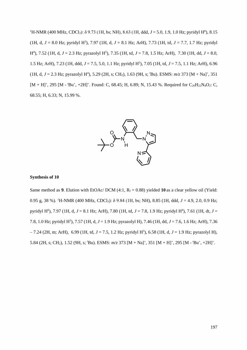
197
1H-NMR (400 MHz, CDCl3): δ 9.73 (1H, bs; NH), 8.63 (1H, ddd, J = 5.0, 1.9, 1.0 Hz; pyridyl H6), 8.15
(1H, d, J = 8.0 Hz; pyridyl H3), 7.97 (1H, d, J = 8.1 Hz; ArH), 7.73 (1H, td, J = 7.7, 1.7 Hz; pyridyl
H4), 7.52 (1H, d, J = 2.3 Hz; pyrazolyl H5), 7.35 (1H, td, J = 7.8, 1.5 Hz; ArH), 7.30 (1H, dd, J = 8.0,
1.5 Hz; ArH), 7.23 (1H, ddd, J = 7.5, 5.0, 1.1 Hz; pyridyl H5), 7.05 (1H, td, J = 7.5, 1.1 Hz; ArH), 6.96
(1H, d, J = 2.3 Hz; pyrazolyl H4), 5.29 (2H, s; CH2), 1.63 (9H, s; tBu). ESMS: m/z 373 [M + Na]+, 351
[M + H]+, 295 [M - tBu+, +2H]+. Found: C, 68.45; H, 6.89; N, 15.43 %. Required for C20H22N4O2: C,
68.55; H, 6.33; N, 15.99 %.
Synthesis of 10
Same method as 9. Elution with EtOAc/ DCM (4:1, Rf = 0.88) yielded 10 as a clear yellow oil (Yield:
0.95 g, 38 %). 1H-NMR (400 MHz, CDCl3): δ 9.84 (1H, bs; NH), 8.85 (1H, ddd, J = 4.9, 2.0, 0.9 Hz;
pyridyl H6), 7.97 (1H, d, J = 8.1 Hz; ArH), 7.80 (1H, td, J = 7.8, 1.9 Hz; pyridyl H4), 7.61 (1H, dt, J =
7.8, 1.0 Hz; pyridyl H3), 7.57 (1H, d, J = 1.9 Hz; pyrazolyl H), 7.46 (1H, dd, J = 7.6, 1.6 Hz; ArH), 7.36
– 7.24 (2H, m; ArH), 6.99 (1H, td, J = 7.5, 1.2 Hz; pyridyl H5), 6.58 (1H, d, J = 1.9 Hz; pyrazolyl H),
5.84 (2H, s; CH2), 1.52 (9H, s; tBu). ESMS: m/z 373 [M + Na]+, 351 [M + H]+, 295 [M - tBu+, +2H]+.
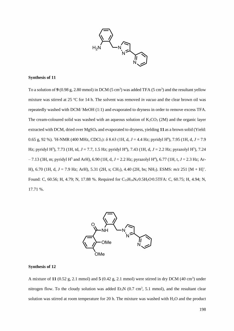
198
Synthesis of 11
To a solution of 9 (0.98 g, 2.80 mmol) in DCM (5 cm3) was added TFA (5 cm3) and the resultant yellow
mixture was stirred at 25 oC for 14 h. The solvent was removed in vacuo and the clear brown oil was
repeatedly washed with DCM/ MeOH (1:1) and evaporated to dryness in order to remove excess TFA.
The cream-coloured solid was washed with an aqueous solution of K2CO3 (2M) and the organic layer
extracted with DCM, dried over MgSO4 and evaporated to dryness, yielding 11 as a brown solid (Yield:
0.65 g, 92 %). 1H-NMR (400 MHz, CDCl3): δ 8.63 (1H, d, J = 4.4 Hz; pyridyl H6), 7.95 (1H, d, J = 7.9
Hz; pyridyl H3), 7.73 (1H, td, J = 7.7, 1.5 Hz; pyridyl H4), 7.43 (1H, d, J = 2.2 Hz; pyrazolyl H5), 7.24
– 7.13 (3H, m; pyridyl H5 and ArH), 6.90 (1H, d, J = 2.2 Hz; pyrazolyl H4), 6.77 (1H, t, J = 2.3 Hz; Ar-
H), 6.70 (1H, d, J = 7.9 Hz; ArH), 5.31 (2H, s; CH2), 4.40 (2H, bs; NH2). ESMS: m/z 251 [M + H]+.
Found: C, 60.56; H, 4.79; N, 17.88 %. Required for C15H14N4.0.5H2O.0.5TFA: C, 60.75; H, 4.94; N,
17.71 %.
Synthesis of 12
A mixture of 11 (0.52 g, 2.1 mmol) and 5 (0.42 g, 2.1 mmol) were stirred in dry DCM (40 cm3) under
nitrogen flow. To the cloudy solution was added Et3N (0.7 cm3, 5.1 mmol), and the resultant clear
solution was stirred at room temperature for 20 h. The mixture was washed with H2O and the product
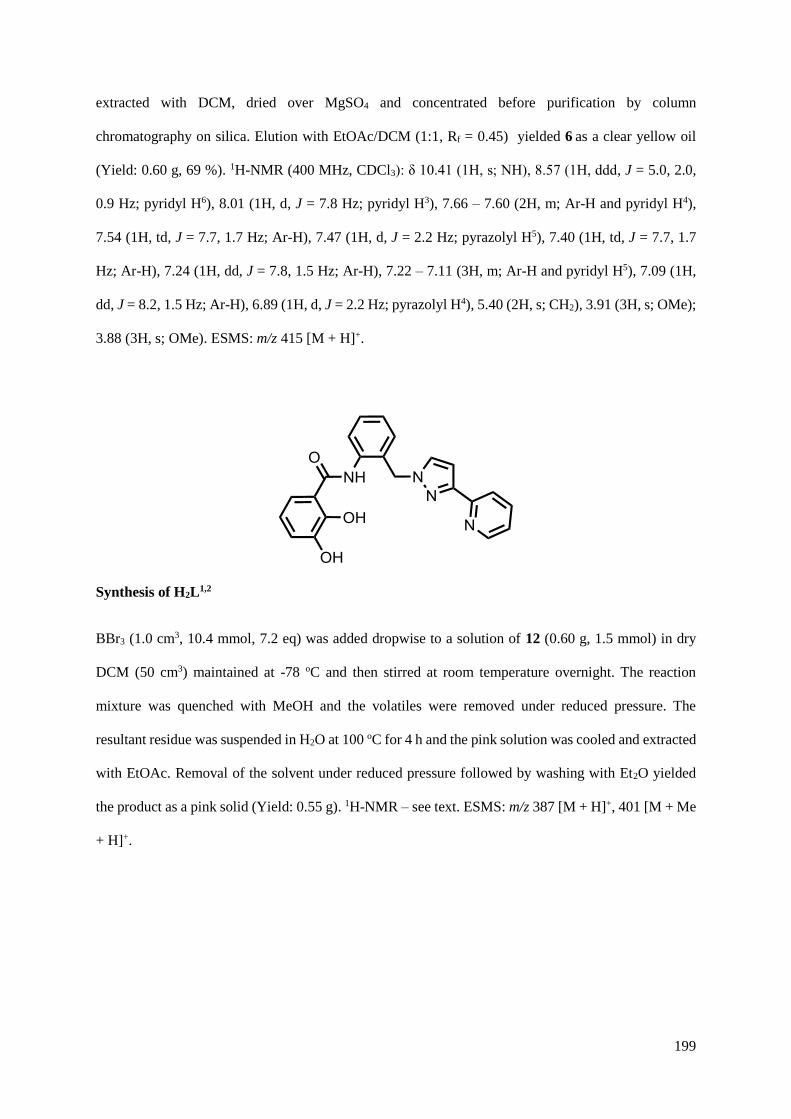
199
extracted with DCM, dried over MgSO4 and concentrated before purification by column
chromatography on silica. Elution with EtOAc/DCM (1:1, Rf = 0.45) yielded 6 as a clear yellow oil
(Yield: 0.60 g, 69 %). 1H-NMR (400 MHz, CDCl3): δ 10.41 (1H, s; NH), 8.57 (1H, ddd, J = 5.0, 2.0,
0.9 Hz; pyridyl H6), 8.01 (1H, d, J = 7.8 Hz; pyridyl H3), 7.66 – 7.60 (2H, m; Ar-H and pyridyl H4),
7.54 (1H, td, J = 7.7, 1.7 Hz; Ar-H), 7.47 (1H, d, J = 2.2 Hz; pyrazolyl H5), 7.40 (1H, td, J = 7.7, 1.7
Hz; Ar-H), 7.24 (1H, dd, J = 7.8, 1.5 Hz; Ar-H), 7.22 – 7.11 (3H, m; Ar-H and pyridyl H5), 7.09 (1H,
dd, J = 8.2, 1.5 Hz; Ar-H), 6.89 (1H, d, J = 2.2 Hz; pyrazolyl H4), 5.40 (2H, s; CH2), 3.91 (3H, s; OMe);
3.88 (3H, s; OMe). ESMS: m/z 415 [M + H]+.
Synthesis of H2L1,2
BBr3 (1.0 cm3, 10.4 mmol, 7.2 eq) was added dropwise to a solution of 12 (0.60 g, 1.5 mmol) in dry
DCM (50 cm3) maintained at -78 oC and then stirred at room temperature overnight. The reaction
mixture was quenched with MeOH and the volatiles were removed under reduced pressure. The
resultant residue was suspended in H2O at 100 oC for 4 h and the pink solution was cooled and extracted
with EtOAc. Removal of the solvent under reduced pressure followed by washing with Et2O yielded
the product as a pink solid (Yield: 0.55 g). 1H-NMR – see text. ESMS: m/z 387 [M + H]+, 401 [M + Me
+ H]+.
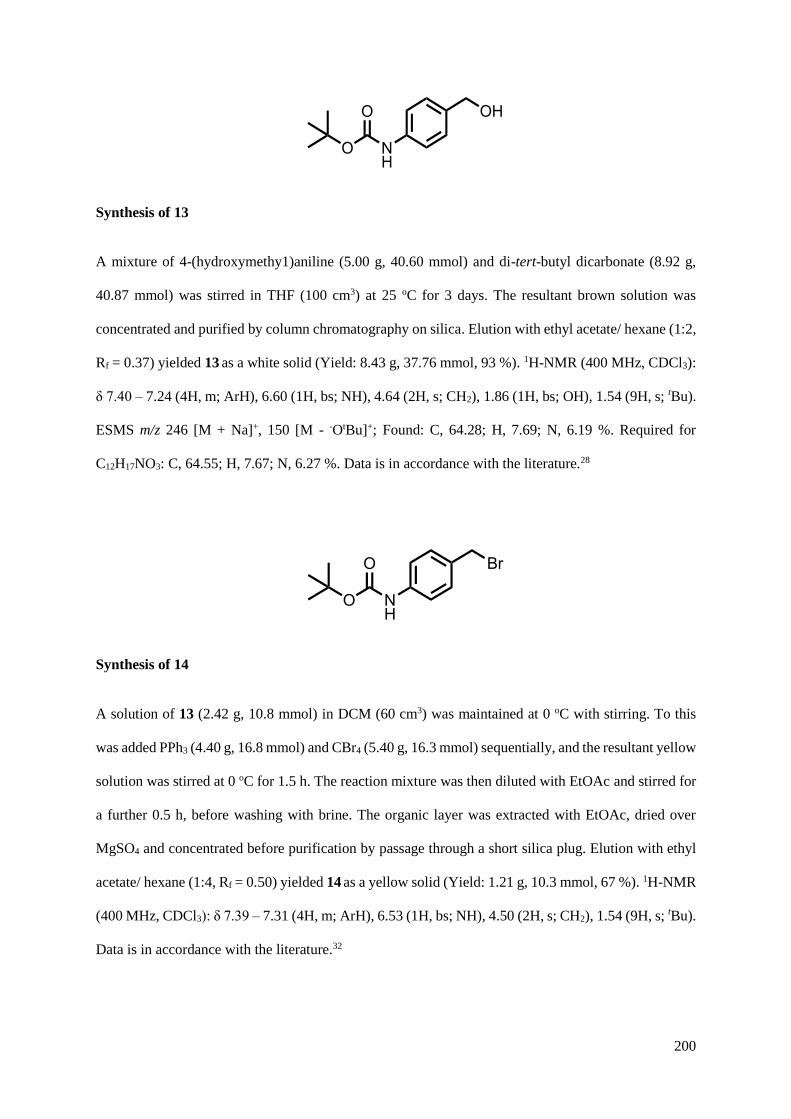
200
Synthesis of 13
A mixture of 4-(hydroxymethy1)aniline (5.00 g, 40.60 mmol) and di-tert-butyl dicarbonate (8.92 g,
40.87 mmol) was stirred in THF (100 cm3) at 25 oC for 3 days. The resultant brown solution was
concentrated and purified by column chromatography on silica. Elution with ethyl acetate/ hexane (1:2,
Rf = 0.37) yielded 13 as a white solid (Yield: 8.43 g, 37.76 mmol, 93 %). 1H-NMR (400 MHz, CDCl3):
δ 7.40 – 7.24 (4H, m; ArH), 6.60 (1H, bs; NH), 4.64 (2H, s; CH2), 1.86 (1H, bs; OH), 1.54 (9H, s; tBu).
ESMS m/z 246 [M + Na]+, 150 [M - -OtBu]+; Found: C, 64.28; H, 7.69; N, 6.19 %. Required for
C12H17NO3: C, 64.55; H, 7.67; N, 6.27 %. Data is in accordance with the literature.28
Synthesis of 14
A solution of 13 (2.42 g, 10.8 mmol) in DCM (60 cm3) was maintained at 0 oC with stirring. To this
was added PPh3 (4.40 g, 16.8 mmol) and CBr4 (5.40 g, 16.3 mmol) sequentially, and the resultant yellow
solution was stirred at 0 oC for 1.5 h. The reaction mixture was then diluted with EtOAc and stirred for
a further 0.5 h, before washing with brine. The organic layer was extracted with EtOAc, dried over
MgSO4 and concentrated before purification by passage through a short silica plug. Elution with ethyl
acetate/ hexane (1:4, Rf = 0.50) yielded 14 as a yellow solid (Yield: 1.21 g, 10.3 mmol, 67 %). 1H-NMR
(400 MHz, CDCl3): δ 7.39 – 7.31 (4H, m; ArH), 6.53 (1H, bs; NH), 4.50 (2H, s; CH2), 1.54 (9H, s; tBu).
Data is in accordance with the literature.32
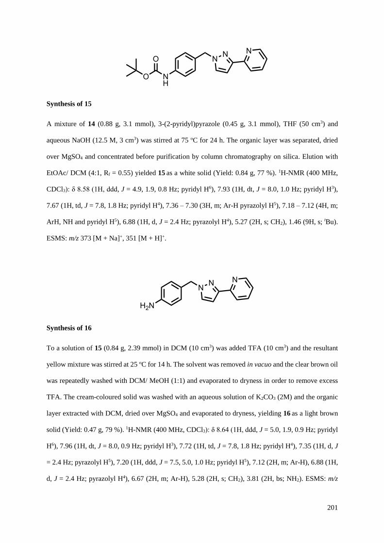
201
Synthesis of 15
A mixture of 14 (0.88 g, 3.1 mmol), 3-(2-pyridyl)pyrazole (0.45 g, 3.1 mmol), THF (50 cm3) and
aqueous NaOH (12.5 M, 3 cm3) was stirred at 75 oC for 24 h. The organic layer was separated, dried
over MgSO4 and concentrated before purification by column chromatography on silica. Elution with
EtOAc/ DCM (4:1, Rf = 0.55) yielded 15 as a white solid (Yield: 0.84 g, 77 %). 1H-NMR (400 MHz,
CDCl3): δ 8.58 (1H, ddd, J = 4.9, 1.9, 0.8 Hz; pyridyl H6), 7.93 (1H, dt, J = 8.0, 1.0 Hz; pyridyl H3),
7.67 (1H, td, J = 7.8, 1.8 Hz; pyridyl H4), 7.36 – 7.30 (3H, m; Ar-H pyrazolyl H5), 7.18 – 7.12 (4H, m;
ArH, NH and pyridyl H5), 6.88 (1H, d, J = 2.4 Hz; pyrazolyl H4), 5.27 (2H, s; CH2), 1.46 (9H, s; tBu).
ESMS: m/z 373 [M + Na]+, 351 [M + H]+.
Synthesis of 16
To a solution of 15 (0.84 g, 2.39 mmol) in DCM (10 cm3) was added TFA (10 cm3) and the resultant
yellow mixture was stirred at 25 oC for 14 h. The solvent was removed in vacuo and the clear brown oil
was repeatedly washed with DCM/ MeOH (1:1) and evaporated to dryness in order to remove excess
TFA. The cream-coloured solid was washed with an aqueous solution of K2CO3 (2M) and the organic
layer extracted with DCM, dried over MgSO4 and evaporated to dryness, yielding 16 as a light brown
solid (Yield: 0.47 g, 79 %). 1H-NMR (400 MHz, CDCl3): δ 8.64 (1H, ddd, J = 5.0, 1.9, 0.9 Hz; pyridyl
H6), 7.96 (1H, dt, J = 8.0, 0.9 Hz; pyridyl H3), 7.72 (1H, td, J = 7.8, 1.8 Hz; pyridyl H4), 7.35 (1H, d, J
= 2.4 Hz; pyrazolyl H5), 7.20 (1H, ddd, J = 7.5, 5.0, 1.0 Hz; pyridyl H5), 7.12 (2H, m; Ar-H), 6.88 (1H,
d, J = 2.4 Hz; pyrazolyl H4), 6.67 (2H, m; Ar-H), 5.28 (2H, s; CH2), 3.81 (2H, bs; NH2). ESMS: m/z

202
273 [M + Na]+, 251 [M + H]+. Found: C, 68.97; H, 5.31; N, 20.82 %. Required for C15H14N4.0.15 TFA:
C, 68.72; H, 5.33; N, 20.95 %.
Synthesis of 17
A mixture of 16 (0.25 g, 1.0 mmol) and 5 (0.22 g, 1.1 mmol) were stirred in dry DCM (25 cm3) under
nitrogen flow. To the cloudy solution was added Et3N (0.30 cm3, 2.2 mmol), and the resultant clear
solution was stirred at room temperature for 1 h. The mixture was then sequentially washed with 1M
HCl (50 cm3) and 1M NaOH (50 cm3). The organic layer was extracted with DCM, dried over MgSO4
and evaporated to dryness, yielding 17 as a light brown solid, which was used without any further
purification (Yield: 0.26 g, 63 %). 1H-NMR (400 MHz, CDCl3): δ 10.05 (1H, s; NH), 8.61 (1H, ddd, J
= 5.0, 1.9, 0.9 Hz; pyridyl H6), 7.94 (1H, dt, J = 7.9, 1.0 Hz; pyridyl H3), 7.78 – 7.62 (4H, m; Ar-H and
pyridyl H4), 7.40 (1H, d, J = 2.4 Hz; pyrazolyl H5), 7.31 – 7.23 (2H, m; Ar-H), 7.22 – 7.13 (2H, m; Ar-
H), 7.07 (1H, dd, J = 8.1, 1.6 Hz; pyridyl H5), 6.92 (1H, d, J = 2.4 Hz; pyrazolyl H4), 5.35 (2H, s; CH2),
3.95 (3H, s; OMe); 3.89 (3H, s; OMe). ESMS: m/z 415 [M + H]+. Found: C, 67.86; H, 4.83; N, 13.19
%. Required for C24H22N4O3.0.15DCM: C, 67.90; H, 5.26; N, 13.12 %.

203
Synthesis of H2L1,4
BBr3 (1M solution in DCM, 6 cm3, 6 mmol) was added dropwise to a solution of 17 (0.20 g, 0.48 mmol)
in dry DCM (50 cm3) maintained at -78 oC and then stirred at room temperature overnight. The reaction
mixture was quenched with MeOH and the volatiles were removed under reduced pressure. The
resultant orange residue was suspended in H2O at 100 oC for 2 h and the brown solution was cooled and
filtered. The pink precipitate was washed with water and DCM, yielding H2L1,4 as an off-white solid
(Yield: 0.15 g, 81 %). 1H-NMR (400 MHz, MeOD): δ 8.65 (1H, d, J = 5.4 Hz; pyridyl H6), 8.46 (1H,
td, J = 7.9, 1.5 Hz; pyridyl H4), 8.35 (1H, d, J = 8.1 Hz; pyridyl H3), 7.95 (1H, d, J = 2.5 Hz; pyrazolyl
H5), 7.81 (1H, m; pyridyl H5), 7.69 (2H, d, J = 8.5 Hz; Ph-H), 7.43 (1H, dd, J = 7.8, 1.5 Hz; cat-H),
7.37 (2H, d, J = 8.5 Hz; Ph-H ), 7.15 (1H, d, J = 2.5 Hz; pyrazolyl H4), 6.99 (1H, dd, J = 7.8, 1.5 Hz;
cat-H) 6.80 (1H, t, J = 7.8 Hz; cat-H5), 5.49 (2H, s; CH2). ESMS: m/z 387 [M + H]+.
4.4.2 Complex synthesis
The complexation reactions were all carried out using the same general method; the example given
below is typical.
Synthesis of Ti4Zn4L1,38OMe8
.4dmf.4MeOH
A solution of Ti(OiPr)4 (8.5 mg, 0.03 mmol) in MeOH (5 cm3) was added to a stirring solution of L1
(39 mg, 0.1 mmol) in MeOH (3 cm3) causing the solution to turn yellow, to which Zn(BF4)2.6H2O (10.2
mg, 0.03 mmol) in MeOH (2 cm3) was added. An excess of Et3N was added (1 cm3) and the mixture
was stirred in the dark at room temperature for 24 h. A fine orange precipitate was collected and washed

204
with MeOH. X-Ray quality crystals were grown by slow diffusion of MeOH into a solution of the
complex in dimethylformamide. (Yield: 13 mg).
4.5 X-ray crystallography
Details of the crystal, data collection and refinement parameters are summarised. Data were corrected
for absorption using empirical methods (SADABS)33 based upon symmetry-equivalent reflections
combined with measurements at different azimuthal angles. The structures were solved by direct
methods and refined by full-matrix least squares on weighted F2 values for all reflections using the
SHELX suite of programs.34 Non-hydrogen atoms were refined anisotropically. Hydrogen atoms were
placed in calculated positions, refined using idealized geometries (riding model) and were assigned
fixed isotropic displacement parameters.
The structures of [Ti4Zn4(L1,3)8(OMe)8] and H2L1,3.HBr were collected at the National Crystallography
Service at the University of Southampton. The ‘Squeeze’ function in PLATON was used to eliminate
regions of diffuse electron density in solvent-accessible voids for [Ti4Zn4(L1,3)8(OMe)8], information is
given in the CIF.
In each other case a suitable crystal was mounted in a stream of cold N2 on a Bruker APEX-2 or SMART
CCD diffractometers (at the University of Sheffield) equipped with graphite-monochromated Mo-Kα
radiation from a sealed-tube source. Details of each structure are given in their individual CIFs.
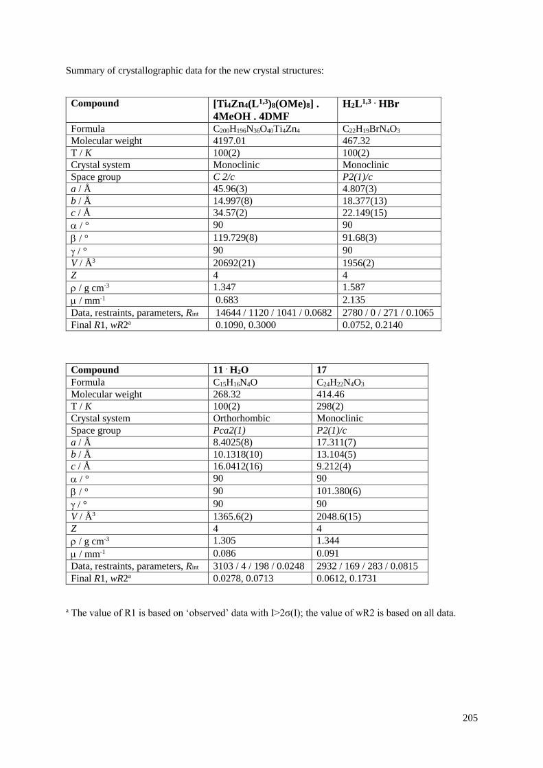
205
Summary of crystallographic data for the new crystal structures:
Compound [Ti4Zn4(L1,3)8(OMe)8] .
4MeOH . 4DMF
H2L1,3 . HBr
Formula C200H196N36O40Ti4Zn4 C22H19BrN4O3
Molecular weight 4197.01 467.32
T / K 100(2) 100(2)
Crystal system Monoclinic Monoclinic
Space group C 2/c P2(1)/c
a / Å 45.96(3) 4.807(3)
b / Å 14.997(8) 18.377(13)
c / Å 34.57(2) 22.149(15)
/ ° 90 90
/ ° 119.729(8) 91.68(3)
/ ° 90 90
V / Å3 20692(21) 1956(2)
Z 4 4
/ g cm-3 1.347 1.587
/ mm-1 0.683 2.135
Data, restraints, parameters, Rint 14644 / 1120 / 1041 / 0.0682 2780 / 0 / 271 / 0.1065
Final R1, wR2a 0.1090, 0.3000 0.0752, 0.2140
Compound 11 . H2O 17
Formula C15H16N4O C24H22N4O3
Molecular weight 268.32 414.46
T / K 100(2) 298(2)
Crystal system Orthorhombic Monoclinic
Space group Pca2(1) P2(1)/c
a / Å 8.4025(8) 17.311(7)
b / Å 10.1318(10) 13.104(5)
c / Å 16.0412(16) 9.212(4)
/ ° 90 90
/ ° 90 101.380(6)
/ ° 90 90
V / Å3 1365.6(2) 2048.6(15)
Z 4 4
/ g cm-3 1.305 1.344
/ mm-1 0.086 0.091
Data, restraints, parameters, Rint 3103 / 4 / 198 / 0.0248 2932 / 169 / 283 / 0.0815
Final R1, wR2a 0.0278, 0.0713 0.0612, 0.1731
a The value of R1 is based on ‘observed’ data with I>2σ(I); the value of wR2 is based on all data.
206
4.6 References
1. M. D. Ward and P. R. Raithby, Chem. Soc. Rev., 2013, 42, 1619.
2. M. M. J. Smulders, I. A. Riddell, C. Browne and J. R. Nitschke, Chem. Soc. Rev., 2013, 42,
1728.
3. M. Wang, V. Vajpayee, S. Shanmugaraju, Y.-R. Zheng, Z. Zhao, H. Kim, P. S. Mukherjee, K.-
W. Chi and P. J. Stang, Inorg. Chem., 2011, 50, 1506.
4. Y. Sakata, S. Hiraoka and M. Shionoya, Chem.-Eur. J., 2010, 16, 3318.
5. C. Piguet, G. Bernardinelli and G. Hopfgartner, Chem. Rev., 1997, 97, 2005.
6. P. de Wolf, P. Waywell, M. Hanson, S. L. Heath, A. Meijer, S. J. Teat and J. A. Thomas, Chem.-
Eur. J., 2006, 12, 2188.
7. C. Piguet, J. C. G. Bunzli, G. Bernardinelli, G. Hopfgartner, S. Petoud and O. Schaad, J. Am.
Chem. Soc., 1996, 118, 6681.
8. M. M. J. Smulders, A. Jimenez and J. R. Nitschke, Angew. Chem. Int. Ed., 2012, 51, 6681.
9. I. S. Tidmarsh, H. Fenton and M. D. Ward, Dalton Trans., 2010, 39, 3805.
10. S. Hiraoka, Y. Sakata and M. Shionoya, J. Am. Chem. Soc., 2008, 130, 10058.
11. H. B. Wu and Q. M. Wang, Angew. Chem. Int. Ed., 2009, 48, 7343.
12. X. K. Sun, D. W. Johnson, D. L. Caulder, K. N. Raymond and E. H. Wong, J. Am. Chem. Soc.,
2001, 123, 2752.
13. F. E. Hahn, M. Offermann, C. S. Isfort, T. Pape and R. Frohlich, Angew. Chem. Int. Ed., 2008,
47, 6794.
14. M. D. Ward, Chem. Commun., 2009, 4487.
15. D. L. Caulder, C. Bruckner, R. E. Powers, S. Konig, T. N. Parac, J. A. Leary and K. N.
Raymond, J. Am. Chem. Soc., 2001, 123, 8923.
16. A. Stephenson, D. Sykes and M. D. Ward, Dalton Trans., 2013, 42, 6756.
17. F. J. Brown, P. R. Bernstein, L. A. Cronk, D. L. Dosset, K. C. Hebbel, T. P. Maduskuie, H. S.
Shapiro, E. P. Vacek, Y. K. Yee, A. K. Willard, R. D. Krell and D. W. Snyder, J. Med. Chem., 1989,
32, 807.
18. J. M. Lehn, Science, 2002, 295, 2400.
19. I. S. Tidmarsh, T. B. Faust, H. Adams, L. P. Harding, L. Russo, W. Clegg and M. D. Ward, J.
Am. Chem. Soc., 2008, 130, 15167.
20. J. F. Ayme, J. E. Beves, D. A. Leigh, R. T. McBurney, K. Rissanen and D. Schultz, J. Am.
Chem. Soc., 2012, 134, 9488.

207
21. O. R. Clegg, R. V. Fennessy, L. P. Harding, C. R. Rice, T. Riis-Johannessen and N. C. Fletcher,
Dalton Trans., 2011, 40, 12381.
22. S. P. Argent, H. Adams, T. Riis-Johannessen, J. C. Jeffery, L. P. Harding, O. Mamula and M.
D. Ward, Inorg. Chem., 2006, 45, 3905.
23. J. Hamblin, F. Tuna, S. Bunce, L. J. Childs, A. Jackson, W. Errington, N. W. Alcock, H.
Nierengarten, A. Van Dorsselaer, E. Leize-Wagner and M. J. Hannon, Chem.-Eur. J., 2007, 13, 9286.
24. O. Mamula, A. von Zelewsky, P. Brodard, C. W. Schlapfer, G. Bernardinelli and H. Stoeckli-
Evans, Chem.-Eur. J., 2005, 11, 3049.
25. B. Hasenknopf, J. M. Lehn, N. Boumediene, A. DupontGervais, A. VanDorsselaer, B. Kneisel
and D. Fenske, J. Am. Chem. Soc., 1997, 119, 10956.
26. C. S. Campos-Fernandez, B. L. Schottel, H. T. Chifotides, J. K. Bera, J. Bacsa, J. M. Koomen,
D. H. Russell and K. R. Dunbar, J. Am. Chem. Soc., 2005, 127, 12909.
27. K. E. Allen, R. A. Faulkner, L. P. Harding, C. R. Rice, T. Riis-Johannessen, M. L. Voss and
M. Whitehead, Angew. Chem. Int. Ed., 2010, 49, 6655.
28. T. Schadendorf, C. Hoppmann and K. Rueck-Braun, Tet. Lett., 2007, 48, 9044.
29. A. J. Amoroso, A. M. C. Thompson, J. C. Jeffery, P. L. Jones, J. A. McCleverty and M. D.
Ward, J. Chem. Soc., Chem. Commun., 1994, 2751.
30. M. Meyer, B. Kersting, R. E. Powers and K. N. Raymond, Inorg. Chem., 1997, 36, 5179.
31. C. Mukai, M. Kobayashi, S. Kubota, Y. Takahashi and S. Kitagaki, J. Org. Chem., 2004, 69,
2128.
32. D. W. Ma, S. H. Yu, B. Li, L. Chen, R. H. Chen, K. Q. Yu, L. Q. Zhang, Z. W. Chen, D. F.
Zhong, Z. Gong, R. X. Wang, H. L. Jiang and G. Pei, Chemmedchem, 2007, 2, 187.
33. G. M. Sheldrick, SADABS: A program for absorption correction with the Siemens SMART
system, University of Göttingen, Germany, 1996.
34. G. M. Sheldrick, Acta Cryst. Sect. A, 2008, 64, 112.

208
5. Coordination chemistry of a 3,5-
substituted aniline ligand: Towards
exohedral functionalisation of M8L12
coordination cages
5.1 Introduction
In the well-established field of self-assembled coordination cages, the focus of many research groups
has shifted from serendipitous discovery of new cage structures to the design and application of
functional cage molecules.1-3 In the majority of coordination cages described in the literature hitherto,
the organic spacer which links the coordinating termini of the ligand is unfunctionalised; typically an
unsubsituted aryl or alkynyl moeity.4-6 Guest-binding and reactivity modulation occur as a result of the
micro-environment within the cavity, which is quite different from that outside the container, along
with the complementary size and shape of the guest. Functional cage behaviour associated with
substituted ligand backbones is a relatively unexplored area in comparison, with few literature
examples.
The Fujita group have prepared a series of ligands based on a 1,3-bis(4-pyridyl)benzene backbone (see
Figure 5.1.1). The unsubstituted ligand, when mixed with half an equivalent of Pd(NO3)2 under self-
assembly conditions, forms an approximately spherical M12L24 cage complex. Substitution at the 5-
position of the phenylene spacer allows the formation of a series of M12L24 cages which have 24 pendant
substituents decorating the exterior of the cage; this is known as exohedral functionalisation.7 Examples
of substituents used include metallo-porphyrins, saccharides, DNA strands and hexapeptide aptamers.
These substituents contribute to strong and selective interaction of the spherical complexes with a wide
variety of substrates, which do not occur when the unfunctionalised ligand is used; for example, the
saccharide coated molecular sphere forms aggregates with the protein concanavalin A.8

209
Figure 5.1.1 Examples of exohedrally functionalised M12L24 spherical complexes from the Fujita group.
Reproduced from Ref. 7 with permission from The Royal Society of Chemistry.
Fujita’s group have also used a series of ligands which are substituted at the 2-position of the phenyl
spacer (i.e. the concave position) of an elongated ligand.7 Formation of M12L24 molecular spheres with
these ligands results in structures with 24 inwardly directed substituents, an example of endohedral
functionalisation. By lining the interior surface of the cage with sugar, alkyl, tetra(ethylene glycol),
perfluoroalkyl or peptide chains, the host-guest chemistry of the cage is drastically altered. For example,
with 24 inwardly directed sugar groups, precisely monodisperse silica nanoparticles can be formed
within the cage cavity.9
Nitschke’s group have prepared a ligand which contains 4,4-difluoro-4-bora-3a,4a-diaza-s-indacene
(BODIPY) and pyrene fluorophores (se Figure 5.1.2).10 Reaction with Fe(OTf)2 yields a Fe4L6

210
tetrahedron which can act as an anion sensor at nanomolar concentrations, and as a white-light-emitting
ensemble when a host-guest complex with the aromatic guest perylene is formed. As with the above
examples, the useful behaviour of the cage complex is a result of the functionality incorporated within
the ligand backbone.
Figure 5.1.2 The fluorphore incorporating ligand used by the Nitschke group.10
The Ward group has synthesised a range of ligands with heteroaromatic spacer groups connecting two
pyrazolyl-pyridine termini via flexible methylene hinges (see Figure 5.1.3).11-13 Reaction of the furan,
thiophene or pyridyl containing ligand with labile transition metal dications [e.g. Zn(II) or Co(II)]
results in a series of structures with the usual 2M : 3L ratio observed with this family of ligands; the
heteroatom of the aromatic spacer does not participate in coordinative bonding with the metal centres.
For example, combination of the 2,6-pyridyl ligand with Zn(ClO4)2 or Co(BF4)2 led to the formation of
a M8L12 cube. It was hoped that the 12 “free” pyridyl nitrogens would be endohedrally directed,
providing a three-dimensional H-bond accepting array, but unfortunately this is not what was observed;
the nitrogen atoms are oriented in a variety of directions, some inwards and some outwards.

211
Figure 5.1.3 Ligands prepared by the Ward group with heteroaromatic spacer groups (Bottom left; Reproduced
from Ref. 11 with permission from The Royal Society of Chemistry; bottom right: Reproduced with permission
from Ref. 12. Copyright 2009 American Chemical Society).
A recent focus in the Ward group has been the appendage of a hydroxymethyl substituent to the
coordinated pyridyl ring of the 1,5-naphthalene substituted ligand. While not directly altering the
function of the interior of the cage, the 24 externally-directed pendant alcohol groups render the cage
water soluble, something which has not previously been achieved with ligands in this family.14,15 A
tantalising prospect would be to introduce a substituent in the ligand backbone which would allow the
solubility and functionality of the resultant cage to be easily altered. One such way that this could be
achieved is by the introduction of an aniline group as the central spacer, something that has not
previously been explored within the Ward group; this will allow easy functionalization via amide
condensation reactions with a range of acid chlorides.

212
5.2 Results and discussion
5.2.1 Ligand synthesis
When one considers a potential bis(pyridyl-pyrazolyl)-substituted aniline ligand, two candidates
become immediately obvious due to their symmetrical nature; the 3,5- and 2,6- disubstituted isomers
(see Figure 5.2.1). On closer inspection of the availability of the starting materials and the relative ease
of synthesis, the 3,5-disubstituted isomer was identified as the principal target Lan. It is noted that the
3,5-substituted phenylene spacer, with no amine group, is known to give M8L12 cubes.12
Figure 5.2.1 Potential bis(pyridyl-pyrazolyl)-substituted aniline ligands.
Synthesis of the ligand Lan was achieved in 5 steps starting from the readily available starting material
dimethyl 5-aminoisophthalate (see Figure 5.2.2), and followed the same general synthetic route as seen
for the ligands in Chapter 4.16 The di-ester was reduced to the di-alchohol 18 by treatment with excess
LiAlH4 in tetrahyrofuran (THF),17 and subsequently N-protected as the carbamate 19 by reaction with
Boc2O in THF.18 Conversion to the di-alkyl bromide 20 by an Appel bromination was achieved in good
yield following a literature procedure,18 which was then substituted by reaction with PyPzH in THF and
aqueous sodium hydroxide at reflux to give 21. The Boc group was then removed by an overnight stir
in dichloromethane (DCM) with trifluoroacetic acid (TFA), and neutralised with potassium carbonate
to give the desired ligand Lan.

213
Figure 5.2.2 Reaction scheme for the preparation of Lan. (i) a. LiAlH4, THF, b. H2O, KOH, EtOAc (ii) Boc2O,
THF; (iii) CBr4, PPh3, DCM; (iv) PyPzH, THF, NaOH(aq); (v) TFA, DCM.
The compounds 21 and Lan were new and so were fully characterised by 1H NMR spectroscopy,
electrospray mass spectrometry (ESMS) and elemental analysis; the full 1H NMR spectrum of the ligand
Lan is shown below, which is simplified due to the C2 symmetry of the ligand (see Figure 5.2.3). Slow
evaporation of a solution of Lan in ethyl acetate and hexane resulted in the formation of crystals of x-
ray quality; the crystal structure is shown below (see Figure 5.2.4). The structure is typical for ligands
of this type, with a transoid arrangement of the two near-planar rings in each pyrazolyl-pyridine
fragment. There are hydrogen bonding interactions between the lattice water molecules and one of the
pyrazolyl nitrogens [N(22) to O(1S) separation 2.88 Å], and also two hydrogen-bonds between the
aniline group and pyridyl nitrogens of two adjacent molecules [N(57) to N(11) separation 3.09 Å, N(57)
to N(31) separation 3.24 Å].

214
Figure 5.2.3 1H NMR (400 MHz, CDCl3) spectrum of Lan ( * = traces of protonated solvent).
Figure 5.2.4 Molecular structure of Lan.2.25(H2O). Non-H atoms are shown with 30% thermal ellipsoids.
5.2.2 Coordination chemistry of Lan
With the synthesis and the characterisation of the ligand complete, the coordination chemistry of the
ligand with labile transition metal mono- and dications was studied. Previously in the Ward group, the
structurally related ligands Lm-Ph and L2,6-Py have been studied (see Figure 5.2.5, top).12,13,19 These ligands
from a range of structures when mixed with perchlorate or tetrafluorborate M(II) salts (where M = Co,

215
Ni or Zn), including M4L6 squares and M6L9 open-books, but both ligands form a M8L12 cube when
mixed with Co(BF4)2 (see Figure 5.2.5, bottom). It might be expected that similar complexes form when
the structurally similar ligand Lan is mixed with the same metal salts.
Figure 5.2.5 Ligands used previously by the Ward group with a meta-subsituted aromatic spacer, and the
[Co8L12](BF4)16 cubic coordination cages that result from their reaction with Co(BF4)2. Reproduced with
permission from Ref. 12. Copyright 2009 American Chemical Society.
Thus, reactions were set up with M(BF4)2 or M(ClO4)2 salts (where M = Cd, Co, Cu and Zn) and Lan in
a 2 : 3 ratio in methanol and dichloromethane solution stirring at room temperature, and also with
Ag(PF6) and Lan in a 1 : 1 ratio. After removing the solvent and washing the powders with methanol
and dichloromethane, the reaction products were analysed by 1H NMR and electrospray positive
ionisation mode mass spectrometry (ESMS). Unfortunately, in most cases (M = Ag, Cd, Cu and Zn)
the dominant product in solution as determined by ESMS was a mononuclear M1L1 complex and with
Co(BF4)2 no product peaks were observed in the mass spectrum.
It has been reported previously that with the potentially pentadentate ligand Lfur (see Figure 5.1.3),
Ag(I)20 and Cd(II)11 salts form mononuclear complexes in which the pyridyl-pyrazolyl termini form a
tetradentate chelate around the metal ion, and the furan oxygen atom is inwardly directed towards the
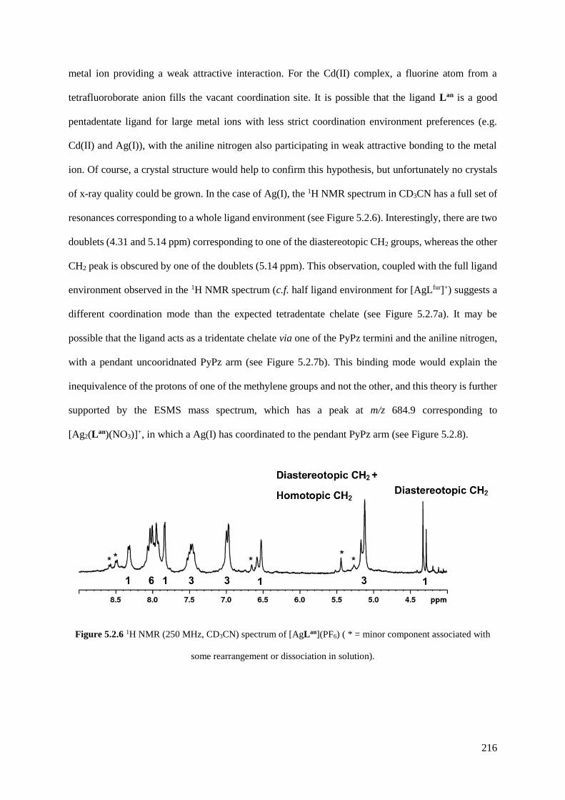
216
metal ion providing a weak attractive interaction. For the Cd(II) complex, a fluorine atom from a
tetrafluoroborate anion fills the vacant coordination site. It is possible that the ligand Lan is a good
pentadentate ligand for large metal ions with less strict coordination environment preferences (e.g.
Cd(II) and Ag(I)), with the aniline nitrogen also participating in weak attractive bonding to the metal
ion. Of course, a crystal structure would help to confirm this hypothesis, but unfortunately no crystals
of x-ray quality could be grown. In the case of Ag(I), the 1H NMR spectrum in CD3CN has a full set of
resonances corresponding to a whole ligand environment (see Figure 5.2.6). Interestingly, there are two
doublets (4.31 and 5.14 ppm) corresponding to one of the diastereotopic CH2 groups, whereas the other
CH2 peak is obscured by one of the doublets (5.14 ppm). This observation, coupled with the full ligand
environment observed in the 1H NMR spectrum (c.f. half ligand environment for [AgLfur]+) suggests a
different coordination mode than the expected tetradentate chelate (see Figure 5.2.7a). It may be
possible that the ligand acts as a tridentate chelate via one of the PyPz termini and the aniline nitrogen,
with a pendant uncooridnated PyPz arm (see Figure 5.2.7b). This binding mode would explain the
inequivalence of the protons of one of the methylene groups and not the other, and this theory is further
supported by the ESMS mass spectrum, which has a peak at m/z 684.9 corresponding to
[Ag2(Lan)(NO3)]+, in which a Ag(I) has coordinated to the pendant PyPz arm (see Figure 5.2.8).
Figure 5.2.6 1H NMR (250 MHz, CD3CN) spectrum of [AgLan](PF6) ( * = minor component associated with
some rearrangement or dissociation in solution).

217
Figure 5.2.7 Two possible coordination modes of the ligand Lan with Ag(I): (a) expected tetradentate chelate,
and; (b) tridentate chelate.
Figure 5.2.8 Electrospray mass spectrum of [AgLan](PF6).
The combination of Zn(ClO4)2 and Lan gave a very complicated mixture of products. This was
evidenced by the ESMS spectrum (see Figure 5.2.10), in which peaks are observed for the following
species: M1L1, M1L2, M2L2, M2L3 and M3L3. The 1H NMR spectrum recorded in CD3CN was consistent
with a mixture of different species, with a large number of poorly resolved peaks between 9.0 – 3.5
ppm (see Figure 5.2.11). Heating the sample to 60 oC and re-recording the spectrum after 1 or 2 days
did not significantly change any of the peaks, and after 1 week of heating the product degraded and
precipitated out of solution. It was clear, therefore, that a different strategy was necessary to form any
type of coordination cage structure with the ligand Lan.

218
Figure 5.2.10 Partial electrospray mass spectrum of the product mixture arising from Zn(ClO4)2 and Lan.
Figure 5.2.11 1H NMR (400 MHz, CD3CN) spectrum of the product mixture arising from Zn(ClO4)2 and Lan.
The complexation reactions were repeated, but this time using a solvothermal method in which a
mixture of the ligand Lan and the appropriate transition metal salt were mixed in a 3 : 2 ratio in methanol
and then transferred to a Teflon lined autoclave. The autoclave was then heated to 100 oC for 12 hours
and then slowly cooled to room temperature. This method can sometimes allow the recrystallization of
the product, with the possibility of X-ray quality crystals being formed. Unfortunately, again in most
cases only mononuclear complexes were formed, with the product precipitating out of solution as a
powder. However, with the reaction of Co(BF4)2 and Lan, a positive result was observed. Small pink
crystals had been formed during the slow cooling, which analysed as [Co8Lan12][BF4]16 by ESMS (see
Figure 5.2.12). The mass spectrum displayed a pleasing series of peaks for sequential loss of
tetrafluoroborate anions from the complete complex, a commonly seen characteristic of cages of this

219
type.5 High-resolution mass spectrometry analysis performed on an Orbitrap mass spectrometer
confirmed the charge spacings of these peaks; the 5+ peak is shown below (see Figure 5.2.13).
Figure 5.2.12 Electrospray mass spectrum of [Co8Lan12][BF4]16 showing a sequence of peaks corresponding to
[Co8Lan12(BF4)16-z]z+, i.e. loss of 3–8 tetrafluoroborate anions from the complete complex.
Figure 5.2.13 Expansions of high-resolution ESMS+ mass spectra of redissolved crystals of [Co8Lan12][BF4]16,
showing theoretical (red) and experimental (grey) isotope patterns and accurate masses for the 5+ peak cluster.

220
The paramagnetic 1H NMR spectrum of the pink crystals, however, is not perfectly clean (see Figure
5.2.14). There is a clear main series of peaks in which 41 different peaks can be identified (as indicated
by peaks marked with an asterisk, *), one peak short of the 42 required for two inequivalent ligand
environments; the other peak is presumably hidden under the solvent peak or is too broad to identify.
The smaller peaks are due to a minor component associated with some rearrangement or dissociation
in solution. Two observed ligand environments is consistent with the formation of a Co8(Lan)12 cube,
provided the metal geometries within the cage are identical to those seen in the Co8(Lm-Ph)12 and
Co8(L2,6-Py)12 cubes (see Figure 5.2.15).12,13,19 Two of the metal centres at opposite vertices have fac tris
chelate geometry [Co(3)/Co(3A) in Figure 5.2.15], whereas the other six metals have mer tris chelate
geometry. The four metal centres labelled with an ‘A’ have opposite optical configuration to those
without the label; consequently, there is an inversion centre in the centre of the cage, which results in
overall S6 geometry, and therefore two inequivalent ligand environments. A crystal structure would
prove this rationalisation of the 1H NMR spectrum, and also provide information as to whether the
amine groups are directed exohedrally or endohedrally. However, no X-ray quality crystals could be
grown despite repeated attempts.
Figure 5.2.14 Paramagnetic 1H NMR (400 MHz, CD3NO2) spectrum of [Co8Lan12][BF4]16. Signals that can be
clearly identified are denoted by an asterisk, *; 41 of the expected 42 signals can be located.
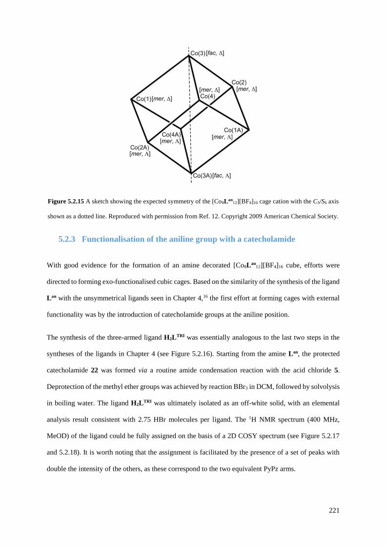
221
Figure 5.2.15 A sketch showing the expected symmetry of the [Co8Lan12][BF4]16 cage cation with the C3/S6 axis
shown as a dotted line. Reproduced with permission from Ref. 12. Copyright 2009 American Chemical Society.
5.2.3 Functionalisation of the aniline group with a catecholamide
With good evidence for the formation of an amine decorated [Co8Lan12][BF4]16 cube, efforts were
directed to forming exo-functionalised cubic cages. Based on the similarity of the synthesis of the ligand
Lan with the unsymmetrical ligands seen in Chapter 4,16 the first effort at forming cages with external
functionality was by the introduction of catecholamide groups at the aniline position.
The synthesis of the three-armed ligand H2LTRI was essentially analogous to the last two steps in the
syntheses of the ligands in Chapter 4 (see Figure 5.2.16). Starting from the amine Lan, the protected
catecholamide 22 was formed via a routine amide condensation reaction with the acid chloride 5.
Deprotection of the methyl ether groups was achieved by reaction BBr3 in DCM, followed by solvolysis
in boiling water. The ligand H2LTRI was ultimately isolated as an off-white solid, with an elemental
analysis result consistent with 2.75 HBr molecules per ligand. The 1H NMR spectrum (400 MHz,
MeOD) of the ligand could be fully assigned on the basis of a 2D COSY spectrum (see Figure 5.2.17
and 5.2.18). It is worth noting that the assignment is facilitated by the presence of a set of peaks with
double the intensity of the others, as these correspond to the two equivalent PyPz arms.

222
Figure 5.2.16 Reaction scheme for the preparation of H2LTRI. (i) a. SOCl2, dmf; (ii) 5, DCM, Et3N; (iii) BBr3,
DCM, H2O.
Figure 5.2.17 Full 1H NMR (400 MHz, CD3OD) spectrum of H2LTRI.

223
Figure 5.2.18 Part of the 1H COSY NMR (400 MHz, MeOD) spectrum of H2LTRI.2.75HBr , showing the full
assignment of the aromatic region. Py = pyridine, Pz = pyrazole, Ph = phenyl, cat = catechol.
Like the ligands in Chapter 4, H2LTRI possesses both hard and soft binding sites. Unlike the previously
seen bis-bidentate ligands, the new tritopic ligand has the potential to form coordination cages in two
distinct ways when mixed with octahedral hard and soft metal ions. The first is with all the hard and
soft metal ions defining the vertices of a heterometallic cage. As the ligand has 4 nitrogen donor atoms
and 2 oxygen donor atoms, this would necessarily lead to a cage formulation of [MHnMS
2nLTRI3n]n+
(where MH is a hard metal and MS a soft metal), providing the hard metal ion is octahedrally coordinated
to 6 oxygen atoms, and the soft metal ion is octahedrally coordinated to 6 nitrogen atoms (see Figure
5.2.19). It should be noted that a cage of this type could also form with mixed N/O donor vertices if
there is no distinct coordination preference for either metal. The second way a coordination cage could
be formed with the ligand H2LTRI is by only the soft metals (i.e. those bound to the PyPz termini)
defining the cage vertices of a homonuclear cage, such as the M8L12 cubes seen above. The catechol
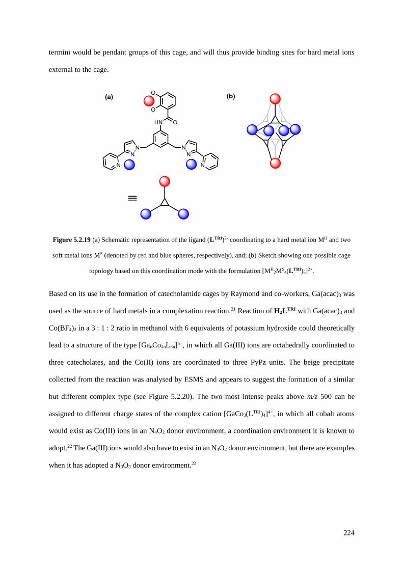
224
termini would be pendant groups of this cage, and will thus provide binding sites for hard metal ions
external to the cage.
Figure 5.2.19 (a) Schematic representation of the ligand (LTRI)2- coordinating to a hard metal ion MH and two
soft metal ions MS (denoted by red and blue spheres, respectively), and; (b) Sketch showing one possible cage
topology based on this coordination mode with the formulation [MH2MS
4(LTRI)6]2+.
Based on its use in the formation of catecholamide cages by Raymond and co-workers, Ga(acac)3 was
used as the source of hard metals in a complexation reaction.21 Reaction of H2LTRI with Ga(acac)3 and
Co(BF4)2 in a 3 : 1 : 2 ratio in methanol with 6 equivalents of potassium hydroxide could theoretically
lead to a structure of the type [GanCo2nL3n]n+, in which all Ga(III) ions are octahedrally coordinated to
three catecholates, and the Co(II) ions are coordinated to three PyPz units. The beige precipitate
collected from the reaction was analysed by ESMS and appears to suggest the formation of a similar
but different complex type (see Figure 5.2.20). The two most intense peaks above m/z 500 can be
assigned to different charge states of the complex cation [GaCo3(LTRI)4]4+, in which all cobalt atoms
would exist as Co(III) ions in an N4O2 donor environment, a coordination environment it is known to
adopt.22 The Ga(III) ions would also have to exist in an N4O2 donor environment, but there are examples
when it has adopted a N3O3 donor environment.23
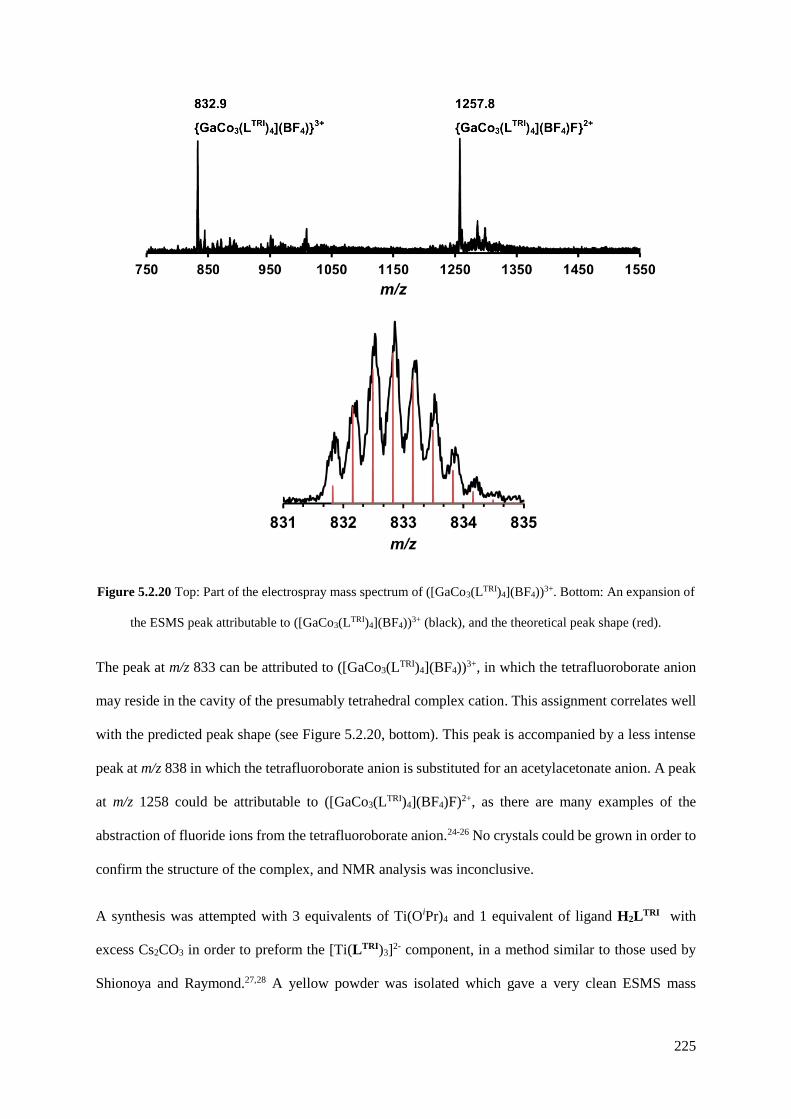
225
Figure 5.2.20 Top: Part of the electrospray mass spectrum of ([GaCo3(LTRI)4](BF4))3+. Bottom: An expansion of
the ESMS peak attributable to ([GaCo3(LTRI)4](BF4))3+ (black), and the theoretical peak shape (red).
The peak at m/z 833 can be attributed to ([GaCo3(LTRI)4](BF4))3+, in which the tetrafluoroborate anion
may reside in the cavity of the presumably tetrahedral complex cation. This assignment correlates well
with the predicted peak shape (see Figure 5.2.20, bottom). This peak is accompanied by a less intense
peak at m/z 838 in which the tetrafluoroborate anion is substituted for an acetylacetonate anion. A peak
at m/z 1258 could be attributable to ([GaCo3(LTRI)4](BF4)F)2+, as there are many examples of the
abstraction of fluoride ions from the tetrafluoroborate anion.24-26 No crystals could be grown in order to
confirm the structure of the complex, and NMR analysis was inconclusive.
A synthesis was attempted with 3 equivalents of Ti(OiPr)4 and 1 equivalent of ligand H2LTRI with
excess Cs2CO3 in order to preform the [Ti(LTRI)3]2- component, in a method similar to those used by
Shionoya and Raymond.27,28 A yellow powder was isolated which gave a very clean ESMS mass

226
spectrum consistent with the formation of Cs2[Ti(LTRI)3] (see Figure 5.2.21), with the only major peak
corresponding to [Ti(LTRI)3]2- (m/z 837.3). The 1H NMR spectrum revealed that the ligand still
possessed C2 symmetry; the PyPz arms are still equivalent even when the catecholate is coordinated to
a metal centre. Unfortunately the spectrum revealed impurities which could not be removed by washing
with methanol, precluding detailed analysis. Even more disappointingly, reaction of the preformed
Cs2[Ti(LTRI)3] component with Cd(ClO4)2 did not result in the formation of any cages which could be
detected by ESMS.
Figure 5.2.21 Electrospray mass spectrum of Cs2[Ti(LTRI)3].
5.2.4 Functionalisation of the aniline group with ferrocene
As the attempted introduction of catechol groups to the exterior of coordination cages had been
unsuccessful, a simpler method to introduce functionality to the exterior of a M8L12 cube was sought.
Ferrocene was identified as a candidate for this purpose, as it can be easily introduced via its carboxylic
acid derivative and also provides the potential for redox active cage behaviour. The synthesis of the
ligand LFc was achieved simply by reacting Lan in dichloromethane in triethylamine with the acid
chloride 23, which was easily prepared from ferrocenecarboxylic acid and oxalyl chloride in
dichloromethane (see Figure 5.2.22). After purification by column chromatography on alumina, the
new ligand was determined to be pure by ESMS and 1H NMR spectroscopy (see Figure 5.2.23).

227
Figure 5.2.22 Reaction scheme for the preparation of LFc. (i) (COCl)2, DCM; (ii) 23, DCM, Et3N.
Reaction of 3 equivalents of LFc with 2 equivalents of Co(BF4)2 in methanol and dichloromethane
resulted in the formation of an orange powder. After washing with methanol, the powder was analysed
by ESMS and 1H NMR spectroscopy to give some results that might seem quite surprising. Whereas
with the parent ligand Lan a M8L12 cubic coordination cage was determined to be the major product, it
was apparent that this was not the major product in this instance; instead, a M6L9 assembly dominates
the electrospray mass spectrum (see Figure 5.2.24). Peaks at m/z 2237.1, 1655.4, 1307.6 and 1057.5
correspond to the loss of 3-6 anions, respectively, from the complete complex [Co6LFc9][BF4]12. A peak
at m/z 1575.5 corresponds to [Co2LFc2(BF4)2(CHO2)]+, as confirmed by the isotope pattern, and is
presumably a fragmentation product arising from the addition of formic acid during the mass spectrum
preparation. The paramagnetic 1H NMR spectrum is quite poorly resolved (see Figure 5.2.25), but it is
clear that it is more complicated than the spectrum of the M8Lan12 cube (see Figure 5.2.14). These two
observations can be rationalised based on previous results in the Ward group.12
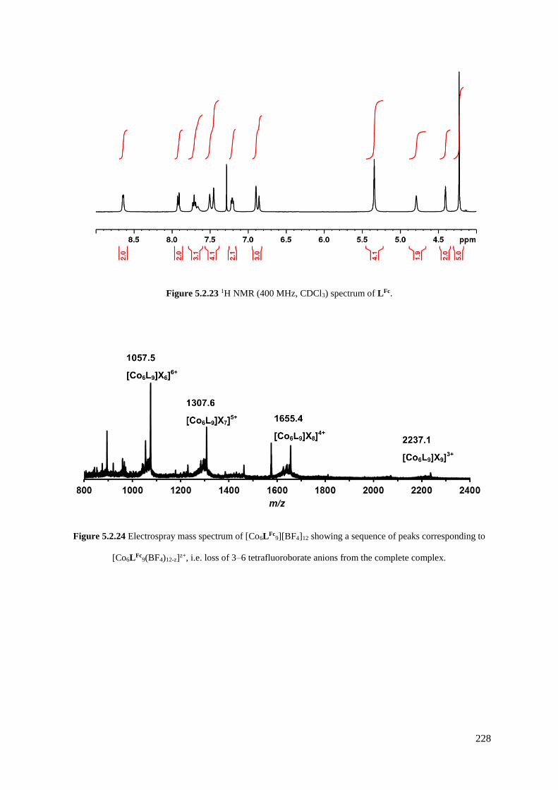
228
Figure 5.2.23 1H NMR (400 MHz, CDCl3) spectrum of LFc.
Figure 5.2.24 Electrospray mass spectrum of [Co6LFc9][BF4]12 showing a sequence of peaks corresponding to
[Co6LFc9(BF4)12-z]z+, i.e. loss of 3–6 tetrafluoroborate anions from the complete complex.

229
Figure 5.2.25 Paramagnetic 1H NMR (400 MHz, CD3NO2) spectrum of [Co6LFc9][BF4]12.
It was found in earlier work12 that the M8L12 cubic and M6L9 open-book structures can interconvert
readily, even through use of different anions of the same charge and shape with the same metal cation;
the two assemblies are clearly of very similar energy. Therefore, it might be not surprising that adding
a bulky ferrocenyl group to the ligand causes a different structure to be formed, due to the change in
sterics of the ligand packing in the cage structures. It is likely that the Co6LFc9 assembly is indeed the
open-book assembly as seen with Lm-Ph and L2,6-Py, and not the trigonal prism also reported within the
Ward group.12, 29 This is on the basis of the paramagnetic 1H NMR spectrum; the open-book structure
requires 4.5 inequivalent ligand environments, whereas the trigonal prism requires 1.5 ligand
environments. Although the 1H NMR spectrum is quite poorly resolved, it is apparent that there are far
more than the 30 paramagnetically shifted peaks required for the trigonal prism.

230
5.3 Conclusion
A general synthetic route for a family of amide-substituted ligands based on a meta-phenylene spacer
has been designed, via the parent aniline ligand Lan. The ligand Lan can be prepared in 5 steps in an
overall 17 % yield from readily available starting materials. A range of functionality can be introduced
to the ligand by simple amide condensation reactions with an appropriate acid chloride. This will enable
the exterior functionalisation of coordination cages, thus improving their practical use. The ligand Lan
reacts with Co(BF4)2 to give a M8L12 (presumably) cubic coordination cage, whereas the ferrocenyl
substituted ligand LFc reacts with Co(BF4)2 to give a M6L9 (presumably) open-book assembly. Based
on previous work in the group, the two types of framework are likely to be of very similar energy to
each other, and can even interconvert in solution. This work suggests that a better starting point for exo-
functionalised coordination cages would be from ligands that tend to give only one type of cage
structure.
5.4 Experimental
5.4.1 Ligand synthesis
3-(2-Pyridyl)pyrazole was used as prepared.30 Dry dichloromethane was obtained by distillation over
calcium hydride.
Synthesis of 5
2,3-Dimethoxybenzoic acid (4.70 g, 25.8 mmol), SOCl2 (7 cm3, 96.5 mmol) and a drop of DMF were
heated to reflux with stirring for 6 h. The condenser was fitted with a CaCl2 drying tube to absorb
liberated SO2 and HCl. The resultant clear yellow solution was diluted with CHCl3 and reduced to

231
dryness three times. Drying under high vacuum yielded 5 as an off white solid, which was used without
any further purification, assuming quantitative yield (Yield: 5.10 g, 99 %). 1H-NMR (250 MHz, CDCl3):
δ 7.55 (1H, dd; Ar-H), 7.20-7.15 (2H, m; Ar-H), 3.94 (3H, s; OMe), 3.92 (3H, s; OMe). EIMS m/z 224
[M + Na]+, 165 [M - Cl-]+. Data is in accordance with the literature.31
Synthesis of 18
A solution of dimethyl 5-aminoisophthalate (5.0 g, 23.9 mmol) in dry THF (90 cm3) was maintained at
0 oC in an N2 atmosphere. To this was added LiAlH4 (2.4 M in THF, 60 cm3, 144 mmol, 6 eq) by
disposable plastic syringe. A colour change from yellow to green and finally to purple was observed.
After stirring for 1 h at 0 oC, the mixture was heated to reflux overnight. The following day, the resultant
white solution was cooled to 0 oC and quenched by the slow addition of aqueous KOH (20%, 25 cm3)
and then diluted with EtOAc (200 cm3). The cream solution was filtered through celite and rinsed with
EtOAc. The resultant yellow solution was evaporated to dryness under reduced pressure before
purification by column chromatography on silica. Elution with EtOAc → 10 % MeOH/EtOAc and
collection of the 2nd fraction (Rf = 0.21 in EtOAc) yielded 18 as a pale yellow solid (Yield: 1.30 g, 8.5
mmol, 36 %). 1H-NMR (400 MHz, MeOD): δ 6.71 (1H, s; ArH), 6.66 (2H, s; ArH), 4.51 (4H, s; CH2).
ESMS: m/z 154 [M + H]+; Data is in accordance with the literature.17
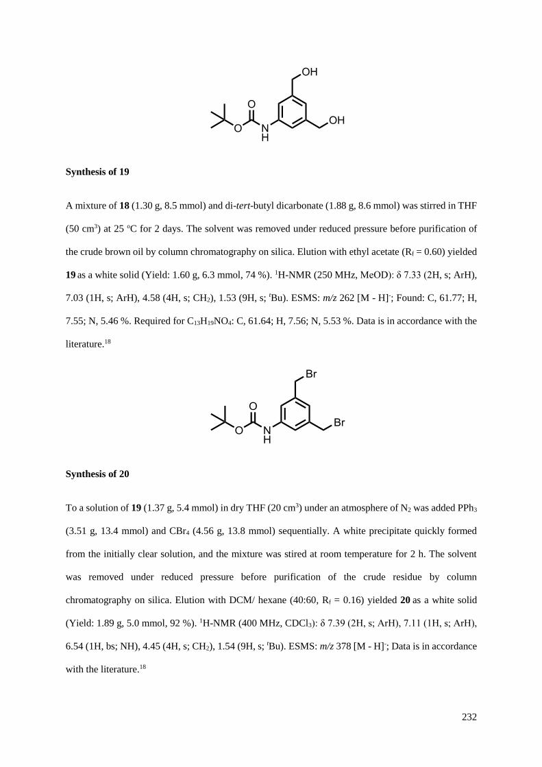
232
Synthesis of 19
A mixture of 18 (1.30 g, 8.5 mmol) and di-tert-butyl dicarbonate (1.88 g, 8.6 mmol) was stirred in THF
(50 cm3) at 25 oC for 2 days. The solvent was removed under reduced pressure before purification of
the crude brown oil by column chromatography on silica. Elution with ethyl acetate (Rf = 0.60) yielded
19 as a white solid (Yield: 1.60 g, 6.3 mmol, 74 %). 1H-NMR (250 MHz, MeOD): δ 7.33 (2H, s; ArH),
7.03 (1H, s; ArH), 4.58 (4H, s; CH2), 1.53 (9H, s; tBu). ESMS: m/z 262 [M - H]-; Found: C, 61.77; H,
7.55; N, 5.46 %. Required for C13H19NO4: C, 61.64; H, 7.56; N, 5.53 %. Data is in accordance with the
literature.18
Synthesis of 20
To a solution of 19 (1.37 g, 5.4 mmol) in dry THF (20 cm3) under an atmosphere of N2 was added PPh3
(3.51 g, 13.4 mmol) and CBr4 (4.56 g, 13.8 mmol) sequentially. A white precipitate quickly formed
from the initially clear solution, and the mixture was stired at room temperature for 2 h. The solvent
was removed under reduced pressure before purification of the crude residue by column
chromatography on silica. Elution with DCM/ hexane (40:60, Rf = 0.16) yielded 20 as a white solid
(Yield: 1.89 g, 5.0 mmol, 92 %). 1H-NMR (400 MHz, CDCl3): δ 7.39 (2H, s; ArH), 7.11 (1H, s; ArH),
6.54 (1H, bs; NH), 4.45 (4H, s; CH2), 1.54 (9H, s; tBu). ESMS: m/z 378 [M - H]-; Data is in accordance
with the literature.18
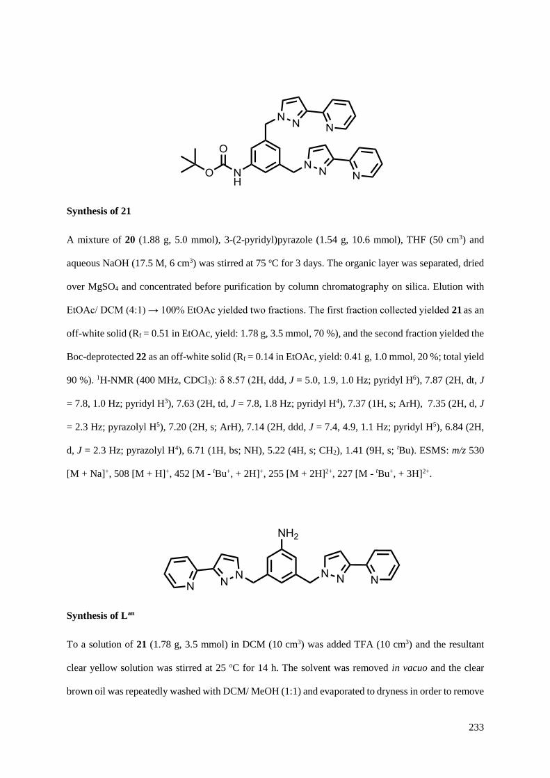
233
Synthesis of 21
A mixture of 20 (1.88 g, 5.0 mmol), 3-(2-pyridyl)pyrazole (1.54 g, 10.6 mmol), THF (50 cm3) and
aqueous NaOH (17.5 M, 6 cm3) was stirred at 75 oC for 3 days. The organic layer was separated, dried
over MgSO4 and concentrated before purification by column chromatography on silica. Elution with
EtOAc/ DCM (4:1) → 100% EtOAc yielded two fractions. The first fraction collected yielded 21 as an
off-white solid (Rf = 0.51 in EtOAc, yield: 1.78 g, 3.5 mmol, 70 %), and the second fraction yielded the
Boc-deprotected 22 as an off-white solid (Rf = 0.14 in EtOAc, yield: 0.41 g, 1.0 mmol, 20 %; total yield
90 %). 1H-NMR (400 MHz, CDCl3): δ 8.57 (2H, ddd, J = 5.0, 1.9, 1.0 Hz; pyridyl H6), 7.87 (2H, dt, J
= 7.8, 1.0 Hz; pyridyl H3), 7.63 (2H, td, J = 7.8, 1.8 Hz; pyridyl H4), 7.37 (1H, s; ArH), 7.35 (2H, d, J
= 2.3 Hz; pyrazolyl H5), 7.20 (2H, s; ArH), 7.14 (2H, ddd, J = 7.4, 4.9, 1.1 Hz; pyridyl H5), 6.84 (2H,
d, J = 2.3 Hz; pyrazolyl H4), 6.71 (1H, bs; NH), 5.22 (4H, s; CH2), 1.41 (9H, s; tBu). ESMS: m/z 530
[M + Na]+, 508 [M + H]+, 452 [M - tBu+, + 2H]+, 255 [M + 2H]2+, 227 [M - tBu+, + 3H]2+.
Synthesis of Lan
To a solution of 21 (1.78 g, 3.5 mmol) in DCM (10 cm3) was added TFA (10 cm3) and the resultant
clear yellow solution was stirred at 25 oC for 14 h. The solvent was removed in vacuo and the clear
brown oil was repeatedly washed with DCM/ MeOH (1:1) and evaporated to dryness in order to remove

234
all traces of TFA. The brown solid was washed with an aqueous solution of K2CO3 (2M) and the organic
layer extracted with DCM, dried over MgSO4 and evaporated to dryness, yielding Lan as a white solid
(Yield: 1.13 g, 79 %). 1H-NMR (400 MHz, CDCl3): δ 8.62 (2H, ddd, J = 5.0, 1.9, 1.0 Hz; pyridyl H6),
7.92 (2H, dt, J = 8.0, 1.0 Hz; pyridyl H3), 7.68 (2H, td, J = 7.8, 1.8 Hz; pyridyl H4), 7.39 (2H, d, J = 2.3
Hz; pyrazolyl H5), 7.18 (2H, ddd, J = 7.8, 4.9, 1.1 Hz; pyridyl H5), 6.89 (2H, d, J = 2.3 Hz; pyrazolyl
H4), 6.51 (1H, s; ArH), 6.39 (2H, s; ArH), 5.23 (4H, s; CH2), 3.64 (2H, bs; NH2). ESMS: m/z 430 [M +
Na]+, 408 [M + H]+, 205 [M + 2H]2+. Found: C, 64.40; H, 5.53; N, 21.92 %. Required for
C24H21N7.2.25H2O: C, 64.34; H, 5.74; N, 21.89 %
Synthesis of 22
A mixture of Lan (1.57 g, 3.9 mmol) and 5 (0.85 g, 4.2 mmol) were stirred in dry DCM (50 cm3) under
nitrogen flow. To the cloudy solution was added Et3N (2 cm3, 14.4 mmol), and the resultant clear
solution was stirred at room temperature for 14 h. The mixture was then sequentially washed with 1M
HCl (50 cm3) and 1M NaOH (50 cm3). The organic layer was extracted with DCM, dried over MgSO4
and concentrated before purification by column chromatography on silica. Elution with EtOAc (Rf =
0.17) yielded 22 as a white solid (Yield: 1.81 g, 82 %). 1H-NMR (400 MHz, CDCl3): δ 10.04 (1H, s;
NH), 8.62 (2H, ddd, J = 5.0, 1.9, 1.0 Hz; pyridyl H6), 7.92 (2H, dt, J = 8.0, 1.0 Hz; pyridyl H3), 7.74
(1H, dd, J = 8.1, 1.5 Hz; ArH), 7.69 (2H, td, J = 7.8, 1.8 Hz; pyridyl H4), 7.57 (2H, d, J = 1.1 Hz; ArH),
7.45 (2H, d, J = 2.3 Hz; pyrazolyl H5), 7.22 – 7.15 (3H, m; ArH and pyridyl H5), 7.08 (1H, dd, J = 8.1,
1.5 Hz; ArH), 6.90 (2H, d, J = 2.3 Hz; pyrazolyl H4), 6.89 (1H, s; ArH), 5.37 (4H, s; CH2), 3.91 (3H, s;
OMe); 3.89 (3H, s; OMe). ESMS: m/z 572 [M + H]+, 287 [M + 2H]2+.
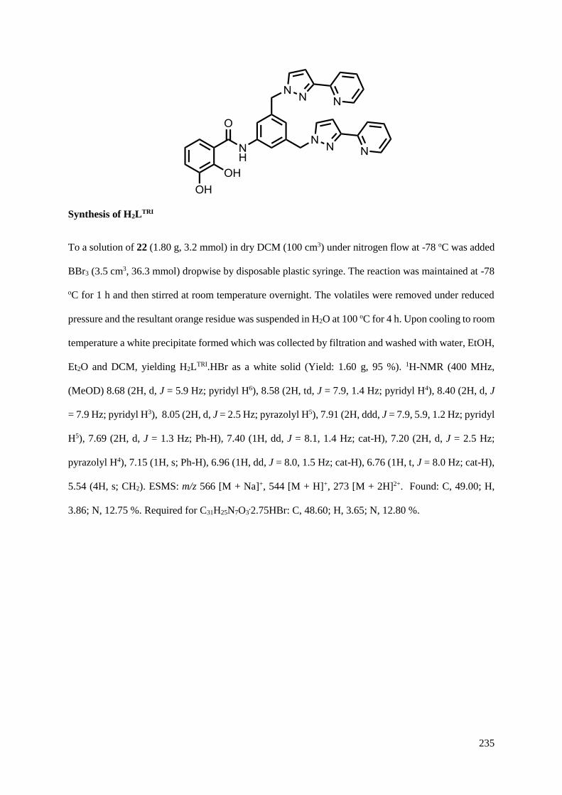
235
Synthesis of H2LTRI
To a solution of 22 (1.80 g, 3.2 mmol) in dry DCM (100 cm3) under nitrogen flow at -78 oC was added
BBr3 (3.5 cm3, 36.3 mmol) dropwise by disposable plastic syringe. The reaction was maintained at -78
oC for 1 h and then stirred at room temperature overnight. The volatiles were removed under reduced
pressure and the resultant orange residue was suspended in H2O at 100 oC for 4 h. Upon cooling to room
temperature a white precipitate formed which was collected by filtration and washed with water, EtOH,
Et2O and DCM, yielding H2LTRI.HBr as a white solid (Yield: 1.60 g, 95 %). 1H-NMR (400 MHz,
(MeOD) 8.68 (2H, d, J = 5.9 Hz; pyridyl H6), 8.58 (2H, td, J = 7.9, 1.4 Hz; pyridyl H4), 8.40 (2H, d, J
= 7.9 Hz; pyridyl H3), 8.05 (2H, d, J = 2.5 Hz; pyrazolyl H5), 7.91 (2H, ddd, J = 7.9, 5.9, 1.2 Hz; pyridyl
H5), 7.69 (2H, d, J = 1.3 Hz; Ph-H), 7.40 (1H, dd, J = 8.1, 1.4 Hz; cat-H), 7.20 (2H, d, J = 2.5 Hz;
pyrazolyl H4), 7.15 (1H, s; Ph-H), 6.96 (1H, dd, J = 8.0, 1.5 Hz; cat-H), 6.76 (1H, t, J = 8.0 Hz; cat-H),
5.54 (4H, s; CH2). ESMS: m/z 566 [M + Na]+, 544 [M + H]+, 273 [M + 2H]2+. Found: C, 49.00; H,
3.86; N, 12.75 %. Required for C31H25N7O3.2.75HBr: C, 48.60; H, 3.65; N, 12.80 %.
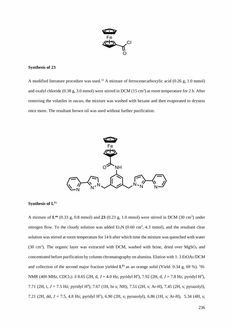
236
Synthesis of 23
A modified literature procedure was used.32 A mixture of ferrocenecarboxylic acid (0.26 g, 1.0 mmol)
and oxalyl chloride (0.38 g, 3.0 mmol) were stirred in DCM (15 cm3) at room temperature for 2 h. After
removing the volatiles in vacuo, the mixture was washed with hexane and then evaporated to dryness
once more. The resultant brown oil was used without further purification.
Synthesis of LFc
A mixture of Lan (0.33 g, 0.8 mmol) and 23 (0.23 g, 1.0 mmol) were stirred in DCM (30 cm3) under
nitrogen flow. To the cloudy solution was added Et3N (0.60 cm3, 4.3 mmol), and the resultant clear
solution was stirred at room temperature for 14 h after which time the mixture was quenched with water
(30 cm3). The organic layer was extracted with DCM, washed with brine, dried over MgSO4 and
concentrated before purification by column chromatography on alumina. Elution with 1: 3 EtOAc/DCM
and collection of the second major fraction yielded LFc as an orange solid (Yield: 0.34 g, 69 %). 1H-
NMR (400 MHz, CDCl3): δ 8.65 (2H, d, J = 4.0 Hz; pyridyl H6), 7.92 (2H, d, J = 7.8 Hz; pyridyl H3),
7.71 (2H, t, J = 7.5 Hz; pyridyl H4), 7.67 (1H, br s; NH), 7.51 (2H, s; Ar-H), 7.45 (2H, s; pyrazolyl),
7.21 (2H, dd, J = 7.5, 4.8 Hz; pyridyl H5), 6.90 (2H, s; pyrazolyl), 6.86 (1H, s; Ar-H), 5.34 (4H, s;

237
CH2), 4.79 (2H, s; Cp), 4.41 (2H, s; Cp), 4.23 (5H, s; Cp). ESMS: m/z 620 [M + H]+, 311 [M + 2H]2+.
Found: C, 67.92; H, 4.78; N, 15.66 %. Required for C35H29FeN7O: C, 67.86; H, 4.72; N, 15.83 %.
5.4.2 Complex synthesis
Synthesis of [Co8(Lan)12](BF4)16
A Teflon lined autoclave was charged with Lan (0.050 g, 0.12 mmol), Co(BF4)2.6H2O (0.036 g, 0.10
mmol) and methanol (5 cm3). Heating to 100 oC for 12 hr followed by slow cooling to room temperature
yielded a crop of small pink crystals, which were washed with methanol and dried to give
[Co8(Lan)12](BF4)16 as a pink solid in 76 % yield.
ESMS: m/z; 2163.2, {[Co8(Lan)12](BF4)13}3+; 1600.8, {[Co8(Lan)12](BF4)12}4+; 1263.1,
{[Co8(Lan)12](BF4)11}5+, 1038.0 {[Co8(Lan)12](BF4)10}6+; 877.4, {[Co8(Lan)12](BF4)9}7+; 756.7,
{[Co8(Lan)12](BF4)8}8+.
Elemental analytical data was consistent with the presence of water of crystallisation due to the
desolvated material being hygroscopic, Found: C, 47.52; H, 4.17; N, 15.76 %. Required for
C288H252B16Co8F64N84.32H2O: C, 47.21; H, 4.35; N, 16.06 %.
Synthesis of [Cd(Lan)](ClO4)2
A Teflon lined autoclave was charged with Lan (0.050 g, 0.12 mmol), Cd(ClO4)2.6H2O (0.035 g, 0.08
mmol) and methanol (5 cm3). Heating to 100 oC for 12 hr followed by slow cooling to room temperature
yielded a white powder, which was washed with methanol and dried to give [Cd(Lan)]-(ClO4)2 in 62 %
yield.
ESMS: m/z; 620, {[Cd(Lan)](ClO4)}+; 583, {[Cd(Lan)](NO3)}+. Found: C, 40.44; H, 3.65; N, 13.27 %.
Required for C24H21CdCl2N7O8.MeOH: C, 39.99; H, 3.36; N, 13.06 %.
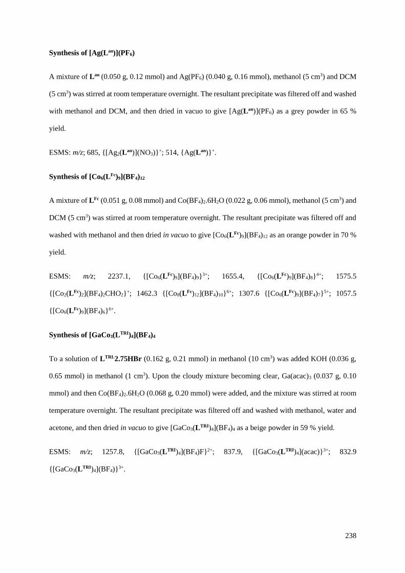
238
Synthesis of [Ag(Lan)](PF6)
A mixture of Lan (0.050 g, 0.12 mmol) and Ag(PF6) (0.040 g, 0.16 mmol), methanol (5 cm3) and DCM
(5 cm3) was stirred at room temperature overnight. The resultant precipitate was filtered off and washed
with methanol and DCM, and then dried in vacuo to give [Ag(Lan)](PF6) as a grey powder in 65 %
yield.
ESMS: m/z; 685, {[Ag2(Lan)](NO3)}+; 514, {Ag(Lan)}+.
Synthesis of [Co6(LFc)9](BF4)12
A mixture of LFc (0.051 g, 0.08 mmol) and Co(BF4)2.6H2O (0.022 g, 0.06 mmol), methanol (5 cm3) and
DCM (5 cm3) was stirred at room temperature overnight. The resultant precipitate was filtered off and
washed with methanol and then dried in vacuo to give [Co6(LFc)9](BF4)12 as an orange powder in 70 %
yield.
ESMS: m/z; 2237.1, {[Co6(LFc)9](BF4)9}3+; 1655.4, {[Co6(LFc)9](BF4)8}4+; 1575.5
{[Co2(LFc)2](BF4)2CHO2}+; 1462.3 {[Co8(LFc)12](BF4)10}6+; 1307.6 {[Co6(LFc)9](BF4)7}5+; 1057.5
{[Co6(LFc)9](BF4)6}6+.
Synthesis of [GaCo3(LTRI)4](BF4)4
To a solution of LTRI.2.75HBr (0.162 g, 0.21 mmol) in methanol (10 cm3) was added KOH (0.036 g,
0.65 mmol) in methanol (1 cm3). Upon the cloudy mixture becoming clear, Ga(acac)3 (0.037 g, 0.10
mmol) and then Co(BF4)2.6H2O (0.068 g, 0.20 mmol) were added, and the mixture was stirred at room
temperature overnight. The resultant precipitate was filtered off and washed with methanol, water and
acetone, and then dried in vacuo to give [GaCo3(LTRI)4](BF4)4 as a beige powder in 59 % yield.
ESMS: m/z; 1257.8, {[GaCo3(LTRI)4](BF4)F}2+; 837.9, {[GaCo3(LTRI)4](acac)}3+; 832.9
{[GaCo3(LTRI)4](BF4)}3+.
239
Elemental analytical data was consistent with the presence of water of crystallisation due to the
desolvated material being hygroscopic, Found: C, 49.00; H, 4.03; N, 12.41 %. Required for
C124H92B4Co3F16GaN28O12.16H2O: C, 48.86; H, 4.10; N, 12.87 %.
Synthesis of Cs2[Ti(LTRI)3]
To a solution of LTRI.2.75HBr (0.199 g, 0.26 mmol) and Cs2CO3 (0.388 g, 1.19 mmol) in methanol (20
cm3) was added Ti(iOPr)4 (0.025 g, 0.09 mmol) in methanol (1 cm3) via plastic disposable syringe. The
mixture was stirred at room temperature overnight. An insoluble solid was filtered off and washed with
methanol, and removal of the solvent by rotary evaporation gave Cs2[Ti(LTRI)3] as a yellow solid in 51
% yield.
ESMS(-): m/z; 857.3, [Ti(LTRI)3]2-.

240
5.5 X-ray crystallography
Details of the crystal, data collection and refinement parameters are summarised. Data were corrected
for absorption using empirical methods (SADABS)33 based upon symmetry-equivalent reflections
combined with measurements at different azimuthal angles. The structures were solved by direct
methods and refined by full-matrix least squares on weighted F2 values for all reflections using the
SHELX suite of programs.34 Non-hydrogen atoms were refined anisotropically. Hydrogen atoms were
placed in calculated positions, refined using idealized geometries (riding model) and were assigned
fixed isotropic displacement parameters.
A suitable crystal was mounted in a stream of cold N2 on a Bruker APEX-2 CCD diffractometer (at the
University of Sheffield) equipped with graphite-monochromated Mo-Kα radiation from a sealed-tube
source. Detail of the structure is given in the CIF.
Summary of crystallographic data for the new crystal structure:
Compound Lan. 2.25H2O Formula C24H25.5N7O2.25
Molecular weight 448.01
T / K 100(2)
Crystal system Monoclinic
Space group P 21/n
a / Å 11.4574(3)
b / Å 10.1888(3)
c / Å 19.1554(5)
/ ° 90
/ ° 95.3053(12)
/ ° 90
V / Å3 2226.57(11)
Z 4
/ g cm-3 1.336
/ mm-1 0.090
Data, restraints, parameters, Rint 5183 / 0 / 315 / 0.0249
Final R1, wR2a 0.0485, 0.1368
a The value of R1 is based on ‘observed’ data with I>2σ(I); the value of wR2 is based on all data.

241
5.6 References
1. M. D. Ward and P. R. Raithby, Chem. Soc. Rev., 2013, 42, 1619.
2. B. Breiner, J. K. Clegg and J. R. Nitschke, Chem. Sci., 2011, 2, 51.
3. M. Yoshizawa, J. K. Klosterman and M. Fujita, Angew. Chem., Int. Ed., 2009, 48, 3418.
4. M. Fujita, Chem. Soc. Rev., 1998, 27, 417.
5. M. D. Ward, Chem. Commun., 2009, 4487.
6. R. Chakrabarty, P. S. Mukherjee and P. J. Stang, Chem. Rev., 2011, 111, 6810.
7. K. Harris, D. Fujita and M. Fujita, Chem. Commun., 2013, 49, 6703.
8. N. Kamiya, M. Tominaga, S. Sato and M. Fujita, J. Am. Chem. Soc., 2007, 129, 3816.
9. K. Suzuki, S. Sato and M. Fujita, Nature Chem., 2010, 2, 25.
10. P. P. Neelakandan, A. Jimenez and J. R. Nitschke, Chem. Sci., 2014, 5, 908.
11. A. Stephenson and M. D. Ward, Dalton Trans., 2011, 40, 10360.
12. A. M. Najar, I. S. Tidmarsh, H. Adams and M. D. Ward, Inorg. Chem., 2009, 48, 11871.
13. Z. R. Bell, L. P. Harding and M. D. Ward, Chem. Commun., 2003, 2432.
14. S. Turega, W. Cullen, M. Whitehead, C. A. Hunter and M. D. Ward, J. Am. Chem. Soc., 2014,
136, 8475.
15. M. Whitehead, S. Turega, A. Stephenson, C. A. Hunter and M. D. Ward, Chem. Sci., 2013, 4,
2744.
16. A. J. Metherell and M. D. Ward, RSC Adv., 2013, 3, 14281.
17. R. Neelarapu, D. L. Holzle, S. Velaparthi, H. Bai, M. Brunsteiner, S. Y. Blond and P. A.
Petukhov, J. Med. Chem., 2011, 54, 4350.
18. H. Onagi and J. Rebek, Chem. Commun., 2005, 4604.
19. S. P. Argent, H. Adams, L. P. Harding and M. D. Ward, Dalton Trans., 2006, 542.
20. A. Stephenson and M. D. Ward, RSC Adv., 2012, 2, 10844.
21. D. L. Caulder, R. E. Powers, T. N. Parac and K. N. Raymond, Angew. Chem. Int. Ed., 1998,
37, 1840.
22. A. Panja, RSC Adv., 2013, 3, 4954.
23. M. Albrecht and R. Frohlich, J. Am. Chem. Soc., 1997, 119, 1656.

242
24. R. L. Paul, Z. R. Bell, J. C. Jeffery, J. A. McCleverty and M. D. Ward, Proc. Nat. Acad. Sci.
U.S.A, 2002, 99, 4883.
25. I. S. Tidmarsh, T. B. Faust, H. Adams, L. P. Harding, L. Russo, W. Clegg and M. D. Ward, J.
Am. Chem. Soc., 2008, 130, 15167.
26. A. Stephenson, D. Sykes and M. D. Ward, Dalton Trans., 2013, 42, 6756.
27. S. Hiraoka, Y. Sakata and M. Shionoya, J. Am. Chem. Soc., 2008, 130, 10058.
28. X. K. Sun, D. W. Johnson, D. L. Caulder, K. N. Raymond and E. H. Wong, J. Am. Chem. Soc.,
2001, 123, 2752.
29. A. Stephenson, S. P. Argent, T. Riis-Johannessen, I. S. Tidmarsh and M. D. Ward, J. Am. Chem.
Soc., 2011, 133, 858.
30. A. J. Amoroso, A. M. C. Thompson, J. C. Jeffery, P. L. Jones, J. A. McCleverty and M. D.
Ward, J. Chem. Soc., Chem. Commun., 1994, 2751.
31. M. Meyer, B. Kersting, R. E. Powers and K. N. Raymond, Inorg. Chem., 1997, 36, 5179.
32. A. Aguilar-Aguilar, A. D. Allen, E. P. Cabrera, A. Fedorov, N. Y. Fu, H. Henry-Riyad, J.
Leuninger, U. Schmid, T. T. Tidwell and R. Verma, J. Org. Chem., 2005, 70, 9556.
33. G. M. Sheldrick, SADABS: A program for absorption correction with the Siemens SMART
system, University of Göttingen, Germany, 1996.
34. G. M. Sheldrick, Acta Cryst. Sect. A, 2008, 64, 112.