
Implementation and Optimization of the Advanced Encryption ...
Upload
independentCategory
view
0download
0
sc~moi
Security and encryption optical systems based ona correlator with significant output images
Youzhi Li, Kathi Kreske, and Joseph Rosen
An improved optical security system based on two phase-only computer-generated masks is proposed.The two transparencies are placed together in a 4f correlator so that a known output image is received.In addition to simple verification, our security system is capable of identifying the type of input maskaccording to the corresponding output image it generates. The two phase masks are designed with aniterative optimization algorithm with constraints in the input and the output domains. A simulation ispresented with the resultant images formed by the two phase-only elements. Various mask combina-tions are compared to show that a combination is unique and cannot be duplicated. This uniqueness isan advantage in security systems. © 2000 Optical Society of America
OCIS codes: 070.4550, 070.2580, 050.1950, 070.6110, 100.5090.
1. Introduction
Optical technologies have recently been employed indata security.1–4 Compared with traditional com-puter and electrical systems, optical technologies of-fer primarily two types of benefits. ~1! Opticalystems have an inherent capability for parallel pro-essing, that is, rapid transmission of information.2! Information can be hidden in any of several di-
ensions, such as phase or spatial frequency; that is,ptical systems have excellent capability for encodingnformation.
In several pioneering studies1–3 the authors dem-onstrated different optical verification systems for in-formation security applications, based on opticalcorrelations. These systems correlate two functions:one, the lock, is always inside the correlator, and theother, the key, is presented to the system by the userin the verification stage. Mostly, the systems deter-mine whether the input is true or false by detectingthe correlation peak in the output plane. The nextgeneration of these security systems should offer ahigher level of security and more sophisticated ser-vices than the simple verification offered by the ex-
The authors are with the Department of Electrical and Com-puter Engineering, Ben-Gurion University of the Negev, P.O. Box653, Beer-Sheva 84105, Israel. J. Rosen’s e-mail address [email protected].
Received 29 February 2000; revised manuscript received 10 July2000.
0003-6935y00y295295-07$15.00y0© 2000 Optical Society of America
isting systems. In this paper we propose an opticalsecurity system that is based on existing optical cor-relators but has some additional benefits over thoseof the present generation.
The first property we intend to improve is the se-curity level of the verification systems. It seems tous that the Achilles’ heel of the existing systems isthat the output of the optical system is a single nar-row intense spot of light, the correlation peak. Thispeak of light is detected by an intensity detector or acamera and converted to an electronic signal. If thesignal is above some predefined threshold, the inputmask is verified as the true input. We believe thatthis procedure has a weakness, because unauthorizedintruders may bypass the correlator and illuminatethe camera from the outside with a sufficiently in-tense light spot to cause a false verification. In ad-dition, the complete information of the key mask isgiven in the lock and vice versa. This is because thekey function is equal to the complex conjugate of theFourier transform of the lock function. That meansthat the reading of one phase mask by some phase-contrast technique permits a counterfeiting of theother mask. To overcome these drawbacks, we sug-gest replacing the single spot with a collection of lightpoints ordered in some predefined code or creating animage. This image is confidential and known only tothe system designer. If and only if this image ap-pears on the camera plane as a result of a correlationbetween two masks, the true input is verified.Therefore knowing one phase mask does not permit aperson to know the distribution of the other. Even ifa person in addition knows the expected image in the
10 October 2000 y Vol. 39, No. 29 y APPLIED OPTICS 5295
“tmatt
s
5
output, he cannot compute the other mask’s values.He also needs to know the phase distribution of theoutput image to calculate the missing phase mask.However, the phase distribution of the output imagecan be measured only when the two masks exist in-side the system performing the correlation processbetween their functions.
As we shall see, the same system with the samefilter can yield many images for different inputmasks. This property is an additional benefit of theproposed system. It can verify more than one kindof true input and identify the type of input. Let uscompare the existing and the proposed systems witha real example. In a secured plant, for instance, theexisting verification systems1–3 can let someone enteror block that person from entering. Our system cando the same, but in addition it can identify the au-thorized person that asks to enter and distinguishhim from other authorized persons. That is becauseeach person gets a different key function, whichyields a different image in the system’s output, whenthe key mask is introduced in the input.
To bypass the correlator illegally is impossible nowunless the intruder knows the expected image andcan project this image onto the output camera. Onecan argue that, because the correlator’s yield is animage, this image should be automatically recog-nized. If a second optical correlator is added to rec-ognize the yield of the first one, the output result ofthe second correlator is a correlation peak, which canbe counterfeited in this stage. Our reply to this ar-gument is that optical pattern recognition is not al-ways the best option. If the image is binary with asimple shape or is some code such as a bar code andit appears alone on the output plane at more or lessthe same location, it can easily be recognized by adigital computer with appropriate software. Break-ing into a digital pattern-recognition system seemsharder than just illuminating the camera with in-tense light spot. Although having the verificationprocess in two stages adds complexity, it offers twonew benefits: ~1! improvement of the security leveland ~2! more information about the verified user.
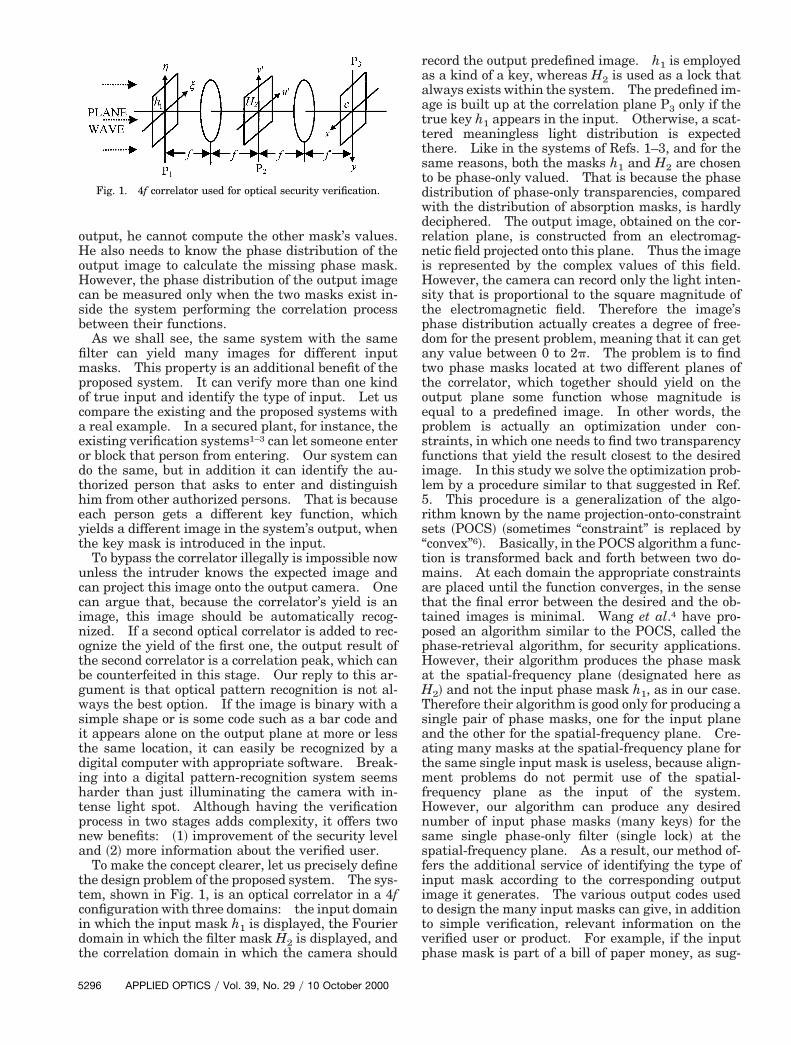
To make the concept clearer, let us precisely definethe design problem of the proposed system. The sys-tem, shown in Fig. 1, is an optical correlator in a 4fconfiguration with three domains: the input domainin which the input mask h1 is displayed, the Fourierdomain in which the filter mask H2 is displayed, andthe correlation domain in which the camera should
Fig. 1. 4f correlator used for optical security verification.
296 APPLIED OPTICS y Vol. 39, No. 29 y 10 October 2000
record the output predefined image. h1 is employedas a kind of a key, whereas H2 is used as a lock thatalways exists within the system. The predefined im-age is built up at the correlation plane P3 only if thetrue key h1 appears in the input. Otherwise, a scat-tered meaningless light distribution is expectedthere. Like in the systems of Refs. 1–3, and for thesame reasons, both the masks h1 and H2 are chosento be phase-only valued. That is because the phasedistribution of phase-only transparencies, comparedwith the distribution of absorption masks, is hardlydeciphered. The output image, obtained on the cor-relation plane, is constructed from an electromag-netic field projected onto this plane. Thus the imageis represented by the complex values of this field.However, the camera can record only the light inten-sity that is proportional to the square magnitude ofthe electromagnetic field. Therefore the image’sphase distribution actually creates a degree of free-dom for the present problem, meaning that it can getany value between 0 to 2p. The problem is to findtwo phase masks located at two different planes ofthe correlator, which together should yield on theoutput plane some function whose magnitude isequal to a predefined image. In other words, theproblem is actually an optimization under con-straints, in which one needs to find two transparencyfunctions that yield the result closest to the desiredimage. In this study we solve the optimization prob-lem by a procedure similar to that suggested in Ref.5. This procedure is a generalization of the algo-rithm known by the name projection-onto-constraintsets ~POCS! ~sometimes “constraint” is replaced byconvex”6!. Basically, in the POCS algorithm a func-ion is transformed back and forth between two do-ains. At each domain the appropriate constraints
re placed until the function converges, in the sensehat the final error between the desired and the ob-ained images is minimal. Wang et al.4 have pro-
posed an algorithm similar to the POCS, called thephase-retrieval algorithm, for security applications.However, their algorithm produces the phase maskat the spatial-frequency plane ~designated here asH2! and not the input phase mask h1, as in our case.Therefore their algorithm is good only for producing asingle pair of phase masks, one for the input planeand the other for the spatial-frequency plane. Cre-ating many masks at the spatial-frequency plane forthe same single input mask is useless, because align-ment problems do not permit use of the spatial-frequency plane as the input of the system.However, our algorithm can produce any desirednumber of input phase masks ~many keys! for theame single phase-only filter ~single lock! at the
spatial-frequency plane. As a result, our method of-fers the additional service of identifying the type ofinput mask according to the corresponding outputimage it generates. The various output codes usedto design the many input masks can give, in additionto simple verification, relevant information on theverified user or product. For example, if the inputphase mask is part of a bill of paper money, as sug-

et
er
w
fSi
gested in Ref. 1, we can design a verification systemof bills that yields a series of codes, each of whichwould contain information on, for instance, the print-ing date and location of every bill. To the best of ourknowledge, this additional service of coding informa-tion in the key function was not proposed in Ref. 4 orin other studies.
The algorithm is explained in detail in Section 2,but before that we note that an additional applicationcan be realized by the proposed system. The samesetup and the same algorithm are suitable for encryp-tion as well. Let us consider the image in the cor-relation plane P3 as the information that we wish toncrypt. The same optimization algorithm yieldswo phase functions, h1 and H2. One of them, say
h1, is the encrypted data, whereas the other function,H2, is employed as the decipher of this encrypteddata. Placing h1 in the input plane of the correlator,in which H2 is positioned in its Fourier plane, is theonly way to reconstruct the original image. In com-parison with other optical encryption systems,7,8 theencryption process in our system is iterative and dig-ital. The deciphering can be done either digitally oroptically. However, the main advantage of thismethod comes from the nature of the encrypted data.Unlike in other methods,7,8 the encrypted data ap-pear now as a phase-only function. This means thatthe amount of data in the encrypted function is halfthe general complex function with the same size; suchphase functions are difficult to read with conven-tional detection devices.
2. Analysis
With regard to the 4f correlator shown in Fig. 1, theinformation is encoded into two phase-only computer-generated masks. One is located in the input plane,denoted by h1~j, h! 5 exp@ jf~j, h!#, and the other is inthe spatial-frequency plane, denoted by H2~u, n! 5xp@ jF~u, n!#. In this system the output at the cor-elation plane is given by
c~x, y! 5 I21$I$h1~j, h!%H2~u, n!%
5 I21$I$h1~j, h!%exp@ jF~u, n!#%, (1)
where I and I21 denote the Fourier transform ~FT!and the inverse FT, respectively. For notation sim-plicity we assume that ~u, n! are the spatial-frequencyvariables related to the spatial coordinates ~u9, n9! bythe relation ~u, n! 5 ~u9, n9!ylf. The expected sys-tem’s output is
c~x, y! 5 A~x, y!exp@ jc~x, y!#, (2)
where A~x, y! is the amplitude of the expected outputimage and c~x, y! denotes the phase of c~x, y!. FromEq. ~1! the input function is given by
h1~j, h! 5 I21HI$c~x, y!%
H2~u, n! J5 I21$I$c~x, y!%exp@2jF~u, n!#%. (3)
To design two phase-only masks that produce anoutput image with a given magnitude, we choose touse the generalized POCS algorithm. This iterativealgorithm starts with a random function for the firsth1~j, h!. Then the function h1~j, h! is transformedby the correlation, defined in Eq. ~1!, into the outputfunction c~x, y! and then back through the inversecorrelation defined by Eq. ~3!. At every iteration, ineach of the two domains ~x, y! and ~j, h!, the obtainedfunctions are projected onto the constraint sets. Inthe ~x, y! domain the constraint set expresses theexpectations to get the predefined image. In the ~j,h! domain the constraint set manifests the limitationon the input function to be a phase-only function.The algorithm continues to circulate between the twodomains until the error between the actual and thedesired output functions is no longer meaningfullyreduced.
As mentioned above, the constraint in the outputplane should reflect the desire to get the image ex-pressed by the positive function A~x, y!. Thereforein the output plane the projection P1 on the con-straint set is
P1@c~x, y!# 5 A~x, y!exp@ jc~x, y!#, (4)
where A~x, y! is a real positive function representingthe output image. In the input plane we recall thath1~j, h! should be a phase-only function, and there-fore the projection P2 on the constraint set is
P2@h1~j, h!# 5 Hexp@ jf~j, h!# if ~j, h! [ W0 otherwise , (5)
here f~x, y! denotes the phase of h1~j, h!, that is,exp@ jf~j, h!# 5 h1~j, h!yuh1~j, h!u, and W is a windowunction that is necessary for reasons described inection 3. The iteration process is shown schemat-
cally in Fig. 2. Note that H2~u, n! is chosen onlyonce before the beginning of the iterations, in a pro-cess that will be explained below. After H2~u, n! is
Fig. 2. Block diagram of the main POCS algorithm used to com-pute the phase-only mask h1~j, h!.
10 October 2000 y Vol. 39, No. 29 y APPLIED OPTICS 5297

Wct
tF
o
a
a
5
defined, it becomes part of the correlator and is neverchanged during the circulating process.
The convergence of the algorithm to the desiredimage in the nth iteration is evaluated by the averagemean-square error en between the intensity of thecorrelation function before and after the projection,as follows,
en 51M **uu P1@c~x, y!#u2 2 gnucn~x, y!u2u2 dxdy, (6)
where gn is a matching constant9 determined to min-imize en and M is the total area of the output plane.
hen the reduction rate of this error function be-omes slower than some predefined value, the itera-ions are stopped.
As discussed in Ref. 5, there are two conditionshat guarantee that this error will never diverge.irst, the correlator should be an energy-conserving
Fig. 3. Two expected output images of the correlator used in thecomputer simulation.
Fig. 4. Block diagram of the mini POCS algorithm used to com-pute the phase-only mask H2~u, n!.
298 APPLIED OPTICS y Vol. 39, No. 29 y 10 October 2000
perator. This property is easily achieved if H2~u,n! is a phase-only function, as indeed it is in thepresent case. The second condition to satisfy thenondiverging feature is realized if, among all thefunctions that belong to the constraint sets, the twoprojected functions in the nth iteration, P1@cn~x, y!#
nd P2@h1,n~j, h!# are the functions closest ~by meanof the mean-square metric! to the functions cn~x, y!
nd h1,n~j, h!, respectively. It is easy to show thatthe second condition is also fulfilled in the presentalgorithm. Therefore the POCS algorithm herecan never diverge. Note that the nondiverging fea-ture of the algorithm is an additional reason to
Fig. 5. Phase function of the mask H2~u, n!.
Fig. 6. Average mean-square error ~MSE! versus the iterationsnumber for the POCS algorithm in the case of the scale ~solidcurve! and the duck ~dashed curve!.
Tiet1twladct
lprs
a
i
wf
s
favor phase-only functions in the spatial-frequencydomain.
3. Simulation Results
We wrote a computer simulation demonstrating ourgeneral concept discussed above. In our simula-tions the algorithm was tested with two differentbinary images as shown in Fig. 3; one ~a! is a ducksmashing a computer, and the other ~b! is a scale.
he images comprise 120 3 120 pixels, whereas thenput and the output planes have 256 3 256 pixelsach. In the input domain the two correlated func-ions are made to cover only the central area of28 3 128 pixels, designated as the window W. Allhe rest of the matrix outside this window is paddedith zeros. This ensures that the computer simu-
ation based on discrete FT truly simulates the an-log optical system. The signal transformed by theiscrete FT is considered periodical. Thereforeorrelation between two functions that are ex-ended beyond the central window W causes corre-
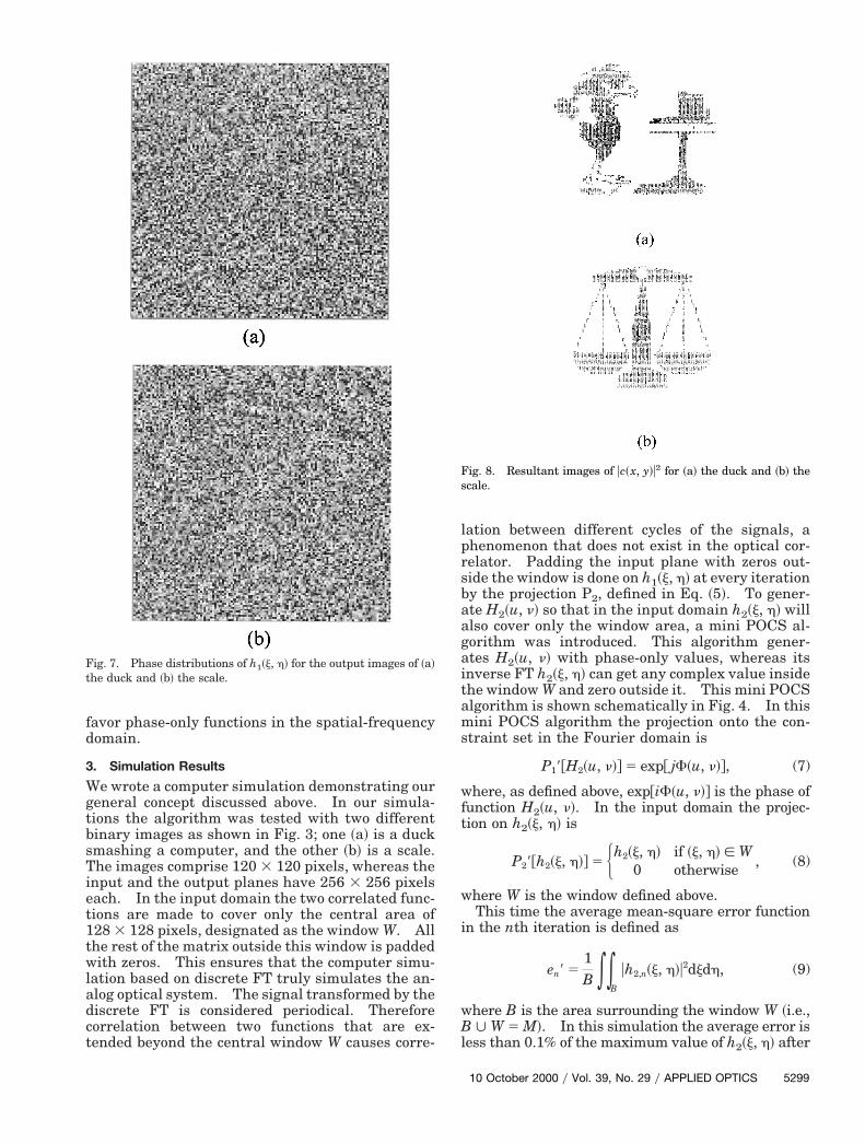
Fig. 7. Phase distributions of h1~j, h! for the output images of ~a!the duck and ~b! the scale.
ation between different cycles of the signals, ahenomenon that does not exist in the optical cor-elator. Padding the input plane with zeros out-ide the window is done on h1~j, h! at every iteration
by the projection P2, defined in Eq. ~5!. To gener-te H2~u, n! so that in the input domain h2~j, h! will
also cover only the window area, a mini POCS al-gorithm was introduced. This algorithm gener-ates H2~u, n! with phase-only values, whereas itsnverse FT h2~j, h! can get any complex value inside
the window W and zero outside it. This mini POCSalgorithm is shown schematically in Fig. 4. In thismini POCS algorithm the projection onto the con-straint set in the Fourier domain is
P19@H2~u, n!# 5 exp@ jF~u, n!#, (7)
here, as defined above, exp@iF~u, n!# is the phase ofunction H2~u, n!. In the input domain the projec-
tion on h2~j, h! is
P29@h2~j, h!# 5 Hh2~j, h! if ~j, h! [ W0 otherwise , (8)
where W is the window defined above.This time the average mean-square error function
in the nth iteration is defined as
en9 51B **
B
uh2,n~j, h!u2djdh, (9)
where B is the area surrounding the window W ~i.e.,B ø W 5 M!. In this simulation the average error isless than 0.1% of the maximum value of h2~j, h! after
Fig. 8. Resultant images of uc~x, y!u2 for ~a! the duck and ~b! thecale.
10 October 2000 y Vol. 39, No. 29 y APPLIED OPTICS 5299
ltsH
Tcmi
to
5
only 30 iterations. Figure 5 shows the phase ofH2~u, n! obtained with 30 iterations of the miniPOCS.
H2~u, n! was calculated only once by the mini POCSand then introduced into the correlator at the spatial-frequency plane. With the same H2~u, n!, we calcu-ated two different input functions h1~j, h!, for thewo images, using the main POCS algorithm de-cribed in Section 2. Note that, because the function2~u, n! is a random-valued function, there is no lim-
itation by H2 on the number of different output pat-terns that can be created by the same single H2 andmany different h1 functions. The only limitation isthe number of patterns that can be drawn on a finite-sized matrix. For both images the algorithm wasterminated after 100 iterations. The error plots for
both experiments are shown in Fig. 6. The finalaverage errors are less than 2% of the average valueof the image, for both images. Figures 7~a! and 7~b!show the phase functions of the two masks h1 for theexpected output images shown in Figs. 3~a! and 3~b!,
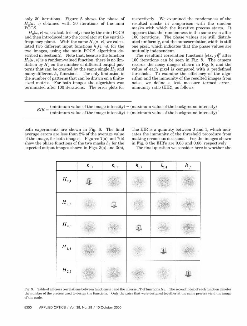
Fig. 9. Table of all cross correlations between functions h1 and thehe number of the process used to design the functions. Only thef the scale.
EIR 5~minimum value of the image intensity!
~minimum value of the image intensity!
300 APPLIED OPTICS y Vol. 39, No. 29 y 10 October 2000
respectively. We examined the randomness of theresulted masks in comparison with the randommasks with which the iterative process starts. Itappears that the randomness is the same even after100 iterations. The phase values are still distrib-uted uniformly, and the autocorrelation width is stillone pixel, which indicates that the phase values aremutually independent.
The resultant correlation functions uc~x, y!u2 after100 iterations can be seen in Fig. 8. The camerarecords the noisy images shown in Fig. 8, and thevalue of each pixel is compared with a predefinedthreshold. To examine the efficiency of the algo-rithm and the immunity of the resulted images fromnoise, we define a test measure termed error–immunity ratio ~EIR!, as follows:
he EIR is a quantity between 0 and 1, which indi-ates the immunity of the threshold procedure fromaking erroneous decisions. For the images shown
n Fig. 8 the EIR’s are 0.63 and 0.66, respectively.The final question we consider here is whether the
rse FT of functions H2. The second index of each function denotesthat were designed together at the same process yield the image
maximum value of the background intensity!
maximum value of the background intensity!.
invepairs
2 ~
1 ~

wmr
gaodah
taTlts
two phase functions h1~j, h! and H2~u, n! can be de-ciphered when we know the image function A~x, y!.Because each process of POCS starts with a randomfunction as the first trial, the final solutions are al-ways different from one experiment to another, al-though all of them yield the same desired image onthe correlation plane. Therefore even if some unau-thorized intruder acquires the predefined image inthe output plane, he would not be able to reproducethe masks H2~u, n! and h1~j, h! to get access to thesystem. This feature is demonstrated in the tableshown in Fig. 9. Five pairs of H2~u, n! and h1~j, h!
ere calculated for the same image of the scale by theini and the main POCS. This table shows the cor-
elation intensity between any possible pair h1,i~j, h!and I21$H2, j~u, n!%. Only the pairs, calculated to-ether in the same process, yield the desired image,s seen along the diagonal of the table. All the restf the cross correlations yield scattered meaninglessistributions. The conclusion is that, even if the im-ge is known, it is impossible to deduce the right h1~j,! for an unknown H2~u, n!.
4. Conclusions
We have developed a method to design an opticalsecurity system based on computer-generated opticaldiffractive elements. According to our method, onecan design two phase-only transparencies for a 4fcorrelator in order to receive a chosen image. Theresulting masks can be used for security and encryp-tion systems, as the desired image will be received inthe output plane only when the two specific phasemasks are placed in the 4f correlator. Because com-putation of the two holograms starts from completelyrandom functions, they cannot be reproduced, even ifthe output image is known. With the same phasemask in the spatial-frequency plane, the system can
produce many images in the output by the introduc-tion of different input masks. Therefore, in additionto simple verification, the system can provide infor-mation on the identity of the authorized person.Our group is currently working on a similar algo-rithm for security system implemented in a jointtransform correlator ~JTC!. The expected advan-age from a JTC-based security system is the invari-nce of the system to in-plane shifts of both masks.hus the JTC can be a proper solution for the prob-
em of misalignment sensitivity of the filter mask inhe 4f correlator. We hope that the report of thistudy will be published soon.
References1. B. Javidi and J. L. Horner, “Optical pattern recognition for
validation and security verification,” Opt. Eng. 33, 1752–1756~1994!.
2. B. Javidi, G. S. Zhang, and J. Li, “Experimental demonstrationof the random phase encoding technique for image encryptionand security verification,” Opt. Eng. 35, 2506–2512 ~1996!.
3. B. Javidi and E. Ahouzi, “Optical security system with Fourierplane encoding,” Appl. Opt. 37, 6247–6255 ~1998!.
4. R. K. Wang, I. A. Watson, and C. Chatwin, “Random phaseencoding for optical security,” Opt. Eng. 35, 2464–2469 ~1996!.
5. J. Rosen, “Learning in correlators based on projections ontoconstraint sets,” Opt. Lett. 18, 1183–1185 ~1993!.
6. H. Stark, ed., Image Recovery Theory and Application, 1st ed.~Academic, New York, 1987!.
7. P. Refregier and B. Javidi, “Optical image encryption based oninput plane and Fourier plane random encoding,” Opt. Lett. 20,767–769 ~1995!.
8. B. Javidi, L. Bernard, and N. Towghi, “Noise performance ofdouble-phase encryption compared to XOR encryption,” Opt.Eng. 38, 9–19 ~1999!.
9. B. K. Jennison, J. P. Allebach, and D. W. Sweeney, “Iterativeapproaches to computer-generated holography,” Opt. Eng. 28,629–637 ~1989!.
10 October 2000 y Vol. 39, No. 29 y APPLIED OPTICS 5301
Copyright © 2022 FDOKUMEN