Encryption (Image Steganography)
115
REGENT UNIVERSITY COLLEGE OF SCIENCE AND TECHNOLOGY IMAGE STEGANOGRAPHY (A METHOD OF HIDING INFORMATION IN PLAIN SIGHT) A CASE STUDY AT INTERGRATED SECURITY SYSTEMS GHANA LIMITED (ISSYS GH LTD.) SUBMITTED BY OBIRI OHENE NANA KOFI ID No.:00540111 THESIS SUBMITTED TO THE SCHOOL OF INFORMATICS AND ENGINEERING REGENT UNIVERSITY COLLEGE OF SCIENCE AND TECHNOLOGY IN PARTIAL
-
Upload
regentghana -
Category
Documents
-
view
0 -
download
0
Transcript of Encryption (Image Steganography)
REGENT UNIVERSITY COLLEGE OF SCIENCE
AND TECHNOLOGY
IMAGE STEGANOGRAPHY
(A METHOD OF HIDING INFORMATION IN PLAIN SIGHT)
A CASE STUDY AT INTERGRATED SECURITY SYSTEMS GHANA LIMITED
(ISSYS GH LTD.)
SUBMITTED BY
OBIRI OHENE NANA KOFI
ID No.:00540111
THESIS SUBMITTED TO THE SCHOOL OF INFORMATICS AND ENGINEERING
REGENT UNIVERSITY COLLEGE OF SCIENCE AND TECHNOLOGY IN PARTIAL
FULFILLMENT OF THE REQUIREMENT FOR THE AWARD OF
BACHELOR OF SCIENCE IN INFORMATION SYSTEMS SCIENCES
JUNE, 2014.
DECLEARATION
I OHENE NANA KOFI OBIRI declare that:
A. This thesis has not been previously been accepted for any
degree and is not being concurrently submitted in candidature
for any degree.
B. The thesis is a result of my own investigation, except where
otherwise stated. All sources used in the production of this
thesis are acknowledged by appropriate citation and explicit
references and are included in the reference that is
appended.
C. I give my consent for this thesis, if accepted, to be
available for photocopying and for inter-library loan, and
for the title and summary to be made available to
organizations external to Regent University College of
Science and Technology.
……………………………………. ……………………………………..
Student Signature Date
(Ohene Nana Kofi Obiri)
Supervisors Declaration
This Thesis is submitted for examination with my full knowledge
and acceptance of the thesis:
……………………………………. ……………………………………..
Supervisor Signature Date
(Mr. Henry Quarshie)
DEDICATION
This research project is dedicated to Almighty God who molded me
right from conception till birth and by whose divine assistance
made it easy for me to accomplish this work.

ACKNOWLEDGEMENT
Firstly, all praise is due to God (Glorified and Exalted is He),
without his immeasurable blessings and favours none of this
could have been possible.

During the course of this research, there have been numerous
people who have provided me with guidance, inspiration and
support for completing this thesis. I am indebted to my
supervisor Mr. Henry Quashie for his continuous encouragement
and support at all stages of this research. His involvement
proved vital to the completion of this thesis. I would like to
thank him for his useful and valuable advice. I also owe thanks
to Dr. Stanly S. Moffat, Vice President (RUCST). For his
insightful and encouraging comments, suggestions and teaching
skills throughout my study of report Writing in his class. On the personal front, I would like to express my gratitude to
my family, for their continuous love, support and sincere
prayers during the course of this research. I must also express
my thanks to all my colleagues in the Department of Informatics
and Engineering at (RUCST). I will also like to thank my friends
and other participants who helped me a lot by participating and
motivating me in the course of my research.
Lastly but not the least, I will like to thank my late father
for providing me a chance and funding to acquire higher
education and the inspiration he gave to me on Education. May
His soul rest in peace.
LIST OF FIGURES
FIGURE 1. Basic Model of Steganography …………………………………...14
FIGURE 2 .Organization chart with sample information assets
…………….15
FIGURE 3 .Properties contributing to information security.………………
16
FIGURE 4 .Waterfall model of the system development life cycle.
…………..32
FIGURE 5 .A graphical block illustration of the system.…………………..
…36
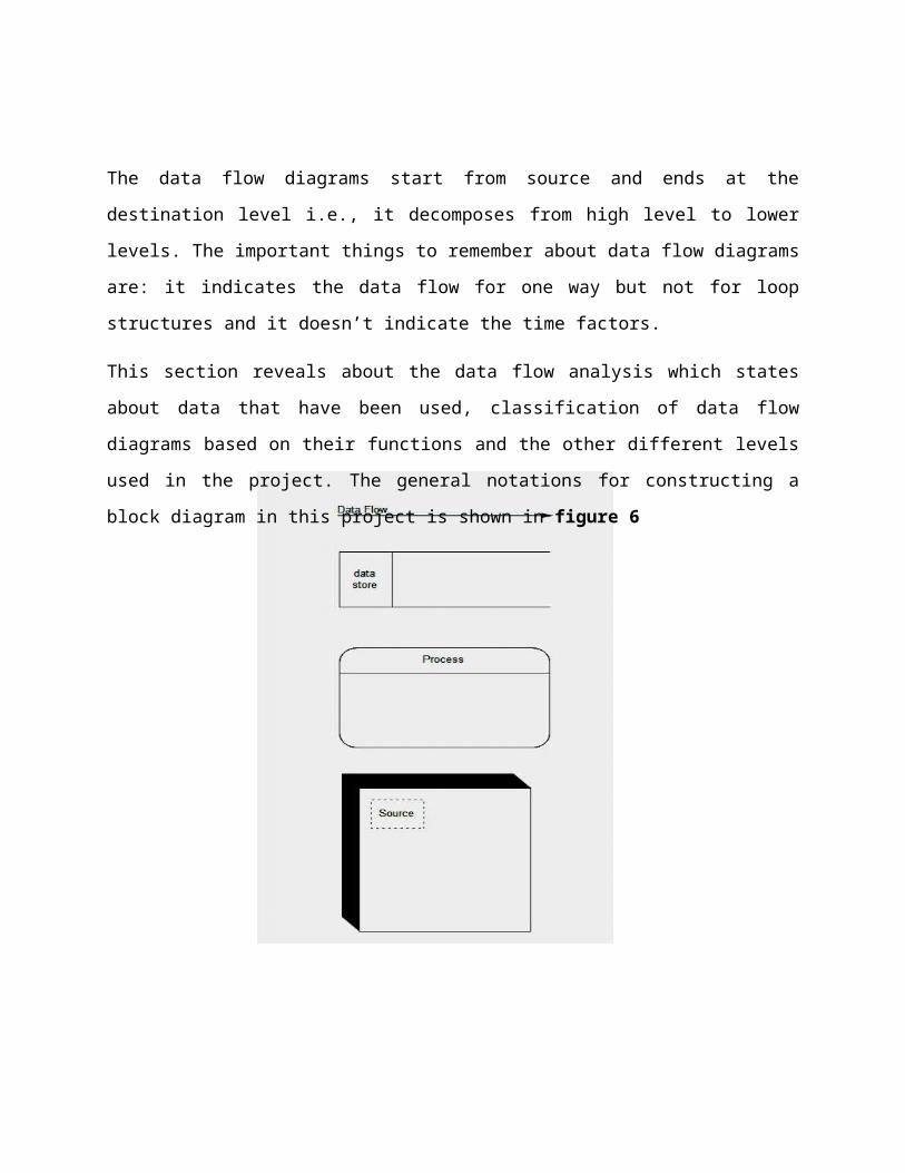
FIGURE 6 .General representations for constructing a block
diagram …….39
FIGURE 7 .(DFD 0)………………………………………………………...……41
FIGURE 8 .DFD 1)…………………………………………………………........41
FIGURE 9 .(DFD 2)……………………………………………………………...42
FIGURE 10 .Use case diagrams for the proposed system.…………………….43
FIGURE 11 .Activity diagram for encryption ………………………………....44
FIGURE 12 .Activity diagram for decryption ………………………………....45
FIGURE 13. Sequence diagram ………………………………………………...46
FIGURE 14 .Public value codes analysis
……………..........................................49
FIGURE 15 .Load carrier image file code analysis …………………………...50
FIGURE 16 . Load information file code analysis …………………………….5.0
FIGURE 17 .Least significant bit algorithm code
analysis…………………..51
FIGURE 18 .Decryption algorithm code analyses……………………………52
FIGURE 19. Encryption main page ………………………………………….....61
FIGURE 20 .Carrier image file Select.……………………………………….....62
FIGURE 21 .Carrier image preview …………………………………………....63
FIGURE 22 .Information file select …………………………………………….64
FIGURE 23 .Destination folder select ………………………………………….65
FIGURE 24 .Encryption Error message ……………………………………….66
FIGURE 25 .Decrypt main page ………………………………………………..67
FIGURE 26 .Specifying a stego-image for decryption
………………………...68
ABSTRACT
Organizations have desired to keep certain sensitive
communications and information secret for years. In our new age
of digital media and internet communications, this need often
seems even more pressing. Today’s information age, were
technology has made information sharing and transfer increased
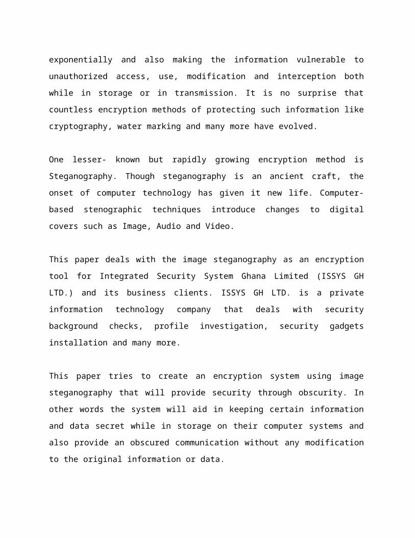
exponentially and also making the information vulnerable to
unauthorized access, use, modification and interception both
while in storage or in transmission. It is no surprise that
countless encryption methods of protecting such information like
cryptography, water marking and many more have evolved.
One lesser- known but rapidly growing encryption method is
Steganography. Though steganography is an ancient craft, the
onset of computer technology has given it new life. Computer-
based stenographic techniques introduce changes to digital
covers such as Image, Audio and Video.
This paper deals with the image steganography as an encryption
tool for Integrated Security System Ghana Limited (ISSYS GH
LTD.) and its business clients. ISSYS GH LTD. is a private
information technology company that deals with security
background checks, profile investigation, security gadgets
installation and many more.
This paper tries to create an encryption system using image
steganography that will provide security through obscurity. In
other words the system will aid in keeping certain information
and data secret while in storage on their computer systems and
also provide an obscured communication without any modification
to the original information or data.
TABLE OF CONTENTS
PAGE
DECLARATION……………………………………………………………...I
DEDICATION………………………………………………………………...II
ACKNOWLEDGEMENT……………………………………………………III
LIST OF FIGURES …………………………………………………………..IV
ABSTRACT …………………………………………………………………..V
CHAPTER ONE: INTRODUCTION PAGE
1.0 INTRODUCTION……………………………..…….….…………………...1
1.1 BACKGROUND OF STUDY………………………………….…………....3
1.2 PROBLEM STATEMENT…………………….……..…………….....……...3
1.3 GOALS AND OBJECTIVES ……………………………….……………….4
1.3.1 MAIN OBJECTIVE ………………………………………………….4
1.3.2 SPECIFIC OBJECTIVES………………………………………...........4
1.4 SIGNIFICANCE OF STUDY ………………………………………………..5
1.5 RESEACH METHOD…………………………………………………...........5
1.6 LIMITATION(S) ……………………………………………………………...5
1.8 USE OF THE PROPOSED SYSTEM ………………………………………...5
1.8 DEFINITION OF TERMS…………………………………………………...6
1.9 ORGANIZATION OF CHAPTERS…………………………………………8
CHAPTER TWO: REVIEW OF RELATED LITERATURE PAGE
2.0 INTRODUCTION…………………………………………………………....9
2.1 OVER VIEW OF STEGANOGRAPHY…………………………………….11
2.2 DIFFERENT KINDS OF STEGANOGRAPHY ……………………………12
2.3 RECOVERING INFORMATION FILE FROM A STEGO-OBJECT …….13
2.4 INFORMATION SECURITY …………………………………………….….14
2.4.1 INFORMATION VALUE ……………………………………………………..15
2.5 SECURITY CLASSIFICATION ……………………………………………..16
2.5.1 INFORMATION SECURITY ATTACKS ……………………………17
2.5.2 INFORMATION SECURITY MEASURES …………………………18
2.6 REQUIREMENTS FOR HIDING INFORMATION DIGITALLY …….……19
2.7 STEGANOGRAPHY APPLICATIONS ………………………………………22
2.7. 1 DATA STEGANOGRAPHY …………………………………………..22
2.8 STEGANOGRAPHIC TECHNIQUES ……………………………………..…23
2.9 IMAGE DEFINITION AND STRUCTURE ……………………………….…24
2.9.1 1IMAGE PROCESSING ………………………………………………25
2.9.2 IMAGE FORMATS …………………………………………………...26
2.9.3 BITMAP IMAGES ……………………………………………………26
2.10 IMAGE COMPRESSION ……………………………………………………..26
2.11 DETECTING STEGANOGRAPHY ………………………………………..….27
CHAPTER THREE:
RESEACH METHODOLOGY AND SYSTEM DESIGN PAGE
3.0 INTRODUCTION …………………………………………………………………..28
3.1 SCOPE OF THE SYSTEM ………………………………….……………….……..28
3.2 FEATURES OF THE SYSTEM ……………………………………………..……...28
3.3 REQUIREMENTS GATHERING TECHNIQUE …………….……….……………29
3.3.1 FUNCTIONAL REQUIREMENTS ………………………….…..…………...29
3.3.2 NON-FUNCTIONAL REQUIREMENTS ………………………….………...29
3.3.3 HARDWARE REQUIREMENTS ………………………………….…………30
3.3.4 SOFTWARE REQUIREMENTS …………………………………….…...…….30
3.3.5 NON FUNCTIONAL REQUIREMENTS TO THE USER ……….
…………....30
3.3.6 INPUT REQUIREMENTS ………………………………………………...........31
3.4 SYSTEM DEVELOPMENT LIFE CYCLE (SDLC) …………………………………31
3.4.1 WATER FALL DEVELOPMENT METHODOLOGY………………………….31
3.5 DEVELOPMENT TOOLS USED …………………………………….………………33
3.6 SYSTEM DESIGN TRADEOFF PARAMETERS …………………………………...35
3.7 PROPOSED SYSTEM ARCHITECTURE ………………………………...………....36
3.8 SYSTEM DESIGN ALGORITHM …………………………………………………...36
3.9 SYSTEM DESIGN MODLE PHASES …………………………………………….....37
3.10 DATA FLOW DIAGRAM ………………………………………………..……..……38
3.10.1 CONSTRUCTING DATA FLOW DIAGRAM ………………………………..40
3.10 UNIFIED MODELING LANGUAGE (UML) ………………………………………43
3.11 TEXTUAL USE CASE …………………………………………………….…….…...47
3.11.2 ACTOR …………………………………………………………………………47
3.11.2 ENCRYPTION PROCESS ……………………………………………………..47
3.11.3 DECRYPTION PROCESS ……………………………………………………..48
3.12 SYSTEM IMPLEMENTATION AND TESTING …………………………………...48
3.12.1 PROGRAMMING CODES ……………………………………………….....49
3.13 TESTING …………………………………………………………………………...53
3.13.1 BASICS OF SOFTWARE TESTING ……………………………………...53
3.13.2 FUNCTIONAL AND NON-FUNCTIONAL TESTING ……………………54
3.14 AIM OF TESTING ……………………………………………………….….5.4
CHAPTER FOUR: RESULTS AND DISCUSSION PAGE
4.0 INTRODUCTION……………………………………………………………………58
4.1 RESULTS ……………………………………………………………………………58
4.2 DISCUSSION ……………………………………………………………………….59
4.3 SOTWARE INSTALLATION ……………………………………………………….60
4.3.1 STARTING THE APPLICATION ……………………………………………..60
4.4 SCREEN SHOOTS EXPLANATION ………………………………………………61
4.4.1 ENCRYPTION MAIN SCREEN ……………………………………………...61
4.4.2. SELECTING] COVER IMAGE FILE FOR ENCRYPTION
………………...62
4.4.2.1 SELECTED COVER IMAGE FILE PREVIEW ……………………..63
4.4.3SELECTING INFORMATION FILE FOR
ENCRYPTION ..................64
4.4.4ENCRYPTION ………………………………………………………….65
4.4.5ENCRYPTION ERROR MESSAGE ………………………………….66
4.4.6DECRYPTION MAIN PAGE ………………………………………….67
4.4.7DECRYPTING A STEGO-
IMAGE .................................................
........68
CHAPTER 5: CONCLUSION AND RECOMMENDATIONS
PAGE
5.0 INTRODUCTION ……………………………………………………………………69
5.1 CONCLUSION …………………………………………………………………. …...69
5.2 RECOMMENDATION ……………………………………………………………….70
REFERENCES: ………………………………………………………………………….71
APENDIX I
PAGE
IMAGE STEGANOGRAPHIC SYSTEM PROGRAMMING CODE……………………73
CHAPTER ONE
INTRODUCTION
1.0 INTRODUCTION
Information security has become an integral part of the
infrastructure of today’s world, Organizations find information
security require a lot of attention. As more and more of our
lives and livelihoods become digital and interconnected.
Protecting that information naturally becomes more important.
The information communicated and stored on computer systems
comes in numerous forms and is used in many applications. In a
large number of these applications, it is desired that the
communication and storage of information be done in secret. Such
secret communication and storage ranges from the obvious cases
of bank transfers, corporate communications, personal medical
details and credit card purchases, on down to a large percentage
of everyday email. With emails, many people wrongly assume that
their communication is safe because it is just a small piece of
an enormous amount of data being sent worldwide. After all, who
is going to see it? But in reality, the Internet is not a secure
medium, and there are programs “out there” which just sit and
watch messages go by for interesting information.
Encryption provides an obvious approach to information security,
and encryption programs are readily available. However,
encryption clearly marks a message as containing “interesting”
information, and the encrypted message becomes subject to
attack. Furthermore, in many cases it is desirable to send and
store information without anyone even noticing that information
has been sent or saved on a computer system.
Steganography ( \Steg`a*nog"ra*phy\ ) is the study of hiding
messages [1]. According to [2], Steganography “is the art and
science of writing hidden messages inside innocent looking
containers such as digital files, in such a way that no one
apart from the sender and intended recipient realizes the
existence of the hidden message”. The secret message is normally
embedded in a cover medium known as a stego file in a way that
totally conceals the existence of any form of communication
going on. Digital images are the most widely used cover mediums
in digital steganography.
The reason for this is because the human visual system can
hardly pick the difference between an original image and a stego
image when embedding of secret information is properly done.
The word Steganography is of Greek origin and means “covered
writing” or “Concealed writing”. Steganography differs from
cryptography in the sense that where cryptography focuses on
keeping the contents of a message secret, steganography focuses
on keeping the existence of a message secret [3]. Steganography
and cryptography are both ways to protect information from
unwanted parties but neither technology alone is perfect and can
be compromised. Once the presence of hidden information is
revealed or even suspected, the purpose of steganography is
partly defeated [3]. The strength of steganography can thus be
amplified by combining it with cryptography.
Modern steganography does this by imperceptibly manipulating
bits with the aid of computers. Much of modern steganography
takes advantage of the fact that digital formats for media
files tend to contain more details than the level at
which human senses can perceive differences. Since these
media files, usually audio or images, are just stored as
binary numbers, these numbers can be manipulated to store
information in addition to information about the audio or
image file[4].
The growing possibilities of modern communications need the
special means of security especially on computer systems.
Information security is becoming more important as the number of
data being exchanged on the internet increases. Therefore, the
confidentiality and data integrity are requires to protect
against unauthorized access, use and modification. This has
resulted in an explosive growth of the field of information
hiding.
Information hiding is an emerging research area, which
encompasses applications such as copyright protection for
digital media, watermarking, fingerprinting, and steganography.
In watermarking applications, the message contains information
such as owner identification and a digital time stamp, which
usually applied for copyright protection. Fingerprint, the owner
of the data set embeds a serial number that uniquely identifies
the user of the data set.
This adds to copyright information to makes it possible to trace
any unauthorized use of the data set back to the user.
Steganography hide the secret information within the host data
set and presence imperceptible and is to be reliably
communicated to a receiver.
1.1 BACKGROUND OF STUDY
Integrated Security Systems Ghana limited (ISSYS GH LTD.) is a
private Information Technology firm which has been in existence
for the past four years now. ISSYS GH LTD. seeks to provide
security infrastructure, investigation services, corporate
intelligence, background checks and criminal history reports.

The organization currently has two branches which are situated
in Ghana and the United States of America respectively.
This project focuses on the Ghana branch which is situated at
Airport Residential Area in the Greater Accra Region. A current
employee number stand at twenty five personals and these
personals operates in these three areas listed below.
i. Technical Support unit: - This unit provides support
through the use of current electronic technologies to
enhance the effectiveness, efficiency and completeness of
services for the entire organization.
ii. Information Security unit:-This unit establishes,
maintains, and enforces electronic information security and
access standards for all entities under the direction of
the organizations administration.
iii. Communication unit – This unit is responsible for public
relations (e.g. media activities, social web activities,
events) and is also in charge of internal communications.
This unit also acts as the point of contact for internal
and external bodies.
1.2 PROBLEM STATEMENT
The information and communication unit of ISSYS GH LTD. was
challenged with confidential communication channels, unauthorized
disclosure of corporate information and data, secret data storing
as well as protection of information on their systems. Keeping
such information confidential from other employees within the
organization as well as preventing wrong delivery, disclosures
and modification of information has been a major challenge for
the organization.
A typical example is an employee knowing or having critical
criminal or medical information about an individual or client
company.
Such information when leaked or disclosed as well as its
unauthorized use or modification can course a lot of personal and
organizational damages. This can end up in law suits with several
financial damages to ISSYS GH LTD. and its affiliates.
1.3 GOALS AND OBJECTIVES
To develop an encryption system that can provide security through
obscurity to solve the problems mentioned above.
1.3.1 MAIN OBJECTIVE
The main objective of this project is to develop an encryption
system using image steganographic method, which will help the
organization encrypt its information and data whiles in storage
and transmition on a network.
1.3.2 SPECIFIC OBJECTIVES
The project seeks to achieve the following:-
To provide a secret form of encryption through obscurity
using image steganography.
To make all confidential information on both their systems
and client systems encrypted to prevent unauthorized access,
viewing, use, suspicion and modification.
To provide a steganographic encryption platform for
confidential communication and secret information sharing
and storing.
The encrypted image must avoid drawing suspicion to the
existence of hidden information in it.
1.4 SIGNIFICANCE OF STUDY
The reason for the study is to help prevent unauthorized access,
use and modification of private and confidential information by
unauthorized person of ISSYS GH LTD and its business clients, and
also hide the very existence such information on their systems.
Prior to the conclusion of this project, an encryption system,
based on image steganography is expected to be developed.
1.5 RESEARCH METHOD
The methodology adopted in this project is the linear-sequential
life cycle model (waterfall model).This model is based on
sequential design process. This methodology was adopted because
of its flexibility to researchers in terms of the sequential
approach to solving problems. This means that at any phase in the
development process begins only if the previous phase is
complete.
In this model, phases do not overlap. Also the outcome of one
phase acts as the input for the next phase sequentially and it is
very simple to understand and to use.
1.6 LIMITATION(S)
This project has an assumption that both ISSYS GH LTD. and its
business clients want to share and keep confidential information
secret from third parties and unauthorized users. Both parties
should have a prior agreement to share and keep secret encrypted
messages on their systems.
1.7 USE OF THE PROPOSED SYSTEM
The user needs to run the steganographic application. The user
has two options tabs; Encrypt and Decrypt. If user select encrypt
tab, application give the user a screen to select any image file
(carrier or cover file) and also an information file, then an
option to save the encrypted stego-image to a destination folder.
If user selects decrypt tab, application gives the user an option
to select only a bitmap image file (stego - image) and a path
where the user wants to save the hidden extracted information
file to.
This project has two methods – encrypt and decrypt.
i. In Encryption the information file is embedded into an image
file (carrier or cover file).
ii. In Decryption is getting the information from the encrypted
image (stego-image).
In all of the above methods neither the information file nor the
bitmap image file (stego-image) which is embedded in should not
lose its originality and must avoid drawing suspicion to the
existence of a hidden information.
1.8 DEFINITION OF TERMS
This section of research includes important or key terms that
should be substantially and clearly defined according to how they
are used in the study in order to facilitate understanding of the
problem and avoid ambiguous meaning to terms, which can be
otherwise interpreted in different ways. Definitions of terms may
be of two categories:
Conceptual Definition.
Operational Definition.
i. Conceptual Definition;
These are words usually taken from the dictionary. It
carries a universal meaning easily understood by people.
Cipher: A cryptographic system in which units of plaintext
of regular length, usually letters are arbitrarily
transposed or substituted according to a predetermined code.
Cypher text: This is an encrypted text. Plaintext is what
you have before encryption. Cipher text is the encrypted
result.
Encryption: The processes of coding or scrambling
information in a way that it can only be decoded and read
by someone who has the correct decoding key or algorithm. (
obscures information)
Decryption: The process of decoding data that has been
encrypted into a secret format with a known key or
algorithm.( recovers the information)
Algorithm: This is a step-by-step procedure or formula for
solving a problem or accomplishing some task especially by a
computer.
Information file: This is a file that contains accurate, up-
to-date documents.
ii. Operational Definition;
This words expresses the meaning of the terms as used in a
particular field of study.
Cover object / carrier file: A file which is used to hide
information inside of it.
Steganalysis: The process of detecting hidden information
inside of a stego-file.
Stego-file/ stego-image: The file in which the information
is hidden.
Least significant bits: Pieces of information inside a file
which can be overwritten or altered without damaging the file.
Payload: the amount of weight or capacity an image file type
can be embedded with other file type.
1.9 ORGANIZATION OF CHAPTERS
CHAPTER ONE: INTRODUCTION
Talks about the general overview of the research and answers
questions as to what I intend to do and how I am going to achieve
the expected results.
CHAPTER TWO: REVIEW OF RELATED LITERATURE
Would contain an introduction and a literature review on
steganography, it is followed by an introduction to information
security and security classification, the various steganographic
encryption techniques ,a general overview of image structure and
processing ,then lastly image formats, bitmap images as well as
Steganalysis.
CHAPTER THREE: RESEACH METHOD AND SYSTEM DESIGN
This would contain the methodology for data collection, design of
the system and analysis of the system; implementation and testing
It would also contain tools used in the development of the
system.
CHAPTER FOUR: RESULTS AND DISCUSSION
Contains results and discussion of the proposed system.
CHAPTER FIVE: CONCLUSION AND RECOMMENDATIONS
Deals with the conclusion and recommendations for further
research work.
CHAPTER TWO
REVIEW OF RELATED LITERATURE
2.0 INTRODUCTION
Due to advances in Information Communication Technology (ICT),
most of information is kept electronically. The role of
information technology (IT) as an integral part of our daily life
makes information security critical for individuals and
organizations. Consequently, the security of information has
become a fundamental issue. The amount of personal and
corporate information transmitted and stored on networks, and
the variety of threats to that information, combine to form
a pressing need for increased protection of that information.
It is of no surprise that countless encryption methods like
cryptography, steganography, finger print and watermarking are
used by organizations and individuals to protect such
information.
Besides cryptography, steganography can be employed to secure
information. Steganography is a technique of hiding information
in digital media. In contrast to cryptography, the information
or encrypted message is embedded in a digital host before
passing it through a network or storing it, thus the existence
of the information is unknown. Besides hiding data for
confidentiality, this approach of information hiding can be
extended to copyright protection for digital media like audio,
video, and images.
The growing possibilities of modern communications require the
use of secure means of protecting information. The most common
method of protecting information is cryptography whereby the
information is scrambled into unintelligible stream that cannot
be decrypted by the casual viewer [5]. Steganography is an
approach in information hiding whereby the information is hidden
inconspicuously inside a host data set such that its presence is
imperceptible [6].
Basically, the purpose of cryptography and steganography is to
provide secret communication. However, steganography must not be
confused with cryptography. Cryptography hides the contents of
the secret information from malicious people, whereas
steganography conceals the very existence of the information.
Therefore, the methods used in breaking the system are different
[7].
In cryptography, the system is broken when the attacker can
decrypt the unreadable data to form back the secret information.
But to extract hidden information that is embedded using
steganography, the attacker first of all need to realize the very
existence of the secret information. Without this knowledge, the
secret data can pass through even right under his or her nose.
Also in cryptography, the structure of a n information is
scrambled to make it meaningless and unintelligible unless the
decryption key or algorithm is available. It makes no attempt to
disguise or hide the encoded information. Basically, cryptography
offers the ability of storing and transmitting information
between persons in a way that prevents a third party from reading
it. Cryptography can also provide authentication for verifying
the identity of someone or something. In contrast, steganography
does not alter the structure of the secret information, but
instead hides it inside a cover-image so that it cannot be seen
or known.
A message in a cipher text (encrypted message), for instance,
might arouse suspicion on the part of the recipient while an
“invisible” message created with steganographic methods will not.
In other words, steganography prevents an unintended recipient
from suspecting that a secret message exists. In addition, the
security of classical steganography system relies on secrecy of
the data encoding system [8].
Once the encoding system is known, the steganography system is
defeated. It is possible to combine the techniques by encrypting
message using cryptography and then hide the encrypted message
using steganography. The resulting stego-image (encrypted image)
can be transmitted or stored without revealing that secret
information is being exchanged or preserved. Furthermore, even if
an attacker were to defeat the steganographic technique and
suspect the message from the stego-object (encrypted image), he
would still require the steganographic decoding algorithm
(steganographic system) to decipher the encrypted message [9].
Common techniques used in steganography are least significant bit
insertion (LSB), masking and filtering, and transformation
techniques.
In this paper I present least significant bit insertion
techniques (LSB), which randomly select the least significant
pixels of the cover-object that is used to hide the Information
file.
2.1 OVER VIEW OF STEGANOGRAPHY
The word ( \Steg`a*nog"ra*phy\ ) comes from the Greek word
“Steganos”, which means covered or secret and –“graphy” which
means writing or drawing. Therefore, steganography means, covered
writing. Steganography is the art and science of hiding
information such that its presence cannot be detected
[10]. Secret information is encoded in a way such that the very
existence of the information is concealed in a human perceptible.
Steganography is an ancient technology that has applications even
in today’s modern society. Steganography has taken many forms
since its origin in ancient Greece. The first recorded use of the
term can be traced back to 440 BC [11]. During the war between
Sparta and Xerxes. Dermeratus wanted to warn Sparta of Xerxes’
pending invasion. To do this, he scraped the wax off one of the
wooden tablets they used to send messages and carved a message on
the underlying wood. Covering it with wax again, the tablet
appeared to be unused and thereby slipped past the sentries’
inspection. Herodotus, who documented the conflict between Persia
and Greece in the fifth century B.C., felt that the art of secret
writing saved Greece from Xerxes, the tyrant king of Persia.
However, this would not be the last time steganography would be
used in times of war. In World War II, the Germans utilized this
technology. Unlike the Greeks, these messages were
not physically hidden; rather they used a method termed “null
ciphering.” Null ciphering is a process of encoding a message in
plain sight. For example, the second letter of each word
in an innocent message could be extracted to reveal a
hidden message.
A message sent by a German spy during World War II read:
“Apparently neutral’s protest is thoroughly discounted and
ignored. Isman hard hit. Blockade issue affects for pretext
embargo on by-products, ejecting suits and vegetable oils”.
By taking the second letter of every word, the hidden message is
“Pershing sails for NY June 1” can be retrieved [12].Also during
the American Revolution, invisible ink which would glow over a
flame was used by both the British and Americans to communicate
secretly [13].
More recent cases of steganography include using special inks to
write hidden messages on bank notes and also the entertainment
industry using digital watermarking and fingerprinting of audio
and video for copyright protection. Two other technologies that
are closely related to steganography and cryptography are water
marking and fingerprinting [14]. These technologies are mainly
concerned with the protection of intellectual property, thus the
algorithms have different requirements than steganography and
cryptography.
The main goal of steganography is to communicate securely in a
completely undetectable manner [15] and to avoid drawing
suspicion to the transmission of a hidden data [16]. Therefore,
in existing communication methods, steganography can be used to
carry out hidden exchanges. The idea of steganography is to keep
others from thinking that the information even exists and not to
keep others from knowing the hidden information.
If a steganography method causes anybody to suspect there is
secret information in a carrier medium, then the method has
failed [17].
2.2 DIFFERENT KINDS OF STEGANOGRAPHY
There are several suitable medium that can be used as cover-
objects such as image, audio and video [5]. Message is the data
that the sender wishes to keep confidential and will be embedded
into the cover-object by using a stego system encoder. There are
several suitable carriers below to be the cover-object [18]:
a. Network Protocols such as TCP, IP and UDP.
b. Audio that is using digital audio formats such as wav,
midi, mp3 and voc.
c. Video files such as mpeg, mp4, flv.
d. Images file such as bmp, gif and jpg.
A stegosystem encoder can be represented by using the following
relation [19]:
Z = ƒ (C, M,K) ………………….. (1)
Where Z’ is the stego-object
C is the cover-object
M is the message or information file
K is the stego-key. (Optional)
A stego-key which is optional is a password, which ensures that
only the recipient who knows the corresponding decoding key will
be able to extract the message from a cover-object. The output
of the stegosystem encoder is known as the stego-object.
2.3 RECOVERING INFORMATION FILE FROM A STEGO-OBJECT
Recovering message from a stego-object requires the cover-object
itself and a corresponding decoding key if a stego-key was used
during the encoding process. The original image may or may
not be required in most applications to extract the
message. In general, the information hiding process extracts
redundant bits from cover- object. The process consists of two
steps
[4, 16]:
i. Identification of redundant (least significant) bits in a
cover-object. Redundant bits are those bits that can be
modified without corrupting the quality or destroying the
integrity of the cover-object.
ii. Embedding process. It selects the subset of the redundant
bits to be replaced with data from the information file.
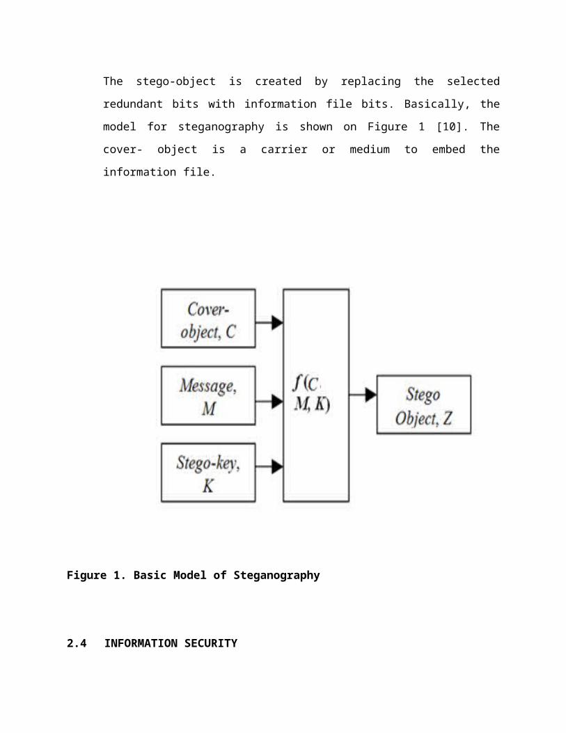
The stego-object is created by replacing the selected
redundant bits with information file bits. Basically, the
model for steganography is shown on Figure 1 [10]. The
cover- object is a carrier or medium to embed the
information file.
Figure 1. Basic Model of Steganography
2.4 INFORMATION SECURITY
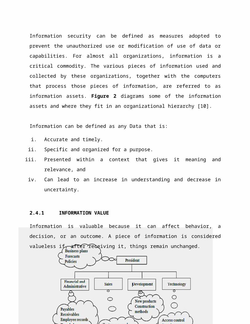
Information security can be defined as measures adopted to
prevent the unauthorized use or modification of use of data or
capabilities. For almost all organizations, information is a
critical commodity. The various pieces of information used and
collected by these organizations, together with the computers
that process those pieces of information, are referred to as
information assets. Figure 2 diagrams some of the information
assets and where they fit in an organizational hierarchy [10].
Information can be defined as any Data that is:
i. Accurate and timely.
ii. Specific and organized for a purpose.
iii. Presented within a context that gives it meaning and
relevance, and
iv. Can lead to an increase in understanding and decrease in
uncertainty.
2.4.1 INFORMATION VALUE
Information is valuable because it can affect behavior, a
decision, or an outcome. A piece of information is considered
valueless if, after receiving it, things remain unchanged.
Figure 2. Organization chart with sample information assets
In some cases, organizations spend significant investments
gathering or generating information, and then ultimately
give the information away for free (for marketing, customer
support, reputation building, or participation in professional
societies, among other reasons). Instead of the initial
investment, the value comes from the use the organization makes
of the information.
Other types of organizations do not measure value in terms of
money or effort, but in terms of reputation (particularly in
government) or operational advantages (particularly in the
military, or in nonprofit organizations, although the advantages
sought by these organizations differ greatly). Organizational
use is partially determined by the properties of the information,
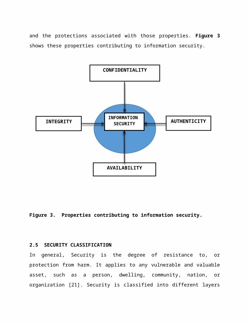
and the protections associated with those properties. Figure 3
shows these properties contributing to information security.
Figure 3. Properties contributing to information security.
2.5 SECURITY CLASSIFICATION
In general, Security is the degree of resistance to, or
protection from harm. It applies to any vulnerable and valuable
asset, such as a person, dwelling, community, nation, or
organization [21]. Security is classified into different layers
CONFIDENTIALITY
INFORMATION SECURITYINTEGRITY AUTHENTICITY
AVAILABILITY
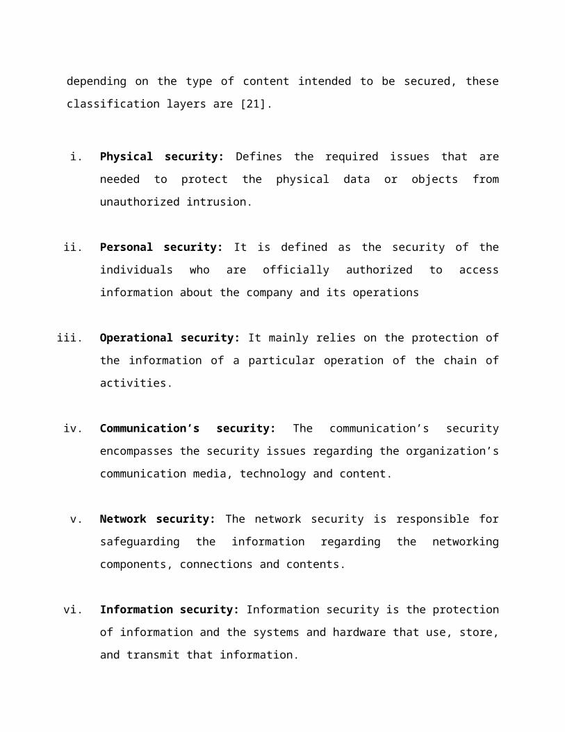
depending on the type of content intended to be secured, these
classification layers are [21].
i. Physical security: Defines the required issues that are
needed to protect the physical data or objects from
unauthorized intrusion.
ii. Personal security: It is defined as the security of the
individuals who are officially authorized to access
information about the company and its operations
iii. Operational security: It mainly relies on the protection of
the information of a particular operation of the chain of
activities.
iv. Communication’s security: The communication’s security
encompasses the security issues regarding the organization’s
communication media, technology and content.
v. Network security: The network security is responsible for
safeguarding the information regarding the networking
components, connections and contents.
vi. Information security: Information security is the protection
of information and the systems and hardware that use, store,
and transmit that information.
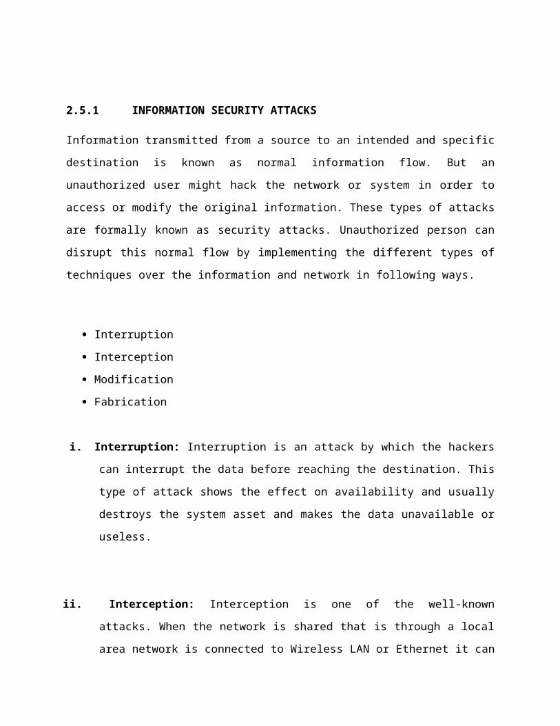
2.5.1 INFORMATION SECURITY ATTACKS
Information transmitted from a source to an intended and specific
destination is known as normal information flow. But an
unauthorized user might hack the network or system in order to
access or modify the original information. These types of attacks
are formally known as security attacks. Unauthorized person can
disrupt this normal flow by implementing the different types of
techniques over the information and network in following ways.
Interruption
Interception
Modification
Fabrication
i. Interruption: Interruption is an attack by which the hackers
can interrupt the data before reaching the destination. This
type of attack shows the effect on availability and usually
destroys the system asset and makes the data unavailable or
useless.
ii. Interception: Interception is one of the well-known
attacks. When the network is shared that is through a local
area network is connected to Wireless LAN or Ethernet it can
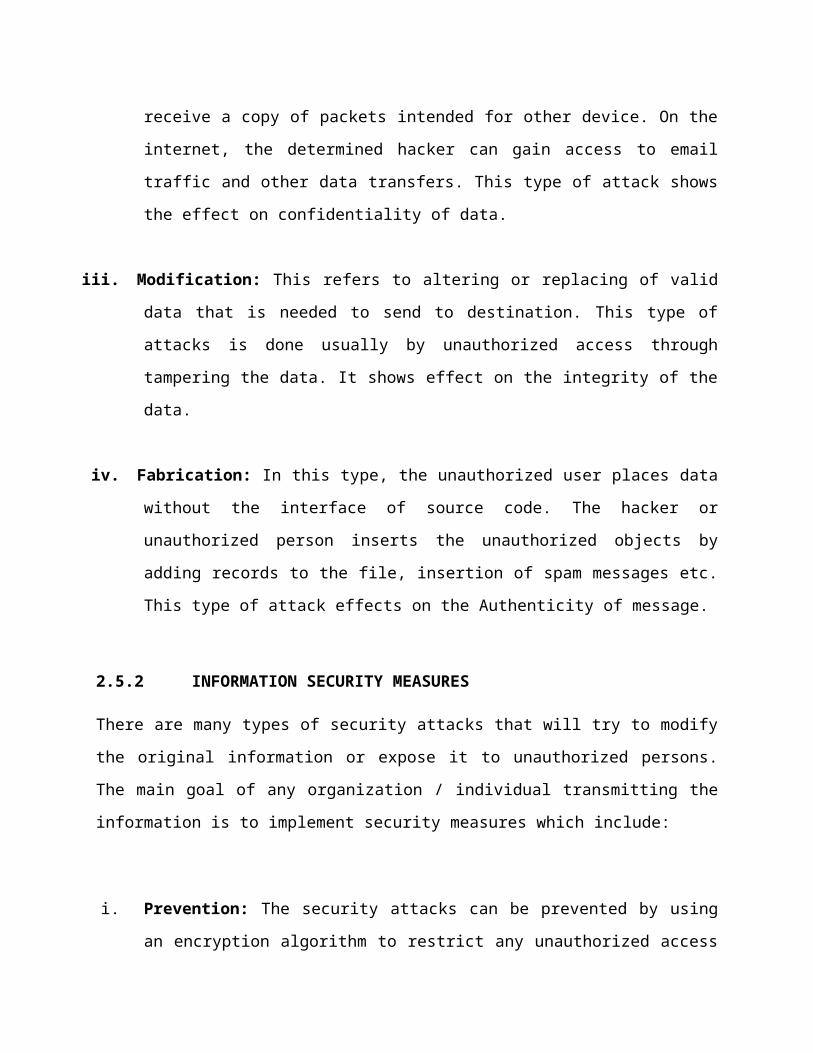
receive a copy of packets intended for other device. On the
internet, the determined hacker can gain access to email
traffic and other data transfers. This type of attack shows
the effect on confidentiality of data.
iii. Modification: This refers to altering or replacing of valid
data that is needed to send to destination. This type of
attacks is done usually by unauthorized access through
tampering the data. It shows effect on the integrity of the
data.
iv. Fabrication: In this type, the unauthorized user places data
without the interface of source code. The hacker or
unauthorized person inserts the unauthorized objects by
adding records to the file, insertion of spam messages etc.
This type of attack effects on the Authenticity of message.
2.5.2 INFORMATION SECURITY MEASURES
There are many types of security attacks that will try to modify
the original information or expose it to unauthorized persons.
The main goal of any organization / individual transmitting the
information is to implement security measures which include:
i. Prevention: The security attacks can be prevented by using
an encryption algorithm to restrict any unauthorized access
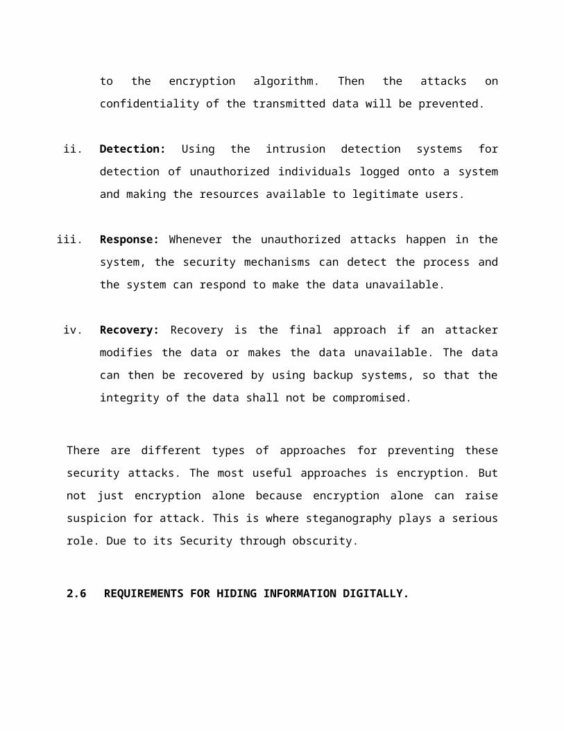
to the encryption algorithm. Then the attacks on
confidentiality of the transmitted data will be prevented.
ii. Detection: Using the intrusion detection systems for
detection of unauthorized individuals logged onto a system
and making the resources available to legitimate users.
iii. Response: Whenever the unauthorized attacks happen in the
system, the security mechanisms can detect the process and
the system can respond to make the data unavailable.
iv. Recovery: Recovery is the final approach if an attacker
modifies the data or makes the data unavailable. The data
can then be recovered by using backup systems, so that the
integrity of the data shall not be compromised.
There are different types of approaches for preventing these
security attacks. The most useful approaches is encryption. But
not just encryption alone because encryption alone can raise
suspicion for attack. This is where steganography plays a serious
role. Due to its Security through obscurity.
2.6 REQUIREMENTS FOR HIDING INFORMATION DIGITALLY.
There are many different protocols and embedding techniques that
enable us to hide information in a given object. However, all of
the protocols and techniques must satisfy a number of
requirements so that steganography can be applied correctly.
The following is a list of main requirements that steganography
techniques must satisfy:
Information integrity.
Information confidentiality.
Information Authenticity.
Information availability.
i. Information Integrity
The information must have a reliable meaning. This meaning may be
protected by assuring the information’s data integrity.
Preventing undesirable and unauthorized changes to the
information [22]. Integrity is the property that data has not
been changed, destroyed, or lost in an unauthorized or accidental
manner. This implies both that control is exercised over the
content of information in the system and over modifications
made to that information.
By attacking data integrity (i.e., modifying information without
authorization), an adversary may block necessary processing,
impede other defenses, or disrupt computer-based capabilities.
By protecting integrity, the organization assures that the
content, format, and semantics of the information remain
controlled by the organization, facilitating ongoing reliable
use. For businesses, assuring data integrity protects their
ability to receive orders, produce quality products, deliver
orders to appropriate addresses, invoice the correct parties for
payment, and other aspects of business life. For military
organizations, assuring data integrity protects their logistics
chain, deployment, targeting, damage assessment, and military
operations in general.
i. Information Confidentiality
The information must provide an advantage to its use, providing a
benefit not available to all. This advantage may derive from the
information’s confidentiality. Restricting the knowledge of the
information to authorized parties [22].
By attacking confidentiality (i.e., intercepting information
without authorization), an adversary may compromise
authenticating information, publicize internal planning and
forecast information, and disclose personal identifying
information (allowing impersonation to other organizations) and
other closely held information.
By protecting confidentiality, the organization retains control
over which parties have access or use of the information,
restricting competitors from exploiting this information, and
enabling necessary internal planning. If an organization
cannot prevent unauthorized disclosure of information, then
it is difficult for that organization to retain control over
the use of that information. When the information is critical
enough, a clear and unambiguous structure for the analysis of
confidentiality becomes useful.
ii. Information Authenticity
The information must have suitable authority for its use. This
authority is assured by the authenticity of the information
protected by nonrepudiation, which is the ability to definitively
identify the source of the information [22].
By attacking authenticity (i.e., imitating authorized sources),
an adversary may cause false information to be accepted as valid,
or fraudulently obtain increased access to computers or data.
By protecting authenticity, the organization assures a trace from
the responsible individuals to any actions done on the data. This
trace enables organizations to audit actions by individuals,
reducing the chance that malice or error will corrupt key
elements of the organization’s information. For businesses, such
authority establishes managerial direction over company
processes. For the military, such authority enables the chain of
command and reduces uncertainty in decision making.
iii. Information Availability
The information must be available when needed by the
organization. The availability protections ensure that the
information and its processing capabilities are providing service
as designed whenever users make authorized requests [22].
Protecting availability involves ensuring the presence of the
information, its access rights, usable formatting, and suitable
computing resources for handling the information.
By attacking availability (i.e., denying service or access), an
adversary may block the retrieval, processing, or use of key
information supporting an organization’s mission. By defending
availability, an organization assures that its necessary
activities may continue.
There are other properties that may be significant to an
organization’s information security. (Parker D. 2010), for
example, adds utility and possession [23]. However, the four
listed above give a sense of the variety of ways that information
may be attacked and defended. While all of these characteristics
of information are required for use in organizations, the
importance of each characteristic varies from organization to
organization.
In financial institutions, data integrity is paramount, if an
institution loses the reliability of its information, regulators
will shut it down. In e-commerce (e-businesses), availability is
key. Loss of service may lead to large loss of revenue. For many
military applications, confidentiality is the most important
property, disclosure to the enemy of military plans or operations
could be fatal to the personnel’s involved. In each of these
cases, the value of the information (and thus, the corporate
value) is increased via the protection of the information and
decreased by lack of such protection.
2.7 STEGANOGRAPHY APPLICATIONS
There are many applications for digital steganography of image,
including copyright protection, feature tagging, and secret
communication and confidential data storage [10, 17].
Copyright notice or watermark can embedded inside an image to
identify it as intellectual property. Were as confidential
information can be hidden in an image to prevent unauthorized
view, modification, and use.
2.7.1 DATA STEGANOGRAPHY
The advent of computers has allowed us to begin embedding
messages into pictures or sound files. To the human eye, the
picture itself remains unchanged, yet within it there could be up
to a book’s worth of information. Computers, as we may know,
operate in binary. That means that every letter and instruction
is eventually broken down into a code of ‘1’s and ‘0’s.
Let’s say that the binary for the letter ‘A’ is 11101101.
Originally, computer architects designed this system in such a
way that the very last ‘1’ or ‘0’ had no particular influence on
the value of the designated character. If the last number in this
message were ‘0’ instead of ‘1’, the computer would still know
that this is an ‘A’. 11101100.
The last digit of all binary messages, which is neither
meaningful nor necessary, is known as the Least Significant Bit
(LSB). One method, used by data steganography software, is to
break up the hidden message between the LSBs of the carrier in a
pre-determined pattern.
This does not change the original meaning of the message. This
method implies that the hidden message cannot be bigger than the
carrier and should really be much smaller.
2.8 STEGANOGRAPHIC TECHNIQUES
Over the past few years, numerous steganography techniques that
embed hidden messages in multimedia objects have been proposed
[26]. There have been many techniques for hiding information or
messages in images in such a manner that the alterations made to
the image are perceptually indiscernible. Common approaches are
including [25]:
Least significant bit insertion
(LSB)
Masking and filtering
Transform techniques
i. Least Significant Bits Insertion (LSB)
This is the simple approach to embedding information in image
file. This steganographic technique embeds the bits of the
message directly into least significant bit plane of the cover-
image in a deterministic sequence. Manipulating the least
significant bit does not result in human- perceptible difference
because the amplitude of the change is small [25]. LSB is always
the last bit on the right-hand side of any binary number.
Changing this bit causes the least possible effect to the
original value.
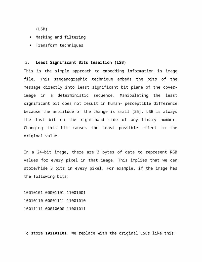
In a 24-bit image, there are 3 bytes of data to represent RGB
values for every pixel in that image. This implies that we can
store/hide 3 bits in every pixel. For example, if the image has
the following bits:
10010101 00001101 11001001
10010110 00001111 11001010
10011111 00010000 11001011
To store 101101101. We replace with the original LSBs like this:
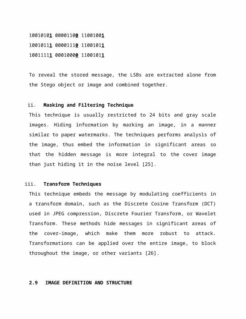
10010101 00001100 11001001
10010111 00001110 11001011
10011111 00010000 11001011
To reveal the stored message, the LSBs are extracted alone from
the Stego object or image and combined together.
ii. Masking and Filtering Technique
This technique is usually restricted to 24 bits and gray scale
images. Hiding information by marking an image, in a manner
similar to paper watermarks. The techniques performs analysis of
the image, thus embed the information in significant areas so
that the hidden message is more integral to the cover image
than just hiding it in the noise level [25].
iii. Transform Techniques
This technique embeds the message by modulating coefficients in
a transform domain, such as the Discrete Cosine Transform (DCT)
used in JPEG compression, Discrete Fourier Transform, or Wavelet
Transform. These methods hide messages in significant areas of
the cover-image, which make them more robust to attack.
Transformations can be applied over the entire image, to block
throughout the image, or other variants [26].
2.9 IMAGE DEFINITION AND STRUCTURE
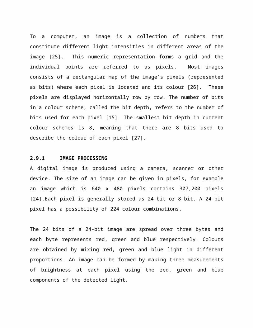
To a computer, an image is a collection of numbers that
constitute different light intensities in different areas of the
image [25]. This numeric representation forms a grid and the
individual points are referred to as pixels. Most images
consists of a rectangular map of the image’s pixels (represented
as bits) where each pixel is located and its colour [26]. These
pixels are displayed horizontally row by row. The number of bits
in a colour scheme, called the bit depth, refers to the number of
bits used for each pixel [15]. The smallest bit depth in current
colour schemes is 8, meaning that there are 8 bits used to
describe the colour of each pixel [27].
2.9.1 IMAGE PROCESSING
A digital image is produced using a camera, scanner or other
device. The size of an image can be given in pixels, for example
an image which is 640 x 480 pixels contains 307,200 pixels
[24].Each pixel is generally stored as 24-bit or 8-bit. A 24-bit
pixel has a possibility of 224 colour combinations.
The 24 bits of a 24-bit image are spread over three bytes and
each byte represents red, green and blue respectively. Colours
are obtained by mixing red, green and blue light in different
proportions. An image can be formed by making three measurements
of brightness at each pixel using the red, green and blue
components of the detected light.
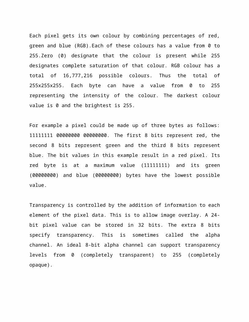
Each pixel gets its own colour by combining percentages of red,
green and blue (RGB).Each of these colours has a value from 0 to
255.Zero (0) designate that the colour is present while 255
designates complete saturation of that colour. RGB colour has a
total of 16,777,216 possible colours. Thus the total of
255x255x255. Each byte can have a value from 0 to 255
representing the intensity of the colour. The darkest colour
value is 0 and the brightest is 255.
For example a pixel could be made up of three bytes as follows:
11111111 00000000 00000000. The first 8 bits represent red, the
second 8 bits represent green and the third 8 bits represent
blue. The bit values in this example result in a red pixel. Its
red byte is at a maximum value (11111111) and its green
(00000000) and blue (00000000) bytes have the lowest possible
value.
Transparency is controlled by the addition of information to each
element of the pixel data. This is to allow image overlay. A 24-
bit pixel value can be stored in 32 bits. The extra 8 bits
specify transparency. This is sometimes called the alpha
channel. An ideal 8-bit alpha channel can support transparency
levels from 0 (completely transparent) to 255 (completely
opaque).
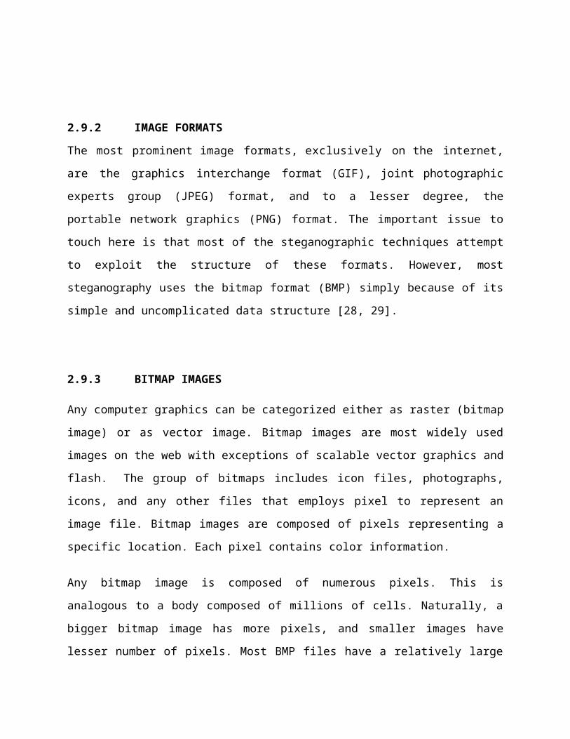
2.9.2 IMAGE FORMATS
The most prominent image formats, exclusively on the internet,
are the graphics interchange format (GIF), joint photographic
experts group (JPEG) format, and to a lesser degree, the
portable network graphics (PNG) format. The important issue to
touch here is that most of the steganographic techniques attempt
to exploit the structure of these formats. However, most
steganography uses the bitmap format (BMP) simply because of its
simple and uncomplicated data structure [28, 29].
2.9.3 BITMAP IMAGES
Any computer graphics can be categorized either as raster (bitmap
image) or as vector image. Bitmap images are most widely used
images on the web with exceptions of scalable vector graphics and
flash. The group of bitmaps includes icon files, photographs,
icons, and any other files that employs pixel to represent an
image file. Bitmap images are composed of pixels representing a
specific location. Each pixel contains color information.
Any bitmap image is composed of numerous pixels. This is
analogous to a body composed of millions of cells. Naturally, a
bigger bitmap image has more pixels, and smaller images have
lesser number of pixels. Most BMP files have a relatively large
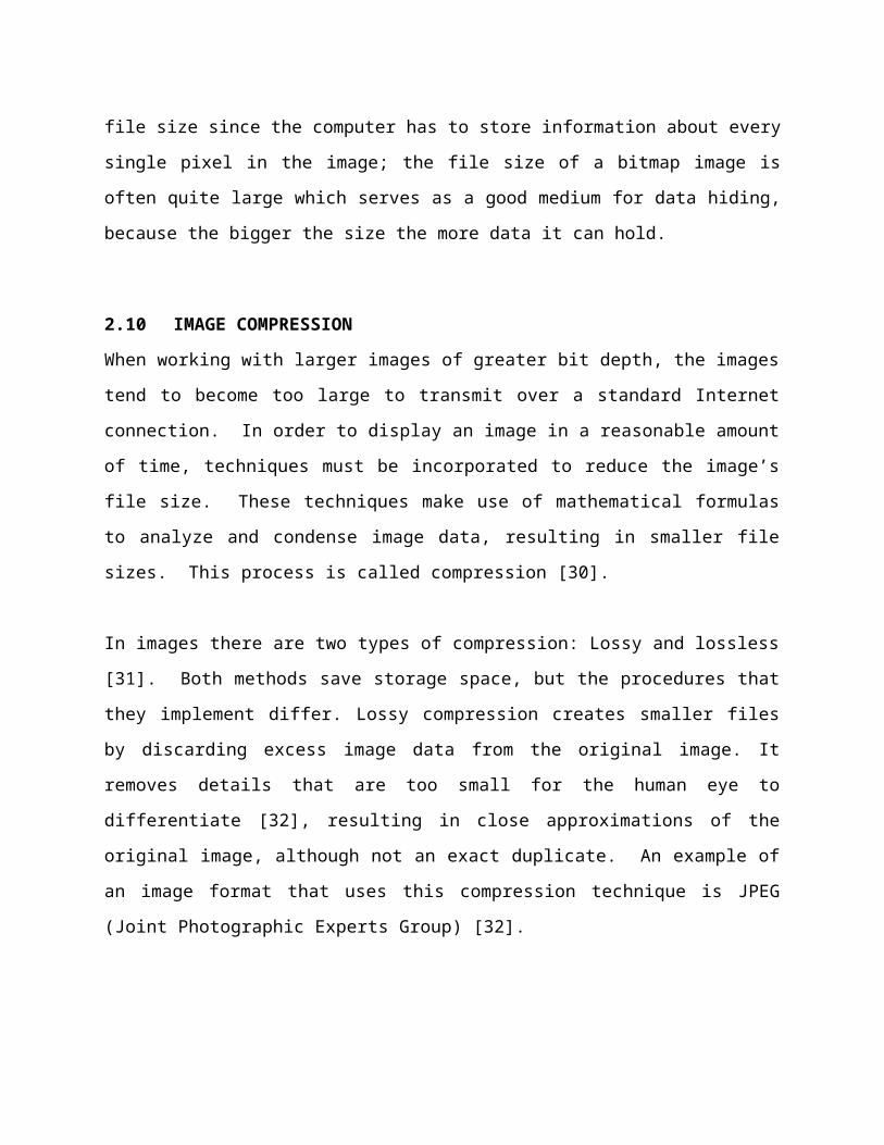
file size since the computer has to store information about every
single pixel in the image; the file size of a bitmap image is
often quite large which serves as a good medium for data hiding,
because the bigger the size the more data it can hold.
2.10 IMAGE COMPRESSION
When working with larger images of greater bit depth, the images
tend to become too large to transmit over a standard Internet
connection. In order to display an image in a reasonable amount
of time, techniques must be incorporated to reduce the image’s
file size. These techniques make use of mathematical formulas
to analyze and condense image data, resulting in smaller file
sizes. This process is called compression [30].
In images there are two types of compression: Lossy and lossless
[31]. Both methods save storage space, but the procedures that
they implement differ. Lossy compression creates smaller files
by discarding excess image data from the original image. It
removes details that are too small for the human eye to
differentiate [32], resulting in close approximations of the
original image, although not an exact duplicate. An example of
an image format that uses this compression technique is JPEG
(Joint Photographic Experts Group) [32].
Lossless compression, on the other hand, never removes any
information from the original image, but instead represents data
in mathematical formulas [30]. The original image’s integrity is
maintained and the decompressed image output is bit-by-bit
identical to the original image input [31]. The most popular
image formats that use lossless compression is GIF (Graphical
Interchange Format) and 8-bit BMP (Microsoft Windows bitmap
file) [32].
Compression plays a very important role in choosing
which steganographic algorithm to use. Lossy compression
techniques result in smaller image file sizes, but it increases
the possibility that the embedded message may be partly lost due
to the fact that excess image data will be removed. Lossless
compression though, keeps the original digital image intact
without the chance of lost, although it does not compress the
image to such a small file size [32].
2.11 DETECTING STEGANOGRAPHY
The art of detecting Steganography is referred to as
Steganalysis. To put it simply Steganalysis involves detecting
the use of Steganography. Steganalysis does not deal with trying
to decrypt the hidden information, just discovering it. There for
Steganalysis is "the process of detecting steganography by
looking at variances between bit patterns and unusually large
file sizes" [33].
One method that can be used to detect Steganography is: Viewing
the file and comparing it to another copy of the same file found
on the Internet (Picture File.)
CHAPTER THREE
RESEACH METHODOLOGY AND SYSTEM DESIGN
3.0 INTRODUCTION
This chapter provides a detailed explanation on the procedures
used in carrying out this study, for the system to work
successfully. The chapter also gives an insight into scope and
features of the system as well as the requirements. The
development tools used and data flow diagrams as well as the
system design. The system was designed and will be executed using
software engineering methods with strict adherence to the
principles of software development life cycle.
3.1 SCOPE OF THE SYSTEM
The system will offer a secure way of encryption of confidential
data through obscurity for ISSYS GH. and its business clients. As
a case study, the system is designed to cover only the day to day
activities of the Information Security unit and the communication
units of the organization.
3.2 FEATURES OF THE SYSTEM:
The systems graphical user interface is essential to a user. For
this reason, the user interface was well thought – through and
made easy to use; as well as using tabs and bottoms where
appropriate to enhance the user experience and also an image
preview panel which gives a clear image of which image is to be
encrypted.
3.3 REQUIREMENTS GATHERING TECHNIQUES
The system was designed primarily to encrypt confidential files
on computer systems. As a result, the instrument for data
collection for this project was through the primary source with
which, a critical examination of the various types of information
threats which existed in the organization was collected by
various open interviews of the personals in that unit.
In order to get a fair idea of the threats that existed and to
take the necessary steps in order to curb it and meet the goal
for which the system will be developed. This allowed for the
collection of first-hand data. On spot observations were also
made without the awareness of the personnel and units involved.
This allowed for the accurate capturing of a true reflection of
the threats to information security in that unit of the
organization as well as helping to cross-validate certain
responses from the interviews.
3.3.1 FUNCTIONAL REQUIREMENTS
These are the functions that the system must deliver in order to
meet user requirements. The functional requirements of this
system include:
The system will allow an effective and reliable way of
security for information through obscurity.
The system will not allow the User(s) to modify encrypted
image in any way.
The system will allow for the use of any image file and
information file to be used respectively for encryption.
User(s) should have a basically fair knowledge in computer
file types and computing in order to effectively make use of
the system.
3.3.2 NON FUNCTIONAL REQUIREMENTS
These requirements form the constrain of the system and can be
divided into two parts. Hardware and software.
3.3.3 HARDWARE REQUIREMENTS
Since Microsoft .Net framework prepares a huge amount of tool and
options for programming. One of .Net tools for pictures and
imagery is auto-converting feature. Since the output of the
encryption process is a bitmap image (*.bmp). Also the encryption
algorithm needs a fast processing time. These technologies need
an immerse hardware resources which includes;
Minimum memories of 1GB RAM.
A minimum processor speed of 1GHz.
A minimum video graphic acceleration of 256MB RAM.
A minimum free hard disk space of 200MB.
3.3.4 SOFTWARE REQUIREMENTS
The system would require:
32bit Windows vista, windows 7 and windows 8 Operating
system.
Microsoft .Net framework 4.5.
3.3.5 NON FUNCTIONAL REQUIREMENTS TO THE USER
i. Portability: The effort required to move the software to a
different target platform. The system can easily be moved
and executed on new systems without any difficulties. This
will facilitate software portability.
ii. Availability: The program should be flexible and should be
available within a mean time and should work in any
operating environment.
iii. Reliability: Requirements about how often the software
fails. The system may exhibit failures when an information
file size is greater than the payload of the carrier or
cover image. The carrier or cover image size must always be
greater than information file size.
iv. Usability: Usability is the factor for any data security
system; the software should be flexible for transferring the
data between one ends to another or the save to destination
folder. It should provide a friendly user interface.
v. Legal: legal issues involving privacy of information, image
usage, export of restricted technologies, etc. shall be
bound by the organization and its business clients.
3.3.6 INPUT REQUIREMENTS
Steganography system requires any type of image file and the
information file that is to be hidden. It has two modules encrypt
and decrypt. The .NET framework prepares a huge amount of tool
and options for use; one of the .NET tools for pictures and
images is auto-converting of most types of pictures. I used this
tool in developing this system. This aided in simple programming
to hide the information in any type of image without converting
its formats, since C# has an inbuilt image converting feature.
3.4 SYSTEM DEVELOPMENT LIFE CYCLE (SDLC)
The system development life cycle adopted in this paper is the
waterfall model which is based on a sequential design process.
This methodology was adopted because of the flexibility if offers
to researchers in terms of the sequential approach to solving
problems.
This methodology certifies that each stage of the design process
has been successfully completed and thus guaranteeing that all
stages are completely dealt with.
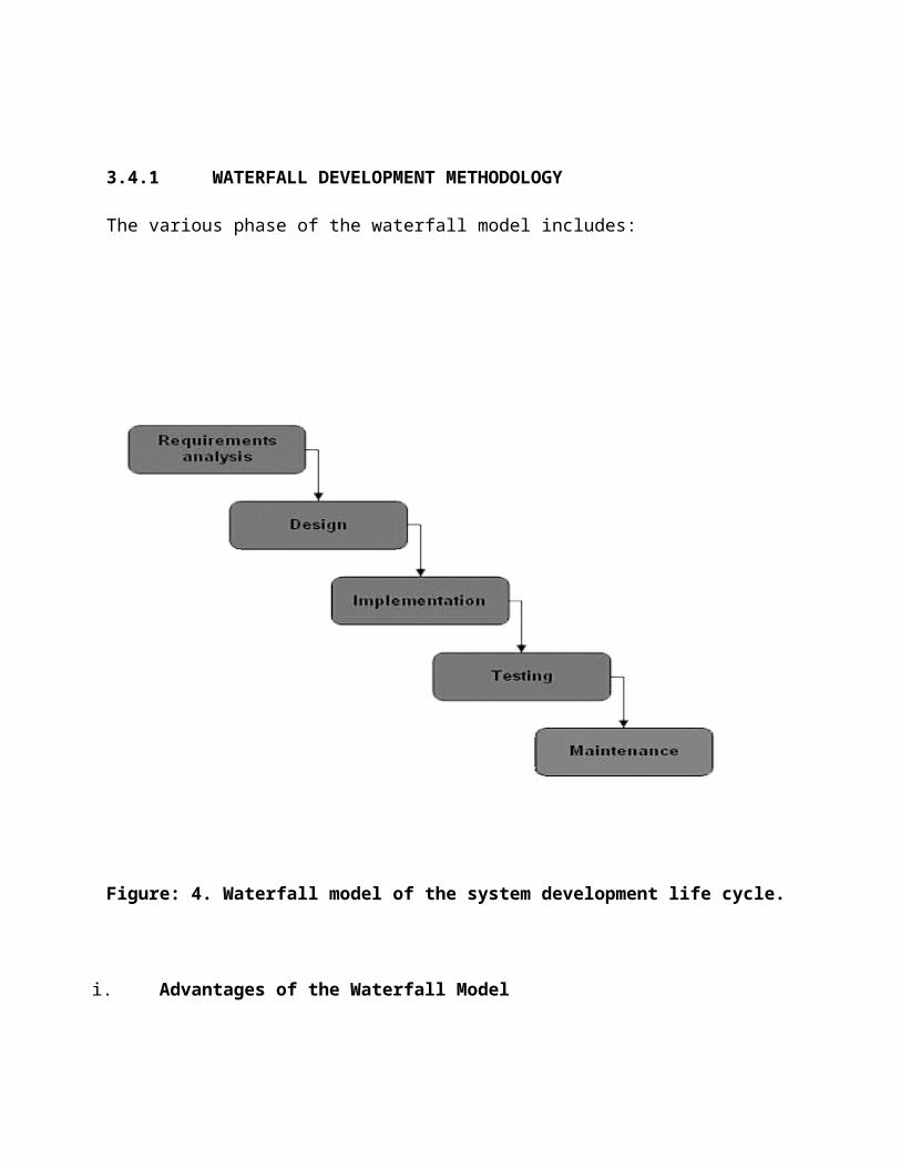
3.4.1 WATERFALL DEVELOPMENT METHODOLOGY
The various phase of the waterfall model includes:
Figure: 4. Waterfall model of the system development life cycle.
i. Advantages of the Waterfall Model
There are certain advantages of the waterfall model, which causes
it to be the most commonly used model. The model present four key
advantages as follows:
Design errors are captured before any software is written
saving time during the implementation phase.
The approach is very structured and it is easier to measure
progress by reference to clearly defined milestones.
Testing is easier as it can be done by reference to the
scenarios defined in the functional specification.
3.5 DEVELOPMENT TOOLS USED
The design and development tools used include the following:
i. Microsoft Visual Studio:
This is an integrated development environment (IDE) from
microsoft.it is used to develop computer programs for Microsoft
windows family of operating systems as well as web site and web
applications, the programmer come with the .NET framework
developed by.
The framework is used to build web and user interactive GUI
(Graphical User Interface) applications. .NET supports multiple
languages like C, C#, Visual Basic, Jscript.
I have chosen Microsoft .net platform for building the windows
based steganographic system. The main component of .NET which is
used in this project was Visual C#.
ii. Common Language Runtime (CLR):
One of the main important sections of Microsoft .NET environment
is CLR. The Common Language Runtime (CLR) is core to .NET
framework. As mentioned above, the “Common Language Runtime‟ is
an important component of .NET platform.
The CLR handles the object layouts and manages references to
objects. It makes the designing architecture simpler and easier.
I used Microsoft Visual C# for structuring the application. CLR
is efficient when C# language is used for writing programs.
The various advantages when the C# language is employed are;
Complete Object oriented design
Provides high security and stronger to break the code
Uses the logics of visual basic and C++ languages
The syntax is simple is similar to languages C, C++.
iii. Windows Forms:
Visual Studio Windows application is supported by the
Microsoft .NET frame work and it allows a rich set of classes so
that the Windows application can be built by any.net programming
language like Visual Basic .net and Visual C#.
In this project I used visual c# to create the windows based
application. In windows based application, we create some type of
forms which are used for user interface. These forms are known as
“Windows forms”.
Using windows forms we can easily drag and drop the controls
like radio buttons and text boxes etc., using the Windows
forms designer.
Windows forms are also known as win forms in which the
standard built in controls can be used.
By using the custom Graphical User Interface (GUI) controls
we can modify the controls and also add new ones.
iv. Visual C#
Visual C# is the one of the component in Microsoft Visual Studio
2012 which works similar to Visual basic. Creating applications
using Visual C# is easier compared to the JAVA.
In order to create the application, we need to use the
designer tool and tool box so that required tool like radio
button, text boxes etc., can be placed.
After designing the next phase is to relate them with
specified functions. This can be done using visual C#
coding.
The coding can be done by double clicking in the elements on
the designer tool.
The program or code which is written using C# language is
saved with “.CS” extension.
The code can be compiled using “Debug” option. When we click
on debug option the .NET architecture creates the class
file.
After creation of class file, Common Language Runtime (CLR)
converts the class file into the machine language that is
compatible with the hardware since CLR supports cross-
language integration.
v. Visual paradigm (VP) 11.1
Visual Paradigm for unified modeling language (UML) is a UML CASE
tool supporting UML 2, SysML and business Process modeling
notation from the object management group. In addition to
modeling support, it provides report generation and code
engineering capabilities including code generation. VP -UML
supports thirteen types of diagrams; examples are
Use case diagram.
Sequence diagram.
Activity diagram.
State diagram.
Process modeling tool.
Class diagram.
Communication diagram.
Interaction overview diagram.
3.6 SYSTEM DESIGN TRADEOFF PARAMETERS
Designing any steganographic system must take into consideration
the following parameters:
i. Capacity: The amount of data that can be hidden without
significant change the cover
ii. Robustness: the resistance for possible modification or
destruction in unseen data.
iii. Invisibility: The hiding process should be performed in a
way that it does not raise any suspicion.
Increasing the capacity of any cover to store more data than a
practical possible threshold, then its transparency or robustness
will be affect and vice versa. Similarly, invisibility and
robustness are related; if any of these two parameters are
influenced; it can affect the performance in the other one.
3.7 PROPOSED SYSTEM ARCHITECTURE
The data hiding patterns using the steganographic technique in
this project can be explained using this simple block diagram.
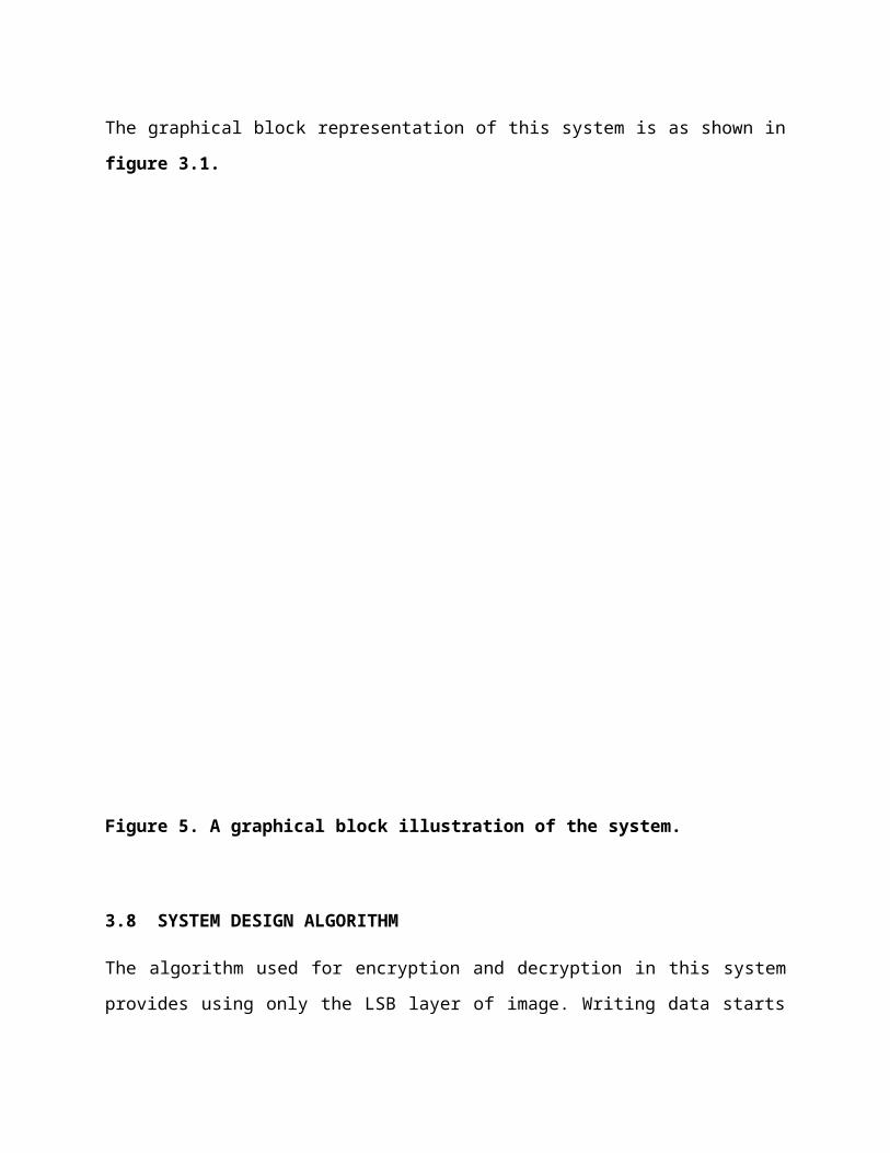
The graphical block representation of this system is as shown in
figure 3.1.
Figure 5. A graphical block illustration of the system.
3.8 SYSTEM DESIGN ALGORITHM
The algorithm used for encryption and decryption in this system
provides using only the LSB layer of image. Writing data starts
from last layer (LSB layer); because the significance of this
layer is least and the upper layer has doubled significance from
its down layer. So every phase we go to the upper layer, the
image quality decreases and image touch up become obvious.
The encrypt module is used to hide information into the carrier
image; no one can see that information file. This module requires
any type of carrier image and information file and gives only one
bitmap image file (*.bmp) as output to the save destination
folder.
The decrypt module is used to get the hidden information in the
carrier bitmap image file (*.bmp). It take the carrier bitmap
image file as an input, and gives one information file as an
output to the save destination folder. In all these phases the
stego-image (*.bmp) is not affected in any.
3.9 SYSTEM DESIGN MODULE PHASES
The systems module designs at different phases are:
Encryption module phase
Decryption module phase
i. Encryption Module Phase
The encryption module phase of the system is the primary stage.
In this phase, the user selects the image file, which acts as a
carrier or cover image as well as an information file that will
be hidden in the carrier image.
In this project, I use Bitmap (*.bmp) images as a default
carriers because bitmap images have a large image size and also
bitmap images are pixel dependent compared to jpeg image and
other image formats. But the user has an option to choose other
image file types as carrier image file or cover image file.
In the encryption module, the information file will be embedded
into the cover or carrier image file. The embedding will be done
based on the principle of “Least Significant Bit” (LSB)
algorithm.
The LSB algorithm uses the least significant bits of each pixel
and replace with the significant bits of the information file,
such that the information will be encrypted into the carrier
image. This process makes the picture not to lose its resolution.
The data embedding into image i.e., encryption is implemented
using Microsoft visual C#.
ii. Decryption Module Phase
In the decryption module of the system, the user selects the
stego-image from a location. The user then sends the stego-image
to the decryption phase. In the decryption phase, the same “Least
Significant Algorithm‟ is implemented but in the reverse way.
Here the least significant bits from the stego-image are
extracted and combined in an order to structure the original
information bits.
After successful arrangement, the information file is decrypted
from the carrier file and accessed as an original information
file. The information file extraction from the carrier image
i.e., decryption is implemented using Microsoft Visual C#.
3.10 DATA FLOW DIAGRAMS
Data flow diagrams are the basic building blocks that define the
flow of data in a system to the particular destination and
difference in the flow when any alteration happens. It makes
whole process like a good document and makes simpler and easy to
understand for both programmers and non-programmers by dividing
into the sub process.
The data flow diagrams are the simple blocks that reveal the
relationship between various components of the system and provide
high level overview, boundaries of particular system as well as
provide detailed overview of system elements.
The data flow diagrams start from source and ends at the
destination level i.e., it decomposes from high level to lower
levels. The important things to remember about data flow diagrams
are: it indicates the data flow for one way but not for loop
structures and it doesn’t indicate the time factors.
This section reveals about the data flow analysis which states
about data that have been used, classification of data flow
diagrams based on their functions and the other different levels
used in the project. The general notations for constructing a
block diagram in this project is shown in figure 6
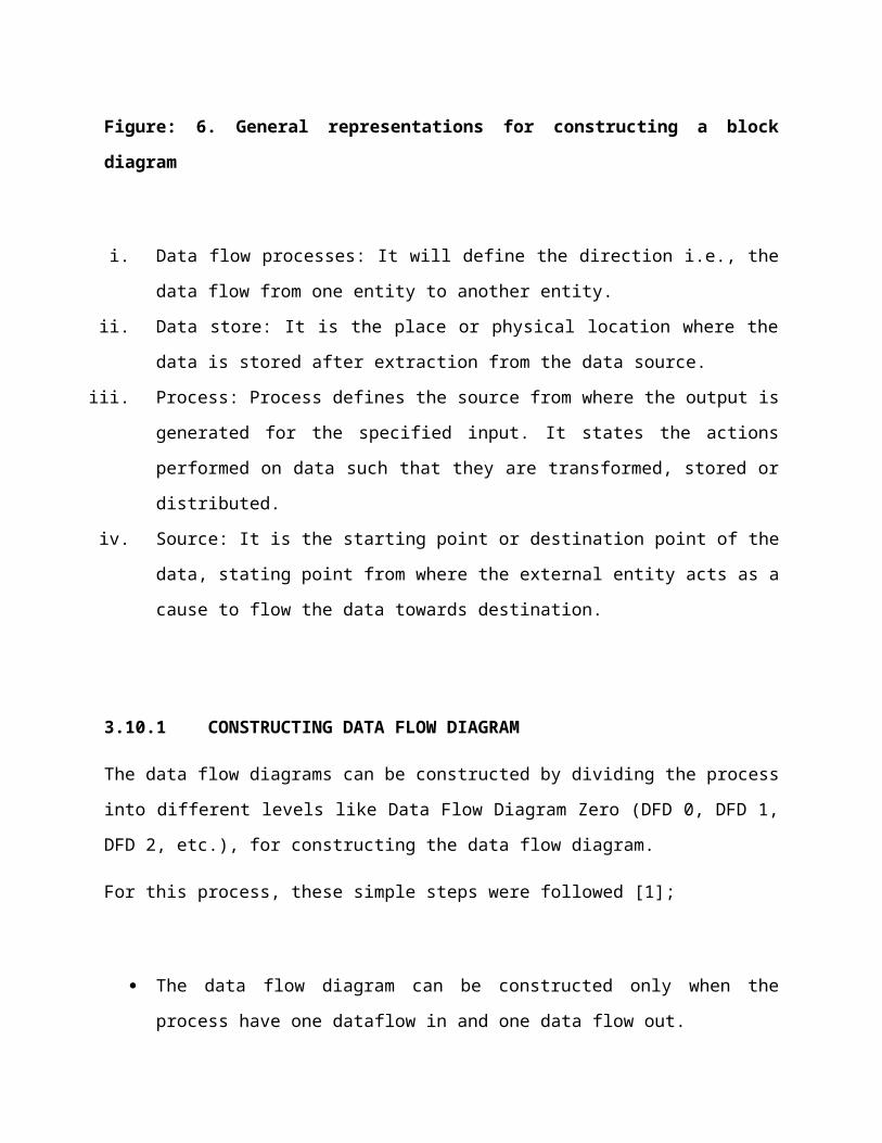
Figure: 6. General representations for constructing a block
diagram
i. Data flow processes: It will define the direction i.e., the
data flow from one entity to another entity.
ii. Data store: It is the place or physical location where the
data is stored after extraction from the data source.
iii. Process: Process defines the source from where the output is
generated for the specified input. It states the actions
performed on data such that they are transformed, stored or
distributed.
iv. Source: It is the starting point or destination point of the
data, stating point from where the external entity acts as a
cause to flow the data towards destination.
3.10.1 CONSTRUCTING DATA FLOW DIAGRAM
The data flow diagrams can be constructed by dividing the process
into different levels like Data Flow Diagram Zero (DFD 0, DFD 1,
DFD 2, etc.), for constructing the data flow diagram.
For this process, these simple steps were followed [1];
The data flow diagram can be constructed only when the
process have one dataflow in and one data flow out.
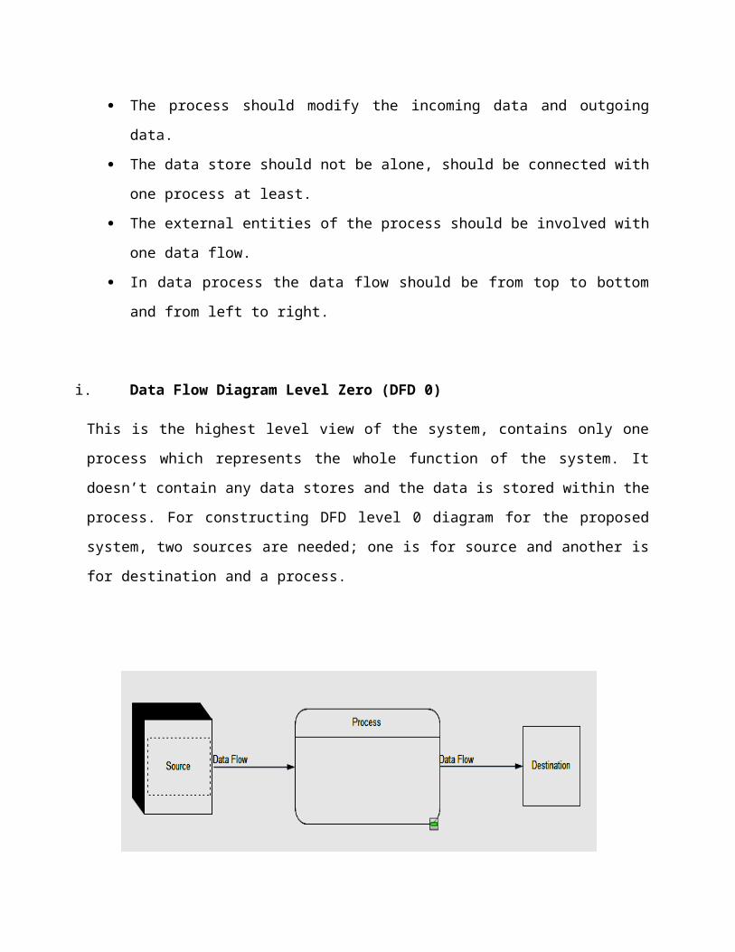
The process should modify the incoming data and outgoing
data.
The data store should not be alone, should be connected with
one process at least.
The external entities of the process should be involved with
one data flow.
In data process the data flow should be from top to bottom
and from left to right.
i. Data Flow Diagram Level Zero (DFD 0)
This is the highest level view of the system, contains only one
process which represents the whole function of the system. It
doesn’t contain any data stores and the data is stored within the
process. For constructing DFD level 0 diagram for the proposed
system, two sources are needed; one is for source and another is
for destination and a process.
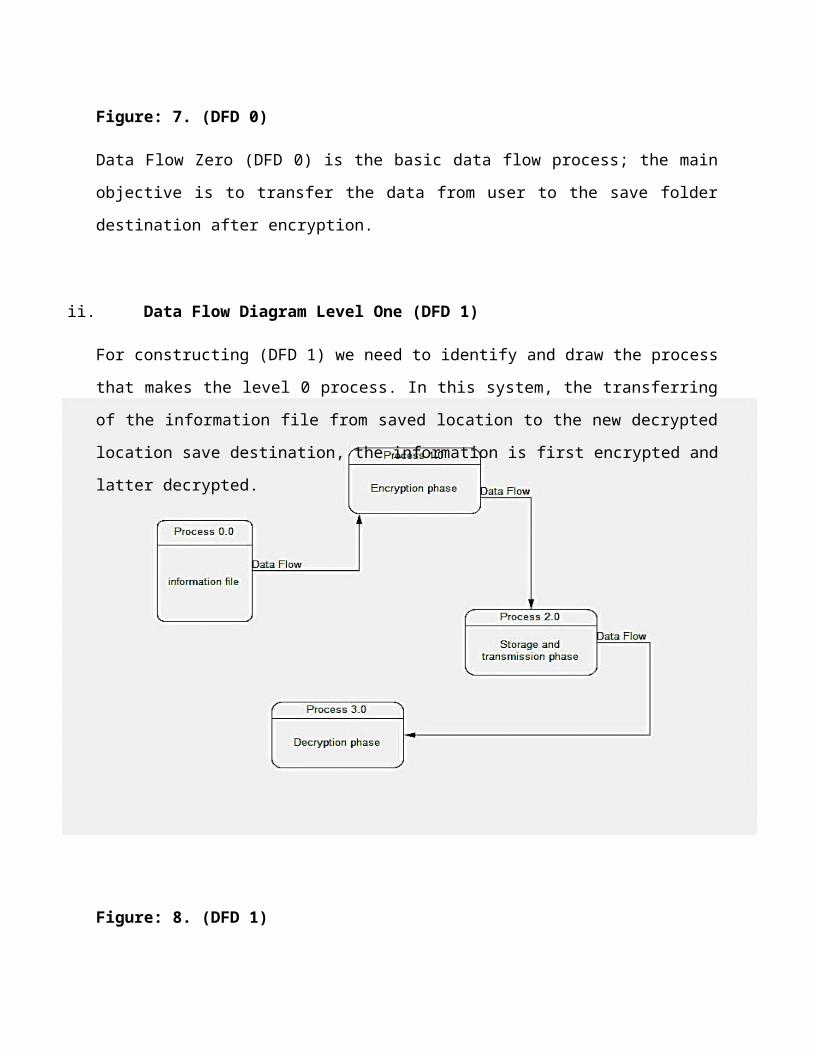
Figure: 7. (DFD 0)
Data Flow Zero (DFD 0) is the basic data flow process; the main
objective is to transfer the data from user to the save folder
destination after encryption.
ii. Data Flow Diagram Level One (DFD 1)
For constructing (DFD 1) we need to identify and draw the process
that makes the level 0 process. In this system, the transferring
of the information file from saved location to the new decrypted
location save destination, the information is first encrypted and
latter decrypted.
Figure: 8. (DFD 1)
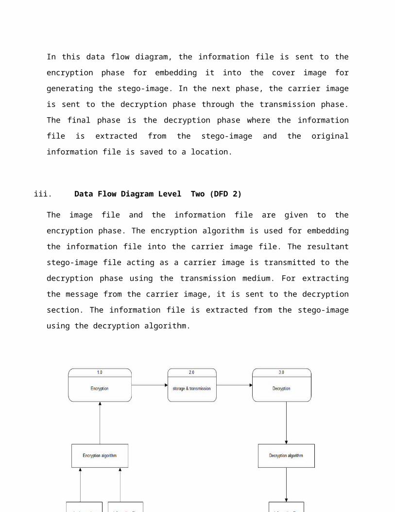
In this data flow diagram, the information file is sent to the
encryption phase for embedding it into the cover image for
generating the stego-image. In the next phase, the carrier image
is sent to the decryption phase through the transmission phase.
The final phase is the decryption phase where the information
file is extracted from the stego-image and the original
information file is saved to a location.
iii. Data Flow Diagram Level Two (DFD 2)
The image file and the information file are given to the
encryption phase. The encryption algorithm is used for embedding
the information file into the carrier image file. The resultant
stego-image file acting as a carrier image is transmitted to the
decryption phase using the transmission medium. For extracting
the message from the carrier image, it is sent to the decryption
section. The information file is extracted from the stego-image
using the decryption algorithm.
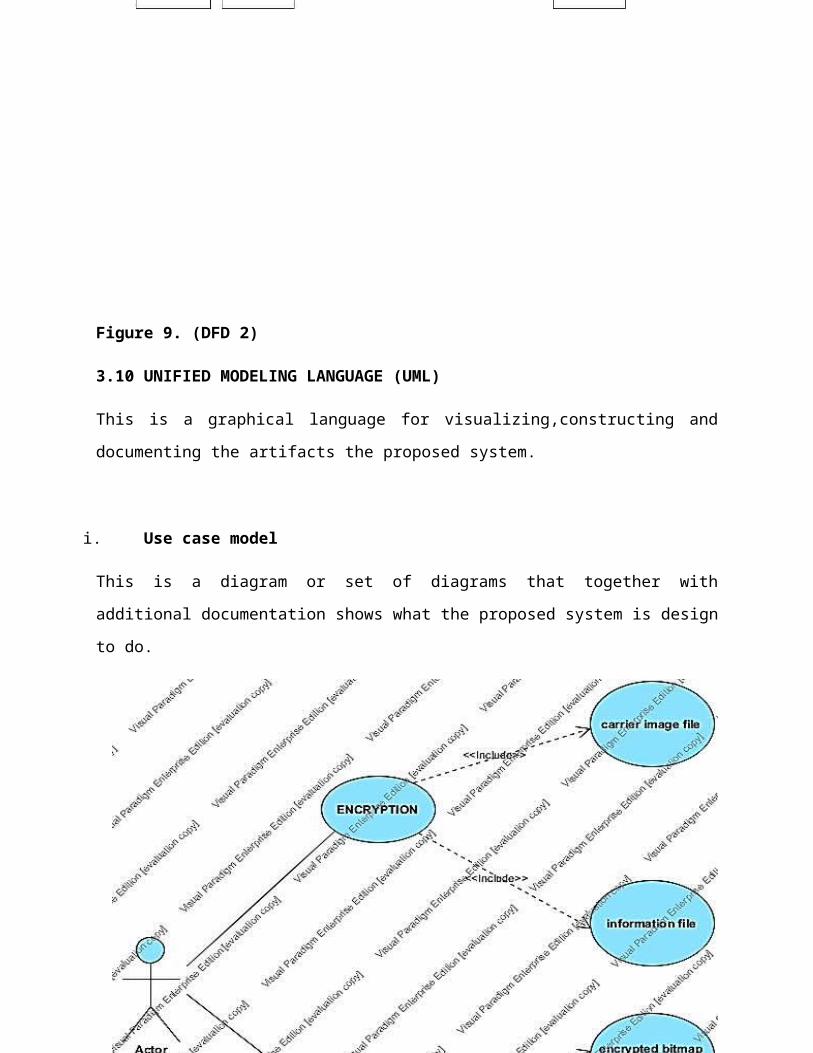
Figure 9. (DFD 2)
3.10 UNIFIED MODELING LANGUAGE (UML)
This is a graphical language for visualizing,constructing and
documenting the artifacts the proposed system.
i. Use case model
This is a diagram or set of diagrams that together with
additional documentation shows what the proposed system is design
to do.
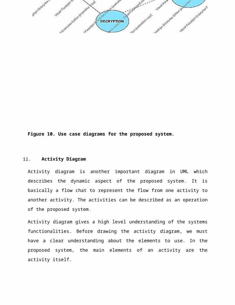
Figure 10. Use case diagrams for the proposed system.
ii. Activity Diagram
Activity diagram is another important diagram in UML which
describes the dynamic aspect of the proposed system. It is
basically a flow chat to represent the flow from one activity to
another activity. The activities can be described as an operation
of the proposed system.
Activity diagram gives a high level understanding of the systems
functionalities. Before drawing the activity diagram, we must
have a clear understanding about the elements to use. In the
proposed system, the main elements of an activity are the
activity itself.
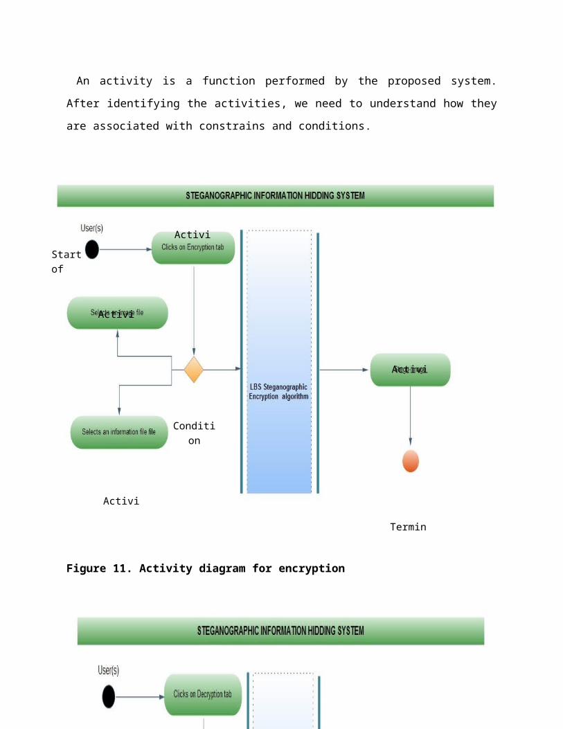
An activity is a function performed by the proposed system.
After identifying the activities, we need to understand how they
are associated with constrains and conditions.
Figure 11. Activity diagram for encryption
Activi
Activi
Activi
Activi
Termin
Condition
Start of proces
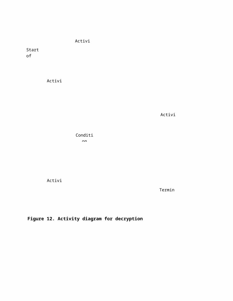
Figure 12. Activity diagram for decryption
Start of proces
Condition
Termin
Activi
Activi
Activi
Activi
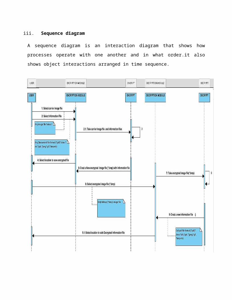
iii. Sequence diagram
A sequence diagram is an interaction diagram that shows how
processes operate with one another and in what order.it also
shows object interactions arranged in time sequence.
Figure 13. Sequence diagram
3.11 TEXTUAL USE CASE
The textual use case defines what I intend to achieve with each
process within the proposed system.
3.11.1 Actor
i. User(s):
Could be the staff or specialized personnel.
Needs to run the application or system.
3.11.2 Encryption Process:
a. Use Case Number: UC-STEGO1.
b. Use Case Title: Encryption.
1. Level: User Level
2. Primary Actor: Any Actor (staff)
3. Context of Use: The user clicks on the encryption tab which
by default the first page on the startup of the system.
4. Preconditions: The user must have an information and image
files available on the system or a storage device for the
encryption process.
5. Success Guarantee: The stego-image is saved to a destination
folder as a bitmap (*.bmp)
6. Main Success Scenario:
i. The system provides an option to select a carrier image
and an information file to be embedded.
ii. The user selects any image to use as a carrier file and
an information file that needs to be hidden.
iii. The system encrypts both files when the encryption
button is clicked. .
iv. The system responds appropriately by allowing the user
an option to save encrypted file (stego-image) to a
destination folder of their choice.
Steps 3 and 4 are actions that the system performs, and steps 1
and 2 are interactions between the system and user.
3.11.3 Decryption Process:
c. Use Case Number: UC-STEGO2
d. Use Case Title: Decryption
1. Level : User Level
2. Primary Actor : Any Actor (staff)
3. Context of Use: The user clicks on the Decryption tab.
4. Preconditions: The user must have a stego-image file
(encrypted bitmap image file) available on the system or a
storage device for the Decryption process.
5. Success Guarantee: The embedded information file is
retrieved from the stego-image file and saved to a
destination folder.
6. Main Success Scenario :
i. The system provides an option to select a stego-image file
and a destination to save the information file to.
ii. The user selects an encrypted stego-image file (encrypted
bitmap image file).
iii. The system decrypts the stego-image file when the decryption
button is clicked.
iv. The system responds appropriately by allowing the user an
option to save decrypted file (information file) to a
destination folder of their choice.
Steps 1 and 3 are actions that the system performs, and steps 2
and 4 are interactions between the system and user.
3.12 SYSTEM IMPLEMENTATION AND TESTING
The system design is translates to programming codes usingMicrosoft Visual studio C# programming language. Microsoft visualstudio C# comes with an inbuilt code analyzer, this automatedtesting of programming code for the purpose of debugging anapplication before it is distributed or sold. Code analysisconsists of statements created with a text editor or visualprogramming tool and then saved in a file.
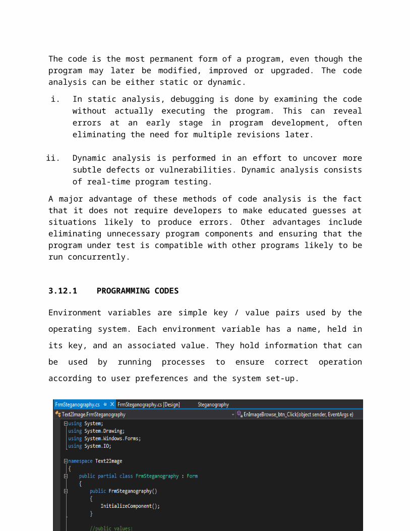
The code is the most permanent form of a program, even though theprogram may later be modified, improved or upgraded. The codeanalysis can be either static or dynamic.
i. In static analysis, debugging is done by examining the codewithout actually executing the program. This can revealerrors at an early stage in program development, ofteneliminating the need for multiple revisions later.
ii. Dynamic analysis is performed in an effort to uncover moresubtle defects or vulnerabilities. Dynamic analysis consistsof real-time program testing.
A major advantage of these methods of code analysis is the factthat it does not require developers to make educated guesses atsituations likely to produce errors. Other advantages includeeliminating unnecessary program components and ensuring that theprogram under test is compatible with other programs likely to berun concurrently.
3.12.1 PROGRAMMING CODES
Environment variables are simple key / value pairs used by the
operating system. Each environment variable has a name, held in
its key, and an associated value. They hold information that can
be used by running processes to ensure correct operation
according to user preferences and the system set-up.
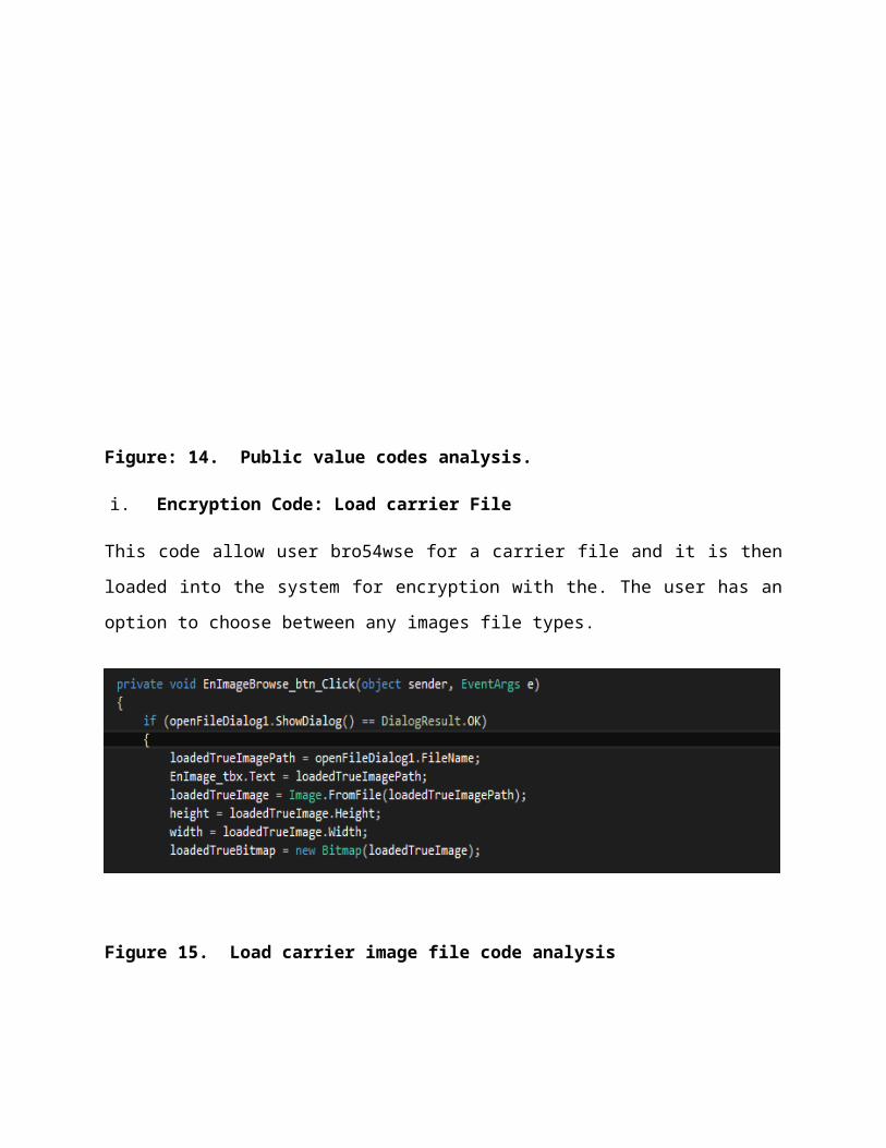
Figure: 14. Public value codes analysis.
i. Encryption Code: Load carrier File
This code allow user bro54wse for a carrier file and it is then
loaded into the system for encryption with the. The user has an
option to choose between any images file types.
Figure 15. Load carrier image file code analysis
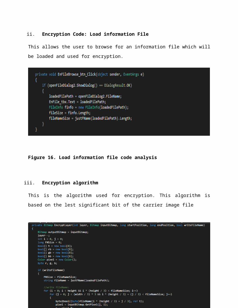
ii. Encryption Code: Load information File
This allows the user to browse for an information file which will
be loaded and used for encryption.
Figure 16. Load information file code analysis
iii. Encryption algorithm
This is the algorithm used for encryption. This algorithm is
based on the lest significant bit of the carrier image file
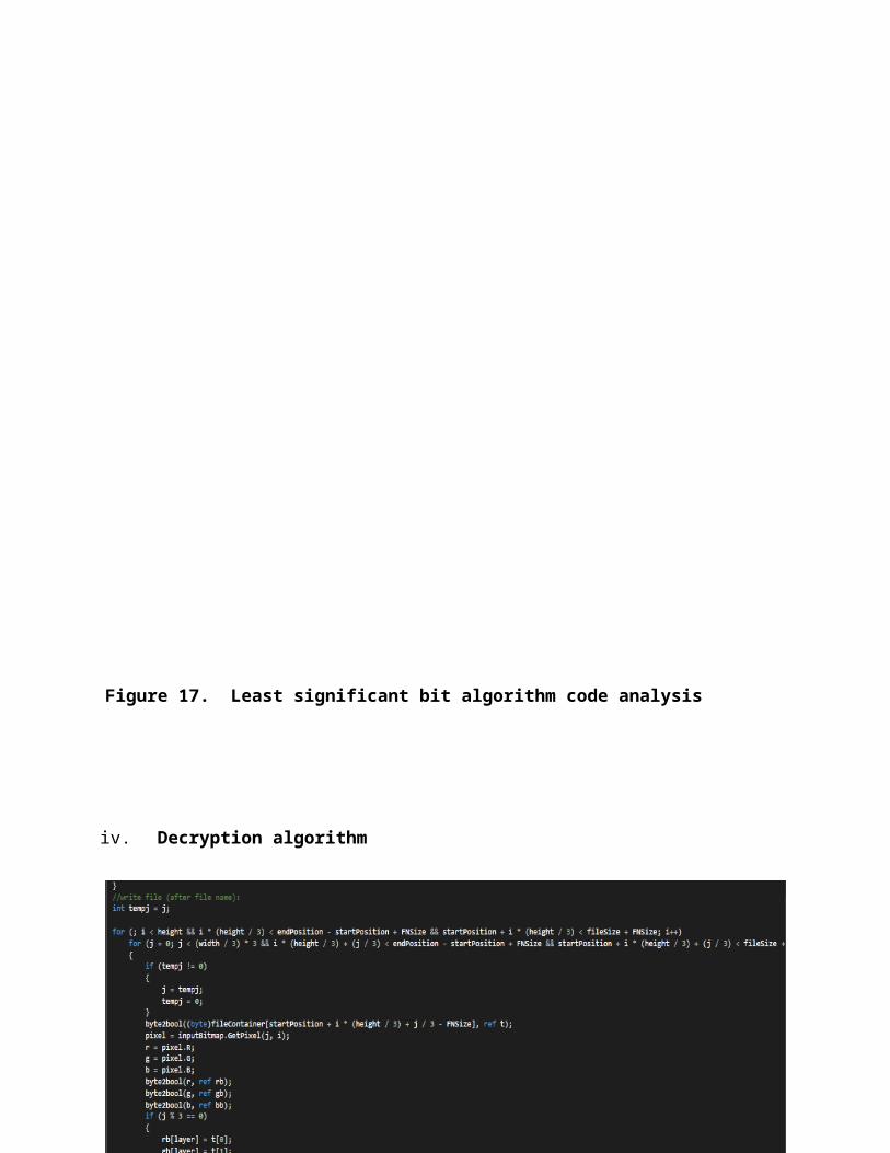
Figure 17. Least significant bit algorithm code analysis
iv. Decryption algorithm
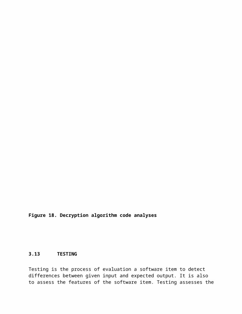
Figure 18. Decryption algorithm code analyses
3.13 TESTING
Testing is the process of evaluation a software item to detect differences between given input and expected output. It is also to assess the features of the software item. Testing assesses the
quality of the product. Software testing is a process that shouldbe done during the development process after implementation (coding). In other words software testing is a verification and validation process.
Verification; verification is the process to make sure the product satisfies the conditions imposed at the start of thedevelopment phase. In other words, to make sure the product behaves the way we want it to.
Validation; validation is the process to make sure the product satisfies the specified requirements at the end of the development phase. In other words, to make sure the product is built as per customer requirements.
3.13.1 BASICS OF SOFTWARE TESTING
In order to start the testing process the primary thing is
requirements of software development cycle. Using this phase the
testing phase will be easier for testing.
The capacity of the software can be calculated by executing the
code and inspecting the code in different conditions such as
testing the software by subjecting it to different sources as
input and examining the results with respect to the inputs.
There are two basics of software testing: black box testing and white box testing:
i. Black box testing: Black box testing is a testing technique that ignores the internal mechanism of the system and focuses on the output generated against any input and
execution of the system. It is also called functional testing.
ii. White box testing: White box testing is a testing technique that takes into account the internal mechanism of a system. It is also called structural testing and glass box testing.
Black box testing is often used for validation and white box testing is often used for verification.
3.13.2 FUNCTIONAL AND NON-FUNCTIONAL TESTING
i. Functional testing: Defines the specified function of a
particular code in the program. This type of testing gives
us a brief description about the program’s performance and
security in the various functional areas.
ii. Non-functional testing: Defines the capabilities of
particular software like its log data etc. It is opposite to
functional testing and so will not describe the
specifications like security and performance.
The performance of the particular program not only depends on
errors in coding. The errors in the code can be noticed during
execution, but the other types of errors can affect the program
performance like when the program is developed based on one
platform that may not perform well and give errors when executed
in different platform. So, compatibility is another issue that
reduces the software performance.
3.14 AIM OF TESTING
The main aim of testing is to analyze the performance and to
evaluate the errors that occur when the program is executed with
different input sources and running indifferent operating
environments. There are different types of approaches for testing
a .NET framework based application are;
Unit testing
Validation testing
Integration testing
User acceptance testing
Output testing
Black box and white box testing.
i. Unit Testing: This is the approach of taking a small part of
testable application and executing it according to the
requirements and testing the application behavior. Unit testing
is used for detecting the defects that occur during execution
(MSDN, 2010).When an algorithm is executed, the integrity should
be maintained by the data structures. Unit testing is made use
for testing the functionality of each algorithm during
execution. Unit testing reduces the ambiguity in the units.
In this project, I have developed an application using different
phases like encryption, decryption. So for getting the correct
output, all the functions that are used are executed and tested
at least once so as to making sure that all the control paths,
error handling and control structures are in proper manner.
ii. Limitations of Unit Testing: This is limited to test only
the functionality of the units. It can’t identify
integration errors, performance problems and system
problems. Unit testing can show the errors which occur in
the units when the testing runs. It may not display the
errors that currently are absent.
iii. Validation Testing: Validation is the process of finding
whether the product is built correct or not. The software
application or product that is designed should fulfill the
requirements and reach the expectations set by the user.
Validation is done while developing or at the final stage of
development process to determine whether it is satisfies the
specified requirements of user.
Using validation test the developer can qualify the design,
performance and its operations. Also the accuracy,
repeatability, selectivity, Limit of detection and
quantification can be specified using “Validation testing”
(MSDN, 2010).
i. Output Testing: After completion of validation testing the
next process is output testing. Output testing is the process
of testing the output generated by the application for the
specified inputs. This process checks weather the application
is producing the required output as per the user’s
specification or not. The “output testing” can be done by
considering mainly by updating the test plans, the behavior of
application with different type of inputs and with produced
outputs, making the best use of the operating capacity and
considering the recommendations for fixing the issues (MSDN,
2010).
ii. Integration Testing: This is an extension to unit testing,
after unit testing the units are integrated with the logical
program. The integration testing is the process of examining
the working behavior of the particular unit after embedding
with program. This procedure identifies the problems that occur
during the combination of units. The integration testing can be
normally done in three approaches;
Top-down approach
Bottom-up approach
Umbrella approach
a. Top-down approach:
In the top-down approach the highest level module should be
considered first and integrated. This approach makes the high
level logic and data flow to test first and reduce the necessity
of drivers. One disadvantage with top-down approach is its poor
support and functionality is limited (MSDN, 2010)
b. Bottom-up approach:
Bottom-up approach is opposite to top-down approach. In this
approach, the lowest level units are considered and integrated
first. Those units are known as utility units. The utility units
are tested first so that the usage of stubs is reduced. The
disadvantage in this method is that it needs the respective
drivers which make the test complicated, the support is poor and
the functionality is limited (MSDN, 2010).
c. Umbrella approach:
The third approach is umbrella approach, which makes use of both
the top – bottom and bottom - top approaches. This method tests
the integration of units along with its functional data and
control paths. After using the top - bottom and bottom-top
approaches, the outputs are integrated in top - bottom manner.
The advantage of this approach is that it provides good support
for the release of limited functionality as well as minimizing
the needs of drivers and hubs. The main disadvantage is that it
is less systematic than the other two approaches (MSDN, 2010).
v. User Acceptance Testing
This is the process of obtaining the confirmation from the user
that the system meets the set of specified requirements. It is
the final stage of project; the user performs various tests
during the design of the applications and makes further
modifications according to the requirements to achieve the final
result. The user acceptance testing gives the confidence to the
clients about the performance of system.
CHAPTER FOUR
RESULTS AND DISCUSSION
4.0 INTRODUCTION
To complete this study properly, it is necessary to discuss the
achievements realized in relation to the objectives of the
project so as to answer the research questions as well as
limitations encountered during the projects timeline.
This chapter compasses the interpretation of the finding
resulting from this study as well as the discussion on the
development of the system.
4.1 RESULTS
For designing the image steganographic system, I operated on
different phases like encryption and decryption. A system for
encrypting any type of data or information file into an image
file and saved to a destination folder in a bitmap image format
(*.bmp) was developed successfully.
A prototype of the image Steganographic system was set up for
test run on the computer systems of the information and
communication units of ISSYS GH. It was found out that encrypted
information showed no evidence of existence in the stego-image;
the personals were unable to guess or distinguish which images on
their computer systems had been encrypted with the image
steganographic system, unless the file names are revealed to
them. The units were satisfied with the method of encryption
employed.
Another test was run on one of their business clients systems and
the result was the same. Confidential data and information was
securely encrypted by the system. Stego-image showed no evidence
of any hidden information in it. The system provided a form of
security through obscurity which was the main aim of this
research.
This means ISSYS GH. Will now use the image steganographic system
with its business clients were necessary to exchange protected
information when necessary and store information in bitmap images
using the image steganographic system.
4.2 DISCUSSION
The proposed steganographic system will provide security to
information files and data files as well as hide the very
existence of those files. This will prevent unauthorized access
and modification of the hidden information files. In the long
term this will protect information integrity, availability,
authenticity and confidentiality.
The design phase is the primary phase, which gives a brief idea
about the different levels used for developing an application
with the help of block diagrams. The software is designed in a
user friendly manner. So, it is simple to use for developing a
prototype of the application. The most important phase in the
project is the execution phase. The execution phase is developed
with the help of design phase. For executing the application, I
worked on two sections: one is encryption and another is
decryption.
As I designed the program using .NET platform, the next part is
debugging the program. I faced some problems when writing the
code, but at last I am successful in executing the program
without errors. I used different approaches for testing the
application, which helped me to know about the limitations.
In this project I mainly concentrated on embedding the
information file or data into an image file. I have designed the
image steganographic application which embedded the information
file into the image file.
Normally, after embedding the data into the image, the image may
lose its resolution. In the proposed approach, the image is
slightly changed in its resolution at a threshold which is
invisible to the human visual system.
The speed of embedding the information file into the image is
also high in the proposed approach such that the image is
protected and the information or data is stored securely.
For the decryption phase, I have used the same .NET programming
language for the purpose of designing. There are many
steganographic algorithms available. But I used the Least
Significant Bit algorithm in designing the image steganographic
application because LSB algorithm works efficiently when we
consider bitmap images (*.bmp files).
The speed of embedding is also high when using LSB compared to
other algorithms. This approach is highly secured from stego
attacks and Steganalysis.
I have chosen image steganography because it is simple to use and
its user friendly application. There are many applications for
image hiding but the proposed approach is created using Microsoft
.NET frame work which is easier for coding and the performance is
better compared to other languages.
This project gave me good experience in dealing with the
information and data security issues in theoretical as well as in
technical domain and in .NET programming as I used Microsoft
visual studio c# for designing the image steganographic
application.
I did the project in satisfactory level with the help and good
guidance from my supervisor.
4.3 SOFTWARE INSTALLATION
You can install the programme in windows by performing the
following steps below;
1. Insert the CD into your CD –ROM
2. If the system is set to autorun.The programme will auto
start after some few seconds. If this happens skip to step
below or else
3. Click on my computer icon
4. Double click on the CD-ROM
5. Double click on the startup icon
6. Select install software. Ignore publisher verification error
message
7. After successful installation which will take less than a
minute to complete, the image steganographic system will
automatically launch
4.3.1 STARTING THE APPLICATION
There are two methods;
a. Double clicking the image steganographic icon on the start
menu.
b. Going to the start menu and program.
4.4 SCREEN SHOOTS EXPLANATION
These are the various screen shot images of the procedures used
for encrypting and decrypting. This gives a detailed graphical
process on how to use the system.
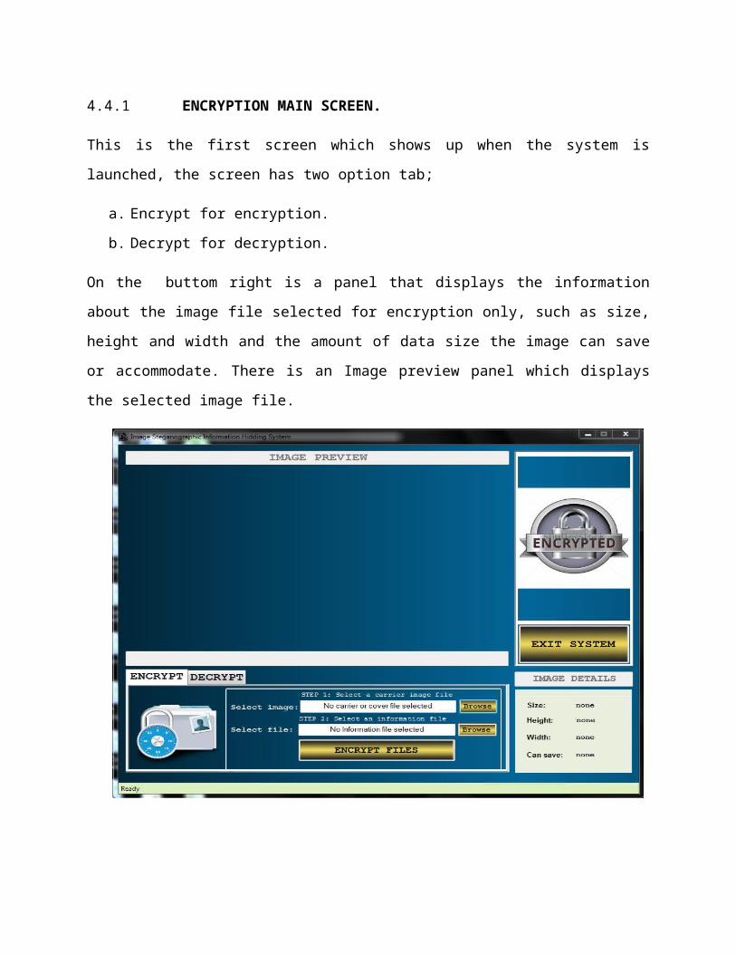
4.4.1 ENCRYPTION MAIN SCREEN.
This is the first screen which shows up when the system is
launched, the screen has two option tab;
a. Encrypt for encryption.
b. Decrypt for decryption.
On the buttom right is a panel that displays the information
about the image file selected for encryption only, such as size,
height and width and the amount of data size the image can save
or accommodate. There is an Image preview panel which displays
the selected image file.
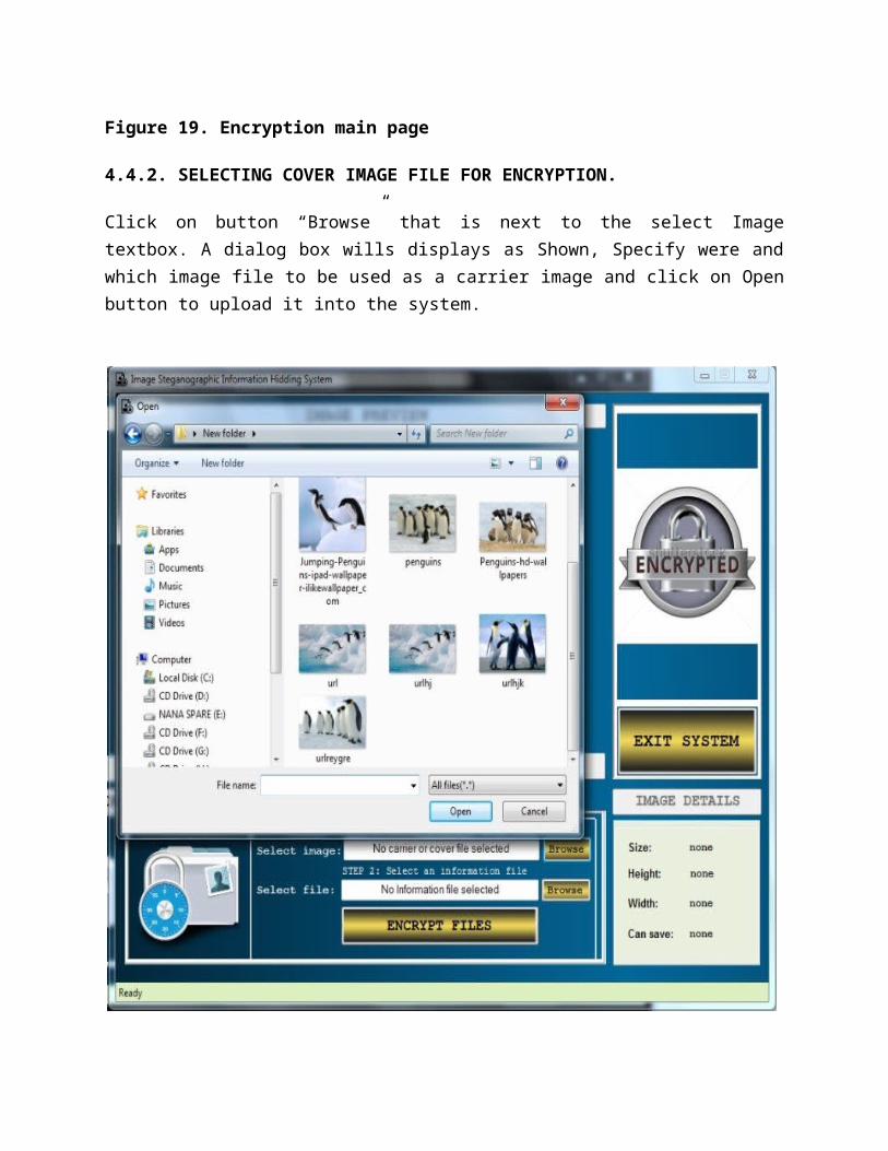
Figure 19. Encryption main page
4.4.2. SELECTING COVER IMAGE FILE FOR ENCRYPTION.
Click on button “Browse” that is next to the select Imagetextbox. A dialog box wills displays as Shown, Specify were andwhich image file to be used as a carrier image and click on Openbutton to upload it into the system.
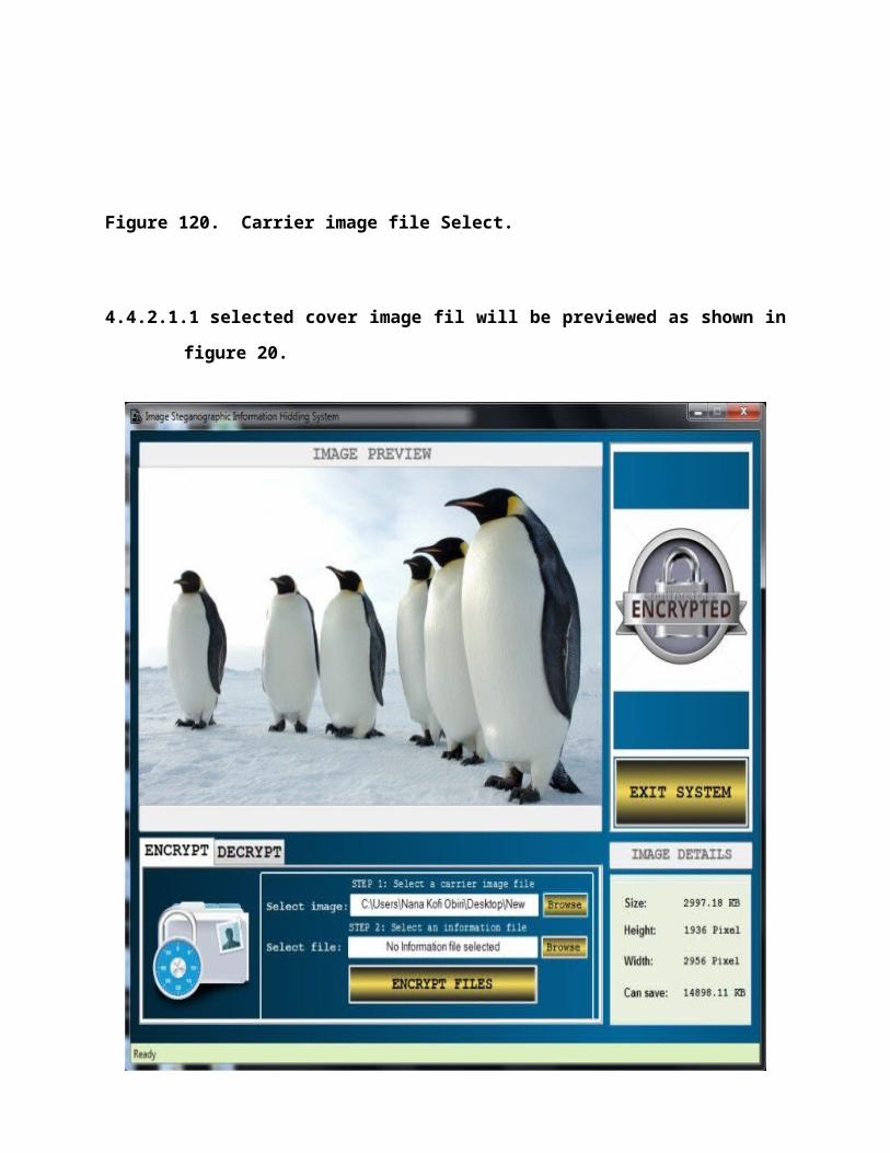
Figure 120. Carrier image file Select.
4.4.2.1.1 selected cover image fil will be previewed as shown in
figure 20.
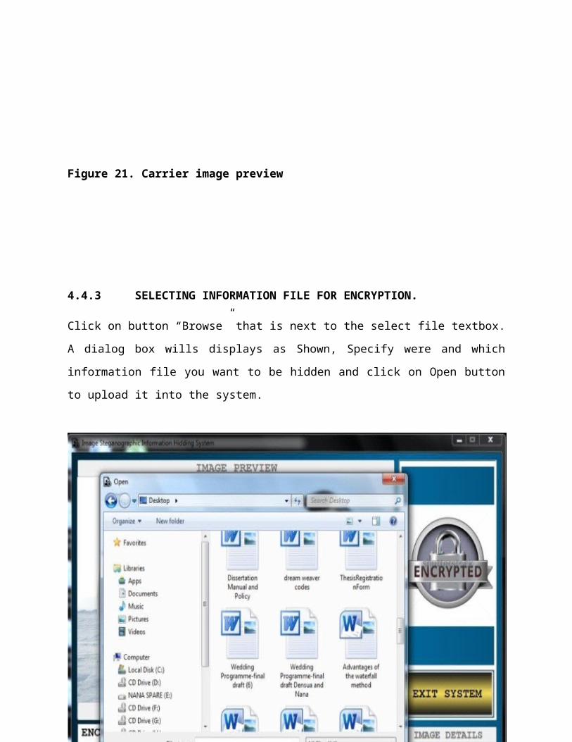
Figure 21. Carrier image preview
4.4.3 SELECTING INFORMATION FILE FOR ENCRYPTION.
Click on button “Browse” that is next to the select file textbox.
A dialog box wills displays as Shown, Specify were and which
information file you want to be hidden and click on Open button
to upload it into the system.
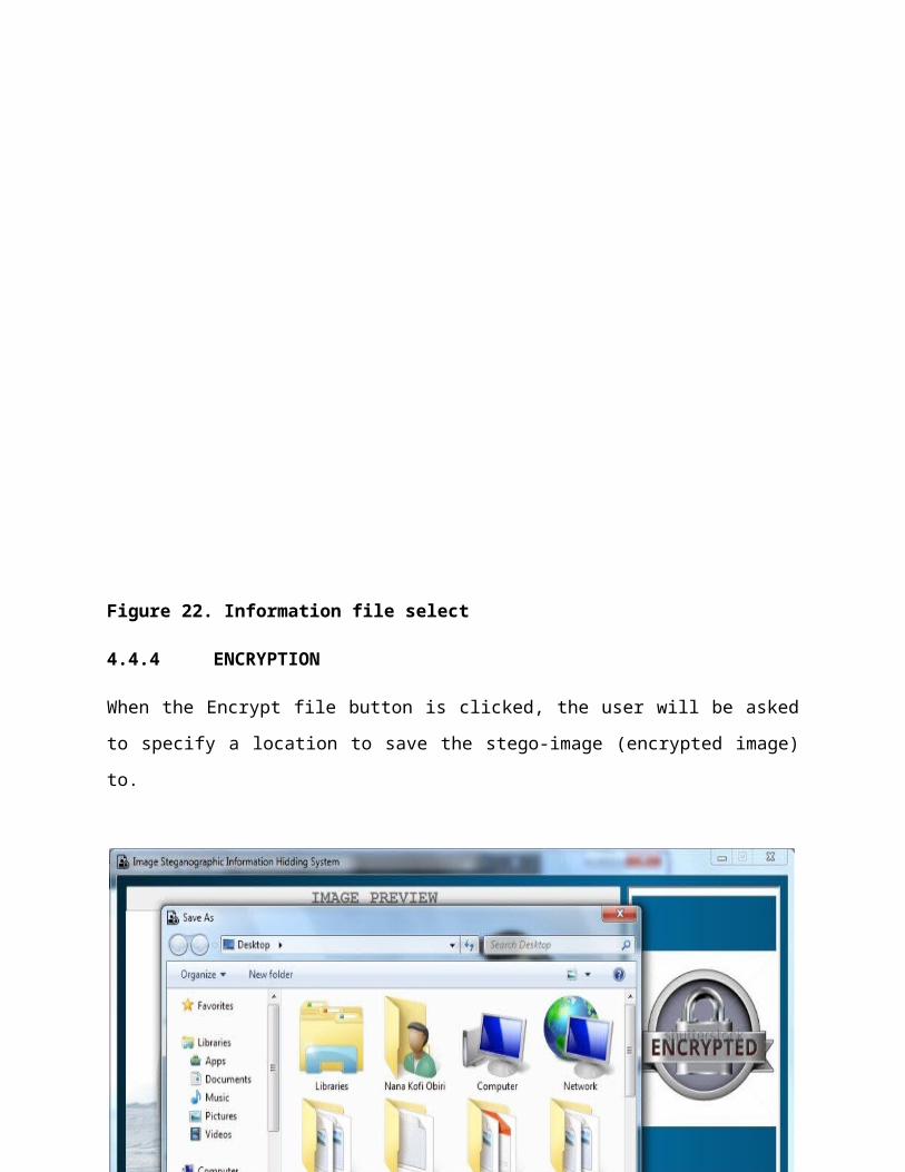
Figure 22. Information file select
4.4.4 ENCRYPTION
When the Encrypt file button is clicked, the user will be asked
to specify a location to save the stego-image (encrypted image)
to.
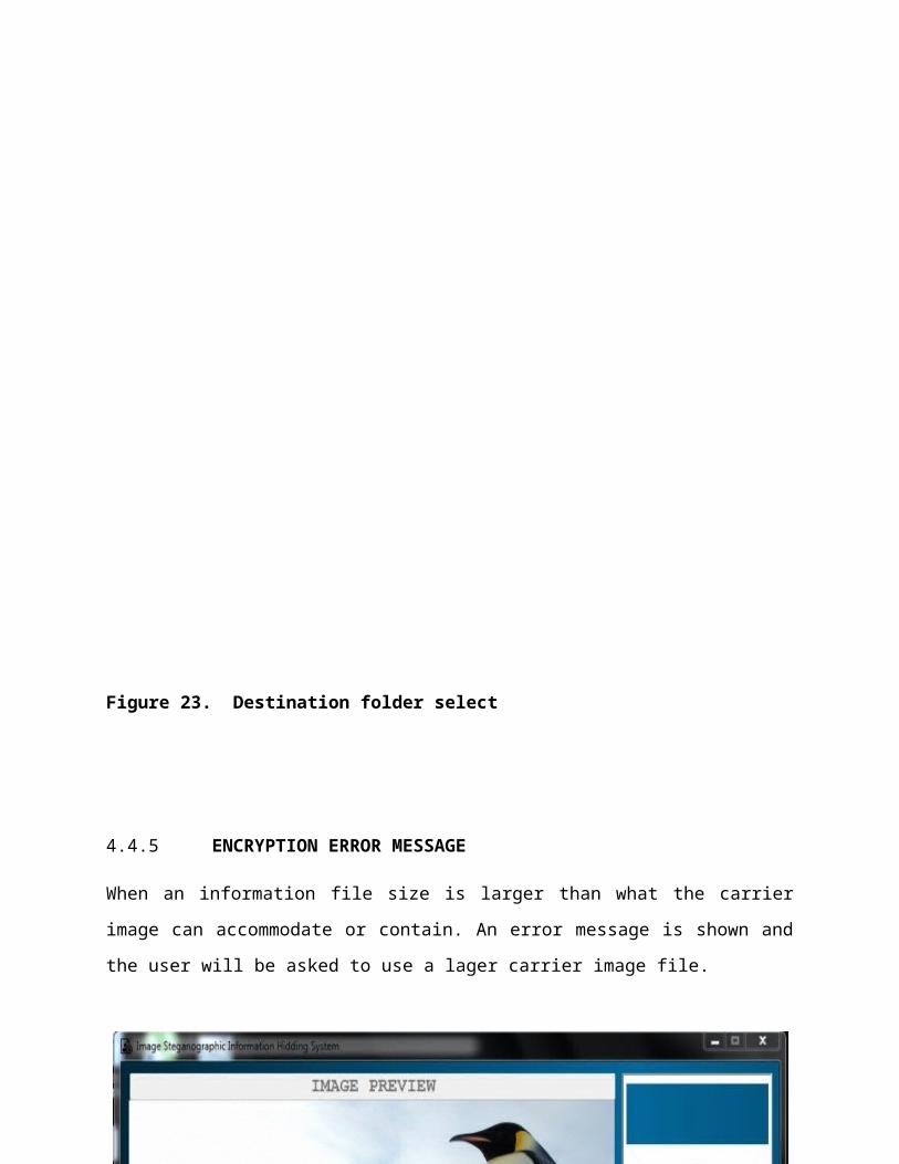
Figure 23. Destination folder select
4.4.5 ENCRYPTION ERROR MESSAGE
When an information file size is larger than what the carrier
image can accommodate or contain. An error message is shown and
the user will be asked to use a lager carrier image file.
Figure 24. Encryption Error message
4.4.6 DECRYPTING MAIN PAGE
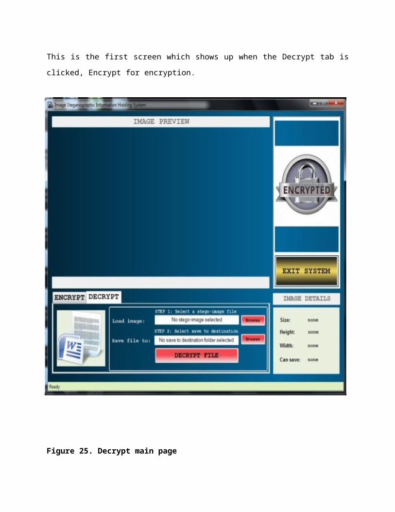
This is the first screen which shows up when the Decrypt tab is
clicked, Encrypt for encryption.
Figure 25. Decrypt main page
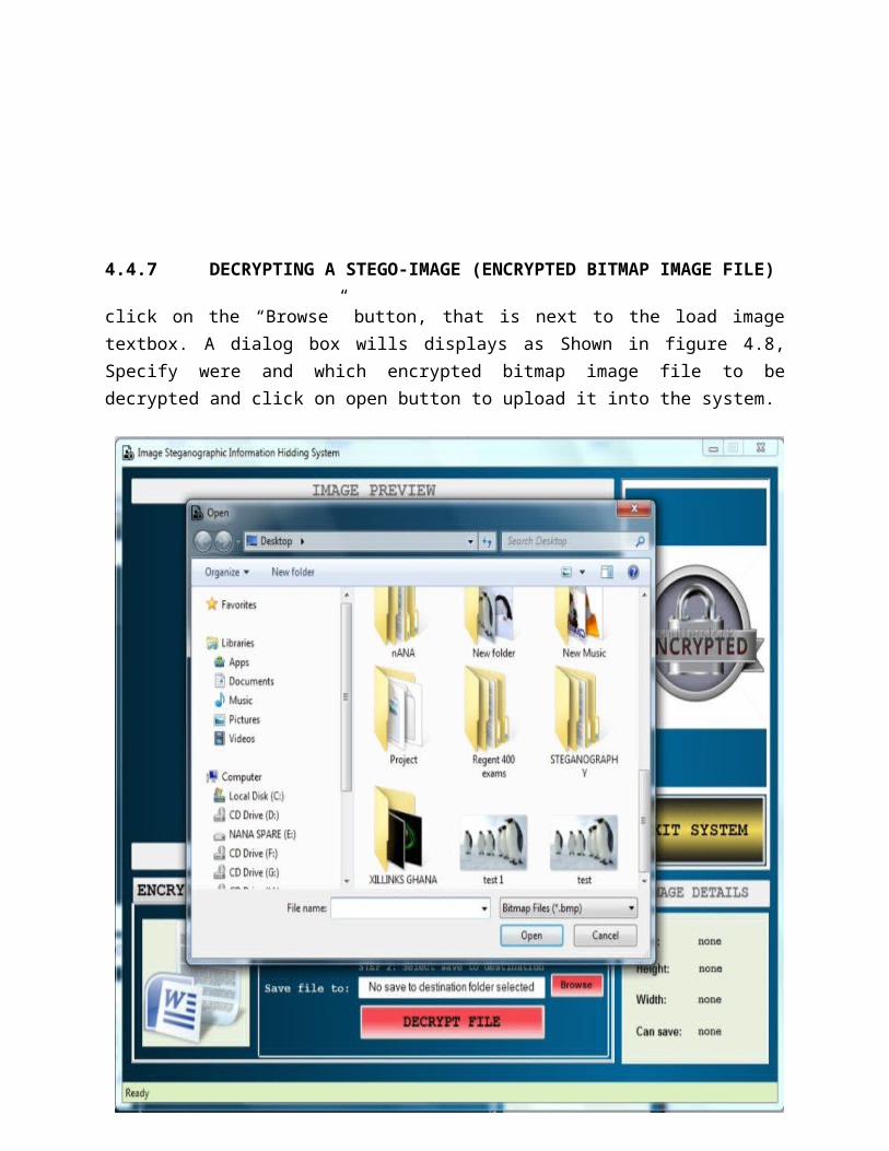
4.4.7 DECRYPTING A STEGO-IMAGE (ENCRYPTED BITMAP IMAGE FILE)
click on the “Browse” button, that is next to the load imagetextbox. A dialog box wills displays as Shown in figure 4.8,Specify were and which encrypted bitmap image file to bedecrypted and click on open button to upload it into the system.
Figure 26. Specifying a stego-image for decryption
CHAPTER FIVE
CONCLUSION AND RECOMMENDATIONS
5. INTRODUCTION
The purpose of this chapter is to summarize the thesis researchand suggest research recommendations for further analysis. Thefirst section of the chapter will give a summary of the researchquestions, followed by the finding to the research questionswhich answers the objectives of this paper The last part of thechapter will discuss the propose recommendations for furtherresearch.
5.1 CONCLUSION
On the basis of the problem statement in this study, thisresearch came up with the following conclusions:
An encryption system which can hide information and data in animage file was the best ways to keep such data and informationfrom unauthorized usage and modification. Since even a leakedstego-image will still require a known algorithm or thesteganographic system to decrypt it. Moreover, it could beconcluded that the implementation of the image steganographic
system in the said company hides the very existence of the formof encryption deployed. This has helped to prevent suspecting thevery existence of the hidden data or information file.
This means that the company has reduced the risk of informationand data modification and access by unauthorized persons as wellas making information in the company more manageable that isinformation is available, authentic, and confidential and itsintegrity is protected. The stego-image resolution doesn’t changemuch and is negligible when we embed the information or data fileinto the image.
I used the least significant bit algorithm in this project fordeveloping the system because it is faster, reliable andcompression ratio is moderate compared to other algorithms.
The major limitation of the system is that, the output file islimited a bitmap images (*.bmp) file. The system accepts onlyimages as a carrier or cover file, and the compression depend onthe document size as well as the carrier or cover image size.
And lastly, the study concludes that the personnel of the companyare the fundamental barometers of the level of efficiencyprovided by the image steganographic system. In order to developan ultimate Encryption system, a prior consultation among theemployees would be advisable in order to cater the needs of whoand which department will use the system and the types of imagesto use since every image has a copy right or an owner.
5.2 RECOMMENDATION
The future work on this project is to improve the compressionratio of the image to the data or information file so as toaccommodate even larger information file or data files.
Also this project can be extended to a level such that it can beused for the different types of image formatslike .gif, .jpeg, .png, .tif etc., in the future as output files(stego-image).
The security using Least Significant Bit Algorithm is good but wecan improve the level to a certain extent by varying the carriersas well as using different keys for encryption and decryption.The encrypted image can be further protected with a passwordeither with a public key or private key.
REFERENCE
[1] Shirey R. Internet Security Glossary, Version 2. RFC 4949. 2007.
[2]. Mohammad Fahmi, Alalem Abdallah , Muhanah Manasrah,(2008)“A Steganographic Data Security Algorithm with Reduced Steganalysis Threat,” Birzeit University, Birzeit.
[3] Wang, H & Wang, S,“ Cyber warfare: Steganography vs. Steganalysis ”, Communications of the ACM, 47:10, October 2004
[4] Johnson NF, Jajodia S. Exploring steganography: seeing the unseen. IEEE Computer 1998;31(2):26–34.
[5] R A Isbell, “Steganography: Hidden Menace or Hidden Saviour”,Steganography White Paper, 10 May 2002.
[6] M.M. Amin, M. Salleh, S. Ibrahim, et al., “Information HidingUsing Steganography”, 4th National Conference On Telecommunication Technology Proceedings (NCTT2003), Shah Alam, Malaysia, pp. 21-25, January 14-15,2003.
[7] J.Zollner, H. Federrath, H. Klimant, et al., “Modeling the Security of Steganographic Systems”, in 2nd Workshop on Information Hiding, Portland, April 1998, pp. 345-355.
[8] N. Provos, P. Honeyman, “Detecting Steganography Content on the Internet”. CITI Technical Report 01-11, 2001.
[9] E.T. Lin and E.J. Delp, "A Review of Data Hiding in Digital Images," in Proceedings of the Image Processing, Image Quality, Image Capture Systems Conference, PICS '99, Ed., Apr. 1999, pp. 274--278.
[10] C. Cachin, “An Information-Theoretic Model for Steganography”, in proceeding 2nd Information Hiding Workshop, vol. 1525, pp. 306-318, 1998.
[11] Evans, J.A.S. (2006).The beginnings of history: Herodotus and the Persian wars. Campbellville, Ont.: Edgar Kent. ISBN 0-88866-652-7
[12] kahn 1996
[13] Second Lieutenant J. Caldwell, Steganography, United States Air Force, http://www.stsc.hill.af.mil/crosstalk/2003/06/caldwell.pdf, June 2003
[14] Anderson R.J.& Petitcolas, F.A.P., “On the limits of steganography”, IEEE Journal of selected A as in Communications, May1998
[15] R. Chandramouli, N. Memon, “Analysis of LSB Based Image Steganography Techniques”, IEEE pp. 1019-1022, 2001.
[16] N.F. Johnson, S. Jajodia, “Staganalysis: The Investigation of Hiding Information”, IEEE, pp. 113-116, 1998.
[17] D. Artz, “Digital Steganography: Hiding Data within Data”, IEEE InternetComputing, pp. 75-80, May-Jun 2001.
[18] S. Tanako, K. Tanaka and T. Sugimura, “Data Hiding via Steganographic Image Transformation”, IEICE Trans. Fundamentals, vol. E83-A, pp. 311-319, February, 2000.
[19] R.Popa, “An Analysis of Steganographic System”, The "Politehnica" University of Timisoara, Faculty of Automatics and Computers, Department of Computer Science and Software Engineering, May 25,1998.
[20] F.A.P Peticolas, R.J. Anderson and M.G. Kuhn, “Information Hiding – A Survey”, in proceeding of IEEE, pp. 1062-1078, July 1999.
[21] Bruce Schneier, Beyond Fear: Thinking Sensibly about Security in an Uncertain World, Copernicus Books, pages 26-27.
[22] Shirley R. Internet security glossary. IETF Request for Comment 4949; 2007, August. Retrieved October 10, 2011, from http://tools.ietf.org/html/rfc4949.
[23] Parker D. Our excessively simplistic information model and how to fix it. ISSA J.2010:8(7):12–21.
[24] N.F. Johnson & S. Jajodia, “Steganalysis of Images Created Using Current Steganography Software”, in Proceeding for the Second Information Hiding Workshop, Portland Oregon, USA, April 1998, pp. 273-289.
[25] N.F. Johnson and S. Jajodia, “Exploring Steganography: Seeing the Unseen”, IEEE, pp. 26-34, 1998
[26] “Reference guide: Graphics Technical Options and Decisions”, http://www.devx.com/projectcool/Article/19997.
[27] Owens, M., “A discussion of covert channels and steganography”, SANS Institute, 2002.
[28] A. Cheddad,J. Condell, K. Curran and P.M. Kevitt. (2010). “Digital image steganography:Survey and analysis of current methods.” Signal Processing Journal. [On line]. 90(3), pp.727-752. Available: http://www.abbascheddad.net/Survey.pdf [Aug. 2011].
[29] M.Fortrini. “Steganography and digital watermarking: A global view.” University of California, Davis. Available: http://lia.deis.unibo.it/Courses/RetiDiCalcolatori/Progetti00/fortini/ project.pdf. [June 2011].
[30] Moerland, T., “Steganography and Steganalysis”, Leiden Institute of Advanced Computing Science, www.liacs.nl/home/tmoerl/privtech.pdf
[31] Dunbar, B., “Steganographic techniques and their use in an Open-Systems environment”, SANS Institute, January 2002
[32] Johnson, N.F. & Jajodia, S., “Exploring Steganography: Seeing the Unseen”, Computer Journal, February 1998.
[33] “Reference guide: Graphics Technical Options and Decisions”, http://www.devx.com/projectcool/Article/19997