
Section 3 - Nord Stream AG
78
Section 3 Description of the project
-
Upload
khangminh22 -
Category
Documents
-
view
1 -
download
0
Transcript of Section 3 - Nord Stream AG
Section 3
Description of the project

Environmental impact assessment report | Section 3 | 65
Description of the project3
General3.1
The aim of this chapter is to describe the Nord Stream project in sufficient depth to enable the scope and extent of the project to be understood, and for all potential sources of impacts to be identified.
Scope of project activities addressed in the Finnish EIA report3.1.1
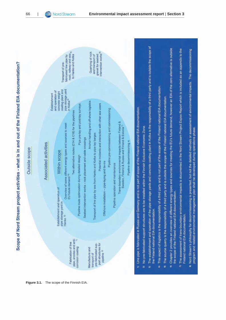
The scope of the Finnish national EIA report is presented in Figure 3.1. A distinction is made between Nord Stream project activities that are (1) within the scope of the EIA report, (2) associated with the EIA - i.e. they are not assessed as part of this EIA report but are services provided by suppliers and subject to seperate regulation under Finland’s ”Act on Environmental Impact Assessment Procedure” and (3) outside the scope of this EIA report.
In general the scope of the Finnish national EIA-report is confined to those project activi-ties that occur off-shore in Finland’s territorial waters and exclusive economic zone within the Baltic Sea.
The footnotes to Figure 3.1 explain the justification for not assessing certain project-related activities at this time.
It should be noted that the description of the proposed Nord Stream project that follows in this chapter describes for completeness some locations and activities that are outside the scope of Finnish national EIA assessment process and consequenty are not addressed fur-ther in this report.
Transboundary impacts of project-related activities from other countries to Finland and from the Finnish exclusive economic zone to other countries are outside the scope of this docu-ment. They are addressed in the Nord Stream Espoo Report /5/.
Environmental impact assessment report | Section 366 |
Figure 3.1. The scope of the Finnish EIA.
Environmental impact assessment report | Section 3 | 67
Project overview3.1.2
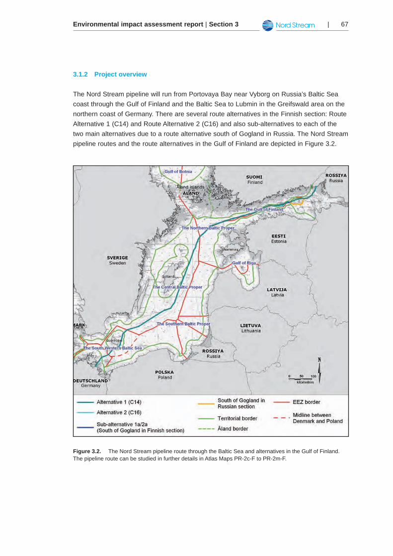
The Nord Stream pipeline will run from Portovaya Bay near Vyborg on Russia’s Baltic Sea coast through the Gulf of Finland and the Baltic Sea to Lubmin in the Greifswald area on the northern coast of Germany. There are several route alternatives in the Finnish section: Route Alternative 1 (C14) and Route Alternative 2 (C16) and also sub-alternatives to each of the two main alternatives due to a route alternative south of Gogland in Russia. The Nord Stream pipeline routes and the route alternatives in the Gulf of Finland are depicted in Figure 3.2.
Figure 3.2. The Nord Stream pipeline route through the Baltic Sea and alternatives in the Gulf of Finland. The pipeline route can be studied in further details in Atlas Maps PR-2c-F to PR-2m-F.
Environmental impact assessment report | Section 368 |
The Nord Stream pipeline will consist of two 48-inch steel pipelines. The pipelines are referred to as the ‘north-west’ and ‘south-east’ pipelines to distinguish their orientation rela-tive to each other. Each pipeline has a total offshore length of about 1,220 km for Alternative 1 (C14) and of about 1,222 km for Alternative 2 (C16).
Landfall facilities in Russia and Germany will connect the two pipelines to the Russian and European gas networks. Onshore pipeline sections in Russia (approximately 1.5 km) and in Germany (approximately 0.5 km) will connect the offshore sections of the pipelines with the landfall facilities. The onshore sections are also known as dry sections.
The pipelines will be connected to a compressor station at the Russian landfall in Vyborg, which will be equipped with metering and pressure-control facilities. Similarly, the pipe-lines will be connected to a receiving terminal in Greifswald in Germany, which also will be equipped with a metering station and pressure-control facilities.
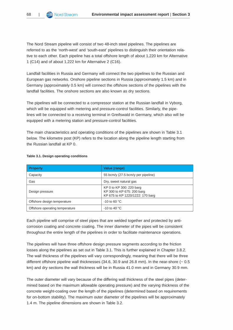
The main characteristics and operating conditions of the pipelines are shown in Table 3.1 below. The kilometre post (KP) refers to the location along the pipeline length starting from the Russian landfall at KP 0.
Table 3.1. Design operating conditions
Property Value (range)
Capacity 55 bcm/y (27.5 bcm/y per pipeline)
Gas Dry, sweet natural gas
Design pressureKP 0 to KP 300: 220 bargKP 300 to KP 675: 200 bargKP 675 to KP 1220/1222: 170 barg
Offshore design temperature -10 to 60 °C
Offshore operating temperature -10 to 40 °C
Each pipeline will comprise of steel pipes that are welded together and protected by anti-corrosion coating and concrete coating. The inner diameter of the pipes will be consistent throughout the entire length of the pipelines in order to facilitate maintenance operations.
The pipelines will have three offshore design pressure segments according to the friction losses along the pipelines as set out in Table 3.1. This is further explained in Chapter 3.8.2. The wall thickness of the pipelines will vary correspondingly, meaning that there will be three different offshore pipeline wall thicknesses (34.6, 30.9 and 26.8 mm). In the near-shore (~ 0.5 km) and dry sections the wall thickness will be in Russia 41.0 mm and in Germany 30.9 mm.
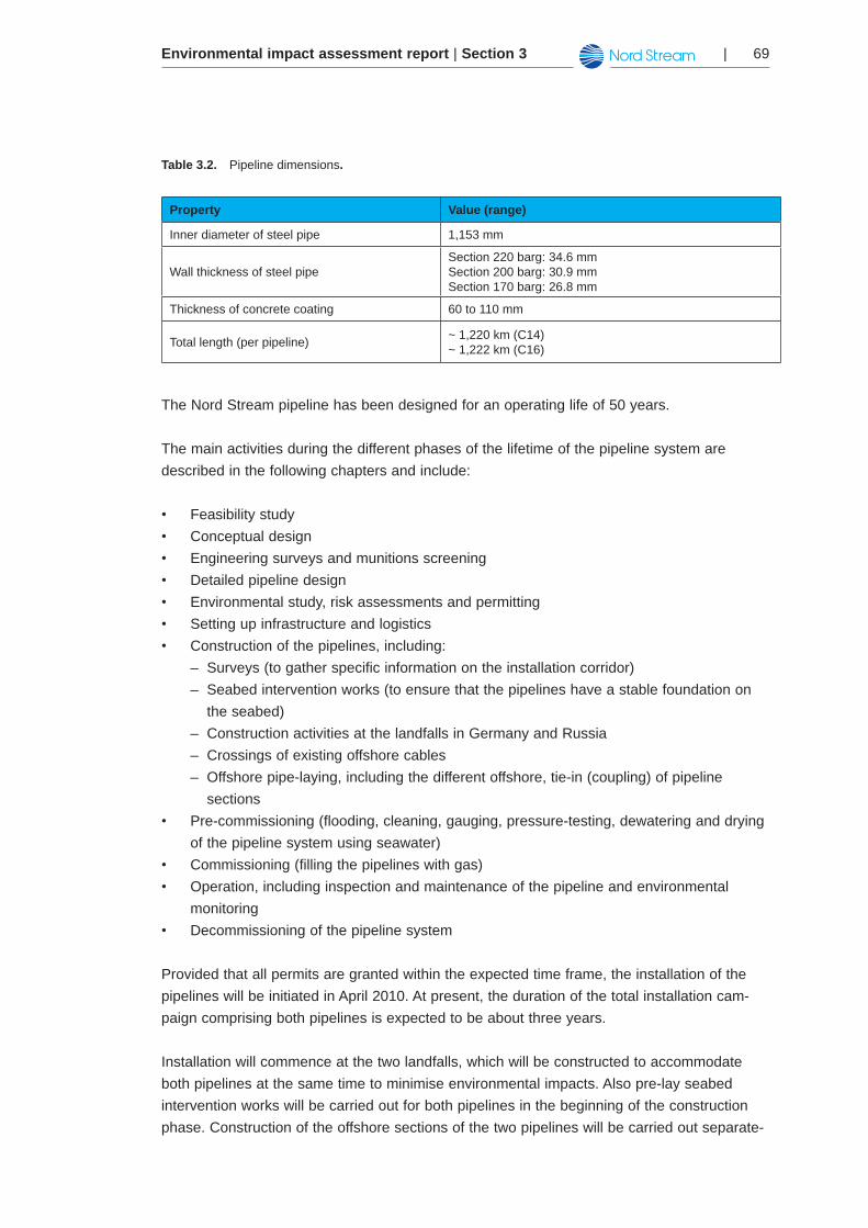
The outer diameter will vary because of the differing wall thickness of the steel pipes (deter-mined based on the maximum allowable operating pressure) and the varying thickness of the concrete weight-coating over the length of the pipelines (determined based on requirements for on-bottom stability). The maximum outer diameter of the pipelines will be approximately 1.4 m. The pipeline dimensions are shown in Table 3.2.
Environmental impact assessment report | Section 3 | 69
Table 3.2. Pipeline dimensions.
Property Value (range)
Inner diameter of steel pipe 1,153 mm
Wall thickness of steel pipeSection 220 barg: 34.6 mm Section 200 barg: 30.9 mmSection 170 barg: 26.8 mm
Thickness of concrete coating 60 to 110 mm
Total length (per pipeline) ~ 1,220 km (C14)~ 1,222 km (C16)
The Nord Stream pipeline has been designed for an operating life of 50 years.
The main activities during the different phases of the lifetime of the pipeline system are described in the following chapters and include:
Feasibility study•Conceptual design•Engineering surveys and munitions screening•Detailed pipeline design•Environmental study, risk assessments and permitting•Setting up infrastructure and logistics•Construction of the pipelines, including:•
Surveys (to gather specific information on the installation corridor) –Seabed intervention works (to ensure that the pipelines have a stable foundation on –the seabed) Construction activities at the landfalls in Germany and Russia –Crossings of existing offshore cables –Offshore pipe-laying, including the different offshore, tie-in (coupling) of pipeline –sections
Pre-commissioning (flooding, cleaning, gauging, pressure-testing, dewatering and drying •of the pipeline system using seawater)Commissioning (filling the pipelines with gas)•Operation, including inspection and maintenance of the pipeline and environmental •monitoringDecommissioning of the pipeline system•
Provided that all permits are granted within the expected time frame, the installation of the pipelines will be initiated in April 2010. At present, the duration of the total installation cam-paign comprising both pipelines is expected to be about three years.
Installation will commence at the two landfalls, which will be constructed to accommodate both pipelines at the same time to minimise environmental impacts. Also pre-lay seabed intervention works will be carried out for both pipelines in the beginning of the construction phase. Construction of the offshore sections of the two pipelines will be carried out separate-
Environmental impact assessment report | Section 370 |
ly, at different times. The first line will be ready for gas delivery in September 2011, and the second pipeline is planned to come on stream in November 2012.
In the Finnish sector, the construction works, including pipe-laying and seabed intervention works, will be conducted during several phases from 2010-2012. The construction schedule for activities in the Finnish exclusive economic zone is presented in Chapter 3.5.1.
Pipeline route3.2
The Nord Stream pipeline passes through the exclusive economic zones (EEZ) of Russia, Finland, Sweden, Denmark and Germany. In Russia, Denmark and Germany the pipeline also passes through territorial waters (TW).
This Chapter describes the route development process that has taken place during the past decade and presents the details of the proposed route.
Development of the pipeline route3.2.1
Determining the optimal route for the pipeline has been an evolving process. The initial route was based on a desk study; geophysical reconnaissance surveys in 2005; and detailed geo-physical, geotechnical and environmental sampling in 2006. The desk study was based on the North Transgas survey and feasibility study conducted in 1998-1999. An addition-al reconnaissance survey was performed in 2007 to evaluate potential alternative routes and to extend parts of the 2005 survey corridor. The proposed pipeline route was based on this extensive survey coverage.
During 2007 and 2008, route selection has been ongoing based on consultation with the authorities in the five transitory countries (the ‘countries of origin’). The route selection has been supported by further detailed geophysical investigations, a geotechnical sampling pro-gramme and in-situ testing and environmental sampling. Details of these studies and surveys can be found in Chapter 5.1 and in Appendix IV.
Detailed design and the above-mentioned investigation programmes have resulted in a number of potential optimisations of the route to further minimise seabed interventions. Minimisation of seabed interventions has been a key criterion during development of the route as it is desirable for economic, technical and environmental reasons: as less material will be placed or rearranged on the seabed, less environmental impact will be achieved and less economical and technical resources will be needed to perform the installation.
Environmental impact assessment report | Section 3 | 71
As a result, two alternative routes in the Finnish exclusive economic zone were selected. These routes are denoted route C14 (Alternative 1) and C16 (Alternative 2).
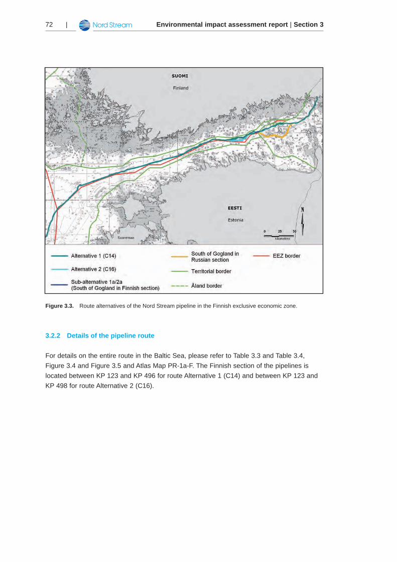
The alternative routes in the Finnish exclusive economic zone are shown in Figure 3.3. See also Atlas Map PR-1b-F. While these routes remains subject to further optimisation (based on detailed design and further investigations), it broadly comprises the proposed final routing of the pipeline. For a description of optimisations and route alternatives, please refer to Chapter 6.
Both pipeline route alternatives pass outside Finnish territorial water, and run close to the Finnish and Estonian exclusive economic zone border.
The route of the Nord Stream pipeline inside Finnish waters is largely governed by the geol-ogy of the Gulf of Finland. Generally, the seabed is more uneven to the north (closer to the coast of Finland) and outcropping bedrock is also more abundant. To minimise seabed inter-vention works it is preferable to place the pipeline as far south as possible.
The majority of the route is identical for the two route alternatives. The routes differ in the Kalbådagrund area: South-east of Kalbådagrund, the route C16 deviates from route C14 by going even further south around the Kalbådagrund shallow area and running close to the boundary of the Finnish exclusive economic zone. The purpose of this deviation is to avoid passing across the geological structure known as the Kalbådagrund area.
As also indicated in Figure 3.3 a route alternative in the Gulf of Finland goes south of Gogland in the Russian exclusive economic zone. Consequently, different sub-alternative routes are necessary in the Finnish exclusive economic zone depending on which route alter-native is chosen inside Finnish waters.
The pipeline length in the Finnish exclusive economic zone is approximately 373 km for route C14 (Alternative 1) and approximately 375 km for route C16 (Alternative 2).
Environmental impact assessment report | Section 372 |
Figure 3.3. Route alternatives of the Nord Stream pipeline in the Finnish exclusive economic zone.
Details of the pipeline route3.2.2
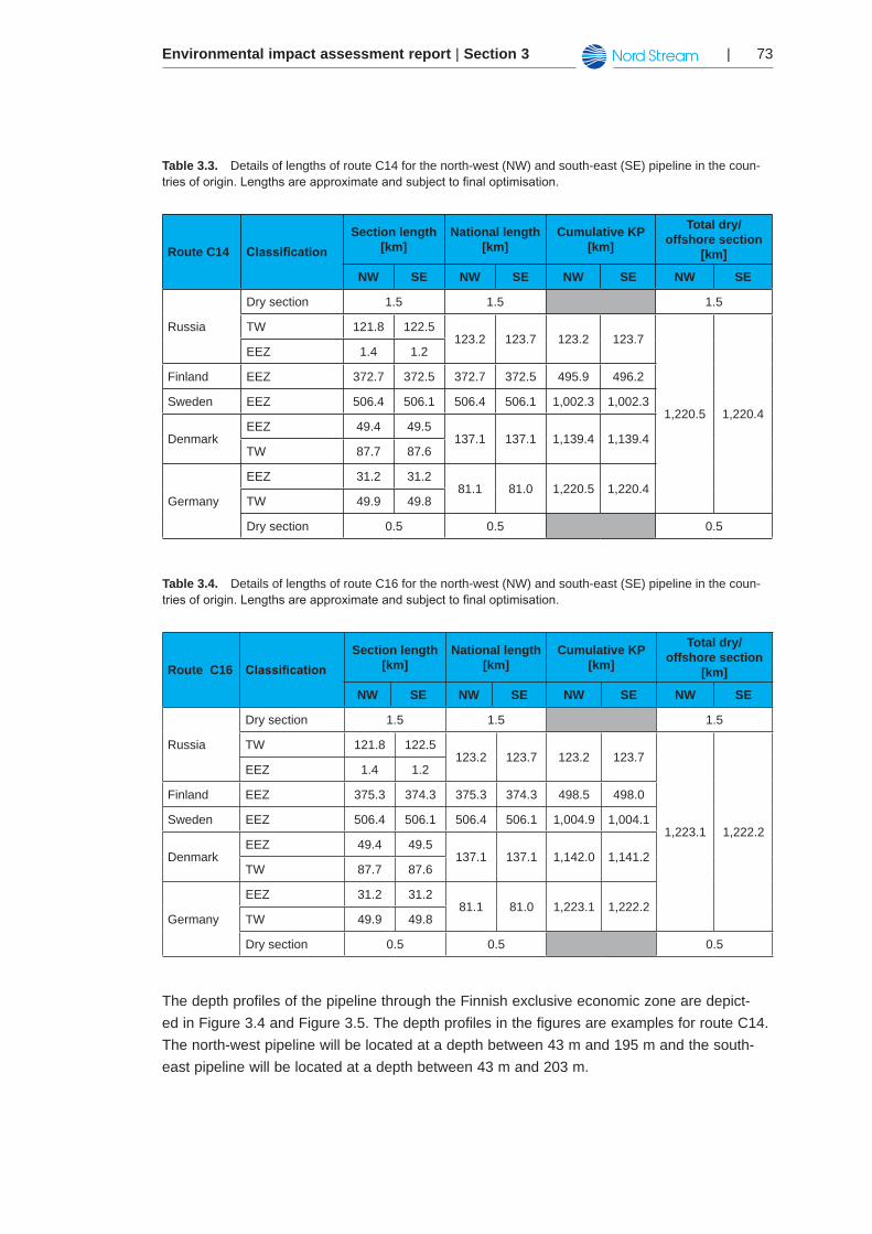
For details on the entire route in the Baltic Sea, please refer to Table 3.3 and Table 3.4, Figure 3.4 and Figure 3.5 and Atlas Map PR-1a-F. The Finnish section of the pipelines is located between KP 123 and KP 496 for route Alternative 1 (C14) and between KP 123 and KP 498 for route Alternative 2 (C16).
Environmental impact assessment report | Section 3 | 73
Table 3.3. Details of lengths of route C14 for the north-west (NW) and south-east (SE) pipeline in the coun-triesoforigin.Lengthsareapproximateandsubjecttofinaloptimisation.
Route C14 ClassificationSection length
[km]National length
[km]Cumulative KP
[km]
Total dry/ offshore section
[km]
NW SE NW SE NW SE NW SE
Russia
Dry section 1.5 1.5 1.5
TW 121.8 122.5123.2 123.7 123.2 123.7
1,220.5 1,220.4
EEZ 1.4 1.2
Finland EEZ 372.7 372.5 372.7 372.5 495.9 496.2
Sweden EEZ 506.4 506.1 506.4 506.1 1,002.3 1,002.3
DenmarkEEZ 49.4 49.5
137.1 137.1 1,139.4 1,139.4TW 87.7 87.6
Germany
EEZ 31.2 31.281.1 81.0 1,220.5 1,220.4
TW 49.9 49.8
Dry section 0.5 0.5 0.5
Table 3.4. Details of lengths of route C16 for the north-west (NW) and south-east (SE) pipeline in the coun-triesoforigin.Lengthsareapproximateandsubjecttofinaloptimisation.
Route C16 ClassificationSection length
[km]National length
[km]Cumulative KP
[km]
Total dry/ offshore section
[km]
NW SE NW SE NW SE NW SE
Russia
Dry section 1.5 1.5 1.5
TW 121.8 122.5123.2 123.7 123.2 123.7
1,223.1 1,222.2
EEZ 1.4 1.2
Finland EEZ 375.3 374.3 375.3 374.3 498.5 498.0
Sweden EEZ 506.4 506.1 506.4 506.1 1,004.9 1,004.1
DenmarkEEZ 49.4 49.5
137.1 137.1 1,142.0 1,141.2TW 87.7 87.6
Germany
EEZ 31.2 31.281.1 81.0 1,223.1 1,222.2
TW 49.9 49.8
Dry section 0.5 0.5 0.5
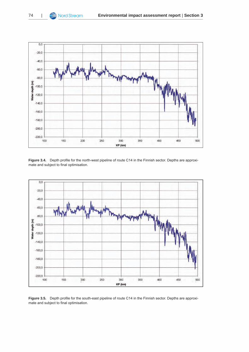
The depth profiles of the pipeline through the Finnish exclusive economic zone are depict-ed in Figure 3.4 and Figure 3.5. The depth profiles in the figures are examples for route C14. The north-west pipeline will be located at a depth between 43 m and 195 m and the south-east pipeline will be located at a depth between 43 m and 203 m.
Environmental impact assessment report | Section 374 |
Figure 3.4. Depthprofileforthenorth-westpipelineofrouteC14intheFinnishsector.Depthsareapproxi-mateandsubjecttofinaloptimisation.
Figure 3.5. Depthprofileforthesouth-eastpipelineofrouteC14intheFinnishsector.Depthsareapproxi-mateandsubjecttofinaloptimisation.
Environmental impact assessment report | Section 3 | 75
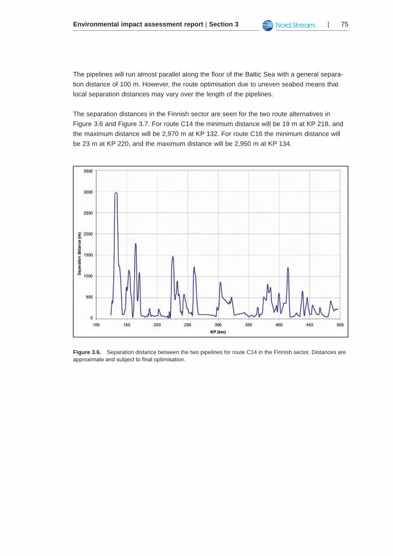
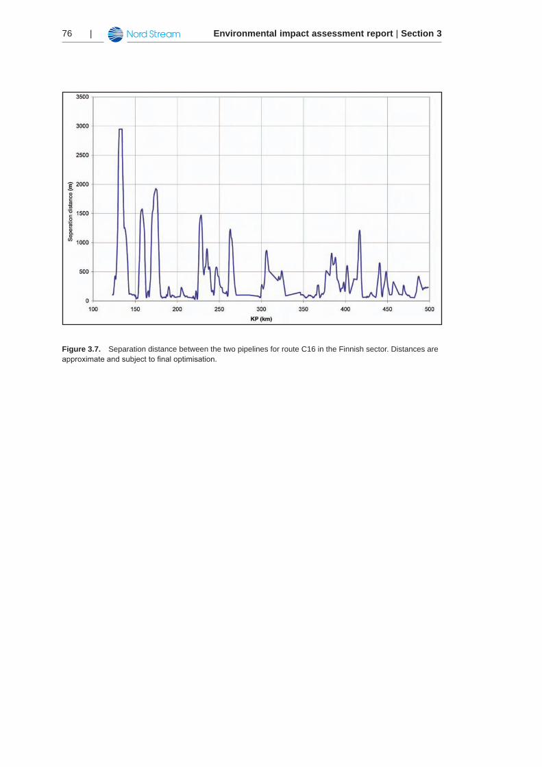
The pipelines will run almost parallel along the floor of the Baltic Sea with a general separa-tion distance of 100 m. However, the route optimisation due to uneven seabed means that local separation distances may vary over the length of the pipelines.
The separation distances in the Finnish sector are seen for the two route alternatives in Figure 3.6 and Figure 3.7. For route C14 the minimum distance will be 19 m at KP 218, and the maximum distance will be 2,970 m at KP 132. For route C16 the minimum distance will be 23 m at KP 220, and the maximum distance will be 2,950 m at KP 134.
Figure 3.6. Separation distance between the two pipelines for route C14 in the Finnish sector. Distances are approximateandsubjecttofinaloptimisation.
Environmental impact assessment report | Section 376 |
Figure 3.7. Separation distance between the two pipelines for route C16 in the Finnish sector. Distances are approximateandsubjecttofinaloptimisation.
Environmental impact assessment report | Section 3 | 77
Detailed design 3.3
This Chapter describes pertinent features of the engineering design and materials design of the Nord Stream pipeline project and the independent third party certification that will be applied.
Engineering design3.3.1
Design criteria3.3.1.1
The Nord Stream project will follow applicable national legislation and regulations. In general, these national legislative acts and regulations provide few specific technical requirements for offshore pipelines, but refer to internationally recognised codes and standards.
Codes and standards3.3.1.2
The Nord Stream pipeline is designed and will be operated according to the code DNV OS-F101, Submarine Pipeline Systems, issued by Det Norske Veritas (DNV), Norway. The 2000 version with the 2003 amendments and corrections are applied. DNV OS-F101 pro-vides criteria and guidance on design, materials, fabrication, manufacturing, installation, pre-commissioning, commissioning, operation and maintenance of pipeline systems.
The DNV OS-F101 principle code is supported by other international codes and the following DNV recommended practices:
RP F102 Pipeline Field Joint Coating and Field Repair of Linepipe Coating•RP F103 Cathodic Protection of Submarine Pipelines by Galvanic Anodes•RP F105 Free Spanning of Pipelines•RP F106 Factory Applied External Pipeline Coatings for Corrosion Control•RP F107 Assessment of Pipeline Protection Based on Risk Principles•RP F110 Global Buckling of Submarine Pipelines•RP F111 Interference Between Trawl Gear and Pipelines•RP E305 On-bottom Stability Design of Submarine Pipelines •
The DNV code and guideline structure is widely used because of the code’s in-depth cover-age of a very broad range of topics. The use of DNV design codes has been an established practice for offshore design companies for the last several decades. The DNV code for sub-marine pipelines DNV OS-F101 is currently used for all marine pipeline designs in the Danish and Norwegian sectors of the North Sea oil and gas developments and is used extensive-ly on a global basis. DNV OS-F101 likewise has been applied in studies for other projects in parts of the Baltic Sea.
The development of the 2000 (as amended in 2003) DNV OS-F101 submarine pipeline code follows issuance of the DNV 1976, DNV 1981 and DNV 1996 pipeline codes. The line pipe
Environmental impact assessment report | Section 378 |
requirements of DNV OS-F101 are based on the ISO standard 3183-3 Petroleum and natural gas industries – Steel for pipelines.
Engineering design contractor 3.3.1.3
The Italian company SES (Saipem Energy Services, former Snamprogetti S.p.A. of the Eni Group) has been appointed engineering contractor for the detailed design of the Nord Stream project. The Eni Group is one of the largest contractors in the oil and gas industry and has been responsible for the technical design of both the Langeled and Blue Stream gas pipe-lines between Norway and England and between Russia and Turkey, respectively.
Independent verification and certification3.3.1.4
Nord Stream AG has assigned independent third-party experts to witness, audit and partici-pate in all aspects of the project design and implementation.
The companies DNV and SGS/TÜV have been appointed to perform independent third-par-ty verification during the design phase of the Nord Stream project, i.e., to verify the quality of engineering work.
Surveillance and verification activities associated with manufacture, fabrication, installa-tion and pre-commissioning has also been assigned to a third party in conjunction with Nord Stream AG representation as deemed appropriate. Subsequently, DNV will be involved in all processes of surveillance and inspection and will provide final certification of compliance for the overall pipeline system.
The third parties will monitor all activities and make an independent statement, or certificate of compliance, which establishes that the project has been designed, fabricated, installed, pre-commissioned and handed over in accordance with the relevant international codes and standards.
Pipeline materials design and corrosion protection3.3.2
The Nord Stream pipelines will be constructed of individual steel line pipes that will be weld-ed together in a continuous laying process. The line pipes will be internally coated with an epoxy-based material. The purpose of the coating is to reduce hydraulic friction, thereby improving the flow conditions.
An external three-layer polyethylene coating will be applied over the line pipes to prevent cor-rosion. Further corrosion protection will be achieved by incorporating sacrificial anodes of alu-minium and zinc. The sacrificial anodes are a dedicated and independent protection system in addition to the anticorrosion coating.
A concrete weight-coating containing iron ore will be applied over the line pipe’s external anti-corrosion coating. While the primary purpose of the concrete coating will be to provide on-
Environmental impact assessment report | Section 3 | 79
bottom stability, the coating will also provide additional external protection against foreign objects, such as impacts by fishing gear.
The present status (October 2008) of the specifications for the above-mentioned materials and the expected quantities required for the construction of the Nord Stream pipelines are outlined below. These specifications may be subject to further optimisation during detailed design.
Line pipe3.3.2.1
The Nord Stream pipelines will be constructed of steel line pipes with a length of 12.2 m that are welded together. The line pipes will be a submerged arc, single seam, longitudinally weld-ed SAWL 485 I FD grade carbon steel pipes, as per DNV OS-F101 (see Chapter 3.3.1.2), with a nominal diameter of 48” and a constant internal diameter of 1,153 mm. The wall thick-ness of the steel pipes is based on maximum allowable operation pressure, prevention of external collapse and resistance to external impacts and therefore varies in four thicknesses between 26.8 – 41.0 mm. In Finland, the wall thickness is 34.6 mm until KP 300, after which it is reduced to 30.9 mm.
Buckle arrestors3.3.2.2
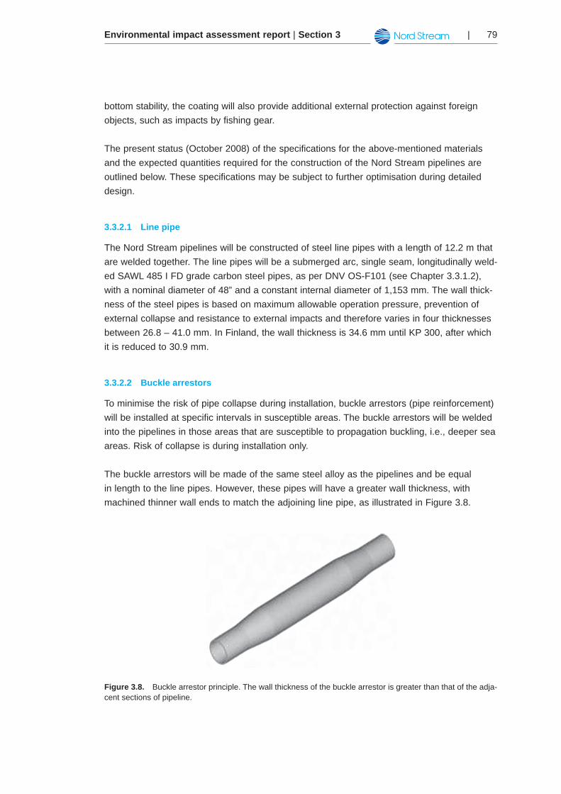
To minimise the risk of pipe collapse during installation, buckle arrestors (pipe reinforcement) will be installed at specific intervals in susceptible areas. The buckle arrestors will be welded into the pipelines in those areas that are susceptible to propagation buckling, i.e., deeper sea areas. Risk of collapse is during installation only.
The buckle arrestors will be made of the same steel alloy as the pipelines and be equal in length to the line pipes. However, these pipes will have a greater wall thickness, with machined thinner wall ends to match the adjoining line pipe, as illustrated in Figure 3.8.
Figure 3.8. Buckle arrestor principle. The wall thickness of the buckle arrestor is greater than that of the adja-cent sections of pipeline.
Environmental impact assessment report | Section 380 |
Buckle arrestors will be used along a 305 km stretch of the pipeline. In the Finnish sector, buckle arrestors will be used from KP 420 onwards (until KP 520 in the Swedish sector). The spacing between the buckle arrestors will be 927 m (equal to 76 line pipes).
Welding of line pipes3.3.2.3
Welding consumables similar and compatible to the composition of the line-pipe material will be used. The weld properties will have a minimum steel grade equal to that of the line pipe. No other materials will be added during welding.
Internal pipe coating3.3.2.4
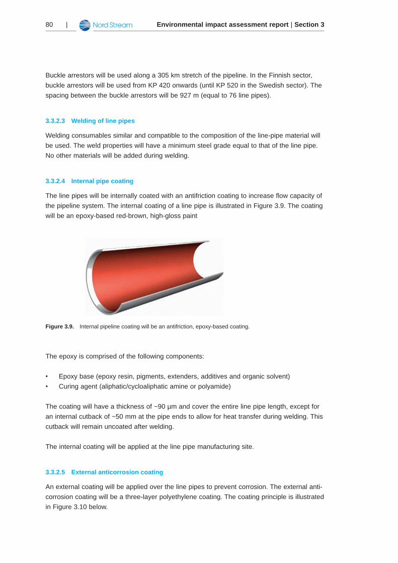
The line pipes will be internally coated with an antifriction coating to increase flow capacity of the pipeline system. The internal coating of a line pipe is illustrated in Figure 3.9. The coating will be an epoxy-based red-brown, high-gloss paint
Figure 3.9. Internal pipeline coating will be an antifriction, epoxy-based coating.
The epoxy is comprised of the following components:
Epoxy base (epoxy resin, pigments, extenders, additives and organic solvent)•Curing agent (aliphatic/cycloaliphatic amine or polyamide)•
The coating will have a thickness of ~90 µm and cover the entire line pipe length, except for an internal cutback of ~50 mm at the pipe ends to allow for heat transfer during welding. This cutback will remain uncoated after welding.
The internal coating will be applied at the line pipe manufacturing site.
External anticorrosion coating3.3.2.5
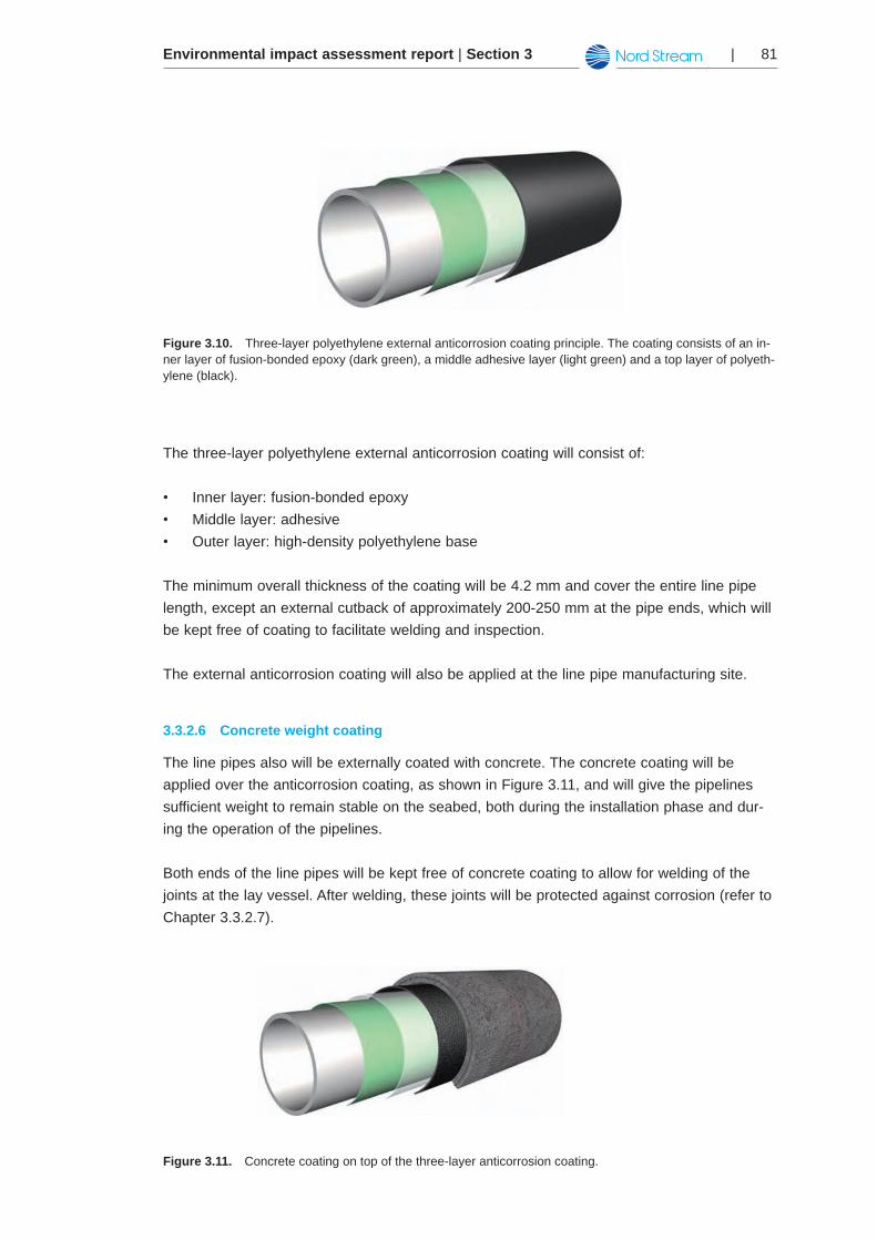
An external coating will be applied over the line pipes to prevent corrosion. The external anti-corrosion coating will be a three-layer polyethylene coating. The coating principle is illustrated in Figure 3.10 below.
Environmental impact assessment report | Section 3 | 81
Figure 3.10. Three-layer polyethylene external anticorrosion coating principle. The coating consists of an in-ner layer of fusion-bonded epoxy (dark green), a middle adhesive layer (light green) and a top layer of polyeth-ylene (black).
The three-layer polyethylene external anticorrosion coating will consist of:
Inner layer: fusion-bonded epoxy •Middle layer: adhesive •Outer layer: high-density polyethylene base •
The minimum overall thickness of the coating will be 4.2 mm and cover the entire line pipe length, except an external cutback of approximately 200-250 mm at the pipe ends, which will be kept free of coating to facilitate welding and inspection.
The external anticorrosion coating will also be applied at the line pipe manufacturing site.
Concrete weight coating3.3.2.6
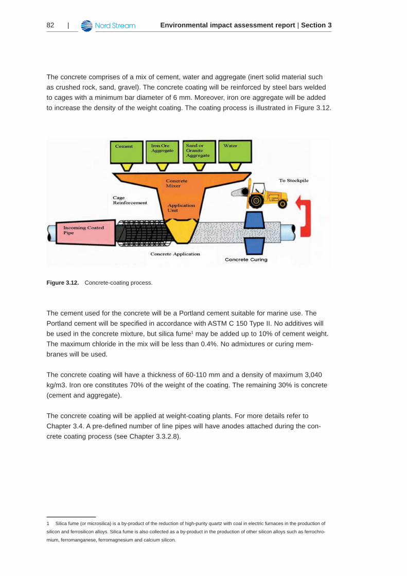
The line pipes also will be externally coated with concrete. The concrete coating will be applied over the anticorrosion coating, as shown in Figure 3.11, and will give the pipelines sufficient weight to remain stable on the seabed, both during the installation phase and dur-ing the operation of the pipelines.
Both ends of the line pipes will be kept free of concrete coating to allow for welding of the joints at the lay vessel. After welding, these joints will be protected against corrosion (refer to Chapter 3.3.2.7).
Figure 3.11. Concrete coating on top of the three-layer anticorrosion coating.
Environmental impact assessment report | Section 382 |
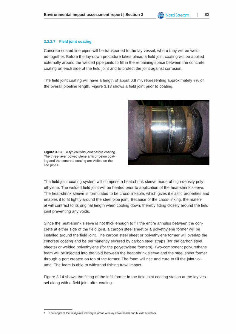
The concrete comprises of a mix of cement, water and aggregate (inert solid material such as crushed rock, sand, gravel). The concrete coating will be reinforced by steel bars welded to cages with a minimum bar diameter of 6 mm. Moreover, iron ore aggregate will be added to increase the density of the weight coating. The coating process is illustrated in Figure 3.12.
Figure 3.12. Concrete-coating process.
The cement used for the concrete will be a Portland cement suitable for marine use. The Portland cement will be specified in accordance with ASTM C 150 Type II. No additives will be used in the concrete mixture, but silica fume1 may be added up to 10% of cement weight. The maximum chloride in the mix will be less than 0.4%. No admixtures or curing mem-branes will be used.
The concrete coating will have a thickness of 60-110 mm and a density of maximum 3,040 kg/m3. Iron ore constitutes 70% of the weight of the coating. The remaining 30% is concrete (cement and aggregate).
The concrete coating will be applied at weight-coating plants. For more details refer to Chapter 3.4. A pre-defined number of line pipes will have anodes attached during the con-crete coating process (see Chapter 3.3.2.8).
1 Silica fume (or microsilica) is a by-product of the reduction of high-purity quartz with coal in electric furnaces in the production of
silicon and ferrosilicon alloys. Silica fume is also collected as a by-product in the production of other silicon alloys such as ferrochro-
mium, ferromanganese, ferromagnesium and calcium silicon.
Environmental impact assessment report | Section 3 | 83
Field joint coating3.3.2.7
Concrete-coated line pipes will be transported to the lay vessel, where they will be weld-ed together. Before the lay-down procedure takes place, a field joint coating will be applied externally around the welded pipe joints to fill in the remaining space between the concrete coating on each side of the field joint and to protect the joint against corrosion.
The field joint coating will have a length of about 0.8 m1, representing approximately 7% of the overall pipeline length. Figure 3.13 shows a field joint prior to coating.
Figure 3.13. Atypicalfieldjointbeforecoating.The three-layer polyethylene anticorrosion coat-ing and the concrete coating are visible on the line pipes.
The field joint coating system will comprise a heat-shrink sleeve made of high-density poly-ethylene. The welded field joint will be heated prior to application of the heat-shrink sleeve. The heat-shrink sleeve is formulated to be cross-linkable, which gives it elastic properties and enables it to fit tightly around the steel pipe joint. Because of the cross-linking, the materi-al will contract to its original length when cooling down, thereby fitting closely around the field joint preventing any voids.
Since the heat-shrink sleeve is not thick enough to fill the entire annulus between the con-crete at either side of the field joint, a carbon steel sheet or a polyethylene former will be installed around the field joint. The carbon steel sheet or polyethylene former will overlap the concrete coating and be permanently secured by carbon steel straps (for the carbon steel sheets) or welded polyethylene (for the polyethylene formers). Two-component polyurethane foam will be injected into the void between the heat-shrink sleeve and the steel sheet former through a port created on top of the former. The foam will rise and cure to fill the joint vol-ume. The foam is able to withstand fishing trawl impact.
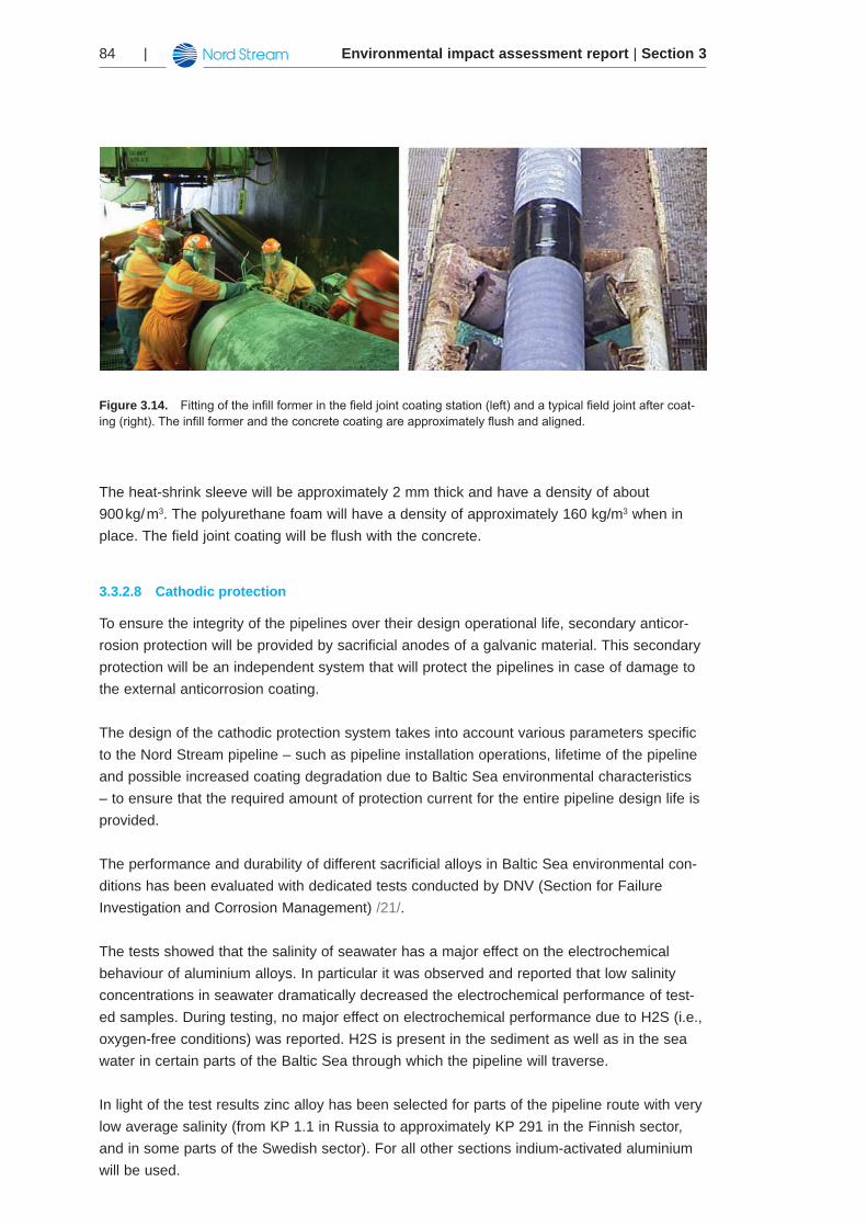
Figure 3.14 shows the fitting of the infill former in the field joint coating station at the lay ves-sel along with a field joint after coating.
1 Thelengthofthefieldjointswillvaryinareaswithlaydownheadsandbucklearrestors.
Environmental impact assessment report | Section 384 |
Figure 3.14. Fittingoftheinfillformerinthefieldjointcoatingstation(left)andatypicalfieldjointaftercoat-ing(right).Theinfillformerandtheconcretecoatingareapproximatelyflushandaligned.
The heat-shrink sleeve will be approximately 2 mm thick and have a density of about 900 kg/ m3. The polyurethane foam will have a density of approximately 160 kg/m3 when in place. The field joint coating will be flush with the concrete.
Cathodic protection3.3.2.8
To ensure the integrity of the pipelines over their design operational life, secondary anticor-rosion protection will be provided by sacrificial anodes of a galvanic material. This secondary protection will be an independent system that will protect the pipelines in case of damage to the external anticorrosion coating.
The design of the cathodic protection system takes into account various parameters specific to the Nord Stream pipeline – such as pipeline installation operations, lifetime of the pipeline and possible increased coating degradation due to Baltic Sea environmental characteristics – to ensure that the required amount of protection current for the entire pipeline design life is provided.
The performance and durability of different sacrificial alloys in Baltic Sea environmental con-ditions has been evaluated with dedicated tests conducted by DNV (Section for Failure Investigation and Corrosion Management) /21/.
The tests showed that the salinity of seawater has a major effect on the electrochemical behaviour of aluminium alloys. In particular it was observed and reported that low salinity concentrations in seawater dramatically decreased the electrochemical performance of test-ed samples. During testing, no major effect on electrochemical performance due to H2S (i.e., oxygen-free conditions) was reported. H2S is present in the sediment as well as in the sea water in certain parts of the Baltic Sea through which the pipeline will traverse.
In light of the test results zinc alloy has been selected for parts of the pipeline route with very low average salinity (from KP 1.1 in Russia to approximately KP 291 in the Finnish sector, and in some parts of the Swedish sector). For all other sections indium-activated aluminium will be used.
Environmental impact assessment report | Section 3 | 85
The cathodic protection system will thus consist of:
Zinc and indium-activated aluminium bracelet anodes (two half-shells per anode)•Anode electrical continuity cables (two cables per half shell)•Cartridge/materials necessary to perform the cable welding between anodes and pipes•
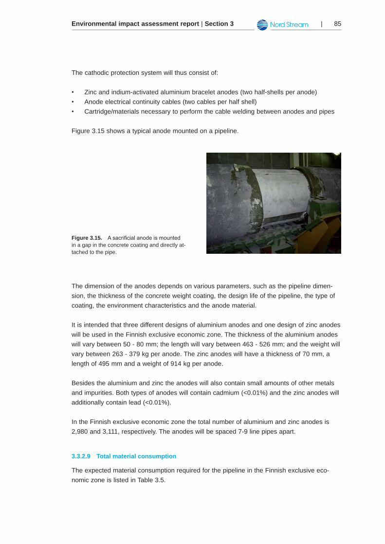
Figure 3.15 shows a typical anode mounted on a pipeline.
Figure 3.15. Asacrificialanodeismountedin a gap in the concrete coating and directly at-tached to the pipe.
The dimension of the anodes depends on various parameters, such as the pipeline dimen-sion, the thickness of the concrete weight coating, the design life of the pipeline, the type of coating, the environment characteristics and the anode material.
It is intended that three different designs of aluminium anodes and one design of zinc anodes will be used in the Finnish exclusive economic zone. The thickness of the aluminium anodes will vary between 50 - 80 mm; the length will vary between 463 - 526 mm; and the weight will vary between 263 - 379 kg per anode. The zinc anodes will have a thickness of 70 mm, a length of 495 mm and a weight of 914 kg per anode.
Besides the aluminium and zinc the anodes will also contain small amounts of other metals and impurities. Both types of anodes will contain cadmium (<0.01%) and the zinc anodes will additionally contain lead (<0.01%).
In the Finnish exclusive economic zone the total number of aluminium and zinc anodes is 2,980 and 3,111, respectively. The anodes will be spaced 7-9 line pipes apart.
Total material consumption3.3.2.9
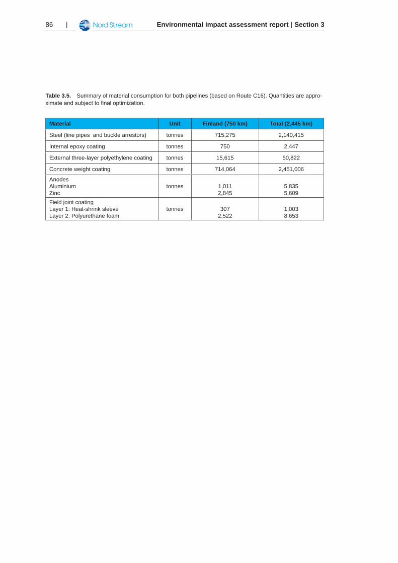
The expected material consumption required for the pipeline in the Finnish exclusive eco-nomic zone is listed in Table 3.5.
Environmental impact assessment report | Section 386 |
Table 3.5. Summary of material consumption for both pipelines (based on Route C16). Quantities are appro-ximateandsubjecttofinaloptimization.
Material Unit Finland (750 km) Total (2,445 km)
Steel (line pipes and buckle arrestors) tonnes 715,275 2,140,415
Internal epoxy coating tonnes 750 2,447
External three-layer polyethylene coating tonnes 15,615 50,822
Concrete weight coating tonnes 714,064 2,451,006
Anodes AluminiumZinc
tonnes 1,0112,845
5,8355,609
Field joint coating Layer 1: Heat-shrink sleeveLayer 2: Polyurethane foam
tonnes 3072,522
1,0038,653
Environmental impact assessment report | Section 3 | 87
Installation logistics3.4
Large-scale offshore pipeline construction work requires considerable support from onshore support facilities, such as weight-coating plants and interim stockyards. In addition to weight-coating and storage of line pipe, the support facilities will provide general storage for sup-ply of consumables to the offshore fleet, and managerial support for Nord Stream AG and its contractors.
In this Chapter the details of the logistical concept of the Nord Stream project are described.
Logistics concept3.4.1
The concept has been developed specifically for the project and includes:
Transport of anti-corrosion coated pipes and concrete weight coating materials to the •weight-coating plantsTransport of weight-coated pipes to the interim stockyards•Transport of weight-coated pipes to the lay vessels from the weight-coating plants and •interim stockyardsTransport of material for rock placement from quarry to rock placement location•
The logistics concept has been designed to reduce the onshore and offshore transportation. The use of existing facilities has been favoured in order to avoid new construction wherever feasible. A primary focus in the development of the logistics concept, therefore, has been on minimising environmental impacts and reducing costs.
The following chapters describe the present status (November 2008) of the planned logistical setup. It should be noted that the suppliers for the second pipeline (the south-east pipeline) have not yet been selected. Therefore, logistics may be adapted to accommodate any chang-es. The concept is also based on expected readiness and availability of the sites.
Preparation of the facilities will comply with national legislation and requirements and will be subject to independent, national permitting. Information about these onshore facilities, howev-er, is included here to give a better overview of the project logistics.
Transport of line pipe and coating material to the weight-coating plants3.4.2
Line pipe for the first pipeline will be produced at pipe mills in Russia and Germany. At the mills, they will be internally coated with flow coating and externally coated with anti-corrosion coating before they are transported to weight-coating plants in Kotka in Finland and Sassnitz-Mukran in Germany, where weight-coating will be applied. The locations of the weight-coating plants are shown in Figure 3.20.
Environmental impact assessment report | Section 388 |
The following description of pipeline supply logistics relates to the Kotka weight-coating plant and stockyard.
Pipes for the first pipeline will be manufactured by Europipe, Germany (75%), and OMK, Russia (25%), as result of an international tendering process. Manufacturing contracts for the second pipeline have not yet been awarded. Due to the large diameter and wall thickness of the pipes only a few pipe fabrication sites worldwide are capable of producing them.
The majority of the pipes will be transported directly by train from the manufacturing sites to the weight-coating plants. Train deliveries (for the first pipeline) to Kotka began in June 2008 and will continue until October 2009. Deliveries for the second pipeline will take place from January 2010 to March 2011.
A small portion of the pipes produced in Germany (corresponding to 34 shiploads, or 10% of the pipeline length) will be transported by ship from Bremen or Mukran to Kotka. The load-ins at Kotka will take place from October 2008 to March 2009 for the first pipeline but have not yet been determined for the second pipeline.
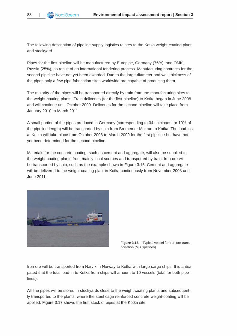
Materials for the concrete coating, such as cement and aggregate, will also be supplied to the weight-coating plants from mainly local sources and transported by train. Iron ore will be transported by ship, such as the example shown in Figure 3.16. Cement and aggregate will be delivered to the weight-coating plant in Kotka continuously from November 2008 until June 2011.
Figure 3.16. Typical vessel for iron ore trans-portation (MS Splittnes).
Iron ore will be transported from Narvik in Norway to Kotka with large cargo ships. It is antici-pated that the total load-in to Kotka from ships will amount to 10 vessels (total for both pipe-lines).
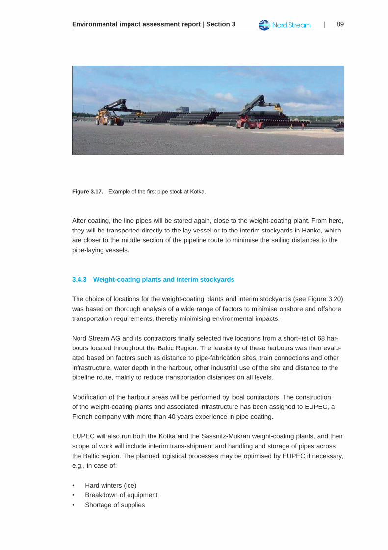
All line pipes will be stored in stockyards close to the weight-coating plants and subsequent-ly transported to the plants, where the steel cage reinforced concrete weight-coating will be applied. Figure 3.17 shows the first stock of pipes at the Kotka site.
Environmental impact assessment report | Section 3 | 89
Figure 3.17. ExampleofthefirstpipestockatKotka.
After coating, the line pipes will be stored again, close to the weight-coating plant. From here, they will be transported directly to the lay vessel or to the interim stockyards in Hanko, which are closer to the middle section of the pipeline route to minimise the sailing distances to the pipe-laying vessels.
Weight-coating plants and interim stockyards3.4.3
The choice of locations for the weight-coating plants and interim stockyards (see Figure 3.20) was based on thorough analysis of a wide range of factors to minimise onshore and offshore transportation requirements, thereby minimising environmental impacts.
Nord Stream AG and its contractors finally selected five locations from a short-list of 68 har-bours located throughout the Baltic Region. The feasibility of these harbours was then evalu-ated based on factors such as distance to pipe-fabrication sites, train connections and other infrastructure, water depth in the harbour, other industrial use of the site and distance to the pipeline route, mainly to reduce transportation distances on all levels.
Modification of the harbour areas will be performed by local contractors. The construction of the weight-coating plants and associated infrastructure has been assigned to EUPEC, a French company with more than 40 years experience in pipe coating.
EUPEC will also run both the Kotka and the Sassnitz-Mukran weight-coating plants, and their scope of work will include interim trans-shipment and handling and storage of pipes across the Baltic region. The planned logistical processes may be optimised by EUPEC if necessary, e.g., in case of:
Hard winters (ice)•Breakdown of equipment•Shortage of supplies•
Environmental impact assessment report | Section 390 |
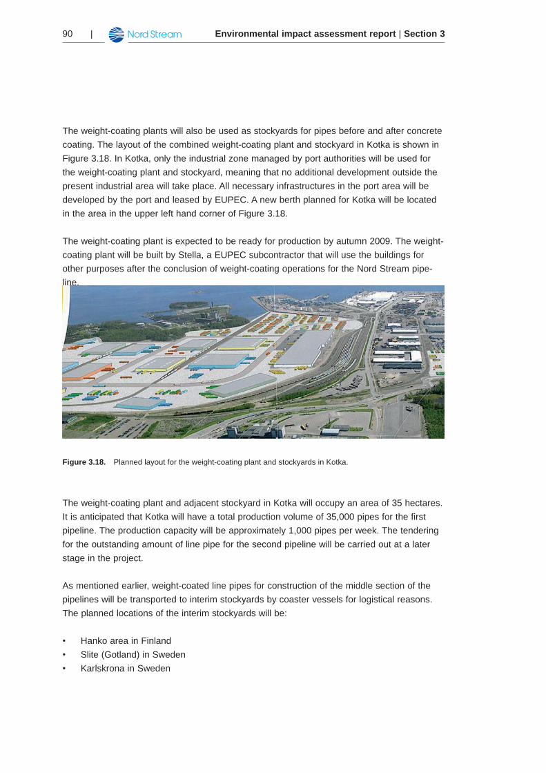
The weight-coating plants will also be used as stockyards for pipes before and after concrete coating. The layout of the combined weight-coating plant and stockyard in Kotka is shown in Figure 3.18. In Kotka, only the industrial zone managed by port authorities will be used for the weight-coating plant and stockyard, meaning that no additional development outside the present industrial area will take place. All necessary infrastructures in the port area will be developed by the port and leased by EUPEC. A new berth planned for Kotka will be located in the area in the upper left hand corner of Figure 3.18.
The weight-coating plant is expected to be ready for production by autumn 2009. The weight-coating plant will be built by Stella, a EUPEC subcontractor that will use the buildings for other purposes after the conclusion of weight-coating operations for the Nord Stream pipe-line.
Figure 3.18. Planned layout for the weight-coating plant and stockyards in Kotka.
The weight-coating plant and adjacent stockyard in Kotka will occupy an area of 35 hectares. It is anticipated that Kotka will have a total production volume of 35,000 pipes for the first pipeline. The production capacity will be approximately 1,000 pipes per week. The tendering for the outstanding amount of line pipe for the second pipeline will be carried out at a later stage in the project.
As mentioned earlier, weight-coated line pipes for construction of the middle section of the pipelines will be transported to interim stockyards by coaster vessels for logistical reasons. The planned locations of the interim stockyards will be:
Hanko area in Finland•Slite (Gotland) in Sweden•Karlskrona in Sweden•
Environmental impact assessment report | Section 3 | 91
The location of the stockyards is shown in Figure 3.20. Negotiations are currently (October 2008) ongoing with the municipal port of Hanko. The proposed storage site is currently used for storage of containers and is 3-4 hectares in size.
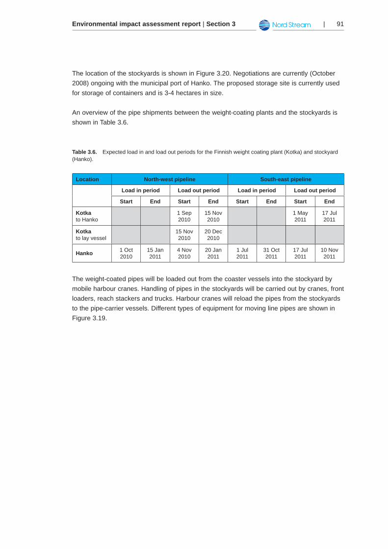
An overview of the pipe shipments between the weight-coating plants and the stockyards is shown in Table 3.6.
Table 3.6. Expected load in and load out periods for the Finnish weight coating plant (Kotka) and stockyard (Hanko).
Location North-west pipeline South-east pipeline
Load in period Load out period Load in period Load out period
Start End Start End Start End Start End
Kotkato Hanko
1 Sep 2010
15 Nov 2010
1 May 2011
17 Jul 2011
Kotka to lay vessel
15 Nov 2010
20 Dec 2010
Hanko 1 Oct 2010
15 Jan 2011
4 Nov 2010
20 Jan 2011
1 Jul 2011
31 Oct 2011
17 Jul 2011
10 Nov 2011
The weight-coated pipes will be loaded out from the coaster vessels into the stockyard by mobile harbour cranes. Handling of pipes in the stockyards will be carried out by cranes, front loaders, reach stackers and trucks. Harbour cranes will reload the pipes from the stockyards to the pipe-carrier vessels. Different types of equipment for moving line pipes are shown in Figure 3.19.
Environmental impact assessment report | Section 392 |
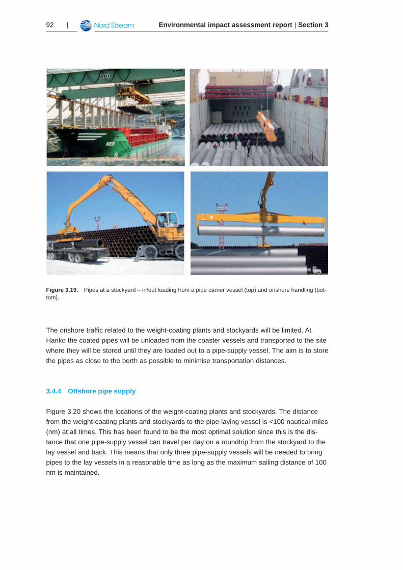
Figure 3.19. Pipes at a stockyard – in/out loading from a pipe carrier vessel (top) and onshore handling (bot-tom).
The onshore traffic related to the weight-coating plants and stockyards will be limited. At Hanko the coated pipes will be unloaded from the coaster vessels and transported to the site where they will be stored until they are loaded out to a pipe-supply vessel. The aim is to store the pipes as close to the berth as possible to minimise transportation distances.
Offshore pipe supply3.4.4
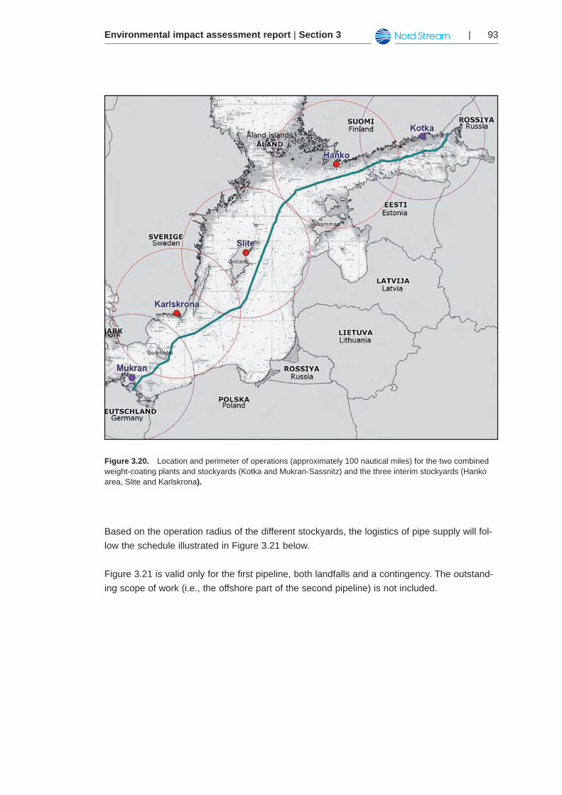
Figure 3.20 shows the locations of the weight-coating plants and stockyards. The distance from the weight-coating plants and stockyards to the pipe-laying vessel is <100 nautical miles (nm) at all times. This has been found to be the most optimal solution since this is the dis-tance that one pipe-supply vessel can travel per day on a roundtrip from the stockyard to the lay vessel and back. This means that only three pipe-supply vessels will be needed to bring pipes to the lay vessels in a reasonable time as long as the maximum sailing distance of 100 nm is maintained.
Environmental impact assessment report | Section 3 | 93
Figure 3.20. Location and perimeter of operations (approximately 100 nautical miles) for the two combined weight-coating plants and stockyards (Kotka and Mukran-Sassnitz) and the three interim stockyards (Hanko area, Slite and Karlskrona).
Based on the operation radius of the different stockyards, the logistics of pipe supply will fol-low the schedule illustrated in Figure 3.21 below.
Figure 3.21 is valid only for the first pipeline, both landfalls and a contingency. The outstand-ing scope of work (i.e., the offshore part of the second pipeline) is not included.
Environmental impact assessment report | Section 394 |
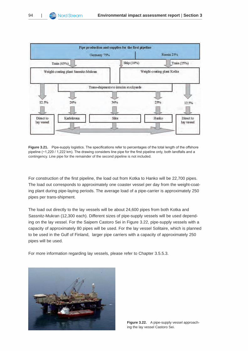
Figure 3.21. Pipe-supplylogistics.Thespecificationsrefertopercentagesofthetotallengthoftheoffshorepipeline(~1,220/1,222km).Thedrawingconsiderslinepipeforthefirstpipelineonly,bothlandfallsandacontingency. Line pipe for the remainder of the second pipeline is not included.
For construction of the first pipeline, the load out from Kotka to Hanko will be 22,700 pipes. The load out corresponds to approximately one coaster vessel per day from the weight-coat-ing plant during pipe-laying periods. The average load of a pipe-carrier is approximately 250 pipes per trans-shipment.
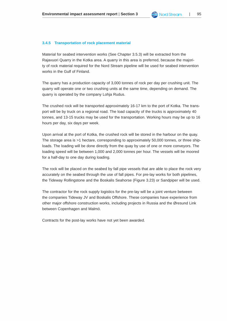
The load out directly to the lay vessels will be about 24,600 pipes from both Kotka and Sassnitz-Mukran (12,300 each). Different sizes of pipe-supply vessels will be used depend-ing on the lay vessel. For the Saipem Castoro Sei in Figure 3.22, pipe-supply vessels with a capacity of approximately 80 pipes will be used. For the lay vessel Solitaire, which is planned to be used in the Gulf of Finland, larger pipe carriers with a capacity of approximately 250 pipes will be used.
For more information regarding lay vessels, please refer to Chapter 3.5.5.3.
Figure 3.22. A pipe-supply vessel approach-ing the lay vessel Castoro Sei.
Environmental impact assessment report | Section 3 | 95
Transportation of rock placement material3.4.5
Material for seabed intervention works (See Chapter 3.5.3) will be extracted from the Rajavuori Quarry in the Kotka area. A quarry in this area is preferred, because the majori-ty of rock material required for the Nord Stream pipeline will be used for seabed intervention works in the Gulf of Finland.
The quarry has a production capacity of 3,000 tonnes of rock per day per crushing unit. The quarry will operate one or two crushing units at the same time, depending on demand. The quarry is operated by the company Lohja Rudus.
The crushed rock will be transported approximately 16-17 km to the port of Kotka. The trans-port will be by truck on a regional road. The load capacity of the trucks is approximately 40 tonnes, and 13-15 trucks may be used for the transportation. Working hours may be up to 16 hours per day, six days per week.
Upon arrival at the port of Kotka, the crushed rock will be stored in the harbour on the quay. The storage area is >1 hectare, corresponding to approximately 50,000 tonnes, or three ship-loads. The loading will be done directly from the quay by use of one or more conveyors. The loading speed will be between 1,000 and 2,000 tonnes per hour. The vessels will be moored for a half-day to one day during loading.
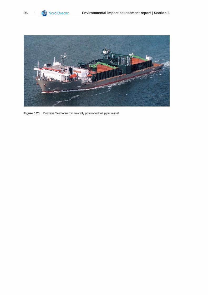
The rock will be placed on the seabed by fall pipe vessels that are able to place the rock very accurately on the seabed through the use of fall pipes. For pre-lay works for both pipelines, the Tideway Rollingstone and the Boskalis Seahorse (Figure 3.23) or Sandpiper will be used.
The contractor for the rock supply logistics for the pre-lay will be a joint venture between the companies Tideway JV and Boskalis Offshore. These companies have experience from other major offshore construction works, including projects in Russia and the Øresund Link between Copenhagen and Malmö.
Contracts for the post-lay works have not yet been awarded.
Environmental impact assessment report | Section 396 |
Figure 3.23. Boskalis Seahorse dynamically positioned fall pipe vessel.
Environmental impact assessment report | Section 3 | 97
Construction 3.5
This chapter describes the activities that will take place during construction of the Nord Stream pipeline. Activities include:
Surveying (to gather specific information on the pipeline corridor) •Seabed intervention works (to ensure that the pipelines have a stable foundation on the •seabed) Construction activities at the landfalls in Germany and Russia•Crossings of existing offshore cables, including pre-lay preparations•Offshore pipe-laying•Tie-in (coupling) of the different offshore sections•
The main contractor for the construction of the Nord Stream pipelines will be Saipem UK Ltd of the Eni Group. Dry sections and tie-ins are included in the scope of work, and it is intend-ed that Saipem will manage all sub-contractors.
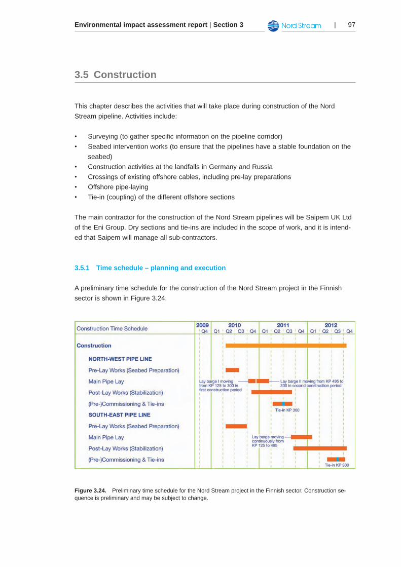
Time schedule – planning and execution3.5.1
A preliminary time schedule for the construction of the Nord Stream project in the Finnish sector is shown in Figure 3.24.
Figure 3.24. Preliminary time schedule for the Nord Stream project in the Finnish sector. Construction se-quence is preliminary and may be subject to change.
Environmental impact assessment report | Section 398 |
Provided that all permits are granted within the expected time frame, the installation of the pipelines will be initiated in April 2010. At present, the installation campaign for both pipe-lines is expected to be completed within three years. The north-west line will be ready for gas delivery in September 2011, and the south-east pipeline is planned to come on stream in November 2012.
The construction time schedule in Figure 3.24 is a general time schedule showing one possi-ble scenarios for the installation activities. Installation in the Finnish sector will begin after the required permits have been granted. The aim is that construction works will begin in 2010. The actual time schedule may change due to the time of year when the installation work can start as a consequence of the permitting process and due to further optimisation dur-ing detailed design and construction. In Finland there may be restrictions because of weather conditions during the period from December to April.
Seabed intervention works along the route, including both pre-lay and post-lay activities (i.e., ‘earthworks’ taking place before and after pipe-lay, respectively), are planned to be carried out in campaigns throughout the entire construction phase. According to the preliminary time schedule, pre-lay gravel works for both pipelines in the Finnish sector are estimated to take place during the second and third quarter of 2010. Pipe-laying and post-lay gravel works for the north-west pipeline (the first pipeline to be constructed) are estimated to take place from the last quarter of 2010 until the third quarter of 2011. Pipe-laying and post-lay gravel works for the south-east pipeline are estimated to begin in the third or fourth quarter of 2011 and to last until the fourth quarter of 2012.
Laying of the first pipeline will take around one year, and a similar time frame is foreseen for the second pipeline. It is expected that two lay vessels will be working in the Finnish sector, one starting from the Russian landfall and working until KP 300 and the other starting from the Swedish exclusive economic zone border and working until KP 300. At KP 300, the two pipe sections will be welded together (tie-in). Pipe-laying in the Finnish sector will take five to six months per pipeline.
Pre-commissioning activities, including tie-in activities, are expected to take approximate-ly five months for each pipeline. Commissioning of the pipeline, including gas-filling, will take approximately one month.
Route, engineering and construction surveys3.5.2
Several marine surveys have been and will be conducted in connection with the Nord Stream pipeline to gather specific information on seabed conditions, topography, bathymetry and objects such as wrecks, boulders, ordnance, etc. This information has been and will be used for route planning, detailed design and assessment of installation methods. The following Chapters provide a short overview of the surveys that already have been performed and the surveys that will be performed before, during and after installation of the pipeline.
Environmental impact assessment report | Section 3 | 99
The surveys have concentrated on three different corridors:
Anchor corridor (+/- 1 km on either side of the specified route alignment). Within this •corridor, anchors from the lay vessel may be laid during installation of the pipeline.Installation corridor (+/- 7.5 m on either side of the specified route alignment). This •corridor is based on the specified installation tolerance for normal pipe-lay defined in the contract with the installation contractor (also refer to Chapter 9 on Risk Assessment).Security corridor (+/- 25 m either side of the specified route alignment). This corridor is •based on the effects of underwater explosion on the pipeline, e.g. due to munitions on the seabed. The corridor width has been based on engineering analyses of munitions types found in the Baltic Sea and the distance at which an explosion can cause damage to the pipeline. The analyses have Surveys performed by the detailed design contractor and verified by the certifying authority (also refer to Chapter 9 on Risk Assessment).
Surveys performed for detailed design3.5.2.1
The following surveys have been performed in order to facilitate detailed design. The sur-veys, methods applied and results are further described in Chapter 5.1 and therefore are mentioned only briefly here.
Reconnaissance survey
A reconnaissance survey was carried out to facilitate selection of the preliminary pipeline route based on information on geological and anthropogenic features.
Engineering, geophysical and geotechnical survey
Engineering, geophysical and geotechnical surveys were performed to optimise the pipeline route and detailed pipeline design, including the seabed intervention measures required to ensure the long-term integrity of the pipeline system.
Munitions screening survey
Munitions from World War I, World War II and other conflicts in the Baltic region were dumped in the Baltic Sea. A munitions screening survey has been performed to identify the presence of potentially unexploded munitions and/or chemical warfare agents in the installa-tion corridor. Such munitions could constitute a danger for the construction workers, the pipe-line and the environment during the installation works and the operational life of the pipeline system.
Other surveys
In addition to the surveys already mentioned, cultural heritage surveys and numerous envi-ronmental field investigations (including sampling of water, seabed sediments, plankton (phyto- and zooplankton), macrozoobenthos (seabed fauna), fish and surveys of marine mammals and birds) have been carried out in the period from 2005-2008.
Environmental impact assessment report | Section 3100 |
Surveys to be performed prior to construction3.5.2.2
The following surveys and other activities will be performed prior to commencement of the construction works. The activities are scheduled to be performed during the permitting proc-ess.
Anchor corridor survey
Prior to the installation of the Nord Stream pipelines, an anchor corridor survey will be under-taken to identify and catalogue obstructions within the lay vessel anchor corridor. The survey will mainly be conducted in a 1 km wide corridor to each side of the route alignment. In shal-lower waters (less than 100 m), the survey corridor will be reduced to 800 m.
The anchor corridor survey in the Finnish exclusive economic zone has started on 15th of November 2008 and will be finished by September 2009.
The objectives for the anchor corridor survey are:
To map potential hazards to anchoring and the environment and provide the basis for an •anchoring risk assessment. To identify hazards such as potential munitions, anthropogenic debris, geological •features, obstructions and existing infrastructure. To identify and map areas and features of cultural heritage to be safeguarded•
The anchor corridor survey will comprise four phases as follows:
Phase 1: Geophysical surveyBathymetric survey in a 2x2 m grid•Sidescan sonar survey, frequency 600 kHz, 75 m range, 50 m line spacing in high risk •sections of the route (extending from Finnish Russian boarder to approx. KP 395)Sidescan sonar survey, frequency 300 kHz / 600 kHz, 125 m range, 100 m line spacing •in the lower risk sections of the route from (approx. 395 to Finnish/Swedish boarder). In the event that potential munitions are located additional infill lines at 50 m spacing will be performed.Towed magnetometer survey using a caesium single-sensor magnetometer.•Evaluation of targets and development of initial anchoring philosophy•
Phase 2: Visual inspection ROV based visual inspection of cultural heritage and suspected anthropogenic objects •(munitions, barrels, general debris)Evaluation of results and refinement of anchoring philosophy•
Phase 3: ROV based gradiometer surveyIn discrete critical areas magnetometer survey will be performed utilising an ROV based •gradiometer array survey will be performed
Environmental impact assessment report | Section 3 | 101
Phase 4: Expert evaluation of survey findingsReview of video inspections by marine warfare experts to correlate survey findings to •munitions deployed within the Baltic Sea.
Where munitions, cultural heritage and other potentially dangerous debris are identified, anchor exclusion zones will be established. The installation contractor will then develop anchor patterns and procedures to ensure that the areas of concern are not impacted by the anchors or the sweep of the anchor wires. In critical sections the anchor patterns will be sub-mitted to the relevant authorities.
The anchoring procedures will be risk assessed as far as the potential risk to safety and envi-ronment. Based on the results of the risk assessment various mitigation measures will be developed. These may include the use of buoyancy on the anchor wires, ‘live anchors’ i.e. tugs rather than placing the anchors on the seabed or munitions clearance.
Due to Nord Stream AG´s plan to use a dynamically positioned laybarge for both pipelines between KP 0–300 visual inspections and expert evaluation (phases 2-4) will be done only in route sections where anchored laybarge will be used.
Munitions clearance
As a result of the munitions survey already performed for the installation corridor, 29 muni-tions have been identified along Route C14 (Alternative 1) and two additional munitions was identified on Route C16 (Alternative 2). Risk zones, where dumped munitions can be found are shown in Atlas Map MU-1-F. Locations of identified munitions from a preliminary sur-vey are shown in Atlas Maps MU-3a-F to MU-3b-F. It is anticipated that more munitions will be identified during the anchor corridor survey. All munitions identified within the 50 m wide security corridor will be cleared, whereas all munitions identified within the anchoring corridor will be cleared if deemed necessary following expert assessment by the installation contrac-tor as described above in the anchor corridor survey scope. Based on the munitions screen-ing survey results it is envisaged that approximately 600 to 900 mines will be located within the combined anchor corridor for the two pipelines.
Over the last decade, the collective navies of the Baltic States have developed methods that are both safe and effective for the clearance of mines and other explosive underwater ord-nance on the seabed of the Baltic. These methods have also been used by other national navies around the world to dispose of ordnance in past theatres of warfare. The basic princi-ples of the method involve placing a small charge next to the identified live or suspected live ordnance on the seabed using a small, specially developed ROV. These charges are then detonated from a surface support ship located at a safe distance from the target.
Each type and model of mine will be identified and confirmed during the pre-detonation inspections. The amount of explosive material contained within the munitions will be deter-mined based on historical data. The appropriate amount of charge necessary to detonate the mine in situ while minimising impact on the surrounding area shall be calculated in accord-ance with standard procedures. The main objective of the clearance operations is to clear
Environmental impact assessment report | Section 3102 |
ordnance that pose a threat to pipeline installation or that may have a future detrimental impact on seabed conditions and environment. It is envisaged that the clearance will be per-formed in two phases, firstly the security corridor, followed by selected munitions within the anchor corridor.
A clearance plan will be developed in close conjunction with relevant national authorities. The clearance plan will:
Identify hazards and any conditions requiring extraordinary mitigation measures•Provide procedures for the clearance of the munitions with individual processes identified •for each munitions typeApply appropriate mitigation with emphasis on the surrounding environment•Provide marine mammal observation and fisheries liaison personnel •Provide the lines of communication with the relevant authorities and interested parties•Include the necessary survey and monitoring to demonstrate that clearance operations •have been successful.
Due to the intention to use dynamically positioned laybarge without anchors for both pipe-lines between KP 0-300 munitions clearance will be done only in the parts of the route where anchored laybarge will be used.
Surveys to be performed during construction3.5.2.3
The following surveys will be performed in direct relation to the construction works.
Pre-lay survey
A pre-lay survey will be performed just prior to the commencement of construction work. The scope of the pre-lay survey is to confirm the previous route survey and to ensure that no new obstacles are found on the sea bed. A pre-lay survey comprises:
ROV-based bathymetric survey to establish seabed conditions prior to seabed •intervention works. Such surveys will be performed along the pipeline route to and from the theoretical touchdown points at both ends of the proposed rock bermROV-based bathymetric survey including intervention and adjacent shoulders, i.e., •theoretical touchdown points where the pipeline will be in contact with the natural seabed ROV-based bathymetric surveys to establish the extent of berm settlement and the •necessity of additional rock placement prior to pipeline installation ROV-based pre-lay visual inspection survey•
Environmental impact assessment report | Section 3 | 103
Construction support survey
Full survey capability will stand by to perform any ad hoc survey activities that may arise dur-ing pipeline construction. It will comprise:
Full geophysical spread: multibeam echosounders, sidescan sonars, sub-bottom profilers •and magnetometersROVs for visual inspection work•
As-laid survey
To document the pipe-laying, an as-laid survey will be performed once the pipelines have been laid on the seabed by the pipe-laying vessel. The survey will establish the as-laid posi-tion and condition of the pipelines and will comprise:
Bathymetry and sidescan sonar measurements•Visual inspection by ROV•
As-built survey
As a final documentation of the pipeline installation, an as-built survey will be conduct-ed. It will be carried out after seabed intervention, trenching, rock placement, etc., i.e., after the pipelines have been completed. The survey will demonstrate that the pipelines have been installed correctly. Therefore, it must establish that the required trench depth has been achieved, the extent of backfill and rock placement is as designed, and that the integrity of the pipelines has been maintained. The survey typically includes a visual inspection of the pipeline by ROV.
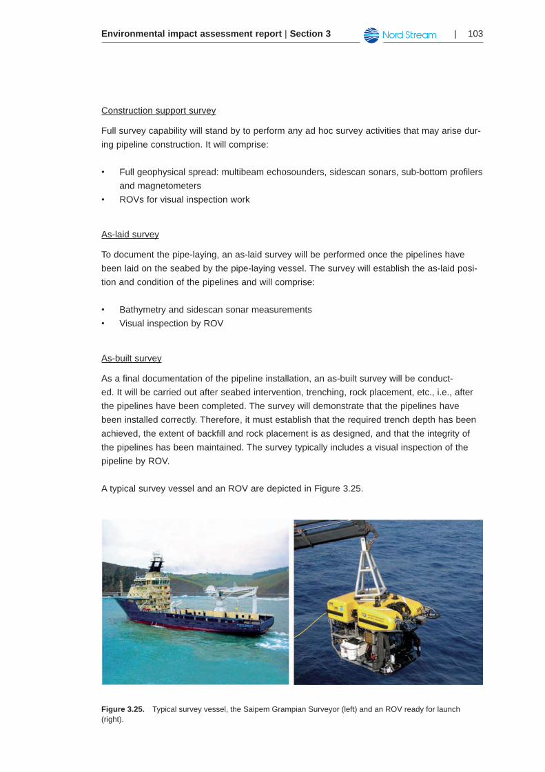
A typical survey vessel and an ROV are depicted in Figure 3.25.
Figure 3.25. Typical survey vessel, the Saipem Grampian Surveyor (left) and an ROV ready for launch (right).
Environmental impact assessment report | Section 3104 |
Seabed intervention works3.5.3
Seabed intervention works comprises the ’earthworks‘ undertaken on the seabed to protect the pipelines against failure and to minimise impacts on the environment and human activi-ties. The interventions entail various methods for achieving a more level foundation for the pipelines. A level seabed allows the pipeline to be installed within acceptable limits for span lengths, pipe stresses and off-bottom clearances.
Seabed intervention works will take place before and after pipe-laying. During the engineer-ing phase, the requirements for protection of the pipelines will also be considered. First, this Chapter describes the general reasons and requirements for seabed intervention works and the methods that may be used. It then describes the locations and methods of seabed inter-vention works to be used in the Finnish exclusive economic zone. Examples of typical sea-bed intervention works are shown in Atlas Map PR-9.
Requirements and alternatives for seabed intervention works3.5.3.1
Once the pipelines are laid, the pipe wall thickness and concrete coating will provide sub-stantial protection of the pipelines. However, the pipelines will have varying needs for addi-tional protection along the route to avoid:
Stress due to freespan development caused by an uneven seabed (see Atlas Map •FC-21a-F to FC-21e-F)Excessive movement due to hydrodynamic loading •Excessive movement (lateral and upheaval buckling) due to compressive pipeline •loadingImpacts from shipping traffic•Impacts from fishing gear, e.g., trawls•
In areas where one or more of these factors are possible, this additional protection usually is achieved by trenching the pipelines into the seabed or by rock placement.
Acceptable span lengths and heights depend on the structural parameters of the pipelines, the soil conditions, waves and currents. The areas with non-allowable freespans along the pipeline route as per DNV RP F105 on freespanning of pipelines (see Chapter 3.3.1) have been identified from the bathymetrical/geophysical surveys. In some areas along the pipeline route, the sea bottom is rough. Outcrops of hard till or crystalline bedrock with sedimentary deposits between the outcrops pose difficulties to pipeline installation, insofar as the pipelines may ‘ride’ from crest-to-crest of the harder outcrops and sag in the middle. The pipelines may be stressed excessively in these sections if the seabed is not properly prepared prior to pipe-line installation.
Studies of the type and size of fishing gear used in the Baltic Sea have been carried out and indicate that fishing gear is unlikely to inflict serious damage to the pipelines. The pipeline has been designed to withstand impacts from trawl boards up to 3,000 kg as per DNV RP F111 on interference between trawl gear and pipelines (see Chapter 3.3.1.2).
Environmental impact assessment report | Section 3 | 105
To ensure the integrity of the pipelines, the following methods in general are considered tech-nically feasible:
Re-routing of pipelines•Peak removal (dredging or blasting away hard outcrops or ‘crests’)•Placement of fill material, rock placement •Trenching, dredging and backfilling •Placement of prefabricated support structures•
The seabed in the Finnish section is very uneven, and substantial re-routing has therefore been required in order to minimise seabed intervention works.
Removal of significant outcrops from the seabed by blasting (peak removal) was mentioned earlier as an option in the Finnish section due to the presence of outcrops of relatively hard material (see also Chapter 5.3 on seabed geology). However, peak removal is considered unacceptable for environmental reasons and therefore will not take place in the Finnish sec-tor.
Rock placement is the only type of intervention works that will be used in the Finnish sector. The rock placement will level the seabed to properly support the pipeline and will be applied only where re-routing alone has not been sufficient or possible.
No trenching, dredging or use of pre-fabricated support structures is foreseen.
In general, the seabed intervention works for the entire pipeline will be carried out in three phases:
Phase 1 – pre-lay (performed before pipe-laying)•Phase 2 – post-lay (performed before pressure-testing)•Phase 3 – post-lay (performed after pressure-testing to prevent in-service buckling/•fatigue)
Seabed intervention works are defined depending on the phase of construction during which they take place:
Pre-lay works for statics: intervention works carried out before pipe-laying for stress\•freespan correction (to reduce overstress in the different load conditions due to long freespans caused by seabed unevenness)Post-lay works for statics: the purpose of these works is the same as for the pre-lay •works, but they are carried out between the pipe-laying and pressure-testing phasesPost-lay works for fatigue: these intervention works are carried out after pipe-laying for •stress\freespan correction (to reduce fatigue damage)
Intervention works, such as rock berms, are designed as those typically used in the North Sea where there is active fishing activity. Therefore, the rock berms themselves will be over-trawlable. It should be noted, however, that in areas where the seabed profile is irregular
Environmental impact assessment report | Section 3106 |
the pipeline will not be in continuous contact with the seabed. In these areas, the pipelines most likely will not be overtrawlable due to the presence of freespans exceeding the critical height of typically being 0.5 m. Therefore, in these sections permanent restrictions for fishing across/along the pipelines may be requested for safety reasons. Unacceptable freespans can also develop during the operations phase of the pipelines. If this occurs, it may be requested to implement temporary restrictions for fishing until these freespans have been rectified. The inspection and required maintenance of the rock berms will take place at specific intervals throughout the operations phase (see also Chapter 3.8.6).
Temporary fishing restrictions will also be required during installation operations due to the presence of pipe-laying and rock placement vessels.
Seabed intervention works in the Finnish exclusive economic zone3.5.3.2
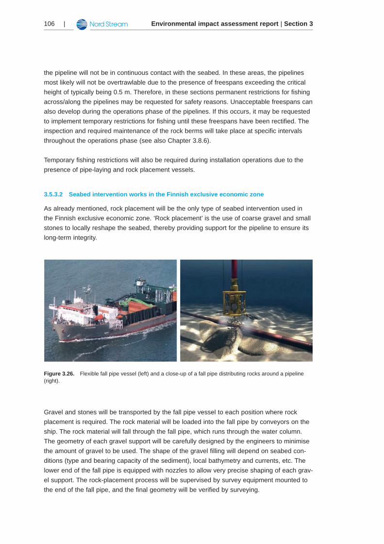
As already mentioned, rock placement will be the only type of seabed intervention used in the Finnish exclusive economic zone. ‘Rock placement’ is the use of coarse gravel and small stones to locally reshape the seabed, thereby providing support for the pipeline to ensure its long-term integrity.
Figure 3.26. Flexible fall pipe vessel (left) and a close-up of a fall pipe distributing rocks around a pipeline (right).
Gravel and stones will be transported by the fall pipe vessel to each position where rock placement is required. The rock material will be loaded into the fall pipe by conveyors on the ship. The rock material will fall through the fall pipe, which runs through the water column. The geometry of each gravel support will be carefully designed by the engineers to minimise the amount of gravel to be used. The shape of the gravel filling will depend on seabed con-ditions (type and bearing capacity of the sediment), local bathymetry and currents, etc. The lower end of the fall pipe is equipped with nozzles to allow very precise shaping of each grav-el support. The rock-placement process will be supervised by survey equipment mounted to the end of the fall pipe, and the final geometry will be verified by surveying.
Environmental impact assessment report | Section 3 | 107
Gravel works are primarily required as follows:
Gravel supports for freespan correction (pre-lay and post-lay)•Gravel cover (post-lay) for additional stabilisation of the pipeline after pipe-laying (for •certain sections)Gravel basement at KP 300 where pipe sections are welded together (tie-in)•Gravel supports for cable crossings •
In principle, rock placement of the pipelines above the seabed may also be considered a means to provide local protection from dropped or dragged anchors and to some extent from extent ship grounding. However, the bulk of rock placement activities will be performed to restrict stress due to freespan development and to ensure local dynamic stability.
The rock material must be chemically and mechanically stable for the entire lifetime of the pipeline. Unweathered, virgin rock of basalt, gabbro or granite type will be used. The aver-age size of the rock material will be 50 mm but range from 20-100 mm. Material for rock placement will be extracted from quarries on land. It is a prior condition that the material used must not contain any contaminants, such as heavy metals, that can be dissolved in the brackish water environment of the Baltic Sea.
Rock for pre-lay works will be rapakivi granite (also known as ‘Baltic Brown’), which will be extracted from a quarry in the Kotka area (see also Chapter 3.4.4). However, when the fall pipe vessels are being mobilised to Finland, they may come with a full load of Norwegian rock. At this stage of the project, the extraction site for post-lay works is undecided.
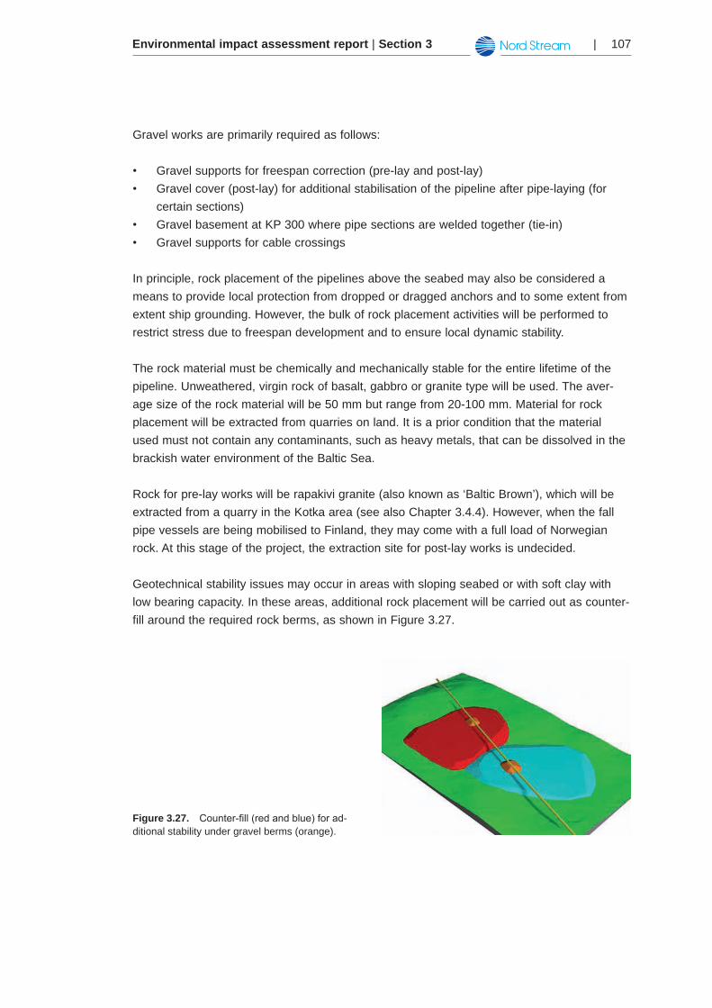
Geotechnical stability issues may occur in areas with sloping seabed or with soft clay with low bearing capacity. In these areas, additional rock placement will be carried out as counter-fill around the required rock berms, as shown in Figure 3.27.
Figure 3.27. Counter-fill(redandblue)forad-ditional stability under gravel berms (orange).
Environmental impact assessment report | Section 3108 |
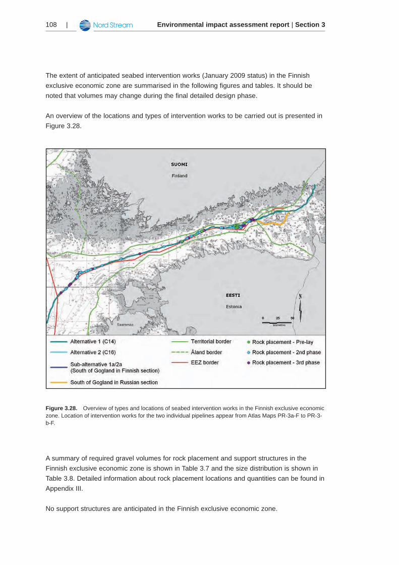
The extent of anticipated seabed intervention works (January 2009 status) in the Finnish exclusive economic zone are summarised in the following figures and tables. It should be noted that volumes may change during the final detailed design phase.
An overview of the locations and types of intervention works to be carried out is presented in Figure 3.28.
Figure 3.28. Overview of types and locations of seabed intervention works in the Finnish exclusive economic zone. Location of intervention works for the two individual pipelines appear from Atlas Maps PR-3a-F to PR-3-b-F.
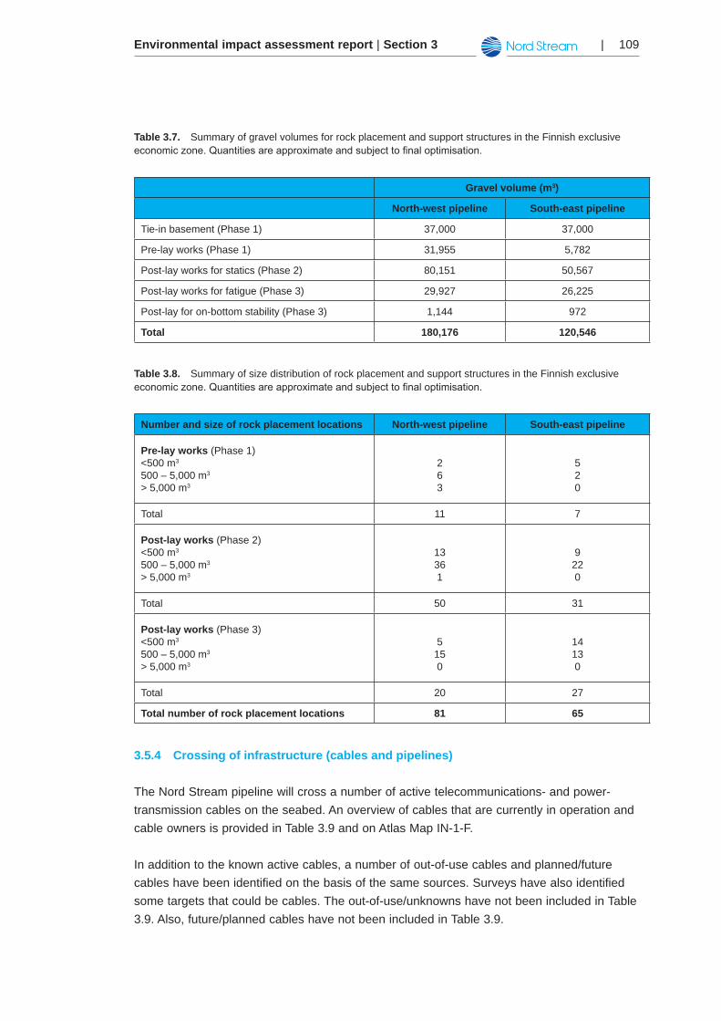
A summary of required gravel volumes for rock placement and support structures in the Finnish exclusive economic zone is shown in Table 3.7 and the size distribution is shown in Table 3.8. Detailed information about rock placement locations and quantities can be found in Appendix III.
No support structures are anticipated in the Finnish exclusive economic zone.
Environmental impact assessment report | Section 3 | 109
Table 3.7. Summary of gravel volumes for rock placement and support structures in the Finnish exclusive economiczone.Quantitiesareapproximateandsubjecttofinaloptimisation.
Gravel volume (m3)
North-west pipeline South-east pipeline
Tie-in basement (Phase 1) 37,000 37,000
Pre-lay works (Phase 1) 31,955 5,782
Post-lay works for statics (Phase 2) 80,151 50,567
Post-lay works for fatigue (Phase 3) 29,927 26,225
Post-lay for on-bottom stability (Phase 3) 1,144 972
Total 180,176 120,546
Table 3.8. Summary of size distribution of rock placement and support structures in the Finnish exclusive economiczone.Quantitiesareapproximateandsubjecttofinaloptimisation.
Number and size of rock placement locations North-west pipeline South-east pipeline
Pre-lay works (Phase 1)<500 m3
500 – 5,000 m3
> 5,000 m3
263
520
Total 11 7
Post-lay works (Phase 2)<500 m3
500 – 5,000 m3
> 5,000 m3
13361
9220
Total 50 31
Post-lay works (Phase 3)<500 m3
500 – 5,000 m3
> 5,000 m3
5150
14130
Total 20 27
Total number of rock placement locations 81 65
Crossing of infrastructure (cables and pipelines)3.5.4
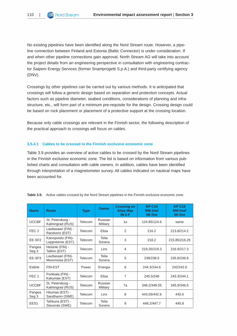
The Nord Stream pipeline will cross a number of active telecommunications- and power-transmission cables on the seabed. An overview of cables that are currently in operation and cable owners is provided in Table 3.9 and on Atlas Map IN-1-F.
In addition to the known active cables, a number of out-of-use cables and planned/future cables have been identified on the basis of the same sources. Surveys have also identified some targets that could be cables. The out-of-use/unknowns have not been included in Table 3.9. Also, future/planned cables have not been included in Table 3.9.
Environmental impact assessment report | Section 3110 |
No existing pipelines have been identified along the Nord Stream route. However, a pipe-line connection between Finland and Estonia (Baltic Connector) is under consideration. If and when other pipeline connections gain approval, North Stream AG will take into account the project details from an engineering perspective in consultation with engineering contrac-tor Saipem Energy Services (former Snamprogetti S.p.A.) and third-party certifying agency (DNV).
Crossings by other pipelines can be carried out by various methods. It is anticipated that crossings will follow a generic design based on separation and protection concepts. Actual factors such as pipeline diameter, seabed conditions, considerations of planning and infra-structure, etc., will form part of a minimum pre-requisite for the design. Crossing design could be based on rock placement or placement of a protective support at the crossing location.
Because only cable crossings are relevant in the Finnish sector, the following description of the practical approach to crossings will focus on cables.
Cables to be crossed in the Finnish exclusive economic zone3.5.4.1
Table 3.9 provides an overview of active cables to be crossed by the Nord Stream pipelines in the Finnish exclusive economic zone. The list is based on information from various pub-lished charts and consultation with cable owners. In addition, cables have been identified through interpretation of a magnetometer survey. All cables indicated on nautical maps have been accounted for.
Table 3.9. Active cables crossed by the Nord Stream pipelines in the Finnish exclusive economic zone.
Name Route Type Owner Crossing on Atlas Map
IN-1-F
KP C14NW-line/SE-line
KP C16NW-line/SE-line
UCCBF St. Petersburg - Kaliningrad (RUS) Telecom Russian
Military 1a 124.85/124.6 same
FEC 2 Lauttasaari (FIN) - Randvere (EST) Telecom Elisa 2 216.2 213.8/214.2
EE-SF2 Kaivopoisto (FIN)- Leppneeme (EST) Telecom Telia
Sonera 3 218.2 215.85/216.25
Pangea Seg 3
Helsinki (FIN) - Tallinn (EST) Telecom Linx 4 219.25/219.3 216.9/217.3
EE-SF3 Lauttasaari (FIN)- Meremoisa (EST) Telecom Telia
Sonera 5 238/238.5 235.8/236.8
Estlink FIN-EST Power Energia 6 244.3/244.6 242/242.6
FEC 1 Porkkala (FIN) - Kakumäe (EST) Telecom Elisa 7 245.5/246 243.3/244.1
UCCBF St. Petersburg - Kaliningrad (RUS) Telecom Russian
Military 7a 348.2/348.55 345.9/346.6
Pangea Seg 3
Hiiumaa (EST) - Sandhamn (SWE) Telecom Linx 8 443.05/442.6 440.6
EES1 Tahkuna (EST) - Stavsnäs (SWE) Telecom Telia
Sonera 9 448.2/447.7 445.8
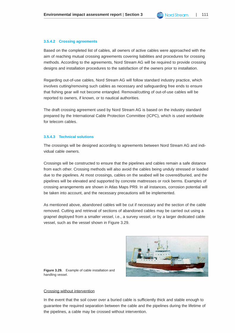
Environmental impact assessment report | Section 3 | 111
Crossing agreements 3.5.4.2
Based on the completed list of cables, all owners of active cables were approached with the aim of reaching mutual crossing agreements covering liabilities and procedures for crossing methods. According to the agreements, Nord Stream AG will be required to provide crossing designs and installation procedures to the satisfaction of the owners prior to installation.
Regarding out-of-use cables, Nord Stream AG will follow standard industry practice, which involves cutting/removing such cables as necessary and safeguarding free ends to ensure that fishing gear will not become entangled. Removal/cutting of out-of-use cables will be reported to owners, if known, or to nautical authorities.
The draft crossing agreement used by Nord Stream AG is based on the industry standard prepared by the International Cable Protection Committee (ICPC), which is used worldwide for telecom cables.
Technical solutions 3.5.4.3
The crossings will be designed according to agreements between Nord Stream AG and indi-vidual cable owners.
Crossings will be constructed to ensure that the pipelines and cables remain a safe distance from each other. Crossing methods will also avoid the cables being unduly stressed or loaded due to the pipelines. At most crossings, cables on the seabed will be covered/buried, and the pipelines will be elevated and supported by concrete mattresses or rock berms. Examples of crossing arrangements are shown in Atlas Maps PR9. In all instances, corrosion potential will be taken into account, and the necessary precautions will be implemented.
As mentioned above, abandoned cables will be cut if necessary and the section of the cable removed. Cutting and retrieval of sections of abandoned cables may be carried out using a grapnel deployed from a smaller vessel, i.e., a survey vessel, or by a larger dedicated cable vessel, such as the vessel shown in Figure 3.29.
Figure 3.29. Example of cable installation and handling vessel.
Crossing without intervention
In the event that the soil cover over a buried cable is sufficiently thick and stable enough to guarantee the required separation between the cable and the pipelines during the lifetime of the pipelines, a cable may be crossed without intervention.
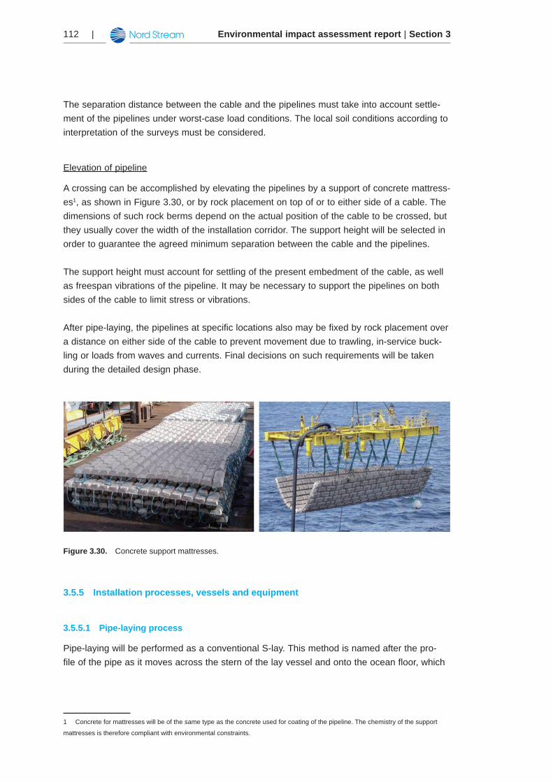
Environmental impact assessment report | Section 3112 |
The separation distance between the cable and the pipelines must take into account settle-ment of the pipelines under worst-case load conditions. The local soil conditions according to interpretation of the surveys must be considered.
Elevation of pipeline
A crossing can be accomplished by elevating the pipelines by a support of concrete mattress-es1, as shown in Figure 3.30, or by rock placement on top of or to either side of a cable. The dimensions of such rock berms depend on the actual position of the cable to be crossed, but they usually cover the width of the installation corridor. The support height will be selected in order to guarantee the agreed minimum separation between the cable and the pipelines.
The support height must account for settling of the present embedment of the cable, as well as freespan vibrations of the pipeline. It may be necessary to support the pipelines on both sides of the cable to limit stress or vibrations.
After pipe-laying, the pipelines at specific locations also may be fixed by rock placement over a distance on either side of the cable to prevent movement due to trawling, in-service buck-ling or loads from waves and currents. Final decisions on such requirements will be taken during the detailed design phase.
Figure 3.30. Concrete support mattresses.
Installation processes, vessels and equipment3.5.5
Pipe-laying process3.5.5.1
Pipe-laying will be performed as a conventional S-lay. This method is named after the pro-file of the pipe as it moves across the stern of the lay vessel and onto the ocean floor, which
1 Concrete for mattresses will be of the same type as the concrete used for coating of the pipeline. The chemistry of the support
mattresses is therefore compliant with environmental constraints.
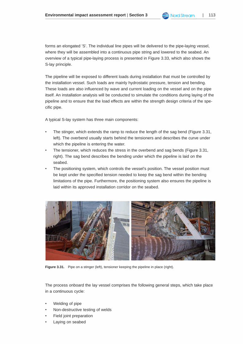
Environmental impact assessment report | Section 3 | 113
forms an elongated ’S’. The individual line pipes will be delivered to the pipe-laying vessel, where they will be assembled into a continuous pipe string and lowered to the seabed. An overview of a typical pipe-laying process is presented in Figure 3.33, which also shows the S-lay principle.
The pipeline will be exposed to different loads during installation that must be controlled by the installation vessel. Such loads are mainly hydrostatic pressure, tension and bending. These loads are also influenced by wave and current loading on the vessel and on the pipe itself. An installation analysis will be conducted to simulate the conditions during laying of the pipeline and to ensure that the load effects are within the strength design criteria of the spe-cific pipe.
A typical S-lay system has three main components:
The stinger, which extends the ramp to reduce the length of the sag bend (Figure 3.31, •left). The overbend usually starts behind the tensioners and describes the curve under which the pipeline is entering the water.The tensioner, which reduces the stress in the overbend and sag bends (Figure 3.31, •right). The sag bend describes the bending under which the pipeline is laid on the seabed. The positioning system, which controls the vessel’s position. The vessel position must •be kept under the specified tension needed to keep the sag bend within the bending limitations of the pipe. Furthermore, the positioning system also ensures the pipeline is laid within its approved installation corridor on the seabed.
Figure 3.31. Pipe on a stinger (left), tensioner keeping the pipeline in place (right).
The process onboard the lay vessel comprises the following general steps, which take place in a continuous cycle:
Welding of pipe•Non-destructive testing of welds•Field joint preparation•Laying on seabed•
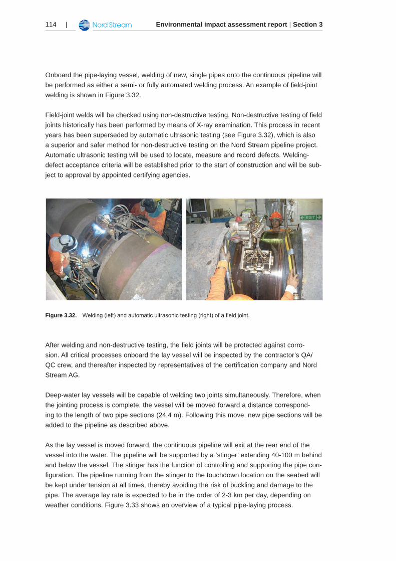
Environmental impact assessment report | Section 3114 |
Onboard the pipe-laying vessel, welding of new, single pipes onto the continuous pipeline will be performed as either a semi- or fully automated welding process. An example of field-joint welding is shown in Figure 3.32.
Field-joint welds will be checked using non-destructive testing. Non-destructive testing of field joints historically has been performed by means of X-ray examination. This process in recent years has been superseded by automatic ultrasonic testing (see Figure 3.32), which is also a superior and safer method for non-destructive testing on the Nord Stream pipeline project. Automatic ultrasonic testing will be used to locate, measure and record defects. Welding-defect acceptance criteria will be established prior to the start of construction and will be sub-ject to approval by appointed certifying agencies.
Figure 3.32. Welding(left)andautomaticultrasonictesting(right)ofafieldjoint.
After welding and non-destructive testing, the field joints will be protected against corro-sion. All critical processes onboard the lay vessel will be inspected by the contractor’s QA/QC crew, and thereafter inspected by representatives of the certification company and Nord Stream AG.
Deep-water lay vessels will be capable of welding two joints simultaneously. Therefore, when the jointing process is complete, the vessel will be moved forward a distance correspond-ing to the length of two pipe sections (24.4 m). Following this move, new pipe sections will be added to the pipeline as described above.
As the lay vessel is moved forward, the continuous pipeline will exit at the rear end of the vessel into the water. The pipeline will be supported by a ‘stinger’ extending 40-100 m behind and below the vessel. The stinger has the function of controlling and supporting the pipe con-figuration. The pipeline running from the stinger to the touchdown location on the seabed will be kept under tension at all times, thereby avoiding the risk of buckling and damage to the pipe. The average lay rate is expected to be in the order of 2-3 km per day, depending on weather conditions. Figure 3.33 shows an overview of a typical pipe-laying process.
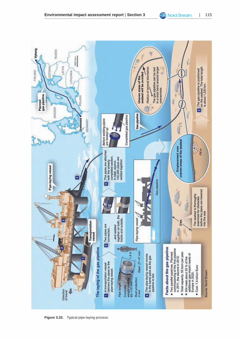
Environmental impact assessment report | Section 3 | 115
Figure 3.33. Typical pipe-laying process.
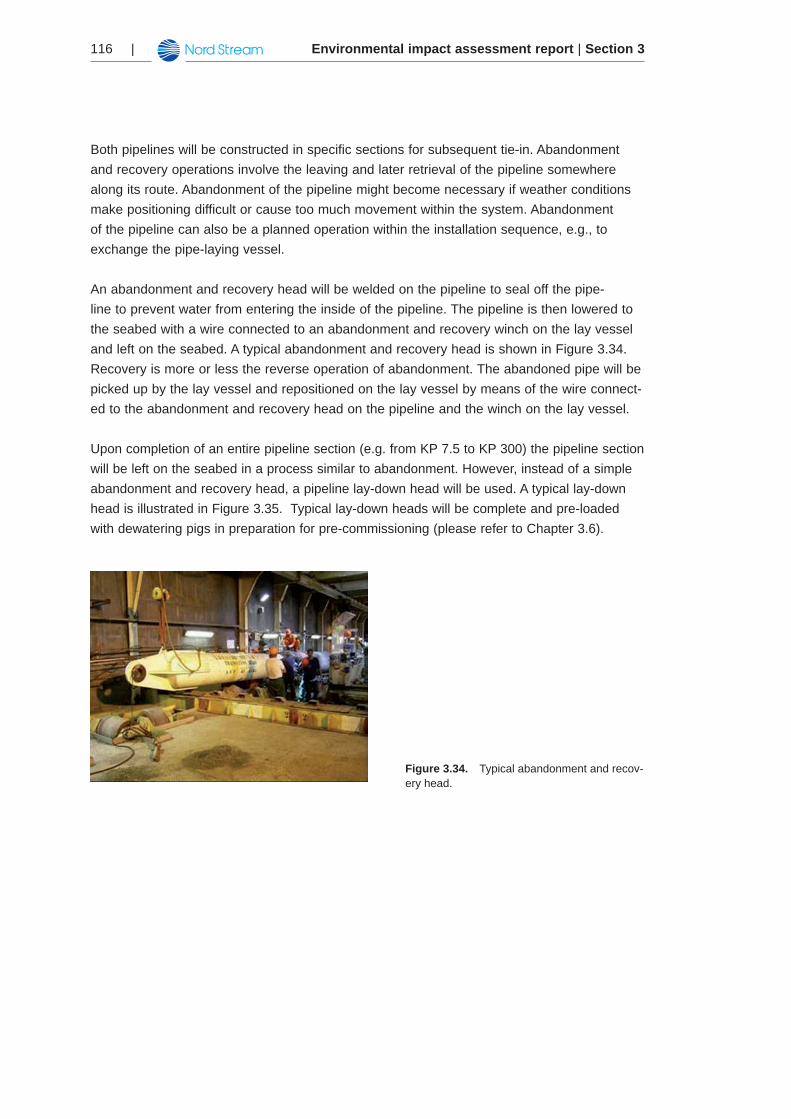
Environmental impact assessment report | Section 3116 |
Both pipelines will be constructed in specific sections for subsequent tie-in. Abandonment and recovery operations involve the leaving and later retrieval of the pipeline somewhere along its route. Abandonment of the pipeline might become necessary if weather conditions make positioning difficult or cause too much movement within the system. Abandonment of the pipeline can also be a planned operation within the installation sequence, e.g., to exchange the pipe-laying vessel.
An abandonment and recovery head will be welded on the pipeline to seal off the pipe-line to prevent water from entering the inside of the pipeline. The pipeline is then lowered to the seabed with a wire connected to an abandonment and recovery winch on the lay vessel and left on the seabed. A typical abandonment and recovery head is shown in Figure 3.34. Recovery is more or less the reverse operation of abandonment. The abandoned pipe will be picked up by the lay vessel and repositioned on the lay vessel by means of the wire connect-ed to the abandonment and recovery head on the pipeline and the winch on the lay vessel.
Upon completion of an entire pipeline section (e.g. from KP 7.5 to KP 300) the pipeline section will be left on the seabed in a process similar to abandonment. However, instead of a simple abandonment and recovery head, a pipeline lay-down head will be used. A typical lay-down head is illustrated in Figure 3.35. Typical lay-down heads will be complete and pre-loaded with dewatering pigs in preparation for pre-commissioning (please refer to Chapter 3.6).
Figure 3.34. Typical abandonment and recov-ery head.
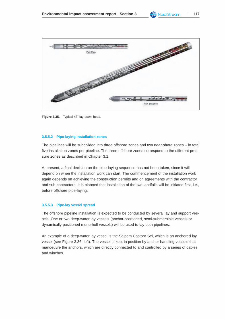
Environmental impact assessment report | Section 3 | 117
Figure 3.35. Typical 48” lay-down head.
Pipe-laying installation zones3.5.5.2
The pipelines will be subdivided into three offshore zones and two near-shore zones – in total five installation zones per pipeline. The three offshore zones correspond to the different pres-sure zones as described in Chapter 3.1.
At present, a final decision on the pipe-laying sequence has not been taken, since it will depend on when the installation work can start. The commencement of the installation work again depends on achieving the construction permits and on agreements with the contractor and sub-contractors. It is planned that installation of the two landfalls will be initiated first, i.e., before offshore pipe-laying.
Pipe-lay vessel spread3.5.5.3
The offshore pipeline installation is expected to be conducted by several lay and support ves-sels. One or two deep-water lay vessels (anchor-positioned, semi-submersible vessels or dynamically positioned mono-hull vessels) will be used to lay both pipelines.
An example of a deep-water lay vessel is the Saipem Castoro Sei, which is an anchored lay vessel (see Figure 3.36, left). The vessel is kept in position by anchor-handling vessels that manoeuvre the anchors, which are directly connected to and controlled by a series of cables and winches.
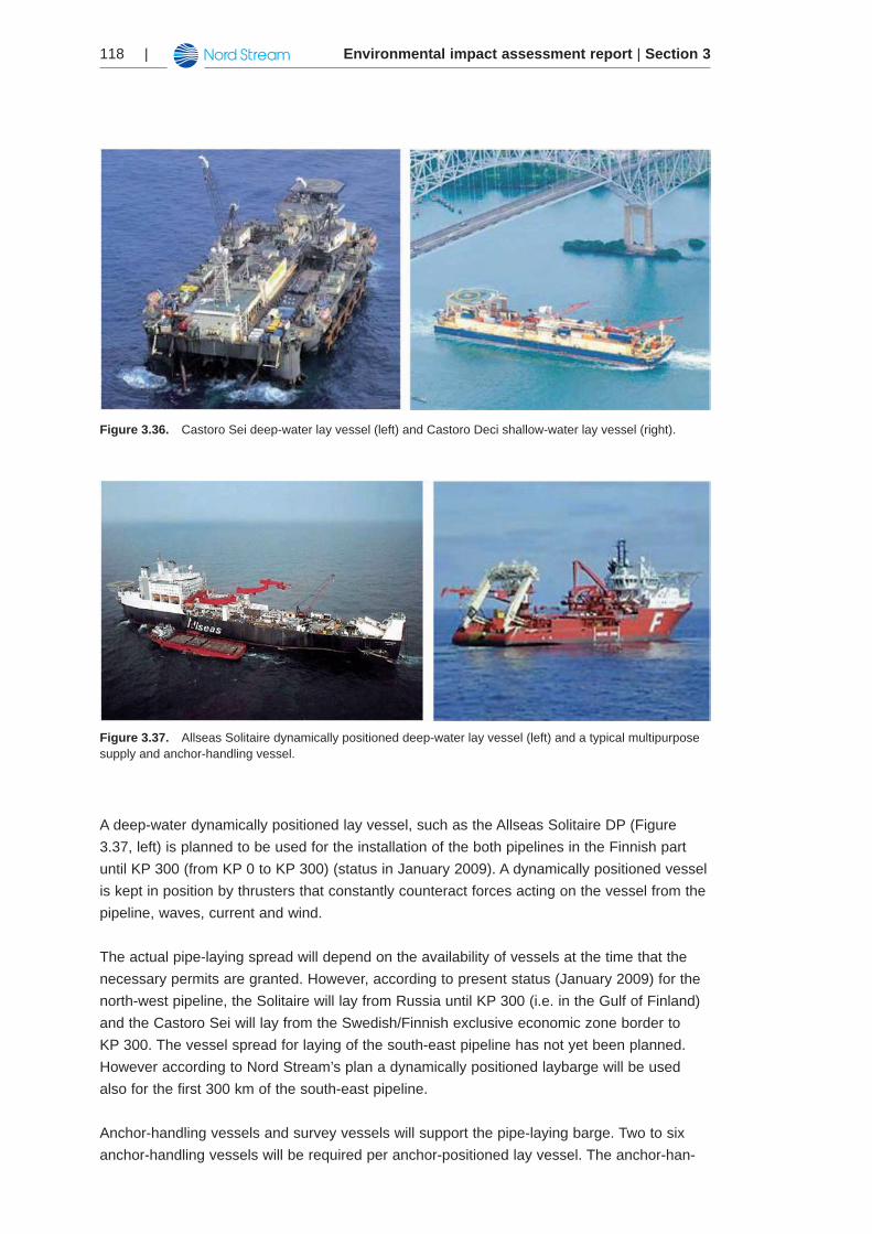
Environmental impact assessment report | Section 3118 |
Figure 3.36. Castoro Sei deep-water lay vessel (left) and Castoro Deci shallow-water lay vessel (right).
Figure 3.37. Allseas Solitaire dynamically positioned deep-water lay vessel (left) and a typical multipurpose supply and anchor-handling vessel.
A deep-water dynamically positioned lay vessel, such as the Allseas Solitaire DP (Figure 3.37, left) is planned to be used for the installation of the both pipelines in the Finnish part until KP 300 (from KP 0 to KP 300) (status in January 2009). A dynamically positioned vessel is kept in position by thrusters that constantly counteract forces acting on the vessel from the pipeline, waves, current and wind.
The actual pipe-laying spread will depend on the availability of vessels at the time that the necessary permits are granted. However, according to present status (January 2009) for the north-west pipeline, the Solitaire will lay from Russia until KP 300 (i.e. in the Gulf of Finland) and the Castoro Sei will lay from the Swedish/Finnish exclusive economic zone border to KP 300. The vessel spread for laying of the south-east pipeline has not yet been planned. However according to Nord Stream’s plan a dynamically positioned laybarge will be used also for the first 300 km of the south-east pipeline.
Anchor-handling vessels and survey vessels will support the pipe-laying barge. Two to six anchor-handling vessels will be required per anchor-positioned lay vessel. The anchor-han-
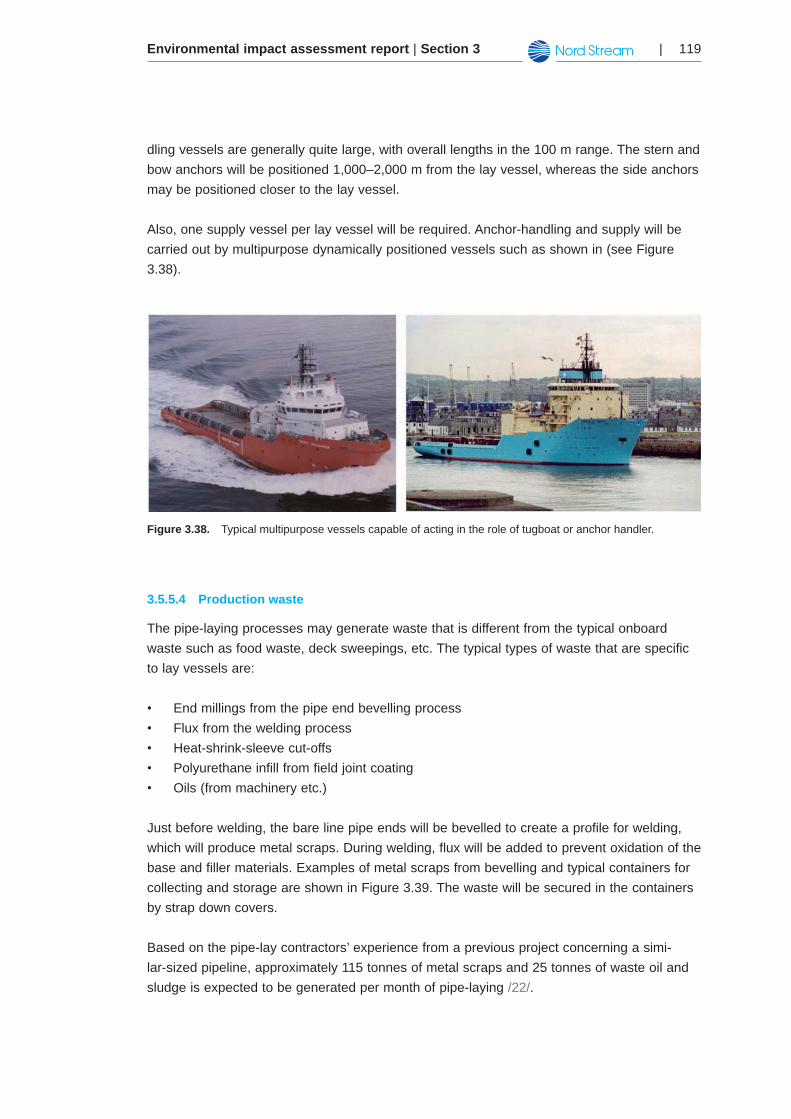
Environmental impact assessment report | Section 3 | 119
dling vessels are generally quite large, with overall lengths in the 100 m range. The stern and bow anchors will be positioned 1,000–2,000 m from the lay vessel, whereas the side anchors may be positioned closer to the lay vessel.
Also, one supply vessel per lay vessel will be required. Anchor-handling and supply will be carried out by multipurpose dynamically positioned vessels such as shown in (see Figure 3.38).
Figure 3.38. Typical multipurpose vessels capable of acting in the role of tugboat or anchor handler.
Production waste3.5.5.4
The pipe-laying processes may generate waste that is different from the typical onboard waste such as food waste, deck sweepings, etc. The typical types of waste that are specific to lay vessels are:
End millings from the pipe end bevelling process •Flux from the welding process •Heat-shrink-sleeve cut-offs •Polyurethane infill from field joint coating•Oils (from machinery etc.)•
Just before welding, the bare line pipe ends will be bevelled to create a profile for welding, which will produce metal scraps. During welding, flux will be added to prevent oxidation of the base and filler materials. Examples of metal scraps from bevelling and typical containers for collecting and storage are shown in Figure 3.39. The waste will be secured in the containers by strap down covers.
Based on the pipe-lay contractors’ experience from a previous project concerning a simi-lar-sized pipeline, approximately 115 tonnes of metal scraps and 25 tonnes of waste oil and sludge is expected to be generated per month of pipe-laying /22/.
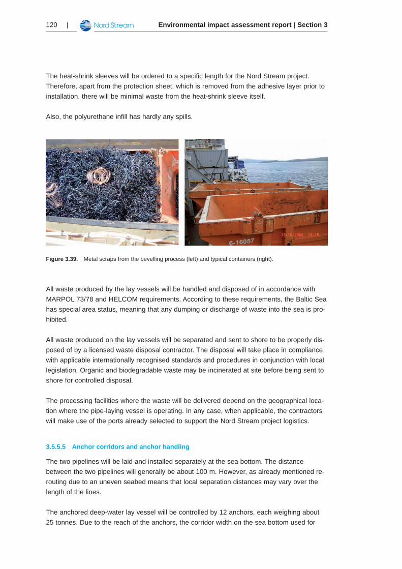
Environmental impact assessment report | Section 3120 |
The heat-shrink sleeves will be ordered to a specific length for the Nord Stream project. Therefore, apart from the protection sheet, which is removed from the adhesive layer prior to installation, there will be minimal waste from the heat-shrink sleeve itself.
Also, the polyurethane infill has hardly any spills.
Figure 3.39. Metal scraps from the bevelling process (left) and typical containers (right).
All waste produced by the lay vessels will be handled and disposed of in accordance with MARPOL 73/78 and HELCOM requirements. According to these requirements, the Baltic Sea has special area status, meaning that any dumping or discharge of waste into the sea is pro-hibited.
All waste produced on the lay vessels will be separated and sent to shore to be properly dis-posed of by a licensed waste disposal contractor. The disposal will take place in compliance with applicable internationally recognised standards and procedures in conjunction with local legislation. Organic and biodegradable waste may be incinerated at site before being sent to shore for controlled disposal.
The processing facilities where the waste will be delivered depend on the geographical loca-tion where the pipe-laying vessel is operating. In any case, when applicable, the contractors will make use of the ports already selected to support the Nord Stream project logistics.
Anchor corridors and anchor handling3.5.5.5
The two pipelines will be laid and installed separately at the sea bottom. The distance between the two pipelines will generally be about 100 m. However, as already mentioned re-routing due to an uneven seabed means that local separation distances may vary over the length of the lines.
The anchored deep-water lay vessel will be controlled by 12 anchors, each weighing about 25 tonnes. Due to the reach of the anchors, the corridor width on the sea bottom used for
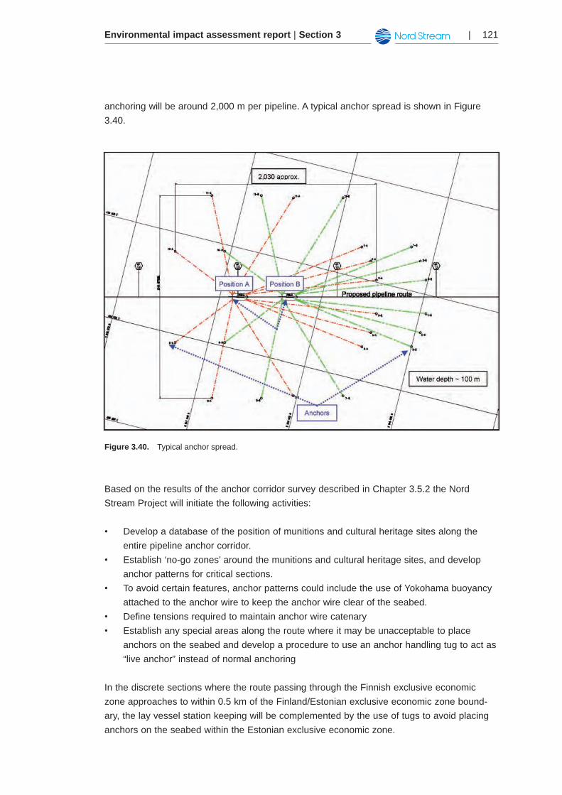
Environmental impact assessment report | Section 3 | 121
anchoring will be around 2,000 m per pipeline. A typical anchor spread is shown in Figure 3.40.
Figure 3.40. Typical anchor spread.
Based on the results of the anchor corridor survey described in Chapter 3.5.2 the Nord Stream Project will initiate the following activities:
Develop a database of the position of munitions and cultural heritage sites along the •entire pipeline anchor corridor. Establish ‘no-go zones’ around the munitions and cultural heritage sites, and develop •anchor patterns for critical sections. To avoid certain features, anchor patterns could include the use of Yokohama buoyancy •attached to the anchor wire to keep the anchor wire clear of the seabed. Define tensions required to maintain anchor wire catenary•Establish any special areas along the route where it may be unacceptable to place •anchors on the seabed and develop a procedure to use an anchor handling tug to act as “live anchor” instead of normal anchoring
In the discrete sections where the route passing through the Finnish exclusive economic zone approaches to within 0.5 km of the Finland/Estonian exclusive economic zone bound-ary, the lay vessel station keeping will be complemented by the use of tugs to avoid placing anchors on the seabed within the Estonian exclusive economic zone.
Environmental impact assessment report | Section 3122 |
Preventive measures and communications during pipeline installation3.5.5.6
To ensure minimum interference with pipe-laying operations from other sea traffic, an exclu-sion zone will be established around the lay vessel, typically extending 2,500–3,000 m, beyond the position of the lay vessel; however in the Finnish sector the actual extent will be defined by the barge captain in consultation with GOFREP. Unauthorised ship traffic, includ-ing fishing vessels, will not be permitted to enter the zone.
Nord Stream AG will issue a ‘Notice to Mariners’ on the installation activities to the relevant national coast guards throughout the period of construction. The relevant maritime authorities will be kept informed continuously on the installation progress. The coast guard will inform the ship traffic of ongoing activities and traffic limitations, such as exclusion zones, through various media, e.g., broadcasts on Navtext.
A marine captain will be onboard the pipe-laying vessel during installation to monitor all third-party shipping activity. Also, if required standby vessels will perform watch duties accord-ingly. The anchor-handling tug may perform this activity. Experienced crew will be available for watch duty at all times. The standby vessel will alert vessels in the vicinity and provide details of the exclusion zone coordinates. Any unexpected vessels entering a closest point of approach radius will be monitored closely, and actions will be taken to avoid incidents.
The contractor will pay special attention to areas where shipping lanes and other heavy traffic areas are crossed. The pipe-laying vessel must be able to cross shipping lanes unhindered by other vessels and must be able to position anchors as necessary.
In sensitive areas, pipe-laying and touchdown on the seabed will be followed closely by means of an ROV. This will be the case in areas with cultural heritage, for example.
Tie-ins3.5.6
As mentioned in the previous Chapter, the offshore pipelines will be divided into five offshore zones. The connection of these major pipeline sections – tie-in – will be carried out accord-ingly at two offshore locations where the water depth is high and at one near-shore location.
One of the tie-in positions will be located at KP 300 in the Finnish exclusive economic zone, where the connection will be carried out as a sub-sea connection (hyperbaric tie-in). The tie-in location at KP 300 corresponds with the pressure (and wall thickness) transitions of the pipeline from 220 barg to 200 barg. The water depth at the location is approximately 80 m.
At tie-in locations, pipeline sections will purposely overlap and then be cut and aligned for hyperbaric welding. Before a lay vessel finalises and lays down a pipeline section on the sea bottom, a lay-down head will be welded to the end of the pipe head in order to preserve the dry, non-corrosive environment inside the pipeline. The lay-down head (as shown in Figure 3.35) will be cut off during the tie-in procedure to permit subsequent hyperbaric welding.
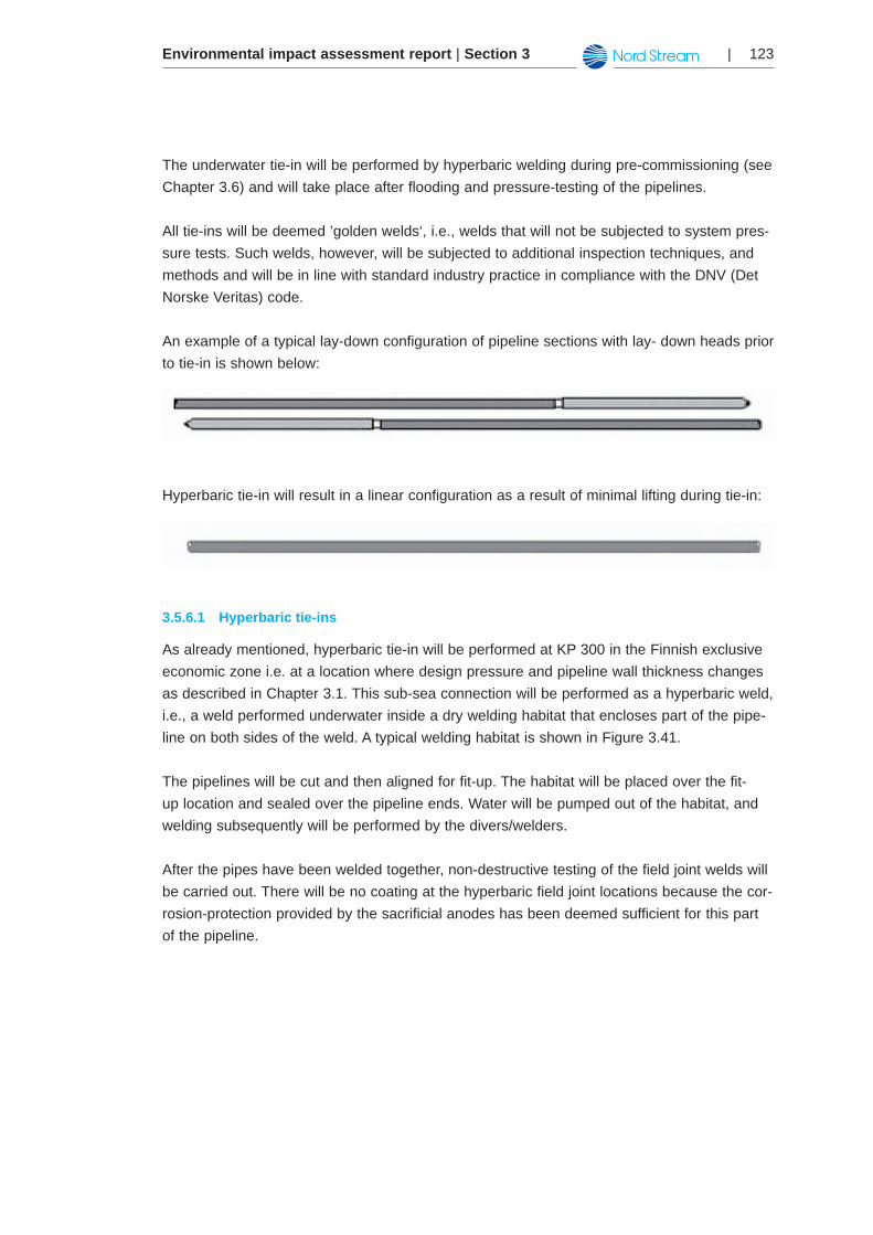
Environmental impact assessment report | Section 3 | 123
The underwater tie-in will be performed by hyperbaric welding during pre-commissioning (see Chapter 3.6) and will take place after flooding and pressure-testing of the pipelines.
All tie-ins will be deemed ’golden welds‘, i.e., welds that will not be subjected to system pres-sure tests. Such welds, however, will be subjected to additional inspection techniques, and methods and will be in line with standard industry practice in compliance with the DNV (Det Norske Veritas) code.
An example of a typical lay-down configuration of pipeline sections with lay- down heads prior to tie-in is shown below:
Hyperbaric tie-in will result in a linear configuration as a result of minimal lifting during tie-in:
Hyperbaric tie-ins3.5.6.1
As already mentioned, hyperbaric tie-in will be performed at KP 300 in the Finnish exclusive economic zone i.e. at a location where design pressure and pipeline wall thickness changes as described in Chapter 3.1. This sub-sea connection will be performed as a hyperbaric weld, i.e., a weld performed underwater inside a dry welding habitat that encloses part of the pipe-line on both sides of the weld. A typical welding habitat is shown in Figure 3.41.
The pipelines will be cut and then aligned for fit-up. The habitat will be placed over the fit-up location and sealed over the pipeline ends. Water will be pumped out of the habitat, and welding subsequently will be performed by the divers/welders.
After the pipes have been welded together, non-destructive testing of the field joint welds will be carried out. There will be no coating at the hyperbaric field joint locations because the cor-rosion-protection provided by the sacrificial anodes has been deemed sufficient for this part of the pipeline.
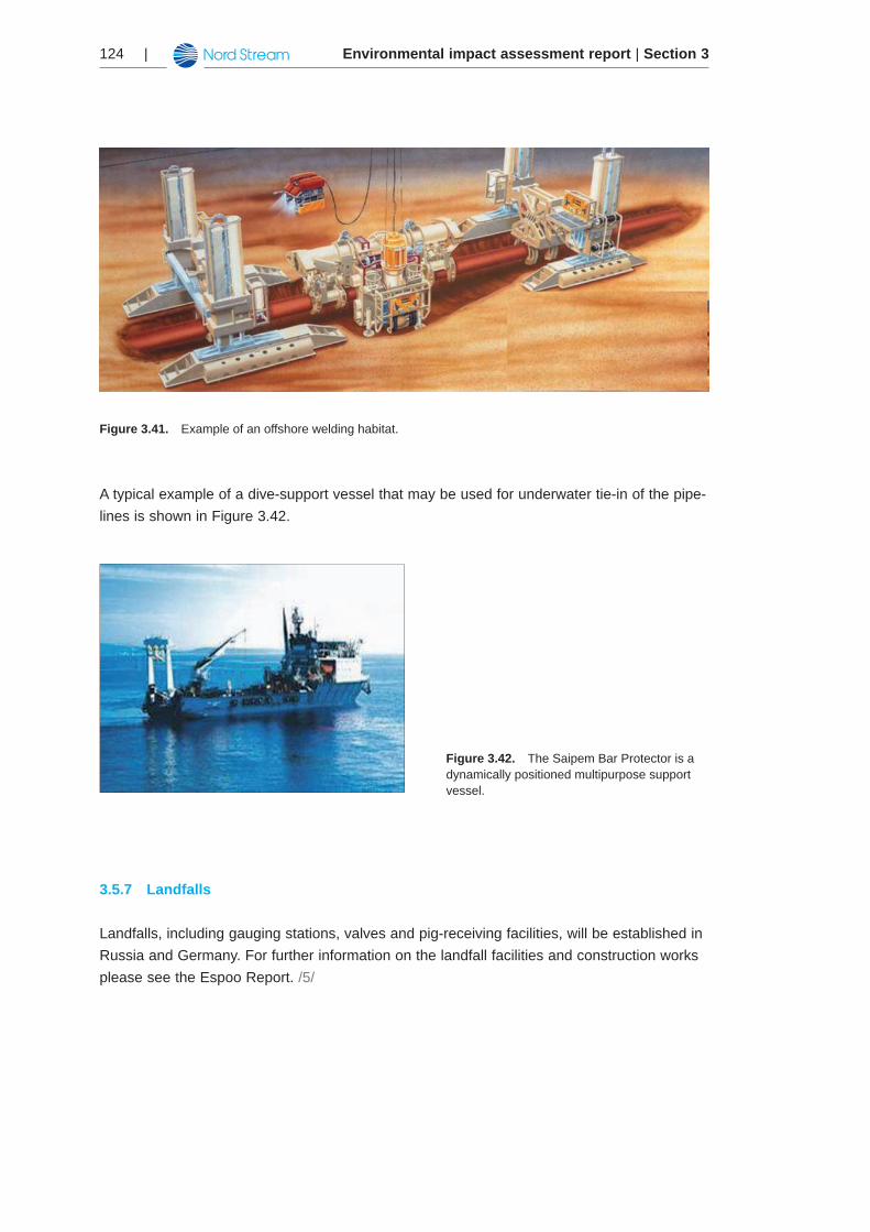
Environmental impact assessment report | Section 3124 |
Figure 3.41. Example of an offshore welding habitat.
A typical example of a dive-support vessel that may be used for underwater tie-in of the pipe-lines is shown in Figure 3.42.
Figure 3.42. The Saipem Bar Protector is a dynamically positioned multipurpose support vessel.
Landfalls3.5.7
Landfalls, including gauging stations, valves and pig-receiving facilities, will be established in Russia and Germany. For further information on the landfall facilities and construction works please see the Espoo Report. /5/
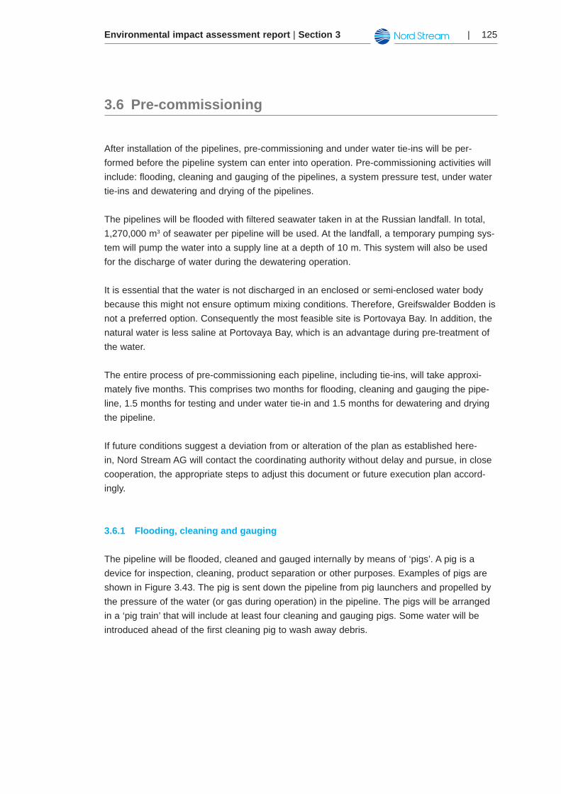
Environmental impact assessment report | Section 3 | 125
Pre-commissioning3.6
After installation of the pipelines, pre-commissioning and under water tie-ins will be per-formed before the pipeline system can enter into operation. Pre-commissioning activities will include: flooding, cleaning and gauging of the pipelines, a system pressure test, under water tie-ins and dewatering and drying of the pipelines.
The pipelines will be flooded with filtered seawater taken in at the Russian landfall. In total, 1,270,000 m3 of seawater per pipeline will be used. At the landfall, a temporary pumping sys-tem will pump the water into a supply line at a depth of 10 m. This system will also be used for the discharge of water during the dewatering operation.
It is essential that the water is not discharged in an enclosed or semi-enclosed water body because this might not ensure optimum mixing conditions. Therefore, Greifswalder Bodden is not a preferred option. Consequently the most feasible site is Portovaya Bay. In addition, the natural water is less saline at Portovaya Bay, which is an advantage during pre-treatment of the water.
The entire process of pre-commissioning each pipeline, including tie-ins, will take approxi-mately five months. This comprises two months for flooding, cleaning and gauging the pipe-line, 1.5 months for testing and under water tie-in and 1.5 months for dewatering and drying the pipeline.
If future conditions suggest a deviation from or alteration of the plan as established here-in, Nord Stream AG will contact the coordinating authority without delay and pursue, in close cooperation, the appropriate steps to adjust this document or future execution plan accord-ingly.
Flooding, cleaning and gauging3.6.1
The pipeline will be flooded, cleaned and gauged internally by means of ‘pigs’. A pig is a device for inspection, cleaning, product separation or other purposes. Examples of pigs are shown in Figure 3.43. The pig is sent down the pipeline from pig launchers and propelled by the pressure of the water (or gas during operation) in the pipeline. The pigs will be arranged in a ‘pig train’ that will include at least four cleaning and gauging pigs. Some water will be introduced ahead of the first cleaning pig to wash away debris.
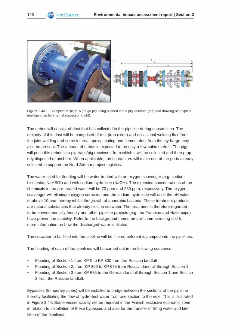
Environmental impact assessment report | Section 3126 |
Figure 3.43. Examples of ‘pigs’. A gauge pig being pushed into a pig launcher (left) and drawing of a typical intelligent pig for internal inspection (right).
The debris will consist of dust that has collected in the pipeline during construction. The majority of this dust will be comprised of rust (iron oxide) and occasional welding flux from the joint welding and some internal epoxy coating and cement dust from the lay barge may also be present. The amount of debris is expected to be only a few cubic metres. The pigs will push this debris into pig traps/pig receivers, from which it will be collected and then prop-erly disposed of onshore. When applicable, the contractors will make use of the ports already selected to support the Nord Stream project logistics.
The water used for flooding will be water treated with an oxygen scavenger (e.g. sodium bisulphite, NaHSO3) and with sodium hydroxide (NaOH). The expected concentrations of the chemicals in the pre-treated water will be 70 ppm and 230 ppm, respectively. The oxygen scavenger will eliminate oxygen corrosion and the sodium hydroxide will raise the pH-value to above 10 and thereby inhibit the growth of anaerobic bacteria. These treatment products are natural substances that already exist in seawater. The treatment is therefore regarded to be environmentally friendly and other pipeline projects (e.g. the Franpipe and Haltenpipe) have proven the usability. Refer to the background memo on pre-commissioning /23/ for more information on how the discharged water is diluted.
The seawater to be filled into the pipeline will be filtered before it is pumped into the pipelines.
The flooding of each of the pipelines will be carried out in the following sequence:
Flooding of Section 1 from KP 0 to KP 300 from the Russian landfall •Flooding of Section 2, from KP 300 to KP 675 from Russian landfall through Section 1•Flooding of Section 3 from KP 675 to the German landfall through Section 1 and Section •2 from the Russian landfall.
Bypasses (temporary pipes) will be installed to bridge between the sections of the pipeline thereby facilitating the flow of hydro-test water from one section to the next. This is illustrated in Figure 3.44. Some vessel activity will be required in the Finnish exclusive economic zone in relation to installation of these bypasses and also for the transfer of filling water and later tie-in of the pipelines.
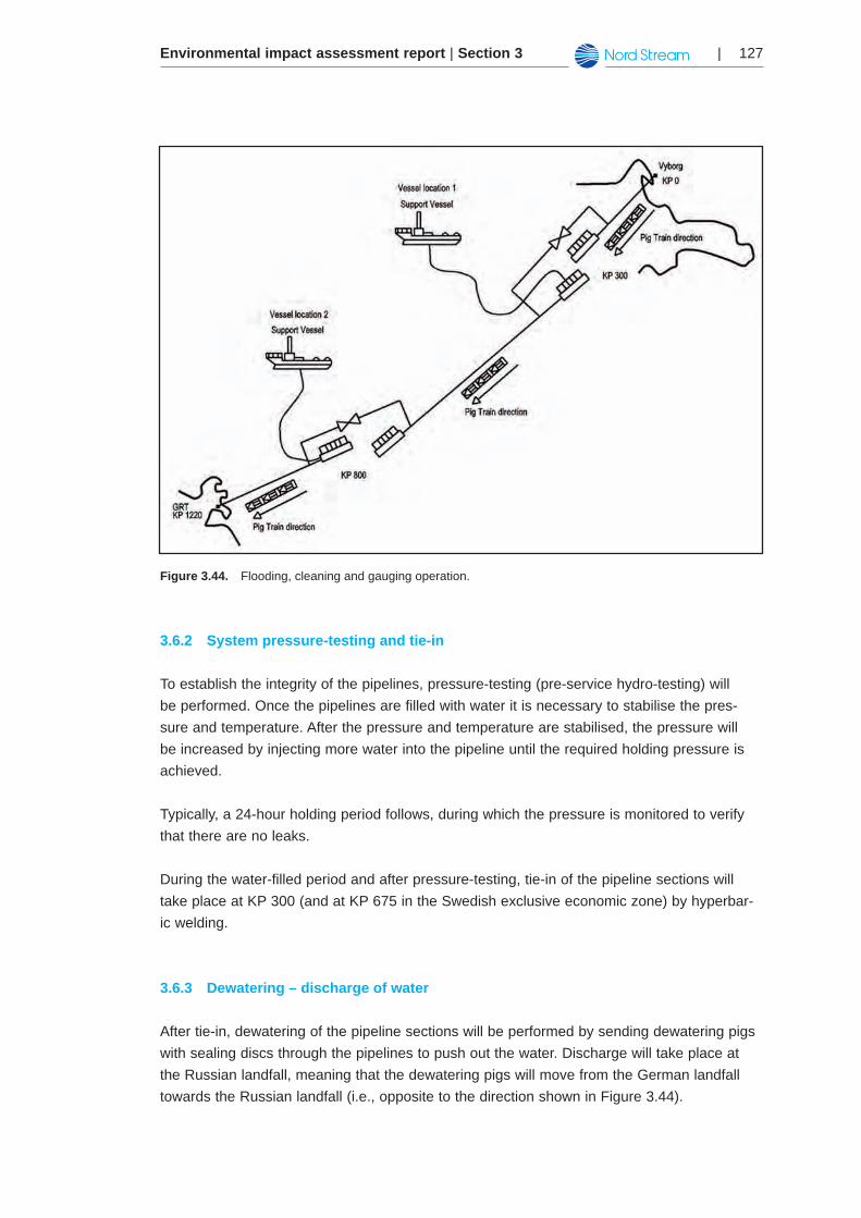
Environmental impact assessment report | Section 3 | 127
Figure 3.44. Flooding, cleaning and gauging operation.
System pressure-testing and tie-in3.6.2
To establish the integrity of the pipelines, pressure-testing (pre-service hydro-testing) will be performed. Once the pipelines are filled with water it is necessary to stabilise the pres-sure and temperature. After the pressure and temperature are stabilised, the pressure will be increased by injecting more water into the pipeline until the required holding pressure is achieved.
Typically, a 24-hour holding period follows, during which the pressure is monitored to verify that there are no leaks.
During the water-filled period and after pressure-testing, tie-in of the pipeline sections will take place at KP 300 (and at KP 675 in the Swedish exclusive economic zone) by hyperbar-ic welding.
Dewatering – discharge of water3.6.3
After tie-in, dewatering of the pipeline sections will be performed by sending dewatering pigs with sealing discs through the pipelines to push out the water. Discharge will take place at the Russian landfall, meaning that the dewatering pigs will move from the German landfall towards the Russian landfall (i.e., opposite to the direction shown in Figure 3.44).
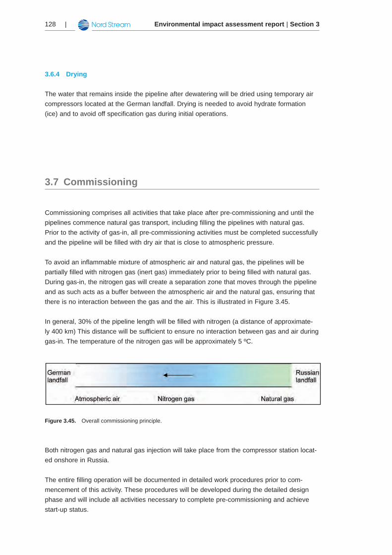
Environmental impact assessment report | Section 3128 |
Drying3.6.4
The water that remains inside the pipeline after dewatering will be dried using temporary air compressors located at the German landfall. Drying is needed to avoid hydrate formation (ice) and to avoid off specification gas during initial operations.
Commissioning3.7
Commissioning comprises all activities that take place after pre-commissioning and until the pipelines commence natural gas transport, including filling the pipelines with natural gas. Prior to the activity of gas-in, all pre-commissioning activities must be completed successfully and the pipeline will be filled with dry air that is close to atmospheric pressure.
To avoid an inflammable mixture of atmospheric air and natural gas, the pipelines will be partially filled with nitrogen gas (inert gas) immediately prior to being filled with natural gas. During gas-in, the nitrogen gas will create a separation zone that moves through the pipeline and as such acts as a buffer between the atmospheric air and the natural gas, ensuring that there is no interaction between the gas and the air. This is illustrated in Figure 3.45.
In general, 30% of the pipeline length will be filled with nitrogen (a distance of approximate-ly 400 km) This distance will be sufficient to ensure no interaction between gas and air during gas-in. The temperature of the nitrogen gas will be approximately 5 ºC.
Figure 3.45. Overall commissioning principle.
Both nitrogen gas and natural gas injection will take place from the compressor station locat-ed onshore in Russia.
The entire filling operation will be documented in detailed work procedures prior to com-mencement of this activity. These procedures will be developed during the detailed design phase and will include all activities necessary to complete pre-commissioning and achieve start-up status.
Environmental impact assessment report | Section 3 | 129
Operations concept3.8
Nord Stream AG will be the owner and operator of the pipeline system. An operations con-cept and security systems have been developed to ensure the safe operation of the pipe-lines in any situation, including avoiding over-pressurisation, managing and monitoring poten-tial gas leaks and ensuring material protection. The details of the facilities and the operations concept are described in the following Chapters.
Main pipeline system facilities3.8.1
The main Nord Stream pipeline system facilities are located at the landfall facilities in Russia and Germany, the main office in Zug, the Portovaya Bay Compressor Station and the Greifswald Receiving Terminal.
The Portovaya Bay Compressor Station will be located approximately 1.5 km upstream of the landfall facilities in Russia. The Portovaya Bay Compressor Station will be owned and oper-ated by OAO Gazprom. The Greifswald Receiving Terminal will be located downstream and immediately adjacent to the landfall facilities in Germany. The Greifswald Receiving Terminal will be owned and operated by WINGAS GmbH.
The landfall facilities in Russia and the Portovaya Bay Compressor Station are separate sites, but the landfall facilities in Germany and the Greifswald Receiving Terminal will be integrated in a single site. The main components at the landfall facilities will be pipeline pig launchers and receivers, together with isolation and emergency shut down valves. Pipeline pig launchers and receivers are used to clean and inspect the pipelines, and isolation and emergency shut down valves are used to ensure that the pressure in the pipelines is not exceeding the maximum allowable operating pressure.
Corporate activities are based in Zug, Switzerland, and managed by the executive direc-tors of Nord Stream AG. These activities include monitoring performance against targets for health, safety and environment and business coordination with upstream and downstream third parties (OAO Gazprom and WINGAS GmbH).
The Nord Stream pipeline system will be monitored and controlled from the main con-trol room located at the Nord Stream AG head office in Zug. The main control room will be manned 24 hours per day, 365 days per year. There will also be a back-up control room in Zug, to be used in the event that the main control room becomes unusable, e.g. due to a building fire.
There will be a Nord Stream AG branch office in Moscow, Russia. This office will have full pipeline system parameter monitoring, relayed from the main control room in Zug via the Nord Stream supervisory control and data acquisition (SCADA) system.
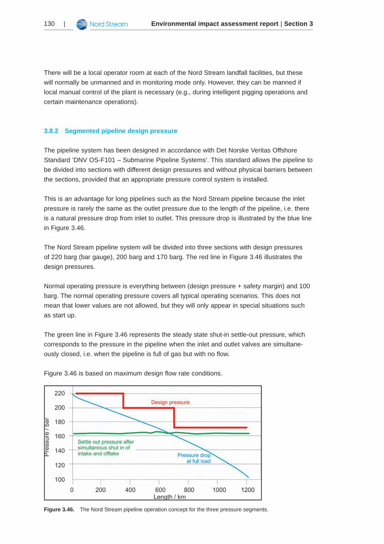
Environmental impact assessment report | Section 3130 |
There will be a local operator room at each of the Nord Stream landfall facilities, but these will normally be unmanned and in monitoring mode only. However, they can be manned if local manual control of the plant is necessary (e.g., during intelligent pigging operations and certain maintenance operations).
Segmented pipeline design pressure3.8.2
The pipeline system has been designed in accordance with Det Norske Veritas Offshore Standard ’DNV OS-F101 – Submarine Pipeline Systems‘. This standard allows the pipeline to be divided into sections with different design pressures and without physical barriers between the sections, provided that an appropriate pressure control system is installed.
This is an advantage for long pipelines such as the Nord Stream pipeline because the inlet pressure is rarely the same as the outlet pressure due to the length of the pipeline, i.e. there is a natural pressure drop from inlet to outlet. This pressure drop is illustrated by the blue line in Figure 3.46.
The Nord Stream pipeline system will be divided into three sections with design pressures of 220 barg (bar gauge), 200 barg and 170 barg. The red line in Figure 3.46 illustrates the design pressures.
Normal operating pressure is everything between (design pressure + safety margin) and 100 barg. The normal operating pressure covers all typical operating scenarios. This does not mean that lower values are not allowed, but they will only appear in special situations such as start up.
The green line in Figure 3.46 represents the steady state shut-in settle-out pressure, which corresponds to the pressure in the pipeline when the inlet and outlet valves are simultane-ously closed, i.e. when the pipeline is full of gas but with no flow.
Figure 3.46 is based on maximum design flow rate conditions.
Figure 3.46. The Nord Stream pipeline operation concept for the three pressure segments.
Environmental impact assessment report | Section 3 | 131
Per the DNV pipeline standard, the Nord Stream pipeline system pressure control system comprises:
A pressure regulating system•A pressure safety system•
The pressure regulating system is designed to ensure that the local design pressure of each pipeline section is not exceeded during normal operation (see also Chapter 3.8.5).
The pressure safety system is designed to ensure that the local maximum pressure for each pipeline section is not exceeded during incidental situations. Examples of such incidental situ-ations are closure of the pipeline outlet valve or failure of the pressure regulating system. The maximum pressure to which the pipeline can be subjected under these conditions is called the incidental pressure. The incidental pressure can be a minimum of 5% and a maximum of 10% above the design pressure. For the Nord Stream pipeline, the incidental pressure is 5% above design pressure.
The pressure safety system has two components to ensure the system’s reliability: Pressure Safety System 1 is the primary protection system, and Pressure Safety System 2 is the back-up protection system. The pressure regulating system and the pressure safety system func-tion independently of one another (see also Chapter 3.8.5).
Pipeline control system3.8.3
The Nord Stream overall pipeline control system comprises the following functions:
Pipeline pressure regulation•Pipeline pressure safeguarding•Pipeline leak detection•Pipeline parameter monitoring •Telemetry and telecommunications•Fire and gas detection and protection•Emergency shut down•
A short introduction to each is given in following sections.
Pipeline pressure regulation3.8.3.1
The Portovaya Bay Compressor Station and the Greifswald Receiving Terminal control the pipeline pressure and gas flow rate. These facilities have their own monitoring systems. In addition, the pressure regulation system will automatically alert the manned control rooms at Portovaya Bay and Greifswald if the normal operating pressure parameters of the pipeline system is threatened. Because of its capacity to advise the compressor station and receiving terminal to adjust gas flow rates, the Nord Stream control system has ‘indirect’ pressure regu-lation functionality.
Environmental impact assessment report | Section 3132 |
Pipeline pressure safeguarding3.8.3.2
If steps to modulate the gas flow rate are not taken at the compressor station and/or the receiving terminal and the pipeline pressure continues to rise, the pressure safety system function will intervene. The pressure safety system will automatically block the pipeline inlet in the event of the pipeline system moving outside its normal operating pressure envelope (e.g. overpressure). Because of its capacity to shut down the pipeline inlet in the event of overpres-surisation, the Nord Stream control system has ‘direct’ pressure safeguarding functionality.
Pipeline leak detection3.8.3.3
If the Nord Stream leak detection system detects a leak, it will automatically alert the emer-gency shutdown system to shut down one or both pipelines (as appropriate to the nature of the leak). The alert is sent via the Nord Stream supervisory control and data acquisi-tion (SCADA) system. The SCADA system displays the pipeline operating parameters at the Nord Stream plant locations, including the main control room in Zug and the two landfall facilities, as well as at other Nord Stream AG and third-party locations where such informa-tion is required, i.e., Portovaya Bay Compressor Station control rooms, Greifswald Receiving Terminal control rooms, Nord Stream AG branch office in Moscow.
It will be possible to detect leaks down to 1-2% of throughput. Leak detection is more difficult in gas pipelines than in liquid pipelines because of the effects of compressibility. Very small leaks offshore might not be detected by the system when they are smaller than the accuracy of the measurement and calculations. Both will be fine-tuned constantly during operation so the accuracy will increase with time and operating experience.
Refer to Chapter 3.8.3.7 for more information about emergency shut down in the case a leak is detected.
Pipeline parameter monitoring3.8.3.4
The Nord Stream SCADA system also provides pipeline gas temperature safeguarding func-tionality. Automatic shutdown temperatures have been established for Nord Stream, and the SCADA system will alert the Greifswald Receiving Terminal control room if gas temperatures are in danger of approaching the established high- or low-temperature margins.
Normal operating temperature is the temperature within the design limits: That means inlet temperature≤40°Candoutlettemperature≥-5°C(shorttime)or-1°C(permanent).Inextreme hot summers in Russia the inlet temperature might increase and the gas flow might need to be reduced in that time (typically during the hot hours during the day) not to exceed the maximum inlet temperature. In extreme cold winters in Germany the outlet temperature may decrease and the gas flow may need to be reduced in that time not to exceed the lower temperature limit, but also other corrective actions might be taken. Both scenarios have no impact on the environment or the safety of the pipeline.
Besides the temperature, pipeline instrumentation continuously also measures gas composi-tion, inlet and outlet flow and pressure.
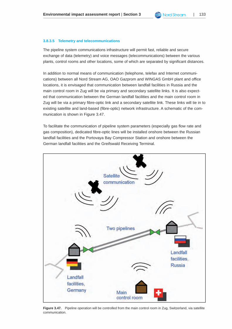
Environmental impact assessment report | Section 3 | 133
Telemetry and telecommunications3.8.3.5
The pipeline system communications infrastructure will permit fast, reliable and secure exchange of data (telemetry) and voice messages (telecommunications) between the various plants, control rooms and other locations, some of which are separated by significant distances.
In addition to normal means of communication (telephone, telefax and Internet communi-cations) between all Nord Stream AG, OAO Gazprom and WINGAS GmbH plant and office locations, it is envisaged that communication between landfall facilities in Russia and the main control room in Zug will be via primary and secondary satellite links. It is also expect-ed that communication between the German landfall facilities and the main control room in Zug will be via a primary fibre-optic link and a secondary satellite link. These links will tie in to existing satellite and land-based (fibre-optic) network infrastructure. A schematic of the com-munication is shown in Figure 3.47.
To facilitate the communication of pipeline system parameters (especially gas flow rate and gas composition), dedicated fibre-optic lines will be installed onshore between the Russian landfall facilities and the Portovaya Bay Compressor Station and onshore between the German landfall facilities and the Greifswald Receiving Terminal.
Figure 3.47. Pipeline operation will be controlled from the main control room in Zug, Switzerland, via satellite communication.
Environmental impact assessment report | Section 3134 |
Fire and gas detection and protection3.8.3.6
The landfall facilities in Russia and Germany will have local fire and gas detection and pro-tection systems.
Emergency shutdown3.8.3.7
The landfall facilities in Russia and Germany will have local emergency shutdown systems. The systems will be triggered in the case of facilities fire detection, facilities gas detection or pipeline leak detection. A full risk analysis has been carried out for the system.
The amount of time it takes for a leak to be discovered depends, not surprisingly, on the type of leak detection system, the parameters of the pipeline being monitored and the size of the leak. Typically, a small leak of <10 cm might take several hours to detect. A larger leak of >10 cm may be detected in as quickly as a few minutes.
In the event of a significant hazardous event, such as a fire or a gas leak, the pipeline will shut down immediately (or with a very short time delay). In the case of a leak, the emergency shut down valve closure time will depend on the size of the leak and the leak detection time. The time it will take for the emergency shut down valve to close is approximately 3 seconds per inch of pipeline, i.e., approximately 150 seconds (since the pipeline is 48 inches).
Since there are no valves along the route it is not possible to shut down sections of the pipe-line. This means that in case of a leak and subsequent shut down, water may enter into the pipeline.
Normal pipeline operations 3.8.4
Normal operating conditions are those in which the pipeline system flow rate, pressures and temperatures are all within the pipeline design parameters and in which flow rate is regulat-ed in accordance with the notification requirements of the gas transportation agreement. The operation will take place as follows:
Pipeline outlet pressure (or Greifswald Receiving Terminal inlet pressure) will be 1. controlled by the Greifswald Receiving Terminal control valves. These valves will also control line packing, which occurs when pipeline inlet flow is greater than pipeline outlet flow.Pipeline inlet flow rate will be controlled by the number of compressors on line at 2. Portovaya Bay Compressor Station. It is anticipated that the compressors will operate in ‘flow control’ mode, which automatically adjusts compressor speed. The required pipeline inlet pressure (or Portovaya Bay Compressor Station outlet 3. pressure) will be determined by the sum of the pressure at the pipeline outlet plus the pressure drop along the pipeline. With the compressors in ’flow control ‘mode, the compressor speed will adjust automatically to achieve the required compressor discharge pressure.
Environmental impact assessment report | Section 3 | 135
If pipeline inlet flow is greater than pipeline outlet flow, pipeline inventory will increase 4. (line packing).If pipeline inlet flow is less than pipeline outlet flow, then pipeline inventory will decrease 5. (line unpacking).During conditions that result in low pipeline outlet temperatures, the line heaters at 6. Greifswald Receiving Terminal will be used to ensure that the outlet gas temperature does not fall below the specified minimum.
Transportation operations3.8.5
Transportation operations mean the daily functioning of the Nord Stream pipeline system in order to transport natural gas through the pipelines. To do this in a reliable and safe manner, the operations department will liaise on a daily basis with OAO Gazprom (regarding opera-tion of the Portovaya Bay Compressor Station and the upstream fiscal meters) and WINGAS GmbH (regarding operation of the Greifswald Receiving Terminal and the downstream fis-cal meters). Installing fiscal meters is standard commercial practice for both the ‘gas seller’ (OAO Gazprom) and the ‘gas buyer’ (WINGAS GmbH) in order to measure the gas entering and leaving the pipeline. Operational gas measurement is also performed in order to perform inventories of the gas present in the pipeline and to detect leaks.
Transportation operations are managed remotely from the main control room in the Zug head office. The main control room is manned 24 hours per day, 365 days per year, by two control room operators. The control room operators will monitor operation of the pipeline within the normal operating envelope (as defined by real-time pipeline flow modelling software), whilst fulfilling daily transportation nomination requirements of OAO Gazprom and avoiding shut-down of the pipeline system due to malfunction of the system.
Procedures for planning and nominating daily transportation volumes, including intra-day adjustments, will be established in the detailed operating manual (to be developed in detail prior to operation and to supplement the gas transportation agreement). The detailed operat-ing manual will also specify the routine communication arrangements between Nord Stream AG, OAO Gazprom and WINGAS GmbH.
The operations group will maintain all transportation records (daily volumes, gas quality, etc.), which will be made available to other groups within Nord Stream AG as required.
Maintenance operations3.8.6
Maintenance operations mean the daily maintenance and inspection of the Nord Stream pipeline system in order to enable transport of natural gas through the pipelines in accord-ance with the uptime requirements of the gas transportation agreement.
As part of the maintenance system, Nord Stream AG will have an emergency pipeline repair system in the event of damage to the pipeline. The system will include a repair philosophy,
Environmental impact assessment report | Section 3136 |
procedures, blockage equipment and material, contracts with vessels and repair companies and agreements with authorities for necessary permits in the different countries and territori-al waters.
Planned maintenance and scheduled inspections will be carried out as a minimum in accord-ance with (1) manufacturers’ requirements, (2) statutory requirements and (3) recognised good industry practice. Planned maintenance and inspections will be carried out in non-winter months whenever possible to avoid working in severe winter weather conditions.
Service companies will perform maintenance activities, which comprise external inspection surveys and internal inspection (pigging).
External inspection and maintenance3.8.6.1
Planned survey inspections will be carried out along the length of the pipelines to ensure the integrity of the system. Unacceptable pipeline spanning may develop as a result of waves and currents, requiring correction, e.g., by the placement of rocks, sandbags or mattress-es. Anode potential monitoring will also be performed to ensure the integrity of the protection system.
Inspections will be conducted from a survey vessel equipped with different types of sen-sors, such as cameras and scanners, to inspect the general condition of the pipelines and to detect leaks. This visual/physical leak detection should be considered complimentary to the pressure-based leak detection system described in Chapter 3.8.3.3. The equipment is typical-ly mounted on remotely operated vehicles, i.e., un-manned, manoeuvrable underwater robots that are operated from the survey vessel. During the first years of operation, these surveys will be performed every one to two years along both pipelines. Later, this frequency will be optimised based on experience. It will take approximately 60 to 90 days to survey one pipe-line.
Based on experience from other pipelines it is known that freespans may develop along the pipeline during the operations phase. The freespans may be caused by hydrodynam-ic impacts, such as currents, eroding the gravel supporting the pipeline. Development of freespans during operation of the pipeline will be investigated as a part of the external inspection. The freespans will be rectified and gravel supports maintained as necessary.
Internal inspection (pigging)3.8.6.2
During operation of the pipeline system, pigging will be performed if necessary to remove any foreign matter that may have formed, such as hydrate or corrosion products. Pigs or pigs in ‘trains’ will be launched from the landfall facilities in Russia and driven through the pipeline by the gas medium (see Figure 3.43).
It can be expected that during operation the cleaning pigs will push residue from the internal epoxy flow coating and iron oxide to the pig receiver at the German landfall. The amount of solids collected during operational cleaning of a dry gas pipeline operated without any chemi-
Environmental impact assessment report | Section 3 | 137
cal injection will be minimal (less than 1 tonne). However, a proper chemical analysis will be carried out, and the debris will be properly disposed at a location for this type of waste. No liquid hydrocarbons are expected to be formed in the pipelines. Measures will be taken to ensure the pipelines are operated within the design boundaries.
At determined intervals, Nord Stream AG will carry out a more in-depth inspection of the pipeline condition. An ‘intelligent’ pig will be sent through the pipeline system to check for any corrosion or changes in pipeline wall thickness caused by third party impacts. The principle of detection is based on magnetic flux in the longitudinal direction of the pipeline. The follow-ing defects can be detected: changes in pipe wall thickness (internal and external), dents and changes in material hardness, transverse cracks in the base metal and metallic objects in the immediate vicinity of the pipelines. The frequency of these inspections is expected to be every three to eight years but will depend on the quality of gas fed into the pipeline system. Nord Stream AG will adjust the frequency of inspections as necessary.
Engineering operations3.8.7
Engineering operations comprise the engineering support required to ensure (1) the integri-ty of the Nord Stream pipeline system, particularly with respect to pressure containment, and (2) the safe and reliable daily operation of the pipeline system. Engineering operations cover both routine and/or minor tasks as well as non-routine and/or major tasks.
Engineering operations are based at the head office in Zug, where the engineering group works closely with the operations group. The engineering group has primary responsibility for coordination with inspection and certification agencies/authorities.
Engineering group tasks include:
Planning and execution of the periodic major inspections of the pipeline (using specialist •contractors) as described in Chapter 3.8.6.Planning and execution of any modifications, additions or major repairs to any part of the •Nord Stream pipeline system (using specialist contractors)Technical support for mission critical specialist equipment and systems (e.g., SCADA •system, telecom network, pipeline flow modelling software, transportation history database).
Manning philosophy3.8.8
All key personnel at the Zug head office and the Moscow branch office will be Nord Stream AG staff.
An engineering workstation will be installed at the main control room in Zug and at the local operation rooms at the German and Russian landfall facilities. From these engineering work-
Environmental impact assessment report | Section 3138 |
stations, the various settings of the pipeline system monitoring, control and safeguarding sys-tems can be checked and/or adjusted by the appropriate level of technical authority,
When skilled manpower is required at Nord Stream landfall facilities (e.g., during mainte-nance and intelligent pigging operations), it will be provided via a suitably licensed operations and maintenance services contractor, using appropriately qualified and experienced techni-cians. A Nord Stream operations/HSE supervisor will be present whenever landfall facilities in Germany and Russia are manned.
Nord Stream AG will also enter into service contracts with:
Vendors to support specialist equipment (e.g., large valves, SCADA equipment, telecom •equipment, etc.)Specialist inspection and survey companies•Fabric maintenance companies (e.g., painting, etc.)•
Major inspection and maintenance campaigns and major repairs will be planned by Nord Stream AG operations staff at the head office in Zug. Ad-hoc contracts will be awarded for execution of these non-routine activities.
There will be emergency response plans in place for safety and environmental incidents. Such incidents may be handled by Nord Stream AG core staff and its usual service contrac-tors, or they may require the ad-hoc contracting of specialist personnel and/or service com-panies, depending on the nature of the incident.
The pipeline emergency response plans will be designed to ensure an effective response to emergencies, such as personal injury and illness, damage to assets and adverse environmen-tal impact, and to prevent such emergencies escalating in consequence. Lines of communica-tion for emergency response will also be outlined in the pipeline emergency response plans.
Relevant supervisory and technical personnel based at the Nord Stream AG head office in Zug will make regular visits to the Nord Stream plant locations for the purpose of quality assurance regarding all operational activities.
Decommissioning3.9
The Nord Stream pipeline is designed to operate for 50 years. The decommissioning pro-gramme will be developed during the operations phase, since existing regulations and technical know-how gained over the lifetime of the pipelines must be taken into account. Regardless of decommissioning method, decommissioning will comply with all applicable legal requirements regarding decommissioning at that time.
Environmental impact assessment report | Section 3 | 139
The current legislative frameworks and guidelines as well as environmental considerations for decommissioning are further described in Chapter 10.
The current practice for decommissioning is either removal of the pipeline or leaving the pipe-line on the seabed after it is cleaned and filled with water. The prevailing industry view is that leaving the pipeline in place involves the least environmental impact because pipeline remov-al will disturb sediments. Also, the pipeline will have become a habitat and in other ways inte-grated in the natural surroundings. Nord Stream AG may undertake an EIA of the various alternatives for decommissioning the pipelines nearer the end of operations phase.
The current technological options and preferred methods for decommissioning of offshore installations and pipelines most likely will have changed in 50 years’ time, when the Nord Stream pipelines may be decommissioned. Knowledge about the environmental impact of various decommissioning strategies will be more developed due to considerable decommis-sioning activities within the North Sea in the coming 50 years. Nord Stream AG will use the prevailing technology available at the time of decommissioning since the technical options are expected will have changed. Finally, the layout of the pipeline (degree of burial in the seabed, etc.) at the time of decommissioning may affect the method of decommissioning and relevant mitigation measures.
The technical life of the pipeline may be extended beyond the expected 50 years design life through the close monitoring and evaluation of degrading mechanisms, such as corrosion and anode consumption, and conducting additional ‘fit-for-purpose’ assessments and recerti-fication.
Relation to other projects3.10
In this subchapter there is a brief description of Nord Stream Project’s relation to other infra-structure and utilisation of natural resources projects in Finnish project area. For more detailed information of existing and planned infrastructure please refer to Chapter 5.6.7.
Cables and pipelines3.10.1
The Swedish internet and telecom operator IP-Only is planning a new telecom cable with route Helsinki (FIN) – Tallinn (EST) – Hanko (FIN) – Kökar (FIN) – Stockholm (SWE). The cable would cross Nord Stream pipeline route twice. The project is at the stage where the environmental permit application procedure has been established and the marine survey applications have been delivered. The aim is that the cable will be laid during 2009 which means that the cable will be active before the planned pipeline. /24/
Environmental impact assessment report | Section 3140 |
A power cable Estlink II from Estonia to Finland is under planning. The 600-800 MW cable is planned to be ready in 2012. The route of the cable is not decided officially yet, but it would cross the planned pipeline once. According to preliminary plans the landing place in Estonia would be at Aseri. The landing place in Finland has not been decided yet. /25/
A Russian telecom cable from St. Petersburg to Kaliningrad is under planning by ZAO “NPP, Sevzaphydroproject”. The cable project is at the stage that a permit application for marine surveys has been delivered to Embassy of Finland. The surveys in Finnish EEZ are to be performed during the years 2008 – 2009. The cable is planned to be constructed during the year 2010. The cable route in Finnish EEZ is planned to be along the planned Nord Stream pipeline which might cause complications due to necessity for safety zones of both, cable and pipeline. Both parties have agreed to continue cooperation during the planning process-es of these projects. /26/
The two companies Gasum and Eesti Gaas are planning a gas pipeline connection, called the Balticconnector, across the middle of the Gulf of Finland between the Paldiski Peninsula in Estonia and Vuosaari or Inkoo in Finland. The companies have carried out a technical study and preliminary field investigations. They are also elaborating spatial plans and stra-tegic environmental assessments together with the local authorities in territories the planned pipeline will cross. The project is currently in the environmental impact assessment (EIA) stage in Finland. The full-scale EIA for the offshore section of the pipeline is planned to be carried out at the end of 2009 at the earliest /27/.
None of these above mentioned projects is in conflict with the Nord Stream Project. Crossings with cables and pipelines will be done according to separate agreements with each company.
Raw material extraction3.10.2
There are five granted permits for raw material extraction in Finnish territorial waters outside Helsinki and Sipoo area. The distance between these areas and the planned Nord Stream pipeline route is about 18 – 26 kilometres. /28/
A claim for mining mineral extraction area south from Helsinki in Gulf of Finland has been delivered to Finnish Ministry of Employment and the Economy. The area of claim is about 0.85 km2. The 50 m wide area reaches to the Finnish EEZ border. It crosses also the planned pipeline route. /29/