
SECTION 03A - Emission Control System
60
03A-1 Emission Control Svstem 03A-1 SECTION TITLE PAGE SECTION TITLE PAGE 01-l STARTING SYSTEM . . . . . . . . . e.. . . . . . s.. . . . . . . . . . . . . . . 05-l IGNITION SYSTEM - DISTRIBUTORLESS.. . . . , . . . . . . . . . 02-1 GOVERNOR . . . . . . . . . . . . . . . . . . . . . . . . . . . . . . . . . . . . . . . . . 06-l FUEL SYSTEM . . . . . . . . . . . . . . . . . . . . . . . . . . . . . . . . . . . . . . . 03-l COOLING SYSTEM . . . . . . . . . . . . . . . . . . . . . . . . . . , . . . . . . . . 07-l EMISSION CONTROL SYSTEM ........................ 03A-1 SPECIFICATIONS .................................... 08-l CHARGING SYSTEM ................................. 04-1 SECTION 03A - Emission Control System SUBJECT PAGE SUBJECT PAGE DESCRIPTION AND OPERATION ...................... ( Exhaust Gas Recirculation (EGR) Valve ............. ( Crankcase Emission Control System ............... ( DIAGNOSIS AND TESTING ............................ ( Symptoms of EGR System Malfunctions ............ ( Rough Idle ...................................... f Surge, Stall, or Won’t Start ....................... f Detonation (Spark Knock) ........................ ( Poor Fuel Economy ............................. ( 13A-3 3A-3 3A-6 13A-7 3A-7 13A-7 13A-7 13A-7 13A-7 EGR System Gas Flow Test . . . . . . . . . . . . . . . . . . . . . . . . 03A-7 Diaphragm Leak Test . . . . . . . . . . . . . . . . . . . . . . . . . . . . . . 03A-7 EGR Valve Leakage Check . . . . . . . . . . . . . . . . . . . . . . . . . 03A-8 Testing for EGR Source Vacuum . . . . . . . . . . . . . . . . . . . . 03A-8 Tesing the 2-Port PVS Valve . . . . . . . . . . . . . . . . . . . . . . . . 03A-8 REMOVAL AND INSTALLATION . . . . . . . . . . . . . . . . . . . . . . . 03A-9
-
Upload
khangminh22 -
Category
Documents
-
view
2 -
download
0
Transcript of SECTION 03A - Emission Control System
03A-1 Emission Control Svstem 03A-1
SECTION TITLE PAGE SECTION TITLE PAGE
01-l STARTING SYSTEM . . . . . . . . . e.. . . . . . s.. . . . . . . . . . . . . . . 05-l IGNITION SYSTEM - DISTRIBUTORLESS.. . . . , . . . . . . . . . 02-1 GOVERNOR . . . . . . . . . . . . . . . . . . . . . . . . . . . . . . . . . . . . . . . . . 06-l FUEL SYSTEM . . . . . . . . . . . . . . . . . . . . . . . . . . . . . . . . . . . . . . . 03-l COOLING SYSTEM . . . . . . . . . . . . . . . . . . . . . . . . . . , . . . . . . . . 07-l EMISSION CONTROL SYSTEM ........................ 03A-1 SPECIFICATIONS .................................... 08-l CHARGING SYSTEM ................................. 04-1
SECTION 03A - Emission Control System
SUBJECT PAGE SUBJECT PAGE
DESCRIPTION AND OPERATION ...................... ( Exhaust Gas Recirculation (EGR) Valve ............. ( Crankcase Emission Control System ............... (
DIAGNOSIS AND TESTING ............................ ( Symptoms of EGR System Malfunctions ............ (
Rough Idle ...................................... f Surge, Stall, or Won’t Start ....................... f Detonation (Spark Knock) ........................ ( Poor Fuel Economy ............................. (
13A-3 3A-3 3A-6 13A-7 3A-7 13A-7 13A-7 13A-7 13A-7
EGR System Gas Flow Test . . . . . . . . . . . . . . . . . . . . . . . . 03A-7 Diaphragm Leak Test . . . . . . . . . . . . . . . . . . . . . . . . . . . . . . 03A-7 EGR Valve Leakage Check . . . . . . . . . . . . . . . . . . . . . . . . . 03A-8 Testing for EGR Source Vacuum . . . . . . . . . . . . . . . . . . . . 03A-8 Tesing the 2-Port PVS Valve . . . . . . . . . . . . . . . . . . . . . . . . 03A-8
REMOVAL AND INSTALLATION . . . . . . . . . . . . . . . . . . . . . . . 03A-9


03A-3 Emission Control System 03A-3
DESCRIPTION AND OPERATION
Exhaust Gas Recirculation (EGR) Valve The exhaust gas recirculation (EGR) system feeds a controlled amount of exhaust gas back through the
cylinders to reduce the combustion temperature. This reduces the formation of an atmospheric pollutant known as “oxides of nitrogen” (NOx).
CARBURETOR SPACER EGR VALVE EGR TUBE INTAKE MANIFOLD
The EGR valve is a vacuum-operated flow-control valve. It is attached to the carburetor by an EGR valve adapter.
Between the EGR valve adapter and the carburetor is a spacer which has gaskets on both sides.

03A-4 Emission Control Svstem 03A-4
DESCRIPTION AND OPERATION (Continued)
2 REQUIR
A CARBURETOR B PORT VACUUM SWITCH (PVS) C SPACER D EGR VALVE E EGR GASKET F RESTRICTOR G GASKET H EGR SPACER
The EGR valve is operated by a vacuum signal from the carburetor, which actuates the valve diaphragm. As the vacuum increases sufficiently to overcome the diaphragm
spring, the valve is opened, allowing EGR flow. The amount of flow is dependent on the location of a tapered pintle, which is a direct result of the vacuum signal.

03A-5 Emission Control Svstem 03A-5
DESCRIPTION AND OPERATION (Continued)
EGR VALVE (CLOSED)
A DIAPHRAGM SPRING B VACUUM NIPPLE C PINTLE D INTAKE MANIFOLD E EXHAUST GAS F MANIFOLD VACUUM G PINTLE SEAT H DIAPHRAGM
A DIAPHRAGM SPRING B TO VACUUM C PINTLE D INTAKE MANIFOLD E EXHAUST GAS F MANIFOLD VACUUM G PINTLE SEAT H DIAPHRAGM
The EGR vacuum port is open to vacuum when the throttle plate is opened slightly (off idle). Vacuum is then available to the EGR control valve. Vacuum level decreases as the throttle plate opens.
At closed throttle, the EGR port is blocked from vacuum. At wide open throttle, EGR vacuum is weak to zero and will cause the EGR valve to close for maximum engine power. Note that at idle (when EGR vacuum is off) the EGR system is least needed because NOx formation is at a minimum.
THROT TLE PLATE (OFF IDLE
POSITION) HIGH VACUUM FLOW TO EGR
HlGH INTAKE++ MANIFOLD VACUUM
m VACUUM
Under certain circumstances, the EGR valve will usually be off. These include:
1. At idle, when the engine needs a richer mixture.
2. When the engine is cold.
3. When there is a heavy load (wide-open throttle).
At idle and at wide-open throttle, there is no vacuum at the EGR vacuum port. To control EGR at various engine temperatures, a port vacuum switch (PVS) is used.
03A-6 Emission Control System 03A-6
DESCRIPTION AND OPERATION (Continued)
COLD ENGINE WARM ENGINE
O-RING IS HELD SEATED TO BLOCK
“9 PORT CONNECTED TO VACUUM SOUF
TEM
WHEN ENGINE WARMS, SENSOR EXPANDS TO PUSH PLUNGER UP
FLOW IH VALVE
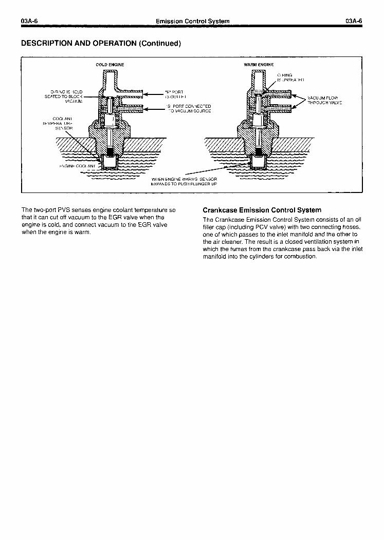
The two-port PVS senses engine coolant temperature so that it can cut off vacuum to the EGR valve when the engine is cold, and connect vacuum to the EGR valve when the engine is warm.
Crankcase Emission Control System The Crankcase Emission Control System consists of an oil filler cap (including PCV valve) with two connecting hoses, one of which passes to the inlet manifold and the other to the air cleaner. The result is a closed ventilation system in which the fumes from the crankcase pass back via the inlet manifold into the cylinders for combustion.

03A-7 Emission Control Svstem 03A-7
DIAGNOSIS AND TESTING
Symptoms of EGR System Malfunctions Many problems of poor engine performance are incorrectly diagnosed as being related to the EGR valve or EGR system. Therefore, it is important to know what engine symptoms can be EGR-related and how to test the system.
CAUTION: Improper use of leaded gasoline can plug up an EGR valve with deposits that restrict flow.
Poor Fuel Economy
This is an EGR condition only if it is related to detonation or some other symptom of restricted or zero EGR flow.
Rough Idle
This can be caused by an EGR valve stuck open, by dirt on the valve seat, or by loose mounting bolts. Loose mounting will cause a vacuum leak and a hissing noise. A stuck valve can be diagnosed by a functional test and by visual inspection.
Surge, Stall, or Won’t Start
Can be caused by the valve stuck open.
Detonation (Spark Knock)
Any condition that prevents poor EGR gas flow can cause detonation. This includes a valve stuck closed, leaking valve diaphragm, restrictions in flow passages, EGR disconnected, or a problem in the vacuum source. On engines with high spark advance, detonation is serious enough to destroy an engine. Diagnose the condition by performing the tests in this section.
EGR System Gas Flow Test The exhaust gas flow test must be made with the engine idling and hot. It tells you if the gas flow passages are open.
1. Remove the vacuum line from the valve diaphragm. Plug the line to prevent a vacuum leak or dirt entry.
2. Attach a hand vacuum pump to the valve diaphragm.
3. Apply 15 inches of vacuum to the valve, a little at a time.
If the gas flow is okay, the engine will begin to idle roughly at some point, or it may stall. If the idle doesn’t change, there is a restricted passage in the valve or the spacer. Remove the valve for inspection. If the valve diaphragm fails to hold vacuum, install a new EGR valve.
HAND VACUUM PUMP
Diaphragm Leak Test The diaphragm leak test can be performed with the engine Off.
1. Attach a hand vacuum pump to the vacuum nipple of the EGR valve.
2. Apply eight inches of vacuum and trap (hold) it.
The diaphragm must hold 7-8 inches of vacuum for at least 30 seconds. If it holds vacuum, the diaphragm is okay. Proceed to the Source Vacuum test. If the diaphragm won’t hold vacuum, replace the EGR valve.
VACl PI
APPLY 8 INCHES VACUUM AND TRAP
SECOND HAND
03A-8 Emission Control Svstem 03A-8
DIAGNOSIS AND TESTING (Continued)
EGR Valve Leakage Check Perform this test if the engine stalls, idles roughly, or runs poorly. 1. Remove and cap the EGR valve vacuum hose. Start
the engine. If the engine idle quality improves noticeably, double-check the vacuum hose routing because the valve may have a vacuum supply at idle.
2. If the enaine idle auatitv does not imDrove, remove the EGR”valve froh the spacer. Blodk the’EGR passages with a plate or install a known good EGR valve. Start the engine. If the idle quality is still bad, the problem is elsewhere. Reinstall the EGR valve. If the idle quality improves noticeably, the EGR valve has excessive leakage and should be replaced.
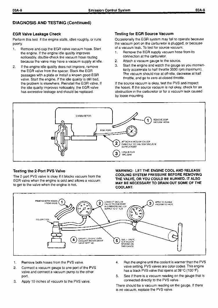
Testing for EGR Source Vacuum Occasionally the EGR system may fail to operate because the vacuum port on the carburetor is plugged, or because of a vacuum leak. To test for source vacuum: 1. Remove the EGR supply vacuum hose from its
connection at the carburetor. 2. Attach a vacuum gauge to the source. 3. Start the engine and watch the gauge as you momen-
tarily accelerate to half throttle 3000 rpm maximum). The vacuum should rise at off-idle, decrease at half throttle, and go to zero at closed throttle.
If the source vacuum is okay, test the PVS and inspect the hoses. If the source vacuum is not okay, check for an obstruction in the carburetor or for a vacuum leak caused by loose mounting.
CARBURETOR
EGR HOSE
Testing the 2-Port PVS Valve The Z-port PVS valve is okay if it blocks vacuum from the EGR valve when the engine is cold and allows a vacuum to get to the valve when the engine is hot.
WARNING: LET THE ENGINE COOL AND RELEASE COOLING SYSTEM PRESSURE BEFORE REMOVING THE VALVE, OR YOU COULD BE BURNED. IT ALSO MAY BE NECESSARY TO DRAIN OUT SOME OF THE COOLANT.
REMOVE BOTH HOSES CONNECT VACUUM GAUGE TO ONE PORT AND REMOTE VACUUM
APPLY 10 INCHES VACUUM TO VALVE
OPERATE ENGINE UNTIL COOLANT WARMS ABOVE VALVE SETTING
THIS GAUGE
1. Remove both hoses from the PVS valve. 4. Run the engine until the coolant is warmer than the PVS 2. Connect a vacuum gauge to one port of the PVS valve setting. PVS valves are color coded. This engine
valve and connect a vacuum pump to the other has a black PVS valve that opens at 38°C (1 OOOF). port. 5. See if there is a vacuum reading on the gauge that is
3. Apply IO inches of vacuum to the PVS valve. connected directly to the PVS valve.
There should be a vacuum reading on the gauge. If there is no vacuum, replace the PVS valve.

03A-9 Emission Control Svstem 03A-9
REMOVAL AND INSTALLATION
Removal 1. Remove the vacuum hose that goes to the PVS
valve.
2. Remove the EGR hose.
3. Remove the two EGR valve mounting bolts.
4. Remove the EGR valve gasket.
5. Remove the EGR restrictor.
2 REQUIR
6 PORT VACUUM SW C SPACER D EGR VALVE E EGR GASKET F RESTRICTOR G GASKET H EGR SPACER
-
‘ITCH (PVS)
Installation 1. Seat the EGR restrictor into the spacer block. A small
amount of grease may be applied to the EGR restrictor prior to installation. This will ensure that the EGR restrictor does not become dislodged during the installation of the EGR valve gasket and the EGR valve. Do not allow grease to block the hole in the EGR restrictor.
2. Install the EGR valve gasket.
3. Install the EGR valve.
4. Install the two EGR valve mounting bolts. Tighten to 16-20 Nom (12-l 5 ft. Ibs.).
5. Install the EGR hose. Tighten to 34-47 Nom (25-35 ft. Ibs.).
6. Attach the vacuum hose that comes from the PVS valve.

04-I Charaina Svstem 04-I
SECTION TITLE PAGE SECTION TITLE PAGE
BASIC ENGINE . . . , . . . . . . . . . . . . . . . . . . . . . . . . . . . . . . . . . . . 01-l STARTING SYSTEM . . . . . . . . . . . . . . . . . . . . . . . . . . . . . . . . . . 05-l IGNITION SYSTEM - DISTRIBUTORLESS ............... 02-I GOVERNOR ......................................... 06-I FUEL SYSTEM ....................................... 03-1 COOLING SYSTEM ................................... 07-I EMISSION CONTROL SYSTEM ........................ 03A-1 SPECIFICATIONS .................................... 08-l CHARGING SYSTEM ................................. 04-I
SECTION 04 - Charging System
SUBJECT PAGE
DESCRIPTION AND OPERATION ...................... 04-3 Generator ......................................... 04-3
DIAGNOSIS AND TESTING ............................ 04-5 Preliminary Information ............................ 04-5 Isolating the Problem .............................. 04-5 Battery Testing .................................... 04-5 Capacity Test ..................................... 04-5 System Connections .............................. 04-6 Generator Connections ............................ 04-6 Electrical Testing Precautions ...................... 04-6 Output Voltage Test ............................... 04-6 Regulator Bypass Test ............................. 04-7 Key-Off Check .................................... 04-7 Regulator Sense Voltage ........................... 04-7 External Circuit Tests .............................. 04-8 Field Voltage Test ................................. 04-8 Initial Excitation Circuits ........................... 04-9
SUBJECT PAGE
Regulator Input Test ............................... 04-9 Generator Brush Check ............................ 04-10 Field Ground and Open Tests ...................... 04-10 Field Voltage Test ................................. 04-I 0 Overcharging ..................................... 04-l 1 Generator Disassembly ............................ 04-11
ADJUSTMENTS ...................................... 04-l 2 Belt Adjustments .................................. 04-l 2
REMOVAL AND INSTALLATION ....................... 04-I 3 OVERHAUL ......................................... 04-l 4
Disassembly ...................................... 04-l 4 Releasing Front Bearing Retainer ................. 04-I 4 Front or Rear Bearing Removal ................... 04-14 Front Bearing Installation ........................ 04-I 5 Pressing Front Bearing Onto Shaft ............... 04-15
Assembly ......................................... 04-15 Output Voltage Test ............................. 04-I 6


04-3 Charaina Svstem 04-3
DESCRIPTION AND OPERATION
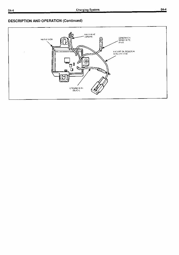
Generator The generator charging system is a negative ground system, and consists of an generator, a regulator, a charge indicator, a storage battery, and associated wiring.
The present VSG range uses a Prestolite 37-amp or 51 -amp generator. These units have a self-contained regulator mounted directly to the generator case. The generator is belt driven from the engine. Current is supplied
from the generator-regulator system to the rotating field of the generator through two brushes to two slip rings.
The generator produces power in the form of alternating current. The alternating current is rectified to direct current by six diodes. The generator regulator automatically adjusts the generator field current to maintain the generator output voltage within prescribed limits to correctly charge the battery.
(TO
OUTPUT TERMINAL (+)
EXCITATION RESISTOR PIGTAIL IGNITION SWITCH)
FIELD TERMINAL ,~ / (INSIDE REGULAI ‘OR COVER)
FIELD TERMINAL
04-4 Chargina System 04-4
DESCRIPTION AND OPERATION (Continued)
REGULATOR
GROUND WIRE
TOR

04-5 Charging System 04-5
DIAGNOSIS AND TESTING
Preliminary Information Before performing charging system tests on the engine, note the complaint such as: slow cranking, battery dead or using an excessive amount of water, top of battery wet, ammeter shows charge at all times and/or no charge, generator warning lamp does not come on and/or never goes out, voltmeter shows above or below open circuit nominal voltage. This information will aid in isolating the part of the system causing the symptom.
Next, visually inspect as follows:
1. Check battery posts and battery cable terminals for clean and tight connections. Remove the battery cables (if corroded), clean and install them securely.
2. Check for clean and tight wiring connections at the generator, regulator and engine. Inspect for evidence of arcing.
3. Check the generator belt tension using belt tension gauge T63L-8620-A, Model 210019 or equivalent and tighten to specification (if necessary).
Isolating the Problem Battery, starting system, and light systems problems can be caused by poor charging system performance. It is also possible to suspect the charging system because of an overload in another area of the electrical system.
To avoid guesswork, it is necessary to isolate the battery, the charging system, and the electrical circuits to correctly identify the area where the difficulty lies. The best method to do this is to check the battery first before any electrical system diagnosis. The battery must be in proper state of charge. The battery must be operating properly before the other areas of the electrical system can perform normally.
Battery Testing WARNING: KEEP BATTERIES OUT OF REACH OF CHILDREN. BATTERIES CONTAIN SULFURIC ACID. AVOID CONTACT WITH SKIN, EYES OR CLOTHING. ALSO, SHIELD YOUR EYES WHEN WORKING NEAR THE BATTERY TO PROTECT AGAINST POSSIBLE SPLASHING OF THE ACID SOLUTION. IN CASE OF ACID CONTACT WITH SKIN, EYES, OR CLOTHING, FLUSH IMMEDIATELY WITH WATER FOR A MINIMUM OF 15 MINUTES. IF ACID IS SWALLOWED, DRINK LARGE QUANTITIES OF MILK OR WATER, FOLLOWED BY MILK OF MAGNESIA, A BEATEN EGG OR VEGETABLE OIL. CALL A PHYSICIAN IMMEDIATELY.
HYDROGEN AND OXYGEN GASES ARE PRODUCED DURING NORMAL BATTERY OPERATION. THIS GAS MIXTURE CAN EXPLODE IF FLAMES, SPARKS OR LIGHTED TOBACCO ARE BROUGHT NEAR THE BATTERY. WHEN CHARGING OR USING A BATTERY IN AN ENCLOSED SPACE, ALWAYS PROVIDE VENTILATION AND SHIELD YOUR EYES.
WARNING: BATTERIES ARE HEAVY, WEIGHING 30 LBS. OR MORE. LIFT THEM WITH YOUR LEGS RATHER THAN YOUR BACK TO PREVENT MUSCLE STRAINS, AND BE CAREFUL NOT TO DROP THEM (POSSIBLE BREAKAGE) OR TO SPILL THE CONTENTS (SULFURIC ACID).
CAUTION: 12-volt starting motors can be damaged beyond repair if connected to a 24-volt power supply (two 12-volt batteries in series, or a 24-volt motor- generator set), even when cranking loads are relatively light. Extensive starting motor damage is more likely if the starter is connected to a 24-volt supply while being subjected to prolonged heavy cranking loads such as attempting to start an engine in subzero temperature.
Tests are made on a battery to determine the state of charge and also its capacity or ability to crank an engine. The ultimate result of these tests is to show that the battery is good, needs recharging, or must be replaced.
Before attempting to test a battery, it is important to give it a thorough examination to determine if it has been damaged. Remove battery cable clamps, negative (-) terminal first. Check for dirty or corroded connections and loose battery posts. Remove hold downs and heat shields and inspect for a broken or cracked case or cover. If the battery is worn or damaged, if there is a loose or broken post, or if there is a cracked case or cover, replace the battery.
The battery capacity test should be run next to remove any surface charge prior to determining the state of charge of a maintenance free battery.
Capacity Test A high rate discharge tester (Rotunda Battery-Starter Tester 02-0204) or equivalent in conjunction with a voltmeter is used for this test.
4.
5.
Turn the control knob on the Battery-Starter Tester to the “OFF” position.
Turn the voltmeter selector switch to the 20-volt position and test selector switch to “AMP”.
Connect both positive test leads to the positive (+) battery post and both negative leads to the negative (-) battery post. The voltmeter clips must contact the battery posts and not the high-rate discharge tester clips. Unless this is done, the actual battery terminal voltage will not be indicated.
Turn the load control knob in a clockwise direction until the ammeter reaches the applicable discharge rate specified in the discharge rate table.
With the ammeter reading the required load for 15 seconds, note the voltmeter reading. Avoid leaving the high discharge load on the battery for periods longer than 15 seconds.
If the voltmeter reading is above the minimum specified in the table with the test equipment for that temperature, the battery has a good output capacity and will readily accept a charge, if required. Check the state of charge.
If the voltage reading obtained during the capacity test is below the minimum specified in the table, check the state of charge.
04-6 Charcring System 04-6
DIAGNOSIS AND TESTING (Continued)
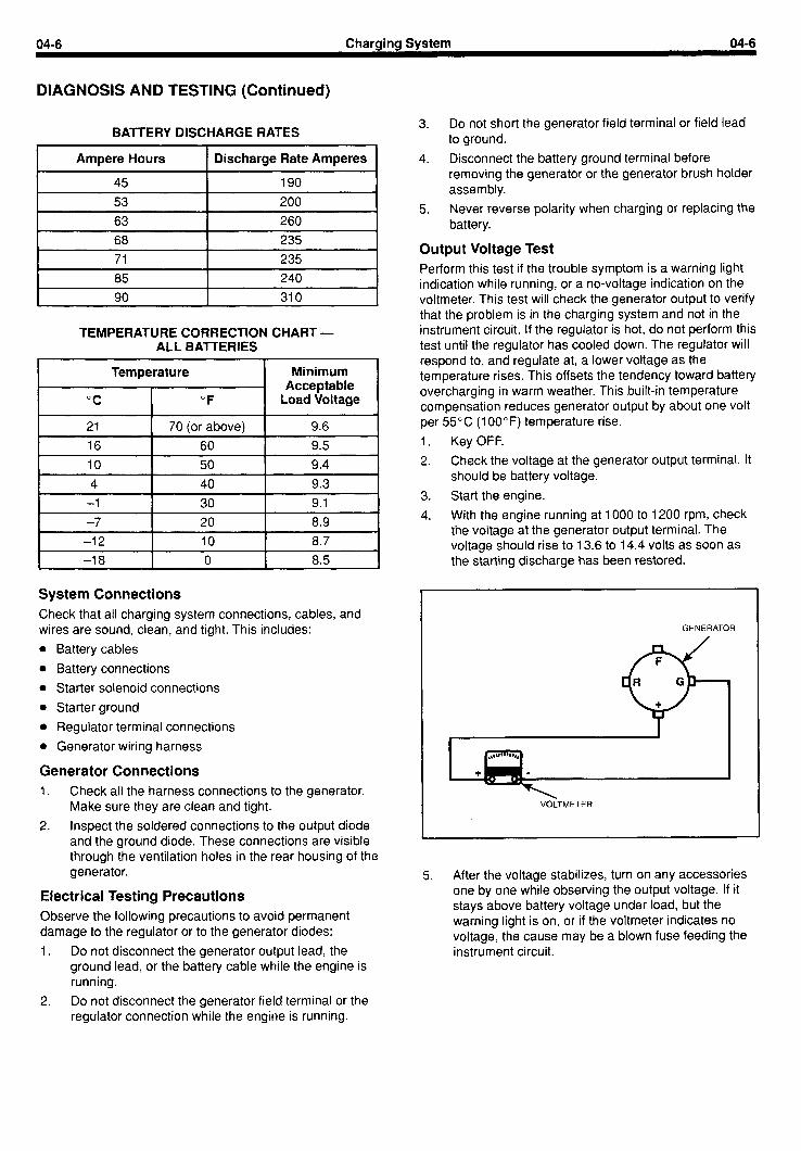
BATTERY DISCHARGE RATES
Ampere Hours Discharge Rate Amperes
45 190 53 200 63 260 68 235 71 235 85 240 90 310
TEMPERATURE CORRECTION CHART - ALL BATTERIES
Temperature Minimum Acceptable
“C “F Load Voltage
21 70 (or above) 9.6
16 60 9.5 10 50 9.4
4 40 9.3 -1 30 9.1 -7 20 8.9 -12 IO 8.7 -18 0 8.5
System Connections Check that all charging system connections, cables, and wires are sound, clean, and tight. This includes:
l Battery cables
l Battery connections
l Starter solenoid connections
l Starter ground
l Regulator terminal connections
l Generator wiring harness
Generator Connections 1. Check all the harness connections to the generator.
Make sure they are clean and tight.
2. Inspect the soldered connections to the output diode and the ground diode. These connections are visible through the ventilation holes in the rear housing of the generator.
Electrical Testing Precautions Observe the following precautions to avoid permanent damage to the regulator or to the generator diodes:
1. Do not disconnect the generator output lead, the ground lead, or the battery cable while the engine is running.
2. Do not disconnect the generator field terminal or the regulator connection while the engine is running.
3. Do not short the generator field terminal or field lead to ground.
4. Disconnect the battery ground terminal before removing the generator or the generator brush holder assembly.
5. Never reverse polarity when charging or replacing the battery.
Output Voltage Test Perform this test if the trouble symptom is a warning light indication while running, or a no-voltage indication on the voltmeter. This test will check the generator output to verify that the problem is in the charging system and not in the instrument circuit. If the regulator is hot, do not perform this test until the regulator has cooled down. The regulator will respond to, and regulate at, a lower voltage as the temperature rises. This offsets the tendency toward battery overcharging in warm weather. This built-in temperature compensation reduces generator output by about one volt per 55°C (lOOOF) temperature rise.
1. Key OFF.
2. Check the voltage at the generator output terminal. It should be battery voltage.
3. Start the engine.
4. With the engine running at 1000 to 1200 rpm, check the voltage at the generator output terminal. The voltage should rise to 13.6 to 14.4 volts as soon as the starting discharge has been restored.
GENERATOR
VOLTMETER

04-7 Charainrr System 04-7
DIAGNOSIS AND TESTING (Continued)
Regulator’ Bypass Test Perform this test if the Output Voltage Test indicates less than 13.6 volts at light load.
1. Key OFF.
2. Disconnect the field lead from the “F” terminal.
3. Connect a jumper from the “F” terminal to the “R” terminal.
4. Start the engine.
CAUTION: Be sure to keep the rpm low, as an unregulated generator can produce voltage high enough to cause damage.
5. With the engine running at idle, check the output voltage.
GENERATOR
VOLTMETER
l If the output voltage is still low, the problem is in the generator.
l If the output voltage rises above 13.6 volts with the regulator bypassed, check the regulator circuit for low output (although the problem may still be partly or entirely in the generator). Possible generator problems include:
- Defective output or field diodes.
- Excess resistance in the field circuit, which includes the regulator.
- Excess resistance in the charging circuit external to the generator.
Key-Off Check 1. Key OFF.
2. Remove the jumper between the “R” and “F” terminals, if present.
3. Connect the field lead to the “F” terminal, if it is not already corrected.
4. Check the voltage at the “R” terminal. If any voltage is present, it indicates a shorted output diode or diodes. This causes undercharging and also allows the battery to discharge through the regulator and field with the engine stopped.
GENERATOR
*
Regulator Sense Voltage 1. Start the engine.
2. With the engine running at 1000 to 1200 rpm, check the voltage from the “0” terminal to ground.
GENERATOR
VOLTMETER

04-8 Charaina System 04-8
DIAGNOSIS AND TESTING (Continued)
3. With the engine running at 1000 to 1200 rpm, check the voltage from the “R” terminal to ground.
GENERATOR
’ VOLTMETER
Even if the output voltage is low, the “R” terminal voltage should be within 0.5 volt of the “0” terminal voltage. If the “R” terminal voltage is higher than the output voltage, it indicates an open diode or diodes, and the higher “R” voltage would signal the regulator to reduce output before normal charging voltage could be built up. This causes an undercharging condition.
If the voltage at the “R” terminal is more than 0.5 volt lower than the output voltage, one or more of the field diodes is defective. In this condition, the regulator would normally increase the generator output to bring the sense voltage up to the regulating value, and an overcharging condition would result.
4. Continue with External Circuit Tests.
External Circuit Tests This test checks the circuit between the generator and the battery by measuring the voltage from each battery terminal to ground.
1. With the engine running at 1000 to 1200 rpm, measure the voltage from the positive (+) battery terminal to ground. Voltage at the positive (+) terminal should be the same as the generator output voltage. If it is lower by more than 0.2 volt, excess resistance is present in the generator output lead or in the battery positive cable or connections. Check for wire or cable damage, or for loose or dirty connections.
2. Measure the voltage from the battery negative (-) terminal to ground. It should be zero. If it is more than
0.2 volt, check the ground circuit. The following connections must be clean and tight:
l Generator mounting bolts
l Generator and engine mounting surfaces
l Ground cable connections to the engine and battery
Field Vdltage Test This test checks for initial excitation voltage at the “F” terminal. Perform this test if the output voltage did not rise above battery voltage in the output voltage test, but did rise with the regulator bypassed.
1. Make sure the field lead is connected.
2. Key ON.
3. Measure the field voltage by carefully probing the “F” terminal.
GENERATOR
VOLTMETER
CAUTION: To avoid grounding the field and causing component damage, use a taped probe or connect the field lead through a jumper to provide meter probe access to the terminal.
A reading of 1.5 to 3.0 volts is normal. A zero-volt reading indicates an open in the initial excitation circuit, either in the regulator or in the circuit between the battery and the regulator.
If battery voltage appears at the “F” terminal, an open is present in the field circuit, either in the coil or in the brushes. The meaning of voltage readings between these extremes depends on the specific equipment being tested.

04-9 Charaina Svstem 04-9
DIAGNOSIS AND TESTING (Continued)
Initial Excitation Circuits
GENERATOR
REGULATOR
EXClTATlON RESISTOR I
GENERATOR FIELD FUSE
IGNITION SWITCH
GENERATOR WARNING LIGHT
I INSTRUMENTS (IF EQUIPPED)
tNSTRUMENT FUSE (IF EQUIPPED)
= BATTERY
initial excitation voltage reaches the field terminal through an excitation lead from the ignition switch to the regulator, and an excitation resistor inside the regulator. If the circuit is equipped with a voltmeter, this is the only path. If the circuit is equipped with a generator warning light, the warning light provides an alternate path in parallel with the excitation resistor. This excitation function of the warning light is an incidental result of its being positioned in the circuit so as to compare battery and output voltages, but it is important because it can mask an open in the excitation circuit.
Normally, initial excitation current is drawn through both paths, but either one will pass sufficient current if the other is open. If the excitation resistor is open, or higher in value than it should be, there will still be excitation current to magnetize the field at startup, but the voltage at the field terminal will be lower because of the larger voltage drop through the increased resistance, Likewise, if the warning light bulb is burned out, the excitation resistor will provide field current, but also at reduced voltage. A burned-out bulb is easily detected if it fails to light when the key is turned ON, and the other warning lights and gauges respond normally.
Regulator input Test This test measures excitation supply voltage to the regulator. Perform this test if the field terminal voltage is less than 1.5 volts.
1. Key ON.
2. Carefully probe the yellow wire terminal in the pigtail connector for the regulator excitation lead. Battery voltage should be present.
EXCITATION RESIST
(YEI
VOLTMETER
04-10 Charging System 04-10
DIAGNOSIS AND TESTING (Continued)
3. If battery voltage is not present, check the circuit from the ignition switch, through the alternator field fuse (If so equipped) to the pigtail connector for the regulator excitation lead. If battery voltage is present at the yellow regulator lead, but the regulator output is low, replace the regulator.
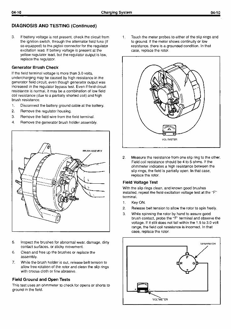
Generator Brush Check If the field terminal voltage is more than 3.0 volts, undercharging may be caused by high resistance in the generator field circuit, even though generator output was increased in the regulator bypass test. Even if field circuit resistance is normal, it may be a combination of low field coil resistance (due to a partially shorted coil) and high brush resistance.
1. Disconnect the battery ground cable at the battery.
2. Remove the regulator housing.
3. Remove the field wire from the field terminal.
4. Remove the generator brush holder assembly.
L
BRUSH ASSEMBLY
5. Inspect the brushes for abnormal wear, damage, dirty contact surfaces, or sticky movement.
6. Clean and free up the brushes or replace the assembly.
7. While the brush holder is out, release belt tension to allow free rotation of the rotor and clean the slip rings with crocus cloth or fine abrasive.
Field Ground and Open Tests This test uses an ohmmeter to check for opens or shorts to ground in the field.
1. Touch the meter probes to either of the slip rings and to ground. If the meter shows continuity or low resistance, there is a grounded condition. In that case, replace the rotor.
2. Measure the resistance from one slip ring to the other. Field coil resistance should be 4 to 5 ohms. If the ohmmeter indicates a high resistance between the slip rings, the field is partially open. In that case, replace the rotor.
Field Voltage Test With the slip rings clean, and known good brushes installed, repeat the field excitation voltage test at the “F” terminal.
1. Key ON.
2. Release belt tension to allow the rotor to spin freely.
3. While spinning the rotor by hand to assure good brush contact, probe the “F” terminal and observe the voltage. If it still does not fall within the 1.5 to 3.0 volt range, the field coil resistance is incorrect. In that case, replace the rotor.
VOLTMETER
GENERATOR
VOLTMETER
04-I 1 Charging System 04-I 1
DIAGNOSIS AND TESTING (Continued)
If the foregoing test sequence does not identify the cause of undercharging, it may be due to low regulator output when the system is operating under load.
4. Engine ON.
5. While running the engine at 1600 rpm, measure the “F” terminal voltage. Field voltage should be 10.5 to 11.5 volts initially, and quickly taper off to 7.5 to 8.5 volts as the starting discharge is re-charged. If the voltage is low or fluctuating, the regulator is defective. In that case, replace the regulator.
Overcharging If the output voltage test indicates on overcharging condition (greater than 14.4 volts), it usually indicates a defective regulator, but not always. If the regulator sense voltage at the “R” terminal is lower than the output voltage
by more than 0.5 volt due to a defective diode trio, a good regulator will increase field current and generator output in an effort to bring the sense voltage up to regulating value. Whether and to what extent the system will overcharge will depend on the nature and degree of the field diode failure, as field current must pass through the field diodes.
Generator Disassembly If the foregoing series of on-equipment tests has not identified the cause of charging system malfunctions, remove and disassemble the generator for further tests. See “Overhaul” in this section. If specialized test equipment is available for checking diodes and stator windings under operating-load conditions, follow the equipment manufacturer’s instructions. If this equipment is not available, refer the job to the nearest Authorized Service Station.

04-l 2 Charging System 04-l 2
ADJUSTMENTS
Belt Adjustments 1. Check the belt tension with Tool T63L-8620-A. The
3. Apply pressure on the generator front housing only and tighten the adjusting arm to generator bolt.
belt should be within specifications (Specifications 4. Check the belt tension using Tool T63L-8620-A. Section). Adjust the belt for specified tension..
2. If the belt is not within specification, loosen the 5. Tighten all mounting bolts. generator mounting bolt to a snug position and loosen the adjusting arm bolts.

04-l 3 Charging System 04-I 3
REMOVAL AND INSTALLATION
Removal 1.
2.
Disconnect the battery ground cable.
Loosen the gen erator mounti ng bolts and remove adjustment arm -to-generator attaching bolt.
the
3. Remove the electrical connector from the generator.
4. Disengage the generator belt. Remove the generator mounting bolt, and remove the generator.
Installation 1. Install the generator wiring connector. Position the
generator to the engine, and install the spacer (if used) and the generator mounting bolt. Tighten the bolt only finger tight.
2. Install the adjustment arm-to-generator attaching bolt.
3. Position the belt on the pulley and adjust the belt tension using Tool T63L-8620-A. Apply pressure on the generator front housing only, when tightening the belt. Tighten the adjusting arm bolt and the mounting bolt.
4. Connect the battery ground cable.

04-l 4 Charging System 04-I 4
OVERHAUL
Disassembly 1. Mark both end housings and the stator with a scribe
mark for assembly.
2. Remove retaining nut, lockwasher, spacer pulley, spacer, dish washer, fan and fan spacer.
NOTE: Observe position and direction of spacer and dished washer between pulley and fan.
3. Remove regulator and brush holder.
4. Remove four through bolts.
5. Separate the front housing and rotor from the stator and rear housing.
6. Press rotor out of front housing.
7. Remove front bearing retainer and bearing.
8. Support rear bearing with a large washer, incorporating a cut out to accommodate the rotor shaft, and press bearing from shaft.
9. Remove rectifier (diode) assembly retaining screws and lift out stator and rectifier assembly.
10. Unsolder stator to rectifier connections using a pair of pliers as a heat sink to reduce heat spread to diodes.
STATOR CONNECT10
Releasing Front Bearing Retainer
To remove the front bearing, which is pressed on the rotor shaft, it must first be removed from the front housing. It is retained in the housing by a snap ring which is accessible from the front when the pulley and fan are removed.
1. With a pair of snap ring pliers, squeeze the ears of the snap ring together.
2. Rock the snap ring out of its groove.
3. Press or tap the rotor shaft and bearing out of the front housing.
Front or Rear Bearing Removal
Remove the bearing from the shaft with a suitable puller and adapter.
L
04-l 5 Charaincr Svstem 04-I 5
OVERHAUL (Continued)
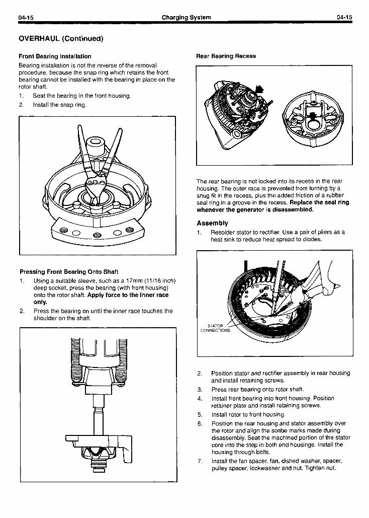
Front Bearing Installation
Bearing installation is not the reverse of the removal procedure, because the snap ring which retains the front bearing cannot be installed with the bearing in place on the rotor shaft.
1. Seat the bearing in the front housing.
2. Install the snap ring.
Pressing Front Bearing Onto Shaft 1. Using a suitable sleeve, such as a 17mm (1 l/l 6 inch)
deep socket, press the bearing (with front housing) onto the rotor shaft. Apply force to the inner race only.
2. Press the bearing on until the inner race touches the shoulder on the shaft.
Rear Bearing Recess
The rear bearing is not locked into its recess in the rear housing. The outer race is prevented from turning by a snug fit in the recess, plus the added friction of a rubber seal ring in a groove in the recess. Replace the seal ring whenever the generator is disassembled.
Assembly 1. Resolder stator to rectifier. Use a pair of pliers as a
heat sink to reduce heat spread to diodes.
STATOR CONNECT10
2. Position stator and rectifier assembly in rear housing and install retaining screws.
3. Press rear bearing onto rotor shaft.
4. Install front bearing into front housing. Position retainer plate and install retaining screws.
5. Install rotor to front housing.
6. Position the rear housing and stator assembly over the rotor and align the scribe marks made during disassembly. Seat the machined portion of the stator core into the step in both end housings. Install the housing through bolts.
7. Install the fan spacer, fan, dished washer, spacer, pulley spacer, lockwasher and nut. Tighten nut.

04-16 Charaina Svstem 04-16
OVERHAUL (Continued)
NOTE: Dished washer must be fitted correctly, with the outer circumference pressing against the fan. In this way, it acts as a vibration damper and prevents fatigue failures.
Output Voltage Test
If possible, check the generator on a bench tester before re-installing. After bench-testing, or if bench-testing is not available, re-install the generator to the engine:
1. Install and connect the generator.
2. Apply proper tension to the drive belt.
3. Make sure the battery cable connections are tight.
4. Key ON.
5. With the engine running at 1000 to 1200 rpm, measure the voltage from the output terminal to ground.
GENERATOR
VOLTMETER
6. Gradually increase the electrical load while observing the voltage reading. If voltage stays between 13.6 and 14.4 volts under all but extreme load conditions, the charging system is working properly.

05-I Starting System 05-I
SECTION TITLE PAGE SECTION TITLE PAGE
BASIC ENGINE ....................................... 01-I STARTING SYSTEM .................................. 05-l IGNITION SYSTEM - DISTRIBUTORLESS ............... 02-l GOVERNOR ......................................... 06-l FUEL SYSTEM ....................................... 03-1 COOLING SYSTEM ................................... 07-l EMISSION CONTROL SYSTEM ........................ 03A-1 SPECIFICATIONS .................................... 08-I CHARGING SYSTEM . . . . . . . . . . . . . . . . . . . . . . . . . . . . . . . . . 04-I
SECTION 05 - Starting System
SUBJECT PAGE
DESCRIPTION AND OPERATION ...................... 05-3 TESTING ............................................ 05-4
Road Service ..................................... 05-4 On-Engine Testing ................................. 05-4
Starter Cranking Circuit Test ..................... 05-4 Starter Load Test ................................ 05-5 Starter Solenoid Test ............................ 05-5
Bench Tests ...................................... 05-5 Starter No-Load Test ............................. 05-5 Armature Open Circuit Test ...................... 05-6 Armature and Field Grounded Circuit Test ......... 05-6
SUBJECT PAGE
REMOVAL AND INSTALLATION ....................... 05-7 OVERHAUL ......................................... 05-8
Disassembly ...................................... 05-8 Cleaning and Inspection ........................... 05-8 Assembly ......................................... 05-10 Permanent-Magnet Starter ......................... 05-11
Overhaul ....................................... 05-11 Disassembly .................................... 05-11 Assembly ....................................... 05-l 2

05-3 Startina Svstem 05-3
DESCRIPTION AND OPERATION
There are two starters available in the VSG range. Most engines are equipped with the Bosch electromagnetic field starter which is detailed in this section. Some engines are equipped with the United Technologies permanent magnet starter. This starter features an inertially-actuated pinion gear which is described later in this section.
The electromagnetic field starter is a four pole, four brush motor with a series field and a solenoid-operated roller clutch drive.
The solenoid assembly is mounted to a flange on the starter drive housing. The entire shift lever mechanism and the solenoid plunger are enclosed in the drive housing, thus protecting them from exposure to dirt and road splash.
The solenoid incorporates two windings, a pull-in-winding and a hold-in winding. Together they provide sufficient magnetic attraction to pull the solenoid plunger into the solenoid.
Engine cranking occurs when the starter solenoid on the starter is energized through the starter control (ignition) switch. When energized, the solenoid shifts the starting motor pinion into mesh with the engine flywheel ring gear.
Simultaneously, the main contacts of the solenoid are closed and battery current is directed to the starting motor causing the armature to rotate.
After the engine starts, the starter drive is disengaged when the ignition switch is returned from the start to the ON or RUN position. This opens the circuit to the starter solenoid and the solenoid return spring causes the shift lever to disengage the starter drive from the engine flywheel ring gear.
The starting motor is protected from excessive speed by an overrunning clutch incorporated in the starter drive assembly. The overrunning clutch permits the drive pinion gear to rotate faster than the armature thus disengaging itself from the engine flywheel ring gear when the engine starts.
05-4 Startina Svstem 05-4
TESTING
Road Service On Engine Testing On road service calls, connect a booster battery to the system for cases of a starter that will not crank the engine or a starter that cranks the engine very slowly. If the starter does not turn the engine over, even with the booster battery attached, refer to the following tests. Be certain that correct battery polarity is observed when using a booster battery; positive to positive, and negative to negative connection of the auxiliary cables.
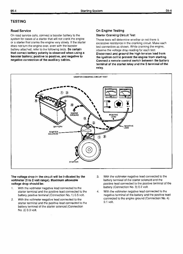
Starter Cranking Circuit Test
These tests will determine whether or not there is excessive resistance in the cranking circuit. Make each test connection as shown. While cranking the engine, observe the voltage drop reading for each test. Disconnect and ground the high tension lead from the ignition coil to prevent the engine from starting. Connect a remote control switch between the battery terminal of the starter relay and the S terminal of the relay.
STARTER CRANKING CIRCUIT TEST
The voltage drop in the circuit will be indicated by the voltmeter (0 to 2 volt range). Maximum allowable voltage drop should be:
1. With the voltmeter negative lead connected to the starter terminal and the positive lead connected to the battery positive terminal (Connection No. 1) 0.5 volt.
2. With the voltmeter negative lead connected to the starter terminal and the positive lead connected to the battery terminal of the starter solenoid (Connection No. 2) 0.3 volt.
3. With the voltmeter negative lead connected to the battery terminal of the starter solenoid and the positive lead connected to the positive terminal of the battery (Connection No. 3) 0.2 volt.
4. With the voltmeter negative lead connected to the negative terminal of the battery and the positive lead connected to the engine ground (Connection No. 4) 0.1 volt.
05-5 Starting System 05-5
TESTING (Continued)
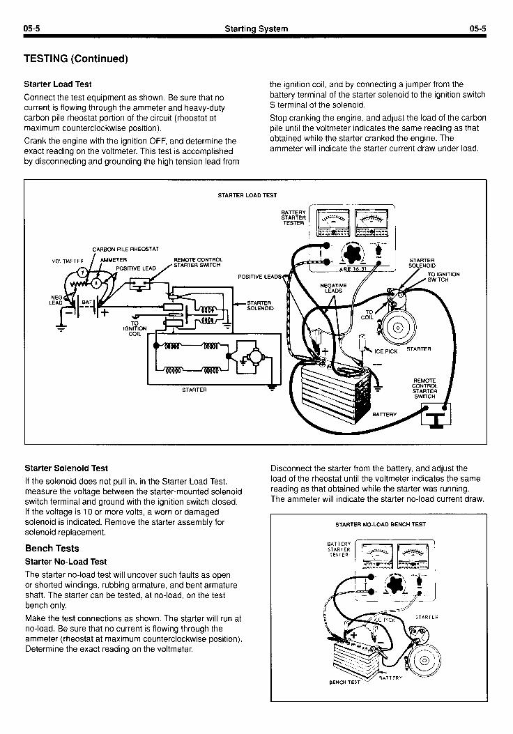
Starter Load Test
Connect the test equipment as shown. Be sure that no current is flowing through the ammeter and heavy-duty carbon pile rheostat portion of the circuit (rheostat at maximum counterclockwise position).
Crank the engine with the ignition OFF, and determine the exact reading on the voltmeter. This test is accomplished by disconnecting and grounding the high tension lead from
the ignition coil, and by connecting a jumper from the battery terminal of the starter solenoid to the ignition switch S terminal of the solenoid.
Stop cranking the engine, and adjust the load of the carbon pile until the voltmeter indicates the same reading as that obtained while the starter cranked the engine. The ammeter will indicate the starter current draw under load.
STARTER LOAD TEST
I
STARTER SOQENOIO
CARBON PILE RHEOSTAT
REMOTE CONTROL STARTER SWITCH
POSITIVE LEADS
Starter Solenoid Test
If the solenoid does not pull in, in the Starter Load Test, measure the voltage between the starter-mounted solenoid switch terminal and ground with the ignition switch closed. If the voltage is 10 or more volts, a worn or damaged solenoid is indicated. Remove the starter assembly for solenoid replacement.
Bench Tests Starter No-Load Test
The starter no-load test will uncover such faults as open or shorted windings, rubbing armature, and bent armature shaft. The starter can be tested, at no-load, on the test bench only.
Make the test connections as shown. The starter will run at no-load. Be sure that no current is flowing through the ammeter (rheostat at maximum counterclockwise position). Determine the exact reading on the voltmeter.
Disconnect the starter from the battery, and adjust the load of the rheostat until the voltmeter indicates the same reading as that obtained while the starter was running. The ammeter will indicate the starter no-load current draw.
STARTER NO-LOAD BENCH TEST
05-6 Startina Svstem 05-6
TESTING (Continued)
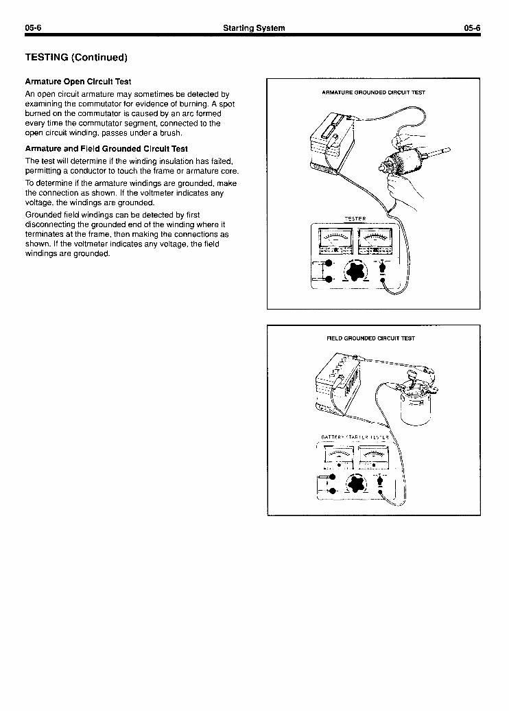
Armature Open Circuit Test
An open circuit armature may sometimes be detected by examining the commutator for evidence of burning. A spot burned on the commutator is caused by an arc formed every time the commutator segment, connected to the open circuit winding, passes under a brush.
Armature and Field Grounded Circuit Test
The test will determine if the winding insulation has failed, permitting a conductor to touch the frame or armature core.
To determine if the armature windings are grounded, make the connection as shown. If the voltmeter indicates any voltage, the windings are grounded.
Grounded field windings can be detected by first disconnecting the grounded end of the winding where it terminates at the frame, then making the connections as shown. If the voltmeter indicates any voltage, the field windings are grounded.
ARMATURE GROUNDED CIRCUIT TEST
TESTER k
FIELD GROUNDED CIRCUIT TEST

OS-7 Startina Svstem 05-7
Removal installation 1. Disconnect the battery ground cable. 1. Position the starter assembly to the starter mounting
2. Disconnect the cable and wires at the terminals on plate and start the mounting bolts.
the solenoid. 2. Snug the starting motor mounting bolts while holding
3. Remove the starter mounting bolts and remove the the starter squarely against the mounting surface and
starter assembly. fully inserted into the pilot hole. Tighten the mounting bolts.
3. Connect the cable and wires to the terminals on the solenoid. Connect the battery ground cable.
05-8 Startina Svstem 05-8
OVERHAUL
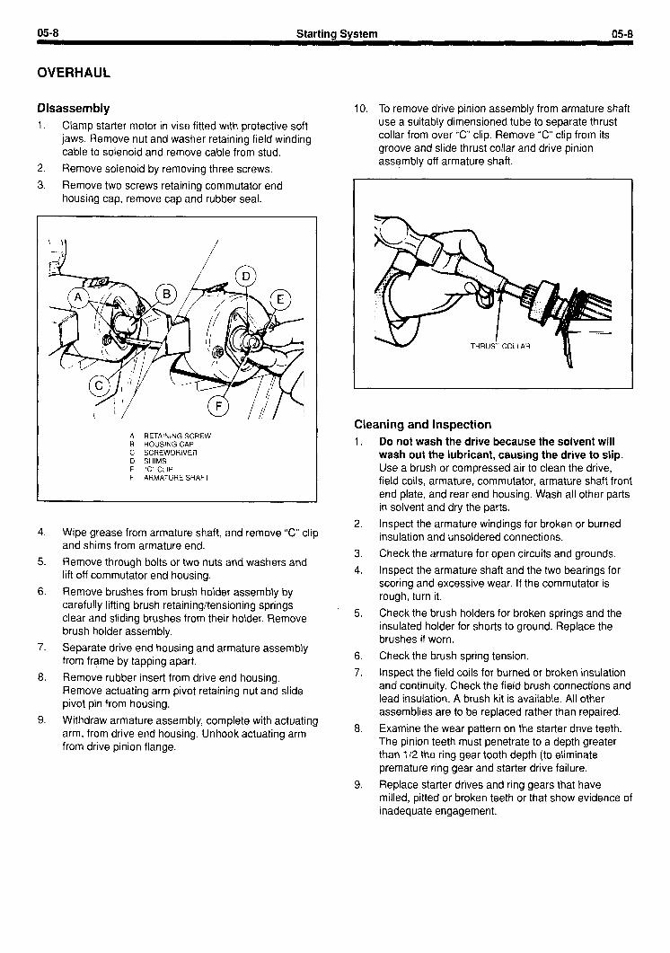
Disassembly 1. Clamp starter motor in vise fitted with protective soft
jaws. Remove nut and washer retaining field winding cable to solenoid and remove cable from stud.
2. Remove solenoid by removing three screws.
3. Remove two screws retaining commutator end housing cap, remove cap and rubber seal.
’ ‘I . /
A RETAINING SCREW B HOUSING CAP C SCREWDRIVER D SHIMS E “C” CLIP F ARMATURE SHAFT
4. Wipe grease from armature shaft, and remove “C” clip and shims from armature end.
5. Remove through bolts or two nuts and washers and lift off commutator end housing.
6. Remove brushes from brush holder assembly by carefully lifting brush retaining/tensioning springs clear and sliding brushes from their holder. Remove brush holder assembly.
7. Separate drive end housing and armature assembly from frame by tapping apart.
8. Remove rubber insert from drive end housing. Remove actuating arm pivot retaining nut and slide pivot pin from housing.
9. Withdraw armature assembly, complete with actuating arm, from drive end housing. Unhook actuating arm from drive pinion flange.
10. To remove drive pinion assembly from armature shaft use a suitably dimensioned tube to separate thrust collar from over “C” clip. Remove “C” clip from its groove and slide thrust collar and drive pinion assembly off armature shaft.
1.
Cleaning and Inspection Do not wash the drive because the solvent will wash out the lubricant, causing the drive to slip. Use a brush or compressed air to clean the drive,
2.
3.
4.
field coils, armature, commutator, armature shaft front end plate, and rear end housing. Wash all other parts in solvent and dry the parts.
Inspect the armature windings for broken or burned insulation and unsoldered connections.
Check the armature for open circuits and grounds.
Inspect the armature shaft and the two bearings for scoring and excessive wear. If the commutator is rough, turn it.
5. Check the brush holders for broken springs and the insulated holder for shorts to ground. Replace the brushes if worn.
6.
7.
8.
9.
Check the brush spring tension.
Inspect the field coils for burned or broken insulation and continuity. Check the field brush connections and lead insulation. A brush kit is available. All other assemblies are to be replaced rather than repaired.
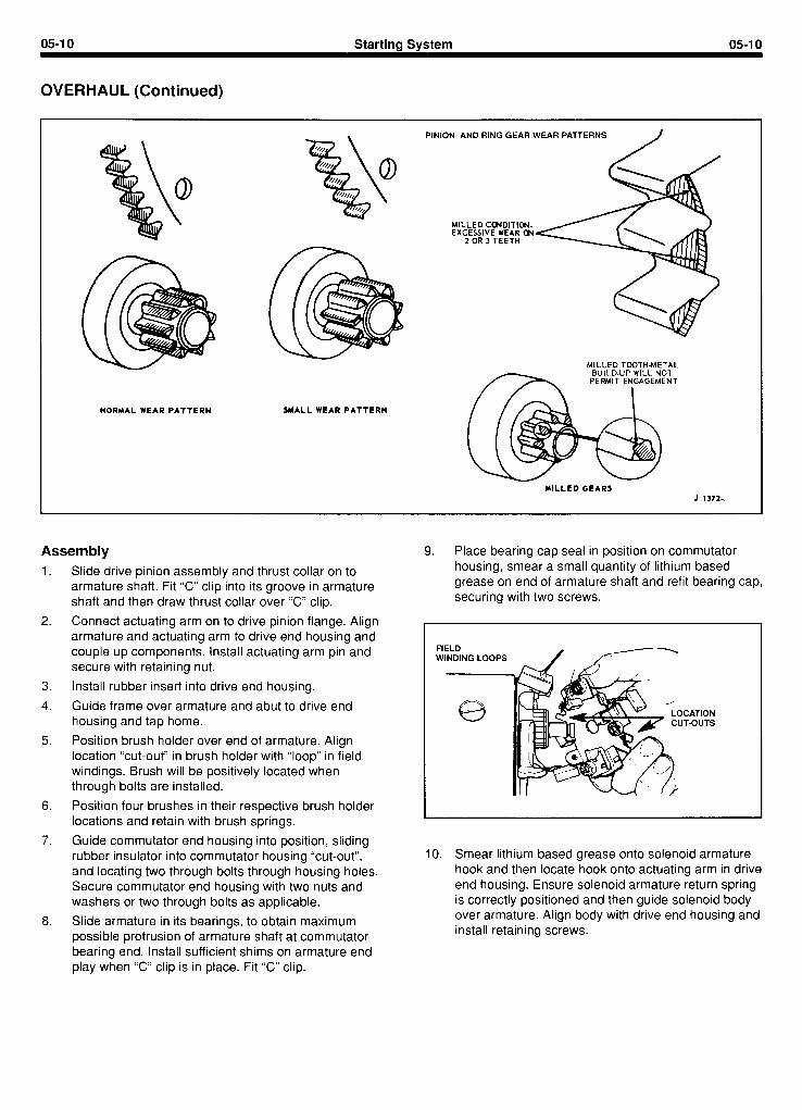
Examine the wear pattern on the starter drive teeth. The pinion teeth must penetrate to a depth greater than 112 the ring gear tooth depth (to eliminate premature ring gear and starter drive failure.
Replace starter drives and ring gears that have milled, pitted or broken teeth or that show evidence of inadequate engagement.
05-9 Starting System 05-9
OVERHAUL (Continued)
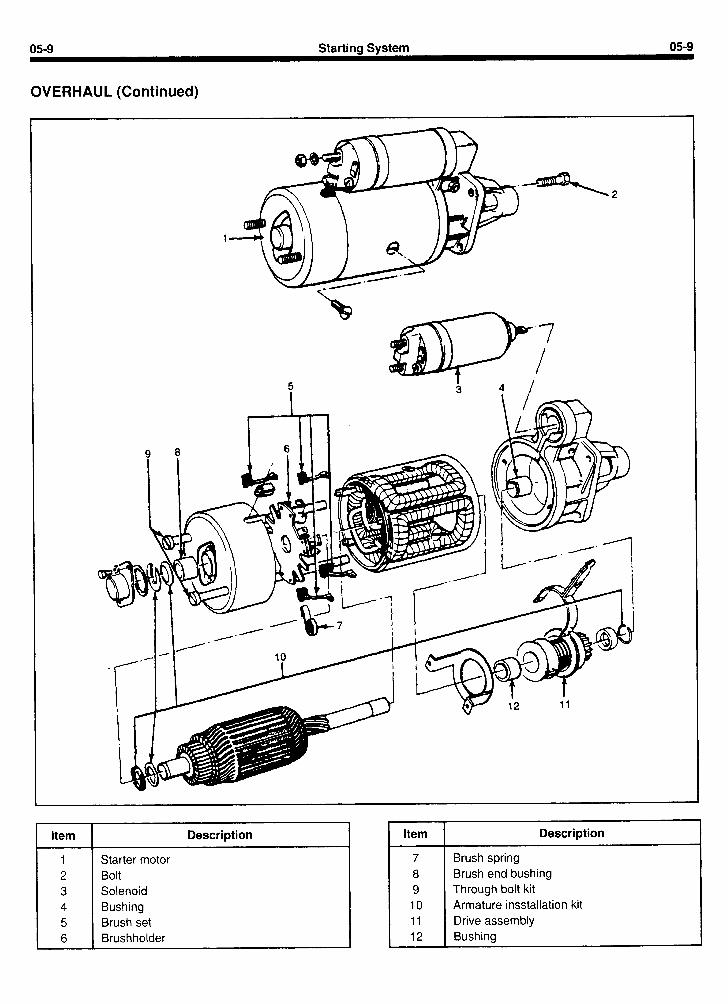
Item Description
Starter motor Bolt Solenoid Bushing Brush set Brushholder
Item
7 8 9 10 11 12
Description
Brush spring Brush end bushing Through bolt kit Armature insstallation kit Drive assembly Bushing
0510 Startincl System 05-10
OVERHAUL (Continued)
NORMAL WEAR PATTERN SMALL WEAR PATTERN
PINION AND RING GEAR WEAR PATTERNS J
MILLED CONDITION. EXCESSIVE WEAR U4
2 OR 3 TEETH
MILLED TOOTH-METAL
MILLED GEARS J 1372-d
Assembly 9. Place bearing cap seai in position on commutator
1. Slide drive pinion assembly and thrust collar on to
2.
armature shaft. Fit “C” clip into its groove in armature shaft and then draw thrust collar over “C” clip.
Connect actuating arm on to drive pinion flange. Align armature and actuating arm to drive end housing and couple up components. Install actuating arm pin and secure with retaining nut.
3.
4.
Install rubber insert into drive end housing.
Guide frame over armature and abut to drive end housing and tap home.
5. Position brush holder over end of armature. Align location “cut-out” in brush holder with “loop” in field windings. Brush will be positively located when through bolts are installed.
6.
7.
8.
Position four brushes in their respective brush holder locations and retain with brush springs.
Guide commutator end housing into position, sliding rubber insulator into commutator housing “cut-out”, and locating two through bolts through housing holes. Secure commutator end housing with two nuts and washers or two through bolts as applicable.
Slide armature in its bearings, to obtain maximum possible protrusion of armature shaft at commutator bearing end. Install sufficient shims on armature end play when “C” clip is in place. Fit “C” clip.
housing, smear a small quantity of lithium based . - . - . -.. . grease on end of armature shaft and refit bearing cap, securing with two screws.
FIELD WINDING LOOPS
e
IO. Smear lithium based grease onto solenoid armature hook and then locate hook onto actuating arm in drive end housing. Ensure solenoid armature return spring is correctly positioned and then guide solenoid body over armature. Align body with drive end housing and install retaining screws.

0511 Starting System 05-l 1
OVERHAUL (Continued)
11. Reconnect field winding cable to solenoid and install retaining nut.
A ARMATURE B ARMATURE RETURN SPRING C SOLENOID BODY
Permanent-Magnet Starter
Some engines in the VSG range are equipped with the United Technologies permanent-magnet starter. This starter has a pinion gear which is actuated by inertial force in place of a starter solenoid. When the starter is energized, inertia causes the pinion gear to move out along a spirally-threaded shaft and engage the flywheel. When the engine has started, the starter motor is de-energized and spring tension causes the pinion gear to move away from the flywheel and back to its original position.
05-l 2 Starting System 05-I 2
OVERHAUL (Continued)
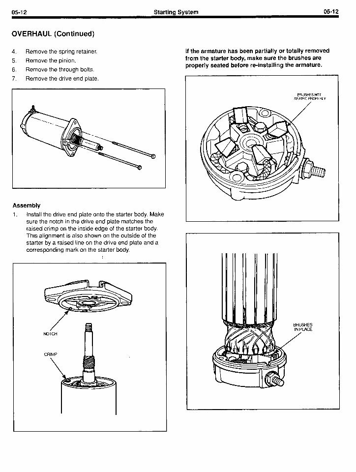
4. Remove the spring retainer.
5. Remove the pinion.
6. Remove the through bolts.
7. Remove the drive end plate.
Assembly
1. Install the drive end plate onto the starter body. Make sure the notch in the drive end plate matches the raised crimp on the inside edge of the starter body. This alignment is also shown on the outside of the starter by a raised line on the drive end plate and a corresponding mark on the starter body.
If the armature has been partially or totally removed from the starter body, make sure the brushes are properly seated before re-installing the armature.
BRUSHES NOT SEATED PROPERLY
HES ACE
OVERHAUL (Continued)
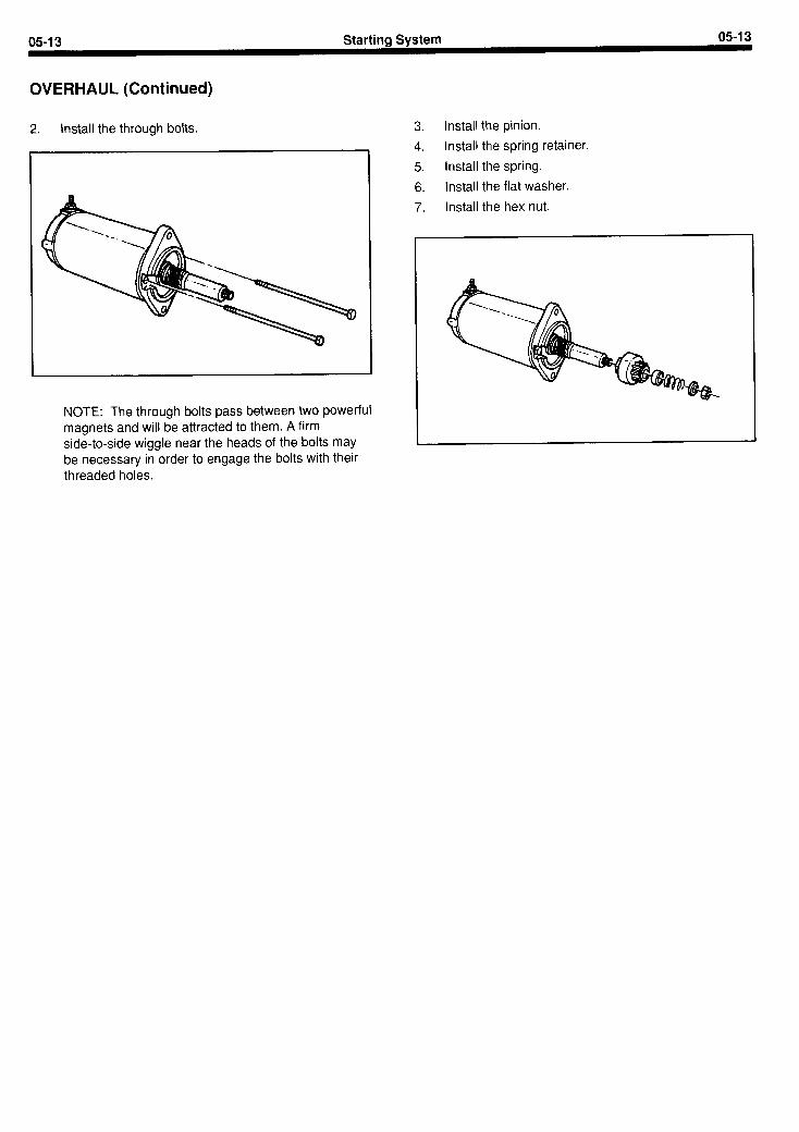
2. Install the through bolts.
NOTE: The through bolts pass between two powerful magnets and will be attracted to them. A firm side-to-side wiggle near the heads of the bolts may be necessary in order to engage the bolts with their threaded holes.
3. Install the pinion.
4. Install the spring retainer.
5. Install the spring.
6. Install the flat washer.
7. Install the hex nut.
06-I Governor 06-I
SECTION TITLE PAGE SECTION TITLE PAGE
BASIC ENGINE . . . . . . . . . . . . . . . . . . . . . . . . . . . . . . . . . . . . . . . 01-l STARTING SYSTEM . . . . . . . . . . . . . . . . . . . . . . . . . . . . . . . . . . 05-I IGNITION SYSTEM - DISTRIBUTORLESS.. . . . . . . . . . . . . . 02-l GOVERNOR . . . . . . . . . . . . . . . . . . . . . . . . . . . . . . . . . . . . . . . . . 06-l
COOLING SYSTEM . . . . . . . . . . . . . . . . . . . . . . . . . . . . . . . . . . . 07-l FUEL SYSTEM . . . . . . . . . . . . . . . . . . . . . . . . . . . . . . . . . . . . . . . 03-l EMISSION CONTROL SYSTEM ........................ 03A-1 SPECIFICATIONS .................................... 08-l CHARGING SYSTEM ................................. 04-I
SECTION 06 - Governor
SUBJECT PAGE SUBJECT PAGE
DESCRIPTION AND OPERATION ...................... ( ADJUSTMENTS ...................................... (
Preliminary Checks ................................ ( Oil Level ........................................ ( Belt Tension .................................... ( Throttle Control Rod ............................. (
RPM Adjustments ................................. ( High Speed ..................................... ( Spread or Sensitivity ............................ (
16-3 16-4 16-4 16-4 16-4 16-4 16-4 16-4 16-4
Increase Spread ................................. 06-4 Decrease Spread ................................ 06-5 Low Speed ...................................... 06-5 No-Load Surge .................................. 06-5
REMOVAL AND INSTALLATION ....................... 06-6 ELECTRONIC DESCRIPTION AND OPERATION ........ 06-7 ELECTRONIC DIAGNOSIS AND TESTING ............. 06-8
Calibration ........................................ 06-9


06-3 Governor 06-3
DESCRIPTION AND OPERATION
A mechanical flyweight-type governor and an electronic increases, the rotation of the governor shaft increases. governor are available for this engine. The mechanical Centrifugal force causes the weights to move outward as governor is mounted on the right front of the engine and is belt driven from the engine accessory pulley.
A direct mechanical linkage from the governor throttle control lever to the carburetor throttle lever limits carburetor action to the governor setting. As the engine speed
the rotation of the governor shaft increases. However, a spring retards or limits the movement of the weights until centrifugal force overcomes the spring tension. At this time the weights are forced outward closing the throttle plates through the linkage to the throttle shaft.
06-4 Governor 06-4
ADJUSTMENTS
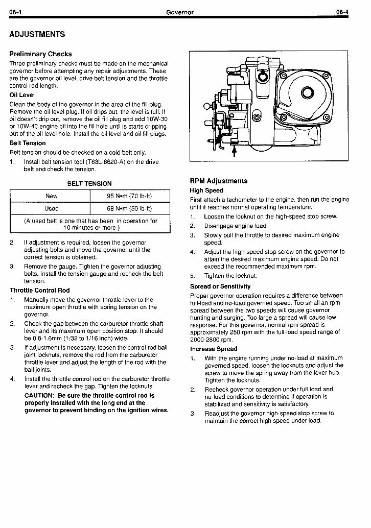
Preliminary Checks Three preliminary checks must be made on the mechanical governor before attempting any repair adjustments. These are the governor oil level, drive belt tension and the throttle control rod length.
Oil Level
Clean the body of the governor in the area of the fill plug. Remove the oil level plug. If oil drips out, the level is full. If oil doesn’t drip out, remove the oil fill plug and add 1 OW-30 or 1 OW-40 engine oil into the fill hole until is starts dripping out of the oil level hole. Install the oil level and oil fill plugs.
Belt Tension
Belt tension should be checked on a cold belt only.
1. Install belt tension tool (T63L-8620-A) on the drive belt and check the tension.
BELT TENSION
New I 95 Nom (70 lb-ft) I
Used I 68 Nom (50 lb-ft) I (A used belt is one that has be,en in operation for
10 minutes or more.)
2. If adjustment is required, loosen the governor adjusting bolts and move the governor until the correct tension is obtained.
3. Remove the gauge. Tighten the governor adjusting bolts. Install the tension gauge and recheck the belt tension.
Throttle Control Rod 1. Manually move the governor throttle lever to the
maximum open throttle with spring tension on the governor.
2. Check the gap between the carburetor throttle shaft lever and its maximum open position stop. It should be 0.8-I .6mm (l/32 to 1 /I 6 inch) wide.
3. If adjustment is necessary, loosen the control rod ball joint locknuts, remove the rod from the carburetor throttle lever and adjust the length of the rod with the ball joints.
4. Install the throttle control rod on the carburetor throttle lever and recheck the gap. Tighten the locknuts.
CAUTION: Be sure the throttle control rod is properly installed with the long end at the governor to prevent binding on the ignition wires.
RPM Adjustments High Speed
First attach a tachometer to the engine, then run the engine until it reaches normal operating temperature.
1. Loosen the locknut on the high-speed stop screw.
2. Disengage engine load.
3. Slowly pull the throttle to desired maximum engine speed.
4. Adjust the high-speed stop screw on the governor to attain the desired maximum engine speed. Do not exceed the recommended maximum rpm.
5. Tighten the locknut.
Spread or Sensitivity
Proper governor operation requires a difference between full-load and no-load governed speed. Too small an rpm spread between the two speeds will cause governor hunting and surging. Too large a spread will cause low response. For this governor, normal rpm spread is approximately 250 rpm with the full-load speed range of 2000-2800 rpm.
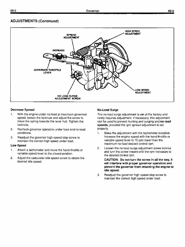
Increase Spread
1. With the engine running under no-load at maximum governed speed, loosen the locknuts and adjust the screw to move the spring away from the lever hub. Tighten the locknuts.
2. Recheck governor operation under full-load and no-load conditions to determine if operation is stabilized and sensitivity is satisfactory.
3. Readjust the governor high-speed stop screw to maintain the correct high speed under load.
06-5 Governor 06-5
ADJUSTMENTS (Continued)
- - ADJUSTMENT
NO LOAD SURGE ADJUSTMENT SCREW
Decrease Spread No-Load Surge 1. With the engine under no-load at maximum governed The no-load surge adjustment is set at the factory and
speed, loosen the locknuts and adjust the screw to rarely requires adjustment. If necessary, this adjustment move the spring towards the lever hub. Tighten the can be used to prevent hunting and surging and no-load locknuts. speeds, provided the rpm spread adjustment is set
2. Recheck governor operation under load and no-load properly.
Make the adjustment with the tachometer installed. Increase the engine speed with the hand throttle or variable speed lever to 75 rpm lower than the maximum no-load desired control rpm.
conditions.
3. Readjust the governor high-speed stop screw to maintain the correct high speed under load.
Low Speed
1. Attach a tachometer and move the hand throttle or variable speed lever to the closed position.
2. Adjust the carburetor idle speed screw to obtain the desired idle speed.
Loosen the no-load surge adjustment screw locknut and turn the screw inward until the rpm increases to the desired control rpm.
CAUTION: Do not turn the screw in all the way. It will interfere with proper governor operation and prevent the governor from returning the engine to idle speed.
3. Readjust the governor high-speed stop screw to maintain the correct high-speed under load.
06-6 Governor 06-6
REMOVAL AND INSTALLATION
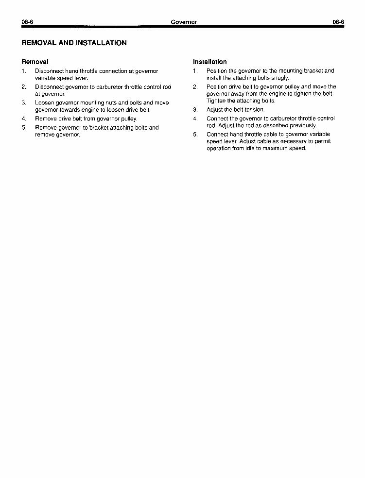
Removal Installation 1.
2.
3.
4.
5.
Disconnect hand throttle variable speed lever.
connection at governor
Disconnect governor to carburetor throttle control rod at governor.
Loosen governor mounting nuts and bolts and governor towards engine to loosen drive belt.
move
Remove drive belt from governor pulley.
Remove governor to bracket attaching bolts and remove governor.
1. Position the governor to the mounting bracket and install the attaching bolts snugly.
2. Position drive belt to governor pulley and move the governor away from the engine to tighten the belt. Tighten the attaching bolts.
3. Adjust the belt tension.
4. Connect the governor to carburetor throttle control rod. Adjust the rod as described previously.
5. Connect hand throttle cable to governor variable speed lever. Adjust cable as necessary to permit operation from idle to maximum speed.
06-7 Governor 06-7
ELECTRONIC DESCRIPTION AND OPERATION
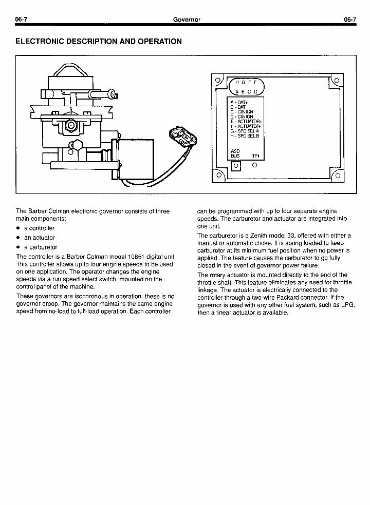
A - BAT+ B - BAT C - DIS IGN D - DIS IGN E - ACTUATOR+ F - ACTUATOR- G-SPDSELA H -SPDSELB
ASD BUS TPl
\ l
The Barber Colman electronic governor consists of three can be programmed with up to four separate engine main components: speeds. The carburetor and actuator are integrated into
l a controller one unit.
l an actuator
l a carburetor
The controller is a Barber Colman model 10851 digital unit. This controller allows up to four engine speeds to be used on one application. The operator changes the engine speeds via a run speed select switch, mounted on the control panel of the machine.
These governors are isochronous in operation; these is no governor droop. The governor maintains the same engine speed from no-load to full-load operation. Each controller
The carburetor is a Zenith model 33, offered with either a manual or automatic choke. It is spring loaded to keep carburetor at its minimum fuel position when no power is applied. The feature causes the carburetor to go fully closed in the event of governor power failure.
The rotary actuator is mounted directly to the end of the throttle shaft. This feature eliminates any need for throttle linkage. The actuator is electrically connected to the controller through a two-wire Packard connector. If the governor is used with any other fuel system, such as LPG, then a linear actuator is available.
0698 Governor 06-8
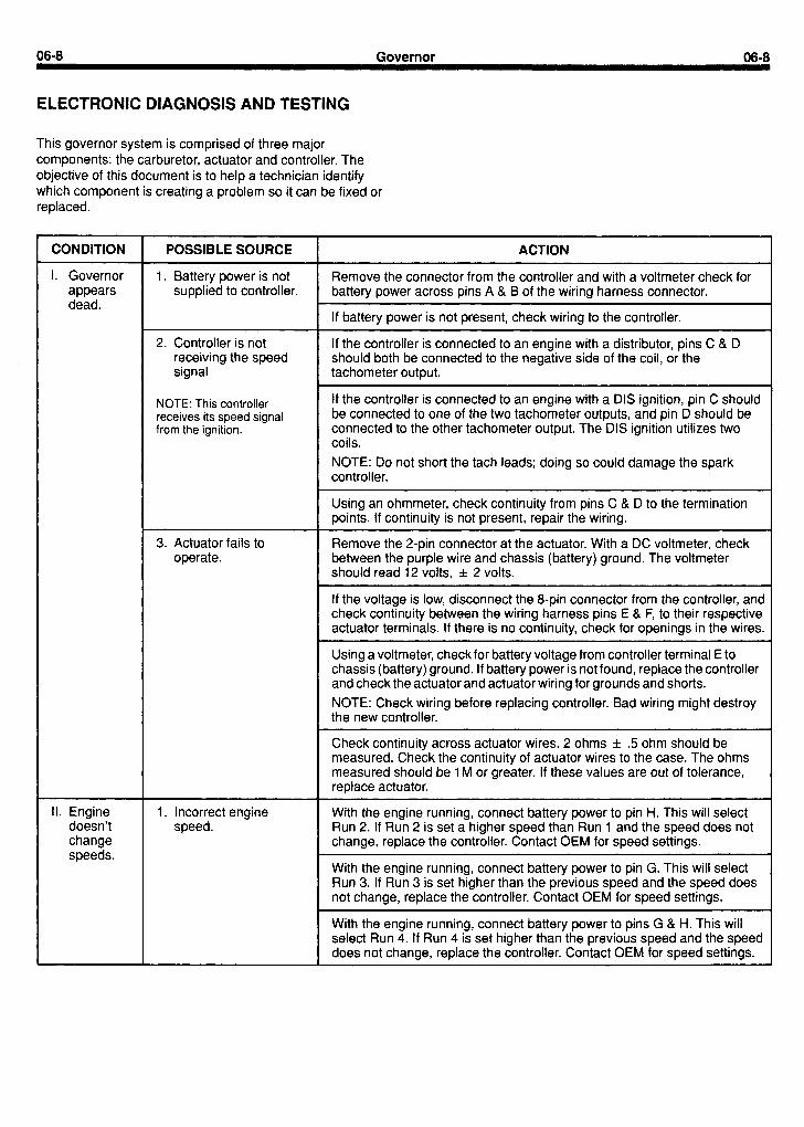
ELECTRONIC DIAGNOSIS AND TESTING
This governor system is comprised of three major components: the carburetor, actuator and controller. The objective of this document is to help a technician identify which component is creating a problem so it can be fixed or replaced.
CONDITION
I. Governor appears dead.
POSSIBLE SOURCE
1 g Battery power is not supplied to controller.
ACTION
Remove the connector from the controller and with a voltmeter check for battery power across pins A & B of the wiring harness connector.
If battery power is not present, check wiring to the controller.
2. Controller is not receiving the speed signal
NOTE: This controller receives its speed signal from the ignition.
If the controller is connected to an engine with a distributor, pins C & D should both be connected to the negative side of the coil, or the tachometer output.
If the controller is connected to an engine with a DIS ignition, pin C should be connected to one of the two tachometer outputs, and pin D should be connected to the other tachometer output. The DIS ignition utilizes two coils. NOTE: Do not short the tach leads; doing so could damage the spark controller.
Using an ohmmeter, check continuity from pins C & D to the termination points. If continuity is not present, repair the wiring.
3. Actuator fails to operate.
Remove the 2-pin connector at the actuator. With a DC voltmeter, check between the purple wire and chassis (battery) ground. The voltmeter should read 12 volts, & 2 volts.
If the voltage is low, disconnect the 8-pin connector from the controller, and check continuity between the wiring harness pins E & F, to their respective actuator terminals. If there is no continuity, check for openings in the wires.
Using a voltmeter, check for battery voltage from controller terminal E to chassis (battery) ground. If battery power is not found, replace the controller and check the actuator and actuator wiring for grounds and shorts. NOTE: Check wiring before replacing controller. Bad wiring might destroy the new controller.
I Check continuity across actuator wires. 2 ohms & 5 ohm should be measured. Check the continuity of actuator wires to the case. The ohms measured should be 1 M or greater. If these values are out of tolerance, replace actuator.
II. Engine doesn’t change speeds.
1. Incorrect engine speed.
With the engine running, connect battery power to pin H. This will select Run 2. If Run 2 is set a higher speed than Run 1 and the speed does not change, replace the controller. Contact OEM for speed settings.
With the engine running, connect battery power to pin G. This will select Run 3. If Run 3 is set higher than the previous speed and the speed does not change, replace the controller. Contact OEM for speed settings.
L With the engine running, connect battery power to pins G & H. This will select Run 4. If Run 4 is set higher than the previous speed and the speed does not change, replace the controller. Contact OEM for speed settings.
06-9 Governor 06-9
ELECTRONIC DIAGNOSIS AND TESTING (Continued)
CONDITION
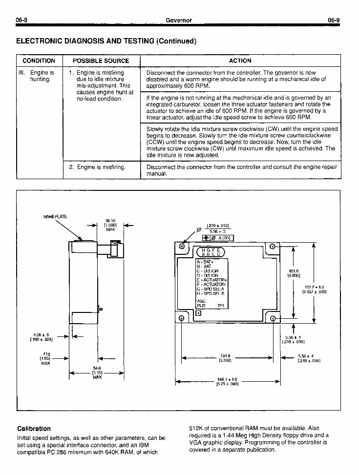
Ill. Engine is hunting.
POSSIBLE SOURCE
1. Engine is misfiring due to idle mixture mis-adjustment. This causes engine hunt at no-load condition.
2. Engine is misfiring.
ACTION
Disconnect the connector from the controller. The governor is now disabled and a warm engine should be running at a mechanical idle of approximately 600 RPM.
If the engine is not running at the mechanical idle and is governed by an integrated carburetor, loosen the three actuator fasteners and rotate the actuator to achieve an idle of 600 RPM. If the engine is governed by a linear actuator, adjust the idle speed screw to achieve 600 RPM.
Slowly rotate the idle mixture screw clockwise (CW) until the engine speed begins to decrease. Slowly turr? the idle mixture screw counterclockwise (CCW) until the engine speed begins to decrease. Now, turn the idle mixture screw clockwise (CW) until maximum idle speed is achieved. The idle mixture is now adjusted.
Disconnect the connector from the controller and consult the engine repair manual.
NAMEPLATE
L
4 +
A - BAT+ B - BAT C - DIS IGN 101.6 D - DIS IGN I4.0001 E - ACTUATOR+ F - ACTUATOR-
\OI;T
4.06 * .6 It
*(@4
[.160 2 .024] - 5.56 f .4 [.219 + .016]
G-SPDSELA 112.7 f 1.0
t-i-SPDSELB [4.437 f .040]
ASD BUS TPl
I 4 ’ cl 0
419 [l.=l -
134.9 5.56 f .4
MAX [5.312] [.219 * .016]
146.1 e 1.0 [5.75 f .040]
)-
Calibration Initial speed settings, as well as other parameters, can be set using a special interface connector, and an IBM compatible PC 286 minimum with 640K RAM, of which
512K of conventional RAM must be available. Also required is a 1.44 Meg High Density floppy drive and a VGA graphic display. Programming of the controller is covered in a separate publication.

06-10 Governor 06-10
ELECTRONIC DIAGNOSIS AND TESTING (Continued)
B+ d-b+ BATTERY SPEED + - -III-
ACTUATOR
- A. SELECT
COIL
. . 1 23 45 678
1 I I I I I I I A BC DE F G H
E - ACTUATOR+ F - ACTUATOR- G-SPDSELA H-SPDSELB
TACH LEAD
BATTERY + - 1b DIS MODULE
1 2345678 I 1 I 1 1 1 1 1
A B C D E F G H
~
CONNECTOR

07-l Coolina Svstem 07-I
SECTION TITLE PAGE SECTION TITLE PAGE
BASICENGINE ....................................... 01-I STARTING SYSTEM .................................. 05-l IGNITION SYSTEM - DISTRIBUTORLESS ............... 02-1 GOVERNOR ....... .................................. 06-l FUEL SYSTEM ....................................... 03-1 COOLING SYSTEM ................................... 07-l EMISSION CONTROL SYSTEM ........................ 03A-1 SPECIFICATIONS .................................... 08-l CHARGING SYSTEM ................................. 04-1
SECTION 07 - Cooling System
SUBJECT PAGE SUBJECT PAGE
DESCRIPTION AND OPERATION ...................... 07-3 ADJUSTMENTS ...................................... 07-4 Drive Belt ......................................... 07-4 Belt Tension ...................................... 07-4


07-3 Coolina Svstem 07-3
DESCRIPTION AND OPERATION
The system is of the full flow type with a centrifugal pump. The thermostat, located in the cylinder head, controls the flow through the system maintaining the proper temperature.
The coolant flow is from the bottom of the radiator to the pump which delivers it to the cylinder block. It then flows through the cored passages to cool the entire length of each cylinder wall. Upon reaching the rear of the cylinder block, the coolant is directed upward into the cylinder head
where seats.
it cools the combustion chambers, valves and valve
The coolant from the cylinder head flows past the thermostat, if it is open, through the coolant outlet housing and into the top of the radiator.
Another passage in the head routes the warm coolant through the intake manifold to help atomize the fuel mixture, and then through a hose to the inlet hose of the water pump.

07-4
ADJUSTMENTS
Cooling System 07-4
Drive Belt Belt Tension The fan drive belt should be properly adjusted at all times. 1. Install the belt tension tool on the drive belt and check
the tension. A loose drive belt can cause improper generator, fan and water pump operation. A belt that is too tight places a severe strain on the water pump and the generator bearings.
A properly tensioned drive belt minimizes noise and also prolongs the service life of the belt. Therefore, it is recommended that a belt tension gauge be used to check and adjust the belt tension. Any belt that has been operated for a minimum of 10 minutes is considered a used belt, and when adjusted, it must be adjusted to the used tension shown in the specifications.
2. If adjustment is necessary, loosen the generator mounting and adjusting arm bolts. Move the generator toward or away from the engine until the correct tension is obtained. Remove the gauge.
3. Tighten the generator adjusting arm and mounting bolts. Install the tension gauge and recheck the belt tension.
\ GAUGE T63L8620-A
(V-BELT) OR 021-00019 WRlB8ED BELTS)
Q1039-1G
08-I Wecifications 08-I
SECTION TITLE PAGE SECTION TITLE PAGE
BASIC ENGINE ....................................... 01-l STARTING SYSTEM .................................. 05-l IGNITION SYSTEM - DISTRIBUTORLESS ............... 02-l GOVERNOR ......................................... 06-I FUEL SYSTEM ....................................... 03-I COOLING SYSTEM ................................... 07-l EMISSION CONTROL SYSTEM ........................ 03A-1 SPECIFICATIONS .................................... 08-I CHARGING SYSTEM ................................. 04-l
SECTION 08 - Specifications
SUBJECT PAGE SUBJECT PAGE
SPECIFICATIONS .................................... 08-3 Special Service Tools .............................. 08-8 Engine Model Years 1993+ ......................... 08-3 Conversion Factors ............................... 08-8
Torque Specifications ............................. 08-8

08-3 Specifications 08-3
SPECIFICATIONS
ENGINE MODEL YEARS 1993+
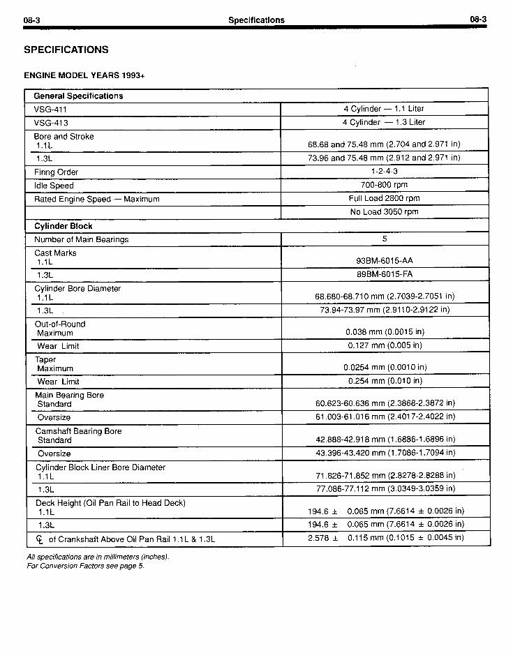
1 General Specifications
1 VSG-411 4 Cylinder - 1 .I Liter
1 VSG-413 4 Cylinder - 1.3 Liter
I Bore and Stroke l.lL 68.68 and 75.48 mm (2.704 and 2.971 in)
I 1.3L I 73.96 and 75.48 mm (2.912 and 2.971 in)
Firing Order
Idle Speed
1-2-4-3
700-800 rpm
Rated Engine Speed - Maximum Full Load 2800 rpm
No Load 3050 rpm
I Cylinder Block
1 Number of Main Bearings I 5
I Cast Marks 1 .I L I 93BM-6.015-AA
I 1.3L I 89BM-6015-FA
Cylinder Bore Diameter l.lL I 68.680-68.710 mm (2.7039-2.7051 in)
I 1.3L I 73.94-73.97 mm (2.911 O-2.91 22 in)
Out-of-Round Maximum
Wear Limit
0.038 mm (0.0015 in)
0.127 mm (0.005 in)
I Taper Maximum I 0.0254 mm (0.0010 in)
Wear Limit
Main Bearing Bore Standard
Oversize
Camshaft Bearing Bore Standard
0.254 mm (0.010 in)
60.623-60.636 mm (2.3868-2.3872 in)
61.003-61 .016 mm (2.4017-2.4022 in)
42.888-42.918 mm (1.6886-1.6896 in)
Oversize 43.396-43.420 mm (1.7086-I .7094 in) .
Cylinder Block Liner Bore Diameter 1 .lL 71.826-71.852 mm (2.8278-2.8288 in)
1 1.3L I 77.086-77.112 mm (3.0349-3.0359 in)
I Deck Height (Oil Pan Rail to Head Deck) l.lL I 194.6 & 0.065 mm (7.6614 -+ 0.0026 in)
I 1.3L I 194.6 & 0.065 mm (7.6614 & 0.0026 in)
g of Crankshaft Above Oil Pan Rail I .I L & 1.3L I 2.578 k 0.115 mm (0.1015 & 0.0045 in)
All specifications are in millimeters (inches). For Conversion Factors see page 5.
08-4 Specifications 08-4
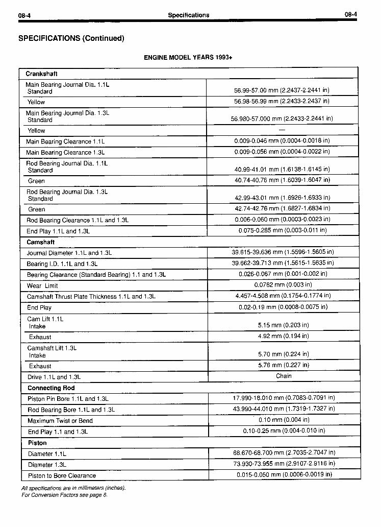
SPECIFICATIONS (Continued)
ENGINE MODEL YEARS 1993+
I Crankshaft I
Main Bearing Journal Dia. 1 .I L Standard
Yellow
56.99-57.00 mm (2.2437-2.2441 in)
56.98-56.99 mm (2.2433-2.2437 in)
r Main Bearing Journal Dia. 1.3L Standard 56.980-57.000 mm (2.2433-2.2441 in) I
I Main Bearing Clearance I .I L I 0.009-0.046 mm (0.0004-0.0018 in) I Main Bearing Clearance 1.3L
Rod Bearing Journal Dia. 1 .I L Standard
Green
0.009-0.056 mm (0.0004-0.0022 in)
40.99-41 .Ol mm (1.6138-l .6145 in)
40.74-40.76 mm (1.6039-I .6047 in)
I Rod Bearing Journal Dia. 1.3L Standard 42.99-43.01 mm (1.6926-1.6933 in) I
Green
Rod Bearing Clearance 1 .I L and 1.3L
End Play 1 .I L and 1.3L
42.74-42.76 mm (1.6827-1.6834 in)
0.006-0.060 mm (0.0003-0.0023 in)
0.075-0.285 mm (0.003-0.011 in)
I- Camshaft
Journal Diameter 1 .I L and 1.3L
Bearing I.D. 1 .I L and 1.3L
Bearing Clearance (Standard Bearing) 1 .I and 1.3L
39.615-39.636 mm (1.5596-1.5605 in)
39.662-39.713 mm (1.5615-l .5635 in)
0.026-0.067 mm (0.001-0.002 in)
I Wear Limit I 0.0762 mm (0.003 in) I Camshaft Thrust Plate Thickness 1 .I L and 1.3L
End Play
Cam Lift 1 .I L Intake
Exhaust
Camshaft Lift 1.3L Intake
Exhaust
Drive 1 .I L and 1.3L
Connecting Rod
Piston Pin Bore 1 .I L and 1.3L
Rod Bearing Bore 1 .I L and 1.3L
Maximum Twist or Bend
End Play 1 .I and 1.3L
Piston I
Diameter I .I L
Diameter 1.3L
Piston to Bore Clearance
All specifications are in millimeters (inches). For Conversion Factors see page 8.
4.457-4.508 mm (0.1754-0.1774 in)
0.02-0.19 mm (0.0008-0.0075 in)
5.15 mm (0.203 in)
4.92 mm (0.194 in)
5.70 mm (0.224 in)
5.76 mm (0.227 in)
Chain
17.990-I 8.010 mm (0.7083-0.7091 in)
43.990-44.010 mm (1.7319-1.7327 in)
0.10 mm (0.004 in)
0.1 O-O.25 mm (0.004-0.010 in)
68.670-68.700 mm (2.7035-2.7047 in)
73.930-73.955 mm (2.9107-2.9116 in)
0.015-0.050 mm (0.0006-0.0019 in)
,

08-5 Specifications 08-5
SPECIFICATIONS (Continued)
ENGINE MODEL YEARS 1993+
Piston Pin
Diameter 1 .I L and 1.3L
Length l.lL
1.3L
Interference Fit in Rod at 21 OC 1 .I L and 1.3L
Clearance in Piston at 21 “C 1 .I L and 1.3L
Piston Rings
1 18.026-I 8.029 mm (0.7097-0.7098 in)
58.6-59.4 mm (2.31-2.33 in)
63.6-64.4 mm (2.51-2.53 in)
0.016-0.048 mm (0.0006-0.0018 in)
0.008-0.014 mm (0.0003-0.0006 in)
Top Compression Ring Thickness 1 .I L and 1 .3L 1.503-I .505 mm (0.05918-0.05925 in)
Bottom Compression Ring Thickness 1 .I L and 1.3L 1.728-1.740 mm (0.0680-0.0685 in)
Top Compression Ring Side Clearance 1 .I L and 1.3L .013-.027 mm (0.0005-0.0011 in)
Bottom Compression Ring Side Clearance 1 .I L and 1.3L .005-.042 mm (0.0002-0.0017 in)
Compression Ring Side Clearance - Wear Limit 0.15 mm (0.006 in)
Oil Ring Thickness 1 .I L and 1.3L 2.978-2.990 mm (0.1172-0.1177 in)
Oil Ring Side Clearance 1 .I L and 1.3L O-.032 mm (O-0.0012 in)
Top Compression Ring - Standard Bore - Ring Gap b/ 0.25-0.45 mm (0.01 O-0.01 7 in)
Bottom Compression Ring - Standard Bore - Ring Gap IT1/ 0.25-0.45 mm (0.01 O-0.01 7 in)
1 Oil Ring - Standard Bore - Ring Gap b/ - 0.20-0.40 mm (0.008-0.015 in)
Cylinder Head 1 Maximum permissible cylinder head distortion 1 .I L and 1.3L: Measured over a distance of 26 mm 0.04 mm (0.0015 in)
Measured over a distance of 152 mm 0.08 mm (0.003 in)
Measured over the entire length 0.15 mm (0.006 in) L
Valve Stem Bore 1 .I L and 1.3L 7.063-7.094 (0.2781-0.2793 in)
Valve Seat Angle 45” L
Valve Seat Insert - Exhaust, Outside Diameter c/ 1 .I L and 1.3L -
Combustion Chamber Volume 1 .lL
1.3L
31.500-31.515 mm (1.2402-I .2407 in)
27.24-29.24 cc (4.22-4.53 cu in)
31.79-33.79 cc (4.93-5.24 cu in) 1
Reface cylinder head mating surface: The following minimum combustion chamber depth must be left after skimming - 1 .I L and 1.3L
All specifications are in millimeters (inches). For Conversion Factors see page 8.
14.4 mm & 0.15 mm (0.567 in zt 0.006 in)
b/ Ring Gap may exceed these specifications by 0.15 mm
- (0.006 in) when measurement is made in the block. c/ inset? must be chilled in liquid nitrogen or dry ice prior to assembly.
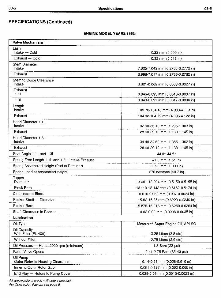
08-6 Specifications 08-6
SPECIFICATIONS (Continued)
ENGINE MODEL YEARS 1993+
Valve Mechanism
Lash Intake - Cold I 0.22 mm (0.009 in)
Exhaust - Cold I 0.32 mm (0.013 in) I Stem Diameter Intake I 7.025-7.043 mm (0.2766-0.2772 in) I
Exhaust I 6.999-7.017 mm (0.2756-0.2762 in) I Stem to Guide Clearance Intake I 0.021-0.069 mm (0.0008-0.0027 in) I Exhaust l.lL 0.046-0.095 mm (0.0018-0.0037 in) I 1.3L I 0.043-0.091 mm (0.0017-0.0036 in) I
Length Intake I 103.70-I 04.40 mm (4.083-4.110 in) I Exhaust ~~~ -I 104.02-l 04.72 mm (4.096-4.122 in) I
Head Diameter 1 .I L Intake I 32.90-33.10 mm (1.296-1.303 in) I Exhaust I 28.90-29.10 mm (1 .I 38-l .145 in) I
Head Diameter 1.3L Intake I 34.40-34.60 mm (1.355-1.362 in)
Exhaust I 28.90-29.10 mm (1 .I 38-1 .I45 in) I Seat Angle 1 .I L and 1.3L I 44.0”-44.5”
Spring Free Length 1 .I L and 1.3L, Intake/Exhaust
Spring Assembled Height (Pad to Retainer) I 41 .O mm (1.61 in)
33.22 mm (1.308 in)
Spring Load at Assembled Height 270 newtons (60.7 lb)
Tappet Diameter
Block Bore
Clearance to Block
I 13.081-I 3.094 mm (0.5150-0.5155 in)
13.11 O-l 3.143 mm (0.5162-0.5174 in)
I 0.016-0.062 mm (0.007-0.0024 in)
Rocker Shaft - Diameter I 15.82-l 5.85 mm (0.6229-0.6240 in)
Rocker Bore I 15.875-I 5.913 mm (0.6250-0.6264 in)
Shaft Clearance in Rocker I 0.02-0.09 mm (0.0008-0.0035 in)
Lubrication
Oil Type Motorcraft Super Engine Oil, API SG
Oi I Capacity With Filter (FL 400) 3.25 Liters (3.5 qts)
Without Filter I 2.75 Liters (2.9 qts)
Oil Pressure - Hot at 2000 rpm (minimum) I 1.5 Bars (22 psi)
Relief Valve Opens
Oil Pump Outer Rotor to Housing Clearance
, Inner to Outer Rotor Gap
End Play - Rotors to Pump Cover
All specifications are in millimeters (inches). For Conversion Factors see page 8.
2.41-2.75 Bars (35-40 psi)
0.14-0.26 mm (0.006-0.010 in)
0.051-0.127 mm (0.002-0.005 in)
0.025-0.06 mm (0.001 O-0.0023 in)

08-7 Wecifications 08-7
SPECIFICATIONS (Continued)
ENGINE MODEL YEARS 1993+ \
Ignition System
Firing Order I 1-2-4-3
DIS d/ (with 87 Octane Unleaded Gasoline) 1 .I L and 1.3L
Spark Plugs - AGRF 22 Cl (Gap)
Distributorless Type
Fixed
1 .O mm (0.040 in)
1 Coil Type High Output DIS Coil
Coil Output
Primary Resistance (at the Coil Tower)
37.0 KV Minimum
0.50-I .OO Ohm
I High Tension Leads 30,000 Ohms Max. per Lead
Belt Tension
Alternator New 351-449 N (79-l 01 Ibs)
Used-Reset (Minimum) 249-334 N (56-75 Ibs)
Governor New
Used-Reset (Minimum)
334 N (75 Ibs)
222 N (50 Ibs)
Fuel System
I .I L and 1.3L Unleaded 1986-
Pump Delivery Pressure
Starter - Current Draw
87 Octane
0.24-0.38 Bar (3.5-5.5 psi)
Normal Engine Cranking
Maximum Load - at Stall
No Load
175 amps
410 amps
35 to 55 amps
All specifications are in millimeters (inches). For Conversion Factors see page 8. d/ Distributor-less Ignition System. -
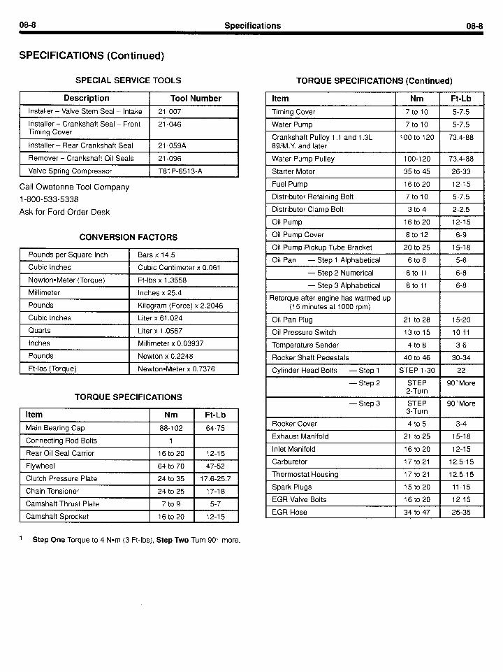
08-8 Specifications 08-8
SPECIFICATIONS (Continued)
SPECIAL SERVICE TOOLS TORQUE SPEClFlCATlOf IS (Contini
Description
Installer - Valve Stem Seal - Intake
Installer - Crankshaft Seal - Front Timing Cover
Installer - Rear Crankshaft Seal
Remover - Crankshaft Oil Seals
Valve Spring Compressor
Call Owatonna Tool Company
I-800-533-5338
Ask for Ford Order Desk
Tool Number
21-007
21-046
21-059A
21-096
T81 P-651 3-A
Item Nm Ft-Lb
Timing Cover 7to10 5-7.5
Water Pump 7to10 5-7.5
Crankshaft Pulley 1 .I and 1.3L 89/M.Y. and later
100to120 73.4-88
Water Pump Pulley 100-l 20 73.4-88
Starter Motor 35 to 45 26-33
Fuel Pump 16to20 12-l 5
Distributor Retaining Bolt 7to10 5-7.5
Distributor Clamp Bolt 3 to 4 2-2.5
Oil Pump 16to20 12-l 5
CONVERSION FACTORS Oil Pump Cover 8to12 6-9
Pounds per Square Inch Bars x 14.5
Cubic Inches Cubic Centimeter x 0.061
NewtoneMeter (Torque) Ft-lbs x 1.3558
Millimeter Inches x 25.4
Pounds Kilogram (Force) x 2.2046
Cubic Inches Liter x 61.024 r
Quarts Liter x 1.0567 I
Inches Millimeter x 0.03937
Pounds Newton x 0.2248
Ft-lbs (Torque) NewtonaMeter x 0.7376
Oil Pump Pickup Tube Bracket
Oil Pan - Step 1 Alphabetical
20 to 25 15-l 8
6 to 8 5-6
- Step 2 Numerical 8toll 6-8
- Step 3 Alphabetical
Retorque after engine has warmed up (15 minutes at 1000 rpm)
Oil Pan Plug
Oil Pressure Switch
Temperature Sender
Rocker Shaft Pedestals
Cylinder Head Bolts - Step 1
- Step 2
8to11 6-8
21 to 28
13to15
4 to 8
40 to 46
STEP l-30
STEP 2-Turn
STEP 3-Turn
4 to 5
21 to 25
16to20
17to21
17to21
15to20
16to20
34 to 47
15-20
10-11
3-6
30-34
22
90”More
TORQUE SPECIFICATIONS - Step 3 90”More
Item Nm Ft-Lb I
Main Bearing Cap 88-l 02 64-75
Connecting Rod Bolts 1
Rear Oil Seal Carrier 16to20 12-15
Flywheel 64 to 70 47-52
Clutch Pressure Plate 24 to 35 17.6-25.7
Chain Tensioner 24 to 25 17-l 8 I
Camshaft Thrust Plate 7 to 9 5-7
Camshaft Sprocket 16to20 12-15
1 Step One Torque to 4 Nom (3 Ft-lbs), Step Two Turn 90’ more.
Rocker Cover
Exhaust Manifold
Inlet Manifold
Carburetor
Thermostat Housing
Spark Plugs
EGR Valve Bolts
EGR Hose
3-4
15-l 8
12-l 5
12.5-l 5
12.5-l 5
11-15
12-15
25-35