
Seawind: a Wireless Network Emulator
16
Seawind: a Wireless Network Emulator Markku Kojo, Andrei Gurtov, Jukka Manner, Pasi Sarolahti, Timo Alanko, and Kimmo Raatikainen University of Helsinki, Department of Computer Science P.O.Box 26, FIN-00014 UNIVERSITY OF HELSINKI, Finland markku.kojo,andrei.gurtov,jukka.manner,pasi.sarolahti, timo.alanko,kimmo.raatikainen @cs.helsinki.fi Abstract Behavior of current communication protocols as well as current and future networked ap- plications is of fundamental importance for technical and commercial success of Mobile Internet. The forthcoming wireless Wide-Area Networks, such as GPRS and UMTS, are quite complex and network operators have a large set of parameters to tune the transfer performance of these networks. In this situation it is of great value to be able to execute practical experiments. The Seawind emulation software introduced in this paper enables measurements of protocol implementations in modeled networking environments. The Sea- wind software provides a rich set of ways to define transfer characteristics including delays and errors. The software has also means to conduct large sets of experiments in an auto- matic fashion. In addition, tools of analyzing measurement data has been integrated into the Seawind software. 1 Introduction Nowadays Wireless Wide Area Networks (WWAN) are widely used by mobile users to access data services. New mobile data networks, as for example the General Packet Radio Service (GPRS) [6, 8], and future third generation mobile communication systems [32] are expected to provide a high-speed packet data access suitable for a wide range of Internet services. How- ever, wireless links represent a different communication environment than the wireline Internet. Hence, protocols and applications not particularly designed for wireless links often require en- hancements in order to achieve reasonable performance in a wireless environment [4, 17]. Evaluating such enhancements over a real data link or network is often costly; if a system is only in a development stage, the evaluation may be impossible. A frequently asked question is whether next-generation wireless networks could provide multimedia services that meet the end- user expectations. Network emulation is a convenient tool to examine how existing multimedia applications behave. An emulator can also be used in usability studies involving real end-users. The main difference to a field trial is that an existing network is replaced by a model describing characteristics of transfer, delay and error behavior, for example. An emulation also allows controlling the network characteristics and reproduce the environment. On the other hand, the problems of emulation include the accuracy of the model; parameters drawn from real-world phenomena and properties are always estimates. 1
Transcript of Seawind: a Wireless Network Emulator

Seawind: a Wireless Network Emulator
Markku Kojo, Andrei Gurtov, Jukka Manner,Pasi Sarolahti, Timo Alanko, and Kimmo Raatikainen
University of Helsinki, Department of Computer ScienceP.O.Box 26, FIN-00014 UNIVERSITY OF HELSINKI, Finland�
markku.kojo,andrei.gurtov,jukka.manner,pasi.sarolahti,timo.alanko,kimmo.raatikainen � @cs.helsinki.fi
Abstract
Behavior of current communication protocols as well as current and future networked ap-plications is of fundamental importance for technical and commercial success of MobileInternet. The forthcoming wireless Wide-Area Networks, such as GPRS and UMTS, arequite complex and network operators have a large set of parameters to tune the transferperformance of these networks. In this situation it is of great value to be able to executepractical experiments. The Seawind emulation software introduced in this paper enablesmeasurements of protocol implementations in modeled networking environments. The Sea-wind software provides a rich set of ways to define transfer characteristics including delaysand errors. The software has also means to conduct large sets of experiments in an auto-matic fashion. In addition, tools of analyzing measurement data has been integrated into theSeawind software.
1 Introduction
Nowadays Wireless Wide Area Networks (WWAN) are widely used by mobile users to accessdata services. New mobile data networks, as for example the General Packet Radio Service(GPRS) [6, 8], and future third generation mobile communication systems [32] are expected toprovide a high-speed packet data access suitable for a wide range of Internet services. How-ever, wireless links represent a different communication environment than the wireline Internet.Hence, protocols and applications not particularly designed for wireless links often require en-hancements in order to achieve reasonable performance in a wireless environment [4, 17].
Evaluating such enhancements over a real data link or network is often costly; if a system isonly in a development stage, the evaluation may be impossible. A frequently asked question iswhether next-generation wireless networks could provide multimedia services that meet the end-user expectations. Network emulation is a convenient tool to examine how existing multimediaapplications behave. An emulator can also be used in usability studies involving real end-users.The main difference to a field trial is that an existing network is replaced by a model describingcharacteristics of transfer, delay and error behavior, for example. An emulation also allowscontrolling the network characteristics and reproduce the environment. On the other hand, theproblems of emulation include the accuracy of the model; parameters drawn from real-worldphenomena and properties are always estimates.
1

In this paper we describe the Seawind emulator and present a case study that demonstratesits practical utility. The primary target of Seawind is performance studies of real protocols andapplications as seen by the end user in the present and future wireless networks. AlthoughSeawind was developed for modeling wireless networks, GPRS in the first hand, the Seawindemulator is rather generic and it can be used in modeling a wide range of networks.
Emulation is a compromise between two other possible approaches in performance evalua-tion; between simulation and measurements using a testbed [2]. The main advantage of a net-work emulator is that the performance of actual implementations of protocols and applicationscan be examined. This is a clear advantage, for example, over most of the TCP performancestudies that rely on the abstract TCP model available in the NS simulator [14]. However, mostend users – if not all – connected to the Internet use TCP implementations that are not neces-sarily close to the one found in the NS simulator (for example, those in Windows or Linux).Therefore, the NS simulator or other simulators having their own TCP implementations do notallow a network operator to tune the networking parameters so that the performance is optimizedfor real end users and their applications. Furthermore, a real-time emulator provides answers to”what-if” type of questions. It also allows back-engineering parameters of closed networkingimplementations.
Emulation studies can be time-consuming because the duration of an experimental sessionis determined by the speed of the modeled network. In order to enhance the usability of theemulator, the Seawind emulator supports an automatic set up of tests and collection of a suf-ficient number of test repetitions for statistically valid results. Therefore, the experiments canbe run overnight and during weekends without any human intervention. The Seawind packagealso provides basic tools for statistical analysis and for graphical presentation of results. We useSeawind on the Linux operating system. The Seawind software runs in the user space and canbe easily ported to any Unix operating system.
Several extensive performance studies have been made using Seawind. TCP performancehas been studied in [13, 25] and GPRS performance in [18]. Seawind was also used in theMonads demonstration at MOBICOM 2000.
The rest of the paper is organized as follows. After a brief summary of related work, wediscuss, in Section 2, common characteristics of wireless links. We also derive the requirementsfor a network emulator taking those features into account. In Section 3 we describe the Seawindarchitecture. We present the structure of the Seawind simulation Process that is the core ofthe Seawind emulator. In Section 4 we discuss the features of Seawind that are important inemulation of any wireless network. In Section 5 we present how we validated the Seawindemulator. Finally, a case study is described in Section 6 in order to illustrate the practical valueof Seawind.
2 Related Work
Simulation of communication networks is an active research area. A wealth of different sim-ulators are found worldwide; most of them are freely available while some are commercialproducts. The software tools for network simulations can be divided into two categories: dis-crete event simulators and real-time simulator or emulators, as we call them. Many simulationtools are discrete event simulators that operate in virtual time. These simulators have their ownabstract implementations for modeling different links, protocols, and even applications. Prob-ably the most well-known discrete event simulators are NS [14] and the commercial simulator
2
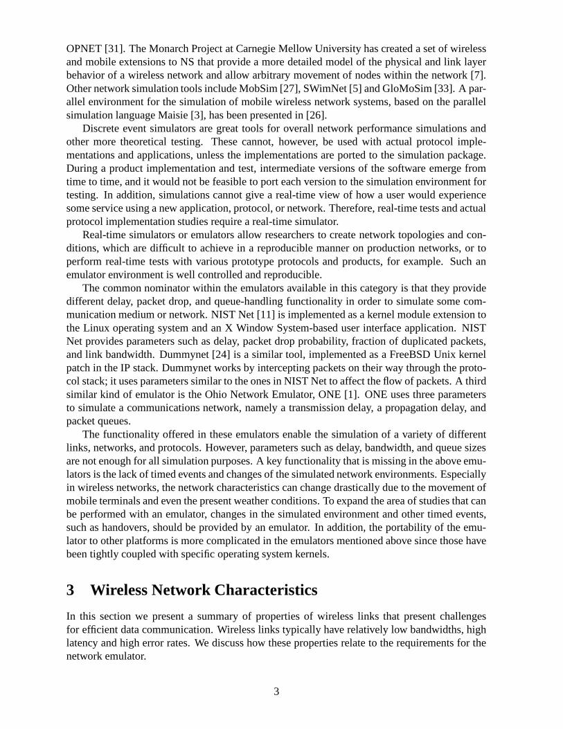
OPNET [31]. The Monarch Project at Carnegie Mellow University has created a set of wirelessand mobile extensions to NS that provide a more detailed model of the physical and link layerbehavior of a wireless network and allow arbitrary movement of nodes within the network [7].Other network simulation tools include MobSim [27], SWimNet [5] and GloMoSim [33]. A par-allel environment for the simulation of mobile wireless network systems, based on the parallelsimulation language Maisie [3], has been presented in [26].
Discrete event simulators are great tools for overall network performance simulations andother more theoretical testing. These cannot, however, be used with actual protocol imple-mentations and applications, unless the implementations are ported to the simulation package.During a product implementation and test, intermediate versions of the software emerge fromtime to time, and it would not be feasible to port each version to the simulation environment fortesting. In addition, simulations cannot give a real-time view of how a user would experiencesome service using a new application, protocol, or network. Therefore, real-time tests and actualprotocol implementation studies require a real-time simulator.
Real-time simulators or emulators allow researchers to create network topologies and con-ditions, which are difficult to achieve in a reproducible manner on production networks, or toperform real-time tests with various prototype protocols and products, for example. Such anemulator environment is well controlled and reproducible.
The common nominator within the emulators available in this category is that they providedifferent delay, packet drop, and queue-handling functionality in order to simulate some com-munication medium or network. NIST Net [11] is implemented as a kernel module extension tothe Linux operating system and an X Window System-based user interface application. NISTNet provides parameters such as delay, packet drop probability, fraction of duplicated packets,and link bandwidth. Dummynet [24] is a similar tool, implemented as a FreeBSD Unix kernelpatch in the IP stack. Dummynet works by intercepting packets on their way through the proto-col stack; it uses parameters similar to the ones in NIST Net to affect the flow of packets. A thirdsimilar kind of emulator is the Ohio Network Emulator, ONE [1]. ONE uses three parametersto simulate a communications network, namely a transmission delay, a propagation delay, andpacket queues.
The functionality offered in these emulators enable the simulation of a variety of differentlinks, networks, and protocols. However, parameters such as delay, bandwidth, and queue sizesare not enough for all simulation purposes. A key functionality that is missing in the above emu-lators is the lack of timed events and changes of the simulated network environments. Especiallyin wireless networks, the network characteristics can change drastically due to the movement ofmobile terminals and even the present weather conditions. To expand the area of studies that canbe performed with an emulator, changes in the simulated environment and other timed events,such as handovers, should be provided by an emulator. In addition, the portability of the emu-lator to other platforms is more complicated in the emulators mentioned above since those havebeen tightly coupled with specific operating system kernels.
3 Wireless Network Characteristics
In this section we present a summary of properties of wireless links that present challengesfor efficient data communication. Wireless links typically have relatively low bandwidths, highlatency and high error rates. We discuss how these properties relate to the requirements for thenetwork emulator.
3

Slow, asymmetric and changing line rate. The line rate of a wireless WAN link does notoften exceed some tens of kilobits per second. Such a link speed is typical also for dial-upmodem users. For some wireless links, the line rate can vary over time, due to a change in theamount of radio resources assigned to the user or change of the channel encoding scheme. Theline rates may be asymmetric, for example when using certain types of satellite links or GPRS.Thus, the emulator should provide the desired line rate by delaying data packets and providemeans to emulate changes in the line rate, in both directions independently. For the majorityof W-WANs a rate up to 100 kbps is sufficient. However, modeling future broadband wirelessnetworks will require line rates at least up to 2 Mbps.
High latency and variable delays. The propagation delay of wireless links is typically high.The delay comes from the special transmission schemas on the wireless link and from the pro-cessing delays of the link hardware. For example, the Global System for Mobile Communica-tions (GSM) uses interleaving of data on the radio link to reduce the effect of error bursts, andthis introduces a latency of 90 ms independent of packet size [20]. Additional latency in usinga GSM data service is caused by the connection to the Internet Service Provider (ISP) and theprocessing time within the GSM system. The total one-way latency in GSM sums up to 200-300ms1. The emulator should correctly model this delay by adding a propagation delay to eachpacket. Variable delays may appear on a wireless link due to a number of reasons, for exampleLink-level ARQ recovery, radio resource (re-)allocation and handovers to mention a few. Thereshould be a possibility to add such random delays to a packet flow.
Error losses. Some wireless links impose a significant amount of data corruption due to trans-mission errors. The error rate depends on the current radio conditions and the strength of thechannel coding schema. For example, in the transparent GSM data service the residual bit er-ror rate (BER) of the link is allowed to be as high as ������� after the Forward Error Correction(FEC) [21]. Radio conditions can vary greatly. In the ideal conditions all protocol data units(PDU) are delivered correctly, and in the worst case nothing can be correctly sent over the link.For accuracy of emulations and ease of use the emulator should be able to drop packets on aper-packet basis or using a bit error probability. The transmission error on the link can be seenby the upper layers as a delay in data delivery (reliable link level), loss of a PDU (error detectionin link layer) or as a corrupted data packet (transparent link layer). The emulator should provideall three cases.
Congestion losses at the bottleneck queue, over-buffering. The wireless link is often thebottleneck in the path of a data flow, because fixed networks are fast and reliable comparedto the capabilities of the wireless link. Routers play a significant role because congestion datalosses are most likely to happen at the bottleneck queue. A limited number of buffers can beallocated in a last-hop router per user. The emulator should contain a queue at the emulatedbottleneck link and provide means to limit the queue size in terms of bytes and number ofpackets. Optionally, a timer would be used to limit the time a packet can be buffered. Newqueue management algorithms and drop policies should be easily attached.
1Note, that we do not include the transmission delay into the link latency. Thus the round-trip time is defined asthe sum of transmission and propagation delays in both directions.
4
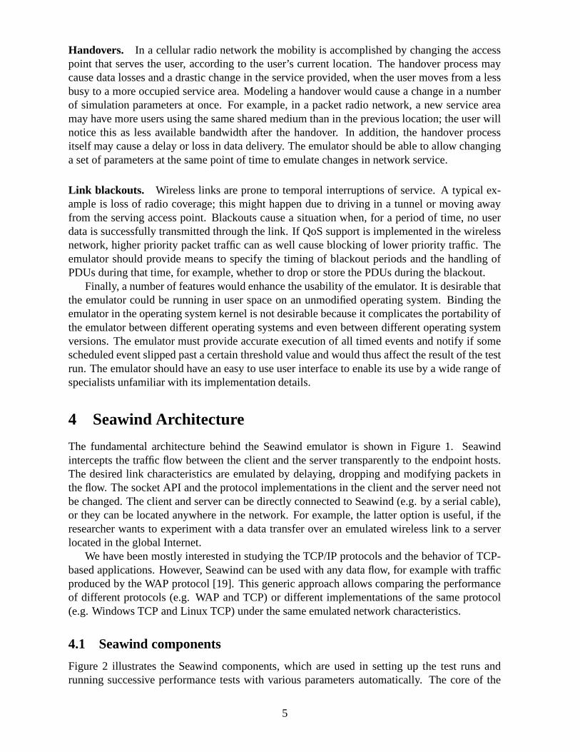
Handovers. In a cellular radio network the mobility is accomplished by changing the accesspoint that serves the user, according to the user’s current location. The handover process maycause data losses and a drastic change in the service provided, when the user moves from a lessbusy to a more occupied service area. Modeling a handover would cause a change in a numberof simulation parameters at once. For example, in a packet radio network, a new service areamay have more users using the same shared medium than in the previous location; the user willnotice this as less available bandwidth after the handover. In addition, the handover processitself may cause a delay or loss in data delivery. The emulator should be able to allow changinga set of parameters at the same point of time to emulate changes in network service.
Link blackouts. Wireless links are prone to temporal interruptions of service. A typical ex-ample is loss of radio coverage; this might happen due to driving in a tunnel or moving awayfrom the serving access point. Blackouts cause a situation when, for a period of time, no userdata is successfully transmitted through the link. If QoS support is implemented in the wirelessnetwork, higher priority packet traffic can as well cause blocking of lower priority traffic. Theemulator should provide means to specify the timing of blackout periods and the handling ofPDUs during that time, for example, whether to drop or store the PDUs during the blackout.
Finally, a number of features would enhance the usability of the emulator. It is desirable thatthe emulator could be running in user space on an unmodified operating system. Binding theemulator in the operating system kernel is not desirable because it complicates the portability ofthe emulator between different operating systems and even between different operating systemversions. The emulator must provide accurate execution of all timed events and notify if somescheduled event slipped past a certain threshold value and would thus affect the result of the testrun. The emulator should have an easy to use user interface to enable its use by a wide range ofspecialists unfamiliar with its implementation details.
4 Seawind Architecture
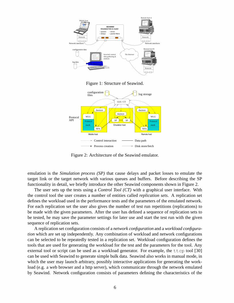
The fundamental architecture behind the Seawind emulator is shown in Figure 1. Seawindintercepts the traffic flow between the client and the server transparently to the endpoint hosts.The desired link characteristics are emulated by delaying, dropping and modifying packets inthe flow. The socket API and the protocol implementations in the client and the server need notbe changed. The client and server can be directly connected to Seawind (e.g. by a serial cable),or they can be located anywhere in the network. For example, the latter option is useful, if theresearcher wants to experiment with a data transfer over an emulated wireless link to a serverlocated in the global Internet.
We have been mostly interested in studying the TCP/IP protocols and the behavior of TCP-based applications. However, Seawind can be used with any data flow, for example with trafficproduced by the WAP protocol [19]. This generic approach allows comparing the performanceof different protocols (e.g. WAP and TCP) or different implementations of the same protocol(e.g. Windows TCP and Linux TCP) under the same emulated network characteristics.
4.1 Seawind components
Figure 2 illustrates the Seawind components, which are used in setting up the test runs andrunning successive performance tests with various parameters automatically. The core of the
5
− queues− delays
− errors− packet filters
Protocols
Remote host A
Protocols
Mobile host
Protocols
Network interfacesNetwork interfaces
Emulated link & routerSEAWIND
The Internet
Remote host Bconfiguration data
log data
Seawind control,data gathering &analysis
�����
�����
���������������
���������������
������������������������������������������������������������
�������������������������������������������� � � � �
��������������
Figure 1: Structure of Seawind.
Mobile host Remote host
Emulation host
daemon daemon
daemon
SP SP
Control interaction
Disk store/fetch
GUI / CT
NPANPA
WLG WLG
configuration
Process creation
Data path
log storage
ProtocolAPI Protocol
stack
Protocol
stack
files
Figure 2: Architecture of the Seawind emulator.
emulation is the Simulation process (SP) that cause delays and packet losses to emulate thetarget link or the target network with various queues and buffers. Before describing the SPfunctionality in detail, we briefly introduce the other Seawind components shown in Figure 2.
The user sets up the tests using a Control Tool (CT) with a graphical user interface. Withthe control tool the user creates a number of entities called replication sets. A replication setdefines the workload used in the performance tests and the parameters of the emulated network.For each replication set the user also gives the number of test run repetitions (replications) tobe made with the given parameters. After the user has defined a sequence of replication sets tobe tested, he may save the parameter settings for later use and start the test run with the givensequence of replication sets.
A replication set configuration consists of a network configuration and a workload configura-tion which are set up independently. Any combination of workload and network configurationscan be selected to be repeatedly tested in a replication set. Workload configuration defines thetools that are used for generating the workload for the test and the parameters for the tool. Anyexternal tool or script can be used as a workload generator. For example, the ttcp tool [30]can be used with Seawind to generate simple bulk data. Seawind also works in manual mode, inwhich the user may launch arbitrary, possibly interactive applications for generating the work-load (e.g. a web browser and a http server), which communicate through the network emulatedby Seawind. Network configuration consists of parameters defining the characteristics of the
6
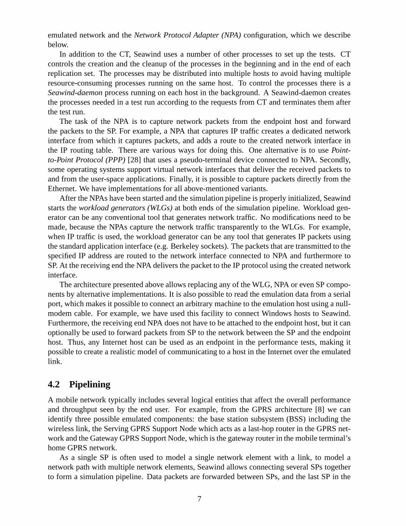
emulated network and the Network Protocol Adapter (NPA) configuration, which we describebelow.
In addition to the CT, Seawind uses a number of other processes to set up the tests. CTcontrols the creation and the cleanup of the processes in the beginning and in the end of eachreplication set. The processes may be distributed into multiple hosts to avoid having multipleresource-consuming processes running on the same host. To control the processes there is aSeawind-daemon process running on each host in the background. A Seawind-daemon createsthe processes needed in a test run according to the requests from CT and terminates them afterthe test run.
The task of the NPA is to capture network packets from the endpoint host and forwardthe packets to the SP. For example, a NPA that captures IP traffic creates a dedicated networkinterface from which it captures packets, and adds a route to the created network interface inthe IP routing table. There are various ways for doing this. One alternative is to use Point-to-Point Protocol (PPP) [28] that uses a pseudo-terminal device connected to NPA. Secondly,some operating systems support virtual network interfaces that deliver the received packets toand from the user-space applications. Finally, it is possible to capture packets directly from theEthernet. We have implementations for all above-mentioned variants.
After the NPAs have been started and the simulation pipeline is properly initialized, Seawindstarts the workload generators (WLGs) at both ends of the simulation pipeline. Workload gen-erator can be any conventional tool that generates network traffic. No modifications need to bemade, because the NPAs capture the network traffic transparently to the WLGs. For example,when IP traffic is used, the workload generator can be any tool that generates IP packets usingthe standard application interface (e.g. Berkeley sockets). The packets that are transmitted to thespecified IP address are routed to the network interface connected to NPA and furthermore toSP. At the receiving end the NPA delivers the packet to the IP protocol using the created networkinterface.
The architecture presented above allows replacing any of the WLG, NPA or even SP compo-nents by alternative implementations. It is also possible to read the emulation data from a serialport, which makes it possible to connect an arbitrary machine to the emulation host using a null-modem cable. For example, we have used this facility to connect Windows hosts to Seawind.Furthermore, the receiving end NPA does not have to be attached to the endpoint host, but it canoptionally be used to forward packets from SP to the network between the SP and the endpointhost. Thus, any Internet host can be used as an endpoint in the performance tests, making itpossible to create a realistic model of communicating to a host in the Internet over the emulatedlink.
4.2 Pipelining
A mobile network typically includes several logical entities that affect the overall performanceand throughput seen by the end user. For example, from the GPRS architecture [8] we canidentify three possible emulated components: the base station subsystem (BSS) including thewireless link, the Serving GPRS Support Node which acts as a last-hop router in the GPRS net-work and the Gateway GPRS Support Node, which is the gateway router in the mobile terminal’shome GPRS network.
As a single SP is often used to model a single network element with a link, to model anetwork path with multiple network elements, Seawind allows connecting several SPs togetherto form a simulation pipeline. Data packets are forwarded between SPs, and the last SP in the
7

pipeline sends the packet out to the destination.Some links use flow control at the link level. This means that the rate at which the packets are
transmitted from one network element to another is controlled by the receiving network element.Seawind supports flow control between SPs and between NPAs by using a sliding window basedalgorithm.
4.3 Channel model
While computer networks become increasingly complex, the principle of having a set of routers(switches, etc.) interconnected by communication links remains the same. In Seawind, a singleSimulation Process models an outgoing link, optionally attached to a network node with buffer-ing and a specified queue management policy. Several SPs can be pipelined to represent a paththrough the network between the client and the server.
The emulated link is modeled as a direction-specific channel, which is maintained separatelyfor the uplink (towards the fixed end) and for the downlink (towards the mobile end) traffic. Thedownlink and uplink channels are largely independent, with an exception of some special events(for example a blackout). The model of the channel is shown in Figure 3. Packets arriving to theemulator are placed into the input queue. The maximum queue length can be limited in terms ofbytes or packets. Different packet-drop policies can be applied on the queue (e.g. the traditionaltail-drop or RED active queue management [9]). For example, the input queue can be used tomodel a queue in a router, and thus inspect the effect of congestion and congestion-based lossesat a network node.
allocation delaytransmission delay
propagation delayerror delay
INPUT QUEUE LSB LRBLINK
ReassemblyFragmentation
Figure 3: The channel model.
Some link protocols (e.g. Radio Link Control (RLC) [23] in GSM) fragment PDUs of theupper protocol layer as a part of internal operation. The fragmentation unit before the link andthe reassembly unit after the link allow to logically fragment the data packet into smaller piecesfor the purpose of the different events performed during the emulations. The actual size of thetransmitted data transmitted by lower-level protocols can increase due to protocol overhead (e.g.added header) or decrease due to compression. This is also taken into account in the calculations.
The channel model also includes Link Send Buffer (LSB) and Link Receive Buffer (LRB) tomodel the send and receive buffers that are present with real links. The link send buffer is usedto store the frames to be transmitted to the link, and the link receive buffer is used to store framesat the receiving end until all pieces of a fragmented unit have arrived, allowing reassembly. Thelink receive buffer is also needed to store out-of-order frames, when a link layer AutomaticRepeat Request (ARQ) mechanism is used for retransmitting corrupted or missing frames. Thesize of these buffers should be large enough allowing the ARQ sliding window protocol to keepthe link fully utilized. These buffers may significantly increase the buffering capacity of the link.
Before data can be delivered over the link, the radio resources often have to be allocatedfirst. The delay can be rather high due to possible contention or even queueing for resources. In
8

the current model the allocation delay is triggered when a data unit arrives to an empty queue.Once the resources are allocated, data units are taken from the head of the queue one-by-onefor “transmission” over the link. The length of the transmission delay is computed according tothe line rate and the packet size. When the transmission delay for the data unit is completed, apropagation delay is issued for the unit.
Transmission errors on a link are modeled by specifying a probability that is evaluated onper-packet basis or on per-bit basis. If a data unit is corrupted, the following actions depend onthe desired error mode. In the corrupt mode the data unit is forwarded in the channel with thecorrupted bits. In the drop mode the corrupted data unit is dropped by Seawind (i.e. the linklayer receiver is assumed to detect the transmission error). In the delay model the data unit isdelayed for a user-specified amount of time. This can be used to emulate a link ARQ protocolretransmitting the corrupted data unit to recover from transmission errors. In such a case theupper protocol layers experience only an excessive delay for the affected packet.
5 Seawind Features
5.1 Emulation
Protocol filters. A protocol filter is a protocol-specific module that is implemented separatelyfor each protocol (e.g. TCP, WAP) used with Seawind. New protocol filters can be easily addedusing the interface provided. A protocol filter has two functions: packet recognizer recognizesthe packet boundaries from the incoming data and populates Seawind structures used in differentemulation calculations. Usually the packet recognizer is based on the link layer protocol used fortransmitting the Seawind packets (e.g. PPP used over an asynchronous link). Another functionof the protocol filter is the packet printer, which scans the required information from the protocolheaders and stores it to a log file. This information later allows combining the packet trace withthe SP event log to determine various events, like the reason for a packet loss and to measureround-trip times. For example, when using TCP/IP protocols the packet outputter uses an outputformat which is compatible with the tcpdump [15] tool to allow interoperability with existingtools used for analysis.
State changes. The user can define multiple sets of parameters (states) that are changed duringa test run. For example, the available bandwidth, error properties and delay properties can bechanged simultaneously according to the given time interval distribution. This feature can beused to model changes in the mobile communication environment, e.g. due to handoffs. Thestate is changed synchronously at all SPs used in the emulation. Seawind also provides aninterface to trigger state changes from an external program, thus providing a flexible way forcreating a wide range of mobility scenarios.
Random distributions. A wide variety of random distributions are included in Seawind tomodel different kinds of network properties. The list includes the basic distributions (e.g. uni-form, exponential, Cauchy) and a two-state Markov distribution. Additionally, any arbitrarydistribution can be stored in a file to be used by different parameters during the emulation.Seawind uses its own random number generator to avoid being affected by the biased randomnumber generators that some operating systems may have.
9

Parallel workload generators. Seawind allows using an arbitrary number of WLGs in au-tomatically run tests and in manually executed tests. Starting the workload generating toolsmanually is straightforward, as user may launch any number of applications using the commandshell, and Seawind transparently captures the data generated by the applications from the net-work device interface. In automatic operation the user may enter a number of WLG definitionswith a starting time relative to the beginning of the test run. This makes it possible to inspectcompeting traffic flows over the network emulated by Seawind.
Multiple queues. The user data packets may belong to different priority classes. Multiplequeues are present in SP to hold user packets of different priority and background load packets(Figure 4). A number of algorithms are given for each queue. The classifier algorithm assigns aspecific queue to an arrived packet. The queue management algorithm (e.g. RED [9]) activelymarks packets based on the averaged queue length. The drop policy algorithm (e.g. head drop)discards packets that exceed state queue size or length limits. Finally, packets can be markedusing Explicit Congestion Notification (ECN) [10]. All algorithms have well-defined interfacesso new implementations can be easily added. We currently have a basic implementation of thesingle-priority traffic, but in the near future we will implement more classifier algorithms forhandling multiple queues.
Background load. In addition to the main workload captured by the NPA components, Sea-wind provides a framework for generating virtual background load (BGL), which affects theinternal queueing and delay calculations of SP components. With this feature, the user maycreate a flexible model of the effects caused by other users in the emulated access network. Fig-ure 4 illustrates the background load framework and how it can be used with multiple Seawindinput queues. A BGL generator can be attached to any SP in the simulation pipeline to generatepackets according to the defined model. Because the BGL packets exist only virtually, the in-formation about BGL packets is forwarded to the next SP using a dedicated BGL channel. TheBGL can be consumed by any SP in the pipeline, but it is not forwarded to the NPAs.
Data ch.
BGL ch.
workload data workload data
BGL generator BGL sink
SP #1 SP #2Source Destination
Figure 4: Background load generators with two pipelined SPs with multiple queues.
5.2 Output analysis
The CT collects the log output from various Seawind components and stores them on the discfor further analysis. Two kinds of logs are generated by the Seawind components. Filter logis generated by the NPAs and SPs. It contains information about the network packets that havetraversed through Seawind. For example, when monitoring IP packets, Seawind uses tcpdumpfor this purpose. The filter log is created by the protocol filter described above and is protocoldependent. Seawind log contains Seawind-specific information of the test run. SP stores theinformation about the events such as delays or losses on each data unit. For each event a times-tamp is stored to make it possible to verify that the events have been performed on time. Seawind
10

log is also collected from NPAs and WLGs. The contents of those Seawind logs depend on themechanism used in NPA or on the tool used as WLG.
During a test run there are usually a large amount of log information generated. Therefore itis essential to have tools and scripts for analyzing the logs. For a filter log containing tcpdump-compatible information about IP packets this is easy, as there are a wide variety of publiclyavailable tools such as tcptrace [22] available.
Currently our scripts collect information about various time measurements, throughput, num-ber of retransmissions, number of packet losses and fairness (using Jain’s fairness index [16]).Optionally, the information about different TCP variables in the Linux kernel, such as congestionwindow size or RTT/RTO estimates, can also be stored to be coupled with the other statistics.We also plan to enhance the graph plotting scripts to show various Seawind or Linux TCP eventssuch as delays, packet losses and retransmission timeouts.
6 Implementation Issues
Developing a real-time emulator for an operating system and network environment that do notguarantee real-time response is not straightforward [12]. An off-the-shelf personal computer andUnix OS are not designed for real-time use, have coarse timer resolution, and are prone to delayscaused by the I/O (a disk or network access). Especially in a multi-process environment, keepinga real-time schedule is hard, because processes have to compete for the system resources.
We have not set any absolute real-time requirement for the response times of Seawind events,as it would be impossible to guarantee the required response time in the general case. However,in this section we introduce how we try to ensure that the Seawind response times are accurateenough for performance tests and how we monitor the accuracy of emulation.
Simulation process. We have enhanced the timing accuracy of the events by waking up SPa configurable amount of milliseconds prior the event is due and wait in a busy loop until theactual event time is reached. Before running the performance tests, the user can take a fewpreliminary runs to adjust the timing estimator for his environment, if the default value is notgood for some reason. By distributing the Seawind processes we wanted to make it possible torun the simulation process in a lightly loaded host in order to avoid competition of the systemresources.
After each event Seawind takes a timestamp from the system clock and stores it to the log.If a threshold value given by the user is exceeded, a warning message is printed so that the usercan discard the results for the particular test. However, if the timing estimator is correctly setand there are no other resource-consuming processes running, this occurs very rarely. In ourexperience the accuracy of Seawind remains within 1 ms with rare exceptions.
During the test runs Seawind avoids unnecessary I/O access, which could cause harmfulcontext switches. It only reads and writes the workload and background load to and from itsneighboring processes. The configuration file is read before the test starts and the log is onlystored in the memory buffers during the test. After the test is over, the memory buffer is flushedon the disk.
Communication. The inter-process communication between Seawind components need to beperformed in a timely manner to ensure correct emulation results. Seawind uses TCP connec-tions between the neighboring components. This is an obvious selection, because the compo-
11

nents can be distributed into multiple hosts located anywhere in the network, and the connectionis required to be reliable. However, certain TCP features, namely the slow start and Nagle’salgorithm [29], may cause unwanted delays in the delivery of workload data.
The packet size for the workload data should be selected to be small enough to fit in a singleTCP segment in order to avoid the effect of slow start on the transmission rate. Usually this isthe case, as the packet size is selected to be small on the emulated slow link, and on the otherhand, Seawind is often used over Ethernet using 1500-byte frames. We have disabled Nagle’salgorithm from the TCP connections used in the internal Seawind communication in order toallow TCP sender to transmit the TCP segments without delaying them. Finally, it is assumedthat the link used to transmit the packets between NPAs and SPs is substantially faster than theemulated link. For example, 100 Mbps Ethernet is sufficient when emulating line rates up to 2Mbps.
7 Case Study
We now show an example of how to study the behavior of a real TCP implementation by usingSeawind. Figure 5 illustrates the target environment we are modeling and how it is emulatedusing Seawind. In this test case we assume a wireless last-hop link with a bandwidth of 9600bps and a last-hop router with a buffer size for 7 network packets. The last-hop router is locatedon the same 10 Mbps LAN with the remote end host. Additionally, there are link buffers forfour packets at both ends of the wireless link. Thus, the sending link buffer extends the totalbuffering capacity to 11 packets. These network properties are close to what GSM data has, forexample. We do 20 replications of this test case.
data flow
ACK flow
Last−hop router> 2 Mbps
constantdelay
9600 bps
Fixed hostMobile host
TCP dataTCP data
Mobile host Emulation host Fixed host
link buffers
target environment
file server
emulation environment
input queueLRB LSB
LRBLSBreceiver sender
simulation channel
transmissionerrors
10 Mbps LAN
GUI/CT
Figure 5: The emulated environment and its setup in Seawind.
In our scenario the wireless link is prone to transmission errors. The transmission errors areassumed to be detected and the corrupted packets are dropped. In our model the packet-dropprobability is 1 % for the first 40 seconds of the test run. After 40 seconds the link qualitydecreases (e.g. the mobile user moves to a location with a weaker radio link quality) and thepacket drop probability decreases to 10 %.
12
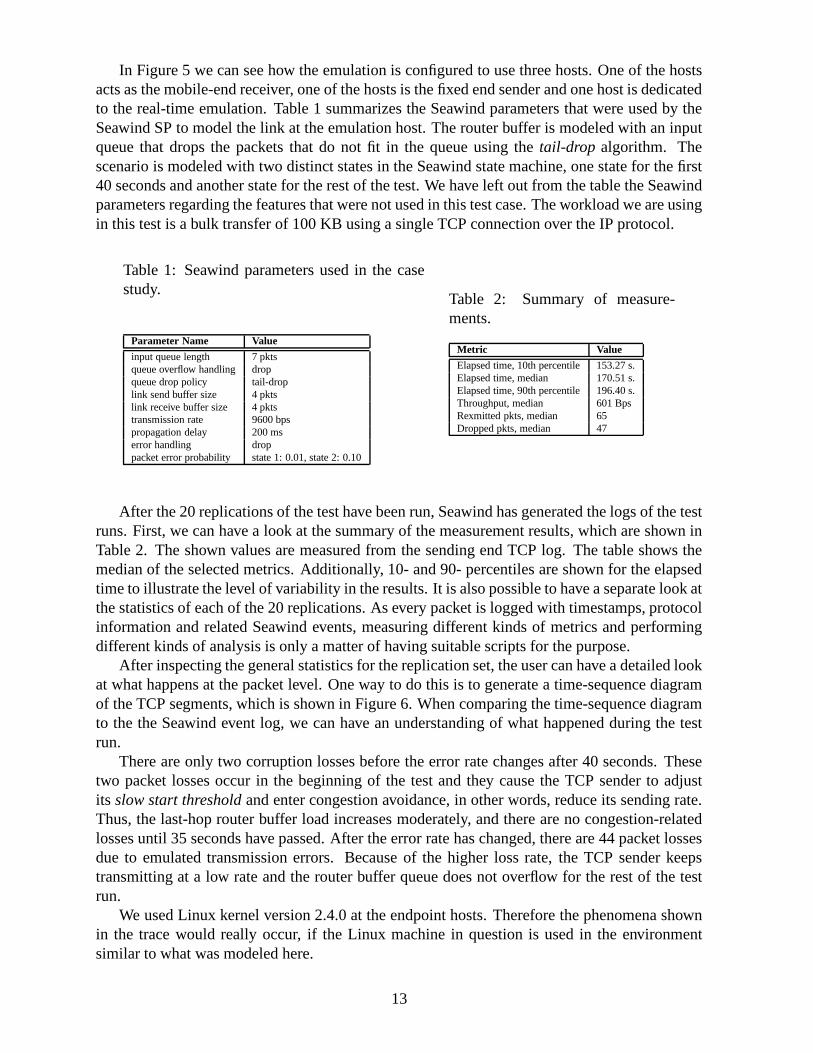
In Figure 5 we can see how the emulation is configured to use three hosts. One of the hostsacts as the mobile-end receiver, one of the hosts is the fixed end sender and one host is dedicatedto the real-time emulation. Table 1 summarizes the Seawind parameters that were used by theSeawind SP to model the link at the emulation host. The router buffer is modeled with an inputqueue that drops the packets that do not fit in the queue using the tail-drop algorithm. Thescenario is modeled with two distinct states in the Seawind state machine, one state for the first40 seconds and another state for the rest of the test. We have left out from the table the Seawindparameters regarding the features that were not used in this test case. The workload we are usingin this test is a bulk transfer of 100 KB using a single TCP connection over the IP protocol.
Table 1: Seawind parameters used in the casestudy.
Parameter Name Value
input queue length 7 pktsqueue overflow handling dropqueue drop policy tail-droplink send buffer size 4 pktslink receive buffer size 4 pktstransmission rate 9600 bpspropagation delay 200 mserror handling droppacket error probability state 1: 0.01, state 2: 0.10
Table 2: Summary of measure-ments.
Metric Value
Elapsed time, 10th percentile 153.27 s.Elapsed time, median 170.51 s.Elapsed time, 90th percentile 196.40 s.Throughput, median 601 BpsRexmitted pkts, median 65Dropped pkts, median 47
After the 20 replications of the test have been run, Seawind has generated the logs of the testruns. First, we can have a look at the summary of the measurement results, which are shown inTable 2. The shown values are measured from the sending end TCP log. The table shows themedian of the selected metrics. Additionally, 10- and 90- percentiles are shown for the elapsedtime to illustrate the level of variability in the results. It is also possible to have a separate look atthe statistics of each of the 20 replications. As every packet is logged with timestamps, protocolinformation and related Seawind events, measuring different kinds of metrics and performingdifferent kinds of analysis is only a matter of having suitable scripts for the purpose.
After inspecting the general statistics for the replication set, the user can have a detailed lookat what happens at the packet level. One way to do this is to generate a time-sequence diagramof the TCP segments, which is shown in Figure 6. When comparing the time-sequence diagramto the the Seawind event log, we can have an understanding of what happened during the testrun.
There are only two corruption losses before the error rate changes after 40 seconds. Thesetwo packet losses occur in the beginning of the test and they cause the TCP sender to adjustits slow start threshold and enter congestion avoidance, in other words, reduce its sending rate.Thus, the last-hop router buffer load increases moderately, and there are no congestion-relatedlosses until 35 seconds have passed. After the error rate has changed, there are 44 packet lossesdue to emulated transmission errors. Because of the higher loss rate, the TCP sender keepstransmitting at a low rate and the router buffer queue does not overflow for the rest of the testrun.
We used Linux kernel version 2.4.0 at the endpoint hosts. Therefore the phenomena shownin the trace would really occur, if the Linux machine in question is used in the environmentsimilar to what was modeled here.
13

0 10 20 30 40 50 60 70 800
1
2
3
4
5
x 104
Time, s
Seq
uenc
e nu
mbe
r, b
ytes
data sentack rcvd
Figure 6: A time-sequence graph of the TCP segments in a test run.
8 Concluding Remarks
This paper presented a wireless network emulator called Seawind. The emulation approach al-lows performance evaluation of existing implementations of protocols and applications over awide range of network characteristics. User scenarios that are difficult to reproduce in existingwireless networks or impossible when the network is only in the design phase can be easilypresented in the emulator. Distinguishable features of the Seawind network emulator are itswireless-oriented design, portability, easy extendibility and an extensive environment of scriptsand tools for the automatic set up of tests and analysis of results. The practical utility of Sea-wind is demonstrated by a case study and a number of studies beyond this paper. We haveexperimented with different operating systems and discovered a number of implementation spe-cific features, of which some did not conform to the RFC specifications. We believe that slowlinks are an environment which have not been considered carefully enough when designing andtesting the different implementations of TCP and other protocols. Therefore, we believe thatSeawind is a valuable tool for testing the protocol implementations in different networking en-vironments in a controllable fashion.
References
[1] M. Allman, A. Caldwell, and S. Ostermann. ONE: The Ohio Network Emulator. Tech-nical Report TR-19972, School of Electrical Engineering and Computer Science, OhioUniversity, August 1997.
[2] M. Allman and A. Falk. On the effective evaluation of TCP. ACM Computer Communica-tion Review, 5(29), October 1999.
[3] R. Bagrodia and W-L. Liao. Maisie: A language for design of efficient discrete-eventsimulations. IEEE Transactions on Software Engineering, April 1994.
14
[4] H. Balakrishnan, V. N. Padmanabhan, S. Seshan, and R. H. Katz. A comparison of mech-anisms for improving TCP performance over wireless links. In Proceedings of ACM SIG-COMM ’96, Stanford, CA, August 1996.
[5] A. Boukerche, S.K. Das, A. Fabbri, and O. Yildiz. Exploiting model independence forparallel PCS network simulation. In 13th workshop of Parallel and Distributed Simulation1999, pages 166–173, May 1999.
[6] G. Brasche and B. Walke. Concepts, services and protocols of the new GSM phase 2+general packet radio service. IEEE Communications Magazine, pages 94–104, August1997.
[7] J. Brosh, D. A. Maltz, D. B. Johnson, Y. Hu, and J. Jetcheve. A performance comparison ofmulti-hop wireless ad hoc network routing protocols. In Proceedings of the Fourth AnnualACM/IEEE International Conference on Mobile Computing and Networking (MOBICOM),pages 85–97, Dallas, Texas, October 1998.
[8] J. Cai and D. J. Goodman. General packet radio service in GSM. IEEE CommunicationsMagazine, pages 122–131, October 1997.
[9] S. Floyd and V. Jacobson. Random Early Detection Gateways for Congestion Avoidance.IEEE/ACM Transactions on Networking, 1(4):397–413, August 1993.
[10] S. Floyd and K. K. Ramakrishnan. A proposal to add explicit congestion notification (ECN)to IP. IETF RFC 2481, January 1999.
[11] NIST Internetworking Technology Group. NIST net network emulation package.http://www.antd.nist.gov/itg/nistnet/, June 2000.
[12] A. Gurtov. Technical Issues of Real-Time Network Emulation in Linux. In Proceedings ofFDPW, June 1999. Available at: http://www.cs.Helsinki.FI/u/gurtov/papers/.
[13] A. Gurtov. TCP performance in presence of congestion and corruption losses. Master’sthesis, Department of Computer Science, University of Helsinki, December 2000. Avail-able at:http://www.cs.Helsinki.FI/group/iwtcp/papers/.
[14] ISI at University of South California. Network simulator 2. Available at:http://www.isi.edu/nsnam/ns/.
[15] V. Jacobson, C. Leres, and S. McCanne. tcpdump. Available at http://ee.lbl.gov/, June1997.
[16] R. Jain. The Art of Computer Systems Performance Analysis: Techniques for ExperimentalDesign, Measurement, Simulation and Modeling. John Wiley & Sons, 1991.
[17] M. Kojo, K. Raatikainen, M. Liljeberg, J. Kiiskinen, and T. Alanko. An efficient trans-port service for slow wireless links. IEEE Journal on Selected Areas In Communications,15(7):1337–1348, September 1997.
15

[18] J. Korhonen, O. Aalto, A. Gurtov, and H. Laamanen. Measured performance of GSMHSCSD and GPRS. In Proceedings of the IEEE International Conference on Communica-tions, 2001.
[19] N. Leavitt. Will WAP deliver the wireless internet. IEEE Computer, 33(5):16–20, May2000.
[20] R. Ludwig. Eliminating Inefficient Cross-Layer Interactions in Wireless Networking. PhDthesis, Aachen University of Technology, April 2000.
[21] M. Mouly and M. Pautet. The GSM System for Mobile Communications. Europe MediaDuplication S.A., 1992.
[22] S. Ostermann. tcptrace. Available at: http://jarok.cs.ohiou.edu/software/tcptrace/tcptrace.html.
[23] M. Rahnema. Overview of the GSM system and protocol architecture. IEEE Communica-tions Magazine, 31(4):92–100, April 1993.
[24] L. Rizzo. Dummynet: A simple approach to the evaluation of network protocols. 27(1):31–41, January 1997.
[25] P. Sarolahti. Performance analysis of TCP improvements for congested reliable wirelesslinks. Master’s thesis, Department of Computer Science, University of Helsinki, February2001. Available at:http://www.cs.Helsinki.FI/group/iwtcp/papers/.
[26] J. Short, R. Bagrodia, and L. Kleinrock. Mobile wireless network system simulation.In Proceedings of the First Annual International Conference on Mobile Computing andNetworking (MOBICOM), pages 195–209, Berkeley, CA USA, November 1995.
[27] Simulation Laboratory (SimLab). MobSim++. Web page:http://www.it.kth.se/labs/sim/demoVisTool/mobsimdemo.html, October 1995.
[28] W. Simpson. The point-to-point protocol (PPP). IETF RFC 1661, July 1994.
[29] W. Stevens. TCP/IP Illustrated, Volume 1; The Protocols. Addison Wesley, 1995.
[30] R. H. Stine. FYI on a network management tool catalog: Tools for monitoring and debug-ging TCP/IP internets and interconnected devices. IETF RFC 1147, April 1990.
[31] OPNET Technologies. OPNET Modeler. Commercial, Information at:http://www.mil3.com/products/modeler/home.html, 2001.
[32] B. H. Walke. Mobile Radio Networks: Networking and Protocols. John Wiley, first edition,1999.
[33] X. Zeng, R. Bagrodia, and M. Gerla. GloMoSim: a library for parallel sim-ulation of large-scale wireless networks. In Proceedings of the 12th Workshopon Parallel and Distributed Simulations (PADS ’98), May 1998. Available at:http://pcl.cs.ucla.edu/projects/glomosim/documents.html.
16