A Virtual Wireless Mesh Network Architecture for Operators
8
VI ME NO: A Virtual Wireless Mesh Network Architecture for Operators Katarzyna Kosek-Szott, Janusz Gozdecki, Krzysztof Loziak, Marek Natkaniec, Szymon Szott and Michal Wagrowski AGH University of Science and Technology, Faculty of Computer Science, Electronics and Telecommunications, al. Mickiewicza 30, 30-059 Krakow, Poland {kosek, gozdecki, loziak, natkaniec, szott, wagrowski}@kt.agh.edu.pl Keywords: Wireless Mesh Networks, Virtualization, Virtual Network Operators, Resource Separation. Abstract: Network virtualization is one of the key concepts of the Future Internet. However, the use of virtualization techniques in wireless mesh networks has thus far not been adequately studied. In this paper we describe VI MENO: a Virtual wireless Mesh Network architecture for Operators, i.e., the first virtualization-enabled wireless mesh network architecture designed for operators. In the proposed architecture, virtualization is used to divide the mesh resources governed by a single mesh network operator among multiple virtual network operators. The advantage of this outsourcing approach is that each virtual network operator can focus on providing a service to its end-users, leaving the network administration to the mesh network operator. This leads to the lowering of the operating expenditure of virtual network operators and allows tailoring of each virtual network to individual operator and service requirements. 1 INTRODUCTION Network virtualization is one of the key concepts of the Future Internet. It enables decoupling the provided services from the underlying infras- tructure (Chowdhury and Boutaba, 2010). There have been multiple research efforts devoted to this topic, mostly with respect to fixed core networks (4WARD, http://www.4ward-project.eu/; AKARI, http://akari-project.nict.go.jp/; ANA, http://www.ana- project.org/; GENI, http://www.geni.net/). In the do- main of wireless local area networks, virtualization has been implemented at the interface level, allow- ing one WiFi access point (AP) to control multiple networks (Banchs et al., 2012). However, the use of virtualization techniques in wireless mesh networks (WMNs) has thus far not been adequately studied even though, as we will show, it can introduce new business scenarios for network operators. WMNs are known for their ability to extend the reach of existing networks (Azcorra et al., 2009). In traditional concepts such a mesh cloud is governed by a single mesh network operator (MNO). We propose a business scenario in which network virtualization is used to divide the mesh resources among multiple vir- tual network operators (VNOs) (Figure 1). Each VNO has dedicated resources in the form of a Virtual Net- work (VN). The VN extends from traffic entry points (either WiFi APs or, in general, Access Routers, ARs) to gateways (GWs) leading to the Internet core net- work. Each VN has statistically guaranteed QoS pa- rameters. The advantage of this outsourcing approach is that each VNO can focus on providing a service to its end-users, leaving the network administration to the MNO. This leads to the lowering of the operating expenditure of VNOs. Furthermore, each VN can be tailored to both operator and service requirements. In this paper we describe VI MENO: a Virtual wireless Mesh Network architecture for Operators. This architecture provides the aforementioned virtu- alization features. Our approach is based on WiFi de- vices (IEEE 802.11, 2012), which are known for their large popularity, low cost, license-free operation, high extendibility, and constant improvement through new IEEE 802.11 amendments. Adopting an approach based on statistical packet multiplexing is in contrast with existing solutions, which are based on circuit switching (most commonly TDMA). However, our approach ensures greater flexibility which is impor- tant when dealing with both bursty traffic as well as varying radio channel conditions. Furthermore, our approach is the first virtualization-enabled WMN ar- chitecture designed for operators: previous efforts fo- cused either on networks for research (Shrestha et al., 2008) or on providing community network access (Matos et al., 2011) or were proposed for ad hoc net- works (Dedecker et al., 2011). The architecture described in this paper is an ini- 207
-
Upload
khangminh22 -
Category
Documents
-
view
1 -
download
0
Transcript of A Virtual Wireless Mesh Network Architecture for Operators

V I M ENO: A Virtual Wireless Mesh Network Architecture for Operat ors
Katarzyna Kosek-Szott, Janusz Gozdecki, Krzysztof Loziak, Marek Natkaniec,Szymon Szott and Michal Wagrowski
AGH University of Science and Technology, Faculty of Computer Science, Electronics and Telecommunications,al. Mickiewicza 30, 30-059 Krakow, Poland
{kosek, gozdecki, loziak, natkaniec, szott, wagrowski}@kt.agh.edu.pl
Keywords: Wireless Mesh Networks, Virtualization, Virtual Network Operators, Resource Separation.
Abstract: Network virtualization is one of the key concepts of the Future Internet. However, the use of virtualizationtechniques in wireless mesh networks has thus far not been adequately studied. In this paper we describeV IMENO: a Virtual wireless Mesh Network architecture for Operators, i.e., the first virtualization-enabledwireless mesh network architecture designed for operators. In the proposed architecture, virtualization is usedto divide the mesh resources governed by a single mesh network operator among multiple virtual networkoperators. The advantage of this outsourcing approach is that each virtual network operator can focus onproviding a service to its end-users, leaving the network administration to the mesh network operator. Thisleads to the lowering of the operating expenditure of virtual network operators and allows tailoring of eachvirtual network to individual operator and service requirements.
1 INTRODUCTION
Network virtualization is one of the key conceptsof the Future Internet. It enables decouplingthe provided services from the underlying infras-tructure (Chowdhury and Boutaba, 2010). Therehave been multiple research efforts devoted to thistopic, mostly with respect to fixed core networks(4WARD, http://www.4ward-project.eu/; AKARI,http://akari-project.nict.go.jp/; ANA, http://www.ana-project.org/; GENI, http://www.geni.net/). In the do-main of wireless local area networks, virtualizationhas been implemented at the interface level, allow-ing one WiFi access point (AP) to control multiplenetworks (Banchs et al., 2012). However, the use ofvirtualization techniques in wireless mesh networks(WMNs) has thus far not been adequately studiedeven though, as we will show, it can introduce newbusiness scenarios for network operators.
WMNs are known for their ability to extend thereach of existing networks (Azcorra et al., 2009). Intraditional concepts such a mesh cloud is governed bya single mesh network operator (MNO). We proposea business scenario in which network virtualization isused to divide the mesh resources among multiple vir-tual network operators (VNOs) (Figure 1). Each VNOhas dedicated resources in the form of a Virtual Net-work (VN). The VN extends from traffic entry points(either WiFi APs or, in general, Access Routers, ARs)
to gateways (GWs) leading to the Internet core net-work. Each VN has statistically guaranteed QoS pa-rameters. The advantage of this outsourcing approachis that each VNO can focus on providing a service toits end-users, leaving the network administration tothe MNO. This leads to the lowering of the operatingexpenditure of VNOs. Furthermore, each VN can betailored to both operator and service requirements.
In this paper we describe VIMENO: a Virtualwireless Mesh Network architecture for Operators.This architecture provides the aforementioned virtu-alization features. Our approach is based on WiFi de-vices (IEEE 802.11, 2012), which are known for theirlarge popularity, low cost, license-free operation, highextendibility, and constant improvement through newIEEE 802.11 amendments. Adopting an approachbased on statistical packet multiplexing is in contrastwith existing solutions, which are based on circuitswitching (most commonly TDMA). However, ourapproach ensures greater flexibility which is impor-tant when dealing with both bursty traffic as well asvarying radio channel conditions. Furthermore, ourapproach is the first virtualization-enabled WMN ar-chitecture designed for operators: previous efforts fo-cused either on networks for research (Shrestha et al.,2008) or on providing community network access(Matos et al., 2011) or were proposed for ad hoc net-works (Dedecker et al., 2011).
The architecture described in this paper is an ini-
207

tial study of the concept of virtual WMNs for oper-ators. We would like to share this concept with thereserach community to stimulate discussion on thenumerous research challenges which we have identi-fied. We plan to implement VIMENO to further studythese issues and provide suitable solutions.
The remainder of this paper is organized as fol-lows. In Section 2 we discuss the business aspects ofour approach. In Section 3, we provide an overviewof the node types forming the network architectureas well as the relevant networking modules. In Sec-tions 4 to 7 we discuss the most important features ofV IMENO: network monitoring, resource separation,traffic shaping, and routing, respectively. The conclu-sions and future work are summarized in Section 8.
Set of APs
Mesh Cloud
Internet
1
n
Figure 1: Concept of the proposal.
2 CONTRACT
The network architecture and its functionality is de-termined by the contract agreed upon between theMNO and its customers, the VNOs. The main taskof the MNO is to ensure the contract execution for allVNOs and in the case of temporary resource scarcity(due to, e.g., congestions, degradation of propaga-tion conditions, or failures) perform appropriate re-configurations to provide fair, or in accordance withan agreed policy, resource distribution. Moreover, wedefine a method for flexible and dynamic resource dis-tribution according to generated traffic as a part of theV IMENO architecture’s self-organising functionality.
Multiple detailed schemes for the contract can beconsidered, however, for the purpose of our inves-tigations we have decided to define a flexible oneto provide smart resource distribution within VNsand create a solid base for further developments.Thus, the VNO buys uplink and downlink through-put (RUL,RDL) and specifies a set of Mesh AccessNodes{MANn}, wheren ∈ (0,NMAN ] and NMAN isthe total number of MANs in the network, on whichthis VN will be available. The throughput guaran-tee is statistical with a given rate probability function,which is in line with current mobile network opera-tor business models for services based on packet datatransmission. It is up to the network planning process
and in particular its dimensioning phase to ensure thatthere are, statistically, enough resources to meet thecontract demands. We can determine the relation be-tween contract commitments and the network capac-ity as follows:
NVNO
∑i=1
RULi ≤CUL(1+ ε), (1)
NV NO
∑i=1
RDLi ≤CDL(1+ ε), (2)
whereRULi andRDL
i is the contracted throughput in theuplink and downlink direction, respectively, for thei-th operator;NV NO is the number of VNOs,CUL andCDL are the uplink and downlink network capacity,respectively; andε is the capacity under-provisioningfactor. These equations reflect our assumption thattypically the total load of the WMN will be smallerthan its capacity, and, therefore, we can assume sta-tistical resource sharing.
Based on the signed contracts, the MNO is re-sponsible for setting up VNs and providing connec-tivity within the mesh network. The access part of thenetwork is separated between VNOs by having eachAP located at a MAN broadcast individual SSIDs foreach VN. VNs are also treated independently by theremaining physical mesh infrastructure. Thus, mul-tiple routing protocol instances must be involved todefine transmission paths. The physical network ar-chitecture is a mesh, however all paths are establishedbetween MANs and Mesh Gateways (MGW) to pro-vide Internet access, which results in the functionalarchitecture of multiple trees. Periodically, or in re-sponse to radio link quality degradation or failures inthe network, the paths can be modified by the rout-ing protocol. Hence, some paths can also be redi-rected to other MGWs. Such an operation may resultin load variation at the MGW and other intermediatemesh nodes. Moreover, the load can be distributed un-equally among VNs, since VNOs define independentsets of MANs and independent throughput contracts.”If there is a risk of exceeding the maximum capac-ity of any link of an MGW (or any other mesh node),the throughput values currently configured for partic-ular VNOs must be fairly decreased at that node. Thismeans that each mesh node must know the proportionof particular VN load requirements that are to be met.This can be reported by the MANs or MGWs cur-rently attached to the mesh node or by a central ded-icated management entity that is to serve as a centralresource distribution coordination point. These issuesare further discussed in Sections 5 and 6.
In order to simplify the description, we assumethat all the connections in the mesh network have been
WINSYS�2013�-�International�Conference�on�Wireless�Information�Networks�and�Systems
208

configured. We therefore bypass the initial bootstrap-ping stage. Additionally, we exclude mobility issues(i.e., the movement of VNO clients between MANs)from our field of study. Finally, we assume that alltraffic flows initiate or terminate, from the mesh net-work perspective, in the MANs and MGWs.
3 NETWORKAND NODE ARCHITECTURE
Figure 2 presents a detailed view of the network ar-chitecture in VIMENO, highlighting the data paths ina given example topology. In the following, we givea brief overview of the elements presented in this fig-ure. There are three mesh node types in the network:(i) Mesh Gateway(MGW) — interconnects the meshand the core networks using either wireless or fixedlinks, (ii) Mesh Access Node(MAN) — offers net-work access to end users, typically equipped with atleast two wireless interfaces: one for providing net-work access and the other for connecting to the meshnetwork, (iii) Mesh Relay Node(MRN) — intercon-nects MANs with MGWs and relays user traffic, typ-ically equipped with at least two wireless interfaces:one in the uplink and one in the downlink data transferdirection, respectively. In practice, to achieve bettermesh network performance, it is recommended thateach MRN have at least three wireless interfaces.
Each mesh node (Figure 3) contains the follow-ing building blocks: (i)wireless interfaces— typicalIEEE 802.11 interfaces, (ii)virtual wireless inter-faces— to support the various VNs transported in themesh network, (ii)schedulers— to properly plan thetransmission from each virtual interface, (iv)trafficshapers— to limit the amount of traffic transportedin the network, they are present only in the ingressnodes: MANs and MGWs for the uplink and down-link directions, respectively, (v)monitoring module— to measure and estimate current PHY and MACparameters, (vi)routing module — to orchestratetraffic forwarding within the network, a separate in-stance is executed for each VN.
In principle, the network operates as follows.Traffic from VNs is separated using virtual interfacesand appropriately configured schedulers (Section 5).The traffic shapers are configured in such a way as tofulfil the contract and minimise the traffic transportedin the mesh network (Section 6). Each VN employs aseparate routing protocol (Section 7). All these mech-anisms are supported by passive network monitoring(Section 4). In the following sections, we describeeach mechanism in detail.
4 MONITORING
Since the parameters of wireless links cannot be de-termined in advance, they need to be estimated af-ter the setup of wireless links. Additionally, duringnetwork operation, the parameters can change due tofluctuations of the radio propagation conditions or in-terference from other networks. Typical operatingsystem tools do not provide reliable estimates on theavailable and used data rates on the wireless links.The only possibility to obtain such information is touse a dedicated monitoring mechanism. In the VI-MENO architecture we define the Monitoring Mod-ule (MM), which provides a passive monitoring ser-vice able to measure several parameters related to ra-dio channel conditions, capabilities of neighbouringnodes and IEEE 802.11 MAC parameters estimation.MM provides precise network measurements withoutdisrupting network operation.
The results of MM measurements are utilizedmainly by the routing module, shapers, and sched-ulers. During normal network operation the most im-portant parameters that have to be delivered by theMM for each link are: the available data rate, the datarate used by each VN, delay, jitter, and packet loss ra-tio. The MM module performs measurements at thePHY and MAC layers within the time-scale of mi-croseconds, based on all types of 802.11 frames (data,management, and control). To ensure a comprehen-sive view of the current wireless channel conditions,including traffic from networks of other operators, thepromiscuous mode of operation of wireless networkcards is used. The use of passive mode means that allmeasurements are performed along with the normalactivity of the wireless card.
The MM works on a frame level, i.e., all framessent and received by each network interface must beexamined by the MM functions. This imposes highrequirements on the implementation effectiveness ofthe frame analysis (i.e., the limited computationalpower available at the nodes should be taken intoaccount). In the Linux operating system the above-mentioned requirements force an implementation ofMM as a kernel module closely interworking with themac80211 wireless framework (mac80211, 2013) .
5 RESOURCE SEPARATION
In V IMENO, network virtualization is realized dif-ferently in the access and mesh parts of the network.This is illustrated in Figure 4. The differences be-tween the two virtualization methods (link and inter-face) are subtle. We discuss them below.
VIMENO:�A�Virtual�Wireless�Mesh�Network�Architecture�for�Operators
209

CH4
CH3
CH2
CH1
Internet
Virtual L
ink VP1
Virtual L
ink VPn
Virtual Link VP1Virtual Link VPn
Virtual Link VP1
Virtual Link VPn
Virtual L
ink VP1
Virtual L
ink VPn
Access Network Mesh Network Core Network
VI1VI1
VIn
Mesh Relay Node
VIn
VI1VI1
VIn
Mesh Relay Node
VIn
SSID1
SSIDn
STA1
STAn
VI1
VIn
TS1,1
TSn,n
VI1,1
VI1,n
VIn,1
Vin,n
Access
Point
Mesh Access
Node
TSn,1
TS1,n
VIn
VI1
TSn,n
TS1,1
VIn,n
VIn,1
VI1,n
VI1,1
Mesh Gateway
TS1,n
TSn,1
Figure 2: Network architecture with basic elements.
VP2VP1VP2VP1
Mesh Node
Monitoring Module
Traffic
Shapers
Virtual
Interfaces
Schedulers
Physical
Interfaces
TSTS TS TS
VIVI VI VI
Routing
Module
Figure 3: Architecture of the mesh node.
Access Point
Access Point
Link VirtualizationInterface Virtualization
SSID1
SSID2
STA1
STA2
VI1
VI2
Access Point
Virtual
Network 1
Virtual
Network 2
Mesh Cloud
Access RouterAccess Router
Internet Edge Router
CH2
CH1
Virtual Link 1
Virtual Link 2
VI1
VI2
Mesh Node
VI1
VI2
Virtual Link 1
Virtual Link 2
VI1VI1
VI2
Mesh Node
VI2
VI1VI1
VI2
Mesh Node
VI2
Figure 4: Separation between virtual networks.
In the access part of VIMENO, the VNs are sep-arated using standard interface virtualization. There-fore, the wireless interface of each AP (at the MAN)is virtualized and a separate virtual interface (VI) isprovided for each VNO. This allows separation be-tween VNOs by setting a different SSID for each ofthem. This type of interface virtualization has beendescribed in numerous papers and, therefore, we re-fer the reader to (Chandra and Bahl, 2004; Smithet al., 2007; Rivera and Zucci, 2010; Al-Hazmi andde Meer, 2011; Braham and Pujolle, 2011) for fur-ther details. Currently, we assume standard 802.11fairness in scheduling between VIs. However, in thefuture we foresee remote configuration of the clientnode MAC parameters by the AP.
In the mesh part of VIMENO, the VNs are sep-arated using link virtualization. Therefore, a sepa-
rate virtual link is provided for each VNO on a sin-gle wireless channel1. The separation of traffic (i.e.,packet flows) between VNs is based on statisticalpacket scheduling (described below). Such a solutionis cheap, scalable, flexible, does not require synchro-nization, and finally, it is in line with the packet natureof the Internet.
Mesh Node #1
VI1
VI2
1,1,0T
1,2,0T
Mesh Node #3
B1,1
Mesh Node #2
3,1,2T
3,2,2T
2,1,0T B1,2
B2,1
VI1
VI2
1,1,1T
1,2,1T
2,1,1T
2,2,1T
Stage 1 Stage 2
Traffic flow (upstream)
2,2,0T
TS1,1
TS2,1
TS1,2
TS2,2
VI1
VI2
Incoming
Traffic
Figure 5: Generalized intra-mesh scheduling assuming twoVNOs.
The generalized intra-mesh scheduling method isillustrated in Figure 5. In principle, the goal of thescheduler’s operation is, in the absence of sufficientresources, to fairly divide the available link capac-ity among the VNs. This is performed in proportionto current traffic shaper settings. At the first stage(i = 1), i.e., at the MAN or MGW, the scheduler isconfigured so that the outgoing traffic rate (in b/s) ofeach VI j of thek-th mesh node is set as follows
T1, j,k = min
(
TS j,k
∑NV NOh=1 T Sh,k
B1, j,T0, j,k
)
, (3)
whereT S j,k is the setting of thej-th traffic shaper ofthe k-th mesh node,NVNO is the number of VNOs,andB1, j is the capacity of the outgoing link of thek-th mesh node. This means, that under non-saturationT1, j,k = T0, j,k (i.e., the current incoming traffic ratescorrespond to the outgoing traffic rates). Additionally,
under saturationT1, j,k =T S j,k
∑NVNOh=1 T Sh,k
B1, j, which means
1A channel allocation scheme is out of the scope of thispaper. We refer the reader to (Lv et al., 2012) for an exem-plary OFDM-based scheme.
WINSYS�2013�-�International�Conference�on�Wireless�Information�Networks�and�Systems
210
that the outgoing traffic rate is scaled according to thecapacity of the outgoing link of thek-th mesh nodeand the current settings of appropriate traffic shapers.
At stagesi > 1 the outgoing traffic rate from eachVI j of the k-th mesh node is dependent on the rateconfigurations of the traffic shapers located at the up-stream ingress nodes:
Ti+1, j,k =
min
(
∑l∈KkTS j,l
∑NV NOh=1 ∑l∈Kk
TSh,l
Bi+1, j, ∑l∈Kk
Ti, j,l
)
,(4)
whereKk is the set of upstream one-hop neighborsof k. Under non-saturation all traffic arriving tothe k-th mesh node is transmitted to the next stage(
Ti+1, j,k = ∑l∈KkTi, j,l
)
. Under saturation, the outgo-ing traffic rate from thek-th mesh node is scaled ac-cording to the value of the capacity of the outgoing
link
(
Ti+1, j,k =∑l∈Kk
T Si, j,l
∑NVNOh=1 ∑l∈Kk
TSi,h,lBi+1, j
)
. Such an ap-
proach requires the dissemination of current TS rateconfigurations, but assures fairness in relation to boththe contracts as well as the current VNO traffic re-quirements.
In order to discriminate between VNs VLAN tagsare employed (IEEE 802.1Q, 2011). They are placedafter the IEEE 802.11 header in each frame. Such asolution is flexible, backward compatible, and allowsstraightforward implementation in wireless devices.
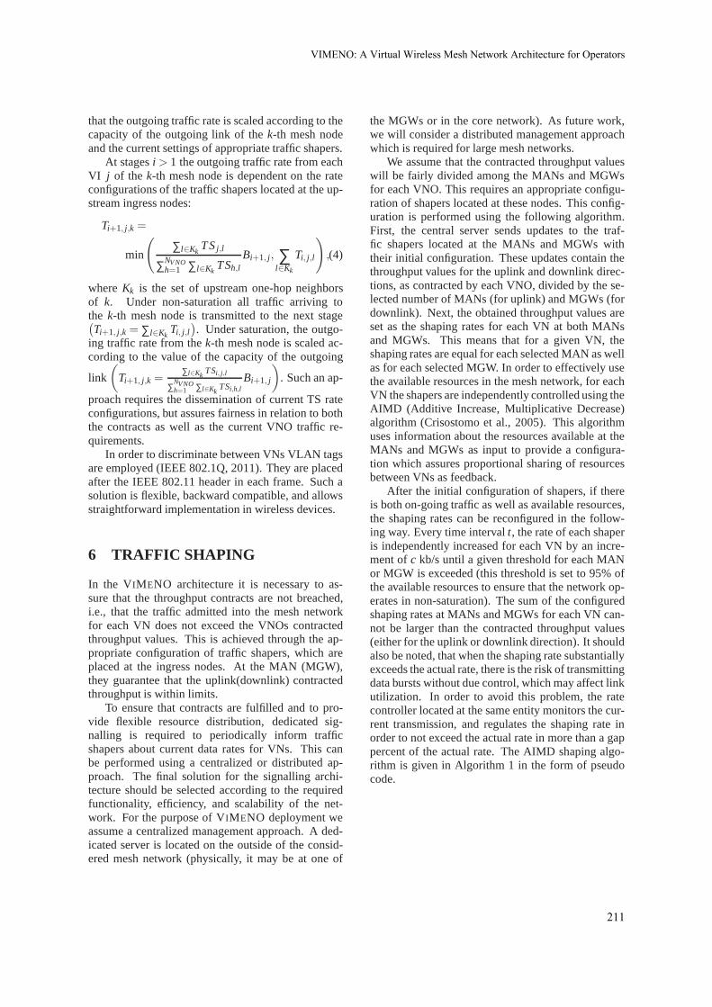
6 TRAFFIC SHAPING
In the VIMENO architecture it is necessary to as-sure that the throughput contracts are not breached,i.e., that the traffic admitted into the mesh networkfor each VN does not exceed the VNOs contractedthroughput values. This is achieved through the ap-propriate configuration of traffic shapers, which areplaced at the ingress nodes. At the MAN (MGW),they guarantee that the uplink(downlink) contractedthroughput is within limits.
To ensure that contracts are fulfilled and to pro-vide flexible resource distribution, dedicated sig-nalling is required to periodically inform trafficshapers about current data rates for VNs. This canbe performed using a centralized or distributed ap-proach. The final solution for the signalling archi-tecture should be selected according to the requiredfunctionality, efficiency, and scalability of the net-work. For the purpose of VIMENO deployment weassume a centralized management approach. A ded-icated server is located on the outside of the consid-ered mesh network (physically, it may be at one of
the MGWs or in the core network). As future work,we will consider a distributed management approachwhich is required for large mesh networks.
We assume that the contracted throughput valueswill be fairly divided among the MANs and MGWsfor each VNO. This requires an appropriate configu-ration of shapers located at these nodes. This config-uration is performed using the following algorithm.First, the central server sends updates to the traf-fic shapers located at the MANs and MGWs withtheir initial configuration. These updates contain thethroughput values for the uplink and downlink direc-tions, as contracted by each VNO, divided by the se-lected number of MANs (for uplink) and MGWs (fordownlink). Next, the obtained throughput values areset as the shaping rates for each VN at both MANsand MGWs. This means that for a given VN, theshaping rates are equal for each selected MAN as wellas for each selected MGW. In order to effectively usethe available resources in the mesh network, for eachVN the shapers are independently controlled using theAIMD (Additive Increase, Multiplicative Decrease)algorithm (Crisostomo et al., 2005). This algorithmuses information about the resources available at theMANs and MGWs as input to provide a configura-tion which assures proportional sharing of resourcesbetween VNs as feedback.
After the initial configuration of shapers, if thereis both on-going traffic as well as available resources,the shaping rates can be reconfigured in the follow-ing way. Every time intervalt, the rate of each shaperis independently increased for each VN by an incre-ment ofc kb/s until a given threshold for each MANor MGW is exceeded (this threshold is set to 95% ofthe available resources to ensure that the network op-erates in non-saturation). The sum of the configuredshaping rates at MANs and MGWs for each VN can-not be larger than the contracted throughput values(either for the uplink or downlink direction). It shouldalso be noted, that when the shaping rate substantiallyexceeds the actual rate, there is the risk of transmittingdata bursts without due control, which may affect linkutilization. In order to avoid this problem, the ratecontroller located at the same entity monitors the cur-rent transmission, and regulates the shaping rate inorder to not exceed the actual rate in more than a gappercent of the actual rate. The AIMD shaping algo-rithm is given in Algorithm 1 in the form of pseudocode.
VIMENO:�A�Virtual�Wireless�Mesh�Network�Architecture�for�Operators
211
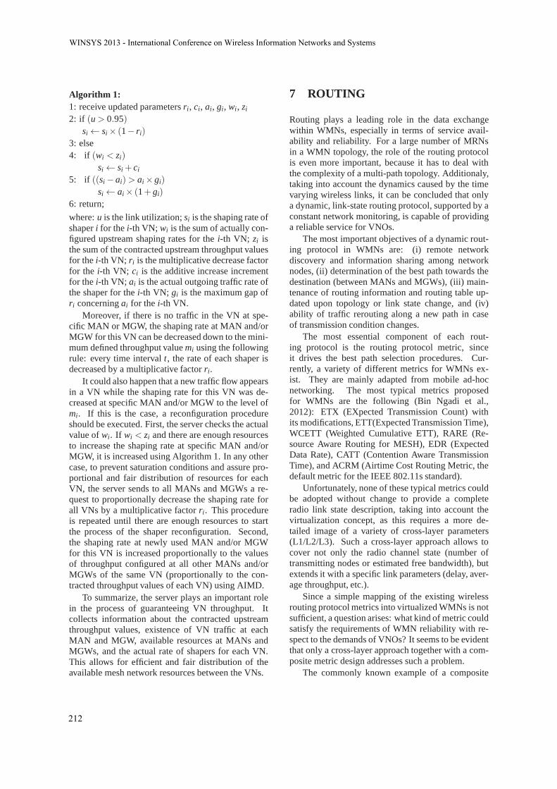
Algorithm 1:1: receive updated parametersri, ci, ai, gi, wi, zi
2: if (u > 0.95)si← si× (1− ri)
3: else4: if (wi < zi)
si← si + ci
5: if ((si− ai)> ai× gi)
si← ai× (1+ gi)
6: return;
where:u is the link utilization;si is the shaping rate ofshaperi for thei-th VN; wi is the sum of actually con-figured upstream shaping rates for thei-th VN; zi isthe sum of the contracted upstream throughput valuesfor thei-th VN; ri is the multiplicative decrease factorfor the i-th VN; ci is the additive increase incrementfor thei-th VN; ai is the actual outgoing traffic rate ofthe shaper for thei-th VN; gi is the maximum gap ofri concerningai for thei-th VN.
Moreover, if there is no traffic in the VN at spe-cific MAN or MGW, the shaping rate at MAN and/orMGW for this VN can be decreased down to the mini-mum defined throughput valuemi using the followingrule: every time intervalt, the rate of each shaper isdecreased by a multiplicative factorri.
It could also happen that a new traffic flow appearsin a VN while the shaping rate for this VN was de-creased at specific MAN and/or MGW to the level ofmi. If this is the case, a reconfiguration procedureshould be executed. First, the server checks the actualvalue ofwi. If wi < zi and there are enough resourcesto increase the shaping rate at specific MAN and/orMGW, it is increased using Algorithm 1. In any othercase, to prevent saturation conditions and assure pro-portional and fair distribution of resources for eachVN, the server sends to all MANs and MGWs a re-quest to proportionally decrease the shaping rate forall VNs by a multiplicative factorri. This procedureis repeated until there are enough resources to startthe process of the shaper reconfiguration. Second,the shaping rate at newly used MAN and/or MGWfor this VN is increased proportionally to the valuesof throughput configured at all other MANs and/orMGWs of the same VN (proportionally to the con-tracted throughput values of each VN) using AIMD.
To summarize, the server plays an important rolein the process of guaranteeing VN throughput. Itcollects information about the contracted upstreamthroughput values, existence of VN traffic at eachMAN and MGW, available resources at MANs andMGWs, and the actual rate of shapers for each VN.This allows for efficient and fair distribution of theavailable mesh network resources between the VNs.
7 ROUTING
Routing plays a leading role in the data exchangewithin WMNs, especially in terms of service avail-ability and reliability. For a large number of MRNsin a WMN topology, the role of the routing protocolis even more important, because it has to deal withthe complexity of a multi-path topology. Additionaly,taking into account the dynamics caused by the timevarying wireless links, it can be concluded that onlya dynamic, link-state routing protocol, supported by aconstant network monitoring, is capable of providinga reliable service for VNOs.
The most important objectives of a dynamic rout-ing protocol in WMNs are: (i) remote networkdiscovery and information sharing among networknodes, (ii) determination of the best path towards thedestination (between MANs and MGWs), (iii) main-tenance of routing information and routing table up-dated upon topology or link state change, and (iv)ability of traffic rerouting along a new path in caseof transmission condition changes.
The most essential component of each rout-ing protocol is the routing protocol metric, sinceit drives the best path selection procedures. Cur-rently, a variety of different metrics for WMNs ex-ist. They are mainly adapted from mobile ad-hocnetworking. The most typical metrics proposedfor WMNs are the following (Bin Ngadi et al.,2012): ETX (EXpected Transmission Count) withits modifications, ETT(Expected Transmission Time),WCETT (Weighted Cumulative ETT), RARE (Re-source Aware Routing for MESH), EDR (ExpectedData Rate), CATT (Contention Aware TransmissionTime), and ACRM (Airtime Cost Routing Metric, thedefault metric for the IEEE 802.11s standard).
Unfortunately, none of these typical metrics couldbe adopted without change to provide a completeradio link state description, taking into account thevirtualization concept, as this requires a more de-tailed image of a variety of cross-layer parameters(L1/L2/L3). Such a cross-layer approach allows tocover not only the radio channel state (number oftransmitting nodes or estimated free bandwidth), butextends it with a specific link parameters (delay, aver-age throughput, etc.).
Since a simple mapping of the existing wirelessrouting protocol metrics into virtualized WMNs is notsufficient, a question arises: what kind of metric couldsatisfy the requirements of WMN reliability with re-spect to the demands of VNOs? It seems to be evidentthat only a cross-layer approach together with a com-posite metric design addresses such a problem.
The commonly known example of a composite
WINSYS�2013�-�International�Conference�on�Wireless�Information�Networks�and�Systems
212
metric is the one used by the EIGRP routing proto-col (EIGRP, 2005). It is formulated as follows:
M =
(
K1×B+ K2×B256−L +K3×D
)
K5
R+K4, (5)
whereM — metric,B — bandwidth (in bits per sec-ond),L — load,D — delay,R — reliability. Addition-ally, K1 to K5 are the cumulative weights. By defaultK1 andK3 are set to 1, while the others are set to 0.The EIGRP protocol uses the minimum bandwidth onthe path towards the destination network and the totaldelay to calculate its routing metric. The load compo-nent reflects link saturation, while the reliability com-ponent represents the measure of the likelihood thata link will fail. A detailed description of the EIGRPmetric can be found in (EIGRP, 2005).
In case of time varying wireless links, the for-mula of a composite metric is not so evident as forEIGRP, since we cannot rely on the stability of thebandwidth and delay values.2 Therefore, the pro-posed VIMENO composite metric should be based oncomponents selected from the following four genericgroups: (i)Basic: hop count, estimated maximumavailable bandwidth; (ii)Quality of Service: linkcapacity, average transmission rate, aggregated per-hop and overall delay, jitter, BER; (iii)Interference:number of nodes operating on the same channel, SNRratio, RxPwr ratio; (iv)Route Stability: consideredas the radio link stability with respect to a rate uti-lization histogram analysis and link availability in along timescale. The following parameters have beenselected as the most representative elements of theV IMENO composite metric: (i)Bandwidth estima-tions: ratio of the required, contractual, bandwidth oraverage available throughput (per VNO) compared tothe estimated free channel bandwidth; (ii)Interfer-ence: number of nodes transmitting on a single radiochannel; (iii) Route stability: multi-rate utilizationand link availability.
These parameters will be provided by the Moni-toring Module operating on all the physical interfacesof the mesh node. However, the exact definition of thefinal VIMENO composite metric formula requires adetailed mathematical and simulation analysis, whichis beyond the scope of this paper.
Importantly, the VIMENO architecture is able tosupport traffic separation between VNOs. This re-quires that at each physical radio link a dedicated vir-tual link is assigned for a single VNO. The virtual linkis then established between a set of virtual interfaceson the physical ones at neighbouring WMN nodes.
2Originally, both parameters, bandwidth and delay, inthe EIGRP metric are assumed to be static.
The set of virtual links composes a VN topology for aVNO. To assure end-to-end connectivity, a dedicatedlink-state routing protocol is required to operate sep-arately for each VN topology.
The main goal of the routing protocol is to provideoptimal path selection between MANs and MGWsand activate a rerouting procedure in case of degra-dation of radio conditions. The rerouting process as-sumes that multiple paths exist between MANs andMGWs. To satisfy this assumption, during the VNOnetwork setup phase, the virtual interfaces dedicatedto a specific VNO should be configured. Additionally,virtual links should be set up over all physical ones,so as not to limit the possibilities of alternative pathselection.
Due to the limitation of the radio resources, wecannot assume resource over-provisioning at a simi-lar level as it is possible in fixed networks, but someover-provisioning may need to be considered to avoidlink congestion. In the case of virtualized WMNslink congestion may be caused by synchronization ofrerouting decisions within the same physical node fordifferent VNOs. To avoid this situation, the value ofthe composite metric should be calculated separatelyfor each VN and the metric computation algorithmshould avoid synchronization of the rerouting pro-cess. As a result, a slight time shift in the signalling ofradio link parameter degradation to each VNO routingprotocol is considered. This helps to avoid the prob-lem of path flipping between interfaces at the samephysical node for all existing VNOs at the same time.The selection of the VN which should be triggered toactivate the rerouting procedure may be based on theVNO contract with respect to the required QoS pa-rameters (delay, jitter, etc.), business-level parameters(VNO priority), currently used bandwidth, etc.
At the first stage of the VIMENO architecture de-velopment, for simplicity and taking into account thatmultiple VNO networks exist in a single WMN node,load balancing takes place at the VNO level. There-fore, we do not consider multi-path routing insideVNO networks. The analysis of multi-path routingis planned as our future work.
8 CONCLUSIONSAND FUTURE WORK
This article has presented an initial study of VI-MENO, the first virtual wireless mesh network ar-chitecture for operators. The novelties proposed inthe article include: definition of a new business sce-nario in which network virtualization is used to dividethe mesh resources among multiple VNOs; distinc-
VIMENO:�A�Virtual�Wireless�Mesh�Network�Architecture�for�Operators
213

tion between interface and link virtualization for theaccess and mesh network parts, respectively; archi-tecture of a virtualized mesh node; virtualization ofthe mesh network composed of intra-mesh schedulingcombined with the assignment of VLAN tags; shap-ing technique based on the throughput metric, provid-ing upstream and downstream guarantees for VNOs;and link-sate routing protocol, composed of differentinstances for each VNO. A promising advantage ofthe proposed architecture (in contrary to the previousTDMA-based solutions) is the fact that it is in linewith the packet nature of the Internet.
Our future work will be directed towards the im-plementation of VIMENO in real wireless devices.This will allow testing and optimizing the proposedsolutions. Future enhancement of VIMENO is alsoplanned in order to make the architecture even moresuited to various possible requirements of wirelessnetwork operators and services. The following net-working challenges will be considered: design of al-ternative routing solutions supporting the virtualiza-tion concept, definition of the formula for the rout-ing composite metric, distributed network manage-ment and traffic shaping, wireless network bootstrap-ping, appropriate load balancing, network reconfigu-ration and rerouting, network resilience and surviv-ability, security of signalling data, and quality of ser-vice (QoS) provisioning. They will be designed tak-ing the perspective of VNOs into account. Obviously,an introduction of new functionalities will require re-thinking of the currently proposed solutions and pro-tocols. E.g., the introduction of QoS provisioning willimpact the settings of traffic shapers and schedulers.
ACKNOWLEDGEMENTS
This work has been carried out as a part of a projectfinanced by the Polish National Science Centre (deci-sion no. DEC-2011/01/D/ST7/05166)).
REFERENCES
Al-Hazmi, Y. and de Meer, H. (2011). Virtualization of802.11 interfaces for wireless mesh networks. InProc.of WONS 2011.
Azcorra, A., Banniza, T., Chieng, D., Fitzpatrick, J., Von-Hugo, D., Natkaniec, M., Robitzsch, S., and Zdarsky,F. (2009). Supporting carrier grade services over wire-less mesh networks: The approach of the EuropeanFP-7 STREP CARMEN.Commun. Mag., 47(4):14–16.
Banchs, A., Serrano, P., Patras, P., and Natkaniec, M.(2012). Providing Throughput and Fairness Guaran-
tees in Virtualized WLANs Through Control Theory.Mob. Netw. Appl., 17:435–446.
Bin Ngadi, M. A., Ali, S., Abdullah, A. H., and Khokhar,R. H. (2012). A taxonomy of cross layer routing met-rics for wireless mesh networks.Journal on WirelessCommunications and Networking, 2012(177).
Braham, O. and Pujolle, G. (2011). Virtual wireless networkurbanization. InNetwork of the Future (NOF), 2011International Conference on the, pages 31–34. IEEE.
Chandra, R. and Bahl, P. (2004). MultiNet: Connecting tomultiple IEEE 802.11 networks using a single wire-less card. InProc. of INFOCOM 2004.
Chowdhury, N. and Boutaba, R. (2010). A survey of net-work virtualization.Comp. Net., 54:862–876.
Crisostomo, S., Sargento, S., Natkaniec, M., and Vicari,N. (2005). A QoS architecture integrating mobile ad-hoc and infrastructure networks. InProc. of AICCSA2005.
Dedecker, P., Hoebeke, J., Moerman, I., Moreau, J., andDemeester, P. (2011). Network virtualization asan integrated solution for emergency communication.Telecommunication Systems, pages 1–18.
EIGRP (2005). Enhanced Interior Gateway Routing Proto-col. http://www.cisco.com/en/US/tech/tk365/technologies_white_paper09186a0080094cb7.shtml.
IEEE 802.11 (2012). IEEE Standard for Informationtechnology—Telecommunications and informationexchange between systems—Local and metropoli-tan area networks—Specific requirements—Part 11:Wireless LAN Medium Access Control (MAC) andPhysical Layer (PHY) Specifications, March 2012.
IEEE 802.1Q (2011). IEEE 802.1Q-2011 — IEEE Stan-dard for Local and metropolitan area networks–MediaAccess Control (MAC) Bridges and Virtual BridgedLocal Area Networks.
Lv, P., Wang, X., and Xu, M. (2012). Virtual access net-work embedding in wireless mesh networks.Ad HocNetworks, 10(7):1362–1378.
mac80211 (2013). Linux wireless (IEEE-802.11) subsys-tem. http://linuxwireless.org.
Matos, R., Sargento, S., Hummel, K. A., Hess, A.,Tutschku, K., and de Meer, H. (2011). Context-basedwireless mesh networks: a case for network virtual-ization. Telecommunication Systems, 51:1–14.
Rivera, A. D. and Zucci, W. (2010). Virtualization of wire-less network interfaces Wi-Fi IEEE 802.11. InProc.of TELE-INFO 2010.
Shrestha, S., Lee, J., and Chong, S. (2008). Virtualizationand slicing of wireless mesh network. InProc. of CFI2008.
Smith, G., Chaturvedi, A., Mishra, A., and Banerjee, S.(2007). Wireless virtualization on commodity 802.11hardware. InProc. of ACM WiNTECH 2007.
WINSYS�2013�-�International�Conference�on�Wireless�Information�Networks�and�Systems
214