Network infrastructure extension using 802.1D-based wireless mesh networks
23
WIRELESS COMMUNICATIONS AND MOBILE COMPUTING Wirel. Commun. Mob. Comput. (2010) Published online in Wiley InterScience (www.interscience.wiley.com). DOI: 10.1002/wcm.916 RESEARCH ARTICLE Network infrastructure extension using 802.1D-based wireless mesh networks Rui Campos 1∗ , Ricardo Duarte 2 , Filipe Sousa 2 , Manuel Ricardo 1 and Jos ´ e Ruela 1 1 INESC Porto, Faculdade de Engenharia, Universidade do Porto, Rua Dr. Roberto Frias, 378, 4200-465 Porto, Portugal 2 Fraunhofer Portugal, Rua do Campo Alegre, 1021, 4169–007 Porto, Portugal ABSTRACT Ubiquitous Internet access is becoming a major requirement for end-users due to the increasing number of services and applications supported over the Internet. Extending the coverage of current Wi-Fi infrastructures installed in companies, universities and cities, has been considered a solution to help in fulfilling this requirement, namely when it comes to wireless and nomadic Internet access. This paper describes and analyses a new and simple solution, called Wi-Fi network Infrastructure eXtension (WiFIX), aimed at extending current Wi-Fi infrastructures. WiFIX is based on standard IEEE 802.1D bridges and a single-message protocol that is able to self-organize the network, and it only requires software changes in IEEE 802.11 access points (APs); no changes to IEEE 802.11 stations are needed. Overhead analysis and experimental results show both the higher efficiency of the solution compared to the IEEE 802.11s draft standard and its good performance as far as data throughput, delay and packet loss are concerned. Copyright © 2010 John Wiley & Sons, Ltd. KEYWORDS wireless mesh networks; multi-hop; bridging; self-management * Correspondence Rui Campos, INESC Porto, Faculdade de Engenharia, Universidade do Porto, Rua Dr. Roberto Frias, 378, 4200-465 Porto, Portugal. E-mail: [email protected] 1. INTRODUCTION The Internet is becoming the global communication infrastructure for accessing multimedia services and data and, as such, it is the infrastructure users are willing to be permanently connected to. With its rapid growth as well as the demand for broadband services, access networks have been receiving intense investments in recent years. In this context, the IEEE 802.11 [1] standard, also known as Wi-Fi (the two terms will be used interchangeably), is assuming a prominent role. Wi-Fi infrastructures are being widely deployed around the world in university campus, corporations or even in entire cities, as a means of providing wireless and broadband access to the Internet. The success achieved by the Wi-Fi technology is related to three aspects: the use of unlicensed frequency bands, high bandwidth capabilities and low deployment cost. In addition, the integration of the technology within portable devices, from laptops to smart phones, has decisively contributed to further strengthen its success. Indeed, Wi-Fi is becoming a true universal wireless technology for accessing the Internet worldwide. Due to its success and the increasing number of devices supporting the technology, the demand for Wi-Fi coverage is growing everyday. Since Wi-Fi has limited radio range, the coverage of large geographical areas can only be achieved by installing multiple Wi-Fi Access Points (APs) that, however, need to be connected to the wired backhaul Ethernet infrastructure. In some cases, this may require the installation of a large number of APs and wires, which introduces complexity, may imply high costs, and may involve considerable technical manpower to deploy the network. Also, the need to connect each AP to the wired infrastructure provides limited flexibility; often, the point of attachment of the APs is constrained by the deployment of wires and Ethernet sockets, besides the fact that in some environments (e.g. outdoor) the installation of wires may be harder and pricy. The 802.11 standard already defines a way for interconnecting APs wirelessly using the so- called Wireless Distributed System (WDS) technology [1]. However, manual configuration of the network topology is required, which precludes the automatic set up of the network as well as automatic adaptation to topology changes. As such, the rapid, easy and cost-effective Copyright © 2010 John Wiley & Sons, Ltd.
-
Upload
independent -
Category
Documents
-
view
2 -
download
0
Transcript of Network infrastructure extension using 802.1D-based wireless mesh networks

WIRELESS COMMUNICATIONS AND MOBILE COMPUTINGWirel. Commun. Mob. Comput. (2010)
Published online in Wiley InterScience (www.interscience.wiley.com). DOI: 10.1002/wcm.916
RESEARCH ARTICLE
Network infrastructure extension using802.1D-based wireless mesh networksRui Campos1∗, Ricardo Duarte2, Filipe Sousa2, Manuel Ricardo1 and Jose Ruela1
1 INESC Porto, Faculdade de Engenharia, Universidade do Porto, Rua Dr. Roberto Frias, 378, 4200-465 Porto, Portugal2 Fraunhofer Portugal, Rua do Campo Alegre, 1021, 4169–007 Porto, Portugal
ABSTRACT
Ubiquitous Internet access is becoming a major requirement for end-users due to the increasing number of services andapplications supported over the Internet. Extending the coverage of current Wi-Fi infrastructures installed in companies,universities and cities, has been considered a solution to help in fulfilling this requirement, namely when it comes to wirelessand nomadic Internet access.
This paper describes and analyses a new and simple solution, called Wi-Fi network Infrastructure eXtension (WiFIX),aimed at extending current Wi-Fi infrastructures. WiFIX is based on standard IEEE 802.1D bridges and a single-messageprotocol that is able to self-organize the network, and it only requires software changes in IEEE 802.11 access points (APs);no changes to IEEE 802.11 stations are needed. Overhead analysis and experimental results show both the higher efficiencyof the solution compared to the IEEE 802.11s draft standard and its good performance as far as data throughput, delay andpacket loss are concerned. Copyright © 2010 John Wiley & Sons, Ltd.
KEYWORDS
wireless mesh networks; multi-hop; bridging; self-management
*Correspondence
Rui Campos, INESC Porto, Faculdade de Engenharia, Universidade do Porto, Rua Dr. Roberto Frias, 378, 4200-465 Porto, Portugal.E-mail: [email protected]
1. INTRODUCTION
The Internet is becoming the global communicationinfrastructure for accessing multimedia services and dataand, as such, it is the infrastructure users are willing to bepermanently connected to. With its rapid growth as wellas the demand for broadband services, access networkshave been receiving intense investments in recent years.In this context, the IEEE 802.11 [1] standard, also knownas Wi-Fi (the two terms will be used interchangeably), isassuming a prominent role. Wi-Fi infrastructures are beingwidely deployed around the world in university campus,corporations or even in entire cities, as a means of providingwireless and broadband access to the Internet. The successachieved by the Wi-Fi technology is related to three aspects:the use of unlicensed frequency bands, high bandwidthcapabilities and low deployment cost. In addition, theintegration of the technology within portable devices, fromlaptops to smart phones, has decisively contributed tofurther strengthen its success. Indeed, Wi-Fi is becoming atrue universal wireless technology for accessing the Internetworldwide.
Due to its success and the increasing number of devicessupporting the technology, the demand for Wi-Fi coverageis growing everyday. Since Wi-Fi has limited radio range,the coverage of large geographical areas can only beachieved by installing multiple Wi-Fi Access Points (APs)that, however, need to be connected to the wired backhaulEthernet infrastructure. In some cases, this may require theinstallation of a large number of APs and wires, whichintroduces complexity, may imply high costs, and mayinvolve considerable technical manpower to deploy thenetwork. Also, the need to connect each AP to the wiredinfrastructure provides limited flexibility; often, the pointof attachment of the APs is constrained by the deploymentof wires and Ethernet sockets, besides the fact that in someenvironments (e.g. outdoor) the installation of wires maybe harder and pricy. The 802.11 standard already definesa way for interconnecting APs wirelessly using the so-called Wireless Distributed System (WDS) technology [1].However, manual configuration of the network topologyis required, which precludes the automatic set up ofthe network as well as automatic adaptation to topologychanges. As such, the rapid, easy and cost-effective
Copyright © 2010 John Wiley & Sons, Ltd.

R. Campos et al. Infrastructure extension using 802.1D-based WMNs
deployment of Wi-Fi infrastructures, using the current Wi-Fi standard, is unfeasible, and new solutions need to bedefined.
802.11-based Wireless Mesh Networks (WMNs) areconsidered the cost-effective solution to extend wirednetwork infrastructures wirelessly. WMNs may be definedin different ways. Herein, we define a WMN as a wirelessnetwork consisting of static Mesh Access Points (MAPs)that perform multi-hop bidirectional forwarding betweenthe wired network infrastructure and wireless clients, e.g.IEEE 802.11 stations (STAs). MAPs are assumed to havetwo Network Interface Cards (NICs), one that is usedfor connecting to the WMN and the other used to serveSTAs; the terms MAP and Mesh Point (MP) will beused interchangeably. Intensive research is being carriedout to define new mesh networking solutions. Within theIEEE 802.11s Task Group (TG)* a new standard is beingspecified [2] to overcome the limitations of the current WDStechnology, namely the lack of self-configuration. In orderto address the infrastructure extension scenario, a tree-basedrouting solution is proposed [2]. However, the use of a 6-address frame format, the introduction of a new type ofdevice, the Mesh Point Portal (MPP), to interconnect theWMN with the wired infrastructure, and the explicit andperiodic registration of wireless terminals running behindeach MAP, make it a complex solution. In References [3,4]Layer-2 solutions for interconnecting multi-hop ad hocnetworks to the Internet are proposed, but they are tied toa specific IP (Internet Protocol) version. Other proposedmesh networking solutions are based on Layer-3 routing[5,6] but only support a single IP version as well. Layer-2.5solutions have also been proposed in References [7,8]. Still,they introduce unnecessary complexity in the infrastructureextension scenario.
A new simple and efficient solution, called WiFIX (Wi-Fi Network Infrastrucuture eXtension), based on IEEE802.1D bridges [9] and a single-message protocol, isproposed in this paper. WiFIX is able to automaticallycreate a tree rooted at the MAP connected to the wiredinfrastructure, called Master MAP; the terms Master MAPand root MP will be used interchangeably. Also, it supportslegacy wireless terminals transparently and does not requiretheir explicit registration. By using overhead analysis thehigher efficiency of WiFIX in comparison with the 802.11stree-based solution is demonstrated. On the other hand,its good performance when it comes to data throughput,delay and packet loss is shown by means of experimentalevaluation. WiFIX targets static WMNs and is only focusedon connectivity issues. It does not provide any mobilitymanagement for mobile STAs. Rather, it relies on current orupcoming 802.11 mobility management solutions [10,11]to support mobile STAs. While WiFIX has been developedhaving Wi-Fi networks in mind, it is able to supportother 802-based networks. Technologies such as Bluetooth,Ethernet or Ultra Wide Band (UWB) can also be used either
* http://ieee802.org/11
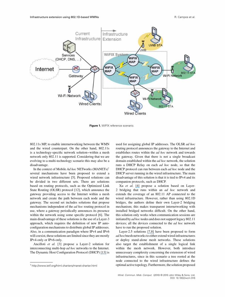
to interconnect APs or to enable access to legacy terminalsusing such technologies. The reference scenario for WiFIXis presented in Figure 1.
Our contribution is twofold. Firstly, we show that asimpler mesh networking solution is preferable to morecomplex solutions that do not bring up benefits for themajor application scenario of mesh networks. Secondly, wepropose a new mesh networking solution that can supportany 802-based technology.
The rest of the paper is organized as follows. Section 2presents the related work. Section 3 describes IEEE802.1D bridges, which are the basis of the proposedsolution. Section 4 presents the tree-based routing solutiondescribed in the IEEE 802.11s draft standard. Section 5details the WiFIX solution, Section 6 provides thesignalling overhead analysis of WiFIX and IEEE 802.11sand Section 7 describes the WiFIX implementation.Section 8 provides the comparison between WiFIX andIEEE 802.11s signalling overheads together with theexperimental evaluation of the two solutions. Finally,Section 9 draws the main conclusions of the work.
2. RELATED WORK
This section presents 802.11 mesh networking solutions thathave been proposed to extend wired network infrastructureswirelessly and to overcome the single-hop paradigm incurrent 802.11 networks.
WDS enables 802.11 APs to communicate wirelessly,instead of using the wired backhaul infrastructure, as it isusual in 802.11 networks. WDS uses a four address frameformat [1], it works together with the IEEE 802.1D learningbridge mechanism supported by standard 802.11 APs, and itis transparent to IEEE 802.11 stations. For each neighbourAP, an AP creates a WDS link, which appears as a portof the local IEEE 802.1D bridge. Frame forwarding withinthe WDS is performed using the learning mechanism. Thedisadvantage is that WDS links between APs need to becreated manually. Thus, each modification in the networkrequires manual reconfiguration.
The 802.11 TG ‘s’ is currently specifying a new standard[2] intended to enable automatic and dynamic creationof 802.11 mesh networks. Even though the standarddoes not focus specifically on the infrastructure extensionscenario, it does define a tree-based routing solution forthis case. The tree is rooted at the MP connected to thewired infrastructure, called root MP. Two mechanisms aredefined to establish the tree topology [2], Proactive PathRequest (PREQ) and Root Announcement (RANN). Theuse of explicit signalling to establish the path betweenan MP and the root MP, and vice-versa, and the needto perform explicit registration at the root or at theparent MP, are major disadvantages of the 802.11s tree-based routing solution. Additionally, the interconnectionof 802.11s WMNs with the wired infrastructure requiresthe use of a 6-address frame format and a new device,the MPP, which combines an IEEE 802.1D bridge and an
Wirel. Commun. Mob. Comput. (2010) © 2010 John Wiley & Sons, Ltd.DOI: 10.1002/wcm.916
Infrastructure extension using 802.1D-based WMNs R. Campos et al.
Figure 1. WiFIX reference scenario.
802.11s MP, to enable internetworking between the WMNand the wired counterpart. On the other hand, 802.11sis a technology-specific network solution---within a meshnetwork only 802.11 is supported. Considering that we areevolving to a multi-technology scenario this may also be adisadvantage.
In the context of Mobile Ad hoc NETworks (MANETs)†
several mechanisms have been proposed to extend awired network infrastructure [5]. Proposed solutions canbe divided in two different sets. There are solutionsbased on routing protocols, such as the Optimized LinkState Routing (OLSR) protocol [12], which announce thegateway providing access to the Internet within a meshnetwork and create the path between each node and thegateway. The second set includes solutions that proposemechanisms independent of the ad hoc routing protocol inuse, where a gateway periodically announces its presencewithin the network using some specific protocol [6]. Themain disadvantage of these solutions is the use of a Layer-3approach, which requires the definition of new IP auto-configuration mechanisms to distribute global IP addresses.Also, in a communication paradigm where IPv4 and IPv6will coexist, these solutions are limited since they are mostlyIPv4-only or IPv6-only.
Ancilloti et al. [3] propose a Layer-2 solution forinterconnecting multi-hop ad hoc networks to the Internet.The Dynamic Host Configuration Protocol (DHCP) [13] is
† http://www.ietf.org/html.charters/manet-charter.html
used for assigning global IP addresses. The OLSR ad hocrouting protocol announces the gateway to the Internet andestablishes routes within the ad hoc network and towardsthe gateway. Given that there is not a single broadcastdomain established within the ad hoc network, the solutionruns a DHCP Relay on each ad hoc node, so that theDHCP protocol can run between each ad hoc node and theDHCP server running in the wired infrastructure. The maindisadvantage of this solution is that it is tied to IPv4 and itscompanion protocols, such as DHCP.
Xu et al. [4] propose a solution based on Layer-2 bridging that runs within an ad hoc network andextends the coverage of an 802.11 AP connected to thewired infrastructure. However, rather than using 802.1Dbridges, the authors define their own Layer-2 bridgingmechanism; this makes transparent internetworking withinstalled bridged networks difficult. On the other hand,this solution only works when communication sessions areinitiated by ad hoc nodes and does not support legacy 802.11devices; all the devices connected to the ad hoc networkhave to run the proposed solution.
Layer-2.5 solutions [7,8] have been proposed to formad hoc/mesh networks to either extend wired infrastructuresor deploy stand-alone mesh networks. These solutionsalso target the establishment of a single logical linkwithin the mesh network. However, both introduceunnecessary complexity concerning the extension of wiredinfrastructures, since in this scenario a tree rooted at thenode connected to the wired infrastructure defines theoptimal active topology. Furthermore, the solution proposed
Wirel. Commun. Mob. Comput. (2010) © 2010 John Wiley & Sons, Ltd.DOI: 10.1002/wcm.916

R. Campos et al. Infrastructure extension using 802.1D-based WMNs
in Reference [7] requires hacks for each specific upperlayer protocol to be supported, for example DHCP andAddress Resolution Protocol (ARP) [14]; this means that,for instance, if the support of IPv6 is required, the solutionhas to be modified to take this and the companion protocolsinto account. The solution proposed in Reference [8]introduces its own addressing scheme, which requires newfeatures to map the new Layer-2.5 addresses into the Layer-2 addresses of the underlying wireless interfaces.
3. IEEE 802.1D BRIDGES
IEEE 802.1D bridges [9] are ubiquitous in Ethernetswitched Local Area Networks (LANs). In IEEE 802.11networks, 802.11 APs also act as 802.1D bridges betweenthe 802.11 link and the wired infrastructure, in orderto enable transparent internetworking between the wiredand wireless domains. 802.1D bridges are also knownas learning bridges since they do not define any explicitsignalling messages to build the local forwarding table.Rather, they learn the path to stations from the sourceaddress of data frames passing through. However, the use ofthis mechanism requires an active topology without loops,i.e. a tree. The Rapid Spanning Tree Protocol (RSTP) [9]has been defined to guarantee that the active topology isloop-free and to ensure proper operation of IEEE 802.1Dbridges. RSTP deals with the automatic and dynamicconfiguration of an active tree network topology whileensuring redundancy.
The learning and forwarding algorithms employed byIEEE 802.1D bridges are briefly described next. For furtherdetails please refer to Reference [9]. The forwardingalgorithm is simple. If the bridge does not have any entryin its forwarding table corresponding to the destinationof the current data frame, the frame is transmitted on allports, except the one on which it was received. Conversely,if there is an entry for the destination address, the frameis forwarded to the specified port, unless this is theincoming port, in which case the frame is dropped. Thelearning algorithm analyses the source address of all framesreceived and compares it against the information in the localforwarding table. If the source address is not found in thetable, a new entry is created with the source address and theport number on which the frame was received; in addition,the lifetime of the entry is reset. If an entry correspondingto the frame source address already exists in the localforwarding table, and the table indicates this address waslast seen on a different bridge port, the port number forthe entry is modified accordingly. If the information is thesame, only the lifetime of the entry is reset. An entry isremoved from the forwarding table when its lifetime hasexpired. The lifetime can be set by configuration; in currentEthernet networks it is usually set to 30 s. This simplemechanism allows 802.1D bridges to learn the paths toeach station connected to the network without exchangingexplicit signalling.
4. TREE-BASED ROUTING IN DRAFTIEEE 802.11s
The IEEE 802.11s draft standard [2] defines a tree-basedrouting solution for the scenario of wired infrastructureextension. The Hybrid Wireless Mesh Protocol (HWMP)is the default routing protocol specified in 802.11s. Itaddresses the extension of the wired infrastructure to STAsby means of a tree-based routing solution. A node inthe mesh network is configured as a special MP, calledroot MP. The root MP is usually connected to the wiredinfrastructure and announces itself to the other MPs,leading to an active topology defined by a tree rooted atthe former. HWMP defines two mechanisms for creatingthe tree: the PREQ mechanism and the proactive RANNmechanism.
In the proactive PREQ mechanism the root MPperiodically and proactively broadcasts a PREQ messagewith increasing sequence numbers. Upon receiving thePREQ message, an MP creates or updates the path to the rootMP in its local forwarding table and, if the PREQ receivedallowed the creation of a better or a newer path to the rootMP, it broadcasts an updated PREQ (TTL, hop count, pathmetric) to its neighbours. By using this mechanism, thePREQ originated at the root MP is propagated to all nodesin the mesh network. After the reception of the PREQ, anMP may need to send a Path Reply (PREP) in response tothe PREQ (registration mode) in order to establish a pathin the opposite direction, i.e. to the root. The need to sendthis response is defined by a flag included in the PREQmessage. If the flag is not set, a tree of paths from all MPsto the root MP is set up but the MPs are not registeredproactively at the root. A source MP may alternativelysend a gratuitous PREP before sending the first data frame,in order to register its address at the root and create apath in the opposite direction; nonetheless, this mechanismonly works for communication sessions initiated in themesh.
The proactive RANN mechanism represents the secondtree-based routing solution. The root MP periodicallybroadcasts a RANN message with increasing sequencenumbers. Unlike what happens in the PREQ mechanism,the RANN message is only used to disseminate the metricsof the paths from the root MP to the MPs, across the mesh;it is not used to create or update any path in the forwardingtable. Upon receiving the RANN message, an MP sendsa unicast PREQ requesting a path to the root MP. Thismessage is sent to the neighbour from which the RANNmessage with lowest metric value has been received. Theroot MP sends a PREP message in response to the unicastPREQ. This solution ensures the establishment of the bestpath between the current MP and the root MP. Besidesregistering at the root MP, an MP broadcasts an updatedRANN (TTL, hop count, path metric) to its neighbours.This way, the information on path characteristics (metric)to the root will be disseminated to all nodes in the meshnetwork.
Wirel. Commun. Mob. Comput. (2010) © 2010 John Wiley & Sons, Ltd.DOI: 10.1002/wcm.916

Infrastructure extension using 802.1D-based WMNs R. Campos et al.
Figure 2. 802.11 frame format.
5. Wi-Fi NETWORKINFRASTRUCTURE eXTENSION(WiFIX)
Taking into account the limitations and the excessivecomplexity of existing solutions, a new solution, called Wi-Fi network Infrastructure eXtension (WiFIX) is proposed.WiFIX targets the main application scenario for meshnetworks---the extension of the wired infrastructure forproviding pervasive Internet access. The solution is simpleand conservative. WiFIX reuses solid and widely usedconcepts such as 802.1D bridges and their simple learningmechanism for frame forwarding, and it is based on asingle-message protocol that enables the self-organizationof the WMN. Also, it avoids the complexity of 802.11s andeven supports the creation of 802 mesh networks insteadof 802.11 mesh networks only; 802 technologies otherthan 802.11 can be used either within the WMN or toenable access to legacy terminals using such technologies,as illustrated in Figure 1. In this paper we focus on 802.11mesh networks only, however. Therefore, the objectiveof WiFIX is to extend the wired network infrastructureto 802.11 STAs, such as smart phones, Personal DigitalAssistants (PDAs), and laptops, connecting to the MAPs.An MAP can provide both wireless and wired connection,depending on the type of NIC used. One NIC is used forcommunicating with peer MAPs while the other is usedto serve 802.11 STAs. It is assumed that a proper wirelesschannel is configured in each NIC in order to avoid radiointerference between intra-mesh communication and thecommunication between 802.11 STAs and the MAPs. Foran 802.11 STA, an MAP appears as a standard 802.11 APand, as such, no modifications to 802.11 STAs are required.
In what follows, we present the encapsulation methodused in WiFIX to allow multi-hop forwarding within amesh network based on legacy IEEE 802.1D bridges, themechanism used to create the active tree topology rooted atthe node connected to the infrastructure, and the forwardingprocess of both unicast and broadcast data frames within aWiFIX mesh network.
5.1. Eo11 encapsulation
In order to enable multi-hop forwarding four MACaddresses are required as defined in the 802.11 WDSformat. Two addresses are needed to store the original
source and the final destination of a data frame and othertwo are required to identify the intermediate source andthe intermediate destination at each hop; otherwise, frameforwarding does not work. The WDS format could beconsidered in WiFIX. However, WDS links need to bemanually configured for each peer MAP. A possible solutionto overcome this limitation would be to define a newmechanism to automatically establish the WDS links. Yet,that approach would have problems, namely with respectto reconfigurations when the mesh topology changes, sinceeach MAP would have to perform time-consuming 802.11scans to find its neighbour MAPs and establish new WDSlinks. On the other hand, the WDS format is not supportedby all off-the-shelf hardware, which is a disadvantage.To overcome these problems, WiFIX configures the NICsof each MAP used for intra-mesh communication in802.11 ad hoc mode. This has two advantages: (1)ad hoc mode is supported by all 802.11 hardware; (2)in ad hoc mode the 802.11 network is maintained ina distributed manner and is identified by a Service SetIdentifier (SSID), which avoids 802.11 scans. Nevertheless,the use of 802.11 ad hoc frame format (Figure 2) hasa limitation: only two MAC addresses are available forframe forwarding purposes. Since multi-hop forwardingusing a single NIC requires four MAC addresses, the othertwo addresses need to be stored somewhere in the dataframes.
The approach adopted was to define a new headertype and encapsulating data frames using a tunnellingmechanism, called Ethernet-over-802.11 (Eo11). Figure 3shows the Eo11 frame format. Thus, the original sourceand destination addresses are stored in the inner headerof the data frame and the outer header contains theintermediate source and destination MAP addresses,which are changed at each intermediate MAP. Theendpoints of a tunnel are located at neighbour nodesin the active topology; as such, the path between eachMAP and the Master MAP can include multiple Eo11tunnels. In this configuration each mesh node forcesa frame to go through the next hop (intermediatedestination).
5.2. Active tree topology creation
The active tree topology rooted at the Master MAP is createdusing a new mechanism called Active Topology Creation
Wirel. Commun. Mob. Comput. (2010) © 2010 John Wiley & Sons, Ltd.DOI: 10.1002/wcm.916

R. Campos et al. Infrastructure extension using 802.1D-based WMNs
Figure 3. Eo11 frame format.
Figure 4. Topology refresh message.
and Maintenance (ATCM). In ATCM, a Topology Refresh(TR) message, whose format is shown in Figure 4, is sentperiodically by the Master MAP. The other MAPs forwardthis message, upon updating the required fields (e.g. parentaddress, TTL, distance). The TR message allows each MAPto select the parent providing best connectivity towards theMaster (in number of hops), while enabling (1) the parent tobe informed about new child nodes that have chosen it and(2) the establishment of Eo11 tunnels between the parentand its children.
The relevant information carried by the TR message isthe following: (1) distance (number of hops to the Master);(2) sequence number, to avoid loops; (3) parent address;(4) protocol version; (5) time-to-live, which reflects the
maximum number of hops to be traversed by this message.This information is complemented by the current nodeaddress and Independent Basic Service Set (IBSS) address,carried in the regular 802.11 frame header.
The ATCM mechanism is similar to the mechanisms ofthe IEEE 802.11s draft standard described in Section 4.Still, it includes new features, namely regarding the creationof the tunnels between parent and child nodes. Also, inATCM, the TR message is simultaneously used (1) toannounce the Master MAP and (2) to notify upstreamneighbours that a given child has selected it as its parentnode in the tree; in the 802.11s mechanisms two messagesare used instead. The ATCM mechanism is illustrated inFigure 5 for Node C and it is formally defined below;
Figure 5. Virtual link setup.
Wirel. Commun. Mob. Comput. (2010) © 2010 John Wiley & Sons, Ltd.DOI: 10.1002/wcm.916

Infrastructure extension using 802.1D-based WMNs R. Campos et al.
Table I. Notations used in the description of the ATCMmechanism.
Notation Description
TTR TR broadcast interval (seconds)CP Current parent mesh node in the tree rooted at
the MasterHM Distance (number of hops) to the MasterSRCTR TR message source addressMaddr Address of the MasterCaddr Address of the current mesh nodePaddr Parent address in TR messageSNR Set of nodes receiving the TR message either
directly from the master or from some upstreamneighbour
BUP Set of best upstream neighboursDP Decision period (seconds) = 3 × TTR
CSN Current sequence numberPSN Previously transmitted sequence numberHmax Maximum number of hops a TR message can
traverseLP Lifetime of the association established with CP
LC [i] Lifetime of the association established with childi
SCi Set of children of node i
Table I summarizes the parameters considered in thedefinition.
5.3. Unicast frame forwarding
The tunnel endpoints created using the ATCM mechanismact as ports of a conceptual 802.1D learning bridge. TheEo11 encapsulation makes it possible for a node to send aunicast frame to the neighbour at the other end of the tunnel,while still maintaining the original source and destinationaddresses. Moreover, the bridge does not need to work inpromiscuous mode, since a unicast frame destined to a nodemultiple hops away from the source will have as outerdestination MAC address the next hop in the path towardsthe destination. The original unicast frame is decapsulatedat every node. The learning bridge algorithm assumed byWiFIX will then process a unicast frame according to thefollowing rules:
• Upon receiving a unicast frame from a tunnel endpoint,add a pair (frame source address on Eo11 header, portcorresponding to the tunnel with endpoint equal toAddress 2 of 80211 header) to the bridge forwardingtable.
• If the unicast frame destination address exists in thebridge forwarding table, send the frame to the tunnelendpoint stated in the bridge forwarding table (theframe is afterwards encapsulated with Eo11 and sentto the associated endpoint address).
Figure 6. DPA processing between the real interface and thetunnels.
• If the unicast frame destination address does not existin the bridge forwarding table, send the frame to alltunnels, except the one the frame was received from.
The rules are essentially those stated in the original802.1D learning bridge algorithm presented in Section 3.The differences (which are underlined) have mostly to dowith the fact that the ports of the 802.1D bridge are actuallytunnel endpoints, as shown in Figure 6.
5.4. Broadcast frame forwarding
If the destination address of a frame received by the IEEE802.1D bridge is the broadcast address, the bridge will sendthe frame to all ports, except the one the frame was receivedfrom. This means that to forward broadcast traffic inside themesh network the encapsulation of the broadcast frames intoa unicast frame per neighbour is required. Considering thata node has a tunnel per neighbour, the broadcast frame willbe sent n-1 times in unicast encapsulated with Eo11, wheren defines the number of nodes forming the mesh network.While this mechanism works, it is highly inefficient due tothe number of frames involved in each broadcast per radiolink, herein defined as the physical space in which nodesare all in radio range of each other.
In order to provide a more efficient solution, the broadcastframe forwarding mechanism has been optimized. A newalgorithm, called Duplicate Processing Algorithm (DPA),has been defined, in order to avoid the transmission ofunnecessary duplicate broadcast frames. The algorithm isapplied between the bridge and the physical Wi-Fi interface(see Figure 6). Using DPA each mesh node forwards justone broadcast frame per radio link. Instead of sending acopy of the broadcast frame to every neighbour (except theoriginator), a single copy of the frame is sent to the broadcastaddress, per radio link. The frame is still encapsulated inEo11, and the information about the original source anddestination is kept. The 802.11 source address is set to thecurrent node address. The DPA algorithm uses informationabout the tree topology (parent and child) as a meansto further improve broadcast forwarding. Only the nodeshaving more than one neighbour forward a broadcast frame;the nodes having a single connection (leaf nodes), transmit
Wirel. Commun. Mob. Comput. (2010) © 2010 John Wiley & Sons, Ltd.DOI: 10.1002/wcm.916

R. Campos et al. Infrastructure extension using 802.1D-based WMNs
this frame only if they are its originator or if the frameis entering the mesh through it. In general, a considerableamount of message retransmissions can be avoided with thisimprovement.
The total number of retransmissions (R) associated withone broadcast message, considering a tree topology with n
nodes, is defined by
R ={
n − nL, if originated in a non leaf noden − nL + 1, if originated in a leaf node
where nL represents the number of leaf nodesin the tree; n−nL relay nodes (the nodes with
Wirel. Commun. Mob. Comput. (2010) © 2010 John Wiley & Sons, Ltd.DOI: 10.1002/wcm.916

Infrastructure extension using 802.1D-based WMNs R. Campos et al.
more than one neighbour) will always forward theframe.
The DPA algorithm deals with two types of duplicates:(1) duplicate frames coming from the local bridge; (2)duplicate frames that arrive from the neighbours through theestablished tunnels. Each node keeps track of the numberof duplicate frames it must drop in the future, either pernode or locally (originated by the bridge); these valuesare called Local Drop counter (LDC) and Neighbour Dropcounter (NDC), respectively. LDC is set per frame andNDC is set per frame and per neighbour. If the broadcastframe is originated locally, the bridge will create unwantedduplicates, one duplicate per neighbour. In this case, DPAsets LDC to Number of Neighbours −1 for the current frame.This means that only one frame out of the set received fromthe bridge will be sent to the network; the other duplicateswill be dropped till LDC reaches zero. If the broadcast frame
is received from another node, the bridge will originate aduplicate for each neighbour except the one that sent theframe. In this case, LDC is set to Number of Neighbours−2.For each broadcast frame sent to the network, the currentnode will receive in the future one duplicate per neighbour,except for the one that originally sent the frame. The NDC
for each neighbour is increased by one for each framesent. If the current node receives a broadcast frame whosecorresponding NDC is greater than 0, the frame is droppedand NDC is decreased by one; if NDC is 0 or undefined thecorresponding frame is retransmitted. Two lifetime valuesare considered for defining the validity time of the LDC
and NDC counters: Short Term Lifetime (STL) and LongTerm Lifetime (LTL). STL is used for the LDC counters,since local duplicates, originated at the bridge, generallyarrive more quickly. LTL is used for duplicates originatedat neighbours.
Wirel. Commun. Mob. Comput. (2010) © 2010 John Wiley & Sons, Ltd.DOI: 10.1002/wcm.916

R. Campos et al. Infrastructure extension using 802.1D-based WMNs
Table II. Notations used in the description of the DPAmechanism.
Notation Description
BFi,NIC Broadcast frame i received from the NICBFi,BR,l Broadcast frame i generated locally received from
the local bridgeBFi,BR,r Broadcast frame i generated remotely received
from the local bridgeSN Set of one-hop neighbours of the current nodeNDC,i,j NDC counter for frame i and neighbour jLDC,i LDC counter for frame iN Number of neighbours of the current node
A broadcast frame is characterized by the original sourceaddress and a hash of the frame (e.g. MD5). Each node hasa table that keeps track of the number of frames that mustbe dropped within a lifetime period, per neighbour (NDC
counters), and the frames forwarded by the local bridge thatshould not be sent to the radio link (LDC counter). The DPAalgorithm is formally described above; Table II indicates thenotation used in the description.
6. OVERHEAD ANALYSIS
This section analyses the WiFIX overhead and the overheadintroduced by the tree-based routing solution consideredin IEEE 802.11s. The analysis takes into account the twotree-based routing mechanisms defined in 802.11s: PREQand RANN. For the PREQ mechanism only the registrationmode is considered for the reasons mentioned in Section 4.Mathematical expressions are derived for the overhead ofeach solution.
Before presenting the overhead expressions, a set ofparameters is defined in Table III. The expressions considerthe overhead introduced by each solution when onlycommunication between 802.11 STAs and the root/Master(and vice-versa) is in place; communication between 802.11STAs is not taken into account. Below, the term link is usedeither to refer to the virtual link between mesh nodes or theradio link used by STAs to attach to a WMN.
The overhead for the proactive PREQ mecha-nism (OPREQ) can be calculated using the followingexpression:
OPREQ(bytes/s) = SPREQ × 1
TPREQn + SPREP
× 1
TPREQ(n − 1) HA (1)
The root sends out one PREQ every each TPREQ seconds.The PREQ message is re-broadcast once by each MPforming the mesh network, resulting in n PREQ messagestransmitted within the mesh network every TPREQ seconds.Upon receiving a PREQ message, each MP replies with
Table III. Notations used in the overhead analysis.
Notation Description
SPREQ PREQ message size (bytes)SPREP PREP message size (bytes)SRANN RANN message size (bytes)STR TR message size (bytes)SA Average frame size (bytes)n Number of nodes forming a mesh networkHA Average number of hops between root and MPnSTA Average number of STAs behind a MAPTPREQ PREQ broadcast interval (seconds)TRANN RANN broadcast interval (seconds)TTR TR broadcast interval (seconds)LFT Lifetime of forwarding table entry (seconds)PB Probability of broadcasting a data frame every
LFT interval due to absence of forwarding tableentry
P Probability that STA is the endpoint initiating acommunication session
a unicast PREP message in order to register itself andthe 802.11 STAs behind it (if any) at the root. The PREPmessage is retransmitted HA times on average.
The overhead for the proactive RANN mechanism(ORANN) can be calculated using the following expression:
ORANN (bytes/s) = SRANN × 1
TRANN
n + (SPREP + SPREQ
)
× 1
TRANN
(n − 1) HA (2)
The root MP sends out one RANN every TRANN seconds.The RANN message is re-broadcast once by each MP,resulting in n RANN messages transmitted within the meshnetwork every TRANN seconds. For each RANN message,each MP replies with a unicast PREQ message towards theroot MP. In response, the root MP sends a PREP messageto the current MP; this procedure is performed every TRANN
interval by n−1 MPs. Both the PREQ and PREP messagescross HA MPs, on average. Therefore, they are transmittedHA times.
The overhead for WiFIX (OWiFIX) can be calculated usingthe following expression (the proof can be found in theappendix):
OWiFIX(bytes/s) = STR
1
TTR
n
+ PSA
1
LFT
2 (n − 1) (PB)nSTA (n − 1) nSTA
+ (1 − P)SA
1
LFT
2 (n − 1) PB (n − 1) nSTA
= STR
TTR
n + 2SA
LFT
(n − 1)2 nSTA (P (PB)nSTA
+ (1 − P) PB) (3)
Wirel. Commun. Mob. Comput. (2010) © 2010 John Wiley & Sons, Ltd.DOI: 10.1002/wcm.916

Infrastructure extension using 802.1D-based WMNs R. Campos et al.
WiFIX also considers a root node (the Master) that sendsout one TR message every TTR seconds. The TR messageis re-broadcast by each MAP, resulting in n TR messagestransmitted within the network every TTR seconds. WiFIXdoes not introduce any further explicit signalling overhead.However, there is additional overhead due to the use of IEEE802.1D bridges and corresponding forwarding procedure.As mentioned in Section 3, when an 802.1D bridge does notknow the path to the destination of the current data frame,it will send the frame to all ports, except the port the framewas received from. If no bridge in the mesh has a forwardingtable entry for the destination of the data frame, the framewill be transmitted n−1 times in the mesh network; weassume this case in Equation (3), i.e. the worst case. Takinginto account that each MAP has two physical interfaces, wehave n−1 links forming the WMN and other n−1 links,one per MAP, to enable the attachment of STAs to theWMN. Thereby, when the path to the destination of a dataframe is unknown, the frame will be sent to 2.(n−1) links;because there are n−1 MAPs and nSTA stations per MAP,this procedure is performed nSTA.(n−1) times. Nonetheless,the broadcast of a data frame across the mesh network,every LFT interval, by an MAP, will only happen with agiven probability, which depends on the destination of thecurrent frame. If the frame is addressed to the Master MAP,the probability of broadcasting the data frame is equal tothe probability of having all STAs behind an MAP silentduring the LFT interval; this is given by the probability of theintersection of nSTA events ‘STA silent during LFT seconds’.Since each STA operates independently from the others, theprobability of the intersection is equal to the product of theindividual probabilities, i.e. (PB)nSTA . If a frame is destinedto an STA, the probability of broadcasting the data frameis simply equal to PB. On the other hand, if we assumebidirectional traffic, whether a communication session isinitiated by a STA or either by the Master mesh node or somenode in the Internet has influence on the WiFIX overhead.We take this into account in Equation (3) by means of theP parameter.
7. WiFIX IMPLEMENTATION INLINUX
The Linux Operating System (OS) provides the meansrequired to implement WiFIX: an 802.1D software bridgeand tools to create virtual interfaces. Using these tools,WiFIX is required to create and delete virtual interfaces, toperform Ethernet-over-80211 encapsulation, and to processthe duplicate broadcast frames. The Linux bridge‡ isflexible enough to support the virtual interfaces. It expectsthem to behave like Ethernet devices and have a 6-byteMAC address. As the ATCM mechanism used by WiFIXenforces a loop free topology, the spanning tree protocolis disabled. Figure 7 illustrates the modules involved in the
‡ http://linux-net.osdl.org/index.php/Bridge
Figure 7. Interaction between WiFIX and its peer Linuxmodules.
implementation, and their interactions. The WiFIX daemonseats between the virtual interfaces, represented by taps, andthe wireless NIC.
The tunnels to each neighbour are implemented usinga tap interface, provided by the vtun module§, which arevirtual interfaces that behave like Layer-2 Ethernet devicesfrom the upper layers point of view; in the implementation,a tap behaves as a tunnel endpoint. A frame sent to a tapinterface is in fact delivered to a file descriptor on the userspace application that created the interface, in this case theWiFIX daemon. The frame will already contain an Ethernetheader, with both the source and final destination MACaddresses. It is up to the WiFIX daemon to further processthe frame and forward it to the wireless NIC. The kernel willthen process this frame in the same way it would process aframe from a physical Ethernet NIC.
The WiFIX daemon accesses the wireless NIC using aLinux packet socket. The packet socket allows the receptionof frames with a predefined Ethertype, and it also enablesthe application using it to specify the source MAC address,the destination MAC address and Ethertype of a frame to bereceived. These features are valuable for our goals, giventhat the proposed solution requires that WiFIX processesthe Eo11 Ethertype and replaces the MAC address of theframe.
The WiFIX daemon runs the ATCM mechanism in orderto detect the parent and child nodes, and create the activetree topology. Each mesh node creates a tap interface perchild and a tap interface concerning the tunnel establishedwith its parent node. All these interfaces are then added tothe bridge. The association between the neighbour addressand the tap file descriptor is maintained in a table, withinthe daemon. When a frame arrives to the WiFIX daemonfrom a tap file descriptor, the application fetches theneighbour address associated with the tap. A new headeris then inserted before the original Ethernet frame, with the
§ http://vtun.sourceforge.net
Wirel. Commun. Mob. Comput. (2010) © 2010 John Wiley & Sons, Ltd.DOI: 10.1002/wcm.916

R. Campos et al. Infrastructure extension using 802.1D-based WMNs
source address equal to the current node MAC address, thedestination equal to the neighbour MAC address, and theEthertype set to Eo11. The frame is then sent to the wirelessNIC, via the packet socket.
The WiFIX daemon receives all the frames encapsulatedin Eo11. Only the frames originated at known neighboursare processed, while all the others are dropped. Whenreceiving a frame, the daemon looks-up in the local table forthe tap file descriptor that corresponds to the source addressof the neighbour in the 802.11 frame header. The frameis then decapsulated and sent to the tap interface filedescriptor. The tap will then forward the frame to the bridge.If the current node is the destination of the frame, the Linuxbridge will pass it upwards. Otherwise, the bridge willforward the frame according to the 802.1D rules. As a result,some frames can be forwarded to other physical interfacesor tap devices that belong to the bridge. The frames passedto the tap devices are then processed by the WiFIX daemonusing the method described above.
Broadcast traffic is handled using the DPA algorithm.The WiFIX daemon keeps track of the expected duplicates,and drops them according to the DPA algorithm. Thenon-duplicate frames are delivered to the tap device thatcorresponds to the 802.11 source address. They are furtherprocessed by the bridge, according to 802.1D rules.
To cope with the extended frame length due to the Eo11header, the MTU of the physical interface was increased by14 bytes, which can be easily handled by 802.11. The MTUof the tap and bridge devices are unchanged to guaranteethat the forwarded frames do not exceed the Ethernet MTU.
The source code was compiled for x86 and cross-compiled to MIPS processors. The latter allowed deployingthe solution on off-the-shelf 802.11g wireless APs runningLinux OS. The Linksys WRT54GL with OpenWRT‖
WhiteRussian distribution was used.
8. EVALUATION
The performance of WiFIX was studied by means oftheoretical analysis and real experiments. In this section,we first evaluate the overhead of WiFIX and compare itwith the tree-based routing solution proposed by the IEEE802.11s draft standard. In addition, we compare WiFIXand 802.11s in terms of reconfiguration speed when anode failure occurs. Finally, we present the experimentalresults obtained using a test-bed running WiFIX and IEEE802.11s, considering throughput, delay and packet loss asthe performance metrics.
8.1. Overhead evaluation
In order to simplify the overhead calculations, we assumeconstant values for some parameters in Table III. TPREQ,
‖ http://www.openwrt.org
Table IV. Average number of hops between Master and MAPs.
N HA
5 1.3610 1.5320 1.6130 1.6250 1.62
TRANN and TTR are set to 1 s, according to the recommendvalue stated in Reference [2] for TPREQ and TRANN. Thevalues for HA are a function of the number of nodes n, andwere obtained by means of simulations using the SpanningTree Simulator (STS)¶, considering the average number ofhops over 1000 random topologies (see Table IV). P is set to0.95, a value that takes into account that it is most probablefor an STA to initiate a communication session than to bethe endpoint of a session initiated by some node in theInternet; indeed, this is the case in most applications (e.g.web browsing, streaming, file transfer), even concerningunidirectional applications, such as real-time audio/video,where there is always a bidirectional signalling phase beforedata exchange.
The value of PB was obtained experimentally byanalysing the behaviour of an 802.11 STA in two cases:(1) when the STA is connected to the Internet but there isno user data exchanged; (2) when the STA is connectedto the Internet and there is user data transferred betweenthe STA and the Internet. The analysis for the secondcase was performed by capturing the traffic generated byfive users utilizing their 802.11 STAs to read e-mails,browse the web, and communicate using instant messaging.The capture of traffic was performed during periods of600 s using Ethereal.# For the first case we have used thesame method and observed that, even though the stationdid not have any active data flow, there was still someactivity due to the exchange of control protocol messages. Inpractice, this represents the worst case for the 802.1D bridgeforwarding procedure; without user traffic the forwardingtable entries will expire more frequently and the overheadwill be higher. The values of PB presented in Table Vrepresent the average of 50 samples, 10 samples per user.The value of PB for a given sample was calculated usingexpression (4).
PB = Ni
SPLFT
= NiLFT
SP(4)
where Ni is the number of intervals in which an STA is silentmore than LFT seconds and SP represents the sample period(in this case 600 s).
Expression (4) reflects the fact that a broadcast will onlybe sent in Ni intervals out of the total number of LFT intervals
¶ http://telecom.inescporto.pt/∼rcampos/software.php# http://www.ethereal.com
Wirel. Commun. Mob. Comput. (2010) © 2010 John Wiley & Sons, Ltd.DOI: 10.1002/wcm.916
Infrastructure extension using 802.1D-based WMNs R. Campos et al.
Table V. Probability of lifetime expiration of the forwarding tableentries.
LFT PB (without user traffic) PB (with user traffic)
5 0.25 0.1910 0.34 0.1820 0.31 0.1030 0.21 0.03
composing the sample period; if an STA is silent less thanLFT seconds, a forwarding table entry will still be availableand the data frame can be unicasted. The log files used tocalculate the values of PB presented in Table V can be foundin Reference [15]. In both cases the local traffic exchangedbetween the STA and the AP enabling Internet access (e.g.for authentication) was not considered in the calculations.
In the following we provide the results obtained for theWiFIX overhead in comparison with the overhead of thetwo mechanisms defined in 802.11s. The overhead analysispresented in Section 6 considered overhead in bytes/s.However, in 802.11 systems, it is more suitable to consideroverhead expressed in frames/s, since the medium accessoverhead (i.e. SIFS, DIFS, Backoff) contributes the mostto the time required to transmit a frame; the size of theframe is a second order factor. Thereby, the overhead results
presented herein are in frames/s and they were obtainedby ignoring the sizes of the messages in the mathematicalexpressions provided in Section 6. The parameters n, LFT
and nSTA were varied in the calculations.
8.1.1. Comparison of WiFIX and PREQ
overhead.
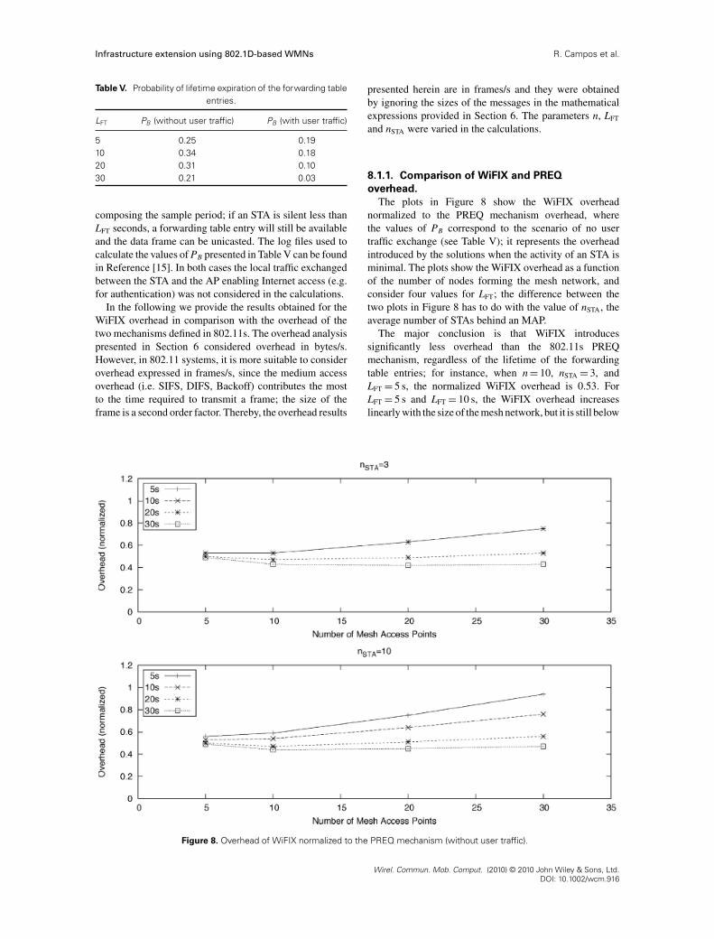
The plots in Figure 8 show the WiFIX overheadnormalized to the PREQ mechanism overhead, wherethe values of PB correspond to the scenario of no usertraffic exchange (see Table V); it represents the overheadintroduced by the solutions when the activity of an STA isminimal. The plots show the WiFIX overhead as a functionof the number of nodes forming the mesh network, andconsider four values for LFT; the difference between thetwo plots in Figure 8 has to do with the value of nSTA, theaverage number of STAs behind an MAP.
The major conclusion is that WiFIX introducessignificantly less overhead than the 802.11s PREQmechanism, regardless of the lifetime of the forwardingtable entries; for instance, when n = 10, nSTA = 3, andLFT = 5 s, the normalized WiFIX overhead is 0.53. ForLFT = 5 s and LFT = 10 s, the WiFIX overhead increaseslinearly with the size of the mesh network, but it is still below
Figure 8. Overhead of WiFIX normalized to the PREQ mechanism (without user traffic).
Wirel. Commun. Mob. Comput. (2010) © 2010 John Wiley & Sons, Ltd.DOI: 10.1002/wcm.916

R. Campos et al. Infrastructure extension using 802.1D-based WMNs
Figure 9. Overhead of WiFIX normalized to the PREQ mechanism (with user traffic).
the PREQ overhead. For higher LFT values the normalizedWiFIX overhead is kept almost constant with the size ofthe mesh network. The WiFIX overhead is higher whensmall values for LFT are considered. This was expected,since the lower the lifetime LFT the higher the numberof times the bridges will send traffic using the broadcastmechanism. Furthermore, in general, the increase in thenSTA value represents an increase in the WiFIX overhead;this is particularly observed for LFT = 5 s and LFT = 10 s. Ifwe consider expression (3), this would be expected, sincethe WiFIX overhead is proportional to nSTA.
The plots in Figure 9 show the same information butconsider the values for PB corresponding to the case wherethere is user traffic (see Table V). By comparing these plotswith the plots in Figure 8, we conclude that the WiFIXoverhead decreases when the STAs become more active, asexpected; greater STA activity means higher probability ofhaving a valid forwarding table entry either for that STA orfor the Master MAP (assuming bidirectional traffic).
The bottom line is that the WiFIX overhead is inverselyproportional to the activity degree of STAs. The moreactive the STAs are the lower the WiFIX overhead is, unlikethe PREQ mechanism, which has a constant signallingrate independent of the user traffic. In practice, due tothe use of a single radio channel to support all MAPsconnected to the wired infrastructure, a WMN is expectedto be formed by only a few MAPs (let’s say n < 10), so that
minimal data throughput can be guaranteed to the STAs.In such case, WiFIX is significantly more efficient thanthe 802.11s PREQ mechanism. The reduction in overheadmay reach 60%.
8.1.2. Comparison of WiFIX and proactive
RANN overhead.
The plots in Figure 10 show the WiFIX overheadnormalized to the RANN mechanism overhead, consideringthe values of PB for the case where the activity of an STAis minimal. The results show that the WiFIX overhead isalso considerably lower than the overhead introduced bythe RANN mechanism, regardless of the values chosenfor LFT. The reduction in overhead may reach about70%. Here, for low LFT values, the normalized WiFIXoverhead also increases linearly with the size of the meshnetwork. Still, the increasing rate is lower than in theplots of Figure 8; this has to do with the higher signallingoverhead of the RANN mechanism when compared to thePREQ mechanism. For higher LFT values (LFT = 20 s andLFT = 30 s) the normalized WiFIX overhead is kept almostconstant as the size of the mesh increases.
The plots in Figure 11 show that with the increase inthe activity of the STAs, the normalized WiFIX overheadbecomes lower; this holds for every LFT value. It isinteresting to note that, in general, the normalized WiFIX
Wirel. Commun. Mob. Comput. (2010) © 2010 John Wiley & Sons, Ltd.DOI: 10.1002/wcm.916

Infrastructure extension using 802.1D-based WMNs R. Campos et al.
Figure 10. Overhead of WiFIX normalized to the RANN mechanism (without user traffic).
overhead slightly decreases with the size of the meshnetwork, when the number of stations behind each MAP(nSTA) increases. This is explained by expression (3). Thevalues of PB in this case are smaller than in the case whenthere is no user traffic exchanged (see Table V). The lowerPB values tend to reduce the contribution of the second termin expression (3) to the total WiFIX overhead, especiallyas nSTA increases. In contrast, the RANN overhead isindependent of PB and grows faster with the size of themesh network. These two opposite effects contribute to theobserved reduction in the normalized WiFIX overhead.
We then conclude that WiFIX is more efficient thanthe RANN mechanism too, regardless of the LFT valueselected. The overhead reduction may reach more than 70%.Overall, WiFIX introduces significantly lower overheadthan both PREQ and RANN, while providing immediatepath availability; even in the cases where there is nopath available the data frame is immediately sent to thedestination using broadcast.
8.1.3. Broadcast optimization.
In this section we evaluate the performance of broadcasttraffic for WiFIX in comparison with both the 802.1D and802.11s approaches. While the performance of the 802.1Dand 802.11s broadcast mechanisms are only influenced bythe number of nodes in the mesh, for WiFIX the network
topology and the tree set up also come into play. A largernumber of active leaf nodes improve the efficiency of WiFIXas far as the broadcast mechanism is concerned. In order toassess the real benefits of WiFIX, we used the STS simulatorto generate hundreds of random network topologies andobtain the average number of leafs as a function of thenumber of MAPs. It was thus possible to find the numberof frame retransmissions generated by a broadcast frameinside the mesh network. Figure 12 shows the number ofretransmissions, per broadcast frame, for each solution. Thecurve for the 802.1D bridging mechanism is not shown; itis the same as for the WiFIX worst case.
The 802.11s standard defines that broadcast frames areflooded on the network by making each node retransmit onetime a broadcast frame that was received or generated byitself. Loops are avoided by using sequence numbers andTTL. This means that each frame broadcast into a networkcomposed of n mesh nodes will originate n retransmissions.The overhead of this solution increases linearly with thesize of the mesh, as shown in Figure 12. The 802.1Dstandard states that each node receiving a broadcast frameshould transmit it on all the other local interfaces exceptthe incoming one. In our context, this will mean that eachMAP would have to transmit a unicast frame to all itsneighbours except the neighbour that originated the frame.A broadcast frame would originate a retransmission on eachtree branch. For a network with n mesh nodes, n−1 frames
Wirel. Commun. Mob. Comput. (2010) © 2010 John Wiley & Sons, Ltd.DOI: 10.1002/wcm.916

R. Campos et al. Infrastructure extension using 802.1D-based WMNs
Figure 11. Overhead of WiFIX normalized to the RANN mechanism (with user traffic).
0
5
10
15
20
25
30
35
0 5 10 15 20 25 30 35
Num
ber
of F
ram
es T
rans
mitt
ed
Number of Mesh Access Points
802.11sWiFIX (worst case)
WiFIX (average)
Figure 12. Number of frames transmitted per broadcast frame as a function of the number of mesh nodes.
Wirel. Commun. Mob. Comput. (2010) © 2010 John Wiley & Sons, Ltd.DOI: 10.1002/wcm.916

Infrastructure extension using 802.1D-based WMNs R. Campos et al.
would have to be transmitted. WiFIX partially behaveslike 802.11s, since each node will originate at most oneframe retransmission per broadcast frame received. But,unlike 802.11s, it prevents leafs from further retransmittingthe broadcast frame, and does not require any additionalinformation in the headers. Loops are avoided by usingintelligence in the nodes. The curve shown in Figure 12was obtained by applying the equation and considering theaverage number of leafs obtained for each number of meshnodes using the STS simulator. The worst case for WiFIXhappens when there is only one leaf node; for a networkwith n nodes, n−1 retransmissions will be required. Still,this is already better than the 802.11s approach. In general,the number of leafs will be higher than in the worst case.By using the simulator, we found out that the number ofretransmissions increases logarithmically with the size ofthe mesh. This means that, on average, WiFIX will originatea smaller number of retransmissions per broadcast frame,and the difference to 802.11s will increase with the sizeof the mesh. This means smaller overhead and lower radioresources consumed.
8.2. Reconfiguration time after node failure
In this section we compare WiFIX and 802.11s when itcomes to the reconfiguration time needed after a node failureoccurs. The current open80211s implementation, used as abasis for our experimental evaluation (see subsection 8.3),does not support the 802.11s proactive mechanisms yet. Inthat sense, it was not possible to compare the two solutionsexperimentally. The analysis presented herein focus on thetheoretical lower and upper limits of the reconfigurationtime for each solution. Below, we ignore the propagationdelays associated to the signalling messages involved inthe various mechanisms under analysis, since they are atleast two orders of magnitude lower than the refresh periodsinvolved in the mechanisms being studied. Our goal is tohave a rough understanding of the reconfiguration timesinvolved in each solution.
The 802.11s PREQ and RANN mechanisms definethat a PREQ and RANN message, respectively, shallbe sent periodically every second by the root MP [2].Upon receiving a new PREQ/RANN message, and aftera propagation delay to wait for additional PREQ/RANNcoming from other paths, each MP selects its best upstreamneighbour. This mechanism is equally employed to establishnew paths between each MP and the root MP after anode failure occurs, as referred to in the last version ofthe 802.11s draft standard [2]: ‘when a proactive pathselection protocol is used, MP failure and information onthe new whereabouts of an MP are disseminated duringtriggered and periodic path update rounds’. This meansthat the reconfiguration time is almost instantaneous, ifthe failure occurs right before the refresh period timeout,and about 1 s, if the failure occurs immediately after theperiodic PREQ/RANN message was received by all MPs inthe WMN. In this case, the failure will only be detected
after one refresh period. The MPs affected by the nodefailure will not receive any PREQ/RANN message in thenext refresh period from their current upstream neighbour.Then, they will select a new upstream neighbour, basedon further PREQ/RANN messages received through otherpaths. Based on the new PREQ/RANN message and theregistration made by each MP at the root MP, new paths arecreated and the reconfiguration of the tree active topologyis accomplished.
The WiFIX solution uses a more robust mechanism toselect the paths between each MAP and the Master MAP.In order to account for possible signalling message failures,it waits 3 times the interval between two consecutive TRmessages until it takes a decision regarding the selectionof the best upstream neighbour; this period is called thedecision period (DP ) of the ATCM mechanism, which isset to 3 × TTR. In the best case, the reconfiguration time dueto the ATCM mechanism will be about DP seconds, if thenode failure occurs before the first TR message within a DP
period is sent by the Master MAP. In the worst case, it willtake about 5 × TTR seconds to complete the reconfigurationof the active topology using ATCM, if the node failureoccurs just after the first TR message is received withina DP period by all MAPs. In this case, the node failure willnot be detected by the end of the DP period, since just twoTR messages were lost. As such, only after an additionalDP period the node failure will be detected and a new activetopology will be configured accordingly.
In WiFIX, the STAs running behind each MAP are notexplicitly registered in the Master MAP, as it happensin the proactive 802.11s mechanisms. As such, in orderto completely evaluate the WiFIX reconfiguration speedwe also need to consider the time required until the newpaths towards the STAs are found. This is related to theinactivity intervals of an STA. Using the same experimentalresults considered for the overhead analysis presented insubsections 8.1.1 and 8.1.2, we could find the CumulativeDistribution Function (CDF) for the inactivity intervalsassociated to an STA when there is user traffic exchanged.The CDF of Figure 13 results from the average of 50samples, 10 samples per user.
Figure 13. Cumulative distribution function for the inactivityintervals associated to an STA (WiFIX).
Wirel. Commun. Mob. Comput. (2010) © 2010 John Wiley & Sons, Ltd.DOI: 10.1002/wcm.916

R. Campos et al. Infrastructure extension using 802.1D-based WMNs
Figure 14. Test-bed setup.
The plot of Figure 13 shows the median (4 ms) and 95thpercentile (0.77 s). These values show that the inactivityinterval associated to an STA contributes marginally to thereconfiguration time of the WiFIX solution. After the newactive topology is established by the ATCM mechanism,the new paths either towards the STAs or the Master MAPwill be found quickly.
We then conclude that the WiFIX reconfiguration timeis higher than the reconfiguration time achieved usingthe proactive 802.11s mechanisms, although they are ofthe same order of magnitude. The reason for the quickreconfiguration times of the proactive 802.11s mechanismsis the immediate change in the paths between each MPand the root MP, every time the affected MPs fail toreceive the next PREQ/RANN from their current upstreamneighbour within a refresh period. While this representsa good mechanism for detecting node failures, in normaloperation, this may cause instability in the paths betweeneach MP and the root MP; a simple message loss mayerroneously lead to the immediate change of the currentpath. On the other hand, a node failure is not envisionedto occur that frequently. Usually, the active topology willbe stable. Node failures will only occur due to sporadicproblems or due to human intervention for maintenancepurposes. Thereby, the higher WiFIX reconfiguration timeis not seen as a relevant problem.
8.3. Experimental evaluation
In order to show its feasibility and good performance,WiFIX was experimentally evaluated using 802.11s as abenchmark. The experimental setup and the results obtained
for WiFIX and 802.11s are described in what follows.The existing open-source implementation of 802.11s** wasused as a basis for our experimental evaluation. In its currentversion open80211s only supports the on-demand part ofHWMP. However, the difference between the 802.11s on-demand and proactive mechanisms exists at the controlplane only. The actual paths established between eachMP and the root MP using any of these mechanisms arethe same, since the same path selection metric (AirtimeLink Metric) is taken into account. Thus, the performanceresults presented in subsection 8.3.2 are those that wouldbe obtained if the 802.11s proactive mechanisms were usedto establish the paths between each MP and the root MP.
8.3.1. Experimental setup and tests.
The test-bed deployed to assess the operation of WiFIX ina real environment is shown in Figure 14. Both performanceand functional tests were carried out. The INESC Porto’swired infrastructure was extended with 10 WMN nodes,positioned along the third floor of the INESC Porto’sbuilding, and forming the topology presented in Figure 14.In each WMN node, wireless NICs with atheros chipsetwere used, in order to be able to run open80211s. ForWiFIX, the wireless NICs of each MAP were set upin 802.11 ad hoc mode to enable the creation of an802.11 ad hoc network between the 10 WMN nodes. Foropen802.11s, using the tools provided by the open802.11sproject, we have created a mesh network between the 10WMN nodes. For running open802.11s, it was necessary
** http://www.open80211s.org
Wirel. Commun. Mob. Comput. (2010) © 2010 John Wiley & Sons, Ltd.DOI: 10.1002/wcm.916

Infrastructure extension using 802.1D-based WMNs R. Campos et al.
to compile the latest Linux 802.11 wireless driver (ath5k);the same Linux wireless driver was used for WiFIX, for thesake of proper comparison between WiFIX and 802.11s.The default wireless driver settings were considered inthe tests, concerning transmission power, number of MACretransmissions, and RTS/CTS. The rate of the wirelessNICs was set to the maximum bit rate possible (currently11 Mbit/s, due to the problems related to the Linux wirelessdriver reported in the official web site††). Channel 3 wasused in the tests, in order to minimize the interference fromINESC Porto’s Wi-Fi infrastructure. In addition, the testswere performed over the weekends, so that the influenceof people walking around, as well as interference from theINESC Porto’s Wi-Fi infrastructure had minimal impact onthe results.
The performance tests were made using mgen‡‡ andiperf§§ as measurement tools, with all MAPs (1 to 9) sendingtraffic to the Master MAP. Both UDP and TCP traffictests were carried out, considering sessions of 120 s. Tentests were considered for TCP and for each offered ratein UDP. mgen was used for generating UDP traffic, whileiperf was used for generating TCP traffic. The averagethroughput, one-way-delay (OWD), and packet loss ratiowere measured for WiFIX and 802.11s. The goal was toevaluate the WMN performance when WiFIX and 802.11sare used alternatively. UDP tests were made considering sixdifferent constant bit rates (from 120 kbit/s to 720 kbit/s) forthe flows between each MAP and the Master MAP. In alltests, the size of the data packets was set to 1500 bytes and,for UDP, the offered rate was set equal for every node.
The functional tests were performed using WiFIX toextend the INESC Porto’s Intranet. No changes were madeto the network services already deployed. The INESCPorto’s access router and DNS servers were used as well.We connected a Cisco Aironet 1200 AP to the Ethernet portof one MAP. This was an unmodified corporation gradeAP. It was used to enable the Windows XP laptop to accessthe WiFIX network and, consequently, the Intranet. Afterconnecting to the WiFIX network, the laptop obtained anIP address from the DHCP server (see Figure 14), andaccessed both Intranet and Internet services; services suchas web browsing, Internet radio streaming, and VoIP workedwithout a glitch, in a similar way as if the node wasdirectly connected to the infrastructure using a standardWi-Fi AP. It was even possible to use more demandingservices like network boot from the local Preboot ExecutionEnvironment (PXE) service.
8.3.2. Experimental results.
In what follows we refer to the experimental resultsobtained for WiFIX and 802.11s, taking into account four
†† http://wireless.kernel.org/en/users/Drivers/ath5k‡‡ http://pf.itd.nrl.navy.mil/mgen/mgen.html§§ http://iperf.sourceforge.net
Figure 15. WiFIX and 802.11s average throughput versus offeredload considering UDP traffic.
metrics: average throughput between an MAP and theMaster MAP, average throughput per MAP, packet lossratio, and OWD.
The plot in Figure 15 presents the average throughputfor both solutions. WiFIX provides higher UDP throughputwhen compared to 802.11s, regardless of the offered load.This is explained by the higher packet loss ratio of 802.11s,even for smaller rates, shown in the plot of Figure 16.The higher packet loss is caused by the unstable pathsestablished by 802.11s, using a new metric called AirtimeLink Metric (ALM), which is defined as the default pathselection metric for 802.11s WMNs [2]. The ALM metricconsiders two constant and two variable parameters. Thevariable parameters are the rate at which the wireless NICis running and the frame error probability for a test framewhose size is considered in the metric too. For all performedtests, the rate was set to constant (11 Mbit/s). As such, onlythe frame error probability was variable and contributed tothe difference between path costs. The 802.11s path refreshmechanism allows the establishment of a new high qualitypath (in terms of ALM) if the current path becomes worse. Agiven MP detecting a path with better ALM metric (usuallyincluding unloaded links, which exhibit lower frame errorprobability) selects it as its new path and starts sending its
Figure 16. Average packet loss ratio for WiFIX and 802.11s.
Wirel. Commun. Mob. Comput. (2010) © 2010 John Wiley & Sons, Ltd.DOI: 10.1002/wcm.916

R. Campos et al. Infrastructure extension using 802.1D-based WMNs
Figure 17. Average UDP throughput per MAP when the offeredload is 360 kbit/s.
traffic through that path. However, shortly the new pathwill suffer a metric degradation, since the current node(and maybe other nodes) selected it as the new path. Theprevious path may now become a good path again and anew change may occur. This leads to frequent oscillationsin the paths between each MP and the root MP (as verifiedduring our tests), as well as the concentration of trafficin some paths, which overall contributes to increase thepacket loss in the WMN and reduce the average throughput.Indeed, this path oscillation phenomenon was also verifiedby Garroppo et al. in their experimental work presentedin Reference [16]. Still, in order to confirm that the worse802.11s performance does come from the use of the ALMmetric, we have made experiments considering hop countas the path selection metric. The results shown in Figure 15validate this hypothesis. When using the hop count metricfor 802.11s the average throughputs of WiFIX and 802.11sare similar, as expected, since the same active tree topologyis employed in both solutions.
WiFIX uses the number of hops between each MAP andthe Master MAP as the default metric to compute the paths.Based on our experimental results and the results achievedin Reference [16], we conclude that the hop count metric isa better metric than ALM.
The plot in Figure 17 shows the average throughputper MAP when the offered load is 360 kbit/s per MAP.Similar plots would be obtained for higher offered loadvalues. This plot shows that the higher average throughputobtained for WiFIX does not come from lower fairness;the average throughput per MAP is also higher for WiFIXindependently of the node considered. These results alsoillustrate the unfair distribution of the throughput among
Figure 18. One-way-delay for WiFIX and 802.11s.
the WMN nodes, a well-known problem in 802.11 meshnetworks [17]. The MAPs closer to the Master have thehighest throughput, since their own traffic is enough toalmost completely fill up their queues, causing the packetsfrom the farther nodes to be dropped very frequently.
The plot in Figure 18 presents the OWD for WiFIX and802.11s. In general, a higher delay is obtained for WiFIX.This is due to the higher number of packets transportedby the WMN when WiFIX is used. For 802.11s, thereis a higher packet loss, which leads to less traffic in theWMN. Therefore, the network delay becomes lower thanfor WiFIX, as expected. Concerning lower offered rates(≤ 240 kbit/s), which defines the cases where the network isoperating below the saturation point, both solutions providesimilar network delays.
Table VI presents the average throughput per node andthe average throughput between an MAP and the MasterMAP for TCP traffic. As for UDP, WiFIX provides higherTCP throughput than 802.11s. Also, the MAPs closest to theMaster MAP are able to transmit more TCP traffic, as forUDP. The reasons for the higher throughput obtained whenusing WiFIX are those mentioned above for the UDP results.
8.4. Discussion
IEEE 802.11s and the other solutions referred to in Section 2perform explicit signalling to establish a path between eachMAP and the root of the tree topology. Conversely, WiFIXtakes advantage of the frequent data frames exchangedbetween each 802.11 STA and the root of the mesh network,even when the STA does not have any active data flow toestablish the path. Due to the use of 802.1D bridges, the
Table VI. Average TCP throughput for WiFIX and 802.11s.
Solution per MAP (kbit/s) Average (kbit/s)
1 2 3 4 5 6 7 8 9
WiFIX 238 2449 1909 39 13 123 54 14 103 549
802.11s 495 1510 1731 17 52 104 160 32 32 459
Wirel. Commun. Mob. Comput. (2010) © 2010 John Wiley & Sons, Ltd.DOI: 10.1002/wcm.916

Infrastructure extension using 802.1D-based WMNs R. Campos et al.
establishment of a path between a new 802.11 STA andthe root of the tree is implicitly performed by the dataframes, either user data or signalling messages. The majoradvantages of WiFIX are: (1) the use of learning bridgesand a single-message protocol to create the spanning treerooted at the Master; (2) the lower overhead when comparedto both PREQ and RANN mechanisms.
The applications considered in the overhead analysismainly generate bursty traffic. If other applications, suchas large file transfer and audio/video streaming, areconsidered, the values for PB will be lower. Consequently,the WiFIX overhead may in practice be even lowerthan the values presented herein. On the other hand, theoverhead analysis assumed bidirectional traffic. Althoughthere are applications that exhibit unidirectional behaviour,we consider this as a reasonable assumption for threereasons. Firstly, even though those applications exhibitunidirectional data traffic, there is always bidirectional sig-nalling associated with the data stream, which enables themaintenance of forwarding state. Secondly, even when anSTA does not exchange any data there is still some signallingmessages being sent around, which was confirmed duringthe experimental analysis performed to find the values ofPB. Thirdly, usually an STA will not have a single dataflow active. Bidirectional data flows may be active togetherwith unidirectional data flows, which implicitly help inmaintaining ‘fresh’ forwarding state at the 802.1D bridges.
The results presented in subsection 8.1 show the higherefficiency of WiFIX when compared to the 802.11s tree-based solution, regardless of the lifetime value selected forthe forwarding table entries (LFT). The recommended valuein the 802.11s draft standard is 5 s [2]. Even for that valuethe WiFIX overhead is significantly below the overheads ofthe proactive 802.11s mechanisms, namely for the typicalcase where STAs behind MAPs send/receive data.
Besides being more efficient than PREQ and RANNfor unicast traffic, WiFIX is also more efficient whenit comes to broadcast traffic, thanks to the use of anintelligent management of broadcast frames. WiFIX takesinto account the inherent broadcast characteristic of theunderlying wireless technology in use and, in that way,avoids unnecessary retransmissions of broadcast frames.Yet, the DPA algorithm included in WiFIX represents anoptimization to the broadcast frame forwarding process.WiFIX still works if only IEEE 802.1D bridges are usedto process broadcast traffic.
The higher reconfiguration time required by WiFIX whena node failure occurs is not seen as a major problem inthe type of WMNs being considered herein, as they areenvisioned to be static and node failures are expected tooccur sporadically. On the other hand, the lower reconfig-uration time induced by the 802.11s proactive mechanismsis achieved using a less robust mechanism that may inducepath oscillations and contribute to further exacerbate theproblems arising from the use of the ALM metric.
While the mesh nodes are assumed to be essentiallystatic, the STAs that connect to a WiFIX mesh networkmay be mobile. WiFIX does not provide any mobility
management solution addressing STAs. Rather, it relies on802.11 mobility management mechanisms already defined(IEEE 802.11f [10]) or being defined (IEEE 802.11r [11]).WiFIX is focused on the connectivity part only, since thosemechanisms address mobility of 802.11 STAs.
The experimental analysis performed using the devel-oped prototype shows the good performance of WiFIXwhen compared to 802.11s. It provides higher throughput,both for UDP and TCP traffic, lower packet loss, and similardelay when the offered load is equal to or lower than themaximum capacity of the WMN. Theoretically, the use ofthe airtime link as the metric to compute the communicationpaths is better than the number of hops. When using thenumber of hops every link is considered to have the samequality. Using the ALM metric links with lower quality maybe avoided. Still, from the experimental results presented insubsection 8.3.2 we conclude that the use of a simple metricappears to be preferable. It is important to realize that WiFIXis not tied to a single metric. It can use metrics other than hopcount deemed useful in a given scenario or environment, tocreate the active tree topology. The performance analysispresented herein focused on the WiFIX target scenario---theextension of the wired infrastructure for providing pervasiveInternet access. Regarding intra-WMN communications,WiFIX may be worse than 802.11s due to the use of asingle active tree rooted at the Master MAP for this typeof communication too.
In its current version, WiFIX supports a single MasterMAP. However, with a few simple modifications, it canbe extended to support multiple Master MAPs. The TRmessage used to create the active topology has to includean identifier (e.g. the MAC address) of the Master MAP, sothat slaves are able to distinguish between different MasterMAPs. Upon selecting an upstream neighbour and a MasterMAP, based on the set of received TR messages, the currentnode shall only retransmit the TR message associated tothe selected Master. Nonetheless, the upstream neighbourselection policy is the same: to choose the parent nodethat ensures the lowest communication cost towards thewired infrastructure. Instead of a single active tree topology,multiple trees rooted at a different Master MAPs are created.
9. CONCLUSION
With the need for pervasive global connectivity due to theincreased number of multimedia services and applicationsrunning over the Internet, IEEE 802.11 mesh networks aregaining momentum as a means to extend the radio coverageof current Wi-Fi networks. Mesh networking proposals havebeen based on Layer-3, Layer-2.5 or Layer-2 solutionsthat either have disadvantages in terms of address auto-configuration or are too complex concerning the main targetscenario for mesh networks.
In this paper we proposed a new and simple solution,called WiFIX, which is based on legacy technology, exhibitsgood performance, and is more efficient than the tree-based solution proposed in the 802.11s draft standard.
Wirel. Commun. Mob. Comput. (2010) © 2010 John Wiley & Sons, Ltd.DOI: 10.1002/wcm.916

R. Campos et al. Infrastructure extension using 802.1D-based WMNs
Current Wi-Fi APs can simply be upgraded with the WiFIXsoftware package and be used to extend existing networkinfrastructures automatically. WiFIX is not limited to802.11 mesh networks; it can be used for creating 802 meshnetworks in general. As future work, we shall implementthe support of multiple Master MAPs and consider the useof multiple radio channels to create an enhanced WiFIXwireless mesh network.
APPENDIX
The expression for WiFIX overhead, as a function of n,is demonstrated using the mathematical induction method.Our statement is that the WiFIX overhead is defined by
OWiFIX(n) = STR
TTRn + 2
SA
LFT(n − 1)2 nSTA (P (PB)nSTA
+ (1 − P) PB) (A1)
In order to simplify the expression above we define twoconstants C1 and C2
C1 = STR
TTRC2 = 2
SA
LFTnSTA (P (PB)nSTA + (1 − P) PB)
The simplified expression becomes
OWiFIX(n) = C1n + C2 (n − 1)2 (A2)
Proof. First, we prove that expression (A2) is true forn = 1for n = 1, the mesh network is composed of the Masteronly. As such, the overhead introduced by WiFIX is onlydue to the periodic message sent out by the Master
OWiFIX(1) = STR
TTR
Using (A2) we get
OWiFIX(1) = C11 + C2 (1 − 1)2 = C1 = STR
TTR
The expression then holds for n = 1.
n = k+1
We need to prove that the expression is valid for n=k + 1,assuming that it is valid for n = k. As such, for n = k we get
OWiFIX(k) = C1k + C2 (k − 1)2
For n = k + 1 we have
OWiFIX(k + 1) = C1(k + 1) + C2k2 (A3)
But, OWiFIX(k + 1) can also be defined as a function ofOWiFIX(k)
OWiFIX(k + 1) = OWiFIX(k) + C1 + C2 (k − 1) + C2k
(A4)
Expression (A4) represents the overhead introduced by kmesh nodes plus the additional overhead introduced by theinsertion of a new mesh node in the network. A new nodemeans that the TTR message will be retransmitted one moretime (C1). In addition, the broadcast sent out by each nodewhen no forwarding table entry exists for a given destinationalso reaches the (k + 1)th mesh node. On the other hand,a broadcast message sent out by the Master when thereis no forwarding table entry available reaches one moremesh node and the corresponding STAs behind it; this isrepresented by the term C2.(k−1). The contribution for theoverall overhead by the k + 1 mesh node is given by C2k.
Expression (A4) can be simplified in order to prove thatit leads to the same result obtained using expression (A3)
OWiFIX(k + 1)
= C1k + C2 (k − 1)2 + C1 + C2 (k − 1) + C2k
= C1 (k + 1) + C2k2 − 2.C2k + C2 + C2k − C2 + C2k
= C1 (k + 1) + C2k2
Thus, the expression holds for all n.
ACKNOWLEDGEMENTS
The authors thank Daniel Sousa for his collaboration in theimplementation of the WiFIX solution. Also, they thankthe valuable comments provided by Jaime Dias whichcontributed to improve the WiFIX solution and the qualityof this paper. Finally, they thank the anonymous reviewersfor their fruitful comments that also contributed to improvethe quality of the paper.
REFERENCES
1. IEEE 802.11 Work Group, Part 11: Wireless LANMedium Access Control (MAC) and Physical Layer(PHY) specifications, June (2007).
2. IEEE 802.11s/D1.07, draft amendment to standard IEEE802.11: Mesh Networking. IEEE, September2007, workin progress.
3. Ancillotti E, Bruno R, Conti M, Gregori E, PinizzottoA. A layer-2 architecture for interconnecting multi-hophybrid ad hoc networks to the internet, in Proceedings
of the Third Annual Conference on Wireless On demand
Network Systems and Services (WONS 2006) Les
Menuires, France, January (2006) 87--96.4. Xu S, Papavassiliou S, Narayanan S. Layer-2 multi-
hop IEEE 802.11 architecture: design and performanceanalysis, in IEE Proceedings-Communications, Vol. 151,5 (2004) 460--466.
5. Bernardos C, Calderon M, Moustafa H. Survey of IPaddress autoconfiguration mechanisms for MANETs,
Wirel. Commun. Mob. Comput. (2010) © 2010 John Wiley & Sons, Ltd.DOI: 10.1002/wcm.916

Infrastructure extension using 802.1D-based WMNs R. Campos et al.
IETF Internet Draft, draft-bernardos-manet-autoconf-
survey-03 (work in progress), April 2008.6. Templin F, Russert S, Yi S. MANET Autoconfiguration,
IETF Internet Draft, draft-templin-autoconf-dhcp-11
(work in progress), February 2008.7. Tschudin C, Gold R, Rensfelt O, Wibling O. LUNAR:
a lightweight underlay network ad-hoc routing protocoland implementation, in Proceedings of Next Generation
Teletraffic and Wired/Wireless Advanced Networking
(NEW2AN’04), St. Petersburg, February (2004).8. Draves R, Padhye J, Zill B. The architecture of the
link quality source routing protocol, microsoft research,Technical Report, MSR-TR-2004-57 (2004).
9. IEEE 802.1D Work Group, IEEE Standard for Localand Metropolitan Area Networks: Media Access Control(MAC) Bridges, June (2004).
10. IEEE 802.11f Work Group, IEEE Trial-Use Rec-ommended Practice for Multi-Vendor Access PointInteroperability via an Inter-Access Point ProtocolAcross Distribution Systems Supporting IEEE 802.11Operation, July (2003).
11. IEEE 802.11r Work Group, grouper.ieee.org/groups/802/11/Reports/tgr update.htm.
12. Clausen T, Jacquet P. Optimized Link State RoutingProtocol (OLSR), IETF RFC 3626,October (2003).
13. Droms R. Dynamic Host Configuration Protocol, IETFRFC 2131,March 1997.
14. Plummer D. An Ethernet Address Resolution Protocol,IETF RFC 826, 1982.
15. Log files, telecom.inescporto.pt/<rcampos/frameCaps.zip.16. Garroppo R, Giordano S, Iacono D, Tavanti L. On the
development of a IEEE 802.11s Mesh Point prototype,in Proceedings of Tridentcom2008, Innsbruck, March(2008).
17. Bruno R, Conti M, Gregori E. Mesh Networks: Com-modity Multihop Ad Hoc Networks, IEEE Communica-
tions Magazine, Vol. 43, Issue 3 (123--131), March 2005.
Authors’ Biographies
Rui Campos received a Diplomadegree in Electrical and ComputersEngineering in 2003 from Universityof Porto, Portugal. He works as aresearcher at INESC Porto and he ispursuing his Ph.D. in Electrical andComputers Engineering. His researchinterests include mobile communica-tions, network auto-configuration and
spanning tree algorithms.
Ricardo Duarte received a Diplomadegree in Electrical and ComputerEngineering in 2004 from Universityof Porto, Portugal. From 2004 to2008, he was a researcher at INESCPorto, where he participated in theIST Framework DAIDALOS andVISNET projects. Currently, he worksat Fraunhofer Portugal, where he is the
head of the IT department. His main research interests aremobile communications, Quality of Service and Ambientnetworks.
Filipe Sousa received a Diplomadegree (2000) and a M.Sc. (2008) inElectrical and Computer Engineeringfrom University of Porto, Portugal. Healso received a Master in BusinessInformation from Catholic Universityof Porto, Portugal in 2004 and theCertificate Cisco Network Professional(CCNP). From 2000 to 2009, he was a
researcher at INESC Porto, where he actively participated inseveral projects in the IST framework. Currently, he worksas a researcher at Fraunhofer Portugal. His main researchinterests are resource management, Quality of Service,network monitoring and mobile communications.
Manuel Ricardo received a Diplomadegree in 1988, an M.S. in 1992,and a Ph.D. in 2000, all in Electricaland Computers Engineering fromUniversity of Porto, Portugal. He isan associate professor at Universityof Porto, where he gives courses inmobile communications and computernetworks. He also leads the Communi-
cation Networks and Services Area at INESC Porto.
Jose Ruela received the Diplomadegree in Electrical Engineering fromthe University of Porto, Portugal, in1972, and the Ph.D. degree in ElectricalEngineering from the University ofSussex, UK, in 1982. He is anassociate professor at the University ofPorto, where he gives courses in Dataand Computer Communications, and
Broadband Networks. He is also research manager of theTelecommunications and Multimedia Unit at INESC Porto.His current research interests are resource managementand Quality of Service in high speed networks and mobilenetworks.
Wirel. Commun. Mob. Comput. (2010) © 2010 John Wiley & Sons, Ltd.DOI: 10.1002/wcm.916