Scanning ion conductance microscopy of living cells
6
Biophysical Journal Volume 73 August 1997 653-658 Scanning Ion Conductance Microscopy of Living Cells Yuri E. Korchev,* C. Lindsay Bashford,# Mihailo Milovanovic,# Igor Vodyanoy,*§ and Max J. Lab* *Department of Physiology, Charing Cross and Westminster Medical School, University of London, London W6 8RP; #Division of Biochemistry, St. George's Hospital Medical School, University of London, London SW1 7 ORE; and 50ffice of Naval Research Europe, London NW1 5TH, England ABSTRACT Currently there is a great interest in using scanning probe microscopy to study living cells. However, in most cases the contact the probe makes with the soft surface of the cell deforms or damages it. Here we report a scanning ion conductance microscope specially developed for imaging living cells. A key feature of the instrument is its scanning algorithm, which maintains the working distance between the probe and the sample such that they do not make direct physical contact with each other. Numerical simulation of the probe/sample interaction, which closely matches the experimental observations, provides the optimum working distance. The microscope scans highly convoluted surface structures without damaging them and reveals the true topography of cell surfaces. The images resemble those produced by scanning electron microscopy, with the significant difference that the cells remain viable and active. The instrument can monitor small-scale dynamics of cell surfaces as well as whole-cell movement. INTRODUCTION The cell membrane, a multifunctional and dynamic struc- ture, is an absolute condition for life. Yet techniques for real-time investigation of the membrane functions of intact cells are limited. We have developed an instrument for studying both the topography and certain functional prop- erties of the surface of living cells. The instrument combines elements from a conventional patch-clamp apparatus used in electrophysiological studies of cell membranes (Hille, 1992) with those of scanning probe microscopy (SPM) (Hansma et al., 1989; Binnig and Rohrer, 1982; Binnig et al., 1986; Bard et al., 1991). In SPM, an appropriately designed sensitive tip scans the surface of a sample, close enough to detect specific physical/chemical surface charac- teristics and its relief. The tip's output is used to generate a map of the chosen characteristic of the scanned surface. There is a great interest in applying SPM to the imaging of biological macromolecules, cellular organelles, and cells (Driscoll et al., 1990; Arkawa et al., 1992; Radmacher et al., 1992; Henderson et al., 1992; Hansma and Hoh, 1994; Lal and John, 1994). However, the interaction between the microscope's tip and the sample remains only partially understood. Consequently, the soft surface of the sample is often damaged during imaging (Schoenenberger and Hoh, 1994; Hansma and Hoh, 1994; Lal and John, 1994). In atomic force microscopy (AFM), the "tapping in liquid" mode of operation (Putman et al., 1994) has greatly reduced the damage. Nevertheless, the mechanism(s) of image gen- eration and their interpretation are unclear, and the nature of Receivedfor publication 6 February 1997 and infinalform 21 April 1997. Address reprint requests to Dr. Yuri E. Korchev, Department of Physiol- ogy, Charing Cross and Westminster Medical School, Fulham Palace Road, London W6 8RF, England. Tel.: 44-181-846-7643; Fax: 44-181- 846-7338; E-mail: [email protected]. C 1997 by the Biophysical Society 0006-3495/97/08/653/06 $2.00 the adhesive interaction between the AFM tip and a "sticky" specimen remains problematical. Hansma et al. (1989) demonstrated a scanning ion-con- ductance microscope that utilizes a glass micropipette as the scanning probe. The fragile micropipettes often broke on contact with the sample or during high-speed scans, thus limiting their usefulness. Microfabrication of more robust silicon probes improved matters to some extent, and al- lowed faster scanning (Prater et al., 1991). Recently, the same group has developed a "tapping mode" SPM (Proksch et al., 1996) in which a bent micropipette is used both as a cantilever and as a current-sensitive probe. However, all of their applications were limited to the imaging of flat poly- meric films. PRINCIPLE OF OPERATION To scan living cells without damaging them or the micropi- pette tip, we have developed a specific scanning protocol that prevents the tip of the micropipette from making direct physical contact with the specimen. The position of the tip relative to the sample surface strongly influences the ion current (1) through the pipette, which provides the feedback signal to control the vertical position of the tip. This ion current depends on the overall resistance of the tip (Fig. 1), which is the combination of the resistance (RP) of the micropipette itself and the access resistance (RAC) of the micropipette opening. Pipette resistance can be easily cal- culated as the resistance of the electrolyte inside the pipette tip, where the pipette tip can be considered as the frustum of a right circular cone, with a base radius that of the glass tube from which the pipette was pulled, an apex radius (r) that of the pipette opening, and height that of the micropipette tip filled with electrolyte. Access resistance is defined as resis- tance along the convergent paths from the bath to the micropipette opening. It is often used by electrophysiolo- gists who study ionic channels (Hille, 1992; Hall, 1975; 653
-
Upload
nanomedlabs -
Category
Documents
-
view
3 -
download
0
Transcript of Scanning ion conductance microscopy of living cells

Biophysical Journal Volume 73 August 1997 653-658
Scanning Ion Conductance Microscopy of Living Cells
Yuri E. Korchev,* C. Lindsay Bashford,# Mihailo Milovanovic,# Igor Vodyanoy,*§ and Max J. Lab**Department of Physiology, Charing Cross and Westminster Medical School, University of London, London W6 8RP; #Division ofBiochemistry, St. George's Hospital Medical School, University of London, London SW17 ORE; and 50ffice of Naval Research Europe,London NW1 5TH, England
ABSTRACT Currently there is a great interest in using scanning probe microscopy to study living cells. However, in mostcases the contact the probe makes with the soft surface of the cell deforms or damages it. Here we report a scanning ionconductance microscope specially developed for imaging living cells. A key feature of the instrument is its scanning algorithm,which maintains the working distance between the probe and the sample such that they do not make direct physical contactwith each other. Numerical simulation of the probe/sample interaction, which closely matches the experimental observations,provides the optimum working distance. The microscope scans highly convoluted surface structures without damaging themand reveals the true topography of cell surfaces. The images resemble those produced by scanning electron microscopy, withthe significant difference that the cells remain viable and active. The instrument can monitor small-scale dynamics of cellsurfaces as well as whole-cell movement.
INTRODUCTION
The cell membrane, a multifunctional and dynamic struc-ture, is an absolute condition for life. Yet techniques forreal-time investigation of the membrane functions of intactcells are limited. We have developed an instrument forstudying both the topography and certain functional prop-erties of the surface of living cells. The instrument combineselements from a conventional patch-clamp apparatus usedin electrophysiological studies of cell membranes (Hille,1992) with those of scanning probe microscopy (SPM)(Hansma et al., 1989; Binnig and Rohrer, 1982; Binnig etal., 1986; Bard et al., 1991). In SPM, an appropriatelydesigned sensitive tip scans the surface of a sample, closeenough to detect specific physical/chemical surface charac-teristics and its relief. The tip's output is used to generate amap of the chosen characteristic of the scanned surface.
There is a great interest in applying SPM to the imagingof biological macromolecules, cellular organelles, and cells(Driscoll et al., 1990; Arkawa et al., 1992; Radmacher et al.,1992; Henderson et al., 1992; Hansma and Hoh, 1994; Laland John, 1994). However, the interaction between themicroscope's tip and the sample remains only partiallyunderstood. Consequently, the soft surface of the sample isoften damaged during imaging (Schoenenberger and Hoh,1994; Hansma and Hoh, 1994; Lal and John, 1994). Inatomic force microscopy (AFM), the "tapping in liquid"mode of operation (Putman et al., 1994) has greatly reducedthe damage. Nevertheless, the mechanism(s) of image gen-eration and their interpretation are unclear, and the nature of
Receivedfor publication 6 February 1997 and infinalform 21 April 1997.Address reprint requests to Dr. Yuri E. Korchev, Department of Physiol-ogy, Charing Cross and Westminster Medical School, Fulham PalaceRoad, London W6 8RF, England. Tel.: 44-181-846-7643; Fax: 44-181-846-7338; E-mail: [email protected] 1997 by the Biophysical Society0006-3495/97/08/653/06 $2.00
the adhesive interaction between the AFM tip and a "sticky"specimen remains problematical.Hansma et al. (1989) demonstrated a scanning ion-con-
ductance microscope that utilizes a glass micropipette as thescanning probe. The fragile micropipettes often broke oncontact with the sample or during high-speed scans, thuslimiting their usefulness. Microfabrication of more robustsilicon probes improved matters to some extent, and al-lowed faster scanning (Prater et al., 1991). Recently, thesame group has developed a "tapping mode" SPM (Prokschet al., 1996) in which a bent micropipette is used both as acantilever and as a current-sensitive probe. However, all oftheir applications were limited to the imaging of flat poly-meric films.
PRINCIPLE OF OPERATION
To scan living cells without damaging them or the micropi-pette tip, we have developed a specific scanning protocolthat prevents the tip of the micropipette from making directphysical contact with the specimen. The position of the tiprelative to the sample surface strongly influences the ioncurrent (1) through the pipette, which provides the feedbacksignal to control the vertical position of the tip. This ioncurrent depends on the overall resistance of the tip (Fig. 1),which is the combination of the resistance (RP) of themicropipette itself and the access resistance (RAC) of themicropipette opening. Pipette resistance can be easily cal-culated as the resistance of the electrolyte inside the pipettetip, where the pipette tip can be considered as the frustum ofa right circular cone, with a base radius that of the glass tubefrom which the pipette was pulled, an apex radius (r) that ofthe pipette opening, and height that of the micropipette tipfilled with electrolyte. Access resistance is defined as resis-tance along the convergent paths from the bath to themicropipette opening. It is often used by electrophysiolo-gists who study ionic channels (Hille, 1992; Hall, 1975;
653

Volume 73 August 1997
A
0
dir
FIGURE 1 Diagram of sensing mechanism of the scanning ion conduc-tance microscope. (A) The micropipette tip/surface interaction. The posi-tion of the micropipette tip relative to the sample surface strongly influ-ences the access resistance (RAC) and, consequently, the ion current (I)flowing through the pipette. The current value at a distance (d) that exceedsthe radius (r) can be used to control the vertical position of the tip to sense
neighboring structures that are higher than the vertical sample/probe sep-
aration. During the scan, the tip of the pipette, with its "spherical currentsensor" of radius d, "rolls" over surface irregularities of the specimenwithout damaging it. (B) Comparison of expected and actual values of tipcurrent (I) as a function of the sample/tip separation (d). The theoreticalcurve was calculated for a simplified model of a frustum (truncatedcone)-shaped tip of known geometry approaching a flat, nonconductivesurface. The experimental data show the approach characteristic of a tip ofsimilar geometry. The vertical arrow indicates the value of current (controlpoint) used for the scanning protocol in the feedback control circuit.
Vodyanoy and Bezrukov, 1992). Generally, RAc is a com-
plex function of the distance (d) between the sample and theprobe, and the geometry and electrochemical properties ofthe sample surface. The current (I) through the pipette,which is measured directly, is given by
V
Rp + RAC(d)
where V is the voltage applied to the electrodes. Equation 1
can be solved numerically for a simple model of the tipapproaching a flat, nonconductive surface. Fig. 1 B illus-trates the good agreement between the experimental dataand the theoretical curve calculated for a pipette geometrysimilar to that used to obtain the experimental curve. Thevertical axis represents the normalized current (Imax is the
current when the tip is far from the surface). The horizontalaxis is the sample/tip separation distance expressed in r. Thecrossed arrow indicates the region where the position of theprobe relative to the local sample surface strongly influ-ences the measured ion current. When this is used as theset-point current for the feedback loop, it will control thevertical position of the tip with maximum sensitivity. How-ever, the tip of the probe is very close to the sample, andtherefore has limited sensitivity toward neighboring struc-tures that are higher than the sample/tip separation. Duringa scan with this set point, the tip of the pipette will thenbreak, damage the specimen, or both. To overcome thisproblem it is important to move the set-point current of thefeedback loop to a value observed when the distance dexceeds that of r (Fig. 1). This produces effectively a"spherical sensor" of diameter d that can "roll" over surfaceirregularities in the specimen without damaging it or thepipette tip.
EXPERIMENTAL SET-UP
The present instrument is based on an inverted opticalmicroscope (Diaphot 200; Nikon Corporation, Tokyo, Japan)with a mechanism for coordinating optical and scannedimages, using a video camera with "frame-grabbing" hard-ware and software. It consists of a computer-controlledthree-axis translation stage with measurement and feedbacksystems (East Coast Scientific, Cambridge, England), whichscans the micropipette tip over the specimen. For livingcells, displacements in excess of 30-50 ,um in the verticaldirection are required. We have therefore used a three-axispiezotranslation stage (Tritor; Piezosystem, Jena, Germany)with a 100-,um travel distance in the x, y, and z directions.The micropipettes were made from 1.00-mm outer diam-
eter, 0.78-mm inner diameter glass microcapillaries on alaser-based Brown-Flaming puller (model P-2000; SutterInstrument Company, San Rafael, CA) with constant outer/inner diameter ratios along their entire lengths and a definedtip geometry (Brown and Flaming, 1986). We estimated thetip radius of the micropipettes used in the present series ofexperiments to be -25 nm, and the cone angle of the tip tobe -1.5°.The micropipettes and the bath were filled with the same
solutions (usually physiological or growth media) to avoidsalt concentration gradient cell potentials and liquid junc-tion potentials. Ag/AgCl electrodes, in the bath and pipette,provided an electrical connection in a conventional electro-physiological circuit. The ion currents flowing into thepipette were measured at applied DC voltages of 50-200mV and were used in the feedback loop that controlled themicropipette's vertical position (Fig. 1 A). The lateral imageresolution was usually 512 x 512 or 1024 X 1024 pixelswith 16-bit vertical resolution. Typically, a single scan takesseveral minutes to acquire. However, the imaging of a largearea of the highly elaborated surface can last up to 10 min.The samples were usually placed on petri dishes and
:lw
654 Biophysical Journal

Imaging of Living Cells
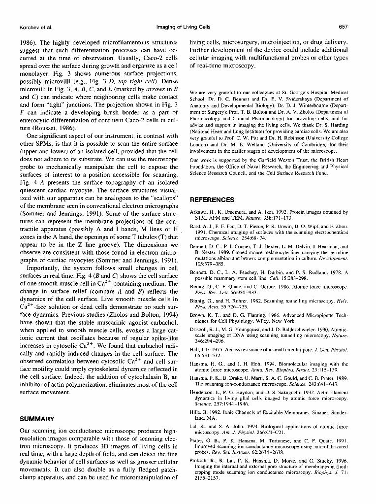
FIGURE 2 Scanning ion-conduc-tance microscope images of murinemelanocyte line melan-b. The cellswere grown as previously described(Bennett et al., 1989). The melan-bcells tend to be bipolar and alignedwith each other. Raised nuclear areasof cells are visible (A, bright high-lights in B and C). Cell borders com-monly show processes (dendrites)formed by melanocytes. In contrastwith epithelial cells, adjacent cells ap-pear largely nonadherent, but with lo-calized contacts. Images B and Cwere selected from a longer sequenceof successive scans. Each scan tookless than 5 min to acquire, and imageC was obtained at higher magnifica-tion.
FIGURE 3 (A, B, D-F) Scanning ion-conductance microscope images, in real time, of a confluent monolayer of a human colon cancer cell line (Caco-2)in a 1:1 mixture of phosphate-buffered saline and medium (RPMI 1640 with 20% fetal calf serum). During the 8-h period of continuous scanning(monitoring), the cells remain viable and motile. A and B, separated by 140 min, show movement of the "junction" between five cells. The nuclear regionsof two cells are discernible under the membrane as the lighter areas, and the boundaries between cells (arrows) appear to be raised. At higher magnificationa variety of surface morphologies were observed in the five adjacent cells (D-F). One cell (top left in D, and at higher magnification, E) showed filamentousstructures, reminiscent of microfilaments, converging on the "junction." Other cells had numerous surface projections, possibly microvilli. The projections(top right in D, and at higher magnification, F) can represent a developing brush border. (C) Scanning electron micrograph of Rama 25 mammary carcinomacells in culture. The cells were grown on plastic in culture medium with serum (Bennett et al., 1978). Microvillous cell surfaces, with denser microvillimarking cell boundaries (arrows), can be observed. These cells grow in culture as a single layer (monolayer), similar to the human colon cancer cells. (Thisscanning electron micrograph was kindly provided by Dr. D. C. Bennett.)
Korchev et al. 655
Volume 73 August 1997
imaged in appropriate medium without any special fixa-tion or treatment.
RESULTS AND DISCUSSION
With the developed scanning protocol our instrument cansuccessfully image complex, highly elaborated cellular sur-faces without damaging them (Fig. 2). Images shown in Fig.2, B and C, were obtained in two successive scans (C athigher magnification). These images show no change insurface topography that could be related to any possiblealteration caused by the scanning probe. The microscopecan image the upper surface of the cell in a single scan witha large "depth of field," in some cases better than 30 ,um.Importantly, we can, at the same time, detect fine surfacestructures that are usually only observed by scanning elec-tron microscopy after fixation and staining. Comparisonbetween the scanning electron micrograph (Fig. 3 C) andour microscope images (Fig. 3, A, B, and D) of similarepithelial cancer cell lines shows matching cellular mor-phologies: microvillous cell surfaces with denser microvillimarking cell boundaries (arrows). This confirms our con-tention that images captured by our microscope resemblethose obtained by scanning electron microscopy of fixed
FIGURE 4 (A) Surface topogra-phy of a small area of a single, qui-escent cardiac myocyte isolated bydigestion of intact perfused ventri-cle. The surface structure is compa-rable to that observed by scanningand transmission electron micros-copy (Sommer and Jennings, 1991). lThe main contractile elements ap-pear as protrusions beneath themembrane. Transmission electronmicroscopy shows these protrusionsin cross section as "scallops" in thesarcolemma. Bands equivalent to Aand I are easily discernible, with thesuggestion of the M line in the Aband. The opening of some T tubules(T) are visible in what would be theZ-line groove. (B and C) Topograph-ical images (scanned 1 min apart,taking 2 min each) of isolatedsmooth muscle cell illustrating themovements of the cell surface inCa2+-containing medium (2.5 mM).The experiment was performed atroom temperature on single guineapig ileal smooth muscle cells ob-tained after collagenase treatment, asdescribed elsewhere (Zholos et al.,1994).
and coated material, the significant difference being that inour system, the cells remain viable and active.As the instrument can scan cells consistently and repro-
ducibly for many hours, we can investigate real-timechanges in cell surfaces. Tracking the junctional boundarybetween five cells from a sequence of images (e.g., Fig. 3,A and B) over an 8-h period of continuous scanning showsthat human colon cancer cells remain motile and thus viable.The addition of cytochalasin B, a compound that inhibitsactin polymerization, abolishes the movement. We suggestthat the filamentous structures apparent in Fig. 3 (D and E)can be membrane manifestations of a cytoskeletal regulatorof cell movement. At higher magnification, the smallerfilamentous structures appear as furrows (Fig. 3 E) that canreflect an interaction between internal microfilaments andthe cell membrane. This observation is important because itcontrasts with AFM studies of the cell surface. In AFMimages the microfilamentous structures are directed up-ward, probably as a result of tip-induced deformation of thecell plasma membrane around the microtubules (Hendersonet al., 1992; Hansma and Hoh, 1994; Lal and John, 1994);valleys or depressions are poorly resolved.
Confluent human colon cancer cells (Caco-2) are knownto undergo enterocytic differentiation in culture (Rousset,
656 Biophysical Journal
Korchev et al. Imaging of Living Cells 657
1986). The highly developed microfilamentous structuressuggest that such differentiation processes can have oc-curred at the time of observation. Usually, Caco-2 cellsspread over the surface during growth and organize as a cellmonolayer. Fig. 3 shows numerous surface projections,possibly microvilli (e.g., Fig. 3 D, top right cell). Densemicrovilli in Fig. 3, A, B, C, and E (marked by arrows in Band C) can indicate where neighboring cells make contactand form "tight" junctions. The projection shown in Fig. 3F can indicate a developing brush border as a part ofenterocytic differentiation of confluent Caco-2 cells in cul-ture (Rousset, 1986).One significant aspect of our instrument, in contrast with
other SPMs, is that it is possible to scan the entire surface(upper and lower) of an isolated cell, provided that the celldoes not adhere to its substrate. We can use the microscopeprobe to mechanically manipulate the cell to expose thesurfaces of interest to a position accessible for scanning.Fig. 4 A presents the surface topography of an isolatedquiescent cardiac myocyte. The surface structures visual-ized with our apparatus can be analogous to the "scallops"of the membrane seen in conventional electron micrographs(Sommer and Jennings, 1991). Some of the surface struc-tures can represent the membrane projections of the con-tractile apparatus (possibly A and I bands, M lines or Hzones in the A band, the openings of some T tubules (T) thatappear to be in the Z line groove). The dimensions weobserve are consistent with those found in electron micro-graphs of cardiac myocytes (Sommer and Jennings, 1991).
Importantly, the system follows small changes in cellsurfaces in real time. Fig. 4 (B and C) shows the cell surfaceof one smooth muscle cell in Ca2+-containing medium. Thechange in surface relief (compare A and B) reflects thedynamics of the cell surface. Live smooth muscle cells inCa2+-free solution or dead cells demonstrate no such sur-face dynamics. Previous studies (Zholos and Bolton, 1994)have shown that the stable muscarinic agonist carbachol,when applied to smooth muscle cells, evokes a large cat-ionic current that oscillates because of regular spike-likeincreases in cytosolic Ca2 . We found that carbachol radi-cally and rapidly induced changes in the cell surface. Theobserved correlation between cytosolic Ca2+ and cell sur-face motility could imply cytoskeletal dynamics reflected inthe cell surface. Indeed, the addition of cytochalasin B, aninhibitor of actin polymerization, eliminates most of the cellsurface movement.
SUMMARY
Our scanning ion conductance microscope produces high-resolution images comparable with those of scanning elec-tron microscopy. It produces 3D images of living cells inreal time, with a large depth of field, and can detect the finedynamic behavior of cell surfaces as well as grosser cellularmovements. It can also double as a fully fledged patch-clamp apparatus, and can be used for micromanipulation of
living cells, microsurgery, microinjection, or drug delivery.Further development of the device could include additionalcellular imaging with multifunctional probes or other typesof real-time microscopy.
We are very grateful to our colleagues at St. George's Hospital MedicalSchool: Dr. D. C. Bennett and Dr. E. V. Sviderskaya (Department ofAnatomy and Developmental Biology); Dr. D. J. Winterbourne (Depart-ment of Surgery); Prof. T. B. Bolton and Dr. A. V. Zholos (Department ofPharmacology and Clinical Pharmacology) for providing cells, and foradvice and support in imaging the living cells. We thank Dr. S. Harding(National Heart and Lung Institute) for providing cardiac cells. We are alsovery grateful to Prof. C. W. Pitt and Dr. H. Robinson (University CollegeLondon) and Dr. M. E. Welland (University of Cambridge) for theirinvolvement in the earlier stages of development of the microscope.
Our work is supported by the Garfield Weston Trust, the British HeartFoundation, the Office of Naval Research, the Engineering and PhysicalScience Research Council, and the Cell Surface Research Fund.
REFERENCES
Arkawa, H., K. Umemura, and A. Ikai. 1992. Protein images obtained bySTM, AFM and TEM. Nature. 358:171-173.
Bard, A. J., F. F. Fan, D. T. Pierce, P. R. Unwin, D. 0. Wipf, and F. Zhou.1991. Chemical imaging of surfaces with the scanning electrochemicalmicroscope. Science. 254:68-74.
Bennett, D. C., P. J. Cooper, T. J. Dexter, L. M. Delvin, J. Heasman, andB. Nester. 1989. Cloned mouse melanocyte lines carrying the germlinemutations albino and brown: complementation in culture. Development.105:379 -385.
Bennett, D. C., L. A. Peachey, H. Durbin, and P. S. Rudland. 1978. Apossible mammary stem cell line. Cell. 15:283-298.
Binnig, G., C. F. Quate, and C. Gerber. 1986. Atomic force microscope.Phys. Rev. Lett. 56:930-933.
Binnig, G., and H. Rohrer. 1982. Scanning tunnelling microscopy. Helv.Phys. Acta. 55:726-735.
Brown, K. T., and D. G. Flaming. 1986. Advanced Micropipette Tech-niques for Cell Physiology. Wiley, New York.
Driscoll, R. J., M. G. Youngquist, and J. D. Baldeschwieler. 1990. Atomic-scale imaging of DNA using scanning tunnelling microscopy. Nature.346:294-296.
Hall, J. E. 1975. Access resistance of a small circular pore. J. Gen. Physiol.66:531-532.
Hansma, H. G., and J. H. Hoh. 1994. Biomolecular imaging with theatomic force microscope. Annu. Rev. Biophys. Struct. 23:115-139.
Hansma, P. K., B. Drake, 0. Marti, S. A. C. Gould, and C. B. Prater. 1989.The scanning ion-conductance microscope. Science. 243:641-643.
Henderson, E., P. G. Haydon, and D. S. Sakaguchi. 1992. Actin filamentdynamics in living glial cells imaged by atomic force microscopy.Science. 257:1944-1946.
Hille, B. 1992. Ionic Channels of Excitable Membranes. Sinauer, Sunder-land, MA.
Lal, R., and S. A. John. 1994. Biological applications of atomic forcemicroscopy. Am. J. Physiol. 266:C1-C21.
Prater, G. B., P. K. Hansma, M. Tortonese, and C. F. Quate. 1991.Improved scanning ion-conductance microscope using microfabricatedprobes. Rev. Sci. Instrum. 62:2634-2638.
Proksch, R., R. Lai, P. K. Hansma, D. Morse, and G. Stucky. 1996.Imaging the internal and external pore structure of membranes in fluid:tapping mode scanning ion conductance microscopy. Biophys. J. 71:2155-2157.

658 Biophysical Journal Volume 73 August 1997
Putman, C. A. J., K. 0. Werf, B. G. Grooth, N. F. Hulst, and J. Greve.1994. Viscoelasticity of living cells allows high resolution imaging bytapping mode atomic force microscopy. Biophys. J. 67:1749-1753.
Radmacher, M., R. W. Tillmann, M. Fritz, and H. E. Gaub. 1992. Frommolecules to cells: imaging soft samples with the atomic force micro-scope. Science. 257:1900-1905.
Rousset, M. 1986. The human colon carcinoma cell lines HT-29 andCaco-2: two in vitro models for the study of intestinal differentiation.Biochimie. 68:1035-1040.
Schoenenberger, C. A., and J. H. Hoh. 1994. Slow cellular dynamics inMDCK and R5 cells monitored by time-lapse atomic force microscopy.Biophys. J. 67:929-936.
Sommer, J. R., and R. B. Jennings. 1991. The Heart and CardiovascularSystem. Raven Press, New York. 3-50.
Vodyanoy, I., and S. M. Bezrukov. 1992. Sizing of an ion pore by accessresistance measurements. Biophys. J. 62:1-3.
Zholos, A. V., and T. B. Bolton. 1994. G-protein control of voltage-dependence as well as gating of muscarinic metabotropic channels inguinea-pig ileum. J. Physiol. (Lond.). 478:195-202.
Zholos, A. V., S. Komori, H. Ohashi, and T. B. Bolton. 1994. Ca21inhibition of inositol trisphosphate-induced Ca2+ release in singlesmooth muscle cells of guinea-pig small intestine. J. Physiol. (Lond.).481:97-109.