Safety of computer control systems: challenges and results in software development
15
Annual Reviews in Control 27 (2003) 23–37 Review Safety of computer control systems: challenges and results in software development Janusz Zalewski a,∗ , Wolfgang Ehrenberger b , Francesca Saglietti c , Janusz Górski d , Andrew Kornecki e a Florida Gulf Coast University, Ft. Myers, FL 33965-6565, USA b University of Applied Science, 36039 Fulda, Germany c Institute for Safety Technology, Forschungsgelände, 85748 Garching/Munich, Germany d Technical University of Gda´ nsk, 80-952 Gda ´ nsk, Poland e Embry-Riddle Aeronautical University, Daytona Beach, FL 32114, USA Abstract This paper reviews some results in improving software safety in computer control systems. The discussion covers various aspects of the software development process, as opposed to the product features. Software diversity, off-the-shelf software, failure mode and effect analysis, rigorous and formal software development are discussed. © 2003 Elsevier Ltd. All rights reserved. Keywords: Software safety; Software diversity; Off-the-shelf software; FMEA; Rigorous development; Formal verification; UML 1. Introduction The key aspect of safety in computer control systems is to minimize the risk of harm, which can lead to loss of life, limbs, or large financial losses due to the failure of hardware or software of a computer control system embedded in a larger application. Safety aspects are important in all modern computer applications, where computer control is embedded in larger systems, for example, all means of transportation, such as cars, railways, airplanes, ships; large plants, such as nuclear power plants, chemical plants, etc.; as well as smaller devices, such as medical electronic devices. New challenges show up every day, because computer- controlled systems are being increasingly applied in other areas related to human safety. In addition to traditional applications concerning safety listed above, several new areas have emerged, related to safety of computer control, including: telecommunication systems, banking systems, fire protection systems on oil/gas platforms, and others. As- suring safety becomes more and more important, because ∗ Corresponding author. Tel.: +1-239-590-7317; fax: +1-239-590-7330. E-mail addresses: [email protected] (J. Zalewski), [email protected] (W. Ehrenberger), [email protected] (F. Saglietti), [email protected] (J. G´ orski), [email protected] (A. Kornecki). of an increasing concern about safety of computers and computer-controlled systems in a modern society as a whole. The technologies of providing safety assurance in com- puter control systems are often based on the architecture of feedback control, but they rarely use, if at all, results from continuous systems. Due to the discrete nature of the safety problem, methods of discrete mathematics are usually ap- plied. In this view, verification of hardware and software, with respect to safety, is a key challenge. Methods currently offered are so complex that they are manageable only for simple systems, while the complexity of safety-related ap- plications is usually high and continues to increase dramat- ically with the progress of computing technologies. 1.1. Software safety: product versus process Safety is usually defined as a ‘negative’ property that as- serts simply that nothing bad happens (Rushby, 1994). Safety is addressed through a hazard analysis process, which is nor- mally not conducted in non-critical software development. Attention of the developers must be focused on preventing hazards that are conditions that lead to a mishap, rather than preventing mishaps directly. In terms of a control system (Fig. 1), hazards are caused by various failures of the controller. An ‘omission failure’ 1367-5788/$ – see front matter © 2003 Elsevier Ltd. All rights reserved. doi:10.1016/S1367-5788(03)00004-X
Transcript of Safety of computer control systems: challenges and results in software development

Annual Reviews in Control 27 (2003) 23–37
Review
Safety of computer control systems: challenges and resultsin software development
Janusz Zalewskia,∗, Wolfgang Ehrenbergerb, Francesca Sagliettic,Janusz Górskid, Andrew Korneckie
a Florida Gulf Coast University, Ft. Myers, FL 33965-6565, USAb University of Applied Science, 36039 Fulda, Germany
c Institute for Safety Technology, Forschungsgelände, 85748 Garching/Munich, Germanyd Technical University of Gda´nsk, 80-952 Gda´nsk, Poland
e Embry-Riddle Aeronautical University, Daytona Beach, FL 32114, USA
Abstract
This paper reviews some results in improving software safety in computer control systems. The discussion covers various aspects of thesoftware development process, as opposed to the product features. Software diversity, off-the-shelf software, failure mode and effect analysis,rigorous and formal software development are discussed.© 2003 Elsevier Ltd. All rights reserved.
Keywords:Software safety; Software diversity; Off-the-shelf software; FMEA; Rigorous development; Formal verification; UML
1. Introduction
The key aspect of safety in computer control systems isto minimize the risk of harm, which can lead to loss of life,limbs, or large financial losses due to the failure of hardwareor software of a computer control system embedded in alarger application. Safety aspects are important in all moderncomputer applications, where computer control is embeddedin larger systems, for example, all means of transportation,such as cars, railways, airplanes, ships; large plants, suchas nuclear power plants, chemical plants, etc.; as well assmaller devices, such as medical electronic devices.
New challenges show up every day, because computer-controlled systems are being increasingly applied in otherareas related to human safety. In addition to traditionalapplications concerning safety listed above, several newareas have emerged, related to safety of computer control,including: telecommunication systems, banking systems,fire protection systems on oil/gas platforms, and others. As-suring safety becomes more and more important, because
∗ Corresponding author. Tel.:+1-239-590-7317; fax:+1-239-590-7330.E-mail addresses:[email protected] (J. Zalewski),
[email protected] (W. Ehrenberger),[email protected] (F. Saglietti), [email protected] (J. Gorski),[email protected] (A. Kornecki).
of an increasing concern about safety of computers andcomputer-controlled systems in a modern society as a whole.
The technologies of providing safety assurance in com-puter control systems are often based on the architecture offeedback control, but they rarely use, if at all, results fromcontinuous systems. Due to the discrete nature of the safetyproblem, methods of discrete mathematics are usually ap-plied.
In this view, verification of hardware and software, withrespect to safety, is a key challenge. Methods currentlyoffered are so complex that they are manageable only forsimple systems, while the complexity of safety-related ap-plications is usually high and continues to increase dramat-ically with the progress of computing technologies.
1.1. Software safety: product versus process
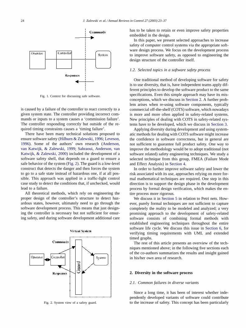
Safety is usually defined as a ‘negative’ property that as-serts simply that nothing bad happens (Rushby, 1994). Safetyis addressed through a hazard analysis process, which is nor-mally not conducted in non-critical software development.Attention of the developers must be focused on preventinghazards that are conditions that lead to a mishap, rather thanpreventing mishaps directly.
In terms of a control system (Fig. 1), hazards are causedby various failures of the controller. An ‘omission failure’
1367-5788/$ – see front matter © 2003 Elsevier Ltd. All rights reserved.doi:10.1016/S1367-5788(03)00004-X
24 J. Zalewski et al. / Annual Reviews in Control 27 (2003) 23–37
Fig. 1. Context for discussing safe software.
is caused by a failure of the controller to react correctly to agiven system state. The controller providing incorrect com-mands or inputs to a system causes a ‘commission failure’.The controller responding correctly but outside of the re-quired timing constraints causes a ‘timing failure’.
There have been many technical solutions proposed toensure software safety (Hilburn & Zalewski, 1996; Leveson,1996). Some of the authors’ own research (Anderson,van Katwijk, & Zalewski, 1999; Sahraoui, Anderson, vanKatwijk, & Zalewski, 2000) included the development of asoftware safety shell, that depends on a guard to ensure asafe behavior of the system (Fig. 2). The guard is a low-levelconstruct that detects the danger and then forces the systemto go to a safe state instead of hazardous one, if at all pos-sible. This approach was applied in a traffic-light controlcase study to detect the conditions that, if unchecked, wouldlead to a failure.
All theoretical methods, which rely on engineering theproper design of the controller’s structure to detect haz-ardous states, however, ultimately need to go through thesoftware development process. This means that just design-ing the controller is necessary but not sufficient for ensur-ing safety, and during software development additional care
Fig. 2. System view of a safety guard.
has to be taken to retain or even improve safety propertiesembedded in the design.
In this paper, we present selected approaches to increasesafety of computer control systems via the appropriate soft-ware design process. We focus on the development processto improve software safety, as opposed to engineering thedesign structure of the controller itself.
1.2. Selected topics in a software safety process
One traditional method of developing software for safetyis to use diversity, that is, have independent teams apply dif-ferent principles to develop the software product to the samespecifications. Even this simple approach may have its mis-conceptions, which we discuss inSection 2. A further prob-lem arises when re-using software components, typicallycommercial off-the-shelf (COTS) software, which nowadaysis more and more often applied in safety-related systems.New principles of dealing with COTS in safety-related sys-tems have to be developed, which we discuss inSection 3.
Applying diversity during development and using system-atic methods for dealing with COTS software might increasethe confidence in software correctness, but in general arenot sufficient to guarantee full product safety. One way toimprove the methodology would be to adopt traditional (notsoftware related) safety engineering techniques. We study aselected technique from this group, FMEA (Failure Modeand Effect Analysis) inSection 4.
In order to further improve software safety and lower therisk associated with its use, approaches relying on more for-mal mathematical techniques are required. One step in thisdirection is to support the design phase in the developmentprocess by formal design verification, which makes the en-tire process more rigorous.
We discuss it inSection 5in relation to Petri nets. How-ever, purely formal techniques are not sufficient to capturecompletely the reality to be modeled and analyzed; a verypromising approach to the development of safety-relatedsoftware consists of combining formal methods withestablished engineering techniques throughout the entiresoftware life cycle. We discuss this issue inSection 6, forverifying timing requirements with UML and extendedtimed graphs.
The rest of this article presents an overview of the tech-niques mentioned above; in the following five sections eachof the co-authors summarizes the results and insight gainedin his/her own area of research.
2. Diversity in the software process
2.1. Common failures in diverse variants
Since a long time, it has been of interest whether inde-pendently developed variants of software could contributeto the increase of safety. This concept has been particularly
J. Zalewski et al. / Annual Reviews in Control 27 (2003) 23–37 25
attractive to reduce the licensing costs of safety-related pro-grams. The basic idea has been as follows:
• Step 1. Produce independently two variants of softwareto solve the same task.
• Step 2. Demonstrate that each single variant has achieveda certain reliability, for example, that its failure probabilityper demandp1 ≈ p2 is below a certain limit, say 10−4.
• Step 3. Conclude for the probability of common failureper demand of both variants:
p12 ≈ p1 × p2 ≈ p12 < 10−8 (1)
This way of thinking may lead to commercially attractivesolutions under certain circumstances. Doubling the effort—we have to produce two variants—would result in thesquareof the relevant reliability figure. In other words,linear effortincrease during production could provide exponential reli-ability gain. The gain would improve safety properties, atthe expense of a loss of availability properties. Under suchassumptions diversity looks to be economically attractive.
Of course, producing two variants one would take anyprecaution to avoid common faults among variants. Thecollection of diversity techniques proposed inSaglietti,Ehrenberger, and Kersken (1992)could be taken to select aproper set of techniques.
There were, however, severe objections against conclusion(1). In a theoretical work (Eckhardt & Lee, 1985), it wasshown that (1) is to be augmented by a measure of thevarying “difficulty” throughout the input data space, namelythe variance of the probability of committing programmingerrors over the input domain of the two diverse programvariants:
p12 ≈ p12 + Var(q) (2)
where q represents the probability of an arbitrary variantfailing on inputx. The variance is to be taken over all inputsx. An accurate estimate ofq would require examination of a
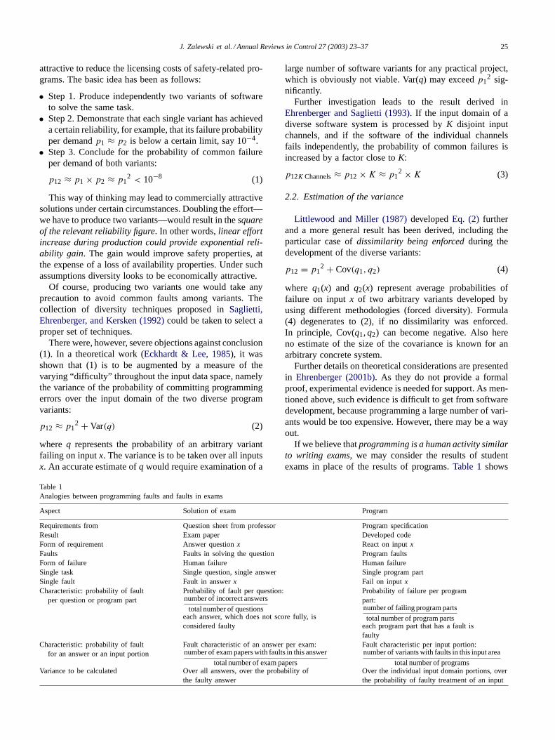
Table 1Analogies between programming faults and faults in exams
Aspect Solution of exam Program
Requirements from Question sheet from professor Program specificationResult Exam paper Developed codeForm of requirement Answer questionx React on inputxFaults Faults in solving the question Program faultsForm of failure Human failure Human failureSingle task Single question, single answer Single program partSingle fault Fault in answerx Fail on inputxCharacteristic: probability of fault
per question or program partProbability of fault per question:number of incorrect answers
total number of questionseach answer, which does not score fully, isconsidered faulty
Probability of failure per programpart:number of failing program parts
total number of program partseach program part that has a fault isfaulty
Characteristic: probability of faultfor an answer or an input portion
Fault characteristic of an answer per exam:number of exam papers with faults in this answer
total number of exam papers
Fault characteristic per input portion:number of variants with faults in this input area
total number of programsVariance to be calculated Over all answers, over the probability of
the faulty answerOver the individual input domain portions, overthe probability of faulty treatment of an input
large number of software variants for any practical project,which is obviously not viable. Var(q) may exceedp1
2 sig-nificantly.
Further investigation leads to the result derived inEhrenberger and Saglietti (1993). If the input domain of adiverse software system is processed byK disjoint inputchannels, and if the software of the individual channelsfails independently, the probability of common failures isincreased by a factor close toK:
p12K Channels≈ p12 × K ≈ p12 × K (3)
2.2. Estimation of the variance
Littlewood and Miller (1987)developedEq. (2) furtherand a more general result has been derived, including theparticular case ofdissimilarity being enforcedduring thedevelopment of the diverse variants:
p12 = p12 + Cov(q1, q2) (4)
where q1(x) and q2(x) represent average probabilities offailure on inputx of two arbitrary variants developed byusing different methodologies (forced diversity). Formula(4) degenerates to (2), if no dissimilarity was enforced.In principle, Cov(q1,q2) can become negative. Also hereno estimate of the size of the covariance is known for anarbitrary concrete system.
Further details on theoretical considerations are presentedin Ehrenberger (2001b). As they do not provide a formalproof, experimental evidence is needed for support. As men-tioned above, such evidence is difficult to get from softwaredevelopment, because programming a large number of vari-ants would be too expensive. However, there may be a wayout.
If we believe thatprogramming is a human activity similarto writing exams, we may consider the results of studentexams in place of the results of programs.Table 1shows
26 J. Zalewski et al. / Annual Reviews in Control 27 (2003) 23–37
the envisaged analogies. The table of the exam results isgiven in Ehrenberger (2001a), where eight questions hadto be answered, including some on deriving algorithms. Atotal of 13 exam papers were considered worth being usedin the evaluation, because the number of faulty answers wasreasonably small. They formed 78 pairs.
Any correct answer was qualified with 0, any incorrectone with 1. For each question, the number of failed answerswas counted. Theqi of questioni was calculated as:
number of exam papers with faults in answeri
number of all exam papers
and the variance of the difficulty of the questions, withNrepresenting the number of questions:
Var(question difficulty) = 1
N
N∑i=1
(qi − 1
N
N∑i=1
qi
)2
(5)
On the other hand, the probabilities of common faults oftwo students (i, j) can be taken from the related matrix aspij
equal to the following:
number of answers with faults in both exam papers
number of all questions
The probabilities of individual faults per solutionpi andpj
could also be evaluated:
pmean= 0.365; (pmean)2 = 0.133
Var(question difficulty) = 0.023< (pmean)2.
pij < pi × pj, for 28 pairs
pij = pi × pj, for 13 pairs
pij > pi × pj, for 37 pairs
pij ≤ pi × pj, for 41 pairs
pij ≤ 2 × pi × pj, for 70 pairs
These observations together with the theoretical considera-tions suggest the following estimate for the common failureprobability of a two-fold diverse system:
p12 ≈ p12 + Var(q) ≈ 2 × p1
2 (6)
Regarding the exams’ results one has to remember that notype of forced diversity had been applied. As forced diversitywill be the rule for any real project with diverse software,failure independence is likely to be higher than in the exams.
2.3. Results
If one accepts theanalogy of the fault producing processesin students’ exams and programming, one may consider datafrom university exams as a basis for studying software di-versity. The investigation of the answers of a student examshows that in general the intuitive result (1) is too optimistic.
A correction by the factor 2 is appropriate. This correctionis more conservative than result (4).
If the program reduces information during its executionby a selection mechanism, the number of channels involvedin that reduction has to be considered as a further sourceof common failure of independent variants. In many casesof industrial software application, the influence of the infor-mation reduction will be more substantial than the influenceof the varying difficulty of the input domain. Under idealcircumstances and bringing together results (6) and (3), wemay conclude that:
p12,K Channels≈ p12 × K ≈ 2 × p12 × K (7)
Under ideal circumstances, the probability of common fail-ure of two diverse software variants may be estimated as twotimes the square of the value of the failure probability of thesingular variant times the number of diversity channels thatentail information reduction.
The results of the experiment with student data can besummarized as follows:
• Errors are not made independently of the questions to beanswered.
• The value of the variance of the difficulty over the inputdomain is close to the value of common failure probability.
• Under ideal circumstances, the probability of commonfailure equals the square of the failure probability of onevariant multiplied by the doubled number of channels.
3. Off-the-shelf software
For evident economical reasons, COTS software compo-nents are increasingly (re)used in different application areas,including safety-critical ones. Due to their origin, the avail-able information on the underlying development process ofthese components is often only fragmentary.
A very limited knowledge on the component production,as well as differences between past and future usage (suchas, different reliability demands or different usage profiles)create a serious challenge for the software engineering com-munity facing the problem of assessing the suitability ofCOTS components for new development projects.
The strategy suggested to approach this difficult problemconsists of five successive decision phases, as illustrated inFig. 3:
• Phase 1. Identification of safety demands at the systemlevel.
• Phase 2. Analysis of the role of COTS software withinthe system (safety relevance and sensitivity).
• Phase 3. Qualitative (subjective) assessment of the soft-ware process and product quality.
• Phase 4. Quantitative (objective) assessment of past (test-ing and) operating experience.
• Phase 5. Validation of component interfaces within theintegrated system.

J. Zalewski et al. / Annual Reviews in Control 27 (2003) 23–37 27
Fig. 3. Phased approach to component analysis.
Considerations on phases 2, 3 and 4 were presented inSaglietti (2000a, 2000b, 2001), respectively. Each phase isdiscussed below in terms of key factors to be considered andnecessary actions to be taken during development.
3.1. Phase 1: identification of safety and reliabilitydemands at the system level
Key factors: risk analysis (black-box, component-inde-pendent).
• Risk analysis: identification of occurrence of failure-initiating events and loss caused by them; comparison ofhazards involved in automation with those inherent to theapplication as such, i.e. in an uncontrolled mode; identi-fication of critical events to be controlled; classificationof event criticality if not under control.
• Analysis of results: determination of minimum quanti-tative target for reliability demands to be demonstrated,in terms of minimum probability of operational sur-vival, i.e. of correct or acceptable performance underapplication-specific operational demand profile.
3.2. Phase 2: analysis of the role of COTS componentswithin the system (Saglietti, 2001)
Key factors: COTS safety relevance, sensitivity (objec-tive, quantitative, system-dependent), safety criticality andsensitivity.
• Safety criticality: identification of potentially critical fail-ure propagation through COTS modules, evaluation of in-dividual responsibility of COTS components in terms ofsafety-relevance to distribute verification and validationeffort accordingly, determination of bottlenecks in systemsafety, definition of fault tolerant architectural propertiesaccordingly.
• Sensitivity: determination of impact of component re-liability on system reliability to know whether modestreliability figures at component level are acceptable forsystems with higher reliability demands, in order to de-
rive to which extent a post-qualification of pre-developedsoftware allows to expect an increase of system reliability.
3.3. Phase 3: qualitative assessment of COTS atcomponent level (Saglietti, 2000b)
Key factors: COTS process and product (subjective, qual-itative, system-independent), assessment of non-operationalevidence.
Qualitative judgment on non-operational aspects from alllife-cycle phases preceding operation; should include thefollowing aspects:
• Development process (structured, semi-formal, formalmethods).
• Safety culture (awareness of consequences, ethical andfinancial).
• Documentation (accuracy and consistency of reports anddependencies).
• Resources (human labor and mechanical aid).• Informal checks (manual analysis of code and docu-
ments).• Automated static analysis (syntactic and semantic checks
by automatic tools).• Non-operational tests (execution for non-representative
inputs).
3.4. Phase 4: quantitative assessment of COTS componentswithin the system (Saglietti, 2000a)
Key factors: COTS behavior during testing and operation(objective, quantitative, system-dependent), assessment ofoperational evidence.
• Quantitative judgment of operational aspects: inspiteof deterministic nature of logical faults, a probabilisticapproach is justified by input randomness, representingphysical variables subject to unpredictability of statetransitions in technical processes under control.
• Estimation of software reliability by statistical testing onthe basis of significant amount of operational evidence,correct execution of a large number of independent, oper-ationally representative scenarios; based on sampling the-ory, estimation of upper bound of failure probability at agiven confidence level.
3.5. Phase 5: validation at integrated system level
Key factors: interface analysis (white box, component-dependent, context-dependent).
Inconsistencies between physics and logical specificationhave to be analyzed, including:
• Violated global properties, such as in Airbus incident inWarsaw.
• Violated local properties at interfaces, such as:

28 J. Zalewski et al. / Annual Reviews in Control 27 (2003) 23–37
◦ Mars Climate Observer, where two different force ref-erence systems were used (British and metric systems).
◦ Berlin Fire Brigade—Millennium: different operatingsystems in different system parts, inconsistent commu-nication of date format.
◦ Ariane 5 Explosion, where conversion routine origi-nally developed for flight trajectory of Ariane 4 usedinsufficient range.
◦ Blood Databank, where program designer developedthe database manager for a single computer applicationwithout considering networked applications; could notanticipate that simultaneous access to a record by twousers would lead to a hazard.
4. Failure mode and effect analysis forobject-oriented software
Over the years, a number of safety analysis tech-niques have been successfully used in conventional (i.e.non-computer-based) systems, e.g. Fault Tree Analysis(FTA), Failure Mode and Effect Analysis (FMEA), HazardOperability Analysis (HAZOP), and others. However, inmany cases, these techniques cannot be directly applied tosoftware.
The problem is that the traditional safety analysis tech-niques do not adequately address issues, which are char-acteristic for software, like discrete nature of processes,complexity, domination of design faults, or real-time con-straints, which are often the central issue of software-controlled industrial applications. This is in particular truefor object-oriented software, which is based on a concep-tually new paradigm and has not been adequately tested insafety-critical applications. To overcome those difficultiesone can purposefully adapt traditional safety techniquesto software or, alternatively, look for possible ways of ex-tending traditional methods of software analysis with thepossibility of safety analysis.
The former approach can be illustrated by several exam-ples. FTA has been adapted for analysis of safety-criticalsoftware systems inLeveson, Cha, and Shimeall (1991). Amethod of informal safety analysis of software-based sys-tems using FTA and FMEA has been applied in nuclearindustry (Maier, 1995). HAZOP has been adopted for usewith respect to computer systems (Redmill, Chudleigh, &Catmur, 1999). The advantage of this approach is that theoriginal techniques have already been widely used for manyindustrial applications and it is easier for safety engineersto adapt to their new (extended) versions. The disadvantageis that most of the traditional safety analysis techniques arerather informal.
The latter approach is based on formal and semi-formalmethods and models originally developed for the softwaredomain. The aim is to extend those methods to make themadequate for safety analysis purposes. This includes attemptsto use temporal logic, Petri nets, LOTOS, event-action mod-
els, object models and others. The advantage of this approachis that those methods are better suited to describe softwareand provide adequate mechanisms for analysis and verifica-tion. The disadvantage is that the methods are new to safetyengineers.
Some of related research, attempting to extend the tra-ditional safety analysis methods in a way that they can beapplied to software intensive systems, was summarized inGórski (2000). Below we give more detail on the work thataims at extending the FMEA (Failure Mode and Effect Anal-ysis) method to make it suitable to analyze object-orientedsoftware designs (Cichocki & Górski, 2000, 2001).
4.1. Overview of the method
FMEA looks at the system design and focuses on safetyconsequences of failures of the components. Identifiedclasses of component failures are analyzed case by caseand each time the analysis process results in an explicitand documented decision. The decision can be just theacceptance (supported by a convincing justification) of theconsequences of the failure or can suggest necessary de-sign changes to remove (or mitigate) the consequences orcauses of failures. Documentation is an important output ofFMEA. This documentation can be then referred to by asafety case for the considered system.
The objectives of our approach are consistent with theobjectives of FMEA. However, we introduce two additionalassumptions: (1) we assume that the analyzed system is be-ing developed using an object-oriented approach, and (2)we assume that the object-oriented models of the system aresupplemented with their formal specifications.
The focus on the object-orientation as the system mod-eling approach was motivated by the increasing popularityof this paradigm in the system developing community, es-pecially as far as software development is concerned. Ob-ject models are general enough to represent systems (people,software and hardware) and can then be specialized towardsrepresentation of software components. As a consequence,the system development can proceed without a major switchof the modeling approach while changing the attention fromthe system to software aspects. This is an important advan-tage during the analyses as we can pass the borders betweenheterogeneous components of the system (both hierarchi-cally and horizontally) without being forced to work withheterogeneous models.
Formal specification provides for precise and unambigu-ous expression of system properties. This in turn providesfor high assurance level of the analyses. We have chosenCSP (Communicating Sequential Processes,Roscoe, 1998)as a formal base for object-oriented models (although otherformalisms could also apply). The motivation behind thischoice was that CSP are well suited to model cooperatingcomponents that interact by passing messages through theinterfacing communication lines. It is exactly the situationwe are facing in case studies related to railway switching.

J. Zalewski et al. / Annual Reviews in Control 27 (2003) 23–37 29
This system has components with relatively little state in-formation. They send and receive messages through definedcommunication channels, and CSP is a formalism that di-rectly provides for specification of such interactions.
As FMEA focuses on components, our primary interestis the decomposition hierarchy of the object model. The de-composition shows what are the system components andhow they interact. The depth of this hierarchy depends onour choice: which components are treated as atoms withoutgoing into details of their internal structure. Specificationrelated to a given level of decomposition constitutes a refer-ence level for the specifications related to the levels below. Inthis step, we choose the reference level and the componentlevel for further analyses. Let us assume that the propertiesat the reference level are the safety properties of the systemof interest. The (formal) specification related to the refer-ence level is to be fulfilled by the lower level for componentsand their interaction structure. Establishing consistency be-tween those two layers of specifications demonstrates thatthe components interact in a safe way.
4.2. Identifying and analyzing failures
Failures of a component are modeled as deviations fromspecifications of its “normal” behavior. To provide for com-pleteness we follow a systematic procedure of failure modeidentification.
The key issue is to select potential failure modes of a com-ponent (formulate failure hypotheses) and to decide whichof them are included in further analyses (accepting or re-jecting the failure hypotheses). In order to build the failurehypotheses we apply the following criteria that form a sortof a checklist to be followed while formulating the failurehypotheses for a component:
• Violations of pre-conditions of operations.• Signal values beyond the associated ranges.• Transition to a wrong state that is already in the specifi-
cation of the component.• Transition to a wrong state that was not included in the
original specification of the component.
In addition to the above, we apply the usual criteria toformulate failure mode hypotheses: checklists of the fail-ure modes of a considered type of component; experiencereports provided by users of similar systems; failure pro-files of components; requirements coming from the projectstakeholders. The list of accepted failure mode hypothesesis passed to the next analytical step.
The objective of this step is to analyze the consequencesof the selected failure modes on the properties of the refer-ence object. Each failure mode is modeled by changing theCSP specification that implements the reference object interms of its component objects. Then we check the conse-quences of the failure mode with the help of the FDR tool(FDR, 1997). If the specifications are consistent, the ana-lyzed failure mode has no negative effects on the reference
object. In the opposite case, however, we know that the fail-ure mode can affect safety. The tool provides event scenariosrelated to such situations.
We call this process thefailure mode injection campaign.The results of the fault injection campaign are used in deci-sions related to a given failure mode: acceptance, handling(by redesign) or elimination (by removing its causes). Thecriteria used to support such decisions include availabilityof the resources for redesign, availability of candidate com-ponents to replace a given one, and the assessment of thecredibility of the considered failure mode.
4.3. Railway signaling system case study
The approach has been validated during the case studyrelated to a railway signaling system. The system is respon-sible for setting signals on a rail track connecting two adja-cent stations. Its decomposition layers are shown inFig. 4.
Fig. 5 shows the co-operation diagram showing the com-ponents implementing the BLOCK object. We developedspecifications down to seven decomposition levels and thenused our approach to analyze consequences of componentfailures. Safety properties were derived from the railway reg-ulations and expressed with respect to the first three levelsof decomposition. The levels below represented the designdecisions.
Formal specifications were very helpful in the process ofidentification and selection of failure modes of components.It was easy to control the completeness of analyses andthe precise meaning of specifications was very helpful inunderstanding the semantics of failures.
Fig. 4. Decomposition hierarchy of the railway signaling system.

30 J. Zalewski et al. / Annual Reviews in Control 27 (2003) 23–37
Fig. 5. Co-operation diagram from the railway signaling case study.
The failure modes were modeled as extensions to for-mal specifications of ‘normal’ behaviors. This providedfor better manageability of specifications and switchinga failure on/off could be achieved by common condi-tional compilation techniques. Application of the tool(FDR) removed the burden of formal analysis of compo-nent failure mode consequences. An additional advantagewas that the tool was able to provide example scenariosshowing how a given failure breaks system safety. Thosescenarios were very useful while considering componentre-design.
5. Rigorous development process
The fundamental objective of achieving software safety isto guarantee that the software does not cause or contributeto a system reaching a hazardous system state. This maybe supported by conformance to well defined engineeringstandards, such as FMEA discussed above. In this section,we address some issues of designing safe software by takinga more systematic approach regarding the traditional designmethods.
5.1. Safety analysis and verification
A specific process for safety improvement is describedin Mojdehrakhsh, Tsai, Kirani, and Elliott (1994). The pro-cess must assure that the software safety analysis is closelyintegrated with the system safety analysis and the softwaresafety is explicitly verified. The following activities regard-ing software safety program are geared toward achieving thestated objective, with emphasis on analysis first and verifi-cation next. The analysis phase involves conducting systemsafety analysis to:
• Identify the key inputs into the software requirementsspecification, such as hazardous commands, limits, tim-ing constraints, sequence of events, voting logic, failuretolerance, etc.
• Create and identify the specific software safety require-ments in the body of the conventional software specifica-tion.
• Identify which software design components are safety crit-ical.
The initial analyses and subsequent system and softwaresafety analyses identify when software is a potential causeof a hazard or will be used to support the control of a hazard.Using specific software design and implementation tech-niques and processes is crucial to reduce potential hazardsintroduced by software. The associated verification phaseinvolves the following steps:
• Apply specific verification and validation techniques toensure appropriate implementation of the software safetyrequirements.
• Create test plans and procedures to satisfy the intent ofthe software safety verification requirements.
• Introduce any necessary corrective actions resulting fromthe software safety verification.
The process is fundamental to the identification of thesafety-critical functions and the causal factors, includingthe factors that may be software-induced or controlled. Theidentification shall include also creation of an appropri-ate taxonomy of hazards (commission, omission, timingerror).
In addition to those discussed in a previous section, FTA,FMEA, and HAZOP, some of the techniques used for anal-ysis and verification include (Bishop, 1990): Event TreeAnalysis (ETA), Failure Mode Effect and Criticality Anal-ysis (FMECA), Common Mode Failure Analysis (CMF),Cause Consequence Diagrams (CCD), and Petri Nets(PN).
Most of these methods allow for rigorous treatment of thedevelopment process. The one we found particularly suitablefor studying safety properties is Petri nets (Kornecki, Nasah,& Zalewski, 1998; Saglietti, 1998). We have applied it tothe analysis of the TCAS software specification.
5.2. Petri nets in design verification
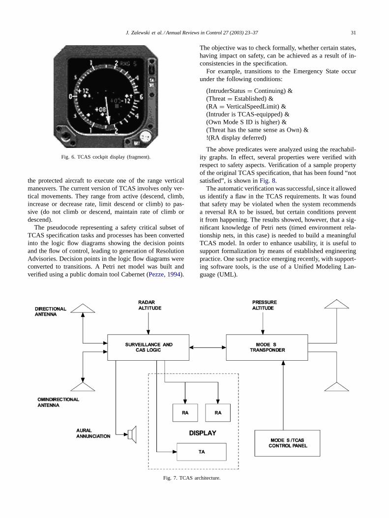
TCAS is a Traffic Collision Avoidance System, introducedto reduce the risk of mid-air collisions between aircraft. TheTCAS equipment is a small electronic device, consisting of acomputer and software, a directional antenna, a transponderand cockpit display and controls (Figs. 6 and 7).
TCAS continuously monitors aircraft within 10 nauticalmiles to identify the potential threat. If an aircraft is detectedto be a threat, a Traffic Advisory (TA) is issued showingthe available information about the potential threat, includ-ing the call sign, relative position, altitude difference, andaltitude vector.
If an aircraft persists to be a threat, the TCAS evaluateswhether collision might occur within the next 25 s. In suchcase, a Resolution Advisory (RA) is issued, which requires
J. Zalewski et al. / Annual Reviews in Control 27 (2003) 23–37 31
Fig. 6. TCAS cockpit display (fragment).
the protected aircraft to execute one of the range verticalmaneuvers. The current version of TCAS involves only ver-tical movements. They range from active (descend, climb,increase or decrease rate, limit descend or climb) to pas-sive (do not climb or descend, maintain rate of climb ordescend).
The pseudocode representing a safety critical subset ofTCAS specification tasks and processes has been convertedinto the logic flow diagrams showing the decision pointsand the flow of control, leading to generation of ResolutionAdvisories. Decision points in the logic flow diagrams wereconverted to transitions. A Petri net model was built andverified using a public domain tool Cabernet (Pezze, 1994).
Fig. 7. TCAS architecture.
The objective was to check formally, whether certain states,having impact on safety, can be achieved as a result of in-consistencies in the specification.
For example, transitions to the Emergency State occurunder the following conditions:
(IntruderStatus= Continuing) &(Threat= Established) &(RA = VerticalSpeedLimit) &(Intruder is TCAS-equipped) &(Own Mode S ID is higher) &(Threat has the same sense as Own) &!(RA display deferred)
The above predicates were analyzed using the reachabil-ity graphs. In effect, several properties were verified withrespect to safety aspects. Verification of a sample propertyof the original TCAS specification, that has been found “notsatisfied”, is shown inFig. 8.
The automatic verification was successful, since it allowedus identify a flaw in the TCAS requirements. It was foundthat safety may be violated when the system recommendsa reversal RA to be issued, but certain conditions preventit from happening. The results showed, however, that a sig-nificant knowledge of Petri nets (timed environment rela-tionship nets, in this case) is needed to build a meaningfulTCAS model. In order to enhance usability, it is useful tosupport formalization by means of established engineeringpractice. One such practice emerging recently, with support-ing software tools, is the use of a Unified Modeling Lan-guage (UML).

32 J. Zalewski et al. / Annual Reviews in Control 27 (2003) 23–37
Fig. 8. Sample output from Cabernet.
6. Verifying timing requirements using UML
This section presents a method of enhancing UML bydealing with timing requirements via statecharts. We pro-pose to combine traditional engineering tools, such as thoserelying on the UML notation, with formal method tools,such as model checkers. Combining both types of tools intoa single integrated system via a common user interface, to
express and verify timing properties, leads to an architectureof a verification system (Al-Daraiseh, Zalewski, & Toetenel,2001) as inFig. 9.
The idea is based on the work presented inRoubtsova, vanKatwijk, and Toetenel (2001). They use tuples of extendedclass, object and statechart UML diagrams as specificationsof real-time software. The semantics of the UML specifica-tion are defined by transformation to the eXtended Timed

J. Zalewski et al. / Annual Reviews in Control 27 (2003) 23–37 33
Fig. 9. Architecture of the integrated system.
Graphs (XTG) (Ammerlaan, Spelberg, & Toetenel, 1998).The correctness of the transformation is demonstrated byshowing that the XTG computation tree can be projectedinto the computation tree of the corresponding UML speci-fication.
Thanks to the transformation we were able to specifytemporal logic properties in the UML language and to verifythem at the XTG level using the model checker. Two tools,a typical design tool based on UML, and a typical modelchecker based on a formal method, are interfaced to a uservia a GUI.
Technically, for expressing timing requirements, UMLstatecharts are converted to XTGs, which in turn are con-verted to textual representation and analyzed by a modelchecker. A new software tool has been developed to easethe interfacing of models built in XTG formal language toother tools.
6.1. Integrated methodology
Both statecharts and XTG’s are visual tools to model thebehavior of software. Since UML has no means to expressreal-time properties, we propose a method to convert theUML statecharts to XTGs, so that statechart models can bemodel checked using the PMC model checker (van Katwijk,Toetenel, Sahraoui, Anderson, & Zalewski, 2000). Convert-ing a UML model expressed in statecharts, to XTG graphs,requires thorough understanding of their mutual correspon-dence.
XTG is a new notation for describing real-time systemsbased on timed automata (Ammerlaan et al., 1998). It pro-vides a simple representation for high level specificationlanguages and is suitable for those languages that allow
Fig. 10. Simple statechart representing a counter.
extensive data modeling, with maximal progress semantics,and modeling interprocess communication by value passingthrough data channels.
A UML statechart consists of states and transitions. Astate is an ontological condition that persists for a signif-icant period of time, is distinguishable from other suchconditions, and is disjoint from them. A distinguishablestate means that it differs from other states in the eventsit accepts, the transitions it takes as a result of accept-ing those events, or the activities it performs. A transi-tion is a response to an event that causes a change instate.
A simple statechart diagram is shown inFig. 10. In theIDLE state nothing is happening and the timer is not count-ing down, waiting for the start command “StartCmd”. TheStartCmd carries a single value, which is the starting timethe timer shall count down.
When this event occurs the system transfers to the Count-ing Down state and the timer starts counting down again.There is also a timeout signal “tm”. When the timeout oc-curs, the “tm” transition is taken and the action from its ac-tion list will be executed. The actions are shown after theslash “/”. In this case, the action is to send a signal to a clientobject.
Actions in the UML notation are usually short but they rununtil completion before the transition completes. After that,the counting state is re-entered, and the counting starts againuntil the StopCmd event occurs. Then the system transfersto IDLE waiting for the Start.
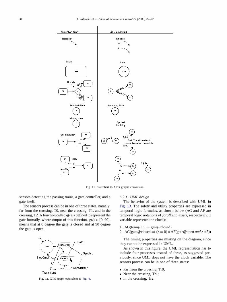
To convert UML statecharts to XTG graphs, we devel-oped an equivalence table (partially presented inFig. 11)that contains the statechart symbols and the XTG equivalentsymbols. As shown inFig. 11, the state symbols are equiv-alent but their shapes are different.
Transitions in both cases are the same. According to thetable, the equivalent XTG graph for the Counter example isshown inFig. 12.
6.2. Railroad crossing case study
To check the usefulness of the concept of model con-version and the applicability of the tool developed for thispurpose, we applied the entire procedure to the railroadcrossing system. The system consists of three parts: a set of
34 J. Zalewski et al. / Annual Reviews in Control 27 (2003) 23–37
Fig. 11. Statechart to XTG graphs conversion.
sensors detecting the passing trains, a gate controller, and agate itself.
The sensors process can be in one of three states, namely:far from the crossing, T0, near the crossing, T1, and in thecrossing, T2. A function calledg(t) is defined to represent thegate formally, where output of this function,g(t) ∈ [0, 90],means that at 0 degree the gate is closed and at 90 degreethe gate is open.
Fig. 12. XTG graph equivalent toFig. 9.
6.2.1. UML designThe behavior of the system is described with UML in
Fig. 13. The safety and utility properties are expressed intemporal logic formulas, as shown below (AG and AF aretemporal logic notations offorall andexists, respectively;zvariable represents the clock):
1. AG(train@in⇒ gate@closed)2. AG(gate@closed⇒ (z= 0)×AF(gate@openand z<5))
The timing properties are missing on the diagram, sincethey cannot be expressed in UML.
As shown in this figure, the UML representation has toinclude four processes instead of three, as suggested pre-viously, since UML does not have the clock variable. Thesensors process can be in one of three states:
• Far from the crossing, Tr0;• Near the crossing, Tr1;• In the crossing, Tr2.
J. Zalewski et al. / Annual Reviews in Control 27 (2003) 23–37 35
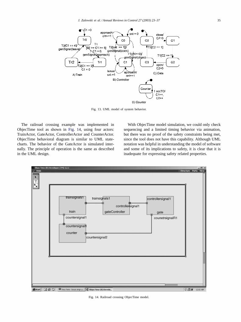
Fig. 13. UML model of system behavior.
The railroad crossing example was implemented inObjecTime tool as shown inFig. 14, using four actors:TrainActor, GateActor, ControllerActor and CounterActor.ObjecTime behavioral diagram is similar to UML state-charts. The behavior of the GateActor is simulated inter-nally. The principle of operation is the same as describedin the UML design.
Fig. 14. Railroad crossing ObjecTime model.
With ObjecTime model simulation, we could only checksequencing and a limited timing behavior via animation,but there was no proof of the safety constraints being met,since the tool does not have this capability. Although UMLnotation was helpful in understanding the model of softwareand some of its implications to safety, it is clear that it isinadequate for expressing safety related properties.

36 J. Zalewski et al. / Annual Reviews in Control 27 (2003) 23–37
Fig. 15. Three XTG processes representing the system: sensors, controllerand gate.
6.2.2. XTG designNext the UML description is translated into XTG’s. The
gate has four possible states (Fig. 15). Initially, it is open(G0). When receiving aclosesignal, it transfers to the clos-ing state (G1). One time unit is allowed to close the gate,enforced by [C2= 1] clock constraint.
This description is sufficient to use the XTGConvertertool for producing an XTG code, form the XTG graphs, andprepare for automatic model checking. Results for railroadcrossing are presented inAl-Daraiseh et al. (2001)andvanKatwijk et al. (2000). A portion of the generated XTG codefor the sensors process is shown inFig. 16.
Fig. 16. XTG code for model checking.
Finally, after running the generated code through the PMCmodel checker, the verification results are obtained. Theproperties to be verified in the railroad crossing systemare:
1. AG(train@in⇒ gate@closed)2. AG(gate@closed⇒ (z = 0) × AF(gate@open and
z < 5))
This means that, at any time, if there are trains in thecrossing the gate should be closed, and at any time if thegate is closed, it should open in the future.
7. Conclusion
Modern safety related systems can be so complex and sosoftware dependent, that dealing with the software produc-tion process becomes indispensable to achieve the requiredlevel of trustworthiness in software.
Usual verification methods, such as simulation and in-formal prototyping, are dealing only with the products, notwith the processes, and may work well for checking indi-vidual, safety-related or timing properties, but not for theverification of the correctness of development processes. Onthe other hand, the use of diverse software for safety criti-cal systems is process-related, basing on the assumption ofdissimilar development methodologies.
Also the evaluation of commercial off-the-shelf softwareto be re-used in a safety-critical context requires a carefulconsideration of the original development process. Tradi-tional approaches to safety, such as FMEA, FTA, HAZOP,etc., when applied to software systems, also need some ad-justment to the new challenges posed by including softwarein the safety systems.
On the whole, the approaches described in this article arecomplementary with respect to their suitability to addressdifferent problems at different levels of formalism. An ade-quate combination is considered to be promising.
One way to proceed is to incorporate formal techniquesinto engineering practice and support it by a combined useof automatic tools, so that formal verification of safety prop-erties may become more automated and better accessible toengineers and software developers. However, as we pointedout in a separate study, the use of automated tools to developsafety-related software needs some additional care and con-sideration (Kornecki & Zalewski, 2003).
References
Al-Daraiseh, A., Zalewski, J., & Toetenel, H. (July 22–25, 2001). Softwareverification in ground transportation systems. InProceedings of theSCI2001, 5th world multiconference on systemics, cybernetics andinformatics. Orlando, FL.
Ammerlaan, M., Spelberg, R. L., & Toetenel, H. (1998). XTG—Anengineering approach to modelling and analysis of real-time systems.In Proceedings of the 10th euromicro workshop on real-time systems(pp. 88–97). IEEE Computer Society Press.
J. Zalewski et al. / Annual Reviews in Control 27 (2003) 23–37 37
Anderson, E., van Katwijk, J., & Zalewski, J. (August 16–21, 1999). Newmethod of improving software safety in mission critical real-time sys-tems. InProceedings of the 17th international system safety confer-ence(pp. 587–596). Orlando, FL, System Safety Society, Unionville,VA.
Bishop, P. (Ed.). (1990).Dependability of critical computer systems:Guidelines. Techniques directory. London: Elsevier Applied Science.
Cichocki, T., & Górski, J. (2000). Failure mode and effect analysis forsafety critical systems with software components. InProceedings ofthe SAFECOMP 2000, 19th international conference on computersafety, reliability and security(pp. 382–394). Berlin: Springer-Verlag.
Cichocki, T., & Górski, J. (2001). Formal support for fault modelling andanalysis. InProceedings of the SAFECOMP 2001, 20th internationalconference on computer safety, reliability and security(pp. 190–199).Berlin: Springer-Verlag.
Eckhardt Jr., Q.E., Lee, L.D., 1985. A theoretical basis for the analysis ofmultiversion software subject to coincident errors. IEEE Transactionson Software Engineering SE-11 (12), 1511–1517.
Ehrenberger, W. (July 22–25, 2001a). Software diversity: Some consid-erations on failure dependency. InProceedings of the SCI2001, 5thworld multiconference on systemics, cybernetics and informatics. Or-lando, FL.
Ehrenberger, W. (2001b).Software-verification. Munich: Hanser Verlag.Ehrenberger, W., & Saglietti, F. (May 12–14, 1993). Architecture and
safety qualification of large software systems. InProceedings of theESREL’93, European safety and reliability conference(pp. 985–999).Munich, Germany, Elsevier, Amsterdam.
FDR. (1997).Failures-divergence refinement, FDR2. Oxford, UK: FormalSystems (Europe) Ltd.http://www.formal.demon.co.uk/FDR2.html.
Górski, J. (September 25–29, 2000). Application of system level analysistechniques to ensure safety of embedded software. InProceedings ofthe 2nd world congress for software quality(pp. 149–154). Yokohama,Tokyo: Union of Japanese Scientists and Engineers.
Hilburn, T., & Zalewski, J. (1996). Real-time safety critical systems: Anoverview. In Proceedings of the 2nd IFAC workshop on safety andreliability in emerging control technologies(pp. 127–138). Oxford:Elsevier.
Kornecki, A., Nasah, B., & Zalewski, J. (November 4–7, 1998). TCASsafety analysis using timed environment-relation Petri nets. InPro-ceedings of the ISSRE’98, international symposium on software reli-ability engineering. Germany: Paderborn.
Kornecki, A., & Zalewski, J. (February 11–13, 2003). Assessment of soft-ware development tools for safety-critical real-time systems. InPro-ceedings of the PDS2003, IFAC workshop on programmable devicesand systems. Czech Republic: Ostrava.
Leveson, N., Cha, S.S., Shimeall, T.J., 1991. Safety verification of Adaprograms using software fault trees. IEEE Software 8 (7), 48–59.
Leveson, N. (1996).Safeware: System safety and computers. Reading,MA: Addison-Wesley.
Littlewood, B., & Miller, D. R. (1987). A conceptual model of multi-version software. InProceedings of the FTCS-17, international sym-
posium on fault-tolerant computing(pp. 170–175). IEEE ComputerSociety Press.
Maier, T. (September 12–15, 1995). FMEA and FTA to support safetydesign of embedded software in safety-critical systems. InProceedingsof the ENCRESS conference on safety and reliability of software basedsystems. Belgium: Bruges.
Mojdehrakhsh, R., Tsai, W.T., Kirani, S., Elliott, L., 1994. Retrofittingsoftware safety in an implantable medical device. IEEE Software11 (1), 41–50.
Pezze, M. (1994).Cabernet: A customizable environment for the speci-fication and analysis of real-time systems. Technical Report, Dip. diElettronica e Informazione, Politecnico di Milano, Italy.
Redmill, F., Chudleigh, M., & Catmur, J. (1999).System safety: HAZOPand software HAZOP. New York: John Wiley and Sons.
Roscoe, A. W. (1998).The theory and practice of concurrency. London:Prentice Hall.
Roubtsova, E. E., van Katwijk, J., & Toetenel, W. J. (2001). Transfor-mation of UML specification to XTG. InProceedings of the AndreiErshov 4th international conference(pp. 249–256). Novosibirsk, Rus-sia, Springer-Verlag, Berlin.
Rushby, J., 1994. Critical system properties: Survey and taxonomy. Re-liability Engineering and System Safety 43, 189–219.
Saglietti, F., Ehrenberger, W., & Kersken, M. (1992).Software Diver-sität für Steuerungen mit Sicherheitsverantwortung. Report BAU-Forschungsbericht FB 664, Bundesanstalt für Arbeitsschutz,Dortmund.
Saglietti, F. (1998). Integration of logical and physical properties ofembedded systems by use of timed Petri nets. InProceedings of theSAFECOMP’98, 17th international conference on computer safety,reliability and security(pp. 319–328). Berlin: Springer-Verlag.
Saglietti, F. (2000a). Evaluation of pre-developed software for use insafety-critical systems. InProceedings of the EUROMICRO’2000, 26theuromicro conference on software process and product improvement(Vol. 2, pp. 193–199). IEEE Computer Society Press.
Saglietti, F. (November 27–December 1, 2000b). Statistical significanceof expert judgement for ultrahigh software reliability demands. InProceedings of the 5th international conference on probabilistic safetyassessment and management. Osaka, Japan: Universal Academy Press.
Saglietti, F. (July 22–25, 2001). Criticality and sensitivity analysis foroff-the-shelf components in safety-relevant systems. InProceedingsof the SCI2001, 5th world multiconference on systemics, cyberneticsand informatics. Orlando, FL.
Sahraoui, A. E. K., Anderson, E., van Katwijk, J., & Zalewski, J. (2000).Formal specification of a safety shell in real-time control practice.Proceedings of the WRTP’2000, 25th IFAC workshop on real-timeprogramming(pp. 117–123). Oxford: Elsevier.
van Katwijk, J., Toetenel, H., Sahraoui, A. E. K., Anderson, E., &Zalewski, J. (2000). Specification and verification of a safety shellwith statecharts and extended timed graphs. InProceedings of theSAFECOMP 2000, 19th international conference on computer safety,reliability and security(pp. 37–52). Berlin: Springer-Verlag.