Safety Limit Switch - D4N - SOS.sk
35
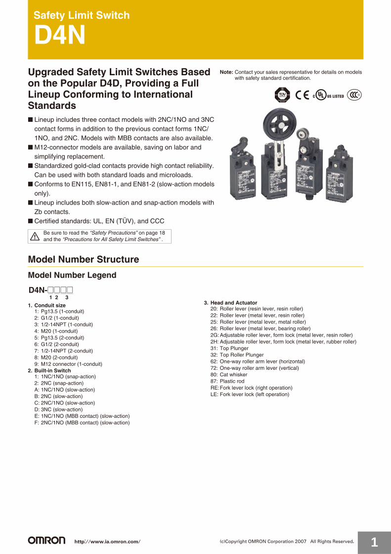
Safety Limit Switch D4N Upgraded Safety Limit Switches Based on the Popular D4D, Providing a Full Lineup Conforming to International Standards ■ Lineup includes three contact models with 2NC/1NO and 3NC contact forms in addition to the previous contact forms 1NC/ 1NO, and 2NC. Models with MBB contacts are also available. ■ M12-connector models are available, saving on labor and simplifying replacement. ■ Standardized gold-clad contacts provide high contact reliability. Can be used with both standard loads and microloads. ■ Conforms to EN115, EN81-1, and EN81-2 (slow-action models only). ■ Lineup includes both slow-action and snap-action models with Zb contacts. ■ Certified standards: UL, EN (TÜV), and CCC Model Number Structure Model Number Legend 1. Conduit size 1: Pg13.5 (1-conduit) 2: G1/2 (1-conduit) 3: 1/2-14NPT (1-conduit) 4: M20 (1-conduit) 5: Pg13.5 (2-conduit) 6: G1/2 (2-conduit) 7: 1/2-14NPT (2-conduit) 8: M20 (2-conduit) 9: M12 connector (1-conduit) 2. Built-in Switch 1: 1NC/1NO (snap-action) 2: 2NC (snap-action) A: 1NC/1NO (slow-action) B: 2NC (slow-action) C: 2NC/1NO (slow-action) D: 3NC (slow-action) E: 1NC/1NO (MBB contact) (slow-action) F: 2NC/1NO (MBB contact) (slow-action) 3. Head and Actuator 20: Roller lever (resin lever, resin roller) 22: Roller lever (metal lever, resin roller) 25: Roller lever (metal lever, metal roller) 26: Roller lever (metal lever, bearing roller) 2G: Adjustable roller lever, form lock (metal lever, resin roller) 2H: Adjustable roller lever, form lock (metal lever, rubber roller) 31: Top Plunger 32: Top Roller Plunger 62: One-way roller arm lever (horizontal) 72: One-way roller arm lever (vertical) 80: Cat whisker 87: Plastic rod RE: Fork lever lock (right operation) LE: Fork lever lock (left operation) Note: Contact your sales representative for details on models with safety standard certification. Be sure to read the “Safety Precautions” on page 18 and the “Precautions for All Safety Limit Switches” . 1 2 3 D4N-@@@@ http://www.ia.omron.com/ 1 (c)Copyright OMRON Corporation 2007 All Rights Reserved.
-
Upload
khangminh22 -
Category
Documents
-
view
0 -
download
0
Transcript of Safety Limit Switch - D4N - SOS.sk
Safety Limit Switch
D4NUpgraded Safety Limit Switches Based on the Popular D4D, Providing a Full Lineup Conforming to International Standards■ Lineup includes three contact models with 2NC/1NO and 3NC
contact forms in addition to the previous contact forms 1NC/1NO, and 2NC. Models with MBB contacts are also available.
■ M12-connector models are available, saving on labor and simplifying replacement.
■ Standardized gold-clad contacts provide high contact reliability.Can be used with both standard loads and microloads.
■ Conforms to EN115, EN81-1, and EN81-2 (slow-action models only).
■ Lineup includes both slow-action and snap-action models with Zb contacts.
■ Certified standards: UL, EN (TÜV), and CCC
Model Number Structure
Model Number Legend
1. Conduit size1: Pg13.5 (1-conduit)2: G1/2 (1-conduit)3: 1/2-14NPT (1-conduit)4: M20 (1-conduit)5: Pg13.5 (2-conduit)6: G1/2 (2-conduit)7: 1/2-14NPT (2-conduit)8: M20 (2-conduit)9: M12 connector (1-conduit)
2. Built-in Switch1: 1NC/1NO (snap-action)2: 2NC (snap-action)A: 1NC/1NO (slow-action)B: 2NC (slow-action)C: 2NC/1NO (slow-action)D: 3NC (slow-action)E: 1NC/1NO (MBB contact) (slow-action)F: 2NC/1NO (MBB contact) (slow-action)
3. Head and Actuator20: Roller lever (resin lever, resin roller)22: Roller lever (metal lever, resin roller)25: Roller lever (metal lever, metal roller)26: Roller lever (metal lever, bearing roller)2G: Adjustable roller lever, form lock (metal lever, resin roller)2H: Adjustable roller lever, form lock (metal lever, rubber roller)31: Top Plunger32: Top Roller Plunger62: One-way roller arm lever (horizontal)72: One-way roller arm lever (vertical)80: Cat whisker87: Plastic rodRE:Fork lever lock (right operation)LE: Fork lever lock (left operation)
Note: Contact your sales representative for details on models with safety standard certification.
Be sure to read the “Safety Precautions” on page 18and the “Precautions for All Safety Limit Switches” .
1 2 3 D4N-@@@@
http://www.ia.omron.com/ 1(c)Copyright OMRON Corporation 2007 All Rights Reserved.

D4N
Ordering InformationList of ModelsSwitches with Two Contacts (with Direct Opening Mechanism)
Note: It is recommended that M20 be used for Switches to be exported to Europe and 1/2-14NPT be used for Switches to be exported to North American countries.
Actuator Conduit size
Built-in switch mechanism1NC/1NO
(Snap-action)2NC
(Snap-action)1NC/1NO
(Slow-action)2NC
(Slow-action)
Model Direct opening Model Direct
opening Model Direct opening Model Direct
openingRoller lever (resinlever, resin roller)
1-conduit
Pg13.5 D4N-1120 D4N-1220 D4N-1A20 D4N-1B20G1/2 D4N-2120 D4N-2220 D4N-2A20 D4N-2B201/2-14NPT D4N-3120 D4N-3220 D4N-3A20 D4N-3B20M20 D4N-4120 D4N-4220 D4N-4A20 D4N-4B20M12 connector D4N-9120 D4N-9220 D4N-9A20 D4N-9B20
2-conduitPg13.5 D4N-5120 D4N-5220 D4N-5A20 D4N-5B20G1/2 D4N-6120 D4N-6220 D4N-6A20 D4N-6B20M20 D4N-8120 D4N-8220 D4N-8A20 D4N-8B20
Roller lever (metal lever, resin roller)
1-conduit
Pg13.5 D4N-1122 D4N-1222 D4N-1A22 D4N-1B22G1/2 D4N-2122 D4N-2222 D4N-2A22 D4N-2B221/2-14NPT D4N-3122 D4N-3222 D4N-3A22 D4N-3B22M20 D4N-4122 D4N-4222 D4N-4A22 D4N-4B22M12 connector D4N-9122 D4N-9222 D4N-9A22 D4N-9B22
2-conduitPg13.5 D4N-5122 D4N-5222 D4N-5A22 D4N-5B22G1/2 D4N-6122 D4N-6222 D4N-6A22 D4N-6B22M20 D4N-8122 D4N-8222 D4N-8A22 D4N-8B22
Roller lever (metal lever, metal roller)
1-conduit
Pg13.5 D4N-1125 D4N-1225 D4N-1A25 D4N-1B25G1/2 D4N-2125 D4N-2225 D4N-2A25 D4N-2B251/2-14NPT D4N-3125 D4N-3225 D4N-3A25 D4N-3B25M20 D4N-4125 D4N-4225 D4N-4A25 D4N-4B25M12 connector D4N-9125 D4N-9225 D4N-9A25 D4N-9B25
Roller lever (metal lever, bearing roller)
1-conduit
Pg13.5 D4N-1126 D4N-1226 D4N-1A26 D4N-1B26G1/2 D4N-2126 D4N-2226 D4N-2A26 D4N-2B261/2-14NPT D4N-3126 D4N-3226 D4N-3A26 D4N-3B26M20 D4N-4126 D4N-4226 D4N-4A26 D4N-4B26M12 connector D4N-9126 D4N-9226 D4N-9A26 D4N-9B26
Plunger
1-conduit
Pg13.5 D4N-1131 D4N-1231 D4N-1A31 D4N-1B31G1/2 D4N-2131 D4N-2231 D4N-2A31 D4N-2B311/2-14NPT D4N-3131 D4N-3231 D4N-3A31 D4N-3B31M20 D4N-4131 D4N-4231 D4N-4A31 D4N-4B31M12 connector D4N-9131 D4N-9231 D4N-9A31 D4N-9B31
2-conduitPg13.5 D4N-5131 D4N-5231 D4N-5A31 D4N-5B31G1/2 D4N-6131 D4N-6231 D4N-6A31 D4N-6B31M20 D4N-8131 D4N-8231 D4N-8A31 D4N-8B31
Roller plunger
1-conduit
Pg13.5 D4N-1132 D4N-1232 D4N-1A32 D4N-1B32G1/2 D4N-2132 D4N-2232 D4N-2A32 D4N-2B321/2-14NPT D4N-3132 D4N-3232 D4N-3A32 D4N-3B32M20 D4N-4132 D4N-4232 D4N-4A32 D4N-4B32M12 connector D4N-9132 D4N-9232 D4N-9A32 D4N-9B32
2-conduitPg13.5 D4N-5132 D4N-5232 D4N-5A32 D4N-5B32G1/2 D4N-6132 D4N-6232 D4N-6A32 D4N-6B32M20 D4N-8132 D4N-8232 D4N-8A32 D4N-8B32
One-way roller arm lever (horizontal)
1-conduit
Pg13.5 D4N-1162 D4N-1262 D4N-1A62 D4N-1B62G1/2 D4N-2162 D4N-2262 D4N-2A62 D4N-2B621/2-14NPT D4N-3162 D4N-3262 D4N-3A62 D4N-3B62M20 D4N-4162 D4N-4262 D4N-4A62 D4N-4B62M12 connector D4N-9162 D4N-9262 D4N-9A62 D4N-9B62
2-conduitPg13.5 D4N-5162 D4N-5262 D4N-5A62 D4N-5B62G1/2 D4N-6162 D4N-6262 D4N-6A62 D4N-6B62M20 D4N-8162 D4N-8262 D4N-8A62 D4N-8B62
One-way roller arm lever (vertical)
1-conduit
Pg13.5 D4N-1172 D4N-1272 D4N-1A72 D4N-1B72G1/2 D4N-2172 D4N-2272 D4N-2A72 D4N-2B721/2-14NPT D4N-3172 D4N-3272 D4N-3A72 D4N-3B72M20 D4N-4172 D4N-4272 D4N-4A72 D4N-4B72M12 connector D4N-9172 D4N-9272 D4N-9A72 D4N-9B72
2-conduitPg13.5 D4N-5172 D4N-5272 D4N-5A72 D4N-5B72G1/2 D4N-6172 D4N-6272 D4N-6A72 D4N-6B72M20 D4N-8172 D4N-8272 D4N-8A72 D4N-8B72
Adjustable roller lever, form lock (metal lever, resin roller)
1-conduit
Pg13.5 D4N-112G D4N-122G D4N-1A2G D4N-1B2GG1/2 D4N-212G D4N-222G D4N-2A2G D4N-2B2G1/2-14NPT D4N-312G D4N-322G D4N-3A2G D4N-3B2GM20 D4N-412G D4N-422G D4N-4A2G D4N-4B2GM12 connector D4N-912G D4N-922G D4N-9A2G D4N-9B2G
2-conduitG1/2 D4N-612G D4N-622G D4N-6A2G D4N-6B2GM20 D4N-812G D4N-822G D4N-8A2G D4N-8B2G
Adjustable roller lever, form lock (metal lever, rubber roller)
1-conduit
Pg13.5 D4N-112H D4N-122H D4N-1A2H D4N-1B2HG1/2 D4N-212H D4N-222H D4N-2A2H D4N-2B2H1/2-14NPT D4N-312H D4N-322H D4N-3A2H D4N-3B2HM20 D4N-412H D4N-422H D4N-4A2H D4N-4B2HM12 connector D4N-912H D4N-922H D4N-9A2H D4N-9B2H
2-conduitG1/2 D4N-612H D4N-622H D4N-6A2H D4N-6B2H
M20 D4N-812H D4N-822H D4N-8A2H D4N-8B2H
http://www.ia.omron.com/ 2(c)Copyright OMRON Corporation 2007 All Rights Reserved.

D4N
Switches with Three Contacts and MBB Contacts (with Direct Opening Mechanism)
Note: It is recommended that M20 be used for Switches to be exported to Europe and 1/2-14NPT be used for Switches to be exported to North American countries.
Actuator Conduit size
Built-in switch mechanism2NC/1NO
(Slow-action)3NC
(Slow-action)1NC/1NO MBB (Slow-action)
2NC/1NO MBB (Slow-action)
Model Direct opening Model Direct
opening Model Direct opening Model Direct
openingRoller lever (resin lever, resin roller)
1-conduit
Pg13.5 D4N-1C20 D4N-1D20 D4N-1E20 D4N-1F20G1/2 D4N-2C20 D4N-2D20 D4N-2E20 D4N-2F201/2-14NPT D4N-3C20 D4N-3D20 D4N-3E20 D4N-3F20M20 D4N-4C20 D4N-4D20 D4N-4E20 D4N-4F20M12 connector --- --- D4N-9E20 ---
2-conduitPg13.5 D4N-5C20 D4N-5D20 D4N-5E20 D4N-5F20G1/2 D4N-6C20 D4N-6D20 D4N-6E20 D4N-6F20M20 D4N-8C20 D4N-8D20 D4N-8E20 D4N-8F20
Roller lever (metal lever, resin roller)
1-conduit
Pg13.5 D4N-1C22 D4N-1D22 D4N-1E22 D4N-1F22G1/2 D4N-2C22 D4N-2D22 D4N-2E22 D4N-2F221/2-14NPT D4N-3C22 D4N-3D22 D4N-3E22 D4N-3F22M20 D4N-4C22 D4N-4D22 D4N-4E22 D4N-4F22M12 connector --- --- D4N-9E22 ---
2-conduitPg13.5 D4N-5C22 D4N-5D22 D4N-5E22 D4N-5F22G1/2 D4N-6C22 D4N-6D22 D4N-6E22 D4N-6F22M20 D4N-8C22 D4N-8D22 D4N-8E22 D4N-8F22
Roller lever (metal lever, metal roller)
1-conduit
Pg13.5 D4N-1C25 D4N-1D25 D4N-1E25 D4N-1F25G1/2 D4N-2C25 D4N-2D25 D4N-2E25 D4N-2F251/2-14NPT D4N-3C25 D4N-3D25 D4N-3E25 D4N-3F25M20 D4N-4C25 D4N-4D25 D4N-4E25 D4N-4F25M12 connector --- --- D4N-9E25 ---
Roller lever (metal lever, bearing roller)
1-conduit
Pg13.5 D4N-1C26 D4N-1D26 D4N-1E26 D4N-1F26G1/2 D4N-2C26 D4N-2D26 D4N-2E26 D4N-2F261/2-14NPT D4N-3C26 D4N-3D26 D4N-3E26 D4N-3F26M20 D4N-4C26 D4N-4D26 D4N-4E26 D4N-4F26M12 connector --- --- D4N-9E26 ---
Plunger
1-conduit
Pg13.5 D4N-1C31 D4N-1D31 D4N-1E31 D4N-1F31G1/2 D4N-2C31 D4N-2D31 D4N-2E31 D4N-2F311/2-14NPT D4N-3C31 D4N-3D31 D4N-3E31 D4N-3F31M20 D4N-4C31 D4N-4D31 D4N-4E31 D4N-4F31M12 connector --- --- D4N-9E31 ---
2-conduitPg13.5 D4N-5C31 D4N-5D31 D4N-5E31 D4N-5F31G1/2 D4N-6C31 D4N-6D31 D4N-6E31 D4N-6F31M20 D4N-8C31 D4N-8D31 D4N-8E31 D4N-8F31
Roller plunger
1-conduit
Pg13.5 D4N-1C32 D4N-1D32 D4N-1E32 D4N-1F32G1/2 D4N-2C32 D4N-2D32 D4N-2E32 D4N-2F321/2-14NPT D4N-3C32 D4N-3D32 D4N-3E32 D4N-3F32M20 D4N-4C32 D4N-4D32 D4N-4E32 D4N-4F32M12 connector --- --- D4N-9E32 ---
2-conduitPg13.5 D4N-5C32 D4N-5D32 D4N-5E32 D4N-5F32G1/2 D4N-6C32 D4N-6D32 D4N-6E32 D4N-6F32M20 D4N-8C32 D4N-8D32 D4N-8E32 D4N-8F32
One-way roller arm lever (horizontal)
1-conduit
Pg13.5 D4N-1C62 D4N-1D62 D4N-1E62 D4N-1F62G1/2 D4N-2C62 D4N-2D62 D4N-2E62 D4N-2F621/2-14NPT D4N-3C62 D4N-3D62 D4N-3E62 D4N-3F62M20 D4N-4C62 D4N-4D62 D4N-4E62 D4N-4F62M12 connector --- --- D4N-9E62 ---
2-conduitPg13.5 D4N-5C62 D4N-5D62 D4N-5E62 D4N-5F62G1/2 D4N-6C62 D4N-6D62 D4N-6E62 D4N-6F62M20 D4N-8C62 D4N-8D62 D4N-8E62 D4N-8F62
One-way roller arm lever (vertical)
1-conduit
Pg13.5 D4N-1C72 D4N-1D72 D4N-1E72 D4N-1F72G1/2 D4N-2C72 D4N-2D72 D4N-2E72 D4N-2F721/2-14NPT D4N-3C72 D4N-3D72 D4N-3E72 D4N-3F72M20 D4N-4C72 D4N-4D72 D4N-4E72 D4N-4F72M12 connector --- --- D4N-9E72 ---
2-conduitPg13.5 D4N-5C72 D4N-5D72 D4N-5E72 D4N-5F72G1/2 D4N-6C72 D4N-6D72 D4N-6E72 D4N-6F72M20 D4N-8C72 D4N-8D72 D4N-8E72 D4N-8F72
Adjustable roller lever, form lock (metal lever, resin roller)
1-conduit
Pg13.5 D4N-1C2G D4N-1D2G D4N-1E2G D4N-1F2GG1/2 D4N-2C2G D4N-2D2G D4N-2E2G D4N-2F2G1/2-14NPT D4N-3C2G D4N-3D2G D4N-3E2G D4N-3F2GM20 D4N-4C2G D4N-4D2G D4N-4E2G D4N-4F2GM12 connector --- --- D4N-9E2G ---
2-conduitG1/2 D4N-6C2G D4N-6D2G D4N-6E2G D4N-6F2GM20 D4N-8C2G D4N-8D2G D4N-8E2G D4N-8F2G
Adjustable roller lever, form lock (metal lever, rubber roller)
1-conduit
Pg13.5 D4N-1C2H D4N-1D2H D4N-1E2H D4N-1F2HG1/2 D4N-2C2H D4N-2D2H D4N-2E2H D4N-2F2H1/2-14NPT D4N-3C2H D4N-3D2H D4N-3E2H D4N-3F2HM20 D4N-4C2H D4N-4D2H D4N-4E2H D4N-4F2HM12 connector --- --- D4N-9E2H ---
2-conduitG1/2 D4N-6C2H D4N-6D2H D4N-6E2H D4N-6F2H
M20 D4N-8C2H D4N-8D2H D4N-8E2H D4N-8F2H
http://www.ia.omron.com/ 3(c)Copyright OMRON Corporation 2007 All Rights Reserved.

D4N
General-purpose Switches with Two Contacts
Note: 1. It is recommended that M20 be used for Switches to be exported to Europe and 1/2-14NPT be used for Switches to be exported to North American countries.
2. Mechanically speaking, these models are basic limit switches.
General-purpose Switches with Three Contacts and MBB Contacts
Note: 1. It is recommended that M20 be used for Switches to be exported to Europe and 1/2-14NPT be used for Switches to be exported to North American countries.
2. Mechanically speaking, these models are basic limit switches.
Actuator Conduit size
Built-in switch mechanism
1NC/1NO(Snap-action)
2NC(Snap-action)
1NC/1NO (Slow-action)
2NC(Slow-action)
Model Direct opening Model Direct
opening Model Direct opening Model Direct
opening
Fork lever lock (right operation) 1-conduit
G1/2
---
---
---
---
D4N-2ARE
---
D4N-2BRE
---1/2-14NPT D4N-3ARE D4N-3BRE
M20 D4N-4ARE D4N-4BRE
2-conduitG1/2
--- ---D4N-6ARE
---D4N-6BRE
---M20 D4N-8ARE D4N-8BRE
Fork lever lock (left operation) 1-conduit
G1/2
--- ---
D4N-2ALE
---
D4N-2BLE
---1/2-14NPT D4N-3ALE D4N-3BLE
M20 D4N-4ALE D4N-4BLE
2-conduitG1/2
--- ---D4N-6ALE
---D4N-6BLE
---M20 D4N-8ALE D4N-8BLE
Cat whisker
1-conduit
G1/2 D4N-2180
---
D4N-2280
---
---
---
D4N-2B80
---1/2-14NPT D4N-3180 D4N-3280 D4N-3B80
M20 D4N-4180 D4N-4280 D4N-4B80
2-conduitG1/2 D4N-6180
---D4N-6280
--- ---D4N-6B80
---M20 D4N-8180 D4N-8280 D4N-8B80
Plastic rod
1-conduit
G1/2 D4N-2187
---
D4N-2287
--- ---
D4N-2B87
---1/2-14NPT D4N-3187 D4N-3287 D4N-3B87
M20 D4N-4187 D4N-4287 D4N-4B87
2-conduitG1/2 D4N-6187
---D4N-6287
--- ---D4N-6B87
---M20 D4N-8187 D4N-8287 D4N-8B87
Actuator Conduit size
Built-in switch mechanism
2NC/1NO(Slow-action)
3NC(Slow-action)
1NC/1NO MBB(Slow-action)
2NC/1NO MBB (Slow-action)
Model Direct opening Model Direct
opening Model Direct opening Model Direct
opening
Fork lever lock (right operation) 1-conduit
G1/2 D4N-2CRE
---
D4N-2DRE
---
D4N-2ERE
---
D4N-2FRE
---1/2-14NPT D4N-3CRE D4N-3DRE D4N-3ERE D4N-3FRE
M20 D4N-4CRE D4N-4DRE D4N-4ERE D4N-4FRE
2-conduitG1/2 D4N-6CRE
---D4N-6DRE
---D4N-6ERE
---D4N-6FRE
---M20 D4N-8CRE D4N-8DRE D4N-8ERE D4N-8FRE
Fork lever lock (left operation) 1-conduit
G1/2 D4N-2CLE
---
D4N-2DLE
---
D4N-2ELE
---
D4N-2FLE
---1/2-14NPT D4N-3CLE D4N-3DLE D4N-3ELE D4N-3FLE
M20 D4N-4CLE D4N-4DLE D4N-4ELE D4N-4FLE
2-conduitG1/2 D4N-6CLE
---D4N-6DLE
---D4N-6ELE
---D4N-6FLE
---M20 D4N-8CLE D4N-8DLE D4N-8ELE D4N-8FLE
Cat whisker
1-conduit
G1/2
---
---
D4N-2D80
---
---
---
---
---1/2-14NPT D4N-3D80
M20 D4N-4D80
2-conduitG1/2
---D4N-6D80
--- --- ---M20 D4N-8D80
Plastic rod
1-conduit
G1/2
---
D4N-2D87
--- --- ---1/2-14NPT D4N-3D87
M20 D4N-4D87
2-conduitG1/2
---D4N-6D87
--- --- ---M20 D4N-8D87
http://www.ia.omron.com/ 4(c)Copyright OMRON Corporation 2007 All Rights Reserved.

D4N
Specifications
Standards and EC DirectivesConforms to the following EC Directives:
Machinery DirectiveLow Voltage DirectiveEN50047EN60204-1EN1088GS-ET-15
Certified Standards
*1.Consult your OMRON representative for details.*2.Certification for CSA C22.2 No. 14 is authorized by the UL mark.*3.Ask your OMRON representative for information on certified
models.
Certified Standard RatingsTÜV (EN60947-5-1), CCC (GB14048.5)
Note: Use a 10 A fuse type gI or gG that conforms to IEC269 as a short-circuit protection device. This fuse is not built into the Switch.
UL/CSA (UL508, CSA C22.2 No. 14)A300
Q300
Certification body Standard File No.
TÜV Product Service
EN60947-5-1(certified direct opening) *1
UL *2 UL508, CSA C22.2 No.14 E76675
CQC (CCC) *3 GB14048.5 2004010305105973
ItemUtilization
category AC-15 DC-13
Rated operating current (Ie) 3 A 0.27 A
Rated operating voltage (Ue) 240 V 250 V
Rated voltage Carry current
Current (A) Volt-amperes (VA)
Make Break Make Break
120 VAC10 A
60 67,200 720
240 VAC 30 3
Rated voltage Carry current
Current (A) Volt-amperes (VA)
Make Break Make Break
125 VDC2.5 A
0.55 0.5569 69
250 VDC 0.27 0.27
http://www.ia.omron.com/ 5(c)Copyright OMRON Corporation 2007 All Rights Reserved.

D4N
Characteristics
Note: 1. The above values are initial values.2. Once a contact has been used to switch a standard load, it cannot be used for a load of a smaller capacity.
Doing so may result in roughening of the contact surface and contact reliability may be lost.*1.The degree of protection is tested using the method specified by the standard (EN60947-5-1). Confirm that sealing properties are sufficient for
the operating conditions and environment beforehand. Although the switch box is protected from dust or water penetration, do not use the D4N in places where foreign material such as dust, dirt, oil, water, or chemicals may penetrate through the head. Otherwise, accelerated wear, Switch damage or malfunctioning may occur.
*2.The durability is for an ambient temperature of 5 to 35 C and an ambient humidity of 40% to 70%. For more details, consult your OMRON representative.
*3.Do not pass the 3 A, 250 VAC load through more than 2 circuits.*4.This value will vary with the switching frequency, environment, and reliability level. Confirm that correct operation is possible with the actual load
beforehand.*5.The mechanical durability of fork lever lock models is 10,000,000 operations min.
Degree of protection *1 IP67 (EN60947-5-1)
Durability *2Mechanical 15,000,000 operations min. *5
Electrical 500,000 operations min. (3 A resistive load at 250 VAC) *3300,000 operations min. (10 A resistive load at 250 VAC)
Operating speed 1 to 500 mm/s (D4N-1120)
Operating frequency 30 operations/minute max.
Contact resistance 25 m max.
Minimum applicable load *4 1 mA resistive load at 5 VDC (N-level reference value)
Rated insulation voltage (Ui) 300 V
Rated frequency 50/60 Hz
Protection against electric shock Class II (double insulation)
Pollution degree (operating environment) 3 (EN60947-5-1)
Impulse withstand voltage (EN60947-5-1)
Between terminals of same polarity 2.5 kV
Between terminals of different polarity 4 kV
Between each terminal and non-current carrying metallic parts
6 kV
Insulation resistance 100 M min.
Contact gap Snap-action: 2 0.5 mm min.Slow-action: 2 2 mm min.
Vibration resistance Malfunction 10 to 55 Hz, 0.75 mm single amplitude
Shock resistanceDestruction 1,000 m/s2 min.
Malfunction 300 m/s2 min.
Conditional short-circuit current 100 A (EN60947-5-1)
Conventional free air thermal current (Ith) 10 A (EN60947-5-1)
Ambient operating temperature 30 to 70 C (with no icing)
Ambient operating humidity 95% max.
Weight Approx. 82 g (D4N-1120)Approx. 99 g (D4N-5120)
http://www.ia.omron.com/ 6(c)Copyright OMRON Corporation 2007 All Rights Reserved.

D4N
Structure and Nomenclature
Structure
Direct Opening Mechanism1NC/1NO Contact (Slow-action) 2NC Contact (Slow-action)
Pg13.5
G1/2
1/2-14NPT
M20
M12 connector
Note: M12 connector types are not available for Switches with three contacts.
HeadThe direction of the switch head can be varied to any of the four directions. (Roller plunger models can bemounted in either of two directions at a 90° angle.)
Conduit OpeningA wide variety of conduits is available.
Built-in SwitchThe built-in switch has a direct opening mechanism that forcibly separates the NC contact even whenthere is contact deposit.
Safety-oriented Lever Setting(Form-lock construction)Grooves which engage the lever are cut in the lever and rotary shaft to prevent the lever from slipping against the rotary shaft.There are resin-lever and metal-lever types.
CoverThe cover, with a hinge on its lower part, can be opened by removing the screw of the cover, which ensures ease of maintenance and wiring.
Size Box 1-conduit 2-conduit
Yes
Yes
Yes
Yes
Yes
Yes
Yes
Yes
Yes
---
Contact spring
Return spring
Fixed contact (NC)
Fixed contact (NO)
Plunger
Movable contact
Conforms to EN60947-5-1 Direct Opening Operation
(Only the NC contact side has a direct opening mechanism.)When contact welding occurs, the contacts are separated from each other by the plunger beingpushed in.
Contact spring
Fixed contact (NC)
Plunger
Movable contact
Return spring
Conforms to EN60947-5-1 Direct Opening Operation
(Both NC contacts have a direct opening mechanism.)
http://www.ia.omron.com/ 7(c)Copyright OMRON Corporation 2007 All Rights Reserved.
D4N
Contact Form
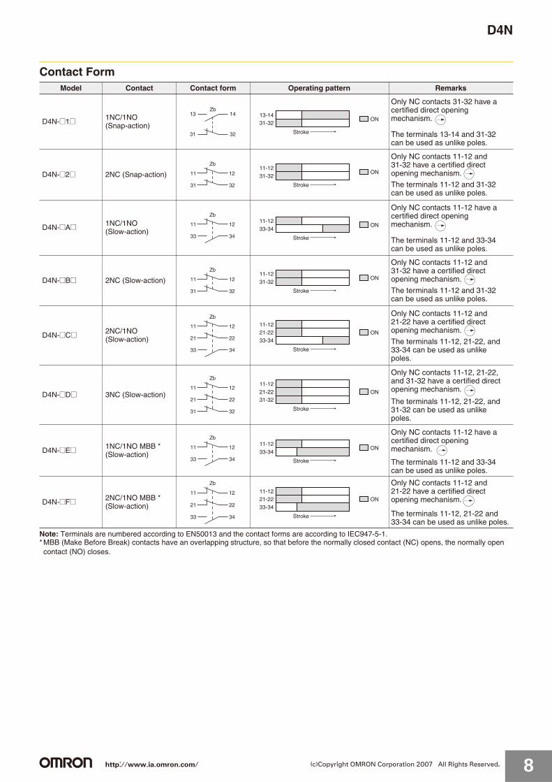
Note: Terminals are numbered according to EN50013 and the contact forms are according to IEC947-5-1.* MBB (Make Before Break) contacts have an overlapping structure, so that before the normally closed contact (NC) opens, the normally open contact (NO) closes.
Model Contact Contact form Operating pattern Remarks
D4N-@1@ 1NC/1NO (Snap-action)
D4N-@2@ 2NC (Snap-action)
D4N-@A@ 1NC/1NO (Slow-action)
D4N-@B@ 2NC (Slow-action)
D4N-@C@ 2NC/1NO (Slow-action)
D4N-@D@ 3NC (Slow-action)
D4N-@E@ 1NC/1NO MBB * (Slow-action)
D4N-@F@ 2NC/1NO MBB * (Slow-action)
14
32
13
31
Zb
ON
Stroke
13-1431-32
Only NC contacts 31-32 have a certified direct opening mechanism.
The terminals 13-14 and 31-32 can be used as unlike poles.
11
31
12
32
Zb
ON
Stroke
11-1231-32
Only NC contacts 11-12 and 31-32 have a certified direct opening mechanism.
The terminals 11-12 and 31-32 can be used as unlike poles.
11
33
12
34
Zb
ON
Stroke
11-1233-34
Only NC contacts 11-12 have a certified direct opening mechanism.
The terminals 11-12 and 33-34 can be used as unlike poles.
11
31
12
32
Zb
ON
Stroke
11-1231-32
Only NC contacts 11-12 and 31-32 have a certified direct opening mechanism.
The terminals 11-12 and 31-32 can be used as unlike poles.
33 34
11
21
12
22
Zb
ON
Stroke
21-2233-34
11-12
Only NC contacts 11-12 and 21-22 have a certified direct opening mechanism.
The terminals 11-12, 21-22, and 33-34 can be used as unlike poles.
11
21
12
22
31 32
Zb
ON
Stroke
11-1221-2231-32
Only NC contacts 11-12, 21-22, and 31-32 have a certified direct opening mechanism.
The terminals 11-12, 21-22, and 31-32 can be used as unlike poles.
11
33
12
34
Zb
ON
Stroke
11-1233-34
Only NC contacts 11-12 have a certified direct opening mechanism.
The terminals 11-12 and 33-34 can be used as unlike poles.
33 34
11
21
12
22
Zb
ON
Stroke
11-1221-2233-34
Only NC contacts 11-12 and 21-22 have a certified direct opening mechanism.
The terminals 11-12, 21-22 and 33-34 can be used as unlike poles.
http://www.ia.omron.com/ 8(c)Copyright OMRON Corporation 2007 All Rights Reserved.

D4N
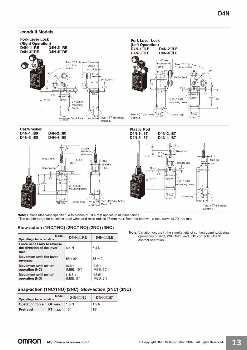
Dimensions and Operating Characteristics (Unit: mm)
Switches1-conduit Models
Note: Unless otherwise specified, a tolerance of 0.4 mm applies to all dimensions.* Refer to page 12 for details on M12 connectors.
Roller Lever (Resin Lever, Resin Roller)D4N-1@20 D4N-2@20D4N-3@20 D4N-4@20D4N-9@20 * 17.5 dia. × 6.8
resin roller
Two, 4+0.15 dia. holesDepth: 5
0
30
27.5
11±0.2
47±1
40±1
(27)
21.5
22±0.2
31 max.
55 47±0.2
2.5
9±0.2
26R
18
20±0.1
22±0.1
14.2
Resin lever
2.15±0.05Rmounting holes
Conduit cap
20.5 × 20.5
Roller Lever (Metal Lever, Resin Roller)D4N-1@22 D4N-2@22D4N-3@22 D4N-4@22D4N-9@22 * 17.5 dia. × 6.8
resin roller
Two, 4+0.15 dia. holesDepth: 5
0
30
27.5
11±0.2
45±1
39.5±1
(31)
21.5
22±0.2
31 max.
55 47±0.2
2.5
9±0.2
26R
18
20±0.1
22±0.1
14.2
Metal lever
2.15±0.05Rmounting holes
Conduit cap
20.5 × 20.5
Roller Lever (Metal Lever, Metal Roller)D4N-1@25 D4N-2@25D4N-3@25 D4N-4@25D4N-9@25 * 17.5 dia. × 7
sintered stainless steel roller
Two, 4+0.15 dia. holesDepth: 5
0
30
27.5
11±0.2
45±1
39.5±1
(31)
21.5
22±0.2
31 max.
55 47±0.2
2.5
9±0.2
26R
18
20±0.1
22±0.1
14.2
Metal lever20.5 × 20.5
2.15±0.05Rmounting holes
Conduit cap
Roller Lever (Metal Lever, Bearing Roller)D4N-1@26 D4N-2@26D4N-3@26 D4N-4@26D4N-9@26 * 17 dia. × 6
Bearing roller
Two, 4+0.15 dia. holesDepth: 5
0
Metal lever20.5 × 20.5
2.15±0.05Rmounting holes
Conduit cap 30
27.5
11±0.2
43.6±1
39±1
(31.5)
21.5
22±0.2
31 max.
55 47±0.2
2.5
9±0.2
26R
18
20±0.1
22±0.1
14.2
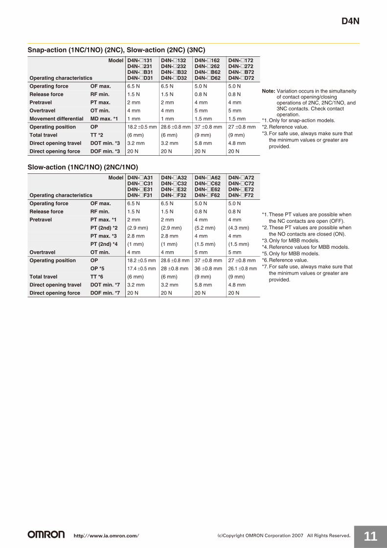
Snap-action (1NC/1NO) (2NC), Slow-action (2NC) (3NC)
Note: Variation occurs in the simultaneity of contact opening/closing operations of 2NC, 2NC/1NO, and 3NC contacts. Check contact operation.
*1.Only for snap-action models.*2.Reference value.*3.For safe use, always make sure that the minimum values or greater
are provided.
Model
Operating characteristics
D4N-@120D4N-@220D4N-@B20D4N-@D20
D4N-@122D4N-@222D4N-@B22D4N-@D22
D4N-@125D4N-@225D4N-@B25D4N-@D25
D4N-@126D4N-@226D4N-@B26D4N-@D26
Operating force OF max. 5.0 N
Release force RF min. 0.5 N
Pretravel PT 18 to 27
Overtravel OT min. 40
Movement differential MD max. *1
14
Operating position OP ---
Total travel TT *2 (80 )
Direct opening travel DOT min.*3
50
Direct opening force DOF min. *3
20 N
Slow-action (1NC/1NO) (2NC/1NO)
*1. These PT values are possible when the NC contacts are open (OFF).*2. These PT values are possible when the NO contacts are closed (ON).*3.Only for MBB models.*4.Reference values for MBB models only.*5.Reference values.*6.For safe use, always make sure that the minimum values or greater
are provided.
Model
Operating characteristics
D4N-@A20D4N-@C20D4N-@E20D4N-@F20
D4N-@A22D4N-@C22D4N-@E22D4N-@F22
D4N-@A25D4N-@C25D4N-@E25D4N-@F25
D4N-@A26D4N-@C26D4N-@E26D4N-@F26
Operating force OF max. 5.0 N
Release force RF min. 0.5 N
PT *1 18 to 27
PT (2nd)*2
(44 )
PT *3 27.5 to 36.5
PT (2nd)*4
(18 )
Overtravel OT min. 40
Operating position OP ---
Total travel TT *5 (80 )
Direct opening travel DOT min.*6
50
Direct opening force DOF min.*6
20 N
http://www.ia.omron.com/ 9(c)Copyright OMRON Corporation 2007 All Rights Reserved.
D4N
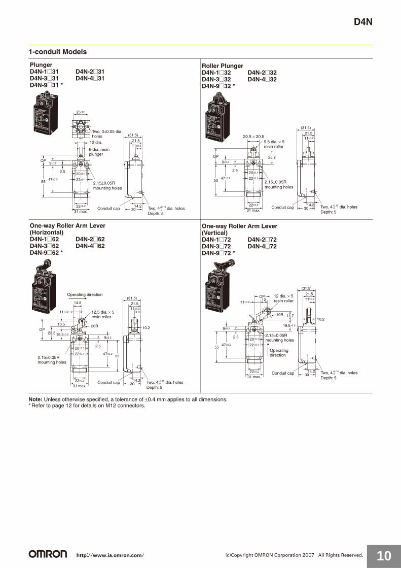
1-conduit Models
Note: Unless otherwise specified, a tolerance of 0.4 mm applies to all dimensions.* Refer to page 12 for details on M12 connectors.
PlungerD4N-1@31 D4N-2@31D4N-3@31 D4N-4@31D4N-9@31 *
Two, 3±0.05 dia. holes
6-dia. resin plunger
Two, 4+0.15 dia. holesDepth: 5
030
(31.5)
21.5
25±0.1
11±0.2
22±0.2
31 max.
55 47±0.2
2.5
9±0.2OP
20±0.1
22±0.1
14.2
12 dia.
2.15±0.05Rmounting holes
Conduit cap
Roller PlungerD4N-1@32 D4N-2@32D4N-3@32 D4N-4@32D4N-9@32 *
9.5 dia. × 5 resin roller
Two, 4+0.15 dia. holesDepth: 5
030
25.2
11±0.2
22±0.2
31 max.
55 47±0.2
2.5
9±0.2
OP
20±0.1
22±0.1
14.2
(31.5)
21.520.5 × 20.5
2.15±0.05Rmounting holes
Conduit cap
Two, 4+0.15 dia. holesDepth: 5
0
One-way Roller Arm Lever (Horizontal)D4N-1@62 D4N-2@62D4N-3@62 D4N-4@62D4N-9@62 *
Operating direction
12.5 dia. × 5 resin roller
30
14.8
23.3
13.5
19.5±0.2
11±0.211±0.2
20R 10.2
22±0.2
31 max.
47±0.2
2.5
9±0.2
OP
20±0.1
22±0.1
14.2
55
(31.5)
21.5
2.15±0.05Rmounting holes
Conduit cap
Two, 4+0.15 dia. holesDepth: 5
0
One-way Roller Arm Lever (Vertical)D4N-1@72 D4N-2@72D4N-3@72 D4N-4@72D4N-9@72 *
Operating direction
12 dia. × 5 resin roller
30
OP
14.719R
19.5±0.2
11±0.211±0.2
12
10.2
22±0.2
31 max.
47±0.2
2.5
9±0.2
20±0.1
22±0.1
14.2
(31.5)
55
21.5
2.15±0.05Rmounting holes
Conduit cap
http://www.ia.omron.com/ 10(c)Copyright OMRON Corporation 2007 All Rights Reserved.
D4N
Snap-action (1NC/1NO) (2NC), Slow-action (2NC) (3NC)
Slow-action (1NC/1NO) (2NC/1NO)
Model
Operating characteristics
D4N-@131D4N-@231D4N-@B31D4N-@D31
D4N-@132D4N-@232D4N-@B32D4N-@D32
D4N-@162D4N-@262D4N-@B62D4N-@D62
D4N-@172D4N-@272D4N-@B72D4N-@D72
Operating force OF max. 6.5 N 6.5 N 5.0 N 5.0 NNote: Variation occurs in the simultaneity
of contact opening/closing operations of 2NC, 2NC/1NO, and 3NC contacts. Check contact operation.
*1.Only for snap-action models.*2.Reference value.*3.For safe use, always make sure that
the minimum values or greater are provided.
Release force RF min. 1.5 N 1.5 N 0.8 N 0.8 N
Pretravel PT max. 2 mm 2 mm 4 mm 4 mm
Overtravel OT min. 4 mm 4 mm 5 mm 5 mm
Movement differential MD max. *1 1 mm 1 mm 1.5 mm 1.5 mm
Operating position OP 18.2 0.5 mm 28.6 0.8 mm 37 0.8 mm 27 0.8 mm
Total travel TT *2 (6 mm) (6 mm) (9 mm) (9 mm)
Direct opening travel DOT min. *3 3.2 mm 3.2 mm 5.8 mm 4.8 mm
Direct opening force DOF min. *3 20 N 20 N 20 N 20 N
Model
Operating characteristics
D4N-@A31D4N-@C31D4N-@E31D4N-@F31
D4N-@A32D4N-@C32D4N-@E32D4N-@F32
D4N-@A62D4N-@C62D4N-@E62D4N-@F62
D4N-@A72D4N-@C72D4N-@E72D4N-@F72
Operating force OF max. 6.5 N 6.5 N 5.0 N 5.0 N
*1.These PT values are possible when the NC contacts are open (OFF).
*2.These PT values are possible when the NO contacts are closed (ON).
*3.Only for MBB models.*4.Reference values for MBB models.*5.Only for MBB models.*6.Reference value.*7.For safe use, always make sure that
the minimum values or greater are provided.
Release force RF min. 1.5 N 1.5 N 0.8 N 0.8 N
Pretravel PT max. *1 2 mm 2 mm 4 mm 4 mm
PT (2nd) *2 (2.9 mm) (2.9 mm) (5.2 mm) (4.3 mm)
PT max. *3 2.8 mm 2.8 mm 4 mm 4 mm
PT (2nd) *4 (1 mm) (1 mm) (1.5 mm) (1.5 mm)
Overtravel OT min. 4 mm 4 mm 5 mm 5 mm
Operating position OP 18.2 0.5 mm 28.6 0.8 mm 37 0.8 mm 27 0.8 mm
OP *5 17.4 0.5 mm 28 0.8 mm 36 0.8 mm 26.1 0.8 mm
Total travel TT *6 (6 mm) (6 mm) (9 mm) (9 mm)
Direct opening travel DOT min. *7 3.2 mm 3.2 mm 5.8 mm 4.8 mm
Direct opening force DOF min. *7 20 N 20 N 20 N 20 N
http://www.ia.omron.com/ 11(c)Copyright OMRON Corporation 2007 All Rights Reserved.

D4N
1-conduit Models
Note: Unless otherwise specified, a tolerance of 0.4 mm applies to all dimensions.* Refer to following diagrams for details on M12 connectors.
Snap-action (1NC/1NO) (2NC), Slow-action (2NC) (3NC)
Slow-action (1NC/1NO) (2NC/1NO)
Model
Operating characteristics
D4N-@12HD4N-@22HD4N-@B2HD4N-@D2H
D4N-@12GD4N-@22GD4N-@B2GD4N-@D2G*1
Operating force OF max. 4.5 NNote: Variation occurs in the simultaneity of contact
opening/closing operations of 2NC, 2NC/1NO, and 3NC contacts. Check contact operation.
*1.The operating characteristics of these Switches were measured with the roller lever set at 32 mm.
*2.Only for snap-action models.*3.Reference value.*4.For safe use, always make sure that the minimum values
or greater are provided.
Release force RF min. 0.4 N
Pretravel PT 18 to 27
Overtravel OT min. 40
Movement differential MD max. *2 14
Operating position OP ---
Total travel TT *3 (80 )
Direct opening travel DOT min. *4 50
Direct opening force DOF min. *4 20 N
Model
Operating characteristics
D4N-@A2HD4N-@C2HD4N-@E2HD4N-@F2H
D4N-@A2GD4N-@C2GD4N-@E2GD4N-@F2G *1
Operating force OF max. 4.5 N*1.The operating characteristics of these Switches were
measured with the roller lever set at 32 mm.*2.This PT value is possible when the NC contacts are open
(OFF).*3.This PT value is possible when the NO contacts are
closed (ON).*4.Only for MBB models.*5.Reference value for MBB models only.*6.Reference value.*7.For safe use, always make sure that the minimum values
or greater are provided.
Release force RF min. 0.4 N
Pretravel PT *2 18 to 27
PT (2nd) *3 (44 )
PT *4 27.5 to 36.5
PT (2nd) *5 (18 )
Overtravel OT min. 40
Operating position OP ---
Total travel TT *6 (80 )
Direct opening travel DOT min. 50
Direct opening force DOF min. *7 20 N
Adjustable Roller Lever, Form Lock(with Metal Lever, Resin Roller)D4N-1@2G D4N-2@2GD4N-3@2G D4N-4@2GD4N-9@2G * 17.5 dia. × 6.8
resin roller
Two, 4+0.15 dia. holesDepth: 5
0
2.15±0.05Rmounting holes
Conduit cap
20.5 × 20.5
30
27.5
11±0.2
21.5
22±0.2
31 max.
55 47±0.2
2.5
9±0.2
20 to 66R
18
20±0.1
22±0.1
14.2
45±1
39.5±1
(31)
Adjustable Roller Lever, Form Lock(with Metal Lever, Rubber Roller)D4N-1@2H D4N-2@2HD4N-3@2H D4N-4@2HD4N-9@2H * 50 dia. × 8
rubber rollerBearing
Stainless steel lever
Two, 4+0.15 dia. holesDepth: 5
0
20.5 × 20.5
30
27.5
11±0.2
21.5
22±0.2
31 max.
55 47±0.2
2.5
9±0.218
20±0.1
22±0.1
14.2
48.2±1
41.3±1
(29.2)
32 to 66R
2.15±0.05Rmounting holes
Conduit cap
1-conduit M12 ConnectorD4N-9@@@
(14)
M12 × 114.2
30
http://www.ia.omron.com/ 12(c)Copyright OMRON Corporation 2007 All Rights Reserved.
D4N
1-conduit Models
Note: Unless otherwise specified, a tolerance of 0.4 mm applies to all dimensions.* The usable range for stainless steel wires and resin rods is 35 mm max. from the end with a total travel of 70 mm max.
Slow-action (1NC/1NO) (2NC/1NO) (2NC) (3NC)Note: Variation occurs in the simultaneity of contact opening/closing
operations of 2NC, 2NC/1NO, and 3NC contacts. Check contact operation.
Snap-action (1NC/1NO) (2NC), Slow-action (2NC) (3NC)
20.5 × 20.5
Two, 4+0.15 dia. holesDepth: 5
0
Fork Lever Lock (Right Operation)D4N-1@RE D4N-2@RED4N-3@RE D4N-4@RE
2.15±0.05Rmountingholes
30
27.5
11±0.2
47 max.
39.3±1
(27.2)
21.5
22±0.2
31 max.
55 47±0.2
2.5
9±0.2
26R90°
18
20±0.1
22±0.1
14.2
Two, 17.5 dia. × 8 rubberrollers
Conduit cap Two, 4+0.15 dia. holesDepth: 5
0
Fork Lever Lock (Left Operation)D4N-1@LE D4N-2@LED4N-3@LE D4N-4@LE
2.15±0.05Rmounting holes
Two, 17.5 dia. ×8 rubber rollers
30
27.5
11±0.2
39.3±1
(27.2)
21.5
22±0.2
31 max.
5547±0.2
2.5
9±0.2
26R90°
18
20±0.1
22±0.1
14.2
47 max.
20.5 × 20.5
Conduit cap
Two, 4+0.15 dia. holesDepth: 5
0
Cat WhiskerD4N-1@80 D4N-2@80D4N-3@80 D4N-4@80
1.2-dia.stainlesssteel wire *
2.15±0.05Rmounting holes
30
(31.5)
11±0.2
21.5
22±0.2
31 max.
55 47±0.2
2.5
9±0.2
(50.1)
PT
143.1
20±0.1
22±0.1
14.2
20.5 × 20.5
Sealing cap16.6 dia.
Conduit cap
Two, 4+0.15 dia. holesDepth: 5
0
Plastic RodD4N-1@87 D4N-2@87D4N-3@87 D4N-4@87
2.15±0.05Rmounting holes
30
(31.5)
11±0.2
22±0.2
31 max.
55
115
38
42
12±0.2
47±0.2
2.5
PT
20±0.1
22±0.1
14.2
21.5
9±0.2
Resin rod *20.5 ×20.5
Sealing cap16.6 dia.
Conduit cap
ModelOperating characteristics D4N-@@RE D4N-@@LE
Force necessary to reverse the direction of the lever: max.
6.4 N 6.4 N
Movement until the lever reverses 55 10 55 10
Movement until switch operation (NC)
(6.5(MBB: 10 )
(6.5(MBB: 10 )
Movement until switch operation (NO)
(18.5(MBB: 5 )
(18.5(MBB: 5 )
ModelOperating characteristics D4N-@@80 D4N-@@87
Operating force OF max. 1.5 N 1.5 N
Pretravel PT max. 15 15
http://www.ia.omron.com/ 13(c)Copyright OMRON Corporation 2007 All Rights Reserved.
D4N
2-conduit Models
Note: Unless otherwise specified, a tolerance of 0.4 mm applies to all dimensions.
Roller Lever (Resin Lever, Resin Roller)D4N-5@20D4N-6@20D4N-8@20
17.5 dia. × 6.8resin roller
Two, 4+0.15 dia. holesDepth: 5
0
30
Cap
27.5
20.5
20.5 × 20.5
11±0.2
47±1
40±1
(27)
21.5
42±0.2 (3)
56 max.
47
39±0.2
25 dia.
2.55.49±0.2
26R
18
20±0.1
40±0.1
42±0.1
22±0.1
14.2
Resin lever
2.15±0.05Rmountingholes
Conduitcap
Roller Lever (Metal Lever, Resin Roller)D4N-5@22D4N-6@22D4N-8@22 17.5 dia. × 6.8
resin roller
Two, 4+0.15 dia. holesDepth: 5
0
30
Cap
27.5
20.5
11±0.2
21.5
42±0.2 (3)
56 max.
4725 dia.
2.55.49±0.2
18
20±0.1
40±0.1
42±0.1
22±0.1
14.2
26R
45±1
39.5±1
(31)
39±0.2
Metal lever20.5 × 20.5
2.15±0.05Rmountingholes
Conduit cap
PlungerD4N-5@31D4N-6@31D4N-8@31
Two, 3±0.05dia. holes
Two, 4+0.15 dia. holesDepth: 5
0
30
Cap
20.5
42±0.2 (3)
56 max.
4725 dia.
2.55.49±0.2
OP
20±0.1
40±0.1
42±0.1
22±0.1
14.2
(31.5)21.511±0.2
25±0.1
12 dia.
39±0.2
6-dia. resin plunger
2.15±0.05Rmountingholes
Conduit cap
Roller PlungerD4N-5@32D4N-6@32D4N-8@32
9.5 dia. × 5 resin roller
Two, 4+0.15 dia. holesDepth: 5
0
30
Cap
20.5
42±0.2 (3)
56 max.
4725 dia.
2.5
5.4
9±0.2
OP 25.2
20±0.1
40±0.1
42±0.1
22±0.1
14.2
11±0.2
(31.5)21.5
39±0.2
20.5 × 20.5
2.15±0.05Rmountingholes
Conduit cap
Snap-action (1NC/1NO) (2NC), Slow-action (2NC) (3NC)
Note: Variation occurs in the simultaneity of contact opening/closing operations of 2NC, 2NC/1NO, and 3NC contacts. Check contact operation.
*1.Only for snap-action models.*2.Reference value.*3.For safe use, always make sure that the minimum values or greater
are provided.
Model
Operating characteristics
D4N-@120D4N-@220D4N-@B20D4N-@D20
D4N-@122D4N-@222D4N-@B22D4N-@D22
D4N-@131D4N-@231D4N-@B31D4N-@D31
D4N-@132D4N-@232D4N-@B32D4N-@D32
Operating force OF max. 5 N 5 N 6.5 N 6.5 N
Release force RF min. 0.5 N 0.5 N 1.5 N 1.5 N
Pretravel PT 18 to 27 18 to 27 2 mm 2 mm
Overtravel OT min. 40 40 4 mm 4 mm
Movement differentialMD max. *1
14 14 1 mm 1 mm
Operating position OP --- --- 18 0.5 mm
28.2 0.8 mm
Total travel TT *2 (80 ) (80 ) (6 mm) (6 mm)
Direct opening travel DOT min. *3
50 50 3.2 mm 3.2 mm
Direct opening forceDOF min. *3
20 N 20 N 20 N 20 N
Slow-action (1NC/1NO) (2NC/1NO)
*1.This PT value is possible when the NC contacts are open (OFF).*2.This PT value is possible when the NO contacts are closed (ON).*3.Only for MBB models.*4.Reference value for MBB models.*5.Only for MBB models.*6.Reference value.*7.For safe use, always make sure that the minimum values or
greater are provided.
Model
Operating characteristics
D4N-@A20D4N-@C20D4N-@E20D4N-@F20
D4N-@A22D4N-@C22D4N-@E22D4N-@F22
D4N-@A31D4N-@C31D4N-@E31D4N-@F31
D4N-@A32D4N-@C32D4N-@E32D4N-@F32
Operating force OF max. 5 N 5 N 6.5 N 6.5 N
Release force RF min. 0.5 N 0.5 N 1.5 N 1.5 N
Pretravel PT *1 18 to 27 18 to 27 2 mm 2 mm
PT (2nd)*2
(44 ) (44 ) (2.9 mm) (2.9 mm)
PT *3 27.5 to 36.5
27.5 to 36.5 2.8 mm 2.8 mm
PT (2nd)*4
(18 ) (18 ) (1 mm) (1 mm)
Overtravel OT min. 40 40 4 mm 4 mm
Operating position OP --- --- 18 0.5 mm
28.2 0.8 mm
OP *5 --- --- 17.4 0.5 mm
280.8 mm
Total travel TT *6 (80 ) (80 ) (6 mm) (6 mm)
Direct opening travel DOT min.*7
50 50 3.2 mm 3.2 mm
Direct opening forceDOF min. *7
20 N 20 N 20 N 20 N
http://www.ia.omron.com/ 14(c)Copyright OMRON Corporation 2007 All Rights Reserved.

D4N
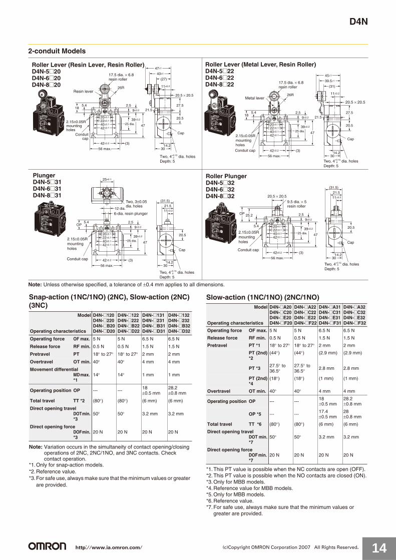
2-conduit Models
Note: Unless otherwise specified, a tolerance of 0.4 mm applies to all dimensions.v
Two, 4+0.15 dia. holesDepth: 5
0
One-way Roller Arm Lever (Horizontal)D4N-5@62D4N-6@62D4N-8@62
12 dia. x 5 resin roller
2.15±0.05Rmounting holes
30
Cap
20.5
21.5
42±0.2 (3)
56 max.
4725 dia.
2.55.49±0.2
20±0.1
40±0.1
42±0.1
22±0.1
14.2
11±0.2
10.2
(31.5)14.8
Operating direction
23.3
13.5
11±0.2
19.5±0.2
20ROP
21.5
39±0.2
Conduit cap
Two, 4+0.15 dia. holesDepth: 5
0
One-way Roller Arm Lever (Vertical)D4N-5@72D4N-6@72D4N-8@72
Operating direction
12 dia. × 5 resin roller
30
Cap
20.5
21.5
42±0.2 (3)
56 max.
4725 dia.
2.55.49±0.2
20±0.1
40±0.1
42±0.1
22±0.1
14.2
OP
14.719R
19.5±0.2
11±0.212 11±0.2
10.2
(31.5)
21.5
39±0.2
2.15±0.05Rmountingholes
Conduit cap
Adjustable Roller Lever, Form Lock (with Metal Lever, Resin Roller)D4N-6@2GD4N-8@2G
17.5 dia. × 6.8resin roller
Two, 4+0.15 dia. holesDepth: 5
0
30
Cap
27.5
20.5
11±0.2
21.5
42±0.2 (3)
56 max.
4725 dia.
2.55.49±0.2
18
20±0.1
40±0.1
42±0.1
22±0.1
14.2
45±1
39.5±1
(31)
39±0.2
20 to 66RResin lever2.15±0.05Rmounting holes
Conduit cap
20.5 × 20.5
Adjustable Roller Lever, Form Lock(with Metal Lever, Rubber Roller)D4N-6@2HD4N-8@2H
50 dia. × 8rubber rollerBearing
Stainlesssteel lever
Two, 4+0.15 dia. holesDepth: 5
0
20.5 × 20.5
30
Cap
27.5
20.5
11±0.2
21.5
42±0.2 (3)
56 max.
4725 dia.
2.55.49±0.2
18
20±0.1
40±0.1
42±0.1
22±0.1
14.2
48.2±1
41.3±1
(29.2)
39±0.2
32 to 66R2.15±0.05Rmounting holes
Conduit cap
Snap-action (1NC/1NO) (2NC), Slow-action (2NC) (3NC)
Note: Variation occurs in the simultaneity of contact opening/closing operations of 2NC, 2NC/1NO, and 3NC contacts. Check contact operation.
*1. The operating characteristics of these Switches were measured with the roller lever set at 30 mm.
*2. The operating characteristics of these Switches were measured with the roller lever set at 31 mm.
*3. Only for snap-action models.*4. Reference value.*5. For safe use, always make sure that the minimum values or greater are
provided.
Model
Operating characteristics
D4N-@162D4N-@262D4N-@B62D4N-@D62
D4N-@172D4N-@272D4N-@B72D4N-@D72
D4N-@12GD4N-@22GD4N-@B2GD4N-@D2G*1
D4N-@12HD4N-@22HD4N-@B2HD4N-@D2H*2
Operating force OF max. 5.0 N 5.0 N 4.5 N 4.5 N
Release force RF min. 0.8 N 0.8 N 0.4 N 0.4 N
Pretravel PT max. 4 mm 4 mm 18 to 27 18 to 27
Overtravel OT min. 5 mm 5 mm 40 40
Movement differentialMD max. *3
1.5 mm 1.5 mm 14 14
Operating position OP 37 0.8 mm 27 0.8 mm --- ---
Total travel TT *4 (9 mm) (9 mm) (70 ) (70 )
Direct opening travel DOT min. *5
5.8 mm 4.8 mm 50 50
Direct opening forceDOF min. *5
20 N 20 N 20 N 20 N
Slow-action (1NC/1NO) (2NC/1NO)
*1. The operating characteristics of these Switches were measured with the roller lever set at 30 mm.
*2. The operating characteristics of these Switches were measured with the roller lever set at 31 mm.
*3. This PT value is possible when the NC contacts are open (OFF).*4. This PT value is possible when the NO contacts are closed (ON).*5. Only for MBB models.*6. Reference value for MBB models only.*7. Only for MBB models.*8. Reference value.*9. For safe use, always make sure that the minimum values or greater are provided.
Model
Operating characteristics
D4N-@A62D4N-@C62D4N-@E62D4N-@F62
D4N-@A72D4N-@C72D4N-@E72D4N-@F72
D4N-@A2GD4N-@C2GD4N-@E2GD4N-@F2G*1
D4N-@A2HD4N-@C2HD4N-@E2HD4N-@F2H*2
Operating force OF max. 5.0 N 5.0 N 4.5 N 4.5 N
Release force RF min. 0.8 N 0.8 N 0.4 N 0.4 N
Pretravel PT max.*3 4 mm 4 mm 18 to 27 18 to 27
PT (2nd)*4
(5.2 mm) (4.3 mm) (44 ) (44 )
PT max.*5 4 mm 4 mm 27.5 to 36.5 27.5 to 36.5
PT (2nd)*6
(1.5 mm) (1.5 mm) (18 ) (18 )
Overtravel OT min. 5 mm 5 mm 40 40
Operating position OP 37 0.8 mm 27 0.8 mm --- ---
OP *7 36 0.8 mm 26.1 0.8 mm --- ---
Total travel TT *8 (9 mm) (9 mm) (70 ) (70 )
Direct opening travel DOT min. *9
5.8 mm 4.8 mm 50 50
Direct opening forceDOF min. *9
20 N 20 N 20 N 20 N
http://www.ia.omron.com/ 15(c)Copyright OMRON Corporation 2007 All Rights Reserved.

D4N
2-conduit Models
Note: Unless otherwise specified, a tolerance of 0.4 mm applies to all dimensions.* The usable range for stainless steel wires and resin rods is 35 mm max. from the end with a total travel of 70 mm max.
Slow-action (1NC/1NO) (2NC), Slow-action (2NC) (3NC)Note: Variation occurs in the simultaneity of contact opening/closing
operations of 2NC, 2NC/1NO, and 3NC contacts. Check contact operation.
Snap-action (1NC/1NO), Slow-action (2NC) (3NC)
Two, 4+0.15 dia. holesDepth: 5
0
Fork Lever Lock (Right Operation)D4N-5@RE D4N-6@RED4N-7@RE D4N-8@RE
2.15±0.05Rmounting holes
30
Cap
27.5
20.5
11±0.2
21.5
42±0.2 (3)
56 max.
4725 dia.
2.55.49±0.2
18
20±0.1
40±0.1
42±0.1
22±0.1
14.2
39.3±1
(27.2)
26R90°
47 max.
39±0.2
Two, 17.5 dia. ×8 rubber rollers
Conduit cap
20.5 × 20.5
Two, 4+0.15 dia. holesDepth: 5
0
Fork Lever Lock (Left Operation)D4N-5@LE D4N-6@LED4N-7@LE D4N-8@LE
2.15±0.05Rmounting holes
Cap
Two, 17.5 dia. ×8 rubber rollers
20.5 × 20.5
30
27.5
20.5
11±0.2
21.5
14.2
39.3±1
(27.2)
42±0.2 (3)
56 max.
4725 dia.
2.55.49±0.2
18
20±0.1
40±0.1
42±0.1
22±0.1
90°26R
47 max.
39±0.2
Conduit cap
Two, 4+0.15 dia. holesDepth: 5
0
Cat WhiskerD4N-5@80 D4N-6@80D4N-7@80 D4N-8@80
1.2-dia.stainlesssteel wire *
2.15±0.05Rmounting holes
30
Cap
20.5
11±0.2
16.6 dia.
42±0.2 (3)
56 max.
4725 dia.
2.5
20.5 × 20.5
5.49±0.2
20±0.1
40±0.1
42±0.1
22±0.1
14.2
(50.1)
PT
143.1 21.5
(31.5)
39±0.2
Sealing cap
Conduit cap
Two, 4+0.15 dia. holesDepth: 5
0
Plastic RodD4N-5@87 D4N-6@87D4N-7@87 D4N-8@87
2.15±0.05Rmountingholes
30
Cap
20.5
11±0.2
16.6 dia.
42±0.2 (3)
56 max.
4725 dia.
2.55.4
9±0.212±0.2
20±0.1
40±0.1
42±0.1
22±0.1
14.2
115
38
42
PT
(31.5)
21.5
39±0.2
Resin rod *
Sealing cap
Conduit cap
ModelOperating characteristics D4N-@@RE D4N-@@LE
Force necessary to reverse the direction of the lever: max. 6.4 N 6.4 N
Movement until the lever reverses 55 10 55 10
Movement until switch operation (NC)
(6.5 ) (6.5 )(MBB: 10 )
Movement until switch operation (NO)
(18.5 ) (18.5 )(MBB: 5 )
ModelOperating characteristics D4N-@@80 D4N-@@87
Operating force OF max. 1.5 N 1.5 N
Pretravel PT max. 15 15
http://www.ia.omron.com/ 16(c)Copyright OMRON Corporation 2007 All Rights Reserved.
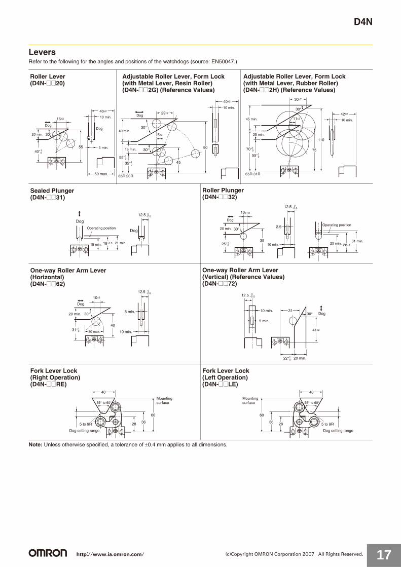
D4N
LeversRefer to the following for the angles and positions of the watchdogs (source: EN50047.)
Note: Unless otherwise specified, a tolerance of 0.4 mm applies to all dimensions.
Roller Lever(D4N-@@20)
40±2
15±3
40+1 0
55
50 max.
30°20 min.
Dog
10 min.
Dog
5 min.
Adjustable Roller Lever, Form Lock(with Metal Lever, Resin Roller)(D4N-@@2G) (Reference Values)
40±2
45
29±7
5±2
30°
30°
55+1 0
35+1 0
65R 20R
90
40 min.
Dog
15 min.
10 min.
Adjustable Roller Lever, Form Lock(with Metal Lever, Rubber Roller)(D4N-@@2H) (Reference Values)
42±2
110
75
30±7
11±3
30°
70+1 0
55+1 0
65R 31R
45 min.
25 min.
10 min.
Sealed Plunger(D4N-@@31)
12.5 0−2.5
18±0.5
Dog
15 min. 21 min.
DogOperating position
Roller Plunger(D4N-@@32)
25+1 0
3528±1
10±1.5
2.530°
12.5 0−2.5
Dog
20 min.
10 min.
Operating position
25 min.31 min.
One-way Roller Arm Lever (Horizontal)(D4N-@@62)
30 max.
Dog
20 min.
31+1 0
10±2
40
5 min.
10 min.
30°
12.5 0−2.5
One-way Roller Arm Lever (Vertical) (Reference Values)(D4N-@@72)
30°
20 min.
31
41±2
22+1 0
5 min.
10 min.
12.5 0−2.5
Dog
Fork Lever Lock (Right Operation)(D4N-@@RE)
60
36
55° to 60°
5 to 9R
Dog setting range
40
28
Mountingsurface
Fork Lever Lock (Left Operation)(D4N-@@LE)
60
36
55° to 60°
5 to 9R
Dog setting range
40
28
Mountingsurface
http://www.ia.omron.com/ 17(c)Copyright OMRON Corporation 2007 All Rights Reserved.
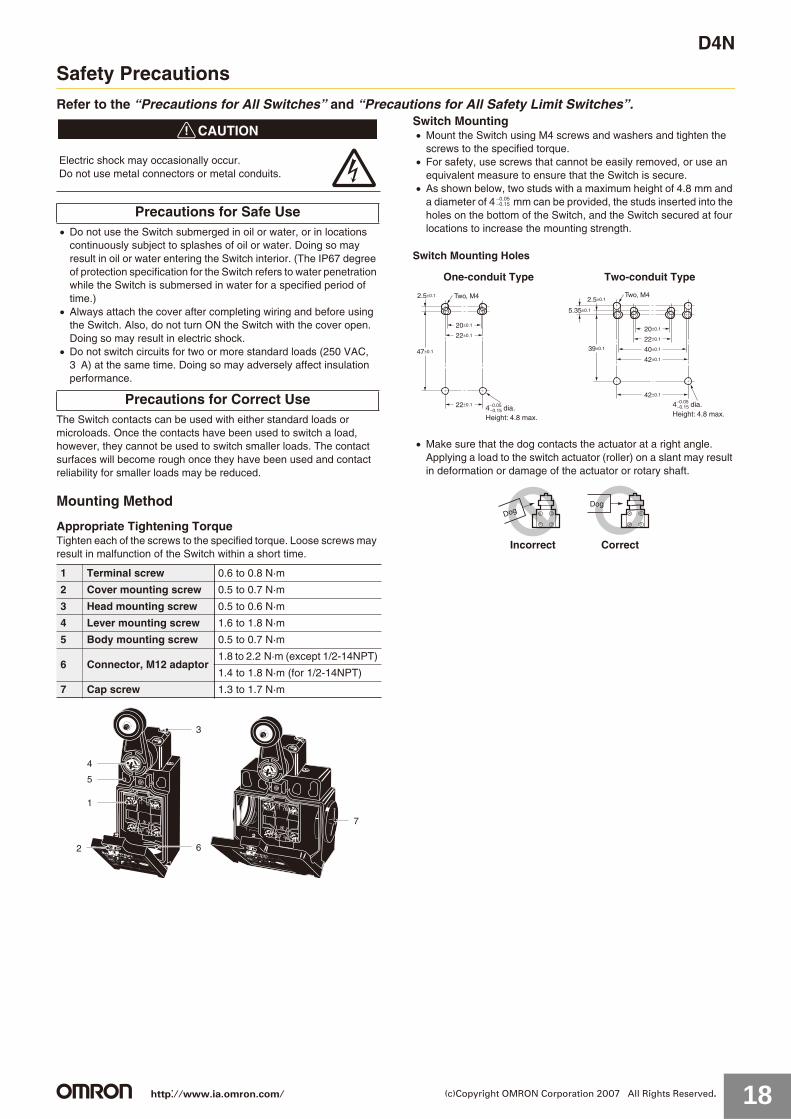
D4N
Safety Precautions
Refer to the “Precautions for All Switches” and “Precautions for All Safety Limit Switches”.
!CAUTION
Do not use the Switch submerged in oil or water, or in locations continuously subject to splashes of oil or water. Doing so may result in oil or water entering the Switch interior. (The IP67 degree of protection specification for the Switch refers to water penetration while the Switch is submersed in water for a specified period of time.)Always attach the cover after completing wiring and before using the Switch. Also, do not turn ON the Switch with the cover open. Doing so may result in electric shock.Do not switch circuits for two or more standard loads (250 VAC, 3 A) at the same time. Doing so may adversely affect insulation performance.
The Switch contacts can be used with either standard loads or microloads. Once the contacts have been used to switch a load, however, they cannot be used to switch smaller loads. The contact surfaces will become rough once they have been used and contact reliability for smaller loads may be reduced.
Mounting Method
Appropriate Tightening TorqueTighten each of the screws to the specified torque. Loose screws may result in malfunction of the Switch within a short time.
Switch MountingMount the Switch using M4 screws and washers and tighten the screws to the specified torque.For safety, use screws that cannot be easily removed, or use an equivalent measure to ensure that the Switch is secure.As shown below, two studs with a maximum height of 4.8 mm and a diameter of 4 mm can be provided, the studs inserted into the holes on the bottom of the Switch, and the Switch secured at four locations to increase the mounting strength.
Switch Mounting Holes
Make sure that the dog contacts the actuator at a right angle. Applying a load to the switch actuator (roller) on a slant may result in deformation or damage of the actuator or rotary shaft.
Electric shock may occasionally occur. Do not use metal connectors or metal conduits.
Precautions for Safe Use
Precautions for Correct Use
1 Terminal screw 0.6 to 0.8 N·m
2 Cover mounting screw 0.5 to 0.7 N·m
3 Head mounting screw 0.5 to 0.6 N·m
4 Lever mounting screw 1.6 to 1.8 N·m
5 Body mounting screw 0.5 to 0.7 N·m
6 Connector, M12 adaptor1.8 to 2.2 N·m (except 1/2-14NPT)
1.4 to 1.8 N·m (for 1/2-14NPT)
7 Cap screw 1.3 to 1.7 N·m
7
6
3
4
5
1
2
One-conduit Type Two-conduit Type
0.050.15
2.5±0.1
22±0.1
47±0.1
20±0.1
22±0.1
Two, M4
−0.154−0.05 dia. Height: 4.8 max.
42±0.1
39±0.1
20±0.1
22±0.1
40±0.1
42±0.1
2.5±0.1
5.35±0.1
Two, M4
−0.154−0.05 dia. Height: 4.8 max.
DogDog
CorrectIncorrect
http://www.ia.omron.com/ 18(c)Copyright OMRON Corporation 2007 All Rights Reserved.

D4N
WiringWiring
When connecting to the terminals via insulating tube and M3.5 crimp terminals, arrange the crimp terminals as shown below so that they do not rise up onto the case or the cover. Applicable lead wire size: AWG20 to AWG18 (0.5 to 0.75 mm2).Use lead wires of an appropriate length, as shown below. Not doing so may result in excess length causing the cover to rise and not fit properly.
One-conduit Type (3 Poles)
Two-conduit Type (3 Poles)
Do not push crimp terminals into gaps in the case interior. Doing so may cause damage or deformation of the case.Use crimp terminals not more than 0.5 mm in thickness. Otherwise, they will interfere with other components inside the case.
[Reference] The crimp terminals shown below are not more than 0.5 mm thick.
Contact ArrangementThe contact arrangements are shown below.
Screw Terminal Type
Connector Type
Applicable socket: XS2F (OMRON).Refer to the Connector Catalog for details on socket pin numbers and lead wire colors.
Socket Tightening (Connector Type)Turn the socket connector screws by hand and tighten until no space remains between the socket and the plug.Make sure that the socket connector is tightened securely. Otherwise, the rated degree of protection (IP67) may not be maintained and vibration may loosen the socket connector.
Conduit OpeningConnect a recommended connector to the opening of the conduit and tighten the connector to the specified torque. The case may be damaged if an excessive tightening torque is applied.When using 1/2-14NPT, wind sealing tape around the joint between the connector and conduit opening so that the enclosure will conform to IP67. Use a cable with a suitable diameter for the connector. Attach and tighten a conduit cap to the unused conduit opening when wiring. Tighten the conduit cap to the specified torque. The conduit cap is provided with the Switch (2-conduit types).
Changing the LeverThe lever mounting screws can be used to set the lever position to any position in a 360 angle at 7.5 increments. Grooves are incised on the lever and rotary shaft that engage to prevent the lever from slipping against the rotary shaft. The screws on adjustable roller lever models can also loosened to change the length of the lever. Remove the screws from the front of the lever before mounting the lever in reverse (front/back), and set the level so that operation will be completed before exceeding a range of 180 on the horizontal.
Manufacturer Type
J.S.T. Mfg. Co.FN0.5-3.7 (F Type)
N0.5-3.7 (Straight Type)
2221
3433
1211A
A
CE
B
DF
C
E
B
D
F 28 mm
Tolerance ±2 mm
33 mm42 mm
2221
3433
1211A
C
E
B
D
F
ACE
B D F
28 mm
Tolerance ±2 mm
Left hand
42 mm
ACE
B D F
28 mm
Tolerance ±2 mm
Right hand
42 mm
L
l F
BD dia.
dz dia.
Correct Incorrect
Terminal screwCrimp terminal
t: 0.5 mmdz dia.: 3.7 mmD dia.: 2.9 mm
B: 6.6 mmL: 19 mmF: 7.7 mmI: 8.0 mm
14
32
13
31
D4N-@D@@ (3NC)
11
21
12
22
31 32
D4N-@B@@ (2NC)D4N-@2@@ (2NC (SNAP))
11
31
12
32
D4N-@C@@ (2NC/1NO)D4N-@F@@ (2NC/1NO (MBB))
D4N-@A@@ (1NC/1NO)D4N-@E@@ (1NC/1NO (MBB))
33 34
11
21
12
22
11
33
12
34
D4N-@1@@ (1NC/1NO (SNAP))
14 (4)
32 (2)
(3) 13
(1) 31
1
3
2 4
Pin No. (Terminal No.)
D4N-9B@@ (2NC)D4N-92@@ (2NC (SNAP))
D4N-9A@@ (1NC/1NO)D4N-9E@@ (1NC/1NO (MBB))
(1) 11
(3) 31
12 (2)
32 (4)
(1) 11
(3) 33
12 (2)
34 (4)
D4N-91@@ (1NC/1NO (SNAP))
http://www.ia.omron.com/ 19(c)Copyright OMRON Corporation 2007 All Rights Reserved.

D4N
Recommended ConnectorsUse connectors with screws not exceeding 9 mm, otherwise the screws will protrude into the case interior, interfering with other components in the case. The connectors listed in the following table have connectors with thread sections not exceeding 9 mm. Use the recommended connectors to ensure conformance to IP67.
Use LAPP connectors together with seal packing (JPK-16, GP-13.5, or GPM20), and tighten to the specified tightening torque. Seal packing is sold separately.
LAPP is a German manufacturer.Before using a 2-conduit 1/2-14NPT type, attach the provided changing adaptor to the Switch and then connect the recommended connector.
OthersWhen attaching a cover, be sure that the seal rubber is in place and that there is no foreign material present. If the cover is attached with the seal rubber out of place or if foreign material is stuck to the rubber, a proper seal will not be obtained.Do not use any screws to connect the cover other than the specified ones. The seal characteristics may be reduced. Make sure that foreign particles do not enter the head when removing the screws from the four corners to change the head position in any of the four directions. Use the following recommended countermeasures to prevent telegraphing when using adjustable or long levers.1. Make the rear edge of the dog smooth with an angle of 15 to
30 or make it in the shape of a quadratic curve.2. Design the circuit so that no error signal will be generated.
Size Manufacturer Model Applicable cable diameter
G1/2 LAPP ST-PF1/25380-1002 6.0 to 12.0 mm
Pg13.5 LAPP ST-13.55301-5030 6.0 to 12.0 mm
M20 LAPP ST-M20 1.55311-1020 7.0 to 13.0 mm
1/2-14NPT LAPP ST-NPT1/25301-6030 6.0 to 12.0 mm
http://www.ia.omron.com/ 20(c)Copyright OMRON Corporation 2007 All Rights Reserved.

D4N
Production DiscontinuationFollowing the release of the D4N, production of the D4D-N was discontinued.
Date of Production DiscontinuationProduction of the D4D-N Series was discontinued as of the end of March 2006.
Recommended Substitute ProductSales of the D4N series commenced in January 2004.
Product Substitution1. Dimensions
The D4D-N and D4N use the same mounting method, and mounting hole. The multi-contact structure and the extra 4 mm in length, however, are different.
2. Terminal NumbersFor the 2-contact slow-action model, the terminals 21, 22, 23, and 24 on the D4D-N are 31, 32, 33, and 34 on the D4N.
3. Recommended TerminalsIf the recommended terminals are not used, the Switch may not be compatible. Make sure that the Switch is compatible with the terminals.
Comparison with Discontinued Products
Dimensions (Unit: mm)
Item Model D4N
Switch color Very similar
Dimensions Very similar
Wiring/connection Significantly different
Mounting method Completely compatible
Ratings/performance Very similar
Operating characteristics Very similar
Operating method Completely compatible
Discontinued Product (1-conduit Plunger-type D4D-N) Recommended Substitute Product (1-conduit Plunger-type D4N)
Discontinued product (2-conduit Plunger-type D4D-N) Recommended Substitute Product (2-conduit Plunger-type D4N)
25 dia. ±0.1
Two, 3 ±0.05 dia. holes
12 dia.
6-dia. resin plunger
0Two, 4+0.15 dia. holes depth: 5
2.15±0.05Rmounting holes
31 max.
OP
30
(31.5)
21.5
25±0.1
12 dia.11±0.2
22±0.2
31 max.
55 47±0.2
2.5
9±0.2OP
20±0.1
22±0.1
14.2
2.15±0.05Rmounting holes
0Two, 4+0.15 dia. holes depth: 5
Two, 3 ±0.05 dia. holes
6-dia. resin plunger
Conduit cap
Two, 3 ±0.05 dia. holesdepth: 6
12 dia.6 dia.
2.15±0.05Rmounting holes
56 max.
25 dia.
Cap
0Two, 4+0.15 dia. holes depth: 5
OP
30
Cap
20.5
42±0.2 (3)
56 max.
4725 dia.
2.55.49±0.2
OP
20±0.1
40±0.1
42±0.1
22±0.1
14.2
(31.5)21.511±0.2
25±0.1
12 dia.
39±0.22.15±0.05Rmounting holes
0Two, 4+0.15 dia. holes depth: 5
Two, 3 ±0.05dia. holes
6-dia. resin plunger
Conduit cap
http://www.ia.omron.com/ 21(c)Copyright OMRON Corporation 2007 All Rights Reserved.
D4N
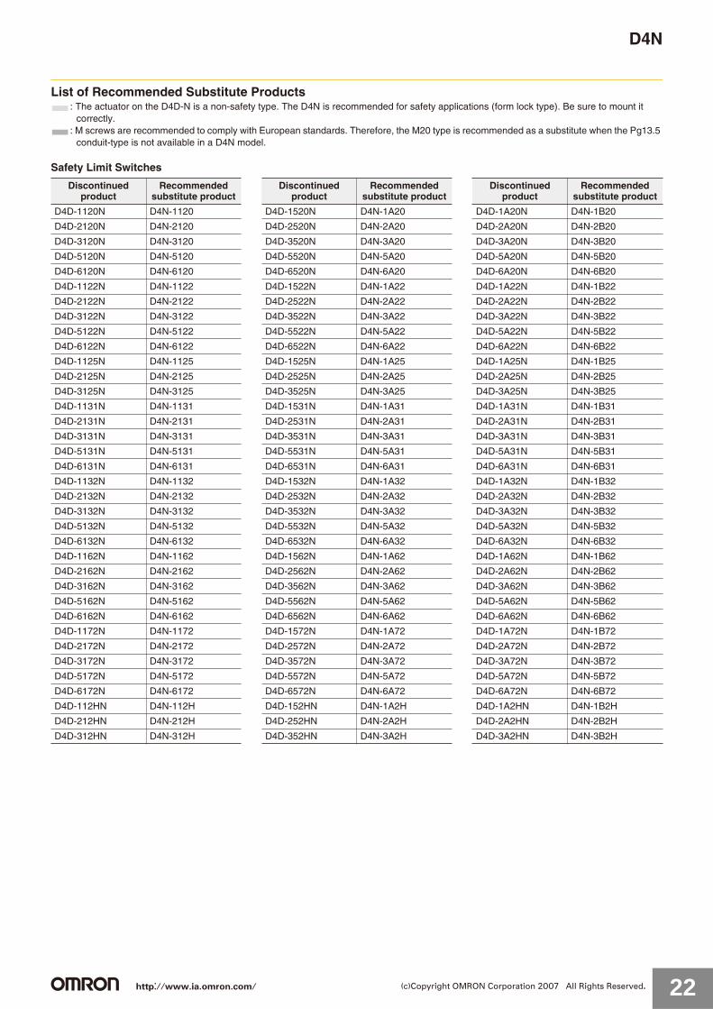
List of Recommended Substitute Products: The actuator on the D4D-N is a non-safety type. The D4N is recommended for safety applications (form lock type). Be sure to mount it
correctly.: M screws are recommended to comply with European standards. Therefore, the M20 type is recommended as a substitute when the Pg13.5
conduit-type is not available in a D4N model.
Safety Limit Switches
Discontinued product
Recommended substitute product
Discontinued product
Recommended substitute product
Discontinued product
Recommended substitute product
D4D-1120N D4N-1120 D4D-1520N D4N-1A20 D4D-1A20N D4N-1B20
D4D-2120N D4N-2120 D4D-2520N D4N-2A20 D4D-2A20N D4N-2B20
D4D-3120N D4N-3120 D4D-3520N D4N-3A20 D4D-3A20N D4N-3B20
D4D-5120N D4N-5120 D4D-5520N D4N-5A20 D4D-5A20N D4N-5B20
D4D-6120N D4N-6120 D4D-6520N D4N-6A20 D4D-6A20N D4N-6B20
D4D-1122N D4N-1122 D4D-1522N D4N-1A22 D4D-1A22N D4N-1B22
D4D-2122N D4N-2122 D4D-2522N D4N-2A22 D4D-2A22N D4N-2B22
D4D-3122N D4N-3122 D4D-3522N D4N-3A22 D4D-3A22N D4N-3B22
D4D-5122N D4N-5122 D4D-5522N D4N-5A22 D4D-5A22N D4N-5B22
D4D-6122N D4N-6122 D4D-6522N D4N-6A22 D4D-6A22N D4N-6B22
D4D-1125N D4N-1125 D4D-1525N D4N-1A25 D4D-1A25N D4N-1B25
D4D-2125N D4N-2125 D4D-2525N D4N-2A25 D4D-2A25N D4N-2B25
D4D-3125N D4N-3125 D4D-3525N D4N-3A25 D4D-3A25N D4N-3B25
D4D-1131N D4N-1131 D4D-1531N D4N-1A31 D4D-1A31N D4N-1B31
D4D-2131N D4N-2131 D4D-2531N D4N-2A31 D4D-2A31N D4N-2B31
D4D-3131N D4N-3131 D4D-3531N D4N-3A31 D4D-3A31N D4N-3B31
D4D-5131N D4N-5131 D4D-5531N D4N-5A31 D4D-5A31N D4N-5B31
D4D-6131N D4N-6131 D4D-6531N D4N-6A31 D4D-6A31N D4N-6B31
D4D-1132N D4N-1132 D4D-1532N D4N-1A32 D4D-1A32N D4N-1B32
D4D-2132N D4N-2132 D4D-2532N D4N-2A32 D4D-2A32N D4N-2B32
D4D-3132N D4N-3132 D4D-3532N D4N-3A32 D4D-3A32N D4N-3B32
D4D-5132N D4N-5132 D4D-5532N D4N-5A32 D4D-5A32N D4N-5B32
D4D-6132N D4N-6132 D4D-6532N D4N-6A32 D4D-6A32N D4N-6B32
D4D-1162N D4N-1162 D4D-1562N D4N-1A62 D4D-1A62N D4N-1B62
D4D-2162N D4N-2162 D4D-2562N D4N-2A62 D4D-2A62N D4N-2B62
D4D-3162N D4N-3162 D4D-3562N D4N-3A62 D4D-3A62N D4N-3B62
D4D-5162N D4N-5162 D4D-5562N D4N-5A62 D4D-5A62N D4N-5B62
D4D-6162N D4N-6162 D4D-6562N D4N-6A62 D4D-6A62N D4N-6B62
D4D-1172N D4N-1172 D4D-1572N D4N-1A72 D4D-1A72N D4N-1B72
D4D-2172N D4N-2172 D4D-2572N D4N-2A72 D4D-2A72N D4N-2B72
D4D-3172N D4N-3172 D4D-3572N D4N-3A72 D4D-3A72N D4N-3B72
D4D-5172N D4N-5172 D4D-5572N D4N-5A72 D4D-5A72N D4N-5B72
D4D-6172N D4N-6172 D4D-6572N D4N-6A72 D4D-6A72N D4N-6B72
D4D-112HN D4N-112H D4D-152HN D4N-1A2H D4D-1A2HN D4N-1B2H
D4D-212HN D4N-212H D4D-252HN D4N-2A2H D4D-2A2HN D4N-2B2H
D4D-312HN D4N-312H D4D-352HN D4N-3A2H D4D-3A2HN D4N-3B2H
http://www.ia.omron.com/ 22(c)Copyright OMRON Corporation 2007 All Rights Reserved.

D4N
General-purpose Limit Switches
Discontinued product
Recommended substitute product
Discontinued product
Recommended substitute product
Discontinued product
Recommended substitute product
D4D-1121N D4N-112G D4D-15REN D4N-1ARE D4D-1AREN D4N-1BRE
D4D-2121N D4N-212G D4D-25REN D4N-2ARE D4D-2AREN D4N-2BRE
D4D-3121N D4N-312G D4D-35REN D4N-3ARE D4D-3AREN D4N-3BRE
D4D-5121N D4N-512G D4D-55REN D4N-5ARE D4D-5AREN D4N-5BRE
D4D-6121N D4N-612G D4D-65REN D4N-6ARE D4D-6AREN D4N-6BRE
D4D-1127N D4N-112H D4D-15LEN D4N-1ALE D4D-1ALEN D4N-1BLE
D4D-2127N D4N-212H D4D-25LEN D4N-2ALE D4D-2ALEN D4N-2BLE
D4D-3127N D4N-312H D4D-35LEN D4N-3ALE D4D-3ALEN D4N-3BLE
D4D-5127N D4N-512H D4D-55LEN D4N-5ALE D4D-5ALEN D4N-5BLE
D4D-6127N D4N-612H D4D-65LEN D4N-6ALE D4D-6ALEN D4N-6BLE
D4D-1180N D4N-4180 D4D-1521N D4N-1A2G D4D-1A21N D4N-1B2G
D4D-2180N D4N-2180 D4D-2521N D4N-2A2G D4D-2A21N D4N-2B2G
D4D-3180N D4N-3180 D4D-3521N D4N-3A2G D4D-3A21N D4N-3B2G
D4D-5180N D4N-8180 D4D-5521N D4N-5A2G D4D-5A21N D4N-5B2G
D4D-6180N D4N-6180 D4D-6521N D4N-6A2G D4D-6A21N D4N-6B2G
D4D-1187N D4N-4187 D4D-1527N D4N-1A2H D4D-1A27N D4N-1B2H
D4D-2187N D4N-2187 D4D-2527N D4N-2A2H D4D-2A27N D4N-2B2H
D4D-3187N D4N-3187 D4D-3527N D4N-3A2H D4D-3A27N D4N-3B2H
D4D-5187N D4N-8187 D4D-5527N D4N-5A2H D4D-5A27N D4N-5B2H
D4D-6187N D4N-6187 D4D-6527N D4N-6A2H D4D-6A27N D4N-6B2H
D4D-1A80N D4N-4B80
D4D-2A80N D4N-2B80
D4D-3A80N D4N-3B80
D4D-5A80N D4N-8B80
D4D-6A80N D4N-6B80
D4D-1A87N D4N-4B87
D4D-2A87N D4N-2B87
D4D-3A87N D4N-3B87
D4D-5A87N D4N-8B87
D4D-6A87N D4N-6B87
http://www.ia.omron.com/ 23(c)Copyright OMRON Corporation 2007 All Rights Reserved.

Precautions for All Safety Limit SwitchesNote: Refer to the “Safety Precautions” section for each Switch for specific precautions applicable to each Switch.
Do not use the Switch in atmospheres containing explosive or flammable gases.Although the switch box is protected from dust or water penetration, the head is not protected from minute foreign matter or water penetration. Ensure that minute foreign matter and water do not penetrate the head. Failure to do so may result in accelerated wear, Switch damage, or malfunctioning.The durability of the Switch varies considerably depending on the switching conditions. Always confirm the usage conditions by using the Switch in an actual application, and use the Switch only for the number of switching operations that its performance allows.Do not use the Switch as a stopper.Do not use the Switch in a startup circuit. Use it instead for a safety confirmation signal.Check the Switches before use and inspect regularly, replacing them when necessary. If a Switch is kept pressed for an extended period of time, the components may deteriorate quickly, and the Switch may not release.To protect the Switch from damage due to short-circuits, be sure to connect a quick-response fuse with a breaking current 1.5 to 2 times larger than the rated current in series with the Switch. When complying with EN certified ratings, use a 10 A IEC 60269-compliant gI or gG fuse.Do not drop the Switch. Doing so may prevent it from functioning to its full capacity. Do not disassemble or modify the Switch. Doing so may prevent it from operating correctly.
Mechanical CharacteristicsOperating Force, Stroke, and Contact Characteristics
The following graph indicates the relationship between operating force and stroke or stroke and contact force. In order to operate the Limit Switch with high reliability, it is necessary to use the Limit Switch within an appropriate contact force range. If the Limit Switch is used in the normally closed condition, the dog must be installed so that the actuator will return to the FP when the actuator is actuated by the object. If the Limit Switch is used in the normally open condition, the actuator must be pressed to 80% to 100% of the OT (i.e., 60% to 80% of the TT) and any slight fluctuation must be absorbed by the actuator.If the full stroke is set close to the OP or RP, contact instability may result. If the full stroke is set to the TTP, the actuator or switch may become damaged due to the inertia of the dog. In that case, adjust the stroke with the mounting panel or the dog. Refer to page C-2,Dog Design, page C-3, Stroke Settings vs. Dog Movement Distance, and page C-3, Dog Surface for details.The following graph shows an example of changes in contact force according to the stroke. The contact force near the OP or RP is unstable, and the Limit Switch cannot maintain high reliability. Furthermore, the Limit Switch cannot withstand strong vibration or shock.
If the Limit Switch is used so that the actuator is constantly pressed, it will fail quickly and reset faults may occur. Inspect the Limit Switch periodically and replace it as required.
OperationCarefully determine the proper cam or dog so that the actuator will not abruptly snap back, thus causing shock. In order to operate the Limit Switch at a comparatively high speed, use a cam or dog with a long enough stroke that keeps the Limit Switch turned ON for a sufficient time so that the relay or valve will be sufficiently energized.The operating method, the shape of the dog or cam, the operating frequency, and the travel after operation have a large influence on the durability and operating accuracy of the Limit Switch. The cam must be smooth in shape.
Appropriate force must be imposed on the actuator by the cam or another object in both rotary operation and linear operation. If the object touches the lever as shown below, the operating position will not be stable.
Precautions for Safe Use
Precautions for Correct Use
Operating force
Contact force
FPChanges to opposite side
Changes to opposite sideOTP
Stroke
Stroke
Snappedback
Abruptlyactuated
Incorrect Correct
Snappedback Abruptly
actuated
Incorrect Correct
Dog Dog
Incorrect Correct
http://www.ia.omron.com/ C-1(c)Copyright OMRON Corporation 2007 All Rights Reserved.

Precautions for All Safety Limit Switches
Unbalanced force must not be imposed on the actuator. Otherwise, wear and tear on the actuator may result.
Make sure that the actuator does not exceed the OT (overtravel) range, otherwise the Limit Switch may malfunction. When mounting the Limit Switch, be sure to adjust the Limit Switch carefully while considering the whole movement of the actuator.
The Limit Switch may soon malfunction if the OT is excessive. Therefore, adjustments and careful consideration of the position of the Limit Switch and the expected OT of the actuator are necessary when mounting the Limit Switch.
Be sure to use the Limit Switch according to the characteristics of the actuator. If a roller arm lever actuator is used, do not attempt to actuate the Limit Switch in the direction shown below.
Do not modify the actuator to change the OP.In the case of a long actuator of an adjustable roller lever type, the following countermeasures against lever shaking are recommended.
1. Make the rear edge of the object smooth with an angle of 15 to 30or make it in the shape of a quadratic curve.
2. Design the circuit so that no error signal will be generated.3. Use or set a switch that is actuated in one direction only.
(Also, set the switch for operation in one direction only.)
Operating EnvironmentThese Switches are for indoor applications. The Switches may fail if they are used outdoors.Do not use the Switch in locations where toxic gases, such as H2S,SO2, NH3, HNO3, and Cl2, may be present, or in locations that are subject to high temperatures or humidity. Doing so may damage the Switch due to contact failure or corrosion.Do not use the Switches in the following locations.· Locations subject to severe temperature changes·Locations subject to high temperatures or condensation· Locations subject to severe vibration· Locations where the interior of the Protective Door may come into direct contact with cutting chips, metal filings, oil, or chemicals
· Locations where the Switch may come into contact with thinner or detergents
· Locations where explosive or flammable gases are present
Switch ContactsSwitch contacts can be used with both standard loads and microloads, but once a contact has been used to switch a standard load, it cannot be used for a load of a smaller capacity. Doing so may result in roughening of the contact surface and contact reliability may be lost.
Storing SwitchesDo not store the Switch in locations where toxic gases, such as H2S,SO2, NH3, HNO3, and Cl2, may be present, or in locations that are subject to, excessive dirt, excessive dust, high temperature, or high humidity.
Other PrecautionsWhen attaching a cover, be sure that the seal rubber is in place and that there is no foreign material present. If the cover is attached with the seal rubber out of place or if foreign material is stuck to the rubber, a proper seal will not be obtained.Perform maintenance inspections periodically. Use the Switch with a load current that does not exceed the rated current. Do not use any screws to connect the cover other than the specified ones. The seal characteristics may be reduced.
Dog DesignOperating Speed, Dog Angle, and Relationship with ActuatorBefore designing a dog, carefully consider the operating speed and angle of the dog and their relationship with the shape of the actuator. The optimum operating speed (V) of a standard dog at an angle of 30to 45 is 0.5 m/s maximum.
Roller Lever Models1. Non-overtravel Dog
Dog Dog
Incorrect Correct
Roller Roller
Dog
Install a stopper.
PT (Pretravel)
FP (Free position)OP (Operating position)
OT (Overtravel)
80% of rated OT
100% of rated OT
TTP (Total travel position)
Distance to the optimumsetting range.
Optimum setting range
Reference line
Correct
Stopper
Incorrect
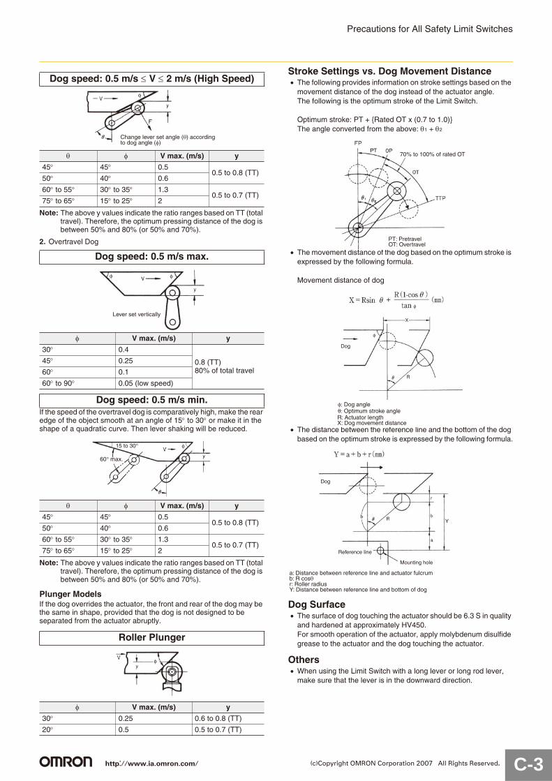
Dog speed: 0.5 m/s max. (Standard Speed)
V max. (m/s) y
30 0.4
0.8 (TT)80% of totaltravel
45 0.25
60 0.1
60 to 90 0.05 (low speed)
Lever set vertically
φ
http://www.ia.omron.com/ C-2(c)Copyright OMRON Corporation 2007 All Rights Reserved.
Precautions for All Safety Limit Switches
Note: The above y values indicate the ratio ranges based on TT (total travel). Therefore, the optimum pressing distance of the dog is between 50% and 80% (or 50% and 70%).
2. Overtravel Dog
If the speed of the overtravel dog is comparatively high, make the rear edge of the object smooth at an angle of 15 to 30 or make it in the shape of a quadratic curve. Then lever shaking will be reduced.
Note: The above y values indicate the ratio ranges based on TT (total travel). Therefore, the optimum pressing distance of the dog is between 50% and 80% (or 50% and 70%).
Plunger ModelsIf the dog overrides the actuator, the front and rear of the dog may be the same in shape, provided that the dog is not designed to be separated from the actuator abruptly.
Stroke Settings vs. Dog Movement DistanceThe following provides information on stroke settings based on the movement distance of the dog instead of the actuator angle.The following is the optimum stroke of the Limit Switch.
Optimum stroke: PT + {Rated OT x (0.7 to 1.0)}The angle converted from the above: 1 + 2
The movement distance of the dog based on the optimum stroke is expressed by the following formula.
Movement distance of dog
The distance between the reference line and the bottom of the dog based on the optimum stroke is expressed by the following formula.
Dog SurfaceThe surface of dog touching the actuator should be 6.3 S in quality and hardened at approximately HV450.For smooth operation of the actuator, apply molybdenum disulfide grease to the actuator and the dog touching the actuator.
OthersWhen using the Limit Switch with a long lever or long rod lever, make sure that the lever is in the downward direction.
Dog speed: 0.5 m/s V 2 m/s (High Speed)
V max. (m/s) y
45 45 0.50.5 to 0.8 (TT)
50 40 0.6
60 to 55 30 to 35 1.30.5 to 0.7 (TT)
75 to 65 15 to 25 2
Dog speed: 0.5 m/s max.
V max. (m/s) y
30 0.4
0.8 (TT)80% of total travel
45 0.25
60 0.1
60 to 90 0.05 (low speed)
Dog speed: 0.5 m/s min.
V max. (m/s) y
45 45 0.50.5 to 0.8 (TT)
50 40 0.6
60 to 55 30 to 35 1.30.5 to 0.7 (TT)
75 to 65 15 to 25 2
Roller Plunger
V max. (m/s) y
30 0.25 0.6 to 0.8 (TT)
20 0.5 0.5 to 0.7 (TT)
Change lever set angle (θ) according to dog angle (φ)
φ
Lever set vertically
φφ
60° max.
15 to 30° φ
φ
70% to 100% of rated OT
PT: PretravelOT: Overtravel
Dog
φ: Dog angleθ: Optimum stroke angleR: Actuator lengthX: Dog movement distance
φ
φ
Dog
Reference line
Mounting hole
a: Distance between reference line and actuator fulcrumb: R cosθr: Roller radiusY: Distance between reference line and bottom of dog
Y
http://www.ia.omron.com/ C-3(c)Copyright OMRON Corporation 2007 All Rights Reserved.
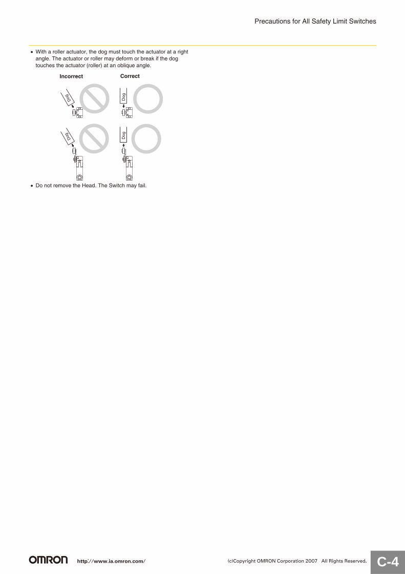
Precautions for All Safety Limit Switches
With a roller actuator, the dog must touch the actuator at a right angle. The actuator or roller may deform or break if the dog touches the actuator (roller) at an oblique angle.
Do not remove the Head. The Switch may fail.
Dog
Dog
Dog
Dog
Incorrect Correct
http://www.ia.omron.com/ C-4(c)Copyright OMRON Corporation 2007 All Rights Reserved.

Precautions for All SwitchesRefer to the Safety Precautions section for each Switch for specific precautions applicable to each Switch.
If the Switch is to be used as a switch in an emergency stop circuit or in a safety circuit for preventing accidents resulting in injuries or deaths, use a Switch with a direct opening mechanism, use the NC contacts with a forced release mechanism, and set the Switch so that it will operate in direct opening mode.For safety, install the Switch using one-way rotational screws or other similar means to prevent it from easily being removed. Protect the Switch with an appropriate cover and post a warning sign near the Switch to ensure safety.Do not perform wiring while power is being supplied. Wiring while the power is being supplied may result in electric shock. Keep the electrical load below the rated value.Be sure to evaluate the Switch under actual working conditions after installation.Do not touch the charged Switch terminals while the Switch has carry current, otherwise an electric shock may be received.If the Switch has a ground terminal, be sure to connect the ground terminal to a ground wire.The durability of the Switch greatly varies with switching conditions. Before using the Switch, be sure to test the Switch under actual conditions. Make sure that the number of switching operations is within the permissible range.If a deteriorated Switch is used continuously, insulation failures, contact welding, contact failures, Switch damage, or Switch burnout may result.Maintain an appropriate insulation distance between wires connected to the Switch.Some types of load have a great difference between normal current and inrush current. Make sure that the inrush current is within the permissible value. The greater the inrush current in the closed circuit is, the greater the contact abrasion or shift will be. Consequently, contact welding, contact separation failures, or insulation failures may result. Furthermore, the Switch may become broken or damaged.
The user must not attempt to repair or maintain the Switch and must contact the machine manufacturer for any repairs or maintenance.Do not attempt to disassemble or modify the Switch. Doing so may cause the Switch to malfunction.Do not drop the Switch. Doing so may result in the Switch not performing to its full capability.
WiringPay the utmost attention so that each terminal is wired correctly. If the terminal is wired incorrectly, the Switch will not function. Furthermore, not only will the Switch have a negative influence on the external circuit, the Switch itself may become damaged or burnt.
MountingDo not modify the Actuator, otherwise the operating characteristicsand performance of the Actuator will change.Do not enlarge the mounting holes of the Switch or modify the Switch, otherwise insulation failures, housing damage, or human accidents may result.Do not apply oil, grease, or other lubricants to the moving parts of the Actuator, otherwise the Actuator may not operate correctly. Furthermore, ingress of oil, grease, or other lubricants inside the Switch may reduce sliding characteristic or cause failures in the Switch.Mount the Switch and secure it with the specified screws tightened to the specified torque along with flat and spring washers.Be sure to wire the Switch so that the conduit opening is free of metal powder or any other impurities.If glue or bonding agent is applied, make sure that it does not adhere to the movable parts or enter the Switch, otherwise the Switch may not work correctly or cause contact failure. Some types of glue or bonding agent may generate a gas that may have a negative influence on the Switch. Pay the utmost attention when selecting the glue or locking agent.Some models allow changes in the head direction. When changing the head of such a model, make sure that the head is free of any foreign substance. Tighten each screw of the head to the rated torque.Be sure to take measures so that no foreign material, oil, or water will enter the Switch through the conduit opening. Be sure to attach a connector suitable for the cable thickness and tighten the connector securely to the rated torque.Do not impose shock or vibration on the Actuator while it is fully pressed. Otherwise, the Actuator will partially abrade and an actuation failure may result.
Precautions for Safe Use
i (Inrush current)
io (Constant current)
t
I(A)
http://www.ia.omron.com/ C-5(c)Copyright OMRON Corporation 2007 All Rights Reserved.

Precautions for All Switches
Switch OperationThe Switch in actual operation may cause accidents that cannot be foreseen from the design stage. Therefore, the Switch must be practically tested before actual use.When testing the Switch, be sure to apply the actual load conditions together with the actual operating environment.All the performance ratings in this catalog are provided under the following conditions unless otherwise specified.
Inductive load:A minimum power factor of 0.4 (AC) or a maximum time constant of 7 ms (DC)
Lamp load: An inrush current 10 times higher than the normal current
Motor load: An inrush current 6 times higher than the normal current
1. Ambient temperature: 5 C to 35 C2. Ambient humidity: 40% to 70%.
Note: An inductive load causes a problem especially in DC circuitry. Therefore, it is essential to know the time constants (L/R) of the load.
Mechanical Conditions for Switch SelectionAn Actuator suitable for the operating method must be selected. Ask your OMRON representative for details. Check the operating speed and switching frequency.1. If the operating speed is extremely low, switching of the
movable contact will become unstable, thus resulting in incorrect contact or contact welding.
2. If the operating speed is extremely high, the Switch may break due to shock. If the switching frequency is high, the switching of the contacts cannot keep up with the switching frequency. Make sure that the switching frequency is within the rated switching frequency.
Do not impose excessive force on the Actuator, otherwise the Actuator may become damaged or not operate correctly.Make sure that the stroke is set within the suitable range specified for the model, or otherwise the Switch may break.
Electrical Characteristics for Switch SelectionElectrical Conditions
The switching load capacity of the Switch greatly varies between AC and DC. Always be sure to apply the rated load. The control capacity will drastically drop if it is a DC load. This is because a DC load has no current zero-cross point, unlike an AC load. Therefore, if an arc is generated, it may continue comparatively for a long time. Furthermore, the current direction is always the same, which results in contact relocation, whereby the contacts easily stick to each other and do not separate when the surfaces of the contacts are uneven.
If the load is inductive, counter-electromotive voltage will be generated. The higher the voltage is, the higher the generated energy will be, which will increase the abrasion of the contacts and contact relocation load conditions. Be sure to use the Switch within the rated conditions.If the load is a minute voltage or current load, use a Switch designed for minute loads. The reliability of silver-plated contacts, which are used by standard Switches, will be insufficient if the load is a minute voltage or current load.
ConnectionsWith a Za contact form, do not contact a single Switch to two power supplies that are different in polarity or type.
Do not use a circuit that will short-circuit if a fault occurs, otherwise the charged part may melt and break off.
Application of Switch to a Low-voltage, Low-current Electronic Circuit.1. If bouncing or chattering of the contacts results and causes
problems, take the following countermeasures.(a) Insert an integral circuit.(b) Suppress the generation of pulses from the contact bouncing
or chattering of the contacts so that it is less than the noise margin of the load.
2. Conventional silver-plated contacts are not suitable for this application, in which particularly high reliability is required. Use gold-plated contacts, which are ideal for handling minute voltage or current loads.
3. The contacts of the Switch used for an emergency stop must be normally closed with a positive opening mechanism.
To protect the Switch from damage due to short-circuits, be sure to connect in series a quick-response fuse with a breaking current 1.5 to 2 times larger than the rated current to the Switch. When complying with EN certified ratings, use a 10-A IEC 60269-compliant gI or gG fuse.
Precautions for Correct Use
Solenoids(Approximately 10 to 20 times higher)
Incandescentlamps (Approximately 10 to 15 times higher)
Motors(Approximately 5 to 10 times higher)
Relays (Approxi-mately 4 to 5 times higher)
t
I(A)
Power Connection Examples(Connection of Different Polarities)
Incorrect Power Connection Example(Connection of Different Power Supplies)There is a risk of AC and DC mixing.
NC
NO
NC
NO
Incorrect
Correct
Connect the load to the same polarities.
NC
NO
L
L
AC
DC
Incorrect
NC
NO
NC
NO
LL
Incorrect
http://www.ia.omron.com/ C-6(c)Copyright OMRON Corporation 2007 All Rights Reserved.

Precautions for All Switches
Contact Protection CircuitsUsing a contact protection circuit to increase the contact durability, prevent noise, and suppress the generation of carbide or nitric acid. Be sure to apply the contact protection circuit correctly, otherwise adverse results may occur.The following tables shows typical examples of contact protection circuits. If the Switch is used in an excessively humid location for
switching a load that easily generates arcs, such as an inductive load, the arcs may generate NOx, which will change into HNO3 when it reacts with moisture. Consequently, the internal metal parts may corrode and the Switch may fail. Be sure to select the best contact protection circuit from the following table.
Typical Examples of Contact Protection Circuits
Do not use the following types of contact protection circuit.
Using Switches for MicroloadsContact failure may occur if a Switch for a general load is used to switch a microload circuit. Use Switches in the ranges shown in the diagram right. However, even when using microload models within the operating range shown here, if inrush current occurs when the contact is opened or closed, it may increase contact wear and so decrease durability. Therefore, insert a contact protection circuit where necessary. The minimum applicable load is the N-level reference value. This value indicates the malfunction reference level for the reliability level of 60% ( 60) (JIS C5003). The equation, 60 = 0.5×10 6/operations indicates that the estimated malfunction rate is less than 1/2,000,000 operations with a reliability level of 60%.
Circuit exampleApplicable
current Features and remarks Element selectionAC DC
CR
*(Yes) Yes
* Load impedance must be much smaller than the CR circuit impedance when using the Switch for an AC voltage.
Use the following as guides for C and R values:
C: 1 to 0.5 F per 1 A of contact current (A)R: 0.5 to 1 per 1 V of contact voltage (V)
These values depend on various factors, including the load characteristics. Confirm optimum values experimentally.Capacitor C suppresses the discharge when the contacts are opened, while the resistor R limits the current applied when the contacts are closed the next time. Generally, use a capacitor with a low dielectric strength of 200 to 300 V. For applications in an AC circuit, use an AC capacitor (with no polarity).
Yes Yes
The operating time of the contacts will be increased if the load is a Relay or solenoid. Connecting the CR circuit in parallel to the load is effective when the power supply voltage is 24 or 48 V and in parallel to the contacts when the power supply voltage is 100 to 200 V.
Diode No Yes
The energy stored in the coil reaches the coil as current via the diode connected in parallel, and is dissipated as Joule heat by the resistance of the inductive load. This type of circuit increases the release time more than the CR type.
Use a diode having a reverse breakdown voltage of more than 10 times the circuit voltage, and a forward current rating greater than the load current.
Diode + Zener diode No Yes
This circuit effectively shortens the reset time in applications where the release time of a diode circuit is too slow.
Use a Zener diode with a low breakdown voltage.
Varistor Yes Yes
This circuit prevents a high voltage from being applied across the contacts by using the constant-voltage characteristic of a varistor. This circuit also somewhat increases the reset time. Connecting the varistor across the load is effective when the supply voltage is 24 to 48 V, and across the contacts when the supply voltage is 100 to 200 V.
---
Powersupply
Inductiveload
C R
Powersupply
C
R
Inductiveload
Powersupply
Inductiveload
Powersupply
Inductiveload
Powersupply
Inductiveload
Although it is thought that switching a DC inductive load is more difficult than a resistive load, an appropriate contact protection circuit can achieve almost the same characteristics.
Powersupply
CLoad
This circuit arrangement is very effective for diminishing arcing at the contacts when breaking the circuit. However, since electrical energy is stored in C (capacitor) when the contacts are open, the current from C flows into the contacts when they close. This may lead to contact welding.
Powersupply
C Load
This circuit arrangement is very useful for diminishing arcing at the contacts when breaking the circuit. However, since the charging currentto C flows into the contacts whenthey are closed, contact weldingmay occur.
Vol
tage
(V
DC
)
30
24
12
5
01 10 100 1,000 Current (mA)0.1
1 mA
Operatingrange for standardmodels
Operating range for micro-load models
26 mA0.16 mA
800 mW5 mW
100 mA 160 mA
Unusablerange
http://www.ia.omron.com/ C-7(c)Copyright OMRON Corporation 2007 All Rights Reserved.

Precautions for All Switches
Operating EnvironmentThe Switches are designed for use indoors. Using a Switch outdoors may cause it to malfunction.Do not use the Switch submerged in oil or water, or in locations continuously subject to splashes of water. Doing so may result in oil or water entering the Switch interior.Confirm suitability (applicability) in advance before using the Switch where it would be subject to oil, water, chemicals, or detergents. Contact with any of these may result in contact failure, insulation failure, earth leakage faults, or burning. Do not use the Switch in the following locations:• Locations subject to corrosive gases• Locations subject to severe temperature changes• Locations subject to high humidity, resulting in condensation• Locations subject to severe vibration• Locations subject to cutting chips, dust, or dirt• Locations subject to high humidity or high temperatureUse protective covers to protect Switches that are not specified as waterproof or airtight whenever they are used in locations subject to splattering or spraying oil or water, or to accumulation of dust or dirt.
Be sure to install the Switch so that the Switch is free from dust or metal powder. The Actuator and the Switch casing must be protected from the accumulation of dust or metal powder.
Do not use the Switch in locations where the Switch is exposed to steam or hot water at a temperature greater than 60 C.Do not use the Switch under temperatures or other environmental conditions not within the specified ranges. The rated permissible ambient temperature range varies with the model. Refer to the Specifications in this catalog.If the Switch is exposed to radical temperature changes, the thermal shock may deform the Switch and the Switch may malfunction.
Be sure to protect the Switch with a cover if the Switch is in a location where the Switch may be actuated by mistake or where the Switch is likely cause an accident.
Make sure to install the Switch in locations free of vibration or shock. If vibration or shock is continuously imposed on the Switch, contact failure, malfunction, or decrease in service life may be caused by abrasive powder generated from the internal parts. If excessive vibration or shock is imposed on the Switch, the contacts may malfunction or become damaged.Do not use the Switch with silver-plated contacts for long periods if the switching frequency of the Switch is comparatively low or the load is minute. Otherwise, sulfuric film will be generated on the contacts and contact failures may result. Use the Switch with gold-plated contacts or use a Switch designed for minute loads instead.Do not use the Switch in locations with corrosive gas, such as sulfuric gas (H2S or SO2), ammonium gas (NH3), nitric gas (HNO3),or chlorine gas (Cl2), or high temperature and humidity. Otherwise, contact failure or corrosion damage may result.If the Switch is used in locations with silicone gas, arc energy may create silicon dioxide (SiO2) on the contacts and a contact failure may result. If there is silicone oil, silicone sealant, or wire covered with silicone close to the Switch, attach a contact protection circuit to suppress the arcing of the Switch or eliminate the source of silicone gas generation.
Regular Inspection and ReplacementIf the Switch is normally closed with low switching frequency (e.g., once or less per day), a reset failure may result due to the deterioration of the parts of the Switch. Regularly inspect the Switch and make sure that the Switch is in good working order.In addition to the mechanical durability or electrical durability of the Switch described previously, the durability of the Switch may decrease due to the deterioration of each part, especially rubber, resin, and metal. Regularly inspect the Switch and replace any part that has deteriorated to prevent accidents from occurring.If the Switch is not turned ON and OFF for a long period of time, contact reliability may be reduced due to contact oxidation. Continuity failure may result in accidents (i.e., the switch may not turn ON due to increased contact resistance.)Be sure to mount the Switch securely in a clean location to ensure ease of inspection and replacement. The Switch with operation indicator is available, which is ideal if the location is dark or does not allow easy inspection or replacement.
Storage of SwitchWhen storing the Switch, make sure that the location is free of corrosive gas, such as H2S, SO2, NH3, HNO3, or Cl2, or dust and does not have a high temperature or humidity.Be sure to inspect the Switch before use if it has been stored for three months or more.
Incorrect Correct
Terminal boxTerminal box
Incorrect Correct
Incorrect Correct Separate the Switchfrom heat sources
Incorrect Correct
Prevent false operation
Difficult to inspect or install
The cover must be locatedin the direction ensuringease of maintenance or inspection.
Easy to inspectIncorrect Correct
http://www.ia.omron.com/ C-8(c)Copyright OMRON Corporation 2007 All Rights Reserved.
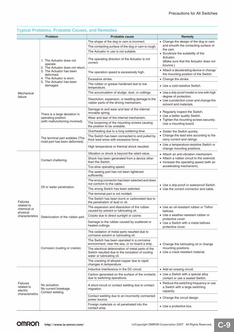
Precautions for All Switches
Typical Problems, Probable Causes, and RemediesProblem Probable cause Remedy
Mechanical failure
1. The Actuator does not operate.
2. The Actuator does not return.3. The Actuator has been
deformed.4. The Actuator is worn.5. The Actuator has been
damaged.
The shape of the dog or cam is incorrect. Change the design of the dog or cam and smooth the contacting surface of the cam.Scrutinize the suitability of the Actuator.(Make sure that the Actuator does not bounce.)
The contacting surface of the dog or cam is rough.
The Actuator in use is not suitable.
The operating direction of the Actuator is not correct.
The operation speed is excessively high.Attach a decelerating device or change the mounting position of the Switch.
Excessive stroke. Change the stroke.
The rubber or grease hardened due to low temperature. Use a cold-resistive Switch.
The accumulation of sludge, dust, or cuttings. Use a drip-proof model or one with high degree of protection.Use a protection cover and change the solvent and materials.
Dissolution, expansion, or swelling damage to the rubber parts of the driving mechanism.
There is a large deviation in operating position (with malfunctioning involved).
Damage to and wear and tear of the internal movable spring. Regularly inspect the Switch.
Use a better quality Switch.Tighten the mounting screws securely. Use a mounting board.
Wear and tear of the internal mechanism.
The loosening of the mounting screws causing the position to be unstable.
The terminal part wobbles (The mold part has been deformed).
Overheating due to a long soldering time. Solder the Switch quickly.Change the lead wire according to the carry current and ratings.
The Switch has been connected to and pulled by thick lead wires with excessive force.
High temperature or thermal shock resulted.Use a temperature-resistive Switch or change mounting positions.
Failures related to chemical or physical characteristics
Contact chattering.
Vibration or shock is beyond the rated value. Attach an anti-vibration mechanism.Attach a rubber circuit to the solenoid.Increase the operating speed (with an accelerating mechanism).
Shock has been generated from a device other than the Switch.
Too-slow operating speed.
Oil or water penetration.
The sealing part has not been tightened sufficiently.
Use a drip-proof or waterproof Switch.Use the correct connector and cable.
The wrong connector has been selected and does not conform to the cable.
The wrong Switch has been selected.
The terminal part is not molded.
The Switch has been burnt or carbonated due to the penetration of dust or oil.
Deterioration of the rubber part.
The expansion and dissolution of the rubber caused by solvent or lubricating oil.
Use an oil-resistant rubber or Teflon bellows.Use a weather-resistant rubber or protective cover.Use a Switch with a metal bellows protective cover.
Cracks due to direct sunlight or ozone.
Damage to the rubber caused by scattered or heated cuttings.
Corrosion (rusting or cracks).
The oxidation of metal parts resulted due to corrosive solvent or lubricating oil.
Change the lubricating oil or change mounting positions.Use a crack-resistant material.
The Switch has been operated in a corrosive environment, near the sea, or on board a ship.
The electrical deterioration of metal parts of the Switch resulted due to the ionization of cooling water or lubricating oil.
The cracking of alloyed copper due to rapid changes in temperature.
Failures related to electric characteristics
No actuation.No current breakage.Contact welding.
Inductive interference in the DC circuit. Add an erasing circuit.
Carbon generated on the surface of the contacts due to switching operations.
Use a Switch with a special alloy contact or use a sealed Switch.
A short-circuit or contact welding due to contact migration.
Reduce the switching frequency or use a Switch with a large switching capacity.
Contact welding due to an incorrectly connected power source. Change the circuit design.
Foreign materials or oil penetrated into the contact area. Use a protective box.
http://www.ia.omron.com/ C-9(c)Copyright OMRON Corporation 2007 All Rights Reserved.

Precautions for All Switches
OtherThe standard material for the Switch seal is nitrile rubber (NBR), which has superior resistance to oil. Depending on the type of oil or chemicals in the application environment, however, NBR may deteriorate, e.g., swell or shrink. Confirm performance in advance. The correct Switch must be selected for the load to ensure contact reliability. Refer to Precautions for microloads in individual product information for details. Wire the leads as shown in the following diagram.
Correct Wiring
Incorrect Wiring
Correct
Crimp terminal
Crimped locationfacing up Lead
Terminal screw
Terminal screw
Terminal Terminal
Incorrect
Crimp terminal
Crimped location facing down Lead
Terminal screw
Terminal screw
Terminal TerminalToo close to maintaindielectric strength
http://www.ia.omron.com/ C-10(c)Copyright OMRON Corporation 2007 All Rights Reserved.
This catalog is a guide to help customers select the proper safety products. Observe the following items when choosing products, select the right products for your devices or equipment, and develop a safety-related system to fully utilize product functions.
Setting Up a Risk Assessment System The items listed in this catalog must be used properly in terms of product location as well as product performance and functionality. Part of the process of selecting and using these products should include the introduction and development of a risk assessment system early in the design development stage to help identify potential dangers in your equipment that will optimize safety product selection. A badly designed risk assessment system often results in poor choices when it comes to safety products.• Related International Standards: ISO 14121 Principles of Risk Assessment
Safety PolicyWhen developing a safety system for the devices and equipment that use safety products, make every effort to understand and conform to the entire series of international and industrial standards available, such as the examples given below.• Related International Standards: ISO 12100 Basic Concepts, General Principles for Design IEC 61508 Functional Safety of Electrical/Electronic/Programmable Electronic Safety-related Systems
Role of Safety ProductsSafety products have functions and mechanisms that ensure safety as defined by standards. These functions and mechanisms are designed to attain their full potential within safety-related systems. Make sure you fully understand all functions and mechanisms, and use that understanding to develop systems that will ensure optimal usage.• Related International Standards: ISO 14119 Interlocking Devices Associated with Guards-Principles for Design and Selection
Installing Safety ProductsMake sure that properly educated and trained engineers are selected to develop your safety-related system and to install safety products in devices and equipment.• Related International Standards: ISO 12100 Basic Concepts, General Principles for Design IEC 61508 Functional Safety of Electrical/Electronic/Programmable Electronic Safety-related Systems
Observing Laws and RegulationsSafety products should conform to pertinent laws, regulations, and standards, but make sure that they are used in accordance with the laws, regulations, and standards of the country where the devices and equipment incorporating these products are distributed.• Related International Standards: IEC 60204 Electrical Equipment of Machines
Observing Usage PrecautionsCarefully read the specifications and precautions listed in this catalog for your product as well as all items in the Operating Manual packed with the product to learn usage procedures that will optimize your choice. Any deviation from precautions will lead to unexpected device or equipment failure not anticipated by safety-related systems or fire originating from equipment failure.
Transferring Devices and EquipmentWhen transferring devices and equipment, be sure to keep one copy of the Operating Manual and pack another copy with the device or equipment so the person receiving it will have no problem operating it.• Related International Standards: ISO 12100 Basic Concepts, General Principles for Design IEC 61508 Functional Safety of Electrical/Electronic/Programmable Electronic Safety-related Systems
WARNING
http://www.ia.omron.com/ (c)Copyright OMRON Corporation 2007 All Rights Reserved.

2007.11
OMRON CorporationIndustrial Automation Company
http://www.ia.omron.com/ (c)Copyright OMRON Corporation 2007 All Rights Reserved.
In the interest of product improvement, specifications are subject to change without notice.
Read and Understand This Catalog
Please read and understand this catalog before purchasing the products. Please consult your OMRON representative if you have any questions or comments.
Warranty and Limitations of LiabilityWARRANTYOMRON's exclusive warranty is that the products are free from defects in materials and workmanship for a period of one year (or other period if specifi ed) from date of sale by OMRON.
OMRON MAKES NO WARRANTY OR REPRESENTATION, EXPRESS OR IMPLIED, REGARDING NON-INFRINGEMENT, MERCHANTABILITY, OR FITNESS FOR PARTICULAR PURPOSE OF THE PRODUCTS. ANY BUYER OR USER ACKNOWLEDGES THAT THE BUYER OR USER ALONE HAS DETERMINED THAT THE PRODUCTS WILL SUITABLY MEET THE REQUIREMENTS OF THEIR INTENDED USE. OMRON DISCLAIMS ALL OTHER WARRANTIES, EXPRESS OR IMPLIED.
LIMITATIONS OF LIABILITYOMRON SHALL NOT BE RESPONSIBLE FOR SPECIAL, INDIRECT, OR CONSEQUENTIAL DAMAGES, LOSS OF PROFITS, OR COMMERCIAL LOSS IN ANY WAY CONNECTED WITH THE PRODUCTS, WHETHER SUCH CLAIM IS BASED ON CONTRACT, WARRANTY, NEGLIGENCE, OR STRICT LIABILITY.
In no event shall responsibility of OMRON for any act exceed the individual price of the product on which liability is asserted.
IN NO EVENT SHALL OMRON BE RESPONSIBLE FOR WARRANTY, REPAIR, OR OTHER CLAIMS REGARDING THE PRODUCTS UNLESS OMRON'S ANALYSIS CONFIRMS THAT THE PRODUCTS WERE PROPERLY HANDLED, STORED, INSTALLED, AND MAINTAINED AND NOT SUBJECT TO CONTAMINATION, ABUSE, MISUSE, OR INAPPROPRIATE MODIFICATION OR REPAIR.
Application ConsiderationsSUITABILITY FOR USEOMRON shall not be responsible for conformity with any standards, codes, or regulations that apply to the combination of products in the customer's application or use of the product. At the customer's request, OMRON will provide applicable third party certifi cation documents identifying ratings and limitations of use that apply to the products. This information by itself is not suffi cient for a complete determination of the suitability of the products in combination with the end product, machine, system, or other application or use.
The following are some examples of applications for which particular attention must be given. This is not intended to be an exhaustive list of all possible uses of the products, nor is it intended to imply that the uses listed may be suitable for the products:
• Outdoor use, uses involving potential chemical contamination or electrical interference, or conditions or uses not described in this catalog.
• Nuclear energy control systems, combustion systems, railroad systems, aviation systems, medical equipment, amusement machines, vehicles, safety equipment, and installations subject to separate industry or government regulations.
• Systems, machines, and equipment that could present a risk to life or property.
Please know and observe all prohibitions of use applicable to the products.
NEVER USE THE PRODUCTS FOR AN APPLICATION INVOLVING SERIOUS RISK TO LIFE OR PROPERTY WITHOUT ENSURING THAT THE SYSTEM AS A WHOLE HAS BEEN DESIGNED TO ADDRESS THE RISKS, AND THAT THE OMRON PRODUCT IS PROPERLY RATED AND INSTALLED FOR THE INTENDED USE WITHIN THE OVERALL EQUIPMENT OR SYSTEM.
DisclaimersCHANGE IN SPECIFICATIONSProduct specifi cations and accessories may be changed at any time based on improvements and other reasons.
It is our practice to change model numbers when published ratings or features are changed, or when signifi cant construction changes are made. However, some specifi cations of the product may be changed without any notice. When in doubt, special model numbers may be assigned to fi x or establish key specifi cations for your application on your request. Please consult with your OMRON representative at any time to confi rm actual specifi cations of purchased product.
DIMENSIONS AND WEIGHTSDimensions and weights are nominal and are not to be used for manufacturing purposes, even when tolerances are shown.
ERRORS AND OMISSIONSThe information in this catalog has been carefully checked and is believed to be accurate; however, no responsibility is assumed for clerical, typographical, or proofreading errors, or omissions.
PERFORMANCE DATA Performance data given in this catalog is provided as a guide for the user in determining suitability and does not constitute a warranty. It may represent the result of OMRON’s test conditions, and the users must correlate it to actual application requirements. Actual performance is subject to the OMRON Warranty and Limitations of Liability.
PROGRAMMABLE PRODUCTSOMRON shall not be responsible for the user's programming of a programmable product, or any consequence thereof.
COPYRIGHT AND COPY PERMISSIONThis catalog shall not be copied for sales or promotions without permission.
This catalog is protected by copyright and is intended solely for use in conjunction with the product. Please notify us before copying or reproducing this catalog in any manner, for any other purpose. If copying or transmitting this catalog to another, please copy or transmit it in its entirety.