
Switch Mode Power Supply - megatech.ro
60
New Product 1 S8JX-P S8JX-G Common Precautions Switch Mode Power Supply S8JX (15/35/50/100/150/300/600-W Models) Easy-to-use, Widely range from 15 W to 600 W (Output Voltage: 5 V to 48 V) • Easy Mounting: Front-mounted type, DIN rail-mounted type are available. Screw-mount at the top. (except 300-/600-W models) • Safety standards: UL 508/60950-1 cUL CSA C22.2 No. 107.1 cUR CSA C22.2 No. 60950-1 EN 50178 (= VDE 0160) Over voltage category III EN 60950-1 (= VDE 0805 Teil 1) • EMC: Conforms to EN 61204-3. (EMI:EN55011 ClassA) • Free-warranty period: 2 years (3 years for 300-/600-W models) (Not including fans) • Input conditions: The input voltage range of 15-W, 35-W, 50-W, 100-W, and 150-W models has been increased to 80 to 370 VDC (EC Directives and safety standards do not apply.). S8JX-P Series with EMI ClassB and Power Factor Correction is newly added to S8JX Series. (Applicable to all capacities from 50 W to 600 W) • Limits for harmonic current emissions (conforms to EN61000-3-2) • Conforms to EMI EN55011 Class B • Applicable to input free voltage: 100 to 240 VAC • Extended DC input voltage range: 80 to 370 VAC * DC input is not subject to EC directives and safety standards. • Warranty period (charge free): 5 years (except for the fan) • Easy mounting: Front-mounting bracket type and DIN-Rail mounting type are included as standard with the product. Screw-mount at the top. (except 300-/600-W models) • Safety standards - UL508/60950-1, cUL CSA C22.2 No.107.1, cUR CSA C22.2 No.60950-1 - EN50178 (=VDE0160) Over voltage category III EN60950-1 (=VDE0805 Teil1) <Applicable only for 300 W and 600 W> • High capacity application-covered functions are included as standard with the product. • Alarm detection function, Remote control function, Remote sensing function S8JX-G Series S8JX-P Series The standards, performance and functions of 300-/600-W models detailed in this manual differ slightly from those at the time products were launched. Your understanding is appreciated. 300-/600-W (24 V) Models Upcoming Refer to Safety Precautions on page 53.
-
Upload
khangminh22 -
Category
Documents
-
view
1 -
download
0
Transcript of Switch Mode Power Supply - megatech.ro

New Product
1
S8JX
-PS
8JX-G
Com
mon P
recautions
Switch Mode Power SupplyS8JX (15/35/50/100/150/300/600-W Models)
Easy-to-use, Widely range from 15 W to 600 W (Output Voltage: 5 V to 48 V)• Easy Mounting:
Front-mounted type, DIN rail-mounted type are available.Screw-mount at the top. (except 300-/600-W models)
• Safety standards:UL 508/60950-1cUL CSA C22.2 No. 107.1cUR CSA C22.2 No. 60950-1EN 50178 (= VDE 0160) Over voltage category IIIEN 60950-1 (= VDE 0805 Teil 1)
• EMC: Conforms to EN 61204-3.(EMI:EN55011 ClassA)
• Free-warranty period:2 years (3 years for 300-/600-W models)(Not including fans)
• Input conditions: The input voltage range of 15-W, 35-W, 50-W, 100-W, and 150-W models has been increased to 80 to 370 VDC (EC Directives and safety standards do not apply.).
S8JX-P Series with EMI ClassB and Power Factor Correction is newly added to S8JX Series.(Applicable to all capacities from 50 W to 600 W) • Limits for harmonic current emissions (conforms to
EN61000-3-2)• Conforms to EMI EN55011 Class B• Applicable to input free voltage: 100 to 240 VAC• Extended DC input voltage range: 80 to 370 VAC
* DC input is not subject to EC directives and safety standards.• Warranty period (charge free): 5 years (except for the fan)• Easy mounting: Front-mounting bracket type and
DIN-Rail mounting type are included as standard with the product. Screw-mount at the top. (except 300-/600-W models)
• Safety standards- UL508/60950-1, cUL CSA C22.2 No.107.1,
cUR CSA C22.2 No.60950-1- EN50178 (=VDE0160) Over voltage category III
EN60950-1 (=VDE0805 Teil1)
<Applicable only for 300 W and 600 W>• High capacity application-covered functions are
included as standard with the product. • Alarm detection function, Remote control function,
Remote sensing function
S8JX-G Series
S8JX-P Series
The standards, performance and functions of 300-/600-W models detailed in this manual differ slightly from those at the time products were launched. Your understanding is appreciated.
300-/600-W (24 V) ModelsUpcoming
Refer to Safety Precautions on page 53.

S8JX
2
S8JX
-GS
8JX-P
Com
mon P
recautions
Model Number StructureModel Number LegendNote: Not all combinations are possible. Refer to List of Models in Ordering Information on page 3.
1. Power Ratings015: 15 W035: 35 W050: 50 W100: 100 W150: 150 W
2. Output Voltage05: 5 V12: 12 V15: 15 V24: 24 V48: 48 V
3. Configuration (15/35/50/100/150 W model)None: Open-frameC: Covered
4. Configuration/mountingNone: Front-mountingD: DIN Rail-mounting
1. Power Ratings300: 300 W600: 600 W
2. Output Voltage05: 5V12: 12 V24: 24 V48: 48 V
3. Configuration/mounting (covered type)C: Front-mountingCD: DIN Rail-mounting
Note: Estimates can be provided for coatings and other specifications that are not given in the datasheet. Ask your OMRON representative for details.
15-/35-/50-/100-/150-W Models
1 2 3 4S8JX-G@@@@@@@
300-/600-W Models
1 2 3 S8JX-G@@@@@@

S8JX
3
S8JX
-GS
8JX-P
Com
mon P
recautions
Ordering InformationList of ModelsNote: For details on normal stock models, contact your nearest OMRON representative.
*1. The front-mounting bracket is included as standard with the product. *2. A front-mounting bracket is not included with the product.*3. The range for compliance with EC Directives and safety standards (UL, EN, etc.) is 100 to 240 VAC (85 to 264 VAC).
Configuration Input voltage Power ratings Output voltage (VDC) Output current Model
Open-frame Power Supplies
Front-mounting *1
100 to 240 VAC (free)
(80 to 370 VDC *3)S8JX-G15005@: Switchable between 100 to 120 VAC and 200 to 240 VAC. (DC power cannot be input.)
15 W
5 V 3 A S8JX-G0150512 V 1.3 A S8JX-G0151215 V 1 A S8JX-G0151524 V 0.65 A S8JX-G0152448 V 0.35 A S8JX-G01548
35 W
5 V 7 A S8JX-G0350512 V 3 A S8JX-G0351215 V 2.4 A S8JX-G0351524 V 1.5 A S8JX-G0352448 V 0.75 A S8JX-G03548
50 W
5 V 10 A S8JX-G0500512 V 4.2 A S8JX-G0501224 V 2.1 A S8JX-G0502448 V 1.1 A S8JX-G05048
100 W
5 V 20 A S8JX-G1000512 V 8.5 A S8JX-G1001224 V 4.5 A S8JX-G1002448 V 2.1 A S8JX-G10048
150 W
5 V 30 A S8JX-G1500512 V 13 A S8JX-G1501224 V 6.5 A S8JX-G1502448 V 3.3 A S8JX-G15048
DIN Rail-mounting *2
15 W
5 V 3 A S8JX-G01505D12 V 1.3 A S8JX-G01512D15 V 1 A S8JX-G01515D24 V 0.65 A S8JX-G01524D48 V 0.35 A S8JX-G01548D
35 W
5 V 7 A S8JX-G03505D12 V 3 A S8JX-G03512D15 V 2.4 A S8JX-G03515D24 V 1.5 A S8JX-G03524D48 V 0.75 A S8JX-G03548D
50 W
5 V 10 A S8JX-G05005D12 V 4.2 A S8JX-G05012D24 V 2.1 A S8JX-G05024D48 V 1.1 A S8JX-G05048D
100 W
5 V 20 A S8JX-G10005D12 V 8.5 A S8JX-G10012D24 V 4.5 A S8JX-G10024D48 V 2.1 A S8JX-G10048D
150 W
5 V 30 A S8JX-G15005D12 V 13 A S8JX-G15012D24 V 6.5 A S8JX-G15024D48 V 3.3 A S8JX-G15048D

S8JX
4
S8JX
-GS
8JX-P
Com
mon P
recautions
*1. The front-mounting bracket is included as standard with the product.*2. A front-mounting bracket is not included with the product.*3. The range for compliance with EC Directives and safety standards (UL, EN, etc.) is 100 to 240 VAC (85 to 264 VAC).
Configuration Input voltage Power ratings Output voltage (VDC) Output current Model
Covered Power Supplies
Front-mounting *1
100 to 240 VAC (free)
(80 to 370 VDC *3)S8JX-G15005@@: Switchable between 100 to 120 VAC and 200 to 240 VAC. (DC power cannot be input.)
15 W
5 V 3 A S8JX-G01505C12 V 1.3 A S8JX-G01512C15 V 1 A S8JX-G01515C24 V 0.65 A S8JX-G01524C48 V 0.35 A S8JX-G01548C
35 W
5 V 7 A S8JX-G03505C12 V 3 A S8JX-G03512C15 V 2.4 A S8JX-G03515C24 V 1.5 A S8JX-G03524C48 V 0.75 A S8JX-G03548C
50 W
5 V 10 A S8JX-G05005C12 V 4.2 A S8JX-G05012C24 V 2.1 A S8JX-G05024C48 V 1.1 A S8JX-G05048C
100 W
5 V 20 A S8JX-G10005C12 V 8.5 A S8JX-G10012C24 V 4.5 A S8JX-G10024C48 V 2.1 A S8JX-G10048C
150 W
5 V 30 A S8JX-G15005C12 V 13 A S8JX-G15012C24 V 6.5 A S8JX-G15024C48 V 3.3 A S8JX-G15048C
DIN Rail-mounting *2
15 W
5 V 3 A S8JX-G01505CD12 V 1.3 A S8JX-G01512CD15 V 1 A S8JX-G01515CD24 V 0.65 A S8JX-G01524CD48 V 0.35 A S8JX-G01548CD
35 W
5 V 7 A S8JX-G03505CD12 V 3 A S8JX-G03512CD15 V 2.4 A S8JX-G03515CD24 V 1.5 A S8JX-G03524CD48 V 0.75 A S8JX-G03548CD
50 W
5 V 10 A S8JX-G05005CD12 V 4.2 A S8JX-G05012CD24 V 2.1 A S8JX-G05024CD48 V 1.1 A S8JX-G05048CD
100 W
5 V 20 A S8JX-G10005CD12 V 8.5 A S8JX-G10012CD24 V 4.5 A S8JX-G10024CD48 V 2.1 A S8JX-G10048CD
150 W
5 V 30 A S8JX-G15005CD12 V 13 A S8JX-G15012CD24 V 6.5 A S8JX-G15024CD48 V 3.3 A S8JX-G15048CD
Front-mounting *1
100 to 120 VAC200 to 240 VAC(Switchable)
300 W
5 V 60 A S8JX-G30005C12 V 27 A S8JX-G30012C24 V 14A S8JX-G30024C48 V 7A S8JX-G30048C
600 W
5 V 120A S8JX-G60005C12 V 53A S8JX-G60012C24 V 27A S8JX-G60024C48 V 13A S8JX-G60048C
DIN Rail-mounting *2 300 W
5 V 60 A S8JX-G30005CD12 V 27 A S8JX-G30012CD24 V 14A S8JX-G30024CD48 V 7A S8JX-G30048CD

S8JX
5
S8JX
-GS
8JX-P
Com
mon P
recautions
Ratings, Characteristics, and Functions
*1. When a load is connected that has a built-in DC-DC converter, the overload protection may operate at startup and the Power Supply may not start. Refer to Overload Protection on page 19.
*2. Do not use an Inverter output for the Power Supply. Inverters with an output frequency of 50/60 Hz are available, but the rise in the internal temperature of the Power Supply may result in ignition or burning.
*3. Rated input voltage: 100 or 200 VAC at 100% load.*4. Output characteristics: Specified at power supply output terminals.*5. If the output voltage adjuster (V. ADJ) is turned, the voltage will increase by more than the allowable voltage range. When adjusting the output
voltage, confirm the actual output voltage from the Power Supply and be sure that load is not damaged. *6. For details, refer to Overload Protection on page 19.*7. To reset the protection, turn OFF the input power for seven minutes or longer and then turn it back ON.*8. The weight indicated is for Front-mounting, Open-frame Power Supply.*9. The range for compliance with EC Directives and safety standards (UL, EN, etc.) is 100 to 240 VAC (85 to 264 VAC).
Input specification 100 to 240 V input
Item Power ratings *1 15 W 35 W
Efficiency 68% min. 73% min.
Input
Voltage *2100 to 240 VAC (allowable range: 85 to 264 VAC)
80 to 370 VDC *9
Frequency *2 50/60 Hz (47 to 450 Hz)
Current *3100 V input 0.4 A max. 1 A max.
200 V input 0.25 A max. 0.6 A max.
Power factor ---
Harmonic current emissions ---
Leakage current *3100 V input 0.5 mA max.
200 V input 1 mA max.
Inrush current (for a cold start at 25°C) *3
100 V input 20 A max.
200 V input 40 A max.
Noise filter Yes
Output *4
Voltage adjustment range *5 −10% to 15% (with V. ADJ) (48-V models: ±10%)
Ripple *3 2% (p-p) max.
Input variation influence 0.4% max. with AC input voltage
Load variation influence 0.8% max. (0 to 100% load, rated input voltage)
Temperature variation influence 0.05%/°C max. (at rated input and output)
Startup time 500 ms max. (up to 90% of output voltage at rated input and output)
Hold time *3 20 ms min.
Additional functions
Overload protection *6 105% to 175% of rated load current, voltage drop, intermittent, automatic reset
Overvoltage protection *7 Yes
Overheat protection No
Parallel operation No (However, backup operation is possible; external diodes required.)
Series operation Yes (For up to two Power Supplies; external diodes required.)
Protective circuit operation indicator No
Other
Ambient operating temperature Refer to the derating curve in Engineering Data on page 16 (with no icing or condensation).
Storage temperature −25 to 65°C (with no icing or condensation)
Ambient operating humidity 25% to 85% (Storage humidity: 25% to 90%)
Dielectric strength3.0 kVAC for 1 min. (between all inputs and outputs; detection current: 20 mA)2.0 kVAC for 1 min. (between all inputs and PE terminals; detection current: 20 mA)1.0 kVAC for 1 min. (between all outputs and PE terminals; detection current: 20 mA)
Insulation resistance 100 MΩ min. (between all outputs and all inputs/PE terminals) at 500 VDC
Vibration resistance 10 to 55 Hz, 0.375-mm single amplitude for 2 h each in X, Y, and Z directions
Shock resistance 150 m/s2, 3 times each in ±X, ±Y, ±Z directions
Output indicator Yes (Color: Green)
EMIConducted Emissions Conforms to EN 55011 Group 1 Class A and based on FCC Class A *9
Radiated Emissions Conforms to EN 55011 Group 1 Class A *9
EMS
Electrostatic Discharge Conforms to EN61000-4-2
Radiated Electromagnetic Field Conforms to EN61000-4-3
Electrical Fast Transient/Burst Conforms to EN61000-4-4
Surge Conforms to EN61000-4-5
Conducted Disturbance Conforms to EN61000-4-6
Voltage Dips/Short Interruptions Conforms to EN61000-4-11
Approved standards *9
UL Listed: UL 508 (Listing), UL UR: UL 60950-1 (Recognition)
cUL Listed: CSA C22.2 No.107.1cUR: CSA C22.2 No. 60950-1
EN/VDE: EN50178 (= VDE 0160) Over voltage category III, EN 60950-1 (= VDE 0805 Teil 1)(Terminal block: Based on DIN 50274 (VDE 0660-514))
SEMI SEMI F47-0200 (200-VAC input)
Weight *8 250 g max.

S8JX
6
S8JX
-GS
8JX-P
Com
mon P
recautions
*1. When a load is connected that has a built-in DC-DC converter, the overload protection may operate at startup and the Power Supply may not start. Refer to Overload Protection on page 19.
*2. Do not use an Inverter output for the Power Supply. Inverters with an output frequency of 50/60 Hz are available, but the rise in the internal temperature of the Power Supply may result in ignition or burning.
*3. Rated input voltage: 100 or 200 VAC at 100% load.*4. Output characteristics: Specified at power supply output terminals.*5. If the output voltage adjuster (V. ADJ) is turned, the voltage will increase by more than the allowable voltage range. When adjusting the output
voltage, confirm the actual output voltage from the Power Supply and be sure that load is not damaged. *6. For details, refer to Overload Protection on page 19.*7. To reset the protection, turn OFF the input power for seven minutes or longer and then turn it back ON.*8. The weight indicated is for Front-mounting, Open-frame Power Supply.*9. The range for compliance with EC Directives and safety standards (UL, EN, etc.) is 100 to 240 VAC (85 to 264 VAC).
Input specification 100 to 240 V input
Item Power ratings *1 50 W 100 W
Efficiency
5-V Models 76% min. 76% min.
12-V Models 81% min. 81% min.
24-V Models 83% min. 83% min.
48-V Models 82% min. 83% min.
Input
Voltage *2100 to 240 VAC (allowable range: 85 to 264 VAC)
80 to 370 VDC *9
Frequency *2 50/60 Hz (47 to 450 Hz)
Current *3100 V input 1.4 A max. 2.5 A max.
200 V input 0.8 A max. 1.5 A max.
Power factor ---
Harmonic current emissions ---
Leakage current *3100 V input 0.5 mA max.
200 V input 1 mA max.
Inrush current (for a cold start at 25°C) *3
100 V input 20 A max.
200 V input 40 A max.
Noise filter Yes
Output *4
Voltage adjustment range *5 −10% to 15% (with V. ADJ) (48-V models: ±10%)
Ripple *3 2% (p-p) max.
Input variation influence 0.4% max. (with AC input voltage)
Load variation influence 0.8% max. (0 to 100% load, rated input voltage)
Temperature variation influence 0.05%/°C max. (at rated input and output)
Startup time 500 ms max. (up to 90% of output voltage at rated input and output)
Hold time *3 20 ms min.
Additional functions
Overload protection *6 105% to 175% of rated load current, voltage drop, intermittent, automatic reset
Overvoltage protection *7 Yes
Overheat protection No
Parallel operation No (However, backup operation is possible; external diodes required.)
Series operation Yes (For up to two Power Supplies; external diodes required.)
Protective circuit operation indicator No
Other
Ambient operating temperature Refer to the derating curve in Engineering Data on page 16 (with no icing or condensation).
Storage temperature −25 to 65°C (with no icing or condensation)
Ambient operating humidity 25% to 85% (Storage humidity: 25% to 90%)
Dielectric strength3.0 kVAC for 1 min. (between all inputs and outputs; detection current: 20 mA)2.0 kVAC for 1 min. (between all inputs and PE terminals; detection current: 20 mA)1.0 kVAC for 1 min. (between all outputs and PE terminals; detection current: 20 mA)
Insulation resistance 100 MΩ min. (between all outputs and all inputs/PE terminals) at 500 VDC
Vibration resistance 10 to 55 Hz, 0.375-mm single amplitude for 2 h each in X, Y, and Z directions
Shock resistance 150 m/s2, 3 times each in ±X, ±Y, ±Z directions
Output indicator Yes (Color: Green)
EMIConducted Emissions Conforms to EN 55011 Group 1 Class A and based on FCC Class A *9
Radiated Emissions Conforms to EN 55011 Group 1 Class A *9
EMS
Electrostatic Discharge Conforms to EN61000-4-2
Radiated Electromagnetic Field Conforms to EN61000-4-3
Electrical Fast Transient/Burst Conforms to EN61000-4-4
Surge Conforms to EN61000-4-5
Conducted Disturbance Conforms to EN61000-4-6
Voltage Dips/Short Interruptions Conforms to EN61000-4-11
Approved standards *9
UL Listed: UL 508 (Listing), UL UR: UL 60950-1 (Recognition)
cUL Listed: CSA C22.2 No.107.1cUR: CSA C22.2 No. 60950-1
EN/VDE: EN50178 (= VDE 0160) Over voltage category III, EN 60950-1 (= VDE 0805 Teil 1)(Terminal block: Based on DIN 50274 (VDE 0660-514))
SEMI SEMI F47-0200 (200-VAC input)
Weight *8 300 g max. 550 g max.

S8JX
7
S8JX
-GS
8JX-P
Com
mon P
recautions
*1. When a load is connected that has a built-in DC-DC converter, the overload protection may operate at startup and the Power Supply may not start. Refer to Overload Protection on page 19.
*2. Do not use an Inverter output for the Power Supply. Inverters with an output frequency of 50/60 Hz are available, but the rise in the internal temperature of the Power Supply may result in ignition or burning.
*3. Rated input voltage: 100 or 200 VAC at 100% load.*4. Output characteristics: Specified at power supply output terminals.*5. If the output voltage adjuster (V. ADJ) is turned, the voltage will increase by more than the allowable voltage range. When adjusting the output
voltage, confirm the actual output voltage from the Power Supply and be sure that load is not damaged. *6. For details, refer to Overload Protection on page 19.*7. To reset the protection, turn OFF the input power for seven minutes or longer and then turn it back ON.*8. The weight indicated is for Front-mounting, Open-frame Power Supply.*9. The range for compliance with EC Directives and safety standards (UL, EN, etc.) is 100 to 240 VAC (85 to 264 VAC).
Input specification 100/200 V switchable 100 to 240 V inputItem Power ratings *1 150 W at 5 V 150 W at 12 V 150 W at 24 or 48 V
Efficiency
5-V Models 78% min. --- ---
12-V Models --- 79% min. ---
24-V Models --- --- 86% min.
48-V Models --- --- 85% min.
Input
Voltage *2
Switchable between 100 to 120 VAC (allowable range: 85 to 132 VAC) and 200 to 240 VAC (allowable range: 170 to 264 VAC).
100 to 240 VAC (allowable range: 85 to 264 VAC)
80 to 370 VDC *9
Frequency *2 50/60 Hz (47 to 450 Hz)
Current *3100 V input 3.5 A max. 3.6 A max. 3.5 A max.
200 V input 2.1 A max. 2.2 A max. 2.1 A max.
Power factor ---
Harmonic current emissions ---
Leakage current *3100 V input 0.5 mA max.
200 V input 1 mA max.
Inrush current (for a cold start at 25°C) *3
100 V input 20 A max.
200 V input 40 A max.
Noise filter Yes
Output *4
Voltage adjustment range *5 −10% to 15% (with V. ADJ) (48-V models: ±10%)
Ripple *3 2% (p-p) max.
Input variation influence 0.4% max. (with AC input voltage)
Load variation influence 0.8% max. (0 to 100% load, rated input voltage)
Temperature variation influence 0.05%/°C max. (at rated input and output)
Startup time 500 ms max. (up to 90% of output voltage at rated input and output)
Hold time *3 20 ms min.
Additional functions
Overload protection *6105% to 175% of rated load current, voltage drop, automatic reset
105% to 175% of rated load current, voltage drop, intermittent, automatic reset
Overvoltage protection *7 Yes
Overheat protection No
Parallel operation No
Series operation Yes (For up to two Power Supplies; external diodes required.)
Protective circuit operation indicator No
Other
Ambient operating temperature Refer to the derating curve in Engineering Data on page 16 (with no icing or condensation).
Storage temperature −25 to 65°C (with no icing or condensation)
Ambient operating humidity 25% to 85% (Storage humidity: 25% to 90%)
Dielectric strength3.0 kVAC for 1 min. (between all inputs and outputs; detection current: 20 mA)2.0 kVAC for 1 min. (between all inputs and PE terminals; detection current: 20 mA)1.0 kVAC for 1 min. (between all outputs and PE terminals; detection current: 20 mA)
Insulation resistance 100 MΩ min. (between all outputs and all inputs/PE terminals) at 500 VDC
Vibration resistance 10 to 55 Hz, 0.375-mm single amplitude for 2 h each in X, Y, and Z directions
Shock resistance 150 m/s2, 3 times each in ±X, ±Y, ±Z directions
Output indicator Yes (Color: Green)
EMIConducted Emissions Conforms to EN 55011 Group 1 Class A and based on FCC Class A *9Radiated Emissions Conforms to EN 55011 Group 1 Class A *9
EMS
Electrostatic Discharge Conforms to EN61000-4-2
Radiated Electromagnetic Field Conforms to EN61000-4-3
Electrical Fast Transient/Burst Conforms to EN61000-4-4
Surge Conforms to EN61000-4-5
Conducted Disturbance Conforms to EN61000-4-6
Voltage Dips/Short Interruptions Conforms to EN61000-4-11
Approved standards *9
UL Listed: UL 508 (Listing), UL UR: UL 60950-1 (Recognition)
cUL Listed: CSA C22.2 No.107.1cUR: CSA C22.2 No. 60950-1
EN/VDE: EN50178 (= VDE 0160), Over voltage category III, EN 60950-1 (= VDE 0805 Teil 1)(Terminal block: Based on DIN 50274 (VDE 0660-514))
SEMI --- SEMI F47-0200 (200-VAC input)Weight *8 800 g max. 700 g max. 600 g max.

S8JX
8
S8JX
-GS
8JX-P
Com
mon P
recautions
Input specification 100/200 V (Selected)
Item Power ratings *1 300 W 600 W
Efficiency
5V models 71% min. 72% min.
12V models 75% min. 78% min.
24V models 82% min. 80% min.
48V models 82% min. 80% min.
Input
Voltage *2100 to 120 VAC (allowable range: 85 to 132 VAC)200 to 240 VAC (allowable range: 170 to 264 VAC)(Switchable)
Frequency *2 50/60 Hz (47 to 450 Hz)
Current *3100 V input 8 A max.
16 A max.(5V, 12V, 48V)14 A max.(24V)
200 V input 4.5 A max.9 A max.(5V, 12V, 48V)8 A max.(24V)
Power factor ---
Harmonic current emissions ---
Leakage current *3100 V input 0.5 mA max.
200 V input 1 mA max.
Inrush current (for a cold start at 25°C) *3
100 V input 25 A max. 30 A max.
200 V input 50 A max. 60 A max.
Noise filter Yes
Output *4
Voltage adjustment range *5 −10% to 15% (with V. ADJ) (48-V models: ±10%)
Ripple *3 2.8% (p-p) max.(5V) *62% (p-p) max.(12V, 24V, 48V)
3.8% (p-p) max.(5V) *62% (p-p) max.(12V) *62% (p-p) max.(24V, 48V)
Input variation influence 0.4% max.
Load variation influence 0.8% max. (0 to 100% load, rated input voltage)
Temperature variation influence 0.05%/°C max.
Startup time 650 ms max. 500 ms max.
Hold time *3 20 ms min.
Additional functions
Overload protection *7
105% to 175%of rated load current, Inverted L voltage drop, the circuit will be shut OFF when the overload exceeds 5 s.(5V, 12V) *10voltage drop, intermittent, automatic reset. (24V, 48V)
105% to 175% of rated load current, Inverted L voltage drop, the circuit will be shut OFF when the overload exceeds 5 s. *10
Overvoltage protection *8 Yes (5V, 12V) *10Yes (24V, 48V) *10 Yes *10
Overheat protection Yes (5V, 12V) *10N0 (24V, 48V) *10 Yes *10
Parallel operation Yes (up to 5 units)
Series operation Yes (For up to two Power Supplies; external diodes required.)
Protective circuit operation indicator Yes (color: red) (5V, 12V) No (24V, 48V) Yes (color: red)
Other
Ambient operating temperature Refer to the derating curve in Engineering Data on page 16 (with no icing or condensation).
Storage temperature −25 to 65°C (with no icing or condensation)
Ambient operating humidity 25% to 85% (Storage humidity: 25% to 90%)
Dielectric strength3.0 kVAC for 1 min. (between all inputs and outputs; detection current: 25 mA)2.0 kVAC for 1 min. (between all inputs and PE terminals; detection current: 25 mA)1.0 kVAC for 1 min. (between all outputs and PE terminals; detection current: 25 mA)
Insulation resistance 100 MΩ min. (between all outputs and all inputs/PE terminals) at 500 VDC
Vibration resistance 10 to 55 Hz, 0.375-mm single amplitude for 2 h each in X, Y, and Z directions
Shock resistance 150 m/s2, 3 times each in ±X, ±Y, ±Z directions
Output indicator Yes (Color: Green)
EMIConducted Emissions *3 Conforms to EN 55011 Group 1 Class A and based on FCC Class A *11
Radiated Emissions Conforms to EN 55011 Group 1 Class A *11 *12
EMS
Electrostatic Discharge Conforms to EN61000-4-2
Radiated Electromagnetic Field Conforms to EN61000-4-3
Electrical Fast Transient/Burst Conforms to EN61000-4-4
Surge Conforms to EN61000-4-5
Conducted Disturbance Conforms to EN61000-4-6
Voltage Dips/Short Interruptions Conforms to EN61000-4-11
Approved standards *13
UL UR: UL 508 (Recognition), UL 60950-1 (Recognition)
cUR: CSA C22.2 No. 60950-1
EN/VDE: EN50178 (= VDE 0160), Over voltage category III, EN 60950-1 (= VDE 0805 Teil 1) (Terminal block: Based on DIN 50274 (VDE 0660-514))
Weight *9 1,800 g max. (5V, 12V) 1,600 g max. (24V, 48V) 2,500 g max.

S8JX
9
S8JX
-GS
8JX-P
Com
mon P
recautions
*1. When a load is connected that has a built-in DC-DC converter, the overload protection may operate at startup and the Power Supply may not start. Refer to Overload Protection on page 19.
*2. Do not use an Inverter output for the Power Supply. Inverters with an output frequency of 50/60 Hz are available, but the rise in the internal temperature of the Power Supply may result in ignition or burning.
*3. Rated input voltage: 100 or 200 VAC at 100% load.*4. Output characteristics: Specified at power supply output terminals.*5. If the output voltage adjuster (V. ADJ) is turned, the voltage will increase by more than the allowable voltage range. When adjusting the output
voltage, confirm the actual output voltage from the Power Supply and be sure that load is not damaged. *6. Measurement methods are based on JEITA standard RC-9131A. Refer to Ripple Noise Voltage on page 55.*7. For details, refer to Overload Protection on page 19.*8. To reset the protection, turn OFF the input power for three minutes or longer and then turn it back ON.*9. The weight indicated is for Front-mounting Power Supply.*10.The protection-ON alarm indicator will light as soon as the output is interrupted. For resetting, turn OFF the input power, leave for more than
three minutes , and then turn it back ON again.*11.Noise values depend on the wiring methods and other factors. Insert noise filters and cores in the input and output lines.
300 W, 5 V: Two E04SR401938 (manufactured by SEIWA) on the output line.300 W, 12 V: One E04SR401938 (manufactured by SEIWA) on the output line.600 W, 5 V or 12 V: One FN2450G-16-61 (manufactured by Schaffner) on the input line.
One E04RC613620 (manufactured by SEIWA) on the output line.*12.For the 600-W, 5-V and 12-V models, class A compliance was met with an aluminum plate placed under the Power Supply.*13.The range for compliance with EC Directives and safety standards (UL, EN, etc.) is 100 to 240 VAC (85 to 264 VAC).

S8JX
10
S8JX
-GS
8JX-P
Com
mon P
recautions
ConnectionsBlock Diagrams
Voltage detection
Photocoupler
Drive control Circuit
Overcurrent detection circuit
+V
−V
DC OUTPUT Noise filter
Inrush current protection
Fuse2.0 A
AC (L)
INPUT
AC (N) Rectifier Smoothing
circuit Rectifier/
Smoothing circuit
Overvoltage detection circuit
S8JX-G01505@@ (15 W)S8JX-G01512@@ (15 W)S8JX-G01515@@ (15 W)S8JX-G01524@@ (15 W)
Voltage detection circuit
Photocoupler
Overvoltage detection circuit
Drive control circuit
Overcurrent detection circuit
+V
−V
DC OUTPUT
Rectifier/smoothing circuit
Noise filter
Inrush current protection
Fuse: 2.0 A
AC (L)
INPUT
AC (N)Rectifier Smoothing
circuit
S8JX-G01548@@ (15 W)
Voltage detection
Photocoupler
Drive control Circuit
Overcurrent detection circuit
+V
−V
DC OUTPUT Noise filter
Inrush current protection
Fuse3.15 A
AC (L)
INPUT
AC (N) Rectifier Smoothing
circuit Rectifier/
Smoothing circuit
Overvoltage detection circuit
S8JX-G03505@@ (35 W)S8JX-G03512@@ (35 W)S8JX-G03515@@ (35 W)S8JX-G03524@@ (35 W)
Voltage detection circuit
Photocoupler
Overvoltage detection circuit
Drive control circuit
Overcurrent detection circuit
+V
−V
DC OUTPUT
Rectifier/smoothing circuit
Noise filter
Inrush current protection
Fuse: 3.15 A
AC (L)
INPUT
AC (N)Rectifier Smoothing
circuit
S8JX-G03548@@ (35 W)

S8JX
11
S8JX
-GS
8JX-P
Com
mon P
recautions
Voltagedetection
Photocoupler
Drive controlCircuit
Overcurrentdetectioncircuit
+V
−V
DC OUTPUTNoisefilter
Inrush currentprotection
Fuse6.3 A
AC (L)
INPUT
AC (N)Rectifier Smoothing
circuitRectifier/
Smoothing circuit
Overvoltagedetection circuit
S8JX-G05005@@ (50 W)S8JX-G05012@@ (50 W)S8JX-G05024@@ (50 W)
Voltage detection circuit
Photocoupler
Overvoltage detection circuit
Drive control circuit
Overcurrent detection circuit
+V
−V
DC OUTPUT
Rectifier/smoothing circuit
Noise filter
Inrush current protection
Fuse: 6.3 A
AC (L)
INPUT
AC (N)Rectifier Smoothing
circuit
S8JX-G05048@@ (50 W)
DC OUTPUTINPUT
Voltagedetection
+V
−V
Noisefilter
Inrush currentprotection
Fuse8 A
AC (L)
AC (N)Rectifier
Photocoupler
Drive controlCircuit
Overcurrentdetectioncircuit
Smoothingcircuit
Rectifier/Smoothing circuit
Overvoltagedetection circuit
S8JX-G100@@@@ (100 W)

S8JX
12
S8JX
-GS
8JX-P
Com
mon P
recautions
Voltage detection circuit
PhotocouplerInput voltage switch 100/200 V switching
Overvoltage detection circuit
Noise filter
Fuse: 8 A
AC (L)
INPUT
AC (N)
Drive control circuit
Overcurrent detection circuit
+V
−V
DC OUTPUT
Inrush current protection Rectifier/smoothing circuit
Rectifier/smoothing circuit
S8JX-G15005@@ (150 W)
Note: Set the input voltage switch to "115V" for 100 to 120 VAC and to "230V" for 200 to 240 VAC.
INPUT DC OUTPUT
Voltagedetection
+V
−V
Noisefilter
Inrush currentprotection
Fuse10 A
AC (L)
AC (N)Rectifier
Photocoupler
Drive controlCircuit
Overcurrentdetectioncircuit
Smoothingcircuit
Overvoltagedetection circuit
Rectifier/Smoothing circuit
S8JX-G15012@@ (150 W)S8JX-G15024@@ (150 W)S8JX-G15048@@ (150 W)
INPUT DC OUTPUT
Voltagedetection
+V
−V
Noisefilter
Inrush current protection
Fuse10 A
AC (L)
AC (N)
Photocoupler
Drive controlCircuit
Overcurrentdetectioncircuit
Overvoltagedetection circuit
Rectifier/Smoothing circuit
Rectifier/Smoothing circuit
Parallel operation selector
100/200V (Selectable)
Rectifier/Smoothing circuit
Fan
Overheatdetection circuit
Overheatdetectioncircuit
S8JX-G30005@@ (300 W)S8JX-G30012@@ (300 W)
Note: Short-circuit the input voltage selector terminals if the input is 100 to 120 VAC.Keep the terminals open if the input is 200 to 240 VAC.

S8JX
13
S8JX
-GS
8JX-P
Com
mon P
recautions
INPUT DC OUTPUT
Voltagedetection
+V
−V
Noisefilter
Inrush current protection
Fuse10 A
AC (L)
AC (N)
Photocoupler
Drive controlCircuit
Overcurrentdetectioncircuit
Overvoltagedetection circuit
Rectifier/Smoothing circuit
Rectifier/Smoothing circuit
Parallel operation selector
100/200V (Selectable)
S8JX-G30024@@ (300 W)S8JX-G30048@@ (300 W)
Note: Short-circuit the input voltage selector terminals if the input is 100 to 120 VAC.Keep the terminals open if the input is 200 to 240 VAC.
AC(L)
INPUT
AC(N)
DC OUTPUT
Fan
Voltagedetection
Overheatdetection circuit
+V
−V
Noisefilter
Inrush current protection
Fuse20 A
Photocoupler
ControlCircuit
Overcurrentdetectioncircuit
Overheatdetectioncircuit
Overvoltagedetection circuit
Rectifier/Smoothing circuit
Rectifier/Smoothing circuit
Parallel operation selector
100/200V (Selectable)
Rectifier/Smoothing circuit
S8JX-G60005@ (600 W)S8JX-G60012@ (600 W)S8JX-G60048@ (600 W)
Note: Short-circuit the input voltage selector terminals if the input is 100 to 120 VAC.Keep the terminals open if the input is 200 to 240 VAC.
Fan
INPUT DC OUTPUT
Voltagedetection
+V
−V
Noisefilter
Inrush current protection
Fuse20 A
AC (L)
AC (N)
Photocoupler
Drive controlCircuit
Overcurrentdetectioncircuit
Overheatdetectioncircuit
Overvoltagedetection circuit
Rectifier/Smoothing circuit
Rectifier/Smoothing circuit
Parallel operation selector
100/200V (Selectable)
S8JX-G60024@ (600 W)
Note: Short-circuit the input voltage selector terminals if the input is 100 to 120 VAC.Keep the terminals open if the input is 200 to 240 VAC.

S8JX
14
S8JX
-GS
8JX-P
Com
mon P
recautions
Construction and NomenclatureNomenclature
15-/35-/50-/100-/150-W Models
E
D
A
C
B
+V
−V
AC (L)
AC (N)
100 to 120 VAC 200 to 240 VAC
E
F
D
A
C
B
+V
−V
AC (L)
Bottom
AC (N)
*1. The fuse is located on the (L) side. It is NOT user-replaceable. For a DC power input, connect the low side to the positive (+) terminal.
*2. This is the protective earth terminal specified in the safety standards. Always ground this terminal.
No. Name Function
1 DC Output Terminals (−V), (+V)
Connect the load lines to these terminals.
2 AC Input Terminals (L), (N)
Connect the input lines to these terminals. *1
3 Protective Earth Terminal (PE) ( )
Connect the ground line to these terminals. *2
4 Output Voltage Adjuster (V. ADJ)
It is possible to increase or decrease the output voltage.
5 Output Indicator (DC ON: Green)
Lights green while a direct current (DC) output is ON.
6 Input voltage switch
Switches the internal circuits according to the input voltage."115V": 100 to 120 VAC"230V": 200 to 240 VAC
Note: The S8JX-G05024CD is shown above.
Note: The S8JX-G15005C is shown above.
+V
+V
−V
−V
AC(L)
AC(N)
Bottom
Note: The S8JX-G30005C is shown above.
*1. The fuse is located on the (L) side. It is NOT user-replaceable.*2. This is the protective earth terminal specified in the safety standards.
Always ground this terminal.*3. This is not applicable to 24-V and 48-V models.
No. Name Function
1 DC Output Terminals (+V), (−V) Connect the load lines to these terminals.
2 AC Input Terminals (L), (N) Connect the input lines to these terminals. *1
3 Protective Earth Terminal (PE) ( ) Connect the ground line to these terminals. *2
4 Input Voltage Selector Terminals
Short-circuit the terminals if the input is 100 to 120 VAC and open the terminals if the input is 200 to 240 VAC.
5 Output Indicator (DC ON: Green) Lights green while a direct current (DC) output is ON.
6 Output Voltage Adjuster (V. ADJ)
It is possible to increase or decrease the output voltage.
7Protection-ON Alarm Indicator (ALM: Red)
The red indicator will be lit if the overvoltage or overheat protection circuit is triggered. This indicator will also be lit when overload is detected. *3
8 Selector of Parallel Operation
Set the selector to PARALLEL if the Units are in parallel operation.300-W 24V, 48V Model
AC (L)
AC (N)
Bottom
+V
+V
−V
−V
E
F
D
C
H
A B
Note: The S8JX-G30024C is shown above.
300-W 5V, 12V Model 300-W Model

S8JX
15
S8JX
-GS
8JX-P
Com
mon P
recautions
Reference Values
Reliability (MTBF)
Value
15 W: 300,000 hrs35 W: 300,000 hrs50 W: 300,000 hrs100 W: 270,000 hrs150 W: 240,000 hrs for 5 V and 12 V150 W: 250,000 hrs for 24 V and 48 V300 W: 200,000 hrs for 5 V and 12 V300 W: 400,000 hrs for 24 V and 48 V600 W: 170,000 hrs
DefinitionMTBF stands for Mean Time Between Failures, which is calculated according to the probability of accidental device failures, and indicates reliability of devices.Therefore, it does not necessarily represent a life of the product.
Life expectancy 10 yrs. min.
Definition The life expectancy indicates average operating hours under the ambient temperature of 40°C and a load rate of 50%. Normally this is determined by the life expectancy of the built-in aluminum electrolytic capacitor.
Side
AC (L)
AC (N)
+V +V−V−V
Note: The S8JX-G60005C is shown above.
600-W 24V, 48V Model
AC (L)AC (N)
Side+V +V−V−V
GEF
D
A
C
H
B
Note: The S8JX-G60024C is shown above.
*1. The fuse is located on the (L) side. It is NOT user-replaceable.*2. This is the protective earth terminal specified in the safety standards.
Always ground this terminal.
No. Name Function
1DC Output Terminals (+V), (−V)
Connect the load lines to these terminals.
2AC Input Terminals (L), (N)
Connect the input lines to these terminals. *1
3Protective Earth Terminal (PE) ( )
Connect the ground line to these terminals. *2
4Input Voltage Selector Terminals
Short-circuit the terminals if the input is 100 to 120 VAC and open the terminals if the input is 200 to 240 VAC.
5 Output Indicator (DC ON: Green)
Lights green while a direct current (DC) output is ON.
6 Output Voltage Adjuster (V. ADJ)
It is possible to increase or decrease the output voltage.
7Protection-ON Alarm Indicator (ALM: Red)
The red indicator will be lit if the overvoltage or overheat protection circuit is triggered. This indicator will also be lit when overload is detected.
8 Selector of Parallel Operation
Set the selector to PARALLEL if the Units are in parallel operation.
600-W 5V, 12V Model 600-W Model

S8JX
16
S8JX
-GS
8JX-P
Com
mon P
recautions
Engineering DataDerating Curves (Standard Mounting)
Open-frame Power Supplies Covered Power Supplies
Note: 1. Internal parts may occasionally deteriorate or be damaged. Do not use the Power Supply in areas outside the derating curve (i.e., the area shown by shading in the above graph).
2. If there is a derating problem, use forced air-cooling.3. For Customers Using a DC Input
When using an input voltage of less than 100 VDC, reduce the load calculated with the above derating curve by at least the following coefficients.
35-W and 100-W (5-V or 12-V output) models: 0.850-W/150-W models: 0.85 (DC power cannot be input only to the S8JX-G15005@@.)15-W and 100-W (24-V or 48-V output): 0.9
Single Unit Operation Parallel Operation
Note: 1. Internal parts may occasionally deteriorate or be damaged. Do not use the Power Supply in areas outside the derating curve (i.e., the area shown by shading in the above graph).
2. If there is a derating problem, use forced air-cooling.
Single Unit Operation Parallel Operation
Note: 1. Internal parts may occasionally deteriorate or be damaged. Do not use the Power Supply in areas outside the derating curve (i.e., the area shown by shading in the above graph).
15-/35-/50-/100-/150-W Models
300-/600-W 24V, 48V Models
600-W 5V, 12V Models
−20 −10 0 10 20 30 40 50 60 70 80
120
100
80
60
40
20
0
Load
rat
e (%
)
−20 −10 0 10 20 30 40 50 60 70 80
120
100
80
60
40
20
0
Load
rat
e (%
)
Ambient Temperature (°C) Ambient Temperature (°C)
A A
1
Solid line
Dotted line
Front-mounting, Bottom-mounting,DIN Rail mounting, Side mounting (300W 5V, 12V/ 600W 24V, 48V Models)
Side mounting (300W 24V, 48V Models)
−20 −10 0 10 20 30 40 50 60 70 80
120
100
80
60
40
20
0
Load
rat
e (%
)
−20 −10 0 10 20 30 40 50 60 70 80
120
100
80
60
40
20
0
Load
rat
e (%
)
Ambient Temperature (°C) Ambient Temperature (°C)
1
−20 −10 0 10 20 30 40 50 60 70 80
120
100
80
60
40
20
0 −20 −10 0 10 20 30 40 50 60 70 80
120
100
80
60
40
20
0
Load
rat
e (%
)
Load
rat
e (%
)
Ambient Temperature (°C) Ambient Temperature (°C)
1

S8JX
17
S8JX
-GS
8JX-P
Com
mon P
recautions
Mounting
The following three mounting methods are possible.. Front-mounting: Refer to Mounting Bracket Provided with Front-mounting Power Supplies on page 25.. Bottom-mounting. Side-mounting
Note: Additional mounting methods are also available using DIN Rail-mounting models.
Standard Mounting
Note: 1. Improper mounting will interfere with heat dissipation and may occasionally result in deterioration or damage of internal parts. Use the standard mounting method only.
2. When mounting the Power Supply, mounting it to a metal plate (*) is recommended.3. Install the Power Supply so that the air flow circulates around the Power Supply, as the Power Supply is designed to radiate heat by
means of natural air flow.
ë
15-/35-/50-/100-/150-W Models
15-/35-/50-/100-/150-W Models
300-W 5V, 12V Model
300-W 24V, 48V Model
B
C
Front-mounting
*
DIN Rail-mounting Bottom-mounting
*
Vertical Side-mounting
*
Horizontal Side-mounting
*
Front-mounting Bottom-mounting
20mm min.20mm min. 20mm min.20mm min.
Side-mounting
DIN Rail mountingNote: 1. Improper mounting will interfere with heat dissipation and may occasionally result in deterioration or
damage of internal parts. Use the standard mounting method only.2. When mounting the Power Supply, mounting it to a metal plate (*) is recommended.3. Do not cover the air holes (provided at fan mounted side and the opposite side) to have enough air-
cooling.
Front-mounting
20mm min. 20mm min. 20mm min.20mm min.
Bottom-mounting Side-mounting
DIN Rail mounting
Note: 1. Improper mounting will interfere with heat dissipation and may occasionally result in deterioration or damage of internal parts. Use the standard mounting method only.
2. When mounting the Power Supply, mounting it to a metal plate (*) is recommended.3. Install the Power Supply so that the air flow circulates around the Power Supply, as the Power Supply
is designed to radiate heat by means of natural air flow.

S8JX
18
S8JX
-GS
8JX-P
Com
mon P
recautions
600-W Model
Front-mounting
20mm min.20mm min. 20mm min.20mm min.
Bottom-mounting
Side-mountingNote: 1. Improper mounting will interfere with heat dissipation and may occasionally
result in deterioration or damage of internal parts. Use the standard mounting method only.
2. When mounting the Power Supply, mounting it to a metal plate (*) is recommended.
3. Do not cover the air holes (provided at fan mounted side and the opposite side) to have enough air-cooling.
S8JX
19
S8JX
-GS
8JX-P
Com
mon P
recautions
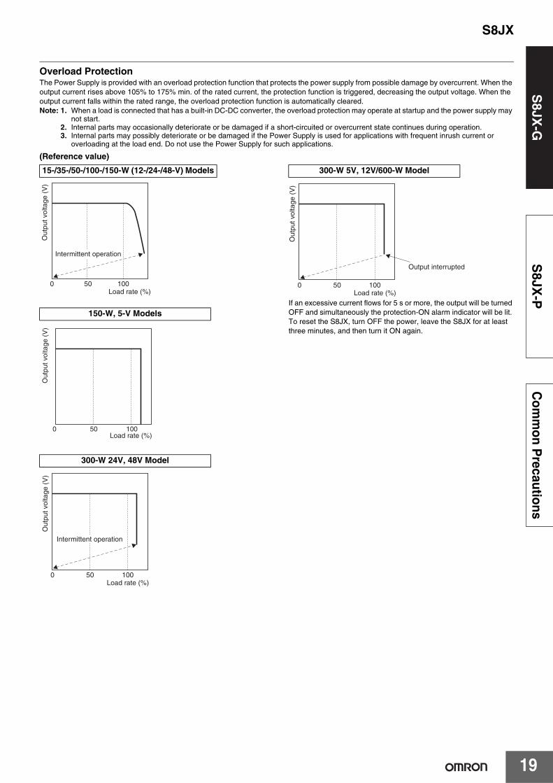
Overload ProtectionThe Power Supply is provided with an overload protection function that protects the power supply from possible damage by overcurrent. When the output current rises above 105% to 175% min. of the rated current, the protection function is triggered, decreasing the output voltage. When the output current falls within the rated range, the overload protection function is automatically cleared. Note: 1. When a load is connected that has a built-in DC-DC converter, the overload protection may operate at startup and the power supply may
not start.2. Internal parts may occasionally deteriorate or be damaged if a short-circuited or overcurrent state continues during operation.3. Internal parts may possibly deteriorate or be damaged if the Power Supply is used for applications with frequent inrush current or
overloading at the load end. Do not use the Power Supply for such applications.
(Reference value)
If an excessive current flows for 5 s or more, the output will be turned OFF and simultaneously the protection-ON alarm indicator will be lit. To reset the S8JX, turn OFF the power, leave the S8JX for at least three minutes, and then turn it ON again.
15-/35-/50-/100-/150-W (12-/24-/48-V) Models
150-W, 5-V Models
300-W 24V, 48V Model
50
Intermittent operation
0Load rate (%)
100
Out
put v
olta
ge (
V)
0 Load rate (%)
100 50
Out
put v
olta
ge (
V)
500Load rate (%)
100
Out
put v
olta
ge (
V)
Intermittent operation
300-W 5V, 12V/600-W Model
50
Output interrupted
0Load rate (%)
100O
utpu
t vol
tage
(V
)

S8JX
20
S8JX
-GS
8JX-P
Com
mon P
recautions
Overvoltage Protection
Consider the possibility of an overvoltage and design the system so that the load will not be subjected to an excessive voltage even if the feedback circuit in the power supply fails. When an excessive voltage that is approximately 130% of the rated voltage or more is output, the output voltage is shut OFF, preventing damage to the load due to overvoltage. Reset the input power by turning it OFF for at least seven minutes and then turning it back ON again.
Consider the possibility of an overvoltage and design the system so that the load will not be subjected to an excessive voltage even if the feedback circuit in the Power Supply fails. When an excessive voltage that is approximately 120% of the rated voltage or more is output, the output voltage is shut OFF, preventing damage to the load due to overvoltage (Except 300-W 24V, 48V models ). Reset the input power by turning it OFF for at least three minute and then turning it back ON again.
(Reference value)
Note: Do not turn ON the power again until the cause of the overvoltage has been removed.
Overheat Protection
If the internal temperature rises excessively as a result of fan failure or any other reason, the overheat protection circuit will be triggered to shut OFF the output voltage and simultaneously the protection-ON alarm indicator will be lit. Reset the input power by turning it OFF for at least three minutes and then turning it back ON again.
Inrush Current, Startup Time, Output Hold Time
Note: A maximum startup time of 500 ms is required (650 ms for 300 W). Construct a system configuration that considers the startup time of other devices.
15-/35-/50-/100-/150-W Models
300-/600-W Models
300-W 5V, 12V/600-W Model
Out
put v
olta
ge (
V)
Overvoltage protection Operating
Variable rangeRated output
Voltage
0 V
Startup time Hold time (20 ms min.)
AC inputvoltage
AC inputcurrent
Outputvoltage
Inrush current on input application
90% 96.5%
Input ON Input OFF

S8JX
21
S8JX
-GS
8JX-P
Com
mon P
recautions
Dimensions (Unit: mm)
Front-mounting Models
Panel mounting holes dimensions
Surface screw mounting
SideMounting
BottomMounting
Two, M3
75±0.5
82±0.5
Two, M3
78±0.5
Five, M3.5
Label
Cover
3.5 dia.
3.5 dia.
Two, M3 (Depth 4 mm max.)
35.5±1
39.5±182±0.5
78±0.5
91±1
75±0.5
90±110 max. 5 max.
50±0.5
8.29.5
4.5
8.5
15
3.5
26.517.5
7.5
3.5
S8JX-G015@@ (15 W)S8JX-G015@@C (15 W)S8JX-G035@@ (35 W)S8JX-G035@@C (35 W)
Panel mounting holes dimensions
Surface screw mounting
SideMounting
BottomMounting
Two, M3
75±0.5
92±0.5
Two, M3
92±0.5
3.5 dia.
3.5 dia. 3.5
Two, M3(Depth 4 mm max.)
8.29.5
Five, M3.5
10 max. 100±1
92±1
75±0.5
3.5
36±1
40±1
4.5
4.5
92±0.5
92±0.5
65±0.520
26.520
5 max.
8
Label
Cover
S8JX-G050@@ (50 W)S8JX-G050@@C (50 W)
Panel mounting holes dimensions
Surface screw mounting
SideMounting
BottomMounting
Two, M3
75±0.5
141±0.5
Two, M3
141±0.5
3.5 dia.
3.5 dia.
150 W
8.29.5
Five, M3.5
48±1
50±1
10 max. 150±1
5 max.
3.5
5 141±0.5
Two, M3(Depth 4 mm max.)
122±0.516
3.5
28
5 141±0.5
92±1
75±0.5
8
100·150 W100 W
Label
Cover
S8JX-G100@@ (100 W)S8JX-G100@@C (100 W)S8JX-G15024 (150 W)S8JX-G15024C (150 W)S8JX-G15048 (150 W)S8JX-G15048C (150 W)

S8JX
22
S8JX
-GS
8JX-P
Com
mon P
recautions
92±1
3633.5
3.5
3.5
5max.12max.
68±0.5
860±1
10
2-M4
13
9.58.2
169±0.5
169±0.5
140±0.5Input voltage switch14
178±1
5
5Two, M3 (Depth: 4 mm max.)
3.5 dia.
3.5 dia.3-M3.5
Label
Cover
Panel mounting holes dimensions
Surface screw mounting
SideMounting
BottomMounting
169±0.5
68±0.5
Two, M3
169±0.5
Two, M3
S8JX-G15005 (150 W)S8JX-G15005C (150 W)
92±1
3633.5
3.5
3.5
5max.10max.
68±0.5
860±1
9.58.2
169±0.5
169±0.5
140±0.514
178±1
5
5Two, M3 (Depth: 4 mm max.)
3.5 dia.
3.5 dia.5-M3.5
Label
Cover
Panel mounting holes dimensions
Surface screw mounting
SideMounting
BottomMounting
169±0.5
68±0.5
Two, M3
169±0.5
Two, M3
S8JX-G15012 (150 W)S8JX-G15012C (150 W)

S8JX
23
S8JX
-GS
8JX-P
Com
mon P
recautions
13
16
10
92±1
110±1
26
8.6 50±0.5
21
17 136±0.5
22.5 max.164.5±1Four, M5 terminal screws Five, M4 terminal screws
17 136±0.5
10
90±0.5
Eight, M4 holes(depth: 8 max. on both sides)
Four, M4 holes(depth: 8 max.)
Panel mounting holes dimensions
Surface screw mounting
SideMounting
BottomMounting
50±0.5
136±0.5
Four, 4.5 dia.
90±0.5
136±0.5
Four, 4.5 dia.
S8JX-G30005C (300 W)S8JX-G30012C (300 W)
92±1
4 max.
110±1
10
8.6
Nine, M4 terminal screws
19 136±0.5
90±0.5
10
167.1±1
19 136±0.5
21
50±0.5
20 max.
Eight, M4 holes(depth: 8 max. on both sides)
Four, M4 holes(depth: 8 max.)
Panel mounting holes dimensions
Surface screw mounting
SideMounting
BottomMounting
50±0.5
136±0.5
Four, 4.5 dia.
90±0.5
136±0.5
Four, 4.5 dia.
S8JX-G30024C (300 W)S8JX-G30048C (300 W)

S8JX
24
S8JX
-GS
8JX-P
Com
mon P
recautions
1316
10
92±1
26
8.6
50±0.5
124±0.511
20.9
24.4±0.5159.8±1
100±0.5
42
14.8137±0.5
150±1
Four, M5 terminal screws
Eight, M4 holes(depth: 8 max. on both sides)
Four, M4 holes(depth: 8 max.)
Five, M4 terminal screws
S8JX-G60005@ (600 W)S8JX-G60012@ (600 W)
Panel mounting holes dimensions
Surface screw mounting
SideMounting
BottomMounting
50±0.5
124±0.5
Four, 4.5 dia.
100±0.5
137±0.5
Four, 4.5 dia.
108.6
159.8±124.4±0.5
11124±0.5
50±0.5
20.9
14.8
100±0.5
42
137±0.5
8.6 10150±1
92±1
Nine, M4 terminal screws
Eight, M4 holes(depth: 8 max. on both sides)
Four, M4 holes(depth: 8 max.)
Panel mounting holes dimensions
Surface screw mounting
SideMounting
BottomMounting
50±0.5
124±0.5
Four, 4.5 dia.
100±0.5
137±0.5
Four, 4.5 dia.
S8JX-G60024C (600 W)S8JX-G60048C (600 W)

S8JX
25
S8JX
-GS
8JX-P
Com
mon P
recautions
Mounting Bracket Provided with Front-mounting Power Supplies a15-/35-/50-/100-/150-W Models
S82Y-J00F Front-mounting Bracket
Front-mounting MethodTemporarily attach the enclosed mounting bracket as shown in the illustration on the right, hook the holes (parts a) in the Power Supply on hooks on the mounting bracket (parts b), and secure the Power Supply with two mounting screws.
300-/600-W Models
Front-mounting Bracket (S82Y-J30F) Dimensions with Mounting Brackets
Attaching the Mounting Brackets
Dimensions Mounting dimensions
11
9
1.5
60
1120
5
31.5
20.5
15
4.7
4.6
4.6 15±0.2
74Two, 3.5 dia.
t = 1.0
Material: Stainless steel
Two, M3
20
60
b
b
a
a
Power SupplyMounting bracket
Note: Mounting screws are not provided.
48
1530
7.5 7.5
160
32±0.2
92
145±0.3
R2.5
10 dia.
Two, 5 dia. t = 1.6
Note: Mounting Brackets are provided in a set, one for the right side and one for the left side.
145±0.3
80±0.5 Four, M4
300-W Model
300-W Model
Note: To provide ventilation space, the body will shift forward by 21.6 mm from the mounting surface.
145±0.3
120±0.5 Four, M4
600-W Model 600-W Model
Note: To provide ventilation space, the body will shift forward by 23.6 mm from the mounting surface.

S8JX
26
S8JX
-GS
8JX-P
Com
mon P
recautions
Separately purchasable mounting brackets (Please ask your dealer for details of delivery.)
Bracket for changeover from S82J-series
The mounting-hole pitch of mounting brackets A - I below is identical to that of our product S82J. These brackets can be used forswitchover with the S82J-series.
Note: Mounting brackets (A, B, C, D, E, F, G, H, I) are compatible with S82J mounting holes.
For 15-W/30-W/50-W/100-W/150-W/300-W/600-W models (separately purchasable)
Models compatible with the S82J-series
Mounting Orientation Products names Model
50-W models
Underside mounting
Mounting bracket A (For S8JX-G-series 50-W models) S82Y-JX05B
100-W 24 V models Mounting bracket B (For S8JX-G-series 100-W 24 V models) S82Y-JX10B
100-W 5 V, 12 V, 150-W 24 V models Mounting bracket C (For S8JX-G-series 100-W 5 V, 12V, 150 W models) S82Y-JX15B
100-W 5 V, 12 V, 150-W 24 V models Front mounting Mounting bracket D (For S8JX-G-series 100-W 5 V, 12 V, 150 W models) S82Y-JX15F
25-W models Underside mounting Mounting bracket E (For S8JX-G-series 30-W models) S82Y-JX03B
300-W modelsUnderside mounting Mounting bracket F (For S8JX-G-series 300-W models) S82Y-JX30B
Front mounting Mounting bracket G (For S8JX-G-series 300-W models) S82Y-JX30F
600-W modelsUnderside mounting Mounting bracket H (For S8JX-G-series 600-W models) S82Y-JX60B
Front mounting Mounting bracket I (For S8JX-G-series 600-W models) S82Y-JX60F
28403.5
R2R1.75 R0.5
161
150.5±0.56.5
Thickness = 2
3.5 dia.
A
B
B
A
Mounting Bracket AS82Y-JX05B
Screws usedA: Accessories (2 locations)
Be sure to use the accessory screws.Mounting screw tightening torque (recommended): 0.49 N · m
B: M3 (2 locations)
Method of Mounting
28504.5
R2
R2.25 R0.5
1706.5
4.5 dia.
160±0.5
Thickness = 2
B
A
B
A
Mounting Bracket BS82Y-JX10B
Screws usedA: Accessories (2 locations)
Be sure to use the accessory screws.Mounting screw tightening torque (recommended): 0.49 N · m
B: M4 (2 locations)
Method of Mounting

S8JX
27
S8JX
-GS
8JX-P
Com
mon P
recautions
Å@
35504.5
R2
R2.25
R0.5
188
178±0.53
4.5 dia.
Thickness = 2
B
A
A
B
Mounting Bracket CS82Y-JX15B
Screws usedA: Accessories (2 locations)
Be sure to use the accessory screws.Mounting screw tightening torque (recommended): 0.49 N · m
B: M4 (2 locations)
Method of Mounting
119
110±0.5
4.5 2545
45.654
5 dia.
Thickness = 1.6
B
B
A
A
Mounting Bracket DS82Y-JX15F
Screws usedA: Accessories (2 locations)
Be sure to use the accessory screwsMounting screw tightening torque (recommended): 0.49 N · m
B: M4 (2 locations)
Method of Mounting
112±0.5
3.5 dia.
Thickness = 2
28403.5
R0.5
R2
R1.75
1246.5
B
B
A
A
Mounting Bracket ES82Y-JX03B
Screws usedA: Accessories (2 locations)
Be sure to use the accessory screws.Mounting screw tightening torque (recommended): 0.49 N · m
B: M3 (2 locations)
Method of Mounting

S8JX
28
S8JX
-GS
8JX-P
Com
mon P
recautions
7
Front
Thickness = 3.2
Four, M4
150±0.1167
100±0.1110
AA
A
BB
B
Mounting Bracket FS82Y-JX30B
Screws usedA: Accessories (4 locations)
Be sure to use the accessory screws.B: M4 (4 locations)
Screws of a length that will not project beyond the fixture (thickness: 3.2 mm) should be selected.
Method of Mounting
7.5 7.5145±0.3
160
32±0.2
92Two, 5 dia.
11.6
R2.510 dia.
29.6
48
Thickness = 1.6
145±0.3
90±0.5 Four, M4
A
A
A
A
Mounting Bracket GS82Y-JX30F
Screws usedA: Accessories (4 locations)
Be sure to use the accessory screws.
Note: For ventilation of the back surface, the body should be placed 21.6 mm in front of the mounting side.
Method of Mounting
Front
Thickness = 3.2
169
150±0.1 9
45
100±0.1170
Eight, M4
A
AA
B
BB
Mounting Bracket HS82Y-JX60B
Screws usedA: Accessories (4 locations)
Be sure to use the accessory screws.B: M4 (4 locations)
Screws of a length that will not project beyond the fixture (thickness: 3.2 mm) should be selected.(Although there are 8 holes in the bracket body, only 4 of these are used.)
Method of Mounting
145±0.3
140±0.5 Four, M4
Two, 5 dia.
6.6
10 dia. R2.5
21.6
32±0.2
92
145±0.3160
7.5
48
Thickness = 3.2
7.5
A
A
A
A
Mounting Bracket IS82Y-JX60F
Screws usedA: Accessories (4 locations)
Be sure to use the accessory screws.
Note: For ventilation of the back surface, the body should be placed 23.6 mm in front of the mounting side.
Method of Mounting

S8JX
29
S8JX
-GS
8JX-P
Com
mon P
recautions
DIN Rail-mounting Models
S8JX-G015@@D (15 W)S8JX-G015@@CD (15 W)S8JX-G030@@D (35 W)S8JX-G030@@CD (35 W)
8.29.5
Five, M3.5
6 max. 44±1
Label
Cover
10 max. 90±1
91±1
47
14.5 max.
98.6
5 max.
7 (Sliding: 16.6 max.)
S8JX-G050@@D (50 W)S8JX-G050@@CD (50 W)
8.29.5
Five, M3.5
36±1
40±1
6 max. 44±1 10 max. 100±1
92±1
47
14.5 max.
108.6
5 max.
7 (Sliding: 16.6 max.)
Label
Cover
S8JX-G100@@D (100 W)S8JX-G100@@CD (100 W)S8JX-G15024D (150 W)S8JX-G15024CD (150 W)S8JX-G15048D (150 W)S8JX-G15048CD (150 W)
8.29.5
Five, M3.5
48±1
50±1
10 max. 150±1
5 max.
92±1
47
7 (Sliding: 16.6 max.) 158.6
6 max. 50±1
14.5 max.
100·150 W150 W100 W
Label
Cover

S8JX
30
S8JX
-GS
8JX-P
Com
mon P
recautions
92±1
47
6 max.60±1
Input voltage switch
12 max.14.5 max.
5 max.
7 (Sliding: 16.6 max.)
178±1
186.6
2-M4
Label
3-M3.5
Cover
13
9.58.2
10
S8JX-G15005D (150 W)S8JX-G15005CD (150 W)
9.58.2
10 max. 178±1
5-M3.5
Cover
6 max.60±1
14.5 max.
92±1
47
5 max.
7 (Sliding: 16.6 max.)186.6
Label
S8JX-G15012D (150 W)S8JX-G15012CD (150 W)

S8JX
31
S8JX
-GS
8JX-P
Com
mon P
recautions
26 13
16
7.5
179.3
92±1
4.4(Sliding: 10 max.)
6.5 max.110±1
10
8.6
Four, M5 terminal screws 175.3±122.5 max.
46.6
Five, M4 terminal screws
6.5 max.
S8JX-G30005CD (300W)S8JX-G30012CD (300W)
Note: Use a metal DIN Rail when mounting a 300-W model to a DIN Rail.
92±1
4 max.
4.4 (Sliding: 10 max.)
6.5 max.110±1
6.5 max.
10
8.6
Nine, M4 terminal screws 10.2167.1±1
20 max.
46.6
181.3
(17.7)
S8JX-G30024CD (300 W)S8JX-G30048CD (300 W)
Note: Use a metal DIN Rail when mounting a 300-W model to a DIN Rail.

S8JX
32
S8JX
-GS
8JX-P
Com
mon P
recautions
DIN Rail (Order Separately)
Note: 1. If there is a possibility that the Unit will be subject to vibration or shock, use a steel DIN Rail. Otherwise, metallic filings may result from aluminum abrasion.
2. If the Unit may be subjected to sliding to either side, attach an End Plate (model PFP-M) on each side of the Unit.
Terminal Cover (Order Separately)
Replacement Fan (sold separately)
Terminal Cover model Applicable Power Supply and applicable location
S82Y-JX-C4PS8JX-G-300W, 24-V or 48-V output
S8JX-G-600W, 24-V or 48-V output
S82Y-JX-C5PS8JX-G-300W, input
S8JX-G-600W, input
S82Y-JTC1
S8JX-G-15W
S8JX-G-30W
S8JX-G-50W
S8JX-G-100W
S8JX-G-150W, 12-V, 24-V or 48-V model
Model
S82Y-JXFAN
Mounting Rail(Material: Aluminum)
4.5
15 25 2510 10
1,000 (500) ∗25 25 15 (5) *
35±0.3
7.3±0.15
27±0.15
1
* Value in parentheses are for PFP-50N.
Model
PFP-100N
PFP-50N
Mounting Rail(Material: Aluminum)
4.5
15 25 2510 10
1,000
25 25 15 1 1.5
29.2242735±0.3
16
Model
PFP-100N2
1.3
4.8
35.5 35.51.8
1.8
M4 springwasher
106.2
1
50
M4 × 8panhead
screw
11.5
10
End Plate
Model
PFP-M

S8JX
33
S8JX
-GS
8JX-P
Com
mon P
recautions
Model Number StructureModel Number LegendNote: Not all combinations are possible. Refer to List of Models in Ordering Information on page 34.
1. Power Ratings050: 50 W100: 100 W150: 150 W
2. Output Voltage05: 5 V12: 12 V24: 24 V48: 48 V
3. Configuration (50/100/150 W model)None: Open-frameC: Covered
4. Configuration/mountingNone: Front-mountingD: DIN Rail-mounting
1. Power Ratings300: 300 W600: 600 W
2. Output Voltage05: 5V12: 12 V24: 24 V48: 48 V
3. Configuration/mounting (covered type)C: Front-mountingCD: DIN Rail-mountingN: Without mounting bracket
Note: Estimates can be provided for coatings and other specifications that are not given in the datasheet. Ask your OMRON representative for details.
50-/100-/150-W Models
1 2 3 4S8JX-P@@@@@@@
300-/600-W Models
1 2 3S8JX-P@@@@@@

S8JX
34
S8JX
-GS
8JX-P
Com
mon P
recautions
Ordering InformationList of ModelsNote: For details on normal stock models, contact your nearest OMRON representative.
*1. The front-mounting bracket is included as standard with the product.*2. A front-mounting bracket is not included with the product.*3. The range for compliance with EC Directives and safety standards (UL, EN, etc.) is 100 to 240 VAC (85 to 264 VAC).
Configuration Input voltage Power ratings Output voltage (VDC) Output current Model
Open-frame Power Supplies
Front-mounting *1
100 to 240 VAC (free)
(80 to 370 VDC *3)
050 W
05 V 10 A S8JX-P0500512 V 4.2 A S8JX-P0501224 V 2.1 A S8JX-P0502448 V 1.1 A S8JX-P05048
100 W
05 V 20 A S8JX-P1000512 V 8.5 A S8JX-P1001224 V 4.5 A S8JX-P1002448 V 2.1 A S8JX-P10048
150 W
05 V 30 A S8JX-P1500512 V 13 A S8JX-P1501224 V 6.5 A S8JX-P1502448 V 3.3 A S8JX-P15048
DIN Rail-mounting *2
050 W
05 V 10 A S8JX-P05005D12 V 4.2 A S8JX-P05012D24 V 2.1 A S8JX-P05024D48 V 1.1 A S8JX-P05048D
100 W
05 V 20 A S8JX-P10005D12 V 8.5 A S8JX-P10012D24 V 4.5 A S8JX-P10024D48 V 2.1 A S8JX-P10048D
150 W
05 V 30 A S8JX-P15005D12 V 13 A S8JX-P15012D24 V 6.5 A S8JX-P15024D48 V 3.3 A S8JX-P15048D
Covered Power Supplies
Front-mounting *1
050 W
05 V 10 A S8JX-P05005C12 V 4.2 A S8JX-P05012C24 V 2.1 A S8JX-P05024C48 V 1.1 A S8JX-P05048C
100 W
05 V 20 A S8JX-P10005C12 V 8.5 A S8JX-P10012C24 V 4.5 A S8JX-P10024C48 V 2.1 A S8JX-P10048C
150 W
05 V 30 A S8JX-P15005C12 V 13 A S8JX-P15012C24 V 6.5 A S8JX-P15024C48 V 3.3 A S8JX-P15048C
DIN Rail-mounting *2
050 W
05 V 10 A S8JX-P05005CD12 V 4.2 A S8JX-P05012CD24 V 2.1 A S8JX-P05024CD48 V 1.1 A S8JX-P05048CD
100 W
05 V 20 A S8JX-P10005CD12 V 8.5 A S8JX-P10012CD24 V 4.5 A S8JX-P10024CD48 V 2.1 A S8JX-P10048CD
150 W
05 V 30 A S8JX-P15005CD12 V 13 A S8JX-P15012CD24 V 6.5 A S8JX-P15024CD48 V 3.3 A S8JX-P15048CD
S8JX
35
S8JX
-GS
8JX-P
Com
mon P
recautions
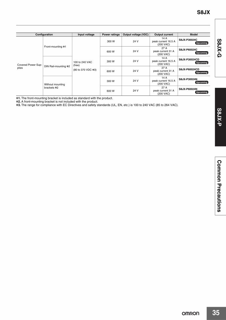
*1. The front-mounting bracket is included as standard with the product. *2. A front-mounting bracket is not included with the product.*3. The range for compliance with EC Directives and safety standards (UL, EN, etc.) is 100 to 240 VAC (85 to 264 VAC).
Configuration Input voltage Power ratings Output voltage (VDC) Output current Model
Covered Power Sup-plies
Front-mounting *1
100 to 240 VAC (free)
(80 to 370 VDC *3)
300 W 24 V14 A
peak current 16.5 A(200 VAC)
S8JX-P30024C
600 W 24 V27 A
peak current 31 A(200 VAC)
S8JX-P60024C
DIN Rail-mounting *2
300 W 24 V14 A
peak current 16.5 A(200 VAC)
S8JX-P30024CD
600 W 24 V27 A
peak current 31 A(200 VAC)
S8JX-P60024CD
Without mounting brackets *2
300 W 24 V14 A
peak current 16.5 A(200 VAC)
S8JX-P30024N
600 W 24 V27 A
peak current 31 A(200 VAC)
S8JX-P60024N
Upcoming
Upcoming
Upcoming
Upcoming
Upcoming
Upcoming

S8JX
36
S8JX
-GS
8JX-P
Com
mon P
recautions
Ratings, Characteristics, and Functions
*1. When a load is connected that has a built-in DC-DC converter, the overload protection may operate at startup and the Power Supply may not start. Refer to Overload Protection on page 44.
*2. Do not use an Inverter output for the Power Supply. Inverters with an output frequency of 50/60 Hz are available, but the rise in the internal temperature of the Power Supply may result in ignition or burning.
*3. Rated input voltage: 100 or 200 VAC at 100% load.*4. Output characteristics: Specified at power supply output terminals.*5. If the output voltage adjuster (V. ADJ) is turned, the voltage will increase by more than the allowable voltage range. When adjusting the output
voltage, confirm the actual output voltage from the Power Supply and be sure that load is not damaged. *6. For details, refer to Overload Protection on page 44.*7. To reset the protection, turn OFF the input power for three minutes or longer and then turn it back ON.*8. The weight indicated is for Front-mounting, Open-frame Power Supply.*9. The range for compliance with EC Directives and safety standards (UL, EN, etc.) is 100 to 240 VAC (85 to 264 VAC).
Input specification 100 to 240 V input
Item Power ratings *1 50 W 100 W 150 W
Efficiency
5-V Models 73% min. 78% min. 79% min.
12-V Models 76% min. 78% min. 78% min.
24-V Models 77% min. 81% min. 81% min.
48-V Models 80% min. 81% min. 82% min.
Input
Voltage *2100 to 240 VAC (allowable range: 85 to 264 VAC)
80 to 370 VDC *9
Frequency *2 50/60 Hz (47 to 63 Hz)
Current *3100 V input 0.75 A max. 1.4 A max. 2.1 A max.
200 V input 0.4 A max. 0.75 A max. 1.1 A max.
Power factor 0.9 min.
Harmonic current emissions Conforms to EN61000-3-2
Leakage current *3100 V input 0.5 mA max.
200 V input 1 mA max.
Inrush current (for a cold start at 25°C) *3
100 V input 17.5 A max.
200 V input 35 A max.
Noise filter Yes
Output *4
Voltage adjustment range *5 −10% to 15% (with V. ADJ) (48-V models: ±10%)
Ripple *3 2% (p-p) max.This shall be 3% (p-p) or less when the ambient temperature is less than 0°C (for only 5 V type).
Input variation influence 0.4% max. with AC input voltage
Load variation influence 0.8% max. (0 to 100% load, rated input voltage)
Temperature variation influence 0.05%/°C max. (at rated input and output)
Startup time 1,000 ms max.
Hold time *3 20 ms min.
Additional functions
Overload protection *6105% to 160% of rated load current, voltage drop, intermittent, automatic reset
105% to 160% of rated load current, voltage drop, automatic reset
Overvoltage protection *7 Yes
Overheat protection No
Parallel operation No (However, backup operation is possible; external diodes required.)Series operation Yes (For up to two Power Supplies; external diodes required.)
Protective circuit operation indicator No
Other
Ambient operating temperature Refer to the derating curve in Engineering Data on page 42 (with no icing or condensation).
Storage temperature −25 to 75°C (with no icing or condensation)
Ambient operating humidity 25% to 85% (Storage humidity: 25% to 90%)
Dielectric strength3.0 kVAC for 1 min. (between all inputs and outputs; detection current: 20 mA)2.0 kVAC for 1 min. (between all inputs and PE terminals; detection current: 20 mA)1.0 kVAC for 1 min. (between all outputs and PE terminals; detection current: 20 mA)
Insulation resistance 100 MΩ min. (between all outputs and all inputs/PE terminals) at 500 VDC
Vibration resistance 10 to 55 Hz, 0.375-mm single amplitude for 2 h each in X, Y, and Z directions
Shock resistance 150 m/s2, 3 times each in ±X, ±Y, ±Z directions
Output indicator Yes (Color: Green)
EMIConducted Emissions Conforms to EN 55011 Group 1 Class B and based on FCC Class B *9
Radiated Emissions Conforms to EN 55011 Group 1 Class B *9
EMS
Electrostatic Discharge Conforms to EN61000-4-2
Radiated Electromagnetic Field Conforms to EN61000-4-3
Electrical Fast Transient/Burst Conforms to EN61000-4-4
Surge Conforms to EN61000-4-5
Conducted Disturbance Conforms to EN61000-4-6
Voltage Dips/Short Interruptions Conforms to EN61000-4-11
Approved standards *9
UL Listed: UL 508 (Listing), UL UR: UL 60950-1 (Recognition)
cUL Listed: CSA C22.2 No.107.1cUR: CSA C22.2 No. 60950-1
EN/VDE: EN50178 (= VDE 0160) Over voltage category III, EN 60950-1 (= VDE 0805 Teil 1)(Terminal block: Based on DIN 50274 (VDE 0660-514))
SEMI SEMI F47-0706 (200-VAC input)
Weight *8 370 g max. 550 g max. 590 g max.

S8JX
37
S8JX
-GS
8JX-P
Com
mon P
recautions
Input specification 100 to 240 V input
Item Power ratings *1 300 W 600 W
Efficiency 24V models 79% min. 78% min.
Input
Voltage *2 100 to 240 VAC (allowable range: 85 to 264 VAC)80 to 370 VDC *8
Frequency *2 50/60 Hz (47 to 63 Hz)
Current *3100 V input 4.5 A max. 8.7 A max.
200 V input 2.2 A max. 4.3 A max.
Power factor 0.9 min.
Harmonic current emissions Conforms to EN61000-3-2
Leakage current *3100 V input 0.5 mA max.
200 V input 1 mA max.
Inrush current (for a cold start at 25°C) *3
100 V input 17.5 A max.
200 V input 35 A max.
Noise filter Yes
Output *4
Voltage adjustment range *5 −10% to 15% (with V. ADJ)
Ripple *3 2% (p-p) max.
Input variation influence 0.4% max.
Load variation influence 0.8% max. (0 to 100% load, rated input voltage)
Temperature variation influence 0.05%/°C max.
Startup time 1,000 ms max.
Hold time *3 20 ms min.
Additional functions
Overload protection *6 105% to 160% of rated load current, voltage drop, intermittent, automatic reset.
Overvoltage protection *7 Yes
Overheat protection Yes
Parallel operation Yes (up to 5 Power Supplies)
Series operation Yes (For up to two Power Supplies; external diodes required.)
Protective circuit operation indicator Yes (color: red)
Other
Ambient operating temperature Refer to the derating curve in Engineering Data on page 42 (with no icing or condensation).
Storage temperature −25 to 75°C (with no icing or condensation)
Ambient operating humidity 25% to 85% (Storage humidity: 25% to 90%)
Dielectric strength
3.0 kVAC for 1 min. (between all inputs and outputs; detection current: 20 mA)2.0 kVAC for 1 min. (between all inputs and PE terminals; detection current: 20 mA)1.0 kVAC for 1 min. (between all outputs and PE terminals; detection current: 100 mA)100 VAC for 1 min. (between all outputs and RC terminals; detection current: 100 mA)500 VAC for 1 min. (between all outputs and ALM terminals; detection current: 20 mA)
Insulation resistance 100 MΩ min. (between all outputs and all inputs/PE terminals) at 500 VDC
Vibration resistance 10 to 55 Hz, 0.375-mm single amplitude for 2 h each in X, Y, and Z directions
Shock resistance 150 m/s2, 3 times each in ±X, ±Y, ±Z directions *11
Output indicator Yes (Color: Green)
EMIConducted Emissions *3 Conforms to EN 55011 Group 1 Class B and based on FCC Class B *12
Radiated Emissions Conforms to EN 55011 Group 1 Class B *12
EMS
Electrostatic Discharge Conforms to EN61000-4-2
Radiated Electromagnetic Field Conforms to EN61000-4-3
Electrical Fast Transient/Burst Conforms to EN61000-4-4
Surge Conforms to EN61000-4-5
Conducted Disturbance Conforms to EN61000-4-6
Voltage Dips/Short Interruptions Conforms to EN61000-4-11
Approved standards *8
UL UR: UL 508 (Recognition), UL 60950-1 (Recognition)
cUR: CSA C22.2 No.107.1, CSA C22.2 No. 60950-1
EN/VDE: EN50178 (= VDE 0160) Over voltage category III *9, EN 60950-1 (= VDE 0805 Teil 1) *9(Terminal block: Based on DIN 50274 (VDE 0660-514))
SEMI SEMI F47-0706 (200-VAC input)
Weight 1,200 g max. *10 1,800 g max. *10

S8JX
38
S8JX
-GS
8JX-P
Com
mon P
recautions
*1. When a load is connected that has a built-in DC-DC converter, the overload protection may operate at startup and the Power Supply may not start. Refer to Overload Protection on page 44.
*2. Do not use an Inverter output for the Power Supply. Inverters with an output frequency of 50/60 Hz are available, but the rise in the internal temperature of the Power Supply may result in ignition or burning.
*3. Rated input voltage: 100 or 200 VAC at 100% load.*4. Output characteristics: Specified at power supply output terminals.*5. If the output voltage adjuster (V. ADJ) is turned, the voltage will increase by more than the allowable voltage range. When adjusting the output
voltage, confirm the actual output voltage from the Power Supply and be sure that load is not damaged. *6. For details, refer to Overload Protection on page 44.*7. To reset the protection, turn OFF the input power for three minutes or longer and then turn it back ON.*8. The range for compliance with EC Directives and safety standards (UL, EN, etc.) is 100 to 240 VAC (85 to 264 VAC).*9. The 24-V models are scheduled to obtain certification in March 2012.*10.The weight is of the type without a mounting bracket.*11.S8JX-P600@@CD: 100 m/s2
*12.300-W/600-W models conform to Class B with an aluminum plate set under the product.

S8JX
39
S8JX
-GS
8JX-P
Com
mon P
recautions
ConnectionsBlock Diagrams
Voltagedetection
Photocoupler
Overvoltagedetection circuit
Drive controlCircuit
Overcurrentdetectioncircuit
+V
–V
DC OUTPUTNoisefilter
Inrush currentprotection
Fuse2.5 A
AC(L)
INPUT
AC(N)Rectifier Smoothing
circuitRectifier/
Smoothing circuitHigh-frequency
current regulation
S8JX-P050@@@@ (50 W)
Voltagedetection
Photocoupler
Overvoltagedetection circuit
Drive controlCircuit
Overcurrentdetectioncircuit
+V
–V
DC OUTPUTNoisefilter
Inrush currentprotection
Fuse6.3 A
AC(L)
INPUT
AC(N)Rectifier Smoothing
circuitRectifier/
Smoothing circuitHigh-frequency
current regulation
S8JX-P100@@@@ (100 W)S8JX-P150@@@@ (150 W)

S8JX
40
S8JX
-GS
8JX-P
Com
mon P
recautions
INPUT
AC(L)
AC(N)
Current balance circuit
DC OUTPUT
-V
+V
-V
+V
Output voltage monitor
Remote sensing
-S
+S
Power supply balance
CB
CBG
Remote control
+RC
-RC
Fan
Auxiliary power supply circuit
Overheating detection
Alarm detection
Fan detectionAlarm display ALM
ALMC
ALMEAlarm output
Fuse10 A Noise
filter
Rectifier Inrush currentprotection
High-frequency current regulation
Smoothingcircuit
Rectifier/Smoothing circuit
Rectifier/Smoothing circuit
Control circuit
Drive circuit
Photocoupler
Photocoupler
Photocoupler
Photocoupler
Overcurrentdetection circuit
Rectifier/Smoothing circuit
Voltagedetection
Overvoltagedetection circuit
S8JX-P300@@@@ (300 W)
INPUT
AC(L)
AC(N)
DC OUTPUT
-V
+V
-V
+V
-S
+S
CB
CBG
+RC
-RC
ALM
ALMC
ALME
Fuse20 A Noise
filter
Rectifier Inrush currentprotection
High-frequency current regulation
Smoothingcircuit
Rectifier/Smoothing circuit
Rectifier/Smoothing circuit
Control circuit
Drive circuit
Photocoupler
Photocoupler
Photocoupler
Photocoupler
Overcurrentdetection circuit
Rectifier/Smoothing circuit
Voltagedetection
Overvoltagedetection circuit
Current balance circuit
Output voltage monitor
Remote sensing
Power supply balance
Remote control
Fan
Auxiliary power supply circuit
Overheating detection
Alarm detection
Fan detectionAlarm display
Alarm output
S8JX-P600@@@@ (600 W)

S8JX
41
S8JX
-GS
8JX-P
Com
mon P
recautions
Construction and NomenclatureNomenclature
Reference Values
50-/100-/150-W Models
Reliability (MTBF)
50 W: 190,000 hrs100 W: 160,000 hrs 150 W: 160,000 hrs300 W: 160,000 hrs 600 W: 150,000 hrs
Definition MTBF stands for Mean Time Between Failures, which is calculated according to the probability of accidental device failures, and indicates reliability of devices. Therefore, it does not necessarily represent a life of the product.
Life expectancy 10 yrs. min.
Definition The life expectancy indicates average operating hours under the ambient temperature of 40ºC and a load rate of 50%. Normally this is determined by the life expectancy of the built-in aluminum electrolytic capacitor.
+V
–V
AC(L)
AC(N)
+V
–V
AC(L)
AC(N)
11
45
3 3
2 2
4
5
*1. The fuse is located on the (L) side. It is NOT user-replaceable. For a DC power input, connect the low side to the positive (+) terminal.
*2. This is the protective earth terminal specified in the safety standards. Always ground this terminal.
No. Name Function
1DC Output Terminals (−V), (+V) Connect the load lines to these terminals.
2AC Input Terminals (L), (N) Connect the input lines to these terminals. *1
3Protective Earth Terminal (PE) ( ) Connect the ground line to these terminals. *2
4Output Voltage Adjuster (V. ADJ)
It is possible to increase or decrease the output voltage.
5Output Indicator (DC ON: Green) Lights green while a direct current (DC) output is ON.
Note: The S8JX-P05005CD is shown above.
Note: The S8JX-P15005C is shown above.
5 7
6
4
2
1
3
3
5
4
6
7
1 2
*1. The fuse is located on the (L) side. Ensure that the (L) side is set to (+).*2. This is a PE (Protective Earth) terminal defined in safety standards and
must be grounded.*3. Signal input/output connectors are included as standard and
implemented in the CN1 before shipment. In this connector, the circuits of 1-2, 3-4, and 7-8 are shorted. Removal of the connector may deteriorate the output stability and accuracy, so be sure to perform the connection of +S and -S terminals. Never connect a load to the output voltage monitor terminal (+V, -V).
No. Name Function
1 Input Terminals (L), (N) Connect the input lines to these terminals. *1
2 Protective Earth Terminal (PE) ( ) Connect the ground line to these termi-nals. *2
3 DC Output Terminals (−V), (+V) Connect the load lines to these terminals.
4 Output Indicator (DC ON: Green) Lights green while a direct current (DC) output is ON.
5 Output Voltage Adjuster (V. ADJ) It is possible to increase or decrease the output voltage.
6 Alarm indicator (ALM: Red)
This lamp lights up at the time of output voltage deterioration or fan stoppage, and in standby mode by remote control function.
7
Signal output connector *3 1: Output voltage monitor terminal (+V)
2: Remote sensing terminal (+S)3: Output voltage monitor terminal (-V)4: Remote sensing terminal (-S)5: Current balance terminal (CB)6: Current balance ground terminal
(CBG)7: Remote control terminal (+RC)8: Remote control terminal (-RC)9: (Not connected)10: (Not connected)11: Alarm detection output terminal
(ALMC) (Collector side)12: Alarm detection output terminal
(ALME) (Emitter side)
11
9
7
5
3
1
12
10
8
6
4
2
CN 1/2
Note: The S8JX-P30024N is shown above.
Note: The S8JX-P60024N is shown above.
600-W Models
300-W Models

S8JX
42
S8JX
-GS
8JX-P
Com
mon P
recautions
Engineering DataDerating Curves (Standard Mounting)
Front-mounting, DIN Rail mounting, Bottom-mounting, Side-mounting
Note: 1. Internal parts may occasionally deteriorate or be damaged. Do not use the Power Supply in areas outside the derating curve (i.e., the area shown by shading in the above graph).
2. If there is a derating problem, use forced air-cooling.3. (For Customers using 100-W type for a DC Input)
When using an input voltage of less than 100 VDC, reduce the load calculated with the above derating curve by at least the following coefficients.When using a voltage exceeding 340 VDC, the ambient temperature should be 60°C or less.
Note: 1. Internal parts may occasionally deteriorate or be damaged. Do not use the Power Supply in areas outside the derating curve (i.e., the area shown by shading in the above graph).
2. The ambient temperature is defined at a location 50 mm forward from the center of the front surface of the product.
3. (For Customers using 300-/600-W type for a DC Input)Reduce the load calculated with the above derating curve by at least the following coefficients.
Front-mounting, DIN Rail mounting, Bottom-mounting
Horizontal-side-mounting
Note: 1. Internal parts may occasionally deteriorate or be damaged. Do not use the Power Supply in areas outside the derating curve (i.e., the area shown by shading in the above graph).
2. If there is a derating problem, use forced air-cooling.3. (For customers using 150-W type for a DC Input)
When using an input voltage of less than 100 VDC, reduce the load calculated with the above derating curve by at least the following coefficients.When using a voltage exceeding 340 VDC, the ambient temperature should be 60°C or less.
50-/100-W Models
300-/600-W Models
–20 –10 0 10 20 30 40 50 60 70 80
120
100
80
60
40
20
0
Ambient Temperature (°C)
Covered type
Open-frame type
1
Load
rat
e (%
)
1
00
Input voltage (VDC)
100
0.9
1.0
340 37080
Coe
ffici
ent
Maximum operating temperature 60°C
S8JX-P 100-W Models
–20 –10 0 10 20 30 40 50 60 70 80
120
100
80
60
40
20
0
Ambient Temperature (°C)
Load
rat
e (%
)
1
1
00
Input voltage (VDC)
Coe
ffici
ent
100
1.0
0.8
37080
S8JX-P 300-/600-W Models
150-W Models
–20 –10 0 10 20 30 40 50 60 70 80
120
100
80
60
40
20
0
Ambient Temperature (°C)
Covered type
Open-frame type
1
Load
rat
e (%
)
–20 –10 0 10 20 30 40 50 60 70 80
120
100
80
60
40
20
0
Ambient Temperature (°C)
1
Load
rat
e (%
)
Covered type
Open-frame type
1
00
Input voltage (VDC)
100
1.0
0.8
340 37080
Coe
ffici
ent
Maximum operating temperature 60°C
S8JX-P 150-W Models

S8JX
43
S8JX
-GS
8JX-P
Com
mon P
recautions
Mounting
The following three mounting methods are possible.. Front-mounting: Refer to Mounting Bracket Provided with Front-mounting Power
Supplies on page 52.. Bottom-mounting. Side-mounting
Note: Additional mounting methods are also available using DIN Rail-mounting models.
Standard Mounting
Note: 1. Improper mounting will interfere with heat dissipation and may occasionally result in deterioration or damage of internal parts. Use the standard mounting method only.
2. When mounting the Power Supply, mounting it to a metal plate (*) is recommended.3. Install the Power Supply so that the air flow circulates around the Power Supply, as the Power Supply is designed to radiate heat by
means of natural air flow.
Note: 1. Improper mounting will interfere with heat dissipation and may occasionally result in deterioration or damage of internal parts. Use the standard mounting method only.
2. When mounting the Power Supply, mounting it to a metal plate (*) is recommended.3. Do not cover the air holes (provided at fan mounted side and the opposite side) to have enough air-cooling.
50-/100-/150-W Models
50-/100-/150-W Models
300-/600-W Models
C
B
Front-mounting
*
DIN Rail-mounting Bottom-mounting
*
Vertical Side-mounting
*
Horizontal Side-mounting
*
∗300W 600W ∗ ∗ ∗300W 600W300W 600W
Front-mounting Bottom-mounting Side-mounting

S8JX
44
S8JX
-GS
8JX-P
Com
mon P
recautions
Remote sensing functionThis function is used when compensating the voltage drop of the load line.The remote sensing function is operated by connecting +S terminal (2 pin on CN) to +side of the load terminal and -S terminal (4 pin on CN) to -side of the load terminal.When the remote sensing function is not used, using a connector provided as standard enables the connection between +S and +V terminals (1 pin on CN) and between -S and -V terminals (3 pin on CN) respectively.
Note: 1. Use a two-core shield wire for connection line (*1).2. If the voltage drop on a load line (*2) is large, the output
voltage of the power supply may rise by the voltage drop amount and activate the overvoltage protection. Therefore, be sure to use as thick a wire as possible.
3. Be sure to use the voltage drop at 0.3 V or less.4. If the load line is long, be sure to use an electrolytic
capacitor between the load terminals. As the used electrolytic capacitor may be heated by ripple current due to the connected load, be sure to use an electrolytic capacitor having an allowable ripple current exceeding the used ripple current.
5. Opening status of +S and -S terminals may deteriorate the output stability and accuracy. Therefore, be sure to connect +S and -S terminals.
6. Remove a connector provided as standard and prepare a harness separately.
Remote control functionThis function is to turn ON/OFF the output by an external signal using +RC terminal (7 pin on CN) and -RC terminal (8 pin on CN) while input voltage remains applied. To use this function, connect a switch or a transistor to +RC and -RC terminals.When not in use, use the standard supplied connector to short-circuit +RC and -RC terminals.
Max. applied voltage: 12 V max., Counter voltage: -1 V max.,Sink current: 3.5 mA
Note: 1. If counter voltage is applied to remote control terminals, output voltage cannot be turned ON/OFF.Please remember this when wiring.
2. Use a twist wire or a two-core shield wire for connection line.3. Remote control circuit is disconnected from input and output
circuits.4. Remove a connector provided as standard and prepare a
harness separately.
Alarm detection functionWhen output voltage drops due to overcurrent protection, overvoltage protection, or overheat protection in operation or input voltage drop, when the built-in fan stops, or when the Power Supply goes standby by remote control, the alarm indicator (LED: red) lights up to indicate the output voltage trouble. In addition, the transistor outputs that outside.
Transistor output: 30 VDC max., 50 mA max.Residual voltage when the function is ON: 2 V max., leakage current when the function is OFF: 0.1 mA max.Detection voltage: approximately 80% of the output voltage setting valueWhen trouble is detected, the transistor output is turned OFF (nonconductive pins 11-12 on CN) and the LED (red) lights up.
Note: 1. The alarm detection function monitors the voltage at the Power Supply output end. To check an accurate voltage, measure a voltage at the load end.
2. Remove the standard supplied connector and prepare a connector separately.
Overload ProtectionThe Power Supply is provided with an overload protection function that protects the power supply from possible damage by overcurrent. When the output current rises above 105% to 160% min. of the rated current, the protection function is triggered, decreasing the output voltage. When the output current falls within the rated range, the overload protection function is automatically cleared. Note: 1. When a load is connected that has a built-in DC-DC
converter, the overload protection may operate at startup and the power supply may not start.
2. Internal parts may occasionally deteriorate or be damaged if a short-circuited or overcurrent state continues during operation.
3. Internal parts may possibly deteriorate or be damaged if the Power Supply is used for applications with frequent inrush current or overloading at the load end. Do not use the Power Supply for such applications.
(Reference value)
Level Output voltage Built-in fan
Short or L (0-0.8 V) ON Rotation
Open or H (2.4-12 V) OFF Stop
+V *2
+
–V
*1–V –S
S8JX
CN
+V +S
TRSW
+RC
–RC
S8JXCN
50-W Models
100-/150-W Models 300-/600-W Models
ALMC
ALME
S8JX
CN
Vce max : DC30VIc max : 50mA
50
Intermittent operation
0Load rate (%)
100
Out
put v
olta
ge (
V)
0Load rate (%)
10050
Out
put v
olta
ge (
V)
500Load rate (%)
100
Intermittent operation
Out
put v
olta
ge (
V)

S8JX
45
S8JX
-GS
8JX-P
Com
mon P
recautions
Overvoltage Protection
Consider the possibility of an overvoltage and design the system so that the load will not be subjected to an excessive voltage even if the feedback circuit in the power supply fails. When an excessive voltage that is approximately 130% of the rated voltage or more is output, the output voltage is shut OFF, preventing damage to the load due to overvoltage. Reset the input power by turning it OFF for at least three minutes and then turning it back ON again.
Consider the possibility of an overvoltage and design the system so that the load will not be subjected to an excessive voltage even if the feedback circuit in the Power Supply fails. When an excessive voltage that is approximately 130% of the rated voltage or more is output, the output voltage is shut OFF, preventing damage to the load due to overvoltage and simultaneously the alarm indicator will be lit. Reset the input power by turning it OFF for at least three minute and then turning it back ON again.
(Reference value)
Note: Do not turn ON the power again until the cause of the overvoltage has been removed.
Output peak current (300-W 24V, 600-W 24V Models)The following conditions should be satisfied for the peak current value.
Note: 1. Do not hold peak load current over 10 seconds.In addition, you should not use duty cycle under conditions beyond above figure.It may cause damage in its power supply.
2. Please derate peak load current depending on ambient temperature and mounting orientation.
3. Please keep the average current of peak load cycle from becoming more than the rated value.
Overheat Protection
If the internal temperature rises excessively as a result of fan failure or any other reason, the overheat protection circuit will be triggered to shut OFF the output voltage and simultaneously the protection-ON alarm indicator will be lit. Reset the input power by turning it OFF for at least three minutes and then turning it back ON again.
Inrush Current, Startup Time, Output Hold Time
Note: A maximum startup time of 1,000 ms is required. Construct a system configuration that considers the startup time of other devices.
50-/100-/150-W Models
300-/600-W Models
Out
put v
olta
ge (
V)
Overvoltage protection Operating
Variable rangeRated output
Voltage
0 V
[A]
• t1• Ip• lave
≤ 10 s≤ rated peak current≤ rated current
Ip: peak current
lave: average current
t2t1
Duty=t1+t2
t1 ×100 [%] ≤ 35% (180 to 240 VAC)
outp
ut c
urre
nt
300-/600-W Models
Startup time Hold time (20 ms min.)
AC inputvoltage
AC inputcurrent
Outputvoltage
Inrush current on input application
90% 96.5%
Input ON Input OFF

S8JX
46
S8JX
-GS
8JX-P
Com
mon P
recautions
Dimensions (Unit: mm)
Front-mounting Models
Panel mounting holes dimensions
Surface screw mounting
SideMounting
BottomMounting
Two, M3
78.5±0.5
118±0.5
Two, M3
120±0.5
S8JX-P050@@ (50 W)S8JX-P050@@C (50 W)
3.5 dia.(for mounting)
3.5(for mounting)
Two, M3 (Depth 4 mm max.)
3.5 dia.(for mounting)
8.29.5
Five, M3.5
Cover
11.5 max. 129±1
92±1
78.5±0.5
42±1 5 118±0.5
5 120±0.5
86±0.515
3622
Label
5 max.
7
3.5(for mounting)
3.5 dia.(for mounting)
3.5 dia.(for mounting)
8.29.5
Five, M3.5
Label
42±1
11.5 max. 159±1
5 max.
5 148±0.5
Two, M3 (Depth 4 mm max.)98±0.5
15
3.5(for mounting)
36
22
5 150±0.5
92±1
78.5±0.5
7Cover
3.5(for mounting)
Panel mounting holes dimensions
Surface screw mounting
SideMounting
BottomMounting
Two, M3
78.5±0.5
148±0.5
Two, M3
150±0.5
S8JX-P100@@ (100 W)S8JX-P100@@C (100 W)S8JX-P15012 (150 W)S8JX-P15012C (150 W)S8JX-P15024 (150 W)S8JX-P15024C (150 W)S8JX-P15048 (150 W)S8JX-P15048C (150 W)

S8JX
47
S8JX
-GS
8JX-P
Com
mon P
recautions
S8JX-P15005 (150 W)S8JX-P15005C (150 W)
3.5 dia.(for mounting)
3.5 dia.(for mounting)
8.29.5
1013
Three, M3.5
Two, M4
Label
42±1
13.5 max. 159±1
5 max.
5 148±0.5
Two, M3 (Depth 4 mm max.)98±0.5
15
3.5(for mounting)
36
22
5 150±0.5
92±1
78.5±0.5
7Cover
3.5(for mounting)
Panel mounting holes dimensions
Surface screw mounting
SideMounting
BottomMounting
Two, M3
78.5±0.5
148±0.5
Two, M3
150±0.5

S8JX
48
S8JX
-GS
8JX-P
Com
mon P
recautions
Panel mounting holes dimensions
Rear surface screw mounting
FrontMounting 113.5±0.5
48±0.5Three, 4.5 dia.
S8JX-P300@@C (300 W)Two, 4.5 dia.
Four, M5
48±0.5
113.5±0.5
70±1
110.8±1
77.6±1
13.5
5
8.5
10
16
1326
4.5
Three, M4
214.3
239.8 max.
Four, M5
120±0.5
110±0.5
35±0.5
46±0.5
71±1 165±1
92±1
14
24.1
8.5
10
Three, M420
Four, M4(Depth 6 mm max.)
Four, M4(Depth 6 mm max.)
16
1326
41.5 max.
22.5 max.
Panel mounting holes dimensions
Rear surface screw mounting
StandardMounting
SideMounting
120±0.5
Four, 4.5 dia.
35±0.5
110±0.5
Four, 4.5 dia.
46±0.5
S8JX-P300@@N (300 W)

S8JX
49
S8JX
-GS
8JX-P
Com
mon P
recautions
16
4.510
8.5
Three, M4
214.3
239.8 max.
113.5±0.5
109±1
98±0.5
2613Four, M5
110.8±1
116.6±1
Two, 4.5 dia.
13.5
5
Panel mounting holes dimensions
Rear surface screw mounting
FrontMounting 113.5±0.5
93±0.5 Three, 4.5 dia.
S8JX-P600@@C (600 W)
1613 Four, M5
108.5
Three, M4
22.5 max.
Four, M4 (Depth 6 mm max.)
Four, M4 (Depth 6 mm max.)
25
21
40.5 max.
110±1
26
92±150±0.5
164.8±1
125±0.5
25
64±0.5
112±0.5
Panel mounting holes dimensions
Rear surface screw mounting
StandardMounting
SideMounting
112±0.5
Four, 4.5 dia.
64±0.5
125±0.5
Four, 4.5 dia.
50±0.5
S8JX-P600@@N (600 W)

S8JX
50
S8JX
-GS
8JX-P
Com
mon P
recautions
DIN Rail-mounting Models
92±1
5 max.
14.5 max.
7 (Sliding: 16.6 max.)
129±1
137.6
11.5 max.
47
6 max.
Label
8.29.5
Five, M3.5
Cover42±1
43.4±1
S8JX-P050@@D (50 W)S8JX-P050@@CD (50 W)
159±1
14.5 max.
5 max.
92±1
7 (Sliding: 16.6 max.) 167.6
11.5 max.6 max. 43.4±1
Label
8.29.5
Five, M3.5
Cover42±1
47
S8JX-P100@@D (100 W)S8JX-P100@@CD (100 W)S8JX-P15012D (150 W)S8JX-P15012CD (150 W)S8JX-P15024D (150 W)S8JX-P15024CD (150 W)S8JX-P15048D (150 W)S8JX-P15048CD (150 W)
159±113.5 max. 5 max.
92±1
47
7 (Sliding: 16.6 max.) 167.6
14.5 max.
43.4±1
Cover
13
9.5
10
Three, M3.5
42±1
6 max.
Two, M4
Label
8.2
S8JX-P15005D (150 W)S8JX-P15005CD (150 W)

S8JX
51
S8JX
-GS
8JX-P
Com
mon P
recautions
110.8±1
6.6
8.5
10
Three, M4
77.6±1
Four, M5
16
1326
70±1
(Sliding: 12 max.)214.3
239.8 max. 9.1
5.5
46
S8JX-P300@@CD (300 W)
Note: Use a metal DIN Rail when mounting a 300-W model to a DIN Rail.
6.6
1316
8.5
Four, M5
Three, M4
(Sliding: 12 max.)
214.3239.8 max.
5.5
109±1
26
110.8±1
10
116.6±1
46
S8JX-P600@@CD (600 W)
Note: Use a metal DIN Rail when mounting a 600-W model to a DIN Rail.

S8JX
52
S8JX
-GS
8JX-P
Com
mon P
recautions
Mounting Bracket Provided with Front-mounting Power Supplies a
DIN Rail (Order Separately)
Note: 1. If there is a possibility that the Unit will be subject to vibration or shock, use a steel DIN Rail. Otherwise, metallic filings may result from aluminum abrasion.
2. If the Unit may be subjected to sliding to either side, attach an End Plate (model PFP-M) on each side of the Unit.
Terminal Cover (Order Separately)
Replacement Fan (sold separately)
S82Y-J00F Front-mounting Bracket
Front-mounting MethodTemporarily attach the enclosed mounting bracket as shown in the illustration on the right, hook the holes (parts a) in the Power Supply on hooks on the mounting bracket (parts b), and secure the Power Supply with two mounting screws.
Terminal Cover model Applicable Power Supply and applicable location
S82Y-JTC1
S8JX-P50W
S8JX-P100W
S8JX-P150W 12-V, 24-V or 48-V output
Product Model
Replacement fan unit for 300-W models S82Y-JXP30FAN
Replacement fan unit for 600-W models S82Y-JXP60FAN
Dimensions Mounting dimensions
11
9
1.5
60
1120
5
31.5
20.5
15
4.7
4.6
4.6 15±0.2
74Two, 3.5 dia.
t = 1.0
Material: Stainless steel
Two, M3
20
60
b
b
a
a
Mounting bracket
Note: Mounting screws are not provided.
Mounting Rail(Material: Aluminum)
4.5
15 25 2510 10
1,000 (500) ∗25 25 15 (5) *
35±0.3
7.3±0.15
27±0.15
1
* Value in parentheses are for PFP-50N.
Model
PFP-100N
PFP-50N
Mounting Rail(Material: Aluminum)
4.5
15 25 2510 10
1,000
25 25 15 1 1.5
29.2242735±0.3
16
Model
PFP-100N2
1.3
4.8
35.5 35.51.8
1.8
M4 springwasher
106.2
1
50
M4 × 8panhead
screw
11.5
10
End Plate
Model
PFP-M

S8JX
53
S8JX
-GS
8JX-P
Com
mon P
recautions
Safety PrecautionsRefer to Safety Precautions for All Power Supplies.
Minor electric shock, fire, or Product failure may occasionally occur. Do not disassemble, modify, or repair the Product to touch the interior of the Product.
Minor burns may occasionally occur. Do not touch the Product while power is being supplied or immediately after power is turned OFF.
Fire may occasionally occur. Tighten terminal screws to the specified torque.
M3.5, M4:1.13 N·m. (The DC output terminal of S8JX-G15005@@ and S8JX-P15005:1.56 N·m.)
M5:2.25 N·m.
Minor injury due to electric shock may occasionally occur. Do not touch the terminals while power is being supplied. Always close the terminal cover after wiring.
Minor electric shock, fire, or Product failure may occasionally occur. Do not allow any pieces of metal or conductors or any clippings or cuttings resulting from installation work to enter the Product.
Mounting• Take adequate measures to ensure proper heat dissipation to
increase the long-term reliability of the Product. • The 300 W 24V, 48V models of S8JX-G series are designed to
radiate heat by means of natural air-flow. Be sure to allow convection in the atmosphere around devices when mounting. Do not use in locations where the ambient temperature exceeds the range of the derating curve.
• The 300 W 5V, 12V, 600 W models of S8JX-G series, and 600 W models of S8JX-P series are designed to radiate heat by means of forced air-flow. Do not cover the air holes (provided at fan mounted side and the opposite side) to have enough air-cooling.
• The screws must not protrude beyond the following values inside the Power Supply when screw holes provided on the chassis are used.15 W, 35 W, 50 W, 100 W, or 150 W: 4 mm300 W or 600 W of S8JX-P series: 6 mm300 W or 600 W of S8JX-G series: 8 mmMounting screw tightening torque (recommended value) : 0.54 N·m.
• Front mounting is possible using provided mounting bracket.• When cutting out holes for mounting, make sure that cuttings do
not enter the interior of the Products.• Improper mounting will interfere with heat dissipation and may
occasionally result in deterioration or damage of internal parts. Use the standard mounting method only.
• The internal parts may occasionally deteriorate and be broken due to adverse heat radiation. Do not loosen the screw on the side face of the main body.
• When mounting two or more Power Supplies side-by-side, allow at least 20 mm for S8JX-G series and 15 mm for S8JX-P series spacing between them.
• Provide a space of at least 20 mm back and forth for S8JX-G series, and 50 mm back and forth for S8JX-P series when mounting 300-W and 600-W models as well.
• Use the metal plate as the mounting panel. • Minor fire may occasionally occur. Set the input voltage switch to
the input voltage that is to be used (150-W, 5-V models of S8JX-G series only).
*1. Convection of air*2. 20 mm min. (15 mm min. for S8JX-P series)*3. Use a metal plate as the mounting surface.
CAUTION
Precautions for Safe Use
15-/35-/50-/100-/150-W Models
S8JX-G Series 300-W 5V, 12V Model
S8JX-G Series 300-W 24V, 48V Model
Standard Mounting (Horizontal Mounting)
*1
*1
*2 *3
Standard Mounting (Bottom-mounting)
*1
*1
*2 *3 *1 *2
*1
Standard Mounting (Front-mounting and DIN Rail-mounting)
*1
*1
*1
*3 *2
*2
Standard Mounting(Bottom-mounting)
Standard Mounting(Front-mounting and DIN Rail-mounting)

S8JX
54
S8JX
-GS
8JX-P
Com
mon P
recautions
*1. Convection of air*2. 20 mm min. (15 mm min. for S8JX-P series)*3. Use a metal plate as the mounting surface.
Wiring• Connect the ground completely. A protective earthing terminal
stipulated in safety standards is used. Electric shock or malfunction may occur if the ground is not connected completely.
• Minor fire may possibly occur. Ensure that input and output terminals are wired correctly.
• Do not apply more than 75 N force to the terminal block when tightening it.
• Be sure to remove the sheet covering the Product for machining before power-ON so that it does not interfere with heat dissipation.
• Use the following material for the wires to be connected to the S8JX to prevent smoking or ignition caused by abnormal loads.
Recommended Wire Type
* The rated current for the output terminals on the S8JX-G30005@@, S8JX-G30012@@, S8JX-G60005@, S8JX-G60012@, S8JX-P300@@ and S8JX-P600@@ is 60A for each terminal. The rated current for the output terminals on the S8JX-G30024@@, S8JX-G30048@@, S8JX-G60024@, and S8JX-G60048@ is 20 A for each terminal. Use two terminals together if the current flow is higher than the rated terminal current.
Method of Manufacturing Connector Harness for Signal I/O For S8JX-P Series 300-/600-W models, PHD connectors manufactured by JST Mfg. Co., Ltd. should be used.
To ensure correct wiring, the following points should be borne in mind when manufacturing the connector. It is recommended that the JST Mfg. Co., Ltd. catalog be read for further details.• Electric cable size AWG26 to AWG22 should be used.• The electric cable sheath stripping length should be approximately
2.3 mm.• Dedicated tool YC (Manufactured by JST Mfg. Co., Ltd.) should be
used for crimping of terminals and wiring.• Although UL12007 (Twisted wire) and other equivalent twisted
wires can be used for electric cables, UL1061 with a small outer sheath shape and equivalent twisted wires should be used for AWG22.
• When accommodating crimped terminal wiring in the housing, insert the wiring as far as possible to the back of the housing in a single movement and check for an audible click. In addition, check that wiring inserted in the housing is properly locked in place.
Installation Environment• Do not use the Power Supply in locations subject to shocks or
vibrations. In particular, install the Power Supply as far away as possible from contactors or other devices that are a vibration source.
• Install the Power Supply well away from any sources of strong, high-frequency noise and surge.
Ambient Operating and Storage Environments• Store the Power Supply at a temperature of −25 to 65°C (−25 to
75°C for S8JX-P series) and a humidity of 25% to 90%. • The Internal parts may occasionally deteriorate or be damaged.
Do not use the Power Supply outside the derating range (i.e., the area shown by shading in the derating curve diagram on page 42.)
• Use the Power Supply at a humidity of 25% to 85%. • Do not use the Power Supply in locations subject to direct sunlight.• Do not use locations where liquids, foreign matter, or corrosive
gases may enter the interior of the Product.
Overload Protection• Internal parts may possibly deteriorate or be damaged if a short-
circuited, overload or peak load state continues during operation.• Internal parts may possibly deteriorate or be damaged if the Power
Supply is used for applications with frequent inrush current or overloading at the load end. Do not use the Power Supply for such applications.
Charging a BatteryWhen connecting a battery at the load, connect an overcurrent limiting circuit and overvoltage protection circuit.
S8JX-P Series 300-W Models
S8JX-G Series 600-W Models
S8JX-P Series 600-W Models
15 W, 35 WAWG12 to AWG20 (a cross section of 0.517 to 3.309 mm2)UL-certified temperature of at least 75°C
50W, 100W, 150 W (except for 5 V)
AWG12 to AWG16 (a cross section of 1.309 to 3.309 mm2)UL-certified temperature of at least 60°C or 60/75°C
150 W at 5 V
Input side
AWG12 to AWG16 (a cross-section of 1.309 to 3.309 mm2) UL-certified temperature of at least 60°C or 60/75°C
Output side
AWG8 to AWG14 (a cross-section of 2.081 to 8.368 mm2) UL-certified temperature of at least 60°C or 60/75°C
S8JX-G series300W 5V, 12V600W 5V, 12VS8JX-P series 300 W, 600 W
Input sideAWG12 to AWG20 (a cross section of 0.517 to 3.309 mm2)UL-certified temperature of at least 60°C or 60/75°C
Output sideAWG6 to AWG20 (a cross section of 0.517 to 13.30 mm2)UL-certified temperature of at least 60°C or 60/75°C
S8JX-G series300 W 24V, 48V, 600 W 24V, 48V
AWG12 to AWG20 (a cross section of 0.517 to 3.309 mm2)UL-certified temperature of at least 60°C or 60/75°C
*3
*1*1
*3
*1*1
*1*1
*3
Connector used S12B-PHDSS
Manufactured by JST Mfg.Co., Ltd.Housing PHDR-12VS
Terminal SPHD-001T-P0.5 or BPHD-001T-P0.5
1

S8JX
55
S8JX
-GS
8JX-P
Com
mon P
recautions
Output Voltage Adjuster (V.ADJ)• The output voltage adjuster (V.ADJ) may possibly be damaged if it
is turned with unnecessary force. Do not turn the adjuster with excessive force.
• After completing output voltage adjustment, be sure that the output capacity or output current does not exceed the rated output capacity or rated output current.
Ripple Noise Voltage (S8JX-G Series 300-W, 5 V and 600-W 5 V or 12 V Models)The specified standard for the ripple voltage noise was measured with a measurement circuit that is based on JEITA standard RC-9131A.
DIN Rail-mounting To mount the Power Supply to a DIN Rail, pull down the rail stopper until you hear it clicks open, hook portion (A) of the Power Supply onto the DIN Rail, press the Power Supply in direction (B), and then push up the rail stopper to lock the Power Supply in place.
To dismount the Power Supply, pull down portion (C) with a flat-blade screwdriver and pull out the Power Supply.
Series Operation Two power supplies can be connected in series. The (±) voltage output can be accomplished with two Power Supplies.
Note: 1. If the load is short-circuited, a reverse voltage will be generated inside the Power Supply. If this occurs the Power Supply may possibly deteriorate or be damaged. Always connect a diode as shown in the figure. Select a diode having the following ratings.
2. Although Products having different specifications can be connected in series, the current flowing through the load must not exceed the smaller rated output current.
Parallel Operation
The Product is not designed for parallel operation.
However, the following backup operation is possible. (Requires a mounting diode)
The same model should be used for power supplies A and B.
• The output voltages of power supplies A and B output should be set higher only by a value equivalent to the drop in diode D1 and D2 forward voltages (VF).In addition, since power loss occurs resulting from power supply output current (IOUT) × diode forward voltage (VF), the diode should be cooled to ensure that its temperature is kept at the value indicated in the catalog or lower.
• Since power loss occurs due to load power and the diode, care should be exercised to ensure that the rated power (Rated output voltage × rated output current) for one power supply is not exceeded.
Parallel operation is possible under 80% of the rated value.• To operate in parallel, set the switch to the "PARALLEL" side.• The length and thickness of each wire connected to the load must
be the same so that there is no difference in voltage drop value between the load and the output terminals of each Power Supply.
• It is desirable to set the same value on the voltage adjuster of each Power Supply.
Type Schottky Barrier diode
Dielectric strength (VRRM) Twice the rated output voltage or above
Forward current (IF) Twice the rated output current or above
S8JX
OscilloscopeFrequency band:
100 MHz
C1 C2Load
C1:100µFC2:0.47µF
Coaxial cable
+V
−V
30 mm min.
Track stopper(C)
(B)
(A)
+V
−V
AC (L)
AC (N)
AC (L)
AC (N)
+V
−V
+V
−V
AC (L)
AC (N)
AC (L)
AC (N)
+V
−V
Series OperationCorrect
Output Voltage (±)Correct
15-/35-/50-/100-/150-W Models
• Type: Schottky Barrier diode• Withstand voltage (VRRM): Equivalent to or higher than the rated
power supply output voltage• Forward current (IF): Double the rated power supply output
current or higher
S8JX-G Series 300-/600-W Models
+V
−V
AC (L)
AC (N)
AC (L)
AC (N)
+V
−V
Parallel OperationIncorrect
+V
A
B
D1
D2
-V
+V
-V
Load
+V
−V
AC (L)
AC (N)
AC (L)
AC (N)
+V
−V
Parallel OperationCorrect

S8JX
56
S8JX
-GS
8JX-P
Com
mon P
recautions
Connecting CB terminal (5 pin on CN) and CBG terminal (6 pin on CN) enables the current balancing function and that allows the parallel operation at 80% or less of the total output capacity.Up to five Power Supplies can be connected.• Use 2-conductor shielded cable as a connection wire (*1).• Adjust the output voltage difference of each Power Supply to 100 mV
or less or 1% or less of the rated output voltage, whichever is smaller, using the output voltage adjuster (V. ADJ).During parallel operation, load current may be biased to one side, resulting in damage to internal components.
• Parallel operation is used to increase static capacity. The output voltage may drop with sudden load fluctuations.
• There may be steps in the rising waveform of the output voltage during parallel operation.
• Remove the standard supplied connector and prepare a connector separately.
In Case There Is No Output Voltage
The possible cause for no output voltage may be that the overcurrent or overvoltage protection has operated. The internal protection may operate if a large amount of surge voltage such as a lightening surge occurs while turning ON the Power Supply.In case there is no output voltage, please check the following points before contacting us: • Checking overcurrent protected status:
Check whether the load is in overcurrent status or is short-circuited. Remove wires to load when checking.
• Checking overvoltage or internal protection:Turn the power supply OFF once, and leave it OFF for at least 7 minutes for S8JX-G series and 3 minutes for S8JX-P series. Then turn it ON again to see if this clears the condition.
There is a possibility that functions such as over-current protection, over-voltage protection or overheating protection are functioning. In addition, other possible causes include stoppage of the built-in fan and the remote control function (OFF). Please check the following 5 points and, if there is still no output voltage, contact your OMRON sales representative.
Method of Checking Over-current Protection• Check (after removing load line) whether or not the load is in over-
current status (including short circuits).
Method of Checking Over-voltage Protection• Switch off the input power supply, and switch back on after at least
3 minutes have elapsed.• Check whether or not the +S and -S terminals are open.
Method of Check Overheating Protection• Switch off the input power supply and switch back on after allowing
sufficient time for cooling.
Checking for Built-in Fan Stoppage• Check whether or not the built-in fan has stopped. The fan is a
replaceable component.
Checking the Remote Control Function• Check whether or not the +RC and -RC terminals are in open
status. Carry out the regulated connections.
Switching the AC Input Voltage between 100 and 200 VAC
The input voltage can be switched between 100 V and 200 V by using the input voltage switch. Make the setting shown in the following figure for the voltage that will be used. (The input voltage is factory-set to 200 V.)
The input voltage can be switched between 100 and 200 V by shorting or opening the input voltage selection terminals. Set the required voltage as shown below. (The voltage is factory-set to 200 V.)
Note: A 300-W model is shown above.
S8JX-P Series 300-/600-W Models
S8JX-G SeriesS8JX-P Series 50-/100-/150-W Models
S8JX-P Series 300-/600-W Models
S8JXCN
CB CBG
+V
–V
AC(L)
AC(N)
S8JXCN
CB CBG+V
–V
AC(L)
AC(N)
*1
S8JX-G Series 150-W, 5-V Models
S8JX-G Series 300-/600-W Models
The input voltage switch is at the back on the bottom of the Power Supply.
"230V": 200 to 240 VAC
"115V": 100 to 120 VAC
SHORT BAR
N
L
VOLTAGE SELECTSHORT 100-120VOPEN 200-230V
SHORT BAR
N
L
VOLTAGE SELECTSHORT 100-120VOPEN 200-230V
200-V input100-V input
Short with the short bar. Remove the short barand leave the terminals open.

S8JX
57
S8JX
-GS
8JX-P
Com
mon P
recautions
Fan Replacement
The service life of the fan is approximately 50,000 hours (at 25°C).The service life varies, however, depending on the ambient temperature or other surrounding environmental conditions such as dust. As a preventive maintenance measure, replace the fan within approx. two years if it is used at an ambient temperature of 40°C. Purchase the S82Y-JX FAN Replacement Fan (sold separately) to replace the fan.
Replace the fan as shown in the following illustration.
• Please contact your OMRON sales representative regarding fan replacement. Fans will be replaced at cost. In addition, a replacement fan unit (Model S82Y-JXP@@FAN) is available. Please use the curve below as a guideline for the timing of fan replacement.
• Fan replacements made by the customer fall outside the scope of safety standards.
Replacement should be implemented as shown below.
S8JX-G Series 300-W 5V, 12V/600-W Model
Fan Set:Fan (above), instruction sheet
S8JX-P Series 300-/600-W Models

S8JX
58
S8JX
-GS
8JX-P
Com
mon P
recautions
Typical ValuesFor Reference OnlyS8JX-G Series
Note: 1. Refer to the Engineering Data on pages 16 to 20 for details.2. The typical values indicate the values for an input condition of 230 VAC. All items are measured at a frequency of 50 Hz.
S8JX-P Series
Note: 1. Refer to the Engineering Data on pages 42 to 45 for details.2. The typical values indicate the values for an input condition of 230 VAC. All items are measured at a frequency of 50 Hz.
Power ratingsItem 15 W 35 W 50 W 100 W 150 W 300 W 600 W
Efficiency
5-V models 75% 79% 80% 81% 83% 75% 78%
12-V models 80% 84% 85% 86% 85% 80% 83%
15-V models 80% 84% --- --- --- --- ---
24-V models 81% 84% 86% 88% 90% 88% 84%
48-V models 80% 84% 86% 89% 91% 88% 85%
Input
Current
230 V input
0.19 A 0.43 A 0.6 A 1.1 A 2.0 A 3.7 A 6.5 A
Leakage current 0.30 mA 0.30 mA 0.35 mA 0.30 mA 0.60 mA 0.7 mA 0.6 mA
Inrush current (See Note 1.) 40 A 40 A 40 A 37 A 42 A 35 A 35 A
Output
Ripple
f = 20 MHz measuring
5-V models 0.35% (p-p) 0.35% (p-p) 0.60% (p-p) 1.25% (p-p) 1.40% (p-p) 0.55% (p-p) 1.80% (p-p)
12-V models 0.20% (p-p) 0.20% (p-p) 0.30% (p-p) 0.50% (p-p) 1.00% (p-p) 1.10% (p-p) 0.80% (p-p)
15-V models 0.15% (p-p) 0.15% (p-p) --- --- --- --- ---
24-V models 0.10% (p-p) 0.15% (p-p) 0.15% (p-p) 0.25% (p-p) 0.45% (p-p) 0.75% (p-p) 0.60% (p-p)
48-V models 0.05% (p-p) 0.05% (p-p) 0.06% (p-p) 0.12% (p-p) 0.25% (p-p) 0.30% (p-p) 0.75% (p-p)
f = 100 MHz measuring
5-V models 0.50% (p-p) 0.55% (p-p) 0.75% (p-p) 1.50% (p-p) 1.50% (p-p) 1.90% (p-p) 2.70% (p-p)
12-V models 0.30% (p-p) 0.35% (p-p) 0.35% (p-p) 0.70% (p-p) 1.25% (p-p) 1.90% (p-p) 1.30% (p-p)
15-V models 0.20% (p-p) 0.30% (p-p) --- --- --- --- ---
24-V models 0.20% (p-p) 0.20% (p-p) 0.20% (p-p) 0.40% (p-p) 0.60% (p-p) 1.10% (p-p) 0.60% (p-p)
48-V models 0.07% (p-p) 0.07% (p-p) 0.08% (p-p) 0.15% (p-p) 0.30% (p-p) 0.45% (p-p) 0.80% (p-p)
Start up time (See note 1.) at 100% load
5-V,12-V,15-V models 200 ms 200 ms 210 ms 220 ms 250 ms 100 ms 110 ms
24-V,48-V models 200 ms 200 ms 210 ms 220 ms 250 ms 350 ms 120 ms
Hold time (See note 1.) at 100% load
5-V models 200 ms 200 ms 190 ms 180 ms 54 ms 45 ms 45 ms
12-V models 200 ms 200 ms 190 ms 170 ms 200 ms 50 ms 50 ms
15-V models 210 ms 200 ms --- --- --- --- ---
24-V models 200 ms 200 ms 210 ms 170 ms 210 ms 50 ms 50 ms
48-V models 190 ms 200 ms 200 ms 200 ms 210 ms 50 ms 50 ms
Power ratingsItem 50 W 100 W 150 W 300W 600W
Efficiency
5-V models 78% 83% 85% --- ---
12-V models 81% 84% 85% --- ---
24-V models 81% 87% 88% 87.0% 86.6%
48-V models 85% 86% 88% --- ---
Input
Current
230 V input
0.29 A 0.59 A 0.86 A 1.73A 3.42 A
Leakage current 0.33 mA 0.59 mA 0.6 mA 0.68 mA 0.68 mA
Inrush current (See Note 1.) 33 A 33 A 33 A 29.8 A 31.6 A
Output
Ripple
f = 20 MHz measuring
5-V models 0.32% (p-p) 1.40% (p-p) 1.32% (p-p) --- ---
12-V models 0.22% (p-p) 0.48% (p-p) 0.48% (p-p) --- ---
24-V models 0.17% (p-p) 0.36% (p-p) 0.28% (p-p) 0.27% (p-p) 0.20% (p-p)
48-V models 0.08% (p-p) 0.21% (p-p) 0.23% (p-p) --- ---
f = 100 MHz measuring
5-V models 0.40% (p-p) 1.44% (p-p) 1.48% (p-p) --- ---
12-V models 0.22% (p-p) 0.50% (p-p) 0.55% (p-p) --- ---
24-V models 0.18% (p-p) 0.38% (p-p) 0.31% (p-p) 0.49% (p-p) 0.22% (p-p)
48-V models 0.09% (p-p) 0.22% (p-p) 0.23% (p-p) --- ---
Start up time (See note 1.) at 100% load
5-V models 460 ms 370 ms 360 ms --- ---
12-V models 460 ms 410 ms 410 ms --- ---
24-V models 480 ms 410 ms 430 ms 102 ms 70 ms
48-V models 500 ms 420 ms 420 ms --- ---
Hold time (See note 1.) at 100% load
5-V models 57 ms 42 ms 37 ms --- ---
12-V models 31 ms 34 ms 28 ms --- ---
24-V models 34 ms 35 ms 33 ms 34 ms 35.2 ms
48-V models 44 ms 37 ms 33 ms --- ---
In the interest of product improvement, specifications are subject to change without notice.
ALL DIMENSIONS SHOWN ARE IN MILLIMETERS.
To convert millimeters into inches, multiply by 0.03937. To convert grams into ounces, multiply by 0.03527.

Read and Understand this Catalog
Please read and understand this catalog before purchasing the product. Please consult your OMRON representative if you have any questions or comments.
Warranty and Limitations of Liability
WARRANTY
OMRON's exclusive warranty is that the products are free from defects in materials and workmanship for a period of one year (or other period if specified) from date of sale by OMRON.
OMRON MAKES NO WARRANTY OR REPRESENTATION, EXPRESS OR IMPLIED, REGARDING NON-INFRINGEMENT, MERCHANTABILITY, OR FITNESS FOR PARTICULAR PURPOSE OF THE PRODUCTS. ANY BUYER OR USER ACKNOWLEDGES THAT THE BUYER OR USER ALONE HAS DETERMINED THAT THE PRODUCTS WILL SUITABLY MEET THE REQUIREMENTS OF THEIR INTENDED USE. OMRON DISCLAIMS ALL OTHER WARRANTIES, EXPRESS OR IMPLIED.
LIMITATIONS OF LIABILITY
OMRON SHALL NOT BE RESPONSIBLE FOR SPECIAL, INDIRECT, OR CONSEQUENTIAL DAMAGES, LOSS OF PROFITS, OR COMMERCIAL LOSS IN ANY WAY CONNECTED WITH THE PRODUCTS, WHETHER SUCH CLAIM IS BASED ON CONTRACT, WARRANTY, NEGLIGENCE, OR STRICT LIABILITY.
In no event shall the responsibility of OMRON for any act exceed the individual price of the product on which liability is asserted.
IN NO EVENT SHALL OMRON BE RESPONSIBLE FOR WARRANTY, REPAIR, OR OTHER CLAIMS REGARDING THE PRODUCTS UNLESS OMRON'S ANALYSIS CONFIRMS THAT THE PRODUCTS WERE PROPERLY HANDLED, STORED, INSTALLED, AND MAINTAINED AND NOT SUBJECT TO CONTAMINATION, ABUSE, MISUSE, OR INAPPROPRIATE MODIFICATION OR REPAIR.
Application Considerations
SUITABILITY FOR USE
OMRON shall not be responsible for conformity with any standards, codes, or regulations that apply to the combination of products in the customer's application or use of the products.
Take all necessary steps to determine the suitability of the product for the systems, machines, and equipment with which it will be used.
Know and observe all prohibitions of use applicable to this product.
NEVER USE THE PRODUCTS FOR AN APPLICATION INVOLVING SERIOUS RISK TO LIFE OR PROPERTY WITHOUT ENSURING THAT THE SYSTEM AS A WHOLE HAS BEEN DESIGNED TO ADDRESS THE RISKS, AND THAT THE OMRON PRODUCTS ARE PROPERLY RATED AND INSTALLED FOR THE INTENDED USE WITHIN THE OVERALL EQUIPMENT OR SYSTEM.
PROGRAMMABLE PRODUCTS
OMRON shall not be responsible for the user’s programming of a programmable product, or any consequence thereof.
Disclaimers
CHANGE IN SPECIFICATIONS
Product specifications and accessories may be changed at any time based on improvements and other reasons.
It is our practice to change model numbers when published ratings or features are changed, or when significant construction changes are made. However, some specifications of the products may be changed without any notice. When in doubt, special model numbers may be assigned to fix or establish key specifications for your application on your request. Please consult with your OMRON representative at any time to confirm actual specifications of purchased products.
DIMENSIONS AND WEIGHTS
Dimensions and weights are nominal and are not to be used for manufacturing purposes, even when tolerances are shown.
PERFORMANCE DATA
Performance data given in this catalog is provided as a guide for the user in determining suitability and does not constitute a warranty. It may represent the result of OMRON’s test conditions, and the users must correlate it to actual application requirements. Actual performance is subject to the OMRON Warranty and Limitations of Liability.

Authorized Distributor:
In the interest of product improvement, specifications are subject to change without notice.
Cat. No. T042-E1-06Printed in Japan
1111
© OMRON Corporation 2009 All Rights Reserved.
OMRON Corporation Industrial Automation Company
OMRON ELECTRONICS LLC One Commerce Drive Schaumburg, IL 60173-5302 U.S.A. Tel: (1) 847-843-7900/Fax: (1) 847-843-7787
Regional Headquarters
OMRON EUROPE B.V. Wegalaan 67-69-2132 JD Hoofddorp The Netherlands Tel: (31)2356-81-300/Fax: (31)2356-81-388
Contact: www.ia.omron.com Tokyo, JAPAN
OMRON ASIA PACIFIC PTE. LTD. No. 438A Alexandra Road # 05-05/08 (Lobby 2), Alexandra Technopark, Singapore 119967 Tel: (65) 6835-3011/Fax: (65) 6835-2711
OMRON (CHINA) CO., LTD. Room 2211, Bank of China Tower, 200 Yin Cheng Zhong Road, PuDong New Area, Shanghai, 200120, China Tel: (86) 21-5037-2222/Fax: (86) 21-5037-2200