Safety and availability in GIS
64
CONFIDENTIAL II JORNADAS TÉCNICAS - ABB EN PERÚ | APRIL 6, 2017 Safety and availability in GIS Jessica Ponce de Leon | Head of Sales for AMERICAS, ABB Switzerland Ltd. Service Continuity
-
Upload
khangminh22 -
Category
Documents
-
view
2 -
download
0
Transcript of Safety and availability in GIS

CONFIDENTIAL
II JORNADAS TÉCNICAS - ABB EN PERÚ | APRIL 6, 2017
Safety and availability in GIS
Jessica Ponce de Leon | Head of Sales for AMERICAS, ABB Switzerland Ltd.
Service Continuity

April 17, 2017 Slide 2
Agenda
ABB GIS
Safety and Availability in GIS
• GIS main differences with AIS. What is a gas compartment?
• Service Continuity
• International Standards
GIS designs for Service Continuity
• ABB Solution: Service Continuity Concept
• ABB Solution: Repair cases
• Other solutions in the market
Conclusions

ABB GIS
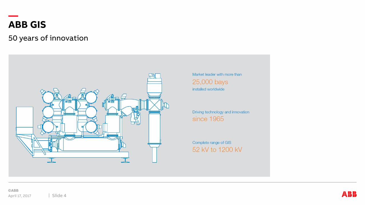
50 years of innovation
April 17, 2017 Slide 4
ABB GIS

Factory Network
April 17, 2017 Slide 5
GIS ABB

A lot of «first time»
April 17, 2017 Slide 6
ABB GIS

GIS main differences with AISSafety and availability in GIS
What is a gas compartment?

What is a GIS?
April 17, 2017 Slide 8
GIS main differences with AIS
Usual substation components arranged in
Metal enclosures (Aluminum or steel)
Insulated with gas (SF6) at high pressure
Components which are segregated into independent gas zones for operational flexibility
High reliable equipment and system
Assures availability during
Maintenance
Repair

Components
April 17, 2017 Slide 9
Gas compartment
Support insulator Support insulatorBarrier insulator Barrier insulator

Enclosure and conductor
April 17, 2017 Slide 10
Gas compartment
The enclosure can vary in length and shape, it’s form by an Aluminum casting
Aluminum (or copper) conductor

Barrier Insulator
April 17, 2017 Slide 11
Gas compartment

Barrier Insulator
April 17, 2017 Slide 12
Gas compartment
ABB clearly identify them with orange color

Support Insulator
April 17, 2017 Slide 13
Gas compartment
Support insulator Support insulatorBarrier insulator Barrier insulator
• ABB’s design of gas compartments at the busbar provides extra mechanical support by using support insulators in order to reduce mechanical stress and increase safety when maintenance or repair is performed

Density Monitor
April 17, 2017 Slide 14
Gas compartment
In every gas compartment (in every closed space between orange marks) you must find one. We only show some of them here
Note the cabling to the Local control cubicle

Pressure relief device
April 17, 2017 Slide 15
Gas compartment
In every gas compartment (in every closed space between orange marks) you must find one. We only show some of them here

Valve
April 17, 2017 Slide 16
Gas compartment
• Every gas compartment must have its own valve for the proper gas handling

Absorber
April 17, 2017 Slide 17
Gas compartment
• Each gas compartment is equipped with an absorber to remove moisture and decomposition products out of the gas
• Molecular sieve grade 5A is used as absorbing medium
• Easy access for exchange, if maintenance inside gas compartment required.
Adsorber (Circuit-breaker)
Adsorber (Other compartments)

Components
April 17, 2017 Slide 18
Gas compartment
Valve
Aluminum or copper conductor
AbsorberPressure Relief DeviceDensity Monitor
Enclosure
…and cabling to LCC
Support insulator Support insulatorBarrier insulator Barrier insulator

Service ContinuitySafety and availability in GIS

Safety rules have to be considered
April 17, 2017 Slide 20
Service continuity
Consequence = Reduced pressure means reduced dielectric withstand capability of the gas
compartment…..
Full pressure
Reduced pressure
Atmospheric pressure
Degass the compartment.. safety rules would prohibit working on one side of pressurised gas barrier which has been exposed to an arc…
Life part
Grounded part
… and therefore pressure will have to be reduced in the adjacent compartment; meaning… Repair /
maintainace
Reduced pressure

What happens if…
April 17, 2017 Slide 21
Service continuity
M a GIS gas compartment must be opened for maintenance
R a GIS component must be repaired after a flashover
E GIS is extended by a bay or more
T part of the GIS must be tested with High-voltage on site
…a GIS gas compartment must be opened for maintenance
replacement of a CB interrupter due to wear
replacement of a gas sealing system due to leakage
replacement of a saturated humidity adsorbent

What happens if…
April 17, 2017 Slide 23
Service continuity
A part of the substation (or the entire substation) must be taken off line for Maintenance/ Repair/ Extension/ Test
The extend of the shutdown depends on … multiple factors.
1. the circuit (DBB, SBB, OHB, …) and the sequence of the bays
2. partitioning (gas compartments, placement o fbarrier insulators)
3. other design features of the GIS (flange connections, placement oftemporary earthing devices)
4. OHS rules for working at pressurized insulators set by the user and/or byABB

International StandardsSafety and availability in GIS
What IEC says about this?

IEC 62271-203 – ed 2.0, recommendations – Annex F
April 17, 2017 Slide 25
Gas segregation and service continuity
Background:
• Reliability of GIS is generally very good
• Maintenance and failures can cause long outages
• Bad experience with some GIS designs
• European users wanted to have recommendations in IEC standard regarding Service Continuity

IEC 62271-203 – ed 2.0, recommendations – Annex F
April 17, 2017 Slide 26
Service continuity in GIS - Factors
Single line diagram
Gas compartment
Physical arrangement of components
Facilities for dismantling
Design of partitions
Provisions for onsitedielectric testing
Isolating link
Necessity of on-site dielectric testing
Provisions for futureextensions
Availability of spare parts

Annex F – Examples of Partitioning – Example 1
April 17, 2017 Slide 27
GIS partitioning
In some arrangements the two busbar-disconnectors are separated by only one partition. In Figure F.1. the removal of the gas compartment partition at 'A' may require both busbars of a double busbar substation to be de-energized, with the loss of all feeders on that section of busbar for the duration of the repair.
Figure F.1 — Impact due to the removal of common partition between busbar-disconnector

How partitioning may affect service continuity
April 17, 2017 Slide 28
GIS partitioning
SF6 operating pressure
SF6 reduced pressure
De-gassed atmospheric pressure air
Repair of partition insulator
Between fault and repair, the compartment needs to be de-energized
Pressure in the adjacent compartments may be reduced during repair for safety reason
Both busbars and all feeders are out of service

Annex F – Examples of Partitioning – Example 2
April 17, 2017 Slide 29
GIS partitioning
In Figure F.2 the removal of the disconnector, including its partitions, at ‘B' requires the compartments of the adjacent disconnectors to be de-gassed. This causes the loss of the associated feeders for the duration of the repair.
Figure F.1 — Impact of GIS partitioning on service continuity

Annex F – Examples of Partitioning – Example 3
April 17, 2017 Slide 30
GIS partitioning
In the case study, the removal of the disconnector at ‘D’ in SECTION-3 requires only the outage of the faulty feeder and not of the adjacent feeders. See Figure F.6.
Figure F.6 — Impact of GIS partitioning on service continuity

Annex F – Examples of Partitioning – Example 3
April 17, 2017 Slide 31
GIS partitioning
In the case study, the removal of the disconnector at ‘D’ in SECTION-3 requires only the outage of the faulty feeder and not of the adjacent feeders. See Figure F.6.
Figure F.6 — Impact of GIS partitioning on service continuity

Annex F – Examples of Partitioning – Example 4
April 17, 2017 Slide 32
GIS partitioning
Buffer compartments to avoid de-gassing of disconnector compartments and loss of Line 4
In the example the substation has a total number of six feeders, four line and two transformer feeders. The busbars are divided by a busbar separation and linked with a coupler. A future extension is planned at the right side of the substation

IEC 62271-203 – ed 2.0, recommendations – Annex F
April 17, 2017 Slide 33
User defines requirements on service continuity
It is the responsibility of users to define a strategy of maintenance relatively to the impact on service continuity and, it is the responsibility of manufacturers to design and define partitioning in order to fulfil users need.
The service continuity requirements should achieve an appropriate balance between equipment cost and the criticality of the substation in the user´s network.
The user may define some general statements that allow a quantitative assessment of the service continuity during maintenance, repair or extension. The following general statements are given as examples:
• At least one line and transformer-feeder must remain in service during maintenance and repair
• Maximum one busbar and one feeder permitted out of service during maintenance and repair
• The power flow must be maintained between specified feeders during extension

Remarks
User defines requirements on service continuity
April 17, 2017 * CIGRE brochureSlide 34
Our customers should specify:
– Circuit, possible with optimized feeder sequence*
– Service continuity requirements
• How many feeders adjacent to a faulty feeder/busbarsegment may be out of service during repair?
e.g. DBB all, 5, 3, 1?
• Shall HV testing of feeders/busbars be possible withoutshutdown?
• Shall the substation be extandable without shutdown?
• OHS procedures for working on pressurized partitions
Users Manufacturers
We:
– Design partitioning schemes and layouts according to customer requirements and ABB OHS rules
– Provide a maintanence/repair concept
– Provide a detailed method statement in case of repairs

Circuit
April 17, 2017 Slide 35
Design considerations
Highly recommended:
Cigre brochure TB585, Circuit Configuration Optimization
• Compares availability and repair of all common circuits in an easy to understand methodology
• Contains also maintenance considerations for GIS DBB systems

IEC 62271-203 – ed 2.0, recommendations – Annex F
April 17, 2017 Slide 36
Example for detailed service continuity requirements

IEC 62271-203 – ed 2.0, recommendations – Annex F
April 17, 2017 Slide 37
Documentation for enquiries and tenders

ABB solutionGIS designs for Service Continuity
Service continuity concept

Service continuity concept
April 17, 2017 Slide 39
ABB solution
There are 3 levels of service continuity:
LSC-X
• More than 3 feeders may be out of service simultaneously.
• All busbars may be out of service for a certain time.
LSC-3
• No more than 3 feeders may be out of service simultaneously.
• And at least one busbar has to be in service.
LSC-1
• No more than 1 feeder may be out of service simultaneously.
• And at least one busbar has to be in service.

Key benefits
April 17, 2017 Slide 40
Service continuity + Safety for personnel
Service Continuity Concept [SCC] – Partition insulators are designed according to IEC62271-203
– Bursting pressure type test: safety factor of 3 (referring to maximum diferential pressure duringoperation and maintanence, repair)
– Routine tests in production: safety factor of 2
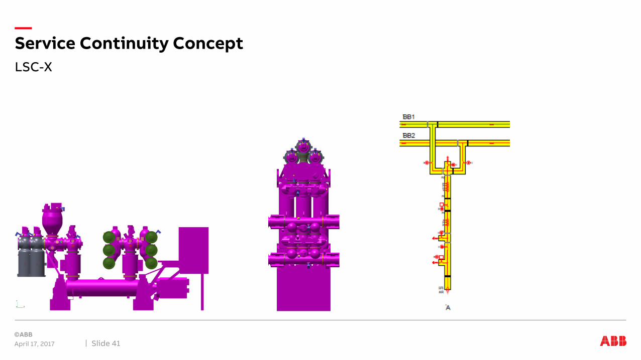
LSC-X
April 17, 2017 Slide 41
Service Continuity Concept

LSC-3
April 17, 2017 Slide 42
Service Continuity Concept

LSC-1
April 17, 2017 Slide 43
Service Continuity Concept
ABB solutionGIS designs for Service Continuity
Repair cases

Basic rules
April 17, 2017 Slide 45
ABB Solution
• Bay-wise gas segregation, to avoid outages of complete busbars
• Buffer compartment between busbar disconnectors to avoid shutdown of complete substations
• Buffer compartment between circuit breaker and busbardisconnector, to remain both busbars in Service in case of maintenance or repair
• Make strategic spares available
Double BB with partition insulators

Repair cases
April 17, 2017 Slide 46
Maintenance and repair concept
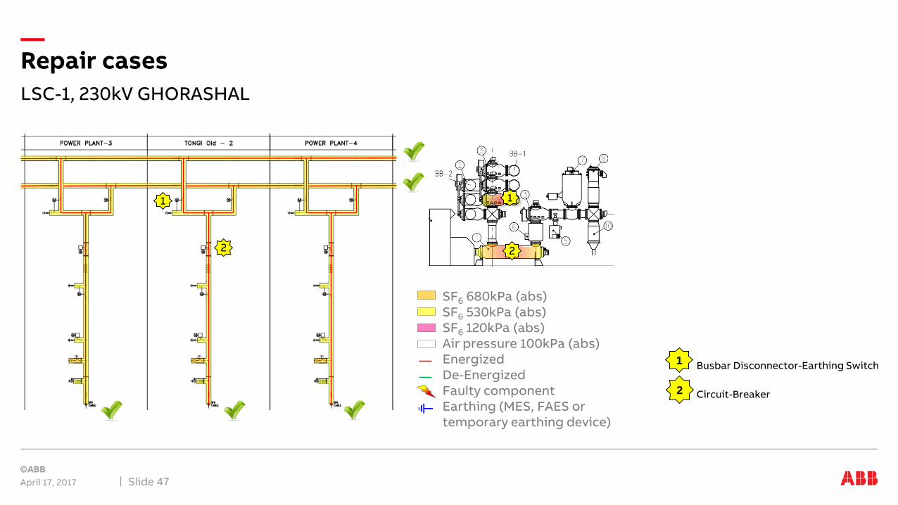
LSC-1, 230kV GHORASHAL
April 17, 2017 Slide 47
Repair cases
SF6 680kPa (abs)SF6 530kPa (abs)SF6 120kPa (abs)Air pressure 100kPa (abs)EnergizedDe-EnergizedFaulty componentEarthing (MES, FAES or temporary earthing device)
1
2
1
2
Busbar Disconnector-Earthing Switch
Circuit-Breaker
1
2

De-energize and earth faulty section
April 17, 2017 Slide 48
Case 1 - Busbar Disconnector/Earthing Switch replacement
SF6 680kPa (abs)SF6 530kPa (abs)SF6 120kPa (abs)Air amb. pressure 100kPa (abs)EnergizedDe-EnergizedFaulty componentEarthing (MES, FAES or temporary earthing device)
1

Gas handling
April 17, 2017 Slide 49
Case 1 - Busbar Disconnector/Earthing Switch replacement
SF6 680kPa (abs)SF6 530kPa (abs)SF6 120kPa (abs)Air amb. pressure 100kPa (abs)EnergizedDe-EnergizedFaulty componentEarthing (MES, FAES or temporary earthing device)
1

Replace faulty component
April 17, 2017 Slide 50
Case 1 - Busbar Disconnector/Earthing Switch replacement
SF6 680kPa (abs)SF6 530kPa (abs)SF6 120kPa (abs)Air amb. pressure 100kPa (abs)EnergizedDe-EnergizedFaulty componentEarthing (MES, FAES or temporary earthing device)
1

GIS parts which may remain in service
April 17, 2017 Slide 51
Case 1 - Busbar Disconnector/Earthing Switch replacement
Busbar disconnector replacement
After fault until revision
During revision
Busbar BB1
Busbar BB2
Affected feeder
Feeder on the left of the faulty bay
Feeder on the right of the faulty bay
1

De-energize and earth faulty section
April 17, 2017 Slide 52
Case 2 - Circuit-breaker replacement
SF6 680kPa (abs)SF6 530kPa (abs)SF6 120kPa (abs)Air amb. pressure 100kPa (abs)EnergizedDe-EnergizedFaulty componentEarthing (MES, FAES or temporary earthing device)
2

Gas handling
April 17, 2017 Slide 53
Case 2 - Circuit-breaker replacement
SF6 680kPa (abs)SF6 530kPa (abs)SF6 120kPa (abs)Air amb. pressure 100kPa (abs)EnergizedDe-EnergizedFaulty componentEarthing (MES, FAES or temporary earthing device)
2

Replace faulty component
April 17, 2017 Slide 54
Case 2 - Circuit-breaker replacement
SF6 680kPa (abs)SF6 530kPa (abs)SF6 120kPa (abs)Air amb. pressure 100kPa (abs)EnergizedDe-EnergizedFaulty componentEarthing (MES, FAES or temporary earthing device)
2

GIS parts which may remain in service
April 17, 2017 Slide 55
Case 2 - Circuit-breaker replacement
Circuit-breaker replacement
After fault until revision
During revision
Busbar BB1
Busbar BB2
Affected feeder
Feeder on the left of the faulty bay
Feeder on the right of the faulty bay
2

Other solutions in the marktetGIS designs for Service Continuity
Examples

DBB Switchgear. Observations & consequences ?
April 17, 2017 Slide 57
Lets take test !
Negative
example Observations
• No bay-wise gas segregation
• No buffer compartment between both busbar disconnectors
• CTs inside CB compartment
Consequence
• Failure in one BB disconnector will lead to a complete shutdown of the substation
• Failure in a busbar, will cause:
• long repair time
• big environment impact
Substation example from the 60’s

Double Busbar Scheme – High risk example
April 17, 2017 Slide 58
Arrangements and Configurations
Negative
example
Critical gas-zones
Double BB without partition insulators
LINE TRAFO CABLE TRAFO

Double Busbar Scheme – Positive example
April 17, 2017 Slide 59
Arrangements and Configurations
Positive
exampleDouble BB without partition insulators
LINE TRAFO CABLE TRAFO

Examples
April 17, 2017 Slide 60
Other solutions in the market
BUSBAR OUT OF SERVICE
COMPARTMENT DE-GASSED
BUSBAR OUT OF SERVICE
A

Conclusions

April 17, 2017 Slide 62
User defines requirements on service continuity
Users
responsibility to define strategy of service continuity
Manufacturers
responsibility to design and define
partitioning
User may define general statements:
• At least one feeder must remain in service
• Maximum one busbar out of service
• Maintain power flow during extensions
What customer invests now, customer will safe in the future!

Basic rules
April 17, 2017 Slide 63
Service Continuity
• Bay-wise gas segregation, to avoid outages of complete busbars
• Buffer compartment between busbar disconnectors to avoid shutdown of complete substations
• Buffer compartment between circuit breaker and busbardisconnector, to remain both busbars in Service in case of maintenance or repair
• Make strategic spares available
Double BB with partition insulators