Volunteer Career Mentor Binder - Aligned Impact Muscatine ...
Upload
khangminh22Category
view
1download
0
DSN STMR LEPE TNBGC1 DSEM 0604 Version 01
Nuclear Energy Division
Nuclear Services Department
Radioactive Materials Transportation Service
Packaging Operations Laboratory
Safety Analysis Report
TN-BGC 1 package
Chapter 4- mechanical strength of internalfittings
Clt: 7.1.1.3.1
Classification: DO
AUTHOR CHECKED BY APPROVED BY
Name V. PAUTROT S. CHAIX S. CLAVERIE-FORGUES
SIGN.
Date:
TABLE OF CHANGES
VERSI DATE AUTHOR TYPE OF CHANGE NBON PAGES
01 17/07/12 V. PAUTROT Initial issue 8
LIST OF ATTACHED DOCUMENTS(independent pagination, identification and formalism)
No. TITLE NB PAGES
Resistance of containers AA204, TN90, AA226, AA227, AA236 and AA303 to1 an internal pressure ref. EMB TNBGC PBC DJS CA 000339 A dated 33
07/08/03
2 Package TN-BGC 1 - Consequences of the combustion of hydrogen in the 282 _ TN90 internal fitting ref. 195H03W01 ind. A dated 12/08/03 28
Page 2/8

CONTENTS
1. INTRODUCTION ............................................................................................................................. 4
2. REFERENCES ................................................................................................................................ 4
3. IMPORTANT ELEMENTS FOR SAFETY AND STRESS .......................................................... 43.1. RESISTANCE OF INTERNAL FITTINGS TO INTERNAL PRESSURE: METHODOLOGY ............... 4
3.2. MAINTENANCE OF THE CRITICALITY-SAFETY OF THE PACKAGE MODEL:METHODOLOGY ..................................................................................................................................... 5
3.2.1. Normal conditions of transport ................................................................................................... 53.2.2. Accident conditions of transport ................................................................................................ 5
4. RESISTANCE OF CONTAINERS TO INTERNAL PRESSURE ................. ............................. 64.1. RESISTANCE OF CONTAINERS TO STATIC PRESSURE .............................................................. 6
4.1.1. Resistance of containers ............................................................................................................. 6
4.1.2. Conclusion ......................................................................................................................................... 64.2. MECHANICAL RESISTANCE OF THE INTERNAL FITTINGS TO AN EXPLOSION CAUSED BY
HYDROGEN .............................................................................. , .............................................................. 7
5. CONCLUSION .................................................................................................................................. 7
-P 3
Page 3/8

1. INTRODUCTION
The purpose of this chapter is to analyse the mechanical behaviour of the internal fittings loaded into the TN-
BGC 1 under normal and accident conditions of transport.
2. REFERENCES[1]: Regulations on the transport of radioactive materials - 1996 edition (revised, No TS-R-1 -
International Atomic Energy Authority.
[2]: Formulas for stress and strain - ROARK and YOUNG - Edition 1989.
[3]: CODAP 95 - French code on the calculation of appliances under pressure.
3. IMPORTANT ELEMENTS FOR SAFETY AND STRESS
This paragraph covers the content and the associated internal fittings, for which the mechanical strength must@
be justified under normal or accident conditions of transport.
The safety studies carried out in this report concerning confinement or dose rates do not require that the
internal fittings resist normal or accident conditions of transport. In fact, the containment chamber is not
delimited by the internal fittings. It has not been demonstrated that these internal fittings remain leak-tight
under NCT or ACT. For information, the drop test reports in chapter 3 nevertheless show that the internal
fittings that were tested remain leak-tight after ACT.
Consequently, only two requirements are considered in this chapter:
* the resistance of the packaging sheaths to internal pressure generated:
> by the thermal powerof the content and the regulatory ambient conditions in NCT as wellas by any gaseous discharges due to radiolysis,
> by the fire test or by an explosion related to the accumulation of hydrogen in thecontainers, in ACT
" the maintenance of the criticality-safety of the package model, therefore the fissile materials in@the geom etrical configuration determined in chapter 8, under normal and accident conditions oftransport. This implies justifying the isolation of the fissile material in the internal fittings that forman integral part of the isolation system, following the tests intended to qualify the packagestransporting fissile material.
3.1. RESISTANCE OF INTERNAL FITTINGS TO INTERNAL PRESSURE: METHODOLOGY
It is confirmed that the various internal fittings used to maintain the content in a defined volume are not
stressed beyond the elastic limit of the materials that compose them when they are subject to internal
pressure.
The determined pressures must cover all of the pressures that may be reached under normal and accident
conditions of transport, particularly according to:
* the initial pressure before loading,
* the thermal pressure of the content, which may vary between 0 and 340 W,
Page 4/8
* the temperatures reached in the cavity of the internal fittings,
* the pressure generated by gaseous discharges,
* the transport configuration (package horizontal, vertical or in caisson),
* normal and accident conditions defined by the regulations.
The particular case of resistance to an internal explosion following a possible accumulation of hydrogen is also
covered in paragraph 4.2.
3.2. MAINTENANCE OF THE CRITICALITY-SAFETY OF THE PACKAGE MODEL: METHODOLOGY
It is confirmed that the various internal fittings used to maintain the content in a defined volume are not
stressed beyond the elastic limit of the materials that compose them when they are subject to internal
pressure.
The sheaths and spacers which must remain integral to ensure the criticality-safety of the package model are
presented in table 1, for each of the fissile contents.
3.2.1. Normal conditions of transport
We notice in table 1 that the resistance of the primary or secondary packaging (boxes for powder and pellets,
flasks for liquid solutions), the racks and cladding for fuel rods and the baskets, wedges and spacers for the
metal content is not required to be demonstrated, except for the spacers that keep the metallic contents apart
(spacers E4 and E5) or those that radially position the material in the tertiary containers (E7); this resistance
may nevertheless be considered as confirmed, given the low levels of stress to which these elements are
subject.
Under normal conditions of transport, the only stress used for the sheaths is the internal pressure. The
calculation conditions are therefore defined in the previous paragraph.
3.2.2. Accident conditions of transport
Under accident conditions of transport, the mechanical tests imposed by the regulations must be considered.
These are as follows for the criticality-safety verification of damaged packages:
* mechanical test combining the dynamic crushing of the TN-BGC1 package by a weight of 500kg dropping 9 metres with a free drop of the TN-BGC 1 from a height of 1 metre onto a punch.
These two tests are not likely to cause high stresses on the internal fittings because the dynamiccrush test does not cause significant deceleration on the internal fittings. The various drop testscarried out in chapter 3 demonstrate, in particular, that the TN-BGC 1 package's internal cavity isfully preserved during these tests (total lack of distortion). We also show that following thesetests, the internal fittings remain leak-tight: indeed, the leak rate from the TN90 fitting remainssatisfactory after the various test sequences (see chapter 3 in the attached documents 2 and 3).As the TN90 is the least-robust internal fitting of all the internal fittings that are usable in thepackage (thinnest walls), it is confirmed that the internal fittings do not undergo distortion andremain leak-tight following ACT,
* the thermal test (hydrocarbon fires of a duration of 30 minutes).Chapter 5 specifies the conditions of temperature and pressure that are likely to occur in theinternal fittings. These results are taken into account to justify the internal fittings' resistance to
Page 5/8

pressure,
immersion test under a height of water of 15 metres for 8 hours, or the enhanced immersiontest under a height of water of 200 metres for 1 hour, which applies here for certain contentcontaining more than 10 5 A2.It is shown in chapter 3 that these two tests do not call into question the strength of theconfinement envelope of the package model TN-BGC 1. They therefore have no impact on theinternal fittings.
The only stress to be considered for the internal fittings is therefore, as in normal conditions of transport, the
internal pressure. The calculation conditions are therefore defined in the previous paragraph.
4. RESISTANCE OF CONTAINERS TO INTERNAL PRESSURE
In this paragraph, the resistance, to internal pressure, of containers of type TN90, AA 204, AA 203 and AA 41
is analysed.
The particular case of resistance to an internal explosion following a possible accumulation of hydrogen is also*
covered in paragraph 3.2. This case concerns the containers TN 90, AA 41, AA 203 and AA 204.
4.1. RESISTANCE OF CONTAINERS TO STATIC PRESSURE
4.1.1. Resistance of containers
The analysis of the resistance to internal pressure of containers'of type TN 90, AA 204, AA 203 and AA 41 is
found in attached document no 1 according to the rules of CODAP 95 [3].
4.1.2. Conclusion
Concerning containers of type AA 204, AA 203, AA 41 and TN 90, the maximum acceptable pressures
determined in attached document 1, so as not to exceed the CODAP resistance criteria, are summarised in
the following table:
Resistance of containers AA 204, AA 203, AA 41 and TN 90
Normal conditions Exceptional situation Exceptional situation...... . _ _}n 1l n02
Padm (in Pa) 9.105 13.105 13.105
ý'where:
" the normal situation corresponds to normal use of the containers under normal conditions oftransport,
" the exceptional situation nol corresponds to exceptional use of the containers under normalconditions of transport,
" the exceptional situation n02 corresponds to an exceptional use of the containers under accidentconditions of transport.
Page 6/8
These maximum acceptable pressures are greater than the pressures that are likely to be encountered in
these containers (including when taking into account gaseous discharges - see Chapter 9), therefore the
maintenance of the content in the containers is guaranteed.
4.2. MECHANICAL RESISTANCE OF THE INTERNAL FITTINGS TO AN EXPLOSION CAUSED BYHYDROGEN
The resistance to pressure of the TN90 container during an internal explosion following a possible
accumulation of hydrogen causing a pressure peak of 60 bars is demonstrated and justified in the attached
document 2.
Note: the containers AA203, AA204 and AA41 are not studied in the previously-mentioned attached
document. However, we may consider their resistance demonstrated by the results obtained because these
containers are, in all points (shell, base and lid) of their design more robust than the TN 90. The safety
margins in relation to a risk of explosion are therefore superior for these containers.
Given the factor 8.8 for the multiplication of the initial pressure during an explosion, the pressure inside these
containers must not exceed 6.8 bars in order to guarantee maintenance of their geometry and no dispersion of
material. When the containers are likely to produce gaseous discharges -in the absence of devices that are
able to prevent the accumulation of gas in the container's cavity (Poral plug), the transport time will be limited
under the conditions specified in chapter 9.
5. CONCLUSION
This chapter demonstrates that the internal fittings used to transport the content in the TN-BGC 1 package are
capable of undergoing normal and accident conditions of transport (including during gaseous discharge or an
explosion related to an accumulation of hydrogen) without compromising the safety of the TN-BGC 1 package
model.
Page 7/8

TABLE 1: INTERNAL FITTINGS HAVING A CRITICALITY-SAFETY FUNCTION IN THE TN-BGC IPACKAGE MODEL
Criticality-safety parameters
C~ E2oE
AA203) cc. TN90 AA204 Spacers
TN9O AA41
1 120 x x
2 120 x x
3 120 x x
4 120 90 x x (E4)
5 120 90 x x (E5)
6 120 ×
7 120 x x
8 120 x x
9 120 x x
10 120 X x
120 x x.
11 100 x x (E7)
60 __x x (E7)
18 120 ._< x
19 120 x x
20 120 x x
23 120 x x
26 120 x x
40 120 x x
41 " 120 x x
42 :120 x x
46 120 x x
Page 8/8

REPLACEMENT OF CEA PACKAGING DEN/DTAP/SPI!GETCEA SAFETY DOSSIER - TYPE TN-BGCI PACKAGING
CHAPTER 5 - APPENDIX 2RESISTANCE OF AA204, TN90, AA226, AA227, AA336
COMMISSARIAT A LENERGIE ATOMIvQUE AND AA303 CONTAINERS TO INTERNAL PRESSURE
ORIGINAL
PROGRAMME:TITLE:
REPLACEMENT OF CEA PACKAGINGSAFETY DOSSIER - TYPE TN-BGCI PACKAGING
CHAPTER 5 - APPENDIX 2RESISTANCE OF CONTAINERS
AA204, TN90, AA226, AA227, AA336 AND AA303TO INTERNAL PRESSURE
COPY
Summary:- This note is an integral part of the TN-BGCl safety file, and includes substantiation for the
structural resistance of containers AA204, TN90, AA226, AA227, AA336 and AA303 to internalpressure
Signature [signature] [signature] [signature]
Date 18/07/03 31/07/03 07/08/2003Name C. MATHON T. CUVILLIER D. LALLEMANDUnit ATR engineering DEN/DTAP/SPI/GET DEN/DTAP/SPI/GET
t -tPosition Engineer Project manaager Head of GET
I Written by J Checked by Approved by
I 2 3T I Nl 678I4 5 6 7 8 9 10 II 12 13 14
IClAI010101313191AI15 16 17 18 19 20 21 22 23
¶l• Chapter 5 - Appendix 2
This document is the property of the CEA and cannot be used, reproducedor communicated without prior written authorization from the CEA.
Page: 1 /33 1
REPLACEMENT OF CEA PACKAGING DEN/DTAP/SPI/GET
CEA SAFETY DOSSIER - TYPE TN-BGC1 PACKAGING
CHAPTER 5 - APPENDIX 2RESISTANCE OF AA204, TN90, AA226, AA227, AA336
COMMISSARIAT A LENERGIE ATOMIQUE AND AA303 CONTAINERS TO INTERNAL PRESSURE
INDEX OF CHANGES
EDITION DATE Type of change Pagesmodified
A 07/08/03 Issue of document
EM ITINIBI c PIB IC ICDAIC 00 1313191A1 2 3 4 5 6 7 8 9 10 11 12 13 14 15 16 17 18 19 20 21 22 23
Ior communicated without prior written authorization from the CEA.
REPLACEMENT OF CEA PACKAGING DEN/DTAP/SPIIGETC E A SAFETY DOSSIER - TYPE TN-BGC1 PACKAGING
CHAPTER 5 - APPENDIX 2RESISTANCE OF AA204, TN90, AA226, AA227, AA336
COMMISSARIAT A LENERGIE ATOMIQUE AND AA303 CONTAINERS TO INTERNAL PRESSURE
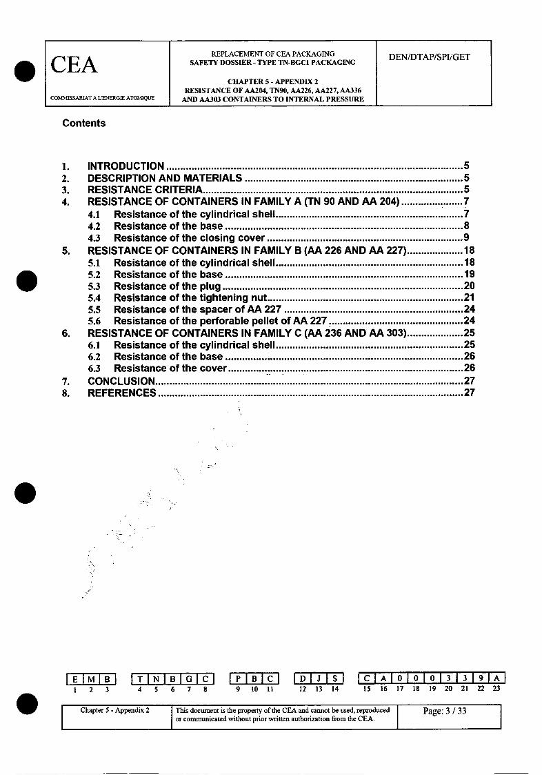
Contents
1. INTRO DUCTIO N ...................................................................................................... 52. DESCRIPTION AND MATERIALS ......................................................................... 53. RESISTANCE CRITERIA .......................................................................................... 54. RESISTANCE OF CONTAINERS IN FAMILY A (TN 90 AND AA 204) .................. 7
4.1 Resistance of the cylindrical shell ............................................................... 74.2 Resistance of the base ................................................................................ 84.3 Resistance of the closing cover ................................................................ 9
5. RESISTANCE OF CONTAINERS IN FAMILY B (AA 226 AND AA 227) ................ 185.1 Resistance of the cylindrical shell ............................................................... 185.2 Resistance of the base ................................................................................ 195.3 Resistance of the plug .................................................................................. 205.4 Resistance of the tightening nut ................................................................. 215.5 Resistance of the spacer of AA 227 ........................................................... 245.6 Resistance of the perforable pellet of AA 227 ............................................ 24
6. RESISTANCE OF CONTAINERS IN FAMILY C (AA 236 AND AA 303) ............... 256.1 Resistance of the cylindrical shell .............................................................. 256.2 Resistance of the base ................................................................................ 266.3 Resistance of the cover ................................................................................ 26
7. CO NC LUSIO N .............................................................................................................. 278. REFERENCES ............................................................................................................. 27
1 2 3 4 5 6 7 8 9 10 11 12 13 14ICTAOTOO133191A
IS 16 17 18 19 20 21 22 23
Chapter 5 - Appendix 2 IThis document is the property of the CEA and cannot be used, reproduced I Page: 3 / 33
or communicated without prior written authorization from the CEA.

REPLACEMENT OF CEA PACKAGING DEN/DTAP/SPI/GET
CEA SAFETY DOSSIER- TYPE TN-BGC1 PACKAGING
CHAPTER 5 - APPENDIX 2RESISTANCE OF AA204, TN90, AA226, AA227, AA336
COMMISSARIAT A LENERGIE ATOMIQUE AND AA303 CONTAINERS TO INTERNAL PRESSURE
SUMMARY
The aim of this chapter is to analyse mechanical resistance to an internal pressure forpacking containers AA 204, TN 90, AA 226, AA 227, AA 236 and AA 303. Threeresistance criteria are defined for each of these containers according to CODAP.
The first resistance criterion corresponds to normal use (normal situation) of thecontainers in normal transport conditions (calculated based on the properties of thematerials within the temperature tolerance interval of normal transport conditions).
The second resistance criterion corresponds to exceptional use (exceptional situation no1) of the containers in normal transport conditions (calculated based on the properties ofthe materials within the temperature tolerance interval of normal transport conditions).
The third resistance criterion corresponds to exceptional use (exceptional situation no 2)of the containers in accident transport conditions (calculated based on the properties ofthe materials within the temperature tolerance interval of accident transport conditions).
The maximum acceptable pressures determined to avoid exceeding the resistancecriteria of CODAP are resumed in the following tables:
Resistance of containers AA 226 and AANormal situation Exceptional Exceptional
situation n1l situation n02
Padm (in Pa) 35.105 53.105 52.105
Resistance of containers AA 236 and AA 303
Normal situation Exceptional Exceptionalsituation nol situation n02
Padm (in Pa) 10.105 15.105 15.105
1 2 34T IN I6B784 5 6 7 8 9 10 11 12 13 14
IC AIA 010101313191AI15 16 17 18 19 20 21 22 23
Chapter 5 - Appendix 2 This document is the property of the CEA and cannot be used, reproduced Page: 4 / 33or communicated without prior written authorization from the CEA.
NW

REPLACEMENT OF CEA PACKAGING DEN/DTAP/SPI/GETCEA SAFETY DOSSIER - TYPE TN-BGCI PACKAGINGCELACHAPTER 5 - APPENDIX 2
RESISTANCE OF AA204, TN90, AA226, AA227, AA336COMMISSARIAT A LENERGIE ATOMIQUE AND AA303 CONTAINERS TO INTERNAL PRESSURE
1. INTRODUCTION
The aim of this appendix is to analyse resistance to internal pressure based on the rulesof CODAP 95 <1> of the following packing containers:
* containers AA 204 and TN 90 (family A),
* containers AA 226 and AA 227 (family B),
* containers AA 236 and AA 303 (family C),
2. DESCRIPTION AND MATERIALS
A description of each container is included in chapter 3.
The rest of this document considers a general steel grade in terms of resistance toensure the least favourable point of view, i.e. austenitic stainless steel Z3 CN 18.10 orequivalent. Only the study of the resistance of the covers of containers in family A willconsider the steel grade Z6 CNDT 17.12, tolerance interval for containers in the family(AA 204 and TN 90).
3. RESISTANCE CRITERIA
CODAP 95 <1> distinguishes 2 types of resistance criteria, depending on whether thesituation is normal or exceptional.
Resistance criteria in normal service situations are determined based on normaltransport conditions. Therefore, according to <1> (part C, table C 1.7.2), the nominalconstraints for the calculation of fn are as follows:
Rmfn=-3
where Rm is the resistance of the steel to rupture within the temperature toleranceinterval for the maximum temperature of the containers in normal transport conditions.
This gives:
1 2 3 4 5 6 7 89 I0 I I 1D3S
12 13 14ICIAIOIOIO1 313 191AI
15 16 17 18 19 20 21 22 23
l --r5-Apni ae:/3ITi
oueti hepoet fteCAadcantb sd erdcdChapter 5 - Appendix 2 This document is the property of the CEA and cannot be used, reproduced
or communicated without prior written authorization from the CEA. IPage: 5 / 33 1
REPLACEMENT OF CEA PACKAGING DEN/DTAP/SPI/GET
CEA SAFETY DOSSIER - TYPE TN-BGC1 PACKAGING
CHAPTER 5 - APPENDIX 2RESISTANCE OF AA204, TN90, AA226, AA227, AA336
COMMISSARIAT A LENERGIE ATOMIQUE AND AA303 CONTAINERS TO INTERNAL PRESSURE
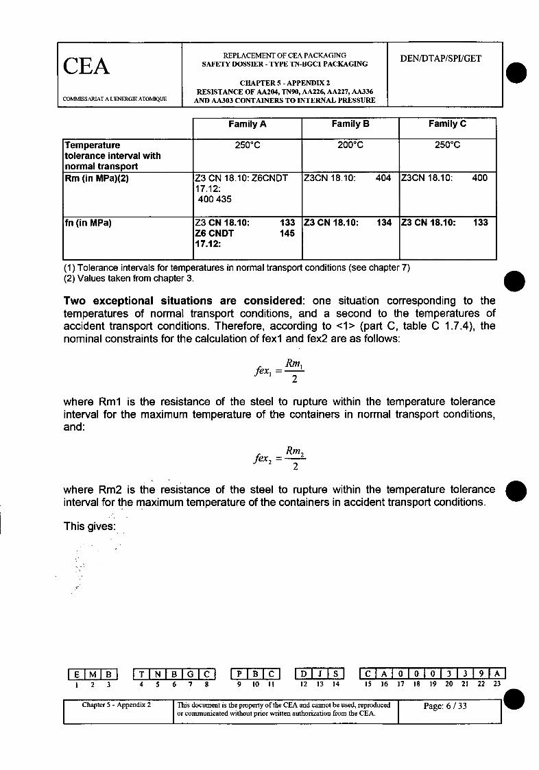
Family A Family B Family C
Temperature 2500C 2000C 2500Ctolerance interval withnormal transportRm (in MPa)(2) Z3 CN 18.10: Z6CNDT Z3CN 18.10: 404 Z3CN 18.10: 400
17.12:400435
fn (in MPa) Z3 CN 18.10: 133 Z3 CN 18.10: 134 Z3 CN 18.10: 133Z6 CNDT 14517.12:
(1) Tolerance intervals for temperatures in normal transport conditions (see chapter 7)(2) Values taken from chapter 3.
Two exceptional situations are considered: one situation corresponding to thetemperatures of normal transport conditions, and a second to the temperatures ofaccident transport conditions. Therefore, according to <1> (part C, table C 1.7.4), thenominal constraints for the calculation of fexl and fex2 are as follows:
fex, Rml2
where Rml is the resistance of the steel to rupture within the temperature toleranceinterval for the maximum temperature of the containers in normal transport conditions,and:
fex2 Rm 22
where Rm2 is the resistance of theinterval for the maximum temperature
steel to rupture within the temperature toleranceof the containers in accident transport conditions.
This gives:
I 2 3ITIN5BIGIc7
4 5 6 7 8 9 10 IIDIJSIS12 13 14
IClAI010101313191A15 16 17 18 19 20 21 22 23
I
Chapter 5 - Appendix 2 This document is the property of the CEA and cannot be used, reproducedor communicated without prior written authorization from the CEA.
Page: 6 / 33
W
REPLACEMENT OF CEA PACKAGING DEN/DTAP/SPUGETCEA SAFETY DOSSIER - TYPE TN-BGC1 PACKAGING
CHAPTER 5 - APPENDIX 2RESISTANCE OF AA204, TN90, AA226, AA227, AA336
COMM•SSARIAT A LENERGIE ATOMIQUE AND AA303 CONTAINERS TO INTERNAL PRESSURE
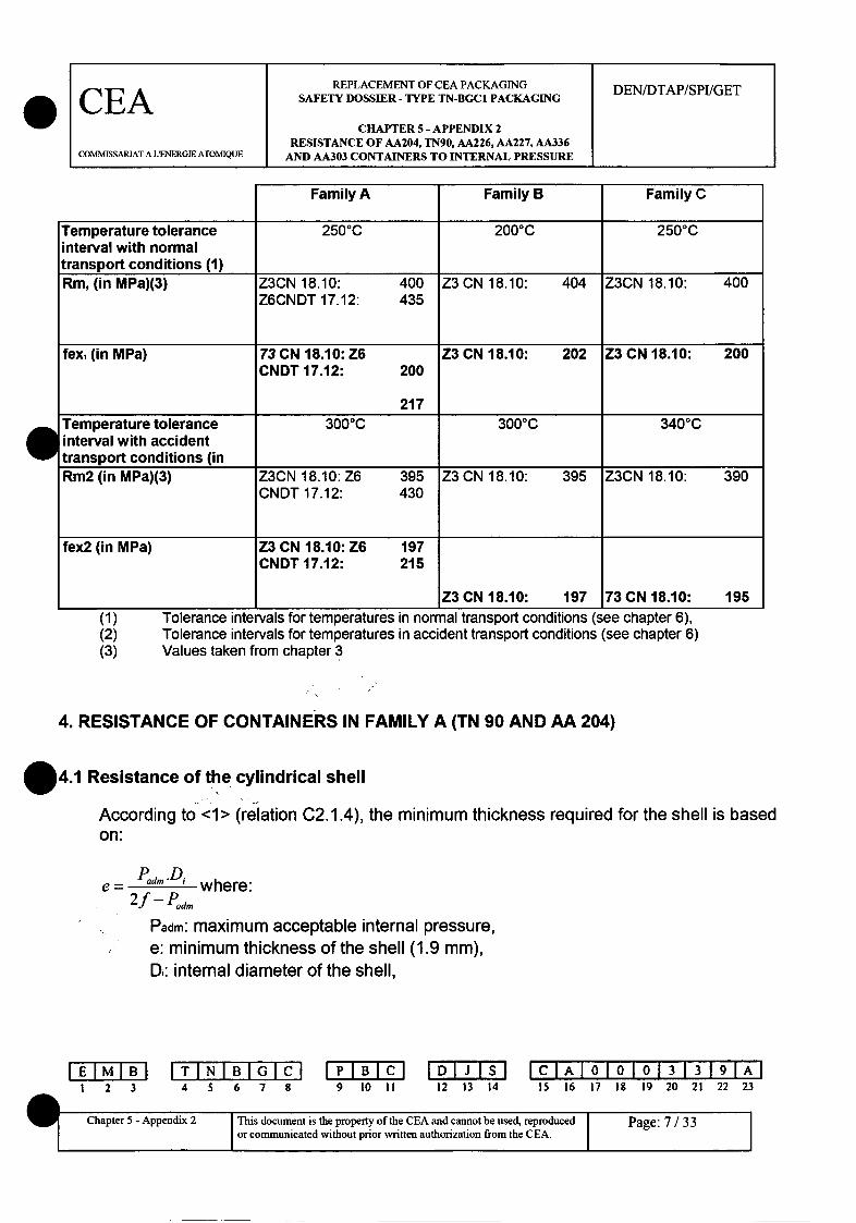
Family A Family B Family C
Temperature tolerance 2500C 2000C 2500Cinterval with normaltransport conditions (1)Rm, (in MPa)(3) Z3CN 18.10: 400 Z3 CN 18.10: 404 Z3CN 18.10: 400
Z6CNDT 17.12: 435
fex, (in MPa) 73 CN 18.10: Z6 Z3 CN 18.10: 202 Z3 CN 18.10: 200CNDT 17.12: 200
217
Temperature tolerance 3000C 3000C 3400Cinterval with accidenttransport conditions (inRm2 (in MPa)(3) Z3CN 18.10: Z6 395 Z3 CN 18.10: 395 Z3CN 18.10: 390
CNDT 17.12: 430
fex2 (in MPa) Z3 CN 18.10: Z6 197
CNDT 17.12: 215
Z3 CN 18.10: 197 73CN18.10: 195
(1)(2)(3)
Tolerance intervals for temperatures in normal transport conditions (see chapter 6),Tolerance intervals for temperatures in accident transport conditions (see chapter 6)Values taken from chapter 3
4. RESISTANCE OF CONTAINERS IN FAMILY A (TN 90 AND AA 204)
*4.1 Resistance of the cylindrical shell
According to <1> (relation C2.1.4), the minimum thickness required for the shell is basedon:
Poem *D,e - *where:
2f - Pad.
Padm: maximum acceptable internal pressure,e: minimum thickness of the shell (1.9 mm),Di: internal diameter of the shell,
1 2 3 4 5 6 7 8 9 10 II 12 13 14ICIAI01010131I3191AI
15 16 17 18 19 20 21 22 23
Chapter 5 - Appendix 2 This document is the property of the CEA and cannot be used, reproducedor communicated without prior written authorization from the CEA.
Page: 7 / 33
REPLACEMENT OF CEA PACKAGING DEN/DTAP/SPI/GETCEA SAFETY DOSSIER - TYPE TN-BGCI PACKAGING
CHAPTER 5 - APPENDIX 2RESISTANCE OF AA204, TN90, AA226, AA227, AA336
COMMISSARLAT A LENERGIE ATON1QUE AND AA303 CONTAINERS TO INTERNAL PRESSURE
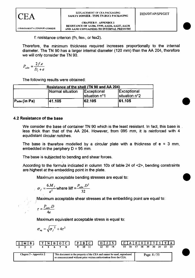
f: resistance criterion (fh, fexi, or fex2).
Therefore, the minimum thickness required increases proportionally to the internaldiameter. The TN 90 has a larger internal diameter (120 mm) than the AA 204, thereforewe will only consider the TN 90.
P,,d,, - 2 f.e+f eTam=Di +e
The following results were obtained:
Resistance of the shell (TN 90 and AA 204)Normal situation Exceptional Exceptional
situation nol situation n02Padm (in Pa) 41.105 62.105 61.105
4.2 Resistance of the base
We consider the base of container TN 90 which is the least resistant. In fact, this base isless thick than that of the AA 204. However, from 095 mm, it is reinforced with 4equidistant circular notches.
The base is therefore modelled by a circular plate with a thickness of e = 3 mm,embedded in the periphery D = 95 mm.
The base is subjected to bending and shear forces.
According to the formula indicated in column 10b of table 24 of <2>, bending constraintsare highest at the embedding point in the plate.
Maximum acceptable bending stresses are equal to:
6 .M p _D2
of = fwhere Mf = adm
e 32'Maximum acceptable shear stresses at the embedding point are equal to:
.am' •am .D
4e
Maximum equivalent acceptable stress is equal to:
•q 2"• +-f +4
0
1 2 3IT INI BI6G
4 5 6 7 8 9 10 II 12 13 14IC IAI6 I1 I0 1313191A9
15 16 17 18 19 20 21 22 23
Chapter 5 - Appendix 2 This document is the property of the CEA and cannot be used, reproduced I Page: 8/33C e 1n i or communicated without prior written authorization from the CEA. I

REPLACEMENT OF CEA PACKAGING DEN/DTAP/SPI/GETCEA SAFETY DOSSIER - TYPE TN-BGC PACKAGING
CHAPTER 5 - APPENDIX 2RESISTANCE OF AA204, TN90, AA226, AA227, AA336
COMMISSARIAT A LENERGIE ATOMIQUE AND AA303 CONTAINERS TO INTERNAL PRESSURE
O'eq is a total primary stress, and must therefore obey the following:
oe, = 1.5 x f (see C10.1.7.1 of <1>), where f is the resistance criterion (fn, fexi or fex2).
i is a pure shear stress and must therefore obey the following:r = 0.6 x f (see C10.1.7.3 of <1>).This gives:
Resistance of the shell (TN 90 and AA204)
Normal situation Exceptional Exceptionalsituation nol situation n02
Padm in bending (in Pa) 10.105 15.105 15.105
Padm in shear (in Pa) 100.105 151.105 149.105
Padm (in Pa) 10.105 15.105 15.105
4.3 Resistance of the closing cover
We consider the closing cover of container AA 204 which is the least resistant. In fact, thematerial (stainless steel Z6 CNDT 17.12) is less resistant than the material of the cover ofthe TN 90 (stainless steel Z6 CNU 17.04). In addition, if the AA 204 is subjected tointernal pressure, the plug is supported in the centre of the cover via a threaded axiswhich distributes forces less effectively than the folding handle on the TN 90.
4.3.1 Closing cover
The closing cover is modelled using an axisymmetric gantry, which can absorb threeloading options, which depend on the quality of the sealing provided by the internal o ringbetween the upper and lower end plates.
4.3.1.1 Initial loading option
The internal o ring between the upper and lower end plates is assumed to provide fullsealing.
1 2 34T - 678G4 5 6 7 8 9 10 !1 12 13 14
ICIAIOIOIO 13 13191AI15 16 17 18 19 20 21 22 23
Chapter 5 - Appendix 2 This document is the property of the CEA and cannot be used, reproducedor communicated without prior written authorization from the CEA. I
Page: 9 / 33 I
REPLACEMENT OF CEA PACKAGING DEN/DTAP/SPI/GET
CEA SAFETY DOSSIER - TYPE TN-BGC1 PACKAGING
CHAPTER 5 - APPENDIX 2RESISTANCE OF AA204, TN90, AA226, AA227, AA336
COMMISSARIAT A LUENERGIE ATOMIQUE AND AA303 CONTAINERS TO INTERNAL PRESSURE
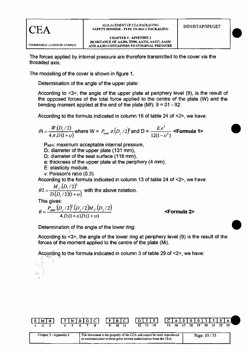
The forces applied by internal pressure are therefore transmitted to the cover via the
threaded axis.
The modelling of the cover is shown in figure 1.
Determination of the angle of the upper plate:
According to <3>, the angle of the upper plate at periphery level (9), is the result ofthe opposed forces of the total force applied to the centre of the plate (W) and thebending moment applied at the end of the plate (Mf): 9 = 01 - 92.
According to the formula indicated in column 16 of table 24 of <2>, we have:
91 = w.(D/2) where W = Pam 2y.(DJ /2) and D - E.e <Formula 1>4r.Df(1 + 0) 12(1 _ 2 )
Padm: maximum acceptable internal pressure,Di: diameter of the upper plate (131 mm),Dj: diameter of the seal surface (118 mm),e: thickness of the upper plate at the periphery (4 mm),E: elasticity module,v: Poisson's ratio (0.3).
According to the formula indicated in column 13 of table 24 of <2>, we have:
9 Mf .(D / 2)202 .(D, / 2)- with the above notation.D.(Di / 2).(1+ v)
This gives:
Pad4.(Dj/2).(Dj / 2)Mf.(Dj / 2)
4.D.(1 + v)D.(1 + v)<Formula 2>
Determination of the angle of the lower ring:
According to <3>, the angle of the lower ring at periphery level (9) is the result of theforces of the moment applied to the centre of the plate (M,).
According to the formula indicated in column 3 of table 29 of <2>, we have:
1 2 3TINIBGC4 5 6 7 8
P B IBC9 10 11 12 13 14
C IA 1010 1013 13 19 1A15 16 17 18 19 20 21 22 2 3 '
Chapter 5 - Appendix 2 This document is the property of the CEA and cannot be used, reproduced Pap:or communicated without prior written authorization from the CEA.

REPLACEMENT OF CEA PACKAGING DEN/DTAP/SPI/GET
CEA SAFETY DOSSIER - TYPE TN-BGCI PACKAGING
CHAPTER 5 - APPENDIX 2RESISTANCE OF AA204, TN90, AA226, AA227, AA336
COMMISSARIAT A LENERGIE ATOMIQUE AND AA303 CONTAINERS TO INTERNAL PRESSURE
0M= lwhere D'= E.1' , (c= 3(1-_V 2 and--D'.A.C11 12(1- 2 ) 21 (Dc/2)2.t2 a
cosh(1). sinh(Al) + cos(1). sin(A1)
Sinh 2 (A)- Sin 2 (Al)
Where:'t: thickness of the ring (2.5 mm),Dc: mean diameter of the ring (133.5 mm),1: height of the ring (8 mm),E: elasticity module,v: Poisson's ratio (0.3).The expression of e' is only valid if Al < 6, which has been proved (A.1 = 0.8).
Determination of moment Mf
According to <3>, the angle of the upper plate at periphery level (0) is equal to theangle of the lower ring at periphery level (E'): E = e'.
This gives:
Padm,(Dj/2)2.(Dj/2) Mf.(Dj/ 2 ) Mf C12
4.D(1 + v) D.(1 + o) D'.i.CI<Formula 3>
i.e.: Mf C12 + (D /2).t Pa,,.(Dj /2) 2 (Dj /2).ti~e: M Lc a (1 + o).e' ) 4.e 2.(l + )
Mfx(61 + 12,3) = 10705xPdm
Mf -- 146.P
Determination of Pad. at the Periphery of the upper plate:Maximum acceptable bending stresses are equal to:
6Mf= where Mf = 14 6 /Padm
'f e2
Maximum acceptable shear stresses at the embedding point are equal to:
Pod,.(Dj / 2)2
Di eMaximum equivalent acceptable stress is equal to:
1 2 3ITI N I6B784 5 6 7 8 9 10 II 12 13 14
I C IA oI oI oI013 3T19IFA-115 16 17 18 19 20 21 22 23
Chapter 5 - Appendix 2 This document is the property of the CEA and cannot be used, reproduced Page: I1Ior communicated without prior written authorization from the CEA.
REPLACEMENT OF CEA PACKAGING DEN/DTAP/SPI/GET
CEA SAFETY DOSSIER -TYPE TN-BGC1 PACKAGING
CHAPTER 5 - APPENDIX 2RESISTANCE OF AA204, TN90, AA226, AA227, AA336
COMMISSARIAT A L'ENERGIE ATOMIQUE AND AA303 CONTAINERS TO INTERNAL PRESSURE
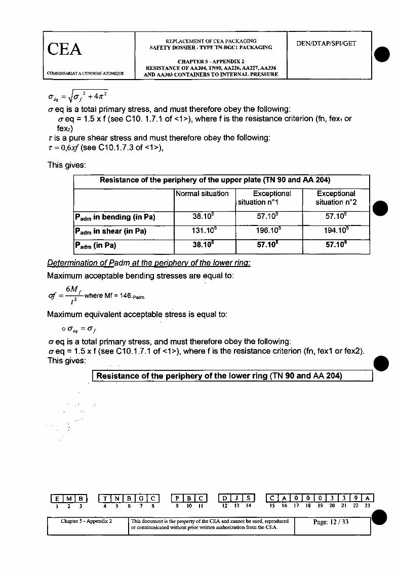
O'aq = •af +-4r
a eq is a total primary stress, and must therefore obey the following:a eq = 1.5 x f (see C10. 1.7.1 of <1>), where f is the resistance criterion (fn, fexi orfex2)
r is a pure shear stress and must therefore obey the following:I- = 0,6xf (see C10.1.7.3 of <1>),
This gives:
Determination of Padm at the periphery of the lower rinqg:
Maximum acceptable bending stresses are equal to:
of = 6 where Mf = 1 4 6 .Padm
t2
Maximum equivalent acceptable stress is equal to:
o0 a =a'f
a-eq is a total primary stress, and must therefore obey the following:a- eq = 1.5 x f (see C10.1.7.1 of <1>), where f is the resistance criterion (fn, fexl or fex2).This gives: I4I Resistance of the periphery of the lower ring (TN 90 and AA 204) l
IEIMIB21 2 3
ITI N I6B784 5 6 7 8 9 10 11
DIJI S12 13 14
IClAlololol 313 191A115 16 17 19 19 20 21 22 23
I Chapter 5 - Appendix 2 This document is the property of the CEA and cannot be used, reproducedor communicated without prior written authorization from the CEA. I
Page: 12 / 33
IW
0
REPLACEMENT OF CEA PACKAGING DEN/DTAP/SPI/GET
CEA SAFETY DOSSIER - TYPE TN-BGCI PACKAGING
CHAPTER 5 - APPENDIX 2RESISTANCE OF AA204, TN90, AA226, AA227, AA336
COMMISSARIAT A LENERGIE ATOMIQUE AND AA303 CONTAINERS TO INTERNAL PRESSURE
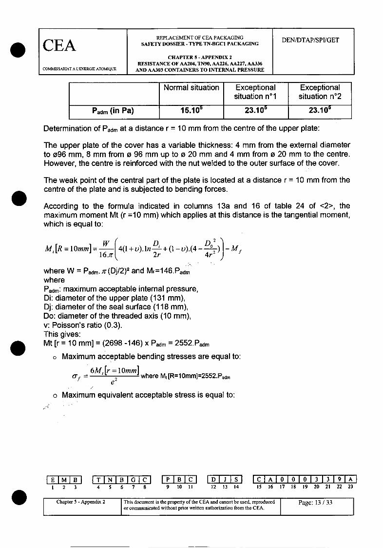
Determination of Padm at a distance r = 10 mm from the centre of the upper plate:
The upper plate of the cover has a variable thickness: 4 mm from the extemal diameterto 096 mm, 8 mm from o 96 mm up to o 20 mm and 4 mm from o 20 mm to the centre.However, the centre is reinforced with the nut welded to the outer surface of the cover.
The weak point of the central part of the plate is located at a distance r = 10 mm from thecentre of the plate and is subjected to bending forces.
According to the formula indicated in columns 13a and 16 of table 24 of <2>, themaximum moment Mt (r =10 mm) which applies at this distance is the tangential moment,which is equal to:
W 4(1+v).1n R1 +-).(4- ) -MfM,[R =l0mm]= li".
16.)r 2r 4r'
where W = Padmr. /T(Dj/2)2 and Mf=146.PadmwherePadrm: maximum acceptable internal pressure,Di: diameter of the upper plate (131 mm),Dj: diameter of the seal surface (118 mm),Do: diameter of the threaded axis (10 mm),v: Poisson's ratio (0.3).This gives:Mt [r = 10 mm] = (2698 -146) x Padm = 2552.Padm
o Maximum acceptable bending stresses are equal to:
6M, [r = 10mm] where Mt [R= 1Omm]=2552.Padmof M e 2
o Maximum equivalent acceptable stress is equal to:
1 2 3 4 5 6 7 8 9 10 IIDIJIS12 13 14
IClAI010101313191AI15 16 17 18 19 20 21 22 23
I Chapter 5 - Appendix 2 IThis document is the property of the CEA and cannot be used, reproduced Page: 13 / 33Ch r Aor communicated without prior written authorization from the CEA. I P
REPLACEMENT OF CEA PACKAGING DEN/DTAP/SPI/GET
CEA SAFETY DOSSIER - TYPE TN-BGC1 PACKAGING
CHAPTER 5 - APPENDIX 2RESISTANCE OF AA204, TN90, AA226, AA227, AA336
COMMISSARIAT A L'ENERGIE ATOMIQUE AND AA303 CONTAINERS TO INTERNAL PRESSURE
a,,~ = a'f
a- eq is a total primary stress, and must therefore obey the following:a- eq = 1.5 x f (see C10.1.7.1 of <1>), where f is the resistance criterion (fn, fexi or fex2).This gives:
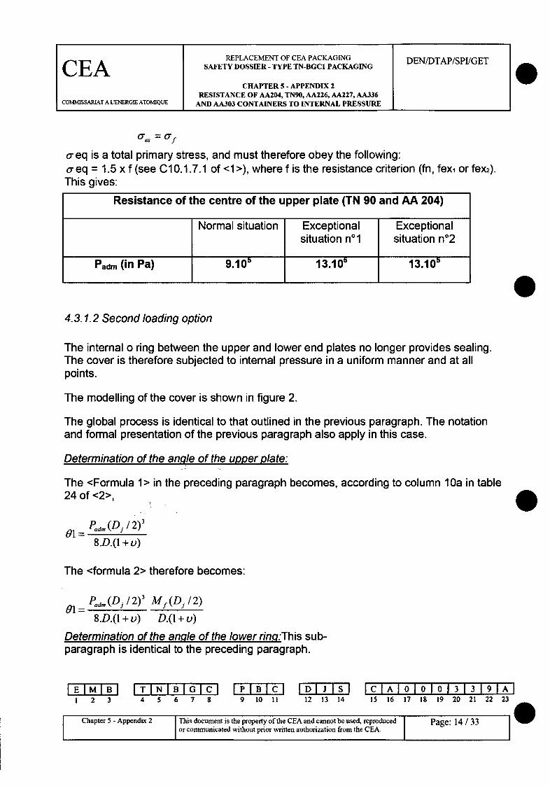
Resistance of the centre of the upper plate (TN 90 and AA 204)
Normal situation Exceptional Exceptionalsituation no1 situation n02
Padm (in Pa) 9.105 13.105 13.105
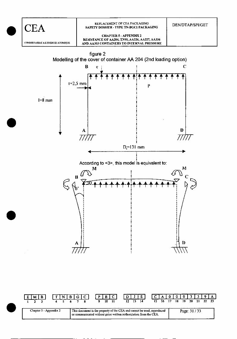
04.3.1.2 Second loading option
The internal o ring between the upper and lower end plates no longer provides sealing.The cover is therefore subjected to intemal pressure in a uniform manner and at allpoints.
The modelling of the cover is shown in figure 2.
The global process is identical to that outlined in the previous paragraph. The notationand formal presentation of the previous paragraph also apply in this case.
Determination of the angle of the upper plate:
The <Formula 1> in the preceding paragraph becomes, according to column 10a in table24 of <2>,
01= Padm(D /2)'8-D.(1 + v)
The <formula 2> therefore becomes:
01 = Pad, (Dj / 2)' Mf (Dj / 2)
8.D.(1 + v) D.(1 + v)
Determination of the anqle of the lower rinaq:This sub-paragraph is identical to the preceding paragraph.
IEIM IB1 2 3
T IN I6B784 5 6 7 8 9 10 II 12 13 14
IClAI010101313191A15 16 17 18 19 20 21 22 23
Page:14AsChapter 5 - Appendix 2 This document is the property of the CEA and cannot be used, reproduced Page:
or communicated without prior written authorization from the CEA. w
0
REPLACEMENT OF CEA PACKAGING DEN/DTAP/SPUGET
CEA SAFETY DOSSIER-TYPE TN-BGC1 PACKAGING
CHAPTER 5- APPENDIX 2RESISTANCE OF AA204, TN90, AA226, AA227, AA336
COMMISSARIAT A LENERGIE ATOMIQUE AND AA303 CONTAINERS TO INTERNAL PRESSURE
Determination of moment Mf:
The <formula 3> in the above paragraph therefore becomes:
Paad(Dj/2)' Mf.(Dj/2) Mf.C1 2 i.e.:8.D.(I + v) D.(1 + u) D.-.C,,
C12 (D/2).t3 P Pam(Dj/2)3 -3
fs +1* (l+ou).e3 ) 8.e 3.(1 + ) ie.
Mfx(6 l + 12,3) = 6597xPad,,
Mf = 90.Pad,
Determination of Padm at the periphery of the upper plate and at the periphery of the lower ring:
The expressions of stresses at the periphery of the upper plate and at the periphery of thelower ring are identical to those determined in the previous paragraph (1st loading option).
Therefore, by comparing the expression of the moment obtained above (Mf = 90.Padm) withthat obtained for the above load (Mf = 146.Padm at § 5.3.1.1), it can be concluded that, with aconstant acceptable constraint, acceptable pressure for this load exceeds that determined forthe above load.
Determination of Padm at the centre of the upper plate:
The thickness of the plate is assumed to be equal to 8 mm at the centre (conservative value).
The maximum moment M[r = 0] at this location is the difference between the moment given bycolumn 10a in table 24 of <2>, and the moment Mf calculated above:
M[R =o] =Pad,,.(Dj / 2) 2 .(3 +v) - hrM[R =o] = Pd,.D 2)M f where M f 90.Pad,,16
i.e.:
M[r+o]=(885-90) x Padm=795.Padm
o Maximum acceptable bending stresses are equal to:
I 2 3 4 5 6 7 8 9 10 Ii 12 13 14[C IA I010101313191AI
15 16 17 18 19 20 21 22 23
Chapter 5 -Appendix 2 This document is the property of the CEA and cannot be used, reproduced Page: 15 / 331 1 ~or communicated without prior written authorization from the CEA. II
REPLACEMENT OF CEA PACKAGING DEN/DTAP/SPI/GET
CEA SAFETY DOSSIER - TYPE TN-BGC1 PACKAGING
CHAPTER 5 - APPENDIX 2RESISTANCE OF AA204, TN90, AA226, AA227, AA336
COMMISSARIAT A LENERGIE ATOMIQUE AND AA303 CONTAINERS TO INTERNAL PRESSURE
_ 6M[R = 0],where M [r-0] =7 9 5 .Padm
Maximum equivalent acceptable stress is equal to:aeq = a f
o eq is a total primary stress, and must therefore obey the following:a-eq = 1.5 x f (see C10.1.7.1 of <1>), where f is the resistance criterion (fn, fex,or fex2). This gives:
0
Resistance of the centre of the upper plate (TN 90 and AA 204)
Normal situation Exceptional Exceptionalsituation nol situation n02
Padm(in Pa) 29.105 43.105 43.10 5
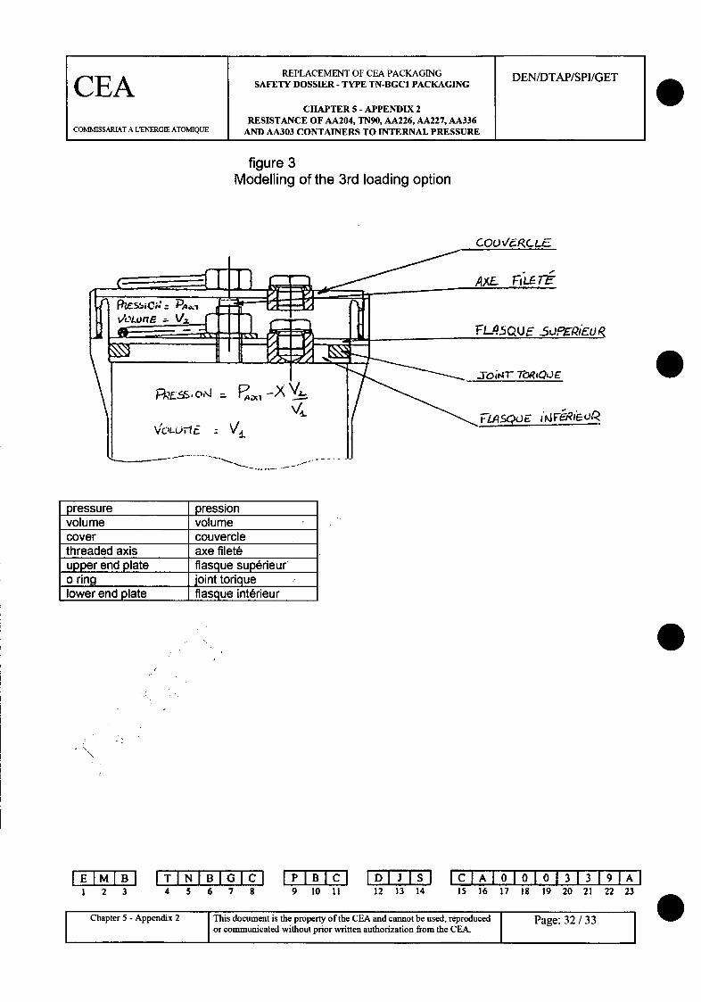
4.3.1.3 Third loading option
The third loading option is an intermediate case between those analysed in paragraphs5.3.11 and 5.3.1.2 where the internal o ring between the upper and lower end plates nolonger provides full sealing, however the pressure on both sides of the end plates has notyet had time to balance, therefore the cover is subjected to the effects of uniformpressure and a force exercised by the threaded axis simultaneously (see figure 3).
Where X is pressure at time t in volume V between the top of the container and the upperend plate (see figure 3). This pressure will change from 0 (situation for the 1st loadingoption) to Padm (situation for the 2nd loading option).
Pressure in volume V between the bottom of the container and the lower end plate (see
figure 3) at time t is equal to: Pd. - XV2v,'
At time t, the expressions of the constraints subjected by the cover are obtained bytotalling the constraints due to uniform pressure X, and the constraints due to the forceapplied by the threaded axis:
F= (Id. - XV2 ). 4.J where Dj is the diameter of the seal surface.
I 2 3ITINIBI4IC6
4 5 6 7 8 9 10 IIDI I S12 13 14
C AO0 00 33 9 A15 16 17 18 19 20 21 22 23 a,
ChapterunicatependixoutThisorocumentnisuthe property of the CEA and cannot be used, reproducedChapter ~o 5-oAmuendixe2 without prior written authorization from the CEA. Pge163 w
REPLACEMENT OF CEA PACKAGING DEN/DTAP/SPI/GETCEA SAFETY DOSSIER - TYPE TN-BGC1 PACKAGING
CHAPTER 5 - APPENDIX 2RESISTANCE OF AA204, TN90, AA226, AA227, AA336
COI'MMISSARIAT A L'ENERGIE ATOM]QUE AND AA303 CONTAINERS TO INTERNAL PRESSURE
It is easy to demonstrate that the expressions of constraints due to uniform pressure Xare linear combinations of X. This also applies for the expressions of constraints due tothe force applied by the threaded axis.
Therefore, the expressions of the constraints 6 suffered by the cover are linearcombinations of X, which enables us to conclude that:
D constantaX
Therefore, at time t, the values of d at all points of the cover are between their respectivevalues in the first loading option (X = 0) and the 2nd loading option (X = Padre), thereforecreating an interval.
4.3.2 Upper plate of the cover
The upper plate of the cover may possibly be subject to stamping (pure shear) by thethreaded axis with a diameter Do = 10 mm. The thickness of the upper plate (noted e) interms of Do is as follows: e = 4+10=14mm.
Maximum acceptable shear stresses are equal to:
" d, = .(D / 2)2 where Dj is the diameter of the seal surface (118 mm).Do.e
x is a pure shear stress and must therefore obey the following:
r = 0,6xf (see C 10.1.7.3 of<1>)
This gives:
Resistance to the stamping of the upper plate of the cover (TN 90 and AA 204)
Normal situation Exceptional Exceptional situationsituation nol n02
Padm (in Pa) 35.10* 52.105 51.105
4.3.3 Cover threadThe cover thread is subjected to pure shear forces.Properties are as follows:
1 2 3 4 5 6 7 8P 0 I BC9 10 11
rDJS12 13 14
ICIAI010101313191AI15 16 17 18 19 20 21 22 23
I 11 Chapter 5 - Appendix 2 This document is the property of the CEA and cannot be used, reproducedor communicated without prior written authorization from the CEA.
Page: 17 / 33 II

REPLACEMENT OF CEA PACKAGING DEN/DTAP/SPI/GETCEASAFETY DOSSIER -TYPE TN-BGC1 PACKAGING
CHAPTER 5 - APPENDIX 2RESISTANCE OF AA204, TN90, AA226, AA227, AA336
COMMISSARIAT A LENERGIE ATOMIQUE AND AA303 CONTAINERS TO INTERNAL PRESSURE
0
0
0
Trapezoidal thread 130 x 4 - 7e,Diameter on thread sides = 130 - 2 = 128 mm,Length in thread = 21-6-8 = 7 mm.
The section subject to shear is equal to:
S .1287 1407mm 2
2
Therefore, if we consider that sealing is no longer provided by the internal o ring locatedbetween the upper and lower end plates in a detrimental manner, mean acceptableshear stress is equal to:
P.dm -J '-D j2
4.S
where Dj = 135 mm is the diameter of the surface of the internal o ring located on thecover.
This shear stress must obey the rule r = 0.6 x f, where f is the resistance criterion (fn,fex, or fex 2).
This gives:
Resistance of the cover thread (TN 90 and AA 204)
Normal situation Exceptional Exceptionalsituation nol situation n02
Padm(in Pa) 78.100 118.100 116.105
5. RESISTANCE OF CONTAINERS IN FAMILY B (AA 226 AND AA 227)
5.1 Resistance of the cylindrical shell
The cylindrical shell of container AA 227, which is the least resistant (less thick andhigher internal diameter) is considered.
According to <1> (relation C2.1.4), the minimum thickness required for the shell is based
on: e -2f -Pdam
0
1 2 3 4 5 6 7 8 9 10 II 12 13 14IC AIA 010101313191AI
15 16 17 18 19 20 21 22 23
Chapter 5 - Appendix 2 This document is the property of the CEA and cannot be used, reproduced Page: 18 / 33
C 1 or communicated without prior written authorization from the CEA. I
REPLACEMENT OF CEA PACKAGING DEN/DTAP/SPIIGETCEA SAFETY DOSSIER - TYPE TN-BGC1 PACKAGING
CHAPTER 5 -APPENDIX 2RESISTANCE OF AA204, TN90, AA226, AA227, AA336
COMMISSARIAT A LENERGIE ATOMIQUE AND AA303 CONTAINERS TO INTERNAL PRESSURE
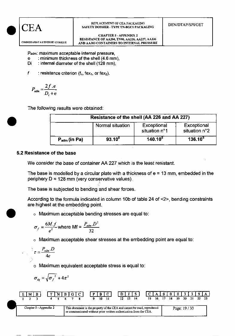
Padm: maximum acceptable internal pressure,e minimum thickness of the shell (4.6 mm),Di internal diameter of the shell (128 mm),
f resistance criterion (fn, fexl, or fex2).
2f.ePadm D--Di +e
The following results were obtained:
Resistance of the shell (AA 226 and AA 227)
Normal situation Exceptional Exceptionalsituation n0 l situation n02
Padm (in Pa) 93.10- 140.10' 136.105
5.2 Resistance of the base
We consider the base of container AA 227 which is the least resistant.
The base is modelled by a circular plate with a thickness of e = 13 mm, embedded in theperiphery D = 128 mm (very conservative values).
The base is subjected to bending and shear forces.
According to the formula indicated in column 10b of table 24 of <2>, bending constraintsare highest at the embedding point.
o Maximum acceptable bending stresses are equal to:
1f = 26M.f where Mf- =Pad, -De2 32
o Maximum acceptable shear stresses at the embedding point are equal to:
P.D
4e
o Maximum equivalent acceptable stress is equal to:
O= •-f ~.+4fT2
I 2 3I T IN6IBI8
4 5 6 7 8 9 t0 II 12 13 14CIlAI01 0101313 191AI15 16 17 18 19 20 21 22 23
Chapter 5 - Appendix 2 This document is the property of the CEA and cannot be used, reproduced Ior communicated without prior written authorization from the CEA. I
Page: 19 /33
I

REPLACEMENT OF CEA PACKAGING DEN/DTAP/SPI/GETCEA SAFETY DOSSIER - TYPE TN-BGC1 PACKAGING
CHAPTER 5 - APPENDIX 2RESISTANCE OF AA204, TN90, AA226, AA227, AA336
COMMISSARIAT A LENERGIE ATOMIQUE AND AA303 CONTAINERS TO INTERNAL PRESSURE
o eq is a total primary stress, and must therefore obey the following:o-eq = 1.5xf (see C10.1.7.1 of <1>), where f is the resistance criterion (fn, fex, or fex2).i is a pure shear stress and must therefore obey the following:T = 0.6 x f (see C10.1.7.3 of <1>).This gives:
Resistance of the base (AA 226 and AA 227)
Normal Exceptional Exceptionalsituation situation n1l situation n02
Padm in bending (in Pa) 106.10 160.100 156.10
Padm in shear (in Pa) 320.1 490.105 480.105
Padm (in Pa) 106.10 160.105 156.105
5.3 Resistance of the plug
We consider the plug of container AA 227 which is the least resistant.
The plug is modelled by a circular plate with a thickness of e = 10 mm, supported on theperiphery D = 135 mm (diameter of the seal surface).
The plug is subjected to bending forces.
According to the formula indicated in column 10a of table 24 of <2>, bending constraintsare highest at the centre of the plate.
o Maximum acceptable bending stresses are equal to:
6"M Pd, .D 2 .(3 +0,3)
Of = --M where Mf = 4d
e 264
o Maximum equivalent acceptable stress is equal to:aeq = f
a eq is a total primary stress, and must therefore obey the following:
aeq = 1.5 x f (see C10.1.7.1 of <1>), where f is the resistance criterion (fn, fexi or fex2).
IF- MI I TINIBI ýG~ IDIJ31sl IClAI010101313191AI1 2 3 4 5 6 7 8 9 10 11 12 13 14 15 16 17 18 19 20 21 22 23
C2 This document is the property of the CEA and cannot be used, reproduced Page: 20 / 33C or communicated without prior written authorization from the CEA. 1 :

REPLACEMENT OF CEA PACKAGING DEN/DTAP/SPI/GETCEA SAFETY DOSSIER - TYPE Th-BGC1 PACKAGINGCELACHAPTER 5 - APPENDIX 2
RESISTANCE OF AA204, TN9", AA226, AA227, AA336COMMISSARIAT A LTNERGIE ATOMIQUE AND AA303 CONTAINERS TO INTERNAL PRESSURE
This gives:
5.4 Resistance of the tightening nut
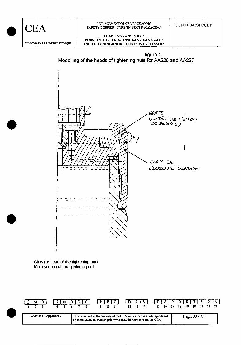
5.4.1 Main sections of tightening nuts
The main sections of the tightening nuts of AA 226 and AA 227 are identical. They aresubjected to traction and bending forces via 4 equidistant claws (see figure 4).
The part of the main section with a claw is modelled with a beam. The section of thisbeam located on the mean diameter Dm = (174.5+155)/2 = 164.75 mm, has an inertia I =(b.h3)/12,
Where b = 4 5 z.Dm = 129mm and where h = (1 74,5-155)/2=9,75mm180
Maximum acceptable bending stresses are equal to:Mf~i.whereMD = /4). 4x2 Dj = diameter of the seal surface (135
'dmr(DI 4x2
mm), and where z = h/2 = 4.875 mm is the distance to the neutral axis.
Maximum acceptable traction stresses are equal to:
Padm.r.-(D 2/ 4)f= 4.h.b
which is also the general primary equivalent constraint for the membrane (o" t'eq)Total maximum acceptable primary constraints are equal to:
I a= oaf +at which is also a total primary equivalent constraint (a eq).
The general primary equivalent constraint for the membrane (a t'eq) must obey thefollowing:a-t'eq = f (see C10. 1.7.1 of <1>), where f is the resistance criterion (fn, fex, or fex2).The total primary equivalent constraint (a t'eq) must obey the following:
I 2 34T IN I6B784 5 6 7 8 9 10 II 12 13 14
IClAI010101313191A15 16 17 18 19 20 21 22 23
Chapter 5 - Appendix 2 Page: 21/33
This document is the property of the CEA and cannot be used, reproducedIChapter 5 - Appendix 2 This document is the property of the CEA and cannot be used, reproduced
or communicated without prior" written authorization from the CEA. Page: 21 / 33
REPLACEMENT OF CEA PACKAGING DEN/DTAP/SPI/GETCEA SAFETY DOSSIER - TYPE TN-BGC1 PACKAGING
CHAPTER 5 - APPENDIX 2RESISTANCE OF AA204, TN90, AA226, AA227, AA336
COSMISSARIAT A LENERGIE ATOMIQUE AND AA303 CONTAINERS TO INTERNAL PRESSURE
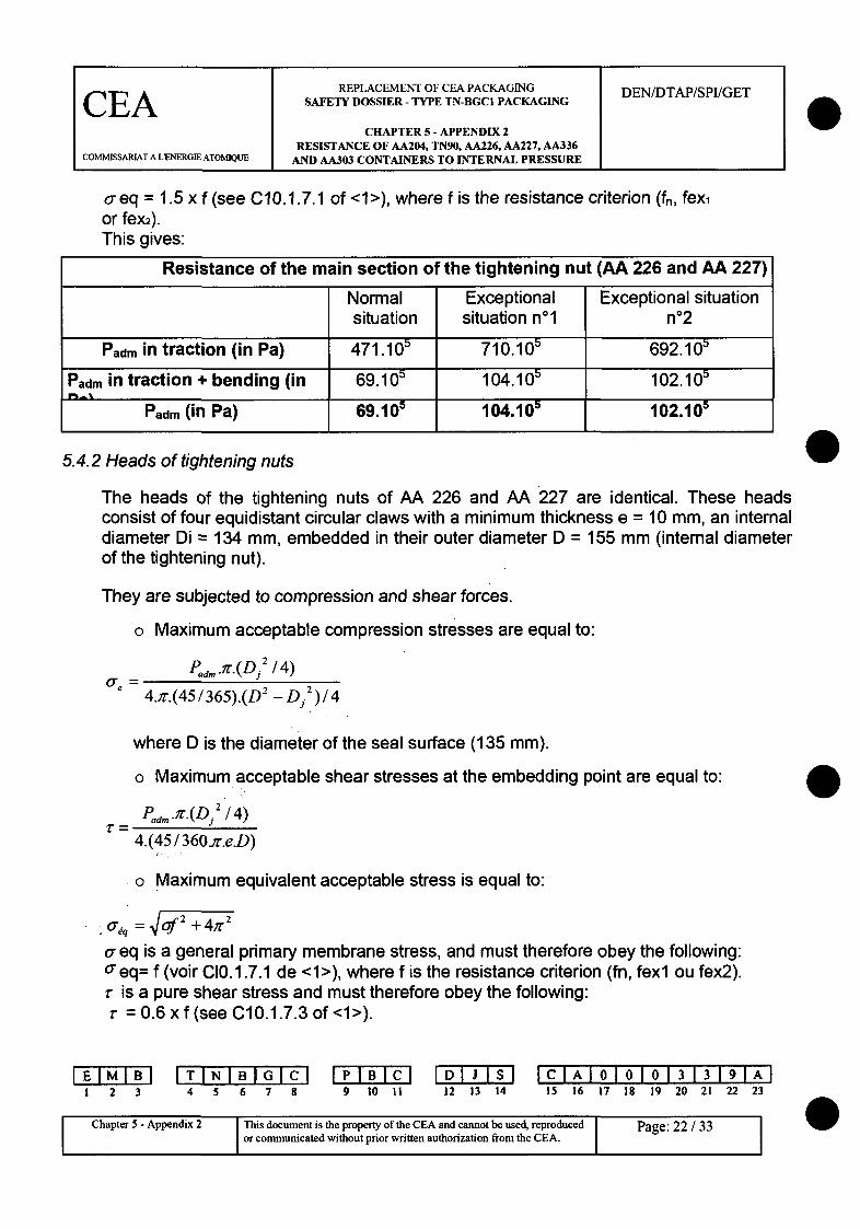
o-eq = 1.5 x f (see C10.1.7.1 of <1>), where f is the resistance criterion (fn, fex,or fex2).This gives:
Resistance of the main section of the tightening nut (AA 226 and AA 227)
Normal Exceptional Exceptional situationsituation situation nol n02
Pad. in traction (in Pa) 471.105 710.105 692.105
Padm in traction + bending (in 69.105 104.10 102.105
Padm (in Pa) 69.105 104.105 102.105
5.4.2 Heads of tightening nuts
The heads of the tightening nuts of AA 226 and AA 227 are identical. These headsconsist of four equidistant circular claws with a minimum thickness e = 10 mm, an internaldiameter Di = 134 mm, embedded in their outer diameter D = 155 mm (internal diameterof the tightening nut).
They are subjected to compression and shear forces.
o Maximum acceptable compression stresses are equal to:
P.dm *m(Di'14)0e =
4.i'.(45/365).(D 2 - Dj 2 )/4
where D is the diameter of the seal surface (135 mm).
o Maximum acceptable shear stresses at the embedding point are equal to:
P.dm *.7.(Dj2 /4)
4.(45 / 360.r.eD)
o Maximum equivalent acceptable stress is equal to:
U-q =
a- eq is a general primary membrane stress, and must therefore obey the following:aeq= f (voir C[0.1.7.1 de <1>), where f is the resistance criterion (fn, fexl ou fex2).r is a pure shear stress and must therefore obey the following:r = 0.6 x f (see C10.1.7.3 of <1>).
I 2 3IT INIB I6G
4 5 6 7 8 9 10 II 12 13 14IC 1AI6Ii I0 1313191A9
15 16 17 18 19 20 21 22 23
Chapter 5 - Appendix 2 This document is the property of the CEA and cannot be used, reproduced Page: 22 / 33Chape 1 Aor communicated without prior written authorization from the CEA. I
REPLACEMENT OF CEA PACKAGING DEN/DTAP/SPI/GET
CEA SAFETY DOSSIER- TYPE TN-BGC1 PACKAGING
CHAPTER 5 - APPENDIX 2RESISTANCE OF AA204, TN90, AA226, AA227, AA336
COM•MSSARIAT A LENERGIE ATOM]QUE AND AA303 CONTAINERS TO INTERNAL PRESSURE
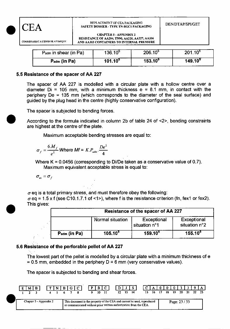
Padm in shear (in Pa) 136.105 206.105 201.105
Padm (in Pa) 101.105 153.105 149.10
5.5 Resistance of the spacer of AA 227
The spacer of AA 227 is modelled with a circular plate with a hollow centre over adiameter Di 105 mm, with a minimum thickness e = 8.1 mm, in contact with theperiphery De = 135 mm (which corresponds to the diameter of the seal surface) andguided by the plug head in the centre (highly conservative configuration).
The spacer is subjected to bending forces.
According to the formula indicated in column 2b of table 24 of <2>, bending constraintsare highest at the centre of the plate.
Maximum acceptable bending stresses are equal to:
* MeWhere Mf = K.Pm.De2
f e 2 d.4
Where K = 0.0456 (corresponding to Di/De taken as a conservative value of 0.7).Maximum equivalent acceptable stress is equal to:
a-es = 'f
a- eq is a total primary stress, and must therefore obey the following:a-eq = 1.5 x f (see C10.1.7.1 of <1>), where f is the resistance criterion (fn, fexl or fex2).This gives:
5.6 Resistance of the perforable pellet of AA 227
The lowest part of the pellet is modelled by a circular plate with a minimum thickness of e= 0.5 mm, embedded in the periphery D = 6 mm (very conservative values).
The spacer is subjected to bending and shear forces.
1 2 3 4 5 6 7 8 9 10 IIID'I'J'FS's
12 13 14CIlAI 010101313191A15 16 17 18 19 20 21 22 23
W Chapter 5 - Appendix 2 This document is the property of the CEA and cannot be used, reproducedor communicated without prior written authorization from the CEA. I
1
Page: 23 / 33I

REPLACEMENT OF CEA PACKAGING DEN/DTAP/SPI/GETCIA SAFETY DOSSIER - TYPE TN-BGC1 PACKAGING
CHAPTER 5 - APPENDIX 2RESISTANCE OF AA204, TN90, AA226, AA227, AA336
COMMISSARIAT A LERGIE ATOMIQUE AND AA303 CONTAINERS TO INTERNAL PRESSURE
0
This gives:
Resistance of the head of the tightening nut (AA 226 and AA 227)I
IPadm in compression (in IPadm in shear (in Pa) IPadm (in Pa:
I
5.4.3 Threads of tightening nuts
The threads of the tightening nuts of AA 226 and AA 227 are identical. They are subjectedto pure shear forces.
Their properties are as follows:
o Round thread 160x6o Diameter on thread sides = 160 - 6 = 157 mm,o Length in thread = 34 mm
The section subject to shear is equal to:
/T.157.34S = = 8384mm 2
2
Therefore, mean acceptable shear stresses are equal to:
Pad,..n'.Dj 2= - where Dj = 135 mm is the diameter of the seal surface.
4.S
This shear stress must obey the following rule: a eq = 0.6 x f (see C1 0.1.7.1 of <1>),
where f is the resistance criterion (fn, fexl or fex2).
This gives:
0
Resistance of the thread of the tightening nut (AA 226 and AA 227)
Padm in compression (in Pa)
Exceptionalsituation n02
149.10)I I I
I 2 3 4 5 6 7 8 9 10 11DI I S12 13 14
ICAI000133 9A15 16 17 18 19 20 21 22 23
Chapter 5 - Appendix 2 This document is the property of the CEA and cannot be used, reproduced Page: 24 / 33Ch e 5 dor communicated without prior written authorization from the CEA. F
REPLACEMENT OF CEA PACKAGING DEN/DTAP/SPI/GET
CEA SAFETY DOSSIER - TYPE TN-BGC1 PACKAGING
CHAPTER 5 - APPENDIX 2RESISTANCE OF AA204, TN90, AA226, AA227, AA336
COMMISSARLIAT A L'ENERGIE ATOMIQUE AND AA303 CONTAINERS TO INTERNAL PRESSURE
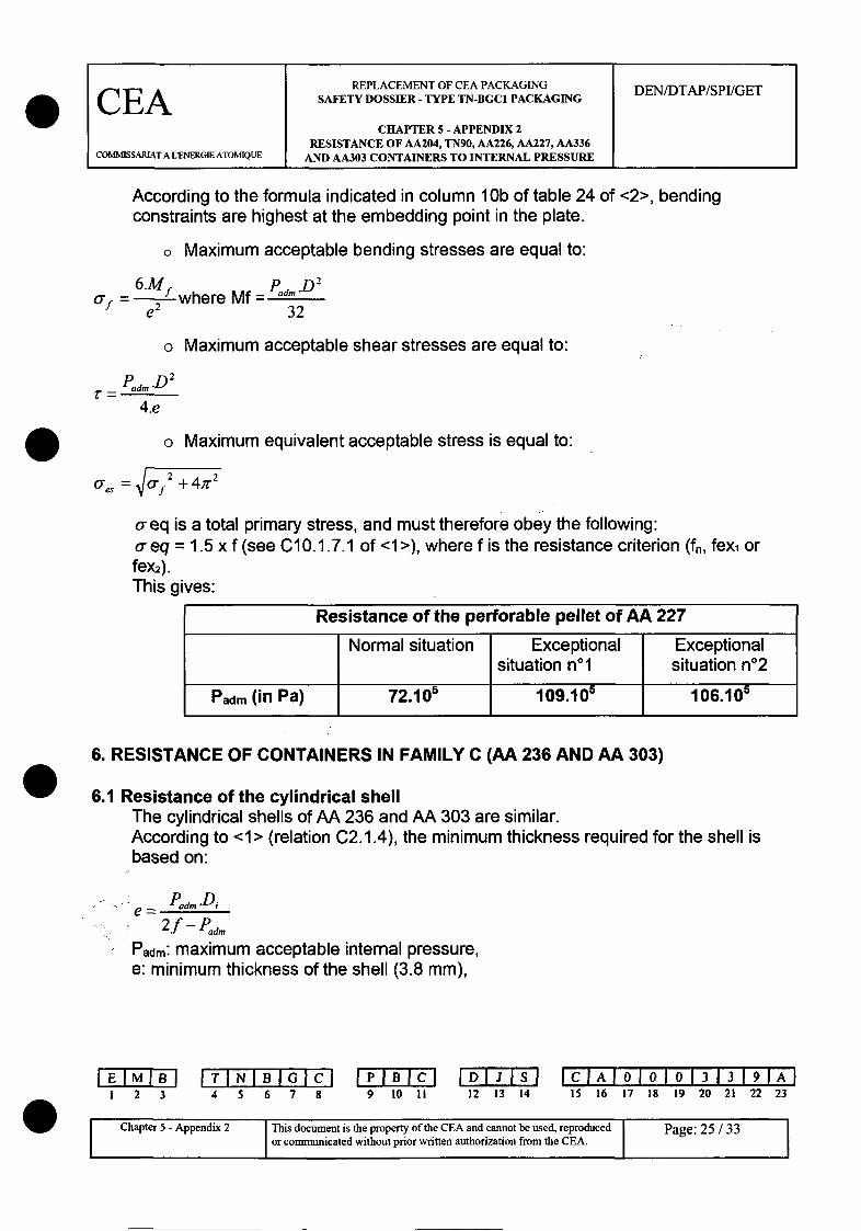
According to the formula indicated in column 1 Ob of table 24 of <2>, bending
constraints are highest at the embedding point in the plate.
o Maximum acceptable bending stresses are equal to:
6M P mD 2f = e 2Mf where Mf- = a...e2 32
o Maximum acceptable shear stresses are equal to:
4.e
o Maximum equivalent acceptable stress is equal to:
es =Vfr2 +4r 2
a eq is a total primary stress, and must therefore obey the following:o- eq = 1.5 x f (see C10.1.7.1 of <1>), where f is the resistance criterion (fn, fex, orfex2).This gives:
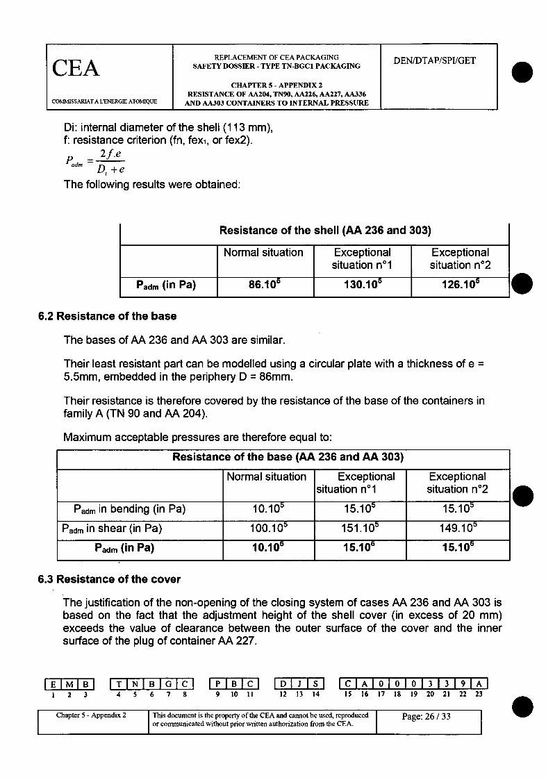
6. RESISTANCE OF CONTAINERS IN FAMILY C (AA 236 AND AA 303)
6.1 Resistance of the cylindrical shellThe cylindrical shells of AA 236 and AA 303 are similar.According to <1> (relation C2.1.4), the minimum thickness required for the shell isbased on:
e=PadmDi2f - PFd.
Paom: maximum acceptable internal pressure,e: minimum thickness of the shell (3.8 mm),
I 2 3 4 5 6 7 8 9 10 II1DI23s112 13 14
ICIAI OIOJO 131 3191AI15 16 17 18 19 20 21 22 23
Chapter 5 - Appendix 2 This document is the property of the CEA and cannot be used, reproduced Page: 25 / 33or communicated without prior written authorization from the CEA.
REPLACEMENT OF CEA PACKAGING DEN/DTAP/SPIIGETCEA SAFETY DOSSIER - TYPE TN-BGC1 PACKAGING
CHAPTER 5 - APPENDIX 2RESISTANCE OF AA204, TN90, AA226, AA227, AA336
COMMISSARIAT A L-NERGIE ATOMIQUE AND AA303 CONTAINERS TO INTERNAL PRESSURE
Di: internal diameter of the shell (113 mm),f: resistance criterion (fn, fexi, or fex2).
_adm = 2f.e
Di+ e
The following results were obtained:
Resistance of the shell (AA 236 and 303)
6.2 Resistance of the base
The bases of AA 236 and AA 303 are similar.
Their least resistant part can be modelled using a circular plate with a thickness of e =5.5mm, embedded in the periphery D = 86mm.
Their resistance is therefore covered by the resistance of the base of the containers infamily A (TN 90 and AA 204).
Maximum acceptable pressures are therefore equal to:
Resistance of the base (AA 236 and AA 303)
Normal situation Exceptional Exceptionalsituation n01 situation n02
Padm in bending (in Pa) 10.105 15.105 15.105
Padm in shear (in Pa) 100.105 151.10" 149.105
Padm (in Pa) 10.10r 15.105 15.105
6.3 Resistance of the cover
The justification of the non-opening of the closing system of cases AA 236 and AA 303 isbased on the fact that the adjustment height of the shell cover (in excess of 20 mm)exceeds the value of clearance between the outer surface of the cover and the innersurface of the plug of container AA 227.
i 2 3I TINIB I67
4 5 6 7 8 9 10 II 12 13 14IClAI0 0I 0 21313122 A2
15 16 17 18 19 20 21 22 23
Chapter 5 - Appendix 2 This document is the property of the CEA and cannot be used, reproduced Page: 26 / 33C i or communicated without prior written authorization from the CEA. I
REPLACEMENT OF CEA PACKAGING DEN/DTAP/SPI/GETCEA SAFETY DOSSIER - TYPE TN-BGC1 PACKAGING
CHAPTER 5 - APPENDIX 2RESISTANCE OF AA204, TN9O, AA226, AA227, AA336
COIMISSARIAT A LENERGIE ATOMIQUE AND AA303 CONTAINERS TO INTERNAL PRESSURE
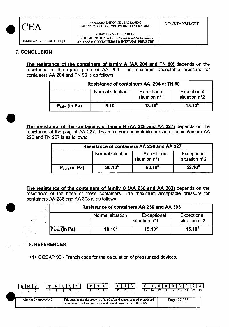
7. CONCLUSION
The resistance of the containers of family A (AA 204 and TN 90) depends on theresistance of the upper plate of AA 204. The maximum acceptable pressure forcontainers AA 204 and TN 90 is as follows:
Resistance of containers AA 204 et TN 90
Normal situation Exceptional Exceptionalsituation no1 situation n02
Padm (in Pa) 9.105 13.105 13.105
The resistance of the containers of family B (AA 226 and AA 227) depends on theresistance of the plug of AA 227. The maximum acceptable pressure for containers AA226 and TN 227 is as follows:
Resistance of containers AA 226 and AA 227
Normal situation Exceptional Exceptionalsituation no1 situation n02
Padm (in Pa) 35.10 53.105 52.10
The resistance of the containers of family C (AA 236 and AA 303) depends on theresistance of the base of these containers. The maximum acceptable pressure forcontainers AA 236 and AA 303 is as follows:
Resistance of containers AA 236 and AA 303
Normal situation Exceptional Exceptionalsituation nol situation n02
Padm (in Pa) 10.105 15.105 15.105
8. REFERENCES
<1> CODAP 95 - French code for the calculation of pressurized devices.
I
I
1 2 3I TIN5I 678
4 5 6 7 8 9 10 II 12 13 14ICIAI010101313191A
15 16 17 18 19 20 21 22 23
Chapter 5 - Appendix 2 This document is the property of the CEA and cannot be used, reproducedor communicated without prior written authorization from the CEA.
Page: 27 / 33 I

REPLACEMENT OF CEA PACKAGING DEN/DTAP/SPI/GET
CEA SAFETY DOSSIER - TYPE TN-BGC 1 PACKAGING
CHAPTER 5 - APPENDIX 2RESISTANCE OF AA204, TN90, AA226, AA227, AA336
COMMISSARIAT A LENERGIE ATOMIQUE AND AA303 CONTAINERS TO INTERNAL PRESSURE
<2> ROARK'S Formulas for Stress and Strain, 6"' Edition - Warren C. Young.<3> Resistance of materials - 1968 edition - S.P. Timoshenko.
0
I 2 3
TINIBI c4 5 6 7 8 9 10 II
DIs CAOOO1 33 91A12 13 14 15 16 17 19 19 20 21 22 23 A
I Chapter 5-Appendix 2 This document is the property of the CEA and cannot be used, reproduced Page:28Ch e I por communicated without prior written authorization from the CEA. P 0
REPLACEMENT OF CEA PACKAGING DEN/DTAP/SPI/GET
CEA SAFETY DOSSIER - TYPE TN-BGC1 PACKAGING
CHAPTER 5 - APPENDIX 2RESISTANCE OF AA204, TN90, AA226, AA227, AA336
COMMISSARIAT A LENERGIE ATOMIQUE AND AA303 CONTAINERS TO INTERNAL PRESSURE
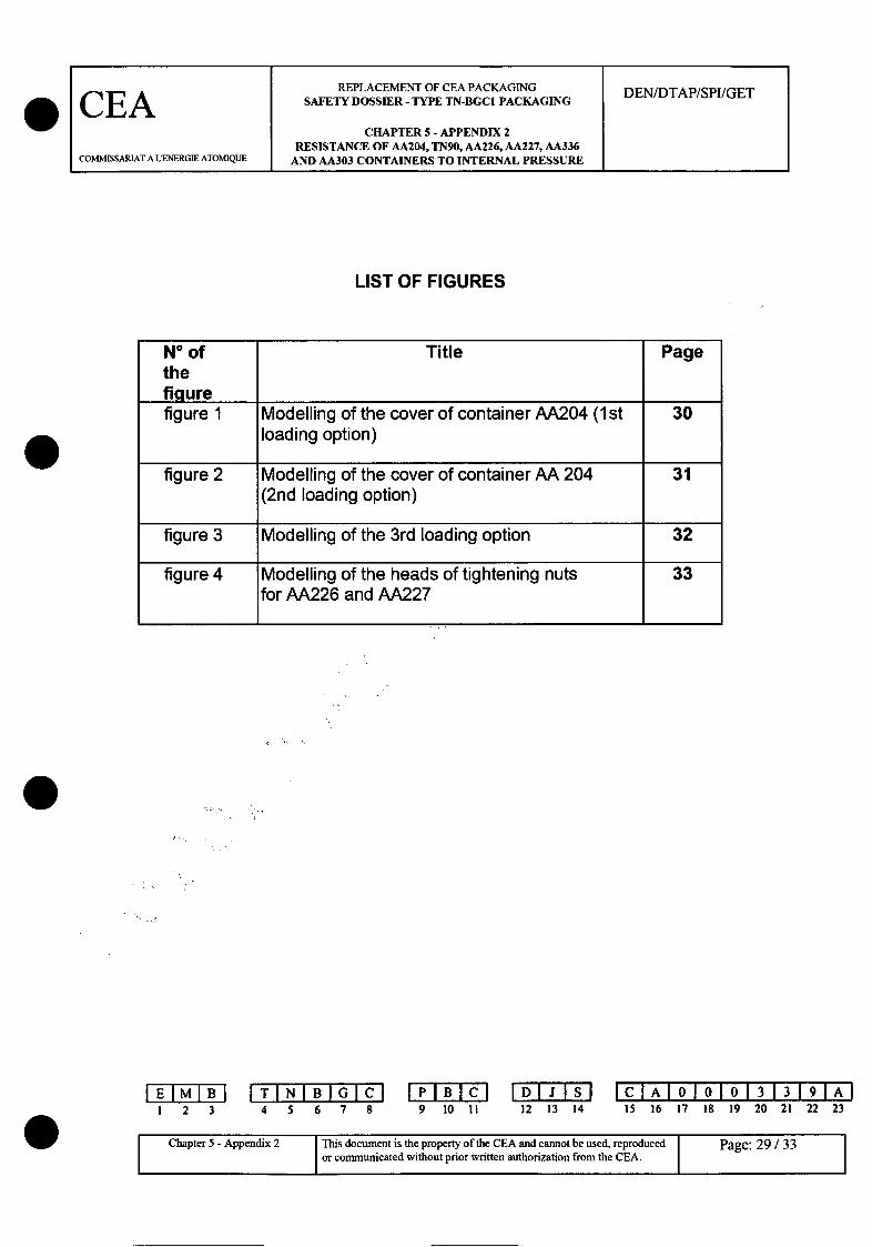
LIST OF FIGURES
N° of Title Pagethefigurefigure 1 Modelling of the cover of container AA204 (1st 30
loading option)
figure 2 Modelling of the cover of container AA 204 31
(2nd loading option)
figure 3 Modelling of the 3rd loading option 32
figure 4 Modelling of the heads of tightening nuts 33for AA226 and AA227
I 2 3IT INIBI 678
4 5 6 7 8 9 10 II 12 13 14IcIAI010101313191AI
15 16 17 18 19 20 21 22 23
Chapter 5 - Appendix 2 This document is the property of the CEA and cannot be used, reproduced Page: 29/33
or communicated without prior written authorization from the CEA.

REPLACEMENT OF CEA PACKAGING DEN/DTAP/SPI/GET
CEA SAFETY DOSSIER - TYPE TN-BGC1 PACKAGING
CHAPTER 5 - APPENDIX 2RESISTANCE OF AA204, TN90, AA226, AA227, AA336
COMMISSARIAT A LENERGIE ATOMIQUE AND AA303 CONTAINERS TO INTERNAL PRESSURE
figure 1Modelling of the cover of container AA204 (1st loading option)
B C
V
C:
AI
t=2,5 mm4
1=8 mm
IW
D,=10 mm
D,=131.1 mm
9A=
According to <3>, this modelB
is equivalent to:
M
!
M
C------------ I
WI
1 2 3
TI GNI CB-14 5 6 7 8 9 10 II 12 13 14
CIAI0 00 313 91AI5 16 17 18 19 20 21 22 23
Chapter 5 - Appendix 2 This document is the property of the CEA and cannot be used, reproduced Page: 30 /I Ior communicated without prior written authorization from the CEA.
REPLACEMENT OF CEA PACKAGING DEN/DTAP/SPI/GET
CEA SAFETY DOSS[ER - TYPE TN-BGC1 PACKAGING
CHAPTER 5 - APPENDIX 2RESISTANCE OF AA204, TN90, AA226, AA227, AA336
COMMISSARIAT A L'ENERGIE ATOM[QUE AND AA303 CONTAINERS TO INTERNAL PRESSURE
figure 2Modelling of the cover of container AA 204 (2nd loading option)
BV
II
1=8 mm
6
1=2,5 mm4
t!t
F D// 77/Dj=131 mm
According to <3>, this model is equivalent to:,3d M ' M3i C
IA i - I)
MB TI 2 3 4 5 6 7 8 9 10 II 12 13 14
CIcIA 1o010IO0 3 1-3191A115 16 17 18 19 20 21 22 23
w This document is the prperty of the CEA and cannot be used, reproduced Page: 31 / 33Chpe 5 peni or communicated without prior written authorization from the CEA. II
REPLACEMENT OF CEA PACKAGING DEN/DTAP/SPI/GET
CEA SAFETY DOSSIER - TYPE TN-BGC PACKAGING
CHAPTER 5 - APPENDIX 2RESISTANCE OF AA204, TN90, AA226, AA227, AA336
COMMISSARLA.T A L'EERGIE ATOMIQUE AND AA303 CONTAINERS TO INTERNAL PRESSURE
figure 3Modelling of the 3rd loading option
czzzzHTl I'--'1"
coo vsCtLE
AXE- FiL-1-T
FLq.50QUE' -50
K.?
RyVSC'.j = P""'
,rRicoR"4'I
zp
~1 -Jol"Ar TOR14Q'JE
FLA&SQOLE jMrF~qi6(JQ
pressure pressionvolume volumecover couverclethreaded axis axe filet6upper end plate flasque supdrieuro ring joint toriquelower end plate flasque int deur
1 2 3
TINlIoBG l4 5 6 7 8 9 10 II
DIJSIS12 13 14
ICIAI010101313191A15 16 17 18 19 20 21 22 23
Chapter 5 - Appendix 2 This document is the property of the CEA and cannot be used, reproduced Page: 32/33
C 1 or communicated without prior written authorization from the CEAl I
REPLACEMENT OF CEA PACKAGING DEN/DTAP/SPI/GET
CEA SAFETY DOSSIER - TYPE TN-BGC1 PACKAGING
CHAPTER 5 - APPENDIX 2RESISTANCE OF AA204, TN90, AA226, AA227, AA336
COMMISSARIAT A LENERGIE ATOMIQUE AND AA303 CONTAINERS TO INTERNAL PRESSURE
figure 4Modelling of the heads of tightening nuts for AA226 and AA227
(QLo r71i-e DE1',C0
COP~PS Dr-_
I
Claw (or head of the tightening nut)Main section of the tightening nut
I 2 3 4 5 6 7 8 9 10 II 12 13 14ICIAI010101313191A
15 16 17 18 19 20 21 22 23
iTChapterhiApendx2 is document is the property of the CEA and cannot be used, reproduced Pae:33 33e 1 Aor communicated without prior written authorization from the CEA.
Reference: 195H03W0112 August 2003
CEA CADARACHEDENIDTAP/SPIIGET
Order No.: N°4000029671 I P5H33
TN-BGCICONSEQUENCES OF HYDROGEN
COMBUSTION IN THE TN 90INTERNAL ARRANGEMENT
20 Av. de la Houille Blanche 38170 SEYSSINET
Tel.: 04 76 84 13 97
Fax: 04 76 84 13 98
e-mail: [email protected]
AQ 002RAP

DOCUMENT TYPE Ref.: 195H03W01
20, Av. de la Houille Blanche DESIGN NOTE Date: 12/08/03 d38170 SEYSSINETTel.: 04 76 84 13 97 Fax: 04 76 84 13 98 Page:2/28 I Issue: A
Title: Consequences of hydrogen combustion in the TN 90 internal arrangement ofTN-BGCl.
Customer • CEA CADARACHE
For the attention of • Mr Thomas Cuvillier
DEMA reference • 195H03W01
Author • Mr Bruno Debunne
I
Summary:
This design note assesses the mechanical consequences of combustion of astochiometric mix of hydrogen and oxygen on container TN90.
a
S
Issue Date Change characteristics Pages modifiedA • 12/08/03 First issue
The finite element calculations were performed with the LS-DYNA software program.
Name Date Signature
Issued by: Bruno Debunne
Checked by: Yves Brun 0a - w
AQ 002RAP
cm,,f m m-DOCUMENT TYPE Ref.: 195H03W01
20, Av. de la Houjile Blanche DESIGN NOTE Date: 12/08/0338170 SEYSSINETTel.: 04 76 84 13 97 Fax: 04 76 84 13 98 Pale:3/28 Issue: A
CONTENTS
I. PURPOSE OF THE DESIGN NOTE.
II. METHODOLOGY
III. MATERIAL
111.1. STAINLESS STEEL Z6 CN 18-09 (304)
IV. LINEAR STATIC STUDY - CODAP DIMENSIONING CRITERION
4
4
5
5
6
IV.1.IV.2.IV.3.IV.4.IV.4.1.IV.4.2.IV.4.3.IV.4.4.
STRESS ADMISSIBILITY CRITERIA
STATIC STRESS IN THE TN 90 SHELLSTATIC STRESS IN THE FLAT BOTTOM OF THE TN 90STATIC FINITE ELEMENT CALCULATION
PRESENTATION OF THE MODEL
LINEAR STATIC STUDY P-- I BAR
MAXIMUM PERMITTED PRESSURE (CODAP CRITERION AT 3000C)CONCLUSION ON THE CODAP LINEAR STATIC STUDY
667779
1011
0
V. NON-LINEAR STATIC STUDY - BEYOND DIMENSIONING CRITERION 12
V.1. PRESENTATION OF THE MODEL 12V.2. SUMMARY OF CALCULATIONS 12V.3. DETAILED CALCULATION RESULTS 14V.3.1. INTERNAL PRESSURE: 40 BAR 14V.3.2. INTERNAL PRESSURE: 70 BAR 15V.4. CONCLUSION OF THE NON-LINEAR STATIC TEST BEYOND DIMENSIONING 18
VI. NON-LINEAR DYNAMIC STUDY - PRESSURE STEP 19
VI.A. PRESSURE STEP: 70 BAR 20VI.2. PRESSURE STEP: 65 BAR 21VI.3. PRESSURE STEP: 60 BAR 21VIA. CONCLUSION OF THE DYNAMIC STUDY - PRESSURE STEP 23
VII. NON-LINEAR DYNAMIC STUDY - DYNAMIC PRESSURE 24
VII.L. PRESENTATION OF THE MODEL 24VII.2. MODELLING THE DYNAMIC PRESSURE 25VII.3. CALCULATION RESULT FOR AN INITIAL PRESSURE OF 1 BAR 26VII.4. CALCULATION RESULT FOR AN INITIAL PRESSURE OF 5 BAR 27VII.5. CONCLUSION OF THE DYNAMIC STUDY - PRESSURE WAVE 27
VIII. GENERAL CONCLUSION 28Aw
AQ 002RAP
cm F = l DOCUMENT TYPE Ref.: 195H03W01
20, Av. de la Houille Blanche DESIGN NOTE Date: 12/08/0338170 SEYSSINETTel.: 04 76 84 13 97 Fax: 04 76 84 13 98 Page:4/28 I Issue: A
I
I. PURPOSE OF THE DESIGN NOTE.
The purpose of this design note is to determine the consequences of astochiometric hydrogen/oxygen mix produced inside the TN90 internal arrangement.
II. METHODOLOGY
Before carrying out the explosion study itself with a set of parameters the mostsuited to the phenomenon, we performed a behaviour study of the TN 90 containmentusing different approaches to attempt to determine the behavioural domain (safety) interms of pressure permitted by the containment.
Conscious of differences in static or rapid dynamic loadings, we started the study instatic mode and moved gradually into rapid dynamic mode (explosion).
The following stages were performed as responses to a question:
Linear static study - CODAP dimensioninq criterionIf TN 90 was pressure equipment, what would be its normal and
exceptional working pressure, with reference to a design coderecognised by the safety authorities (CODAP) ?
Non-linear static study - Beyond dimensioning criterion
Taking hydrogen combustion in the TN 90 as an accident situation,what is the static pressure leading to the rupture of the containment in a"beyond dimensioning" design?
Non-linear dynamic study - Pressure step beyond dimensioning criterion
Time calculation: How does the structure respond to a pressure step?What is the influence of the dynamic calculation compared with a
static calculation?
Non-linear dynamic study - Dynamic pressure beyond dimensioning criterion
Time calculation: How does the structure respond to a pressure wave 1passing through the TN 90. I
AQ 002RAP

~9~MI1 DOCUMENT TYPE Ref.: 195H03W01
0, Av. de la Houjile Blanche DESIGN NOTE Date: 12/08/03
38170 SEYSSINETTel.: 04 76 84 13 97 Fax: 04 76 84 13 98 Page:5/28 Issue: A
III. MATERIAL
111.1. Stainless steel Z6 CN 18-09 (304)
Acier Z6 CN 18.09 (304) TEMPERATURESymbole Unit4 Source - ._ - ____.___
Propridt& 00C 20-C 100-C 200°C 300°C 400°C 5000C 6000C 700°C 8000C
Masse volumique p kg/m3
7930
Module d'4lasficitd E .103 MPa 1 198.5 197 191.5 184 176.5 168 160 151.5
Coefficient de poisson v - 0.3 1
Limite lastique mini Ro.2%A Mpa 2 180 145 118 1 100 89 81
Limite Mlastique 81% Rp, MPa 2 215 180 145 127 116 109
Limite A [a rupture mini R. Mpa 1 483 450 404 395
Contrainte max. admissible S. Mpa 1 116 115 109 96
Conductivit6 thermique X W/mK 1 14.7 15.8 17.2 18.6 20 21.1 22.2 23-2 24.1
Coefficient de dilatation a .10'/K 1 16.4 17.23 18.02 1 18.81 19.59
Capacitd thermnique C, J/kg.K 1 4,4.3 492.0 525.2 541-7 553.1 560.2 566.7 578.2 587.8
Source: 1) RCC-M ZI 2) Standard NF 100-88-3 --
Acier SteelSymbole SymboIUnitd UnitSource SourceTEMPERATURE TEMPERATUREPropridt6 PropertyMasse volumique DensityModule d'61asticitM Modulus of elasticityCoefficient de poisson Poisson's ratioLimite 6lastique mini Min. yield strengthLimite 6lastique 6 1 %.. Yield strength at 1 %Limite A la rupture mini Min. ultimate tensile strengthContrainte max. admissible Max. permitted stressConductivitl thermique Thermal conductivityCoefficient de dilatation Coefficient of expansionCapacit6 thermique Heat capacity
The steel making up the TN90 is modelled by an elastic or bilinear elasto-plasticbehaviour.
The calculation temperature adopted conservatively is 300°C. This temperaturelowers the mechanical boundaries of the stainless steel significantly. The resultingdeformations will be enveloping.
AQ 002RAP
DOCUMENT TYPE Ref.: 195H03W01
20, Av. de la Houille Blanche DESIGN NOTE Date: 12/08/03 b38170 SEYSSINETTel.: 04 76 84 13 97 Fax: 04 76 84 13 98 Page:6/28 I Issue: A
IV. LINEAR STATIC STUDY - CODAP DIMENSIONING CRITERION
IV. 1. Stress admissibility criteria
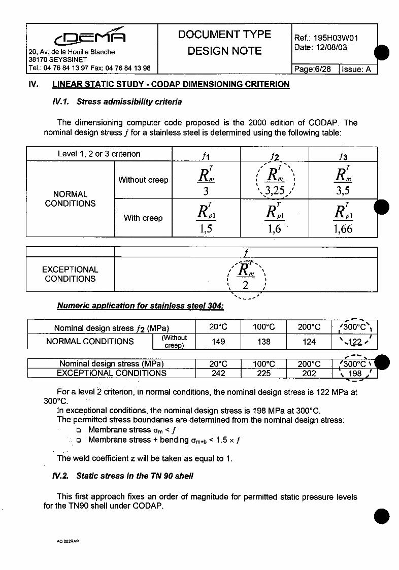
The dimensioning computer code proposed is the 2000 edition of CODAP. Thenominal design stress f for a stainless steel is determined using the following table:
Level 1,2 or 3 criterion fl f2 f3
RT R ,
Without creep Rm , Rm T ImNORMAL 3 ','3,25..' 3,5
CONDITIONS T' TT
With creep R__ RI R _I
1,5 1,6 1,66
EXCEPTIONAL ,,R" "CONDITIONS , 2S2
Numeric application for stainless steel 304:
Nominal design stress 12 (MPa) 200C 100 0C 2000C I300°0C\
NORMAL CONDITIONS (Without 149 138 124 ' -1.2ZIcreep)
Nominal design0stregss MPa) I20-C I1000C 2000C "300-CEXCEPTIONAL CONDITIONS 242 225 202 _. 98
For a level 2 criterion, in normal conditions, the nominal design stress is 122 MPa at3000C.
In exceptional conditions, the nominal design stress is 198 MPa at 3000C.The permitted stress boundaries are determined from the nominal design stress:
a Membrane stress am < fo Membrane stress + bending am+b < 1.5 x f
The weld coefficient z will be taken as equal to 1.
IV.2. Static stress in the TN 90 shell
This first approach fixes an order of magnitude for permitted static pressure levelsfor the TN90 shell under CODAP.
AQ 002RAP
i,,,1=1DOCUMENT TYPE Re.19H3020, Av. de la Houille Blanche DESIGN NOTE Date: 12/08/03
38170 SEYSSINETTel.: 04 76 84 13 97 Fax: 04 76 84 13 98 Page:7/28 I Issue: A
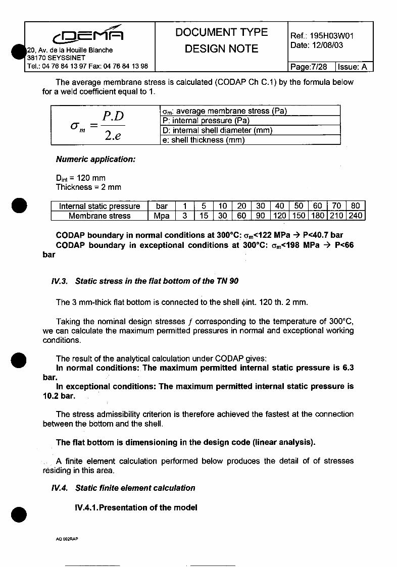
The average membrane stress is calculated (CODAP Ch C.1) by the formula belowfor a weld coefficient equal to 1.
RoD Oam: average membrane stress (Pa)P. -- P: internal pressure (Pa)
2.e D: internal shell diameter (mm)e: shell thickness (mm)
Numeric application:
Dint = 120 mmThickness = 2 mm
Internal static pressure bar 1 5 10 120 130 140 150 160 70 180Membrane stress Mpa 3 15 30 60 90 120 150 180 210 240
CODAP boundary in normal conditions at 300°C: am<122 MPa -- P<40.7 barCODAP boundary in exceptional conditions at 3000 C: am<198 MPa -- P<66
bar
IV.3. Static stress in the flat bottom of the TN 90
The 3 mm-thick flat bottom is connected to the shell ýint. 120 th. 2 mm.
Taking the nominal design stresses f corresponding to the temperature of 3000C,we can calculate the maximum permitted pressures in normal and exceptional workingconditions.
The result of the analytical calculation under CODAP gives:In normal conditions: The maximum permitted internal static pressure is 6.3
bar.In exceptional conditions: The maximum permitted internal static pressure is
10.2 bar.
The stress admissibility criterion is therefore achieved the fastest at the connectionbetween the bottom and the shell.
The flat bottom is dimensioning in the design code (linear analysis).
A finite element calculation performed below produces the detail of of stressesresiding in this area.
IV.4. Static finite element calculation
IV4.1 .Presentation of the model
AQ 002RAP
cmf- M M-I DOCUMENT TYPE Ref.: 195H03W01
20, Av. de la Houille Blanche DESIGN NOTE Date: 12/08/0338170 SEYSSINETTel.: 04 76 84 13 97 Fax: 04 76 84 13 98 1 Page:8/28 I Issue: A
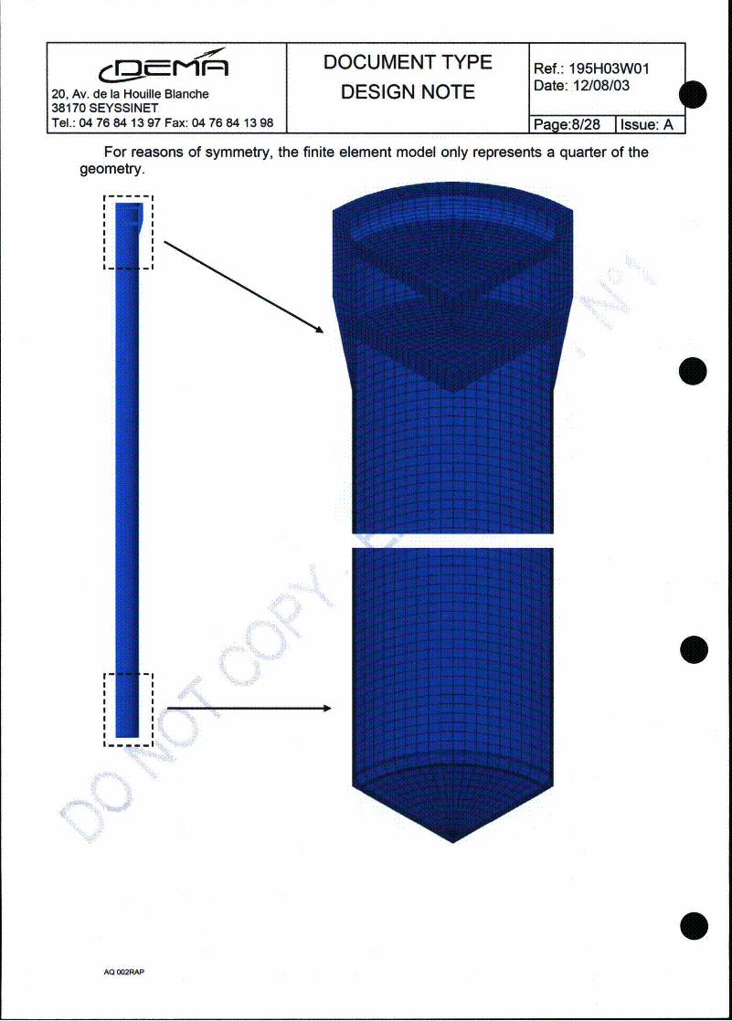
PFor reasons of symmetry, the finite element model only represents a quarter of the
geometry.
I--------I
I-IIm Im
If ii •
AQ 002RAP
l|r,, DOCUMENT TYPE Ref.: 195H03W01
120, Av. de la Houille Blanche DESIGN NOTE Date: 12/08/03
38170 SEYSSINETTel.: 04 76 84 13 97 Fax: 04 76 84 13 98 Page:9/28 I Issue: A
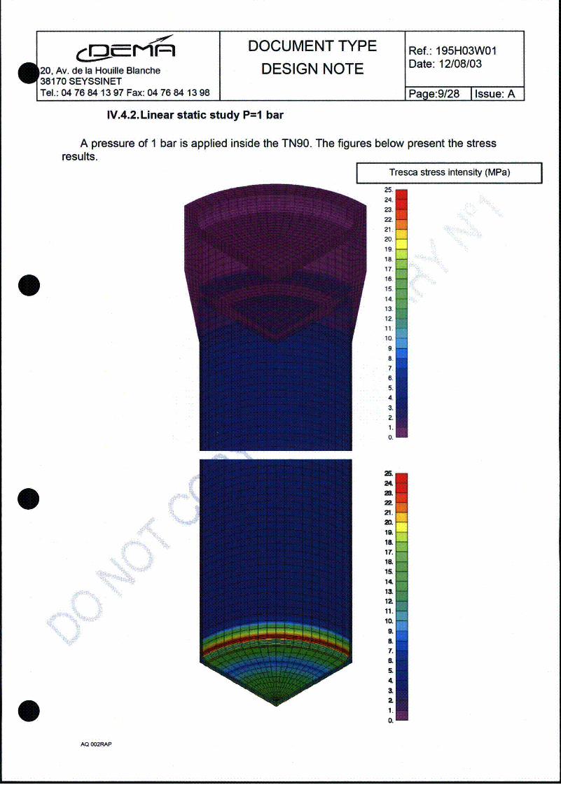
IV.4.2. Linear static study P=1 bar
A pressure of I bar is applied inside the TN90. The figures below present the stressresults.
Tresca stress intensity (MPa) I25.24.23.22.21.20.19.18.17.16.15.14.13.12.11.10.
9.a.
7.
4.3.2.
19.
0.
12L19.
21.
10.
1&~
17.
14.13.
12.
1.
10.a.
AQ 002RAP
DOCUMENT TYPE Ref.: 195H03W01
20, Av. de la Houille Blanche DESIGN NOTE Date: 12/08/03
Tel.: 04 76 84 13 97 Fax: 04 76 84 13 98 1 Page: 10/28 1 Issue: A
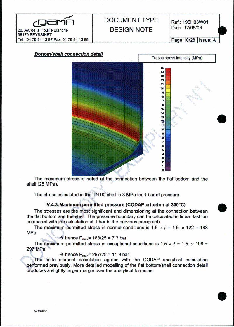
Bottom/shell connection detailI Tresca stress intensity (MPa)
I
2S
U
21
ZIO19.
17.1a
14'a11.
10,ItL8.a7.a
4a
1.
The maximum stress is noted at the connection betweenshell (25 MPa).
the flat bottom and the
The stress calculated in the TN 90 shell is 3 MPa for I bar of pressure.
IV.4.3.Maximum permitted pressure (CODAP criterion at 300°C)The stresses are the most significant and dimensioning at the connection between
the flat bottom and the shell. The pressure boundary can be calculated in linear fashioncompared with the calculation at 1 bar in the previous paragraph.
The maximum permitted stress in normal conditions is 1.5 x f = 1.5. x 122 = 183MPa.
-- hence Pmax= 183/25 = 7.3 bar.The maximum permitted stress in exceptional conditions is 1.5 x f = 1.5. x 198 =
297 MPa.-4 hence Pmax= 297/25 = 11.9 bar.
The finite element calculation agrees with the CODAP analytical calculationperformed previously. More detailed modelling of the flat bottom/shell connection detailproduces a slightly larger margin over the analytical formulas.
AQ 002RAP

S. MI1 DOCUMENT TYPE Ref.: 195H03W01
120, Av. de la Houille Blanche DESIGN NOTE Date: 12/08/03
38170 SEYSSINETTel.: 04 76 84 13 97 Fax: 04 76 84 13 98 Page: 11/28 1 Issue: A
IV.4.4.Conclusion on the CODAP linear static study
This first linear static calculation approach gives the maximum permitted pressurewith respect to the reference computer code for pressure equipment (CODAP).
The stress admissibility criteria have been determined for a temperature of 3000C(conservative temperature for the mechanical strength of the TN 90).
Using a finite element calculation we can draw the conclusion that the TN 90 isdimensioned for a normal working pressure of 7.3 bar and a test pressure of 11.9 bar.The most stress-loaded area is the flat bottom/shell connection, which limits the internalpressure to the values mentioned above.
The cover located in the upper part is only slightly under stress (see stress mappingon page 9). The cover is in fact much thicker than the flat bottom which gives it highinertia and slight deformations. The upper area in which the cover is found is thereforenot the part which dimensions the TN 90.
The shell (Dint. 120, th. 2 mm) is dimensioned for far greater pressures (40.7 bar innormal conditions and 66 bar in exceptional conditions).
By taking the CODAP as the design code, the pressure use limit for the TN 90is 12 bar in an exceptional situation at 300°C and 7.3 bar in normal conditions(penalised at 3000C).
AQ 002RAP
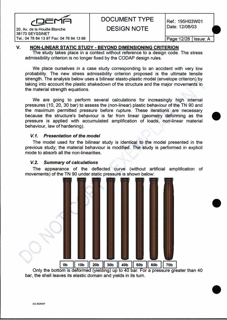
lo:M DOCUMENT TYPE Ref.: 195H03W01
20, Av. de la Houille Blanche DESIGN NOTE Date: 12/08/0338170 SEYSSINETTel.: 04 76 84 13 97 Fax: 04 76 84 13 98 Page: 12128 1 Issue: JA
bV. NON-LINEAR STATIC STUDY - BEYOND DIMENSIONING CRITERION
The study takes place in a context without reference to a design code. The stressadmissibility criterion is no longer fixed by the CODAP design rules.
We place ourselves in a case study corresponding to an accident with very lowprobability. The new stress admissibility criterion proposed is the ultimate tensilestrength. The analysis below uses a bilinear elasto-plastic model (envelope criterion) bytaking into account the plastic shakedown of the structure and the major movements inthe material strength equations.
We are going to perform several calculations for increasingly high internalpressures (10, 20, 30 bar) to assess the (non-linear) plastic behaviour of the TN 90 andthe maximum permitted pressure before rupture. These iterations are necessarybecause the structure's behaviour is far from linear (geometry deforming as thepressure is applied with accumulated amplification of loads, non-linear materialbehaviour, law of hardening).
V.1. Presentation of the modelThe model used for the bilinear study is identical to the model presented in the
previous study; the material behaviour is modified. The study is performed in explicitmode to absorb all the non-linearities.
V.2. Summary of calculationsThe appearance of the deflected curve (without artificial amplification of
movements) of the TN 90 under static pressure is shown below:
Only the bottom is deformed (yielding) up to 40 bar. For a pressure greater than 40bar, the shell leaves its elastic domain and yields in its turn.
AQ OO2WA
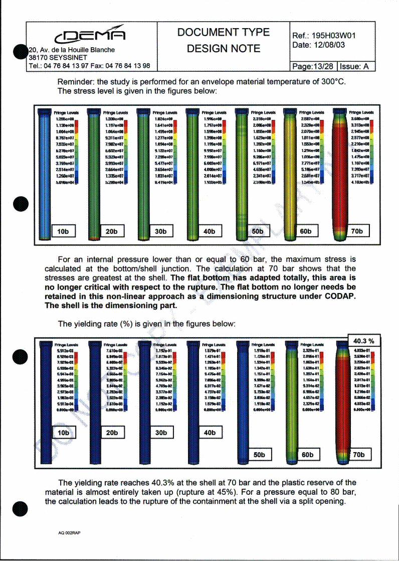
DOCUMENT TYPE Ref.: 195H03W012T8,A.de la Houille Blanche DESIGN NOTE Dt:1/80
38170 SEYSSINETTel.: 04 76 84 13 97 Fax: 04 76 84 13 98 1 Page:13/28 1 Issue: A
Reminder: the study is performed for an envelope material temperature of 300°C.The stress level is given in the figures below:
r1imp LO ,Ab RW.4 LWb .M.. "VW fk r" L"
1.3M1.15 6- 12"r1e4lI 1.t51,46_ "Il.ElNOIk 1.3lon6lI6 1TMt
-17WMW. 23110M 127-=!- 113s40S. IJBie-- i.411.406.i
7A33601 7.5640 1964.0" 1.1998M 1.3926M6 12MOM46 z2.21.
62M.1 55aft."1 ,.1.41I &9908 t1 1.4! 12,94.! 1"MSAWOW Was.40 72W.40 7.110WW0 U105ie7 1255.46 14.461m
25146W0 2SIWebO 3AIS IAO 650 1 7.3"&W0120M1347 MS 2M 1.30*W.1 2.00.0 1717.0Wf176.407 383.401 u419e07 9".1 1.92NH1e40f 1 1.%&7Ol,0 1107.4
S 20b 30b 40bI0b 60b 470b
For an internal pressure lower than or equal to 60 bar, the maximum stress iscalculated at the bottom/shell junction. The calculation at 70 bar shows that thestresses are greatest at the shell. The flat bottom has adapted totally, this area isno longer critical with respect to the rupture. The flat bottom no longer needs beretained in this non-linear approach as a dimensioning structure under CODAP.The shell is the dimensioning part.
The yielding rate (%) is given in the figures below:
The yielding rate reaches 40.3% at the shell at 70 bar and the plastic reserve of thematerial is almost entirely taken up (rupture at 45%). For a pressure equal to 80 bar,the calculation leads to the rupture of the containment at the shell via a split opening.
AQ 002RAP
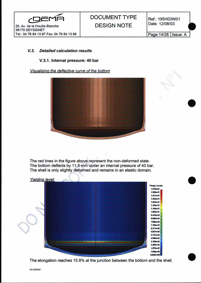
:DOCUMENT TYPE Ref.: 195H03W0120, Av. de la Houille Blanche DESIGN NOTE Date: 12/08/0338170 SEYSSINETTel.: 04 76 84 13 97 Fax: 04 76 84 13 98 1Page: 14/28 1 Issue: A
I
V.3. Detailed calculation results
V.3.1. Internal pressure: 40 bar
Visualisina the deflective curve of the bottom
The red lines in the figure above represent the non-deformed state.The bottom deflects by 11.5 mm under an internal pressure of 40 bar.The shell is only slightly deformed and remains in an elastic domain.
01A21.1 l
1.154.01 -
1.10"I -
L415.42
6M37002
4337.4
3.13s42
Mown.4
The elongation reaches 15.8% at the junction between the bottom and the shell.
AQ O02RAP

DOCUMENT TYPE Ref.: 195H03W01
120, Av. de la Houille Blanche DESIGN NOTE Date: 12/08/0338170 SEYSSINETTel.: 04 76 84 13 97 Fax: 04 76 84 13 98 Page:15/28 1 Issue:A
V.3.2. Internal pressure: 70 bar
Visualisina the deflective curve of the TN90
I Increase indiameter: +50 mm /
II II
17
k
LoweLra
The red lines in the figure above represent the non-deformed state.The bottom deflects by 17 mm under an internal pressure of 70 bar.The shell diameter is increased by 50 mm. This increase in diameter (smaller
Young module at 3000C) is extremely unfavourable for the mechanical strength, for theeffect of the pressure on the membrane is amplified by this geometric non-linearity.
AQ 002RAP
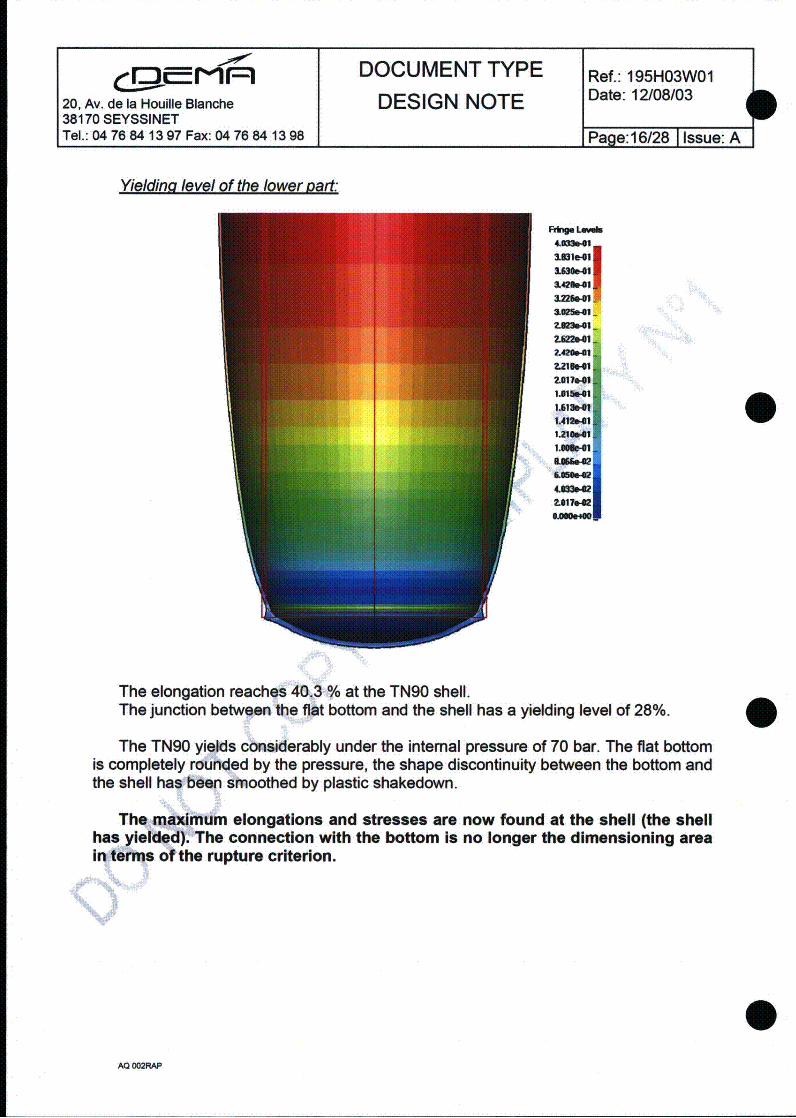
DOCUMENT TYPE Ref.: 195H03W01
20, Av. de la Houille Blanche DESIGN NOTE Date: 12/0810338170 SEYSSINETTel.: 04 76 84 1397 Fax: 04 76 84 1398 1 Page:16/28 1 Issue: A
I
Yielding level of the lower part:
Rfg. LuWW
1421"11
1=02411
2.42b1"
2.017"1lU156741
1.61"4IU11.1
1.216s411
MIAN"
5651.42"I 7WU.1 -UW
The elongation reaches 40.3 % at the TN90 shell.The junction between the flat bottom and the shell has a yielding level of 28%.
The TN90 yields considerably under the internal pressure of 70 bar. The fiat bottomis completely rounded by the pressure, the shape discontinuity between the bottom andthe shell has been smoothed by plastic shakedown.
The maximum elongations and stresses are now found at the shell (the shellhas yielded). The connection with the bottom is no longer the dimensioning areain terms of the rupture criterion.
AQ 002RAP
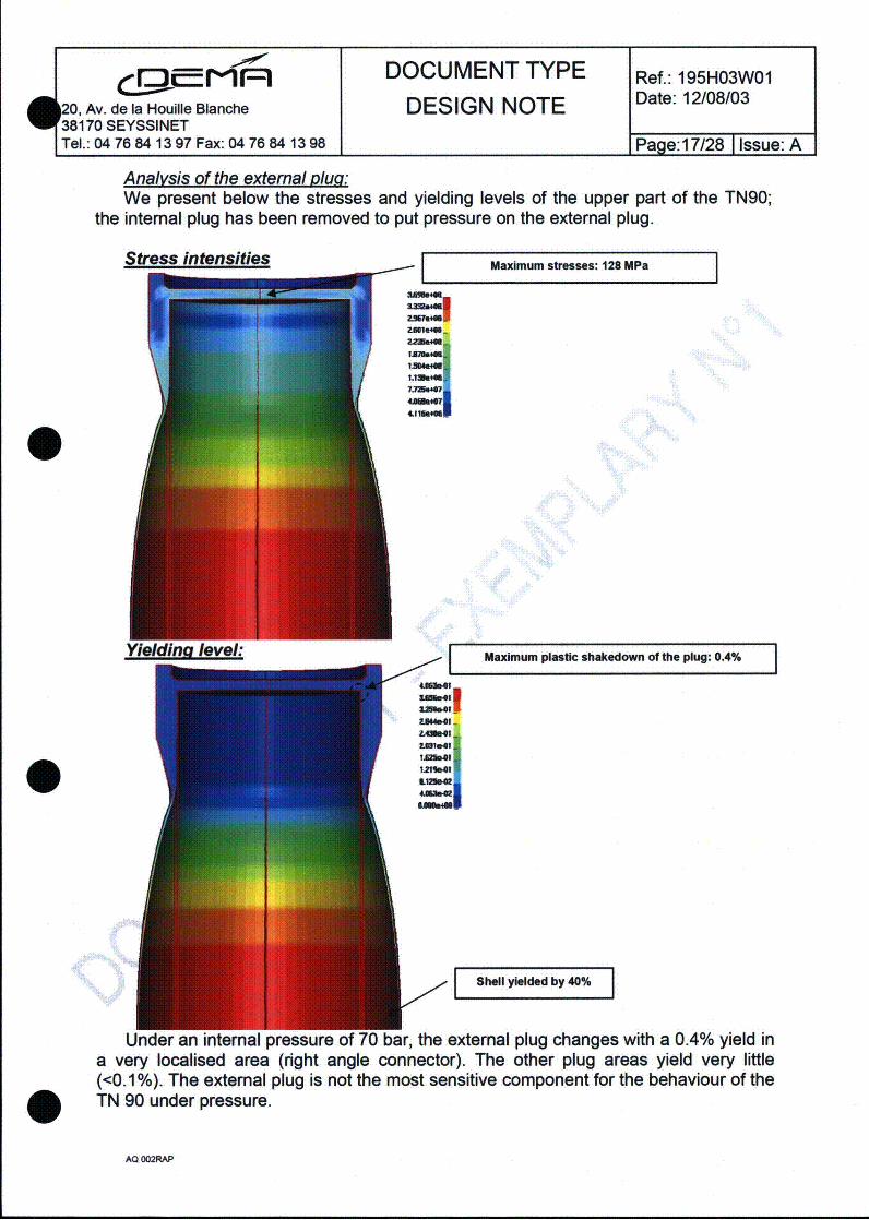
DOCUMENT TYPE Ref.: 195H03W01
20, Av. de la Houille Blanche DESIGN NOTE Date: 12/08/0338170 SEYSSINETTel.: 04 76 84 13 97 Fax: 04 76 84 13 98 1 Page:17/28 1 Issue: A
Analysis of the external Dlu0:We present below the stresses and yielding levels of the upper part
the internal plug has been removed to put pressure on the external plug.of the TN90;
Stress intensities
Lre.2564"
ZmuUMEUemi
Maximum stresses: 128 MPaI
tin..,IumtriLimE*.noIMbtwin
Maximum plastic shakedown of the plug: 0.4% I
I hl yeddbyE4%
Under an internal pressure of 70 bar, the external plug changes with a 0.4% yield ina very localised area (right angle connector). The other plug areas yield very little(<0.1 %). The external plug is not the most sensitive component for the behaviour of theTN 90 under pressure.
AQ 002RAP

DOCUMENT TYPE Ref.: 195H03W01Date: 12/08/03
20, Av. de la Houille Blanche DESIGN NOTE D38170 SEYSSINET
Tel.: 04 76 84 13 97 Fax: 04 76 84 13 98 Page: 18/28 1 Issue: A
The plug is connected to the body by a screw thread, where the shear stressreaches 122 MPa for a pressure of 60 bar. This stress is less than the permitted limit of197 MPa (Rm 311"/ 2 ). The stress levels in the plug are very much below those in thelower part (flat bottom) and the plug is therefore not the dimensioning part.
V.4. Conclusion of the non-linear static test beyond dimensioning
Several non-linear calculations have been performed to assess the behaviour of theTN 90 for increasing pressures.
We note that for static pressures below 40 bar, the shell remains virtuallyunchanged (elastic domain), but the flat bottom is deformed (plastic shakedown). 4Above 40 bar, the flat bottom is shaken down and there is little change to thedeformations in this zone. The maximum permitted pressure is therefore restricted bythe behaviour of the shell under pressure. For a pressure of 70 bar, the plastic reserveis almost entirely taken up in the shell.
The tremendous plastic shakedown capacity of the stainless steel is enough toerase the flat bottom/shell discontinuity.
The TN 90 can withstand a maximum internal static pressure of 70 bar. Thedeformation of the TN 90 is very important for this pressure without rupture of thecontainment nevertheless (at 80 bar).
The maximum permitted static pressure for the TN 90 is therefore moved to70 bar.
I
AQ 002RAP

0 DOCUMENT TYPE Ref.: 195H03W01
0, Av. de la Houille Blanche DESIGN NOTE Date: 12/08/0338170 SEYSSINETTel.: 04 76 84 13 97 Fax: 04 76 84 13 98 Page:19/28 1 Issue: A
VI. NON-LINEAR DYNAMIC STUDY - PRESSURE STEP
The time response of a structure depends on the dynamic loading applied to it. Theeffect of the pressure loading dynamics on the behaviour of the TN 90 is assessed insimplified fashion in this study. We are going to apply a uniform internal pressureinstantaneously (TN 90 response to a pressure step with infinite gradient).
L
Internal pressure (bar)
Final pressure (bar)
qP
0 Time (s)
Standard stress respoiStress (MPa)
Ise diagram with plastic phase
Stress corresponding to the end ofthe dynamic study (MPa)
---- I --StFess corresponding toN' static pressure (MPa)
0
In this dynamic study, we expect to exceed the stresses corresponding to the staticstate. For a linear system (spring), the amplification factor is equal to 2. As the systemis non-linear, the stress amplitudes will be less through consumption of the energy inyielding phase.
The study is performed in time dynamics with a bilinear elasto-plastic behaviour ofthe steel. The criterion adopted for the stress admissibility is always the boundary atthe rupture (45% elongation corresponding to 395 MPa in Von Mises stress).
AQ 002RAP
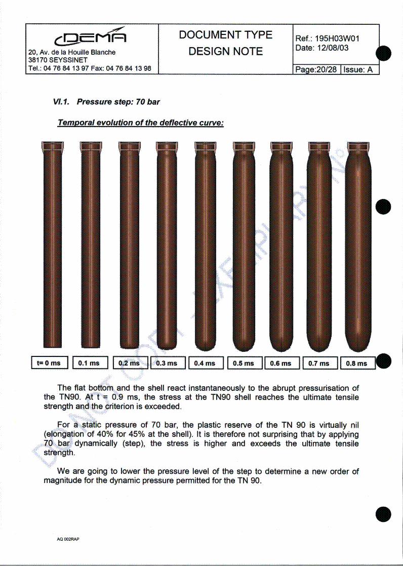
DOCUMENT TYPE Ref.: 195H03W01
20, Av. de la Houille Blanche DESIGN NOTE Date: 12/08/0338170 SEYSSINETTel.: 04 76 84 13 97 Fax: 04 76 84 13 98 1 Page:20/28 I Issue: A
b
VI. 1. Pressure step: 70 bar
Temporal evolution of the deflective curve:
0
1 08I MS
The flat bottom and the shell react instantaneously to the abrupt pressurisation ofthe TN90. At t = 0.9 ms, the stress at the TN90 shell reaches the ultimate tensilestrength and the criterion is exceeded.
For a static pressure of 70 bar, the plastic reserve of the TN 90 is virtually nil(elongation of 40% for 45% at the shell). It is therefore not surprising that by applying70 bar dynamically (step), the stress is higher and exceeds the ultimate tensilestrength.
We are going to lower the pressure level of the step to determine a new order ofmagnitude for the dynamic pressure permitted for the TN 90.
AQ 002RAP

C,..D_|pI,=IDOCUMENT TYPE Re.19H300, Av. de la Houille Blanche DESIGN NOTE Date: 12/08/03
38170 SEYSSINETTel.: 04 76 84 13 97 Fax: 04 76 84 13 98 Page:21/28 I Issue: A
A.2. Pressure step: 65 bar
A new calculation at 65 bar results in the rupture of the containment. We shall notgive details of this result here.
VI.3. Pressure step: 60 bar
L~ ~3I~1 ~The result of the time calculation indicates that the TN 90 withstands a pressure of
60 bar applied uniformly and instantaneously without breaking. The transient only lastsone millisecond. It is an order of magnitude of the pressure wave in an H2+0 2
explosion.
AQ 002RAP
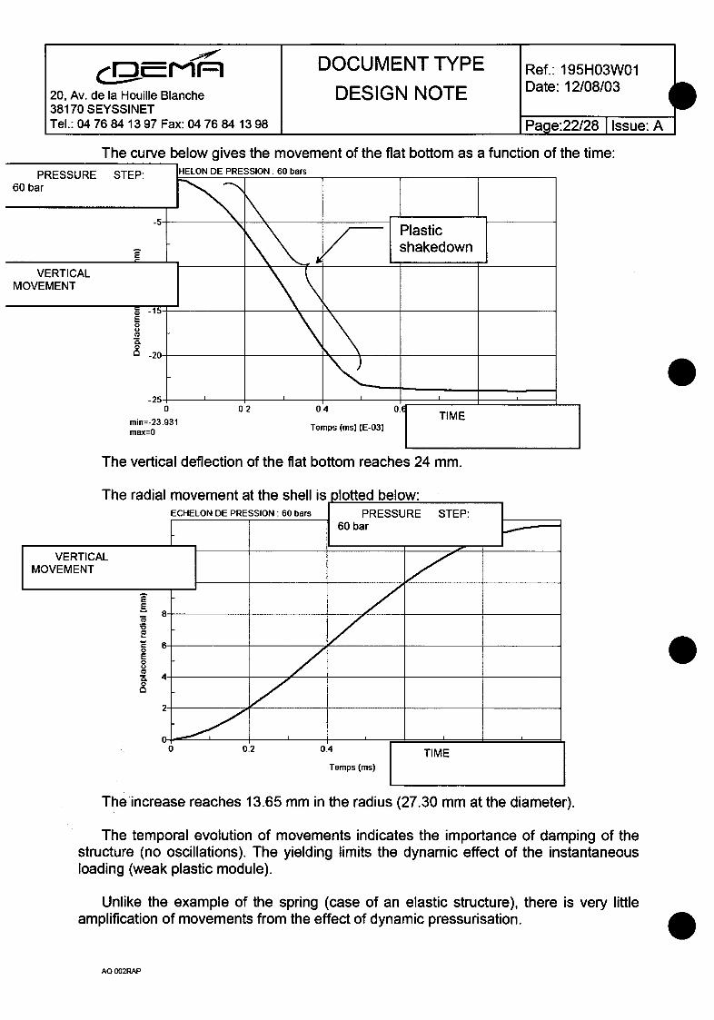
.- 00r DOCUMENT TYPE Ref.: 195H03W01
20, Av. de la Houille Blanche DESIGN NOTE Date: 12/08/03 d38170 SEYSSINET __Tel.: 04 76 84 13 97 Fax: 04 76 84 13 98 Page:22/28 Issue: A
bThe curve below gives the movement of the flat bottom as a function of the time:
o-rn. IHELON DE PRESSION: 60 barso I r-r-:
The vertical deflection of the flat bottom reaches 24 mm.
The increase reaches 13.65 mm in the radius (27.30 mm at the diameter).
The temporal evolution of movements indicates the importance of damping of thestructure (no oscillations). The yielding limits the dynamic effect of the instantaneousloading (weak plastic module).
Unlike the example of the spring (case of an elastic structure), there is very littleamplification of movements from the effect of dynamic pressurisation.
i0AQ 002RAP

rr ,) ,l -= M DOCUMENT TYPE Ref.: 195H03W0120, Av. de la Houille Blanche DESIGN NOTE Date: 12/08/03
38170 SEYSSINETTel.: 04 76 84 13 97 Fax: 04 76 84 13 98 Page:23/28 I issue: A
VI.4. Conclusion of the dynamic study - Pressure step
The amplification of stresses and dynamic deformations is restricted by the strongplastic damping of the structure.
The dynamic pressure in a step of 60 bar is withstood by the structure.
The TN 90 structure reacts rapidly (the transient only lasts one millisecond).
AQ 002RAP
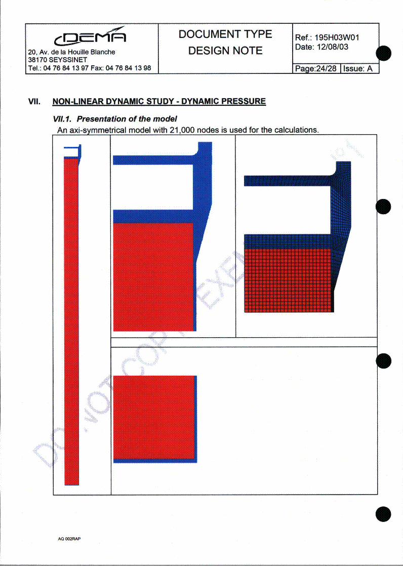
DOCUMENT TYPE Ref.: 195H03W01Date: 12/08/03
20, Av. de la Houille Blanche DESIGN NOTE e38170 SEYSSINETTel.: 04 76 84 13 97 Fax: 04 76 84 13 98 1 Page:24/28 I Issue: A
i
VIl. NON-LINEAR DYNAMIC STUDY - DYNAMIC PRESSURE
VII. 1. Presentation of the modelAn axi-svmmetdcal model with 21
AQ 002RAP
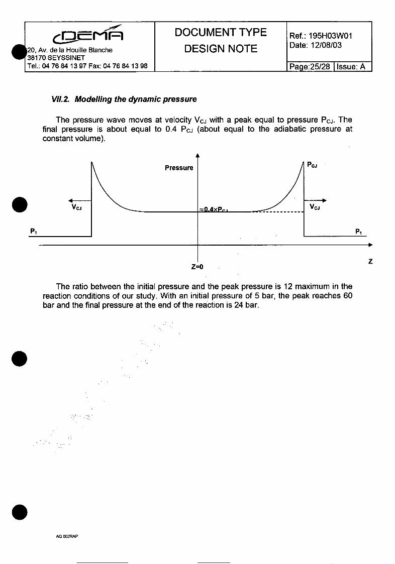
DOCUMENT TYPE Ref.: 195H03W01
120, Av. de la Houjile Blanche DESIGN NOTE Date: 12/08/0338170 SEYSSINETTel.: 04 76 84 13 97 Fax: 04 76 84 13 98 Page:25/28 I Issue: A
VII.2. Modelling the dynamic pressure
The pressure wave moves at velocity Vcj with a peak equal to pressure Pcu. Thefinal pressure is about equal to 0.4 Pcj (about equal to the adiabatic pressure atconstant volume).
PcwPressure
P1 P1
zZ=O
The ratio between the initial pressure and the peak pressure is 12 maximum in thereaction conditions of our study. With an initial pressure of 5 bar, the peak reaches 60bar and the final pressure at the end of the reaction is 24 bar.
AQ 002RAP

DOCUMENT TYPE Ref.: 195H03W01
20, Av. de la Houille Blanche DESIGN NOTE Date: 12/08/0338170 SEYSSINETTel.: 04 76 84 13 97 Fax: 04 76 84 13 98 1 Page:26/28 I Issue: A
VII.3. Calculation result for an initial pressure of I barThe initial pressure is equal to 1 bar, the final pressure is 8 bar.
Final deflective curve of the bottom
0
The deflection of the flat bottom reaches 2.7 mm.Stresses
FOP. Laveb
~Iaml.IW"7'Au....
4.131.a72.7790O?
IA IO
IA9012470013'MI..M-
925400I7.90
UK..4.6IiU.&&1-960UNDO..
Yielding. level
I I MThe maximum stress is equal to 136 MPa. The yielding level reaches 1.5% at the
junction between the flat bottom and the shell.
AQ 002RAP

100,,r- DOCUMENT TYPE Re.19H3020, Av. de la Houille Blanche DESIGN NOTE Date: 12/08/03
38170 SEYSSINETTel.: 04 76 84 13 97 Fax: 04 76 84 13 98 _Pae:27128 Issue: A
VI/.4. Calculation result for an initial pressure of 5 barThe pressure peak is 60 bar, the final pressure is equal to 24 bar.
Yieldina level of TN 90 bottom at the end of the transient:
'ii
1.923"11.731"1
1346e41-
U.16e427.593642
=841
The yielding level reaches 19.2 % at the junction between the flat bottom and theshell.
Stress intensities at the flat bottom at the end of the transient:
123584MiiAo.4u
534740M f
MSIMaximum stresses: 176 MPa I|
The maximum stress is equal to 176 MPa.
VII.5. Conclusion of the dynamic study - Pressure wave
The TN 90, initially at 5 bar, is placed under dynamic pressure by a peak at 60 barthen a final pressure of 24 bar. The deformations are localised at the flat bottom and itsjunction with the shell. The calculation result does not give excessive deformationpotentially causing the containment to rupture. The maximum yielding level reaches19.2% for a permitted boundary of 45%.
AQ 002RAP
DOCUMENT TYPE Ref.: 195H03W01
20, Av. de la Houllie Blanche DESIGN NOTE Date: 12/08/0338170 SEYSSINETTel.: 04 76 84 13 97 Fax: 04 76 84 13 98 Page:28/28 I issue: A
VIII. GENERAL CONCLUSION
Several calculations have been performed to assess the mechanical strength of theTN 90 under static then dynamic pressure, under dimensioning then beyonddimensioning criterion.
If the TN 90 was built as a pressure equipment (CODAP), it would be correctlydimensioned for a working pressure of 7 bar. This pressure is restricted by theconnection between the flat bottom and the shell.
By using a beyond dimensioning criterion (rupture), the TN 90 withstands a staticpressure of 70 bar after plastic shakedown. The flat bottom is therefore fully shakendown and the shell is therefore the dimensioning part (situation rapidly unstable).
The TN 90 withstands a pressure step of 60 bar (instantaneous and uniformpressurisation). Plastic shakedown takes place at the same time for the flat bottom andthe shell.
Applying a pressure wave (corresponding to combustion of a stochiometrichydrogen and oxygen mix at 5 bar), with a peak of 60 bar and a final pressure of 24bar, causes a shakedown of the flat bottom with a maximum deformation of 19.2%where it connects to the shell. The TN 90 containment therefore does not rupture underthe application of dynamic pressure of 60 bar passing through the TN 90.
In this study, we have taken the TN 90 to be at temperature (300'C) and we haveignored the effect of the loading velocity on the behaviour of the material. These areconservative hypotheses in terms of containment rupture.
I
AQ 002RAP
DSN STMR LEPE . TNBGCI DSEM 0605 Version 02
Nuclear Energy Division
Nuclear Services Department
Radioactive Materials Transportation Service
Packaging Operations Laboratory
Safety Analysis Report
TN-BGC 1 package
Chapter 5 - Thermal analysis
Clt: 7.1.1.3.
Classification: DO
AUTHOR CHECKED BY APPROVED BY
Name V. PAUTROT S. CHAIX S. CLAVERIE-FORGUES
Sign.
Date:
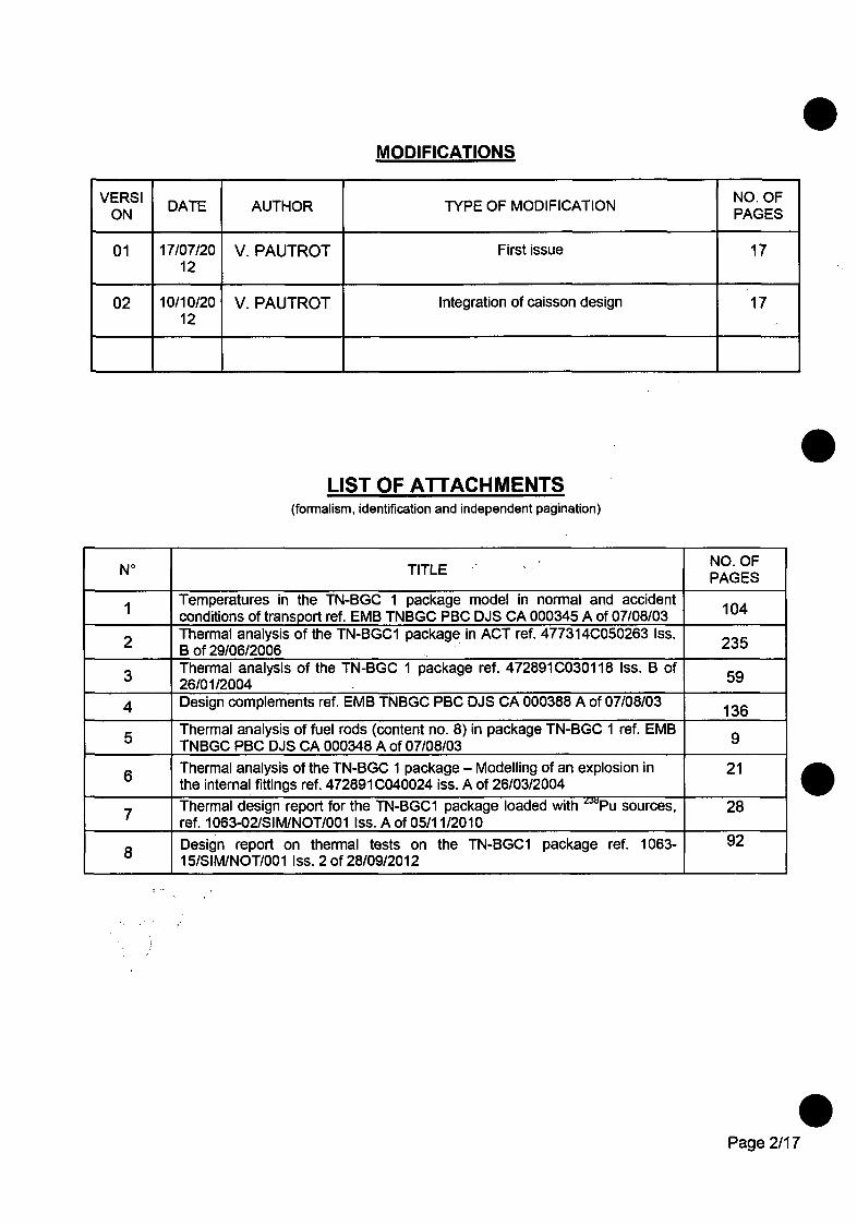
MODIFICATIONS
VERSI DATE AUTHOR TYPE OF MODIFICATION PAGESON PAGES
01 17/07/20 V. PAUTROT First issue 1712
02 10/10/20 V. PAUTROT Integration of caisson design 1712
LIST OF ATTACHMENTS(formalism, identification and independent pagination)
No TITLE NO. OFPAGES
Temperatures in the TN-BGC 1 package model in normal and accidentI conditions of transport ref. EMB TNBGC PBC DJS CA 000345 A of 07/08/03 104
Thermal analysis of the TN-BGC1 package in ACT ref. 477314C050263 Iss.2 B of 29/06/2006 235
m 3 Thermal analysis of the TN-BGC 1 package ref. 472891C030118 Iss. B of26/01/2004
4 Design complements ref. EMB TNBGC PBC DJS CA 000388 A of 07/08/03 136
Thermal analysis of fuel rods (content no. 8) in package TN-BGC 1 ref. EMB5__ _ TNBGC PBC DJS CA 000348 A of 07/08/036 Thermal analysis of the TN-BGC 1 package - Modelling of an explosion in 21
the internal fittings ref. 472891C040024 iss. A of 26/03/2004Thermal design report for the TN-BGC1 package loaded with "Pu sources, 28
7_ ref. 1063-02/SIM/NOT/001 Iss. A of 05/11/2010
8 Design report on thermal tests on the TN-BGC1 package ref. 1063- 9215/SIM/NOT/O01 Iss. 2 of 28/09/2012
Page 2/17

CONTENTS
1. PURPOSE ....................................................................................................................................... 5
2. REFERENCES ................................................................................................................................ 5
3. GENERAL DESIGN ASSUMPTIONS ......................................................................................... 53.1. CONDITIONS OF TRANSPORT ......................................................... ERREUR! SIGNET NON DEFINI.3.2. POWER TRANSPORTED ........................................................................................................................ 63.3. PROPERTIES OF MATERIALS ........................................................................................................... 63.4. MODELS ................................................................................................................................. ................. 63.5. MODELLING ASSUMPTIONS ............................................................................................................. 6
3.5.1. Package .............................................................................................................................................. 63.5.2. Content ................................................................................................................................................ 73.5.3. Thermal exchanges ................................................................................ .......................................... 7
4. CALCULATION CONFIGURATIONS ADOPTED ....................................................................... 7
5. TEMPERATURES OF ACCESSIBLE SURFACES WITHOUT SUNLIGHT AT THEAMBIENT TEMPERATURE OF 380C .......................................................................................... 8
6. AIR TRANSPORT SCENARIO .................................................................................................. 8
7. TEMPERATURES UNDER NORMAL CONDITIONS OF TRANSPORT ................................... 87.1. PACKAGE ............................................................... I ................................................................................ 8
7.1.1. Package joints ................................................................................................................................... 87.1.2. Other package components ......... * ............................ 8
7.2. INTERNAL ARRANGEMENTS AND CONTENT ............................................................................... 97.2.1. Zero power content ......................................................................................................................... 97.2.2. Power content limited to 340 W (for the TN90) or 170 W (for AA41-203-204) ....................... 97.2.3. Content packaged in a vinyl cover - maximum power = 80 W ................................................. 9
7.3. GAS IN CAVITIES IN THE PACKAGE AND INTERNAL FITTINGS .............................................. 107.3.1. Zero powercontent ......................................................................................................................... 107.3.2. Power content limited to 340 W (for the TN90) or 170 W (for AA41-203-204) ...................... 107.3.3. Content packaged in a vinyl cover - maximum power = 80 W ............................................... 10
8. TEMPERATURES UNDER ACCIDENT CONDITIONS OF TRANSPORT ............................... 118.1. JOINTS .................................................................................................................................................... 118.2. OTHER PACKAGE COMPONENTS ..................................................................................................... 118.3. INTERNAL FITTINGS AND CONTENT ................................................................................................. 11
8.3.1. Zero power content ......................................................................................................................... 118.3.2. Maximum power content limited to 340 W (for the TN90 - AA226-227) or 170 W (for
AA41-203-204) ............................................................................................................................... 128.3.3. Content packaged in a vinyl cover - maximum power = 80 W ............................................... 13
8.4. GAS IN CAVITIES IN THE PACKAGE AND INTERNAL FITTINGS .............................................. 138.4.1. Zero power content ......................................................................................................................... 138.4.2. Maximum power content limited to 340 W (for the TN90) or 170 W (for AA41-203-204) .......... 138.4.3. Content packaged in a vinyl cover - maximum power = 80 W ............................................... 14
Page 3/17

9. SPEC IA L CASE O F CO NTENT No 46 ....................................................................................... 14
10. SHIELDED CA ISSO N TRA NSPO RT ....................................................................................... 14
11. CO NC LUSIO NS .......................................................................................................................... 15
41
.Page 4/17

1. PURPOSE
The aim of this chapter is to study the thermal behaviour of the TN-BGC1 package and its content. In order to
cover all existing content and configurations, the calculations are carried out for envelope configurations
covering all possible scenarios (Cf. table 1).
This analysis integrates:
* the maximum power likely to be released by the content of the package,
* the horizontal or vertical position of the package during transport,
* the characteristics of the different internal fittings and content,
* normal and accident conditions of transport as defined in regulations.
2. REFERENCES
[1] International Atomic Energy Agency (IAEA) regulations for the safe transport of radioactive material,No. TS-R-1 - 1996 edition (amended in 2005).
[2] Finite element design software: I-DEAS Master Series V4.0 developed by SDRC La Defense with theTMG Thermal Analysis module
[3] Handbook of CHEMISTRY and PHYSICS - D. R. LIDE - 7 3rd Edition - 1992 - 1993
3. GENERAL DESIGN ASSUMPTIONS
3.1. CONDITIONS OF TRANSPORT,
Isolated transport
The package, consisting of a cylindrical casing fitted inside a cage, is transported vertically or horizontally.
Caisson transport
The package is transported in a vertical position in a shielded CB9 type caisson.
Note: The different calculations shown in attachments 1 to 6 on caisson transport should be ignored as the
thermal characteristics of the caissons used as input data do not correspond to the caissons used. However,
the caisson calculations can be used to cover air transport scenarios (see § 6).
Page 5/17

3.2. POWER TRANSPORTED
The heat is dissipated by natural convection and radiation in the ambient air, and conducted via the main
components of the package casing.
The power released by the content of a package may vary between 0 and 340 W.
3.3. PROPERTIES OF MATERIALS
The thermal characteristics of package materials are taken from chapter 2. The conductivity of the resin is
determined on the basis of the results of tests carried out in 1998 at the Saclay centre (the tests were subject
to reports with the references EMB TNBGC PBC DJS CA 000343 A and EMB TNBGC PBC DJS CA 000344
A). The thermal properties of the materials used in the content are indicated in chapter 1.
3.4. MODELS
The mapping of temperatures reached in normal and accident conditions of transport is determined by finite
element calculations in most cases.
Several models have been created, depending on the nature of content and the internal fittings in the package
cavity. Models can be 3D or axisymmetric.
These models and the results obtained are shown in attachment 1 and completed by calculations shown in
attachments 2 to 4.
The special case of the transport of mixed oxide fuel rods, for which a specific design method enables us to
obtain the temperature of cladding in normal and accident conditions of transport (attachment 5), is subject to
analytical calculations.
3.5. MODELLING ASSUMPTIONS
3.5.1. Packaqe
3.5.1.1. Normal conditions 6f transport
The package, as described in chapter 2, is considered as intact.
3.5.1.2. Accident conditions of transport
The following assumptions are taken into consideration:
• the shock-absorbing cover is reduced by 42 mm along the longitudinal axis (the balsa isassumed to be compressed by approx. 60%) after an axial fall on the shock-absorbing cover,
* the shock-absorbing cover is reduced by 33 mm along the radius after a fall on the generator,
* part of the outer shell of the casing is depressed after the impact of a bar,
* the shock-absorbing part of the casing is reduced by 39 mm along the longitudinal axis after anaxial fall on the base of the casing.
Page 6/17
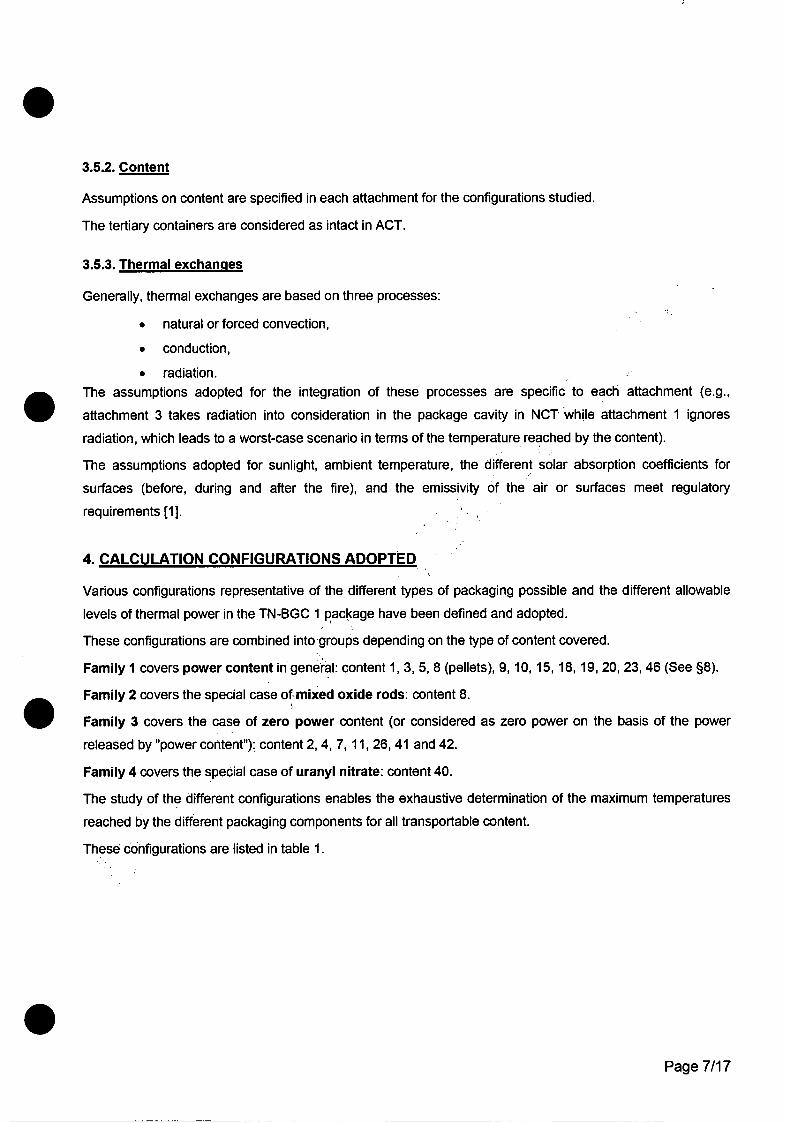
3.5.2. Content
Assumptions on content are specified in each attachment for the configurations studied.
The tertiary containers are considered as intact in ACT.
3.5.3. Thermal exchanges
Generally, thermal exchanges are based on three processes:
* natural or forced convection,
* conduction,
* radiation.. The assumptions adopted for the integration of these processes are specific to each attachment (e.g.,
attachment 3 takes radiation into consideration in the package cavity in NCT while attachment 1 ignores
radiation, which leads to a worst-case scenario in terms of the temperature reached by the content).
The assumptions adopted for sunlight, ambient temperature, the different solar absorption coefficients for
surfaces (before, during and after the fire), and the emissivity of the air or surfaces meet regulatory
requirements [1].
4. CALCULATION CONFIGURATIONS ADOPTED
Various configurations representative of the different types of packaging possible and the different allowable
levels of thermal power in the TN-BGC 1 package have been defined and adopted.
These configurations are combined into groups depending on the type of content covered.
Family I covers power content in general: content 1, 3, 5, 8 (pellets), 9, 10, 15, 18, 19, 20, 23, 46 (See §8).
Family 2 covers the special case of mixed oxide rods: content 8.
Family 3 covers the case of zero power content (or considered as zero power on the basis of the power
released by "power content"): content 2, 4, 7, 11, 26, 41 and 42.
Family 4 covers the special case of uranyl nitrate: content 40.
The study of the different configurations enables the exhaustive determination of the maximum temperatures
reached by the different packaging components for all transportable content.
These configurations are listed in table 1.
Page 7/17

5. TEMPERATURES OF ACCESSIBLE SURFACES WITHOUT SUNLIGHT AT THE AMBIENTTEMPERATURE OF 38°C
These temperatures, which correspond to those of the package cage, are not calculated in the context of this
chapter. Chapter 10 provides for the measurement of the temperatures of accessible surfaces at thermal
equilibrium and checking their availability in terms of regulatory limits.
6. AIR TRANSPORT SCENARIO
If transported by air, the regulatory ambient temperature is 550C and sunlight is not taken into consideration;
this scenario is generally covered regardless of the horizontal or vertical position of the package by the
caisson transport scenario (air temperature in the caisson equal to a maximum of 71 °C for zero power content*
- See report EMB TNBGC PBC DJS CA000346 A of 07/08/03).
The results obtained for caisson transport are then envelopes and it is proved that these results are not
limiting for zero thermal power.
7. TEMPERATURES UNDER NORMAL CONDITIONS OF TRANSPORT
7.1. PACKAGE
7.1.1. Package ioints
The maximum temperature reached by the package joints equals 1240C (attachment 4) for configuration 3.1
as defined in table 1 (family 1). This temperature is below the maximum temperature of use for joints (2500C
for Viton - 3000C for silicone).
7.1.2. Other Package components
The maximum temperatures of the different package components for the different applicable loading scenarios
are shown in the table below. The table shows the configuration leading to these maximum temperatures. The
temperatures are acceptable for the materials used.
Package component Maximum temperature Family Reference attachment
Internal shell 1580C 1 (without covers) 1
Internal shell 690C 1 (with covers) 3
External shell 117 0C 1 and 2 1
In particular, at the temperature of 158 0C, the neutron-absorbing resin is not downgraded and retains all of its
properties. ,•.
Page 8/17
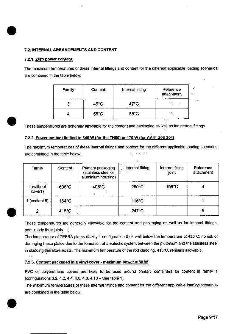
7.2. INTERNAL ARRANGEMENTS AND CONTENT
7.2.1. Zero power content
The maximum temperatures of these internal fittings and content for the different applicable loading scenarios
are combined in the table below.
Family Content Internal fitting Referenceattachment
3 450C 470C 1
4 550C 550C 1
These temperatures are generally allowable for the content and packaging as well as for internal fittings.
7.2.2. Power content limited to 340 W (for the TN90) or 170 W (for AA41-203-204)
The maximum temperatures of these internal fittings and content for the different applicable loading scenarios
are combined in the table below.
Family Content Primary packaging Internal fitting Internal fitting Reference(stainless steel or joint attachment
aluminium housing)
1 (without 6060C 4050C 2600C 1980C 4covers)
1 (content 5) 1640C 1160C 1
2 4150C 2470C 5
These temperatures are generally allowable for the content and packaging as well as for internal fittings,
particularly their joints.
The temperature of ZEBRA plates (family 1 configuration 5) is well below the temperature of 4300 C; no risk of
damaging these plates due to the formation of a eutectic system between the plutonium and the stainless steel
in cladding therefore exists. The maximum temperature of the rod cladding, 415°C, remains allowable.
7.2.3. Content packagqed in a vinyl cover - maximum power = 80 W
PVC or polyurethane covers are likely to be used around primary containers for content in family 1
(configurations 3.2, 4.2, 4.4, 4.6, 4.8, 4.10- See table 1).
The maximum temperatures of these internal fittings and content for the different applicable loading scenarios
are combined in the table below.
Page 9/17
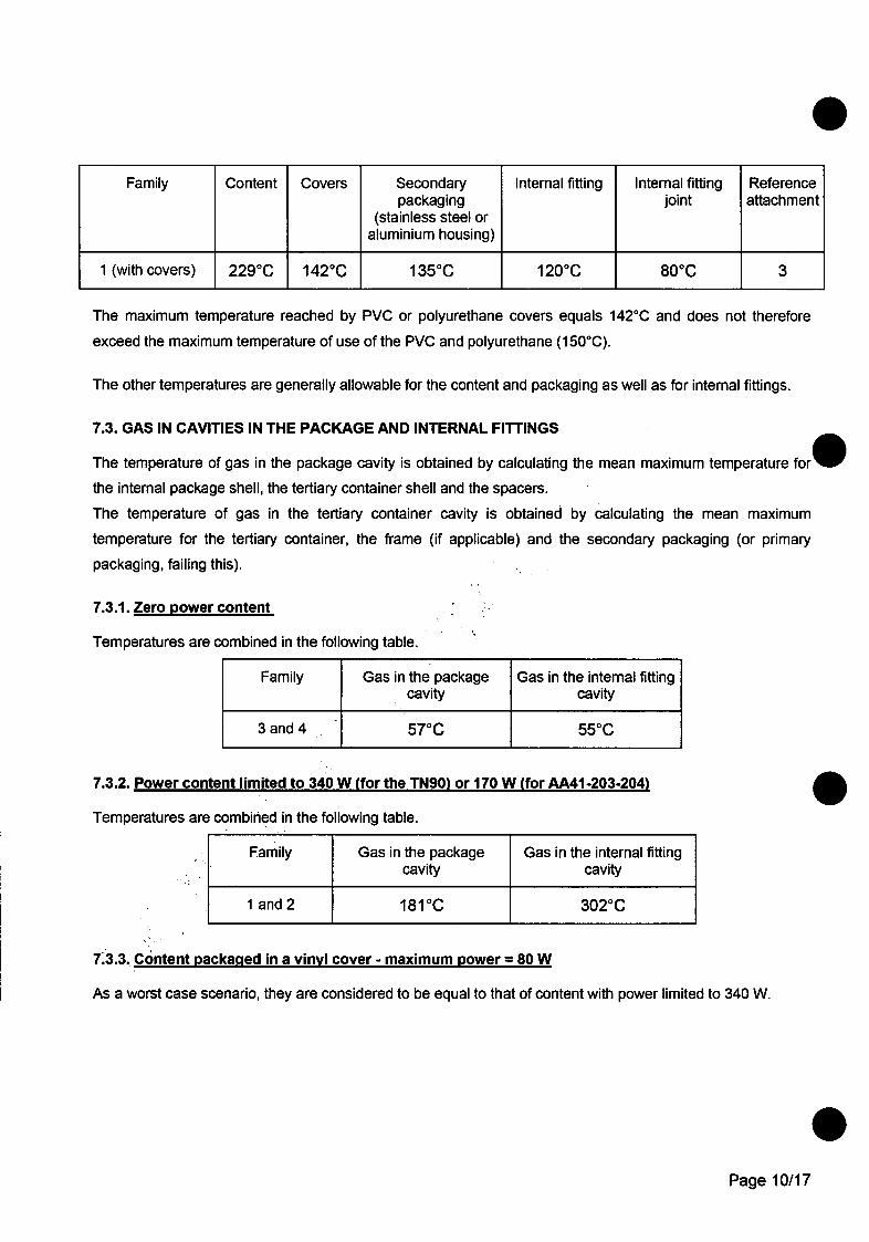
Family Content Covers Secondary Internal fitting Internal fitting Referencepackaging joint attachment
(stainless steel oraluminium housing)
1 (with covers) 229°C 142°C 135°C 120-C 800C 3
The maximum temperature reached by PVC or polyurethane covers equals 1420C and does not therefore
exceed the maximum temperature of use of the PVC and polyurethane (150 0C).
The other temperatures are generally allowable for the content and packaging as well as for internal fittings.
7.3. GAS IN CAVITIES IN THE PACKAGE AND INTERNAL FITTINGS
The temperature of gas in the package cavity is obtained by calculating the mean maximum temperature forW
the internal package shell, the tertiary container shell and the spacers.
The temperature of gas in the tertiary container cavity is obtained by calculating the mean maximum
temperature for the tertiary container, the frame (if applicable) and the secondary packaging (or primary
packaging, failing this).
7.3.1. Zero power content
Temperatures are combined in the following table.
Family Gas in the package Gas in the internal fittingcavity cavity
3 and 4 57°C 550C
7.3.2. Power content limited to 340 W (for the TN90) or 170 W (for AA41-203-204)
Temperatures are combined in the following table.
Family Gas in the package Gas in the internal fittingcavity cavity
1 and 2 1810C 3020C
7•3.3. Content packaged in a vinyl cover - maximum power = 80 W
As a worst case scenario, they are considered to be equal to that of content with power limited to 340 W.
Page 10/17

8. TEMPERATURES UNDER ACCIDENT CONDITIONS OF TRANSPORT
Note: attachment 1 is referred to exclusively for determining temperatures for family 4 (content 40 - uranyl
nitrate). Indeed, the ACT calculations described in this report are adjusted based on results obtained during
fire tests carried out in 1988, and for which the CEA cannot guarantee representativeness. The CEA therefore
applies an approach which is exclusively based on calculations, as described in attachments no. 2 and 3.
8.1. JOINTS
The maximum temperature reached by the package joints equals 1890C (attachment 2) for configuration 6.1
as defined in table 1 (family 2). This temperature is below the maximum temperature of use for joints (2500C
for Viton - 3000C for silicone) and the extrusion temperature, with a threshold of 231 0C (see chapter 6).
8.2. OTHER PACKAGE COMPONENTS
The maximum temperatures of the different package components for the different applicable loading scenarios
are combined in the table below. The temperatures are acceptable for the materials used.
Package component Maximum temperature Family Reference attachment
Internal shell 187 0C 1 (with covers) 2
Internal shell 2260C 2 2
Internal shell 1740C 1 (without covers) 2
External shell 7980C 1 and 2 2
The resin is subjected to surface temperatures of approximately 8000C. Fire tests carried out by the owner of
this resin demonstrate that, when subjected to an external temperature of 8000C, the resin carbonises on the
surface and is downgraded over a thickness of 10 mm, while the rest of the resin retains its nominal neutron-
absorbing properties.
8.3. INTERNAL FITTINGS AND CONTENT
8.3.1. Zero power content
The maximum temperatures of these internal fittings and content for the different applicable loading scenarios
are summarised in the table below.
Page 11/17

Family Content Internal fitting Referenceattachment
3 1310C 1420C 2
4 970C 1260C 1
These temperatures are generally allowable for the content and packaging as well as for internal fittings.
The mean maximum temperature reached by the uranyl nitrate (content no. 40) will not exceed 118 0C (boiling
point of uranyl nitrate, equal to 1180 ([3]), avoiding pressurisation. In fact, if the primary container (AA97)
suffers from a loss of tightness, the secondary container will retain its tightness in accident conditions of
transport, and the temperature reached by the uranyl nitrate will be between 97°C (temperature reached by
the uranyl nitrate) and 1260C (temperature reached by the gas inside the container).
8.3.2. Maximum power content limited to 340 W (for the TN90 - AA226-227) or 170 W (for AA41-203-204)
The maximum temperatures of these internal fittings and content for the different applicable loading scenarios
are combined in the table below.
Family Content Primary packaging Internal fitting Internal fitting Reference(stainless steel or joint attachment
aluminium housing)
1 5220C 3360C 2050C 1880C 2
1 (content 5) 2520C 1830C 2
2 3760C 3120C 2
These temperatures are generally allowable for the content and packaging as well as for internal fittings,*
particularly their joints.
The temperature of ZEBRA plates (family 1 configuration 5) is well below the temperature of 430°C; no risk of
damaging these plates due to the formation of a eutectic system between the plutonium and the stainless steel
in cladding therefore exists. The maximum temperature of the rod cladding, 3760C, remains allowable.
Note: while some temperatures are below those obtained under NCT, this is due to the assumptions adopted
in attachment no. 2, which are more representative of the thermal phenomena taking place in the package
cavity than those described in attachments no. 1, 3 or 5, which are extreme worst-case scenarios.
Page 12/17
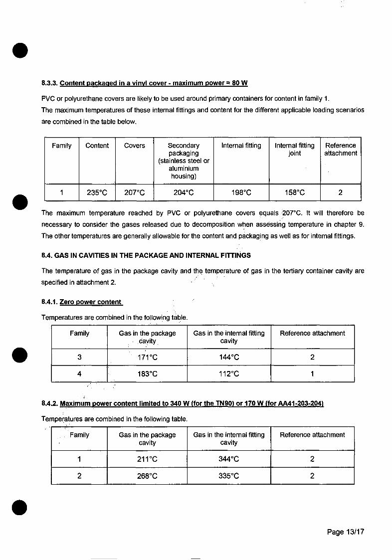
8.3.3. Content packagqed in a vinyl cover - maximum power = 80 W
PVC or polyurethane covers are likely to be used around primary containers for content in family 1.
The maximum temperatures of these internal fittings and content for the different applicable loading scenarios
are combined in the table below.
Family Content Covers Secondary Internal fitting Internal fitting Referencepackaging joint attachment
(stainless steel oraluminiumhousing)
1 2350C 2070C 2040 C 1980 C 1580C 2
The maximum temperature reached by PVC or polyurethane covers equals 207°C. It will therefore be
necessary to consider the gases released due to decomposition when assessing temperature in chapter 9.
The other temperatures are generally allowable for the content and packaging as well as for internal fittings.
8.4. GAS IN CAVITIES IN THE PACKAGE AND INTERNAL FITTINGS
The temperature of gas in the package cavity and the temperature of gas in the tertiary container cavity are
specified in attachment 2.
8.4.1. Zero power content
Temperatures are combined in the following table.
Family Gas in the package Gas in the internal fitting Reference attachmentcavity cavity
3 171CC 1440C 2
4 1830C 1120C 1
8.4.2. Maximum power content limited to 340 W (for the TN90) or 170 W (for AA4t-203-204)
Temperatures are combined in the following table.
Family Gas in the package Gas in the internal fitting Reference attachmentcavity cavity
1 2110C 3440C 2
2 2680C 3350C 2
Page 13/17

8.4.3. Content packacqed in a vinyl cover - maximum power = 80 W
Temperatures are combined in the following table.
Family Gas in the package Gas in the internal fitting Reference attachmentcavity cavity
1 164 0C 2460C 2
9. SPECIAL CASE OF CONTENT No 46
This content is specifically covered in attachment 7. On the basis of the temperatures reached by the different
parts of the package and gas in cavities, this content is classified in family 1. The analysis performed in this@
chapter for family 1 therefore also applies to this content.
10. SHIELDED CAISSON TRANSPORT
Caisson transport is covered in attachment no. 7.
This report demonstrates that, for the authorised configurations, the temperatures reached both in normal and
accident conditions of transport by the different parts of the TN-BGC 1 and its internal fittings are allowable for
the materials used and that the temperature limits inherent to regulations are not exceeded (subject to
transport with exclusive use).
Furthermore, when PVC or polyurethane covers are used, the temperatures reached by these covers do not
exceed the maximum temperature of use of the PVC and polyurethane (150 0C) in NCT. Therefore, the
conclusions of chapter 3.7 of folder [DA01] remain valid.
Finally, the gas temperatures in the packaging cavity and the internal fittings also remain below those adoptedO
in chapter 3.4 of folder [DA01] and therefore have no effect on the maximum activity values applied to ensure
compliance with regulatory release criteria.
Transport in a CB9 type caisson is authorised for uranium-bearing content transported with B(U) type
approval. The maximum power per package must be less than 4 W, and the maximum total thermal power
released by all the packages must be below 48 W.
Transport in a CB9 type caisson subject to exclusive use is authorised for plutonium-bearing content
transported with B(U) type approval.
If covers are used, the maximum total thermal power released by all packages must be less than 480 W and
maximum power per package must be less than 80 W. AA203 and AA204 type internal fittings are not
authorised. If AA41 type internal fittings are used, thermal power is limited to 20 W/AA41.
Page 14/17

If covers are not used, the maximum total thermal power released by all packages must be less than 960 W
and maximum power per package must be less than 160 W. For content no. 5, the maximum total thermal
power released by all packages must be less than 1050 W and the maximum power per package must be less
than 175 W."
11. CONCLUSIONS
Transport package
The various analyses carried out in this chapter and its attachments demonstrate that the temperatures
reached both in normal and accident conditions of transport by the different parts of the TN-BGC 1 are
allowable for the materials used and that the temperature limits inherent to regulations are not exceeded.
Subsequent to the fire test, the resin will be considered as downgraded over a thickness of 10 mm.
Internal fittings and content
The temperatures reached by the materials of internal fittings do notlexceed allowable limits. In particular, the
maximum temperature of tertiary packaging joints remains below 198 0C in normal conditions of transport, and
1580C in accident conditions of transport (Note: this difference in temperature is caused by the fact that the
ACT calculations included in attachment 2 were carried out on the basis of new assumptions which are less
penalising, particularly the consideration of the radiation in the cavity, which was ignored in NCT in attachment
4).
The temperatures reached by joints guarantee the isolation of the powder (for criticality) or the uranyl nitrate.
This chapter ensures that:
" the maximum temperature reached by PVC or polyurethane covers does not therefore exceedthe maximum temperature of use of the PVC and polyurethane (150 0C) in NCT.
• the mean maximum temperature reached by the TN 90 containing uranyl nitrate does notexceed 970C, avoiding pressurisation (value below boiling point: 118 0C),
* with ZEBRA plates, the temperature of these plates remains below 4300C, at which a risk ofdowngrading exists, due to the formation of a eutectic system between the plutonium and thestainless steel in cladding.
* the maximum temperature reached by the fuel rod cladding remains acceptable.
Finally, this chapter determines the temperatures reached in the package cavity and the internal fittings in
NCT and ACT, which are used in release and radiolysis studies.
It is also important to take note that the maximum temperature of the internal shell of the package and the
internal fittings is used as input data for the mechanical studies in chapters 3 and 4.
Page 15/17

TABLE 1: DESCRIPTION OF FAMILIES
Frames Secondary Frames, Tertiary ExternalFamily Primary or spacers Thermal power
packaging covers packaging or shims packaging spacers
I (content 1, 3, Housing (x4) AA 99 (x4) P1 TN 90 El + E2 4 x 85W8-pellets, 9,
10, 18, 19, 20, Housing (x4) Covers (x8) AA 99 (x4) P1 TN 90 El +E2 4x 20 W23 and 46) Housing (x4) Covers (x8) AA 99 (x4) AA 204 El+El0 4 x 20 W
Housing (x4) AA 99 (x4) AA 204 E1+E10 4x 42,5 W
Housing (x2) Covers (x4) AA 99 (x2) AA 203 El+E8 2 x 20 W
Housing (x2) AA 99 (x2) AA 203 El+E8 2 x 85 W
Housing (xl) Covers (x2) AA 99 (XI) AA 41 (XI) E1+El1 20 W
Housing (xl) AA 99 (XI) AA 41 (XI) El+Ell 100W
Housing (x2) Covers (x4) AA 99 (x2) AA 41 (x2) E1+E12+E13 2 x 20 W
Housing (x2) AA 99 (x2) AA 41 (x2) E1+E12+E13 2 x 85 W
Housing (x3) Covers (x6) AA 99 (x3) AA 41 (x3) E1+E9+E13 3 x 20 W
Housing (x3) AA 99 (x3) AA41 (x3) El+E9+E13 3x56,6 W
1 (content 5) E5 TN 90 El + E2 150 W
2 (content 8 - R1 TN90 E1 + E2 340W
rods) R1 AA204 E + El10 170 W
3 (content 4) E4 TN 90 P4 E1 + E2 5 W
E7 TN 90 E1 +E2 16 W
E7bis AA204. E1+E10 0
3 (content 2, 7, E7bis AA203 E1+E8 011, 26, 41 and
42) E7bis (xl) AA 41 (XI) El+El1 0
E7bis (x2) AA 41 (x2) E1+E12+E13 0
E7bis (x3) •_' _ AA 41 (x3) E1+E9+E13 0
4 (content 40) AA 97 (x2) P2 TN 90 E3 or E3 2x2W
Page 16/17
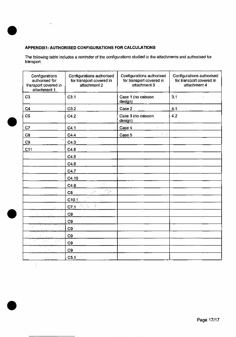
APPENDIXI: AUTHORISED CONFIGURATIONS FOR CALCULATIONS
The following table includes a reminder of the configurations studied in the attachments and authorised fortransport.
Configurations Configurations authorised Configurations authorised Configurations authorisedauthorised for for transport covered in for transport covered in for transport covered in
transport covered in attachment 2 attachment 3 attachment 4attachment 1
C3 C3.1 Case 1 (no caisson 3.1design)
C4 C3.2 Case 2 4.1..
C5 C4.2 Case 3 (no caisson 4.2design)
C7 C4.1 Case 4
C8 C4.4 Case 5
C9 C4.3
Cl1 C4.6
C4.5
C4.8
C4.7
C4.10
C4.9
C8
C10.1
C7.1 _ __.._._
C9
C9.,* C9
C9
C9
C9
C5.1
Page 17/17
REPLACEMENT OF CEA PACKAGING
TN-BGCI PACKAGING SAFETY DOSSIERCHAPTER 6 - APPENDIX 3 DEN/DTAP/SPI/GET
TEMPERATURES IN THE TNBGCI PACKAGE MODELCOMMISSARIAT A L'ENERGIE DURING NCT AND HAC
ATOMIQUE
ORIGINALPROGRAMME: REPLACEMENT OF CEA PACKAGINGTITLE: SAFETY DOSSIER - TYPE TN-BGC I PACKAGING 0"
CHAPTER 6 APPENDIX 3
TEMPERATURES IN THETNBGC1 PACKAGE MODEL DURING NO ALAND ACCIDENT CONDITIONS O .SPORT
Summary: kh
- This appendix presents the hypotheses and meth of calculating external and internal temperatures ofsections of TN-BGC 1 packaging andtheir fontents.This appendix does not present ayl calculation results, except the benchmark calculations of the model.Appendix A6-4 is dedicated to c• i 'aTon results.
[signature] [signature]
[signature] [signature]
04/08/03 07/08/03
T. CUVILLIER D. LALLEMAND
DEN/DTAP/SPI/GET DEN/DTAP/SPI/GET
Chargd d'affaires Head of GET4- 4
I Checked by Approved by
y
IEIMII IT I NIBG1CG IPIBICI IDIJ 151 ICIAIOIOIO 1314 151A-1I 2 3 4 5 6 7 8 9 10 11 12 13 14 15 16 17 18 19 20 21 22 23
Chapter 6 - Appendix 3 - This document is the property of the CEA and cannot be Page I of 106modelling and results.doc used, reproduced or communicated without prior
written authorization from the CEA.
REPLACEMENT OF CEA PACKAGING
I TN-BGC1 PACKAGING SAFETY DOSSIER
I CHAPTER 6 - APPENDIX 3 DEN/DTAP/SPI/GETTEMPERATURES IN THE TNBGCI PACKAGE MODEL
COMMISSARIAT A LENERGIE DURING NCT AND HACATOMIQUE I II
IErMBI ITIN1BI31C IPIBICI IDJ I-SI ICIAIOIOIOI 314 Is IAI1 2 3 4 5 6 7 8 9 10 It 12 13 14 15 16 17 18 19 20 21 22 23
Chapter 6 - Appendix 3 - This document is the property of the CEA and cannot be Page2 of 106modelling and results.doc used, reproduced or communicated without prior
written authorization from the CEA.
mREPLACEMENT OF CEA PACKAGINGI TN-BGCI PACKAGING SAFETY DOSSIER
I CHAPTER 6 - APPENDIX 3 DEN/DTAP/SPI/GETTEMPERATURES IN THE TNBGCI PACKAGE MODEL
COMMISSARIAT A LENERGIE DURING NCT AND HACATOMIQUE
CONTENTS
1. Introduction ..................................................................................................................... 42. M ethodology and general hypotheses ........................................................................ 42 .1 U se o f tests ....................................................................................................................... 42 .2 M odellin g .......................................................................................................................... 52.2.1 G eneral approach ......................................................................................................................... 0"
2 .2 .2 M esh ing ............................................................................................................................. ;;2.3 Hypotheses common to all calculations ..................................................................... -2 .3 .1 C onduction ................................................................................................................... '........ .... .(y2.3.2 Free convection ....................................................................................................... '....62.3.3 Radiation ............................................................................................................. 62.3.4 Ambient temperature ........................................................................................... ............ 62.3.5 Threshold thermal conditions ..................................................................... ... ............ 7
3. Validation of finite element model ................. 83.1 Testing conditions ......................................... ......................... 83.2 Materials ........................................................................... 9...4 N, .. ...................... .
3.3 Results obtained ................................................................ .. 9. ....................................
4. Temperatures in the TNBGCI package model i n rmal andaccident conditions of transport ............................. ...... ............................................. 10
4.1 TNBGC 1 packaging loaded with type C3 packi"ng .h/.................... 11...... 14.1l.1 Hyp te s anEoelig..........., ....................................................... l4.. H potheses and modelling .......... 11
4.1.2 Internal power .................................. X11,.. .............................................................. 114.1.3 Results ................................................. ........... 124.2 TNBGCI packaging loaded with type C2.1 MIan C2.2 packing ....... .... * ........ 134.2.1 Hyp te s an o eln ....4• ....... ..•............................................................................ 13
4.21 Hpotheses and modelling. el14.2.2 Internal power ................. . .................................. ........................................ 144.2.3 R esu lts ........................ % ....... ................................................................................ 154.3 TNBGCI packaging loadedWith type C4 packing ...................................................... 164.3.1 Hypotheses and mode g ........................................................................................ 164.3.2 Internal power.-... ...... ...................................... 164.3.3 Results ....................................... ... 164.4 TNBGC1 pac1a g' ded with type C7 packing ................................................... 174.4.1 Hypotl"es s and modelling ...................................................................................... 174.4.2 Intrena po' .............................................................................................................. 184 .4.3 R e u lts . , ...................................................................................................................... 184.5 TN' l packaging loaded with type C8 packing ...................................................... 204.5.1 ,, yt heses and modelling .......................................................................................... 204.5.2 i. nternal power ................................................................................................. 204 Re su lts ......................................................................................................................... 20
packaging loaded with type C5 and C 1I packing ....................................... 21ypotheses and modelling ........................................................................................... 21
.6 Internal power.. ............................................................................. 22
.6.3 Results ................... .... ........................................................... 224.7 TNBGC1 packaging loaded with type C9 packing ...................................................... 234.7.1 Hypotheses and modelling .............................................................................. 234.7.2 R esu lts ......................................................................................................................... 25
5. Conclusions ...................................................................................................................... 26
6. References ........................................................................................................................ 26
IEIMIBI ITINIBIGICI IPIBIC] IDIJIS C I' A 01 0101314'15 I1 2 3 4 5 6 7 8 9 10 11 12 13 14 15 16 17 18 19 20 21 22 23
Chapter 6- Appendix 3 - This document is the property of the CEA and cannot be Page3 of 106modelling and results.doc used, reproduced or communicated without prior
written authorization from the CEA.
(I :j IREPLACEMENT OF CEA PACKAGINGI TN-BGCI PACKAGING SAFETY DOSSIERCHAPTER 6- APPENDIX 3 DEN/DTAP/SPI/GET
TEMPERATURES IN THE TNBGCI PACKAGE MODELCOMMISSARIAT A LENERGIE DURING NCT AND HAC
ATOMIQUE
1. INTRODUCTION
This study aims to define the temperature distribution within the TN-BGCI packaging loadedwith its different possible packing methods.
The general conditions taken into account are as follows:
" statutory sunshine <1>," package placed horizontally (the most detrimental case)," accident conditions of fire<l>. 4 \
2. METHODOLOGY AND GENERAL HYPOTHESES
2.1 Use of tests .
A) Thermal tests on sections of packaging or complete packag e6performed (chapter 6,appendix I):
" Tests on sections determined the thermal conducVi\of the resin before and after thefire test.
" The test on the prototype packaging 4'curate y determined the temperature field ondifferent points of the packaging when in a'ertical position.
" The test on the manufactured4packaging accurately determined the temperature field ondifferent points of the packa.g w'en in a horizontal position.
When we compare results obtained fom horizontal and vertical positions, we observe that,when all the other param-ers~arve the same, a horizontal position leads to highertemperatures in the packagi. herefore, the calculations made in this report all considerthe horizontal position S
B) A fire test as arried out on two prototype pieces of packaging that wererepresentative o erduction packaging, after these prototypes had been subjected to thestatutodry ro ptet report on this fire test is given in chapter 6, appendix 2.
'yHowev n t Is fire test, the ambient temperature at the start of the fire test was 13'C(instead o • e statutory 38QC) and the thermal power released by the contents was nil(instea'a the 340W in the case of some contents).
EMBI TINIBIGC I I C I A 1 CA 10 101314 5' A1 2 3 4 5 6 7 9 9 10 11 12 13 14 15 16 17 18 19 20 21 22 23
Chapter 6- Appendix 3 - This document is the property of the CEA and cannot be Page4 of 106modelling and results.doc used, reproduced or communicated without priorwritten authorization from the CEA.

REPLACEMENT OF CEA PACKAGING
TN-BGC1 PACKAGING SAFETY DOSSIERCHAPTER 6- APPENDIX 3 DEN/DTAP/SPI/GET
TEMPERATURES IN THE TNBGCI PACKAGE MODELCOMMISSARIAT A L'ENERGIE DURING NCT AND HAC
ATOMIQUE
Therefore, using the temperatures taken during the fire test, it was necessary to benchmarkthe results to obtain temperatures that were representative of accident conditions of transportby applying the statutory hypotheses [11. It is on the basis of this benchmarking work that theconstructed model is validated.
2. 2 Modelling
2.2.1 General approach
The models are performed according to the finite elements method using IDEAS sofitar'e[2]. Thethermal calculations are carried out with the TMG module:
" in a permanent state in normal conditions of transport," in a transient state which is representative of accident conditionsof.transport, with the
initial temperature field (t = Os) being defined by results obtained-in n66rmal conditions oftransport. >2
Different calculations were carried out:" the first modelling involves creating an axisymme o del in which the content is
modelled only according to its thermal power (imo ow). This model constitutes thebasis for the validation of the other hyile" se adopted relating to materialcharacteristics, exchanges, etc. The model t~edl presented in figure 1 and figure 2.
* the second modelling involves taking -.t rstrmodel and adding the most detrimentalcontent modelled to determine the tepr,,erature of the containment seals: the C3packaging. The model used is presented in figure 9, figure 10 and figure 11.
" The third, more simple, two-d6me:sional type of modelling, (section model) is performedto determine the maximumn mApeature of some internal installations: C2.2, C4, C5A,C5B, C11A, C11B and ý!99 ,\
" A fourth, three-dimepsiýaZype of modelling has to be carried out when there is a lackof symmetry or coavergence in 2D, to determine the maximum temperature of someinternal installations: 6201, C7A, C7B, C7C, C8, C9A.
2.2.2 Meshing
The geometry o e -BGC I packaging model shown in figure 1 results from [3].Contents•
EIA3ach p-aging studied (content) requires a specific modelling indicated below. Thedifferent meshing and thermal calculations have been archived [7].
IEIMIBI ITINIBIGI IPIBICl IDIJISl IClAI0101'013144ISlAI123 4 56 7 8 9 0 11 12 13 14 15 16 17 18 19 20 21 22 23
Chapter 6 - Appendix 3 - This document is the property of the CEA and cannot be Page5 of 106modelling and results.doc used, reproduced or communicated without prior
written authorization from the CEA.

REPLACEMENT OF CEA PACKAGING
TN-BGC1 PACKAGING SAFETY DOSSIER
I CHAPTER 6 - APPENDIX 3 DEN/DTAP/SPI/GETTEMPERATURES IN THE TNBGCI PACKAGE MODEL
COMMISSARIAT A L'ENERGIE DURING NCT AND HACATOMIQUE I I
The characteristics of the different packings represented are detailed in chapter 3 of the presentsafety dossier.
2.3 Hypotheses common to all calculationsFor all the calculations, the packaging is in a horizontal position. Indeed, the test results showedthat this configuration was the most detrimental one.
The aluminium cage of the packaging is neglected. A.a
2.3.1 Conduction
Conduction through the packaging is defined by the thermal conductible: ofeach material(described in table 1).
Conduction through the packaging is defined by the thermal con'ductiyity (X) of each material.The conductive exchanges are automatically calculated by TMG. T the air spaces (gaps) with athickness of e, this is defined using an exchange coefficient cor , u. = air(T)/e.
Due to the fact that there are shock absorbers filled<Rith'iwood at each end of the casing,exchanges at the ends are neglected.
2.3.2 Free Convection
Free convection is taken into account by51 laws relating to outer surfaces (vertical plates andhorizontal cylinders). These laws areý isbed in document [41 for fire conditions (turbulentregime):
" h = 1.22 x (AT)° 33 W/mI2 f06 horizontal cylindrical surfaces,* h = 1.28 x (AT)° 33 W/6.fN vertical flat surfaces,
Free convection between'A outer shell of the packaging and the ambient air is imposed.
2.3.3 Radiatio
All the pack( g Maces that open onto the ambient air are considered as radiating surfaces. In thespaces, a radiation exchange is considered.
2.3.4 ient temperature
The ambient temperature equals 311 K (38°C) in normal conditions, before and after the fire. Inaccident conditions of transport, this varies over time. The variation law is indicated hereafter.
IEIMIBI ITINIBIGICl IPIBiCl IDIJSl ICAIoIoI'01314"ISIAI1 23 4 5 6 78 910 1i 12 131 4 15 16 17 18 19 20 21 22 23
Chapter 6- Appendix 3 - This document is the property of the CEA and cannot be Page6 of 106modelling and results.doc used, reproduced or communicated without priorwritten authorization from the CEA.
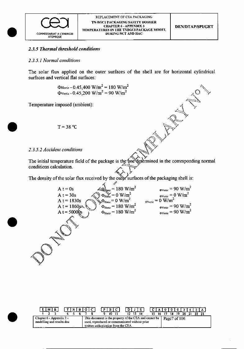
REPLACEMENT OF CEA PACKAGING
TN-BGC1 PACKAGING SAFETY DOSSIER
I CHAPTER 6 - APPENDIX 3 DEN/DTAP/SPI/GETTEMPERATURES IN THE TNBGCI PACKAGE MODEL
COMMISSARIAT A L'ENERGIE DURING NCT AND HACATOMIQUE I
2.3.5 Thermal threshold conditions
2.3.5.1 Normal conditions
The solar flux applied on the outer surfaces of the shell are for horizontal cylindricalsurfaces and vertical flat surfaces:
(I)Horiz = 0.45,400 W/m2 = 180 W/m2
(I)Vertic = 0.45,200 W/m2 = 90 W/m 2
Temperature imposed (ambient):
T= 38 'C
2.3.5.2 Accident conditions
,rmined in the corresponding normal
of the packaging shell is:
The initial temperature field of the package isconditions calculation.
The density of the solar flux
A t = OsAt=30s" t = 30s
A t = 1830sA t = 1860sA t = 50000E
= 180 W/m2
0,okY = 0 W/m 2
(D.•odz = 0 W/m2
(noriz = 180 W/m2
*io-io = 180 W/m2
OVerti = 90 W/m2
,Verec• = 0 W/m2
oVeitic = 0 W/m2
,bVer6c = 90 W/m2
,Vertic = 90 W/m2
EMB ~~ [T IN I B I GCI PBC DJ ICIAIOIOIO 3 1415T1Al1 2 3 4 5 6 7 8 9 10o I 12 13 14 15 16 17 18 19 20 21 22 23
Chapter 6- Appendix 3 - This document is the property of the CEA and cannot be Page7 of 106modelling and results.doc used, reproduced or communicated without prior
written authorization from the CEA.

REPLACEMENT OF CEA PACKAGING
TN-BGC1 PACKAGING SAFETY DOSSIERI CHAPTER 6 - APPENDIX 3 DEN/DTAP/SPI/GET
TEMPERATURES IN THE TNBGCI PACKAGE MODELCOMMISSARIAT A L'ENERGIE DURING NCT AND HAC
ATOMIQUE
180160
R 140E 120
100
80
Sfic04o
xc 40
20
- surfaceshorizontales
-0 .. surfacesverticales <~o ~
~
yt* r) 0
temps (s) 0
flux solaire (W/m2) solapgn W/im2n)temps (s) tim'(•sW" 1 "surfaces horizontales Ahdiuzdfal surfacessurfaces verticales / ,vehtical surfaces
Imposed fire temperatures (a :bent):
A t• s- 0 T =38TC
T=8"
O•At=30s T =800TC
A At =1830s T=800TC
A t = 1860s T =38TC
IEIIB ITNIB GIMCl PB~ D~ IClAI0101013141'SIA-11 2 3 4 5 6 78 9 10 11 12 13 14 15 16 17 18 19 20 21 22 23
Chaptr 6-Apendi 3 - This document is the property of the CEA and cannot be Paef 106modelling and results doc used, reproduced or communicated without priorwritten authorization from the CEA.
0
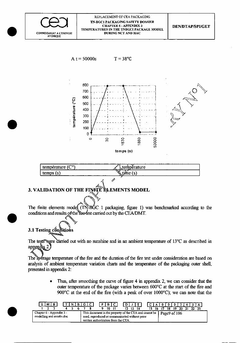
REPLACEMENT OF CEA PACKAGING
TN-BGC1 PACKAGING SAFETY DOSSIERc e : CHAPTER 6 - APPENDIX 3 DEN/DTAP/SPI/GETTEMPERATURES IN THE TNBGCI PACKAGE MODEL
COMMISSARIAT A L'ENERGIE DURING NCT AND HACATOMIQUE
A t = 50000s T = 380 C
CL
0.
800 --
700
600--------
500...............
400
300 ..
200 --. 4-- -
100
0 • -
0,C> C
A•o VA\.
Iv
0 0(0 000 0
010)
temps (s)
I temp&ature (C°) Zkterhpliraturetemps (s) \tihe (s)
3. VALIDATION OF THE FINIAEEMENTS MODEL
The finite elements mode 1 packaging, figure 1) was benchmarked according to theconditions and results o..the ie~test carried out by the CEA/DMT.
3.1 Testing co s
The te ere eanied out with no sunshine and in an ambient temperature of 13TC as described in
The 'ae temperature of the fire and the duration of the fire test under consideration are based onanalysis of ambient temperature variation charts and the temperature of the packaging outer shell,presented in appendix 2:
9 Thus, after smoothing the curve of figure 4 in appendix 2, we can consider that theouter temperature of the package varies between 600TC at the start of the fire and900TC at the end of the fire (with a peak of over 1000QC); we can note that the
IEIIBIITINIBIG7CI IPIBICI IDIJ ISI ICIA101010131415FAI1 2 3 4 5 6 7 8 9 10 It 12 13 14 15 16 17 18 19 20 21 22 23
Chapter 6 - Appendix 3 - This document is the property of the CEA and cannot be Page9 of 106modelling and results.doc used, reproduced or communicated without priorwritten authorization from the CEA.

REPLACEMENT OF CEA PACKAGING
TN-BGC1 PACKAGING SAFETY DOSSIER
I CHAPTER 6 - APPENDIX 3 DEN/DTAP/SPI/GETTEMPERATURES IN THE TNBGCI PACKAGE MODEL
COMMISSARIAT A LENERGIE DURING NCT AND HAC(ATOMIQUE I I I
temperature of the flames exceeds these values. These latter results as well as thecurve of figure 3 (appendix 2) show that the temperature of the fire during the testwas higher than 800'C on average, despite these variations.
* Moreover, measurement of the duration of the test took account of the fact thatthe ambient temperature did not instantly rise to 8000C.
Therefore, we considered that the fire test corresponded to an average fire temperatre of800'C during a period of 30 minutes.
As we mentioned earlier, the outer shell of the packaging reached a relatively hightemperature. In the axisymmetric model benchmark calculation, we 4onsidered themaximum temperatures reached at the outer shell during the test. The~ re, the fact thatboth packages are placed side by side above the fire has no impact onqmth calculationsmade.
During the test, part of the structure supporting the specimensbrdke and the specimens fellinto the layer of fuel with the lid side first. At this end Noftthepackaging there is a cap toabsorb shocks (falls) and for insulation (thermal). Intihlyvthere was a layer of fuel of about143 mm (see appendix 2). As the packaging fell aetelýM0>min. and 25 min. the thickness ofthis layer at the time of the fall and after the fall as derefore lower (10 min.) and even verylower (25 min.) than the initial value. According to he photographs taken after the fire test,we estimate that the packaging was at anlanieof 450 with the horizontal. In fact, only avery small part of the caps were lying an yeer of fuel during the fire test. For thisreason and insofar as this was a termally shielded area, the fact that this part of thepackaging was not subjected . St conditions has very little impact on the test results.Therefore, the benchmark calcuia." 'ns did not take this event into account.
Consequently, the calculat,•6onditions corresponding to the test are:" no solar fl & *" even initi'at•4emperature of 13'C;" ambie•"i,•emlerature before and after fire of 13'C;" averT4emperature of fire of 800'C;
(dn% of fire - 30 minutes;power in the packaging - nil.
3.2 Materials
The characteristics of the materials selected are presented in table 1. It should be noted that ifthe thickness of the burnt resin considered afterwards in the model is taken as 13 mm, theresults are benchmarked according to a thickness of 10 mm of burnt resin (maximum thicknessof burnt resin measured after the fire test, see appendix 2).
IEI I IT I NIB O I PBBI G I J I C IlA 10 1 0 1"0 1 3141 'I IAI1 2 3 4 5 6 7 8 9 0 11 12 13 14 15 16 17 18 19 20 21 22 23
Chapter 6- Appendix 3 - Tis documen is the property of the CEA and cannot be Page10 of 106modelling and results.doc used, reproduced or communicated without prior
written authorization from the CEA.

REPLACEMENT OF CEA PACKAGING
TN-BGC1 PACKAGING SAFETY DOSSIERCHAPTER 6 - APPENDIX 3 DEN/DTAP/SPI/GET
TEMPERATURES IN THE TNBGCI PACKAGE MODELCOMMISSARIAT A L'ENERGIE DURING NCT AND HAC
ATOMIQUE
3.3 Results obtained
The results obtained using the finite elements model under the conditions corresponding tothe fire test are presented in table 2. Figure 6 presents the packaging isotherms under testconditions at the end of the fire (t = 1830s).The following table gives the different maximum temperatures within the packaging andcompares them with the test results.
CALCULATED Tmax (°C) and t (s) TEST Tmax (°C) and t (s) Figeur
Base of shell . yThermocouple 6 T = 211 T = 210 figure 7
Node606 t=1,838 t6062,100gueOuter shell T=778 T= 1igu"e
Thermocouple 3 t1 y figure 8Node 742 - 1Inner shell T = 176 ( = 176
Thermocouple 2 t = 5,810 \\\.t=4,000 figure 8Node 746
Top of shelloofT= 131 2 T- 132Template 0= 156 T 1figure 7Node 451 15,69 ,____
The model results are similar to the test res'utlts.
This allows us to consider thatAf general hypotheses adopted in the model to describethermal exchanges are represe-htative of the thermal behaviour of the packaging, and touse this model to map the d~l of the TN BGC1 packaging in normal and accidentconditions of transport.
4. TEMPERArfMES IN THE MODEL OF THE TNBGCI PACKAGE DURINGNORMAL A. CIDENT CONDITIONS OF TRANSPORT
Belo,•,e present the temperatures of the packaging and internal installations obtainedfr'rm thMe general hypotheses presented in section 2 and validated in section 3 and thediffe V1tt models detailed below.
The different packing methods studied are indicated in chapter 3 of the present safetydossier. As the study was conducted for normal and accident conditions of transport, inmost cases we have taken the dimensions that correspond to the minimum gap.
The characteristics of the packaging materials are given in table 1. The characteristics of thematerials used for internal installations and contents are given in table 3.
EI T B LIN I B IGMC IPIBICJ IDLJ ISI I C 101 013 15T 7 A1 2 3 4 5 6 7 8 9 10 11 12 13 14 15 16 17 18 19 20 21 22 23
Chapter 6- Appendix 3 - This document is the property of the CEA and cannot be Page 1 of 106modelling and results.doc used, reproduced or communicated without prior
written authorization from the CEA.
REPLACEMENT OF CEA PACKAGING
TN-BGCI PACKAGING SAFETY DOSSIERCHAPTER 6 - APPENDIX 3 DEN/DTAP/SPI/GET
TEMPERATURES IN THE TNBGCI PACKAGE MODELCOMMISSARIAT A L'ENERGIE DURING NCT AND HAC
ATOMIQUE I I I
4.1 TNBGC1 packaging loaded with type C3 packing
4.1.1 Hypotheses and modelling
The content selected is the one that leads to maximum temperatures in the lid area (so as todetermine the maximum temperatures of the seals and locking ring of the lid). This isplutonium oxide powder packed in a TN 90 (C3 packing) for which:
" the internal power is maximum (340 W),
" the content is the closest to the lid of the packaging and its heightsihe lowest (in thecase of bars and plates of metal plutonium, the content an ' nternal power aredistributed throughout the entire height of the spacer set EQ.
" the low thermal conductivity and low value of the-66duct (of the density and thespecific heat of the content (p.Cp) respectivelye'41~ t'oiiigh temperatures of thecontent in normal and accident conditions of transpkirt.
z ý'' -'ý1Other detrimental hypotheses concerning C3'.opWckng were considered:
" the spacer El is in contact with thei Axsidi f the packaging lid,
" the spacer E2 (and possibly the baqket PI) are respectively in contact with the lid andplug of the TN90,
" following the statutorld• tpests, we consider that the internal plug of the TN 90 is incontact with the 1 of t IeyTN 90 (figure 10 and figure 11) and the packaging ispunched.
As the basket PI is<I0 made up of a part of circular shell, we made two calculations; onecalculation with th basket P1 and a second calculation without the basket P1, in order todetermine theAmNotdetrimental case.
IEMIB ITIN±BIGI IPIBICI IDIJISI I A1O010131,FT'IAII 2 3 4 5 6 7 8 9 10 11 12 13 14 15 16 17 18 19 20 21 22 23
Chapter 6 - Appendix 3- This document is the property of the CEA and cannot be Page12 of 106modelling and results.doc used, reproduced or communicated without prior
written authorization from the CEA.

REPLACEMENT OF CEA PACKAGING
TN-BGCI PACKAGING SAFETY DOSSIERCHAPTER 6 - APPENDIX 3 DEN/DTAP/SPI/GET
TEMPERATURES IN THE TNBGCI PACKAGE MODELCOMMISSARIAT A LENERGIE DURING NCT AND HAC
ATOMIQUE
4.1.2 Internal power
The exchange height is estimated according to the diameter of the aluminium cans and themaximum density of the PuO2powder, which corresponds to the lowest exchangeheight.
M MV -n.r 2 .H
O1
M
M = 19.25 kg (density corresponding to We' a mum power acceptable)r= 44.5 mm (radius of cans)p =3500 kg/m3
thus H=0.884m I
Therefore, a power of 340 W on a height of 0•mis introduced.
4.1.3 Results
The maximum temperatures nogten, normal conditions of transport (NCT) and accidentconditions of transport (H ')or tie C3.A axisymmetric model are summarised in thefollowing tables. As the temfperatures of models with and without the P1 basket aresimilar, we have onlrgivenelirves with the P 1 basket in the appendix. The isotherms fornormal conditions r -indicated in figure 12, figure 13 and figure 14. The isotherms foraccident conditiens -noof fire t = 1830s) are shown in figure 15, figure 16 and figure 17.Charts showingw-femperature varies over time are given in figure 18 and figure 19.
C3.Mognte~nt) NCT RACMaximum Maximum temperature (°C time (s)temperature (°C) elementwith P1 without P1 with P1 without P1 with/without P1
PuO2 powder centre 500 494 546 / E56 538 12010PuO2powder 387 380 441 / E60 432 12010PuO2 aluminium can 369 362 424/E162 415 12 010 / 11010
_Can 309 [300 75/E214 364 11010/10010
IEIIBIITINIBIGMCI IPIBlCl IIlJ 1sl ICIAIOIOIO1 31415I AIS23 4 5 6 7 8 9 1011 12 13 14 5 16 17 18 19 20 21 22 23
Chapter 6- Appendix 3- This document is the property of the CEA and cannot be Page 13 of 106modelling and results.doc used, reproduced or communicated without priorwritten authorization from the CEA.
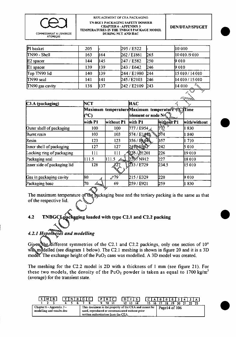
REPLACEMENT OF CEA PACKAGING
I TN-BGC1 PACKAGING SAFETY DOSSIER
CHAPTER 6 - APPENDIX 3 DEN/DTAP/SPI/GETTEMPERATURES IN THE TNBGCI PACKAGE MODEL
COMMISSARIAT A LENERGIE DURING NCT AND HACATOMIQUE
PI basket 205 - 295 /E522 - 10010
TN90 - Shell 163 164 262 /E1861 265 10010/9010E2 spacer 144 145 247 /E582 250 9010
El spacer 139 139 243 /E642 246 9010Top TN90 lid 140 139 244 /E1980 244 15 010 / 14 010TN90sea] 141 141 245/E2103 246 14010/15010
["N90 gas cavity 138 137 242 /E2109 243 14010
C3.A (packaging) NCT HAC , >Maximum temperature Maximum temperaturIVO T ime
(0 C) /element or node NQ__._ _
with P1 without P1 with P1 WOthhot'P1 with/without
Outer shell of packaging 100 100 777 / E954A 7Q Y 1 830Burnt resin 103 103 574 / ET 74 1840
Resin 123 123 356 / 357 1710Inner shell of packaging 127 127 2,41RE•8Q" 242 5010
Lockingringof packaging II1 d '5'/ýBr1201 26 19010Packaging seal 111.5 111.5 4. 22N912 227 18010
34.5 15010Inner side of packaging lid 128 r2-7 ý213 / E729 234.5 15010
Gas in packaging cavity 80 ,t -'79 215 / E329 220 9 010Packaging base 70 A4 , 69 P59 / E921 k59 1 830
The maximum temperature qfhc kgingbase and the tertiary packing is the same as thatof the respective lid.
4.2 TNBGC Jc-ging loaded with type C2.1 and C2.2 packingY
4.2.1~~H and modelling
GivNz(• different symmetries of the C2.1 and C2.2 packings, only one section of 10'wa'modelled (see diagram 1 below). The C2.1 meshing is shown in figure 20 and it is a 3Dmode. The exchange height of the PuO 2 cans was modelled. A 3D model was created.
The meshing for the C2.2 model is 2D with a thickness of 1 mm (see figure 21). Forthese two models, the density of the PuO 2 powder is taken as equal to 1700 kg/mi3
(average) for the transient state.
I T I N I B I G M IPIBICI IDli ISI FC I T110 T114I-A-1 23 4 5 6 7 8 9 t011 12 13 14 15 16 17 18 19 20 21 22 23
Chapter 6- Appendix 3 - This document is the property of the CEA and cannot be Page 14 of 106modelling and results.doc used, reproduced or communicated without prior
written authorization from the CEA.

CREPLACEMENT OF CEA PACKAGINGTN-BGCI PACKAGING SAFETY DOSSIERCHAPTER 6 - APPENDIX 3 DEN/DTAP/SPI/GET
TEMPERATURES IN THE TNBGCI PACKAGE MODELCOMMISSARIAT A LENERGIE DURING NCT AND HAC
ATOMIQUE
flux solaire
6change par__ _ convection et
' rayonnernent Tempdrature
• ambiante (38T)_________ou
temrnprature de feu
dchange par conductionPuissance P' et rayonnement dans les
modlerjeux jeuxface supdrieure c.=0
hauteur d'(change moddli cpour Ie module 31)
face inlttrieure (31) 0
Flux solaire Solar fluxtchange par convection et ra'y'Anment Exchange via convection and radiationTemp6rature ambiante (Q8 %ou,15emperature Ambient temperature (380) or firedefeu ý %_=) temperature
Echange par conodction et rayonnement Exchange via conduction and radiation indans les jeux /-w the spacesFace sup~rieure% . Upper sideFace inf~rienireZ6 Lower sideHauter 'e'hange moddlis~e pour le Exchange height modelled for 3D modelmod61en3D
M6•l•-'a"nche Model of sectionJeuXj spacesPuissance P Power P'
Diagram 1: Thermal threshold conditions of the models C2.1 and C2.2
IEIIBIITINIBIG 7CI IPIBICI IDIJISI IC AIA 010101314151A-I1 23 4 5 5 6 7 9 t 101i 12 13 14 15 16 17 18 19 20 21 22 23
Chapter 6 - Appendix 3 - This document is the property of the CEA and cannot be Page 15 of 106modelling and results.doc used, reproduced or communicated without prior
written authorization from the CEA.
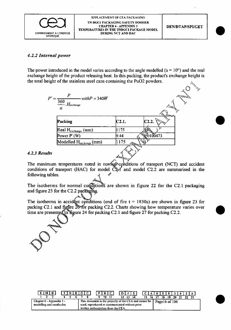
C e : I REPLACEMENT OF CEA PACKAGINGI TN-BGCI PACKAGING SAFETY DOSSIERCHAPTER 6 - APPENDIX 3 DEN/DTAP/SPI/GET
TEMPERATURES IN THE TNBGCI PACKAGE MODELCOMMISSARIAT A L'ENERGIE DURING NCT AND HAC
ATOMIQUE
4.2.2 Internal power
The power introduced in the model varies according to the angle modelled (a = 100) and the realexchange height of the product releasing heat. In this packing, the product's exchange height isthe total height of the stainless steel cans containing the PuO2 powders.
P 360 P withP =340W.Hexchange
Packing C2.1. C2.2.
Real Hexchange (mm) 1175Power P'0 944 (W)l 0 73Modelled Hexchange_(mm) 11175 _ ____
4.2.3 Results
The maximum temperatures noted in normik co. tions of transport (NCT) and accidentconditions of transport (HAC) for model &2.I and model C2.2 are summarised in thefollowing tables.
The isotherms for normal co tions are shown in figure 22 for the C2.1 packagingand figure 25 for the C2.2 p ck-ng.
The isotherms in accid nt conditions (end of fire t = 1830s) are shown in figure 23 forpacking C2.1 and figgurre 27or packing C2.2. Charts showing how temperature varies overtime are presentbliý*Ngre 24 for packing C2.1 and figure 27 for packing C2.2.
IEMII T I N I BI G C IPIBICI IDIJ 151 ICIAIOIOIOI 314 ISIAII 2 3 4 5 6 7 8 9 0 11 12 13 14 15 16 17 18 19 20 21 22 23
Chater6- ppedix3 -This document is the property of the CEA and cannot be Page 16 of 106modelling and results.doc used, reproduced or communicated without priorwritten authorization from the CEA.
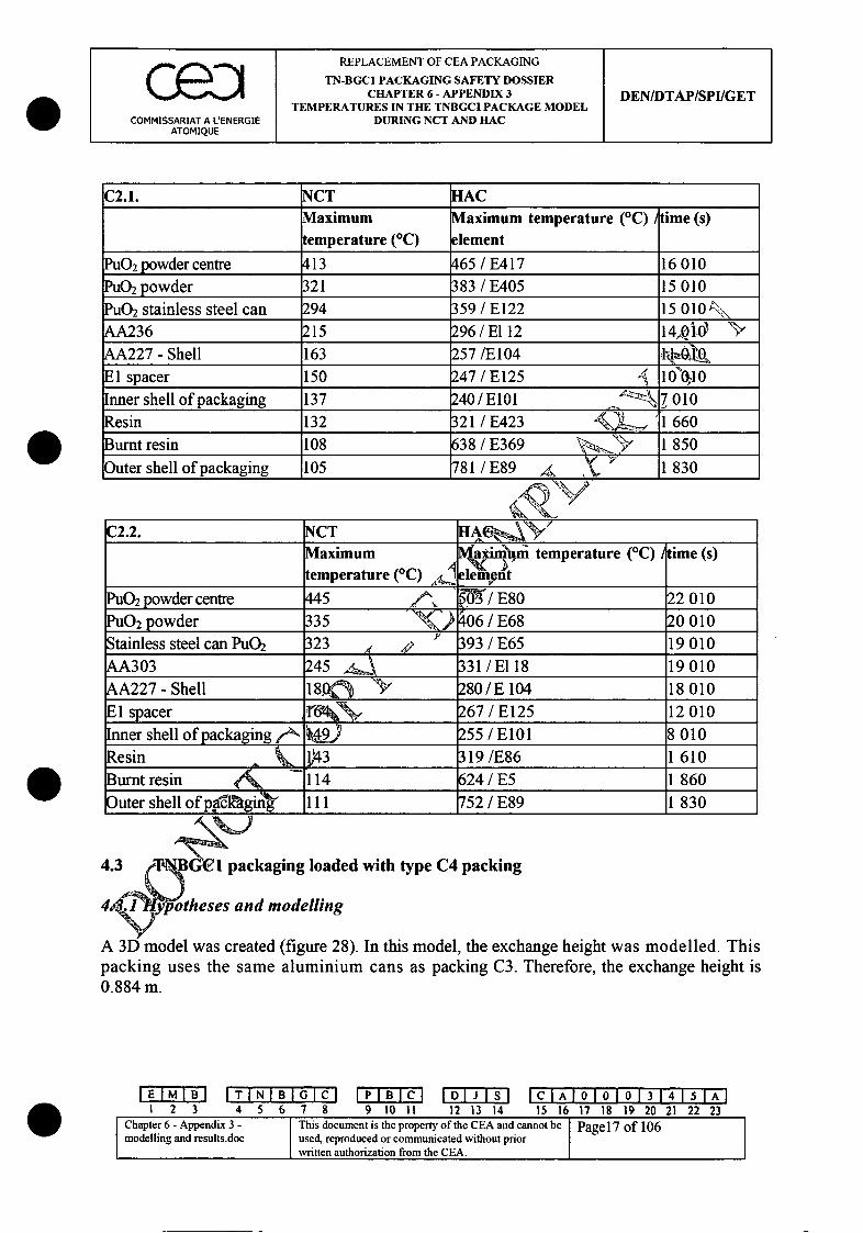
REPLACEMENT OF CEA PACKAGING
TN-BGCI PACKAGING SAFETY DOSSIERc CHAPTER 6 - APPENDIX 3 DEN/DTAP/SPI/GET
TEMPERATURES IN THE TNBGCI PACKAGE MODELCOMMISSARIAT A L'ENERGIE DURING NCT AND HAC
ATOMIQUE
C2.1. NCT HACMaximum Maximum temperature (°C) time (s)
temperature (C) element
PuO 2 powder centre 413 465 / E417 16010QuO2 powder 321 383 /E405 15010
Pu02 stainless steel can 294 359 / E122 15 010 \AA236 215 296/El 12 14,Q010 idAA227 - Shell 163 257/E104 ld_____,
El spacer 150 247 / E125 I 10"'0-1I0Inner shell of packaging 137 240/El0l ... A7 010Resin 132 321 /E423 '•l1 660Burnt resin 108 638 / E369 " 1 850
Outer shell of packaging 105 781 / E89 1830
C 2 .2 . N C T _tA _ _ __,_'__7
Maximum Aagim'tn- temperature (QC) time (s)temperature (°C) a leient
PuO2powder centre 445 0'3-/E80 2201002 powder 35 06/ E68 20010
Stainless steel can PuO2 323 3, / 93 / E65 19010
AA303 245 3 31/El 18 19010AA227- Shell 18,0n 280/E 104 18010E Ispacer 4161kN, 267 / E125 12010Inner shell of packaging , ý9 255 / El01 8010Resin 1 143 319/E86 1610Burnt resin 114 624 / E5 1 860Outer shell of p#1gin' 111 752 / E89 1 830
4.3 1 packaging loaded with type C4 packing
44.1- .1 otheses and modelling
A 3D model was created (figure 28). In this model, the exchange height was modelled. Thispacking uses the same aluminium cans as packing C3. Therefore, the exchange height is0.884 m.
IEMII ITI N IB 1071 IPIBICI IDIJ ISI I C I AIIO 1 I 3 141 57 -Al123 4 5 6 78 9 1011 12 13 14 15 16 17 18 19 20 21 22 23
Chapter 6 - Appendix 3- This document is the property of the CEA and cannot be Pagel 7 of 106modelling and results.doc used, reproduced or communicated without priorwritten authorization from the CEA.
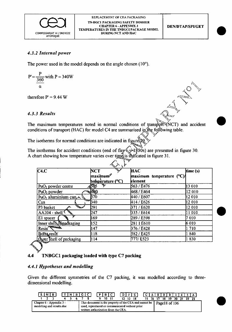
C e :) JREPLACEMENT OF CEA PACKAGINGTN-BGC1 PACKAGING SAFETY DOSSIERCHAPTER 6 - APPENDIX 3 DEN/DTAP/SPI/GET
TEMPERATURES IN THE TNBGCI PACKAGE MODELCOMMISSARIAT A L'ENERGIE DURING NCT AND HAC
ATOMIQUE I I I
4.3.2 Internal power
The power used in the model depends on the angle chosen (100).
V= . with P = 340W360
therefore P' = 9.44 W
44.3.3 Results
The maximum temperatures noted in normal conditions of transpo (NCT) and accidentconditions of transport (HAC) for model C4 are summarised inth e following table.
The isotherms for normal conditions are indicated in figu ,
The isotherms for accident conditions (end of fire(.-- 830s) are presented in figure 30.A chart showing how temperature varies over timsiNdicated in figure 31.
C4.C NCT AC time (s)naxiium9 maximum temperature (0C)t__ efhprature (0C) element
PuO 2 powder centre A54•5 63 / E476 13010PuO2 powder 47Q_0_0. 468 / E464 12010PuON aluminium canJ.k 170 440 / E607 12 010Can _ _ __340 414 / E626 12010P3 basket 291 371 / E620 12010AA204 - shell'( 247 335 / E614 11010El spacer ( -N 169 289 / E598 7010Inner shil'o pýadkaging 152 2811 E610 6010Resin; 147 376 / E428 1 710BgdTfresi1f 118 582 / E425 1 840
,te~r~hell ofpackaging 114 777/E523 1 830
4.4 TNBGC1 packaging loaded with type C7 packing
4.4.1 Hypotheses and modelling
Given the different symmetries of the C7 packing, it was modelleddimensional modelling.
according to three-
I TN I N I B G1 23 4 567 8 9 10 II 12 13 14
ClAI010J 1o 314"115 16 17 18 19 20 21 22 23
Chapter6-Appendix3- This document is the property of the CEA and cannot be Page 18 of 106modelling and results.doc used, reproduced or communicated without priorpwritten authorization from the CEA.
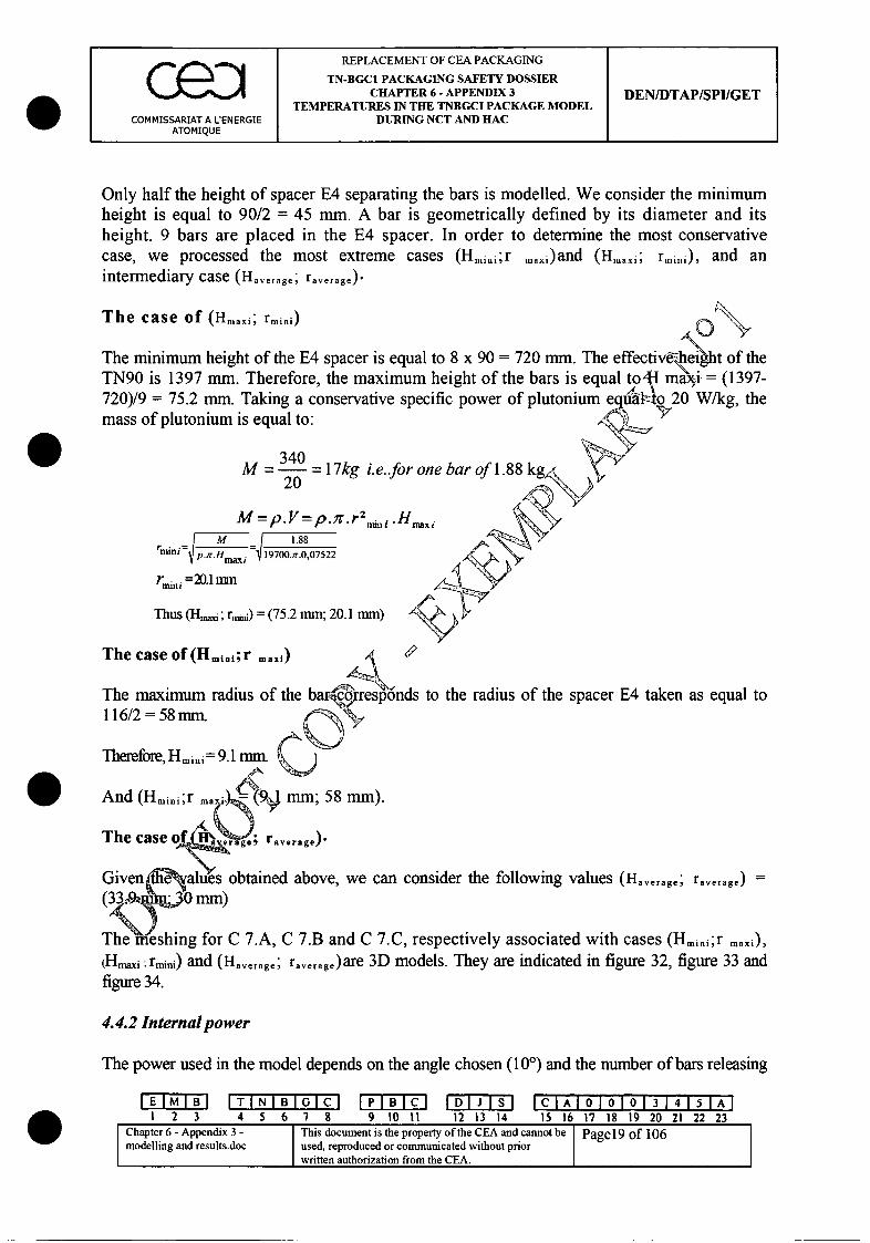
REPLACEMENT OF CEA PACKAGING
TN-BGCl PACKAGING SAFETY DOSSIERCHAPTER 6 - APPENDIX 3 DEN/DTAP/SPI/GET
TEMPERATURES IN THE TNBGCI PACKAGE MODELCOMMISSARIAT A L'ENERGIE DURING NCT AND HAC
ATOMIQUE
Only half the height of spacer E4 separating the bars is modelled. We consider the minimumheight is equal to 90/2 = 45 mm. A bar is geometrically defined by its diameter and itsheight. 9 bars are placed in the E4 spacer. In order to determine the most conservativecase, we processed the most extreme cases (Hmnini;r ... i)and (Hmaxi; rmini), and anintermediary case (Haverage; raverage).
The case of (Haxi; rmini)
.ight of theThe minimum height of the E4 spacer is equal to 8 x 90 = 720 mm. The elTN90 is 1397 mm. Therefore, the maximum height of the bars is equal720)/9 = 75.2 mm. Taking a conservative specific power of plutonium e9_imass of plutonium is equal to:
W/kg, the
340M=- =17kg i.e..for one bar of 1.8820
M =P. V--p. 7r. r~n HM.88
S p H - 19700.;T.0,07522
rni =20.1m m
Thus (HI,,,i; rn,6) = (75.2 mm; 20.1 mm)
The case of(Hmii;r mrx)
The maximum radius of the barcrresp'onds to the radius of the spacer E4 taken as equal to116/2 = 58mm. nu
Therefore, Hmini=9.1minl~~
And(Hmini;r .- mm; 5 mm).
The case o e&-a erage; ra.verag we a
Given alues obtained above, we can consider the following values (Hverage; raverage) =
(33•9. mm)
The eshing for C 7.A, C 7.B and C 7.C, respectively associated with cases (Hmini;r maxi),
(Hmaxi; rmini) and (H.ve.age; raverage)are 3D models. They are indicated in figure 32, figure 33 andfigure 34.
4.4.2 Internal power
The power used in the model depends on the angle chosen (100) and the number of bars releasing
III TINIT N B IG C IPlBlCl IDILISl IC IA 1 010101 3 14 1 51A-1123 4 5 6 7 8 9 t011 12 13 14 15 16 17 18 19 20 21 22 23
Chapter 6 - Appendix 3 - This document is the property of the CEA and cannot be Page19 of 106modelling and results.doc used, reproduced or communicated without priorwritten authorization from the CEA.
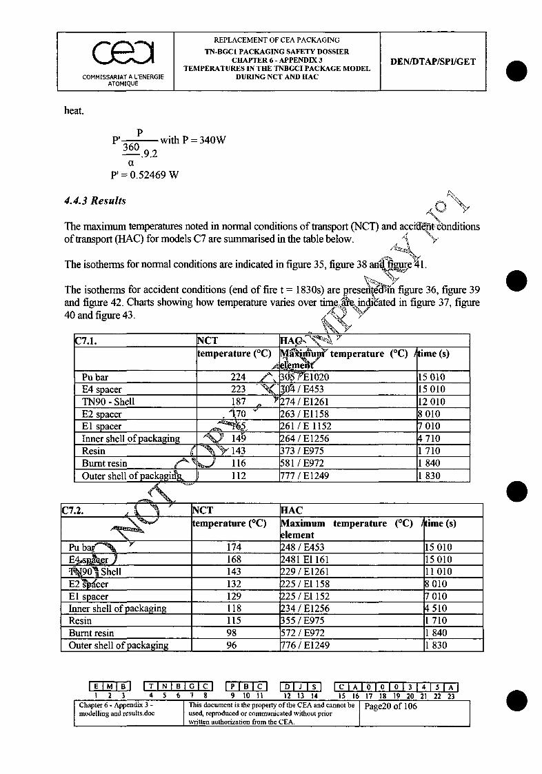
C e D) REPLACEMENT OF CEA PACKAGINGTN-BGCI PACKAGING SAFETY DOSSIER
CHAPTER 6- APPENDIX 3 DEN/DTAP/SPI/GETTEMPERATURES IN THE TNBGCI PACKAGE MODEL
COMMISSARIAT A LENERGIE DURING NCT AND HACATOMIQUE I I
heat.
PP' with P = 340W
360.9.2a
P 0.52469 W
4.4.3 Results
The maximum temperatures noted in normal conditions of transport (NCT) and accidd&t'Eonditionsof transport (HAC) for models C7 are summarised in the table below. "
The isotherms for normal conditions are indicated in figure 35, figure 38 anil fue •41.
The isotherms for accident conditions (end of fire t = 1830s) are presentedýikih figure 36, figure 39and figure 42. Charts showing how temperature varies over time indicated in figure 37, figure40 and figure 43.
C7.1. NCT ____ ____ ____
temperature (QC)l temperature (C) )me (s)
Pu bar 224 3' & 3iin7•1020 15010E4 spacer 223 "Y"<,Or4 / E453 15010TN90_- Shell 187 e 74/E1261 12010E2 spacer _,I 70 263 / E1158 8010E1I spacer__1 __ 261/E 1152 7010Inner shell of packaging 14 264 / E1256 4710Resin '43 373/ E975 1710Burnt resin _'_ _ 116 581/E972 1 840Outer shell of packagit~g. 112 777 / E1249 1 830
C7.2. NCT HACtemperature (C) Maximum temperature (fC) time (s)
elementPu b Y 174 248 / E453 15010E44s eer ) 168 2481 El 161 15010Xl•901§hSell 143 229 / E1261 11010
E2 sp-cer 132 225 / El 158 8010E1 spacer 129 225 / El 152 7010Inner shell of packaging 118 234 / E1256 4510Resin 115 355 / E975 1710Burnt resin 98 572 / E972 1 840Outer shell of packaging 96 776 / E1249 1 830
EIM TIIN T I B I GCC [PIBRJ IDIJ Isi ICIAIOIOIO1 314151AI123 45 67 8 9 10 11 12 13 14 15 16 17 18 19 20 21 22 23
[ Chapter 6 - Appendix 3. -This document is the property of the CEA and cannot be Page20 of 106modelling and results.doc used, reproduced or communicated without priorwritten authorization from the CEA.

REPLACEMENT OF CEA PACKAGING
TN-BGCI PACKAGING SAFETY DOSSIERCHAPTER 6 - APPENDIX 3 DEN/DTAP/SPI/GET
TEMPERATURES IN THE TNBGCI PACKAGE MODELCOMMISSARIAT A LENERGIE DURING NCT AND HAC
ATOMIQUE
C7.3. NCT HACtemperature (C) Maximum temperature (QC) time (s)
element
Pu bar 204 020E4 spacer 198 .53TN90 - Shell 167 261E2 spacer 152 158 ____
El spacer 148 152 ,,S ' "Inner shell of packaging 134 256 _
Resin 130 75 4 _ _
Burnt resin 108 72 _\ "Outer shell of packaging 104 249 i-% " _"
The results indicated in the different tables allow us to conclude thditzinoo'l C7.1 is the mostdetrimental case (the smallest exchange height and the maximumi rad'•us)
4.5 TNBGC1 packaging loaded with type C8 packi4n
4.5.1 Hypotheses and modelling
Half of the plate and E5 spacer was model1$d4(only 1/8 of the cross-section was modelled).The meshing is indicated in figure 44 and 9eoresponds to a 3D model (for reasons ofsymmetry). We take a conservative positidoh and consider that the plates are in contact withtheir packing. S4.5.2 Internal power
We consider the case o stac s of plates with an effective height of 100 mm. The powerto enter depends on)1 numb"er of stacks and angle a (45").
-. P
4.5.3 Results
The maximum temperatures noted in normal conditions of transport (NCT) and accidentconditions of transport (HAC) for model C8 are summarised in the table below.
The isotherms for normal conditions are indicated in figure 45.
EMB I TINIBIGC IPIBICJ IDIJISI I C I A 1 0 1o 0 lo 3 1 4 I1 51FA 1123 4 5 6 7 8 9 10 1i 12 13 14 15 16 17 18 19 20 21 22 23
SChapter 6- Appendix 3- This document is the property of the CEA and cannot be Page2l of 106modelling and results.doc used, reproduced or communicated without priorwritten authorization from the CEA.

REPLACEMENT OF CEA PACKAGING
TN-BGCI PACKAGING SAFETY DOSSIERCHAPTER 6 - APPENDIX 3 DEN/DTAP/SPI/GET
TEMPERATURES IN THE TNBGCI PACKAGE MODELCOMMISSARIAT A L'ENERGIE DURING NCT AND HAC
ATOMIQUE
The isotherms for accident conditions (end of fire t = 1830s) are presented in figure 46. Achart showing how temperature varies over time is indicated in figure 47.
C8. NCT IACMaximum Maximum temperature (°C) Ytime (s)temperature element ......... .
Plates 164 245/ E1019 14 ,110 1-0E5 spacer 142 223/ E2514 14 1A QTN90 - Shell 116 207/ E2938 ,11 Noj10E2 spacer 108 205/ E2932 8_ 010El spacer 106 205/ E2024 8 8Y 010Inner shell of packaging 100 212/ E2120 5 010Resin 8 326 / E2908 .. 1 710Burnt resin 88 537/ E290_ 5 1 850Outer shell of packaging 86 748 / 1 830
4.6 TNBGCI packaging loaded with type C5 .an C . packing
4.6.1 Hypotheses and modelling
For these two models, the coefficient of exchange via convection results from theexperiment and is equal to: 2.3 ATO4.33 [i.
* For model C5, two conns- were studied: uranyl nitrate (C5.A) and U02 powder(C5.B).
" For model C 1,, ,contents were studied: uranium metal (ClI .A) and uraniummetal oxid l .B).
The contentsko cking bottles C5 and ClI releases a negligible power. Part of asection (1"'Qdgsuring 1 mm in thickness was modelled (see diagram 2, figure 48 andfigure-. The insulating spacer E3 was not modelled because it is mainly made up ofemptykspa e and insulating material.
IEIIBIITINIBIGIFCI IPIBICI IDIJ Isi ICIAIOIOIO1 314151AI1 2 3 4 5 6 7 8 9 10 11 12 13 14 15 16 17 18 19 20 21 22 23
Chapter 6- Appendix 3- IThis document is the property of the CEA and cannot be Page22 of 106modelling and results.doc used, reproduced or communicated without priorwritten authorization from the CEA.
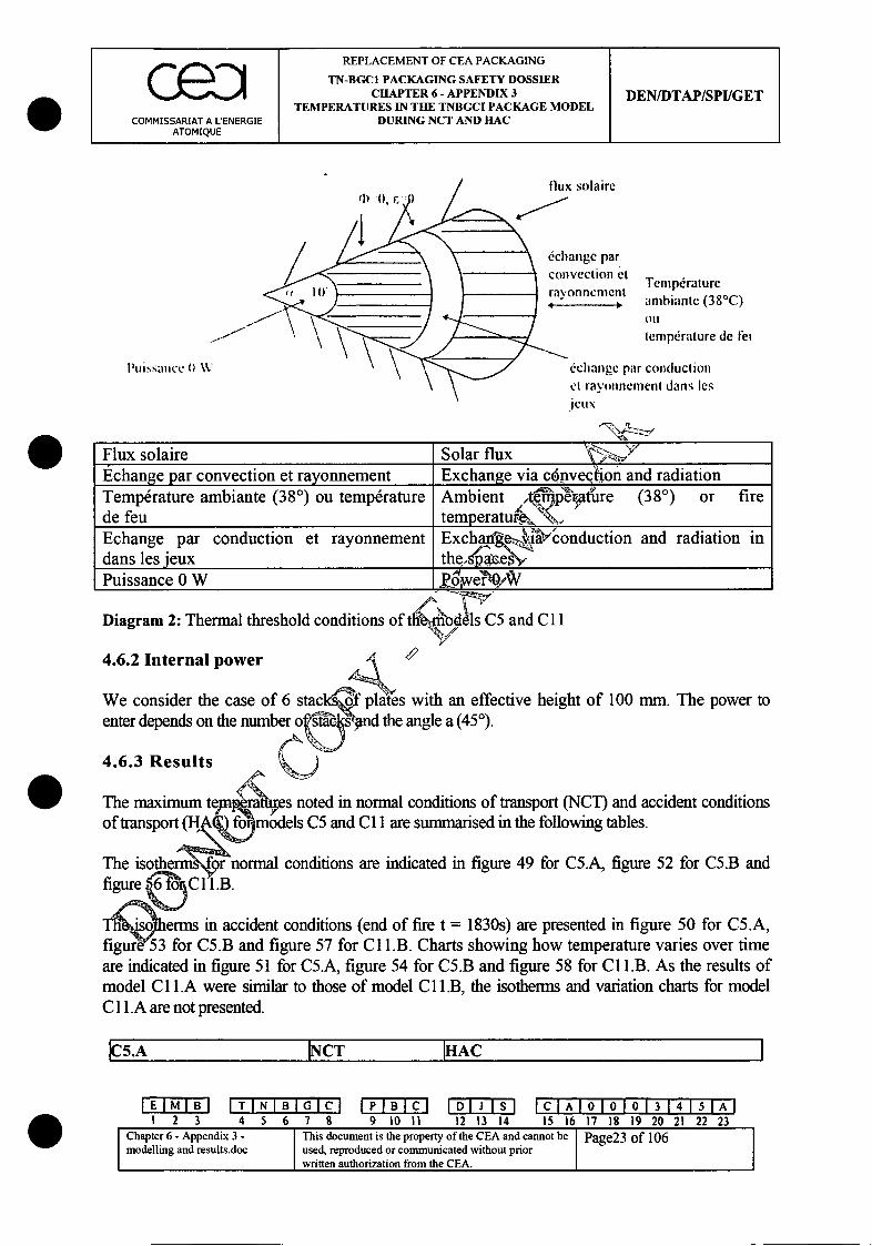
REPLACEMENT OF CEA PACKAGING
TN-BGC1 PACKAGING SAFETY DOSSIERCHAPTER 6 - APPENDIX 3 DEN/DTAP/SPI/GET
TEMPERATURES IN THE TNBGCI PACKAGE MODELCOMMISSARIAT A LENERGIE DURING NCT AND HAC
ATOMIQUE
Ilux solaire
6changc parconvection et Tempdrature
i ravonnfcmcnt" ambiante (38'C)
Ott
.temprature de fet
Puissance 0 W &change par conductioneli ravi'tl l neril dans les
Flux solaire Solar flux '-.Echange par convection et rayonnement Exchange via c6nvechon and radiationTemperature ambiante (380) ou temperature Ambient tem p erature (380) or firede feu temperatu~~Echange par conduction et rayonnement Egxcha n'•Y.onduction and radiation indansElesjeux the ,ps___"e __M
Puissance 0 W _ _.O_/VV
Diagram 2: Thermal threshold conditions of th•rid6es C5 and C 1I
4.6.2 Internal pi
We consider theenter depends on th
4.6.3 Results
ower
case of 6 stack43 plades with an effective height of 100 mm. The power toke number o 49nd the angle a (450).
4er a es noted in normal conditions of transport (NCT) and accident conditions1omodels C5 and C1I are summarised in the following tables.
L normal conditions are indicated in figure 49 for C5.A, figure 52 for C5.B and
The maximumof transport (1&
The.B.
fiqhiherms in accident conditions (end of fire t = 1830s) are presented in figure 50 for C5.A,figure 53 for C5.B and figure 57 for C1 1.B. Charts showing how temperature varies over timeare indicated in figure 51 for C5.A, figure 54 for C5.B and figure 58 for C l.B. As the results ofmodel C I.A were similar to those of model C I.B, the isotherms and variation charts for modelC I .A are not presented.
J5.A NCT PAC
IEMI I[TINIBIGlC M P B~ ID J c A101ol 1'ol314151TA11 2 3 4 5 6 7 8 9 10 11 12 13 14 15 16 17 18 19 20 21 22 23
iChapter 6 - Appendix 3 - This document is the property of the CEA and cannot be Pae3o10modelling and results.doc used, reproduced or communicated without prior
written authorization from the CEA.
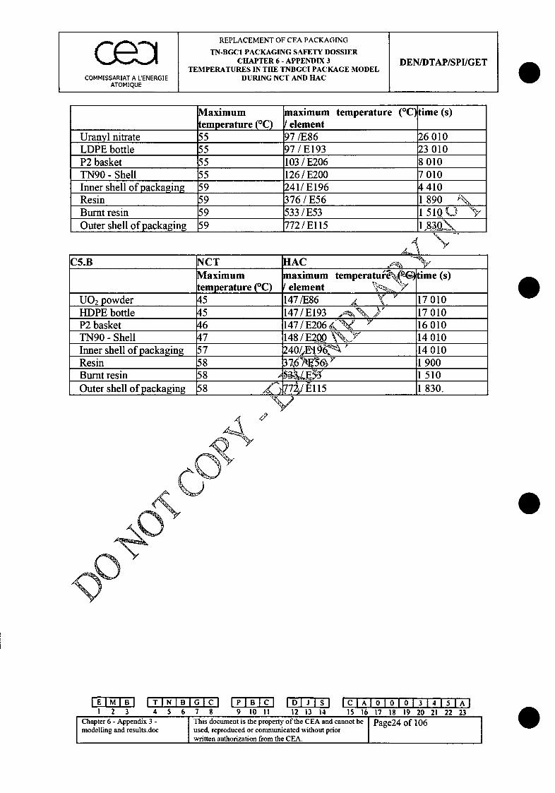
REPLACEMENT OF CEA PACKAGING ITN-BGCI PACKAGING SAFETY DOSSIER
I CHAPTER 6 - APPENDIX 3 DEN/DTAP/SPI/GETTEMPERATURES IN THE TNBGCI PACKAGE MODEL
COMMISSARIAT A L'ENERGIE DURING NCT AND HACATOMIQUE
Maximum maximum temperature (°Ctime (s)temperature (C) I element
Uranyl nitrate 55 97/E86 26010LDPE bottle 55 97 / E193 23010P2 basket 55 103/E206 8010TN90 - Shell 55 126 / E200 7010Inner shell of packaging 59 241/ E196 4410Resin 59 376 /E56 1 890 •\Burnt resin 59 533/E53 1 510 (J)Outer shell of packaging 9 72 / El 15 1 k3_Q
A-
C5.B NCT HAC __'__
Maximum maximum temperaturli G) time (s)temperature (*C) I element >'_,.__
U0 2 powder 45 147/E86 , 17010HDPE bottle 45 147/ E 193 Ko Y 17010P2 basket 46 147/E206•7k?• ' 16010TN90 - Shell 47 148/E20 \' 00 14010Inner shell of packaging 57 240/,X1q6-,'ý " 14 010Resin 58 3726• / 6• 1900Burnt resin 58 53;3,•E• 1510Outer shell of packaging 58 7 1 E115 1 830.V
EMB ITINIBIGC PBC DJSI CA 010131" A1 2 3 4 5 6 7 8 9 10 11 12 13 14 15 16 17 18 19 20 21 22 23
Chapter 6 - Appendix 3 - This document is the property of the CEA and cannot be Page24 of 106modelling and results.doc used, reproduced or communicated without prior
written authorization from the CEA.
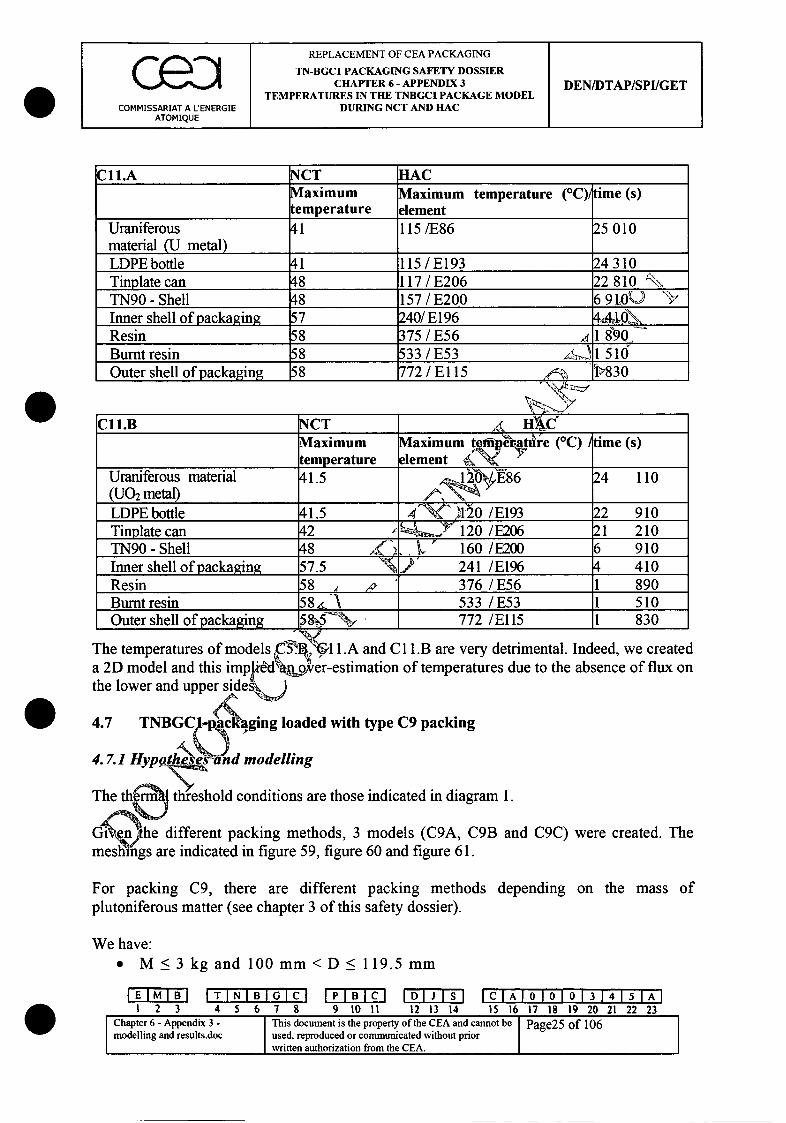
Ie REPLACEMENT OF CEA PACKAGINGTN-BGCI PACKAGING SAFETY DOSSIER
CHAPTER 6 - APPENDIX 3 DEN/DTAP/SPI/GETTEMPERATURES IN THE TNBGCI PACKAGE MODEL
COMMISSARIAT A L'ENERGIE DURING NCT AND HACATOMIQUE
C11.A NCT HACMaximum Maximum temperature (0C) time (s)temperature element
Uraniferous 41 115/E86 25010material (U metal)
LDPE bottle 41 115/E193 24310Tinplate can 48 117 / E206 22 810 •\TN90 - Shell 48 157 / E200 6 9 LOUInner shell of packaging 57 240/E196 4Al-o\Resin 58 375 / E56 18+907Burnt resin 58 533/E53 /-S- 1l516Outer shell of packaging 58 772 / E 115 1> ___830
C11.B NCT I rAIC' ____
Maximum aximum tem-perature (QC) time (s)temperature element __,___"__
Uraniferous material 41.5 ,,/ E86 24 110(U O 2 m etal)
y__J 8_ _
LDPE bottle 41.5 ý1l0/E193 22 910Tinplate can 42 ____ ___120 /E206 21 210TN90 - Shell 48 X __"_, L 160 /_E200 6 910
Inner shell of packaging 57.5 241 /E196 4 410Resin 58 A 376_/ E56 1 890Burnt resin 58i 533 /E53 1 510Outer shell of packaging 8 772 /El 15 1 830
The temperatures of models 05'7.; 11.A and C 11.B are very detrimental. Indeed, we createda 2D model and this implfe-dhn~oicer-estimation of temperatures due to the absence of flux onthe lower and upper side a
4.7 TNBGC pac ,ging loaded with type C9 packing
4.7.1 Hypolhsees nd modelling
The th•enrl threshold conditions are those indicated in diagram 1.
Gmien'. shhhe different packing methods, 3 models (C9A, C9B and C9C) were created. Themeshmigs are indicated in figure 5 9, figure 60 and figure 6 1.
For packing C9, there are different packing methods depending on the mass ofplutoniferous matter (see chapter 3 of this safety dossier).
We have:* M <3 kg and 100mm <D < 119.5 mm
IMIB ITINIBIGI¢CC P B C LD~I~~)~IsI 1• A1 1 A 1QL I31I4 I S IA I1 2 3 4 5 6 7 8 9 10 11 12 13 14 15 16 17 18 19 20 21 22 23
Chapter 6 - Appendix 3 - This document is the property of the CEA and cannot be Page25 of 106modelling and results.doc used, reproduced or communicated without prior
written authorization from the CEA.

REPLACEMENT OF CEA PACKAGING
TN-BGC1 PACKAGING SAFETY DOSSIERCHAPTER 6 - APPENDIX 3 DEN/DTAP/SPI/GET
TEMPERATURES IN THE TNBGCI PACKAGE MODELCOMMISSARIAT A LENERGIE DURING NCT AND HAC
ATOMIQUE
" M<4kgand36mm<D<100mm
* M>4kgandD<36mmin which M is the mass of plutoniferous matter and D is the inner diameter of the containerin which the matter is packed.
We consider the following cases:
9 M = 3 kg and (D = 60 W (given a specific power of 20 W/kg).
We will study two cases: D= 119.5 mm (1) and D = 100 mm (2)
* M = 4 kg and (D = 80 W
We will study two cases: D= 100 mm (3) and D =36 mm (4)
M 7.5kg andciD150 W
We will study the case: D = 36 mm (5)
We calculate the exchange heights in the foiowli'hi"er:
A,
M MV 2r~
Heg -Mexc•ha"ge - r~ n-' .p
o tematter and p is the density of the matter.
(1) - ixchange= 13.5 mm; D =119.5 mm; P = 60 W0.12346 W for 1 mm of height
Hexchange = 19.4 mr; D =100 mn; P = 60 WP'= 0.08591 W for 1 mm of height
(3) Hexchange = 25.8 mm; D =100 mm; P 80 WP'=- 0.08613 W for 1 mm of height
(4) Hexchange = 199.5 mm; D = 36 mm; P = 80 WP'= 0.01114 W for 1 mm of height
(5) Hexchange= 374.0 mm; D = 36 mm; P = 150 WP'= -0.01114 W for 1 mm of height
C9.C
C9.A
C9.B
C9.B
I 4ITINIBI6 Cl1 2 3 4 5 6 7 9 9 10 I! 12 13 14
IC lAI01 Ol01314 S1I2A2 l
Chapter 6 - Appendix 3 - This document is the property of the CEA and cannot be Pag26of 106modelling and results.doc used, reproduced or communicated without priorwritten authorization from the CEA.
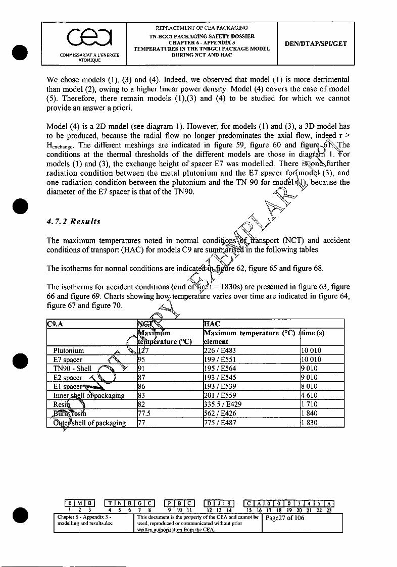
Ie REPLACEMENT OF CEA PACKAGINGI TN-BGC1 PACKAGING SAFETY DOSSIER
CHAPTER 6- APPENDIX 3 DEN/DTAP/SPI/GETTEMPERATURES IN THE TNBGCI PACKAGE MODEL
COMMISSARIAT A L'ENERGIE DURING NCT AND HACATOMIQUE I
We chose models (1), (3) and (4). Indeed, we observed that model (1) is more detrimentalthan model (2), owing to a higher linear power density. Model (4) covers the case of model(5). Therefore, there remain models (1),(3) and (4) to be studied for which we cannotprovide an answer a priori.
Model (4) is a 2D model (see diagram 1). However, for models (1) and (3), a 3D model hasto be produced, because the radial flow no longer predominates the axial flow, indeed r >Hexchange. The different meshings are indicated in figure 59, figure 60 and figure•,6\.\\The.... ..ng fiue 6 1 •\Th
conditions at the thermal thresholds of the different models are those in diagram 1. F•ormodels (1) and (3), the exchange height of spacer E7 was modelled. There isonefurtherradiation condition between the metal plutonium and the E7 spacer forimoll, (3), andone radiation condition between the plutonium and the TN 90 for modee(z ) because thediameter of the E7 spacer is that of the TN90.
4. 7.2 Results
The maximum temperatures noted in normal cconditions of transport (HAC) for models C9 are
The isotherms for normal conditions are indicatedl
(NCT) and accidentthe following tables.
62, figure 65 and figure 68.
The isotherms for accident conditions (end offir 'Pt = 1830s) are presented in figure 63, figure66 and figure 69. Charts showing how temperature vanes over time are indicated in figure 64,figure 67 and figure 70.
C9.A C•.• HAC,,. aximum Maximum temperature (C) time (s)A eMperature (QC) element
Plutonium . jý7 226 / E483 10 010E7 spacer • 95 199 / E551 10010TN90 -Shell 91 195/E564 9010E2 spacer AA, 87 193/E545 9010E1 spaceEZ 86 193 / E539 8010Innersl1l 6f~packaging 83 201 / E559 4610Resin 1 82 335.5/E429 1710
_B_'_ _ __esi _ 77.5 562 / E426 1 840Oý_Pshell of packaging 77 775 / E487 1 830
7
IEIIBIITINIBIO7CI iPIBICI IDIJ Isi IC IAI01010131415I[AI123 4 5 6 78 9 10 I 12 13 14 15 16 17 18 19 20 21 22 23
IChapter 6 - Appendix 3 - This document is the property of the CEA and cannot be Page27 of 106modelling and results.doc used, reproduced or communicated without priorwritten authorization from the CEA.
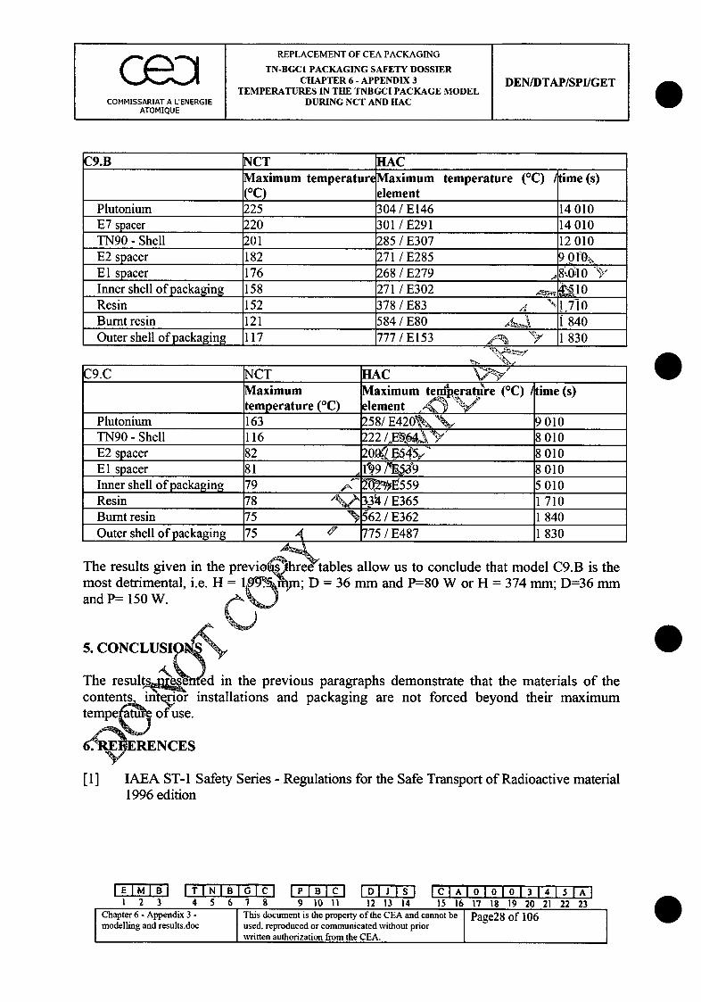
REPLACEMENT OF CEA PACKAGING
I TN-BGCI PACKAGING SAFETY DOSSIER0 CHAPTER 6- APPENDIX 3 DEN/DTAP/SPI/GET
TEMPERATURES IN THE TNBGCI PACKAGE MODELCOMMISSARIAT A L'ENERGIE DURING NCT AND HAC
ATOMIQUE I I
C9.B NCT HACMaximum temperature Maximum temperature ('C) time (s)(0C) element
Plutonium 225 304 / E146 14010E7 spacer 220 301 / E291 14010TN90 - Shell 201 285 / E307 12010E2 spacer 182 271 / E285 9.01 '0ýEl spacer 176 268 / E279 g, 0;10Inner shell of packaging 158 271 / E302 & ý5 0Resin 152 378 / E83 X N 1 , 1 0
Burnt resin 121 584 / E80 1i 840Outer shell of packaging 117 777 / E153 1 " 1 830
C9.C NCT HACMaximum Maximum temperatilre (*C) itime (s)temperature (QC) element 0' ýý"/
Plutonium 163 258/E42Ok 9 010TN90 - Shell 116 222/,E526Y'Y 8010E2 spacer 82 20KI F54.5 8 010El spacer 81 19/ 73W'9 8010Inner shell of packaging 79 •,$ 62•02I/ E559 5010Resin 78 ' 3ý4 / E365 1710Burnt resin 75 562 / E362 1 840Outer shell of packaging 75 ,7 75 / E487 1 830
The results given in the previot•~hree tables allow us to conclude that model C9.B is themost detrimental, i.e. H 1-9-9.,051 ; D = 36 mm and P=80 W or H = 374 mm; D=36 mmand P=- 150 W. "k %
5. CONCLUSIOS
The results h ed in the previous paragraphs demonstrate that the materials of thecontents intnor installations and packaging are not forced beyond their maximumtempe. j of use.
6 ' PRENCES
[1] IAEA ST-1 Safety Series - Regulations for the Safe Transport of Radioactive material1996 edition
0
EM B I TINIBIGIC1 IC AI 01010131415[1AI123 4 5 67 8 9 10 11 12 13 14 15 16 17 18 19 20 21 22 23
Chater6- ppedix3 -This document is the property of the CEA and cannot be Page28 of 106modelling and results.doc used, reproduced or communicated without priorwritten authorization from the CEA.
REPLACEMENT OF CEA PACKAGING
TN-BGC1 PACKAGING SAFETY DOSSIERCHAPTER 6 - APPENDIX 3 DEN/DTAP/SPI/GET
TEMPERATURES IN THE TNBGCI PACKAGE MODELCOMMISSARIAT A LENERGIE DURING NCT AND HAC
ATOMIQUE
[2] Software for the calculation of finite elements: I-DEAS Master Series V4.0developed by SDRC La DMfense combined with TMG, the thermal analysismodule
[3] TN-BGC 1 Packaging - Packaging, whole concept plan: Plan 9990-65 ind. C.Packaging, assembled plug: Plan 9990-117 ind. B
[4] Heat transmission - WI-1 Mc Adams. Chapter VII
[5] I-DEAS - TMG Reference Manual.
[6] TN-BGC1 Packaging safety dossier - Chapter 2 and appendic&,_hapter 6 andappendices.
[7] Archive note 3648-V-3, archive cartridge 3,64' fle:ie351554/THERMIQUE/viroleC 10.arcie351554/THERMIQUE/TNBGC1 .arc
[8] Touloukian - Specific heat (volume 5 -vp.1 olume 4 - p. 167)
[9] New Treatise on Inorganic Chemistry - I SCAL - Volume XV - thirdfascicle - Transuranium - Masson et yi . 261, 262 - 1962.
[10] Handbook of Chemistry and Pl1 sics - David R. LIDE - 73 'e' edition - p. 13131 -
1992-1993.
[11] J. F Sacadura - IntrodcdWin to heat transfer - Lavoisier - p. 430 - p. 433 1983.
[12] J. Bost - Plastics"yVolume 1 - Chemistry Applications - Techniques andDocumentat p. 19 - 1982.
[13] New T-rl orn Inorganic Chemistry - Paul PASCAL - Volume XV - firstfas 0cie uraim- Masson et Cie - p. 290 - 1960.
IEIMIBI ITINIBIGlCl IPIBICl IDIJISI ICIA'I0101013141,•5IAI1 2 3 4 5 6 7 8 9 10 11 12 13 14 15 16 17 18 19 20 21 22 23
Chapter 6- Appendix 3 - This document is the property of the CEA and cannot be Page29 of 106modelling and results.doc used, reproduced or communicated without prior
1written authorization from the CEA.
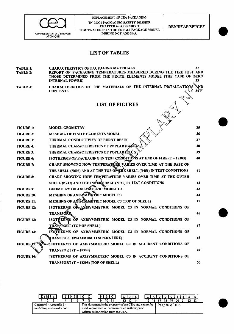
REPLACEMENT OF CEA PACKAGING
TN-BGCI PACKAGING SAFETY DOSSIERc e0 CHAPTER 6 - APPENDIX 3 DEN/DTAP/SPI/GETTEMPERATURES IN THE TNBGCI PACKAGE MODEL
COMMISSARIAT A LENERGIE DURING NCT AND HACATOMIQUE
LIST OF TABLES
TABLE 1: CHARACTERISTICS OF PACKAGING MATERIALS 32TABLE 2: REPORT ON PACKAGING TEMPERATURES MEASURED DURING THE FIRE TEST AND
THOSE DETERMINED FROM THE FINITE ELEMENTS MODEL (THE CASE OF ZEROINTERNAL POWER) 33
TABLE 3: CHARACTERISTICS OF THE MATERIALS OF THE INTERNAL INSTALLATIONS "DCONTENTS 3&
LIST OF FIGURES
FIGURE 1: MODEL GEOMETRY-- , 35
FIGURE 2: MESHING OF FINITE ELEMENTS MODEL 36
FIGURE 3: THERMAL CONDUCTIVITY OF BURNT RESIN 37
FIGURE 4: THERMAL CHARACTERISTICS OF POPLAR (BASEY$ 38
FIGURE 5: THERMAL CHARACTERISTICS OF POPLAR.R(i}G) 39FIGURE 6: ISOTHERMS OF PACKAGING IN TEST CONDITIONS AT END OF FIRE (T = 1830S) 40
FIGURE 7: CHART SHOWING HOW TEMPERATURE VRIES OVER TIME AT THE BASE OF
THE SHELL (N606) AND AT THE TOP 0 SHELL (N451) IN TEST CONDITIONS 41
FIGURE 8: CHART SHOWING HOW TEMPERATURE VARIES OVER TIME AT THE OUTER
SHELL (N742) AND THE S4N15HELL (N746) IN TEST CONDITIONS 42
FIGURE 9: GEOMETRY OF AXISYMEIRICMODEL C3 43
FIGURE 10: MESHING OF AXIS-M- -, C MODEL C3 44
FIGURE 11: MESHING OF AYM IMETRIC MODEL C3 (TOP OF SHELL) 45
FIGURE 12: ISOTHERMiS. O ,I SYMMETRIC MODEL C3 IN NORMAL CONDITIONS OF
TRANSP'di~F 46
FIGURE 13: ISOTHERS OF AXISYMMETRIC MODEL C3 IN NORMAL CONDITIONS OF
TPORT (TOP OF SHELL) 47
FIGURE 14: .THERMS OF AXISYMMETRIC MODEL C3 IN NORMAL CONDITIONS OF
SPORT (MAXIMUM TEMPERATURE) 48
FIGURE 15: ISOTHERMS OF AXISYMMETRIC MODEL C3 IN ACCIDENT CONDITIONS OF
TRANSPORT (T = 1830S) 49
FIGURE 16: ISOTHERMS OF AXISYMMETRIC MODEL C3 IN ACCIDENT CONDITIONS OF
TRANSPORT (T = 1830S) (TOP OF SHELL) 50
IEIMIBI ITINIBIGICI IPIBICl IDIJISI IClAI 010101314'ISIAI123 45678 91011 121314 15 16 17 18 19 20 212223
Chapter 6 - Appendix 3 - This document is the property of the CEA and cannot be Page30 of 106modelling and results.doc used, reproduced or communicated without prior
written authorization from the CEA.

( m l REPLACEMENT OF CEA PACKAGINGI TN-BGC1 PACKAGING SAFETY DOSSIERCHAPTER 6 - APPENDIX 3 DEN/DTAP/SPI/GET
TEMPERATURES IN THE TNBGCI PACKAGE MODELCOMMISSARIAT A LENERGIE DURING NCT AND HAC
ATOMIQUE
a
FIGURE 17: ISOTHERMS OF AXISYMMETRIC MODEL C3 IN ACCIDENT CONDITIONS OF
TRANSPORT (T = 1830S) (MAXIMUM TEMPERATURE)
FIGURE 18: CHART SHOWING HOW MAXIMUM TEMPERATURE VARIES OVER TIME FOR
AXISYMMETRIC MODEL C3
FIGURE 19: CHART SHOWING HOW TEMPERATURE VARIES OVER TIME AT THE BASE AND
THE TOP OF THE PACKAGING IN ACCIDENT CONDITIONS
FIGURE 20: MESHING OF MODEL C2.1
FIGURE 21: MESHING OF MODEL C2.2
FIGURE 22: ISOTHERMS OF MODEL C2.1 IN NORMAL CONDITIONS OF TRANSPORTJ
FIGURE 23: ISOTHERMS OF MODEL C2.1 IN ACCIDENT CONDITIONS OF TRANSPORT (T =
1830S)
IGURE 24: CHART SHOWING HOW TEMPERATURE VARIES OVER TIME F-OR-MODEL C2.1
FIGURE 25: ISOTHERMS OF MODEL C2.2 IN NORMAL CONDITIONS OF TRANSPORT
FIGURE 26: ISOTHERMS OF MODEL C2.2 IN ACCIDENT CONDITIAO TRANSPORT (TFFIGURE 27: 180) OT=M OELC.1830S)
FIGURE 27: CHART SHOWING HOW TEMPERATURE VAR9`S0O1 WEE FOR MODEL C2.2
FIGURE 28: MESHING OF MODEL C4 . V
FIGURE 29: ISOTHERMS OF MODEL C4 IN NORMAL&CIONITIONS OF TRANSPORT
FIGURE 30: ISOTHERMS OF MODEL C4 IN ACCIDENTCONDITIONS OF TRANSPORT (T
1830S)
FIGURE 31: CHART SHOWING HOW TEMPERATURE VARIES OVER TIME FOR MODEL C4
FIGURE 32: MESHING OF MODEL C7.A
FIGURE 33: MESHING OF MODEL Ei•
FIGURE 34: MESHING OF MOD•C•
FIGURE 35: ISOTHERMS OI MODELJC7.A IN NORMAL CONDITIONS OF TRANSPORT
FIGURE 36: ISOTHERMSORFMDEL C7.A IN ACCIDENT CONDITIONS OF TRANSPORT (T =~~~~1830S) •J•n'
FIGURE 37: CHR'j P ISOWING HOW TEMPERATURE VARIES OVER TIME FOR MODEL C7A
FIGURE 38: ISOT1 RMS OF MODEL C7.B IN NORMAL CONDITIONS OF TRANSPORT
FIGURE 39: ISOTH RMS OF MODEL C7.B IN ACCIDENT CONDITIONS OF TRANSPORT (T =
O830S)FIGURE0 •• HART SHOWING HOW TEMPERATURE VARIES OVER TIME FOR MODEL C7.B
k,53
S55
56
57
58
59
60
61
62
63
64
65
66
67
68
69
70
71
72
73
74
51
52
6
EMB I TINIBI G C ICIAI0I0I01314I15IAI1 2 3 4 5 6 7 8 9 10 11 12 13 14 15 16 17 18 19 20 21 22 23
Chapter 6 - Appendix 3 - This document is the property of the CEA and cannot be Page31 of 106modelling and results.doc used, reproduced or communicated without prior
written authorization from the CEA.

REPLACEMENT OF CEA PACKAGING
TN-BGC1 PACKAGING SAFETY DOSSIERCHAPTER 6 - APPENDIX 3 DEN/DTAP/SPI/GET
TEMPERATURES IN THE TNBGCI PACKAGE MODELCOMMISSARIAT A LENERGIE DURING NCT AND HAC
ATOMIQUE I I
FIGURE 41: ISOTHERMS OF MODEL C7.C IN NORMAL CONDITIONS OF TRANSPORT 75
FIGURE 42: ISOTHERMS OF MODEL C7.C IN ACCIDENT CONDITIONS OF TRANSPORT (T =
1830S) 76
FIGURE 43: CHART SHOWING HOW TEMPERATURE VARIES OVER TIME FOR MODEL C7.C 77
FIGURE 44: MESHING OF MODEL C8 78
FIGURE 45: ISOTHERMS OF MODEL C8 IN NORMAL CONDITIONS OF TRANSPORT k\,79
FIGURE 46: ISOTHERMS OF MODEL C8. IN ACCIDENT CONDITIONS OF TRANSPORT (TF,
1830S) 80
FIGURE 47: CHART SHOWING HOW TEMPERATURE VARIES OVER TIME FOR C 81
FIGURE 48: MESHING OF MODEL C5.A AND C5.B 82
FIGURE 49: ISOTHERMS OF MODEL C5.A IN NORMAL CONDITIONS OF TRANSPO 83
FIGURE 50: ISOTHERMS OF MODEL C5.A IN ACCIDENT CONDITIONS OFZRANSPORT (T
1830S) A, 84
FIGURE 51: CHART SHOWING HOW TEMPERATURE VARIES OVER- FEOR MODEL C5.A 85
FIGURE 52: ISOTHERMS OF MODEL C5.B IN NORMAL CONDITIO SO TRANSPORT 86
FIGURE 53: ISOTHERMS OF MODEL C5.B IN ACCIDENT C O 0 D S OF TRANSPORT (T
1830S) 87
FIGURE 54: CHART SHOWING HOW TEMPERATURL ARI.• 6VER TIME FOR MODEL C5.B 88
FIGURE 55: MESHING OF MODEL CI1A AND C11M - 89
FIGURE 56: ISOTHERMS OF MODEL C11.B IN No CONDITIONS OF TRANSPORT 90
FIGURE 57: ISOTHERMS OF MODEL Cll.B IN ACIDENT CONDITIONS OF TRANSPORT (T
1830S) 91
FIGURE 58: CHART SHOWING HO IMPERATURE VARIES OVER TIME FOR MODEL Cll.B 92
FIGURE 59: MESHING OF MOD L'• 93
FIGURE 60: MESHING OF ODE I-'g(.B 94
FIGURE 61: MESHINGF M'O1E C9.C 95
FIGURE 62: ISOTHERMSF MODEL C9.A IN NORMAL CONDITIONS OF TRANSPORT 96
FIGURE 63: ISOTHE S OF MODEL C9.A IN ACCIDENT CONDITIONS OF TRANSPORT (T =
1830S,97
FIGURE 64: CKT SHOWING HOW TEMPERATURE VARIES OVER TIME FOR MODEL C9.A 98
IEIMIBI ITINIBIGICI IPIBICl IDIJISl IA 010101314"TIA123 4 5 6 7 8 9 1011 12 13 14 15 16 17 18 19 20 21 22 23
I Chapter 6 - Appendix 3 - This document is the property of the CEA and cannot be Page32 of 106modelling and results.doc used, reproduced or communicated without priorC written authorization from the CEA.
REPLACEMENT OF CEA PACKAGING
TN-BGCI PACKAGING SAFETY DOSSIERCHAPTER 6 - APPENDIX 3 DEN/DTAP/SPI/GET
TEMPERATURES IN THE TNBGCI PACKAGE MODELCOMMISSARIAT A L'ENERGIE DURING NCT AND HAC
ATOMIQUE
FIGURE 65:
FIGURE 66:
FIGURE 67:
FIGURE 68:
FIGURE 69:
FIGURE 70:
ISOTHERMS OF MODEL C9.B IN NORMAL CONDITIONS OF TRANSPORT 99
ISOTHERMS OF MODEL C9.B IN ACCIDENT CONDITIONS OF TRANSPORT (T =
1830S) 100
CHART SHOWING HOW TEMPERATURE VARIES OVER TIME FOR MODEL C9.B 101
ISOTHERMS OF MODEL C9.C IN NORMAL CONDITIONS OF TRANSPORT 102
ISOTHERMS OF MODEL C9.C IN ACCIDENT CONDITIONS OF TRANSPORT (T =
1830S) 0 103'
CHART SHOWING HOW TEMPERATURE VARIES OVER TIME FOR MODEL e9.C-. 104
EMB ITINIBIG C IPIBICl IDIJIS ICIA 0101013154 15 A11 2 3 4 5 6 78 9 9 0 11 12 13 14 15 16 17 18 19 20 21 22 23
Chapter 6- Appendix 3 - This document is the property of the CEA and cannot be Page33 of 106modelling and results.doc used, reproduced or communicated without prior
written authorization from the CEA.
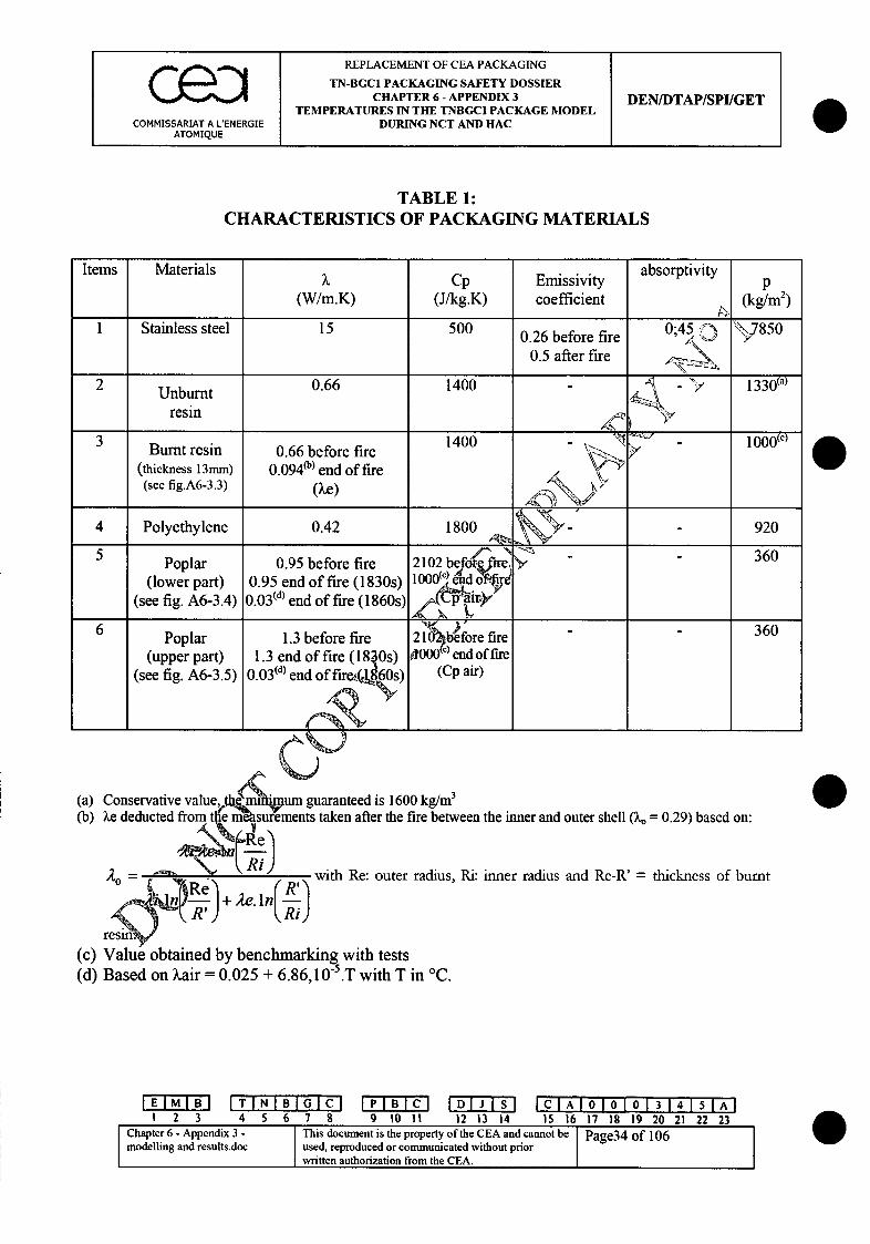
REPLACEMENT OF CEA PACKAGING
TN-BGCI PACKAGING SAFETY DOSSIERc e D CHAPTER 6 - APPENDIX 3 DEN/DTAP/SPI/GETTEMPERATURES IN THE TNBGCI PACKAGE MODEL
COMMISSARIAT A L'ENERGIE DURING NCT AND HACATOMIQUE
TABLE 1:CHARACTERISTICS OF PACKAGING MATERIALS
Items Materials ? Cp Emissivity absorptivity
(W/m.K) (J/kg.K) coefficient (kg/m2)
1 Stainless steel 15 500 0.26 before fire,0;45 •j »7850
0.5 after fire
2 Unburnt 0.66 1400 -1330o)
resin • *y
31400 1 • 000(c)Burnt resin 0.66 before fire 1400" -
(thickness 13mm) 0.0940b) end of fire(see fig.A6-3.3) (ke) - SO
4 Polyethylene 0.42 1800 - - 920
5 N 360Poplar 0.95 before fire 2102 before fire> - 6
(lower part) 0.95 end of fire (1830s) 1000() id of'rd(see fig. A6-3.4) 0 .0 3(d) end of fire (1860s)
6 - - 360Poplar 1.3 before fire 21025before fire
(upper part) 1.3 end of fire (180s) 4000c) endof fire(see fig. A6-3.5) 0 .0 3(d) end of fire, 60s) (Cp air)
(a) Conservative value •um guaranteed is 1600 kg/m3
(b) Xe deducted from e m s ements taken after the fire between the inner and outer shell (k = 0.29) based on:
Ao= 1 / Ri)-with Re: outer radius, Ri: inner radius and Re-R' = thickness of burnt
(c) Value obtained by benchmarking with tests(d) Based on kair = 0.025 + 6.86,10" .T with T in 'C.
EMB ITINIBIGC IPIBICI IDIJ Isi ICIAIOIOIO 3 141531rA11 2 3 4 5 6 7 8 9 10 11 12 13 14 15 16 17 18 19 20 21 22 23
Chapter 6 - Appendix. 3 - ThiZs document is the property of the CEA and cannot be Pg3 of 106modelling and results.doc used, reproduced or communicated without prior
written authorization from the CEA.
Copyright © 2022 FDOKUMEN