
SafeRing/SafePlus 12-24kV Gas-insulated ring main unit ...
128
— DISTRIBUTION SOLUTIONS SafeRing/SafePlus 12-24kV Gas-insulated ring main unit SafeRing and Compact switchgear SafePlus
-
Upload
khangminh22 -
Category
Documents
-
view
1 -
download
0
Transcript of SafeRing/SafePlus 12-24kV Gas-insulated ring main unit ...

— DISTRIBUTION SOLUTIONS
SafeRing/SafePlus 12-24kVGas-insulated ring main unit SafeRing andCompact switchgear SafePlus

2 S A F E R I N G / S A F E PLU S 1 2- 2 4 K V

3D I S TR I B U TI O N S O LU TI O N S
—Contents
1 Introduction 5
2 Design philosophy 8
3 Arrangement 9
4 Manufacturing 104.1 Completely sealed system. . . . . . . . . . . . . . . . . . . . . . . . . . . . . . . . . . . . . . . . . . . 104.2 Factory routine tested . . . . . . . . . . . . . . . . . . . . . . . . . . . . . . . . . . . . . . . . . . . . . .11
5 Safety 125.1 Internal Arc Classification (IAC) . . . . . . . . . . . . . . . . . . . . . . . . . . . . . . . . . . . . . . . 125.2 Arc suppressor. . . . . . . . . . . . . . . . . . . . . . . . . . . . . . . . . . . . . . . . . . . . . . . . . . 165.3 Interlocking and locking. . . . . . . . . . . . . . . . . . . . . . . . . . . . . . . . . . . . . . . . . . . . .17
6 SafeRing 186.1 Applications SafeRing . . . . . . . . . . . . . . . . . . . . . . . . . . . . . . . . . . . . . . . . . . . . . 196.2 SafeRing configurations. . . . . . . . . . . . . . . . . . . . . . . . . . . . . . . . . . . . . . . . . . . . 206.3 Technical data SafeRing . . . . . . . . . . . . . . . . . . . . . . . . . . . . . . . . . . . . . . . . . . . . 23
7 SafePlus 247.1 Applications SafePlus . . . . . . . . . . . . . . . . . . . . . . . . . . . . . . . . . . . . . . . . . . . . . 257.2 C - Cable switch module . . . . . . . . . . . . . . . . . . . . . . . . . . . . . . . . . . . . . . . . . . . . 267.3 F - Switch-fuse module . . . . . . . . . . . . . . . . . . . . . . . . . . . . . . . . . . . . . . . . . . . . 297.4 V - Vacuum circuit-breaker module . . . . . . . . . . . . . . . . . . . . . . . . . . . . . . . . . . . . . 327.5 V20/V25 - High duty vacuum circuit-breaker . . . . . . . . . . . . . . . . . . . . . . . . . . . . . . . 357.6 Sl - Busbar sectionalizer module. . . . . . . . . . . . . . . . . . . . . . . . . . . . . . . . . . . . . . . 377.7 Sv - Busbar sectionalizer module . . . . . . . . . . . . . . . . . . . . . . . . . . . . . . . . . . . . . . 387.8 Sv20/Sv25 - Busbar sectionalizer module . . . . . . . . . . . . . . . . . . . . . . . . . . . . . . . . . 397.9 D - Direct cable connection module. . . . . . . . . . . . . . . . . . . . . . . . . . . . . . . . . . . . . 407.10 De - Direct cable connection module with earthing switch . . . . . . . . . . . . . . . . . . . . . . 417.11 Be - Busbar earthing module . . . . . . . . . . . . . . . . . . . . . . . . . . . . . . . . . . . . . . . . . 437.12 CB - Circuit-breaker module . . . . . . . . . . . . . . . . . . . . . . . . . . . . . . . . . . . . . . . . . 447.13 M - Metering module . . . . . . . . . . . . . . . . . . . . . . . . . . . . . . . . . . . . . . . . . . . . . . 467.14 Mt - Metering tariff module . . . . . . . . . . . . . . . . . . . . . . . . . . . . . . . . . . . . . . . . . 487.15 Side connection . . . . . . . . . . . . . . . . . . . . . . . . . . . . . . . . . . . . . . . . . . . . . . . . . 497.16 Mini - metering (integreated meterin) . . . . . . . . . . . . . . . . . . . . . . . . . . . . . . . . . . . 50
8 Current transformers 51
9 Measuring transformers 52
10 Combisensor 53
11 Sensor 54
12 Mechanisms 57
13 Cable bushings 6014 Cable termination 63
14.1 Cable termination 12 kV . . . . . . . . . . . . . . . . . . . . . . . . . . . . . . . . . . . . . . . . . . . . 6414.2 Cable termination 24 kV. . . . . . . . . . . . . . . . . . . . . . . . . . . . . . . . . . . . . . . . . . . . 65

4 S A F E R I N G / S A F E PLU S 1 2- 2 4 K V
15 Cable test bushings 68
16 Extension of switchgear 6916.1 External busbars on top. . . . . . . . . . . . . . . . . . . . . . . . . . . . . . . . . . . . . . . . . . . . 6916.2 Side extension. . . . . . . . . . . . . . . . . . . . . . . . . . . . . . . . . . . . . . . . . . . . . . . . . . 70
17 Base frame 71
18 Low voltage compartment / Top entry box 72
19 Motor operation 73
20 Transformer protection 75
21 Fuse-links 7621.1 Fuse selection table - CEF. . . . . . . . . . . . . . . . . . . . . . . . . . . . . . . . . . . . . . . . . . . 7721.2 Fuse selection table - CEF-S . . . . . . . . . . . . . . . . . . . . . . . . . . . . . . . . . . . . . . . . . 78
22 Relays 79
23 Capacitive voltage indicators . . . . . . . . . . . . . . . . . . . . . . . . . . . . . . . . . . . . . . . . . . . 86
24 Short-circuit and earth-fault indicators 88
25 Manometers/Pressure indicators 90
26 Key interlock 92
27 SafeRing / SafePlus Digital 94
28 Marine applications 10028.1 Marine applications IAC AFL . . . . . . . . . . . . . . . . . . . . . . . . . . . . . . . . . . . . . . . . . 101
29 Low version switchgear 102
30 Battery back-up solutions 103
31 Outdoor enclosure 104
32 Dimensions 105
33 Technical data 11433 1 Technical data - SafeRing 115
33.2 Technical data - SafePlus . . . . . . . . . . . . . . . . . . . . . . . . . . . . . . . . . . . . . . . . . . . 11633.3 Technical data - general . . . . . . . . . . . . . . . . . . . . . . . . . . . . . . . . . . . . . . . . . . . . 11733.4 Technical data - number of operations . . . . . . . . . . . . . . . . . . . . . . . . . . . . . . . . . . 119
34 Environmental Certification 124

5D I S TR I B U TI O N S O LU TI O N S
—1 Introduction
SafeRing and SafePlus switchgears for secondary distribution were developed by ABB in Skien and introduced to the markets in 2000, replacing the previous SF6-insulated products RGC and CTC. The installed base of SafeRing / SafePlus is more than 150 000 switchgears in more than 100 countries all over the world.
The switchgear portfolio is constantly under development to adjust to new market require-ments and customers’ needs.
SafeRing is available in standard configurations based on a high-volume production. These standardized RMUs, which are the most re-quired configurations within a distribution network, can be extendable upon request. SafePlus is the switchgear version of SafeRing with flexibility, modularity and higher ratings.
Customer benefits• A wide range of functional units, easy to extend
and upgrade• Up to five modules in one common gas tank• No live parts exposed• Fully sealed for lifetime• Climatically independent• Designed and tested according to IEC• High reliability and safety• Compact dimensions• Safe and easy for operators in both
maintenance and operating conditions• All operations are carried out from the front of
the switchgear

6 S A F E R I N G / S A F E PLU S 1 2- 2 4 K V
Applicable standardsSafeRing / SafePlus is tested according to the following IEC-standards:• IEC 62271–1: Specifications High-voltage
switchgear• IEC 62271-100: Alternating-current circuit-
breakers• IEC 62271-102: Alternating current
disconnectors earthing switches• IEC 62271-103: High-voltage switches• IEC 62271-105: Switch-fuse co-operation• IEC 62271-200: Arc fault and switchgear• IEC 60529: Degrees of protection provided by
enclosures
SafeRing / SafePlus is also tested together with a CSS (Compact Secondary Substations) according to IEC 62271-202. Tests have been performed on CSS from various manufacturers.
Normal operation conditionsThe rated characteristics of the switchgear are valid under the following ambient conditions:• minimum ambient temperature: – 25 °C• maximum ambient temperature: + 40 °C
For different temperature ranges, please contact your ABB sales representative.
Ambient humidity:• maximum 24 h average of relative humidity 95%• maximum 24 h average of water vapour
pressure 2.2 kPa• maximum monthly average of relative humidity
90% RH• maximum monthly average of water vapour
pressure 1.8 kPa
The normal operational altitude is up to 1,500 m above sea level. For higher altitude applications, please contact your ABB sales representative.The switchgear is designed for operation in a nor-mal, non-corrosive and uncontaminated atmo-sphere.
Industry• Pulp and Paper• Cement• Textiles• Chemicals• Food• Automotive• Petrochemical• Quarrying• Oil and gas pipelines• Rolling mills• Mines
Utilities and Power Plants• Power generation stations• Transformer stations and metering• Main and auxiliary switchgear
Transport• Airports• Ports• Railways• Underground transport
Infrastructure• Hotels• Shopping centers• Hospitals• Large infrastructure and civil works
Renewables• Wind• Solar/PV

7D I S TR I B U TI O N S O LU TI O N S
GeneralSafeRing is a SF6-insulated ring main unit for the secondary distribution network. SafeRing can be supplied in 10 different configurations suitable for most switching applications in 12/24 kV distribution networks. As an option, SafeRing can be delivered as an extendable ring main unit.
SafePlus is ABB’s flexible, extendable compact switchgear. Together, SafeRing and SafePlus represent a complete solution for 12/24 kV secondary distribution networks. SafeRing and SafePlus have identical user interfaces.
SafeRing / SafePlus is a completely sealed system with a stainless steel tank containing all the live parts and switching functions. A sealed steel tank with constant atmospheric conditions ensures a high level of reliability as well as personnel safety and a virtually maintenance-free system.
The SafeRing concept offers a choice of either a switch fuse combination or circuit breaker with relay for protection of the transformer. SafeRing can be supplied with an integrated remote control and monitoring unit.
Modularity and external busbarsAll standard modules are only 325 mm wide. The width of non-standard modules, for example the metering module, are provided in the following pages.
SafePlus can be configured with a maximum of five modules in one SF6 tank with an internal busbar. To configure switchgears with more than five modules as many tanks as needed can be joined together by use of an external busbar. Alternatively, the whole switchgear can be
configured as fully modular with the use of the external busbar between all modules. The external busbar is fully insulated and screened in order to maintain climatic independence and a maintenance-free solution. All modules can be delivered prepared for future extension.
Transformer protectionSafePlus offers a choice between a switch fuse combination and circuit breaker with relay for transformer protection. The switch fuse combination offers optimal protection against short-circuits, while the circuit breaker with relay option offers better protection against low overcurrents. Circuit breaker with relay is always recommended for larger transformers.

8 S A F E R I N G / S A F E PLU S 1 2- 2 4 K V
SafeRing / SafePlus – ABB switchgears for secondary distribution Secondary distribution switchgears have been the subject of significant development the past decades, resulting in increased functionality and smaller dimensions.
The traditional switching cells are substituted with complete switchgear systems. Specific functions such as grounding, disconnecting, cable connections, busbar extension, protection and switching have become integrated features in compact functional units.
Compact switchgear systems meet customers’ MV application needs. ABB has always been a part of this development. The current ABB SafePlus range satisfies the most complex system specifications.
The most unique specialization is the development of the cable ring switchgear. The numerous public distribution substations requested a unified switching functionality which evolved into the ring main unit concept. ABB SafeRing range is one major contributor to this specialization.
Two Products – One rangeABB SafeRing is adapted to the needs of the immense utility distribution network. ABB SafePlus offers more in terms of flexibility and electrical capacity. Both switchgears offer the same customer interface.
Customers’ involvementThe applied functionality in ABB SafeRing and SafePlus is the result of input from customers all over the world. Key customers are continuously involved with ABB design staff to ensure optimized switchgear operation. The functionality will always find its background from customer demands.
Personnel – safety and serviceSafety is not only a specification and rating issue, but also a real life experience. Standards and associated testing will disclose weakness at the time of testing. ABB takes this further to be an objective related to durability and repetitive manufacturing quality.
All products are manufactured in accordance with ISO 9001. The latest edition of relevant IEC standards will always apply to our continuous product development and test program. “Integrated functionality” is a key objective to reduce the number of moving components, further reducing the risk of any mechanical defect.
We are responsible for the environmentThe location for manufacturing SafeRing and SafePlus is Norway. Norway’s green policy contributes to the focus on environmental factors in manufacturing as well as over the switchgear's lifespan.
All products are manufactured in accordance with our ISO 14001 certification. Recycling is confirmed at a 97% level. To simplify this process, we will continuously work with our partners to develop routines for handling end of life. Plastic parts are individually marked to simplify the recycling process. Solutions for elimination of gas emission in the rare event of a fault can be supplied.
Modern – development and manufacturingNumerical simulations together with long experience ensure a compact and robust design. Dielectric simulations ensure that compactness will not influence the dielectric capability.
The combination of design techniques, experience and the most modern production technology guarantees state of the art products and durability.
Complete solutions – one supplierComplex applications involving different standard remote levels, such as monitoring, control and measurement and protection can now be supplied from one supplier.
This makes large scale implementation feasible and will simplify engineering and procurement.The control and monitoring unit available for SafeRing is located behind the front cover. This option is also readily available for retrofit since such demands normally evolve after the switchgear is in service.
—2 Design philosophy

9D I S TR I B U TI O N S O LU TI O N S
—3 Arrangement
External
Internal
Description D
Manometer 1
Operating shaft disconnector 2
Padlock hole 3
Cable 5
Cable clamp 6
Arc proof cable compartment 7
Door handle 8
Self-supplied protection relay 9
Operating shaft spring 10
Charged spring indicator 11
Push buttons 12
Fuse canister 13
Fuse operating handle 14
Fuse blown indicator 15
Cable bushings 16
Bottom list 17
Side panel 18
Operating handle 19
Disconnector position indicator 20
Operating shaft earthing switch 21
Earthing switch position indicator 23
Disconnector/earthing switch potition indicator
24
1
2
3
4
Description ID
Mechanism compartment 1
SF₆ gas tank 2
Cable compartment 3
Pressure relief area 4

10 S A F E R I N G / S A F E PLU S 1 2- 2 4 K V
ExteriorUpper and lower front covers are made of 3 mm aluminium covered with a polycarbonate foil. These foils contain the mimic diagram of the main circuit integrated with the position indicators for the switching devices. Background colour for these foils is light grey (RAL 7035). The upper front cover is removable. The lower front cover can be opened.
There are four different cable compartment covers: standard, with inspection window, arc proof and with extra depth for parallel cables. These covers are manufactured from 1.5 mm aluzink (except the arc proof cover) and are powder painted with colour RAL 7035.
All cable compartment covers are removable. Each module has a separate cable compartment which is divided from the others by means of partition walls. These partition walls can easily be removed, allowing comfortable access for connection of cables.
A vertical partition wall is fitted to divide the cable compartment(s) from the rear side of the switchgear / ring main unit.
In case of an arc fault inside the SF6 tank, followed by an opening of the pressure relief valve in the bottom of the tank, this partition wall will prevent the hot gases blowing out from the pressure relief to enter the cable compartments. Side covers are made of 2 millimeter hot rolled steel and powder painted with colour RAL 7035.
EnclosureSafeRing and SafePlus use SF6 gas (sulphur hexafluoride) as insulation and quenching medium. The SF6 gas is contained in a welded stainless steel tank, which is sealed for life. The pressure system is defined as a sealed for life system with an operating lifetime exceeding 30 years. The leakage rate is less than 0,1% per year.
In order to ensure a reliable and tight welding, all welding work is carried out by computer controlled robots. Electrical and mechanical bushings penetrating the tank are clamped and sealed to the tank by high quality O-rings.
The mechanical bushing has in addition a rotating shaft which connects the shaft of the switch to the corresponding shaft of the mechanism. The rotating shaft is sealed by a double set of gas seals.
All SF6 Tanks have to pass a leakage test before gas filling. Leakage test and gas filling are done inside a vacuum chamber. The first step in the leakage test is to evacuate all air inside both the SF6 tank and vacuum chamber simultaneously. Then the SF6 tank is filled with helium. Due to the characteristics of helium this test will detect all possible leakages. If the SF6 tank passes this test the helium will be evacuated and replaced by SF6.
The SF6 tank has a degree of protection of IP67 and can be immersed into water and still maintain all functions in a satisfactory way.
—4 Manufacturing
— 4 1 Completely sealed system

11D I S TR I B U TI O N S O LU TI O N S
ABB has set a high quality automated system for production and quality control which assures sustainability of factory output. Part of the assurance is standard routine testing procedures according to IEC62271-200 performed on every manufactured switchgear.
IEC factory routine tests:• Visual inspection and check• Mechanical operations check• Check of secondary wiring• Electrical sequence operations• Power frequency withstand voltage test• Partial discharge measurement• Measurement of resistance of the main
circuits• Secondary insulation test• Control of the gas tightness
State of the artFor the routine testing, ABB uses the latest technologies and systems, such as:• Fully automated high voltage testing cabin• Temperature compensated gas filling system• Automated connection counting system• Automated screw torque control• Computer aided mechanical characteristics
control
—4 2 Factory routine tested

R
L
L
F
—01 Arc duration and damage caused
Melting of Steel
Melting of Copper
Melting of Cables
0 100 200 500 ms
kA2 s
—01
12 S A F E R I N G / S A F E PLU S 1 2- 2 4 K V
During development of all ABB products, focus is on personnel safety. The SafeRing / SafePlus portfolio was designed and tested to withstand a variety of internal arc scenarios at the same current level as the maximum short circuit current. The tests show that the metal enclosure of SafeRing / SafePlus is able to protect personnel standing close to the switchgear during internal arc fault.
Causes and effects of internal arcsAlthough an internal arc fault is highly unlikely it can theoretically be caused by various factors, such as:• Insulation defects due to quality deterioration
of the components. The reasons can be adverse environmental conditions and a highly polluted atmosphere.
• Inadequate training of the personnel in charge of the installation leading to incorrect installation of the cables.
• Broken or modified safety interlocks.• Overheating of the contact area, e.g. when the
connections are not sufficiently tightened.• Short circuits caused by small animals that have
entered into the cable compartment (i.e. through cable entrance).
The energy produced by the internal arc causes the following phenomena:• Increase of the internal pressure.• Increase of the temperature.• Visual and acoustic effects.• Mechanical stresses on the switchgear structure.• Melting, decomposing and evaporation of materials.
Tested according to IEC standard 62271-200The capability of SafeRing / SafePlus switchgear towithstand internal arc is proven by type testsperformed according to internal arc classification (IAC) as described in the standard IEC 62271-200 as follows:
Accessibility: A and B (switchgear)A=Accessible to authorized personnel only300 mm safety distance on accessible sides of the switchgear (also distance to sensors during testing)
B=public access100 mm safety distance on accessible sides of the
switchgear (also distance to sensors during testing)
F-Front = Access from the frontL-Lateral = Access from sidesR-Rear = Access from the rear
Accessible sides of switchgear = Area that personnel can enter freely. For accessibility A this means a 300 mm safety distance + 500 mm or more in safe moving area.
Non-accessible side of switchgear = Area that is physically blocked or clearly marked as not safe for personnel. All test specimens passed the following test criteria according to the standards:1. Correctly secured doors and covers do not open2. No fragmentation of the enclosure occurs within the
time specified for the test. Projection of small parts up to an individual mass of 60 g are accepted
3. Arcing does not cause holes in the enclosure of the switchgear up to a height of 2 m
4. Indicators do not ignite due to the effect of hot gases5. The enclosure remains connected to its earthing point
—5 Safety
— 5 1 Internal Arc Classification (IAC)

13D I S TR I B U TI O N S O LU TI O N S
SafeRing / SafePlus is available for a wide range of installations and applications in order to secure the highest safety for operators. Switchgears are designed and type-tested for internal arc classification according to the following configurations:
5 1 1 IAC AFLR - with ventilation upwards through an exhaust channelWith this setup, hot gasses and pressure are evacuated into the safe area of the switchgear room above the switchgear through the gas exhaust channel. In this setup the switchgear can be installed as free standing. This solution is not available for M-module. With this solution, a base frame of 450 mm (optional 290 mm) is included as standard.
Basic parameters of setup:• IAC AFLR up to 25 kA / 1s• Minimum height of ceiling: 2600 mm• Minimum distance from backwall:
- 800 mm with accessible rear side - 100 mm with non-accessible rear side
• Switchgear needs to be installed and fixed to the floor in accordance with “SafeRing / SafePlus 12-24kV Installation and operating instructions”
For number of modules, availability, heights and specifications, see table no. 5.1.1.
—5 1 Internal Arc Classification (IAC)
—01 *290 mm base frame available as an option. Note: The height of the exhaust channel must always be 2002 mm in order to comply with the requirements in IEC standards. When the base frame is 290 mm, the exhaust channel is extended to reach 2002 mm height—02 1100 mm version available as an option
—01
—02
5 1 2 IAC AFLR or AFL - downwards ventilation With ventilation down to the cable trench.
With this setup, hot gases and pressure are evacuated downwards in the cavity in the floor beneath the switchgear. Hot gases are led to the cable trench by means of a back plate installed on the rear side of the switchgear, forcing the hot gases down during an arc fault. The switchgear must be arranged as instructed according to the basic parameters below.
Basic parameters of set-up:• IAC AFLR or AFL up to 20 kA / 1s• Minimum height of ceiling: 2000 mm• Recommended distance to back wall: - 800 mm with accessible rear side - 100 mm recommended for non-accessible rear
side (possible down to 20mm)• Back plate installed on the switchgear• Requires a minimum opening between
switchgear and cable trench in the “pressure relief area” for each module shown as opening “A” in illustration “02”.
- Opening “A” in a 1-way module: 250 x 205 mm - Opening “A” in 2-5 way modules: 150 x 205 mmIt is optional to cover opening “B” between the switchgear cable compartment and the cable trench with a gland plate. This is not an allowed option for low version switchgears. • Minimum width of cable trench: 475 mm• Minimum depth of cable trench: 450 mm• A pressure relief channel to a safe area is required
and it must have a free opening area of 0,1m²• Switchgear needs to be installed and fixed to the
floor in accordance with “SafeRing / SafePlus 12-24kV Installation and operating instructions".
1336
(11
00
)*
min
. 26
00
178
6 (1
626
)*
200
2
45
0 (
290
)*
100
min
. 24
00
800 475
45
0 A B
SF6
SF6
100
650
min
. 24
00
1336
SF₆
100
110
1
min
. 24
00
1786
SF₆
100
min
. 24
00
1336
SF₆
14 S A F E R I N G / S A F E PLU S 1 2- 2 4 K V
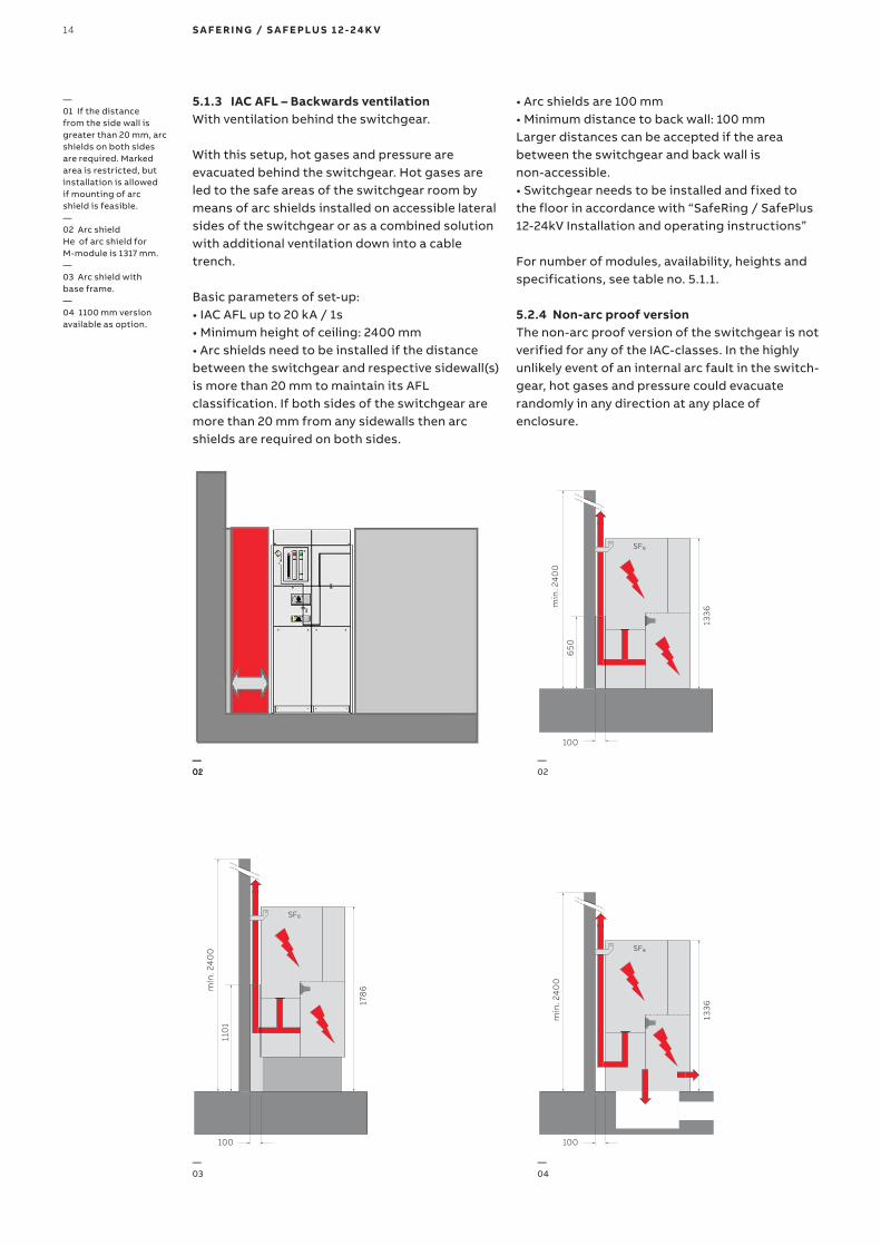
5 1 3 IAC AFL – Backwards ventilationWith ventilation behind the switchgear.
With this setup, hot gases and pressure are evacuated behind the switchgear. Hot gases are led to the safe areas of the switchgear room by means of arc shields installed on accessible lateral sides of the switchgear or as a combined solution with additional ventilation down into a cable trench.
Basic parameters of set-up:• IAC AFL up to 20 kA / 1s• Minimum height of ceiling: 2400 mm• Arc shields need to be installed if the distance between the switchgear and respective sidewall(s) is more than 20 mm to maintain its AFL classification. If both sides of the switchgear are more than 20 mm from any sidewalls then arc shields are required on both sides.
• Arc shields are 100 mm• Minimum distance to back wall: 100 mmLarger distances can be accepted if the area between the switchgear and back wall is non-accessible. • Switchgear needs to be installed and fixed to the floor in accordance with “SafeRing / SafePlus 12-24kV Installation and operating instructions”
For number of modules, availability, heights and specifications, see table no. 5.1.1.
5 2 4 Non-arc proof versionThe non-arc proof version of the switchgear is not verified for any of the IAC-classes. In the highly unlikely event of an internal arc fault in the switch-gear, hot gases and pressure could evacuate randomly in any direction at any place of enclosure.
—01 If the distance from the side wall is greater than 20 mm, arc shields on both sides are required. Marked area is restricted, but installation is allowed if mounting of arc shield is feasible.—02 Arc shieldHe of arc shield for M-module is 1317 mm.—03 Arc shield with base frame.—04 1100 mm version available as option.
—01
—04
—03
—02
min
. 24
00
1336
65
0
100
178
6min
. 24
00
110
1
100
—02
100
min
. 24
00
1336

15D I S TR I B U TI O N S O LU TI O N S
Table 5 1 1
ISC (kA/1s)
IAC class VentilationHeight of switchgear
(mm)Roof height
(mm)Base frame
Max sets of current transformers
16
AFL Backwards1336 (standard)
1100 (low)2400 (standard)
2400 (low)Optional
(290/450 mm)2 2)
AFL Downwards 3) 1336 (standard)1100 (low) 6)
2000 (standard) 2000 (low)
Optional (290/450 mm)
2 2)
AFLR Downwards 3) 1336 (standard)1100 (low) 6)
2000 (standard) 2000 (low)
Optional (290/450 mm)
2 2)
AFLR Upwards 4) 2002 1) 2600Mandatory 5)
(290/450 mm)2 2)
20
AFL Backwards1336 (standard)
1100 (low)2400 (standard)
2400 (low)Optional
(290/450 mm)2 2)
AFL Downwards 3) 1336 (standard) 1100 (low) 6)
2000 (standard) 2000 (low)
Optional (290/450 mm)
2 2)
AFLR Downwards 3) 1336 (standard) 1100 (low) 6)
2000 (standard) 2000 (low)
Optional (290/450 mm)
2 2)
AFLR Upwards 4) 2002 1) 2600Mandatory 5)
(290/450 mm)2 2)
25 AFLR Upwards 4) 2002 1) 2600Mandatory 5)
(450 mm)2 2)
1) Height of exhaust channel is always 2002 mm. This dimension is independent of the height of the base frame and switchgear.
2) In case two sets of CT’s are required, additional base frame is mandatory and it is not allowed with gland plate as second set of CT’s will be installed in base frame.
3) IAC classification is unavailable in case of installation deviating from basic parameter set-up described in "downwards ventilation" section on previous pages.
4) Upwards ventilation solution requires a base frame for attaching the gas exhaust channel. Only available from 2-way to 5-way switchgears.
5) Not allowed with gland plate between switchgear and base frame, gland plate can be installed below base frame.
6) Not allowed with gland plate on low version for this ventilation direction

1336
min
. 24
00
100
16 S A F E R I N G / S A F E PLU S 1 2- 2 4 K V
—01 Arc suppressor iside the tank
Arc suppressor – active device for increased safetyThe arc suppressor is an optimal quick-make short circuit device with a mechanical pressure detector which can be installed in each incoming feeder inside the sealed SF6 tank of SafeRing and SafePlus switchgear.
If an arc fault should occur inside the SF6 tank the pressure device of the arc suppressor will automatically trip and short circuit the incoming feeder(s) within milliseconds, thereby extinguish-ing the arc and preventing a gas blowout. The arc is extinguished without any emission of hot gases and the bolted short circuit will be interrupted by the upstream circuit-breaker.
No links or release mechanisms are installed out-side the tank. Corrosion and any environmental influences are therefore prevented, giving optimum reliability.
The pressure detector is insensitive to pressure changes due to variation in atmospheric temperature or pressure, as well as external phenomena such as vibrations or shocks.
The arc suppressor is tested for short-circuit currents in the range of 1kArms to 21kArms and it will reduce the generated arc energy to less than 5% of the arc energy released during an arcing time of 1 second.
Since the system is self-contained, an internal arc fault in the tank will have no impact on the surroundings, so there will be no cleaning work required. No arc fault tests have to be repeated in combination with channel release systems or transformer stations.
Arc protection in IED (Intelligent Electronic Device)Protection relays REF615 and REF620 IED can optionally be fitted with a fast and selective arc flash protection. It offers a two- or three-channel arc-fault protection system for arc flash supervision of different cable compartments of switchgear modules. Total tripping time is less than 100 ms.
—5 2 Arc suppressor
—01

17D I S TR I B U TI O N S O LU TI O N S
InterlocksThe safety mechanical interlocks between switches are standard and detailed information is described for each module. They are set out by the IEC standards and are necessary to guarantee the correct operation sequence.
ABB safety interlocks enable the highest level of reliability, even in the case of an accidental error, and ensure operator safety.
KeysThe use of key interlocks is very important in realizing the interlocking logics between panels of the same switchgear or of other medium, low and high voltage switchgear. The logics are realized by means of distributors or by ringing the keys. The earthing switch closing and opening operations can be locked by means of keys. For a more detailed description, see dedicated inter-locking pages for each module and chapter 26 “Key interlocks”.
—5 3 Interlocking and locking
PadlocksThe cable compartment doors can be locked in the closed position by means of padlocks. The padlock can also be applied to the switches to avoid improper operation of the switchgear. For a more detailed description, see dedicated interlocking pages for each module. Padlocks from 4 to 8 mm diameter can be accommodated.
Blocking coil/electrical interlockingThe earthing switch closing/opening operations can be electrically interlocked by use of electrical blocking coils. Voltage presence system with signalling contact is required. For a more detailed description, see dedicated interlocking pages for each module.
Undervoltage release This release opens the circuit-breaker when there is a sharp reduction or cut in the power supply voltage. This is an optional feature.

� � SafeRing � �� SafeRing
� � SafeRing
� � SafeRing
18 S A F E R I N G / S A F E PLU S 1 2- 2 4 K V
—6 SafeRing
SafeRing installed in Compact Secondary Substations
RMU type SafeRingCCV / CCF
RMU type SafeRingCCVV / CCFF
RMU type SafeRingCCCV / CCCF
RMU type SafeRingDeV / DeF

C De F V
19D I S TR I B U TI O N S O LU TI O N S
SafeRing is designed for use in the following applications: • Compact secondary substations• Small industries• Wind power plants• Solar/PV plants• Hotels, shopping centers, office buildings,
business centers etc.• Light mining applications, airports, hospitals,
tunnels and underground railways
—6 1 Applications SafeRing
Available modules:C Cable switch De Direct cable connection with earthing switch F Switch-fuse disconnector V Vacuum circuit-breaker

20 S A F E R I N G / S A F E PLU S 1 2- 2 4 K V
GeneralSafeRing is a ring main unit for the secondary distribution network. SafeRing can be supplied in 10 different configurations suitable for most switching applications in 12/24 kV distribution networks. As an option, SafeRing can be delivered as an extendable ring main unit.
SafeRing is a completely sealed system with a stainless steel tank containing all the live parts and switching functions. A sealed steel tank with constant atmospheric conditions ensures a high level of reliability as well as personnel safety and a virtually maintenance-free system.
The SafeRing concept offers a choice of either a switch fuse combination or circuit breaker with relay for protection of the transformer. SafeRing can be supplied with an integrated remote control and monitoring unit and additional equipment which makes the switchgear more intelligent.
SafeRing is supplied with the following standard equipment• Earthing switches• Operating mechanisms with integrated
mechanical interlocking• Operating handle• Facilities for padlocks on all switching functions• Bushings for cable connection in front with
cable covers• Lifting lugs for easy handling• All 3- and 4-way units are designed for the
subsequent fitting of an integrated remote control and monitoring unit
• Cable compartment cover allowing surge arrestor or double cable connection
• Busbar, 630A• Earthing bar• Capacitive voltage indication
Optional features• Bushings for connection of external busbar on
top of the ring main unit• Bushings (inner cone type) for side connection
(400A) (C-, F- and De-modules only)• Bushings for cable testing, including earthing
device (C- and De- modules only)• Interlocking of compartment for cable test
bushings• Arc suppressor with signal (1NO) wired to
terminals (only on incoming feeders)• Arc proof and interlocked cable covers• Signal (1NO) from internal pressure indicator
wired to terminals (only one each SF6 tank) • Latched single spring mechanism for ring cable
switch
Optional features also available as retrofit• Manometer for SF6 pressure monitoring
(temperature compensated)• Integrated control and monitoring unit (ICMU)• Integrated battery and charger
• Motor operation• Trip coil open• Trip coil open and close
• Auxiliary switch for load break switch position 2NO+2NC
• Aux. switch for vacuum circuit breaker position 2NO+2NC
• Aux. switch for disconnector position 2NO+2NC• Aux. switch for earth switch position 2NO+2NC• Aux. switch for fuse blown 1NO• Vacuum circuit breaker tripped signal 1NO
• Extra base frame (h=450 mm or 290 mm)• Top entry box• Relays and RTU (Remote Terminal Unit)
• Different key interlocking systems• External current and voltage sensors for
monitoring• Fault passage indicators• Cable compartment cover with inspection
window• Arc proof cable cover with inspection window• Deep cable cover for double connection• Cable support bars, non-magnetic or adjustable• Earthing bar for surge arrestor
— 6 2 SafeRing configurations
� �� SafeRing
� ��SafeRing
� ��SafeRing
� ��SafeRing
� �� SafeRing
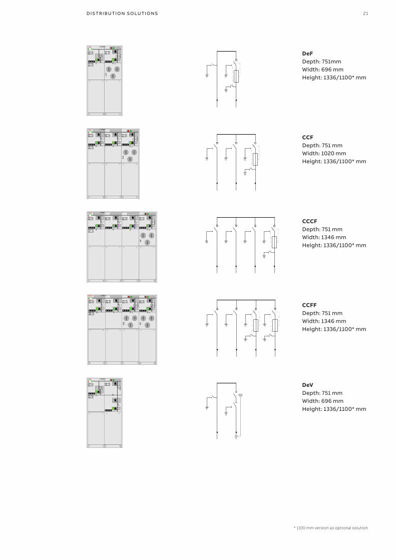
* 1100 mm version as optional solution
21D I S TR I B U TI O N S O LU TI O N S
DeFDepth: 751mmWidth: 696 mmHeight: 1336/1100* mm
CCFDepth: 751 mmWidth: 1020 mmHeight: 1336/1100* mm
CCCFDepth: 751 mmWidth: 1346 mmHeight: 1336/1100* mm
CCFFDepth: 751 mmWidth: 1346 mmHeight: 1336/1100* mm
DeVDepth: 751 mmWidth: 696 mmHeight: 1336/1100* mm

� ��SafeRing
� ��SafeRing
� ��SafeRing
� ��SafeRing
� ��SafeRing
* 1100 mm version as optional solution
22 S A F E R I N G / S A F E PLU S 1 2- 2 4 K V
CCVDepth: 751 mmWidth: 1020 mmHeight: 1336/1100* mm
CCCVDepth: 751mmWidth: 1346 mmHeight: 1336/1100* mm
CCVVDepth: 751 mmWidth: 1346 mmHeight: 1336/1100* mm
CCCDepth: 751 mmWidth: 1020 mmHeight: 1336/1100* mm
CCCCDepth: 751 mmWidth: 1346 mmHeight: 1336/1100* mm

23D I S TR I B U TI O N S O LU TI O N S
CCCCDepth: 751 mmWidth: 1346 mmHeight: 1336/1100* mm
—6 3 Technical data SafeRing
SafeRing C-module F-module V-module
Switch disconnector Earthing switch
Switch-fuse disconnector suppressor
Downstream earthing switch
Vacuum circuit-breaker
Earthing switch/disconnector
Rated voltage kV 12/17,5/24 12/17,5/24 12/17,5/24 12/17,5/24 12/17,5/24 12/17,5/24
Rated frequency 5) Hz 50/50/50 50/50/50 50/50/50 50/50/50 50/50/50 50/50/50
Power frequency withstand voltage
kV 284)/38/50 284)/38/50 284)/38/50 284)/38/50 284)/38/50 284)/38/50
Lightning impulse withstand voltage
kV 95/95/125 95/95/125 95/95/125 95/95/125 95/95/125 95/95/125
Rated normal current A 630/630/630 2001) 200/200/200
Breaking capacities:
- active load A 630/630/630
- closed loop A 650/650/650
- off load cable charging A 140/140/140
- off load transformer A 20/20/20
- earth-fault A 205/160/160
- earth-fault cable charging A 117/91/91
- short-circuit breaking current kA see2) 16/16/16
Making capacity kA 52,5/40/40 52,5/40/40 see2) 12,5/12,5/12,5 40/40/40 40/40/40
Short time current 3 sec. 3) kA 21/16/16 21/16/16 16/16/16 16/16/16
1) Depending on the current rating of the fuse-link2) Limited by high voltage fuse-links 3) Maximum rating for bushings Interface C (400 series bolted)4) GOST version is available with 42kV power frequency withstand
voltage5) For rated frequency 60Hz de-rating of current paramenters needs
to be applied

24 S A F E R I N G / S A F E PLU S 1 2- 2 4 K V
General SafePlus is a metal enclosed compact switchgear system for up to 24 kV distribution applications. The switchgear has a unique flexibility due to its extendability and the possible combination of fully modular and semi-modular configurations.
SafePlus combined with SafeRing, which is ABB’s standard ring main unit, represent a complete solution for 12/24 kV distribution networks. SafePlus and SafeRing have identical user interfaces, operation procedures, spare parts and components.
SafePlus is a completely sealed system with a stainless steel tank containing all live parts and switching functions.
—7 SafePlus
A sealed steel tank with constant gas conditions ensures a high level of reliability as well as personnel safety and a virtually maintenance-free system. As an option, external busbars can be provided to obtain full modularity.
The external busbar kit has to be mounted to the switchgears on site. It is fully insulated and screened to ensure reliability and climatic independence.
The SafePlus system offers a choice of either a switch-fuse combination or a circuit-breaker with relay for protection of the transformer. SafePlus accommodates a wide selection of protection relays for most applications. SafePlus can also be supplied with remote control and monitoring equipment.

A
V
3
3
3
3
3
M
M
3
C
Sl Sv
CBDe
Be M Mt
D F V
25D I S TR I B U TI O N S O LU TI O N S
—7 1 Applications SafePlus
SafePlus is designed for use in the following applications:• Compact secondary substations• Small industries• Wind power plants• Solar/PV plants• Hotels, shopping centers, office buildings,
business centers etc.• Light mining applications, airports, hospitals,
tunnels and underground railways
Available modules:C Cable switch moduleDe Direct cable connection with earthing moduleD Direct cable connection moduleF Switch-fuse disconnector moduleV Vacuum circuit-breaker moduleV20/V25 High duty Vacuum circuit-breaker module 20/25kABe Busbar earthing moduleSl Busbar sectionalizer, load break switch moduleSv Busbar sectionalizer, vacuum circuit-breaker moduleSv20/Sv25 Busbar sectionalizer, vacuum circuit-breaker module 20/25kACB Circuit-breaker moduleM Metering moduleMt Metering tariff module
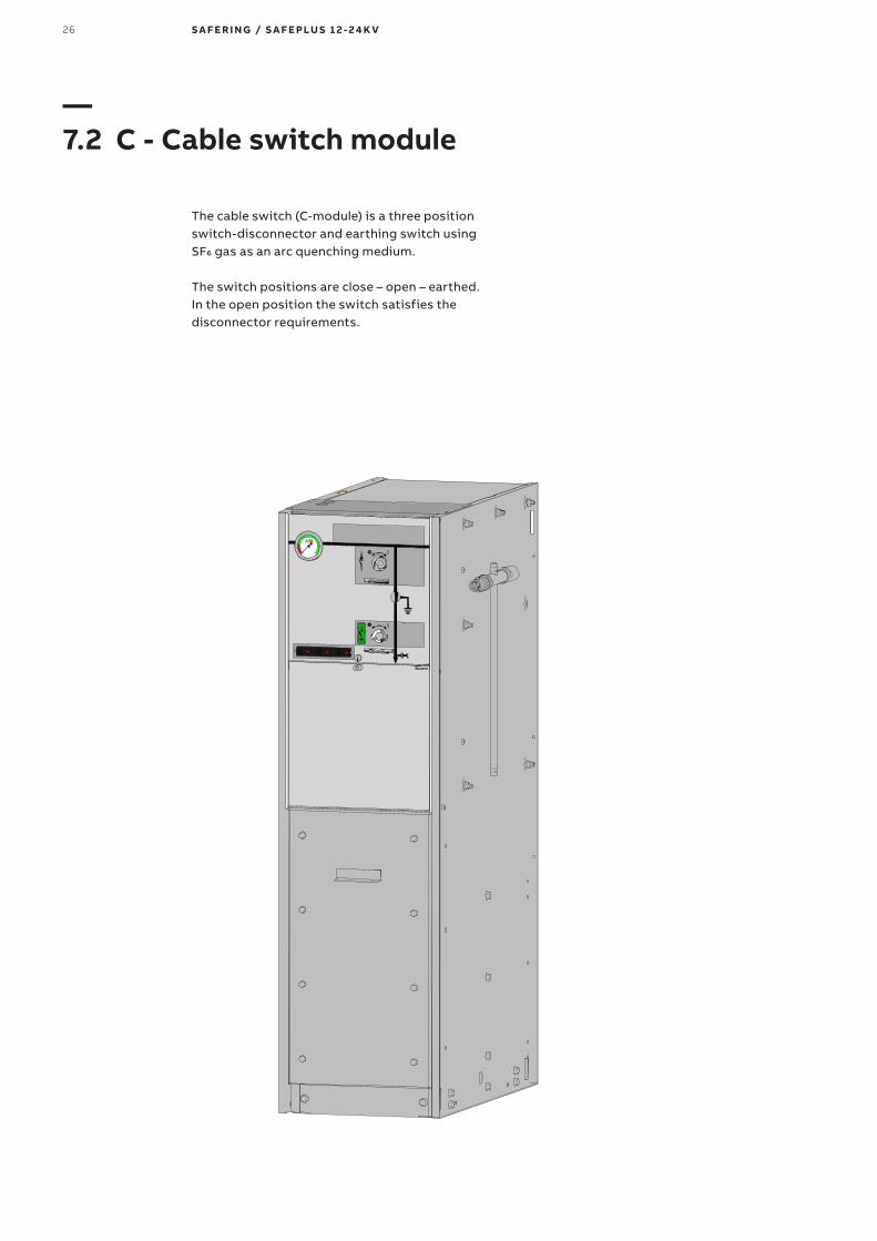
26 S A F E R I N G / S A F E PLU S 1 2- 2 4 K V
The cable switch (C-module) is a three position switch-disconnector and earthing switch using SF6 gas as an arc quenching medium.
The switch positions are close – open – earthed. In the open position the switch satisfies the disconnector requirements.
—7 2 C - Cable switch module

Depth: 751 mmWidth: 325 mmHeight: 1336 mm / optional 1100 mm
27D I S TR I B U TI O N S O LU TI O N S
—7 2 1 C - Cable switch module - Technical data
Common featuresAll modules share many common features. These are described in the chapter “SafeRing/SafePlus configurations”.
Standard features• Three position load break switch with
disconnector and earthing switch• Operating mechanism with two separate
operating shafts for load break function and earthing function
• Switch position indication for load break switch and earthing switch
• Cable bushings horizontal in front, Interface C (400 series bolted) with integrated voltage divider for voltage indication
Optional features• Bushing for top extention• Bushing for side connection• Bushings for side extension (400 A)• Bushings for cable testing (including earthing
device test points) • Cable bushings:
- Interface B (400 series plug-in, In = 400 A) - Interface C (400 series bolted) combisensors
with integrated capacitor for voltage indica-tion and sensors for current and voltage moni-toring
- Interface D (600 series bolted)• Arc suppressor with signal (1NO) wired to
terminals (only on incoming feeder)• Arc proof solution (see chapter "Safety")• Signal (1NO) from internal pressure indicator
wired to terminals (only one each SF6 tank)• Latched single spring mechanism
Optional features also available as retrofit• Motor operation for load break switch• Low voltage compartment / top entry box
Technical data
Switch disconnector
Rated voltage kV 12 17,5 24
Power frequency withstand voltage kV 281) 38 50
Impulse withstand voltage kV 95 95 125
Rated normal current A 630 630 630
Breaking capacities:
- active load A 630 630 630
- closed loop A 650 650 650
- off load cable charging A 140 140 140
- earth-fault A 205 160 160
- earth-fault cable charging A 117 91 91
Making capacity kA 62,5 52,5 52,5
Short time current 3 sec. kA 25 21 21
Number of mechanical operations 1000 close / open manual
Electrical and mechanical classes E3, C2, M1
Earthing switch
Rated voltage kV 12 17,5 24
Power frequency withstand voltage kV 281) 38 50
Impulse withstand voltage kV 95 95 125
Making capacity kA 62,5 50 50
Short time current 3 sec. kA 25 21 21
Number of mechanical operations 1000 close / open manual
1) GOST version is available with 42kV power frequency withstand voltage
28 S A F E R I N G / S A F E PLU S 1 2- 2 4 K V
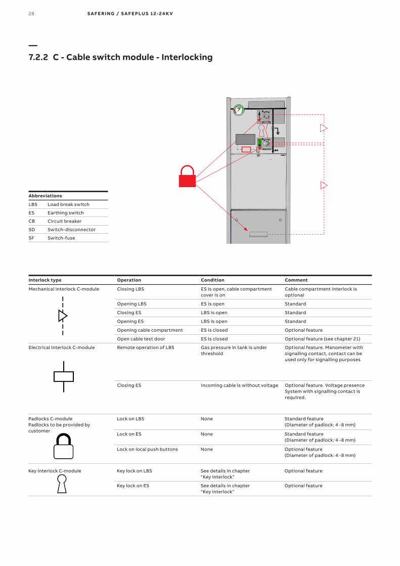
—7 2 2 C - Cable switch module - Interlocking
Abbreviations
LBS Load break switch
ES Earthing switch
CB Circuit breaker
SD Switch-disconnector
SF Switch-fuse
Interlock type Operation Condition Comment
Mechanical interlock C-module Closing LBS ES is open, cable compartment cover is on
Cable compartment interlock is optional
Opening LBS ES is open Standard
Closing ES LBS is open Standard
Opening ES LBS is open Standard
Opening cable compartment ES is closed Optional feature
Open cable test door ES is closed Optional feature (see chapter 21)
Electrical interlock C-module Remote operation of LBS Gas pressure in tank is under threshold
Optional feature. Manometer with signalling contact, contact can be used only for signalling purposes
Closing ES Incoming cable is without voltage Optional feature. Voltage presence System with signalling contact is required.
Padlocks C-modulePadlocks to be provided by customer
Lock on LBS None Standard feature (Diameter of padlock: 4 -8 mm)
Lock on ES None Standard feature (Diameter of padlock: 4 -8 mm)
Lock on local push buttons None Optional feature (Diameter of padlock: 4 -8 mm)
Key interlock C-module Key lock on LBS See details in chapter “Key interlock”
Optional feature
Key lock on ES See details in chapter “Key interlock”
Optional feature

29D I S TR I B U TI O N S O LU TI O N S
—7 3 F - Switch-fuse module
The switch fuse (F-module) includes a three position and earthing switch similar to the cable switch (C-module).
By means of the fuse tripping device it operates as a switch-fuse combination. There is a double earthing switch which in earthed position connects earth to both sides of the fuse-links simultaneously.
Both earthing switches are operated in one operation. The switch-fuse and earthing switch is mechanically interlocked to prevent hazardous access to the fuse-links.
The lower cover which gives access to the fuse-links is also mechanically interlocked with the earthing switch.

Depth: 751 mmWidth: 325 mmHeight: 1336 mm / optional 1100 mm
Technical data
Switch-fuse-disconnector
Rated voltage kV 12 17,5 24
Power frequency withstand voltage kV 282) 38 50
Impulse withstand voltage kV 95 95 125
Rated normal current A 200 200 200
Breaking capacities:
- off load transformer A 20 20 20
Making capacity kA 1) 1) 1)
Number of mechanical operations 1000 close / open manual
Electrical and mechanical classes E3, M1
Earthing switch downstream
Rated voltage kV 12 17,5 24
Power frequency withstand voltage kV 282) 38 50
Impulse withstand voltage kV 95 95 125
Making capacity kA 12,5 12,5 12,5
Short time current 1 sec. kA 5 5 5
Number of mechanical operations 1000 close / open manual
Electrical and mechanical classes E2, M0
1) Limited by high voltage fuse-links2) GOST version is available with 42kV power frequency withstand voltage
For fuse selection tables and transformer protection, see chapter “Fuse-links”.
30 S A F E R I N G / S A F E PLU S 1 2- 2 4 K V
—7 3 1 F - Switch-fuse module - Technical data
Common featuresAll modules share many common features. These are described in the chapter “SafeRing/SafePlus configurations”.
Standard features• Three position switch-fuse-disconnector with
upstream earthing switch mechanically linked with downstream earthing switch
• Switch position indication for switch-fuse-disconnector and earthing switches
• Operating mechanism with double spring for switch-fuse-disconnector function
• Common mechanism for earthing functions• Fuse canisters for DIN type fuse. Only accessible
when earthing switches are closed• Fuse-link / transformer rating:
- 12 kV, max 125 A CEF fuses - 24 kV, max 63 A CEF fuses
• Fuse tripping arrangement• Optical fuse trip indication
Optional features• Bushings for side extension (400 A)• Cable bushings:
- Interface B (400 series plug-in, In = 400A) - Interface C (400 series bolted) - Interface C (400 series bolted) combisensors
with integrated screen for voltage indication and sensors for current and voltage monitor-ing
• Signal (1NO) from internal pressure indicator wired to terminals (only one each SF6 tank)
• Arc proof solution (see chapter "Safety")
Optional features also available as retrofit• Motor operation for switch-fuse-disconnector• Auxiliary switches for load break switch
position, earthing switch position and fuse blown
• Trip coil open• Trip coil open and close

31D I S TR I B U TI O N S O LU TI O N S
—7 3 2 F - Switch-fuse module - Interlocking
Abbreviations
LBS Load break switch
ES Earthing switch
CB Circuit breaker
SD Switch-disconnector
SF Switch-fuse
Interlock type Operation Condition Comment
Mechanical interlock F-module Closing SF ES is open, fuse striker pin has not triggered, cable compartment cover is on
Cable compartment interlock is optional
Opening SF ES is open Standard
Closing ES SF is open, fuse door panel is closed Standard
Opening ES SF is open, fuse door panel is closed Standard
Opening fuse door panel ES is closed Standard
Closing fuse door panel ES is closed Standard
Opening cable compartment ES is closed Optional feature
Closing cable compartment ES is closed Optional feature
Electrical interlock F-module Closing ES Incoming cable is without voltage Optional feature. Voltage presence System with signalling contact is required.
Padlocks F-modulePadlocks to be provided by customer
Lock on SF None Standard feature (Diameter of padlock: 4 -8 mm)
Lock on ES None Standard feature (Diameter of padlock: 4 -8 mm)
Lock cable compartment cover in closed position
None Optional feature (Diameter of padlock: 4 -8 mm)
Lock cable compartment cover in open position
None Optional feature (Diameter of padlock: 4 -8 mm)
Lock on push buttons None Optional feature (Diameter of padlock: 4 -8 mm)
Key interlock F-module Lock on SF
Key lock on ES See details in chapter“Key interlock”
Optional feature

32 S A F E R I N G / S A F E PLU S 1 2- 2 4 K V
—7 4 V - Vacuum circuit-breaker module
The vacuum circuit-breaker (V-module) has vacuum bottles as interrupters of the current.A three-position disconnector/earthing switch that is connected downstram and in series with the circuit-breaker.
The operation between vacuum circuit-breaker and disconnector/earthing switch is mechanically interlocked.

Depth: 751 mmWidth: 325 mmHeight: 1336 mm / optional 1100 mm
33D I S TR I B U TI O N S O LU TI O N S
—7 4 1 V - Vacuum circuit-breaker module - Technical data
Common featuresAll modules share many common features. These are described in the chapter “SafeRing/SafePlus configurations”.
Standard features• 200 A vacuum circuit-breaker for transformer
protection or 630 A vacuum circuit-breaker for feeder protection
• Two position double spring mechanism for vacuum circuit-breaker
• Three position disconnector/earthing switch downstream from circuit-breaker
• Three position single spring mechanism for disconnector/earthing switch
• Interlocking between vacuum circuit-breaker and disconnector/earthing switch
• Switch position indication for vacuum circuit-breaker and disconnector/earthing switch
• Self-powered electronic protection relay with ring core CTs on cables (only standard on 200 A)
• Trip coil (for relay tripping)• Cable bushings horizontal in front with
integrated capacitor for voltage indication: Interface A (200 series plug-in) for 200 A vacuum circuit-breaker and Interface C (400 series bolted) for 630 A vacuum circuit-breaker
Optional features• Cable bushings:
- Interface B (400 series plug-in) - Interface D (600 series bolted) - Interface C (400 series bolted) combisensors
with integrated voltage divider for voltage indication and integrated sensor for current and voltage monitoring
• Arc suppressor with signal (1NO) wired to terminals
• Arc proof solution (see chapter "Safety") • Signal (1NO) from internal pressure indicator
wired to terminals (only one each SF6 tank)
Optional features also available as retrofit• Motor operation for vacuum circuit-breaker• Auxiliary switches: vacuum circuit breaker
position 2NO+2NC, disconnector position 2NO+2NC, earthing switch position 2NO+2NC and vacuum circuit-breaker tripped signal 1NO
• Blocking coil for earth switch• Undervoltage release with/without time delay
Technical data
Vacuum circuit-breaker
Rated voltage kV 12 17,5 24
Power frequency withstand voltage kV 281) 38 50
Impulse withstand voltage kV 95 95 125
Rated normal current A 200 / 6302)
Breaking capacities:
- short-circuit breaking current kA 21 16 16
Making capacity kA 52,5 40 40
Short time current 3 sec. 3) kA 21 16 16
Number of mechanical operations 2000 close / open manual
Electrical and mechanical classes:
E2, C2, S1, M1 for operating sequence O - 3min - CO - 3min - CO
Downstream disconnector and earthing switch
Rated voltage kV 12 17,5 24
Power frequency withstand voltage kV 281) 38 50
- across disconnector kV 32 45 60
Impulse withstand voltage kV 95 95 125
- across disconnector kV 110 110 145
Making capacity kA 52,5 40 40
Short time current 3 sec. kA 21 16 16
Number of mechanical operations 1000 close / open manual
Electrical and mechanical classes E2, M0
1) GOST version is available with 42kV power frequency withstand voltage2) Depend on type of used bushing3) Interface A - 12,5kA/1s, Interface B - 16kA/1s

—7 4 2 V - Vacuum circuit-breaker module - Interlocking
Abbreviations
LBS Load break switch
ES Earthing switch
CB Circuit breaker
SD Switch-disconnector
SF Switch-fuse
Interlock type Operation Condition Comment
Mechanical interlock V-module Closing CB None
Opening CB None
Closing SD CB is open, ES is open, cable compartment cover is on
Cable compartment interlock is optional
Opening SD CB is open, ES is open Standard
Closing ES SD is open Standard
Opening ES SD is open Standard
Opening cable compartment ES is closed Optional feature
Closing cable compartment ES is closed Optional feature
Electrical interlock V-module Closing ES Incoming cable is without voltage Optional feature. Voltage presence System with signalling contact is required.
Padlocks V-modulePadlocks to be provided by customer
Lock on ES None Standard feature (Diameter of padlock: 4 -8 mm)
Lock on CB None Standard feature (Diameter of padlock: 4 -8 mm)
Lock on SD None Standard feature (Diameter of padlock: 4 -8 mm)
Lock on push buttons None Optional feature (Diameter of padlock: 4 -8 mm)
Lock cable compartment cover in closed position
Optional feature (Diameter of padlock: 4 -8 mm)
Lock cable compartment cover in open position
None Optional feature (Diameter of padlock: 4 -8 mm)
Key interlock V-module Key lock on SD See details in chapter “Key interlock”
Optional feature
Key lock on ES See details in chapter“Key interlock”
Optional feature
34 S A F E R I N G / S A F E PLU S 1 2- 2 4 K V

—7 5 V20/V25 - High duty vacuum circuit-breaker modules
The high duty vacuum circuit-breaker module uses vacuum bottles to interrupt the current. A three-position disconnector/earthing switch is connected downstreamand in series with the circuit-breaker.
The operation between vacuum circuit-breaker and disconnector/earthing switch is mechanically interlocked.
35D I S TR I B U TI O N S O LU TI O N S

Depth: 751 mmWidth: 325 mmHeight: 1460 mm / optional 1226 mm
—7 5 2 V20/V25 - High duty vacuum circuit-breaker modules
36 S A F E R I N G / S A F E PLU S 1 2- 2 4 K V
Common featuresAll modules share many common features. These are described in the chapter “SafeRing/SafePlus configurations”.
Standard features• 630 A vacuum circuit-breaker for feeder
protection• Mechanism with operating sequence;
O – 0,3 s – CO – 15 s – CO• Auto-reclosing capability• Vacuum circuit-breaker with downstream three-
position disconnector/earthing switch• Three-position single spring mechanism for
disconnector/earthing switch• Interlocking between vacuum circuit-breaker
and disconnector/earthing switch• Switch position indication for vacuum circuit-
breaker and disconnector/earthing switch• Mechanical counter• Cable bushings horizontal in front Interface C
(400 series bolted) with integrated capacitor for voltage indication
• Cable compartment cover allowing surge arrestor or double cable connection
Optional features as factory mounted• Cable bushings:
- Interface C (400 series bolted) combisensors with integrated voltage divider for voltage in-dication and integrated sensor for current and voltage monitoring
• Arc proof solution (see chapter "Safety")• Arc suppressor with signal (1NO) wired to
terminals Optional features also available as retrofit• Motor operation for vacuum circuit-breaker• Auxiliary switches: Vacuum circuit breaker
position 2NO+2NC, disconnector position 2NO+2NC, earthing switch position 2NO+2NC
• Undervoltage release with/without time delay• Blocking magnet to prevent unintended
operation• Advanced relays type REF, RET and RED
Interlocking• The rules are the same as for the standard
V-module except for lockable push buttons.
Technical data
Vacuum circuit-breaker
Rated voltage kV 12 17,5 24
Power frequency withstand voltage kV 281) 38 50
Impulse withstand voltage kV 95 95 125
Rated frequency 2) Hz 50/60
Rated normal current A 630 630 630
Breaking capacities:
- short-circuit breaking current kA 25 20 20
Making capacity kA 62,5 50 50
Short time current 3 sec. kA 25 21 21
Number of mechanical operations 2000 close / open
Electrical and mechanical classes:
E2, C2, S1, M1 for operating sequence O - 0,3s - CO - 15s - CO 3)
Optional:E2, C2, S1, M2 for operating sequence O - 0,3s - CO - 15s - CO
Downstream disconnector and earthing switch
Rated voltage kV 12 17,5 24
Power frequency withstand voltage kV 28 38 50
- across disconnector kV 32 45 60
Impulse withstand voltage kV 95 95 125
- across disconnector kV 110 110 145
Making capacity kA 62,5 50 50
Short time current 1 sec. kA 25 21 21
Short time current 3 sec. kA 25 21 21
Number of mechanical operations 1000 close / open manual
Electrical and mechanical classes E2, M0
1) GOST version is available with 42kV power frequency withstand voltage2)De-rating for current parameters needs to be applied for 60Hz3) EL2 mechanism combined with VG5 vacuum-bottles gives electrical and mechanical class: E1, C2, S1, M1 for operating sequence O-0,3 s-CO-3min-CO

—7 6 Sl - Busbar sectionalizer module
Depth: 751 mmWidth: 325 mmHeight: 1336 mm /
optional 1100 mm
Depth: 751 mmWidth: 650 mmHeight: 1336 mm /
optional 1100 mm
Extension is needed when Sl-module is the last module in one common SF6 tank
Common featuresAll modules share many common features. These are described in the chapter “SafeRing/SafePlus configurations”. Standard features• Three position load break switch with
disconnector and earthing switch• Operating mechanism with two separate
operating shafts for load break function and earthing function
• Switch position indication for load break switch and earthing switch
Optional features• Latched single spring mechanism• Arc proof solution (see chapter "Safety")
Optional features also available as retrofit• Motor operation for load break switch• Auxiliary switches, load break switch position
2NO+2NC and earthing switch position 2NO+2NC
• Ronis key interlock
InterlockingThe rules are the same as for the C-module with the exception of the rules for the cable compartment cover.
Technical data
Busbar sectionalizer Sl
Rated voltage kV 12 17,5 24
Power frequency withstand voltage kV 281) 38 50
Impulse withstand voltage kV 95 95 125
Rated normal current A 630 630 630
Breaking capacities:
- active load A 630 630 630
- closed loop A 670 670 670
- off load cable charging A 141 141 141
- earth-fault A 205 160 160
- earth-fault cable charging A 117 91 91
Making capacity kA 62,5 52,5 52,5
Short time current 3 sec. kA 25 21 21
Number of mechanical operations 1000 close / open manual
Electrical and mechanical classes E3, C2, M1
Earthing switch
Rated voltage kV 12 17,5 24
Power frequency withstand voltage kV 281) 38 50
Impulse withstand voltage kV 95 95 125
Rated normal current A 630 630 630
Making capacity kA 62,5 50 50
Short time current 3 sec. kA 21 21 21
Number of mechanical operations 1000 close / open manual
Electrical and mechanical classes E2, M0
1) GOST version is available with 42kV power frequency withstand voltage
37D I S TR I B U TI O N S O LU TI O N S

Depth: 751 mmWidth: 650 mmHeight: 1336 mm /
optional 1100 mm
Sv is always in combination with busrise module (Br)
38 S A F E R I N G / S A F E PLU S 1 2- 2 4 K V
—7 7 Sv - Busbar sectionalizer module
Common featuresAll modules share many common features. These are described in the chapter “SafeRing/SafePlus configurations”.
Standard features• 630 A vacuum circuit-breaker• Two position double spring mechanism for
vacuum circuit-breaker• Three position disconnector / earthing switch
downstream from circuit-breaker• Three position single spring mechanism for
disconnector / earthing switch• Interlocking between vacuum circuit-breaker
and disconnector / earthing switch• Switch position indication for vacuum circuit-
breaker and disconnector / earthing switch
Optional features also available as retrofit• Motor operation for vacuum circuit-breaker• Auxiliary switches: vacuum circuit-breaker
position 2NO+2NC, disconnector position 2NO+2NC and earthing switch position 2NO+2NC
• Arc proof solution (see chapter "Safety")• Protection relay (metering module is required)• Trip coil for relay trip• Additional trip coil• Undervoltage release with/without time delay
InterlockingThe rules are the same as for the standard V-module with the exception of the rules for the cable compartment cover.
Technical data
Busbar sectionalizer Sv
Rated voltage kV 12 17,5 24
Power frequency withstand voltage kV 281) 38 50
Impulse withstand voltage kV 95 95 125
Rated normal current A 630 630 630
Breaking capacities:
- short-circuit breaking current kA 21 16 16
Making capacity kA 52,5 40 40
Short time current 3 sec. kA 21 16 16
Number of mechanical operations 2000 close / open manual
Electrical and mechanical classes:
E2, C2, S1, M1 for operating sequence O - 3min - CO - 3min - CO
Downstream disconnector and earthing switch
Rated voltage kV 12 17,5 24
Power frequency withstand voltage kV 281) 38 50
- across disconnector kV 32 45 60
Impulse withstand voltage kV 95 95 125
- across disconnector kV 110 110 145
Making capacity kA 52,5 40 40
Short time current 3 sec. kA 21 16 16
Number of mechanical operations 1000 close / open manual
Electrical and mechanical classes E2, M0
1) GOST version is available with 42kV power frequency withstand voltage

39D I S TR I B U TI O N S O LU TI O N S
—7 8 Sv - Busbar sectionalizer module - Sv25 / Sv20
Depth: 751 mmWidth: 650 mmHeight: 1460 mm /
optional 1226 mm
Sv is always in combination with busrise module (Br)
Optional features also available as retrofit• Motor operation for vacuum circuit-breaker• Low voltage compartment / Top entry box• Auxiliary switches: vacuum circuit-breaker
position 2NO+2NC, disconnector position 2NO+2NC and earthing switch position 2NO+2NC
• Arc proof solution (see chapter "Safety")• Protection relay (metering module is required)• Trip coil for relay trip• Additional trip coil• Undervoltage release with/without time delay
InterlockingThe rules are the same as for the standard V-module with the exception of the rules for the cable compartment cover.
Technical data
Vacuum circuit-breaker
Rated voltage kV 12 24
Power frequency withstand voltage kV 281) 50
Impulse withstand voltage kV 95 125
Rated normal current A 630 630
Breaking capacities:
- short-circuit breaking current kA 25 20
Making capacity kA 65 50
Short time current 3 sec. kA 25 21
Number of mechanical operations 2000 close / open manual
Electrical and mechanical classes SV20:
E1,C2,S1,M1 for operating sequence O - 0,3s - CO - 3min - CO
Electrical and mechanical classes SV25:
E2,C2,S1,M1 for operating sequence O - 0,3s - CO - 15s - CO
Downstream disconnector and earthing switch
Rated voltage kV 12 24
Power frequency withstand voltage kV 281) 50
- across disconnector kV 32 90
Impulse withstand voltage kV 95 125
- acros disconnector kV 110 145
Making capacity kA 62,5 50
Short time current 1 sec. kA 25 21
Short time current 3 sec. kA 212) 21
Number of mechanical operations 1000 close / open manual
Electrical and mechanical classes E2, M0
1) GOST version is available with 42kV power frequency withstand voltage2) 25kA available as option
Common featuresAll modules share many common features. These are described in the chapter “SafeRing/SafePlus configurations”.
Standard features• 630 A vacuum circuit-breaker• Vacuum circuit-breaker with downstream three-
position disconnector/earthing switch• Three position single spring mechanism for
disconnector / earthing switch• Interlocking between vacuum circuit-breaker
and disconnector / earthing switch• Switch position indication for vacuum circuit-
breaker and disconnector / earthing switch

Depth: 751 mmWidth: 325 mmHeight: 1336 mm / optional 1100 mm
40 S A F E R I N G / S A F E PLU S 1 2- 2 4 K V
—7 9 D - Direct cable connection module
Common featuresAll modules share many common features. These are described in the chapter “SafeRing/SafePlus configurations”.
Optional features• Bushings for connection of external busbars• Cable bushings:
- Interface B (400 series plug-in) (In = 400 A) - Interface C (400 series bolted) combisensors
with integrated capacitor for voltage indication and sensors for current and voltage monitoring
- Interface D (600 series bolted)• Arc proof solution (see chapter 5)
InterlockingPadlock on cable compartment cover (optional).
Technical data
Direct cable connection
Rated voltage kV 12 17,5 24
Power frequency withstand voltage kV 281) 38 50
Impulse withstand voltage kV 95 95 125
Rated normal current A 630 630 630
Short time current 3 sec. kA 25 21 21
1) GOST version is available with 42kV power frequency withstand voltage

41D I S TR I B U TI O N S O LU TI O N S
Depth: 751 mmWidth: 325 mmHeight: 1336 mm / optional 1100 mm
—7 10 De - Direct cable connection module with earthing switch
Common featuresAll modules share many common features. These are described in the chapter “SafeRing/SafePlus configurations”.
Standard features• Earthing switch• Two position single spring mechanism• Switch position indication• Cable bushings horizontal in front, Interface C
(400 series bolted) with integrated capacitor for voltage indication
Technical data
Direct cable connection with earthing switch
Rated voltage kV 12 17,5 24
Power frequency withstand voltage kV 281) 38 50
Impulse withstand voltage kV 95 95 125
Rated normal current A 630 630 630
Making capacity kA 62,5 50 50
Short time current 3 sec. kA 25 21 21
Number of mechanical operations 1000 close / open manual
1) GOST version is available with 42kV power frequency withstand voltage
Optional features• Bushings for cable testing, including earthing
device• Cable bushings:
- Interface B (400 series plug-in) (In = 400 A) - Interface C (400 series bolted) combisensors
with integrated capacitor for voltage indication and sensors for current and voltage monitoring
- Interface D (600 series bolted)• Interlocking of compartment for cable test
bushings• Arc proof solution (see chapter "Safety")

42 S A F E R I N G / S A F E PLU S 1 2- 2 4 K V
—7 10 1 De-module - Interlocking
Abbreviations
LBS Load break switch
ES Earthing switch
CB Circuit breaker
SD Switch-disconnector
SF Switch-fuse
Interlock type Operation Condition Comment
Mechanical interlock De-module Closing ES None
Opening ES None
Opening cable compartment ES is closed Optional feature
Closing cable compartment ES is closed Optional feature
Electrical interlock De-module Closing ES Incoming cable is without voltage Optional feature. Voltage presence System with signalling contact is required.
Padlocks De-modulePadlocks to be provided by customer
Lock on ES None Standard feature (Diameter of padlock: 4 -8 mm)
Lock cable compartment cover in closed position
None Optional feature (Diameter of padlock: 4 -8 mm)
Lock cable compartment cover in open position
None Optional feature (Diameter of padlock: 4 -8 mm)
Key interlock De-module Key lock on ES See details in chapter“Key interlock”
Optional feature

43D I S TR I B U TI O N S O LU TI O N S
Depth: 751 mmWidth: 325 mmHeight: 1336 mm / optional 1100 mm
— 7 11 Be - Busbar earthing module
Common featuresAll modules share many common features. These are described in the chapter “SafeRing/SafePlus configurations”.
Technical data
Busbar earthing
Rated voltage kV 12 17,5 24
Power frequency withstand voltage kV 281) 38 50
Impulse withstand voltage kV 95 95 125
Rated normal current A 630 630 630
Making capacity kA 62,5 50 50
Short time current 1 sec kA 25
Short time current 3 sec. kA 21 21 21
Number of mechanical operations 1000 close / open manual
1) GOST version is available with 42kV power frequency withstand voltage
Standard features• Earthing switch• Two position single spring mechanism• Switch position indication for earthing switch
Optional features• Arc proof solution (see chapter "Safety")

M
M
3
Depth: 800 mmWidth: 696 mmHeight: 1336 mm
44 S A F E R I N G / S A F E PLU S 1 2- 2 4 K V
—7 12 CB - Circuit-breaker module
Technical data
Circuit-breaker module
Rated voltage kV 12 17,5 24
Power frequency withstand voltage kV 281) 38 50
Impulse withstand voltage kV 95 95 125
Rated normal current A 630 / 12502)
Breaking capacities:
Short-circuit breaking current kA 25 20 20
Making capacity kA 62,5 50 50
Short time current 2 sec. - 630 kA 25 20 20
Short time current 3 sec. - 1250 kA 25 20 20
Number of mechanical operations 30000 close / open manual
Electrical and mechanical classes E2, C2, M2
Operating sequence O - 0,3s - CO - 15s - CO
1) GOST version is available with 42kV power frequency withstand voltage2) For 1250 variant combisensors can not be used
Common featuresAll modules share many common features. These are described in the chapter “SafeRing/SafePlus configurations”.
Standard features• 630/1250A vacuum circuit breaker• Disconnector• Earthing switch• Bushings for connection of external busbars• Auto reclosing sequence• Closing and tripping coil• Low voltage compartment with different
protection relays
Optional features also available as retrofit• Motor operated disconnector / earthing switch• Motor operated mechanism, circuit-breaker
A selection of configurable functions
Protection:• Non-directional overcurrent protection, 3 stages• Directional overcurrent protection, 3 stages• Non-directional earth-fault protection• Directional earth-fault protection• Residual overvoltage protection• 3-phase thermal overload• 3-phase overvoltage protection• Under- or overfrequency including rate of
change, 5 stages
Measurement:• 3-phase current• Neutral current• 3-phase voltage• Residual voltage• 3-phase power and energy including cos phi• Transient disturbance recorder
Optional functionality• Capacitor bank protection• Capacitor bank control• Power quality• Auto changeover

45D I S TR I B U TI O N S O LU TI O N S
7 12 1 CB - Circuit-breaker module - Interlocking
Abbreviations
LBS Load break switch
ES Earthing switch
CB Circuit breaker
SD Switch-disconnector
SF Switch-fuse
Interlock type Operation Condition Comment
Mechanical interlock CB-module Closing CB None
Opening CB None
Closing SD CB is open, ES is open, cable compartment cover is on
Cable compartment interlock is optional
Opening SD CB is open, ES is open
Closing ES SD is open
Opening ES SD is open
Opening cable compartment ES is closed Optional feature
Closing cable compartment ES is closed Optional feature
Electrical interlock CB-module Closing ES Incoming cable is without voltage Optional feature. Voltage presence System with signalling contact is required.
Padlocks CB-modulePadlocks to be provided by customer
Lock cable compartment cover in closed postion
None Standard feature (Diameter of padlock: 4 -8 mm)
Lock cable compartment cover in open postion
None Standard feature (Diameter of padlock: 4 -8 mm)

Depth: 802 mmWidth: 696 mmHeight: 1806 mm (with LV-compartment)
� ��SafePlus
46 S A F E R I N G / S A F E PLU S 1 2- 2 4 K V
—7 13 M - Metering module
The M-module is a factory assembled, type tested, air insulated metering cubicle with conventional CTs and VTs. The M-module is designed for CTs and VTs with dimensions according to DIN 42600 Narrow type.
Standard features• 2 or 3 pcs (has to be specified) DIN 42600
Narrow type current transformers with ribs• 3 pcs DIN 42600 Narrow type single pole
voltage transformers• 6 pcs bushings Interface C (400 series bolted)
with connections and external busbars for SafePlus modules on left- and right-hand side
• 3 pcs bushings Interface C (400 series bolted) only required if the M-module is left-hand side or right-hand side end module
• Internal layout with CTs and VTs on left-hand side or right-hand side dependent of power direction (has to be specified)
• Padlock interlocking to prevent access to live parts
Voltage transformers• Single pole insulated with measuring and earth-
fault windings• Primary voltage and frequency (50 or 60 Hz) has
to be specified• Secondary windings --/110:V3/110:3V or
--/100:V3/100:3V have to be specified• Note: VTs can also be delivered without open
Delta Earth fault windings• Burden / class has to be specified
Current transformers• Single-core or double-core design• Secondary side reconnectable possible• Primary current max. 600 Amp, has to be
specified• Secondary current 5 Amp or 1 Amp has to be
specified• Burden / class has to be specified
Technical data
Metering module
Rated voltage kV 12 17,5 24
Power frequency withstand voltage kV 281) 38 50
Impulse withstand voltage kV 95 95 125
Rated normal current 2) A 630 630 630
Short time current 1 sec kA 25
Short time current 3 sec. kA 21 21 21
1) GOST version is available with 42kV power frequency withstand voltage2) Limited by primary current of the current transformers
—01 Metering module busbar in/out, front view.—02 Metering module busbar in/out, side view.—03 Metering module busbar in/out, front view without CT's.
—01
—02
—03

47D I S TR I B U TI O N S O LU TI O N S7 S A FEPLUS
Low voltage compartment• Terminals for voltage transformers' secondary
connection• 3-pole MCB (Miniature Circuit Breaker) for
measuring voltage• 1-pole MCB for earth-fault voltage• Damping resistor for voltage transformers open
delta earth fault windings to avoid ferroresonance
• Separating terminals for current transformers' secondary windings
• Space for electronic kWh-meter
Optional features• Primary fuses for voltage transformers• Voltmeter with selector switch, 6 positions +0• A-meter with selector switch, 3 positions +0• Additional meters• Ronis key interlocking to prevent access to live
parts• Cable entry from bottom for incoming or
outgoing cables• Metering module delivered for voltage
measuring only• Metering module delivered without low voltage
equipment and wiring• Metering module delivered without VTs and
CTs, with connections only• Arc proof solution AFL 20kA 0,5s available for
busbar in/out configuration
Optional features also available as retrofit• Base frame (290 or 450 mm)
—01 Metering mod-ule busbar in/cable out, front view.—02 Metering module busbar in/cable out, front view without CT's.—03 Metering module busbar in, front view.
—01
—02
—03

Depth: 1047 mmWidth: 800 mmHeight: 1806 mm
� �� SafePlus
� ��SafePlus
� �� SafePlus
� ��SafePlus
48 S A F E R I N G / S A F E PLU S 1 2- 2 4 K V
—7 14 Mt - Metering tariff module
The Mt-module is a factory assembled, type tested, air insulated non-arc proof metering cubicle with conventional CTs and VTs. The Mt-module is designed for CTs and VTs with dimensions according to DIN 42600 Narrow type and for installation of transformers locally.
The Mt-module is manufactured and tested according to IEC 62271-200. It is available in 3 versions:• Bottom cable in/out• Left side top connection for outgoing cable,
bottom cable in• Right side top connection for outgoing cable,
bottom cable in
Standard features• 3 pcs DIN 42600 Narrow type current
transformers with ribs• 3 pcs DIN Narrow type single pole voltage
transformers• Padlock interlocking to prevent access to live parts• MV cable connection to SafePlus cubicle using
Elastimold, 3M, Pirelli, Raychem, Kabeldon, etc. connectors
• MV cable connection inside Mt-module by conventional cable lugs
Voltage transformers• Single pole insulated with measuring and earth-
fault windings• Primary voltage and frequency (50 or 60 Hz) has
to be specified• Secondary windings --/110:V3/110:3V or
--/100:V3/100:3V have to be specified• Note: VTs can also be delivered without open
Delta Earth fault windings• Burden / class has to be specified
Current transformers• Single-core or double-core design• Secondary side reconnectable possible• Primary current max 600 Amp, has to be specified• Secondary current 5 Amp or 1 Amp has to be
specified
Technical data
Metering tariff module
Rated voltage kV 12 24
Power frequency withstand voltage kV 281) 50
Impulse withstand voltage kV 95 125
Rated normal current 2) A 630 630
Short time current 1 sec. kA 20 20
1) GOST version is available with 42kV power frequency withstand voltage2) Limited by primary current of the current transformers
—01 Metering tariff module bottom cable in/out, front view.—02 Metering tariff module bottom cable in/top right side cable out, front view.—03 Metering tariff module bottom cable in/ top left side cable out, front view.
—01
—03
—02

49D I S TR I B U TI O N S O LU TI O N S
Technical data
Metering module
Rated voltage kV 12 24
Power frequency withstand voltage kV 281) 50
Impulse withstand voltage kV 95 125
Short time current 1 sec kA 25
Short time current 3 sec. kA 21 21
1) GOST version is available with 42kV power frequency withstand voltage
—01 Side connected metering. Measuring voltage on the cable-in side. This solution is non-arc proof only. Installation on base frame not possible.
—7 15 Side metering
—01
The side metering module is a factory assembled, type tested, air insulated metering cubicle with conventional VTs for busbar voltage metering.
Standard features• 3 pcs of ELEQ UGECAK single phase voltage
transformers• Layout with module on left-hand side or right-hand
side (has to be specified)• 3 pcs bushings Interface C (400 series bolted) for
connections of cables on left- or right-hand side• Permanent fixed cover to prevent access to live
parts
Optional features• 1 pcs Arteche VEG-24 touch-proof type, phase-
phase voltage transformer (only available for 24kV)• Voltage indication system (VDS or VPIS)

50 S A F E R I N G / S A F E PLU S 1 2- 2 4 K V
—7 16 Mini-metering (integrated metering)
Features• Ring main unit configurations such as CCVm
with breaker and CCFm with fuses.• Solution is available for 3- or 4-way units for 12
and 24kV. • The measurement has to be taken from the
right-hand side.• No need for separate metering module in
typical ring main unit applications with one incoming/outgoing feeder.
Integrated voltage and current transformers used for tariff metering.• CTs Class 0.2S• VTs Class 0.2 (touch proof design)
Customer benefits• Space saving with one common SF6 gas tank
solution• Arc suppressors in cable switch panels for
increased personnel safety • Manometer with visible indication of arc
suppressor• Factory mounted solution with integrated VTs &
CTs for reduced installation time on site• Compact dimensions• Cost saving with reduced footprint• Standard design with short lead time• Arc-proof tested solution
—01 Side connected metering. Measuring voltage on the cable-in side. This solution is non-arc proof only. Installation on base frame not possible.
—01

51D I S TR I B U TI O N S O LU TI O N S
KOKM 072 KOLMA KOLA
Ring core current transformers and earth-fault transformers
Protection relay standard CT’s typical Ring core current transformer type Ratio - burden
Transformer type: class 10P10 KOKM 072 or SVA 100-100-45 50-100-200/1 A 1,5/3/6 VA
Transformer type: class 5P10 KOKM 072 or SVA 100-100-45 150/1 A 4 VA
Transformer type: class 5P10 KOKM 072 or SVA 100-100-45 100-200/1 A 4 - 7 VA
Transformer type: class 5P10 KOKM 072 or SVA 100-100-45 300-600/1 A 4 - 7 VA
Transformer type: class 5P10 KOKM 072 or SVA 100-100-45 400-600/1 A 4 - 7 VA
Earth-fault transformer
Earth-fault transformer, class 10P10, burden 0,5 - 15VA dependent on selected ratio KOLMA 06A1 (90 mm)
Multi-tap secondary:50-150/1 A or 50-750/5 A
Earth-fault transformer, class 10P10, burden 0,5 - 15VA dependent on selected ratio KOLMA 06D1 (180 mm)
Multi-tap secondary:50-150/1 A or 50-750/5
Earth-fault transformer, 0,5 - 20VA KOLA 100 mm ring type 50 - 1600 A
Earth-fault transformer, 0,5 - 20VA KOLA 180 mm ring type 50 - 1800 A
Earth-fault transformer, 0,5 - 5VA KOLA 397 x 300 mm rectangular type 50 - 1250 A
Current transformers for self-powered relays, see chapter 24 “Relays”
—8 Current transformers
Toroidal current transformersToroidal transformers are insulated either in epoxy-resin or encapsulated in a plastic housing. They are used either for power measuring devices or protection relays.
These transformers can be closed or split-core type. They can be used both for measuring phase current and for detecting earth-fault current. They conform to standard IEC 61869-1.
KOKM 072 xA 10 – These indoor ring core current transformers supply metering and protection devices at a maximum nominal voltage of 0.72 kV and nominal frequency of 50 or 60 Hz.The transformers can be mounted inside the RMU switchgear. Secondary circuits can be mounted using copper wires with a cross-section up to 4 mm2 (strand) or up to 6 mm2 (solid conductor). CTs with secondary current 0,075A are specially designed and applicable for self-powered relays.
KOLA and KOLMA are used for measurement of residual current (I 0).

52 S A F E R I N G / S A F E PLU S 1 2- 2 4 K V
—9 Measuring transformers
Current transformers to DIN standardsThe DIN current transformers are insulated in resin and are used for powering measuring and protection devices. These transformers can have a wound core with one or more cores and come with performance and precision classes that suit the requirements of the installation. These devices conform to standard IEC 61869-2. Their dimensions normally comply with standard DIN 42600 Narrow Type.
The current transformers can also be supplied with a capacitive socket for connection to volt-age signalling devices. The ABB range of current transformers is called TPU.
TPU 4x.xx up to 12 kVTPU 5x.xx up to 17.5 kVTPU 6x.xx up to 24 kV
Voltage transformersThe voltage transformers are insulated in epoxy resin and are used for powering measuring and protection devices. They are available for fixed assembly or on a plug-in plate for panels with withdrawable circuit-breakers. In this case, the transformers can be equipped with a medium voltage protection fuse. They conform to stan-dard IEC 61869-3. Their dimensions comply with standard DIN 42600 Narrow Type. These transformers can have one or two poles and possess performance and precision classes that suit the functional requirements of the instruments to which they are connected. The ABB range of voltage transformers is called TJC, TDC, TJP.
TJC 4x.xx up to 12 kVTJC 5x.xx up to 17.5 kVTJC 6x.xx up to 24 kV

53D I S TR I B U TI O N S O LU TI O N S
—10 Combisensor
Sensor variantsTwo versions are available: one providing voltagemeasurement together with voltage indication capability or a second one providing both of these plus the possibility of current measurement (KEVCY 24 RE1).
LinearityDue to the absence of a ferromagnetic core, the sensor has a linear response over a very wide primary current range, far exceeding the typical CT range.
Current sensorCurrent measurement in KEVCY 24 RE1 sensors is based on the Rogowski coil principle. A Rogowski coil is a toroidal coil without an iron core placed around the primary conductor in the same way as the secondary winding in a current transformer.
Voltage sensorVoltage measurement in KEVCY 24 RE1 sensors is based on the capacitive divider principle.
Sensor applicationKEVCY 24 RE1 are compact and very small bushing type sensors designed to be used in SF6 gas insulated switchgear type SafeRing and SafePlus. The external cone type of the sensor is designed according to the standard EN 50181, Interface C (400 series 630 A, M16 bolt), and therefore enables connection of all compatible cable plugs.
Secondary cablesThe sensor is equipped with two cables:• Cable for coupling electrode with BNC
connector• Current and voltage signal cable with RJ-45
connector for connection with the IED
The cable connector for connection with the IED is type RJ-45. The sensor accuracy classes are verified up to the RJ-45 connector, i.e. considering also its secondary cable. This cable is intended to be connected directly to the IED, and subsequently neither burden calculation nor secondary wiring is needed. Every sensor is therefore accuracy tested when equipped with its own cable and connector. Standard cable length for connection with an IED is 2.2 meters. Standard cable length for connec-tion with a coupling electrode is 0.45 meters.
Technical data, general
Rated primary current of application up to 630 A
Rated primary voltage of application up to 24 kV
Highest voltage for equipment, Um 24 kV
Rated power frequency withstand voltage 50 kV
Rated lighting impulse withstand voltage 125 kV
Technical data, voltage sensor Value
Rated primary voltage, Upr 22/√3 kV
Maximum rated primary voltage, Uprimax 22/√3 kV
Rated frequency, fn 50/60 Hz
Voltage accuracy class 0.5/3P
Rated burden, Rbr 10 MOhm
Rated transformation ratio, Kn 10 000 : 1
Rated voltage factor, ku 1.9/8h
Technical data, current sensor
Rated primary current, Ipr 80 A
Rated transformation ratio, Kra 80A /150 mV at 50 Hz80 A/180 mV at 60 Hz
Rated secondary output, Usr 3mV/Hzi.e 150 mV at 50 Hz or 180 mV at 60 Hz
Rated continuous thermal current, Icth 630 A
Rated short-time thermal current, Ith 25 kA / 3 s
Rated dynamic current, Idyn 63 kA
Rated frequency, fr 50/60 Hz
Rated extended primary current factor, Kpcr 7.875
Current accuracy class 0.5/5P100
Accuracy limit factor, Kalf 100
Rated burden, Rbr 10 MOhm
Cables
Current and voltage sensing:LengthConnector
2.2 mRJ-45 (CAT-6)
Coupling electrode:LengthConnector
0.45 mBNC

54 S A F E R I N G / S A F E PLU S 1 2- 2 4 K V
—11 Sensor
KECA 80 C85 Indoor current sensorElectronic Instrument Transformers (sensors) offer an alternative way of making the current measure-ment needed for the protection and monitoring of medium voltage power system. Sensors based on alternative priciples have been introduced as successors to conventional instrument transformers in order to significantly reduce size, increase safety and to provide greater rating standardization ans a wider functionality range. These well known principles can only be fully utilized in combination with versatile electronic relays.
Sensor characteristicsKECA 80 C85 sensors are able to reach measuring class 0.5 for continuous measurement from 5% of the rated primary current (Ipr) up to the rated continuos thermal current (Icth). This is beyond 120% of Ipr that is common for conventional CTs.
For dynamic current measurement (protection purposes), ABB sensors KECA 80 C85 fulfill requirements of protection class 5P up to an impressive value reaching the rated short-time thermal current Ith. That provides the possibility to designate the corresponding accuracy class as 5P630, proving excellent linearity and accuracy measurements.
Sensor applicationsKECA 80 C85 sensors are intended for use in current measurement in low voltage or medium voltage switchgear. In medium voltage switchgear, the current sensor shall be installed over a bushing insulator, insulated cable, insulated & shielded cable connectors or any other type of insulated conductor. The current sensor is equipped with a clamping system which provides easy and fast installation and therefore makes the sensor suitable for retrofit purposes.
Secondary cablesThe sensor is equipped with a cable for connection with the IED. The cable connector is type RJ-45. The sensor accuracy classes are verified up to the RJ-45 connector, i.e. considering also its secondary cable. These cables are intended to be connected directly to the IED, and subsequently
neither burden calculation nor secondary wiring is needed. Every sensor is therefore accuracy tested when equipped with its own cable and connector.
The design of the sensor is optimized to be easily assembled on the shielded cable connectors used with bushings designed according to the standard EN 50181, Interface C.
Correction factorsThe amplitude and phase error of a current sensor is, in practice, constant and independent of the primary current. Due to this fact it is an inherent and constant property of each sensor and it is not considered to be an unpredictable and influenced error. Hence, it can be easily corrected in the IED by using appropriate correction factors, stated sepa-rately for every sensor.
Parameters for application
Rated primary current of application up to 2500 A
Sensor parameters
Highest voltage for equipment, Um 0,72 kV
Rated power frequency withstand voltage 3 kV
Rated primary current, Ipr 80 A
Rated continuous thermal current Icth 2500 A
Rated transformation ratio, Kra 80A /150 mV at 50 Hz180 mV at 60 Hz
Rated short-time thermal current, Ith 50 kA/3 s
Rated dynamic current, Idyn 125 kA
Rated frequency, fr 50/60 Hz
Rated extend primary current factor, Kpcr 31,25
Accuracy limit factor, Kalf 630
Accuracy class 0,5/5P630
Rated burden, Rbr 10 MOhm
Length of cable 2.2; 3.4; 3.6 m
Connector RJ-45 (CAT-6)
Weight 0,25 kg

55D I S TR I B U TI O N S O LU TI O N S
KECA 80 D85 Indoor current sensor (split core type)Electronic Instrument Transformers (sensors) offer an alternative way of making the current measure-ment needed for the protection and monitoring of medium voltage power system. Sensors based on alternative priciples have been introduced as successors to conventional instrument transformers in order to significantly reduce size, increase safety and to provide greater rating standardization ans a wider functionality range. These well known principles can only be fully utilized in combination with versatile electronic relays.
Sensor characteristicsKECA 80 C85 sensors are able to reach measuring class 0.5 for continuous measurement from 5% of the rated primary current (Ipr) up to the rated continuos thermal current (Icth). This is beyond 120% of Ipr that is common for conventional CTs.
For dynamic current measurement (protection purposes), ABB KECA 80 C85 sensors fulfill requirements of protection class 5P up to an impressive value reaching the rated short-time thermal current Ith. That provides the possibility to designate the corresponding accuracy class as 5P630, proving excellent linearity and accuracy measurements.
Sensor applicationsKECA 80 D85 sensors are intended for use in current measurement in medium voltage air and gas insulated switchgear. The current sensor is split core type equipped with a clamping system which provides easy and fast installation and therefore makes the sensor suitable for retrofit purposes. The current sensor shall be installed over a bushing insulator, insulated cable, insulated & shielded cable connectors or any other type of insulated conductor.
Secondary cablesThe sensor is equipped with a cable for connection with the IED. The cable connector is type RJ-45. The sensor accuracy classes are verified up to the RJ-45 connector, i.e. considering also its secondary cable. These cables are intended to be connected directly to the IED, and subsequently
neither burden calculation nor secondary wiring is needed. Every sensor is therefore accuracy tested when equipped with its own cable and connector.
Correction factorsThe amplitude and phase error of a current sensor is, in practice, constant and independent of the primary current. Due to this fact it is an inherent and constant property of each sensor and it is not considered as unpredictable and influenced error. Hence, it can be easily corrected in the IED by using appropriate correction factors, stated separately for every sensor.
Parameters for application
Highest voltage for equipment, Um 0,72 kV
Rated power frequency withstand voltage 3 kV
Rated primary current, Ipr 80 A
Rated continuous thermal current, Icth 4000 A
Rated transformation ratio, Kra 80A /150 mV at 50 Hz180 mV at 60 Hz
Rated short-time thermal current, Ith 50 kA/3 s
Rated dynamic current, Idyn 125 kA
Rated frequency, fr 50/60 Hz
Rated extend primary current factor, Kpcr 50
Accuracy limit factor, Kalf 630
Accuracy class 0,5/5P630
Rated burden, Rbr 10 MOhm
Length of cable 5 m
Connector RJ-45 (CAT-6)
Weight 0,25 kg

56 S A F E R I N G / S A F E PLU S 1 2- 2 4 K V
KEVA 24 C Indoor voltage sensorKEVA 24 voltage sensors are intended for use in voltage measurement in gas insulated medium voltage switchgear. The voltage sensors are designed to easily replace the insulating plugs originally used in the cable T-connectors. Due to their compact size and optimized design, sensors can be used for retrofit purposes as well as in new installations.
Correction factorsThe amplitude and phase error of a voltage sensor is, in practice, constant and independent of the primary voltage. Due to this fact, it is an inherent and constant property of each sensor and is not considered to be an unpredictable and influenced error. Hence, it can be easily corrected in the IED by using appropriate correction factors, stated separately for every sensor.
Values of the correction factors for the amplitude and phase error of a current sensor are mentioned on the label and should be uploaded into the IED without any modification before the sensors are put into operation. Please refer to the current sensor instructions and IED manual for more information.
Parameters for application
Rated primary voltage of application up to 24 kV
Sensor parameters
Rated primary voltage, Upn 22/√3
Highest voltage for equipment, Um 24 kV
Rated power frequency withstand voltage 50 kV
Rated lightning impulse withstand voltage 125 kV
Rated continuous thermal current Icth 2500 A
Rated transformation ratio, Kra
for voltage measurement10000 : 1
Voltage accuracy class 0,5/3P
Length of cable 2,2 m
Sensor variants and use in cable T-conectors
Sensor type designation
Cable T-connectors
Manufacturer Type Interface
KEVA 24 C10Nexans-Euromold
400 TB/G
M16
440 TB/G
K400 TB/G
K440 TB/G
400PB-XSA
KEVA 24 C21 Kabeldon
CSE-A 12630
M16
CSEP-A 12630
CSE-A 24630
CSEP-A 24630
SOC 630 - 1/2
KEVA 24 C22
NKT
CB 12-630
M12CC 12-630
CB 24-630
CC 24-630
RaychemRSTI L56xx
M16
RSTI-CC L56xx
KEVA 24 C23
Raychem
RSTI 58xx/39xx
RSTI CC 58xx/39xx
RSTI LCxx/LAxx (older)
NKT
CB 12-630
M16CC 12-630
CB 24-630
CC 24-630

C-module V-module F-module
Description Id
LBS 1
Position indicator 2
Fuse holders 3
Cable bushings 4
Push buttons for operating of swithces
5
ES 6
Disconnector 7
—01
57D I S TR I B U TI O N S O LU TI O N S
All operating mechanisms are situated outside the SF6 tank behind the front covers with degree of protection of IP2X.
This allows for easy access to all operating mechanisms if retrofit or service should be required. The speed of operation of these mechanisms is independent of the operator.
To prevent access to the cable compartment before the earthing switch is in closed position, all mechanisms can as an option be supplied with mechanical interlocks which make it impossible to remove the cable compartment covers with the earthing switch in open postion. It will then also be impossible to operate the load break/discon-nector switch to open position before the cable
compartment cover is mounted properly. Each mechanism is equipped with a padlocking device. When adding a padlock to this device, access to operate the mechanism will be impossible. This device has three holes; the diameter of suitable padlocks is 4 - 8 mm.
All operating mechanisms are equipped with position indicators for all switches. In order to achieve true indication, indicators are directly connected to the operating shafts of the switches inside the SF6 tank. Please see shafts shown with green color on next page.
The operating handle has an anti-reflex system which prevents an immediate re-operation of the switch.
—12 Mechanisms
—01 Mechanisms front view.SF6 tank with oper-ating mechanisms.

C-mechanism F-mechanism
58 S A F E R I N G / S A F E PLU S 1 2- 2 4 K V
Cable switch module and busbar sectionalizer with load break switchThe mechanism (3PKE) has two operating shafts: the upper one for the load break switch and the lower one for the earthing switch.
Both shafts are single spring operated and oper-ate one common shaft which is directly connected to the three position switch (CFE-C) inside the SF6 tank. When both load break switch and earthing switch are in open position, the switch satisfies the specifications of disconnector.
Due to the mechanical interlock between the upper and lower operating shaft, it is impossible to operate the load break switch when the earthing switch is in closed position or to operate the earthing switch when the load break switch is in closed position.
Switch-fuse moduleThe mechanism (3PAE) has two operating shafts: the upper one for the load break switch and the lower one for the earthing switch.
The upper shaft operates two springs: one for closing and one for opening. Both springs are charged in one operation. By means of mechanical push buttons it is then possible to close and open the load break switch.
The opening spring is always charged when the load break switch is in closed position and will be ready to open the load break switch immediately if one of the HV-fuse-links blows. The blown fuse-link(s) has/have to be replaced before the operator will be able to close the load break switch again. According to IEC 60282-1, all three fuse-links should be replaced, even if only one or two have operated.
The lower shaft is single spring operated. Both operating shafts operate one common shaft which is directly connected to the three position switch (CFE-F) inside the SF6 tank. Due to the mechanical interlock between the upper and lower operating shaft, it is impossible to operate the load break switch when the earthing switch is in closed position or to operate the earthing switch when the load break switch is in closed position.
It will also be impossible to access the fuse compartment before the earthing switch is in closed position.

V-mechanism
59D I S TR I B U TI O N S O LU TI O N S
Vacuum circuit breaker and busbar sectionalizer with circuit breakerThese two modules have two mechanisms: the upper one (2PA) with one operating shaft is for the circuit-breaker and the lower one (3PKE) with two operating shafts is for the disconnector and earthing switch.
The upper mechanism has two operating springs: one for closing and one for opening. Both springs are charged in one operation. By means of mechanical push buttons it is then possible to close and open the circuit breaker.
The opening spring is always charged when the circuit breaker is in closed position and will be ready to open immediately if the protection relay gives a trip signal.
However, a quick reclosing is not possible. If the mechanism is equipped with a motor operation a reclosing will take approximately 10 seconds. The lower mechanism is of type 3PKE and therefor identical to the one described above for the cable switch module.
There is a mechanical interlock between these two mechanisms which prevents operating of the disconnector and earthing switch when the circuit breaker is in closed position. When the earthing switch is in closed position it will be impossible to operate the disconnector, but the circuit breaker can be closed for testing purpose.
High duty vacuum circuit-breaker V25/V20This module has two mechanisms: the upper one (EL2/EL2S) is for the circuit-breaker and the lower one (3PKE) with two operating shafts is for the disconnector and earthing switch. The vacuum circuit-breaker has the possibility of rapid auto-reclosing duty.
By means of mechanical push buttons it is possi-ble to close and open the circuit-breaker. The opening spring is always charged when the circuit-breaker is in closed position and will be ready to open immediately if the protection relay gives a trip signal. If the mechanism is recharged after closing it is possible to perform open - close - open sequence.
The lower mechanism is of type 3PKE and therefor identical to the one described above for the cable switch module.
There is a mechanical interlock between these two mechanisms which prevents operating of the disconnector and earthing switch when the circuit-breaker is in closed position. When the earthing switch is in closed position it will be impossible to operate the disconnector, but the circuit-breaker can be closed for testing purpose.

60 S A F E R I N G / S A F E PLU S 1 2- 2 4 K V
—13 Cable bushings
The connection of the HV-cables is made by cable bushings. The bushings are made of cast resin epoxy with moulded-in conductors. In addition, a screen is moulded in to control the electrical field and is also used as the main capacitor supplying the voltage indicating systems.
Up-to-date production facilities and highly advanced robots and test equipment ensure the high quality required for each single device. A very high number of units have been installed worldwide in distribution networks, power stations and industrial complexes.
Used together with fully screened connectors, these bushings present an ideal solution for areas with humidity or condensation problems. The bushings are designed according to CENELEC EN 50181, EDF HN 52-S-61 and IEC 60137.
There are 3 different types of cable bushings available:• Interface A (200 series with plug-in contact,
In=200A)• Interface C (400 series with M16 bolted contact,
In=630A)• Interface C (400 series with M16 bolted contact)
and integrated voltage and current sensors (In=630A)

—01
—02
61D I S TR I B U TI O N S O LU TI O N S
The following cable bushings are available as standard:
• Interface A with plug• 200 series, In = 200 A• Standard on F and V modules (In = 200 A)• The yellow area indicates the silver coated
contact spring.• Cable cross-section: See tables 16.1.1 and 16.2.1.
• Interface C with M16 x 2 metric threads• C1, In = 630 A
C2, In = 1250A• Standard on C, V (In=630A), D and De modules;
and for top extension• Cable cross-section: See tables 16.1.2 and
16.2.2..
Cable bushings Interface B and D are also available on request.
The installation instructions from the cable termination manufacturer must be followed. Be sure to lubricate the bushings thoroughly with the silicone supplied.
Where cables are not connected, the earthing switch must be locked in closed position or the bushings must be fitted with dead end receptacles before the unit is energized.
—01 Interface A—02 Interface C

X X
Standard cable cover with single cable Extended cable cover with double cable and surge arrester
X
Arc proof cable cover with double cable
62 S A F E R I N G / S A F E PLU S 1 2- 2 4 K V
All bushings are situated at the same height from the floor and are protected by a cable compartment cover. The three drawings below show typical arrangements with cable connectors for single and double cables.
The table below shows the net distance X in millimeters from cable bushing to the inner part of cable compartment cover.
Cable compartment type
Interface A(200 series
plug-in)
Interface C(400 series
bolted)
Standard cable cover 400 360
With window 392 353
Arc proof cable coverwith/without window
377 337
Expanded cable cover 595 555
The following manufacturers of cable terminations are recommended:• 3M• Euromold/Elastimold• Kabeldon• nkt cables• Prysmian • Südkabel• Tyco Electronics
—14 Cable termination
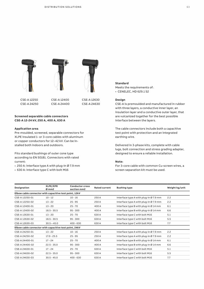
CSE-A 12250CSE-A 24250
CSE-A 12400CSE-A 24400
CSE-A 12630CSE-A 24630
63D I S TR I B U TI O N S O LU TI O N S
Screened separable cable connectorsCSE-A 12-24 kV, 250 A, 400 A, 630 A
Application areaPre-moulded, screened, separable connectors for XLPE insulated 1- or 3-core cables with aluminum or copper conductors for 12–42 kV. Can be in-stalled both indoors and outdoors.
Fits standard bushings of outer cone type according to EN 50181. Connectors with rated current:• 250 A: interface type A with plug-in Ø 7.9 mm• 630 A: interface type C with bolt M16
Designation XLPE/EPRØ mm2
Conductor cross section mm2
Rated current Bushing type Weight kg/unit
Elbow cable connector with capacitive test point, 12kV
CSE-A 12250-01 10 - 12 10 - 16 250 A Interface type A with plug-in Ø 7.9 mm 2.2
CSE-A 12250-02 13 - 22 25 - 95 250 A Interface type A with plug-in Ø 7.9 mm 2.2
CSE-A 12400-01 13 - 20 25 - 70 400 A Interface type B with plug-in Ø 14 mm 6.1
CSE-A 12400-02 18.5 - 30.5 95 - 300 400 A Interface type B with plug-in Ø 14 mm 6.6
CSE-A 12630-01 13 - 20 25 - 70 630 A Interface type C with bolt M16 5.1
CSE-A 12630-02 18.5 - 30.5 95 - 300 630 A Interface type C with bolt M16 5.5
CSE-A 12630-03 30.5 – 45.0 400 - 630 630 A Interface type C with bolt M16 7.7
Elbow cable connector with capacitive test point, 24kV
CSE-A 24250-01 13 - 22 10 - 16 250 A Interface type A with plug-in Ø 7.9 mm 2.2
CSE-A 24250-02 17.0 - 25.5 25 - 95 250 A Interface type A with plug-in Ø 7.9 mm 2.2
CSE-A 24400-01 17 - 24 25 - 70 400 A Interface type B with plug-in Ø 14 mm 6.1
CSE-A 24400-02 22.5 - 35.0 95 - 300 400 A Interface type B with plug-in Ø 14 mm 6.6
CSE-A 24630-01 17 - 24 25 - 70 630 A Interface type C with bolt M16 5.1
CSE-A 24630-02 22.5 - 35.0 95 - 300 630 A Interface type C with bolt M16 5.5
CSE-A 24630-03 30.5 - 45.0 400 - 630 630 A Interface type C with bolt M16 7.7
StandardMeets the requirements of:• CENELEC, HD 629.1 S2
DesignCSE-A is premoulded and manufactured in rubber with three layers, a conductive inner layer, an insulation layer and a conductive outer layer, that are vulcanized together for the best possible interface between the layers.
The cable connectors include both a capacitive test point with protection and an integrated earthing wire.
Delivered in 3-phase kits, complete with cable lugs, bolt connection and stress grading adapter, designed to ensure a reliable installation.
Note:For 3-core cable with common Cu-screen wires, a screen separation kit must be used.
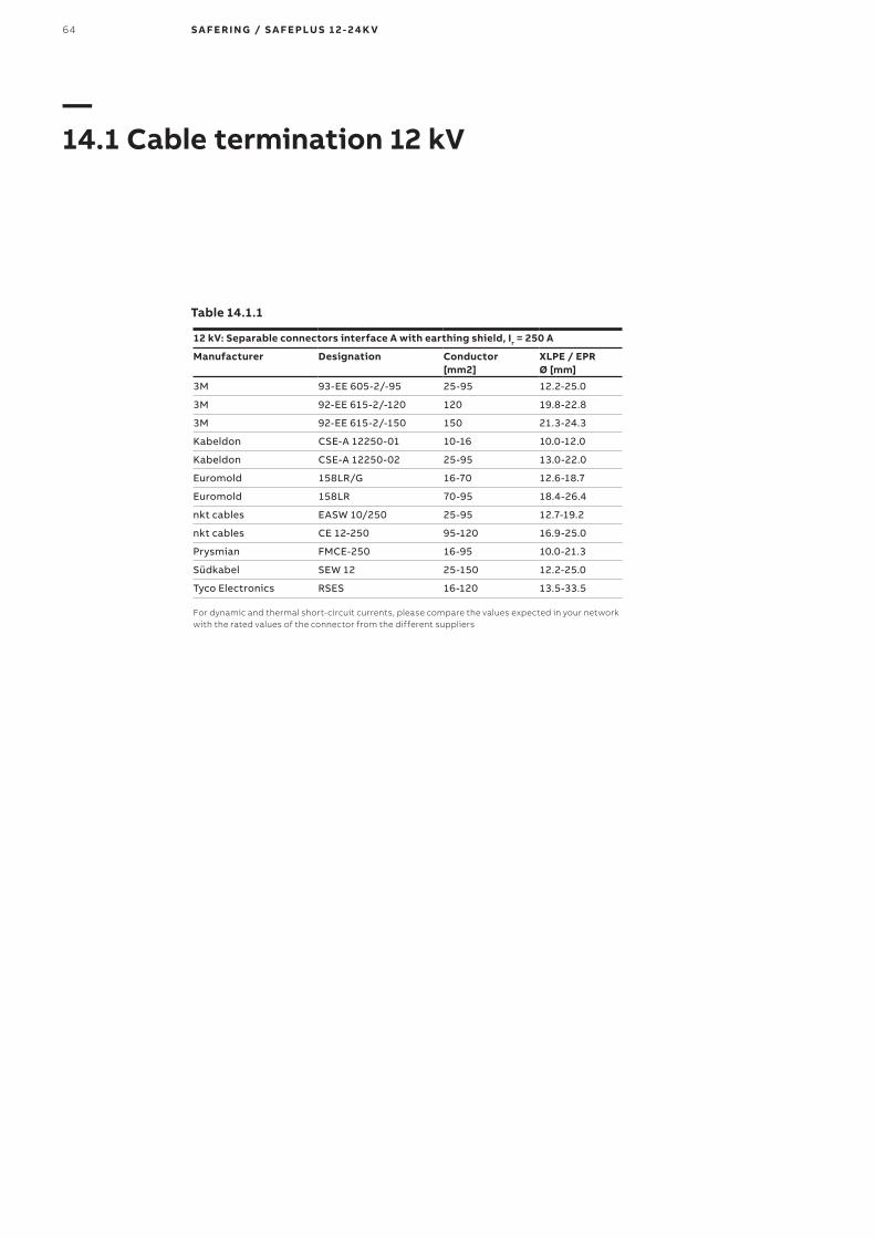
64 S A F E R I N G / S A F E PLU S 1 2- 2 4 K V
—14 1 Cable termination 12 kV
12 kV: Separable connectors interface A with earthing shield, Ir = 250 A
Manufacturer Designation Conductor [mm2]
XLPE / EPR Ø [mm]
3M 93-EE 605-2/-95 25-95 12.2-25.0
3M 92-EE 615-2/-120 120 19.8-22.8
3M 92-EE 615-2/-150 150 21.3-24.3
Kabeldon CSE-A 12250-01 10-16 10.0-12.0
Kabeldon CSE-A 12250-02 25-95 13.0-22.0
Euromold 158LR/G 16-70 12.6-18.7
Euromold 158LR 70-95 18.4-26.4
nkt cables EASW 10/250 25-95 12.7-19.2
nkt cables CE 12-250 95-120 16.9-25.0
Prysmian FMCE-250 16-95 10.0-21.3
Südkabel SEW 12 25-150 12.2-25.0
Tyco Electronics RSES 16-120 13.5-33.5
For dynamic and thermal short-circuit currents, please compare the values expected in your network with the rated values of the connector from the different suppliers
Table 14 1 1

65D I S TR I B U TI O N S O LU TI O N S
12 kV: Separable connectors interface C, Ir = 630 A Cable compartment with
Manufacturer DesignationConductor [mm2]
XLPE / EPR Ø [mm] Ea
rthi
ng s
hiel
d Ye
s /
No
Additional equipment for dual cable arrangement
SurgeArrester with
Single cable + surge arrester Dual cables
Stan
dar
d
Dis
tan
ce A
= 3
60
mm
Wit
h w
ind
ow
Dis
tan
ce A
= 3
53 m
m
Arc
pro
of
Dis
tan
ce A
= 3
37 m
m
Dee
pD
ista
nce
A =
555
mm
Stan
dar
d
Dis
tan
ce A
= 3
60
mm
Wit
h w
ind
ow
Dis
tan
ce A
= 3
53 m
m
Arc
pro
of
Dis
tan
ce A
= 3
37 m
m
Dee
pD
ista
nce
A =
555
mm
3M 93-EE 705-6/-95 50-95 15.0-23.5 Y KU 23.1+93-EE w705-6/95
MUT 23
3M 93-EE 705-6/-240 120-240 21.8-32.6 Y 93-EE 718-6/150-240 MUT 23
Kabeldon CSE-A 12630-01 25-70 13.0-20.0 Y CSEP-A 12630-01 CSAP-A 12 X X X X X X X
Kabeldon CSE-A 12630-02 95-300 18.5-30.5 Y CSEP-A 12630-02 CSAP-A 12 X X X X X X X X
Kabeldon CSE-A 12630-03 400-630 30.5-45.0 Y CSEP-A 12630-03 CSAP-A 12 X X X X X X X
Euromold 430TB/G 25-300 12.0-37.5 Y 300 PB/G 2) 300SA 2) X X X X X X X X
Euromold 484TB/G 3) 50-630 16.0-56.0 Y 804PG/G 2) 800SA 2) X X X X X X X X
nkt cables CB12-630 25-300 12.7-34.6 Y CC 12-630 CSA 12 X X X X X X X X
nkt cables AB12-630 25-300 12.7-34.6 N AC 12-630 ASA 12 X X X X X X X X
nkt cables CC24-630(1250) 400-630 34.0-45.6 Y CC24-630(1250) or CC 12-630
CSA 12X X X X X X X X
Prysmian FMCTs-400 70-300 18.5-30.4 Y FMPCs-400-12+ FMCTs-400
Yes 1)
X X
Prysmian FMCTs-400/1250 70-300 18.5-42.0 Y FMPCs-400-12+ FMCTs-400/1250
Yes 1)
X X
Südkabel SET 12 50-300 15.0-32.6 Y SEHDK 13.1 MUT 23 X X X X X
Südkabel SET 12 50-300 15.0-32.6 KU 23.2/22 +SET 12 MUT 23 X X X X X
Südkabel SEHDT 13 400-500 31.3-36.4 Y None KU33+MUT 23 X
Tyco Electronics RSTI-L 25-300 12.7-34.6 Y RSTI-CC-L RSTI-SA X X X X X X X X
Tyco Electronics RICS 25-300 Flexible N None RDA X X X X
Tyco Electronics RSTI-36Lxx 400-630 28.9-45.6 Y RSTI-66CP-M16+ RSTI-36Lxx
NoneX X
1) Combination with surge arrester possible with Euromold 400PBX-XSA2) For dual cable + surge arrester, deeper cable compartment is required. Solution available for Euromold connectors only.3) Available up to 1250 A.Separable connectors without earthing shield are not recommended.For dynamic and thermal short-circuit currents, please compare the values expected in your network with the rated values of the connector from the different suppliers
Table 14 1 2

66 S A F E R I N G / S A F E PLU S 1 2- 2 4 K V
—14 2 Cable termination 24 kV
Table 14 2 1
24 kV: Separable connectors interface A with earthing shield, Ir = 250 A
Manufacturer Designation Conductor [mm2]
XLPE / EPR Ø [mm]
3M 93-EE 605-2/-95 25-95 12.2-25.0
3M 93-EE 615-2/-120 120 24.0-27.0
3M 93-EE 615-2/-150 150 25.5-28.5
Kabeldon CSE-A 24250-01 10-16 13.0-22.0
Kabeldon CSE-A 24250-02 25-95 17.0-25.5
Euromold K158LR/G 16-25 12.6-18.7
Euromold K158LR 25-95 18.4-26.4
nkt cables EASW 20/250 25-95 17.0-25.0
nkt cables CE 24-250 25-120 16.9-25.0
Prysmian FMCE-250 35-95 18.6-26.0
Südkabel SEW 24 25-95 17.3-25.0
Tyco Electronics RSES 16-120 13.5-33.5
Separable connectors without earthing shield are not recommended.For dynamic and thermal short-circuit currents, please compare the values expected in your network with the rated values of the connector from the different suppliers.

67D I S TR I B U TI O N S O LU TI O N S
24 kV: Separable connectors interface C with earthing shield, Ir = 630 A Cable compartment with
Manufacturer DesignationConductor [mm2]
XLPE / EPR Ø [mm]
Additional equipment for dual cable arrangement
SurgeArrester with
Single cable + surge arrester Dual cables
Stan
dar
d
Dis
tan
ce A
= 3
60
mm
Wit
h w
ind
ow
Dis
tan
ce A
= 3
53 m
m
Arc
pro
of
Dis
tan
ce A
= 3
37 m
m
Dee
pD
ista
nce
A =
555
mm
Stan
dar
d
Dis
tan
ce A
= 3
60
mm
Wit
h w
ind
ow
Dis
tan
ce A
= 3
53 m
m
Arc
pro
of
Dis
tan
ce A
= 3
37 m
m
Dee
pD
ista
nce
A =
555
mm
3M 93-EE 705-6/-95 50-95 15.0-23.5 KU 23.1+93-EE 705-6/-95 MUT 23 X X X X X
3M 93-EE 705-6/-240 95-240 21.8-32.6 93-EE 718-6/150-240 MUT 23 X X X X X X X X
Kabeldon CSE-A 24630-01 25-70 17.0-24.0 CSEP-A 24630-01 CSAP-A 24 X X X X X X
Kabeldon CSE-A 24630-02 95-300 22.5-35.0 CSEP-A 24630-02 CSAP-A 24 X X X X X X X
Kabeldon CSE-A 24630-03 400-630 30.5-45.0 CSEP-A 24630-03 CSAP-A 24 X X X X X X
Euromold K400TB/G 25-300 12.0-37.5 K400CP-SC+K400TB/G 400PB-XSA X X
Euromold K430TB/G 25-300 12.0-37.5 K300PB/G 300SA X X X X X X X X
Euromold K484TB/G 35-630 16.0-56.0 K804PB 800SA X X X X X X X X
nkt cables CB24-630 25-300 12.7-34.6 CC 24-630 CSA 24 X X X X X X X X
nkt cables CC24-630(1250) 400-630 34.0-45.6 CC24-630(1250) or CC24-630
CSA 24 X XX
X X X X X
Prysmian FMCTs-400 35-300 18.5-35.3 FMPCs-400-24 + FMCTs-400
Yes 1) X X
Prysmian FMCTs-400/1250 35-630 18.5-47.1 FMPCs-400-24 + FMCTs-400/1250
Yes 1) X X
Südkabel SET 24 25-240 15.0-32.6 SEHDK 23.1 MUT 23 X X X X X X X X
Südkabel SET 24 25-240 15.0-32.6 KU 23.2/23 + SET 24 MUT 23 X X X X X
Südkabel SEHDT 23.1 300 31.9-34.6 KU 23.2/23+ SEHDT 23.1 MUT 23 X X X X X
Südkabel SEHDT 23 300-500 31.9-40.6 None KU33+ MUT 23 X
Tyco Electronics RSTI-L 25-300 12.7-34.6 RSTI-CC-L RSTI-SA X X X X X X X X
Tyco Electronics RSTI-56Lxx 400-630 34.0-45.6 RSTI-66CP-M16 + RSTI-56Lxx
None X X
1) Combination with surge arrester possible with Euromold 400PBX-XSA
Separable connectors without earthing shield are not recommended.
For dynamic and thermal short-circuit currents, please compare the values ex-pected in your network with the rated values of the connector from the different suppliers.
Table 14 2 2

68 S A F E R I N G / S A F E PLU S 1 2- 2 4 K V
—15 Cable test bushings
As an option, both C- and De-modules can be equipped with cable test bushings situated behind the lower front cover. This cover can be interlocked against the earthing switch to avoid access to the cable test compartment before the earthing switch is in closed position.
When these bushings are mounted, cable insulation tests can easily be done according to the following procedure:
Principle sketch for testing:1. Close the earthing switch after having checked
the voltage indicators2. Open compartment cover3. Install the injection device onto the access
terminals4. Open the removable earthing bridge5. Perform cable testing6. Re-install the earthing bridge7. Remove the injection device8. Close compartment cover9. Open the earthing switch
If the switchgear is not equipped with cable test bushings, cable testing is possible directly at the cable connectors if they are designed for this purpose. Please follow the supplier’s instruction. For interlocking on the cable test cover, see interlock table for C-module, chapter 7.2.2.

� ��SafePlus
SafePlus �� �� �� SafePlus �� SafePlus ��SafePlusSafePlus
� ��SafePlus
� ��SafePlus
� ��SafePlus
69D I S TR I B U TI O N S O LU TI O N S
On the top of all SafeRing/SafePlus switchgears it is possible as an option to have bushings for connection of external busbars on the left and/or right side.
For a SafePlus switchgear consisting of only one module, only one set of bushings on the top is used.
When bushings are mounted on the top, you will have these possibilities:1. When adding a dead end receptacle to each of
these bushings, SafeRing/ SafePlus will be prepared for future busbar extension.
2. With an external busbar kit, it is possible to connect two or more sections.
Since a 5-way switchgear is the maximum size within one common SF6 tank, the busbar kit allows a configuration with more than 5 modules.
The installation of the external busbars has to be done on site. See manual 1VDD006006 GB for installation instructions.
The complete extension kit and the dead end receptacles are fully screened, earthed and insulated with EPDM rubber. This makes a safe and reliable switchgear extension. In addition, protection covers are available as an option.
SafePlus switchgear can also be configured as fully modular. This results in a 1250 A busbar rating.
The busbars between the modules and the end adapters used on the left and right side are identical to the parts used in the previous example. For the three modules in the middle, a special cross adapter is used.
The length of the external busbars is dependent on the type of modules to be connected.
Connection by external busbars is available for all modules except rhe Mt-module.
—16 Extension of switchgear
—01
—01 SafePlus prepared for future extension on right hand side.—02 Fully modular SafePlus with external busbar cover.—03 SafePlus with one incomer (C-module), one Metering module (M-module) and three fused T-offs (F-mod-ules), prepared for future extension.
—02
—03
— 16 1 External busbars on top

� ��SafeRing
� ��SafePlus
� ��SafePlus
� ��SafePlus� ��
SafePlus� ��
SafePlus
70 S A F E R I N G / S A F E PLU S 1 2- 2 4 K V
—16 2 Side extension
It is possible to have optional bushings on the left or right side of SafeRing or SafePlus C- or F-modules for side connection of external busbars. The rated current of the side connection is limited to 400A.
For a 1-way SafePlus C- or F-module, one or two sets of bushings can be installed. This is also applicable for a 2-way unit.
When bushings are mounted on the side, you will have these possibilities:1. When adding a dead end receptacle to each of
these bushings, SafeRing / SafePlus will be prepared for future busbar extension.
2. With a specially designed connection kit, it will be possible to connect two or more sections.
Since a 5-way switchgear is the maximum size within one common SF6 tank, the busbar kit allows a configuration with more than 5 modules. The second switchgear can consist of maximum 2 modules.
The installation of the external busbars has to be done on site. See manual 1VDD006106 GB for installation instructions.
SafePlus switchgear can also be configured as fully modular. The busbars between the modules and the end adapters used on the leftmost and rightmost module are identical to the parts used in the previous example.

SafePlus� ��
REF 610� ��
SafePlus� ��
REF 610� ��
SafePlus� ��
REF 610� ��
Front view Side view Rear view
71D I S TR I B U TI O N S O LU TI O N S
When SafeRing or SafePlus is placed directly on a floor, the height from the floor to the centre of the cable bushings is 595 millimeters. If there is no cable trench this height might not be sufficient for proper installation of cables. It is then possible to place the switchgear on an additional base frame.
This base frame is available in two different heights; 290 and 450 millimeter.
Inside the standard cable compartment for the vacuum circuit-breaker there will be enough space for three current transformers for the protection relay.
If an earth-fault transformer or an extra set of current transformers is required, an additional base frame is necessary. Please see examples on the left hand side.
The base frame has openings for cable entrance from the bottom and from both sides. It is delivered as a kit and has to be assembled on site.
—17 Base frame
—01
—01 Base frame 450 mmwith earth-fault transformer and extra set of current transformers.—02 Base frame 290 mmwith an extra set of current transformers.—03 Base frame 290 mmwith earth-faulttransformers.
—02
—03

� ��SafeRing
72 S A F E R I N G / S A F E PLU S 1 2- 2 4 K V
—18 Low voltage compartment / Top entry box
Low voltage compartmentAll SafePlus switchgears can be supplied with an optional low voltage compartment. This compartment may be equipped with protection relays, meters, position switches, terminal blocks, etc.
The compartment is fixed to the side covers of the SF6 tank and must cover the total width of the switchgear. Each module has a separate hinged door, but there are no partition walls between the modules.
The low voltage compartment has the possibility of external cable entry from either left- or right-hand side.
A locking system for the door is available on re-quest.
Different heights for the low voltage compartment are available: 300, 470 and 700 mm/400, 570 and 800 mm.
Top entry boxIf motor operation, coils, auxiliary switches, self-powered protection relay, etc. are mounted on a SafeRing or SafePlus module, the terminal blocks and the wiring are located behind the front covers.
However, an additional top entry box can be mounted on the top of all SafeRing and SafePlus switchgears. Since the top entry box is fixed to the side covers of the SF6 tank, the total width of the switchgear must be covered.
The top entry box allows entrance of the customer’s low voltage wiring from the rear side, left-hand side and right-hand side.
Furthermore, the top entry box gives the opportunity to install ammeters with position switches, a local/remote switch for motor operation, etc.
—01 Low voltage compartment with REF615 relay—02 Top entry box with A-meter and selector switch—03 Side view top entry box—04 Top entry box seen from above when front / top covers have been removed
—01
—02
—03
—04

73D I S TR I B U TI O N S O LU TI O N S
—19 Motor operation
Closing and opening operations of load-break switches and charging of the springs of the mechanisms for the circuit- breaker and the switch-fuse combination may be performed by a motor operation. The disconnector in the V-module and all earthing switches do not have this possibility. All motor devices require DC voltage. If the control voltage is either 110 or 220 VAC, a rectifier is integrated in the control unit.
The operating cycle for motor operation is CO - 3 min (i.e. it may be operated with a frequency of up to one close and one open operation every third minute). Motors and coils can easily be mounted to the mechanisms after delivery (retro-fit). Test voltage for tables below is + 10/ - 15 % for motor operations and closing coils and +10/ -30% for trip coils and opening coils. The motor and coils can easily be mounted to the mechanisms after delivery (retro-fit).
Characteristics of motor operation for C-moduleRated voltage(V)
Power consumption (W) or (VA)
Operation times Peak start current (A)
FuseClosing time (s) Opening time (s)
24 90 6 - 9 6 - 9 14 F 6,3 A48 150 4 - 7 4 - 7 13 F 4 A60 90 6 - 9 6 - 9 7 F 4 A110 90 6 - 9 6 - 9 3 F 2 A220 90 6 - 9 6 - 9 1,7 F 1 A
Characteristics of motor operation for F-moduleRated voltage(V)
Power consumption (W) or (VA)
Operation times Peak start current (A)
FuseCharge/Closing time (s)
Opening time (ms)
24 160 9-14 40-60 14 F 6,3 A48 200 5-9 40-60 13 F 4 A60 140 8-13 40-60 7 F 4 A110 140 8-13 40-60 3 F 2 A220 140 8-13 40-60 1,7 F 1 A
Characteristics of motor operation for V-moduleRated voltage(V)
Power consumption (W) or (VA)
Operation times Peak start current (A)
FuseCharge/Closing time (s)
Opening time (ms)
24 180 10-17 40-60 14 F 6,3 A48 220 5-9 40-60 13 F 4 A60 150 9-13 40-60 7 F 4 A110 170 9-13 40-60 3 F 2 A220 150 9-14 40-60 1,7 F 1 A
Characteristics of shunt trip coils, closing coils and opening coils for F-and V-moduleRated voltage(V)
Power consumption (W) or (VA)
Operation times Peak start current (A)
Fuse for closing coil Y2(Opening coil Y1 is unfused)Closing time (ms) Opening time (ms)
24 V DC 150 40-60 40-60 6 F 6,3 A48 V DC 200 40-60 40-60 4 F 4 A60 V DC 200 40-60 40-60 3 F 4 A110 V DC 200 40-60 40-60 2 F 2 A220 V DC 200 40-60 40-60 1 F 1 A110 V AC 200 40-60 40-60 2 F 2 A230 V AC 200 40-60 40-60 1 F 1 A

1
2
2
6
3
3
1 4 5
5
7
1
3
8 9 4 12
13
10
11
14
15
16
1718
74 S A F E R I N G / S A F E PLU S 1 2- 2 4 K V
1. Terminal blocks/control unit motor operation 2. Auxiliary switch S7, load break switch3. Auxiliary switch S10, earthing switch4. Opening coil Y15. Closing coil Y26. Auxiliary switch S9, fuse blown7. Motor operation8. Relay trip coil Y3 / Y4 / Y5 /Y6*9. Auxiliary switch S9, circuit breaker tripped signal10. Auxiliary switch S5, circuit breaker11. Auxiliary switch S6, mechanism latched12. Auxiliary switch S8, spring charged13. Auxiliary switch S14, operating handle, VCB14. Auxiliary switch S15, operating handle, disconnector15. Auxiliary switch S7, disconnector16. Auxiliary switch S13, cable compartment cover17. Auxiliary switch S20, arc suppressor18. Auxiliary switch S19, SF6 gas pressure
* Depending of the type of protection relay, the V module can only be delivered with one of the relay trip coils.
—01 SafePlus consist-ing of CFV modules equipped with various auxiliary switches, coils and motor operation
—01

� ��SafeRing
75D I S TR I B U TI O N S O LU TI O N S
—20 Transformer protection
SafeRing / SafePlus offers a choice between a switch fuse combination and circuit-breaker in combination with relay for transformer protection. The switch-fuse combination offers optimal protection against short-circuit currents, while the circuit-breaker with relay offers better protection against low over-currents. Circuit- breaker with relay is always recommended for higher rated transformers.
SafeRing is delivered with a 200 A rated V-module. SafePlus V- module has two options: 200 or 630 A rating. Both for SafeRing and SafePlus the relay is a self- powered relay that utilizes the energy from the CTs under a fault situation to energize the trip coil. The self-powered relay can also be used for cable protection. More details on the different relays can be found in the chapter on relays.
Transformer protection with self-powered relayRecommended types:• ABB relay type REJ603 r1.5• Woodward relays type WIC 1 and WIB 1 PE• Kries relay type IKI-30/IKI-35
Important features V-module:• Relay behind cover. No need for additional low
voltage box for the self-powered relays used for transformer protection.
Typical for vacuum circuit-breaker protection:• Good protection against short-circuits• Very good for protection of over-currents
• Small fault currents are detected in an early stageSafeRing / SafePlus - Fuse-link selectionBy selection of fuse-links for the protection of a transformer, it is important that requirements in IEC 62271-105 and in IEC 69787 are fulfilled. In particular, Annex A in IEC 62271-105 gives a good example of the coordination of fuse-links, switch and transformer.
Correct selection of fuse-links for the protection of the transformer will give:• Optimal protection of the transformer• No damage on the fuse-link’s fuse-elements
due to the magnetizing inrush current of the transformer
• No overheating of the fuse-links, the switch-fuse combination or the switchgear due to the full load current or the permissible periodic overload current of the transformer
• A transfer current of the combination which is as low as possible, and less than the rated transfer current of the switch-fuse combination
• A situation where the fuse-links alone will deal with the condition of a short-circuit on the transformer secondary terminals
• Fuse-links that discriminate with the low-voltage fuse-links in the event of phase-to-phase faults occurring downstream the low-voltage fuse-links
By carefully checking that these rules are followed, fuse-links from any manufacturer can be used in combination with SafeRing and SafePlus as long as the fuse-links are in accordance with the requirements described in the following pages.

Fuse holder Fuse adapterFuse-link
76 S A F E R I N G / S A F E PLU S 1 2- 2 4 K V
—21 Fuse-links
SafeRing / SafePlus is designed and tested for fuse-links according to IEC 60282-1. The dimensions of the fuse-links have to be in accordance with IEC 60282-1, Annex D. The fuse-links have to be type I with terminal diameter equal to 45 +1 mm and body length (e) equal to 442 mm.
The dimensions of the fuse-links can also to be in accordance with DIN 43625 and the length of the fuse canister is based on the use of fuse-links with length 442 mm. For installation of shorter fuses, (<24kV ) a fuse adapter will be needed. Please note: When inserting the fuse-link into the canister, the striker-pin must always face outwards against the fuse holder. The fuse adapter has to be fixed to the fuse-link contact that faces inward in the fuse canister. The maximum size of distribution transformer which can be fed from a SafeRing/ SafePlus switch-fuse module is 1600 kVA. For higher rated transformers, we recommend our vacuum circuit-breaker module with CT’s and protection relay.
The below table shows CEF fuse-links for use in SafeRing / SafePlus. For more technical data, refer to ABB Poland catalogue 3405PL202-W86-en. In order to find the correct fuse-link compared to the transformer rating in kVA, please see the selection tables 21.1.1, 21.1.2 and 21.2.1
Type Rated voltage kV Rated current A e / D mm Type Rated voltage kV Rated current A e / D mmCEF 3,6/7,2 6 192/65 CEF 17,5 6 292/65
CEF 3,6/7,2 10 192/65 CEF 17,5 10 292/65
CEF 3,6/7,2 16 192/65 CEF 17,5 16 292/65
CEF 3,6/7,2 25 192/65 CEF 17,5 25 292/65
CEF 3,6/7,2 40 192/65 CEF 17,5 40 292/87
CEF 3,6/7,2 50 192/65 CEF 17,5 50 292/87
CEF 3,6/7,2 63 192/65 CEF 17,5 63 292/87
CEF 3,6/7,2 80 192/87 CEF 17,5 80 442/87
CEF 3,6/7,2 100 192/87 CEF 17,5 100 442/87
CEF 3,6/7,2 125 292/87
CEF 3,6/7,2 160 292/87
CEF 12 6 292/65 CEF 24 6 442/65
CEF 12 10 292/65 CEF 24 10 442/65
CEF 12 16 292/65 CEF 24 16 442/65
CEF 12 25 292/65 CEF 24 25 442/65
CEF 12 40 292/65 CEF 24 40 442/65
CEF 12 50 292/65 CEF 24 50 442/87
CEF 12 63 292/65 CEF 24 63 442/87
CEF 12 80 292/87
CEF 12 100 292/87
CEF 12 125 442/87

77D I S TR I B U TI O N S O LU TI O N S
—21 1 Fuse selection table - CEF
100% Transformer rating (kVA)Fuse-link rated voltage
Un (kV) 25 50 75 100 125 160 200 250 315 400 500 630 800 1000 1250 1600
7,2 kV
3 16 25 25 40 40 50 50 80 100 125 160 160
3,3 16 25 25 40 40 50 50 63 80 100 125 160
4,15 10 16 25 25 40 40 50 50 63 80 100 125 160
5 10 16 25 25 25 40 40 50 50 63 80 100 160 160
5,5 6 16 16 25 25 25 40 50 50 63 80 100 125 160
6 6 16 16 25 25 25 40 40 50 50 80 100 125 160 160
6,6 6 16 16 25 25 25 40 40 50 50 63 80 100 125 160
10 6 10 10 16 16 25 25 25 40 40 50 50 80 80 125 125
12 kV11 6 6 10 16 16 25 25 25 25 40 50 50 63 80 100 125
12 6 6 10 16 16 16 25 25 25 40 40 50 63 80 100 125
13,8 6 6 10 10 16 16 25 25 25 25 40 50 50 63 80 100
17,5 kV15 6 6 10 10 16 16 16 25 25 25 40 40 50 63 80 100
17,5 6 6 6 10 10 16 16 16 25 25 25 40 50 50 63 80
20 6 6 6 10 10 16 16 16 25 25 25 40 40 50 63 63
24 kV22 6 6 6 6 10 10 16 16 16 25 25 25 40 50 50 63
24 6 6 6 6 10 10 16 16 16 25 25 25 40 40 50 63
Table 21.1.1
Table 21.1.2
- The table is based on using fuses type ABB CEF- Normal operating conditions with no overload- Ambient temperature -25oC - +40oC
120% Transformer rating (kVA)Fuse-link rated voltage
Un (kV) 25 50 75 100 125 160 200 250 315 400 500 630 800 1000 1250 1600
7,2 kV
3 16 25 25 40 40 50 63 80 100 125 160
3,3 16 25 25 40 40 50 63 80 80 100 125
4,15 10 16 25 25 40 40 50 63 80 80 100 125
5 10 16 25 25 25 40 40 50 63 80 80 125 160
5,5 6 16 16 25 25 25 40 50 50 80 80 100 125 160
6 6 16 16 25 25 25 40 40 50 63 80 100 125 160
6,6 6 16 16 25 25 25 40 40 50 63 80 80 100 125
10 6 10 10 16 16 25 25 25 40 40 50 63 80 80 125
12 kV11 6 6 10 16 16 25 25 25 25 40 50 50 80 80 100 125
12 6 6 10 16 16 16 25 25 25 40 40 50 63 80 100 125
13,8 6 6 10 10 16 16 25 25 25 25 40 50 50 80 80 100
17,5 kV15 6 6 10 10 16 16 16 25 25 25 40 40 50 63 80 100
17,5 6 6 6 10 10 16 16 16 25 25 25 40 50 50 63 80
20 6 6 6 10 10 16 16 16 25 25 25 40 40 50 63 80
24 kV22 6 6 6 6 10 10 16 16 16 25 25 25 40 50 50 63
24 6 6 6 6 10 10 16 16 16 25 25 25 40 40 50 63
- The table is based on using fuses type ABB CEF- Normal operating conditions with 20% overload- Ambient temperature -25oC - +40oC

78 S A F E R I N G / S A F E PLU S 1 2- 2 4 K V
—21 2 Fuse selection table - CEF-S
The table was calculated according to standards IEC 60787 and IEC 62271-105. The following trans-former and switchgear work conditions were as-sumed:• Maximum long-lasting transformer overload -
120%,• Magnetizing inrush current for transformers up
to and including 630kVA - 12 x In during 100ms,• Magnetizing inrush current for transformers
above 630kVA - 10 x In during 100ms,• Standard ambient working conditions for
SafeRing / SafePlus switchgear (most important: ambient temperature -25 ºC to +40
Tran
sfo
rmer
rat
ed
volt
age
(kV
)
Transformer rating (kVA)
Fuse
-lin
k ra
ted
volt
age
(kV
)
Fuse
-lin
k le
ngth
„e
“ (m
m)25 50 75 100 125 160 200 250 315 400 500 630 Catalogue No CEF-S
Catalogue No CEF-S-TCU
Fuse-link rating In (A)
3 16 25 40 50
6/12 292
3.3 16 25 40 50 50
4.15 16 20 40 40 50 10A: 1YMB531011M0001 10A:1YMB531861M0001
5 10 20 25 40 40 50 16A: 1YMB531011M0002 16A:1YMB531861M0002
5.5 10 20 20 40 40 40 50 20A: 1YMB531011M0003 20A:1YMB531861M0003
6 10 16 20 25 40 40 50 25A: 1YMB531011M0004 25A:1YMB531861M0004
6.6 10* 16 20 25 40 40 50 50 40A: 1YMB531011M0005 40A:1YMB531861M0005
10 10* 10 16 20 20 25 40 40 50 50A: 1YMB531011M0006 50A:1YMB531861M0006
11 10* 10 16 20 20 25 40 40 40 50
12 10* 10 16 16 20 20 25 40 40 50
13.8 10* 10* 16 16 16 20 20 40 40 40
10/24 442
15 10* 10* 10 16 16 20 20 25 40 40 10A: 1YMB531012M0001 10A:1YMB531862M0001
17.5 10* 10* 10 16 16 20 20 20 40 40 40 16A: 1YMB531012M0002 16A:1YMB531862M0002
20 10* 10* 10* 10 16 16 20 20 25 40 40 20A: 1YMB531012M0003 20A:1YMB531862M0003
22 10* 10* 10* 10 16 16 20 20 20 40 40 40 25A: 1YMB531012M0004 25A:1YMB531862M0004
24 10* 10* 10* 10 16 16 16 20 20 25 40 40 40A: 1YMB531012M0005 40A:1YMB531862M0005
Max
gG
fus
e-lin
k at
LV
sid
e (A
)
40 80 125 160 160 200 250 250 300 400 400 800
Table 21.2.1
ºC),For ratings marked with “*” transformer maximum short-circuit current at LV side, transferred to HV side, is below fuse-link minimum breaking current I3.
The table above details the rated current of a par-ticular fuse-link for a given line voltage and trans-former rating. For different criteria, the fuse selec-tion must be recalculated.

79D I S TR I B U TI O N S O LU TI O N S
—22 Relays
SafePlus can be delivered with a V-module with 630A vacuum circuit-breaker. This chapter describes the different choices of protection relays and feeder terminals that can be used in SafePlus. These relays require an additional low voltage compartment.
For transformer protection with maximum 200A vacuum circuit-breaker see chapter 20, “Transformer protection”.
Standard test procedure is functional test of trip circuit of the relays. All customer settings must be done on site.
REF type feeder terminals are configured according to customer specification for protection functions. Special control requirements on request only.
The V-module can also be delivered prepared for protection relays.
This is defined in two types:• Trip coil and auxiliary contact.• Cut out in LV-compartment, trip coil, aux
contact, wiring and drawings.
There are three main groups of relays delivered: A. ABB feeder protection relaysB. Self-powered relaysC. ABB feeder terminals type REF 54x
A. ABB offers a wide range of feeder protection relays. These relays have been sold for a long period and have an excellent reputation for reliability and secure operation. These relays have either 18-80VDC or 80-265VAC/DC auxiliary supplies and are connected to conventional CTs and VTs as well as combisensors.
B. Self-powered relays are suitable for rough conditions and places without the possibility of auxiliary supply. SafeRing and SafePlus can be delivered with different types to fulfil all relevant needs in a distribution network.
C. ABB feeder terminals type REF 54x provide cost-effective solutions for different protection, monitoring and control applications. The terminals enable the use of accurate and reliable current and voltage sensors as well as conventional CTs and VTs.

80 S A F E R I N G / S A F E PLU S 1 2- 2 4 K V
Feeder protectionThe power protection applications can be roughly divided into two categories, namely standard applications (utilizing basic current based protection) and high requirement applications (utilizing current and voltage based protection) and also the combination of the two.
The selected power protection scheme or system has to fulfil the application-specific requirements regarding sensitivity, selectivity and operating speed of the power protection. The power protection requirements are mainly determined by the physical structure of the power network or system and in most cases the requirements can be fulfilled with non-directional/directional over-current protection intelligent electronic devices (IED).
In power networks or systems with a more complex structure, more advanced power protection functions like distance protection or line differential protection may have to be introduced.
The purpose of the over- and under-voltage power protection system is to monitor the voltage level of the network. If the voltage level deviates from the target value by more than the permitted margin for a set time period, the voltage protection system is activated and it initiates actions to limit the duration of this abnormal condition and the resulting stresses caused to the power system or its components.
To prevent major outages due to frequency disturbances, the substations are usually equipped with under-frequency protection IEDs, which in turn control various power load-shedding schemes. These are just a few examples of the protection for power feeders provided by ABB relays.

REC615
REF601
REF611
REF615
81D I S TR I B U TI O N S O LU TI O N S
Powered Relays For features and functions, see table at page 85.
REC615REC615 is a dedicated grid automation IED designed for remote control and monitoring, protection, fault indication, power quality analyzing and automation in medium-voltage secondary distribution systems, including networks with distributed power generation and with secondary equipment such as medium-volt-age disconnectors, switches and ring main units.
REF601REF601 is a dedicated feeder protection relay intended for the protection of utility substations and industrial power systems in primary and secondary distribution networks. REF601/REJ601 is a member of ABB’s Relion® product family and part of its 601 series. The relay is available in three alternative application configurations: A, B and C.
REF611REF611 is a dedicated feeder IED designed for the protection, control, measurement and supervision of utility substations and industrial power systems including radial, looped and meshed distribution networks with or without distributed power generation. REF611 is available in two alternative standard configurations.
REF615REF615 is a dedicated feeder IED perfectly aligned for the protection, control, measurement and supervision of utility and industrial power distribution systems. It mainly provides protection for overhead lines, cable feeders and busbar systems of power distribution substations. It fits both isolated neutral networks and power networks with resistance or impedance earthed.

REF620
REF630
RIO600
82 S A F E R I N G / S A F E PLU S 1 2- 2 4 K V
REF620REF620 is a dedicated feeder IED perfectly aligned for the protection, control, measurement and supervision of utility and industrial power distribution systems, including radial, looped and meshed distribution networks. REF620 is a member of ABB’s Relion® protection and control product family and its 620 series. The 620 series IEDs are characterized by their functional scalability and withdrawable-unit design. The 620 series has been designed to unleash the full potential of the IEC 61850 standard for communication and inter-operability of substation automation devices.
REF630REF630 is a comprehensive feeder management IED for protection, control, measuring and supervision of utility and industrial distribution substations.
REF630 also features necessary control functions constituting an ideal solution for feeder bay control. REF630 provides main protection for overhead lines and cable feeders of distribution networks. Fits both isolated neutral networks and networks with resistance or impedance earthed neutral. Four pre-defined configurations to match typical feeder protection and control requirements are available.
REF630 incorporates local and remote control functions. The IED offers a number of freely assignable binary inputs/outputs and logic circuits for establishing bay control and interlocking functions for circuit breakers and motor operated switch-disconnectors. REF630 supports both single and double busbar substation busbar layouts.
RIO600RIO600 is designed to expand the digital and analog I/O of ABB’s Relion® protection and control relays and to provide I/O for COM600 substation automation units using the IEC 61850 and Modbus TCP communication. Both galvanic RJ-45 and optical LC type connectors are supported for Ethernet station bus communication. RIO600 can also be used in secondary substations for fault passage indication and power measurements reporting values directly to a peer protection relay or to an upper level system. RIO600 accepts three-phase sensor signals (voltage and current) and provides fault detection and metering functions.

83D I S TR I B U TI O N S O LU TI O N S
Technical functions powered relays Powered relays
Functionality groups IEC61850 IEC60617 IEEE device no.
REF601 REF611 REF615 REF620 REF630 RIO600
Overcurrent functions
Three-phase transformer inrush detector INRPHAR1 3l2f> 68 X X X X X X
Three-phase non-directional overcurrent protection, low stage
PHLPTOC I> 51P-1 X X X X X X
Three-phase non-directional overcurrent protection, high stage
PHHPTOC I>> 51P-2 X X X X X X
Three-phase non-directional overcurrent protection, instantaneous stage
PHIPTOC I>>> 50P/51P X X X X X X
Three-phase directional overcurrent protection, low stage
DPHLPTOC I>-> 67-1 X X X X
Three-phase directional overcurrent protection, high stage
DPHHPTOC I>>-> 67-2 X X X X
Earth-fault functions
Non-directional earth-fault protection, low stage
EFLPTOC Io> 51N-1 X X X X X X
Non-directional earth-fault protection, high stage
EFHPTOC Io>> 51N-2 X X X X X X
Non-directional earth-fault protection, instantaneous stage
EFIPTOC Io>>> 50N/51N X X X X X
Directional earth-fault protection, low stage
DEFLPDEF Io>-> 67-N1 X X X X X
Directional earth-fault protection, high stage
DEFHPDEF Io>>-> 67N-2 X X X X X
Over-/undervoltage
Three-phase overvoltage protection PHPTOV U>/>>/>>> 59 X X X
Three-phase undervoltage protection PHPTUV U</<</<<< 27 X X X
Residual overvoltage protection ROVPTOV Uo> 59G X X X X
Frequency protection function
FRPFRQ f>/f<,df/dt 81 X X X
Thermal protection function
Three-phase thermal protection T1PTTR 3Ith>F 49F X X X X X
Arc protection function
Arc protection ARCSARC ARC 50L/50NL X X X
Advanced protection functions
Auto-reclosing DARREC O -> I 79 X X X X X
Fault locator SCEFRFLO FLOC 21FL X X
Distance protection DSTPDIS Z< 21,21P,21N X
Synchro check SYNCRSYN SYNC 25 X X X
Measuring functions
Three-phase current measurement CMMXU 3I 3I X X X X X
Voltage VMMXU 3U 3V X X X X
Power and energy measurement (S,P,Q,PF)
PEMMXU P,E P,E X X X X
Frequency FMMXU f f X X X
Disturbance recorder RDRE DR DFR X X X X
Residual current measurement RESCMMXU Io In X X X X X
Residual voltage measurement RESVMMXU Uo Vn X X X X X
Load profile recorder LDPMSTA LOADPROF LOADPROF X X
Communication functions
103 X X X X
IEC61850 X X X X
Modbus X X X X
For full overview of protection relay functionality refer to the data sheet of the specific relay.

REJ603R.1.5
REJ603 3.0
IKI-30
WIB1
WIC1
WIP1
84 S A F E R I N G / S A F E PLU S 1 2- 2 4 K V
Self-powered relays
REJ603REJ603 is designed for selective short-circuit and earth-fault protection of feeders in secondary distribution networks and for protection of small transformers in utilities and industries. REJ603 is a current-transformer-powered numerical feeder protection relay designed for applications where auxiliary power is not available or cannot be guaranteed, thereby making it an ideal choice for installation at remote locations. The relay is primarily used in ring main units and secondary distribution switchgear within distribution networks.REJ603R.1.5: Functions are easy to set up by using the dip-switches.REJ603 3.0: Contains LCD display, LED indicators and navigation keys. The measurement, events, setting can be viewed in display.
IKI-30/IKI-35The Transformer protection relay IKI-30 is applicable for transformers with nominal power between 160 and 12 500 kVA; as overcurrent, short-circuit or earth-fault protection relay in combination with a circuit- breaker and as overcurrent protection in combination with load breakers and high voltage fuses.
WIB1/WIC1All available versions of the WIB1/WIC1 relay are a high-tech and cost-optimized protection for MV switchgears. Specifically in compact switchboards, the WIB1/WIC1 protection system in combination with a circuit-breaker can replace the combination of load-break-switch with HV fuses. The overload protection for the attached unit is clearly improved. When power distribution networks are extended more and more high powered transformers are used and HV fuses are inadmissible. For such applications the WIB1/WIC1 protection system is an optimal replacement.
WIP1The WIP1 is an overcurrent relay with multiple characteristics. Definite time and inverse time tripping characteristics can be selected. The WIP1-1 does not require any auxiliary voltage supply. Consequently, it can also be used for switchgears without built-in batteries. It takes its power supply energy from the current transformers’ circuits and provides the tripping pulse energy to the circuit breaker. Due to its wide setting ranges, the tripping characteristic can be selected to protect a wide variety of different equipment. Optionally the WIP1 is available with earth fault element (option IE) and negative sequence element (option IS).

85D I S TR I B U TI O N S O LU TI O N S
Functionality Relay
FeaturesDescription
IEC 60617IEEE device no
WIP 1REJ603
r.1.5REJ603
3.0WIC 1 WIB 1 IKI 30
Protection functions
Three-phase transformer inrush detector
3l2f> 68 - X X - - X
Phase overcurrent (multi-characteristic)
3l> (low set) 50/51 X X X X X X
Short-circuit protection I>> 50/51 X X X X X X
Number of overcurrent elements
50/51B 2 2 3 2 2 2
Earth-fault current I0> (low set) 50N/51N X X X X X X
Number of earth-fault elements
2 2 2 1 2 2
Characteristic curves
Overcurrent element DEFT,INV 1) DEFT,INV 1) DEFT,INV 1) DEFT,INV 1) DEFT DEFT,INV 1)
Earth-fault current DEFT,INV 1) DEFT,INV 1) DEFT,INV 1) DEFT DEFT,INV 1) DEFT
Additional functions
Trip indication X X X X (option) X X
Electro-impulse 1 1 1 1 2 1
input remote tripping (voltage)
230VAC - - 115/230VAC 115/230VAC24VDC/
115/230VAC
Auxiliary power, voltage (option)
Measuring circuit
Rated secondary currentring core CT with
Isec = 1A
wide range special CT
wide range special CT
wide range special CT
wide range special CT
wide range special CT
Measuring range, start current I> (A)
0,172) 7,2 X3) 7,2 7,2 7,2
Climatic withstand
Storage temperature (°C) -40 …+85 -40 …+85 -40 …+85 -40 …+85 -40 …+85 -30 …+70
Operating temperature (°C) -20 …+55 -40 …+85 -25 …+55 -40 …+85 -40 …+85 -25 …+55
1) - Definite time overcurrent (DEFT) - Normal inverse time overcurrent (NINV) - Very inverse time overcurrent (VINV) - Extremely inverse time overcurrent (EINV) - Long time inverse time overcurrent (LINV)
2) secondary current3) The relay’s minimum powering current is 0.07 x In when currents in three phase and 0.18 x In when current in a single phase
- Resistance inverse time overcurrent (RINV)- Characteristics of high voltage fuse-link (HV-FUSE)- Characteristics of full range fuse (FR-FUSE)- Definite time overcurrent - Inverse characteristics, please contact us for further information
Technical functions self-powered relays
REJ603 r.1.5 transformer protection and cable protection kit (self-powered)
Ring core current transformer type Current range
Transformer type KOKM 072 CT1 8 - 28 A
Transformer type KOKM 072 CT2 16 - 56 A
Transformer type KOKM 072 CT3 32 - 112 A
Transformer type KOKM 072 CT4 64 - 224 A
Transformer type KOKM 072 CT5 128 - 448 A
WIB1 transformer protection and cable protection kit (self-powered)
Ring core current transformer type Current range
Transformer type KOKM 072 CT2 or WIC1-W2 16 - 56 A
Transformer type KOKM 072 CT3 or WIC1-W3 32 - 112 A
Transformer type KOKM 072 CT4 or WIC1-W4 64 - 224 A
Transformer type KOKM 072 CT5 or WIC1-W5 128 - 448 A
REJ603 v3.0 transformer protection and cable protection kit
Ring core current transformer type Current range
Transformer type KOKM 072 CT2 or WIC1-W2 16 - 56 A
Transformer type KOKM 072 CT3 or WIC1-W3 32 - 112 A
Transformer type KOKM 072 CT4 or WIC1-W4 64 - 224 A
Transformer type KOKM 072 CT5 or WIC1-W5 128 - 448 A
Ring core current transformers and earth-fault transformers

HR-module (VDS)
VIM 3 VIM 1
VPIS
WEGA 1.2C (VDS)
Capdis (VDS)
PCM
86 S A F E R I N G / S A F E PLU S 1 2- 2 4 K V
SafeRing / SafePlus switchgears are equipped with voltage indicators in accordance either with IEC 62271-206 standard for voltage presence indication system (VPIS) or IEC 61243-5 standard for voltage detection system (VDS).
Voltage indicators VPISVPIS indicators indicate only presence of the medium voltage. Absence of the voltage needs to be confirmed by use of voltage detection equipment.
Phase comparison and testing of VPISEach phase of the integrated voltage presence indicating system has a connection point on the front panel, which can be used to perform phase comparison and to test the voltage presence indicator.
Voltage indicators VDSVDS is used to detect the presence or absence of medium voltage according to IEC 61243-5. The VDS system delivered by ABB can be either based on the LRM or the HR-system.
Voltage indicators VDS LRMWith the VDS LRM system, the following can be indicated:• Overvoltage• Nominal voltage presence• Isolation problems• No voltage• Broken lead indication (Optional feature)Indication is done visually on the display.
Voltage indicators VDS HRSafeRing / SafePlus can be delivered with a Voltage Detection System, VDS HR, according to IEC 61243-5. The indicator itself consists of two parts: a fixed part assembled at the switchgear and portable indicator lamps, type VIM-1 and VIM-3, which can be connected to the coupling system interface.
Phase comparatorPhase comparator is used for controlling the phase sequence when connecting two voltage systems together, e.g. during the switching from one source of power supply to another. Phase comparison can be done by any phase comparator according to IEC 61243-5.
—23 Capacitive voltage indicators

87D I S TR I B U TI O N S O LU TI O N S
Technical functions capacitive voltage indicators
Manufacturer Maxeta Anda Maxeta Horstmann Horstmann Horstmann Kries Kries
Model VPIS DNX5 HR module 1) WEGA 1.2C (45 deg)
WEGA 2.2C (45 deg)
WEGA 1.2C Vario
Capdis S1+(R4)
Capdis S2+(R4)
Type VPIS VPIS VDS VDS VDS VDS VDS VDS
Standard 62271-206 62271-206 61243-5 61243-5 61243-5 61243-5 61243-5 61243-5
Capacity variable sec. no no no no no yes yes yes
Voltage range 9-15kV15-24kV
3-6kV6-12kV12-24kV24-40,5kV
6-12kV12-24kV
3-6kV6-12kV10-24kV
3-6kV6-12kV10-24kV
Adjustable Adjustable Adjustable
Signalling contacts no no no no yes no no yes 2)
Self testing external no external internal internal internal internal internal
Phase comparison yes yes yes yes yes yes yes yes
Indicating lamps yes yes Yes (external VIM-1 or VIM-3)
internal internal internal internal internal
Resistivity tape - - HR LRM LRM LRM LRM LRM
Link up to FPI no no no Compass B,Sigma D, Sigma D+
Compass B,Sigma D, Sigma D+
- - IKI 50
Way of indication Led lamps Led lamps Led lamps(external)
Display, symbols
Display, symbols
Display, symbols
Display, symbols
Display, symbols
External source for testing
no no no no no no no no
Broken signal leash detection
no no no no no no yes yes
1) Combination of HR module and combisensor will reduce the tolerance of voltage measurement to approximity 1%. Recommend to use LRM system.2) For signalling contact, auxiliary voltage is required

Compass B
IKI-50
88 S A F E R I N G / S A F E PLU S 1 2- 2 4 K V
The increasing demand for reliability and effectivness of distribution networks requires higher flexibility and more automated ring main units. As one of the biggest players in the medium voltage distribution segment, ABB replies to this demand by installation of grid automation devices. One of the basic devices is fault passage indicator.
Fault passage indicatorsA fault passage indicator may be delivered as an option to the SafeRing / SafePlus switchgear. The indicator is usually placed in the front panel of the switchgear. It makes it possible to detect any faults, including short circuits, earth-faults and short current direction, and makes it easier to lo-cate any fault.
A fault passage indicator offers different functionalities to the customers, either short-circuit indication which is designed to detect, display and remotely indicate short-circuits in medium voltage distribution networks, or earth-fault indication which is designed to detect, locally indicate and remotely report earth-fault currents in medium voltage distribution networks.
Both functionalities can be combined in one device.
—24 Short-circuit and earth-fault indicators

89D I S TR I B U TI O N S O LU TI O N S
Tech
nica
l fun
ctio
ns c
apac
itiv
e vo
ltag
e in
dic
ato
rsM
anuf
actu
rer
Ho
rstm
ann
Ho
rstm
ann
Ho
rstm
ann
Ho
rstm
ann
Ho
rstm
ann
Ho
rstm
ann
Kri
esK
ries
Kri
esK
ries
Kri
esK
ries
Kri
esA
nd
a
Mo
del
Sig
ma
Sig
ma
F+E
3Si
gm
a D
Sig
ma
D+
Co
mp
ass
BC
om
pas
s B
CS1
IKI-
50
IKI-
50
-P
ULS
-EW
IKI-
20
IKI-
20
PU
LSIK
I-2
0C
IKI-
20
C P
ULS
IKI-
22E
KL-
7
Ded
icat
ed v
olt
.ind
.-
-W
ega
1.2C
/W
ega
1.2
vari
o/W
ega
2.2
C
Weg
a 1.
2C/
Weg
a 1.
2 va
rio/
Weg
a 2
.2C
Weg
a 1.
2C/
Weg
a 1.
2 va
rio/
Weg
a 2
.2C
AB
B
Co
mb
i-se
nso
r
Cap
dis
S1/
S2-
R4
Cap
dis
S1/
S2-
R4
Cap
dis
S1
ST
C f
ault
ind
.X
XX
XX
XX
XX
XX
XX
XD
irec
tio
nal
ind
.-
-X
XX
XX
X-
--
-X
-D
irec
tly
eart
hed
neu
tral
-X
XX
XX
XX
XX
XX
XX
Iso
late
d n
eutr
al -
Wat
tmet
ric
(sin
)-
--
XX
X-
--
--
-X
-
Co
mp
ensa
ted
neu
tral
-W
attm
etri
c (c
os)
--
-X
X (w
/ S
um
-S
enso
r)
IE>1
0A
X (
IE>1
0A
)X
X-
--
-X
-
Co
mp
ensa
ted
neu
tral
-tr
ansi
ent
--
-X
--
-X
--
--
X-
Co
mp
ensa
ted
neu
tral
-p
uls
--
-X
X (o
nly
typ
e B
p)
--
X-
X-
X-
-
Mo
nito
rin
gX
X-
-X
XX
XX
X-
-X
-Tr
ip c
urr
ent
sho
rt-
circ
uit
100
-10
00
A2
00
-20
00
A5
0-2
00
0A
50
-20
00
A5
0-2
00
0A
20
0-2
00
0A
100
-10
00
A10
0-1
00
0A
100
-20
00
A10
0-2
00
0A
40
0-1
00
0A
40
0-1
00
0A
100
-20
00
A4
00,
60
0,8
00,
10
00
A
Res
po
nse
tim
e sh
ort
-ci
rcui
t4
0-8
0m
s4
0/8
0/2
00/
3
00
ms
40
ms-
60
s4
0m
s-6
0s
40
ms-
60
s4
0m
s-6
0s
60
-16
00
ms
60
-16
00
ms
60
-20
0m
s6
0-2
00
ms
100
ms
100
ms
60
-20
0m
s4
0,6
0,8
0,10
0m
s
Trip
cu
rren
t ea
rth
-fau
lt-
20
-16
0A
20
-10
00
A(l
ow
imp
.n
etw
ork
)
20
-10
00
A(l
ow
imp
.n
etw
ork
),5
-20
0A
(w
attm
etri
c),
10-1
00
A
(tra
nsi
ent)
, 1-
20
-10
00
A(l
ow
imp
.n
etw
ork
),5
-20
0A
(w
attm
etri
c)
100
-10
00
A(l
ow
imp
.n
etw
ork
),5
-20
0A
(w
attm
etri
c)
40
-20
0A
+
4-3
0A
(co
sphi
m
eth
od
e)
40
-20
0A
+
4-3
0A
(co
sphi
m
eth
od
e) +
tr
ansi
ent
met
ho
de
40
-20
0A
40
-15
0A
40
0-1
00
0A
pu
lsat
ion
40
0-2
00
A +
tr
ansi
ent
met
ho
de
20,
40,
60,
80
A
Res
po
nse
tim
e ea
rth
-fa
ult
-6
0/8
0/2
00/
3
00
ms
40
ms-
60
s4
0m
s-6
0s
40
ms-
60
s4
0m
s-6
0s
(lo
w im
p.
net
wo
rk),
20
0m
s-6
0s
(wat
tmet
ric)
60
-16
00
ms
60
-16
00
ms
60
-20
0m
sA
pp
r. 9
s af
ter
det
ecti
ng
p
uls
atin
g
curr
ent
100
ms
100
ms
60
-20
0m
s8
0, 1
20,
16
0, 2
00
ms
Rem
ote
tes
t/re
set
XX
XX
XX
XX
XX
XX
XX
Aut
om
atic
res
et t
ime
1,2
,4,8
h2
,4,8
,24
h1
min
- 24
h1
min
- 24
h1
min
- 24
h1
min
- 24
h1,
8h
or
auto
mat
ic
afte
r lo
ad
curr
ent
is
reco
vere
d
1,8
h o
r au
tom
atic
af
ter
load
cu
rren
t is
re
cove
red
2,4
h2
,4h
2,4
h2
,4h
2,4
h1,
2,4
,8h
Su
pp
lyLo
ng
life
lit
hiu
m c
ell
Lon
g li
fe li
thiu
m
cell
CT
po
wer
edC
T p
ow
ered
,au
x.su
pp
ly
po
ssib
le: 2
4V
AC
, 24
-60
V
DC
24-2
30
V A
C/
DC
(ext
)24
-23
0V
AC
/D
C (e
xt)
24-2
30
V A
C/
DC
24-2
30
V A
C/
DC
3 o
pti
on
s:
Au
x.( e
xt),
ca
pac
ito
r b
uffe
red
, b
atte
ry, d
ep.
on
vers
ion
2 o
pti
on
s:
Au
x.( e
xt),
ca
pac
ito
r b
uffe
red
, dep
.o
n ve
rsio
n
Sel
f-p
ow
ered
+
cap
acit
or
Sel
f-p
ow
ered
+
cap
acit
or
24-2
30
V A
C/
DC
, on
øy
for
sen
siti
ve
eart
h-f
ault
fu
nct
ion
+ b
atte
ry
230
V A
C/D
C (e
xt),
3,6
V
bat
tery
(in
t)
Life
tim
e o
f b
atte
ry2
0 ye
ars
(bat
teri
es)
20
year
s (b
atte
ries
)2
0 ye
ars
(bat
teri
es)
20
year
s (b
atte
ries
)2
0 ye
ars
(bat
teri
es)
20
year
s (b
atte
ries
)-
-17
* ye
ars
(bat
teri
es)
12 h
fo
r ca
p.
buf
feri
ng
4 h
for
cap
acit
or
4 h
for
cap
acit
or
15 y
ears
(b
atte
ries
)10
yea
rs (
bat
teri
es)
No
. of
rela
y co
ntac
ts1
34
44
44
41-
3 d
ep. o
nve
rsio
n2
dep
. on
vers
ion
22
1-3
2
Co
mm
. pro
toco
le-
--
-M
od
bu
sM
od
bu
sM
od
bu
sM
od
bu
sM
od
bu
sM
od
bu
s-
--
-C
onf
igu
rati
on
DIP
DIP
DIP
/SW
DIP
/SW
Men
u/S
WM
enu/
SW
Men
u n
av.
Men
u n
av.
DIP
DIP
DIP
DIP
DIP
DIP

90 S A F E R I N G / S A F E PLU S 1 2- 2 4 K V
SafeRing and SafePlus are sealed systems designed and tested according to IEC 62271-200 as maintenance free switchgear for lifetime (30 years). The switchgear does not require any gas handling.
ABB applies state of the art technology for gas tightness providing the equipment with an expected leakage rate lower than 0.1 % per annum, referring to the filling-pressure of 1.4 bar*. The switchgear will maintain gas-tightness and a gas-pressure better than 1.35 bar* throughout its designed lifespan. This pressure value is still within a good margin. From the pressure used during type testing, which is 1.3 bar*.
—25 Manometers/Pressure indicators
* at 20°C.For increasing the safety under operation of the switchgear, manometers may be used for each tank.
In case of need of remote indication, manometers can be equipped with signalling contacts. Detailed descriptions of manometer functions are described in the table on next page.
AltitudeMaximum height above sea level for installation without reducing gas pressure is 1500 meters. In the interval from 1500 to 2000 meters, gas pressure has to be reduced. For installation above 2000 meters, please contact ABB for instructions.

91D I S TR I B U TI O N S O LU TI O N S
Mo
del
Insu
lati
on
med
ium
Tem
p
com
pen
sati
on
Acc
urac
ySc
ale
rang
e (A
bso
lute
)A
pp
eara
nce
(Ab
solu
te)
Mar
king
of
scal
e (A
bso
lute
)O
ver-
pre
ssur
e in
d
Sig
nalli
ng
cont
act
Tres
hold
p
ress
ure
Co
nnec
tio
n to
the
tan
k
Pro
ject
sp
ecif
ic
ord
erin
gS
F6X
+/- 1
%
(20
deg
.)0.
..2 b
arre
d z
on
e 0.
..1,2
bar
gre
en z
on
e 1,
2 b
ar...
mar
k at
1,2
bar
-1x
NO
/NC
1,2
bar
solid
NH
P 3
047
69
P0
001
SF6
X+/
- 1%
(2
0 d
eg.)
+/- 2
,5%
(-
20.
.+6
0 d
eg.)
1...2
bar
red
zo
ne
1,0.
..1,2
bar
gre
en z
on
e 1,
2...
2,0
bar
mar
k at
1,4
bar
--
-so
lid
2R
AA
014
075
P0
001
SF6
X+/
- 1%
(2
0 d
eg.)
+/- 2
,5%
(-
20.
.+6
0 d
eg.)
1...2
bar
red
zo
ne
1,0.
..1,2
bar
gre
en z
on
e 1,
2...
2,0
bar
mar
k at
1,4
bar
X (
yello
w
ind
icat
ion)
--
solid
Den
sity
sw
itch
G
MD
1S
F6X
+/- 2
% (-
25..+
70
deg
.)-
--
-1x
NC
1,15
/1,2
5 b
arso
lid

A B
1)
A B
2)
A B
3)
A B
4)
92 S A F E R I N G / S A F E PLU S 1 2- 2 4 K V
—26 Key interlock
Available key locks are: Ronis, Castell, Kirk and STI. Ronis is default and recommended by ABB. For features, see table on next page.
All load break switches, earthing switches and disconnector can be equipped with any single key interlock. For double key locks, Ronis is the only type that fits SafeRing / SafePlus switchgears. Key interlocks are not available on fuse-switches or vacuum circuit breakers.
Example for single key interlockKey interlocks can be used as follow: Two switch-gears A and B are connected to each other by cables. The purpose of interlocks is to prevent closing of the earthing switch unless the load break switch in the other switchgear is locked in open position.
1. One key interlock will be mounted close to the operating shaft of the load break switch in switchgear A. An identical key interlock will be mounted close to the operating shaft of the earthing switch in switchgear B. As long as the load break switch in switchgear A is in closed position, it will be impossible to remove or operate the key in the key interlock.
2. First you have to operate the load break switch in switchgear A to open position. Then it will be possible to operate the key interlock and turn the key which extends the locking bolt. This will prevent access to the operating shaft of the load break switch. Then withdraw the key and insert it into the identical key interlock on the earthing switch of switchgear B.
3. When the key is inserted you will be able to operate the key interlock and turn the key which will withdraw the extended locking bolt. Then there will be access to operate the earthing switch to closed position. As long as the earthing switch is in closed position, the key will be captured, making it impossible to close the load break switch in switchgear A.
4. If the load break switch in switchgear B and earthing switch in switchgear A are equipped with another identical key interlock which has a different key combination than described above, it will be impossible to make an earth connection of an incoming energized cable from either switchgear A or B.
Another example for use of key interlocks is to prevent access to the distribution transformer before the primary side of the transformer is connected to earth. This can be solved by means of two identical key interlocks: one mounted on the earthing switch for the distribution transformer feeder and the other one on the door in front of the transformer.

93D I S TR I B U TI O N S O LU TI O N S
C/Sl-module
Type LBS off LBS on ES off single key ES on ES on/off Doorlock
Ronis X X X X X N/A
Castell X X X X N/A N/A
Kirk X X X X N/A N/A
STI X X X X N/A N/A
F-module
Type
Ronis N/A N/A X X X N/A
Castell N/A N/A X X N/A N/A
Kirk N/A N/A X X N/A N/A
STI N/A N/A X X N/A N/A
V / V20 / V25 / Sv / Sv20 / Sv25-module
Type SD off SD on
Ronis X X X X X N/A
Castell X X X X N/A N/A
Kirk X X X X N/A N/A
STI X X X X N/A N/A
De/Be-module
Type
Ronis N/A N/A X X X N/A
Castell N/A N/A X X N/A N/A
Kirk N/A N/A X X N/A N/A
STI N/A N/A X X N/A N/A
M-module *)
Type
Ronis N/A N/A N/A N/A N/A X
Castell N/A N/A N/A N/A N/A X
Kirk N/A N/A N/A N/A N/A X
STI N/A N/A N/A N/A N/A X
Types and features of locks
Note:None of the key lock functions in the table above are available for CB-module. This module has integrated key locks on all push buttons.
*) For M-module, use of an exchange box needs to be considered

94 S A F E R I N G / S A F E PLU S 1 2- 2 4 K V
SafeRing / SafePlus for Smart Grid applicationsThe SafeRing / SafePlus 12-24 kV ring main unit (RMU) portfolio from ABB is enhanced to meet the increasing demand for Smart Grid applications in secondary distribution networks.
Standard grid automation devices for ABB’s ring main units are located in the space behind the lower front cover in the C-modules, hence eliminating the need for additional low voltage compartments on the top of the switchgear.
Thanks to the flexibility of SafeRing / SafePlus modules, grid automation solutions can also be delivered with different switchgear configurations with low voltage compartments if required.
Standard packages for Smart Grid applications can provide monitoring, control, measurement and supervision functionalities including feeder automation devices with wired and/or wireless communication interfaces and power supply back-up.
The already compact SafeRing / SafePlus range can also be delivered as an ultra-compact unit with integrated Smart Grid solutions (reduced overall height of 1100 mm) to be fitted inside sub-stations with height limitations.
—27 SafeRing / SafePlus Digital
Customer benefitsThe integrated smart grid functionalities enable the network operators to: • Monitor the grid so that they are able to remotely
locate the fault.• Reconfigure the network so that the faulty part
of the network is disconnected.• Reconfigure the network so that the energy loss
is minimized and/or achieve savings for future investments.
Additional benefits for utilities and energy consumers are:• Improved quality of the power supply.• Fewer and shorter outages and improved voltage
quality. • Ensured safety for personnel.• Enhanced operational efficiency and network
stability.• Improved tools for the network operators and
the field crews.• Less need to travel to locations with difficult
access.

Control room
95D I S TR I B U TI O N S O LU TI O N S
A ring main unit for Smart Grid applications is equipped with an advanced Feeder Automation (FA) device, which in cooperation with additional devices (e.g. Fault Passage Indicators) provides various data to the remote control centers. Key functions of all standard packages from the factory are described in the next pages. There are seven different selections which give the end users possibility to adjust the package to fit their requirements.
All secondary devices within the ring main unit are powered by a 24V DC battery. The battery is charged by its charger, which needs external power supply: • 90...264V AC 50/60 Hz or 85...200V DC in case of
Feeder Automation device ARG600 (internal battery charger) is used.
• 94...132V AC or 184...264V AC 50/60 Hz in case of Feeder Automation device RTU540CID01 or REC615 (external battery charger) is used.
Please contact us in case you need another main power supply option.
Remote and local communication
A Remote communication (communication to the remote control center)Default delivery (standard package solution) comes with IEC 60870-5-104 remote communication protocol implementation. The communication media is either wired Ethernet and/or wireless (GSM/GPRS) communication. Please contact us in case you need another remote communication protocol option.
B Local communication (communication between different automation devices within the RMU) The signals from the ring main unit switches, Fault Passage Indicators (FPI) and low voltage (LV) multi-meters are brought to the Feeder Auto-mation device by two different ways: • Digital signals (e.g. switch positions indication
and control) are hardwired • Analog signals (e.g. measurements from the
Fault Passage Indicators and low voltage multi-meters) are obtained over local communication bus which can be serial Modbus RTU or serial IEC 60870-5-101 communication protocol. Modbus RTU is used within the Remote Measurement package together with RTU540CID01 Feeder Automation device (via it’s CPA port), IEC 60870-5-101 is used for connecting low voltage multi-meters in case ARG600 Feeder Automation device (via its RS1/RS2 ports).
96 S A F E R I N G / S A F E PLU S 1 2- 2 4 K V
Packages All standard packages include: • Power supply backup source for automation
devices (24V DC batteries and battery charger) • Wire (Ethernet) and/or wireless (GSM/GPRS)
communication interfaces (SIM card is not part of delivery)
• IEC 60870-5-104 host (slave) communication protocol
Three levels of automation packages are defined below. There are additional options which can be selected for each package.
Main selections and their options are (*) default values)
1. Automation level • Remote Monitoring package (Level 1)• Remote Control package (Level 2)• Remote Measurement package (Level 3)
2. Feeder automation device • ARC600• RTU 540CID01 Communication/modem:
- No *) - ARG600
• REC615 Communication/modem:
- None *)
3. MV network fault types: • OC (over-current) and EF (earth-fault)
directional • OC and EF non directional• Fault
4. Fault Passage Indicators (FPI): • Kries: IKI-20 *) • Horstmann: SIGMA F+E • Kries: IKI-50 (directional)• Horstmann: ComPass B (directional)
5. Fault passage indicators remote reset: • No • Yes *)
6. Distribution transformer feeders common remote emergency trip:
• No • Yes *)
7. Supervision of the LV side of the distribution transformer:
• None *)• Vamp: WIMO 6CP10 • Circutor: CVM-MINI-ITF-RS485-C2
Options description: 1 Automation level The four automation levels are described below.
Level 1 - Remote Monitoring This package provides remote monitoring of: • The position of load break switches in C module
-> grid topology supervision • Fault passage indicator fault signalization
-> fast fault localization, reduced outage time, efficient use of manpower
• Faults in the transformer feeders
Level 2 - Remote Control This package includes the features from the Remote Monitoring package and in addition provides: • Remote control of load break switches LBS) in C
modules -> fast fault isolation, fast restoration of healthy part of the MV network, operator safety
Level 3 - Remote Measurement This package includes the features from the Remote Control package and in addition provides: • Medium voltage (MV) network analog data values
such as: currents, voltages, frequency, power, energy, load flow direction etc. -> improved notification of overloaded equipment, better maintenance planning, improved power quality
Note: There are spare inputs (1 – 5 pieces) which can be used for additional customer specified „digital/binary” signals such as: SF6 gas pressure signal, low voltage fuses tripped signal, transformer overheating signals, etc. The number of spare inputs depends on the configuration of the ring main unit (CCF, CCCF etc.) and on the type of fault detection for the MV network.

97D I S TR I B U TI O N S O LU TI O N S
2 Feeder automation device Compact Feeder Automation devices secure remote monitoring and control of the secondary substations in the distribution network. They enables the network control centers to monitor and control the field devices over the different communication infrastructures.
A. ARC600 The Wireless Controller ARC600 is a compact, solution-based device for the remote control and monitoring of secondary substations such as network disconnectors, load break switches and ring main units in distribution networks.
ARC600 enables the network control system to monitor, control and measure the field devices over the public communication infrastructure (LTE). The Wireless Controller ARC600 utilizes the built-in GPRS for reliable and secure end-to-end communication providing remote monitoring and control of up to three objects.
B. RTU 540CID01 The RTU540 DIN rail provides advanced functionality and makes it the perfect fit for existing and future Grid Automation solutions. The compact housing with the possibility to integrate harwired information fulfills complex requirements and space restrictions at the same time.
C. REC615REC615 is a dedicated grid automation intelligent electronic devices (IED) designed for remote control and monitoring, protection, fault indication, power quality analyzing and automation in medium voltage secondary distribution systems, including networks with distributed power generation and with secondary equipment such as medium voltage disconnectors, switches and ring main units.
KECA 80 C85 The sensors are able to reach measuring class 0.5 for continuous measurement from 5% of the rated primary current (Ipr) up to the rated continuous thermal current (Icth). This is beyond 120% of Ipr that is common for conventional current transformers (CT).
KEVA 24 C Indoor voltage sensor are intended for use in voltage measurement in gas insulated MV switchgear. The voltage sensors are designed to easily replace the insulating plugs originally used in the cable T-connectors. Due to their compact size and optimized design, sensors can be used for upgrade purposes as well as in new installations.

98 S A F E R I N G / S A F E PLU S 1 2- 2 4 K V
RIO600RIO600 is designed to expand the digital and analog I/O of ABB’s Relion® protection and control relays and to provide I/O for COM600 substation automation unit using the IEC 61850 and Modbus TCP communication. Both galvanic RJ-45 and optical LC type of connectors are supported for Ethernet station bus communication. RIO600 can also be used in secondary substations for fault passage indication and power measurements reporting values directly to a peer protection relay or to an upper level system. RIO600 accepts three-phase sensor signals (voltage and current) and provides fault detection and metering functions.
4 Fault Passage Indicators Fault Passage Indicators are devices which detect faults in the MV network. Some of them are also able to provide MV analog value measurements to the Feeder Automation device which transfers these signals to the control centers.
5 Fault passage indicators remote reset Selection: No The Fault Passage Indicators signalization will be reset according to its setting (e.g. manually, automatically after fixed set time).
Selection: Yes This option gives possibility to reset Fault Passage Indicators remotely from the control centers.
Note: There is one common reset command for all Fault Passage Indicators when using ARC600 Feeder Automation device – all Fault Passage Indicators within the ring main unit will be reset at the same time.
3 MV network fault types Different signals from Fault Passage Indicators can be transmitted to the control centers. These are selected based on type of the MV network (isolated neutral, compensated neutral, high resistance earthing, low resistance earthing or solidly earthing).
Available options are: Over-current and earth-fault directional With this selection, two different types of events can be transferred to the remote control centers: • Fault in forward direction and differentiate between types of fault (over-current or earth-fault).• Fault in backward direction and differentiate between types of fault (over-current or earth-fault).
Over-current and earth-fault non-directional With this selection, two different types of events can be transferred to the remote control centers: • Over-current fault (does not differentiate fault direction) • Earth-fault (does not differentiate fault direction)
Fault With this selection, one type of event can be transferred to the remote control centers: • Fault (does not differentiate overcurrent or earth-fault nor fault direction)

99D I S TR I B U TI O N S O LU TI O N S
Vamp: WIMO 6CP10 WIMO 6CP10 secondary substation measuring and monitoring unit is a compact multi-function monitoring device with extensive measuring and calculation functions. WIMO 6CP10 is ideal for secondary substation measuring and monitoring management. The unit measures currents, voltages and frequencies, and calculates power and energy values.
Circutor: CVM-MINI-ITF-RS485-C2 The CVM-MINI panel analyzer is a programmable measuring instrument; it offers a series of options, which may be selected from configuration menus on the instrument itself.
The CVM-MINI measures, calculates and displays the main electrical parameters for three-phase, balanced or unbalanced industrial systems.
Measurements are taken as true effective values using the three alternating and neutral voltage inputs and three current inputs to measure In /1A or In /5A secondary from external measurement transformers. The CVM-MINI allows the display of all electrical parameters, using the backlit LCD display, showing three instant electrical parameters, maximum or minimum on each page jump. Note: The availability depends on the selected Feeder Automation device and ring main unit module configuration. These devices are by de-fault mounted in a top entry box or low voltage compartment.
6 Distribution transformer feeders common remote emergency trip Selection: No No possibility to remotely trip distribution transformer modules.
Selection: Yes This option gives the possibility to remotely trip distribution transformer modules (usually F- and/or V-modules) from the control centers.
Note: There is one common trip command for all distribution transformer modules – all modules will be tripped at the same time.
7 Supervision of the LV side of the distribution transformer This option gives the possibility to remotely supervise the secondary (Low Voltage) side of the distribution transformer. Different multi-function monitoring devices with extensive measuring and calculation functions will be available in this selection.
The unit measures currents, voltages and frequencies, and calculates power and energy values. The interconnection cable between Feeder Automation device and low voltage multi-meters is not part of delivery.
None No possibility to remotely supervise LV network analog data.

Protection cover
Other data/parameters are identical to data for standard SafePlus.
100 S A F E R I N G / S A F E PLU S 1 2- 2 4 K V
—28 Marine applications
SafePlus switchgear is type-certified by DNV and suitable for Marine applications.
The switchgear conforms to environmental, vibration and ingress protection requirements of the DNV Rules. Available functional units for marine applications are:• Switch disconnector module (C)• Fuse-switch disconnector module (F)• Circuit-breaker module (V)
The switchgear is delivered for ratings up to 24 kV and can be manufactured with any combination of the above modules, from 2 up to 5 modules.
SafePlus switchgear for Marine applications provides ingress protection IP 22C as a standard feature.
Available DNV certified ABB protection relays: • REx615 • REx630
Optional arc suppressor to avoid any damages occurring in case of an internal arc inside the gas tank is available.
Dimensions
Height 1880 mm
Width 372, 696, 1021, 1346 and 1671 mm (1, 2, 3, 4, 5 functional units)
Depth 765 mm for RMU, 1060 mm including roof

188
6
1336
280
5
300
101D I S TR I B U TI O N S O LU TI O N S
—28 1 Marine applications IAC AFL
IAC AFL for marine version of SafePlusWith this set-up, hot gases and pressure are evacuated behind the switchgear through the pressure flap.
Basic parameters of set-up:• IAC AFL up to 20 kA / 1 s• Minimum height of ceiling: 2085 mm• Minimum distance from backwall: 300 mm• Recommended distance to sidewall is minimum
300 mm

102 S A F E R I N G / S A F E PLU S 1 2- 2 4 K V
—29 Low version switchgear
Available functional units for low version applications are the same as for standard SafeRing/SafePlus, except for the metering and CB-modules.
The switchgear is delivered for ratings up to 24kV and can be manufactured in any combination of the SafeRing / SafePlus modules, from 1 up to 5 modules.
Optional arc suppressor to avoid any damages occurring in case of an internal arc inside the gas tank is available.
• CT’s must be placed beneath the switchgear• Height: 1100 mm• Same width as standard units• Only arc proof cable compartment door is
available
IAC AFL for low version of SafePlusFor the low-version switchgear, AFL is the highest IAC-classification. Available solutions are blow-out down to cable trench.
Bacis parameters of set-up:• IAC AFL up to 20 kA / 1 s• Minimum height of ceiling for blow-out down to
cable trench: 2000 mm• Minimum height of ceiling for blow-out behind
switchgear: 2400 mm• Minimum distance from backwall: 100 mm
Parameters and technical data are the same as for standard SafeRing / SafePlus.

103D I S TR I B U TI O N S O LU TI O N S
In case the auxillary voltage should drop/disappear, it is possible to add batteries as back-up to make sure there is voltage on critical components all the time. The time the batteries will last depends on the components that are used in each configuration. It is possible to have a battery package of either 20 or 32 Ah.
Battery charger• ADC 5000 Series• 60 watt (Usually usually used for SmartGrid
solutions) 125 watt (standard)
• Input voltage: 230/115 VAC Output voltage: 24 VAC Operating temp without power loss: -40...55 oC
Battery• 24 (2x12) VDC• 20 or 32 Ah
Lifetime: 10 years
—30 Battery back-up solutions

104 S A F E R I N G / S A F E PLU S 1 2- 2 4 K V
—31 Outdoor enclosure
ModuleWidth(mm)
Height(mm)
Depth(mm)
Weight(kg)
2-way low 812 1760 1030 160
3-way low 1137 1760 1030 190
3-way high 1137 2255 1030 215
4-way low 1462 1760 1030 245
4-way high 1462 2255 1030 260
5-way low 1787 1760 1030 255
5-way high 1784 2255 1030 285
Outdoor enclosure is a water proof cabinet which protects the switchgear from outdoor conditions. Note that the outdoor enclosure may be installed in restricted areas only. Every offer needs to be discussed with ABB sales representative.
Basic parameters for setup: – Available for 2-5 way unit in low version – Available for 3-5 way unit in high version – IP 54

��SafePlus
� �� SafeRing
� �SafeRing
� ��SafePlus
695370
1345 1670
� ��SafeRing
1020
595
107
107
325 325
79107
107
107107
1-way (C-module) 2-way (CV-module) 3-way (CCF-module)
4-way (CCVV-module) 5-way (CCCFF-module)
105D I S TR I B U TI O N S O LU TI O N S
—32 Dimension

Y
X
106 S A F E R I N G / S A F E PLU S 1 2- 2 4 K V
Module X (mm) Y (mm)
1-way 370 297
2-way 695 622
3-way 1020 947
4-way 1345 1272
5-way 1670 1597
—Standard

X
Y
ZNote: Height of exhaust channel is always 2002 mm, according to requirements in IEC standards. When base frame is 290 mm, the exhaust channel is extended to reach 2002 mm height
107D I S TR I B U TI O N S O LU TI O N S
Module X (mm) Y (mm) Z (mm)
1-way NA NA NA
2-way 695 666 623
3-way 1020 991 948
4-way 1345 1316 1273
5-way 1670 1641 1598
—AFLR, with exhaust channel, base frame and low voltage compartment

VD4
SafePlus� ��
� �� REF541
696
� ��SafePlus
69656
1336
180
9
802
SAFEPLUS
VD4
244
150
152150
595
Metering module M, front view Metering module M, side view right
CB modul
180
9
108 S A F E R I N G / S A F E PLU S 1 2- 2 4 K V
—CB-module
—Metering-module

� � SafeRing
1460
*)
696
124
260
� ��SafePlus
� �� REF541
1020
180
9
20
Low voltage compartment with REF541
LVC with REF542plus
Top entry box with ammeter and position switch*) standard height for switchgear with V20/V25
Top entry box - side view
30 110280
473
LVC with REF610,611,615 LVC with REF541
109D I S TR I B U TI O N S O LU TI O N S
—Top entry box
—Low voltage compartment with relays

1336
Low voltage compartment for V20/V25
Dimensions operating handle
Part no 1VDP000443R1 1VDP000437R1 2RAA027294A1
Description Standard Long shaft Extra long shaft
A 136 mm 293 mm 443 mm
B 133 mm 290 mm 440 mm
C 373 mm 473 mm 473 mm
C
A B
—Operating handle
110 S A F E R I N G / S A F E PLU S 1 2- 2 4 K V
—Low voltage compartment with relays

Lower version is an optional solution.
110
01336
236
111D I S TR I B U TI O N S O LU TI O N S
—Standard compared to low version

1466
1561
1591
1651
430 280
315
External busbars Busbar cover
Bushings for connection of external busbarsPrepared for future extension with dead end receptacles
112 S A F E R I N G / S A F E PLU S 1 2- 2 4 K V
—Busbar cover
—Bushing on top

56
660
195
4038
178
6
104
5
4038
1626
88
5
33
Base frame, height 450 mm Base frame, height 290 mm
Extended cable compartment cover Arc proof cable cover
113D I S TR I B U TI O N S O LU TI O N S
—Extended cable cover
—Base frame

114 S A F E R I N G / S A F E PLU S 1 2- 2 4 K V
Height (mm) Standard switchgear Lower version switchgear
No
n IA
C/I
AC
AFL
w
itho
ut b
ase
fram
e
No
n IA
C/I
AC
AFL
wit
h 2
90
mm
bas
e fr
ame
No
n IA
C/I
AC
AFL
wit
h 4
50
mm
bas
e fr
ame
IAC
AFL
R w
ith
29
0 m
m b
ase
fram
e
IAC
AFL
R w
ith
45
0 m
m b
ase
fram
e
No
n IA
C/I
AC
AFL
w
itho
ut b
ase
fram
e
No
n IA
C/I
AC
AFL
wit
h 2
90
mm
bas
e fr
ame
No
n IA
C/I
AC
AFL
wit
h 4
50
mm
bas
e fr
ame
without low voltage compartment or top entry box
Standard 1336 1626 1786 2002 2002 1100 1390 1550
Top connection without dead ends 1466 1756 1916 2002 2002 1230 1520 1680
Top connection with dead ends 1561 1851 2011 2002 2002 1325 1615 1775
External busbars 1591 1881 2041 2002 2041 1355 1645 1805
Busbar cover 1651 1941 2101 2002 2101 1415 1705 1865
with top entry box(124 mm)
Standard 1460 1750 1910 2002 2002 1224 1514 1674
Top connection without dead ends 1466 1756 1916 2002 2002 1230 1520 1680
Top connection with dead ends 1561 1851 2011 2002 2011 1325 1615 1775
External busbars 1591 1881 2041 2002 2041 1355 1645 1805
Busbar cover 1651 1941 2101 2002 2101 1415 1705 1865
with low voltage compartment (473 mm) *)
Standard 1809 2096 2256 2096 2256 1570 1860 2020
Top connection without dead ends 1809 2096 2256 2096 2256 1570 1860 2020
Top connection with dead ends 1809 2096 2256 2096 2256 1570 1860 2020
External busbars 1809 2096 2256 2096 2256 1570 1860 2020
Busbar cover 1809 2096 2256 2096 2256 1570 1860 2020
with low voltage compartment (700 mm) *)
Standard 2036 2326 2486 2326 2489 1800 2090 2250
Top connection without dead ends 2036 2326 2486 2326 2486 1800 2090 2250
Top connection with dead ends 2036 2326 2486 2326 2486 1800 2090 2250
External busbars 2036 2326 2486 2326 2486 1800 2090 2250
Busbar cover 2036 2326 2486 2326 2486 1800 2090 2250
*) For V-module 12kV/25kA and 24kV/20kA height of low voltage compartment is 570 / 800 mm, so 100 mm has to be added to the total switchgear heights in the table
—Hight table

115D I S TR I B U TI O N S O LU TI O N S
—33 Technical data
IEC 62271-1 Common specifications for high-voltage switchgear and controlgear standards
IEC 62271-100 High-voltage switchgear and controlgear - Part 100: High-voltage alternating-current circuit-breakers
IEC 62271-102 High-voltage switchgear and controlgear - Part 102: Alternating current disconnectors and earthing switches
IEC 62271-103 High-voltage switches- Part 1: Switches for rated voltages above 1 kV and less than 52 kV
IEC 62271-105 High-voltage switchgear and controlgear - Part 105: Alternating current switch-fuse combinations
IEC 62271-200High-voltage switchgear and controlgear - Part 200: A.C. metal-enclosed switchgear and controlgear for rated voltages above 1 kV and up to and including 52 kV
IEC 60529 Degrees of protection provided by enclosures (IP code)
Codes and standardsSafeRing / SafePlus are manufactured and tested in accordance with the latest version of the below IEC regulations
Voltage detection system (VDS) IEC 61243-5
Voltage presence indication systems (VPIS) IEC 62271-206, IEC 61958
Bushings CENELEC EN 50180 / EN 50181, IEC 61243-5, IEC 62271-206, IEC 60137, EDF HN 52-S-61
Electronic protection relays IEC 60255
Instrument transformers - general requirements IEC 61869-1
Current instrument transformers IEC 61869-2
Voltage instrument transformers IEC 61869-3
Current sensors IEC 60044-8
Voltage sensors IEC 60044-7
Combined bushings sensors IEC 60044-7, IEC 60044-8, CENELEC EN 50181, IEC 62271-206, IEC 61243-5
MV fuses IEC 60282-1
Cable connection CENELEC EN 50180, CENELEC EN 50181, IEC 60137, IEC 60502-4

116 S A F E R I N G / S A F E PLU S 1 2- 2 4 K V
SafeRing - ring main unit, electrical data
1 Rated voltage Ur kV 12 17,5 24
2 Rated power frequency withstand voltage Ud kV 28 4) 38 50
- across disconnector kV 32 45 60
3 Rated lightning impulse withstand voltage Up kV 95 95 125
- across disconnector kV 110 110 145
4 Rated frequency 5) fr Hz 50/60 50/60 50/60
5 Rated normal current (busbars) Ir A 630 630 630
6 Rated normal current (cable switch) Ir A 630 630 630
7 Rated normal current (switch-fuse-disconnector) Ir A 200 1) 200 1) 200 1)
8 Rated normal current (vacuum circuit-breaker) Ir A 200 200 200
9 Rated short-time withstand current Ik kA 21 3) 16 3) 16 3)
10 Rated duration of short-circuit tk s 3 3 3
11 Rated peak withstand current Ip kA 52,5 40 40
12 Internal arc classification IAC AFL Iac kA/s 20/1 20/1 20/1
13 Internal arc classification IAC AFLR Iac kA/s 20/1 20/1 20/1
14 Loss of service continuity LSC2-PM, F-module LSC2A-PI
Making and breaking capacities C-module:
15 Rated mainly active load breaking current Iload A 630 630 630
16 Number of operations for mainly active load breaking n 100 100 100
17 Rated distribution line closed-loop breaking current Iloop A 650 650 650
18 Rated no-load transformer breaking current A 20 20 20
19 Rated single capacitor bank breaking current Isb A 140 140 140
20 Rated earth-fault breaking current Ief1 A 205 160 160
21 Rated cable- and line-charging breaking current under earth-fault conditions Ief2 A 117 91 91
22 Rated short-circuit making current Ima kA 52,5 40 40
23 Cable charging capacity Icc2 A 65 52 52
24 Line charging capacity Iic A 1 1 1,5
25 Electrical and mechanical classes E3, C2, M1
Making and breaking capacities F-module:
26 Rated making capacity 2) Ima kA 21 16 16
27 Rated making capacity (downstream earthing switch) Ima kA 12,5 12,5 12,5
28 Rated short-time current (downstream earthing switch) Ik kA 5 5 5
29 Rated duration of short-circuit tk s 1 1 1
30 Electrical and mechanical classes E3, M1
Making and breaking capacities V-module:
31 Rated short-circuit breaking current Isc kA 16 16 16
32 Rated cable-charging breaking current Ic A 31,5 31,5 31,5
33 Rated short-time current (earthing switch) Ik kA 16 16 16
34 Rated short-circuit making current (earthing switch) Ima kA 40 40 40
35 Electrical and mechanical classes E2, C2, S1, M1
1) T-off fuse module: depending on the current rating of the fuse2) T-off fuse module: limited by high voltage fuse-links3) Valid with Interface C bushings (bolted type) only4) GOST version is available with 42kV power frequency withstand voltage5) De-rating for current parameters needs to be applied for 60Hz
—33 1 Technical data - SafeRing

117D I S TR I B U TI O N S O LU TI O N S
—33 2 Technical data - SafePlus
SafePlus - Compact Switchgear, electrical data1 Rated voltage Ur kV 12 17,5 24
2 Rated power frequency withstand voltage Ud kV 28 6) 38 50
- across disconnector kV 32 45 60
3 Rated lightning impulse withstand voltage Up kV 95 95 125
- across disconnector kV 110 110 145
4 Rated frequency 8) fr Hz 50/60 50/60 50/60
5 Rated normal current (busbars) Ir A 630 630 630
6 Rated normal current (external busbars) Ir A 1250 1250 1250
7 Rated normal current (cable switch) Ir A 630 630 630
8 Rated normal current (switch-fuse-disconnector) 1) Ir A 200 200 200
9 Rated normal current (vacuum circuit-breaker) 3) Ir A 630 630 630
10 Rated short-time withstand current 3) 7) Ik kA 25 21 21
11 Rated duration of short-circuit tk s 3 3 3
12 Rated peak withstand current Ip kA 62,5 52,5 52,5
13 Internal arc classification IAC AFL Iac kA/s 20/1 20/1 20/1
14 Internal arc classification IAC AFLR Iac kA/s 25/1 25/1 25/1
15 Loss of service continuity LSC2-PM, F-Module LSC2A-PI, M-module LSC2B-PM10)
Making and breaking capacities C-module:
16 Rated mainly active load breaking current Iload A 630 630 630
17 Number of operations for mainly active load breaking n 100 100 100
18 Rated distribution line closed-loop breaking current Iloop A 650 650 650
19 Rated no-load transformer breaking current A 20 20 20
20 Rated single capacitor bank breaking current Isb A 140 140 140
21 Rated earth-fault breaking current Ief1 A 205 160 160
22Rated cable- and line-charging breaking current under earth-fault conditions
Ief2 A 117 91 91
23 Rated short-circuit making current Ima kA 62,5 52,5 52,5
24 Cable charging capacity Icc2 A 65 52 52
25 Line charging capacity Iic A 1 1 1,5
26 Electrical and mechanical classes E3, C2, M1
Making and breaking capacities F-module:
27 Rated making capacity 2) Ima kA 25 20 20
28 Rated making capacity (downstream earthing switch) Ima kA 12,5 12,5 12,5
29 Rated short-time current (downstream earthing switch) Ik kA 5 5 5
30 Rated duration of short-circuit tk s 1 1 1
31 Electrical and mechanical classes E3, M1
Making and breaking capacities V-module:
32 Rated mainly active load breaking current 3) I1 A 630 630 630
33 Rated short-circuit breaking current Isc kA 21 16 16
34 Rated cable-charging breaking current Ic A 31,5 31,5 31,5
35 Rated short-time current (earthing switch) Ik kA 21 16 16
36 Rated short-circuit making current (earthing switch) Ima kA 52,5 40 40
37 Electrical and mechanical classes E2, C2, S1, M1
Making and breaking capacities V20-, V25-module:
38 Rated mainly active load breaking current 3) I1 A 630 630 630
39 Rated short-circuit breaking current Isc kA 25 25 20
40 Making capacity load break switch Ima A 62,5 62,5 50
41 Rated short-time current (earthing switch) Ik kA 25 21 21
42 Rated short-circuit making current (earthing switch) Ima kA 62,5 52,5 52,5
43 Electrical and mechanical classes E2, C2, S1, M1
Making and breaking capacities CB-module:
44 Rated mainly active load breaking current 3) I1 A 630/1250 630/1250 630/1250
45 Rated short-circuit breaking current Isc kA 25 20 20
46 Making capacity Ima kA 62,5 50 50
47 Rated short-time current Ik kA 25 20 20
48 Electrical and mechanical classes E2, C2, M2

118 S A F E R I N G / S A F E PLU S 1 2- 2 4 K V
—33 3 Technical data - general
1) T-off fuse module: depending on the current rating of the fuse2) T-off fuse module: limited by high voltage fuse-links3) Valid with Interface C bushings (400 series bolted type) only4) De-rating allows for higher maximum temperature5) For installation above 1500 m, reduced gas pressure is required
6) GOST version is available with 42kV power frequency withstand voltage7) Duration and time can vary based on type of modules used in CSG8) De-rating for current parameters needs to be applied for 60Hz9) Lower temperature available upon request10) LSC 1 in case module is connected at least on one side directly to the busbars
General data, enclosure and dimensions
1 Type of ring main unit SafeRing and compact switchgear SafePlus Metal-enclosed switchgear and controlgear according to IEC 62271-200
2 Number of phases 3
3 Type-tested RMU and CSG Yes
4 Pressure test on equipment tank or containers 2.64 bar abs
5 Facility provided with pressure relief Yes
6 Insulating gas SF6
7 Nominal operating gas pressure 1,4 bar abs 20°C
8 Rated filling level for insulation Pre 1,4 bar
9 Minimum functional level of insulation Pme 1,3 bar
10 Gas leakage rate / annum < 0,1%
11 Expected operating lifetime 30 years
12 Facilities provided for gas monitoring 1) Yes, temperature compensated manometer can be delivered
13 Material used in tank construction Stainless steel sheet, 2,5 mm
14 Busbars 240 mm2 Cu
15 Earth bar (external) 100 mm2 Cu
16 Earth bar bolt dimension M10
Overall dimensions of the fully assembled RMU Height mm Depth mm Width mm
17 2-way unit 1336 765 696
18 3-way unit 1336 765 1021
19 4-way unit 1336 765 1346CSG (2, 3 and 4 way units as RMU) with additional height for optional low voltage compartment (470 mm)
20 1-way unit 1336 765 371
21 5-way unit 1336 765 1671
22 Distance between units when external extension is used 8 mm
23 Distance between units when side extension is used 14 mm
1) Manometer with 1NO or 1NO/1NC upon request
Normal service conditions for indoor switchgear according to IEC 62271-200
49 Ambient temperature 4)
50 Maximum value °C +40 +40 +40
51 Maximum value of 24 hours mean °C +35 +35 +35
52 Minimum value 9) °C -25 -25 -25
53 Altitude for installation above sea level 5) m 1500 1500 1500
54 Relative humidity max. 24 hour mean 95% 95% 95%

119D I S TR I B U TI O N S O LU TI O N S
Operations, degree of protection and colours
1 Means of switch operation separate handle
2 Means of fuse switch/circuit-breaker operation separate handle and push buttons
3 Rated operating sequence of circuit-breaker (V-module) O – 3 min – CO – 3 min – CO
4 Rated operating sequence of circuit-breaker (CB-module) O – 0,3 s – CO – 15s – CO
5 Total opening time of circuit-breaker approx. 75 ms
6 Closing time of circuit-breaker approx. 40 – 60 ms
7 Mechanical operations of switch 1000 CO - class M1
8 Mechanical operations of earthing switch 1000 CO - class M1
9 Mechanical operations of circuit-breaker (V-module) 2000 CO - class M1
10 Mechanical operations of circuit-breaker (CB-module) 30000 CO - class M3
11 Principle switch-disconnector and earthing switch 3 position combined switch-disconnector and earthing switch
Load break switch:
12 Rated operations on short circuit current (class E3) 5 - class E3
13 Rated operations mainly active load (class E3) 100 - class E3
Degree of protection:
14 High voltage live parts, SF6 tank IP 67
15 Front cover mechanism IP 2XC
16 Cable covers IP 3X
17 Protection class of fuse compartment IP 67
18 Low voltage compartment IP 2XC (IP22 on request)
Colours:
18 Front covers RAL 7035
19 Side and cable covers RAL 7035
Fuses, cable compartment
1 Standard fuse-link length 442 mm. Shorter fuse-links can be used with fuse adapter
2 Standard dimensions According to DIN 43625
3 Maximum size 12kV 125 A
4 Maximum size 24kV 63 A
Cable box for heat shrinkable termination:
5 Phase to phase clearance 107 mm
6 Phase to earth clearance 54,5 mm
7 Phase to earth over insulator surface (creepage) 120 mm
8 Type of cable termination adapters Elbow or T-connector
Weight table
Maximum weights for standard SafeRing
2-way DeV 300 kg 2-way DeF 300 kg
3-way CCV 450 kg 3-way CCF 450 kg
4-way CCCV 600 kg 4-way CCCF 600 kg
4-way CCVV 600 kg 4-way CCFF 600 kg
3-way CCC 450 kg
4-way CCCC 600 kg
SafePlus
Standard 1-way 150 kg
2-, 3- and 4-way as for SafeRing
5-way 750 kg
M - metering module incl. transformers 250 kg
Mt - metering tariff module incl. transformers 350 kg
CB - module incl. low voltage compartment 410kg

SafeRing/SafePlus C-module - 12, 15, 17,5 and 24kV
1
10
100
1000
10 100 1000630
Breaking current (A)
No
. op
erat
ion
s
120 S A F E R I N G / S A F E PLU S 1 2- 2 4 K V
—33 4 Technical data - number of operations

SafeRing V-module - 12, 15, 17,5 and 24kV (VG5)
1
10
100
1000
0,1 1 10Breaking current (kA)
No
. op
erat
ion
s
16
2000
121D I S TR I B U TI O N S O LU TI O N S

SafePlus V-module - 12, 15, 17,5 and 24kV (VG5)
1
10
100
0,1 1 10
1000
2000
16 21
12kV; 15kV
17,5kV; 24kV
No
. op
era
tio
ns
Breaking current (kA)
122 S A F E R I N G / S A F E PLU S 1 2- 2 4 K V

1
10
100
1000
0,1 1 10 25
2000
No
. op
era
tio
ns
Breaking current (kA)
20
12kV
15; 17,5; 24kV
SafePlus V20/V25 High duty - 12, 15, 17,5 and 24kV (VG5)
123D I S TR I B U TI O N S O LU TI O N S

1
10
100
1000
10000
0,1 1 10 20
30000
No
. op
era
tio
ns
Breaking current (kA)
1
10
100
1000
10000
30000
No
. op
era
tio
ns
0,1 1 10 25
Breaking current (kA)
124 S A F E R I N G / S A F E PLU S 1 2- 2 4 K V
VD40 X0 - 20kA VD40 X0 - 25kA
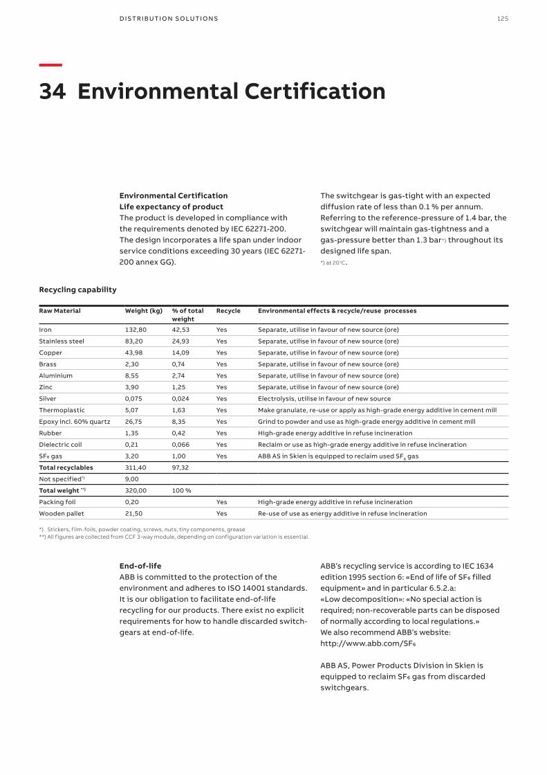
125D I S TR I B U TI O N S O LU TI O N S
—34 Environmental Certification
Environmental CertificationLife expectancy of productThe product is developed in compliance with the requirements denoted by IEC 62271-200. The design incorporates a life span under indoor service conditions exceeding 30 years (IEC 62271-200 annex GG).
The switchgear is gas-tight with an expected diffusion rate of less than 0.1 % per annum. Referring to the reference-pressure of 1.4 bar, the switchgear will maintain gas-tightness and a gas-pressure better than 1.3 bar*) throughout its designed life span. *) at 20oC.
Recycling capability
Raw Material Weight (kg) % of total weight
Recycle Environmental effects & recycle/reuse processes
Iron 132,80 42,53 Yes Separate, utilise in favour of new source (ore)
Stainless steel 83,20 24,93 Yes Separate, utilise in favour of new source (ore)
Copper 43,98 14,09 Yes Separate, utilise in favour of new source (ore)
Brass 2,30 0,74 Yes Separate, utilise in favour of new source (ore)
Aluminium 8,55 2,74 Yes Separate, utilise in favour of new source (ore)
Zinc 3,90 1,25 Yes Separate, utilise in favour of new source (ore)
Silver 0,075 0,024 Yes Electrolysis, utilise in favour of new source
Thermoplastic 5,07 1,63 Yes Make granulate, re-use or apply as high-grade energy additive in cement mill
Epoxy incl. 60% quartz 26,75 8,35 Yes Grind to powder and use as high-grade energy additive in cement mill
Rubber 1,35 0,42 Yes High-grade energy additive in refuse incineration
Dielectric coil 0,21 0,066 Yes Reclaim or use as high-grade energy additive in refuse incineration
SF6 gas 3,20 1,00 Yes ABB AS in Skien is equipped to reclaim used SF6 gas
Total recyclables 311,40 97,32
Not specified*) 9,00
Total weight **) 320,00 100 %
Packing foil 0,20 Yes High-grade energy additive in refuse incineration
Wooden pallet 21,50 Yes Re-use of use as energy additive in refuse incineration
End-of-lifeABB is committed to the protection of the environment and adheres to ISO 14001 standards. It is our obligation to facilitate end-of-life recycling for our products. There exist no explicit requirements for how to handle discarded switch-gears at end-of-life.
ABB’s recycling service is according to IEC 1634 edition 1995 section 6: «End of life of SF6 filled equipment» and in particular 6.5.2.a: «Low decomposition»: «No special action is required; non-recoverable parts can be disposed of normally according to local regulations.» We also recommend ABB’s website: http://www.abb.com/SF6
ABB AS, Power Products Division in Skien is equipped to reclaim SF6 gas from discarded switchgears.
*) Stickers, film-foils, powder coating, screws, nuts, tiny components, grease**) All figures are collected from CCF 3-way module, depending on configuration variation is essential.

126 S A F E R I N G / S A F E PLU S 1 2- 2 4 K V

127D I S TR I B U TI O N S O LU TI O N S

—ABB ASEPDSP.O.Box 108, SentrumN-3701 Skien, NorwayPhone: +47 35 58 20 00
www.abb.com
1VD
D0
06
104
EN
rev
07-
2018
© Copyright 2018 ABB. All rights reserved. Specifications subject to change without notice.