Routing of Power Efficient IR-UWB Wireless and Wired Services for In-Building Network Applications
13
JOURNAL OF LIGHTWAVE TECHNOLOGY, VOL. 30, NO. 11, JUNE 1, 2012 1651 Routing of Power Efficient IR-UWB Wireless and Wired Services for In-Building Network Applications Solomon Tesfay Abraha, Student Member, IEEE, Chigo Okonkwo, Member, IEEE, Prasanna Angulugaha Gamage, Member, IEEE, Eduward Tangdiongga, Member, IEEE, and Ton Koonen, Fellow, IEEE Abstract—We present a wireless link budget analysis for im- pulse-radio ultrawideband (IR-UWB) systems with different pulse-shaping techniques using a realistic path loss model. Sim- ulation results confirm that a proper pulse design technique is crucial for satisfying Federal Communications Commission mask requirements and performance enhancement of IR-UWB systems. We present a novel pulse design technique, based on a linear combination of modified doublets pulses and compare it with conventional pulses such as monocycle, doublet and fifth-order derivative of Gaussian pulses. The proposed pulse outperforms the conventional pulses in terms of spectral power efficiency and achievable reach using an M-ary pulse-amplitude modulation format and a fixed data rate. Furthermore, we propose and experimentally demonstrate routing over a hybrid wired-wireless network of IR-UWB services using the proposed pulse shape. The routing functionality is realized using a single semiconductor optical amplifier based on the cross-gain modulation technique. Error-free transmission of both 1.25 Gb/s baseband wired services and 2 Gb/s wireless IR-UWB services has been achieved over 1 km fiber link. The proposed technique can efficiently distribute and multicast both wireless IR-UWB and wired services in future in-building networks. Index Terms—Impulse radio, in-building network, signal pro- cessing, ultrawideband (UWB) communications. I. INTRODUCTION I N recent years, there has been growing interest for converged integration of wired/wireless over a single in-building optical network infrastructure to provide both broadband communications and sensor applications. From the indoor wireless perspective, some of the important design re- quirements are high data capacity, robustness against multipath fading, low power dissipation, co-existence with other wireless services, low cost, and reduced complexity. Ultrawideband (UWB) technology is considered as one of the most promising techniques for next-generation short-range broadband wireless and sensor networks with capabilities of achieving these design requirements [1]–[8]. However, the main limitation of UWB systems is the limited propagation distance (typically m) Manuscript received December 28, 2011; revised February 09, 2012; accepted February 22, 2012. Date of publication February 29, 2012; date of current version April 06, 2012. This work was supported by the European Union program FP7 ICT-212352 ALPHA. The authors are with the COBRA Research Institute, Eindhoven Uni- versity of Technology, 5600MB Eindhoven, The Netherlands (e-mail: [email protected]; [email protected]; [email protected]; e.tang- [email protected]; [email protected]). Color versions of one or more of the figures in this paper are available online at http://ieeexplore.ieee.org. Digital Object Identifier 10.1109/JLT.2012.2189554 over which the expected high data rate can be realized. This is mainly due to low power spectral density (PSD) assigned to dB m/MHz in the frequency range from 3.1 to 10.6 GHz regulated by the Federal Communications Commission (FCC). To increase the coverage area, UWB signals can be distributed over wired lines such as coaxial cable or optical fiber. Due to the low loss, large bandwidth, and immunity to electromagnetic interference, inherent to optical fiber, UWB over fiber is considered as promising solution [9]. UWB systems based on trains of short duration pulses formed using a single basic pulse are called impulse radio ultrawide- band (IR-UWB) [2]. It is this property that has led to the term “impulse radio.” The interval between individual pulses can be uniform or variable. There are a number of different methods that can be used for modulating the pulse train with data for communications [3]–[5]. One of the common characteristics of IR-UWB systems is that the pulse train is transmitted without translation to a higher carrier frequency, and thus, IR-UWB is sometimes also termed “carrierless” radio. One of the fundamental points that require detailed consid- eration in IR-UWB circuits and systems design is the selection of the impulse signal type as it determines the performance of the IR-UWB system [6]. Various electrical and optical IR-UWB generator architectures have been proposed [7]–[14]. The most commonly used pulse-shaping techniques are based on Gaussian-based monocycle and doublet pulses due to better bit error rates (BERs) and robust multipath resilience in com- parison to other impulse signals [6]. In particular, in the past few years, several photonic generation schemes that focused on the generation of the conventional monocycle and doublet employing different schemes have been reported [9]–[14]. However, these pulse shapes poorly exploit the permissible power under the FCC mask without additional processing, resulting in limited wireless coverage. On the other hand, electrical generation of fifth-order deriva- tives [7] and photonic generation techniques that focused on nonconventional pulses aimed at enhancing the power spectral efficiency has been reported [15]–[19]. It is important to note that, most of the IR-UWB-over-fiber systems reported in the literature differs in terms of their generation techniques, mod- ulation techniques, bandwidth, center frequency, data rate, and pulse shape [9]–[35]. For example, the data rate of IR-UWB over fiber varies widely from 500 Mb/s [17] to 5 Gb/s [35]. The wireless demonstrations of IR-UWB-over-fiber systems range from 5 cm [22] to 8 m [33]. This clearly indicates a need for a realistic wireless link budget analysis for IR-UWB systems to determine the achievable data rate versus the wireless range. 0733-8724/$31.00 © 2012 IEEE
-
Upload
independent -
Category
Documents
-
view
2 -
download
0
Transcript of Routing of Power Efficient IR-UWB Wireless and Wired Services for In-Building Network Applications

JOURNAL OF LIGHTWAVE TECHNOLOGY, VOL. 30, NO. 11, JUNE 1, 2012 1651
Routing of Power Efficient IR-UWB Wireless andWired Services for In-Building Network Applications
Solomon Tesfay Abraha, Student Member, IEEE, Chigo Okonkwo, Member, IEEE,Prasanna Angulugaha Gamage, Member, IEEE, Eduward Tangdiongga, Member, IEEE, and
Ton Koonen, Fellow, IEEE
Abstract—We present a wireless link budget analysis for im-pulse-radio ultrawideband (IR-UWB) systems with differentpulse-shaping techniques using a realistic path loss model. Sim-ulation results confirm that a proper pulse design technique iscrucial for satisfying Federal Communications Commission maskrequirements and performance enhancement of IR-UWB systems.We present a novel pulse design technique, based on a linearcombination of modified doublets pulses and compare it withconventional pulses such as monocycle, doublet and fifth-orderderivative of Gaussian pulses. The proposed pulse outperformsthe conventional pulses in terms of spectral power efficiency andachievable reach using an M-ary pulse-amplitude modulationformat and a fixed data rate. Furthermore, we propose andexperimentally demonstrate routing over a hybrid wired-wirelessnetwork of IR-UWB services using the proposed pulse shape.The routing functionality is realized using a single semiconductoroptical amplifier based on the cross-gain modulation technique.Error-free transmission of both 1.25 Gb/s baseband wired servicesand 2 Gb/s wireless IR-UWB services has been achieved over 1km fiber link. The proposed technique can efficiently distributeand multicast both wireless IR-UWB and wired services in futurein-building networks.
Index Terms—Impulse radio, in-building network, signal pro-cessing, ultrawideband (UWB) communications.
I. INTRODUCTION
I N recent years, there has been growing interest forconverged integration of wired/wireless over a single
in-building optical network infrastructure to provide bothbroadband communications and sensor applications. From theindoor wireless perspective, some of the important design re-quirements are high data capacity, robustness against multipathfading, low power dissipation, co-existence with other wirelessservices, low cost, and reduced complexity. Ultrawideband(UWB) technology is considered as one of the most promisingtechniques for next-generation short-range broadband wirelessand sensor networks with capabilities of achieving these designrequirements [1]–[8]. However, the main limitation of UWBsystems is the limited propagation distance (typically m)
Manuscript received December 28, 2011; revised February 09, 2012;accepted February 22, 2012. Date of publication February 29, 2012; date ofcurrent version April 06, 2012. This work was supported by the EuropeanUnion program FP7 ICT-212352 ALPHA.The authors are with the COBRA Research Institute, Eindhoven Uni-
versity of Technology, 5600MB Eindhoven, The Netherlands (e-mail:[email protected]; [email protected]; [email protected]; [email protected]; [email protected]).Color versions of one or more of the figures in this paper are available online
at http://ieeexplore.ieee.org.Digital Object Identifier 10.1109/JLT.2012.2189554
over which the expected high data rate can be realized. Thisis mainly due to low power spectral density (PSD) assignedto dB m/MHz in the frequency range from 3.1 to 10.6GHz regulated by the Federal Communications Commission(FCC). To increase the coverage area, UWB signals can bedistributed over wired lines such as coaxial cable or opticalfiber. Due to the low loss, large bandwidth, and immunity toelectromagnetic interference, inherent to optical fiber, UWBover fiber is considered as promising solution [9].UWB systems based on trains of short duration pulses formed
using a single basic pulse are called impulse radio ultrawide-band (IR-UWB) [2]. It is this property that has led to the term“impulse radio.” The interval between individual pulses can beuniform or variable. There are a number of different methodsthat can be used for modulating the pulse train with data forcommunications [3]–[5]. One of the common characteristics ofIR-UWB systems is that the pulse train is transmitted withouttranslation to a higher carrier frequency, and thus, IR-UWB issometimes also termed “carrierless” radio.One of the fundamental points that require detailed consid-
eration in IR-UWB circuits and systems design is the selectionof the impulse signal type as it determines the performanceof the IR-UWB system [6]. Various electrical and opticalIR-UWB generator architectures have been proposed [7]–[14].The most commonly used pulse-shaping techniques are basedon Gaussian-based monocycle and doublet pulses due to betterbit error rates (BERs) and robust multipath resilience in com-parison to other impulse signals [6]. In particular, in the pastfew years, several photonic generation schemes that focusedon the generation of the conventional monocycle and doubletemploying different schemes have been reported [9]–[14].However, these pulse shapes poorly exploit the permissiblepower under the FCC mask without additional processing,resulting in limited wireless coverage.On the other hand, electrical generation of fifth-order deriva-
tives [7] and photonic generation techniques that focused onnonconventional pulses aimed at enhancing the power spectralefficiency has been reported [15]–[19]. It is important to notethat, most of the IR-UWB-over-fiber systems reported in theliterature differs in terms of their generation techniques, mod-ulation techniques, bandwidth, center frequency, data rate, andpulse shape [9]–[35]. For example, the data rate of IR-UWBover fiber varies widely from 500 Mb/s [17] to 5 Gb/s [35]. Thewireless demonstrations of IR-UWB-over-fiber systems rangefrom 5 cm [22] to 8 m [33]. This clearly indicates a need fora realistic wireless link budget analysis for IR-UWB systemsto determine the achievable data rate versus the wireless range.
0733-8724/$31.00 © 2012 IEEE
1652 JOURNAL OF LIGHTWAVE TECHNOLOGY, VOL. 30, NO. 11, JUNE 1, 2012
Before building the actual system for a particular application, ithelps the system designers to decide on different design choicessuch as pulse-shaping techniques, modulation format, codingtype, antenna types, and configurations. In this context, it isimperative to compare the performance of the proposed pulse-shaping techniques with most commonly pulse designing tech-niques. Furthermore, the networking and convergence aspectof IR-UWB over a single in-building optical networks are ex-tremely important.This paper is organized as follows. After the introduction
in Section I, the channel capacity of IR-UWB systems fromShannon’s communication theory perspective and its impli-cations on pulse-shaping modulation formats and coding isdiscussed in Section II. The comparison of the most commonlyused pulse-shaping techniques with our pulse design techniquefrom the viewpoint of FCC-mask restrictions and spectralpower efficiency is discussed in Section III. Section IV quanti-fies the link power budget analysis and presents a performancecomparison among the different pulse-shaping techniques.Section V presents the motivation of routing of integratedIR-UWB and wired baseband date for in-building networks.Section VI presents experimental setup in detail. In Section VII,the detailed experimental results from routing the of 2 Gb/swireless IR-UWB and 1.25 Gb/s wired services are presented.Finally, the paper is concluded in Section VIII.
II. CAPACITY OF IR-UWB SYSTEMS
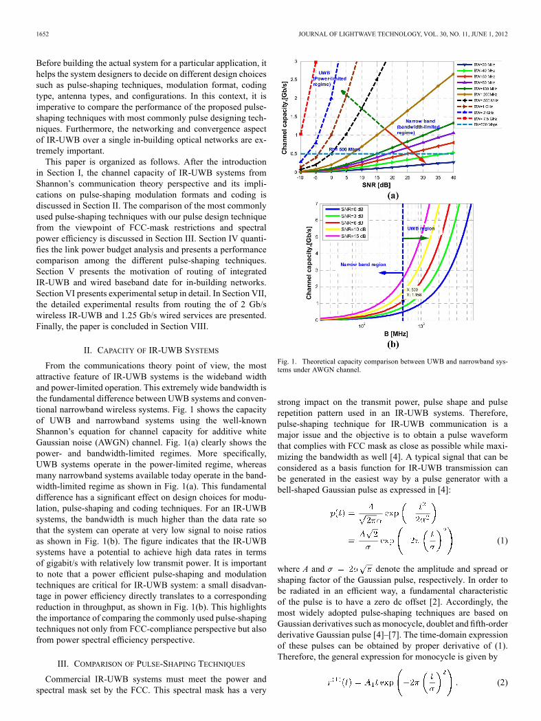
From the communications theory point of view, the mostattractive feature of IR-UWB systems is the wideband widthand power-limited operation. This extremely wide bandwidth isthe fundamental difference between UWB systems and conven-tional narrowband wireless systems. Fig. 1 shows the capacityof UWB and narrowband systems using the well-knownShannon’s equation for channel capacity for additive whiteGaussian noise (AWGN) channel. Fig. 1(a) clearly shows thepower- and bandwidth-limited regimes. More specifically,UWB systems operate in the power-limited regime, whereasmany narrowband systems available today operate in the band-width-limited regime as shown in Fig. 1(a). This fundamentaldifference has a significant effect on design choices for modu-lation, pulse-shaping and coding techniques. For an IR-UWBsystems, the bandwidth is much higher than the data rate sothat the system can operate at very low signal to noise ratiosas shown in Fig. 1(b). The figure indicates that the IR-UWBsystems have a potential to achieve high data rates in termsof gigabit/s with relatively low transmit power. It is importantto note that a power efficient pulse-shaping and modulationtechniques are critical for IR-UWB system: a small disadvan-tage in power efficiency directly translates to a correspondingreduction in throughput, as shown in Fig. 1(b). This highlightsthe importance of comparing the commonly used pulse-shapingtechniques not only from FCC-compliance perspective but alsofrom power spectral efficiency perspective.
III. COMPARISON OF PULSE-SHAPING TECHNIQUES
Commercial IR-UWB systems must meet the power andspectral mask set by the FCC. This spectral mask has a very
Fig. 1. Theoretical capacity comparison between UWB and narrowband sys-tems under AWGN channel.
strong impact on the transmit power, pulse shape and pulserepetition pattern used in an IR-UWB systems. Therefore,pulse-shaping technique for IR-UWB communication is amajor issue and the objective is to obtain a pulse waveformthat complies with FCC mask as close as possible while maxi-mizing the bandwidth as well [4]. A typical signal that can beconsidered as a basis function for IR-UWB transmission canbe generated in the easiest way by a pulse generator with abell-shaped Gaussian pulse as expressed in [4]:
(1)
where A and denote the amplitude and spread orshaping factor of the Gaussian pulse, respectively. In order tobe radiated in an efficient way, a fundamental characteristicof the pulse is to have a zero dc offset [2]. Accordingly, themost widely adopted pulse-shaping techniques are based onGaussian derivatives such as monocycle, doublet and fifth-orderderivative Gaussian pulse [4]–[7]. The time-domain expressionof these pulses can be obtained by proper derivative of (1).Therefore, the general expression for monocycle is given by
(2)

ABRAHA et al.: POWER EFFICIENT IR-UWB WIRELESS AND WIRED SERVICES 1653
Using a similar procedure, the general expression for secondderivative of Gaussian pulse or doublet pulse is given by
(3)
The corresponding modified doublet with arbitrary scaling ormodifying parameter is given by [19]
(4)
Notice that, if and is a set of very small positivevalues, then results in a family of modified doublet pulses.As a special case, for , then and becomes con-ventional doublet in (3). Therefore, a modified doublet pulsesis a Gaussian doublet variant in which the amplitude ratio be-tween its positive and negative part of doublet pulse is slightlymodified as reported in [19].The fifth-order derivative of Gaussian pulse is expressed
as [7]
(5)
where the superscript shown in is the order of thederivative. The term is the corresponding appropriateamplitudes.With the objective of a better FCC mask, high power spectral
efficiency and simplicity, we have recently reported a photonicgeneration technique based on a linear combination modifieddoublet in [19]. The linear combination operation is expressedas
(6)
where and are the input modified doublets, oneis delayed from the other, and . Thislinear sum in practice can be considered as a two-tap microwavedelay filter approach, hence providing the benefits of the modi-fied doublet and the filtering effect of the microwave delay line.In this paper, we report the detailed analysis of our proposedpulse compared to the most commonly used technique and itsperformance in terms of its achievable data rate versus distanceis also presented.The Fourier transform of the nth-order derivative of Gaussian
pulse is given as [7]
(7)
Considering the amplitude spectrum of the nth derivative ofGaussian pulse is expressed as
(8)
The frequency at the maximum value of (8) commonly referredto as the peak emission frequency is given by the criticalpoint of . Accordingly, a general relationship betweenpeak emission frequency , the order of derivation n and theshaping factor , is given by [2], [18]
(9)
The normalized PSD of nth derivative of Gaussian pulse can beexpressed as
(10)Using a similar approach, the amplitude spectrum of the pro-
posed pulse or linear sum is given by
(11)
where the is the amplitude spectrum of the modifieddoublet. The filtering effect of the microwave delay line can beseen from the bandpass frequency response of the second termin (11). For small values of , the linear combination given in(6) can be approximated as the derivative of the modified dou-blet pulses, which leads to higher derivatives of Gaussian pulsecalled modified third-order derivative of Gaussian pulse, .The corresponding peak emission frequency of this modifiedthird-order derivative of Gaussian pulse is related to the peakfrequency modified doublet as described in (9). The approxi-mate value under the assumption that is very small comparedto the pulse-shaping parameter is expressed as
(12)
where is the arbitrary scaling parameter. Note that for, the modified doublet becomes the conventional doublet andthe modified third-order derivative, becomes the normalthird-order derivative of Gaussian pulse.Therefore, the corresponding normalized PSD of the pro-
posed pulse or linear combination of modified doublet pulseis given as
(13)where the expression for is given by [30]
(14)
Hence, the transmitted PSD of the proposed pulse is given by
(15)
where is the peak PSD the FCC permits. The parameters, and can now be chosen under the constraint satisfying

1654 JOURNAL OF LIGHTWAVE TECHNOLOGY, VOL. 30, NO. 11, JUNE 1, 2012
TABLE ISUMMARY OF KEY PARAMETERS OF THE PULSES ( : PULSE-SHAPING FACTOR, : PEAK FREQUENCY, : FRACTIONAL BANDWIDTH, dB: 3 DB
BANDWIDTH, AND % : POWER SPECTRAL EFFICIENCY)
Fig. 2. Time-domain pulse shapes of different pulse shaping. (a) Monocycle.(b) Doublet. (c) Proposed pulse. (d) Fifth-order derivative.
the FCC-mask requirements and maximizing the spectral powerefficiency defined as [19]
% (16)
In our analysis ps, and ps are thevalues of parameters resulting in a power spectral efficiencyof 57.40% for the proposed pulse. This power spectral effi-ciency is near to the highest power spectral efficiency of 63%for photonic-generated IR-UWB reported in [16]. Note thatthe proposed pulse exhibits higher power spectral efficiencycompared to 50.97% reported in [17] and significant higherthan the 48.52% reported for electrically generated pulses in[18]. Although the power spectral efficiency is slightly lessthan the reported result in [16], we believe that the efficiencycan be increased further by employing some microwavephotonic-shaping techniques at the expense of increasing com-plexity (and hence costs) in the system.Fig. 2 presents the time-domain pulses shapes of the con-
ventional monocycle, doublet, and fifth-order derivative pulsesin comparison to the proposed pulse. Notice that the proposedpulse is similar to the third-order derivative pulses with threezero-crossings higher than monocycle and doublet but less than
Fig. 3. Fully FCC-mask compliant PSD of monocycle, doublet, fifth-orderderivative, and proposed pulse.
the fifth-order derivative. This clearly indicates that the peak fre-quency lie within the peak frequency of doublet and the fifth-order derivative as shown in the PSD of the pulses shown inFig. 3. Fig. 3 shows the PSD of these pulses, showing that theproposed pulse shape outperforms the conventional monocycleand doublet pulses. It also shows that the power spectral effi-ciency is higher than the fifth-order derivative due to its higher3 dB bandwidth, as shown in Fig. 3. In addition, Table I sum-marizes some of the parameters of the pulses and it is evidentthat as the order of the derivative increases the peak frequencyincreases and 3 dB bandwidth decreases under the constraintof the FCC mask. Thus, the proposed pulse has a simple pulseshape but has better FCC-mask compliance and better powerspectral efficiency. It should be noted that the proposed pulsecan be easily realizable using microwave photonics-based mi-crowave delay line approach.
IV. LINK BUDGET AND DATA RATE ANALYSIS
In principle, UWB signal should be able to transmit high datarates, as shown in Fig. 1. The theoretical channel capacity versusdistance was evaluated for IR-UWB systems using the free-space path loss model with a single center frequencyGHz in [33]. In [36], the distance as a function of throughputwas analyzed for pulse-amplitude modulation (PAM) IR-UWBsystems. However, this analysis was not performed using a more

ABRAHA et al.: POWER EFFICIENT IR-UWB WIRELESS AND WIRED SERVICES 1655
Fig. 4. General schematic for link budget analysis.
realistic pulse-shaping technique and the path loss was consid-ered constant over the bandwidth of the signal. Therefore, foran IR-UWB system, the bandwidth is larger and hence the fre-quency dependence of the system should be considered [4], [5].In addition, realistic pulses should be considered for evaluationof the performance of IR-UWB systems. To highlight the ef-fect of the pulse-shaping technique on the performance of theIR-UWB systems, we perform a comparison amongmonocycle,doublet, fifth-order derivative, and the proposed pulse. For a faircomparison, we assume that the transmitted and received an-tennas are omnidirectional with unity gain. The general schemeused for the analysis shown in Fig. 4. It is assumed that the op-tical link shown in Fig. 4 does not produce any distortion of thedesired IR-UWB pulses. In addition, all the electrical compo-nents involved in the system have enough bandwidth to supportthe whole IR-UWB bandwidth. Noise of the system at the re-ceiver is assumed to be AWGN. The operating environment ofthe system is assumed to be free-space with a power decayingexponent, . Furthermore, it is also assumed that here is nomultipath scenario, which can cause intersymbol interferencefor the system. In the calculations, the noise spectral densityis taken with the formdB m/MHz, where is the Boltzmann’s constantJ/K, K is room temperature. Noise figure ofdB and a link margin, of dB are assumed.The commonly used Friis transmission formula may give
misleading or incorrect results when applied to UWB systems[7]. The Friis transmission formula or path loss formula usedfor most communication system link design predict that thereceived power will decrease with the square of increasingfrequency. The equation is given as follows:
(17)
where is the transmitted power, and are the trans-mitted and received antenna gains, respectively, is the car-rier frequency, and is the speed of light. It is important tonote that for narrowband systems, this change in received powerover the signal bandwidth is usually ignored as it has little ef-fect. However, IR-UWB systems can occupy large bandwidthin terms of several gigahertz. Therefore, the frequency depen-dence of the Friis appears to have a filter with its transfer func-tion proportional to the inverse of the square of the frequency(i.e., ). The main source of this frequencydependence is due to the implicit assumption in the Friis equa-tion that the antenna had a constant gain. In reality, the antenna
can be either constant gain or constant aperture. It is possibleto have antenna configurations based on the combinations ofconstant gain/constant aperture antennas. Based on the configu-ration of the antenna systems, the received power can be eitherincreased by the square frequency, decreased with the square ofthe frequency or independent of the frequency [37]. In general,it is extremely important to note that antenna is a crucial com-ponent for IR-UWB systems. It can distort the spectrum of theIR-pulses and affect the performance of the overall system [38].In other words, if the antenna gain response is not reasonably flatwithin the required band, then the antenna frequency responseshould be considered during the pulse design stage to maximizethe spectral efficiency as reported in [38]. For this analysis, boththe transmit and received antennas are assumed to be omnidi-rectional with relatively constant gain antennas in keeping withcommercially available (Skycross SMT-3TO10M-A) antennas,as has been reported in [20].To account for variations across the bandwidth of the
IR-UWB signal, (17) should be modified. In particular, thetransmitted and received power should be calculated usingthe integral of the PSD within frequency range and the totaltransmitted power should be within the FCC-mask restrictions.Therefore, the transmitted power is given by
(18)
where is defined for conventional pulses in (10) andproposed pulse in (13), is defined in (15) and
dB m/MHz is the maximum PSD permitted. If we as-sume that the received signal occupies a band from to ,the received power at distance becomes
(19)
where is the wideband path loss with center frequencyin (17) replaced by the variable . Accordingly, the receivedpower becomes
(20)
The parameter involved in the analysis can be observed fromthe general scheme shown in Fig. 4. The received power given

1656 JOURNAL OF LIGHTWAVE TECHNOLOGY, VOL. 30, NO. 11, JUNE 1, 2012
in (20) necessary at distance to achieve a given SNR can becomputed from the relation given as follows [7]:
(21)
where LM is the link margin of the system and is the re-ceived noise power, and is equal to
(22)
where is the noise equivalent bandwidth of the receivershown in Fig. 4. If the symbol rate is assumed equal to the pulserepetition rate, in other words, a single UWB pulse is trans-mitted for each data symbol, and the energy per informationsymbol equals the energy per pulse. Then, the average outputSNR is given by
(23)
where is the received symbol energy, is the symbol du-ration, and is the symbol rate. For uncoded and M-arraymodulation scheme, the symbol rate is related to the bit rate asfollows:
(24)
Similarly, the received symbol energy is related to the energyper bit using the following expression:
(25)
For a target BER, , the required for PAM can beobtained using the following equation [4]:
(26)
Therefore, the compact relationship between the distance andthe data rate can be represented as the following equation:
(27)
Figs. 5 and 6 show the achievable distance for 2 Gb/sIR-UWB for various M-ary pulse-amplitude modulation(M-PAM) format employing different pulse-shaping tech-niques. For these results, the target BER is set at and
, respectively. The simulation results confirm that, the pro-posed pulse and fifth-order derivative outperform monocycleand double pulses in terms of the achievable distance. The mainreason is the fact that the proposed pulse and fifth-order deriva-tive are relatively power efficient pulses with power spectralefficiency of 57.40% and 50.75%, respectively. Furthermore,the achievable distance decreases for higher modulation level.This is due to the fact that PAM is a spectrally efficient modu-lation technique but it is not power efficient. Furthermore, weexpect that the nonconventional pulses proposed in [16]–[18]
Fig. 5. Transmission range for M-PAM ).
Fig. 6. Transmission range for M-PAM .
Fig. 7. Transmission ranges for 2-PAM for different data rate using differentpulse-shaping techniques .
to have higher performance than monocycle and doublet pulsesdue to their reported higher power efficiencies. The resultin Fig. 7 shows the expected distance for different IR-UWBrate for 2-PAM for targeted BER of . In general, thesimulation result in Fig. 7 shows the monocycle and doubletpulses have limited coverage in terms of few centimeters forhigher data rates Gb/s. For , the proposed
ABRAHA et al.: POWER EFFICIENT IR-UWB WIRELESS AND WIRED SERVICES 1657
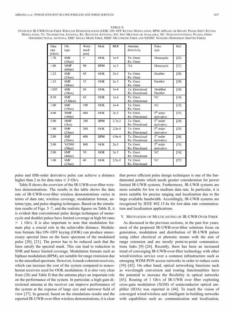
TABLE IIOVERVIEW IR-UWB-OVER-FIBER WIRELESS DEMONSTRATIONS (OOK: ON–OFF KEYING MODULATION, BPM: BIPHASE OR BINARY PHASE-SHIFT KEYINGMODULATION, TX: TRANSMITTER ANTENNA, RX: RECEIVER ANTENNA, NA: NOT MENTION OR AVAILABLE, NC: NONCONVENTIONAL PULSES, OMNI:
OMNIDIRECTIONAL ANTENNA, SMF: SINGLE MODE FIBER, MMF: MULTIMODE FIBER AND NZDSF: NONZERO DISPERSION SHIFTED FIBER)
pulse and fifth-order derivative pulse can achieve a distancehigher than 2 m for data rates Gb/s.Table II shows the overview of the IR-UWB-over-fiber wire-
less demonstrations. The results in the table shows the datarate of IR-UWB-over-fiber wireless demonstrations varies interms of data rate, wireless coverage, modulation format, an-tenna type, and pulse-shaping techniques. Based on the simula-tion results of Figs. 5–7, and the realistic figures on Table II, itis evident that conventional pulse design techniques of mono-cycle and doublet pulses have limited coverage at high bit rates
Gb/s. It is also important to note that modulation for-mats play a crucial role in the achievable distance. Modula-tion formats like ON–OFF keying (OOK) can produce unnec-essary spectral lines on the basic spectrum of the modulatedpulse [20], [21]. The power has to be reduced such that thelines satisfy the spectral mask. This can lead to reduction inSNR and hence limited coverage. Modulation formats such asbiphase modulation (BPM), are suitable for range extension dueto the smoothed spectrum. However, it needs coherent receivers,which can increase the cost of the system compared to nonco-herent receivers used for OOK modulation. It is also very clearfrom (28) and Table II that the antenna plays an important roleon the performance of the system. In particular, a high-gain di-rectional antenna at the receiver can improve performance ofthe system at the expense of large size and narrower field ofview [37]. In general, based on the simulations results and thereported IR-UWB-over-fiber wireless demonstrations, it is clear
that power efficient pulse design techniques is one of the fun-damental points which needs greater consideration for powerlimited IR-UWB systems. Furthermore, IR-UWB systems aremore suitable for low to medium data rate. In particular, it ismore suitable for precise ranging and localization due to thelarge available bandwidth. Accordingly, IR-UWB systems arerecognized by IEEE 802.15.4a for low-data rate communica-tion and localization applications.
V. MOTIVATION OF MULTICASTING OF IR-UWB OVER FIBER
As discussed in the previous sections, in the past few years,most of the proposed IR-UWB-over-fiber solutions focus ongeneration, modulation and distribution of IR-UWB pulsesusing either electrical or photonic means with the aim ofrange extension and are mostly point-to-point communica-tions links [9]–[26]. Recently, there has been an increasedtrend of converging IR-UWB-over-fiber technology with otherwired/wireless service over a common infrastructure such asemerging WDM-PON access networks in order to reduce costs[39]–[42]. On other hand, optical networking functions suchas wavelength conversion and routing functionalities havethe potential to increase the flexibility in optical networks[43]. Routing of 1 Gb/s of IR-UWB over fiber exploitingcross-gain modulation (XGM) of semiconductor optical am-plifier (SOA) was reported in [44]. To reach the vision ofconverged wired/wireless and intelligent in-building networkswith capabilities such as: communication and localization,
1658 JOURNAL OF LIGHTWAVE TECHNOLOGY, VOL. 30, NO. 11, JUNE 1, 2012
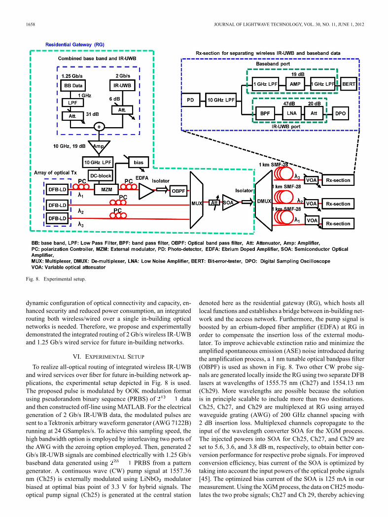
Fig. 8. Experimental setup.
dynamic configuration of optical connectivity and capacity, en-hanced security and reduced power consumption, an integratedrouting both wireless/wired over a single in-building opticalnetworks is needed. Therefore, we propose and experimentallydemonstrated the integrated routing of 2 Gb/s wireless IR-UWBand 1.25 Gb/s wired service for future in-building networks.
VI. EXPERIMENTAL SETUP
To realize all-optical routing of integrated wireless IR-UWBand wired services over fiber for future in-building network ap-plications, the experimental setup depicted in Fig. 8 is used.The proposed pulse is modulated by OOK modulation formatusing pseudorandom binary sequence (PRBS) of dataand then constructed off-line using MATLAB. For the electricalgeneration of 2 Gb/s IR-UWB data, the modulated pulses aresent to a Tektronix arbitrary waveform generator (AWG 7122B)running at 24 GSamples/s. To achieve this sampling speed, thehigh bandwidth option is employed by interleaving two ports ofthe AWG with the zeroing option employed. Then, generated 2Gb/s IR-UWB signals are combined electrically with 1.25 Gb/sbaseband data generated using PRBS from a patterngenerator. A continuous wave (CW) pump signal at 1557.36nm (Ch25) is externally modulated using LiNbO modulatorbiased at optimal bias point of 3.3 V for hybrid signals. Theoptical pump signal (Ch25) is generated at the central station
denoted here as the residential gateway (RG), which hosts alllocal functions and establishes a bridge between in-building net-work and the access network. Furthermore, the pump signal isboosted by an erbium-doped fiber amplifier (EDFA) at RG inorder to compensate the insertion loss of the external modu-lator. To improve achievable extinction ratio and minimize theamplified spontaneous emission (ASE) noise introduced duringthe amplification process, a 1 nm tunable optical bandpass filter(OBPF) is used as shown in Fig. 8. Two other CW probe sig-nals are generated locally inside the RG using two separate DFBlasers at wavelengths of 1555.75 nm (Ch27) and 1554.13 nm(Ch29). More wavelengths are possible because the solutionis in principle scalable to include more than two destinations.Ch25, Ch27, and Ch29 are multiplexed at RG using arrayedwaveguide grating (AWG) of 200 GHz channel spacing with2 dB insertion loss. Multiplexed channels copropagate to theinput of the wavelength converter SOA for the XGM process.The injected powers into SOA for Ch25, Ch27, and Ch29 areset to 5.6, 3.6, and 3.8 dB m, respectively, to obtain better con-version performance for respective probe signals. For improvedconversion efficiency, bias current of the SOA is optimized bytaking into account the input powers of the optical probe signals[45]. The optimized bias current of the SOA is 125 mA in ourmeasurement. Using the XGMprocess, the data on CH25modu-lates the two probe signals; Ch27 and Ch 29, thereby achieving

ABRAHA et al.: POWER EFFICIENT IR-UWB WIRELESS AND WIRED SERVICES 1659
Fig. 9. PSD of the wireless IR-UWB data.
the multicast wireless IR-UWB and wired services for all-op-tical routing. Employing an AWG, the routing of the opticalsignal to their final destinations is performed by the demulti-plexing (DMUX). The optical signals reach the receiver after 1km SMF-28 distribution fiber where the signal is detected by a10 GHz photodetector. Then, the received electrical signals areseparated in the electrical domain using appropriate filters andfinally amplified for processing.The performance analysis is done using a DSP-based BER
measurement for IR-UWB data and using bit-error-tester(BERT) for wired data. A 20 GHz real-time TektronixDPO72004 digital storage oscilloscope running at a sam-pling rate of 50 GSamples/s is used for capturing the IR-UWBpulses. The collected IR-UWB data is processed off-line fordemodulation and DSP-based BER measurement. Finally, anRF spectrum analyzer is employed to present the electricalspectrum of our pulse for comparison with the FCC-mask re-quirements. Although, in this paper, we consider the electricalgeneration of the proposed pulse using AWG, the optical gener-ation of the pulse is reported in [19]. The feasibility of modifieddoublet generation based on a programmable photonic chip fre-quency discriminator have been experimentally demonstratedrecently and reported in [46]. In general, we believe that theproposed pulse can be generated in the future using photonicintegrated chip based on the concept of microwave delay linefilters.
VII. EXPERIMENTAL RESULTS
To meet the FCC-mask requirement and effciently use theavailable spectrum of IR-UWB, we employ the pulse shapingthat has a low spectral components below 2 GHz as describedin Section III. Fig. 9 shows the available free spectrum (GHz) of the proposed IR-UWB pulse. The wired baseband dataof 1.25 Gb/s is shown in Fig. 10 and spectrum is filtered usinglow-pass filter (LPF) of 1 GHz bandwidth to limit the bandwidthbelow 2 GHz to avoid any interfence with IR-UWB data. Fig. 11shows the filtered baseband signal. Thus, the LPF suppresses thehigher side lobes shown in Fig. 10. Fig. 12 shows the efficientlymultiplexed 2 Gb/s IR-UWB and 1.25 Gb/s signals with a viewto mitigate the impact of interference.
Fig. 10. PSD of the baseband wired data before LPF filtering.
Fig. 11. PSD of the baseband wired data after LPF filtering.
Fig. 12. PSD of wired baseband and wireless IR-UWB multiplexedelectrically.
The data modulated channel (Ch25) is multiplexed withprobe channels (Ch27 and Ch29) for multiwavelength convser-sion using XGM-SOA. Fig. 13 presents the optical spectra ofall channels and the products from four-wave mixing (FWM)at SOA output. The FWM products are due to the high optical

1660 JOURNAL OF LIGHTWAVE TECHNOLOGY, VOL. 30, NO. 11, JUNE 1, 2012
Fig. 13. Optical spectrum pump at the output of SOA.
Fig. 14. Probe channel after demultiplexer.
signals and the SOA nonlinear effects. These unwanted prod-ucts are weaker than the desired converted channels and canbe filtered out in the demultiplexer. This removal of unwantedweak FWM product can be seen in Fig. 14 in which the probechannel (Ch29) is shown after the demultiplexer output. Thereceived electrical spectrum for the baseband data of all thethree channels are shown together in Fig. 15. This shows thatthe XGM process has taken place efficiently by modulatingthe probe channels of Ch27 and Ch29 respectively. A 1 GHzLPF is used at receiver part to separate the baseband data fromwireless IR-UWB data, the results show negligible impact ofIR-UWB pulses on the baseband data. To recover the IR-UWBinformation from the multiplexed electrical signal, a bandpassfilter (BPF) with frequency response shown in Fig. 16 is used.The spectrum of the BPF has a flat response with small notcharound 9 GHz. However, the rejection ratio for low-frequencycomponents (DC-2 GHz) is not high to completely suppress thebaseband data. Hence, we observe some leakage of basebandto IR-UWB by comparison of the IR-UWB spectrum whenthe baseband is switched OFF and ON, as can be seen inFigs. 17 and 18 respectively. This very small leakage acts asa background noise for the IR-UWB information, which leadsto the noise floor in the BER curve of all the three channels as
Fig. 15. PSD of baseband data with IR-UWB data ON.
Fig. 16. Frequency response of BPF employed at receiver.
Fig. 17. PSD of the received IR-UWB data (Baseband data OFF).
shown in Fig. 19. It is important to note that this small leakagecan be eliminated using an optimized BPF (3.1–11 GHz) andthe data rate of wired service can be potentially increasedto Gb/s using an optimized LPF and spectral efficientadvanced modulation formats such as discrete-multitone.

ABRAHA et al.: POWER EFFICIENT IR-UWB WIRELESS AND WIRED SERVICES 1661
Fig. 18. PSD of received IR-UWB data (baseband data ON).
Fig. 19. BER curves of IR-UWB data.
We measured the BER performance to evaluate the qualityof the routing signals. The BER of 2 Gb/s wireless IR-UWBdata are subsequently computed using a DSP algorithm in a bit-for-bit comparison between the transmitted and received data.The DSP algorithm distinguishes binary “1” and “0” by com-paring the average power within the central window of each bitslot to an adaptive decision threshold. The BER of the wireddata is computed for each channel using a bit-error-rate tester(BERT). The results of BER plots shown in Figs. 19 and 20show a conversion power penalty of less than 2.5 dB for wire-less IR-UWB and less than 1 dB for wired. The penalties comefrom ASE noise of SOA, the cross-gain competition betweenthe probe channel, wavelength-conversion penalty, and the non-linearity of the SOA gain profile. The power penalty due to thetransmission fiber of 1 km SMF is negligible for all the threechannels both for the wireless and wired services as seen inFigs. 19 and 20, respectively. Note that when performing BERevaluation in Fig. 19 and 20, the optical signals which con-tain both the baseband and the IR-UWB are measured. Thismakes the system performance worse than the case when theyare separately evaluated using an optical transceiver optimized
Fig. 20. BER curves of baseband data.
for each bit rate. Further degradation in the receiver perfor-mance is attributed to the electrical processing in the Rx-sec-tion after optical detection. A nonoptimal combination of anelectrical splitter filters and amplifier has decreased the levelsignal-to-noise ratio significantly. However, we believe that op-timized electrical processing will increase the receiver sensi-tivity considerably. In general, the experimental results con-firms the successful routing of wireless 2 Gb/s of IR-UWB and1.25 Gb/s wired services over 1 km SMF-28 fiber transmissionfor in-building network application. We underline here that thebit rate of the wired signals can be increased significantly if FEClimit, optimized LPF and spectral efficient modulation (i.e., dis-crete multitone) is considered.
VIII. CONCLUSION
We have theoretically investigated the wireless link powerbudget of IR-UWB systems using realistic assumptions for thepath loss model and the pulses. Accordingly, a comparisonbetween the widely used pulses and the proposed pulse is madebased on simulations. The simulation results confirmed thatpower-efficient pulse design techniques were crucial to en-hance the reach of IR-UWB systems. Based on the simulationresults, the proposed pulse outperformed the most commonlyused pulses in terms of spectral power efficiency and reach inthe wireless link. Furthermore, the simulation results showedthat the expected wireless reach for high data rate ( Gb/s)of IR-UWB systems was limited ( m). This indeed showsthat IR-UWB-over-fiber systems techniques are required forreach extension, and novel optical pulse-shaping techniquesare required for generating spectral power efficient pulses.We also experimentally demonstrated routing of integrated2 Gb/s of wireless IR-UWB and 1.25 Gb/s wired services usingXGM in a single SOA. The experimental results confirmedthat integration of wireless IR-UWB data with wired basebanddata was possible by efficiently exploiting the spectrum ofIR-UWB pulses. Successful routing of three channels hasbeen achieved at FEC error-free limit for wireless 2 Gb/s ofIR-UWB and a BER of for 1.25 Gb/s baseband data.Increasing the transmission capacity of the wired service isfeasible using an FEC-limited, optimized LPF and advanced

1662 JOURNAL OF LIGHTWAVE TECHNOLOGY, VOL. 30, NO. 11, JUNE 1, 2012
modulation techniques. We believe that the proposed solutionof routing of integrated wired and wireless IR-UWB servicesprovides attractive features for future high-capacity in-buildingnetworks.
REFERENCES
[1] G. R. Aiello and G. D. Rogerson, “Ultra-wideband wireless systems,”IEEE Microw. Mag., vol. 4, no. 2, pp. 36–47, Jun. 2003.
[2] M. G. Di Benedetto and B. Vojcic, “Ultra-wideband wireless commu-nications: A tutorial,” J. Commun Netw., vol. 5, no. 4, pp. 290–302,Dec. 2003.
[3] M. Ghavami, L. B.Michal, and R. Kohno, UltraWideBand Signals andSystems in Communication Engineering. West Sussex, U.K.: Wiley,2007.
[4] H. Nikookar and R. Prasad, Introduction to Ultra Wideband for Wire-less Communications. New York: Springer Science and BusinessMedia, 2009.
[5] M. Gabriella and G. Giancola, Understanding Ultra Wideband RadioFundamentals. Berkeley, CA: Pearson Education, Inc., 2004.
[6] X. Chen and S. Kiaei, “Monocycle shapes for ultra wideband system,”in IEEE Int. Symp. Circuits Syst., May 2002, vol. 1, pp. 26–29.
[7] H. Sheng, P. Orlik, A. M. Haimovich, L. J. Cimini, Jr., and J. Zhang,“On the spectral and power requirements for ultra wideband transmis-sion,” in IEEE Int. Conf. Commun., May 2003, vol. 1, pp. 738–742.
[8] B. Allen, S. A. Ghorashi, and M. Ghavami, “A review of pulse designfor impulse radio,” in Proc. UWB Commun. Technol. Syst. Des., Jul.2004, pp. 93–97.
[9] J. Yao, “Photonics for ultra wideband communications,” IEEEMicrow.Mag., vol. 4, no. 2, pp. 82–495, Jun. 2009.
[10] J. Yao, F. Zeng, and Q. Wang, “Photonic generation of ultrawidebandsignals,” J. Lightw. Technol., vol. 43, no. 2, pp. 3219–3235, Nov. 2007.
[11] F. Zeng and J. Yao, “An approach to ultrawideband pulse generationand distribution over optical fiber,” IEEE Photon. Technol. Lett., vol.18, no. 7, pp. 823–825, Apr. 2006.
[12] F. Zeng and J. Yao, “Ultra-wideband impulse radio signals generationusing a high-speed electrooptic phase modulator and a Fiber-Bragg-grating-based frequency discriminator,” IEEE Photon. Technol. Lett.,vol. 18, no. 19, pp. 2062–2064, Oct. 2006.
[13] Q. Wang, F. Zeng, S. Blais, and J. P. Yao, “Optical ultrawidebandmonocycle pulse generation based on cross-gain modulation in a semi-conductor optical amplifier,”Opt. Lett., vol. 31, no. 21, pp. 3083–3085,Nov. 2006.
[14] H. Chen, M. Chen, T. Wang, M. Li, and S. Xie, “Methods for ultra-wideband pulse generation based on optical cross-polarization modu-lation,” J. Lightw. Technol., vol. 26, no. 5, pp. 2492–2499, Aug. 2008.
[15] M. Abtahi, J. Magne, M. Mirshafiei, L. Rusch, and S. LaRochelle,“Generation of power-efficient FCC-compliant UWBwaveforms usingFBGs: Analysis and experiment,” J. Lightw. Technol., vol. 26, no. 5,pp. 628–635, Mar. 2008.
[16] M. Abtahi, M. Mirshafiei, S. LaRochelle, and L. A. Rusch, “All-op-tical 500-Mb/s UWB transceiver: An experimental demonstration,” J.Lightw. Technol., vol. 26, no. 15, pp. 2795–2802, Aug. 2008.
[17] E. Zhou, X. Xu, K. Lui, and K. K. Wong, “High-speed photonicpower-efficient ultra-wideband transceiver based on multiple PM-IMconversions,” IEEE Trans. Microw. Theory Tech., vol. 58, no. 11, pp.3344–3351, Nov. 2010.
[18] S. T. Abraha, C. Okonkwo, H. Yang, D. Visani, Y. Shi, H. D. Jung, E.Tangdiongga, and T. Koonen, “Performance evaluation of IR-UWB inshort range fiber communication using linear combination of monocy-cles,” J. Lightw. Technol., vol. 29, no. 16, pp. 1143–1151, Aug. 2011.
[19] S. T. Abraha, C. Okonkwo, E. Tangdiongga, and T. Koonen,“Power-efficient impulse radio ultra wideband pulse generator basedon the linear sum of modified pulses,” Opt. Lett., vol. 36, no. 12, pp.2363–2365, Jun. 2011.
[20] S. L. Pan and J. P. Yao, “UWB-over-fiber communications:Modulationand transmission,” J. Lightw. Technol., vol. 28, no. 16, pp. 2445–2455,Aug. 2010.
[21] S. L. Pan and J. P. Yao, “Performance evaluation of UWB signal trans-mission over optical fiber,” IEEE J. Sel. Areas Commun., vol. 28, no.6, pp. 899–900, Aug. 2010.
[22] S. L. Pan and J. P. Yao, “Photonic generation of chrip-freeUWB signalsfor UWB over fiber applications,” presented at the presented at the Int.Top. Meet. Microw. Photon., Valencia, Venezuela, Oct. 2009.
[23] J. B. Jensen, R. Rodes, A. Caballero, X. Yu, T. B. Gibbon, and I. T.Monroy, “4 Gbps impulse radio ultra-wideband transmission over 100m multi-mode fiber with 4 meters wireless transmission,” Opt. Exp.,vol. 17, no. 19, pp. 16898–16903, Sep. 2009.
[24] J. B. Jensen, R. Rodes, M. Beltran, and I. T. Monroy, “Shared medium2Gbps baseband and 2Gbps UWB in-building converged optical/wire-less network with multimode fiber and wireless transmission,” pre-sented at the presented at the Eur. Conf. Opt. Commun., Torino, Italy,Sep. 2010.
[25] X. Yu, R. Rodes, J. B. Jensen, A. Caballero, T. B. Gibbon, and I. T.Monroy, “1 Gbps impulse radio ultra wideband multi-hope system em-ploying a single mode fiber repeater,” in Proc. IEEE LEOS Annu. Meet.Conf. Proc., 2009, pp. 697–698.
[26] R. Rodes, T. T. Pham, J. B. Jensen, T. B. Gibbon, and I. T. Monroy,“Energy-efficient VCSEL-based multiGigabit IR-UWB over fiber withairlink transmission system,” presented at the presented at the 23rdAnnu. Meet. IEEE Photon. Soc., Denver, CO, Nov. 2010.
[27] T. T. Pham, X. Yu, L. Dittmann, and I. T. Monroy, “Integration ofoptically generated impulse radio UWB signals into baseband WDM-PON,” IEEE Photon. Technol. Lett., vol. 23, no. 8, pp. 474–476, Apr.2011.
[28] Y. M. Chang, J. Lee, and J. H. Lee, “Ultrawideband doublet pulse gen-eration based on nonlinear polarization rotation of an elliptically po-larized beam and its distribution over a fiber/wireless link,” Opt. Exp.,vol. 18, no. 19, pp. 20072–20085, Sep. 2010.
[29] Y. M. Chang, J. Lee, H. S. Lee, L. Yan, and J. H. Lee, “Generation anddistribution of 1.25 Gb/s ultrawideband doublet pulses based on thecombination of nonlinear polarization rotation and parametric amplifi-cation,” J. Lightw. Technol., vol. 29, no. 6, pp. 931–938, Mar. 2011.
[30] M. Hanawa, K. Mori, K. Nakamura, A. Matsui, Y. Kanda, and K.Nonaka, “Dispersion tolerant UWB-IR-over-fiber transmission underFCC indoor spectrum mask,” presented at the presented at the Opt.Fiber Commun. Conf., San Diego, CA, 2009, Paper OTuJ3.
[31] C. M. Tan, L. C. Ong, M. L. Yee, B. Luo, and P. K. Tang, “Transmis-sion of ultra wideband radio usingmultimode radio-over-fiber system,”presented at the presented at the Asia-Pacific Microw. Conf., Suzhou,China, Dec. 2005.
[32] M. Dastmalchi, M. Abtahi, D. Lemus, L. A. Rusch, and S. LaRochelle,“Simple and efficient UWB pulse generator,” presented at the Pre-sented at the Conf. Bragg Gratings, Photosensitivity, Poling GlassWaveguides, Karlsruhe, Germany, Jun. 21, 2010, Paper TuA5.
[33] R. Rodes, X. Yu, A. Caballero, J. B. Jensen, T. B. Gibbon, N. G.Gonzalez, and I. T. Monroy, “Range extension and channel capcityincrease in impulse radio ultra-wideband communications,” TsinghuaSci. Technol., vol. 15, no. 2, pp. 169–173, Apr. 2010.
[34] T. T. Pham, X. Yu, T. B. Gibbon, L. Dittmann, and I. T. Monroy,“AWDM-PON-compatible system for simultaneous distribution of gi-gabit baseband and wireless ultrawideband services with flexible band-width allocation,” IEEE Photon. J., vol. 3, no. 1, pp. 13–19, Feb. 2011.
[35] X. Yu and I. T. Monroy, “Distribution of photonically generated 5Gbits/s impulse radio ultrawideband signals over fiber,”Opt. Lett., vol.36, no. 6, pp. 810–812, Mar. 2011.
[36] J. Foerster, E. Green, S. Somayazulu, and D. Leeper, “Ultra-widebandtechnology for short or medium range wireless communications,” IntelTechnol. J., pp. 1–11, 2nd Quarter 2001.
[37] H. G. Schantz, “Introduction to ultra-wideband antennas,” in Proc.IEEE Conf. Ultra Wideband Syst. Technol., Nov. 2003, pp. 1–9.
[38] M. Mirshafiei, M. Abtahi, P. Larochelle, and L. A. Rusch, “Widebandantenna EIRP measurements for various UWB waveforms,” in Proc.IEEE Int. Conf. Ultra Wideband, 2008, vol. 1, pp. 125–128.
[39] R. Llorente, T. Alves, M. Morant, M. Beltran, J. Perez, A. Cartaxo, andJ.Marti, “Ultra-wideband radio signals distibution in FTTH networks,”IEEE Photon. Technol. Lett., vol. 20, no. 11, pp. 945–947, Jun. 2008.
[40] K. Prince, J. B. Jensen, A. Caballero, Y. Xianbin, T. B. Gibbon, D.Zibar, N. Guerrero, A. V. Osadchiy, and I. T. Monroy, “Convergedwireline and wireless access over a 78-km deployed fiber long-reachWDM PON,” IEEE Photon. Technol. Lett., vol. 21, no. 17, pp.1274–1276, Sep. 2009.
[41] T. T. Pham, X. Yu, T. B. Gibbon, L. Dittmann, and I. T. Monroy,“AWDM-PON-compatible system for simultaneous distribution of gi-gabit baseband and wireless ultrawideband services with flexible band-width allocation,” IEEE Photon. J., vol. 3, no. 1, pp. 13–19, Feb. 2011.
[42] S. Pan and J. Yao, “Simultaneous provision of UWB and wired ser-vice in a WDM-PON network using a centralized light source,” IEEEPhoton. J., vol. 2, no. 5, pp. 712–718, Oct. 2010.
[43] K. K. Y. Wong, G. W. Lu, K. C. Lau, P. K. A. Wai, and L. K. Chen,“All-optical wavelength conversion and multicasting by cross-gainmodulation in a single-stage fiber optical amplifier,” in Proc. Opt.Fiber Commun. Conf./Nat. Fiber-Opt. Eng. Conf., Mar. 2007, pp. 1–3.
[44] S. T. Abraha, C. N. Tran, C. M. Okonkwo, H. Chen, E. Tangdiongaa,and A. M. J. Koonen, “Service multicasting by all-optical routing of 1Gb/s IR-UWB for in-building networks,” presented at the presented atthe Opt. Fiber Commun. Nat. Fiber Opt. Eng. Conf., Los Angeles, CA,Mar. 2011, Paper JWA068.

ABRAHA et al.: POWER EFFICIENT IR-UWB WIRELESS AND WIRED SERVICES 1663
[45] G. Kovacs, E. Udvary, and T. Berceli, “Semiconductor optical ampli-fiers for all-optical wavelength conversion,” in Proc. Int. Conf. Trans-parent Opt. Netw., Jul. 2004, vol. 2, pp. 37–40.
[46] D. Marpaung, L. Chevalier, M. Burla, and C. Roeloffzen, “Impulseradio ultrawideband pulse shaper based on a programmable pho-tonic chip frequency discriminator,” Opt. Exp., vol. 19, no. 25, pp.24838–24848, Dec. 2011.
Solomon Tesfay Abraha (S’09) received the B.Tech. degree (with distinction)in electrical engineering from Defense University College, Ethiopia, in 2003,and the M.Sc. degree in telecommunications engineering from the Delft Uni-versity of Technology (TU Delft), Delft, The Netherlands, in 2008.In 2006–2008, he received Netherlands Fellowship Program scholarship
grant from TU Delft. In 2008, he joined COBRA Research Institute, EindhovenUniversity of Technology, Eindhoven, The Netherlands, where he is currentlydoing research on European Union FP7 program ALPHA project toward hisPh.D. degree in the field of impulse radio ultra wideband over fiber systems.His research interests include optical fiber access and in-building networks,radio-over-fiber, wireless optics technique, and adaptive signal processing forcommunications applications.
Chigo Okonkwo (S’04–M’09) received the B.Eng., M.Sc., and Ph.D. de-grees from the University of Essex, Essex, U.K., in 2001, 2002, and 2009,respectively.In 2004, he joined the Photonic Networks Research Laboratory, University
of Essex, as a Senior Research Officer working on UK EPSRC-funded researchprojects. On completing the Ph.D., he was appointed as a Senior Researcherat the COBRA Research Institute, Eindhoven University of Technology, Eind-hoven, The Netherlands. He has contributed to European Union FP7 researchprojects ALPHA, POF-PLUS, and EURO-FOS. He is currently working oncoherent optical access networks within a joint framework project with SouthKorean Research Institute ETRI. His current research interests include digitalprocessing techniques, novel integrated devices, and subsystems for access andin-building networks.
Prasanna Angulugaha Gamage (M’09) received the B.Sc. degree in engi-neering (second class upper hons.) from the University ofMoratuwa,Moratuwa,Sri Lanka, in 1996, the M.Sc. degree in telecommunication engineering fromRMIT University, Melbourne, Vic., Australia, in 2004, and the Ph.D. degree inelectrical and electronic engineering from The University of Melbourne, Mel-bourne, in 2009.He is currently a Postdoctoral Researcher in COBRA Research Insti-
tute, Eindhoven University of Technology, Eindhoven, The Netherlands.His research interests include fiber-radio systems, ROADMS, and opticalcross-connects.
Eduward Tangdiongga (S’01–M’10) received the M.Sc. and Ph.D. degreesfrom the Eindhoven University of Technology, Eindhoven, The Netherlands, in1994 and 2001, respectively.In 1994, he joined the COBRA Research Institute, working on high-speed
optical switches. From 2001 he has participated in several European Union andDutch sponsored research programs targeting for integration of various wiredand wireless services on a single optical in-building network. In 2006, he wasappointed as an Assistant Professor on short-haul optical communication. Hisresearch interest includes access networks, radio over (single-mode, multimode,and plastic) fiber and optical wireless.
Ton Koonen (M’00–SM’01–F’07) has been a Full Professor at the EindhovenUniversity of Technology (TU/e), Eindhoven, The Netherlands, since 2001, andthe Chairman of the group Electro-Optical Communication Systems since 2004.Before joining TU/e, he worked for more than 20 years in applied research in in-dustry, a.o. at Bell Laboratories in Lucent Technologies, and as a Part-Time Pro-fessor at Twente University. He is involved in many European research projects,both as participant and as reviewer. His current research interests are in opticalfiber access and in-building networks, including radio-over-fibre and wirelessoptics techniques.Prof. Koonen is a Bell Labs Fellow. He was an elected member of the IEEE
Photonic Society Board of Governors.