Introduction to Campus Wired LAN Deployment Using Cisco ...
97
#CLUS
-
Upload
khangminh22 -
Category
Documents
-
view
0 -
download
0
Transcript of Introduction to Campus Wired LAN Deployment Using Cisco ...

#CLUS

#CLUS
Dana Daum, Communications ArchitectCCIE#5060, CCDE#20160024BRKCRS-1500
Introduction to Campus Wired LAN Deployment Using Cisco Validated Designs

Agenda
© 2018 Cisco and/or its affiliates. All rights reserved. Cisco Public#CLUS
• Introduction to the Campus LAN CVDs
• Access Layer Deployment
• Distribution Layer Deployment
• Core Layer Deployment
• Software-Defined Access
• Conclusion
BRKCRS-1500 3

Agenda
© 2018 Cisco and/or its affiliates. All rights reserved. Cisco Public#CLUS
• Introduction to the Campus LAN CVDs
• Access Layer Deployment
• Distribution Layer Deployment
• Core Layer Deployment
• Software-Defined Access
• Conclusion
BRKCRS-1500 4

© 2018 Cisco and/or its affiliates. All rights reserved. Cisco Public#CLUS
Cisco Webex Teams
Questions? Use Cisco Webex Teams (formerly Cisco Spark) to chat with the speaker after the session
Find this session in the Cisco Live Mobile App
Click “Join the Discussion”
Install Webex Teams or go directly to the team space
Enter messages/questions in the team space
How
Webex Teams will be moderated by the speaker until June 18, 2018.
cs.co/ciscolivebot#BRKCRS-1500
© 2018 Cisco and/or its affiliates. All rights reserved. Cisco Public 5
1
2
3
4
5

© 2018 Cisco and/or its affiliates. All rights reserved. Cisco Public#CLUS
The Challenge.
BRKCRS-1500
“I want to design and deploy a network.”
Platform choices
Best practices
Manageable
Design options
On time
Future ready
Within budget
6

© 2018 Cisco and/or its affiliates. All rights reserved. Cisco Public#CLUS
Cisco Validated Designs
BRKCRS-1500
“Classic” and Modular CVDs, White Papers, and Tools
www.cisco.com/go/cvd/campusgithub.com/CiscoDevNet/cvd-config-templates
…provide a framework for design and deployment guidance based on common use cases.
7
New Version Soon!

© 2018 Cisco and/or its affiliates. All rights reserved. Cisco Public#CLUS
LAN Deployment Principles
BRKCRS-1500
Flexibility and ScalabilityEase of Deployment
Security
Easy to Manage
Advanced Technology ReadyResiliency
8

© 2018 Cisco and/or its affiliates. All rights reserved. Cisco Public#CLUS
Hierarchical Network Design
BRKCRS-1500
Building Block
Access
Distribution
Core
Distribution
Access
• Each layer has specific role
• Modular topology—building blocks
• Easy to grow, understand, and troubleshoot
• Creates small fault domains—clear demarcations and isolation
• Promotes load balancing and resilience
Maps well to our session agenda.
9
© 2018 Cisco and/or its affiliates. All rights reserved. Cisco Public#CLUS
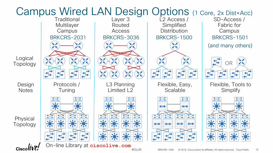
Campus Wired LAN Design Options (1 Core, 2x Dist+Acc)
BRKCRS-1500
Traditional Multilayer Campus
Layer 3 Routed Access
L2 Access / Simplified
Distribution
SD-Access / Fabric for Campus
Physical Topology
Logical Topology
Design Notes
OR
BRKCRS-1501
(and many others)
BRKCRS-3036 BRKCRS-1500BRKCRS-2031
Protocols / Tuning
L3 Planning Limited L2
Flexible, Easy, Scalable
Flexible, Tools to Simplify
On-line Library at ciscolive.com10

© 2018 Cisco and/or its affiliates. All rights reserved. Cisco Public#CLUS
What We are Trying to Avoid!
BRKCRS-1500
No hierarchy
Poor performance
Hard to troubleshoot
Multiple single points of
failure
11

Agenda
© 2018 Cisco and/or its affiliates. All rights reserved. Cisco Public#CLUS
• Introduction to the Campus LAN CVDs
• Access Layer Deployment
• Attributes and platform choices
• Platform Specific
• Global Options
• Client facing interfaces
• Uplinks to Distribution Layer
• Distribution Layer Deployment
• Core Layer Deployment
• Software-Defined Access
• Conclusion
BRKCRS-1500 12

© 2018 Cisco and/or its affiliates. All rights reserved. Cisco Public#CLUS
Access Layer Attributes
• Ethernet network access• Wired 10/100/1000/mGig(802.3bz)
• Supports Wireless LAN 802.11a/b/g/n/ac access
• Simplified and flexible design• Layer 2 edge for applications that require spanned vlans
• Avoid Spanning Tree loops for resiliency
• Policy enforcement point• Secure network and applications from malicious attacks
• Packet marking for QoS
• Advanced Technologies support• Deliver PoE services: 802.3af(PoE), 802.3at(PoE+), and Cisco Universal POE (UPOE)
– 60watts per port
• QoS enforcement to protect multimedia applications
BRKCRS-1500 13

© 2018 Cisco and/or its affiliates. All rights reserved. Cisco Public#CLUS
Access Layer Design
• A common deployment method is used for all access layer devices in the design
• Whether they are located in the headquarters or at a remote site.
• A single interface configuration is used for a standalone computer, an IP phone, or an IP phone with an attached computer.
• The LAN access layer is configured as a Layer 2
• All Layer 3 services provided by directly connected distribution layer switch or router.
Uniform deployment in the network
BRKCRS-1500
WirelessAccess Point
User IP PhoneAccessSwitch
DistributionSwitch
ORRemoteRouter
14

© 2018 Cisco and/or its affiliates. All rights reserved. Cisco Public#CLUS
Cisco Catalyst 9000 Series platform transitions
BRKCRS-1500
CiscoCatalyst 9300
Cisco Catalyst 3850/3650
Copper
Cisco Catalyst 9400
Cisco Catalyst 4500-E
Cisco Catalyst 9500
Cisco Catalyst 3850X/4500X
Backbone switching Access switching
Cisco Catalyst 6840X/6880X
15

Agenda
© 2018 Cisco and/or its affiliates. All rights reserved. Cisco Public#CLUS
• Introduction to the Campus LAN CVDs
• Access Layer Deployment
• Attributes and platform choices
• Platform Specific
• Global Options
• Client facing interfaces
• Uplinks to Distribution Layer
• Distribution Layer Deployment
• Core Layer Deployment
• Software-Defined Access
• Conclusion
BRKCRS-1500 16

© 2018 Cisco and/or its affiliates. All rights reserved. Cisco Public#CLUS
Single Logical Switch
S3S2S1
Single Logical Switch
Configure the Stack Master on a switch that does not have uplinks configured
S3S2S1
Catalyst 2960-X Resiliency
• Stack Master provides central control over multiple 2960 Series switches configured in a stack
• To increase resiliency in a 2960 stack of three or more switches:
Platform Specific Configuration
BRKCRS-1500
MASTER
Creates double failure
Ensure that the original Stack Master MAC address remains the stack MAC
address after a failure to prevent protocol restart
stack-mac persistent timer 0
MASTERMAC=00:BB:AA:CC:DD:FF
switch [switch number] priority 15
17

© 2018 Cisco and/or its affiliates. All rights reserved. Cisco Public#CLUS
Catalyst 4500 and 3850/3650 Resiliency– Stateful SwitchoverPlatform Specific Configuration
BRKCRS-1500
When a 4500 has two supervisors installed for resiliency, Stateful Switchover (SSO) should be configured – minimizes traffic loss when the primary supervisors has a failure.
SSO is the default configuration for Catalyst 3850 and Catalyst 3650 with at least two members in a stack.
A4507R(config)#redundancy
A4507R(config-red)# mode sso
^C
A4507R#show redundancy state
my state = 13 -ACTIVE
peer state = 8 -STANDBY HOT
Mode = Duplex
Unit = Primary
Unit ID = 3
Redundancy Mode (Operational) = Stateful Switchover
Redundancy Mode (Configured) = Stateful Switchover
Redundancy State = Stateful Switchover
Manual Swact = enabled
Communications = Up
Hot-StandbySupervisor
ActiveSupervisor
Note: Catalyst 4500 SSO operation requires ipbase or enterprise services license levelHot-Standby
Switch
ActiveSwitch
Catalyst 4500 Catalyst 3850/3650
18

© 2018 Cisco and/or its affiliates. All rights reserved. Cisco Public#CLUS
CLI-based Quality of Service DeploymentMacros to Ease the Deployment Process for Platform-Specific Commands
BRKCRS-1500
Macros Used Later in the Deployment Process:
1. AccessEdgeQoS MacroApplied on all client facing interfaces
2. EgressQoS MacroApplied on all other interfaces
Using Macros to Deploy Quality of Service…• Removes the platform specific QoS configuration from the day to day repetitive configuration
tasks• Eases the deployment process and allows for easier creation of deployment templates
Complex Simplified
Initial Configuration Defines Macros and Platform-specific Global Settings
+ Conditional Trust
+ AutoQoS
19

© 2018 Cisco and/or its affiliates. All rights reserved. Cisco Public#CLUS
Recommendation for QoS
• APIC-EM can be used to implement QoS – EasyQoS App
• Goes beyond default policies by deploying policies based on an organization’s “intent”
EasyQoS
BRKCRS-1500
“Under the hood”
BRKCRS-2501:Campus QoS Design Simplified
https://www.cisco.com/c/en/us/td/docs/solutions/CVD/Dec2017/APIC-EM-EasyQoS-DesignGuide-Dec2017.html
20

Agenda
© 2018 Cisco and/or its affiliates. All rights reserved. Cisco Public#CLUS
• Introduction to the Campus LAN CVDs
• Access Layer Deployment
• Attributes and platform choices
• Platform Specific
• Global Options
• Client facing interfaces
• Uplinks to Distribution Layer
• Distribution Layer Deployment
• Core Layer Deployment
• Software-Defined Access
• Conclusion
BRKCRS-1500 21

© 2018 Cisco and/or its affiliates. All rights reserved. Cisco Public#CLUS
Resiliency Features for LAN SwitchesGlobal LAN Switch Configuration
BRKCRS-1500
• Rapid PVST+ – improved topology change detection over classic STP Layer 2 loop detection
• BPDUguard default – detect spanning tree BPDUs on portfast-enabled ports for L2 loop prevention
• UDLD – detect and protect against unidirectional links caused by incorrect physical interconnects that can cause spanning tree loops
• Error disable recovery – allows recovery without intervention of automatically disabled ports, post-event
• VTP transparent – ignore VTP updates to avoid accidental outages from unplanned VLAN changes
• Load-Interval – reduce time to compute interface load for better visibility to traffic bursts
spanning-tree mode rapid-pvst
spanning-tree portfast bpduguard default
udld enable
errdisable recovery cause all
vtp mode transparent
load-interval 30
Protection across the LAN
22

© 2018 Cisco and/or its affiliates. All rights reserved. Cisco Public#CLUS
Enabling Device ManagementGlobal LAN Switch Configuration
BRKCRS-1500
snmp-server community [SNMP RO] RO
snmp-server community [SNMP RW] RW
ip domain-name cisco.local
no ip http server
ip http secure-server
ip ssh version 2
ip scp server enable
line vty 0 15
transport input ssh
transport preferred none
SSH requires domain-nameDisables HTTP
Enables SSH ONLY on IP access to console
Enables HTTPS and creates default modulus Crypto Key
Eliminate annoying long wait for mistyped commands
access-list 55 permit 10.4.48.0 0.0.0.255
line vty 0 15
access-class 55 in
!
snmp-server community [SNMP RO] RO 55
snmp-server community [SNMP RW] RW 55
Restrict vty and SNMPv2c accessUse SNMP to manage network devices by a Network Management System.
‒ SNMP(v2c) should be configured for both a read-only and a read-write community string.
Enable secure management of ALL LAN devices
• Enabled through encrypted protocols SSH, HTTPS, and SCP
• Less secure protocols, Telnet and HTTP, should be turned off
Enables Secure Copy for file management
23

© 2018 Cisco and/or its affiliates. All rights reserved. Cisco Public#CLUS
Device Management AuthenticationGlobal LAN Switch Configuration
BRKCRS-1500
enable secret [enable password]
service password-encryption
!
username admin password [admin password]
aaa new-model
aaa authentication login default group tacacs+ local
aaa authorization exec default group tacacs+ local
aaa authorization console
ip http authentication aaa
tacacs-server host 10.4.48.15 key [tacacs key]
Local username and password for fallback
Use tacacs+ first, fallback to local
Define tacacs+ server and secret key
enable secret [enable password]
service password-encryption
!
username admin secret [admin password]
aaa new-model
tacacs server TACACS-SERVER-1
address ipv4 10.4.48.15
key [tacacs key]
!
aaa group server tacacs+ TACACS-SERVERS
server name TACACS-SERVER-1
!
aaa authentication login default group TACACS-SERVERS local
aaa authorization exec default group TACACS-SERVERS local
aaa authorization console
ip http authentication aaa
New Method
Traditional Method
• Use AAA to control management access to network infrastructure devices (SSH and HTTPS)
• Centralized/easy control of password expiration—rapidly revoke access for employee departure
• TACACS+ primary protocol to the AAA server for management authentication to infrastructure devices
• Local AAA users defined on network infrastructure devices provide a fallback authentication source
24

© 2018 Cisco and/or its affiliates. All rights reserved. Cisco Public#CLUS
Synchronize the Clock on All DevicesGlobal LAN Switch Configuration
BRKCRS-1500
NTP ServerIP Addr: 10.4.48.17
ntp server 10.4.48.17
ntp update-calendar
!
clock timezone PST -8
clock summer-time PDT recurring
!
service timestamps debug datetime msec localtime
service timestamps log datetime msec localtimeTimestamp output with local NTP synchronized time
Set local timezone, offset from UTC
Update hardware clock on Catalyst 6500 and 4500
• Troubleshooting a network event requires correlation across multiple devices (switches and routers)
• Network devices should be programmed to synchronize time to a local NTP server in the network.
• allows event log timestamps from multiple devices to be correlated
• Configure console messages, logs, and debug output to provide time stamps
25

© 2018 Cisco and/or its affiliates. All rights reserved. Cisco Public#CLUS
• Data VLAN provides access to the network for all attached devices other than IP Phones
• Management VLAN for in-band access to the network for the switches management interface
• Voice VLAN for IP Phone network access
Access Layer Virtual LANsAccess Switch Configuration
BRKCRS-1500
vlan 10
name Data
vlan 20
name Voice
vlan 30
name Management
Note: The management VLAN is neverconfigured on user facing interfaces
Uplink Interfaces
Mgmt VLAN 30
Data VLAN 10
Voice VLAN 20
Client Facing Interfaces
Network ManagementStation
26

© 2018 Cisco and/or its affiliates. All rights reserved. Cisco Public#CLUS
In-Band ManagementAccess Switch Configuration
BRKCRS-1500
Network ManagementStation
Note: Do not use the ip default-gateway command on the Catalyst 4500 since it has ip routing enabled by default and the “ip default-gateway” command will not have any effect.
Instead use the following command on the Catalyst 4500.ip route 0.0.0.0 0.0.0.0 [default router]
interface vlan [management vlan]
ip address [ip address] [mask]
no shutdown
ip default-gateway [default router]
IP Default Gatewayfor Management VLAN
Configure the switch with an IP Address so that it can be managed via in-band connectivity.
27

Agenda
© 2018 Cisco and/or its affiliates. All rights reserved. Cisco Public#CLUS
• Introduction to the Campus LAN CVDs
• Access Layer Deployment
• Attributes and platform choices
• Platform Specific
• Global Options
• Client facing interfaces
• Uplinks to Distribution Layer
• Distribution Layer Deployment
• Core Layer Deployment
• Software-Defined Access
• Conclusion
BRKCRS-1500 28

© 2018 Cisco and/or its affiliates. All rights reserved. Cisco Public#CLUS
• Use a single port profile for all access ports
• Apply configuration supporting end-user devices
This single command does the following:- removes any channel-group configuration (incompatible with access mode)- enables switchport access mode (disables trunk negotiation, enables VLAN participation)- enables PortFast (faster connect with interface directly into spanning-tree forwarding mode)
• To enable QoS, use a Macro (if you’re not using EasyQoS):
Client Facing InterfacesAccess Switch Configuration
BRKCRS-1500
interface range [interface type] [port number]–[port number]
switchport access vlan [data vlan]
switchport mode access
switchport voice vlan [voice vlan]
switchport host
macro apply AccessEdgeQoS
The host interface configuration supports PCs, phones, or wireless access points.
WirelessAccess Point
User IP Phone
AccessSwitch
29

© 2018 Cisco and/or its affiliates. All rights reserved. Cisco Public#CLUS
Access Layer – Hardening the Edge
BRKCRS-1500
IP Source Guard
Dynamic ARPInspection
DHCPSnooping
Port Security
The Cisco Validated Design usesCatalyst Integrated Security Features to protect your network from intentional and unintentionalattacks
Port security prevents CAM attacks and DHCP Starvation attacks
DHCP Snooping prevents Rogue DHCP Server attacks
Dynamic ARP Inspection prevents current ARP attacks
IP Source Guard prevents IP/MAC Spoofing
IPv6 Router Advertisement Guard prevents IPv6 Man-in-the-Middle attacks
+ IPv6 RA Guard
30

© 2018 Cisco and/or its affiliates. All rights reserved. Cisco Public#CLUS
Port SecurityClient Facing Interface Configuration
BRKCRS-1500
ClientAdvertises MAC00:10:10:10:10:10
00:10:10:10:10:11
00:10:10:10:10:12
00:10:10:10:10:13
00:10:10:10:10:14
00:10:10:10:10:15
00:10:10:10:10:16
00:10:10:10:10:17
00:10:10:10:10:18
00:10:10:10:10:19
00:10:10:10:10:1A
00:10:10:10:10:1B
Exceeds Maximum
switchport port-security
switchport port-security maximum 11
switchport port-security aging time 2
switchport port-security aging type inactivity
switchport port-security violation restrict
Configure on the client interface:
Protect your switch from CAM table overflow attacks.
31

© 2018 Cisco and/or its affiliates. All rights reserved. Cisco Public#CLUS
DHCP SnoopingClient Facing Interface Configuration
BRKCRS-1500
Configure in the global configuration:
Example DHCP Snooping Binding TableMAC Address IP Address VLAN Interface
00:50:56:BA:13:DB 10.4.80.10 10 GigabitEthernet2/0/1
ClientMAC=00:50:56:BA:13:DBIP Addr=10.4.80.10
TrustedUntrustedDHCP Request
DHCPServer
DHCP Request
DHCP Reply
DHCP Reply
ip dhcp snooping vlan [data vlan], [voice vlan]
no ip dhcp snooping information option
ip dhcp snooping
ip dhcp snooping limit rate 100
Configure on the client interface:
DHCP Request
32

© 2018 Cisco and/or its affiliates. All rights reserved. Cisco Public#CLUS
ARP InspectionClient Facing Interface Configuration
BRKCRS-1500
Client
Untrusted
Example DHCP Snooping Binding TableMAC Address IP Address VLAN Interface
00:50:56:BA:13:DB 10.4.80.10 10 GigabitEthernet2/0/1
Advertises MAC00:10:10:10:10:10
Does Not Match
Configure in the global configuration:
ip arp inspection vlan [data vlan], [voice vlan] ip arp inspection limit rate 100
Configure on the client interface:
33

© 2018 Cisco and/or its affiliates. All rights reserved. Cisco Public#CLUS
IP Source GuardClient Facing Interface Configuration
BRKCRS-1500
Client
Example DHCP Snooping Binding TableMAC Address IP Address VLAN Interface
00:50:56:BA:13:DB 10.4.80.10 10 GigabitEthernet2/0/1
IP Pkt Source Addr10.4.80.22
Does Not Match
On the Catalyst 4500 configure on the interface:
ip verify source vlan dhcp-snooping
ip verify source
Configure on the client interface:
34

© 2018 Cisco and/or its affiliates. All rights reserved. Cisco Public#CLUS
BPDU GuardClient Facing Interface Configuration
BRKCRS-1500
• If a portfast configured interface receives a BPDU, an invalid configuration exists, such as the connection of an unauthorized device.
• BPDU guard prevents loops by moving a nontrunking interface into an errdisable state when a BPDU is received on an interface when portfast is enabled.
BPDUHub at a desk
spanning-treee portfast bpdudguard default
Configure on the switch at the global level:
Portfast
35

© 2018 Cisco and/or its affiliates. All rights reserved. Cisco Public#CLUS
IPv6 Router Advertisement GuardClient Facing Interface Configuration
BRKCRS-1500
If a port device role is configured as host, IPv6 First Hop Security (FHS) RA Guard drops all IPv6 Router Advertisement messages
Useful even for IPv4-only networks
Other port device role options include: monitor, router, and switch
“I am an IPv6 router.” “No you are not.”
Define policy in the global configuration:
ipv6 nd raguard policy HOST_POLICY
device-role host
ipv6 nd raguard attach-policy HOST_POLICY
Attach policy configuration to the client interface:
IPv6 StackRouter Advertisement
BRKSEC-2003: IPv6 Security Threats and Mitigations; BRKSEC-3003: Advanced IPv6 Security in the LAN36

Agenda
© 2018 Cisco and/or its affiliates. All rights reserved. Cisco Public#CLUS
• Introduction to the Campus LAN CVDs
• Access Layer Deployment
• Attributes and platform choices
• Platform Specific
• Global Options
• Client facing interfaces
• Uplinks to Distribution Layer
• Distribution Layer Deployment
• Core Layer Deployment
• Software-Defined Access
• Conclusion
BRKCRS-1500 37

© 2018 Cisco and/or its affiliates. All rights reserved. Cisco Public#CLUS
EtherChannel Member InterfacesUplink Interface Configuration
BRKCRS-1500
• Layer 2 EtherChannels are used to interconnectthe switch to upstream devices.
• Member interfaces should be on different switches or linecards for resiliency.
• Configure the physical interfaces before configuring thelogical portchannel interface.
• Uses LACP for EtherChannel protocol
• Add Egress QoS macro for trust inbound traffic and queue outbound
interface range [type] [port], [type] [port]
switchport
channel-protocol lacp
channel-group 10 mode active
macro apply EgressQoS
logging event link-status
logging event trunk-status
logging event bundle-status
Note: ISR routers do not support LACP. Therefore, when connecting a remote site access switch to an ISR router with an EtherChannel you must configure the switch with mode forced on.
interface range [type] [port], [type] [port]
switchport
channel-group 10 mode on
macro apply EgressQoS
38

© 2018 Cisco and/or its affiliates. All rights reserved. Cisco Public#CLUS
Trunk ConfigurationUplink Interface Configuration
BRKCRS-1500
• When using EtherChannel the interface type will be port-channel and the number must match channel-group configured on the member interfaces.
interface port-channel 10
switchport trunk encapsulation dot1q
switchport trunk allowed vlan [data],[voice],[mgmt]
switchport mode trunk
ip arp inspection trust
ip dhcp snooping trust
logging event link-status
no shutdown
• An 802.1Q trunk is used for the connection to the upstream device– Allows upstream device to provide the Layer 3 services to all the VLANs defined on the access
layer switch.
– VLANs allowed on the trunk are pruned to only the VLANs that are active on the access switch.
– DHCP Snooping and ARP Inspection are set to trust.
39

Agenda
© 2018 Cisco and/or its affiliates. All rights reserved. Cisco Public#CLUS
• Introduction to the Campus LAN CVDs
• Access Layer Deployment
• Distribution Layer Deployment
• Attributes and platform choices
• Platform Specific
• Global Options
• Connectivity to Access and Core Layers
• Core Layer Deployment
• Software-Defined Access
• Conclusion
BRKCRS-1500 40

© 2018 Cisco and/or its affiliates. All rights reserved. Cisco Public#CLUS
Campus LAN Distribution Layer Attributes
• Primary function is access layer aggregation for a building or geographic area.
• Resilient design to reduce failure impact
• Layer 2 boundary for access layer
• Spanning Tree Protocol boundary
• Broadcast packet boundary
• Provides load balancing to access layer
• Layer 3 features and functions
• Default IP Gateway for L2 access layer
• IP Routing summarization to rest of network
• Efficient IP Multicast
• Provides load balancing to core layer
• QoS to manage congestion caused by many to few links
BRKCRS-1500 41

© 2018 Cisco and/or its affiliates. All rights reserved. Cisco Public#CLUS
Alternative Distribution Layer AttributesLAN Distribution Layer
BRKCRS-1500
Large LAN Services Block
• Connection point for services
• Drives modular building block design
Two tier remote site:
• Aggregates LAN Access Layer and connects to WAN routers
Internet
WAN
Collapsed Core: Two tier main campus LAN and WAN Core
• LAN Access Layer aggregation
• Central connect point for all services
42

© 2018 Cisco and/or its affiliates. All rights reserved. Cisco Public#CLUS
Simplified Distribution Layer Design
• Traditional two box distribution layer has many points to manage
• Preferred Distribution Layer uses a “Single Box Design”
• Two switches acting as a single logical switch(Virtual Switching System)
• A multiple member switch stack acting as a single logical switch
• Simplified Design Benefits
• Fewer boxes to manage
• Simplified configuration
• Logical Hub and Spoke topology
LAN Distribution Layer
BRKCRS-1500
Traditional two box design
-FHRP-
Spanning TreeLoop Avoidance
Multiple Boxesto manage
First Hop Redundancy Protocol for
Resilient IPDefault Gateway
VSS – Virtual Switching System
Switch Stack
43

© 2018 Cisco and/or its affiliates. All rights reserved. Cisco Public#CLUS
Traditional Design Compared to Simplified DesignLAN Distribution Layer
BRKCRS-1500
Preferred—simplified design:
• EtherChannel - resilient links, all links forwarding
• No FHRP - single Default IP gateway
• Works with VLAN per closet or few VLANs spanned designs
• Logical Hub and Spoke topology
• Reduced dependence on Spanning Tree- keep RPVST+ for edge protection
SiSi SiSi
VLAN 30 VLAN 30 VLAN 30
Traditional designs:
• Looped design with spanned VLANs – Relies on STP to block loops
– Reduces available bandwidth
• Loop free design
– Can increase bandwidth
– Still relies on FHRP
– Multiple distribution layer boxes to configure
VLAN 30 VLAN 30 VLAN 30 VLAN 10 VLAN 20 VLAN 30
Permits Both
Preferred
SiSi SiSi
VLAN 10 VLAN 20 VLAN 30
44

© 2018 Cisco and/or its affiliates. All rights reserved. Cisco Public#CLUS
• Physically separate chassis, line cards, and power supplies, with fixed/modular options
• VSS-two physical chassis into a single logical entity
• SSO between chassis
• 4500-E Quad Sup RPR (new)
• Used to aggregate a smaller number of Gigabit or 10 Gigabit access layer switches
• In Service Software Upgrades (ISSU)
• Physically separate and resilient supervisors, line cards, and power supplies
• Clusters two physical chassis into a single logical entity
• Highest density Gigabit and 10 Gigabit Ethernet
• 40 Gigabit Ethernet
• Stateful Switchover (SSO) + Quad-Supervisor SSO (VS4O) available option
• VSS and Multi-Chassis EtherChannel for highly resilient connectivity
• Centralized stack configuration, control, and management plane
• Used to aggregate a smaller number of Gigabit access layer switches
• Distributed, per switch, Layer 2/Layer 3 forwarding, CAM tables, and BPDU processing
• UADP – Wireless Capable
• Extensible fixed base chassis, with resilient line card expansion and power supplies
• Clusters two physical chassis into a single logical entity
• Used to aggregate a smaller number of Gigabit or 10 Gigabit access layer switches
• Stateful Switchover between chassis
• Enhanced Fast Software Upgrade (eFSU) capable
Distribution Layer Platform Options
BRKCRS-1500
One common approach to configuring and operating the Distribution Layer
Catalyst 4500-E Supervisor 7, 8 (VSS)Catalyst 4500-X (VSS)
Catalyst 6500/6807 Supervisor 6T/2T
(VSS)
Catalyst 3850-12SCatalyst 3850-
(12/24/48)XS (Stack)
Catalyst 6880-XCatalyst 6840-X
(VSS)
Density, Resilience, Throughput, Scalability, Reduced failover times
45

© 2018 Cisco and/or its affiliates. All rights reserved. Cisco Public#CLUS
Catalyst 9500 Distribution Layer Portfolio
BRKCRS-1500
C9500-24Q
• 24 x 40G
• QSFP+ Ports
• 4 x UADP 2.0
• 950 W PS
• N+1 FRU FAN Modules
• USB 3.0 Module
• IOS-XE 16.5.1a
• FIRST StackWise Virtual
C9500-12Q
• 12 x 40G
• QSFP+ Ports
• 2 x UADP 2.0
• 950 W PS
• N+1 FRU FAN Modules
• USB 3.0 Module
• IOS-XE 16.6.1
C9500-40X
• 40 x 1/10G + 8x1/10G /
2x40G
• SFP/SFP+ Ports
• 2 x UADP 2.0
• 950 W PS
• N+1 FRU FAN Modules
• USB 3.0 Module
• IOS-XE 16.6.1
46

Agenda
© 2018 Cisco and/or its affiliates. All rights reserved. Cisco Public#CLUS
• Introduction to the Campus LAN CVDs
• Access Layer Deployment
• Distribution Layer Deployment
• Attributes and platform choices
• Platform Specific
• Global Options
• Connectivity to Access and Core Layers
• Core Layer Deployment
• Software-Defined Access
• Conclusion
BRKCRS-1500 47

© 2018 Cisco and/or its affiliates. All rights reserved. Cisco Public#CLUS
Catalyst VSS SetupLAN Distribution Layer
BRKCRS-1500
1) Prepare standalone switches for VSS
2) Configure Virtual Switch Link
VSS-Sw1# show etherchannel 63 ports
ANDVSS-Sw2# show etherchannel 64 ports
Ports in the group:
-------------------
Port: Te5/4 Port state = Up Mstr In-Bndl
Port: Te5/5 Port state = Up Mstr In-Bndl
Switch 1 Switch 21) Prepare standalone switches for VSS
2) Configure Virtual Switch Link
3) Validate Virtual Switch Link Operation
Router#conf t
Router(config)# hostname VSS-Sw1
VSS-Sw1(config)#switch virtual domain 100
VSS-Sw1(config-vs-domain)# switch 1
Router#conf t
Router#config)# hostname VSS-Sw2
VSS-Sw2(config)#switch virtual domain 100
VSS-Sw2(config-vs-domain)# switch 2
VSL
VSS-Sw1(config)#interface port-channel 63
VSS-Sw1(config-if)#switch virtual link 1
VSS-Sw1(config)#interface range tengigabit 5/4-5
VSS-Sw1(config-if)#channel-group 63 mode on
VSS-Sw1(config-if)#no shutdown
VSS-Sw2(config)#interface port-channel 64
VSS-Sw2(config-if)#switch virtual link 2
VSS-Sw2(config)#interface range tengigabit 5/4-5
VSS-Sw2(config-if)#channel-group 64 mode on
VSS-Sw2(config-if)#no shutdown
Reference
48

© 2018 Cisco and/or its affiliates. All rights reserved. Cisco Public#CLUS
Catalyst VSS SetupLAN Distribution Layer
BRKCRS-1500
VSS-Sw1# show switch virtual redundancy
• Check for both switches visible, Supervisors in SSO mode, second Supervisor in Standby-hot status
VSS-Sw1(config)#
4) Enable Virtual Mode Operation
5) Verify Operation and Rename Switch
VSS-Sw1# switch convert mode virtual
Do you want to proceed? (yes/no)
• The switch now renumbers from y/z to x/y/z• When process is complete, save configuration when prompted, switch reloads and forms VSS.
6) Configure Dual-Active Detection
4) Enable Virtual Mode OperationVSS-Sw2# switch convert mode virtual
Do you want to proceed? (yes/no)
• The switch now renumbers from y/z to x/y/z• When process is complete, save configuration when prompted, switch reloads and forms VSS.
*Feb 25 14:28:39.294: %VSDA-SW2_SPSTBY-5-LINK_UP: Interface Gi2/1/24 is now dual-active detection capable
*Feb 25 14:28:39.323: %VSDA-SW1_SP-5-LINK_UP: Interface Gi1/1/24 is now dual-active detection capable
7) Configure the System Virtual MAC Address
VSL
VSS
Switch 1 Switch 2
BRKCRS-3035: Advanced Enterprise Campus Design: Virtual Switching System (VSS)
VSS(config)# switch virtual domain 100
VSS(config-vs-domain)# mac-address use-virtual
Configured Router mac address is different from operational value. Change will take effect
after config is saved and the entire Virtual Switching System (Active and Standby) is reloaded.
• Connect a Gigabit Link between the VSS switchesVSS(config)# switch virtual domain 100
VSS(config-vs-domain)# dual-active detection fast-hello
VSS(config)# interface range gigabit1/1/24, gigabit2/1/24
VSS(config-if-range)# dual-active fast-hello
VSS(config-if-range)# no shuthostname VSS
VSS(config)#
yes yes
Reference
49

© 2018 Cisco and/or its affiliates. All rights reserved. Cisco Public#CLUS
“Is there an easier way to enable VSS?”Use Easy VSS to configure from a single console port
BRKCRS-1500
VSS-Sw1# show switch virtual redundancy
• Check for both switches visible, Supervisors in SSO mode, second Supervisor in Standby-hot status
VSS-Sw1(config)#
1) C6K - Enable Easy VSS feature, convert, and reload
2) Verify Operation and Rename Switch
VSS-Sw1# switch virtual easy
VSS-Sw1# switch convert mode easy links
Local Interface Remote Interface Hostname
TenGiigabit3/4 TenGigabit3/4 VSS-Sw2
TenGigabiti4/4 TenGigabit4/4 VSS-Sw2
VSS-Sw1# switch convert mode easy links T3/4 T4/4 domain 100
VSS-Sw1(config)# switch virtual domain 100
VSS-Sw1(config-vs-domain)# mac-address use-virtual
VSS-Sw1# copy running-config startup-config
VSS-Sw1# reload
3) Configure Dual-Active Detection
VSL
VSS
VSS-Sw1 VSS-Sw2
• Connect a Gigabit Link between the VSS switchesVSS(config)# switch virtual domain 100
VSS(config-vs-domain)# dual-active detection fast-hello
VSS(config)# interface range gigabit1/1/24, gigabit2/1/24
VSS(config-if-range)# dual-active fast-hello
VSS(config-if-range)# no shut
hostname VSS
VSS(config)#
?
Prerequisites:• Switches running same software with feature support (C4K:3.6E, C6K:15.2(1)SY1)• Links to be used for VSLs up with CDP communication
Reference
50

© 2018 Cisco and/or its affiliates. All rights reserved. Cisco Public#CLUS
“How can I simplify my distribution without VSS?”
• Fixed switch hardware architecture with distributed forwarding architecture
• First on WS-3850-48XS, now available on Catalyst 9500-24Q, others
• StackWise Virtual Link (SVL) between two nodes (10Gb or 40Gb)
• Both StackWise Virtual members must have consistent IOS/License
StackWise Virtual (SWV)
BRKCRS-1500
WS-3850-48XS WS-3850-48XS
Distribution
Access
SVL
FastHello
StackWise Virtual Pair
51

© 2018 Cisco and/or its affiliates. All rights reserved. Cisco Public#CLUS
StackWise Virtual SetupLAN Distribution Layer
BRKCRS-1500
1) Prepare standalone switches for SWV
2) Configure StackWise Virtual Links*Automatically creates EtherChannel (128)
3850-D1 3850-D2 1) Prepare standalone switches for SWV
2) Configure StackWise Virtual Links*Automatically creates EtherChannel (128)
3850-D1#conf t
3850-D1(config)# stackwise-virtual
3850-D1(config-stackwise-vir)# domain <1-255>
3850-D2#conf t
3850-D2(config)# stackwise-virtual
3850-D2(config-stackwise-vir)# domain <1-255>
SVL
3850-D1(config)# interface range FortyG x/y/z – x/y/z
3850-D1(config-if)# stackwise-virtual link 1
3850-D2(config)# interface range FortyG x/y/z – x/y/z
3850-D2(config-if)# stackwise-virtual link 1
3) Configure Dual-Active Detection(Fast Hello)
3850-D1(config)# interface range TenG x/y/z – x/y/z
3850-D1(config)# stackwise-virtual dual-active-detection
Note: Maximum of 8-SVL links and 4-Dual Active Detection links
3) Configure Dual-Active Detection(Fast Hello)
3850-D2(config)# interface range TenG x/y/z – x/y/z
3850-D2(config)# stackwise-virtual dual-active-detection
4) Save and reload to convert
3850-D1# copy run start
3850-D1# reload
4) Save and reload to convert
3850-D2# copy run start
3850-D2# reload
3850-D1
52

Agenda
© 2018 Cisco and/or its affiliates. All rights reserved. Cisco Public#CLUS
• Introduction to the Campus LAN CVDs
• Access Layer Deployment
• Distribution Layer Deployment
• Attributes and platform choices
• Platform Specific
• Global Options
• Connectivity to Access and Core Layers
• Core Layer Deployment
• Software-Defined Access
• Conclusion
BRKCRS-1500 53

© 2018 Cisco and/or its affiliates. All rights reserved. Cisco Public#CLUS
In-Band Management Interface
• The loopback interface is the preferred way to manage when using in-band access
• Logical interface
• Always available as long as device is operational
• Commonly a host address (32-bit address mask)
• Bind SNMP, SSH, TACACS and PIM processes to Loopback interface address for optimal resiliency
LAN Distribution Layer
BRKCRS-1500
interface loopback 0
ip address 10.1.1.1 255.255.255.255
!
snmp-server trap-source loopback 0
ip ssh source-interface loopback 0
ip pim register-source loopback 0
ip tacacs source-interface loopback 0
54

© 2018 Cisco and/or its affiliates. All rights reserved. Cisco Public#CLUS
Distribution Layer IP Unicast Routing – EIGRPLAN Distribution Layer
BRKCRS-1500
router eigrp [NAME]
address-family ipv4 unicast autonomous-system [AS]
af-interface default
passive-interface
exit-af-interface
network [network] [inverse mask]
eigrp router-id [ip address of loopback 0]
eigrp stub summary
nsf
exit-address-family
NSF Aware •Nothing to enable. •Only need IOS version that supports NSF for EIGRP
Single Logical Distribution Layer design
• Uses Stateful SwitchOver(SSO) and Non-Stop Forwarding(NSF)
• SSO provides sub-second failover to redundant supervisor
• NSF maintains packet forwarding while control plane recovers
EIGRP was chosen for…simplicity, scalability, and flexibility
• Named Mode configuration
• Tie eigrp router-id to loopback 0 for maximum resiliency
• Enable all routed links to be passive by default
• Enable EIGRP for address space
• Each distribution is a stub network
L2
L3
NSF Capable •Works on dual supervisor system •Signals peer of SSO and to delay adjacency timeout•Once control plane recovers, re-establishes peering
55

© 2018 Cisco and/or its affiliates. All rights reserved. Cisco Public#CLUS
Distribution Layer IP Unicast Routing – OSPFLAN Distribution Layer
BRKCRS-1500
router ospf [process]
router-id [ip address of loopback 0]
nsf
area [area number] stub no-summary
passive-interface default
network [network] [inv. mask] area [area #]
network [network] [inverse mask] area 0
Single Logical Distribution Layer design
• Uses Stateful SwitchOver(SSO) and Non-Stop Forwarding(NSF)
• SSO provides sub-second failover to redundant supervisor
• NSF maintains packet forwarding while control plane recovers
OSPF is available for…
compatibility
• Tie ospf router-id to loopback 0 for maximum resiliency
• Enable all routed links to be passive by default
• Enable OSPF for address space
• Each distribution is a stub area and ABR
L2
L3
NSF Aware •Nothing to enable. •Only need IOS version that supports NSF for OSPF
NSF Capable •Works on dual supervisor system •Signals peer of SSO and to delay adjacency timeout•Once control plane recovers, re-establishes peering
56

© 2018 Cisco and/or its affiliates. All rights reserved. Cisco Public#CLUS
WAN
Distribution Layer IP Multicast Routing
• IP Multicast allows a single IP data stream to be replicated by the infrastructure (Routers and Switches)
• More efficient than multiple IP Unicast streams
• Beneficial for IPT Music on Hold and IP Broadcast video streams
• IP PIM Sparse-Mode
• Sparse-mode uses a Rendezvous Point(RP) to allow IP Multicast receivers to find IP Multicast Sources
• Place IP Multicast RP in the center or Core of the network
• On every Layer 3 switch and router
• Configure ip pim autorp listener to enable discovery across sparse mode links
• Enable pim sparse-mode on all Layer 3 interfaces
LAN Distribution Layer
BRKCRS-1500
RendezvousPoint
ip multicast-routing
ip pim autorp listener
!
interface GigabitEthernet 1/0/1
ip pim sparse-mode
57

Agenda
© 2018 Cisco and/or its affiliates. All rights reserved. Cisco Public#CLUS
• Introduction to the Campus LAN CVDs
• Access Layer Deployment
• Distribution Layer Deployment
• Attributes and platform choices
• Platform Specific
• Global Options
• Connectivity to Access and Core Layers
• Core Layer Deployment
• Software-Defined Access
• Conclusion
BRKCRS-1500 58

© 2018 Cisco and/or its affiliates. All rights reserved. Cisco Public#CLUS
VSS Distribution Connectivity to Access LayerResilient Connectivity
BRKCRS-1500
• Alternatively…With StackWise distribution layer, home EtherChannel uplinks to multiple switches in stack
• Use EtherChannel for link resiliency and load sharing
• With VSS use Multi-Chassis EtherChannel, home to each switch
59

© 2018 Cisco and/or its affiliates. All rights reserved. Cisco Public#CLUS
Layer 2 Connectivity to Access Layer
• Configure Layer 2
• With Hub and Spoke design, no STP loops, still enable RPVST+
• Configure VLANs servicing Access Layer
• Set Distribution Layer to be STP root for Access Layer VLANs
• Configure EtherChannel member interfaces
• Uses LACP for EtherChannel protocol
• For Layer 2 EtherChannel, configure physicalinterfaces prior to logical interface
• Apply Egress QoS macro
• Configure 802.1Q Trunk on EtherChannellogical port (port-channel) interface
LAN Distribution Layer
BRKCRS-1500
vlan 10,20,30
spanning-tree vlan 1-4094 root primary
!
Interface range gigabit 1/1/1, gigabit 2/1/1
macro apply EgressQoS
channel-protocol lacp
channel-group 10 mode active
!
interface port-channel 10
switchport trunk encapsulation dot1q
switchport trunk allowed 10,20,30
switchport trunk native vlan 999
switchport mode trunk
60

© 2018 Cisco and/or its affiliates. All rights reserved. Cisco Public#CLUS
• Configure Layer 3 for Access Layer VLANs• Configure a VLAN interface(SVI) for every Access Layer VLAN• This SVI is the IP Default Gateway for the Access Layer hosts in the
VLAN
• Configure ip-helper address on each SVI• IP helper forwards DHCP requests from hosts in the VLAN to the DHCP
Server• IP helper-address points to the DHCP Server for the VLAN• If more than one DHCP server, you
can list multiple ip-helper commands
• Configure ip pim sparse-mode• Enables IP Multicast packets to flow to hosts on the VLAN
DHCP Server(s)
Layer 3 Connectivity for Access LayerLAN Distribution Layer
BRKCRS-1500
interface vlan [number]
ip address [ip address] [mask]
ip helper-address 10.2.2.1
ip pim sparse-mode
IP Addr: 10.2.2.1
61

© 2018 Cisco and/or its affiliates. All rights reserved. Cisco Public#CLUS
Layer 3 Connectivity to Core Layer– Interface ConfigurationLAN Distribution Layer
BRKCRS-1500
• If no Core Layer, links to WAN routers are Layer 3 links
• Configure EtherChannel Member Interfaces
• Configure the physical interfaces to tie to the logical port-channel
interface port-channel 20
no switchport
ip address [ip address] [mask]
ip pim sparse-mode
!
interface range teng1/1/8 , teng2/1/8 , teng1/2/8 , teng2/2/8
channel-protocol lacp
channel-group 20 mode active
macro apply EgressQoS
• Links from Distribution Layer to Core are Layer 3 links
• Configure Layer 3 EtherChannel interface
• When creating L3 EtherChannel, create the logical (port-channel) interface first
WAN
62

© 2018 Cisco and/or its affiliates. All rights reserved. Cisco Public#CLUS
Layer 3 Connectivity to Core Layer– EIGRP Routing ConfigurationLAN Distribution Layer
BRKCRS-1500
• Enable authentication of neighbor routing protocol communication on interface to the core
• Enable EIGRP for the core-facing interface(disable passive-interface)
Su
mm
ary
key chain EIGRP-KEY
key 1
key-string [KEY STRING]
!
router eigrp [NAME]
address-family ipv4 unicast autonomous-
system [AS]
af-interface port-channel 20
authentication mode md5
authentication key-chain EIGRP-KEY
no passive-interface
summary-address [network] [mask]
exit-af-interface
exit-address-family
• As networks grow, IP address summarization is used • To reduce bandwidth required for routing
updates• To reduce convergence time around a link failure • Summarize all subnets in the distribution layer to
the rest of the network
63

© 2018 Cisco and/or its affiliates. All rights reserved. Cisco Public#CLUS
• Enable authentication of neighbor routing protocol communication on interface to the core
Layer 3 Connectivity to Core Layer– OSPF Routing ConfigurationLAN Distribution Layer
BRKCRS-1500
• Enable OSPF for the core-facing interface(disable passive-interface)
Sum
mary
interface Port-channel 20
ip ospf message-digest-key [key id] md5 [key]
!
router ospf 100
area 0 authentication message-digest
area [area number] range [address range] [mask]
no passive-interface Port-channel 20
• As networks grow, IP address summarization is used • To reduce bandwidth required for routing
updates• To reduce convergence time around a link failure • The OSPF area range command allows you to
summarize all subnets in the distribution layer to the rest of the network
64

Agenda
© 2018 Cisco and/or its affiliates. All rights reserved. Cisco Public#CLUS
• Introduction to the Campus LAN CVDs
• Access Layer Deployment
• Distribution Layer Deployment
• Core Layer Deployment
• Attributes and platform
• Global Options
• Software-Defined Access
• Conclusion
BRKCRS-1500 65

© 2018 Cisco and/or its affiliates. All rights reserved. Cisco Public#CLUS
Core Layer AttributesLAN Core Layer
BRKCRS-1500
Do I need a Core Layer?
• Must be highly resilient – no single points of failure in design
• No high touch/high complexity services
• Avoid constant tuning or configuration changes
• Layer 3 Transport
• No Spanning Tree convergence or blocking
• Primary function is distribution layer aggregation for large or geographically dispersed LAN deployment
• Lowers the complexity and cost of a fully meshed distribution layer
66

© 2018 Cisco and/or its affiliates. All rights reserved. Cisco Public#CLUS
• LAN Core platform allowing independent control planes and a consolidated DC and LAN core possible through Virtual Device Contexts (VDC)
• Resilient supervisor and SSO support, and load sharing power supplies
• Wide Range of connectivity from Gigabit Ethernet, GEC, High Density 10 Gb Ethernet, 10-GEC, 40Gb and 100Gb Ethernet
• In Service Software Upgrades
• Data Center NX-OS heritage
Core Layer Platform Options
BRKCRS-1500
Nexus 7700 with Supervisor 2E(2x Independent Chassis)
• LAN Core platform with consistent IOS interface and feature set as rest of LAN allowing single logical and resilient platform using Virtual Switching System (VSS)
• Redundant supervisor and SSO support, VSS, and Quad-Supervisor SSO available (VS4O), and load sharing power supplies
• Wide Range of connectivity from Gigabit Ethernet, GEC, 10 Gb Ethernet, 10-GEC, and 40 Gb Ethernet
• Up to 440G/slot (6807-XL / Sup 6T)
• VSS and Multi-Chassis EtherChannel for highly resilient connectivity and scalable distributed forwarding
Catalyst 6807-XL, Supervisor 6T/2T(VSS Option)
67

Agenda
© 2018 Cisco and/or its affiliates. All rights reserved. Cisco Public#CLUS
• Introduction to the Campus LAN CVDs
• Access Layer Deployment
• Distribution Layer Deployment
• Core Layer Deployment
• Attributes and platform
• Global Options
• Software-Defined Access
• Conclusion
BRKCRS-1500 68

© 2018 Cisco and/or its affiliates. All rights reserved. Cisco Public#CLUS
In-Band Management InterfaceLAN Core Layer
BRKCRS-1500
• The loopback interface is the preferred way to manage when using in-band access• Logical interface
• Always available as long as device is operational
• Commonly a host address (32-bit address mask)
• Bind SNMP, SSH, TACACS and PIM processes to Loopback interface address for optimal resiliency
interface loopback 0
ip address 10.1.1.1 255.255.255.255
!
snmp-server trap-source loopback 0
ip ssh source-interface loopback 0
ip pim register-source loopback 0
ip tacacs source-interface loopback 0
69

© 2018 Cisco and/or its affiliates. All rights reserved. Cisco Public#CLUS
Core Layer IP Unicast Routing - EIGRPLAN Core Layer
BRKCRS-1500
• Enable EIGRP for address space in use for core – just as was done in the distribution
• However…
• No passive interfaces in Core – route to everything from the core
• Remember to…
• Enable authentication of neighbor routing protocol communication
• Enable NSF
key chain EIGRP-KEY
key 1
key-string [key]
router eigrp LAN
address-family ipv4 unicast autonomous-system 100
network [network] [inverse mask]
eigrp router-id [ip address of loopback 0]
nsf
exit-address-family
af-interface default
authentication mode md5
authentication key-chain EIGRP-KEY
exit-af-interface
70

© 2018 Cisco and/or its affiliates. All rights reserved. Cisco Public#CLUS
Core Layer IP Unicast Routing - OSPFLAN Core Layer
BRKCRS-1500
• Enable OSPF for address space in use for core – just as was done in the distribution
• Core is OSPF Area 0
• However…
• No passive interfaces in Core – route to everything from the core
• Remember to…
• Enable authentication of neighbor routing protocol communication
• Enable NSF
interface [interface]
ip ospf message-digest-key [key id] md5 [key]
router ospf 100
router-id [ip address of loopback 0]
nsf
area 0 authentication message-digest
network [network] [inverse mask] area 0
71

© 2018 Cisco and/or its affiliates. All rights reserved. Cisco Public#CLUS
interface loopback 1
ip address 10.1.1.2 255.255.255.255
ip pim sparse-mode
!
access-list 10 permit 239.1.0.0 0.0.255.255
ip pim send-rp-announce Loopback1 scope 32 group-list 10
ip pim send-rp-discovery Loopback1 scope 32
WAN
Resilient IP Multicast Routing – VSS Core
• IP Multicast allows a single IP data stream to be replicatedby the infrastructure (Routers and Switches)
• IP PIM Sparse-Mode
• Every Layer 3 switch and router points to the Rendezvous Pont (RP)
• RP placed centrally in the network (core)
• Auto-RP used for dynamic RP announcement to network devices
• RP resiliency is critical to IP Multicast operation
• VSS SSO ensures RP availability
LAN Core Layer
BRKCRS-1500
RendezvousPoint
DataCenter
Announce “I (10.1.1.2) will be an RP”Discovers RPs and tells best to AutoRP listeners
72

© 2018 Cisco and/or its affiliates. All rights reserved. Cisco Public#CLUS
WAN
Resilient IP Multicast RP – Two Box Core
• When the core isn’t a single logical platform (such as Nexus)
• IP Multicast allows a single IP data stream to be replicatedby the infrastructure (Routers and Switches)
• IP PIM Sparse-Mode is used
• Sparse-mode uses a Rendezvous Point(RP) to allow IP Multicast receivers to find IP Multicast Sources
• Place IP Multicast RP in the center or Core of the network
• Auto-RP used for dynamic RP announcement to network devices
• RP resiliency is critical to IP Multicast operation
• Multiple RP redundancy methods
• Design uses Anycast RP for simplicity and fast failover
LAN Core Layer
BRKCRS-1500
RendezvousPoint
DataCenter
Reference
73

© 2018 Cisco and/or its affiliates. All rights reserved. Cisco Public#CLUS
Anycast RP Operation & ConfigurationResilient IP Multicast
BRKCRS-1500
MSDPSA SA
Data CenterSource Source
ReceiverReceiver
RP110.1.1.1
RP210.1.1.1
interface loopback 0
ip address 10.1.1.3 255.255.255.255
ip pim sparse-mode
interface loopback 1
ip address 10.1.1.1 255.255.255.255
!
ip msdp peer 10.1.1.2 connect-source loopback 0
ip msdp originator-id loopback 0
!
access-list 10 permit 239.1.0.0 0.0.255.255
ip pim send-rp-announce Loopback1 scope 32 group-list 10
!
ip pim send-rp-discovery Loopback0 scope 32
interface loopback 0
ip address 10.1.1.2 255.255.255.255
ip pim sparse-mode
interface loopback 1
ip address 10.1.1.1 255.255.255.255
!
ip msdp peer 10.1.1.3 connect-source loopback 0
ip msdp originator-id loopback 0
!
access-list 10 permit 239.1.0.0 0.0.255.255
ip pim send-rp-announce Loopback1 scope 32 group-list 10
!
ip pim send-rp-discovery Loopback0 scope 32
ip pim auto-rp listenerip pim auto-rp listener
X
Announce “I will be an RP (10.1.1.1)”
Discovers RP and tells AutoRP listenersip pim auto-rp listener
Announce “I will be an RP (10.1.1.1)”
Discovers RP and tells AutoRP listeners
Reference
74

© 2018 Cisco and/or its affiliates. All rights reserved. Cisco Public#CLUS
Layer 3 Connectivity to Distribution Layer
• Links from Core Layer are Layer 3 links (no SVIs)
• Use MEC to VSS in distribution layer
• Configure Layer 3 EtherChannel interface
• When creating L3 EtherChannel, create the logical (port-channel) interface first
• Configure EtherChannel Member Interfaces
• Configure the physical interfaces to tie to the logical port-channel
• Dual home to WAN or Data Center to Core
LAN Core Layer
BRKCRS-1500
interface port-channel 20
no switchport
ip address [ip address] [mask]
ip pim sparse-mode
!
interface range teng1/1/8 , teng2/1/8 , teng1/2/8 , teng2/2/8
channel-protocol lacp
channel-group 20 mode active
macro apply EgressQoS
no shutdown
WAN
75

Agenda
© 2018 Cisco and/or its affiliates. All rights reserved. Cisco Public#CLUS
• Introduction to the Campus LAN CVDs
• Access Layer Deployment
• Distribution Layer Deployment
• Core Layer Deployment
• Software-Defined Access
• Conclusion
BRKCRS-1500 76

© 2018 Cisco and/or its affiliates. All rights reserved. Cisco Public#CLUS
Multilayer CampusLayer 3 Distribution with Layer 2 Access
BRKCRS-1500
10.1.20.0
10.1.120.0
VLAN 20Data
VLAN 120Voice
VLAN 40Data
VLAN 140Voice
10.1.40.0
10.1.140.0
IGP IGP Layer 3
Layer 2
77

© 2018 Cisco and/or its affiliates. All rights reserved. Cisco Public#CLUS
Simplification with Routed Access DesignLayer 3 Distribution with Layer 3 Access
BRKCRS-1500
10.1.20.0
10.1.120.0
VLAN 20 Data
VLAN 120 Voice
VLAN 40 Data
VLAN 140 Voice
10.1.40.0
10.1.140.0
IGP IGP Layer 3
Layer 2
IGP IGP
• Move the Layer 2 / 3 demarcation to the network edge
• Leverages L2 only on the access ports, but builds a L2 loop-free network
• Design Motivations – Simplified control plane, ease of troubleshooting, highest availability
78

© 2018 Cisco and/or its affiliates. All rights reserved. Cisco Public#CLUS
Routed Access AdvantagesSimplified Control Plane
79BRKCRS-1500
• Simplified Control Plane
• No STP feature placement (root bridge, loopguard, …)
• No default gateway redundancy setup/tuning (HSRP, VRRP, GLBP ...)
• No matching of STP/HSRP priority
• No asymmetric flooding
• No L2/L3 multicast topology inconsistencies
• No Trunking Configuration Required
• L2 Port Edge features still apply:
• Spanning Tree Portfast
• Spanning Tree BPDU Guard
• Port Security, DHCP Snooping, DAI, IPSG
• Storm Control
• Etc.
L3 L3 L3 L3
L3

© 2018 Cisco and/or its affiliates. All rights reserved. Cisco Public#CLUS
Why isn’t routed access deployed everywhere?
• VLANs don’t span across multiple wiring closet switches/switch stacks(Does this impact your requirements?)
• IP addressing
• DHCP scopes and subnets increase – management and operational complexity
• Deployed access platforms must be able to support routing features
Routed Access Design Constraints
BRKCRS-1500
L3 L3 L3 L3
L3
80

© 2018 Cisco and/or its affiliates. All rights reserved. Cisco Public#CLUS
What if you could do this?
• Enables:
• Host mobility
• Network segmentation
• Role-based accesscontrol
• It is an Overlay networkto the network underlay
• Control Plane based on LISP
• Data Plane based on VXLAN
• Policy Plane based on TrustSec
Software-Defined Access
BRKCRS-1500
Software-Defined Access Design Guide - CVD
https://www.cisco.com/c/dam/en/us/td/docs/solutions/CVD/Campus/CVD-Software-Defined-Access-Design-Guide-2018APR.pdf
81

© 2018 Cisco and/or its affiliates. All rights reserved. Cisco Public#CLUS
Cyber
SecurityIoTMobility
Bring Your Own DeviceDevices in the Workspace
Auto-detect Non-User DevicesDevices everywhere
Networking and SecurityAdvanced threats
What’s different in your network today versus a decade ago? How does it affect your network?
BRKCRS-1500 82

© 2018 Cisco and/or its affiliates. All rights reserved. Cisco Public#CLUS
Key Challenges for Traditional Networks
Slower Issue ResolutionComplex to ManageDifficult to Segment
Ever increasing number of users and endpoint types
Ever increasing number of VLANs and IP Subnets
Multiple steps, user credentials, complex
interactions
Multiple touch-points
Separate user policies for wired and wireless networks
Unable to find users when troubleshooting
Traditional Networks Cannot Keep Up!
BRKCRS-1500 83

© 2018 Cisco and/or its affiliates. All rights reserved. Cisco Public#CLUS
Automated Network Fabric
Single Fabric for Wired & Wireless with Workflow-based Automation
Insights & Telemetry
Analytics and insights into user and application behavior
Identity-based Policy & Segmentation
Decoupled security policy definition from VLAN and IP
Address
DNA Center
AnalyticsPolicy Automation
Employee Network
User Mobility
Policy stays with user
Software-Defined Access
BRKCRS-1500 84

© 2018 Cisco and/or its affiliates. All rights reserved. Cisco Public#CLUS
DNA Center—Deploying Software-Defined Access
BRKCRS-1500
DNA ApplianceIdentity Services Engine
Routers Switches Wireless AP WLC
DNA Center
DESIGN PROVISION POLICY ASSURANCE
DNA Center: Simple Workflows
85

© 2018 Cisco and/or its affiliates. All rights reserved. Cisco Public#CLUS
Border Nodes
Cisco ISE
Edge Nodes
Control Plane Nodes• LISP Map
Server/Resolver• EID to RLOC Mapping
Fabric Border Nodes• Internal Border - XTR• External Border - PXTR
Fabric Edge Nodes• Host Registration• Host Resolution• Host Mobility
- Dynamic EID
Identity Services Engine (ISE)• AAA/Radius• 802.1x/MAB• TrustSec (SGT)
Components of SD-Access
BRKCRS-1500
Intermediate Nodes
DHCP
Control Plane
EnterpriseNetwork
Campus
Fabric
“Fusion” Routers(M-VRF Option)
86

© 2018 Cisco and/or its affiliates. All rights reserved. Cisco Public#CLUS
SD-Access DeploymentDecisions, decisions, decisions…
BRKCRS-1500
• Are you ready for L3 access?This is the deployment model described in the Deployment CVD, as implemented by DNA Center.
• Underlay protocol - Will you integrate with your existing IGP, or will you redistribute a different IGP process?Deployment CVD shows unique IS-IS IGP underlay.
• Virtualization - Are there requirements for multiple Virtual Networks (VRFs)?Deployment CVD configures support for multiple virtual networks, and ability to access common/shared services via a “fusion” router setup.
• Additional items:Security Policy – Are you incorporating this? Ready for ISE?Edge/Border/Control Plane node placementAddressing: Loopbacks, Redistribution, Underlay/Overlay, DHCP Scopes, etc.
87

© 2018 Cisco and/or its affiliates. All rights reserved. Cisco Public#CLUS
Software Defined Access Cisco Live Orlando - Session Map
88TECCRS-2001
Missed One? On-Demand Library online @ CiscoLive.com
Monday (June 11) Tuesday (June 12) Wednesday (June 13) Thursday (June 14)08:00-11:00 11:00-13:00 13:00-15:00 15:00-18:00 08:00-11:00 11:00-13:00 13:00-15:00 15:00-18:00 08:00-11:00 11:00-13:00 13:00-15:00 15:00-18:00 08:00-11:00 11:00-13:00 13:00-15:00 15:00-18:00
BRKCRS-2810Solution Overview
LTRCRS-2810 (2)Hands-On Lab
LTRCRS-2810 (1)Hands-On Lab
BRKCRS-2811External Connect
BRKCRS-2812 (1)Migration
BRKCRS-2814Assurance
BRKCRS-2812 (2)Migration
BRKCRS-2815 (2)Design & Scale
BRKCRS-2816Routed Underlay
BRKCRS-2817Extension for IOT
BRKDCN-2489DC Integration
BRKCRS-3811Policy Management
BRKEWN-2020Wireless Overview
BRKEWN-2021Live Setup
BRKCRS-1501SDA CVD
BRKCRS-2815 (1)Design & Scale

Agenda
© 2018 Cisco and/or its affiliates. All rights reserved. Cisco Public#CLUS
• Introduction to the Campus LAN CVDs
• Access Layer Deployment
• Distribution Layer Deployment
• Core Layer Deployment
• Software-Defined Access
• Conclusion
BRKCRS-1500 89

© 2018 Cisco and/or its affiliates. All rights reserved. Cisco Public#CLUS
Would you build this?
BRKCRS-1500 90

© 2018 Cisco and/or its affiliates. All rights reserved. Cisco Public#CLUS
You Now Have the Tools to Build This! (and more)
BRKCRS-1500
Two-Tier Remote-Site LANWAN
DistributionSwitch
ClientAccess
Switches
Two-Tier Collapsed LAN Core
WAN
Firewall
DistributionSwitch
WANRouter
IPS
ClientAccess
Switches
Server Room
InternetThree-Tier LAN Design
Firewall
High DensityLAN Distribution
Module
GuestWLC
WAAS
WAN
Network-ServicesDistribution
Module
Internet
ClientAccess
Switches
DataCenter
LANCore Layer
Remote BuildingCluster
LAN DistributionModule
91

© 2018 Cisco and/or its affiliates. All rights reserved. Cisco Public#CLUS
Summary
• Cisco Validated Designs provide a design framework for the wired campus with step-by-step deployment based on the cumulative Cisco leading practices
• Access Layer
• Consistent LAN Access Layer across the network (small site to large campus)
• Supports both layer 2 and layer 3 application needs
• Secure boundary and ready for advanced technologies
• Distribution Layer
• Simplified single logical platform with resilient and scalable design
• Etherchannel for resiliency and scalability
• Core Layer
• Scalable, resilient Layer 3 core using Nexus 7700 or Catalyst 6800 VSS for simplified topology and configuration
BRKCRS-1500
Resiliency, scalability, and flexibility – easily deployed throughout the network.
92

© 2018 Cisco and/or its affiliates. All rights reserved. Cisco Public#CLUS
Published Design Guideswww.cisco.com/go/cvd
BRKCRS-1500
It is very good for us to hear all of your
feedback!
Look for the feedback link in the guides:
Team members respond to feedback
requests. We appreciate your feedback and
have updated documents specifically to
address your questions.
93

Complete your online session evaluation
© 2018 Cisco and/or its affiliates. All rights reserved. Cisco Public#CLUS
Give us your feedback to be entered into a Daily Survey Drawing.
Complete your session surveys through the Cisco Live mobile app or on www.CiscoLive.com/us.
Don’t forget: Cisco Live sessions will be available for viewing on demand after the event at www.CiscoLive.com/Online.
BRKCRS-1500 94

© 2018 Cisco and/or its affiliates. All rights reserved. Cisco Public#CLUS
Demos in the Cisco campus
Walk-in self-paced
labs
Meet the engineer
1:1 meetings
Related sessions
Continue your education
BRKCRS-1500 95

Thank you
#CLUS

#CLUS