ROHDE & SCHWARZ FSEB20 Datasheet
9
Test Equipment Solutions Datasheet Test Equipment Solutions Ltd specialise in the second user sale, rental and distribution of quality test & measurement (T&M) equipment. We stock all major equipment types such as spectrum analyzers, signal generators, oscilloscopes, power meters, logic analysers etc from all the major suppliers such as Agilent, Tektronix, Anritsu and Rohde & Schwarz. We are focused at the professional end of the marketplace, primarily working with customers for whom high performance, quality and service are key, whilst realising the cost savings that second user equipment offers. As such, we fully test & refurbish equipment in our in-house, traceable Lab. Items are supplied with manuals, accessories and typically a full no-quibble 2 year warranty. Our staff have extensive backgrounds in T&M, totalling over 150 years of combined experience, which enables us to deliver industry-leading service and support. We endeavour to be customer focused in every way right down to the detail, such as offering free delivery on sales, covering the cost of warranty returns BOTH ways (plus supplying a loan unit, if available) and supplying a free business tool with every order. As well as the headline benefit of cost saving, second user offers shorter lead times, higher reliability and multivendor solutions. Rental, of course, is ideal for shorter term needs and offers fast delivery, flexibility, try-before-you-buy, zero capital expenditure, lower risk and off balance sheet accounting. Both second user and rental improve the key business measure of Return On Capital Employed. We are based near Heathrow Airport in the UK from where we supply test equipment worldwide. Our facility incorporates Sales, Support, Admin, Logistics and our own in-house Lab. All products supplied by Test Equipment Solutions include: - No-quibble parts & labour warranty (we provide transport for UK mainland addresses). - Free loan equipment during warranty repair, if available. - Full electrical, mechanical and safety refurbishment in our in-house Lab. - Certificate of Conformance (calibration available on request). - Manuals and accessories required for normal operation. - Free insured delivery to your UK mainland address (sales). - Support from our team of seasoned Test & Measurement engineers. - ISO9001 quality assurance. Test equipment Solutions Ltd Unit 8 Elder Way Waterside Drive Langley Berkshire SL3 6EP T: +44 (0)1753 596000 F: +44 (0)1753 596001 Email: [email protected] Web: www.TestEquipmentHQ.com
-
Upload
khangminh22 -
Category
Documents
-
view
1 -
download
0
Transcript of ROHDE & SCHWARZ FSEB20 Datasheet

Test Equipment Solutions Datasheet
Test Equipment Solutions Ltd specialise in the second user sale, rental and distribution of quality test & measurement (T&M) equipment. We stock all major equipment types such as spectrum analyzers, signal generators, oscilloscopes, power meters, logic analysers etc from all the major suppliers such as Agilent, Tektronix, Anritsu and Rohde & Schwarz.
We are focused at the professional end of the marketplace, primarily working with customers for whom high performance, quality and service are key, whilst realising the cost savings that second user equipment offers. As such, we fully test & refurbish equipment in our in-house, traceable Lab. Items are supplied with manuals, accessories and typically a full no-quibble 2 year warranty. Our staff have extensive backgrounds in T&M, totalling over 150 years of combined experience, which enables us to deliver industry-leading service and support. We endeavour to be customer focused in every way right down to the detail, such as offering free delivery on sales, covering the cost of warranty returns BOTH ways (plus supplying a loan unit, if available) and supplying a free business tool with every order.
As well as the headline benefit of cost saving, second user offers shorter lead times, higher reliability and multivendor solutions. Rental, of course, is ideal for shorter term needs and offers fast delivery, flexibility, try-before-you-buy, zero capital expenditure, lower risk and off balance sheet accounting. Both second user and rental improve the key business measure of Return On Capital Employed.
We are based near Heathrow Airport in the UK from where we supply test equipment worldwide. Our facility incorporates Sales, Support, Admin, Logistics and our own in-house Lab.
All products supplied by Test Equipment Solutions include:
- No-quibble parts & labour warranty (we provide transport for UK mainland addresses).- Free loan equipment during warranty repair, if available.- Full electrical, mechanical and safety refurbishment in our in-house Lab.- Certificate of Conformance (calibration available on request).- Manuals and accessories required for normal operation.- Free insured delivery to your UK mainland address (sales).- Support from our team of seasoned Test & Measurement engineers.- ISO9001 quality assurance.
Test equipment Solutions LtdUnit 8 Elder WayWaterside DriveLangleyBerkshireSL3 6EP
T: +44 (0)1753 596000F: +44 (0)1753 596001
Email: [email protected]: www.TestEquipmentHQ.com

Spectrum Analyzers FSE20 Hz to 40 GHz
• Spectrum analysiswith ultra-wide dynamic rangeNoise figure = 18 dB/T.O.I. = 20 dBm
(FSEB)
and
• Universal analysis of digital and analog modulated signals (option)BPSK, QPSK, π/4-DQPSK, 8PSK, QAM
MSK, GMSK, 2FSK, AM, FM, PM
• High-speed synthesizer5 ms for full span (FSEA, FSEB)
• Refresh rate, quasi-analog25 sweeps/s
• Large LC TFT display24 cm/9.5", active
• Future-proof modular designCustomized solutions through wide
variety of options
2 Spectrum Analyzers FSE
The spectrum analyzers from Rohde&Schwarz
Characteristics
• Combines the following functions: spectrum analysis and analysis of digitally modulated signals (option)
• Spectrum analysis with maximum dynamic range
• Adaptation of all models to your specific requirements by means of a wide range of options.Easy upgrading of basic models into top-class models
Overview
The FSE spectrum analyzers fromRohde&Schwarz have been optimizedboth for general-purpose measure-ments and meeting the stringent re-quirements of testing advanced digitalcommunication systems. Extremelyhigh measurement speed, future-proofmodular design and excellent charac-teristics put the analyzers right at thetop of today's market – at an extremelyattractive price.
20 Hz 9 kHz 1 GHz 2 GHz 3.5 GHz 7 GHz 26.5 40 GHz
S
FSEA 20
FSEB 20
FSEM 20
FSEK 20
FSEB 30
FSEM 30
FSEK 30
FSEA 30
DAB NADC TFTS DECT BLUETOOTHGSM 900 GSM 1800/1900
Q-CDMA PHP ISM WLAN
SATELLITE RADAR MICROWAVELINK
W-CDMA
Frequency
Time
Modulation
• Intermodulation, harmonics• Spurious• Phase noise
• Burst• Power ramping• Gated measurements
• Vector, frequency and phase errors• Eye and constellation diagrams• Modulation depth and deviation

Spectrum Analyzers FSE 3
Modular design for a safe investmentThe FSE "option building blocks"
FSE options and their applications
FSE-B2 7-GHz Frequency Extension
FSE-B4 Low Phase Noise and OCXO
FSE-B7 Vector Signal Analyzer
FSE-B8/-B9/-B10/-B11
Tracking Generator
FSE-B13 1-dB Attenuator
FSE-B15 Controller
FSE-B21 External Mixing
FSE-B23 Broadband Output 741.4 MHz
FS-K3 Noise Measurement Software
FSE-K4 Phase Noise Measurement Software
FSE-K10/-K11 GSM Application Firmware
Incorporated in basic model Can be retrofitted (option) 1) Cannot be retrofitted in combination with FSE-B22.2) Factory-fitted only.
Option/function/software Designa- FSEA FSEB FSEM FSEKtion 20 30 20 30 20 30 20 30
Frequency from 20 Hz – – – – –
Frequency to 3.5 GHz – – – – – – –7-GHz Frequency Extension FSE-B2 – – – –Low Phase Noise and OCXO FSE-B4
FFT Filter FSE-B5
Vector Signal Analyzer FSE-B7
Tracking Generator 3.5 GHz FSE-B8 – – – – – –Tracking Generator 3.5 GHz with I/Q Modulator
FSE-B9 – – – – – –
Tracking Generator 7 GHz FSE-B10 – – – –
Tracking Generator 7 GHz with I/Q Modulator
FSE-B11 – – – –
Switchable Attenuator for Tracking Generator FSE-B12 – –
1-dB Attenuator FSE-B131) – –
Controller FSE-B15
Ethernet Interface FSE-B16
2nd IEC/IEEE-Bus Interface FSE-B17
Removable Harddisk FSE-B182)
Second Harddisk for FSE-B18 FSE-B19
External Mixing FSE-B21 – – – –
Increased Level Accuracy up to 2 GHz FSE-B222)
Broadband Output 741.4 MHz FSE-B232)
Noise Measurement Software FS-K3
Phase Noise Measurement Software FSE-K4
GSM Application Firmware FSE-K10/-K11
Digital m
obile
radio syst
ems
Analog
mob
ile radio s
ystem
s
TV and
CATV
AM and FM
soun
d broadcastin
g
Genera
l-purp
ose RF m
easur
emen
ts
Required Recommended

14 Spectrum Analyzers FSE
SpecificationsFSEA20 FSEA30 FSEB20 FSEB30 FSEM20 FSEM30 FSEK20 FSEK30
Specifications are guaranteed under the following conditions:30 minutes warmup time at ambient temperature, specified environmental conditions met, calibration cycle adhered to, and total calibration performed. Data without tolerances: typical values only. Data designated "nominal" apply to design parameters and are not tested.FrequencyFrequency range 9 kHz to
3.5 GHz20 Hz to 3.5 GHz
9 kHz to 7 GHz
20 Hz to 7 GHz
9 kHz to 26.5 GHz
20 Hz to 26.5 GHz
9 kHz to40 GHz
20 Hz to40 GHz
Frequency resolution 0.01 HzRefer. frequency Internal, nominal
Aging per day1) – 1×10⁻⁹ – 1×10⁻⁹ – 1×10⁻⁹ – 1×10⁻⁹
Aging per year1) 1×10⁻⁶ 2×10⁻⁷ 1×10⁻⁶ 2×10⁻⁷ 1 ×10⁻⁶ 2×10⁻⁷ 1 ×10⁻⁶ 2×10⁻⁷
Temperature drift (0°C to 50°C) 1×10⁻⁶ 5×10⁻⁸ 1×10⁻⁶ 5×10⁻⁸ 1×10⁻⁶ 5×10⁻⁸ 1×10⁻⁶ 5×10⁻⁸
Total error (per year) 2.5×10⁻⁶ 2.5×10⁻⁷ 2.5×10⁻⁶ 2.5×10⁻⁷ 2.5×10⁻⁶ 2.5× 10⁻⁷ 2.5×10⁻⁶ 2.5× 10⁻⁷
With option FSE-B4Aging per day1) 1×10⁻⁹ – 1×10⁻⁹ – 1×10⁻⁹ – 1×10⁻⁹ –Aging per year1) 2×10⁻⁷ – 2×10⁻⁷ – 2×10⁻⁷ – 2×10⁻⁷ –Temperature drift (0°C to 50°C) 5×10⁻⁸ – 5×10⁻⁸ – 5×10⁻⁸ – 5×10⁻⁸ –Total error (per year) 2.5×10⁻⁷ – 2.5×10⁻⁷ – 2.5×10⁻⁷ – 2.5×10⁻⁷ –External 10 MHz or n × 1 MHz, n=1 to 16
Frequency display with markerResolution 0.1 Hz to 10 kHz (dependent on span)Error(sweep time >3× auto sweep time)
±(marker frequency × reference error + 0.5% × span + 10% × resolution bandwidth + 1/2 (last digit))
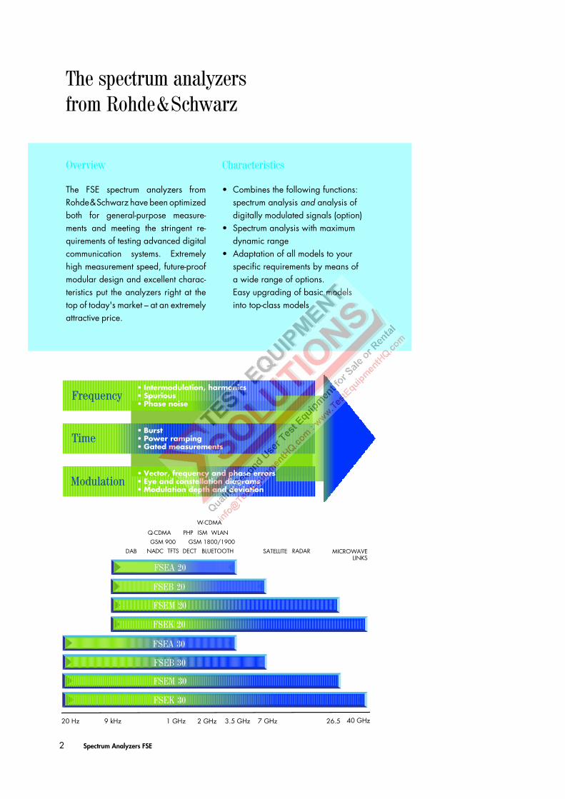
Frequency counter measures the marker frequency Resolution 0.1 Hz to 10 kHz (selectable)Count accuracy (S/N >25 dB) ±(frequency × reference error + 10 Hz + 1/2 (last digit))Display range for frequency axis 0 Hz, 10 Hz to full spanResolution/error of display range 0.1 Hz/1%Spectral purity (dBc/Hz)SSB phase noise, f ≤500 MHz,
for f >500 MHz see diagrams below
carrier offset 100 Hz2) – <–87 – <–81 – <–81 – <–811 kHz2) <–85 <–107 <–79 <–100 <–79 <–100 <–79 <–10010 kHz2) <–95 <–120 <–90 <–114 <–90 <–114 <–90 <–114100 kHz3) <–119 <–119 <–113 <–113 <–113 <–113 <–113 <–1131 MHz3) <–135 <–138 <–129 <–132 <–129 <–132 <–129 <–132
With option FSE-B4 for models .20 with option FSE-B4 values of models .30 applySweep timeSpan = 0 Hz 1 µs to 2500 s in 5% stepsSpan ≥10 Hz 5 ms to 16000 s in steps ≤10%Error <1%Picture refresh rate (span ≤7 GHz) >20 updates/s with 1 trace, >15 updates/s with 2 tracesSampling rate 50 ns (20-MHz A/D converter)Number of pixels 500Time measurement with marker and cursor linesResolution 50 nsSweep trigger free run, single, line, video, gated, delayed, external Zero span additionally pretrigger, posttrigger, trigger delay
SSB
phas
e no
ise
–70
–80
–90
–100
–110
–120
–130
–140
–150
dBc/Hz
1 kHz 10 kHz 100 kHz 10 MHz1 MHzCarrier offset
FSEB/M/K 3.5 GHz
FSEA 500 MHzFSEA 3.5 GHzFSEB/M/K 500 MHz
FSEM/K 26.5 GHz
–155
eSSB phase noisof models 20(typ. values)
1) After 30 days of operation. 2) Models 20: valid for span ≤50 kHz, RBW<1 kHz. 3) Valid for span >100 kHz.
100 Hz 1 kHz 10 kHz 100 kHz 10 MHz1 MHzCarrier offset
dBc/Hz
SSB
phas
e no
ise
–70
–80
–90
–100
–110
–120
–130
–140
–150
–155
–60
FSEB/M/K 3.5 GHz
FSEA 500 MHzFSEA 3.5 GHzFSEB/M/K 500 MHz
FSEM/K 26 GHz FSEK 40 GHz
SSB phase noiseof models(typ. values)
30

Spectrum Analyzers FSE 15
Resolution bandwidths3-dB bandwidths(in 1/2/3/5 steps)
10 Hz to 10 MHz
1 Hz to10 MHz
10 Hz to 10 MHz
1 Hz to 10 MHz
10 Hz to 10 MHz
1 Hz to 10 MHz
10 Hz to 10 MHz
1 Hz to 10 MHz
FFT Filter (in 1/2/3/5 steps)(see also folding page)
– 1 Hz to 1 kHz
– 1 Hz to 1 kHz
– 1 Hz to 1 kHz
– 1 Hz to 1 kHz
Bandwidth error ≤3 MHz <10%5 MHz <15%10 MHz +25%, –10%
Shape factor 60:3 dB<1 kHz <61 kHz to 2 MHz <15 <12 <15 <12 <15 <12 <15 <12>2 MHz <7
Video bandwidths 1 Hz to 10 MHz in 1/2/3/5 steps
LevelDisplay range noise floor displayed to 30 dBmMaximum input levelRF attenuation 0 dB
DC voltage 0 VCW RF power 20 dBm (=0.1 W)Pulse spectral density 97 dBµV/MHz
RF attenuation ≥10 dBDC voltage 0 VCW RF power 30 dBm (=1W)Max. pulse voltage 150 V 50 VMax. pulse energy (10 µs) 1mWs 0.5 mWs
1-dB compression of input mixer +10 dBm nominal (0-dB RF attenuation)Displayed average noise floor (dBm) (0-dB RF attenuation, RBW10 Hz, VBW1 Hz, 20 averages, trace average, span 0 Hz, termination 50 Ω)Frequency 20 Hz – <–80 – <–74 – <–74 – <–74
1 kHz – <–110 – <–104 – <–104 – <–10410 kHz <–90 <–125 <–84 <–119 <–84 <–119 <–84 <–119100 kHz <–110 <–135 <–104 <–129 <–104 <–129 <–104 <–1291 MHz <–130,
typ. –135<–145,
typ. –150<–125,
typ. –130<–142,
typ. –145<–124,
typ. –129<–142,
typ. –145<–124,
typ. –129<–142,
typ. –14510 MHz to 3.5/6 GHz <–145, typ. –150 <–142, typ. <–147 <–138, typ. –1406 GHz to 7 GHz – – <–139 <–139 <–135, typ. –1387 GHz to 18 GHz – – – – <–138, typ. –140 <–134, typ. –13918 GHz to 26.5 GHz – – – – <–135, typ. –138 <–131, typ. –13626.5 GHz to 30 GHz – – – – – – <–120, typ. –12530 GHz to 40 GHz – – – – – – <–116, typ. –122
Max. dynamic range bandwidth: 10 Hz 1 Hz 10 Hz 1 Hz 10 Hz 1 Hz 10 Hz 1 HzDispl. noise floor to 1-dB compression 155 dB 165 dB 152 dB 162 dB 150 dB 160 dB 150 dB 160 dBMax. harmonics suppres., f >50 MHz >90 dBMax. intermodulation-free range50 MHz to 3.5 GHz (nominal) 105 dB 115 dB – – – – – –150 MHz to 7/26.5 GHz (nominal) – – 105 dB 115 dB 103 dB 112 dB 103 dB 112 dBIntermodulation3rd-order intermod., intermodula-tion-free dynamic range, level 2 × –20 dBm, ∆f >5 × RBW or 10 kHz, whichever is the greater value
>64 dBc for f >50 MHz (T.O.I. >12 dBm,
typ. 18 dBm)
>70 dBc for f >150 MHz (T.O.I. >15 dBm,
typ. 20 dBm)
>74 dBc for f >100 MHz>60 dBc for f >7 GHz
(T.O.I. >17 dBm, typ. 22 dBm; >10 dBm for f >7 GHz)
Intermodulation-free range at –40 dBm mixer level
105 dB
Intercept point k2 (dBm) >25, typ. >40 for f <50 MHz,>45, typ. >50 for f >50 MHz
>25 for f <150 MHz, >35 typ.>40 for f >150 MHz, >45 typ.
Immunity to interferenceImage frequency (dB) >75 >80, typ.>90 >80, typ. >90Intermediate frequency (dB) >80 >100 >75 Spurious response (f >1 MHz, without input signal, 0-dB attenuation)
Span <30 MHz <–100 dBm <–110 dBm <–100 dBm <–110 dBm <–100 dBm <–110 dBm <–100 dBm <–110 dBmSpan ≥30 MHz <–100 dBmfin = 25.06 MHz, 25.175 MHz,
5.7172 GHz<–100 dBm
fin = 60 MHz <–100 dBm <–110 dBm <–100 dBmfin = 14.1894 GHz, 15.6722 GHz
Span >10 MHz −90 dBmSpan ≤10 MHz −90 dBm −90 dBm −90 dBm −90 dBm
Other interfering signals (mixer level <–10 dBm)1)
<–80 dB2) <–75 dB2)
SpecificationsFSEA20 FSEA30 FSEB20 FSEB30 FSEM20 FSEM30 FSEK20 FSEK30
1) For models 20, starting from 100 kHz carrier spacing on. 2) For models with option FSE-B23: <–50 dBm.

16 Spectrum Analyzers FSE
Level displayMeasurement display 500 × 400 pixels (with one diagram displayed); max. 2 diagrams with independent settingsLog level range 10 dB to 200 dB, in steps of 10 dBLin level range 10% of reference level per division (10 divisions) or logarithmic scalingTrace max. 4 traces with 1 diagram, 2 traces per diagram with 2 diagrams, simultaneous measurement with all tracesTrace detector max peak, min peak, auto peak (normal), sample, rms, averageTrace functions clear/write, max hold, min hold, averageSetting range of reference levelLog level display –130 dBm to 30 dBm, in steps of 0.1 dBLinear level display 7.0 nV to 7.07 V in steps of 1%Units of level axis dBm, dBµV, dBmV, dBµA, dBpW (log and lin level display) mV, µV, mA, µA, pW, nW (linear level display)Level measurement error–40 dBm, RF attenuation 20 dB, ref. level –15 dB, RBW 5 kHz
The values are guaranteed for bandwidths from 10 Hz to 30 kHz and 100 kHz to 10 MHz
Absolute error at 120 MHz <0.3 dBFreq. response (10 dB RF atten.)
<1 GHz <0.5 dB1 GHz to 3.5/7 GHz <1 dB7 GHz to 18 GHz – – – – <2 dB1)18 GHz to 26.5 GHz – – – – <2.5 dB1)26.5 GHz to 40 GHz – – – – – – <3 dB1)
Attenuator error <0.3 dBIF gain error <0.2 dB (typ. 0.1 dB)Linearity error
Log level display(RBW≥1kHz,analog)0 dB to –50 dB <0.3 dB–50 dB to –70 dB <0.5 dB–70 dB to –80 dB <1 dB – <1 dB – <1dB – <1dB ––70 dB to –95 dB – <1 dB – <1 dB – <1 dB – <1 dBLinear level display 5% of ref. level
Bandwidth switching error1 Hz to 30 kHz/100 to 500 kHz <0.2 dB/<0.2 dB1 MHz to 10 MHz <0.3 dB
Total measurement error (0 to 50 dB below reference level, span/RBW <100, rss 95% reliability)<1 GHz <1 dB1 GHz to 3.5/7 GHz <1.5 dB7 GHz to 18 GHz – – – – <2.5 dB1)18 GHz to 26.5 GHz – – – – <3 dB1)26.5 GHz to 40 GHz – – – – – – <3.5 dB1)Pulse amplitude error (single pulses)
Bandwidth <1 MHz/≥1 MHz <0.5 dB, nominal/<2 dB, nominal
Trigger functionsTrigger free run, line, video, RF, external Delayed sweepTrigger source free run, line, video, RF, externalDelay time 100 ns to 10 s, resolution 1 µs min. (or 1% of delay time)Error of delay time ±(1 µs + (0.1% × delay time))Delayed sweep time 2 µs to 1000 sGated sweepTrigger source external, RFGate delay 1 µs to 100 sGate length 1 µs to 100 s, resolution min. 1 µs or 1%Error of gate length ±(1 µs + (0.05% × gate length))Gap sweep (span = 0 Hz)Trigger source free run, line, video, RF, external Pretrigger 1 µs to 100 s, 50 ns resolution, dependent on sweep timeTrigger to gap time 1 µs to 100 s, 50 ns resolution, dependent on sweep timeGap length 1 µs to 100 s, 50 ns resolution
Audio demodulationAF demodulation types AM and FMAudio output speaker and phone jackMarker stop time 100 ms to 60 s
SpecificationsFSEA20 FSEA30 FSEB20 FSEB30 FSEM20 FSEM30 FSEK20 FSEK30
1) For RF frequencies >7 GHz: error after calling peaking function. For sweep times <10 ms/GHz: additional error 1.5 dB.

Spectrum Analyzers FSE 17
Inputs & outputs (front panel)RF input N female, 50 Ω adapter system, 50 Ω, N
male and female, 3.5 mm male and female
adapter system, 50 Ω, N male and female, K male and female, 2.4 mm female
VSWR (RF attenuation ≥10 dB)f <3.5 GHz <1.5f <7 GHz – <2.0f <26.5 GHz – – – – <3 <2.5f <37 GHz – – – – – – <2.5f <40 GHz – – – – – – typ. 2.5
Attenuator 0 dB to 70 dB, selectable in 10-dB stepsProbe power supply +15 V DC, –12.6 V DC and ground, max. 150 mAPower supply and coding connector for antennas etc (antenna code)
12-contact Tuchel
Supply voltages ±10 V, max. 100 mA, groundAF output Zout = 10 Ω, jack plugOpen-circuit voltage adjustable up to 1.5 V
Inputs & outputs (rear panel)IF 21.4 MHz Zout = 50 Ω, BNC female, bandwidth >1 kHz or resolution bandwidthLevel 0 dBm at reference level, mixer level >–60 dBmVideo output Zout = 50 Ω, BNC femaleVoltage (bandwidth ≥1 kHz) 0 V to 1 V, full scale (open-circuit voltage); log scalingReference frequencyOutput, usable as input BNC female
Output frequency 10 MHzLevel 10 dBm nominal
Input 1 MHz to 16 MHz, integer MHzRequired level >0 dBm from 50 Ω
Sweep output BNC female, 0 V to 10 V, proportional to displayed frequencyPower supply connect. f. noise source BNC female, 0 V and 28 V, switch-selectedExternal trigger/gate input BNC female, >10 kΩVoltage –5 V to +5 V, adjustableIEC/IEEE-bus control interface to IEC-625-2 (IEEE 488.2), Instruction set: SCPI 1994.0Connector 24-contact Amphenol femaleInterface functions SH1, AH1, T6, L4, SR1, RL1, PP1, DC1, DT1, C11Serial interface RS-232-C (COM 1 and COM 2), 9-contact female connectorsMouse interface PS/2 compatiblePlotter1) via IEC/IEEE bus or RS-232-C; plotter language: HP-GLPrinter interface parallel (Centronics compatible) or serial (RS-232-C)Keyboard connector 5-contact DIN female for MF-2 keyboardUser interface 25-contact Cannon femaleConnector f. external monitor (VGA) 15-contact female
General dataDisplay 24-cm LC TFT color display (9.5")Resolution 640 × 480 pixels (VGA resolution)Pixel failure rate <2 x 10⁻⁵
Mass memory 1.44-Mbyte 3 1/2" diskette (built-in disk drive), harddiskOperating temperature rangeNominal temperature range +5°C to +40°CLimit temperature range +0°C to +50°CStorage temperature range –40°C to +70°CHumidity +40°C at 95% relative humidity (IEC 68–2–3)Mechanical stressSinusoidal vibration 5 to 150 Hz, max. 2 g at 55 Hz; 0.5 g from 55 to 150 Hz; to IEC 68-2-6, IEC 68-2-3, IEC 1010-1, MIL-T-28800D, class 5Random vibration 10 to 300 Hz, acceleration 1.2 grmsShock 40 g shock spectrum, to MIL-STD-810D and MIL-T-28800D, classes 3 and 5Recommended calibration interval 1 year (2 years for operation with external reference)RFI suppression to EMC directive of EU (89/336/EEC) and German EMC legislationPower supplyAC supply 200 V to 240 V: 50 Hz to 60 Hz, 100 V to 120 V: 50 Hz to 400 Hz, class of protection I to VDE 411Power consumption 170 VA 180 VA 185 VA 195 VA 220 VA 230 VA 220 VA 230 VASafety to EN 61010-1, UL 3111-1, CSA C22.2 No. 1010-1, IEC 1010-1Test mark VDE, GS, UL, cULDimensions in mm (W x H x D) 435 × 236 × 460 (5 units of height) 435 × 236 ×
570435 x 236 x
460435 x 236 x
570Weight 21.5 kg 22.7 kg 21.8 kg 23.2 kg 23.8 kg 25.2 kg 24.4 kg 25.8 kg
SpecificationsFSEA20 FSEA30 FSEB20 FSEB30 FSEM20 FSEM30 FSEK20 FSEK30
1) The plot function is not available with option FSE-B15 installed.

18 Spectrum Analyzers FSE
Ordering informationOrder designation Type Order No.Spectrum Analyzer 9 kHz to 3.5 GHz FSEA20 1065.6000.25Spectrum Analyzer 20 Hz to 3.5 GHz FSEA30 1065.6000.35Spectrum Analyzer 9 kHz to 7 GHz FSEB20 1066.3010.25Spectrum Analyzer 20 Hz to 7 GHz FSEB30 1066.3010.35Spectrum Analyzer 9 kHz to 26.5 GHz FSEM20 1080.1505.25Spectrum Analyzer 20 Hz to 26.5 GHz FSEM30 1079.8500.35Spectrum Analyzer 9 kHz to 40 GHz FSEK20 1088.1491.25Spectrum Analyzer 20 Hz to 40 GHz FSEK30 1088.3494.35
Accessories suppliedPower cable, operating manual, spare fuses;FSEM: test-port adapter 3.5 mm female (1021.0512.00) and N female (1021.0535.00)FSEK: test-port adapter K female (1036.4790.00) and N female (1036.4777.00)
Ordering information continued overleaf
FFT Filter FSE-B5
Analog filter
100 000
10 000
1000
100
10
1
0.1
0.011 3 10 100 30030
Sweep time for 10 kHz Span
Swee
p tim
e (s
)
RBW (Hz)
SpecificationsFFT Filter FSE-B5 (standard in models 30)
• High frequency resolution due to very small shape factor of 2.5
• Extremely short measurement time, up to 150 times faster than with conventional filters
Resolution bandwidths (RBW)3 dB bandwidths, in 1/2/3/5 steps 1 Hz to 1 kHzBandwidth error 2%, nom.Shape factor 60:3 dB 2.5, nom.
Display range for frequency axisMin. span 25 x RBWMax. span 100 000 x RBW,
max. 2 MHz
Level measurement errorAdditional total level error, referred to RBW 5 kHz <1 dB
Max. display range 100 dB
Immunity to interferenceSpurious response ≤100 dBm
1 dB Attenuator FSE-B13Frequency range max. 7 GHz (stopp fre-
quency ≤7 GHz)Setting range ofRF attenuation 0 dB to 70 dBStep width 1 dBAdditional attenuatoruncertainty <0.1 dB
External Mixing FSE-B21LO output/IF input(front panel) SMA female , 50 Ω
LO signal 7.5 GHz to 15.2 GHzAmplitude +15.5 dBm ±3 dB
IF signal 741.4 MHzFull-scale level –20 dBm
IF input (front panel) SMA female , 50 ΩFrequency 741.4 MHz
Full-scale level –20 dBmLevel measurement errorat IF inputs (IF level –30 dBm,reference level –20 dBm, RBW 30 kHz) <1 dB
Increased Level Accuracy FSE-B22Total level error ≤0.5 dB with 10 dB RF
attenuation≤0,6 dB with 20/30/40 dB RF attenuation
Specifications are valid for:Temperature range 20 to 30 °CFrequency range 10 MHz to 2 GHzResolution bandwidths 5 to 30 kHz/300 kHz/
1 MHzSignal level 10 dB to 50 dB below
reference levelStop frequency ≤2 GHzSweep time ≥3 x auto sweep time
Broadband Output 741.4 MHz FSE-B23FSE-B23 reduces the suppression of other interfer-ence signals to −50 dBm and must not be combined with FSE-K10/-K11.
FSEA FSEB FSEM FSEKGain from RFinput to IF output (dB) 6 6 4 43 dB BW (MHz) 60 150 1501) 1501)
40 to 802) 40 to 1203)
1) f<7 GHz. 2) 7 GHz to 26.5 GHz. 3) 7 GHz to 40 GHz.