
Robust person identification system using iris
13
International J. of Engg. Research & Indu. Appls. (IJERIA). ISSN 0974-1518, Vol.3, No. IV (November 2010), pp. 165-177 ROBUST PERSON IDENTIFICATION SYSTEM USING IRIS PRAVIN S. PATIL, SATISH R. KOLHE, MILIND E. RANE AND PRADEEP M. PATIL Abstract Human iris provides a unique structure suitable for non-invasive biometric assessment. In particular the irises are as distinct as fingerprints even for twins. In this paper a robust system for person identification is presented that uses a technique of localization, alignment, feature extraction, matching the features of irises and finally the decision regarding the degree of match. A CASIA iris database of iris images has been used in the implementation of the iris recognition system. The results show that proposed method is quite effective. . ---------------------------------------- Keywords: Iris recognition, LOG, Iris Localisation © Ascent Publication House: http: //www.ascent-journals.com
Transcript of Robust person identification system using iris

International J. of Engg. Research & Indu. Appls. (IJERIA).
ISSN 0974-1518, Vol.3, No. IV (November 2010), pp. 165-177
ROBUST PERSON IDENTIFICATION SYSTEM USING IRIS
PRAVIN S. PATIL, SATISH R. KOLHE, MILIND E. RANE
AND PRADEEP M. PATIL
Abstract
Human iris provides a unique structure suitable for non-invasive biometric assessment. In particular
the irises are as distinct as fingerprints even for twins. In this paper a robust system for person
identification is presented that uses a technique of localization, alignment, feature extraction,
matching the features of irises and finally the decision regarding the degree of match. A CASIA iris
database of iris images has been used in the implementation of the iris recognition system. The results
show that proposed method is quite effective.
.
----------------------------------------
Keywords: Iris recognition, LOG, Iris Localisation
© Ascent Publication House: http: //www.ascent-journals.com

PRAVIN S. PATIL, SATISH R. KOLHE, MILIND E. RANE AND PRADEEP M. PATIL 166
1. INTRODUCTION
Biometric verification has been receiving extensive attention over the past decade with
increasing demands in automated personal identification. Biometrics deals with the
uniqueness of an individual arising from their physiological or behavioral characteristics for
the purpose of personal identification. Biometric recognition [1] systems verify a person’s
identity by analyzing his/her physical features or behavior (e.g. face [2], fingerprint, voice,
signature, keystroke rhythms). Among many biometrics techniques, iris recognition is one of
the most promising approaches due to its high reliability for personal identification [1–8].
Iris recognition is a method of biometric authentication that uses pattern recognition
techniques based on high-resolution images of the irides of an individual's eyes. A major
approach for iris recognition today is to generate feature vectors corresponding to individual
iris images and to perform iris matching based on some distance metrics [3–6]. Most of the
commercial iris recognition systems implement a famous algorithm using iris codes
proposed by Daugman [3]. Iris recognition uses camera technology, with subtle infrared
illumination reducing specular reflection from the convex cornea, to create images of the
detail-rich, intricate structures of the iris. Converted into digital templates, these images
provide mathematical representations of the iris that yield unambiguous positive
identification of an individual. One of the difficult problems in feature-based iris recognition
is that the matching performance is significantly influenced by many parameters in feature
extraction process (eg., spatial position, orientation, center frequencies and size parameters
for 2D Gabor filter kernel), which may vary depending on environmental factors of iris
image acquisition. The human iris contains around 266 visible patterns, which forms the
basis of several recognition algorithms [5]. Even on the same person, left and right irises are
different. The iris is unique to an individual and is stable with age [6]. This is a key
advantage of iris recognition as its stability, or template longevity as, barring trauma, a single
enrollment can last a lifetime. Wildes [9] started the segmentation of the iris ring by the
construction of a binary edge-map. Next, used the circular Hough transform to fit circles that
delimit the iris ring. This is the most usually seen method in the iris segmentation literature
and is proposed with minor variants by [10-13]. Proenca et al. proposed a method [14] that

ROBUST PERSON IDENTIFICATION SYSTEM USING IRIS 167
uses a clustering process to increase the robustness to noisy data. The method proposed by
Du et al. [15] is based on the previous detection of the pupil. The image is then transformed
into polar coordinates and the iris outer border localized as the largest horizontal edge
resultant from Sobel filtering. Morphologic operators were applied by Mira et al. [16] to
find both iris borders. They detected the inner border by sequentially using threshold, image
opening and closing techniques. The outer border was similarly detected. Eric Sung et al.
proposed complexity measure based on maximum Shannon entropy of wavelet packet
reconstruction to quantify the iris information [17]. Jiali Cui et al. proposed [18] the iris
recognition algorithm based on PCA (Principal Component Analysis) is first introduced and
then, iris image synthesis method is presented. Lee et al. have introduced [19] the invariant
binary feature which is defined as iris key. Kazuyuki et al. developed [20] phase-based
image matching algorithm. The use of phase components in two-dimensional discrete
Fourier transforms of iris images makes possible to achieve highly robust iris recognition in
a unified fashion with a simple matching algorithm. In this paper a robust biometric system
based on iris features is proposed for personal identification. It uses a technique of
localization, alignment, feature extraction, matching the features of irises and finally the
decision regarding the degree of match.
This paper has been organized in the following way. The iris recognition system is divided
into three parts: image acquisition, iris localization and pattern matching. Image acquisition,
iris localization are described in Section 2. In Section 3, the algorithm of this system is
explained. Finally the results obtained and concluding remarks are mentioned.
2. PROPOSED IRIS RECOGNITION SYSTEM
Block diagram of the proposed iris recognition system is as shown in Figure 1 that contains
the typical stages of iris recognition system.

PRAVIN S. PATIL, SATISH R. KOLHE, MILIND E. RANE AND PRADEEP M. PATIL 168
Figure 1. Proposed iris recognition system
The initial stage concerns about the segmentation of the iris. This consists in localize the iris
inner (pupillary) and outer (scleric) boundaries, assuming either circular or elliptical shapes
for each border. Additionally, it is used to detect regions of the iris texture occluded by any
other type of data, as eyelids, eyelashes, glasses or hair. Features of iris image are extracted
using the Laplacian of Gaussian (LoG) filter. These extracted features are stored in the
database during enrollment. While matching features of the query image are correlated with
the feature vectors of templates in the database and decision is formulated.
2.1 Image acquisition
The system captures eye images with the iris diameter typically between 100 and 200 pixels
from a distance of 15–46 cm using a 330-mm lens.
2.2 Iris localization
Image acquisition of the iris cannot be expected to yield an image containing only the iris. It
will also contain data derived from the surrounding eye region. Therefore, prior to iris
pattern matching, it is important to localize that portion of the image derived from inside the
limbus (the border between the sclera and the iris) and outside the pupil. If the eyelids are
occluding part of the iris, then only that portion of the image without the eyelids should be
included.
For the localization of iris first any random circular contour is formed which contains iris +
pupil region to eliminate the remaining portion of the eye .A circular pseudo image is formed
of desired diameter. The inside region of the circle is set at gray level ‘1’(white) and the
outside region to ‘0’(black). The diameter selected is such that the circular contour will
encircle the entire iris. This diameter selection is crucial as it should be common for all iris
images. Thus when the product of the gray levels of the circular pseudo image and the
ROBUST PERSON IDENTIFICATION SYSTEM USING IRIS 169
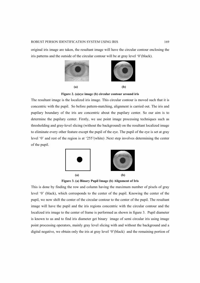
original iris image are taken, the resultant image will have the circular contour enclosing the
iris patterns and the outside of the circular contour will be at gray level ‘0’(black).
(a) (b)
Figure 2. (a)eye image (b) circular contour around iris
The resultant image is the localized iris image. This circular contour is moved such that it is
concentric with the pupil. So before pattern-matching, alignment is carried out. The iris and
pupilary boundary of the iris are concentric about the pupilary center. So our aim is to
determine the pupilary center. Firstly, we use point image processing techniques such as
thresholding and gray-level slicing (without the background) on the resultant localized image
to eliminate every other feature except the pupil of the eye. The pupil of the eye is set at gray
level ‘0’ and rest of the region is at ‘255’(white) .Next step involves determining the center
of the pupil.
(a) (b)
Figure 3. (a) Binary Pupil Image (b) Alignment of Iris
This is done by finding the row and column having the maximum number of pixels of gray
level ‘0’ (black), which corresponds to the center of the pupil. Knowing the center of the
pupil, we now shift the center of the circular contour to the center of the pupil. The resultant
image will have the pupil and the iris regions concentric with the circular contour and the
localized iris image to the center of frame is performed as shown in figure 3. Pupil diameter
is known to us and to find iris diameter get binary image of semi circular iris using image
point processing operators, mainly gray level slicing with and without the background and a
digital negative, we obtain only the iris at gray level ‘0’(black) and the remaining portion of

PRAVIN S. PATIL, SATISH R. KOLHE, MILIND E. RANE AND PRADEEP M. PATIL 170
the image is at gray level ‘255’(white) . The shape of the iris in this case can be considered
to be semi-circular.
Now scanning row-wise, a counter determines the number of pixels having gray level ‘0’
(white) in each row and the maximum count can be considered as the diameter of the iris
along the row. Now scanning column-wise, a counter determines the number of pixels
having gray level ‘0’ (white) in each column and the maximum count can be considered as
the radius of the iris. Doubling gives the diameter of the iris along the column. Taking the
average of the two, we get the average iris diameter. Final Result of iris localization eye with
iris and pupil are circled correctly.
(a) (b) (c)
Figure 4. (a) Binary Semi-Iris Image (b) Localized iris (c) Image removing eyelids
Removing the portion of the iris occluded by the eyelids is carried out next. The eyelids are
occluding part of the iris, so only that portion of the image below the upper eyelids and
above the lower eyelids are included. This is achieved by changing the gray level above the
upper eyelids and below the lower eyelids to ‘0’. Figure 5 shows entire steps performed on
another eye image.
(a) (b) (c)
(d) (e) (f) (g)
Figure 5. (a)eye image (b) circular contour around iris (c) Binary Pupil Image (d) Alignment of
Iris (e) Binary Semi-Iris Image (f) Localized iris (g) Image removing eyelids

ROBUST PERSON IDENTIFICATION SYSTEM USING IRIS 171
2.3 Feature extraction
After localizing and aligning the image containing the iris, the next task is to decide if this
pattern matches with the one existing in the database. The pattern matching is decomposed
into three parts. Firstly a representation of the localized and aligned iris image is chosen that
makes their distinctive patterns apparent. We have employed an isotropic, circularly
symmetric band-pass decomposition derived from the application of Laplacian of Gaussian
filter to the image. This result in a pyramid formation of the iris image i.e. a Multiscale
Representation which is used for iris pattern matching realized by the filter. The main idea of
using a multi-scale representation in this paper is to capture range of spatial detail to detect
and characterize edges of the numerous iris patterns known. As the name suggests, a multi-
scale representation gives us iris images at varying spatial scales. It is observed that different
structures give rise to edges at varying scales; small scales correspond to fine details and
large scales correspond to gross structures. By studying the image at each scale,
classification of prominent edges of the different iris patterns at each level is possible.
Steps involved in the multiscale representation using LoG filter:
The LoG filter can be specified as
2 24 2 2 / 2( 1/ )(1 / 2 ) ρ σπσ ρ σ −− − l
(1)
where σ -standard deviation of the Gaussian, ρ -radial distance of a point from the filter’s
center.
One dimensional mask w =[1 4 6 4 1]/16, Two dimensional mask TW w w= × The
resultant matrix mask
Now construction of the Laplacian Pyramid begins first with convolution of the Iris Image
with LoG Mask ‘W’, so as to yield low-pass Gaussian filtered images kg .
1 4 6 4 1
4 16 24 16 41
6 24 36 24 6256
4 16 24 16 4
1 4 6 4 1
w=
(2)
PRAVIN S. PATIL, SATISH R. KOLHE, MILIND E. RANE AND PRADEEP M. PATIL 172
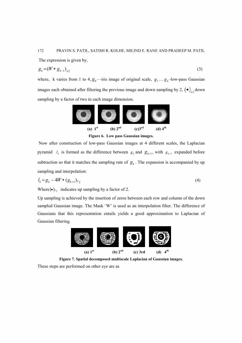
The expression is given by,
21)( ↓−∗= kk gWg
(3)
where, k varies from 1 to 4, 0g —iris image of original scale, 1g …
4g -low-pass Gaussian
images each obtained after filtering the previous image and down sampling by 2, ( )2↓
• down
sampling by a factor of two in each image dimension.
(a) 1st (b) 2
nd (c)3
rd (d) 4
th
Figure 6. Low pass Gaussian images.
Now after construction of low-pass Gaussian images at 4 different scales, the Laplacian
pyramid kl is formed as the difference between kg and 1+kg , with 1+kg expanded before
subtraction so that it matches the sampling rate of kg . The expansion is accompanied by up
sampling and interpolation:
21)(4 ↑+∗−= kkk gWgl (4)
Where ( ) 2↑• indicates up sampling by a factor of 2.
Up sampling is achieved by the insertion of zeros between each row and column of the down
sampled Gaussian image. The Mask ‘W’ is used as an interpolation filter. The difference of
Gaussians that this representation entails yields a good approximation to Laplacian of
Gaussian filtering.
(a) 1st (b) 2
nd (c) 3rd (d) 4
th
Figure 7. Spatial decomposed multiscale Laplacian of Gaussian images.
These steps are performed on other eye are as
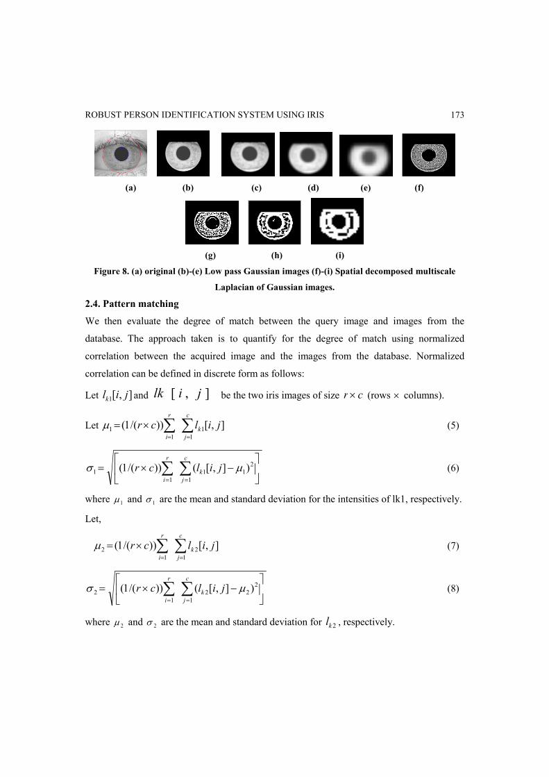
ROBUST PERSON IDENTIFICATION SYSTEM USING IRIS 173
(a) (b) (c) (d) (e) (f)
(g) (h) (i)
Figure 8. (a) original (b)-(e) Low pass Gaussian images (f)-(i) Spatial decomposed multiscale
Laplacian of Gaussian images.
2.4. Pattern matching
We then evaluate the degree of match between the query image and images from the
database. The approach taken is to quantify for the degree of match using normalized
correlation between the acquired image and the images from the database. Normalized
correlation can be defined in discrete form as follows:
Let ],[1 jilk and ],[ jilk be the two iris images of size cr × (rows × columns).
Let ∑∑==
×=c
j
k
r
i
jilcr1
1
1
1 ],[))/(1(µ
(5)
−×= ∑∑
==
c
j
k
r
i
jilcr1
2
11
1
1 )],[())/(1( µσ
(6)
where 1µ and 1σ are the mean and standard deviation for the intensities of lk1, respectively.
Let,
∑∑==
×=c
j
k
r
i
jilcr1
2
1
2 ],[))/(1(µ (7)
−×= ∑∑
==
c
j
k
r
i
jilcr1
2
22
1
2 )],[())/(1( µσ
(8)
where 2µ and 2σ are the mean and standard deviation for 2kl , respectively.

PRAVIN S. PATIL, SATISH R. KOLHE, MILIND E. RANE AND PRADEEP M. PATIL 174
Normalized correlation between 1kl and 2kl can be defined as
21
1
2211
1
)],[)(],[(
σσ
µµ
×××
−−∑∑==
cr
jiljilc
j
kk
r
i
(9)
Normalized correlation is preferred over standard correlation, since normalized correlation
accounts for local variations in image intensity that disrupts standard correlation. This
robustness is achieved since the mean intensities are subtracted in the numerator and the
standard deviations are multiplied in the denominator of the correlation ratio. The matching
operation results in multiple correlation values for each of the four spatial frequency bands.
Thus the matching multiscale representation using normalized correlation yields a set of four
goodness-of-match values, one for each frequency band. Blocking of non-relevant image
data, combined with a median operation allows for local adjustments of matching and a
degree of outlier rejection thereby providing robustness against mismatches due to noise,
misalignment and occlusion of stray eyelashes.
3. PROPOSED ALGORITHM
The steps involved in the proposed algorithm are
1. Read the eye image
2. Localization and alignment of iris image
3. Determination of ratios of Limbus diameter & Pupil diameter ratio 1.
4. Read another image from database
5. Localization and alignment of iris image
6. Determination of ratios of Limbus diameter & Pupil diameter ratio 2.
7. if ratio1=ratio 2 then goto step 8 else goto step13
8. diameter ratios of both irises are equal
9. Pattern matching for both the irises multiscale LoG filtering to make the distinct iris
patterns apparent.
10. Apply low pass Gaussian filter to the localized and aligned iris image.
11. Evaluate the degree of match.

ROBUST PERSON IDENTIFICATION SYSTEM USING IRIS 175
12. if normalized correlation = 1 then go to step 14
13. display both the irises are not identical and goto step 15
14. display both the irises are identical and goto step 15
15. stop
4. RESULTS AND DISCUSSION
The performance of the iris recognition system has been evaluated on the CASIA[21] iris
image database. This database consists of images from 108 different eyes with 7 images per
eye. These 7 samples were collected over two different sessions with 4 samples in one
session and 3 in the other. A number of experiments were performed to show the
effectiveness of the developed algorithm, using Pentium IV 2.8 GHz processor.
The results of the individual eye matching for two different cases are as given below
Case1: Result obtained for iris images of two different persons - Ratios of Limbus Diameter
& Pupil Diameter of both the irises are not equal
The Normalized correlation value are given by
Corr0 = 0.6625- for the 1stLoG of 2 iris image
Corr0 = 0.8101- for the 2nd LoG of 2 iris image
Corr0 = 0.8513- for the 3rd LoG of 2 iris image
Corr0 = 0.9284- for the 4th LoG of 2 iris image
Both the irises are not identical
Case 2: Result obtained for iris images of same person -Ratios of Limbus Diameter & Pupil
Diameter of both the irises are equal
The Normalized correlation value are given by
Corr0 = 1.0000- for the 1st LoG of 2 iris image
Corr0 = 1.0000- for the 2nd LoG of 2 iris image
Corr0 = 1.0000- for the 3rd LoG of 2 iris image
Corr0 = 1.0000- for the 4th LoG of 2 iris image
Both the irises are identical

PRAVIN S. PATIL, SATISH R. KOLHE, MILIND E. RANE AND PRADEEP M. PATIL 176
In order to test the system performance system was so trained with one training images and
remaining six images of each class were used as test images. The recognition rate of this
system is 94.28%. Increase in the number of training images improves the performance, as
system is better trained with the cost of increases in computational time.
CONCLUSION
The automated localization and alignment technique used in this paper is quite unique and
efficiently frames the subject’s iris with minimum subject participation. The pattern
matching technique employs multiscale pyramid representation using a LoG filter, which
provides optimal enhancement of the features of the iris patterns, and then normalized
correlation is employed for evaluating the degree of similarity for correct recognition.
REFERENCES
[1] Jain AK, Ross A, Prabhakar S. “An introduction to biometric recognition,” IEEE transactions on
circuits and systems for video technology—special issue on image and video-based biometrics,
vol. 14(1); 2004.
[2] Kashima H, Hongo H, Kato K, Yamamoto K., “A robust iris detection method of facial and eye
movement,” Canadian conference on computer and robot vision; 2001.
[3] Daugman J G, “Recognizing people by their iris patterns,” Information Security Technical
Report, Volume 3, Issue 1, 1998, Pages 33-39.
[4] Daugman J G, “Recognizing people by their iris patterns,” Information Security Technical
Report, Volume 4, Supplement 1, 1999, Page 29.
[5] Daugman J G, “The importance of being random: statistical principles of iris recognition,”
Pattern Recognition, Volume 36, Issue 2, February 2003, Pages 279-291.
[6] Daugman J G, “How Iris Recognition Works,” Handbook of Image and Video Processing
(Second Edition), 2005, Pages 1251-1262.
[7] Kawaguchi, T, Rizon, M, ”Iris detection using intensity and edge information,”
Pattern Recognition, Volume 36, Issue 2,, February 2003, Pages 549-562.
[8] Bowyer, K W, Hollingsworth, K P, Flynn, P J, “Image Understanding for Iris Biometrics: A
survey,” CVIU, May 2008, Pages 281-307.
[9] Wildes R.P., “Iris recognition: an emerging biometric technology,” Proceedings of the IEEE,
vol. 85(9); 1997. p. 1348–63.

ROBUST PERSON IDENTIFICATION SYSTEM USING IRIS 177
[10] Ma L., Tan T., Wang Y., and Zhang D.., “Personal Identification Based on Iris Texture
Analysis,” IEEE Transactions on Pattern Analysis and Machine Intelligence, 25(12):1519{1533,
December 2003.
[11] Ma L., Wang Y., and Zhang D., “Efficient iris recognition by characterizing key local
variations,” IEEE Transactions on Image Processing, vol. 13, no. 6, pp. 739–750, June
[12] Huang J., Wang Y., Tan T., and Cui J., “A new iris segmentation method for recognition,” in
Proceedings of the 17th International Conference on Pattern Recognition (ICPR04), vol. 3, 2004,
pp. 23–26.
[13] Ma L., Wang Y., and Tan T., “Iris recognition using circular symmetric filters,” in Proceedings
of the 25th International Conference on Pattern Recognition (ICPR02), vol. 2, 2002, pp. 414–
417.
[14] Proenca H. and Alexandre L. A., “Iris segmentation methodology for non-cooperative iris
recognition,” IEE Proc. Vision, Image & Signal Processing, vol. 153, issue 2, pp. 199–205,
2006.
[15] Du Y., Ives R., Etter D., Welch T., and Chang C., “A new approach to iris pattern recognition,”
in Proceedings of the SPIE European Symposium on Optics/Photonics in Defence and Security,
vol. 5612, October 2004, pp. 104–116.
[16] Mira J. and Mayer J., “Image feature extraction for application of biometric identification of iris
- a morphological approach,” in Proceedings of the 16th Brazilian Symposium on Computer
Graphics and Image Processing (SIBGRAPI 2003), Brazil, October 2003, pp. 391–398.
[17] Sung E., Chen X., Zhu J. and Yang J., “Towards non-cooperative iris recognition systems”,
Seventh international Conference on Control, Automation, Robotics And Vision (ICARCV’02),
Dec. 2002, Singapore, pp. 990-995.
[18] Cui J., Wang Y., Huang J., Tan T. and Sun Z., “An Iris Image Synthesis Method Based on PCA
and Super-resolution”, IEEE CS Proceedings of the 17th International Conference on Pattern
Recognition (ICPR’04).
[19] Gu Lee H., Noh S., Bae K., Park K.-R. and Kim J., “Invariant biometric code extraction”, IEEE
Intelligent Signal Processing and Communication Systems (ISPACS 2004), Proceedings IEEE
ISPACS, 18-19 Nov. 2004, pp. 181-184.
[20] Miyazawa K, Ito K, Aoki T, Kobayashi K, Nakajima H., “An Efficient Iris Recognition
Algorithm Using Phase-Based Image Matching”, IEEE Image Processing Conference, 2005
(ICIP 2005), 11-14 Sept. 2005, Vol. 2, pp. II- 49-52.
[21] Chinese Academy of Sciences. Specification of CASIA Iris Image Database (ver1.0).
http://www.nlpr.ia.ac.cn/english/irds/irisdatabase.htm, March 2007.
Pravin S. Patil and Satish R. Kolhe
Computer Science Department
North Maharashtra University
Jalgaon, Maharashtra, India.
Milind E. Rane and Pradeep M. Patil Electronics Engineering Department
Vishwakarma Institute of Technology
Pune, Maharashtra, India