Controlling the display of capsule endoscopy video for diagnostic assistance
Upload
independentCategory
view
0download
0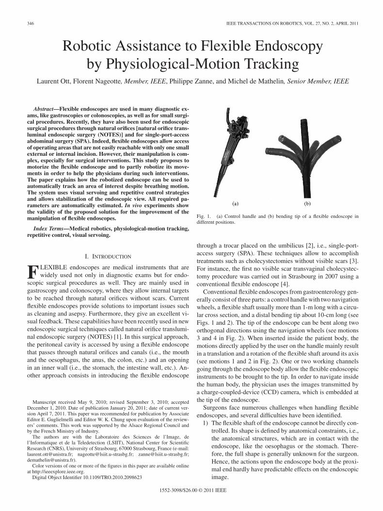
346 IEEE TRANSACTIONS ON ROBOTICS, VOL. 27, NO. 2, APRIL 2011
Robotic Assistance to Flexible Endoscopyby Physiological-Motion Tracking
Laurent Ott, Florent Nageotte, Member, IEEE, Philippe Zanne, and Michel de Mathelin, Senior Member, IEEE
Abstract—Flexible endoscopes are used in many diagnostic ex-ams, like gastroscopies or colonoscopies, as well as for small surgi-cal procedures. Recently, they have also been used for endoscopicsurgical procedures through natural orifices [natural orifice trans-luminal endoscopic surgery (NOTES)] and for single-port-accessabdominal surgery (SPA). Indeed, flexible endoscopes allow accessof operating areas that are not easily reachable with only one smallexternal or internal incision. However, their manipulation is com-plex, especially for surgical interventions. This study proposes tomotorize the flexible endoscope and to partly robotize its move-ments in order to help the physicians during such interventions.The paper explains how the robotized endoscope can be used toautomatically track an area of interest despite breathing motion.The system uses visual servoing and repetitive control strategiesand allows stabilization of the endoscopic view. All required pa-rameters are automatically estimated. In vivo experiments showthe validity of the proposed solution for the improvement of themanipulation of flexible endoscopes.
Index Terms—Medical robotics, physiological-motion tracking,repetitive control, visual servoing.
I. INTRODUCTION
F LEXIBLE endoscopes are medical instruments that arewidely used not only in diagnostic exams but for endo-
scopic surgical procedures as well. They are mainly used ingastroscopy and colonoscopy, where they allow internal targetsto be reached through natural orifices without scars. Currentflexible endoscopes provide solutions to important issues suchas cleaning and asepsy. Furthermore, they give an excellent vi-sual feedback. These capabilities have been recently used in newendoscopic surgical techniques called natural orifice translumi-nal endoscopic surgery (NOTES) [1]. In this surgical approach,the peritoneal cavity is accessed by using a flexible endoscopethat passes through natural orifices and canals (i.e., the mouthand the oesophagus, the anus, the colon, etc.) and an openingin an inner wall (i.e., the stomach, the intestine wall, etc.). An-other approach consists in introducing the flexible endoscope
Manuscript received May 9, 2010; revised September 3, 2010; acceptedDecember 1, 2010. Date of publication January 20, 2011; date of current ver-sion April 7, 2011. This paper was recommended for publication by AssociateEditor E. Guglielmelli and Editor W. K. Chung upon evaluation of the review-ers’ comments. This work was supported by the Alsace Regional Council andby the French Ministry of Industry.
The authors are with the Laboratoire des Sciences de l’Image, del’Informatique et de la Teledetection (LSIIT), National Center for ScientificResearch (CNRS), University of Strasbourg, 67000 Strasbourg, France (e-mail:[email protected]; [email protected]; [email protected];[email protected]).
Color versions of one or more of the figures in this paper are available onlineat http://ieeexplore.ieee.org.
Digital Object Identifier 10.1109/TRO.2010.2098623
Fig. 1. (a) Control handle and (b) bending tip of a flexible endoscope indifferent positions.
through a trocar placed on the umbilicus [2], i.e., single-port-access surgery (SPA). These techniques allow to accomplishtreatments such as cholecystectomies without visible scars [3].For instance, the first no visible scar transvaginal cholecystec-tomy procedure was carried out in Strasbourg in 2007 using aconventional flexible endoscope [4].
Conventional flexible endoscopes from gastroenterology gen-erally consist of three parts: a control handle with two navigationwheels, a flexible shaft usually more than 1-m long with a circu-lar cross section, and a distal bending tip about 10-cm long (seeFigs. 1 and 2). The tip of the endoscope can be bent along twoorthogonal directions using the navigation wheels (see motions3 and 4 in Fig. 2). When inserted inside the patient body, themotions directly applied by the user on the handle mainly resultin a translation and a rotation of the flexible shaft around its axis(see motions 1 and 2 in Fig. 2). One or two working channelsgoing through the endoscope body allow the flexible endoscopicinstruments to be brought to the tip. In order to navigate insidethe human body, the physician uses the images transmitted bya charge-coupled-device (CCD) camera, which is embedded atthe tip of the endoscope.
Surgeons face numerous challenges when handling flexibleendoscopes, and several difficulties have been identified.
1) The flexible shaft of the endoscope cannot be directly con-trolled. Its shape is defined by anatomical constraints, i.e.,the anatomical structures, which are in contact with theendoscope, like the oesophagus or the stomach. There-fore, the full shape is generally unknown for the surgeon.Hence, the actions upon the endoscope body at the proxi-mal end hardly have predictable effects on the endoscopicimage.
1552-3098/$26.00 © 2011 IEEE
OTT et al.: ROBOTIC ASSISTANCE TO FLEXIBLE ENDOSCOPY BY PHYSIOLOGICAL-MOTION TRACKING 347
Fig. 2. Transmission of motions between the (right) endoscope handle andthe (left) endoscope bending tip. Arbitrary motions directly applied by the useron the (0) handle mainly result in a (1) translation and a rotation of the flexibleshaft around its axis inside the (2) lumen. During an accurate task on a movingorgan, the orientation (i.e., 3 and 4) of the endoscope tip is used to follow thetarget, while the instruments are translated inside the channels (i.e., 5 and 6) toperform the task.
2) Multiple actions have to be combined to perform the de-sired movements.
3) Physiological motions of the organs, for instance, due tobreathing, generate critical disturbances on the anatom-ical targets to be treated and on the flexible endoscope(see Fig. 2). Expert hand–eye coordination is required tooperate, despite these disturbances.
4) Classical flexible endoscopic instruments have limitedcontrollable degrees of freedom (DoFs). The surgeon canonly push or pull them inside the endoscope working chan-nels, thereby resulting in a translation along the directionof the tip of the endoscope. The surgeon must move thetip of the endoscope in order to drive the instruments inother directions (see Fig. 2).
For NOTES procedures, where at least two flexible instru-ments are needed, the high number of mobilities to manageimplies that several physicians simultaneously handle the endo-scopic device and its instruments. Hence, they have to share asmall working space around the endoscope control handle, andexcellent coordination is needed.
In this paper, we are interested in helping the surgeon inperforming accurate medical tasks once they are on the oper-ating area. Usually, around the operating area, the endoscopistprimarily uses the navigation wheels to orient the endoscopetoward the anatomical target and the instruments to perform thesurgical task. If the tip of the endoscope could automaticallytrack the anatomical target, despite the physiological motions,the physician would be able to focus on the manipulation ofthe endoscopic tools. Therefore, we propose to partly robotizethe motion of the endoscope in order to automatically track theanatomical target, despite its motion. In this manner, the surgeonis relieved of stabilizing the anatomical target in the endoscopicimage. The residual motion of the anatomical target with re-spect to the endoscope tip will then be only along the directionof the line of view. This residual motion can be quite easily
manually compensated by the surgeon using only the surgicalinstruments, since these extend directly from the bending tip ofthe endoscope toward the target.
In this study, the virtual link between the tip of the endoscopeand the anatomical target is performed using visual-servoingtechniques. Indeed, vision is the only exteroceptive sensor nat-urally embedded in the flexible endoscope.
Stabilization is an important field of research in medicalrobotics, especially for flexible systems. Solutions have beenproposed to provide rigidity to flexible systems once they are onthe operating site. Degani et al. [5] presented a snake-like robotwith a locking mechanism, which is called highly-articulatedrobotic probe (HARP), to perform intrapericardial interventions.Yamashita et al. [6] proposed an MRI-compatible steerable andlockable outer sheath for flexible devices used in minimallyinvasive surgery. These locking mechanisms allow the flexiblesystems to be made insensitive to physiological motion. How-ever, in abdominal surgery, the target would keep moving due tobreathing, and its position in the image would not be stabilized.Contrary to this approach, we propose to provide a form ofactive stabilization, which is also called physiological-motioncompensation. This solution does not make the system insen-sitive to motion. Instead, it allows a part of the relative motionof the target to be actively compensated with respect to the en-doscope in order to stabilize the position of the target in theimage.
Physiological-motion compensation using robots is a promis-ing approach for surgical assistance [7]. It has been used in la-paroscopic surgery to compensate breathing motions [8], in car-diac surgery to stabilize the surgical instruments with respectto the beating heart [8], [9], and in microsurgery for tremorreduction using a handheld micromanipulator [10]. However,physiological-motion rejection has never been applied to flexi-ble endoscopes.1 The main difference arises from the fact thatthe camera is embedded at the tip of the endoscope in an eye-in-hand configuration. As a consequence, the effects of physio-logical motion and actuated motion of the endoscope cannot beeasily separated. Another difficulty is due to the motion trans-mission between the motors and the distal tip of the endoscope.It introduces nonlinearities that have to be handled to obtaingood tracking performances.
To provide the desired assistance, the endoscopic system mustbe able to follow the dynamic motion of the organ. In usual trans-luminal procedures, the breathing of the patient is controlledusing a breathing machine that imposes a perfectly periodicmotion to the organs. The amplitude of the motion is typicallyof 2 cm for the liver or the gallbladder, which are especiallysensitive to breathing motion [12].
The paper is organized as follows. The next section presentsthe design of the robotized endoscope. Section III introducesthe mechanical and vision model of the flexible endoscopicsystem. The proposed control algorithms for motion trackingusing visual servoing are presented in Section IV with a stabilityanalysis. Section V presents and characterizes nonlinearities
1Primarily, results have been presented at the Internet Content Rating Asso-ciation (ICRA) conference [11].
348 IEEE TRANSACTIONS ON ROBOTICS, VOL. 27, NO. 2, APRIL 2011
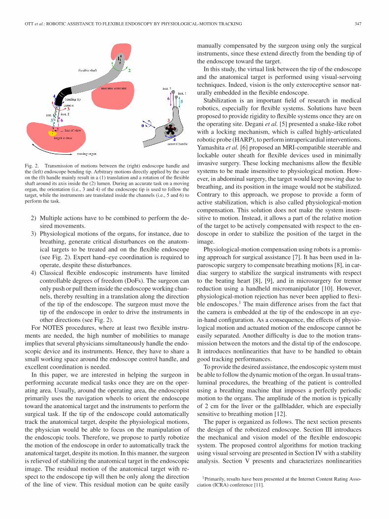
Fig. 3. CAD view of the (a) motor/endoscope coupling and (b) real view ofthe handle of the motorized endoscope.
induced by wire transmissions and explains how the controlstrategies are refined to take this problem into account. Finally,in vitro and in vivo results are presented in Section VI.
II. ENDOSCOPE ROBOTIZATION
Conception of surgical robots involving bending sections isan active field of research, especially for medical purposes.Indeed, this kind of articulation provides the ability to the robotto go through tortuous anatomy, which is difficult with discretejoints. For instance, Piers et al. [13] proposed a 2-DoF steerableguide for laparoscopic tools made of superelastic NiTi. Simaanet al. [14] presented a telerobotic system for the surgery of thethroat. The slave design consists of two snake-like arms allowingto perform complex operations such as suturing in the constraintenvironment.
Our solution to motorize the endoscope consists in minimiz-ing the modification to conventional endoscopes since these sys-tems have been optimized to allow large workspaces and goodresistance to efforts. In conventional endoscopes, the controlwheels are mounted on two coaxial shafts that drive two pul-leys. Two pull wires encircle the pulleys, run all the way throughthe endoscope shaft, and are attached to the bending tip. Whenrotating the wheels, the distribution of the length of the wire oneach side of the shaft is modified, which creates the bending ofthe tip (see Fig. 6). The deflection of the tip of the endoscopewill be motorized in order to improve the manipulability of theendoscope once on the operating area.
A. Endoscope Motorization
Our robotic endoscope experimental prototype is basedon a single working-channel flexible gastroscope Karl Storz13801PKS. This endoscope has a diameter of 9.5 mm and is 1 mlong. The navigation wheels have been replaced by two hollowshaft rotary motors that drive the two coaxial shafts coming outfrom the handle (see Fig. 3). By plugging hollow shaft motorsdirectly on the shafts, it is possible to drive the system withoutadding gears in the assembly (see Fig. 3). In this way, additionalbacklash is not introduced in the system. Motors have been cho-sen to guarantee a sufficient torque to reach extreme positionsof the workspace and to minimize the weight of the system.
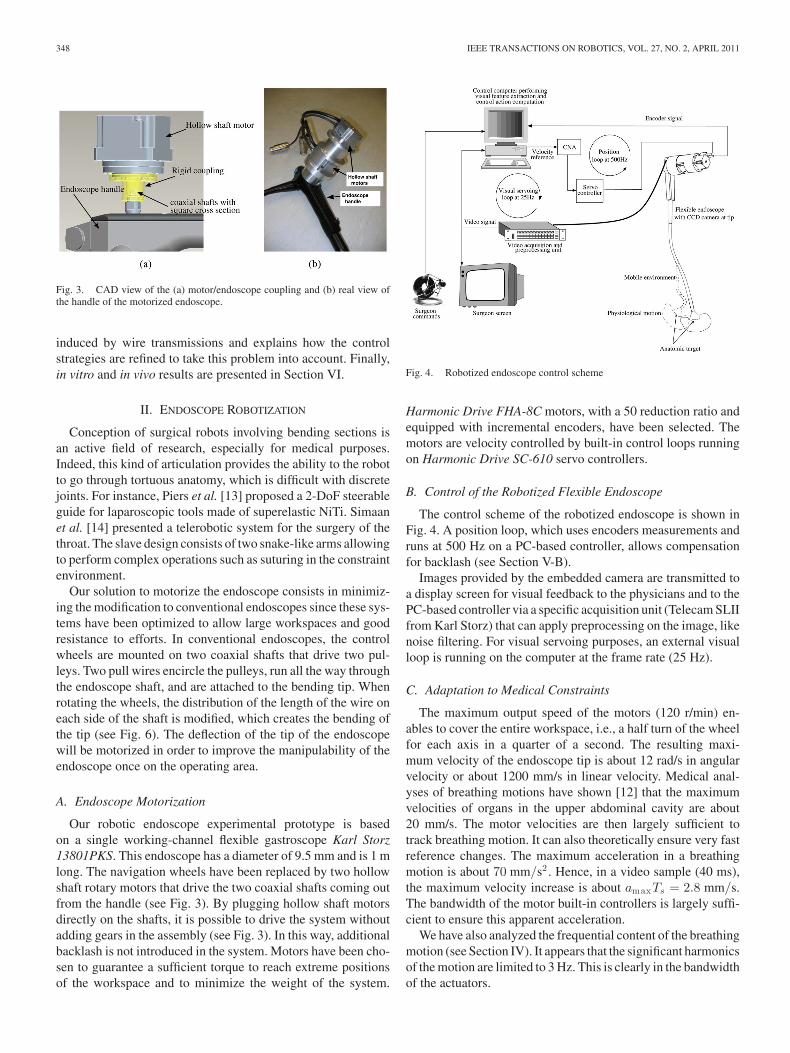
Fig. 4. Robotized endoscope control scheme
Harmonic Drive FHA-8C motors, with a 50 reduction ratio andequipped with incremental encoders, have been selected. Themotors are velocity controlled by built-in control loops runningon Harmonic Drive SC-610 servo controllers.
B. Control of the Robotized Flexible Endoscope
The control scheme of the robotized endoscope is shown inFig. 4. A position loop, which uses encoders measurements andruns at 500 Hz on a PC-based controller, allows compensationfor backlash (see Section V-B).
Images provided by the embedded camera are transmitted toa display screen for visual feedback to the physicians and to thePC-based controller via a specific acquisition unit (Telecam SLIIfrom Karl Storz) that can apply preprocessing on the image, likenoise filtering. For visual servoing purposes, an external visualloop is running on the computer at the frame rate (25 Hz).
C. Adaptation to Medical Constraints
The maximum output speed of the motors (120 r/min) en-ables to cover the entire workspace, i.e., a half turn of the wheelfor each axis in a quarter of a second. The resulting maxi-mum velocity of the endoscope tip is about 12 rad/s in angularvelocity or about 1200 mm/s in linear velocity. Medical anal-yses of breathing motions have shown [12] that the maximumvelocities of organs in the upper abdominal cavity are about20 mm/s. The motor velocities are then largely sufficient totrack breathing motion. It can also theoretically ensure very fastreference changes. The maximum acceleration in a breathingmotion is about 70 mm/s2 . Hence, in a video sample (40 ms),the maximum velocity increase is about amaxTs = 2.8 mm/s.The bandwidth of the motor built-in controllers is largely suffi-cient to ensure this apparent acceleration.
We have also analyzed the frequential content of the breathingmotion (see Section IV). It appears that the significant harmonicsof the motion are limited to 3 Hz. This is clearly in the bandwidthof the actuators.
OTT et al.: ROBOTIC ASSISTANCE TO FLEXIBLE ENDOSCOPY BY PHYSIOLOGICAL-MOTION TRACKING 349
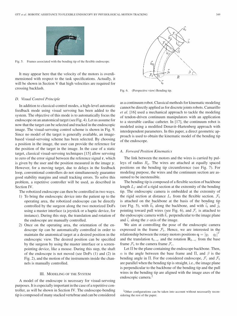
Fig. 5. Frames associated with the bending tip of the flexible endoscope.
It may appear here that the velocity of the motors is overdi-mensioned with respect to the task specifications. Actually, itwill be shown in Section V that high velocities are required forcrossing backlash.
D. Visual Control Principle
In addition to classical-control modes, a high-level automaticfeedback mode using visual servoing has been added to thesystem. The objective of this mode is to automatically focus theendoscope on an anatomical target (see Fig. 4). Let us assume fornow that the target can be selected and tracked in the endoscopicimage. The visual-servoing control scheme is shown in Fig. 9.Since no model of the target is generally available, an image-based visual-servoing scheme has been selected. By choosinga position in the image, the user can provide the reference forthe position of the target in the image. In the case of a statictarget, classical visual-servoing techniques [15] allow servoingto zero of the error signal between the reference signal r, whichis given by the user and the position measured in the image y.However, for a moving target, due to delays in the feedbackloop, conventional controllers do not simultaneously guaranteegood stability margins and small tracking errors. To solve thisproblem, a repetitive controller will be used, as described inSection IV.
The robotized endoscope can then be controlled in two ways.1) To bring the endoscopic device into the patient up to the
operating area, the robotized endoscope can be directlycontrolled by the surgeon along the two motorized DoFsusing a master interface (a joystick or a haptic device, forinstance). During this step, the translation and rotation ofthe endoscope are manually controlled.
2) Once on the operating area, the orientation of the en-doscope tip can be automatically controlled in order tomaintain the anatomical target at a desired position in theendoscopic view. The desired position can be specifiedby the surgeon by using the master interface or a screen-pointing device, like a mouse. During this step, the shaftof the endoscope is not moved (see DoFs (1) and (2) inFig. 2), and the motion of the instruments inside the chan-nels is manually controlled.
III. MODELING OF THE SYSTEM
A model of the endoscope is necessary for visual-servoingpurposes. It is especially important in the case of a repetitive con-troller, as will be shown in Section IV. The endoscope-bendingtip is composed of many stacked vertebrae and can be considered
Fig. 6. (Perspective view) Bending tip.
as a continuum robot. Classical methods for kinematic modelingcannot be directly applied as for discrete joints robots. Camarilloet al. [16] used a mechanical approach to tackle the modelingof tendon-driven continuum manipulators with an applicationto a steerable cardiac catheter. In [17], the continuum robot ismodeled using a modified Denavit–Hartenberg approach withinterdependent parameters. In this paper, a direct geometric ap-proach is used to obtain the kinematic model of the bending tipof the endoscope.
A. Forward Position Kinematics
The link between the motors and the wires is carried by pul-leys of radius Rp . The wires are attached at equally spacedpositions on the bending tip circumference (see Fig. 7). Formodeling purpose, the wires and the continuum section are as-sumed to be inextensible.
The bending tip is composed of a flexible section of backbonelength Lf and of a rigid section at the extremity of the bendingtip. The endoscopic camera is embedded at the extremity ofthe rigid section at distance Lt from the flexible section. Fb
is attached on the backbone at the basis of the bending tip(see Fig. 5), with �kb along the backbone, and with �ib and �jb
pointing toward pull wires (see Fig. 6), and Fc is attached tothe endoscopic camera with�kc perpendicular to the image planeand�ic along the x-axis of the image.
We aim at controlling the pose of the endoscopic cameraexpressed in the frame Fb . Hence, we are interested in therelationship between the rotary motors positions q = [q1 q2 ]
T
and the translation tb→c and the rotation Rb→c from the baseframe Fb to the camera frame Fc .
Let Π be the plane containing the endoscope backbone. Then,α is the angle between the base frame and Π, and β is thebending angle in Π. For the considered endoscope, Fc and Fb
are parallel when the bending tip is straight, i.e., the image planeis perpendicular to the backbone of the bending tip and the pullwires in the bending tip are aligned with the image axes of theendoscopic camera.2
2Other configurations can be taken into account without necessarily recon-sidering the rest of the paper.
350 IEEE TRANSACTIONS ON ROBOTICS, VOL. 27, NO. 2, APRIL 2011
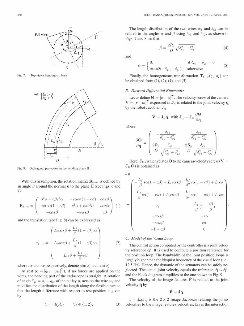
Fig. 7. (Top view) Bending-tip basis.
Fig. 8. Orthogonal projection in the bending plane Π.
With this assumption, the rotation matrix Rb→c is defined byan angle β around the normal u to the plane Π (see Figs. 6 and7)
Rb→c =
⎛⎜⎝
s2α + cβc2α −sαcα(1 − cβ) cαsβ
−sαcα(1 − cβ) c2α + cβs2α sαsβ
−cαsβ −sαsβ cβ
⎞⎟⎠ (1)
and the translation (see Fig. 8) can be expressed as
tb→c =
⎛⎜⎜⎜⎜⎜⎜⎜⎝
Ltcαsβ +Lf
β(1 − cβ)cα
Ltsαsβ +Lf
β(1 − cβ)sα
Ltcβ +Lf
βsβ
⎞⎟⎟⎟⎟⎟⎟⎟⎠
(2)
where sx and cx, respectively, denote sin(x) and cos(x).At rest (q = [q10 q20 ]
T ), if no forces are applied on thewires, the bending part of the endoscope is straight. A rotationof angle δqi = qi − qi0 of the pulley pi acts on the wire wi andmodifies the distribution of the length along the flexible part sothat the length difference with respect to rest position is givenby
δli = Rpδqi ∀i ∈ {1, 2}. (3)
The length distribution of the two wires δl1 and δl2 can berelated to the angles α and β using δr1 and δr2 , as shown inFigs. 7 and 8, so that
β =2Rp
D
√δ2q1
+ δ2q2
(4)
and
α ={
0, if δq1 = δq2 = 0
atan2(−δq2 ,−δq1 ), otherwise.(5)
Finally, the homogeneous transformation Tb→c(q1 , q2) canbe obtained from (1), (2), (4), and (5).
B. Forward Differential Kinematics
Let us define Θ = [α β]T . The velocity screw of the cameraV = [v ω]T expressed in Fc is related to the joint velocity qby the robot Jacobian Jq
V = Jqq, with Jq = JΘ∂Θ∂q
where
∂Θ∂q
=
⎛⎜⎜⎜⎜⎝
− δq2
δ2q1 + δ2
q2
δq1
δ2q1 + δ2
q2
2Rp
D
δq1√δ2q1 + δ2
q2
2Rp
D
δq2√δ2q1 + δ2
q2
⎞⎟⎟⎟⎟⎠
.
Here, JΘ , which relates Θ to the camera-velocity screw (V =JΘΘ) is obtained as
JΘ
=
⎛⎜⎜⎜⎜⎜⎜⎜⎜⎜⎜⎜⎜⎜⎜⎜⎝
−Lf
βsα(1 − cβ) − Ltsαsβ
Lf
β2 cα(1 − cβ) + Ltcα
Lf
βcα(1 − cβ) + Ltcαsβ
Lf
β2 sα(1 − cβ) + Ltsα
0Lf
β(1 − sβ
β)
−cαsβ −sα
−sαsβ cα
−1 + cβ 0
⎞⎟⎟⎟⎟⎟⎟⎟⎟⎟⎟⎟⎟⎟⎟⎟⎠
.
C. Model of the Visual Loop
The control action computed by the controller is a joint veloc-ity reference q∗. It is used to compute a position reference forthe position loop. The bandwidth of the joint position loops islargely higher than the Nyquist frequency of the visual loop (i.e.,12.5 Hz). Hence, the dynamic of the actuators can be safely ne-glected. The actual joint velocity equals the reference, q ∼ q∗,and the block diagram simplifies to the one shown in Fig. 9.
The velocity of the image features F is related to the jointvelocity q by
F = Jq.
J = LdJq is the 2 × 2 image Jacobian relating the jointsvelocities to the image features velocities. Ld is the interaction
OTT et al.: ROBOTIC ASSISTANCE TO FLEXIBLE ENDOSCOPY BY PHYSIOLOGICAL-MOTION TRACKING 351
Fig. 9. Block diagram of the visual servoing loop.
matrix of the considered image features that relates the velocityscrew of the camera to the velocity of the image feature in theimage. For example, for a point of position [X Y ]T in theimage plane and of 3-D position [x y d]T with respect to thecamera frame
Ld =(
Gx 0
0 Gy
)
×
⎛⎜⎜⎝
−1d
0X
dXY −(1 + X2) Y
0 −1d
Y
d1 + Y 2 −XY −X
⎞⎟⎟⎠
where Gx and Gy are the magnification factors of the camera.The discrete-time open-loop transfer function from the ve-
locity reference to the measured position of the features in theimage is given by
P (z) =Y (z)U(z)
= z−3Z{
ZOHJs2
}= J
Tsz−4
1 − z−1
where Z{·} represents the z-transform operator, and Ts is thesampling period of the loop. The delay z−3 in the feedback loopaccounts for the image acquisition and processing times.
Under the aforementioned assumptions, the dynamic part ofthe transfer function is constant. However, the gain matrix Jdepends on the position of the bending tip, on the position ofthe target in the image and on the depth d of the target withrespect to the camera.
D. Model Validation
In order to compare our model with the actual behavior ofthe flexible endoscope, one needs to measure the homogeneoustransformation from the basis frame Fb to the camera frame Fc .
We have chosen to use the images provided by the endoscopiccamera to estimate the pose of the camera frame with respectto a calibrated environment composed of a box marked withblack points on a white background. To allow metric estima-tion, the endoscopic camera has been carefully calibrated usingthe method proposed in [18] and implemented in a toolbox byBouguet [19].
To validate the model, the flexible shaft of the endoscope hasbeen maintained in a fixed position with respect to the envi-ronment, and the bending tip has been moved across the entireworkspace. The pose of the camera with respect to the environ-ment Ti
env→c is estimated from each image Ii , and the encoderpositions qi are recorded. The pose is obtained using the itera-tive algorithm proposed by Dementhon and Davis [20], and the
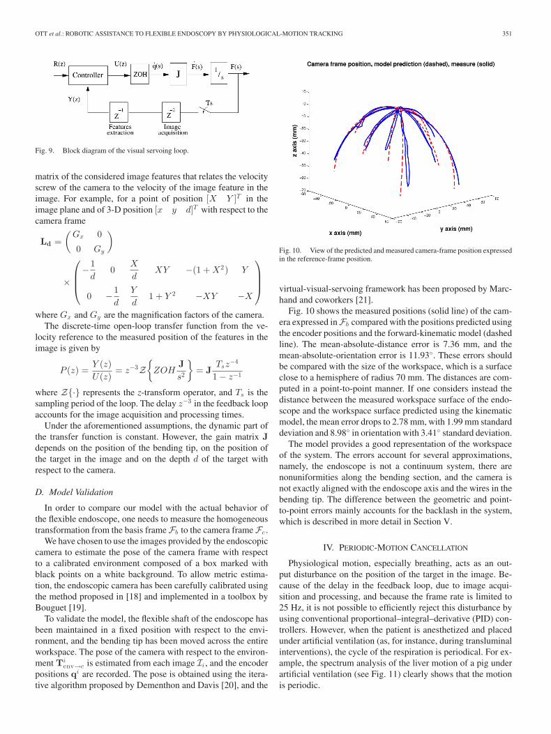
Fig. 10. View of the predicted and measured camera-frame position expressedin the reference-frame position.
virtual-visual-servoing framework has been proposed by Marc-hand and coworkers [21].
Fig. 10 shows the measured positions (solid line) of the cam-era expressed in Fb compared with the positions predicted usingthe encoder positions and the forward-kinematic model (dashedline). The mean-absolute-distance error is 7.36 mm, and themean-absolute-orientation error is 11.93◦. These errors shouldbe compared with the size of the workspace, which is a surfaceclose to a hemisphere of radius 70 mm. The distances are com-puted in a point-to-point manner. If one considers instead thedistance between the measured workspace surface of the endo-scope and the workspace surface predicted using the kinematicmodel, the mean error drops to 2.78 mm, with 1.99 mm standarddeviation and 8.98◦ in orientation with 3.41◦ standard deviation.
The model provides a good representation of the workspaceof the system. The errors account for several approximations,namely, the endoscope is not a continuum system, there arenonuniformities along the bending section, and the camera isnot exactly aligned with the endoscope axis and the wires in thebending tip. The difference between the geometric and point-to-point errors mainly accounts for the backlash in the system,which is described in more detail in Section V.
IV. PERIODIC-MOTION CANCELLATION
Physiological motion, especially breathing, acts as an out-put disturbance on the position of the target in the image. Be-cause of the delay in the feedback loop, due to image acqui-sition and processing, and because the frame rate is limited to25 Hz, it is not possible to efficiently reject this disturbance byusing conventional proportional–integral–derivative (PID) con-trollers. However, when the patient is anesthetized and placedunder artificial ventilation (as, for instance, during transluminalinterventions), the cycle of the respiration is periodical. For ex-ample, the spectrum analysis of the liver motion of a pig underartificial ventilation (see Fig. 11) clearly shows that the motionis periodic.

352 IEEE TRANSACTIONS ON ROBOTICS, VOL. 27, NO. 2, APRIL 2011
Fig. 11. Spectrum analysis of the motion of the liver of a pig under artifi-cial ventilation obtained from an image-sequence analysis. The fundamentalfrequency is 0.267 Hz, and the Nyquist frequency is 12.5 Hz. No significantharmonics appear beyond 3 Hz.
A. Repetitive Control
To assist surgeons during operations, the robotized endo-scopic system must be able to reject the periodic disturbancesdue to breathing. The user should also be able to choose theposition of the stabilized target in the endoscopic image. This isnecessary in our application because the endoscopic instrumentsare not articulated and the endoscope must be moved to reachdifferent points of interest around the target. For this purpose,repetitive control with feedforward is used. Repetitive controlis based on the internal-model principle [22] that states that theinclusion of the model of a signal in a stable closed-loop systemcan assure perfect tracking or complete rejection of this signal.To reject periodic disturbances of period T , the controller hasthe following form:
Cr (z−1) =Q(z, z−1)z−N
1 − Q(z, z−1)z−NL(z, z−1) (6)
with N = T/Ts , and where Q(z, z−1) is a low-pass filteradded for stability robustness purposes. The filter L(z, z−1)must be chosen to guarantee stability and performance (seeSection IV-B).
Then, the repetitive control law is given by the followingequation:
ur [k] = Q(q, q−1)(ur [k − N ] + L(q, q−1)e[k − N ]) (7)
where q−1 is the unit delay operator. Thus, the control action iscomposed of the repetition of the control action at the previousperiod of the disturbance and of a bettering term computed fromthe error signal e[k − N ].
The basic form of the repetitive controller does not allowto track references signals efficiently [11]. In order to tracknonperiodic references, a feedforward controller built on a sim-ulated model of the plant P(z−1) is added to the system. Forour system, P(z−1) = J Ts z−4
1−z−1 , where J is an estimate of theimage Jacobian. Since the model of the plant contains an inte-grator, a proportional control law is used for the feedforwardcontroller
Cref (z−1) = kc J−1 .
By including J−1 in the controller, the gain of the controller kc
can be tuned independently of the configuration of the system.In the following simulations and experiments, it has been setto kc = 3.5. This gain ensures a minimum of 5% settling time(0.5 s) with a 10 dB gain margin and 60◦ phase margin whenthe model of the Jacobian is exact.
B. Tuning the Repetitive Controller for Stabilityand Performances Purposes
For a steady reference, the closed-loop error signal can beexpressed the following ways:
e(z) = Q(z, z−1)(I − P(z−1)L(z, z−1))z−N e(z)
− (1 − Q(z, z−1)z−N )d(z) (8)
or
e(z) = −[I + Q(z, z−1)z−N (P(z−1)L(z, z−1) − I)]−1
× (1 − Q(z, z−1)z−N )d(z). (9)
a) Stability condition: Using the small-gain theorem, itcan be stated from (9) that if Q and PL are stable and if
‖Q(z, z−1)(P(z−1)L(z, z−1) − I)‖∞ < 1
with z = ejωTs ∀ωTs ∈ [0, π] (10)
then the closed loop is stable.b) Disturbance rejection: From (8), it appears that the free
response error becomes null in one period of the disturbanceif P(z−1)L(z, z−1) = I. Moreover, from (9), it can be seenthat if (1 − Q(ejωTs , e−jωTs )e−jωN Ts ) = 0 for all harmonicfrequencies of the disturbances, then the periodic disturbancesare perfectly rejected.
c) Controller tuning: Given the stability and disturbancerejection conditions, it is interesting to choose L(z, z−1) as theinverse of the plant model P(z−1) [23]. This is possible forstable minimum-phase systems. If the plant is unstable, it isfirst stabilized using a conventional controller, then the repet-itive controller is applied to the stabilized plant. More com-plex solutions have also been proposed for unstable [23] andnonminimum-phase systems [23], [24].
It is difficult to obtain a model capturing all the dynam-ics of the plant. From (10), it can be seen that the stabilitycondition is relaxed if the filter Q(z, z−1) has a low gain atfrequencies where the model is uncertain. However, to obtainsmall residual errors, (1 − Q(ejωTs , e−jωTs )e−jωN Ts ) shouldequal zero at the harmonic frequencies of the disturbanceω = k2π/NTs, for k = 1, . . . , N/2. Hence, Q(z, z−1) is usu-ally chosen as a noncausal zero-phase low-pass filter with a unitdc gain that satisfies a compromise between stability robustnessand performance.
OTT et al.: ROBOTIC ASSISTANCE TO FLEXIBLE ENDOSCOPY BY PHYSIOLOGICAL-MOTION TRACKING 353
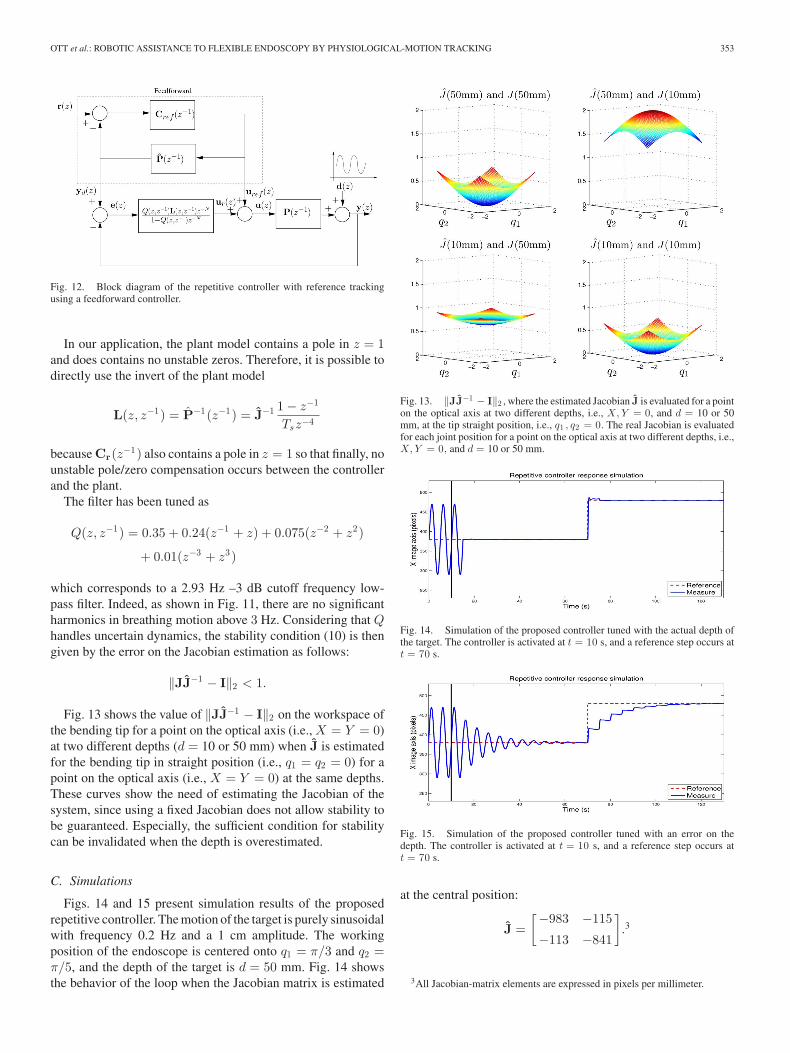
Fig. 12. Block diagram of the repetitive controller with reference trackingusing a feedforward controller.
In our application, the plant model contains a pole in z = 1and does contains no unstable zeros. Therefore, it is possible todirectly use the invert of the plant model
L(z, z−1) = P−1(z−1) = J−1 1 − z−1
Tsz−4
because Cr(z−1) also contains a pole in z = 1 so that finally, nounstable pole/zero compensation occurs between the controllerand the plant.
The filter has been tuned as
Q(z, z−1) = 0.35 + 0.24(z−1 + z) + 0.075(z−2 + z2)
+ 0.01(z−3 + z3)
which corresponds to a 2.93 Hz –3 dB cutoff frequency low-pass filter. Indeed, as shown in Fig. 11, there are no significantharmonics in breathing motion above 3 Hz. Considering that Qhandles uncertain dynamics, the stability condition (10) is thengiven by the error on the Jacobian estimation as follows:
‖JJ−1 − I‖2 < 1.
Fig. 13 shows the value of ‖JJ−1 − I‖2 on the workspace ofthe bending tip for a point on the optical axis (i.e., X = Y = 0)at two different depths (d = 10 or 50 mm) when J is estimatedfor the bending tip in straight position (i.e., q1 = q2 = 0) for apoint on the optical axis (i.e., X = Y = 0) at the same depths.These curves show the need of estimating the Jacobian of thesystem, since using a fixed Jacobian does not allow stability tobe guaranteed. Especially, the sufficient condition for stabilitycan be invalidated when the depth is overestimated.
C. Simulations
Figs. 14 and 15 present simulation results of the proposedrepetitive controller. The motion of the target is purely sinusoidalwith frequency 0.2 Hz and a 1 cm amplitude. The workingposition of the endoscope is centered onto q1 = π/3 and q2 =π/5, and the depth of the target is d = 50 mm. Fig. 14 showsthe behavior of the loop when the Jacobian matrix is estimated
Fig. 13. ‖JJ−1 − I‖2 , where the estimated Jacobian J is evaluated for a pointon the optical axis at two different depths, i.e., X, Y = 0, and d = 10 or 50mm, at the tip straight position, i.e., q1 , q2 = 0. The real Jacobian is evaluatedfor each joint position for a point on the optical axis at two different depths, i.e.,X, Y = 0, and d = 10 or 50 mm.
Fig. 14. Simulation of the proposed controller tuned with the actual depth ofthe target. The controller is activated at t = 10 s, and a reference step occurs att = 70 s.
Fig. 15. Simulation of the proposed controller tuned with an error on thedepth. The controller is activated at t = 10 s, and a reference step occurs att = 70 s.
at the central position:
J =[−983 −115
−113 −841
].3
3All Jacobian-matrix elements are expressed in pixels per millimeter.
354 IEEE TRANSACTIONS ON ROBOTICS, VOL. 27, NO. 2, APRIL 2011
Fig. 16. Backlash deadband map for axis 1. Only the first actuator is moving,and the target position is measured on the X-image axis.
The disturbance is very well rejected in only one period, and thereference is tracked as expected. A very small error appears afterthe reference step due to the slight modification of the systemmodel. Fig. 15 shows the results for the same configurationof the endoscope but when the used image Jacobian has beenestimated at the actual actuator positions, except for a point onthe optical axis at depth d = 10 mm:
J =[−2915 −257
−251 −2583
].
As expected from the previous analysis, the modeling errordoes not lead to instability. However, the performance of thecontroller to reject disturbances drastically decreases, and manyperiods are needed to learn the disturbance. Also, the feedfor-ward controller is not able to cancel the reference tracking error,and the repetitive controller needs several iterations to compen-sate the residual error.
V. MECHANICAL NONLINEARITIES
Practically, flexible endoscopes have a complex nonlinearbehavior. The wire transmission between the navigation wheelsand the bending tip induces friction that results in backlash.When changing the direction of motion on one of the joints, themotor motion has no effect on the endoscope tip, while the jointposition stays in a deadband.
A. Characterization
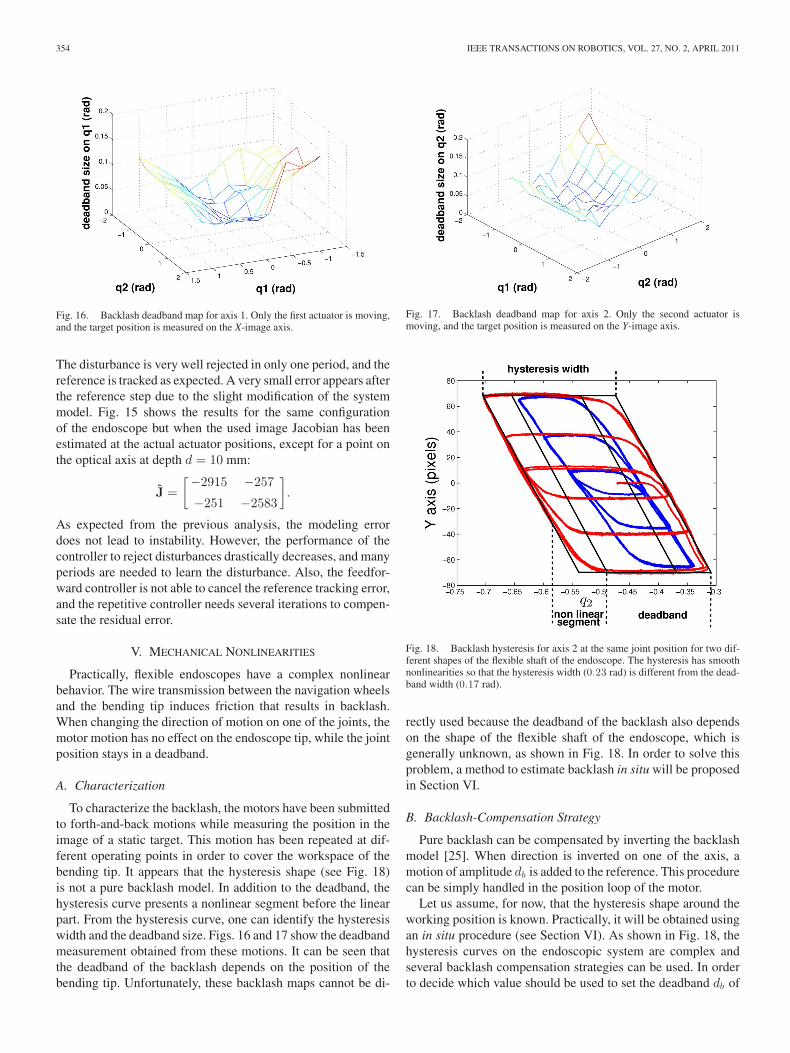
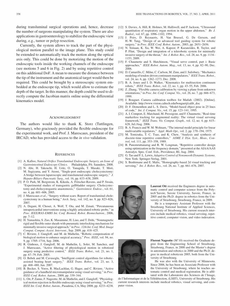
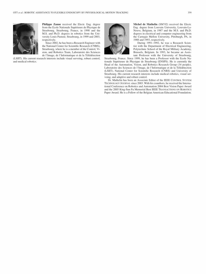
To characterize the backlash, the motors have been submittedto forth-and-back motions while measuring the position in theimage of a static target. This motion has been repeated at dif-ferent operating points in order to cover the workspace of thebending tip. It appears that the hysteresis shape (see Fig. 18)is not a pure backlash model. In addition to the deadband, thehysteresis curve presents a nonlinear segment before the linearpart. From the hysteresis curve, one can identify the hysteresiswidth and the deadband size. Figs. 16 and 17 show the deadbandmeasurement obtained from these motions. It can be seen thatthe deadband of the backlash depends on the position of thebending tip. Unfortunately, these backlash maps cannot be di-
Fig. 17. Backlash deadband map for axis 2. Only the second actuator ismoving, and the target position is measured on the Y-image axis.
Fig. 18. Backlash hysteresis for axis 2 at the same joint position for two dif-ferent shapes of the flexible shaft of the endoscope. The hysteresis has smoothnonlinearities so that the hysteresis width (0.23 rad) is different from the dead-band width (0.17 rad).
rectly used because the deadband of the backlash also dependson the shape of the flexible shaft of the endoscope, which isgenerally unknown, as shown in Fig. 18. In order to solve thisproblem, a method to estimate backlash in situ will be proposedin Section VI.
B. Backlash-Compensation Strategy
Pure backlash can be compensated by inverting the backlashmodel [25]. When direction is inverted on one of the axis, amotion of amplitude db is added to the reference. This procedurecan be simply handled in the position loop of the motor.
Let us assume, for now, that the hysteresis shape around theworking position is known. Practically, it will be obtained usingan in situ procedure (see Section VI). As shown in Fig. 18, thehysteresis curves on the endoscopic system are complex andseveral backlash compensation strategies can be used. In orderto decide which value should be used to set the deadband db of

OTT et al.: ROBOTIC ASSISTANCE TO FLEXIBLE ENDOSCOPY BY PHYSIOLOGICAL-MOTION TRACKING 355
Fig. 19. Comparison of the backlash compensation strategies.
the backlash-inverse compensation, three strategies have beencompared. The simulation results are presented in Fig. 19 for asinusoidal motion of amplitude 200 pixels in the image. In thefirst strategy, no backlash compensation is used, in the second,the deadband width (0.15 rad) is used, whereas the hysteresiswidth (0.2 rad) is used in the third. The controller has been tunedwith an accurate estimate of the Jacobian so that tracking errorsare mainly due to nonlinearities.
After convergence, the maximum absolute error and the meanabsolute error are, respectively, 3.76 pix. and 0.31 pix. withoutbacklash compensation, 0.62 pix. and 0.11 pix. with db set tothe deadband width and 6.19 pix. and 0.41 pix. with db set to thehysteresis width. Without backlash compensation, the repetitivecontroller learns the residual error due to backlash and allowsto decrease it over time. However, because of the Q filter, thedisturbance cannot be completely rejected and a repetition ofthe reference change appears at the next period of the distur-bance. The backlash compensation using the identified hystere-sis width avoids the occurrence of the reference repetition, butit also results in periodic jolts and induces a greater residual er-ror after convergence than without any backlash compensation.Finally, applying the backlash inverse with the deadband widthallows a reduction of both the repetition of the reference and theresidual error after convergence. The best strategy for reducingtracking error and allowing the most stable view for the user isthen to compensate the deadband width. Practically, to obtainthe expected results, the deadband must be crossed in a singlesampling period of the visual loop (40 ms) so that no delay isintroduced in the direct loop. On our prototype, the maximumdeadband is less than 0.3 rad (see Fig 18). The deadband com-pensation is implemented in the position loop running at 500Hz. With the chosen motors, the largest deadband is crossed inless than 25 ms, which is sufficient.
VI. EXPERIMENTAL RESULTS
It has been shown in Section IV that an estimate of the Jaco-bian matrix is needed to tune the repetitive controller. However,the Jacobian matrix depends on the depth d of the anatomicaltarget expressed in the camera frame. Since this depth is gen-erally unknown, we propose a method to directly estimate theJacobian of the system. The method of estimation as well as thepractical method for deadband estimation are explained in thissection. This section also presents experimental results obtainedin vitro and in vivo.
A. Visual Features
To servo the 2 DoFs of the bending tip, a single-image point(i.e., two coordinates) is a sufficient visual feature. However, theenvironment of our application is complex without the possibil-ity to add fiducial markers. The solution proposed here relieson template-matching algorithms. The area of interest is firstmanually selected by the surgeon and is learned as the referencetemplate. For each new image, the parameters of the transforma-tion (i.e., translation, affine, homographic, etc.), which minimizea dissimilarity measure between the current image and the refer-ence template (which is usually a sum of pixel to pixel squareddifferences) are searched using a local optimization algorithm.These techniques provide an estimate of the transformation be-tween the area of interest in the current image and its position inthe initial image so that any point from the initial area of interestcan be used as a visual feature.
In the following, in vitro and in vivo experiments, the visualfeatures F are the coordinates of the center of the window de-fined by the user. The motion of the window in the image ismodeled by a homography, which can represent the perspectiveprojection of the general movement of a planar surface. Thisis well suited to track small organ patches. The homography isestimated using the tracking algorithm proposed in [26]. Thisproved to be quite robust under in vivo conditions.
B. Jacobian Estimation
It is difficult to estimate the Jacobian matrix from the modeldetailed in Section III because the depth of the target in thecamera frame is generally unknown. Depth could be estimatedusing structure from motion techniques. However, since in situestimations have to be involved, we prefer to directly estimatethe Jacobian matrix. Therefore, we propose an automatic directestimation of the gains of the Jacobian matrix. Such an estima-tion includes the magnification factors of the camera and avoidsthe need for camera calibration.
On a static environment, the image velocities are related tothe joint velocities by the following equation:
F =[
Jx1 Jx2
Jy1 Jy2
]q (11)
where Jx1 , Jx2 , Jy1 , and Jy2 are the unknown gains of theJacobian matrix. By performing at least two controlled dis-placements, i.e., qa = [q1a , q2a ]T , and qb = [q1b , q2b ]T , andby measuring the corresponding image target velocities Fa =

356 IEEE TRANSACTIONS ON ROBOTICS, VOL. 27, NO. 2, APRIL 2011
Fig. 20. Deadband identification during a testbed experiment. For axis 1, theidentified values are dbt = 0.1347 rad and dbb = 0.1482 rad. For axis 2, thevalues are dbt = 0.1226 rad and dbb = 0.1290 rad.
[Xa , Ya ]T , and Fb = [Xb , Yb ]T , it is possible to estimate thelocal Jacobian
⎡⎢⎢⎢⎣
Jx1
Jx2
Jy1
Jy2
⎤⎥⎥⎥⎦ =
⎡⎢⎢⎢⎣
q1a q2a 0 0
q1b q2b 0 0
0 0 q1a q2a
0 0 q1b q2b
⎤⎥⎥⎥⎦
−1⎡⎢⎢⎢⎣
Xa
Xb
Ya
Yb
⎤⎥⎥⎥⎦. (12)
The displacements should be independent for inversion pur-poses and large enough in order to obtain the image velocities outof the backlash nonlinear zones. We chose joint velocities qa =Ω[cos(π/4), sin(π/4)]T and qb = Ω[cos(3π/4), sin(3π/4)]T ,where Ω is constant.
Practically, the target has also its own motion, which shouldbe discriminated from the effect of the camera motion. For thispurpose, we use the periodicity of the target self-motion. It isfirst recorded during one period of the disturbance, while theendoscope bending tip is not activated. The corrected imageposition Fc during the endoscope motion is then obtained as
Fc [k] = F[k] − F[k mod N ]
where [k mod N ] ∈ {0, . . . , N − 1}, and F[k mod N ] is thelearned image position during the first period without endoscopemotion. The estimation of the Jacobian is realized automatically.It is required at the beginning of the operation or if the positionof the endoscope is modified by the user. This is generally notthe case during accurate tasks, as explained Section I.
C. Deadband Estimation
It has been seen that the deadband width is necessary to imple-ment backlash compensation in order to obtain a good trackingaccuracy. Since the deadband width depends on the workingconditions, we propose a method to estimate it in situ. The hys-teresis curves are obtained independently for each axis by per-forming open loop back-and-forth motions. For each axis, the ef-fect of the motor motion is observed in the image along the maindirection. The effect of the disturbance is removed in the samemanner as for the Jacobian estimation. The deadband estimationis performed both at the top (solid line) and at the bottom (dashedline) of the hysteresis curve (see Fig. 20). The first step consistsof finding the points of extreme abscissas (change of motordirection) Ot = [xot yot ]T , and Ob = [xob yob ]T . Then, the
Fig. 21. Laboratory testbed experiment with the repetitive controller. Thecontroller is activated at t = 5 s. A reference step is applied at time t = 60 s.
points on the curve Pt = [xpt ypt ]T , and Pb = [xpb ypb ]T
with same ordinates and farthest from Ot = [xot yot ]T , andOb = [xob yob ]T are located. The deadbands are then esti-mated as
dbt = |xot − xpt | and dbb = |xob − xpb |.
Finally, we choose the smallest value of the identified deadbandsdb = min(dbb , dbt) to set the backlash-inverse compensationin order to limit the jolts. The deadband-estimation procedureis carried out automatically and is only required once at thebeginning of the operation or if the position of the endoscope isgreatly modified by the user.
D. Experiments on a Laboratory Testbed
We have developed a laboratory testbed to validate the controlstrategy. We use a model of the abdominal cavity organs that isfixed to a motorized device so that the motion of the target canbe controlled to produce a periodic output disturbance.
In the presented experiment, the disturbance is a pure sinu-soid of period 5 s. The gains of the Jacobian matrix have beenestimated, as explained in Section VI-B, and one found
J =(−1106 185
19 −879
).
The backlash deadbands have also been automatically estimatedin situ (see Fig. 20). The results of the automatic compensationare presented in Fig. 21. Since the main objective is the stabi-lization of the target in the image, we are mainly interested inthe amplitude of the residual motion target. The amplitude of thedisturbance before compensation is 218 pixels on the X-imageaxis and 52.7 pixels on the Y-image axis corresponding to a rel-ative motion between the camera frame and the target of 25 mm.The amplitude of the residual errors after convergence are 13.9pixels on the X-image axis and 10.9 pixels on the Y-image axis,which is equivalent to a relative motion of 2 mm. The effect ofthe disturbance in the image is highly reduced: more than 90%on X and almost 80% on Y .

OTT et al.: ROBOTIC ASSISTANCE TO FLEXIBLE ENDOSCOPY BY PHYSIOLOGICAL-MOTION TRACKING 357
Fig. 22. In vivo experiment setup.
E. In Vivo Experiments
Several in vivo experiments have been performed at the IR-CAD4 on anesthetized pigs placed under artificial ventilation (avideo is available at the following address5). In the presentedexperiment, the distal tip of the motorized endoscope was in-serted into the abdominal cavity by passing through a flexibletrocar (see Fig. 22). These are the conditions conventionallyused in single-access-port surgery. The trocar is only used as aport and its motion is free. The anatomical target is chosen tobe the liver, which is subject to large breathing motions. Theimage target is a small burn spot onto the organ. Note that inthese experiments, the breathing motion of period 4 s acts notonly on the moving target but on the flexible shaft of the endo-scope as well. This creates a motion of the endoscope, whichalso results in an additional apparent motion of the target in theimage. There is actually no need to make a distinction betweenthis apparent motion and the actual motion of the target, sincethe visual-servoing scheme allows cancellation of the relativeapparent motion independently of the motion origin.
In the given configuration, the Jacobian matrix has been esti-mated as
J =(−1540 151
−242 −1456
).
For the deadband, the identified values are dbt = 0.1272 radand dbb = 0.1341 rad for axis 1 and dbt = 0.1032 rad anddbb = 0.1707 rad for axis 2. Results of the visual servoing arepresented in Fig. 23. The amplitude of the disturbance beforecompensation is 179.6 pixels on the X-image axis and 93.6pixels on the Y-image axis. Under the conditions of the exper-iment, this corresponds to a large movement of the target ofabout 12.7 mm in the plane perpendicular to the line of view.The amplitude of the residual disturbance after convergence is21.2 pixels on the X-image axis and 16.9 pixels on the Y-imageaxis, i.e., reduction of 88% and 82%. The relative motion of thetarget with respect to the endoscope is brought back to about 1.7mm in the plane perpendicular to the line of view. The effect ofthe repetitive controller is very close to the behavior observedon the laboratory testbed, despite the high-frequency harmonics
4Institut de Recherche sur les Cancers de l’Appareil Digestif, Strasbourg,France.
5https://lsiit-cnrs.unistra.fr/avr-fr/index.php/Image:OTT-TRO10.avi
Fig. 23. In vivo experiment with the repetitive controller. The controller hasbeen activated at t = 8 s. Two reference changes are applied at t = 42 s andt = 68 s.
contained in the breathing disturbance signal (see Fig. 11). Thesmall residual error is due to the Q filter, which is necessaryto ensure stability of the system decreases the capability of re-jecting high-frequency harmonics, mainly due to the backlash.The behavior during reference change is also very good, sincethe error is brought back to its steady-state level in only twoperiods of the disturbance. This makes procedures requiring a1.7 mm accuracy possible without stopping breathing, blockingthe motion of the organ, or using gating procedures. This allowsthe surgeon to operate continuously without manually compen-sating the motion of the organ with the endoscope. Under theexperimental conditions, the amplitude of motion along the lineof view was very small so that it was possible to track the targetwith the instruments without actually moving them in the chan-nels of the endoscope. For other conditions, it could be necessaryto translate the instruments in the channels. Interesting applica-tions are in burning procedures where the contact between theinstrument and the target is not required. The system has beenpresented to several surgeons specialized in abdominal surgeryat the IRCAD. They have acknowledged the potential of thisrobotized endoscope as a way to assist endoscopists in automat-ically tracking the motion of a target and, hence, to improve theusability of flexible endoscopes in NOTES procedures.
VII. CONCLUSION
We have shown in this paper that it is possible to control aflexible endoscope for breathing compensation using only theembedded vision system of the endoscope. The system is basedon repetitive control and 2-D visual servoing so that no cameracalibration is required. The theoretical and practical behaviorof the endoscopic system has been analyzed and an automaticmethod to estimate the linear and nonlinear components of thesystem has been proposed. The presented method for breathingcompensation can be used without any expert tuning of thecontroller. In vivo experiments have been carried out on a pigmodel, and they exhibit excellent results. The repetitive controlalgorithm has a satisfying behavior according to the surgeonswho have assessed the system at the IRCAD, Strasbourg. Theproposed approach can be used to stabilize the endoscopic view
358 IEEE TRANSACTIONS ON ROBOTICS, VOL. 27, NO. 2, APRIL 2011
during transluminal surgical operations and, hence, decreasethe number of surgeons manipulating the system. There are alsoapplications in gastroenterology to stabilize the endoscopic viewduring, e.g., tumor or polyp resection.
Currently, the system allows to track the part of the physi-ological motion parallel to the image plane. This study couldbe extended to automatically track the motion along the opticalaxis only. This could be done by motorizing the motion of theendoscopic tools inside the working channels of the endoscope(see motions 5 and 6 in Fig. 2) and by using repetitive controlon this additional DoF. A mean to measure the distance betweenthe tip of the instrument and the anatomical target would then berequired. This could be brought by a stereoscopic system em-bedded at the endoscope tip, which would allow to estimate thedepth of the target. In this manner, the depth could be used to di-rectly compute the Jacobian matrix online using the differentialkinematics model.
ACKNOWLEDGMENT
The authors would like to thank K. Storz (Tuttlingen,Germany), who graciously provided the flexible endoscope forthe experimental work, and Prof. J. Marescaux, president of theIRCAD, who has provided access to the in vivo validation.
REFERENCES
[1] A. Kalloo, Natural Orifice Transluminal Endoscopic Surgery, an Issue ofGastrointestinal Endoscopy Clinics. Philadelphia, PA: Saunders, 2008.
[2] N. Abe, H. Takeuchi, H. Ueki, O. Yanagida, T. Masaki, T. Mori,M. Sugiyama, and Y. Atomi, “Single-port endoscopic cholecystectomy:A bridge between laparoscopic and translumenal endoscopic surgery,” J.Hepato-Biliary-Pancreatic Surg., vol. 16, pp. 633–638, 2009.
[3] P. O. Park, M. Bergstrom, K. Kikeda, A. Fritscher-Ravens, and P. Swain,“Experimental studies of transgastric gallbladder surgery: Cholecystec-tomy and cholecystogastric anastomosis,” Gastrointest. Endosc., vol. 61,no. 4, pp. 601–606, 2005.
[4] J. Marescaux et al., “Surgery without scars: Report of transluminal chole-cystectomy in a human being,” Arch. Surg., vol. 142, no. 9, pp. 823–826,2007.
[5] A. Degani, H. Choset, A. Wolf, T. Ota, and M. Zenati, “Percutaneousintrapericardial interventions using a highly articulated robotic probe,” inProc. IEEE/RAS-EMBS Int. Conf. Biomed. Robot. Biomechatron., 2006,pp. 7–12.
[6] H. Yamashita, S. Zuo, K. Masamune, H. Liao, and T. Dohi, “Nonmagneticrigid and flexible outer sheath with pneumatic interlocking mechanism forminimally invasive surgical approach,” in Proc. 12th Int. Conf. Med. ImageComput. Comput.-Assist. Intervent., Sep. 2009, pp. 418–425.
[7] C. Riviere, J. Gangloff, and M. de Mathelin, “Robotic compensation ofbiological motion to enhance surgical accuracy,” Proc. IEEE, vol. 94, no.9, pp. 1705–1716, Sep. 2006.
[8] R. Ginhoux, J. Gangloff, M. de Mathelin, L. Soler, M. Sanchez, andJ. Marescaux, “Active filtering of physiological motion in robotizedsurgery using predictive control,” IEEE Trans. Robot., vol. 21, no. 1,pp. 67–79, Feb. 2005.
[9] O. Bebek and M. Cavusoglu, “Intelligent control algorithms for robotic-assisted beating heart surgery,” IEEE Trans. Robot., vol. 23, no. 3,pp. 468–480, Jun. 2007.
[10] B. Becker, S. Voros, R. MacLachlan, G. Hager, and C. Riviere, “Activeguidance of a handheld micromanipulator using visual servoing,” in Proc.IEEE Conf. Robot. Autom., 2009, pp. 339–344.
[11] L. Ott, P. Zanne, F. Nageotte, M. de Mathelin, and J. Gangloff, “Physiolog-ical motion rejection in flexible endoscopy using visual servoing,” in Proc.IEEE Int. Conf. Robot. Autom., Pasadena, CA, May 2008, pp. 4233–4238.
[12] S. Davies, A. Hill, R. Holmes, M. Halliwell, and P. Jackson, “Ultrasoundquantitation of respiratory organ motion in the upper abdomen,” Br. J.Radiol., vol. 67, pp. 1096–1102, 1994.
[13] J. Peirs, D. Reynaerts, H. Van Brussel, G. De Gersem, andH.-W. Tang, “Design of an advanced tool guiding system for roboticsurgery,” in Proc. IEEE Conf. Robot. Autom., 2003, pp. 2651–2656.
[14] N. Simaan, K. Xu, W. Wei, A. Kapoor, P. Kazanzides, R. Taylor, andP. Flint, “Design and integration of a telerobotic system for minimallyinvasive surgery of the throat,” Int. J. Robot. Res., vol. 28, no. 9, pp. 1134–1153, 2009.
[15] F. Chaumette and S. Hutchinson, “Visual servo control, part i: Basicapproaches,” IEEE Robot. Autom. Mag., vol. 13, no. 4, pp. 82–90, Dec.2006.
[16] D. Camarillo, C. Milne, C. Carlson, M. Zinn, and J. Salisbury, “Mechanicsmodeling of tendon-driven continuum manipulators,” IEEE Trans. Robot.,vol. 24, no. 6, pp. 1262–1273, Dec. 2008.
[17] B. A. Jones and I. D. Walker, “Kinematics for multisection continuumrobots,” IEEE Trans. Robot., vol. 22, no. 1, pp. 43–55, Feb. 2006.
[18] Z. Zhang, “Flexible camera calibration by viewing a plane from unknownorientations,” in Proc. Int. Conf. Comput. Vis., vol. 26, no. 7, pp. 666–673,1999.
[19] J. Bouguet. Camera calibration toolbox for Matlab. (2002). [Online].Available: http://www.vision.caltech.edu/bouguetj/calib_doc
[20] D. F. Dementhon and L. S. Davis, “Model-based object pose in 25 linesof code,” Int. J. Comput. Vis., vol. 15, pp. 123–141, 1995.
[21] A. I. Comport, E. Marchand, M. Pressigout, and F. Chaumette, “Real-timemarkerless tracking for augmented reality: The virtual visual servoingframework,” IEEE Trans. Vis. Comput. Graph., vol. 12, no. 4, pp. 615–628, Jul./Aug. 2006.
[22] B. A. Francis and W. M. Wohnam, “The internal model principle for linearmultivariable regulators,” Appl. Math Opt., vol. 2, pp. 170–194, 1975.
[23] M. Tomizuka, T. C. Tsao, and K. Chew, “Analysis and synthesis ofdiscrete-time repetitive controllers,” ASME J. Dyn. Syst., Meas., Con-trol, vol. 111, pp. 353–358, 1989.
[24] B. Panomruttanarug and R. W. Longman, “Repetitive controller designusing optimization in the frequency domain,” presented at the AIAA/AASAstrodyn. Spec. Conf. Exh., Providence, RI, Aug. 2004.
[25] G. Tao and F. L. Lewis, Adaptive Control of Nonsmooth Dynamic Systems.New York: Springer-Verlag, 2001.
[26] S. Benhimane and E. Malis, “Homography-based 2d visual tracking andservoing,” Int. J. Robot. Res., vol. 26, no. 7, pp. 661–676, 2007.
Laurent Ott received the Engineers degree in auto-matic control and computer science from the Poly-tech’Savoie, Savoie University, Savoie, France, in2005 and the Ph.D. degree in robotics from the Uni-versity of Strasbourg, Strasbourg, France, in 2009.
He is a temporary Assistant Professor with theStrasbourg National Institute of Applied Sciences,University of Strasbourg. His current research inter-ests include medical robotics, visual servoing, repet-itive control, computer vision, and video indexation.
Florent Nageotte (M’10) received the Graduate de-gree from the Engineering School of Strasbourg,Strasbourg, France, in 2000 and the Master’s degreein automation and robotics in 2000 and the Ph.D. de-gree in medical roboticsin 2005, both from the Uni-versity of Strasbourg.
He was also with the University of Minnesota.Since 2006, he has been an Associate Professor withthe University of Strasbourg, where he teaches au-tomatic control and medical registration. He is affil-iated with the Laboratoire des Sciences de l’Image,
de l’Informatique et de la Teledetection, (LSIIT), University of Strasbourg. Hiscurrent research interests include medical robotics, visual servoing, and com-puter vision.
OTT et al.: ROBOTIC ASSISTANCE TO FLEXIBLE ENDOSCOPY BY PHYSIOLOGICAL-MOTION TRACKING 359
Philippe Zanne received the Electr. Eng. degreefrom the Ecole Nationale Superieure de Physique deStrasbourg, Strasbourg, France, in 1998 and theM.S. and Ph.D. degrees in robotics from the Uni-versity Louis Pasteur, Strasbourg, in 1999 and 2003,respectively.
Since 2002, he has been a Research Engineer withthe National Center for Scientific Research (CNRS),Strasbourg, where he is a member of the Control, Vi-sion, and Robotics Team, Laboratoire des Sciencesde l’Image, de l’Informatique et de la Teledetection
(LSIIT). His current research interests include visual servoing, robust control,and medical robotics.
Michel de Mathelin (SM’02) received the Electr.Eng. degree from Louvain University, Louvain-La-Neuve, Belgium, in 1987 and the M.S. and Ph.D.degrees in electrical and computer engineering fromthe Carnegie Mellon University, Pittsburgh, PA, in1988 and 1993, respectively.
During 1991–1992, he was a Research Scien-tist with the Department of Electrical Engineering,Polytechnic School of the Royal Military Academy,Brussels, Belgium. In 1993, he became an Assis-tant Professor with the University of Strasbourg,
Strasbourg, France. Since 1999, he has been a Professor with the Ecole Na-tionale Superieure de Physique de Strasbourg (ENSPS). He is currently theHead of the Automation, Vision, and Robotics Research Group (34 people),Laboratoire des Sciences de l’Image, de l’Informatique et de la Teledetection(LSIIT), National Center for Scientific Research (CNRS) and University ofStrasbourg. His current research interests include medical robotics, visual ser-voing, and adaptive and robust control.
Dr. Mathelin has been an Associate Editor of the IEEE CONTROL SYSTEM
TECHNOLOGY JOURNAL since 2003. With his coauthors, he received the Interna-tional Conference on Robotics and Automation 2004 Best Vision Paper Awardand the 2005 King-Sun Fu Memorial Best IEEE TRANSACTIONS ON ROBOTICS
Paper Award. He is a Fellow of the Belgian American Educational Foundation.
Copyright © 2022 FDOKUMEN