Linking RNA Polymerase Backtracking to Genome Instability in E. coli
RNA polymerase I structure and transcription regulation
104
Dissertation zur Erlangung des Doktorgrades der Fakultät für Chemie und Pharmazie der Ludwig-Maximilians-Universität München RNA polymerase I structure and transcription regulation Christoph Engel aus Leipzig 2013
-
Upload
khangminh22 -
Category
Documents
-
view
0 -
download
0
Transcript of RNA polymerase I structure and transcription regulation

Dissertation zur Erlangung des Doktorgrades der Fakultät für Chemie und Pharmazie
der Ludwig-Maximilians-Universität München
RNA polymerase I
structure and transcription regulation
Christoph Engel
aus
Leipzig
2013

2
Erklärung
Diese Dissertation wurde im Sinne von § 7 der Promotionsordnung vom 28. November 2011
von Herrn Prof. Dr. Patrick Cramer betreut.
Eidesstattliche Versicherung
Diese Dissertation wurde eigenständig und ohne unerlaubte Hilfe erarbeitet.
München, den ………………..
…………………………………
Christoph Engel
Dissertation eingereicht am 12.12.2013
1. Gutachter: Prof. Dr. Patrick Cramer
2. Gutachter:
Mündliche Prüfung am
PD Dr. Dietmar Martin
21.01.2014

3
Summary
Transcription of ribosomal RNA by RNA polymerase (Pol) I initiates ribosome biogenesis
and regulates eukaryotic cell growth. Obtaining the crystal structure of Pol I would improve
our understanding of the enzymes regulation and its functional properties. It has therefore
been a target of investigation over the past 10 years. Within this work, a number of strategies
were pursued to obtain a novel Pol I crystal form that allows for solving a high-resolution
structure. Purification of Pol I from the fission yeast Schizosaccharomyces pombe was
established and its crystallization assayed for this purpose. For the baker’s yeast
Saccharomyces cerevisiae, new strains were established, the fermentation and purification
adapted and a new crystal form obtained. This allowed for solving the structure of the 590-
kilodalton (kDa) enzyme at a resolution of 2.8 Å. For phasing, intrinsically bound zinc atoms
were used. An atomic model of Pol I was built and refined to an R-free factor of 21% with
excellent stereochemistry. The model revealed all 14 subunits of the enzyme with exception
of the tandem winged helix domain of subunit A49 and several unstructured surface residues.
The structure shows differences to Pol II. The dimerization domain of the Pol-I-specific
A49/A34.5 subcomplex is anchored on the polymerase by an elongated, well ordered, lysine-
rich tail. The Pol-I- and Pol-III-specific subunit complex AC40/AC19 is first described
structurally. Furthermore, the C-terminal domain of subunit A12.2 is shown to resemble the
fold and positioning of TFIIS, thereby explaining the intrinsic cleavage activity of Pol I. A
novel ‘expander’ element occupies the DNA template site and stabilizes an expanded active
centre cleft with an unwound bridge helix. A ‘connector’ element invades the cleft of an
adjacent polymerase and stabilizes an inactive polymerase dimer. The connector and expander
must detach during Pol I activation to enable transcription initiation and cleft contraction by
convergent movement of the polymerase ‘core’ and ‘shelf’ modules. Conversion between an
inactive expanded and an active contracted polymerase state may generally underlie
transcription. Regulatory factors can modulate the core–shelf interface that includes a
‘composite’ active site for RNA chain initiation, elongation, proofreading and termination.

4
Acknowledgments
First and foremost I would like to thank Patrick Cramer, the master of polymerases, for his
excellent supervision. His overseeing of general strategies and support of even somewhat
outrageous ideas have contributed a great deal to this work’s success. Consistent support and
encouragement even throughout the extended dry-patches of this work alongside managing an
immense machinery, that is his lab and the Gene Center itself, were truly inspiring for me. To
learn from Patrick’s presentation skills in speech and writing, his open-mindedness and his
general attitude towards science contributed to shaping my own ideas. Thank you Patrick.
I thank all past and present members of the Cramer lab and would like to highlight some that
were especially important to this work’s success and to me personally. Starting off as a master
student under my supervision, walking to Spain and then returning despite better knowledge
of what was to come, Tobias Gubbey contributed a great deal. Not only did he perform many
experiments and made the lab an increasingly happy place, but also did his assistance in daily
work help to take my mind off the short-term problems in favour of more general strategies.
Also thanks to Sarah Sainsbury for consistent discussion throughout all stages of the project
and for not taking me for a lunatic (at least in the beginning). Sarah’s efforts to teach me
computational crystallography and her help during preparation of the paper were most
important. I would like to thank Carlo “Radioactive Man” Bäjen for helping me with endless
fermentations, all assays involving radioactivity, daily lab business, coffee, “Buse” and
general discussions about the world. If friendship and moral support would count, Carlo
would be co-author of this work.
Thanks to Schulzi for searching, finding, having, celebrating, going and being NUTs. Also
thanks to Alan Cheung for advice on data-collection strategies and computational
crystallography training and support. Thanks to Stefan Benkert for fermentation and help with
establishing the S. pombe protocols. Thanks to Stefan Jennebach for introduction to the topic
of Pol I and for not losing his nerves with me in the early stages. Thanks to Simon Neyer for
work on the Elp1 project and being crazy enough to come back for Pol I. Also thanks to
Sebastian Geiger, Claus Kuhn and Claudia Blattner, the past Pol I team as well as Kerstin
Maier and Stefanie Etzold for help with yeast cloning. Thanks to Franz Herzog for
crosslinking and Kathrin “Gollum” Schwinghammer for the best synchrotron trips. And of
course thanks to all members of the lab and the positive interactions: Youwei “Eier”, Carrie,
Rike, Else, Merle, Anna and Bruno, Kerstin K., Daniel R., Fuen, Clemens, Jürgen, Sofia,
Anselm, Wolfgang, Michi, Mai, Poony, Phillipp “Fallout Boy”, Carina, Pölli, Dietmar, Tobias

5
K., Lutz Z., Claudia Bu., as well as “our” students Saskia, Silva, Katharina and everyone I
forgot.
I would also like to thank my external colleagues for help, input and discussions: Steve Hahn
and Bruce Knutson, Alessandro Vannini, Ana Lisica and Stephan Grill as well as Herbert
Tschochner and his lab, Christoph Carles, Oliver Gadal and Achim Griesenbeck. Thanks to
Sebastian Hogl for the occasional late-night mass spec and Skat session and to Malte Kock
and Petra Wendler for electron microscopy. SLS and ESRF staff were most kind and very
helpful. Also thanks to Karina, Sabine and Laura from the MPI crystallization facility and
Stefan Uebel of the Core facility as well as the ZfP mass spectrometry facility. Many thanks
also to Irina Heckmann and Max Kern from the Stefan Jentsch Department of the MPI for
Biochemistry for sharing a great A190-shuffle strain with me.
Furthermore, I am most grateful to the Boehringer Ingelheim Fonds for personal and financial
support as well as a travel grant. Special thanks to Claudia Walther, Anja Hoffmann and
Sandra Schedler who are the heart of the organization. Also thanks to the Bavarian Elite
Network program “Protein dynamics in health and disease” and all its members for great
retreats and scientific exchange. Furthermore, I thank the SFB960 graduate school “RNA
Biology”.
To my past mentors Gert Bange and Irmgard Sinning I am still grateful for an exciting start
into the real world of Biochemistry during my master thesis and consistent discussions and
support also past my graduation. Further thanks to the members of my thesis advisory
committee: Herbert Tschochner and Petra Wendler.
Also thanks to Andrea, Sarah, Tobias and Sebastian for carefully reading this thesis.
Last but not least, I thank my family for their constant support: My sister Lydia, my parents
Lutz and Simone as well as grand parents Christa and Klaus, Liesel and Rolf and the cousins,
uncles, aunts, … Especially thanks to Andrea for putting up with all that (me) and for
bringing proper language into this thesis.

6
Contributions
During the preparation of this thesis, I was trained and assisted by many great researchers in
our institute who I hereby acknowledge for their respective contributions:
• Patrick Cramer designed and supervised all research and wrote the manuscript of the
publication associated with this thesis with input from all authors
• Claus Kuhn initially established the Pol I fermentation and purification in our
laboratory and obtained an initial crystal form
• Sebastian Geiger solved the structures of Pol I subunit complexes A14/A43, and
A49/A34.5
• Claudia Blattner established the recombinant expression and purification of Rrn3 and
was able to solve its crystal structure
• Stefan Jennebach positioned Pol-I-specific subunits and Rrn3 on a Pol-II-based
homology model of Pol I
• Stefan Benkert performed all yeast fermentations with the help of Carlo Bäjen or
Tobias Gubbey
• Malte Kock performed electron microscopy of Pol I samples together with Petra
Wendler
• Franz Herzog carried out mass spectrometry following crosslinking and evaluated the
results
• Sarah Sainsbury, Alan Cheung and Dirk Kostrewa aided in processing and
interpretation of crystallographic data
• Sarah Sainsbury and Alan Cheung helped preparing Figures for the associated
publication
• Alan Cheung produced movies of crystal structures associated with this thesis and the
publication
• Carlo Bäjen performed all radioactive work presented in this thesis
• Simon Neyer and Silva Bussemer contributed to the Elp1 project
• Tobias Gubbey aided in or carried out work associated with the Core Factor
• Sarah Sainsbury and Alan Cheung advised on crystallographic work
• Polymerase purification, strain establishment, cloning, crystallographic work, data
collection, structure solution and model building and all experiments were planned
and performed by Christoph Engel

7
Publication
Engel, C., Sainsbury, S., Cheung, A. C., Kostrewa, D. & Cramer, P.
RNA polymerase I structure and transcription regulation.
Nature 502, 650-655, Oct. 31 (2013)
Author Contributions: C.E. planned and carried out experiments and crystal structure
determination. S.S. advised on experimental and crystallographic work. A.C.C. performed
computational crystallographic analysis. D.K. contributed to computational crystallography
and model building. P.C. designed and supervised research and prepared the manuscript, with
contributions from all authors.
8
List of Figures
Figure 1. The nucleolus and rDNA repeat organization .......................................................... 15
Figure 2. Pol I initiation in yeast .............................................................................................. 16
Figure 3. Structure-guided sequence alignment ....................................................................... 19
Figure 4. Crystal structures of multi-subunit DNA-dependent RNA polymerases .................. 21
Figure 5. Electron microscopy structures of the complete RNA polymerase I and known
crystal structures of Pol I subunits ........................................................................................... 22
Figure 6. Purification of Pol I ................................................................................................... 44
Figure 7. Purified Pol I is active in elongation and cleavage of a preannealed
elongation scaffold ................................................................................................................... 44
Figure 8. Initial Pol I crystals of form A in the PEG 6000 condition ...................................... 45
Figure 9. Crystal form B in a PEG 3350 condition .................................................................. 46
Figure 10. Crystal form C, initial diffraction and crystal optimization .................................... 47
Figure 11. X-ray diffraction of crystal form C ......................................................................... 48
Figure 12. Phasing Pol I with intrinsically bound zincs ........................................................... 50
Figure 13. Crystal structure of Pol I ......................................................................................... 51
Figure 14. Structure of the two largest Pol I subunits .............................................................. 52
Figure 15. Structure of the subassembly AC40/AC19/Rpb10/Rpb12 ..................................... 53
Figure 16. Subunit A12.2 - Structure and sequence comparison ............................................. 53
Figure 17. Structure and location of the TFIIF-like subcomplex A49/A34.5 .......................... 54
Figure 18. Expanded cleft, expander and unwound bridge helix ............................................. 56
Figure 19. Shift in domain positions between Pol I and Pol II ................................................ 56
Figure 20. Composite active site and A12.2 hairpin ................................................................ 57
Figure 21. Connector and Pol I dimerization ........................................................................... 58
Figure 22. Activity of Pol I and re-evaluation of expander crosslinking data ......................... 59
Figure 23. Model for Pol I initiation regulation ....................................................................... 60
Figure 24. Generation S. pombe strains with tagged Pol I subunits ......................................... 81
Figure 25. Purification of S. pombe Pol I ................................................................................. 82
Figure 26. Elongation/cleavage assay of S. pombe Pol I ......................................................... 83
Figure 27. Crystallization of S. pombe Pol I ............................................................................ 84
Figure 28. S. pombe Pol I crystals in a PEG 4000 condition ................................................... 85
Figure 29. Purification of S. pombe Pol IΔ .............................................................................. 87

9
Figure 30. Proteolytic digest of S. pombe Pol I ........................................................................ 88
Figure 31. Crystallization of a chymotrypsin-digested S. pombe Pol I variant ........................ 89
Figure 32. Structure-based alignment of A190 and Rpb1 ........................................................ 97
Figure 33. Structure-based alignment of A135 and Rpb2 ........................................................ 98
Figure 34. Structure-based sequence alignment of the sub complex AC40/AC19
with Rpb3/Rpb11 ..................................................................................................................... 99
Figure 35. Detailed comparison of A190–A135 domains with their Rpb1–Rpb2
counterparts ............................................................................................................................ 101
Figure 36. Sequence conservation of the expander and the connector element ..................... 102
Figure 37. Mutation of the expander element does not result in a growth defect on
YPD medium .......................................................................................................................... 103

10
Table of contents
Summary .................................................................................................................................... 3
Acknowledgments ...................................................................................................................... 4
Contributions .............................................................................................................................. 6
Publication .................................................................................................................................. 7
List of Figures ............................................................................................................................ 8
Table of contents ...................................................................................................................... 10
1. Introduction .......................................................................................................................... 13
1.1 General importance and composition of RNA polymerases .......................................... 13
1.2 The rDNA gene and its organization .............................................................................. 14
1.3 Pol I transcription cycle .................................................................................................. 16
1.4 Regulation of Pol I activity ............................................................................................. 17
1.5 Structural information on DNA-dependent RNA polymerases and their general
transcription factors .............................................................................................................. 18
1.6 Scope of this study .......................................................................................................... 21
2. Materials and Methods ......................................................................................................... 24
2.1 Materials ......................................................................................................................... 24
2.1.1 Strains ...................................................................................................................... 24
2.1.2 Oligonucleotides ...................................................................................................... 25
2.1.3 Media ....................................................................................................................... 29
2.1.4 Plasmids .................................................................................................................. 30
2.1.5 Buffers for the purification of RNA polymerase I .................................................. 33
2.2 Molecular Biology Methods ........................................................................................... 34
2.2.1 Polymerase Chain reaction ...................................................................................... 34
2.2.2 Preparation of competent E. coli cells ..................................................................... 34
2.2.3 Transformation in E. coli and plasmid purification ................................................ 35
2.2.4 DNA digest and ligation .......................................................................................... 35

11
2.2.5 Preparation of competent yeast cells and DNA transformation .............................. 35
2.3 Biochemical Methods ..................................................................................................... 37
2.3.1 Fermentation of S. cerevisiae .................................................................................. 37
2.3.2 Fermentation of S. pombe ........................................................................................ 37
2.3.3 Pol I purification ...................................................................................................... 38
2.3.4 Expression and purification of recombinant proteins.............................................. 39
2.3.5 Protein analysis ....................................................................................................... 39
2.3.6 Transcription assays ................................................................................................ 40
2.4 Crystallization and structure solution ............................................................................. 40
2.4.1 Pol I crystallization and microseeding .................................................................... 40
2.4.2 Data collection and processing ................................................................................ 41
2.4.3 Phasing .................................................................................................................... 41
2.4.4 Model building and refinement ............................................................................... 42
3. Results and Discussion ......................................................................................................... 43
3.1 Purification of S. cerevisiae Pol I ................................................................................... 43
3.2 S. cerevisiae Pol I crystallizes in three different forms, of which one is suitable for
structure determination ......................................................................................................... 43
3.3 Data collection and processing ....................................................................................... 47
3.4 Solving the structure of Pol I .......................................................................................... 48
3.5 Pol I structure .................................................................................................................. 51
3.6 Composite active centre and the A49/A34.5 subcomplex .............................................. 54
3.7 Expander and cleft expansion ......................................................................................... 55
3.8 Connector and polymerase dimerization ........................................................................ 57
3.9 Transcription regulation ................................................................................................. 58
4. Conclusion and Outlook ....................................................................................................... 61
4.1 Conclusions .................................................................................................................... 61
4.2 Evaluation of previously obtained structural information on Pol I ................................ 62
4.3 RNA polymerase I from an evolutionary point of view ................................................. 64

12
4.4 Future perspectives ......................................................................................................... 66
5. References ............................................................................................................................ 70
6. Appendix .............................................................................................................................. 79
6.1 Schizosaccharomyces pombe RNA polymerase I .......................................................... 79
6.1.1 Construction and cultivation of S. pombe strains with tagged Pol I subunits ......... 79
6.1.2 S. pombe Pol I - purification and activity ................................................................ 81
6.1.3 Attempts to crystallize S. pombe Pol I .................................................................... 83
6.1.4 Conclusion of the S. pombe Pol I project ................................................................ 89
6.2 Scripts for crystallographic data processing ................................................................... 91
6.2.1 XDS script for data integration ............................................................................... 91
6.2.2 XSCALE script for the combination of five datasets from four crystals ................ 92
6.2.3 XSCALE – Selected output parameters .................................................................. 92
6.3 Scripts and parameterization files for structure refinement ............................................ 93
6.3.1 Refinement strategy file for phenix.refine .............................................................. 93
6.3.2 Definition of bond lengths for one coordinated Zinc atom ..................................... 93
6.3.3 Definition file for NCS refinement ......................................................................... 94
6.3.4 Definition file for Rigid body refinement ............................................................... 95
6.3.5 Definition file for TLS refinement .......................................................................... 96
6.3.6 Solvent definition file for refinement ...................................................................... 96
6.4 Structure-based alignment of A190 and Rpb1 ............................................................... 97
6.5 Structure-based alignment of A135 and Rpb2 ............................................................... 98
6.6 Structure-based alignment of AC40/AC19 and the Rpb3/Rpb11 subcomplex .............. 99
6.7 Conservation of Pol I and Pol II subunits ..................................................................... 100
6.8 Domain differences between the polymerase subunits A190/Rpb1 and A135/Rpb2 .. 101
6.9 Evolutionary conservation of expander and connector elements ................................. 102
6.10 Expander mutations do not display a growth defect in S. cerevisiae on
YPD medium ...................................................................................................................... 103
7. Abbreviations ..................................................................................................................... 104

13
1. Introduction
1.1 General importance and composition of RNA polymerases
Every cell needs to perform a series of metabolic processes in order to stay alive. Among
them, the transcription of DNA into RNA plays a central role. This task is performed by
DNA-dependent RNA polymerases (Pols). Whereas viruses and organelles use a single
subunit polymerase, all other cell types have evolved one or more mutli-subunit polymerases1.
In bacteria and archaea, one single polymerase transcribes all forms of RNA2,3. However, in
eukaryotes, three different polymerases have evolved to perform specific tasks: (1) Pol I
transcribes ribosomal RNA (rRNA); (2) Pol II produces messenger RNA (mRNA) and several
small, functional RNAs; and (3) Pol III transcribes transfer RNA (tRNA), one small rRNA
and others4. In plants, two additional polymerases (IV and V) exist and have a function in
RNA interference and gene silencing5,6. The three general eukaryotic Pols share a common
core of the five subunits Rpb5, Rpb6, Rpb8, Rpb10 and Rpb12. Furthermore, the large
subunits are homologous: A190 and A135 in Pol I, Rpb1 and Rpb2 in Pol II and C160 and
C128 in Pol III7. All Pols contain a protruding element that is called stalk and consists of two
strongly associated subunits that have related counterparts: A14/A43 in Pol I8, Rpb4/Rpb7 in
Pol II9 and C17/C25 in Pol III10. Additionally, the Pols include a heterodimeric subcomplex
that is shared between Pol I and III (AC40/AC19) and homologous to Rpb3/Rpb11 in Pol II7.
Apart from the 12 homologous, shared or common subunits, Pol I and III contain an
additional subcomplex that consists of the two subunits A49/A34.5 or C37/C53,
respectively11. Finally, the trimeric C82/C34/C31 subcomplex is unique to Pol III12. Table 1
displays all subunits of the three eukaryotic polymerases and their relation to each other.
Throughout this thesis, the nomenclature will refer to the yeast Saccharomyces cerevisiae and
might differ from other organisms.

14
Table 1. Yeast RNA Polymerase Subunits and Homologues4.
Pol II Pol I Pol III
Polymerase Core
Rpb1 A190 C160
Rpb2 A135 C128
Rpb3 AC40 AC40
Rpb11 AC19 AC19
Rpb9 AC12.2 N-ribbon C11 N-ribbon
TFIIS C-ribbona AC12.2 C-ribbon C11 C-ribbon
Rpb5 Rpb5 Rpb5
Rpb6 Rpb6 Rpb6
Rpb8 Rpb8 Rpb8
Rpb10 Rpb10 Rpb10
Rpb12 Rpb12 Rpb12
Polymerase Stalk
Rpb4 A14 C17
Rpb7 A43 C25
General Transcription Factors and Their Counterparts
Tfg1 (TFIIFα) A49 (N-terminal domain) C37
Tfg2 (TFIIFβ) A34.5 C53
Tfa1 (TFIIEα)b C82b
Tfa2 (TFIIEβ)c A49 (C-terminal domain)c C34c
C31 a TFIIS is a dissociable factor that is not part of the polymerase core. Its C-terminal ribbon domain (C ribbon) is however structurally and functionally related to the corresponding domains of A12.2 and C11. b These proteins share ‘‘extended’’ WH domains but their evolutionary relationship remains at present tentative. c These proteins share two subsequent WH domains but their evolutionary relationship remains at present tentative.
1.2 The rDNA gene and its organization
Apart from transcription of DNA into RNA, the translation of mRNA into proteins is another
central cellular process that is common to all organisms. It is performed by ribosomes which
themselves consist of RNA and proteins13. The large ribosomal subunit is termed 60S and
contains the 24S, the 5.8S and the 5S rRNAs as well as 42 ribosomal proteins. The small
subunit, called 40S, consists of the 18S rRNA and 32 additional proteins13. Biogenesis of
ribosomes starts with processing of the 35S rRNA precursor which is produced by Pol I from
multiple copies of the rDNA gene. From the 35S precursor, the three ribosomal RNAs 24S,
18S and 5.8S are processed. The smallest rRNA (5S) is transcribed by Pol III14.

15
In quantitative terms, the production of rRNA is one of the most energy-consuming processes
in the cell. It accounts for up to 60% of overall transcription rates and results in up to 80% of
total RNA in exponentially growing cells15,16. The factories of rRNA transcription are the
nucleoli, which are the most prominent substructure of the nucleus. Multiple copies of the
rDNA gene (~150 in yeast) are located in the same genomic region and are, if they are active,
each transcribed by several Pol I molecules. This results in the formation of “Christmas-tree-
like” structures that can be visualized by electron microscopy in so-called “Miller-spreads”17.
Figure 1 displays a nucleolus as the most prominent substructure of the nucleus (a)18 as well
as a Miller spread (b)17. In yeast, rDNA repeats are clustered at one single position on
chromosome XII whereas human cells have five separate rDNA clusters19,20. Each of those
clusters can form a nucleolus and is therefore termed nucleolar organizer region (NOR)21. All
NORs share a conserved organization that is depicted in Figure 1c22: The rDNA genes are
tandemly repeated and separated by an intergenic spacer (IGS) that plays a role in silencing.
Each yeast repeat contains the 35S rRNA precursor gene, its promoter, an enhancer, a
terminator, the Pol III transcribed 5S rRNA gene and elements that regulate replication22.
Figure 1. The nucleolus and rDNA repeat organization. a Electron microscopic representation of a S. cerevisiae nucleolus18. FC, Fibrillar centre; DFC, Dense fibrillar centre; GC, Granular centre. b Miller spread of a Triturus viridescens oocyte displays rDNA transcription by multiple Pol I molecules resulting in a christmas-tree-like representation17. The bar corresponds to 1µm. c Schematic representation of the S. cerevisiae rDNA locus22. The position of the rDNA repeat cluster on chromosome XII including the left (L) and the right (R) flanking regions with respect to the centromere and telomere is shown. Each rDNA repeat consists of the Pol I-transcribed 35S rRNA gene (precursor for the 18S, 5.8S, and 25S rRNAs) and the RNA Pol III-transcribed 5S rRNA gene. Arrows mark the transcription start sites and direction. The positions of three regulatory DNA elements ENH (enhancer), CP (core promoter), and UE (upstream element) are indicated.

16
1.3 Pol I transcription cycle
In general, rDNA promoters are 140-160 base pair
(bp) long stretches which are not well conserved
throughout different organisms23. Nevertheless, all of
them seem to contain two regulatory elements, the
so-called upstream element (UE) and the core
element (CE), as displayed in Figure 1 and Figure 2.
The UE is bound by the upstream activation factor
(UAF) that consists of Rrn5, Rrn9, Rrn10, UAF30
and the associated histones H3 and H423. The UAF is
then bound by the TATA binding protein (TBP) and
the core factor (CF) which in turn interacts with the
core element of the promoter24. CF is a heterotrimer
that consists of the proteins Rrn6, Rrn7 and
Rrn1125,26. Upon interaction of CF with the initiation
factor Rrn3, Pol I is recruited27. It has been shown
that this recruitment is dependent on the binding of
Rrn3 to the Pol I stalk subunit A43 on the one hand,
and an interaction with the CF component Rrn6 on
Figure 2. Pol I initiation in yeast21,23,24. The Upstream Activating Factor (UAF) binds to the upstream element (UE) and recruits TBP (TATA binding protein) as well as the Core Factor (CF). Pol I (RP I) itself binds Rrn3 via its subunit A43 and is subsequently recruited to CF, partly by interaction of Rrn3 with Rrn6.
the other hand27. Following initiation, Pol I starts transcribing and the initiation factors Rrn3,
CF as well as TBP dissociate from the complex. The complete process of initiation is
schematically depicted in Figure 223.
Once in elongation mode, Pol I transcribes the complete 35S rRNA precursor. The Pol I
elongation complex contains several components including a number of general Pol II
elongation factors. It has been shown that the Spt4/5 complex can interact with Pol I and has a
regulatory effect28,29. Additionally, the Paf1 complex has been shown to associate with
elongating Pol I30. The Paf1 complex is associated with chromatin remodelling and was
mainly studied in the Pol II system31. Recent work from this system deomstrated that the
subunit Rtf1 of the Paf1 complex binds the C-terminal repeat (CTR) of Spt5 if this CTR
carries a specific phosphorylation32,33. By homology, this strongly argues for elongating Pol I
to be associated with both, the Paf1 complex as well as Spt4/5. Independently, a head-to-tail
dimerization of elongating polymerases has been proposed from EM studies34. This would
agree with the high loading rate of Pol I and might contribute to Rrn3 release. However, it is

17
unclear how backtracking and/or RNA cleavage would take place in such a scenario.
Furthermore, a strain with Rrn3 fused to the C-terminus of A43 is still able to elongate at wild
type levels.
The termination of Pol I transcription has been a focus of numerous studies. Whereas a 61 bp
T-rich sequence is sufficient to terminate Pol I in vivo, the involved players and their
respective roles remain to be defined. In any case, the endonuclease Rnt1 as well as the
exonuclease Rat1 and the helicase Sen1 seem to be involved35-37. The action of Rat1 in a
“torpedo-like” fashion has been discussed but does not seem to be sufficient for termination in
an in vitro system38. A binding site for the protein Reb1 has been found at the 3’ end of the
25S rRNA sequence and is situated only 16 bp 5’ of the T-rich sequence39. Binding of the
Reb1 homologue Nsi1 was suggested to slow down elongating Pol I before it hits the T-rich
termination patch39. However, the rRNA precursor still needs to be cleaved off and released.
Which nuclease performs this task or if the Pol I subunit A12.2 is involved in that process
remains to be resolved.
1.4 Regulation of Pol I activity
Despite the presence of numerous rDNA copies, only half of them are actively transcribed at
one point in time, even in exponentially growing cells40. The reason for rDNA gene
inactivation can mostly be found in epigenetic silencing which is characterized by DNA
hyper-methylation and deacetylation of histones (eg. H4)41. Additionally, silencing of rDNA
genes in higher eukaryotes requires a transcript of the IGS which is incorporated into a
nucleolar remodelling complex that subsequently associates with the IGS itself42.
Independent of the epigenetic state of rDNA repeats and hence the number of active genes,
Pol I loading rate seems to have a high importance in regulating rDNA transcription40.
Meaning, Pol I activity can be regulated via the availability of Pol I / Rrn3 complexes since
the formation of a stable complex of Pol I with Rrn3 was shown to be a prerequisite for
efficient initiation43. Rrn3 binds to the Pol I stalk subunit A43 in a phosphorylation dependent
manner27,44,45. Thus, one of the main mechanisms controlling Pol I activity is based on
phosphorylation and dephosphorylation of Pol I subunits and Rrn3 itself45 and thereby the
manipulation of available Pol I / Rrn3 complex. Rrn3 forms a homodimer in solution but
binds Pol I as a monomer, for which it needs to be dephosphorylated44. In contrast, site
specific Pol I phosphorylation is required for binding Rrn345,46. The two main Pol I
phosphorylation sites cluster around the stalk46 and around A190 residue 141547. The

18
phosphorylation of those sites and hence the amount of Pol I / Rrn3 complex formation was
shown to be dependent on signalling via the target of rapamycin (TOR) pathway48. The TOR
pathway also links the production of rRNA to ribosomal protein transcription by Pol II49. In
line with this, the level of Rrn3 is decreased by down-regulated expression coupled to targeted
proteasomal degradation upon starvation-induced impairment of TOR signalling50. On the
other hand, if the amount of Pol I / Rrn3 complex is artificially increased by a covalent fusion
of Rrn3 to A43, regulation defects occur16. This further strengthens the role of Pol I / Rrn3
complex number to be important for rRNA transcription regulation.
Independent of Rrn3, an inactive dimeric form of Pol I was observed in yeast43,51. Similarly, a
human version of Pol I was described to be inactive and is most likely dimeric as well52. To
summarize, it is known that Pol I regulation takes place (1) at an epigenetic level, (2) via a
phosphorylation-dependent influence on the abundance of Pol I / Rrn3 complexes, and (3) by
changing the level of available Rrn3. A dimerization of Pol I does take place and might have
an additional regulatory role. Also, further phosphorylations on Pol I subunits might have
additional influences. However, none of these appear to account for rRNA expression changes
on their own. It seems rather likely that a complex interplay occurs which orchestrates the
efficient and tight regulation of rRNA transcription. Supporting the special requirement of
tight regulation, it has been shown that deregulation of rRNA transcription in humans is
largely observed in cancer cells and is correlated to tumour malignancy53,54. This also means,
that Pol I - dependent transcription emerges as a novel target for cancer therapy54. The
availability of a Pol I structure with atomic resolution would be the ideal starting point for
designing specific inhibitors, comparable to the structure-based design of antibiotics
influencing the bacterial RNA polymerase55,56.
1.5 Structural information on DNA-dependent RNA polymerases and their general
transcription factors
At the beginning of this work, the structure of RNA polymerase II 10-subunit-core from yeast
had been solved for a decade57,58 and the 12-subunit-structure was known9,59. Despite intense
work on Pol I, the only available data on the complete polymerase originated from electron
microscopy. This included a negative stain reconstruction from Patrick Schultz’s lab60 as well
as a cryo EM map from our group8. In addition, the crystal structure of the heterodimeric
stalk-subunit-complex A14/A43 has been reported8,61. Later on, the crystal structures of the
Pol-specific subunit complex A49/A34.5 and the initiation factor Rrn3 were solved in our

19
lab44. Finally, the architecture of the complete 14-subunit Pol I has been further elucidated by
lysine-lysine crosslinking coupled to mass spectrometry62. This did not only display the
location of the A49/A34.5 subcomplex on the A135 lobe and the top of the cleft (not entirely
complying with the cryo-EM8), but also showed that the C-terminus of A12.2 folds like the
Pol II elongation and cleavage factor TFIIS. The TFIIS-like fold explains the strong intrinsic
cleavage activity which Pol I exhibits in contrast to Pol II8. According to their structural and
functional properties, domains were assigned to the different polymerase subunits58. Despite
the notable differences between the three eukaryotic multi-subunit polymerases, most
domains are apparently conserved8. Figure 3 displays the domain assignment for Pol II and
the suspected Pol I homology, which largely originated from sequence analysis of all
subunits8. In the case of A12.2, information regarding homology to TFIIS was added later on
according to crosslinking/mass spectrometry results62. The sequence comparison shows that
A190 contains the main elements of the Pol II subunit Rpb1. Most strikingly, it displays large
insertions in the clamp head and the jaw domains, as well as a prominent deletion in the foot
domain. Furthermore, Pol I does not contain the C-terminal domain (CTD) of Rpb1 with its
regulatory, repetitive sequence elements8. A135 and Rpb2 are overall conserved, as are AC40
and Rpb3 as well as AC19 and Rpb11. The latter two, however, display differences in their N-
or C-terminal regions.
Figure 3. Structure-guided sequence alignment8. Pol II structure-guided sequence alignment of five Pol I subunits with their homologs in Pol II. The domain organization of Pol II subunits Rpb1, Rpb2, Rpb3, Rpb11, and Rpb9 is shown as diagrams8. Insertions and deletions exceeding five amino acid residues are indicated. Conserved folds are indicated by orange highlighting of the bar above the diagrams. CTD: C-terminal domain.

20
The structure of the N-terminal so-called dimerization domain of A49 shows a strong
homology to the dimerization domain of Tfg1 and Tfg2, subunits of the Pol II initiation factor
TFIIF11,63. Furthermore, the A49 C-terminal tandem-winged helix (tWH) domain displays
similarities with the winged helix domain of the Pol II initiation factor TFIIE11. Overall, the
homologies between Pol I subunits and Pol II transcription factors seem quite striking but also
make a lot of sense: While Pol II transcribes a larger number of different target genes, it
requires a high variability in levels of regulation. In contrast, Pol I only needs to perform one
single task and may well have perfectly adapted to it, including the permanent incorporation
of transcription factors. Pol III exhibits some of the respective elements as well, and also
contains an additional heterotrimeric subcomplex C82/C34/C31 that displays similarities to
TFIIE64-66.
In the past years, the development of novel structure and domain prediction algorithms such
as “HHPred” by the Soeding group67 led to the discovery that the Core factor subunit Rrn7
(TAF1B in humans), one of the main Pol I initiation factors, is homologous to the general Pol
II initiation factor TFIIB68,69. The consistent discovery of homologies between Pol II
transcription factors and Pol I subunits or initiation factors is a striking feature that confirms
the close evolutionary relationship between all multi-subunit polymerases4. This suggests that,
when working with Pol I, structural and functional features of other polymerases and their
transcription factors should be studied and constantly considered. Figure 4 displays the crystal
structures of 12-subunit RNA polymerase II from the yeasts S. cerevisiae70 and S. pombe71 as
well as bacterial polymerase from Thermus aquaticus72 and the archeal polymerase from
Sulfolobus solfataricus3,73. Pol I subunit crystal structures and EM reconstructions of the
complete enzyme are displayed in Figure 5. Known crystal structures of Pol I subunits are the
A14/A43 stalk subcomplex, the A49/A34.5 dimerization domain and the A49 C-terminal
tandem winged helix domain. Solved crystal structures of Pol II transcription factors include
TFIIB, TFIIS, the human TFIIF homologue as well as parts of TFIIE, TFIID and TFIIH.

21
Figure 4. Crystal structures of multi-subunit DNA-dependent RNA polymerases3,70-74. The crystal structures of eukaryotic Pol II from S. cerevisiae (1WCM)70 and S. pombe (3H0G)71 are displayed in front view. The bacterial polymerase from T. aquaticus (1I6V)72 and the archaeal polymerase from S. solfataricus (2WAQ)73 are displayed in back view (Figures modified from 74). The core and overall shape are conserved throughout evolution. Bacterial polymerase does not contain a stalk and organism- or polymerase-specific subunits exist in all organisms. Subunit colour code as indicated.
1.6 Scope of this study
Solving the structure of Pol II at an atomic level led to a much more detailed and well-
founded understanding of transcription. Furthermore, it induced a boost of work targeted at
specific polymerase features that were elucidated by the structure, giving the complete
transcription field a significant boost. Since then, one focus of Patrick Cramer’s group was to
solve the structure of another eukaryotic polymerase to validate, compare and deepen our
understanding of transcription in general. Independently, its role as a major player in
ribosome synthesis and its apparently well-defined structure made Pol I an appealing target.

22
Claus Dieter Kuhn was the first “Pol-I-PhD-student” who implicated a novel protocol for the
large scale purification of S. cerevisiae Pol I in collaboration with the group of Herbert
Tschochner in Regensburg. Claus succeeded in obtaining a cryo-EM map and elucidating the
functional architecture of Pol I as well as in crystallizing the 14-subunit Pol I75.
Unfortunately, it was never possible to solve the Pol I structure from the initial crystals due to
a number of reasons, such as poor reproducibility, an extremely large unit cell and enormous
radiation damage of the crystals during data collection, a high number of molecules in the
Figure 5. Electron microscopy structures of the complete RNA polymerase I and known crystal structures of Pol I subunits8. a Cryo EM envelope of Pol I with fitted Pol II 10-subunit-core crystal structure8. The fit demonstrates that the overall shape is conserved between Pol I and Pol II. However, solvent exposed parts display significant differences. The position of the A49/A34.5 dimerization module is proposed to be outside the funnel domain (bottom left in the panel). b Negative stain EM reconstruction of Pol I60. Under specific conditions, Pol I forms a dimer which is characterized by interaction of the stalk from one polymerase with the cleft of another. The indicated bar corresponds to 10 nm. c Crystal structure of the S. cerevisiae Pol I stalk8. A43 (blue) and A14 (red) correspond to the Pol II subunits Rpb7 and Rpb4, respectively. However, a domain swop seems to have taken place and the overall shape of the Pol I stalk is less bulky than the one of its Pol II counterpart. Upon limited proteolysis, flexible regions have been removed, including the C-terminal (presumably unstructured) region of A43 in order to improve crystallization behaviour61. d The structure of the A49/A34.5 (slate and pink, respectively; solved from the yeast Candida glabrata) dimerization domain is similar to the Tfg1/Tfg2 dimerization domain of the Pol II initiation factor TFIIF11. Both engage in a double beta-barrel fold that results in a tight association of the two subunits. A34.5 contains an additional, charged C-terminal tail and A49 has a C-terminal domain that is displayed in (e). e Crystal structure of the tandem winged helix domain (tWH) situated at the C-terminus of A4911. By structural and functional homology, it likely is related to the winged helix domain of the Pol II initiation factor TFIIE.

23
asymmetric unit and difficulties with phasing. Therefore, a second PhD student, Stefan
Jennebach, took over the project and continued to work on Pol I crystallization and structure
determination. Whereas he managed to increase our understanding of Pol I by applying
lysine-lysine crosslinking coupled to mass spectrometry, solving the Pol I crystal structure
from the initial crystal form still failed. From Stefan’s work it became clear that a different
crystal form needed to be obtained for solving the structure. Thus, multiple ideas were raised
which all had the common goal of obtaining a novel crystal form: (1) Purification of Pol I
from a different organism could lead to an altered crystallization behaviour. Pol II had been
recently endogenously purified from Schizosaccaromyces pombe and its structure solved in a
novel crystal form by the Kornberg lab71. After a proof of principle by this work, a
comparable approach was intended for S. pombe Pol I. (2) The deletion of Pol I subunits or
addition of transcription factors and/or nucleic acid scaffolds in either organism may also
drive an alternative crystallization and hence yield a different crystal form. In line with this,
proteolytic digest was intended in order to obtain a minimal Pol I. (3) Solving the structure
from the initial crystal form using up-to-date approaches. X-ray detectors, beamline setups
and data collection strategies had been improved since the first description of Pol I crystals
and so have programs for processing and molecular replacement. Additionally, a novel, higher
resolution EM map could in principle be used in order to obtain novel results for molecular
replacement which might enable us to solve the structure or at least elucidate the backbone
Pol I architecture from the original crystal form.
Firstly, the establishment of novel strains with tagged S. pombe Pol I subunits was required,
since no tagged strains existed. Furthermore, large-scale fermentation and purification
approaches as well as crystallization protocols needed to be put in place and optimized. For
the first Pol I purification protocol, a S. cerevisiae strain was used, which originated from a
cloning strain and harboured a genomic knockout of the stalk subunit A43 as well as a
plasmid for the expression of an A43 variant containing a 6x histidine tag at its N-terminus. In
order to circumvent potential issues arising from the tag-location at the exposed stalk,
expression differences due to plasmid-based A43 expression or proteolytic degradation during
purification, a novel S. cerevisiae strain containing a genomic 10x histidine tag at the C-
terminus of A190 and a triple protease knock-out was established.
With the changes in organism, expression and purification, the aim of this study was to
produce novel Pol I crystals in order to solve the structure. From the structure, deductions for
transcriptional mechanisms in general and the synthesis of ribosomal RNA in specific as well
as for the evolutionary relation between different transcriptions systems were intended.

24
2. Materials and Methods
2.1 Materials
2.1.1 Strains
Table 2. Strains used in this study
Strain Genotype Source
E. coli XL-1 Blue rec1A; endA1, gyrA96; thi-1; supE44; elA1; lac[F'proAB lacI qZDM15 Tn10(Tetr)]
Stratagene
E. coli BL21(DE3)RIL B; F-; ompT; hsdS(rB- mB
-); dcm+; Tetr; gal λ(DE3); endA; Hte [argU, ileY, leuW, Camr] Stratagene
S. cerevisiae CB010 MATa pep4::HIS3; prb1::LEU2; prc1::HISG; can1; ade2; trp1; ura3; his3; leu2-3
Cramer et al. 2000
S. cerevisiae CB010 A190-his/flag MATa pep4::HIS3; prb1::LEU2; prc1::HISG; can1; ade2; trp1; ura3; his3; leu2-3; A190::A190-his/flag_G418R
This study
S. cerevisiae CB010 ΔA12.2(75-C) A190-his/flag MATa pep4::HIS3; prb1::LEU2; prc1::HISG; can1; ade2; trp1; ura3; his3; leu2-3; A190::A190-his/flag_G418R; A12.2::A12.2Δ75-125_ClonatR
This study
S. cerevisiae CARA (Rrn3 fused to A43) Δrrn3::his5+; Δrpa43::kanr; pGEN-RRN3-A43 Laferte et al. 2006
S. cerevisiae DF5 ΔA190 ycPLAC33-A190 ΔA190::hyg; ycPLAC-A190 +/-250bp Jentsch lab
S. cerevisiae DF5 ΔA190 pRS314-A190 ΔA190::hyg; pRS314-A190 This study
S. cerevisiae DF5 ΔA190 pRS314-A190 Δ1337-1441 ΔA190::hyg; pRS314-A190 Δ1337-1441 This study
S. cerevisiae DF5 ΔA190 pRS314-A190 Δ1361-1395 ΔA190::hyg; pRS314-A190 Δ1361-1395 This study
S. cerevisiae DF5 ΔA190 pRS314-A190 D1388R ΔA190::hyg; pRS314-A190 D1388R This study
S. cerevisiae DF5 ΔA190 pRS314-A190 R1015E ΔA190::hyg; pRS314-A190 R1015E This study
S. cerevisiae DF5 ΔA190 ycPLAC33-A190 pRS314-A190Δ981-C
ΔA190::hyg; ycPLAC33-A190; pRS314-A190Δ981-C This study
S. pombe 972h- (WT) Wild type Evolution
S. pombe 972h- A49-his/flag A49::A49-FLAG/10xHIS-kanMX4 This study
S. pombe 972h- AC40-his/flag AC40::AC40-FLAG/10xHIS-kanMX4 This study
S. pombe 972h- A14-his/flag A14::A14-FLAG/10xHIS-kanMX4 This study
S. pombe T611 ade6-M210; ura4-D18; leu1-32; mating type h- Albert at al. 2011
S. pombe T611 ΔRpa34 ade6-M210; ura4-D18; leu1-32; rpa34::kan-MX4 Albert at al. 2011
S. pombe T611 ΔRpa51 ade6-M210; ura4-D18; leu1-32; rpa51::URA4 Albert at al. 2011
S. pombe T611 ΔRpa51/AC40-his/flag ade6-M210; ura4-D18; leu1-32; rpa51::URA4; AC40::AC40-FLAG/10xHIS-kanMX4
This study

25
2.1.2 Oligonucleotides
Table 3. Primers used in this study - part I of V
Primer name Sequence
Spo-ac40-f01 CCTAAAGGAGTCATCGAGCTTG
Spo-ac40-r03 GCATCAATTAAAGGCGTCGC
Spo-a14-f01 CCACCTGAAGAAATGTTGGAA
Spo-a14-r03 AATATGCAAACTCAAGTACTG
Spo-a49-f01 TTACTCAACTGATGTTCTTACC
Spo-a49-r03 CACCTTTAATCCCGTATTCCC
Hsa-AID-f01 TACCATGGACAGCCTCTTGATGAAC
Hsa-AID-f02 TACCATGGGGTGCCACGTGGAATTGCTCT
Hsa-AID-r01h TAGGATCCTCAGTGATGGTGATGGTGATGAAGTCCCAAAGTACGAAATGCG
Hsa-AID-r02h TAGGATCCTCAATGGTGATGGTGATGGTGCTCATACAGGGGCAAAAGGAT
pGEX_mut_Nco_fw CTGGTTCCGCGTGGATCCATGGAATTCCCGGGTCGACTC
pGEX_mut_Nco_rev GAGTCGACCCGGGAATTCCATGGATCCACGCGGAACCAG
pGEX_mut_Nde_fw CTGGTTCCGCGTGGATCCCATATGTTCCCGGGTCGACTCGAG
pGEX_mut_Nde_rev CTCGAGTCGACCCGGGAACATATGGGATCCACGCGGAACCAG
Spo_Elp1_f_Nde TACATATGAAAAATTTGGTAACACACCTGCATC
Spo_Elp1_N600_6h_r_Not TAGCGGCCGCTTAGTGATGGTGATGGTGATGTCTTTCGGTGCAGAAAAACGATAAGAC
Spo_Elp1_N662_6h_r_Not TAGCGGCCGCTTAGTGATGGTGATGGTGATGAGGCATTTGTAAAACCACTGCC
Spo_Elp1_delN632_f_Nde TACATATGCGACACGATGAGCGATGCCGC
Spo_Elp1_r_8h_Not TAGCGGCCGCTAGTGATGGTGATGGTGATGGTGATGTATTAAAATACTCAATTTTTCAAAAGG
Spo_Elp1_N1218_6h_r_Not TAGCGGCCGCTAGTGATGGTGATGGTGATGGGGAATAACTTTCTCACCAATAGTAC
Spo_tag_control_r GTTGGAATTTAATCGCGGCCTCG
Spo_A14_tag_control CTGGAAGTGAGAGTGTTCTATCCC
Spo_A49_tag_control CCGGTATTGGTAGCGTCCAAG
Spo_AC40_tag_control CCTACCGCTTATTGCCTACTATAC
Spo_Elp1_M1 TCTGGATCCGTTTTAGCAACAATTAAG
Spo_Elp1_M2 TTTAAAGCTTTAATATACGTACGTACTCCG
Elp1_Nde_f2 GACATCCATATGAAAAATTTGGTAACACACCTGC
Elp1_BamH_rev GTTGCTAAAACGGATCCAGATGG
Elp1_Not_rev AGCCTGCGGCCGCTATTAAAATACTCAATTTTTCAAAAGG
Elp1_fw_HR AGGAGATATACCATGAAAAATTTGGTAACACACCTGCATC
Elp1_fw_HR_2 AGGAGATATACCATGGTAACACACCTGCATCATG
Elp1_rev_HR GTGATGGTGATGTTTTATTAAAATACTCAATTTTTCAAAAGG
CDC48_Nde_fw ATCACATATGAACGCACCATCCACCATG
CDC48_Not_rev TAATTGGATCCTGCATACAAATCATCAGCACCATC
Spo_RRN3_xho_r TGCTCTCGAGAAAGGGAGATTCACCCAACATTACGG
Spo_Elp1_tap_fw CCACAAGCACCGGTTGTTCCAAACGTTAAACCTTTTGAAAAATTGAGTATTTTAATATCCATGGAAAAGAGAAG
Spo_Elp1_tap_rev GTAAATCTATATGTAAATGAAAAAATTTCCCCATTTATCCAAAACCAATCCTAACCTACGACTCACTATAGGG
Spo_Elp1_tap_control GGAGGTTGATCGCTCGTGTTG
Spo_Elp1_tap_control2 TTCATCGTGTTGCGCAAGAGCCG

26
Table 4. Primers used in this study - part II of V
Primer name Sequence
Sce_A190_10his_fw GGGTAAATTGAACAATGTTGGTACGGGTTCATTTGATGTGTTAGCAAAGGTTCCAAATGCGGCTGAT
TACAAAGATGACGATGACAAGCATC
Sce_A190_10his_rev CTTCTGACCTTCTCCTTCAAATAAACTAATATTAAATCGTAATAATTATGGGACCTTTTGCCTGCTT GCATAGGCCACTAGTGGATCTG
Sce_A190_tag_control GAGCGTGAACAATTGGACAGTCC
Elp1_seq_1 GCAACAATTAAGTCAGATAGTTCCG
Elp1_seq_2 GTCCTTGAAACTTTTGGCTTCCG
Elp1_seq_3 CAGTGATACATCCAAGTCACAGTC
Spo_Elp1_tap_f2 CCACAAGCACCGGTTGTTCCAAACGTTAAACCTTTTGAAAAATTGAGTATTTTAATACAGCTGAAGCTTCGTACGCTG
Spo_Elp1_tap_r2 CAGATCCACTAGTGGCCTATGCGGTTAGGATTGGTTTTGGATAAATGGGGAAATTTTTTCATTTACATATAGATTTAC
GST_Nco_fw TAATCCATGGGCAGCTCCCCTATACTAGGTTATTGG
GST_Nde_rev TATATACATATGCGATCCACGCGGAACCAGATCCG
Spo_Elp1_tap_r3 GTAAATCTATATGTAAATGAAAAAATTTCCCCATTTATCCAAAACCAATCCTAACCGCATAGGCCACTAGTGGATCTG
elp2-nhe-fw CGCGCGGCAGCCATATGGGCTTTCAGTATGAGGCTTTAC
elp2-nhe-rev GTCCACCAGTCATGCTAGTTATCCCAACGTAACGTTC
elp3-nhe-fw CGCGCGGCAGCCATATGGGCTCGACTTCCAGTTTGGCC
elp3-nhe-rev GTCCACCAGTCATGCTAGCTAAAGCCATTTAGACATG
elp4-nhe-fw CGCGCGGCAGCCATATGGGCTCGTTCAAAAGGAAAGCAGC
elp4-nhe-rev GTCCACCAGTCATGCTAGCTAAAAATCCAAAGATTTAACAG
elp5-nhe-fw CGCGCGGCAGCCATATGGGCTCGAAATTCCTTTTGAACCG
elp5-nhe-rev GTCCACCAGTCATGCTAGTTAAATTAGTAAATCTTCATCAGC
elp6-nhe-fw CGCGCGGCAGCCATATGGGCTCTTCTTTACACGAGCATTTACG
elp6-nhe-rev GTCCACCAGTCATGCTAGTTAGAGTTGCAGCGTCACC
SpE1-nhe-fw CGCGCGGCAGCCATATGGGCAAAAATTTGGTAACACACCTGC
SpE1-delN208-fw CGCGCGGCAGCCATATGGGCGGCAAAACTTATATTTGCTGG
SpE1-delN421-fw CGCGCGGCAGCCATATGGGCGTACAAATGACTTCGATAAACG
SpE1-delN668-fw CGCGCGGCAGCCATATGGGCATTTACCCTAGAATTATGGTTC
SpE1-delN762-fw CGCGCGGCAGCCATATGGGCATTGACAATAAAGTTAATTTATTG
SpE1-nhe-rev GTCCACCAGTCATGCTAGCTATATTAAAATACTCAATTTTTCAAAAGG
SpE1-N1153-rev GTCCACCAGTCATGCTAGCTATCCTCTCGCGCGTTTTCTCTC
SpE1-N1092-rev GTCCACCAGTCATGCTAGCTAATCTTCTTTTTTCTTCTCTC
SpE1-N1044-rev GTCCACCAGTCATGCTAGCTAACCGGTGGCGCGAGCAATCCG
SpE1-N737-rev GTCCACCAGTCATGCTAGCTATAAAGAAGTGAGAAACAAGTC
SpE1-N661-rev GTCCACCAGTCATGCTAGCTACATTTGTAAAACCACTGCC
SpE1-N617-rev GTCCACCAGTCATGCTAGCTAAACCAAGTGTACAAATTTAAG
SpE1-N400-rev GTCCACCAGTCATGCTAGCTATGTGACCAACAGCGAAGAGC
SpE1-19-rev1 CAATAAATTAACTTTATTGTCAATAACCAAGTGTACAAATTTAAG
SpE1-19-fw2 CTTAAATTTGTACACTTGGTTATTGACAATAAAGTTAATTTATTG
CtE1-nhe-fw CGCGCGGCAGCCATATGGGCCGTAACCTGCGCAACATCAG
CtE1-nhe-rev GTCCACCAGTCATGCTAGTCACACCTTGCCCTCCTTCC
SpE1-not-r-no-tag TAGCGGCCGCTATATTAAAATACTCAATTTTTCAAAAGG
CtE1-seq-1 CGAGCTGGATAGTGTGAGTGAGC
CtE1-seq-2 GCCATGATTTCTCCGCCGTCGAAG
CtE1-seq-3 GATCAATACCATCTGCGATGC
Hp_A190_fw GGACGTCGACGCGGCCAAG

27
Table 5. Primers used in this study - part III of V
Primer name Sequence
Hp_A190_rev ACGCATGAAACCGTTCGGCCG
Hp_A190_c1fw CCGAGTCCGACGACGAAGACG
Hp_A190_c1r GAACACTGCCAGCGCATCAAC
Hp_A190_c2fw GTTGATGCGCTGGCAGTGTTC
Hp_A190_c2r AAGGCTTGAAGTTAGACACAAC
Spo-elp3-f-sac AAGAGCTCAATAATTTTGTTTAACTTTAAGAAGGAGATATAATGTCGACTTCCAGTTTGGCC
Spo-elp3-r-xho ATCTCGAGCTAAAGCCATTTAGACATG
Spo-elp2-f-nde AACATATGTTTCAGTATGAGGCTTTAC
Spo-elp2-r-sac TAGAGCTCTTATCCCAACGTAACGTTC
scrrn6-f-e AGGAGATATACCATGAGTGAGGGACAAATTCCAAG
scrrn6-r-e GTGATGGTGATGTTTTTATCCAAACCCCCGGATCC
scrrn7-f-bk AAGTTCTGTTTCAGGGCCCGATGTCTACTTTCATAAGAGGTCCC
scrrn7-r-bk ATGGTCTAGAAAGCTTCAATTCATCCTATGCAGACAGGC
sc7n210-r-b ATGGTCTAGAAAGCTTCAATAATTTGGCAGCTGGATCCTCC
scrrn11-f-nco AACCATGGGUTTTGAAGTCCCTATAACTTTAAC
scrrn11-r-xho AACTCGAGTCACTCACTTGAGTCTTCATCAC
scrrn6-fw-k AAGTTCTGTTTCAGGGCCCGATGAGTGAGGGACAAATTCCAAG
scrrn6-rev-k ATGGTCTAGAAAGCTTTATCCAAACCCCCGGATCC
scrrn11-f-k AAGTTCTGTTTCAGGGCCCGATGTTTGAAGTCCCTATAACTTTAAC
scrrn11-r-k ATGGTCTAGAAAGCTTCACTCACTTGAGTCTTCATCAC
sc7-rbs-r AATAATTTTGTTTAACTTTAAGAAGGAGATATACAGTCAATTCATCCTATGCAGACAGGC
sc6-rbs-f AATAATTTTGTTTAACTTTAAGAAGGAGATATACAGATGAGTGAGGGACAAATTCCAAGC
sc6-r TTATCCAAACCCCCGGATCC
sc6-rbs-r CTGTATATCTCCTTCTTAAAGTTAAACAAAATTATTTTATCCAAACCCCCGGATCC
sc11-rbs-f AATAATTTTGTTTAACTTTAAGAAGGAGATATACAGATGTTTGAAGTCCCTATAACTTTAAC
sprrn6-f-e AGGAGATATACCATGTCAACATGGCCTATTGATGC
sprrn6-r-e GTGATGGTGATGTTTTTAAAATCCGCTTCTTTTCTTTTTC
sprrn7-f-bk AAGTTCTGTTTCAGGGCCCGATGGAAGGCAATTGGTTTGAAGG
sprrn7-r-bk ATGGTCTAGAAAGCTTTAATCTTGATTGTGTATACCGG
sp7n232-r-b ATGGTCTAGAAAGCTTCAGTTTTTTTGAAGCCTTTTAAATATTTTTAGAGG
sprrn11-f-nco AACCATGGGATTCTCTCCTTGTACCGTTAAAG
sprrn11-r-xho AACTCGAGCTACAATTCGACGTCAATTCCTG
sp11dn32-f-bam AAGGATCCGTCAAGAAGGTATAAAACAAGAC
sprrn6-f-k AAGTTCTGTTTCAGGGCCCGATGTCAACATGGCCTATTGATGC
sprrn6-r-k ATGGTCTAGAAAGCTTTAAAATCCGCTTCTTTTCTTTTTC
sprrn11-f-k AAGTTCTGTTTCAGGGCCCGATGTTCTCTCCTTGTACCGTTAAAG
sprrn11-r-k ATGGTCTAGAAAGCTCTACAATTCGACGTCAATTCCTG
sp7-rbs-r CTGTATATCTCCTTCTTAAAGTTAAACAAAATTATTTTAATCTTGATTGTGTATACCGG
sp6-rbs-f AATAATTTTGTTTAACTTTAAGAAGGAGATATACAGATGTCAACATGGCCTATTGATGC
sp6-r TTAAAATCCGCTTCTTTTCTTTTTC
sp6-rbs-r CTGTATATCTCCTTCTTAAAGTTAAACAAAATTATTTTAAAATCCGCTTCTTTTCTTTTTC
sp11-rbs-f AATAATTTTGTTTAACTTTAAGAAGGAGATATACAGATGTTCTCTCCTTGTACCGTTAAAG
scrrn6-dn182-fw-e AGGAGATATACCATGGGCAGCCTGGACTCTCAATATATTCAGAC

28
Table 6. Primers used in this study - part IV of V
Primer name Sequence
scrrn6-n557-rev-e GTGATGGTGATGTTTTTGAGTGTTTGATAAAGCATAG
scCF-seq-1 GGGAAAGAACGGACGAACG
scCF-seq-2 TTAGGCTCGCAATTGGGTG
scCF-seq-3 GGTGGTAGATTTTGCATTC
scCF-seq-4 GATTCACAACCGCGTAATTC
spCF-seq-1 CTTAGAAATCTTCATACCTGC
spCF-seq-2 CTAGTGTAAGTTTGGATTATGG
spCF-seq-3 CATCTGGCAATTCTTAGATG
sc7dn320-f-b AAGTTCTGTTTCAGGGCCCGGATAGAGACCGACAATACCC
sp7dn343-f-b AAGTTCTGTTTCAGGGCCCGAATGTATGTTATGGGTTTGATG
pOPINK-sequ TTTGGTGGTGGCGACCATCC
sc190hisCNfw1 AAGGTTCCAAATGCGGCTCTGGTGCCGCGCGGCAGCCATCACCATCACCATCACCATCACCAT
CACTGACCTTATGTATCATACACATACG
sc190TAGfw2 CGCTAGAATTGTGGTGGGTAAATTGAACAATGTTGGTACGGGTTCATTTGATGTGTTAGCAAA GGTTCCAAATGCGGCT
sc190cnTAGrev CTTCTGACCTTCTCCTTCAAATAAACTAATATTAAATCGTAATAATTATGGGACCTTTTGCCT GCTTTTAGGGGCAGGGCATGCTCATGTAG
sc190bioKANfw1 AAGGTTCCAAATGCGGCTAGCAACAGCGGCCTGAACGATATTTTTGAAGCGCAGAAAATTGAA
TGGCATGATTACAAAGATGACGATGAC
sc6dN197-e-fw AGGAGATATACCATGGACGGAACCGAAATCATAGC
sc6dN576-e-fw AGGAGATATACCATGCTTTTCAATAACGCTGATGAAC
sc6N763-e-re GTGATGGTGATGTTTGCTGCCGCGCGGCACCAGTGATCGTGAAATTTCGTTTTG
sc6-e-re-tag GTGATGGTGATGTTTGCTGCCGCGCGGCACCAGTCCAAACCCCCGGATCC
sp6-e-re-tag GTGATGGTGATGTTTGCTGCCGCGCGGCACCAGAAATCCGCTTCTTTTCTTTTTC
sc7dN96-b-fw AAGTTCTGTTTCAGGGCCCGGGTCATGAGGCCAAATTAC
sc7N319-b-re ATGGTCTAGAAAGCTTCAAGAAAGCATCCAATTTATTGTG
sc7N416-b-re ATGGTCTAGAAAGCTTCAAATCTTGTACAGTTTCCTTCTAG
sc11dN92-f-nco AACCATGGGAAGCGAAACAGACTCTCAAG
sc11N322-r-xho AACTCGAGTCATTTTTGGCAATTAATTAAAGAAGACC
scpol1_prom_fw GTTAAGGCAGAGCGACAGAG
scpol1_prom_re GTCTTCAACTGCTTTCGCAT
scRPA12_n75_fw AAGAAATCCGTGGTTAAAACTTCTTTGAAGAAGAACGAAGATTACAAAGATGACGATGACAAGTGACCTTAT GTATCATACACATACG
scRPA12_n75_re AAAGCGGGGATGATATTAATGTACAAATTGTAATATGTGCGAACACAACCCAATTAGGGGCAGGGCATGCTC
ATGTAG
sc_dRPA12c_c_f CTTGGACTGTGGTGATCTCCTG
sc_dRPA12c_c_r TCGGTGGTGAAGGACCCATCC
scRPA12_n75_f2 CGTCACCACGACGGCAGACGATGCGTTTCCATCTTCTCTTAGAGCCAAGAAATCCGTGGTTAAAAC
A190_dEXP_1_f AAATCAAAAAACAAAAGAGAACTACAGGAGTTGACATGAATGAACAAATTAATAAGAG
A190_dEXP_1_r CTCTTATTAATTTGTTCATTCATGTCAACTCCTGTAGTTCTCTTTTGTTTTTTGATTT
A190_dEXP_2_f AGATGTTGCAAATAGTTCTTCGAGAGAAGCTGAAAAGTCTTCTG
A190_dEXP_2_r CAGAAGACTTTTCAGCTTCTCTCGAAGAACTATTTGCAACATCT
A190_K1377A_f TAATGATGAAGAACAAAGTCATAAGGCAACTAAACAAGCGGTTTCGTATGAC
A190_K1377A_r GTCATACGAAACCGCTTGTTTAGTTGCCTTATGACTTTGTTCTTCATCATTA
A190_Y1384A_f AAACTAAACAAGCGGTTTCGGCTGACGAGCCAGATGAAGATG
A190_Y1384A_r CATCTTCATCTGGCTCGTCAGCCGAAACCGCTTGTTTAGTTT
A190_D1388R_f GCGGTTTCGTATGACGAGCCACGTGAAGATGAAATTGAAAC

29
Table 7. Primers used in this study - part V of V
Primer name Sequence
A190_D1388R_r GTTTCAATTTCATCTTCACGTGGCTCGTCATACGAAACCGC
A190_KYD_AAR_f GAACAAAGTCATAAGGCAACTAAACAAGCGGTTTCGGCTGACGAGCCACGTGAAGATG A190_KYD_AAR_r CATCTTCACGTGGCTCGTCAGCCGAAACCGCTTGTTTAGTTGCCTTATGACTTTGTTC
A190_R1015E_f GAAGGTTTAATTGATACGGCCGTTAAAACATCTGAGTCCGGTTATTTGCAACGT
A190_R1015E_r ACGTTGCAAATAACCGGACTCAGATGTTTTAACGGCCGTATCAATTAAACCTTC
A190_1380-91A_f GTCATAAGAAAACTAAAGCTGCAGCCGCGGCTGCCGCAGCTGCGGCCGCAGCTATTGAAACTATGAGAGAAG
A190_1380-91A_r CTTCTCTCATAGTTTCAATAGCTGCGGCCGCAGCTGCGGCAGCCGCGGCTGCAGCTTTAGTTTTCTTATGAC
A190_c1_r GCTGATAGATTTCTAATCTC
A190_c2_f ATGGATATTTCTAAACCGG
A190_c3_f GAAGCATCTGCAAATGACG
A190_c4_f ATTGACACCATCTTCAAACG
A190_c5_f CATCTTGAAGACGTCTGTTG
A190_c6_f GTTTTAGCTAAGTATAATCC
A190_c7_f TGAGAGAAGCTGAAAAGTC
A190_c8_f GGTTCATTTGATGTGTTAGC
A190_insert_f GATGCCATGGCTGGTGGTTATG
A190_insert_r AATTGGAGCTCCACCGCGG
polyA_ins_1_r AGCTGCGGCCGCAGCTGCGGCAGCCGCGGCTGCAGCTTTAGTTTTCTTATGACTTTG
polyA_ins_2_f GCTGCAGCCGCGGCTGCCGCAGCTGCGGCCGCAGCTATTGAAACTATGAGAGAAGC
KYD_AAR_ins_1_r CGAAACCGCTTGTTTAGTTGCCTTATGACTTTGTTC
KYD_AAR_ins_2_f ACTAAACAAGCGGTTTCGGCTGACGAGCCACGTGAAGATGAAATTG
2.1.3 Media
Table 8. Media and additives used in this study
Name Description Lysogeny broth (LB) 1% (w/v) Tryptone , 0.5 % (w/v) Yeast extract, 8.6 mM NaCl ZY 1% (w/v) Tryptone , 0.5 % (w/v) Yeast extract
20x NPS 170 mM Potassium dihydrogen phosphate, 720 mM Dipotassium hydrogen phosphate
LB plates 1% (w/v) Tryptone , 0.5 % (w/v) Yeast extract, 8.6 mM NaCl, 1.5 % (w/v) agar, 1x Antibiotic
X-Gal plates 1% (w/v) Tryptone, 0.5 % (w/v) Yeast extract, 8.6 mM NaCl, 1.5 % (w/v) agar, 1x Antibiotic, 0.02% X-Gal dissolved in N,N-Dimethylformamide (DMF)
YPD 2 % (w/v) Peptone, 2 % (w/v) Glucose, 1 % Yeast extract
YPD plates 2 % (w/v) Peptone, 2 % (w/v) Glucose, 1 % Yeast extract, 2 % (w/v) Agar
Autoinduction “5052” 25 % (v/v) Glycerol, 2.5 % (w/v) Glucose, 10 % (w/v)α-Lactose Ampicillin 100 µg/ml final concentration Kanamycin 30 µg/ml final concentration Chloramphenicol 30 µg/ml final concentration Tertacyclin 12.5 µg/ml final concentration Streptamycin 50 µg/ml final concentration Geneticin 200 µg/ml final concentration IPTG 0.1 mM - 1.0 mM final concentration

30
2.1.4 Plasmids
Table 9. Plasmids used in this study - part I of III
No. Plasmid Resistance Organism Insert Comment
1 pET24d Kan
2 pET24a Amp
3 pET24d Kan H. sapiens AID Full length
4 pANY Amp S.pombe A14-FLAG-10xHIS Template for genomic insertion
5 pANY Amp S.pombe A49-FLAG-10xHIS Template for genomic insertion
6 pANY Amp S.pombe AC40-FLAG-10xHIS Template for genomic insertion
7 pET24d Kan H. sapiens AID Construct 2
8 pET24d Kan H. sapiens AID Construct 4
9 pGEX-4T-1 Amp hybrid N-term GST-tag
10 pGEX-4T-1-CE Amp hybrid NcoI site inserted to “9”
11 pET24a Kan S. pombe Elp1.4
12 pGEX Amp H. sapiens AID Full length
13 pGEX Amp H. sapiens AID Construct 2
14 pGEX Amp H. sapiens AID Construct 4
15 pET21a Amp
16 pET21d Amp
17 pET21a Amp S. pombe RPA21/ker1 A14/43 homologue; S. Geiger
18 pOPINE Amp
19 pBS1539 Amp from M. Seizl
20 pOPINE Amp S. pombe Elp1 Full length
21 pET28b Kan
22 pET28b Kan S. pombe Elp1-N600
23 pET28b Kan S. pombe Elp1-N662
24 pET28b Kan S. pombe Elp1 Full length
25 pYM13 Amp
26 pET21a Amp S. pombe Rrn3 Full length
27 GFP-Amp Amp hybrid GFP from H. Feldmann
28 pET28b Kan S. pombe Elp3 Full length
29 pET28b Kan S. pombe Elp4 Full length
30 pET28b Kan S. pombe Elp6 Full length
31 pET28b Kan S. pombe Elp1.2
32 pET28b Kan S. pombe Elp1.7
33 pET28b Kan S. pombe Elp1.12
34 pET28b Kan S. pombe Elp1.13
35 pET28b Kan S. pombe Elp1.16
36 pET28b Kan S. pombe Elp1.8
37 pET28b Kan S. pombe Elp1.9

31
Table 10. Plasmids used in this study - part II of III
No. Plasmid Resistance Organism Insert Comment
38 pET28b Kan S. pombe Elp1.15
39 pET28b Kan S. pombe Elp1.17
40 pET28b Kan S. pombe Elp2 Full length
41 pET28b Kan S. pombe Elp5 Full length
42 pET28b Kan S. pombe Elp1.6
43 pET28b Kan S. pombe Elp1.18
44 pET28b Kan S. pombe Elp1.5
45 pET28b Kan S. pombe Elp1.21
46 pET28b Kan S. pombe Elp1.1
47 pET28b Kan S. pombe Elp1.3
48 pET28b Kan S. pombe Elp1.10
49 pET28b Kan S. pombe Elp1.11
50 pET28b Kan S. pombe Elp1.14
51 pET28b Kan S. pombe Elp1.4
52 pANY Amp H. polymorpha A190-FLAG-10xHIS Template for genomic insertion
53 pOPINB Kan
54 pOPINK Kan
55 pOPINE Amp
56 pCDF-Duet Strep
57 pET-TBP Amp S. cerevisiae TBP core from S. Sainsbury
58 pET28b Kan S. cerevisiae A49/A34.5 both full length; from S. Geiger
59 pET28b Kan S. cerevisiae Rrn3 Full length; from C. Blattner
60 pET21b Amp S. cerevisiae A14/A43 both full length; from C. Blattner
61 pOPINE Amp S. cerevisiae Rrn6 No tag
62 pOPINB Kan S. cerevisiae Rrn7 N-term 6xhis
63 pOPINB Kan S. cerevisiae Rrn7-N210 N-term 6xhis
64 pOPINB Kan S. cerevisiae Rrn6/7/11 N-term 6xhis on Rrn7 / ongoing
65 pCDFDuet Strep S. cerevisiae Rrn11 No tag
66 pOPINK Kan S. cerevisiae Rrn6 N-term GST-tag
67 pOPINK Kan S. cerevisiae Rrn7 N-term GST-tag
68 pOPINK Kan S. cerevisiae Rrn11 N-term GST-tag
69 pOPINE Amp S. pombe Rrn6 No tag
70 pOPINB Kan S. pombe Rrn7 N-term 6xhis
71 pOPINB Kan S. pombe Rrn7-N232 N-term 6xhis
72 pOPINB Kan S. pombe Rrn6/7/11 N-term 6xhis on Rrn7 / ongoing
73 pCDFDuet Strep S. pombe Rrn11 No tag
74 pCDFDuet Strep S. pombe Rrn11ΔN32 N-term 6xhis
75 pOPINK Kan S. pombe Rrn6 N-term GST-tag

32
Table 11. Plasmids used in this study - part III of III
No. Plasmid Resistance Organism Insert Comment
76 pOPINK Kan S. pombe Rrn7 N-term GST-tag
77 pOPINK Kan S. pombe Rrn11 N-term GST-tag
78 pOPINE Amp S. cerevisiae Rrn6 182-557 C-term 6xhis
79 pOPINK Kan S. cerevisiae Rrn7-N210 N-term GST-tag
80 pOPINK Kan S. pombe Rrn7-N232 N-term GST-tag
81 pF6A-NT2 Amp hybrid Clonat resistance Template for genomic insertion
82 pOPINA Kan
83 pRS314 Amp/Trp S. cerevisiae A190 +/- ca. 250bp Wittekin 1988
84 pET28 Kan S. cerevisiae Rrn7 from S. Jennebach
85 pET21 Amp S. cerevisiae Rrn7 from S. Jennebach
86 pET28 Kan S. cerevisiae Rrn6 and Rrn11 from C. Blattner
87 pET21 Amp S. cerevisiae Rrn6 and Rrn11 from C. Blattner
88 YCplac33 Amp/Ura S. cerevisiae A190 +/- 250bp from I. Heckmann (Jentsch)
89 YCplac111 Amp/Leu S. cerevisiae A190 +/- 250bp from I. Heckmann (Jentsch)
90 pRS314 Amp S. cerevisiae A190 Δexpander1_1 originates from 83
91 pRS314 Amp S. cerevisiae A190 Δexpander1_2 originates from 83
92 pRS314 Amp S. cerevisiae A190 Δexpander1_3 originates from 83
93 pRS314 Amp S. cerevisiae A190 Δexpander2_1 originates from 83
94 pRS314 Amp S. cerevisiae A190 D1388R_1 originates from 83
95 pRS314 Amp S. cerevisiae A190 R1015E_2 originates from 83
96 pRS314 Amp S. cerevisiae A190 Δ981-C originates from 83
97 pOPINE Amp S. cerevisiae Rrn6 C-term 6xHis
98 pOPINE Amp S. cerevisiae Rrn6 197-763 C-term 6xHis
99 pOPINE Amp S. cerevisiae Rrn6 577-763 C-term 6xHis
100 pOPINB Kan S. cerevisiae Rrn7 97-319 N-term 6xHis
101 pOPINB Kan S. cerevisiae Rrn7 97-416 N-term 6xHis
102 pCDF Strep S. cerevisiae Rrn11 92-322 No tag
103 pETDuet Amp S. cerevisiae Rrn7-Rrn11-Rrn6 From B. Knutson & S. Hahn

33
2.1.5 Buffers for the purification of RNA polymerase I
Table 12. Buffers for Pol I purification
Buffer Component Concentration Buffer A HEPES pH 7.8
MgCl2 Glycerol DTT PMSF Benzamidine Leupeptin Pepstatin
150 mM 60 mM 20 % v/v 5 mM 1 mM 1 mM 60 µM 200 µM
Buffer B Potassium acetate HEPES pH 7.8 MgCl2 Glycerol PMSF Benzamidine β-mercapto-ethanol
50 mM 20 mM 1 mM 10 % v/v 1 mM 1 mM 10 mM
Buffer C Potassium acetate HEPES pH 7.8 MgCl2 Imidazol Glycerol PMSF Benzamidine β-mercapto-ethanol
1.5 M 20 mM 1 mM 10 mM 10 % v/v 1 mM 1 mM 10 mM
Buffer D Potassium acetate HEPES pH 7.8 MgCl2 Imidazol Glycerol β-mercapto-ethanol
300 mM 20 mM 1 mM 25 mM 10 % v/v 10 mM
Buffer E Potassium acetate HEPES pH 7.8 MgCl2 Imidazol Glycerol β-mercapto-ethanol
300 mM 20 mM 1 mM 200 mM 10 % v/v 10 mM
Buffer F HEPES pH 7.8 MgCl2 Glycerol DTT
20 mM 1 mM 10 % v/v 5 mM
Buffer G Ammonium sulfate HEPES pH 7.8 MgCl2 ZnCl2 DTT
60 mM 5 mM 1 mM 10 µM 5 mM
Additional buffers are described within the methods they are used for.

34
2.2 Molecular Biology Methods
2.2.1 Polymerase Chain reaction
Relevant genes were amplified by polymerase chain reaction (PCR) from genomic DNA of
Saccharomyces cerevisiae or cDNA from Schizosaccharomyces pombe. Primers are listed in
Table 3-7 and were purchased from Thermo Fisher Scientific. Colony-PCR was performed
with self-made Thermus aquaticus polymerase. The total PCR reaction volume was 50 µl
using Phusion High-Fidelity PCR Master Mix (general lab production; 2x concentrated). Each
primer was used at a final concentration of 250 nM. In each case, dNTP concentration was
0.2 mM. Generally, the following protocol was used for initial trials:
180 s 98 °C Initial denaturation 15 s 98 °C Denaturation 60 s 55 °C 25x Primer annealing 120 s 72 °C Elongation 600 s 72 °C Final elongation ∞ 8 °C Storage
2.2.2 Preparation of competent E. coli cells
Two different strains of chemically competent bacteria cells were used in this study: E. coli
XL1-Blue and BL21-CodonPlus(DE3)-RIL (see Table 2). For preparation of chemically
competent cells, a 400 ml culture was grown to an optical density at 600 nm (OD600) of 0.5,
chilled on ice and centrifuged (Centrifuge 5810 R with an A-4-81 rotor; Eppendorf) for
10 min at 4,000 rpm and 4°C. The supernatant was removed and the pellet resuspended in 100
ml of buffer TFB-I (30 mM Potasium acetate pH 5.8, 50 mM MnCl2, 100 mM RbCl, 10 mM
CaCl2, 15% (v/v) Glycerol) on ice. Subsequently, cells were centrifuged, the supernatant was
removed and the pellet resuspended in TFB-II (10 mM MOPS pH 7.0, 75 mM CaCl2, 10 mM
RbCl, 15% (v/v) Glycerol). Finally, 50 µl portions of cell suspension were aliquoted in
precooled 1.5 ml tubes on ice, flash frozen in liquid nitrogen and stored at -80 °C.

35
2.2.3 Transformation in E. coli and plasmid purification
Plasmids were transformed in the two E. coli strains BL21-CodonPlus(DE3)-RIL and XL1-
Blue for protein expression and plasmid amplification, respectively. For transformation,
chemically competent cells were thawed on ice and 0.5 µl of pure plasmid, 2.5 µl of infusion
reaction product (Clontech) or 5 µl of plasmid ligation product were added (according to the
respective task). Cells were mixed and placed on ice for 15 min, followed by heat shock for
40 s at 42 °C and chilling on ice for 2 min. Subsequently, 0.5 ml LB medium was added and
cells were shaken for 1 h at 37 °C. Cells were then harvested by centrifugation, resuspended
in fresh LB and plated on LB agar plates with the respective antibiotics. Colonies were picked
and used to start 5 ml overnight cultures for cloning. Those cultures were used to perform a
miniprep (Qiagen Kit), which was carried out as recommended by the manufacturer.
2.2.4 DNA digest and ligation
Plasmids and amplified DNA were digested dependent on the respective cutting sites and their
application. For in-fusion cloning, reactions were performed in a total volume of 200 µl with
5 µg of vector, 1x NEBuffer 4 (NEB), 1x Bovine Serum Albumin (BSA) and 40U of each
restriction enzyme. For classical cloning, reaction volumes of 50 µl were used. The reactions
were incubated at 37 °C for 3 h and purified via Agarose gels (Gel extraction, Qiagen) or PCR
purification (Qiagen).
For in-fusion cloning, reactions were incubated with commercially available dry-down
components according to the manufacturer's instructions (Clontech).
Classical ligation was performed in a total reaction volume of 20 µl with 1 µl T4 ligase (NEB)
in the supplied buffer with 75 ng of digested vector and 5-10 fold molar excess of insert.
Reactions were incubated at RT for 1 hour or 16 °C over night and transformed into
chemically competent E. coli XL1-Blue.
2.2.5 Preparation of competent yeast cells and DNA transformation
This protocol was used for all S. cerevisiae as well as S. pombe transformations. A 20 ml
YPD culture was inoculated with a single yeast colony from a YPD plate and grown over
night at 30°C. On the next day, OD600 was determined and a new 100 ml culture started with
an OD600 of 0.25. After 5-6 hours, OD600 was at 1.0 and cells were harvested in 250 ml
conical tubes (2500 rpm, 5 min). The medium was discarded, cells were resuspended in 25 ml

36
sterile water by vortexing and centrifuged again. Water was discarded and the cells
resuspended in 1 ml of sterile 100 mM Li2Ac solution (freshly diluted from 1 M stock). The
suspension was then transferred into a 1.5 ml reaction tube and centrifuged for 15 sec (table
top centrifuge, full speed). Supernatant was removed and the pellet resuspended in 400 µl of
fresh 100 mM Li2Ac. In parallel, 500 µl of salmon sperm DNA (2 mg/ml) were boiled at
95°C for 5 min and quickly chilled on ice. The cells were then split into 100 µl aliquots,
pelleted and the supernatant removed. To each pellet, the following transformation mix was
added in the following order: (1) 240 µl sterile PEG3350 (50% w/v), (2) 36 µl 1 M Li2Ac, (3)
50 µl salmon sperm DNA (2 mg/ml), and (4) 34 µl PCR product of the insertion construct (or
2 µl plasmid DNA plus 32 µl water). Tubes were vigorously vortexed for more than 1 min
and incubated at 30°C for 30 min under shaking. Subsequently, reactions were transferred to a
42 °C heating block and incubated under shaking for 25 min. Cells were then pelleted (table
top centrifuge at 8000 rpm for 15 s), the supernatant removed and cells were resuspended in 1
ml YPD medium. Cells were transferred into 15 ml conical tubes and shaken at 30 °C for 3 h.
After centrifugation at 2500 rpm for 5 min, the pellet was resuspended in 500 µl sterile water
and plated on YPD plates with the respective marker in two fractions (one plate with 100 µl
and one with 400 µl). The plates were incubated at 30 °C for 3-4 days, single colonies picked
and re-plated on fresh plates. For verification of correct genomic insertion, the respective
genes were amplified by PCR and sequenced.

37
2.3 Biochemical Methods
2.3.1 Fermentation of S. cerevisiae
In order to obtain large amounts of cell mass for Pol I purification from yeast, large scale
fermentation in 200 l scale was performed essentially as described8 with specific changes. A
sample from the respectively used S. cerevisiae cryo stock was plated on YPD and grown for
48 hours at 30°C. Precultures of 50 ml were inoculated from those plates and grown
overnight. From those, 2 l cultures were started and grown over 8-12 h at 30 °C. Meanwhile,
YPD medium was prepared, pH was adjusted to 7.0 with NaOH and the medium was
autoclaved in a 200 l fermenter. The 2 l cultures were inspected via light microscopy,
combined and transferred into the fermenter to reach a final optical density at 600 nm (OD600)
of 0.20 – 0.25. Ampicillin and Tetracylin were added (100 µg/µl and 50 µg/µl final
concentration, respectively) to avoid bacterial contamination. Antifoam reagent was added to
reduce foaming during the fermentation. Cells were grown at 30 °C, 82 Nl/min (normal litres
per minute) air influx and 250 rpm stirring for ~10 hours until an OD600 of 1.8 - 2.2 was
reached. Cells were harvested with a continuous-flow centrifuge, resuspended in freezing
buffer (Buffer A; 50% slurry) and flash frozen in liquid nitrogen for storage at -80°C.
2.3.2 Fermentation of S. pombe
The fermentation of S. pombe in large scale was subject to trial-and-error based optimization
which finally yielded a reproducible protocol: S. pombe cells were plated on YPD from a cryo
stock and grown at 30°C for 48-72 h. A preculture of 500 ml was started and grown over
night in YPD at 30°C under shaking. Cells were inspected for contaminations via light
microscopy and secondary cultures of 2 l each were inoculated at a starting OD600 of 0.3 - 0.5.
After 10-12 h, cells were inspected and transferred into the 200 l fermenter at a starting OD600
of 0.30-0.35. YPD medium was prepared in the fermenter, but pH was not adjusted and was at
~6.0 initially. The medium was autoclaved and Ampicillin and Tetracyline were added to
final concentrations of 100 µg/µl and 50 µg/µl, respectively. Antifoam reagent was added to
reduce foaming during the fermentation. The fermenter was operated at 22 Nl/min (normal
litres per minute) air influx and with 250 rpm stirring at 30°C. After 11-13 h, an OD600 of 6.0
to 7.5 was reached and cells were harvested with a continuous-flow centrifuge, resuspended in
freezing buffer (Buffer A; 50% slurry) and flash frozen in liquid nitrogen for storage at -80°C.

38
2.3.3 Pol I purification
Pol I enzyme used for crystallization was essentially obtained as described8, using a protocol
that was based on a procedure originally established by the Tschochner laboratory76, but with
several changes. Pol I was purified from the expression-optimized strain CB010 expressing a
C-terminal Flag/10×histidine-tagged subunit A190. For purification, 500 g of yeast cells were
lysed by bead beating in buffer A after the addition of ammonium sulphate to 400 mM from a
3 M stock at 4 °C. The lysate was cleared by centrifugation (30 min at 10,000 xg) and
ultracentrifugation (90 min at 30,000 xg) and dialysed overnight against buffer B (50 mM
potassium acetate, 20 mM HEPES, pH 7.8, 1 mM MgCl2, 10% (v/v) glycerol, 10 mM β-
mercaptoethanol, 1 mM PMSF and 1 mM benzamidine). After centrifugation (60 min at
18,500 xg) the pellet was re-suspended in buffer C (1.5 M potassium acetate, 20 mM HEPES,
pH 7.8, 1 mM MgCl2, 10 mM imidazole, 10% (v/v) glycerol, 10 mM β-mercaptoethanol,
1 mM PMSF and 1 mM benzamidine) and incubated with 8 ml Ni-NTA beads (Qiagen) for
4 h. Bound protein was washed with five column volumes (CV) buffer C, followed by 5 CV
buffer D (300 mM potassium acetate, 20 mM HEPES, pH 7.8, 1 mM MgCl2, 25 mM
imidazole, 10% (v/v) glycerol, 10 mM β-mercaptoethanol) and eluted in 5 CV buffer E
(buffer D but containing 200 mM imidazole). The eluate was loaded on a 10/100 MonoQ
anion exchange column (GE Healthcare) and eluted with a gradient from 0.3 to 2.0 M
potassium acetate in buffer F (20 mM HEPES, pH 7.8, 1 mM MgCl2, 10% (v/v) glycerol and
5 mM DTT). Eluted Pol I was diluted from 1.1 to 0.2 M potassium acetate, loaded on a 5/50
MonoS cation exchange column (GE Healthcare) and eluted with a gradient from 0.2 to 1.0 M
potassium acetate in buffer F including a plateau at 350 mM potassium acetate. Pol I eluted at
490 mM, was concentrated to 500 µl and applied to a Superose 6 10/300 size exclusion
column (GE Healthcare) in buffer G (60 mM ammonium sulphate, 5 mM HEPES, pH 7.8,
1 mM MgCl2, 10 µM ZnCl2, 5 mM DTT). A single peak contained up to 1.8 mg of
homogenous and pure Pol I.

39
2.3.4 Expression and purification of recombinant proteins
The protocols for recombinant expression and purification of proteins that were used in this
work have been previously described. The initiation factor Rrn3 was obtained from S.
cerevisiae44 and from S. pombe (this study) with the same protocol. Core Factor consisting of
Rrn6, Rrn7 and Rrn11 was prepared similar to the strategy developed in David Schneiders
lab26 with several modifications developed together with T. Gubbey during his master
thesis77. Single domains from Core Factor were designed, expressed and purified during this
work as well77. The work on elongator complex protein 1 (Elp1) from S. pombe was a part of
this work and has been partially documented during internships by S. Bussemer78 and S.
Neyer79. A strategy for the recombinant expression and purification of Elp1 and its
subdomains has been developed and yielded functional protein in sizable quantities for the
first78,79. However, results obtained on Elp1 will not be topic of this thesis. Recombinant Pol I
subunit complexes A14/A43 and A49/A34.5 were expressed and purified as developed by S.
Geiger8,11.
2.3.5 Protein analysis
Sodium dodecyl sulphate - polyacrylamide gel electrophoresis (SDS-PAGE) was performed
with the commercially available NuPAGE system (Invitrogen) using 12% acrylamide gels for
polymerase samples and 4-12% gels for other proteins. Protein samples were incubated with
5x SDS-loading dye (25 % Glycerol, 7.5% (w/v) SDS, 250 mM Tris-HCl pH 6.8, 0.5 %
Bromphenol blue, 12.5% β-Mercatoethanol) to achieve a final concentration of 1x. Gels
were run in 1x MOPS buffer (Invitrogen) at 150-200 V using a prestained protein marker
(Invitrogen) as molecular weight standard. Gels were stained with instant blue (Expedeon). At
low protein concentrations, TCA-precipitation was performed in order to enrich the sample or
gels were silver stained.
For silver staining, gels were soaked in 50% ethanol for 20 min and 5% ethanol (also 20 min).
Gels were then incubated 5 min in 35µM DTT solution and transferred to silver nitrate
solution (1 mg/ml AgNO3, 1.3 mM formaldehyde) for 10 min. Gels were rinsed twice with 50
ml Millipore water and subsequently washed twice with 25 ml chilled developing solution (30
mg/ml Na2CO3, 6.6 mM formaldehyde). Developing was performed for 3-8 min in developing
solution and stopped with solid citric acid monohydrate.

40
Trichloroacetric acid (TCA) precipitation was performed by adding TCA to a final
concentration of 10%. Samples were incubated on ice for at least 30 min, centrifuged (table
top) at full speed for 15 min and the supernatant was removed. The pellet was washed with 1
ml of acetone (-20°C) and again centrifuged 15 min at full speed. Supernatant was removed
and the residual acetone evaporated for 10 min at RT or 3 min at 95 °C. The final protein
pellet was then dissolved in 15 µl water and 5 µl 5x SDS loading dye. If required, pH was
adjusted by the addition of ammonia vapour in trace amounts.
Protein concentration was determined by absorption measurement at 280 nm using a
Nanodrop spectrometer (Thermo Scientific).
Dynamic light scattering (DLS) was performed and evaluated with a Wyatt instrument at the
MPI for Biochemistry (Martinsried, Germany) core facility.
2.3.6 Transcription assays
All elongation and cleavage assays were performed exactly as described8,80. Unspecific
initiation assays were performed as described81.
2.4 Crystallization and structure solution
2.4.1 Pol I crystallization and microseeding
Freshly purified Pol I was subjected to commercial screens and to crystallization conditions
that had previously produced RNA polymerase crystals from different organisms. MRC-2
microplates (96-well format; SWISSCI) were set up with 100 nl sitting drops using the
Phoenix pipetting device (Art Robbins). Initial crystals were obtained in 10% PEG 4000,
300 mM ammonium acetate, 50 mM HEPES, pH 7.5, and 5 mM TCEP at 20 °C. These
crystals formed thin plates that poorly diffracted X-rays.
For microseeding, a complete drop containing Pol I crystals was transferred into a seed bead
aliquot (Hampton Research) and 60 µl of reservoir solution was added. After vortexing
(2x 90 s) and sonication (2x 90 s) 50 nl of seed solution was added to each drop of either 200
nl + 200 nl fresh protein + reservoir solution after they were set up with the Phoenix pipetting
device (Art Robbins). Optimization and micro-seeding yielded brick-like crystals with a size
of up to 300 × 60 × 40 µm using as reservoir solution 8% PEG 4000, 300 mM ammonium
acetate, 50 mM imidazole, pH 7.0, and 5 mM TCEP. After a two-step transfer (30 min each

41
step) to the same buffer containing an additional 20% PEG 400, crystals were harvested,
flash-frozen and stored in liquid nitrogen.
2.4.2 Data collection and processing
Diffraction data were collected at the Swiss Light Source in Villigen, Switzerland, on
beamlines PX1 and PX2 as well as at the European Synchrotron Radiation Facility in
Grenoble, France, on beamlines ID23-1 and ID29 using Pilatus 6M detectors. Wavelengths,
increment, flux and total rotation were adapted to the respective crystal and are given in
(Table 13 and 14). Data were processed with XDS82 and showed P1 symmetry (Table 13 and
14). An exemplary XDS script is presented in Appendix 6.2.1. A two-fold non-
crystallographic symmetry (NCS) axis was detected by calculation of a self-rotation function
using program MOLREP and the CCP4 suite83. Analysis of the Matthews coefficient was
performed via a web server as well as the program matthews in the CCP4 suite and suggested
the presence of two molecules per asymmetric unit as well as the self-rotation function.
2.4.3 Phasing
Molecular replacement using as search models Pol II58, a Pol I homology model62 or a Pol I
electron microscopic envelope8 failed. For this, the programs Molrep83 and Phaser84 were
applied. Soaking with heavy metals as well as cluster derivates was attempted but either
destroyed the crystal or could not be detected. We could, however, use anomalous diffraction
from intrinsically bound zinc ions for phasing. After performing a fluorescence scan, three
data sets were collected from a single crystal at the peak, inflection, and low-energy remote
wavelengths (Table 14). From the peak data set, the positions of 14 zinc ions (7 in each Pol I
complex) were determined with SHELX C and D85. The occupancies calculated by SHELX
were between 100% and 58% for the first 14 sites, followed by a drop to ~25% for additional
peaks that were not considered. Zinc positions were refined using autoSHARP86 in a
multiwavelength anomalous diffraction experiment using four wavelengths (Table 13 and 14).
Two Pol II-based homology models of the Pol I core were fitted to match the experimental
zinc positions using the program MOLOC. Initial phases at 3.5 Å resolution were obtained
with autoSHARP86 and yielded a first electron density map. Following solvent flattening with
SOLOMON86 using the positioned homology models as an initial mask, the program
PARROT87 performed automated NCS averaging and extended phases to 2.8 Å resolution.

42
2.4.4 Model building and refinement
An atomic model of Pol I was built with COOT88 starting from the positioned homology
models. The PHENIX suite84 was used to refine the structure with manually assigned rigid
body groups considering domain boundaries, and independent TLS parameterization for a
total of 24 TLS groups. NCS restraints with groups defined according to the rigid bodies and
individual atomic displacement parameters were applied during refinement. In the later stages
of refinement, prominent water molecules and two bound sulphate ions were placed and
validated by visual inspection. The final refinement script and parameterization files are
displayed in Appendix 6.3. The final model has an Rfree factor of 21.0% at 2.8 Å resolution
and excellent sterochemistry (Table 13). For visualization, secondary structure was assigned
with DSSP89 and by inspection. The model has been deposited in the Protein Data Bank
(PDB) under the accession code 4C2M.

43
3. Results and Discussion
3.1 Purification of S. cerevisiae Pol I
In order to optimize purity, homogeneity and yield of Pol I, several parameters in
fermentation, tag-type and -location as well as purification were probed and fine-tuned (see
Methods). Finally, the strain CB010 with a C-terminal Flag/10xHistidine tag on the largest
Pol I subunit A190 was used. The strain carries a triple protease knockout and was used for
purification of a 10-subunit variant of Pol II, from which its structure was solved in the first
place57. Cells were grown to an optical density at 600 nm of 2.0 which corresponds to mid
logarithmic growth phase. In principle, the previously used purification technique was
maintained8. In brief, cells are broken and debris removed. After precipitation, Pol I is re-
solubilized and Ni-NTA affinity chromatography performed, followed by anion- as well as
cation-exchange chromatography and a final size exclusion step. Due to the higher number of
histidines in the affinity tag it was possible to include imidazole in the loading and washing
buffers for the Ni-NTA affinity chromatography step. Figure 6 displays anion- and cation-
exchange as well as size exclusion (SEC) chromatograms and the corresponding SDS-PAGE
gels. Purified Pol I was active in DNA-templated RNA extension and in RNA cleavage
(Figure 7).
3.2 S. cerevisiae Pol I crystallizes in three different forms, of which one is suitable for
structure determination
With the Pol I obtained using the adapted fermentation and purification protocol, it was first
attempted to reproduce the initial Pol I crystals75. Initial crystalline precipitate was obtained in
the original PEG 6000 condition and could be optimized by micro-seeding (streak seed) to
yield crystal form A as shown in Figure 8. Crystals of form A diffracted as poorly and
displayed the same unit cell as previously observed. The best dataset did not exceed 7 Å
resolution and sustained extreme radiation damage which resulted in a fluctuation of 10 Å in
length of the longest crystallographic axis during data collection (data not shown). Measures
to minimize radiation damage such as manual translation or helical wheel data collection did
not resolve the issue. Optimization of crystals by dehydration and or additive screening as
well as alternative seeding strategies did not improve diffraction as previously described80.

44
Figure 6. Purification of Pol I. a-c The three last steps of Pol I purification are MonoQ anion exchange, MonoS cation exchange and Superose6 size exclusion chromatography in that sequence (see Methods). All chromatograms are displayed with absorption at 280 nm (A280) in blue and absorption at 260 nm (A260) in red. Elution parameters are indicated above the respective peaks: Potassium acetate concentration and conductivity for ion exchange and elution volume for SEC. d A Coomassie-stained SDS-PAGE of the final SEC peak displays all 14 subunits of Pol I.
Figure 7. Purified Pol I is active in elongation and cleavage of a preannealed elongation scaffold. Purified S. cerevisiae Pol I and Pol II can extend RNA in a DNA–RNA scaffold in the presence of nucleoside triphosphate substrates (NTPs). In the absence of nucleoside triphosphate substrates, Pol I cleaves RNA. Transcription assays were performed as described8 using the DNA–RNA scaffold shown. After running a 20% acrylamide urea gel, RNA was detected by fluorescence.

45
Figure 8. Initial Pol I crystals of form A in the PEG 6000 condition75. a Crystals of form A obtained from initial drop setups as described. b Crystals of form A obtained from streak seeding of a. c Crystals of form A obtained from streak seeding of b. d and e Crystals of form A as displayed in c after manipulation with micro-tools and fishing in cryo-protectant solution, respectively. f Diffraction pattern of e: Diffraction is visible to ~7 Å with anisotropic spots to ~4.5 Å. Spots display a “comet-like” appearance and decay rapidly upon radiation damage.
An alternative crystal form B was obtained by screening in a PEG 3350 condition (Figure 9).
While the initial needles only diffracted powder-like, optimization with the additive NDSB-
201 (a non-setergent sulfobetaine) yielded improved rods. Improved rods diffracted X-rays
but displayed a unit cell of ~575 x 286 x 237 ų and angles of 90°, 95° and 90° in the C2
space group. It was thus concluded that form B is the same crystal form as form A, even
though it grows in a different condition and is obtained with an additive and not from micro
seeding. Hence, crystal form B was found not to be suitable for structure determination as
well.

46
On the hunt for a new Pol I crystal form, all conditions that were previously found to
crystallize multi-subunit polymerases were screened. In the PEG4000 condition, in which the
structure of S. pombe Pol II was solved, I obtained a novel Pol I crystal form C of very small
rods that grew from a single nucleation point and oriented in a star-shape (Figure 10). Initial
X-ray diffraction from a tiny crystal was to low resolution and highly anisotropic.
Nevertheless, spots were strong but could hardly be indexed. From the relatively high distance
of spots on one axis, however, it could be speculated that this crystal form lacks the
extraordinarily long crystallographic axis that in characteristic for crystal forms A and B.
Optimization of crystal form C proved challenging, since it turned out to be poorly
reproducible in larger drops. Therefore, optimization was carried out in screening drops as
Figure 9. Crystal form B in a PEG 3350 condition. a A new needle-like crystal form B was obtained in PEG 3350 conditions. b Initial crystals of form B as displayed in panel a diffract X-rays in a powder-like fashion to a resolution of ~7 Å. c Optimization of crystals from panel a with additives yielded a more space-filling rod. d Diffraction of optimized crystals from panel c shows clear spots to ~6.5 Å. Analysis shows a unit cell similar to the one of crystal form A. Hence, the same crystals seem to form under entirely different conditions, both are not suitable for structure determination.

47
Figure 10. Crystal form C, initial diffraction and crystal optimization. a and b Initial crystals of the novel form C in a PEG4000 condition (see Methods). c Initial diffraction of the crystal in panel a. Despite a strong anisotropic diffraction, spots are clearly defined and display a relatively large spacing, hinting for smaller axes compared to crystal from A and B. c and d The first round of optimization in screening drops improved the crystals to 3-dimensional plates. f-h Final crystals of form C after several rounds of optimization. Crystals are either plates or bricks. Thick plates as shown in panel f diffracted to the highest resolution.
described (Methods). Whereas additives and drop ratio variations hardly influenced
crystallization, micro-seeding by using crushed crystals as a third drop component resulted in
a striking improvement of crystal quality. Crystals of the novel form C now grew to sizes of
up to 350 µm on the long axis and turned out to actually be plates, not rods (Figure 10e-h).
3.3 Data collection and processing
Optimized crystals of form C diffracted X-rays well to a resolution of 2.8Å in the best case.
Figure 11a displays a diffraction image of the crystal CE188 (panel b). Processing (see
Methods) revealed a triclinic unit cell with axes of 122.8Å x 139.1Å x 209.6Å and angles of
108.0°, 95.4° and 93.8°. Completeness and redundancy of the data were high and data from
different crystals and/or datasets scaled together very well. Matthew coefficient analysis as
well as a self-rotation function both suggested the presence of two molecules in the
asymmetric unit (AU). The best datasets from four different crystals were merged in order to
obtain the best possible results (see Table 13).

48
Figure 11. X-ray diffraction of crystal form C. a Diffraction image of crystal CE188 (shown in b). Clear data and well-defined spots to a resolution of ~2.8Å are visible. c Initial indexing shows the triclinic unit cell (see text). d Data collection statistics for one dataset from the crystal CE188. Note the low Rmerge in low resolution shells and the high redundancy as well as completeness and intensity of the data.
3.4 Solving the structure of Pol I
For phasing, molecular replacement was attempted but did not yield a conclusive solution (see
Methods). Hence, experimental phasing was performed. In our laboratory, Pol II crystals have
been phased solely from anomalous diffraction of intrinsically bound zinc atoms beforehand
(A.C. Cheung, personal communication). Therefore, the same strategy was applied to solve
crystal form C of Pol I. A fluorescence scan on Pol I crystals failed to detect a signal on the
zinc absorption edge of the original crystals, but succeeded on the optimized, thick crystals of
form C. Datasets were collected from a single crystal (CE175) in a multi wavelength

49
anomalous diffraction (MAD) scenario on the peak, inflection and low energy remote
wavelengths (Table 14). The positions of 14 zinc atoms were determined from the peak
dataset in a single wavelength anomalous diffraction (SAD) experiment (Methods; Figure 12).
With a manual fit, two models of the 10-subunit Pol II core could be placed on the initial zinc
positions. With those positions, a three dimensional fit in the unit cell of crystal form C was
obtained (Figure 12c). The phase information of the positioned homology models and the
intrinsic zinc atoms in a four-wavelength MAD scenario (together with the data shown in
Table 13. Diffraction data and refinement statistics.
Crystal I - IV Data collectiona Space group P1 Cell dimensions a, b, c (Å) 122.7, 139.0, 209.6 α, β, γ (°) 108.1, 95.4, 93.8 Resolution (Å) 40-2.8 (2.87-2.80)b Rsym 24.0 (201.8) I/σI 9.61 (1.52) Completeness (%) 99.9 (99.8) Redundancy 13.1 (11.5) CC(1/2)
c (%) 99.6 (54.1) Refinement Resolution (Å) 40-2.80 No. of reflections 320,814 Rwork/ Rfree 16.8/21.0 No. amino acid residues 8,681 No. of atoms Protein 68,820 Ligand/ion 24 Water 214 B-factors (Å2) Protein 81.1 Ligand/ion 130.4 Water 53.8 R.m.s deviations Bond lengths (Å) 0.010 Bond angles (º) 1.26 Ramachandrand Preferred/allowed/disallowed (%) 94.5/4.6/0.9
aDiffraction data were collected at beamline X10SA of the Swiss Light Source, Switzerland, and ID23-1 as well as ID29 of the European Synchrotron Radiation Facility ESRF in Grenoble, France, and processed with XDS82. Data were collected at 0.25° or 0.1° increments (180° or 360° in total, respectively) at a wavelength of 1.0 Å. Datasets of four crystals were merged. The Rpim values were 0.072 (overall, 40-2.8 Å), 0.026 (40-15.3 Å); 0.659 (2.85-2.80 Å). bNumbers in parenthesis refer to the highest resolution shell. cCC1/2 = percentage of correlation between intensities from random half-datasets90. dCalculated with MolProbity91.

50
Table 13 as a high energy remote) sufficed to generate an initial map. This map already
clearly displayed secondary structure features that could be correlated to their Pol II
counterparts (Figure 12d). The positioned polymerases were subsequently used as masks for
automatic solvent flattening and phase extension (see Methods). The program PARROT was
used and yielded an electron density map that was suitable for building the structure of Pol I
at atomic resolution. All scripts used for structure determination are given in the appendix of
this work. The structure of both molecules in the AU was built manually and refined at 2.8 Å
resolution to an Rfree factor of 21.0%. It comprises a Pol I dimer containing 8,681 amino acid
residues, and lacks only the mobile A49 tWH domain and several surface loops. Table 14. MAD diffraction data collection statistics.
Peak Inflection Remote Data collectiona Wavelength (Å) 1.28288 1.28382 1.29639 Cell dimensions a, b, c (Å) 122.0, 139.2, 209.1 α, β, γ (°) 108.3, 95.1, 94.2 Resolution (Å) 40-3.5 (3.59-3.50)b 40-3.5 (3.59-3.50) 40-3.5 (3.59-3.50) Rsym 15.1 (54.3) 17.0 (74.1) 21.3 (99.8) I/σI 16.54 (6.0) 8.14 (2.0) 6.53 (1.4) Completeness (%) 98.0 (97.9) 97.2 (95.5) 97.1 (95.5) Redundancy 9.8 (9.9) 5.0 (5.0) 5.0 (4.9) CC(1/2)
c (%) 99.7 (94.5) 99.0 (67.9) 98.5 (47.3) aDiffraction data were collected on a Pilatus 6M detector at beamline X06SA of the Swiss Light Source, Villigen, Switzerland and processed with XDS82. Data were collected in 0.1° increments (1080° in total). As a high-energy remote dataset, the data given in Table 13 were used. bNumbers in parenthesis refer to the highest resolution shell. cCC1/2 = percentage of correlation between intensities from random half datasets90.
Figure 12. Phasing Pol I with intrinsically bound zincs. a The occupancy of 14 zinc sites that were determined by SHELX in a SAD scenario is shown. All sites above 50% were considered; <30% sites were discarded as noise or bound solvent molecules. b The sites from panel a can be related to each other by rotation around a two-fold axis. This agrees with the presence of two molecules in the asymmetric unit. c Two Pol II core models positioned according to zinc positions (coloured chains) can pack in three dimensions in crystal form C. d Initial density shows secondary structure elements at positions corresponding to their Pol II counterparts. Here, the funnel helices of Rpb1/A190 are shown.

51
3.5 Pol I structure
The structure of Pol I in crystal form C reveals the 10-subunit Pol I core and the
subcomplexes A49/A34.5 and A14/A43 on opposite sides (Figure 13). Compared with the
largest Pol II subunit Rpb1, subunit A190 contains insertions in its domains clamp, dock,
cleft, pore and funnel, and lacks parts of the clamp head, foot, jaw and cleft domains (Figure
13c, Figure 14a and c, Figure 32 and Figure 35a). The jaw domain contains a long insertion
that we name ‘expander’. The clamp head contains a helical insertion at the position of the
archaeal polymerase subunit Rpo1373. Compared to the Pol II subunit Rpb2, subunit A135
contains a truncated external 1 domain, an extended protrusion, and a clamp insertion (Figure
13c and Figure 14 b and d, Figure 33 and Figure 35b).
Figure 13. Crystal structure of Pol I. a Subunit interactions and colour key. The thickness of the connecting lines corresponds to the surface area buried in the corresponding interfaces. Subunits A190, A135, AC40, A14, Rpb5, Rpb6, A43, Rpb8, A12.2, Rpb10, AC19, Rpb12, A49, A34.5 and the A43 connector from the adjacent Pol I enzyme in the dimer correspond to chains A, B, C, D, E, F, G, H, I, J, K, L, M, N and O, respectively, in the PDB coordinate file. b Top and side views58 of a ribbon representation of the Pol I structure. The mobile A49 tWH domain11 was positioned according to crosslinking information62. c Regions that differ in fold between Pol I (left) and Pol II (right). Regions with Pol-I- and Pol-II-specific folds are in green and red, respectively.

52
Figure 14. Structure of the two largest Pol I subunits. a Schematic of domains and domain-like regions of the largest subunit A190, based on the Pol II nomenclature58. The amino acid residue numbers at the domain boundaries are indicated. Apparent amino acid insertions and deletions compared with Rpb1 are marked. b Schematic of domains and domain-like regions of the second largest Pol I subunit A135, based on the Pol II nomenclature58 as in a. c Ribbon diagram of A190. The thumbnail shows the location of A190 within Pol I. Locations of N and C termini are indicated. Colour-coding as in a. Top view as in Figure 13. Labelling of corresponding secondary structure elements is as for Pol II58. New or lacking secondary structure elements are labelled. New elements were named according to the preceding Pol II element, with lower-case letters added alphabetically for subsequent elements. d Ribbon diagram of A135 as in c. The thumbnail shows the location of A135 within Pol I.
A heterodimer of AC40 and AC19 resembles Rpb3/Rpb11 in Pol II, but AC40 contains an
additional ‘toe’ domain where the archaeal subunit D contains a domain with an iron-sulphur
cluster3 (Figure 13c and Figure 15). Subunit A12.2 binds with its N-terminal zinc ribbon
domain (N-ribbon) where the homologous Rpb9 domain binds Pol II58, but its C-ribbon binds
in the pore like transcription elongation factor IIS (TFIIS)92 (Figure 16), consistent with
crosslinking62. A detailed structural alignment of the two large subunits A190 and A135 as
well as of AC40 and AC19 with their respective Pol II counterparts is displayed in Appendix
6.6 (Figure 34).

53
Figure 15. Structure of the subassembly AC40/AC19/Rpb10/Rpb12. a Schematic of domain structures. AC40 and AC19 were aligned with homologous Pol II subunits Rpb3 and Rpb11, respectively. Organization and annotation as in Figure 14. b Ribbon view from the ‘back’ of the enzyme58 (left, Pol I; right, Pol II).
Figure 16. Subunit A12.2 - Structure and sequence comparison. a Location of A12.2 (orange) within Pol I (silver) viewed from the side58. The location of the N- and C-ribbon domains is indicated. b Structures of Rpb9 (orange) and TFIIS (orange, yellow, green) within Pol II (silver)92, viewed as in a. c Subunit A12.2 amino acid sequence alignment. The sequence of yeast S. cerevisiae A12.2 (Sc) was aligned with that of the human subunit (Hs), and the N- and C-terminal domains were aligned with their counterparts in the Pol II subunit Rpb9 and the Pol II elongation factor TFIIS92, respectively.

54
3.6 Composite active centre and the A49/A34.5 subcomplex
Whereas Pol II contains a ‘tunable’ active site that is transiently complemented by the C-
ribbon in TFIIS92, Pol I contains a ‘composite’ active site that comprises the A12.2 C-ribbon.
The C-ribbon occludes the binding site for α-amanitin, explaining why Pol I is less sensitive
to this toxin than Pol II93. The A12.2 C-ribbon contains a hairpin that reaches the active site
like the catalytic hairpin of TFIIS, explaining the strong RNA cleavage activity of Pol I8. Pol
III contains a corresponding C-ribbon in its subunit C1194. The composite active site of Pol I
and III enables efficient proofreading8,95 and termination96,97.
The A49/A34.5 subcomplex stabilizes A12.2 (Figure 17a), explaining why it stimulates
A12.2-dependent8 RNA cleavage11, and why it dissociates after A12.2 deletion98. A49/A34.5
stretches over the polymerase surface, to reach the AC40 toe domain with its positively
charged A34.5 C-terminal tail (Figure 17). The mobile A49 tWH domain (Figure 13) may
close over nucleic acids in the cleft62 to increase transcription processivity8. The A49/A34.5
subcomplex is related to the Pol II initiation factor TFIIF and to the Pol III subcomplex
C37/C53, which contain similar dimerization domains located at corresponding positions99-101.
Figure 17. Structure and location of the TFIIF-like subcomplex A49/A34.5. a Ribbon model of A49/A34.5 on the Pol I core surface viewed from the side58. On the basis of a comparison with the Pol-II-TFIIF complex99,100, A49 and A34.5 correspond to TFIIF subunits Tfg1 and Tfg2, respectively. The jaw-lobe module is stabilized by the A49/A34.5 subcomplex in a position close to the protrusion. b Interaction of A49/A34.5 with Pol I core domains. The view is from the front of the enzyme58. Different Pol I subunit domains are coloured as in Figure 14. c 2Fo-Fc electron density (blue mesh, contoured at 1σ) for the positively charged A34.5 C-terminal tail that contributes to A49/A34.5 binding61.

55
3.7 Expander and cleft expansion
Compared to Pol II, the active centre cleft of Pol I is expanded by 8 Å (Figure 18). This
results from an apparent movement of the two major polymerase modules58, ‘core’ and
‘shelf’, which mainly comprise subunits A135 and A190, respectively (Figure 18 and Figure
19). Cleft expansion differs from cleft opening by swinging of the clamp58, and includes a
relative rotation of the core and shelf modules around an axis through the active site, similar
to the ratcheting observed for bacterial RNA polymerase bound by an inhibitor protein102 and
in a paused state103. The expanded cleft is stabilized by the expander, which forms two α-
helices in the active centre (Figure 18c). The expander binds the bridge helix, which is
unwound in its central region (Figure 18d). Expander residues Asp 1385 and Asp 1388
sandwich the Pol I-specific residue Arg 1015 in the unwound bridge helix (Figure 18e). The
expander residue Tyr 1384 inserts between the core and shelf modules, whereas Lys 1377
reaches the aspartate loop (Figure 18e).
Cleft expansion changes the active centre that lies at the core-shelf interface (Figure 20a). A
tilting between the A190 active site domain and the A135 hybrid-binding domain alters the
conformation of the catalytic aspartate loop and loop β26–β27 that emanate from these
domains (Figure 20b and c). In the tilted conformation, binding of catalytic metal ions and the
RNA 3′ end as in Pol II58,104,105 is impossible. Cleft contraction may rearrange the active site
such that the aspartate loop can bind metal ions with its residues Asp 627, Asp 629 and
Asp 631, and the A135 loop β26–β27 can bind the RNA 3′ end with its residues Lys 916 and
Lys 924. Binding of the substrate triphosphate may differ in Pol I because the A12.2 hairpin
shields the A135 residues Arg 714 and Arg 957, the counterparts of triphosphate-binding Pol
II residues. The A12.2 hairpin apparently interferes with closure of the triphosphate-binding
trigger loop104,105, but may bind the triphosphate and position metal ion B, as suggested for the
TFIIS hairpin during RNA cleavage92.

56
Figure 18. Expanded cleft, expander and unwound bridge helix. a Schematic of Pol I structure indicating the four mobile modules (core, shelf, clamp and jaw-lobe) and the two peripheral subcomplexes. The view is from the top as in Figure 13, but rotated counter clockwise by 90°. The direction of cleft expansion by movement of the shelf module away from the core module is indicated by an arrow, and goes along with a 12° rotation between the two modules around the indicated axis through the active site. b Expansion of the Pol I active centre cleft. Pol I (black) and Pol II (orange) were superimposed with their subunits A135 and Rpb2. The view is as in a. c A novel expander element (raspberry) that is inserted into the A190 jaw domain (blue) stabilizes the expanded Pol I cleft and a stretched and unwound bridge helix (green). View is from the top58, but rotated by 30° towards the front view. d 2Fo-Fc electron density (blue mesh, contoured at 1.3σ) for the bridge helix (green) reveals a central, unwound region. At the bottom, a comparison of the bridge helix in Pol II (orange), aligned on the core module side, reveals an expansion by 6Å (arrow). View from the front as in Figure 13. e The expander (raspberry) stabilizes the unwound central bridge helix (green). View as in c. f Binding of the expander and the DNA–RNA hybrid in the active centre are mutually exclusive. Superposition of the Pol I structure with the Pol II elongation complex structure (PDB code 1Y1W) reveals clashes between the expander (raspberry) and the DNA template strand (blue) and the RNA transcript (red).
Figure 19. Shift in domain positions between Pol I and Pol II. Individual domain fragments of Pol I were isolated, superposed onto their counterparts in Pol II and recombined to form a ‘pseudo-Pol II’ model. This pseudo-Pol II model was then superposed onto the complete Pol I structure over a single common domain (indicated by column headings). The resulting root mean squared deviation (r.m.s.d.) Cα (Å) value for every individual domain (indicated by row headings) was calculated using PyMol and coloured according to value.

57
Figure 20. Composite active site and A12.2 hairpin. a Tilting between the A190 active site domain and the A135 hybrid binding domain. The active site domains of Pol I and Pol II were superposed, and the axis of rotation is indicated. The view is approximately from the side58. b View of the Pol I active centre from the A135 side towards the clamp. The A12.2 hairpin (orange) forms an integral part of the active site. The backbone carbonyl of Asp 627 is flipped compared to its counterpart Asp 481 in Pol II, and the side chain of Asp 629 is rotated and interacts with Lys 916 and Lys 924 in A135. To catalyse nucleotide addition, the aspartate loop must re-establish a metal-binding conformation and move closer to the A135 loop b26–b27, which may contribute to binding of metal ion B. c For comparison, the active site in Pol II with DNA template (blue), RNA (red), and nucleoside triphosphate substrate analogue (yellow) and the closed trigger loop are shown104.
3.8 Connector and polymerase dimerization
The observed dimeric form of Pol I is established by mutual interactions of the expanded cleft
of one polymerase with the stalk subcomplex A14/A438,27 of the other polymerase, resulting
in a handshake (Figure 21). A14/A43 binds to the core enzyme similar to its counterparts
Rpb4/Rpb7 in Pol II70 and C17/C25 in Pol III10,101. A43 also binds a previously unobserved
N-terminal α-helix in Rpb6 (Figure 13), explaining the known interaction between A43 and
Rpb627, and loss of A43 and Rpb6 from Pol I after A14 deletion106. Stalk-mediated Pol I
dimerization was also observed by electron microscopy60, suggesting that the dimer observed
in the crystal corresponds to that formed in solution.
The flexibly linked C-terminal region of A43 folds into a ‘connector’ that invades the cleft of
the adjacent polymerase (Figure 21). The connector forms a helix (Κ5) that binds along the
clamp coiled-coil, a β-hairpin (D1–D2) that binds the RNA exit path and the lid, and an acidic
C-terminal tail that binds the polymerase switch regions 2 and 3. The connector buries
2,350 Å2 of surface area between the two polymerases, consistent with a role in dimer
stabilization. The defined structure of the connector and its specific interactions with the
polymerase cleft argue that connector-mediated polymerase dimerization is functionally
significant. Consistent with this, the connector cannot be accommodated in a modelled
contracted state of Pol I, and a C-terminal truncation of A43 that deletes the connector results
in thermosensitivity in vivo27, and is lethal when combined with other Pol I mutations107.

58
Figure 21. Connector and Pol I dimerization. a Structure of the A43 connector and corresponding 2Fo-Fc electron density (blue mesh, contoured at 1σ) and its binding to the coiled-coil at the inner side of the clamp (silver). b Structure of the Pol I dimer and its stabilization by the A14/A43 subcomplex. One polymerase is shown as a cartoon model, the other in surface representation. The connector (blue) invades the cleft of a neighbouring polymerase.
3.9 Transcription regulation
Pol I dimerization inhibits assembly of the transcription initiation complex because it
occludes the binding sites for the Pol I initiation factors Rrn327,44 and Rrn744,68,69 (Figure 21).
Pol I dimers and monomers are in a concentration-dependent equilibrium in vitro (Figure
22a), but also monomers are predicted to be inactive because the expander overlaps with the
binding sites for the DNA template strand and RNA (Figure 18f). The expander binds the
cleft of Pol I in solution, as shown by extensive crosslinking62 (Figure 22c). The expander
interferes with DNA loading in the active centre, because Pol I shows only weak de novo
RNA synthesis from a tailed DNA template, in contrast to Pol II, which is much more active
(Figure 22b). Consistent with a regulatory role of the expander, its deletion does not lead to a
growth defect in vivo (see Appendix 6.10; Figure 37).

59
Figure 22. Activity of Pol I and re-evaluation of expander crosslinking data. a Dynamic light scattering is consistent with a concentration-dependent Pol I dimer-monomer equilibrium in solution. Note that the sample with the higher Pol I concentration shows an increased hydrodynamic radius and apparent (estimated) molecular mass for the predominant peak by mass that accounts for over 96%. The method cannot distinguish monomeric and dimeric species. Thus, the estimated molecular mass observed at 3.5 mg/ml
Pol I concentration (769 kDa) arises from a mixture of monomers (590 kDa) and dimers (1,180 kDa). b De novo RNA synthesis activity on tailed DNA template. Assays were performed as described81 using the DNA template shown. After running a 20% acrylamide urea gel, de novo synthesized, radioactive RNA was detected by phosphoimaging. c Previously obtained crosslinks62
of the expander element map to the Pol I cleft. Crosslinks to A190 and A135 are indicated in grey and wheat respectively.
Pol I initiation thus requires (1) release of the connector, to generate monomers and enable
Rrn3 and Rrn7 binding, (2) release of the expander, to enable DNA loading, and (3) cleft
contraction, to induce a catalytically competent conformation of the active centre and enable
RNA synthesis. The resulting mature DNA–RNA hybrid excludes the expander from the
active centre during elongation, because Pol I is as active as Pol II when provided with a
mature hybrid (Figure 7).
This model for regulated Pol I (as illustrated in Figure 23) initiation agrees with known
functional data. First, Pol I dimers from yeast extracts are inactive in transcription43,51.
Second, when the connector is unavailable for Pol I dimerization, owing to a fusion with
Rrn3, Pol I regulation is impaired in vivo16. Third, A43 phosphorylation apparently
counteracts Pol I dimerization and promotes Rrn3 binding, because (1) A43 binds Rrn327 and
is phosphorylated in Pol I–Rrn3 complexes45, (2) A43 phosphorylation sites46 at Ser 208,
Ser 220, Ser 262/263 and Ser 285 are exposed in our structure and face Rrn344, and (3) Pol I

60
dephosphorylation prevents Rrn3 binding and results in low transcription activity45, and
extracts from non-growing cells lack active Pol-I–Rrn3 complexes43. The same regulatory
mechanism apparently exists in multicellular eukaryotes, because the expander is well
conserved, and the connector is partially conserved (Appendix 6.9; Figure 36). Consistent
with this, inactive human Pol I may be dimeric, whereas human Pol I complexes containing
the Rrn3 homologue transcription initiation factor-IA (TIF-IA) are active52. Like Rrn3, human
TIF-IA binds A43108, which may be dephosphorylated during the cell cycle by the Cdc14
phosphatase that inhibits Pol I109.
Figure 23. Model for Pol I initiation regulation. The binding site for the initiation factor Rrn3 (green) is occluded in the inactive Pol I dimer (silver; A14 and A43 highlighted in red and blue, respectively). Rrn3 is released from inactive Rrn3 dimers44, resulting in active Pol-I-Rrn3 complexes. For details compare text.

61
4. Conclusion and Outlook
4.1 Conclusions
The Pol I structure enables a detailed structure–function analysis of rRNA production, the
first step in ribosome biogenesis. It also elucidates the evolution of related cellular RNA
polymerases. Pol I and III apparently acquired a composite active site for intrinsic RNA
proofreading, 3′ processing, and chain termination, to enable accurate, high-level production
of stable RNA products. The composite active site probably impairs extensive RNA
backtracking because the binding site for backtracked RNA110 is occupied by A12.2. Further
backtracking may occur during termination and enable cleft expansion and hybrid release, as
suggested for the bacterial enzyme111 and for Pol III112. By contrast, the tuneable active site of
Pol II allows for accommodation of backtracked RNA in the pore, Pol-II-specific regulation
during the elongation phase, and 3′ RNA processing on the polymerase surface by the
machinery for pre-mRNA cleavage and polyadenylation.
The most intriguing finding from this work, however, relates to a possible general mechanism
of transcription regulation. We observe an expanded, inhibited conformation of a eukaryotic
RNA polymerase that resembles a conformation of bacterial RNA polymerase associated with
inactive states102,103. Because the polymerase core is highly conserved, all cellular RNA
polymerases can probably interconvert between an expanded inactive state and a contracted
active state. State conversion will change the catalytic properties of the enzyme, because the
active site is formed at the interface between the mobile core and shelf modules. Only the
contracted state contains the active site in a catalytically competent conformation and binds
the hybrid tightly. The conversion between polymerase states may be regulated allosterically
by factors that bind at the interface of the core and shelf modules. Factors may bind in the
pore, as observed for TFIIS92 and Gfh1102, or near the RNA exit channel, as observed for
Rrn327,44, the Pol II initiation factor TFIIB that stimulates RNA chain initiation
allosterically81, and the Pol II coactivator Mediator113. The bacterial regulator catabolite
activator protein114 and the growth regulator ppGpp also bind at the RNA exit channel, and
the latter was suggested to influence polymerase activity by modulating the core–shelf
interface115.

62
4.2 Evaluation of previously obtained structural information on Pol I
At the beginning of this work, structural information on Pol I included a negative stain
reconstruction60, a cryo EM structure8, crystal structures of Pol-I-specific subunits8,11 and
structures of general polymerase subunits within Pol II58. During the work on this thesis,
crosslinking/MS data that were published from our lab allowed the positioning of Pol-I-
specific subunits on a Pol-II-based homology model62. With the availability of a complete Pol
I crystal structure, it is now possible to compare the results of the other methods and evaluate
them.
Crystal structures of the A49/A34.5 dimerization module and the A14/A43 stalk were most
helpful during building of the Pol I structure. The overall fold is identical in Sebastian
Geiger’s great structures that could be positioned by simply placing them roughly inside the
respective densities and rigid-body-fitting them. Some regions in the respective subunits,
however, differ from their in-solution structures when bound to Pol I. Firstly, the C-terminal
tail of A34.5 becomes structured without adopting any secondary structure (Figure 17). This
explains why the A49/A34.5 subcomplex dissociates upon an A34.5 C-terminal deletion11.
Secondly, the tWH domain solved in the same study11 is not visible in Pol I. Most likely, it
becomes structured upon binding of DNA and/or interaction with transcription factors.
Furthermore, the C-terminal region of the stalk subunit A43 was suspected to be flexible and
unstructured in solution61. As we found here, it forms the connector element that mediates
dimerization of two polymerases. Hence, crystal structures of single subunits were correct and
most helpful but information inferred from them turned out to be incomplete.
The negative stain EM reconstruction from Patrick Schulz’s group provided a nice envelope
of the polymerase (Figure 5b)60. Positioning of subunits and general interpretation in this
study were most accurate despite the rather low resolution and the early publication date.
Notably, a dimeric state of Pol I was described and is similar to the one observed in the crystal
structure presented in this work. The comparison of results from both techniques was a great
control for the results obtained in this study. Of course, detailed description of novel elements,
such as the expander and the connector and a quantification of cleft opening or its underlying
core/shelf rotation was impossible from EM data.
Cryo EM results are somewhat harder to evaluate. Dimers have not been observed in this
case8. Positions of Pol-I-specific subunits turned out to not entirely correspond to the crystal
structure. The stalk is positioned in the same spot, but more closely attached to the
polymerase in the crystal structure. Density of the truncated foot domain is rather strong in the

63
EM envelope and the AC40 toe domain was not visible. The position of the dimerization
module was interpreted differently in the EM density compared to the crystal structure. In
cryo EM it was placed on the bottom side of the core module (Figure 5). The massive density
at this part around the position of AC40/AC19 and the N-terminal region of A135 in the
crystal structure could result from either a different state of the polymerase under cryo
conditions, a bound impurity (rather unlikely since not observed in SDS-PAGE), or a partial
misinterpretation of the polymerase position inside the density since Pol II was used as a
reference. The same is the case for the density observed for the C-terminal domain of A12.2
on the outside of the polymerase. Another possible speculation concerning the identity of the
additional density on the core module that was interpreted as dimerization module and A12.2
C-terminus could be the following: We discussed the detachment of the expander element
during transcription since it would otherwise clash with nucleic acids inside the active centre
cleft. If the cryo EM density resembles an active, contracted, state of the polymerase, the
expander must be detached from the inside of the cleft but still needs to be close to the jaw. It
is therefore possible that the expander is observed in a storage position on the outside of the
polymerase while not being bound inside the cleft, explaining the additional densities in cryo
EM.
In contrast to partial disagreements between the cryo EM interpretation and the crystal
structure, results from crosslinking/mass spectrometry62 agree with the crystal structure very
well. The position of the dimerization domain and the A12.2 C-terminal domain were similar.
Even a prediction of the A190 Jaw-insertion being situated inside the cleft was indeed true
and turned out to be the expander element.
The general polymerase subunits Rpb5, Rpb6, Rpb8, Rpb10 and Rpb12 are mostly identical
in Pol II and Pol I. Rpb6 forms an additional N-terminal helix α0 which was discussed earlier.
Additionally, some further density is visible at the N-terminus of Rpb12 which binds to
“Domain 2” of AC40. Rpb5, Rpb8 and Rpb10 are otherwise identical in Pol I and Pol II
despite the occasional visibility of a residue more or less and minor differences in side-chain
positions. Zinc binding sites of the general subunits are conserved and have Zinc atoms bound
in all cases. Hence, it can be concluded that the general polymerase subunits carry out the
same functions and occupy the same position. Nevertheless, some degrees of freedom are
present which make room for polymerase-specific interactions, such as the Rpb6 helix α0.
For the above mentioned reasons it can be concluded that a combination of negative stain EM
and crosslinking/MS data gave rise to the most correct information agreeing with the state
observed in the crystal structure. This might be helpful for future projects, in case different

64
methods provide alternative results. It was even possible to infer information about a
different, monomeric, state of the polymerase from crosslinking results and hence extended
the space available for interpretations. In cryo EM, either sample preparation and freezing
resulted in the adaptation of an alternate conformation, or technical problems led to alterations
of the density that do not agree with the crystal structure very well. This also explains the
impossibility to use a Pol I cryo EM envelope as a model for molecular replacement to solve
the crystal form A. It might indeed be useful to reprocess EM data using the open
conformation presented in this study. If technical difficulties played a role during initial
processing, this would come to light and might be helpful for future EM processing. If no
differences in the density arise from re-processing, functional conclusions for conformational
rearrangements could be drawn.
4.3 RNA polymerase I from an evolutionary point of view
With the availability of a detailed atomic model for a second eukaryotic multi-subunit RNA
polymerase, it now becomes possible to inspect evolutionary relationships in a new light.
Firstly, it was confirmed that additional Pol I subunits indeed are built-in transcriptions
factors. The A49/A34.5 dimerization module resembles the fold of the Tfg1/Tfg2 domains in
TFIIF as described11. Furthermore, the C-terminal ribbon of A12.2 adopts the fold of its TFIIS
counterpart as suggested62.
Most unexpectedly, the AC40 toe domain adopts the fold of the archaeal subunit RpoD that
binds an iron-sulphur-cluster. Despite displaying a similar fold, the toe is likely not capable of
binding an iron-sulphur-cluster itself since 3 of the 4 coordinating cysteine residues of RpoD
are not present in AC40 and a bulky Phenylalanine (F251) occupies the binding pocket.
Another archaeal feature can be observed in the clamp head region. The first large clamp head
insertion (A190 helices α3a and α3b; residues 126 – 215; see Figure 14) is situated in the
same place at which the residues 38 – 82 of the archaeal subunit Rpo13 bind to the
polymerase (PDB entry 2WAQ)73. Although the double-helical fold is similar in both parts,
they bind in a ~180° flipped manner. Functional relevance, however, remains unclear. The
second clamp head insertion displays partial density close to the clamp coiled-coil but cannot
be built continuously which is why no homologues could be identified. The clamp coiled-coil
itself is elongated in Pol I when compared to any other polymerase. This might improve
connector binding due to the enlarged interaction surface available which, however, remains
speculative. The existence of an enlarged coiled-coil disagrees with the described binding of

65
Spt4/5 to Pol I29, since the Spt4/5 structure bound to a recombinant clamp116 would clash in
this case. Further in vitro experiments with purified components may be in place to resolve
this conflict in the Pol I system.
The absence of large parts of the foot domain in A190 compared to Rpb1 was mentioned
earlier (Figure 13). Again, it is not clear if there is functional relevance. Potentially, the foot
domain is used as a binding site for a Pol-II-specific factor which does not need to interact
with Pol I leading to a degeneration of the element. The mediator complex could be such a
factor. It would be interesting to mutate the foot domain of Pol II in a Rpb1 shuffle strain in a
way that is resembles the Pol I foot. This might lead to differences in transcription factor
binding by Pol II.
The most interesting novel elements in Pol I, however, are the expander and the connector.
Both are specific to Pol I and can, in a way, also be regarded as built-in transcription factors,
similar to the dimerization module, the tWH or the C-terminal ribbon of A12.2. Functional or
structural equivalents might be present in the Pol II or Pol III transcription systems.
Modulation of the Core/Shelf interface by different factors has already been speculated about
(see above). Hence, connector binding might be nothing but a Pol-I-specific, built-in
inactivation factor that has functional homologues in other systems. Similarly, the expander-
like elements could be present in Pol II transcription factors that contribute to cleft-opening or
that prevent unspecific DNA interaction inside the cleft. The fact that both elements have not
been identified in Pol I previously and that they are hardly predictable from amino acid
sequence information argues that the same could be the case in the Pol II system.
In general, it seems like Pol I resembles a minimalistic system for transcription that carries
features from both other eukaryotic polymerases as well as the archaeal polymerase.
Homologues of factors that only transiently interact with other polymerases are permanently
built into Pol I. This makes a lot of sense, since a much lower degree of regulation is required
for Pol I. Pol II transcribes thousands of genes and thus needs to be regulated at a number of
different levels for which, most likely, different possibilities have emerged throughout
eukaryotic evolution. In contrast, Pol I just needs to perform one single task: the production of
rRNA. For this it only needs to be switched on or off, dependent on the cell cycle phase or on
the availability of nutrients. The permanently bound TFIIS homologue in A12.2 enables rapid
resolving of problems arising from mis-incorporation of nucleotides or backtracking. It also
ensures that no sequence mistakes can be made which would otherwise have catastrophic
effects during ribosome assembly.

66
Furthermore, the same minimalistic tendencies can be observed in the Pol I initiation system.
The Pol II initiation system is extremely complicated and includes factors like TFIIF, TFIIE,
TFIIA, TFIIB, TFIID, TFIIH and mediator with a total of almost 100 subunits4. The Pol III
initiation system is somewhat more compact but still contains numerous factors including the
7-subunit factor TFIIIC and the trimeric TFIIIB that interact with polymerase as well as
DNA4. Directly Pol-I-associated initiation factors solely comprise Rrn3 and the core factor as
the main components in addition to the ubiquitously present TBP and the indirectly
interacting UBF4. Now, if the core factor is more closely examined, it becomes clear that it
contains three central elements: the TFIIB-like factor Rrn768, the TPR domain-containing
Rrn11 and Rrn6 with its large WD40 beta-propeller (inferred from sequence homology and
domain prediction). Most interestingly, a central part of TFIIIC (τ91) also contains a large
WD40 beta-propeller117 and interacts with τ131 which itself is a TPR domain protein. Last,
the central TFIIIB component Brf1 is homologue to Rrn768,69. To summarize: If the Pol III
initiation machinery is condensed to its most basic parts, one ends up with the homologues of
the Pol-I-specific core factor of Rrn6, Rrn7 and Rrn11, of which Rrn6 and Rrn7 also have
distant homologues in the Pol II factors TFIID and TFIIB, respectively. This agrees with the
Pol I system indeed being the evolutionary most compacted and specialized initiation system
and thus most ideally suited for structural investigation.
4.4 Future perspectives
Solving the high resolution structure of Pol I in an inactive, dimeric state with an expanded
active centre cleft mainly accomplished three things: Firstly, it answered a lot of open
questions that were discussed throughout this thesis. Secondly, it raised the same number of
new, more detailed questions that arise from interpretation of the novel data. And finally, it
opened up the possibility to extend structural studies to polymerase complexes.
A large number of follow-up projects come to mind. Having the structure firstly allows for
new attempts on solving the structure of the old crystal form A that C. Kuhn discovered and
S. Jennebach worked on75,80. Despite low resolution of the data (~5.5Å), conformational
flexibilities might be visible. Especially the behaviour of connector and expander elements as
well as the general state of cleft extension (or contraction) will allow for further speculation
on functional significance. It may also explain why all past attempts to solve the Pol I
structure from crystal form A were not successful. Initial results look promising but naturally,

67
re-processing of the data takes time and interpretation of low-resolution maps is not straight
forward.
In the crystal form C, which has been obtained and solved in this work, soaking of factors is
hardly possible due to the dimeric state and the very tight packing (solvent content 57%).
Nevertheless, single or di-nucleotides could be soaked into the crystal to examine very early
initiation states. They could be accommodated despite the presence of the expander inside the
active centre cleft. Additionally, the toxin α-amanitin could be soaked at high concentrations
in order to see if it replaces the A12.2 C-terminal domain or binds differently in Pol I
compared to Pol II118.
A second paper describing the structure of Pol I was published by the Müller lab alongside
this work119. The resolution and data quality was slightly below the work described here.
Nevertheless, similar elements are observed and similar conclusions drawn, thereby providing
an unbiased validation for our work and vice versa. Interestingly, their work describes the
expander element solely as an inhibitor of unspecific DNA binding119 since they present a
different crystal form that does not have the expander resolved but otherwise is similar to
ours, i.e. it exhibits the expanded cleft conformation. The authors therefore conclude that the
expander does not contribute to stabilization of an expanded cleft119. In contrast to that, our
map quality allowed for residue-specific analysis of expander interactions with the inside of
the cleft (see Figure 18e, Figure 36 and Appendix 6.9). This suggests a contribution of the
expander to open-cleft-stabilization. In terms of data interpretation, the absence of an element
in a low-resolution structure might be a hint, but is somewhat speculative to be used as a sole
argument for functional significance. Meaning that the expanded-cleft dimer could still be
formed due to an influence of the expander, but expander detachment follows due to buffer
conditions or as a crystallization artefact. In order to clarify the role of the expander element,
additional experiments have hence to be conducted: Firstly, a Pol I version with the complete
expander knockout needs to be purified and subjected to functional assays, in order to see if
polymerase function (initiation, elongation and cleavage) are influenced. This version might
also be subjected to crystallization trials. If the expander stabilizes an expanded cleft, a
deletion might lead to crystallization in a contracted form. Secondly, a recombinant expander
could be purified and added to the polymerase in excess. This could lead to an increased
occurrence of dimers that could be addressed in DLS experiments. Gradual addition of
recombinant expander to transcription assays could furthermore display its influence on DNA
binding specificity.

68
Similar to the expander, the connector element should be further investigated. A novel
knockout of the element starting from A43 residue 251 to the C-terminus should be remade.
Previous knockouts27 lack a small part of the A43 OB-fold61 in addition to the connector.
Purified Pol I from a connector deletion strain might show a reduced tendency for
dimerization, as might be the case for expander knockouts. In general, crystallization of Pol I
with a contracted cleft should be aimed at, since a number of questions could be answered:
What happens to the A12.2 C-terminal domain upon cleft contraction? How does the active
centre actually get rearranged into its active state and becomes capable of performing
catalysis? What are the dynamics of nucleic acid binding and elongation? Is the dimerization
module attached identically in the expanded and the contracted state? For this purpose,
deletion of the expander and the connector are two possible strategies. Furthermore, an
expander/connector double knockout could be useful. Additionally, dissociation of the stalk,
eg. by A14 deletion as described107, could drive crystallization in a different form since the
stalk is not available for crystal contacts and/or dimer formation. Independently, A34.5 could
be deleted which is accompanied by A49 dissociation from the polymerase11 could give rise
to a different crystal form. These experiments are under way and might, if successful, lead to
a number of interesting follow-up results. It is furthermore worthwhile to construct the
mentioned strains in S. pombe as well as in S. cerevisiae. The respective changes might
indeed result in the minimal changes that are required for consistent and reproducible
crystallization of the S. pombe enzyme (see Apendix 6.1).
Independently of the projects that aim at obtaining the structure of Pol I in an active,
contracted state, it is now possible to attempt the crystallization of Pol I in complex with
transcription factors and/or nucleic acids. Considering elongation factors, binding of the
Spt4/5 complex should be examined, a potential complex checked by EM and probed for
crystallization. Additionally, recombinant Paf1 complex became available in the lab (Xu et al.
unpublished). This complex could be bound to Pol I, potentially in the presence of Spt4/5
similarly to a recent study in Pol II32,33. This large elongation factor complex could be
subjected to EM and crosslinking/MS studies to examine its general architecture.
But most interestingly, the initiation complex can now be targeted. Crystallization of a Pol I /
Rrn3 complex can be attempted since tight binding was established44 and phase information
can now be obtained by molecular replacement with the Pol I structure. An extension to the
minimal pre-initiation complex by addition of recombinant CF is the next step. CF expression
and purification has been established together with T. Gubbey throughout this work77. We
also managed to form this complex and subject it to negative stain EM (M. Kock) and

69
crosslinking/MS analysis in collaboration with F. Herzog. Results will enable the positioning
of CF elements that can be modelled and the A49 tWH domain in relation to CF. This hybrid
approach allows for a high confidence positioning and combines the methods that were
proven to be most reliable in the Pol I field (see above). The complex itself can be further
extended by a DNA/RNA hybrid scaffold and TBP to form the complete Pol I PIC. The
strong stability of this complex also makes it a prime target for crystallization, since it
resembles the minimal, evolutionary conserved polymerase initiation machinery. This project
can furthermore be complemented by the S. pombe Pol I system, that became available during
the course of this study (see Appendix 6.1).
In terms of the initiation complex, it might also be worth to break it down into its minimal
domains. A minimal Rrn7 construct could be bound to the polymerase. The Rrn7-N210
constructs (see Materials Table 10) comprises the TFIIB-like elements and the N-terminal
cyclin fold, as far as can be inferred from homology analysis68. It thus resembles the TFIIB
construct that has been successfully crystallized together with Pol II81 and might be able to
bind to Pol I on its own. Other CF domains, such as the WD40 beta propeller of Rrn6 of the
TPR domain of Rrn11 can be examined by crystallography, especially considering that Rrn11
in S. pombe is enormously truncated and contains only the minimally conserved TPR part. In
any case, partial structures would be helpful to later solve the initiation complex.
In a different line of investigation, the cleft expansion and contraction demonstrated on the
dimeric structure of Pol I presented in this work should be addressed. Does Pol II indeed
perform a similar movement under specific circumstances? Does the same hold true for
archaeal polymerase and for Pol III? Or might there be an evolutionary relationship between
bacterial polymerase and Pol I that restricts the explained core-shelf-movement to the two of
them? To answer these questions, it is constantly aimed at solving novel structures of
polymerases in different states and with different transcription factors bound.
To summarize, the structure of Pol I presented here is the conclusion of an almost 10-year
long quest for the right crystal form. The description of novel elements and a dimeric state
with an extended active centre cleft furthermore elaborated a novel theory of the regulation of
Pol I in specific and of all polymerases in general.

70
5. References
1 Roeder, R. G. & Rutter, W. J. Multiple forms of DNA-dependent RNA polymerase in eukaryotic organisms. Nature 224, 234-237 (1969).
2 Zhang, G. et al. Crystal structure of Thermus aquaticus core RNA polymerase at 3.3 A resolution. Cell 98, 811-824 (1999).
3 Hirata, A., Klein, B. J. & Murakami, K. S. The X-ray crystal structure of RNA polymerase from Archaea. Nature 451, 851-854, doi:10.1038/nature06530 (2008).
4 Vannini, A. & Cramer, P. Conservation between the RNA polymerase I, II, and III transcription initiation machineries. Molecular cell 45, 439-446, doi:10.1016/j.molcel.2012.01.023 (2012).
5 Herr, A. J., Jensen, M. B., Dalmay, T. & Baulcombe, D. C. RNA polymerase IV directs silencing of endogenous DNA. Science 308, 118-120, doi:10.1126/science.1106910 (2005).
6 Wierzbicki, A. T. et al. Spatial and functional relationships among Pol V-associated loci, Pol IV-dependent siRNAs, and cytosine methylation in the Arabidopsis epigenome. Genes & development 26, 1825-1836, doi:10.1101/gad.197772.112 (2012).
7 Cramer, P. et al. Structure of eukaryotic RNA polymerases. Annual review of biophysics 37, 337-352, doi:10.1146/annurev.biophys.37.032807.130008 (2008).
8 Kuhn, C. D. et al. Functional architecture of RNA polymerase I. Cell 131, 1260-1272, doi:10.1016/j.cell.2007.10.051 (2007).
9 Armache, K. J., Kettenberger, H. & Cramer, P. Architecture of initiation-competent 12-subunit RNA polymerase II. Proceedings of the National Academy of Sciences of the United States of America 100, 6964-6968, doi:10.1073/pnas.1030608100 (2003).
10 Jasiak, A. J., Armache, K. J., Martens, B., Jansen, R. P. & Cramer, P. Structural biology of RNA polymerase III: subcomplex C17/25 X-ray structure and 11 subunit enzyme model. Molecular cell 23, 71-81, doi:10.1016/j.molcel.2006.05.013 (2006).
11 Geiger, S. R. et al. RNA polymerase I contains a TFIIF-related DNA-binding subcomplex. Molecular cell 39, 583-594, doi:10.1016/j.molcel.2010.07.028 (2010).
12 Fernandez-Tornero, C. et al. Insights into transcription initiation and termination from the electron microscopy structure of yeast RNA polymerase III. Molecular cell 25, 813-823, doi:10.1016/j.molcel.2007.02.016 (2007).
13 Ben-Shem, A., Jenner, L., Yusupova, G. & Yusupov, M. Crystal structure of the eukaryotic ribosome. Science 330, 1203-1209, doi:10.1126/science.1194294 (2010).
14 Kressler, D., Hurt, E. & Bassler, J. Driving ribosome assembly. Biochimica et biophysica acta 1803, 673-683, doi:10.1016/j.bbamcr.2009.10.009 (2010).
15 Warner, J. R. The economics of ribosome biosynthesis in yeast. Trends in biochemical sciences 24, 437-440 (1999).
16 Laferte, A. et al. The transcriptional activity of RNA polymerase I is a key determinant for the level of all ribosome components. Genes & development 20, 2030-2040, doi:10.1101/gad.386106 (2006).

71
17 Miller, O. L., Jr. & Beatty, B. R. Visualization of nucleolar genes. Science 164, 955-957 (1969).
18 Trumtel, S., Leger-Silvestre, I., Gleizes, P. E., Teulieres, F. & Gas, N. Assembly and functional organization of the nucleolus: ultrastructural analysis of Saccharomyces cerevisiae mutants. Molecular biology of the cell 11, 2175-2189 (2000).
19 Venema, J. & Tollervey, D. Ribosome synthesis in Saccharomyces cerevisiae. Annual review of genetics 33, 261-311, doi:10.1146/annurev.genet.33.1.261 (1999).
20 McStay, B. & Grummt, I. The epigenetics of rRNA genes: from molecular to chromosome biology. Annual review of cell and developmental biology 24, 131-157, doi:10.1146/annurev.cellbio.24.110707.175259 (2008).
21 Nomura, M. Ribosomal RNA genes, RNA polymerases, nucleolar structures, and synthesis of rRNA in the yeast Saccharomyces cerevisiae. Cold Spring Harbor symposia on quantitative biology 66, 555-565 (2001).
22 Merz, K. et al. Actively transcribed rRNA genes in S. cerevisiae are organized in a specialized chromatin associated with the high-mobility group protein Hmo1 and are largely devoid of histone molecules. Genes & development 22, 1190-1204, doi:10.1101/gad.466908 (2008).
23 Moss, T., Langlois, F., Gagnon-Kugler, T. & Stefanovsky, V. A housekeeper with power of attorney: the rRNA genes in ribosome biogenesis. Cellular and molecular life sciences : CMLS 64, 29-49, doi:10.1007/s00018-006-6278-1 (2007).
24 Aprikian, P., Moorefield, B. & Reeder, R. H. New model for the yeast RNA polymerase I transcription cycle. Molecular and cellular biology 21, 4847-4855, doi:10.1128/MCB.21.15.4847-4855.2001 (2001).
25 Lin, C. W. et al. A novel 66-kilodalton protein complexes with Rrn6, Rrn7, and TATA-binding protein to promote polymerase I transcription initiation in Saccharomyces cerevisiae. Molecular and cellular biology 16, 6436-6443 (1996).
26 Bedwell, G. J., Appling, F. D., Anderson, S. J. & Schneider, D. A. Efficient transcription by RNA polymerase I using recombinant core factor. Gene 492, 94-99, doi:10.1016/j.gene.2011.10.049 (2012).
27 Peyroche, G. et al. The recruitment of RNA polymerase I on rDNA is mediated by the interaction of the A43 subunit with Rrn3. The EMBO journal 19, 5473-5482, doi:10.1093/emboj/19.20.5473 (2000).
28 Anderson, S. J. et al. The transcription elongation factor Spt5 influences transcription by RNA polymerase I positively and negatively. The Journal of biological chemistry 286, 18816-18824, doi:10.1074/jbc.M110.202101 (2011).
29 Viktorovskaya, O. V., Appling, F. D. & Schneider, D. A. Yeast transcription elongation factor Spt5 associates with RNA polymerase I and RNA polymerase II directly. The Journal of biological chemistry 286, 18825-18833, doi:10.1074/jbc.M110.202119 (2011).
30 Zhang, Y., Sikes, M. L., Beyer, A. L. & Schneider, D. A. The Paf1 complex is required for efficient transcription elongation by RNA polymerase I. Proceedings of the National Academy of Sciences of the United States of America 106, 2153-2158, doi:10.1073/pnas.0812939106 (2009).

72
31 Tomson, B. N. & Arndt, K. M. The many roles of the conserved eukaryotic Paf1 complex in regulating transcription, histone modifications, and disease states. Biochimica et biophysica acta 1829, 116-126, doi:10.1016/j.bbagrm.2012.08.011 (2013).
32 Wier, A. D., Mayekar, M. K., Heroux, A., Arndt, K. M. & Vandemark, A. P. Structural basis for Spt5-mediated recruitment of the Paf1 complex to chromatin. Proceedings of the National Academy of Sciences of the United States of America 110, 17290-17295, doi:10.1073/pnas.1314754110 (2013).
33 Mayekar, M. K., Gardner, R. G. & Arndt, K. M. The recruitment of the Saccharomyces cerevisiae Paf1 complex to active genes requires a domain of Rtf1 that directly interacts with the Spt4-Spt5 complex. Molecular and cellular biology 33, 3259-3273, doi:10.1128/MCB.00270-13 (2013).
34 Albert, B. et al. RNA polymerase I-specific subunits promote polymerase clustering to enhance the rRNA gene transcription cycle. The Journal of cell biology 192, 277-293, doi:10.1083/jcb.201006040 (2011).
35 Kufel, J., Dichtl, B. & Tollervey, D. Yeast Rnt1p is required for cleavage of the pre-ribosomal RNA in the 3' ETS but not the 5' ETS. Rna 5, 909-917 (1999).
36 Petfalski, E., Dandekar, T., Henry, Y. & Tollervey, D. Processing of the precursors to small nucleolar RNAs and rRNAs requires common components. Molecular and cellular biology 18, 1181-1189 (1998).
37 Ursic, D., Himmel, K. L., Gurley, K. A., Webb, F. & Culbertson, M. R. The yeast SEN1 gene is required for the processing of diverse RNA classes. Nucleic acids research 25, 4778-4785 (1997).
38 Dengl, S. & Cramer, P. Torpedo nuclease Rat1 is insufficient to terminate RNA polymerase II in vitro. The Journal of biological chemistry 284, 21270-21279, doi:10.1074/jbc.M109.013847 (2009).
39 Reiter, A. et al. The Reb1-homologue Ydr026c/Nsi1 is required for efficient RNA polymerase I termination in yeast. The EMBO journal 31, 3480-3493, doi:10.1038/emboj.2012.185 (2012).
40 French, S. L., Osheim, Y. N., Cioci, F., Nomura, M. & Beyer, A. L. In exponentially growing Saccharomyces cerevisiae cells, rRNA synthesis is determined by the summed RNA polymerase I loading rate rather than by the number of active genes. Molecular and cellular biology 23, 1558-1568 (2003).
41 Lawrence, R. J. et al. A concerted DNA methylation/histone methylation switch regulates rRNA gene dosage control and nucleolar dominance. Molecular cell 13, 599-609 (2004).
42 Grummt, I. Different epigenetic layers engage in complex crosstalk to define the epigenetic state of mammalian rRNA genes. Human molecular genetics 16 Spec No 1, R21-27, doi:10.1093/hmg/ddm020 (2007).
43 Milkereit, P. & Tschochner, H. A specialized form of RNA polymerase I, essential for initiation and growth-dependent regulation of rRNA synthesis, is disrupted during transcription. The EMBO journal 17, 3692-3703, doi:10.1093/emboj/17.13.3692 (1998).

73
44 Blattner, C. et al. Molecular basis of Rrn3-regulated RNA polymerase I initiation and cell growth. Genes & development 25, 2093-2105, doi:10.1101/gad.17363311 (2011).
45 Fath, S. et al. Differential roles of phosphorylation in the formation of transcriptional active RNA polymerase I. Proceedings of the National Academy of Sciences of the United States of America 98, 14334-14339, doi:10.1073/pnas.231181398 (2001).
46 Gerber, J. et al. Site specific phosphorylation of yeast RNA polymerase I. Nucleic acids research 36, 793-802, doi:10.1093/nar/gkm1093 (2008).
47 Ficarro, S. B. et al. Phosphoproteome analysis by mass spectrometry and its application to Saccharomyces cerevisiae. Nature biotechnology 20, 301-305, doi:10.1038/nbt0302-301 (2002).
48 Claypool, J. A. et al. Tor pathway regulates Rrn3p-dependent recruitment of yeast RNA polymerase I to the promoter but does not participate in alteration of the number of active genes. Molecular biology of the cell 15, 946-956, doi:10.1091/mbc.E03-08-0594 (2004).
49 Mayer, C. & Grummt, I. Ribosome biogenesis and cell growth: mTOR coordinates transcription by all three classes of nuclear RNA polymerases. Oncogene 25, 6384-6391, doi:10.1038/sj.onc.1209883 (2006).
50 Philippi, A. et al. TOR-dependent reduction in the expression level of Rrn3p lowers the activity of the yeast RNA Pol I machinery, but does not account for the strong inhibition of rRNA production. Nucleic acids research 38, 5315-5326, doi:10.1093/nar/gkq264 (2010).
51 Milkereit, P., Schultz, P. & Tschochner, H. Resolution of RNA polymerase I into dimers and monomers and their function in transcription. Biological chemistry 378, 1433-1443 (1997).
52 Miller, G. et al. hRRN3 is essential in the SL1-mediated recruitment of RNA Polymerase I to rRNA gene promoters. The EMBO journal 20, 1373-1382, doi:10.1093/emboj/20.6.1373 (2001).
53 Drygin, D., Rice, W. G. & Grummt, I. The RNA polymerase I transcription machinery: an emerging target for the treatment of cancer. Annual review of pharmacology and toxicology 50, 131-156, doi:10.1146/annurev.pharmtox.010909.105844 (2010).
54 Hein, N., Hannan, K. M., George, A. J., Sanij, E. & Hannan, R. D. The nucleolus: an emerging target for cancer therapy. Trends in molecular medicine, doi:10.1016/j.molmed.2013.07.005 (2013).
55 Temiakov, D. et al. Structural basis of transcription inhibition by antibiotic streptolydigin. Molecular cell 19, 655-666 (2005).
56 Belogurov, G. A. et al. Transcription inactivation through local refolding of the RNA polymerase structure. Nature 457, 332-335, doi:10.1038/nature07510 (2009).
57 Cramer, P. et al. Architecture of RNA polymerase II and implications for the transcription mechanism. Science 288, 640-649 (2000).
58 Cramer, P., Bushnell, D. A. & Kornberg, R. D. Structural basis of transcription: RNA polymerase II at 2.8 angstrom resolution. Science 292, 1863-1876, doi:10.1126/science.1059493 (2001).

74
59 Bushnell, D. A. & Kornberg, R. D. Complete, 12-subunit RNA polymerase II at 4.1-A resolution: implications for the initiation of transcription. Proceedings of the National Academy of Sciences of the United States of America 100, 6969-6973, doi:10.1073/pnas.1130601100 (2003).
60 Bischler, N. et al. Localization of the yeast RNA polymerase I-specific subunits. The EMBO journal 21, 4136-4144 (2002).
61 Geiger, S. R., Kuhn, C. D., Leidig, C., Renkawitz, J. & Cramer, P. Crystallization of RNA polymerase I subcomplex A14/A43 by iterative prediction, probing and removal of flexible regions. Acta crystallographica. Section F, Structural biology and crystallization communications 64, 413-418, doi:10.1107/S174430910800972X (2008).
62 Jennebach, S., Herzog, F., Aebersold, R. & Cramer, P. Crosslinking-MS analysis reveals RNA polymerase I domain architecture and basis of rRNA cleavage. Nucleic acids research 40, 5591-5601, doi:10.1093/nar/gks220 (2012).
63 Gaiser, F., Tan, S. & Richmond, T. J. Novel dimerization fold of RAP30/RAP74 in human TFIIF at 1.7 A resolution. Journal of molecular biology 302, 1119-1127, doi:10.1006/jmbi.2000.4110 (2000).
64 Lefevre, S. et al. Structure-function analysis of hRPC62 provides insights into RNA polymerase III transcription initiation. Nature structural & molecular biology 18, 352-358, doi:10.1038/nsmb.1996 (2011).
65 Wang, Z. & Roeder, R. G. Three human RNA polymerase III-specific subunits form a subcomplex with a selective function in specific transcription initiation. Genes & development 11, 1315-1326 (1997).
66 Wu, C. C. et al. RNA polymerase III subunit architecture and implications for open promoter complex formation. Proceedings of the National Academy of Sciences of the United States of America 109, 19232-19237, doi:10.1073/pnas.1211665109 (2012).
67 Soding, J., Biegert, A. & Lupas, A. N. The HHpred interactive server for protein homology detection and structure prediction. Nucleic acids research 33, W244-248, doi:10.1093/nar/gki408 (2005).
68 Knutson, B. A. & Hahn, S. Yeast Rrn7 and human TAF1B are TFIIB-related RNA polymerase I general transcription factors. Science 333, 1637-1640, doi:10.1126/science.1207699 (2011).
69 Naidu, S., Friedrich, J. K., Russell, J. & Zomerdijk, J. C. TAF1B is a TFIIB-like component of the basal transcription machinery for RNA polymerase I. Science 333, 1640-1642, doi:10.1126/science.1207656 (2011).
70 Armache, K. J., Mitterweger, S., Meinhart, A. & Cramer, P. Structures of complete RNA polymerase II and its subcomplex, Rpb4/7. The Journal of biological chemistry 280, 7131-7134, doi:10.1074/jbc.M413038200 (2005).
71 Spahr, H., Calero, G., Bushnell, D. A. & Kornberg, R. D. Schizosacharomyces pombe RNA polymerase II at 3.6-A resolution. Proceedings of the National Academy of Sciences of the United States of America 106, 9185-9190, doi:10.1073/pnas.0903361106 (2009).
72 Campbell, E. A. et al. Structural mechanism for rifampicin inhibition of bacterial rna polymerase. Cell 104, 901-912 (2001).

75
73 Korkhin, Y. et al. Evolution of complex RNA polymerases: the complete archaeal RNA polymerase structure. PLoS biology 7, e1000102, doi:10.1371/journal.pbio.1000102 (2009).
74 Werner, F. & Grohmann, D. Evolution of multisubunit RNA polymerases in the three domains of life. Nature reviews. Microbiology 9, 85-98, doi:10.1038/nrmicro2507 (2011).
75 Kuhn, C. D. Functional Architecture of RNA Polymerase I Ph.D. thesis, Ludwig-Maximilians-Universität München, (2008).
76 Tschochner, H. A novel RNA polymerase I-dependent RNase activity that shortens nascent transcripts from the 3' end. Proceedings of the National Academy of Sciences of the United States of America 93, 12914-12919 (1996).
77 Gubbey, T. The essential Core Factor complex is recruited to RNA Polymerase I by the specific transcription initiator Rrn3, Ludwig-Maximilians-Universität München, (2012).
78 Bussemer, S. Cloning, recombinant expression and purification of a Schizosaccharomyces pombe Elp1 variant for its structural and functional characterization. (Ludwig-Maximilians Universität München, 2010).
79 Neyer, S. Cloning, recombinant expression and purification of Schizosaccharomyces pombe Elp1 for its structural and functional characterization. (Ludwig-Maximilians Universität München, 2011).
80 Jennebach, S. RNA polymerase I domain architecture and basis of rRNA cleavage Ph.D. thesis, Ludwig-Maximilians-Universität München, (2011).
81 Sainsbury, S., Niesser, J. & Cramer, P. Structure and function of the initially transcribing RNA polymerase II-TFIIB complex. Nature 493, 437-440, doi:10.1038/nature11715 (2013).
82 Kabsch, W. Xds. Acta crystallographica. Section D, Biological crystallography 66, 125-132, doi:10.1107/S0907444909047337 (2010).
83 4, C. C. P. N. The CCP4 suite: programs for protein crystallography. Acta Crystallographica Section D: Biological Crystallography 50, 760-763, doi:10.1107/S0907444994003112 (1994).
84 Adams, P. D. et al. PHENIX: a comprehensive Python-based system for macromolecular structure solution. Acta crystallographica. Section D, Biological crystallography 66, 213-221, doi:10.1107/S0907444909052925 (2010).
85 Sheldrick, G. M. Experimental phasing with SHELXC/D/E: combining chain tracing with density modification. Acta Crystallographica Section D: Biological Crystallography 66, 479-485, doi:10.1107/S0907444909038360 (2010).
86 Vonrhein, C., Blanc, E., Roversi, P. & Bricogne, G. Automated structure solution with autoSHARP. Methods in molecular biology 364, 215-230, doi:10.1385/1-59745-266-1:215 (2007).
87 Cowtan, K. Recent developments in classical density modification. Acta crystallographica. Section D, Biological crystallography 66, 470-478, doi:10.1107/S090744490903947X (2010).

76
88 Emsley, P., Lohkamp, B., Scott, W. G. & Cowtan, K. Features and development of Coot. Acta crystallographica. Section D, Biological crystallography 66, 486-501, doi:10.1107/S0907444910007493 (2010).
89 Kabsch, W. & Sander, C. Dictionary of protein secondary structure: pattern recognition of hydrogen-bonded and geometrical features. Biopolymers 22, 2577-2637, doi:10.1002/bip.360221211 (1983).
90 Karplus, P. A. & Diederichs, K. Linking crystallographic model and data quality. Science 336, 1030-1033, doi:10.1126/science.1218231 (2012).
91 Davis, I. W. et al. MolProbity: all-atom contacts and structure validation for proteins and nucleic acids. Nucleic acids research 35, W375-383, doi:10.1093/nar/gkm216 (2007).
92 Kettenberger, H., Armache, K. J. & Cramer, P. Architecture of the RNA polymerase II-TFIIS complex and implications for mRNA cleavage. Cell 114, 347-357 (2003).
93 Buhler, J. M., Sentenac, A. & Fromageot, P. Isolation, structure, and general properties of yeast ribonucleic acid polymerase A (or I). The Journal of biological chemistry 249, 5963-5970 (1974).
94 Ruan, W., Lehmann, E., Thomm, M., Kostrewa, D. & Cramer, P. Evolution of two modes of intrinsic RNA polymerase transcript cleavage. The Journal of biological chemistry 286, 18701-18707, doi:10.1074/jbc.M111.222273 (2011).
95 Alic, N. et al. Selectivity and proofreading both contribute significantly to the fidelity of RNA polymerase III transcription. Proceedings of the National Academy of Sciences of the United States of America 104, 10400-10405, doi:10.1073/pnas.0704116104 (2007).
96 Prescott, E. M. et al. Transcriptional termination by RNA polymerase I requires the small subunit Rpa12p. Proceedings of the National Academy of Sciences of the United States of America 101, 6068-6073, doi:10.1073/pnas.0401393101 (2004).
97 Arimbasseri, A. G., Rijal, K. & Maraia, R. J. Transcription termination by the eukaryotic RNA polymerase III. Biochimica et biophysica acta 1829, 318-330, doi:10.1016/j.bbagrm.2012.10.006 (2013).
98 Van Mullem, V., Landrieux, E., Vandenhaute, J. & Thuriaux, P. Rpa12p, a conserved RNA polymerase I subunit with two functional domains. Molecular microbiology 43, 1105-1113 (2002).
99 Chen, Z. A. et al. Architecture of the RNA polymerase II-TFIIF complex revealed by cross-linking and mass spectrometry. The EMBO journal 29, 717-726, doi:10.1038/emboj.2009.401 (2010).
100 Eichner, J., Chen, H. T., Warfield, L. & Hahn, S. Position of the general transcription factor TFIIF within the RNA polymerase II transcription preinitiation complex. The EMBO journal 29, 706-716, doi:10.1038/emboj.2009.386 (2010).
101 Fernandez-Tornero, C. et al. Conformational flexibility of RNA polymerase III during transcriptional elongation. The EMBO journal 29, 3762-3772, doi:10.1038/emboj.2010.266 (2010).
102 Tagami, S. et al. Crystal structure of bacterial RNA polymerase bound with a transcription inhibitor protein. Nature 468, 978-982, doi:10.1038/nature09573 (2010).

77
103 Weixlbaumer, A., Leon, K., Landick, R. & Darst, S. A. Structural basis of transcriptional pausing in bacteria. Cell 152, 431-441, doi:10.1016/j.cell.2012.12.020 (2013).
104 Cheung, A. C., Sainsbury, S. & Cramer, P. Structural basis of initial RNA polymerase II transcription. The EMBO journal 30, 4755-4763, doi:10.1038/emboj.2011.396 (2011).
105 Wang, D., Bushnell, D. A., Westover, K. D., Kaplan, C. D. & Kornberg, R. D. Structural basis of transcription: role of the trigger loop in substrate specificity and catalysis. Cell 127, 941-954, doi:10.1016/j.cell.2006.11.023 (2006).
106 Smid, A., Riva, M., Bouet, F., Sentenac, A. & Carles, C. The association of three subunits with yeast RNA polymerase is stabilized by A14. The Journal of biological chemistry 270, 13534-13540 (1995).
107 Beckouet, F., Mariotte-Labarre, S., Peyroche, G., Nogi, Y. & Thuriaux, P. Rpa43 and its partners in the yeast RNA polymerase I transcription complex. FEBS letters 585, 3355-3359, doi:10.1016/j.febslet.2011.09.011 (2011).
108 Yuan, X., Zhao, J., Zentgraf, H., Hoffmann-Rohrer, U. & Grummt, I. Multiple interactions between RNA polymerase I, TIF-IA and TAF(I) subunits regulate preinitiation complex assembly at the ribosomal gene promoter. EMBO reports 3, 1082-1087, doi:10.1093/embo-reports/kvf212 (2002).
109 Clemente-Blanco, A. et al. Cdc14 phosphatase promotes segregation of telomeres through repression of RNA polymerase II transcription. Nature cell biology 13, 1450-1456, doi:10.1038/ncb2365 (2011).
110 Cheung, A. C. & Cramer, P. Structural basis of RNA polymerase II backtracking, arrest and reactivation. Nature 471, 249-253, doi:10.1038/nature09785 (2011).
111 Epshtein, V., Cardinale, C. J., Ruckenstein, A. E., Borukhov, S. & Nudler, E. An allosteric path to transcription termination. Molecular cell 28, 991-1001, doi:10.1016/j.molcel.2007.10.011 (2007).
112 Nielsen, S., Yuzenkova, Y. & Zenkin, N. Mechanism of eukaryotic RNA polymerase III transcription termination. Science 340, 1577-1580, doi:10.1126/science.1237934 (2013).
113 Soutourina, J., Wydau, S., Ambroise, Y., Boschiero, C. & Werner, M. Direct interaction of RNA polymerase II and mediator required for transcription in vivo. Science 331, 1451-1454, doi:10.1126/science.1200188 (2011).
114 Lawson, C. L. et al. Catabolite activator protein: DNA binding and transcription activation. Current opinion in structural biology 14, 10-20, doi:10.1016/j.sbi.2004.01.012 (2004).
115 Zuo, Y., Wang, Y. & Steitz, T. A. The mechanism of E. coli RNA polymerase regulation by ppGpp is suggested by the structure of their complex. Molecular cell 50, 430-436, doi:10.1016/j.molcel.2013.03.020 (2013).
116 Martinez-Rucobo, F. W., Sainsbury, S., Cheung, A. C. & Cramer, P. Architecture of the RNA polymerase-Spt4/5 complex and basis of universal transcription processivity. The EMBO journal 30, 1302-1310, doi:10.1038/emboj.2011.64 (2011).
117 Mylona, A. et al. Structure of the tau60/Delta tau91 subcomplex of yeast transcription factor IIIC: insights into preinitiation complex assembly. Molecular cell 24, 221-232, doi:10.1016/j.molcel.2006.08.013 (2006).

78
118 Brueckner, F. & Cramer, P. Structural basis of transcription inhibition by alpha-amanitin and implications for RNA polymerase II translocation. Nature structural & molecular biology 15, 811-818, doi:10.1038/nsmb.1458 (2008).
119 Fernandez-Tornero, C. et al. Crystal structure of the 14-subunit RNA polymerase I. Nature 502, 644-649, doi:10.1038/nature12636 (2013).
120 Ringel, R. et al. Structure of human mitochondrial RNA polymerase. Nature 478, 269-273, doi:10.1038/nature10435 (2011).
121 Schwinghammer, K. et al. Structure of human mitochondrial RNA polymerase elongation complex. Nature structural & molecular biology 20, 1298-1303, doi:10.1038/nsmb.2683 (2013).
122 Chen, S. et al. Repression of RNA Polymerase I upon Stress Is Caused by Inhibition of RNA-Dependent Deacetylation of PAF53 by SIRT7. Molecular cell 52, 303-313, doi:10.1016/j.molcel.2013.10.010 (2013).
123 Lariviere, L. et al. Structure of the Mediator head module. Nature 492, 448-451, doi:10.1038/nature11670 (2012).
124 Krissinel, E. & Henrick, K. Inference of macromolecular assemblies from crystalline state. Journal of molecular biology 372, 774-797, doi:10.1016/j.jmb.2007.05.022 (2007).

79
6. Appendix
6.1 Schizosaccharomyces pombe RNA polymerase I
6.1.1 Construction and cultivation of S. pombe strains with tagged Pol I subunits
At the beginning of this work, several strategies were designed which all aimed at obtaining a
novel crystal form for RNA polymerase I. Work on crystal form A by C. Kuhn75 and S.
Jennebach80 showed that the originally obtained crystals of S. cerevisiae Pol I were not
suitable for solving its structure. Around the same time, a study from the lab of R. Kornberg
presented the crystal structure of S. pombe Pol II71. This proved that, in principle, the structure
of multi-subunit RNA polymerases can be solved from other organisms, especially S. pombe.
Therefore, the initial idea for this work was to establish a protocol that enables the
purification of Pol I from the fission yeast S. pombe and use it for crystallization trials. In
detail, this means that S. pombe strains with tagged Pol I needed to be constructed, their large
scale fermentation established and a purification protocol developed.
All in all, the subunits of Pol I are largely conserved between S. cerevisiae and S. pombe (see
Table 15). The most striking difference is the size of the subunit A43. Its charged C-terminal
domain that we term “connector” (see Results) is lacking entirely in S. pombe. Thus, the
molecular weight of the 14-subunit enzyme in S. cerevisiae is roughly 20 kDa larger than in S.
pombe (589.6 kDa and 568.5 kDa, respectively). Regarding its biochemical features, the S.
pombe enzyme is predicted to have a slightly higher PI (6.55 compared to 6.25 in S.
cerevisiae; calculated with the program “Protparam” of the “Expasy” toolkit on
www.expasy.org). The sequence identity between Pol I of both organisms is 48,6%. It is
therefore likely that the enzyme is similar but could display different surface properties which
might influence crystallization.

80
Table 15. Comparison of Pol I subunit sizes in S. cerevisiae and S. pombe
Subunit No. of residues in S. cerevisiae
No. of residues in S. pombe
Sequence identity [%]
A190 1664 1689 50
A135 1203 1227 61
A49 415 425 27
A43 326 173 34
AC40 335 348 56
A34.5 233 251 17
Rpb5 215 210 56
Rpb6 155 142 49
A14 137 147 13
Rpb8 146 125 43
AC19 142 125 48
A12.2 125 119 57
Rpb10 70 71 71
Rpb12 70 63 38
As a strain, the wild-type like 972h- was used, from which Pol II was previously purified and
crystallized71. Taking into account that a bulky tag for purification might hinder
crystallization, a rather small tag was chosen: a C-terminal Flag- coupled to a 10xhistidine
tag. The Flag-tag (DYKDDDDK) is used linker as well as an epitope tag to follow the
polymerase fractions throughout the purification steps. The 10xhistidine tag was chosen to
enable a high-affinity Ni-NTA purification. As tag locations, the three Pol-I-specific subunits
A14, A49 and AC40 were used. While A14 and A49 are Pol-I-specific, peripheral subunits,
AC40 is shared with Pol III. Genomic insertion constructs were designed, containing the
following elements (see Figure 24a): 5’ – homology to the 3’ end of the Pol I subunit – Flag-
tag – 10xHis tag – Stop codon – G418 resistance cassette – homology to the terminator
sequence of the Pol I subunit – 3’. The respective constructs were ordered (Gene Art) and
amplified from the delivered plasmids. Genomic insertion into S. pombe was performed as
described for S. cerevisiae (see Methods). Correct insertion was tested by amplification of the
3’ end of modified genes (see Figure 24a). For all three insertion-constructs, positive clones
were obtained (Figure 24b). Since it could not be excluded that the inserted tags have an
influence on polymerase assembly or function, growth curves of 500 ml cultures were
recorded (Figure 24c). All constructed strains were viable and none of the Pol I tags lead to a
growth defect. Slight fluctuations are more likely to originate from experimental error than
from significant growth defects.

81
Figure 24. Generation S. pombe strains with tagged Pol I subunits. a Design of constructs for genomic insertion and location of control primers to validate correct insertion. The same strategy was used for construction of all three Pol-I-tag strains. b Result of control PCRs from genomic DNA of the established strains shows a product in 2 of 3 clones for each strain. Sybr-safe stained 1% agarose gel with 1kB marker. c Growth curves of the constructed strains in comparison to the wild type strain show no growth defect during the first 12 hours. In order to obtain cell masses that enable the purification of a sufficient amount of Pol I from
endogenous expression levels, large scale fermentation of S. pombe was inevitable. The
establishment of a respective protocol, however, was not straight forward and included trial-
and-error based optimization of parameters from classical S. cerevisiae fermentation as well
as S. pombe growth in culture flasks. The protocol that was finally established is detailed in
the Methods section of this work.
6.1.2 S. pombe Pol I - purification and activity
Resulting from completion of the first stages of this work, S. pombe strains with tagged Pol I
subunits could be cultivated in large quantities: a 200 litre fermenter yielded up to 2.5 kg of S.
pombe cells. Even though the handling of S. pombe is somewhat different to S. cerevisiae, the
purification protocol for Pol I could in principle be maintained. As shown in a western blot in
Figure 25a, the first steps could be adapted with little to no buffer changes. For anion
exchange and cation exchange (MonoQ and MonoS, respectively), gradients were maintained

82
from the S. cerevisiae protocol, but elution profiles and contaminant peaks changed as well as
the elution properties of the polymerase (see Figure 25b-d). The MonoS cation exchange step
was not as important for the S. pombe protein as for its S. cerevisiae counterpart. The step
Figure 25. Purification of S. pombe Pol I. a The first steps of the purification are cell lysis, two centrifugation steps, dialysis and Ni-NTA affinity chromatography. The Flag-tag of the A14 subunit is followed during these steps via an anti-flag western blot detected with secondary HRP antibody. b-d Elution profiles of the columns run throughout the purification. The respective elution parameters are indicated. e Coomassie-stained SDS-PAGE of S. pombe Pol I after SEC. Subunit identities are indicated and were confirmed by mass spectrometry.

83
rather polishes the purity, comparable to the size exclusion step. However, the overall yield of
S. pombe Pol I was mostly higher than from S. cerevisiae. Therefore, the loss of protein
associated with performing the MonoS step could be tolerated and the step was maintained.
After the final Superose6 size exclusion step, all Pol I bands are visible on a Coomassie-
stained SDS-PAGE (Figure 25e). The presence of all 14 subunits was confirmed by mass
spectrometry. A purification from three pellets (about 500 g yeast) yielded up to 2.5 mg
protein if the MonoS step was included. For establishment, the A14-tag strain was used.
Later, the AC40-tagged strain appeared to have slightly higher yield without increasing Pol III
contamination and was thus used from that point on.
Figure 26. Elongation/cleavage assay of S. pombe Pol I. A standard elongation/cleavage assay was performed with Pol I from S. pombe with the displayed scaffold was performed as described8,80. An elongation is clearly visible as is a partial cleavage activity. 20% urea PAGE, fluorescence detection.
Following establishment of a reproducible protocol for
large scale Pol I purification from S. pombe, the second
phase of the project was completed. Nevertheless, before
crystallization trials were initiated, it needed to be
ensured that the purified complex is stable and can carry
out its designated task: transcribing RNA from a DNA
template and cleave it, if required. For this reason,
elongation and cleavage assays were performed with
fluorescently labelled RNA annealed to a tailed template
DNA-scaffold (Figure 26).
The assay was carried out exactly as described8,80. It is
clearly visible, that upon addition of S. pombe Pol I and
NTPs elongation as well as cleavage of RNA take place.
Thus, it can be concluded that the purified Pol I from S.
pombe is active and must hence be in its natural state, not
being damaged by the purification procedure. Therefore,
the protocol can be used to obtain material that is suitable
for crystallization trials.
6.1.3 Attempts to crystallize S. pombe Pol I
Being able to purify active S. pombe Pol I in sizable quantities was a prerequisite for
performing large scale crystallization trials. All screens that were available at the
crystallization facility of the MPI for Biochemistry (Martinsried, Germany) were tested with
the purified S. pombe Pol I. Additionally, drop ratios, Pol I concentrations and temperatures

84
were screened. During the first experiments, initial crystals were obtained in two related PEG
3350 conditions (Figure 27a and b) from a number of different preparations. Unfortunately,
those could not be reproduced during later stages of the project. It can be speculated, that
most likely purification protocols and experience in polymerase handling had improved and
advanced the purity of proteins during the course of the experiments. Hence it is likely that
either a contaminant crystallized and formed the crystals in Figure 27a and b, or, that the
presence of contaminants (such as residual proteases) fostered the crystallization of S. pombe
Pol I. Regardless, the initial crystals diffracted X-rays to low resolution (Figure 27f). It was,
however, not possible to determine space group parameters from that. Other crystals of S.
pombe Pol I were obtained (Figure 27c-e), but it was either impossible to improve them (d
and e) or reproducibility was again an issue (c).
Figure 27. Crystallization of S. pombe Pol I. a and b Rod-shaped crystals that were obtained from early Pol I preparationss in related conditions. c – e Additional crystal forms and their respective conditions. For details see text. f Diffraction analysis of the crystals from a. The diffraction clearly originated from protein, but it was impossible to conclusively index the data from the obtained frames.
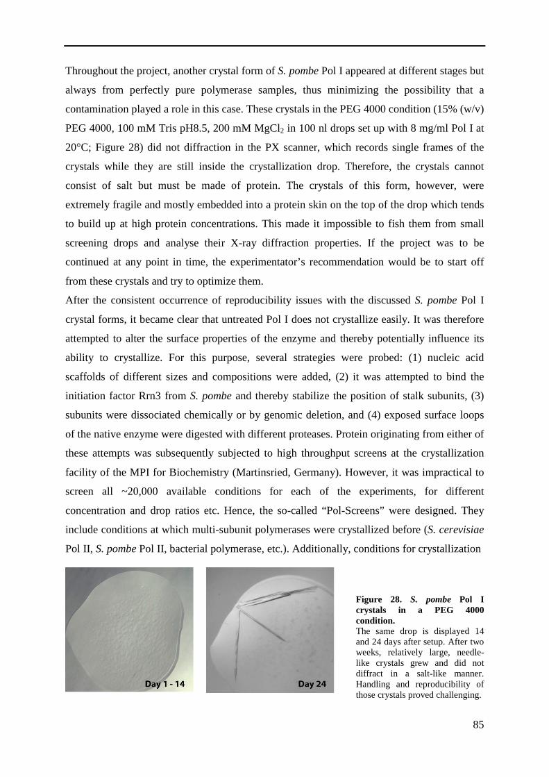
85
Throughout the project, another crystal form of S. pombe Pol I appeared at different stages but
always from perfectly pure polymerase samples, thus minimizing the possibility that a
contamination played a role in this case. These crystals in the PEG 4000 condition (15% (w/v)
PEG 4000, 100 mM Tris pH8.5, 200 mM MgCl2 in 100 nl drops set up with 8 mg/ml Pol I at
20°C; Figure 28) did not diffraction in the PX scanner, which records single frames of the
crystals while they are still inside the crystallization drop. Therefore, the crystals cannot
consist of salt but must be made of protein. The crystals of this form, however, were
extremely fragile and mostly embedded into a protein skin on the top of the drop which tends
to build up at high protein concentrations. This made it impossible to fish them from small
screening drops and analyse their X-ray diffraction properties. If the project was to be
continued at any point in time, the experimentator’s recommendation would be to start off
from these crystals and try to optimize them.
After the consistent occurrence of reproducibility issues with the discussed S. pombe Pol I
crystal forms, it became clear that untreated Pol I does not crystallize easily. It was therefore
attempted to alter the surface properties of the enzyme and thereby potentially influence its
ability to crystallize. For this purpose, several strategies were probed: (1) nucleic acid
scaffolds of different sizes and compositions were added, (2) it was attempted to bind the
initiation factor Rrn3 from S. pombe and thereby stabilize the position of stalk subunits, (3)
subunits were dissociated chemically or by genomic deletion, and (4) exposed surface loops
of the native enzyme were digested with different proteases. Protein originating from either of
these attempts was subsequently subjected to high throughput screens at the crystallization
facility of the MPI for Biochemistry (Martinsried, Germany). However, it was impractical to
screen all ~20,000 available conditions for each of the experiments, for different
concentration and drop ratios etc. Hence, the so-called “Pol-Screens” were designed. They
include conditions at which multi-subunit polymerases were crystallized before (S. cerevisiae
Pol II, S. pombe Pol II, bacterial polymerase, etc.). Additionally, conditions for crystallization
Figure 28. S. pombe Pol I crystals in a PEG 4000 condition. The same drop is displayed 14 and 24 days after setup. After two weeks, relatively large, needle-like crystals grew and did not diffract in a salt-like manner. Handling and reproducibility of those crystals proved challenging.

86
of Pol II complexes with initiation factors and for the mitochondrial RNA polymerase were
added. For all of these, a gradient of precipitant concentration is covered in the screens. This
makes it relatively easy to judge if a novel polymerase sample is suitable for crystallization
and at the same time covers a range of likely conditions.
The results of the different strategies listed above were as follows:
(1) The S. pombe RNA polymerase I bound all nucleic acid scaffolds that were provided to it,
as determined by the A280/A260 ratio in analytical size exclusion experiments (data not
shown). However, none of the bound scaffolds did influence its tendency to crystallize
consistently.
(2) The initiation factor Rrn3 was cloned from S. pombe, expressed recombinantly and
purified for the first time. Unfortunately, the expressions were highly contaminated with
chaperones that migrate identically to Rrn3 in SDS-PAGE. The small amount of protein that
could be purified did not interact with Pol I as strongly as it was shown for its S. cerevisiae
counterpart44. Therefore, at the time being it was not possible to form a S. pombe Pol I / Rrn3
complex that could be subjected to meaningful crystallization trials. If follow-up studies were
to be made, it might be worthwhile to prepare S. pombe Pol I in the presence of phosphatase
inhibitors. A phosphorylated version of Pol I might bind Rrn3 more easily, as suggested in
other studies44.
(3) Chemical dissociation of the peripheral Pol I – subunit complex A49/A34.5 was described
in the S. cerevisiae system8. The same protocol was performed on S. pombe Pol I. However,
two problems made it impossible to transfer the procedure. Firstly, the S. pombe enzyme
reacted much stronger and dissociated heavily. Secondly, the fraction of polymerase that
actually lost A49/A34.5 and remained stable showed a reduced binding to MonoQ anion
exchanger. This is most likely due to the absence of the charged C-terminal region of the stalk
subunit A43 in S. pombe. Thus, a different re-purification method has to be chosen if
reattempted. MonoS cation exchange is most likely not applicable, since one of the regions
mostly responsible for MonoS resin binding is the lysine-rich C-terminal tail of A34.5, which
is removed alongside A49. Size exclusion would remove the urea and might thus lead to
partial reattachment of dissociated subunits. If performed under urea conditions, a second size
exclusion would be necessary to remove urea independently, since it might influence
experiments to follow (such as crystallization trials). A Ni-NTA affinity purification might be
of use but would again leave the sample contaminated with imidazole.
Since the chemical dissociation of Pol I subunits in large scale was unsuccessful, purification
of Pol I from S. pombe strains with mutated subunits was considered. During the course of

87
this work, a study from the lab of Oliver Gadal reported S. pombe strains with deleted A34.5
and A49 subunits34. Those strains were kindly gifted to us and a A190-Flag/10xhistidine tag
was introduced to the A34.5 deletion strain. The strain itself shows a slow-growth phenotype
and does not reach cell densities of wild type S. pombe strain under laboratory conditions.
Nevertheless, Pol I could be purified from this strain with the exception of the MonoS cation
exchange step (due to the lack of A34.5 lysine-rich tail). The purified Pol I version is termed
“Pol IΔ” and not only entirely lacks A34.5 but also A49 (Figure 29). Thus, genomic
construction of a polymerase version with different surface properties was successful in S.
pombe for the first time. However, Pol IΔ displayed other impurities and a partial
contamination with Pol III as identified by mass spectrometry. Additionally, other subunits
were substoichiometric in the Pol IΔ variant and the overall yield was extremely low (about
100 µg Pol IΔ from 350 g yeast). Crystallization screens were carried out nevertheless but did
not yield hits in the initial standard screens and the Pol-screens.
(4) For the crystallization of recombinant proteins, it has become a standard procedure to
partially digest single proteins or complexes and analyse the dynamics of the reaction to
identify stable fragments. These fragments can then expressed separately and subjected to
further rounds of digestion and finally might be suitable for crystallization61. For
endogenously purified multi-subunit complexes such as Pol I, however, this strategy is not
applicable due to enormous cloning efforts and lethality issues. Thus, an adaptation of the
strategy was applied in this case. Firstly, in-drop digest of S. pombe Pol I was performed
similarly to the procedure that lead to solution of the structure of human mitochondrial RNA
polymerase120,121. For Pol I, this did not improve crystallization behaviour. Secondly, a
limited digest with different proteases was performed and stopped after one hour by the
addition of an access of protease inhibitor mix. Digested polymerase was subsequently
Figure 29. Purification of S. pombe Pol IΔ. Pol I from a S. pombe strain with a genomic deletion of A34.5 and an AC40 Flag/His-tag was purified (MonoS cation exchange skipped). The subunit-complex A49/34.5 dissociated completely and is not visible in Coormassie stained SDS-PAGE. Pol IΔ displays an increased amount of contaminating bands

88
gelfiltered to remove proteases and their inhibitors, and subjected to functionality assays as
well as crystallization trials. Figure 30a compares the analytical size exclusion profile of an
untreated S. pombe Pol I sample with a subtilisin digestion variant (SDS-PAGE of both is
displayed in b). The profiles and band patterns show that, following proteolytic digestion, the
polymerase stays assembled but loses a large portion of its molecular weight. Hence, the
removal of surface parts was likely successful. Similar to subtilisin digestion, the protocol was
also successful with the proteases trypsin and chymotrypsin. All proteases gave rise to a
distinct band pattern in the digested polymerases (Figure 30c). To test if the stubbed
polymerases are still functionally active, standard elongation/cleavage assays were performed.
Whereas elongation seemed to be slightly impaired, all digestion variants did elongate the
RNA and were capable of product cleavage (Figure 30d).
Figure 30. Proteolytic digest of S. pombe Pol I. a Size exclusion chromatograms of undigested and subtilisin digested polymerase. An elution shift of 1.1 ml hints at massive removal of unstructured parts, whereas the polymerase core seems to be stable since the digestion variant still elutes in a single peak. b Coomassie-stained SDS-PAGE of the peaks from a. c Difference in gel band patterns of Pol I in a Coomassie-stained SDS-PAGE following proteolytic digest and SEC. d All digestion variants are still active as shown by an elongation/cleavage assay. Fluorescence detection of 20% urea PAGE.

89
Subjected to crystallization screens, the subtilisin and trypsin digestion variants did not
produce any hits. In contrast, the chymotrypsin digest crystallized after 10-15 days at a Pol I
concentration of 5 mg/ml in 30% Jeffamine ED-2001 pH 7.0 and 100 mM Hepes pH 7.0
(Figure 31a-c). Crystals grew at 20°C in 100 nl drops for 5 – 10 days and were very small but
seemed to be clean ellipsoids of up to 25 µm length. Reproduction proved successful in every
3rd trial most likely due to sample inhomogeneity resulting from up-scaling issues with the
digestion protocol. One successful reproduction of the digestions crystals yielded needle-like
crystals (Figure 31d) after over a month. The Jeffamine drops, however, dry out quickly and
crystals could not be removed from protein skin to subject them to X-ray diffraction analysis.
6.1.4 Conclusion of the S. pombe Pol I project
The goal of this work was to produce a novel crystal form of Pol I from which its structure
can be solved. For this purpose, using the S. pombe enzyme as an alternative for S. cerevisiae
was the central strategy. Initial results were positive: a fermentation and purification protocol
could be established and first crystals were obtained rapidly. Later on, however,
reproducibility became a central issue. Quality of the different fermentations and purifications
seems to be an issue that can hardly be quantified. Nevertheless, comparable problems appear
to occur also for S. cerevisiae Pol II if complex with transcription factors: Some preps
produce high quality crystals whereas others don’t diffract to high resolution at all. In the case
of S. pombe Pol I, the difference, however, was wether the protein would crystallize at all.
Figure 31. Crystallization of a chymotrypsin-digested S. pombe Pol I variant. a – c Time course of a Jeffaminne drop shows the appearance of initial crystals from digested polymerase. d Reproducibility is again an issue due to upscaling issues with digestion protocol. In rare cases, the crystals from c could be obtained but not harvested.

90
The subunit A43 was always present in preparations but tended to be substoichiometric. Also,
it migrated at much higher apparent molecular weight in SDS-PAGE than its theoretical
molecular weight of 21 kDa would suggest. This hints at the occurrence of posttranslational
modifications. Beside the known phosphorylation other modifications such as sumoylation,
ubiquitinylation or acetylation could take place. In the human system, for example,
acetylation of the A49 homologue has been recently reported to play a regulatory role122.
Similarly, the absence of the connector element in S. pombe could result in the need for a
different level of A43 regulation by posttranslational modification. By purifying a mixture of
modified and unmodified complexes, a heterogeneity would be introduced, which could
explain the inconsistency in S. pombe Pol I crystallization behaviour.
Nevertheless, despite failure to consistently crystallize Pol I from S. pombe, the work on it
resulted in a number of benefits:
(1) This is the first time that RNA polymerase I from an organism other than S. cerevisiae
could be purified in crystallization grade quality and quantity.
(2) Pol-Screens to easily probe crystallization behaviour of novel samples have been
designed for this project and are now widely used also for Pol-II-related projects and
ultimately were an integral part of solving the structure of S. cerevisiae Pol I, since
they gave rise to the first hit of crystal form C.
(3) A novel system for functional and structural projects was established. Since
crystallization is dependent on small influences, Pol I complexes of S. pombe could be
superior to their S. cerevisiae homologues and thus provide an easily accessible
secondary system for further generations of PhD students working on polymerase
projects. Similar experiences have been made with the “mediator head” in our lab123.
For functional analysis, in vitro data from a second organism can be of importance as
controls just as well.
(4) Experience in handling of polymerases seems to be of great importance to ensure
consistency. Therefore, establishing a new system was the best possible training and
provided all the practical experience necessary for solving the structure of a
polymerase and thus laid a solid groundwork for the work carried out in the S.
cerevisiae system.
With this, the project can be judged as a partial success despite the inability to solve the
structure of S. pombe Pol I as of now.

91
6.2 Scripts for crystallographic data processing
6.2.1 XDS script for data integration
!***************************************************************************** ! XDS.INP used on crystal CE188 for the PILATUS 6M pixel detector at SLS !***************************************************************************** DETECTOR=PILATUS MINIMUM_VALID_PIXEL_VALUE=0 OVERLOAD=1048500 SENSOR_THICKNESS=0.32 NX=2463 NY=2527 QX=0.172 QY=0.172 !PILATUS 6M DIRECTION_OF_DETECTOR_X-AXIS= 1.0 0.0 0.0 DIRECTION_OF_DETECTOR_Y-AXIS= 0.0 1.0 0.0 TRUSTED_REGION=0.0 1.41 !====================== JOB CONTROL PARAMETERS =============================== !JOB= XYCORR INIT COLSPOT IDXREF !THIS JOB WAS USED IN A FIRST RUN FOR INDEXING JOB= DEFPIX XPLAN INTEGRATE CORRECT !====================== GEOMETRICAL PARAMETERS =============================== ORGX=1250.0 ORGY=1238 !Detector origin (pixels) DETECTOR_DISTANCE= 575 !(mm) ROTATION_AXIS= 1.0 0.0 0.0 OSCILLATION_RANGE=0.1 X-RAY_WAVELENGTH= 1.00000 INCIDENT_BEAM_DIRECTION=0.0 0.0 1.0 FRACTION_OF_POLARIZATION=0.99 POLARIZATION_PLANE_NORMAL= 0.0 1.0 0.0 !======================= CRYSTAL PARAMETERS ================================= SPACE_GROUP_NUMBER=0 !0 is used for unknown crystals FRIEDEL'S_LAW=TRUE. !==================== SELECTION OF DATA IMAGES ============================== NAME_TEMPLATE_OF_DATA_FRAMES=~/ce188/ce188_1_0????.cbf DATA_RANGE=1 5300 BACKGROUND_RANGE=1 20 !====================== INDEXING PARAMETERS ================================= SEPMIN=4.0 CLUSTER_RADIUS=2 !============== DECISION CONSTANTS FOR FINDING CRYSTAL SYMMETRY ============= MAX_CELL_AXIS_ERROR=0.03 ! Maximum relative error in cell axes tolerated MAX_CELL_ANGLE_ERROR=2.0 ! Maximum cell angle error tolerated TEST_RESOLUTION_RANGE=8.0 4.5 MIN_RFL_Rmeas= 50 ! Minimum #reflections needed for calculation of Rmeas MAX_FAC_Rmeas=2.0 ! Sets an upper limit for acceptable Rmeas !================= PARAMETERS CONTROLLING REFINEMENTS ======================= REFINE(INTEGRATE)= BEAM ORIENTATION CELL !REFINE(CORRECT)=DISTANCE BEAM ORIENTATION CELL AXIS !================== CRITERIA FOR ACCEPTING REFLECTIONS ====================== VALUE_RANGE_FOR_TRUSTED_DETECTOR_PIXELS= 6000 30000 INCLUDE_RESOLUTION_RANGE=70.0 2.8 MINIMUM_ZETA=0.05 !============== INTEGRATION AND PEAK PROFILE PARAMETERS ===================== NUMBER_OF_PROFILE_GRID_POINTS_ALONG_ALPHA/BETA=13 !=========== PARAMETERS DEFINING BACKGROUND AND PEAK PIXELS ================= MINIMUM_NUMBER_OF_PIXELS_IN_A_SPOT=3

92
6.2.2 XSCALE script for the combination of five datasets from four crystals
0-DOSE_SIGNIFICANCE_LEVEL=0.50 OUTPUT_FILE=merge_zero.hkl FRIEDEL'S_LAW=TRUE MERGE=TRUE STRICT_ABSORPTION_CORRECTION=FALSE INPUT_FILE= ../ce188/xds_2/XDS_ASCII.HKL INCLUDE_RESOLUTION_RANGE= 40 2.8 CRYSTAL_NAME=ce188_2 INPUT_FILE= ../ce188/xds/XDS_ASCII.HKL INCLUDE_RESOLUTION_RANGE= 40 2.8 CRYSTAL_NAME=ce188_1 INPUT_FILE= ../ce201/xds/XDS_ASCII.HKL INCLUDE_RESOLUTION_RANGE= 40 2.8 CRYSTAL_NAME=ce201 INPUT_FILE= ../ce259/xds_b/XDS_ASCII.HKL INCLUDE_RESOLUTION_RANGE= 40 2.8 CRYSTAL_NAME=ce259_b INPUT_FILE= ../ce152/xds/XDS_ASCII.HKL INCLUDE_RESOLUTION_RANGE= 40 2.8 CRYSTAL_NAME=ce152
6.2.3 XSCALE – Selected output parameters
THE DATA COLLECTION STATISTICS REPORTED BELOW ASSUMES: SPACE_GROUP_NUMBER= 1 UNIT_CELL_CONSTANTS= 122.74 139.02 209.55 108.060 95.403 93.848 ALL DATA SETS WILL BE SCALED TO ../ce188/xds_2/XDS_ASCII.HKL ****************************************************************************** READING INPUT REFLECTION DATA FILES ****************************************************************************** NUMBER OF UNIQUE REFLECTIONS IN FILE "REMOVE.HKL" 163 DATA MEAN REFLECTIONS INPUT FILE NAME SET# INTENSITY ACCEPTED REJECTED 1 0.2659E+02 643001 316 ../ce188/xds_2/XDS_ASCII.HKL 2 0.2835E+02 1638774 769 ../ce188/xds/XDS_ASCII.HKL 3 0.8544E+01 765475 479 ../ce201/xds/XDS_ASCII.HKL 4 0.2161E+02 380492 259 ../ce259/xds_b/XDS_ASCII.HKL 5 0.1127E+02 770320 352 ../ce152/xds/XDS_ASCII.HKL ****************************************************************************** OVERALL SCALING AND CRYSTAL DISORDER CORRECTION ****************************************************************************** CORRELATIONS BETWEEN INPUT DATA SETS AFTER CORRECTIONS DATA SETS NUMBER OF COMMON CORRELATION RATIO OF COMMON B-FACTOR #i #j REFLECTIONS BETWEEN i,j INTENSITIES (i/j) BETWEEN i,j 1 2 137844 0.966 1.0060 -0.1070 1 3 105989 0.955 1.0063 0.0559 2 3 106853 0.944 1.0065 0.0198 1 4 84571 0.918 0.9930 -0.5293 2 4 87131 0.935 1.0109 -0.5341 3 4 76583 0.899 1.0267 -1.1212 1 5 114809 0.929 0.9950 0.2459 2 5 115454 0.943 0.9855 0.2195 3 5 94390 0.915 0.9767 0.4377 4 5 76769 0.959 1.0379 -0.1888 SUBSET OF INTENSITY DATA WITH SIGNAL/NOISE >= -3.0 AS FUNCTION OF RESOLUTION RESOLUTION NUMBER OF REFLECTIONS COMPLETENESS R-FACTOR R-FACTOR COMPARED I/SIGMA R-meas CC(1/2) Anomal SigAno Nano LIMIT OBSERVED UNIQUE POSSIBLE OF DATA observed expected Corr 12.52 40590 3478 3597 96.7% 8.3% 10.8% 40590 30.37 8.7% 99.7* -13 0.676 3402 8.85 86692 6567 6577 99.8% 9.3% 11.4% 86692 30.16 9.6% 99.8* -17 0.629 6538 7.23 105359 8480 8494 99.8% 11.0% 12.8% 105359 24.10 11.5% 99.7* -17 0.686 8432 6.26 134659 10110 10123 99.9% 13.5% 14.9% 134659 20.42 14.1% 99.5* -19 0.691 10096 5.60 155578 11348 11354 99.9% 15.0% 16.4% 155578 18.72 15.6% 99.5* -19 0.680 11331 5.11 160339 12647 12666 99.8% 15.6% 16.8% 160339 17.34 16.2% 99.4* -19 0.685 12604 4.73 179718 13775 13785 99.9% 16.1% 17.1% 179718 17.17 16.8% 99.4* -23 0.673 13749 4.43 198177 14751 14759 99.9% 17.1% 18.0% 198177 16.51 17.7% 99.4* -22 0.677 14727 4.17 210053 15700 15712 99.9% 19.1% 20.0% 210053 14.87 19.9% 99.2* -19 0.690 15670 3.96 211043 16572 16583 99.9% 22.7% 23.5% 211043 12.52 23.6% 98.8* -18 0.701 16514 3.78 226004 17508 17527 99.9% 27.7% 28.7% 226004 10.67 28.8% 98.5* -18 0.713 17474 3.61 244122 18170 18183 99.9% 35.4% 36.4% 244122 9.15 36.9% 97.9* -16 0.729 18133 3.47 259891 19069 19093 99.9% 44.4% 45.7% 259891 7.76 46.1% 97.0* -14 0.736 19043 3.35 261803 19820 19837 99.9% 54.5% 56.2% 261803 6.28 56.7% 95.3* -13 0.733 19760 3.23 262055 20421 20441 99.9% 71.0% 72.1% 262055 4.81 73.9% 92.0* -10 0.744 20365 3.13 275504 21262 21300 99.8% 86.9% 88.3% 275504 3.91 90.4% 88.6* -9 0.738 21209 3.04 291152 21807 21828 99.9% 110.2% 112.7% 291152 3.17 114.6% 83.4* -7 0.730 21777 2.95 304614 22508 22545 99.8% 135.3% 136.6% 304614 2.59 140.6% 77.2* -7 0.730 22485 2.87 311277 23188 23214 99.9% 166.9% 169.0% 311277 2.05 173.5% 68.2* -5 0.713 23151 2.80 274084 23763 23801 99.8% 201.8% 205.1% 274081 1.52 211.3% 54.1* -4 0.691 23388 total 4192714 320944 321419 99.9% 24.0% 25.5% 4192711 9.61 25.0% 99.6* -13 0.710 319848

93
6.3 Scripts and parameterization files for structure refinement
6.3.1 Refinement strategy file for phenix.refine
phenix.refine \ ~/merge3/merge3.mtz \ ~/pol1/build6_5.pdb \ strategy=rigid_body+individual_sites+individual_adp+tls \ refinement.input.xray_data.r_free_flags.label=FreeR_flag \ rigid_bodies.params \ ncs_groups.params \ tlsmd.params \ main.ncs=True ncs.type=cartesian \ ncs.find_automatically=False \ check_rotamer_consistency=False \ disulfide_distance_cutoff=0.5 \ adp.convert_to_iso=true \ adp.set_b_iso=60 \ poli-zinc.restraints \ solvent.params \ refinement.ncs.excessive_distance_limit=None \ main.number_of_macro_cycles=6
6.3.2 Definition of bond lengths for one coordinated Zinc atom
refinement.geometry_restraints.edits { zn_sg_dist = 2.34 sigma_zn_sg_dist = 0.05 zn_ne2_dist = 2.00 sigma_zn_ne2_dist = 0.02 slack = None ### Zn A:3001 ### bond { action = *add atom_selection_1 = chain A and resid 3001 and resname ZN and name ZN atom_selection_2 = chain A and resid 62 and resname CYS and name SG distance_ideal = $zn_sg_dist sigma = $sigma_zn_sg_dist slack = $slack } bond { action = *add atom_selection_1 = chain A and resid 3001 and resname ZN and name ZN atom_selection_2 = chain A and resid 65 and resname CYS and name SG distance_ideal = $zn_sg_dist sigma = $sigma_zn_sg_dist slack = $slack } bond { action = *add atom_selection_1 = chain A and resid 3001 and resname ZN and name ZN atom_selection_2 = chain A and resid 72 and resname CYS and name SG distance_ideal = $zn_sg_dist sigma = $sigma_zn_sg_dist slack = $slack } bond { action = *add atom_selection_1 = chain A and resid 3001 and resname ZN and name ZN atom_selection_2 = chain A and resid 75 and resname HIS and name NE2 distance_ideal = $zn_ne2_dist sigma = $sigma_zn_ne2_dist slack = $slack }

94
6.3.3 Definition file for NCS refinement
refinement.ncs.restraint_group { reference = chain A and resseq 1:84 selection = chain P and resseq 1:84 } refinement.ncs.restraint_group { reference = chain A and resseq 85:139 selection = chain P and resseq 85:139 } refinement.ncs.restraint_group { reference = chain A and resseq 176:272 selection = chain P and resseq 176:272 } refinement.ncs.restraint_group { reference = chain A and resseq 296:363 selection = chain P and resseq 296:363 } refinement.ncs.restraint_group { reference = chain A and resseq 364:380 selection = chain P and resseq 364:380 } refinement.ncs.restraint_group { reference = chain A and resseq 381:441 selection = chain P and resseq 381:441 } refinement.ncs.restraint_group { reference = chain A and resseq 442:477 selection = chain P and resseq 442:477 } refinement.ncs.restraint_group { reference = chain A and resseq 478:652 selection = chain P and resseq 478:652 } refinement.ncs.restraint_group { reference = chain A and resseq 653:826 selection = chain P and resseq 653:826 } refinement.ncs.restraint_group { reference = chain A and resseq 827:989 selection = chain P and resseq 827:989 } refinement.ncs.restraint_group { reference = chain A and resseq 990:1028 selection = chain P and resseq 990:1028 } refinement.ncs.restraint_group { reference = chain A and resseq 1029:1152 selection = chain P and resseq 1029:1152 } refinement.ncs.restraint_group { reference = chain A and resseq 1160:1204 selection = chain P and resseq 1160:1204 } refinement.ncs.restraint_group { reference = chain A and resseq 1213:1337 selection = chain P and resseq 1213:1337 } refinement.ncs.restraint_group { reference = chain A and resseq 1361:1395 selection = chain P and resseq 1361:1395 } refinement.ncs.restraint_group { reference = chain A and resseq 1596:1664 selection = chain P and resseq 1596:1664 } refinement.ncs.restraint_group { reference = chain B and resseq 8:79 selection = chain Q and resseq 8:79 } refinement.ncs.restraint_group { reference = chain B and resseq 88:204 selection = chain Q and resseq 88:204 } refinement.ncs.restraint_group { reference = chain B and resseq 205:404 selection = chain Q and resseq 205:404 } refinement.ncs.restraint_group { reference = chain B and resseq 405:489 selection = chain Q and resseq 405:489 } refinement.ncs.restraint_group { reference = chain B and resseq 490:697 selection = chain Q and resseq 490:697 } refinement.ncs.restraint_group { reference = chain B and resseq 698:798 selection = chain Q and resseq 698:798 } refinement.ncs.restraint_group { reference = chain B and resseq 799:910 selection = chain Q and resseq 799:910 } refinement.ncs.restraint_group { reference = chain B and resseq 911:1038 selection = chain Q and resseq 911:1038 }
refinement.ncs.restraint_group { reference = chain B and resseq 1039:1203 selection = chain Q and resseq 1039:1203 } refinement.ncs.restraint_group { reference = chain C and resseq 31:76 selection = chain R and resseq 31:76 } refinement.ncs.restraint_group { reference = chain C and resseq 77:220 selection = chain R and resseq 77:220 } refinement.ncs.restraint_group { reference = chain C and resseq 221:334 selection = chain R and resseq 221:334 } refinement.ncs.restraint_group { reference = chain D selection = chain S } refinement.ncs.restraint_group { reference = chain G and resseq 14:127 selection = chain V and resseq 14:127 } refinement.ncs.restraint_group { reference = chain G and resseq 128:250 selection = chain V and resseq 128:250 } refinement.ncs.restraint_group { reference = chain O and resseq 265:315 selection = chain 4 and resseq 265:315 } refinement.ncs.restraint_group { reference = chain E and resseq 5:147 selection = chain T and resseq 5:147 } refinement.ncs.restraint_group { reference = chain E and resseq 148:215 selection = chain T and resseq 148:215 } refinement.ncs.restraint_group { reference = chain F selection = chain U } refinement.ncs.restraint_group { reference = chain H selection = chain W } refinement.ncs.restraint_group { reference = chain I and resseq 2:74 selection = chain X and resseq 2:74 } refinement.ncs.restraint_group { reference = chain I and resseq 75:125 selection = chain X and resseq 75:125 } refinement.ncs.restraint_group { reference = chain J selection = chain Y } refinement.ncs.restraint_group { reference = chain K selection = chain Z } refinement.ncs.restraint_group { reference = chain L selection = chain 1 } refinement.ncs.restraint_group { reference = chain M selection = chain 2 } refinement.ncs.restraint_group { reference = chain N and resseq 22:140 selection = chain 3 and resseq 22:140 } refinement.ncs.restraint_group { reference = chain N and resseq 141:180 selection = chain 3 and resseq 141:180 }

95
6.3.4 Definition file for Rigid body refinement
refinement.refine.sites { rigid_body = chain A and resseq 1:84 rigid_body = chain A and resseq 85:139 rigid_body = chain A and resseq 176:272 rigid_body = chain A and resseq 296:363 rigid_body = chain A and resseq 364:380 rigid_body = chain A and resseq 381:441 rigid_body = chain A and resseq 442:477 rigid_body = chain A and resseq 478:652 rigid_body = chain A and resseq 653:826 rigid_body = chain A and resseq 827:989 rigid_body = chain A and resseq 990:1028 rigid_body = chain A and resseq 1029:1152 rigid_body = chain A and resseq 1160:1204 rigid_body = chain A and resseq 1213:1350 rigid_body = chain A and resseq 1362:1395 rigid_body = chain A and resseq 1440:1543 rigid_body = chain A and resseq 1544:1595 rigid_body = chain A and resseq 1596:1664 rigid_body = chain B and resseq 8:79 rigid_body = chain B and resseq 88:204 rigid_body = chain B and resseq 205:404 rigid_body = chain B and resseq 405:489 rigid_body = chain B and resseq 490:697 rigid_body = chain B and resseq 698:798 rigid_body = chain B and resseq 799:910 rigid_body = chain B and resseq 911:1038 rigid_body = chain B and resseq 1039:1203 rigid_body = chain C and resseq 31:76 rigid_body = chain C and resseq 77:220 rigid_body = chain C and resseq 221:334 rigid_body = chain G and resseq 14:127 rigid_body = chain G and resseq 128:250 rigid_body = chain E and resseq 5:147 rigid_body = chain E and resseq 148:215 rigid_body = chain F rigid_body = chain D rigid_body = chain H rigid_body = chain I and resseq 2:74 rigid_body = chain I and resseq 75:125 rigid_body = chain J rigid_body = chain K rigid_body = chain L rigid_body = chain M rigid_body = chain N and resseq 22:140 rigid_body = chain N and resseq 141:180 rigid_body = chain O rigid_body = chain P and resseq 1:84 rigid_body = chain P and resseq 85:139 rigid_body = chain P and resseq 176:272 rigid_body = chain P and resseq 296:363 rigid_body = chain P and resseq 364:380 rigid_body = chain P and resseq 381:441 rigid_body = chain P and resseq 442:477 rigid_body = chain P and resseq 478:652 rigid_body = chain P and resseq 653:826 rigid_body = chain P and resseq 827:989 rigid_body = chain P and resseq 990:1028 rigid_body = chain P and resseq 1029:1152 rigid_body = chain P and resseq 1160:1204 rigid_body = chain P and resseq 1213:1350 rigid_body = chain P and resseq 1362:1395 rigid_body = chain P and resseq 1440:1543 rigid_body = chain P and resseq 1544:1595 rigid_body = chain P and resseq 1596:1664 rigid_body = chain Q and resseq 8:79 rigid_body = chain Q and resseq 88:204 rigid_body = chain Q and resseq 205:404 rigid_body = chain Q and resseq 405:489 rigid_body = chain Q and resseq 490:697 rigid_body = chain Q and resseq 698:798 rigid_body = chain Q and resseq 799:910 rigid_body = chain Q and resseq 911:1038 rigid_body = chain Q and resseq 1039:1203 rigid_body = chain R and resseq 31:76 rigid_body = chain R and resseq 77:220 rigid_body = chain R and resseq 221:334 rigid_body = chain V and resseq 14:127 rigid_body = chain V and resseq 128:250 rigid_body = chain T and resseq 5:147 rigid_body = chain T and resseq 148:215 rigid_body = chain U rigid_body = chain S rigid_body = chain W rigid_body = chain X and resseq 2:74 rigid_body = chain X and resseq 75:125 rigid_body = chain Y rigid_body = chain Z rigid_body = chain 1 rigid_body = chain 2 rigid_body = chain 3 and resseq 22:140 rigid_body = chain 3 and resseq 141:180 rigid_body = chain 4 }

96
6.3.5 Definition file for TLS refinement
refinement.refine.adp { tls = chain A and (resid 654:1013 or resid 1361:1367) or \ chain B and (resid 8:209 or resid 400:553 or resid 647:1068) or \ chain C or \ chain J or \ chain K or \ chain L or \ chain N and resid 147:180 tls = chain A and (resid 477:653 or resid 1014:1261 or resid 1368:1395 or resid 1500:1608) or \ chain B and resid 1069:1092 or \ chain E or \ chain F and resid 73:154 tls = chain A and (resid 1:476 or resid 1609:1649 or resid 3001:3002) or \ chain B and (resid 1093-1203 or resid 3001) or \ chain O tls = chain A and resid 1650:1664 or \ chain D or \ chain F and resid 55:72 or \ chain G tls = chain M or \ chain N and resid 25:146 tls = chain I and (resid 2:52 or resid 3001) tls = chain I and resid 53:78 tls = chain I and (resid 79:125 or resid 3002) tls = chain A and (resid 1262:1337 or resid 1440:1499) tls = chain B and resid 210:399 tls = chain B and resid 554:646 tls = chain H tls = chain P and (resid 654:1013 or resid 1361:1367) or \ chain Q and (resid 8:209 or resid 400:553 or resid 647:1068) or \ chain R or \ chain Y or \ chain Z or \ chain 1 or \ chain 3 and resid 147:181 tls = chain P and (resid 477:653 or resid 1014:1261 or resid 1368:1395 or resid 1500:1608) or \ chain Q and resid 1069:1092 or \ chain T or \ chain U and resid 73:154 tls = chain P and (resid 1:476 or resid 1609:1649 or resid 3001:3002) or \ chain Q and (resid 1093-1203 or resid 3001) or \ chain 4 tls = chain P and resid 1650:1664 or \ chain S or \ chain U and resid 55:72 or \ chain V tls = chain 2 or \ chain 3 and resid 25:146 tls = chain X and (resid 2:52 or resid 3001) tls = chain X and resid 53:78 tls = chain X and (resid 79:125 or resid 3002) tls = chain P and (resid 1262:1337 or resid 1440:1499) tls = chain Q and resid 210:399 tls = chain Q and resid 554:646 tls = chain W }
6.3.6 Solvent definition file for refinement
refinement { main.ordered_solvent = True ordered_solvent { # reduce resolution limit to allow ordered solvent below 2.8 A low_resolution = 2.9 mode = every_macro_cycle output_chain_id = w # more reasonable minimum and maximum hydrogen bond distances h_bond_min_mac = 2.2 h_bond_min_sol = 2.2 h_bond_max = 3.5 b_iso_min = 1.0 b_iso_max = 70.0 # B-factor for new water molecules; if not set, the mean B-factor is used b_iso = 50.0 primary_map_type = mFobs-DFmodel primary_map_cutoff = 3.0 secondary_map_and_map_cc_filter { cc_map_2_type = 2mFobs-DFmodel poor_cc_threshold = 0.7 poor_map_value_threshold = 1.0 } } }

97
6.4 Structure-based alignment of A190 and Rpb1
Figure 32. Structure-based alignment of A190 and Rpb1. Invariant and conserved residues are highlighted in green and light green, respectively. Secondary structure elements are indicated above and below the alignment for A190 and Rpb1, respectively (cylinders, helices; arrows, strands). Residues that form different folds in Pol I or form Pol-II-specific folds are in green or red, respectively (compare Figure 13 and Figure 14).

98
6.5 Structure-based alignment of A135 and Rpb2
Figure 33. Structure-based alignment of A135 and Rpb2. Invariant and conserved residues are highlighted in green and light green, respectively. Secondary structure elements are indicated above and below the alignment for A135 and Rpb2, respectively (cylinders, helices; arrows, strands). Residues that form different folds in Pol I or form Pol-II-specific folds are in green or red, respectively (compare Figure 13 and Figure 14).

99
6.6 Structure-based alignment of AC40/AC19 and the Rpb3/Rpb11 subcomplex
Figure 34. Structure-based sequence alignment of the sub complex AC40/AC19 with Rpb3/Rpb11. Structure-based alignment of AC40 and Rpb3 (a) and of AC19 and Rpb11 (b). Invariant and conserved residues are highlighted in green and light green, respectively. Secondary structure elements are indicated above and below the alignment for AC40 and Rpb3, respectively (cylinders, helices; arrows, strands). Residues that form different folds in Pol I or form Pol-II-specific folds are in green or red, respectively (compare Figure 13 and Figure 15).

100
6.7 Conservation of Pol I and Pol II subunits
According to the presented structure-based sequence alignments and a previously published
one8, the identity between subunits of Pol I and Pol II was re-evaluated. A new (and for the
first time structurally founded) table of identities was prepared (Table 16).
Table 16. Subunits of the three S. cerevisiae RNA polymerases with Sequence identity inferred from structure-based sequence alignments

101
6.8 Domain differences between the polymerase subunits A190/Rpb1 and A135/Rpb2
Figure 35. Detailed comparison of A190–A135 domains with their Rpb1–Rpb2 counterparts. a Comparison of A190 domain structures (top) that differ significantly from their corresponding Pol II regions (bottom). Labelling of corresponding secondary structure elements is as for Pol II58. New or lacking secondary structure elements are labelled. New elements were named according to the preceding Pol II element with small letters added alphabetically for subsequent elements. b Comparison of A135 domain structures (top) that differ significantly from their corresponding Pol II regions (bottom).

102
6.9 Evolutionary conservation of expander and connector elements
Figure 36. Sequence conservation of the expander and the connector element. a Amino acid sequence alignment of the connector region in S. cerevisiae (Sc); Candida glabrata (Cg); Homo sapiens (Hs) and Mus musculus (Mm). Secondary structure elements are indicated above the alignment (K5 helix, cylinder; strands D1, D2; arrows). Residues that are involved in the interface with the Pol I clamp and cleft and showed a buried surface area in excess of 40Ų are indicated with an asterisk above the alignment. Buried surfaces were calculated with the PISA server124. A structure-based alignment of the A14–A43 stalk residues was published8,61 and is not included here. b Amino acid sequence alignment of the expander region in S. cerevisiae, C. glabrata, H. sapiens and M. musculus. Secondary structure elements are indicated above the alignment (helices, cylinders; strands, arrows). Residues that are involved in the interface with the Pol I cleft and showed a buried surface area in excess of 40Ų are indicated with an asterisk above the alignment. Buried surfaces were calculated with the PISA server124.

103
6.10 Expander mutations do not display a growth defect in S. cerevisiae on YPD medium
Figure 37. Mutation of the expander element does not result in a growth defect on YPD medium. The expander element was mutated at different positions. None of them exhibited an obvious growth defect. If repeated at 30°C, 37°C or under stress conditions, no effect took place as well (data not shown).

104
7. Abbreviations
°C Degree celsius
FAM 6-carboxy-fluoresceine
Å Ångstrom
Amp Ampicillin
AU asymmetric unit
Bp base pairs
Cam Chloramphenicol
CE Core element
CF Core factor
CV Column volume
DSS Di-succimidyl suberate
DTT Dithiothreitol
EM Electron microscopy
ESRF European Synchrotron Radiation Facility
g g-force
G418 Geneticin
h hours
HRP Horseradish peroxidase
IGS Intergenic space
Kan Kanamycin
LB Luria-Bertani medium
MAD Multi-wavelength anomalous diffraction
min minutes
NCS Non-crystallographic symmetry
Nl normal litres
NOR Nucleolar organizer region
NTP Nucleoside triphosphate
OD600 Optical density at 600nm
PAGE Polyacrylamide gel electrophoresis
PDB Protein Data Bank
PEG Polyethylen glycol
PI Protease inhibitor mix
PIC Pre initiation complex
Pol RNA polymerase
rmsd root mean square deviation
RNAP RNA polymerase
RT Room temperature
s seconds
SAD Single-wavelength anomalous
diffraction
SEC Size exclusion chromatography
SDS Sodium-Dodecyl-Sulphate
SLS Swiss Light Source
Strep Streptamycin
TCA Trichloroacetric acid
TCEP Tris(2-carboxyethyl)phosphine
Tet Tetracyclin
TOR Target of rapamycin
TPB TATA-binding protein
UAF Upstream activating factor
UE Upstream element
v/v Volume per volume
w/v Weight per volume
YPD Yeast extract peptone dextrose
medium