RMA: A Pattern Based J2EE Development Tool - CiteSeerX
120
RMA: A Pattern Based J2EE Development Tool by Jun Chen A thesis presented to the University of Waterloo in fulfilment of the thesis requirement for the degree of Master of Mathematics in Computer Science Waterloo, Ontario, Canada, 2004 c Jun Chen 2004
-
Upload
khangminh22 -
Category
Documents
-
view
0 -
download
0
Transcript of RMA: A Pattern Based J2EE Development Tool - CiteSeerX

RMA: A Pattern Based J2EE Development Tool
by
Jun Chen
A thesis
presented to the University of Waterloo
in fulfilment of the
thesis requirement for the degree of
Master of Mathematics
in
Computer Science
Waterloo, Ontario, Canada, 2004
c© Jun Chen 2004

AUTHOR’S DECLARATION FOR ELECTRONIC SUBMISSION OF A THESIS
I hereby declare that I am the sole author of this thesis. This is a true copy of the thesis, including
any required final revisions, as accepted by my examiners.
I understand that my thesis may be made electronically available to the public.
ii

Abstract
The development process for creating J2EE web applications is complex and tedious, and is thus
error prone. The quality of a J2EE web application depends on correctness of code as well as
the efficiency and flexibility of its architecture. Although the J2EE specification has promised
to hide the distributed nature of the application, application developers still have to be aware of
this fact in both the design (architecture) and implementation (code) perspectives. In this thesis,
we present the detailed design of our pattern-based J2EE development tool, RoadMapAssembler
(RMA). RMA demonstrates how patterns can be used to generate efficient architectural code while
also hiding the deployment logic and distributed nature of J2EE applications in the implementation
perspective. Furthermore, it shows the generation of a J2EE framework as a process of assembling
patterns in an incremental fashion using known inter-pattern relationships.
iii

Acknowledgement
I would like to express my deepest gratitude to my supervisor, Professor Steve MacDonald. His
guidance, insight and expressive clarity have served as an inspiration and have helped me tremen-
dously during these past two years. This thesis would not be possible without his patience and
advice. I would also like to thank my readers, Professor Tim Brecht and Professor Richard Trefler
for taking the time to review my thesis. Also, I like to thank my friends who had helped me so
much in the past two years.
A special thank you to my parents for their endless love, support and encouragement during
my studies away from home.
iv

Contents
1 Introduction 1
1.1 Introduction . . . . . . . . . . . . . . . . . . . . . . . . . . . . . . . . . . . . . . . . . 1
1.1.1 The Development Process . . . . . . . . . . . . . . . . . . . . . . . . . . . . 1
1.1.2 The Deployment Process . . . . . . . . . . . . . . . . . . . . . . . . . . . . . 3
1.2 Contribution . . . . . . . . . . . . . . . . . . . . . . . . . . . . . . . . . . . . . . . . 3
1.2.1 RoadMapAssembler . . . . . . . . . . . . . . . . . . . . . . . . . . . . . . . . 4
1.3 Outline . . . . . . . . . . . . . . . . . . . . . . . . . . . . . . . . . . . . . . . . . . . 4
2 Background 7
2.1 J2EE . . . . . . . . . . . . . . . . . . . . . . . . . . . . . . . . . . . . . . . . . . . . . 7
2.1.1 Presentation Tier Technologies . . . . . . . . . . . . . . . . . . . . . . . . . . 8
2.1.2 EJBs . . . . . . . . . . . . . . . . . . . . . . . . . . . . . . . . . . . . . . . . 9
2.1.3 Data Access Technologies . . . . . . . . . . . . . . . . . . . . . . . . . . . . . 10
2.1.4 Deployment Tools . . . . . . . . . . . . . . . . . . . . . . . . . . . . . . . . . 11
2.2 Eclipse . . . . . . . . . . . . . . . . . . . . . . . . . . . . . . . . . . . . . . . . . . . . 13
3 J2EE Framework and Patterns 16
3.1 Data Access Object . . . . . . . . . . . . . . . . . . . . . . . . . . . . . . . . . . . . 18
3.2 Transfer Value Object . . . . . . . . . . . . . . . . . . . . . . . . . . . . . . . . . . . 20
3.3 Session Facade . . . . . . . . . . . . . . . . . . . . . . . . . . . . . . . . . . . . . . . 21
3.4 Service Locator . . . . . . . . . . . . . . . . . . . . . . . . . . . . . . . . . . . . . . 23
3.5 Transfer Object Assembler . . . . . . . . . . . . . . . . . . . . . . . . . . . . . . . . 25
3.6 Value List Handler . . . . . . . . . . . . . . . . . . . . . . . . . . . . . . . . . . . . . 27
v

3.7 Business Delegate . . . . . . . . . . . . . . . . . . . . . . . . . . . . . . . . . . . . . 28
3.8 Summary . . . . . . . . . . . . . . . . . . . . . . . . . . . . . . . . . . . . . . . . . . 29
4 Pattern Relationships And Pattern Assembly 31
4.1 Pattern Relationships . . . . . . . . . . . . . . . . . . . . . . . . . . . . . . . . . . . 31
4.1.1 Transfer Value Object + Data Access Object . . . . . . . . . . . . . . . . . . 33
4.1.2 Transfer Object Assembler + Data Access Object Subcomponent . . . . . . 34
4.1.3 Value List Handler + Data Access Object Subcomponent . . . . . . . . . . . 37
4.1.4 Session Facade + Business Components . . . . . . . . . . . . . . . . . . . . . 39
4.1.5 Service Locator + Business Delegate + Session Facade Subcomponent . . . 42
4.1.6 Discussion on Pattern Relationships . . . . . . . . . . . . . . . . . . . . . . . 44
4.2 Pattern Assembly . . . . . . . . . . . . . . . . . . . . . . . . . . . . . . . . . . . . . 45
4.2.1 Assembly Processes . . . . . . . . . . . . . . . . . . . . . . . . . . . . . . . . 46
4.2.2 Writing Application Code . . . . . . . . . . . . . . . . . . . . . . . . . . . . 58
4.3 A Sample Application . . . . . . . . . . . . . . . . . . . . . . . . . . . . . . . . . . . 60
4.3.1 Assembling a Sample Application . . . . . . . . . . . . . . . . . . . . . . . . 62
4.3.2 Discussion . . . . . . . . . . . . . . . . . . . . . . . . . . . . . . . . . . . . . 68
4.4 Summary . . . . . . . . . . . . . . . . . . . . . . . . . . . . . . . . . . . . . . . . . . 68
5 Isolation of Deployment Logic 70
5.1 Removing Deployment Logic at the Code Level . . . . . . . . . . . . . . . . . . . . . 72
5.1.1 Generating Access Interfaces . . . . . . . . . . . . . . . . . . . . . . . . . . . 72
5.1.2 Refined Service Locator . . . . . . . . . . . . . . . . . . . . . . . . . . . . . . 74
5.1.3 Proxy for EJBs . . . . . . . . . . . . . . . . . . . . . . . . . . . . . . . . . . 78
5.1.4 Discussion . . . . . . . . . . . . . . . . . . . . . . . . . . . . . . . . . . . . . 79
5.2 Generating Deployment Files . . . . . . . . . . . . . . . . . . . . . . . . . . . . . . . 81
5.2.1 Generating Deployment Descriptor Files . . . . . . . . . . . . . . . . . . . . 82
5.2.2 Packaging the EAR File . . . . . . . . . . . . . . . . . . . . . . . . . . . . . . 83
5.3 Summary . . . . . . . . . . . . . . . . . . . . . . . . . . . . . . . . . . . . . . . . . . 84
6 Analysis 85
vi

7 Related Work 89
7.1 COPS for Parallel Programming . . . . . . . . . . . . . . . . . . . . . . . . . . . . . 89
7.2 Tools for J2EE Development . . . . . . . . . . . . . . . . . . . . . . . . . . . . . . . 90
7.2.1 JBuilder and WebSphere . . . . . . . . . . . . . . . . . . . . . . . . . . . . . 91
7.2.2 Struts . . . . . . . . . . . . . . . . . . . . . . . . . . . . . . . . . . . . . . . . 92
7.2.3 Pattern Transformation based JAFAR . . . . . . . . . . . . . . . . . . . . . 92
7.2.4 Model Transformation based OptimalJ . . . . . . . . . . . . . . . . . . . . . 94
7.2.5 Role/Constraint based Fred . . . . . . . . . . . . . . . . . . . . . . . . . . . 97
7.3 Summary . . . . . . . . . . . . . . . . . . . . . . . . . . . . . . . . . . . . . . . . . . 99
8 Future Work and Conclusion 100
8.1 Future Work . . . . . . . . . . . . . . . . . . . . . . . . . . . . . . . . . . . . . . . . 100
8.2 Conclusion . . . . . . . . . . . . . . . . . . . . . . . . . . . . . . . . . . . . . . . . . 101
A Acronyms 106
B UML Legends 108
vii

List of Figures
1.1 RMA Architecture . . . . . . . . . . . . . . . . . . . . . . . . . . . . . . . . . . . . . 5
2.1 J2EE Container Architecture . . . . . . . . . . . . . . . . . . . . . . . . . . . . . . . 8
2.2 Hierarchy of a J2EE Application Archive . . . . . . . . . . . . . . . . . . . . . . . . 12
3.1 Sun’s J2EE framework . . . . . . . . . . . . . . . . . . . . . . . . . . . . . . . . . . . 17
3.2 Data Access Object . . . . . . . . . . . . . . . . . . . . . . . . . . . . . . . . . . . . 19
3.3 Transfer Value Object Class Diagram . . . . . . . . . . . . . . . . . . . . . . . . . . 21
3.4 Session Facade Class Diagram . . . . . . . . . . . . . . . . . . . . . . . . . . . . . . 23
3.5 Service Locator . . . . . . . . . . . . . . . . . . . . . . . . . . . . . . . . . . . . . . . 24
3.6 Transfer Object Assembler . . . . . . . . . . . . . . . . . . . . . . . . . . . . . . . . . 26
3.7 Value List Handler . . . . . . . . . . . . . . . . . . . . . . . . . . . . . . . . . . . . . 28
3.8 Business Delegate . . . . . . . . . . . . . . . . . . . . . . . . . . . . . . . . . . . . . . 29
4.1 Transfer Value Object and Data Access Object . . . . . . . . . . . . . . . . . . . . . 35
4.2 Transfer Value Object, Transfer Object Assembler and Data Access Object . . . . . 37
4.3 Transfer Value Object, Data Access Object and Value List Handler . . . . . . . . . 38
4.4 Session Facade and EJBs . . . . . . . . . . . . . . . . . . . . . . . . . . . . . . . . . 41
4.5 Service Locator + Business Delegate . . . . . . . . . . . . . . . . . . . . . . . . . . . 43
4.6 Sample Code for the Transfer Value Object . . . . . . . . . . . . . . . . . . . . . . . 48
4.7 Sample Code for the Data Access Object-1 . . . . . . . . . . . . . . . . . . . . . . . 49
4.8 Sample Code for the Data Access Object-2 . . . . . . . . . . . . . . . . . . . . . . . 50
4.9 Sample Code for the Assembler . . . . . . . . . . . . . . . . . . . . . . . . . . . . . . 53
4.10 Sample Code for the Value List Handler . . . . . . . . . . . . . . . . . . . . . . . . . 55
viii

4.11 Sample Code for the Session Facade . . . . . . . . . . . . . . . . . . . . . . . . . . . 57
4.12 Sample Code for the Business Delegate . . . . . . . . . . . . . . . . . . . . . . . . . . 59
4.13 Use Cases for Sample Application . . . . . . . . . . . . . . . . . . . . . . . . . . . . . 60
4.14 Simplified Architecture for Sample Application . . . . . . . . . . . . . . . . . . . . . 61
4.15 Wizard Pages for Generating DAO . . . . . . . . . . . . . . . . . . . . . . . . . . . . 63
4.16 Wizard Pages for Generating the Transfer Object Assembler . . . . . . . . . . . . . . 64
4.17 Wizard Pages for Generating Session Facade . . . . . . . . . . . . . . . . . . . . . . . 66
4.18 Wizard Page for Generating Value List Handler . . . . . . . . . . . . . . . . . . . . . 67
5.1 Code for Accessing an EJB . . . . . . . . . . . . . . . . . . . . . . . . . . . . . . . . 71
5.2 Code for Refined Service Locator-1 . . . . . . . . . . . . . . . . . . . . . . . . . . . . 76
5.3 Code for Refined Service Locator-2 . . . . . . . . . . . . . . . . . . . . . . . . . . . . 77
5.4 Class Diagram for EJB Proxy . . . . . . . . . . . . . . . . . . . . . . . . . . . . . . 78
5.5 Layers for Generated Code of Hiding Distributed Computing . . . . . . . . . . . . . 80
B.1 UML Legend-Class Symbols . . . . . . . . . . . . . . . . . . . . . . . . . . . . . . . . 108
B.2 UML Legends-Association Symbols . . . . . . . . . . . . . . . . . . . . . . . . . . . . 109
ix

List of Tables
4.1 The Categorization of Roles in the Relationships . . . . . . . . . . . . . . . . . . . . 45
6.1 Code Distribution on Generated Code for Architecture . . . . . . . . . . . . . . . . . 85
6.2 Code Distribution on Generated Code for Deployment Hiding . . . . . . . . . . . . . 86
6.3 Code Generated for Different J2EE Patterns. These values are the aggregate of all
instances of each pattern. . . . . . . . . . . . . . . . . . . . . . . . . . . . . . . . . . 86
x

Trademarks
• Eclipse and WebSphere are trademarks or registered trademarks of International Business
Machines Corporation in the United States, other countries, or both.
• Java and J2EE are registered trademarks of Sun Microsystem, Corporation.
• JBuilder is a registered trademark of Borland Software Corporation.
• OptimalJ is a registered trademark of Compuware Corporation.
• RealMethods is a registered trademark of realMethods, Inc.
xi

Chapter 1
Introduction
1.1 Introduction
J2EE is Sun Microsystem’ solution to multi-tier enterprise web applications. J2EE simplifies web
application development by providing a set of standardized components and services for com-
municating among these components. Although J2EE has hidden away most of the lower level
distribution details, the development of J2EE applications is still known for its complexity, both in
the design and implementation perspectives.
J2EE employs various technologies for web applications, such as Java Server Pages (JSP) and
Enterprise Java Beans (EJB). The diversity of technology requires a highly integrated development
environment for J2EE applications. J2EE development is also a multi-stage process. Thus, getting
a J2EE application up and running usually includes two steps: the development process and the
deployment process. The development process consists of designing and writing code, while the
deployment process specifies deployment information for the application in both application code
and external descriptor files. It would be preferable for the two stages to be done in the same
environment.
1.1.1 The Development Process
Despite the fact that J2EE is designed to hide the complexity of distributed programming, J2EE
still suffers from abstraction overflow at the design level. While J2EE containers have hidden the
management of some issues, such as persistence and transactions, the efficiency of the application
1
is still largely up to the application developers. For example, developers have to deal with excessive
amounts of communications between client and business components, with these communications
potentially taking place across a network. Thus, in order to provide a good blueprint for guiding
developers in their design, Sun has published its blueprint of a J2EE framework [1]. The framework
is divided into three tiers: the presentation tier, the business tier, and the integration tier. The
framework is made up of a set of design patterns. Most of these patterns tackle specific problems
related to the underlying distributed environment. These patterns are arranged in such way that
their interactions provide an efficient and reusable solution to a typical web application. It would be
preferable that developers choose which patterns to use and assemble the selected patterns together
correctly, since not all patterns need to be present in all applications.
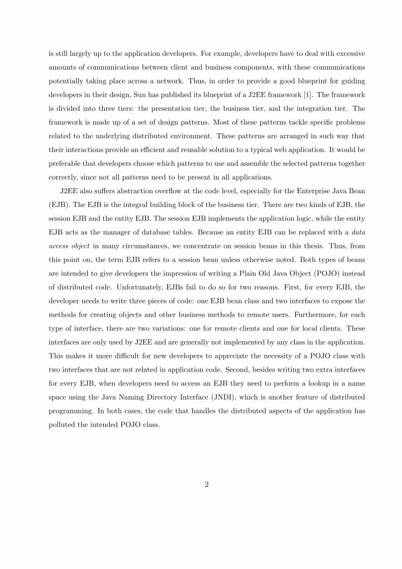
J2EE also suffers abstraction overflow at the code level, especially for the Enterprise Java Bean
(EJB). The EJB is the integral building block of the business tier. There are two kinds of EJB, the
session EJB and the entity EJB. The session EJB implements the application logic, while the entity
EJB acts as the manager of database tables. Because an entity EJB can be replaced with a data
access object in many circumstances, we concentrate on session beans in this thesis. Thus, from
this point on, the term EJB refers to a session bean unless otherwise noted. Both types of beans
are intended to give developers the impression of writing a Plain Old Java Object (POJO) instead
of distributed code. Unfortunately, EJBs fail to do so for two reasons. First, for every EJB, the
developer needs to write three pieces of code: one EJB bean class and two interfaces to expose the
methods for creating objects and other business methods to remote users. Furthermore, for each
type of interface, there are two variations: one for remote clients and one for local clients. These
interfaces are only used by J2EE and are generally not implemented by any class in the application.
This makes it more difficult for new developers to appreciate the necessity of a POJO class with
two interfaces that are not related in application code. Second, besides writing two extra interfaces
for every EJB, when developers need to access an EJB they need to perform a lookup in a name
space using the Java Naming Directory Interface (JNDI), which is another feature of distributed
programming. In both cases, the code that handles the distributed aspects of the application has
polluted the intended POJO class.
2

1.1.2 The Deployment Process
“A deployment descriptor is an XML-based text file whose elements describe how to assemble and
deploy the unit into a specific environment.”[26] The most common information that is specified in
the descriptors is for an EJB and the EJBs that it references. However, specifying this information
in XML format is rather tedious and error prone. Moreover, there is also a potential consistency
problem if the namespace changes in either the application code or the deployment descriptors.
To remedy this problem, the information needed for the deployment descriptors can be gathered
while developers write the application code. For example, when developers decide to have one
EJB reference another EJB, if the developer can somehow make their intention known to the
development environment, the interfaces and JNDIs of the EJBs involved in the association can be
identified and automatically added to the correct deployment descriptor. Thus, we can virtually
incorporate development and deployment into a single process. Accordingly, when descriptors can
be automatically generated we also solve the consistency problems in the name space between
application code and descriptor files.
1.2 Contribution
RMA presents an approach to tackle the abstraction overflow problems that exist in J2EE ap-
plication development. On the software architecture front, RMA incrementally builds up a J2EE
application using the J2EE framework as a guide. Next, we extract the pattern relationships from
the framework. Then, we identify the roles and constraints that make up these relationships. By
generating code with a small amount of developer intervention, we are able to generate code to
fulfill the roles and their constraints for most applications. Using a bottom-up incremental ap-
proach, the upper level patterns can fully utilize the code for existing pattern so RMA can generate
much more concrete code than many other J2EE IDEs. Also, due to incremental construction,
developers can easily customize the generated code if the need arises since they are fully aware of
the purpose of the code generated at every step. RMA offers both flexibility and correctness during
the development process by automating pattern assembly.
We have also devised a way to use J2EE design patterns to completely hide the deployment logic
from application logic. As a result, developers can write POJOs while we address the J2EE-specific
3

problems, such as extra interfaces, name space management and deployment descriptor generation.
To achieve our goal of hiding the extra interfaces and name space management we either refine the
structure or expand the use of some existing patterns. We have combined the pattern generation
and descriptor generation into a single seamless process. As a result, by removing deployment
from the development process, the user can concentrate of their application code and not on the
distributed J2EE execution environment.
1.2.1 RoadMapAssembler
Figure 1.1 shows the architecture and work flow of RMA. RMA is built on top of Eclipse [22]
technology. Eclipse is an open architecture development platform that is based on plugins. The
core of Eclipse provides a built-in Java Integrated Development Environment (IDE). Developed
as a plugin of the Eclipse platform, RMA can leverage features from other existing Java plugins,
such as refactoring and code completion. RMA is a pattern-based development tool. It constructs
applications by assembling EJBs and other Java classes into pattern-based components according
to the predefined roles and constraints. We will talk more about roles and constraints later in
this thesis. RMA consists of a set of wizards that run in the Eclipse IDE’s workbench. The
wizards solicit required role and constraint information from the user. RMA’s “Artifact Extractor”
combines the solicited information with information derived from the application code to construct
a concrete implementation of the required constraints. The implementations for constraints are
assembled by RMA and passed into the “Code Generator” to produce architectural code for the
application and necessary deployment descriptors. Eclipse automatically compiles the Java source
files in the workspace into Java class files. The developer can export the application by invoking
the “Packager” to pack both the Java class files and deployment descriptors into a deployable
application file. As Figure 1.1 demonstrates, RMA incorporates both development and deployment
processes into a single process.
1.3 Outline
This thesis is organized as follows. Chapter 2 offers an overview of the technologies involved in this
thesis. Chapter 3 provides a brief discussion on the J2EE framework and some of its major patterns.
Chapter 4 describes pattern relationships and the way that they are assembled in RMA using an
4

Figure 1.1: RMA Architecture
5

example application. In Chapter 5 we demonstrate how we hide the deployment logic. Chapter 6
gives a quantitative analysis of the code generated by our tool for our sample application. Chapter 7
describes related work done in J2EE development tools, especially those done in a pattern-based
fashion. We also offer a comparison between RMA and other development tools in this chapter.
Future work and conclusions are given in Chapter 8.
6

Chapter 2
Background
In this chapter, we survey the important background technologies used or referenced in the imple-
mentation of RMA. The two technologies that we will discuss are J2EE and Eclipse. J2EE is the
multi-tier web application platform that is the target platform for RMA
2.1 J2EE
A typical web application consists of three tiers: the presentation or web tier, the business tier and
the data or integration tier. The presentation tier handles the generation of the GUI for soliciting
client requests and displaying the output of the request. The business tier components implement
the business logic that processes client requests, while the data tier connects the business compo-
nents to the underlying persistent database. The tiers can be implemented in different technologies.
The components that are implemented in the different technologies need to communicate with each
other in order to accomplish anything useful. Some of these components may even require remote
invocations.
J2EE is Sun’s solution for creating web applications, in which tiers are encapsulated into the
different standardized components and communication among components is handled by the J2EE
container. Figure 2.1 shows the break down of the J2EE server architecture. The J2EE server has
two containers: the web container and the EJB or bean container. The web container manages the
components that run in the web tier, while the EJB container manages the EJBs of the business tier.
The components in the different tiers require different implementation technology. The following
7

J2EE Server
Entity EJB Session EJB
Web Container
JSP
Bean Container
BrowserDatabase
Servlet
Figure 2.1: J2EE Container Architecture [3]
three sections contain a brief overview of some of these J2EE technologies.
2.1.1 Presentation Tier Technologies
The Java Servlet [4] and Java Server Page (JSP) [4] are the presentation tier technologies. Java
Servlets and JSPs are managed by the web container. A Servlet contains the code that processes the
HTTP requests made by clients. The Servlet processes the client input using HttpRequest objects,
which are populated by the container. The output of the processing is written out as HTML pages
and sent back to the clients by the web container. Java Servlets are very similar to other Common
Gateway Interface (CGI) solutions, such as Perl. However, compared to other CGIs, Java Servlets
are platform independent and have a richer set of powerful APIs. Developers can use both the
standard Java libraries and those specialized for HTTP as they write Java Servlets. The Java
Servlet’s main pitfall is its poor maintainability. In Servlets, everything must be written in Java
code, even for the output of the simplest static HTML tags. As the web page becomes complicated,
the code for creating HTML and the code for the business logic becomes indistinguishable, thus
further reducing the maintainability. Moreover, a good web page designer does not necessarily
know Java well. Thus, forcing an experienced HTML developer to learn Java is an inefficient way
of using human resources.
To solve the problems that surround the Servlet, Sun introduced JSP. A JSP is written in the
fashion of an HTML page instead of a Java class. Developers create the static portion of an HTML
8

page using plain HTML tags. Developers are also allowed to mark certain parts of a JSP page to
insert Java code to generate the dynamic portion of the page. A JSP is translated to a Servlet page
before being deployed to the container. So a JSP page is just another way of writing a Java Servlet
class but the former affords the benefit of cleaner separation of presentation logic and business
logic.
2.1.2 EJBs
EJBs are the Java component architecture for server side distributed computing. There are two
kinds of EJB in use: the Session EJB and the Entity EJB. The Session EJB is designed to contain
business logic. The Session EJB can be further divided into two categories: the stateful Session
EJB and stateless Session EJB. The stateless Session EJB does not keep the session state, so every
invocation of a stateless Session EJB triggers an independent operation. The stateful Session EJB
remembers the state of execution by storing the state information in instance variables.
The implementation of a Session Bean contains three classes: the home interface, the business
interface, and the bean class. The home interface defines the methods for constructing a new
instance of a bean. All of these methods have create as their method name and differ from each
other according to different parameter signatures. The business interface defines the methods that
the client can invoke on this session EJB. Both types of interface have variations for local or remote
access, where remote access might include the remote exceptions. The bean class implements
the create methods and business methods that the developer defined in the home and business
interfaces. Note however that the bean class does not implement either of the two interfaces in
any programmatic sense, because the method names do not match. For example, the ejbCreate
methods of the bean class are exported as the create methods in the home interface. As a result,
the container is responsible for generating the classes that implement these interfaces at deployment
time. A Session bean class implements the SessionBean interface instead. Then the container-
generated classes delegate the user request to the bean class that is running inside of the EJB
container. Next, it is up to the container to map between the methods defined in the bean class
and those defined in the interfaces. This obscurity is troublesome to many new comers to J2EE
programming.
The Entity EJB is designed to represent the persistent relational database tables of a J2EE
9

application as an object model. Like the Session EJB, the Entity EJB also has home and business
interfaces, and a bean class. The home interface of an Entity Bean contains the methods whose
names start with find, instead of create as is the case for the Session Bean. There are two kinds
of Entity Bean: the container-managed Entity Bean and the bean-managed Entity Bean. The
container-managed Entity Bean relies on the container to provide the services for database manip-
ulation. Thus, developers no longer need to write a concrete bean class. Instead, they are asked to
write an abstract bean class and provide a set of SQL scripts for the different database operations.
The container generates the concrete code for database management at deployment time. In the
case of a bean-managed bean, the responsibility of writing code for database management belongs
to developers. We will talk more of approaches to access database from a J2EE application in the
following section.
EJBs are run inside of containers. Containers provide many essential services for EJBs. They
manage the life cycle of an EJB and provide a pool for the EJB objects that have been deployed. For
each type of EJB deployed, there are multiple instances of that EJB object in that pool, replicated
by the container. The container is also responsible for workload distribution and consistency among
the replicas. When the container receives a request for a specific type of EJB, an instance of that
EJB is picked from pool to handle the client request. The container then manages the persistent
connection between the clients and invoked beans. In the case of the Entity Bean, the container
also manages transaction operations as well as the data consistency between the Entity Beans and
the underlying database table. Accordingly, the container deactivates the beans that have not been
used for a certain period of time by serializing the object onto the disk. The deactivated beans can
be reactivated from the disk by the container as needed.
2.1.3 Data Access Technologies
There are two major approaches to accessing a persistent database from a J2EE application: Entity
Beans and data access objects using a Java Database Connection (JDBC) driver. We have described
how the Entity EJB works. Although the Entity EJB is believed to be an elegant architecture,
it has been a controversial part of the J2EE architecture. Developers have been debating the
benefits gained against the amount of resources invested in making an EJB work. Two of the
major problems of Entity EJBs are their complexity and inflexibility. Moreover, for the container-
10

managed bean, J2EE introduces a new query language, EJB QL. EJB QL is new and not as well
understood by developers as well as SQL. EJB QL also has many limitations. For example, EJB
QL does not support the sub-query and the ‘order by’ clause that is commonly used in SQL.
Developers also need to code complex EJB QL into already cumbersome deployment descriptors,
a detail that will be discussed in detail later. For the bean-managed Entity bean, developers need
to write more complicated database manipulation code by themselves. Yet, the flexibility gained
by having developers write this code does not help much when fine-tuning the application. The
bean-managed Entity bean allows developers to decide how a database table should be accessed
but not when. For example, a database query may return a large set of matching Entity EJBs. As
a result, the container might decide to initialize each Entity EJB before it is used, or wait until the
first reference. Developers can optimize the SQL query to speed up the database processing, but
they have no control over when the Entity EJB is initialized. The Entity EJBs usually have higher
overhead than POJOs even when accessed through local interface [16].
A data access object (DAO) is an alternative to complicated Entity EJBs. A data access object is
a light weight POJO class that can use various technologies to access databases. The DAO exports
a simple data access interface to business tier components that is independent of the underlying
database technology. If the database technology changes, only the DAO must be updated. Since
the business logic is written using the simpler DAO interface, it is unaffected. However, despite
the data access object not having access to some of the useful services offered by the Entity EJB
container, some services, such as transactional management, can be migrated to the business logic
tier components with careful design. Accordingly, because of their simplicity and flexibility, data
access objects are commonly used in J2EE applications.
2.1.4 Deployment Tools
A J2EE application is deployed as a J2EE Application Archive (EAR) file. A typical EAR file
contains a Web Archive (WAR), Java Archive (JAR) files and a set of descriptor files. The organi-
zation of the EAR file is shown in Figure 2.2. The WAR file contains the files for the presentation
tier, such as HTML pages, JSPs and Servlet classes. The JAR files contains the class files that
implement various business tier and data tier components. Examples of these business components
are the EJBs and supporting POJOs. In short, an EAR file is a compressed file that packs the
11

• J2EE Application Archive (EAR)-application.xml-sun-j2ee-ri.xml-Web Archive (WAR)
∗ web.xml∗ JSP/Servlet
-Java Archive (JAR)∗ ejb-jar.xml∗ EJB classes
Figure 2.2: Hierarchy of a J2EE Application Archive
WAR, JAR and descriptor files.
After an EAR file is deployed in the J2EE container, the container needs to know what kind of
components are contained in each compressed file and how they interact. “A deployment descriptor
is an XML-based text file that the container uses to assemble and deploy the unit into a specific
environment [26]”. A typical J2EE application contains four descriptor files: ‘application.xml’,
‘sun-j2ee-ri.xml’, ‘web.xml’ and ‘ejb-jar.xml’. Both the ‘application.xml’ and ‘sun-j2ee-ri.xml’ files
are stored in the EAR. The ‘application.xml’ informs the J2EE container about the names of WAR
file and the JAR files stored in this EAR file.
The ‘sun-j2ee-ri.xml’ is a file that captures the remote EJB references that exist in the JAR files
of this application. EJBs can be remotely referenced by each other or by the servlets and JSPs in
the web components. The container needs to know which EJBs are referenced, the variable names
for references used in the code, and the JNDI names of these EJBs.
The ‘web.xml’ file is the deployment descriptor for the web components. It describes all of the
JSP and Servlet pages contained within. The most common information about a JSP and Servlet
page that is specified in the ‘web.xml’ file is the web alias for application users and the JNDI names
of the referenced EJBs and databases. The web alias of a Servlet/JSP is a name that is different
from the file name of the Servlet and JSP that is used to access the Servlet and JSP pages from a
URL.
The ‘ejb-jar.xml’ file describes all the EJBs that are included in the current JAR file. The
container needs to know the name of EJB bean class, remote and local home interfaces, and
remote and local business interfaces. The information about EJB and database references using
12
JNDI names from an EJB also needs to be detailed. The ‘ejb-jar.xml’ also needs to describe
some security details such as the method permissions of each bean. Other optional, but useful,
configuration information, such as different transactional styles, can be set in the ‘ejb-jar.xml’ file.
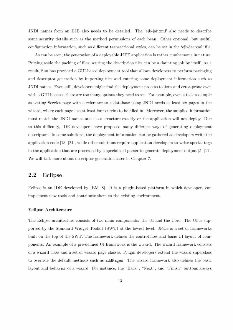
As can be seen, the generation of a deployable J2EE application is rather cumbersome in nature.
Putting aside the packing of files, writing the description files can be a daunting job by itself. As a
result, Sun has provided a GUI-based deployment tool that allows developers to perform packaging
and descriptor generation by importing files and entering some deployment information such as
JNDI names. Even still, developers might find the deployment process tedious and error-prone even
with a GUI because there are too many options they need to set. For example, even a task as simple
as setting Servlet page with a reference to a database using JNDI needs at least six pages in the
wizard, where each page has at least four entries to be filled in. Moreover, the supplied information
must match the JNDI names and class structure exactly or the application will not deploy. Due
to this difficulty, IDE developers have proposed many different ways of generating deployment
descriptors. In some solutions, the deployment information can be gathered as developers write the
application code [13] [21], while other solutions require application developers to write special tags
in the application that are processed by a specialized parser to generate deployment output [5] [11].
We will talk more about descriptor generation later in Chapter 7.
2.2 Eclipse
Eclipse is an IDE developed by IBM [8]. It is a plugin-based platform in which developers can
implement new tools and contribute them to the existing environment.
Eclipse Architecture
The Eclipse architecture consists of two main components: the UI and the Core. The UI is sup-
ported by the Standard Widget Toolkit (SWT) at the lowest level. JFace is a set of frameworks
built on the top of the SWT. The framework defines the control flow and basic UI layout of com-
ponents. An example of a pre-defined UI framework is the wizard. The wizard framework consists
of a wizard class and a set of wizard page classes. Plugin developers extend the wizard superclass
to override the default methods such as addPages. The wizard framework also defines the basic
layout and behavior of a wizard. For instance, the “Back”, “Next”, and “Finish” buttons always
13

show up at the bottom of each wizard page. Clicking on the “Next” or “Back” button always brings
the user to the next or the previous page respectively. Together, JFace and SWT implement the
Eclipse workbench. The workbench defines the Eclipse graphical user interface, such as the editor
and the resource explorer views.
The Core component is UI-independent. The Core component consists of a runtime engine
and a workspace manager. The runtime engine looks for the available plugins at start-up and
manages plugin loading in a lazy fashion, which means that plugins are not loaded into memory
until explicitly invoked by the user. A typical Eclipse environment may include more than fifty
plugins. The lazy-loading significantly improves the performance and scalability of Eclipse by
reducing the application’s memory usage. The workspace manages user resources, such as projects,
and the mapping of these resources to the underlying file system.
Plugin Development
Every component of Eclipse is a plugin, even the UI and Core components. Each plugin contains a
XML manifest file, which declares the extensions and extension points of this plugin. An extension is
an interface of an existing plugin that this plugin contributes to. An extension point is an interface
defined by a plugin that future plugins can contribute to. A good analogy for the relationship
between the extension and the extension point is that of the power-strip and the power plug [22].
The Java classes that implement this plugin are packed into a JAR file and stored in the same
directory as the manifest file.
JDT Plugin
Among all the plugins, the Java Development Tools (JDT) is the set of plugins most related to our
research. JDT implements a complete IDE for editing, compiling, debugging, and testing a Java
file. JDT provides APIs to programmatically manipulate Java resources. As a result, by extending
the extension point declared by the JDT, we may add new features into Eclipse’s Java IDE. The
JDT consists of three components: the JDT Core, the JDT UI, and the JDT Debug.
The JDT Core models the core Java elements and APIs. The JDT breaks down a Java project
into a set of models with each model representing a specific type of Java element. For example, a
class defined in a “.java” file is modelled as IType. The fields and methods defined in a class are
14

modeled as IField and IMethod accordingly. A plugin can programmatically traverse the resource
tree to access and manipulate Java elements. For example, a plugin can parse a Java class that is
modeled as IType to determine the fields that the class contains and automatically generate accessor
methods for the fields. For code manipulation on even finer granularites, JDT provides powerful
APIs to parse a whole Java file into a Document Object Model (DOM). Subsequently, using the
JDT Core’s DOM package, the plugin developer can manipulate the code within each method. The
JDT Core also automatically maintains consistency between the model and underlying file system
resources.
The JDT UI implements some Java-specific graphical user interfaces. The JDT Debug provides
APIs for debugging support, such as launching a Java application in debug mode.
We chose Eclipse as the development platform for RMA because of Eclipse’s flexibility in inte-
grating new features as plugins and its richness in providing support for Java development. Our
RMA extends the JDT to provide customized support for J2EE development. RMA also makes
extensive uses of the APIs provided by other Eclipse plugins to exploit the benefits of existing
features.
15

Chapter 3
J2EE Framework and Patterns
RMA is a pattern-based development tool. RMA’s wizards gather information to create pattern
based components, which will later be assembled into a complete application. Thus, it is important
for us to understand the patterns supported by RMA before going any further into the discussion
on application construction. This chapter briefly describes the patterns from the Sun blueprint,
the framework that combines them into a complete architecture [1].
A software framework defines a reusable design and partial implementation of a solution to
a certain problem domain. The framework specifies a typical control flow and architecture of a
typical application of that problem domain. A framework’s structure is usually made up of many
sub-frameworks with each sub-framework solving some specific recurring problem. Accordingly,
many such components can work together to solve a more complicated problem. The control flow
of a framework dictates which subcomponents may interact with each other and how they should
interact. In many situations, the subcomponents of a framework are implemented using existing
design patterns. In that case, the framework becomes a collection of the known patterns and
relationships among these patterns that can be used to solve a complicated design problem. A
framework can be instantiated to only include a subset of its collection to meet specific needs. The
addition and removal of the subcomponents can be checked against the relationships defined in the
framework.
Design patterns act as the micro-architectural units within a pattern-based framework [15].
They are considered to be architectural elements because they also define the structural and be-
havioral rules of some objects. Patterns can be generally divided into three groups: creational
16

Service Locator
View Helper
Front Controller Front Controller
Dispatcher View Service To Worker
Service Activator
Composite ViewFront Controller
Intercepting Filter
Presentation Tier
Business Tier
Transfer Object Assembler
Composite Entity Transfer Object
Value List Handler
Session Facade
Data Access Object
Business Delegate
Data Tier
Figure 3.1: Sun’s J2EE framework [1](The shaded patterns are supported by RMA)
17

patterns, behavioral patterns, and structural patterns [9]. The creational patterns capture some
of the best practices for creating objects. The well-known Factory Pattern [9] is an example of
such a pattern. The behavioral patterns capture good practices for complex object interactions,
such as the Observer [9], while the structural patterns capture recurring structural arrangements of
objects. The Composite pattern [9] is an example of a structural pattern. Combining the concept
of framework and pattern, we believe there is a framework consisting entirely of patterns as its
subcomponents. Thus, while the control flow of this framework might be captured by the relation-
ships among behavioral patterns, the structural information is gathered by the structural patterns,
and the process of creating and assembling the framework objects is dictated by the creational of
patterns.
Frameworks are generally specific to a particular application domain, such as a GUI, a parallel
computing structure, etc. J2EE has its own framework from Sun, as shown in Figure 3.1. As in
many other frameworks, the J2EE framework is made up of a list of patterns, with these patterns
grouped into three tiers: the presentation tier, the business tier, and the data tier. These different
tiers have design patterns that are used for different purposes: the presentation tier is responsible
for soliciting client requests and displaying the results returned from the server; the business tier
is responsible for processing client requests using the business logic; and the data tier is mainly
responsible for database access.
Our research work has concentrated on the patterns of the business tier and the data tier
because we believe the structures and behaviors of these patterns are more intriguing and deserve a
thorough investigation. In this chapter, we first describe the known J2EE patterns of the business
and data tiers. Then, we study the relationships among these patterns in the next chapter.
3.1 Data Access Object
Persistent data is used in most web applications. As we have seen in Section 2.1.3, the Entity EJB
and the data access object (DAO) are the two most commonly used approaches for database ma-
nipulation. However, the Entity EJB has been controversial due to its complexity and inflexibility.
Conversely, the data access object is a light weight POJO object that encapsulates the code for
managing persistent data and provides an interface for the business components to access this data.
The management of the persistent database includes connecting to various data sources and
18

ClientDataAccessObject
create() : void
read() : Object
update() : void
delete() : void
Data
DataSource
ResultSet
uses
accesses
uses
Figure 3.2: Data Access Object [1]
manipulating the data stored in those data sources. The relational database is the most common
type of persistent data, but not the only one. In the domain of Internet computing, other data
sources, such as flat files, are also used. Additionally, a data source can be an external system such
as those used in Business-to-Business (B2B) systems. The code for manipulating the data is closely
dependent on the data source that is used. Thus, keeping the code for handling the persistent
data out of the business components to reduce the complexity of their code is important. The
maintainability of the application is also improved by this decoupling because the changes in the
data source only affect the data access object.
Figure 3.2 shows the class diagram for a typical data access object. The Client of a data access
object can be any component from the business tier or the presentation tier. The DataAccessObject
defines and implements a basic interface for manipulating the persistent database. The DataAc-
cessObject accesses the underlying DataSource to either retrieve or update data. For retrieval, the
matching data is stored in the ResultSet. ResultSet can be any data structure that is capable of
storing data. The java.sql.ResultSet is usually used to satisfy the role of ResultSet if the Data-
Source is a relational database. The DataAccessObject packs the data into the ResultSet in the
form of a transfer value objects and sends it back to the Client. For updates, the Client also needs
to send the updated data in the form of a transfer value object to the DataAccessObject. The
DataAccessObject unpacks the transfer value object and performs necessary operations to update
the database.
A common data access object defines the basic database operations such as connect, select,
insert, delete, and update. A more powerful data access object can accommodate more complex
19

search methods that return a list of matched data, packed in the form of a transfer value object, to
clients. Furthermore, a data access object can cache frequently retrieved data to reduce the network
workload. It is also possible to apply the Abstract Factory [9] pattern to the data access object
to further improve the flexibility of the application by encapsulating the connection mechanism of
different data sources into subclasses.
3.2 Transfer Value Object
The server side business components in J2EE applications are generally implemented as EJBs.
Some business components, such as Entity EJBs, need to return data back to the client. The
traditional way of accessing a Java object’s state is by invoking its accessor methods. A client
may need to invoke several accessor methods to retrieve all of the information it needs from a
business component. If the business object is implemented as a remote object, the invocations of
the fine-grained accessors might introduce significant network overhead. It is extremely inefficient
for a remote invocation to retrieve a small piece of data.
The transfer value object (TO) efficiently ferries the client requests and responses between the
J2EE components. A transfer value object packs all of the state of a business component into a
single object. When a client requests data from a business component, the values of its instance
variables are copied into that transfer value object. Then the transfer value object is passed back to
the client by value [1]. The client can access the complete state of the remote business component
from the transfer value object without paying network overhead for each individual (possibly fine-
grained) access.
Figure 3.3 shows a class diagram for the transfer value object. In the class diagram the
Client accesses the Components to retrieve the necessary information. The Component in the
class diagram can be any J2EE component in the business or integration tier. Upon receiving the
request, the Component creates a transfer value object and returns it to the client. Next, the client
accesses data from the local transfer value object. The client can also perform changes on the values
contained in the transfer value object and send the whole object back for update.
There are some variations in the implementation strategies of the transfer value object. The
plain transfer value object only transfers the data for reading. The updatable transfer value object
carries the data back to the component for updating. To implement the updatable transfer value
20

ClientTransferObject
Component
getData() : TransferObject
setData() : void
PresComponent BizComponent IntComponent
accesses
Figure 3.3: Transfer Value Object Class Diagram [1]
object, the component code needs to be modified to include a set method that accepts a transfer
value object. The set method needs to copy the values stored in the transfer value object to
the corresponding local instance variables. A more advanced design might include a flag for each
variable in the transfer value object that is set only when its value is modified. Using the change flags
can reduce the total number of update operations needed. A problem with updates is that different
concurrent update operations from different clients may cause corrupted data in the Component.
Thus, to solve this inconsistency, a time stamp can be set for every transfer value object before it
is sent back. The update strategy complicates the design of both the transfer value object and the
Components.
A Component may own multiple transfer value objects. Each transfer value object includes
a different subset of data encapsulated in the Component. This is especially useful when the
Component is a composite object itself.
3.3 Session Facade
In J2EE, the server side business components are implemented as EJBs or POJOs. These busi-
ness components fulfill requests from the clients of the presentation tier. However, exposing those
components to the clients is not always a good design decision. If the client directly uses these
components, the clients are tightly coupled to the interfaces of the business components. If the
21

interfaces of the business components are changed, the client code needs to be changed as well.
Moreover, a client request may require a complicated collaboration between multiple business com-
ponents. Thus, in order to use such a business service, the developer for the client component
needs to have a great deal of knowledge about how these business components interact. However,
to force a presentation tier developer to know the implementation details of the business tier is a
violation of the separation of concerns, which is practiced in industrial team environments. Also,
these types of collaborations should be kept on the server side to reduce overhead caused by remote
communications.
Even if the presentation tier developers do successfully implement the client code, the mingling
of the code for the presentation tier and that for accessing business components reduces the main-
tainability of the software. If the code for accessing and coordinating components is handled by
the clients, duplication of code will be unavoidable.
The direct access of business components not only produces poorly organized code, but it
also affects the network traffic. For example, a client may request a task that is implemented
using a set of fine-grained remote business components. In other words, the client must make
many remote invocations to accomplish a single task. As a result, access to fine grained business
components increases the communications between components and leads to a degradation of the
performance [1].
The session facade (SF) provides a centralized contact point between the client and business
components to simplify the interface between the presentation and business tiers. The facade
encapsulates several business components behind a single interface. Methods in the facade may
simply be delegated to the correct component, or higher-level methods that require the cooperation
of several business components can be created. A session facade is also in an ideal place to insert
access control for privileged components.
Figure 3.4 shows the class diagram for the session facade. The Client accesses the SessionFacade
to invoke the services of the BusinessComponents. The SessionFacade delegates the work to the
BusinessComponent that implements the Client’s request. The ApplicationServices, DataAcces-
sObject, and BusinessObject are all different types of BusinessComponent that exist in the J2EE
environment. The SessionFacade object manages the business components by taking care of the
name lookup and coordination of business components. Furthermore, the SessionFacade exposes
22

Client
SessionFacade
BusinessComponent
ApplicationService BusinessObject DataAccessObject
1..*
1..*
1..* 1..*
Figure 3.4: Session Facade Class Diagram [1]
only coarse-grained services to the client. If the services requested by the client, or business com-
ponents that provide them, are not independent from each other, the SessionFacade should be
implemented as a stateful Session EJB. Otherwise, a stateless Session EJB is sufficient.
3.4 Service Locator
In J2EE applications, many business tier components, such as EJBs, are registered in a centralized
registry. The clients need to go through a series of lookups to locate the requested services using the
JNDI name. However, handling the name space lookup can be quite complex. First, the developers
need to get the InitialContext of the name space. Next, from the InitialContext, developers need
to look up JNDI names to locate the business components. After this task, developers still need
to perform a downcast and handle remote exceptions to retrieve the handle to the remote object.
However, due to the complexity of the lookup process, errors can be introduced during the imple-
mentation. Moreover, because J2EE is a distributed system by nature, obtaining remote references
is a common occurrence. If the lookup code is not isolated from the client code, the developers
have to duplicate the lookup code whenever it is needed. Furthermore, the implementation of the
InitialContext and the JNDI naming service is specific to a given vendor and presents an additional
23

ClientServiceLocator
Cache
InitialContext
Target
RegisterService
uses1..*
uses
caches
maintains
refers
creates
lookup
obtain/accesses
resolve
Figure 3.5: Service Locator [1]
problem. Different vendors may decide how a JNDI path is interpreted and resolved. Thus, in
order to keep the client code portable, the developers should encapsulate the lookup process into
an isolated class.
Figure 3.5 is the class diagram of service locator (SL) [1]. The Client represents any component
that uses the ServiceLocator. In theory, only one ServiceLocator is necessary for a J2EE application.
However, in practice, multiple identical ServiceLocators are used in a J2EE application because a
single J2EE application may run on top of multiple Java Virtual Machines (JVM). For example, the
web container and the EJB container can run in different JVMs, even on two physically separated
machines. Upon receiving a request for a lookup, the ServiceLocator uses the InitialContext to
consult the RegisterService to resolve the JNDI name. The ServiceLocator then proceeds to retrieve
the handle to the Target resource. Next, the retrieved handle is returned to the Client. A more
advanced implementation of the ServiceLocator may cache the handles to reduce future lookups.
24

EJBs are the most common Targets for the ServiceLocator to look up. The ServiceLocator
uses the InitialContext to access the JNDI registry service, and then locates the EJBHome object
of the requested EJB. Then, the ServiceLocator caches and returns the EJBHome object. Upon
receiving of EJBHome object, the client needs to downcast the EJBHome to the desired subtype
to create the EJBObject, the reference to the EJB that allows clients to invoke its methods. The
EJB ServiceLocator needs to be able to handle both the local and remote EJB objects.
3.5 Transfer Object Assembler
During the development process, developers might want to provide a logical application model
that is different from the underlying physical database tables. An application model is a set of
data used by a particular application and encapsulated in the different business components in
the business tier. If the clients need to use the application model, they need to access multiple
business components and assemble the retrieved data. Consequently, a significant amount of the
code for accessing business components is present in the client. Besides accessing the business
components, the client may also need to construct the application model from data in the business
components. This leads to a tight coupling between the client components and the business tier.
As a result, changes to the interfaces of the business components in the business tier may cause
many modifications in the client code. The code for accessing and constructing this model can
increase the complexity of the client code. As well, if the code is embedded in individual clients,
we will encounter a lot of undesirable code duplication. Moreover, if the business components and
the clients from the presentation tier are running on separate machines, the performance can be
degraded if the construction of the application model always needs multiple invocations to complete.
The transfer object assembler is used to centralize the creation of the application model and
decouple the clients from the business tier. The driving forces behind the transfer object assembler
and session facade are very similar. They are both designed to decouple the tiers and reduce
network traffic. However, the difference lies in that the session facade aggregates the tasks while
the transfer object assembler aggregates the data. The application model is an example of a transfer
value object, and is returned by the transfer object assembler. It contains data assembled from a
set of business tier components and presents clients with one logical application model.
Figure 3.6 shows the class diagram for the transfer object assembler. The Client accesses
25

ClientTransferObjectAssembler
ApplicationModel
BusinessObject
DataAccessObject
ServiceFacade
Service
uses
contains
0..*
assembles accesses
accesses
accesses
accesses
obtains/uses
Figure 3.6: Transfer Object Assembler [1]
26

the TransferObjectAssembler for the application model. Then, the TransferObjectAssembler ac-
cesses the different underlying business components, such as the DataAccessObject, SessionFacade,
BusinessObject, and Service, to assemble the requested application model.
The transfer object assembler can be implemented as a POJO or as a Session EJB. If the transfer
object assembler is managed by a session facade, which exposes the construction of the snapshot
of the application model as a business service, a stateless Session EJB is preferable. However,
maintaining consistency between the application model and underlying object models is virtually
impossible due to constant modifications . Thus, caching the retrieved data in the transfer object
assembler using a stateful bean is not useful. A new transfer value object is created every time the
transfer object assembler is called to create a new application model.
3.6 Value List Handler
In many web-based applications, the client performs some kind of search for data based on keyword
queries. The server side business logic accesses the underlying database to retrieve matching data
and returns them. Accordingly, the presentation tier modules are responsible for displaying the
returned data. However, the result set for some searches can be very large. One example is an
online search engine, which may result in hundreds of matched web links for each query. Moreover,
delivering all of the results across tiers increases the network traffic and reduces the performance
of the system. Furthermore, clients may not need all of the matched results. In the case of the
search engine, clients generally abandon the results after they browse through the first few pages.
In that case, transferring all of the results back is inefficient. As a result, the transfer list handler
manages large data transfers between the business components and presentation tier components
by sending results in batches and only on demand.
The class diagram of value list handler is shown in Figure 3.7. The Client accesses the Val-
ueListHandler to query the information. The ValueListHandler queries the underlying database
using the DataAccessObject. The DataAccessObject retrieves the query results and returns it to
the ValueListHandler as a ValueList. The ValueList aggregates a list of transfer value objects. The
client accesses the ValueListHandler for a sublist of the ValueList. The ValueIterator of that sublist
can then be used to iterate through its elements.
The value list handler is generally implemented as a POJO class. In some cases, it might be
27

Client
ValueListHandler List
DataAccessObject Value
ValueIterator
manages
accesses
holds
uses
uses creates/returns
Figure 3.7: Value List Handler [1]
useful to keep the retrieved data cached for the whole session.
3.7 Business Delegate
Allowing the web tier components to directly access the business tier components is generally not
a good idea. The direct accesses usually produce tight coupling between two tiers. As a result,
changes in the interfaces of the business components may require changes to the code for the web
tier components, thus reducing the maintainability of the system. This direct access also increases
the complexity of web tier components. To access a remote component, the web component needs
to manage the name space of the remote components and perform a set of complicated lookup
operations. The web tier components are mainly responsible for the presentation logic. Thus, to
include the code for handling distributed computing inside the presentation logic is a violation of
separation of concerns. As a result, the business delegate sits between the client tier and business
tier to hide the complexity of name space management. A business delegate usually maintains a
one-to-one mapping with a session facade or other coarse-grained business component.
Figure 3.8 is the class diagram of a typical business delegate (BD) [1]. The Client accesses
the BusinessDelegate for the remote services. The BusinessDelegate uses the ServiceLocator to
28

Client BusinessDelegate
ServiceLocator
BusinessService
EJBService JMSService
0..*
accessesaccesses1..*
Figure 3.8: Business Delegate [1]
locate the BusinessService, and then invokes the appropriate method. The BusinessService can
be an EJB component as well as a Java Messenger Service (JMS), which handles asynchronous
messaging services such as a mail service.
Although the business delegate is a business tier pattern, it is usually deployed in the web tier
as a local POJO to provide a logical abstraction to business tier components. A session facade is
usually fronted by a business delegate. The business delegate manages access to the remote session
facade. The invocation of methods in the session facade is delegated through proxy methods
defined in the business delegate. Accordingly, the delegate methods can be used to catch remote
exceptions and translate them into the application exceptions at the client. The methods can also
be customized to cache the intermediate results of consecutive invocations.
In the J2EE framework, the business delegate is the middle man between the web tier and
business tier. In Chapter 5, we will introduce our variation of the business delegate that can be
used to abstract remote accesses not only between the business tier and web tier, but also those
between the business tier components.
3.8 Summary
The J2EE patterns in the business tier have two main goals: to decouple the presentation tier from
the business tier and to reduce the network overhead. Some patterns generally act as a middle
man between the presentation tier and business tier. Those patterns reduce the network traffic
by implementing facilities such as caching and aggregating small tasks into one bigger task. The
29

decoupling is also realized by hiding the interfaces of the business components and the complexity
of coordinating them in these patterns. Examples of such patterns are the business delegate and
session facade. Other patterns reduce the frequency of data transferred over the network by
aggregating small pieces of data and sending them as one single object. The network traffic can be
further reduced by caching, as is done with the search results using the value list handler. Examples
of such patterns are transfer value object and transfer object assembler. Another problem addressed
by business tier design patterns is to abstract the low-level name space management using the service
locator. The data tier design patterns are designed to decouple the client code from that used to
access different data sources. An example of a data tier pattern is data access object. After seeing
the individual patterns, we can now examine how these patterns interact to solve more complicated
problems.
30

Chapter 4
Pattern Relationships And Pattern
Assembly
In this chapter, we will identify some important pattern relationships from Sun’s J2EE blueprint.
We also show how these pattern relationships can be used to assemble patterns into a complete
application. Additionally, we concentrate on the pattern relationships from the business tier and
data tier because their relationships are more intriguing and complex than those in the presentation
tier.
4.1 Pattern Relationships
We define a pattern relationship as a set of roles and constraints. A role defines a participant in
the relationship. A role contains a set of properties that an implementation class of this role must
fulfill. Thus, each of these properties is a constraint of the role. An example of using roles and
constraints to define a relationship is a pair of computers using the File Transfer Protocol (FTP).
There are two roles in this relationship: the server role and the client role. Each role is played by
a computer. Once we decide to establish this relationship, we must assign computers to each role.
When selecting computers to play the different roles, we must ensure that their properties satisfy
the necessary constraints. The server must be connected to the Internet and it must have FTP
server software installed. The computer that plays the client role must have an Internet connection
and FTP client software installed. Only when these constraints are properly satisfied is the FTP
31

server and client relationship established.
Pattern relationships can be built in an analogous manner. In RMA, a role is played by a
Java class and a constraint can be anything, ranging from the class type to the signatures of the
methods. In addition, we have categorized the constraints based on how they are implemented. We
define the constraints that are implemented consistently across all applications as static constraints.
Constraints whose values can be programmatically derived from application context are the deriv-
able constraints, while non-derivable constraints are those that the developers must implement
manually.
An example of a static constraint is the super-type of a Session EJB bean class. All Session EJB
bean classes have to extend the SessionBean class. This static constraint is consistent throughout
all applications. Derivable constraints can be best illustrated with the naming convention to which
EJBs must adhere. For example, for an EJB bean class named “XYZBean”, we can program-
matically deduce the name of remote and home interfaces as “XYZ” and “XYZHome”. Derivable
constraints can be used not only for simple class name deduction but also for more complicated
method body deduction, as we will see later. Derivable constraints may also require information
solicited from the developer. For example, developers have to pick transfer value objects when
creating a transfer object assembler. RMA derives the data access objects of these selected transfer
value objects to access the necessary information. Non-derivable constraints have neither a default
implementation nor a derivable implementation from the program context. For example, we know
the select method in a DAO should select data from an underlying database table, but we have
no idea how the selection should proceed until the developer specifies the SQL clause.
As shown in Figure 1.1 (page 5), developers start the development process by selecting a pattern
relationship to instantiate. In the wizard responsible for the selected relationship, developers select
a set of suitable objects to fulfill the different roles in the relationship. RMA is responsible for
querying the workspace to create a list of possible candidate objects and presents them to developers
to select in the wizard. Some simple derivable constraints, such as EJB bean class names, can be
specified by the developers in the wizard. More complicated derivable constraints, such as the
binding of transfer value object and transfer object assembler, requires the “Artifact Extractor” to
process the Java classes using reflection. RMA combines information gathered from the developers
as well as that extracted from the class files into the program model. At the code generation
32

stage, the program model is fed into a “Code Generator” to produce the concrete code. The “Code
Generator” is implemented using an Eclipse Plugin called JET [24]. The generated code may add
new classes or methods to existing classes to implement the constraints or it may use an existing
constraint implementation.
In the following sections, we will examine some important relationships in the J2EE framework.
Each relationship is discussed according to its participating roles and the constraints of these roles.
4.1.1 Transfer Value Object + Data Access Object
The data access object is a data-oriented pattern and is responsible for querying the database and
returning the results back to the client. In order to reduce the number of fine-grained queries from
a business component, the query results are aggregated into transfer value objects. Each tuple
of the database table is packed into a transfer value object. Figure 4.1 is the class diagram that
captures the relationship between a transfer value object and a data access object.
Roles
In this relationship, the data access object encapsulates and manages an underlying database table.
The transfer value objects play two different roles in the collaboration. In one role, they stand for a
tuple of data in the underlying database table, with each element in the tuple corresponding to an
instance variable in the transfer value object. In another role, they model the primary key of the
table. The primary key is a subset of fields in the database table that uniquely identifies a tuple.
Because the primary key usually contains more than one field, aggregating them into a single class
using a transfer value object is a good practice.
The data access object is responsible for processing the raw result set returned by the database,
and assigning the corresponding values to the variables in the transfer value object. The client may
then access the transfer value object for needed values.
Constraints
The transfer value object is a light weight POJO class. It has a set of variables that model all
fields in the underlying table, which are exposed to other classes with a set of accessor methods.
Given information of the owner of a transfer value object, we can derive the names of the fields that
33

should be included in the transfer value object. The accessor methods to these variables can also
be easily derived.
The data access object implements basic database operations, such as select, insert, delete and
update. The select method takes a primary key object, implemented as a transfer value object,
and returns an array of matching tuples, which are disassembled and repacked into transfer value
objects. The insert methods take in a transfer value object, which stores the values to be inserted,
and returns a transfer value object, which represents the primary key of the inserted tuple. The
delete methods take in a transfer value object, which contains the primary key, and returns a boolean
value to indicate the result of the deletion. The update methods take in a transfer value object
for new data to be stored in the database. The update methods should unpack the transfer value
object to extract necessary information for update. The update method returns a boolean variable
to signal the result of the update. While the signature of the database access query methods are
static constraints, the implementation of the access methods in the data access object are specified
as non-derivable constraints because no default SQL query statement can be accurate enough to
meet the developers’ intention.
We have enforced certain naming conventions on the data access object and its transfer value
object and primary key class, so that the name of the primary key class and transfer value object
class can be programmatically deduced from the name of the data access object and vice versa. We
will discuss this convention later in this chapter.
Composite Subcomponent
The association between transfer value objects and data access objects is used frequently in other,
more complicated, data-oriented relationships. Due to their close association, it is better to think
of them as playing a single composite role of data management in the design phase. We would like
to refer to this composite role as the data access object subcomponent in subsequent discussions.
The constraints of the subcomponent are the aggregate of its elements’ constraints.
4.1.2 Transfer Object Assembler + Data Access Object Subcomponent
The transfer object assembler is used to provide a coarse-grained view of the application model
on the top of the fine-grained object models. The transfer object assembler queries the underlying
34

Figure 4.1: Transfer Value Object and Data Access Object
business components to retrieve data to assemble, while the data access object subcomponent man-
ages the database queries and updates. The data transfers between the transfer object assembler
and data access object subcomponent are packed as transfer value objects. Figure 4.2 shows the
relationship between the transfer object assembler, the data access object subcomponent, and other
helper patterns.
Roles
This relationship has three participants: the Aggregator, the data access object subcomponent, and
the transfer object assembler. The data access object subcomponent plays the same role as it does
in Section 4.1.1. Besides playing the roles of primary key and data entry in the subcomponent,
the transfer value object also plays the role of creating the Aggregator. The Aggregator contains
the transfer value objects that are put together by the transfer object assembler.
The transfer object assembler plays the roles of creating and packing the Aggregator. A set
of fine-grained data access object subcomponents are managed and accessed by the transfer object
assembler. The transfer object assembler first breaks up the client request into fine-grained tasks
that are applied to individual data access objects. The results returned from the data access objects
are all in the form of transfer value objects. Then, the transfer object assembler packs those results
35

into a coarse-grained transfer value object, the Aggregator, which is returned to the client.
Constraints
The transfer object assembler can be a light weight POJO or an EJB. It should cache handles to the
underlying fine-grained data models (the DAOs), which can be stored as instance variables. The
association between the transfer object assembler and the data models should be initialized first,
inside of a constructor, before any specific operations are performed. The transfer object assembler
also needs to have accessor methods that delegate the client requests to the individual data access
objects. The getter method should take a primary key transfer value object, which can be used to
fetch matching data. The data assembled in the transfer object assembler is usually related in the
databases as either one-to-one or one-to-many relationships. Thus, given the primary key of one
database table, the transfer object assembler should have sufficient information to extract all of
the necessary parts from all of the tables. The getter methods should delegate the queries to the
select methods in the data access objects, which also take in a primary key transfer value object.
The getter methods put the results into an Aggregator and return it while the setter methods
in the transfer object assembler take in an Aggregator. RMA extracts each transfer value object
contained in the Aggregator and passes it to the update methods of the corresponding data access
object. The data access object subcomponents maintain the same constraint as in Section 4.1.1.
The Aggregator follows all of the constraints of a transfer value object with the additional
derivable constraints that all of its variables are transfer value objects.
The name of the transfer object assembler class can be solicited from the developer. The
developer also selects a set of the transfer value objects. Using our naming convention, we can
programmatically derive the name of the owner data access object. As a result, the constraints on
the association between transfer value object and data access object are derivable. For each selected
transfer value object, the user must then select the method in the data access object that returns
that transfer value object. The candidate methods can be derived using the constraints we have
just discussed, and the user selects the specific methods that should be used. Combining the above
information, we can also derive most of the implementation of the transfer object assembler.
36

Figure 4.2: Transfer Value Object, Transfer Object Assembler and Data Access Object
4.1.3 Value List Handler + Data Access Object Subcomponent
The value list handler is used to cache query results from the database. It also provides a mechanism
for sub-listing and iteration which allows the client to access only the desired portion of the data.
The data access object subcomponent is used again to provide back-end database access. Figure 4.3
shows the relationships between the value list handler and other supporting patterns.
Roles
This relationship involves three J2EE patterns and one classic Gang of Four pattern, the Iterator [9].
The data access object subcomponent manages the database access. The transfer value object
encapsulates a single tuple of values returned from the database query. The transfer value objects
are aggregated into a value list object. A value list handler connects to a single database table
only, so the data access object and value list handler maintain a one-to-one mapping.
In contrast to the transfer object assembler ’s Aggregator that aggregates different types of
transfer value objects, the value list object manages a list of the same type of transfer value object.
37

Figure 4.3: Transfer Value Object, Data Access Object and Value List Handler
The value list handler returns the data as a sequence of sublists using the Iterator pattern. The
Iterator pattern is used to generate the iterator to traverse the query result. The value list handler
handles the data caching and sublisting.
Constraints
The value list handler is implemented as either a light-weight POJO or as a Session EJB. If the
value list handler is implemented as an EJB, it should be implemented as a stateful Session EJB
because the data it caches should be held throughout the session. The value list handler maintains
a handle to a data access object subcomponent, while the data access object maintains the same
constraints as in its relationship with transfer object assembler. Because the handle needs to be
properly instantiated before the value list handler can be used, the constructor of a value list
handler should be coded to instantiate the data access object subcomponent. The value list handler
should have a method that performs the database query. The query method should have a primary
key transfer value object as the parameter, and delegate the query to an appropriate select method
38

in the corresponding data access object.
The query method should store the returned data in a data structure that includes support for
an iterator.
The value list handler also needs a method to expose the sub-lists of cached items to the client.
This method should take two parameters indicating the beginning and the end of the sub-list. The
sub-list method creates a copy of the desired sub-list and returns it to client. There should also
be a method in the value list handler where users can retrieve an iterator for the query result.
The returned iterator and sub-list method should enumerate over the list, providing elements in
the order required by the requesting client (front-to-back, back-to-back, etc). A reset method that
refreshes the cached data by re-fetching them from the underlying database should also be included.
All data that is fetched from the database should be packed in the form of a transfer value object
before being placed into the storage list. As a result, all of the constraints discussed for the value
list handler so far are derivable.
Given an application context, the developer can choose the DAO that will be associated with
the value list handler. From the DAO, the developer can further select the appropriate transfer
value object, and the method in the DAO that creates it, to complete the specification of the
value list handler. With this context information, the derivable constraints on the method body
of the constructor and query methods can all be programmatically fulfilled. Since the interface to
the Iterator can be fixed, the subList method has a consistent implementation for all applications,
and is thus a static constraint. Implementations for common iterators are usually available, making
these derivable constraints since the user can simply select one. Moreover, specialized iterators could
also be created manually making this a non-derivable constraint.
4.1.4 Session Facade + Business Components
Business services can be implemented using patterns such as the value assembler, the data access
object subcomponent and the value list handler. While pattern-supported business components
are robust and flexible, sometimes it is necessary for several business components to co-operate in
order to fulfill complicated services. However, this collaboration should be kept at the server side to
reduce the network overhead. In other cases, simplifying the interface to a set of business services
by using a single object as the access point may be desirable. The session facade is a pattern that
39

provides a centralized location where business services implemented using different patterns can
interact. Figure 4.4 shows a collaboration of a session facade and several other patterns.
Roles
There are three roles in this collaboration: the session facade, the business component, and the
service locator. The client accesses the session facade for the services provided by the different
business components.
The business components can be either data-oriented or task-oriented. A data-oriented business
component can be implemented as a value list assembler, a value list handler or a data access object.
Task-oriented business components are implemented as Session EJBs. If Session EJBs are accessed,
the session facade needs the service locator to locate the handles of those EJBs.
The session facade plays the dual roles of delegating mediator and aggregator. It delegates
the incoming requests to the corresponding business components. The session facade also plays
the role of mediator by coordinating complicated interactions between business components. The
intermediate results can also be cached at the session facade. Lastly, the session facade aggregates
the results returned from the business components and returns them back to the client.
A Composite Role
The abstraction of business services using a session facade to hide the lookup services using the
service locator is a common practice in many J2EE applications. It can be seen as a composite
role that is useful when pattern collaborations involve components taht are implemented as EJBs.
The session facade and service locator patterns together play the role of mediator that not only
hides fine-grained communication but also the complexity of name lookups. We will refer to this
composite pattern as a session facade subcomponent.
Constraints
The session facade is usually implemented as a Session EJB object that accepts requests from
the web tier. If the session facade that handles the task needs several steps of fine-grained process
interactions and produces intermediate results, the session facade must be implemented as a stateful
Session EJB. Otherwise, a stateless Session Bean is sufficient. Moreover, the session facade should
40

Figure 4.4: Session Facade and EJBs
contain business methods that delegate client requests to different components. Furthermore, the
delegation methods should contain “try-catch” clauses that catch and handle possible exceptions
and translate them to application level exception for clients. Additionally, the session facade should
keep a reference to the service locator and the beans that it encapsulates.
The service locator should be able to handle name lookups for both remote and local EJBs using
their JNDI names. The lookup methods take in a JNDI name and return the EJBHome object.
Moreover, the lookup methods should also provide a mechanism to cache the mapping between a
JNDI name and an EJBHome object to reduce the overhead of future lookups.
The business component can be implemented as either a POJO or an EJB. Also, once given the
class names of the participating business components and a list of methods to export, the constraints
for service delegation can be derived. However, the constraint of coordinating the invocations to
business components is a non-derivable constraint that is left for the developer to implement. The
implementation of the service locator is static over all applications.
41

4.1.5 Service Locator + Business Delegate + Session Facade Subcomponent
The business tier normally exposes its services through the coarse-grained session facades which
are implemented as Session EJBs. Thus, to access a session facade, the web tier components need
to go through a complex name lookup process to obtain a handle. We would like to hide the need
for these handles from the web developers. Instead, the web tier developers should use remote
services as though they were using a local object. Figure 4.5 shows a collaboration of patterns that
achieve this goal.
Roles
The participating patterns are the business delegate, service locator and session facade subcom-
ponent identified in Section 4.1.4. The clients of this relationship are from the presentation tier.
When a client requests a business service, it contacts the business delegate. The business delegate
queries the service locator for the handle to its associated session facade in the business tier. Each
business delegate is associated with a single session facade.
The service locator should contain a cache of handles to known remote objects. If a match
cannot be found in the cached entries, the service locator performs a new lookup and caches
the result. If the service locator ’s lookup was successful, the business delegate can then delegate
the client request to the session facade subcomponent, which may either handle the task itself or
distribute the work to other business tier components. If the lookup failed in the service locator,
the business delegate is responsible for retrying the connection. Remote exceptions that occur in
the process of lookup and communication should be handled in the business delegate.
Constraints
The client of the business delegate is usually a JSP or Servlet from the presentation tier. The
business delegate and service locator are implemented as POJOs. The connection between the
business delegate and the remote session facade is maintained automatically for the client. The
business delegate stores the JNDI name of the remote session facade. The constructor of the
business delegate invokes the lookup operation on the service locator by providing target resource’s
JNDI name. The retrieved EJBHome object is used to create a handle to the associated EJBObject.
The business delegate needs to have a set of methods that delegate its work to the methods defined
42

Figure 4.5: Service Locator + Business Delegate
by the remote session facade. Such proxy methods have the same signatures as the delegated
methods. A try-catch clause should be present in each of the proxy methods to either handle
the exceptions or translate caught network or name space exceptions to other application-level
exceptions.
The service locator has the same constraints as the service locator in the session facade sub-
component. The only difference lies in the fact that this service locator is used in the web container
instead of in the EJB container. It is good practice for the service locator to be kept as a single-
ton for each container in order to avoid confusion in namespace management. The session facade
subcomponent maintains the same constraints as when it is used alone.
Given a session facade selected by the developer, the constraints for delegating client requests
to the session facade can be derived by extracting the class name and method signatures of that
session facade in the business tier. Furthermore, given the JNDI name of the session facade, the
code for interacting with the service locator can also be derived. In Chapter 5, we will introduce a
variation on the collaboration between the service locator and the business delegate in which both
patterns have different constraints than those discussed in this section. Our variation improves the
level of abstraction of the application.
43

4.1.6 Discussion on Pattern Relationships
Incremental Construction
So far, we have seen how a complicated relationship can be formed by composing simple patterns.
For example, the collaboration between the transfer value object and the data access object forms
the basis for more complicated relationships, which are made up of the transfer value object, data
access object and value list handler. However, the collaboration of the patterns does not end there.
The value list handler can also be hidden behind a session facade in a real world application.
Furthermore, the session facade can be accessed through a business delegate. The web tier client
accesses the business delegate to indirectly access the data managed by the value list handler.
Thus, by assembling patterns or pattern-based subcomponents together, we have a flexible way to
incrementally build up a complete web application.
Role Categorization
A close examination of the roles in the relationships we have discussed so far reveals that roles can
be categorized into three types: the primary role, the supportive-pattern role, and the supportive-
non-pattern role. Every pattern relationship we discussed has a pattern that acts as a primary
role, and this primary pattern defines the relationship in which it is involved. In a relationship, a
primary role coordinates the supportive roles to fulfill the goal of this relationship.
The supportive-non-pattern roles are the most fundamental building blocks of the whole appli-
cation. They can be assembled into supportive-pattern roles by picking a pattern as the primary
role in the relationship. The resulting relationship can be further used as a supportive-pattern role
in other relationships. In other words, a concrete pattern relationship is defined by creating a new
primary pattern role and using existing components or relationships to play the supportive roles.
The whole application is constructed by recursively assembling the supportive roles into a rela-
tionship based on a primary role. Because we follow a bottom-up approach, the primary role can
always find existing components to fulfill the supportive-pattern roles or supportive-non-pattern
roles from the workspace. Table 4.1 shows the break down of roles in the relationships we have
covered.
44

Table 4.1: The Categorization of Roles in the Relationships
Relationship Primary Role Supportive-Pattern Role Supportive-Non-Pattern Role
TO + DAO DAO TO
TO + DAO + TOA TOA TO, DAO
TO + DAO + VLH VLH TO, DAO
SF+Business Components SF Business Components
SL + BD + SF BD SL, SF
Implicit and Explicit Relationships
There are differences in how closely patterns are related to each other in the pattern relationships.
For example, the transfer value object is closely associated with most of the data-oriented patterns.
On the other hand, the service locator is used extensively in task-oriented pattern collaborations. In
most of their associations with other patterns, these two play support roles. They each have rather
simple and consistent program structures and logic. The transfer value object contains nothing
but a set of variables and their accessor methods. The service locator implements the logic for
locating EJBs using JNDI names. The same lookup logic can be used for all EJBs. We consider
the relationship between two highly correlated patterns such as that between a transfer value object
and a data access object as an implicit relationship. The data access object is the primary pattern,
while the transfer value object is a secondary support pattern. The existence of the primary pattern
implies the existence of its supportive patterns. This idea is expressed in the composite roles for the
data access object subcomponent and session facade subcomponent. Patterns related to each other
through implicit relationships are considered to be one larger unit rather than a set of individual
patterns.
There are other kinds of pattern relationships, such as those between a session facade and other
business components. Because the relationship between such patterns only exists if the developer
explicitly expresses it in the program, we called such a relationship an explicit relationship.
4.2 Pattern Assembly
In this section we explain how RMA assembles the pattern relationships we discussed in the previous
section. The description of the assembly process is organized to emphasize the creation of the
45

primary roles. The use of different properties of a relationship is also discussed.
4.2.1 Assembly Processes
Pattern assembly consists of two main tasks: specifying relationship parameters and generating
code. As we have discussed, the parameters of a relationship are the roles and constraints. The
first task needs developer intervention with support from RMA. The second task is carried out by
RMA based on the supplied parameters.
To specify a pattern relationship, the developers must go through three steps: picking a rela-
tionship to create, matching existing pattern instances to roles, and fulfilling the required constraint
relationships. RMA provides a list of patterns from which the developers can choose one as the
primary role. The patterns that are currently supported are those that were described in Chapter 3.
The primary roles can be any of the patterns listed in the “Primary Role” column in Table 4.1.
When the developer decides to generate a particular primary role, RMA displays a list of existing
pattern instances that might be used as candidates to fulfill the supporting roles in the relationship.
Because RMA supports a bottom-up incremental build process, patterns for the supportive roles
must already exist in the workspace. RMA deduces the compatibility of a pattern instance with a
supportive role by analyzing the XML description files which are generated for most relationships.
We will cover the details of these description files later in this chapter. Through wizards, the
developer selects the classes that will make up this relationship.
RMA is also responsible for analyzing the selected pattern instances to provide developers with
a list of pattern instance artifacts that can be used to fulfill the role constraints. Examples of typical
role properties are class names, instance variable names and types, and method signatures, which
can all be extracted from patterns using Java reflection. Through RMA wizards, the developers
are responsible for mapping artifacts to the properties to fulfill the required constraints.
There are usually two types of code generated for a relationship: the code for the primary
pattern and that for the supportive patterns that have an implicit association with the primary
role. The classes which fulfill the primary roles usually contain handles to the classes of the
supportive patterns. The code for handling the invocations of the supportive patterns from the
primary pattern is generated according to constraints defined in the relationship. However, the
code generated for the primary pattern is not always complete. Moreover, the degree of detail
46

for the code generated depends on the nature of the constraints. Roles defined using more static
constraints and more derivable constraints than non-derivable constraints can be generated in more
detail than others. For example, constraints defined for the business delegate in its relationship with
a session facade are either derivable or static. Both the method signatures and method content can
be deduced from the context. In contrast, non-derivable constraints are impossible to automatically
fulfill. For example, the implementation of query methods in a data access object only defines the
purpose, but not the programmatic make up of the SQL query statement. Yet, in the case of
non-derivable constraints, we create a task description indicated by a tag, such as “EJB-TODO”,
in place of concrete code. The tasks also show up in the task list view of the Eclipse workbench so
that developers can easily find those places where application code is needed. As we have discussed,
the implicit supportive patterns generally have simple static constraints or derivable constraints,
so they can be easily generated.
Besides the generation of code, RMA also maintains consistency between the code and XML
description files resulting from changes to program components in the workspace. For example, the
XML descriptor files are automatically updated when Session EJBs are added to or removed from
the workspace. We will discuss code generation for the pattern relationships we have identified in
the following sections.
Creating Data Access Objects and Transfer Value Objects
Because we are using a bottom-up incremental build approach, the components in the data tier
must be created first. RMA allows developers to use either a connection string or a JNDI name
to connect each data access object to its database. The JNDI name and connection string should
be given to RMA by the developers through the DAO wizard. In order to generate the data access
object, RMA also needs to know the data schema of the underlying database table. This wizard
requests the name of each field of the database table as well as its type. The schema information
is also used to generate the transfer value object that is automatically created for this data access
object. The developers also need to inform RMA about the primary key of the underlying table so
the primary key transfer value object can be created.
The relationship between data access objects and transfer value objects is implicit, so for each
data access object created, two transfer value objects are created, one for a complete database tuple
47

int id;public int getid(){
return id;}public void setid(int p0){
id=p0;}
Figure 4.6: Sample Code for the Transfer Value Object
and one for primary key. Every transfer value object contains variables that model the fields in the
table and accessors to those variables. Because the variables and accessor methods of a transfer
value object are defined using derivable constraints, the transfer value object is fully implemented
after generation. For example, a table column with type integer and name “id” produces an instance
variable and two accessor methods in the transfer value object as shown in Figure 4.6.
The generated instance variable has the same name as the database table column. The name
of the getter method follows the naming convention of get plus the variable name. The getter
method returns the type of this variable, int. The setter method has a similar naming convention
to the getter method and takes in a parameter with the type of this table column. The method
body of setter performs a simple assignment of the parameter to the instance variable.
The data access object has both derivable and non-derivable constraints defined for it, so the
generated code is incomplete. Because both the signatures and content of the methods for the
database connection are defined using static constraints, RMA is able to generate complete code
for it. RMA automatically inserts the connection string solicited by the wizard as the argument to
the invocation of the database connection method from the constructor.
The method signatures for the database access methods are defined in the derivable constraints.
We append the database table name with “DAO” to form the name of a data access object. The
transfer value object always follows the naming convention of combining the name of its owner class
and “TO”. The name for the primary key class follows the naming convention of combining the
name of its owner data access object and “ PKTO”. As shown in Figure 4.7 and Figure 4.8, for a
database called “SatelliteTable”, the names for the transfer value object and primary key class are
SatelliteTableDAOTO and SatelliteTableDAO PKTO.
In contrast, the method bodies for the database queries are non-derivable constraints left for
48

public class SatelliteTableDAO implements Serializable{protected static String SELECT SQL;protected static String UPDATE SQL;protected static String INSERT SQL;protected static String DELETE SQL;//auto-generated constructorpublic SatelliteTableDAO() {
try {SELECT SQL=“”;UPDATE SQL=“”;INSERT SQL=“”;DELETE SQL=“”;//database connection codeinit(“jdbc:mysql://plg2:3306/solardisplay?user=root&password=root”);
} catch (Exception e) {e.printStackTrace();
}}//build the database connectionprivate void init(String url) {
try {Class.forName(“com.mysql.jdbc.Driver”).newInstance();conn = DriverManager.getConnection(url);
} catch (Exception e) {System.err.println(“Connection failed: ” + e.getMessage());e.printStackTrace();
}}//create methodpublic SatelliteTableDAO PKTO create(SatelliteTableDAOTO to) {
Connection con = getConnection();SatelliteTableDAO PKTO id = null;PreparedStatement prepstmt = null;try {
prepstmt = con.prepareStatement(INSERT SQL);//EJB-TODO: set TransferObject fields to statement} catch (Exception e) {
e.printStackTrace();}return id;
}//continued in next page
Figure 4.7: Sample Code for the Data Access Object-1
49

//selection methodpublic SatelliteTableDAOTO find(SatelliteTableDAO PKTO key) {
SatelliteTableDAOTO to = new SatelliteTableDAOTO();Connection con = getConnection();PreparedStatement prepstmt = null;ResultSet rs = null;try {
prepstmt = con.prepareStatement(SELECT SQL);//EJB-TODO: set primary key herers = prepstmt.executeQuery();if (rs.next()) {
//EJB-TODO: set values to each TransferObject fields}
} catch (Exception e) {e.printStackTrace();
}return to;
}.......//connection methodspublic Connection getConnection() {
return conn;}protected Connection conn;private DataSource ds;
}
Figure 4.8: Sample Code for the Data Access Object-2
50

the developer to fill in. Figure 4.7 and Figure 4.8 show the code that is automatically generated
for the data access object. The comments starting with “EJB-TODO:” marks places where the
developer may need to insert application-specific code. These places also appear in the task list of
Eclipse so the developer can easily navigate to these parts of the code.
Besides generating code, RMA also generates an XML descriptor file describing the relationships
between the data access object and the two transfer value objects. Each file records the names of
the concrete classes participating in the relationship and the roles of the classes. For example, the
entry for transfer value object contains information such as the name of its owner. Subsequently,
the entry for data access object specifies its primary key class. This information is used to fulfill
constraints when developers try to assemble this supportive-pattern role into other relationships.
So far, we have created database access code. We now proceed to build the components that
manage or use the data returned from the data access object. The transfer object assembler and
value list handler are two of the most common direct clients of data access objects.
Creating Transfer Object Assemblers
The transfer object assembler is used to assemble different physical data tables into a single logical
view. If we view the transfer object assembler as an object that combines fields from multiple tables
together, we might also consider the transfer object assembler as an aggregator of multiple transfer
value objects from different data access objects. Following this line of thinking, RMA’s wizard for
creating a transfer object assembler starts by picking appropriate transfer value objects to assemble.
RMA queries the workspace to parse the descriptor files for the relationships between data access
objects and transfer value objects. First, all available transfer value objects are presented to the
developer for selection. Next, for each selected transfer value object, RMA displays all compatible
accessor methods in its owner class. The developer needs to explicitly select the method for updating
and retrieving the transfer value object from the provided list. The methods in the selection list are
programmatically filtered by RMA using derivable constraints defined for the accessors methods.
For the updating methods, all methods without the parameters of the type of the selected transfer
value object will be filtered out. For the retrieving methods, all methods that do not have a return
type of the selected transfer value object are filtered out.
Another attribute the developer may try to set is the multiplicity of the transfer value objects.
51

The transfer object assembler usually assumes that there is a one-to-one multiplicity, so the logical
data model needs only one instance of each transfer value object. In a one-to-many or many-to-
many relationship, a transfer value object of one type might relate to multiple entries of other
types of transfer value objects. By being able to handle different types of relationships, RMA has
expanded the usefulness of the transfer object assembler.
There are two pieces of code generated for the transfer object assembler : the assembler class and
the aggregator class. The aggregator class contains the transfer value objects that are aggregated
by the assembler and is a transfer value object itself. If any aggregated transfer value object has
multiplicity of more than one, an array is used to store them. The assembler class is implemented
as a Session EJB. According to the constraints defined in Section 4.1.2, the ejbCreate method
builds the connections from the assembler to the owners of transfer value objects. The update
method takes a parameter of the aggregator type. It breaks the aggregator into individual transfer
value objects which are then used to set the data at the owner data access object using the setter
methods selected in the wizard. The getData method uses the previously selected getter methods
on the owner to load the corresponding data from the data access objects and assemble them into
the aggregator object. The developer might need to write code that initializes the search criteria.
For example, in a one-to-one or one-to-many relationship, the developer has to assign the foreign
key of one table as the search key of another table. The aggregator object is returned from the
getData method. The method signature and body of both the getData and update methods result
from derivable constraints, so RMA produces almost complete source code. The only non-derivable
constraint is the initialization of the search criteria for the different DAOs. Figure 4.9 shows an
example transfer object assembler.
RMA implements the transfer object assembler as a Session EJB. The XML descriptor file for
the transfer object assembler is the same as that for other EJB modules. We will talk more about
the generation of EJB modules and their descriptors later.
Creating Value List Handlers
A value list handler is an ideal choice to cache database query results and send large amounts of
data back to clients in batches on demand.
The information needed by RMA to generate a value list handler is similar to that used for the
52

public class ClientInfoManagerBean implements SessionBean {explorer.dao.AddressTableDAO addresstabledao;explorer.dao.ClientTableDAO clienttabledao;public void ejbCreate()
throws CreateException {this.addresstabledao = new AddressTableDAO();this.clienttabledao = new ClientTableDAO();
}//access (getter) methodpublic explorer.clientinfo.ClientInfo getData(Object criteria) {
explorer.clientinfo.ClientInfo val = new explorer.clientinfo.ClientInfo();try {
//EJB-TODO: please initialize the search criteriaexplorer.
dao.ClientTableDAO PKTO clienttabledao pkto= (ClientTableDAO PKTO) criteria;
val.clienttabledaoto = clienttabledao.find(clienttabledao pkto);//EJB-TODO: please initialize the search criteriaexplorer.
dao.AddressTableDAO PKTO addresstabledao pkto= new explorer.dao.AddressTableDAO PKTO();
addresstabledao pkto.clientid=clienttabledao pkto.id;val.addresstabledaoto = addresstabledao.find(addresstabledao pkto);
} catch (Exception e) {e.printStackTrace();
}return val;
}//update (setter) methodpublic void updateClientInfo(explorer.dao.ClientInfoTO cinfo) {
this.clienttabledao.update(cinfo.clienttabledaoto);this.addresstabledao.update(cinfo.addresstabledaoto);
}}
Figure 4.9: Sample Code for the Assembler
53

transfer object assembler. The descriptor files for the relationships between a transfer value object
and a data access object are parsed to generate a list of data access objects. The developer can
select only one of them from the list, and specify the setter and getter methods for a transfer value
object from the selected data access object. Then, RMA allows developers to select the option of
generating the value list handler class as either a stateful Session EJB or a POJO class.
A value list handler is generated by RMA. The data access object is initialized either in the
ejbCreate method or in the constructor according to the constraint defined in Section 4.1.3. The
value list handler class contains a getSubList method, which is a static constraint discussed in
Section 4.1.3. The signature and content of the subList method is also statically defined, and
thus can be generated by RMA. RMA also needs to generate the query method executeSearch
that populates the value list. The developer completes this derivable constraint by selecting the
appropriate query method in the data access object from a list provided by the value list handler
wizard. The developer might want to refine the generated code to refine the search criteria before
passing it into the delegated method. RMA also generates an Iterator class for each value list
handler. Through the wizard, developers can set options such as “backtrackable”, “loopable” and
the “iterating steps” of the iterator. RMA uses these options to customize the generated iterator
to accommodate the developers’ needs. An access method called getIterator is automatically
inserted into the value list handler. Figure 4.10 shows an example value list handler.
Creating EJBs and Session Facades
The data access object forms the basis of data manipulation in a J2EE application, and the Session
EJB forms the basis of business services. The Session EJBs access the data access objects to fulfill
client needs. Common uses of EJBs for data manipulation include the transfer object assembler
and the value list handler. Besides being incorporated into pattern-based relationships, EJBs might
exist independently as well. The session facade is a pattern that organizes and coordinates several
EJBs. The session facade may be used to simplify the interface to a large number of objects,
create high-level services from more basic business components, or even control access to privileged
administrative methods.
RMA provides a wizard to generate free-form Session EJBs. A new EJB is created given a
class name and Java package entered by the user. A skeleton of the EJB bean class is generated.
54

package explorer.dao;import java.util.*;import javax.ejb.*;public class SatelliteVListBean implements SessionBean {
private SatelliteTableDAO dao = null;protected List valueList = null;//initializing the data access objectpublic SatelliteVListBean() {
try {this.dao = new SatelliteTableDAO();
} catch (Exception e) {e.printStackTrace();
}}//executing the search by delegationpublic void executeSearch(SatelliteTableDAOTO criteria) {
try {if (criteria != null) {
List resultList = new ArrayList();SatelliteTableDAOTO[] stos=dao.findByMasterPlanet(criteria);for (int i=0; i<stos.length; i++){
resultList.add(stos[i]);}
setList(resultList);}
} catch (Exception e) {e.printStackTrace();
}}//retrieving the iteratorpublic SatelliteVListIterator getIterator(){
return (new SatelliteVListIterator(valueList, 1, true));{}........//return sublistpublic List getSubList(int startPosition, int endPosition) {
List sublist=new ArrayList();for (int i=startPosition; i<endPosition; i++){
sublist.add(valueList.get(i));}return sublist;
}}
Figure 4.10: Sample Code for the Value List Handler
55

All of the necessary stub methods for the EJB bean class are generated with default content. The
developer can modify the generated class to insert public methods that provide the business logic.
Besides supporting the generation of a completely new free-form EJB, RMA also supports the
generation of an EJB from an existing POJO class. Web application development involves the
reuse of many existing codes. Many web-based applications are migrated from some form of non-
distributed application. To speed up the migration process, many existing business components
should be reused. Also, to exploit the benefit of transaction management and security checking, a
POJO-based business component might need to be wrapped into a Session EJB. RMA allows the
developer to pick a POJO class from the file system or a JAR file and create a wrapper EJB class.
The wrapper EJB class has methods with the same signatures as those in the POJO class. The
POJO class and required JAR file are also copied into the workspace by RMA.
RMA supports a wizard to assemble several EJBs into a session facade. RMA queries the
workspace to extract all defined EJBs for the new facade. The developer can pick a subset of the
EJBs. For each EJB, the developer can further decide which methods they want to expose in the
session facade. In the case of naming conflicts, the developer can rename methods for the facade.
Because the session facade follows a common derivable delegation constraint on its methods, the
generated session facade has almost complete code. The generated method in the session facade
delegates the requests to the corresponding method in the hidden EJBs. The method body tests
the validity of the EJB handle and performs the delegation. Because the session facade is an EJB
itself, it can also be aggregated by another session facade to create another layer of abstraction.
The session facade is implicitly related to the service locator, which is used to locate the hidden
EJBs. Figure 4.11 shows an example session facade. The only non-derivable constraints involve
parameters to construct the hidden EJBs, which are application-dependent and left to the developer.
The methods that perform delegation to other business components are a derivable constraint.
Any additional functionality, such as access control or higher-level methods, is a non-derivable
constraint that is left for the developer to implement.
For each EJB generated, there are some additional actions that need to be performed, such as
the generation of home and business interfaces and XML descriptors as well as updating the global
service locator. The access interfaces define how EJBs are created and invoked. The descriptor
file contains the deployment information for this EJB. A service locator is updated to contain
56

package explorer.admin;import javax.ejb.*;import java.rmi.*;public class AdminBean implements SessionBean {
//initialize the facaded beanspublic void ejbCreate() {
login = new explorer.admin.LoginProxy(/*EJB-TODO: please insert constructor parameters if necessary*/);changeclientinfo = new explorer.admin.ChangeClientInfoProxy(/*EJB-TODO: please insert constructor parameters if necessary*/);register = new explorer.admin.RegisterProxy(/*EJB-TODO: please insert constructor parameters if necessary*/);}......public void setSessionContext(SessionContext sc) {
this.sc = sc;}//perform delegationpublic boolean doLogin(explorer.dao.ClientTableDAOTO p0) {
if (login == null) {login = new explorer.admin.LoginProxy(/*EJB-TODO: please insert constructor parameters if necessary*/);
}boolean result = false;try {
result = login.doLogin(p0);} catch (Exception e) {
e.printStackTrace();}
}}
Figure 4.11: Sample Code for the Session Facade
57

the information about the newly generated EJB. We will examine these actions in more detail
in Chapter 5. To complete the EJB, the developer implements the stub methods and inserts
application-specific business methods.
Creating Business Delegates
The relationship between the session facade and the business delegate is implicit. There is always
a one-to-one correspondence between the two patterns. The business delegate is automatically
generated when a session facade is created through an RMA wizard. The methods in the business
delegate also have a one-to-one correspondence with the methods in the session facade.
According to constraints defined in Section 4.1.5, the corresponding methods in the business
delegate and session facade have the same signature. RMA is responsible for maintaining the
consistency between the methods in the session facade and the business delegate. The addition,
modification, and removal of public methods in the session facade is automatically reflected in the
business delegate. In other words, RMA automatically enforces the relationship constraint between
the session facade and the business delegate.
The generated code for the business delegate methods delegates client requests to the cor-
responding session facade method. The method body of the delegate methods in the business
delegate is surrounded by a try-catch clause, which is a static constraint. Exceptions related to the
remote connections are caught and handled. The service locator is another important participant
in this relationship. The service locator is implicitly associated with the business delegate. The
constructor of the business delegate initializes the handle of the session facade. The service locator
is first invoked to locate the home object of the session facade, then the create method on the ses-
sion facade’s home object is invoked. These are all static or derivable constraints, and as a result
the business delegate is complete without any user code. Figure 4.12 shows an example business
delegate.
4.2.2 Writing Application Code
RMA generates the code for the control flow and architecture based on relationships extracted
from the J2EE framework. The developers are responsible for writing the code fulfilling the non-
derivable constraints that remain. RMA provides a task-list window in the Eclipse IDE to guide
58

package explorer.admin;import java.rmi.*;public class AdminProxy {
//using service locator to access find session facadepublic AdminProxy() {
try {proxy =
org.locator.ServiceLocator.getInstance().get explorer admin AdminHome().create();
} catch (Exception e) {e.printStackTrace();
}}//perform delegationpublic boolean doLogin(explorer.dao.ClientTableDAOTO p0) {
try {boolean result = false;result = proxy.doLogin(p0);return result;
} catch (RemoteException e) {e.printStackTrace();
}return false;
}.......
}
Figure 4.12: Sample Code for the Business Delegate
59

Login ChangeInfo
Register
Admin
ViewPlanetInfo SatelliteTable
ClientTable
AddressTable
PlanetTable
includeinclude
extends
include
Figure 4.13: Use Cases for Sample Application
the developers through these tasks. Then, the developers input any application-specific logic into
the generated code to complete the application logic.
4.3 A Sample Application
In order to demonstrate how RMA helps incrementally build up a web application and hides the
deployment logic from application code, we present a simple web application to lay the ground for
further discussion.
Our sample code models an online astronomer’s club, as shown in Figure 4.13. It consists
of four simple use cases: Login, Register, ChangeInfo and ViewContent. This example is simple
but it captures some essential J2EE patterns. By analysis, we can quickly identity four database
tables: Client, Address, Planet and Satellite. The Login use case accesses the Client table for
password verification. The Register and ChangeInfo use cases need to access both the Client and
Address tables, while the ViewContent use case displays the contents of the Planet and Satellite
tables. Login, Register, and ChangeInfo are administrative use cases. Thus, we should provide
a centralized access point for the administrative beans. Moreover, both ChangeInfo and Register
need to read and write to two DAOs, but we would prefer a logical model that appears as one
database table. In the case of ViewPlanetInfo, the amount of data returned could be large, so we
60

Adm
inP
roxy
Logi
nPro
xy
Cha
ngeI
nfoP
roxy
Reg
iste
rPro
xy
Clie
ntD
AO
Add
ress
DA
O
Pla
netD
AO
Clie
ntA
ddre
ssA
ssem
bler
Clie
ntT
O
Add
ress
TO
Pla
netT
O
Pla
netV
List
Pro
xy
subL
ist(
int s
, int
e)(
) : v
oid
Pla
netIn
foV
iew
erP
roxy
Ser
vlet
Con
trol
ler
Val
ueA
ssem
bler
Val
ueLi
st
Tra
nsfe
rVal
ueO
bjec
t
&
D
AO
Sat
ellit
eVLi
stP
roxy
new
Ope
ratio
n()
: voi
d
Ses
sion
Fac
ade
Ses
sion
Fac
ade
Val
ueLi
st
Sat
ellie
teD
AO
Sat
ellit
eTO
Tra
nsfe
rVal
ueO
bjec
t
&
D
AO
Tra
nsfe
rVal
ueO
bjec
t
&
D
AO
Tra
nsfe
rVal
ueO
bjec
t
&
D
AO
Bus
ines
s T
ier
Pres
enta
tion
Tie
rD
ata
Tie
r
Fig
ure
4.14
:Si
mpl
ified
Arc
hite
ctur
efo
rSa
mpl
eA
pplic
atio
n
61

would prefer that content be delivered only when needed in order to reduce network overhead.
4.3.1 Assembling a Sample Application
Now, we show how to use RMA to create our sample application. Figure 4.14 shows the simpli-
fied class diagram of our sample application. Our process starts by constructing DAOs for each
database table. We construct four DAOs: ClientTableDAO, AddressTableDAO, PlanetTableDAO,
and SatelliteTableDAO, for our sample application. For each of the DAOs, RMA automatically
creates one transfer value object class and one primary key class. RMA prompts the developers for
information about the database connection parameters, such as the JNDI name of the database,
the connection string, and the JDBC library, as shown in Figure 4.15(a). RMA then uses this
information to produce code that connects the application to the database. Developers are also
prompted to enter the fields of the modeled database table, as shown in Figure 4.15(b). This in-
formation is used to construct the primary key object as well as the transfer value object for this
data access object. Finally, to make a DAO complete, the developers need to insert appropriate
SQL query statements into the generated code.
As shown in Figure 4.13, the sample application contains two main use cases in the business
tier, Admin and ViewPlanetInfo. The Admin use case contains three smaller use cases: Login,
Register, and ChangeInfo. Login performs a simple validation of the submitted client id and
matches the password against the data stored in the client table. RMA provides a simple wizard
to generate skeleton code for a Session EJB. We need to write up business methods for accessing
the ClientTableDAO to validate the password.
The Register use case makes use of two DAOs: ClientTableDAO and AddressTableDAO. The
application model of this use case consists of data from multiple database tables, so we apply the
transfer object assembler pattern to make the two tables appear as one. This is an example where
the application model is different than the underlying data model. In the transfer object assembler
wizard of RMA, a list of transfer object objects that exist in the application domain are presented.
Next, the developer selects the transfer objects to aggregate, as shown in Figure 4.16(a). In our
sample application, ClientTableDAOTO and AddressTableDAOTO are chosen.
Having selected the transfer objects, the next step is to select the method in the owner DAO
that creates and updates each transfer object. Figure 4.16(b) shows the wizard page for generating
62

(a) Wizard Page for Generating DAO-1: Specifying the connection parameters
(b) Wizard Page for Generating DAO-2: Specifying the connection parameters
Figure 4.15: Wizard Pages for Generating DAO
63

(a) Wizard Page for Generating Assembler-1: Selecting Transfer Value Objects to assemble
(b) Wizard Page for Generating Assembler-2: Specifying the Getter and Setter methods of Transfer
Value Objects
Figure 4.16: Wizard Pages for Generating the Transfer Object Assembler
64

the transfer object assembler. These methods are used by the transfer object assembler to construct
the aggregator. The end product generated by our development tool wizard is a transfer object
assembler, which centralizes the retrieval and update of the application model while hiding away the
underlying fine-grained data models. Along with each transfer object assembler class, an aggregator
class that contains all of the transfer value objects managed by this transfer object assembler is
produced, which is a transfer value object itself. No user code is needed for the transfer object
assembler to add new client information to the database. We also generate an EJB for the Register
use case, in which we write business methods that access the generated transfer object assembler.
The ChangeInfo use case is implemented in a similar fashion to the Register use case. In fact,
it uses the transfer object assembler created for the Register use case. The only difference is that
the business methods validate the client id and password before updating information.
It would be beneficial to centralize access to the three administrative business components (Lo-
gin, Register, and ChangeInfo). This centralization simplifies the interface between the presentation
and business tiers and helps increase the granulity of communication. To do this, we apply the
session facade pattern to create the Admin bean. RMA provides a session facade wizard that
displays all beans within the application domain. Next, the developer selects the beans that will be
encapsulated by the facade, as shown in Figure 4.17(a). For our application, we choose the three
desired beans from the list of beans.
Once the set of beans is selected, the developer selects the business methods that will be
accessible using the session facade. We pick doLogin, register and changeInfo as the business
methods from each bean to expose. The generated code contains proper delegation from the session
facade to methods of the facaded beans without the need for user code. Moreover, method names
can be changed to resolve any conflicts, as shown in Figure 4.17(b).
For the ViewPlanetInfo use case, the business component needs to access two DAOs: Planet-
TableDAO and SatelliteTableDAO. In the presentation tier, we decided to display one planet and
all of its satellites in one page. Thus, it makes sense to cache all planet information on the server
side and return them one by one as the client requests them. For example, if the client abandons
the viewing half way through the list of planets, it would be wasteful to send the whole result
set to the client. As a result, we build up the value list handlers for both SatelliteTableDAO and
PlanetTableDAO. Each time a client sends a request, our business component returns one planet
65

(a) Wizard Page for Generating Session Facade-1: Selecting the EJBs to be facaded
(b) Wizard Page for Generating Session Facade-2: Selecting the methods in the selected
EJBs to expose
Figure 4.17: Wizard Pages for Generating Session Facade
66

(a) Wizard Page for Generating Value List Handler-1: Selecting Data Access Object
whose Transfer Value Object will be cached
(b) Wizard Page for Generating Value List Handler-2: Setting Iterator param-
eters
Figure 4.18: Wizard Page for Generating Value List Handler
67

transfer value object and all of the satellite transfer value objects associated with that planet. This
is a one-to-many relationship. Although we return all satellites of each planet back to the user
each time, having a value list handler for satellites might still be reasonable in case the list is too
long in some cases and we decide we need to cache them. In the value list handler wizard, we pick
PlanetTableDAO as the data access object, whose transfer value object will be cached, as shown in
Figure 4.18(a). Then, we pick the method that creates PlanetTableDAOTO objects from its owner
class, PlanetTableDAO. The wizard generates a complete value list handler ready for use. After
that, RMA solicits the parameters to customize the generated Iterator, as shown in Figure 4.18(b).
The value list handler of SatelliteTableDAOTO is generated in the same fashion.
4.3.2 Discussion
The whole application development process takes an incremental bottom-up approach. Thus when
developers create a pattern, they already have all lower tier components ready to use for assembly,
as is the case with the transfer object assembler and session facade. This feature helps RMA to
generate the method-to-method associations in the transfer object assembler, value list handler,
and session facade patterns. In the case of the transfer object assembler and value list handler
patterns, developers only need to write code to initialize the owner of the transfer value object if
they want to use non-default constructors. This code is clearly marked using the task view feature
in Eclipse. For the session facade pattern, the code is complete if delegation is the only purpose
of that session facade. A business delegate is automatically generated for every session facade.
Considering that the code for the transfer value object and service locator is always complete, in
four of the five patterns used in our sample application, we generated complete or almost complete
pattern implementation code. This leaves the application-specific code for the developer, rather
than complex distributed architectural code. Thus, developer effort is focused on the application
domain, where their expertise lies.
4.4 Summary
A J2EE application can be created by assembling business components according to the known
relationships extracted from the framework. A relationship is made up of a set of pattern or non-
pattern-based components, each playing a specific role. The role in a relationship can be a composite
68

role, which means it is also made up of a relationship. Each role has a set of properties or constraints
that need to be satisfied in order to fulfill its role in the relationship. Moreover, the constraints
differ in nature. Static and derivable constraints can be programmatically implemented, while
non-derivable constraints need code provided by the programmer. RMA ensures the generated
pattern and relationship code follows the framework specification in Sun’s J2EE blueprint. By
incrementally building the application, developers have complete knowledge of the code that is
generated. This allows the code to be more easily understood and further modified. As a result of
using RMA, developers not only save development time, but also ensure that their application has
a sound architecture.
69

Chapter 5
Isolation of Deployment Logic
The J2EE EJB architecture is based on Java Remote Method Invocation (RMI). As a result,
EJBs require interfaces to export methods to remote clients, similar to the Interface Definition
Languages in other RMI solutions. Unfortunately, the interfaces have several characteristics that
are counter-intuitive and make writing them error prone. Most of these problems revolve around
the fact that the EJB bean class does not implement any of these extra interfaces. This has several
ramifications. First, it can be difficult for developers new to J2EE programming to understand
the need or relationship between an EJB bean class and its interfaces since there is no explicit
association. Second, since the bean class does not implement the interfaces, we cannot rely on
compile-time checking to be sure the interfaces are consistent with the implementation. As a result,
the obvious solution is for the bean class to implement the interfaces, but this is only possible for
the local business interface. The remote interfaces add the checked exception RemoteException
to the list of exceptions each method can throw, so any class implementing these interfaces must
also add it. The home interfaces cannot be implemented by the bean class because the method
names do not match. The bean class implements a set of methods with the name ejbCreate
with different initialization arguments, where the home interfaces export the same set of methods
renamed create. The translation between these methods is performed by the J2EE container
in which the bean executes. Developers must be aware of this mapping and be sure to use the
correct names for the methods while still ensuring the remainder of the signatures match. This last
characteristic can be particularly problematic.
Accessing EJB objects is even more obscure. Developers have to go through several steps of
70

private EJBHome getRemoteHome(String jndiHomeName, Class homeClassName) {EJBHome remoteHome = null;try {
//1. check cache for Remote Objectif (cache.containsKey(jndiHomeName)) {
remoteHome = (EJBHome) cache.get(jndiHomeName);} else {
//2. perform lookupObject objref = this.initialContext.lookup(jndiHomeName);//3. downcastObject obj = PortableRemoteObject.narrow(objref, homeClassName);remoteHome = (EJBHome) obj;//4. cachingcache.put(jndiHomeName, remoteHome);-}
} catch (NamingException nex) {nex.printStackTrace();
} catch (Exception e) {e.printStackTrace();
}//5. return the resultreturn remoteHome;
}
Figure 5.1: Code for Accessing an EJB
lookups to get a handle to an object. Figure 5.1 shows a snippet of code that details how an EJB
object is accessed using a typical service locator.
Remembering a large set of JNDI and interfaces names is by no mean an easy task. Specifying
the JNDI name of each bean, the JNDI names of beans it references as well as the interface
information for all of these beans in the deployment descriptor is even more cumbersome. In
RMA, our approach hides all of the interface definition/access as well as JNDI referencing from
application code. In other words, developers can create and access an EJB in the same way as
any POJO object. The deployment descriptors are generated automatically using relationship
information that is either derived from pattern relationships or provided by the developer.
71

5.1 Removing Deployment Logic at the Code Level
To remove deployment logic at the code level, RMA has to hide the interface generation and name
space lookup from the application code. This section describes our solution.
5.1.1 Generating Access Interfaces
First, let us examine how the access interfaces are hidden. RMA produces an EJB either by
creating a new EJB class or converting an existing POJO. The generated EJB class contains default
implementations of necessary EJB methods such as ejbCreate and ejbPassivate. Developers
are responsible for customizing the default implementation of these methods and writing business
methods. The method signatures of the ejbCreate methods are needed for creating home interfaces,
and the method signatures of the business methods are needed for generating the business interfaces.
The signature of a method can be extracted using either reflection or XDoclet [27]. XDoclet is a
tag-based approach, similar to Javadoc [7]. It processes a Java class, and, whenever a recognized
tag is encountered, it executes the pre-defined tasks associated with that tag. Apache XDoclet
comes with a set of pre-implemented tags and associated tasks that are specifically designed for
J2EE applications. For example, a method has to be decorated either with “@home-method” or
“@business-method” in order to allow XDoclet to determine its purpose. XDoclet is responsible
for extracting the method signatures of the methods and generating its interface counterpart in the
appropriate interfaces. Developers also need to specify which access interfaces are needed, either
local or remote, as a tag associated with the class.
The main drawback of the tag-based approach is that it needs too much user intervention. For
every method created, developers need to write additional tags. This is rather cumbersome as
the application grows larger, and embedding deployment information inside the application code is
rather inelegant. Furthermore, the XDoclet tags are identical to ordinary Javadoc tags. Mixing the
tags for generating interfaces and the tags for normal documentation together in the same file may
cause maintainability problems, because the XDoclet tags may be mistakenly deleted as developers
revise their program comments.
RMA tackles interface creation using Java’s reflection technology. At any point after the bean
class has been created, developers can invoke an interface generation wizard to specify the types
of access (local or remote) that this EJB supports. RMA uses reflection to process the EJB class
72

to extract the signatures of the methods defined in the bean class. The methods are grouped
using their names. Because all EJBs extend the same common abstract class, they all implement
the same set of abstract methods to satisfy the inheritance requirements. Thus, we can filter out
most of those methods whose purpose is to fulfill the subclass’ contract to the parent class, except
those named ejbCreate. All of the ejbCreate methods are parsed for their argument signatures.
The gathered data are used to produce the create methods in the home interface. A create
method has the same parameters as its ejbCreate counterpart, but a different name, and throws
appropriate exceptions according to the type of interface to which it belongs. The remaining
methods are developer-defined business methods. RMA extracts the signatures of those methods
and produces the business interfaces. Each method in the business interface has the same signature
as its counterpart in the bean class except for the addition of remote exceptions in the remote
interface. The names of the generated access interfaces follow the naming convention defined by
Sun [4] to simplify class management. RMA also monitors the EJB bean class for changes using
JDT listeners provided by Eclipse. As a result, any addition, removal or modification of a method
is captured by RMA, which refreshes the generated interfaces to ensure consistency between the
interfaces and bean classes. The only potential drawback is that this solution automatically includes
all public methods of the EJB bean class in the business interfaces, though this is the common case.
The creation and update of the access interface involves no tag annotations. Thus, compared to
the XDoclet approach, RMA allows developers to simply write their program while automatically
generating interfaces at the same time. More importantly, RMA provides a higher level of ab-
straction than XDoclet. Because RMA prompts developers for the access types instead of interface
types, this leaves the developers with an impression that they have just set a property and they
are completely unaware of the interface generation process. Furthermore, there are no references to
those interfaces in the EJB class, while the “@home-method” and “@business-method” tags expose
the abstraction.
So far, RMA has hidden the creation and update of interfaces, but the interfaces still need to
be referenced in the instantiation of EJBs as shown in Figure 5.1. RMA fixes this problem by using
a refined version of the service locator and proxies that we will discuss next.
73

5.1.2 Refined Service Locator
In Section 3.4, we discussed using the service locator to hide JNDI lookup and caching for EJB
references. In that implementation, shown in Figure 5.1, the developers need to supply a JNDI name
and the class representing the EJB home interface as the parameters to the service locator ’s lookup
method. The returned value of a lookup invocation is a generic EJB home object. Developers need
to further cast it down to the appropriate type before using it to get a handle by invoking one of the
create methods in the home interface. In other words, the developers need to be aware of the JNDI
name and the EJB home interface before they can access an EJB object. Yet, the presence of the
JNDI names in the business components violates our objective of separating the distributed nature
of the J2EE application from application code. Furthermore, if developers create a new EJB, they
need to assign a new JNDI name to the EJB before it can be referenced by other EJBs. Assigning
the JNDI names is clearly another task of a distributed nature that should be removed from the
application developer’s list of responsibilities. We also want to continue to hide the home interface
from the developers. It is constructed automatically from the bean class, and we do not want to
expose it in the lookup service. In RMA, we propose a refined service locator which we believe can
deliver a better separation of distributed code from application code than the traditional service
locator.
The goal of our refined service locator is to hide the assignment and use of JNDI names. We will
address hiding the home interface later. Clearly, we have to automatically generate a JNDI name
for every EJB created in the workspace. Then, we have to store the generated JNDI names and
manage them. So far, we have taken a rather simple approach to generating the JNDI names. For
each EJB bean class generated in the workspace, we take its fully qualified class name and replace
“.” with “ ”. For example, an EJB with a fully qualified name of “org.club.astronomy.Client” has
its JNDI name generated as “org club astronomy Client jndi”. RMA can be modified to construct
the JNDI names in more complex fashion, such as appending a random number, to reduce the risk
of naming conflicts.
Because the developers no longer supply the target EJB’s JNDI names and home class to the
service locator ’s lookup method, the logical conclusion is the service locator should store this infor-
mation. There are two approaches for storing this information in the service locator : realMethod’s
per-EJB approach [6] and our singleton approach. In the first approach, a new service locator is
74

created for each EJB. The JNDI name and EJB home interface are hard-coded into the lookup
methods of that service locator. Developers use different service locators in the application code
to retrieve the EJB home object of different EJBs. Because the lookup operation in each service
locator is dedicated to a single EJB, the downcast from the generic EJB home object to the specific
one can be performed in the service locator as well. There are shortcomings to this approach. In
particular, it violates the constraints for the service locator defined in Sun’s blueprint, which rec-
ommends the service locator be a singleton in each JVM. As the application gets more complicated,
the number of service locators in the workspace might increase and become hard to manage.
RMA takes advantage of the source code manipulation facilities offered by Eclipse to update
the service locator. Eclipse provides APIs to parse a Java source file into a Document Object Model
(DOM) tree and manipulate the tree by appending nodes to it. RMA monitors the workspace and,
for every EJB created, a specific lookup method for that EJB is inserted into the DOM tree of
the service locator. The JNDI name and name of the EJB home interface are hard-coded in each
method. This information is passed into the generic lookup method shown in Figure 5.1 to retrieve
the EJB home object. The specific lookup method performs the downcast on the generic EJB home
object before passing it back to the client. With the flexibility offered by Eclipse, we insert lookup
methods instead of classes. By doing so, we adhere to the constraints defined in Sun’s blueprint.
We also believe that methods are easier to manage than classes because most Java IDEs, such as
Eclipse and JBuilder, provide popup or auto-fill facilities for completing method names. Thus, as
long as we follow the conventions for naming the lookup methods, developers can easily pick out
needed method from the popup list. Figure 5.2 and Figure 5.3 show the implementation of our
refined service locator.
RMA’s service locator removes JNDI lookups from the developers. Yet developers still need
to use the lookup methods to retrieve the EJBHome object and create a handle to the EJBs. As a
result, they are still aware of, and must use, the home interface. Since this interface is generated
automatically, we would prefer not to expose it. It would be better if developers could use EJBs
just like any other POJO classes without writing any special code to do with name lookups or
obtaining handles. This is solved using proxies as explained in the next section.
75

public class ServiceLocator {//lookup method dedicated to PlanetInfoManager assemblerpublic explorer
.planetinfo
.PlanetInfoManagerHome get explorer planetinfo PlanetInfoManagerHome() {return (explorer.planetinfo.PlanetInfoManagerHome) getRemoteHome(
“explorer planetinfo PlanetInfoManagerBean jndi”,explorer.planetinfo.PlanetInfoManagerHome.class);
}
//lookup method dedicated to ShowPlantInfo value list handlerpublic explorer
.planetinfo
.ShowPlanetInfoHome get explorer planetinfo ShowPlanetInfoHome() {return (explorer.planetinfo.ShowPlanetInfoHome) getRemoteHome(
“explorer planetinfo ShowPlanetInfoBean jndi”,explorer.planetinfo.ShowPlanetInfoHome.class);
}
//generic lookup methodprivate EJBHome getRemoteHome(String jndiHomeName, Class homeClassName) {
EJBHome remoteHome = null;try {
if (cache.containsKey(jndiHomeName)) {remoteHome = (EJBHome) cache.get(jndiHomeName);
} else {Object objref = initialContext.lookup(jndiHomeName);Object obj = PortableRemoteObject.narrow(objref, homeClassName);remoteHome = (EJBHome) obj;cache.put(jndiHomeName, remoteHome);
}} catch (NamingException nex) {
nex.printStackTrace();} catch (Exception e) {
e.printStackTrace();}return remoteHome;
}//continued in next page
Figure 5.2: Code for Refined Service Locator-1
76

private InitialContext initialContext;private static ServiceLocator instance;private Hashtable cache; static {
try {instance = new ServiceLocator();
} catch (Exception e) {System.out.println(e);e.printStackTrace();
}}//singleton private constructorprivate ServiceLocator() {
try {initialContext = new InitialContext();cache = Collections.synchronizedMap(new HashMap());
} catch (NamingException ne) {ne.printStackTrace();
} catch (Exception e) {e.printStackTrace();
}}.....
}
Figure 5.3: Code for Refined Service Locator-2
77

Client
LoginBeanProxy login = new LoginBeanProxy(); return(login.login(id,pwd);}
boolean doLogin(String id, String pwd) {
create(): LoginBeanRemoteInterface
LoginBeanRemoteHome
LoginBeanRemoteInterface
login(String id,String pwd): boolean
LoginBeanProxy(): LoginBeanProxylogin(String id,String pwd): boolean
LoginBeanProxy
jndiNames: String
getLoginBeanRemoteHome(): LoginBeanRemoteHome
ServiceLocator
ServiceLocator.getLoginBeanRemoteHome();
public class LoginBeanProxy { public LoginBeanProxy() try { LoginBeanRemoteHome home =
bean = home.create(); } catch(Exception e) { e.printStackTrace(); } }
return bean.login(id,pwd); } catch(RemoteException re) { re.printStackTrace(); } } LoginBeanRemoteInterface bean;}
try { public boolean login(String id,String pwd) {
use
queryuse
manage
use
Figure 5.4: Class Diagram for EJB Proxy
5.1.3 Proxy for EJBs
The initialization of EJB objects requires three steps: locating the home object using the JNDI
name, downcasting the generic EJB home object to the desired type, and creating the EJB object
handle using the home object. The first and second steps are encapsulated into our refined service
locator. As a result, developers still need to complete the last step to retrieve a handle to the EJB
object. For the third step, a handle to the EJB object is created by calling one of the create
methods on the EJB home object, instead of using a new keyword as with a POJO. The differences
between using an EJB object and a POJO object have no doubt increased the learning curve of
new J2EE programmers. More importantly, the differences have exposed the distributed nature
of J2EE applications to the programmer. Our solution to this problem is to encapsulate all three
steps into one by creating a proxy object for each EJB.
Figure 5.4 shows the class diagram for our proxy. A proxy is automatically created by RMA
when an EJB is created in the workspace. Moreover, a proxy has an almost identical structure
78

as the business delegate. Thus, for every create method in the EJB home object, RMA creates
a constructor in the proxy with the same parameter signature. Inside these constructors, the
appropriate lookup method in the service locator is called to retrieve the EJB home object. Then,
the create method of that EJB home object is called with the constructor parameters to create
a handle to the bean object. As a result, the proxy covers all of the ways of initializing an EJB
object allowed by the EJB home interface. For every method defined in the EJB bean class, a
delegating method is created to delegate the work to the EJB object using the retrieved handle.
Consequently, when developers want to reference an EJB in the code, they can create a proxy for
that EJB using the new keyword followed by the appropriate constructor call. Every invocation of
a method on the EJB object is done by calling the method with the same signature on the proxy.
Thus, by combining the three step initialization into a simple constructor call for the proxy, the
proxy has achieved its goal of giving developers the impression of using a POJO while actually
accessing an EJB.
The proxy classes are used in place of EJB objects in the application code. For all of the EJB
classes generated from pattern assembly, such as session facades or transfer object assemblers, RMA
generates their proxy classes automatically. RMA can also generate proxy and service locator code
for legacy EJB objects imported from other applications. RMA maintains consistency between an
EJB bean class and its proxy. Every modification of the bean class is automatically reflected in
the proxy class.
The proxy approach is very similar to that of the business delegate pattern we discussed in
Section 3.7. The business delegate is only intended to be used between the presentation tier and
the business tier, while the proxy can be used in the application code everywhere EJB references
are needed. It is fair to say that our proxy approach expands the application domain of the business
delegate. Furthermore, RMA automatically creates and manages the necessary code.
5.1.4 Discussion
The generation of access interfaces, the refined service locator, and EJB proxies are our three-
pronged approach to removing distributed system code from J2EE application code. By generating
the interfaces, we removed the RPC-style interface definition. Additionally, using the refined ser-
vice locator, we removed complicated name space management and access for developers. The
79

Figure 5.5: Layers for Generated Code of Hiding Distributed Computing
proxy provides a POJO reflection of an EJB that abstracts away the complicated service locator
manipulation and EJB initialization from the developer.
The code generated by RMA forms a layered structure, shown in Figure 5.5. The layered
structure reflects the dependencies among the generated code. RMA maintains the consistency of
the generated code by refreshing the code according to the dependencies. AT the bottom of the
hierarchy is the EJB bean class. Above the EJB bean class are the access interfaces. At the next
level up, the service locator manipulates the home interface. The proxy forms the upper-most layer
that uses the service locator and business interface for distributed programming. Unlike OptimalJ,
in which changes are propagated from the top layer down to the bottom, RMA supports propagation
of changes from the bottom layer up. Any addition or removal of methods in an EJB bean class
affects the upper layer access interfaces and proxy class. Moreover, the creation of a bean class
also affects the intermediate service locator. RMA keeps track of changes in the lower layer and
automatically refreshes the affected upper level classes. In a black box view, developers provide a
bean class to RMA as input and get a proxy class as output. Thus, all of the transformations in
between the two ends of the black box are completely hidden from the developers.
Another important point to note is that patterns are not only useful in generating sound archi-
80

tectural code but also in hiding the deployment logic. The collaboration of the business-delegate-
style proxy and the service locator abstract away all EJB references from the application code.
So far, we have separated the distributed system code from the application code. We must now
consider another important aspect of J2EE application development: the creation of deployment
descriptors. The deployment descriptor needs information such as the name of access interfaces to
EJBs and the JNDI names of EJBs. Without a proper way to generate deployment descriptors
automatically, all of the distributed information that we have tried so hard to hide at the code level
will have to be exposed to the developers during deployment.
5.2 Generating Deployment Files
As discussed in Chapter 2, a J2EE application needs to be packed into an EAR file before it can be
deployed to the container. An EAR file contains two types of data: class files that implement an
application and the deployment descriptors. Because creating a deployable EAR is such a tedious
and error-prone task, most current IDEs for J2EE provide tools to help generate this file. However,
the differences lie in how each IDE handles the deployment descriptor generation. Most of them
need some intervention from the developers to create the descriptor. For example, JBuilder solicits
the JNDI names for each EJB from developer. Other IDEs follow the XDoclet approach and
require the developers to specify the EJB references as tags in the code. Our goal is to hide the
deployment descriptors from developers completely, just as we have hidden the code for distributed
programming from the application code.
Before going into the details of how each descriptor file is generated, we first present some
general ideas on how RMA handles the generation of deployment descriptors. RMA maintains a
list of program models that represent the different XML descriptor files. RMA collects the necessary
information as the application is developed in the workspace. A temporary descriptor file contains
information gathered about each individual subcomponent. At packaging time, RMA parses those
temporary files to assemble all of the information to create the program models. These models are
written out as readable XML descriptor files that are ready to be incorporated into an EAR file.
81

5.2.1 Generating Deployment Descriptor Files
There are different types of deployment descriptor files to describe different types of J2EE compo-
nents and the storage structure of each component. Figure 2.2 (page 12) shows the hierarchy of
deployment descriptors.
Generating “ejb-jar.xml”
The “ejb-jar.xml” is the XML descriptor file that contains information about the EJBs contained
in a particular JAR file. Examples of some important information contained in this file are the
names of EJB bean classes and their access interfaces, the JNDI names for each EJB, and the EJB
references in each EJB. The names of EJB classes and their interfaces can be gathered as the EJBs
are generated in the workspace. Also, because RMA generates the default JNDI names, the names
can be included in a temporary EJB descriptor file automatically. Because JNDI names are already
hidden away in the application code, exposing them to the developers is not necessary.
EJB references occur when an EJB is referenced by another EJB in the application code.
While the complexity of EJB references can be removed at the code level by RMA, as discussed
in Section 5.1, the complexity of describing this association in the deployment descriptor remains.
The necessary information for generating descriptors for the EJB references is the interface names,
class names, and JNDI names of the referenced EJBs. Since development and deployment have
to be done separately if there is no tool support, remembering which EJBs have been referenced
by which other EJBs in the code would be hard for developers. Yet, even if they do remember
the references, remembering the matching between EJBs and their JNDI names might also be a
daunting task. It is essential for RMA to be able to catch the occurrences of EJB references in the
workspace and generate the temporary descriptor files.
Currently, RMA is designed to handle EJB references resulting from pattern assembly. Hiding
business components such as transfer object assemblers behind a session facade is an example of
an EJB reference due to pattern assembly. For each EJB parsed, a program model for the EJB is
created to store the information. As developers create associations between EJBs during pattern
assembly, RMA uses the models of the selected EJBs to create the deployment descriptor. So as
the code for the EJB reference is created at the code level, the deployment descriptor is generated
in the back end. For example, when a developer adds a transfer object assembler to a session
82

facade using a wizard, RMA uses its internal models to add information about the assembler to
the descriptor for the facade.
The EJB references can also occur in application-specific code written by the developers. In
this case, it is difficult for RMA to know about an EJB reference. Thus, to fill this gap, RMA
provides a wizard for the developer to add an EJB reference to the application code. The wizard is
similar to the one for creating a session facade. In short, developers pick the EJBs that they want
to reference and instead of generating a session facade, the proxies for these EJBs are inserted into
the reference class as instance variables. The deployment descriptors for the EJB references are
created in the background. We admit this is not an elegant solution, but it preserves the abstraction
by displaying the selection as a list of proxies instead of JNDI names.
There are many other useful attributes, such as method permissions and transaction types,
that can be set in the “ejb-jar.xml” file. RMA fills in these attributes with default values. The
developers can modify the default settings as needed using other J2EE deployment tools, such as
J2EE Deploytool [4]. Moreover, RMA could be extended to include these other attributes.
Generating Other Descriptor Files
The “sun-j2ee-ri.xml” is a runtime descriptor specific to the Sun J2EE container that captures the
EJBs and their references that exist in the JAR file. It is a simplified version of the “ejb-jar.xml”
file excluding some information such as the names of the access interfaces of EJBs. RMA generates
this file along with the “ejb-jar.xml” file because all of the information needed for ‘sun-j2ee-ri.xml’
can be found in ‘ejb-jar.xml’.
The “application.xml” file contains the names of the JAR files that contain class files for the
application. RMA always names the JAR file “ejb-jar.jar” and writes this name into “applica-
tion.xml” by default.
5.2.2 Packaging the EAR File
The final packaging is handled by “Packager” as shown in Figure 1.1 and consists of three steps.
First, the necessary deployment descriptors are created by piecing together data contained in the
temporary descriptor files. Second, the Java classes that implement this application are extracted
and assembled in the package hierarchy. The extracted files include all Java classes defined in the
83

application’s classpath. The classpath is tracked by the Eclipse environment. Thus, if a class in
an external JAR file is referenced, RMA treats the whole JAR file as an exportable item. Third,
the deployment descriptors and Java classes are combined to form the final deployable EAR file
following the pre-defined file structure we described in Section 2.1.4. The “ejb-jar.xml” file is always
packed into the “META-INF” directory of the JAR files. The ‘application.xml’ and ‘sun-j2ee-ri.xml’
files are packed into the “META-INF” directory in the EAR file.
5.3 Summary
RMA hides the distributed nature of J2EE application development on three fronts: generating
access interfaces, removing name space lookup from the code level, and automating the generation
of deployment descriptors. RMA provides a programmatic abstraction for using an EJB as though
it were a POJO. RMA generates the code for managing the name space and EJB lookup. The
generated code is divided into layers. RMA monitors these layers for changes and performs necessary
updates to ensure consistency among layers. By automatically generating and updating access
interfaces, RMA ensures the interface is consistent with its implementation. The generation of
deployment descriptors by RMA frees developers from the cumbersome and tedious work of writing
XML files. More importantly, combined with the code-level abstractions, it completes the goal of
hiding the distributed nature of a J2EE application from developers.
84

Chapter 6
Analysis
RMA reduces the work of the application developer by generating code to improve the abstraction.
Although it is hard for us to quantitatively show that RMA improves the process of developing J2EE
applications, we believe that we can show that development effort has been reduced. In particular,
an analysis of the astronomy club application shows that the developer only writes application-
specific code. RMA generates architectural code, deployment logic, and extra distributed system
artifacts (namespace, interfaces, etc.) needed by J2EE.
In our sample astronomy club application, RMA generates 1507 lines of code, about 74% of the
2039 lines that make up the complete program. This percentage is a function of the problem being
solved and not an inherent property of the generated code. Applications with a large amount of
complex application code may have a different proportion of generated code to total code.
We can divide the generated code into two categories: that for architecture and that for deploy-
Table 6.1: Code Distribution on Generated Code for Architecture
Category Number of Line of Code Percentage
Transfer Objects Code 252 29%
EJB Stub Methods Code 150 18%
Pattern Assembly Code 148 18%
Other Pattern Code 297 35%
Total 847 100%
85
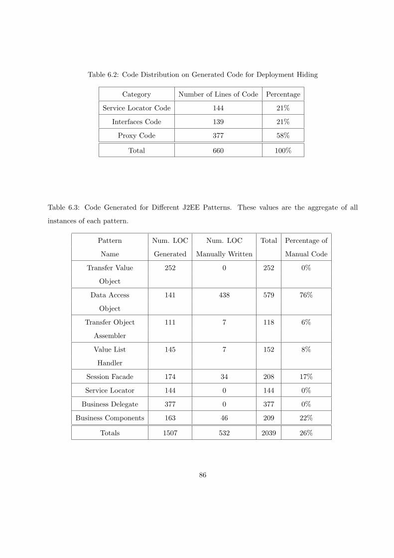
Table 6.2: Code Distribution on Generated Code for Deployment Hiding
Category Number of Lines of Code Percentage
Service Locator Code 144 21%
Interfaces Code 139 21%
Proxy Code 377 58%
Total 660 100%
Table 6.3: Code Generated for Different J2EE Patterns. These values are the aggregate of all
instances of each pattern.
Pattern Num. LOC Num. LOC Total Percentage of
Name Generated Manually Written Manual Code
Transfer Value 252 0 252 0%
Object
Data Access 141 438 579 76%
Object
Transfer Object 111 7 118 6%
Assembler
Value List 145 7 152 8%
Handler
Session Facade 174 34 208 17%
Service Locator 144 0 144 0%
Business Delegate 377 0 377 0%
Business Components 163 46 209 22%
Totals 1507 532 2039 26%
86

ment logic. Of the 1507 lines of generated code, the architectural and deployment code consists
of 847 and 660 lines of generated code respectively, as shown in Table 6.1 and 6.2. A significant
portion, 252 lines, of architecture code is devoted to the transfer value objects and primary key
objects, which only manage four database tables. These classes all share the characteristic of being
straightforward to write but are unavoidable as there is no single, reusable version. Being able
to automatically generate this code, while guaranteeing its correctness, removes a significant bur-
den from developers. The assembly of patterns took up 148 lines. The stub functions, such as
ejbCreate, for EJBs took up 150 lines for the eight session beans. Other generated code includes
those methods special to each pattern, such as the connection methods for data access objects and
the sublist retrieval methods for value list handlers.
In the 660 lines of deployment logic, proxies alone take up 377 lines. The service locator and
access interfaces take up 144 and 139 lines of code respectively.
The most significant amount of hand-written code for this application was in the data access
objects. As shown in Table 6.3, 438 out of 579 lines of code for the DAO were manually inserted.
Most of this code is associated with constructing queries to access database tables. These queries
are non-derivable constraints. We could include an SQL script generation facility similar to that in
realMethods in the future. The transfer object assembler and value list handler need hand written
code to initialize the searching criteria. The amount of code needed to fulfill these constraints is
small; only 7 lines of code are needed in both cases. For the session facade, code is needed for
customizing the coordination of invocations. The service locator, business delegate and transfer
value object require no application-specific code.
Another thing to note is that manual code is always inserted at specific locations. For example,
manual code for a DAO pattern always goes into its query methods. Developers can easily find the
places to start manual coding. RMA also uses the Eclipse task list to direct developers to places in
the generated code that need application-specific code. This feature improves the usability of the
RMA.
With respect to the development time, the majority was spent coding the non-derivable con-
straints, especially those for the data access object. Coding and debugging the four data access
objects in our sample application took about 45 minutes. However, the business delegates and
transfer value objects take almost no development time because they are generated automatically
87

when their owners are defined, according to implicit relationships. The session facade, transfer ob-
ject assembler, and value list handler only require the time for RMA to solicit context information
from the developer to generate code fulfilling the derivable constraints. The wizard pages for the
above three patterns have an average of ten inputs, where most of these options can be specified
with a simple mouse click. In all, it took us less than 10 minutes to work through the wizards for
all uses of these three patterns. In total, we spent less than two hours in developing our sample
application, which includes all application code and all deployment descriptors.
To get a better sense of the benefits of RMA, we would like to better understand how the
proportion of generated code against the total amount of code in an application changes as the
complexity of an application increases. It would still be safe to deduce that as the complexity of the
business logic increases, the percentage of generated code will fall. But we also believe it will not
be a waste of effort to generate code for the following reasons. First, the generated code guarantees
correctness, especially for pattern assembly. Second, as the code becomes more complicated, it is
expected to have more EJBs and data objects such as DAOs in the application. Using our sample
application as an example, which is relatively simple in nature, it takes around 125 lines of transfer
object code for each DAO and 90 lines of deployment code for all EJBs in the application. As
the application becomes more complicated, these numbers will only grow because they are closely
related to factors like the size of the database tables (number of elements in the tuples) and their
number, and the number of business methods and variables in the classes. The total amount of
time saved by not having to write this code in a large application that incorporates hundreds of
EJBs and tables will be significant.
88

Chapter 7
Related Work
After seeing how RMA works to solve problems in the development of J2EE applications, we will
now take a look of other available J2EE IDEs and compare them with RMA whenever applicable.
7.1 COPS for Parallel Programming
We start our survey with something outside of the J2EE domain, that still gives insight into some
common characteristics of development tools for distributed programming. COPS [18] is a pattern-
based development tool for parallel programming that generates code for each pattern instance used
in an application. Accordingly, developers are responsible for writing code to hook the generated
patterns together as needed. Moreover, this generated code must be well-structured and presented
since developers need to work with this code manually.
COPS divides the generated code into three layers: the patterns layer, the intermediate code
level and low level native code layer. For each pattern instance generated by COPS, the development
tool provides a class that contains the hook methods for this pattern. These hook methods are called
by the pattern code in the runtime system. Moreover, developers need to fill in the application
logic in the hook methods. Thus, the classes that contain the empty hook methods make up the
pattern level code. The intermediate level contains the code that models the pattern structure and
behavior. If developers find the pattern provided by COPS does not exactly fit the requirements,
developers can modify the code in this layer to customize the pattern. In the low level native layer,
developers can fine tune the code responsible for the distributed communication.
89

Because COPS has isolated the generated code according to its different concerns, developers
generally have a good idea where and how to customize the generated code. In addition, to
accommodate developers’ customization of the pattern code at the patterns layer, COPS provides
templates for each pattern. Accordingly, there are attributes on each template that can be set to
produce different variations of a pattern. For example, the developer can specify different mesh
styles to generate a desired Mesh pattern. However, producing customized pattern code using the
template attributes is much easier than doing it manually in the intermediate code layer. Even
though template attributes are sufficient for creating pattern variations in most circumstances, the
possibility of modifying code in the lower layers offers application developers even greater flexibility.
Another big advantage of COPS is its extensibility. COPS allows developers to write and add new
patterns into the pattern tool through MetaCOPS [19], a support tool that comes with COPS.
We believe that the approach employed by COPS in the parallel programming domain should
also be applicable to the domain of J2EE web applications. A web application can also be as-
sembled from the pattern instances using a pre-defined framework as the guideline. While the
J2EE containers have hidden much of the remote access code, there are still some aspects of J2EE
applications, such as name space management and deployment descriptor generation, that can be
hidden away using a layered structure. Moreover, the flexibility of the development tool relies on
how well the generated code is structured so that developers can easily customize the code for their
specific needs. The similar nature of the parallel domain and the web application domain has led
us to build our J2EE development tool using some of the ideas in COPS to help solve the problem
of creating J2EE web applications.
7.2 Tools for J2EE Development
A J2EE application is a kind of web-based distributed program. J2EE development tools should
have similar properties to other distributed system development tools. These properties include
the hiding of low level code while providing a high degree of flexibility and maintainability. Besides
these general properties, a J2EE development tool needs to address other issues, such as JNDI
name space management and deployment descriptor generation. There are two main approaches
to J2EE development: the code-centric approach and architecture-centric approach. In the code-
centric approach, the development tool produces pieces of skeleton code for developers to fill in and
90

assemble into a working program. The development tool offers no help on how these individual
pieces fit together to form an application. In the architecture-centric approach, development tool
generates the code skeleton that follows a certain framework architecture. The framework code
defines the control flow of the application. The application-specific code is inserted to complete the
application.
7.2.1 JBuilder and WebSphere
Both JBuilder [21] and WebSphere [13] follow the code-centric approach to J2EE development.
JBuilder and WebSphere provide wizards that help developers produce independent modules for
JSPs, Servlets, and EJBs. These independent modules must be assembled into a complete applica-
tion by the programmer. Accordingly, some simple skeleton code can be generated as the modules
are formed. Moreover, since both systems provide a built-in web-server, developers can easily de-
ploy their application onto the server to test their implementation. Both JBuilder and WebSphere
adopt Apache’s XDoclet technology to produce the deployment descriptors. XDoclet provides a set
of specialized Javadoc-style tags that developers need to insert into the application code. Some of
the most commonly tagged information is the purpose of methods (creation or business) and the
EJB references. At code generation time, the code generation engine parses the code to extract the
tags and generates the deployment descriptors and interfaces. This tag-based approach relies on
developers to ensure the correctness of the specified deployment information. As the complexity
of the application grows, more tags must be maintained and the correctness becomes harder to
ensure. Furthermore, neither JBuilder nor WebSphere address architectural concerns in the gener-
ated code. They also offer little tool support for helping developers to exploit the benefits of proven
good designs for developing J2EE applications.
While JBuilder and Websphere only generate skeletons of stand-alone EJBs, RMA generates
and assembles EJBs using architecturally-sound design patterns. In other words, RMA is better
than JBuilder and Websphere at providing a good architecture for the application. As for han-
dling distributed aspects of web applications, RMA automatically handles the generation of the
deployment descriptors and manages the namespace. The information for deployment descriptors
is collected at development time, so RMA frees developers from writing deployment tags in the ap-
plication code. While JBuilder and Websphere leave the namespace management to the developers,
91

RMA handles it automatically, as discussed in Chapter 5. We believe RMA has achieved a much
better separation of application logic and deployment logic than both JBuilder and WebSphere.
7.2.2 Struts
Struts is a simple but useful tool for J2EE presentation tier components [2]. Struts follows the
Model View Controller (MVC) architecture. It creates a servlet controller using a configuration
file. The controller delegates the client requests to the different JSP and Servlet pages. The client
data are encapsulated in a POJO and passed to the JSP or Servlet pages. Struts has been widely
used and has been incorporated into other development tools such as JBuilder.
Struts only supports patterns for the presentation tier, and relies on other tools for the develop-
ment of the distributed aspects of an application. In contrast, RMA only supports patterns for the
business and data tiers. RMA and Struts could be used together to support the complete process
of developing J2EE application, though we would need to incorporate some of the abstractions in
RMA into Struts if we are to preserve our goal of hiding deployment logic and descriptors from
developers.
7.2.3 Pattern Transformation based JAFAR
JAFAR [11] is a framework-based J2EE development tool based on Rational XDE (eXtended
Development Environment). JAFAR defines a framework for J2EE applications. The framework
consists of components for all three tiers. The framework components help developers design an
application by capturing proven solutions to some frequently performed tasks performed in each
tier. Some of these framework components are fully implemented while others are architectural
skeletons. For components that offer simple but fully implemented services, such as the mail
service, developers can simply include the component in their application. For tasks where the
architectural skeleton is given, application developers need to write code to complete application-
specific logic. Form Validation, which provides basic control flow for validating forms submitted by
clients over the Internet, is an example of an architecture component in JAFAR. JAFAR provides
tools to help developers create their own components and hook them into the framework.
The development of a J2EE application using JAFAR centers on the development of the
application-specific components. The development consists of four steps: creating a project, de-
92

signing components, applying pattern-based transformations, and writing application-specific code.
The application is created by specifying the needed model templates and package structure of the
selected models. JAFAR supports all five models promoted by the 4+1 view model of the archi-
tecture [17]. JAFAR instantiates the models from the model templates and creates the specified
packages as the project is created. The model design is performed using a tool that supports
the Unified Modeling Language (UML), such as Rational XDE. The two design elements that de-
velopers need to model are key abstractions and component interfaces. A key abstraction is an
object-oriented model for a database table. The component interfaces define the business inter-
faces of business logic components. The interface of a component is defined as a UML interface of
a UML subsystem artifact. With the design model ready, developers can start applying pattern
transformations on the models.
JAFAR provides three kinds of pattern transformation: Entity EJB, Session EJB, and Dis-
patcher. The Entity EJB is derived from the key abstraction defined in the design model. As
the transformation is performed on the key abstraction, an Entity EJB is created with all of the
attributes defined in the key abstraction. Session EJBs are generated from the business interfaces
defined in the design model. All of the methods defined in business interfaces are mapped to public
methods in a Session EJB. JAFAR also supports the creation of skeleton code for the Dispatcher
class that distributes client requests to the correct business components. The Dispatcher class
is implemented in the web tier using a servlet. For all three transformations, code is not only
generated for the bean classes and dispatcher classes but also for other auxiliary classes as well.
For example, home and business interfaces are automatically generated for each bean class. Some
simple J2EE patterns are also applied during the pattern transformation. For instance, the Entity
Bean is associated with a transfer value object that aggregates all of its instance variables by de-
fault. The Session Bean always has a POJO delegate, which hides the complexity of name space
lookup.
Some of the deployment information is gathered while developers model the EJBs and Dis-
patchers. For example, the component interfaces provide information about the name of the bean
classes and all of their public methods. Unfortunately, it is not clear how JAFAR handles the name
space in the deployment descriptor.
The JAFAR IDE supports pattern-oriented development. Providing developers with a high-
93

level control flow, they can concentrate on developing application-specific code. JAFAR generates
many useful J2EE patterns, but in some cases developers have to assemble them together. However,
it is not clear if JAFAR frameworks are accessible to developers. Furthermore, JAFAR does not
offer enough help in applying design patterns to user components that might need to collaborate
with each other. For instance, the code generated for the Dispatcher class still needs customized
code to select the worker to which an incoming job should be dispatched. This drawback limits
the benefits that the developers can exploit by using design patterns. It is also not clear how EJB
references among components defined by the application developer are reflected in the deployment
descriptor if the deployment information is only gathered at the modelling stage. This can limit
the use of legacy code in a JAFAR project.
RMA is an improvement over JAFAR at the architectural level in three ways. First, RMA allows
developers to assemble EJBs into pattern relationships and generates code to create the binding.
Thus, developers can create architecturally-sound applications but they are not bound to a single
pre-built framework. Second, RMA does not require developers to make use of the whole framework
as JAFAR does. Developers can incrementally build their applications in a bottom-up fashion and
use only the components that they think are necessary. Consequently, only the code needed for an
application is generated, which can make the code easier for developers to work with and improve
performance [18] [19]. Because developers are fully aware of what code they are generating, RMA’s
generated code is more accessible than that of JAFAR. Third, RMA supports more business tier
patterns than JAFAR does. Design patterns such as the transfer object assembler and the value list
handler are not supported in JAFAR. In terms of handling the distributed nature of the application,
we believe RMA is an improvement over JAFAR because of its ability to automatically handle the
namespace management.
7.2.4 Model Transformation based OptimalJ
OptimalJ [5] is a Model Drive Architecture (MDA) based J2EE tool. MDA allows developers to
specify the class relationships with XML tags, which the transformation engine uses to produce
the concrete code that reflects the description [23]. OptimalJ defines a generic framework for
J2EE applications. Then, developers are asked to design the application-specific models. OptimalJ
instantiates a dynamic concrete framework that inherits from the pre-defined generic framework
94

and incorporates the developer-defined models. Lastly, developers are asked to fill in the business
logic to complete the application. OptimalJ distinguishes itself in the way it uses MDA models in
its code generation.
OptimalJ has three levels of abstraction: the Domain Model, the Application Model, and the
Code Model. The Domain Model is a Platform Independent Model (PIM). It defines business
domains without any application detail [5]. For example, a developer can define a Customer
artifact with properties, such as the name and birthday, in the Domain Model. The Domain Model
does not describe what kind of programming language the Customer artifact will be implemented
in and the type of program construct that will be used to implement it. The Application Model
defines the application in terms of the programming technology that will be used to implement
the application. The Application Model is a Platform Specific Model (PSM) and still contains no
implementation detail. The Application Model defines what is to be generated for each Domain
Model artifact in the web tier, the EJB tier, and the data tier. For the Customer example, the
Application Model may decide to use an Entity EJB to model the Customer and the schema of the
underlying database table. Thus, the schema information is needed for generating the Entity Bean.
The Code Model is the actual implementation of the application. For the Customer example, its
Code Model contains an Entity EJB object class, the interfaces for the EJB, and other associated
auxiliary classes such as the primary key class. In the development process, the business analyst
defines the Domain Model. OptimalJ automatically performs a series of model transformations to
produce the concrete framework code. As we will see, the pattern information is used in the model
transformation.
There are two types of patterns used in OptimalJ: transformation patterns and functional pat-
terns. The transformation patterns are used to map of an upper level model to the next level
model. The transformation patterns can be further divided into two types: technology patterns
and implementation patterns. The technology patterns are the J2EE patterns that are used for
mapping artifacts defined in the Domain Model to the Application Model. For example, a Domain
Model level composite artifact such as Department may contain a set of Employee artifacts. Opti-
malJ automatically applies the Composite Entity pattern [1] to the Department artifact by some
advanced analysis of the Domain Model. Employees are modelled as leaves and the Department
as the aggregator of the Composite Entity pattern. The implementation patterns transform the
95

Application Model into the Code Model. An implementation pattern for an Entity EJB generates
the Entity bean’s home and business interfaces, the primary key class, and some simple DBMS
SQL scripts.
The functional patterns capture and reuse user-defined patterns by allowing developers to merge
artifacts into one larger, single unit. For example, if the developers frequently use the Customer and
Address artifacts, then they might decide to combine two artifacts into a single “CustomerContact”
artifact for future reuse. The merging can be performed at all three levels.
The deployment descriptors for the application are generated by gathering information from
the Code Model transformation. For example, the names for the EJB bean class and interfaces are
generated only after Code Model transformation is applied using implementation patterns. The
descriptors can be created during the transformation process.
OptimalJ is no doubt a powerful development tool. It provides multiple layers of abstractions,
similar to the approach taken by COPS. Because the developers generate the framework at a
much higher abstraction than the detailed implementation technology, the design decisions can
be reapplied to other implementation technologies besides J2EE, given the appropriate technology
patterns. OptimalJ has great flexibility in its ability to include new patterns, but it fails to provide
developers with good access to the generated code. OptimalJ employs automatic reasoning to make
decisions about the generation of the implementation code. The generated code is too complicated
for the developer to quickly understand in order to fine tune it.
The main difference between RMA and OptimalJ is the different approach they take in con-
structing and generating the architecture of the application. While MDA technologies can only
specify class-level bindings, RMA’s roles and constraints enables it to generate method-level bind-
ings, which are more concrete. RMA also improves over OptimalJ by providing incremental con-
struction of the application, so the developers are fully aware of what code is generated at each
stage. Thus, RMA provides a better understanding of the generated code than OptimalJ. It is
interesting to note that both RMA and OptimalJ use a layered structure to enforce consistency
in the generated code. Both RMA and OptimalJ create deployment descriptors and manage the
name space automatically.
96

7.2.5 Role/Constraint based Fred
Fred is another pattern-based J2EE tool [12]. Fred tackles the design problems of EJBs in the
business tier using the same patterns as those used in JAFAR and OptimalJ. Similar to JAFAR,
which used Rational XDE as its development environment, Fred exploits the existing prototype
tool also called Fred [12]. The Fred prototype tool provides an easy way to create an EJB-sensitive
source code editor and other useful services in the development process. Fred has distinguished
itself from other J2EE development tools in two main aspects: a flexible code generation cycle and
extensibility.
In both JAFAR and OptimalJ, the pattern or framework engine creates architectural code
based on developer specifications. The generated architectural code is difficult for developers to
read and understand, and thus is hard to modify. Fred allows the developer to carry out the code
generation step by step. For every piece of pattern code generated, Fred provides the developer
with a list of tasks that need to be carried out in order to complete the application. For instance,
when a developer creates an Entity EJB using Fred, Fred creates tasks prompting the developer
to complete the finder methods specified in the generation wizard. The task list is dynamically
generated. As a task is completed, it is automatically removed from the list. New tasks can also
be dynamically added to the task list due to the completion of a previous task.
Fred’s ability to manage the task lists to guide developers through the development process
results from its view of a pattern as an aggregation of roles and constraints. A role describes a set
of properties that a program element should have in order to play the role. Each such property
is called a constraint. Roles and constraints can be applied to most program elements, such as
classes and methods. A pattern in Fred defines two types of roles: a bound role and an unbound
role. The bound roles of a pattern are the roles that are common to every instance of that pattern
and show up in the framework with a specific name. In other words, the bound roles are the roles
that the pattern needs to fulfill in order to be hooked into the framework. On the other hand,
the unbound roles are pattern-specific. For example, a session facade needs to play bound roles
of implementing the EJBHome and EJBObject interfaces, which are common to all EJBs. At the
same time, the session facade plays the unbounded role of accessing facaded Entity/Session EJBs.
Moreover, for each role, there is a list of properties specifying the requirements that are needed
to fulfill that role. For instance, the session facade contains an unbound role named “session”.
97

“Session” has a constraint that states that it must contain instance variables of type EJBObject
in its implementation. After the pattern code is generated, the environment monitors the code
input by the developer to check whether the constraints still hold. The “session” task is kept in
the task list until an EJBObject is specified for the session facade. While some roles need to be
manually written by the developer, others can be completed using default values provided by the
environment. For example, the default value for an instance variable required by the “session” role
is null.
Fred also employs the concept of composite patterns to handle patterns that are closely related
to each other. For example, each Entity Bean always has a transfer value object that stores the
persistent fields of the Entity Bean. The suggestion to generate related patterns appears in the task
list as an optional task when Fred believes there is enough information to generate them. Then,
the developer can use wizards to carry out the generation.
There is no predefined set of patterns that will be sufficient for all application development.
Developers always run into difficulty when they cannot find the pattern they are looking for in a
pattern-based development tool. Thus, Fred provides a set of wizards for creating new patterns by a
pattern developer. For each pattern, developers need to specify the different roles that this pattern
needs to play and the constraints on each role. As the patterns are instantiated, the roles specified
by the pattern developer are loaded to generate the concrete task and constraint list. Subsequently,
the newly-added patterns are used in the same fashion as any other existing patterns.
The deployment descriptors can be generated using the values of the role properties filled in
by the user. The association between EJBs can be captured by binding roles to the business
components.
Fred offers significantly more flexibility, both in constructing the application and in using pat-
terns, than OptimalJ and JAFAR. Because the code is no longer generated automatically but
rather because of direct interaction with the developer, developers have a better understanding
of the purpose of the generated code. The developer-written code is also automatically checked
against the pattern constraints by the environment. This kind of constraint checking helps devel-
opers improve the correctness of their code. Furthermore, the ability to extend Fred’s pattern pool
is another feature that increases the utility of the tool. While Fred performs constraint checking
on developer-written code, there is the possibility that such code can be automatically generated
98

with some wizard support. For example, when developers create a session facade for hiding a
set of Entity or Session beans, they have to manually write code to include those beans as fields,
instantiate them, and use them. In short, if developers want to use methods from those beans, they
also need to write delegating methods. It would be better if developers could launch a wizard to
pick out the bean they want to use and have the tool generate implementation code, including the
delegating methods. In this scenario, the development tool can not only improve the correctness
of code but also reduces development effort.
Fred is most like RMA; both of them use the concepts of roles and constraints. While Fred only
uses roles and constraints to guide developers through development, RMA generates code to imple-
ment the constraints to fulfill roles where possible. In other words, Fred only tells developers what
they should do in order to instantiate a pattern-relationship, while RMA goes further by generating
as much of the concrete implementation of a pattern relationship as possible. For those constraints
that cannot be automatically generated, RMA provides tool support to guide developers to manu-
ally construct them. In terms of handling the distributed nature of the application, both Fred and
RMA collect information during the development stage to generate deployment descriptors. It is
also important to note that RMA-style name space management is not found in Fred.
7.3 Summary
To summarize, we believe that RMA has been successful at addressing some of the major short-
comings of other development tools. First, RMA efficiently uses pattern and framework knowledge
in code generation. This knowledge allows us to generate concrete pattern implementations in-
cluding method-level relationships. Second, RMA presents the generated code to developers in a
usable fashion, so the developers can modify the code as needed. Third, RMA enables developers
to build applications incrementally, allowing them to have full knowledge of the purpose of each
piece of code generated. The clarity in presentation and incremental construction of architectural
code exemplify the flexibility of RMA. Lastly, the deployment logic is automatically generated by
RMA. Moreover, changes to the user code are captured by RMA and automatically reflected in the
descriptors without developer intervention.
99

Chapter 8
Future Work and Conclusion
8.1 Future Work
First of all, we would like to implement additional applications that contain a more complicated
architecture and behavior than our current sample application. Additionally, we would like to know
how much effort can be saved by RMA on these larger programs. This work would allow us to
better understand the strengths of the tool and address any weaknesses. At the same time, we may
also like to discover additional pattern relationships that can be automatically generated by RMA.
Currently we have implemented some of the patterns of the business tier and the integration
tier. We have left out the patterns from the presentation tier because we did not want to duplicate
the efforts of Struts, which provides good support for presentation tier patterns. A typical EAR
file contains two components, a WAR file that contains presentation tier JSPs or Servlets and a
JAR file that contains EJBs. Because RMA does not support the presentation tier, the WAR file
needs to be filled in by the developer afterward. In order for Servlets and JSPs to use the EJBs,
the JNDI names of those EJBs need to be specified in the deployment descriptor of the referencing
Servlet or JSP. The only place for presentation tier developers to get the JNDI name is from
the deployment descriptor of the EJB JAR. This omission results in a hole in our abstraction of
deployment logic, but only because we have not incorporated the presentation tier into the current
system. One possible improvement is to extend RMA with presentation tier patterns to cover the
entire development process and completely hide deployment logic across the complete application.
Another possible solution is to provide a simple wizard that inserts an existing WAR file produced
100

by other tools into the EAR produced by RMA. Lastly, to make the framework complete at the
integration tier, we would also like to accommodate Entity EJBs, applying the same approach we
used for Session beans.
Our next goal is to make our pattern tool extensible. One of the shortcomings of pattern-
based software tools is their inflexibility in incorporating new patterns. Thus, it would be ideal if
application developers could create or refine a pattern and plug it into our tool, as can be done
in DPnDP [25], PAS [10], and COPS [19]. The new pattern should work in the same fashion as
the existing patterns. We believe that the Eclipse plugin architecture is a promising solution to
solve this problem. Moreover, any Eclipse plugin can define its own extension points for other
plugins to add new features. Thus, we propose creating a pattern generation engine that provides
a standard interface as its extensible interface to all patterns. Patterns can be implemented as
plugins to hook up to the pattern generation engine. Each pattern plugin contains its own user
interface wizard and code generation template and model. As new patterns are added to the core
engine, they show up in the menus of the core plugin. Yet, the difficulty lies in finding an efficient
means of enforcing consistencies on constraints and roles of the same pattern relationship produced
by different pattern plugins. For example, if there are two plugins that generate a transfer object
assembler to aggregate some existing data access objects, we might expect both of them to hook
up to data access objects appropriately. The transfer object assemblers produced by both plugins
should also be acceptable to a plugin that handles the session facade and EJB relationship.
We are also considering the possibility of incorporating a task-driven development methodol-
ogy [12] into RMA. RMA should guide developers through the process of pattern assembly by
suggesting the next possible steps. For example, it could suggest the creation of a session facade
when the tool finds more than three EJBs have been created. We may also enforce constraints
on pattern relationships for imported legacy code or for generated framework code that has been
changed by the user.
8.2 Conclusion
Design patterns are more useful when they work together than when they work alone. In this thesis,
we have presented RMA, which incrementally constructs a J2EE web application by assembling
patterns according to relationship roles and constraints. RMA follows an incremental bottom-up
101

approach in assembling patterns. The lowest level data tier patterns are first assembled, followed
by the upper level business tier patterns. As a result, RMA can produce concrete code instead
of an architectural description as is done in pattern-based J2EE IDEs. By generating concrete
pattern implementation code, RMA allows developers to focus on their application code, which is
where their expertise lies. The construction steps are controlled by developers, so they are fully
aware of the purpose of the code generated. This improves the developers’ ability to work with the
generated code if necessary. RMA has distinguished itself from other pattern-based J2EE tools in
that it places more emphasis on capturing pattern relationships than on static code generation for
a predefined architectural description.
In RMA, we use pattern relationships to hide the distributed nature of a J2EE application at
both the architectural and code levels. We use the collaboration between our refined service locator
and proxy patterns to hide the name space management at the code level. We also show that
the deployment descriptors can be generated using information gathered during the development
phase. Through RMA, we have shown that deployment logic can be provided automatically with
appropriate tool support rather than being exposed to application developers. Lastly, we have
successfully developed RMA as an Eclipse plugin, using one of the most popular Java IDEs. In
this way, the rich functionality of Eclipse, such as code generation, can easily be incorporated
into our tool. The flexibility of Eclipse also opens the possibility of implementing more complex
functionality, such as implementing pattern generation engines as plugins to provide extensibility.
102

Bibliography
[1] DeePak Alur, John Crupi, and Dan Malks. Core J2EE Patterns, Best Practices and Design
Strategies. Sun Microsystem Press, 2003.
[2] Apache Software Foundation. Struts. Available at: http://jakarta.apache.org/struts/-
index.html.
[3] Eric Armstrong, Stephanie Bodoff, Maydene Fisher, Dale Green, and Kim Haase. The
J2EE Tutorial for the Sun ONE Platform. Sun Microsystems, Inc., 2003. Available at:
http://java.sun.com/j2ee/1.3/docs/tutorial/doc/Front.html.
[4] Stephanie Bodoff, Dale Green, Kim Haase, Eric Jendrock, Monica Pawlan, and Beth Stearns.
The J2EE Tutorial. Addison-Wesley Pub Co, March 2002.
[5] John Crupi and Frank Baerveldt. Implementing Sun Microsystems’ Core J2EE Patterns. Com-
puware Corporation, 2004. Available at: http://www.compuware.com/dl/j2eepatterns.pdf.
[6] Lisa Friendly. The realMethods Framework. Sun Microsystems, Inc. Available at:
http://www.realmethods.com.
[7] Lisa Friendly. Design of Javadoc. Sun Microsystems, Inc., 1995. Available at:
ftp://ftp.java.sun.com/docs/javadoc-paper/iwhd.pdf.
[8] Erich Gamma and Kent Beck. Contributing To Eclipse. Addison-Wesley, 2004.
[9] Erich Gamma, Richard Helm, Ralph Johnson, and John Vlissides. Design Patterns: Elements
of Reusable Object-Oriented Software. Addison-Wesley Pub Co, 1995.
[10] D. Goswami, A. Singh, and B. Preiss. From design patterns to parallel architectural skeletons.
Journal of Parallel and Distributed Computing, 62(4):669–695, 2002.
103

[11] Nicolas Guelfi and Paul Sterges. JAFAR: Detailed design of a pattern of a pattern-based J2EE
framework. In The Proceeding of 6th Annual IASTED International Conference on Software
Engineering and Applications, pages 331–337, Cambridge, MA, USA, 2002. ACTA Press.
[12] Imed Hammouda and Kai Koskimies. A pattern-based J2EE application development envi-
ronment. Nordic J. of Computing, 9(3):248–260, 2002.
[13] IBM. Websphere. Available at: http://www-306.ibm.com/software/info1/websphere/-
index.jsp.
[14] Imperial College Department of Computing, UK. Free On-Line Dictionary of Computing,
2004. Available at: http://wombat.doc.ic.ac.uk/foldoc/.
[15] Ralph E. Johnson. Frameworks = (components + patterns). Communication ACM, 40(10):39–
42, 1997.
[16] Rod Johnson. Expert one-on-one J2EE Design and Development. Wiley Publishing, Inc, 2003.
[17] P. Kruchten. Architectural blueprints - the.
[18] S. MacDonald, J. Anvik, S. Bromling, J. Schaeffer, D. Szafron, and K. Tan. From patterns to
frameworks to parallel programs. Parallel Computing, 28(12):1663–1683, 2002.
[19] S. MacDonald, D. Szafron, J. Schaeffer, J. Anvik, S. Bromling, and K. Tan. Generative
design patterns. In Proceedings of the 17th International Conference on Automated Software
Engineering (ASE2002), pages 23–34, Edinburgh, UK, September 2002.
[20] Hardo Mueller. The Unified Modeling Language. Institute of Photogrammetry Bonn, Denmark,
1997. Available at: http://www.ipb.uni-bonn.de/ hardo/papers/isprs97/node4.html.
[21] Sung Nguyen. EJB Development Using Borland JBuilder 8 and Borland Enterprise
Server 5.2. Borland Software Corporation, January 2003. Available at: http://-
www.borland.com/products/white papers/pdf/ejb development using jb8 and bes52.pdf.
[22] Object Technology International, Inc. Eclipse Platform Technical Overview, February 2003.
Available at: http://www.eclipse.org/whitepapers/eclipse-overview.pdf.
104

[23] OMG. MDA Guide Version 1.0.1, June 2003. Available at: http://www.omg.org/docs/omg/-
03-06-01.pdf.
[24] Remko Popma. JET Tutorial. Azzurri Ltd., July 2003. Available at: http://www.eclipse.org/-
articles/Article-JET/jet tutorial1.html.
[25] S. Siu. Openess and extensibility in design–pattern–based parallel programming systems.
Master’s thesis, Department of Computer and Electrical Engineering, University of Waterloo,
1996.
[26] Sun Microsystem. J2EE Blueprints, 2001. Available at: http://java.sun.com/blueprints/-
guidelines/designing enterprise applications/packaging deployment/descriptors/.
[27] Craig Walls and Norman Richards. XDoclet in Action. Manning Publication, Co., December
2003.
105

Appendix A
Acronyms
Term Expansion Definition
BD Business Delegate “A design pattern that encapsulates accessto a business service [1].” See Section 3.7 fordetails.
DAO Data Access Object “A design pattern that abstracts and encap-sulates access to persistent store [1].” SeeSection 3.1 for details.
EJB Enterprise Java Bean “A server-side component architecture forwriting reusable business logic and portableenterprise applications [14].”
IDE Integrated Development Environment “A system for supporting the process of writ-ing software [14].”
J2EE Java 2 Enterprise Edition “Sun’s Java platform for multi-tier server-oriented enterprise applications [14].”
JAR Java Archive “A compressed archive file containing Javaclass files, filename extension: “.jar” [14].”
JDBC Java Database Connectivity “Part of the Java Development Kit which de-fines an application programming interfacefor Java for standard SQL access to databasesfrom Java programs [14].”
106

Term Expansion Definition
JNDI Java Naming Directory Interface “Part of the Java platform, providing appli-cations based on Java technology with a uni-fied interface to multiple naming and direc-tory services [14].”
JSP Java Server Page “A freely available specification for extend-ing the Java Servlet API to generate dynamicweb pages on a web server [14].”
POJO Plain Old Java Object A normal Java class.
RMA RoadMapAssembler A pattern-based J2EE development tool de-veloped by us.
SF Session Facade “A design pattern that encapsulatesbusiness-tier components and exposes acoarse-grained service to remote clients [1].”See Section 3.3 for details.
SL Service Locator “A design pattern that encapsulates serviceand component lookups [1].” See Section 3.4for details.
SQL Structured Query Language “An industry-standard language for creating,updating and, querying relational databasemanagement systems [14].”
TO Transfer Value Object “A design pattern that carries data across thetier [1].” See Section 3.2 for details.
TOA Transfer Value Object Assembler “A design pattern that assembles a com-posite transfer object from multiple datasources [1].” See Section 3.5 for details.
VLH Value List Handler “A design pattern that handles the search,caches the results, and provide the ability totraverse and select items from the results [1].”See Section 3.6 for details.
WAR Web Archive A special kind of JAR file that contains filesfor the presentation tier of a J2EE applica-tion.
107

Appendix B
UML Legends
Figure B.1: UML Legend-Class Symbols [20]
108

Figure B.2: UML Legend-Association Symbols [20]
109