14 Pattern Development
30
Section 14.1 Principles of Pattern Development Section 14.2 Drawing Pattern Developments 14 Pattern Development Chapter Objectives Explain how pattern development is used in the packaging industry. Identify the methods for processing sheet- metal patterns. Describe the general principles of pattern development. Discuss the three main types of pattern development. Prepare patterns using the three main types of pattern development. Prepare patterns for intersecting prisms and cylinders. • • • • • • Pack it Up The use of yellow and gray is important to these packaging designs. How do these colors complement the packaged items? Would you use these colors? Why or why not? 494
-
Upload
khangminh22 -
Category
Documents
-
view
0 -
download
0
Transcript of 14 Pattern Development
Section 14.1Principles of Pattern Development
Section 14.2Drawing Pattern Developments
14 Pattern Development
Chapter ObjectivesExplain how pattern development is used in the packaging industry.Identify the methods for processing sheet-metal patterns.Describe the general principles of pattern development.Discuss the three main types of pattern development.Prepare patterns using the three main types of pattern development.Prepare patterns for intersecting prisms and cylinders.
•
•
•
•
•
•
Pack it Up The use of yellow and gray is important to these packaging designs. How do these colors complement the packaged items? Would you use these colors? Why or why not?
494

Drafting Career
Philippe Starck is a French designer who created a line of everyday items for Target. Design Guys, a Minneapolis-based fi rm, was asked to create the packaging for the Starck product line. The team at Design Guys wanted to showcase Starck’s work using an understated look that could still grab the customer’s attention. They wanted their packaging to refl ect Starck’s elegance and artistry, and his belief that joy can be found in simple things.
The team at Design Guys invented unique fold-up
forms using plastic shrink-wrap. They chose a joyful yellow color set off by a neutral gray. They included Philippe Starck’s face and commentary about his design on the packaging. Their packaging is powerful because it says something about the joy of using the item inside, about the artistry of Philippe Starck, and about Target, the store that makes high quality and great design available to a mass audience.
Academic Skills and AbilitiesGraphic designEngineering technologyMarketingProblem solvingSketching and visualizing
Career PathwaysDesigners are both creative and practical. A
bachelor’s degree is required for most entry-level positions. Helpful high school courses include Eng-lish, mathematics, business, family and consumer sciences, computer-aided design (CAD), and art.
•••••
Go to glencoe.com for this book’s OLC to learn more about Design Guys.
Design Guys, Packaging Specialists
495DesignGuys
Principles of Pattern Development
14.1
Preview Patterns are essential in making industrial products and those we use at home. Look at the packages the products you buy every day. Did you ever think these were made from patterns?
Content Vocabulary • pattern
development• stretchout
• development• pattern
• parallel-line development
• stretchout line
• measuring line• radial-line
development
• triangulation• transition piece
Academic VocabularyLearning these words while you read this section will also help you in your other subjects and tests.• diverse • approximate
Graphic Organizer
Use a table like the one below to organize notes about pattern development.
Type of pattern development: Application:
1.2.3.
Go to glencoe.com for this book’s OLC for a downloadable version of this graphic organizer.
Academic Standards
English Language Arts
Students use a variety of technological and information resources (e.g., libraries, databases,
computer networks, video) to gather and synthesize information and to create and communicate
knowledge (NCTE)
Mathematics
Solve problems that arise in mathematics and in other contexts (NCTM)
ADDA Section 14
Standards and Practices Listing (ASME Y14.24)
NCTE National Council of Teachers of English Language Arts
NCTM National Council of Teachers of Mathematics
ADDA American Design Drafting Assocation
ASME American Society of Mechanical Engineers
Industry Standards
496 Chapter 14 Pattern Development
AF F
HGBGH
F C F
D
E
A
G
B
CH
D
E
Understanding Pattern DevelopmentHow are patterns used in designing products for industry?
Making patterns or pattern developmentsis an important part of industrial drafting. Many different industries use them. Familiar items such as pipes, ducts for hot- or cold-air systems, parts of buildings, aircraft, auto-mobiles, storage tanks, cabinets, boxes and cartons, frozen food packages, and count-less other items are designed using pattern developments.
To make such items, a drafter must fi rst draw them as a pattern or pattern develop-ment. A pattern development, also called a stretchout or simply a development, is a full-size layout of an object made on a single fl at plane. A development that is not full size is not a pattern; it is simply a drawing or rep-resentation of the pattern. Therefore, outlines for very large objects drawn at a reduced scale are not pattern developments.
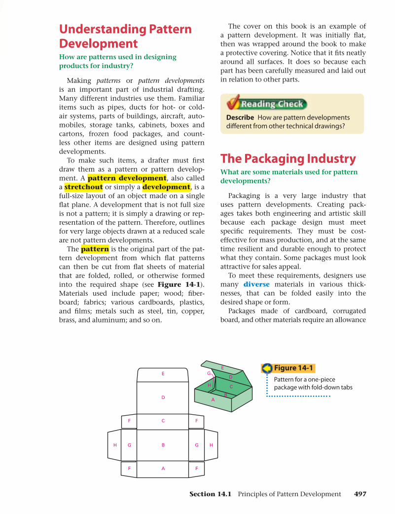
The pattern is the original part of the pat-tern development from which fl at patterns can then be cut from fl at sheets of material that are folded, rolled, or otherwise formed into the required shape (see Figure 14-1). Materials used include paper; wood; fi ber-board; fabrics; various cardboards, plastics, and fi lms; metals such as steel, tin, copper, brass, and aluminum; and so on.
The cover on this book is an example of a pattern development. It was initially fl at, then was wrapped around the book to make a protective covering. Notice that it fi ts neatly around all surfaces. It does so because each part has been carefully measured and laid out in relation to other parts.
Describe How are pattern developments diff erent from other technical drawings?
The Packaging IndustryWhat are some materials used for pattern developments?
Packaging is a very large industry that uses pattern developments. Creating pack-ages takes both engineering and artistic skill because each package design must meet specifi c requirements. They must be cost-effective for mass production, and at the same time resilient and durable enough to protect what they contain. Some packages must look attractive for sales appeal.
To meet these requirements, designers use many diverse materials in various thick-nesses, that can be folded easily into the desired shape or form.
Packages made of cardboard, corrugated board, and other materials require an allowance
Figure 14-1
Pattern for a one-piece package with fold-down tabs
Section 14.1 Principles of Pattern Development 497
FOLDLINES
BEND MARK
BOX
FOLD ORBENDLINES
COVER
PATTERN FOR CASE
PATTERN FOR DRAWER
CASE
DRAWER
E
S S
E
PATTERN
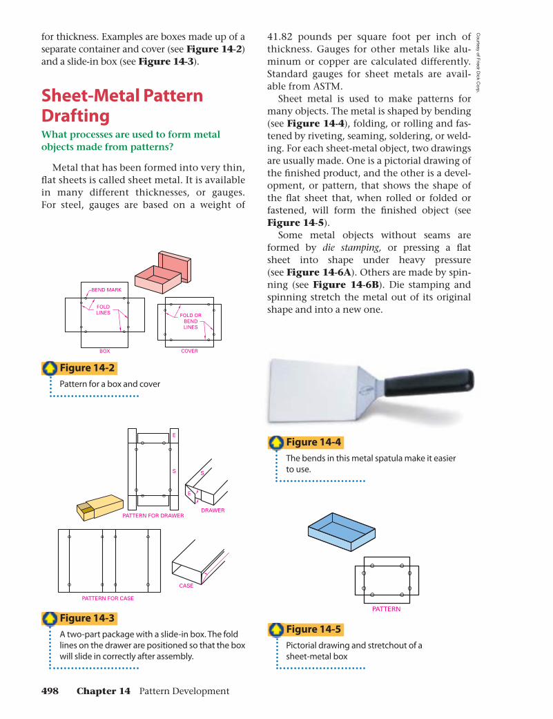
for thickness. Examples are boxes made up of a separate container and cover (see Figure 14-2) and a slide-in box (see Figure 14-3).
Sheet-Metal Pattern DraftingWhat processes are used to form metal objects made from patterns?
Metal that has been formed into very thin, fl at sheets is called sheet metal. It is available in many different thicknesses, or gauges. For steel, gauges are based on a weight of
41.82 pounds per square foot per inch of thickness. Gauges for other metals like alu-minum or copper are calculated differently. Standard gauges for sheet metals are avail-able from ASTM.
Sheet metal is used to make patterns for many objects. The metal is shaped by bending (see Figure 14-4), folding, or rolling and fas-tened by riveting, seaming, soldering, or weld-ing. For each sheet-metal object, two drawings are usually made. One is a pictorial drawing of the fi nished product, and the other is a devel-opment, or pattern, that shows the shape of the fl at sheet that, when rolled or folded or fastened, will form the fi nished object (see Figure 14-5).
Some metal objects without seams are formed by die stamping, or pressing a fl at sheet into shape under heavy pressure (see Figure 14-6A). Others are made by spin-ning (see Figure 14-6B). Die stamping and spinning stretch the metal out of its original shape and into a new one.
Figure 14-4
The bends in this metal spatula make it easier to use.
Figure 14-2
Pattern for a box and cover
Figure 14-3
A two-part package with a slide-in box. The fold lines on the drawer are positioned so that the box will slide in correctly after assembly.
Figure 14-5
Pictorial drawing and stretchout of a sheet-metal box
498 Chapter 14 Pattern Development
Courtesy of Fried
r Dick C
orp.

Figure 14-6
Examples of products created by (A) die stamping and (B) spinning sheet metal
Calculating Volume Familiar items such as pipes, storage tanks, cabinets, and boxes are designed and patterns are prepared using pattern development. When these items are meant to hold a specifi c quantity or amount of fl uid, solid, or gaseous material, the designer must calculate the volume of the items to make sure they will hold the specifi ed amount of material. For some shapes, calculating the volume is easy. For example, to fi nd the volume of a cube, simply multiply the length times the width times the height. Calculating the volumes of other shapes requires the use of other mathematical formulas.
The volume of a right cylin-der is determined using the formula:
Volume = (area of base) (height)
For example, the calculations to fi nd the volume of the cylinder shown here are:
Area of base � πr 2
� (3.1416) (22) � (3.1416) (4) � 12.57 square inches
Volume � (12.57) (4)
� 50.28 cubic inchesThe volume of a right circular cone is determined using the formula:
Volume � (area of base)(height)
________________ 3 Area of base � πr 2
� (3.1416) (22)� (3.1416) (4)� 12.57 square inches
Volume � (12.57)(6)
________ 3
� 25.14 cubic inches
Academic Standards
Mathematics
Geometry Use visualization, spatial reasoning, and
geometric modeling to solve problems.
4
2
RIGHT CIRCULAR CYLINDER
6
2
RIGHT CIRCULAR CONE
For help with this math activity, go to the Math Appendix located at the back of this book.
Section 14.1 Principles of Pattern Development 499
Cou
rtes
y of
Mat
fer
Inc.
, Cou
rtes
y of
Sitr
am C
ookw
are
A B C D
F
E
E
AB
D
Surface GeometrySheet-metal patterns, like all other patterns,
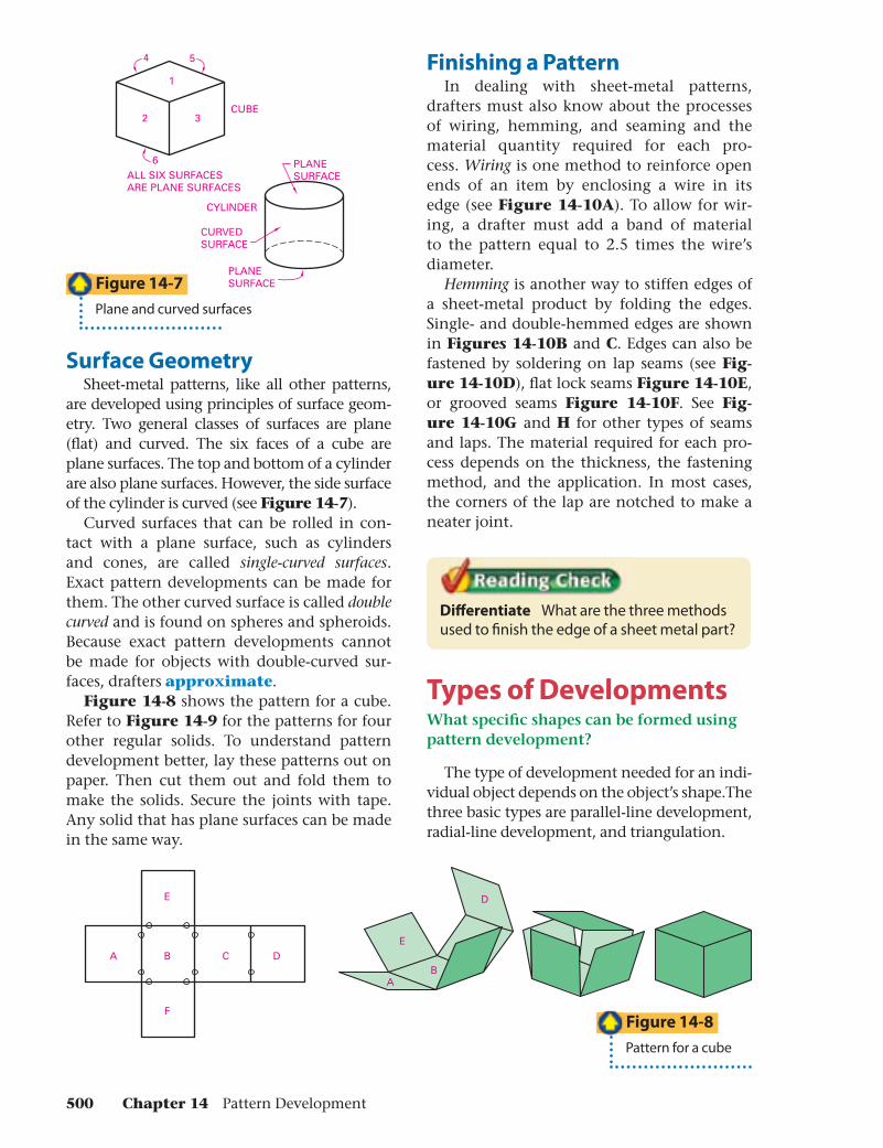
are developed using principles of surface geom-etry. Two general classes of surfaces are plane (fl at) and curved. The six faces of a cube are plane surfaces. The top and bottom of a cylinder are also plane surfaces. However, the side surface of the cylinder is curved (see Figure 14-7).
Curved surfaces that can be rolled in con-tact with a plane surface, such as cylinders and cones, are called single-curved surfaces. Exact pattern developments can be made for them. The other curved surface is called double curved and is found on spheres and spheroids. Because exact pattern developments cannot be made for objects with double-curved sur-faces, drafters approximate.
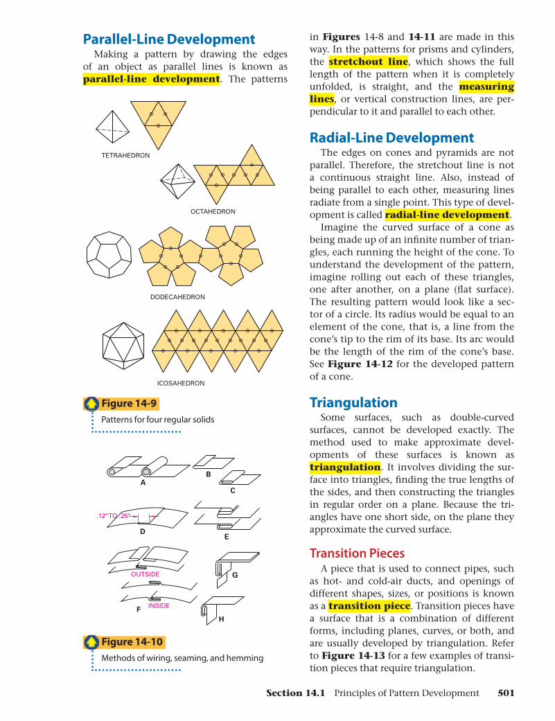
Figure 14-8 shows the pattern for a cube. Refer to Figure 14-9 for the patterns for four other regular solids. To understand pattern development better, lay these patterns out on paper. Then cut them out and fold them to make the solids. Secure the joints with tape. Any solid that has plane surfaces can be made in the same way.
Figure 14-8
Pattern for a cube
1
2 3
4 5
6
CUBE
ALL SIX SURFACESARE PLANE SURFACES
PLANESURFACE
CYLINDER
CURVEDSURFACE
PLANESURFACE
Figure 14-7
Plane and curved surfaces
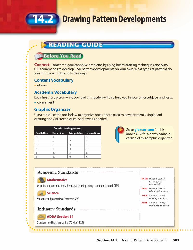
Finishing a PatternIn dealing with sheet-metal patterns,
drafters must also know about the processes of wiring, hemming, and seaming and the material quantity required for each pro-cess. Wiring is one method to reinforce open ends of an item by enclosing a wire in its edge (see Figure 14-10A). To allow for wir-ing, a drafter must add a band of material to the pattern equal to 2.5 times the wire’s diameter.
Hemming is another way to stiffen edges of a sheet-metal product by folding the edges. Single- and double-hemmed edges are shown in Figures 14-10B and C. Edges can also be fastened by soldering on lap seams (see Fig-ure 14-10D), fl at lock seams Figure 14-10E, or grooved seams Figure 14-10F. See Fig-ure 14-10G and H for other types of seams and laps. The material required for each pro-cess depends on the thickness, the fastening method, and the application. In most cases, the corners of the lap are notched to make a neater joint.
Diff erentiate What are the three methods used to fi nish the edge of a sheet metal part?
Types of DevelopmentsWhat specifi c shapes can be formed using pattern development?
The type of development needed for an indi-vidual object depends on the object’s shape.The three basic types are parallel-line development, radial-line development, and triangulation.
500 Chapter 14 Pattern Development
A
G
H
E
B
C
F
OUTSIDE
INSIDE
D
.12" TO .25"
OCTAHEDRON
TETRAHEDRON
DODECAHEDRON
ICOSAHEDRON
in Figures 14-8 and 14-11 are made in this way. In the patterns for prisms and cylinders, the stretchout line, which shows the full length of the pattern when it is completely unfolded, is straight, and the measuring lines, or vertical construction lines, are per-pendicular to it and parallel to each other.
Radial-Line DevelopmentThe edges on cones and pyramids are not
parallel. Therefore, the stretchout line is not a continuous straight line. Also, instead of being parallel to each other, measuring lines radiate from a single point. This type of devel-opment is called radial-line development.
Imagine the curved surface of a cone as being made up of an infi nite number of trian-gles, each running the height of the cone. To understand the development of the pattern, imagine rolling out each of these triangles, one after another, on a plane (fl at surface). The resulting pattern would look like a sec-tor of a circle. Its radius would be equal to an element of the cone, that is, a line from the cone’s tip to the rim of its base. Its arc would be the length of the rim of the cone’s base. See Figure 14-12 for the developed pattern of a cone.
TriangulationSome surfaces, such as double-curved
surfaces, cannot be developed exactly. The method used to make approximate devel-opments of these surfaces is known as triangulation. It involves dividing the sur-face into triangles, fi nding the true lengths of the sides, and then constructing the triangles in regular order on a plane. Because the tri-angles have one short side, on the plane they approximate the curved surface.
Transition PiecesA piece that is used to connect pipes, such
as hot- and cold-air ducts, and openings of different shapes, sizes, or positions is known as a transition piece. Transition pieces have a surface that is a combination of different forms, including planes, curves, or both, and are usually developed by triangulation. Refer to Figure 14-13 for a few examples of transi-tion pieces that require triangulation.
Figure 14-10
Methods of wiring, seaming, and hemming
Figure 14-9
Patterns for four regular solids
Parallel-Line DevelopmentMaking a pattern by drawing the edges
of an object as parallel lines is known as parallel-line development. The patterns
Section 14.1 Principles of Pattern Development 501

AB
C
3 2G
1
DEF
F
E
A
G
S1 2 3 4 1
L
DCB
STRETCHOUT LINE (SL)
F
E
A
G
DCB
LAP
Figure 14-13
Examples of transition pieces
Figure 14-12
Developed surface of a cone
Figure 14-11
A pattern for a prism, showing stretchout line and lap
Section 14.1 AssessmentAfter You Read
Self-Check 1. Explain why pattern development is
important to packaging industry. 2. List methods for processing sheet-metal
patterns. 3. Differentiate between pattern drafting
and other kinds of technical drafting. 4. Identify the three main types of pattern
developments and the purpose for each.
Academic IntegrationEnglish Language Arts
5. Using research resources such as the library, the Internet, or a business peri-odical, fi nd two articles about an event or trend in the packaging industry. In
a one-page essay, tell how the event or trend discussed could affect pattern drafting. Identify the source for each article and tell how you found it. Indi-cate whether or not you feel the infor-mation is valid and reliable, and why you feel that way.
Drafting Practice 6. Referring to Figure 14-2, draft a full-size
pattern development for a box which, when assembled, will measure 6″ wide, 4″ long, and 2.5″ tall. Draft another pattern development for a suitable cover for the box. Assemble the box and cover. Mate-rial: card stock or cardboard.
Go to glencoe.com for this book’s OLC for help with this drafting practice.
502 Chapter 14 Pattern Development
Arnold
and B
rown
Connect Sometimes you can solve problems by using board drafting techniques and Auto-CAD commands to develop CAD pattern developments on your own. What types of patterns do you think you might create this way?
Content Vocabulary• elbow
Academic VocabularyLearning these words while you read this section will also help you in your other subjects and tests.• convenient
Graphic Organizer
Use a table like the one below to organize notes about pattern development using board drafting and CAD techniques. Add rows as needed.
Steps in drawing patterns
Parallel line Radial line Triangulation Intersections
1. 1. 1. 1.2. 2. 2. 2.3. 3. 3. 3.4. 4. 4. 4.5. 5. 5. 5.6. 6. 6. 6.
Go to glencoe.com for this book’s OLC for a downloadable version of this graphic organizer.
Academic Standards
Mathematics
Organize and consolidate mathematical thinking though communication (NCTM)
Science
Structure and properties of matter (NSES)
ADDA Section 14
Standards and Practices Listing (ASME Y14.24)
NCTM National Council of Teachers of Mathematics
NSEM National Science Education Standards
ADDA American Design Drafting Assocation
ASME American Society of Mechanical Engineers
Industry Standards
Drawing Pattern Developments14.2
Section 14.2 Drawing Pattern Developments 503
1 2
34
TOPVIEW
FRONTVIEW
1-4 2-3S1 2 3 4 1
L
A B
1 2
34
1-4 2-3 1 2 3 4 1
C
1 2
34
1-4 2-3 1 2 3 4 1
D
S L
1 2
34
1-4 2-3 1 2 3 4 1
E
Parallel-Line DevelopmentsWhy is accuracy so important when drawing pattern developments?
Pattern development drawings are often prepared in board drafting on buff, light green, or light brown paper rather than on tracing materials such as vellum or fi lm, and nearly always in pencil. Remember that pat-tern developments are prepared at full size and that accuracy in layout and measure-ments is of key importance.
Because accuracy is crucial, lines are often drawn somewhat thinner than they are for other types of drawings, but they still need to be sharp and black, and of good quality.
The easiest type of development to create is the parallel-line development. It is used to develop patterns for prisms, cylinders, and elbows.
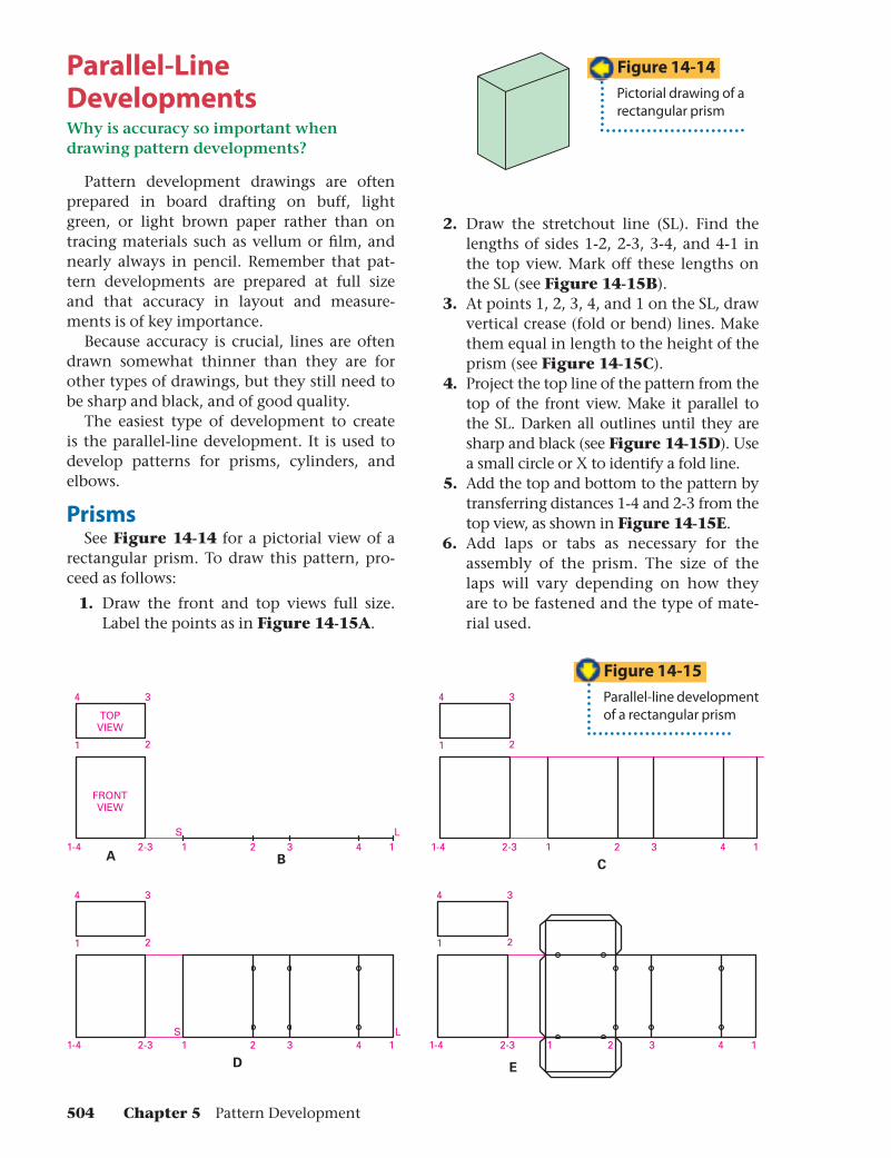
PrismsSee Figure 14-14 for a pictorial view of a
rectangular prism. To draw this pattern, pro-ceed as follows:
1. Draw the front and top views full size. Label the points as in Figure 14-15A.
2. Draw the stretchout line (SL). Find the lengths of sides 1-2, 2-3, 3-4, and 4-1 in the top view. Mark off these lengths on the SL (see Figure 14-15B).
3. At points 1, 2, 3, 4, and 1 on the SL, draw vertical crease (fold or bend) lines. Make them equal in length to the height of the prism (see Figure 14-15C).
4. Project the top line of the pattern from the top of the front view. Make it parallel to the SL. Darken all outlines until they are sharp and black (see Figure 14-15D). Use a small circle or X to identify a fold line.
5. Add the top and bottom to the pattern by transferring distances 1-4 and 2-3 from the top view, as shown in Figure 14-15E.
6. Add laps or tabs as necessary for the assembly of the prism. The size of the laps will vary depending on how they are to be fastened and the type of mate-rial used.
Figure 14-15
Parallel-line developmentof a rectangular prism
Figure 14-14
Pictorial drawing of a rectangular prism
504 Chapter 5 Pattern Development
TOP VIEW
3 2
4 1D
C
CD
3-4 1-2
A-B
B
A
AUXILIARY VIEW
PICTORIAL DRAWINGOF TRUNCATED PRISM
C D
C
B
A
1L
23
4321
BA
S
FRONT VIEW
CIRCUMFERENCEOF CIRCLE
C= D
B
A
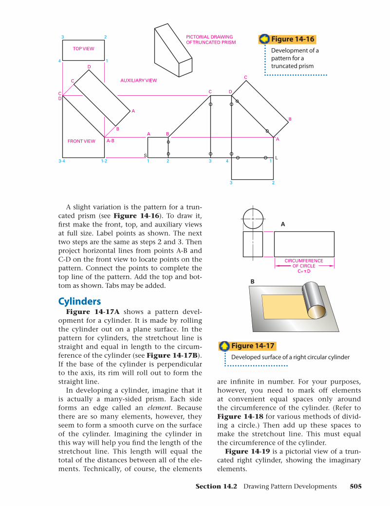
A slight variation is the pattern for a trun-cated prism (see Figure 14-16). To draw it, fi rst make the front, top, and auxiliary views at full size. Label points as shown. The next two steps are the same as steps 2 and 3. Then project horizontal lines from points A-B and C-D on the front view to locate points on the pattern. Connect the points to complete the top line of the pattern. Add the top and bot-tom as shown. Tabs may be added.
CylindersFigure 14-17A shows a pattern devel-
opment for a cylinder. It is made by rolling the cylinder out on a plane surface. In the pattern for cylinders, the stretchout line is straight and equal in length to the circum-ference of the cylinder (see Figure 14-17B). If the base of the cylinder is perpendicular to the axis, its rim will roll out to form the straight line.
In developing a cylinder, imagine that it is actually a many-sided prism. Each side forms an edge called an element. Because there are so many elements, however, they seem to form a smooth curve on the surface of the cylinder. Imagining the cylinder in this way will help you fi nd the length of the stretchout line. This length will equal the total of the distances between all of the ele-ments. Technically, of course, the elements
are infi nite in number. For your purposes, however, you need to mark off elements at convenient equal spaces only around the circumference of the cylinder. (Refer to Figure 14-18 for various methods of divid-ing a circle.) Then add up these spaces to make the stretchout line. This must equal the circumference of the cylinder.
Figure 14-19 is a pictorial view of a trun-cated right cylinder, showing the imaginary elements.
Figure 14-17
Developed surface of a right circular cylinder
Figure 14-16
Development of a pattern for a truncated prism
Section 14.2 Drawing Pattern Developments 505
12 PARTS AT 30° = 360°
8
910
11
12
7
6
5
2
34
1
12 PARTS AT 30° = 360°
8
910
11
12
7
6
5
2
34
124
2322
2120
14
1516
13
1718 19
24 PARTS AT 15° = 360°
89
1011
12
7 65
2
34
1
1
1
2
2
3
3
4
4
5
5
6
6
7
7
8
8
9
9
10
10
11
11
12
12
1LS
X
A
B
X
Y Y
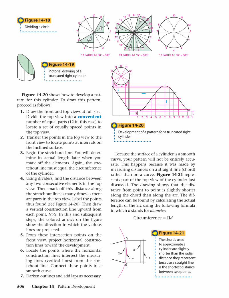
Figure 14-20 shows how to develop a pat-tern for this cylinder. To draw this pattern, proceed as follows:
1. Draw the front and top views at full size. Divide the top view into a convenientnumber of equal parts (12 in this case) to locate a set of equally spaced points in the top view.
2. Transfer the points in the top view to the front view to locate points at intervals on the inclined surface.
3. Begin the stretchout line. You will deter-mine its actual length later when you mark off the elements. Again, the stre-tchout line must equal the circumference of the cylinder.
4. Using dividers, fi nd the distance between any two consecutive elements in the top view. Then mark off this distance along the stretchout line as many times as there are parts in the top view. Label the points thus found (see Figure 14-20). Then draw a vertical construction line upward from each point. Note: In this and subsequent steps, the colored arrows on the fi gure show the direction in which the various lines are projected.
5. From these intersection points on the front view, project horizontal construc-tion lines toward the development.
6. Locate the points where the horizontal construction lines intersect the measur-ing lines (vertical lines) from the stre-tchout line. Connect these points in a smooth curve.
7. Darken outlines and add laps as necessary.
Because the surface of a cylinder is a smooth curve, your pattern will not be entirely accu-rate. This happens because it was made by measuring distances on a straight line (chord) rather than on a curve. Figure 14-21 repre-sents part of the top view of the cylinder just discussed. The drawing shows that the dis-tance from point to point is slightly shorter along the chord than along the arc. The dif-ference can be found by calculating the actual length of the arc using the following formula in which d stands for diameter:
Circumference � �d
Figure 14-18
Dividing a circle
Figure 14-20
Development of a pattern for a truncated right cylinder
Figure 14-21
The chords used to approximate a cylinder are slightly shorter than the radial distance they represent because a straight line is the shortest distance between two points.
Figure 14-19
Pictorial drawing of a truncated right cylinder
506 Chapter 14 Pattern Development
7
65 4 3
2
11 2 3 4 5 6 7 6 5 4 3 2 1
A
B
7
65 4 3
2
11 2 3 4 5 6 7 6 5 4 3 2 1
L
LAP
S
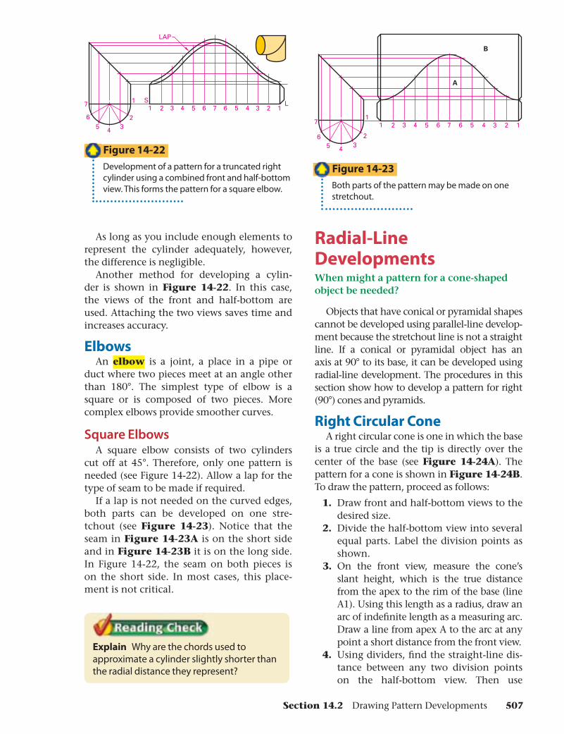
As long as you include enough elements to represent the cylinder adequately, however, the difference is negligible.
Another method for developing a cylin-der is shown in Figure 14-22. In this case, the views of the front and half-bottom are used. Attaching the two views saves time and increases accuracy.
ElbowsAn elbow is a joint, a place in a pipe or
duct where two pieces meet at an angle other than 180°. The simplest type of elbow is a square or is composed of two pieces. More complex elbows provide smoother curves.
Square ElbowsA square elbow consists of two cylinders
cut off at 45°. Therefore, only one pattern is needed (see Figure 14-22). Allow a lap for the type of seam to be made if required.
If a lap is not needed on the curved edges, both parts can be developed on one stre-tchout (see Figure 14-23). Notice that the seam in Figure 14-23A is on the short side and in Figure 14-23B it is on the long side. In Figure 14-22, the seam on both pieces is on the short side. In most cases, this place-ment is not critical.
Explain Why are the chords used to approximate a cylinder slightly shorter than the radial distance they represent?
Figure 14-23
Both parts of the pattern may be made on one stretchout.
Figure 14-22
Development of a pattern for a truncated right cylinder using a combined front and half-bottom view. This forms the pattern for a square elbow.
Radial-Line DevelopmentsWhen might a pattern for a cone-shaped object be needed?
Objects that have conical or pyramidal shapes cannot be developed using parallel-line develop-ment because the stretchout line is not a straight line. If a conical or pyramidal object has an axis at 90° to its base, it can be developed using radial-line development. The procedures in this section show how to develop a pattern for right (90°) cones and pyramids.
Right Circular ConeA right circular cone is one in which the base
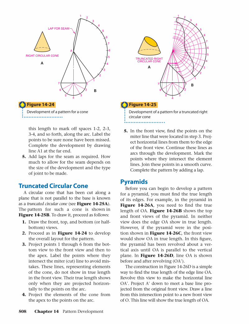
is a true circle and the tip is directly over the center of the base (see Figure 14-24A). The pattern for a cone is shown in Figure 14-24B. To draw the pattern, proceed as follows:
1. Draw front and half-bottom views to the desired size.
2. Divide the half-bottom view into several equal parts. Label the division points as shown.
3. On the front view, measure the cone’s slant height, which is the true distance from the apex to the rim of the base (line A1). Using this length as a radius, draw an arc of indefi nite length as a measuring arc. Draw a line from apex A to the arc at any point a short distance from the front view.
4. Using dividers, fi nd the straight-line dis-tance between any two division points on the half-bottom view. Then use
Section 14.2 Drawing Pattern Developments 507
1 23
4
5
6
7
6
5
4
3
2
117
RIGHT CIRCULAR CONE
LAP FOR SEAM
6
54
3
2 B
A
A
TRUNCATED RIGHTCIRCULAR CONE
A
B7
7
1 23
4
5
6
6
6
5
54
4
3
3
2
2
1
1
this length to mark off spaces 1-2, 2-3, 3-4, and so forth, along the arc. Label the points to be sure none have been missed. Complete the development by drawing line A1 at the far end.
5. Add laps for the seam as required. How much to allow for the seam depends on the size of the development and the type of joint to be made.
Truncated Circular ConeA circular cone that has been cut along a
plane that is not parallel to the base is known as a truncated circular cone (see Figure 14-25A).The pattern for such a cone is shown in Figure 14-25B. To draw it, proceed as follows:
1. Draw the front, top, and bottom (or half-bottom) views.
2. Proceed as in Figure 14-24 to develop the overall layout for the pattern.
3. Project points 1 through 6 from the bot-tom view to the front view and then to the apex. Label the points where they intersect the miter (cut) line to avoid mis-takes. These lines, representing elements of the cone, do not show in true length in the front view. Their true length shows only when they are projected horizon-tally to the points on the arc.
4. Project the elements of the cone from the apex to the points on the arc.
5. In the front view, fi nd the points on the miter line that were located in step 3. Proj-ect horizontal lines from them to the edge of the front view. Continue these lines as arcs through the development. Mark the points where they intersect the element lines. Join these points in a smooth curve. Complete the pattern by adding a lap.
PyramidsBefore you can begin to develop a pattern
for a pyramid, you must fi nd the true length of its edges. For example, in the pyramid in Figure 14-26A, you need to fi nd the true length of OA. Figure 14-26B shows the top and front views of the pyramid. In neither view does the edge OA show in true length. However, if the pyramid were in the posi-tion shown in Figure 14-26C, the front view would show OA in true length. In this fi gure, the pyramid has been revolved about a ver-tical axis until OA is parallel to the vertical plane. In Figure 14-26D, line OA is shown before and after revolving (OA′).
The construction in Figure 14-26D is a simple way to fi nd the true length of the edge line OA. Revolve this view to make the horizontal line OA′. Project A′ down to meet a base line pro-jected from the original front view. Draw a line from this intersection point to a new front view of O. This line will show the true length of OA.
Figure 14-25
Development of a pattern for a truncated right circular cone
Figure 14-24
Development of a pattern for a cone
508 Chapter 14 Pattern Development

O
AA
A' 1
O A'
A A'1B C
O A
OO
TRUELENGTH
TRUELENGTH
A'
A'A1A
O
O
A
D
1
41
23
21
OO
43
2 1
1'
2-3 1-4
TRUELENGTH
O2
1
432
12
12 1'2'
O
O
43
3
4
2
1
O
Right Rectangular PyramidsFigure 14-27 shows the pattern for a right
rectangular pyramid. To draw it, proceed as follows:
1. Find the true length of one of the edges (O1 in this case) by revolving it until it is parallel to the vertical plane (O1′).
2. With the true length as a radius, draw an arc of indefi nite length to use as a mea-suring arc.
3. On the top view, measure the lengths of the four base lines (1-2, 2-3, 3-4, 4-1). Mark these lengths off as the straight-line distances along the arc.
4. Connect the points and draw crease lines. Mark the crease lines.
5. Add base 1-2-3-4 as shown.
Oblique PyramidsSee Figure 14-28 for the development of an
oblique pyramid. To draw it, proceed as follows:1. Find the true lengths of the lateral edges.
Do this by revolving them parallel to the vertical plane as shown for edges O2 and O1. These edges are both revolved in the top view, and then projected to locate 2′and 1′. Lines O2′ and O1′ in the front view are the true lengths of edges O2 and O1. Edge O2 � edge O3. Edge O1 � edge O4.
2. Start the development by laying off 2-3. Because edge O2 � edge O3, you can locate point O by plotting arcs centered on 2 and 3 and with radii the true length of O2 (O2′). Point O is where the arcs intersect.
3. Construct triangles O-3-4, O-4-1, and O-1-2 with the true lengths of the sides to complete the development of the pyramid as shown.
Explain How do you fi nd the true length of the lateral edges of an oblique pyramid?
Figure 14-26
Finding the true length of a line
Figure 14-27
Development of a pattern fora right rectangular pyramid
Figure 14-28
Developing a pattern for an oblique pyramid
Section 14.2 Drawing Pattern Developments 509
A5
4
32 1
TOP VIEW
ELEMENTS
5 4 3 2 1
FRONT VIEW
PARTIAL DEVELOPMENT
TRUE-LENGTH DIAGRAM
54321
5
4
3
2
1
AOO
A
B C
D
TriangulationWhat is another word for “triangulation”?
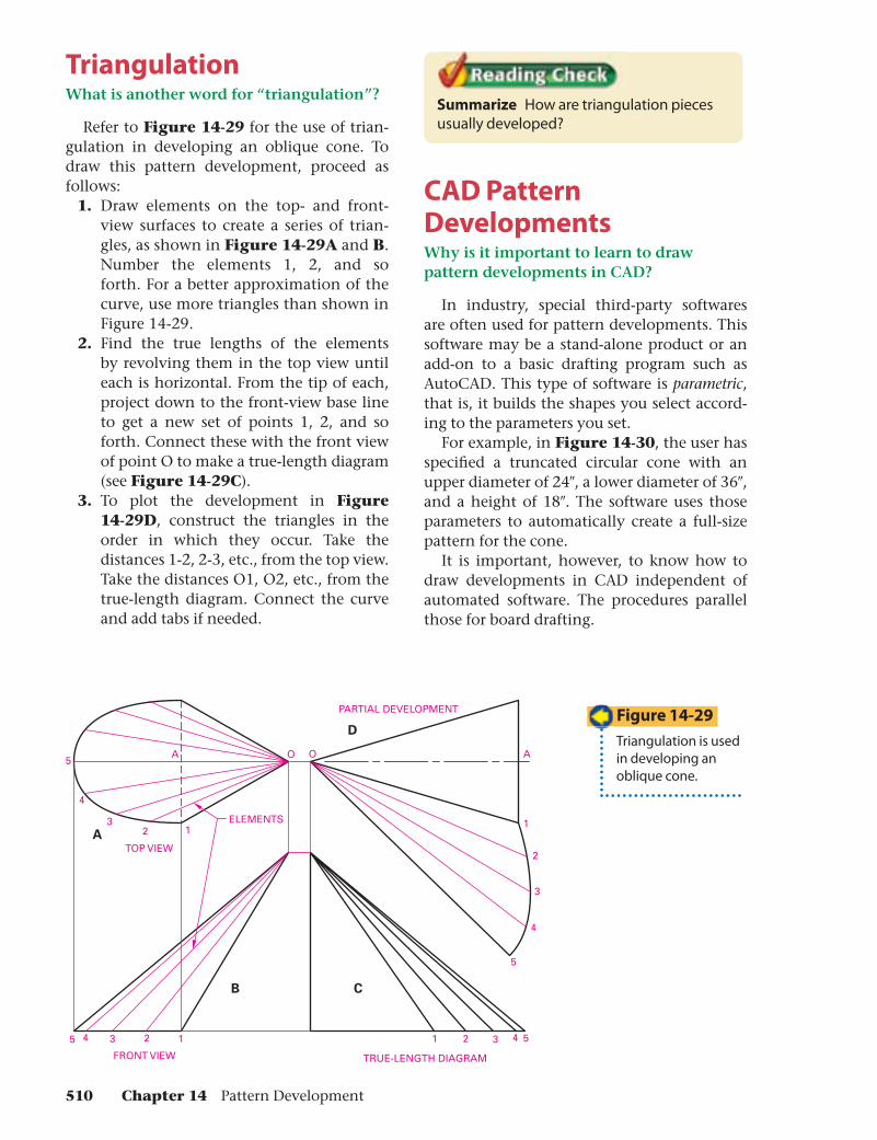
Refer to Figure 14-29 for the use of trian-gulation in developing an oblique cone. To draw this pattern development, proceed as follows:
1. Draw elements on the top- and front-view surfaces to create a series of trian-gles, as shown in Figure 14-29A and B. Number the elements 1, 2, and so forth. For a better approximation of the curve, use more triangles than shown in Figure 14-29.
2. Find the true lengths of the elements by revolving them in the top view until each is horizontal. From the tip of each, project down to the front-view base line to get a new set of points 1, 2, and so forth. Connect these with the front view of point O to make a true-length diagram (see Figure 14-29C).
3. To plot the development in Figure14-29D, construct the triangles in the order in which they occur. Take the distances 1-2, 2-3, etc., from the top view. Take the distances O1, O2, etc., from the true-length diagram. Connect the curve and add tabs if needed.
Summarize How are triangulation pieces usually developed?
CAD Pattern DevelopmentsWhy is it important to learn to draw pattern developments in CAD?
In industry, special third-party softwares are often used for pattern developments. This software may be a stand-alone product or an add-on to a basic drafting program such as AutoCAD. This type of software is parametric, that is, it builds the shapes you select accord-ing to the parameters you set.
For example, in Figure 14-30, the user has specifi ed a truncated circular cone with an upper diameter of 24″, a lower diameter of 36″, and a height of 18″. The software uses those parameters to automatically create a full-size pattern for the cone.
It is important, however, to know how to draw developments in CAD independent of automated software. The procedures parallel those for board drafting.
Figure 14-29
Triangulation is used in developing an oblique cone.
510 Chapter 14 Pattern Development

2.00
.501.50
.10
TOP VIEW
FRONT VIEW
CAD Parallel-Line DevelopmentFigure 14-31 is a pictorial view of a rectan-
gular prism. A pattern for this prism is made by parallel-line development (see Figure 14-32). To draw this pattern, proceed as follows:
1. Use the PLINE command to draw the front and top views at full size.
2. Select the top view and then enter the LIST command. A text window appears listing information about the rectangle. The perimeter equals the length of the stretchout line you need. Draw the stre-tchout line.
3. At the beginning of the stretchout line, create a 2″ vertical line to represent the beginning of the pattern. Offset this line to the right by 1.5″, .5″, 1.5″, and .5″(the dimensions of the top view) to cre-ate the crease lines and the right end
Figure 14-30
An example of parametric pattern development software. The user specifi es the dimensions in the box on the left, and the software automatically creates the pattern development in the drawing window.
Figure 14-32
CAD development of the rectangular prism from Figure 14-31
Figure 14-31
A rectangular prism
of the development. The last vertical line should lie exactly at the end of the stretchout line. Add the top horizontal across the entire development.
4. Add small circles as shown in Figure 14-32 to identify the crease lines.
5. Add the top and bottom to the pattern by copying the top view and placing it as shown on the development. Use the COPY command to create both the top and the bottom.
6. Add laps or tabs as necessary for the assembly of the prism. The size of the laps will vary depending on how they are to be fastened and the type of material used. Here you should use the OFFSET command to create .1″ tabs and chamfer the corners of the tabs at 45°.
Describe How do you create a pattern development using parametric software?
CAD Radial-Line DevelopmentAutoCAD provides tools to make radial-
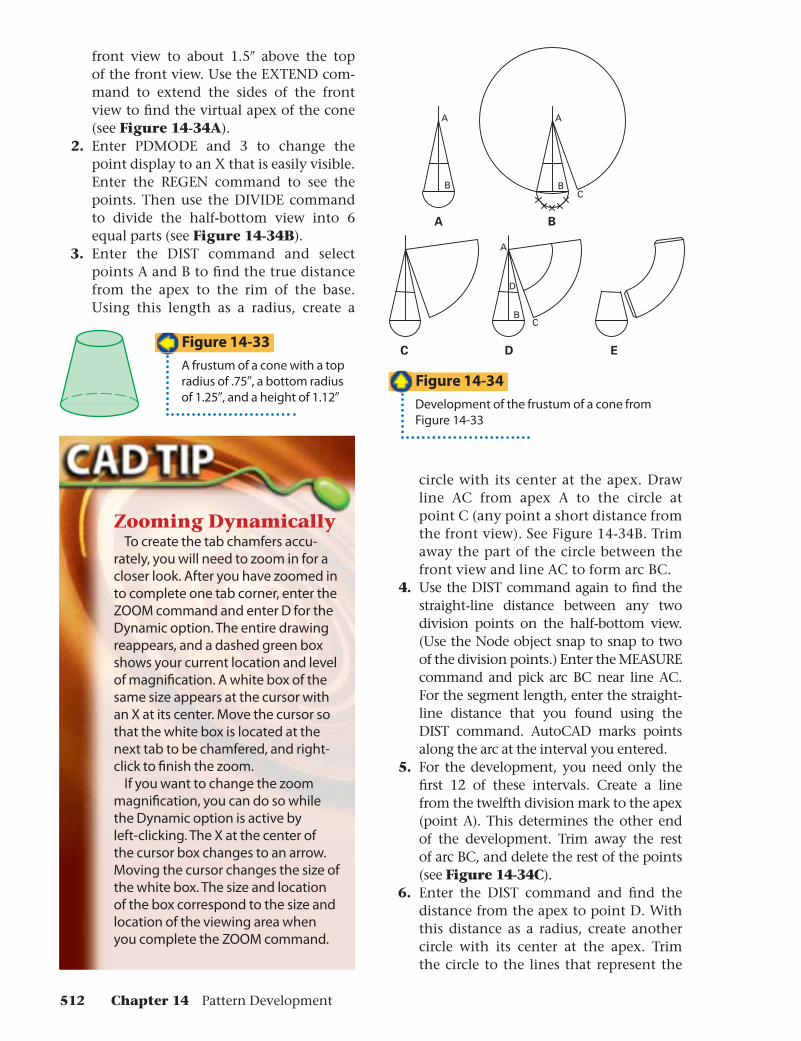
line development a fast, accurate process. See Figure 14-33 for a pictorial of a frustum of a right circular cone. The top radius is .75″, the bottom radius is 1.25″, and the height is 1.12″. Develop the cone as shown in Figure 14-34.
1. Draw front and half-bottom views. Extend a line through the center of the
Section 14.2 Drawing Pattern Developments 511
B
A
B
A
D
BC
A
C D E
C
A
B
front view to about 1.5″ above the top of the front view. Use the EXTEND com-mand to extend the sides of the front view to fi nd the virtual apex of the cone (see Figure 14-34A).
2. Enter PDMODE and 3 to change the point display to an X that is easily visible. Enter the REGEN command to see the points. Then use the DIVIDE command to divide the half-bottom view into 6 equal parts (see Figure 14-34B).
3. Enter the DIST command and select points A and B to fi nd the true distance from the apex to the rim of the base. Using this length as a radius, create a
circle with its center at the apex. Draw line AC from apex A to the circle at point C (any point a short distance from the front view). See Figure 14-34B. Trim away the part of the circle between the front view and line AC to form arc BC.
4. Use the DIST command again to fi nd the straight-line distance between any two division points on the half-bottom view. (Use the Node object snap to snap to two of the division points.) Enter the MEASURE command and pick arc BC near line AC. For the segment length, enter the straight-line distance that you found using the DIST command. AutoCAD marks points along the arc at the interval you entered.
5. For the development, you need only the fi rst 12 of these intervals. Create a line from the twelfth division mark to the apex (point A). This determines the other end of the development. Trim away the rest of arc BC, and delete the rest of the points (see Figure 14-34C).
6. Enter the DIST command and fi nd the distance from the apex to point D. With this distance as a radius, create another circle with its center at the apex. Trim the circle to the lines that represent the
Zooming DynamicallyTo create the tab chamfers accu-
rately, you will need to zoom in for a closer look. After you have zoomed in to complete one tab corner, enter the ZOOM command and enter D for the Dynamic option. The entire drawing reappears, and a dashed green box shows your current location and level of magnifi cation. A white box of the same size appears at the cursor with an X at its center. Move the cursor so that the white box is located at the next tab to be chamfered, and right-click to fi nish the zoom.
If you want to change the zoom magnifi cation, you can do so while the Dynamic option is active by left-clicking. The X at the center of the cursor box changes to an arrow. Moving the cursor changes the size of the white box. The size and location of the box correspond to the size and location of the viewing area when you complete the ZOOM command.
Figure 14-33
A frustum of a cone with a top radius of .75″, a bottom radius of 1.25″, and a height of 1.12″
Figure 14-34
Development of the frustum of a cone from Figure 14-33
512 Chapter 14 Pattern Development
POINT OFINTERSECTION
A B C D
A B C D
beginning and end of the development (see Figure 14-34D).
7. Clean up the drawing by trimming away unneeded lines. Enter PDMODE and enter a new value of 0 to hide the divi-sion points, using REGEN to change the points on-screen. To fi nish the draw-ing, add .1″ tabs with 45° chamfers (see Figure 14-34E).
Explain How do you locate the virtual apex of a frustum of a cone?
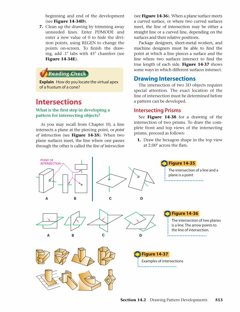
IntersectionsWhat is the fi rst step in developing a pattern for intersecting objects?
As you may recall from Chapter 10, a line intersects a plane at the piercing point, or point of intersection (see Figure 14-35). When two plane surfaces meet, the line where one passes through the other is called the line of intersection
(see Figure 14-36). When a plane surface meets a curved surface, or where two curved surfaces meet, the line of intersection may be either a straight line or a curved line, depending on the surfaces and their relative positions.
Package designers, sheet-metal workers, and machine designers must be able to fi nd the point at which a line pierces a surface and the line where two surfaces intersect to fi nd the true length of each side. Figure 14-37 shows some ways in which different surfaces intersect.
Drawing IntersectionsThe intersection of two 3D objects requires
special attention. The exact location of the line of intersection must be determined before a pattern can be developed.
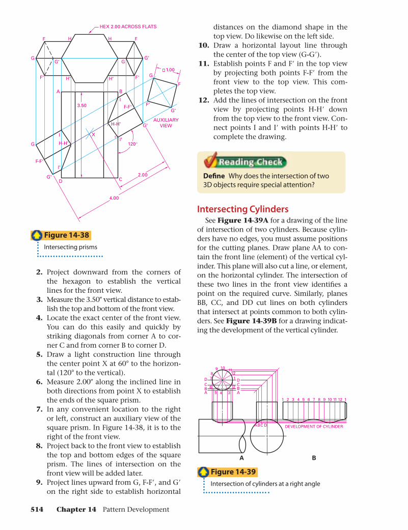
Intersecting PrismsSee Figure 14-38 for a drawing of the
intersection of two prisms. To draw the com-plete front and top views of the intersecting prisms, proceed as follows:
1. Draw the hexagon shape in the top view at 2.00″ across the fl ats.
Figure 14-35
The intersection of a line and a plane is a point
Figure 14-36
The intersection of two planes is a line. The arrow points to the line of intersection.
Figure 14-37
Examples of intersections
Section 14.2 Drawing Pattern Developments 513
A B
C
G'
G
G'G
F F
F
H
F'
F'F'
F-F'
F-F'
H'
H
H'
H-H'
H-H'
G' G
G'
I'
I'
I
I
G
G'D
X
HEX 2.00 ACROSS FLATS
2.00
120°
4.00
AUXILIARYVIEW
1.00
3.50
1 2 3 4 5 6 7 8 9 10 11 12 1
DEVELOPMENT OF CYLINDER
BA
89 10
1211
17
64 3
25
DCBA
A CB D
DCBA
2. Project downward from the corners of the hexagon to establish the vertical lines for the front view.
3. Measure the 3.50″ vertical distance to estab-lish the top and bottom of the front view.
4. Locate the exact center of the front view. You can do this easily and quickly by striking diagonals from corner A to cor-ner C and from corner B to corner D.
5. Draw a light construction line through the center point X at 60° to the horizon-tal (120° to the vertical).
6. Measure 2.00″ along the inclined line in both directions from point X to establish the ends of the square prism.
7. In any convenient location to the right or left, construct an auxiliary view of the square prism. In Figure 14-38, it is to the right of the front view.
8. Project back to the front view to establish the top and bottom edges of the square prism. The lines of intersection on the front view will be added later.
9. Project lines upward from G, F-F′, and G′on the right side to establish horizontal
distances on the diamond shape in the top view. Do likewise on the left side.
10. Draw a horizontal layout line through the center of the top view (G-G′).
11. Establish points F and F′ in the top view by projecting both points F-F′ from the front view to the top view. This com-pletes the top view.
12. Add the lines of intersection on the front view by projecting points H-H′ down from the top view to the front view. Con-nect points I and I′ with points H-H′ to complete the drawing.
Defi ne Why does the intersection of two 3D objects require special attention?
Intersecting CylindersSee Figure 14-39A for a drawing of the line
of intersection of two cylinders. Because cylin-ders have no edges, you must assume positions for the cutting planes. Draw plane AA to con-tain the front line (element) of the vertical cyl-inder. This plane will also cut a line, or element, on the horizontal cylinder. The intersection of these two lines in the front view identifi es a point on the required curve. Similarly, planes BB, CC, and DD cut lines on both cylinders that intersect at points common to both cylin-ders. See Figure 14-39B for a drawing indicat-ing the development of the vertical cylinder.
Figure 14-38
Intersecting prisms
Figure 14-39
Intersection of cylinders at a right angle
514 Chapter 14 Pattern Development
HALF DEVELOPMENT
GF
GF
E
D
CBA
E
D
CBA
7
65
43
1
12
34
56
7
2
12
3
4
5
67
PLANE
M
a a
PLANE
a
a
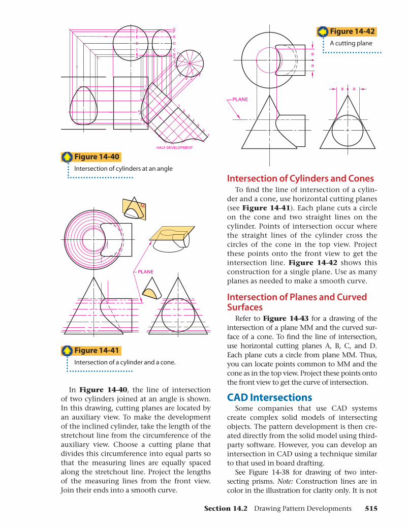
In Figure 14-40, the line of intersection of two cylinders joined at an angle is shown. In this drawing, cutting planes are located by an auxiliary view. To make the development of the inclined cylinder, take the length of the stretchout line from the circumference of the auxiliary view. Choose a cutting plane that divides this circumference into equal parts so that the measuring lines are equally spaced along the stretchout line. Project the lengths of the measuring lines from the front view. Join their ends into a smooth curve.
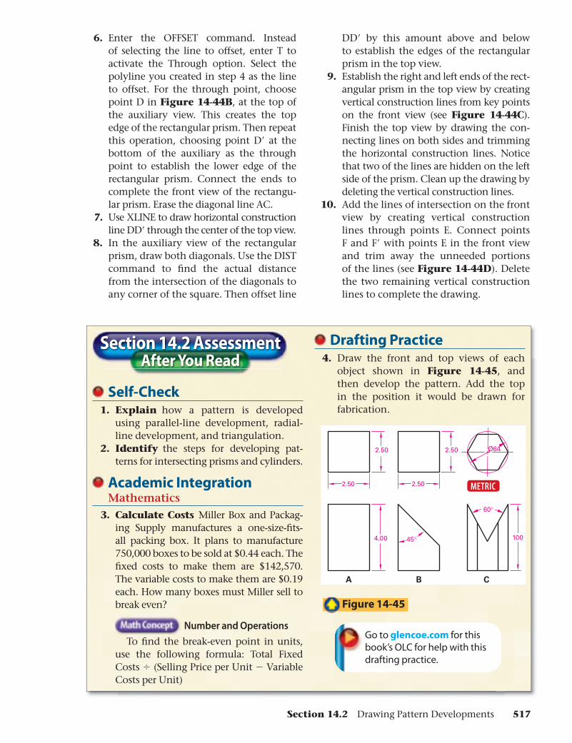
Intersection of Cylinders and ConesTo fi nd the line of intersection of a cylin-
der and a cone, use horizontal cutting planes (see Figure 14-41). Each plane cuts a circle on the cone and two straight lines on the cylinder. Points of intersection occur where the straight lines of the cylinder cross the circles of the cone in the top view. Project these points onto the front view to get the intersection line. Figure 14-42 shows this construction for a single plane. Use as many planes as needed to make a smooth curve.
Intersection of Planes and Curved Surfaces
Refer to Figure 14-43 for a drawing of the intersection of a plane MM and the curved sur-face of a cone. To fi nd the line of intersection, use horizontal cutting planes A, B, C, and D. Each plane cuts a circle from plane MM. Thus, you can locate points common to MM and the cone as in the top view. Project these points onto the front view to get the curve of intersection.
CAD IntersectionsSome companies that use CAD systems
create complex solid models of intersecting objects. The pattern development is then cre-ated directly from the solid model using third-party software. However, you can develop an intersection in CAD using a technique similar to that used in board drafting.
See Figure 14-38 for drawing of two inter-secting prisms. Note: Construction lines are in color in the illustration for clarity only. It is not
Figure 14-40
Intersection of cylinders at an angle
Figure 14-41
Intersection of a cylinder and a cone.
Figure 14-42
A cutting plane
Section 14.2 Drawing Pattern Developments 515

ABCDE
ABCDE
MM
A B
C
A
A B
C
D'
D
"THROUGH"POINTS
B
A B
C
D'
D
C
D'D
A B
C
D'
D
D
D'D
E E
F
F'
F
F'E
E
AUXILIARYVIEW
necessary or desirable to use a different color for these lines because parts of them are incorpo-rated into the fi nal drawing. Create the intersec-tion shown in Figure 14-44 by following these steps.
1. Draw the hexagon shape in the top view at 2.00″ across the fl ats.
2. Use the XLINE command to place con-struction lines downward from the cor-
ners to establish the vertical lines for the hexagon in the front view.
3. Place line AB horizontally across the construction lines as shown in Figure 14-44A. Offset the line downward by 3.50″ to create the bottom line of the front view. Trim the construction lines to the boundaries of the front view.
4. Locate the exact center of the front view. You can do this easily and quickly by striking a diagonal from corner A to cor-ner C. Start a new line at the midpoint of line AC (the center of the front view), and use polar coordinates to extend it 2.00″at 30°. Copy the new line using its right endpoint as the base point. Place the copy so that the right endpoint is at the intersection of the diagonals. Enter the PEDIT command and use the Join option to change the two lines into a single polyline, a line of any length as defi ned in Chapter 4, that defi nes the length and location of the rectangular prism.
5. To the right of the front view, construct an auxiliary view of the square prism.
Figure 14-44
Developing intersecting prisms.
Figure 14-43
Intersection of a plane and a curved surface
516 Chapter 14 Pattern Development
6. Enter the OFFSET command. Instead of selecting the line to offset, enter T to activate the Through option. Select the polyline you created in step 4 as the line to offset. For the through point, choose point D in Figure 14-44B, at the top of the auxiliary view. This creates the top edge of the rectangular prism. Then repeat this operation, choosing point D′ at the bottom of the auxiliary as the through point to establish the lower edge of the rectangular prism. Connect the ends to complete the front view of the rectangu-lar prism. Erase the diagonal line AC.
7. Use XLINE to draw horizontal construction line DD′ through the center of the top view.
8. In the auxiliary view of the rectangular prism, draw both diagonals. Use the DIST command to fi nd the actual distance from the intersection of the diagonals to any corner of the square. Then offset line
DD′ by this amount above and below to establish the edges of the rectangular prism in the top view.
9. Establish the right and left ends of the rect-angular prism in the top view by creating vertical construction lines from key points on the front view (see Figure 14-44C). Finish the top view by drawing the con-necting lines on both sides and trimming the horizontal construction lines. Notice that two of the lines are hidden on the left side of the prism. Clean up the drawing by deleting the vertical construction lines.
10. Add the lines of intersection on the front view by creating vertical construction lines through points E. Connect points F and F′ with points E in the front view and trim away the unneeded portions of the lines (see Figure 14-44D). Delete the two remaining vertical construction lines to complete the drawing.
Section 14.2 AssessmentAfter You Read
Self-Check 1. Explain how a pattern is developed
using parallel-line development, radial-line development, and triangulation.
2. Identify the steps for developing pat-terns for intersecting prisms and cylinders.
Academic IntegrationMathematics
3. Calculate Costs Miller Box and Packag-ing Supply manufactures a one-size-fi ts-all packing box. It plans to manufacture 750,000 boxes to be sold at $0.44 each. The fi xed costs to make them are $142,570. The variable costs to make them are $0.19 each. How many boxes must Miller sell to break even?
Number and Operations
To fi nd the break-even point in units, use the following formula: Total Fixed Costs � (Selling Price per Unit � Variable Costs per Unit)
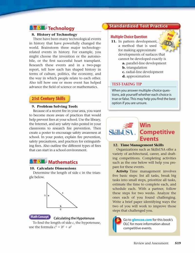
Drafting Practice 4. Draw the front and top views of each
object shown in Figure 14-45, and then develop the pattern. Add the top in the position it would be drawn for fabrication.
Go to glencoe.com for this book’s OLC for help with this drafting practice.
Figure 14-45
2.50
2.50
4.00
2.50
2.50
45°
Ø64
100
A B C
60°
METRIC
Section 14.2 Drawing Pattern Developments 517

Section 14.1 Pattern development is used extensively in the packaging industry for many products.Pattern development involves drafting a usually full-size drawing for an item that is either folded, rolled, or stamped into its shape using different methods.The three main types of pattern develop-ment are parallel-line, radial-line, and triangulation.
•
•
•
Section 14.2 On parallel-line developments, the stre-tchout line is always straight, while on radial-line development, it is curved. Tri-angulation developments involve approx-imating the surface geometry for objects that cannot be precisely patterned.Patterns can also be developed for inter-sections, or combined shapes, such as prisms and cylinders.
•
•
Review Content and Academic Vocabulary 1. Use each of these content and academic vocabulary words in a sentence or drawing.
Content Vocabulary pattern development (p. 497) stretchout (p. 497) development (p. 497) pattern (p. 497) parallel-line development (p. 501)
•••••
stretchout line (p. 501) measuring line (p. 501) radial-line development (p. 501) triangulation (p. 501) transition piece (p. 501) elbow (p. 507)
•••
•••
Academic Vocabulary diverse (p. 497) approximate (p. 500) convenient (p. 506)
•••
Review Key Concepts 2. List uses for pattern development in the packaging industry. 3. Describe how sheet metal is used in pattern development. 4. Describe the general principles of pattern development. 5. Identify the three main types of pattern development. 6. Explain when parallel-line, radial-line, and triangulation developments are used. 7. Explain how patterns are developed for intersecting prisms and cylinders.
14Chapter Summary
Review and Assessment
518 Chapter 14 Pattern Development
b
a5
6
c
Multiple Choice Question 11. In pattern development,
a method that is used for making approximate developments of surfaces that cannot be developed exactly is
a. parallel-line developmentb. triangulationc. radial-line developmentd. approximation
Technology 8. History of Technology
There have been many technological events in history that have powerfully changed the world. Brainstorm three major technology-related events in history. For example, you might choose the invention or the automo-bile, or the fi rst successful heart transplant. Research these events and in a two-page report, tell how each has shaped history in terms of culture, politics, the economy, and the way in which people relate to each other. Also tell how one or more event has helped advance the fi eld of science or mathematics.
9. Problem-Solving ToolsBecause of a recent fi re in your area, you want
to become more aware of practices that would help prevent fi res at your school. Use the library, the Internet, and any safety rules posted in your classrooms to research fi re prevention. Then create a poster to encourage safety awareness at school. In your poster, explain fi re prevention, safety precautions, and practices for extinguish-ing fi res. Also outline the different types of fi res that can start in a school environment.
Mathematics 10. Calculate Dimensions
Determine the length of side c in the trian-gle below.
Calculating the Hypotenuse
To fi nd the length of side c, the hypotenuse, use the formula c2 = b2 + a2
Prep For
TEST-TAKING TIP
When you answer multiple-choice ques-tions, ask yourself whether each choice is true or false. This may help you fi nd the best option if you are unsure.
Win Competitive Events
12. Time Management SkillsOrganizations such as SkillsUSA offer a
variety of architectural, career, and draft-ing competitions. Completing activities such as the one below will help you pre-pare for these events.
Activity Time management involves fi ve basic steps: list all tasks, break big tasks into small steps, prioritize all tasks, estimate the time to complete each, and schedule each. With a partner, follow these steps for two weeks. Analyze the ones each of you found challenging. Write a brief paper identifying ways the two of you will work to improve those steps that challenged you.
Go to glencoe.com for this book’s OLC for more information about competitive events.
Review and Assessment 519
78
2.50
.50
2.50
.50
4.00
12
345 6
7 8 11 2 3 4 5 6
78
12
345
61-84-5 2-3 6-7
2.50
2.50
30°
30°
2.50
2.50.50
2.50
1.50 .50
.50
1.00
2.50
A B C
4.004.004.00
Problems14
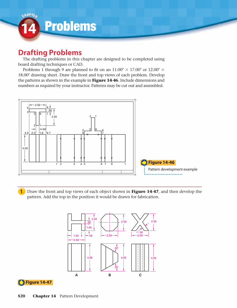
Drafting ProblemsThe drafting problems in this chapter are designed to be completed using
board drafting techniques or CAD.Problems 1 through 9 are planned to fi t on an 11.00″ × 17.00″ or 12.00″ ×
18.00″ drawing sheet. Draw the front and top views of each problem. Develop the patterns as shown in the example in Figure 14-46. Include dimensions and numbers as required by your instructor. Patterns may be cut out and assembled.
1. Draw the front and top views of each object shown in Figure 14-47, and then develop the pattern. Add the top in the position it would be drawn for fabrication.
Figure 14-46
Pattern development example
Figure 14-47
520 Chapter 14 Pattern Development
A B C
Ø64
100
Ø2.50
4.0045°
Ø2.50
90°
4.00
A
Ø2.50
2.00
Ø1.50
B
Ø64
12
90°
C
Ø2.50
4.00
R4.00
100
Ø2.50
Ø2.00
Ø64
56
Ø2.50
2.20
135°
2.20
1.00
A B C D
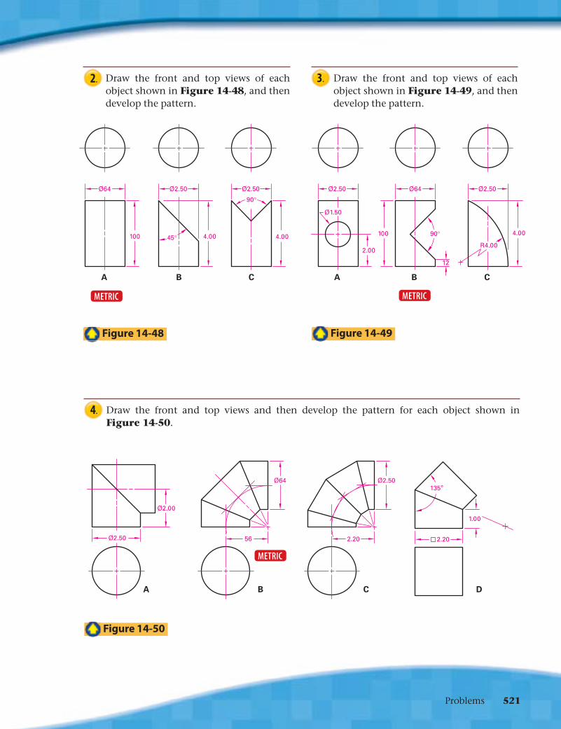
2. Draw the front and top views of each object shown in Figure 14-48, and then develop the pattern.
3. Draw the front and top views of each object shown in Figure 14-49, and then develop the pattern.
Figure 14-49
Figure 14-50
4. Draw the front and top views and then develop the pattern for each object shown in Figure 14-50.
Figure 14-48
METRICMETRIC
METRIC
Problems 521
A B C
Ø2.50
3.50
45°4.38
5.50
Ø1.62
1.25 Ø1.25
45°
1.75
Ø2.50
3.50
50
88
44
Ø35
8.00
4.003.00
8.00
14.00
NOTES: 1. ALL HEMS AND TABS .25"2. HANDLE Ø.50
18.00
12.00
.50
NOTE: HEM ALL EDGES .25"
Problems14
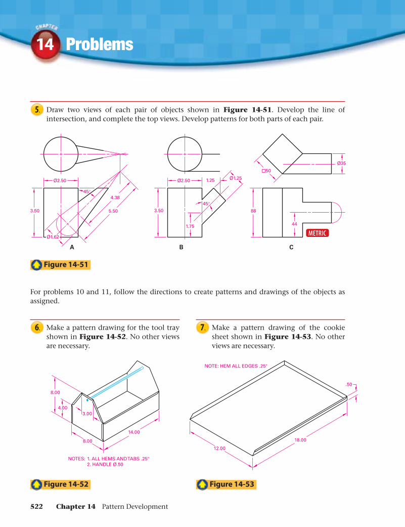
5. Draw two views of each pair of objects shown in Figure 14-51. Develop the line of intersection, and complete the top views. Develop patterns for both parts of each pair.
METRIC
6. Make a pattern drawing for the tool tray shown in Figure 14-52. No other views are necessary.
For problems 10 and 11, follow the directions to create patterns and drawings of the objects as assigned.
7. Make a pattern drawing of the cookie sheet shown in Figure 14-53. No other views are necessary.
Figure 14-51
Figure 14-52
Figure 14-53
522 Chapter 14 Pattern Development
10
0
10
20
30
40
50
60
70
80
90
100
110
120
130
140
150METRIC
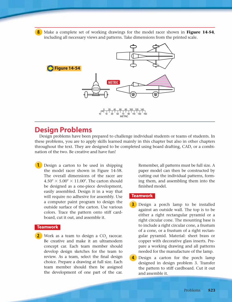
8. Make a complete set of working drawings for the model racer shown in Figure 14-54, including all necessary views and patterns. Take dimensions from the printed scale.
Figure 14-54
METRIC
Design ProblemsDesign problems have been prepared to challenge individual students or teams of students. In
these problems, you are to apply skills learned mainly in this chapter but also in other chapters throughout the text. They are designed to be completed using board drafting, CAD, or a combi-nation of the two. Be creative and have fun!
1. Design a carton to be used in shipping the model racer shown in Figure 14-58. The overall dimensions of the racer are 4.50″ × 5.00″ × 11.00″. The carton should be designed as a one-piece development, easily assembled. Design it in a way that will require no adhesive for assembly. Use a computer paint program to design the outside surface of the carton. Use various colors. Trace the pattern onto stiff card-board, cut it out, and assemble it.
Teamwork
2. Work as a team to design a CO2 racecar. Be creative and make it an ultramodern concept car. Each team member should develop design sketches for the team to review. As a team, select the fi nal design choice. Prepare a drawing at full size. Each team member should then be assigned the development of one part of the car.
Remember, all patterns must be full size. A paper model can then be constructed by cutting out the individual patterns, form-ing them, and assembling them into the fi nished model.
Teamwork
3. Design a porch lamp to be installed against an outside wall. The top is to be either a right rectangular pyramid or a right circular cone. The mounting base is to include a right circular cone, a frustum of a cone, or a frustum of a right rectan-gular pyramid. Material: sheet brass or copper with decorative glass inserts. Pre-pare a working drawing and all patterns needed for the manufacture of the lamp.
4. Design a carton for the porch lamp designed in design problem 3. Transfer the pattern to stiff cardboard. Cut it out and assemble it.
Problems 523