
RIVET-REPAIR DESIGN | McGraw-Hill Education - Access ...
18
9.4. RIVET-REPAIR DESIGN For each step in the design process for rivet repair, three procedures are described. The first, indicated as " General " (see below), follows the general guidelines established by the FAA and uses minimums as the design criteria. The second procedure, marked "Applied," uses the FAA minimums but is designed so that the rivet layout is repairable. The third technique for rivet layout, marked "Calculated," shows the results if the repair was designed using the calculations previously discussed. Before proceeding with an explanation regarding how to use this information, the information provided in Fig. 9-8 should be reviewed. The strength data provided in Fig. 9-8 are accurate but not complete. In area (B) of Fig. 9-8 the strength comment in the upper left corner is limited only to the second row from the left and the row of rivets to which the arrow is pointing. The strength of the sheet is determined by the strength at its weakest point, which in this case is not the rows to which the arrow is referring. The relative sheet strength of the (B) joint is 66.7 percent, which results from the 3D spaced rivets. Figure 9-8 Riveted sheet-metal splices. 9.4.1. Splicing of Sheets Figure 9-8, which is a duplication of Fig. 2.18 in AC 43.13-1B & 2B, is an example of how sheet-metal materials might be spliced. The technician should note the difference between a "splice" and a "patch." A splice is the mating of two or more pieces of material so that the load is transferred from one material to another. A patch consists of two or more lap joints, where the loads applied to original material are first transferred from the original material to a doubler (which may be the patch material) and then from the doubler back to the original material. In aircraft design, a transition doubler may be a stinger, rib, or flange. © McGraw-Hill Education. All rights reserved. Any use is subject to the Terms of Use, Privacy Notice and copyright information.
-
Upload
khangminh22 -
Category
Documents
-
view
1 -
download
0
Transcript of RIVET-REPAIR DESIGN | McGraw-Hill Education - Access ...

9.4. RIVET-REPAIR DESIGN
For each step in the design process for rivet repair, three procedures are described. The first, indicated as "General" (see below),follows the general guidelines established by the FAA and uses minimums as the design criteria. The second procedure,marked "Applied," uses the FAA minimums but is designed so that the rivet layout is repairable. The third technique for rivetlayout, marked "Calculated," shows the results if the repair was designed using the calculations previously discussed.
Before proceeding with an explanation regarding how to use this information, the information provided in Fig. 9-8 should bereviewed. The strength data provided in Fig. 9-8 are accurate but not complete. In area (B) of Fig. 9-8 the strength comment inthe upper left corner is limited only to the second row from the left and the row of rivets to which the arrow is pointing. Thestrength of the sheet is determined by the strength at its weakest point, which in this case is not the rows to which the arrow isreferring. The relative sheet strength of the (B) joint is 66.7 percent, which results from the 3D spaced rivets.
Figure 9-8 Riveted sheet-metal splices.
9.4.1. Splicing of Sheets
Figure 9-8, which is a duplication of Fig. 2.18 in AC 43.13-1B & 2B, is an example of how sheet-metal materials might be spliced.The technician should note the difference between a "splice" and a "patch." A splice is the mating of two or more pieces ofmaterial so that the load is transferred from one material to another. A patch consists of two or more lap joints, where the loadsapplied to original material are first transferred from the original material to a doubler (which may be the patch material) andthen from the doubler back to the original material. In aircraft design, a transition doubler may be a stinger, rib, or flange.
© McGraw-Hill Education. All rights reserved. Any use is subject to the Terms of Use, Privacy Notice and copyright information.

When splicing sheets, the splice should be designed as illustrated in the following example. The example makes the followingassumptions:
Width of sheet (length of splice): W = 12 in [30.48 cm]
Sheet material: 2024-T3 Alclad sheet
0.032 in [0.813 mm] thickness
UTS = 59 000 psi
UBS @ 1.5D = 97 000 psi
USS = 37 000 psi
Rivet material: AN470AD rivets
2117 = T4
USS = 30 000 psi
9.4.1.1. Determining the Rivet Diameter
In AC 43.13-1B & 2B, para. 2.99h, the discussion regarding rivet size uses the phrase "approximately three times the thickness ofthe thicker sheet." This relationship between the thickness of the sheet and the diameter of the rivet is not a minimum. If atechnician uses the calculations previously discussed and these calculations result in a rivet diameter slightly smaller than"three times the thickness of the thicker sheet" of material, the technician may elect to use the smaller-diameter rivet.
9.4.1.1.1. General.
Select the rivet diameter approximately three times the sheet thickness. Thus, 3 × 0.32 = 0.096 in [2.44 mm]. Since the nextstandard size greater than 0.096 in is in, use -in [3.175-mm] 2117-T4 (AD) rivets. Unless design criteria dictates otherwise,when the calculated rivet diameter exceeds that of a standard-size rivet, the next largest standard-size rivet is used.
9.4.1.1.2. Applied.
The minimum diameter of the rivets to be installed is in [3.18 mm], but for the layout work that follows the criteria for a rivet
two standard sizes over (or in [4.76 mm]) will be used for the rivet layout.
9.4.1.1.3. Calculated.
18
18
18
316
© McGraw-Hill Education. All rights reserved. Any use is subject to the Terms of Use, Privacy Notice and copyright information.

9.4.1.1.3. Calculated.
By applying Eq. (9-18), which is d = 1.27t (F /F ), the technician may calculate the diameter of the rivet required.
Although, when using the AC 43.13 charts, the rivet-diameter selection was in [3.18 mm], using a -in [3.97-mm] rivet wouldbetter meet the criteria when considering the mechanical properties of the materials involved. However, the calculated rivet sizeis only 0.006 in [0.15 mm] over the diameter of the -in [3.18-mm] "charted" rivet diameter, and if the driven diameter of thecharted rivet is considered, a difference of 0.002 in [0.05 mm] between the calculated and charted rivet exists.
Since the mechanical properties of the materials used for the repair do not reflect a safety factor, it is fairly safe to assume thatthe -in [3.18-mm] rivet is capable of handling the loads involved. The technician could, however, calculate the design loadapplied to the repair area by examining the existing rivet diameters and their spacing, as indicated in Eqs. (9-37) through (9-45).
In continuing this example, the -in [3.18-mm] rivet will be assumed to meet the design load criteria.
9.4.1.2. Determining the Number of Rivets
When determining the number of rivets, the ability of the rivets to withstand a shear load is equated to the ability of the rivets towithstand an equal bearing or tensile load, whichever is least.
9.4.1.2.1. General.
Determine the number of rivets required per inch of width W from Table 9-3. The number of rivets per inch equals 6.2; hence thetotal number of rivets required is 12 × 6.2 = 74.4, or 75 rivets. Unless design criteria dictate otherwise, when the number of rivetsexceeds a whole number, the number of rivets is always rounded up. The technician should note here that this example dealswith a splice. A splice differs from a patch repair, which must have twice the number of rivets because it must first transmit theload to the patch and then return it to the skin on the other side of the damaged (or removed) area.
The technician may apply footnote (c) of Table 9-3, if appropriate. For single-lap joints, 75 percent of 74.4 rivets, or 56 (whenrounded), may also be successfully used.
9.4.1.2.2. Applied.
Since the diameter of the layout -6 rivets is larger than the -4 rivets, the -6 rivets are capable of withstanding greater shearforces. Because -4 rivets will be initially installed and their load-bearing capability is less than that of an equal number of -6rivets, the number of rivets used in the repair should be that calculated in the general procedure. A review of Table 9-3 verifiesthis fact. Note that for a given thickness of material, as the diameter of the rivet increases, the number of rivets decreases.
9.4.1.2.3. Calculated.
b s
d = 1.27 × 0.032 × ( ) = 0.13197 00030 000
18
532
18
18
18
© McGraw-Hill Education. All rights reserved. Any use is subject to the Terms of Use, Privacy Notice and copyright information.

9.4.1.2.3. Calculated.
The load-carrying capability of the sheet material is generally assumed to be the load applied to the repair area. However, thetechnician might wish to develop a maximum-load applied criteria by analyzing the aircraft's existing rivet pattern and usingthese concepts to calculate the applied load. If this process and the general procedure are followed (i.e., additional spacing isnot added to the rivet pattern in order to accommodate repairs to the repair), this will usually result in a duplication of theexisting rivet pattern. For the purposes of this example, the load-carrying capabilities of the original material will be assumed tobe the applied load.
When using this technique, the technician should take care in determining the cause for the repair. If rivet shear (as a result offlight loads) is the cause, the existing rivet pattern is insufficient and should not be used to determine applied loads. This alsoapplies to the general guidelines established by the FAA in AC 43.13-1B & 2B.
By using Eq. (9-34), if the shear strength of the rivet [see Eq. (8-29)] is greater than the bearing strength of the sheet [see Eq. (8-35) or Eq. (9-36) if the opposite is true], the number of rivets required may be calculated. In this example the rivet shear strengthis 389.1 lb and the bearing strength of the sheet at a -in [3.18 mm] hole is 398.8 lb. When doing these calculations, the drilled-hole diameter rather than the rivet's predriven diameter must be used. Because the shear strength of the rivet is less than thebearing strength of the sheet, Eq. (9-34) is used.
Using Eq. (9-34) to find T , the number of rivets required is 58. If this was a patch-type repair, twice as many rivets per side ofthe joint, or 116 rivets, would be required. Remember, when doing these calculations, the drilled-hole diameter and not itspredriven diameter must be used.
9.4.1.3. Determining Rivet Spacing and Layout
In this step, the layout is accomplished based upon an equalization of shear strength to the bearing or tensile capabilities of thesheet.
9.4.1.3.1. General.
Using the minimum-diameter rivets of in [3.18 mm] to establish a rivet pattern, to find the number of rows required, the edgedistance, which is a constant, 2D, must be subtracted twice from the length of the splice. This results in an available rivet-rowwidth of 11.500 in [2.92 cm]. The number of rivets that may be placed in a row is one more than the row length divided by therivet spacing used. This is because the row length both starts and ends with a rivet. In the case of 3D rivet spacing, that means31 rivets per row maximum. 4D spacing would accommodate 24 rivets per row maximum. Since 4D spacing is used only intwo-row applications and 75 rivets are needed, the splice may not be accomlished in two rows. This is also the case even iffootnote (c) (Table 9-3) is applied and 56 rivets were used to accomplish the repair. Therefore, 3D spacing must be used.
Using a 3D pitch, based upon 75 rivets, there would be 25 rivets per row with a pitch of 0.46 in [11.68 mm], edge distance of0.250 in [6.35 mm], and a gauge of 0.375 in [9.53 mm]. Figure 9-9 shows this layout.
18
r
18
© McGraw-Hill Education. All rights reserved. Any use is subject to the Terms of Use, Privacy Notice and copyright information.
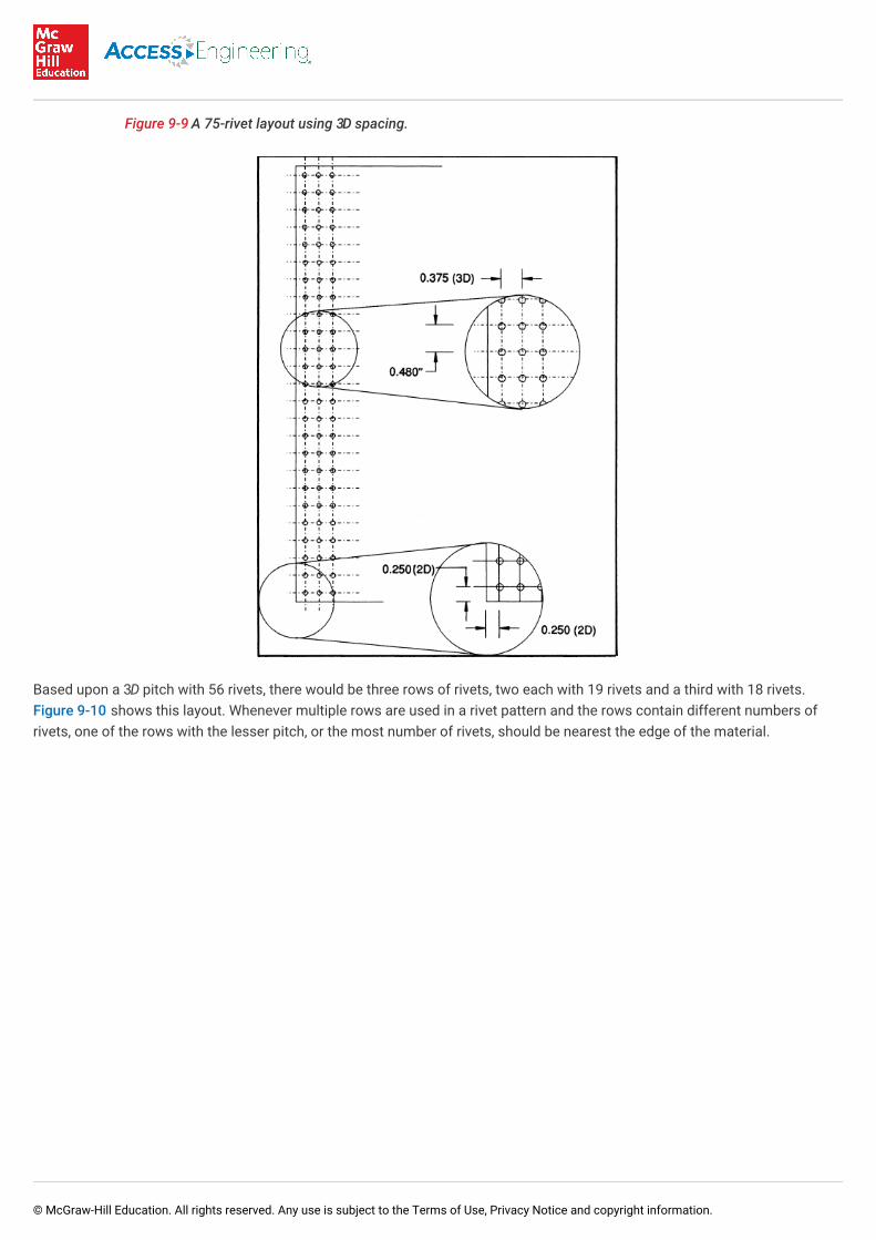
Figure 9-9 A 75-rivet layout using 3D spacing.
Based upon a 3D pitch with 56 rivets, there would be three rows of rivets, two each with 19 rivets and a third with 18 rivets.Figure 9-10 shows this layout. Whenever multiple rows are used in a rivet pattern and the rows contain different numbers ofrivets, one of the rows with the lesser pitch, or the most number of rivets, should be nearest the edge of the material.
© McGraw-Hill Education. All rights reserved. Any use is subject to the Terms of Use, Privacy Notice and copyright information.

Figure 9-10 A 56-rivet layout using 3D spacing.
9.4.1.3.2. Applied.
© McGraw-Hill Education. All rights reserved. Any use is subject to the Terms of Use, Privacy Notice and copyright information.

9.4.1.3.2. Applied.
This step of the rivet-layout procedure is the step that makes the applied process different from the general process. In thissection the edge distance and rivet spacing are calculated to comply with the minimum diameter of a rivet two sizes larger thanwas previously determined. In applying the "repairable repair" concept, the layout is based upon the edge distance and rivetspacing required by a rivet two standard sizes larger, or in [9.53 mm].
The edge distance for a -in [9.53-mm] (-6) rivet is in [19.05 mm]. The rivet spacing may be either 3D or 4D, so it needs to becalculated twice. The 3D spacing is 0.281 in [7.14 mm]. The 4D spacing is 0.375 in [9.53 mm].
To find the number of rows required, the edge distance, which is a constant 2D, needs to be subtracted twice from the length ofthe splice. This results in an available rivet row width of 11.625 in [2.95 cm]. The number of rivets that may be placed in a row isthen one more than the row length divided by the rivet spacing used, since the row length both starts and ends with a rivet. Inthe case of 3D rivet spacing, that means 42 rivets per row maximum. 4D spacing accommodates 32 rivets per row maximum.Since 4D spacing is used only in two-row applications and 75 rivets are needed, the splice may not be accomplished in tworows. Therefore, 3D spacing must be used.
However, if footnote (c) of Table 9-3, is applied, the number of rivets required is 75 percent of 74.4, or 56 (55.8) rivets, so a rivetpattern of two rows may be used.
Since the applied section uses larger rivets for layout, the rivet spacing will be increased using AC 43.13-1B & 2B guidelines, sothe spacing will exceed the minimums established by the Advisory Circular when - -in-diameter rivets are installed.
Figure 9-11 shows a layout that is acceptable for -6 rivets and accommodates 75 rivets.
Figure 9-11 An acceptable layout for -4 rivets, using -6 spacing.
9.4.1.3.3. Calculated.
38
38
34
4 18
© McGraw-Hill Education. All rights reserved. Any use is subject to the Terms of Use, Privacy Notice and copyright information.

9.4.1.3.3. Calculated.
Using Eq. (9-26), the technician can calculate the proper edge distance for this particular application. These calculations resultin a suggested edge distance of 0.217 in [5.51 mm]. Since this distance is less than the 2D recommended by AC 43.13-1B & 2B,the 2D distance should be used.
At this point the technician should take special note that the terms edge distance and rivet spacing as used in the general andapplied processes refer to a distance measured from the center of the rivet hole. In calculating rivet spacing and edgedistances, the definition of these terms must be altered.
In the splice example given previously, if flush rivets are used, it is recommended that an edge distance of (rivet diameter)be used. For universal-head rivets, an edge distance of not less than 2D is satisfactory.
In splice applications the width for the rivet layout is equal to W. However, in the case of a patch, the width of the rows should betwice the width of the damaged area. The technician should also keep in mind that when adding holes to a sheet of material,such as an aircraft skin, the tensile load-carrying capability of the material is reduced [see Eq. (9-27)].
9.4.2. Repairs for Small Holes
2 D12
© McGraw-Hill Education. All rights reserved. Any use is subject to the Terms of Use, Privacy Notice and copyright information.
9.4.2. Repairs for Small Holes
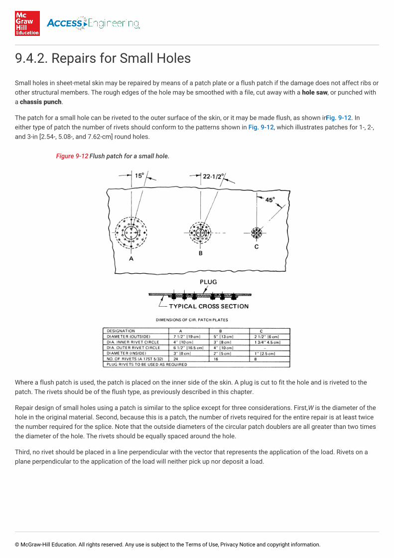
Small holes in sheet-metal skin may be repaired by means of a patch plate or a flush patch if the damage does not affect ribs orother structural members. The rough edges of the hole may be smoothed with a file, cut away with a hole saw, or punched witha chassis punch.
The patch for a small hole can be riveted to the outer surface of the skin, or it may be made flush, as shown in Fig. 9-12. Ineither type of patch the number of rivets should conform to the patterns shown in Fig. 9-12, which illustrates patches for 1-, 2-,and 3-in [2.54-, 5.08-, and 7.62-cm] round holes.
Figure 9-12 Flush patch for a small hole.
Where a flush patch is used, the patch is placed on the inner side of the skin. A plug is cut to fit the hole and is riveted to thepatch. The rivets should be of the flush type, as previously described in this chapter.
Repair design of small holes using a patch is similar to the splice except for three considerations. First, W is the diameter of thehole in the original material. Second, because this is a patch, the number of rivets required for the entire repair is at least twicethe number required for the splice. Note that the outside diameters of the circular patch doublers are all greater than two timesthe diameter of the hole. The rivets should be equally spaced around the hole.
Third, no rivet should be placed in a line perpendicular with the vector that represents the application of the load. Rivets on aplane perpendicular to the application of the load will neither pick up nor deposit a load.
9.4.3. Replacement of Skin Panels
© McGraw-Hill Education. All rights reserved. Any use is subject to the Terms of Use, Privacy Notice and copyright information.

9.4.3. Replacement of Skin Panels
In cases where damage to stressed skin has occurred over an extensive area, it is often necessary to replace an entire panel.The original panel is removed by carefully drilling out the rivets at the seams. A new panel of the same material and thickness iscut to the same size as the original. The rivet pattern at the seams must conform to the original pattern. In cases where aportion of a panel is replaced and different rivet patterns are used on the opposite edges of panels, it is best to copy the patternof the stronger seam. Before a damaged panel is replaced, the interior of the structure must be inspected carefully. Alldamaged ribs, bulkhead, or other structures must be repaired before replacing the skin panel.
9.4.4. Repairs of Sheet-Metal Ribs
Typical repairs for formed sheet-metal and built-up ribs are shown in Fig. 9-13. In making repairs of the type shown, thetechnician must use the correct number of rivets of the proper size and material. The replacement material and material used inmaking reinforcements must be of the same type as that used in the original structure. Furthermore, the material must have thesame heat treatment as the original. The thickness of the repair material must be the same or greater than that of the original.
Figure 9-13 Repairs for sheet-metal ribs.
Repairs for formed sheet-metal rib-cap strips are illustrated in Fig. 9-14. The repairs shown are indicative of the types of repairsrequired; however, many different types of repairs can be made as long as the strength and durability are adequately restored.
© McGraw-Hill Education. All rights reserved. Any use is subject to the Terms of Use, Privacy Notice and copyright information.

Figure 9-14 Repairs for metal rib-cap strips.
9.4.5. Stringer and Flange Splices
© McGraw-Hill Education. All rights reserved. Any use is subject to the Terms of Use, Privacy Notice and copyright information.

9.4.5. Stringer and Flange Splices
Splices for stringers and flanges are shown in Fig. 9-15. The original material is shown unshaded; the reinforcing material isshaded. Remember that stringers are the longitudinal supporting members to which the skin of the fuselage or wing isattached. The stringers are attached to the bulkheads or beltframes (formers), which are principal structural members of theassembly and are designed to take both compression and tension loads. Therefore, these riveting principles must be followed:
1. To avoid eccentric loading and buckling in compression, splicing or reinforcing parts are placed as symmetrically aspossible about the centerline of the member. Attachment is made to as many elements as necessary to prevent bending inany direction.
2. So that reduction of strength under tension of the original member is avoided, the rivet holes at the end of the splice aremade small—that is, not larger than the original skin-attaching rivets—and the second row of rivets is staggered back fromthe ends.
3. To prevent concentrating the loads on the end rivet and the consequent tendency toward progressive rivet failure, the splicemember is tapered at the ends. This also has the effect of reducing the stress concentration at the ends of the splice.
4. When several adjacent stringers are spliced, the splices should be staggered if possible.
5. The diameter of rivets in stringers should be between two and three times the thickness of the leg but should not be morethan one-quarter its width.
Figure 9-15 Splices for stringers and flanges.
9.4.6. Repairing Cracked Structures
© McGraw-Hill Education. All rights reserved. Any use is subject to the Terms of Use, Privacy Notice and copyright information.

Methods for repairing cracked structures are shown in Fig. 9-16. This illustration shows repairs at the intersection of ribs andspars at both the leading edge and the trailing edge of a wing or other airfoil. Reinforcing plates must be of the same alloy andapproximately times the thickness of the original material. In every case where cracks are repaired, the cracks should bestop-drilled before installing any reinforcements. Stop-drilling can be defined as the process of drilling a small hole at theextreme end of a crack to prevent the crack from progressing farther into the material. The hole at the end of the crack removesthe sharp stress-concentration area.
Figure 9-16 Repairs for cracked structures.
The condition causing cracks to develop at a particular point is stress concentration at the point combined with the repetitionof the stress, as would occur with vibration. Stress concentrations are caused by nicks, scratches, or incorrect design factors.Complete failure of wing structures has been caused by stress concentrations where material has been cut to form a notch. Inall repairs, the technician must make sure that material is not cut to form a sharp angle between two edges and that where twoedges come together to form an angle, the material is rounded ("radiused") to a radius sufficient to prevent stressconcentrations. The radius should be made as smooth as possible.
Members of aircraft structures that have developed cracks at fittings can be repaired as shown in Fig. 9-17. The treatment ofcracks in these repairs is the same as described previously.
1 12
© McGraw-Hill Education. All rights reserved. Any use is subject to the Terms of Use, Privacy Notice and copyright information.
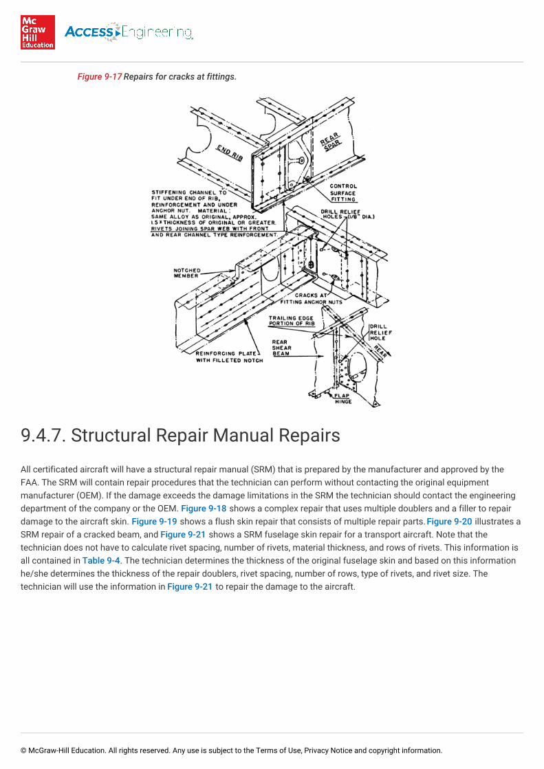
Figure 9-17 Repairs for cracks at fittings.
9.4.7. Structural Repair Manual Repairs
All certificated aircraft will have a structural repair manual (SRM) that is prepared by the manufacturer and approved by theFAA. The SRM will contain repair procedures that the technician can perform without contacting the original equipmentmanufacturer (OEM). If the damage exceeds the damage limitations in the SRM the technician should contact the engineeringdepartment of the company or the OEM. Figure 9-18 shows a complex repair that uses multiple doublers and a filler to repairdamage to the aircraft skin. Figure 9-19 shows a flush skin repair that consists of multiple repair parts. Figure 9-20 illustrates aSRM repair of a cracked beam, and Figure 9-21 shows a SRM fuselage skin repair for a transport aircraft. Note that thetechnician does not have to calculate rivet spacing, number of rivets, material thickness, and rows of rivets. This information isall contained in Table 9-4. The technician determines the thickness of the original fuselage skin and based on this informationhe/she determines the thickness of the repair doublers, rivet spacing, number of rows, type of rivets, and rivet size. Thetechnician will use the information in Figure 9-21 to repair the damage to the aircraft.
© McGraw-Hill Education. All rights reserved. Any use is subject to the Terms of Use, Privacy Notice and copyright information.

Figure 9-18 Skin repair using mulitple repair parts.
Figure 9-19 Flush skin repair with multiple repair parts.
© McGraw-Hill Education. All rights reserved. Any use is subject to the Terms of Use, Privacy Notice and copyright information.

Figure 9-20 Repair of cracked beam.
Figure 9-21 External repair of fuselage.
Table 9-4 Structural Repair Design Data
Repair Material
Part Qty Material
1 Repair Plate 1 Same material and heat treat as original skin; use two gauges greater than originalskim – 0.050 Gauge min
Fastener Requirements for Repairs Using Solid Rivets
Original Minimum Skin Pocket Gauge inRepair Area
Fasteners Number of Rows Spacing (P)
Longitudinal Circumferential
© McGraw-Hill Education. All rights reserved. Any use is subject to the Terms of Use, Privacy Notice and copyright information.

0.036 BACR15CE5D 3 1.56 to 1.61
0.040 BACR15CE5D 3 1.56 to 1.61
0.045 BACR15CE5D 3 1.56 to 1.61
0.050 BACR15CE6D 3 1.87 to 1.94
0.056 BACR15CE6D 3 1.87 to 1.94
0.063 BACR15CE6D 4 1.87 to 1.94
0.071 BACR15CE8D 4 2.38 to 2.56
0.080 BACR15CE8D 4 2.38 to 2.56
Fastener Requirements for Repairs Using Blind Rivets
Original Minimum Skin Pocket Gauge inRepair Area
Fasteners Number of Rows Spacing (P)
Longitudinal Circumferential
0.036 MAS1738E4 3 1.56 to 1.61
0.040 MAS1738E4 3 1.56 to 1.61
0.045 MAS1738E4 3 1.56 to 1.61
0.050 MAS1738E5 3 1.87 to 1.94
0.056 MAS1738E5 3 1.87 to 1.94
0.063 MAS1738E5 4 1.87 to 1.94
0.071 MAS1738E6 4 2.38 to 2.56
0.080 MAS1738E6 4 2.38 to 2.56
Repair Material
Part Qty Material
9.4.8. Chem-Milled Skin Repair
3 12
3 12
3 12
3 12
3 12
4 12
4 12
4 12
3 12
3 12
3 12
3 12
3 12
4 12
4 12
4 12
© McGraw-Hill Education. All rights reserved. Any use is subject to the Terms of Use, Privacy Notice and copyright information.

9.4.8. Chem-Milled Skin Repair
A chem-milled structural member varies in thickness from end to end or side to side. Therefore, repair requires a procedureslightly different from standard procedures. The repair material must be as thick as the thickest part of the chem-milledstructure. The repair material is applied to the thickest part of the damaged member, using normal riveting procedures.Shimming is used to fill the gap between the repair material and the thin part of the member. The shim material is secured withrivets that pass through the damaged part, the shim material, and the repair material. Figure 9-22 shows a typical chem-milledskin repair.
Figure 9-22 Typical chem-milled skin repair.
9.4.9. Special Repairs
Where specific instructions for sheet-metal structural repairs are not available in the manufacturer's manuals, which shouldalways be the first choice of the technician in determining the type of repair to use, publications such as AC 43.13-1B & 2Bpublished by the FAA and MIL-HDBK-5E may be used for the development of a repair design for unique applications. Wheneverspecific instructions for a major sheet-metal structural repair are not available in the manufacturer's manuals, the technicianmust obtain FAA approval for the repair by submitting FAA Form 337. The prudent technician will make it a habit to obtainapproval prior to beginning the installation of such repairs.
© McGraw-Hill Education. All rights reserved. Any use is subject to the Terms of Use, Privacy Notice and copyright information.