MCGRAW-HILL PUBLICATION - World Radio History
296
FEBRUARY 1941 electronics A MCGRAW-HILL PUBLICATION
-
Upload
khangminh22 -
Category
Documents
-
view
2 -
download
0
Transcript of MCGRAW-HILL PUBLICATION - World Radio History

FEBRUARY 1941
electronics A MCGRAW-HILL PUBLICATION

A LONG AND STABLE LÍFE
Design and Production Dev$loprnents Exclusive with Amperex Set ew Stabilit and Performance Standards for Vacuum Condensers
Released six months ago, the new Amperex VC50 and VC25 vacuum condensers have proved themselves a real contribu- tion in communication, dialectric heating and electro -medical apparatus. Their higher current handling ability and lower 12R losses in -educed space suggest important simplifications in equipment design. Oscüllators using Amperex-developed circuits and Amperex VC capacitors meet proposed FCC stability regulations.
LARGE SURFACE AREAS
TO CARRY H. F. CURRENT
GENERAL CHARACTERISTICS AMPEREX VCSO
Capacitance 30 uuf+2% Maximum Peak Voltage....30,000 Maximum RMS Current
65 Amps at 10 Mc. 40 Amps at 30 Mc.
Dimensions: 61/2" 4- 3/32" x 21/2 Mas.
ALL COPPER (OFHC)
CONSTRUCTION
WRITE FOR COMPLETE TECHNICAL RATING AND DATA SHEETS
IN CANAD. ate, NEWFOUNDLAND : ROG3tS MAJESTIC IIMITFD 11 19 BREN-CL =FE SD., LEASIDE TORONTC 11, ONTARIO, J.NADA
.:16111M-.
Type of equipotential and electrostatic flux lines established by probing electrolytic bath to determine shapes and disposition of electrodes. (POINT "A" iN PHOTOGRAPH)
NEW TECHNIQUES: Design and manufac- turing techniques evolved for high power copper anode tubes were successfully brought to bear in developing the unusual qualities of Amperex VC50 and VC25 vacuum condensers. Unique all -copper OFHC construction, large area seals, un- usual mechanical ruggedness and elimina- tion of welds insure more efficient and economical operation.
PRIOR ART: When the vacuum condenser project was initiated in the Amperex laboratory, one of the first steps was the prolonged testing cf all available types under field conditions. Concentrated high frequency fields and bottlenecks to current passage were common to all. These "hot spots" inevitably resulted in overheating, creating the risks of puncturing and dis- tortion of the delicate balance of elements.
THE SHAPE OF THINGS: More than 200 theoretical shapes for the VC50 electrodes were tested' in the electrolytic bath. Re- sulting lines -of -force curves dictated the shapes finally adopted. These spread the fields of force, eliminating destructive con- centrations. It was discovered, also, that elements carrying high frequency current had to offer surface areas much larger than those which had contented older practice. Wires even of comparatively large diameter were found electrically in- sufficient and in addition, presented me- chanical hazards. Elimination of current - carrying welds was indicated. Basic de- velopments and numefous manufacturing refinements growing out of these tests were built into the Amperex VC series. They are responsible for outstanding per- :ormance records.

electronics A McGliA_ * - HILL
PUB ATION
FEBRUARY 1947 ONE -CENTIMETER TUbE Cover
Internal derails of a 1.25 -centimeter reflex oscillator tube developed by Dr. J. M. Lafferty at General Electric Re- search Lboratory. The tube was cast in (Lucite, cut open, and polished
INTERNAT'JNAL PLAN FOR AIR NAVIGATION, by D. H. Pain 80
PICAO chooses standard ILS, vhf omnidirectional radio range, radar DME beacons, and I -f loran
MIDGET ELECTRONIC EQUIPMENT 84
Characteristics of subminiature tubes and parts indicates feasibility of wearable units
SLOTTED -CYLINDER ANTENNA, by E. C. Jordan and W. E. Miller 90
Design characteristics show antenna's suitability for f -m and television
ELECTRONIC TOY -TRAIN CONTROLS, by Joseph L. Bonanno 94
Cars are uncoupled, the locomotive whistles and reverses, freight trains unload
PULSE -TYPE TESTER FOR HIGH -POWER TUBES, by E. C. Easton and E. L. Chaffee 97
Trigger circuit fires ignitron, applying high -voltage pu Ise to grid of tube being tested.
WIDE-ANGLE PHASE MODULATOR, by H. K. Bradford .. 100 Analysis of a phase modulator that permits crystal control of carrier frequency
ELECTRONICS IN THE CATERPILLAR TRACTOR PLANT... 104 Production line and research activity are both aided by intelligent use of vacuum -tube devices
POWER SUPPLY FOR MICROWAVE EQUIPMENT, by Oliver Hoag 110 Servo motor adjusts an autotransformer to provide automatic voltage regulation up to 5,000 volts
ELECTRONIC COMMUTATION FOR TELEMETERING, by Lawrence Lee Rauch 114 Pulse -controlled trigger stages feed readings of 18 aircraft instruments into f -m radio link
TACHOMETRIC AUDIO -FREQUENCY METER, by Edward Kasner 121
Frequencies from 30 to 450 cycles are indicated directly by tachometer -motor unit
ACOUSTIC LOCATING SYSTEM, by Eric A. Walker and Paul M. Kendig 124 Supersonic waves from a spent torpedo are received by a directional listening hydrophone
MEASURING COMPLEX COMPONENTS OF VOLTAGE, by George Pihl 128 Direct reading a -f vtvm indicates real and imaginary components of voltage
AIRBORNE RADAR SPECIFICATIONS 132 Details of nine recently declassified Air Forces and Signal Corps sets
e 134 DB GAIN -LOSS CALCULATOR, by Lloyd A. Lohr Gives db value directly in one setting of straightedge for individual voltage or power values or for ratios
BUSINESS BRIEFS 74 INDUSTRIAL CONTROL 140 NEW BOOKS 268 CROSSTALK 79 ELECTRON ART 142 BACKTALK 274 TUBES AT WORK 136 NEW PRODUCT?' 144 INDEX TO ADVERTISERS 283
NEWS OF THE INDUSTRY 150
DONALD G. FINK, Editor; KEITH HENNEY, Consulting Editor; W. W. MacDonald, Managing Editor; John Markus, Vin Zeluff, Associate Editors; Frank Rockett, A. A. McKenzie, Assistant Editors; Gladys T. Montgomery, Washington Editor; William P. O'Brien, Make-up Editor;
Jeanne E. Grolimund, Editorial Assistant; Harry Phillips, Art Director; Eleanore Luke, Art Assistant
H. W. MATEER, Publisher; WALLACE B. BLOOD, Manager; J. E. Blackburn, Jr., Director of Circulation; Dexter Keener, Director, Eco- nomics Department; John Chapman, World News Director; D. H. Miller, H. R. Denmead, Jr., New York; Ralph H. Flynn, New England; F. P.
Coyle, R. E. Miller, Philadelphia; C. D. Wardner, Chicago; E J. Smith, Cleveland; J. W. Otterson, San Francisco; Roy N. Phelan, Los Angeles; Ralph C. Maultsby, Atlanta; Paul West, London, England
uaa
Contents Copyright, 1947, by McGraw-Hill Publishing Company, Inc. All Rights Reserved. McGRAW-HILL PUBLISHING COMPANY INCORPORATED, JAMES H. McGRAW, Founder and Honorary Chairman PUBLICATION OFFICE 99-129 North Broadway, Albany I, N. Y., U. S. A. EDITORIAL AND EXECUTIVE OFFICES 330 West 42nd St., New York 18, N. Y., U. S. A.-Member A. B. P. Member A. B. C.
James N. McGraw, Jr., President; Curtis W. McGraw, Senior Vince -President and Treasurer; Nelson Bond, Director of Advertising; Eugene Duffield, Editorial Assistant to the President; Joseph A. Gerardi, Secretary; and L. E. Blackburn, lr., Vice -President for circulation oper s. ELECTRONICS, February, 1947, Vol. 20; No, 2. Published monthly, with an additional issue in June, p e 75c a copy. Directory Issue $1.00, Allow at least ten days for change of address. All communications about subscriptions should be addressed to the Director of. nation. Subscription rates-United States and possessions, $6.00 a year, $8.00 for two years, $12.00 for three . Canade(Cáyyppdian funds accepted) $7.00 a year. $11.00 for two years, $14.00 for three years. Pan American countries $10.00 for one year, $16.00 for two years, $2 or three yearf.'All other countries 516.00 for one year, $30.00 for three years. Please indicate position and company cone t!cc on nil aubscr.^i'a.; , Fotere Sec,nd Class matter August 29. 1935. at Post Office, Albany, New York, under the Act of March 3, 1879. BRANCI'. .. T"'.E3. 520 Korth .. "w - , C e I1, Ill.; 63 ^ost ` Street. 5 Francisco 4; Aldwych House. Aldwych, London, W.C. 2; Washington, D. C. 4; Philo ?a.'r. .:.nlm 1 15; Dec - yz -F :to: 16; Itlan!a 3, Ga..;fì7 So. Hope St., Los Angeles 14; 738-9 Oliver Building, Pittsburgh 22.

(%)z RADIO'SILENTZdwó/?
5;,.. 2,4 Z4i, isolate test rooms in laboratory or factory.
Installed where the electric power service passes through the screen, these Filterettes provide high attenuation from 150 kc to 400 mc, thus permit- ting . operation of sensitive high -frequency test apparatus in close proximity to electric production equipment, welding generators, repulsion motors, and high -frequency induction heating equipment.
SPECIFICATIONS HEAVY DUTY FILTERS
Type Amperes Volts Volt. Drop Freq. Range Weight
Two Wire 100 500
a -c/d -c
.2 volts per circuit
0.15 to 400 megacycles
40 lbs.
Three Wire 100 500 a-c/d.c
.2 volts per circuit
0.15 to 400 megacycles 65 lbs.
MEDIUM DUTY FILTERS (Two Wire)
Ne. 1 137 20 110/220 a -c
500 d -c .5 volts
per circuit 0.15 to 20
megacycles 17 lbs.
No. 1116 50 110/220 a -c 500 d -c
.5 volts per circuit
0.15 to 20 megacycles
17 lbs.
Widely used by government, college, and indus- trial laboratories, Tobe Screen Booth Filters will meet your need; Bulletin 472 E , free on request, gives additional data. For information about the complete line of Tobe Filterettes and Capa- citors, ask for our general catalog.
2
HEAVY DUTY FILTER
Mechanical design and assembly conform to practical electrical installation requirements. Outer housings are of welded steel; knockouts at each end accommodate electrical con- duits; heavy, threaded .studs facilitate at- tachment'of cable lugs.
These units employ non -inductive, mineral -oil im- pregnated capacitors; the inductors, of large cross section, have low series resistance, hence voltage drop is negligible. Overload ratings are: 150% of
ampere rating for one hour; 200% of voltage rating for one minute.
MASSACHUSETTS
February, 1947 - ELECTRONICS

"The impossible takes a little longer"...this is one way of saying that the draftsman lets no out -worn conceptions restrict his creative ideas. Yet without his specialized technique for expressing ideas on paper, the designs he creates could scarcely be turned into substance. As the draftsman relies on his own hands and eyes, he calls likewise on his drafting instruments to serve him functionally. So integral a part of his technique do they become, they are virtually his partners in creating.
For 78 years Keuffel & Esser drafting equipment and materials have been partners, in this sense, in creating the greatness of America, in making possible our fleets of ships, our skyscrapers, our overwhelming weight of armor on the battlefield ...So universally is K & E equipment used, it is self-evident that every engineering project of any magnitude has been completed with the help of K & E. Could you wish any surer guidance than this in the selection of your own "drafting partners"?
Because of their balance, smooth action and responsiveness to your hand, you will find that using MINUSA* Drawing Instruments is almost as natural as
breathing. ,Their legs are round and ta- pered, without the harsh feel of sharp cor - p g ners. Joints are firm, snugly fitted, and satin -smooth in operation. Yet these instru- ments are strong and durable, for their
precision will outlast years of continuous use. For complete data on MINUSA* Drawing Instruments, write on your letterhead to Keuffel & Esser Co., Hoboken, N.J. atßEO.M. 8. PAT. OPP.
Drafting, Reproduction, Surveying Equipment
and Materials. Slide Rules.
Measuring Tapes.
ELECTRONICS - February, 1947
KEUFFEL & ESSER EST, 1867
NEW YORK HOBOKEN, N. J. CHICAGO ST. LOUIS DETROIT SAN FRANCISCO
LOS ANGELES 'MONTREAL

isiecIiii ,s
1915
The ocean, long a barrier to spoken com- munications, was conquered when Bell System engineers designed, built, and operated the transmit- ter which first sent the human
voice across the Atlantic and Pacific.
1916
AWestern Electric transmitter was used in one of the pioneer ship -to -shore radiotelephone experiments. Thir- teen years later the first regular commercial service was estab-
lished with Western Elec- tric equipment.
' 1917
With the first airborne transmitter, Western Electric demonstrated two- way radiotelephone between a plane in flight and the ground. From this earliest experiment came
commercial airline equip- ment in 1930.
1920 Western Electric radio became a part of the nation's telephone system when it was used to connect Catalina Island to the mainland. Seven years later, the Bell System
offered commercial radio- telephone service to
Europe.
1922 Western Electric manufactured and installed the first "high power"
(500 Watt) commercial broad- cast transmitter-for the
Detroit News Station WWJ.
1930
Transmitter designed by Bell Labora- tories first used for one-way contact withpolice cars.Police used Western Electric fixed station transmitters as early as 1922, and two-way
mobile equipment from 1935.
From the basic developments pic- tured at the left, the team of Bell Laboratories and Western Electric continued to set the pace with the best in transmitting equipment. Among the later advances pioneered by this team were: 1928. The first 50 kw commercial broadcast transmitter, built by Western Electric, in- stalled at WLW, Cincinnati, Ohio.
1935. A 50 kw Western Electric AM trans- mitter installed at WOR was the first to incorporate the Bell Laboratories -designed stabilized feedback circuit, since accepted as a broadcasting standard. 1937. The first single sideband transmitter was introduced for long distance point-to- point communications. The world-wide mil- itary communications network used in the war came directly from this development. 1938. Flying testa of the first VIIF aircraft transmitter showed relatively static -free communication at all times. Modifications of the original Bell Laboratories design were used for basic Army -Navy aircraft radiotelephony in World War II. 1940. The first Synchronized FM transmitter installed at WOR enabled broadcasters to put top-quality FM programs on the air and keep them on their assigned frequency. 1941. First FM transmitter to use grounded plate amplifier circuit was Western Electric 10 kw installed at WOR.
1941. Twelve talking channels adjacent to each other, available for the first time on a single radio' frequency band, used to connect telephone lines on either side of Chesapeake Bay. Envelope feedback developed by Bell Telephone Laboratories and applied to the carrier technique in radio telephony made this possible.
QUALITY COUNTS -
4 February, 1947 - ELECTRONICS

for dio Transmitter5!
The experience gained during the war, when the Bell Laboratories -\fester. Electric team was the largest supplier of communications equipment, added gr-atly to the skill and knowledge acquired through 30, years of transmitter development.
This background, plus unequalled research and manufacturing facilities, provides assurance that there arc no firer transmitters than those designed by Bell Telephone Laboratories and built by Western Electric-whether for AM or FM broadcasting, point-to-point radiotelephony, or any type of com-
munication or mobile service.
1943. The ARC -1, a crystal con- trolled ten frequency transceiver, used by the Navy's fighter planes during the war, has been accepted as standard VHF egLipment by U.S. airlines. Provides nine plane -to - ground frequencies and one plane - to -plane frequency.
1947. The Western Electric 238 - type mobile radiotelephone system is providing dependable Bell Sys- tem service between vehicles and any wire te_ephone in a growing number of cities and along trunk highways.
1947. The new TRAIN SVIEW design FM transmitter, being produced in 1, 3 and 10 kw units, for the first time provides the operator with an unobstructed view of all tubes while in operation. Incor- porates Bell Laboratories - developed synchronized frequency control.
BELL TELEPHONE LABORATORIES World's lurgeet organization demoted exclusively lo research and decelopntent in all phases of electrical communications.
Western Electric Manufacturing unit of the Bell System and the nation's largest
producer of rmmrnunicrttions equipment.
7telEtGtrtgd es,
GraybáR
ELECTRONICS - February, 1947 5

HQ -129-X
vT THOUSANDS
Hams are pretty shrewd individuals when it comes to selecting
the gear they use. Many thousands knew what they wanted
they're using HQ -129-X receivers on the air every day. That,;
s%e believe; is -one- of -the -finest endorsements -any product can i
achieve. Materials are still hard to get but hundreds of
HQ -129.X% are being shipped every month.
YEARS OF KNOW HOW
[MUM« 1010
SEE THE HQ -1211-X _1.T TOUR DEALER'S
11 2:12A Li.113J3 THE HAMMARLUND MFG. CO., INC., 460 W. 34" ST., NEW YORK 1, N.Y.
MANUFACTURERS OF PRECISION COMMUNICATIONS EQUIPMENT
February, 1947 - ELECTRONICS

WHISTLER Adjustable
Perforating Dies Offer Added
Production Economy
Typical examples of set-ups made from stock units. No delay in start- ing production.
All there is to Wh sties punch and
die units.
WRITE FOR YOUR WHISTLER
CATALOGS. Know the pro- duction advantages of Whistler Adjustable Dies.
ELECTRONICS - February, 1947
5-10-50 and even more different set- ups with the same dies? Impossible? Not when you use Whistler Multi - Use Adjustable Dues. For it's simple to rearrange these units ... add or delete ... get back into production within a few hours. Even so-called complicated arrangements are easy to set up. And, with first cost inva- riably less than for single purpose dies, this continued re -use of the same dies effects added economy in quickly writing off initial die invest-
ment. Over 750 prominent manu- facturers have proven in their own plants that Whistler Adjustable Dies have sent costs into a nose dive. No special tools are needed. Work in practically any size and type of press. Ordering now is particularly advantageous. Large stocks of stand- ard diameter units from 1/22" up are available for overnight shipments. Notching, group dies and special shapes and sizes can be quickly made to order. Write today to:
S. B. WHISTLER & SONS, INC. 752-756 MILITARY ROAD BUFFALO 17, NEW YORK

LET BENTLEY, HARRIS WAR -TIME RESEARCH PAY DIVIDENDS FOR YOU TODAY.
o
IIIIi ;IIIIUIIII,llllllll!;ii1-
\N \
Designing a 3 -way speed control for an air cir-
culating unit, a transformer manufacturer needed an insulation that would not split or crack under constant vibration. Recalling his war -time use of Bentley, Harris Fiberglas Sleeving in hermetically sealed transformers, he tried it in his new product. Here is his report:
"BH Fiberglas Sleeving has the unusual flexi-
bility, strength, durability, and non -f
B
SLE VINGS
ities we need. Even after aging, it does not split or crack under mechanical vibration."
Test BH Fiberglas Sleeving in your own plant, in your own product-under actual service con- ditions. Compare it to ordinary saturated sleeving. Learn why America's leading manufacturers of home appliances and industrial equipment have
ndardized on Bentley, Harris Fiberglas Sleeving their plans for post-war production.
NTLEY, HARRIS MFG. CO., CONSHOHOCKEN, PA.
BH Non -Fraying Fiberglas Sleevings are made by an exclusive Bentley, Harris process (U. S. l'at. No. 2393530). "Fiberglas" is Reg. TM of Owens-Corning Fiberglas Corp
USE COUPON NOW Bentley, Harris Mfg. Co., Dept. E-7, Conshohocken, Pa.
I am interested in BH Non -Fraying Fiberglas Sleeving for (size) (product)
operating at temperatures of _°F at volts. Send samples so I can see for myself how BH Non -Fraying Fiberglas Sleeving stays flexible as string, will not crack or split when bent.
NAME COMPANY
ADDRESS _
MIN
Send samples and prices on other BH Products as follows:
D Magnetd Varnished Tubing Grade "A" D Flexible Varnished Tubing Grade "B"
Saturated Sleeving Grade C-1
D Saturated Sleeving Grade C-2
Saturated Sleeving Grade C-3
February, 1947.- ELECTRONICS

THAT COUNT!
That's Why Every FEDERAL Industrial Power Tube is
X-RAY TESTED
to Last Longer in Heavy -Duty Electronic Equipment
IT'S THE ORDINARILY unseen details, deep in the heart of a tube, that can spell long success or early failure in heavy-duty industrial service. But in Federal tubes, the "insides" are seen-and carefully checked for perfection of every detail ! For every tube gets not one, but three X-ray tests before being OK'd for shipment. This, plus other exacting requirements, is your positive assurance that every Federal tube will have the stamina-the "guts"-to take the terrific strains of sudden load changes, mechanical shock and vibration.
The 9C23, like all Federal industrial tubes, is built to take a beating. As shown in this actual X-ray photo, all internal elements are widely spaced and well braced. Flexible leads reduce strains and sim- plify installation. For complete information, write. to Dept. L413.
One 9C23 tube gives ample power for this 20 -KW Electronic Heater, made by REEVE ELECTRONICS, INC., CHICAGO, ILL.
DATA FOR 9C23 TUBE
Filament Voltage . . . . 22 volts Filament Current 82 amp.
Maximum Ratings for Maximum Frequency of 20 MC
DC Plate Voltage 15000 volts DC Plate Current 4.0 amp. Plate Dissipation 25 Kw.
Type of Cooling Water (Minimum Flow, 10 G.P.M.)
Federal Telephone and Radio Corporal/on In Canada:-ederal Electric Manufacturing Company, Ltd., Montreal. Export Distrib :-International Standard Electric Corp. 67 Brood St., N.Y.C.
Newark 1,
New Jersey
ELECTRONICS -February, 1947 9

01111111°'
For BY pass Applications
specify %eGP A for best performance
The Erie line of General Purpose Ceramic Condensers has been set up to provide ceramic dielectric condensers quickly and economical- ly for by-passing and coupling applications.
By "General Purpose" is meant those con- densers which are not directly frequency de- termining, such as those used for AVC Filter- ing, Resistance -Capacitance Audio Coupling, Tone Compensation, Volume Control R.F. By -Passing, Audio Plate R.F. By -Passing, Oscil- lator Grid Coupling, R.F. Coupling, Antenna Coupling. In these applications, power factor is not critical and moderate capacity changes caused by temperature variations do not affect the proper functioning of the circuits.
The GP (General Purpose) line of Erie Ce- ramicons does not sacrifice quality in any way
*Ceramicon is the registered trade name of silvered ceramic condensers made by Erie Resistor Corporation.
c
whatsoever. Since the line of Erie GP Ceram - icons is limited to definite capacity values, it is practical to manufacture large quantities of any given value at one time, with consequent saving in production costs.
Condensers classified as GP1 have a tem- perature coefficient between+/130 and -1600 P/M/°C and are available up to 510 MMF. Condensers classified as GP2, manufactured in capacities of 150 MMF and higher, may in- clude all of the above dielectrics and, in ad- dition, the Erie Hi -K type.
Erie GP Ceramicons are made in insulated styles in popular capacity values up to 5,000 MMF and in non -insulated styles up to 10,000 MMF. Write for full details.
Sleds atca Dú edeo«
ERIE RESISTOR CORP., ERIE, PA. LONDON, ENGLAND TORONTO, CANADA
February, 1947 - ELECTRONICS
j
Se."/"..
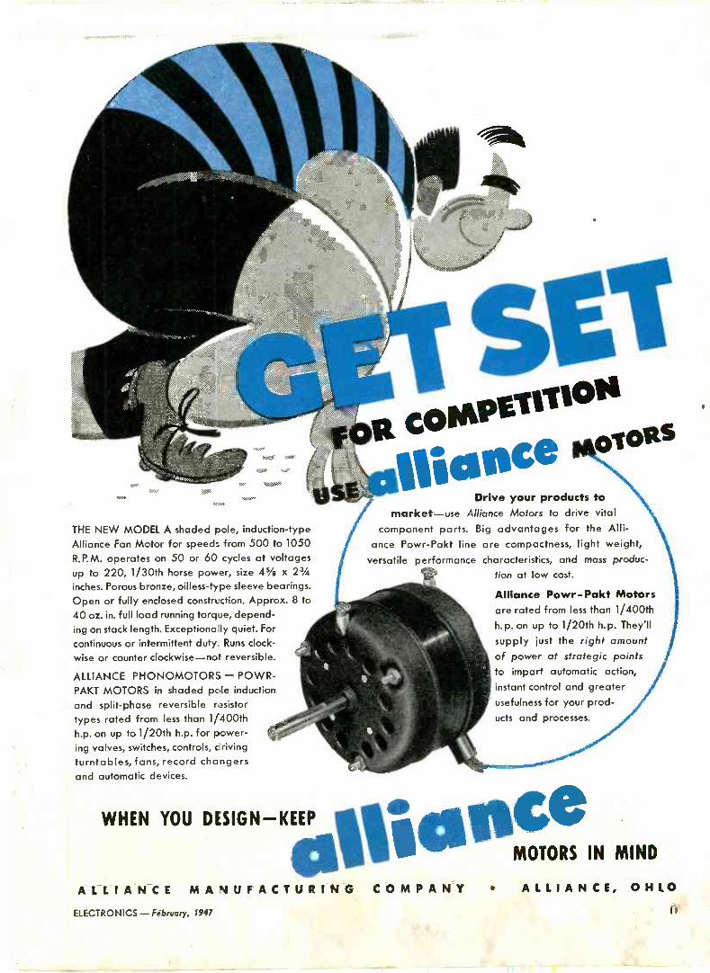
THE NEW MODEL A shaded pole, induction -type Alliance Fan Motor for speeds from 500 to 1050
R.P.M. operates on 50 or 60 cycles at voltages up to 220, 1/30th horse power, size 45/e x 23/4
inches. Porous bronze, oilless-type sleeve bearings. Open or fully enclosed construction. Approx. 8 to
40 oz. in. full load running torque, depend- ing on stack length. Exceptionally quiet. For
continuous or intermittent duty Runs clock-
wise or counter clockwise-not reversible.
ALLIANCE PHONOMOTORS - POWR- PAKT MOTORS in shaded pole induction
and split -phase reversible resistor
types rated from less than 1/400th h.p. on up to 1/20th h.p. for power- ing valves, switches, controls, driving turntables, fans, record changers and automatic devices.
E g COMPE71TIOS Ilidece lo"S
Drive your products to market-use Alliance Motors to drive vital
component parts. Big advantages for the Alli- ance Powr-Pakt line are compactness, light weight,
versatile performance characteristics, and mass produc-
tion at low cost.
Alliance Powr-Pakt Motors are rated from less than 1/400th h.p. on up to 1/20th h. p. They'll
supply just the right amount of power at strategic points to impart automatic action, instant control and greater usefulness for your prod- ucts and processes.
WHEN YOU DESIGN -KEEP `e ,1, MOTORS IN MIND a ALLIANCE MANUFACTURING COMPANY ALLIANCE, OHIO
ELECTRONICS-February, 1947 II
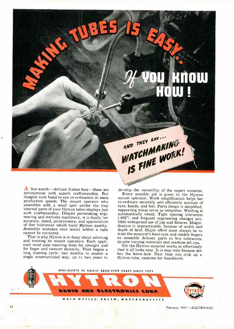
A fine watch-delicate Italian lace-these are synonymous with superb craftsmanship. But imagine such hand -to -eye co-ordination at mass production speeds. The mount operator who assembles with a small spot welder the tiny internal parts of your Hytron tubes displays just such craftsmanship. Despite painstaking engi- neering and intricate machinery, it is finally her accuracy, speed, perseverance, and appreciation of fine tolerances which build Hytron quality. Assembly mistakes once sealed within a tube cannot be corrected.
That is why Hytron is so fussy about selecting and training its mount operato -s. Each appli- cant must pass exacting tests for eyesight and for finger and tweezer dexterity. Then begins a long training cycle: two months to master a single constructional step; up to two years to
develop the versatility of the expert mounter. Every possible aid is given to the Hytron
mount operator. Work simplification helps her co-ordinate smoothly and efficiently motions of eyes, hands, and feet. Parts design is simplified; supporting micas serve as templates. Welding is automatically timed. Tight spacing tolerances (.003") and frequent engineering changes pro- hibit widespread use of jigs and fixtures. Magni- fication is impracticable, because of width and depth of field. Major effort must always be to train the mounter's keen eyes and nimble fingers to assemble delicate parts to fine tolerances, despite varying materials and machine set-ups.
Yet the Hytron mounter works so effortlessly that it all looks easy. It is easy only because she has the know-how. Next time you pick up a Hytron tube, examine her handiwork.
SPECIALISTS IN RADIO RECEIVING TUBES SINCE 1921 \ VAL lir, ® ..._
S ' einr0 IMO Oei2E.CZOO OR VK
MAIN OFFICE: S A L E M, MASSACHUSETTS
12 February, 1997 - ELECTRONICS

...IT'S A ,Jeneen
SPEAMI(ER:
MODEL VH-91 peX* PROJECTOR
This latest addition to the famous JENSEN Hypex line meets a real need for paging and intercommunication applications. Particularly efficient in the voice fre- quency range, it delivers clear, intelligible speech with maximum "punch" to override high noise levels.
By reason of an extremely clever mounting bracket, this projector can be pointed in any direction and securely locked into position with a single wing nut. Two holes in the bracket are provided for mounting on table, wall, ceiling or a post.
The diaphragm is cloth base, phenolic impregnated. Nominal voice coil impedance, 8 ohms; power handling capacity, 15 watts maximum speech signal input. Two - wire RC cable is provided for connections. Mounting facilities are also provided on the bracket for a S/a"x 3h" core or smaller transformer. Because of the Hypex flare formula, useful output is attained for a 100° total angle.
This new Hypex projector is now in production; de- liveries are expected early in 1947 and literature will be available shortly.
JENSEN MANUFACTURING COMPANY 6607 S. LARAMIE AVE., CHICAGO 38, U.S.A.
In Canada: Copper Wire Products Ltd., 11 King St. W., Toronto, Ont.
'Trade Mark Registered
ez>ir.eDºa -.,tfavis,/'rT-,/fttPfit1 Wceir.i,ftc 4rien2enl`
E.ECTRONICS - FieSruvry, 1747 13

WxM u .ß
. umOeeoe.one. V° ph,.
These Western Electric FM broadcast transmitters -22 in all-are now on the air in the
88-108 me band... and others (not shown) are in operation for experimental purposes, or
are in process of installation. In FM-as in AM-transmitters of Bell Telephone Labora-
tories design and Western Electric manufacture have acquired a reputation for quality, 14 F.êi ary, 1947 - ELECTRONICS

F M TRANSMITTERS
88 90 92 94 96 98 100
IN THE NEW BAND
NEW LINE OF FM TRANSMITTERS
Outstanding in styling and performance! 250 watt, 1, 3, 10, 25 and 50 kw.
dependability and low operating cost. For FM equipment from 250 watts to 50 kw, contact
your local Graybar Broadcast Equipment Representative. He will be glad to tell you all the
technical features and advantages which make them outstanding, or-write to Graybar
Electric Co., 420 Lexington Ave., New York 17, N. Y. QUALITY COUNTS ELECTRONICS - February, 1947 Is

BAKELITE RESI NO ID
SEALED CANNOT MELT
PAT. PEND.
SPECIAL WARTIME DEVELOPMENT NOW AVAILABLE FOR PUBLIC USE . . .
TYPE P6 DUMONT PAPER CAPACITORS
AC -DC CONTINUOUS AT HIGH TEMPERATURES
OURAE AIED CAP .OS W.V 600
BAKELIZED TUBES
* Dumont engineers scored in the great-
est single achievement in paper tubular
capacitors ... meeting the most exact-
ing requirements. This type P6 has the
ends sealed in BAKELITE RESINOID.
Leads cannot PULL OUT or MELT OUT.
Bakelite treated tubes sealed in vacuum.
,
EA uRa .v.d°°.'
DUMONt 13 URA en CAP..05 W.V 6OO
Oö¡Rq òNT
ó ó
* HEAT PROOF
* MOISTURE PROOF
* LONGER LIFE
* VACUUM SEALED
* SOLVES SPACE
PROBLEMS
DUMONT ELECTRIC CORP. 34 HUBERT STREET MFR'S OF CAPACITORS FOR EVERY REQUIREMENT NEW YORK, N. Y.
16 February, 1947 - ELECTRONICS

Plastics where plastics belong The tip insulators on this welding electrode holder
are excellent examples of the use of technical
plastics where plastics belong... using resistance to
heat and impact and electrical insulating properties.
Synthane (our type of plastics) qualifies well
for this job. Glass base laminated resists heat
and impact fatigue, insulates and wears well.
For these reasons and others, Synthane finds its
way into an army of applications requiring electri-
cal, chemical, mechanical or combined specifications.
If you have a use for Synthane, let us help you
before you design. Perhaps we can save you time
and trouble with design, materials or completely
fabricated parts. Write for the complete catalog
of Synthane Plastics and their applications today.
Synthane Corporation, 6 River Road, Oaks, Penna.
SiiYN11IANE where Synthane belongs
DESIGN MATERIALS FABRICATION . SHEETS RODS TUBES
FABRICATED PARTS 'MOLDED. MACERATED MOLDEDLAMINATED

Get your copy before you plan with plastics
SYNTHANE CORPORATION, 6 RIVER ROAD, OAKS, PA, Gentlemen:
Please send me without obligation the complete catalog of Synthane technical plastics.
PLAN YOUR PRESENT AND FUTURE WITH SYNTHANE TECH
NICAL PLASTICS SHEETS RODS TUBES FABRICATED
PARTS MOLDED LAMINATED MOLDED -MACERATED
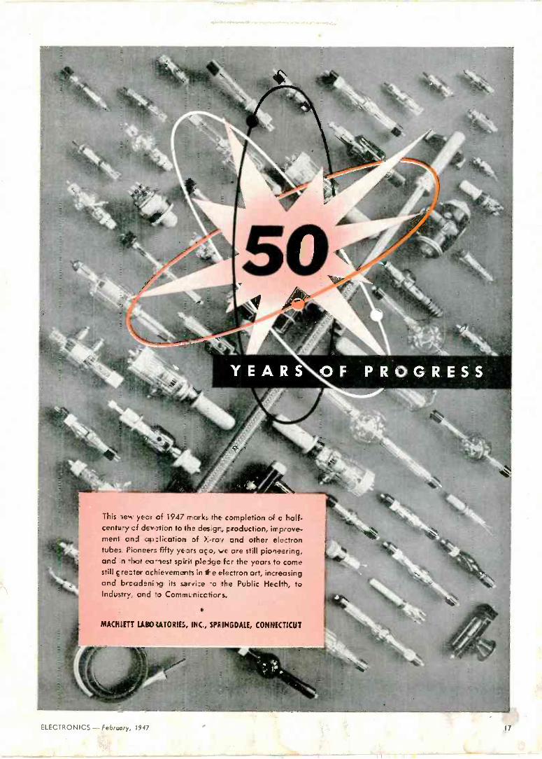
YEARS OF PROGRESS
This tew year of 1947 marks the completion of o half- centa:y cf dew2tian to the des gr, production, improve- ment and ap_lication of >..rai and other electron tubes. Pioneers fifty ye ors aço, ve are still pioneering, and n -hat ea ,est spirit pledge fcr the years to come still çrewter achievements in the electron art, increasing and brcadeni ig its service -o the Public Health, to Indusrry, and o ComaºLnicctiors.
MACIfEET' LANDIATORIES, INC., SPRINGDALE, CONNECTICUT
ELECTRONICS - Febrtary, 1947

GIVE POSITIVE "FIX" ON CRITICAL ASSEMBLY FOR
I'OKBoRO High spots from independent investigator's on -the - scene report ... another study of assembly methods in key industrial plants by James O. Peck Company.
"We gave Phillips Screws a big responsibility," Foxboro's chief engineer explained, "to maintain an accurate alignment of the helical coils in our tem- perature recording and control instruments.
"PHILLIPS' POSITIVE DRIVE makes positive fastening easier, more certain; Five Phillips Head Screws hold in accurate position the helical coils which are the heart of these instruments. The four. point contact of the driver in the Phillips recess makes it easy for the assembler to start the screws and drive them home. And we can depend on them to hold securely despite vibration or shock.
"WE SAVE DRIVER SLIPS that would cost us up to $50 apiece. This is a tight -spot assembly where the slip of a driver -a constant hazard when driv- ing slotted head screws - would irreparably dam- age the delicate capillary tubes, less than a half - inch away. The cost of such a slip - disassembly, replacing the damaged element, and reassembly - runs up to fifty dollars."
GET THE WHOLE INSIDE STORY of this critical assembly and other equally interesting studies ... of metal, wood and plastic prod- ucts. Plenty of tips to help you improve your own assemblies. FREE-use the coupon.
so. it ASSEMBLY SAVINGS
WITH PHILLIPS SCREWS
mis tom= COMPANY
Prod,r... :Tautnämmata
PHILLIPS x SCREWS Phillips Screw Mfrs.,c/o Horton -Noyes 8 4300 Industrial Trust Bldg., Providence, R. I.
Wood Screws Machine Screws Sell -tapping Screws Stove Bolts
American Screw Co. neon Manufaeturisg Di.
Send Assembly Savings Phillips Central Screw Co. Reading Screw Co. me reports on with Screws. Chandler Products Corp. PR Russell Burdsall & Warr
Name : Continental Screw Co. Bolt & Nut Co.
Corbin Screw Div. of Scovill Manufacturing Co.
' Company American Hdwe. Corp. The H. M. Harper Co. National Look Co.
Shakeproof Inc. The Southington Hardware Mfg. Co.
Address International Screw Co. National Sere, & Mfg. Co. The Steel Company ßaf Canada. Ltd.
5.14 Lamson & Sessions Co. New England Screw Co. Sterling Bolt Co.
Milford Rivet and ParkerKalon Corporation Stronghold Screw Products. Ina. Machine Co. Pawtucket Screw Co. Wolverine Bolt Company
18 February, 1947 - ELECTRONICS

A section of the heating element used in Simmons Elec- tronic Blanket, showing water proof insulation and royon core. light wire it D -H 99 Alloy, dark wire copper.
Controlled Sleeping Comfort Made Possible by a New Driver -Harris Alloy .LIF beneath a new Simmons
Electronic Elanke-, turn the contrcl to the temperature desired and rela< fir a night of comfort.
Separately insulaed, but wourd to- gether on c rayon core and water- prtofed, fine copper w.re and ever finer D -H 93 Alloy Wire form ci net- work throughout the blanket. The
copper wi-e supplies tFe heat - the D -H 99 Alloy w re controls it by flashing fault signals to an electronic control box wherever clanket tem- peratvre vcries as little as I° C.
Simmons selected D -H 99 Alloy for
'T -ade Mark Heg. U.S. P,t. Off.
this highly demanding application becauae it, alone, met or exceeded every specified -equirement. D -H 99 Alloy had the corrosion resistance to withstand washing or cleaning, the fatigue resistarce to withstand re- peated folding anc the constant sen- sitivity so vital to operating safety and comfort. Only .0039" in diameter, D -H 99 Alloy has a stable temper- ature coefficient of 00636 per degree C and is deperdably uniform from spool to spool.
If your products or processes involve electrical circuits that require a high
Driver -Harris COMPANY
HARRISON, NEW JERSEY BRANCHES: Los Angeles
Chicago Detroit Sun Francisco
Cleveland Seattle
T. C. of resistance, you'll find D -H 99 Alloy unequalled for these ap- plications.
Schematic diagram Simmons Electronic Blanket

TYPE 1OCF4
(RC1 ettsItcs:
length, 1692
Max dlametet:l0112
Duo -Decal 1 pin base
6.3v
Motet voltage _
10,000 v
Anode voltage ' 250 v
Second gtid voltage
= 40010
Neg. gcid voltage -A5v-
i Further
details on request
TELETRON fol 64%e Jikjä/n -ucaic..0 IONTRAP
e The Du Mont Type 10CP4 metallized teletron is de- signed for greater efficiency in utilizing the available light output of a television picture tube and for greater economy in receiver manufacturing. By eliminating the ion -trap a troublesome circuit adjustment is done away with, for it is unnecessary to provide an ion -deflection field in the neck of the tube. In addition to protecting the screen, the metal- lization acts as a mirror. The major portion of the avail- able light is reflected through the viewing screen with a striking increase in light output and contrast. The Du Mont Type 10CP4 metallized teletron is interchangeable with older types with only slight modifications.
ALLEN B. DU MONT LABORATORIES, INC.
ALLEN B. DU MONT LABORATORIES, INC., PASSAIC, NEW JERSEY CABLE ADDRESS: WESPEXLIN, NEW YORK
_IN.- -ail, V 20 February, 1947 - ELECTRONICS

9erfteitedined TO ATMOSPHERIC MOIST IRE
Perao AGAINST INDUSTRIAL FUMES .
ebecected BY EXTREME HEAT OR COLD
Veriaeas4ed SEVERE MECHANICAL SHOCKS
. . . in short, constructed to last under the worst of operating conditions. * Although essentially fitted for the "tough" applications, Chicago Transformer's Sealed in Steel con- struction is being specified with increasing frequency by engineers who design electronic equipment for only average, or normal, con- ditions, but who, because of the vital services performed by their products, require an extra margin of dependability.
Their reasoning - (a) Water vapor, oxygen, and carbon
dioxide exist in all atmospheres; chlorine and sulphur compounds in the air of in- dustrial localities.
(b) The action of these agents, intens- ified by heat and direct current potentials, corrodes copper coil windings, shortens transformer life.
(c) Moisture, even when not excessive in the air, frequently condenses on the inside of partially sealed or unsealed cases and shields as the result of variations in temperature. Their conclusion -
It is good engineering to specify the transformers that have met with outstand- ing success the most rigid military tests for sealing against corrosion, have been proven to stay sealed in extremes of heat and cold ... Chicago Transformers, Sealed in Steel.
O
.T.'s exclusive Bushing -Gasket Seal at terminals employs tough resilient gaskets to permanentl) seal all openings and to cushion terminals and bushings against mechanical shock or drastic changes in temperature. (No cracking because of sudden Meat transfer from soldering iron to terminals during chassis assembly operation.)
Seamless, Drawn Steel Case and C.T.-innovated Deep Seal Base Cover provide a strong, impenetrable housing which, with its compc,ct, modern, and streamlined "good looks," helps sell the equipment in which it appears.
Coil is impregnated by a process using heat and alternate cycles of vacuum and pressure. By use of vacuum, all moisture is withdrawn from the coil, while pressure and heat thoroughly impregnate it with wax or varnish. Supe. rior to ordinary impregnation processes, this method insures that the transform is potted without moisture trapped insider;,,;
DIVISION OF ESSEX WIRE CORPORáT1CN
3 5 0 1 ADDISON STREET - CHICAGO 1 3, ILLINOIS
ELECTRONICS-February, 1997 211

FOR THE LARGER STATION ,. Reece«
FEATURES. High Fidelity Signal-flat frequency response 30 to 10,000 c.p.s.- distortion less than 3% at 95% modulation-noise level minus 60 db below 100% modulation. Low Operating Cost-simple circuit design plus quality components operated at well below capacity assure exceptionally long tube life and economical operation. Fast, Easy Maintenance-full length doors, large compartments and improved mechanical design provide maximum convenience and accessibility. Instantaneous Power Reduction for nighttime operation through a single switch, without program interruption. High Stability Crystal Oscillator with transfer switch. Provision for second crystal. Easy to Operate-centralized manual or automatic plus remote con- sole control. Minimum number of tuning controls, sixteen meters instantly check all circuits, full complement of circuit -indicating lights, modern motor tuning. Automatic Recycling minimizes lost air time. Easily Meets All FCC Requirements and is fully approved.
Enduring beauty! Modern functional design, fin: ished in harmonious contrast of Dove Grey and Woodland Brown baked enamel, trimmed in chrome. A full complement of circuit indicating lights imme- diately localize a control circuit failure.
This handsome control console gives the engineer fully automatic con= trol of all transmitter operations plus studio switching facilities for handling emergency programs originating at the transmitter. Controls audio and monitor switching; contains VU meter and remote antenna current meter. Finished in colors to match transmitter, -
DEVOTED TO RESEARCH AND MANUFACTURE
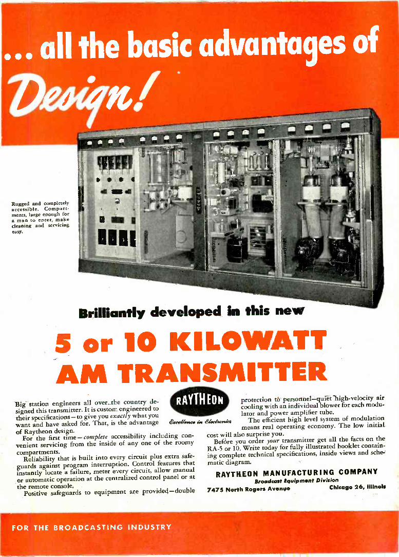
Rugged and completely accessible. Compart- ments, large enough for a man to enter, make cleaning and servicing easy.
Brilliantly developed in this new
5 or 10 KILOWATT AM TRANSMITTER
Big station engineers all over the country de-
signed this transmitter. It is custom engineered to their specifications-to give you exactly what you
want and have asked for. That, is the advantage of Raytheon design.
For the first time - complete accessibility including con-
venient servicing from the inside of any one of the roomy
compartments. Reliability that is built into every circuit plus extra safe-
guards against program interruption. Control features that instantly locate a failure, meter every circuit, allow manual
or automatic operation at the cemralized control panel or at
the remote console. Positive safeguards to equipment are provided-double
(o°xrrllencs sn ehboAoswi
protection tb personnel-quiet high -velocity air cooling with an individual blower for each modu- lator and power amplifier tube.
The efficient high level system of modulation means real operating economy. The low initial.
cost will also surprise you. Before you order your transmitter get all the facts on the
RA -5 or 10. Write today for fully illustrated booklet contain- ing complete technical specifications, inside views and sche-
matic diagram.
RAYTHEON MANUFACTURING COMPANY Broadcast Equipment Division
7475 North Rogers Avenue Chicago 26, Illinols
FOR THE BROADCASTING INDUSTRY

MOLDED IRON CORES
141% STANDARD AND HIGH -FREQUENCY TYPES A pioneer in Iron Core production, Stackpole can supply prac- tically any desired type from 100 cycles to upward of 175 megacy- cles and in an infinite variety of shapes, sizes and characteristics. Also available are High -Resistivity Cores showing a resistance of practical infinity: Insulated Cores wherein the screws are kept out of the coil field and "Q" consequently increased; Iron Cores for choke coils; and Side -Molded Iron Cores featuring uniform perme- ability with respect to linearity. Write for details and samples of any type.
for higher "Q" STACKPOLE SCREW -TYPE MOLDED CORES These Stackpole developments are proving highly popular for circuits where small assemblies are the order of the day, and where "Q" must be kept at z n absolute maximum. The cores them- selves are threaded, thus eï_ninating the conventional brass core screw. Tubes can be threcced t3 fit cores if desired. More eco- nomical, however, is the use of a wire C -spring clip placed (ob- tainable from usual sources of supply) in a slot in an unthreaded tube. Stackpole Screw -Type Co -es are ideal for the design of I -F and dual I -F Transformers Icr AM and FM.
LOOK FOR THE STACKPOLE MIN- UTE MAN . . .
your assurance cf the highest ii molded materials quality.
IRON SLEEVE TYPES ... for better coils in less space
By use of Stackpole Sleeve Cores, much smaller cans of any material may be used to provide "Q" that is equal to, or better than, that of conventional cores and cans. Thus they facilitate an exceptionally high order of tuning unit efficiency in greatly reduced size. Cans are not always necessary - and, where they are, inexpensive aluminum containers may often be used.
STACKPOLE CARBON CO., Electronic Components Division, ST, MARYS, PA.
24 February, 1947 -ELECTRONICS

Meissner Coils, long the accepted standard for engineers
who insist on high quality performance, are designed to
meet your most exacting requirements. Precision -made,
these superior components are backed by a 24 year
reputation for quality and uniformity in manufacture.
A complete line, inch.ding Air Core Plastic I. Fs, Iron Core
Plastic I. Fs and standard I. Fs. Send for free catalog.
recia' Soo*!
WRITE FOR FULL
INFORMATION alummar. p
The new Hazeltine Combination AM -IF and FM -IF Single Unit Coils. The
answer to space and production problems in the design of AM -FM receivers.
ELECTRONIC DISTRIBUTOR AND INDUSTRIAL SALES DEPARTMENT
MAGUIRE INDUSTRIES, a. 936 N. MICHIGAN AVENUE CHICAGO 11, ILLINOIS
ELECTRONICS - February, 1947 25

The heart of a magnetron, showing lami- nations, as produced by the Raytheon Manufacturing Co., Waltham, Mass.
The MAGNETRON again proves that Copper Is the Metal of Invention
THE first magnetrons produced in this country were "hogged" out of solid OFHC copper bar, a diffi-
cult process because copper in this form does not machine freely. About 100 man-hours of expert machine work were required per piece, and rejections were high. The magnetron threatened to be an almost fatal bottleneck in the radar program.
At this point Raytheon stepped in with a new idea. OFHC copper may be difficult to drill and turn with great accuracy, but it can be easily punched. The idea was to build up magnetrons of punched laminations, stacked in precision jigs, and silver -brazed in an auto- matic conveyor furnace. This made it possible to increase production from 100 a day to 2500, and make better tubes as well. Revere supplied much of the copper strip used by Raytheon.
This remarkable accomplishment is another ex-
ample of the fact that copper is indeed "The Metal of
Invention." It lends itself easily to brand new ideas. Revere supplies copper in its six basic types, and in
many different forms, and in addition produces brasses, bronzes, aluminum and magnesium alloys, and electric welded steel tube. The Revere Technical Advisory Service will gladly cooperate with you in selecting the proper metals for electronic uses.
REVERE COPPER AND BRASS INCORPORATED
Founded by Paul Revere in 1801 230 Park Avenue, New York 17, New York
Mills: Baltimore, Md.; Chicago, Ill.; Detroit, Mi:b.; New Bedford, Mass.; Rome, N. Y.-Sales Offices in
Principal Cities, Distributors Everyr-here.
Listen to Exploring the Unknown on the Mutual Network every Sunday evening, 9 to 9:30 p.m., EST.
26 February, 1947 -ELECTRONICS

LABORATORY INSTRUMENTS FOR SPEED AND ACCURACY
-hp- 400A VACUUM TUBE
VOLTMETER
Precise, Swift Measurements
between .005 and 300 volts,
10 cps to 1 mc.
There's an almost limitless number of uses for this practical, wide -band -hp- voltmeter in today's laboratory, plant, production line, electrical or electronic installation. Power or car- rier circuit voltages, capacity, hum and output level, amplifier gain, network response, audio to video voltages- this -hp- model 400A quickly and accurately measures them all. The simple panel control gives you in- stantaneous choice of 9 direct reading voltage and decibel ranges. Each decibel range is related to the next by a 10 db interval.
For greatest precision in voltage measurement, this -hp- 400A volt- meter has an open, easily -read linear scale. Because of generous overlap between ranges, it is always possible to make readings well up on the scale, thus minimizing meter frictional
MAXIMUM ACCURACY ON
THIS -hp- LINEAR SCALE
errors. Tedious switching during a series of measurements can always be eliminated by selection of the proper range. The linear scale meter is exceptionally rugged, and will maintain its high degree of accuracy over a long period of time, despite hard knocks in the field.
The overall accuracy of the -hp- 400A voltmeter is within 3% to 100 kc; 5% to 1 mc. Variations caused by changing line voltage or aging tubes affect readings less than 3%. Input impedance of 1 megohm enhances exactness of measurement because circuits under test are not disturbed. And overloads 100 times normal do not appreciably affect performance of this light, compact instrument.
Write or wire today for further details. Immediate shipment can be made from stock.
HEWLETT-PACKARD COMPANY 1358A PAGE MILL ROAD PALO ALTO, CALIFORNIA
Export Agents: Franar and Hansen, 301 Clay Street, San Francisco 11, California, U.S. A.
These -hp- Representatives Are at Your Service
CHICAGO 6, ILLINOIS Alfred Crossley 549 W. Randolph Street State 7444
DENVER 10, COLORADO
Ronald G. Bowen 1886 South Humboldt Street Spruce 9368
HIGH POINT, NORTH CAROLINA Bivins & Caldwell 134 West Commerce Street High Point 3672
HOLLYWOOD 46, CALIFORNIA Norman B. Neely Enterprises 7422 Melrose Avenue Whitney 1147
NEW YORK 7, NEW YORK
Burlingame Associates Ltd. 11 Park Place Worth 2-2171
TORONTO 1, CANADA Atlas Radio Corp. Ltd. 560 King Street West Waverley 4761
Power Supplies Frequency Standards Amplifiers Electronic Tachometers Noise and Distortion Analyzers Audio Signal Generators Attenuators
Frequency Meters UHF Signal Generators Square Wave Generators Audio Frequency Oscillators Wave Analyzers Vacuum Tube Voltmeters
ELECTRONICS - Februay, 1947 27

THE TRUSTY TRIO FOR
Severe operating conditions are a "push -over" for Turner Dynamic mikes. Their accurate pickup and smooth natural response to voice and music is not affected by climate or temperature. Built- in ruggedness enables them to stand up and deliver under abuse that renders an ordinary micro- phone useless. Typical of Turner Quality are Models 99, 999, and U9S. Professionals both in appearance and performance they will give added efficiency to your operations. Find out more about these Turner Dynamics.
MODEL 99 DYNAMIC Used by broadcast stations, large city police departments, and specified as standard equipment by internation- ally known manufacturers. Will not blast from close speaking. Case fits any standard microphone stand and adjustable saddle gives semi- or non - directional operation. Response is flat within t 5db from 40-9000 cycles. Level: 52db below 1 volt/dyne/sq. cm. at high impedance. Gun metal type finish. Complete with 20 ft. removable cable set in a choice of 30-50 ohms, 200 ohms, 500 ohms, or high impedance.
MODEL 999 sALINEED DYNAMIC Same style and finish as Model 99. Equipped with Balanced Line features for critical applications and professional results under all conditions. Has voice coil and transformer leads insulated from ground and microphone case. Line is balanced to the ground. Re- sponse is flat within 5db from 40- 9000 cycles. Level: 52db below 1 volt/ dyne/sq. cm. at high impedance. Com- plete with 20 ft. balanced line low capacity removable cable set with 3 -pin polarized locking connection in a choice of standard impedances.
e Write for complete literature describing all Turner Microphones for public address, recording, call system, amateur and commercial broadcast, and special applications.
MODEL U9S DYNAMIC Four Impedances at Your Fingertips
Whatever impedance you need - 50 ohms, 200 ohms, 500 ohms or high impedance-you can get it quickly and easily with the turn of the switch on Turner U9S. This flexible unit handles toughest jobs. Same precision engineering and rug- ged construction as Model 999 with built-in multi -impedance trans- former. Response is flat within t 5db from 40-9000 cycles. Level: 52db be- low 1 volt/dyne/sq. cm. at high impedance. Complete with 20 ft. removable cable set.
THE TURNER COMPANY 905 17th Street N. E. Cedar Rapids, Iowa
BY TURNER Licensed under U.S. patents of the American Telephone and Tele- graph Company, and Western Electric Company, Incorporated.
28 February, 1947 - ELECTRONICS

1181V CLOSE %UT 111E TOLERAE BE?
The G.S. C alog Bulletin describes ma different types
s of G.S, Small Gears. Please sk for a copy on company .stati ery. There's no cost or obliga on.
49F extreme precision is a factor in the small gears you need, better let "G.S." do the job. For, here, men, materials and machinery are co-
ordinated to the intensively specialized operation of manufacturing FRAC- TIONAL HORSEPOWER GEARS exclusively. G.S. Gears from 12 to 96 D.P. are produced in volume with remarkable uniformity. Take advantage of this unusual Small Gear service, developed to its present high degree of efficiency thru a quarter century of experience with all different types and materials. G.S. engineers will gladly lend you every possible aid. Ask them today for suggestions, ideas and cost estimates.
Spurs Spirals 'ielicols - Revels 'Interna s satini Goering Rocks Thread Grinding
2635 WEST MED1LL AVENUE CHICAGO 47, ILLINOIS
W;RIO'S _rRTEST -XCLUSIVf MANIJEACTUZEf'S OF [RUT ON HORSEPOWER 6EARS
29 ELECTRONICS - FFbrnary, 1447

DIRECTIONAL ANTENNA EQUIPMENT FOR
THE NEW "ISO -COUPLER" FOR FM
OTHER BROADCAST PRODUCTS
Adjustable, Shielded Sampling Loop
Coupling Unit
Isolation Filter
Illustrated is a new phasing unit recently shipped to W G A C,
Augusta, Georgia for use with their new 5 KW RCA trans-
mitter. W G A C was the 60th station to choose JOHNSON
for their directional system. This impressive total is growing
at an accelerated clip-it's based on definite advantages.
Your JOHNSON equipment will be more efficient because
it is designed especially for your antenna system. Because
it is not a "packaged" unit intended to solve everyone's
problems there will be no unused components, nor will you
have to add a few to meet your particular needs. JOHNSON -
built cabinets will match the style and finish of your trans-
mitter. Standardization is employed where it will not impair
efficiency. For instance 90% of the major components are of standard design, and manufactured by JOHNSON. This
permits an even flow of parts to your assembly job and
careful control of their quality by JOHNSON engineers. No
name of better reputation can appear on your phasing and
antenna coupling units.
SAVE THE COST OF A SEPARATE FM TOWER!
If you are going to add FM to your existing AM facilities, quite likely you've looked at the price of a tower and wondered
if the new antenna can go on top of an AM radiator. If the location is suitable and it's structurally possible, the answer
is, it can and you'll never turn an easier several thousand dollars your way. The JOHNSON ISO -COUPLER announced
in March of 1946 was the first commercial equipment offered to properly handle the two systems on one structure.
It's designed for power up to and including 50 KW AM, and 10 KW IFM. A heavy, weatherproof cabinet does away
with the need of routine cleaning and uncertainties inherent in equipment exposed to the weather.
ONLY THE "ISO -COUPLER" OFFERS ALL OF THESE ADVANTAGES Tower Lighting Choke 1. Completely isolates AM and FM-no interaction pos-
sible. `a
Open Wire Transmission
2. Can be furnished with correcting network so that in-
stallation does not affect adjustment of present an-
tenna coupling or directional equipment. Line Support
3. Easy to install and adjust.
4. Adjustments are efficient, broad, stable, and not af- fected by climatic changes.
5. Adjustments are possible at any time without disturbing
coaxial lines.
JOHNSON
E. F. JOHNSON COMPANY 30
6. Optimum impedance match possible for any FM fre- quency for 51.5 ohm line.
7. Standing wave ratio up to 2 caused by antenna can be eliminated between Iso-Coupler and transmitter.
S. Iso-Coupler can be used with any size and length of RMA standard FM line and any type of end terminal.
9. Coaxial line between Iso-Coupler and antenna can be fastened directly to AM tower, eliminating expen sive line insulators and replacements.
10. Pressurizing maintenance independent of electrical adjustment.
The first ISO -COUPLER has already given many months of satisfactory
service and we're in steady production.
Write to Department D for free Johnson literature today.
WASECA, MINNESOTA February, 1947 - ELECTRONICS

Two re ffiers that emphasize
, 1117,4rig-«
c \C`t4,A.
AVAILABLE NOW FOR
QUANTITY DELIVERY These rugged Chatham rectifiers offer proven dependability under savere operating conditions. Xenon gas fill results in heavy current ca- pacity, low voltage drop, and high peak inverse voltage rating. Another feature is very wide ambient tem- perature range. Chatham engineering provides immunity to shock and vi- tiation. Both types are especially applicable to mobile, airborne and remote installations where extreme
TYPE 3828: Filament Volts 2 5AC Peak Inv. Volts 1000KV
Peak Anode Amps.....1.0 Aver. Anode Amps...0.25 Voltage Drop Approx.
10V Height 6.38lrthes
,
temperature ranges are encountered. Types 3B28 and 4B32 operate de- pendably, and without auxiliary heat- ers, within a temperature range of -75°C to +90°C. All ratings are conservative and ample overload ca- pacity prevents failure under acci- dental overload. Further details will be furnished promptly on request.
INQUIRIES INVITED
TYPE 4B32:
Filament Volts 5.0AC Peak Inv. Volts 10KV Peak Anode Amps 5.0 Aver. Anode Amps.. 1.25 Voltage Drop Approx.
10V Height 7.88 Inches
CHATHAM ELECTRONICS 475 WASHINGTON ST NEWARK 2, NEW JERSEY
ELECTRONICS - February, 1947 si

o
More Uniform Current Control
Smaller Physical Size. . , with
TAPER-WOUN
heostats (C)
3 SECTION TAPER
(B) 2 SECTION
TAPER (4)
UNIFORM WINDING
Variation of Current, Voltage, or Wattage with Rheostat Shaft Rotation
l I 1
100
56.2
25
6.25
a 40 l00
PER CENT ROTATION OF RHEOSTAT SHGF?
HOW A TAPERED WINDING PROVIDES MORE UNIFORM CONTROL
In a uniformly wound rheostat, each degree of rotation adds a constant number of ohms to a constantly increasing number of ohms. Hence, as the rheostat shaft is rotated, the resistance increases more slowly and the current decreases more slowly than before, as shown in Curve A of the chart above. A tapered winding (Curves B and C), by increasing the number of ohms per degree of rotation as the total ohms in the circuit
Rheostat windings are sometimes tapered -that is, wound in two or more sections of diminishing wire sizes. The can be done because only the first turn of a rheostat car- ries the maximum current. Succeeding turns carry only a fraction of the maximum cur- rent. Thus, they can be of smaller wire size, permitting the use of a smaller rheostat- or a winding of higher resistance for a given size rheostat. Ohmite will design special tapered windings to suit indi- vidual needs. An extensive line of standard tapered rheostats is also available.
Write on company letterhead for Catalog and Engineering Manual No. 40.
OHMITE MANUFACTURING CO. 4816 Flournoy St., Chicago 4 4, III.
increase, makes the rotation versus current curve more nearly linear.
ASP
RHEOSTATS RESISTORS TAP SWITCHES
rll

E L E CTi, VIBROMETER
ff iizeret /9 ,4t4ei4rt
N WEAR AND STRAIN
The new Televiso Model 11-B Vibrometer provides a
fast, accurate and easily used method of maintaining
proper vibration limits in any manufacturing process
or test procedure.
The Vibrometer has a frequency response of from
2 to 2,500 cps and indicates all three types of vi-
bration measurement, i.e., displacement, velocity and
_acceleration.
Suitable for most industrial applications, the Vi -
Televiso Vibrometers are used by the fore- most research and industrial institutions in America.
¡WRITE TODAY FOR VIBROMETER BULLETIN NUMBER 33
PRICE-$235 F.O.B. Chicago
DELIVERY - within 30 days
,GUARANTY-Unconditionally guaranteed for 2 years
LE
SOCS atdte [U{L
Y!t-
l'111
brometer is of especial value
in measuring the vibration
characteristics of motors, gears, bearings, rotors,
blowers and similar equipment.
The portability and rugged construction of the
Model 11-B Vibrometer make it usable for held serv-
ice, as well as for production and laboratory work.
Televiso PRODUCTS CO. 7466 IRVING PARK ROAD
CHICAGO 34, ILLINOIS
February, 1947 - ELECTRONICS

YOU ca.. problems I" -
like these... there are 18 good reasons -18 "dag" colloidal graphite dispersions-why there need be no clumsy handling of
a host of production and maintenance
problems.
To bring you abreast of the many
war -time and post-war applications
for these versatile "dag" dispersions
as they affect your operations,
Acheson has prepared the full line
of free booklets listed below.
Particularly, because it's brand new, we
recommend that you request the new,
completely illustrated bulletin No. 460- which is the complete general story of "dag" colloidal graphite dispersions.
wIGUS PAT ,Of,g colloidal products
POSITIVE
RECTIFIER
CONTACT
RAY -
FOCUSING
ANODES
N\ .BENT
DRAWING
"PAINTED"
SHIELDING
LAYERS
E LECTROSTATIC
SHIELDING
ACHESON COLLOIDS CORPORATION, Port Huron, Michigan This new literature on ssdag" colloidal graphite is
yours for the asking:
4601 A data and reference booklet regarding "dag" colloidal graphite dispersions and their applica-
lions. 16 pages profusely illustrated.
Facts about "dag" colloidal graphite 421 for ASSEMBLING AND RUNNING -IN
POSITION ENGINES AND MACHINERY.
co offa Qrat ite YS.iSlll1lr . Ln[rUL.ISi
r432
ACHESON COLLOIDS CORPORATION PORT HURON, MICHIGAN DEPT. B-5
Please send me without obligation, a copy of each of the bulletins checked:
J17LcoA B.1
422IFacts about "dag" colloidal graphite as a PARTING COMPOUND.
Facts about "dag" colloidal graphite as a HIGH TEMPERATURE LUBRICANT.
J `:2v !
Facts about "dag colloidal gra. 431 I phite for IMPREGNATION AND SUR-
FACE COATINGS.
Facts about "dag" colloidal graphite in the FIELD OF ELECTRONICS.
NAME
FIRM_
No. STATE
OUR PRESENT OIL SUPPLIER IS
(Lubricants containing"dag" colloidal graphite are available from major oil companies.)
L
ELECTRONICS - February, 194 4.

Have you a use for a
STEATITE SPRING? Illustrated above are steatite ceramic springs produced
by the Research Division of American Lava Corporation. Pitches, lengths, inside and outside diameters can be
varied within fairly wide limits. Compression and
elongation limits vary only sl ghtly with changes in size.
Metallized surfaces can be supplied. We do not know where this steatite spring may be
useful It is announced so that its availability may be
known by research and engineering men in the elec-
tronic and electrical fields. The development of this steatite ceramic spring re-
sults from American Lava Corporation's constant search
for better techniques and ceramics and new technical
applications. American Lava Corporation was founded on research. Its Research Division has long been ac-
knowledged as being far in the forefront of the industry.
No other organization has such resources in trained technical men, research equipment, and facilities. No
other organization has ceramic data comparable to
that developed at American Lava Corporation in 44
years of constant research. Here, if anywhere, you will find the answer to any problem involving technical
ceramics. We like tough problems and are ready to
cooperate with you on your technical ceramic problems.
AMERICAN LAVA CORPORATION CHATTANOOGA 5, TENNESSEE
44TH YEAR OF CERAMIC LEADERSHIP
ENGINEERING SERVIC OFFICES- 5T. 100115, Mo., 1123 Wosldnnlon Ave., Tel: Gorfield 4959 NEWARK, N. l., 671 Broad St., Tel: Mdtchell 2-8/59 CA-Mt/RIDGE, Moss.. 38-8 8rattle SI.,
Tel KIrklond 4498 -CICM5O, 9 5. Clint>n St., Tel: Centro( 1721 SAN FRANCISCO, 163 Second SI., Tel. DOulle, 2464 LOS ANGELES, 324 N. Son Pedro St., Tel. Mutual 9076

For true to life recording there has never been
anything better than Presto Green Label Discs.
RECORDING CORPORATION 242 WEST 55TH STREET NEW YORK 19, N.Y. Walter P. Downs, Ltd., in Canada
World's Largest Manufacturer of Instantaneous Sound Recording Equipment & Discs
36 February, 1947 - ELECTRONICS

National Research Corporation developed Type
3103 Evaporator, a 48" high -production unit, to
provide a simple, quick method for coating plastics
with precious metals and other metal finishes. Plas-
tic articles to be coated are loaded into the vacuum
chamber together with tungsten or molybdenum filaments on which the plating metal is placed, either wound on like wire or placed in boat -type
containers. When the filament is heated electrically, the metal evaporates and coats the plastic in a
few seconds.
To cut coating time, Callite prepared these special tungsten and molybdenum elements to vaporize plating metals -at pressures of 1 micron or less. The heating cycle is so rapid that no distortion of the plastics takes place despite the high rate of heat transfer front the white-hot filaments.
Callite has aided industry materially to develop new processes, new products and better ways for producing old standbys. If your oper- ation requires dependable components of standard or special metallurgy and shape - call on Callite first. Perhaps your specific application has been worked out already in the laboratory of our experience. Callite Tungsten Corporation, 547 Thirty-ninth St., Union City, N. J. Branch Offices located in Chicago and Cleveland.
with
this High
Vacuum
Evaporator
k11111111111111111111111101111
A L L I TE TUNGSTEN loys of these metals.
Calliflex Thermostatic
Bi -Metals; Callinite Facing
Material. Send for bulletins.
and
Callite's heating
elements
METALLURGY
Tungsten, molybdenum, silver, plat-
inum, palladium and al -
ELECTRONICS -February, 1947 37

Let KARP solve your housing problems
Cabinets and housings fabricated by CARP are distinguished for superior sturdiness that insures longer life, and handsome, custom -crafted ap- pearance. This "plus" in both utility and beauty gives your finished assembly added market value. it easily justifies a higher selling price if that is your aim- or gives you competitive advantage without higher price. KARP builds in this extra worth by pcinstaking skill and care to the most minute detail-a result of superior specialized experience and ability, together with the finest of modern plant equip-
ment and facilities. You get a de luxe, custom job at a cost that compares with that of ready-made stock items.
Our large store of dies and tools is available fa save you ehe expense of many special dies. Yef your job is individuclixed to your exact specifi- catiors.
Tell Les yo er needs and problems. Send us your blueprints. Get our quotations on cabinets, en- closures, chassis, racks, panels and housing. ANY METAL. ANY SIZE. ANY GAUGE. ANY QUAN- TITY.
WRITE FOR OUR NEW CATALOG. SEE OUR EXHIBIT AT THE R. E. SHOW
KAR P METAL PRODUCTS CO.,INC. 124 30th Street, Brooklyn 32, N. Y.
elidAjM Aerfrinen tl C C/I"CÌti(.lL
38 February, 1947 - ELECTRONICS

Announcing a brand new miniature capacitor
The "HI-KAP" made with Centralab's original Ceramic -X!
//
ACTUAL SIZE
SHOWN ABOVE
Ceramic Trimmers Bulletin 630
Ceramics Bulletin 720
Look at "HI-KAP" Performance, Ratings, Convenience of Design!
Diameter (Max. O. D.)
Thickness (Maximum)
Guaranteed Min. Capac.
Flash Test V. D. C.
Weight (Average) .035 oz.
Other capacity values available. Inquire now!
Compare these Exclusive "HI-KAPtt Features
. Never Before Available in Small Capacitors!
Here it is-a sensational new quality line of miniature ceramic disc capacitors,
developed and completely fabricated by Cen-
tralab! No other capacitor this size offers you
the dependability, economy and versatility which these "Hi -Kap" features now make possible:
RELIABILITY: Permanent Ceramic -X stability as-
sures utmost reliability in small physical size and low mass weight. Impervious to moisture.
CONVENIENCE: Convenient placement of 22 -gauge leads permits low inductance connections on al-
most any appropriate capacitor application.
CAPACITY: "Hi -Kaps" are rated at a guaranteed minimum capacity for applications where close tolerances are unnecessary. Lowest minimum ca -
Variable Resistors Ceramic Capacitors Selector Switches
Bulletin 697 Bulletin 630 Bulletin 722
pacity will be exceeded by substantial amount on
all units.
CONSTRUCTION: Pure silver electrodes bonded to
permanent Ceramic -X with a tensile strength of
3000 lbs. per sq. in. High strength leads soldered directly to electrodes. Flat plate design assures
low internal inductance.
INSULATION: Entire "Hi -Kap" unit is covered
with a phenolic coating plus special impregnation to provide extra protection against voltage break-
down, mechanical damage and humidity. No further treatment required for export equipment (tropical use).
For complete information, write for Bulletin 933.
39 ELECTRONICS - rebruary, 1947

4,
GENERATOR ROTORS CAN BE OPERATED SAFELY AT
125,000 RPM Cunico is the newest addition to the Arnold high quality permanent magnet line. It is a copper nickel cobalt alloy which has very high coercive force. Ductile, machineable and malleable, Cunico can be fabricated into a wide variety of simple and complex designs. Draw- ing, cutting, machining, punching and screw machine operations are practical.
Cunico can be magnetized in any direction, and is most efficient where a large cross section is available to produce sufficient total flux. Generator rotors are a typical application. A relatively short length is required to maintain the flux because of its high coercive force.
5Ó0 400 300 X1 100
ryET.AG f-CRCE H CtRti*EDS
Ó, - ; /:, ri e% -e1\i/. I ,?®á
1 II . 1 t!Iill «inni r1
0000.
ID 2A 3.0 4,0 DO X106
ENERGY PRODUCT (84H MAX
THE ARNOLD ENGINEERING COMPANY SUESIDIARY OF ALLEGHENY LUDLUM STEEL CORPORATION
147 EAST ONTARIO STREET, CHICAGO 11, ILLINOIS
Specialists in the manufacture of ALNICO PERMANENT MAGNETS
CUNICO CAN BE PRODUCED IN THE FOL.
LOWING SHAPES AND APPROXIMATE SIZES:
BARS-'/4" to 1" square STRIPS -2" maximum width x
.015" to .312" thickness RODS -1/4" to 1" in diameter WIRE-No. 2 to No. 24 AWG sizes CASTINGS-Maximum section 1"
thick Write today for dera,l;.
ARNOLD'S TECHNICAL BULLETIN
"Permanent Mag- nets for Industry" suggests many
ways in which the war -born improve- ments in permanent magnets can be most valuable to you. Send for it!
40 February, 1947 - ELECTRONICS
*ANSONIA* c --
r
D
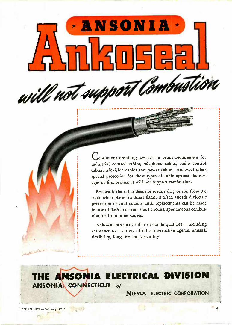
Continuous unfailing service is a prime requirement for
industrial control cables, telephone cables, radio control
cables, television cables and power cables. Ankoseal offers
special protection for these types of cable against the rav-
ages of fire, because it will not support combustion.
Because it chars, but does not readily drip or run from the
cable when placed in direct flame, it often affords dielectric
protection to vital circuits until replacements can be made
in case of flash fires from short circuits, spontaneous combus-
tion, or from other causes.
Ankoseal has many other desirable qualities - including
resistance to a variety of other destructive agents, unusual
flexibility, long life and versatility.
-a
THE ANSONIA ELECTRICAL DIVISION ANSONIA,CONIECTICUT of
NOMA ELECTRIC CORPORATION
ELECTRONICS -February, 1947 41

WURLITZER provides BLILEY CRYSTAL selection of the nation's
top-flight bands and entertainers
The Wurlitzer automatic, electric phonograph, affec- tionately known as the juke box, is a proven source of top-flight entertainment on almost every high- way and byway of America. Behind this assured performance lies a combination of electronic and mechanical ingenuity that could only be achieved by precision engineering.
In the new Wurlitzer instrument, selection of records may be accomplished by carrier current trans- mission of crystal controlled r -f pulses from the
eutey 47ZYSTALS
remote selector box to a receiver in the reproducer. Design considerations called for reliable crystal start- ing and rapid, clean pulsing.
Bliley engineers were consulted concerning the crystal unit and associated oscillator circuit needed to meet these requirements. The problem was success- fully solved and Bliley Crystals are now used in thousands of Wurlitzer installations.
Make it a habit to consult Bliley, first, on all fre- quency control applications. When you specify Bliley,
you automatically select the creative engineer- ing and production facilities that have built leadership in frequency control applications over the past fifteen years.
Write for Bulletin E-31
BLILEY ELECTRIC COMPANY UNION STATION BUILDING, ERIE, PENNSYLVANIA
42 February, 1947 -ELECTRONICS

v -h -f POWER TRIODE
GL -5513 ELECTRICAL CHARACTERISTICS
Filament voltage 6.3v
Filament current 32 crap
Amplification factor 87
Interelectrode capacitances: Grid -plate Grid -filament Plate -filament
Type of cooling
8.7 mmfd 21.1 maid
.11 mnfd forced -air
MAX RATINGS, CLASS B R -F POWER
AMPLIFIER, VIDEO SERVICE, SYNCHR.
PEAK (MITIONS Plate voltage 3,OOC v
current 1.2 anp input 3,300 w
dissip. 1,200 w
MAX RATINGS, CLASS C
TELEGRAPHY
Plate voltage current input dissip.
4,OOC v
1 amp 3,600 w
1,200 w
* Frequency (at max ratings) ranges up to 220 mc, covering
both television video and FM bands.
* Power output is substantial-see text below.
* Designed directly for grounded -grid circuits, with high -mu
characteristics that give high power gains.
* Complete internal shielding, plus ultra -compact construc-
tion, result in low plate -filament capacitance-making neu-
tralization easy, where required.
* Thoriated-tungsten filament SAVES, calling for minimum
filament power. Forced -air cooling assures convenient station installation.
* RING -SEAL terminals enable tube to be "plugged in"
quickly-their generous contact area also promotes h -f circuit efficiency.
TYPE GL -5513 has a tube out- put in excess of 2 kw (Class C
telegraphy), with power gain of approximately 10 when operated as a grounded -grid amplifier. In Class B video service, under syn- chronizing peak conditions, output exceeds 1 kw, with approximate power gain of 8 in grounded -grid service.
This capable new triode, besides its application to television trans- mitters for both the video and FM
bands, is directly suited to dielec- tric -heating service employing the high and very -high frequencies. Here the tube's low filament -power requirements are of special value, contributing to simple, economical transformer and circuit design.
As a rule, the GL -5513 requires nc neutralization in grounded -grid
GENERAL
circuits, but when this is needed, a
small amount of cross -neutraliza- tion will suffice. Modern engineer- ing is evident not only in the tube's electrical characteristics, but also in its compact structure - in its trim and efficient radiator design -in the fact that all external metal parts are silver-plated to provide better contact surfaces-and in the ring -type fernico metal -to -glass seals used throughout.
Help in applying G.E.'s new GL -5513 triode to new equipment now on your drawing -boards, gladly will be furnished by General Electric tube engineers. Telephone or write your nearest G -E electronics office, or communi- cate with Electronics Department, General Electric Company, Schenec- tady 5, New York.
ELECTRIC FIRST AND GREATEST NAME IN ELECTRONICS
ELECTRONICS -Fekruary, 1947 43

miniaturized RELAYS
with Steatite Insulation
SHOWN OVERSIZE FOR CLARITY
No. 12231
Originally designed for use in aircraft Orig relays equipment, these MINIATURE
dependable operation give completely vibration, under extreme conditions of
humidity and temperature.
The Steatite insulation and gen- eral construction of these relays makes them inherently suitable for switching circuits requiring perma- nently low leakage, for switching certain high frequency circuits, and for any application where a com- pact, light weight, yet sturdy relay is required. Particular attention has been paid to design of relays that will not "chatter" under vibration even in the un -energized position.
The antenna changeover relay shown is of unique design and pro- vides the wide contact spacing and positive action necessary for this special purpose, for a weight of only 0.2 lb.
The other small relays are pro- vided in the contact combinations illustrated at right, with maximum overall dimensions of 11/" x 11/16" x 11/" and a maximum weight of 0.07 lb.
For price and delivery information, write
No. 7735
See A. R. C. Exhibit, Booths 40-41A, of I. R. E. Show
A.R.C. ,p RA mamma mamma,,,,,A.,RLlIRTANCL D.C. coNTACf 1.
ARRANOLMLNT
11975 14 90
12232 28 300 °----i' 11914 14 90 o---i
12231 28 300 e 0---+t
0-4 11638 28 300 l
:',----4. 1,1
7735 28 112
AIRCRAFT RADIO CORPORATION BOONTON, NEW JERSEY
44 February, 1947 - ELECTRONICS

Ground Station Radio Transmitter
The new Collins 30K-2 embodies certain design
features that are of ou.standing benefit to owners
who employ radio communication from point to
point, ground to plane, or shore to ship. This 250
watt radio transmitter can be pretuned to any two
frequencies between 2.D mc and 30.0 mc. Relay operation of all r -f circuits, including antenna tun-
ing, provides instantaneous frequency shift.
A speech clipper in the audio circuit raises the
effective modulation áevel and emphasizes the
speech sounds that produce intelligibility. The effectiveness is especially noticeable on congested
frequency channels and under adverse atmospheric conditions. The 30K-2, when the speech clipper is
in operation, has a signal output comparable to
that of tre.nsmitters with normal modulation and
a much larger power output.
Because the r -f carrier is fully utilized, the power consumption of the 30K is comparatively small for
the results achieved. Maximum power demand is
approximately 1250 watts from a 115 volt a -c
single phase power source. Nominal r -f power output is 300 watts on cw or 250 watts on voice transmission.
Installation of the 30K-2 is extremely simple. No time consuming, expensive operations are required. Just connect it to a power source and attach the antenna. The transmitter output network will accommodate a wide variety of antennae and transmission lines. A remote control unit is avail- able. For complete details of this new and versatile radio transmitter, write for an illustrated bulletin.
IN RADIO COMMUNICATIONS, IT'S .. .
COLLINS RADIO COMPANY, CEDAR RAPIDS, IOWA
11 West 42nd Street, yew York 18, N. Y. 458 South Spring Street, Los Angeles '13, California
ELECTRONICS- February, 1947 45

,p0 ug t000Ni '?
SE;HMOOEIM,y,,M°0 yyI
.,., o R.P.M. e'°LL
PULLEY ON GEAR RATIO I:I AA
N0.3C1qr
2
e00011111111111111111111/004%,,e,,, ' ]O
... for the equipment you build! There's no more certain way to insure the efficient perform- ance in your customers' hands of the machines or devices you build, than to equip their panels or controls with trustworthy
instruments. And for that very reason, the name WESTON on a panel instrument helps build buyer acceptance and good- will for the products on which they are installed.
WESTON instruments are available in all the types, sizes and ranges essential for panel or built-in requirements. Com- plete information, or engineering cooperation, is available on request. Weston Electrical Instrument Corporation, 618 Fre- linghuysen Avenue, Newark 5, New Jersey.
Weston Alhaay Atlanta Boston Buffalo Chicago Cincinnati Cleveland Dallas Denver Detroit Jacksonville Knoxville Los Angeles Meriden Minneapolis Newark New
Orleans New Tort Philadelphia Phoenix Pittsburgh Rochester . San Francisco Seattle St. Louis Syracuse In Canada, Northern Electric Co., Ltd., Powerlite Devices, Ltd.
46 February, 1947 - ELECTRONICS

IN k phono -radio combination, loud speaker vibrations
feed back through the mounting springs of the record
player. Picked up by the tone arm, they are amplified
over and aver again, producing, unfortunately, noise
. not music. It is a tricky and interesting problem to design mount-
ing springs capable of supporting the varying (1 to 10)
record load yet of such flexibility that there will be little
vibration over the usable audio range.
Though .t is another matter to engineer (and often
build) the complicated gadgets required for properly
testing the springs-it's all in a day's work at Hunter.
And here you see mounting springs on trial in the
Hunter inspection laboratory.
SIGNAL POWER
GENERATOR AMPLIFIER
SPE AN ER
VOICE
COIL
L.
RADIO
SET
VARIABLE
FREQUENCY
RECORD
AMPLIPIER
i ._ á'+K i+-- npw4.tyd
HUNTER PRESSED STEEL COMPANY Lansdale, Pennsylvania

IN ONE INSTALLATION
U I Provides Excellent Ap ara Structural Strength and Insulating Properties for Webster Control Panel
Over 500 pieces of LAMICOID help special - made Webster "Moderator" Control Panel provide automatic heat variation. Front and rear views of this 37 -zone installation reveal the use of this thermosetting plastic laminate for dials, washers, and terminal boards.
This is a typical LAMICOID application where structural strength, appearance and electrical insulating properties are required. In fact, this unique combination makes LAMucoID so popular for such critical items as-panel boards, coil forms, threaded bush- ings, bus bar insulation, condensers, circuit breakers, terminal strips and blocks, rheo- stats ... and many similar parts.
A tough dielectric, LAMICOID is suitable
`p1tE M..o.,..
e,.
9\-UP M\Cp
for either high or low voltage applications. Its good compressive strength, low power fac- tor and resistance to varying atmospheric con- ditions round out its useful qualities - help it perform satisfactorily on the toughest jobs.
LAMICOID is made in many different electrical and mechanical grades from a wide selection of choice fabric and paper bases. It is furnished in a variety of forms, too. Sheets, rods and tubes are readily sawed, punched or machined into intricate shapes.
Because Mica Insulator Company manu- factures a complete line of insulating ma- terials-you can be sure of reliable, impartial recommendations as to the type best suited to your requirements.
LAMINATED PLASTICS
48 February, 1947 - ELECTRONICS

Attractiveness, legibility and permanence
cf translucent LAMICOID make it idea
f,r rodio and instrument dials.
Narren Webster & Company utilizes versatility of LAMICOID for
rundreds of parts where both structural and insulating properties
]re required.
Easy to clean graphic LAMICOID makes distinctive and dignified
,onel for this Warren Webster "Moderator" control.
MICA COMPANY Dept. 22, Schenectady 1, New York
Sales Offices and Fabricators in Principal Cities
Send for your copy of the revised 4 -page booklet on
LAMICOID. Lists electrical and mechanical specifica-
tions, and many suggested applications, colors and
NEMA grades.
Mica Insulator Company, P. O. Box 1076, Schenectady 1, New York
Gentlemen: Please send me a copy of your 4 -page bulletin on LAMICOID.
Name
Position
Company
Address
City Zone State
ELECTRONICS - February, 1947 49

MODERN The K -TRAN is modern in size, much smaller in all dimensions than old style I. F. Transformers. The K -TRAN is modern in performance. Any old style I. F. Transformer can be matched by one of a few types of K -IRAN. The K -TRAN is modern in price. More economical to purchase, more economical to stock, more economical to assemble than old style I. F. Transformers. Be modern. Use K -TRANS.
1/Tu M4 TI1f MANUFACTURING COR PO R AT ION
MASS PRODUCTION COILS & MICA TIIMMER CONDENSERS 9 0 0 PASSAC AVE. + -' EAST NEWARK, N. J
50 February, 1947 - ELECTRONICS

* RICHARDSON MEANS ß/iIN PLASTICS
s OVr 1CH-WHY depart e eeH OW.Vi1 e, How will it be used? Which INSUROK
grade? Which type ... molded, laminated,
rubber or combinations of each? Why?
These men are Richardson Plast'cians who specialize
in asking ... and answering ... questions of this kind.
They're designers who scrutinize virtually every
plastics order entering our door. Over drawing boards and under
T-squares, they visualize and create. The impractical is sifted;
the practical is found. And satisfaction results for all concerned.
This is efficiency the way we like to serve it up. This
is Richardson versatility ...whereby our customers
receive all they expect-and more! It's a policy
we've believed in and practiced for many years.
INSUROK Peeddeo« Peadeeed
c] e RICHARDSON COMPANY Sales Headquarters: MELROSE PARK, ILL. FOUNDED 1858 LOCKLAND, CINCINNATI 15, OHIO
NEW YORK 6, 75 WEST STREET ROCHESTER 4, N. Y., 1031 SIBLEY TOWERS BLDG.
PHIIADELPHIA 40, PA., 3728 NO. BROAD STREET Sales Offices MILWAUKEE 3, WIS., 743 NO. FOURTH STREET
CLEVELAND 15, OHIO, 326-7 PLYMOUTH IBLDG. PARK,ETROIT
2, MICH., 6-252BRUN G.
M. BLDG.N. J.
ST. INDIANAPOLIS,
MO.,12,I 5579 PERSHING AVENUE
* RESEARCH ... a continuous transfor- mation of possibilities into practical ideas in plastics.
*PRODUCTION ...Complete machine shop facilities for manufacturing our own dies, molds, tools.
*LAMINATING . Sheets, rods, tubes.
Standard NEMA grades; over 100 special .grades.
*MOLDING ... Rubber and bitumi- nous plastics; and synthetic resin plastics... Beetle, Bakelite, Durez, etc.
*FABRICATING . Complete equipment for
drilling, punching, saw- ing, turning, milling, etc.

Hermetic.... Pressure-
Stupakoff hermetic seals are the answer where pr ucts must have permanently vacuum- and pressure- tight insulated electrical lead-ins. They seal atmosphere, dirt, dust, fungus, and other substances that normally cause failures
Available from stock or specially made to suit your needs, Stupakoff metal -glass seals can be supplied
Give Permanent.... ht Seals
*Reg. U.S. Pat. Oft. Trade Mark Ne. 331962
against
foreign
ZUue An l,íena4úme.
with single or multiple, hollow or solid electrodes. The metal Kovar is available in sheets, rod, wire,
ng and special shapes for manufacturers having orking facilities.
gladly send literature, recommendations and your hermetic seal requirements. Write today.
EXPORT DEPARTMENT 13 E. 40th St, New Yerk 16, N.Y. Cable Address AR LAB all cedes.
52 February, 1947 - ELECTRONICS

halikrafters PRESENTS THE
Another first! Greatest contin-
uous frequency
coverage of any
communications
receiver- from
540 kc to 110 Mc
This is the long-awaited Hallicrafters SX-42, a truly great communications receiver. The tremendous frequency range of the SX-42, greater than ever before available in
a receiver of this type, is made possible by the develop- ment of a new "split -stator" tuning system and the use
of dual intermediate frequency transformers. Packed with advance features that every ham and every other radio enthusiast desires, the SX-42 clearly lives up to
the Hallicrafters ideal of "the radio man's radio." From now on watch Hallicrafters - the name that's
remembered by the veteran, preferred by the radio ama- teur. See your distributor for demonstration of the SX-42
and for colorful literature describing this great set in complete technical detail.
BUILDERS OF
Because of the pre- cise and thorough engineering that must be done on the SX-42 and because the parts supply has not been con- tinuous, top produc- tion peaks have not yet been reached. In the immediate future deliveries will necessarily run behind the demand, but the SX-42 is definitely worth waiting for.
hallicrafters RADIO THE HALLICRAFTERS CO., MANUFACTURERS OF RADIO
AND ELECTRONIC EQUIPMENT, CHICAGO 16, U. S. A. Sole Hallicrafters Representatives in Canada: Rogers Majestic limited, Toronto-Monheol
ME' AVIATION RADIOTELEPHONE
tilfflem_ a ma.
ELECTRONICS - February, 1947 53

PU `ING ELECTRO with
S TO 0 K
CaXe/(02-4-
To help you incorporate the many advantages of
electronics in your business, the War Assets
Administration is making available its enormous
inventory of tubes and equipment now.
Qualified distributors all over the country have been
appointed by WAA to represent it. In every field where
electronic application has proved its worth, these
distributors maintain inventories and have the technical
"know-how" to service your needs.
Get in touch with your nearest distributor and see how
government -owned war surplus can help you- electronically. Or-if it is more convenient-write to
ELECTRONICS DIVISION OFFICE OF .AJR:C.t T DISPOSAL
WAR ASSE S ADMI ISTRAATON 425 Second St., N.W. Washington 25, D. C.
54 February, 1947-ELECTRONICS

s
RECTIFYING (NO. 864A)
TRANSMITTI NG (NO. <<15
RECEIVING (NO. 6SK7)
Millions and millicns of electronic tubes
are at your disposal. Pictured are some
of the types which are available to you.
VOLTAGE REGULATOR (NO. V11)15e.
CATHODE RAY
(NO. 38P1)
RECEIVING (NO. 61.6)
tubes. tubes. tub'51
"NO ELECTRONIC DEVICE IS BETTER THAN ITS TUBE"
ELECTRONICS - February, 1947

Receiver
MODERN COMMUNICATION and
PRODUCTI01t
depend on
Today-virtually all methods of high-speed communication use electronic tubes. In the industrial field, heating, welding and various methods of control are being done better and faster because of electronics. From big broad- casting stations to tiny hearing aids-from induction heating to voltage regulation-the science of electronics is playing a major role in industry.
Matching Stub and Antennae
Microphone
5h February, 1947 - ELECTRONICS
Authoril" Distributors will serve Ye.
Listed here are the names and locations of WAA ap-
pointed distributors. Not all of them will have complete
stocks but it will pay you to consult them on your elec-
tronic problems.
Automatic Radio Mfg. Co., Inc.
120 Brookline Avenue Boston 15, Massachusetts
Communication Measurements Laboratory
120 etrººrwich Street
New York 6, New York
Tobe Deutschmann Corporation Canton, Massachusetts
Electronic Corporation of America' 353 West 58th Street
New York 19, New York
Electro -Voice, Inc. Buchanan, Michigan
Emerson Radio & Phonograph Corporation
123 Duane Street
New York 7, New York
Essex Wire Corporation 1601 Wall Street
Ft. Wayne 6, Indiana
General Electric Company Building 267-1 River Road
Schenectady 5, New York
Hammarlund Mfg. Company, Inc.
460 West 34th Street
New York 1, New York
Hoffman Radio Corporation 3741 South Hill Street
Los Angeles 7, California
Hytron Radio & Electronics Corporation 76 LaFayette Street Salem, Massachusetts
E. F. Johnson Company 206 Second Avenue S. W.
Waseca, Minnesota
Newark Electric Co., Inc.
242 West 55th Street
New York 19, N. Y.
Larestosterassnial...'
Majestic Radio & Television Corporation 125 West Ohio Street
Chicago 10, Illinois
Raytheon Manufacturing Company 60 East 42nd Street
New York 17, New York
Smith -Meeker Engineering Company 125 Barclay Street
New York 7, New York
Sylvania Electric Products, Inc.
Emporium, Pennsylvania
Technical Apparatus Company 165 Washington Street
Boston 8, Massachusetts
Tung -Sol Lamp Works, Inc.
95 Eighth Avenue Newark 4, New Jersey
American Condenser Co.
4410 Ravenswood Avenue Chicago 11, Illinois
WAR ASSETS ADMINISTRATION A UNITED STATES GOVERNMENT AGENCY
FOR THE DISPOSAL OF SURPLUS PROPERTY ru
ELECTRONICS - February, 1947 57

Radio communication is as vital to the airways as rails are to the railroads. For high performance, dependability, and easy
maintenance, WILCOX radio equipment has earned the confidence of airline personnel throughout the world. Solve
your communication problems with Wilcox.
Check the Wilcox 2500 Watt 96C Transmitter For:
I. PERFORMANCE-Transmitter units combine with modulator and rectifier to give either simultaneous transmission on a number of frequencies, or the selection of an individual frequency best suited to the immediate corn. munication problem. Complete remote controL
2. DEPENDA8ILITY-Research, engineering, and testing combined with highest quality materials result in a rugged product capable of sustained operation through all conditions of temperature, humidity. and weather.
3. MAINTENANCE-All controls and components are completely ac- cessible. Plugs and receptacles or clips make every major section readily removable. Fuses, power and telephone line terminals are located on con- venient panels.
4. SAFETY_The disconnect switch at base of transmitter cuts off all voltage and grounds components so unit can be serviced without affecting operation of adjacent channels.
A request on your letterhead will bring complete information
Wilcox Electric Company, Inc. KANSAS CITY, MISSOURI
58 February, 1947 - ELECTRONICS

LAPP GAS -FILLED CONDENSERS
AT PREWAR PRICES
There's good news for designers and builders of high voltage electronic circuits who find themselves caught in an inflationary spiral of costs. No advance in prices has been announced -none is contemplated-for Lapp Gas -filled Condensers. Known as the most satisfactory source of high current and high voltage capaci- tance, these units offer non -deteriorating, de- pendable performance; impossibility of punc-
ture; lowest loss with consequent economy of power; constant capacitance under tempera- ture variation; and compact, space -saving de- sign. Variable, adjustable, and fixed units are available with current ratings up to 500 am- peres R.M.S., power ratings up to 60 Kv peak. Units now in service range up to 60,000 mmf. (fixed units), 16,000 mmf. (variable and adjust- able units).
LAPP INSULATOR COMPANY, INC., LE ROY, NEW YORK
ELECTRONICS - February, 1947 59

Amphenol
ALL -WAVE ANTENNA
GETS ALL THREE!
Purchasers of modern radios deserve good reception on all three bands-standard broadcast, short wave and frequency modu- lation. Until Amphenol engineers perfected this new all -wave unit, the only way to achieve this was to install three separate antennas, a costly and unsightly solution.
The FM section of this new 3 -way antenna is a horizontally polarized dipole. It operates most efficiently between 88 and 108 mc.
A 65 -foot length of Amphenol Polyethylene covered copper wire serves as the standard broadcast and short wave antenna. The polyethylene covering minimizes precipita- tion static and assures long life.
A specially designed series M derived low-pass filter automatically switches the energy from the proper antenna to receiver input.
Installation is simple. The mounting is a 1 -inch steel mast 5 -feet in length. All hard- ware is included. A guy clamp bolted to the mast provides for tripod guying.
Vinyl -jacketed Amphenol 52 ohm coaxial transmission line serves' as a low -loss lead in and eliminates interference from transmission line pickup. Noisy areas are not a problem with this antenna.
In a comparative test with the best avail- able standard double doublet (with matching transformer) the Amphenol All -Wave Anten- na proved far superior in gain-as well as being interference free.
Write for complete technical data, or see your jobber for full information.
e
BC
SW
FM AMPHENOL ALL -WAVE ANTENNA UNIT INCLUDES:
* FM dipole with molded phenolic weatherproof filter housing
* 50 -feet Amphenol RG -5/U 52 ohm coaxial cable
AMERICAN PHENOLIC CORPORATION CHICAGO 50, ILLINOIS
* Steel mast 5 -feet long with guy clamp and adjustable insulator
* Antenna wire polyethylene covered
* Built-in M derived network
COAXIAL CABLES AND CONNECTORS INDUSTRIAL CONNECTORS, FITTINGS AND CONDUIT ANTENNAS RF COMPONENTS PLASTICS FOR ELECTRONICS
60 Febriary, 1947 - ELECTRONICS

PALMER MFG. CO.
SUSPENDED UNIT
GAS HEATER WALTON LABORATORIES. INC.
HUMIDIFIER
*THREE STURDY, DEPENDABLE POWER SOURCES ....
TYPE NO. TYPE H. P. SPEED
KP732L SHADED POLE 1/30 1500
K711H CAPACITOR (Ball Bear. ng)
1/20 3200
L732GC CAPACITOR 1/15 1600
EASTERN AIR DEVICES, INC. 585 DEAN STREET BROOKLYN 17, N. Y.
73 series
MOTIONAIR COMPANY
INDIRECT AIR CIRCULATOR
EAD motors meet the most rigid require-
ments of the heating and air condition-
ing industry. They are designed to
give smooth running quiet performance
at high efficiency with minimum size
and weight. Replaceable "capsule"
bearings with their large oil reservoirs
assure long bearing life and trouble
free operations. Consult our Engineer-
ing Dept. with your design and appli-
cation problems.
ELECTRONICS - February, 1947 61

(
FM Sound Exciter Und Sound R -F Drive knit
(also part of sound PA) (also Part of sot nd PA)
STRAIGHT-LINE Arrangement (ever -all width 208 inches). Unit -construction permits flexible station lay-
out, advantageous use of avail:_ lie floor. space.
Sound Rectifier Unit Power Control Unit
Picture Modulator Rectifier Unit
U -SHAPED Arrangement - several versions possible down to a minimum width of 150 inches. Transmitting equipment also includes console; sideband filter, di- plexer, and dummy load (three units at right, rear); watercooling equipment (left, rear); and racks for test
and other equipment (right, foreground).
62 February, 1947 - ELECTRONICS

t"'
Picture Rectifier Picture R -F Driver- also Port picture
PA
Picture Modulatom
also Pad Picture PA
One transmitter ... one standard of quality... for all 12 metropolitan channels
This revolutionary, new RCA television transmitter, we believe, offers the last word in convenience, operating economy, and performance. Here, in one attrac- tively styled group of cabinets, are all
the necessary components of both the visual and aural transmitters. Take a look at some of its features: - Simplicity of operation... complete unifica-
tion of control ... no trick circuits ... no neutralization of modulated power -
amplifier stage required on any channel... only one easily adjusted modulated stage.
- Roomy, "walk-in" type construction...easy access to all parts through full-length front and rear doors ... ease of handling and in- stallation (each section only 25 by 36 by 80 inches).
-A revolutionary new tube used in both sound and picture power amplifiers-the RCA -8D21, a dual tetrode. Sets new rec- ords for stability, gain per stage, low grid
let esir
THE FIRST POSTWAR
ALL tIVJ ìJJ2! TELEVISION TRANSMITTER
RCA's new 5 -kw, 54 to 216 mc, Type TT -5A
current, linearity, anti band -width by employ- ing advanced prinçiples or screening, cool- ing, and electron optics.
- The separate, sideband filter used in RCA's high-level system (i.e. only last stage modulated) means more straightforward circuits; eliminates complicated adjust- ments; assures better picture quality.
- "Refectometers" incorporated in both the aural and visual output circuits. Basically these are uni -directional vacuum -tube volt- meters which provide an instantaneous check of the standing -wave ratio on the transmission line and peak power output; also used as safety devices -to protect trans- mission line from power arcs.
- Manual or automatic sequence starting. In automatic position, a three -slot recycling sequence returns transmitter to the air three times in case of momentary overload.
- A special "hold -in" circuit. Provides in- stantaneous return to air after momentary power -line failure. - Console provides four -position, push- button monitoring of visual signal-trans- mitter input, modulator output, sideband- filter output, and "off the air." (Third or fourth position measures percentage modulation of visual carrier.)
Outstanding features like these-of ben- efit to the station engineer, manager, owner, and audience-have been built into all the new items in RCA's complete television line. Deliveries on existing or- ders from 20 top broadcasters have al-
ready begun on such items as portable field equipment, synchronizing genera- tors, and monoscope cameras. Initial ship- ments of transmitters and other equip- ment will be made this fall.
New RCA -8D21 Dual Tetrodo spe- ciolly developed for television
broadcasting
TELEVISION BROADCAST EQUIPMENT
RADIO CORPORATION of AMERICA ENGINEERING PRODUCTS DEPARTMENT, CAMDEN, N.J.
In Canada: RC A VICTOR Company Limited, Montreal
ELECTRONICS - February, 1947

breaking the back of the
breakeven point! The break-even point in most businesses breaks the heart of management. Costs must come down. The race to be com- petitive is on in earnest. If a steady flow of dependable capaci- tors to your assembly lines will help to put your break-even point in its proper place, call on C -D. We've specialized in capacitors for 37 years. We've made no less than 250,000 different types! Typical of this versatility are the capacitors illustrated below. It's still possible that we've never made
MICA DYKANOL PAPER
the precise capacitor you require. But our engineers "can do". And they will! For a better product-for lower produc- tion costs-put our experience to work for you.
Catalog of standard types available on request. Your specifications for special capacitors are solicited. Cornell-Dubilier Electric Corporation, South Plainfield, New Jersey. To meet your capacitor needs promptly and efficiently, C -D operates plants in New Bedford, Provi- dence, Worcester and Brookline.
ELECTROLYTIC CAPACITORS
A FEW OF THE CAPACITORS WE HAVE MADE TO ORDER
v
0
CAPACITOR #1 - A series of capacitors designed for television requirements. Hermetically sealed, Dykanol impreg- nated and filled. Capacity range from .005 to .05 mfd. at voltages from 2,000 to 3,500 DC. Diameter remains 1", length varies with capacity.
CAPACITOR #2 - This special capacitor is essentially for high frequency plate - blocking applications. Capacity ratings of 100 and 1,200 mmfd. at 10,000 V.D.C. Extremely high r. f. current rating with respect to its size. Ceramic construction with wide path base mount- ing terminal.
El
CAPACITOR #3 - Designed and pro- duced for a manufacturer of business machines. Capacitive -resistive type of spark suppressor unit. Dykanol impreg- nated. Hermetically sealed and pro- vided with two insulated terminals for efficient assembly into parent equipment.
64 February, 1947 - ELECTRONICS

A POTTER ELECTRONIC COUNTER FOR EVERY
COUNTERS AND SCALERS
For straight high-speed counting and frequency dividing i.e. radiation counting -machine operations
CHECK THESE IMPORTANT FEATURES!
Speed and Accuracy Will count at rates up to a million per second with absolute accuracy.
Versatility Can be used for measurement and control of dis- crete quantities, length, area, time, velocity and frequency. Can also be used to totalize counts from several sources occurring smultaneously and at random.
t flexibility Readily substituted for slower inaccurate mechanical controls-adaptable to all types of input actuations. -Selection of any predetermined count made simply by dial switches. Easy to ins all and operate.
Reliability Sturdy construction using simple straight forward reliable circuits and high quality components. As- sures maximum trouble free continuous operation. - No moving parts to. wear cut - II you have a specific application problem or wish additional information on Potter Elec- tronic Counter Circuits, write Potter Instrument Company, Dept. 6A.
timing control counting sorting totalizing
NEED
DUAL PREDETERMINED COUNTERS
For controlling two sequential operations at high rates i.e. zipper manufacture
SINGLE PREDETERMINED COUNTERS
For high speed counting and grouping of items for processing or packaging i.e. pack- aging of pills, buttons, hardware, etc.
Photoelectric Screen for gating interval timer in projectile ve- locity measurements.
INTERVAL TIMERS
For measuring or predetermining intervals with micro -second accuracy i.e. projectile velocities -accurate time base generator.
POTTER INSTRUMENT COMPANY 136-56 ROOSEVELT AVENUE FLUSHING, W. Y.
ELECTRONICS-February, 1947 65

RADIO Builders and
Listeners ...Both Give Top Rating
4. ÓIF pepsDRIVER
CAN'T SLIP
S
OUT
TAPERED RECESS
to these Cost -Controlling,
Good -Looking AMERICAN PHILLIPS SCREWS 1. TOP RATING in Production Savings: Fast, fumble -proof, automatically straight -driving ... American Phillips Screws make possible high -volume radio production where even the slightest surface -scratch means "reject." For at highest speeds, the 4 -winged American Phillips Driver can't twist out to scar work -surfaces! Speed ... with complete safety both for work and workers ... that's the double advantage that makes American Phillips Screws the lowest -cost fastening method on any job. Whatever product you assem- ble, you will find that American Phillips Screws pay off with SAVINGS UP TO 50! ; .
2. TOP RATING in Sales Promotion: The decorative heads of American Phillips Screws are a customer -accepted mark of quality. And they're an added assurance of service- ability under incessant use. So standardize on American Phillips Screws throughout your assembly departments. Write:
AMERICAN SCREW COMPANY, PROVIDENCE 1, RHODE ISLAND Chicago 11: 589 E. Illinois St. Detroit 2: 502 Stephenson Building
AMERICAN PHILLIPS
ALL TYPES ALL METALS: Steel, Brass, Bronze, Stain- less Steel, Aluminum, Monel, Everdur (sili- con bronze)
66 February, 1947 - ELECTRONICS

APACIT
THEIR STRENGTH ADDS "STAYING POWER'' TO 'route PRODUCTS
Capacitors needn't be the weak link in your product- they can have just as much "staying power" as any other component in your equipment.
G -E capacitors have long life. One reason for this is that they are Pyranol* impregnated. Practically all moisture, air, and gas have been withdrawn from the capacitor before the Pyranol treatment takes place. The use of Pyranol also means that these capacitors can op- erate at high temperatures-up to 75 C (167 F) case temperature. This eliminates one of the main causes of capacitor breakdown.
Casings, available' in all standard shapes, are double - rolled, or roll -crimped and soldered, sealing the capacitor hermetically. Plastic bushings, of high dielectric strength, bring out the hot -tin dipped soldered terminals.
GENERAL
Low Starting Torque Moto -
High PoNer Factor Luminous Tub' Transf orrnc _
High Starting Torque Motor
If you are building a quality product, here's a quality a -c capacitor that you'll never have to worry about. They're available in a broad range of voltage ratings and capacities. .Write for the latest Bulletin GEA -2027C. Apparatus Dept., General Electric, Schenectady 5, N. Y.
'Reg. U. S. Pat. O8.
Why Manufacturers 1. Their price is right.
2. You can get fast ship- ments.
3. The range of ratings is broad.
Like G -E Capacitors
4. Designed for small size and light weight in all ratings.
S. Their quality is un- excelled.
ELECTRIC 407-111-6700
ELECTRONICS - February, 1947 67

TIME DELAY ON OVERLOADS .... The magnet coil surrounds a hermetically sealed and liquid 'ailed cylinder which contains an iron plunger. This plunger, while normally not in the magnet field, moves into the field on overloads with the liquid controlling the speed at which the plunger moves. The magnetic flux increases as the plunger rises, attaining its maximum when the plunger reaches the top of the cylinder. At this point the trip armature is attracted to the pole piece and operates the latch mechanism which opens the contacts. Various time delays can be obtained by the use of liquids of differ- ent visçcsitias.
Plunger in normal po. Bition at bottcm of cylinder.
INSTANTANEOUS ACTION ON SHORT CIRCUITS ....
Short circuit currents energize the pole piece with sufficient speed to attract the armature before the plunger moves.
Plunger after ov load with armati attracted to p piece, opening c tacts.
BLOWOUT ACTION AT CONTACTS .... Magnetic blowout contacts mounted in individual arc- ing chambers add speed to the arc interruption. As the value cf the current to be interrupted increases the quenching effect becomes greater due to the in- tensified magnetic blowout field.
HEINEMANN ELECTRIC COMPANY Established 1888
97 PLUM STREET TRENTON, N. J.

The remarkable current -generating efficiency o
Western Electric SOUND -POWERED TELEP
is based on critical electronic positioning o
elements visually indicated by the...
ikIn the manufacture of Sound -Powered Telephones, made for our Army and
Navy by Western Electric du-ing the war, one of the most difficult operations was the positioning of the armature in the ex- act center of the magnetic circuit. The bal- anced armature design means that the ar- mature must be balanced .-nagnetically among four air gaps.
During the early years of manufacture, this adjustment was done by means of feeler gauges. This method, however, did not always yield the true magnetic center because of slight differences in magnetic materials. Many units would be rejected in subsequent tests.
To overcome this condition, production engineers at Western Electric devised a method whereby the armature can be ac- curately located magnetically, with the aid of the cathode-ray oscillograph. This ability to see electronically what goes on in these air gaps has been of considerable assistance in overcoming one of the most difficult operations associated with the production of Sound -Powered Telephones.
And so another cathode-ray oscillograph application. Surely in your own produc- tion and inspection routine, or in mainte- nance or servicing, or again in research and engineering, you can use this "elec- tronic seeing" to profitable advantage
Submit your problem.
NO BATTERIES REQUIRED!
As the name implies, Sound - Powered Telephones require no external source of power. The feeble sound power of the voice is converted into electrical energy. Telephonic communication up to 10 miles is feasible over ordinary Army field.telephone wires, and up to 100 miles under laboratory conditions. Such equipment was extensively used by our armed forces afloat and ashore.
® ALLEN B. DU MONT LABORATORIES, INC.
ALLEN B. DuMONT LABORATORIES, INC., PASSAIC, NEW JERSEY CABLE ADDRESS: ALBEEDU, PASSAIC, N. J., U. S. A.
ELECTRONICS - February, 1947 69

STRTII [RS HUN HEAVY-DUTY RELAYS
In addition to many standard types of large power relays, Struthers -Dunn can supply adaptations for applications involving high inrush loads, radio - frequency or high -voltage insulation, extra long life, and other special
service conditions. All units include three point armature support for excep-
tionally quiet operation, wiping action on the fine silver contacts and numer-
ous other features.
Write for Data Section 4671 for detailed information on both standard
and special types.
STRUTHERS-DUNN, INC., 146-150 N. 13th St., Phila. 7, Pa.
ATLANTA BALTIMORE BOSTON BUFFALO CHICAGO CINCINNATI CLEVELAND DALLAS DENVER DETROIT HARTFORD INDIANAPOLIS LOS ANGELES MINNEAPOLIS M O N T R E A L
NEW YORK PITTSBURGH ST. LOUIS SAN FRANCISCO SEATTLE SYRACUSE TORONTO
70 February, 1947 - ELECTRONICS

ziee egie: oic4,egreace vc`.aye ox y.orvL pezoree-er-L`
Short Ifube
nPoor Opaarion
Customer Dissatisfaction 1
Circuit Unbalance
Loss of Accuracy
1
THERE ARE HO VOLTAGE PROBLEMS WHEN A SOLA CONSTANT
VOLTAGE TRANSFORMER IS A tetelG+ Check! ... before the equipment leaves your plant. Can it stand violent voltage fluctuations, sometimes as great as 30%, and still perform as you intended it should?
It is not necessary, you know, to sad- dle your customer with the responsibility of providing stable operating voltage. You can do it for him at an actual saving, both in original cost and maiintenance, by including a SOLA Constant Voltage Transformer as a "built-in" component.
There are 31 standard types of SOLA Constant Voltage Transformers, several speccally designed for chassis mount- ing, available in capacities from LOVA to 15KVA. If none are adaptable to your requirements, special units can be custom designed to your exact specifi- cations.
Whether your product is designed for home, science or industry-Constant Voltage is your problem. May we recommend the solution?
ATRANSFORMERS
This book provides the answer to your Constant Voltage problem.
Ask for Bulletin DCY-102
Transformers for:ConstantVottoge Cold Cathode lighting Mercury Lamps Series Lighting Fluorescent Lighting X -Ray Equipment Luminous Tube Signs
Cil Burner Ignition Radio Power Controls Signal Systems etc. SOLA ELECTRIC COMPANY, 2525 Clybourn Avenue, Chicago 14, Illinois Manufactured in Canada under license bs FERRANTI ELECTRIC LIMITED. Toronto
ELECTRONICS - February, 1947

4t
THE Luc ENGINEER
but not on your pi yroll
TUNE IN THE ELECTRICAL
INSULATIII_Y'
READ911,1 It TER ti
Because your IMC engineer represents not just one, but most of the recognized leading manufacturers of electrical in- sulation-each specializing in his own particular product- his experience in the insulation field is more complete. As a specialist in electrical insulation, he and the IMC organization behind him are qualified to .. .
1. Assist you in the selection of the best insulating materials for the job.
2. Familiarize you with their proper application.
3. Suggest ways to eliminate waste.
4. Increase your production.
PRODUCTS LIST: Macallen Mica Products --Vortex Varnished Cloths and Tapes-\crslot Combination SIo- Insulation - Fiberglas Elec- trical insulation-Manning Insulating Paper; and
Pressboards-Dow Corning Siliccres- Dieflex Varnished Tubing; and Saturat- ed Sleevings-Na- tional Hard Fibre and Fish paper-Pheralite Bakelite-Permacel Adhesive Tapes-As- bestos Woven Tapes and Sleevings -In - manco Cotton Tapes, Webbing s, and Sleev rgs-Pedigree lnsulcting Varnishes -Wedgie Brand Wood Wedges.
INSULATION MANUFACTURERS CORPORATION
*CHICAGO 6 565 West Washing- ton Blvd.
*CLEVELAND 14 1231 Superior Ave., N. E.
Branches in: MILWAUKEE 2, 312 Eod Wisconsin Avenue, DETROIT 2, 11341 Woodward Avenue; M dNEA?OLIS 3, 12CE Harmon Place;,
PEORIA 5 1)1 Heins Cour., and other .Ries

THE CLOSED SHOP Key to Labor Monopoly
F THE PEOPLE of the United States are to loosen the monopoly control now exercised by some segments of union labor and re-
capture the power to control their own economic and political destiny, they must come to grips with the problem of the closed shop. A satisfac- tory solution of that problem is as vital to the in-
terests of the wage earner, who should be fully protected in his right to organize and bargain collectively through representatives of his own choosing, as it is vital to the interests of the nation as a whole.
By the closed shop, which unfortunately is a term that seems to shed more heat than light, I mean any shop in which the worker must make his peace with a union in order to have a job. There are approximately 131/2 million union members in the United States. Of these about 10
million are governed by arrangements calling for "closed" shops, union shops, maintenance of
membership provisions and similar devices which make good standing in a union a condition to holding a job.
Such arrangements raise serious issues about what is commonly presumed to be the basic American right to work. Also, closed shop ar- rangements lie at the root of the dominant eco- nomic power now exercised by some labor leaders.
The problem of reducing the power of these labor leaders to proportions that make it safe for democracy is the age-old problem of monopoly. In an earlier era this problem was created largely by businessmen who sought to escape the re- straints of competition by combinations or agree- ments to control prices and production. Such ef-
forts are still attempted and must be curbed by law.
Union Labor Monopoly
But, after more than a decade during which a monopoly position for organized labor has been aggressively promoted by the federal government, the major monopolists today are those labor lead-
ers who wield the power of enormous nationwide unions. About 90% of the soft coal miners do the bidding of John L. Lewis. A like percentage of
the auto workers are represented by the United Automobile Workers of the C. I. O. About 80% of the production workers in steel are members of the United Steel Workers, C. I. O. No single corporation has more than a fraction of the eco- nomic power that is concentrated in these unions. And if corporations were to combine their power to cope effectively with that of these union mo- nopolies they would unquestionably find them- selves charged with violating the federal anti- trust laws.
In its national sweep, the monopoly power of
unions rests largely on their exemption from the federal antitrust laws. My previous editorial in this series (the 53rd) discussed the desirability of
removing that exemption. The local roots of this monopoly power are often embedded in closed shop arrangements.
Closed Shop in Coal
An illuminating case in point is provided by the United Mine Workers, whose leader John L. Lewis has graciously given the country a 31/2 -
month reprieve from "the hysteria and frenzy of an economic crisis," as he himself termed it. Dur- ing that latest crisis the dispatches from the soft coal fields reported that the miners were standing behind John L. Lewis almost to a man. And the implication usually was that the driving forces of the strike were loyalty to Lewis and the pros- pect of economic gain.
Underlying that performance, however, and basic to it was an agreement in the soft coal fields providing that "as a condition of employment all employees shall be members of the United Mine Workers." Hence to hold a job in 90% of the soft coal industry which is governed by contracts with the United Mine Workers, a miner must not offend the union. To avoid offense the union member must even be careful in criticising what his union

does. Suspension from the union for six months, and hence from the right to hold a job, is the pen- alty imposed by the United Mine Workers con- stitution for circulating a statement "wrongfully condemning any decision rendered by any officer of the organization."
The willingness of the miners to follow Lewis until the country froze over was not, of course, exclusively a product of the agreement limiting jobs in the coal fields to union members of good standing. Some of it originated in bad handling of employee relations in the coal fields in years gone by. But the fact remains that Lewis' soft coal mo- nopoly has as one of its principal foundations an agreement which gives the United Mine Workers a job -or -no -job hold on 90% of the soft coal miners.
In its extreme form, the closed shop not only makes union membership a condition of employ- ment but narrowly limits the numbers admitted to union membership and hence to the opportu- nity to work. In this way it is used to enforce re- striction of output and working rules which would never stand up under free competition.
Fair Dealing
The closed shop raises major issues of personal freedom and fair dealing between individuals. As matters now stand, closed shop agreements require employers to discharge workers who lose their good standing in the unions involved. At the same time they frequently impose no require- ment on unions to grant membership to law abid- ing and technically qualified persons. Many un- ions with closed shop agreements refuse to grant membership on the basis of competence. Thus, qualified workers are denied a fair chance to hold a job.
In its dealings with the closed shop issue the federal government has been pushed into a self- contradictory position. The National Labor Re- lations Act (the Wagner Act) provides, and prop- erly, that "employees shall have the right ... to bargain collectively through representatives of their own choosing." In furtherance of that basic proposition, the Wagner Act also provides that "It shall be an unfair labor practice for an em- ployer ... by discrimination in regard to hire or tenure of employment to encourage or discourage membership in any labor organization ..." Stand- ing alone, the provision would clearly outlaw the closed shop,
But then, to favor the closed shop, the Wagner Act turns right around and provides that "noth- ing in this Act ... shall preclude an employer from making an agreement with a labor organi- zation . to require, as a condition of employ- ment, membership therein," provided that cer- tain conditions of representation are fulfilled. This places the National Labor Relations Board in the impossible position of trying to administer a law which simultaneously points in opposite directions.
In successfully contending that there should be no closed shop arrangements on the railroads, the late Joseph Eastman, Federal Co-ordinator of Transportation, said, "If genuine freedom of choice is to be the basis of labor relations under the Railway Labor Act, as it should be, then the yellow dog contract and his corollary, the closed shop ... have no place in the pictur&" The so- called yellow dog contract, which requires a worker to agree not to join a union as a condition of c*nployment, has long since been outlawed.
At te, time the closed shop was defended as a protective device for feeble young unions strug- gling against predatory employers. But a mere glance over the current economic scene discloses that the time when that argument was supported by the facts is past. Now it is the labor leaders who frequently exercise decisive economic power.
At elections in November three more states, Arizona, Nebraska and South Dakota, passed constitutional amendments outlawing the closed shop. In doing so, they joined six other states, which, in one way or another, have restricted the closed shop. The South Dakota amendment pre- sented the basic issue created by the closed shop in simple and direct terms when it declared that "The right of persons to work shall not be denied or abridged on account of membership or non- membership in any labor union, or labor organi- zation."
That issue must be squarely faced by the new Congress if its first order of business, the labor crisis, is to be resolved.
President McGraw-Hill Publishing Company, Inc.
THIS IS THE 541m OF A SERIES

chosen for Performance Eimae
4X500A tetrodo
REL ... t e pi r m ufacturer of f -m ns . ers, has been en- gineeri gear around Eimac Tubes ever since 1939.
One of their latest designs is
illustrated above at the right- the 1000 -watt unit with Arm- strong dual -channel direct -crys- tal -controlled frequency modula- tion. For the power amplifier, shown in the center, REL chose a pair of Eimac 4X500A tetrodes because of their remarkable power gain, stability to f requen- cies above 110 mc, and efficiency. Actually, 70 per cent of the input to the final amplifier is delivered to the load.
In the REL transmitter, less than 20 watts of drive produces the rated kilowatt. In face, a pair of Eimac 4X500A's can deliver 1750 watts of useful output with only 25 watts of drive; while four tubes in push-pull parallel, tak- ins 50 watts on the grids, put out 3500 watts.
Unwavering stability is achieved in these tubes by combination of exclusive Eimac emission - con- trolled grids and a concentric - ground -plane ring terminal for the screen grid. Visible in the ac- companying illustration, this ring permits finger contact with chas- sis ground and effective isolation of input and output circuits. Self oscillation is minimized and neu- tralization, if necessary, is made simple.
FURTHER POINTS
GRIIDS...Special treatment suppresses primary emission and controls sec- ondary emission to add efficiency to stability. One hundred per cent useful structure, without interfering supports, and precise alignment be- tween control grid and screen give maximum plate efficiency and low grid current.
FILAMENT...Special thoriated tung- sten provides high electron emis- sion at low temperature.
EIMAC 4X500A POWER TETRODE
Electrical Characteristics Filament: Thoriated tungsten
Voltage 5 0 v
Current 13.5 amp Direct Interelectrode Capacitances
(Average) Grid -plate 0 05 uuf Input 12.8 ouf Output 5.7 ouf
Maximum Ratings Plate voltage, d -c 4000 v
Plate current, d -c 350 mo.
Plate dissipation 500 w
Ask for full details on these and other Eimac tubes for f -ni, a -nt, television, and industrial applications in a com- prehensive range of power and fre- quency capabilities.
EITEL-McCULLOUGH, INC. 1367E San Mateo Ave., San Bruno, Calif.
Export Agents: FRAZAR AND HANSEN 301 Clay Street, San Francisco 11, California, U.S.A.
Follow the leaders to MIR
ELECTRONICS-February, 1947 73

.. and what a
DIFFERENCE!
General Electric Speakers are built to be different - better. For warm, live, pulsat- ing. radio and record repro- duction, specify speakers by General Electric.
Better tone quality
High wattage handling capacity
No warping of voice coil
Greater design possibilities
Overall greater efficiency
Better controlled air gaps
Rigidity, strength, durability
Consult General Electric now for your Speaker requirements. Write to: General Electric Com-
pany, Electronics Department, Syracuse 1, N. Y.
GENERAL ELECTRIC
BUSINESS BRIEFS By W. W. MacDONALD
Redesign is the topside topic of the month. Object: to hold prod- uct prices down and quality up, or at very least to embody a suffi- cient number of improvements to justify higher prices.
Reported in January, the fear is growing among manufacturers that high labor and material costs might result in the pricing of some electronic equipment right out of the market. One hears it expressed everywhere. We heard it, for ex- ample, even amid the party atmos- phere of a recent Sales Managers Club shindig at the Hotel New Yorker.
Incidentally, there was a very good magician among the enter- tainers. The thought occurred to us, in view of the current pressure for redesign, that he might make a worthwhile addition to some- body's engineering staff.
Chassis Makers note a tendency on the part of their customers to specify elongated and other weird - shaped holes which will accept component parts of different makes. (NEMA and ASA officials say the trend toward standardiza- tion of parts is speeding up, much as it did after the first world war.) Also noted is the more frequent in- clusion of mounting brackets of various kinds which slightly in- crease chassis costs but materially reduce subsequent assembly time.
J. H. Scheinman of Minute Man Products came in the other day to suggest that radio engineers con- sult with their metal stampers early in the design stage so that the latter can suggest possible economies. One of his customers uses one die and movable gages to knock out five, six and seven -tube chassis.
Distributors of electronic equip- ment, and particularly those han- dling radio receivers, report that they are already encountering seri- ous resistance to higher prices, substantiating manufacturer mis- givings. We get this from O. Fred Rost, editor of Electrical Whole- saling, who says that the second
most disturbing problem faced by the group he knows so well is un- balanced inventories. In this re- spect distributors and manufac- turers appear to be in the same boat.
Consumer Resistance to the high prices initially placed on table model radios has now built up to the point where many such sets are going begging for buyers. We pre- dicted trouble on this score last month.
A certain well-known brand is selling in the midwest for (to coin a trick merchandising phrase) cost plus 20 percent loss.
Mobile Radiophones are rolling up impressive installation totals in new fields. Taxicab companies alone bought more than $4,000,000 worth in 1946 and FCC applica- tions at present point to a weekly sales potential of $100,000. We have no figures on actual installa- tions, but telephone company ap- plications filed in Washington during the year represented a pro- posed investment of $2,760,000.
Component Inventory reports are now flowing into RMA offices weekly from set manufacturers. Items on which they are short as well as those on which they are long are listed, facilitating the com- pletion of merchandise by swap- ping among members. Names are held confidential by the Association.
We wired Bond Geddes just be -
STOCK PRICES (Percent decrete, as of Dec. 26,
from 1946 high) Bendix . -36% Cornell-Dubilier . -39 Farnsworth -59 GE . -32 Magnavox . -18 Noblitt-Sparks -22 Philco -47 RCA . -51 Sperry -51 Sylvania -42 Union Carbide -26 Westinghouse -37 Zenith -54 Dow -Jones Industrial
Average -I8%
74 February, 1947 - ELECTRONICS

INVESTIGATE ...
one of a battery of presses die
stamping AIRLOOPS jl
out of flat sheet copper k
at 1400 per hour
PRODUCING PRECISION
MADE AIRLOOPS WHICH
PROVIDE BETTER
PERFORMANCE
AT LOWER COSTS
patent *2,401,472 r
-
FRANKLIN /4 - CORPORATION
1)(
43.20 34th ST. LONG ISLAND CITY 1, N.
; I ' I lilï + h l'' ,\
`, 11li ,¡ I 0,)1.I'
iÌl
.. THE BUILT-IN LOOP ANTENNA AND CABINET BACK ` ...THE i
AIRL
Compare
AI RLOOPS
with
conventional
loops... you'll agree
no set
builder can
afford to
overlook the
significance
of the
AIRLOOP
OOPS are lower in cost
increase sensitivity
have high uniform "Q" over entire band
have low distributed capacity
have 27% greater effective loop area
have electrical and mechanical stability
are back panel and loop in one
eliminate individual loop adjustment on assembly line
effect maximum space utilization
eliminate haywire
are air dielectric throughout their entire length.
ELECTRONICS -February, 1947 75

..tagged for the big jobs!
HEXACON ELECTRIC
SOLDERING IRONS
TYPE P-150 This production iron p-ovides a large reserve of heat at -he right tempe azure for sustained produc ion.
Follow the leaders-and you'll use HEXACON! For rugged, heavy duty
work or for light, intricate work .. for continuous production or hard -to -get at
Work ... here's the answer. One reason is "Balanced Heat"-dissipating excessive
element -impairing heat-and minimizing. element burn -outs and tip replacements.
Another, is their light weight, efficiency and dependability.
LITERATURE AVAILABLE-The complete HEXECON line of screw tip and plug tip irons
from 40 to 700 watts, and with tip diameters ranging from 14" to 134", is fully illustrated and
described. Write today; no obligation.
HEXACON ELECTRIC CO. 130 W. CLAY AVENUE, ROSELLE PARK, N. J.
BUSINESS BRIEFS (continued)
fore presstime and asked him to list current shortages for us in order of importance. Back came a telegram reading as follows : Prin- cipal current shortages are cab- inets, tubes, speakers, volume con- trols and some condensers. Major materials short lead, copper and certain steel plate stampings.
CAA has announced that lack of funds will close 57 aeronautical communication stations and three airport control towers. This dark cloud exhibits some silver lining, however.
There is no indication of cuts in the Authority's radio research and development program. It will ask for $180,000 in the year ending June 1947, as against $80,000 in the previous 12 months. $900,000 is the figure in mind for the year ending June 1948 but our Wash- ington informant thinks this will be cut somewhat by the Budget Bureau before it gets to Congress.
Radio Receiver Production should run somewhere between 13 and 18 million sets for 1947, think industry leaders. Around 20 per- cent of them may include f -m.
Radio Exports totalled $27,000,- 000 in the first eight months of 1946, Brazil taking one fifth and being our best customer. Canada, Mexico, Argentina, China and the Union of South Africa were next in line, in this order.
Egg And Chicken Question that puzzled our ancestors had to do with which came first. Modern counterpart involves f -m and tele- vision, and until recently there was a lot of speculation as to which' one would come first com- mercially.
Now an answer appears to be emerging from the engineering and economic mists. They seem to be coming along together. Tele- vision is being aggressively pushed into the limelight by a few big companies whose production lines are at long last starting to roll. But f -m is likely to make up for its comparative lack of flash in 1947 by virtue of the fact that a larger number of manufacturers will pro- duce and promote it.
76 February, 1947 - ELECTRONICS

F -M Applications filed with the FCC between January 1939 and Oc- tober 1946 break down as follows : 70.8 percent from owners of a -m stations (some with newspaper in- terests), 12.3 from non a -m news- paper interests, and the remaining 16.9 from people having neither a -m station nor newspaper inter- ests.
Television Receiver Production should hit between 320,000 and 360,000 in 1947, thinks RMA's R.
C. Cosgrove. (RCA is set up to produce 160,000 sets at an average list of about $400, according to George Beers. $600,000 worth of testing facilities have already been set up.. )
Speaking Of Color, a rooter for black -and -white television re- marked the other day at an off-the- record meeting that the word red is frequently coupled with the word herring.
Receiving Tube Sales for 1946
totalled between 193 and 195 mil- lion, says M. F. Balcom, chairman of RMA's tube division, who thinks production and demand will be substantially in balance by spring. Current production is running about 40 percent better than in 1941.
Broadcast Networks total 38, the number of affiliated stations rang- ing from 384 in the case of Mutual down to three. American has 238, Mississippi Valley 78, Don Lee 39, Yankee 23, Quaker 18, Texas State 16, Wolverine 14, Northwest 12 and Arkansas 10.
Employable Veterans available through the New York offices of the Veterans' Administration alone total sevéral hundred at the present time. L. S. Krull of the Rehabilitation Training and Edu- cation Subdivision (252 7th Ave- nue) dug out the following facts about men anxious to secure tech- nical jobs in the electronics field for us:
Average age 24, two years high- school, attended some civilian ra- dio school. About 1 percent have some pre-war radio experience, 20 percent were radio technicians in the services, 2 percent have had some practical radio experience since.
Experience and skill are heavy factors in correctly pro- ducing fine pitch straight bevel gears. Teeth with proper bearing - minimum runout - accuracy of form and bevel - all of these involve special experience which Beaver Gear Engineers have gained in developing straight bevels up to 64D.P., and finer in some cases. Highly specialized production methods and inspection equipment insure gears made to exact specifications.
For assistance with your problems on straight bevel gears, write or phone us for recommendations. No obligation of course.
Spurs, Helicals, Straight Bevels, Sprockets, Racks,Worms,Worm Gears, Thread Grinding
Complete Gear Trains
i rot Write Today for this
FREE BULLETIN Describes Beaver Gears facilities and methods, also includes table of gear tooth parts.
.., .-
1021 PARMELE STREET, ROCKFORD, ILLINOIS
ELECTRONICS -February, 1947 77

What? Hospital
Everything you want to know about Mallory electrolytic capacitors-types, sizes, elec- trical characteristics-even data on test measurements and mounting hardware. Write today for a free copy.
Not For This MALLORY Capacitor!
ze Not Good Enough ?
Gauze, such as is used in making `fabricated plate" for Mallory FP capacitors, must be of the highest purity obtainable. Believe it or not, the best gauze used in hospitals falls far short of the purity required for Mallory. fabricated anode plate.
To be sure, hospital gauze is sterile. But it contains chlorides and other adulterants that play havoc with capacitor performance. The chloride content of the gauze used by Mallory is less than one-half of one part per million. Extra watchfulness and constant co-operation between plant and supplier are required to maintain such standards.
It is because of Mallory's vigilance in small details that depend- ability and Mallory capacitors are synonymous.
MALLORP. R. MALLORY a Ca Inc.
CAPACITORS (ELECTROLYTIC, OIL and WAX)
P. R. MALLORY & CO., Inc., INDIANAPOLIS 6, INDIANA
78 February, 1947 - ELECTRONICS

ELECTRONICS....DONALD G. FINK....Editor....FEBRUARY, 1947
CROSS
WANTED ... The third of a billion dollars spent on research by OSRD during the war, most of it in the field of electronics, failed to uncover the answers to certain problems posed by the Air Forces. Major J. G. P. Callahan, speaking at the Carnegie Institute of Technology, listed them as follows:
1. The measurement of and indication of true air- speed of aircraft from 0 to 1,000 miles per hour and of missiles up to 4,000 miles per hour.
2. The measurement and indication of true height of aircraft above the sea level datum up to 80,000 feet and of missiles up to 80 miles.
3. A. method of determination of the vertical in maneuvering aircraft.
4. A celestial ground -position indicator for use in aircraft during day and night with an accuracy of ±3 miles.
5. Methods of polar navigation. 6. Automatic indication of load balance in aircraft. 7. A simple remotely -indicating system for engine
rpm, pressure and temperature in aircraft. 8. A system of measurement of fuel and oil quan-
tity, especially accurate when the quantity is small. These needs are still unsatisfied. The solutions
have immediate application to commercial, as well as military; aviation. Electronic methods of navigation and instrumentation are indicated. Any answers?
ULTRASUPER . . . Our editors, concerned with consistent style, are plagued by the words "ultra- sonic" and "supersonic". They are used interchange- ably and apply with equal vagueness to velocities (higher than that of sound) and frequencies (above the audible range). Inquiry reveals that the pre- ferred usage, among those working with both quanti- ties, is supersonic for velocities and ultrasonic for frequencies. This is an arbitrary choice, singe the words themselves give no clue (super and ultra mean above and beyond, respectively). So, with us at
TALK
least, it's supersonic for aircraft and missiles, and ultrasonic for vibration.
We try also, and recommend the practice to engi- neering writers, to avoid the adjectives above or below when referring to wavelengths and frequen- cies. Higher or lower for frequencies. Longer or shorter for wavelengths. Class dismissed.
COLUMBIUM . . . The unassisted reception of WBAL's radio programs by a piece of very cold columbium nitride, reported by Johns Hopkins Uni- versity, is the first authenticated version of a long line of reports, starting with the lad who persisted in receiving WOR on the filling of a tooth. The nitride incident is covered in Electron Art (p 142, this issue). The Johns Hopkins people state no theory of how it works, but we picked one up from an old friend who has worked with columbium for, lo, these many years: The nitride reaches the superconductive state at a certain temperature (about 14 degrees above absolute zero) and its resistance suddenly drops. Moreover if its temperature varies in the vicinity of the critical temperature, its resistance varies accord- ingly. The sensitivity is enormous and the material can go in and out of superconductivity at a rate of hundreds of kilocycles per second. When nearby WBAL produced an r -f field in the nitride, each half of each r -f cycle heated the material, and the re- sistance changed proportionately to the depth of mod- ulation. A high -gain audio amplifier and loudspeaker attached to said nitride did the rest. We can't vouch for this, but it sounds good. The man with the filling had no theory at all. He was just sore.
Watch this superconductivity business. Supercon- ductive microwave cavities, made of lead immersed in liquid helium, can display circuit Q's far above those of room -temperature circuits or crystals: Theory points to Q's in the millions. And the ice -box technique is not so difficult as it might appear.

Antenna installation on aircraft for utiliz- ing instrument landing system recom- mended by PICAO. Glide -path signal is picked up by dipole, while streamlined nondirectional ram's -horn antenna receives
localizer signals
International Plan for Air Navigation
PICAO group picks CAA instrument landing system for international airports. Radar dis-
tance -measuring beacons and vhf omnidirectional radio ranges were recommended for short-range navigation, with low -frequency loran as an interim long-range navigation aid
HE Provisional International Civil Aviation Organization
(PICAO) has recently been con- sidering existing and proposed systems of radio navigation and communication for world-wide standardization'. Delegates from 29 of the 46 member nations at- tended meetings of the Special Radio Technical Division of the PICAO Air Navigation Committee, held at Montreal between October 30th and November 23rd, and made recommendations to the council which, if adopted, will become man- datory for the member nations.
Operating Specifications
Before any recommendations could be made, it was necessary to agree on a set of quantitative oper- ational requirements for the vari- ous aspects of air navigation and traffic control. Once this had been achieved, recommendations on ex- isting systems for immediate standardization were soon made. Later, attention was turned to systems still in the experimental stage and a number of techniques were recommended for further
development. This work now gives the development engineer a most valuable background on which to plan his program.
The most pressing problem in airline operation today is the land-
ing of aircraft under conditions of poor visibility, at a rate equal to that at which the air traffic control organization can feed them into the approach zone. It was, therefore, recommended that at all interna -
Layout of low -frequency loran station recommended by PICAO as international aid to long-range air navigation. Radiator tower is 625 feet high, with top loading umbrella of twelve 325 -foot radials for efficient radiation at 180 kc. In foreground is small antenna for receiving synchronizing pulses from master
station, along with Quonset huts for housing equipment and stores
80 February, 1947 - ELECTRONICS

By D. H. PAIN Staff Engineer
RCA International Division Radio Corporation of America
New York, N. Y.
tional airports a standard instru- ment landing system (ILS) should be installed as soon as possible and certainly not later than January 1st, 1951.
Instrument Landing
The system chosen for standard- ization includes a localizer, a glide path, and marker beacons. Basically it is the CAA system', but eventu- ally will incorporate a new type of localizer developed by the CAA in which 90 and 150 -cps modulation is no longer used. Instead, 30 -cps sideband patterns are radiated in such a manner that the phase of the resultant received 30 -cps modula- tion reverses as the on -course line is crossed. Then by radiating a nondirectional reference phase sig- nal as 30 -cps frequency modulation on an ultrasonic subcarrier, it is possible to derive course indication in the aircraft by phase -comparison techniques.
A principal advantage of this system is that it enables a single aircraft receiver and indicator to be used for both instrument land- ing and short-range navigation, as described later. For this reason it was recommended that a change- over to phase -comparison localizer equipment should begin in 1951.
In many countries U. S. AAF surplus type SCS51 instrument landing equipment, although not complying completely with PICAO standards, will probably be kept in operation as a temporary expedi- ent.
In order to give the pilot a con- tinuous indication of distance from the touchdown point, it was recom- mended that by 1952 the markers
Experimental CAA installation of distance -measuring -equipment antenna on
belly of DC -3. Though 1,000 me was used for this radar interrogator -responder beacon in U. S. development work, PICAO has requested a 40 -mc band between 200 and 300 me to make propagation characteristics correspond to
those of other recommended radio aids
should be supplemented by a short- range beacon to give this informa- tion to aircraft equipped with radar distance -measuring equip- ment (DME). This makes use of the well-known interrogator -re- sponder technique, and the various ground transponder beacons are to be identified by coding the reply pulses.
Short -Distance Navigation
In the short-range navigation area where high accuracy is re- quired for precise traffic control, the group decided to recommend a vhf omnidirectional radio range`, used in combination with a DME beacon on the same site. This sys- tem presents position information in the form of azimuth and range, and is commonly known as an R-6 system. In the particular case of Europe, where routes are not necessarily along well-defined air- ways, a regional conference will be held to consider whether the R-® facilities to be installed at terminals of long-distance routes
should be supplemented by the British -sponsored Gee system. Chains of Gee stations installed during the war already cover most of western Europe with a lattice of hyperbolic position lines. These are provided in the same manner as in the standard loran system', but transmissions are made in the vhf band.
The principle of the vhf omni- range depends on the production of a heart -shaped polar diagram which is effectively made to rotate in space at 1,800 rpm. This is achieved by feeding a five -element quincunx antenna array through a rotating capacitance goniometer. The re- ceived signal then varies in ampli- tude at 30 cps and the phase of this signal depends on the azimuth bear- ing of the receiver. In order to determine this variable phase, an- other signal which carries a fixed 30 -cps reference phase as f -m on an ultrasonic subcarrier is radiated by the central nondirectional an- tenna only. By making these two 30 -cps signals coincide in phase in
ELECTRONICS - February, 1947 8l
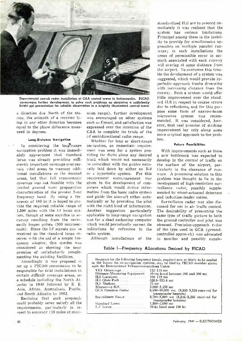
Experimental search radar installation at CAA control tower in Indianapolis. PICAO encourages further development, to solve such problems as obtaining a sufficiently bright ppi presentation for reliable observation in a brightly illuminated control tower
a direction due North of the sta- tion, the azimuth of a receiver ly- ing in any other direction becomes equal to the phase difference meas- ured in degrees.
Long -Distance Navigation
In considering the long-range navigation problem it was immedi- ately appreciated that standard loran was already providing suffi- ciently important coverage over cer- tain vital areas to warrant addi- tional installations as the demand arose, but that full transoceanic coverage was not feasible with the limited ground wave propagation characteristics of the present 2 -mc frequency band. By using a fre- quency of 180 kc it is hoped to pro- vide the required reliable range of 1,500 miles with the 1-f loran sys- tem, though at some sacrifice in ac- curacy resulting from the neces- sarily longer pulses (300 microsec- onds). Since the 1-f signals can be received on the standard loran re- ceiver with the aid of a simple fre- quency adaptor, this systdm was considered as showing the most promise of satisfactorily comple- menting the existing facilities.
Accordingly it was proposed to set up a PICAO commission to be responsible for trial installations in certain difficult coverage areas, on a schedule including the North At- lantic in 1949 followed by S. E. Asia, Africa, Australasia, Pacific, and South Atlantic by 1952.
Realizing that such proposals could probably never satisfy all the requirements, particularly in re- spect to accuracy (10 miles at maxi-
mum range), further development was encouraged on other systems such as Consol, and satisfaction was expressed over the intention of the CAA to complete its trials of the 1-f omnidirectional radio range.
Whether for long or short-range navigation, an immediate require- ment was seen for a system pro- viding for flight along any desired track which would not necessarily be coincident with the guides natu- rally laid down by either an R -O
or a hyperbolic system. For this requirement encouragement was given to the development of com- puters which would derive infor- mation from the basic radio system and guide the aircraft either auto- matically or by providing the pilot with the right kind of information. Another suggestion particularly applicable to long-range navigation was for a dead reckoning computer which would periodically correct its indications by reference to the radio system.
Although installations of the
standardized ILS are to proceed im- mediately it was realized that the system has serious limitations. Principal among these is the inabil- ity to provide for simultaneous ap- proaches on multiple parallel run- ways ; in such installations the areas of permissible error in azi- muth associated with each runway will overlap at some distance from the airport. To overcome this trou- ble the development of a system was suggested, which would provide hy- perbolic -approach tracks diverging with increasing distance from the runway. Such a system would offer little improvement over the stand- ard ILS in respect to course errors due to reflections, and for this pur- pose some form of narrow -beam microwave system was recom- mended. It was considered, how- ever, that real promise of striking improvement lay only along some more original approach to the prob- lem.
Future Possibilities
With improvements such as these a new bottleneck was expected to develop in the control of traffic on the surface of the airport, par- ticularly in the clearance of run- ways. A promising solution to this problem was thought to lie in the development of high -resolution sur- veillance radar, possibly supple- mented by wheel -actuated detectors and induction -leader cables.
Surveillance radar was also dis- cussed for use in air traffic control. The desirability of presenting the same type of traffic picture to both the ground controller and pilot was stressed. Precision -approach radar of the type used in GCA (ground - controlled approach) was advocated to monitor and possibly supple -
Table I-Frequency Allocations Desired by PICAO
Requests for the following frequency bands, required now or likely to be needed in the future for air -navigation systems, may be filed by PICAO member states with the International Telecommunications Union
VHF Omnirange 112-118 me Distance -Measuring Equipment 40 -mc band between 200 and 300 me ILS Localizers 108-112 me ILS Glide Path 328.6-335.4 me ILS Markers 75 me Microwave ILS 5,000-5,250 me GCA Precision Radar 8,500-10,000 me (9,300-9,320 reserved for
transponder beacons) Surveillance Radar 2,700-3,000 me (3,246-3,266 reserved for
transponder beacons) Standard Loran 1,800-2,000 me L -F Loran 20-kc band near 180 kc
82 February, 1947 - ELECTRONICS

s
ment instrument landing system facilities. The other half of the air traffic control problem was seen to lie in improving the efficiency of the short -distance ground -air com- munication facilities. For this pur- pose some form of visual message presentation was advocated as a solution which would also help solve the language difficulties associated with international operation.
For long-distance communication two-way radiotelephony with air- craft was seen as a requirement to replace the present c -w code trans- missions, but it was realized that this could not be done by the mere expedient of increasing the trans- mitter power, owing to the limit set by corona discharge from the an- tenna at high altitude. To over- come this difficulty it was suggested that the possibilities of nar- row -band frequency modulation and single-sideband transmission should be investigated.
The recent tremendous increase in the number and importance of long-range flights has also given rise to a new technique known as pressure pattern flight. This technique makes use of an accurate knowledge of the weather in order to take full advantage of the upper atmosphere winds, and usually in- volves flying along an isobaric track. In order to do this it must be pos- sible to detect in flight any change in the atmospheric pressure pattern which may occur after takeoff. It was foreseen that this might ulti- mately be accomplished by the pe- riodic transmission of weather maps by radio facsimile, but for the immediate future the continued use of the present method was en- visaged. Here a change in pressure is -detected by comparing the read- ing of the barometeric altimeter with that of a radio altimeter.
The radio altimeter also received consideration in connection with
Basic vhf navigation equipment. Interchanging c single panel of this ground station unit will make it conform to PICAO standards for the vhf omnidirectional radio range or either the equisignal or phase -comparison type of localizer for the instrument
landing system
the special difficulties encountered in the siting of an instrument land- ing system for water landings of flying boats. The low -altitude f -m altimeter used throughout the war as the AN/APN-1 functions ideally over the plane surface of water and, in conjunction with radar distance - measuring equipment, could provide the basis for an en- tirely synthetic glide path gener- ated in the aircraft by a computing device.
Dual -range indicator of experimental air- borne radar distance -measuring equip- ment, to be used with instrument landing system and with vhf omnidirectional radio range to indicate distance from beacons
Throughout the discussions in Montreal, it was obvious that great benefit was derived by the inter- change of information and opinions which was possible at such an in- ternational gathering. Before dispersing, therefore, the Radio Technical Division recommended that a permanent group within PICAO should be set up to observe, encourage, and guide the future development of radio aids to navi- gation of all types, as well as to disseminate their findings among all the member nations. Provisions were also made for initiating re- quests now for frequency alloca- tions likely to be needed in the near future, as summarized in Table I.
REFERENCES
(1) U. S. Demonstrates -Radio Aids to Air Navigation, ELECTRONICS, p 280, Dec. 1946.
(2) Caporale, Peter, Civil Aeronautics Administration Instrument Landing System, Part I-p 116, Feb. 1945 ; Part II-p 128, March 1945.
(3) Luck, D. G. C., An Omnidirectional Radio Range System, RCA Review, Part I- .iuly 1941 ; Part II-Jan. 1942 ; Part III- March 1946.
(4) The Loran System-Part I, ELEC- TRONICS, p 94, Nov. 1945 ; Loran Re- ceiver -Indicator, ELECTRONICS, p 110, Dec. 1945 ; Loran Transmitting Stations, p 109, March 1946.
ELECTRONICS - February, 1947 83
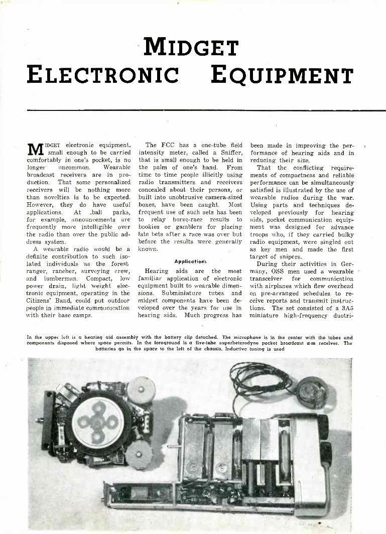
MIDGET ELECTRONIC EQUIPMENT
MIDGET electronic equipment, small enough to be carried
comfortably in one's pocket, is no longer uncommon. Wearable broadcast receivers are in pro- duction. That some personalized receivers will be nothing more than novelties is to be expected. However, they do have useful applications. At .ball parks, for example, announcements are frequently more intelligible over the radio than over the public ad- dress system.
A wearable radio would be a definite contribution to such iso- lated individuals 'as the forest ranger, rancher, surveying crew, and lumberman. Compact, low power drain, light weight elec- tronic equipment, operating in the Citizens' Band, could put outdoor people in immediate communication with their base camps.
The FCC has a one -tube field intensity meter, called a Sniffer, that is small enough to be held in the palm of one's hand. From time to time people illicitly using radio transmitters and receivers concealed about their persons, or built into unobtrusive camera -sized boxes, have been caught. Most frequent use of such sets has been to relay horse -race results to bookies or gamblers for placing late bets after a race was over but before the results were generally known.
Applications
Hearing aids are the most familiar application of electronic equipment built to wearable dimen- sions. Subminiature tubes and midget components have been de- veloped over the years for use in hearing aids. Much progress has
been made in improving the per- formance of hearing aids and in reducing their size.
That the conflicting require- ments of compactness and reliable performance can be simultaneously satisfied is illustrated by the use of wearable radios during the war. Using parts and techniques de- veloped previously for hearing aids, pocket communication equip- ment was designed for advance troops who, if they carried bulky radio equipment, were singled out as key men and made the first target of snipers.
During their activities in Ger- many, OSS men used a wearable transceiver for communication with airplanes which flew overhead on pre -arranged schedules to re- ceive reports and transmit instruc- tions. The set consisted of a 3A5 miniature high -frequency duotri-
In the upper lett is a hearing aid assembly with the battery clip detached. The microphone is in the center with the tubes and components disposed where space permits. In the foreground is a five -tube superheterodyne pocket broadcast a -m receiver. The
batteries go in the space to the left of the chassis. Inductive tuning is used

Using subminiature tubes and comparably small circuit
components, one can build electronic equipment small
enough to be comfortably carried in a suit pocket. Design
data, types of components that are available, and possible
applications are presented
ode and two CK507AX's. One sec- tion of the 3A5 was connected as a grid -modulated oscillator for trans- mission. For reception the circuit comprised a separate squelch oscil- lator and a super -regenerative detector, two stages of audio ampli- fication, and an insert -type mag- netic receiver. The antenna for operation between 250 and 300 me was a dipole at the end of a two - wire line which plugged into the top of the case. The set had a range of a mile, a battery life under
FIRST GRID}
FILAMENT,
PLATE,
BEAM FORMING;,' PLATES --y
,SECOND GRID
PLATE
WINDOW IN BEAM FORMING ELECTRODE
COMMON FILAMENT,
GRID
(A)
( SECTION ONE)
1PLATE
GRID
'COMMON PLATE/ SPACE -CHARGE
GRID
(SECTION TWO) (B)
FIG. 1-(A) Cross section of beamed power tube shows use of windows to form secondary emission suppressing beams. (B) Cross section of space -charge tetrode shows use of virtual cathode to reduce
filament heating power
continuous operation of 12 hours, and a weight of 2.5 lb. A radio built along these lines for opera- tion in the Citizens' Band would fill some of the previously sug- gested applications nicely.
A boon to reporters and others who must record verbatim what is said will be a portable wire recorder now in development. Wire and tape recording can be done under conditions of vibration for which disc recording is not feas- ible, and without any other ad- justment than maintaining the proper volume level to the record- ing head. In the particular de- velopmental unit referred to, the wire, run at as slow a rate as is consistent with intelligible record- ing of speech, is driven by a 2 -volt permanent -magnet motor. A spool carries wire for recording 30 min- utes. The unit is powered by a rechargeable 2 -volt battery having 2 -hours' life, and a 45 -volt B -bat- tery having upwards of 100 -hours' life. The electronic circuit uses four subminiature tubes, types CK503AX, CK505AX, and CK510- AX. The unit has a frequency response within plus or minus 5 db from 100 to 3,000 cps.
An inch -long Geiger counter tube of such small diameter that it can be inserted in one's veins to meter passage of radioactive tracers whose activity is insuffi- cient to produce measurable radia- tion outside the body has been developed at the University of California. Such a small tube, combined with other midget com- ponents, makes possible a wear- able radiation counter that could be carried concealed on one's person to locate illicit manufacture of fissionable materials.
ilttl4+t"ttt
-/ 000 \---t
Small components illustrate the reasons why equipment can be built to small di-
mensions
Other applications of the ex- tremely small units that can be built using these techniques in- clude improved radiosonde sets carried aloft by balloons for weather observation, telemetering equipment in rockets projected into the ionosphere for high -altitude studies, geophysical sounders more readily lowered into oil wells a mile below the earth's surface, portable radar -type aids for the blind (now undergoing tests), and airborne telemetering and control equip- ment. Much impetus was given to these developments by the radio proximity fuze.
tubes
There are commercially available in subminiature size most of the major types of electronic tubes, such as the sharp -cutoff radio -fre- quency pentode, the triode-heptode frequency converter, a diode -
ELECTRONICS - February, 1947 85

pentode detector -amplifier, and pentode power amplifiers with out- put powers as high as 25 milli - watts. There is a series of directly heated filamentary tubes for use in wearable equipment where the power drain must be held to a minimum, and a series of indirectly heated unipotential cathode tubes for use in equipment that must be extremely compact but can con- sume usual powers.
The filamentary series of tubes, weighing less than a tenth of an ounce, are housed in flat T-2 by T-3 (two -eighths by three -eighths inch) glass envelopes no longer than 1.57 in. The filaments oper- ate at 1.25 volts or less and draw between 30 and 50 ma. Types and essential characteristics of some of these tubes are listed in Table 1.
Although these tubes are rated for a maximum plate potential of only 45 volts, the power pentodes deliver sufficient power to operate an air -conduction earphone. More power can be obtained where necessary from push-pull or paral- lel operation of several tubes. Power triodes are not desirable in wearable equipment because of their relatively low power sensi- tivity. Low internal resistance of the output amplifier, necessary to damp some of the magnetic ear- phones, can be more readily ob- tained by voltage negative feed- back in the pentodes than by using triodes.
FIG. 2-Tube socket is held in chassis hole by retaining clip, thus eliminating
space otherwise required for bolts
FIG. 3-Experimental subminiature tube socket consists of individual clips for each lead, mounted in nonconducting chassis. A small piece of plastic is used to illus-
trate the mounting method
In designing the output stage of electronic equipment, one begins with the required output and works backward. The output power re- quired to operate an insert type earphone ranges from one to 100 mw, depending in part on the efficiency of the receiver itself and partly on the acuity of the indi- vidual ear. The medium value for hard -of -hearing persons can be taken as 20 mw. Allowing for a 20 -percent power loss in the output transformer, an average value for miniature transformers, one ob- tains, as the required output power from the tube, 25 mw. With 4.5 volts peak on its grid, and no nega- tive feedback, a CK506AX output pentode will deliver this power. In the case of equipment designed for persons with normal hearing, nega- tive feedback could be used to decrease distortion, and still leave sufficient output.
The most recent development in subminiature tubes is the CK521AX beamed power tube. It approaches the beam tetrode in characteristics, yet can be made in smaller size. The first and second grids are not aligned; the sacrifice in performance being more than
made up in simplification of assem- bly. A thin metal window shown in Fig. lA concentrates the elec- trons to the plate into a dense beam that suppresses secondary emis- sion. To get optimum spacing between the second grid and the window and between the window and the anode, the plane of the electrodes is perpendicular to the long axis of the envelope rather than parallel to it as in other sub- miniature tubes. A grid bias of minus three volts is recommended with 22.5 volts on plate and screen.
Power to heat the filaments of these tubes is most critical. Al- though there are available several efficient A -batteries, they are ex- hausted before the B -batteries in most equipment. The CK510AX illustrates one of the techniques developed to fully utilize filament heating power. The tube consists of two space -charge tetrodes using a common filament. The first grid, extending through both sections of the tube as shown in Fig. 1B is used as a positive space -charge grid to produce a virtual cathode. The electron cloud formed at the first grid provides a reservoir of electrons for the two independent triode sections. Without the vir- tual space -charge cathode, the fila- ment would have to be designed to provide the peak space current that might be required, despite the fact that this peak emission might be drawn only momentarily.
By using a virtual cathode, the filament can contribute electrons to the virtual cathode cloud of electrons at the average tube cur- rent and can be designed for a peak emission near this average value. The cloud of electrons in the vir- tual cathode serves as a reservoir that can become rapidly depleted during peaks of current but can be restored during the subsequent low current periods. Moreover, by us- ing a virtual cathode, common cath- ode coupling is reduced.
Maximum instantaneous current that the tube can handle is more a function of the charge that can be stored at the virtual cathode than of the physical electron emission of the hot filament. By taking advan- tage of this storage in a virtual cathode, the filament can be de- signed for lower heating power,
86 February, 1947 - ELECTRONICS

thus lengthening the life of the, A - battery. The independence of the two triode sections, provided no cathode impedance is added to the external circuit, is sufficient to en- able them to be operated in cascade to give an overall gain of over 40 db.
Sockets
Filamentary tubes are available either with long leads for wiring directly to the circuit or with short leads for insertion into sockets. De- signers of industrial equipment often prefer to solder tubes into the circuits to be sure of rigid, corro- sion -resistant connections. They also prefer to make the equipment semipermanent. (One manufacturer is planning a series of premium subminiature tubes that will have long life for use in semipermanent equipment.) In cases where space is extremely limited, it may be de- sirable to omit the socket. For very high -frequency circuits it may also be desirable to omit the socket both to eliminate a possible source of r -f loss and to shorten the leads to re- duce shunt capacitance and series inductance.
Designers of communication equipment, accustomed to using tube sockets, ordinarily prefer them. The fact that in flat -press tubes the leads are along a straight line means that they can be started into the socket at an angle by bend- ing all the leads, pushed home, and then stood erect among the com- pactly placed parts of the equip- ment. Thus little headroom need be left over the tubes. Parts can be located immediately adjacent to the tube, the tube being removed as it was put in-by being tilted out from its normal position to where one can readily grasp it before it is pulled out. These tubes are coated with Aquadag, the coating being connected to a normally grounded lead, so that an electrostatic tube shield is unnecessary.
There are two types of sockets now available: a completely assem- bled socket, and a group of individ- ual clips that, when mounted on an insulating chassis, form a .socket. The first type has the advantage of pre -assembly, because it is only necessary to fasten it into the chas- sis. The latter, available experi-
Table 1-Characteristics of Typical Filmentary Subminiature Tubes
2E31 2E325
2E35 2E36"
2E4I 2E42,
2G21 2G226
CK502AX
CH503AX
CK505AX
CK506AX
CK507AX
CK510AX
CK515BX
CK521AX
ñ
4 .. ß
e: rä: ri]d'
É
_
(Sharp -cutoff r -f pentode ampl'fier)
1.25 50
(Output pentode) 1.25 30
(Diode -pentode de- tector, amplifier)
1.25 30
(Triode-heptode frequency converter)
1.25 50
(Output pentode) 1.25 30
(Output pentode) 1.25 30
(Pentode amplifier) 0.625 30
(Output pentode) 1: 25 50
(Output pentode) 1.25 45
(Double space -charge tetrode amplifier)
0.625 50
(Triode amplifier) 0.625 30
(Beamed output) 1.25 50
° Ó° U,Q Ç CLÿ tiE
, óR c O 3 0 . C67 i'á 3z í.. p o C F < a...
500c
45 500,
45 375, 20 - 45 60d - - 45 550c r,
45
30
45
45
45
550c
175° 35
500° - 25
575° 11
65° 150f 16
45 160°
22.5 400c 6°
° Measured at ten percent total distortion b Lower number indicates leads are long enough to solder into circuit; upper number
indicates leads are clipped for insertion into socket c Measured at zero plate and screen resistance d Conversion transconductance
Per section r Two sections in cascade g Internal plate resistance 220,000 ohms ; into 20,000 ohms
mentally, has the advantage of com- pactness, because it comprises only the essentials of the socket, the metal clips ; the plastic or impreg- nated fiber chassis forms the base.
One method of mounting the as- sembled socket is illustrated in Fig. 2. A hole is cut in the chassis to accommodate the socket. The flange around the top of the socket keeps it from passing through the hole; a
retaining clip, slipped on from the bottom, holds the socket in the hole. Another method is to put the socket in a hole in a metal chassis and
punch the chassis on either side of the socket hard enough to cold flow metal into recesses in the sides of the socket. For mounting the tube in the most advantageous position, it may be necessary to locate the socket on an angle strap. During tests for socket leakage on this as- sembled type, resistance between pins after immersion for 48 hours in an atmosphere of 90 percent rel- ative humidity and 50 C measured 2,000 meg. These particular plastic sockets are useful up to 60 me; polystyrene sockets are available
(D) Pocket wire recorder
ELECTRONICS - February, 1947 87
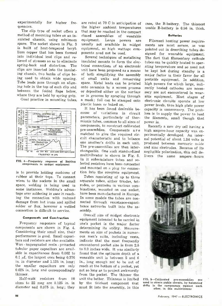
experimentally for higher f re- quencies.
The clip type of socket offers a method of mounting tubes on an in- suJated chassis, using minimum space. The socket shown in Fig. 3 is built of heat -tempered beryl- lium copper that has been formed into individual lead clips and re- lieved of stresses so as to eliminate spring -back and distortion. The clips are inserted into the insulat- ing chassis, two banks of clips be- ing used to obtain wide spacing. Tube leads pass through an align- ing hole in the top of each clip and between the folded flaps below, where they are held by spring grip.
Good practice in mounting tubes,
CRYSTAL HEARING -AID MICROPHONE
50,IOHM PRI
TMINEATUR r
RANSFORMER '-200 OHM PRIT 1
CRYSTAL]]I HEARING -AID AIR -CONDUCTION
RECEIVER
100 200 400 1p00 2000 000010200 20000 FREQUENCY IN CPS
FIG. 4-Frequency response of limiting components in midget equipment
is to provide holding cushions of rubber at their tops. To connect wires to the sockets in the small space, welding is being used in some instances. Welding's advan- tage over soldering is ease in reach- ing the connection with reduced damage from hot irons and spilled solder or flux, however a welded connection is difficult to service.
Components and Construction
Frequency responses of typical components are shown in Fig. 4. Considering their small size, their performance is good. Small capaci- tors and resistors are also available. Wax - impregnated resin - protected tubular paper capacitors are avail- able in capacitances from 0.002 to 0.1 µf, the largest ones being 0.376 in. in diameter and 1.125 in. long; the smaller capacitors are only 0.625 in. long and correspondingly thinner.
Half -watt resistors from 10 ohms to 22 meg are 0.125 in. in diameter and 0.375 in. long; they
are rated at 70 C in anticipation of the higher ambient temperatures that may be reached in the compact closed assemblies of wearable equipment. Large powers are usually not available in midget equipment, so high wattage com- ponents need not be used.
Several techniques of metalizing insulated mounts to form the elec- trical connections of an electronic unit have been proposed as a means of both simplifying the assembly of small units and conserving space. Metal leads can be printed onto ceramics by a screen process or deposited either on the surface or in grooves by spraying through a mask; foil can be stamped onto plastic bases or baked on.
It has been found desirable be- cause of variations in circuit parameters, particularly of ther- mionic tubes, common to all sizes of components, to construct calibrated pre -assemblies. Components a r e matched to give the required cir- cuit characteristic and to balance one another's drifts in each unit. The pre -assemblies are then inter- changeable. One such standardized multivibrator is shown in Fig. 5. In it subminiature tubes and se- lected resistors have been connected and mounted on a plug for connec- tion into the complete equipment.
Tubes consisting of up to three separate tubes, either triodes, tet- rodes, or pentodes in various com- binations, mounted on one socket, have been manufactured in Europe. In some models the tubes are con- nected through resistance -capaci- tance networks built into the as- sembly.
Overall size of midget electronic equipment intended to be carried in one's pocket is the major factor determining its utility. Measure- ments on size of pockets in numer- ous men's suits, including vests, indicate that the most frequently encountered pocket size is from 2.5 to 3.0 inches wide. It was similarly found that the optimum depth of a wearable unit is between 5 and 6 in., long enough not to be out of reach at the bottom of a pocket, yet not so long as to project awkwardly from the pocket. The thinner the unit the better. Thinness is limited by the thickest component that must fit into the assembly, in this
case, the B -battery. The thinnest usable B -battery is 0.56 in. thick.
Batteries
Filament heating power require- ments are most severe, as was pointed out in describing tubes de- signed for wearable equipment. The fact that filamentary cathode tubes can be quickly heated to oper- ating temperature and so need not be kept hot during standby is a major factor in their favor for all portable equipment. In addition, high powers for which large, indi- rectly heated cathodes are neces- sary are not encountered in wear- able equipment. Most stages of electronic circuits operate at low power levels, thus high plate power capacity is unnecessary. The prob- lem is to supply the power to heat the filaments, small though that power is.
Recently a new dry cell having a high ampere -hour capacity was ex- perimentally developed. An inter- nal potential of about 1.34 volts is produced between mercuric oxide and zinc electrodes. Because of its negligible polarization, this cell de- livers the same ampere - hours
FIG. 5-Calibrated pre -assemblies are used to obtain stable circuits, by balancing drifts in the components against each
other, in this multivibrator
ee February, 1947 - ELECTRONICS

whether operated continuously or intermittently, has nearly constant output voltage and substantially constant internal resistance at audio frequencies throughout its life. A substantially flat voltage characteristic is maintained throughout life up to rated current drain (50 ma max), thus efficiency is maintained during life. The volt- age drops quickly at the end of the cell's useful life. Of particular interest in wearable equipment is the fact that, volume for volume, the cell has three to four times the ampere -hour capacity of a conven- tional zinc -graphite dry battery. The corrosion -resistant steel case, acting as positive terminal, does not enter into electrolytic action of the cell.
Carbon -zinc cells are made in a variety of sizes for compact assem- bly, with the A- and B -batteries scaled to comparable dimensions, as shown in Fig. 6. The familiar layer -built B -batteries, which have duplex electrodes (zinc on one side, carbon on the other) to conserve space, are made in 15, 22.5, 30, 45, and other voltage sizes. The effi-
ciency of energy conversion from chemical to electrical is higher in these flat cells than in comparable zinc -graphite cells of other shapes, and for the same external size they contain a larger volume of depolar- izing mixture than cylindrical dry cells, and have higher zinc utiliza- tion. These batteries can readily be broken open between cells to ob- tain any intermediate voltage for use in experimental portable equip- ment. The stack must be restrapped to keep the cells pressing tightly on one another if the internal resis- tance of the battery is to be kept low. Because the inert plastic case does not enter into chemical action with the paste, there is no danger of corrosive chemicals eating through the container and damag- ing adjacent parts.
RRsearch into the action of the carbon -zinc cells indicates that their efficiency of energy conversion can be increased. These cells are still undergoing development.
Battery equipment is usually de- signed to such tolerances that it will work until the battery terminal voltage has fallen to two-thirds its initial value. For example, an A -
battery is expected to remain in service until its initial 1.4 volts has fallen to about 0.9 volt. However, in the B -battery circuit, the in- crease in internal resistance of the battery may result in interstage coupling before the terminal volt- age has fallen to this low value. This coupling through the battery impedance can be reduced by ex- ternal decoupling filters, or usually by a large bypass capacitor across the B -battery. The bypass capaci- tor should have very little shunt leakage, or else be disconnected when the circuit is not in use. In one very small hearing aid model recently marketed, opposing feed- back of the signal appearing across the battery is made to the last two stages to reduce the battery coup- ling and thereby obtain longer B - battery life.
Me*hods of Providing Grid Bias
Although many subminiature tubes are designed for zero grid bias, others require a small nega- tive bias. Because of the inevitable decrease in plate supply potential, some provision must be made for the grid bias to decrease corres- pondingly, if the tube is to continue operating effectively during the en- tire battery life.
Self bias is the simple and obvi- ous method of obtaining the neces- sary simultaneous decrease in grid bias with loss in B -voltage. The self bias resistor will, of course, cause considerable loss in tube amplification if unbypassed, but will improve the linearity of the effec- tive transfer characteristic, there- by decreasing harmonic and inter - modulation distortion.
In pentode output stages, the increase in the tube's internal im- pedance caused by this current feedback may be objectionable in certain applications. To prevent this cathode degeneration, a large bypass capacitor is required, with added space requirements. That the bypass capacitor will occupy con- siderable space will be recognized from its capacitance. In a typical circuit the CK507AX with a plate and screen supply of 45 volts re- quires a grid bias of minus two volts and conducts an average space current of 1.2 ma. (Although the required grid bias is small, the
FIG. 6-Batteries for wearable equipment are available in a variety of types and sizes. Shown here are two pairs of A- and B -Batteries with their paper covers re- moved; both pairs give the same voltage
low plate current necessitates a large cathode resistor.) The self biasing resistor must be 1,670 ohms. The bypass capacitor that, in shunt with this resistance, gives a time constant of 0.01 sec (period of a 100 cps signal) is 60µf. In ad- dition, the A -battery will have to be insulated from ground, which is usually preferable to wasting heater power in the Zathode re- sistor (even though the cathode resistor would then be smaller, but requiring a much larger bypass ca- pacitor) which would be necessary if the A -battery were grounded.
One means of counteracting the degeneration introduced by an un - bypassed cathode resistor is to pro- vide positive feedback across the cathode resistor from the plate cir- cuits.
If voltage amplification can be sacrificed, voltage feedback can be used in the output stage to de- crease the effective internal im- pedance of the tube. The compon- ents of such a circuit usually require less total volume than the cathode bypass capacitor, although the A -battery drain may be higher because of an added tube. However, the combined effects of these feed- backs will be complex and can lead to instabilities. Whatever the solu- tion, it is usually a compromise be- tween minimum bulk and minimum battery drain.
Material for this article has been obtained from more sources than can reasonably be listed here. To those who generously supplied in- formation, greatful appreciation is extended.-F. R.
ELECTRONICS-February, 1947 69

SLOTTED - CYLINDER Simple mechanical construction, easily obtained vertical directivity, and horizontal polari- zation make the slotted -cylinder antenna ideal for f -m and television transmission and reception. Directivity and impedance characteristics for designing arrays are presented
FIG. 1-(A) Vertical radiation pattern of a three-quarter wavelength slot antenna compared to that of a half wavelength dipole. and (B) horizontal radiation pat- tern of slot antenna in a vertical cylinder
of 0.21 wavelength diameter
SLOT ANTENNAS have been suc- cessfully used on high speed
aircraft to establish electric cur- rents on outside surfaces of the metallic airplane structure and so make the aircraft itself the radia- tor. Examination of the charac- teristics of slot radiators shows that they possess properties that make them useful in many other applications as well.
In such applications a particu- larly useful form of the radiator is a slot cut lengthwise in a long, narrow, hollow cylinder. The first reference in the literature to this form of radiator appeared several years agog. It proposed the use of a slit cylinder to guide or radiate electromagnetic waves. Slot radia- tors of one form or another have already found commercial applica-
tion in frequency modulation' and television'.
It is the purpose of this article to discuss some general properties of slot -in -cylinder radiators and to present radiation patterns and impedance curves that should en- able engineers to determine the suitability of these antennas for
I8I
i
.COAXIAL FEEDLINE
FIG. 2-Vertical directivity can be in- creased by stacking slots. Mechanical construction is simple. Slots are fed from a transmission line inside the slotted
cylinder
applications in which they may be interested.
Radiation Patterns
Figure 1 shows the vertical and horizontal radiation patterns of a three-quarter wavelength slot cut in a vertical cylinder. For com- parison, the vertical pattern of a half -wave dipole is also shown. For
equal lengths, the vertical slot and vertical dipole have practically the same vertical radiation patterns. Length -of the cylinder itself has no noticeable effect on the pattern. It must be long enough to accommo- date the slot, but can be any con- venient length longer. The horizontal pattern of the vertical slot -in -cylinder is dependent upon the diameter of the cylinder. In general, radiated field intensity is greater on the side on which the slot is located than it is on the opposite side of the cylinder. How- ever, for cylinder diameters of about one -tenth wavelength or less, radiation in the horizontal plane is essentially uniform.
The radiation pattern of a slot in a narrow cylinder is almost the same as that of the corresponding length dipole, but with one im- portant difference : the electric field produced by a vertical dipole is vertically polarized whereas that produced by a vertical slot is horizontally polarized. Because horizontal polarization is used for both frequency modulation and
FIG. 3-(A) vertical, and (B) horizontal radiation patterns of slotted -cylinder array
shown in Fig. 2
90 February, 1947 - ELECTRONICS

ANTENNA By E. C. JORDAN and W. E. MILLER
Departnu t;lrctricoi Euyiiieirio!i (i ira r.,itp of Illinois rbouo, Illinois
television, the slot -in -cylinder pos- sesses considerable advantage over the ordinary dipole in these appli- cations. A vertical slot has the desired vertical directivity with nearly uniform radiation in the horizontal plane and, in addition, has the correct polarization for f -m and television broadcasting.
When greater vertical directivity is desired, it can be obtained by stacking slots vertically as illus- trated in Fig. 2. Because each unit of the array (that is, each slot) has considerable vertical di- rectivity by itself and therefore radiation from any one element does not interact to a considerable extent with that from other ele- ments, it is possible to space the units a wavelength apart without producing unduly large secondary lobes. Directivity of any array is proportional to its overall length; so when large spacing between units is permissible it is possible to have a long, and hence a highly directive, array without requiring an excessive number of units, simplifying feeding problems. The array of Fig. 2 has four slots, each three-quarters of a wavelength long, and spaced one wavelength center -to -center. When longer slots are used, larger vertical sepa- rations are permissible.
In Fig. 3 there are shown the measured vertical and horizontal patterns of the four -element array. Vertical directivity is very sharp and it is seen that most of the power is radiated within a few degrees of the horizontal. The excellent agreement between meas- ured and theoretical patterns indi- cates that predicted gains can be closely attained in practice. In
ELECTRONICS- February, 1947
Fig. 3B there is also shown the relative field intensity in the hori- zontal direction produced by a pair of horizontal crossed half -wave dipoles fed with the same power as the four -slot array. Figure 4 shows the directed power gain of the slotted -cylinder array as a func- tion of the number of three-quarter wavelength slots, spaced one wave- length apart. The gain shown is referred to that of a single half - wave dipole. The gain over a pair of crossed dipoles (as would be re- quired to produce a uniform horizontal pattern with horizontal polarization) would be double that shown. The values given in Fig. 4 represent the average gain in the horizontal direction. For a one - eighth wavelength diameter cylin- der, the horizontal pattern is not uniform and the actual gain is a little greater on the slot side of the cylinder and a little le on the side opposite the slots.
Impedance Characteristics
In order to feed the . slotted - cylinder antenna properly, it is necessary to know something of its impedance characteristics and how these characteristics vary with slot length and width, and cylinder diameter. Figure 5 shows resis- tance and reactance of a slotted cylinder as measured at the center of the slot. Impedance is shown as a function of slot length for various ratios of antenna diameter to wavelength. As cylinder diame- ter in wavelengths is made progressively smaller, the length of the slot required for resonance becomes very large, and there is a certain critical diameter below which resonance cannot be obtained

at any slot length. For the par- ticular slot width used in this case, this critical diameter appears to be about 0.11 wavelength. It will be noticed that the resonant length (that is, the length for zero reac- tance) is very long for narrow diameter cylinders, but becomes smaller as the cylinder diameter increases. For larger diameter cylinders, second resonance points appear at slot lengths roughly double that for the first resonance. Resistance at this second resonant point is comparatively low, being of the order of 40 ohms, while at
10
01 2 3 4 5 6
NUMBER OF SLOTS 7
FIG. 4-Concentration of power in the vertical plane, relative to that from a dipole, for an array similar to that of
Fig. 2
the first resonant point it ranges between 300 and 1,000 ohms. The effect of greater slot width is to increase the length of slot required for resonance for a given cylinder diameter.
Explanation of Operation
There are two rather simple physical pictures which can be used to explain the operation of the slot - in -cylinder antenna. The first con- siders the edges of the slot as constituting a parallel -wire trans- mission line which is shorted at both ends.
A voltage is applied across the transmission line (usually, but not necessarily, at the middle) and standing waves of voltage and cur- rent are set up along the line. Be- cause of the close spacing between the edges of the slot, transmission line currents would not be expected to radiate appreciably. However, the 'slot transmission line has con- nected to it the remainder of the cylinder which has a twofold effect.
In the first place, the voltage
across the slot causes currents to flow around the outside of the cylinder and these currents flowing in the circular path radiate appre- ciable amounts of power, the diameter of the path being a signi- ficant fraction of a wavelength. In addition, the cylinder acts as an inductive reactance shunted across the slot transmission line, and so modifies the phase velocity and hence the wavelength along the line. From transmission line theory it is known that inductive shunt loading will increase both phase velocity and wavelength, and so increase the line length required for resonance. If the loading is too great (that is, if shunt induc- tive reactance is too low) wave motion along the line ceases- and the loaded line acts as an attenu- ating network.
This simple picture serves to explain most of the characteristics of the impedance curves for nar- row cylinders. For larger diameter cylinders it is necessary to resort to waveguide theory for the second physical picture. The inside of the
cylinder is a degenerate cylindrical waveguide.
Within a waveguide the phase velocity and wavelength are always greater than the corresponding free -space quantities and the ratio of wavelength in the guide to free - space wavelength becomes very large as the diameter of the cylin- der decreases to the cutoff diameter. For completely closed cylindrical waveguides the cutoff diameter for the dominant mode is 0.586 times the wavelength, but when the cylinder has a slot in it, with the excitation applied across the slot, the cutoff diameter is very much less than this value. In this latter case the capacitance of the slot reduces the required diameter of guide in much the same way as the length of a transmission line section required for resonance is reduced by capacitive loading of the load to which it is connected. It is apparent that the greater the capacitive loading (that is, the narrower the slot) the smaller will be the cutoff diameter of the cylinder.
1000
600
N
600 O
z Lu U Z ¢ 400
o.12or, W
á 200
cr
w
_ a
+
200
400 0
R -- SLOT WIDTH.
DIAMETER 0.062 CYLINDER
CYLINDER DIAMETER = 0.130XX'.
I 1
I / \ I / /
/
\ ! R 7
' /
X R , ,
/
i t 0.110>-, ' '-.,\ \
1 `,. , , :. 1 - -
y ,
, - ..--0:125X
x
i 1
' R C/ / \ \ ,'//X
, - --- =/ - -\>/ V '
x . -
0.5 SLOT LENGTH IN
10 1.5 WAVELENGTHS
FIG. 5-For a slot representing a fixed fraction of the cylinder diameter, resonant impedance increases and resonant slot length approaches a half wavelength as
cylinder diameter is increased
92 February, 1947 - ELECTRONICS
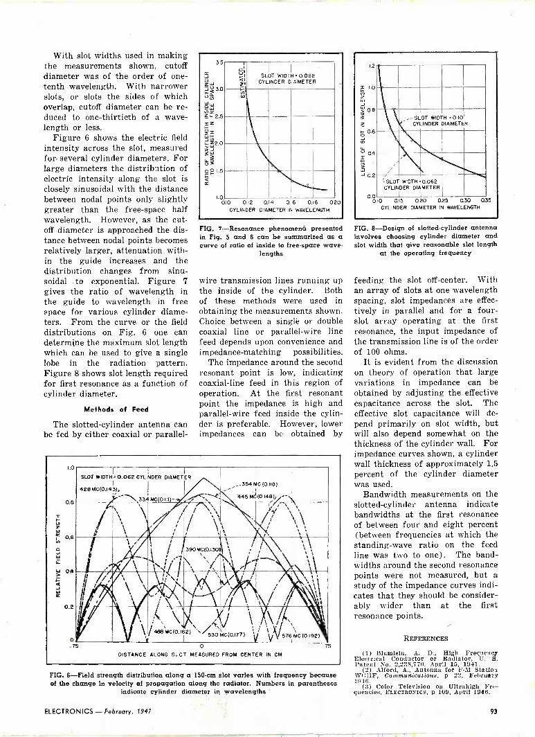
With slot widths used in making the measurements shown, cutoff diameter was of the order of one - tenth wavelength. With narrower slots, or slots the sides of which overlap, cutoff diameter can be re- duced to one -thirtieth of a wave- length or less.
Figure 6 shows the electric field intensity across the slot, measured for several cylinder diameters. For large diameters the distribution of electric intensity along the slot is closely sinusoidal with the distance between nodal points only slightly greater than the free -space half wavelength. However, as the cut- off diameter is approached the dis- tance between nodal points becomes relatively larger, attenuation with- in the guide increases and the distribution changes from sinu- soidal . to exponential. Figure 7 gives the ratio of wavelength in the guide to wavelength in free space for various cylinder diame- ters. From the curve or the field distributions on Fig. 6 one can determjne the maximum slot length which can be used to give a single lobe in the radiation pattern. Figure 8 shows slot length required for first resonance as a function of cylinder diameter.
Methods of Feed
The slotted -cylinder antenna can be fed by either coaxial or parallel -
35
1.0 010 012 0.14 0.16 0.18 020
CYLINDER DIAMETER IN WAVELENGTH
1 o` FI "l
SLOT WIDTH 0.062 CYLINDER DIAMETER
u, W
\\\hNs'N..._L__,
FIG. 7 -Resonance phenomentt presented in Fig. 5 and 6 can be summarized as a curve of ratio of inside to free -space wave-
lengths
wire transmission lines running up the inside of the cylinder. Both of these methods were used in obtaining the measurements shown. Choice between a singlè or double coaxial line or parallel -wire line feed depends upon convenience and impedance -matching possibilities.
The impedance around the second resonant point is low, indicating coaxial -line feed in this region of operation. At the first resonant point the impedance is high and parallel -wire feed inside the cylin- der is preferable. However, lower impedances can be obtained by
1.0
0.8
0.6
04
0.2
o
SLOT WIDTH.
428 MG(0.I43),
0.062CYLINDERDIAMETIER
/ - 334 MC 0.111 - 4
I
354 MC
'' 445 MC
(0.118)
(0.148) - `
J
. 1,\ ``
}i, ,\'``` /,N ,\
` `\ b
ti /.
Olt
¡ 390MG(0.130t , . ,j ',
'
` i
f \ I ',.,
/468MC(0.162)\/
,
t I
, k \ 530MC(0.177)
11`
576MC(0.192)
T5 0 DISTANCE ALONG SLOT MEASURED FROM CENTER IN CM
75
FIG. 6 -Field strength distribution along a 150 -cm slot varies with frequency because of the change in velocity of propagation along the radiator. Numbers in parentheses
indicate cylinder diameter in wavelengths
1.2
1.0 U W
á o.e 3
o 0.6
Ñ
o 04
- 2 J 0.2
-- SLOT WIDTH 0.10 CYLINDER DIAMETER
-SLOT WIDTH 0.062 CYLINDER DIAMETER
I I 0.0 0.15 0.20 0.25 Q30 035
CYLINDER DIAMETER IN WAVELENGTH
FIG. 8 -Design of slotted -cylinder antenna involves choosing cylinder diameter and slot width that give reasonable slot length
at the operating frequency
feeding the slot off -center. With an array of slots at one wavelength spacing, slot impedances are effec- tively in parallel and for a four - slot array operating at the first resonance, the input impedance of the transmission line is of the order of 100 ohms.
It is evident from the discussion on theory of operation that large variations in impedance can be obtained by adjusting the effective capacitance across the slot. The effective slot capacitance will de- pend primarily on slot width, but will also depend somewhat on the thickness of the cylinder wall. For impedance curves shown, a cylinder wall thickness of approximately 1.5 percent of the cylinder diameter was used.
Bandwidth measurements on the slotted -cylinder antenna indicate bandwidths at the first resonance of between four and eight percent (between frequencies at which the standing -wave ratio on the feed line was two to one). The band- widths around the second resonance points were not measured, but a study of the impedance curves indi- cates that they should be consider- ably wider than at the first resonance points.
REFERENCES
(1) Slumlein, A. D., High Frequency Electrical Conductor or Radiator, U. S. Patent No. 2,238,770, April 15, 1941.
(2) Alford, A., Antenna for F -3I Station WGHF, Communications, p 22, February 1946.
(3) Color Television on Ultrahigh Fre- quencies, ELECTRONICS, p 109, April 1946.
ELECTRONICS - February, 1947 93

Electronic TO-TRAIN CONTROLS The engineering problems in carrier -current control of model railroads rival those in telemetering and remote control. Successful design of system components capable of
hard usage and mass production is described
rri HE problem of remote control I has always taxed the ingenuity of miniature railroad enthusiasts. Literature and patent office files are replete with devices of various de- grees of complexity, ranging from purely mechanical trip mechanisms to electronic circuits, all intended to lend verisimilitude to the opera- tion of toy trains. A genuine re- mote operation of miniature rail- roads became possible only with the recent development of an elec- tronic system of control.
While there is nothing novel in the application of electronics to remote control apparatus-such systems have been used for over two decades in drone aircraft and elsewhere-the adaptation of elec- tronic control to miniature rail- roads presented a number of de- sign problems.
By JOSEPH L. BONANNO Chief Engineer Lionel Corp.
7rrington, N. J.
FIG. 1-Schematic wiring diagram of the receiver. Relay contacts are factory
adjusted
Paramount is the problem of size. Each receiving unit must be self- contained and small enough so that it can be conveniently and incon- spicuously mounted within the min- iature rolling stock. Equipment must be rugged to withstand the vicissitudes of model railroading. It needs stability within a wide range of operating conditions, and interchangeability with a minimum of adjustment. And, of course, it
Gondola car showing mounting of receiver. Complete receivers are shown in left foreground with tuning unit and relay at right
must be inexpensive and suitable to mass production technique.
Receiver Design
The use of miniature vacuum tubes was considered in the early stages of receiver development but rejected principally because of the problem of plate and filament sup- ply. While a miniature step-up transformer and metallic rectifier pile could easily be built, the oper- ating track voltage-which would serve as the power source-nor- mally ranges between 6 and 18 volts. So wide a variation in the power supply, as well as the cost, rendered the use of vacuum tubes impractical in the receivers.
The circuit selected for the re- ceiving stations is an r -f series cir- cuit utilizing a small commercial type mica capacitor and a minia- ture permeability -tuned inductor. The high r -f voltage developed at resonance across the inductor coil is stepped down in a center -tapped secondary winding, and then recti- fied by means of two metallic recti- fiers. Sufficient power is thus obtained from the r -f signal to operate a sensitive d -c relay in the power circuit, shown in Fig. 1.
Of the several types of metallic rectifiers investigated, copper oxide instrument type discs proved the most practicable, principally be- cause their resistance was of an order of magnitude that can be matched to a convenient size 500 -
February, 1947 - ELECTRONICS

Test setup for adjustment of two receivers in locomotive tender, one for controlling
locomotive and one to operate whistle. Spring assembly in foreground provides
predetermined mechanical load for couplers
ohm relay. Selenium rectifiers, while satisfactory in most respects, were rejected because they were not at the time readily available in instrument sizes. Their relatively higher resistance would also have required a higher impedance relay, having a poorer winding space fac- tor, and lower power sensitivity.
Frequency of Operation
The first experimental outfit was built to operate within the range of 50 to 80 kilocycles. Further tests proved, however, that the capaci- tance of the rectifier discs did not unduly load the output until f re- quencies of the order of 500 kc were reached. Consequently, the f re - frequency channel was raised to be-
tween 240 and 360 kc, which while still low enough to avoid interfer- ence in the standard broadcast band, reduced further the size and cost of the components.
Two other considerations influ- enced the selection of the upper fre- quency limit. When higher fre- quencies were employed, stability of individual components became too critical for economical produc- tion. Further, the shorter wave- lengths fall within the order of magnitude of practical track lay- outs with the consequent danger of creating standing waves at points along the track.
Possibly the key to a successful receiver circuit without vacuum tubes, amplifier, or volume control is the design of a compact and rela- tively inexpensive relay operating reliably on 6 milliwatts and handling currents up to 4 amperes at 18 volts for at least 10,000
operations. The design of this relay constituted a major part of the re- ceiver development. To achieve the necessary sensitivity, the relay is
maintained within close limits of mechanical tolerance.
To provide a simple and compact means of adjustment the lower con- tact was designed in the form of an eccentric disc which can be ro- tated to properly regulate the mag- netic air gap. Because the armature spring restoring force at the con- tact points is only 1.5 grams, spe- cial nonwelding contact material had to be found. A solid palladium silver disc proved to be the solution.
The exigencies of space also re- sulted in the design of a novel jar - proof, self-locking permeability adjustment illustrated in Fig. 2. A
molded tube serves as a channel for the movement of the pressed iron tuning plunger. The upper end of the tube is slotted and threaded. A
split retaining ring forced over the slotted end of the tube maintains a
continuous locking pressure upon the adjusting screw regardless of the thread wear. The outside of the tube serves as mounting for the coil and the same molding contains nests for the miniature rectifier discs which are kept in position by means of a metal contact plate crimped to the molding.
The receiver unit as finally de- veloped operates with an overall system efficiency of 8 percent and is housed together with the relay within a molded plastic housing measuring 1 x 2t x inches, or al- most exactly the volume of a safety match box. A typical resonance curve is shown in Fig. 3.
The criteria of low cost and high order of frequency stability under a wide range of operating condi- tions also governed the design of the transmitter. Early determina- tion of power requirements revealed that the r -f shunting effect of mo- tors, solenoids and other operating equipment containing windings either with or without iron cores was negligible; the only serious problem was offered by lamps.
The average lamp used in mini- ature railway layouts operates on 12 volts and consumes ampere. Assuming a maximum of 20 lamps in parallel, the total hot lamp re- sistance approximates 2.5 ohms. To this resistance, however, is added track and contact resistances and lead impedances so that the maxi- mum r -f impedance is seldom less than 10 ohms under the most ad- verse operating conditions. To maintain good voltage regulation the transmitter output is matched to 1.5 ohms. Since power require- ments thus do not exceed 0.6 watt, it is possible to employ a type 117 diode -pentode which develops one watt of power and operates directly from the line.
The power leads normally con- necting the track layout to the var- iable low -voltage transformer offer an easy solution to the transmission problem. A wired wireless system has been adopted, and'the r -f trans- mitter output superimposed di- rectly on the train power circuit,
FIG. 2-Drawing of the receiver proper showing split lock ring at top, adjustable tuning core and tuning coil. The rectifier discs are under the contact plate tabs to
left and center
ELECTRONICS - February, 1947 95

---- Eo Qp. Q .38Q.60
°L375 ---EL
t10707 E
-nta- --------- 0.707EL
1. Aft.---4 290 295 300 305 310
FREQUENCY IN KILOCYCLES
FIG. 3-Receiver resonance curve. E0 is open circuit voltage; EL is voilage with
circuit loaded by 500 -ohm relay
with connection as shown in Fig. 4. The transformer output winding, which acts as an r -f choke, is effec- tively bypassed by a 0.1 /If capaci- tor.
While oscillating circuits that are not crystal controlled are ordinar- ily considered unstable, it was found that by proper selection of circuit constants frequency is maintained within 0.1 percent. Transmitters are thus completely interchangeable. To achieve this result the tank circuit mica capaci- tors selected within 3 percent tol- erance, are shunted by a trimmer for accurate setting under load of final frequency value. These capac- itors, as well as the receiver capaci- tor, receive Class C RMA treatment to prevent drift due to aging. The tapped oscillator tank coil is wound upon a machine -threaded phenolic tube, the outside diameter of which is maintained within 0.2 percent tolerance.
These precautions have resulted in transmitter stability that is well within the required limits of accur- acy. Variation of line voltage from 90 to 125 volts has a scarcely per- ceptible effect, causing a frequency drift of less than 30 cycles. Varia- tions in transmitter load from open circuit up to maximum of 10 ohms, shift frequency not quite 400 cycles from its normal operating adjust- ment. Frequency drift due to changes in normal ambient temper- ature is negligible.
Transmitter output distribution, shown in Fig. 5, is relatively flat over the entire transmitter range even under maximum track loading. Since the vacuum tube plate volt-
age is applied only when the trans- mitter is in actual. operation, the normal tube life of 500 hours is ex- tended considerably. Interchanging tubes has negligible effect upon the transmitter frequency because of the large circuit capacitances.
Ten taps on the oscillator tank coil, each connected to a separate contact button on the control panel illustrated, provide ten fixed operat- ing frequencies in steps varying geometrically from 11.3 to 18.7 kc. For easier identification, each con- trol button, in addition to being numbered, is molded in a distinc- tive color plastic which corresponds to a like -colored disc upon its "drone" car. A standard electronic control outfit contains six receivers, one to control the locomotive re- versing unit, one to operate the train whistle and the remaining four to trigger the electromagnetic couplers on each of the four cars. The transmitter therefore fur- nishes four spare channels that may be used for additional equip- ment, or to operate several trains independently on the same railroad system.
Auxiliary Switching
The utility of the receivers has been extended by auxiliary switch- ing mechanisms, such as a thermal delay switch incorporated in the automatic dump car to save an ad- ditional receiver. In this device a V-shaped bimetal strip in series with the couplers closes the dump- ing circuit when the transmitter button for that car is held down a few seconds. The use of a step or a sequence switch, such as em- ployed in the locomotive reversing unit, permits any number of se-
quence operations to be controlled by one receiver.
Because satisfactory operation of the system depends not only on the accurate setting of the transmitter frequencies and the proper sensi- tivity range of the relays but also upon the delivery of constant volt- age to the receiver input terminals, it is sometimes advisable to reduce r -f losses in the track itself by em- ploying auxiliary lamp cord feed- ers, spacing them approximately 20 feet apart along the track.
There' is no direct interference wjth radio receivers since the fundamental transmitter frequen- cies are well below the commercial broadcast band. It has been found, however, that second and third har- monics can be picked up by a sensi- tive set located in the same room, despite the fact that the miniature track layout is in effect a closed nonradiating parallel wire system. Since the harmonic content is neg- ligible the problem is not serious. Transmitter radiation is well within the allowable FCC limit.
An interesting sidelight of the electronic control system has been the development of an electromag- netic railroad knuckle -type coup- ler which makes it possible for two adjacent cars to be uncoupled by opening either of the mating coup- lers.
(r, 3. J
> 2.
a 2.
á 2.
LL
2' ¢ TRANSMITTER
BUTTON NUMBERS
10 5 9 4 8 3 7 2 6 I
I l i ! I
' I 1 I t I
j I j
I li F -i P ii I i l II I i 7
2263 2719 I 26.1 263.3 íB 2762 2895 3Q2bi 313 9 x22
280 300 RANGE IN KILOCYCLES
360
FIG. 5-Graph of transmitter output into a 12 -ohm load for different frequencies
FIG. 4-Schematic wiring diagram of transmitter. Ten different frequencies are available using pushbuttons to select them and to turn on plate current
96 February, 1947 - ELECTRONICS

Pulse -Type Tester for Nigh -Power Tubes
Motor -driven 5 -rpm commutator in simple trigger circuit causes ignitron to fire and apply high -voltage pulse to grid of tube being tested. Resulting grid and plate voltage and
current pulses are measured on high -persistence c -r tube by means of calibrating spot
By E. C. EASTON and Assistant Professor of Electrical Engineering
Graduate School of Engineering, Harvard University (Formerly o) Cruft Laboratory)
THE purpose of the pulse -type high -power tube tester herein
described is to obtain simultaneous measurements of plate voltage, plate current, grid voltage, and grid current at the crest of the grid -current curve of a triode when the grid current is made to vary as a pulse of very short duration.
An electrically operated commu- tator alternately applies to a cathode-ray oscilloscope a signal from the tube tester or a signal from a calibrating circuit. When the tube tester is connected to the oscilloscope, a voltage proportional to the grid current is applied to the horizontal plates while the vertical deflection is produced by either the plate voltage, plate cur- rent, or grid voltage as desired. The operator obtains readings of the peak values by matching a calibrating spot with the end of the characteristic curve as seen on the long -persistence screen of the oscil- loscope.
The apparatus was designed to test tubes of the type used for loran. The tube can be supplied with plate -current pulses of 200 ampere s at plate voltages up to 20,000 volts. The grid voltage may be varied from -5,000 to +10,000 volts.
Measuring Circuit
The measuring circuit is shown in Fig. 1. The grid current is measured in terms of the voltage across a noninductive shunt R,e.
E. L. CHAFFEE Professor of Applied Physiys Director of Craft Laboratory
Harvard University, Cambridge, Mais.
a R,000 C
100y TO PLATE 32000' VOLTAGE SUPPLY GI7
_3 _J SG,
SIX 05uF 25,000 V-
MANGANIN SHUNT
SG,
R
E
TUBE BEING TESTED
1ÓÓw5 MEG
lo,000 V
Ra 10 MEG
-c
X
'PLUG-IN RESISTORS
PLUG-IN MICA CAPACITORS
° sw,
Rib 7MEG
HIS L 100,000 3.5 00Q00
e R, Re SG C TO GRID VOLTAGE m - 1_23e SUPPLY
TRIGGER IGNITRON PULSE R% -226A INPUT
R +
Q TO BIAS 'SEVEN O-`vF 2i VOLTAGE SUPPLY 12,500V
Ce 81- - SGe Rp-
-MANGANIN SHUNT
ol 2 03
4
5
6 7
08
R15
7MEG
003
R,.
0,000
We We +
INTENSITY CONTROL CIRCUIT
FIG. 1 --Measuring circuit for pulse -type tube tester
This voltage is applied directly to the horizontal plates of a cathode- ray oscilloscope. The plate current is measured in similar fashion by applying directly to the vertical plates of the oscilloscope the voltage across the noninductive shunt R.. By means of switch SW the vertical plates may be con- nected either across R, for plate current measurement, across R. for plate voltage indications, or across R. for determining the grid voltage. Complete shielding of all portions of the measuring circuits is most
essential in this method because of the use of pulses having high rates of change of current.
The combination C,CBRSR. forms a compensated voltage divider to supply a known fraction of the plate voltage to the oscilloscope. Similarly, C.C.RJR, form another compensated voltage divider for the measurement of grid voltage. Each voltage divider is carefully adjusted with the aid of a square -wave generator so that when a square wave of voltage is applied across the divider, a good
ELECTRONICS - February, 1947 97

reproduction of the square wave appears across the low -voltage section.
The high -voltage section of each divider is enclosed in an aluminum shield. The low -voltage section plugs into sockets mounted on the shield. The shield and the bottom of the low -voltage section are grounded to a common point which also serves as the ground connec- tion for the tube to be tested, the cage which holds the apparatus, and the shunts R2 and Rio. By the use of a common ground point, ground currents are kept out of the cage and shields, and thus mag- netic disturbances from ground currents are minimized.
Connections from the voltage dividers and shunts to the oscillo- scope are made through coaxial cable. The grounded side of each shunt and voltage divider is con- nected to the outer conductor of the corresponding cable. All these cables run to a junction box which contains switch SW, and relay RY1. The junction box is grounded to the common ground point, but all cable connections are insulated from the box. Thus, if, because of very heavy tube currents, the grounded side of a cable should be at a dif- ferent potential from ground, no part of the tube current will flow through the outer conductor of the cable. With these precautions in grounding and shielding, no mag- netic pickup or interaction between circuits is observed.
The impulse of grid current is controlled by the ignitron RX-226A. When the trigger circuit causes the ignitron to fire, the voltage on capacitor Co is applied between grid and cathode of tube X. The in- ductance L retards the rise and fall of grid current sufficiently to pro- vide a grid -current pulse which rises rapidly and then holds a rounded peak for several micro- seconds before dropping.
Pulse -Forming Circuit
Before the ignitron is fired, the grid of the tube X is kept at a negative potential by a bias power supply acting through R9. This negative bias is adjustable to a maximum of 5,000 volts and is set at a value sufficient to hold the plate current to a negligible value over the normal range of plate voltage.
By means of voltage divider R7R, in Fig. 1, a portion of the grid voltage is fed to the intensity con- trol of the oscilloscope. When the ignitron fires, the intensity of the electron beam is greatly increased, and the rapidly -formed trace is made visible on the long -per- sistence screen. (Battery B$ serves to position the electron beam to the left of the center of the screen.)
The oscilloscope beam is deflected horizontally by the grid current, and vertically by either the plate voltage, plate current, or grid voltage, depending on the setting of SW,. When the grid current is
COMMUTATOR n rood
19
500
TR,
6X5
RY2 00
R M'AITR2 2
4z ce ól
TRIGGER PULSE FOR IGNITRON
0 O 0 05 V A -C
g0p00 R17
+IIII
B,
67.5 V
MAN
SW2--o 2 AUT
3 S 3`0-3-- 4 SWy -
o5 06
7o 80
FIG. 2-Calibration and trigger circuit
at its peak, the beam is deflected to a maximum horizontally. Hence, if observations are made on each vertical signal at the extreme of the horizontal deflection, all read- ings are obtained at the peak of the grid current.
Calibration Procedure
In order to calibrate the oscillo- scope and thus obtain the true value of each measured quantity from the deflection on the screen, two variable d -c voltages are pro- vided, as shown in Fig. 2. By means of battery B1, potentiometer R17, and voltmeter V1, a known voltage of any desired value can be applied to the vertical plates; B2, R. and V2 supply a similar known adjustable voltage for the horizon- tal plates. When relay RY1 is in the position shown in Fig. 1, these calibrating voltages are applied to the oscilloscope.
By adjusting R17 and R., the lum- inous spot may be moved to any point on the screen. Thus the spot may be moved to the end of the signal trace, and by reading V1 and V2, the vertical and horizontal de- flection voltages can be determined at the peak of the grid current. Knowing these deflection voltages and the resistance of shunts R2 and R1o, the plate and grid currents may be found. Similarly, knowing the voltage divider ratios, the plate and grid voltages may be deter- mined.
In order to keep the outer con- ductors of all coaxial cables at ground potential, it is necessary to have the plate and grid voltages cause a deflection in the opposite direction from that caused by the plate current. Switch SW1 re- verses the polarity of the calibrat- ing voltage whenever the polarity of the signal voltage changes.
Relay RY1 switches the oscillo- scope from signal to calibration. When the relay is energized, the signal is fed to the oscilloscope. When the relay coil current is re- moved, the oscilloscope is connected to the calibrating voltages.
The operation of relay RY1 is controlled by the trigger circuit shown in Fig. 2. This circuit in- cludes a mechanical commutator having three contacts. The com- mutator rotates at 5 rpm. The
98 February, 1947 - ELECTRONICS

rotating Bakelite disc contains a brass insert which connects the contacts with each other as the disc turns. When contacts A and B are connected by the brass insert, relay RY, is energized by trans- former TR,, and the measuring circuit is connected to the oscillo- scope.
When all three contacts are connected together, relay RY, is energized. This relay causes C. to discharge through the primary of transformer TR2. The pulse of voltage from the secondary of TR, fires the ignitron and thus applies the grid voltage to tube X. As the commutator continues to rotate, both RY, and RY2 are deenergized, and the calibration voltages are applied to the oscilloscope. Thus, five times a minute, the following cycle of operations takes place : RY, closes, RY2 closes, the ignitron fires, RY, and RY2 open. With RY, closed, the operator sees the tube characteristic on the oscilloscope screen. With RY, open, he sees the spot as positioned by the calibrat- ing voltage.
The operation of the mechanical commutator is made automatic by setting switch SW, in Fig. 2 on AUT. When this switch is open (position indicated as MAN) the commutator does not rotate. With SW, open, the operation of the com- mutator may be controlled manually by pushbutton SW, on the main panel, or by SW. which is a remote trigger mounted at the end of a long cord. The 6X5 tube shown in Fig. 2 is a rectifier which charges C9.
Protective Devices
To insure the safety of both op- erator and equipment, various pro- tective devices are provided. In Fig. 1, N,, N, and N, are 1 -watt neon bulbs. Should a flashover occur in any of the high -voltage circuits these neon bulbs together with resistors R,2, R,,, and R will prevent the voltages applied to the oscilloscope from exceeding a value of approximately 70 volts.
Spark gap SG, is set to break down at 20,000 volts in order to protect C,, which is rated at 25,000 volts. Gap SG. breaks down at 10,- 000 volts to protect the 12,500 -volt capacitors at C,.
BIAS VOLTAGE SUPPLY
IISV A -C
SW
BLOWERS
115V A -C 10 TRIGGER CIRCUIT
Sw, z
r
GRID VOLTAGE SUPPLY
i TO FILAMENT OF TUBE X
PLATE VOLTAGE SUPPLY
FIG. 3 --Power system for pulse -type tube tester
Paper gaps SG_ and SG, are de- signed to break down and form a mechanical short-circuit if exces- sive voltage should appear across either shunt R, or R,,. These gaps each consist of a spring whose pointed end presses against a brass plate. A piece of thin paper is placed between the point and the plate. If excessive current should be passed through the shunt, the paper is punctured, the spring makes contact with the plate, and the shunt is short-circuited.
In order to prevent the operator from applying plate voltage to tube X before the negative grid bias is connected, the power controls are interlocked as shown in Fig. 3.
Closing switch SW. applies filament voltage to the 866A mercury-vapor tubes in the bias power supply. This switch also supplies voltage for SW,. Closing SW, applies plate voltage to the bias rectifier and thus provides the negative bias for tube XL After SW. is closed, voltage is available for the grid and plate power suppliés.
The use of two autotransformers in the high -voltage parts of the grid and plate power supplies is an added safety feature. In each system, one autotransformer is placed out of the operator's reach and is set so that when the second autotransformer is adjusted by the operator, no dangerously high voltages may be applied to the tube
X at any setting of the operator's control transformer.
Switch SW,,, mounted on the main panel, turns on the blowers which cool tube X and also provides voltage for SW,2. Closing SW,_ applies voltage to the filament of tube X and also provides voltage for the trigger circuit.
When the tube tester is used for making measurements, it is advis- able to keep the oscilloscope signal voltages between 25 and 50 volts. Voltages below 25 give deflections whose short length increases errors in measurement. Voltages much in excess of 50 volts may cause the neon protective bulbs to ignite and give a false indication.
To keep the oscilloscope voltages within the required range when measuring grid or plate voltages, each voltage divider is provided with several different low -voltage sections. Thus, the plate -circuit voltage divider has four low - voltage sections providing voltage ratios of approximately 50, 100,
200, and 400. These ratios cover the voltage ranges 0-2,500, 2,500- 5,000, 5,000-10,000, and 10,000- 20,000 respectively.
Similarly, shunts of different value are provided for R2 and R,,. For R, the available resistances are approximately 2, 1, 0.5, and 0.25 ohms covering the current ranges 0-25, 25-50, 50-100, and 100-200 amperes respectively.
ELECTRONICS - February. 1947 99

WIDE-ANGLE
OSCILLATOR
12J 5
R2
MOD NQI
125A7
12SA7
MOD A0.2
GTI _
-T,---,--r, --
bBtY e ea
't// p , I
dT -T,
AT, T, - L -- I -'.
Tp
LAG OF T, CONSTANT
A -F AMPLITUDE
e j,
A -F CYCLE
CARRIER DEVIATION
FIG. 1-Basic modulator consists of a phase -shifting network feeding two differential amplitude -modulating tubes. The
vector output is phase modulated
AFREQUENCY -MODULATION sys- tem was developed concur-
rently with amplitude -modulation equipment for railroad communica- tion so that its advantages could be made known to the railroads. The equipment was designed so that conversion from one type of modu- lation to the other would be as simple as possible. While the amplitude -modulation system is conventional, the frequency -modu- lation system offers some inter- esting aspects.
Phase -Shift Modulation
The phase -shift method of modulation was chosen for this mobile equipment so that direct crystal control could be used for the carrier. The use of a master oscillator with correction circuits necessary for the frequency stabil- ity required in the vhf band of 152 to 162 me was regarded as imprac- tical. With phase -shift modulation, the carrier is derived from a crystal oscillator, the frequency of which remains unchanged in the process of modulation.
With reactance -tube frequency modulation the base or oscillator
FIG. 2-Addition of two components of varying amplitude and constant phase difference gives a signal of constant amplitude
and varying phase position
By H. K. BRADFORD Assistant Project Engineer
Communication and Navigation Dept. Bendig Radio Division Bendi Aviation Corp.,
Baltimore, Md.
frequency can be changed as much as desired within the circuit capa- bilities, but with phase -shift modu- lation we do not change the base or oscillator frequency, we continu- ously shift the phase of a frequency component derived from the oscil- lator. The oscillator component is never completely detached from the multiplier -amplifier following it so its component is always part of the driving force. For this reason the phase shift is limited to an amount which will not seriously change the driving amplitude.
For example, if the phase shift becomes as much as 180 degrees, the derived phase component will cancel the normal oscillator com- ponent and there will be no output, providing that the amplitudes are equal. This fact restricts the angle of phase shift to an amount which, with the oscillator component, will not seriously affect the total ampli- tude used to drive the multiplier - amplifier. For a complete discus- sion of the theory of various forms of angle modulation refer to Fre- quency Modulation by W. L. Everitt, A. I. E. E. Trans., Nov. 1910, p 613.
4
For the purpose of this discus- sion we will regard phase -shift modulation as adding or subtract- ing increments of time throughout each r -f cycle. If equal increments of time are added to each cycle, the resultant frequency will be lower than before and constant. How- ever if we add increasingly larger increments of time to succeeding r -f cycles, the frequency reduces in accordance with the sizes of these increments. If the increments are proportional to sine functions, those at the beginning of the modulating cycle will be largest, displacing the frequency by the greatest degree, while those toward 90 degrees of the modulating cycle will tend toward zero, at which time the r -f will return to normal fre- quency. The carrier deviation is proportional to the rate at which these time increments increase or decrease and not to their magni- tude.
If the phase between two carriers remains constant they will have the same frequency regardless of the amount by which their phase dif- fers. Thu§ if time (and hence phase) increments follow a sine -
100 February, 1947 - ELECTRONICS

PHASE MODULATOR Technique for phase modulating a crystal -controlled carrier, whereby two compon-
ents of fixed phase difference are, amplitude modulated and added to give the out-
put, is described. Circuit can be used to give frequency modulation, or modified to
give amplitude modulation
wave form, their rate of change will follow a cosine form. If these increments follow a transient form, their rate will follow as their first differential.
Modulation Relationships
If we define the instantaneous voltage of a sine wave as
e = Eo sin wt (1)
we must realize that the angular velocity wt is changing in fre- quency modulation according to one law for the reactance tube and ac- cording to another for the phase - shift method. Suppose that we are to phase -shift modulate with an- other sine wave defined as El sin twit,
then the angle wt in Eq. 1 would have to be altered as wt -l- E, sin wit. However the amplitude here defined as Ei has the meaning that a maximum number of degrees or radians of angle is to be added to or subtracted from the original angle w. The circuit analysis to follow will show that the a -f ampli- tude Ei produces a proportional phase shift. If it is more convenient to regard wt as a rotation, then the addition of E, sin wit simply means that this rotation is periodically' accelerated and decelerated by an amplitude Ei and a period wit. If E, is actually a maximum angle set by the design of the equipment, it may be designated more properly as an angle 4, in which case the entire equation for a phase -modulated wave becomes
e = Eo sin (wt + 4, sin wit) (2)
Because we are not immediately
interested in the energy distribu- tion in the radio spectrum it is possible to make a very simple analysis of Eq. 2.
The part of the total carrier angle wt -}- 4, sin wit which accounts for modulation only is 49 sin wit.
Moreover, we have just found that it is the rate of change of this expression which determines the frequency deviation of the carrier, hence
27r f = d (4 sin wit) wi4, cos wit
at
= 2irfm4 cos colt if = f&, cos wit (t = O for ofm...) of=f 4) (3)
where wi = 2afm
fm = modulating frequency o = angle in radians
Circuit Operation
A simple circuit for performing this type of modulation fundamen- tally is shown in Fig. 1. Elements Ci and Li are the crystal -oscillator plate -tank components adjusted for oscillation in the usual way. The circuit L2C inductively coupled to the oscillator tank, is adjusted so that it acts capacitively. For exam- ple, if the phase shift produced by Ci and L, while loaded with C1R, and the distributed input values of Mod No. 1 could be made plus 45 degrees, and that from L2C2 in turn made minus 45 degrees by detuning for higher inductance, then the poten- tial on Mod No. 1 would be 90 de- grees out of phase with respect to that of Mod No. 2 (Fig. 1). Now if these tubes (12SA7's) are differentially (push-pull)
amplitude modulated at their No. 3 grids by an a -f input indi- cated so that the r -f in the No. 1
grids can be used in inverse de- grees, C,L3 will alternately be driven with the r -f component from the grid of one of the 12SA7 modulat- ors and then the other. During one- half of an audio cycle, the utility of the r -f energy in the modulator grid circuits will be transferred from one 12SA7 to the other and 90 degrees of r -f phase will be gained or lost depending on the in- stantaneous polarity of the a -f. The modulation process will bring about a smooth transition of energy from one source to the other.
The mechanism of this type of modulation is shown in Fig. 2. The designation ei refers to the carrier component entering the grid of Mod No. 1 (12SA7) of Fig. 1 and e2 is the wave entering the other
-2,250 R -F CYCe FS
------t 0.0005 ---- { A -F CYCLE ---
783 CYCLES MAX Af
.-----T I \ / w \
-4- J 2 9 º:
`\ LL > w ú
N \ i a l ó á N \N - \
ea ü,
-IRf CYCLE \ á TIME
tI/f wc \ ~ \ --.- LL
Ñ \
. -i----- FIG. 3-Determination of frequency devi-
ation produced by modulator
ELECTRONICS - February, 1947 101

12SA7 modulator grid. Each cycle of e, is marked off and its period T, is constant. Likewise e2 has a con- stant period T_ and throughout the entire range of e_ it is lagging e, by exactly 90 degrees.
Now e, is decreasing in amplitude due to amplitude modulation, while e2 is increasing in amplitude. The sum of these two waves is desig- nated 92. This sum -wave (dotted curve Fig. 2) appears in C.L. of Fig. 1. Note in Fig. 2 that as the amplitudes of e, and e2 change in- versely the sum -wave e, is actually changing frequency. Its frequency is lowered by the ratio of (OT, + Ti) to T,. It appears to be changing phase with respect to e,. If this process can be made to take place fast enough, a considerable fre- quency change can be brought about. To understand how a phase shift amounting to a fraction of an r -f cycle can bring about many hundreds or even thousands of cy- cles deviation, it is important to note carefully that only one-half of one a -f cycle from positive to neg- ative peak is shown in Fig. 2.
frequency Deviation
We must produce all of the r -f frequency change or deviation from the carrier in the time consumed by one-half of an a -f cycle just as we must achieve all of the ampli- tude change from peak to peak of the a -f cycle in this time. An ex- ample of the conditions actually used may serve even better to ex- plain the phase modulation.
With a carrier of 4.5 mc and an a -f of 1,000 cycles, in 1/2000th sec- ond we must obtain 90 degrees of phase shift between the two carrier components derived from the oscil- lator. In this time there will occur 4,500,000/2,000 or 2,250 r -f cycles. At the middle or 1,125th r -f cycle the maximum deviation will occur.
There will be 45 degrees r -f phase shift at the middle cycle covering 90 degrees of the a -f cycle. Thus the maximum phase shift per r -f cycle to quite a high degree of ac- curacy will be
0f = 45 sin (90/1125)° = 45 sin 0.05° = 0.06264°
Figure 3 shows the conditions in- volved here. Because these values are given in degrees, it is obvious
that if the time of one cycle is measured by 360 degrees that the time of this cycle in question is longer by 0.06264 degrees and the ratio of 360 to 360.06264 is 1.0 to 1.000174. Multiplying 4.5 me by this figure we obtain 4.500783 mc showing that the carrier has devi- ated 783 cycles from 4.5 mc. From Eq. 3 it is clear that the deviation is proportional to the a -f times the total angle of phase modulation. For example with 1,000 cycles a -f and a total phase shift of 90 de- grees or x/2 radians, from Eq. 3 we have 1,000z/2 or 1,566 cycles total deviation of which 783 cycles or one-half of this is the deviation in one direction from the carrier. Thus by this process of rapidly shifting phase, it is possible to change the frequency considerably.
The method of modulation of the 12SA7 modulators from the ampli- tude viewpoint in Fig. 1, is not im- portant except that it must be as linear as possible and as near 100 percent as possible if the advan- tages of total phase shift are to be realized. Grid modulation using converter tubes such as the 12SA7's shown in Fig. 1 provides a good means although 100 -percent modu- lation may not always be realized. Plate modulation would seem effec- tive although more apparatus is re- quired and the circuit is thereby made more complex.
Because the r -f phase -shift rate
and hence the deviation of the car- rier is dependent upon the a -f, the degree of modulation must be made inversely proportional to the a -f if a constant bandwidth is desired. A network for accomplishing this was found unnecessary however and was not used. Because the transient noise components are largest in the upper part of the a -f band the mod- ulation factor (ratio of carrier deviation to a -f) being constant, the noise will be attenuated more than it otherwise would be. Audio correction can be made easily in the a -f system of the receiver.
Practical Circuit
Although the circuit of Fig. 1 is useful for explanation it is not a practical circuit. Adjustment of the phase -splitting circuit L,C2 would affect the operation of the oscillator. Every time the oscillator is adjusted, the phase between the grids of the 12SA7 modulators is altered. Out of several circuits tried, a final design was chosen. It is shown in Fig. 4. In this circuit, the oscillator may have any phase suitable for oscillator tank compon- ents C, and L1.
Using the output voltage at C2
as a reference, components are fed through resistors R, and R2 to two individual tank circuits L2Cs and L,C,. The shunt impedances of these tank circuits unloaded are approx- imately 80,000 ohms at resonance
47 '2
OSCILLATOR
o RI
27 C3
470 470
Ce
8 0-
12SÁ7 MOD NO 2
'47 Ce
27 C,
ol
La0
(ALL CAPACITANCES ARE IN,upf)
I-
FIG. 4 --Actual phase modulator circuit as used in railroad communication equipment
102 February, 1947 - ELECTRONICS

and they lose about 30 percent of this value when displaced 45 de- grees in phase by tuning. Values of R, and R. up to 560,000 ohms were found quite successful, but lower values made adjustment of L2 and L. less critical and suitable for a fair degree of oscillator fre- quency range without readjust- ment. In addition, the grid driving voltages into the phase modulators were increased to a more practical degree through a more favorable voltage division between the series resistors R, and R2 and the tuned circuits.
The grid drive must be just ade- quate to produce a vector sum in the plate circuit C7L, sufficient to drive the following tube. More than this amount of drive makes grid modulation less effective in the lim- ited grid range for a -f. Values of 56,000 ohms for R, and R2 were found satisfactory. Capacitors C. and C, are large enough (27 µµf) so that the modulator tubes can be replaced without readjustment of L2 and L:, and to provide ready com- pensation for distributed capaci- tances. Bias and bypass compon- ents are conventional.
Because the driving power was more than enough for the purpose, it was found more practical to use grid or plate suppression of self - oscillation than any form of neu- tralization. Grid suppressors Rs and R. are shown in Fig. 4 and are ade- quate for the purpose. Inductors L. and L, can be adjusted with an os- cilloscope and set for the life of the equipment. They are set at the r -f grids of the phase modulators for the most perfect circle obtainable (showing 90 degrees phase differ- ence between the r -f components fed to the grids). Phase modula- tion can be observed and the actual angle of modulation measured by attaching the vertical and horizon- tal free oscilloscope plates to C, and C,, and adjusting L, for a straight diagonal line in the ab- sence of modulation. Modulation will open the line into a family of ellipses the limits of which will be an index of the angle of phase mod- ulation. Ninety degrees phase modulation will be indicated when the major axes of these ellipses are four times the lengths of their minor axes and their major axes
are 45 degrees from each other in their limiting positions.
Linearity Calculations
The oscillator frequency was ar- ranged to be multiplied 36 times to the vhf output of 152 to 162 me to take advantage of the phase modu- lator and have a deviation of ap- proximately 30-kc total at the car- rier output. For overall modulation angles in the neighborhood of a radian, the overall distortion was
FIG. 5-Vector analysis linearity
of modulator
found to be about 9.5 percent so the following calculations were made to determine the distortion inherent in the phase modulator for 90 degrees total phase shift (ap- proximately 1.5 radians).
Figure 5 shows vector grid com- ponents A and B 90 degrees dis- placed, and a sum vector C. Linear amplitude modulation of A and B
will subtract an increment AA from the A vector and add an equal in- crement AB to the B vector at any arbitrary point in the a -f cycle simply by definition of linear modu- lation. These increments will pro- duce a phase shift .1th of the sum vector. Line EF is the locus of all positions of the sum vector C limit, and by geometry, any increment such as AA will intersect propor -
á 0.70
o 0.60
íi Q50
z u-,040
LL Q30
Is
Q2o
o.lo
Q oo 5 0 15 20 25 30
ANGLE 0 IN DEGREES
35 40 45 50
FIG. 6-Curve shows degree of nonlin- earity in modulator circuit
tional increments along EF. The angle A4) however, will vary throughout the distance EF. From Figure 5, it may be seen that
C = cos 4,
and A = cos (¢ + 45°) C'
(5)
orA = C' cos (4+45°) t6)
Substituting Eq. 5 in Eq. 6
A = C cos (42 + 45°1
(7) cos 4,
Equation 7 gives us a true expres- sion of A in terms of 4) and con- stants. Plotting A in relative units against (C=1) between zero and 45 degrees for 94, we obtain the curve shown in Fig. 6. This curve shows that within 90 degrees total phase shift the proportionality be- tween A and 4) is fairly good. The distortion resulting from this much curvature is directly related to the area between the curve and the straight line as compared to the total area under the curve. This was roughly estimated at 9 percent which checks well with actual meas- urement. At the low-level point where phase modulation is accom- plished other sources of distortion are very low, less than one percent by measurement.
It is interesting to note that if modulation makes A or B of Fig. 5
more than double, the phase change abruptly stops. An analysis was made on this same basis of the dis- tortion conditions for a total phase shift of 120 degrees and the distor- tion was estimated at about 43 per- cent which is, of course, prohibitive for intelligibility using ordinary communication techniques.
ELECTRONICS - February, 1947 103

Electronics in the CATERPILLAR
TRACTOR PLANT Personnel safety, reduced maintenance costs, improved quality and increased production tempo are a few of the advantages for a manufacturer using electronic methods
intelligently
ELECTRONIC DEVICES
Coil -Winding Speed and Direction Con- trol
Crankshaft Finish Grinder Control Induction Heater (brazing) Magnetic Chuck (rotary table grinder) Annealing Oven Feed and Discharge
Control Flame -Failure Protection Devices Multiple Temperature Recorders Fuel Proportioning Control Intercommunicators Diathermy (infirmary) Automatic Welder Controls (track rol-
lers) Seam Welder Controls (fuel tanks) Nonoxidizing Welder Controls (seams) Crankshaft Balancer Mass Spectrograph Spectrum Analyzer Microphotographic Controls Power -Factor Corrector Air -Cleaner Safety Device for Spectrometer Cathode -Ray Oscilloscopes Oscilloscope Preamplifiers Cathode -Ray Tachometer Oscilloscope -Trace Time Marker D -C Amplifier Continuous -Graph Ink Recorder Torsion Tester for Crankshafts Synchronous Sweep Generator Photoelectric Timing Mark Generator High-speed Cameras Stroboscopes Strain Indicators String Oscillograph Oscillator Frequency Meter Sound Analyzer Vibration Analyzer Sound Level Meter Safety Device for Hydraulic Press Sequence Timer for Machine Operation Moisture Meter (lumber) Surface -Roughness Tester Comparator Gage Insulation Tester Tube Tester Voltage Regulator
THE Caterpillar Tractor Com- pany manufactures Diesel
tractors, motor graders, bulldozers, scrapers and other earth -moving equipment as well as Diesel engines for industrial, marine and electric power use.
The main plant, in East Peoria, Illinois, employs 20,000 men and women who are engaged in every phase of a manufacturing process that turns raw metals into thunder- ing prime movers. About 550 peo- ple work in the research depart- ment, 475 of them on the grounds occupied by the manufacturing plant but apart from it physically and in purpose. While a certain amount of life testing is carried on, the principal emphasis is placed on the purely research aspects of de- veloping better Diesel engines and associated equipment,-gears, crankshafts, and bearings that are necessary to improve the product.
Electronic Methods
In common with other progres- sive but practical industries, this company has little interest in elec- tronic devices as such. but uses elec- tronics whenever the technique does a job better or cheaper than other methods.
In the factory, many packaged units of conventional manufacture are permanently installed as a reg- ular part of the production line ma- chinery. In addition, a number of other devices, manufactured by the maintenance department from parts at hand are in regular daily use.
The research department, al- though using a large number of packaged electronic units, is, by the
nature of its work, likely to rig up temporary combinations of equip- ment, some purchased, some fabri- cated in the laboratory, in such a manner as will serve a given short- term experiment to best advantage. To this end, a regular cataloged stock is maintained consisting of resistors, capacitors and meters, and over 75 different tube types.
Although many of the research engineers and physicists encounter no difficulty in developing and us- ing electronic testing techniques, it has been thought advisable to add to the staff a full-time electronics engineer who is available for con- sultation with other members and designs new testing equipment for more exacting research.
Temperature Controls
For temperature recording and control of heat -treating processes there is no substitute for electronic means that will maintain temper-
P.».»rrr
[
r
13
FIG. 1-Portion of temperature graph from a heat -control unit. For this particular application, a variation of 4 degrees each side of 1060 is tolerated when the oven
has come up to temperature
104 February, 1947 - ELECTRONICS

Airplane view of the East Peoria plant of the Caterpillar Tractor Company. The business section of Peoria is seen across the Illinois River
ature within the required narrow limits.
A large number of drawing fur- naces in the plant require different types and degree of control together with a continuous graph of temper- ature. Packaged units manufac- tured by two different companies are used, although some of these have been modified in the plant. All these equipments operate on varia-
tions of the bridge principle wherein unbalance is indicated by a pen or stylus making a lateral movement of its trace on a verti- cally moving continuous strip of graph paper such as that shown in Fig. 1. This same deviation from a balance point, corresponding to a desired temperature, can be trans- lated into countermotion of a fuel valve to maintain the temperature within either a few degrees or even within a fraction of a degree. Earlier models of commercial equip- ment have been modified so that a single recording and control mech- anism can be switched from one oven to another. Each trace is then made up of a series of dots and dashes with a means of identify- ing the different traces. Later com- mercial equipment for multiple con- trol prints the trace number in small but legible characters beside each point. Motorized positioning FIG. 2-Continuous temperature control associated with graphical recorder is shown at top. Lower section of draw - furnace panel carries electronic flame con-
troT safety equipment
controls connected to the recorder through a selector switch adjust the flow of gas.
Flame Failure Protection
Another important consideration in heating equipment using gas is the danger of flame failure. If it were extinguished even momentar- ily and the flow of heating gas con- tinued, an explosion might occur that would injure personnel and damage equipment.
Such an untoward event is effec- tively guarded against by a combi- nation of controls. A pilot flame in the oven is kept burning at all times so that no appreciable amount of unburned gas can accumulate. In addition, conductivity through the pilot flame maintains a negative bias on the grid of an electronic control tube, connected to an emer- gency gas shutoff valve. If the pilot flame fails for an instant, the bias is removed from the tube, current flows through a relay in the plate circuit, and gas flow stops. It can not be restored until the heating
ELECTRONICS - Frbruary, 1947
rt r
I05

FIG. 3-Discharge end of heat -treating oven with material emerging. Photoelectric devices open oven doors and speed rollers as charge nears end of journey. At the
same time, doors at the other end open to receive a new charge
apparatus is recycled by relighting the pilot and biasing the flame con- trol tube. Packaged units are shown in Fig. 2.
Continuous Drawing Oven
By extension of the electronic techniques for control and safety, it has been found practicable to build a drawing oven for heat treating that requires only the racking up of material at one end as it comes from one manufacturing process and lifting it off at the other with a compressed air hoist, as shown in Fig. 3, as it emerges. All interme- diate steps are cared for by elec- tronic controls.
The oven is 100 feet long and is kept at a temperature such th&t the material moving through at a spe- cified rate receives the proper treat- ment. Transit is accomplished by mounting the material on rails or bars that move easily across revolv- ing rollers. As the rails reach the far end of the oven they interrupt a beam of light that is ient from a lamp at one side of the oven through a window to a phototube at the op- posite side as illustrated in Fig. 4. Relays and contactors then set into motion the machinery for raising the guillotine doors at both the charge and discharge ends of the oven. At the same time, the aper- tures are screened by a gas reduc- ing flame that prevents an undue amount of oxygen from entering, and the last few rollers at both ends are speeded up so that the material
is discharged quickly onto an un - driven -roller platform. As the new charge passes the opening at the incoming end, a light beam at that end is broken, the gas flame is re- duced to a minimum and the guil- lotine door closes. Since the action is automatic, the process requires only relatively skilled operators at each end to charge and discharge the oven.
Welding Controls
A number of production welding operations in the plant require spe- cialized equipment. Among these
FIG. 4-Phtotube electronic control equip- ment used In opening and closing doors
of heat -treating oven
are a commercial seam welder for fabricating fuel tanks. Two tanks at a time are handled by this ma- chine in which the previously formed sides are butied together and clamped in proper position on the welder. The operator throws a switch and fluxed welding rod is unreeled at a proper speed, arc cur- rent is maintained at the proper value and the welding rod carriage moves along at a speed that is also determined electronically.
Another type of straight-line welder, shown in Fig. 5, is less formidable in size and works in
FIG. 5-Seam welder controls are mounted on carriage and connected by cable with electronic equipment in box over operator's head
I06 February, 1947 -ELECTRONICS

such a way that it minimizes oxi- dation. A small unit moves along a track with the power and elec- tronic controls connected to it by cable. Meters and control switches are mounted on the carriage. A hopper filled with flux and a blank- eting material resembling sand maintains a flow to cover the arc at all times. The proper propor- tioning of current, speed of move- ment and welding -rod feed is elec- tronically maintained.
Still another type of welder is used for joining the hubs of two flanges together to form the rollers used in carrying the tracks of diesel tractors. A three -position revolv- ing jig is arranged so that while one roller is being welded another is in position for heating by a gas flame and the third position of the jig is available for a new pair of flanges to be affixed. Each position rotates continuously. In the weld- ing position, electronic controls ap- portion the proper current while fluxed rod is fed down from a large reel overhead that contains an 8 -hour supply.
Safety Devices
Electronic controls are used as safety devices to prevent the opera- tion of equipment during periods when material is being introduced or when preliminary adjustments are made. Two examples of this technique are given below.
A hydraulic press illustrated in Fig. 6 is controlled by two switches so that the operator must theoreti- cally operate a switch with each hand in order to start the machine. However, since it is not impossible to operate the switches by means of a hand and an elbow, a photo- electric device has been added to give a maximum of protection. It consists of a light beam that must be unbroken before power can be turned on. In the photograph, the light beam entering the invisible maze from the left is reflected four times, making a total of five paths that must remain unbroken before the punch can be operated and which will instantly stop the punch if broken. The four mirrors shown have since been replaced by two mirror strips, one on each side of the operating position, so that an extremely intricate maze is devel- oped by multiple reflections be- tween the mirrors.
Another unique instance of per- sonnel protection is a metal -mesh screen placed above the sparking section of a mass spectrograph used in the analysis of metals. Be- cause of the high potentials in- volved in producing the spark it is extremely desirable to afford the operator a measure of protection. A black box contains electron -tube circuits such that a change of ca- pacitance in the grid circuit of the first tube initiates an impulse that
FIG. 6- Hydraulic press protective device. The equipment stops if the light beam reflected back and forth by four mirrors between source and phototube is broken
FIG. 7-Complete control equipment for crankshaft grinder. Vacuum -tube section
occupies left-hand bay
is amplified in following tubes to cut off high voltage from the semi - exposed terminals. The mesh screen serves as one plate of a capacitor, the spectrograph serves as the other, and the operator's body acts as a change in the dielectric, throw- ing the capacitance to another value. So long as he is near the equipment the operator can not turn it on.
Crankshaft Finishing
An otherwise difficult operation of finishing crankshafts and balanc- ing them has been eased by elec- tronic circuits. The finish grinding is done on a commercial machine in which the grinding wheel is driven by an a -c motor but the crankshaft itself is revolved at the required speed by an electronically controlled d -c motor. The control equipment pictured in Fig. 7 uses 14 tubes about equally divided between the so-called industrial and communica- tions types.
After the grinding process, each crankshaft is balanced in a ma- chine designed to indicate by means of simple dial readings the crank- shaft angle at which unbalance oc-
curs and the amount of unbalance at this point. The equipment is op- erated from a -c but the shaft is rotated by means of a d -c motor. Four industrial- type tubes are used to operate the motor directly, but eight communications types handle the off -balance indication. By means of this versatile and accurate ma -
ELECTRONICS - February, 1947 107

FIG. 9-Detail of the cathode-ray tachom- eter pickup and its relation to the cam. The coil is wound with several thousand
turns of fine wire
chine, a skilled machinist is able quickly to check a crankshaft, re- move it to a drill press nearby, drill out a small amount of 'metal from the appropriate point to obtain bal- ance, return the crankshaft to the balancing machine and recheck it under the changed conditions.
Cathode -Ray Tachometer
A typical laboratory device is the cathode-ray tachometer used in maintaining constant engine speed under test conditions. It is fre- quently desirable to obtain data on the performance of new engine parts or techniques which, if con- tinued many minutes would result" in the destruction of equipment. Ordinary mechanical tachometric devices often lack the necessary long-term accuracy and in any case require an appreciable time of ob-
servation in order to integrate slight speed variations.
The cathode-ray tachometer to be described is limited in the number of definite speeds it can accurately indicate, but gains in simplicity and suffices for all practical pur- poses. A small metal cabinet shown in Fig. 8 and containing only in- tensity and focus controls is bolted to the standard dynamometer test bench, out of the way but access -
R6 s. 12,000
-T72Á59 ,50,000 200,000 R9
FIG. 8 -Cathode-ray tachometer. Pickup and cam mounted on shaft of dynamometer at lower left. The viewing tube at the upper right can be swiveled into almost
any position
ible. The 2 -inch cathode-ray indi- cator tube is mounted in a ball-and- socket joint so that it can be swiv- eled into any position convenient for observation by either the oper- ator at the test bench or an assis- tant working on the other side of the engine. The pickup illustrated in Fig. 9 is mounted near the dyna- mometer bearing housing close to a 9 -sided cam attached to the shaft. Two pole pieces at right angles to each other, one near the periphery of the cam and the other near the side form a closed magnetic circuit, the flux density of which is affected by rotation of the cam. Output from the pickup is fed through a 2 -wire shielded microphone cable to the amplifier.
Placement of the pickup is not critical. The overall gain of the system is adequate to permit speed measurements on tiny motors using the slight nonuniformity of the
FIG. 10-Schematic circuit diagram of the cathode-ray tachometer
108 February, 1947 - ELECTRONICS

shaft, owing to flattening or a key- way, as the variable element in the magnetic circuit.
Making use of the fact that the 60 -cps power line frequency is con- trolled to very close limits, the elec- tronic circuits of Fig. 10 provide a circular pattern on the oscillo- scope resulting from the phase - splitting circuit Cs, Re across the secondary of step-up transformer T1. The approximate sine wave gen- erated in the pickup is simultan- eously coupled through transform- ers T4, T. and T, into V V. and V, in such a way that at the same in- stant V and V. are conducting, whereas on the next half cycle, V15
and V, conduct. Since conduction through the
tubes results in a decrease in volt- age fed to the deflection plates of the cathode-ray tube and since the action occurs in a way to reduce the voltage on opposite plates at the same instant, the static circular pattern is modulated into a form containing one or more petals, or bumps. The shape of the bump is not critical and depends to a great extent upon the form of the cam inducing the pickup voltage. Since the line voltage corresponds to 3,600 rpm and the cam has 9 faces, each bump on the circular trace indicates a speed of 400 rpm, or with a 2 -line pattern each bump represents 200 rpm.
Highest speed that can be easily read on the present equipment is 2400 rpm (12 bumps), adequate for relatively slow -speed Diesel en- gines. Speeds intermediate between the 200 -rpm increments are indi- cated qualitatively by a revolution
of the notched trace. While it is seldom necessary to run at inter- mediate speeds, the ordinary ta- chometric equipment can then be used with 200 -rpm points cali- brated against the electronic ta- chometer.
In one test, the position of a fuel -pump plunger is accurately measured by a micrometer. The test operator checks the position by screwing the micrometer in until fuel begins to be reduced. This slowing down because of reducing fuel is immediately apparent using the cathode-ray tachometer and the operator can quickly back off the micrometer without sensibly affect- ing the test.
Dual -Gun Oscilloscope
Electronic techniques are man- datory for economical and accurate recording of data involving simul- taneous observation of several phenomena. The dual gun oscil- loscope and associated amplifiers il- lustrated are used in a fuel testing setup in which photographic re- cordings are made of pressure, fuel injection needle motion, flame in- tensity, and the pressure of nitro- gen fed into the precombustion chamber of a Diesel engine. The interconnections are shown in Fig. 11.
A visual indication is given show- ing the position of the flywheel at the same instant that a mark is placed on the photographic record. The significant portion of the rec- ord is initiated by means of a crankshaft commutator that flashes a light to indicate the position of the engine shaft. This flash is
FUEL VALVE POSITIONING ,PHOTOTUBE FOR FUEL FLAME
9UARTZ WINDOW
DIAPHRAGM STROBOSCOPE PRESSURE INDICATOR
NITROGEN BOTTLE
/ CRANKSHAFT / COMMUTATOR
-CHAMBER PRESSURE DEVICE
FLYWHEEL
PHOTOTUBE
MIXER
AMP 1--- CRO
-IAMP I
CAMERA
FIG. 1I-Block diagram showing electronic equipment setup for engine test. Fuel - valve position is converted to a variable voltage as is diaphragm pressure. Fuel flame is viewed by a phototube. A high-speed camera photographs the traces on
the dual -gun oscilloscope
FIG. 12 Dual -gun cathode-ray oscillo- scope, with two amplifiers and marker
mixer on lower shelf
FIG. 13-Pressure curve from diesel engine precombustion chamber is shown on upper trace, with fuel injection needle motion shown below. A single shaft -angle mark
appears on both traces
picked up by a phototube and fed into an input of a four -channel mixer. The mixer and its power supply are shown between the am- plifiers on the lower deck of the equipment dolly in Fig. 12. Pres- sures and fuel valve needle position are continuously photographed. Other varying functions like flame intensity are observed by a second phototube. Signals are fed through appropriate amplifiers into the modified oscilloscopes and then into the double -gun tube. A representa- tive record showing only two ele- ments and a single shaft -angle mark is illustrated in Fig. 13.
Acknowledgment
The assistance of E. W. Landen, Gordon Monfort, Jerry Reichart, C. R. Schad, S. J. Schmidt and George Walters in the collection and review of the material from which this article has been written is gratefully acknowledged.
-A.A.McK.
ELECTRONICS -February, 1947 109

Chassis of the high -voltage power supply. From the top down: meter panel, regulator and control panel, servo transformer, filter,
and rectifier
DUE to recent trends toward high frequencies, power supply re-
quirements have become more strin- gent. In microwave equipment, op- erating voltages must be extremely stable to maintain necessary fre- quency stability. This is particularly true in the case of laboratory equip- ment.
The requirements for an adequate voltage supply in the laboratory op- eration of the majority of microwave tubes are:
(1) It should have excellent regu- lation for line voltage fluctuation, less than five millivolts of ripple, and efficient control for load current fluc- tuation.
(2) The output voltage should be smoothly variable without steps through the entire voltage range.
(3) Operation should be conven-
Power MICROWAVE
By OLIVER HOAG Project .Engine.(,
Research Laboratories Sperry Gyroscope Co., Inc.
Garden City, N. Y.
ient and simple, with a minimum number of controls.
(4) The supply should be fully protected for the safety of the oper- ator and of the tube under test.
(5) To be useful for medium and high -power tubes, voltage and cur- rent range should be wide.
Present Circuits
The common inverse -feedback reg- ulator circuit can be designed to give the required regulation at low volt- ages. However, at higher voltages more glow -discharge, voltage -regu- lator tubes for the reference voltage are necessary. For an output of 5,000 volts, approximately 31 type OD3/VR150 tubes would be needed. Furthermore, most voltage -regulator tubes have small spasmodic varia- tions in the order of 0.1 to 0.5 volt.' Because even the finest voltage -reg- ulator tubes have some spasmodic variations, the chance of a voltage shift is multiplied by the number of voltage -regulator tubes in the string, and any changes that do occur will appear in the output. Such disturb- ances can be observed in the output of all high -voltage regulators, and can usually be traced to the VR tubes.
Conventional low -voltage regulator circuits usually include some kind of compensation for input voltage vari- ations but satisfactory compensation is not possible when the number of VR tubes in the circuit is changed frequently.
Another objection to a power sup- ply using many VR tubes is the num- ber of controls necessary for its oper- ation. Three adjustments must be made for each voltage setting; a coarse tap -switch control, a trans- former primary voltage adjustment to put the correct voltage across the
regulator tube, and a fine control setting.
Automatic System
This paper describes a voltage reg- ulator system of four main parts, meeting all five requirements of a high -voltage supply for laboratory use. The output is smoothly and continuously variable from 300 to 5,000 volts or higher, using one knob.
While designed for laboratory use on microwave oscillators and ampli- fiers, the characteristics of this regu- lated supply are such that it should prove useful for many other applica- tions requiring high voltages with good flexibility and regulation, pro- vided the positive output can be grounded.
Control Circuit
The block diagram in Fig. 1 shows the four essential units. The servo - transformer unit consists of a three- phase autotransformer to vary the primary voltage of the high -voltage transformer (and thus the d -c input of the electronic regulator), a revers- ible servo motor geared to the auto - transformer, and a control circuit.
The operation of the control cir- cuit can be seen by reference to Fig. 2. The regulator -tube voltage ap- pears across the divider R R,, R,. The voltage appearing across R, is compared with the independent plate supply and the difference is the bias for V the left-hand section of the double triode. Similarly, the differ- ence between the voltage appearing across R, -}- R. and the plate supply is the bias for V2, at the right. The value of this voltage is greater than that applied to V,.
With normal regulator -tube volt- age, V, conducts and V, does not.
I10 February, 1947 - ELECTRONICS

Supply for EQUIPMENT Continuously variable from 300 to 5,000 volts, the voltage - regulated power supply described utilizes an electronically controlled servo motor to automatically adjust an auto - transformer. The d -c output of the device has less than
three millivolts ripple at all voltages
Then the contacts of both relays are open and the motor is not operating. As the regulator -tube voltage be- comes lower, the V. bias becomes less negative, and this tube conducts, energizing the RAISE relay. The bias of V, is also decreased, but since V, was already conducting, the change has no affect on the LOWER relay. Thus, the motor operates to restore the regulator -tube voltage, until the restored voltage cuts off Vs.
When the regulator -tube voltage becomes too high, the increased V, bias cuts off tube V,. This de -ener- gizes the LOWER relay, thereby clos- ing its contacts to operate the motor to lower the voltage to normal.
The normal voltage bandwidth can be adjusted by R2. Its centerpoint is set by R,. This servo control is neces- sarily a discontinuous type' because a primary voltage correction should be made only when the regulator tube is getting too near the limit of its ability. Narrower bandwidth is not desirable.
Before power is applied to the transformer, or before the 6SN7GT is warm, the relays are in a position to lower the autotransformer. The failure of either the 6SN7GT or the 5Y3GT tube would result in a low- ering of the transformer primary to zero. Thus this control circuit is in- herently safe. This servo -trans- former arrangement can be made to work with existing regulator circuits as well as with the one described.
Rectifier and Filter
The rectifier of Fig. 1 is a con- ventional six -phase single -Y circuit
with delta primary. The primary is rated at 208 volts, 60 cycles. The fil- ter requires some special considera- tion because neither the positive nor the negative lead is grounded. In- stead, the positive output after the regulator must be grounded in most microwave work. Since the positive output is not common with any lead in the filter, the latter must float with respect to the ground. This would interfere with the filtering action and produce spikes too large to be cor- rected by ordinary regulator tubes. Figure 3 shows how the filter is by- passed in a way to eliminate the spikes caused by the distributed capacitances in the transformer. High alternating voltages are by- passed to ground through each 0.1 if capacitor.
Regulator Circuit
The circuit of Fig. 4 shows an in- verse -feedback regulator with some fundamental changes. To eliminate the long string of voltage -regulator tubes employed in older regulators, an independent regulated auxiliary voltage source is used. This serves two purposes; first, it supplies the reference voltage and it is extremely stable and constant; second, it is a constant plate supply for the regu- lator's direct -coupled amplifier.
The reference voltage is compared in the right-hand section of the 6SL7GT to that appearing across R1. The difference is the signal which, when greatly amplified, drives the 6B4G regulator tubes. The auxiliary voltage source is constant for all output voltages.
The power supply in its cabinet. The mas- ter control provides both coarse and fine adjustment by taking advantage of the
slack in the gear train
When the regulator is operating at high voltages, R, = 12 x R, and the magnitude of the d -c signal is re- duced by the factor R,/R, + R. or 1/13. At lower output voltages, this factor approaches unity. Actually, however, the gain of the amplifier (estimated to be greater than 15,- 000) is so large that this voltage di- vision becomes negligible. Further- more, the capacitor C, increases the factor to nearly unity for rapid changes in the divider by effectively shunting R2.
Because of the high gain, the regu- lator has a strong tendency to oscil- late, but the addition of capacitor C, across the output prevents the over- compensation caused by the high gain. The stabilization ratio is de- fined as dE. /dEo where E, is the volt- age applied to the regulator and E.
ELECTRONICS - February, 1947

3 PHASE LINE
SERVO TRANSFORMER
HIGH VOLTAGE TRANS AND
RECTIFIER
FILTER REGULATOR
FEEDBACK
FIG. 1-Essential elements of the voltage regulator
is the regulated output. Although difficult to measure accurately, this ratio of the changes in voltages is estimated to be over 10,000.
Assuming the reference voltage to be constant, the most likely cause of voltage drift is the divider R R,. Resistor R, is a commercial one -watt, i -percent, wire -wound precision re- sistor. The other, R,, is a special variable resistor. The divider car- ries only 0.5 ma of current and the resistors dissipate only about 13 per- cent of their rated values. Thus the temperature rise, and hence the re- sistance change, is held to a mini- mum.
Various attempts were made to measure the drift, and because of the necessity of maintaining a bucking or reference voltage more constant than the voltage -being measured, the system shown in Fig. 5 was used.
The regulated reference supplies are extremely stable and were thor- oughly warmed up before the meas- urements were made. The voltage to be measured is adjusted to a value close enough to the total reference voltage to make the difference within the range of the recording voltmeter. This method shows a drift of less than 0.1 percent during the first five minutes of warm-up of the regu- lator, and not more than 0.01 percent at any time thereafter.
Resistor R, in Fig. 4 is made up of ten two -watt composition volume
controls connected as rheostats. There are 475 volts maximum across each one and 4,750 volts across the ten. They are rated at 500 volts each.
The ten volume controls are mounted on vacuum -impregnated linen Bakelite and driven by gears made of impregnated Bakelite. The normal backlash in these gears pro- vides the basis for a combination coarse and fine control of the regu- lated voltage.
When the control knob, which has a 12 to 1 ratio to the volume control gears, is turned in one direction, the first volume control alone changes its resistance. Then the second takes, and later the third, until finally, when all the slack is taken up, all ten are turning. At first, the control is ten times as fine as when all the vol- ume controls are moving. When the control knob is reversed, it is again a fine control. On the panel, the knob is labeled, MASTER CONTROL: (Coarse; turn continuously. Fine; rock back and forth).
Auxiliary Voltage Source
The regulated auxiliary voltage source is indicated by a block in Fig. 4, and is shown in schematic form in Fig. 6. It is an independent constant voltage source, although it may be operated from the same a -c line. In this case, it is supplied by one of the 208 -volt lines and neutral. There- fore, the primary on the transformer
LOWER RELAY
REGULATOR - TUBE PLATE+
TO 6B4G'S
REGULATOR - TUBE CATHODE
)00,000
SERVO MOTOR
¡LOWER
RAISE
O RAISE RELAY A -C
o ()RETURN TO HIGH
SIDE OF A -C RELAY
J
K--,-;° V
A -C
is wound for 120 volts, single phase. The output of the auxiliary unit
is first electronically regulated and then again regulated by the glow -dis- charge tubes. This inverse -feedback regulator does depend upon a glow discharge tube for its reference, but only one type VR75 is used and it is supplied from the regulated side of the 6Y6G tube. The VR75 was se- lected because of its freedom from spasmodic variation found in other glow -discharge tubes. The slope of the top VR75 provides excellent com- pensation for the slope of the bottom VR75'.
Safety Features
For the safety of inexperienced or careless operators, and for safety in servicing, a closed cabinet is used with an interlock switch, which opens the main three-phase relay when the rear door is opened. The regulated auxiliary voltage' source and all filaments, except those in the servo -transformer control circuit, operate with the interlock open. The opening of the interlock prevents the application of any voltage to the autotransformer and prevents the operation of its control circuit. The high -voltage output jacks are located inside the cabinet, and leads to them are brought in through separate grommets. When there is any output voltage, no work can be done on the supply, and high -voltage connections cannot be made.
If failure in the control circuit of the servo transformer allowed it to run to its highest position, many times the proper plate voltage would be applied to the regulator tubes. Since this would be beyond the abil- ity of the electronic regulator to cor- rect, the output voltage would also
FIG. 2-Electronic circuit for control of the servo motor which is geared to the auto-
transf ormer FIG. 3-Although the output of this filter cannot be grounded, capacitors A and B bypass to ground the high peaks caused by distributed capacitance of the trans -
f ormer
FROM RECTIFIER
t
1.13/4F _ -Z TO
- REGULATOR 01,44F
18H _..._-4000,
.. _
112 February, 1947 - ELECTRONICS

300
UNREGULATED D -C
o o o
6SL7GT
"GATE VOLTAGE
5 MEG
O.1
iu F
CI
D.OIIcF ZT I.OuF
*IN SERIES WITH MAIN
RELAY COIL
REGULATED OUTPUT
6J5
FIG. 4-Inverse-feedback type of regulator with auxiliary voltage source to supply the reference voltage
increase to an excessive value. Regu- lator tubes, and perhaps other val- uable equipment, would be damaged. Two things were done to prevent such an occurrence.
First, the circuit shown in Fig. 2
is made inherently safe, in that fail- ure of either tube to conduct will re- sult in lowering the servo trans- former to minimum, where it will remain. And second, included in the regulator circuit of Fig. 4 is a triode - operated relay which must be closed for the operation of the main high - voltage . relay.
The grid of the 6J5 triode receives its bias from the difference between the voltage across RI and the auxil- iary voltage source which is its plate supply. If this bias gets too high, (and it will if the servo transformer goes too high) the triode cuts off, opening its relay. The relay contacts are in series with the main high - voltage relay coil and thus all high voltage is removed. The main high - voltage relay (not shown) is so con- nected that it will not close except when the servo transformer is at
¡RECORDING
1VOLTMETER
REGULATOR
OUTPUT
TO BE
MEASURED
0 -
REG REF
REG REF
REG `O REF
FIG. 5-Block diagram illustrating method of measuring drift
FIG. 6-Circuit of the auxiliary voltage source used for reference. This unit sup- plies plate voltage for the d -c amplifier of
Fig. 4
minimum. When this main relay is open, the motor can lower the servo transformer, but cannot raise it. Thus, should the voltage across R, become excessive, the high voltage is shut off and cannot be applied ex- cept under safe conditions.
Ion bursts in some klystrons cause a sudden and severe surge in the beam current which may dam- age the power supply and its current meter. An over -current relay with contacts in series with the high - voltage relay coil, and a choke in series with the current meter, pro- vide excellent protection from such overloading. The choke will delay meter deflection until the relay opens the main high -voltage relay. Tests indicate that with these safeguards, the power supply can be shorted or subjected to a sudden open -circuit without damage, that failure of any tube will not cause damage to any other part, and that interruption of the power line will safely shut the supply off. Magnetic breakers in the a -c lines provide additional protec- tion against internal breakdowns
and will operate within one-half cycle.
Tests show that the high -voltage regulator has a d -c output with less than three millivolts of ripple which is approximately the same at all output voltages. At 5,000 volts, this is 6 x 10⁻⁶ percent and at 300 volts it is 1 X 10-e percent. When viewed on a high -gain oscilloscope, the out- put is practically free from transient jumps. It can handle a 3 -ma or a 500 -ma load with equal facility. The maximum output current of the reg- ulator is limited only by the number of regulator tubes used.
REFERENCES (1) Hogg, F. Livingston, Electronic Voltage
Regulator, Wireless World, p 330, Nov. 1943. (2) Middel, H. D., Electronics in Instru-
mentation, Proc. of National Electronics Con- ference, 1944, 1.
(3) Hogg, F. Livingston, Electronic Voltage Regulator, Wireless World, p 329, Nov. 1943
BIBLIOGRAPHY (1) A Voltage Regulator for DC Power Sup-
plies, RCA Application Note ,Vo. 96, Aug. 24, 1938.
(2) Hunt, F. W., and Hickman, R. W., On Electronic Voltage Stabilizers, Rev. Sci. Inst., 10, Jan. 1939.
(3) Bereskln, A. B., Voltage -Regulated Power Supplies, Proc. IRE, 31, Feb. 1943.
(4) Hill, Jr., W. R., Analysis of Voltage - Regulator Operation, Proc. IRE, 33, Jan. 1945.
120 V
A -C
574
F
II
15H
5,000
1 MEG
65H7 F
+
VR -150
OUTPUT
UR -105
LECTRONICS-February, 1947 1;3

Electronic For
Electronic commutator unit of airborne transmitter, with one of the 18 commutator channels removed and shown at right. Con- nectors go to bridge units of instrumentation being telemetered
By LAWRENCE LEE RAUCH Princeton University
Princeton, N. J.
IN the flight testing of modern high-performance military air-
craft, often pilotless and radio -con- trolled, the aircraft may crash due to some failure. One method of ob- taining and keeping records from various instruments in the aircraft is to transmit the readings by radio, as they occur, to a ground station where they are recorded. Thus, all records until the instant of the crash are available without risk of loss.
A separate radio link could be used to transmit the signal from each instrument, but this becomes impractical when the number of in- struments to be telemetered is large. The telemetering problem then be- comes one of multiplexing, where a number of signals are synthesized into a single signal which is trans- mitted by a single radio link and then analyzed into the original sig- nals after reception.
Commutation Multiplexing
The telemetering system devel- oped at Princeton University and described in this paper uses an elec- tronic commutation method of time division multiplexing wherein short samples of the various instru-
ment or gage readings are converted into signals and transmitted in cy- clic serial order. Twenty-one chan- nels are used, and each one is sam- pled 952 times per second to give a repetition rate of 952 cps. The switching rate is then 952 x 21, or 20,000 cps (values are approximate).
The overall system is designed for an essentially uniform frequen- cy response from 0 to 200 cps in each of the eighteen active channels (three are inactive). The short
samples in each channel of the syn- chronized receiving commutator are integrated to provide a smooth signal for a recording galvanometer so that an exact record of the original instrument signal may be obtained.
Operation of Transmitter
The block diagram in Fig. 1 illus- trates the operation of the trans- mitter portion of the telemetering system. In effect, the heart of the
10 KC SINE
STRAIN GAGE BRIDGE
A BRIDGE
AMPLIFIER 1
SWITCHING PULSES AVES /20,000 PER SECOND
PULSE GENERATOR
V MASTER PULSE 952 PER SECOND
BRIDGE AMPLIFIER 2
BRIDGE AMPLIFIER 3
TRIGGER CIRCUI T
10 KC
Il_n CONVERTER! - L
INTERCHANNEL PULSE TRANSMITTER TRIGGER CIRCUIT 1Z CONVERTER
MASTER PULSE
IO KC BLANKING
PULSES
NL JZ. TRIGGER CIRCUI T CONVERTER
BLANKER &
10 KC MASTER - PULSE
NSERTERS
TO OTHER CHANNELS
FIG. 1-Block diagram of telemetering transmitter. A total of 18 active and 3 inactive channels are used in the system
114 February, 1947 - ELECTRONICS

Commutation TELEMETERING Readings of 18 bridge -type instruments are sampled in sequence 952 times per second
by broken -ring trigger stages controlled by a master pulse generator, for transmission
over an f -m radio link during flight te sts of new aircraft or on pilotless runs
system is the pulse generator lo-
cated in the airborne transmitting equipment. This supplies 10,000 - cycle sinusoidal voltage to drive bridge -type instrumentation, 20,000 switching pulses per second phased to occur each time the sinusoidal voltage crosses the zero axis, and 952 master pulses per second oc-
curring simultaneously with each 21st switching pulse. Both the switching and master pulses are also sent over the radio link for receiver synchronizing purposes.
Certain instrumentation used in flight testing is well adapted to operation in bridge circuits, as for example strain gages and in- ductance accelerometers. The read- ings of other instruments can usually be converted to bridge un- balance voltages by potentiometers or other means, so this telemetering system has been developed to oper- ate only with bridge -type instru- mentation.
Alternating -current excitation is used to permit easy and reliable amplification of the small unbalance voltages from the bridges to the order of magnitude necessary for electronic switching. Rectification and its attendant difficulties are avoided by synchronizing the exci- tation waveform with the commu- tator sampling. A half -sine -wave sample of each bridge output from zero axis to zero axis is initiated by some switching pulse and is Ground receiver commutator unit of telemeterirg system
ELECTRONICS-February, 1947 115

RECEIVER
PULSE SELECTOR
1 MAUER PULS S
SWITCHING PULSES
TRIGGER CIRCUIT I
etINTERCHANNEL PULSE e_ITRIGGER NL
CIRCUIT it
r
TRIGGER CIRCUIT 3
J-LIL
TO OTHER CHANNELS
CONVERTER
CONVERTER
INTEGRATOR RECTIFIER
- (CONVERTER
INTEGRATOR RECTIFIER
INTEGRATOR RECTIFIER
FIG. 2-Block diagram of receiving equipment. The 18 trigger circuits are connected as a broken ring to provide accurate electronic switching to each channel in turn,
with the process repeated 952 times per second
-terminated 50 microseconds later by the next switching pulse. The area under this hal:-sine-wave sample is proportional to the signal.
For sampling, each of the iden- tical transmitting channels consists principally of a tuned 10,000 -cycle bridge amplifier feeding into a con- verter (electronic gate circuit) con- trolled by a trigger stage. (The term converter rather than gate is
used since the action of a gate oper- ated at a fixed frequency is in gen- eral to modulate the gated signal onto the harmonics of the fixed frequency) . The amplified, ampli- tude -modulated 10,000 -cycle signal from the instrument bridge is present at the input of the con- verter at all times. At the proper time the converter is turned on by its trigger stage and the half -sine -
wave sample passes through to the common output of the converters and on to the radio transmitter.
The entire commutation sampling sequence is thus controlled by the trigger stages. These operate on what is called the broken ring prin- ciple. The 20,000 -cycle switching pulses are fed simultaneously to all trigger stages and have the effect of turning off any stage that hap- pens to be on. Each master pulse fed to the first stage overcomes the action of the simultaneous switch- ing pulse and turns the first stage on. The next switching pulse turns the first stage off, since there is no master pulse.
By the action of the first stage going off, an interchannel master pulse is fed to the second stage, turning it on in the same manner as the master pulse turned on the first stage. This process continues until the last channel is turned on by the preceding one and then off by a switching pulse. However, there is no interchannel master pulse connection from the last trig- ger stage to the first trigger stage,
OSCILLATOR
ABOUT 00003 TUNE TO IOKC
12SL7
V-1
00 T -I
I T
$
' - ;r_ óZ L
000005
w
SWITCHING PULSE OUTPUT
I2-62xj,uF ZERO TEMP COEFFICIENT
CORE NOT VARIABLE
1.700 TURNS NO. 38 2 CENTER TAPPED
DRIVER
+250V
POWER AMPLIFIER PULSE GENERATOR
500 -OHM LINE
0.0002
V2
di_!J 8 r
SIGNAL FROM CHANNELS
CLIPPER - CATHODE FOLLOWER
MASTER PULSE TO CHANNEL NO. I
+250V
á 10 01
250 V
o VI o SECOND 12SN7 QDUMMY g TRIGGER
s
o
ó
- N o
8
FIRST DUMMY TRIGGER
15.000 39000
d
Wee 56000
VIO 12SN7
0.000015 i o
8 4,000 0ö
o
VI3 12H6
250
VI4 I2SN7
3,000
BLOCKING OSCILLATOR 1NV-- 1,000
0.90)
330
V9
000
12SN7
OUTPUT SIGNAL TO -RADIO TRANSMITTER
MULTIVIBRATOR
12SN7
22,000,
7-45,Ic,uF
1 --iii---- 0.00015
0.0001 i
ó $ o
8 4
+ 250V
I2SL7 V4
1'0.000025 CATHODE
FOLLOWER V
80 12SN7
S11 0.1 - 0.00004
SCALE -OF -THREE DIVIDER
V8 V7 2H6 12H6
1,000
0.5 10.000 TEST
00011 0.01 Z POI Nr
oi)
SCALE -OF -SEVEN DIVIDER
7-45,u,uF
0001
QOIZI POINT
0000015
FIG. 3-Pulse generator circuit of transmitter, used to generate 952 master pulses and 20,000 switching pulses per second as well as 10-kc power for bridge excitation
116 February, 1947 - ELECTRONICS

so the switching sequence is ended
until a new one is initiated. by a
master pulse from the pulse generator.
If the trigger stages are con-
nected as a complete ring by start- ing the first channel with the interstage master pulse from the last channel, instead of by the mas- ter pulse from the pulse generator, the resulting switching action is
entirely unsatisfactory. If an error in the switching once occurs, it remains. Two . or more sequences may progress around the ring simultaneously, or a phase slip may occur, or the sequence may stop. These possibilities are particularly important at the receiving commu- tator which must be operated by
radio link synchronizing pulses which are not infallible. If a
switching error of any kind occurs in the present system using the broken ring principle, it will be cor- rected in not more than 1/952th second so that an error will not be
carried for more than one sampling sequence.
Before the sequence of half -sine samples from the common output of the converters reaches the radio transmitter, it goes through blanker and master pulse inserters. Here it is limited in positive and negative directions, after which are added positive synchronizing mas- ter pulses above the positive limit level and negative synchronizing switching pulses below the negative limit level. The synchronizing mas- ter pulses occur during one of the three sampling intervals not used by the eighteen active channels. The synchronizing switching pulses oc-
cur between all sampling intervals and also serve as interchannel blanking pulses so that the required radio link modulation bandwidth for tolerable crosstalk levels is reduced.
Operation of Receiver
At the ground receiving station, the output of the radio receiver is fed to the common inputs of all of the converters, as indicated in Fig. 2. The synchronized switching op- eration of the converters is accom- plished in much the same manner as in the airborne commutator. The output of the radio receiver is also fed to a pulse selector, where mas- ter and switching pulses are
¡ nT l I SOV
TO O CONVERTER
.250V
4V 15pwF-.._ 40yuF s
POSÉOSTER PREVIOUS CHANNEL) _WV
40uyF r
12SN7
411 t
15 F
INTERCHANNEL MASTER PULSE
1 )2SN7
REGULATED 8av INTERCI.NNEL MASTER
PULSE OUTPUT (TO NEXT R
CHANNEL)
1-1-Î0V
I. CONTROL PULSE TO CONVERTER
ó 15uuF
litliiii(1.34v SWITCHING PULSE
INPUT
FIG. 4-Trigger stages of two adjacent channels, showing interconnections to give
broken -ring action
generated in accordance with the respective synchronizing pulses on
the radio signal. In this way the 50 -microsecond samples from any given transmitting channel are con-
nected to the proper receiving chan- nel integrator and galvanometer.
The received samples consist of half -sine waves, proportional to the bridge unbalance voltage in the respective transmitting channel, added to pulses of constant height. Due to the number of channels be-
ing odd, the successive half -sine wave samples alternate in phase, which results in total samples whose areas are alternately larger and smaller. The amplitude of al- ternation is proportional to the desired channel telemetering signal. The frequency spectrum of the samples of the given channel then consists of constant components at even multiples of 476 cycles (half the repetition rate) and amplitude - modulated components proportional to the channel telemetering signal at odd multiples of 476 cycles.
The 476 -cycle amplitude -modu- lated component arriving at the integrator -rectifier of a channel is
selected by a low-pass filter which has little attenuation below 700
cycles and at least 60 decibels of attenuation at 952 cycles and above. The amplitude -modulated 476 -cycle sinusoidal signal at the output of the filter is amplified and then de- modulated by a balanced full -wave rectifier, followed by a low-pass filter attenuating above 200 cycles to eliminate the 952 -cycle and higher components. The demodu- lated output of each channel is usu-
One channel of commutator unit at
ground station. Low-pass pulse filter is at right rear on chassis
ally connected to a recording galva- nometer having a uniform response from 0 to 200 cycles.
The pulse generator circuit of .
the transmitter, shown in Fig. 3,
employs a 10,000 -cycle pushpull tuned -plate oscillator using a 12SL7
double -triode tube V,. The tuned circuit is temperature compensated and a frequency -adjusting trimmer capacitor is provided. The rela- tively strong signal from this oscil- lator excites a 6N7 untuned class B
power amplifier V. through a 12SN7 cathode -follower driver V,. Capaci- tance attenuators are provided at the input of the driver to adjust the output and balance of the power amplifier. A power output of 5
watts at 10,000 cycles is furnished to a 500 -ohm line for excitation of instrumentation.
A 12SL7 push -push pulse genera- tor V, is fed from the plates of V,.
A positive pulse occurs each time the 10,000 -cycle sinusoidal signal
ELECTRONICS - February, 1947 117

crosses the zero axis. These 20,000 - cycle positive pulses are shaped by the 12SN7 multivibrator V. and emerge from Vie 12SN7 cathode follower V. as switching pulses for the channel trigger stages. An ad- justment for the base level of the switching pulses is provided in the circuit of V.
The shaped pulses from V; are also fed to a 12H6 scale -of -seven divider V, and then to a 12H6 scale - of -three divider V,. Two triggered blocking oscillators are provided by the 12SN7 V. for the two scaling circuits. The resulting pulses, oc- curring every twenty-first switch- ing pulse, have been delayed in phase by the scaling circuits and
section of V and limited in the negative direction by the master pulse cathode follower V and the left section of the diode V,3.
Broken -Ring Trigger Circuit
Two consecutive stages of the 18 - stage trigger chain controlled by the pulse generator are shown in Fig. 4 to illustrate how electronic commutation is achieved in the transmitter. Each trigger tube is stable with either side conducting, although each of the positive switching pulses will stop conduc- tion in the right side (turn the stage off) if it happens to be con- ducting, thereby placing the left side in a conducting state.
100.000 10.0024
1+75v CONVERTER AMPLIFIER V2
V, 6 12SA7 12SL79:1° '»OA01f
10.000
SIGNAL 15,000 OUTPUT
TRIGGER
10.001
560000
O ó
50.000
V3 12SN7
á1
339Q ás,
X0.01 +
RELAY
BRIDGE 'OUTPUT TRANSIFORTAER .
-45V
ó OA 390,000
1154p F
10,000 100,000 º r 0.2
TO RELAY CONTROL CIRCUIT
+250V
INTERCHANNEL MASTER PULSE. TO NEXT STAGE
INTERCHANNEL MASTER PULSE FROM PRECED- ING STAGE
SWITCHING PULSES
BRIDGE INPUT TRANSFORMER
t=- -
1,975
CALIBRATION CALIBRATION VOLTAGE ATTENUATOR
SIGNAL
60,...,000 o --.o
60 000 º II
STRAIN GAGE
BRIDGE
50V AT 10,000
CYCLES FROM
500 -OHM OUTPUT OF PULSE GENERATOR
FIG. 5-Circuit of one of the 18 commutator channels in the transmitter
are used to operate a 12SN7 dummy trigger stage V,,,. This trigger stage has no accompanying converter and is used merely to supply interchan- nel master pulses in the proper phase to the second 12SN7 dummy trigger stage V,,, which furnishes the full -width 50 -microsecond syn- chronizing master pulses for the radio link and the master pulses for the first commutator channel.
The common synthesized signal from the channels is limited in the positive direction by the character- istic of the converters and in the negative direction by the right sec- tion of the 12H6 diode clipper V,3. The synchronizing master pulses from V are added to the signal by the cathode -follower -connected left section of the 12SN7 V,,. The blanking pulses (also synchroniz- ing switching pulses) are added to the signal by the multivibrator V. and the diode -connected right
If the first stage shown is turned off by a switching pulse, the nega- tive interchannel master pulse from the plate of V, will stop conduction in the left side of the second stage (V.), thereby turning it on. This process continues from stage to stage.
The circuit of one of the 18 iden- tical transmitting channels is given in Fig. 5. Here V. corresponds to one of the trigger tubes in Fig. 4. The 50 -microsecond positive pulse from the left plate of V. is used to turn the 12SA7 converter tube V. on for its allotted interval. During the rest of the time the third grid of the converter tube grid is biased below cutoff by a 45 -volt battery.
A portion of the power in the 500 -ohm, 10,000 -cycle circuit from the pulse generator is delivered to the 120 -ohm strain gage bridge at approximately 5 volts by the bridge input transformer. The bridge cir-
cuit contains a potentiometer for resistance balance and two variable capacitors for capacitance balance. Experience has shown that the ca- pacitance balance in any installa- tion is very stable. The toggle switch provides a known fixed un- balance for single -point calibration purposes.
Normally the 10,000 -cycle ampli- tude -modulated bridge output passes through the bridge output transformer to the 12SL7 two -stage tuned amplifier V,. The signal from the output of the amplifier is pres- ent at all times at the input to con- verter V2. The amplifier employs inverse feedback from the cathode of the second stage to the grid of the first stage. Eleven calibrated steps of attenuation are provided by a tapped resistor in the cathode of the second stage, sufficient in- verse feedback being maintained at the minimum attenuation position.
Automatic Calibration
A comprehensive automatic cali- bration system is incorporated in the commutator of the transmitter so that overall accuracies of the order of one percent can be ob- tained by recording a calibration directly before and after a test maneuver of the aircraft. Two automatic selector switches are ar- ranged so that in a period of ap- proximately eighteen seconds each channel will separately have ten calibration points plotted covering its full range. Each channel is dis- connected from its instrument for one second by its relay while the ten calibration voltages are applied by the automatic selector switch.
When a channel is calibrated by this automatic system, the relay in Fig. 5 operates and the output from the 25 -ohm tapped voltage divider is applied to the input of the ampli- fier in place of the strain gage bridge. The voltage divider is coupled to the attenuator so that the calibration covers the full mod- ulation range of the channel for each attenuator setting. At maxi- mum gain a stress of approximately 10,000 psi on dural on one arm of the bridge will cover the full modu- lation range.
In Fig. 6 is shown the waveform of a single commutation sequence as fed into the pulse selector from
118 February, 1947 - ELECTRONICS

MP I 2
72V MASTER PULSE LEVEL
56V UPPER LIMIT LEVEL
-- 30V BALANCE LEVEL
-- 4V LOWER LIMIT LEVEL
3 4 5 6 7 8 9 1011 12 13 14 15 16 17 18 19 -OV (AXIS) BLANKING PULSE LEVEL
FIG. 6-Signal pattern at transmitter commutator output, showing one entire commuta-
tion cycle including master pulse MP
the output of the radio receiver. Referring to the circuit of the pulse selector in Fig. 7, the large negative blanking pulses from the radio re- ceiver (absolute value of peaks is
zero) applied to the grid of the
12SH7 tube V. cause corresponding positive pulses at the plate, while the more positive portions of the signal of Fig. 6 are lost due to the biasing action of the circuit.
Pulse Selector in Receiver
The 12SH7 tube V, drives a 20,-
000 -cycle tuned circuit of moderate Q to provide a stabilized sinusoidal signal synchronized with the blank- ing pulses. The output of the tuned circuit is then shifted in phase and passed through a two -stage square - wave generator consisting of the left section of the 12SN7 V. and the 12SH7 V.. The 20,000 -cycle square wave is 'differentiated and the posi- tive pulses are selected and deliv- ered at low impedance by the cas- cade cathode followers of the 12SN7 V. for use as switching pulses for
the receiving commutator channels. Having thus traced through the
switching pulse section of the pulse selector, we return to the signal of Fig. 6 and the problem of selecting the positive synchronizing master pulse. This positive pulse on the grid of the 12SH7 V. causes a cor- responding negative pulse at the plate, while the more negative portions of the- signal are lost due
to the positive bias on the cathode. The negative pulse is applied to
the right grid of the 12SN7 V,,
thereby permitting the capacitor in
the cathode circuit to discharge slowly through the resistor across it. if the pulse is long enough, the potential of the paralleled cathodes of the right section of V, and the left section of the 12SN7 V, will decrease to such a value that the multivibrator circuit of V, will trig- ger and deliver a negative pulse at the left plate. This negative pulse acts as a master pulse for the dum- my trigger circuit of the 12SN7 V.
(for it controls no converter),
which in turn supplies an inter - channel master pulse to operate the first channel of the commutator trigger chain.
The dummy trigger circuit is in-
corporated in the pulse selector be-
cause the master pulse from V,
comes relatively late during a
sampling period due to the delay action of the selection circuit, which insures that short noise pulses will
not be mistaken for the longer 50 -
microsecond synchronizing master pulses.
Receiver Commutator Channel
The receiver commutator trigger chain is identical with that of the transmitter except that it is oper- ated by the pulse selector instead of the pulse generator. The circuit of one receiver commutator channel is given in Fig. 8. The 12SN7 V,
is used in the familiar trigger cir- cuit. However, the 12SN7 double cathode follower converter V, is
operated by negative control pulses from the trigger stage. The cathode of the left section normally holds the cathode of the right section at such a high potential that the latter is cut off. During the on period of
the channel the negative pulse from V, cuts off the left section of V, and allows the right section to gain control and conduct the channel sample as a cathode follower. Thus the channel sample pulses at the cathode of V, are in the negative direction. These channel samples
SIGNAL FROM BLANKING PULSE SELECTOR TUNED AMPLIFIER RECEIVER
23,000
V,
2SH7
39,000
-0.25
0.0001 OUARE-WAVE GENERATOR
CASCADE CATHODE FOLLOWERS
.0006, r 0.0006 p
o_
2SH7 (
1 0.001 S T0.0015
00,000 270
TI
ó oö
N
+250V MASTER PULSE SELECTOR
ó 0 49,000 I MEG/ /60,000
iii
ó ó d
Vs 12SH7 H-
N o
0.01 -
ó ó =0
12,000 30,000
SIGNAL TO CHANNELS
.9S 10,000
o ó
0.011.
0.00001-
100,000
PHASE SHIFTER
220,000 0.006
o d
V3
12SN7
MULTIVIBRATOR
i 10,000
47,000
\\; 390,000 27,000
15,56 22,000 0.000025
V4
2SH7
Tos
DUMMY TRIGGER
3,570
0.00031--. M
820,000
6,800 +250 V 15,000
V 39,000
12SN7 0.000025,-0.000015 1 1x
we0.00004 390,000
12,000
100,000 02=
41 Z +250V
V5 60,000
2,000
3,000
51,000 MASTER PULSES TO CHANNELS
Ve 12SNT
10.000015 -390,000
100,000 SWITCHING PULSES TO CHANNELS
`10,000
FIG. 7-Circuit of pulse selector in receiver
ELECTRONICS - February, 1947 119

from the 12SN7 phase inverter and cathode follower V3 are delivered to the following pulse filter as positive pulses. As previously explained, the output of the pulse filter is a 476 - cycle sinusoidal signal amplitude modulated by the channel intelli- gence. This passes through a highly stabilized three -stage amplifier us- ing V, and V3.
The left section of the 12SL7 acts as a voltage amplifier, driving the right section operating as a cathode follower phase inverter to drive the push-pull 12SN7 output stage. The amplified amplitude - modulated 476 -cycle sinusoidal sig- nal is then demodulated by a full - wave copper -oxide rectifier and low- pass filter. Balancing current is supplied from a 12 -volt d -c source by a potentiometer before the sig- nal is delivered to a recording galvanometer. A maximum peak - to -peak output of approximately 20 milliamperes is available for the galvanometer. This may be reduced by means of a gain control in the inverse feedback loop.
Radio Link
Any deviation from a linear re- sponse in the radio link will appear identically in all channels as a devi- ation from linear response, but no crosstalk or noise will result. To maintain crosstalk below tolerable limits it is necessary for the ampli- tude - versus - frequency response of the radio link to be uniform
Power amplifier of f -m transmitter used at Bikini as the radio link for the telemetering
system described
between certain limits. In the present system these limits can be shown to be approximately 250 and 70,000 cycles for adjacent -channel crosstalk below 50 decibels. The maximum air -to -ground range is 15 to 25 miles.
Acknowledgment
The equipment described herein, known as the NDRC Telemetering System Type 2 Model A, is a partial
result of the research and develop- ment in high-speed time -division aircraft telemetering carried on at Palmer Physical Laboratory, Princeton University, from 1943 through 1946. The work was done under contract with Section 17.2 of NDRC. The writer was one of a small group, now dis- persed, whose members contributed the ideas leading to the equipment described.
This equipment is the result of considerable flight test experience with P59, F7F and P80 aircraft gained with the earlier Type 1
Model B telemetering system in close cooperation with the Hell Air- craft Corporation during the latter part of 1944 and early part of 1945. The sampling method of this earlier system required the radio link to transmit a slowly varying d -c com- ponent.
The present system employs, among other things, an altered sampling method requiring a more easily obtainable lower limit of 250 cycles for the radio link frequency response. Two of these systems were recently used at Bikini on Operation Crossroads to telemeter air pressures at 18 locations on each of two target ships, using a fre- quency -modulated transmitter as the radio link. Maximum frequency deviation was 150 kc, frequency response was uniform from 0 to 70,000 cycles, and power output was 700 watts.
SIGNAL FROM PULSE SELECTOR .250V
INTERSTAGE MASTER PULSE TO NEXT STAGE
INTr4 PUL- PP -
TRIGGER CATHODE - FOLLOWER
CONVERTER PHASE INVERTER AMPLIFIER AMPLIFIER
ó
8 01 TE MASTER
STAGE
SWITCHING PULSE INPUT
TO GALVANOMETER
ä 0 8 V,
I2'
8
N7 S
D g ip; D. do
S
.12\ 10,000
700
H GH g TÑ NORMAL PS
V2 2S¡á7 gOFF >g
8 Ñ
Ñ
Ñ
700 w..
PULSE FILTER
d ci
M 35 «,
0.26 od
R12
4-.3ss
0.75 T0.75 0.75 H
.219.11,
Q
Vq
12SL7
A 0
A G
500 OHMS -.1 00000Q900i
V 2SN7 m
d
FIG. 8-Circuit of one of the 18 commutator channels in the receiver
120 February, 1947 - ELECTRONICS

By EDWARD KASNER Assistant Engineer
Kollsman Instrument Division Square D Company
Elmhurst, N. Y.
Tachometric Audio -Frequency Meter
AMPLIFIE -
INPUT
FREQUENCY
DIVIDER
POWER AMPLIFIER
PHASE
SPLITTER
POWER AMPLIFIER''
SYNCHRONOUS MOTOR
MAGNETIC DRAG
TACHOMETuj
FIG. 1 Block diagram of tachometric audio -frequency meter
i INPUT (A)
R,
C,
Ri
C.
h ewe a e rTI( RIR=
A (INPUT) LJ
,
R3 R.
f` k Lr l' r-}' r B.0 Rs Rs
C,C= D (OUTPUT) C. C.
FIG. 2-Basic Eccles -Jordan circuit used to lower input frequency sufficiently to drive a synchronous motor, with input,
output, and grid -voltage waveforms
Eccles -Jordan scale -of -two trigger circuits divide the audio
input frequency and produce two-phase output for driving
a synchronous motor and magnetic drag tachometer. Fre-
quencies from 30 to 450 cycles are indicated directly by
pointer with 0.5 -percent accuracy
D1RECT-READING, wide -range elec- tronic audio -frequency meters
are seldom capable of maintaining an accuracy of better than two per- cent. Limiting factors such as supply -voltage regulation, temper- ature variations, and the aging of tubes and circuit components can be compensated for Only to a limited degree.
During the development of a more accurate frequency meter, investigation was made of all con- ventional methods of frequency measurement. The device which within reasonable limits proved to be the most dependably inde- pendent of variables other than frequency was the combination of a synchronous motor and magnetic drag tachometer shown in block form in Fig. 1. Its adaptation for the purpose of frequency measure- ment in conjunction with suitable electronic circuits is herein described.
The characteristics of a syn- chronous motor are such that although it will maintain constant speed at any rated load, its torque when out of synchronism is very low. Also, in order to realize a fair degree of efficiency and good start- ing characteristics, the motor must be of polyphase construction.
The use of a polyphase (two- phase) motor necessitates the in- clusion of a phase -splitting circuit in order that the frequency -meter input be single-phase. Since the range of frequencies through which a synchronous motor will remain synchronous is limited (from about 10 to 150 cycles for a good 60 -cycle motor), frequency dividers are required for range extension.
Frequency -Divider Circuit
The Eccles -Jordan scale -of -two circuit shown in Fig. 2 provides a reliable frequency divider. Resis- tors R,-R:,-R,, and R,,-R.-R6
ELECTRONICS - February, 1947
der
I _' ..-. -r _.
121

impress bias voltages on the grids of V, and V,. Due to slight circuit inequalities, one tube (say V,) con- ducts more current than the other. The larger voltage drop across its load resistor R, causes a decrease in current through V,. This in turn causes a smaller drop across R,, and V, conducts even more cur- rent. The tendency is to drive one tube toward cutoff and the other toward saturation. Actually, one grid is kept at about zero (because of grid current) and the other is driven well beyond cutoff.
When a square -wave input is ap- plied at A, C, - R, and C4 - R. differentiate the square waves, and sharp full -wave pulses appear at B and C. When a positive pulse ap- pears, the conducting tube under- goes no change. The nonconducting
tube attempts to conduct but is prevented from doing so by the high negative bias impressed upon it by the other tube.
When a negative pulse appears, both tubes are momentarily driven to cutoff. The charges existing across C, and C, can now exert con- trol over the circuit. The higher charge across C, causes V, to con- duct more current and, through the process previously described, V, is driven to cutoff. One input cycle causes one transfer of conduction, and two input cycles cause one cycle of conduction transference.
Two -Phase Output Circuit
The use of the Eccles -Jordan circuit to extend frequency range and simultaneously produce a two- phase output from a single-phase
B+
INPUT T
FIRST DIVIDER SECOND DIVIDER A SECOND DIVIDER B L 6SN7 6SN7 6SN7
OUTPUT-- PHASE I
OUTPUT-- PHASE 2
FIG. 3-Use of Eccles -Jordan circuits to produce two square -wave outputs differing in phase by 90 degrees
input is believed to be new. The method whereby this is done is shown in Fig. 3. Two dividers, each driven from a plate of the first divider, receive signals having 180 degrees difference in phase. Due to the frequency -dividing action, their outputs are 90 degrees out of phase. The principle underlying this arrangement is that the second subharmonics of two signals of the same frequency and of 180 degrees phase displacement are 90 degrees out of phase.
If V, and V, drive power ampli- fiers whose loads are the fields of the synchronous motor, the motor will run at a speed proportional to one-fourth the input frequency. Conditions which would be limiting factors in the accuracy of a con- ventional electronic frequency meter can in no way interfere with the synchronous operation of the motor in this circuit.
Construction of Tachometer
The magnetic drag tachometer is used to operate a direct -reading indicator corresponding to the speed of the motor. It consists of a spring -loaded shaft, on which is mounted a pointer and a copper
VOLTAGE AMPLIFIER
A -F INPUT
VI 6J5
j 0.25 MEG
PULSE -SHAPING TRIGGER CIRCUIT
0.15 MEG
trio N
115V AC
20
650V fgC-T
ó120 o MA
'Ant
5,000
20
FIRST
20,000
DIVIDER
r 0.5 MEG
10,000
20,000
V3 6SN7
oto O ó o + o oo o 20 to"o
0 a.
00 o0 tri nr In Rl
SECOND DIVIDER A
20,000 0.0005 R3
0.5 MEG
10,000
20,000
V4 6SN7
M M o + ó o ó 0 o
o 0
Q 2 in"oT ri o ó M1
o
M
SECOND DIVIDER B
20,000 < 0.0005
`14r 0.5 MEG
?Coo 2
0,000
20,000
M o o o o
V5 6SN7
POWER AMPLIFER 5,000
VB 5V4
IOT
10H 000
+ T20
TACHOMETER HEAD-\
POINTER
rTWO -PHASE ¡ MOTOR
-4
- -00Qy `DIAL
5,000 5,000
L
0.2 MEG
2dó1 V6 6L6
C2 20 6L6
+ 10 0.25 MEG
FIG. 4-Complete electronic circuit used to drive synchronous motor and magnetic drag tachometer. Values used for three 15,000 -ohm cathode resistors in the dividers are critical
122 February, 1947 - ELECTRONICS

cup. A rotating permanent magnet within the cup, driven by the syn- chronous motor, sets up eddy cur- rents in the cup, producing a shaft torque proportional to the speed of magnet rotation. The torque, acting against the spring, causes a shaft displacement proportional to the torque. The pointer indicates the speed on a dial calibrated in cycles per second.
The drag cup is made of a special alloy with a very low temperature - resistance coefficient. The magnet is seasoned and is compensated for temperature errors. The effect of age upon accuracy is negligible. Overall accuracies better than half of one percent can be maintained in normal use.
Complete Circuit
The complete circuit of an ex- perimental unit designed to operate from 30 to 450 cycles is given in Fig. 4. Here the outputs from the frequency dividers are not taken directly from the plates but from taps in the load resistors, to pre- vent instability due to loading.
If one phase of a two-phase motor is reversed, the direction of rotation will be reversed. In order to 'prevent the instrument from reading backwards, the load resis- tors of the second dividers are made unequal (R2 + R8 = 1.5R,) . This unbalance assures consistency in the firing order of the second dividers. The simultaneous re- versal of both phases will not affect the direction of rotation. There- fore, the first divider requires no unbalance.
The problem of varying input waveform is taken care of by trig- ger circuit 172 preceding the first divider. Except that the input is applied to one grid and the static voltage distribution is changed, this circuit operates in a manner similar to the frequency divider. Its output is either a square or rectangular wave, regardless of input waveform. The only input limitation is that the unknown fre- quency be periodic. If it should be necessary to determine the aver- age frequency of an aperiodic in- put, the trigger circuit would have to be replaced by some sort of
Cutaway view of synchronous motor, magnetic drag tachometer, and indicating scale
Exploded view of rotating parts of motor and tachometer, showing permanent magnet at right end of synchronous motor shaft and copper cup at left end of tachometer shaft. Eddy currents induced in cup by magnet cause tachometer shaft to be dis-
placed against spring torque in proportion to speed of magnet rotation
integrating or averaging circuit. Since the impedance of the motor
varies with the frequency applied, the method of coupling the motor to the power amplifiers must be free of matching errors. This is easily done by using large electro- lytic capacitors (20µf for C, and C2) directly between the plates and the motor.
Voltage amplifier V, precedes the trigger circuit. The sensitivity of the frequency meter is determined by the gain of the amplifier and can be extended as desired by the use of a ,pentode or another stage. Range extension can be accom- plished through the use of addi- tional frequency dividers preceding the first divider.
The power 'amplifier design is determined chiefly by the require- ments of the motor used. For a motor rated at about 50 ma at 100 volts (per phase), the circuits of V. and V, suffice. Variations, such as inverse feedback and class -R output, would probably be required if the motor were larger or a range of frequencies greater than ten to one were to be used.
The foregoing combination of frequency divider, synchronous motor, and magnetic tachometer provides an excellent device for the measurement of audio freqùencies. In comparison with available com- mercial frequency meters, it offers an increase in accuracy of better than 400 percent.
ELECTRONICS - February, 1947
-
123

UNDERWATER locating equipment has been developed by the
Harvard Underwater Sound Labo- ratory for finding torpedoes lost during test runs.
An oscillator -amplifier and a mag- netostriction projector are mounted in the torpedo. The oscillator unit, powered by the main battery in the electric torpedo or by special bat- teries in the air or steam torpedo, delivers a supersonic signal to the projector, which transmits an al- most nondirectional sound beam of moderate intensity into the sur- rounding water.
Mounted on the searching ship is the second part of the equipment, a directional receiving hydrophone and a heterodyne receiving ampli- fier. The directional hydrophone is trained to receive a maximum sig- nal. This signal is heterodyned in the receiving amplifier to an audi- ble tone which is heard in the loud- speaker. The vessel is then steered in the direction indicated by the re- ceiver.
Transmitter
The two -stage oscillator -amplifier employs two 3Q5 -GT tubes, one of which operates as a frequency -sta- bilized oscillator driving the output stage. The schematic diagram of Fig. 1 shows the circuit of this unit.
ACOUSTIC
By ERIC A. WALKER and PAUL M. KENDIG nunce Reecareh Laboratory
I be Pcon.. ylrania State College Rriool of Engineering
state College, Pa.
FIG. 2-Electronic portion of the transmitter, the transducer, and the rubber pad that clamps between the transducer diaphragm and the shell of the torpedo
Both filament and plate current are supplied from the storage batteries of an electric torpedo, and with a supply voltage of 150 volts an acous- tic signal in excess of one-half watt is transmitted to the water. Figure
305
0.001
47,000
42.7MH
70.0051
33,000
240
0.18 MEG
;Z0.001
33,000
1NV 180
1\ 0.001
0.47 MEG
305
3,000
PRO- JECTOR
150V
FIG. 1-Circuit of oscillator and amplifier that drives the magnetostriction transducer in the torpedo
2 shows the oscillator -amplifier as- sembly and projector.
The supersonic sound projector is mounted inside the torpedo by means of a mounting ring which is cylindrically curved on the bottom and is brazed, silver soldered, or welded to the inside surface of the torpedo shell. The projector is clamped into the mounting ring un- til the projector diaphragm makes proper contact with a rubber pad between the diaphragm and the shell surface. The active element of the transducer is a magnetostric- tive nickel tube mounted on a small metal button, the diaphragm, which is joined to the case of the projec- tor by a thin section of metal.
Transducer Construction
A coil of several hundred turns surrounds the nickel tube and a small permanent magnet rod is placed inside and along the axis of the tube, in order to provide mag -
124 February, 1947 - ELECTRONICS

LOCATING SYSTEM
A supersonic beeper, installed in a torpedo, produces a 24.5 -kilocycle sound wave that
is picked up by a directional magnetostriction hydrophone in a search vessel. Final
location of a lost torpedo is done by a diver carrying a portable hydrophone
In operation, using the directional receiving hydrophone and the re- ceiving amplifier to be described, an average unit receiving from 80 to 90 volts at 23 to 25 kilocycles from the oscillator -amplifier produces an excellent signal at 550 yards, and a detectable signal at 880 yards to 1320 yards, depending upon water conditions.
FIG. 3-Magnetostriction listening hydrophone in its streamlined plastic housing. Magnet and coil assemblies inside a nickel tube form the transducer
netic polarization. Alternating cur- rent from the oscillator -amplifier flows through the coil and produces the driving force to set the mag- netostrictive tube into oscillation. The tube and its diaphragm com- prise a mechanically resonant sys- tem so that the conversion of elec- trical to acoustical energy is achieved with high efficiency at the resonant frequency. This frequency depends primarily on the length of the nickel tube, which is approxi- mately one -quarter wavelength.
The chosen frequency is a com- promise between two conflicting factors : The range is increased as the frequency is lowered; and for given physical dimensions of the re- ceiving hydrophone, the principal sound beam becomes sharper as the frequency is increased.
A frequency of 24.5 kilocycles was chosen because satisfactory range could be obtained, and the dimensions of the receiving hydro -
phone were not too large at this frequency.
Range
With a ten -volt signal at the res- onant frequency impressed upon the coil of the transducer, the acou- stic field at a distance of one meter in the direction of maximum inten- sity is from 30 to 35 db above one dyne/cm'. Ideally, the projector would be nondirectional, but when mounted on one side of the 20 to 22 -inch diameter torpedo shell, the shell causes the acoustic signal to differ by 10 to 15 db in different di- rections. Thus, the intensity of the sound field one meter away in the direction of minimum output is about 20 db above one dyne/cm'.
Assuming an inverse square law of diminution of the field with dis- tance and taking -20 db versus one dyne/cm' as a threshold signal strength, a maximum operating range is set at about 1,100 yards.
Listening Equipment
The hydrophone for the listening equipment must be directional enough to locate the missing tor- pedo, but not too sharp so that training the projector would be dif- ficult. To fit this requirement, a magnetostriction hydrophone was developed.
The active element of the mag- netostriction unit is a nickel tube about 12 inches long with 1 k -inch outside diameter and 0.035 -inch wall thickness. Three magnet and coil assemblies are placed inside the tube, the middle magnet and coil assembly being 5 inches long, while each of the two end coils is half the physical size of the center one and has half the number of turns. This produces a shading effect which re- duces the minor lobes of the pat- tern, giving the desired sharpness.
Three bar magnets are used to produce a magnetic field in the nickel tube. The poles of the mag- nets appear along their edges, which are flush with the inside sur- face of the tube. Two half -cylindri- cal wooden forms are placed on either side of the magnets to form a cylindrical assembly which fits within the nickel tube. This as- sembly is small enough to permit wire to be wound on the cylinder to form a coil. The first turn of the coil is wrapped around one of
ELECTRONICS - February, 1947 125

the poles of the magnet, and each successive turn is wrapped adjacent to the preceding one. Thus, the last turn appears around the pole of the magnet on the side of the coil opposite the one from which it started.
The three coils are connected in series aiding, and all three magnets are placed with like poles pointing in the same direction. The coil as- sembly is slipped inside the nickel tube to which a cap and rubber gaskets are fitted at each end to provide water tight joints. The caps are held together by six struts. The electrical cable is brought out through a gland providing a water - seal.
Figure 3 is a photograph of the listening hydrophone in its stream- lined Lucite housing. The stream- lining is required so that search may be conducted while the vessel is in motion. Several holes are drilled in the housing to make it free flood- ing.
Reflector Details
To limit the sensitivity of the hydrophone to one direction for use as a direction indicator, it is equipped with a pressure -release reflector. This consists of a semi - cylindrical sheet of i -inch Celltite Neoprene, which covers one-half the cylindrical tube at one time. The characteristics of the hydro - phone are such that at a frequency of 24.5 kilocycles (the frequency of the projector), signals striking the concave surface of this reflector
Add I/ Direction o,
v.j, Mo.rimum Sensitivity
Home Reflector Transducer
Re!/estor
t Direuion of 1 MadiTu/e Sensitirily
RN/ec/or
FIG. 4-The rod and lever mechanism ro tales a reflector for training the listening
hydrophone in depth
are focused along the axis of the hydrophone. Use of the reflector accordingly results in reducing the back response far below that of the front side; and increasing the level of the front response by virtue of the focusing effect.
Figure 4 illustrates a rod and lever system that is used to change the direction of maximum sensi- tivity by rotating the reflector through 90 degrees about a longi- tudinal axis. This permits of hori- zontal search when the reflector is as shown at the top of Fig. 4, and vertical search when it is as shown at the bottom. The rod which con- trols the reflector extends up through the center of a supporting pipe to the deck of the search vessel.
Performance Characteristics
The magnetostriction listening hydrophone has a peak sensitivity of about -80 db volts per dyne/ cm', which is nearly constant (about five -db variation) from 15 to 35 kilocycles when used in con- junction with a matching trans- former.
The azimuthal pattern for this unit is shown in Fig. 5. The minor lobes are nearly 20 db below the principal beam, while the front -to - back discrimination is about 30 db. The pattern is much broader in a plane perpendicular to the long axis of the hydrophone. In fact, it is practically nondirectional when used without a reflector. When used with the reflector, as previously noted, the back lobe is reduced about 30 db.
Receiver Circuit
To realize the maximum capa- bilities of the transmitting system located in a lost torpedo, satisfac- tory receiving equipment had to be devised. Water background noise on a moving boat limits the maxi- mum usable sensitivity.
The diagram of the listening re- ceiver is shown in Fig. 6. The first stage is an untuned very low -fre- quency amplifier which is followed by a tuned vlf amplifier, and con- verter. The local oscillator injects a signal to the converter which, when mixed with the incoming vlf signal, produces an audible beat - frequency output. Tuning of the
sr zí°or
ieo
27G" 9G
FIG. 5-Azimuthal pattern of magnetro- striction listening hydrophone when
mounted in its housing
local oscillator and vlf tuned cir- cuits is ganged to produce proper tracking between the two frequen- cies over the tuning range of 21 to 51 kilocycles. The difference in fre- quency between the local oscillator and input signal is 1,500 cycles, and the audio resonant filter is ad- justed to that frequency. If neces- sary, the audio filter consisting of C, and L, may be switched into the circuit to improve signal-to-noise ratio. The 6V6 output stage pro- vides appreciable audio power which may be applied to the loud- speaker or may be. picked up on headphones.
A level indicator is bridged across the output system, and use of this meter enhances the accuracy of bearing determinations. In addi- tion, the rapid drop of level after the searching vessel has passed di- rectly over a torpedo is immediately obvious, both visually and aurally.
A master gain control varies the gain of the first r -f stage, while auxiliary gain control in the a -f system permits the user of head- phones to select his own desired operating level independent of the level of loudspeaker operation.
Search Procedure
The listening hydrophone is at- tached to a long pipe which is in- stalled in a steel well, approximately 18 inches square and standing about 2 feet above the cabin deck, located amidships on the starboard side of the keel. The hydrophone is drawn up in the well when not in use, and
126. February, 1947-ELECTRONICS

lowered to a point about three feet below the keel when in use. Leads from the hydrophone are brought up through the tube to the listen- ing receiver. The hydrophone is ro- tatable through 360 degrees. Over - side training gear was installed on some vessels.
When search is begun, the fre- quency control of the receiving oscillator -amplifier is locked at the frequency of the torpedo's projec- tor, and the gain control is set at a high level. The audible tone from the speaker is usually de- pended upon to give the first indica- tion that the projector signal is being picked up, although with very weak signals it is necessary to use headphones.
Search
When the projector signal is heard, the search boat is steered on the bearing specified by the in- dicator on the training gear, which points in the direction of the major lobe of the listening hydrophone. During the approach, the oscillator - amplifier meter is used instead of the audible note to indicate the di- rection from which the signal strength is a maximum and the course is corrected as required in order to maintain the highest pos- sible meter reading. It is neces- sary, of course, to reduce the gain from time to time to prevent the meter needle from going off scale. If this procedure is followed, the searching boat will pass directly over the lost torpedo. This pre- liminary search is done with the
hydrophone reflector in the azimu- thal -searching position.
As soon as the course of the searching boat has been definitely established, the training gear is ro- tated through 90 degrees and the reflector changed to the depth - searching position. This means that the long axis of the hydro - phone is now parallel to the course of the vessel, so that the reception beam is narrow in the direction the vessel is moving. When the signal reaches a maximum, the vessel should be directly over the lost torpedo, and a marker buoy.
The next step is for a diver to descend to the bottom and seek to locate the torpedo exactly. Under conditions of zero visibility, even the small area involved may still leave the diver a long and tedious search problem.
Experiments have been carried out in which the diver carries either in his hand or attached to his belt a listening hydrophone whose cable is attached to the div- er's lines and connected to a standard listening amplifier on the deck of the diving boat.
The hydrophone is held with its axis horizontal and the main sound lobe pointed the way the diver is facing. He is instructed by his helmet telephone to turn himself about slowly while the operator in the boat watches the meter on the panel of the listening receiver. In this manner, the orientation of the diver for maximum signal recep- tion is determined and he is in- structed to walk straight ahead.
The orientation process can be repeated if either the diver or the operator suspects a deviation, or if the signal drops rapidly, indicating that the diver has passed the tor- pedo. This method has had start- ling success in several instances when the torpedo has been found by the diver's stumbling over it as he walked up the sound beam.
The acoustic locating system described, or similar systems, ef- fected an enormous saving for the Navy in locating lost torpedos. The boat -equipped system has accounted for the recovery of over 250 electric torpedoes, and over 175 steam tor- pedoes. The same amplifier used with a diver's hydrophone ac- counted for over 60 additional electric torpedoes, and over 95 ad- ditional steam torpedoes. These recoveries represented a saving to the Government of over $4,000,000.
Acknowledgments
This work was started at the Harvard Underwater Sound Labo- ratory under OSRD Contract OEMsr-287 by a number of scien- tists and technicians. Most of this group were 'transferred later to the Ordnance Research Laboratory at The Pennsylvania State College where the work is being continued. The work reported is the result of a group effort and not of one or two men. No one is singled out for special commendation. The authors' contribution lies principally in the writing of this report. This paper was cleared for publication by the Navy Department.
0.001
INPUT
VLF 10-Il(40,F VLF 20-50KC
6SK7 ¡t-=; -i i 6SK7 10,-1}}º> 7 2..K;'
I
13.5-460uuF uu5LL áI r =_=
u 51
u i1 F_9
_1
21-51 KC % OSCILLATOR r/ N 6SJ7
/re) Ó / I^ ,
-Y...
0.15 MEG
56Ó
e,000 27,000 MASTER GAIN
13.5 -460 uuF--
10,000, 0.15 ` .- 560 \x,e 47µµF .(
í27,000 0.05 0.22MEG
ÑO-110pmF 43.5-460pµF
10.22 MEG
CONVERTER
6SJ7
56Q00
1.5KC A -F
0.001 O.IMEG 'MEG 6SJ7 K---'+Venv`
m¡rÑ 0.5
f7
N
o
ó o 1
Ñ
47 pNF
3,300
o
A -F 6V6GT
0.001,
FIG. 6-Heterodyne circuit used for receiving 24.5 -kilocycle signal from the underwater torpedo. Both visual and aural indication are provided
ELECTRONICS - February, 1947 127

Measuring Complex Components Real and imaginary components of unknown voltage are directly indicated in sign and magnitude relative to reference voltage by audio -frequency vacuum -tube voltmeter. Instrument simplifies measurements on amplifiers and filters. Operation is described
By GEORGE E. PIHL Assistant Professor of Electrical Engineering
Northeastern University Boston, Massachusetts
UNKNOWN REFERENCE VOLTAGE INPUT
e, CATHODE FOLLOWER
RECTIFIER NO. 2
D -G VTVM
RECTIFIER NO. I
PHASE SHIFT
VOLTAGE INPUT
AMPLIFIER
-t- e,
FIG. 1-Block diagram of meter for indicating real and imaginary components of a complex voltage
THE INSTRUMENT discussed in this paper is a vacuum -tube
voltmeter that indicates directly the real and imaginary components of an unknown voltage, in terms of a reference voltage. The voltmeter has full-scale ranges of 1, 5, 10, and 50 volts and the frequency range extends throughout the audio spectrum, 20 to 20,000 cycles per second.
There has long been a need, par- ticularly in the field of communica- tions, for an instrument that would measure unknown alternating volt- age in terms of its real and imagi- nary components, with respect to a second voltage used as reference. This need is especially true in measurements on filters, attenuat- ors, and amplifiers where a knowl- edge of phase shift may be impor- tant. The instrument will perform such measurement at any frequency within the audio range. Its opera- tion is based upon the well known
fact that the magnitude of the vec- tor sum of a large voltage and a small voltage is very nearly equal to the sum of the large voltage and the in -phase component of the small voltage.
Basic Method
Let e, be a voltage of large mag- nitude used as reference. Let e, and e, be the magnitudes of the real and imaginary components of the unknown voltage ems. If we put e, on the real axis, then the vector sum e, of the two voltages will be
e,=e,+e2 e, = e2+ e, + je,
The magnitude of e, is
[(e, +' e,)2 + (ei)2]1/2
If e, is sufficiently large in compari- son to e,, then (e,) 2 becomes negli- gible with respect to (e, + e,)2 and the magnitude of e, is approxi- mately
FIG. 2-Reference and unknown voltages are rectified and combined. Combination is effectively the algebraic sum of reference and the in -phase component of the un-
known voltage
le,i _ [(e. + e,)2]1/2 = Therefore, e, is approximately
e, - e,
It is therefore possible to meas- ure the real component of the un- known with respect to a large volt- age used as reference by providing an instrument that reads the differ- ence between the magnitude of the vector sum of the unknown and reference and the magnitude of the reference alone.
.128. February, 1947 - ELECTRONICS

of Voltage
Complex vacuum -tube voltmeter simplifies study of ph ase and angle of voltages in audio -frequency circuits
In a similar manner, if the refer- ence voltage is advanced in phase by exactly 90 degrees, then the in- dication of the instrument will be the imaginary component of the unknown with respect to the origi- nal reference axis.
The block diagram of a system which will perform as indicated by the preceding is shown in Fig. 1.
The reference voltage e, is fed into
MEASÚRED WLTAGE SPIRAL FOR A
p -10 -SECTION
TELEPHONE ARTS CIAL
REAL COMPONENT VOLTS iO 2D 3.0 40 0
Angle and amplitude of voltages across sections of an artificial transmission line can be quickly determined using the
complex voltmeter
an amplifier to make the resultant amplitude large in comparison to ems. The amplified reference is ap- plied to a phase -shift circuit which allows the output voltage to be either in phase, or in leading quad- rature with respect to e thus pro- viding for measurement of both e, and e,. Output of the phase -shift network is applied to rectifier No. 1, producing at its output ter- minals a d -c voltage proportional to the magnitude of the amplified reference.
The unknown voltage is applied (through a cathode follower) in series with the output of the phase - shift network to the input of recti- fier No. 2. At the output of this rec- tifier there appears, therefore, a d -c voltage proportional to the vector sum of the unknown and the ampli- fied reference. The outputs of the two rectifiers are connected in series opposition to a d -c vacuum - tube voltmeter which therefore
measures the voltage component de- sired. Multiple range can be ob- tained through a voltage divider in the es input circuit.
Inherent Error
If the reference voltage has an amplitude of 50 volts and the am- plitude of the unknown is limited to a maximum of one volt, then the in- herent error of this method for various assumed phase angles can be determined as follows
e,=50+j0 e. = e. + je, where (ers + e,2)1 /2 = 1.0
If we let e, have the values given in the Table I, the true value of e, can be computed from
e = [(1.0)2 - e.21/s
The magnitude of the vector sum will be
feel = [(e. + 50)2 + ej 11/º
Therefore the measured values of e, and e, will be
ELECTRONICS - February, 1947 149

Table I -Comparison of true and measured values of voltage
Value of either the real or the imaginary components
True Measured True Measured 0.00 0.01 0.60 0.61 0.10 0.11 0.70 0.70 0.20 0.21 0.80 0.80 0.30 0.31 0.90 0.90 0.40 0.41 1.00 1.00 0.50 0.51
Measured values are tabulated to two decimal places to correspond with the precision of indicating instrument used in actual circuit.
e, = l(er + 50)2 e91/2 _ 50 e, = [42 + (50 + eí)2)1/2 - 50
Obviously the error in the meas- urement of either component will be the same for the same compon- ent value. As Table I shows, inher- ent error due to the method of measurement is not serious because the maximum error of 0.01 volts is only one percent of full scale. Fur- thermore, it is possible to reduce this error in the actual operation of the instrument as will be ex- plained later.
Rectifier Circuits
Because the method of operation of this instrument is based upon the measurement of a small voltage difference between two large volt- ages, it is apparent that the two rectifier circuits must have charac- teristics as nearly identical as pos- sible. This condition is not difficult to satisfy as each rectifier is oper- ating linearly because the applied a -c voltages are large. In addition, although the voltage applied to rec- tifier No. 2 is a variable, depending upon ee, the variation is never greater than two percent under all conditions. Because both rectifiers operate linearly, a simple zero set control can be provided in the d -c vacuum -tube voltmeter circuit to take care of slight unbalance of the rectifier circuits which may develop as the frequency is varied.
It is evident from the foregoing that the heart of the instrument is the rectifier system. The circuit diagram of Fig. 2 satisfies all of the requirements. In this circuit the amplified reference is rectified by T, acting as a linear peak diode, the
resulting d -c voltage appearing across R1 with the polarity indi- cated. The vector sum of the un- known and amplified reference is applied to T, also acting as a linear peak diode, the resulting d -c volt- age appearing across R2. The differ- ence of these two d -c voltages then appears across C, as is evident from the above connections. Diodes T, and T, may conveniently be a dual diode, both diodes included in the same envelope. This circuit has the advantage over other possible solu- tions in that both signal sources and the vtvm have a common low potential or ground side.
Phase Shift Networks
From the description of the method given, it is apparent that if the reference is a source of low voltage, it must be amplified before being applied to the rectifier sys- tem. Furthermore, for the meas- urement of e the amplified refer- ence must be exactly in phase with e, and for the measurement of e, the amplified reference must be exactly 90 degrees leading with respect to e,. Because some phase shift within the amplifier is in- evitable over an extended frequency range, two phase -shift controls are necessary. One is provided to se- cure the in -phase reference, the other for the 90 -degree reference.
The reference is first shifted ap- proximately 45 degrees in a leading direction by a resistance -capaci- tance circuit. The phase control
for the measurement of e, consists of a resistance -capacitance network to shift the phase in a lagging di- rection so that the net phase shift is zero. The phase control for the measurement of e, consists of an- other resistance -capacitance net- work to shift the phase an addi- tional amount over the original 45 degrees so that the net phase shift is 90 degrees.
Complete Circuit
The diagram of the instrument is shown in Fig. 3. Tube T, is a double triode, each section being used as a cathode follower. The first section provides a means of changing the voltage range by the voltage divider in the cathode cir- cuit. Range is selected by Si. The second section provides a divided output voltage at constant im- pedance for introduction into the rectifier system.
Tube T, is the double rectifier which works into the d -c vacuum tube voltmeter, T,. The latter has a range of plus or minus one volt, center zero. The switch S, provides a means of opening one rectifier circuit in order to set the magni- tude of the amplified reference voltage at 50 volts, allowing it to be read by the same vtvm because S, also changes vtvm range from one volt to 100 volts. The magnitude of the reference is controlled by R,.
The reference is applied to the first section of T6, another double
1
/ B t-
6SL7 / T3 w UE -- g
;R7SaY Ñ USE 200uÁ Se GAL
R60.5MEG `r?,
0 ò
RS
o.
á
¢
0.02 0.002 FREQ
a
0.00021
RE AC PHASE
0.5 MEG
a
ï'aT .1
002 0.002 VR1055
10,000 450 V
6SL7
0.02v.00 02
S6
00002 25,000
REAL PHASE
b.0002 VR 150
0.51-:
R, 2 ó
450v
FIG. 3- Complete circuit diagram of the complex voltmeter indicates use of cathode followers to feed vacuum tube voltmeter
130 February, 1947 -- ELECTRONICS
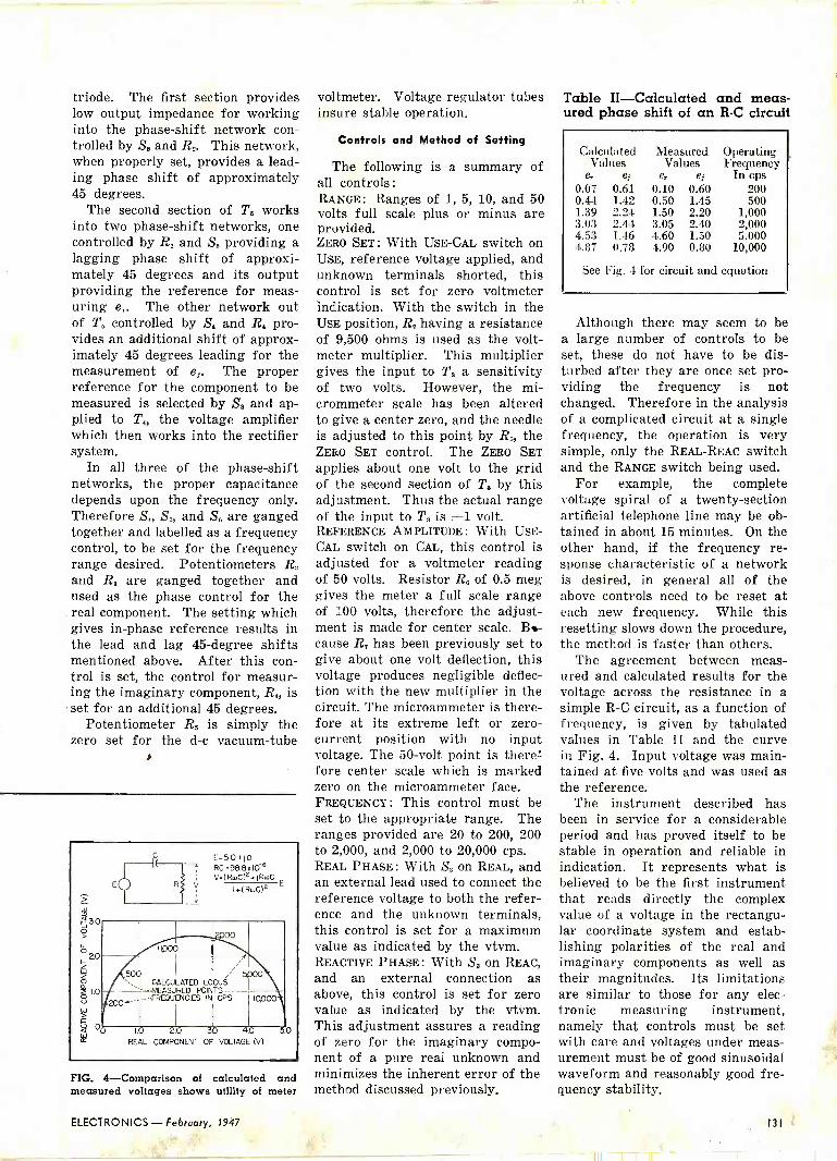
triode. The first section provides low output impedance for working into the phase -shift network con- trolled by S, and R,. This network, when properly set, provides a lead- ing phase shift of approximately 45 degrees.
The second section of T. works into two phase -shift networks, one controlled by R. and S6 providing a lagging phase shift of approxi- mately 45 degrees and its output providing the reference for meas- uring e,. The other network out of T. controlled by So and R. pro- vides an additional shift of approx- imately 45 degrees leading for the measurement of ej. The proper reference for the component to be measured is selected by S, and ap- plied to T the voltage amplifier which then works into the rectifier system.
In all three of the phase -shift networks, the proper capacitance depends upon the frequency only. Therefore S S5, and S6 are ganged together and labelled as a frequency control, to be set for the frequency range desired. Potentiometers R, and R. are ganged together and used as the phase control for the real component. The setting which gives in -phase reference results in the lead and lag 45 -degree shifts mentioned above. After this con- trol is set, the control for measur- ing the imaginary component, R4, is set for an additional 45 degrees.
Potentiometer R. is simply the zero set for the d -c vacuum -tube
E.5.0 .j0 ----4- RC=98.8x10⁶
V=(RmC)ZrjRwC R V Ir(RmC)Z
E
,500 CALCULATED LOCUS
-MEASURED POINTS
200-' -FREQUENCIES IN CPS 10000
1.0 20 30 4.0 QO
REAL COMPONENT OF VOLTAGE (V)
FIG. 4 -Comparison of calculated and measured voltages shows utility of meter
voltmeter. Voltage regulator tubes Table II -Calculated and meas - insure stable operation. ured phase shift of an R -C circuit
Controls and Method of Setting
The following is a summary of all controls: RANGE: Ranges of 1, 5, 10, and 50 volts full scale plus or minus are provided. ZERO SET: With USE -CAL switch on USE, reference voltage applied, and unknown terminals shorted, this control is set for zero voltmeter indication. With the switch in the USE position, R, having a resistance of 9,500 ohms is used as the volt- meter multiplier. This multiplier gives the input to T. a sensitivity of two volts. However, the mi- crommeter scale has been altered to give a center zero, and the needle is adjusted to this point by R5, the ZERO SET control. The ZERO SET applies about one volt to the grid of the second section of T. by this adjustment. Thus the actual range of the input to T. is ±1 volt. REFERENCE AMPLITUDE: With USE - CAL switch on CAL, this control is adjusted for a voltmeter reading of 50 volts. Resistor Rn of 0.5 meg gives the meter a full scale range of 100 volts, therefore the adjust- ment is made for center scale. DI - cause R, has been previously set to give about one volt deflection, this voltage produces negligible deflec- tion with the new multiplier in the circuit. The microammeter is there- fore at its extreme left or zero - current position with no input voltage. The 50 -volt point is there' fore center scale which is marked zero on the microammeter face. FREQUENCY: This control must be set to the appropriate range. The ranges provided are 20 to 200, 200 to 2,000, and 2,000 to 20,000 cps. REAL PHASE: With Ss on REAL, and an external lead used to connect the reference voltage to both the refer- ence and the unknown terminals, this control is set for a maximum value as indicated by the vtvm. REACTIVE PHASE: With S, on REAC, and an external connection as above, this control is set for zero value as indicated by the vtvm. This adjustment assures a reading of zero for the imaginary compo- nent of a pure real unknown and minimizes the inherent error of the method discussed previously.
Calculated Values
e, e Measured
Values e, of
Operating Frequency
In cps 0.07 0.61 0.10 0.60 200 0.44 1.42 0.50 1.45 500 1.39 2.24 1.50 2.20 1,000 3.03 2.44 3.05 2.40 2,000 4.53 1.46 4.60 1.50 5,000 4.87 0.78 4.90 0.80 10,000
See Fig. 4 for circuit and equation
Although there may seem to be a large number of controls to be set, these do not have to be dis- turbed after they are once set pro- viding the frequency is not changed. Therefore in the analysis of a complicated circuit at a single frequency, the operation is very simple, only the REAL-REAC switch and the RANGE switch being used.
For example, the complete voltage spiral of a twenty -section artificial telephone line may be ob- tained in about 15 minutes. On the other hand, if the frequency re- sponse characteristic of a network is desired, in general all of the above controls need to be reset at each new frequency. While this resetting slows down the procedure, the method is faster than others.
The agreement between meas- ured and calculated results for the voltage across the resistance in a simple R -C circuit, as a function of frequency, is given by tabulated values in Table II and the curve in Fig. 4. Input voltage was main- tained at five volts and was used as the reference.
The instrument described has been in service for a considerable period and has proved itself to be stable in operation and reliable in indication. It represents what is believed to be the first instrument that reads directly the complex value of a voltage in the rectangu- lar coordinate system and estab- lishing polarities of the real and imaginary components as well as their magnitudes. Its limitations are similar to those for any elec- tronic measuring instrument, namely that controls must be set with care and voltages under meas- urement must be of good sinusoidal waveform and reasonably good fre- quency stability.
ELECTRONICS - February, 1947 131

Airborne Radar Specifications
BECAUSE of an interest expressed by numerous readers, ELECTRONICS publishes the following
table of radar technical specifications as an addendum to the data appearing in the November 1945 issue.
A Presidential directive, issued since compilation of this information, makes the Office of Technical Serv- ices, Department of Commerce, Washington 25, D. C., the official source for all information relating to de- classified Army and Navy manuals. As the tremendous
task of listing and numbering OSRD, Radiation Lab- oratory, Service, Intelligence and other reports goes forward, the titles, identifying numbers and brief summaries are published in weekly issues of a run- ning bibliography. Subscriptions to this publication are sold by the Superintendent of Documents, Govern- ment Printing Office, Washington 25, D. C., at an initial yearly charge of $10. The reports are available on microfilm or in photostat form.
TECHNICAL DETAILS OF RADAR SETS RECENTLY DECLASSIFIED BY THE ARMY AIR FORCES AND SIGNAL CORPS
Type Number AN/APS-10'-' AN/APS-1S AN/APO-5 AN/APG-13 : SCR 717.1 SCR -720 -A, -B, -C,-I3 ' SCR 520.A SCR 517-C AN/APQ7
Primary Function Airborne search with beacon functions
Airborne search, bombing and navigation by beacon
Range only for gun turrets
Ronge for forward firing cannon
Airborne surface search with beacon functions. Similar in purpose to SCR 517-8
Air search with beacon font- tion. Similar in purpose to SCR -5204,-B
Air Search (See SCR -720-A)
Airborne sur- face search. Also used on small craft
High resolution for blind bomb. ing; also as altimeter and navigational aid
Site, Weight (Pounds) '. Air Transport- able -100
Air Transport. oble-349
Air Transport- able -95
Air transport- able -113
Air transport. able -373
Air transport. able -415
Air transport. able -477
Air transport. able -401
Air transport- able -775
Carrier.. Frequency. (me)
10,000 9,375 2,500 2,800 3,300 3,000 3,000 3,000 10,000
Wavelength (A.) (em) 3 3.2 12 10.7 9.1 10 10 10 3
Peak Power (Pt) (kw) 8 40 0.5 1.5 150 150 60 60 50
Pulse Width (d) (microseconds)
0.8 1
(Beacon, 2) 0.7 0.7 1.125 0.75 1 1
(Beacon, 2.5) 1, 1, 0.4 (Beacon, 20)
Pulse Rate (fr) (pas) 800 AS0 1,200 1,200 750 (Beacon, 375)
1,500 (Beacon, 375)
2,000 (for 100 mile range, 400¡
400 400, 800, 1,600 (Beacon, 400)
Radiator Type, Size Gain (Go)
dipole; 18 in. paraboloid mod- ified for csc
coverage below horizontal 700
Cutler feed to 29 -in. parabo laid modified for es(' to 70 deg 200
22 in. 18- element end- fire or 12 -in. paraboloid. 25-40
End -fire array 35
Horizontal di- pole in 29 -in. parabola 340
Dipole in 29in. parabola 340
Vertical dipole in 30 -in. paraboloid 340
Dipole with 29. in. parabola 340
A
Variable -width wove guide feeding dipole array in 16 -foot scanner 1,500
Types of Scan Circular Tilt -18 and + 3 deg
Circular Tilt + 20 deg
Range search out to 1,800 or 3,600 yd
not for search
Circular Tilt + 10 to -45 deg
Circular Four types of tilt
Circular (180 deg search) Tilts at 30 deg a second
Circular (180 deg search) Tilts + 5 to -30 deg
Sector ± 30 deg
Beam Width (b) - (degrees)
5 3 28 28 9 10 10 10 0.4 Azimuth 30 Elevation
Horizontoi Scanning Rate (rpm)
12 or 24 - - 20 360 360 60 90
Receiver Noise (n). (db above ktAf(
15 18 13 - 11.15 11.15 - 19-21 15
Receiver Bandwidth 1.(M) (mc)
6 2.5 8 1.9 - 3 - 4 4
Indicators 1 or 2 PPI
1 type PPI 1 type A
Pilot light and linkage to computer
1 type A with step marker
2 type PPI 1 or 2 type B
with 2 or 1 type C
- 1 type 8 Elevation meter
2 type PPI 1 type A
Maximum Range (r max) at 1,000 Feet Attitude, or as other- wise noted (miles)
55 - (bombers at 10,000 feet) 2
- - S to 10 - (bombers at 10,000 feet) 5.7
Mounted on fighters 100
Minimum Ronge (yd) 400 200 - 300 200 100-250 - 125 - Ronge Accuracy (yd) + 2 percent 1 percent 40 ± 30. ± 5 percent ± 10 percent - ± 10 percent -
Angular Accuracy -. (degrees)
2 3 - - ± 3 ± S ± 3 ±- 3
Additional information Radar and ' beacon have
AFC and require no manual tuning
Precision long- range beacon delay in 10 mile steps
Ronge unit locks on nearest target in line with guns
Operator tracks target manually
Can supply video signal to bombsight equipment
C -tube shows only targets within limits of range -dial setting
Beacon opera. tion at 10 and 100 miles
Beacon ranges at 25 and 100 mills
PPI shows true ground range instead of slant range. Computer produces slant rangemarker at release point.
132 February, 1947 - ELECTRONICS

W. 2559
Mo. 2541
No. 2543
No. 56A12533 No. 56B12534
CINCH laminated miniature sockets exten-
sively and constantly serve communication
requirements; radio sets, auto and home, tele-
vision ... Cinch the complete line, the standard
socket. The sockets shown illustrate the large
possible variety; center shield, shield plus
ground strap, shock proof spring, finder ring
eliminated and replaced with :wo full top
plates, and double bcttom plate cons ruction;
the variation extended with tropicalization or
wax impregnation. Cinch "Know How" antici-
pates the future needs, adequately serves the
present requirements. Cinch laminated minia-
ture socket is the standard. Write for samples.
No. 56612535
KNOW HOW!
»pe (
® ..-,`,r-1 r{
MINIATURE SOCKET IS THE STANDARD
CINCH MFG. CORPORATION, 2335 W. Van Buren St., Chicago 12, III., Subsidiary of United -Carr Fastener Corp., Cambridge 42, Mass.

DB Gain -Loss Calculator V2 or P2
1,000
900
800
700
600
500'
400
300
200
100
90
80
70
60
50
40
30
20
10
e e
7
6
5
4
3
Pz/P IN DBVZ/Vi IN DB
30 60
25 i 50
20 I 40
15 - i-- 30
VL or PI
2
3
4
5
6
7
B
9
10 20 10
o 1 o
5 10 J
IO I 20
15
20 40
400
2 - - 500
20
30
40
50
60
70
80
90 loo
200
300
25 + 50 600
- 700
POWER: VOLTAGE: 800 D8 .10 LOG10 P2/P1 DB=20 LOGpv2iV1 - 900
1 30 60 I,000
By LLOYD A. LOHR nc7unn. 79ibr lopnierat section
V ral Rem Laboratory Wash iagton, D. C.
N WORKING with communica- tions equipment, it is often
desirable to know the db gain or loss ratio of two voltages, currents, or powers with a minimum amount of calculation. This nomograph will give the db value directly for any voltage, current, or power ratio up to 1,000 to 1 with only one setting of a straightedge, and the range can readily be extended by using multiplying factors. The converse problem, of finding a ratio that will give a desired db gain or loss, can just as readily be solved.
If V, and V2 are known, place the straightedge to connect their values on the outer scales and read voltage gain or loss in db on the right side of the center scale.
If P, and P2 are known, place the straightedge to connect their values on the outer scales and read voltage gain or loss in db on the left side of the center scale.
If the db value and one voltage or power value are known, connect these values with a straightedge and read the other voltage or power value on the third scale.
The range of the nomograph can be extended by applying a multi- plier to one of the log scales and adding to the db scale values as follows :
Multiplier Add to Add to for one values on values on log scale P2/P, scale V2/V, scale
10 10 20 100 20 40
1,000 30 60 10,000 40 80
100,000 50 100
Example: What is the db gain for a voltage ratio of 100 to 5? From the nomograph, the db gain is approximately 26.1 db. Checking, db = 20 log V2/V, = 20 log 20 = 26.06 db.
134 ELECTRONICS REFERENCE SHEET February, 1947 - ELECTRONICS

Sava Spae ... lnijarois c Efficiency with a
MALLORY SeltRectifying VIBRATOK
MALLORY VIBRAPACK` Mallory ibrapacks deliver volt- ages from 125 to 400 from low voltage sources...with high effi- ciency, low battery drain, ease of installation, long life.
*Reg. U. S. Pat. Off. for vibrator power supplies.
More Mallory Vibrators are in use today than all other makes combined
If you're a manufacturer of automobile radios, mobile communication systems or of any other equipment using vibrator power supplies, now is the time to consider the Mallory self -rectifying vibrator.
Mallory self -rectifying vibrators are identical in size with the interrupter type. But-and here's the important point-they save space and wiring, and give you less components to worry about.
That's not the whole story either. You get top performance with Mallory self -rectifying vibators. They assure high over-all power supply efficiency and eliminate the voltage drop within the rectifier tube plus the heater load.
Mallory engineers, who have produced more than 15,000,000 vibrators, invite your vibrator problems-will be glad to give you specific information about the self -rectifying type for your particular application. Write for copies of the comprehensive vibrator questionnaire.
MP. Rc MALLORY 8 CO.Inc.
ALLORYVIBRATORS AND VIBRATOR POWER SUPPLIES
P. R. MALLORY & CO., Inc., INDIANAPOLIS 6, INDIANA
ELECTRONICS - February, 1947 13S

TUBES AT WORK Edited by VIN ZELUFF
Guillotine Tuner for F -M 136
Radio Beams for Railroads 136
Airborne Television Telemetering 138
VHF Transmitter Power Measurements 158
Guillotine Tuner for F -M
VARIABLE inductance tuning is one answer to the problems arising from the transfer of f -m stations to the higher frequencies. Such a system has been perfected by Gen- eral Electric engineers.
Two identical silver-plated brass frames are used which, when con- nected at their open ends, form a two -turn inductance. Tuning is done by movement of a silver-plated brass blade between the turns. The inductance of each turn is reduced as is the mutual inductance between them. Slots in the blade provide a means of tracking the oscillator and r -f circuits.
Because the tuner is entirely tool made, precise production control of tracking is possible without high labor content in the cost of manufacture. Both terminals of the tuner project through the re- ceiver chassis to provide a rugged tie point for soldered connections.
Nicknamed the "guillotine" tuner
because of the sliding blade, the unit tunes both f -m bands and two or more short-wave spread bands in General Electric f -m receivers. Other ranges are tuned by adding shunt capacitance and fixed series inductance to the guillotine circuit. With the guillotine tuner it is pos- sible to localize each tank circuit within a small area and to keep r -f chassis currents at a minimum. Since the blade of the guillotine is ungrounded, sliding contacts and pigtails are eliminated. Little trou- ble is had from regeneration or alignment difficulty.
Production assembly and testing of the tuners at the factory will be localized in a department set apart from the main chassis production line. Tuners will be assembled, tested and then transported to the chassis assembly lines in much the same manner as engines are han- dled in an automobile assembly plant. Only two types of front -
Front end of a General Electric receiver containing the guillotine tuner
A two -turn inductance is formed by the two frames A, and tuning is done by the guillotine blade B, sliding in the grooves of two supports. both sides of which show at C. These support posts are held to the
chassis by the clamp D
end assemblies are used to tune eleven different models of General Electric f -m receivers.
The complete tuner is enclosed in a metal box for shielding, and for mechanical protection and dust proofing. Microphonic howl when receiving short-wave stations is said to be completely absent.
In the receiver, a loop is used on all a -m bands but power line pick-up is used for local f -m recep- tion. Terminals permit outdoor antennas to be used.
Radio Beams for Railroads BEAMED RADIO, wire, and cable cir- cuits normally employed in carry- ing commercial messages may be utilized in emergencies to transmit electrical impulses to control rail- road switches and signals.
In a recent test conducted at a signal control tower at Red Bank, Pa., the Pennsylvania Railroad em- ployed a special linking of ex- isting wire, cable, and beamed ra- dio circuits extending from the control tower to Pittsburgh, Wash- ington, D. C., Philadelphia, New York, and back to Pittsburgh and the tower.
Normally a centralized traffic control machine in Brady tower near Redbank controls the signal- ing between Red Bank and Oil City, (53 miles away), by the transmis- sion of d -c pulses. These are ar- ranged to have distinctive character for selecting the desired stations, switches, and signals over a pair of line wires extending throughout
136 February, 1947 - ELECTRONICS

-g1
HUNDREDS OF CONTRO
PROBLEMS SOLVED WI
S OPPI G 1 ri.
Design engineers are discovering new, efficient, money -saving applica-
tions daily for Guardian basic -type Stepping Relays. Typical applications include Automatic Sequence selection of circuits; Automatic Sequence
cross connection of circuits; circuit control of Automatic Business
Machines; control of Production Totalizing and Conveyor equipment; remote selection of records on Coin Operated Phonographs; Automatic Circuit Selection controlled from a pulsing dial; Automatic Wave Changing on short wave transmitters. This Guardian Stepping Relay is furnished for three basic types of A.C. and D_C. operation: Continuous Rotation-Electri- cal Reset-Add and Subtract. On each of these types the contact finger rotates in a counter -clockwise direction and all three types ore designed
to follow 10 pulses' per second within the rated voltage range of the relay. Special construction prohibits skipping or improper indexing of the ratchet.
Guardian Steppers may be furnished as separate units; in combination with relays, contact switches, solenoids, etc., completely assembled and
wired to terminals; mounted on special bases or in enclosures. Any standard Guardian Stepping Relay can be modified to meet practically all "special" stepper control applications where quantities warrant special designing. For complete details write for Bulletin SR.
GUARDIAN ELECTRIC 1625-B W. WALNUT STREET CHICAGO 12, ILLINOIS
A COMPLETE LINE OF RELAYS SERVING AMERICAN INDUSTRY
GUARDIAN SERIES R
1 Continuous Rotation In this type the contact finger advances one step each time the circuit is made and broken. Weight approximately 201/2 ozs.
2 Electrical Reset Resets when a second coil is energized. Weight approximately 23 ounces.
3 Add and Subtract Steps back one or more contacts at a time instead of resetting completely. Weight ap- proximately 281/2 ounces.
TYPICAL GUARDIAN UNITS AVAILABLE IN COMBINATION WITH GUARDIAN STEPPER$
Series 100
Snap -Action Relay
Series S00 Midget Relay
Featherub Switch
Series 1-A Solenoid
ELECTRONICS - February, 1947 137

n..a,.ntaw,::;:; .,.,
"e e it ' x *ye vtrwr
"+*r>r grtee
Some of the electronic equipment installed at Brady tower by Union Switch and Sig-
nal for the test
the controlled territory from the tower. The operator controls trains while watching lights on a diagram.
The switches and signals have corresponding levers on the control machine which are positioned as desired. Operation of a code -start- ing button gives the pulses of long and short duration predetermined sequence to select the correct sta- tion along the railroad and to oper- ate functional relays at this loca- tion. In the test demonstration these pulses were converted to car- rier current pulses which were transmitted over a PRR telephone line from Brady tower to Pitts- burgh using a frequency of 12.3 kc.
The control pulses were delivered to the Western Union office in Pitts- burgh, then transmitted over Western Union carrier -telegraph circuits.to Philadelphia by way of Washington. This carrier fre- quency system has all carrier fre- quencies below 30 kc, and as many as 36 independent multiplex tele- graph messages can be transmitted
in each direction simultaneously on a single pair of line wires. This would permit 144 telegraph oper- ators to send messages simultan- eously in one direction and a simi- lar number in the opposite direc- tion. In the demonstration, one multiplex telegraph channel was utilizgdf for the transmi§sion of the pulses While at the same time there may have been 140 telegraph mes- sages on the same pair of wires traveling in the same direction. Re- peater stations are placed along the line at intervals of about 150 miles.
Microwave Link
At Philadelphia, the control pulses modulated a microwave transmitter and were beamed toward New York City over the Western Union relay system using two intermediate repeater stations between Philadelphia and New York (ELECTRONICS, Dec. 1945, p 300).
The radio beam can handle 256 multiplex telegraph circuits so 1,- 024 operators could transmit tele- grams simultaneously in one direc- tion. The control code would re- quire the equivalent of only one telegraph channel so that 1,020 tele- graph messages could be on the beam at the same time that a con- trol code was being transmitted. The frequencies tised between Phil- adelphia and New York are 3,970 and 4,120 megacycles.
The beamed pulses terminate at the Western Union building in New York. There the pulses are shifted to 'a carrier transmitted over West- ern Union lines from New York to Pittsburgh.
At Pittsburgh, Western Union receiving equipment operated Un- ion Switch and Signal Company carrier equipment to send coded 25.4-kc pulses on to a field carrier location at Brady tower. Here a sharply tuned 25.4-kc receiving fil- ter discriminates against other fre-
BRADY TOWER
60 Mi.
CTC.(lrrkr'
PITTSBURGH
Apprw. 550M1.
Telegraph Carrier
WASHINGTON
-PHILADELPHIA
1NEW YORK PITTSBURGH-
A0prox90Mi.
beamed Radio
Approx. 370 Mi.
Telegraph Carrier
BRADY TOWER - FIELD STATIONS ~ OIL
Doni MK.J CITY
(TCCarrier D.C. line -I
The normal 65 miles of wire line used for traffic control between Brady Tower and Oil City were spread out to over 1,000 miles of carrier current and beamed radio circuits
for the communication teat
quencies (two carrier frequencies, 12.3 and 25.4 kilocycles, are trans- mitted in opposite directions on the one line pair at the same time be- tween Brady and Pittsburgh). After the 25.4 -kilocycle pulses are amplified, they are fed through auxiliary apparatus which converts them to d -c pulses and places them on the code line extending to the switch and signal locations.
After a switch and signal re- spond to the control code, the cir- cuits start an indication signal back to the control point to show what has transpired. This travels back over the same types of circuits.
The demonstration suggests the immediate possibility of use of radio as a standby communication channel to insure continuity of centralized traffic control operation in cases of line failure because of flood, hurricane, or storm, because there would be less possibility of interruption than with pole -carried line wires.
Airborne Television Telemetering TELEVISION TELEMETERING enables observers at a ground station to see by television all instrument record- ings and indicators of pressures, strains and structural failures of a test plane in the air. Thus, the pilot is freed from the necessity of keeping a constant check on his test instruments, and can devote his full attention to handling the plane.
To supply the need for a perma- nent record of test flights, all flight data shown on the television re- ceiver screen on the ground is put on movie film. If serious failures result in the loss of a plane, these pictures, being filmed up to the moment of disintegration, can be studied to establish accurate reasons for the mishap.
The system as developed for the Navy by engineers of Farnsworth and Curtiss-Wright consisted of a television theater and television transmitter in the plane and a mobile television receiving unit on the ground. This equipment trans -
(Continued on p 154)
138 February; 1947 - ELECTRONICS

140A single channel a-c-d-c amplifier.
3 new Subscriber Amplifiers
124H two channel amplifier ith selector switch.
1241 single channel line level amplifier.
These three new amplifiers designed by Bell Telephone Laboratories are the first high quality packaged units ever made specifically for subscriber installations of wired music service.
The 12411 and 12_IJ are adaptations of the same general type used so success- fully on network program distribution lines and in radio stations and public address systems. They differ only in tha t
the 12411 offers a microphone channel in addition to the line channel. The com- pletely new 140A a-c-d-c amplifier, tihich is the first ever to offer the same stability with d -c operation as it does with a -c, can probably be used in 80% of your subscriber installations.
All three units can operate directly from telephone lines because they are equip- ped with a suitable input transformer. All may be used as fixed or portable equipment, and are suitable for rack or cabinet mounting.
For full information, call your local representative of the Graybar Electric Co., or write to Graybar, 420 Lexington Ave., New York 17, New York.
124H 124J 140A
Freq.cency Response 1 db 50 to 10,000 cycles. t 1 db 50 to 10,000 cycles. t 1 db 50 to 10,000 cycles.
Maximum Gain 63 db line) 104 db (microphone)
63 db 60 db
Gain Control Continuously variable. Continuously variable. Continuously variable.
Source Impedance 37)' , 150 or 600 ohms (line), 30or250ohms(microphone).
373/2, 150 or 600 ohms. 150 ohms, 600 ohms or bridging.
Load Impedance I to 1,000 ohms. 1 to 1,000 ohms. (4 windings) 4, 8, 125, 125 ohms.
Signal to Noise Ratio 77 db ¡line), 48 db (microphone).
77db 60 db
Output Noise -37 clmm (line), -8 dlm (microphone). -37 dbm -20 dbm
Output Power 12 watts 2% total harmonic distortion for nominal load impedance. 20 watts 5% harmonic distortion if reconnected and Western Electric tumbes are mused.
6 watts d -c, 10 watts a -c, less than 5% harmonic distor- tion. 5 watts d -c, 8 watts a -c, less than 2% harmonic dis - tortion. 4 watts d -c, 6 watts a -c, less than 1% harmonic distortion.
PoN% r Supply 105-1 volts, 50-60 cycle i -c.
I 105-125 volts, 50-60 cycle a -c.
105-125 volts, a -c or d -c.
9
Western Electric -QUALITY COUNTS
r
ELECTRONICS - February, 1947 139
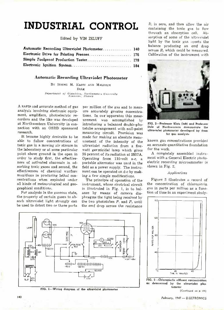
INDUSTRIAL CONTROL Edited by VIN ZELUFF
Automatic Recording Ultraviolet Photometer 140 Electronic Drive for Printing Presses 176 Simple Foolproof Production Tester 178
Electronic Ignition System 184
Automatic Recording Ultraviolet Photometer BY IRVING M. KLOTZ AND MALCOLM
DOLE
Department of Chemistry, Northwestern University Evanston, Illinois
A RAPID and accurate method of gas analysis involving electronic equip- ment, amplifiers, photoelectric re- corders and the like was developed at Northwestern University in con- nection with an OSRD sponsored research.
It became highly desirable to be able to follow concentrations of toxic gas in a moving air stream in the laboratory or at some particular point above ground in the open in order to study first, the effective- ness of activated charcoals in ad- sorbing toxic gases and second, the effectiveness of chemical warfare munitions in producing lethal con- centrations when exploded under all kinds of meteorological and geo- graphical conditions.
For analysis in the gaseous state, the property of certain gases to ab- sorb ultraviolet light strongly can be used to detect two or three parts
per million of the gas and to meas- ure accurately greater concentra- tions. In our apparatus this meas- urement was accomplished by introducing a balanced double-pho- totube arrangement with null -point measuring circuit. Provision was made for making an absolute meas- urement of the intensity of the ultraviolet radiation from a five - watt germicidal lamp which gives 95 percent of its radiation at 2537A. Operating from 110 -volt a -c, a portable alternator was used in the field as a power supply. The instru- ment can be operated on d -c by mak- ing a few simple modifications.
The principle of operation of the instrument, whose electrical circuit is illustrated in Fig. 1, is to bal- ance by means of camera dia- phragms the light being received by the two phototubes P1 and P2 until the emf drop across the resistance
e °OUTSIDE o POT
lill .4.5V »NI 12
-90Illll 1I22II5IVIIIIIIIIIIIIIIIIIIIIr-1
+ . --20,000
5
FIG. I --Wiring diagram of the ultraviolet photometer
R, is zero, and then allow the air containing the toxic gas to flow through an absorption cell. Ab- sorption of some of the ultraviolet light by the toxic gas upsets the balance producing an emf drop across R1 which could be measured. Calibration of the instrument with
FIG. 2-Professor Klotz (left) and Professor Dole of Northwestern demonstrate the ultraviolet photometer developed by them
for gas analysis
known gas concentrations provided an accurate quantitative foundation for the work.
A completely assembled instru- ment with a General Electric photo- electric recording microammeter is shown in Fig. 2.
Applications
Figure 3 illustrates a record of the concentration of chloropicrin gas in parts per million as a func- tion of time in an experiment study -
160
120
Z - º
80
W
á
) 40
00 20 40 TIME IN MINUTES
FIG. 3-Chloropicrin effluent concentration as determined by the ultraviolet pho-
tometer (Continued on p 174)
140 February, 1947 - ELECTRONICS

ThJÁJaSPEED NUT.... aid
THIS is also a Speed Nut! Of course you recognize the Standard SPEED NUT shown above, but just look at the "nightmare" our development engineers dreamed up, to provide multiple fastening and operational functions in a
single unit! It is used in the assembly and mounting of television transformers (see sketch) and you -can readily understand its advantages over special mounting brackets and individual, hard -to -handle threaded nuts and lock washers.
In addition to the widely -used standard types of SPEED NUTS, hundreds more are functionally designed to combine assembly operations, eliminate unneces- sary handling of parts, speed-up produc- tion and thereby reduce final costs. They
JI i J J IrI MORE THAN 4000
FASTEST THING
are fabricated on specially designed, automatic machines which produce com-
pletely finished parts at high speeds. There must be some step in the assem-
bly of your product where, by changing over to SPEED NUTS, your costs could be reduced and your product improved. Why not send us your assembly details, or better still, send in the parts involved. We will be glad to give you a complete fastening analysis ... at no cost.
TINNERMAN PRODUCTS, INC. 2106 FULTON ROAD CLEVELAND 13, OHIO
In Canada: Wallace Barnes Co., Ltd., Hamilton, Ont.
In England: Simmonds Aerocessories, Ltd., London
In France: Aerocessoires Simmonds, S. A., Paris
In Australia: Aerocessories, Pty., Ltd., Melbourne
Age PATENTED
SHAPES AND SIZES T,od< Mork Reg. U. S. Poe. OTf.
IN FASTENINGS ELECTRONICS - February, 1947
141

THE ELECTRON ART Edited by FRANK ROCKETT
Cathode-ray Tube for Displaying Speech Waves 142 Superconductive Radio -Frequency Detector 142 Classroom Demonstration of Cathode Follower 188 Calibrating Laboratory Standards Against WWV 190 Impedance Measurements 194 Radio Reflection from the Moon 196 Microwave Spectroscope 198 Modulation of Concentrated -Arc Lamp 202 Electronics in the Food Industry 206 Edison Effect 208 Variable Electronic Capacitor 210
Cathode -Ray Tube for DISPLAYING patterns of speech waves on a cathode-ray tube en- ables the deaf to communicate ver- bally. The technique is being stu- died at Michigan State Normal Col- lege as a teaching method whereby deaf children can learn to read speech patterns just as they would a printed text. Using the tech- nique, the deaf can enjoy the radio and carry on telephone conversa- tions.
The speech translator tube (Jour Appl Phys, p 891 November 1946) consists of a cylindrical tube in which the phosphorescent material is deposited on a peripheral band. The electron gun at the bottom of the tube projects an intensity - modulated beam at the axis of the tube. An external coil on the neck
Displaying Speech Waves deflects the beam slightly. The electron beam then passes into an expanded section of the tube. A strong magnetic field perpendicular to the tube's axis deflects the elec- tron beam radially so that it strikes the phosphorescent band. There is an accelerating anode at the top of the tube. The tube slowly rotates to provide the sweep so that, to a sta- tionary observer, the pattern ap- pears to move from right to left. One reads against the motion of the pattern; that is, one reads from left to right. Both intensity modu- lation of the beam and deflection produced by currents in the coil on the neck provide means for repre- senting the speech wave on the screen. Used in this way the rotat- ing tube constitutes a sound spec -
Professor Harriet Green speaks into the microphone. Patterns of the speech waves move across the screen of the special revolving cathode-ray tube, the screen of which is at the left inside the light shield. Joyce Arnold and Richard Hudson read the patterns
The modified cathode-ray tube has a long - persistence phosphor on a cylindrical screen. When mounted in a strong per- pendicular magnetic field and slowly ro- tated, the tube displays a continuous pat-
tern of the speech wave
trograph displaying the signal as a continuously moving pattern. Elec- trical connections to the tube are made through slip -rings.
For displaying visible sound (Jour Aco Soc Am p 1-88 July 1946), the speech wave can be mod- ified to incorporate the selective and nonlinear effects introduced by an ear. It is anticipated that by this method the deaf will not only be enabled to hear with their eyes, al- though of course the sensations they receive will not be that of aud- ibly hearing, but also learn to talk and to interpret the significance of sounds not directly associated with speech such as music and noises.
Superconductive Radio -Fre- quency Detector DEVELOPMENT of bolometers has progressed to the point where re- sponse times as fast as 5 x 10-' second are obtained (Jour Opt Soc Am, p 518 September 1946). Such bolometers respond to infrared waves intensity -modulated at voice
(continued on p. 186)
142 February, 1947 - ELECTRONICS

Improved operation of automobile radios
with radio antenna lead-in cable insulated with
Du Pont POLYTHENE Now, with the use of Du Pont polythene, it. is possible to make a lead-in cable, from
the antenna to the instrument, that helps
to assure proper operation of automobile radios-a lead-in cable that is water -tight,
has excellent electrical properties, is eco-
nomical to assemble, and gives long service.
Du Pont polythene has been successfully
used as the insulating material for the
shielded lead-in tubing made by The Amer- ican Brass Company, Waterbury, Conn., because it has low capacitance and is usable
over a wide range of temperatures. In ad-
diition, Du Pont polythene has these other outstanding advantages :
RESISTANCE TO MOISTURE - Poly- thene has low moisture permeability, protects
the cable from short circuits caused by
moisture.
LASTING FLEXIBILITY - Polythene withstands twisting and bending over a wide
range of temperatures.
HIGH "Q"- Electrical losses within a
polythene -insulated cable are negligible.
EASE OF HANDLING - Polythene has good extrusion qualities, is economical to
assemble.
Your insulating problem may be solved by using Du Pont polythene. Write us for complete information on this light -weight, durable insulating material. E. I. du Pont de Nemours & Co. (Inc.), Plastics Dept. 152, Arlington, N. J.
Du Pont manufactures polythene molding powder.
Commercial extruders convert into the forms of
SHEETS 7 TUBE PODI FILAMENT( ELECTRICALrTAPES
A Extruded tube of Du Pont polythene, Type PM -I, 0.125" I. D. x 0.200" 0. D. (one of many sizes), used
for inner core of shielded lead-in tubing for a radio antenna. Polythene is ideal for this core because it is
easily extruded, is stabilized,retains electrical properties.
B Tinned copper basket -weave braid is woven over
inner core of polythene to incorporate electrical prop- erties necessary in shielded lead-in tubing.
C The outer jacket, Type PM -2 polythene, about 35
mils thick, adds neat appearance, seals out water.
REG, U. S. PAT.OFf
easties BETTER THINGS FOR BETTER LIVING
...THROUGH CHEMISTRY
ELECTRONICS - February, 1947 143

NEW PRODUCTS Edited by A. A. McKENZIE
New equipment, components, packaged units, allied products; new tubes. Catalogs and manu- facturers' publications reviewed
Dielectric Heater Crystal (1)
NORTH AMERICAN PHILIPS CO., 100 East 42nd St., New York 17, N. Y. A new midget quartz crystal oscil- lator for controlling the frequency of dielectric heating apparatus measures less than i inch in
diameter and is less than 11 inches long. Frequency coincides with that assigned by the FCC for this service and the unit is completely enclosed with soldering terminals provided for quick connection to the circuit.
UHF Peak Voltmeter (2)
GENERAL RADIO CO., 275 Massachu- setts Ave., Cambridge 39, Mass. The type 1802-A crystal galvanom- eter directly measures 0.1 to 1 volt with an accuracy of ±5 percent at frequencies up to 1,000 megacycles. Two multipliers are furnished to extend the range to 10 or 100 volts. For the measurement of voltage ratios, the frequency limit can be pushed well above 1,000 meg- acycles. Functionally, the instru- ment is a peak -reading device em- ploying a crystal rectifier, d -c
amplifier, and meter. Batteries quired for operation are self tained.
re- con -
Television Lead -In (3)
ANACONDA WIRE AND CABLE CO., 25 Broadway, New York, N. Y. Two types of ATV two -wire poly- ethylene insulated line are available for television and f -m lead-in use, with characteristic impedances to match various types of antenna ar-
USING THE NUMBERS
Readers desiring further details concerning any item listed in the New Products department can obtain the information by using the cards fur- nished as a stiff, colored insert else- where in this department.
Place the number (appearing to the right of the heading) of one item in which you are interested in a
circle and then fill out the balance of the card according to directions appearing on the colored sheet.
rays. Complete information and prices are available on request.
Vacuum Leak Detector (4)
CONSOLIDATED ENGINEERING CORP., Dept. BB, 620 N. Lake Ave., Pasa- dena 4, Calif. A new portable leak detector model 24-101 for vacuum
or pressure systems that will locate and measure leaks as minute as 0.00000001 cubic centimeters per second works on the mass spec- trometer principle. The instrument operates electronically to detect small quantities of helium intro- duced into suspected areas. The warning system contains an audio signal that changes pitch to indi- cate magnitude of the leak. The cabinet housing the equipment measures 43x25x22 inches and is mounted on ball bearing casters.
Flaw Detector (5)
GENERAL ELECTRIC CO., Schenec- tady, N. Y. A new flaw detector that continuously detects weak spots and conducting paths in thin mate- rials such as paper, sheet rubber, plastic material, and enamel films has recently been announced. The apparatus can be used with mate- rials up to 0.025 inch thick moving as fast as 450 feet per minute and wire moving up to 100 feet a min- ute. Principle of operation depends upon applying an adjustable voltage to the material undergoing test and detecting the flow of current through the material when a flaw
144 February, 1947 - ELECTRONICS

VggPteguns
Oa ate u.LteNridsy /.úce ai .rs .ílse /,aGwaciovrsy
?/i444u1 4lieunesri Tecluúresed irasvice Getti peiciperrçsce.
HIGH FREQUENCY VISALGEN Model 205 TS
1. Frequency range from 100 kc to 20 mc.
2. Linear frequency sweep deviation adjustable from 0 to 900 kc peak to peak.
3. Vernier frequency control of 100 kc allows zero beat calibration of main tuning dial or for vernier frequency deviation about main dial frequency setting.
4. Output impedance 1 ohm to 2,500 ohms.
5. Voltage regulated supply for internal os- cillators.
LOW FREQUENCY VISALGEN Model 204 TS
1. Frequency range from 20 kc to 500 kc.
2. Linear frequency sweep deviation adjustable from 0 to 70 kc peak to peak.
3. Low pass filter in the output to minimize spurious output frequencies.
4. Output impedance constant 200 ohms.
5. Output attenuation: 5 -step ladder type - 20 db per step.
OSCILLOSCOPE Model 188 TS
1. New simplified circuit for use with either model Visalgen.
2. Simplified for visual alignment work.
3. Compact design - light weight.
4. Immediately available, also available with either model Visalgen complete in one cabinet.
Visalgen Model 205 TS being used with 188 TS oscilloscope to align Harvey Hi -Fidelity FM Receiver.
Inset: New Low Frequency Visalgen Model 204 TS
HARVEY OF CAMBRIDGE
HARVEY RADIO LABORATORIES, INC., X39 CONCORD AVENUE CAMBRIDGE 38, MASSACHUSETr
ELECTRONICS - February, 1947

passes. The equipment can be set up close to thelinanufacturing proc- ess in order to spot variations in quality immediately.
VHF Receiver (6)
NATIONAL Co., Malden, Mass. The NC -One -Ten -A radio receiver has been redesigned as a result of radiosonde use and represents an improvement over the original re- ceiver that tuned the spectrum
from one to ten meters. Although the instrument has many practical applications, such as reception in the 118 -megacycle aircraft band, it is of particular use to experi- menters and amateurs.
High Mu Triode (7)
NATIONAL UNION RADIO CORP., 57 State St., Newark 2, N. J. An amplification factor of 500 at plate voltage ratings from 1 to 8 kilo- volts is possible with the type 2C53 tube. At plate voltages between 250 and 400 volts, it is possible to obtain single stage amplification from 250 to 300 times. The tube has been particularly designed for
regulation of low -current power supply voltages up to 8 kilovolts, such as in pulse amplifiers, for high -impedance measurements, and in television equipment.
Vacuum Capacitor (8)
RAYTHEON MFG. CO., Waltham, Mass. The type RC100-20 vacuum capacitor is the first in a new line of high -voltage, high -current com- ponents designed for tank circuits in industrial and communications oscillators. The new unit, which has a capacitance of 100 micromi- crofarads, can be used at r -f volt-
ages up to 20,000 and will carry an rms current of 60 amperes. Overall length of the capacitor is 7.25 inches and diameter is 2.5 inches.
Ohm's Law Calculator (9)
OHMITE MFG. CO., 4937 Flournoy St., Chicago, Ill. A new pocket-size calculator reads directly in ohms, volts, amperes and watts. It will also solve parallel resistance and series capacitance problems, will
pNMtTE otlMS «- :-.-- --
multiply, divide and find squares or square roots. Composition re- sistor color coding is also shown. The calculator measures 3x9 inches and sells for 25¢.
Decade Counter (10)
GENERAL ELECTRIC CO., Syracuse, N. Y. A new decade scaling unit for use with particle detectors will respond to impulses of 0.05 micro- second duration separated by only
0.1 microsecond. Scaling factor of the type YYZ-1 unit is either 10 or 100, but units can be used in cas- cade to provide factors of 1,000 or more. Impulse duration and reso- lution times were incorrectly re- ported in a previous announcement of this product.
Television Receiving Antenna (11)
WORKSHOP ASSOCIATES, INC., 66 Needham St., Newton Highlands 61, Mass. Primarily designed for single -channel operation in loca- tions where signal-to-noise ratio is low, the new series of television re- ceiving antennas aims to improve reception only in poor locations. There are separate structures avail- able for each of five bands. Price exclusive of standard coaxial cables is $28.50 each.
Field Intensity Meter (12)
CLARKE INSTRUMENT CORP., 910 King St., Silver Spring, Md. The model 106 field intensity meter for use in the television and f -m bands covers the frequency range 50 to 220 mc. The instrument is direct reading in terms of microvolts per meter over a range of 5 microvolts to 10 volts. Selectivity is adequate for measurements on adjacent f -m
146 February, 1947 - ELECTRONICS

EVERY DE MORNAY-BUDO WAVE GUIDE
is Electrically Tested, Calibrated and Tagged
Crystal Mount DB -453 Rotating Joint DB -446
Un;-directioncd Broad Band Coupler DB -442
Bi-directional Narrow Band Coupler DB -441
90° Elbow (H Plane) DB -433
Bulkhead Flange DB -451
Pr ;zing Unit DB -452 Mitered Elbow (H Plane) DB -439
Uni -directional Narrow Band Coupler DB -440
REFLECTOR
FEED HORN
ROTATING JOINT
FLAT 90' ELBOW
90' TWIST
MITERED. ELBOW
1/4Illhgll.e
1 STRAIGHT SECTION
EDGE 90 ELBOW 90'.TYIST F UNIT
Typical wave guide assembly illus- trating use of De Mornay - Budd com- ponents available from standard stocks.
When you use any De MornayBJdd wave guide assembly, you know exactly how each compo- nent will function electrically. You avoid possible losses in operating efficiency through impedance mismatches, or breakdown and arcing caused by a high standing wave ratio. (See chart below.)
De MornayBudd wave guides are manufac- tured from special precision tubing, and to the
The curve shows the manner in which the reflected power increases with an increase in the voltage standing wave ratio. The curve is calculated from the following equation:
% Power Reflected =
b
¡ Vmax 2 Y
1` Vmin
( Vmax \ ) ? 1 ` Vm;n
90° Twist DB -435
RF Radar Assembly DB -412
most stringent mechanical specifications. Rigid inspection and quality control insure optimum performance
NOTE: Write for complete catalog of De MornayBudd Standard Components and Standard Bench Test Equipment. Be sure to have a copy in your reference files. Write for it today.
tome toeal emrnY Y9nlit nMiY xYR W q
. ir,w.lole,'Ì RT
EQUIPMENT FOR
97% OF ALL
RADAR SETS
De Mornay -Budd, Inc., 473 Grand Concourse, New York 51, N, Y.
ELECTRONICS - February, 1947 147

channels 200 kc apart. A 110 -volt power supply can be substituted for the vibrator supply incorporated in the equipment.
Rectifier Tube (L3)
ELECTRONS INCORPORATED, 127 Sus- sex Ave., Newark 4, N. J. A new half -wave xenon gas -filled rectifier type 16F has been designed for ap- plications in rectifier circuits giv- ing up to 96 amperes d -c at voltages varying from 24 to 600. Character- istics include: average anode cur-
rent, 16 amperes ; peak anode cur- rent, 96 amperes; peak inverse voltage, 620 volts; average arc drop, 7 volts; filament voltage, 2.5 volts.
Navigation Receiver (14)
RADIO CORP. OF AMERICA, Camden, N. J. The new type AVR-25 air- craft communications and naviga- tion receiver consists of four units -control box, azimuth indicator,
e left -right indicator, and receiver proper. The latter unit operates on all the aircraft vhf channels and makes possible the use of two - course visual ranges as well as the omnidirectional range.
F -M Broadcast Tube (15)
WESTERN ELECTRIC Co., 195 Broad- way, New York 7, N. Y. The type 5541 air-cooled transmitting triode has been designed particularly for use in the company's 10 -kw f -m transmitter, but can be adapted for
use in grounded -plate, grounded - grid, or grounded -cathode circuits. Design features include a thoriated tungsten filament, low -inductance and high -conductivity leads.
V -T Test Set (16)
SYLVANIA ELECTRIC PRODUCTS, Inc., 500 Fifth Ave., New York 18, N. Y. The console unit illustrated in- cludes bridge and auxiliary switch gear mounted on the control shelf,
electronically regulated power channels, bridge signal source, amplifier, meters, and other acces- sories conveniently located for tube tests and maintenance. The con- sole is 55 inches high, 70 inches long, and 34 inches deep. It weighs 1,500 pounds.
Current Feed Junction (17)
JAMES KNIGHTS CO., Sandwich, Ill. The Impedacoupler is essentially an
insulating block with ends machined to take standard aluminum or dural tubing having 1 -inch outside diam- eter. It is fitted with an Amphenol type 1R receptacle that takes a type 1SP cable connector. The unit has several uses, such as cen- ter feed point of a half -wave doublet.
Rugged Speaker Driver (18)
UNIVERSITY LOUDSPEAKERS, INC., 225 Varick St., New York 14, N. Y. A new loudspeaker driver unit capable of handling up to 12 watts of audio power features an Alnico V magnet and one-piece phenolic diaphragm. The voice coil is wound on a duralumin band for maximum heat dissipation. Impedance of the unit is 8 ohms and its frequency
range covers 100 to 6,000 cycles. It is 3 inches high with a diameter of 31 inches.
Zinc Solder (19)
SUPERIOR FLUX Co., 901 Public Square Bldg., Dept. 1, Cleveland, Ohio. Zinctite is a self -reacting fluxless solder that can be used for soldering copper, brass, steel or zinc pieces to zinc or zinc -base alloys. It comes in the form of a paste in 1, 1, or 5 pound jars.
Crystal Microphone (20)
BRUSH DEVELOPMENT CO., 3405 Per- kins Ave., Cleveland 14, Ohio. The model BA -106 microphone is manu -
._._.j (Continued on p. 212)
148 February, 1947 - ELECTRONICS

4
ALL PARTS S
DIAMOND G MAKES
THEM!
arts -lock Whatever your need in small p
washers, flat washers, special washers, snap
and retainer rings, stampings of all kinds
clamps, Diamond G is ready ito and hose Diamond
quick deliveries. produce make complete facilities to producte offers its need in your products. ct
spacial parts you may ready elp
Diamond G Engineers stand
you in every way.
Diamond G service to industry is
An new lock
specification and a
the bookew
washer pand Where of Lock
. . . How, Why
let every purchasing Washers." A book production
't9
design engineer Justa
shouldho
without obligation. have.
INC. v, ite to COMPANY,
ß ORGE K. GARREII
1421 CHESTNUT ST., pH%LADELFNIA,
2
FINISHING WASHERS
Diamond G makes a full line of hollow and flush type finishing washers. Available in all finishes and types of metals.
SPECIAL WASHERS AND STAMPINGS
A complete range of sizes are avail- able in Diamond G special "C" wash- ers. Unusual stampings of all kinds produced in Garrett's modern stamp- ing plant which turns out millions of stampings.
SPRING STAMPINGS
Garrett's modern facilities for stamp- ing and precision heat treating make it possible to produce spring stamp- ings of the highest quality. Producing special spring stampings to exact specifications in an amazingly short period of time is a specialty of Garrett's.
SPRING WASHERS
Diamond G has built an outstanding reputation for producing a wide vari- ety of spring washers. They offer manufacturers an excellent source of supply for special shaped, curved, dished and cupped spring washers.
FLAT WASHERS
Outstanding in the Diamond G line of products are the many flat washers made by Garrett's. It offers industry a
quick and dependable source at a
complete line of flat washers includ- ing SAE, machine -screw, and air- craft washers in all sizes, thickness, metals and finishes. Garrett's also produce a complete line of snap, space and retainer rings for all types of industrial installations.
HOSE CLAMPS
Garrett's line of hose clamps includes both types to provide the manufac- turer with the answer to his problems. The Diamond G Multi -Clamp is the ideal clamp of a thousand uses which can be used on automotive, hydraulic, pneumatic, electronic and aviation installations. The Diamond G Auto -Seal Clamp is truly the all- purpose economy clamp for every in- dustrial use , . . is rugged and pro- vides a tight seal on every joint.

NEWS OF THE INDUSTRY Edited by JOHN MARKUS
Worldwide status of television; production figures; new synchro-cyclotron; three -tube receivers for India; important meetings
Television Equipment Maintenance Course
A COURSE in Operation and Main- tenance of Television Equipment is being offered for the first time by New York University, with classes being held Friday evenings at the DuMont television studios under the supervision of S. R. Patremio, chief engineer of DuMont's tele- vision station WABD. Fee is $50 for 15 sessions.
Prerequisite is satisfactory com- pletion of two other NYU evening courses, in Television Circuits (Friday evenings for 15 weeks starting Feb. 7) and Ultrahigh - Frequency Television Circuits (Wednesday evenings for 15 weeks starting Feb. 5). There are no academic requirements, however, for these noncredit courses. Other evening courses offered in the
Spring term cover Elements of Radio and Electronics (Friday evenings), and Applied Electronics (Thursday evenings). Further in- formation can be obtained from S. G. Roth, New York University, Washington Square, New York 3.
French Television Plans AN EFFORT will be made to set a new higher -line standard for French television by early 1947, according to Andre Ory, director of Television Francaise, the gov- ernmental telecasting organization. Present broadcasts from the Eiffel Tower station use 450 lines.
The Societe Radio -Industrie has now developed an experimental set
using 819 lines, with a new small iconoscope. M. Barthelemy, at the Compagnie des Compteurs, is work- ing on a 1,015 line set; Thomson - Houston is perfecting its 500-900 line apparatus. Four -power inter- lacing has been tried by Television Francaise, but has not worked out.
Cab and Truck Frequencies THOUGH REQUESTS by representa- tives of taxicab and trucking groups for five-year experimental radio- telephone licenses have been denied by the FCC, qualified applicants will continue to be granted Class 2
experimental licenses for taxicab operation on 152.27 and 157.53 mc and for truck radio operation on 152.15 and 157.41 mc. Further ap- plications for truck radio systems are invited, to speed the establish- ment of a permanent service.
FMA is Launched REPRESENTATION of commercial f -m broadcasters has been taken over by the newly organized Fre- quency Modulation Association, with Judge Roy Hofheinz of KTHT
(continued on p 250)
IRE Winter Convention March 3-6, 1947-Technical Program
HOTEL COMMODORE GRAND CENTRAL PALACE
Room East Ballroom Main Ballroom West Ballroom Auditorium I Auditorium II
Seating Cap. 500 2,000 400 450 450
Monday 2-5 p.m.
Tuesday 10-12:30 p.m.
Tuesday 2:30-5 p.m.
Wednesday 10-12:30 p.m.
Wednesday 2:30-5 p.m.
Thursday 10 -12:30 p.m.
Thursday 2:30 -5 p.m.
Aids to Navigation
Television; B
Electronic Controls & Applications
Oscillator;Circuit Theory
Receiver Circuits
Particle Accelerators for Nuclear Studies
Aids to Air Naviga- tion & Traffic Control On The Professional
Status of the Engineer
Electronic Measur- ing Equipment
Nucleonics Instrumentation!
Electronic Digital Computers
Basic Electronics Research
Vacuum Tubes and Gas Rectifiers
Radar & Cornmuni- cation Systems
Microwave Corn- ponents and Test Equipment
Power Output Vacuum Tubes
Microwave Tech- niques and Measurements
Wave Propagation and Antennas
Antennas
F -M Reception
Television A
Circuit Theory
Broadcasting & Recording
Relay and Pulse - Time Systems of Communication
Wave Guide Tech - niques
A total of 120 highly technical papers covering most recent developments in radio and electronic engineering will be presented this year by the Institute of Radio Engineers at le annual convention March 3rd to 6th inclusive, in accordance with the above schedule. The accompanying show is at Grand Central Palace this year for the first time, with over 150 manufacturers slated to show their
products
150 February, 1947 - ELECTRONICS

VERSAT1LITY1n the Design - Development - Production
of LF, HF and UHF Equipment
`for example... THE ELECTROMYOGRAPH A Lavoie test instrument designed for the Medical profession. Ampli- fies minute potentials of the order of microvolts generated by muscles-to the extent that these potentials may be measured and analyzed. Includes calibration circuits to facilitate the taking of accurate data.
LAVOIE LABORATORIES are well prepared with trained personnel and special equipment to handle every phase of design, develpment and manufacture of LF, HF and UHF equip- ment. As SPECIALISTS, you are assured of precision work based on correct methods and technique developed through years of
practical experience.
FREQUENCY STANDARDS FREQUENCY METERS RECEIVERS TRANSMITTERS ANTENNAS and MOUNTS
C Detailed information and estimates of LAVOIE service
are available promptly without cost or obligation.
ZacrakMea- RADIO ENGINEERS AND MANUFACTURERS
MORGANVILLE, N. J.
Specialists in the Development and Manufacture of LF and HF Equipment
EgÇTRONICS - February, 1947 151

73jizndivelta, RAILROAD RADIO
A MILESTONE IN RAILROAD RADIO!
"Modern railroad transportation systems cannot function to their maximum efficiencies without the use of modern communications networks. That is why the Santa Fe System maintains com- plete telephone and teletype, as well as telegraph systems along its entire thirteen -thousand -mile right-of-way. It is also the reason for Santa Fe's immediate and careful exploration of all new communications techniques, such as railroad ra- dio, and accounts for the many 'firsts' contributed by the Santa Fe to the railroad communications art."
Prealdent
Atchison, Topeka and Santa Fe Railway
"RAILROADS... LIKE A GIANT CONVEYOR BELT"
"The war has emphasized the importance of American railroads. Like a giant conveyor belt, they link up the industrial, agricultural and mitring areas of this country with the many thousands of markets that dot our land. With reconversion a fact, far-sighted railroad manage- ment is carefully exploring many technical war developments, and, in particular, radio, with the expectation that radio will help keep American rail- roads the safe, efficient and modern network of trans- portation which has so ably served the Nation during the war."
-
"THIS PIONEERING EFFORT ..." "The Chicago and North Western Railroad, always interested in technological developments which promise improvement in the efficiency and safety of railway operations, participated in the first regular use of very high frequency railway radio. This installation went into operation in our Proviso Yards in September, 1940, and continued for over a year thereafter.
"We are happy that the technical and operating information secured from the pioneering effort was subsequently useful to the Army Ordnance Department and to the operators of the large Army Ordnance Plants in making their decision to use railroad radio in connection with the war effort.
"The case histories provided by the use of radio at Proviso and in the large ordnance plants were later to become an important part of the railroad testimony in the Federal Com- munications Commission hear- ing which brought about the present allocation 'of frequen- cies for railway use."
Chicago and Nonh
Aailuay Syrrno
Farnsworth radiotelephone systems, now ready to serve the Nation's railroads, provide:
(1) RELIABLE RADIOTELEPHONE CIRCUITS Farnsworth guarantees its railroad radiotelephone systems for a period of one year-the same kind of comprehensive guarantee furnished with U. S. Govern- ment war -time radio equipment on which battles and lives depended.
(2) IMPROVED OPERATING SERVICES AND FACILITIES Radiotelephone circuits between train crews and supervisory personnel permit industrial customer requirements to be fulfilled more rapidly; provide reliable and instantaneous communications even during adverse visibility conditions; enable the quick reporting of equipment failures and the more rapid and efficient dispatching of relief; permit crews instantly to report unscheduled stops to near - approaching trains.
(3) SAVINGS IN OPERATIONS Railroads using modern radiotelephone circuits have reported through official Association of American Railroads documents convincing proof of the important money -saving, as well as safety -contributing abilities of radiotelephone circuits.
(4) LOW-COST INVESTMENT AND MAINTENANCE
Farnsworth equipment incorporates such important operating and maintenance features as standardized chassis with unitized construction, low -clearance anten- nas, automatically engaging plug-in type connectors, and special test circuits. The combination of these features, found only in Farnsworth equipment, guar- antees maximum availability, flexibility, and usefulness with simplified low-cost maintenance. Yet, Farnsworth railroad radio equipment is priced competitively with other quality systems, many of which lack these special features.
For detailed particulars of Farnsworth Mobile Communications Systems, write Farnsworth Television & Radio Corporation, Dept. E-2, Fort Wayne 1, Indiana.
"TO ATTAIN
STILL HIGHER STANDARDS OF SERVICE..." "An asset in which the Nickel Plate Road takes great pride is the high standard of service which it renders to the shipping public. With its record for outstanding performance during the war years back of it, the Nickel Plate is looking forward to the utilization of new technological developments, such as radio and teletype, in order to attain still higher stand- ards of service and use- fulness."
CJC " P,,;d. n,
The New York, (lúago a St. Laois R. R. Co.
"Train Radio to Aid in Operation of Pere Marquette's New Streamlined Trains" "By virtue of their efficient and effective perform- ance during the war, the nation's Railroads have won the respect and goodwill of the American people. It is essential that this public esteem be maintained. That is why progressive railroad managements are planning the use of many tech- nical developments capable of making additional contributions to the safety and comfort of rail passenger service and why the new, streamlined passenger trains which Pere Marquette soon will put into operation are to be equipped with train radio communication systems."
Pre,Nent
Pere Marquette Railway Company
152 February, 1947 - ELECTRONICS

FEDERAL COM
WAHUG NS S COMMISSION 2b. D. C.
IS READY TO SERVE THE NATION
Mr. John Curtis, Manager
e Communications Division
FortWaye , Indiana
Farnsworth
1n & Radio Corp. Dear Mr. Curtis:
I wish to thank you for lent progress
excel-
lent which the Farnsworth
Television types of e
Farn the equipment in developing
and producing various
tes o f e uipmentased for railroad producin Radio whiche quotes v read
sectionract communication. o g various that radio s various railroad
that of
ation. I was railwaywill enhance
safes presidents who report operations. Y and efficiency recognize As ciency
in you know, time that a the Commission contribute
toproperly enginer as been convinced
for venting toaccidentsSafety
of life an railroad radiosome
v injury
and and reducing
the bothn system
of
will importance after
r accidents. isfe-
use also recognize landa is of
we of radio
as overall efficient means of
encourage the Y of the railroads.
improving the
Commissioner Ewell K. Jett has been a motivating factor in the development of radio communications since the pio- neering days of the early 211th Century. From 1911-1929 he participated in the development of the Navy's use of what was then a new communications art. Since 1929, Mr. Jett has been associated with the Federal Communications Commission and its predecessor. the Federal Radio Com- mission, first as Assistant Chief Engineer; then, since Feb- ruary 1, 1938, as Chief Engineer. On February 15, 1944,
Aapq[11 ALL
TO 7Mr
November 27, 1946
Sincerely yours,
E. K. Jett Commissioner
Mr. Jett was appointed Commissioner. Throughout his career with the Navy and the Commis-
sion, Mr. Jett has been alert to the ever-increasing useful- ness of radio in mobile operations. More recently, with the development of radio equipment for railway and highway services and Mr. Jett's origination of the Citiiens' Radio Communication Service, his activities wth the Commission have taken on even more significance to American econ- omy and wellbeing.
almAivelta Farnsworth Radio and Television Receivers and Transmitters Aircraft Radio Equipment Farnsworth Television Tubes Mobile Communications and Traffic Control Systems for Rail and Highway The Farnsworth Phonograph -Radio The Capehart The Panamuse by Capehart
ELECTRONICS - February, 1947 153

RECOMMENDED By American Standards Association (Bulletin C75.17-1944) as being exceptionally well - suited for establishing a uniform method of noise -testing fixed composition resistors. The high sensitivity, averaging type of indication, and stable operation make the above com- bination ideal for making noise measure- ments. Model 300 Voltmeter reads from .001 to 100 volts and Model 220 Decade Amplifier supplies standardized gains of 10x and 100x. Frequency range 10 cycles to 150 kilocycles.
Descriptiv Lalletin available
BALLANTINE LABORATORIES, INC. BOONTON, NEW JERSEY, U.S.A.
TUBES AT WORK (continued from p 138)
mitted and received 54 channels of data.
In the plane, dial -type instru- ments, rows of small galvanometer light -beam indicators, and break- age indicator lights formed the television theater. The dial instru- ments included an airspeed indica- tor, altimeter, normal accelero- meter, longitudinal accelerometer, rate of pitch indicator, and angle of dive indicator. Forty-eight light beams indicated pressures, strains, positions of control surfaces, volt -
Top view of the conversion -modulator transmitter of the Farnsworth television
telemetering system
ages, currents, and rates of roll, pitch and yaw. Fifteen breakage indicator lights warned of possible structural failures in flight.
The strongly lighted panel was faced by a 23 -tube television camera -transmitter. A complete image of the panel, showing all movements of its dial hands and light beams, was picked up by a Farnsworth image dissector tube for transmission to the ground station.
The television theater and cam- era -transmitter units were locked together in a sealed aluminum pressure -box, inside which a tem- perature control system operated to keep the temperature as constant as possible while the outside read- ing was varying between 75 and -67 F. The pressure -box was de- signed to operate at an altitude of 60,000 feet.
The transmitting antenna, a crossed -dipole type, had four half - wave radiators phased to give a spherical field and projected straight back from the tail of the fuselage. In this position it was relatively unaffected by shadows cast by the plane in a dive or spin. The average power of the trans- mitter was 25 watts, and the signal
154 February, 1947 - ELECTRONICS

OF Flet DESIGNED
qIORTH ó'ó
Here are some of the things you can do with TRANSFAX .. . KODAK'S new reproduction process
You can reproduce drawings.
With Transfax, you can put fabricating instructions, dimensions, layout lines directly on metal ... save
time and money whether one or hundreds of trans- fers are involved.
ELLSWORTH TURRET MILLING MACHINE i MODEL WEIGHT WITH SHAPING. U '
ELLSWORTH -
T MILLING MACHINE
TURRE WEIGHT
WITH SHAPING
ÚN11
MODEL__ LONGITUDINAL FEEO OM
Ina SUE
ARE TIEAEEDEED eKNEE- BaatS er1
DESIGNED TOO` COR?
EIISWORT' OE, OHIO MACHINE
(ROSS FEED
VIRTI(AI FEED OF ENTE"
DESIGNE
ELLSWORTH M, BOO
Nlo
No matter the size or shape of the scale on your dials, Transfax can produce copies ... on a produc- tion line basis ... that are exact duplicates of the original pattern.
You can make name putes.
No darkroom needed-Transfax is a simple proc- ess. Transfax is a white, light-sensitive, quick -drying preparation you spray on. It requires a minimum of
equipment and space and can be handled by anyone with ordinary skill.
Transfax is fast. Spray it on (some surfaces call for
special primers) ... place a transparent or translucent original of your pattern in contact with the sensitized Transfax surface. Expose to light ... wash the Transfax surface with dilute Transfax Clearing Solution. Dry it.
Overcoat it for permanence. The complete operation is done in minutes!
e You can reproduce designs, legends, almost any marking. Lettering can be in Transfax white against any color background, or in reverse with Transfax as a white background. An integral part of the prod- uct, it won't deteriorate ... or discolor ... with age.
Transfax is durable. Overcoated, Transfax reproduc- tions are rubproof, oilproof, do not deteriorate or change color with age ... will resist a cutting flame until the underlying metal melts away.
Do you have a reproduction operation? If you do,
write and tell us about your product ... its markings ... and the type of product surface. We will then be glad to suggest how the Kodak Transfax Process can be applied to your operations.
EASTMAN KODAK COMPANY Industrial Photographic Division Rochester 4, N. Y.
KODAK TRANSFAXPROCESS A revolutionary new reproduction method

To avoid damage from Oxidation...
protect with NITROG N
LINDiE Nitrogen provides an ideal means of protection against oxidation and corrosion by air. For packaging dehydrated foods; for deaerating, processing, storing and packaging fats and oils of all kinds; or for pro- viding an inert atmosphere, free of impurities, for the complete protection of practically any material sus- ceptible to oxidation, use LINDE Nitrogen.
LINDE Nitrogen is 99.7% pure, but is also available bone dry and at higher purity for special applica- tions. It is supplied as a compressed gas in cylinders containing 224 cu. ft. each, or in bulk in tank -truck and tank -car lots as a liquid which is converted into gaseous nitrogen as required. LINDE Nitrogen in bulk offers remarkable savings in cost and eliminates cyl- inder handling.
Write or call the Linde office nearest you.
THE LINDE AIR PRODUCTS COMPANY Unit of Union Carbide and Carbon Corporation
30 E. 42nd St.,New York 17, N. Y. Offices in Other Principal Cities The words ''Linde" and ^Preet-O-Lite" are registered trade -marks.
HYDROGEN NITROGEN OXYGEN
ARGON HELIUM KRYPTON NEON
XENON - J -O;, Jse ACETYLENE
LINDE has offices in Principal Cities
Eastern States Baltimore, Md. Boston, Mass. Buffalo, N. Y. Charleston, W. Va. New York, N. Y. Philadelphia, Pa. Pittsburgh, Pa.
Central States Chicago, Ill. Cincinnati, Ohio Cleveland, Ohio Detroit, Mich. Indianapolis, Ind. Milwaukee, Wis. Minneapolis, Minn. St. Louis, Mo.
Southern States Atlanta, Ga. Birmingham, Ala. Jacksonville, Fla. Memphis, Temi. New Orleans, La.
Southwestern States Dallas, Texas Denver, Colo. Houston, Texas Kansas City, Mo. Tulsa, Okla.
Western States Butte, Mont. El Paso, Texas Los Angeles, Calif. Phoenix, Ariz. Portland, Ore. Salt Lake City, Utah San Francisco, Calif. Seattle, Wash. Spokane, Wash.
156 February, 1947 - ELECTRONICS

TRUARC trims 13 minutes machining to 6
cuts new exhaust fan bearing unit 25% in weight 66% in assembly time
Use of Waldes Truarc Retaining Rings permits housing re- design-eliminates heavy cast bearing caps and screws requir- ing drilling and tapping; lowers labor and material cost.
"TRUARC PAYS DIVIDENDS IN SAVINGS!" declares M. & E. Manufacturing Company, of Indianapolis, makers of exhaust fans for industry. "Improvements in design made possible by Waldes Truarc Retaining Rings provide a quieter, freer -running assembly, assure longer life to the entire unit, eliminate the hazards of uneven unnecessary pressure on the bearing and minimize future service îèquirements. In our experience Truarc has definitely proved itself the better method for doing an important job."
RETAINING RINGS
Courtesy M. & E. Mfg. Co.
Truarc does a better job on axles and shafts for retaining and positioning wheels, pulleys, cams and gears. In widely varied applications, designers find its never -failing grip, its pat- ented design that assures constant circularity, make Truarc the better way to hold machine parts together. Production and maintenance men in many industries see how Truarc rings cut costs sharply, maintain accurate, unvary- ing relationship of parts. Send us your draw- ings; Waldes Truarc engineers will be glad to show how Truarc can help you.
WALDES KOHINOOR, INC., LONG ISLAND CITY I, NEW YORK
Send for new Truarc booklet, "New Development In Retaining Rings"
Waldes Kohinoor, Inc., 47-10 Austel Place 18-K Long Island City 1, N.Y.
Please send booklet, "New Development In Retaining Rings" to:
Name
Title
Company
Business Address
City lone Stet
ELECTRONICS - February, 1947
L J
157

TYPE lA TRANSMISSION
MEASURING SET
3o4 RAPID MEASUREMENT
OF AUDIO FREQUENCY
GAIN or LOSS
£om1ilth/y ,3221- eaníain¢a/ PORTABLE AC OPERATED
With this instrument it is possible to quickly and accurately analyze and service equipment in different locations without fuss in time consuming demounting and transportation of apparatus. It will thus pay for itself in a short time and no
modern radio station can afford to be without it. It can also be used to good advantage in factory checking and inspec- tion of audio equipment.
The set combines in a modern efficient manner an accurate vacuum tube voltmeter, an audio oscillator with four fixed frequencies and a precision attenuator all mounted in a
handy cabinet easily carried by the operator.
SPECIFICATIONS GAIN: Up to 80 db.
LOSS: 60 db. maximum.
VACUUM TUBE VOLTMETER: Range -40 to +40 db. (1 mv. ref. level)
AUDIO OSCILLATOR: Freq. Range; 100 to 10,000.
PRECISION ATTENUATOR: Flat to 20 KC; 93 db. in .1 db. steps.
DIMENSIONS: 101/4" x 161/4" x 83/4,
WEIGHT: 30 lbs.
INPUT: 115 Volts. 60 cycles, 70 watts.
Manufacturers of Precision Electrical Resistance Instruments
337 CENTRAL AVE. JERSEY CITY 7 N. J.
TUBES AT WORK (continued)
Pressure box containing the main chassis of the Farnsworth air -borne television transmitter. Excess heat from the chassis at low altitudes is passed to the radiating -
f in assembly on one end
radiated had an approximate limit of 2.5 miles.
The receiving station was moun- ted on a 11 -ton truck. This vehicle contained a receiver which pro- vided a 350 -line picture, a record- ing unit to film all transmissions, and equipment for two-way voice radio communications with planes in flight. Folding antennas were mounted on the roof.
VHF Transmitter Power Measurements
By LEONARD R. 1VIALLING
Seattle, 14 eshinglon
INCREASING USE of the vhf spec- trum has resulted in the need for an accurate and convenient method of measuring r -f power at fre- quencies ranging from 100 to 500 me and powers ranging up to 100 watts.
Line of sight limitations, low weight requirements, the use of di- rective antennas and the need of portability has lead to a figure of the order of 50 watts maximum continuous power output for trans- mitters designed for vhf use. Pulse power of the order of kilowatts may be conveniently measured if the pulse rate is made low for out- put power tests.
Except when extreme portability is required, vhf transmitters are designed to work into coaxial ca- bles feeding dipole arrays, so that for maximum efficiency the antenna system should be purely resistive. If we terminate the transmission line in a purely resistive load the power output of the transmitter can be determined by a knowledge of the power dissipation in this re- sistor. Maximum convenience is obtained by having a power meas -
I 58 February, 1947 - ELECTRONICS

COMPA cf DESIGN *
In many temperature control applications, space is so Iimited that the physical size of the thermostat is important. The simplicity of the basic Fenwal design makes possible the combining of all the essentials of a good Thermotechnic in- strument-high sensitivity, ruggedness and accuracy-in a
unit of reasonable size and convenient dimensions-the Fenwal THERMOSWITCH Control.
In normal applications, Fenwal's compact units usually may be located in the product or process at the point where most effective control of the entire thermal system is achieved.
The drawing shows the dimensions of the Cartridge THERMOSWITCH Control-the basic THERMO- SWITCH unit. Because of their compactness, Fenwal THERMOSWITCH Controls provide effective temperature regulation without interfering with the overall design of the product or process.
Compact Design is one of many features which make the THERMOSWITCH Con- trol outstanding in the fields of temperature detection and regulation. Send for a copy of our Thermotechnics Booklet which de- scribes the rr14 Facts in Fenwal's Favor."
Dimensions of Cartridge Thermoswiteh Control
ARTRIDGE THFRMOSWi
ELECTRONICS - February, 19f7
N
nummuggiolli
1111111111M1111
FOURTEEN FACTS IN FENWAL'S FAVOR
1.-Fast reaction time 2.-Large heat sensitive area, small
heat storage 3.-Short heat transfer path 4.-Small temperature differential 5.-Built-in temperature anticipation 6.-Enclosed assembly 7.-Minimal vibration effects 8.-Tamperproof and sealed 9.-Rugged construction
10.-Adjustable over wide temper- ature range
11.-Minimum size 12.-Directly responsive to radiant
heat 13.-Uniform sensitivity over adjust-
able temperature range 14.-Readily installed
AlIli of the "Fourteen Facts in Fenwal's Favor".
FENWAL INCORPORATED 43 PLEASANT STREET
ASHLAND MASSACHUSETTS Thermotechnics for Complete Temperature Regulation
159

... ̀ ek..A
Withstand heat, moisture, vibration, and other adverse operating conditions. Regular line includes wide range of types, sizes, ratings, terminals, mountings and en- closures. (Illustration at right)
Crisp action, Durable construction. Low power con- sumption. Light, intermediate and heavy-duty types for sensitive, transfer, time delay, antenna change -over, break-in, and latch -in operation. (Illustration at left)
Operate smoothly. Durable contacts. Line includes wid- est range of sizes, tapers, and current ratings from tiny ring -types for radio to huge multiple assemblies for heaviest industrial use. (Illustration at left)
WARD LEONARD Electric Control Devices since 1892
WARD LEONARD ELECTRIC COMPANY 32 SOUTH ST. MOUNT VERNON, NEW YORK
160 February, 1947 - ELECTRONICS
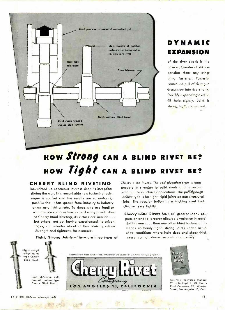
Rivet gun exerts powerful controlled pull
41, ---
Hole size
tolerance
Rivet shank expand- ing as stem enters
Stem breaks at notched
section after being pulled entirely into rivet
Stem trimmed
)07
Neat, uniform blind head
DYNAMIC EXPANSION of the rivet shank is the
answer. Greater shank ex-
pansion than any other
blind fastener. Powerful
controlled pull of rivet gun
draws stem into rivet shank,
forcibly expanding rivet to
fill hole tightly. Joint is
strong, tight, permanent.
HOW Strong CAN A BLIND RIVET BE?
HOW Tight CAN A BLIND RIVET BE?
CHERRY BLIND RIVETING has stirred up enormous interest since its inception during the war. This remarkable new fastening tech- nique is so fast and the results are so uniformly positive that it has spread from industry to industry at an astonishing rate. To those who are familiar with the basic characteristics and many possibilities of Cherry Blind Riveting, its virtues are implicit .. .
but others, not yet having experienced its advan- tages, still wonder about certain basic questions. Strength and tightness, for example.
Tight, Strong Joints - There are three types of
High -strength, self -plugging type Cherry Blind Rivet.
Tight -clinching, pull - through hollow type Cherry Blind Rivet.
Cherry Blind Rivets. The self -plugging type is com-
parable in strength to solid rivets and is recom-
mended for structural applications. The pull -through hollow type is for tight, rigid joints on non-structural
jobs. The regular hollow is a tacking rivet that clinches very tightly.
Cherry Blind Rivets have (a) greater shank ex-
pansion and (b) greater allowable variance in mate-
rial thickness ... than any other blind fastener. This
means uniformly tight, strong joints under actual shop conditions where hole sizes and sheet thick- nesses cannot always be controlled closely.
CHiPRY n ETS THEIR M'NUFACTURE 8AP5LICATION ARE COVERED BY U.S. PATENTS IHSurc 5 PESOIN6
Get this Illustrated Manual. Write to Dept. B-120, Cherry Rivet Company, 231 Winston Street, los Angeles 13, Calif.
ELECTRONICS-February, 1947 I6I

ELIO RECTIFIE R
ELECTRONgINCORPORATED 127 SUSSEX AVENIIF.
'NEWARK. N. J.
P.I.V. 725 PEAK AMPS. 4.0
TUBES AT WORK (continued)
uring device that does not require tuning.
Resistive Termination
Two difficulties arise in the ter- mination of a transmission line with a resistor; power dissipation in the resistor, and correct match- ing of the resistor to the transmis- sion line. The power dissipated in the resistor may be found from a measurement of temperature rise, voltage or current. Of the three, voltage measurement is the most convenient but the capacitive in- put of the voltmeter must then be compensated to obtain effective re- sistive termination of the transmis- sion line.
For the termination, one type of resistor is of particular interest, a i -watt carbon resistor having brass endcaps and contained in a ceramic case. The length- of the carbon mix between brass caps is 0.5 cm, the diameter 0.3 cm.
Assuming a resistor of 50 ohms with these dimensions, the resis-
FIG. 1-Circuit of vhf wattmeter
tance per cm cube is seven ohms and the skin depth is 0.6 cm. The skin effect may thus be neglected as we can expect substantially uni- form current distribution.
Knowing the current distribu- tion enables us to determine the inductive effect of the resistive rod, a.value of 0.001 microhenry or an inductive reactance of 2.5 ohms at 500 mc. Thus the terminating im- pedance gives a standing wave ratio of 1.05 on the transmission line. Sufficiently accurate power measurements may be made when the standing wave ratio is less than 1.1, a value rarely achieved even with the best antenna designs.
The 9005 diode having a resonant
162 February, 1947 - ELECTRONICS

CHOOSE YOUR HIGH -VACUUM GAUGE
FOR iTs...Ri4NGE
DPM-36 Ionization Gauge
Knudsen Gauge
Philips Gauge
Seven fine gauges for measuring high - vacuum pressures are shown on this page. They are all D.P.I. Gauges- all sensitive instruments designed to provide accurate readings. Their im- portant differences lie in their RANGE OF MAXIMUM SENSITIVITY. In the chart, the line below the name of each gauge indicates its full range. The RANGE OF MAXIMUM SENSITIV- ITY is indicated by the widest por- tions of that line.
-8 -7 -6 -5 -4 -3 -2 -1 0 1 2 10 10 10 10 10 10 10 10 10 10 10
I I
Ionization Gauge
Rodi,meter (Knudsen) Gauge
1
Philips Gauge
-8 -7 10 10 10 10
Medium Bulb Double Range Mcleod Gauge
Pirani Gauge - Compensated at zero
-6 k-5
Mcleod Gauge
Butyl Phthalate Manometer
Mercury Manometer
L -4 -3 -2 -1 0 1 2
10 10 10 10 10 10 10
Pirani Gauge
Butyl Phthalate
Manometer
Mercury Manometer
Let us help you choose the D.P.I. Gauge best suited to your spe- cific job. Write-
Vacuum Equipment Division
DISTILLATION- PRODUCTS, INC.
Rochester 13, New York

PAUL and BEEKMAN Division
CAN GIVE YOU
Paul and Beekman Division can relieve you of production headaches ... save you time in manufacturing electronic parts like those illus- trated. We specialize in the large -volume, low-cost production of electronic parts and assemblies. We make them economically be- cause we have just the plant and the machines necessary for the job. We make them to pre-
cise specifications because we have the skilled engineers and operators.
Let us show you how Paul and Beekman, by acting as your parts division, can help you make your product faster and better, at less cost. Write us about your needs. Our engi- neers are available to advise you impartially, with no obligation to you.
WHAT PAUL & BEEKMAN DIVISION MAKES
Condenser shells, coil shields, transformer housings, cans, chassis, complete or sub -assemblies, mounting clamps and mounting plates . . . STANDARD
or to specifications ... from Copper, Aluminum, Steel, Stainless Steel, Brass.
PAULn n d BEEKMAN Dint 1810 COURTLAND ST., PHILADELPHIA 40, PA.
PORTABLE PRODUCTS CORPORATION MANUFACTURERS OF: LAWN MOWERS ELECTRICAL APPLIANCES PRECISION STAMPINGS
INDUSTRIAL INSTRUMENTS RADIOS SAFETY EQUIPMENT
164 February, 1947 - ELECTRONICS

Are you in the know on GLOW?
THESE QUICK FACTS ON G -E NEON
GLOW LAMPS MAY HELP YOU
PRODUCE A MORE SUCCESSFUL PRODUCT
used? How are glow lamps us
Such QUESTION- as indicators. of
ANSWER-They're include re ideal
annunciators, control
panels, electrical appliances, pplia his. Glow lamps also
panels, warning
signals, pilot light illumination for
night lights, exit lights, dial lights, etc.
HIGH VOLTAGE
QUESTION-How does voltage affect -
glow lamp opPlication?
ANSWER-Glow lamps need a c -rh
use is not r minimum starttmended below 105
volts, but there is ecom no
upper voltage
provided. limit if resistors
QUESTION _Where can you get full intor-
G_E Neon Glow Lamps and their
oration °^ your product? Divi-
sion,
to Nela to Specialty Com-
pany,
-Write General Electric N Sion,1 Newark Street, Hoboken'
pang'
QUESTION-What UESTION-What is a neon glow
lamp? What makes it glow? ANSWER --It is the "baby" of the electrical discharge lamp family
of t win electrodes sealed within containing neon gas. bulb
t a gas
isa ionized
by applicationof c orange red glow covers the cathode,
3000 HRS.OLD AND STILL
PLENTY O'GL0w
QUESTION What are the nusin lamps from the product designers standpoint? of
glow ANSWER Paint? high visibilityD'stinctive orange red glow dable rated at
(b) 3000 performance and long life (c) Verhours.
1ï25.w I`ow current consum2tion-as little as (d) Low brightness, low (e) High resistance toheat. (f) Can be installed in small
shock and vibration,
Operate directl
m r y fro
space. 210-230 volt circuits, aegular lOq_125,
-c or d -c.
and
QUESTION-In what sizes are glow lamps made?
ANSWER-General Electric makes á complete line of neon glow lamps, 1n a wide variety of miniature bulb sizes, and in wattages from 3 watts to 1/25 watt, with both screw bases and bayonet bases.
GE LAMPS GENERAL ELECTRIC
ELECTRONICS - February, 1947
Nela Specialty Div. Lamp Dept., Z Newark St.,Hoboken, N. J.
I
165

WRITE FOR YOUR q COPY TODAY! ;
sRq'o I ...... "° . s
41";:
Akra-Ohm Resistors
Accurate Fixed Wire Wound
Types
This New Bulletin tells you what you
want to know about
ACCURATE FIXED WIRE WOUND RESISTORS
DIMENSIONAL SPECIFICATIONS MOUNT- ING AND TERMINAL DESIGNS POWER
DISSIPATION TEMPERATURE COEFFI- CIENT OF RESISTANCE MAXIMUM
RESISTANCE CHARTS RESISTANCE ALLOYS MOISTURE AND FUNGUS
PROOFING HERMETIC SEALING
Shalicross Types Designed to Meet JAN -R 93 Specifications
DEPT. E-27 COLLINGDALE, PA.
CTURING
TUBES AT WORK (continued)
frequency of 1,500 mc and a voltage rating of 117 volts maximum makes a peak diode voltmeter for the measurement of 'voltage across the resistor. For the moment we are concerned with the input capaci- tance of this diode and, allowing for socket and stray capacitance, a value of one µµf may be assumed. The mismatch due to this capacitive reactance may be neutralized by a corresponding inductive reactance.
The shunt capacitive reactance may be converted to an equivalent series reactance of three ohms at 200 me for which the equivalent in- ductance is 0.002 microhenry. Dif- ficulties in making a completely noninductive connection to the transmission line are now avoided as we may leave a short length of the inner conductor equivalent to this value for making the connec- tion to the resistor. With RG -8/U 50 -ohm concentric cable, having a 7/21 copper conductor, the length of conductor is approximately 0.5 cm from the end of the cable to the resistor.
With the relatively small values of correction used the slope of the inductive and capacitive reactance curves may be assumed to be con- stant so that the compensation will hold over a wide band of frequen-
50 CU. FT./MIN BLOWER
COPPER GROUND STRAP
CORRECTING `, INDUCTANCE.
COAXIAL CABLE
TRANS- MITTER
COPPER' ' BLOCK 50 -OHM RESISTOR
ETER
%FEED THROUGH
CAPACITORS
Mounting of components in wattmeter cies, certainly from 100 to 500 mc. The correction is made in approxi- mately the middle of this band.
Accuracy
With a high resistance load, one megohm, and a small r -f bypass ca- pacitor of 100 µµf, the meter read- ing will indicate peak voltage across the terminating resistor. Be- cause of electron transit time and internal diode resonance, the meter indication at 500 mc will be a few
166 February, 1947 - ELECTRONICS

PERMANENT MAGNETS MAY, DO IT BETTER!
Sectional View of Skyguide Aerial Navigator's Compass Courtesy G. M. GIANNINI Company
CHART YOUR COURSE WITH PERMANENT MAGNETS
THE Skyguide points the way through un- known reaches with pinpoint accuracy. As
a vital aid in the navigation of modern com- mercial airplanes, the Skyguide is typical of many such scientific instruments in use today, which rely upon the permanent magnet in their important function.
Actually millions of magnets serve us daily... in industry, transportation, and communication. Every time you call on the phone or turn on the radio, a permanent magnet goes to work for you, silently and unseen.
Although the magnet is one of man's oldest servants, it is as modern as radar, as facsimile
transmission or televisions. Our research engi- neers invite you to consult with them on the new uses of "packaged energy." Only by inves- tigation will you know how this independent source of power may do some job or process better in your industry.
Over 24,000 applications of "packaged ener- gy" have been made by The Indiana Steel Prod- ucts Company, the world's largest sole producer of permanent magnets. For information on methods, materials and comparative product energy curves, write for our free "Permanent Magnet Manual." Your request will receive our prompt attention.
Copyright 1947, The Indiana Steel Products Co.
* THE INDIANA STEEL PRODUCTS COMPANY * PRODUCERS OF "PACKAGED ENERGY"
6 NORTH MICHIGAN AVENUE CHICAGO 2, ILL.
SPECIALISTS IN PERMANENT MAGNETS SINCE 1910
VALPARAISO, INDIANA PLANTS
I STAMFORD, CONN. (CINAUDAGRAPH DIV.)
ELECTRONICS - February, 1947 167
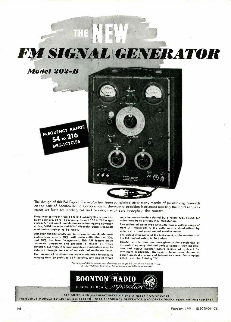
FM SIGNAL GENERATOR
The design of this FM Signal Generator has been completed after many months of painstaking research on the part of Boonton Radio Corporation to develop a precision instrument meeting the rigid require- ments set forth by leading FM and television engineers throughout the country.
Frequency coverage from 54 to 216 megacycles is provided by two ranges, 54 to 108 megacycles and 1108 to 216 mega- cycles. A front panel modulation meter having two deviation scales, 0-80 kilocycles and 0-240 kilocycles permits accurate modulation settings to be made. Although fundamentally an FM instrument, amplitude mod- ulation from zero to 50%, with meter calibrations at 30% and 50%, has been incorporated. This AM feature offers increased versatility and provides a means by which simultaneous frequency and amplitude modulation may be obtained through the use of an external audio oscillator. The internal AF oscillator has eight modulation frequencies ranging from 50 cycles to 15 kilocycles, any one of which
may be conveniently selected by a rotary type switch for either amplitude or frequency modulation. The calibrated piston type attenuator has a voltage range of from 0.1 microvolts to 0.2 volts and is standardized by means of a front panel output monitor meter. The output impedance of the instrument, at the terminals of the R.F. output cable, is 26.5 ohms. Careful consideration has been given to the positioning of the main frequency dial and various controls, with modula- tion and output monitor meters located at eyelevel for maximum readability. Dimensions have been chosen to permit greatest economy of laboratory space. For complete details write for Catalog "D".
The design of this instrument was described on pages 96-101 of the November of ELECTRONICS. Reprints of this article are available upon request.
ssue
BOONTO BOONTON N J U.S.A.
-RADIO
DESIGNERS AND MANUFACTURERS OF THE 0 METER OX CHECKER FREQUENCY MODULATED SIGNAL GENERATOR SEAT FREQUENCY GENERATOR AND OTHER DIRECT READING INSTRUMENTS
168 February, 1947 - ELECTRONICS

I 11
TYPE TS -56
Screw Type. For applications where wires must be attached
and detached quickly and conven-
iently at intervals. Supplied plain or marked to customers' specifica- tions. Also available with Knurled
Head screws.
Contacts-Brass, cadmium plated
Screws-Steel, cadmium plated
Plates -3/4s" XP Phenolic sheet
TYPE TS -58
Tie Point. Used throughout industry
for tying in a wide variety of com-
ponents. Available in any combi-
nation of terminals or brackets as
shown up to and including 14.
Holes are spaced a/s" apart with 3/16' between end holes and.
edge of board. Terminals available
with elongated hole for threading
or notched for wrap -around as-
sembly. Plates are of XP Phenolic
sheet.
40
PART 8382 BRASS A'.Pl.
.167 DIA
PART 8478 BRASS AP.
.140 DIA
tl kt eM
PART 8472 STEEL
HOT TIM
A
FIG. 1
.140 Dio Mtg. Holes
1!,
13j 64 3/32 Dio.
Wire Hole
A
B
6-32x3/8 Binding Heod Screw.
FIGU2E NO
CATALOG NO. BINDING KNURLED
HEAD SCREW HEAD SCREW
NO. OF TERMINALS
OVERALL LENGTH
'A'
MTG. HOLES CENTERS
'B
1 8513 8523 1 1 3/8 1
1 8514 8524 2 1 7/8 1 1/2
1 8515 8525 3 2 3/8 2
1 8516 8526 4 2 7/8 2 1/2
1 8517 8527 5 3 3/8 3
1 8518 8528 6 3 7/8 3 1/2
1 8519 8529 7 4 3/8 4
1 8520 8530 8 4 7/8 4 1/2
1 8521 8531 9 5 3/8 5
1 8522 8532 10 5 7/8 5 1/2
2 8706 8711 1 1 1/4 7/8 2 8710 .8712 2 1 11/16 1 5/16
2 8610 8713 3 2 1/8 1 3/4 2 8707 8714 4 2 9/16 2 3/16
2 8708 8715 5 3 2 5/8
41a .167 DIA
PART 8479 PART 8381 STEEL BRASS
1 TIN.. _ CAD PL..
PART 8473 STEEL
HOT TIN
1r16 XP PHENOLIC SHEET
.140 DIA
PART 5388 STEEL
HOT, TIN
HOLE APPROX.
1/16 X 7/32
PART 8480 STEEL
HOT TIN
18 West Chelten Avenue
Philadelphia 4,4, Pa.
nle
INCORPORATED
ELECTRO N I CS - February, 1947 169

Brush
Magnetic
Oscillographs
make direct -writing recordings of strains and pressures instantaneously!
Instantaneous, permanent, ink -on - paper recordings by Brush Oscil- lographs make their use almost unlimited. Accurate recordings of strains, pressures and count- less electrical phenomena can be made over a frequency range of D.C. to 100 c. p. s. Either A.C. or D.C. circuits can be measured. Whenever desired, recordings may be stopped for notations on chart -paper.
Brush Single -Channel Magnetic Oscillo -
graph with amplifier. Especially suited for strain -gauge applications, counting, surface analysis and similar applica- tions. Three -speed paper drive, S, 25, 125 mm per second. Chart paper 23/8' wide.
Brush Six -Channel Magnetic Oscillo - graph. Excellent for strain -gauge record- ings. Dust -proof case. Interchangeable gear paper drive. Your choice of paper speeds from 1/8" to 5" per second. Chart paper 12" wide. Compact design.
The remarkable new Brush Mag- netic Recording Pen Motor -heart of the Brush Direct -Inking Oscillo - graph. Highly stable. May be used under virtually any climatic or temperature conditions. Exceptional accuracy.
Brush Oscillographs are compact, portable and ruggedly constructed for ease of handling and opera- tion. Investigate them now. Brush engineers will gladly co-operate in determining their application to your problems. Write for tech- nical information for complete details of this equipment. Special bulletins are available on strain - gauge use.
Brush Double -Channel Magnetic Oscillo - graph for use where two simultaneous recordings are desired -as in synchroniz- ing problems. Three -speed paper drive, 5, 25, 125 mm per second. Chart paper 315E;.," wide. Rugged construction.
The Brush
Development Co. 3415 PERKINS AVENUE
Cleveland 14, Ohio
Canadian Representatives: A. C. Wickman, (Canada) Ltd.,
P. O. Box 9,
Station N, Toronto 14
TUBES AT WORK (continued]
percent low with correspondingly less error at lower frequencies. This error has been described as the premature cutoff error and is dependent on the characteristics and geometry of the tube.
Diode resonance is caused by the series inductance of the tube leads resonating with the plate -to -cath- ode capacitance. Resonance checks are best made by a variable -fre- quency signal generator as un- avoidable external lead inductance will lower the resonant frequency of the diode. Resonance with the 9005 may thus occur at 1,000 mc. At 500 mc, the meter indication may be 30 percent high, at 100 mc the error will be one percent. A calibration chart may be made cov- ering the band.
Construction Details To aid heat dissipation in the
resistor, the diode assembly may be placed on a copper plate to which the resistor is soldered using an ample supply of metal. This ensures good thermal and radio conductiv- ity. With an air blower supplying 50 cu ft/min to the copper plate, the resistor may be operated at ten or twenty times its normal rat- ing in free air or much higher for short periods.
Figure 1 shows the wiring ar- rangement of the diode power head. Use of a battery for heater power
FIG. 2-Method of reducing the effective inductance of a carbon resistor
avoids long a -c supply leads. The meter may be any high -resistance d -c voltmeter, preferably with a multiplier switch. For peak pulse power measurements the voltmeter may be replaced by a calibrated os- cilloscope.
If large resistors introduce error because of excessive inductive re- actance, the resistor may be sunk in a hole in the copper as shown in Fig. 2 to provide reversal of cur- rent in the restricted area.
170 February, 1947-ELECTRONICS

ARE YOU BUYING LARGER RESISTORS
THAN YOU ACTUALLY NEED? MOUNT
The job called for an actual rating of 4.7 watts on a wire -
'wound resistor to be used in an enclosed space. As usual, the
manufacturer planned to use a conventional 10 -watt coated
resistor-until a Sprague field engineer proved beyond doubt.
that a 5 -watt Koolohm would do the trick with ample safety
margin. This instance is typical of savings made possible by
Koolohms. Wound with ceramic insulated wire, they dissipate
heat faster, they're easier to mount-and can safely be used at
full wattage ratings. Write for Catalog 10EA.
Sprague Electric Co., Resistor Division, North Adams, Mass.
SPRAGUE
irmJ 1. Trademark Reg. U. S. Pat. Off.
THEM ANY WAY - ANYWHERE
Style A
St 1.
10,000 VOLTS
BREAKDOWN INSULATION
Front ceramic outer shell to
ground
S C
Style
Style `C.
Ch
WIRE WOUND RESISTORS - ELECTRON ICS - February, 1947 171

3S mm. AVIMO Continuous Film Recording Cornera (cover removed).
Oscillograph traces on 70 mm. paper.
RECORDING
TRANSIENT PHENOMENA
The behaviour of moving parts under actual work- ing conditions may be studied by means of standard commercial oscillographs, which translate mechanical or electrical variations into evanescent traces on a fluorescent screen. Avimo cameras record these traces on contin- uous film or ,paper, so that they may be subse- quently checked, ex- amined, and measured Write for Publication C3, giving full details of AVIMO Cameras includ- ing types with built-in cathode ray tubes.
°Vf1 I
CP AVI MO Ltd., TAUNTON
Eng. Tel. 3634
Designers and Manufacturers of 9016E Scientific Cameras
ZOPHARds and Emulsions
Waxes, Comp
Materials for potting, dipping or impreg- nating all types of radio components or all kinds of electrical units. Tropicalized fungus proofing waxes. Waterproofing finishes for wire jackets. Rubber finishes.
Inquiries and problems invited by our en-
gineering and development laboratories.
ZophOr Mills, Inc. has been known for its dependable service and uniform of product. since 1846.
ZOPHAR MILLS, Inc. ESTABLISHED 1846
117 26th STREET, BROOKLYN, 32 N. Y.
ELECTRIC SOLDERING IRONS are sturdily built for the hard usage of industrial service. Have plug type tips and are constructed on the unit system with each vital part, such as heating ele- ment, easily removable and replaceable. In 5 sizes, from 50 watts to 550 watts.
TEMPERATURE REGULATING STAND
This is a thermostatically controlled de- vice for the regulation of the tempera- ture of an electric soldering iron. When placed on and connected to this stand, iron may be maintained at working tem- perature or through adjustment on bottom of stand at low or warm temperatures.
For descriptive literature write
AMERICAN ELECTRICAL
HEATER COMPANY DETROIT 2, MICH., U.S. A.
172 February, 1947 - ELECTRONICS
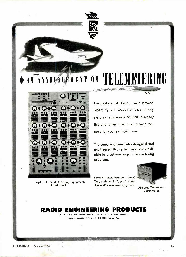
et.
NT " TELE1IETEIG s ., albo
'
A ,
O'= O'§.O ,
a a a elf
04 Olt MO a a
Pai OA! O1'O ala al
O+0 i0 Ma a a .O108-0.
ta !in ..M.
a a a *+woüt
0 -re -08,0 a a saaMa O i,,. +, . 11111111110101 r
Corn plete Ground Receiving Equipment, Front Panel
Pilotless
The makers of famous war proved
NDRC Type II Model A telemetering
system are now in a position to supply
this and other tried and proven sys-
tems for your particular use.
The same engineers who designed and
engineered this system are now avail-
able to assist you on your telemetering
problems.
Licensed manufacturers NDRC Type I Model B, Type II Model A, and other felemetering systems.
Airborne Transmitter Commutator
RADIO ENGINEERING PRODUCTS A DIVISION OF RAYMOND ROSEN & CO., INCORPORATED
32ND & WALNUT STS., PHILADELPHIA 4, PA.
ELECTRONICS - February, 1947 173

T E H T A T ..;. ' -., I N
,-- S R
. ; - ; ;; .: °- ,. . : . . = . . . : ;: : : : MANVFAeTV .° RER§
' e e -ee! .! e . ; "Specials" have always been a Conant specialty Conant designs and laboratory production methods permit the production of special rectifier assemblies at regular prices. If your specifications are on file at Conant, you can be sure of receiving rectifiers which will fit the job. Your specifications must contain the following information.
1 The maximum range of forward at a definite value of current.
2 The maximum inverse current per disc.
3 The ambient temperature at which above values are to be measured.
4 A definite statement of the method used
to make the above measurements and a schematic of your test circuit.
The above can then be interpreted to fit Conant test methods.
resistance
,1;167trrnre>l7 ,WeG70é24
6500 0 STREET, LINCOLN 5, NEBRASKA, U. S. A.
20 Vesey St., New York 7, New York 518 City Bank Bldg., Kansas City 8, Mo. 1526 Ivy St., Denver, Colo. 85 E. Gay St., Columbus, Ohio 1 212 Camp St., Dallas 2, Texas 4214 Country Club Dr., long Beach 7, Col, 600 S. Michigan Ave., Chicago 5,111. 378 Boulevard N. E., Atlanta, Go. Export Div.,75 West St.,New York 6,N,Y. 1215 Harmon Pl., Minneapolis 3, Minn. 4018 Greer Ave., St. Louis. Mo. 50 Yarmouth Rd., Toronto. Cenado
INDUSTRIAL CONTROL (continued from p 140)
ing the rate at which chloropicrin gas penetrated a tube filled with charcoal adsorbent. Note the com- plete removal of the gas up to the time when the "break" occurred, when chloropicrin began to pass through the charcoal in significant quantities.
Figure 4 illustrates a continuous record of phosgene concentrations obtained on the desert in Utah on the occasion of the bursting of a 1,000 -lb bomb charged with phos- gene. Note the amazingly rapid fluctuations in concentration which the ultraviolet photometer was able to resolve.
The dashed line demonstrates the
203 31 -f % VERY STRONG
OF WIND GUST
k- N K m
143
rile% 11111111LAIII-
0 , ._ 2 3 4 5 6 7
11z
,:23 te,, elm"'
FIG. 4-Automatic record of phosgene con centration obtained downwind from the burst point of a 1000 -lb, bomb charged with phosgene. The dashed line shows the response of a conductivity gas analyzer
response of a conductivity gas ana- lyzer, an analyzer which measured the phosgene concentration by measuring the electrical conduc- tance of water in which the phos- gene was continuously dissolved. This method missed most of the de- tails of the phosgene concentration fluctuations.
The two examples cited are typi- cal applications to practical prob- lems. Other analogous possibilities readily suggest themselves. In the design of large-scale reactors in chemical -engineering processes, in- formation on smaller models is gen- erally required. For example, in evaluating the performance of ad- sorbent beds in solvent recovery or
174 February, 1947 - ELECTRONICS

The Rauland VISITRON 1OFP4/R6025
...the NEW Picture Tube with Unprecedented Brilliance
r aIu-ete
Specifications of the Rauland Visitron i0FP4/R6025
Heater Voltage 6.3 A.C. or D.C.
Focusing Method Electromagnetic
Deflection Electromagnetic
Deflection Angle 50 Degrees
Screen Phosphor P4 Aluminized Reflector
Bulb Diameter (Max.) 10s/a" at screen end
Length 175/8' t 3/s"
Base Small Shell Duodecal 7 Pin
Anode Terminal Cavity
Anode Volts (Max.) 13,040
Anode Volts (Operating) 9,000
External Coating (Optional): 500 rnmf.
RADIO RADAR SOUND
NEW! ALUMINIZED
REFLECTOR -SCREEN Doubles
the Brilliance Highlight: 7S foot lamberts
(av9e ) Contrast Range.
Ov No /on spot./4 er 100 to 1
Cathode Clow
140
'1130
5120
110
8100
190 an
2 80 i i 70
á 60
W 50
t,1140
30
20
ID
c
COMPARISON BRILLIANCY CURVES Aluminraed Reflector Screen
vs Un-alumtnlxed Screen
Et=63 volts Anode voltage -9000 Grid No 2.250 olrs Roster sexe 6e8(focused)
No I GRID DRIVE
WRITE FOR INTERESTING BULLETIN
foulaz,'. COMMUNICATIONS TELEVISION
Electroneering is our business THE RAULAND CORPORATION CHICAGO 41, ILLINOIS
ELECTRONICS - February, 1947 175

Photo courtesy of EMERSON Radio & Phonograph Corp.
WHY ARE CORWICO WIRE PRODUCTS SPECIFIED
BY THIS LARGE RADIO MANUFACTURER?
Because their ENGINEERING Department values their faith- ful performance of the requirements of insulation resist- ance and voltage breakdown .. .
Because their PRODUCTION Department finds that they possess the essential qualities which permit easy pushback or mechanical stripping .. .
Because their PURCHASING Department finds that these quality products, backed by dependable service, are sold at prices that spell true economy .. .
CORNISH WIRE CO.,
15 Park Row New York City, 1
INDUSTRIAL CONTROL (continued)
toxic -gas protection, the ultraviolet photometer is particularly conveni- ent when substances such as ace- tone, butadiene, benzene or phos- gene, with ultraviolet -absorbing properties, are under study. Simi- larly, it is frequently necessary to have a constant check on the concen- tration in air of volatile materials in various industrial processes, and for this purpose the automatic - recording apparatus is especially suitable.
In addition the ultraviolet pho- tometer has proved convenient in investigations of a number of fun- damental scientific problems. It has been used, for example, in a study of the rate of conversion of NO into NO,. Similarly it is now being applied to an investigation of the kinetics of the decomposition of hydrogen peroxide. In general it is applicable to any problem requiring the analysis of a substance which absorbs ultraviolet radiation.
Electronic Drive for Printing Presses THE Philadelphia Inquirer is the first newspaper to install a new type of electronic drive for increased flexibility, minimum speed variation with load, and maximum efficiency over a wide range of operating speeds. It will be applied to 61 rotogravure and 44 newspaper press units at the new plant of the news- paper.
The drive system operates di- rectly from a 440 -volt plant circuit and consists of a sealed -ignitron tube panel and a magnetic control panel, motor selector switches, and the necessary d -c drive motors. Ex- cept for the drive motors, the equip- ment is completely static. This con- tributes to compactness, eliminates the necessity of special founda- tional and structural supports, and facilitates incorporation with mod- ern load -center power distribution equipment.
With this new General Electric drive, especially adapted for use with high-speed rotary web presses, adjustable voltage is supplied to ad- justable -speed d -c drive motors which may be mounted coaxially with the main shaft of the press. Stepless speed control-including jogging, ; slow threading speed,
176 February, 1947 - ELECTRONICS

One good way to raise the eyebrows of progressive engineers is to have other leaders in the industry utilize your product. A singular piece of equipment like the Altec Lansing Intermodulation Analyzer can't be bought on the basis of glib recommendation. You should be convinced of its magnitude by application to your own problem ... or by studying the names of the organizations where it is now in use.
Originally developed for film studios, the Altec Lansing Intermodulation Analyzer is rapidly being adopted by broad- casting and recording studios as well as sound research laboratories.
' It supplements present methods of checking audio -distortion where quick and frequent intermodulation checks are necessary to maintain low distortion in high quality systems.
SEE THE ALTEC LANSING INTERMOD- ULATION ANALYZER AT THE I. R. E.
SHOW.
0K EEP ADVANCING WITH
1161 N. Vine St., Hollywood 38, Calif.
250 W. 57th St., N. Y. 19, N. Y.
ALTEC LANSING"
ELECTRONICS - February, 1947 177

A MILLION MILES OF STRAIGHTENED VOLTAGES
¡Ø4,g' //bee of Atoc4 Sorensen Voltage Regulators guarantee many miles of speed with safety by constantly and automatically stabilizing volt- ages that operate vital communications equipment on surface and air transportation lines.
Wire and radio contact systems depend upon quick, accurate response to even the smallest variation to attain peak per- formance. No moving parts in a voltage regulator means no time consuming adjustments, no wear and a minimum of maintenance.
These are just a few lators are chosen as millions of miles of transportation.
reasons why Sorensen Voltage Regu- the perfect power guardian for the communications so essential to safe
Investigate the many advantages of Sorensen regu- lators applied to your unit. Write today for your topy of the new, complete Sorensen catalog M -L. It is filled with schematic drawings, performance curves, pho- tos and contains in detail, "Principles of Operation."
SOREnSEn & [omPpn1i, In[. ST{iR1FOR0, [01111EETIEUT
INDUSTRIAL CONTROL (continued)
acceleration, deceleration, and dy- namic braking-is provided without the necessity of speed -regulating resistors or auxiliary starting mo- tors. The drive is operated by con- ventional push-button stations, including an emergency control sta- tion and an automatic safety signal system.
Simple Foolproof Production Tester
by MARTIN F. BEAVERS General Electric Company PittsJteld, Massachusetts
ENGINEERS who have qualms about having sensitive equipment used by nontechnical workers doing pro- duction -line testing can substitute the device to be described in a dozen applications where use of ex- tremely accurate and expensive in- struments is not warranted.
The voltmeter covers a range from approximately 50 to 500 volts, a -c or d -c, and employs only a 500,- 000 ohm potentiometer and a small neon lamp. Instead of using the brilliance of the neon lamp as an indication of the voltage, the volt- age is read from a scale on the in- strument. Figure 1 shows the volt- meter circuit but because of its simplicity, no detailed construc- tion information is deemed neces- sary.
Operation is based on the inher- ent characteristic of a neon glow lamp that a certain voltage is necessary to make it glow. In most neon lamps, this ignition voltage may vary slightly from one applica -
A
a
I
:
VOLTAGE TO BE
MEASURED
LINEAR TAPER
RI
500,000
FIG. 1.-A potentiometer having a linear change of resistance versus rotation and a neon lamp form the foolproof voltmeter
A LINE OF STANDARD REGULATORS FOR LOAD RANGES UP TO 30 KVA.
SPECIAL UNITS DESIGNED TO FIT YOUR UNUSUAL APPLICATIONS. February, 1947, ELECTRONICS

MITCHELL -RAND in its im-
provement of Varnished
Tubings, took as its starting
point the specifications es-
tablished by the Varnished
Tubing Association and the
Society for Testing Mate-
rials ... and today produ-
ces Varnished Tubings that
meet or exceed the known
specifications for Dielec-
tric, Tensile Strength, Flex-
ibility, Non -Fraying. High
Gloss, Non-Hydroscopic Re-
sistance to High Tempera-
tures. Oils. Fats, Acids, etc.
Write today for your free copy of the M -R WALL CHART with its engineering tables, electrical symbols, carrying capacities of con- ductors, dielectric averages, thicknesses of in- sukating materials, tubing sizes, tap drills, etc.
58 88885
au TE
. L FIBER COTTON YARN I / r s
meet, e%eeed SPECIFICATIONS
sd4 VARNISHED TUBING ASSOCIATION Gelid AMERICAN SOCIETY FOR TESTING MATERIALS
M -R FIBERGLAS (INORGANIC) VARNISHED TUBINGS are made in four grades: Standard; Double Saturated; Triple Strength and Impregnated.
STANDARDRADE for maximum flexibility, has little varnish and is recom- mended for high temperatures where dielectric strength is not a factor. DOUBLE SATURATED has all qualities of the Standard Grade but with addi- tional coats of varnish to bring the dielectric rating up to 1500 volts. TRIPLE STRENGTH is built up with coats of especially flexible insulation varnish for dielectric ratings up to 2500 volts and is particularly suited where assembly operations include the possibility of rough handling.
IMPREGNATED is the Optimum in Superiority for high gloss, non-hydroscopic, resistance to high temperatures, oils, acids, etc. IMPREGNATED has a dielec- tric rating beyond 7000 volts and is unequalled for Long Life Under Most Severe Conditions. Write For Samples.
FOR USERS OF COTTON YARN VARNISHED
TUBINGS The Mitchell -Rand MIRAC and HYGRADE Varnished Tubings of long staple fiber yarn are comparable to Fiberglas Tubings in dielectric rat- ings, tensile strength, flexibility and long life. Write For Samples.
MITC L'L RAND 'INSULATIO COMPANY, INC. S1 MURRAY STREET COrtlandt 7-9264 NEW YORK 7, N.Y.
Fiberglas Varnished Tape and Cloth Insulating Papers and Twines Coble Filling and Pothead Compounds Friction Tape and Splice Transformer Compounds
A PARTIAL LIST OF M -R PRODUCTS Fiberglas Saturated Sleeving, Varnished Tubing .Asbestos Sleeving and Tape varnished Cambric Cloth and Tape Mica Plate, Tape, Paper, Cloth, Tubing
Fiberglas Braided Sleeving Cotton Tapes, Webbings and Sleevings Impregnated Varnish Tubing Insulating Varnishes of all types Extruded Plastic Tubing
ELECTRONICS - February, 1947 179

10'/2 x53/8 x10'/2..
Weighs only 191/2 lbs.
CML MODEL 1210
PORTABLE STROBOSCOPE This newly developed stroboscope employs a novel circular ar-
rangement, using a self -blocking oscillator. Rotary or vibratory
motion can be "stopped" when the moving object is examined
with stroboscopic light source. The speed covered is from 600 to
48,000 RPM (10-800 CPS), in 4 ranges. A synchronized reed is
provided for accurate calibration against the line frequency.
A valuable aid in industry for the slow-motion study of rotating, reciprocating, or vibratory mechanisms, CML 1210 is also useful for studying mechanical stresses and strains under dynamic conditions.
The light source is contained in a probe attached to a 4 -foot flexible cable. This unusual feature makes CML 1210 especially useful when using the Stroboscopic light in small out-of-the-way places. The light probe and cable are housed in the cabinet when the Stroboscope is not in use. The handle of the probe is then used to carry the instrument.
Inquiries Invited. Descriptive Bulletin Available
COMMUNICATION MEASUREMENTS LABORATORY 120 GREENWICH STREET, NEW YORK 6, N. Y.
Sales Offices: CHICAGO; 612 N. Michigan Ave-WASHINGTON: 924 19th St., N.W.
PHILADELPHIA: Van Dam Building, 10th and Market Sts.
INDUSTRIAL CONTROL (continued)
tion of voltage to another. How- ever, for practical purposes, this variation is relatively small and readings are obtainable within three percent accuracy. Another characteristic of the neon lamp is that once it is ignited, the voltage will have to be lowered somewhat below the'tgnition voltage in order to extinguish the lamp. Due to the fact that each individual neon lamp may have a slightly different igni- tion voltage, no definite value can be given; however, ignition volt- ages of the order of 50 volts a -c or 70 volts d -c may be expected from lamps such as the GE, NE -51, neon glow lamp (resistorless).
When d -c voltage is applied, only one of the two electrodes will glow -the one which is connected to the negative side of the source; thus, polarity may be determined by not- ing which of the electrodes glows. However, when connected to an a -c source, both electrodes glow.
There may be a slight difference in ignition voltage depending upon which electrode is connected to the negative side of a d -c source. The electrode which has the lowest igni- tion voltage is preferable, and the meter should be marked with po- larity indications; otherwise the calibration may not be correct if the polarity is reversed on d -c meas- urements.
Other types of neon lamp may be used in this voltmeter circuit. Ex- perimentation with a lamp will en- able one to quickly ascertain its particular characteristics. In gen- eral, a small wattage lamp is more satisfactory than a large wattage lamp. If the lamp has a protective resistor built into the base, the 0.2
FIG. 2-Improved readability and two ranges are provided by this circuit
180 February, 1947 - ELECTRONICS

't ,`3 L\ l"" l l
°
Rr
oß DESiGNM
A0 VG
cT°T slT°Nf
R
G' A°r°MTI,
eK l'<
coree loAgR, ,;L
'f ,.": -,
YOU GET QUALITY PLUS ENGINEERING SERVICE WITH G -E PERMANENT MAGNETS
7rK' j vk
t '. M._
.\ '. .' \`i, \ . ̀ ,
\- THE MAGNET THAT BREWS YOUR COFFEE
l¡.,- ì
,r\ ìY:c-.
'1 i t 1 z!i 1 r'
r i ;.~' ' '' _r' ì r., - lrï'
' \ \ -k' k `.Ç`l,tx \ ; -i" - ..
G.E.'s precise quality control methods used throughout magnet production, plus accurate testing and rigid inspection assure you of receiving magnets of the highest uniform quality for your application.
Greater flexibility of magnet design is possible with the many G -E permanent magnet materials now available. The large group of sintered and cast ALNICO alloys has been augmented by the lightweight, non-metallic mixture, VECTOLITE, and by the ductile permanent magnets, CUNICO, CUNIFE and SILMANAL. From such a wide choice of materials, you may now find a magnet better suited for your application or a material which will make possible new designs heretofore impractical or impossible.
General Electric engineers, backed by research and application experience, have acquired years of "know-how" in selecting the best permanent magnet material and properly designing magnets for thousands of products. These engi- neers are at your service.
For detailed information about G -E permanent mag- net materials, fill out and return the coupon to Metallurgy Division, Chemical Dept., General Electric Co,, Pittsfield, Mass.
PERMANENT MAGNETS
GENERAL ELECTRCD47IC -JA2
t.
The heart of the G -E Automatic Coffee Maker is a tiny but powerful sintered ALNICO 2 magnet. At precisely the right moment, it shuts off the current and the coffee is ready! Press- ing the button raises the magnet to the position shown, where it is held by attraction through glass to the nickel disc at the bottom of the siphon tube. When enough pressure is developed, boiling water surges up the tube, pulling the disc assembly with it. Its top magnetic support gone, the ALNICO magnet drops and opens the contact switch.
ELIMINATE YOUR MAGNET SUB -ASSEMBLY PROBLEMS
Consult General Electric for the design and manufacture of carefully calibrated permanent magnet sub -assemblies, ready for your final product. G -E magnet sub- assemblies will benefit you in the follow- ing ways:
Eliminate your assembly line rejects. Eliminate calibration problems in your factory. Eliminate cost of production and testing equipment. Eliminate breaking and chipping losses on brittle magnetic materials. Eliminate expense of shipping special trays for semi -finished magnets. We shall be glad to send you addition-
al information about G -E permanent magnet sub -assemblies upon request.
METALLURGY DIVISION CHEMICAL DEPARTMENT GENERAL ELECTRIC COMPANY PITTSFIELD, MASS.
Please send me your bulletin, GES -3337A, "Per- manent Magnet Materials."
NAME
TITLE
COMPANY
ADDRESS
CITY STATE
ELECTRONICS - February, 1947 181

" SQUARE x 116 " HIGH
Vor A SCALE DRAWING...
IT'S FULL SIZE! Though small in size, this I.F. Transformer by Wright & Weaire gives the perfect performance and is ideal when layout space is limited as in 'personal' receivers, " Walkie - Talkie", and similar equipment. It packs complete reliability into its small compass --13" square by 11" high. Constructed of the finest materials, allied to up-to-the-minute production technique, it will pass all tests. Write to -day for full details . . . they're interesting. Prompt deliveries san be guaranteed.
SPECIFICATION Primarily designed for use with valves of the
I.R5, I.T4 and I.S5 Series. High gain and selec-
tivity with stability are obtainable. Permeability tuning is employed with enclosed type cores
and the necessary fixed condensers ' built in'. Coils are impregnated and can be used with
confidence in the tropics. Available in the
following preferred frequencies with various
degrees of coupling :-460 Kc/s, 1.6 Mc/s, 2.1
Mc/s, 4.86 Me/s. The response curve shown
is for Type M400 and is typical of the whole
series. Nominal frequency is 460 Kc/s but is adjustable from 420 to 530 Kc/s approx.
WEAR ITE
MINIATURE I.F. TRANSFORMERS WRIGHT 8 WEAIRE LTD., 740, HIGH ROAD, TOTTENHAM, LONDON, N.17, ENGLAND. CABLES: WRITEWEA, LONDON
FACTORY, SIMONSIDE WORKS SOUTH SHIELDS CO. DURHAM - ENGLAND
*Th,+ Trade Mark is well-known in Britain as that of a Company who are responsible for the Design, Development and Manufacture of Transformer,. Vibrators, Switches and Coils. This particular component of real miniature dimensions, yet maintaining highest efficiency, is the latest development of their Engineering Dept. and is backed
by 26 years experience in the manufacture of Radio and Electronic components.
INDUSTRIAL CONTROL (continued)
megohm resistor shown in Fig. 1 may be omitted.
Principle of Operation
As the slide of the potentiometer is moved from terminal B toward terminal A, the voltage across the lamp increases until a point is reached when the lamp bursts into a glow. Suppose that this point is reached when the slide is just one - quarter of the way from terminal B. Then, due to the voltage divider action of R,, the applied voltage across A and B must be four times that required to ignite the neon lamp. After the lamp has ignited, the divider ratio is upset due to the shunting action of the lamp, but the correct position of the slide is obtained just before the upset- ting takes place.
The ohmic value of the potenti- ometer is not critical. Any value from 100,000 ohms to five megohms should give satisfactory results. The value shown in Fig. 1 was chosen since it provides a meter resistance of 1,000 ohms per volt at the maximum voltage of 500 volts to be measured.
An alternative circuit is shown in Fig. 2. This has the advantage of employing the full use of the potentiometer for voltage indica- tion and also spreads out the read- ings, especially in the higher volt- age part of the scale. If the igni- tion voltage of the laïnp is 70 volts d -c, the voltage range, when ap- plied across terminals A and B, is 70 to 210 volts; if voltage is applied across terminals 2A and B, the range is 210 to 630 volts d -c. Other combinations of divider ratio and resistances may be employed.
Calibration
This type of voltmeter is a peak - reading instrument and, if the cali- bration is made with d -c, an a -c scale can be drawn alongside the d -c scale using values equal to 0.707 times the d -c scale values. It is desirable to calibrate with both a -c and d -c if practicable, since a little time lag is inherent in these lamps on alternating current which may produce a small error in the calculated a -c scale.
Having a variable source of known voltages connected across terminals A and B, and the knob of
182 February, 1947 - ELECTRONICS

EO
r E .. ..-`i
cordial. 'd our
really is s booth
invitation anis rn Mech
at the Electronic a friendly
Wel-
top d With engineer rewarded who engin
Will Ce - Meet
men W
perfected Mica
come this both
MYkrO Se
Ce -
display, in
ramie insulation
on See the
d molded form
have the machined
an We may
moldings. the
est m our particularly
t° o4 your in
h insulation problems.
,lou9 d say
hello
anyway an
MYKROY IS SUPP_IED IN SHEETS AND RODS . . MACHINED OR MOLDED TO SPECIFICATIONS
MADE EXCWSI1rELY BY
[ECTR°Nlc E% 70 CLIFTON BOULEVARD CLIFTON, NEW JISE"" Chicago 47: 1917 NO. SPRINGFIELD AVENUE ..TEI t,lb.ny 431f
Export Office: 89 Broad Street, New York 4, N. !.
ELECTRONICS- Februcr., 1947
I -T------ -

Have you a radi- ation measuring problem? Our staff of radiation physicists offers you competent technical infer - motion.
Model 311- Geiger - Mueller Tube. Our back- ground in fine tube production offers close re- producibility of tube character istics.
Hi-megohm re- sistors of stabil- ity and accuracy for the difficult applications. Vacuum sealed in glass with spe- cial surface treat- ment. Values 100 to 10,000,000 megohms.
Summarizing a few recent developments culminating our twenty-year background in the factual "know how" of instrumen-
tation used in radiation physics.
Model 338 Electronometer. An electronic instrument which re- places electrostatic electrometers. Input resistance 10" Ohms.
This advertisement merely serves
to introduce these new instru- ments and tubes to you. For com- plete information, prices and deliveries write us and you will receive a prompt reply.
ee THE VICTOREEN INSTRUMENT CO.
5806 HOUGH AVENUE CLEVELAND 3, OHIO,'
Model 337 Geiger - Mueller Counter Scale of 64. Offers a high degree of stabil- ity and perman- ence with a pre- amplifier and special voltage regulation added features.
Model 348 Voltage regulator unit. A bank of seven subminia- ture voltage reg- ulator tubes arranged in one unit for precision voltage reeve lotion.
Subminiature electrometer vac- uum tubes (actual size) offer an ex- panding concep- tion of circuit development - Available as
Diodes Triodes Tetrodes Pentodes
INDUSTRIAL CONTROL (continued)
the potentiometer turned to one extreme position so that the move- able contact is at terminal A, the applied voltage is raised until the neon lamp glows. This is the mini- mum voltage which can be meas- ured. The applied voltage is raised in uniform steps, and at each volt- age step, the potentiometer knob is turned sufficiently to extinguish the lamp, then turned back until the lamp glows. This position of the knob pointer is marked on a scale.
Electronic Ignition System AN ELECTRONIC ignition system for aircraft was produced experimen- tally at the end of the war by the Bosch firm in Reichenbach, Ger- many, according to report PB - 22653, Office of Technical Services, Department of Commerce. The system is said to eliminate many of the deficiencies of conventional magneto systems.
In the circuit a capacitor is charged through a resistance, and.
discharged through a grid -con- trolled tube to the primary of the high tension coil at the spark plug. After completion of the discharge, the grid voltage prevents further passage of current between the anode and the cathode of the tube, thus enabling the capacitor charge to be built up again.
ELECTRONIC LATHE
Control box and head of 10 -inch lathe using electronic control of spindle speed and made by Monarch Machine Tool Com-
pany of Sidney, Ohio
I 84 February, 1947 - ELECTRONICS

FEDERAUS i/nEc/in> HIGH -FREQUENCY
COAXIAL CABLES offer you
K-12 ... the most popular cable
for FM and AM an- tenna transmission lines.
INTELIN COAXIAL CABLES are especially de- signed for high -frequency transmission line service - the vital link between transmitter and antenna.
Their unusually low attenuation losses, ob- tained by careful selection of dielectrics, con- ductor spacings, and rigid quality control, assure the most efficient transfer of energy with minimum radiation. They are extra flex-
ible, too - can be bent without cracking at
1. LOW LOSSES
2. FLEXIBILITY
3. DURABILITY
pper Conductor - solid or stranded.
Polyethylene Dielectric between central con- ductor and outer braid.
Copper Braid, closely woven over dielectric sheath.
Outer Jacket of Federal's IN -102, a plastic- ized vinyl resin, extremely durable with re- markable abrasive resistance, and highly resistant to most acids and alkalis, smoky atmospheres, oils and greases.
temperatures as low as minus 30°C. Whatever your operating conditions, you'll find that the extra durability of Intelin cables - their out- standing resistance to abrasion, weathering and corrosion - means long uninterrupted service.
Federal's complete line of many sizes and types of coaxial cables enables you to select the right transmission line for practically every field of application. Write today for Bulletin D514 giving complete data and specifications.
PARTIAL LIST OF FEDERAL CABLES COVERING POLICE. BROADCAST AND AMATEUR BAND
High -Frequency Coaxial Cable Data Type
Number Characteristic
Impedance tpeda
ce Capacitance
Phmsier t Ft
Attenuation Db. Per 100 Ft.
Power Rating Kilowatts Physical Dimensions
Frequency In Me acycles , frequency in Me1acycles Conductor Dla. 0.D. Oyer Jacked
K12 52 29
1.0 1.7 30 100 300 1.0 1.7 30 100 300 Solid CDDer
.885". .066 .086 .425 .83 l.70, 39 30 8.50 3.0 1.5 .188" K13 '52 29 .058 .076 .320 .69 1.451 51 43.8 13.5 5.4 2.3 ..250" 1_.L7.5"
' K14 71 21 .070 .092 .460 .93 1.90 i 36.5 I 27.8 5.55 2.71 1.34 .114' .885" Stranded Copper
i 1(45 52 29 .155 .202 .900 2.1 4.20 13 9.9 2.4 .96 .480 .086" .4t5" K49 '75 _ 20 .182 .237 1.03 2.1 3.80E 9.1 6.9 2.1 .79 .435 .048" .415"
In Canada: -federal Electric Manufacturing Company, Ltd., Montreal £spore Distributor--I.rrer.,o'ioeai Sronderd Etocr, c Cwpwarion
's^ Reg. U. S. Pat. OH.
Newark New Jars
ELECTRONICS -February, 1947 185

e(ecaletec POWER SUPPLIES
PZieeidedet
* 1gCCeel3!{Cf
* re4O4.o1ZCic1C2 SPECIFICATIONS
INPUT -115 v. 50-60 cycle REGULATION-Less than 1/20 volt change in output voltage with change of from
105-140 V.A.C. input voltage & from NO-LOAD to FULL -LOAD (over very wide latitude at center of variable range) RIPPLE-Less than 5 millivolts at all loads and voltages DIMENSIONS-Fits any standard rack or cabinet (overall: 19 in. wide; 12/4 in. high
I I in. deep; shipping wt. -100 pounds)
TYPE A-VARIABLE FROM 210-335 V.D.C. @ 400 M. A. TYPE BI-VARIABLE-TWO RANGES: 400-600 V. D. C. @ 125
M. A. and 600-890 V. D. C. @ 125 M. A.
CONSTRUCTION FEATURES Weston model 301 (or equal) milliammeter and voltmeter. Separate switches, pilot lights, and fuses for FIL & PLATE VOLTS. All tubes located on shockmount assemblies. Fuses mounted on front panel and easily accessible. Can vary voltage by turning small knob on front of panel. Can modify Type BI from POSITIVE to NEGATIVE output voltage. Individual components numbered to correspond with wiring diagram. Rigid construction: components designed to withstand most severe military conditions- physical & electrical; were greatly under -rated. (Adapted to civilian use from RADAR Power Supply RA -57.)
Tube complement:.1 Type A: 2-836; 6-616; 2.6SF5; 1-VR150; 1-VR105 Type B1: 2-836; 2-616; 2-6SF5; 1-VR150; 1-VR105
IMMEDIATE DELIVERY
NET PRICES-F. O. B. BALTIMORE TYPE A-$1 79.00 TYPE B1-$175.00
Complete with tubes and ready to plug 1n-Prices subject to change without notice
NATIONAL RADIO SERVICE CO. Reisterstown Rd. & Cold Spring Lane Baltimore 15, Md.
ELECTRON ART (continued from p 1423
frequencies. In experimenting on a bolometer, the sensitive element of which was a strip of columbium nitride a centimeter long in a cry- ostat cooled to about 15 degrees Kelvin (ELECTRONICS, p 226 June 1946), Dr. D. H. Andrews of Johns Hopkins University observed that the bolometer received and detected radio waves when it was operating at the transitional temperature be- tween conductivity and supercon- ductivity. The exact cause of the action is not yet determined.
The observation was made while measuring the inherent noise of the semi -super -conductive bolome- ter element. A trace on an oscillo- scope was ten times the amplitude that would be expected if random motion of electrons at the low tem- perature were the sole cause of bolometer output. To ascertain the nature of the noise, a loudspeaker was connected to the amplifier. The broadcast from a local station was heard..
Stations at 1,090, 1,200, and 1,400 kc were received and detected by the bolometer. In addition, the performance was explored in the range 0.2 to 30 mc using a standard signal generator. Maxima were ob- served at 0.9, 2.9, 5, and 16 mc; minima at 2, 4, and 8 mc, the lat- ter one being quite broad. Above 20 mc the action fell below the threshold of measurability.
The columbium nitride bolometer changes its resistance at the rate of about ten ohms per degree Kel- vin in the region between 14.34 K
Radio detecting bolometer is inside the cooling chamber to the left. The output of the bolometer and of a communications receiver were fed through an electronic switch to the oscilloscope and observed to be the same, indicating that the bolometer receives and detects radio
waves
186 February, 1947.- ELECTRONICS

AIIMf MI f .I \I\J \j u MAN U V UII11111f LirUdu fin U U UUUII UUUUUIIU'
Shorter and shorter wavelengths I ff _E11W!I\f'1nf',1'1'ffUUUUUUUUIUIIIIUUUUI n10 n,111UUWUlUUllllllllll
require better and better dielectrics UUU\ r -..rc '!UUUUUUUUlAAIUUUUUUUUUUU
n fl f\111I
9
'¡UUUU`1U
GENERAL\ 2r4YIGS .o SIEN 'F [0110 1l10
low loss insulators for low, high, ultra -high
and very high frequencies!
Y you re. t .w Insulators with demon- strated a.ility to function efficiently in any frequency range, and with mechanical charac- teristics capable of meeting practically any conditions of exposure, shock or vibration, GENERAL CERAMICS steatite products merit first consideration. In many cases, a standard GENERAL CFRAMICS insulate r will be found available to exactly meet yot_r needs. The specification of these stock items, which are mass-produced to standards that represent the hi ' hest attainments in ceramic fabrication, can
s of Iiit 1 tot ºstance. Where
unusual electrical or mechanical requirements demand an insulator of special design, our engineers will gladly assist in its development. Also, GENERAL CERAMICS production fa- cilities are geared to produce it promptly, accurately and at moderate cost. Your inquiries are invited-write today, no obligation.
* Steatite has o low loss factor -- 0.7% at 1000 KC; no moisture absorption; high surface and volume re-
sistivity; high tensile strength. Compressive strength is
comparable to cast iron. Practically any is feasible in Steatite.
MAKERS OF STEA-1TE, TITANATES, ZIRCON PORCELAIN, ALUMINA, LIGHT -DUTY REFRACTORIES, CHEMICAL STONEWARE
\A
ELECTRONICS -February, 1947 I 8 7

ELECTRON Alb' (continued)
Silent and chatterless
...just like an Adlake Relay! Silent, positive action is just one of many Adlake Relay advantages!
Other important ones are:
Hermetically sealed contact mecha- nism-impervious to dust, dirt and moisture.
Liquid mercury -to -mercury contact -no burning, pitting or sticking.
Armored against outside vibration or impact-designed for either sta- tionary or moving equipment.
Remember, whatever your relay needs may be, there's an Adlake Relay to do the job. So write today for free, illus- trated folder. No obligation, naturally. Address: The Adams & Westlake Com- pany, 1107 N. Michigan, Elkhart, Ind.
ADLAKE RELAY MODEL NO. 1040
THE Adams & Westlake COMPANY Established 1857 ELKHART, INDIANA New York Chicago
Manufacturers of Adlake Hermetically Sealed Mercury Relays for Timing, Load and Control Circuits
and 14.38 K, this change in resist- ance being detected in a bridge. In detecting infrared waves the bo- lometer absorbs the infrared waves, which may either cause the ob- served change in resistance by changing the temperature of the bolometer or by altering the elec- tronic state within it. As a de- tector of r -f, the bolometer devel- ops the demodulated signal directly when operated within a region 0.03 K wide at 14.33 K. Less than a milliampere of current through the bolometer stops the detection, either because of electri- cal polarization or by heating. That detection could be from bimetallic contact is doubtful. That the bo- lometer should develop a noticeable signal from the r -f is especially re- markable in that it is within a re- frigerating chamber that shields it. The rock salt window through which infrared waves are focused on the bolometer was shielded and the output leads were shielded, but the reception of r -f was unim- paired.
Because of the very low resis- tance of the sensitive element of the bolometer at the low tempera- ture of operation, electrical losses within the bolometer are low. As the energy of the incoming r -f is amplitude modulated, it is under- standable that some action similar to that of changing the intensity of incident infrared waves would be produced. However, the remark- able sensitivity of the element to r -f and its production of a demodu- lated signal indicate a phenomena of which scientists are unfamiliar. The bolometer makes possible the detection for measurement or re- ception of extremely weak r -f fields.
Classroom Demonstration of Cathode Follower HIGH INPUT IMPEDANCE of a cath- ode follower can be convincingly demonstrated by the circuit shown below. The 60 -cps power line volt- age is fed in at A. The first tube clips the wave, delivering a square - wave to the second tube, which is the cathode follower. The input to the cathode follower is taken off at B and observed on an oscilloscope. With switch S open, the conductive
133 February, 1947 - ELECTRONICS

SHERRON Veleviiion Studio and
Zranimittin j equipment ! Efficient operation by a minimum of personnel! That is the achievement of the improvements both in technical de- tails and design which distinguish Sher - ron Television Studio and Transmitting Equipment. Unnecessary controls and duplication of executive supervision are eliminated ... All Sherron equipment is designed, developed and manufactured to the individual manufacturer's speci- fications.
ttiont° cordial fa
vitatory
is eX-
isit d to all 1K hirte 112.f.tende
attendieg bers convention.
k
Teleririou Irnui?,;:t:r
This unit is manufactured to furnish ranges of 250 watts and upwards, and in power ranges coinciding with power tube development. individual bayi of additional power can be incorporated as needed. Ex- cept where additional bays may be re- quired. however, the complete unit can be controlled by a single licensed operator.
g
Master Control Board
This unit includes fire video channels, or as many as desired. It also includes dissolv- ing, shading, blanking controls. Simplicity of design enables the master control board
to be operated by a single technician. A sync generator and monoscope
are integral parts of t.'":.r uni:.
Audio Control Cos.sole
In this Sherron unit all
controls are centrally located. Under usual
conditions, a single control operator can
meter and monitor the aural program with complete ease. Ordinarily, this unit may be adjacent to the studio control console. Thus,
the control operator may receive aural in-
structions from the program director or, if
remotely located, by inter -communication.
Studio Control Console
This unit is especially designed to afford exclusive control to the program director in
charge of the broadcast. The director need not be a technician. His sole concern is the quality of the broadcast. He does not oper-
ate the controls but transmits his instruct
tions, by inter -communication, to the master control and studio camera men.
Sherron E!ectrorr ^
SHERRON ELECTRONICS CO. Division of Sherron Metallic Corporation
1201 FLUSHING AVENUE BROOKLYN 6, NEW YORK
ELECTRONICS - February, 1947 189

1Le el I ra
pChasn't egh r edblt
eke o de ;nn f. ' oYseotl.,lt¢
loojçed
ltike that before
mother weanedhtÿ
n ///! ii: ,. c,í i,/',,, n l. i si ií/wei%i
Micah is Lon -Liver .. . Micah is long-lived. This perennial juvenile has
drunk from the proverbial fountain of youth and
eschews vitamin pills and glandular extracts. Gray -
bearded old men remember him when they were
still in swaddling clothes! It's youth! Youth! Youth!
And mica (without the "h") is long-lived, too.
Motors and such may wear out, coils and wire may
disintegrate, but mica marches on, unchanged by
the years. Nothing else lasts as long, nothing else
performs as well. There is no substitute for mica.
And there is no substitute for Macallen Mica!
When You Think of MICA, Think of MACALLEN
Ì16ä
iLithr
'\14 Nti
tpMp A"
ThE1in 16 MACALLEN STREET-BOSTON 21
CHICAGO: 565 W. Washington Blvd. CLEVELAND: 1231 Superior Ave.
ELECTRON ART (continued)
High input resistance of a cathode fol- lower can be demonstrated by closing the
switch
input to the cathode follower so loads the clipper tube that the wave shape at (A) is obtained, but after S is closed and the cathode fol- lower becomes operative, the wave shape changes to that at (B) show- ing the increase in apparent input resistance introduced by the cath- ode current. (The Input Impedance of a Cathode Follower, F. Duerden, Electronic Engineering, p xiv, Nov. 1946).
Calibrating Laboratory Standards Against WWV
By GARDNER P. WILSON Nagai Ordnanre Test Station
Pasadena, California
FREQUENCY STANDARDS in laborato- ries can be simply and rapidly cali- brated against radio station WWV's short-wave broadcasts by using an oscilloscope as a watch with a sec- ond hand revolving 100 times a sec- ond. The technique reduces obser- vational errors.
Propagation Effects
At great distances from WWV, signals are received by sky -wave reflections from the ionized layers. Variations in apparent elevation of these layers change the path length of the radio waves. Often these va- riations in path length are rapid so that the standard carrier or tone arrives at the receiver at a differ- ent frequency from the original. This Doppler effect introduces con- siderable error on short observa- tions made several thousand miles from the transmitter. For long du -
190 February, 1947 - ELECTRONICS

"No matter how you look at it, Joe, those TUNG-SOL Min- iature Tubes are a far better bet than the old larger types. Better service for the user, more com- pact equipment for the set builder and less storage space for the dealer are obvious advantages, but that is only the beginning.
"TUNG-SOL Miniatures stand up better under shock and vibra- tion. You see they are more rigid . .. built with smaller, lighter parts. Then there is
kv 1/yCadal0x1- 4inN AtNLlll 7Ie-
the glass button base. It not only can't come loose, but it has much better dielectric properties than the old style base.
"Now take high frequency cir- cuits. You know how important they have become. TUNG-SOL Miniatures are doing jobs you couldn't even begin to do with old fashioned tubes. The shorter
leads on the Miniature make for low lead inductance and low inter -element capacities.
"Joe, if you want your equipment to be modern you ought to con- sider using Miniatures. TUNG- SOL engineers will be glad to help you plan the circuits and select the tubes. You can talk to them in confidence."
TUNG-SOL 2e4(dtt.%2= iPiJ
ELECTRON TUBES
TUNG-SOL LAMP WORKS, I N C., NEWARK 4, NEW JERSEY Sales Offices: Atlanta Chicago Dallas Denver Detroit Los Angeles New York Also Manufacturers of Miniature Incandescent.Lamps, All -Glass Sealed Beam Headlight Lamps and Current Intennittors
ELECTRONICS - February, 1947 191

THE ANDREW l
Greeted with a flood of orders when introduced last year, the popular Andrew Folded Unipole Antenna now is flowing off the production line at a rate which permits immedi- ate shipment from stock.
Used for transmitting and receiving in the 30 to 44 MC and 72-76 MC frequency ranges, it easily outper- forms other antennas selling at sev-
SEND IN YOUR ORDER NOW
ANDREW CO 363 EAST 75th STREET CHICAGO 19
AT
LONG LAST!
FOLDED U NIPOtE
eral times its price. Here is the ideal communications antenna for police, fire, forestry, railroad and aviation services.
Here's why this antenna is unusually satisfactory:
Perfect impedance matching elimi- nates tricky adjustment of loading. Users report transmitter loads the same on antenna and dummy, regardless of line length.
Improved signal strength over ordi- nary coaxial or other dipole antennas.
Grounded radiating element provides static drain, improving signal to noise ratio and minimizing lightning hazard.
Weighs only 20 pounds with clamps. Easy to install.
Inexpensive. Antenna costs only $60.00, mounting clamps $6.00, trans- mission line adaptor kit S6.00 (specify size and type of Line).
For effective solutions to your antenna problems
consult Andrew Co., designers, engineers and builders of antenna equipment. Expert factory
installation service available.
ELECTRON ART (continued)
ration observations, average re- ceived frequency is identical to that transmitted.
Because the standard frequency arrives at the receiver by several different paths, fading occurs, which at times causes the signal to disappear and reappear with large phase shifts. The phase shift is very apparent when using an oscil- loscope to view the received wave. These fades and shifts make it ex- tremely difficult to observe sinusoi- dal waves for enough time to deter- mine average frequency and keep a particular reference crest or hollow of the received signal on oscillo- scope screen.
Attempts to use either carrier or modulation of WWV as reference for calibration of laboratory stand- ards in Pasadena, California, ap- proximately 2,500 miles from the source, gave unreliable results be- cause of the above difficulties. Dopp- ler frequency shifts of about one part in 10,000 were observed on all short waves and on the tone modula- tion frequencies.
Observational Method
One possibility of minimizing ef- fects of fading and momentary fre- quency shift is to divide the ticks transmitted for 0.005 sec every sec- ond by WWV to run a synchro- nous electric clock. This procedure requires extra equipment and ne- cessitates taking observations over a period of many days to obtain suitably high accuracy; it gives no information about short time errors in the laboratory standard, such as crystal oven temperature cycling or line voltage variations.
A more satisfactory method is to feed the 100 cps signal from the lab- oratory stai dard, which usually has outputs of 10,000, 1,000 and 100 cps in addition to the generated 100,000 cps, to the vertical plates on an oscilloscope, and to the hori- zontal plates by way of a 90 deg phase shifting circuit (an 0.05 µf capacitor in series with a 4,000 ohm resistor) so as to produce a 100 cps circle on the oscilloscope, comparable to a hand of a watch that makes 100 rps. In addition, audio output of a communications receiver tuned to WWV is applied to one set of deflection plates of the oscilloscope. One second tick from WWV then appears as a wave ex-
192 February, 1947 - ELECTRONICS

G-M TUBES
Sylvania Tube GB -302 is a beta -ray counter, util- izing a thin but rugged window of metal foil. It is extremely sensitive t) the beta -radiation of the majority of available radioactive isotopes.
The GB -302 will be particularly valuable in tracer techniques, ani is also well adapted to medical diagnostic ami therapeutical uses.
For the first time, counter tubes of stable, uniform characteristics are now available for practical use in the field of radioactivity.
Formerly, tubes of this type were hand -made - delicate, variable products of the laboratory glass- blower. Through Sylvania research and development, vacuum tube production techniques have now been adapted to their manufacture, with the resulting advantages of stability during tube life, and uni- formity from tube to tube.
Use of Sylvania laboratory and manufacturing techniques enables the external quench circuit tubes to be produced in quantity, to bring the customer the advantages of stability and much longer life.
FEATURES
LONG LIFE UNIFORMITY
DEPENDABILITY STABILITY
CONVENIENCE
Sylvania Tube GG -304 is the gamma -ray count- ing companion to the GB -302. It is useful in ra-
diological safety surveys and other applications where gamma radiation must be efficiently meas-
ured. In addition, Sylvania Tube GG -304 can be used for cosmic ray studies, especially in coincidence work.
Write for full details.
SYLVANIA ELECTRIC MAKERS OF ELECTRONIC DEVICES: RADIO TUBES: CATHODE RAY TUBES: FLUORESCENT LAMPS. FIXTURES. WIRING DEVICES: ELECTRIC LIGHT BULBS
ELECTRONICS - February, 1947 93

ELECTRON ART (continued)
tie man with the arm á,00o miles
long
In his business - just like yours these days - he is always running out of supplies and parts he needs in a hurry. Yet customers have to be satisfied.
Well, he doesn't have a nervous breakdown. He doesn't lose customers. Instead, he gets what he needs when he needs it by specifying Air Express delivery.
"Air Express," he said, "is like reaching out to any supplier's warehouse wherever it is - and pick- ing up just what's wanted. Air Express puts the most distant suppliers right next door."
Specify Air Express -it's Good Business Low rates. Special pick-up and delivery at no extra cost. Direct by air to and from principal U. S. towns and cities. Air -rail to 23,000 off -airline communities. Direct air service to and from scores of foreign countries.
Just phone your local Air Express Division, Railway Express Agency, for fast shipping action ... Write today for Air Express Rate Schedules containing helpful shipping aids. Address Air Express, 230 Park Avenue, New York 17, N. Y. Or ask for them at any Airline or Railway Express Office. Air Express Division, Railway Express Agency, representing the Airlines of the United States.
9E13 7./FRk- F/.PST
1
Rates are low To Air Express a 5 lb. pack- age 1349 miles costs only $2.32! Heavier weights simi- larly inexp ensive. I nvestigatel
tending half way around the circle and repeating itself every 100 revo- lutions. If the laboratory standard is precisely on frequency, the wave will appear stationary, however any drift will appear multiplied 100 times, simplifying observation of errors. If the beginning of the tick is used as the reference point, and if the reference point drifts 36 deg. in 100 sec., the laboratory standard is in error one part in 100,- 000. Shorter intervals can be used for observations and good accuracy obtained for checking oven cycling and line voltage variation effects on the laboratory standard.
Accuracy of the one second tick from WWV for any' one second is within 0.00001 sec. (one part in 100,000). An observation 100 sec. long will reduce this error to one part in 10,000,000. The longer the observation, the smaller the error becomes in comparison with other fixed errors. Changes in radio path length affect arrival time of ticks in the same manner as they do the carrier. The variation introduces random movement of the tick wave around the 100 cps circle, usually within five degrees of arc. How- ever, the average point can readily be seen. Fading will often cause the tick wave to disappear in part or altogether, but it will reappear and the reference cycle can easily be identified.
It is wise precaution when mak- ing these measurements to make a rough check that one second ticks are not appearing every 99 or every 101 revolutions of the oscilloscope trace. A Lissajou pattern using the tone modulation and the local 100 cps will give a quick check. Best receiver tuning for viewing the tick is with the receiver exactly cen- tered on the carrier frequency, half way between tone modulation sidebands. This tuning can easily be verified by oscilloscopic observa- tion as the receiver is tuned.
Impedance Measurements
ELECTRICAL IMPEDANCES, whether they are resistances, inductances, or capacitances, can be quickly measured by varying a known im- pedance to produce a squarewave trace on a cathode-ray oscilloscope. The circuit for making such meas -
194 February, 1947 - ELECTRONICS

CONCENTRICITY... For Uniform Transmission Characteristics
in High Frequency Lines
IN COAXIAL CABLES, more than in any other types, accurate relationship
between the component parts is essential.
Concentricity and uniformity of conductors and dielectric join in Ana-
conda Coaxials to effectively fulfill the objectives of electrical designers.
Each type is specifically designed to serve best in the intended applica-
tion. All electrical characteristics are held within close limits to uniform
standards assuring accurate surge impedances.
In addition to manufacturing standard types of coaxial cables, Anaconda
offers research and engineering facilities to meet needs for specialized types. ilaD.
ANAC0N DA
ANACONDA WIRE & CABLE COMPANY
A NACO NDEI
B16!Ii-FREOuENCY CAME` .. _ ,ha..
. ..
Write for these useful, new folders containing characteristics of Anaconda high frequency co-
axial cable and television lead-in lines. Address: GENERAL OFFICES: 25 Broadway, New York City 4 Anaconda Wire -Fa Cable Company, 25 Broad -
Subsidiary of Anaconda Copper Mining Company way, New York 4, N. Y.
CI3ICAGO OPPICE. 20 North Wacker Drive 6 Sales Offices in Principal Cities
ELECTRONICS-February, i94í- 195

HAYDON Automatic Reset For applications such as time delay relays, where automatic re -setting is required, HAY - DON engineers have built into the 71600 series gear unit a magnetically operated counterbalanced gear shift. This automatic- ally engages and disengages the gear train when the motor field is energized and de - energized. The drive shaft is then reset back to starting position by an external spring. It gives uniform engaging and disengaging action, irrespective of the mounting position of the motor.
This construction is available in speeds from 15 RPM down to one revolution in 10 minutes.
Write for the new HAYDON cata- log for detailed description of this and other HAYDON timers. r i
TIMING ENGINEERING SERVICE
fia don MANUFACTURING COMPANY
* INCORPOZATED e
z o r. eO, e.gedie«.G
OF GENERAL TIME INSTRUMENTS G 0e
ELECTRON ART (continued)
Impedances can be measured in a bal anced attenuator by adjusting for the con dition at which a complex input wave
shape is reproduced in the output
urements is shown in the accom- panying drawing, where the two capacitors could be replaced by two inductors if desired. It should be noted that if inductors are used, their inherent resistances can be used for R, and R2, obviating the need for connecting separate re- sistors.
The circuit operates as a bal- anced attenuator. A squarewave of any convenient frequency is ap- plied to the input. The output is connected to the vertical deflection channel of an oscilloscope the saw - tooth sweep of which is synchron- ized to the squarewave. Impedances of the measuring network are ad- justed until a squarewave is dis- played on the oscilloscope, under which condition R1C, = RZC2 or R1L2 = R,L where these values are ef- fective, including stray imped- ances. Any of the impedances can be varied, preferably one that is grounded. If the reactance across the lower portion of the net- work is too large, the output square - wave will be peaked at its rising edge; if that reactance is too small, the output will be rounded at the rising edge. (U. S. Patent 2,409,419 granted 15 October 1946 to Peter S. Christaldi, assignor to Allen B. DuMont Lab., Inc.)
Radio Reflection front the Moon
By ZOLTAN BAY Technical University Budapest, Hungary
EXPERIMENTS to observe reflection of 120 -me radio waves from the moon, started in the summer of 1944 but interrupted until August 1945, succeeded on February 5, 1946. Theoretical considerations in- dicated that a long transmitted pulse and a narrow received band- width prior to detection were re -
196 February, 1947 - ELECTRONICS

"The things that are unseen are eternal'. 11 Corinthians 1V-18
\i
Ì r_i7
,4
\e ), t,4, /1'
e
What Paul said to the Greeks
about spiritual things applies also
to electrons, protons, and long and
short waves. They too are unseen, eternal,
and obedient to immutable laws.
They are forever going somewhere. They can heal
or kill. They can give light and sound and heat and
power if we control them.
Insulating materials are one of our most important
tools for this job. For more than thirty years Formica
has been one of the best tools for many such pur-
poses, and definitely the very best for some.
You are the judge, but good as its reputation is, you
will not try to judge Formica for your purpose without
!ff, . Ï
examining the properties and specifications of the
various grades, and considering their strength, dura.
bility, workability and cost. Why not ask us to send
this information on a grade we can recommend for
the purpose you mention in your letter. It might call
for one of the grades that are too new for you to
know what it could mean for you. =in= THE FORMICA INSULATION COMPANY 4661 SPRING GROVE AVENUE, CINCINNATI 32, OHIO
ELECTRONICS - February, 1947 197

% i .-..,--___1,7---- .-----...---..--17- .2-
-
.
Beyond... ..."the great undiscovered ocean
of truth"...
We can venture into the UNKNOWN in any branch of research only as fast as we can MEASURE each new conquest.
New Hathaway instruments are being de- veloped and standard designs are being constantly improved to keep abreast of the expanding demands of modern research.
Whatever your requirements may be in spe- cial instruments for measurement or control let Hathaway instrument engineers help you.
Hathaway Type S8 -B I2element oscillograph- one of a complete line of recording oscillographe
You can rest assured that you will find in any Hathaway instrument the most advanced design, and the most exacting craftsmanship.
WRITE FOR TECHNICAL BULLETIN SP -165
INSTRUMENT COMPANY 1315 SO. CLARKSON STREET DENVER 10, COLORADO
ELECTRON ART (continued)
quired for high signal-to-noise ra- tio. However, it was necessary to use a broadband receiver because of anticipated drift of transmitter frequency.
To obtain a signal despite the noise, a method of cumulation was used. As conventionally used in ra- dar, cumulation is provided by long -persistence cathode-ray tubes; the signal luminescence is integ- rated but the noise luminescence is averaged. Thus the improvement in signal-to-noise is a functiòn of the time over which integration is carried.
Calculations indicated that it would be necessary to perform the integration for about an hour. Ca- pacitance circuits were considered unsatisfactory, so an electrochemi- cal method of cumulation was used. A bank of hydrogen coulometers were sequentially switched to the receiver output ...nd timed so that the same one would always be con- nected when the reflection was re- ceived. In operation, four percent more hydrogen was separated in the coulometer receiving the signal than in the others, with a probable error of one percent. The signal-to- noise ratio obtained in this way corresponds to the theoretically computed ratio. The equipment is being used to measure solar radia- tion at 2.6 meters, which is being correlated with solar activity.
Microwave Spectroscope USING WAVELENGTHS between 1.2 and 1.6 cm generated by a klystron oscillator, complex hydrocarbon molecules can be nondestructively identified. The equipment consists of the elements shown in Fig. 1. The oscillator and the trace of the cathode-ray tube are swept in syn- chronism by the sweep generator. Microwave energy passes through the 15 -ft. waveguide, containing the gas to be analysed, to the crystal detector.
The gas selectively absorbs fre- quencies that are characteristic of its molecules. Thus the output de- veloped by the crystal and dis- played on the crt as a function of frequency is indicative of the gas under test. To obtain high selec- tivity, the gas is at low pressure, about 0.1 mm of mercury. The
198 February, 1947 - ELECTRONICS

Engineeréd Service is breaking the
bottleneck of the
f metals
` shortage
MANY MANUFACTURERS have asked us whether it is possible to make an assembly or part in another metal temporarily, and still use the fabricating and stamping tools, when the time comes, for the preferred metal.
It's not only frequently possible ... Colgate is doing it. By designing double purpose dies so that they may be used, during this interim period with a secor.d choice material, and later converted, Colgate is breaking the bottleneck of the metals shortage.
Dies engineered to serve a double purpose is just one example of Colgate Engineered Service in sheet metal fabricating and stamp- ing of aluminum, magnesium, stainless steel and many other light metals.
If your product is ordinarily made of steel (let's say), perhaps some other material could be used. Then, when steel becomes available, in many cases the tools can be converted, at reasonable cost, through Colgate s Engineered Service. Write for more information. .
STAMPING' FORMING DRAWING WELDING FINISHING ASSEMBLING
ELECTRONICS-February, 1947 199

QUAKER CITY GEAR WORKS N C.O i I O P , f b
Philadelphin, Penna
Yours for the asking A new informative booklet
It has illustrated sections on
practically every known form of gearing,
together with
on gears.
many reference
tables and formulas. Write for your copy
today on your company stationery.
Ouaker City Gear Works INCORPORATED
1910 N. Front Street, Philadelphia 22, pa.
ELECTRON ART (continued)
OSCILLATOR WAVEGUIDE
SWEEP GENERATOR
CRYSTAL DETECTOR
CR TUBE
FIG. 1-Basic components of microwave spectrograph
collision frequency of the gas molecules should be less than the operating frequency.
Ammonia, observed to absorb microwaves about ten years ago (Phys Rev, p 234 45 1934), has been found to have 30 different absorp- tion lines in the region of operation of the microwave spectrograph developed by Dr. William E. Good, physicist at Westinghouse Re- search Laboratory. Water vapor, acetone; cyanogen bromide, and carbonyl sulfide have also been identified by the technique. Other molecules, especially organic gases having dipole moments, can be identified by the spectroscope.
In making measurements, gas is admitted to the waveguide gas cell, which is sealed with plastic tape at its ends. The absorption is shown as a series of vertical deflections on the crt. These lines are compared to those obtained from samples of known gases. Photographic records can be made as shown in Fig. 2.
Selective absorption of electro- magnetic radiation at wavelengths between a millimeter and a centi-
FIG. 2-Photographing microwave ab. sorption bands as displayed on cathode-
ray tube
200 February, 1947 - ELECTRONICS

Don't buy an electronic heater 6/íßu//
INVESTIGATE AND INSIST ON
PROOF BY TRIAL - WITH AUTOMATIC
OR HAND -OPERATED APPARATUS Have you soldering, brazing, surface -hardening, annealing or other heat -treating operations? Or do you use heat to treat non-metallic se stances such as plastics, plywood, rubber, etc.?
It is quite possible that you can use electronic heating apparatus for these operations, profitably replacing older and slower heating methods. The savings and increased efficiency are decidedly worthwhile. The speed-up in production is as great as 700% in some instances. Work that formerly took minutes or hours now requires only SECONDS.
Investigate the possibilities of high frequency heating for your produc- tion. But be sure to get plenty of sound experienced advice before you buy. Don't just buy a "machine." Let our engineers prove to you by actual demonstration under your own conditions, how Scientific Electric equipment fits your exact needs. Remember; there is no such thing as an all-purpose electronic heater. Each individual operation and each factory production set-up requires a specific type of installation, with the proper combination of frequency and power output. Consult us without obliga- tion. We will engineer the right installation to your particular require- ment. Buy nothing till we've PROVED IT BY TRIAL for you.
NOW-IMMEDIATE DELIVERY
s DIVISION Of
"Sr" Corrugated Quenched Gap Co., 107 .Monroe St., Garfìeid, N. J.
Scientiic Electric Electronic Healers art made in the following range cf power:
I-3-5-P/z-10-121 /2-I5-l8-25- 40-60-80-100-250KW. - and range of frequency up to 30 Megacycles depznding on power required.
ELECTRONICS - February, 1947 201

iio other part of a modern phonograph is so important as the small crystal cartridge mounted in the pickup or reproducer arm. This cartridge is the pulsating heart of the instrument and upon the degree of efficiency of its operation depends the quality of reproduction. It is not surprising, therefore, that many radio -phono- graph manufacturers and engineers are expressing intense interest in Astalic's new Nylon l -J Phonograph Pickup Cartridge. Designed with Nylon Chuck and MATCHED, sapphire -tipped, knee -action Nylon Needle, this cartridge improves performance with respect to needle life and frequency response, suppresses me- chanical resonance, improves tracking at low needle pressure and reduces record wear. Other important ad- vantages and details concerning Asiatic's new Nylon Cartridge are given in special literature now available.
Visit your Radio Parts Jobber or Write for New Catalog.
IN CA CaNaOrAM ASIAIIC LID, IOHONiO. ONrADIO
Astatic Crystal Devices Manufactured under Brush Development Co. patents.,,
ELECTRON ART (continued)
meter by water vapor in the atmos- phere has been observed with radar (Trans A. I. E. E., p 209 April 1946). Recently it was shown that the same technique could also be used to measure pressure and rate of diffusion of gases (Jour Appl Phys, p 495 June 1946). Atoms can rotate aboùt the intramolecular bonds, as is done in dielectric ab- sorption. However, if the resonant frequency of the bond rotation, determined by the force of the bond and the masses of the atoms, is used in exciting the molecule, the absorption of energy will be very large. Measurements of frequency and absorption at these resonant points indicate the internal con- struction of molecules. The tech- nique might be extended to use of ultrasonic vibrations as well as to electromagnetic vibrations to fur- ther separate phenomena associ- ated with purely mechanical causes from those from electrical causes (Jour Aco Soc Am, p '285 Jan 1946). As each gas molecule has its characteristic resonant frequen- cies and energies of absorption, a study of the absorptions of micro- waves serves to identify the gases present in the sample.
Modulation of Concentrated -Arc Lamp CONCENTRATED -ARC LAMPS° have two electrodes sealed into an argon - filled glass bulb. The radiation emitter is a thin film of molten zirconium, a cloud of ionized zir- conium vapor, and the excited argon gas. The diameter of the 2 -watt lamp is 0.003 in., affording virtually a point source" 3 of light. Radiation from the molten, incan- descent zirconium has a continuous spectral distribution extending from 2.500 A in the ultra-violet, through the visible spectrum, reaching a maximum near 10,000 A, and continuing into the infrared to 5 microns where it is eut off by the glass of the bulb. In addition, the mixed vapor gives all the usual zir- conium and argon lines distributed chiefly between 0.7 and 0.9 micron. Radiation from the molten zircon- ium shows a rapid decrease in modulation percentage with in- crease in frequency and spectral
202 February, 1947 -ELECTRONICS

A Guide to the "GUIDE"
HAVE YOU RECEIVED YOUR FREE COPY?
A booklet of information on the ELECTRONICS Buy Guide is now avail- able. It contains facts about the value and use of the " uide"... gives reasons why the "Guide" is a "must" medium in electrond allied fields.
MANUFACTURERS: This booklet shows ... t,} unique value of the "Guide" in selling both name and product ... the ty of information your advertising should supply ... why the men who d n -in, specify, and buy in electronic fields use the "Guide" as their year' and reference book.
ADVERTISING AGENCIES: This booltlet provides basic facts on how the "Guide" influences all the buying factor in electronic fields. It includes the results of a survey among ELECTRON S' subscribers revealing their appraisal of the "Guide" as a source of buy ng information, their evaluation of the advertising content, and their need catalog type presentations. Be sure to send now for this free booklet of i ormation on the facts, value, use, mechanical require- ments, rates, etc., f the .. .
4Jectron ics BUYERS' GUIDE ISSUE MC A Bonus Issue To All Subscribers ABP
1CATION McGRAW-HILL BUILDING
Get the FACTS, VALUE, USE
of the
ONLY COMPLETE
CATALOG AND
DIRECTORY OF
ELECTRONIC
EQUIPMENT
COMPONENTS
and ALLIED
PRODUCTS
Adeided JUNE 15
1947
NEW YORK 18, N. Y.
ELECTRONICS - February, 1947

The Ghost In Rev. 4 And it was such a beautiful tracing
when it first left the board - but look at the prints now, after that last re- vision ... a nice big "ghost" firmly astride the front elevation. Moral ... don't use inferior tracing cloth.
If this tracing had been on Ark- wright, Rev. 4 would have produced prints just as sharp as the day a tracer first initialed it .. . because Ark- wright's special mechanical process
All Arkwright Tracing Cloths have these 6 important advantages
1 Erasures re -ink without "feathering" 2 Prints are always sharp and clean 3 Tracings never discolor or become
brittle 4 No surface oils, soaps or waxes to
dry out 5 No pinholes or thick threads 6 Mechanical processing creates per-
manent transparency
prevents "ghosts". This oil, wax and soap -free method of manufacture builds the translucency all the way through. Arkwright cloths can't discolor, grow brittle with age.
See for yourself how much better Arkwright is. Send for free working samples. Arkwright is sold by lead- ing drawing material dealers every- where. Arkwright Finishing Com- pany, Providence, R. I.
TRACING /CLOTH.._ s AMERICA'S STANDARD FOR OVER 25 YEARS
ELECTRON ART (continued)
FIG. 1-Modulation response of the 2 -watt lamp when used with an antimony photo -
tube
wavelength; radiation from the gas and vapor can be almost completely modulated at all audio frequen- cies". The resultant modulation in a special application is shown in Fig. 1.
Frequency characteristics of a system using the concentrated -arc lamp and a phototube depend on the spectral response of the photo - tube. The blue -sensitive antimony tube is preferable to the red -sensi- tive caesium type. Although the modulated radiation increases with increasing wattage of the lamp, the percent modulation obtainable decreases. Percentage modulation can be increased by increasing the gas pressure. The dynamic rela- tion between radiation and modu- lating current not being linear, there is some modulation distortion, chiefly second harmonic.
When operated at 50 percent modulation, all lamps have an in- ductive impedance, the larger lamps having less impedance. As shown in Fig. 2, there is a frequency at which the lamp has minimum im- pedance; this frequency decreases as the lamp size increases. The lamps have a negative resistance component (EI curve) at low fre- quencies. The light always lags the current (IL curve), the lag increas- ing with frequency. The impedance of the 2 -watt lamp is sufficiently high to permit connecting the lamp directly into the plate circuit of a
4oe 300
200 É _ z
Q ¢ ni 30000
100
ó
100
200
300 a-
1,000 3,000
z R
/
175
150 125 § 100 i 75 3, z 50
W
25 g
10,000 30,800 á
FREQUENCY IN CPS
IL
x EI
FIG. 2-Modulation impedance characteris tics of the 2 -watt lamp
204 February, 1947 - ELECTRONICS

Where there is Horsepower...
Coal ... Water ... Oil ... these are our sources of power. Our early use of each of them was crude and localized and wasteful-before the time of electrical wire.
Now, wire harnesses horsepower. Wire traps it at its birth-even bringing about its generation. Wire packages power and brings it into our homes. Wire transforms power into a thousand different characters.
The use of horsepower is a many-sided science, now that wire is here. Each specialized application has its specialized wire counterpart. The development of these wires is in itself a scientific undertaking ... a challenge ... an achievement ... a source of pride for the wiremakers among whom a pioneering leader is Belden Manufacturing Company.
Belden WIREMAKER FOR INDUSTRY
ELECTRONICS - February, 1947 205

OHIO MOTORS
Q
F
Check These Four
Advantages of OHIO MOTORS
FREEDOM FROM VIBRATION: All Ohio AC Motors are of the squirrel cage type,
which are inherently in balance. Rotor and shaft assemblies are dynamically balanced.
V2 FREEDOM FROM HEAT: Better -than - adequate ventilation provides longer
life for bearings and windings.
V 3 FREEDOM FROM DIRT: All internal parts are fully protected against falling chips,
dirt and dripping liquids.
V 4 FREEDOM FROM LUBRICATION WORRIES: Large oil reservoirs, packed with wool
yarn, provide generous lubrication. Ball bearings are of the self-sealing type... do not require lubricating for years.
.15Ji%-/31 1 / n17.11rJ. 1111113i/.:MIJ Ili .1la.\BIM J: CHESTER BLAND, Pres.
5908 Maurice Ave. Cleveland 4, Ohio
ELECTRON ART (continued)
6L6. Also, the direct current necéssary to maintain the arc (55 ma) is sufficiently low as to be supplied by the modulator tube. A high voltage must be momentarily applied to the lamp to strike the arc.
(1) Concentrated -Arc Lamp, W. D. Buck- ingham and C. R. Delbert, Journal of the Optical Society of America, p 245, May 1946.
(2) A New Point -Source Lamp for the Laboratory, Harry L. Smith, American Journal of Physics, p 313, September - October 1946.
(3) Characteristics and Applications of Concentrated -Arc Lamps, W. D. Bucking- ham and C. R. Deibert, Photographic So- ciety of America Journal, p 610, November 1946. (See also : New Concentrated -Arc
Lamp, G. S. Oslin, International Photogra- pher, p 12, July 1946.)
(4) The Concentrated Arc -Lamp as a Source of Modulated Radiation, W. D. Buck- ingham and C. R. Deibert; paper presented at the 1946 SMPE winter convention, to be published in Journal of the Society of Motion Picture Engineers. (See also: Characteristics and Applications of Con- centrated -Arc Lamps by the same authors, Journal of the Society of Motion Picture Engineers, p 376, November 1946.) (5) Modulation Characteristics of Con- centrated -Arc Lamps, W. D. Buckingham and C. R. Deibert, The Western Union Tele- graph Co., Electronics Research Labora- tories, Water Mill, L. I., N. Y.
Electronics in the Food Industry RESEARCH is finding the manner in which dielectric heating can be used in dehydrating foods and for thawing frozen foods. With insuf- ficient data on dielectric constants of various foods, the investigation proceeds slowly, but possibilities can be foreseen.
Dehydrating
Determination of moisture con- tent is essential in dehydration processing. Several commercial types of dielectric moisture meters are available. Among the factors that affect measurements of mois- ture content by the dielectric -con- stant method are temperature, par- ticle size, and density of compaction of sample. For reproducible mois- ture measurements these condi- tions must be duplicated from sam- ple to sample. '
Experiments on potatoes revealed that well -compressed blocks could be produced only if the potatoes contained 15 percent moisture. To further dehydrate the compressed blocks to seven -percent moisture, required for proper preservation of the blocks, dielectric heating was found faster than vacuum -oven drying. The initial drying rate was much faster because of the internal heating produced by the dielectric technique. However, once the block
206 February, 1947 - ELECTRONICS

SCA Selenium Rectifiers are ENGINEERED FOR
ENGINEERS. Improved performance at lower costs
through ENGINEERED adaptability. Selenium Corporation of America meets exacting specifications of modern electronic developments. Mcnufacturers of a brood line of Selenium Power
and Instrument Rectifiers, Self generating Photo -Electric
Cells and allied scientific products.
Selenium Rectifiers are rapidly becoming standard in industry
for all rectifier applications. Selenium Corporation of America's
engineering experience can be called upon for the development and production of special rectifiers for any application.
CHECK THESE OUTSTANDING FEATURES:
V Permanent characteristics
V Adaptability to all types of circuits and loads
V Unlimited life-no moving parts
V Immunity to atmospheric changes
V High efficiency per unit weight
V From 1 volt to 50,000 volts rms.
II'
INSTRUMENT RECTIFIERS
V From 10 micro -amperes to 10,000 amperes
V Economical-simple to in- stall-no maintenance cost
V Hermetically sealed units available
SELENIUM CORPORATION OF AMERICA
Affiliate of ,' y' I C K E R S Incorporated
1719 WEST PICO BOULEVARD LOS ANGELES 15, CALIFORNIA
ELECTRONICS - February, 1947 207

Dependable MICROPHONE PLUGS by CANNON ELECTRIC
Judy Canova, radio star, broadcasting over NBC in Hollywood, with Hal Gerard and Joe Kearns. RCA micro- phone is equipped with Types "O" or "P". ALL RADIO NETWORKS USE CANNON MICROPHONE PLUGS.
Left: Type "0342" Receptacle and "03-11" Plug on Western Electric table type mike used by Co- lumbia Broadcasting Co. Center and Right: Other large network mikes use type "0" for cable exten- sion. The latchlock device prevents accidental dis- connection resulting from jerks or strain on cord.
Left: Microphone with "P-42" Receptacle and P -CG -11 Plug used for platform public address. (Photo courtesy Reiss P. A. Systems, Detroit). Right: Mike used by CBS -Hollywood, with P -CG - 12 plug shown in hand. As in the case of the above Type "0", two mating. -"P" plugs can be used conveniently for cable extension where receptacle is not an integral part of the microphone itself.
The New lightweight Type "XL" is standard equipment on the equally new RCA "Announce" Microphone which has a unique construction in the stem, allowing the plug to swing into the stem with a cover. Relief spring on XL -3-11 plug protects cord from sharp bends. Adapters are available to users of microphones such as the Turner (second to right) for those desiring to con- vert to Cannon "XL" Plugs.
TYPE "0" Two plugs and six receptacle styles available in this series. One oval insert arrangement with three 30 -amp. contacts for No. 10 B&S stranded wire.
TYPE "P"
Five plugs and nine standard receptacle styles available in six insert arrangements; two to six 30 -amp. contacts, one eight 15 -amps. for No. 14 B&S stranded wire.
13131351 Two small plugs and four re- ceptacles with zinc shells carry three 15 -amp. contacts for No. 14 B&S stranded wire. Equipped with compression gland and relief spring.
TYPE "XL"
Two steel shell XL plugs for rough, heavy-duty usage. Same insert arrangement as above. Integral clamp construction and leading XL features.
Write Dept. B-120 for C -46A Condensed Catalog, describing all above connectors and list prices. Available from jobbers everywhere.
'gip= CANNON ELECTRIC CANNON / DEVELOPMENT COMPANY EEC,1,27 /
3209 Humboldt Street, Los Angeles 31, California }
Canada & British Empire - Cannon Electric Co., Ltd., Toronto¡ Ontario World Export
Agents (excepting British Empire Fraxar & Hansen, 301 Clay St., San Francisco 11, Calif.
ELECTRON AR1 (continued)
had been thoroughly heated, the rate at which the water vapor could diffuse out of the block determined the speed with which drying could proceed.
Potatoes dried by the faster di- electric heating process did not have as good quality as the slower oven -dried ones. Apparently a low temperature is desirable at the be- ginning of the drying cycle. Modi- fication of the dielectric heating process to meet this condition would counteract its advantage of speed. Where the material to be dried is not subject to damage by heat, dielectric heating would be preferred.
Thawing Precooked, frozen foods in either
small domestic or large processing packages thaw slowly and unevenly if, as is usually done, they are re- moved from refrigeration and stood at room temperature. Portions of the package to thaw first spoil be- fore the entire package thaws.
Experiments conducted on one - pound packages left in their card- board wrappers indicated that the rate of temperature rise was prac- tically uniform during the elec- tronic thawing process; in conven- tional thawing, temperature rises exponentially. The time for thaw- ing by dielectric heating was one - thirtieth that of conventional meth- ods, being minutes instead of hours; thus there is little opportun- ity for spoilage. (Research in Ag- ricultural Products, by T. L. Swen- son, The Scientific Monthly, 1946 June 477.)
Edison Effect EMISSION OF ELECTRONS from a hot metal, the Edison effect, was stud- ied in the modified lamp shown herewith. This electron emission is now used in the Communication and broadcasting industry, in the mo- tion picture industry, and for measurement and control in almost every phase of modern technology from aviation to mining. Thomas A. Edison, born a century ago this February 11th, pioneered in gener- ation of electrical power, incandes- cent and fluorescent lamps, phono- graphs, motion picture projectors, and microphones. Not only does mankind benefit from such natural
208 February, 1947 - ELECTRONICS

Why the EDISON thermal relay .6:
protects electronic tubes
Delays plate voltage application until cathode is properly heated
PROTECTION OF CATHODES in electronic tubes, such as thyratrons and gas filled rectifiers, depends on allowing cathodes to reach op- erating temperature rather than delaying application of plate volt- age for a fixed time. A thermal relay, since its operation also depends on attaining a predetermined temperature, is eminently suitable for cathode protection.
The Edison Thermal Relay is widely used for this purpose be- cause (a) its delay characteristics vary with line voltage as does cathode heating; (b) it is suitable for continuous operation; (c) it offers sustained accuracy; (d) it has a wide range of delay periods; (e) it is silent and positive in operation; (f) it is as independent of ambient temperatures as the cathode it is protecting; (g) it is rela- tively inexpensive; (h) it is small and lightweight. The slow cooling rate of the Edison Thermal Relay prevents loss of equipment oper- ating time due to momentary power interruptions.
The combination of the foregoing features indicates that this is the best device available for cathode protection.
Edison engineers will help solve your cathode protection prob- lems if you will write and give them the data. Just address Instru- ment Division, Thomas A. Edison, Incorporated, 24 Lakeside Ave- nue, West Orange, New Jersey.
CA,. á Fclwwa. AN
.;1'C CONTROL
Here's What It Is 1. ELECTRICAL HEATER - (5 watts nominal up to 150 volts AC/DC) de- flects bi -metal to actuate contacts. 2. CONTACTS-rated at 6 amperes at 250 volts AC or DC for delays less than 1 minute. For delays longer than I
minute, rating can be increased to 500 volts AC or DC if reduced to 3 am- Peres.S.P.S.T. normally open orclosed. 3. MOVING CONTACT ARM-carried by bi -metal, is a preloaded spring, which applies full contact pressure immediately. Action absolutely noise- less and positive in operation. 4. FACTORY -ADJUSTED SCREW-sets contact spacing for desired operating time -5 seconds to 8 minutes. 5. COMPENSATING BI-METAL-main- tains pre-set contact spacing and relay timing, regardless of ambient temper- ature variations. 6. "E" SPRINGS-braced between sturdy ceramic support and glass tube, make assembly shock proof. DIMENSIONS, 11'," diameter, 31/4" height (seated). WEIGHT, 0.08 lb.
HERMETICALLY SEALED in glass envelope, relay is tamper -proof, fully protected from dust, dirt, corrosion, or cotuact with outside air, with operation independent of altitude. ARC -QUENCHING ATMOSPHERE guarantees absolute minimum of con- tact fouling, pitting, or transfer; per- mits equal AC or DC ratings. STANDARD RADIO TUBE BASE 4 -pin or octal.
THOMAS A. EDISON, Incorporated Instrument Division, 24 Lakeside Avenue West Orange, New Jersey GENTLEMEN:
Please send me your Bulletin No. 3007X on the Edison Thermal Relay.
NAME _
COMPANY
ADDRESS
CITY ZONE NO.
STATE
ELECTRONICS - February, 1947 209

ON'T RISK
THE WRONG FLUX
Good soldering jobs depend on the right flux-and Kester has the
right flux for you. You can count on Kester for a flux that will properly
clean, prevent oxidation, make way for a tight bond that will resist shock,
vibration, twisting, bending, and the contraction and expansion of tem-
perature extremes.
Growing out of nearly half a century of. practical experience, Kester's
hundreds of flux formulas have been time -tested in laboratory and industry,
"to establish exact specifications for every flux need. Among them is the
ideal flux formula for your particular soldering job.
Consult Kester engineers at any time for practical, experienced help with
flux problems. They'll gladly suggest the right flux to protect your product.
A letter today will bring expert Kester assistance-without obligation.
KESTER SOLDER COMPANY 4204 Wrightwood Avenue, Chicago 39, Illinois Eastern Plant: Newark, N. .1. Canadian Plant: Brantford, Ontario
KESTER 9:eze. STANDARD FOR INDUSTRY
ELECTRON ART (continued)
Electron emission from a hot cathode was first studied in this simple diode
resources as fertile soil and sun- shine, but also from the inquisitive- ness and creativeness of individuals such as Edison. The effect of Edi- son on our lives indicates the im- portance of fostering those mental and emotional attributes in indi- viduals that make possible socially beneficial basic and applied re- search.
Variable Electronic Capacitor USING THE SPACE CHARGE of a tube, an inertialess electronic capacitor is obtained. Two planar cathodes mutually parallel are mounted on opposite sides of a control grid. As the potential between the grid and the two cathodes is varied, the elec- tron clouds bordering the cathodes move closer to or further from the control grid, thus varying the ca- pacitance between themselves and the control grid. The two variable capacitances appear in series across the two cathodes.
Variation of capacitance is linear with control grid potential over a limited range. At excessively neg- ative potentials, mutual repulsion of the cloud electrons and the fact that the clouds cannot move further from the grid than the faces of the cathodes prevent further capaci- tance reduction. At excessive posi- tive potentials, the control grid draws current, preventing further increase in capacitance. A high series resistor in the control circuit increases the linear range (U. S. Patent 2,407,424).
210 February, 1947 - ELECTRONICS

. . GRAcE
H4!1,85U
a.t7 ;o. I R c o
ACETYLENE
WARE»
cJLegd+e r1 .r A. A. A.
iRMERAL ' LLLRRIC ttl1TRt
KITCHEN WASTE EXI
MAC,Y'S
LUIILiiCO
NO RIVETS NO SCREWS
Simple adhesion methods assure durable, colorful product identification
MI MI Ile OMIRO me
Conditions under which this "Divine" buffer operates dem-
onstrate Meyercord quality.
Double -duty, low-cost Meyercord Decal nameplates advertise as
they identify. They offer full color for quick brand recognition!
Divine Brothers Co., Utica, N.Y., has used them for years as trade-
marks of colorful distinction on quality buffing wheels. They resist
vibration, fumes, moisture, abrasion, acids, wear and constant use.
Advertise your brand -name for the life of your products with
tough, flexible Meyercotd Decals! They can be applied at produc-
tion line speeds. No screws, rivets ... no sharp edges. Washable,
durable! Smooth, lasting adhesion on any commercial surface,
curved or flat ... even on rubber or crinkle finish. Trademarks, operating or lubrication guides, patent data, etc., can be produced in any size, colors, designs. Learn how Meyercord Decals add more
"sell" to nameplates! Write today for free Meyercord Decal Selec-
tor ... it shows where and how to use Decals. Address Dept. 9-2
ldl yeluc
MEYERCORDa Worlds Largest Decal Manufacturer
5323 W. LAKE 3T. CHICAGO 44, ILL.
YORMICK- DEERI!'
Decals for every product
ELECTRONICS - February, 1947 211

This Femedid Tubing makes
Radio Waves TURN CORNERS ... THIS AMERICAN Seamless Flexible Wave Guide is made from thin -wall rectangular metallic tube... can be ex- tended, compressed or bent in two planes to small radii and withstands a large number of flexures of moderate amplitude.
Other widely used American Flexi- ble Wave Guides are the "Vertebra" type, consisting of a series of choke - plate wafers inserted in a
synthetic rubber jacket, and the "Moldlock" type, made of spirally wound strip with fully interlocked joints, with (or without) a
synthetic jacket.
These high precision units mate elec- trically and mechanically with the standard sizes of rigid guide for opera- tion at wave lengths from 20 to less than 3 Cm.
We will be glad to assist in selecting the wave guide best suited to the spe- cific requirements of your installation. Write for our "Electronics Data Book:'
620
A
METAL HOSE THE AMERICAN BRASS COMPANY
American Metal Hose Branch
General Offices: Waterbury 88, Conn. Subsidiary of Anaconda Copper Mining Company
1 NEW PRODUCTS (continued from p 148)
factured for home -recording, pub- lic-address, and amateur radio use. It provides flat response from 40 to 6,000 cycles with output level 50 db below 1 volt dyne per square centimeter open circuit. The micro- phone is supplied with cable, plug, and removable base.
Direct Reading pH Meter (21)
MUIRHEAD AND Co., Ltd., Eimers End, Beckenham, Kent, England. Bulletin B -569-B describes the type D -303-B direct reading meter that has an accuracy of 0.05 pH. The equipment may be used alter- natively as a high -impedance milli - voltmeter. Operating controls are conveniently located on a sloping panel with the meter. Setting -up
controls are arranged to be covered by a flap after initial adjustments have been made to avoid accidental disturbance.
Improved Recording Turntable (22)
PRESTO RECORDING CORP., 242 West 55th St., New York 19, N. Y. The model 14-B recording turntable rep- resents an improvement over the model 14-A. The skeleton illustra- tion shows the degree of isolation of
212 February, 1947 - ELECTRONICS

X p Hi ber Alcohols
Esters DISTILLATI patty Acids Fine Chemic,yj& Vitamins - Vp,pÒRATION Opttcal Coatings Crystals Condensers b -"' Decorative Coatins,s
Yy Sane pto;se11z Blood "?F1t?;.- $ntíbiotics
Scr3 > Bioloïcal- ce rus3uices
L
Incandescent Limps
I Co«".a FOODS O
ìoreseent Ices photo Cells
c g0NI Cs -2(-"Ra z36 FL
Cathode ., Radio Tubes $1 Ra 3Tubes
E_. _. t)
O
F
?,-SOMIC ENERGY
C.,
Magnesium ,\5 Sodiuro
Distillation 1.\"purificatk, i2
Castin9cy Calcium
Welding sintering
'7'Potas6iuui x¢dt. Treating
el, ?'\ 4 /J )
iewWrld "V" t... gh V cuum ái
s
THIS IS OUR WORLD
The definition of "7 -sigh" Vacuum is arbitrary. We choose to
consider that the term applies to pressures less than i nun. 3-Ig.
absolute. The use of this pressure range for industrial processing
is a recent development. The organized body of empirical infor-
mation, built Jnrtn performance records, which characterizes the
conventional branches of engineering, is generally not available
to the engineer who undertakes a project in 3-ligh Vacuums.
The calculation of efficient pipe and manifold sizes, of pump-
ing requirements and capacities, of relative outgassing of con-
struction material, is not easily done with the published data.
The effect of very small leaks at very low pressure and the degree
of tightness which may be expected with suitably designed and
properly built equipment is not generally appreciated. The
virtues and the failings of different types of vacuum gauges and
the location of these gauges for true control of processing con-
ditions is a small field in itself.
Measurements made during our early experience in building large systems conflicted with existing information on rates of
flow at low pressures. An engineer spent twelve months running
tests on pipe and tubing from 3g" diameter to 8" diameter in
various lengths up to 35', including elbows, bellows connectors
and valves. The results of this work are the basis of our present
piping and manifold design.
We have found it necessary to
develop special pieces of basic
equipment to fill specific needs in
NAT I O NA SEARCH UUlln,I1ID
the industrial field. Our Thermocouple Gauge was evolved to
meet a condition of severe vibration met in the preparation of
magnesium. The Alphatron Vacuum Gauge removes the guess-
work connected with pressure measurement in the presence of
water vapor, a serious problem in High Vacuum Dehydration.
We have built diffusion pumps with unusual characteristics to
overcome problems in other fields.
Installations of our Vacuum Diffusion Process are now han-
dling 1,000,000 CFM of water vapor at 100 microns Hg. pressure.
In one plant another process is pumping in two separate opera-
tions 275 lbs. /hour of water vapor at 100-200 microns Hg., and
6,500 lbs./hour of water vapor at 8 mm. Hg.
The design and construction of High Vacuum systems of all
sizes and for all purposes is our business. We have accumulated a
substantial body of practical information on which to base de-
sign. Our engineers are familiar with the problems of industrial
High Vacuum installations. Our production departments have
mastered the requisite fabrication techniques. This is our world.
7f you are considering the use of 3-tigh Vacuum, we can
relieve your engineers of this portion of responsibility. Your
inquiry will receive prompt attention and will place you under
no obligation. VACUUM ENGINEERING DIVISION, National Re- search Corporation, Boston 15,
Massachusetts.
ll'e engineer Plant installations and marnrtadore }ligb
'Vacuum Gauges, Talves, Seals, Diffusion Pnrnps, Stills,
.`Furnaces, t'oatinq Equipment and Dehydration Equipment
7 HIGH VACUUM FOR INDUSTRY
CORPORATION
ELECTRONICS - February, 1947 213

NEW PRODUCTS (continued)
Jé ACCU RATE/il AMPREDIZED
Accuracy of graduation combines with excellent legibility to assure easy, accurate reading when dials, scales, and screens aye engraved by the automatic, precision process designated "Ampredizing".
eAcled Perfect circles, up to 20 inches in diameter, can be engraved as continu- ous or interrupted lines.
flatiitza a11cx Scaled Scales and screens can be accurately matched on both faces of material up to one-half inch thick.
Radiai and .24neah scaled A variety of radial scales can be provided as a single dial, with even the closest graduations accurate to 2 minutes in 360 degrees. Straight, linear scales, up to 15 feet leig, can be engraved with equal accuracy.
Economical, automatic production makes "Ampredized" scales available at cost generally below that of conven- tional pantograph engraving. Write for particulars. - ISION DlflL. 93 MASSACHUSETTS AVENUE BOSTON 16, MASS
the motor -drive mechanism and the turntable cutting -head platform. Speeds of either 33t or 78 rpm are available. Six different cutting pitches, either inside -out or outside - in can be quickly chosen. The cut- ting head responds to frequencies between 50 and 8,000 cycles.
Capacitor Analyzer (23)
SOLAR MANUFACTURING CORP., 285 Madison Ave., New York 17, N. Y. The model CBB capacitor analyzer is direct reading between 10 micro-
microfarads and 800 microfarads. A magic -eye tube is used to indi- cate balance in the Wien bridge, while a simplified neon lamp test circuit is used for insulation re- sistance. The instrument may also be used as a line frequency resis- tance bridge covering a range of 50 ohms to 2 megohms. A complete description is given in catalog IN -2.
Millisecond Relay (24)
STEVENS -ARNOLD Co., 22 Elkins St., South Boston, Mass. A new relay housed in a metal -tube container and suitable principally for use on
214 February, 1947 - ELECTRONICS

intermix changer
A CHANGER WITH NEW APPEAL FOR
MANUFACTURERS, DEALERS, MUSIC LOVERS
Announcing the new Seeburg Model "M" :t . . a record changer to add appeal to even the most glamorous radio - phonograph combinations.
Outstanding among the many fine feasres of the "M" is its exclusive three -post construction which brings these important record playing advantages: -
1. INTERMIX playing of 10 and 12 -inch recordings.
2. INCREASED RECORD LOAD. The "M" has a
capacity of fourteen 10 -inch records, twelve 12 -inch records or twelve 10 -inch and 12 -inch records in-
termixed.
3. LONGER RECORD LIFE. Multiple post construc- tion assures gentle handling, minimum spindle hole wear.
But more than this the Model "M" possesses all the engi-
neering refinements that have made Seeburg changers the favorites of manufacturers, sellers and buyers alike.
FEATURES OF THE
NEW SEEBURG MODEL "M"
THREE -POST CONSTRUCTION that lengthens the life of precious discs, in- creases record load.
INTERMIX PLAYING of both 10 and 12 -inch recordings.
SIMPLE MECHANISM that gives long. trouble -free operation.
SWIFT, QUIET OPERATION that means minimum time between changes-assures pleasurable listening.
CONSTANT SPEED MOTOR that brings turntable up to speed quickly-holds it
there.
RECORD CHANGERS * MUSIC SYSTEMS
J. P. SEEBURG CORPORATION I500 N. DAYTON ST. CHICAGO, 22
ELECTRONICS - February, 1947 215

- "ergeeer
032m024- /441
asumew foe
The No. 90881 RF POWER AMPLIFIER
This "500" watt, RF power amplifier unit may be used as the basis of a high power ama- teur band transmitter or as a means for in- creasing the power output of an existing transmitter. As shipped from the factory, the No. 90881 RF power amplifier is wired for use with the popular RCA or G.E. "812" type tubes, but adequate instructions are furnished for re -adjusting for operation with such other popular amateur style transmitting tubes as Taylor TZ40, Eimac 35T, etc. The amplifier is of unusually sturdy mechanical construction, on a 10 ,j" relay rack panel. The panel con- tains the grid and plate tank tuning capacitor dials, as well as the grid and plate current milliameters. Plug-in inductors are available for operation on 10, 20, 40 or 80 meter amateur bands, from stock, as well as special coils to order for commercial frequencies. The stand- ard Millen No, 90800 exciter unit is an ideal driver for the new No. 90881 RF power amplifier.
JAMES MILLEN MFG. CO., INC.
MAIN OFFICE AND FACTORY
MALDEN MASSACHUSETTS
NEW PRODUCTS (continued)
resistive loads has an operating time of one millisecond or less. Contact rating is 0.5 ampere at 110 volts. Because of its shock -absorb- ing mechanism, the relay can be used as a square -wave generator by applying a -c to the coil and d -c to the contacts. Catalog 105A gives complete details.
Light Meter (25)
THE BARTON Co., 968 Farmington Ave., West Hartford, Conn. The model 623 light meter provides a means of measuring relative light intensites of low magnitude in the blue portion of the light spectrum,
and has been designed particularly in checking the operation of photo- electric lighting controls employing blue -sensitive tubes. A calibration chart and auxiliary light tunnel used with the meter allow adjust- ment of street lighting controls.
Twin Power Supply (26)
FURST ELECTRONICS, 800 W. North Ave., Chicago 22, Ill. The electronic- ally regulated twin power supply,
`aeez,"
eicir4eerctQ/e9.temftnee
Usje SIÍ.ER GRAPHALLOY*
I I
BRUSHES
I
CONTACTS
in BRUSHES for high current density mini- mum wear low contact drop low electrical noise self -lubri- cation
in CONTACTS for low resistance non -welding character GRAPHALLOY works where others won't! Specify GRAPHALLOY with confidence.
*A special silver -impregnated graphite
GRAPHITE METALLIZING
CORPORATION 1055 NEPPERHAN AVENUE, YONKERS 3, NEW YORK
February, 1947 - ELECTRONICS

Can you use .144GPi£1om electrical steel
to
I 6000 4000
2000 PER SEC
Frequency core
loss Curves for 002 Vnc
e.Go9e Elecrri<ol
Sree1.
1000 FREQUENCY,
gcn,co'ei
N;9h.
It Can be Supplied in a Width 12,000 Times Its Thickness!
Now you can get insulated electrical steel thinner than a human hair - steel of exceptional magnetic quality that is rolled to a remarkable gage - uniformity.
This is one of Armco's war -born developments that makes possible many new improvements in electrical equipment of all kinds. Peace -time uses include magnetic cores for tele- vision, high -frequency induction heating, radar, sonic detection, air-
pr- t/oEo.=.ox ' 02 0.04 0.07
0.1
MPEpt iu11Ms PER mg OZ
0.4 da9neenanbGNET/2tNG FORCE, OERSTEDS Cu/ves Ior .002.in< ST
0 7
1.0ER
ED h ARMCa Thin.Goy,
S ()
e<sal Sreet
borne electrical equipment and many other high -frequency devices.
If you make these or similar prod- ucts, it may be possible to greatly im- prove their efficiency by using excep- tionally thin insulated laminations in magnetic cores operating at high fre- quencies.
Low Energy Lou Low energy loss and small, compact cores are two important advantages. For example, 100 kilowatt modula-
tors for radar systems with cores of .002 -inch electrical steel now weigh only one-half pound. Earlier models had cores weighing 20 times as much.
Charts on this page show core loss vs. frequency for .002 -inch silicon steel, and a d -c magnetization curve at low induction. Write us for other information pertaining to your spe- cific products. Just address The Amer- ican Rolling Mill Company, 681 Cur- tis Street, Middletown, Ohio.
ELECTRONICS -February, 1947 217
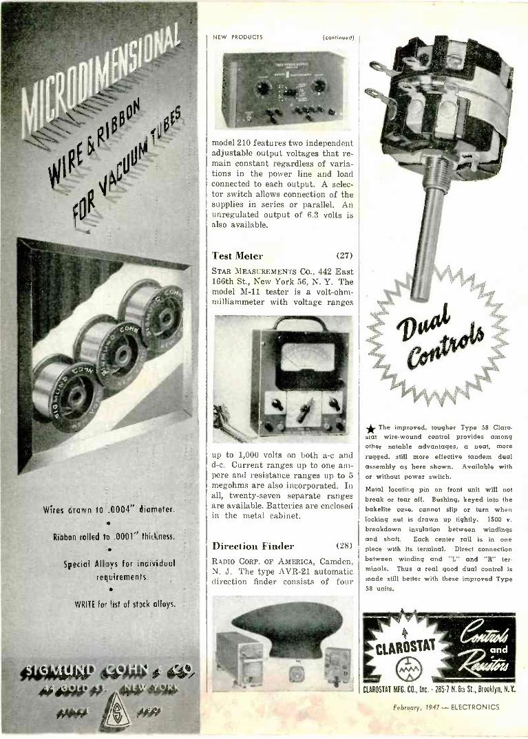
NEW PRODUCTS (continued)
model 210 features two independent adjustable output voltages that re- main constant regardless of varia- tions in the power line and load connected to each output. A selec- tor switch allows connection of the supplies in series or parallel. An unregulated output of 6.3 volts is also available.
Test Meter (27)
STAR MEASUREMENTS CO., 442 East 166th St., New York 56, N. Y. The model M-11 tester is a volt-ohm- milliammeter with voltage ranges
up to 1,000 volts on both a -c and d -c. Current ranges up to one am- pere and resistance ranges up to 5 megohms are also incorporated. In all, twenty-seven separate ranges are available. Batteries are enclosed in the metal cabinet.
Direction Finder (28)
RADIO CORP. OF AMERICA, Camden, N. J. The type AVR-21 automatic direction finder consists of four
Wires crown to .0004" diameter.
s
Ribbon rolled to .0001" thid,ness.
Special Alloys for incividuul
requirements
WRITE fo- `ist of stak alloys.
*. The improved, tougher Type 58 Claro - stat wire -wound control provides among other notable advantages, a neat, more
rugged, still more effective tandem dual assembly as here shown. Available with or without power switch.
Metal locating pin on front unit will not break or tear off. Bushing, keyed into the bakelite case, cannot slip or turn when locking nut is drawn up tightly. 1500 v.
breakdown insulation between windings and shaft. Each center rail is in one piece with its terminal. Direct connection between winding and "L" and "R" ter- minals. Thus a real good dual control is made still better with these improved Type 58 units.
CIAROSTAT MFG. CO., Inc. 285-1 N. 6th St., Brooklyn, N.Y.
February, 1947 - ELECTRONICS

the inside story OF AMERICA'S MOST EFFICIENT SOLDERING IRON
AUTOMANC RETRACTOR
400 HOUR TIP
Since Eject-O-Matic was introduced a
little more than a year ago, it has
met rigid production tests in industrial plants from coast to coast. Today it is
acclaimed by plants using this modern
soldering tool as "the greatest advance
in soldering methods in more than a
quarter of a century". Eject-O-Matic has these exclusive advantages:
TRIGGER OPERATED, AUTOMATIC - FEED- a touch of the trigger dispenses the solder.
MICROMETER CONTROL-measures the
amount of solder ejected.
AUTOMATIC RETRACTOR - prevents melt-
ing of excess solder on tip.
400 -HOUR TIP, MULTI-CLAD-non-corrod- ing, never needs filing or tinning.
COOLING FINS-keep tip at proper working tem-
perature-no thermostat required.
LOADING CHAMBER-easily accessible, holds 4 oz.
reel of solder.
COOLING FINS
EYELET HOLE-permits automatic feeding of solder from large rolls mounted on, or under, bench.
MOLDED HANDLE-made of heat -resistant plastic.
SAFETY -UTILITY BASE - provides resting place for idle or cooling iron.
TRIGGER
EYELET
HOLE
LOADING
CHAMBER
MOLDED
MICROMETER / HANDLE
SAFETY BASE
WEIGHS ONLY 18 OZS.
Write for descriptive literature or, if you wish, we shall be glad to arrange for a demonstration.
Available in 50, 75, 100 and
150 watt models. Tips in 6 dif- ferent sizes and shapes.
Individually packed. Shipping
weight per carton of 12 units,
approximately 35 lbs.
MULTI -PRODUCTS TOOL COMPANY, 123 SUSSEX AVENUE, NEWARK 4, NEW JERSEY
ELECTRONICS-February, 1947 219

5iT BACK
AND RELAX
RANCE WITH
ASSU
..install a
Western Electric 2A PHASE MONITOR
You just can't beat the 2A Phase Monitor as an aid for quick, accurate adjustment and monitoring of directional antenna arrays.
No matter what your antenna contra! or coupling problems, you'll find that Western Electric has the units to solve them efficiently. For details, write Graybar Electric Co., 420 Lexington Avenue, New York 17, N. Y., or ...
ASK TOUR LOCAL raybáR BROADCAST REPRESENTATIVE
IIAIJID DIVISION
CARTER RADIO DIVISION PRECISION PARTS CO.
213 Institute Place Chicago 10, Illinois
Write for full details and catalogue today
220
NEW PRODUCTS (continued)
components for airline use. The receiver contains its own power supply and can be mounted in any convenient location. The azimuth indicator shows the position of the enclosed loop. The pilot's control box contains the station indicator and the necessary switches for re- mote control.
Terminal Lugs (29)
CAMBRIDGE THERMIONIC CORP., 445 Concord Ave., Cambridge 38, Mass. New insulated midget terminal lugs are furnished in both rivet and stud type with 6,000 -volt a -c breakdown. The primary uses of the insulated
lugs cover such applications as tie - points where potential is high or where r -f exists. Further informa- tion is contained in a catalog avail- able through Dept. 4.
Tube Tester (30)
PRECISION APPARATUS CO., Inc., 92- 27 Horace Harding Blvd., Elm- hurst, L. I., N. Y. The type 954-P tube, battery, and set tester in- cludes a mutual -conductance vacuum tube checker and a 37 - range a -c and d -c meter. Voltages
February, 1947 - ELECTRONICS

electronics READER SERVICE .. .
TO BRING YOUR LIBRARY
LITERATURE and NEW Manufacturers' Literature as well as
further information on New Prodt.cts de- scribed in this issue are important 'work- ing tools" for design and production departments. To make it easy to keep up to date, ELECTRONICS will request manufacturers to send readers the liter- ature in which they are interested. Just fill out card as shown in the filled -in sample (right), being particularly care- ful to write out in full all the information called for in each section of each'card that is used.
HOW TO ORDER: 1. There ore two postcards, each di- vided into four parts. Eoch of the four parts contains a box. You must write in this box the number that appears in this issue over the literature or new product item in which you are interested. Place one number only in each box. 2. Fill cut completely (name, address, etc.) for each piece of literature or new product information you desire.
Do net say "same" in lieu of writing out full nformation called for when re- questing more than one item. 3. This service applies only to literate -e and new product items in this issue. It does not apply to advertisements. Write ci- rectly to the company for information on its adverisements.
Careful and complete filling in of each portion cf the card on which informaticn is requesred gives your request authority, and allows the manufacturer to whom v.e send your original request, the opportu- nity to address your copy corréctly.
PLEASE NOTE: In the event this copy of ELECTRONICS
is passed along to other members of your company, please leave this sheet in for their convenience. This assures everyone in your plant the opportunity to fill in their requests. When the round is completed, cards can then be detached along pe- forated Ones and dropped in the mail. Each individual request will be moiled by us to the company offering the informc,- tion and for that reason must be com- pletely filled out.
UP TO DATE ON
PRODUCTS Write in'Arnie number of item describing one item wonted -. Your CompAny Nam ,i'äna.. Ad ress....A1 /74eze..3... C. f aq.L3,, /l....._ Your Name. ,1T t Your Title C6/et ye ....ter....... ELECTRONICS, 330 W. 42nd St., N. Y. 18
Write in circle number of item describing one item wonted -,
Your Company Name.Aags 4 Address 4-.3/7 1./eCA...
........... .Gh je.erf
...3...11 . Your Name..(.../ Your Title L'I.J/C,. l t:ae-gr ELECTRONICS, 330 W. 42nd St., N. Y. 18
Write in circle number of Item e describing one item wonted -u ,/ Your Company Name s.74%CS.f..! 94.fs Address. ..3../7 l..Lrr/5..4.V4R
Chi( af 11! Your Name... ,lrr¿f... if%1 Your Title Cfi//.rls%(. rA!Csrr ELECTRONICS, 330 W. 42nd St., N. Y. 18
Write in circle number of item describing one item wanted -. Your Company N me7!ttC ..... .. .e Address.. 3%1.7.. ewi 3.Ave, ........_.-.
...... a o ' L ilÍ. Your Name. . Ttl!.wee Your Title AdkI.,..tK f.1. ELECTRONICS, 330 W. 42nd St.. N. Y. 18
SAMPLE
CARD
SHOWING
CORRECT
FILL-IN
4 - PLACE 10 STAMP ON CARD DO NOT USE AFTER MAY 1
Write in circle number of item
describing one item wanted-.
Your Company Name
Address
Your Nome
Your Title
ELECTRONICS, 330 W. 42nd St., New York 18, N. Y
Write in circle number of item describing one item wanted 0 Your Company Name
Address
Your Name
Your Title
ELECTRONICS, 330 W. 42nd St., New York 18, N. Y
Write In circle number of item describing one item wonted - Your Company Name
Address
Your Name
Your Title
ELECTRONICS, 330 W. 42nd St., New York 18, N. Y
Write in circle number of item
describing one item wanted-
Your Company Name
Address
Your Name
Your Title
ELECTRONICS, 330 W. 42nd St., New York 18, N. Y
Write in circle number of item describing one item wanted -i
Your Company Name
Address
Your Name
Your Title
ELECTRONICS, 330 W. 42nd St., New York 18, N. Y
Write In circle number of item describing one Item wanted-.
Your Company Name
Address
Your Name
Your Title
ELECTRONICS, 330 W. 42nd St., New York 18, N. Y.
Write in circle number of Item
describing one Item wanted-.
Your Company Name
Address
Write in circle number of Item describing one item wanted-.
Your Company Name
Address
ELECTRONICS-Feb. 1947 Your Name
Your Title CI Fr`TarlrJlr`C 71n\Ar A7 -J f AI_ V 1 ,w
Your Name
Your Title

An electronics service designed for
READERS and MANUFACTURERS
FOR THE READER ...
ELECTRONICS fundamental policy has always been to supply its readers with all the pertinent and timely industry new
The ELECTRONICS Reader Service supplements this policy by offering the reader an easy and effective means of obtainin
complete, up to the minute data on new products and of maintaining at his fingertips comprehensive, practicable informatio
on "who's doing what" in the industry. In every issue of ELECTRONICS there's complete coverage of the month by month development by manufacturers of ne
materials, components and equipmen as well as brief mention of all the i
portant, new, manufacturers' technical pamphlets and catalogs. Some of these
PLACE 10 STAMP ON CARD DO NOT USE AFTER MAY 1
Place
14
Stamp Her.
ELECTRONICS
330 WEST 42nd STREET
NEW YORK 18, N. Y.
Mac. 14
Stamp
Her.
ELECTRONICS
330 WEST 42nd STREET
NEW YORK 18, N. Y.
items will be of particular interest to specific design and plant engineers, buyers, executives and others of our readers. They will want to make further inquiry concerning the new products described or they will want to read and make a permanent part of their indus- trial library some of the manufacturers' literature and catalogs. ELECTRON- ICS Reader Service makes it easy for them to obtain in readily accessible and usable form the information they desire.
FOR THE MANUFACTURER... ELECTRONICS Reader Service wi
also be welcomed by manufacture who are desirous of placing the co plete news of their product develo ments as well as their technical bull tins and catalogs in the hand of thos members of the electronic industry.. including design, electrical, and pr duction engineers, researchers, ph icists, executives, and buyers-who hay- a particular interest in, or represent a potential buying power for, their products.
SUGGESTIONS FOR THE. IMPROVEMENT OF OU READERS' SERVICE ARE INVITE
ELECTRONICS is constantly see ing new and improved ways of provi ing its readers with the news and inf motion they want and need, and assisting the manufacturer in effectively -
delivering his message to electronic markets. If you have any ideas for us,
send them along. They'll receive prom and grateful consideration.
ELECTRONICS-Feb. 194

TOP
FREQUENCY STANDARD (60 cycle) for use with external power supply
CENTER
CHRONOGRAPH Records time intervals
with resolution to .001 second
BOTTOM
FREQUENCY STANDARD (120 cycles) with
self-contained power supply
These tuning forks which include new engineering principles, pro- vide frequencies from 120 to 1,000
cycles directly with an unquali- fied guarantee of accuracy to 1
part in 100,000 over a wide tem- perature range. (Better than -1
second in 24 hours). Closer tol- erances are obtainable on spe- cial order. These tuning fork assemblies are available only in single or multi - frequency instruments of our own manufacture which are de-
signed to test, measure or control other precision equipment by me -1
chanical, electrical accoustical or optical means.
The dependability of these fre- quency standards is being dem- onstrated for myriad purposes in all climates and under all working conditions.
If you have need for low fre- quency standards of exceptional accuracy, your inquiries are in-`,
vited.
American Time Products, Inc. 580 Fifth Ave.
Dist. of Western Electric &
New York, N. Y. {catch .'71'7/4-aster Watch -rate Recorders
ELECTRONICS - February, 1947 221

NEW PRODUCTS (continued)
RtHW ppnNG
RE
HARVEY has been appointed au- thorized dealer for the new Collins line of transmitters and receivers. These units are precision built to the highest standards. We are now taking orders on the whole line for quick delivery.
The Model 30R-1 Transmitter, com- plete with the 310A-1 Exciter and all tubes. is a complete trans- mitter ready to oper- ate. Input is 500 watts on cw, 375 watts on phone. Operating controls in Exciter unit.
e
$1250
32V-1 150 -watt transmitter (120 watts on phone) complete with tubes. Uses the highly stabilized and accurate Collins VFO 111,. $475
70E-8 VFO. It is new, versatile and extremely accu- rate. Overall accu- racy and stability are within 0.015%. Can be used for all bands up to 2/3 meter with doublers. Complete with calibrated' dial. You can build a good band -
switching ex- citer unit with the 70E-8 that will make multi - band operation a pleasure.
$40.00
Collins 75A Receiver. The receiver to end all receivers! 80-40-20- 15-11-10 meter bands. Straight line tuning. Dial calibrated in frequency. 50db image rejec- lion on all bands, uses double con- version. Permabil- ity tuned, ex- tremely high stability, uses sepa- rate oscillator for mixers. Complete with tubes, crystals and speaker.
$375
E
a i 00
' ® O0,
Send your. order in now for earli- est delivery. All prices quoted are Net, F.O.B. New York and are subject to change without notice.
Telephone: LOngacre 3-1800
103 West 43rd St., New York 18, N. Y. /
up to 6,000 can be measured. Among other features, resistance up to 60 megohms and db ranges up to plus 70 can be accommodated on the instrument.
Wien Bridge Filter (31)
KALBFELL LABORATORIES, 1076 Morena Boulevard, San Diego 10, Calif. A Wien bridge filter de- signed to cancel 60 and 120 cycle hum when using an oscillograph or vacuum -tube voltmeter consists of
two bridges in cascade. Terminals are brought out so that either or both can be used. Only fixed mica capacitors and low temperature co- efficient resistors are used, the whole assembly being sealed in polystyrene.
Counter and Control (32)
POTTER INSTRUMENT Co., 136-56 Roosevelt Ave., Flushing, N. Y. The new model 140 single -channel predetermined counter used for high-speed counting, batching, and
packaging control will function at rates of 15,000 per minute or higher if required. The unit utilizes four standard four -tube counter decades arranged to permit use of any predetermined number from 0
to 10,000.
Booster Amplifiers (33)
DAVID BOGEN Co., Inc., 663 Broad- way, New York 12, N. Y. Two new
The renown of Imperial as the finest In Tracing Cloth goes back well over half a century. Draftsmen all over the world prefer it for the uniformity of its high transparency and ink -taking surface and the superb quality of its cloth foundation.
Imperial takes erasures readily, without damage. It gives sharp contrasting prints of even the finest lines. Drawings made on Imperial over fifty years ago are still as good as ever, neither brittle nor opaque.
If you like a duller surface, for clear, hard pencil lines, try Imperial Pencil Tracing Cloth. It is good for ink as well.
IMPERIAL
TRACING
CLOTH
SOLD BY LEADING STATIONERY AND DRAW- ING MATERIAL DEALERS EVERYWHERE
222 February, 1947 - ELECTRONICS

WILCO PRODUCTS INCLUDE:
CONTACTS Silver - Platinum - Tungsten - Alloys Sintered Powder Metal
THERMOSTATIC BIMETAL All temperature ranges, defection rates and electrical resistivitiec.
SILVER CLAD STEEL JACKETED WIRE
Silver on Steel, Copper, Invar or othec combinations requested.
ROLLED GOLD PLATE AND WIRE
NI -SPAIN C* New Constant Modulus Alloy
SPECIA. MATERIALS
*Rog. Trade Mark. The International Nickel (7.,., Inr.
WILCO CONTACTS lkIee tie power f/ow;
Modern industry utilizes WILCO CONTACTS in frequency operations of every range both because of their longer service fife and because they assure maximum ductility, hardness;, density, freedom from sticking, low metal transfer, high conductivity and arc -resistance. These same peerless WILCO qualities of stamina and preci- sion performance-assured by exclusive WILCO processes- will keep the power flowing in your products. WILCO engi- neers will gladly help you select from a great variety of avail- able WILCO contact materials the particular contacts suited to your needs-or develop new alloys for special purpcises.
THE H. A. WILSON COMPANY 105 Chestnut Street, Newark 5, N. J. Branch Offices: Chicago, Detroit, Los Angeles, Providence
SPECIALISTS F3R 30 YEARS IN THE MANUFACTURE OF THERMOMETALS ELECTRICAL CONTACTS PRECIOUS METAL BIMETALLIC PRO!0LCTS
ELECTRONIICS - February, 1947 223

"A Well Known Name in Radio for Over 20 Years"
N O.
2 OF A SERIES
ár ICS powers the MOTOROLA 162 MC
F.M. Transmitter
Reliable power a:: sures the reliable operation of the new Motorola FM Mobile 162 megacycle Trans- mitter...instant.aneous power -from the CARTER Genemotor shown on the chassis above. The ONLY Dynamotor that delivers full power in 3 10 second and over 100,000 service -free transmissions. Write for latest catalog.
\ I I It®® ó ---1-- ic;etr9o, t%.isteie -- i,
2 6 4.n . MAPLEWOOP 1 1. E ly C F: r 4 r l, h: : c r. \ E v t o T u It
METAL
1t j -. -
P
I ?,6 l-lJ. ` pó ó fioOP ` F e,. ,r i r
0
... ..,. . OP, /'
,TR, o, y Pw y F /ß :o
The time -tested Par -Metal line presents superior fea- tures of styling, desigi, and construction.True to pollicy, Par -Metal continues to specialize in Electronic Housings exclusively...and is therefore able to offer leadership in value.. Com- pare! Write for Catalogue.
1
NEW PRODUCTS (continued)
booster amplifiers, types G050 and G0125, capable of delivering 50 and 125 watts respectively use multi- stage inverse feedback to attain a flat response within 1 db from 20 to 20,000 cycles. Input impedance is 500,000 ohms with provision for balanced -line zero -level input for use on telephone lines. The self- contained power pack provides a regulated screen supply.
Mike Input (34)
SPECIAL PRODUCTS CO., Silver Spring, Md. The Max -Mixer is a device to enable owners of public address amplifiers to use three ad- ditional microphones and control each one at the proper level. The
unit is equipped with six feet of shielded cable for connection to the amplifier.
Antenna Rotator (35)
THE WORKSHOP ASSOCIATES, Inc., 66 Needham St., Newton Highlands 61, Mass. Designed primarily for amateur transmitting antenna ar- rays, the new rotator can be used for other service such as f -m and television reception. Mechanically rugged, the device simplifies the electrical -connection problem by using only a 360 -degree rotation that obviates the need for slip rings. The feed line can be matched without difficulty to the antenna structure. - Motion of the antenna
224 February, 1947 - ELECTRONICS

Superior's Electronic Lakoratory opens the doors to far
reaching research and development of electronic tub-
ing, through the study of materials, processes and
controls.
The Emission Microscope, shown above, makes it
possible to test the material in electronic tubes, under
actual operating conditions, for emissive qualities.
Material control standards, otherwise unattainable, are
now realities. The way is open to important develop-
ment of new tubing materials and uses.
lHE
rAE'NS
5MO MAtt, TUg1NG
SUPERIOR TUBE COMPANY NORRISTOWN PENNSYLVANIA
Sealing -in Machine in the process of sealing experimental electronic tubes preparatory to
emission testing.
Comparator measuring dimensions to 10 thou- sandths of an inch, for inspecting the quality of work going into electronic tube cathodes and parts. This is just one of many tesrs con- ducted by the "Quality Conerol Group" of the Superior Laboratories.
ELECTRONICS - February, 1947 225

EVER SEE
THESE?
ESTABLISHED I906
0
- Milford SEMI -TUBULAR Rivets
I I SOLIDwhere solidity is re- quired for strength.
SEMI -TUBULAR to save time in setting.
A pin on Milford Rivet Setters engages the semi - tubular end of the rivet, guides it home accurately and instantly to make an unbreakable assembly. Costs cut. Time saved. Production speeded. Milford designs and manufactures rivets in endless variety and makes 15 standard models of bench and floor type rivet setters (special models, to order).
MILFORD BENCH TYPE RIVET SETTER
SETS 60 RIVETS A MINUTE
in Metal, Wood, Fabric, Plastic or any combination of the four.
Send blue prints or actual sample for more information, or write for a Milford repre- sentative to call.
THE MILFORD RIVET & MACHINE CO. 859 Bridgeport Ave.
MILFORD, CONN. 1002 West River St., Elyria, Ohio
Inquiries may also be addressed to our subsidiary: THE PENN RIVET á MACHINE CO. PHILADELPHIA 33, PENNA.
ANTENNA SYSTEMS for USERS
of PRIVATE BRANDS
--_ - =
We manufacture the following, under
private labels and trademarks:
AUTOMOBILE ANTENNAS . . . every variety, including types that can
be raised and lowered from inside
the car. RESIDENTIAL ANTENNAS . . . AM and
FM, for homes, stores and multi-
family buildings. Complete lines
of noise -reducing systems incor-
porating latest patented develop-
ments of coupling transformers.
FM, AM and TELEVISION . . . Dipoles
with or without reflectors, folded
dipoles, turnstile, radiating types
and other combinations for roof,
sidewall and other mountings.
MARINE ANTENNAS . . . Collapsible
and transmitting types for every
purpose. For POLICE and other mobile units .
roof -top antennas for ultra -high
frequencies.
WE INVITE INQUIRIES AND CONSULTATIONS.
L. 5. BRAN MFG. CORP 200 CENTRAL AVENUE NEWARK, 4 N..1.
WORLD'S
II
OLDEST AND LARGEST MANUFACTURERS OF RADIO ANTENNAS AND ACCESSORIES
NEW PRODUCTS (continued)
stops automatically at north. A three -position switch control is shown on the indicator base casting.
Sound Reproducer (36)
ALLEN D. CARDWELL MFG. CORP., 97 Whiting St., Plainville, Conn. The model CE -26 sound reproducer is a combined amplifier and loud-
speaker designed for general use with microphone, phonograph pick- up, or guitar reinforcing system. Eight watts undistorted output is available with a frequency response flat within 2 db from 60 to 8,000 cycles.
Capacitance Meter (37)
1\IAIDA DEVELOPMENT CO., Box 588, Erie, Pa. The model 201 direct - reading capacitance meter operates on the principle of measuring the current through a capacitor when a known voltage at 100 kilocycles is impressed across it. Ten overlap- ping ranges make possible measure- ments from 0.1 to 10,000 microfar- ads. Each instrument is adjusted to within 1 percent of full-scale
226 February, 1947-ELECTRONICS

METAL PLATES that serve a steady diet
One of the two oscillators that are the aey parts of every Fathometer. Here, the oscillating unit has been tipped back out of as casing to show where the stack of Nickel lamination plates is mounted.
Both an indicating dial and recorder ran be used with the Fathometer. Other components include an amplifier and a driver. xg°
The FATHOMETER t-the first practical application of "Sonar"-utilizes the magnetostriction of Nickel
One of the most practical uses of sonar is the Fathometer, manufactured by the Submarine Signal Co., Boston, Mass.
The Fathometer generates sonic vibrations, throws them at the bottom, and then listens for their echoes. With a Fathome- ter you can map the ocean floor ... locate fish ... safeguard navigation.
Like many other adaptations of sonar, the Fathometer de- pends upon Nickel to send and receive the sonic vibrations. Heart of each oscillator is a stack of thin Nickel plates, laced together with a winding of wire.
HOW THE FATHOMETER WORKS When current is passed through these windings, a magnetic field is created. That's when the magnetostrictive property of Nickel goes to work!
For under the influence of magnetic force, Nickel contracts, returning to its original length when the field goes dead. In a fluctuating field, the resulting vibrations are powerful enough to produce an echo from the ocean floor.
When the sonic waves bounce back to the Fathometer, a second oscillator (acting as a receiver) goes through the same cycle in reverse to convert sound into electrical impulses..- Other components then time the lag between transmission and echo, registering the depth on an indicator.
WHY NICKEL WAS CHOSEN Nickel is used in sonar because it contracts more than other magnetostrictive metal, contracting 32 units of length for every 1,000,000.
Magnetostriction is just one of the specialized properties obtainable with Nickel. When specifying metals for elec- tronic or electrical use always consider Nickel and the INCO Nickel Alloys. They are strong, tough, rustless, corrosion - resistant and thermally durable.
¡'l'rademark registered by Submarine Signal pompan7
THE INTERNATIONAL NICKEL COMPANY, INC- 67 WALL STREET, NEW YORK 5, N. Y.
NICKEL /NED ALLOYS uoa . aa
MONEL' "N"'MONEL "S" *NONE. "0"'MONEL " K1"'MONEL INCONEL' NICKEL "L"NICKEL "Z"'NK:NEL Reg. U. S. Pat. Off.
ELECTRONICS - February, 1947 227

NEW PRODUCTS (continued)
tIMM
' CtCIT00S
MICA 41410.1® OVCNOOKC
Cryscons are electronically tested to insure accurately rated minimum loss trimmers and padders.
The CN -351 series is an efficient RF trimmer capaci- tor. (RF Padders in stand- ard ranges - even to 1.5 -7 mmf). The CN -55 series is a dual IF padder capaci- tor. The latter series may also be had with two fixed series capacitors.
SALES REPRESENTATIVES
CHICAGO AREA:
P. G. RIDLEY 4804 West Chicago Avenue
CHICAGO 5, ILLINOIS
EASTERN AREA:
LEO FREED & CO. 420 Lexington Avenue NEW YORK 17, NEW YORK
PACIFIC COAST AREA:
HARRY A. LASURE CO. 2216 West 11th Street LOS ANGELES 6, CALIFORNIA
Early deliveries for large or medium orders - Inquire re-
gionally or directly.
CRYSCON, Inc. SUBSIDIARY OF:
CRYSTAL RESEARCH LABORATORIES, Inc.
29 Allyn Street Hartford 3, Conn. Telephone 7-3215
reading on all ten ranges and is guaranteed to be within 2 percent of full scale. Inductance measure- ments are generally within 5 per- cent after some computation involv- ing apparent capacitance indica- tion.
Relay Tube (38)
SYLVANIA ELECTRIC PRODUCTS Inc., 500 Fifth Ave., New York 18, N. Y. The cold -cathode relay tube type 0A5 measures 15/8 inch overall and 11/16 inch in diameter. A positive trigger pulse of 85 volts is sufficient
to fire the tube when the anode rests at 750 volts. The new tube has been designed for use in elec- tronic photoflash and similar equip- ment.
F -M and Television Cable(39) FEDERAL TELEPHONE AND RADIO CORP., Newark, N. J. Type KT -51 dual conductor twisted -pair cable is shielded by two metal braid cov-
MEEN
Ime
E
o
HOLDER
Performance
Data
-0--"------..------ ,_.---- ......
io p AMNDET TIME ti
TEMP. CURVE INSiDE HOLDER
CRYSTAL AT 6210 KC
-20 O 40 AMBIENT TEMP K
ACTUAL FREQUENCY CURVE
Selectronic XL -30 is designed for close frequency tolerance .
VHF services .. . police, aircraft, railway communications, etc. Heater works at 6 volts, 1 amp Frequency range- 3.000 KC to 15,000 KC.
ENGINEERS OF
SELECTRONIC CRYSTALS
p
ro
CRYSTAL RESEARCH LABORATORIES, Inc.
29 Allyn Street Hartford 3, Conn. Telephone 7-3215
228 February, 1947 - ELECTRONICS

L PHONOGRAPH -TURNTABLE UNITS
FRACTIONAL HORSEPOWER MOTORS
FRACTIONAL HORSEPOWER MOTORS
Sturdy motors, precision built for long life and rugged requirements. Single phase shaded pole induction type suitable for many applications. Constant speed is mainta;ned through the use of new shading design making this
motor ideal for use where good starting torque re- quirements are needed. Dual motor coils of ample turns impregnated against moisture will operate continuously with an exception- al'y low temperature rise.
Bearings are of ample size and are self -aligning with self-lubricating features.
Production starts soon and we invite inquiries now as
to your 1947 motor requirements.
PRECISION WIRE WOUND RESISTORS
RADIO AND ELECTRONIC TEST EQUIPMENT
t 1
PHONOGRAPH TURNTABLE UNIT
Engineers will find this compact turntable meeting all of their requirements.
PERFORMANCE:-Correct and uniform speed is secured through the use of a motor of ample capacity, preloaded to operate on the flattest portion of the torque -speed characteristic. QUIETNESS:-Is assured by full -floating rubber motor mountings and rubber cushioned drive. Permanent free- dom from turntable wobble is guaranteed by an extra rigid turntable, an extra long bearing and precision machining of these parts.
Unit can be supplied for 110 volt and 220 volt 50 or 60 cycle operation. Deliveries prompt.
ROTARY SELECTOR SWITCHES FOR THE CRITICAL ENGINEER
TYPE XC-Single or multiple decks. Instru- ment type. Contact Resistance less than .001
ohm. Ideal for shunt ammeter, thermo couple type measuring equipment and Wheatstone Bridges.
SERIES EE-14-Single or multiple decks. One to six. 14 circuits each deck. Shorting or non - shorting contacts. Recommended for use in
quality test equipment or accurate switching of multi -circuits with low contact loss.
SERIES EE-20-Similar to Series EE -14 but with 20 circuits each deck. Contacts and moving parts heavy coin silver plated to meet 200 hour salt spray test. Low leakage laminated plastic decks selected for maximum mechanical and dielectric strength.
Write for catalogue
41 CHESTNUT STREET, NEW HAVEN, CONN.
ELECTRONICS - February, 1947 229

BRADLEY
COPPER OXIDE
RECTIFIERS
IDEAL FOR AUTOMATIC
CURRENT CONTROL e
"Coprox" rectifiers may be your answer to more efficient current control. Their varistor character- istics make them ideal for automatic current valving, current limiting, current blocking, as well as
rent measurement. Bradley rectifiers are
designed to give you trouble -free service. Their electrical characteristics remain stable indefinitely When operated within normal rating, their life is
unlimited. Send for curves show-
ing current, voltage, re-
sistance and temperature characteristics of Bradley copper oxide rectifiers.
Illustrated literature, available on request, shows more models of copper oxide rectifiers, plus a line of selenium rectifiers and photocells. Write for "The Bradley Line.
cur -
BRADLEY LABORATORIES, INC.
82 Meadow St. New Haven 10, Conn.
NEW PRODUCTS (continued)
erings. A noncontaminating jacket covers the shield. Characteristic impedance of the cable is 95 ohms. Attenuation per 100 feet is 1.7 db at 30 megacycles, 3.6 at 100 me and 10.0 db at 400 mc.
High Voltage Tester (40)
ROWE RADIO RESEARCH LABORATORY
Co., 2422 North Pulaski Road, Chi- cago 39, Ill. The type SP22 elec- tronic spark plug analyzer uses an oscillographic technique that is easily interpreted by inexperienced
personnel. Tests at peak voltages between 1,000 and 21,000 volts can be rapidly determined. The instru- ment can be modified for testing high tension cable or for other resistance, corona and breakdown testing. The unit measures 20x20x22 inches.
Plug -In Relays (41)
NARD LEONARD ELECTRIC CO., 31 South St., Mount Vernon, N. Y. Bulletin 106 magnetic relays fea- ture pin -plug connections. They are suitable for a -c or d -c operation on standard frequencies and voltages up to 125 volts. Single -break rat -
From out of
the gest.e.
anierica's
finest
transi onu ers
Thermador is a name
remembered when the ut-
most in transformer qual-
ity is desired, and when
exceptional engineering
skill is required.
"Seven Leagues Ahead"
THERMADOR THERMADOR ELECTRICAL MFG. CO
5119 District Blvd . Los Angeles 22. Babdorma
230 February, 1947 - ELECTRONICS

Number, Please... Big Numbers!
When America switched to the monophone telephone in 1925, millions were needed-quick. The job called for complex molds presses to handle heavy pieces-ample production. Kurz -Kasch did it first.
Many firms and individuals have contributed to the amazing advances of the plastics industry. As this series of ads testifies, Kurz -Kasch and its engineers have played their parts since the very earliest days.
We mention it only because yesterday's achievements are your promise of added competence today-because by choosing Kurz -Kasch as your molder now, your production will benefit ahead of time from many of the improvements of tomorrow. And that pays off.
Investigate our complete molding service. Write for your free copy of "A Businessman's Guide to the Molding of Plastics"-or ask for an engineer.
Kurz -Kasch For Over 29 Years
Planners and Molders in Plastics
Kurz -Kasch, Inc., 1425 S. Broadway, Dayton 1, Ohio. Export Offices: 89 Broad Street, New York, N. Y. Branch Sales Offices: New York Chicago Detroit Los Angeles Dallas St. Louis Toronto, Canada:
ELECTRONICS - February, 1947 231

DEVELOPMENT 5" OSCILLOSCOPE OSCILI.OSCOPE ELECTRONIC
elot PRECISION OBSERVATION
of Radio, Sound, Television an Ég other Elect Phenomena
ONLY
STOCK 50 84-376 {/ /
This new 5" Cathode Ray Oscilloscope is a precision instrument at an attractively low price, designed for practical application in laboratory research and production work. Sturdily built to stand up under continuous use, and ably engineered for accuracy, versa- tility and easy operation. lias wide frequency range, 10 cycles to 300 Kc. Deflection sensi- tivity, 1 volt RMS per inch. Sweep range, 10 cycles to 60 Kc. in four steps. For 110-120 volt, 50-60 cycle operation. In welded steel cabinet, with baked black wrinkle -finish; 81/2" wide, 141/" high, 181/2" deep. Instru- ment panel in black, with white designations; has removable calibrated plastic scale. Com- plete with tubes. No. 84-376. Net Only.$99.50
Order from the Central Source for Everything in Radio and Electronics
ALLIED RADIO CORP. 833 W. Jackson Blvd., Dept. 24-B-7, Chicago 7, Illinois
Se cd pvt ALLIED Catalog No. 111
IMPERVIOUS Io MOISTURE
BURKE Bakelite blocks are uniformly dense due to high pressure in hard- ened steel moulds in electrically heated and operated moulding presses. They feature high resistance to moist- ure and electricity.
SERIES 3000 features a center barrier moulded -in construction for extra me- chanical strength. Center barrier off
center to permit the use of terminal lugs on one side.
* ?Unite ¡44 /lieu ßoohiet to 1172 West 12th St., Erie, Pa.
AC AND DC MOTORS AND GENERATORS
BURKE Teuza1 BLOCKS BURKE ELECTRIC COMPANY ERIE, PENNSYLVANIA
NEW PRODUCTS (continued)
ings are 4 amperes, 125 volts, 60 cycles on noninductive loads.
Resistance Welding Control (42)
GENERAL ELECTRIC Co., Schenec- tady, N. Y. A new line of non - synchronous electronic resistance welding control combinations de- signed to meet new NEMA stand-
ards includes ignitron contactors and sequence -weld timers. The control cabinet illustrated can be mounted on a welder and requires only the connection of air and water lines in addition to power.
Interval Counter (43)
RADIO CORP. of America, Camden, N. J. The type WF-99B time in- terval counter gives direct visual indication of the time elapsed be- tween two impulses each of ex- tremely short duration. Maximum time that can be accommodated is one second, in microsecond incre- ments. The equipment can be initi- ated by simple mechanical switches or triggers by inertialess means such as phototube equipment. Op -
232 February, 1947 - ELECTRONICS

1,000 DIFFERENT VOLTAGE RATIOS!
ABRIDGED SPECIFICATIONS
ACCURACY: each resistors adjusted within ±0.1%, error in voltage never exceeds ±0.2%
INPUT IMPEDANCE: constant resistance of 10,000 ohms regardless of ratio setting
OUTPUT IMPEDANCE: varies from 10 to 10,000 ohms, depending upon settings
FREQUENCY CHARACTERISTIC: if external capacitance across output terminals is less than 20 micromicrofarads, frequency error is less than 0.1% below 10,000 cycles
TEMPERATURE COEFFICIENT of resistors is less than ±0.002%. per deg. C at normal room temperature
AT THE MOMENT WE HAVE A FEW IN
STOCK
WRITE FOR COMPLETE DATA
THIS decade voltage di._cer will supply exact
voltage ratios between 0.00= and 1.000 in steps of 0.001. It is very rueful on the input of amplifiers
anl other high-im-Dedan_e circuits for reducing the input voltage by a defiritdz known ratio, which can be varied in very small steps. One thousand different ratios can be obtained.
The input resistance remains constant regardless
of dial settings, consequently reaction on the in-
put voltage is eliminated. The instrument is equivalent to a pair of our type
602 Decade -Resistance Boxes connected in series
and so arranged mechanically that as resistance is
taken out of one box it is added to the other to maintain the total resistance constant at 10,000
ohms. All resistors are wound with an alloy wire of
such characteristics that no difficulty from thermal emf will be encountered in direct -current meas-
urements.
TYPE 654-A DECADE VOLTAGE DIVIDER... $100
GR GENERAL RADIO COMPANY Cambridge 39, Massachusetts
90 West St., New York 6 920 S. MicIaiigan Ave., Chicago 5 950 N. Highland Ave., Los Angeles 38
ELECTRONICS - February, 1947 233

t
HEX, PHILLIPS, FLAT
!SCREW DRIVER
BITS 7in this compact
handle
HALLQWELL
'SOCKET SCREW" KIT with interchangeable bits
For men who like to have a
complete supply of tools, yet dislike bulk and confusion, the Hallowell "Socket Screw" Kits are the answer. Their hollow, durable plastic handles hold in- terchangeable steel bits for most all purposes ... Phillips, Hex and Flat. They each have a
swivel bit -chuck, which locks securely in five positions.
The "Socket Screw" Kit comes in 2 sizes: small #25 Kit; and the large #50 Kit.
Other Hallowell Kits:"Socket Wrench"; "Auto"; "Home".
Obtainable at Dealers throughout the country. If none near you, or he is sold out, send his name to us, along with yours, and you will be taken care of promptly. Kits: Patents Pending
An ideal gift or prize
Over 43 Years in Business
STANDARD PRESSED STEEL CO.
JENKINTOWN, PENNA., BOX 596
Boston Chicago Detroit Indianapolis St. Louis San Francisco
NEW PRODUCTS (continued)
erations can be automatically started and stopped on the basis of a predetermined number of items or counting impulses.
Vacuum Thermocouple (44)
FIELD ELECTRICAL INSTRUMENT Co., 109 East 184th St., New York 53, N. Y. The type U vacuum thermo- couple illustrated represents an im-
provement over the former unit designed for measurement of cur- rent, voltage, power at ultrahigh frequencies. Chief difference is reduction in size owing to a differ- ent conformation of the glass bulb.
Welding Controls (45)
GENERAL ELECTRIC CO., Schenec- tady, N. Y. The complete line of synchronous precision controls for resistance welding machines has
SIGMA SENSITIVE RELAYS have proven themselves countless applications:
Temperature
Vacuum Tube Circuits
Fire and Burglar Alarms
Telephone Dialing
Aircraft Controls
High Speed Keying
... and many others.
SIGMA'S specialty is the com- bination of a fine relay and an unusually thorough approach to your specific application problem.
SIGMA standard relays are available with various enclosures including fixed mountings, 5 -pin, and octal male plug bases.
New relays are being devel- oped for special purposes. Send your requirements to SIGMA for dependable relay recommenda. tions.
Sigma Instruments, INC.
C/ BELAYS 62 Ceylon St., Boston 21, Mass.
234 February, 1947 - ELECTRONICS

developments
See for yourself how new
can give you better electrical insulation
Varflex Corporation wants every manufacturer of
electrical equipment to have one of these new folders. Each
one contains actual working samples of 20 different types of
sleeving and tubing, including Varglas Silicone, which was
developed during the war to meet temperature variations from -85° F. to 500° F.
Write for this folder containing test samples today.
CORPORATION Makers of
Electrical Insulating
Tubing and Sleevire
r.____ MOM _____BMW Varflex Corporation, 308 N. Jay St., Rome, N. Y.
Please send me your FREE folder containing 20 different types of electrical
insulation. I am particularly interested in samples suitable for
Name
Company
Street
City State
ELECTRONICS - February, 1947 235

With Two DI -ACRO BENDERS A difficult production problem of forming two bends in a long length of tubing was solved by "teaming up" two DI -ACRO Benders as illus- trated. This dual -forming arrange- ment saved installation of special machinery. Two accurately formed bends are obtained in one operation -without distortion of the tube and at a cost competitive to power operated equipment. More than 300
pieces are completed per hour -600 individual bends. "DIE -LESS DUPLICATING" Often Does it Quicker WITHOUT DIES This is but one example of how DI - ACRO precision machines-Benders, Brakes and Shears-can accurately and economically duplicate a great variety of parts, pieces and shapes, without die expense.
Write for Catalog-"DIE-LESS DUPLICATING"
eEDI-ACRO is pronounced "DIE-ACK-RO".
ID PRECISION MACHINES
4 e
ESS Duple- 321 EIGHTH AVENUE LAKE CITY, MINNESOTA
U. H. F. STANDARD SIGNAL GENERATOR MODEL 84
SPECIFICATIONS
CARRIER FREQUENCY: 300 to 1000 megacycles. OUTPUT VOLTAGE: 0.1 to 100,000 microvolts.
OUTPUT IMPEDANCE: 50 ohms.
MODULATION: SINEWAVE: 0-30%, 400, 1000 or 2500 cycles. PULSE: Repetiton-60 to 100,000 cycles. Width-
to 50 microseconds. Delay -0 to 50 microseconds. Sync. input-amplifier and control. Sync. output-either polarity, DIMENSIONS: Width 26", Height 12", Depth 10". WEIGHT:125 pounds including external line voltage regulator.
MEASUREMENTS CORPORATION BOONTON NEW JERSEY
NEW PRODUCTS (continued)
been redesigned. The representa- tive system illustrated comprises ignitron Lontactors, sequence con- trols for electrodes, and a synchro- nous weld timer, all components meeting new NEMA standards.
Counting -Rate Meter (46)
GENERAL RADIO Co., 275 Massachu- sets Ave., Cambridge 39, Mass. A counting -rate meter and Geiger counter are available for both qual- itative and quantitive observation
of radioactive materials and cosmic radiation. A loudspeaker is provided for the former and either a meter or an ink recorder can be used to count rates from 5 to 20,000 a min- ute.
Plastic Case Meter (47)
ASSEMBLY PRODUCTS INC., Main and Bell St., Chagrin Falls, Ohio. A line of panel meters in clear plastic cases is now available. Ad- vantages claimed for the instru- ments are better illumination of the
dial and an unbreakable front cover. The scale can be illuminated by conduction of light from the rear along the edge of the plastic.
Antenna Arrays (48)
TECHNICAL APPLIANCE CORP., 41-06 DeLong St., Flushing, N. Y. The
February, 1947 - ELECTRONICS

A Major Development in Hermetic Sealing!
Multiple
Headers
in
All Shapes
ttlt//rt eft
Hermico-Glass
Multiple Headers
and Seals in
Unlimited Shapes
for Unrestricted Use
at 75* Material
Cost Sayings
.... in a COMBINATION OF NEW METAL AND
GLASS FOR HERMETIC SEALING with matched coefficient of expansion
By their exclusive method Df production, HERMETIC can
provide an unlimited variety of shapes in multiple head-
ers, with as many terminals as desired molded into a
cover unit. No matter what your specifications are for
shape, size and weight, single terminals or multiple
headers, your requirements can be taken care of at once
... samples within 48 hours ... production runs, either
long or short, immediately thereafter. Hermico-Glass
Headers are unhampered ay any restrictions whatsoever
in their use.
Hermico-Glass Headers are vacuum -tight . . . have re-
sistan:e of over 10,000 megohms between body and
terminals or between terminals . . . have a permanent
chemical bond between metal and glass ... are capable
of withstanding shock of hot tin dipping to facilitate
soldering.
Terminals may be arranged with a minimum spacing in
any pattern or combination of voltage ratings. Illustrated
are only a few variations. The range is unlimited, offer.
ing you the kind of latitude that will enable you to
distinguish your products from those of competition.
Submit details of your requirements for samples and estimates of
amazingly low cost multiple headers that are guaranteed impervious to
every element. Your inquiry will receive immediate attention.
HERMETIC SEAL PRODUCTS COMPANY 414-418 MORRIS AVENUE NEWARK 3, NEW JERSEY
ELECTRONICS-February, 1947 237

a LOWER
DIELECTRIC LOSS
GREATER ADAPTABILITY
IN MOUNTING
LIGHTER WEIGHT
EASIER TAPPING
o LESS CHANCE
OF BREAKAGE
All types, shapes and sizes including turrets for modern
Radio -Electronic needs.
DEPT.E-27231 FAIRFIELD AVE., UPPER DARBY, PA.
NEW PRODUCTS (continued)
type 620 combination folded dipole and reflector antenna for f -m re- ception is illustrated. Dipole and reflector rods are aluminum, but the mast is wood to permit attach- ing the 300 -ohm ribbon type trans- mission line directly to it for me- chanical support. Other types of f -m, television, and a -m arrays are described in catalog 27A.
Null Detector (49)
GENERAL RADIO CO., 275 Massachu- setts Ave., Cambridge 39, Mass. The type 707-A cathode-ray null de- tector is not new, but has only re- cently been put back into produc-
tion. It is useful at power -line and audio frequencies and can be used for the comparison of frequencies by means of Lissajous figures. In- dication is by means of a one -inch cathode-ray tube.
Literature
(50) Audio Amplifier- Brook Electron- ics, Inc., Box 430, Elizabeth, N. J. A high quality audio amplifier with optional bass and treble con- trols is described in a four -page leaflet. The equipment is suitable for broadcast station or home use.
(51)
Electrical Insulation. James G. Biddle Co., 1211 Arch St., Phila- delphia 7, Pa. Technical publica-
Soun4crafü a+A
QUALITY CONTROL
The Soundcraft name symbolizes quality con- trol in the manufacture of recording discs. It is the recordists guarantee that every Soundcraft disc offers an identical poten- tial for the utmost in high fidelity reproduction.
One factor in the success of Soundcraft's exacting quality control is the disc prover. Capable of meas- uring minute differences in surface noise, fre- quency response, distor- tion, playback life, and thread behavior, this multi -channel test set also makes and compares re- cordings made under typ- ical studio conditions.
Soundcraft discs need not be stamped with serial numbers. Disc prover quality - control plus triple inspection in- sures that every disc is up to the Soundcraft high quality standard. 'Broadcaster' 8" 10" 12" 16" 'Audition' 61/2" 8" 10" 12" 16" 'Playback' 61/2" 8" 10" 12" 16" 'Maestro' 12" 131/4" WA
A Disc for Every Application
REEVES
SOUNDCRAFT CORP. 10 EAST 52 ST.. NEW YORK 22. N.Y.
PROGRESS ALONG SOUND LINES
238 February, 1947 - ELECTRONICS

From 600 to oser 30,000 rolls
Modern functionally designed capacitors. Metal ferrules are soldered to silver bands fused to each end of heavy -walled glass tubes. This vacuum tight assembly is fungus -proof and passes Signal Corps, Air Corps and Navy thermal cycle and immersion tests.
Announcing an illustrated technical booklet on uses of
PLASTIC'ON* GLASSMIKES Contains the following subjects :-
Glassmike characteristics and design data Compaeison of Glassmike and Mica Capacitors Uses of Glassmikes for improved RF and Audio bypassing Use in Audio and RE coupling Glassm ke in television power supplies Video coupling Vibrator buffer applications Geiger Counter Capacitors Instrument capacitors And many other applications
CI)
* PLASTICONS: Plastic -Film Dielectric Capacitors
Come in and visit our exhibit at the I.R.E. show, March 3-7, incl.
WRITE for above free booklet on your firm letterhead.
Order from your jobber: if he cannot supply you, order direct
Çondenscr Products company 1375 NORTH BRANCH STREET CHICAGO 22, ILLINOIS
ELECTRONICS - February, 1947 239

PARTNERS IN TIME!
Today, time saved means more than minutes-it means markets. There's no surer way to speed production than by the use of time -saving tools. That Spintite wrenches achieve this, is proved by their acceptance on the assembly lines of the radio industry.
A few simple twists of the screwdriver type Spintite speed parts into place with a minimum of waste motion.
Ranging in size from 3/16" to 5/8", Spintites are available to fit square, hex, or knurled nuts.
When time is of the essence, there's no substitute for Spintites.
T-73 Set, has 7 sizes of hex heads. Shock -proof handles, and cold forged sockets assure safety and strength.
O, cEsr
STEVENS WALDEN INCORPORATED
Worcester Massachusetts
NEW PRODUCTS (continued)
tion 21T4 entitled "Temperature - Resistance Characteristics of Electrical Insulation" summarizes the composite nature of electrical insulation and the wide variations in insulation resistance owing to temperature changes. Simplified curves of temperature correction factors are presented.
(52) House Organ. Tracerlab Inc., 55 Oliver St., Boston 10, Mass. The first issue of "Tracerlog" an- nounces its purpose to publish technical information on labora- tory, medical and industrial uses of radioactivity as well as descrip- tions of Tracerlab products and services. The monthly publication will be mailed free to interested physicists, chemists, physicians and engineers.
(53) Stand -By Antenna. Andrew Co., 363 East 75th St., Chicago 19, Ill. The type 1200 folded quadrupole antenna, approved by FCC, is im- mediately available for f -m trans- mitters. Bulletin 46 offers full de- tails.
(54) Microwave Components. Sperry Gyroscope Co., Inc., Great Neck, N. Y. A six -page folder describes a cross-section of products avail- able. Although most of the spacè is given over to microwave equip- ment, industrial and navigation equipment is also described.
(55) Speech Equipment. Collins Radio Co., Cedar Rapids, Iowa. A new catalog just published includes in- formation on all essential speech equipment and accessories for broadcast use.
(56) Ceramics Wall Chart. American Lava Corp., Chattanooga 5, Tenn. A two-color wall chart has been prepared for free distribution to engineers desiring complete infor- mation on the more widely used types of AlSiMag compositions. While the chart does not attempt to cover the many special types of
Up to four lattice -type coils of like specifi- cations are produced at the same time on the No. 84 Universal Coil Winding Machine. Two machines can often be assigned to a single operator.
The higher rate of production ... plus other advantages listed below ... makes the No. 84 ideal for a great variety of cross - wound coils.
ACCURACY. Quickly-adjustable"gainer" mechanism accurately places wire turns (spaced or close -wound). "Veeder" Pre - Determining Counter.
CONVENIENCE. Strap -type tensions facilitate handling. In-built calibration. Quick -adjusting wire guide holders.
PRODUC=l'ION. Winding speed, 400-750 rpm. Wires as fine as No. 46 unrolled with- out breakage.
DURABILITY. Many No. 84 machines now operating have been in service 20 years or longer.
Write for Bulletin 84. Universal Winding Co., P. O. Box 1605, Providence 1, R. I.
For Winding Coils in Quantity Automatically,
Accurately- Use .. .
UNIVERSAL WINDING MACHINES
240 February, 1947 - ELECTRONICS

NO CRITICAL =MECHANICAL ItlUSTM[NTS`
DOTS Not : AFFECT PORE N FACTO -R4 sitM r.YSTEM ,..b
POWER undistorted
RAPID CORRECTION OF LINE: VOLTAGE VARIATIONS
NOT 'AFFECTED :MY CNiRItlES =tat thü, POWER,. FACTOR- OR MA6NITODE 'ef.tke LOAD
Send for Bulletin 150 LE
Electric Superior 882 LAUREL STREET BRISTOL, CONNECTICUT, U.S.A.
ZERO WAVEFORM DISTOR- TION...a characteristic of all SECO
Automatic Voltage Regulators... is not the most important but certainly a highly desirable feature in voltage regulating equipment.
Please keep in mind-
Seco Automatic Voltage Regulators
produce zero waveform distortion
But...zero waveform distortion is just one of the many decided advantages of SECO Automatic Voltage Regulators. A few others are listed and a more comprehen- sive investigation would reveal such factors as low cost per KVA - easy installation - rugged me- chanical construction.
Consider these combined ad- vantages when in need of equip- ment to maintain CONSTANT VOLT-
AGE to electrical apparatus. SECO Automatic Voltage Reg-
ulators offer more per dollar value whether the requirement involves I or 100 KVA.
ELECTRONICS - February, 1947 241

//nnouncement In order to unify the handling of all foreign business
and to provide the best possible service to our
customers, we are pleased to announce the ap-
pointment of:
RCA INTERNATIONAL DIVISION 745 Fifth Avenue, New York 22, N. Y., U. S. A.
Radiogram Address: RADIOINTER
as exclusive distributors for our product in all
countries outside +he United States
BOONTO ADIO rtra BOONTON NJ USA etaiet
Designers and Manufacturers of The Q -Meter . . QX-Checker . . Signal Generators . . And
Other Direct Reading Instruments
BURNDY ...New York 54, N.Y. In Canada: Canadian Line Materials, Ltd., Toronto 13. Foreign: Philips Export Corp., New York 17, N. Y.
NEW PRODUCTS (continued)
ceramics available, electronic, electrical -and mechanical engi- neers will find it of great use.
(57) Frequency Shift Converter. H. O. Boehme, Inc., 915 Broadway, New York, N. Y. The type 5-C frequency shift converter accepts the output of two diversity receivers, com- bines the signals and converts them into polar or neútral-keyed direct current. A four -page folder.
(58) Power Rheostats. International Resistance Co., 401 N. Broad St., Philadelphia 8, Pa. Bulletin E-1 covers the characteristics and specifications of the type PRT (AN 3155) power rheostats. Tem- perature rise curves and dimen- sions are clearly pictured.
(59) Regulated Power Supplies. Furst Electronics, 800 W. North Ave., Chicago 22, III. New catalog sheets describe the models 310-A and 310-B electronically regulated power supplies. The type 310-A also provides a source of variable a -c.
(60) Radar Brochure. Radiomarine Corp. of America, 75 Varick St., New York 13, N. Y. A six -page, two-color booklet has been issued to give information on the CR -101 navigation radar equipment that operates on the 3.2 centimeter band.
(61) Magnetic Recorder. Magnecord, Inc., 304 West 63rd St., Chicago 21, Ill. Specifications and a complete resume of the features of the type SD -1 magnetic wire recorder are given in a four -page brochure.
(62) Plastics Molding Service. G. Fel- senthal and Sons, 4100 W. Grand Ave., Chicago 51, Ill. A multicolor 24 -page book arranged as a file folder shows in detail the work done by the company in making plastic computers, industrial parts,
February, 1947 - ELECTRON ICS
NOW... A
N E W GRAPHITE
FOR
ELECTRONIC TUBES
HERE is a new grade of graphite that makes possible the design of greatly improved and more economical power tubes. This graphite, developed as a result of war- time needs, is stronger than ever before. It has finer grain structure. And it is the purest graph- ite ever produced for this purpose. Sylvania Electric Products, Inc., is taking ad- vantage of this "National" graphite in new tubes soon to be announced. This new "National" graphite offers you many advantages. It has no melting point and does
'a'be word ",National" is a registered trade -mark of
NATIONAL CARBON COMPANY, INC. 30 East 42nd Street, New York 17, N. Y. Unit of Union Carbide and Carbon Corporation
Division Sales Offices: Atlanta, Chicago, Dallas, Kansas City, New York, Pittsburgh, San Francisco
not distort at highest temperatures. It has high thermal emissivity, thus permitting heavy overloads of the anode and providing a welcome reserve of plate dissipation. Also it has unmatched thermal conductivity. Write for complete details. Address National Carbon Company, Inc., Department E.
"There is de
volt] o tUard
tb e use ons
of grapbite °' sonreappiti
auhere the greatest
eeoronry is desirable
old at tbe scone tirrt
alloying greater
capability of tabes botb rnecbaraieally
anti d
electrical,.I3W'Parker,ofSylvari'
a
Electric Products,
Ine.'in Radio
New s ,
1946 October'
ELECTRONICS - February, 1947 243

PERFECTION
In amateur radio today perfection is an absolute necessity. The old days of hit-or-miss operation are gone forever. A good example of the need for per- fection is the ever-present menace of the PINK TICKET. Today with fre- quency multipliers in practically all transmitters, it is easy to hit the wrong Harmonic. The positive way to tell which band you are on, is by using the BUD WM -78 wavemeter.
The BUD WM -78 covers all amateur bands from 160 to 5 meters . . . ac- complishing this by bandswitching. Due to its sensitivity the BUD WM -78 can also be used as a neutralizing indicator.
$8.25 your cost at your radio parts dealer
LET BUD SUPPLY
ALL YOUR NEEDS
with the latest types of radio equip- ment, including variable condensers, coils, chokes, dials, switches and a complete line of sheet -metalware.
CLEVELAND 3, OHIO
NEW PRODUCTS (continued)
nameplates, scales and crystals. Tables showing characteristics of some plastics, decimal equivalents and a temperature conversion table are included.
(63) Flexible Shaft Index. S. S. White Dental Mfg. Co., 10 E. 40th St., New York 16, N. Y. An index has been prepared and is available for those owning a flexible -shaft hand- book.
(64) Wire Stripper. The Williams Prod- ucts Co., 515 Main St., Middletown, Conn. A machine that cuts, strips and slits covered wire at high speed can be adjusted to any wire up to inch diameter. It has been designed for production use. Fur- ther information is available from the manufacturer.
Tube Registry Tube Types Registered by RMA (Starting
Oct. 1946)
Type 5D22
G
Ej = 5.0 v Ii', = 250 watts I f = 14.5 amp C;., = 12.7 µµf Ee = 1,000 v (max) Co,r = 4.5 µµf la = 350 ma uCp = 0.06 µµf p. = 4,000 µmhos
Tetrode power amplifier/oscillator, filament type.
Type 6BL6 Velocity modulation reflex oscilla- tor, heater type, pee -wee 4 -pin base, metal glass envelope, maximum
This new guide brings you the
h
special drafting know-how
you need to succeed in ELECTRONICS
YOU can speed up your advancement con- siderably in electronics work with a better knowledge of diagrammatic drawing as it applies to the recent technical developments in this field. To assist you in this achieve- ment here is a prac- tical and up-to-the- minute drafting guidebook, written particularly for all in radio, television, industrial electron- ics, and communica- tion's engineering. It bringe you the infor- mation you need for a clear understand- ing of principles and procedures which are fundamental to to- day's best practices in electronics draft- ing,
Just Out
Drafting for ELECTRONICS
By L. F. B. Carina, Formerly United States Coast Guard Reserve, Communications Engineering Division, Coast Guard Headquarters, Wash- ington, 211 pages, 6 x 9, 186 Illustrations, $2.50.
THIS practical guide and reference manual clearly explains and illustrates the principles of sche-
matic development as applied to diagrammatic drafting for the electronics field. From the practical viewpoint of the draftsman it reviews drafting fundamentals and fully covers the planning, development and reproduction of specialized drawings. Based on approved standards of the American Standards Association and the Insti- tute of Radio Engineers, the book is in accord with the most widely accepted practices. Special attention L devoted to the correct technique as applied in the projec- tion of diagrammatic drawing and full consideration L given to progress in technical developments in electronics.
See these 74 chapters I. Schematic Drafting 2. Fundamentals of In-
strumental Drawing 3. Essential of Lettering 4. Abbreviations and
Letter Symbols 5. Symmetry and Bal-
ance 6. Schematic Delinea-
tion 7. Schematic Circuit
Projection
for practical help: 8. Schematic Patent
Drawing 9. Industrial Electronics
10. Technical Outline Drawings
11. Graphic Integration 12. Checking of Drawings 13. Preparing Drawing
Prints 14. Drawings for Repro-
duction
Examine this hook 10 days free -mail coupon
McGraw-Hill Book Co., 330 W. 42nd St., N.Y.C. 18 Send me Carini-Drafting for Electronics, for 10 days' examination on approval. In 10 days I will send $2.50, plus few cents postage, or return book postpaid. (Post- age paid on cash orders.)
Name
Address
City and State
Company
Position L-2-47 For Canadian price write Embassy Book Co., 12 Rich-
mond Street E., Toronto 1.
February, 1947 - ELECTRONICS

More and More Users of Extruded Vinyl Tubing
are STANDARDIZING on
NATYAR #400
Most users, to make sure that they get the right tubing for a particular job, run tests on the various extruded tubings available to find out whether they are
suitable. For some applications, heat resistance is of primary importance. For
others, it may be tensile strength, high dielectric, oil resistance, low moisture absorption, or a combination.
Before Natvar #400 was available, it was often the practice to stock several different types of special purpose tubings. This is no longer necessary. Test reports show that Natvar #400 is able to hold its own on practically every count for which a special purpose tubing might be considered.
One of the largest electrical manufacturers reports :
This tubing has been used in radio transformer con- struction here at ---- for some time, and it has been found satisfactory ... A comparison of our results with those of the supplier is very favorable . One peculiar characteristic of this material is the manner in which it behaves after immersion in hot transformer oil. A sample before immersion gave a tensile strength of 4140 psi, and after immersion a tensile strength of 6890 psi. . The sag test which was conducted in this investigation was more severe than is usually conducted on materials of this type. Nevertheless, this tubing performed remarkably well under these conditions ... A
copy of this report is being sent to the various division engineers for review.
Another large electrical manufacturer reports :
MATERIAL TESTED: #400 Natvar Tubing, Flexible Extruded Vinyl. Effect of Heat: Like any other plastic, this material softens upon heating, but at 125° C. it does not flow or sag. It remains unaltered, except for darkening, after a week in the drying oven. Effect of Oil: In oil at 100° C., the tubing does not swell, soften, dissolve or harden. It remains unchanged except for a change in color.
Effect of Compound Treatment: The tubing flatted out due to heat, but was still pliable when removed. It is satisfactory for this application. Dielectric Strength: Dielectric Puncture Tests, using a metal rod as inner electrode, and copper ribbon as outer electrode, gave the following results (tested in oil at room temperature):
Short Time
As received 19,000 v=725 v,mil Dried 2 days @ 125°C 19,000 v=744 v/mil Dried 3 days @ 125°C 26,000 v=1023 v/mïl
plus 24 d. in oil : 100°C
Underwriters' Laboratories limitations permit wide use. Natvar #400 is now available for immediate shipment in most sizes, either from your wholesaler's stock or from our own. Write, wire or phone us your requirements.
Step-by-Step
17,600 v=691 v/mil 16,800 v=667 v/mil 19,400 v=723 v/mil
Excerpts from the E.T.L. report covering tests made on Natvar No. 400 in accordance with A.S.T.M. Standards.
DIELECTRIC STRENGTH-A.S.T.M. D350.43 Average volts per mil: At 28°C-1090
At 85°C--. 700 Wall thickness: .0235"
DIELECTRIC CONSTANT AND POWER FACTOR Dielectric constant at 29°C and relative humidity 60%
At 60 cycles: 8.15 At 1 megacycle: 4.35
Power Factor: At 60 cycles: .056 At 1 megacycle: .064
ARC RESISTANCE-A.S.T.M. D495-42 Average -135 seconds
OIL RESISTANCE-A.S.T.M. D295 -43T "Turbol 10" at 105°C was used. After 15 minutes im- mersion there was no apparent change in the tubing. After 24 and 48 hours there was no sign of change in the tubing. Three separate tests were made.
HEAT ENDURANCE-A.S.T.M. D350-43 After 7 days at 125°C the tubing did not crack or otherwise fail when bent 180° around a 5/16" mandrel.
TENSILE STRENGTH AND ELONGATION At 200% elongation: Average 1980 lbs. per sq. in. At Maximum: Average 2870 lbs. per sq. in. Total elongation: 350%
LOW TEMPERATURE FLEXIBILITY
After 3 hrs. at minus 30°F specimens were bent around a mandrel 5/16" in diameter. There was no sign of cracking or other failure.
FLAME RESISTANCE-D350.43 Burned about y4 in. in 10 to 15 seconds and then went out. Three tests were made.
EFFECT OF CHEMICALS Effect of 7 days immersion in solvents at room tem- perature , average of 3 tests in each solvent:
Change in dimensions Change in weight Per cent of dimensions
Per cent of of specimen as received Solvent weight of speci Outside
men as received Length diameter Thickness 5 per cent
sulfuric acid 1 per cent
potassium hydroxide
Petroleum Ethyl Alcohol Benzol
-i- 0.41 none none none
+ 0.83 + 6.62 + 1.66 +21.9
none none +2.6 none
none none +6.6 +10.9
none none none
-24.0
WATER ABSORPTION Average of 5 tests
Water absorption, per cent by weight of dry specimen 0.63
Soluble matter, per cent by weight of dry specimen 0.01 Total water absorption, per cent by weight of dry
specimen 0.64 Change in dimensions: in length none
in outside diameter none to thickness none
NAL VARNISHED P 4bUCTS TELEPHONE
RAHWAY 7-2171
201 RANDOLPH AVENUE
ELECTRONICS - February, 1947
CABLE ADDRESS
NATVAR: RAHWAY, N. J.
lk WOODBRIDGE NEW JERSEY 2-NVP-I
245

PICK-UP
WINK .WITH ..
AS QUICK AS A
5#141/274gjeiL Not a word or a note need be missed when your record players, record -changers or recorders are equipped with Smooth Power motors. That's because these units are built for split- second pick-up to full constant speed.
Their quietness and freedom from vibration give smooth performance that will delight your customers. From our complete line of Smooth Power phonomotors, recorders and'
combination record -changer recorders, you can select ex- actly the right units to match your own fine products.
Model GI-RM4 Smooth Power Recording Motor
THE GENERAL INDUSTRIES co.
DEPT. ME ELYRIA OHIO
NAVE YOU RECE/VED YOUR
While our production has not yet caught up with the heavy demand for SUPREME Testers, it is steadily increasing.
If you have not received your
SUREME Tube Tester, Set Tester, Os.
cillator, Oscilloscope, Multi -Meter, check with your
Authorized SUPREME Distributor.
Big new catalogue now ready. For complete description of all SUPREME Testers, and
Panel Meters, write today.
EXPORT DEPT. THE AMERICAN STEEL EXPORT CO., INC. 374 MADISON AVE,. NEW YORK 17, N..Y.
SUPREME INSTRUMENTS CORP., GREENWOOD, MISS., u.s.A.
NEW PRODUCTS
Eh = 6.3 v Ie = 0.65 amp
Ea =0v =325v
E.a = 325 y I. = 25 ma
riepeller = - 40 y
0.735 IN -
L00,N
(continued)
0250 IN '..
}IN T 1
operating frequency (31 mode) 2,200 mc.
Type 3C33 Double triode power amplifier/oscil- -?- 1 T
E,=12.8v If= 1.125 amp µ = 11
Eh = 1,000 v (max) le =120ma
W,, = 15 watts C,.=8.5µµf
C..a = 4.0 µµf pC, = 5.2 µµf
Z_
-Ma M
-7-f
lator, heater type, integral glass en- velope -base.
Types 9C30 and 9C31 Triode power amplifier/oscillator,
N
E,=15v If = 135 amp
= 42 g,. = 14.000 µmhos Ea = 15,000v(max) Ie = 8 amp
E. = -3,000 v I. =1amp
9C31
z N
Ñ
W, = 40.000 w (9C30), 20,- 000 w (9C31)
C.. = 48 µµf C..s = 6.6 µµf gC, = 9C30..35 µpt
9031
filament type (9C30 water cooled, 9C31 forced air).
Type 7C27 Triode power-amplifier/oscillator, forced air cooled, thoriated tung- sten filament type, metal glass en -
246 February, 1947 - ELECTRONICS

Use ROCKBESTOS Wires, Cables and Cords
to Keep Your Products in Active Service Makers of all sorts of products ranging from airplanes to electronic
devices, who spend a lot of time and money trying to make them failure -proof, can appreciably reduce electrical failures by turning their wiring problems over to Rockbestos.
Build customer -satisfaction into your products with wires, cables and cords designed to give them wide safety margins for long-range operation under the most severe conditions. Reduce profit -eating returns for repairs or replacement and expensive service calls with Rockbestos constructions that have been time -tested under heat and moisture, oil, grease or corrosive fumes in everything from airborne radio equipment to hot metal cranes.
For information, samples, recommendations or engineering as- sistance write to the nearest district office or:
ROCKBESTOS PRODUCTS CORPORATION 444 Nicoll St., New Haven 4, Conn.
ROCKBESTOS
tia
From these three basic
Rockbestos constructions
125 different permanently in- sulated wires, cables and cords
have been developed to give better
service under severe or unusual op-
erating conditions.
` ( :
ROI ESTOS°
NEW YORK BUFFALO CLEVELAND DETROIT CHICAGO PITTSBURGH ST. LOUIS LOS ANGELES SAN FRANCISCO SEATTLE - 4ND fir/
PORTLAND, ORE.
The Wire with
Permanent Insulation
ELECTRONICS - February, 1947 247

2t 16 11iä21NCH
60A_. y2tNCH, INCH
NO 60N ;
WHAT TYPE OF Jewel Assembly
DO YOU NEED? No matter what type or size of Jewel Light Assembly you need, chances are we can produce it for you quickly, more satisfactorily, and at lower cost! Here, every facility is avail- able for high speed quantity produc- tion ... speedy, efficient, economical service. Drake patented features add greatly to the value and dependa- bility of our products.
You'll like the friendly, intelligent cooperation of our engineers. Let them help you with signals or illu- mination problems. Suggestions, sketches, cost estimates or asking for our newest catalog incur no obligation.
1713 W. HUBBARD ST., CHICAGO 22. ILL
NEW PRODUCTS
Ey=16.0v = 28.5 amp = 27
Ee = 4,000 v Ib=2.0amp
E,s = -1,000 v I, = 0.2 amp
W, = 3,000 w C;.=14µµf
= 0.4 155f pen = 14 µµf
(continued)
10-3.500 IN:-
velope, maximum ratings up to 110 mc.
Type 4C27 Triode power amplifier, forced air cooled, heater type, metal glass en- velope. Typical operation at 215
Et=6v Ii=6.5amp µ = 23
En = 8,000 v (max) En=1,000v W, = 150 watts C;n = 11 µµf
C,.5 = 2.25 µµf pC, --- 8µµf
mc using 2 µsec pulses at 400 pps gives peak power output of 50,000 watts.
Type 1P42 Phototube, high -vacuum, spectral response S-4, wavelength of maxi- mum response 4,200 Angstrom, ca- pacitance 1.2 µµf. Sensitivity at
Et, = 150 v (max) ¡t = 0.4 µamp
(average)
DIRECTION F LIGHT
f--0.19IN. WINDOW
ñ
'CATHODE TERMINAL
,ANODE TERMINAL
0.140 IN.
maximum response, 0.020 µamp per µwatt; luminous sensitivity, 25 µamp per lumen. Temperature 75 C (maximum).
ALLOY "A" Nickel -Chromi- um alloy, re-
sists oxidation at elevated temperatures; up to 2100° F. Also used for fixed non - magnetic resistors. Resists chemical corrosion by many media. Specific resistance 650 Ohms/ -
J C.M.F.
ALLOY "C" Nominally 60% Nickel,
15% Chromium, balance iron. High resistance to oxidation and corrosion. Widely used for resistors for radio, electronics, in- dustial equipment and domestic appliances. Op- erating temperatures up to 1700° F. Specific re- sistance 675 Ohms/C.M.F.
ALLOY"45" Copper - Nickel alloy with con-
stant resistance over wide range of temperatures. Specific resistance 294 Ohms/C.M.F.; tempera- ture coefficient 0.00002 Ohms per deg. F.; 32-212 deg. Used in winding of precision resistors, rheo- stats, and electrical measuring devices.
KANTHAL Exclusive man- ufacturers and
distributors of KANTHAL wire, ribbon, and strip. An alloy containing Iron, Chromium, Aluminum and Cobalt ... for oper- ating temperatures up to 2462° F. Three grades, A-1, AS, DS; resistivity 872, 837, 812 Ohms/- C.M.F., respectively, at 68° F.
As fine as .0006" for alloy
and Fine Wire Screen
IN TUNGSTEN and OTHER METALS AND SPECIAL ALLOYS; ALL MESHES IN STANDARD WIDTHS, OR WIRE - MESH PARTS FABRICATED TO ORDER.
Write for Catalogs.
THE C. O. JELLIFF MFG. CORP.
123 PEQUOT ROAD, SOUTHPORT, CONNECTICUT
WIRE CLOTH DIPPING BASKETS
LEKTROMESH
248 February, 1947 - ELECTRONICS

At Your Service to help you with your
SHEET METAL
FABRICATION REQUIREMENTS SHEET METAL PRODUCTS-such as:
INSTRUMENT PANELS, RADIO COMMUNI- CATION CASES and ENCLOSURES, OSCILLA- TOR BOXES, CHASSIS and CABINET ASSEM- BLIES, RACKS and SPARE PARTS BOXES, WATERPROOF CABINETS and BOXES, METAL STAMPINGS, FORMING and WELDING of
FERROUS and NON-FERROUS METALS.
We specialize in RADAR and RADIO COMMUNI- CATION METAL PRODUCTS. "Whistler and. Wiedermann Setups" used for economic and speedy production.
We can assure you of excellent workmanship and prompt deliveries. Send us your blueprints and specifi- cations. We shall quote you immediately.
Our additional facilities enable us to solicit your inquiries regarding SCREW MACHINE ITEMS and
GENERAL MACHINE SHOP PRODUCTS.
S. WALTER CO. PRECISION SHEET METAL PRODUCTS
144-146 CENTRE STREET BROOKLYN 31, N. Y.
Telephone, MAin 4-7395
ELECTRONICS - February, 1947 249

ALLEN
Small screws for electronic devices
Tiny hex -socket Cap Screws and Set Screws steeled to stand amazingly tight set-ups. Cap Screws in the numbered sizes from 1 to 10 inclusive; Set Screws from No. 2 to 10.
The Cap Screws are Allen "pressur- formd" for maximum strength of head and socket. Threads also formed by pressure -process to a high Class 3 fit.
The Set Screws have die -cut threads accurate to a high Class 3 fit, with per- fectly -formed hex sockets. The screws can be held on either end of the handy hex keys and turned into the tapped hole without fingering. Allen Hand Drivers are available to facilitate fast assembling.
In radio and television sets, radio telephones, radar equipment, elec- tronic controls, these screws HOLD
fine adjustments and intricate assemblies.
Order of your local Industrial Distributor
THE ALLEN MFG. CO., HARTFORD 1, CONN., U.S. A.
NEWS OF THE INDUSTRY (continued from p 150)
and KOPY-FM elected as president; Everett L. Dillard is vice-presi- dent, Frank A. Gunther is secre- tary, Arthur Freed is treasurer, and J. N. Bailey is executive direc- tor. The temporary address of FMA is 810 International Bldg., Wash- ington, 4, D. C. The new group was organized in Chicago during the NAB convention after a major- ity of the members of its predeces- sor, FMBI, voted to dissolve that organization.
Latin American Television IN MEXICO, Cuba, Puerto Rico, Brazil, and other South American countries hundreds of thousands of people are seeing themselves on television screens for the first time as a result of two television shows. The Havana show used Du Mont equipment and was sponsored by
Waveguide and reflector of RCA micro- wave radio relay transmitter, set up near ring of Mexico City's 60,000 -seat bullring for beaming first televised bullfights to a
hotel six miles away
Compania Importadora de Lubri- cantes, S. A., which is installing a complete Du Mont -equipped tele- vision station in that city. The other show, staged by RCA, ap- peared first at Mexico City and is scheduled to make the rounds of Latin American cities. Both were black -and -white television.
Production Figures TELEVISION set manufacturers pro- duced 1,844 sets in November to double their figure of 827 sets for October and completely outshadow September production of 19 sets, according to RMA reports. A pre- vious RMA report of 3,242 tele -
a
PHOTO ELECTRIC
CELLS
Unmounted Cells The shapes of Lux-
tron photocells vary from cirdes to squares, with every in-between shape desired. Their sizes range from very small to the largest required.
In addition to the un- mounted cells shown here, Bradley also of- fers cells in a variety of standard mountings, including plug-in and pigtail types.
For direct conver- sion of light into elec- tric energy, specify Bradley's photocells. They are rugged,
1 lightweight and true - \\\to -rating.
Illustrated literature, available on request, shows more models of Bradley photocells, plus a line of copper oxide and selenium rectifiers. Write for "The Bradley Line."
BRADLEY LABORATORIES, INC.
82 Meadow St. New Haven 10, Conn_
February, 1947 - ELECTRONICS

This new type potentiometer»rheostat... puts this much slide wire
r,
461 into this much panel space
Cutaway View of Helipot
It's the BECKMAN 11 k
('Trade mark
No matter what type quality electronic instrument you may be manufacturing or preparing to man- ufacture, be sure to investigate the multiple advantages you can build into your product by using Beckman Helipots for resistance control. War - perfected on such ultra -precision elec- tronic equipment as radar, flight con- trol instruments, depth sounding devices, etc., the Beckman Helipot makes possible entirely new stand- ards of accuracy, convenience and compactness in resistance controls.
Unlike conventional potentiometers which consist of a single turn of slide wire, the Helipot has many turns of slide wire helically coiled into a compact case that occupies no more panel space than a conventional single - turn potentiometer. The slider contact is rotated by a knob in the usual manner and a simple device guides the slider contact as the knob is
rotated so that the entire helical length of resistance winding can be contacted.
Its advantages are many. Heretofore circuits requiring precise con- trol coupled with wide range have gen- erally required at least two potenti- ometer units-one for coarse adjustment and the other for fine adjustment. This means two knobs to operate... two con- trols to waste panel space... two units to complicate installation and wiring. In the
for
Beckman Helipot both wide range and fine adjustment are combined in the one unit. There is only one knob to operate...one unit to take up panel space... one control to in- stall and wire. You not only save
High Linearity-As a result of fulfilling wartime requirements for ultra -precision circuit con- trols, Helipots are mass - pro- duced with linearity tolerances of one tenth of one per cent-and even less!
Precise Settings - Because of the many times longer slide wire, settings can be made with an accuracy impossible with single turn units.
of the HELlcat POTentiometer)
valuable panel space and assem- bly time, but you greatly increase the convenience, utility, simplicity and operating efficiency of your electronic instruments. Note these outstanding Helipot features...
Wide Range_By coiling a long potentiometer slide wire into a helix, theHelipotprovides many times the range possible with a single turn unit of comparable diameter and panel space
Low Torque-Of specialinterest for power -driven applications- the Helipot has unusually low Helipot
-ue
for example The
torque of only one inch/ounces a
Helipots are Available in 3 Standard Sizes TYPE A - 5 watts, incorporating 10 helical turns and a slide wire length of 461/2", coil diam- eter 11/2", is available with resistance values from 25 ohms to 30,000 ohms.
TYPE B - 10 watts, with 15 helical turns and 140" slide wire, coil diameter 3", is available with resistance values from 100 ohms to 100,000 ohms.
TYPE C - 2 watts, with 3 helical turns and 131/2" slide wire, coil diameter 11/2", available in resistances from 5 ohms to 10,000 ohms.
The Type B is also available in special sizes of 25 and 40 helical turns, with resistances ranging from 500 ohms to 300,000 ohms, and containing more than 100,000 change of resist- ance steps.
Data in heading are for the standard Type A unit. SEND US YOUR POTENTIOMETER PROBLEM and our engineering staff will be glad to work with you in applying Helipot advantages to increase the efficiency, accuracy and convenience of your quality electronic instruments.
THE HELIPOT CORPORATION, 1011 MISSION STREET, SOUTH PASADENA 2, CALIFORNIA
ELECTRONICS - February, 1947 231

INRESCO ESISTOR Close tolerance units for
precision performance IN -RES -CO resistors are engineered to meet all Im- portant electronic application needs. They are wire wound for permanent, exact resistance value and both inductive and non -inductive types are standard. Standard tolerances are 1 and 2 % -closer toler- ances on special order. Rigid quality control assures a uniform standard of excellence and modern manu- facturing facilities result in low unit cost and prompt delivery. Manufacturers of electrical and electronic instruments and equipment should investigate the advantages of designating IN -RES -CO as their ex-
clusive wire wound resistor source.
flUE FABRICATION
TECHNICAL DATA FREE
TYPES RN AND SN Tropipruf resistors- RN: 3/4" long x 5/8" dio., Max. Res. 1/2 Megohm, 1/2 watt; SN: 1.3/16" lone x 5/8" dia., Max. Res. 1 Megohm, 1 watt
INSTRUMENT RESISTORS CO.
1036 COMMERCE AVE. UNION, N. J.
WRITE FOR
BULLETIN 120
PHENOL AND VULCANIZED
FABRICATIONS FOR
INDUSTRY
44.96 Tale- cutting engineering and assembling time Time saved in preliminary planning is directly proportionate to efficiencies effected in the blue- print stage. By designing -in BAER fibre fabrica- tions-whether your product Is instrument, ma- chine, appliance or equipment-the utmost in production stream -lining is a d. Further, the inherent advantages of the material-accurately machined, stamped, punched, drilled, milled or sawed by BAER craftsmen-adds a full measure of dependability under varying service conditions.
\--NI-S. BAER COMPANY, 9-11 MONTGOMERY ST., HILLSIDE, N. J.
NEWS OF THE INDUSTRY (continued)
vision sets for September was in error, according to RMA, because one manufacturer had listed 3,223 phonographs in the television column by mistake.
Total for all sets by RMA com- panies in November was 1,496,482, of which a new high of 27,330 had f -m bands. The decrease over October is due to fewer working days.
New Synchro-Cyclotron
A NEW electron accelerator with magnet poles 110 inches in diame- ter is in the planning stage at Carnegie Institute of Technology, Pittsburgh, as a result of a grant of $300,000 for this purpose by The Ruhl Foundation. The machine will be exceeded in size among existing machines only by the giant 184 -inch cyclotron at the Radiation Laboratory of the Uni- versity of California. The grant is conditioned upon at least $250,- 000 being subscribed by others for the same purpose.
1947 Broadcast Engineering Conference is Cancelled
PLANS FOR holding the 1947 Broad- cast Engineering Conference, spon- sored annually by the Departments of Electrical Engineering at the University of Illinois and Ohio State University, have been can- celled due to crowded conditions and lack of sufficient personnel at both universities. The 1947 con- ference originally was scheduled to be held at the University of Illinois. Some 400 persons attended the sixth annual conference last March 18-23 at Ohio State.
Spectroscopic Research
THE SPECTROSCOPY Laboratory of MIT, devoted during the war al- most entirely to work for the Man- hattan District, will now operate as an independent entity under the office of the Dean of Science to make its facilities more directly available to research workers in all principal fields of spectroscopy. Specific research programs are
252 February, 1947 - ELECTRONICS

''Overlay, precious metals, one side or both sides, any thickness.
"Speaking of Cutting Costs,
GENERAL PLATE LAMINATED METALS
Save Money and Improve Performance, too!"
Bese metal, steel, copper, Rickel, etc.
High silver costs are raising the fabrication costs of many products. Yet you can beat these high silver costs by using General Plate Lami- nated Metals. By permanently bonding a thin layer of silver or other
precious metal to thicker inexpensive base metal, you get solid precious metal performance at a fraction of
the cost of solid precious metal. This means your costs come down while performance stays up top. General Plate Laminated Metals give you these additional advantages ... better electrical con- ductivity, high corrosion resistance, better spring properties, easier fabrication, more strength and longer wearing properties. Investigate versatile General Plate Laminated Metals. Write for information and engineering assistance.
SHEET ... Available with pre- cious metal on one side, both sides or wholly covered, inlaid and edge laid in practically any combination of precious to base metal. Base to base metal combinations also available.
TUBE . . . Solid precious metal; laminated precious to base metal, lined, or covered one side or both in a wide range of diameters and odd shapes.
WIRE . . . Shaped, solder filled, channel, solder flushed, squares, flats, ovals and irregular shaped.
GENERAL PLATE DIVISION of Metals & Controls Corporation
ATTLEBORO, MASSACHUSETTS 50 Church Street, New York, N. Y. 205 W. Wacker Drive, Chicago, Ill. 2635 Page Drive, Altadena, California Grant Bldg., Pittsburgh, Pa.
ELECTRONICS - February, 1947 253

-10
-40
details and quotations on re- quest.
Also manufacturers of high grade cotton and silk cov- ered wires, cotton and silk coverings over enamel coat- ed wires, and all construc- tions of Litx wires. A variety of coverings made to cus-
tomers' specifications, or to requirement-, determined by
ENAMELED MAGNET
WIRE
A product, resulting from many years of research in the field of fine wire manu- facture, that meets the most rigid re- quirements of radio and ignition coils.
A new coating method gives a smooth, permanently - adherent enameling, and mercury -process tests guarantee perfect uniformity. Great flexibility and tensile strength assure perfect laying, even at high winding speeds. If you want re- duction in coil dimensions without sacri- ficing electrical values, or seek a uniform, leakproof wire that will deliver extra years of service, this Hudson Wire prod- uct is the answer.
our engineers. Complete de- HUDSON WIRE sign and engineering facili CO. ties are at your disposal;
aiOX WINSTED CONNECTICUT
... are the an wer to any network problem
SHARP CUT-OFF
LOW INSERTION LOSS
HUM PROOF
COMPACT
HIGH STABILITY
Toroidal Cods
Inductance-I MHY to 3 HYS Frequency -300 cy. to 30,000 cy. "Q"-55 at 1000 cy.; 150 at 3000 cy.
Ask t' be pm on mailing list for complete and filters.
S -105 WID EBA ND FIL TER
to 0 0 U-) 0 ,C) 0U.,0tr) N N - ' - N N
% OF CENTER FRED.
Ac(cdi measurements haken on
Toroidal Coil Filter manufactsred by Burnell & Co.
Designers and Manufacturers of Electronic Products
10-12 VAN CORTLANDT AVE. EAST, BRONX 58, N. Y., SEdgwick 3-1593
KIRKLAND Pioneer INDICATING LAMPS
TYPE T2 UNITS 12 LAMPHOLDER
With T2PC Plastic Lens
With T2MC Glass Lens
T2 lampholder, molded of bakelite, holding lip, dia. 11/16". Tip of lamp bulb protrudes sufficiently to be re- moved from front of panel without use of special tool. Very low current consumption bulk (0.038 max. amp. on 24 volts). Series resistor of small sire on 120-220-4411 volts, etc.
T2PC Lens -cap, molded in plastic. T2MC Lens -cap, metal with glass lens.
WRITE TODAY FOR CATALOGUE
THE H. R. KIRKLAND COMPANY 8 King Street Morristown, N. J.
*STAR, Specialists in Internal
and External Perfect
Threaded Die Cast Units
Intricate parts of 100% rust -proof Zinc alloy. Accurate to specification Held to toler- ances of .005. Threads require no machining. Ideal for instrument, small machine and minute electronic parts.
Producers of the Two Vital Aids fo Manufacturers of
Miniature Tube Radios. JE -10 STAR MINIATURE SOCKET
WIRING PLUGS. JE -13 STAR MINIATURE TUBE PIN
STRAIGHTENERS.
Write for complete information.
STAR EXPANSION PRODUCTS CO. (INCORPORATED)
147 Cedar St. New York 6, N. Y.
254 February, 1947 - ELECTRONICS

NEWS OF THE INDUSTRY (continued)
planned in fields of wavelength and intensity measurements, ultravio- let, visible, and infrared absorption spectrophotometry, and the Raman and Zeeman effects.
Three -Tube Sets for India PRODUCTION is now under way in Bombay, India on a three - tube pretuned radio receiver that costs about $45 to produce and is selling for the equivalent of $28.50. Costs are expected to drop to $19.50 as output goes up, however. Estimated demand is 1,000,000 sets even un- der present conditions.
Of the approximately 40 compo- nents employed, only tubes, loud- speaker, and volume control are imported. Tubes come from the United States and cost 35¢ each, as contrasted to a quotation of 72¢ by Philips of Eindhoven. The cabinet is solid teak.
Fixed -price merchandising is in effect, with a ten -percent gross margin for the distributor. If dealers prove cool to the proposi- tion, the manufacturer, National Radio & Engineering Co., Ltd., plans to set up retail merchandising facilities. The cheapest imported set in India now costs about $75 and does not always meet domestic requirements.
British Television AFTER SEVEN YEARS of picture -free ether over Britain, the BBC has picked up television where it left off in 1939, using 405 -line defini- tion. BBC has promised manufac- turers that there will be no techni- cal improvements in the next three years that might make present re- ceivers obsolete.
MEETINGS TO COME
JAN. 27-31; ELECTRICAL ENGINEER- ING EXPOSITION held concurrently with AIEE winter convention; 71st Regiment Armory, New York City.
FEB. 13-14; INSTITUTE OF NAVIGA- TION; Eastern Regional Meeting; Hotel Pennsylvania; technical pa-
CONCORD Bargain Catalog of
RADIO Equipment
FOR
Immediate Shipment
RADIO PARTS SETS
TESTERS
SPECIAL VALUES
HAM GEAR
AMPLIFIERS
RECORD CHANGERS
PLAYERS
I
Just off the press -48 exciting pages of radio parts, equipment, and supplies for dealers, servicemen, amateurs, maintenance, testing, building and experimenting-Thousands of items NOW IN STOCK and ready for IMMEDIATE SHIPMENT! Big feature sections of Radio Sets, Communication Receivers, Amplifiers, Ham Gear, Record Players and Portables, Record Changers and complete Sound Systems. Page after page of bargains and special values in top- quality standard -make radio and electronic parts.
Mail Coupon NOW for FREE COPY Mail coupon below TODAY for your FREE COPY of this latest Concord Buying Guide and Bargain Catalog of Radio and Elec- tronic needs you can order for SAME DAY SHIPMENT from complete stocks in Chicago and Atlanta.
RADIO CORPORATION LAFAYETTE RADIO CORPORATION
CHICAGO 7, ILL. ATLANTA 3, GA. 901 W. Jackson Blvd. 265 Peachtree St.
CONCORD RADIO
CORP, Dept G-27
, Jackson l
'Yes, rush COPY
of the new w
Concrd Bargain
Catalog.
Name, ......
Address. . State..
. .
ELECTRONICS -February, 1947 255

for Delicate Soldering Tasks
VULCAN Pygmy ELECTRIC
SOLDERING
TOOLS
m STANDARD V4 INCH
Also Available 3/16 Inch
Il
(vuïcAN]
Finds its way in where there is little clearance or cramped space.
Particularly useful for meters, electrical instruments, small radios and similar articles.
VULCAN ELECTRIC COMPANY DANVERS, 10, MASS.
Makers of a wide variety of Heating Elements for assembly info manu- facturer's own products and of Heating Specialities that use electricity. /
Robinson "PRECISION" Turntables Now Available
* No -`Wow" or vibration whether i t ' s Brahms, boo- gie or voice.
* "Right angle" belt drive and patented "seis- mic" sub base motor mount- ing.
* Instant, fool- proof le v e r shift from 78 to 331A R.P.M.
* New microm- eter speed ad- justment and patented planetary ball bearing trans- mission.
Console $90 Chassis .5295
Duplex Console $150
RADIO ANTENNA
FOR MOBILE UNITS High -tempered steel Antennas and specially designed mountings that will meet every need for mobile installations in police, fire and other municipal and governmental services. Get the new Premax Antenna Catalog from your radio jobber.
Pre.mux Proc.IucIs Division Chisholm -Ryder Co.. Inc. 4711 Highland Ave. Niagara Falls, N. Y.
DKE stamped metal parts can now be is suppltedinany quantity on short notice. Twenty it years experience in producing all types of cups, sleeves, jc flanged shapes, and fabrications to spe- cification. Tools, }c jigs, fixtures pro- duced on premises for precision and ix economy.
THE ENGINEERING CO. DANIEL KONDAKJIAN
27 WRIGHT ST., NEWARK, N. J.
February, 1947 - ELECTRONICS

NEWS OF THE INDUSTRY (continued)
pers; Paul Rosenberg, chairman, Woolworth Bldg., New York 7.
FEB. 20-22; OPTICAL SOCIETY OF
AMERICA; Winter Meeting; Hotel Pennsylvania.
MARCH 3-6; IRE WINTER MEETING;
Hotel Commodore, New York City, with Radio Engineering Show at Grand Central Palace.
MARCH 22-27; WESTERN METAL
CONGRESS AND EXPOSITION; Oak- land Civic Auditorium, Oakland, California.
MARCH 31 -APRIL 2; MIDWEST
POWER CONFERENCE; Palmer House, Chicago; sponsored by Illi- nois Institute of Technology and directed by Prof. S. E. Winston.
MAY 13-16; 1947 CONFERENCE AND
SHOW ; Radio Parts and Electronic Equipment Shows, Inc., Chicago, Illinois.
BUSINESS NEWS
CARBONNEAU INDUSTRIES, Grand Rapids, Michigan, plans full-scale production soon on a complete line of loudspeakers.
INDUCTIVE EQUIPMENT CORP. has moved into its new building in Gettysburg, Pa. having 50,000 square feet of space for manufac- turing magnet wire, coils, trans -
New plant of Inductive Equipment Corp.
formers, rectifiers, and various types of high -frequency equipment.
R0CKBESTOS PRODUCTS CORP., New Haven, Conn., recently added 11,-
000 square feet to its facilities for manufacture of permanently insu- lated wires, cables, and cords.
ILLINOIS CONDENSER CO., Inc. is in full operation now at its modern
N
Chats what makes a Coil !
All the materials which go
into the making of a coil may
be available but more, much
more is required.
There must be specialized
machines and, above all, the
"know-how" which comes
only through engineering skill and years of experience.
The integrity of your sup-
plier is your real assurance
of dependability.
Our knowledge and modern
facilities are always
of your service.
COTO -COIL CO., INC. =01L SPECIALISTS SINCE 1917
65 Pavilion Ave., Providence 5, R. I.
ELECTRONICS - February. 1947

c/RESISTOR
TYPE 65X Actual Size
Other types available
in the lower values
4505 RESISTOR
BULLETIN AILS
GIVES FULL
It shows illustrations of the different
types of S S. White Molded Resistors
and gives details about construction, with Price
dimensions, etc. A copy, west. Write
List will be mailed on reg
for it-today.
Noiseless in operation Strong and durable Good performance in all
climates
STANDARD RANGE 1000 ohms to 10 megohms
NOISE TESTED
At slight additional cost, resistors in the Standard Range are supplied with each resistor noise tested to the following stand- ard: "For the complete audio frequency ronge, resistor shall have less noise than corresponds to a change of resistance of 1 part in 1,000,000.
HIGH VALUES 15 to 1,000,000 megohms
THE s. S. WHITE DENTAL MFG. CO. INDUSTRIAL DIVISION DEPT. K. 10 ILAST 40th ST., NEW YORK 16. N. T..
SI WHITE FUAUII SNAP'S . /MUM tNAn MOO A,KFAFt ACcn16N,U MAU CIMINO AND GA,ND,NO toots sgc,At 101INutA tusQü MOUND =WM . nAsnc srFCUtr,s - cOMrtAp nAsncl FtOUnFFN
ate ei rgtisenteaa R,M>4 9RdKatiytlal EKtarfraaee
IF YOUR NEEDS in radio or electronics parts. sets or equipment are available
* Literature and full information on ANY manufacturer's products will be sent promptly on re- quest. Wire or phone for quick action.
* Our big bargain counters are loaded with new parts and un- usual special equipment. In- quiring minds enjoy these displays.
anywhere, you'll save time by phoning or wiring Newark Electric. Tremendous,
up-to-the-minute stocks
are maintained in all three stores.
COMPETENT TECHNICAL MEN handle your inquiries intelligently and promptly and can quote prices and delivery dates on specific mer- chandise. Orders shipped same day. When writing address Dept. R-5 MAIL ORDERS FILLED FROM EITHER NEW YORK OR CHICAGO.
CHICAGO
' Er7E\I\ w...u,. t,.
ELECTRIC COMPANY.INc -,
N.Y.C. Stores: 115 W. 45th St. & 212 Ful- ton St. Offices & Warehouse: 242 W. 55th St. N.Y. IS
Dept R-5
NEWARK ELECTRIC
COMPANY, INC.
Please send informative
literature on the following:
STATE:
P.A. Depts. in
all stores. Set
& Appl. Depts.
in N. Y. C.
ri No Spreading
Ourselves Out
Too Thin! Certainly, we could ex- pand our facilities and offer you a more com- plete line. But, then, we couldn't do as well on de- liveries as we're now do- ing!
So to serve you best, we are continuing our pres- ent maximum production on a limited line-thus assuring you the usual prompt and efficient Ken- yon service.
THE : HARK EXCELLä
KENYON
TRANSFORMER CO., Inc. 840 BARRY ST., NEW YORK, N. Y.
ALLIED DISCS
and
RECORDING
EQUIPMENT ALLIED Discs are favored by noted broadcasters and other users, for their high fidelity. Test them on your work. One of the first companies to make instantaneous recording equipment, ALLIED offers you the benefits of its seasoned skill.
Write for our New Descriptive Bulletin.
ALLIED RECORDING PRODUCTS CO.
21-09 43d Ave., LONG ISLAND CITY I, N. Y.
258 February, 1947 - ELECTRONICS

NEWS OF THE INDUSTRY (continued)
new air-conditioned single -story plant located at 1616 N. Throop St. in Chicago.
EMERSON RADIO AND PHONOGRAPH
CORP., New York City, will operate Jefferson -Travis Inc. as a wholly owned subsidiary, utilizing Emer- son distributing facilities for J -T
marine radio equipment.
STAYER MFG. Co., Jackson Heights, New York, was formed recently by Edward F. Stayer, formerly with Fred Goat Co., Inc. The new firm will manufacture electron tube parts, wire forms, clips, caps, shields, and light metal stampings.
ELECTRONIC APPARATUS, INC., New York, N. Y. has acquired a control- ling interest in Tuck Electronic Corp., Jersey City, N. J., engaged in design, development, and manu- facture of specialized industrial and testing electronic apparatus.
GENERAL RADIO CO., Cambridge, !lass. has started work on a new four-story addition to its main plant, to secure 30,000 square feet
Next spring General Radio's plant will appear like this. New addition has steps
on roof
more manufacturing space and bring the total up to 140,000 square feet.
PRESS WIRELESS MFG. CORP. an- nounces that its engineering divi- sion is being moved from Long Is- land City to Hicksville, Long Island, N. Y. to expedite production.
CAPITOL RADIO ENGINEERING INSTI- TUTE, Washington, D. C., has had
Brush Low -Cost Paper Tape
Means Magnetic Recording for Everyone!
No matte hat type of magnetic recorder you design, the
low cost, eXcellent fidelity and uniformity of Brush Paper
Tape make it your best all-round recording medium. With
this new development by the pioneer and leader in the
field of magnetic recording you can bring magnetic recording to the great mass market of all America! Brush
Paper Tape will be furnished you either in bulk in varying
widths or 1225 ft. '/a -inch wide on a metal reel.
Look at these advantages of
Brush Paper Tape... "
Easy to handle
Extreme low-cost
Can be edited...spliced Greater dynamic range
Minimum wear on heads
Excellent high fre- quency reproduction at slow speed
Permanent ... excellent reproduction for several thousand play -backs
Other Brush developments in magnetic recording com-
ponents include Brush Plated Wire and vastly improved
Tape and Wire Recording Heads and Cartridges.
Write today for further information
The Brush Development Company 3405 Perkins Avenue Cleveland 14, Ohio
ELECTRONICS - February, 1947 259

GOAT PRECISE -FORMED DEEP -DRAWN METAL PARTS
900etzte ed 26ea e 4oueert eexa Deep drawing, sizing and coining, in conjunction with
quality control techniques devised by the Goat Company, make possible the economical production of small parts to tolerances unattainable a few years ago. The new method makes ex- pensive annealing operations unnecessary. The use of these economically produced, precision parts reduces both material
costs and assembly costs.
Send us your design prints for engineering recommendations
Address Dept. EL
GOAT METAL STAMPINGS, Division of The Fred Goat Co., Inc.
314 DEAN STREET BROOKLYN ,N. Y.
SPECIAL SOLDERING GUN
ADVANTAGES
TIP STAYS TINNED NO BURNING
SEE WHERE
YOU SOLDER
SOLDER AROUND CORNERS
Service and maintenance men can save time by the fast heat- ing of the Soldering Gun. By use of the new induction principle, 5 second soldering heat is supplied from a light weight built-in transformer. The loop type tip gives you other advantages that are im- portant to soldering. Good balance with weight close to your hand makes it easier to use. The narrow tip gets in between a lot of wiring with ease. Connections can be made without burning insulation. The tip can be formed readily to work in tight places. See your radio parts distributor for a demonstration, or write direct for descriptive bulletin.
* 100 Watts 115 Volts 60 Cycles
* Intermittent Operation With Trigger Switch
* Can't Overheat or Burn Out * Impact Resisting Case
* Handle Stays Cool * Good Balance-Weight Close To Hand
806 Packer Street
WELLER MFG. CO. Easton, Pa. Export Dept. -26 Warren Street, New York 7, N. Y.
In Canada-Atlas Radio Corp., Ltd., 660 King Street N. W., Toronto, Ont.
OUR STORY
is best told in person.
We'll be glad to tell it at your convenience.
HENRY P. SEGEL ( Ósz'zy Now in our 23d year
Electronics Manufacturers' Representatives and Field Engineers
143 Newbury St., Boston 16, Mass. 179 Kenyon St., Hartford 5, Conn.
RAWSON TWIN MULTIMETER
Type 5012 Accuracy t/2 of 1% DC Stye 12"x8"x6" A Combination AC-Multimeter and DC
Multimeter Range of Measurements
DC I microampere to I Ampere. 20 Microvolts to 1000 volts.
AC (thermocouple type) 2 Milliampere to 3 Amperes. 60 Millivolts to 1000 volts.
Write for bulletin WE ALSO SUPPLY
REGULAR DC METERS THERMOCOUPLE AC METERS MULTI METERS FLUXMETERS ELECTROSTATIC VOLTMETERS
Special apparatus built fo order
RAWSON ELECTRICAL INSTRUMENT COMPANY 111 POTTER ST. CAMBRIDGE, MASS
Representatives CHICAGO LOS ANGELES NEW YORK CITY
February, 1947 -ELECTRONICS

NEWS OF THE INDUSTRY (continued) 3 COMMON PROBLEMS both its correspondence and resi- dence courses in radio engineering accredited by the Engineers' Coun- cil for Professional Development.
KMPC, North Hollywood, Califor- nia, has enlarged its transmitter
Artist's sketch of enlarged KMPC trans- mitter building. Directional antenna array at left will give equivalent of 200 -kw
service to greater Los Angeles
building to incorporate a new RCA 50-F 50 -kw transmitter scheduled to go on the air in January 1947.
RADIOMARINE CORPS RATION OF AM-
ERICA installed a modern marine loran receiver aboard the S. S.
America while the ship was being reconditioned for peacetime service.
\VOR, NEW YORK CITY, has in- stalled an SCR -268 radar antenna on the roof of the building housing its f -m station WBAM, for experi- mental f -m transmissions to Wash- ington, D. C. on 47.1 and 106.5 me in cooperation with the Federal Communications Commission. An- other version of this same antenna was used in the moon radar experiments.
FAIRCHILD CAMERA & INSTRUMENT
CORP., Jamaica, N. Y. has purchased a plant in Burlington, Vermont for its new wholly -owned subsidiary company to be known as Fairchild Industries, Inc.
HOFFMAN RADIO CORP., Los An- geles, Calif. has established in what was once a car repair barn in Los Angeles its cabinet factory, involv- ing some 76,000 so ft of floor space.
PERSONNEL
LEONARD HOLE has been named assistant director of television for CBS, and will assume many admin- istrative responsibilities in the operation of Columbia's television station WCBS-TV in New York City. During the war he flew combat missions over France and
IN ELECTRONIC EQUIPMENT DESIGN
ss.w11rT£ FLUME
SHAF75 inW
ONE SIMPLE ANSWER 1. REMOTE CONTROL -Where equip.
ment contains variable elements which must be regulated
from remote points, S.S.White flexible shafts of the
remote control type, satisfy every need for easy in-
stallation, and smooth, sensitive, dependable operation
over distances up to 50 feet or more.
3 i i i i i -raa ` 2. POWER DRIVE -Where equipment in-
cludes instruments or other mechanisms requiring rotary
power drive, S.S.White flexible shafts of the power drive
type, meet every need for positive, reliable trouble -free
operation between practically any two points, regardless
of curves, obstacles or distance.
I E ` _ Na mmuumwawavawommawomemmummiumuwhvoxe
3. COUPLING -The use of short
lengths of S.S.White flexible shafting inside
equipment as couplings between variable ele-
ments and their control dials, gives complete
freedom in placing both the elements and the
dials for space saving, easy assembly and
wiring, and convenient operation and servicing.
FOR DETAILS-WRITE FOR BULLETIN 4501
It gives essential facts and engineering data about S.S.White flexible shafts and their application.
TS NCHI TE TRIAL DIVISION
THE S. S. WHITE DENTAL MFG. CO. INDUS DEPT. E 10 EAST 40th ST.. NEW YORK 16. N. Y..... fí(57 1I .HAITI M MILLS NWT 70015 AIECEAIT ACCESSOIIIIS
SMALL CUTTING ANO °RINGING TOOLS SPICIAI.. IOIMULA UI EIS
MOLDED RUMORS PLASTIC 1IECTAL7M1 CONTRACT PLASTICS MOLDIN°
Oate v4.xeaCeaá ehudasOtlal Egerfrúsea
ELECTRONICS - February, 1947 26'

BE SURE TO
SPECIFY
PHOSPHOR BRONZE
WIRES
The production of "Elephant Brand" Phosphor Bronze Wire has been com- pletely controlled by us from ingot to finished size, since 1874. it is a true bronze wire, containing nothing but vir- gin copper, tin, and phosphorus. The introduction of phosphorus into this composition reduces the oxides and, with the purified metals, forms a most bomoeeneous and uniform alloy. These essential factors are established scientific facts, and have proven the superiority of
Elephant Brand" Phosphor Bronze Wire. This wire contains no zinc-which
eliminates the danger of season-crackinS, thus has the highest fatigue limit. It is made in various tempers to meet specific requirements. "Elephant Brand" Wire is drawn accurately to size, is absolutely uniform throughout the coil, and will not season-crack, regardless of the time that it is carried in stock. All wire can be supplied bright -annealed. Available in the following forms: ROUND WIRE, In coils for spring manufac-
turers FLAT WIRE. In coils or lengths TINNED BINDING, for armature work STRAIGHTENED (Round) In lengths
ILEPHANT °RAND PHOSPHOR a RONZE
THE PHOSPHOR BRONZE SMELTING CO. 2200 Washington Ave.. Philadelphia 46, Pa. Original Manufacturers of Phosphor Bronze
in U. S. A. . . . Established 1874
NEWS OF THE INDUSTRY (continued)
Germany using aircraft and bombs remotely controlled by radio, radar, and television.
ERNEST FREDERIK WERNER ALEX - ANDERSON was awarded the Valde- mar Poulsen Gold Medal by the Royal Danish Academy of Science for his work in the fields of radio and television. Dr. Alexanderson, consulting engineer with General Elcetric Co., holds over 300 patents including that of the high -fre- quency alternator.
FREDERICK R. LACK, vice-president of Western Electric Co., will be president of the American Stand- ards Association for 1946.
A. E. BACHMANN, civilian special- ist in underwater sound, submarine countermeasures, and mine war- fare devices during the war, has been transferred from engineering to sales at Collins Radio Co., and will be in charge of their special products such as railroad radio en- tertainment systems, industrial control devices, and Autotune ap- plications.
A. E. Bachmann H. W. Parker
HENRY W. PARKER becomes techni- cal adviser for Sylvania Electric Products Inc. This new post was created to stimulate review of new developments of interest to the central engineering laboratories, as well as propose new projects for research and development.
AMOS H. CAREY has been appointed director of manufacturing for John Meck Industries, Plymouth, Indi- ana. He was formerly in charge of manufacturing for RCA in Camden.
WALTER EVANS, vice-president in charge of all radio activities for Westinghouse Electric Corp., re- ceived the Certificate of Apprecia- tion from the War Department for "his contribution to the Signal
Current Conversion
With ATR 2uality _Products
BATTERY ELIMINATORS FOR CONVERTING A.C. TO D.C.
New Models ... designed for testing D.C. electrical apparatus on regular A.C. lines. Equipped with full -wave dry disc type rectifier, assuring noise- less, interference -free operation and extreme long life and reliability.
Eliminates Storage Batteries and Battery Chargers. Operates the Equipment at Maxi- mum Efficiency at All Times. Fully Automatic and Fool -Proof.
LOW POWER INVERTERS FOR INVERTING D.C. TO A.C.
Another New ATR Model ... designed for operating small A.C. motors, elec- tric razors, and a host of other small A.C. devices from D.C. voltages sources.
STANDARD AND HEAVY DUTY INVERTERS
FOR INVERTING D.C. TO A.C. Specially designed for operating A.C. radios, television sets, amplifiers, ad- dress systems, and radio test equip- ment from D.C. voltages in vehicles, ships, trains, planes, and in D.C. districts.
WRITE FOR NEW CATALOG- JUST OFF THE PRESS!
AMERICAN TELEVISION & RADIO CO Quelitr Products Soo «. 1931
ST. PAUL I MINN. U. S. A.
February, 1947 - ELECTRONICS

REVERSIBLE GEARED MOTOR . . . ., - , . s'.- %+ . . -. . . . .. ~i¡
Operates on Flashlight batteries, speed de- pending on the voltage. Fairly strong on 6 volts, full power and speed on 27 volts. Designed to be used in bombsights, auto- matic pilots, etc. Two types,
5.00 145 or 250 RPM. Either speed $ $ a bargain at
BASIC MOTOR 2 X 1 X 1
ELECTRICALLY SAME AS GEARED MOTOR
EST
1923
$3.00
ALNICO MAGNETS ARE AGAIN AVAILABLE
5/8 x 5/8 x 3/4
SMALL HORSESHOES
2 for 51.00
BLAN EST
1923
Experimenters and Inventors Supplies
64 Dey St., New York 7, N. Y.
STEATITE
CERAMIC Properties and Characteristics of Our
LAVITE S1-5 Steatite Ceramic Body Compressive Strength 96.000 Ibs. per square inch Tensile Strength 7,200 Ibs. per square inch Flexural Strength 10.500 Ibs. per square inch Modulus Of Rupture 20,000 Ibs. per square inch Dielectric Strength 235 volts per mil Dielectric 6
tor 2 90 J
Constant 42 ) Frequency of Loss Fac Power Factor 4 46 1 megacycle D ula Specific Gravity.. . .. ......... .2.664ch D ensity (from above gravity) ...0.096 lbs. per cubit inch Hardness (Mohr
Temperature 7 0
Softening Temperature 2 350"F. Linear Coefficient of Expansion S 13x10+ Moisture Absorption (ASTM 12.116-42-A) 0 009% Design engineers and manufacturers in the radio, electrical and electronic fields are finding in LAVITE the precise qualities called for in their specifications , high compressive and dielectric strength, low moisture absorption and resistance to rot, fumes, acids, and high heat. The exceed- ingly low loss -factor of LAVITE plus its excel- lent workability makes it ideal for all high fre- quency applications. We will gladly supply samples for testing.
D. M. STEWARD MFG. COMPANY Main Office L Works: Chattanooga, Tenn.
Needham, Mass. Chicago Los Angeles
ö'. Opellg/Ae SW ITCH
25, 32
2 1/ó
Small and
Compact, with Snap-Acti°n
't
Here is the 2 pole open blade snop-oction ACRO switch that many alert electrical
engineers have been looking for. Built with the well known patented
Rolling Spring that assures positive action. Made In both single and
double throw contorts. Standard operating pressures from 3 to 5 oz
Rating: 15 Amps, 125 Volts A.C.
Movement differential-approximately )/16' Terminals as illustrated
or at rear of switch. Variations in operating characteristics are possible
as well as a 3 pole design if needed to suit your application. Write for print, giving vs your engineering details for quick action.
ACRO ELECTRIC COMPANY 1316 SUPERIOR AVENUE CLEVELAND 14, OHIO
COIL WINDING
Inside Perimeters from .592" to 19"
With specialized experience and automatic equipment, PARAMOUNT produces a
wide range of spiral wound paper tubes to meet every need ... from %' to 30' long, from .592' to 19' inside perimeter, includ- ing many odd sizes of square and rectan- gular tubes. Used by leading manufacturers. Hi -Dielectric, Hi -Strength. Kraft, Fish Paper, Red Rope, or any combination, wound ors automatic machines. Tolbrances plus or minus .002'. Made to your specifi- cations or engineered for YOU.
Paramount PAPER TUBE CORP. 616 LAFAYETTE ST., FORT WAYNE 2, IND.
Manufacturers of Paper Tubing for the Electrical Industry
ELECTRONICS - February, 1947 26'

Look to ILLINOIS for
of finest quality! At Illinois' new plant the accent is, as always, on highest quality Electrolytic Capacitors. "Not how many, but how good" has been the fixed company policy over the years and has been directly responsible for our steady growth. A model of efficiency, our new plant features the very latest in equip- ment, newest production techniques and air conditioning. These factors combined with the best basic materials, closer,
more rigid control and a skilled enginering staff show clearly why Illinois is better geared than ever to produce the finest in condensers.
Your copy of our latest catalog is ready for you. Write for it today
ILLINOIS CONDENSER CO. 1616 NORTH THROOP STREET CHICAGO 22, ILL.
MPER DELAY RELAY
THERMOSTATIC METAL TYPE
DEL uY RELAYS PROVIDE DELAYS RANGING FROM 1 TO 120 SECONDS
EATURES: Compensated for ambient temperature changes from --40° to 110° F ... Hermetically sealed; not affected by altitude, moisture or other climate changes ... Explosion -proof ... Octal radio base .. -
Compact, light, rugged, inexpensive ... Circuits available: SPST Nor- mally Open; SPST Normally Closed.
PROBLEM? Send for "Special Problem Sheet' and Bulletin.
AMPERITE REGULATORS
2- x w10 VOLTAGE OF 24V t WITH AMPERITE
BATTERY & CHARGER I VOLTAGE VARIES VARIES APPROX. I ONLY
Amperite REGULATORS are the simplest, lightest, cheapest, and most compact method of obtaining current or voltage regulation ... For currents of .060 to 8.0 Amps . - .
Hermetically sealed; not affected by altitude, ambient temperature, humidity. Write for 4 -page Illustrated Bulletin.
HMPERITE CO., 561 Broadway, New York 12 , N.Y. In Canada: Atlas Radio Corp., Ltd., 560 King St., W. Toronto
NEWS OF THE INDUSTRY (continued)
Corps in connection with the de- velopment and production of radio and radar equipment during World War II".
CHARLES R. DENNY was named by President Truman on Dec. 4 to be chairman of the Federal Communi- cations Commission. He had been
C. R. Denny. new FCC head
acting chairman since Paul A. Porter left to become head of OPA.
JOHN R. GASTON is president and chief engineer of Inductive Equip- ment Corp., Gettysburg, Pa. He was formerly manager of the transformer division of Federal Telephone and Radio Corp.
W. R. G. BAKER, vice-president in charge of electronics department of General Electric Co., was presented with the Certificate of Appreciation by the War Department for his "outstanding contribution to the war effort by the development, de- sign, and production of complex Signal Corps radio and radar equipment".
LOUIS GERARD PACENT, president of Pacent Engineering Corp., received the War Department's Certificate of Appreciation for "developing and adopting manufacturing tech- niques which involved mass produc- tion of communication equipment".
R. C. COSGROVE, general manager, Crosley Division, The Aviation Corp., received the War Depart- ment's Certificate of Appreciation for "outstanding contributions to the war effort by directing the design, development, and produc- tion of Signal Corps radio sets and radar devices".
LAURISTON S. TAYLOR, chief of the X -Ray Section, National Bureau of Standards, was awarded the Medal
February, 1947- ELECTRONICS

40-500 MC GEN. Limited Quantity Available
AIR CORPS TYPE TS-47/APR hi-freq Sig Gen mfgd. by Fairchild. Range 40 to 500 MC (in 2
ranges). Mfg. specs-l% accuracy at 88 F. Silver plated butterfly mill. tank circuit. Extremely rugged. 500 cps pulse or 1000 cps sine wave AM mod. from self contained Heising mod. Output up to 3 milwatts 40 to 400 me, up to 1 milwatt 400 to 500 mc. Self contained vert. radiator or 52 ohm co -ax. cable term. Contains power sup. designed 115-230 vac 50-2400 cps or ext. bat. RF output variable. Excellent for pre-flight check of VHF re- ceivers and hi-freo work demanding accuracy and versatility In above freu range. Brand new and complete with tubes in carrying case. Dim. 11" H X Mit" W X 6W D. YOUR COST $165.00
FIELD MIKE SIG. CORPS T -21B
2 Tube res -coupled Amp. Condenser Mike Remote Control Relay Rugged Construction
FIELD ARTILLEIRY microphone Sig. Corps type T -21B designed to be arranged in the field in com- puted geometric pattern for the purpose of determining intensity and direction
range of gunfire.
Internal 2 stage res. coupled amp uses 1 type "30" and 1 type "32" tubes. Contained relay controls filament circuit from remote point
on applying "B" volt. Condenser mike head de- signed to respond at detonation frees. IDEAL for use with geophysical sonde, explosion warning. well "sounding" and mine safety equip. Roused in rugged brass cylinder. Dim. 7" dia. X 18%" H. Diagram supplied. All units brand new (less tubes) in sealed cartons. YOUR COST $20.50
20% RemiHance--Balance C. O. D.
All Prices FOB N.Y.C.
KELVIN ELECTRONICS 74 Cortland? St., New York 7, N. Y.
-
4
FLEXIBLE SHAFTS
that carry power around any corner have many new uses in peace -time develop- ments. Faithful, de- pendable power drives or remote control in airplanes, automobiles, radio, and many other commercial products.
Shafts made to your specifications. Our en- gineering department will work out your particular power prob- lem without obliga- tion.
Write today fOr Manual D
F. tr-
WSTEWART MFG. C I RP. 4311-13 RAVENSWOOD AVE.
CHICAGO 13, ILL. WEST COAST BRANCH:
431 Venice Blvd.; Los Angeles 15, Cal.
We think so-anal so do our customers. Our tests are discontinued after 30,000 on -off cycles. They're good!
SPST ROTARY SNAP SWITCH
3A-I25 V., IA -250 V. Catalog No. 100
/8" IPS x 5/16 Shank, Single Hole Mounting b" Leads, One Knurled Nut
Listed by Underwriters' Laboratories, Inc.
61,drA, ELECTRIC & MFG. CO., Inc. 31-03 56th ST. 1VOODSIDE, L. I.. N. Y.
WRITE FOR BULLETIN
+nets peinnunent m
Specializing in the production of highest quality Alnico Magnets in all grades including new triple strength No. 5.
Production material checked to assure riighest uniform quality of product.
Castings made to customer's special order on the basis of sketches or blue prints furnished.
Information and suggestions furnished on request.
MANUFACTURERS OF HIGH COERCIVE MAGNETIC ALLOYS)
MAGNETIC, CORPÖrtf ï. 10001 ERWIN AVENUE DETROIT 5, MICHIGAN
ELECTRONICS - February, 1947 265

CAPITOL RADIO ENGINEERING INSTITUTE
-Where Professional Radiomen Study
-Press Wireless Photo
CREI Home Study Training Will Keep You Ahead of Competition - Keep Others from By -Passing You to Better Jobs- By Keeping You in Pace with the Indus- try
Never was there such an opportunity as exists today in Radio Communications. Thousands of highly trained expert technicians and engineers will be required.
You can pick your FUTURE. You can enjoy a permanent, profitable and lasting career.«
CREI's home study training now will prepare you for these important career jobs. Easy -to- read -and -understand lessons are provided and each student has the benefit of individual guidance and careful supervision from a trained instructor. This is real -honest -to -goodness practical engineer- ing training that will prepare you for a good job in many interesting fields of Communications.
Act now! See for yourself how easily you can fit yourself into one of these secure, good paying jobs in tomorrow's Communications. Mail your coupon today.
VETERANS! CREI IS APPROVED FOR "G. I." TRAINING!
CAPITOL RADIO ENGINEERING INSTITUTE An Accredited Technical Institute
Dept. E-2, 16th and Park Road N. W. Washington 10, D. C.
MAIL COUPON
FOR COMPLETE
FREE DETAILS
And Outline of Course
E-2 Capitol Radio Engineering Institute 16th and: Park Road N.W., Washington 10, D.C. Gentlemen: Please send nie complete details de- scribing CREI home study courses. I am attaching a Oriel résumé or m_v experience. education and present position.
Nome
Street
t:ity Zone.. .. State
p I am entitled to training under the (I. I. Bill.
Member of National Home Study Council-National Council of Technical Schools-and Television
Broadcasters Association
NEWS OF THE INDUSTRY (continued)
of Freedom for his part in develop- ing improved methods for bombing, and the Bronze Star Medal for his work under combat conditions in Europe.
FRED L. MOHLER, chief of the Atomic Physics Section of the National Bureau of Standards, was awarded the Medal of Freedom for working out a comprehensive analysis of bombing accuracy while a member of the Ninth Bomber Command in Continental Europe.
BRUCE R. LAFFERTY has been ap- pointed general service manager by the Hallicrafters Co. of Chicago. His 18 years of radio experience includes work with the group in- stalling the first experimental CAA instrument landing systems for airports.
B. R. Lafferty E. F. Hembrooke
EMIL F. HEMBROOKE, director of equipment and engineering for Muzak Corp. since 1945, has been elected a vice-president of the firm.
EUGENE MITTELMAN has resigned his position as director of elec- tronic research and development at Illinois Tool Works to set up his own research and electronic de- velopment organization in Chicago.
WILLIAM J. HALLIGAN, president of The Hallicrafters Co., was pre- sented with the War Department's Certificate of Appreciation for "outstanding contributions to the war effort in the engineering and production of complex radio equip- ment for the Armed Forces during World War II".
FRANK M. FOLSOM, executive vice- president of RCA in charge of the RCA Victor Division, received the War Department's Certificate of Appreciation for outstanding con- tributions to the U. S. Army Signal Corps program during the war.
It Costs You Less To Pay a
Little More For SILLCOCKS-MILLER
PLASTIC PARTS
When you require plastic parts fabricated to close tol- erances, you can always de- pend on Silcocks-Miller.
This organization pioneered in the precision fabrication of parts from plastic sheets, tubes and rods. Out of this long experience, Sillcocks- Miller engineers offer you the understanding, skill and facilities to produce plastic parts to your exact require- ments or to help you work out suitable designs.
This know-how saves you time, trouble and money. That's why "it costs you less to pay a little more for Sillcocks-Miller quality."
Write for Illustrated brochure
THE SIIICOCKS-MILLER CO.
10 West Porker Avenue, Maplewood, N. I. Moiling Address: South Orange, N. J.
SPECIALISTS IN HIGH QUALITY, PRECISION -MADE
PLASTICS FABRICATED FOR COMMERCIAL,
TECHNICAL AND INDUSTRIAL REQUIREMENTS.
February, 1947 - ELECTRONICS

EISLER
ELECTRICAL & ELECTRONIC EQUIPMENT
ELECTRONIC TUBE EQUIPMENT 24 HEAD
RADIO TUBE EXHAUSTING
MACHINE
We Make Complete
Equipment For The
Manufacture Of Incandes- cent Lamps,
Radio and Elec- tronic Tubes.
TRANSFORMERS OF ALL TYPES For
LIGHTING FURNACES
POWER PHASE
CHANGING DISTRIBUTION
ETC. 411.
Air, Oil, or Water
Cooled
01IMI-1C95C0
OU TIDUOF TYPES;,
Sizes 1/4 To 250 KVA
SPOT WELDERS! OF ALL TYPES
FOR ALL PURPOSES SIZES 1/4 TO 250 KVA
Butt Welders - Gun Welders Arc Welders
Neon Sign Units Fluorescent Tube
Manufacturing Equipment
CHAS. EISLER
EISLER ENGINEERING CO. 751 So. 13th St. (Near Avon Ave.). Newark 3. N. J.
NEW MODEL
ELINCO TYPE ALP TYPICAL PERFORMANCE CURVE
18
16
14
12
10
e
6 4
P
4 -- á 3 < o
°z
- º 0
ú
0 1.
/1a C
'J a } $
ATRATEDTORYUE ' NP.OUTPUT 1/30
F0- EFFICIENCY 44X I CURRENT DENSITY.
{ y1 280CM./AMPS. LL111S 1
O ,S 1.0
TORQUE IN t,0 215SD
INCH-POUNDSI I I
Type ALP -191; 110 molt 60 cyc. single-phase Capacitor start & run Motor Capacitor
Value 4.25 Mfd. Curve #235. Elinco ALP Frame Motors are 33/8' x 4.5/16" capacitor start and run, two and four pole AC motors, internal fan cooled. Continuous duty rating-as induction motor to 1/30 h.p. at 1700 r.p.m.; as synchronous motor to 1/60 h.p. at 1800 r.p.m. Substantially higher ratings are avail- able at speeds of 3400 and 3600 r.p.m. respectively. Also, higher rating for intermittent duty.
Write for Temporary Bulletin 46-A ELECTRIC INDICATOR CO.
STAMFORD, CONNECTICUT
THE GENERAL ELECTRIC VARIABLE RELUCTANCE PICKUP
RECORD enthusiasts are critical cus- tomers-whether they be devotees of
Bach or boogie-woogie. Better and better reproduction of their favorite recordings is an insistent demand that must he met.
The General Electric Variable Reluc- tance Pickup can help you to meet that demand. It will appeal immediately to the technical mind due to its simplicity and direct resolution of difficulties often asso- ciated with phonograph pickups.
Check this list of major features:
Low Needle Talk
Negligible needle scratch
Low Distortion 0 Permanent sapphire stylus
Minimum record wear Frequency response
30-10000 cycles
Not affected by adverse climatic conditions
For compiete information write to: General Electric Company, Electronics Department, Syracuse 1, N.1
GENERAL ELECTRIC lee -F1
LOGARITHMIC AC VOLTMETER - WIDE BAND AMPLIFIER
Advanced De-
sign gives you a sensitivity and frequency response never before ob- tained.
No other Voltmeter offers all these advantages
Range .0005 to 500 volts Frequency 5 CPS to 2.0 MC Logarithmic voltage scale
Linear DB scale Input 2 Megohm 15 MMF Accuracy ±2% Stability ±1% 105 to 125 V.
Ideal for Audio, Supersonics, Lower Radio Frequency Spectrum. Measures Stage Gain, RF and IF Amplifiers on Broadcast Receivers.
Write For Complete Information
Instrument Electronics 42-17A Douglasfon Parkway Douglasfon, L. I., N. Y.
ELECTRONICS - February, 1947 2F"

CATALOG SHOWS DOZENS
MOREany mete
Special hadaptedthreads coldand upset.
Weexly output:
ìeces. Many specials, suggesting pro -
or p to latest cata-
log. Includes vtngs for you r tl M st dard Pieces, d
n se hts Pe Oland engi lo&
actswei other purchasing
nearing hf fractions, Catalog 18.
nearing helps. Write for
T The PROGRESSIVE MFG. CO. TORRINGTON.
CONN.
50 NORWOOD ST.
INSTR UM EN TS Precision Movement Dependability Unlimited Alnico Magnets in all DC Instruments-Phosphor bronze control springs-perfectly aligned jewel supports-non-shifting balance weights-added to its many other superior construction features enables Burlington Instruments to maintain critical characteristics.
All ranges AC or DC available in 2f", 3f", 4f" sizes, rectangular and round. Inquiries invited for your specific requirements.
BURLINGTON INSTRUMENT COMPANY BURLINGTORN. IOWA
NEW BOOKS Principles of Radar By members of the staff of the Radar School of M. I. T. McGraw- Hill Book Co., Inc., 19.46, Second Edition, approximately 800 pages printed by offset from manuscript, $5.00.
THE FIRST edition of this book, the first on the subject generally avail- able, was undertaken late in 1942 to serve as a basic text for training Army and Navy officers. The mate- rial was prepared by individual members of the teaching staff. The present edition represents a re- working of much of the earlier material, the addition of new mate- rial, and the elimination of much text describing circuits which are already obsolete.
As any officer who took the M. I. T. radar course will state, radar is not a simple subject and this is not a book which one can sit down and consume like a twen- ty-five cent whodoneit. In fact, it would require an exceptionally ab- sorptive mind to master the con- tents of the book in six months. A recital of some of the chapter head- ings with their approximate dimen- sions will indicate what the student will learn if he takes up radar seriously. The chapter on timing circuits requires 23 sections and about 100 pages; similarly, receiv- ers take up 30 sections and another 100 pages. Other hundred -page chapters are those on r -f lines and antennas; almost the same space is needed for triode transmitters, for modulators, wave guides and reso- nators and about half this amount for servos and synchros.
There is not a radar picture in this book. It is straight theory and design data and not installation, operation or maintenance. It is packed full of quantitative deter- minations using modern tubes and components, plus all the micro - quantities involved in microwave equipment.
Although the subject, radar, may seem to be vertical, the contents of this book have rather horizontal bearing on the new world of micro- waves and all those techniques which employ pulses, transients, cathode-ray tubes, magnetrons and klystrons, wave guides, megacycles and megawatts, square and tri -
February, 1947 - ELECTRONICS

What Makes A
Mailing Click?
r Advertising men agree -the list is more than half the story.
McGraw-Hill Mailing Lists, used by leading manu- facturers and industrial serv- ice organizations, direct your advertising and sales promotional efforts to key purchasing power. They offer thorough horizontal and vertical coverage of major markets, including new personnel and plants. Selections may be made to fit your own special require- ments.
New names are added to every McGraw-Hill list doily. List revisions are made on a twenty-four hour basis. And all names are guaranteed accurate within two per cent.
In view of present day difficulties in maintaining your own mailing lists, this efficient personalized service is particularly important in securing the comprehensive market coverage you need and want. Ask for more detailed information today. You'll probably be surprised at the low over-all cost and the tested effectiveness of these hand-picked selections.
Reuie
/,
OIi- BRAW-HI.LL
RICT MAIL UST SERVICE
McGraw-Hill Publishing Co., Inc.
DIRECT MAIL DIVISION
330 WEST 42nd ST.
NEW YORK 1!, N. Y.
ATTENTION MA
DISTRIBUTOSand
SUPERHETERODYNE PERMEABILITY
TUNERS
'535 to 1660 KC Complete
3 Color Dial and Drive
All units Pre -Tracked at Factory
We also make a Slide Rule type unit for Supers
and TRF type to replace a single condenser.
Open facilities for Die work, Stamping, Coils,
Assembling. Complete and extensive Engineering
and Electrical laboratories available. Send us your
inquiries for quotations.
AERMOTIVE EQUIPMENT CORP. 1632 CENTRAL ST. KANSAS CITY, MO.
H. BRAVERMAN
NEW YORK OFFICE
161 WASHINGTON ST., N. Y. 6. N. Y.
e ELECTR0n CAppCl
R ÉC? 1F1ERS
*Trade Merk Req. U. 5, Pat. Off.
Quality rectifiers, made for manufac- turers of quality in- struments by one of the oldest manufac-
turers of dry disc rectifiers. Electrox Rectifiers are especially adapted to the specific needs of individual users - at no premium in cost.
Write for Cir. 446. Electrox Division
THE SCHAUER MACHINE CO. 2119 Reading Road Cincinnati 2, Ohio
METAL AND
PLASTIC
SPECIALTIES
STAMPINGS
SCREW
MACHINE PARTS -
¡i O
.:; ` r c - ., .
INSTRUMENT HOUSINGS PANELS
CHASSIS
rue gefainemedt4
Experienced fabrication and dependable serge
for all types of radio and electronic pods- Send
us your diawings and specifications for quotation.
STAMFORD METAL SPECIALTY CO., 429 W. BROADWAY, N. Y.12 Inc uu¡e4ms
ELECTRONICS - February, 1947 269

tel pNCE Impuls
NO A.C. HUM... NO POWER CONSUMPTION Where these two factors are important .. .
the impulse relay finds wide application. Essentially an electrically operated toggle -switch,
the impulse relay is energized only for an instant when switching is desired. With each "impulse" of power, con- tacts are shifted and held by a pawl -ratchet -cam mech- anism. At all other times the coil consumes no power ... makes no hum.
For all voltages A.C. or D.C., and available in DPST and DPDT combinations with contact ratings up to 10 amps.
Further details and free catalog on request
ADVANCE ELECTRIC & RELAY CO. 1260 West 2nd St., Los Angeles, California Phone Michigan 9331
DECADE SCALING UNIT
THIS unit offers the research laboratory a quick and effective
means of counting the number of pulses from any desired source. It will prove invaluable in such studies as:
Nuclear Research
Radioactivity
Mass Spectography
GENERAL
TYPE YYZ-1
In addition it will be found ex- tremely useful:
For Timing Purposes
For Counting Rapidly Recurring Phenomena
For Use in Conjunction with Calculating Machines
For additional information, write: General Electric Company, Elecdronics Department, E-6411, Syracuse 1, N. Y.
ELECTRIC 1e.FI
NEW BOOKS (continued)
angular wave forms, followup sys- tems, and many other subjects which are not even mentioned in many prewar textbooks.
The book is rather difficult to read because it is not made by letterpress, and some of the letter- ing on diagrams is small. The subject matter, however, which one needs to really understand the new techniques and how to use them is certainly in this book in very practical form. If the dimen- sions seem large, it is because the dimensions of radar and kindred subjects are large; if it seems that much time would be required to learn the "trade", there is no better time to start; and there is no doubt that Principles of Rader is a good place for the serious engi- neer to dig in.-K. H.
German -English Science Dictionary By Louis DEVRIES, Professor of Mod- ern Languages, Iowa State College. McGraw-Hill Book Co., Inc., New York, 1946, Second Edition, 558 pages, $4.50.
ALTHOUGH prepared primarily for the field of entomology, physiology, physics, botany, chemistry and medicine, this handy volume will prove useful to the electronic engi- neer who must study German liter- ature on applications of electronics in the above -mentioned fields. In this second edition the list of Ger- man abbreviations and correspond- ing English meanings has been more than doubled in length. Also included in the appendix are ab- breviations of German periodicals, tables of German units of measure, and German names of the elements where they differ from the English. -J.M.
Electronic Control Handbook By RALPH R. BATCHER AND WILLIAM E. MouLlc. Caldwell -Clements, Inc., New York, N. Y., 1946, 344 pages, $4.50.
A GUIDE to the design, selection, and operation of automatic process control systems employing elec- tronic circuits. The theory of con- trol systems is taken up first as re- gards antihunting, process delays,
e" February, 1947 - ELECTRONICS

LESS THAN .5% DISTORTION
With 20 Watts at 60 Cycles
FREED 60 CYCLE FILTER
Type 1050
FIVE INSTRUMENTS In ONE 1 Constant Voltage Transformer 2 Variac 3 60 Cycle Low Pass Filter 4 Two Decade Attenuator-, 1% Precision
5 1% 150 Volt A.C. Voltmeter
Indispensable for calibration of in- struments, where the form factor of the applied voltage is important (A.C. in- struments and vacuum tube volt- meters) and for measurements of har- monic distortion of amplifiers, trans- formers and tubes. The instrument is entirely self contained and A.C. operated.
Send for catalogue of Laboratory Test Equipment
FREED TRANSFORMER CO., INC. 78 Spring St., New York 12, N. Y.
Tired... of thumbing through files
and folders for informa- tion on product source, and product specifica- tions?
Use the 1946 electronics BUYERS' GUIDE
You'll find informative, catalog -type copy of lead- ing manufacturers of
electronic components. equipment, and allied products in this conveni- ent, year 'round reference book.
and don't forget TO WATCH FOR THE
1941-48 ISSUE .. .
COMING JUNE 15th
Meet requirements of the elec- tronic field - QUADRIGA WASHERS, to your specifica- tions. Prompt delivery of any
quantity. Special flat, tension and spring, formed and drawn, cupped and finishing. Write for valuable catalog.
ALSO SMALL METAL STAMPINGS, ANY DESIGN
THE QUADRIGA MFG. CO. 221-A W. Grand Ave., Chicago 10, III.
FOR THE MOST EXACTING APPLICATIONS
QUADRIGA WASHERS
o4° FoaoN ece
SMALL PARTS Filaments, anodes, supports. springs.
etc. for electronic tubes. Small wire and flat metal formed parts to your prints
for your assemblies. Doubles pointed pins.
Wire straightened and cut diameter up to
1/2 -inch. Any length up to 12 feet.
LUXON fishing tackle accessories.
Inquiries will receive prompt attention.
ART WIRE AND STAMPING CO.
227 High St. Newark 2, N. J.
ELECTRONICS - February, 1947 271

Turret Lug
Split Lug
Double -end Lug
Swager
Terminal Board
I
HPB Crystal
This graph shows frequency ranges covered by each unit. Write us for
your full-size copy.
Five Standard Slug -Tuned
LS3 Coils Cover '/sto 184mc
For strip amplifier work, the compact (134" high when mounted) LS3 Coil is ideaL Also for Filters, Oscillators, Wave -Traps or any purpose where an adjustable induct- ance is desired. Five Standard Windings - 1, 5,10, 30 and 60 megacycle coils cover inductance ranges between 750 and 0.065 microhenries. CTC LS3 Coils are easy to assemble, one %" hole is all you need. Each unit is du- rably varnished and sup- plied with required mount ing hardware.
SPECIAL COILS CTC will custom -engineer and produce coils of almost any size and style of wind- ing... to the most particu- lar manufacturer's specifi- cations.
Cc4m red Az T1 tee= 91i
Ceomleoneni,7ei vice Custom Engineering ... Standardized Designs...
Guaranteed Materials and Workmanship CAMBRIDGE THERMIONIC CORPORATION
437 Concord Avenue, Cambridge 38, Mass.
NEW BOOKS (continued)
speed of response, proportional po- sition control, throttling range, and more complicated arrangements up to that designated as proportional plus floating plus second derivative controller.
Available types of transducers are taken up in detail, with illus- trations of typical examples for such industrial applications as wire or sheet gaging and conversion of movement into capacitance. An en- tire chapter deals with temperature conversion elements. Other chap- ters deal with control amplifiers, control oscillators, counting and timing controls, passive networks such as bridge circuits, synchros and servo -systems, solenoids and relays, saturable reactors, and con- trol motors.-J.M.
Radio Tube Vade -Mecum By P. H. BRANS. Editions Techniques P. H. Brans, 28 rue du Prince Leo- pold, Anvers (Borgerhout) Belgium, 1946, 6th edition. Distributed by Edi- tors and Engineers, Ltd., 1300 Ken - wood Road, Santa Barbara, Calif., 232 pages, paper cover, $2.50.
A NEW TABLE giving complete characteristics of German and Italian army transmitting tubes, magnetrons and accelerator tubes has been added to the latest edition of this world receiving tube man- ual, the 5th edition of which was reviewed in the July 1946 issue of ELECTRONICS.
The 6th edition for distribution in this country uses only English, rather than the multilingual pres- entation of the 5th edition, thus simplifying the task of reading through the preliminary instructive material in the front of the book. In this edition is a coupon entitling the reader to supplements free of cost, to be issued every three months until the 1947 edition ap- pears. Because of the revision of material, the 24 additional pages represent more than the equivalent amount of added information.- A. A. MCK.
THE TELEPHONE systems of Paris and Enghein, France have been linked by 9 and 10 cm f -m channels, with a relay station at Montmorency. Twelve calls can be handled simul- taneously each way.
nnouncing The 1st volume in the long-awaited
Massachusetts Institute of Technology RADIATION LABORATORY SERIES
Bringing you
the engineering data
you need to design RADAR SYSTEMS Here is an important book which presents the general principles of the design of various radar systems. From the standpoint of the designer the book discusses the basic considerations which underlie and are particular to systems design. After a general approach to problems en- countered, it takes up the leading design con- siderations for the important components that make up a radar set. Two new and important auxiliary techniques-moving target indication and the transmission of radar displays to a remote indicator by radio means-are fully treated. Detailed examples of actual systems are included. Anyone interested in the varied appli- cations of radar will find this new volume of immense value as a basic, useful reference.
Ready Soon
RADAR SYSTEM
ENGINEERING Edited by Louis N. Ridenour, Editor -in -Chief, Radiation Laboratory Series; Associate Profes- sor of Physics, University of Pennsylvania. Approximately 900 pages, 6 x 9, $7.50. This is the first of twenty-eight volumes pre- pared principally by members of the Radiation Laboratory maintained during the war at the Massachusetts Institute of Technology under contract with the National Defense Research Committee of the Office of Scientific Research and Development. The Laboratory was the fore- most U.S. research and development institution in the field of microwave radar. The accuracy and usefulness of the material made available in these volumes is attested by their authoritative background.
Contents I. Introduction 2. The Radar Equation 3. Properties of Radar
Targets 4. Limitations of Pulse
Radar 5. C -W Radar Systems 6. The Gathering and
Presentation of Radar Data
7. The Employment of Radar Data
8. Radar Beacons
9. Antennas, Scanners. and Stabilization
10. The Magnetron and the Pulser
I1. R -F Components 12. The Receiving Sys-
tem-Radar Receivers 13. The Receiving Sys-
tem-Indicators 14. Prime Power Supplies
for Radar 15. Examples of Radar
System Design 16. Moving -target
Indication 17. Radar Relay
EXAMINE
10 DAYS
FREE
McGraw-Hill Book Co., 330 W. 42nd St., N.Y. 18 Send me M.I.T. Radiation Laboratory Series, Vol. 1-Radar System Engineering for 10 days' examination on approval. In 10 days I will send $7.50 plus few cents postage or return book post- paid. (Postage paid on cash orders.) Name Address City and State Company Position L-2-97
For Canadian price write Embassy Book Co., 12 Richmond St. F.., Toronto 1
February, 1947 - ELECTRONICS

PROFESSIONAL SERVICES Consulting - Patents - Design - Development - Measurements
in
Radio, Audio, Industrial Electronic Applications
H. RUSSELL BROWNELL Consulting Engineer
Specializing in Measurements & Testing Instruments & Techniques - Electrical - Elec-
tronic - Magnetic. 188 West 4th S New York 14, N. Y.
Chelsea 2-4208
EDWARD J. CONTENT Acoustical Consultant
and Audio Systems Engineering, FM, Standard Broad- cast and Television Studio Design. Roxbury Road Stanford 3-7459
Stamford. Cont.
DONALDSON ELECTRONICS LABORATORY
Research and Development Shoran Radio Survey Consultant
Custom Built 'Scoopes - Trick Circuits Microsecond Sweeps Microwave Srso-w.
Industrial Applications Ile. Box 14re San Antonio, Texas
STANLEY D. EILENBERGER Consulting Engineer
INDUSTRIAL ELECTRONICS Design-Development-Models
(' plete Laboratory and Shop Facilities 6309 -13 -27th Ave.
Kenosha, 111... Telephone 2-4213
ELECTRONEERS Electronic Consultants
Industrial - Communications - Medical Write or phone for preliminary survey without
charge. 489 Fifth Ave. New York 17, N. Y.
MUrray Hill 2-2492
YOUR card here builds prestige for you and helps to make your name
familiar in the field. The cost is
extremely small in proportion to its value as a business aid.
ELM LABORATORIES IS1.El"FRO NI(' -SI ECHANICA 1.
RESEARCH & DESI(iN Patented ELM Developments include
l'REGRAME Automatic Radio Program Tuner, Faunus "thirty" Direction Finder Loop, Sealed Rtal holder. Home Receiver Designs. 20 South Broadway Dobbs Ferry, New York
Phone Dobbs Ferry 4058
PAUL E. GERST & CO. CONSULT] NY: h1 NS11N El:11
Specialists in Electrical Product Design
El. Machinery, Apparatus ate Applications El. Appliances, Hi -Frequencies Apparatus
Electronics, Radio Communication; 205 W. Wacker Dr. Chicago
C. M. HATHAWAY Consulting Enginser
Research sind Development Prod net Design,.
Tool & Methods, Engineering Pilot Manufacturing
1315 S. Clarkson St., Denver 10, Colorado
INDUSTRIAL DEVELOPMENT ENGINEERING ASSOCIATES
Engineering Consultants Electronic Control, Motion Picture A
Sound Equipment Development-Design-Models
0874 College Ave. Indianapolis 5. Ind.
RICHARD C. KLEINBERGER
Licensed Professional Engineer
Electronic Heating Applications
20 Cushman Road, White Plains, N. Y.
ALBERT .PREISMAN Consulting Engineer
Television, pulse Techniques, Video Amplifiers, Phasing Networks,
Industrial Applications Affiliated with
MANAGEMENT -TRAINING ASSOCIATES :(15-I Ith tit., N . Washington 11I, I). C'.
JOSEPH RAZEK, Ph.D. Consulting Physicist
Electric and Mechanical Engineering Problems Instruments and Control Devices Electronics Specialists in Colormetry, Spectrophotometry and
Industrial Color Control Laboratory and Shop Facilities
202 Darby Road Llanerch, Pa. Phone IillltoD 6910
ARTHUR J. SANIAL
Consulting Engineer
lemdspeakers and Allied Devices
Ib's-14 32 Ave. Flushing, N. Y.
TECHLIT CONSULTANTS, INC
Technical literature and art. Specialists tu elec- tronics. Instruction manuals, sales brochures, catalogues, isousetries, perspective, photo -retouch- ing, schematics, wiring diagrams. Expert work at low coat. We have never missed a deadline.
140 Nassau Street New York 7. N. Y.
RAYMOND M. WILMOTTE INC. A Complete Engineering Service
for the Application of Electronics to Industry
I2onsultation Design Construction 236 West 55 Street 1713 Kalorama Road N. W. New York 19, N. Y. Washington, 5,
YARDENY ENGINEERING CO. Remote Controls (Wires and Wireless,i
Automatic Devices Electronic Electrical Mechanical
Consultation Designing Manufacturing Licensing
105 Chambers Street New York. N. 1.
Worth 2-3534, 3535
PAUL D. ZOTTU Consulting Engineer
INDUSTRIAL ELECTRONICS nigh Frequency Dielectric and Induction Heating Applications. Equipment Selection, Equipment and eempsment Design, Development, Mostela. 272 Centre St. Newton. Mass.
111G-9240
THE
REAL
VALUE
of placing your unusual problem in the hands of
a competent consultant eliminates the elements
of chance and uncertainty from the problem and
provides real facts upon which to base decisions.
ELECTRONICS - February, 1947 273

RUGGED Screw Terminals
for a RUGGED Rheostat The sturdy screw terminals are integral with the massive ce- ramic winding core-a great core that gives 25% more capacity. These solid screw studs cannot be deformed nor ripped loose.
And this is only one of several exclusive features of this line of rheostats, ranging from 50 to 500 watt capacity.
Our 10 watt and 25 watt rheo- stats also, and many different types of Hardwick -Hindle resist- ors, offer other exclusive advan- tages.
Write us today. Our engineers are at your service.
HARDWICK, HINDLE, INC. RHEOSTATS and RESISTORS
Subsidiary of THE NATIONAL LOCK WASHER COMPANY NEWARK 5, N. J. ESTABLISHED 1886 V. S. A.
On special mill ship- ments we can give prompt delivery. Also complete fabrication service backed by over 20 years of experi- ence.
ELECTRICAL
INSULATION CO., INC, 12 Vestry St., New York 13, N. Y.
Backtalk This department is oper- ated as an open forum where our readers may discuss problems of the electronics industry or comment upon articles which ELECTRONICS has published.
Loran for Aircraft Dear Sir:
As an operational navigator of some eighteen years experience in both marine and air navigation, I am deeply concerned as to a state- ment made in your lead article in the September 1946 issue of ELEC- TRONICS.
In referring to the CAA omni- directional beacon, which your au- thor admits is two years away com- mercially, and for which only a small portion of the $300,000 the CAA has allocated for -radio and radar research it is presumed will be available, your author makes the following statement: "omnidirec- tional ranges, are said to be super- ior to loran for use on long over water courses, and over large land areas, such as jungles and deserts where locations of numerous ranges on the ground is impossible."
I would appreciate knowing "Who" said, the beacon was an im- provement over loran, and upon what actual service or demonstra- tion this statement was made. Con- sider that some $300,000,000 have been invested in loran, and that these stations are now operating on the air and are not two years away commercially .. .
In January, 1946, at NAS Floyd Bennett Field, New York, I put my research plane and loran navigator through ... a flight demonstration of loran, that if anything, proved it was more practical and more accurate for air traffic control, air traffic holding patterns, and in con- junction with GCA or radar instru- ment let -downs than any system yet devised by the CAA.
Considering the fact that none of the present loran stations were sited for air -navigation, or air- traffic control, and that NAAS, Charlestown, Rhode Island, is not in ideal loran coverage, the New York
February 1947 - ELECTRONICS

/17 ang. 01 w r
1I
FINE RIBBONS OF
TUNGSTEN and MOLYBDENUM Quality and accuracy in our fabrica- tion of Tungsten & Molybdenum Rib- bons have characterized our service to the Electronic industry.
A development of
IIFH.CROSSCo. m 15 Beekman St-, New York 7,N.Y.
Solve Wire Stripping
Problems with
"SPEEDEX" ..Y- WIRE STRIPPER KIT
The famous "Speedex" Wire Stripper complete with 7 interchangeable blades for stripping any size wire from No. 8 to No. 30 will be the handiest tool in the shop. Strips 800 to 1000 wires per hour-cuts wires too. Just press the handle and the lob is done. For use with solid or stranded wires.
WRITE DEPT. E FOR FULL PARTICULARS
GENERAL CEMENT MFG. CO.
ROCKFORD. ILLINOIS, U. S. A.
WE manufacture a complete line of equipment SPOT WELDERS, electric from 34 to 50 KVA AC ARC TRANSFORMERS, special and standard types WELDERS INCANDESCENT LAMP manufacturing equipment FLUORESCENT TUBE MAKING EQUIPMENT from 100 to ELECTRONIC EQUIPMENT, vacuum plunks, etc. 400 Amps WET GLASS SLICING and cutting machines for laboratory use GENERAL GLASS working machines and burners COLLEGE GLASS working units for students and laboratory
EISLER ENGINEERING CO. 731 So. 13th St. (near Avon Ave.) Newark, New Jersey
OVER
125 TITLES
IN STOCK
SAME -DAY SHIPMENT ON 9E1% OF ALL MAR ORDERS.
Books of nearly oll radio publishers. If you don't know price,
send deposit and we'll ship C.O.D. grCATA2LO.7G
TO EDITORS AND ENGINEERS, Ltd. rOe 1303 Kenwood Road Santa Barbara, California
TELEVISION POWER UNITS Small, compact, designed by experts.
5,000 V. D.C.-10,000 V. D.C. Ready to mount -4" x 5" x 5" For manufacturers and amateurs
WILLARD TELEVISION CORP. 1639 No. California Chicago 47, III.
High Spood Produot ion Of Quality R. F. Coils and Sub-Aasembliee. 41> For Discriminating Manufacturers
Clsppard INSTRUMENT LA ORATORY,INC.
1125 Bank Street, Cincinnati 14, Ohio
This CONTACTS Section
supplements other advertising in this issue with these additional an- nouncements of products essential to efficient and economical produc- tion and maintenance. Make a habit of checking this page, each issue.
Classified Advertising Division ELECTRONICS
MICROMETER FREQUENCY METER
LAMPKIN LABORATORIES Bradenton. Fla. U. S. A.
for Checking
Transmitters from 100 Kr to 175 Mc. within 0.01 per cent
f I.LMGRAP" PA" eCorders
Conference R ECONOMICA[
PERMANENT INSTANTANEOUS
PIAKRACII
UNINTERRUPTED Longtime (up to 12 hours) Conference &Telephone Recordings on Safety Film Models for Dictation "TALKIES" MILES REPRODUCER CO.,mc. 812 RROADWAT,N,T.3
TELEVISION POWER COILS Built for high voltages
5,000-10,000-30,000 V. D. C. working FOR MANUFACTURERS and
AMATEURS MONROE COIL CO.
1606 No. California Ave. Chicago 47, Illinois
INDUSTRY COMES TO
SUN RADIO FOR ELECTRONIC
EQUIPMENT
SUN RADIO & ELECTRONICS CO-, Ine.b
ESTAa21SNE0 1922
122-174 DUANE ST., NEW YORK 7, N. Y. Unite 7-1840
ELECTRON TUBE MACHINERY OF ALL TYPES STANDARD AND SPECIAL DESIGN
We specialize in Equip- ment and Methods for the Manufacture of
RADIO TUBES CATHODE RAY TUBES FLUORESCENT LAMPS INCANDESCENT LAMPS NEON TUBES PHOTO CELLS X-RAY TUBES GLASS PRODUCTS
On Production or Laboratory Basis
Kahle ENGINEERING CO. 1309 SEVENTH STREET
NORTH BERGEN, N. J., U. S. A.
PRINTED TAPE - For 'Parts " Marking - TOPFLIGHT TOOL CO.
Huber Bldg.. York. Pa.
REX RHEOSTAT COMPANY. BALDWIN, L L N. Y.
PROTECTED & UNPROTECTED
RHEOSTATS WITH LUBRICATED CONTACTS
ROTARY DRIVE RHEOSTATS WITHOUT BACK LASH
PROTECTED & UNPROTECTED
ADJUSTABLE RESISTORS UP TO 1000 WATT PROMPT SHIPMENTS J
ELECTRONICS -February, 1947 275

UNIVERSITY REFLEX CONSTRUCTION
Engineered for efficiency and quality
The conversion efficiency of UNIVER- SITY loudspeakers over the useful speech frequency range is 35 to 50 percent! Parallel to this superior sen- sitivity, is naturalness of tone and a ruggedness which permits every model to be unconditionally guaranteed for one year. Magnets of higher magneto - motive force, greater rigidity and con- centricity of voice coils resulting in smaller air -gap clearances, better heat dissipation in the voice coil, diaphragms with a higher fatigue characteristic, and exclusive "rim centering" construction are a tribute to UNIVERSITY design.
UNIVERSITY LOUDSPEAKERS INC
225 VARICK STREET NEW YORK 14, N.Y.
MODEL LH
WITH SAH DRIVER- High efficiency reflex speaker, best for a ll- around, high -power P. A. use.
MODEL MM-2TC- Submergence and explo- sion proof, may be cleaned with live steam-for ship, railroad 'or mine. - -
Pat. Pend.
JONES 500 SERIES PLUGS and SOCKETS
(Heavy Duty) Designed for 5000 Volts and 25 am- peres per con- tact. Socket Con- tacts of phosphor bronze, knife -
switch type. sil- ver plated. Plug Contacts are of hard brass, sil-
o ver plated. Made P -506 -CE in 2, 4, 6, 8, 10
and 12 Contacts. All Plugs and Sockets are Po- larized. Long leakage path from Terminal to Terminal and Terminal to ground. Caps and Brackets
are of steel, parkerized. Plug and Socket blocks interchangeable in Caps and Brackets. This series is designed for heavy duty electrical work and will withstand severest type of service. Write for Bulletin No. 500 describing this line of Heavy Duty Plugs and Sockets.
S506DB
HOWRRD B. JOf1ES DIVISIOfI CIr1CH MFG. CORP.
0 Ul. GEORGE ST. CHICAGO 18
Find Out Now About
*STA R * CERAMICS
There are many kinds for special uses, such as appli- cations calling for resistance to electricity, heat, moisture, chemicals or weathering agents. There are more than a score of formulas in ac- tual production at one time in our factory.
Send for "A Brief Survey of Technical Characteristics of molded Ceramic Prod- ucts." It is right to the point.
The STAR PORCELAIN CO.
Electronics Dept.
Trenton 9, N. J.
BACKTALK (continued)
demonstration of loran was re- markable.
When one considers that radio ranges of any kind, assuming vhf range of seventy miles, will neces- sitate the 700 -knot navigator to tune in ten or more per hour, and perform a flight pattern across the radio range jungle, trans -continen- tal, that looks like a spider's web. Double the speed into supersonic range, and I am sure your radio ranges, omnidirectional or other- wise, can only be tagged "horse and buggy aids". Perhaps they may have some use when the CAA at- tempts to slow the airplane of the future down at its terminal for a landing aid.
W. J. CATLETT, JR., Commander U. S. Navy Technical Development Committee for Air Newport, Rhode Island
Editors Note: The opinion expressed in the article does not represent the con- sidered opinion of Electronics editors but is n statement of opinion held in some Government circles. The Editors, in fact, heartily agree with Commander Catlett. He expresses his opinions as an individual and they do not reflect the policy or opinion of either the Navy Department or the Insti- tute of Navigation.
UHF Tank Circuit Dear Editor: UPON READING carefully my paper "Composite Tank Circuit for Uhf" which appeared in ELECTRONICS for September 1946, I find a number of errors. The first sentence under the subheading Operating Principle should read, "The internal im- pedance of the tube was found, by experimentation, to be capacitive (instead of inductive) at lower fre- quencies, but to become capacitive (not inductive) as the upper fre- quency limit of the tube's oscillat- ing range was approached."
The first sentence of the follow- ing paragraph should conclude, "... the necessary inductive reac- tance." The next to last sentence in the same paragraph should read in part, "... input to the grid -plate is inductive, the line must present a capacitance ...".
In Table I, the first wavelength given for the tube type 1628 should be 49 cm rather than 59. In Eq. 4, a numeral one was omitted before the plus sign in the denominator. In the following paragraph the sentence beginning, "If C' = 0, ..." should read, ".. .
which was before less than ...". P. L. BARGEI.LINI
Florence, Italy
February, 1947 - ELECTRONICS

SEARCHLIGHT SECTION EMPLOYMENT BUSINESS
UNDISPLAYED RATE: 90c a line, minimum 4 lines to figure advance payment count 6 average words as a line. POSITIONS WANTED (full or part-time sal- aried individual employment only), /z above rates. PROPOSALS 75 cents a line an insertion.
NEW ADVERTISEMENTS received by 10
OPPORTUNITIES EQUIPMENT-USED or RESALE
INFORMATION: BOX NUMBERS in care of any of our New York, Chicago or San Francisco offices count 10 words additional in undisplayed ads.
DISCOUNT of 10% if full payment is made in advance for four consecutive insertions of undisplayed ads (not including proposals).
A. M. February 10th will appear in the March issue,
DISPLAYED-RATE PER INCH The advertising rate is $9.00 per inch for all advertising appearing on other than a con- tract basis. Contract rates quoted on request.
AN ADVERTISING INCH is measured 7/8 inch vertically on one column, 3 columns -30 inches -to a page.
subject to limitation of space available.
DIELECTRIC HEATING ENGINEERS We have three open territories in the middle and far West, and the South, for qualified sales engineers. Our Requirements:
I. Enthusiasm and ambition Familiarity with industries processing non-metallic solids.
3. A basic knowledge of electricity and components of electrical circuits. 4. A serviceable automobile. 5. A mature personality.
We offer: I. Contracts covering exclusive territories. 2. Demonstration equipment for use in solving prospects problems. 3. Ample publicity, established accounts and lists of prospects. 4. Factory training. 5. Adequate compensation to start. 6. A liberal commission on all sales. 7. A chance in an industry with a future. Write us for an Interview stating your qualifications for one of these positions.
P-289, Electronics 330 West 42nd St., New York 18, N. V.
AERODYNAMICISTS MECHANICAL ENGINEERS ELECTRONICS ENGINEERS
PHYSICIST -MATHEMATICIAN ADMINISTRATIVE ENGINEER
Competent to assume additional responsi- bility in an expanding engineering or- ganization as staff and project engineers on new, diversified, challenging work in the development of complex aviation de- vices. Only those applicants possessing initiative and the ability to think ana- lytically are desired. Plant is located approximately 200 miles west of New York City in south-central portion of New York State. 40 hour work week permits leisure to enjoy area's many outdoor activities and scenic advantages. Wages paid are equal to, or above, local- ity average.
For further details write to:
Personnel Manager,
LINK AVIATION, INC. BINGHAMTON, NEW YORK
WANTED
MATHEMATICIAN Knowledge of electrical and mechanical means of solving equations. To work on computer develop- ment with New York City concern. Additional knowledge of servo systems desirable.
P-268, Electronics 330 West 42nd St., New York 18, N. Y.
W HEN Answering Advertisements
PLEASE do not send original letters, certificates or photographs. We cannot be responsible for their return. Please tend photostat or carbon copies.
Ecteetd Broadcast Radio receiver Project Engineers, Television receiver Project Engineers and Mechanical Engineers exper- ienced in broadcast receiver engineering methods. Excel- lent opportunity for advance- ment in a growing engineering department.
Reply giving full details to
Personnel Manager BENDIX RADIO
Division of Bendix Aviation Corporation Baltimore 4, Maryland
WANTED-ELECTRONIC ENGINEER By development laboratory of fifty-year old manu- facturing concern located in western New York. Graduate with several years experience in radar, navigation, fire control, servo or simidar systems. Must have extensive knowledge of circuit funda- mentals and be able to design circuit and appa- ratus for implementing broad new systems and to carry the work through prototype and pilot model stages.
P-269, Electronics 330 West 42nd St., New York 16, N. Y.
Progressive electrical manufacturer of
parts widely used in both the electrical and electronic field is expanding a sales program and as a result will re- quire additional representatives in the territories listed below:
/Sales will be both to distributors and to manufacturers/
Kansas, Western Nebraska and Iowa Minneapolis and surrounding area Pittsburgh and West Virginia area
Philadelphia - Baltimore area
If interested, please write to box num- ber indicated, underlining in detail lines now represented, types of indus- try now contacted and approximate annual dollar volume at this time for all lines represented. Address
RW-298, Electronics 520 North Michigan Ave., Chicago 11, III.
POSITIONS VACANT
RESEARCH ENGINEERS - Progressive Mid- western Equipment Manufacturer located in
attractive town of about 70,000 has opening for research engineers in the fields of powder metallurgy, high dielectric ceramics and glass technology applied to high vacuum tubes. University graduates with several years ex- perience will find interesting activity in estab- lished laboratory at competitive salaries. Members of our staff have been notified. Apply P-277, Electronics, 520 North Michigan Ave., Chicago 11, Ill.
PATENT DEPARTMENT of large industrial corporation requires experienced Patent
Attorneys or Agents, at least one with elec- tronic background, for expanding research effort. Minimum supervision. Office in New York suburb. Southwest Connecticut. P-292, Electronics, 330 W. 42nd St., New York 18, N. Y.
COIL DEPARTMENT Head, experienced in set-ups, winding, impregnation, and testing
home receiver type RF and IF coils and chokes, wanted by Television and Radio Manufacturer in New York area. Give experi- ence and salary expected. P-293, Electronics, 330 W. 42nd St., New York 18, N. Y.
WANTED: Graduate radio engineer for Re- search and Development work on high fre-
quency antennas and transmission line. Firm is a progressive subsidiary corporation of one of the nation's largest radio manufacturers, and is located in the Middle West. Salary to be commensurate with qualifications of ac- cepted person. P-294, Electronics, 620 N. Michigan Ave., Chicago 11, Ill.
PRODUCTION ENGINEER. Experienced in glass machinery products and technique.
Also, fluorescent chemicals and coating appli- cation to glass. Excellent opportunity. Write, giving full details in first letter. P-295, Elec- tronics, 330 W. 42nd St., New York 18, N. Y.
EMPLOYMENT SERVICES
SALARIED POSITIONS 82,500-25,000. This thoroughly organized confidential service of
37 years' recognized standing and reputation carries on preliminary negotiations for super- visory, technical and executive positions of the calibre indicated, through a procedure individ- ualized to each client's requirements. Retain- ing fee protected by refund provision. Identity covered and present position protected. Send only name and address for details. R. W. Bixby, Inc., 278 Dun Bldg., Buffalo 2, N. Y.
ELECTRONICS - February, 1947 277

ell) SEARCHLIGHT SECTION EMPLOYMENT SERVICES (Continued from page 277)
,EXECUTIVES $3,000-$25,000. This reliable service, established 1927, is geared to needs
of high grade men who seek a change of con- nection under conditions assuring, if em- ployed, full protection to present position. Send name and address only for details. Personal consultation invited. Jyra Thayer Jennings, Dept. E, 109 Church Street, New Haven, Conn.
POSITIONS WANTED TRANSFORMER ENGINEER - Graduate
F..E., age 35. 11 years experience, all phases of audio and power transformer design, fa- miliar with manufacturing methods, seeks responsible position. PTV -296. Electronics, 330 W. 42nd St., New York 18, N. Y. ENGINEER presently employed as super-
visor of test equipment design section for large manufacturer desires position with smaller progressive organization actively plan- ning production of television receivers. Have successfully organized both prewar and post- war television receiver production test pro- grams. Familiar with preproduction model analysis, test process, establishment of stand- ards, production methods of assembly and test, equipment costs, quality and reject con- trol. Age 35, Position must carry direct responsibility for setting up and initiating production-with commensurate salary. PW- 297, Electronics, 330 W. 42nd St., New York 18, N. Y.
AVAILABLE
EXECUTIVE Electronics Engineer
With administrative and technical experi- ence in manufacturing and design of electronic vacuum tubes seeks position of high executive responsibility with mass manufacturer of equipment, components, or vacuum tubes. All locations considered. All replies confidential.
PW-291, Electronics 330 West 42nd St., New York I N. Y.
mena
PACIFIC NORTHWEST Sales Representative
Established consulting electrical engi- neering firm desires to represent high quality manufacturers in electrical and industrial electronic fields. Excellent contact with industrial planners and plant engineers.
PAVEY AND SPARLING 814 Second Ave. Bldg.
Seattle 4, Washington
\V ANTED
WANTED To purchase or license patents on patentable ideas on Transformers. Particularly interested in ideas pertaining to Transformers and reactors for use with fluores- cent lamps.
Advance Transformer Company 1122 W. Catalpa Avenue
Chicago 40. Illinois
New England
SALES REPRESENTATIVE
Desires connection with high quality manufacturers in elec- tronic fields. Long experience in all phases of electronics.
MORRILL P. MIMS COMPANY M. P. Mims, W5BDB/1
43 Leon St. Boston 15, Mass.
NATIONAL DISTRIBUTION
AVAILABLE
For Manufacturers who make prod- ucts suitable for sale to Radio, Elec- trical, Electronic Jobbers and Indus- trials. We have a complete sales staff for national and export distri- bution. Reply with samples or de- scription of product.
RA -228, Electronics 330 West 42nd St., New York 18, N. Y.
Electronic
POWER GENERATOR Variable Frequency
0-130 volt AC -300-3500 cycles: 1400 watts
Manufactured by
Communication Measurement
Labs. Model e1400
Complete Guaranteed
$750.00 F. O. B.
N. Y.
GREENWICH SALES CO. 59 Cortland St.
Tel. WHitehall 3-3052 New York 7, N. Y.
SHEET METAL MACHINERY NEW and Used - Brakes - Shears
Forming Rolls - Folders - Punches- Di-Acro, Perid, Niagara & Whitney
Equipment B. D. BROOKS CO., INC.
Han. 5226 361 Atlantic Ave., Boston, Mass.
VOLTMETERS BRIDGES (Wheatstone) AMMETERS MEGOHMMETERS MICRO RHEOSTATS
AMMETERS VARIABLE OHMMETERS TRANSFORMERS FREQ. METERS RELAYS
119 Lafayette St., New York 13, N. Y.
IN STOCK FOR IMMEDIATE SHIPMENT 13 T.B.K. Transmitters will operate on
2000 KC to 18003 KC. Less Tubes and Power Supply at $400.00.
2000 Dynamotors 28 V. Input 260 V. Output. Mfg. by Black & Decker & West. $1.35 each.
1500 Micro Switches GE Type Z-YZ- RQI at 450 each.
500 New Steel Junction Boxes 14 ga. 17"x25"x61/2" with Screw Type Brass Hinges for lid. Watertight at $2.75 each.
And over $250,000 worth of Radio Parts, Transformers, Chokes, Fuse Hold- ers, Insulators, Grommets, Shock Mounts, Relays, Condensers, Po- tentiometer Solenium Rectifiers, Bathtub Condensers, Tuning Con- densers, Resistors. Allen head socket screws 4/40-6/32-8/32 -10/24, Screws, Nuts, and Wash- ers, all sizes.
Mail us your inquiries
Relience Merchandizing Co. Arch cor. Croskey Sts.
Rltenhouse 6-4927, Phila. 3, Pa.
SURPLUS PARTS and EQUIPMENT
55,000 Sq. Ft. of Government -owned elec- tronic parts and equipment. All material inspected and tested; backed by usual 90 -day manufacturers' guarantee.
Sorry, no retail sales; all pur- chases against company orders only.
COMMUNICATION MEASUREMENTS LABORATORY
Central Agent for War Assets Adm.
DISPLAY ROOM: 350 W. 40TH ST. Main Office: 120 Greenwich St., New York 6
R. C. A. TYPE 2050 THYRATRON TUBE
1000 only available for immediate ship- ment subject to prior sale at $80.00 per hundred.
BARRY & DROWN 137 Main St. Buffalo 3, New York
a
FOR SALE
2 ALTEC LANSING LIMITER AMPLIFIERS Model A 322. Used about 1 year.
FS -290, Electronics 330 West 42nd St., New York 18, N. Y.
RECEIVER HRO-5T; BRAND NEW
Includes 9 coil sets 50 to 430 Kcs, and 480 to 30,000 Kcs. Complete with tubes, two power sup- plies (110/220 volts A.C. and 6 volts D.C.), also spare parts and tubes.
Immediate Delivery. Price..$200.00 each MASPETH TELEPHONE & RADIO CORP.
427 Flatbush Ave Ext., Brooklyn, N. Y.
I - this or other advertising does not supply the information con- cerning products or services wanted, please write:
ELECTRONICS, New York City
February, 1947 - ELECTRONICS

SEARCHLIGHT SECTION q
INDUSTRIAL CIRCUIT TESTER
WESTON MODEL 785
NEW - FACTORY - GUARANTEED
Recognized throughout Industry as the most Complete Single Unit for mainte- nance and test purposes: Aircraft, Com- munications, Radio, Electronics, Labora- tories. Lighting and Power, Motors, Plant Maintenance, Repair Shops, etc.
D.C. VOLTAGE-Six Full Scale Ranges of: 1/10/50/200/500í 1000 volts (20,000 Ohms per volt).
A.C. VOLTAGE-Six Full Scale Ranges of: 5/15/30/150/300/750 (1,000 Ohms per volt).
D.C. CURRENT --Six Full Scale Ranges of: 50 Microamps 1 10 100 Milliamps 1 /10 Amps.
A.C. CURRENT-Four Full Scale Ranges of: .5/1/5, 10 Amperes.
RESISTANCE-Five Full Scale Ranges of: 3,000 /30,000/300,000 Ohms 3/30 Megohms. Center Scale Values 25"'250 / 2,500/25,000 /250.000 Ohms.
COMPLETE WITH THE FOLLOWING:
(A) I.R.C. Precision Wire Wound Resistor (Surplus -New) 1, 5 of 1% accuracy to extend the 750 volt A.C. range of the 785 to 1500 Volts A.C.
(B) Current Transformer (Surplus -New) to extend the 5 Amp. A.C. range of the 785 to 50, 100, and 200 Amps. A.C.
For Shop use, less carrying case
ONLY $78.91 F.O.B., N. Y.
For Field use, with oak carrying case
ONLY $93.37 F.O.B., N. Y.
25°/o deposit required on C. O. D. shipments
WILCOX CW 3
RECEIVER SURPLUS -NEW
The CW Receiver is a highly selective crystal controlled superheterodyne unit
operating of any fixed frequency in the
band of 1900 kc to 16,500 kc. The total
band is covered by means of four groups of plug-in coils. Extension of the range above or below the specified range may be had by means of special groups of
plug-in coils. Plug connections are pro-
vided for 110 volt, 60 cycle AC power source and for connection of receiver out-
put.
FIXED FREQUENCY RECEIVER
7 TUBE SUPERHET CIRCUIT
CRYSTAL CONTROLLED LOCAL OSCIL-
LATOR
COILS SUPPLIED COVER 5.6 to 10
MEGACYCLE BAND
AUDIO AMPLIFIER STAGE CAPABLE
OF PRODUCING ZERO LEVEL DB OUT-
PUT ACROSS A 500 OHM LOAD
TUBE COMPLEMENT
2-61C7 1-6K8 2-6C8G 1-6SN7 1-80
COMPLETE SET OF EXTRA SPARE
TUBES
FITS STANDARD 19" RACK, 19" WIDE,
31/2" HIGH, 111/2" DEEP
GRAY & BLACK FINISH
PACKED IN WOODEN SHIPPING CASE
WEIGHT ONLY 14 LBS. NET
SHIPPING WEIGHT 42 LBS.
COMPLETE WI T H IINSTRUCTION
BOOK, COILS. LESS CRYSTAL
ONLY $21.95 F.(/.tt., N. Y.
25% deposit required on C. O. D. shipments
PORTABLE A.C. AMMETERS
SURPLUS
NEW
WESTON
MODEL
528
DUAL RANGE 0-3 Amp. and 0-15 Amp. full scale for use on any frequency from 25 to 500 cycles. The ideal instrument for all commercial, industrial, experimental, home, radio, motor and general repair shop testing. Comes complete with a genuine leather, plushlined carrying case and a pair of test leads. A very conven- ient pocket sized test meter priced at less than 50°. of manufacturers list. Your cost
ONLY tile - o l'.II.BS., Y.
PORTABLE A.C. VOLTMETERS
(See illustration of Ammeters)
SURPLUS NEW WESTON MODEL 528
DUAL RANGE 0-15 and 0-150 Volts for use on any frequency from 25 to 125 cycles. Complete with plushlined leather carrying case and a pair of test leads. This Voltmeter, with the matching model Ammeter as illustrated above, makes an ideal pair of test meters for any mechanic to carry around in his tool box.
ONLY $19.511 F.O.B.. N. V.
A.C. VOLTMETER SURPLUS - NEW - GUARANTEED
WESTINGHOUSE, HA 51/2" Square Case, Projection Mounted 0-150 Volts. Accuracy with 1% 5" Scale with 30 divisions easily read at a distance. Ideal for production or any type of fob where critical line volt- ages must be maintained. List Price $37.00. Your cost.
ONLY $14.50 F.O.B., N. Y.
MA It IT IME SW ITCH HOARD Worth. 4-8217. 336 ('anal St.. N. Y. 13, N. Y.
ELECTRONICS - February, 1947 279

SEARCHLIGHT SECTION 'In)
G.E. Pyranol 23F49 1 mf-5000v list $27 C -D TC -50010 lmf 5000v (list $30) (:.E. 14F191 .1 mf 10,000v (list $37) .1-1 mt 7000vdc GE pyranol 25F774 $4.95 .06 mf 15,000vdc GE pyranol 261-585-G2 $5.95 75 mi. 20,000vdc GF, pyranol
14F138 $22.00
HI -VOLTAGE POWER SUPPLY
POWER - E
UNIT RA58-A
$116 `"ter f Ideal for breakdown insulation testing, or as a source of power for a pulse transmitter. This unit supplies continuously variable voltages between 500 and 15,000 volts. DC at 35 ma. A voltage Doubler circuit using two 705a rectifiers and two 1 mf con- densers is employed. BMS ripple voltage at maxi- mum power is 6%. THIS UNIT OPERATES FROM 115 v/60c. Variable voltage is obtained by means of a Varias in the primary circuit of the high volt- age transformer. Size is 21"x173 x29" deep. Net weight 314 lbs.
OIL FILLED CONDENSERS G -E., C -D, W.E., and other well known brand,
1 mf 300 vdc... .25 4 mf 600 vdc pyr .70 2 mf 300 vdc... .30 6 mf 600 vdc pyr .95 4 mf 300 vdc... .35 4 mi 400 vdc... .55
5.5 mf 400 vdc... 1.15 2 mf 550 vdc... .30
.25 mf 600 vdc... .25
.85 mi 600 vdc... .30 I mf 600 vdc... .35 2 mf 600 vdc... .40 3 mf 600 vdc pyr .65
8.8 mf 600 vdc... 1.49 15 mf 220 ac/600 dc
1.50 I mf 1000 ado... .90 2 mf 1000 vdo... 1.10 I mf 1500 vdo... 1.20
.4 mf 1500 vdo... .20 I mi 2000 vdc... 1.10 2 mi 660 ac/ -000 .95 .1 mf 2500 vdc.. 1.75
HI-VOLT CONDENSERS 2 mf 4000 vdc 23F47 $5.75
5.95 4.50 6.75
HI-VOLT TRANSFORMER AMMERTRAN PLATE TRANSFORMER, 115 v- 60 -cycle primary. 6200 volt -et -700 mil second- ary. Size 11"x $39.95 14"x10"
2.6 Hy 800 Ma Choke. Stud Ter- $55.95 minals
Power Supply for LM -18 freq. meter Output: 200v @ 20 ma; 13e @ 600 ma. Input: 105-125v ® 60 cps; 260 ma; 27.6 W. with type 84 rectifier tube; shock motmted.14.75 Complete with input and output plugs...,
Tube Type 3BPI 3F P7 5BP1 5BP4 5CPI 5CP7 5FP4 5FP7 51 P2
NEW C.R. TUBES
Aprox. List 15.00 27.00 20.00 27.00 45.00 48.00 35.00 32.00 48.00
Your Cost 3.95 2.98 4.95 7.95 4.95 6.00 4.95 4.95 8.95
837 2.80 1.50 872A 7.50 2.45 705A 22.50 6.75 2418 -WE 85.00 50.00 861 155.00 85.00 Sockets for SCPl: 3E1.1, & 5BP1 and similar types of tubes $ ,9,5
SELSYN MOTORS Size 5G 115 V-60 cps. NEW!
Ideal for remote control, $7.75 or for antenna rotation
All merchandise guaranteed. Mail orders promptly filled. All prices F. O. B. New York City. Send Money Order or Check. Shipping charges sent C. O. D. Send for Flyers.
COMMUNICATIONS EQUIPMENT CO.
131-E Liberty St., New York City 7, N. Y. TELEPHONE WH 4-7658
WAVE GUIDE PARTS MAGNETRONS! !
Type 2J32 (JAN.) is designed for 10 cm. operation. Rated at 300 kw peak pulse power. Complete infor- mation supplied. Brand new. The 2J32 is listed at $200. Our Price..$25.00 3J31's just re- ceived. One ctn. magnetron listed at $95.00.
OUR PRICE $20.00 KLYSTRON oscillator tubes 2K25/
723 ab designed for 3 cm opera- tion. New. With complete data. Listed at $38.00, reduced to 7.75
1B24 TR tube (3 cm) 2.98 Duplexer using 1824 10.00 30 me oscillator -amplifier with 2
6AC7's. Uses 723ab, Wavegulde input, xtal detector. With 6AC7's 10.00 With 6AC7's, 723ab and IN21 16.50 Thermistor Beads (D-170396), for use with UHF and Micro -Wave Equipment (List. $7.00). In sepa- rate sealed containers .95 3 CM WAVE GUIDE SECTIONS
Silver Plated Directional Couplers with a 20 DB drop with:
A. Straight wave guide section 6" $ 3.95 B. 15° bend in wave guide 15^ 5.90 C. 30° bend in wave guide 10^ long 4.75 D. 90° bend in wave guide 15" long also
90° bend in coupler 6.50 SECTIONS
E. 21/2 foot silver plated with 90° bend (2" radius) 5.50 a 20 DB drop with: with pressurizing nipple and coax coupler 3.95
G. 21/2 foot 3 cm wave guide choke to cover fitting 4.95
II. 5 foot 3 cm wave guide section per foot 1.95 d. Feed Horn 3 cm 3.50
Send for List All merchandise guaranteed. Mail orders promptly filled. All prices F. O. B. New York City. Send Money Order or Check. Shipping charges sent C. O. D.
COMMUNICATIONS EQUIPMENT CO. 131-E Liberty St., New York City 7, N. Y.
TELEPHONE WH 4.7658
Special Values
Panel & Portable Meters D. C. Microammeters:
50-100-200-500 microamps. High Resistance Voltmeters Vacuum Thermo -Couple Meters 31/2" & 41/2" Round & Rectangular
Multirange Portables: readings from 10 microamps. full scale
Precision Electrical Instrument Co. 146 Grand Street New York 13 N. Y.
SPECIAL BUY IN
DELCO DUAL BLOWER
SPECIAL $15.95
Immediate Delivery
Blows 200 CFM; 110 Volt AC, 60 Cycles; over- all length 103/4"; overall width 63/4"; each blower opening 2" in diameter; intake opening 2/5" in diameter. Unit has DELCO sealed in motor requiring no lubrication -built-in mount- ing brackets; ideal unit for cooling large tubes or exhaust for laboratory use -also perfect for Photo Darkroom application.
We also carry a complete line of electronic and communication equipment.. Send for latest oulletin I B.
Write or Wire to - NIAGARA RADIO SUPPLY CORP.
160 Greenwich St. New York 6, N. Y. BOwling Green 9.7993
SURPLUS EQUIPMENT SALES H. F. Constant impedance, 50 ohm coaxial con- nectors, type N: UG2I U $0.75 UG58U $0.75 UG27U $1.00 50239 $0.50 M359 $0.50 Measurements model 78B, R.F. signal generator,
15-25 me and 150.230 ma. good order $45.00 3" cathode ray scope, radar Indicator 10-93/
APG-13A complete with 38PI and 10 tubes, new, 115v 400cps $25.00
Oil filled capacitors: .05 mid 2500 WVDC G.E. Pyranol 26F160.....75 1 mfd`2500 WVDC G.E. Pyranol 23FI21 150 .15 mid 4000 WVDC G.E. Pyranol 25F279.... I.50 .25 mid 4000 WVDC Sprague P-9717 100 2 mfd 4000 WVDC G.E. Pyranol 23F47 5 00 .5-.5 mfd 5000 WVDC G.E. Pyranol 26F729..4.00 .2 mfd 10000 WVDC G.E. Pyranol 26F433....6.00 I mid 15000 WVDC G.E. Pyranol I4F263 25.00 Micas .01 mid 1250 WVDC 15$ .005 mid 2500 WVDC 35e .00015 mid 5000 WVDC, 6 amps at 3 me, 3 amps
at I me $3.00 Silver button micas 15 and 500 mmfd, ...100 each Transformers (115v 60 cps) 6000 v rms 30 ma, 16000 v Insel., potted, G.E. $9.50 5500 a rms 2 ma, 2.5 a 2.5 amps 12000 v. ins.,
6.3 a .6 amps 4800v ins $7.50 2.5 v 2.5 amps 16000 v. Ins., 7 e 7 amps 16000 v
Ins. tapped at 2.5 v, potted, G.E $7.50 1120 a 600 ma c.t., 2x5v 6.2 amps c.t. 3 kv Ins.
6.3 e 3 amps 1700 v Ins., 6.3 v .3 amps. 1.7 kc Ins. potted $12.50
Write for Bulletin
ELECTRO IMPULSE LABS. SHREWSBURY, NEW JERSEY
BEST QUALITY, USED ELECTRON TUBE MACHINERY
Equipment for the manufacture of all kinds of electron tubes, radio tubes, incandescent lamps, neon tubes, plaits electric cells. X -Ray tubes, etc.
AMERICAN ELECTRICAL SALES CO., Inc. 65-67 East 8th St. New York, N. Y.
SE.IVS 4 TIONA L VALUE! Model 689_,I7 WESTON OHMMETER
Limited Quantities. Immediate Delivery. A convenient, pocket size ohmmeter for checking circuits by the resistance and continuity method. The energy for the resistance readings is supplied by a self contained 1.5 volt No. 2 standard large flashlight cell. Variation in battery voltage is compensated by a magnetic shunt adjustable from the outside of the case. Built to meet U.S. Army Requirements for Accuracy and Durability! This Ohmmeter also has a double range 0.10 and 0-1000 ohms for the acurate measure- ment of low resistance values. This type is widely used for production testing armature and field resistances of small motors, relay and coil testing, transformer winding tests and other similar appliances. Model 689 -IF comes complete with operating instruction, test leads and LEATHER CARRYING CASE. List Price
Special $14.85 $25.50 Leather Case
METROPOLITAN ELECTRONIC & INSTRUMENT CO. DEPT. E, 6,M1URUAY STREET, NEW YOIIK 7, N. Y.
W.
February, 1947 - ELECTRONICS

D SEARCHLIGHT SECTION
NEW GUARANTEED "TAB" That's A Buy ELECTIRO NIC PAKTS
RE Choke 85M11 Hammarlund (fi $.97 RF Choke 250MH Hammarhud ($4) 1.20 RF Choke 1MH/300ma National 3 for .90 RE Choke 2.5MH/500ma Hammarlund-CH500. .69 RF Choke Two 2.5M11 NATIONAL & .01 &
.25 .001 mica Condsr RF Choke 203111/0.5amp/1.75ohm Litz WD HF 1.00 Condsr mica .O1mtd/2500V ($3.40) 2 for 1.00 Condsr mica .001mfd/8000VR'-eft SOLAR 3.95 Condor mica 00015mfd/5000V Avx 3.49 Condsr mica .0003/10000VW eft SANGAMO 02 4.50 Condsr mica. 00015/20000VW eft AVX 1970-904 7.50 Condor .01 or .05mfd/600WVDC 10 for 1.00 Condor 0.1 or .03mfd/400WV 10 for 1.00 LS -3 S. C. PM SPEAKER & 8000011m Transf 4.95 Bendix 1339 Model 1 Voltage Regulator 115V 3.75 Electrolytic 500mfd/60WVDC 2 for 1.00 Electrolytic INCCO 8mfd/150W.V. 4 for 1.00 Electroltic SPRAGUE 25mfd/300WVDC Three
for 1 25
Electrolytic CD-20/2omfd-450WVDC Two for 1.50 TBY NEW VIBRAPACK & storage battery.
WILLARD 4V/40AH; Output 156V/30ma; 3V/375ma; 1.5V 200ma; 7.5V/20ma; with Navy Manual 9.95
Condenser Pyranol lmfd/500WVDC 8 tor 1.00
BC -146-B DUAL CRYSTAL TUNING UNIT
Contains Two plug
in CRYSTALS FT243/BT
Cut & coils.
Variable Cond
140m mf. xtal socket
complete $1.25
With carborundum finishing stone, Two $2.25 BC74-B units
CRYSTALS AMATEUR FREQ'S FT243/BT 3 00 Four for
CRYSTAL STD 200KC x lOcys-Vacuum 5.95
Gondar oil lOmfd/600WVDC (2/2.5mfd&5mfd) 1.25
Condsr oil 20mfd/800 WVDC (1-2-4-5-8mfd) 2.50 Condor GE 3mfd/330VAC/1000WVDC 2 for... 2.50 Condor GE Pyr 15mfd/330VAC/1000WVDC... 2.95 Condsr CD oil 8mfd/1500WVDC 2 for 4.50 Condsr Avx oil 2mfd/2000WVDC 2 for 4.25 Condor Avx oil 3mfd/2000WVDC 2 for 5.00 Condsr GE 7mfd/680VAC/2000WVDC 2 for... 7.00 Condor GE 4Sect 28mfd/660VAC/2000-WVDC 9.90 Condor WST Inerteen 2mfd/5500WVDC @ 10.00 Condsr CD oil 2mfd/6000WVDC @ 12.50 t'ondsr WST Inerteen 2mfd/12500WVDC )a 25.00 ('ondsr WST Inerteen lmfd/25000WVDC W 75.00 Condsr CD oil TLA 2mfd/600WVDC 2 for .79 Condsr Avx oil 0.5mfd/1500WVDC 2 for 1.49 Condsr GE Pyr .45mfd/1000WVDC; 4 for 1.00 Condsr oil bath -tub .05mfd/1500WVDC; 2 for 1.00 Condsr oil 2X.1mfd/1500 WVDC 3 for 1.00 Condsr GE PYR 0.1mfd/2000WVDC 2 for 1.00 Condsr Avx oil 0.lmid/3000WVDC each 1.25 Condsr Avx oil 03mfd/7500WVDC each 1.98 Condsr RE 25mfd/10000V wkg new 3 for .75
METERS. BRIDGES. AMPLIFIERS
*'/s% *5% 1500 2000° 5003 5100 10000 15000 50000 75000 140000 147000 166750 201000 229000 250000f 9500001
"TAB" SPECIAL 3 for $1.00
tl0% (Rest I%) 4000 4300"* 7500 7950" 17000 300001 100000 130000
Precision Wire -25000, 294000. 314000, 333500 Wound Resistors -353503, 400000. 402000, 422000 IRC, SHALLCROSS-458000, 478000, THREE FOR
$1.50 MEPCO. INST RES., 500000. 600000, 700000; 3
FOR $1.95 CO.. OHMITE FOR 1MEGOHM 1% accy Three for
$2.45 SPRAGUE 10Meg TenKV MEGOMAX MFAI.$1.75 SPRAGUE I2Meg 12KV MEGOMAX MFA1. 1.95 WWIRC21.69 '/s of I% H'METCLLY SEALED NAVY RESISTORS ($24) 1.69
STANCOR AUDIO P to G H. V. lnsltd $.99 STANCOR PULSE BTO TELEV TRANSF 1.95 STANCOR 355VCT/325ma & 49.OV/325ma 4.50 CHOKE 50HY/125ma Cased mfged CHT 2.50 TRANSO' 10V/25Amp, 2.5V/5A, 772V/7ma 5.50 TRANSO' 7 or 14V/8A. 10 or 20V/8A, pri
210 to 240V 4.95 CRAY TRANSO' RAYTHEON 770V/2.5ma,
2.5V/3A, 115V 60 to 400ey Pri, & 2AP1 tube & socket 8.25
Modulation Transi 3600o1mts/70ma, Seo 720 8.25 LINE TO VOICE COIL 500oluns/6ohms 1.49 WESTON 654 Doughnut trans(' 200/5ampa 3.50 Choke GE 2.6511enry/850ma/10ohms 3.95 C'Ray Transf 1320V-&750VCT/110ma, 5V/3A
2.5V/3.25A 6.3V/2.75A, Pri 115V/50-60cy 11V insl Nary THORDARSON 9.95
Above Transformer complete with High & low Voltage Rectifier tubes, choke, resistors. Condors & 3BP1 tube & Diepheptal socket - Ideal basic C'Ray supply 16.95 WRITE FOR OTHER SIZES FROM STOCK
NEW SELSYNS TYPE XXI AC SYNCHRONOUS AC REPEATER 115V 60 cy-Made for Gunfire control -Guaranteed - Ordnance Insp.- Hi-accuracy - Con- tinuous duty -Packed for overseas shipment,
complete with Insp. Calibration report. Per pair $7.95.
W. E. Crystals boxed sealed 1N21-22-23. 3 for.$I.25 W. E. Crystals boxed sealed 1N26 UUI-IF-1CM. .54 W. E. Dynamic microphone D17334D-A with
50ft cable. Gov't cost $90.00 9.95 Sylvania 1N34 GERMANIUM CRYSTALS NEW 1.39 DAVEN attntr "L" 5000ohm 0.5DB/10pos 1.45 DAVEN attntr "POT" 50000ohm 80DB/30pos 5.90 DAVEN attntr "T" 600/600 3ODB/10pos 4.95 DAVEN 13 circuit switch 2SPDT/3SPST/SP3P. .79 FRIEZ BAROMETRIC Variable 140000ohm .79 Constant Impedance Rotary Beam Coupler 3.95 Hi -Imp S. C. Headsets with 8' cord & plug 3.25 S. C. Key with 6' rub cord & PL55 Plug .75 Resistor 17500ohm/25watt tapped at 7500, 3 for. 1.00 Resistor 100000ohm/40watt, Two for 1.00 Kurman 10000y hummer op6-8V DC ($91 .97 MICRO Mu -Switch Leaf SPDT 15A/12.3V Two 1.08
New Remote Control unit
RM -53 (RC -261)
For voice operation of transmitter distances up to $0 mile from radio set -Complete with manual -Contain, PL55 & PL6O cords & plugs, jacks Mal-
lory9PDT switch. Two 4mtd oil condors. Trans- former multi -tap UTC - 600ohmCT line to G, line to 150 or 250 - ohms. KURMAN sensitive 4 M A Relay DP one normally- open. other closed. Toggle switch, bushings & water- proof box" TAIL" SPECIAL $3.49.
WITH T17 CARBON
MICROPHONE $5.25
GR VARIAC 200CU/860Watt with Dial & K.$14.95 GIt VARIAC 200B/170Watt 9.95 TRANSTAT 88 to 132V/18.2Amps-110V inpt 29.50 SOLA LAB Model Constant V. Transi 60-
wart/95-125V 15.00 LITTLEFUSES 250ma/3AG (LP .25) 48 for 1.00 Condenser Kit silvermica & mica 50 for 2.00 Resistor Kit BT4y&1Watt 50to2megohm east's 2.50 Control Kit AEG; 50to2megohm Ten for 2.50
ANTENNA A-27 (Phantom)
new in metal box with calibration card 2 to 4.5mo's; useable as dummy antenna load frequencies to 28mc's contains Variable Xmitting Cardwell or Millen Type 12,515 condenser 18 to 157- mmf ($7.50) easily converted to split stator & 2 Ward Leonard plague re- sist Non Ind 12- ohms/4watt inclMan- ual & Spare leads SPECIAL $1.95
$2 Min. order FOB N.Y.C. Add Postage all orders and 25% deposit Wdtth 2-7230. Send for catalog 99. Specialists in International Export: School, Col- ler & Industrial trade. Moneyback TAB" Guar- antee.
WE 307A IRE I'ENTODI: NEW (LI'$13) JAN.55.95 WE 339A RE PENTODE NEW (LP$24) JAN. 6.95 WE 703A UUBF 20Watt/100mc's ($40) JAN. 5.95 WE 717A Door Knob tube new ($7.50) JAN 1.95 2C26 JAN New CUM' (LP$5) BOXED JAN 1.95 1tX215 RAYTHEON NEW FW H.V. 500V/15 -
Amp ($25) 7.95 GE 811 Boxed GTD JAN ($3.50) 2.95 1625 JAN new beam (8'807) boxed 2 for 1.30 3BP1 & Socket JAN $3.95; 5CP1 & SOCKET 7.50 5AP1 or 5BP1 or 5BP4 & SOCKET 7.95 6116, 3A4, 0C4, JAN GTD New .68 2050, 2X2, RK60/1641, 651.7, 1E7G, JAN 1.25 OSAI, 6B8G, 6SN7, 616, 6V6. 9002. 9006 CO .84 OAKS JAN Boxed $1.35)4', Two for 2.50 OAG5, 6AG7, 650(7, JAN GTD 900@, 2 for 1.60 VR105, VR150 JAN (LP$3.20) 090@, 2 for 1.60 5Y3GT, Rectifier new GTD 59@. Two for 1.00 Neon glow lamp NE16/991-34W (LP.45) 1.00 Neon glow lamp NE15&51-1/25watt Bay
(LP10) Ten for .80 Mazda 49 min Bay 2V/8oma (LP.15) Ten for 1.00 Mazda 44 min Bay 6.3V/250ma (LP.9) Ten for .75 Neon U-4/GT slgllte dual tel plug, 3 for 1.00
RCA 808 JAN -CRC New Gt'd fil. 7.5V/4amp. plate 1500V/200 watts Rated 140watts output each "UHF" (List $7.75) "TAB" price $2 75@, Two for $5, with sockets &
caps $5.40 2AP1 New JAN Ctd Oscillscope
tube 3.95 GE & WST 807 JAN 2 for 2.50 GE & RAY 955 JAN 2 for 1.25 954 BOXED JAN & SOCKET
2 for 1.35 956, 957, 958A, 959 & socket ea 1.25 RCA 6AC7 JAN/BOXED 4 for 3.00 872A new & socket JAN 2 for 5.75 3B24 H. V. Rectifier P. I. 20000V/60ma NU2V3G JAN 11V 16500V ($3.40) 2 for GE 496A/2C40 Lighthouse tube ($13) RCA 829B/3E29 JAN Boxed gtd & socket
4.95 1.50 3.95 4.50
35L6 New gtd (LP 1.65) 097@, Two for $1.80 3525 New gtd (LP 1.30) 079@. Two for 1.50 50L6 New gtd (LP 1.75) 099@. Two for 1.87 125A7 New gtd (LP 2.10) $1.20@, Two for 2.00 12SQ7 New gtd (LP 1.55) f85@, Two for 1.60 Mazda #323-3V/190ma (LP 1.85) 4 for 1.00 GE Transformers 115V/60cy primary 13V tuaI
4000V/2ma shielded Navy C'Ray 3.95 C'Ray fil 6.3V/2A. 2.5V/1.75A. shielded
20000V HV Insulation 3.00 PRI-TRANSF 230VInpt, 117/112/103/93Y/7-
19.95 2.95
2.95 3.95 3.25
Amp Auto -Trans 115/160/170/180/1.95Amp Transformer Sec 90, 80, 70V at lAmp 6.8V-4V/10A, 8.5V/6A, 5V/3A. 5V/3A Trans(' 750V CT/220ma GE -Cased Collins 115/230V-50/60cy-16.6V/1.25A, 12.6V/
3.5A cased HV Insulated 3.95 Two 6.3V/.3A, 7V/14A, 5V/6A, 5V/3A 3.95 THERMADOR Transi cased 8. C. cont duty,
PRI 200, 210, 220, 230. 240, 440V/50/60cys, Sec. 3800VCT/6KV/2.7AMPS ($365) 45.00
COLLINS CHOKE 6Hy/1.2AMP/30ohm/ 12500 wkg cased HT Insulated 16.00
1lmtclly cased choke 10Hy/150ma, NAVY TWO for 3.25
GE Dual 15Hy/85ma choke cased H.V. inst 1.48 Transi 1200VCT/350ma, pri 105-120V/50-cy... 6.95
Raytheon 886A filament trans- former 115V 60e pri. 2.5Vet 11A Sec and Two new 886A tubes. With caps and sockets $7.00 Raytheon Transformer only $3.25
872A'e Combination Rectifiers. Transformer Kenyon short sockets, New GTD...$12.00
TRANSF Cased PrilO5to250V/60cy, Sec 2240V 500ma, 12V/4.5A,19.2V/2.A..$11.50
WE "OUNCER" MIN PP/P to PP/G input..31.20 WE inpt & PP Driver transfo 6V8/805 6.95 Kenyon Dynamic mike to Grid trans[ 1.95 Transi Hmt'clly cased pri 50800cy-80 to 115V Sec 1000VCT&300V/110ma, 6.3V/5V/3A. Three
6.3V .65A. 6.3V/1.25A & Two H'cased chokes 10Hy 110ma & Two oil condsr 3mfd/330- VAC/1000 WVDC GE Pyranol & RK60 Tube 9.95
Transi line to line 500, 333, 250, 200, 125, 50ohms-1DB Cased THERMADOR tofgr 1.95 RAYTHEON Cased 84OVCT/110ma, 540VCT
21ma 5V/3A, 5V/3A, 6.3V/1A, 6.3V/.6A, 115V BOcy Pri & Two 10Hy/110ma Hmt'cly cased chokes & oil condor Two 2.5&5mfd/ 600 W VDC 8.95
Pulse Transi 0.4MÚ sec loris. BTO Tele- vision 1.49
RAYTIJ,ON VIDEO TRANSO' UX9204A-Tele 1.95 UTC OUNCER MIN. DINAMIC MIKE TO G.. .75 Collins Transi 210-250V/50-60cy Sec 2.5V/15A 4.95 STANCOR 2100V/10ma CRAY 5.95 STANCOR 8.3V/.6A, 2.5V/1.75A, 2.5V/1.79A 3.95 STANCOR 6.4V/12A, 6.4V/10.6A, 5V/3A,
5V/3A IIV tnsl 4.95
"TAD" Dept. 2E, Six Church Street, New York 6, N. Y., U.S.A. "TAB"
ELECTRONICS - February, 1947

PUBLIC
ADDRESS by
El £VLJsTIIaL for the very best in
REPRODUCTION DESIGN
WORKMANSHIP SERVICE
We will gladly send you full details and specifications of the full range of ACOUSTICAL P. A. Equipment on request.
AcvusTica MANUFACTURING CO., LTD. HUNTINGDON ENGLAND TELEPHONE: HUNTINGDON 361
CUP WASHERS
Preferred as a source of pre- cision - made WASHERS and STAMPINGS manufactured to
for Binding Screws your specifications
WHITEHEAD STAMPING CO. 1691 W. Lafayette Blvd. Detroit 16, Michigan
PRECIOUS METALS IN ALL FORMS FOR THE ELECTRONIC INDUSTRIES
1.p3N e
' S VER !ì! WIRE S
FOR A COMPLETE LIST OF OUR PRODUCTS LLOYS FLUX S
SEND FOR OUR NEW FOLDER, E-20
'PLATINUM, GOLD & SILVER FOR SCIENCE, INDUSTRY & THE ARTS"
THE AMERICAN PLATINUM WORKS 231 NEW
ÄRR 5 N
RI AVE.
PRECIOUS METALS S? ICE 1875
e
.t
f o
g
d rr
ig
lo
.i S,
.,,
ris ft. ial SW
:nt Ith lC-
ter nd at- ag-
are at- ent is, -
SAY MODERN METHODS
SLASH SCREW COSTS 86% By Means of Specit lDevelopments
of KEENE, N. H. (Special)-
$58,653 in screw costs alone for one cus
tomer, together with a reduction in weight
amounting to 31l,(: tons is the remarkable
achievement credited to engineers of the
New England Screw Company of this city.
The saving was made through development
of a special screw which replaced two screws
formerly used. "This saving is directly attributable to our
Engineering Department," the president of
the 50 year old firm, declared today. "Our
customer asked us to develop a single part to
replace two screw machine parts which were
the bottleneck in otherwise high-speed pro-
duction. Subsequent research revealed bow
we could make a saving of 43 % in material E
on one item and 230 % on the other. In actual w
production we used 23,370 pounds of brass U
wire as against 87,172 before. And the single u
part does the job better!" o
Illustration on left shows one of the many
special screws developed by this firm. Their i
Engineering Department t
will gladly co-operate with
the engineers of any man-
ufacturer using standard or special screws or head-
ed shanks. The new cata-
log which fully describes the manufacture of New
England Screws, will be
sent to any company re-
questing it.
thi tom
Sc
sa th n si
NEW ENGLAND SCREW CO.
KEENE, NEW HAMPSHIRE
THERE'S A DRAKE SOLDERING IRON FOR EVERY TYPE OF ELECTRONIC WORK
From that mighty mite
the Drake No. 400 to the high- speed production "honey"
the Drake No. 600-10 there is a high quality Drake Soldering Iron "just right" for the job. Drake Heat Controls and the Drake "Magic Cup" Stand are important soldering aids.
SEE
YOUR RADIO
PARTS JOBBER
DRAKE ELECTRIC WORKS, INC. 3656 LINCOLN AVE. CHICAGO, Ill:
February, 1947 - ELECTRONICS

INDEX TO ADVERTISERS
Acheson Colloids Corporation. Acoustical Mfg. Co., Ltd Acro Electric Co. Adams & Westlake Company Advance Electric & Relay Co. Aermotive Equipment Corp Aircraft Radio Corporation Allen Mfg. Co. Alliance Manufacturing Co. Allied Radio Corporation Allied Recording Products Co Altec Lansing Corporation
33 282 263 188 270 269 44
250 11
232 258 177
Eastern Air Devices, Inc 61 Eastern Electronics Corp. 229 Eastman Kodak Company, Industrial Photo -
graphic Div. 155 Eby, Inc., Hugh H 169 Edison, Inc., Thomas A., Instrument Div 209 Editors and Engineers, Ltd. 275 Eisler Engineering Co. ..267, 275 Eitel -McCullough, Inc. 73 Electric Indicator Co 267 Electrical Insulation Co., Inc. 274 Electrons, Inc. 162 American Brass Co., American Metal Hose
Branch 212 Electronic Mechanics, Inc Engineering Co.
183 256 American Electrical Heater Co. 172 Erie Resistor Corporation 10 American Lava Corporation
American Phenolic Corp. 35 60
Essex Electronics 283
American Platinum Works 282 American Precision Dial Co. 214 American Rolling Mill Co. 217 American Screw Company 66 Farnsworth Television & Radio Corp. 152, 153 American Television & Radio Co. 262 Federal Tel. & Radio Corp. 9, 185 American Time Products, Inc 221 Fenwal, Inc. 159 Amperex Electronic Corporation. Formica Insulation Co 197
Inside Front Cover Franklin Airloop Corporation 75 Amperite Company 264 Freed Transformer Co., Inc. 271 Anaconda Wire and Cable Co. 195 Andrew Co. 192 Ansonia Electrical Div. of Noma Electric
Corp. 41 Arkwright Finishing Co. 204 Garrett Co., Inc., Georg, K 149 Arnold Engineering Co. ' 40 Gear Specialties 29 Art Wire & Stamping Co. 271 General Cement Mfg. Co. 275 Asiatic Corporation 202 General Ceramics and Steatite Corp....... 187 Audak Company 284 General Electric Co. Automatic Mfg. Corporation 50 Apparatus Dept. 67 Avimo, Ltd. 172 Chemical Dept. 181
Electronics Department....43, 74, 267, 270 Lamp Dept. 165
General Industries Co. 246 General Magnetic Corporation 265 General Plate Div. of Metals & Controls
Baer Co., N. S 252. Corp. 253 Ballantine Laboratories, Inc 154 General Radio Company 233 Barker & Williamson 238 Goat Metal Stampings, Inc. 260 Beaver Gear Works, Inc 77 Graphite Metallizing Corp. ....... .... 216 Belden Manufacturing Co. 205 Graybar Electric Co. 220 Bell Telephone Laboratories 4, 5 Guardian Electric Mfg. Co 137 Bentley, Harris Mfg. Co. 8 Blan 263 Bliley Electric Co 42 Boonton Radio Corporation...........168, 242 Brach Mfg. Corp. 226 Hallicrafters Company 53 Bradley Laboratories, Inc. 230, 250 Hammarlund Mfg. Co., Inc. 6 Brush Development Co. 170, 259 Hardwick, Hindle, Inc. 274 Bud Radio, Inc. 244 Harvey Radio Company, Inc. 222 Burke Electric Co 232 Harvey Radio Labs., Inc. 145 Burlington Instrument Co 268 Hathaway Instrument Co 198 Burndy Engineering Co., Inc. 242 Haydon Manufacturing Co., Inc 196 Burnell & Company 254 Heinemann Electric Co. 68
Helipot Corporation 251 Hermetic Seal Products Co. 237 Hewlett-Packard Company 27 Hexacon Electric Co 76 Hudson Wire Co. 254
Callite Tungsten Corporation 37 Hunter Pressed Steel Co 47 Cambridge Thermionic Corporation 272 Hytron Radio & Electronics Corp 12 Cannon Electric Development Co 208 Capitol Radio Engineering Institute 266 Carter Motor Co. 224 Carter Radio Div., Precision Parts Co 220 Centralab, Div. of Globe -Union, Inc 39 Illinois Condenser Co. 264 Chatham Electronics 31 Imperial Tracing Cloth 222 Cherry Rivet Co 161 Indiana Steel Products Co. 167 Chicago Transformer Co 21 Instrument Electronics 267 Cinch Manufacturing Corporation 133 Instrument Resistors Co. 252 Clarostat Mfg. Co., Inc. 218 Insulation Manufacturers Corp. 72 Clippard Instrument Laboratory, Inc. 275 International Nickel Co., Inc. 227 Cohn & Co., Sigmund 218 Colgate Mfg. Corp. 199 Collins Radio Company 45 Communication Measurements Laboratory 180 Jelliff Mfg. Corp., C. 0. 248 Conant Electrical Labs 174 Jensen Manufacturing Co. .. 13 Concord Radio Corporation 255 Johnson Co., E. F. 30 Condenser Products Co. 239 Jones Div., Howard B., Cinch Mfg. 276 Cornell-Dubilier Electric Corp. 64 Cornish Wire Company, Inc. 176 Coto -Coil Co., Inc 257 Cross Co.. H. 275 Crystal Research Lab's, Inc. 228 Kahle Engineering Co 275
Karp Metal Products Co., Inc. 38 Kelvin Electronics 265 Kenyon Transformer Co., Inc. 258 Kester Solder Co 210 Keuffel & Esser Co 3
Budd, Inc 147 Kirkland Co. '1 R. 254 'nrporation, Tobe 2 Kurz -Kasch, 231
Inc... Q, 3* 163 282 248
e6 ¡v0s...
19 16
Lampkin I Lapp Insu
.20, (.9 Lavoie E. I. 143 Linde
for PERSONAL RADIOS
Specifications:
INPUT and OUTPUT
IRON CORE
456 KC.
N"x 4."x 2" high
Orders accepted for
PROMPT DELIVERY
Precision manufacturers of all types of IF and RF coils,
chokes, and transformers.
ESSEX ELECTRONICS
BERKELEY HEIGHTS, NEW JERSEY
28

"The s 4 Which Gates
44e69uui; aild valued
AUDAX has mastered wide -range so thoroughly that, today, even the lowest priced MICRODYNE has a range to 7000 cycles-(other models over 10,000 cycles). True, - wide - range makes for naturalness but, -it is highly objectionable if with- out quality. For example, of two singers, each capable of reaching high C, one may have a pleasing voice-the other, not at all. It is the same with pickups. To achieve EAR -ACCEPTABILITY, all other factors must be satisfied. Of these, VIBRATORY -MOMENTUM is most important. The only way to test EAR -ACCEPTABILITY of a pickup is to put it to the EAR -TEST. The sharp, clean-cut facsimile perform- ance of MICRODYNE - regardless of climatic conditions-is a marvel to all who know that EAR - ACCEPTABILITY is the final criterion.
Audax RELAYED -FLUX
Send for complimentary copy of
"PICK-UP FACTS"
"Creators of Fine Electronic -Acoustical Apparatus since 1915"
INDEX TO ADVERTISERS
Machlett Laboratories, Inc Machlett Laboratories, Inc Maguire Industries, Inc. Mallory & Co., Inc., P. R. McGraw-Hill Book Co. Measurements Corporation Meyercord Company
17 17 25
78, 135 244, 272
236 211
Superior Electric Co 241 Superior Tube Company 225 Supreme Instruments Corp 246 Sylvania Electric Products, Inc., Electron-
ics Div. 193 Synthane Corp. 16A, 16B
Mica Insulator Co. 48, 49 Miles Reproducer Co., Inc. 275 Milford Rivet & Machine Co. 226 Millen Mfg. Co., Inc., James Mitchell -Rand Insulation Co., Inc. Monroe Coil Co Multi -Products Tool Company
216 179 275 219
Tech Laboratories, Inc. Televiso Products Co Thermador Electrical Mfg. Co Tinnerman Products, Inc
158 34
230 141
Top Flight Tool Co 275 Tung -Sol Lamp Works, Inc 191 Turner Co. 28
National Carbon Co., Inc National Company, Inc National Radio Service Co National Research Corporation National Varnished Products Corporation Newark Electric Co., Inc New England Screw Co.
243 32
186 213 245 258 282
Union Carbide & Carbon Corp 156 243 United Transformer Corp....Inside Back Clover Universal Winding Co 240 University Loudspeakers, Inc 276
Ohio Electric Mfg. Co. 206 Varfiex, Corp. 235 Ohmite Mfg. Co. 32A, 32B Victoreen Instrument, Co 184 O'Neil -Irwin Mfg. Co. 236 Vulcan Electric Co 256
Paramount Paper Tube Corp Par -Metal Products Corporation Phillips Screw Manufacturers Phosphor Bronze Smelting Co. Portable Products Corp., Paul and Beek-
man Div.
263 224
18 262
164
Waldes Kohinoor, Inc Walter Co., S War Assets Administration 54, Ward Leonard Electric Co Weller Mfg. Co Western Electric Co.......4, 5, 14,
157 249
55, 56, 57 160 260
15, 139, 220 Potter Instrument Co. Premax Products Presto Recording Corp. Progressive Mfg. Co.
65 256 36
268
Westfield Metal Products Co., Inc Weston Electrical Instrument Corp Whistler & Sons, Inc., S. B White Dental Mfg. Co., S. S
271 46
7 258, 261
Whitehead Stamping Co 282 Wilcox Electric Co.. Inc 58 Willard Television Corp 275 Wilson Co., H. A 223 Wright and 'eaire, Ltd 182
Quadriga Manufacturing Co. 271 Quaker City Gear Works, Inc 200
Zophar Mills, Inc 172
Radio Corp. of America, Victor Div. 62, 63, Back Cover
Radio Engineering Products, Div. of Ray- mond Rosen and Co., Inc. 173
Railway Express Agency, Air Express Div 194 Rauland Corporation 175 Rawson Electrical Instrument Co. 260 Raytheon Mfg. Co. 22, 23 Reeves Soundcraft Corp. 238 Revere Copper & Brass, Inc. 26 Rex Rheostat Co..... 275 Richardson Company 51 Robinson Recording Labs 256 Rockbestos Products Corp 247
Schauer Machine Co 269 Scientific Electric Div. of "S" Corrugated
Quenched Gap Co 201 See burg Corporation, J. P 215 Segel Co., Henry P 260 Selenium Corp. of America 207 Shallcross Mfg. Co 166 Sherron Electronics Co 189 Sigma Instruments, Inc 234 Sillcocks-Miller Co. 266 Simpson Electric Co 225 Slater Electric and Mfg. Co 265 Sola Electric Company 7; Sorensen & Company, Inc 178 Sprague Electric Co 171 Stackpole Carbon Company 24 Stamford Metal Specialty Co 269 Standard Pressed Steel Co 234 Star Expansion Products r- 254 Star Porcelain Cow. 276 Stevens -Walden. 240 Steward lu'- 263 'rev.' 265
70 52
275
PROFESSIONAL SERVICES 273
SEARCHLIGHT SECTION (Classified Adverfisingl
BUSINESS OPPORTUNITIES EMPLOYMENT
278 277, 278
WANTED TO PURCHASE 278
USED EQUIPMENT 278, 281
Advance Transformer Co 278 American Electric Sales Co., Inc 280 Barry & Drown - - 278 Brooks Inc., B. D 278 Communications Equipment Co .. 280 Communication Measurements Laboratory.. 7'O Electro -Tech. Equipment Co Electro Impulse Lab Greenwich Sales Co Maritime Switchboard Maspeth Telephone & Metropolitan Elects Niagara Radio Supp Precision Electrical Reliance Marche Tab

r shonvn is cl 6Y6 se sFown o .npa 115011
Application
ce mike, Pickup. Low impedan or multiple line to grid
ku impedance
mike, Picp.
or 1 or 2 grids line to
A-12 low impedanceto mike, Pickup,
line push pull
Single plate to two
50,000 ohms
5000°°"'
80,000 ohms overall
in two sections
or multiple in 80,000 ohms overall,
grids 2,3:1 turn ratio overall
grids 50, 125, 200, 250, 333,
Ií18 500 ohms
50, 125, 200, 250, 333,
500 ohms me 200. 250, 33..
-
50, 125,
8,000 to 15,000 ohms 500 ohms to4 MA 1500 ohms L.w., each side 75 henrys e°
MA 6000 ohms D.C..
ppce.. a \,e ^o.. om
"ot iP vhS - r:;1ll,ad61,
. . . a.,n . .>)p`S
eS G'
OR ( `. toA.,,..
!j{lj OM1 Cr HIGH Ultra FIDELITY
for re,.notepct, ight.v
u ewdesigncontro/ Re cYcles, nits, rethoP ifier
p TC pu
Primary, for There ¡S e frequency provide nd similar audio
units pr niUry, e
he dropno need t %' resPo high
fidelity e e
dept high p rue
of another u resOnpte being if-
n p// individual uct;v¡ty hum balancing p/
unit. Al/ units, unit ; Dg from
1 %? de
g /e?e/ h 10 pg case,
effects coil structure ts,
except those 30 to ep k
high. e1ght, gO°d indure M'hirh se cprry¡n
to corn -
units,
S / inductive , combined9 DC in ?
ounces. Dimensions-- ¡,T.eshielding. ktivith ü s/ nnu
a wide k r
FOR IMMEDIATE DELIVERY
FIDELITY AUDIO ]NITS
LIRA COMPACT SIGH
ULTRA + 2 pB from
Secondary Primary Impedance
impedance 30-20,000
50, 125, 200, 250, 333,
500 ohms
50, 200, 500 ohms
Single plate to multiple ligie
so multiple 1
50, 125, 200. 250, 333,
500 ohms
8,000 to 15,000 ohms
8,000 to 15,000 ohms
to 15,000 ohms
o few of tt.e many Ultra ;e` "y more details.
ware for
;t7 act Audio Un"., availaole
,.-- ,' 4
ci'
a
A9..
50-10,000 multiple alloy
shield for extremely low
humtre pickup
30-20,000
30-20,000
30-20,000
50-12,000
30-20,000
List
Price
$1500
,r )nce
15.00
15.00
14.00
15.00
i4.0°
15.00
10.00

_ Radio Cw-4# onic_& Ie; .
QUICK -REFERENCE iAgLE Q UENCY POyER-FREQ Type No. Class Maximum
1.6 Mc.
Input Power
7:5 Mc. ,
(Watts)
15 mc. ,
i.`.':'.J
30000
40000
CCS
25 Mc. 150
Unmodulated
Mc.
Class
75 Mc.
C Ratings
110 Mc.
at:
150 Mc. 200 Mc. 250 Mc. 300 Mc. 600 Mc.
9C21 Triode 150000 150000 í-5000
9C22 Triode 10Ó000 91000 i':.,00
9C25 Triode 40000. 40000 40000 25000 25000 25000
9C27 Triode 40000 40000 40000 40000 25000 25000 25000
892 Triode 30000 22500 17000
892R TiIode 18000 13500 10500
889-A Triode 16000 16000 16000 16000 16000 14000 11000 8000
'889R -A Triode 16000 16000 16000 16000 13500 10000
8D21* futrcde 10000 10000 10000 10000 10000 10000 10000 10000 10000 10000 10000
7C24 Triode- 5000 5000 5000 5000 5000 5000 5000
833-A Triode 1800 1800 1800 1750 1500 1200
6C24 Triode 1500 1500 1500 1500 1500 1500 1500 1500
4.125A/4021 Tetrode 500 500 500 500 500 500 500 500 425 335
8000 Triode 500 500 500 500 400 300
813 Beam Power 360 360 360 360 300
8005 Triode 240 240 240 240 195
828 Pentode 200 200 200 200 160 130
811 Triode 155 155 155 155 155 125
812 Triode 155 155 155 155 155 125
826 Triode 125 125 125 125 125 125 125 125 125 125 100
829-8* Beam Power -120 120 120 120 120 120 120 120 120 105
8025-A Triode '75 75 ti
75 75 75 75 75 75 75 75 75 75
815` Beam Power 60 60 60 60 60 60 60 55 40
807 Beam Power 60 60 ' 60 60 1 50 40
2E24t Beam Power 40 40 40 40 40 40 40 33
832-A* Beam Power 36 36 36 36 36 36 36 36 36 32
2E26 Beam Power 30 30 30 30 30 30 30 25
802 Pentode 1 25 25 25 25 20 16
*Twin type-input values per tube for push-pull operatim. tRecommended only for highly intermittent appliru'ions. Input values are ICAS ratings.
The accompanying table of ratings vs. operating frequency provides the design engineer with a simple and rapid means of choosing the not suitable RCA tubes to meet the power and frequency requiren.ents of equipment in t` it ,;:Ì . s.
Technical Literalu: Detailed data on all 1.;1. 'ylt s ii
de4. AP.A®/CI C 2 II? . Y # .JV el 7r _e : Ae 1 t.1
are provid.. i in thc. RCA HB -3 TITHE HA N . 3OOK. Technical bulletins covering tube types in which you are interested will be sent on request.
ApplIcat;o:t E.:.ineering Service Ri ..ti tul tl pli. a*.ion engi, :ers
',. itsed It t p operate it,:,ing . si o- any other
TUBE ©B:M ri'TAWá. !ßr'
RCA tube type ;,, your equipment designs. Just writ. t Commer- cial Engineering, Section - 40B, Harrison, N. J.
RCA Laboratz.ries, Princeton, N. J.
THE FOUNTAINHEAD Of - 'MODEM') 'UbE DEVEt,s:-MENT

I

...


![Capitulo1 HILL[1]](https://static.fdokumen.com/doc/165x107/6316ac67d16b3722ff0cffbf/capitulo1-hill1.jpg)