
Forouzan: Data Communications and Networking, Fourth Edition IV. Network Layer 19. Network Layer:...
29
Forouzan: Data Communications and Networking, Fourth Edition IV. Network Layer 19. Network Layer: Logical Addressing © The McGraw-Hill Companies, 2007 549 CHAPTER 19 Network Layer: Logical Addressing As we discussed in Chapter 2, communication at the network layer is host-to-host (computer-to-computer); a computer somewhere in the world needs to communicate with another computer somewhere else in the world. Usually, computers communicate through the Internet. The packet transmitted by the sending computer may pass through several LANs or WANs before reaching the destination computer. For this level of communication, we need a global addressing scheme; we called this logical addressing in Chapter 2. Today, we use the term IP address to mean a logical address in the network layer of the TCP/IP protocol suite. The Internet addresses are 32 bits in length; this gives us a maximum of 2 32 addresses. These addresses are referred to as IPv4 (IP version 4) addresses or simply IP addresses if there is no confusion. The need for more addresses, in addition to other concerns about the IP layer, moti- vated a new design of the IP layer called the new generation of IP or IPv6 (IP version 6). In this version, the Internet uses 128-bit addresses that give much greater flexibility in address allocation. These addresses are referred to as IPv6 (IP version 6) addresses. In this chapter, we first discuss IPv4 addresses, which are currently being used in the Internet. We then discuss the IPv6 addresses, which may become dominant in the future. 19.1 IPv4 ADDRESSES An IPv4 address is a 32-bit address that uniquely and universally defines the connection of a device (for example, a computer or a router) to the Internet. IPv4 addresses are unique. They are unique in the sense that each address defines one, and only one, connection to the Internet. Two devices on the Internet can never have the same address at the same time. We will see later that, by using some strategies, an address may be assigned to a device for a time period and then taken away and assigned to another device. An IPv4 address is 32 bits long.
-
Upload
independent -
Category
Documents
-
view
3 -
download
0
Transcript of Forouzan: Data Communications and Networking, Fourth Edition IV. Network Layer 19. Network Layer:...

Forouzan: Data Communications and Networking, Fourth Edition
IV. Network Layer 19. Network Layer: Logical Addressing
© The McGraw−Hill Companies, 2007
549
CHAPTER 19
Network Layer:Logical Addressing
As we discussed in Chapter 2, communication at the network layer is host-to-host(computer-to-computer); a computer somewhere in the world needs to communicatewith another computer somewhere else in the world. Usually, computers communicatethrough the Internet. The packet transmitted by the sending computer may pass throughseveral LANs or WANs before reaching the destination computer.
For this level of communication, we need a global addressing scheme; we calledthis logical addressing in Chapter 2. Today, we use the term IP address to mean a logicaladdress in the network layer of the TCP/IP protocol suite.
The Internet addresses are 32 bits in length; this gives us a maximum of 232
addresses. These addresses are referred to as IPv4 (IP version 4) addresses or simply IPaddresses if there is no confusion.
The need for more addresses, in addition to other concerns about the IP layer, moti-vated a new design of the IP layer called the new generation of IP or IPv6 (IP version 6).In this version, the Internet uses 128-bit addresses that give much greater flexibility inaddress allocation. These addresses are referred to as IPv6 (IP version 6) addresses.
In this chapter, we first discuss IPv4 addresses, which are currently being used in theInternet. We then discuss the IPv6 addresses, which may become dominant in the future.
19.1 IPv4 ADDRESSESAn IPv4 address is a 32-bit address that uniquely and universally defines the connectionof a device (for example, a computer or a router) to the Internet.
IPv4 addresses are unique. They are unique in the sense that each address definesone, and only one, connection to the Internet. Two devices on the Internet can neverhave the same address at the same time. We will see later that, by using some strategies,an address may be assigned to a device for a time period and then taken away andassigned to another device.
An IPv4 address is 32 bits long.

Forouzan: Data Communications and Networking, Fourth Edition
IV. Network Layer 19. Network Layer: Logical Addressing
© The McGraw−Hill Companies, 2007
550 CHAPTER 19 NETWORK LAYER: LOGICAL ADDRESSING
On the other hand, if a device operating at the network layer has m connections tothe Internet, it needs to have m addresses. We will see later that a router is such adevice.
The IPv4 addresses are universal in the sense that the addressing system must beaccepted by any host that wants to be connected to the Internet.
Address SpaceA protocol such as IPv4 that defines addresses has an address space. An address spaceis the total number of addresses used by the protocol. If a protocol uses N bits to definean address, the address space is 2N because each bit can have two different values (0 or 1)and N bits can have 2N values.
IPv4 uses 32-bit addresses, which means that the address space is 232 or4,294,967,296 (more than 4 billion). This means that, theoretically, if there were norestrictions, more than 4 billion devices could be connected to the Internet. We will seeshortly that the actual number is much less because of the restrictions imposed on theaddresses.
NotationsThere are two prevalent notations to show an IPv4 address: binary notation and dotted-decimal notation.
Binary Notation
In binary notation, the IPv4 address is displayed as 32 bits. Each octet is often referredto as a byte. So it is common to hear an IPv4 address referred to as a 32-bit address or a4-byte address. The following is an example of an IPv4 address in binary notation:
Dotted-Decimal Notation
To make the IPv4 address more compact and easier to read, Internet addresses are usu-ally written in decimal form with a decimal point (dot) separating the bytes. The fol-lowing is the dotted-decimal notation of the above address:
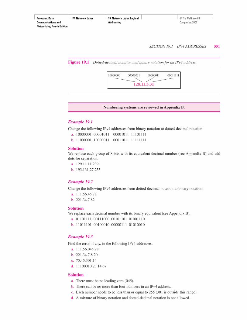
Figure 19.1 shows an IPv4 address in both binary and dotted-decimal notation.Note that because each byte (octet) is 8 bits, each number in dotted-decimal notation isa value ranging from 0 to 255.
The IPv4 addresses are unique and universal.
The address space of IPv4 is 232 or 4,294,967,296.
01110101 10010101 00011101 00000010
117.149.29.2
Forouzan: Data Communications and Networking, Fourth Edition
IV. Network Layer 19. Network Layer: Logical Addressing
© The McGraw−Hill Companies, 2007
SECTION 19.1 IPv4 ADDRESSES 551
Example 19.1
Change the following IPv4 addresses from binary notation to dotted-decimal notation.
a. 10000001 00001011 00001011 11101111
b. 11000001 10000011 00011011 11111111
SolutionWe replace each group of 8 bits with its equivalent decimal number (see Appendix B) and adddots for separation.
a. 129.11.11.239
b. 193.131.27.255
Example 19.2
Change the following IPv4 addresses from dotted-decimal notation to binary notation.
a. 111.56.45.78
b. 221.34.7.82
SolutionWe replace each decimal number with its binary equivalent (see Appendix B).
a. 01101111 00111000 00101101 01001110
b. 11011101 00100010 00000111 01010010
Example 19.3
Find the error, if any, in the following IPv4 addresses.
a. 111.56.045.78
b. 221.34.7.8.20
c. 75.45.301.14
d. 11100010.23.14.67
Solutiona. There must be no leading zero (045).
b. There can be no more than four numbers in an IPv4 address.
c. Each number needs to be less than or equal to 255 (301 is outside this range).
d. A mixture of binary notation and dotted-decimal notation is not allowed.
Figure 19.1 Dotted-decimal notation and binary notation for an IPv4 address
Numbering systems are reviewed in Appendix B.
10000000 00001011 00000011 00011111
128.11.3.31

Forouzan: Data Communications and Networking, Fourth Edition
IV. Network Layer 19. Network Layer: Logical Addressing
© The McGraw−Hill Companies, 2007
552 CHAPTER 19 NETWORK LAYER: LOGICAL ADDRESSING
Classful AddressingIPv4 addressing, at its inception, used the concept of classes. This architecture is calledclassful addressing. Although this scheme is becoming obsolete, we briefly discuss ithere to show the rationale behind classless addressing.
In classful addressing, the address space is divided into five classes: A, B, C, D,and E. Each class occupies some part of the address space.
We can find the class of an address when given the address in binary notationor dotted-decimal notation. If the address is given in binary notation, the first fewbits can immediately tell us the class of the address. If the address is given indecimal-dotted notation, the first byte defines the class. Both methods are shown inFigure 19.2.
Example 19.4
Find the class of each address.
a. 00000001 00001011 00001011 11101111
b. 11000001 10000011 00011011 11111111
c. 14.23.120.8
d. 252.5.15.111
Solutiona. The first bit is 0. This is a class A address.
b. The first 2 bits are 1; the third bit is 0. This is a class C address.c. The first byte is 14 (between 0 and 127); the class is A.
d. The first byte is 252 (between 240 and 255); the class is E.
In classful addressing, the address space is divided into five classes:A, B, C, D, and E.
Figure 19.2 Finding the classes in binary and dotted-decimal notation
a. Binary notation b. Dotted-decimal notation
Firstbyte
Thirdbyte
Secondbyte
Fourthbyte
0
10
110
1110
1111
Class A
Class B
Class C
Class D
Class E
Thirdbyte
Secondbyte
Fourthbyte
Firstbyte
Class A
Class B
Class C
Class D
Class E
0–127
128–191
192–223
240–255
224–239

Forouzan: Data Communications and Networking, Fourth Edition
IV. Network Layer 19. Network Layer: Logical Addressing
© The McGraw−Hill Companies, 2007
SECTION 19.1 IPv4 ADDRESSES 553
Classes and Blocks
One problem with classful addressing is that each class is divided into a fixed numberof blocks with each block having a fixed size as shown in Table 19.1.
Let us examine the table. Previously, when an organization requested a block ofaddresses, it was granted one in class A, B, or C. Class A addresses were designed forlarge organizations with a large number of attached hosts or routers. Class B addresseswere designed for midsize organizations with tens of thousands of attached hosts orrouters. Class C addresses were designed for small organizations with a small number ofattached hosts or routers.
We can see the flaw in this design. A block in class A address is too large foralmost any organization. This means most of the addresses in class A were wasted andwere not used. A block in class B is also very large, probably too large for many of theorganizations that received a class B block. A block in class C is probably too small formany organizations. Class D addresses were designed for multicasting as we will see ina later chapter. Each address in this class is used to define one group of hosts on theInternet. The Internet authorities wrongly predicted a need for 268,435,456 groups.This never happened and many addresses were wasted here too. And lastly, the class Eaddresses were reserved for future use; only a few were used, resulting in another wasteof addresses.
Netid and Hostid
In classful addressing, an IP address in class A, B, or C is divided into netid and hostid.These parts are of varying lengths, depending on the class of the address. Figure 19.2shows some netid and hostid bytes. The netid is in color, the hostid is in white. Note thatthe concept does not apply to classes D and E.
In class A, one byte defines the netid and three bytes define the hostid. In class B,two bytes define the netid and two bytes define the hostid. In class C, three bytes definethe netid and one byte defines the hostid.
Mask
Although the length of the netid and hostid (in bits) is predetermined in classful address-ing, we can also use a mask (also called the default mask), a 32-bit number made of
Table 19.1 Number of blocks and block size in classful IPv4 addressing
Class Number of Blocks Block Size Application
A 128 16,777,216 Unicast
B 16,384 65,536 Unicast
C 2,097,152 256 Unicast
D 1 268,435,456 Multicast
E 1 268,435,456 Reserved
In classful addressing, a large part of the available addresses were wasted.

Forouzan: Data Communications and Networking, Fourth Edition
IV. Network Layer 19. Network Layer: Logical Addressing
© The McGraw−Hill Companies, 2007
554 CHAPTER 19 NETWORK LAYER: LOGICAL ADDRESSING
contiguous 1s followed by contiguous 0s. The masks for classes A, B, and C are shownin Table 19.2. The concept does not apply to classes D and E.
The mask can help us to find the netid and the hostid. For example, the mask for aclass A address has eight 1s, which means the first 8 bits of any address in class Adefine the netid; the next 24 bits define the hostid.
The last column of Table 19.2 shows the mask in the form /n where n can be 8, 16,or 24 in classful addressing. This notation is also called slash notation or ClasslessInterdomain Routing (CIDR) notation. The notation is used in classless addressing,which we will discuss later. We introduce it here because it can also be applied to class-ful addressing. We will show later that classful addressing is a special case of classlessaddressing.
Subnetting
During the era of classful addressing, subnetting was introduced. If an organization wasgranted a large block in class A or B, it could divide the addresses into several contiguousgroups and assign each group to smaller networks (called subnets) or, in rare cases,share part of the addresses with neighbors. Subnetting increases the number of 1s in themask, as we will see later when we discuss classless addressing.
Supernetting
The time came when most of the class A and class B addresses were depleted; however,there was still a huge demand for midsize blocks. The size of a class C block with amaximum number of 256 addresses did not satisfy the needs of most organizations.Even a midsize organization needed more addresses. One solution was supernetting.In supernetting, an organization can combine several class C blocks to create a largerrange of addresses. In other words, several networks are combined to create a super-network or a supernet. An organization can apply for a set of class C blocks instead ofjust one. For example, an organization that needs 1000 addresses can be granted fourcontiguous class C blocks. The organization can then use these addresses to create onesupernetwork. Supernetting decreases the number of 1s in the mask. For example, if anorganization is given four class C addresses, the mask changes from /24 to /22. We willsee that classless addressing eliminated the need for supernetting.
Address Depletion
The flaws in classful addressing scheme combined with the fast growth of the Internet ledto the near depletion of the available addresses. Yet the number of devices on the Internetis much less than the 232 address space. We have run out of class A and B addresses, and
Table 19.2 Default masks for classful addressing
Class Binary Dotted-Decimal CIDR
A 11111111 00000000 00000000 00000000 255.0.0.0 /8
B 11111111 11111111 00000000 00000000 255.255.0.0 /16
C 11111111 11111111 11111111 00000000 255.255.255.0 /24

Forouzan: Data Communications and Networking, Fourth Edition
IV. Network Layer 19. Network Layer: Logical Addressing
© The McGraw−Hill Companies, 2007
SECTION 19.1 IPv4 ADDRESSES 555
a class C block is too small for most midsize organizations. One solution that hasalleviated the problem is the idea of classless addressing.
Classless AddressingTo overcome address depletion and give more organizations access to the Internet,classless addressing was designed and implemented. In this scheme, there are noclasses, but the addresses are still granted in blocks.
Address Blocks
In classless addressing, when an entity, small or large, needs to be connected to theInternet, it is granted a block (range) of addresses. The size of the block (the number ofaddresses) varies based on the nature and size of the entity. For example, a householdmay be given only two addresses; a large organization may be given thousands ofaddresses. An ISP, as the Internet service provider, may be given thousands or hundredsof thousands based on the number of customers it may serve.
Restriction To simplify the handling of addresses, the Internet authorities imposethree restrictions on classless address blocks:
1. The addresses in a block must be contiguous, one after another.
2. The number of addresses in a block must be a power of 2 (1, 2, 4, 8, . . . ).
3. The first address must be evenly divisible by the number of addresses.
Example 19.5
Figure 19.3 shows a block of addresses, in both binary and dotted-decimal notation, granted to asmall business that needs 16 addresses.
We can see that the restrictions are applied to this block. The addresses are contiguous.The number of addresses is a power of 2 (16 = 24), and the first address is divisible by 16. Thefirst address, when converted to a decimal number, is 3,440,387,360, which when divided by16 results in 215,024,210. In Appendix B, we show how to find the decimal value of anIP address.
Classful addressing, which is almost obsolete, is replaced with classless addressing.
Figure 19.3 A block of 16 addresses granted to a small organization
a. Decimal
Block Block
b. Binary
16 A
ddre
ssesFirst
Last
001000000001000011001101 00100101
001000010001000011001101
001011110001000011001101
00100101
00100101
205.16.37.32
205.16.37.33
205.16.37.47
• • •• • •

Forouzan: Data Communications and Networking, Fourth Edition
IV. Network Layer 19. Network Layer: Logical Addressing
© The McGraw−Hill Companies, 2007
556 CHAPTER 19 NETWORK LAYER: LOGICAL ADDRESSING
Mask
A better way to define a block of addresses is to select any address in the block and themask. As we discussed before, a mask is a 32-bit number in which the n leftmost bitsare 1s and the 32 − n rightmost bits are 0s. However, in classless addressing the maskfor a block can take any value from 0 to 32. It is very convenient to give just the valueof n preceded by a slash (CIDR notation).
The address and the /n notation completely define the whole block (the firstaddress, the last address, and the number of addresses).
First Address The first address in the block can be found by setting the 32 − n right-most bits in the binary notation of the address to 0s.
Example 19.6
A block of addresses is granted to a small organization. We know that one of the addresses is205.16.37.39/28. What is the first address in the block?
SolutionThe binary representation of the given address is 11001101 00010000 00100101 00100111. If weset 32 − 28 rightmost bits to 0, we get 11001101 0001000 00100101 0010000 or 205.16.37.32.This is actually the block shown in Figure 19.3.
Last Address The last address in the block can be found by setting the 32 − n right-most bits in the binary notation of the address to 1s.
Example 19.7
Find the last address for the block in Example 19.6.
SolutionThe binary representation of the given address is 11001101 00010000 00100101 00100111. If weset 32 − 28 rightmost bits to 1, we get 11001101 00010000 00100101 00101111 or 205.16.37.47.This is actually the block shown in Figure 19.3.
Number of Addresses The number of addresses in the block is the difference betweenthe last and first address. It can easily be found using the formula 232−n.
In IPv4 addressing, a block of addresses can be defined as x.y.z.t /n
in which x.y.z.t defines one of the addresses and the /n defines the mask.
The first address in the block can be found by setting the rightmost 32 − n bits to 0s.
The last address in the block can be found by setting the rightmost 32 − n bits to 1s.
The number of addresses in the block can be found by using the formula 232−n.

Forouzan: Data Communications and Networking, Fourth Edition
IV. Network Layer 19. Network Layer: Logical Addressing
© The McGraw−Hill Companies, 2007
SECTION 19.1 IPv4 ADDRESSES 557
Example 19.8
Find the number of addresses in Example 19.6.
SolutionThe value of n is 28, which means that number of addresses is 232−28 or 16.
Example 19.9
Another way to find the first address, the last address, and the number of addresses is to representthe mask as a 32-bit binary (or 8-digit hexadecimal) number. This is particularly useful when weare writing a program to find these pieces of information. In Example 19.5 the /28 can be repre-sented as 11111111 11111111 11111111 11110000 (twenty-eight 1s and four 0s). Find
a. The first address
b. The last address
c. The number of addresses
Solutiona. The first address can be found by ANDing the given addresses with the mask. ANDing here is
done bit by bit. The result of ANDing 2 bits is 1 if both bits are 1s; the result is 0 otherwise.
b. The last address can be found by ORing the given addresses with the complement of themask. ORing here is done bit by bit. The result of ORing 2 bits is 0 if both bits are 0s; theresult is 1 otherwise. The complement of a number is found by changing each 1 to 0 andeach 0 to 1.
c. The number of addresses can be found by complementing the mask, interpreting it as adecimal number, and adding 1 to it.
Network Addresses
A very important concept in IP addressing is the network address. When an organiza-tion is given a block of addresses, the organization is free to allocate the addresses tothe devices that need to be connected to the Internet. The first address in the class, how-ever, is normally (not always) treated as a special address. The first address is called thenetwork address and defines the organization network. It defines the organization itselfto the rest of the world. In a later chapter we will see that the first address is the one thatis used by routers to direct the message sent to the organization from the outside.
Address: 11001101 00010000 00100101 00100111
Mask: 11111111 11111111 11111111 11110000
First address: 11001101 00010000 00100101 00100000
Address: 11001101 00010000 00100101 00100111
Mask complement: 00000000 00000000 00000000 00001111
Last address: 11001101 00010000 00100101 00101111
Mask complement: 000000000 00000000 00000000 00001111
Number of addresses: 15 + 1 = 16

Forouzan: Data Communications and Networking, Fourth Edition
IV. Network Layer 19. Network Layer: Logical Addressing
© The McGraw−Hill Companies, 2007
558 CHAPTER 19 NETWORK LAYER: LOGICAL ADDRESSING
Figure 19.4 shows an organization that is granted a 16-address block.
The organization network is connected to the Internet via a router. The router hastwo addresses. One belongs to the granted block; the other belongs to the network thatis at the other side of the router. We call the second address x.y.z.t/n because we do notknow anything about the network it is connected to at the other side. All messages des-tined for addresses in the organization block (205.16.37.32 to 205.16.37.47) are sent,directly or indirectly, to x.y.z.t/n. We say directly or indirectly because we do not knowthe structure of the network to which the other side of the router is connected.
Hierarchy
IP addresses, like other addresses or identifiers we encounter these days, have levels ofhierarchy. For example, a telephone network in North America has three levels of hier-archy. The leftmost three digits define the area code, the next three digits define theexchange, the last four digits define the connection of the local loop to the centraloffice. Figure 19.5 shows the structure of a hierarchical telephone number.
Figure 19.4 A network configuration for the block 205.16.37.32/28
The first address in a block is normally not assigned to any device; it is used as the network address that represents the organization to the rest of the world.
Figure 19.5 Hierarchy in a telephone network in North America
Network address: 205.16.37.32/28
Organizationnetwork
All messages with receiver addresses205.16.37.32 to 205.16.37.47
are routed to x.y.z.t/n
205.16.37.33/28 205.16.37.34/28 205.16.37.39/28
x.y.
z.t/n
205.16.37.46/28 205.16.37.47/28
205.
16.3
7.40
/28
Rest ofthe Internet
864 8902–408( )
Area code
Exchange office
Subscriber
Forouzan: Data Communications and Networking, Fourth Edition
IV. Network Layer 19. Network Layer: Logical Addressing
© The McGraw−Hill Companies, 2007
SECTION 19.1 IPv4 ADDRESSES 559
Two-Level Hierarchy: No Subnetting
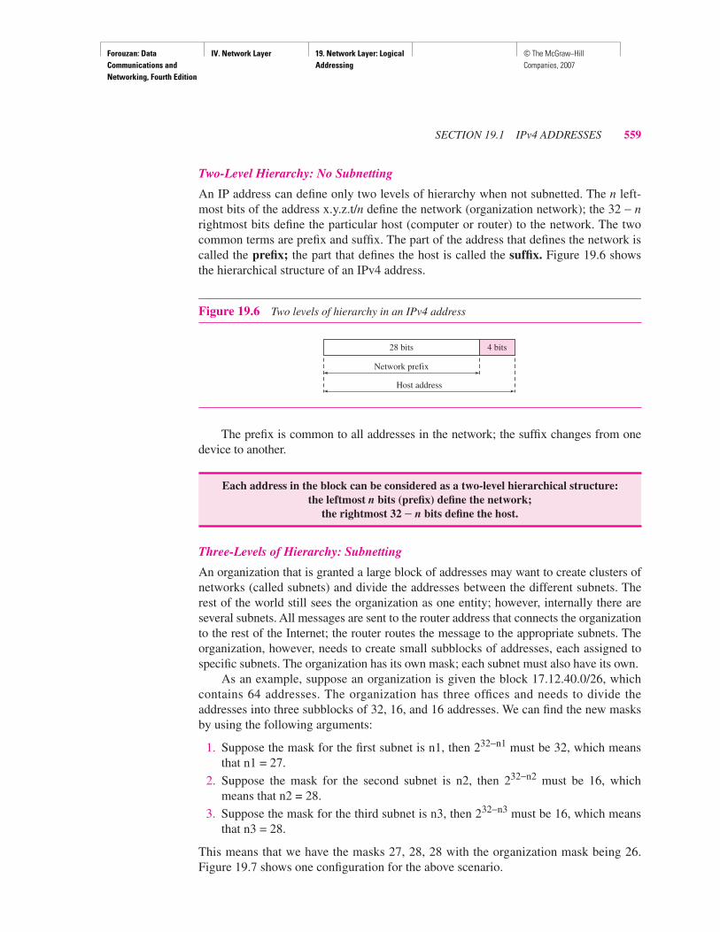
An IP address can define only two levels of hierarchy when not subnetted. The n left-most bits of the address x.y.z.t/n define the network (organization network); the 32 − nrightmost bits define the particular host (computer or router) to the network. The twocommon terms are prefix and suffix. The part of the address that defines the network iscalled the prefix; the part that defines the host is called the suffix. Figure 19.6 showsthe hierarchical structure of an IPv4 address.
The prefix is common to all addresses in the network; the suffix changes from onedevice to another.
Three-Levels of Hierarchy: Subnetting
An organization that is granted a large block of addresses may want to create clusters ofnetworks (called subnets) and divide the addresses between the different subnets. Therest of the world still sees the organization as one entity; however, internally there areseveral subnets. All messages are sent to the router address that connects the organizationto the rest of the Internet; the router routes the message to the appropriate subnets. Theorganization, however, needs to create small subblocks of addresses, each assigned tospecific subnets. The organization has its own mask; each subnet must also have its own.
As an example, suppose an organization is given the block 17.12.40.0/26, whichcontains 64 addresses. The organization has three offices and needs to divide theaddresses into three subblocks of 32, 16, and 16 addresses. We can find the new masksby using the following arguments:
1. Suppose the mask for the first subnet is n1, then 232−n1 must be 32, which meansthat n1 = 27.
2. Suppose the mask for the second subnet is n2, then 232−n2 must be 16, whichmeans that n2 = 28.
3. Suppose the mask for the third subnet is n3, then 232−n3 must be 16, which meansthat n3 = 28.
This means that we have the masks 27, 28, 28 with the organization mask being 26.Figure 19.7 shows one configuration for the above scenario.
Figure 19.6 Two levels of hierarchy in an IPv4 address
Each address in the block can be considered as a two-level hierarchical structure:the leftmost n bits (prefix) define the network;
the rightmost 32 − n bits define the host.
Network prefix
Host address
28 bits 4 bits

Forouzan: Data Communications and Networking, Fourth Edition
IV. Network Layer 19. Network Layer: Logical Addressing
© The McGraw−Hill Companies, 2007
560 CHAPTER 19 NETWORK LAYER: LOGICAL ADDRESSING
Let us check to see if we can find the subnet addresses from one of the addresses inthe subnet.
a. In subnet 1, the address 17.12.14.29/27 can give us the subnet address if we use themask /27 because
b. In subnet 2, the address 17.12.14.45/28 can give us the subnet address if we use themask /28 because
c. In subnet 3, the address 17.12.14.50/28 can give us the subnet address if we use themask /28 because
Figure 19.7 Configuration and addresses in a subnetted network
Host: 00010001 00001100 00001110 00011101
Mask: /27
Subnet: 00010001 00001100 00001110 00000000 ➡ (17.12.14.0)
Host: 00010001 00001100 00001110 00101101Mask: /28Subnet: 00010001 00001100 00001110 00100000 ➡ (17.12.14.32)
Host: 00010001 00001100 00001110 00110010Mask: /28Subnet: 00010001 00001100 00001110 00110000 ➡ (17.12.14.48)
To the rest ofthe Internet
Subnet 1 Subnet 3
x.y.z.t/nNetwork: 17.12.14.0/26
17.12.14.1/27
• • •• • •
• • •
17.12.14.49/2817.12.14.50/28
17.12.14.62/28
17.12.14.63/28
17.12.14.2/27
17.12.14.31/27
17.12.14.30/27
17.12.14.20/27Subnet 2
• • •
17.12.14.33/2817.12.14.34/28
17.12.14.46/28
17.12.14.47/28
17.1
2.14
.32/
2817
.12.
14.4
8/28
17.1
2.14
.0/2
7
Forouzan: Data Communications and Networking, Fourth Edition
IV. Network Layer 19. Network Layer: Logical Addressing
© The McGraw−Hill Companies, 2007
SECTION 19.1 IPv4 ADDRESSES 561
Note that applying the mask of the network, /26, to any of the addresses gives us thenetwork address 17.12.14.0/26. We leave this proof to the reader.
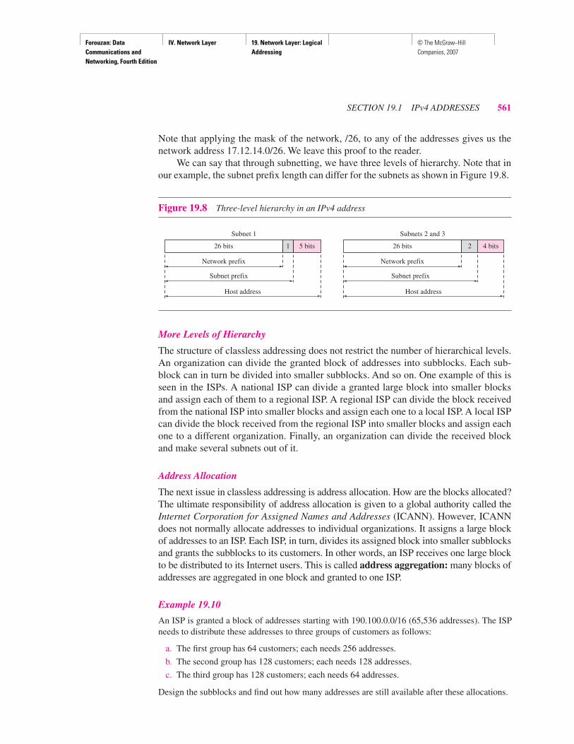
We can say that through subnetting, we have three levels of hierarchy. Note that inour example, the subnet prefix length can differ for the subnets as shown in Figure 19.8.
More Levels of Hierarchy
The structure of classless addressing does not restrict the number of hierarchical levels.An organization can divide the granted block of addresses into subblocks. Each sub-block can in turn be divided into smaller subblocks. And so on. One example of this isseen in the ISPs. A national ISP can divide a granted large block into smaller blocksand assign each of them to a regional ISP. A regional ISP can divide the block receivedfrom the national ISP into smaller blocks and assign each one to a local ISP. A local ISPcan divide the block received from the regional ISP into smaller blocks and assign eachone to a different organization. Finally, an organization can divide the received blockand make several subnets out of it.
Address Allocation
The next issue in classless addressing is address allocation. How are the blocks allocated?The ultimate responsibility of address allocation is given to a global authority called theInternet Corporation for Assigned Names and Addresses (ICANN). However, ICANNdoes not normally allocate addresses to individual organizations. It assigns a large blockof addresses to an ISP. Each ISP, in turn, divides its assigned block into smaller subblocksand grants the subblocks to its customers. In other words, an ISP receives one large blockto be distributed to its Internet users. This is called address aggregation: many blocks ofaddresses are aggregated in one block and granted to one ISP.
Example 19.10
An ISP is granted a block of addresses starting with 190.100.0.0/16 (65,536 addresses). The ISPneeds to distribute these addresses to three groups of customers as follows:
a. The first group has 64 customers; each needs 256 addresses.
b. The second group has 128 customers; each needs 128 addresses.
c. The third group has 128 customers; each needs 64 addresses.
Design the subblocks and find out how many addresses are still available after these allocations.
Figure 19.8 Three-level hierarchy in an IPv4 address
Network prefix
Subnet prefix
Host address
26 bits
Subnet 1
5 bits1
Network prefix
Subnet prefix
Host address
26 bits
Subnets 2 and 3
4 bits2

Forouzan: Data Communications and Networking, Fourth Edition
IV. Network Layer 19. Network Layer: Logical Addressing
© The McGraw−Hill Companies, 2007
562 CHAPTER 19 NETWORK LAYER: LOGICAL ADDRESSING
SolutionFigure 19.9 shows the situation.
1. Group 1
For this group, each customer needs 256 addresses. This means that 8 (log2 256) bits areneeded to define each host. The prefix length is then 32 − 8 = 24. The addresses are
2. Group 2
For this group, each customer needs 128 addresses. This means that 7 (log2 128) bits areneeded to define each host. The prefix length is then 32 − 7 = 25. The addresses are
3. Group 3
For this group, each customer needs 64 addresses. This means that 6 (log2 64) bits are neededto each host. The prefix length is then 32 − 6 = 26. The addresses are
Figure 19.9 An example of address allocation and distribution by an ISP
1st Customer: 190.100.0.0/24 190.100.0.255/24
2nd Customer: 190.100.1.0/24 190.100.1.255/24. . .
64th Customer: 190.100.63.0/24 190.100.63.255/24
Total = 64 × 256 = 16,384
1st Customer: 190.100.64.0/25 190.100.64.127/25
2nd Customer: 190.100.64.128/25 190.100.64.255/25. . .
128th Customer: 190.100.127.128/25 190.100.127.255/25
Total = 128 × 128 = 16,384
Gra
nted
add
ress
es:
190.
100.
0.0
to19
0.10
0.25
5.25
5
ISP
Customer 064: 190.100.63.0/24
Customer 001: 190.100.64.0/25
Customer 128: 190.100.127.128/25
Customer 001: 190.100.128.0/26
Customer 128: 190.100.159.192/26
Customer 001: 190.100.0.0/24Group 1: 190.100.0.0 to 190.100.63.255
To and fromthe Internet
Group 2: 190.100.64.0 to 190.100.127.255
Group 3: 190.100.128.0 to 190.100.159.255
Available190.100.160.0 to 190.100.255.255
• • •
• • •
• • •

Forouzan: Data Communications and Networking, Fourth Edition
IV. Network Layer 19. Network Layer: Logical Addressing
© The McGraw−Hill Companies, 2007
SECTION 19.1 IPv4 ADDRESSES 563
Number of granted addresses to the ISP: 65,536Number of allocated addresses by the ISP: 40,960Number of available addresses: 24,576
Network Address Translation (NAT)The number of home users and small businesses that want to use the Internet is everincreasing. In the beginning, a user was connected to the Internet with a dial-up line,which means that she was connected for a specific period of time. An ISP with a block ofaddresses could dynamically assign an address to this user. An address was given to auser when it was needed. But the situation is different today. Home users and small busi-nesses can be connected by an ADSL line or cable modem. In addition, many are nothappy with one address; many have created small networks with several hosts and needan IP address for each host. With the shortage of addresses, this is a serious problem.
A quick solution to this problem is called network address translation (NAT).NAT enables a user to have a large set of addresses internally and one address, or a smallset of addresses, externally. The traffic inside can use the large set; the traffic outside, thesmall set.
To separate the addresses used inside the home or business and the ones used forthe Internet, the Internet authorities have reserved three sets of addresses as privateaddresses, shown in Table 19.3.
Any organization can use an address out of this set without permission from theInternet authorities. Everyone knows that these reserved addresses are for private net-works. They are unique inside the organization, but they are not unique globally. Norouter will forward a packet that has one of these addresses as the destination address.
The site must have only one single connection to the global Internet through a routerthat runs the NAT software. Figure 19.10 shows a simple implementation of NAT.
As Figure 19.10 shows, the private network uses private addresses. The router thatconnects the network to the global address uses one private address and one globaladdress. The private network is transparent to the rest of the Internet; the rest of theInternet sees only the NAT router with the address 200.24.5.8.
1st Customer: 190.100.128.0/26 190.100.128.63/26
2nd Customer: 190.100.128.64/26 190.100.128.127/26. . .
128th Customer: 190.100.159.192/26 190.100.159.255/26
Total = 128 × 64 = 8192
Table 19.3 Addresses for private networks
Range Total
10.0.0.0 to 10.255.255.255 224
172.16.0.0 to 172.31.255.255 220
192.168.0.0 to 192.168.255.255 216

Forouzan: Data Communications and Networking, Fourth Edition
IV. Network Layer 19. Network Layer: Logical Addressing
© The McGraw−Hill Companies, 2007
564 CHAPTER 19 NETWORK LAYER: LOGICAL ADDRESSING
Address Translation
All the outgoing packets go through the NAT router, which replaces the source addressin the packet with the global NAT address. All incoming packets also pass through theNAT router, which replaces the destination address in the packet (the NAT router globaladdress) with the appropriate private address. Figure 19.11 shows an example of addresstranslation.
Translation Table
The reader may have noticed that translating the source addresses for outgoing packetsis straightforward. But how does the NAT router know the destination address for apacket coming from the Internet? There may be tens or hundreds of private IP addresses,each belonging to one specific host. The problem is solved if the NAT router has a trans-lation table.
Using One IP Address In its simplest form, a translation table has only two columns:the private address and the external address (destination address of the packet). Whenthe router translates the source address of the outgoing packet, it also makes note of thedestination address—where the packet is going. When the response comes back fromthe destination, the router uses the source address of the packet (as the external address)to find the private address of the packet. Figure 19.12 shows the idea. Note that theaddresses that are changed (translated) are shown in color.
Figure 19.10 A NAT implementation
Figure 19.11 Addresses in a NAT
Site using private addresses
NAT router
172.18.3.30 200.24.5.8
172.18.3.1 172.18.3.2 172.18.3.20
Internet
• • •
172.18.3.1Source: 172.18.3.1
Destination: 172.18.3.1
Source: 200.24.5.8
Destination: 200.24.5.8
Internet

Forouzan: Data Communications and Networking, Fourth Edition
IV. Network Layer 19. Network Layer: Logical Addressing
© The McGraw−Hill Companies, 2007
SECTION 19.1 IPv4 ADDRESSES 565
In this strategy, communication must always be initiated by the private network.The NAT mechanism described requires that the private network start the communica-tion. As we will see, NAT is used mostly by ISPs which assign one single address to acustomer. The customer, however, may be a member of a private network that has manyprivate addresses. In this case, communication with the Internet is always initiated fromthe customer site, using a client program such as HTTP, TELNET, or FTP to access thecorresponding server program. For example, when e-mail that originates from a non-customer site is received by the ISP e-mail server, the e-mail is stored in the mailbox ofthe customer until retrieved. A private network cannot run a server program for clientsoutside of its network if it is using NAT technology.
Using a Pool of IP Addresses Since the NAT router has only one global address, onlyone private network host can access the same external host. To remove this restriction, theNAT router uses a pool of global addresses. For example, instead of using only one globaladdress (200.24.5.8), the NAT router can use four addresses (200.24.5.8, 200.24.5.9,200.24.5.10, and 200.24.5.11). In this case, four private network hosts can communicatewith the same external host at the same time because each pair of addresses defines aconnection. However, there are still some drawbacks. In this example, no more than fourconnections can be made to the same destination. Also, no private-network host canaccess two external server programs (e.g., HTTP and FTP) at the same time.
Using Both IP Addresses and Port Numbers To allow a many-to-many relationshipbetween private-network hosts and external server programs, we need more informationin the translation table. For example, suppose two hosts with addresses 172.18.3.1 and172.18.3.2 inside a private network need to access the HTTP server on external host
Figure 19.12 NAT address translation
Source: 200.24.5.8
Destination: 200.24.5.8
Source: 172.18.3.1
Destination: 172.18.3.1
Translation table
172.18.3.1
Destination: 25.8.2.10
Source: 25.8.2.10Source: 25.8.2.10
25.8.2.10
Destination: 25.8.2.10
Private External
• • •• • •

Forouzan: Data Communications and Networking, Fourth Edition
IV. Network Layer 19. Network Layer: Logical Addressing
© The McGraw−Hill Companies, 2007
566 CHAPTER 19 NETWORK LAYER: LOGICAL ADDRESSING
25.8.3.2. If the translation table has five columns, instead of two, that include the sourceand destination port numbers of the transport layer protocol, the ambiguity is eliminated.We discuss port numbers in Chapter 23. Table 19.4 shows an example of such a table.
Note that when the response from HTTP comes back, the combination of sourceaddress (25.8.3.2) and destination port number (1400) defines the private network hostto which the response should be directed. Note also that for this translation to work, thetemporary port numbers (1400 and 1401) must be unique.
NAT and ISP
An ISP that serves dial-up customers can use NAT technology to conserve addresses.For example, suppose an ISP is granted 1000 addresses, but has 100,000 customers.Each of the customers is assigned a private network address. The ISP translates each ofthe 100,000 source addresses in outgoing packets to one of the 1000 global addresses;it translates the global destination address in incoming packets to the correspondingprivate address. Figure 19.13 shows this concept.
19.2 IPv6 ADDRESSESDespite all short-term solutions, such as classless addressing, Dynamic Host Configu-ration Protocol (DHCP), discussed in Chapter 21, and NAT, address depletion is still along-term problem for the Internet. This and other problems in the IP protocol itself,
Table 19.4 Five-column translation table
PrivateAddress
PrivatePort
ExternalAddress
ExternalPort
TransportProtocol
172.18.3.1 1400 25.8.3.2 80 TCP
172.18.3.2 1401 25.8.3.2 80 TCP
. . . . . . . . . . . . . . .
Figure 19.13 An ISP and NAT
172.18.3.1
ISPsite
172.24.1.1
172.30.100
Internet
1000addresses
• • •• • •
• • •• • •

Forouzan: Data Communications and Networking, Fourth Edition
IV. Network Layer 19. Network Layer: Logical Addressing
© The McGraw−Hill Companies, 2007
SECTION 19.2 IPv6 ADDRESSES 567
such as lack of accommodation for real-time audio and video transmission, and encryp-tion and authentication of data for some applications, have been the motivation for IPv6.In this section, we compare the address structure of IPv6 to IPv4. In Chapter 20, wediscuss both protocols.
StructureAn IPv6 address consists of 16 bytes (octets); it is 128 bits long.
Hexadecimal Colon Notation
To make addresses more readable, IPv6 specifies hexadecimal colon notation. In this nota-tion, 128 bits is divided into eight sections, each 2 bytes in length. Two bytes in hexadecimalnotation requires four hexadecimal digits. Therefore, the address consists of 32 hexadecimaldigits, with every four digits separated by a colon, as shown in Figure 19.14.
Abbreviation
Although the IP address, even in hexadecimal format, is very long, many of the digits arezeros. In this case, we can abbreviate the address. The leading zeros of a section (fourdigits between two colons) can be omitted. Only the leading zeros can be dropped, notthe trailing zeros (see Figure 19.15).
An IPv6 address is 128 bits long.
Figure 19.14 IPv6 address in binary and hexadecimal colon notation
Figure 19.15 Abbreviated IPv6 addresses
1111110111101100 1111111111111111
128 bits = 16 bytes = 32 hex digits
FDEC 0074 0000 0000 0000 B0FF 0000 FFFF
• • •
FDEC 0074 0000 0000 0000 B0FF 0000 FFF0
Original
Abbreviated FDEC 74 0 00 B0FF 0 FFF0
FDEC 74 B0FF 0 FFF0More abbreviated
Gap

Forouzan: Data Communications and Networking, Fourth Edition
IV. Network Layer 19. Network Layer: Logical Addressing
© The McGraw−Hill Companies, 2007
568 CHAPTER 19 NETWORK LAYER: LOGICAL ADDRESSING
Using this form of abbreviation, 0074 can be written as 74, 000F as F, and 0000 as 0.Note that 3210 cannot be abbreviated. Further abbreviations are possible if there areconsecutive sections consisting of zeros only. We can remove the zeros altogether andreplace them with a double semicolon. Note that this type of abbreviation is allowedonly once per address. If there are two runs of zero sections, only one of them can beabbreviated. Reexpansion of the abbreviated address is very simple: Align the unabbre-viated portions and insert zeros to get the original expanded address.
Example 19.11
Expand the address 0:15::1:12:1213 to its original.
SolutionWe first need to align the left side of the double colon to the left of the original pattern and theright side of the double colon to the right of the original pattern to find how many 0s we need toreplace the double colon.
This means that the original address is
Address SpaceIPv6 has a much larger address space; 2128 addresses are available. The designers ofIPv6 divided the address into several categories. A few leftmost bits, called the typeprefix, in each address define its category. The type prefix is variable in length, but it isdesigned such that no code is identical to the first part of any other code. In this way,there is no ambiguity; when an address is given, the type prefix can easily be deter-mined. Table 19.5 shows the prefix for each type of address. The third column showsthe fraction of each type of address relative to the whole address space.
xxxx:xxxx:xxxx:xxxx:xxxx:xxxx:xxxx:xxxx 0: 15: : 1: 12:1213
0000:0015:0000:0000:0000:0001:0012:1213
Table 19.5 Type prefixes for IPv6 addresses
Type Prefix Type Fraction
0000 0000 Reserved 1/256
0000 0001 Unassigned 1/256
0000 001 ISO network addresses 1/128
0000 010 IPX (Novell) network addresses 1/128
0000 011 Unassigned 1/128
0000 1 Unassigned 1/32
0001 Reserved 1/16
001 Reserved 1/8
010 Provider-based unicast addresses 1/8

Forouzan: Data Communications and Networking, Fourth Edition
IV. Network Layer 19. Network Layer: Logical Addressing
© The McGraw−Hill Companies, 2007
SECTION 19.2 IPv6 ADDRESSES 569
Unicast Addresses
A unicast address defines a single computer. The packet sent to a unicast address mustbe delivered to that specific computer. IPv6 defines two types of unicast addresses: geo-graphically based and provider-based. We discuss the second type here; the first type isleft for future definition. The provider-based address is generally used by a normal hostas a unicast address. The address format is shown in Figure 19.16.
Fields for the provider-based address are as follows:
❏ Type identifier. This 3-bit field defines the address as a provider-based address.
❏ Registry identifier. This 5-bit field indicates the agency that has registered theaddress. Currently three registry centers have been defined. INTERNIC (code11000) is the center for North America; RIPNIC (code 01000) is the center forEuropean registration; and APNIC (code 10100) is for Asian and Pacific countries.
011 Unassigned 1/8
100 Geographic-based unicast addresses 1/8
101 Unassigned 1/8
110 Unassigned 1/8
1110 Unassigned 1/16
1111 0 Unassigned 1/32
1111 10 Unassigned 1/64
1111 110 Unassigned 1/128
1111 1110 0 Unassigned 1/512
1111 1110 10 Link local addresses 1/1024
1111 1110 11 Site local addresses 1/1024
1111 1111 Multicast addresses 1/256
Figure 19.16 Prefixes for provider-based unicast address
Table 19.5 Type prefixes for IPv6 addresses (continued)
Type Prefix Type Fraction
Nodeidentifier
Subnetidentifier
Subscriber identifier
Provider identifier
Registry
3 5
INTERNIC 11000RIPNIC 01000APNIC 10100
Provider prefix
Subscriber prefix
Subnet prefix
Forouzan: Data Communications and Networking, Fourth Edition
IV. Network Layer 19. Network Layer: Logical Addressing
© The McGraw−Hill Companies, 2007
570 CHAPTER 19 NETWORK LAYER: LOGICAL ADDRESSING
❏ Provider identifier. This variable-length field identifies the provider for Internetaccess (such as an ISP). A 16-bit length is recommended for this field.
❏ Subscriber identifier. When an organization subscribes to the Internet through aprovider, it is assigned a subscriber identification. A 24-bit length is recommendedfor this field.
❏ Subnet identifier. Each subscriber can have many different subnetworks, and eachsubnetwork can have an identifier. The subnet identifier defines a specific subnetworkunder the territory of the subscriber. A 32-bit length is recommended for this field.
❏ Node identifier. The last field defines the identity of the node connected to a subnet.A length of 48 bits is recommended for this field to make it compatible with the48-bit link (physical) address used by Ethernet. In the future, this link address willprobably be the same as the node physical address.
Multicast Addresses
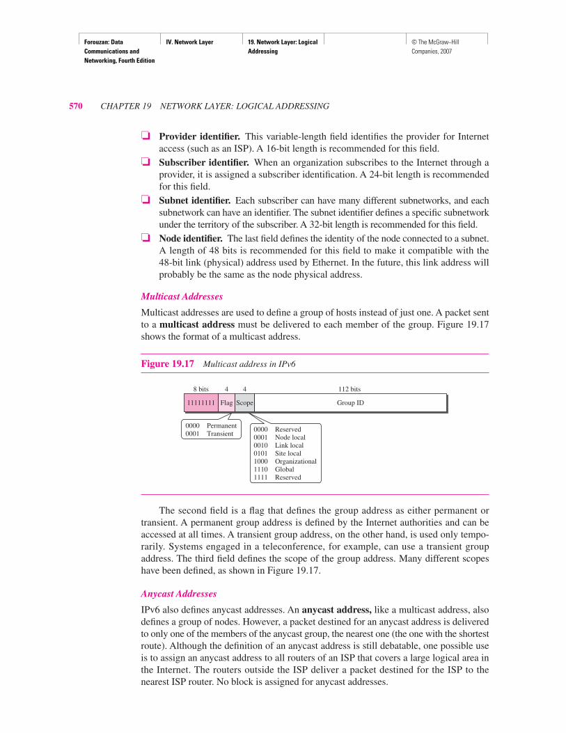
Multicast addresses are used to define a group of hosts instead of just one. A packet sentto a multicast address must be delivered to each member of the group. Figure 19.17shows the format of a multicast address.
The second field is a flag that defines the group address as either permanent ortransient. A permanent group address is defined by the Internet authorities and can beaccessed at all times. A transient group address, on the other hand, is used only tempo-rarily. Systems engaged in a teleconference, for example, can use a transient groupaddress. The third field defines the scope of the group address. Many different scopeshave been defined, as shown in Figure 19.17.
Anycast Addresses
IPv6 also defines anycast addresses. An anycast address, like a multicast address, alsodefines a group of nodes. However, a packet destined for an anycast address is deliveredto only one of the members of the anycast group, the nearest one (the one with the shortestroute). Although the definition of an anycast address is still debatable, one possible useis to assign an anycast address to all routers of an ISP that covers a large logical area inthe Internet. The routers outside the ISP deliver a packet destined for the ISP to thenearest ISP router. No block is assigned for anycast addresses.
Figure 19.17 Multicast address in IPv6
Group ID
112 bits4 4
ScopeFlag
8 bits
11111111
0000 Permanent0001 Transient
0000 Reserved0001 Node local0010 Link local0101 Site local1000 Organizational1110 Global1111 Reserved

Forouzan: Data Communications and Networking, Fourth Edition
IV. Network Layer 19. Network Layer: Logical Addressing
© The McGraw−Hill Companies, 2007
SECTION 19.2 IPv6 ADDRESSES 571
Reserved Addresses
Another category in the address space is the reserved address. These addresses startwith eight 0s (type prefix is 0000 0000). A few subcategories are defined in this category,as shown in Figure 19.18.
An unspecified address is used when a host does not know its own address andsends an inquiry to find its address. A loopback address is used by a host to test itselfwithout going into the network. A compatible address is used during the transitionfrom IPv4 to IPv6 (see Chapter 20). It is used when a computer using IPv6 wants tosend a message to another computer using IPv6, but the message needs to pass througha part of the network that still operates in IPv4. A mapped address is also used duringtransition. However, it is used when a computer that has migrated to IPv6 wants to senda packet to a computer still using IPv4.
Local Addresses
These addresses are used when an organization wants to use IPv6 protocol without beingconnected to the global Internet. In other words, they provide addressing for private net-works. Nobody outside the organization can send a message to the nodes using theseaddresses. Two types of addresses are defined for this purpose, as shown in Figure 19.19.
Figure 19.18 Reserved addresses in IPv6
Figure 19.19 Local addresses in IPv6
All 0s00000000
8 bits 120 bits
a. Unspecified
00000000 00000000000000000................00000000001
8 bits 120 bits
b. Loopback
00000000
8 bits 32 bits
IPv4 addressAll 0s
88 bits
c. Compatible
00000000
8 bits 32 bits
IPv4 addressAll 0s
72 bits
d. Mapped All 1s
16 bits
1111111010
10 bits 48 bits
Node addressAll 0s
70 bits
1111111011
10 bits 48 bits
Node addressAll 0s
a. Link local
b. Site local
38 bitsSubnetaddress
32 bits
Forouzan: Data Communications and Networking, Fourth Edition
IV. Network Layer 19. Network Layer: Logical Addressing
© The McGraw−Hill Companies, 2007
572 CHAPTER 19 NETWORK LAYER: LOGICAL ADDRESSING
A link local address is used in an isolated subnet; a site local address is used inan isolated site with several subnets.
19.3 RECOMMENDED READINGFor more details about subjects discussed in this chapter, we recommend the followingbooks and sites. The items in brackets [. . .] refer to the reference list at the end ofthe text.
BooksIPv4 addresses are discussed in Chapters 4 and 5 of [For06], Chapter 3 of [Ste94], Sec-tion 4.1 of [PD03], Chapter 18 of [Sta04], and Section 5.6 of [Tan03]. IPv6 addressesare discussed in Section 27.1 of [For06] and Chapter 8 of [Los04]. A good discussion ofNAT can be found in [Dut01].
Sites❏ www.ietf.org/rfc.html Information about RFCs
RFCsA discussion of IPv4 addresses can be found in most of the RFCs related to the IPv4protocol:
A discussion of IPv6 addresses can be found in most of the RFCs related to IPv6 protocol:
A discussion of NAT can be found in
760, 781, 791, 815, 1025, 1063, 1071, 1141, 1190, 1191, 1624, 2113
1365, 1550, 1678, 1680, 1682, 1683, 1686, 1688, 1726, 1752, 1826, 1883, 1884, 1886, 1887, 1955, 2080, 2373, 2452, 2463, 2465, 2466, 2472, 2492, 2545, 2590
1361, 2663, 2694
19.4 KEY TERMSaddress aggregation
address space
anycast address
binary notation
class A address
class B address
class C address
class D address
class E address
classful addressing
classless addressing
classless interdomain routing (CIDR)

Forouzan: Data Communications and Networking, Fourth Edition
IV. Network Layer 19. Network Layer: Logical Addressing
© The McGraw−Hill Companies, 2007
SECTION 19.5 SUMMARY 573
19.5 SUMMARY❏ At the network layer, a global identification system that uniquely identifies every
host and router is necessary for delivery of a packet from host to host.
❏ An IPv4 address is 32 bits long and uniquely and universally defines a host orrouter on the Internet.
❏ In classful addressing, the portion of the IP address that identifies the network iscalled the netid.
❏ In classful addressing, the portion of the IP address that identifies the host or routeron the network is called the hostid.
❏ An IP address defines a device’s connection to a network.
❏ There are five classes in IPv4 addresses. Classes A, B, and C differ in the numberof hosts allowed per network. Class D is for multicasting and Class E is reserved.
❏ The class of an address is easily determined by examination of the first byte.
❏ Addresses in classes A, B, or C are mostly used for unicast communication.
❏ Addresses in class D are used for multicast communication.
❏ Subnetting divides one large network into several smaller ones, adding an interme-diate level of hierarchy in IP addressing.
❏ Supernetting combines several networks into one large one.
❏ In classless addressing, we can divide the address space into variable-length blocks.
❏ There are three restrictions in classless addressing:
a. The number of addresses needs to be a power of 2.
b. The mask needs to be included in the address to define the block.
c. The starting address must be divisible by the number of addresses in the block.
❏ The mask in classless addressing is expressed as the prefix length (/n) in CIDR notation.
compatible address
dotted-decimal notation
default mask
hexadecimal colon notation
hostid
IP address
IPv4 address
IPv6 address
link local address
mapped address
mask
multicast address
netid
network address
network address translation(NAT)
prefix
reserved address
site local address
subnet
subnet mask
subnetting
suffix
supernet
supernet mask
supernetting
unicast address
unspecified address

Forouzan: Data Communications and Networking, Fourth Edition
IV. Network Layer 19. Network Layer: Logical Addressing
© The McGraw−Hill Companies, 2007
574 CHAPTER 19 NETWORK LAYER: LOGICAL ADDRESSING
❏ To find the first address in a block, we set the rightmost 32 − n bits to 0.
❏ To find the number of addresses in the block, we calculate 232−n, where n is theprefix length.
❏ To find the last address in the block, we set the rightmost 32 − n bits to 0.
❏ Subnetting increases the value of n.
❏ The global authority for address allocation is ICANN. ICANN normally grantslarge blocks of addresses to ISPs, which in turn grant small subblocks to individualcustomers.
❏ IPv6 addresses use hexadecimal colon notation with abbreviation methods available.
❏ There are three types of addresses in IPv6: unicast, anycast, and multicast.
❏ In an IPv6 address, the variable type prefix field defines the address type or purpose.
19.6 PRACTICE SET
Review Questions1. What is the number of bits in an IPv4 address? What is the number of bits in an
IPv6 address?
2. What is dotted decimal notation in IPv4 addressing? What is the number of bytesin an IPv4 address represented in dotted decimal notation? What is hexadecimalnotation in IPv6 addressing? What is the number of digits in an IPv6 address repre-sented in hexadecimal notation?
3. What are the differences between classful addressing and classless addressing in IPv4?
4. List the classes in classful addressing and define the application of each class (unicast,multicast, broadcast, or reserve).
5. Explain why most of the addresses in class A are wasted. Explain why a medium-sizeor large-size corporation does not want a block of class C addresses.
6. What is a mask in IPv4 addressing? What is a default mask in IPv4 addressing?
7. What is the network address in a block of addresses? How can we find the networkaddress if one of the addresses in a block is given?
8. Briefly define subnetting and supernetting. How do the subnet mask and supernetmask differ from a default mask in classful addressing?
9. How can we distinguish a multicast address in IPv4 addressing? How can we do soin IPv6 addressing?
10. What is NAT? How can NAT help in address depletion?
Exercises11. What is the address space in each of the following systems?
a. A system with 8-bit addresses
b. A system with 16-bit addresses
c. A system with 64-bit addresses

Forouzan: Data Communications and Networking, Fourth Edition
IV. Network Layer 19. Network Layer: Logical Addressing
© The McGraw−Hill Companies, 2007
SECTION 19.6 PRACTICE SET 575
12. An address space has a total of 1024 addresses. How many bits are needed to rep-resent an address?
13. An address space uses the three symbols 0, 1, and 2 to represent addresses.If each address is made of 10 symbols, how many addresses are available in thissystem?
14. Change the following IP addresses from dotted-decimal notation to binary notation.
a. 114.34.2.8
b. 129.14.6.8
c. 208.34.54.12
d. 238.34.2.1
15. Change the following IP addresses from binary notation to dotted-decimal notation.
a. 01111111 11110000 01100111 01111101
b. 10101111 11000000 11111000 00011101
c. 11011111 10110000 00011111 01011101
d. 11101111 11110111 11000111 00011101
16. Find the class of the following IP addresses.
a. 208.34.54.12
b. 238.34.2.1
c. 114.34.2.8
d. 129.14.6.8
17. Find the class of the following IP addresses.
a. 11110111 11110011 10000111 11011101
b. 10101111 11000000 11110000 00011101
c. 11011111 10110000 00011111 01011101
d. 11101111 11110111 11000111 00011101
18. Find the netid and the hostid of the following IP addresses.
a. 114.34.2.8
b. 132.56.8.6
c. 208.34.54.12
19. In a block of addresses, we know the IP address of one host is 25.34.12.56/16.What are the first address (network address) and the last address (limited broadcastaddress) in this block?
20. In a block of addresses, we know the IP address of one host is 182.44.82.16/26.What are the first address (network address) and the last address in this block?
21. An organization is granted the block 16.0.0.0/8. The administrator wants to create500 fixed-length subnets.
a. Find the subnet mask.
b. Find the number of addresses in each subnet.
c. Find the first and last addresses in subnet 1.
d. Find the first and last addresses in subnet 500.

Forouzan: Data Communications and Networking, Fourth Edition
IV. Network Layer 19. Network Layer: Logical Addressing
© The McGraw−Hill Companies, 2007
576 CHAPTER 19 NETWORK LAYER: LOGICAL ADDRESSING
22. An organization is granted the block 130.56.0.0/16. The administrator wants tocreate 1024 subnets.
a. Find the subnet mask.
b. Find the number of addresses in each subnet.
c. Find the first and last addresses in subnet 1.
d. Find the first and last addresses in subnet 1024.
23. An organization is granted the block 211.17.180.0/24. The administrator wants tocreate 32 subnets.
a. Find the subnet mask.
b. Find the number of addresses in each subnet.
c. Find the first and last addresses in subnet 1.
d. Find the first and last addresses in subnet 32.
24. Write the following masks in slash notation (/n).
a. 255.255.255.0
b. 255.0.0.0
c. 255.255.224.0
d. 255.255.240.0
25. Find the range of addresses in the following blocks.
a. 123.56.77.32/29
b. 200.17.21.128/27
c. 17.34.16.0/23
d. 180.34.64.64/30
26. An ISP is granted a block of addresses starting with 150.80.0.0/16. The ISP wantsto distribute these blocks to 2600 customers as follows.
a. The first group has 200 medium-size businesses; each needs 128 addresses.
b. The second group has 400 small businesses; each needs 16 addresses.
c. The third group has 2000 households; each needs 4 addresses.
Design the subblocks and give the slash notation for each subblock. Find out howmany addresses are still available after these allocations.
27. An ISP is granted a block of addresses starting with 120.60.4.0/22. The ISPwants to distribute these blocks to 100 organizations with each organizationreceiving just eight addresses. Design the subblocks and give the slash notationfor each subblock. Find out how many addresses are still available after theseallocations.
28. An ISP has a block of 1024 addresses. It needs to divide the addresses among1024 customers. Does it need subnetting? Explain your answer.
29. Show the shortest form of the following addresses.
a. 2340:1ABC:119A:A000:0000:0000:0000:0000
b. 0000:00AA:0000:0000:0000:0000:119A:A231
c. 2340:0000:0000:0000:0000:119A:A001:0000
d. 0000:0000:0000:2340:0000:0000:0000:0000

Forouzan: Data Communications and Networking, Fourth Edition
IV. Network Layer 19. Network Layer: Logical Addressing
© The McGraw−Hill Companies, 2007
SECTION 19.6 PRACTICE SET 577
30. Show the original (unabbreviated) form of the following addresses.a. 0::0b. 0:AA::0c. 0:1234::3d. 123::1:2
31. What is the type of each of the following addresses?a. FE80::12b. FEC0::24A2c. FF02::0d. 0::01
32. What is the type of each of the following addresses?a. 0::0b. 0::FFFF:0:0c. 582F:1234::2222d. 4821::14:22e. 54EF::A234:2
33. Show the provider prefix (in hexadecimal colon notation) of an address assignedto a subscriber if it is registered in the United States with ABC1 as the provideridentification.
34. Show in hexadecimal colon notation the IPv6 address a. Compatible to the IPv4 address 129.6.12.34 b. Mapped to the IPv4 address 129.6.12.34
35. Show in hexadecimal colon notation a. The link local address in which the node identifier is 0::123/48 b. The site local address in which the node identifier is 0::123/48
36. Show in hexadecimal colon notation the permanent multicast address used in a linklocal scope.
37. A host has the address 581E:1456:2314:ABCD::1211. If the node identification is48 bits, find the address of the subnet to which the host is attached.
38. A site with 200 subnets has the class B address of 132.45.0.0. The site recentlymigrated to IPv6 with the subscriber prefix 581E:1456:2314::ABCD/80. Designthe subnets and define the subnet addresses, using a subnet identifier of 32 bits.
Research Activities39. Find the block of addresses assigned to your organization or institution. 40. If you are using an ISP to connect from your home to the Internet, find the name of
the ISP and the block of addresses assigned to it. 41. Some people argue that we can consider the whole address space as one single
block in which each range of addresses is a subblock to this single block. Elaborateon this idea. What happens to subnetting if we accept this concept?
42. Is your school or organization using a classful address? If so, find out the class ofthe address.