
RISMH ENERGY-1981
430
RISMH ENERGY-1981 SELECTED LECTURES PRESENTED AT A SPRING COLLEGE ON FUSION ENERGY TRIESTE, 26 MAY-19 JUNE 1981 ORGANIZED BY THE INTERNATIONAL CENTRE FOR THEORETICAL PHYSICS, TRIESTE IAEA-SMR-82 INTERNATIONAL CENTRE FOR THEORETICAL PHYSICS, TRIESTE, 1982
-
Upload
khangminh22 -
Category
Documents
-
view
1 -
download
0
Transcript of RISMH ENERGY-1981

RISMH ENERGY-1981SELECTED LECTURES PRESENTED AT ASPRING COLLEGE ON FUSION ENERGY
TRIESTE, 26 MAY-19 JUNE 1981ORGANIZED BY THE
INTERNATIONAL CENTRE FOR THEORETICAL PHYSICS, TRIESTE
IAEA-SMR-82
INTERNATIONAL CENTRE FOR THEORETICAL PHYSICS, TRIESTE, 1982

INTERNATIONAL CENTRE FOR THEORETICAL PHYSICS, TRIESTE, 1982
: ." *•.:
- a- =* : - , '*• i-a "^s*"X~;"~-'•
00
FUSION ENERGY -1981

' ) • ,
THE INTERNATIONAL CENTRE FOR THEORETICAL PHYSICS (ICTP) in Trieste was established by the international Atomic EnergyAgency (IAEA) in 1964 under an agreement with the Italian Government, and with the assistance of the City and University of Trieste.
The IAEA and the United Nations Educational, Scientific and Cultural Organization (UNESCO) subsequently agreed to operate the Centrejointly from 1 January 1970.
Member States of both organizations participate in the work of the Centre, the main purpose of which is to foster, through training andresearch, the advancement of theoretical physics, with special regard to the needs of developing countries.

FUSION ENERGY-1981
SELECTED LECTURES PRESENTED AT ASPRING COLLEGE ON FUSION ENERGY
TRIESTE, 26 MAY-19 JUNE 1981ORGANIZED BY THE
INTERNATIONAL CENTRE FOR THEORETICAL PHYSICS, TRIESTE
INTERNATIONAL CENTRE FOR THEORETICAL PHYSICS, TRIESTE, 1982

1IN 1 liKJN A1HJ1N A L l_tllN 1 K.E, r UR
FUSION ENERGY-1981, IAEA, VIENNA, 1982IAEA-SMR-82
Printed by the IAEA in AustriaFebruary 1982

FOREWORD
The College on Fusion Energy was the third in a series ofmajor activities by ICTP in plasma physics and fusion. Attendedby 170 people from 40 countries, it provided an excellent forumfor presenting original work in developing countries and for de-scription of the latest advances in "big plasma" physics in thefusion programs around the world. Some of the individualachievements in building and operating fusion devices in devel-oping countries are most impressive, as described in theseproceedings.
The state of the art in magnetic and laser plasmas was givenin a number of review talks, which are not published here andare therefore worth describing. R.J. Bickerton outlined the phys-ics hopes for the JET project, Euratom's Joint European Toruswhich is now hoping to operate soon after the US Tokamak,TFTR. T.K. Fowler spoke of the successes of the tandem mirrorsin verifying electrostatic plugging and stabilization of a simplemirror. The tandem upgrade, TMX-U, should produce 1-2 keVcentral cell ion temperatures in 1982 with ECRH heated plugs.The breakeven tandem machine, MFTF-B, is due to operate in'84-'85 if these experiments succeed. D. Baker gave new resultsfrom ZT-40, the Los Alamos Z-pinch which has reached recordtemperatures of 300 eV for this type of device. V. Rubenchikreviewed progress on nonlinear phenomena in laser-plasma in-teractions. B. McNamara outlined the tremendous growth incomputing in the U.S. fusion efforts, from microcomputers forgraphics, to multiprocessor systems for control and diagnosis ofexperiments, to new numerical methods in the computationalphysics field.
The workshop part of the College was especially useful tothose involved in laser plasmas. R. Morse, E.M. Campbell, andK. Mima gave an excellent series of in-depth tutorials on manyunclassified aspects of the subject. Reviews of many topics inmagnetic fusion were given by directors and participants alike.
Group discussions on the teaching of piasma physics in de-veloping countries showed that no single textbook is available asa course guide with examples and exercises. The Trieste Collegesare very useful here in showing participants what topics are cur-rent, to be included in graduate courses. Nonlinear plasmatheory was identified as an essential graduate course, with sever-al good texts available. Experimental plasma physics is often dif-ficult in developing countries and no textbook is available as aLaboratory manual. The proceedings of the 1979 College, en-titled "Modern Plasma Physics" have been published by IAEA,Vienna and does provide a lot of course material.
Dr. Maha Abdallah of UCLA presented a review of high-frequency fluctuations and instabilities in the magnetosphere.Due to various circumstances the participation in this College byspace plasma physicists was slight. However, this subject area isto be strengthened considerably in future colleges with the helpof Dr. Abdallah and her colleagues in the field.
As always, the care, consideration, and hospitality of ICTPand Prof. Salam's interest in progress in the field made the Col-lege a very special gathering.

CONTENTS
I. FUSION REACTORS
Safety and environmental aspects of fusion reactors 1H. Killiç, B. Jensen
Advanced fuel cycles 7H. Momota, Y. Tomita, Y. Nomura
Plasma assessments for the fusion engineering device (FED) 13Y.-KM Peng, P.H. Rutherford, J.F. Lyon, D. Blackfleld, S.K. Borowski, D.R. Cohn, L.M. Hively, J.A. Holmes,W.A. Houlberg, H.C. Howe, P. Mioduszewski, K.E. Rothe, M. Murakami, D.J. Strickler, M. Ulrickson
II. TOKAMAKS: THEORY AND EXPERIMENT
Internal kink modes in TBR ; : 21I.L. Caldas, R.M.O. Galvâo, P.H. Sakanaka, H. Shigueoka
Renormalized theories of low frequency turbulence 25P.H. Diamond, M.H. Rosenbluth, S.P. Hirshman, J.R. Myra
Simulation experiment on magnetic field reconnection processes in tokamak 29Y. Kiwamoto
Projections of transport scaling laws for small toroidal reactors 35B. McNamara
Anomalous transport and neutral beam heating 39C. Mercier, H. Capes
Preliminary results of the TBR small tokamak 45I.C. Nascimento, A.N. Fagundes, R.P. daSilva, R.M.O. Galvâo, E. del Bosco, J.H. Vuolo, E.K. Sanada, R. Dellaqua
Drift wave spectra and enhanced transport in plasmas with magnetic shear , 51A. Rogister, G. Hasselberg
Energy'transport in small tokamaks with LH-heating 59P.H. Sakanaka, I.C. Nascimento, Y. Shigueoka, H. Zwi

Neoclassical ripple transport in tokamàks 65K.C. Shaing, J.D. Callen
An experimental study on programming modes in high-beta small tokamak 73A. Sinman, S. Sinman
Nonlinear wave conversion at electron cyclotron resonance and heating of tokamak plasmas 79V. Stefan
Ion cyclotron resonance heating : ; 85T. Tajima
Decay instability of a whistler in a plasma 89D.P. Tewari, R.R. Sharma
Tokoloshe: A low aspect ratio tokamak 95J.A.M. de Villiers, J.D. Fletcher, A.J. Hayzen.J.R. O'Mahony, D.E. Roberts, D. Sherwel!
Production of plasma vortices by lower'hybrid waves 99M. Y. Yu, P.K. Shukia, H. U. Rahman
III. LASER PLASMA PHYSICS
Some properties of frequency doubling in magnetoactive plasma 109V.M. Codez, D. Jovanovic
An atomic impurity in a high density plasma 113M.P. Dos
Dissipation of Langmuir condensate under strong turbulence 119Nanda Dasgupta, Brahmananda Dasgupta, Padmanabha Dasgupta
Extension of modulation^ instability domain of Langmuir wave due to four wave interaction 123M.R. Gupta, B.K. Som, Brahmananda Dasgupta
Dependence of ion expansion energy on electron temperature in laser produced plasmas 129P.D. Gupta, S.K. Goel, D.D. Bhawalkar
Plasma expansion studies in thin layer coated targets 133P.D. Gupta, S.K. Goel, J.S. Uppal
The ponderomotive force in a plasma medium 137M. Kono, MM. Skoric, D. ter Haar
High irradiance studies of laser-produced plasmas 141A.D. Krumbein, B. Arad, S. Eliezer, Y. Gazit, S. Jacket, M. Loebenstein, I. Pelah, D. Salzmann, A. Zigler,H. Zmora, S. Zweigenbaum

H. Zmora, S. Zweigenbaum
«- '-v.
Hot electron energy transport and ablation processesin laser plasmas 145if. Mima. T. Yabe, K. Nishihara, T. Sugiyama, R.E. Kidder, H. Daido, H. Fujita, S. Nakai, C. Yamanaka
Some aspects of transformation of the nonlinear plasma equations to the space-independent frame 155SM Paul, B. Chakraborty
Temporal and spectral analysis of enhanced stimulated Brillouin scattering from a CO2-laser irradiated plasma 161S.A.H. Rizvt, J. Handke, B. Kronast
About the generation of electromagnetic radiation by a strong-turbulent plasma 167A.M. Rubenchik
Investigation of plasma corona dynamics • 175A.S. Shikanov, G.V. Skliikov, Yu.A. Zakharenkov
Effects of density profile steepening on generation of suprathermal particles, harmonics and magnetic fields in a laserproduced plasma • • 181V.Stefan
IV. THE BUMPY TORUS
EBT-P: the proof of principle experiment for the EBT reactor concept 187W.B. Arà, R.J. Kashuba
Plasma confinement in ECH bumpy torus 193M. Fujiwara, T. Kamimura, H. Ikegami, NBT Group
Physics issues of an EBT reactor 207N.A. Uckan, EBT Theory Group
Beta limits in EBT and their implications for a reactor 213N.A. Uckan, Z).A. Spong, D.B. Nelson
V. COMPACT TORUS AND RFP
The production of plasma currents using rotating magnetic fields 219W.N. Hugrass, I.R. Jones, K.F. McKenna
Resistive instabilities in reversed field configurations 223ilf./l.Af. Santiago, R.M.O. Galvâo, P.H. Sakanaka

VI. MIRRORS
On the theory of stationary charged particle ensembles in strongly non-homogeneous azimuthally symmetricmagnetic fields 227S.K.H. Auluck
Charged particle confinement in magnetic mirror 233D. Bora, P.I. John, Y.C Saxena, R.K. Varma
Tandem mirror research program in University of Tsukuba 239S. Miyoshi, M. Inutake, K. Ishii, A. Itakura,I. Katanuma, T. Kawabe, Y. Kiwamoto, T. Saito, K. Sawada,D. Jsubouchi, K. Yatsu
On the steady states of a partially ionized gas near a wall 247A. Nocentini, A. Sestero
Omnigenous magnetic fields 255G. V. Stupakov
VII. REBs
Soliton scattering of relativistic electron beamR.N. Singh
Determination of reference data of REB diodes by using a numerical method for different applicationsS. Sinman, A. Sinman
261
269
VIII. SMALL EXPERIMENTS
Neutron yield, current sheath magnetic structures and thermonuclear features of the dense plasma focus 275R. Gratton, C. Ferro Fontan, H. Kelly, J. Pouzo, M. Milanese, A. Sicardi Schifino, G. Casin, M. Esper
On some high-frequency oscillations in a reflex discharge 281S.K. Guharay
Review of plasma physics research in Malaysia 289S.Lee,
Geometrical optimization of the dense plasma focus 297S. Lee, Y.H. Chen
Double layers with an expanding plasma 305S.K. Mattoo, Y.C. Saxena, A.N. Sekar
Ion confinement by high-density plasmoids and wall-material damage 313V. Nardi, W.H. Bostick, J. Choi, H. Kiliç, W. Prior, A. Bortolotti, C. Cortese

Ion confinement by high-density plasmoids and wall-material damageV. Nardi, W.H. Bostick, J. Choi, H. Kiliç, W. Prior, A. Bortolotti, C. Cortese
Fissioning of nonlinear ion-acoustic rarefactive pulse in a homogeneous quiescent plasma 321Y. C. Saxena, &K. Mattoo,-AM Sekar
Preliminary results obtained from a dense plasma focus 327S. Sinman, A. Sinman
Excitation of currents at the plasma-neutral gas interface and its role in the braking of plasma motion 331N. Venkataratnani, S.K. Mattoo
Vacuum spark as a fusion device 337C.S. Wong, S. Lee
MUnOMVMVt
13
IX. PLASMA THEORY
Higher order Chapman-Enskog method in plasma applications 343T. Blemki
The compressional Alfvén instability in ECRH plasmas 349A. EINadi
Dielectric response of particle-antiparticle plasmas in a magnetic field 353N.E. Frankel. K.C. Hines, V. Kowalenko
Free-boundary problems in magnetohydrodynamics .„ 359J.P. Goedbloed
Magnetic and temperature effects on the energy loss rate of test ions ...; 367M.H.A. Hassan, P.H. Sakanaka
Plasma physics studies in Singapore , 373R. Jones
Particle acceleration by electromagnetic pulses 377H.M. Lai
Ion acoustic-Langmuir interactions in collisional and viscous plasmas 381M. Mohan, B. Buti
Coalescence of magnetic islands 387R. Pellat
Rapid reconnection of flux lines : 393A, Samain
Application of the descriptive function on non-linear electromagnetic phenomena 397H.T.Silva
Tearing and reconnection 403T. Tajima
UST OF VISITORS 407

L,LO I \Jr \HJLl\JS\a 407
neld
g-ronngatssign
College Directors and Workshop Leaders
op)
asmaer-
B. McNamaraB.B. KadomtsevM.N. RosenbluthR.K. VarmaR.J. BickertcnR.L. MorseEM. CampbellK. NishikawaM. Abdallah
Livermore, California, USA
Moscow, USSRAustin, Texas, USAAhmedabad, IndiaCulham, UKCambridge, Massachusetts, USALivermore, California, USAHiroshima, JapanLos Angeles, California, USA
ige
in-di l

SAFETY AND ENVIRONMENTAL ASPECTSOF FUSION REACTORS
H. KILIÇStevens Institute of Technology,Hoboken, New Jersey,
B. JENSENPSE&G Research Corporation,Newark, New Jersey,United States of America
The first generation of fusion reactors will utilize D-T fuel(tritium, a radioactive isotope of hydrogen). Potentialenvironmental problems such as radiological releases duringnormal operation, in the event of various accidents, and theproblems associated with long term storage of radioactivestructural waste are discussed and compared to fission reactorsof equal size. It is demonstrated that the relative hazard offusion reactors is one hundred times less than that of fissionreactors.
The present effort to develop a controlled thermonuclear fusionreactor is directed towards achieving one of the following fusionreactions:
D + T >He4 3.5 Mev + n(14.1 Mev)D + D ^He3 0.8 Mev + n(2.65 Mev) equal probability
T(1.10 Mev) + H(3.02 Mev)D + He;L_»He4t3.6 Mev) + H(14.2 Mev)
The classical approach has centered on magnetic confinement ofthe reactants, whereas inertial confinement utilizes high poweredlasers, relativistic electron beams or ion beams.
If the confinement problem is to be simplified the highest fusionreaction possibilities at the lowest temperatures and highestdensities are needed. D-T reaction is about 100 times more prob-able than D-D reaction in temperature range 10-100 kev. For thesane densities, the peak values of kinetic temperature for D-Tand D-D occur at approximately 40 kev and 1000 kev respectively.That is to say, temperature and pressure of D-D plasm is 25times higher than D-T plasma.[11 Furthermore, the ignition tem-perature of D-D reaction is 5 times higher than that of D-T plas-ma. Availability to main quantity and its radioactive character-istics is justification for making D-D fuel the obvious choice
but due to the present technology we find that igniting and con-fining matter at temperature, density and times needed to have atleast breakeven is extremely difficult for D-D reaction. Forthese reasons the first prototype fusion reactors will probablyutilize the D-T reaction.
The natural abundance of tritium necessary for the D-T- reactionis low and thus costly. However, it can be bred and recycledback into the reactor by means of a lithium or molten salt(LiBeF4) blanket around the machine to produce the tritium neces-sary to refuel the reactor. The neutrons released after a D-Treaction will interact with Li isotopes in the blanket asfollows:
^Id + n > T + He* ^Li + n 5> T + He* + n
The capture of the additional neutron from ?Li reaction in theblanket will react with 6Li to produce additional tritium. Inthis way more tritium will be produced than will be burned as afuel. The blanket of fusion reactor then serves to absorb andtransfer the energy of the fusion reaction products and to pro-duce the tritium necessary to refuel the reactor. A fusion reac-tor employing D-T fuel and a tritium regenerator present certainhazards which mist be identified and appraised. Accidents whichcould occur at such a thermonuclear facility and possible envi-ronmental impact are discussed below.
I) Lithium Fires and Liquid Metal Spills: The largest source ofstored energy in a fusion reactor using liquid lithium for cool-ing and breeding of tritium is the chemical energy represented bylithium itself (approximately 6,000 gigajoules for a typicaltokamak). Therefore, lithium fires represent serious accidents.Lithium reacts exothermically with oxygen, nitrogen and water.Some data indicates that Li will ignite in air at its meltingpoint, 183°C and b u m with intense white flame. [2] Some observersindicate that high humidity promotes ignition. [3] Also, moltenlithium iray react with metallic oxides en its own container caus-ing ignition.[4] Lithium slowly corrodes the metallic surface ofthe fusion reactor structural materials which are radioactive asa result of neutron activation. Mechanisms by which activatedcorrosion products escape during a lithium fire are complex andnot well understood. In the case of lithium spills there can beconcrete-lithium and other material-lithium reactions which cancause disruptive reactions leading to a release of tritium to theenvironment. Lithium spills extinguishers, air cleaning systems,and elimination of material which can react with lithium can allprevent having Li fire accidents.
II) Hydrogen: Hydrogen occurs as an impurity in the heliumcooling system and has a potential for tritium release due to itsexplosive nature. Hydrogen contains 60,000 Btu/lb versus

20,000 Btu/lb for gasoline and 17,000 Btu/lbfor dynamite andthere is a 90% chance that hydrogen leaks will ignite spontane-ously at 585°C.[5] Various design solutions such as an inert at-mosphere, use of surge valves and/or rupture disc H2 detectors,sprinkler initiators, etc. have been suggested as deterrents tohydrogen accidents.
III) Magnet Failures and Power Mismatch: Magnet failure maycreate situations in which plasma confinement by magnetic fieldis not as expected resulting in local plasma impact on first wallor in a large quantity of stored electrical energy (approximatley3 x 10& joules) being released suddenly as a result of loss ofrefrigerant in magnet system. The magnet transition from super-conductivity to the normal state would release a substantial a-mount of energy.. However, proper design should limit the energyrelease to an acceptable value. Power mismatches due to over-power with coolant flow at nominal failure rate, nominal powerwith loss of coolant flow or loss of coolant to pipe ruptures,afterheat or decay power with loss of coolant flow must be seri-ously considered.
IV) Afterheat Plasma Disturbances and External Hazards: Due tothe neutron interaction with the structural material, consider-able amounts of radioisotopes will be created and as they decay,they generate, heat. I£ this heat is not properly dissipated, itcan damage the reactor compartments and make it difficult tomaintain the first wall. The associated initial adiabatic tem-perature rise in a tokamak system has been calculated to be onthe order of 0.1°F per second. [6] These values are more than anorder of magnitude lower than the corresponding figures for fis-sion fuel (two orders of magnitude for low activation materialssuch as V-Ti) and it is suggested that heat removal by radiation,conduction and neutral convection will suffice to prevent meltingof the reactor wall. The plasma disturbance due to instabili-ties, arcing, operational and auxiliary failures may lead to mel-ting of the first wall or lithium fire. Finally, external haz-ards such as earthquake, tornadoes, floods, turbine missiles, anddeliberate human acts must be taken into consideration.
Environment
In addition to the possible hazards discussed above, there areenvironmental considerations which cannot be ignored. While thefusion reactor is operating, certain radioactive isotopes, mainlytritium, could be released through the various boundaries of thesystem to the environment. The radiological effects of tritiumrelease are well studies. Tritium has always been a component ofthe biosphere. Approximately lo" curies are continually presentdue to the natural cosmic rays.[7] Tritium's radioactive isotopeturns to helium plus an 18 kev (maximum) electron with half life12.3 years. Tritium enters the body through several paths. It
can be inhaled, absorbed through the skin as water vapor orcontaminated air, and it can be taken in through the food chainwhich is exposed to T2. Since tritium is virtually insoluable inhuman tissue about 98% of T 2 inhaled is immediately exhaled. An-imal studies have shown that accute mortality occurs when tissueof 10~3 curie per gram is reached [8] and that it is relativelyinnocuous, but tritiated water is comparatively hazardous. Thework of Kornada, et al[8) indicates that tritium does not have atendency to concentrate in vegetation or organs in the humanbody. 90% of the absorbed tritiated water by vegetables is re-leased at almost the same rate that it is absorbed, correspondingone hour. The remainder, which is 10%, has an effective resi-dence time of ten days and it has a snort biological half life ofabout 12 days in the human body [9].
The main range of electrons emitted by radioactive tritium in wa-ter is 0.8 m and the maximum range in water is 5 m. [10] Injectionof tritium into deep ocean water is thought to be least hazard-ous. As a result of neutron flux throughout reactor machine, theshort life Ar 4 1 and relatively long half-life C 1 4 production arepossible in the reactor building due to neutron air interaction.Also some C^4 may be released to the atmosphere from the gas sep-arator systems.
D. A. Baker, et al [11] assumed a tritium release of 1 curie peryear as HID to the atmosphere. An individual residing near a po-wer plant might receive e dose rate of 2 x 10"3 mrem/yr. In theevent of a release of 1 Ci/yr tritium to surface water, this in-dividual might receive a dose not of 2.8 x 10"5 mrem/yr. Thesame amount of C1* release to the atmosphere was estimated at adose rate of 0.4 mrem/yr to the bone of the hypothetical maximumindividual.
K. E. Shank, et al [12] considered the worst possible case inwhich, all tritium in the UW1AK-I reactor blanket and coolant 3 x10⁷ Ci is released in the oxide form into the environment. Itwas calculated that the radiological dose comnitment to the near-est resident in the Northeast direction (8 km) is 5 rem to thewhole body via inhalation for a ground release. Assuming a re-lease height of 50 m, the whole body dose equivalent is reducedto 1 rem, and the 80 km man-rem dose is approximately 1 x 10 1 4
man-rem which is small relative to the natural background 80 kmdose commitment of approximately 7.4 x l O " man-rem/yr. Finally,in Figure 1 Dr. Holdren has shown that release in the LD50 rangewould mean that radioactivity from a fission reactor would cover,roughly 10 km2 while fusion would cover only 0.1 km2 at a popula-tion density of 100 persons/km2, resulting in 1,000 early deathsin a fission release instead of 10 in a fusion release [13].
Radioactive Waste and Magnetic Field
After a certain operating time (approximately 2-10 years) arelatively large volume of radioactive wall materials must be

disposed of and isolated from the biosphere. Table 1 indicatesthere is a significant difference between fusion and fission interms of BHP, half-lifé of radioactive waste and radioactive in-ventories. It is concluded [6] that the radioactivity in UWHAK-Imaterials like V-Ti are used as first wall material, fusion gainsan additional factor of approximately 100 reduction in the BHP by20 years and V-Ti activation is effectively zero after about 30years (less radioactive than the average rock). It can be seenin Figure 2 that handling the structural material is possiblewithin the first ten minutes of shutdown. Therefore, materialselection will dictate the frequency of replacement and inducedradioactivity.
The magnetic field resulting from operation of the fusion reactormay have strengths up to 500 kG. However, this magnetic fieldwould be weakened to the earth's surface magnetic field strengthwithin 600 meters. Therefore, only plant employees can be sub-ject to large magnetic fields during their.work periods. Studiesare being conducted to determine the biological effects of magne-tic fields on the human body such as brain electrical activity,junior growth, genetics, behavioral changes, etc. The resultsare still unclear.
In the event of a fusion reactor accident, it is clear that thereare no serious environmental or radiological effects. There isno possibility for nuclear runway reaction or meltdown as in afission reactor. Furthermore, the radioactive lifetime of thereactor waste is insignificant when compared to that produced ina fission reactor. The chances of using tritium as a nuclearweapon by terrorists are negligible when compared to fissionfuel. Transport of radioactive fuel is limited to the firstfueling of the fusion reactor therefore no additional fuel pro-cessing plants are needed. Finally, all conr=rns discussed inthe above text are based on D-T burning machines. If advancedtechnology permits achievement of those more difficult reactions(including H - Li6, D-D, D-He3, and H-B11) there will be signifi-cant environmental advantages, as well as great reduction in com-plexity of the equipment surrounding the plasma.
Acknowledgment
This work was supported by PSE&G Research Corporation, NewJersey.
REFERENCES
[I] GLADSTONE, S.r LOUBERG, R. H., Controlled ThermonuclearReactors, D. Van Nostrand Conpany, Inc., N.Y. (I960)
[2] HIEDEL, p. W., Explosive and Toxic Hazardous Materials,Glencoe Press, Beverly Hills.
[3] CCWLER, T. O., PASTERNAK, A. P., Lithium Properties RelatedUse as a Nuclear Reactor, UCRL 5067, April (I960)
[4] DeVRIES, G., Corrosion of Metals by Molten Lithium, PlenumPress (1967)
[5] EPRI-ER 821-WS Workshop Report, (1978)[6] EPRI-WS-77-16 (1978) Figure 6[7] BUSTAD, L. K., et al> "Evaluation of Lang-Term Effects of
Exposure to Internally Deposited Radionuclides," inPeaceful Uses of Atomic Energy, Vol. II, UN, New York andIAEA, Vienna (1972) 125
[8] KORANDA, J. J., MARTIN J. R., "The Movement of Tritium inEcological Systems," (Somatic and Terotogenic Effects onTritium), Messenger Graphics, Phoenix and Las Vegas (1973)430
[9] The Safety of Nuclear Power Reactions and ReleatedFacilities, Wash. 1250, July (1973)
110] ROHWER, p. S., WILCOX, W. H., "Radiological Aspects ofEnvironmental Tritium," Nuclear Safety, 17(2), (1976)216-223
[II] BAKER, D. A., SOLDAIT, J. K., "Methodology for EstimatingRadiaton Doses Due to Tritium and Radiocarbon Releases,"Battelle Pacific Northwest Lab., BNWL-2020 UC-20, Sept(1976) *
112] SHANK, K. E., OftKES, T. W., EASTERLY, C. E. ORNL/TM 6368(1978)
il3] HOLDREN, P.J., UCRL-78759 (1976)

TABLE I
First Hall Radioactive Inventory atShutdown After 10 Years of Operation
Specific ActivityIsotope
V-49Mn-54Mn-56Fe-55Co-5»Co-60Ni-57Total*
Hb-92mNb-95mNb-95Zr-89Sr-89Total*
Ca-45Sc-46Sc-48Ti-45Total*
1-1311-131(milkpathway)Pu-239
dps/era3
1.1 x 10⁶
4.0 x 101°6.9 x lull2.3 x 10 i 2
4.7 x lull7.7 x 10l°1.8 x 10l°
2.5 x 10l3
8.1 x 10ll6.8 x 10ll1.7 x 19l°6.2 x IOU
4.2 x 10l°3.1 x 101°2,9 x 19l°1.9 x 10⁹
ActivityciAwtn
0.672442140294.71.1
310
152049.64.151.0237.9
1900
2.581.8712.10.1256
Advanced Fission
Total Plutonium Isotopes
31.631.6
0.0618.2
' MPCuci/ml
316 SS1 x 10-1°1 x 10-92 x lO"8
3 x 10"8
2 x lO-9
3 X 10 "I 0
1 x 10⁻¹⁰
Nb-lZr1 x 10-1°1 x 10⁻¹°3 x 10-91 x 10-1°3 x 10⁻¹°
V-20TJ1 x 10-98 x 10-1°5 x 10-91 x 10-10
Reactor
Potentialton3 of air/kwtj
6.7242.14.6'14,515.61180
152005001410126
16000
2.62,32.51.99
330230,000
1,000 248,300
, tl/2
3313132.582.771.45.2636.1
10.18735.178.450.8
16583.81.823.08
8
,400
daysdayshoursyearsyears.yearshours
dayshoursdaysdaysdays
daysdaysdayshours
days
years
100,000
10,000
1,000
100
10
I 1 I i l l i " | 1 — t i l l !H| 1—r-rrrn-3
FISSION RELEASE PWR-1, RSS
100,000
108 Ci HTO
;°: wwww
. ICRP EMERGENCY
DOSE LIMIT = 25 retn
~ ATMOSPHERIC STABILITY =PASQUILL F a
- MEAN WIND = 1.0 m/sDRY DEPOSITION VELOCITY
0.01 m/s
1 1 1 1 1 1111 I 1 1 i 1 n i l
10,000
1,000
100
10
0.01 0.1 1.0 10
AREA RECEIVING THIS TK)SB OR GREATER, km2
FIGURE 1
CRITICAL DOSE TO BONE MARROW VERSUS AREA FOR
HYPOTHETICAL FISSION AND FUSION ACCIDENTS
•including those isotopes not listed here

1
îo-i
1 10-2
nvil
T.
[ 10-3
10-4
io-5
-\-\
= * =
\
-
«IC
_
I I . . i
" — - - ^ " " " " •
ALUMINUM \
\ "
\
1 \\\ HANOI-ONVAINTENAHCI
* S.ilfll.
\ \»Al-\«V \
\ \
\
1Yr lioyr 11 . 1 .11 . I'-
0 JO IO 3 1OS JO7 '09
TIM! AFT» SHUTDOWN <^flc)>
FIGURE 2
INDUCED STRUCTURAL RADIOACTIVITY IN DEUTERIUM-TRITIUM FUSION REACTORS
(2-YEAR OPERATION, 5000 MWT)


ADVANCED FUEL CYCLES
H. MOMOTA, Y. TOMITA, Y. NOMURAInstitute of Plasma Physics,Nagoya University,Nagoya, Japan
Abstract: Parametric studies of operation conditions arecarried out and reactor prospects of advanced fuel cycles areexamined. It is found that the high-B Catalyzed DD fuel cyclewith the transmutation of fusion-produced tritium into helium-3is most feasible from the point of view of neutron productionand tritium handling. D-D fuel cycles seem to be less attract-ive compared to the Catalyzed DD. The p-llB and p-*Li fusionplasmas hardly attain the plasma Q value relevant to reactors.
Motivation
Most current fusion researches are based on D-T fusion, butthis fusion has the disadvantage of giving off most of its ener-gy as 14 MeV neutrons. These intense neutron fluxes induce theradiation damage and the radioactivity in the first wall andstructural materials. Breeding and handling of the radioactivetritium also give rise to technological problems. On the otherhand, certain fuel cycles such as the Catalyzed DD cycle [1-3]are attractive because they release most of their energy ascharged particles and problems of tritium processes and 14 MeVneutron fluxes will be reduced. However, it may be their dis-advantages that they should be operated at higher temperaturesand the attainable fusion power densities may be small comparedto D-T fusion. In these circumstances, it may be favorable todiscuss quantitatively advantages and disadvantage's of variousfusion fuel cycles.
In this paper parametric studies are carried out and optimumplasma conditions are determined for each fuel cycle. Then,advantages and disadvantages are discussed among various fusionfuel cycles and their prospects for a fusion plant are examined.
Fusion Fuel Cycles
We consider fuel cycles based on the following fusionreactions,
(a) 17.6 MeV,
00
(c)
(d)
(e)
nLI
D
P
P
+ n *
* 3He
* " B
+ 6 L i
Pn-»--*•
- >
+ T+ 3
P +
3a3He
+ 4 .He +
a +
+ 8 . 7
+ a
03 MeV,3 . 2 7 MeV,
1 8 . 4 MeV,
MeV,
+ 4 . 0 2 MeV.
Total cross-sections for these reactions are exhibited in Fig.l.The D-D reaction (b) includes two branches of nearly equal cross-section and the sum of the cross-section of each branch is shownin this figure.
Fuel cycles related to the above reactions (a) •>• (e) aresummarized as follows [4]. The main reaction of the D-T cycle isthe reaction Ca). Side D-D reactions may be neglected through-out the cycle because of the relatively low operation temperature.The primary reactionof the D-D cycle isthe reaction (b).Before the leakageof fusion-producedtritium and helium-3,certain amounts ofthem undergo fusionin situ (auto-catalytic burn-ing) respectivelythrough the re-actions (a) and (c).Then the overallreaction depends onoperation parameters.In a D-D cycle thelosses of tritiumand helium-3 are notrefuelled. On theother hand, in aCatalyzed DD cycle(denoted by the"Cat.DD" cycle here-after) certain amountsof them are refuelled
I
10' 10'energy (keV)
FIG.land burned in situ bythe following n.anner :
(I) Both tritiumand helium-3 are refuelledand burned through reactions (a) and (c), respectively,overall reaction is
Total cross-section vs.the energy of bombardingparticles for variousreactions.
The

6D * 2p + 2n + 2a + 43.3 MeV.
(II) Recovered tritium is transmuted into helium-3 throughthe process, T(B~)3He, and both the recovery of fusion-producedhelium-3 and transmuted one may be relevant to the reaction (c).In the ideal case, the overall reaction is
6D 3p + n + 2a + B +44.1 MeV.
Reactions in p - n B and p-6Li cycles are reactions fd) and (e),respectively. These fuel cycles are practically neutron-freeand often said to be suitable for direct energy conversion.
Evaluation Functions of Fusion Plasmas
Energy flow in a fusion plant is illustrated in Fig.2 [2].The power Pj/nt injected from an injector is trapped in a fusionplasma with an efficiency n . The output power from the fusionplasma in a steady-state is the sum of the injection power Pjand the fusion power P. , consisting of the neutron power Pn ,the radiation power P , and the charged particles' power P, +P - P , where P denotes the fusion power released as chargedparticles. The neutron power P goes into the blanket and isassumed to be multiplied by additional nuclear reactions, yield-ing the nuclear power (MB-1)P , where M. stands for the blanketmultiplication factor. BotK the output power from the blanketand the radiation power are converted into electricity by a ther-mal convenor of an efficiency n T H . The charged particles'power can be converted into electricity by a direct energy con-
FIG.2 Schematic diagram of the energyflow in a fusion power plant.
vertor of an efficiency n ^ . The amount PJ/I.TI in the grosselectric power is rec.reunited through the injector of an effi-ciency n, . The auxiliary power P represents the power re-quired for pumps, refrigeration, ana other plant needs, and Pe
denotes the net output electric power.
In order to estimate the cost performance of a fusion plant,we will introduce the gross handling power Pg. The handlingpower is defined as the maxim» power treated in each equipment,and the gross handling power is written as a result in terms ofthe plasma Q value CQP = P f/P T). the blanket parameter (¥. =(M--l)P /P.), and the radiation parameter (¥ s (P -P )/Pp.The ratio P./P can be regarded as the cost multiplier, andobviously a small value of P../P is required from an economicalpoint of view.
In Fig.3 the ratio P.o P./P isIn this fi|
demonstrated as a function of
ratio PG/P for the case of small ¥ (pure D-T fusion), and dashedlines indicate that for the case of large * (Cat.DD). It can beseen that the snail value of P Q / P . is achieved by enhancement of0 and V for given efficiencies Sf various convenors. Accord-ingly, we will adopt the plasma Q value and the radiation param-eter as evaluation functions.
10.0
I5.0
\modest technology .
. DT (V,=0.2,fn=0.8,V4=0)
.—Cat .DD (Vr=0.8,fn=0.056,Vb=0)1.0 10.0 100.0
Q.
PIG.3 The ratio P-/P as a function of theplasma 0 valueefor D-T and Cat.DDfusion plant.

Secondly, in order to evaluate the amount of neutrons, wewill define the neutron fraction f as the ratio of the fusionpower released as neutrons P to trie total fusion power Pf ,f = P /P. . Then the neutron fraction is appropriate for theevaluaïion function of neutron production, i.e., the value fn isrequired to be small.
Finally, the appropriate evaluation functions of tritiumhandling and storage may be the amount of tritium which shouldbe handled and stored per unit fusion power. These quantitiesare also required to be small.
T-rvt Diagrams and Optimization
On the basis of the usual energy and particle balance equa-tions [4] , we are able to calculate the value 0 • the confine-ment parameter nT , and the average plasma temperature T. Theresults can be expressed as a usual T-nT diagram, and an exampleis exhibited in Fig.4. In this figure, solid lines and dashedlines indicate respectively D-T and Cat.DD fusion plasmas. Herewe have employed the expression for the cyclotron radiation powerP as follows,
Pcy = 2.5 x ID"38 J i 2 ^
(W-m T e and T± in keV )
1000.0
1.0 1051"nr (m'a-s)
FIG.4 Example of T-nT diagrams. Solid linesrepresent D-T fusion and dashed lines Cat.DD.
where the cyclotron radiation coefficient K represents the frac-tion of the cyclotron radiation that is ultln-tely absorbed inthe first wall [5]. We will assume the value of K io be 10"2.The quantity 8 is the plasma beta value. c
In Fig.4, T-nT diagrams are varied as the ratio of theinjected high energy particle bean power to the total injectionpower y. , and YT , the tritium density normalized by the elec-tron density, are changed. However, it is necessary from apractical point of view to choose the values of y. and Yj so asto give the maximum 0 value under a certain condition. Forthis purpose we will introduce the parameter nTT. The physicalmeanings of this parameter have been presented by J.R. McNally,Jr. [6]. Then we maximize the plasna Q value under a certainvalue of the parameter nTT by optimizing the values y. and Yj.
Results
The resultant 0 is illustrated in Fig.5 for deuteron basedfuel cycles, i.e., D=T, D-D, Cat.DD(I), and Cat.DD(II), as afunction of nTT. Solid lines indicate that fusion-producedchraged particles are utilized completely for plasma heating(y *1), and dashed lines represent in the absence of fusion-produced charged particles' heating (y »0). Corresponding toniT-0 diagram, the radiation paraaeter T , the neutron fractionf , Mount of tritium handling, and amount of tritium storageare exhibited in Figs. 6, 7, 8, and 9, respectively.
100.0
0.110" 10" 10" 10" 10" 10"
nrT(m-'-s-keV)
FIG.S Attainable plasma 0 value for deuteronbased fuel cycles as a function of nTT.

1.0
|Cat.DD(I)|
0
-1.0
i IIIIIII—i i IIIIIII—i i IIIIIII—i i IIIIIII—i i mini—i i nun
0.9
IDT1
ye=1.0 \ 8=QA
yc=0.0 %
i i mill I i mini ' ' •'••••' lw i i "t.1.11019 1020 10" 1022 1023 1024 102S
n r T ( n T 3 - s k e V )
FIG.6 Resultant radiation parameter for deuteronbased fuel cycles as a function of nTT.
1.0
0.8
0.6
0.4
0.2
1 "1 '
|Cat.DD(I)|
• ye=1.0• yc-0.0 ICat.DDdDI
0=0.9
I •
•"——IJ 1 0 " 1020 1021 1022 10" 1024 1025
nrT(m-3-s>keV)
FIG.7 neutron fraction f for deuteron basedfuel cycles as a function of nxi'.
10"ICatDDTÏÏj_
1 ' • • • " • ! t t t 1 7 i i . •
1 0 " 1O20 1021 1022 1023 10" 1 0 "nrT(nT3-s-keV)
FIG.8 Amount of tritium handling per 1M/ fusionpower for deuteron based fuel cycles as afunction of nXT.
IAK
J U10" 10" 1021 1022 1023
nrThn-'-s-keV)1024 102
FIG.9 Amount of tritium storage per 1MH fusionpower for deuteron based fuel cycles as afunction of nTT.

Figure 10 shows the maximized plasma Q value for p-"B and p-6Lifuel cycles. It can be seen that the obtainable 0 is notlarger than unity. ^
We will summarize the results and examine the reactor pro-spects of advanced fuel cycles.
(1) Although the D-T fuel cycle is the most feasible fromthe view of required plasma performances (breakeven at nfT=6xlO19m"3.s-keV and ignition at nxT=3xlO21 m"3-s-keV), it is accompaniedwith large quantities of neutron production and tritium handling.
(2) The high beta Cat.DDCI) fusion plasma with the heatingby charged fusion products (y =1) can ignite at ntT=9xlO22 m~3-s.keV. The radiation parameter in this case is relatively large.The neutron fraction exhibits small values compared to D-T fusion.The amount of tritium handling is considerably decreased, andtritium storage is practically ignored.
(3) The high beta Cat.DD(II) fusion plasma may reduce theproblems of neutron production and tritium handling to suffi-ciently low level. The radiation parameter of this fusionplasma is significantly improved. The disadvantage of thisconcept may be that it requires a large amount of tritium storagefor the process T(B~)3He.
(4) With regard to D-D fusion, it is difficult to find outattractive points compared to Cat.DD.
(5) The clean p-llB and p-6Li fusion plasmas seem to beinadequate for constructing a fusion plant because of their smallvalues of attainable 0 .
100.0 r
0.11021 10" 1023 102' 10"nrT (nT'-s-keV)
10"
(6) And finally, the change in the plasma beta value haslittle effects on the results for D-T fusion plasmas. On theother hand, fusion plasmas on the basis of advanced fuels aresensitive to the plasma beta value, so that a sufficiently highbeta plasma is required.
Required plasma parameters and typical values of evaluationfunctions are listed in Table I for each fuel cycle.
TABLE I Required Plasma Parameters andthe Values of Evaluation Functions
n r Cm"3 -s)
T CkeV)
a Mi
plasma Q value Qp
radiation parameter Vr
neutron fraction fn
tritium handling(kg-GW-'-d"1)
tritium storageCkg-GW"'}
DT
2X10"
14
.£10
oo
0.19
0.8
1-8
Cat.DDtype ( I )
2X10"
40
>50
OO
0.45
0.38
0.16
0
type CH)
1.4X10°
70
.£50
5
0.85
0.056
0.06
400
OD
3X10"
60
^50
GO
0.32
0.5
0.043
250
FIG. 10 Attainable plasma 0 value for p-ilB andp- Li fuel cycles as a function of ntT.
References
[1] McNALLY, J. RAND, Jr., Enginnering Problems of FusionResearch (Proc. 6th Symp., San Diego, Cal., 1975) IEEEPub., Piscataway, N. J. (1976) 1012.
[2] MILEY, G. H., "Fusion Energy Conversion", American NuclearSociety (1976) Chap. 2, 19.
[3] CONN, R. W., SHUY, G. W., KERST, D., SVIATOSLAVSKY, I. N.,SZE, D. K., et al., "Alternate Fusion Fuel Cycle Research",UCLA Center for Plasma Physics and Fusion Engineering Rep.PPG-492 (July 1980).
[4] MOMOTA, H., TOMITA, Y., NOMURA, Y., "An Optimization ofFusion Plasma Parameters", Institute of Plasma PhysicsJapan Research Rep. IPPJ-460 (May 1980).
[5] MILEY, G. H., "Fusion Energy Conversion", American NuclearSociety (1976) Appendix C, 386.
[6] McNALLY, J. RAND, Jr., Nucl. Fusion 17 (1977) 1273.


PLASMA ASSESSMENTS FOR THE FUSIONENGINEERING DEVICE (FED)*Y-K.M. PENGf, KH. RUTHERFORD*, J.F. LYONt+,D. BLACKF1ELD1, S.K. BOROWSKl", D.R. COHN*, L.M. HIVELY",J.A. HOLMES* W.A. HOULBERGtt. H.C. HOWE+,P. MlODUSZEWSKl", K.E. ROTHEt. M. MURAKAMI++,DJ. STRICKLER+, M. ULR1CKSON*United Sûtes of America
t Fusion Engineering Design Center/Oak Ridge National Laboratory,* Princeton Plasma Physics Laboratory,
t t Oak Ridge National Laboratory,S Massachusetts Institute of Technology,* Fusion Engineering Design Center/University of Michigan,
** Fusion Engineering Design Center/General Electric Company,ABSTRACT
An initial range of plasm assumptions and scenarios has beenexamined for the U.S. tokaaak FED concept. The results suggestthat the current FED baseline parameters of R « 4.8 m, Bt » 3.6 T,a » 1.3 m, b » 2.1 a (D-shape;, and I_ - 4.8-5.4 MA are appropri-ate for achieving its nominal goals of P(fusion) - 180 MW and aplasma Q % 5 for a pulse length greater than 100 s. However,large uncertainty still exists in the areas of current startup,ion-cyclotron wave launching, influence of plasma shape on achiev-able beta, impurity control, plasma edge transport, and plasmadisruption. Various options and remedies have been suggested toalleviate the impact of the uncertainty on the FED design concept.They appear promising because they can be studied experimentallyand are not expected to lead to fundamental design modifications of FED.
1. INTRODUCTIONThe U.S. Fusion Engineering Device (FED) is currently en-
visioned[l] t<> be a tokamak that produces a fusion power of 180 HHfor a pulse length greater than 100 s and uses superconductingtoroidal magnets with a maximum field of 8 T. It also assumesion cyclotron resonance heating at 2UCQ without precluding neutralbeams as an alternate, includes a pump limiter for particle ex-haust with a simplified poloidal divertor as an alternate, and 'aims to achieve a plasma Q between 5-10 with ignition as a possi-bility. The baseline parameters currently selected for FED arelisted in Table 1. An elevation view of the F<sD reference con-figuration is given in Fig. 1. Details of the initial FED designand trade-off studies are being made available as an ORNL techni-cal memorandum[2].
The plasma analyses to be reported here deal with design-oriented interpretations of available physics information toguide the FED design evolution. These .alculations provide basisfor the baseline parameters, examine the possible range of plasma
'Research sponsored by the Office of Fusion Energy, U.S. Depart-ment of Energy, under contract W-740S-eng-26 with Union CarbideCorporation.
Table 1. Current FED baseline parameters
D-T fusion powerAverage neutral wall loadICRH powerPlasma Q
Major radius, RPlasma radius, aElongation, b/sPlasma shape
Average beta, <B>Safety factor at edge, q*Beta poloidal/aspect ratio, eh,Plasma current, Ip
Maximum toroidal field, B,On-axis toroidal field, BtMaximum TF ripple at edgeTF coil clear width x height
Number of full-field pulsesDuty factorAvailability
ISO m0.5 m»/mz
36-50 MN>5
4.8 m1.3 m1.6DEE
s.st3.20.54.S-5.4 MAS T3.6 T0.8%7.S x 10.9 •
3.5 x 10⁵
0.610-20%
Figure 1. Elevation view of the FED reference configuration

performance for a given baseline device and assess potentiallyattractive options to the baseline plasma approach. In thefollowing we will present a description of the currently per-ceived scenarios of plasma operation in FED, followed by.assess-ments of RF-assisted current startup, plasma heating, achievablebeta, plasma performance and operation regime, particle and im-purity control options, disruption parameters, and poloidalfield configuration. The paper will close with a discussion ofplasma issues of large physics uncertainty, potentially ofstrong FED design impact, and warranting further analysis.
2. PLASMA OPERATION SCENARIOA typical plasma discharge cycle involves prefill, ioniza-
tion and electron heating, cunent rampup, bulk heating, burn,plasma shutdown, and pumpdown. The proposed scenario of theplasma operation through these phases is summarized in Table 2.During the iordzation, electron heating and current ra"ipup, *attachment of particles to the first wall may be significantand reed to be balanced by controlled ;?as puff. During currentrampup before plasma edge reaches the pump limiter at thechamber bottom, the plasma is assumed to be in contact with aset of startup limif.ers near the midplane of the chamber out-board. Methods of impurity control are currently assumed towork in conjunction with the pump limiter to maintain a lowplasma average charge (Zef£ 1 1.5) with only low-Z impurities.Because of the expected high particle recycling rate (1-5 x io23
s"1) at the limiter, a 5-13% particle exhaust rate will be ade-quate in reducing the plasma density during fusion quench,assuming the absence of large particle desorption from the firstwall.
Table 2
BASELINE OPERATION SCENARIO ASSUMED FOR THE FED PLASMA
M
PHASE
PREFILL
I O N I Z A T I O N AND
ELECTRON HEATING
CURRENT RAMP-UP
BULK HEATING
BURN
SHUTDOWN
njWDOWN
DURATION h>
0.2
6
6
i lOO
10
30
OPERATION
p0 < 3 x 1O'E torr
PIECRH) - 1 MW tao GHz)XMODE FROM HFSV, - 25 V
q^ •* 3.2
V, • J5 V - 2 V
PIICRHI-6MWq ( - 3.2
PIICRH) C 50 MWI;, • 3.2t(j •* 0 5
PUMP LIMITER, FUELING(IMPURITY CONTROLI
PIICRHI • 36 MW
FUSION QUENCHPARTICLE EXHAUSTCURRENT QUENCH
3 it 10'4 lorr -»3x 10 6 totf
PLASMA BEHAVIOR
111 >~ 1019 m 3
<TB>~ 100 BV
KEAR R • 5.» m (UHR)lp -* 0.06 MA. • • 0.2 m
<|\>->3K W1 9 m 3
(Tl - 1 k«VIp •* 4.B MA. • - 1.3 m
R - 4.3 m.Wt- t «
<n i - *ax 1019 m"3
(T) -* 10 k*VP(FUSION) -* I H M Wl p - 6.4 MA (FCTI
l$> •* 5 5%
PIFUSION) - i n MW
(n l -2x 10"m J
(T) - 1 klVlB-0.IMAR -* BB m
3. RF-ASSISTED CURRENT STARTUPAuxiliary rf heating of electrons before and during the
current rise phase in tokamak reactors has been suggested[3]to reduce the initiation loop voltage and the resistive fluxexpenditure, resulting in large engineering benefits. Here anextraordinary wave at 1 MW level is injected from the high fieldside to ionize the neutrals and heat the electrons near theupper hybrid resonance (UHR) for 0.2 s, followed by ICRH atabout 5 MW level. A typical set of results[4] is given in Fig.2, showing that in the absence of impurity, the initial electrontemperature in the UHR region would be about 100 eV, permittingan initiation loop voltage of about 16 V. It is also seen thatthe resistive flux dissipation (Û*RES) could be limited to lessthan 10 Wb through the current rise phase. The suggested designloop voltage (25 V) has also been estimated to be tolerant toan initial oxygen content of about 1%.
1.2 Vs »(4.5 Vs =50 Vs >623Vs- (O.6 Vs) (3.5 Vi) (9.1 V») (ttBVs]
i i I ,—\ MW ERCHf5.0 MW IRCH—f^*7*36
50MWIRCH(VOLTS)
.fcziz
Figure 2. The behavior ofplasma loop voltage ( V l o o p ) ,resistive voltage (V^g),ohmic power C^OHMIC^ » plasmacurrent (lp), and the aver-age electron temperature(Te) during rf-assistedcurrent startup in a cleanplasma.
4. BULK HEATING.
Recent experimental successes[5] and the anticipated tech-nology advantages made plasma heating in the ion cyclotron rangeof frequencies (ICRF) an attractive means of bulk heating inFED. Estimates of power deposition via absorption and mode con-version of a fast magnetosonic wave launched from the low fieldside has recently become available [6], Figure 3 shows typicalresults of second harmonic heating of deuterium in an equal
i

mixture of deuterium and tritium and a parallel wave number ofk|j = 0.1 cm"1. A relatively efficient heating of deuterium atlow and high values of plasma densities and temperatures isindicated.
(*> OH PLASM* (94 %
FEO/VU • ' - * !
WBUftri PLASMA (100%)
1 1 I IDEUTERIUMS .
i \J i \ ii i i i
ELECTRONS / ~ \(14%) / \
1 1DEUTERIUMS(61%)
1 h
i i
11 1 1 1
ELECTRONS f\
K
Figure 3. Typical cal-culated power depositionprofiles of a fast mag-netosonic wave incidentfrom the low field sidenear the second harmonicof deuterium:
(a) ne = 3 x 10¹³cnT3,
T o = 1 keV, 94% waveabsorption per pass, and(b) ne = l.S x 10
11(cnr3,T o = 10 keV, 100% waveabsorption per pass.
3.8 4.2 4.6 5.0 5.4 5.8 3.8 4.2 5.0 5.4 5.8
The backup option of neutral beam heating was also examined. Akey question for FED is the D* neutral beam energy required foradequate penetration in the near-tangential direction. An answercan be obtained by calculating the neutral power into the plasmarequired to maintain a near-thermal-steady-state[7,8] in FED forvarious beam energies. A set of typical results are shown inFig. 4, indicating that the nature of plasma bulk heating is notstrongly altered over the energy range of 100-200 keV as long asthe density buildup scenario[9] is assumed. A beam energy of150 keV is chosen for design margin with reduced burden of parti-cle exhaust via the pump limiter (Fig. 1). One-dimensional trans-port simulations of heating to burn have resulted in a total powerrequirement below 50 MW.
5. BETA CONSIDERATIONSRecent experimental observations in ISX-B[10] have suggested
that the electron energy confinement time (TEe) degrades signifi-cantly with significant values of eBp (up to 0.61 or large tan-gential beam heating power density (up to 2 MW/nr). Since theheating power density in FED is expected to be small by an orderof magnitude, a degradation of xEe with large eSp tends to be amore pessimistic assumption. Assuming a relatively general formfor TcH as . * . . . . 'T E e
X4O"»
4.0
0.8
0.6
0.4
02
0x40'«
4.0
0.8
0.6
0.4
0.2
0
ORNL-OWG 8I-2333R
(c) 200 keV
0 2 4 6 8 40 12 44 46 18 20
<TMMV)
Figure 4. Contours of con-stant neutral beam powerrequired to maintain a near-steady-state temperature anddensity, for full deuteriumbeam energy of (a) 100 keV,(b) 150 keV, and (c) 200 keV.Positive ion beams areassumed.
8 40 42 <4
<T> <k«V)
it can be shown that n t_e t
may be written as
whereF(x) = C*x2exp[-(x/S)Y]
HOC) = (1 • K2)2/4
G(R,a) = asRte2(l - e -
= b / a
- <=2)8.
lEe
Here C (=1.1-1.3) is a mildly increasing function of eg» and q^and As denotes the distance between the plasma and the innerTF coil legs.
From these expressions it is seen that the uncertaintiesin the size-scaling of tge does not influence the proper choicesof eBp and K, and that assuming K = 1.6 leads to a factor-of-three enhancement in neTge. Over a wide range of values for6 and y, F(EB) maximizes over the range of e8n = 0.5-0.6. Theassumption of <g> =5.5% for FED in Tables 1 and 2 is thus con-sistent with eBp = 0.5, q , = 3.2 and Ip = 5.4 MA.
SA1OF
Thereacreac
Thethelase:
15

6. PLASMA PERFORMANCE AND OPERATION REGIMEThe WHIST one-and-one-half-diraensional (1-1/2-D) time-depend-
ent transport code[8] has recently been modified to generatequasi-static plasma operation parameters and profiles. The infor-mation can be displayed in the form of Plasma Operation CONtour(POPCON) plots in the average density-temperature space[ll] forthe FED plasma. The physics assumptions used include: (1) in-jection of ISO-keV neutral deuterium beams tangential to theinside edge of the plasma with a neutral power mix of 66:19:15among full, half, and third energy components; (2) an ion con-duction model that includes twice neoclassical losses plus fluxsurface integrated ripple-plateau[12] and ripple-trapped[13]losses for 0.7% peak-to-average ripple at the plasma edge;(3) Alcator scaling for electron conduction; (4) local fusionalpha heat deposition; (5) pellet fueling coupled with completeparticle exhaust; and (6) absence of impurities.
The initial results are given in Fig. 5, indicating thatthe nominal FED goals of Q >_ 5, Pinj <_ 36 MW, <S> <_ 5.5% andP(fusion) <_ 200 MW can be satisfied over a relatively wideregime in density C0.4S x 10lltcm-3 to 1.2 x lO^cm"3) andtemperature (6.5 keV to 14 keV). The size of this operationregime has also been shown to permit a factor-of-two degradationin xe.
1.Z.I014
Figure 5. Regimes ofdensities and tempera-tures meeting the condi-tions of Q >_ 5, P£nj £36 MW, <B> £ S.5%, and•"fusion i 2°°. MW-
7. PARTICLE AND IMPURITY CONTROLSeveral approaches to impurity and particle control in-
cluding baseline pump liniter[2], backup magnetic divertor[14,15],impurity flow reversal[16] and cold plasma edge[17] are beingassessed for application to FED. The relative effectiveness andthe major issues of these approachs are listed in Table 3.
Table 3. Relative Effectiveness and Major Issues ofVarious Approaches to Impurity and Particle Control
APPROACH
PUMP LIMITER{BASELINEI
POLOIDAL DIVEHTOR(ALTERNATE)
BUNDLE DIVERTOR(SUPPLEMENT!
IMPURITY FLOWREVERSAL
COLO EDGE(E.G. PLASMA FLUSH)
ESTIMATED EFFECTIVENESS
PARTICLE IMPURITYEXHAUST CONTROL
ADEQUATE
ADEQUATE
MODEST
-
UNKNOWN
ADEQUATE
MODEST
UNCERTAIN
UNCERTAIN
MAJORISSUES
• IMPURITY CONTAMINATION• LIMITER EROSION
• CONFIGURATION (INTOR)• PLATE EROSION• IMPACT OF FIELD RIPPLE
• PLASMA EDGE AND IMPURITYTRANSPORT
• RAOIATIVE COLLAPSE• PARTICLE EXHAUST
The pump limiter (Fig. 1) is in the form of a toroidal beltand is composed of ten equal segments, each retrievable betweenthe TF coils. While adequate particle exhaust (5-10% of particleflux to limiter) is anticipated, impurity control methods such asthose listed in Table 3 nay be needed as a supplement. Thepoloidal divertor concept as an alternate to the pump limiterwill borrow heavily from the INTOR results[14], with the possibleexception of using copper coils interior to the TF coils.
Preliminary estimates of the plasma narticle and powerloads to the limiter have recently been obtained using the ORNLPROCTR transport code[18] for ICRH and NB heating cases. Assummarized in Table 4, uncertainty in the level of impurity con-tamination leads to order-of-magnitude variations in the powerto the limiter and a factor of 3-4 variations in the lifetime ofthe limiter. In the case of ICRH, the iced. of lar^e sourceat the plasma edga can lead to high edge density and particleflux, resulting in unacceptably large limiter erosion and shortlifetime. The central fueling by NB (at a rate of about 2 x 10²¹
s"1) can lead to the inverse results. Although large uncertaintyexists in this physics area, the basic FED design apparentlycan accommodate all these options.
8. PLASMA DISRUPTION ASSUMPTIONSA two-phase disruption model is assumed for the current FED
design studies. As depicted in Fig.u a disruption is precededby tearing mode activities[19] which lead to a sudden and largeenhancement of plasma heat loss (thermal quench) followed by aloss of plasma current and position (current quench).

Table 4. Preliminary Estimates of the Plasma Particle andPower Loads to the Pump Limiter Under the Assumptions of a
Clean or Mildly Contaminated Plasma, Using ICRH or NB Heating
POWER TO LIMITER(MW)
ION FLUX TOLIMITER (s-'l
".due ( c m '3 1
\,!cm>
XQ Icm)
LIMITER LIFE-TIME (M)(2014 AVAILABILITY)
CLEAN
ICRH
50
5 x-1023 5
6.5 x lO 1 3 3.7
160
3.2
1.6
2:6
NB
SO
XlO 2 2
x 1012
1600
1.8
0.9
70
MILDLY CONTAMINATED
ICRH
5
S x 1023
1.2 x 10¹⁴
16
5.7
2.9
9.5
NB
• 5
S x 1022 '
6.5 X 10¹²
160
3.2
1.6
26
A set of tentative plasma disruption parameters is summarizedin Table 5, together with additional assumptions and comments.Care has been taken to preserve some pessimism in the assumptions.Initial design assessments[2] have indicated that the graphitearmor can survive hundreds of full power disruptions. Theseparameters and descriptions will be updated as additional informa-tion becomes available.
0
T,
O
V i
THERM/
TEARINGMODE
LC
\
UENCH
CURRENTQUENCH
A I ,
\
^ _
/
I
Figur» 6. Schematic plasmabehavior during a typicalmajor disruption. The dis-ruption is currently assumedto be preceded by increasedactivities o£ n = 2/n = 1and other tearing nodes ina timescale of At2/1, to pro-ceed with a thermal quenchin a timescale of at-, and toterminate with a currentquench and loss of plasmaposition in At.
9. POLOIDAL FIELD CONFIGURATIONSA relatively simple poloidal field coil configuration has
been obtained for FED. As shown In Fig./ » , it contins of anohmic heating solenoid (superconducting) with a separately con-trolled inner segment; two D-shaping coil bandies (copper)interior to the TF coils; and two outer coils (superconducting)that provide a large portion of the vertical field, A sequenceof MHD equilibrium calculations his been obtained to verify thatthe coil locations are appropriate in producing the initialfield null at t « 0 s (Fig. 7b), tnd properly positioning andshaping the plasma through the discharge cycle (Figs. Jc-'f).Aside from the solenoid, the total current in the coils is lessthan 20 mega-ampere-turns (MAT). Each coil bundle in this con-cept, is required to provide the equilibrium field as well as thecurrent drive functions, permitting a highly simplfied configura-tion.
10. DISCUSSIONThe results discussed above serve to highlight the initial
range of plasma assumptions and scenarios examined in the currentdesign assessments of the tokamak FED. They suggest that thecurrent FED baseline parameters of R * 4.8 m, Bg « 3.6 T, a «1.3 m, b * 2.1 n (D-shape), and I_ « 4.8-5.4 MA are appropriatefor achieving the FED design goalS of P(fusion) = 180 MM and aplasma Q > 5.
While we are continuing to rel'ine our estimates of the FEDplasma behavior and performance, several issues stand out becauseof the uncertainty in physics and nheir potentially strong impacton the FED design. These areas include current startup, ion-cyclotron wave launching, influence of plasma shape on theachievable beta, impurity control, plasma edge transport, andplasna disruption. They are emphasized in our continuing effortof FED design studies.
17

Table S. Working Plasma Disruption Parameters for FED
Parameter Value Assumptions/comments
Thermal quench phase
Time scale, tT Sis
Thermal energy deposition 90 MJ
Deposition regionLimiter (via particle) 45 MJ
First wall (via radiation)45 MJVoltage spike 1 kVPlasma flux reduction 5 Wb
Current quench phase
Time scale, tj 10 ms
Thermal energy deposition 10 MJ
Region of plasma impact
Affected area/chamber wall 10%
Energy deposition peakingfactor 10
Plasma magnetic energy 60 MJ
About 5% of T E e undernormal conditions
Concomitant fusion quenchand stopping supple-mentary heating
Little change in plasmaposition and shape
Due to ablated impurities
Short compared with thefirst wall eddy currentdecay time
Ohmic plasma energy
Inboard, top, or bottom
Uncertain
To retain some pessimism
Dissipated via t-Jdy cur-rents in nearby conductors
Various options and remedies have been suggested and assessedto alleviate the impact of the uncertainty on the FED design con-cept. They appear promising because they can be studied experi-mentally and are rot expected to lead to fundamental designmodifications of FED.
II
REFERENCES[1] These major features were recently approved by the Technical
Management Board (1MB) of the U.S. Magnetic Fusion Program.The TMB is currently composed of R. Conn (Chairman), J.Gilleland (Executive Director), H. Furth, B. Montgomery,J. Sheffield, K. Thoaassen and L. Ledman (Executive Secre-tary) .
[2] FLANAGAN, C. A., STEINER, D. and SMITH, G. (Editors), "Ini-tial Trade and Design Studies for the Fusion EngineeringDevice," ORNL/TM-7777 (to be published).
TOO
200
0
-200
-«0
-600
-BOO
0-SHAPINGO
SOLENOID
INNER
D
•
D
200 «M 600 «00 «00 1200
Figure 7. (a) Poloidal field coil configuration and the poloidalflux plots at (b) t = 0 s, (c) t = 2 s, (d) t = 6 s, (e) t = 12 sand (f) t = 112 s.

[3] PENG, Y-K. H., BOROWSKI, S. K. and KAMMASH, T., Nucl. Fusion18, 1489 (1978).
[4] BOROWSKI, S. K., PENG, Y-K. M. and KAMASH, T., "RF-AssistedCurrent Startup of Large Tokamak Plasms," to be published.
[5] HOSEA, J. C. et al., Paper IAEA-CN-38/D-S-1; TFR Group,Paper IAEA-CN-38/D-S; KIMURA, H. et al.. Paper IAEA-CN-38/D-5-2, to be published in Plasna Physics and ControlledNuclear Fusion Research 1980.
[6] BLACKFIELD, D., "Numerical Simulations of ICRF Heated Toka-mak Plasms," UWFDM-353, University of Wisconsin CMay 1980) ;BLACKFIELD, D. and COHN, D. R., private communication.
[7] WATKINS, M. L. et al.. Paper IAEA-CN-38/N-3, to be publishedin Plasm Physio and Controlled Nuclear Fusion Research1980.
[8] HOULBERG, N. A. et al., "Developments in Tokamak TransportModeling," paper presented at ANS/ENS Topical Meeting onAdvances in Mathematical Methods for Nuclear EngineeringProblems, Munich, Federal Republic of Germany, April 27-29,1981.
[9] HOLMES, J. A. et al., Nucl. Fusion 20, 59 (1980).[10] MURAKAMI, M. et al., Paper IAEA-CN-38/M-1, to be published
in Plasma Physics and Controlled Nuclear Fusion Research1980; SWAIN, D. N., to be published.
[11] ATTENBERGER, S. E. and HOULBERG, W. A., "Heating Power Con-tours for the FED Tokamak," to be presented at the 1981IEEE International Conference on Plasma Science, Santa Fe,New Mexico, May 18-20, 1981.
[12] BOOZER, A., PPPL-1619; GOLDSTON, R. J. and TONNER, H. H.,PPPL-1637, Princeton Plasma Physics Laboratory (1980).
[13] GOLDSTON, R. J. and TOWNER, H. H., Nucl. Fusion 20, 781(1980). ~
[14] SCHMIDT, J. A. et al., "INTOR Phase 1 Poloidal DivertorStudies," to be published.
[IS] HIVELY, L. M. et al., "Physics Optimization of Bundle Di-vertors," to be published.
[16] STACEY, W. M. and SIGMAR, D. J., Nucl. Fusion 19, 1665 (1979);BURRELL, K. H. et al., Nucl. Fusion 20, 1021 (1980).
[17] NEUHAUSER, J. IPP-1/182, Max-Planck-Institut fur Plasmaphysik(August 1980).
[18] HONE, H. C. et al., "PROCTR Formulary," to be published asORNL Technical Memorandum.
[19] CARRERAS, B. et al., Phys. Fluids 23_, 1811 (1980); HICKS, H.R. et al., ORNL/TM-7132, Oak Ridge National Laboratory (1981).
IS


INTERNAL KINK MODES IN TBR+
I.L. CALDAS*, R.M.O. CALVAO", P.H. SAKANAKA**, H. SHIGUEOKA*
* Instituto de Fisica,Universidade de SSo Paulo,Sâo Paulo, SP
** Instituto de Fisica "Gleb Wataghin",Universidade Estadual de Campinas,Campinas, SP, Brazil
ABSTRACT
Using the a-stability technique with toroidalcorrections, the stability of the internal kink modes in TBR (asmall research tokamak built at the University of Sâo Faulo) hasbeen studied. From the experimental equilibrium data» the growthrates of the nodes have been calculated as a function of q .
1. Introduction
The internal kink modes have been the object ofintense theoretical research Q.-5] because of its relevance tothe triggering mechanism of internal disruptions in tokamak dis-charges, significantly affecting temperature and current pro-files in the plasma centre.
Internal modes have been observed and investigatedin many large tokamak [6] and in the small tokamak Tosca [?] . Thecorresponding soft-X-ray signal has a modulation of macroscopicnode superimposed on it.
Several theories have been put forward to explainthe internal disruptions. According to these theories the modu-lation is related with the growth of an instability which can bean ideal - MHD or a resistive mode.
- In this paper, the internal kink mode, defined asa mode which leaves the plasma boundary unperturbed, is consider-ed in the context of ideal MHD theory. A code developed inreference QQ is used to investigate the stability of the equi-librium obtained in the small tokamak TER (low B and circularcross-section) \&\. The growth rates of the modes m*l and 2 arepresented as a function of the safety factor qQ at the magneticaxis.
2. q-Stability
We use the magnetobydrodynamic mode equationsderived by Copenhaver for circular cross-section tokamak |jf] inour stability studies. The toroidal mode coupling between themodes m-1, m, and m+1 is neglected. This is justifiable only inthe case that the resonant mode surfaces are well separated, withthe resonant surface of the main mode m close to the magneticaxis Q.0] . However, the geometrical toroidal effects in thedriving term of the Euler equation for the main mode are retain-ed. The equation is integrated numerically using the a-stabilityconcept [ll]> i.e., we look for modes such that the growth rateis larger than a pre-fixed value o. Although the mode couplingterms neglected in this paper tend to modify substantialy themarginal stability curves (o"0), they modify only sligthly thevalue of the growth rate of the main mode once unstable. Thus,using the o-stability technique, we avoid the weakly unstablemode that are not described in our approximation.
The Euler equation considered here, with first--order toroidal terms included, is
ê [f(r) ê <*«>] -where the variable £ is the radial component of the perturbeddisplacement of an element of fluid, f(r) and &,(?) *re functionsof the equilibrium profiles and g-,(r) contains the toroidaleffect corrections [VJ • This equation has been solved numericallyas described in reference PQ .
3. Equilibrium
The stability properties of tokamak plasma dependstrongly on the radial profile of the plasma current which isusually poorly known.
+ This work was supported by FAPESP, CHFq, FINEP and CNEN. 21

A direct measurement of the current profile inTBR has been conducted by inserting a thin magnetic probe intothe plasma along a minor radius parallel to the symmetry axis(z axis) Q.2] . This probe can move in this direction (CK 1 <a)and the time variation of the poloidal field has been measuredaC 9 different positions (different positions corresponding todifferent shots, but the condition is the same and the repro-ducibility is very good). In order to deduce the toroidalcurrent density, j. , it has been assumed cylindrical symmetry;then Che current density is given by
3(rBB)/3r(2)
account in the outward displacements of the centre of the mag-netic surfaces. This has been obtained from the equation
(5)
6 o
where a i s the TBR small radius.
4. Results
identifying Bg with the poloidal magnetic field and r with z.The results are fitted by the expression:
V r ) - JO [X " " / ' ] (3)
where the constants j , r and V depend on the equilibriumconsidered.
described byThe pressure profile has been assumed to be
P(r) - Po exp [-4 (f)2 - 6 (£)*] (4)
where the constant P has been chosen from the data obtainedwith an electrostatic probe Q.3].
During the experiment, the toroidal magneticfield, measured in the centre of the plasma column, is
B, ^ 1500 Gauss
and the ratio between the plasma and the magnetic field pressureis
B •>> 10"S
In TBR the inverse of the aspect ratio is
6 = 4 .
Using this data, the TBR equilibria, in the
cylindrical approximation, have been numerically obtained. Thetoroidal corrections for these equilibria have been taken into
The spectrum and the stability regions of theinternal kink modes have been obtained for the TBR equilibria.They depend critically on the profiles cf the equilibrium quan-tities.
In Figs. l(a) and K b ) we show the growth rate vas a function of the safety factor on the magnetic axis
56dyn/cm
(6)
The equilibrium parameters are:
r « 3CB V » 0.5 a » 8.5cm Po o
in Fig. l(a) and
r « 3cm V - 0.8 a - 8.2cm P 38.4dyn/ctn
in Fig. l(b). For the correspondent experimental values of jthe stability conditions are satisfied. °
For the equilibrium parameters here considered,the stability condition does not depend appreciably on the (3values.
REFERENCES
[l] Bussac, M.N., et al., Phys.Rev.Lett. 35 24(1975) 1638.
jj2J Pao, Y.P., Phys.Fluids 19 11(1976) 1796.
22

3\ Kerner, W., et al., Phys.Rev.Lett. 44 8(1980) 536.
V Galvâo, K.M.O., et al., Phys.Rev.Lett. 41 13(1978) 870.
V Wesson, J.A.., Nuclear Fusion 18_ 1(1978) 87.
6J Goeler, S.v., et al., Phys.Rev.Lett. 33_ 20(1974) 1201.The TFR Group, Plasma Physics 1£ 4(1977) 349.Sesnic, S., Hax-Planck Institut fuer Plasmaphysik, Rep. IPP-
_ -III/22 (1976).Mcguire, K., et al., Nuclear Fusion 19_ 4(1979) 505.
To be presented at this Spring College on Fusion Energy.
Copenhaver, C , Ph.D. thesis, University of Tennesse (1976).
ICopenhaver, C , Phys.Fluids 23_ 3(1980) 624.
jGoedbloed, J.P., Sakanaka, P.H., Phys.Fluids 17.5(1974) 908.
Sakanaka, P.H., Goedbloed, J.P., ibid., p.919.
]Ferreira, J.L., M.S. thesis, University oï Sâo Paulo (1980).
JDallaqua, R.S,, Private coimunication.
m=2
0.
.5
(b) m= 2
FIG. 1 - MHD stability rsgion of TBR.
23


RENORMALIZED THEORIES OFLOW FREQUENCY TURBULENCE
P.H. DIAMOND, M.H. ROSENBLUTHInstitute for Fusion Studies,University of Texas,Austin
S.P.HIRSHMANOak Ridge National Laboratory
J.R. MYRAScience Appll ,/ions, Inc.,Boulder, Colorado,United States of America
Abstract
for the electron response. Second, on* can inquire as to theimpact of nonlinear ion effects on the stability analysis. Third,one can raise the issue of what the roles of non-wave. (<o 1* <o(kg))constituents in the fluctuation spectrum are. A systematicinvestigation of these questions constitutes the recent researchdescribed in this paper. Of course, the spsce limitation preventsa thorough and complete presentation. Hence, the followingdiscussion is limited to the motivation, presentation, anddiscussion of results.
In reference to the first and second questions, a suitablenonlinear equation for the examination of low frequency, finiteLarmor radius turbulence in sheared systems Is necessary. Thegyrokinetic procedure [4] used In linear analyses can be extendedto the nonlinear regime 15] for amplitudes such that e*/T « 1and for frequencies such that u ~ u, . For ku « k^, energyscattering is ignorable and thus the non-adla*atic, guidingcenter distribution satisfies the equation
S •+• vi|ii*V ft ~ ~^~ ( V 4^ XQ)*V Z *
The results of recent investigations in the theory of lowfrequency nicroturbulences are presented and summarized. vR (Eq. 1)
Recently, there has been considerable interest and activityin the subject of renormalized. theories of low frequency turbulence.In particular, the outstanding problem of explaining the anomaloustransport and fluctuation spectra observed in tokamaks has servedas motivation for research in this area. Perhaps the most signifi-cant of the recent endeavors is the work of Hirshman and Molvig [1](HM). HH demonstrated that in the presence of shear (ku - ku (x) ) ,poloidal streaming couples to radial diffusion to yield anaggregate resonance broadening [2]
T', where9 9 9 1
<k|v*eD/l/)
is the electron decorrelation rate. For u>c > u, the electronresonance broadening destroys the fluid electron response,resulting in destabilization of the drift wave by turbulentlyinduced inverse Landau resonance. The spatial structure associatedwith Zr(xe/tx!) is washed out and the mode structure reverts tothe Pearlstein-Berk [3] variety. Taking the ion response to belinear results in saturation by the competition of turbulentelectron growth with linear shear damping. Maximum growth occursat V g - 1.
In spite of its importance, several difficult questions canbe raised in reference to the work of HH. First, one can questionthe validity and consistency of the resonance broadening theory
Here, < ><, indicates a gyroaverage with fixed guiding center.
The nonlinear gyrokinetic equation is xenoraalized using theD.I.A. [6], to obtain the turbulent response function. Theessence of this method is a procedure of iterative substitutionto extract the portion of the nonlinearity which is phase coherentwith the fluctuation at m. The renoraallced nonlinearity andgyrokinetic equation are
•s
«here (schematically)
^ Ç (kj'y v J°(kiP)
(Eq. 2a)
> . ] ' ,(Eq. 2b)
(Eq. 2c)
(Eq. 2d)
(Eq. 2e)
25

The response to the background fluctuations,treated self-consistently. d m is a non-Markuvian U U I U B Joperator (propagator renormalization ion) while t m is arenormalization of the background distribution. "~ Physically,
g_i, is to beis a non-Marko vian diffusion
<° , kj. ->•>turbulent background). The incidence of b m steins from the
tythe m
symmetric treatment of the bivariate nonlinearity. The renormal-ized nonlinearity preserves two crucial properties of the exactnonlinearity. First, taking all f mi>f m
as adiabatic resultsin a cancellation of • - ~
(in the drift kinetic liait);. This preserves the annihilation ofthe adiabatic response by Exn'V.which occurs in the ixact theory.gecond, the renormalized nonlinearity preserves the property thatE^ can do no work on the c(E^xn)/B convection current. Thisavoids fallacious heating anaerroneous secularities in therenomalized theory [6l.
In the course of actual calculations with this formalisa,two dimensional spectrum sums must be performed. It is convenientto change variables from (m'.n1) to (kg,x')> where x' is thedistance from the rational surface of the background mode. Hence,
I - T 1 dx\ (Eq. 3)
Furthermore, an approximate spectrum function is necessary.is convenient to use a form [7,8]
IV' rRwS(kl) H(JSVW).
It
(Eq. 4)
Here, S(k') is the kl spectrum density, while H(x'/w) is thespatial structure function for the background modes. For driftwaves, the spectrum envelope is of width x.. Hence, takingw - x. and choosing H(x'/w) to be a Lorentzian or a boxfunction (whichever is more convenient) gives a tractablespectrum model. Using this model, it is straight forward toverify that for ikfl » 0, d .. is negligible for turbulencelevels such that —
c m+m' or, equivalently, x < w.
21
Thus, the JtUO dimensional spectrum is broad even for Ak« « 0,which corresponds to marginal stability. Also, unrenomlnalizertoperators can be used inside spectrum sums. For the ions, asimilar analysis yields u' > d_., as the criterion for theneglect of d ^ i • Both criteria- are satisfied in theanalyses " ^ discussed here. [7,8]
In reference to the first question, Eq. 2 is now used tocompute the turbulent electron response. Since x e « x _ « w ,the electron diffusion operator is effectivelyMarkovian, in both u and x. Second, evaluation of dm andbm indicates that poloidal scattering and cross terms *~ arenegligible. This stems from the fact that the resonance operatorsevaluate k 1 - px' at x' - x 1. Thus, for k.p ~ 1,
k
Therefore, the renonnalized electron response equation is reducedto
- \ ftdx
. . L — •
(Eq. 5a)
(Eq. 5b)
x-0
Here, bfc is non-Markovian in (u - u(k). Solution of Eq. 5 givesthe non-adiabatic electron response
NAL a,
(Eq. 6)
,.3/2, _ ,- . 1. - Note that inversion of the diffusionoperator yields the <»/u resonance broadening term [l] and partof the coefficient of *' . The background renormalization affectsonly the •£ term.
In evaluating the resonance broadening theory (R.B.T.) forelectrons, it is immediately obvious that R.B.T. is basicallyCOWiZCt in its Markovian approximation for d^. Also, it is clearthat R.B.T. {aiti to provide a consistent procedure for theextraction of the adiabatic response. However^ although R.B.T.iaW> to include the stabilizing effects of b.*" , these arequantitatively but not qualitatively important. Thus, turbulentdestabilization survives and R.B.T. is a reasonable^procedure forobtaining g. for the universal node. Indeed, b. $" impactsonly the large amplitude (u - u, ) regime near saturation,and is less important than ion effects to be discussed below.However, for modes of different structure 112] , the fc,, termsmay be more important. [7]
Regarding the.second question, Eq. 2 can be used to obtainthe renorrnalized, gyrokinetic ion response. Since x_ < x , thei'crvs are nonresonant with the test wave and hence ion diffusiondoes not couple to poloidal streaming. Since u ± » 0^/!^) u c.

there is no turbulently induced ion resonance. Also, fortypical turbulence levels d. < u. Thus, Eq. 2 may be salvediteratively, in the spirit of weak turbulence theory. Such acalculation yields an amplitude and spatially dependent contribu-tion to the effective potential, Q(x), in the eigennode equation.The spatial dependence reflects the fact that the physical processof coupling the m (test) wave to the m' (background) modes isspatially varying, in the presence of shear.^Since x > x_, isirrelevant to eigenmode stability [3], and Q (x)«fs insensitiveto x, for x < xx, the approximation Q (x) - Q (0) is made.It is then straight forward to show that the nonlinear growthrate is ' 2
Y^ - (1 + k P?)"1 E 4 Nm'lVx'2 F (b.b-)B
(Eq. 7)
NLt Y k
ctuatikbecause the driven fluctuation is strongly resonant, for such ti)Note that ««jj^ff i s lange.. Note also that x' is integrated outto x^ (as compared to x 1 ) .
Thus, k^ ~ kg, and ion poloidal scattering is dominant. Radialscattering is weigted by the small factor k ~ u x .
NLPerforming the spectrum sums yields a y , which is strongly
peaked at small to". Notjtag that the range of the kernel of theintegral expression for Y is smaller than the range of S(kg),it is possible to expand S(kg) about -k-. Ignoring the smallcontribution from linear shear damping, the saturation criterionis obtained by the balance of turbulent electron growth with non-linear ion damping. This yields
2dsdk,e
Saturation is determined by the competition of the influx ofenergy from turbulent electron resonance against wavenurober spaceconvection (dS/dkg) to longer, more stable, wavelengths. Theconvection is caused by induced scattering. Solution of Eq. 8for Te/T± • 4, L /L - 20, o « h yields a la - .41 With ionsresponding linearly, u) /ui « 5! The scaling! are also modifiedin a gloii fashion. Hence, ion nonlinearity (specifically,Conpton scattering) has an enoAmoui impact on the nonlinearstability of drift waves in sheared systems. [8]
A similar procedure may be used to compute Y. for driftwaves in a shearless geometry, with k||V_ /<o + 0. This result
is also applicable to the low frequency 'dynamics of(hi.. < SI ) in > background of lower hybrid drift «orie turbulence.|9I The'nonlinear growth rate is
(ktp. (Eq. 9).
NLNote that y"" indicates a cascade to long wavelength and leavestotal mode spectrum energy Invariant. It is instructive to notethe obvious contrasts, and their underlying reasons, of Eq. 7 withEq. 9.
Regarding the third question, to properly study ths natter ofself-consistent fluctuation spectra requires a «normalized theoryit the two-point phase-space density correlation function. [10]Following a procedure sinilar to th&i of Reference 10, a renorm-alized equation for the non-adiabatic electron correlation functioncan be constructed. [11] In the *.: » to limit, that equation is
. (Eq. 10)
Here, "-" refers to the relative coordinate, while D ' vanishesfor large relative separation. [10]„ In Reference 11 explicitsolutions for <og(l)og(2)> and <**>„, are presented. Inaddition, Poisson's equation is solved;' with «normalizeddielectric, to obtain the diffusion level in the saturated state.However, since u > u, the clump ballistic emission is suppressedby orbit decorrelition and thus clump emission is small, unlikethe case in Reference 10, Thus, the diffusion level is onlyslightly higher than that needed for saturation of the mostunstable mode. The spectrum is narrow in kg at fixed ui, and inu at fixed kg (mode •• like). However, there are indicationsthat examination of À.0H clump effects may yield more promisingresults.
REFERENCES
[1] HIRSHMAN,S.P.,MOLVIG,K., Turbulent destabilization and satura-tion of the universal mode in a sheared magnetic field, Phys.Rev. Lett. />2 (1979) 6 U .
[2] DUPREE, T.H., A perturbation theory for strong plasma turbu-lence, Phys. Fluids 9 (1966) 1773. 27

îeating;ithi ex-.e.idientid
iturefile:hieved
irai
iment,
. Conf.
imming of gas
Tokamak,
[3] PEARLSTEIN,L.D.,BERK,H.L., Universal mode instability, Fhya.Rev. Lett. 23 (1969) 220.
[4] CATTO.P.J., Linearized gyrofcinetics, Plama Fhys. 20 (1978) 719.[5] FRIEMAU.E.A., unpublished. DIAMOND,P.H., ROSENBLUTH.M.N., I.F.S.
Report.
[6] KRAICHNAN,R.H., The structure of isotropic turbulence at veryhigh Reynold's number, J. Fluid Mech. 5 <1959) 497.DUPREE.T.H., TETREAULT.D.J., Renormalized dielectric functionfor collisionless drift wave turbulence, Fhys. fluids 21 (1978) 425.AAMODT.R.E., Local determination of the wave-particle interactionin weakly turbulent plasmas, Phys. Fluids 11 (1968) 586.
[7] DIAMOND,P.H.,ROSENBLUTH,M.N., "Theory of the RenormalizedDielectric for Electrostatic Drift Have Turbulence in Tokaaaks",I.F.S. Report #21 (1981). Accepted, Phys. FluidB.
[8] DIAMOND,r.'i.,ROSENBLUTH,M.N., "Theory of Ion Compton Scatter-ing for Eiift Wave Turbulence in a Sheared Magnetic Field",I.F.S. Report #24 (1981). Submitted, Phys. Fluids.
[91 DIAMOND,P.H., MYRA.J.R., "Nonlinear Interaction of High Fre-quency Density Gradient Driven Instabilities in Mirror Machines,II: Saturation of the Lower Hybrid Drift Instability", SAI,PRI Report (1981).
[10] DUPREEjT.H., Theory of phase space density granulation inplasaa, Fhys. Fluids 15 (1972) 334.BOUTROS-GHALI.T., DUPREE.T.H., "Theory of Nonlinear Ion-Electron Instability." (1981).
[11] HIRSHHAN.S.P., DIAMOND,P.H., "Self-Consistent Spectrum ofElectrostatic Drift Wave Fluctuations Due to Electron PhaseSpace Correlations in a Sheared Magnetic Field, O.R.N.L. TM-7093 (1979).
[12] LIU,C, CHENG,C.Z., "Theory of Drift Wave Eigenmode» inToroidal Plasmas", P.P.P.L. Report 1562 (I960).

SIMULATION EXPERIMENT ON MAGNETICFIELD RECONNECTION PROCESSESIN TOKAMAK
Y. KIWAMOTO*Research Institute for Energy Materials,Yokohama National University,Yokohama, Japan
Abstract
Two experimental studies on magnetic field line reconnec-tion processes relevant to tokamak physics are goi.-j on inJapan. In Yokohama National Univeristy, reconnectât! ofpoloidal magnetic field lines is studied by the author vhenreversing the toroidal current of a small toroidal plasma in ashort period (typically less than 4 ysec). Interaction of twocurrent carrying plasma (linear) columns Is being studied byKawashima and his coleagues in Institute of Space and Aeronau-tical Sciences. Mutual attraction and merging of the plasmacolumns and resulting plasma heating are reported.
1. Toroidal Current Reversal Experiment
1.1. Introduction
Magnetic field line reconnection is thought to be afundamental process in the disruptive instability of tokamakplasma. In the internal disruptive instability model,Kadomtsev1) invoked the reconnection process in order to drivethe redistribution of the poloidal shear magnetic field. Inthis paper, we report experimental observation of the poloidalmagnetic field line .reconnections. The observed reconnectionprocess is similar Co that of the Kadomtsev model. A differenceis in that the experiment was made on the zeroth order poloidalfield while the Kadomtsev model is concerned with the higherorder shear field which may be difficult to determine experi-mentally.
1.2. Experimental Method
The experiment is carried out in a small toroidal device.The plasma is produced in a toroidal pyrex tube (major radius12 cm, minor radius 3.1 cm) closely surrounded by a 1.5 mm thick
* Present address: Plasma Research Center, University ofTsukuba, Sakuramura Ibarakiken 305, Japan
copper shell. The toroidal magnetic field strength is 3.2 kGon the minor axis. After the stationary polcidal magnetic fielddistribution is established by ohmic heating current (50 - 100Msec width, 30 - 100 V one turn loop), the polarity of thetoroidal current is reversed in a few ysec. Ignitron switchesare used for the primary current wave-form shaping. We usehydrogen, helium and argon as working gas. The chord averagedelectron density is typically 2xlO12 cm"3. The electron temper-ature determined with the plasma resistivity is about 5 eV(assuming Zejj = 1).
Samples of the loop voltage and the plasma current tracesare shown in Fig.l. On the application of the reverse electricfiedl pulse (arrows), the time sweep rate on the CRT was chang-ed from 100 ysec/div to 2 ysec/div. In order to make the pulseexperiment sufficiently reproducible, we have constructed acomparator-driven trigger circuit so that the reversing elec-tric field pulse is applied at the same level of the toroidalplasma current. Spontaneous poloidal magnetic field fluctua-tions must be kept at low level also so that the small zerothorder poloidal ciagentic field structure may not be smeared out.This consideration has lead to the limitation of the toroidalcurrent magnitude to a low value. The low electron temperature,obtained as a result of the low current level, has made itnecessary to shorten the transient time of the polarity reversalto a few microsecond which is primary determined by the self-inductance cf the plasma ring.
The magnetic field measurement reported here has been madeby using a pair of small magnetic probes (1 mm in dia. 20 turns)pointing the major radial direction (R) and the major axialdirection (z) and movable in the R-z plane.
1.3. Experimental Results
In Fig.2 are shown the poloidal magnetic field distributionat different times after the initiation of the toroidal currentreversal. The arrows stand for the poloidal magnetic fieldvectors at the measured points (dots). Each vector componentof a single arrow is determined by statistically averaging morethan 5 shot data. The toroidal current is changed from 830 Ato -1260 A in a hydrogen plasma. Although the arrow distribu-tions at t * 1*6 ysec and 1.92 ysec may appear somehwat chaoticmicroscopically, the general trend of the incoming field re-versing zoen can be recognized. At t - 2.24 ysec, the toroidalcurrent is -350 A and the polarity of the field at every pointhas reversed, though redistribution of the magnetic field issttll going on. The toroidal current reaches the negativemaximum at t ~ 3.52 ysec. The arrows at this time are scaleddown to halves.' Although we have not completed yet the con-struction of the 2-dimensional magnetic surface mapping,reconnection processes of the poloidal magnetic field linesare evident in Fig.2.
S.
29

Because the symmetry of the magnetic field distributionwith respect tcr the z * 0 plane has been well documented, itmay be instructive to determine the flux function^)
*(R, t) = /dRRBz(R, z = 0, t) (1)
on the euqatorial plane z = 0. As an example we examine theBz(r, z = 0, t) distribution after the reversal of the toroidalcurrent in an hydrogen plasma as shown in Fig.3(a). Thetoroidal current was changed from 1390 A to -1520 A in 3.5 usec.The experimentally determined flux function at each time isplotted in Fig.3(b). For convenience of display, the fluxfunction i|»(R = 12 .cm, t) on the minor axis is taken to be zero.By definition of the flux function, if ideal MHD theory holds,points with the same value of 0 are on the same magnetic sur-face. In Fig.3(b) it is recognized that the outermost magneticsurface conforms the inner wall surface of the pyrex tube.The most remarkable featme in Flg.3(b) is that there are twopoints at R < 12 cm which have the same value of i(f as the localmaximum of t at R > 12 cm. The three points are on the samemagnetic surface. This particular magnetic surface forms aseparatrix of crescent shape as depicted schematically in Fig.4.The dotted circles indicates the neutral shell where thepoloidal magnetic field is zero. The polarity of the poloidalmagnetic field changes across the neutral shell. The crossesin each figure indicate the location of the null points whereB = 0 on the equatorial plane.
The inward propagation of the separatrix surface isundoubtedly associated with a magnetic field reconnectionprocess, though the dynamics of the separatrix and the nullpoints are not fully understood in terms of Kadomtsev's «con-nection model. Magnetic forces may not play the decisive rolein the present experiment. The inward propagation velocitiesof the outer (R > 12 cm) and inner (R < 12 cm) null points weredetermined experimentally as shown in Table 1. The propagationvelocity ranges from 1x10 cm/sec to 3x10° cm/sec. A notablepoint is that the propagation velocity is smaller for largertoroidal current namely for stronger magnetic forces. Dissipa-tive effects may be more decisive in the reconnection processof the present experiment because the larger toroidal currentleads to higher electron temperature and higher electricalconductivity and eventually to lower diffusion velocity.
2. Experiment at ISAS on plasma column merging
Mixing or merging of separate tokamak plasma rings are ofconsiderable interest recently in terms of plasma heatingJ' andquasi steady operation of a tokatnak.4' Interactions betweencurrent carrying two plasma columns have been studied byKawashima and his coleagues in Institute of Space and Aeronau-tical Sciences.s)
2.1. Experimental Method and Results
Two current carrying plasma colums are produced bycapacitor discharge (10 uF 20 kV) between mesh electrodes atboth ends of a 250 mm copper column whose cross-section isshown in Fig.5. The ionization starts at the inner surfaceof the column then as the current increases two separate plasmacolums form on the axes of the two cylinders. The two columnsspontaneously attract each other as shwon in Fig.6. The mergingspeed increases as the plasma current along each column isincreased as shown in Fig.7. The motion of the two colums iswell described by considering JxB interaction between two cur-rent carrying rods with finite mass. On merging of the columnsions are accelerated in the direction antiparallel to thecolumn current. This fact suggests that a strong electricfield is generated in the merging région in the oppositedirection to the column current. The motions of the twocolumns can be controlled as shown in Fig.8 by adjusting thecurrent flowing along the six control rods shown in Fig.5.In Fig.8(A) the left plasma colum was pushed into the rightplasma column by energizing the left control rods. Figure 8(B)shows the two plasma columns hept separated by energizing thecentral control rods.
The author wish to thank Prof. H. Tanaca for continuoussupport to this work at Yokohama National University. Thanksare also due to Prof. N. Kawashima and Dr. S. Besshou forallowing the author to present a part of their unpublished workat Institute of Space and Aeronautical Sciences.
REFERENCES
[1] Xadomtsev, B.B, Sov. J. Plasma Fhys. 1. (1975) 389.[2] Bateman, G., MHD Instabilities. MIT Press, Cambridge,
Massachusetts and London (1978).[31 Shafranov, V.D., Nuclear Fusion, 19 (1979) 187.[4] Ohyabu, N., Hsieh, C.L. and Jensen, T.H., G. A. Report
A14283 June (1977).[5] Recent results are reported in Sakae Besshou "Experiments
on Merging of Two Current-Carrying Plasma Columns" Doctoraldissertation submitted to University of Tokyo (1980).

working gas
Ar
H2
He
Toroidal
( in
initial
780
960
1110
1520
720
1220
1390
830
760
Current
A )
final
-1190
-980
-1190
-1520
-910
-1040
-1520
-1260
-1080
Velocity of neutral shell
( in 106 cm/sec )
inner
1.8
1.3
1.1
2.8
2.5
1.4
2.1
outer
2.8
1.4
2.0
1.5
2.9
1.1
2.2
2.1
1.4
Table 1. Velocity of Neutral Shell
Loop Voltage
100Vi 1 JC 1 I—_l 1 _
\ _ / 2 jusec/div.
Plasma Current
t 2/jsec/div.
FIG.l. Sample traces of one-turn loop voltage and plasmacurrent.
0 jus
I I
0.96JJS
u \ " •• '\
\
I
*. / * — * f
\\\il\V.\K11
2.24JJS
"IG.2. Poloidal magnetic field distribution on (K, z) planeat different times after applying reversing electricfield pulse. Hydrogen plasma. Toroidal currentchanges from 830 A to -1260 A. 31

(a)
32
FIG.3.(a) Bz distribution on the equatorial plane (hydrogenplasma).
(b) Flux function determined from B .

.92 JJS2.24 JJS
2.56 ys
t h eociateid * « * * i tv
[3] P
[41 »151 I
DN
16] Ï
B
171 «1
181 »
two copper
no.5.

I111
S
o5atmS
10 15 20 25( A ) ( B )
PLASMA CURRENT(KA)
FIG.6.
Time resolved photographs of plasma columns (a) 4 usée(b) 6 usée (c) 8 usée after discharge. I - 12 kA inargon plasma with p » 20 m Torr. ™
FIG.7.
Merging tine as a function of plasma curSolid line shows • l " 1 dependence.
34
FIG.S.
Tine re«olved photographs of poaitionally controlledplasm» column, (a) 4 usée (b) S us«c <c) 6 niec(d) 10 iisec after discharge.(A) Acceleration of Merging. Left plasm» column is
pushed into a right plasma column. Controlcurrent (23 IcA/rod) I is applied at 5 usée.
(B) Blockade of merging. Two plasaa columns arekept separated by a stationary control currentI h (6 kA/rod).

PROJECTIONS OF TRANSPORT SCALING LAWSFOR SMALL TOROIDAL REACTORS*
B. McNAMARALawrence Livermore National Laboratory,University of California,Livermore, California,United States of America
for the conductivity. The plasma is assumed to be less than one absorptionlength in thickness, and so neutral injection causes charge exchange of hotneutrals with ambient plasma ions. Ion heat flux is classical. Nuclear poweroutput is cut off at 8.0 kev, as it is negligible in the power balance belowthat energy. The a-particle heating is split between the ions andelectrons, it being assumed that they are well confined. Recent theoreticaland experimental studies!7) of current drive mechanisms indicate that 1 HAper-H watt of input power could be achieved by neutral beams on various RFenergy inputs. The essential difference 1s that beans heat ions and RF heatselectrons. The limits on performance are set by the 8 limit, determined bystability to m « 2 and higher modes.t3) The power Inputs and outputs to theions and electrons for these point models are listed in Table I.
Introduction
Transport in present day SpherooiaksH) is dominated by impurityradiation. Fortunately, this is largely from oxygen and carbon, not metalvapor from the walls of the vessel oj< plasma guns and it is expected this loss orcan be eliminated by improved technique. The formation and gross MHDstability properties of these plasmas is quite well understood!2»3) and sothe reactor predictions depend on estimates of the energy loss rates from theplasma. In the absence of significant experimental data one is driven toconsider other related devices. Tokamaks show classical ion transport,scaling with 1/B2, but anomalous electron transport which is veryinsensitive to magnetic field, the well known Alcator scaling.Cl It seemsprudent to use the same for other toroidal devices even though it is 100 timesclassical and not understood. The only clean, hot plasmas in similarhigh-current density, high-shear fields are in the recent ZT-40 experiments atLos Alamos.\5) These indicate that the ion transport is at least 10 timesclassical as might be expected from a strongly turbulent plasma. Theturbulence is further evidenced by the fact that inducing higher toroidalcurrent in the quiescent phase of the discharge produces higher toroidalfield, snowing that flux conversion is still an active process. The scalingof the Spheromak to a reactor size still produces favorable q values withthese pessimistic results. The reactor is small, with power output in the10-50 MW range, but this could be deployed as a multiple unit power station,with good reliability due to the duplication, or as a small pswe.' unit for aship or remote site. It also makes an attractive test reactor for the nearterm.
Power Balance Equations
The 2-fluid equations for energy balance are integrated over the volumeof the plasma.(6) The Spheromak and RFP field geometries are described bysolutions of the force free equilibrium equation V x B « XBa straight cylinder. The electron heat conduction is given!
a sphere and inby Xe « 5.10''/n
*This work was performed under the auspices of the U.S. Department of Energyat the Lawrence Livermore National Laboratory under Contract N-7405-ENG-48.
Two sets of results from ZT 40 (private communication) were used toestimate the effects of plasma turbulence and field reconnection on thetransport. The high-density cases are dominated by ion loss as shown in TableII for classical ions (UJ • 1.0) and Alcator electrons (ag - 1.0). The ionlosses have to be ten times classical to give the experimental results. Atlow density, the electrons dominate, and so the electron ion rate needs afactor of 45 to give the T e » 300 eV seen in the experiments. Such a highloss rats would virtually eliminate any reasonable Spheromak reactor and soa e - 1.0, Alcator electrons were assumed in what follows.. However, theanomalous ion transport is acceptable.
The Beta-II experiment!1) uses a magnetized plasma gun to form theSpheromak. It would be difficult to scale this up beyond 50 MJ because ofelectrical breakdown and material strength in the gun. Beam heating or RFcurrent drive are needed to bring the current and hence the magnetic fieldstrength into the reactor regime of 15-30 kg. A target plasma and varioussteps on the way to a reactor are shown in Table II. Each case is worthcomment:
Case I. A target plasma of the required size from a 10 MJ gun.
Case II. RF only drives half the current before reaching the 6 limit atB * 10 kg. Keep n * 0.28 to drive 4.2 MA.
Case III. Beam drive also needs lower density en route to reactor fieldstrength.
Case IV. Base case. Classical Ions, Alcator electrons, beam drive, andmodest 10 HW fusion output.
Case w, RF drive useless: density too low at B-limit for needed RF input.
Case VI. Anomalous ion loss still gives 8.8 MU output, Q * 1.4.
Case VII. Higher field rapidly improves output.
Case VIII. R * 1.0 m and highest field gives 57 MW and Q • 6.8. Ohmic lossesare only 1 MW and so btams could be pulsed to maintain current,raising Q considerably. Note anomalous electrons. «•

Conclusions
Small but attractive Spheromak reactors are feasible using pessimisticion confinement scaling and neutral beam current drive to support theconfiguration in steady state. The effective Q can be enhanced considerablyDy switching beams off whan not needed for current drive. These generalconcepts were used as the basis of a graduate study of Spheromak reactorengineering.(8)
References
lw. C. Turner, et al., Proceedings of 4th Symp. on Compact Toroids, Nov.27-29, 1981, Lawrence Livermore National Laboratory.2j. L. Eddleman, B. HcNamara, J. K. Nash, J. W. Shearer, W. C. Turner, A_Computational Compact Torus Experiment, UCID 18827, Lawrence LivermoreNational Laboratory, 1980.
3H. E. Dalhed, 3th Symp. on Compact Toroids, p, 60, LA-700-C, 1980.4 6 . Coppi, Comments on PI. Phys. and Cont. Fus. 3 47 (1977).5H. Dreicer, Bull. Am. Phys. Soc. 26, 7, p. 845, 1981.°D. E. Shumaker, J. K. Boyd, S. P. Auerbach, B. McNamara, UCRL 86566,submitted to J. Comp. Phys. 1981.?D.F.H. Start, J. G. Cordey, E. M. Jones, Plasma Physics, 22, 303-316, 1980.8 E . Morse, B. McNamara, 9th IEEE Conf. on Fusion Engineering.
Table I. Spheromak and RFP Power Balance ModelUnits: Meters, Kilogauss, Kev, Density x 10~14/cc, M Watts
Power
IONS
Ion-Electron Exchange, P^
Charge, ExchangeBeam Heating Pg E f l H
Ion Heat F lux , r .
Nuclear Output PNUC
a-Heat ing, P Q
ELECTRONS
Ohmic Heating P
Electron Heat Flux r
RF Dr ive , PR F
a - H e t t i n g , P
Spheromak
0.26 n 2 A ( T . - T e ) R 3 T 3 / Z
PBd - V V
U* 1 / RAn T - ot-/B
.28n2T iR3(l-(8/T1.)4)
°-2 «JW f<V
1.7710"3 A R B 2 / T | / Z
0 .1 R T e a e
0.2 8RB cipp
0.2«aPMUCO-f>
Reversed Field Pinch
1.2 n2 AfT-T^Ra2 T e " 3 / 2
PBd - T,/TB)
.25 RAn T. a /B
1.22 n2T iRa2 ( l - (8/T i )4 )
° - 2 °aPNUC f ( T e»
8.2 10'4A RB2G(2a)/T3/2
C
0.32 RT «C 6
0.2«aPNUC(l-f)
DEFINITIONS
PBEAM * Pa ' P1« + r1
pn + PRF + pa * P1e '
A « 24 - In (n'/2/Tt)
(Xi)2(J2 * i \ - J0J,(X«)A«)

Table II. Calibration With ZT 40 Experiments*
R = 1.14 m a = 0.22 m
HighDensity
LowDensity
B(KG)
4.824.82
4.82
4.64.6
INPUT PARAMETERS
(kit)200200
200*
190190*
al
110
10
1010
ae11
45
145
"14
xlO14
3.553.55
3.55*
0.150.15*
RESULT OF
T
(eV)
480170
160*
540300*
Ti
(eV)
440120
110
200170
POWER BALANCE
re(HW)
0.180.06
.05
1.984.9
ri(HW)
2.311.5
11.7
.03
.03
Table III. Spheromak Target, RF and Beam Driven Reactors
R = 1.5 m ag * 1.0
Case
B(kg)
P-BEAM
P-RF(NU)
a.1
a
"14
Te(keV)
tykeV)
PNUC(HW)
Q
1
4.3
10
1
0.7
0.8
2
10.0
2.1
10
1
0.7
9.6
7.3
3
10.0
4.2
10
1
0.45
10.3
16.2
2.95
0.7
4
15
6.3
1
1
0.7
17
21.6
9.8
1.6
5
15
6.3
1
1
0.19
46
93
3.3
0.5
6
15
6.3
10
1
0.7
15.7
19.5
8.8
1.4
7
20
8.4
10
1
1.01
23.8
23.5
22.5
2.7
8
30
8.4
10
10
4.5
11.8
12.3
57
6.8
37


ANOMALOUS TRANSPORT AND NEUTRAL BEAMHEATING
C. MERCIER, H. CAPESAssociation Euntom-CEA sur la fusion,Département de recherches sur la fusion contrôlée,Centre d'études nucléaires,Fontenay-aux-Roses,France
ABSTRACT -
Principal results of Che Tokamak experiment simulationswith Makokot are presented. The study of the density evolutionand the temperature-density sawtooth oscillations suggest theuse of generalized anomalous fluxes. This new empirical model isapplied for TFR and JIPP T - II and some projections are givenfor the JET.
I - INTRODUCTION
The computer simulation of the dynamic and stationarybehaviour of the Tokamak plasmas allows a comparison betweenexperimental resales and theoretical predictions by solving.equa-tions with empirical or theoretical coefficients. The codes usedat Fontenay are called "Makokot". «hen these codes, with theirempirical hypotheses', are able to represent existing Tokamak ex-periments, then the same hypotheses can be used for making someprpjections to the next generation» of Tokamak.
0 resistivity ,
S S' are the particles and heat sources due to the neutrals,
£ represent an additional heating ,
V the diffusion speed ,
<j the heat flux .
Obviously we Bust add to these equations initial snd boundary con-ditions.
c) For computing S and S't Makokot uses a Boltzmann typeequation :
Let us now briefly resume the basis of these numericalsimulations. More details are available in the following refe-rence /!/.
a) Our model is cylindrical (I-D). Hswever theoreticaltransport coefficients used in these codes are calculated in to-roidal geometry and empirical ones take also account of the geome-try.
b) The four equations employed are :
(2)
where q(r) is the number of neutrals undergoing a charge exchangecollision per unit of time and volume ; and ft i* the number ofparticles coning from the walls.
Next with q(r) it is possible to obtain all necessaryquantities such as neutral density, neutral flux ...
d) For neutral beam heating simulation our code assumesthat the energy slowing down time is very short so that our ener-gy deposition profile does not take account of energetic ion tra-
3)

jectories daring the slowing down. However such a deposition pro-file does not agree with more sophisticated calculations (MonteCarlo or Fokker Plank code) in the case of high, energy neutralbeam experiments. So, in that cases, we introduce in Makokot,asa data, the beam deposition profile calculated with these codes(Monte Carlo code for instance /2/). Note that a Fokker Plankcode is in progress. In the same way othsr type of additionalheating as the H.F heating /3/ can be taken into account.
e) The problem of impurity diffusion is investigatedeither by using the coronal hypothesis either by solving alldiffusion equations for each ionization levels.
In the coronal model, it is assumed that a stationaryequilibrium is reached between the different ionization levelsfor one impurity. In the full model the evolution of the densityof impurities of species j in the z. degree of ionization canbe described by :
is the source term of neutral impurities coming fromthe wall
and ai2- (T« )(dielectronicpectively.
are the ionization and recombinationas well as radiative) coefficients res-
where W is the flux of the impurity j in the ionization level •
II - MAIS RESULTS OBTAINED WITH THESE CODES
a) The neo-classical transport theory does not allow toexplain the experimental results and it is necessary to introduceanomalous transport coefficients. We, present the velocity diffu-sion and the heat conduction fluxes f1 and Q in the form :
= 11 V = -X
= - If r— (7)
where the transport coefficient % and K are the sum of neo-classical expressions and anomalous one :
„ HC
K.with
K
C + Ki• ne k :
• n. k ;
AN
(8)
Here q is the safety factor, ffle is in cm and le is in eV.
Let us point out that more precise fitting of experimen-tal values for X."1 seems to lead to a dépendance in term of thetotam current I (C *>» I) or, perhaps, to the total power injectedin the q < ] part of the plasma. Nevertheless this empirical ^value is not correct at the edge of the plasma and we limit Xto the Bohm value.
In the same way, for impurities it is necessary to assumethat impurities have a similar anomalous diffusion linked to theanomalous electron diffusion :
t-Principally with these empirical rules, and some other less
important(for more detail* see /I/), we are able to represent mostof the experimental results. However we note some discrepancieswith the experiments :
1/ in the stationary electron density profile usuallyflater than the experimental one, in spite of the useof the Ware effect.
2/ in the calculated time to reach the stationary state,which is always longer than the experimental one.
b) If the reiulti of the simulation of neutral beam heatingexperiment are in general in good agreement with experiments,however recent experiment» in TFR IUI have shown some discrepan-cies with theoretical calculations. We shall investigate thispoint in the section D.
c) If the use of the coronal hypothesis leads roughly toa good agreement with experiments however in some cases it isnecessary to use the full diffusion model ; especially at theedge of the plasma and in the centre of the plasma when the tern-

peracure exhibits an hollow profile. In chat case the impuritiesdiffuse too fast to be able to reach at each point a coronalequilibrium.
d) In the plasma centre, if the q value is.less than 1, thesawtooth oscillations appear on the electron temperature and den-sity. Recent experimental results in TFR /4/ have suggested thefollowing model.
During the growth of the axis values of the temperature,a magnetic island (m - 1) increases. This magnetic island spreadout near the surface q - 1 up to a certain critical size (with athickness S -v -X f (f*i) ) , and from the X point of the islanda strong turbulence spread out inside and outside the island. Theaxis values of the temperature decrease about 20 to 30 Z in thecases of strong sawtooth oscillations, and very quickly during atime of about 10 us. Next during a time of about 10 ms the tem-perature relaxes toward thsir initial value before a new disrup-tion.
However during this phenomenon the axis density valuesdecrease very slowly compared to the temperature and it seemsthat this decreasing is more important «hen the temperature gra-dient is reversed.
In order to reproduce this experimental behaviour, it isnecessary not only to assume a strong increase of the anomaloustransport coefficient during a very short time ( 10 us) but alsoto modify the structure of the anomalous fluxes /I/. We write
(10)
fp+ r
where V and fu are related by the following relation
and with X, = A (r, t ) X. (A/t),o)v lOOO. J
where/Uot] represents the strong increase of the transportcoefficient during the first phase of the sawtooth.
With our cylindrical code the magnetic island is simulatedby a ring with a thickness £ near the surface q - I in which thetransport coefficients are kept constant during the time. In orderto reproduce the heat and particles transport through the X pointof the island we use "tunneling" conditions type (see /I/). In-side and outside the island, the A factor is important duringthe phase of temperature decreasing.
We find that experimental results are well fitted by they* values choosen and by the value T'Xf -(:> . This negativevalue for t slowed down the decreasing of the density and whenthe temperature gradient is strong the center density value mayincrease (see fig. 1 ) .
C - GENERALIZED AHOMALOUS FLUXES
It is interesting to use the generalized fluxes introducedto describe the sawtooth oscillations in order to reduce the dis-crepancies observed between the simulation and the experiment inthe case of the density evolution. We use the expressions (10) withX-X*" fA* I. I .We see that if the t values are lessthan - 1, the peaked temperature profile induces a peaked densityprofile : the electron density penetrates inside the plasma. Thisphenomenon is important because the source term of density is veryweak in the plasma centre.
Two applications have been made. The first one is devotedto a neutral beam experiment in TFR /&/• in which the average den-sity increases from 1,22 up to 1.29 10'*cm3. He note that theanomalous fluxes such as defined by Eqs. [ 10] with X~^-I.S" per-mits to recover with a good agreement, in a time compatible withthe experimental one, the experimental density profile.
We have made our secc d ' .pli'^tion for the case of a gaspuffing experiment in JIPP T - : Tokanak /5/, where the averagedensity increases from 1.66 un to 3.86 1013 Cm3. We recover thefinal density profile with Ï - - I.2S. (Voir fig. I ) .
D - EXPERIMENTS WITH NEUTRAL BEAM HEATING
As we hnve noted previously simulations of recent experi-roenr.s in TFR have shown some n#w features. Principally a decreasof I'.ie enr.rgy confinement time has been shown to occur during theneutral heating.
We have simulated with different hypotheses these ex-periments and we have compared our results with experimentaldensity and temperature profile as well as with the energybalance. We sumnarize our results as follows :
a) The calculated density and temperature profilegood agreement with experiment when new expres-sions for i and <f are used. The time to reach thestationary state is very close of the experimental one.
b) With Ohmic heating good agreement is obtained withthe following impurity concentrations :
It_I£" -- o. cooL«e r 4!

L-
c) With neutral beam heating, our results are very sen-sitive to the energy deposition profile.WLth a depo-sition profile less peaked than the Ohmic one (asgiven by a calculation without slowing down). Werecover experimental results (density and temperatureprofile and energy balance) if we assume that heavyimpurity concentration increases during the rautralheating :
'• s 0. COO6
With a deposition profile more peaked than the Ohmic profile (asgiven by Monte Carlo calculations) we recover experimental resultsby assuming that the heavy impurity concentration increases andalso that the anomalous heat transport coefficients increase
0.0006and K - i. K.
In conclusion it is likely that the reduction of the energyconfinement time is at least partially due to an increase of heavyimpurity concentration :
A ^"Pet -<j,ec<>2 ix l>o TM.
Our results show also that the interpretation of the anomalousconduction-convection losses is very sensitive to the energy de-position profile which is not known experimentally, but deducedfrom calculation in which many unknown effects have not yet beentaken into account. However the increasing of the anomalous trans-port coefficient seems to be in agreement with the growth of thesawtooth oscillations observed during the neutral beam injection.
E - PROJECTION TO THE JET
Tor the Jet parameters (extended version) in Ohmic heatingand without impurity, we have evaluated a stationary state withthe two anomalous transport model (with and without X ) . As ex-pected the essential difference stands in the density profile.It appears that the term proportional to the temperature gradientin P increases the density at the centre of the plasma anddecreases the density at the edge.
With high power neutral beam injection (P - 25 MW,E * 160 Kev, pulse 2 s), we have plotted the average temperatureversus the time. Due to the different energy depnrition profile(more peaked with peaked density profile) the ignition is achievedwith expression (10) for anomalous fluxes.
REFERENCES
/I/ MERCIER, C , et al, A model for Tokamak Confinement, NuclearFusion, Vol. 21, 291 (1981).
/2/ DEI-CAS, R., MARTY, J., Report EUR CEA FC 776 (1974)./3/ CANO, R., et al. Electron cyclotron heating versus neutral
beam heating : A comparison on a Tokamak ignition experiment.Nuclear Fusion 21, 481 (1981).
/*/ TFR Group, Fast Neutral Injection in IFR (Proc. 8th Int. Conf.Brussels, 1980) IAEA CN 38T4.
/5/ TOI.K. et al. Current density profile control by programming of gaspuffing and plasma current waveform in the JIPP Ï - II Tokamak,Nuclear Fusion 19, 1643 (1979).
r-
d

TABLE 1
J.E.T.
- Anomalous fluxes without y -
End of the pulse
< T e N e
< N > cm'
U
q(0)
-3
7.4
7.
7.9
7.5
0.6
o.o;
keV
keV
keV
keV
10»
r0.53
N(0)cm"3 0.65 1014
Te(O) 12.7 keV
T\(O) 15.8 keV
260 kW
T\(
7 MW
15 MM
,14
3 s later
6.4
6.
6.2
5.8
0.6 10
0.15
0.53
0.63 10
17
19
265 kW
6 MW
8 MW
- Anomalous fluxes with y -
End of the pulse 3 s later
8.4
7.7
8.9
8.1
0.6 10,14
0.06
0.52
0.73 10
13
15
250 kU
8 MM
11 MM
,14
I 11.
9.
10.5
8.8
0.6 101
0.1
0.5
0.8 101
24
25
168 kW
17 MW
13 MW
43

M'0.8
0,0-
04
0.1
'[ FXPEM'HENr
Z17L." WITHOUT ï
<*t> = 0.3g V *
ITHPPT.JTI N;
. . 1 . . . . . .
0.9-
0.6-
\ \ \
^v ^ Aos
fTFR
ftr THCI Besiwiws OF rI SRWTOOH
0 0.5 1. mius
•îo-
5
?- 2S.NM/
65fl« Pl/tSf4
<mmmn.2. Tinea)
FI6.I

PRELIMINARY RESULTS OF THE TBRSMALL TOKAMAK
I.C. NASCIMENTO, A.N. FAGUNDES, R.P. DA SILVA, R.M.O. GALVÂO,E. DEL BOSCO, J.H. VUOLO, E.K. SANADA, R. DELLAQUAInstituto de Fisica,Universidade de Sâo Paulo,Laboralôrio de Fisica de Plasmas,Sao Paulo, Brazil
ABSTRACT
The paper gives a short 6>- . iption of the TBR - smallbrazilian tokamak and the first results obtained for plasma for-mation and equilibrium. Measured breakdown curves for hydrogenare shown to be confined within analytically calculated limitsand to depend strongly on stray vertical magnetic fields. Timeprofiles of plasma current in equilibrium are shown and comparedwith the predictions of a simple analytical model for tokamakdischarges. Seasonable agreement is obtained taking Z .. as afree parameter.
1 - BOTCOOCTICH
TBR is a small research Tbkamak designed and construct-ed at the Institute of Physics of the University of Sâb Paulousing mainly available granduate student and technician laborforce. The construction began in early 1976 and operationstarted in April 1980.
The main objective of the project has been to constructwith resources available in the country a versatile and low costdevice which can be used for research and for trainnlng of gra-duate students.
The project and the design of TBR are described in tworeports [1,2]. Design parameters of TBR are given in Table I.
In this paper we present a short description of themachine and some preliminary results obtained for the plasmaformation and equilibrium.
2 — DESCRIPTION OP TBR
Vessel and Vacuum System
The vessel is constructed using 4 stainless steel 304 Lelbows. Each two of these are welded to form the two halves ofthe vacuum chanter. The wall thickness is 3.2 ran and the time
constant for penetration of magnetic field is 320 us. Four dif-ferent port configurations are used: retangular 10 x 4 cm2 and 6x 4 cm2, 3,8 cm circular and 3,8 cm circular tangential. Thetotal machine access is 410 cm2 for 18 ports. Viton O-rings areused for seals and also to provide voltage breaks between thetwo halves.
The base pressure atained in the vessel is 5 x 10~7
Torr. The diffusion pump is new being replaced by a 450 l.s"1
turbanolecular pump.
Toroidal field
The toroidal coil is divided into eight sectors, eachcontaining 14 turns. The two turns at each end of a sectorare half of the thicknesses of the remaining 10 in order to re-duce field ripple in the gaps between sectors. The coils aremade by silver soldering 5 copper bars to form a "U" (see fig.1) and a copper bar to close the loop. Each coil is insulatedby winding fiberglass tape and making epoxy imprégnation invacuum. The electrical connection between adjacent coils isprovided by screwed bars wedges; glued phenolite wedges areused for insulation. An electrolytic capacitor bank of 4.4 nf x2790 V (17 kJ) is used to energize the coils. At maximum, thecurrent is croHbarred with an L/R decay time of 30 ms. Compen-sation coils are used to reduce stray vertical and radial fieldscaused by the toroidal current path and misalignenent of coils(fig. 1, C3 and C4 coils).
Otirdc heating
The ohmic heating air core transformer is cenposed ofthree parts: a central solenoid with 48 turns and two flaredssctions, at the bottom and top, with 20 turns each. Thisdesign has been chosen to improve the coupling with the plasmaand to reduce stray fields. The transformer Is energized withtwo capacitor banks: a fast 5 to 60 pF, 10 kV bank and a slowone of 16,7 nf capacity and 930 V maximum. Passive diode wit-ching and crowbar are used. Compensation coils are used todecrease stray fields from the 0HT in the plasma region (Fig. 1,Cx andC2 coils).
Statical field
The coils used to produce the vertical field are shownin Fig. 1. They are decoupled from OH coils using a solenoidcomectsd in series and placed in the center of the OHF transfor-mer. The position of the coils is determined such that a decayindex n of 0,5 is obtained at the center of the plasma. Twocapacitor banks are used to energize the colls: 5 to 65 JIF x 3kV for fast bank and 40 mF x 110 v for the slew bank. Passiveswitching and crowbar are used.

Discharge cleaning and preionizatlon
An oscillator of 13 kW and 5 kHz is used to opperatethe machine in the discharge cleaning mode. A toroidal DC mag-netic field of 200 gauss is maintained during discharge cleaning.The duration and repetition rate of the RP pulses can be variedbut usually they are 20 ms and 2 pps. Peak to peak current is1 kft, filling gas is hydrogen at pressure of a few times 10~4Torr.
m the Tokamak mode, the oscillator is used to producean oscillating current of 1 kA p-p.
Diagnostic»
The diagnostic* currently in use are Hogowski, loopvoltage, and cosine coils; electrostatic and magnetic problesare «emetines also used. The signals are recorded in storageoscilloscope». A residual ga» analyzer is being installed tomonitor the impurities. A Came System coupled to a PEP 11/45computer together with a Tektronix video display hard copiersystem is being installed for data taking. A 65 GHz microwaveinterferometer, an optical spectrometer, and a soft x-ray detec-tor will ba installed whithin one year.
3 -
Breakdown conditions have been studied in TBR in orderto identify the best regimes for the operation of the machineand the influence of stray vertical and radial magnetic fields.
m order to obtain the breakdown curves, the OUT fastcapacitor bank is fired and the pressure, loop voltage andplasma current are measured. The toroidal magnetic field isfixed at EL-1,8 kG and the voltage of the fast bank is decreaseduntill no measurable current is obtained. Fig. 2 shows thebreakdown curve for H2- A filament is used as preionizer. Fig.3 shows the breakdown curve using the oscillator instead of thefast bank, 4,8 kG for Br, and 6 cm limiter.
The experimental results have been compared with thecrude model vised by Fapoular for discharges in TFR [3] . Theelectron density in function of tine is given by
ne(t) exp(v-B)t
where v is the ionization rate, 8 the loss rate and rig-, theinitial election density. At breakdown, the electron-ioncollision frequency is equal to the electron-atom collisionfrequency, m this case, the critical free electron density is
~ 0,1 n, where n is the initial density of neutral atoms.
From the above «jji.ea»lon we obtain:
(2). where A - In (3)
The loss rat* 6 is due to several causes: diffusion re-combination, grad B drift and geometrical loasBt. In generalthe diffusion and recombination are much —liar than the geome-trical Bv, Br and grad B drift less»» Bd. Far breakdown:
1< - | - , and also t^. < t , «here tj. is the
electric field driving tlaat, and 6,, and 8 are grad B drift andgeometrical lnmi respectively.
For tE i t ili assumed tjr-WS, t E being the period ofthe IC circuit of the OHT. Taking a/p = 4, «here a i s the firstTowsend's coefficient, the following conditions are obtainedfor TBR:
E > 4.1 X 10⁻²p > 1.7 X 10"*
V/anjTorr;
E < o.B x 106p2 - 1.8 * 10JpE > 50p Torr fee
V/an (4)
10"3 Tbrr
These condition» are represented by straight lines in Fig. 2.As we can see, considering the crudeneu of the acdel used, theagreement is reasonable. Interesting characteristics of thecurve are the aininun and double value for the breakdown elec-trical field. For pressures above the miniimin of the curve, themoan free path decreases and the electric field is higher inorder to provide the necessary ionization rate. For lower pres-sures the collision rate decrease and the velocity has to increaseto keep the lonization rate. The double value of the breakdeunelectric field is a characteristic toroidal efect caused by thegrad B drift. The main disagreement with the model is the limitdetermined by the grad B losses. But this relation is affectedcritically by the value of A which in our case has a large error.
Another drawback of the model is the use of extrapolat-ed values for the electron drift velocity v from low E/p tohigh values of E/P. On the ejçerimentaJ. side, the determinationof stray By field and also the value of A are subject tolarge uncertainties estimated at 10 and 501, respectively»
4 - INEUJENCE OF STRftY mQETIC VERTICAL FIELD CM BREAKDOWN
During the initial stage of the breakdown, the valueof the plasma current is lew and the rotational transform isinsuficient to short-circuit the electric field caused by thecharge separation due to the grad B drift. The existence of a

small vertical magnetic field in order to condensate the Ê x Bdrift during the initial phase of breakdown can facilitate plasmaformation. This equivalent field can be expressed by
B ^ = ^ Bp (6)
where vd is the E drift velocity and v the parallel electron ve-locity.
This efect has been investigated in TBR by feeding thevertical field coils with DC currents and measuring breakdownvoltages for fixed pressure. The stray vertical and horizontalmagnetic fields are also measured.
Fig. 4 shows one of these curves for a pressure of6 x 10"4 Torr. "Die minimum electric field for breakdown occursfor an external vertical magnetic field of 4 gauss directed down.Fig. 5 shows two breakdown curves: one taken with no externalvertical field and the other taken using the optimum verticalfield of 4 gauss down, determined from Fig. 4. As we can see,the external field.favours strongly the breakdown. With no ex-ternal field, no breakdown is obtained bellow 5.4 x 10⁻⁴ Torr.Considering that the stray vertical field is 6 G up, a net fieldof the order of 2 G up is necessary to improve breakdown, ïhisis in roughly agreement with Bgff calculated fran relation {6}.Our results are in agreement with the work of Scmetanl et al [4].
He observe also that a small radial field favours theinitial formation of the plasma. For very small radial field,approximately 3 G for Br - 1-8 kG, we can not have breakdown.Using only one radial field compensating coil on top and bottomin series with the toroidal coil, instead of two we have increasedthe radial field to 13 G, directed to the inside, and good break-down curves have been obtained. Possibly, the displacement ofthe toroidal field lines to the inside of torus caused by theradial ixtmeul of Br, introduces.an electron drift that faci-litates the breakdown.
5 - PIA3R EgmJBRUM
The experiments in the Tokamak regime comprehended twophases: the first between Hay and October 80 using a limiter ofhalf a ring shape of 6 cm radius and the second, between NovemberSO and January 81 with a ring limiter of 8 cm radius. In Februa-ry the machine was dismounted in order to replace the diffusionpump by a turbcmolecular pump and to install helical coils aroundthe vessel.
Fig. 6 snows three typical shots for plasma current,and loop voltage. Plasma position is shown for shots a and b.Experimental conditions are shown in Table 2. The experimentshave been performed with hydrogen gas flowing continuously.
Plasma equilibrium is searched by changing the valuesof the parameters of tha fast and slow OH and vertical fieldcapacitor banks, rajustements by trial and error are made varying
the voltages and triggering time of these banks in an iterativeway. Plasma densities are calculated from the filling densityand the temperature from Spitzer's formula at Ip max- Both areaverage values.
Fig. 6a indicate that the plasma is centered and inequilibrium for about 2 ms; however, part of the current hasbeen probably cut out by the limiter in the beginning of thepulse. Fig. 6b shows a long pulse but with the plasma columnchanging position. Fig. 6c shows M B activity while in Figs.6a and 6b M B activity is louer. In the majority of the shots,the lack of good equilibrium is probably due to the slow pene-tration time of the vertical field as compared with the rise timeof the current. A Nal scintillator detector installed near thelimiter has shown a high intensity of hard x-rays indicatingrunaway dominated discharges.
Plasma currents shown in Figs. 6a and 6b are comparedwith the predictions of an analytical-numerical model [5].
The tokanek ohmic heating system can be npflgvinfl as twocoupled electrical circuits. The differential equations describ-ing the behaviour of these circuits are non-linear because theplasma resistance, ÏV>, depends on the plasma current through theelectron temperature, Te. In the model, the circuit equationsfor Bp fixed are solved analytically and a numerical differencescheme is used to calculate the time dependence of Re- At eachtime step, It, is calculated from Te using the expression for theplasma resistivity derived by Hirschman |6] > which is valid forall tokanak transport regimes. This value of Ep is then usedin the analytic solution of the circuit equations to advance the .plasma current in time. Once the plasma current, and hence theonmic power input to the plasma, is known, a new value of Te maybe calculated frcm the finite difference approximation to theplasma transport equations. The radial profiles of the plasmaquantities are chosen a priori as parabolic and assumed constantduring the plasma lifetime.
Figs. 7 and 8 show the calculated time evolution ofthe plasma current for several effective Z and experimental valuesshown in Figs. 6a and 6b. As we can see, there is better agree-ment for Zeff - 4. From the model, the average temperature ob-tained is Te - 150 eV, while using Spitzer's formula with Zeff = 4the value for Te is 75 eV. Confinement time is roughly 0.5 msfor Z>M, in agreement with the predicted value of 0.7 ms fromthe empirical sealing laws given by Hugill and Sheffield [7].
6 - COHcmsiCN
The first results from the operation of TBR indicatethat the parameters of the design were attained. There aredifficulties with the vertical field for equilibrium which isvery critical. Also, the reprcducihility of the shots is notgood and most of the discharges are runaway dominated. Presently,the machine is being reassembled. The vessel was electropolishedand a turbcmolecular pump is going to be used. With glow discharge 47

and discharge cleaning it is expected to decrease Zeff and improvethe reproducibility of shots. The vertical field system is goingto be modified to include feedback stabilization.
ACKMOHLEEOBn'S
He should lite to thank Dr. S.W.Sinpson, Dr. C.H.Singh,Dr. A.HersoovItch, and Dr. F.Karger for their help in differentErases of this work.
This work was supported by Financiadora de Estudos eProjetos- FINEP, Oonselho Nacional de Desenvolvimento Cientîfiooe itecnolôgico - CNPq, Fundaçâo de Amparo à Pesquisa do Estado deSào Paulo - FAPESP and Ocsnissâb Nacional de Ensrgia Nuclear - CNEN.
1)
2)
Nascimento, I . C . ; Salvâo, R.M.O.; Fagundes, A.N.; Vuolo, J.H.and Prates. E.M.P. - I n s t i t u t e de F l s i ca da USP, Laboratôriode F l s i ca de Plasmas, Report LFP-1 (1977).Slnpson, S.W.; Nascimento, I . e . ; Galvào, R.M.O.; S i lva , R.P.da;Drozak, R.M.P.; Fagundes, A.N. and Vuolo, J.H. - Ins t i tute deF l s i c a da DSP, Laboratôrio de F l s i ca de Plasmas, Repart LFP-2IHJSP/P-155 (1978).
3) Papoular, R. - Nucl.Fusion 16, (1976) 37.4) Scnetani, T. and Fujisawa, N. - Plasma Phys. 20, (1978) 1101.5) Drozak, R.M.P.; Galvâo, R.M.O. and Nasciraento, I.C. - Rev.Bras.
F l s i ca 10, (1980) 851.6) Hirschman, S.P.; Hawriluk, R.J. and Birge, B. - Nucl.Fusion 17,
(1977) 611. ~7) a i g i l l , J . and Sheff ie ld , J . - Nucl.Fusion 18, (1978) 15.
TRBIE I
MON PARAMETERS OF 'ffiR
BjtkG)
F i l l i n g pressure (Torr)
Density (cm"3)I (kA)p max
vloop^V) (at I ]IBJ{)
T e (eV) (Z=l)
Pulse lenght (ne)Limiter radius (cm)q (a)
TABLE H
SMRRY Œ" RESULTS
FIG. 6a
5.3
l.OxlO"4
6.5X10¹²
4.0
5.5
17
3.8
6
8.0
FIG.6b
5.3
2.1xL0"4
1.4X10¹³
7.7
4 .720
7.4
8
7.3
FIG. 6c
5.3
2.3xlO"4
1.5xlO1 3
7.2
2.5
30
7.3
8
7.8
4t
Major RadiusVessel RadiusPlaara RadiusAspect RatioToroidal F ie ldPoloidal F ie ldVert ical F ie ldPlasma CurrentCurrent DurationElectron DensityElectron TsnçeratureIon TemperatureConfinement Tine | 7 |
R
^R/aB4B*
4%*i
•4%Tj.TE
0.30 m0.11m-0.08 m45 kG (±6% i n t j )500 G230 G20 kA* mB n _•»-2 x 1 0 i J cm J
-240 eV-70 eV- 0 . 7 ms
He,
He,
Fig. I - Crou section of TBR. Colls Ct.Ct,CtV>i C4 «rt f fr*r tUMcempensatint eoilsiVi and V2 art tht vtrtkal fi«M coil».ondOHi* tht ctntrtl ohmlc twatlnf bobbin.
Td(bai
34

1Ô4 PRESSURE (Torr) 1Ô3
Fig. 2 - Breakdown curve for H 2 wilh the fast bank.
5kHz/l5kW
Id» PRESSURE (Torr) iff3
Fig. 3-Breakdown curve for H2 «with the oscillator.
P=6J0x10"4Torr
BT=1.8kG
10-
-8 -6 - 4 - 2 2 4GAUSS
Fig:4-The influence of an external vertical field onhydrogen breakdown.
40
5 30
20
is 4111
NO EXTERNAL FIELD
—EXTERNAL F i a D ( 4 G * )
10* 1Ô"3 PRESSURE(Torr) uFig. S-Breakdown curves for H2 with and without optimized vertical field. 49

XIjgqornv , . . . .
(a) (b)
5 v I v f i n s
(e)Fig. 6 - Tyflul IkM tnMm «I ptêum cwrMt.lMf iilH|i
3 A 5 6 7TIME(ms)
FHJ.7- Comparision between the analytical-numerical modelpredicted plasma current and measured values ofFig. 6b.
5 6TIME(ms)
Fig.8-Comparision between the analytical-numerical modelpredicted plosmo current and measured values ofFig. 6c.

DRIFT WAVE SPECTRA AND ENHANCEDTRANSPORTIN PLASMAS WITH MAGNETIC SHEAR
A. ROGISTER, G. HASSELBERGInstitut fur Plasmaphysik der Kernforschungsanlage JUIich GmbH,Association Euratom-KFA,JUIich,Federal Republic of Germany
Abstract
We investigate the potentialities of nonlinear scattering ofwaves off ions as et stabilizing mechanism of drift turbulencein plasmas with magnetic shear. The failure of the random phaseaveraging procedure and the local character of the interactionin frequency space are the starting point of a reformulation ofweak turbulence theory. In particular, the usual integral equa-tion is transformed into a system of two first order differen-tial equations coupling the spectra I(kç) and I(k$~ ). The den-sity fluctuation spectrum, which is obtained analytically, hassome desirable features in reference to experiment. Firstly,\ïl\k$ behaves asymptotically <*g + ~; as k^i secondly, the highmode numbers (k^as > 1) contribute about SO X to the cross fielddiffusion while the low mode numbers (keas < 1) provide about80 * of the squared density fluctuation. In discussing the trans-port properties we emphasize the possible role of anomalousheat transfer from electrons to ions. The spectrum of convec-tive cells formed in the interaction of drift waves is obtained*their contribution to the diffusion is found to be negligible,at least in the plasma core.
I. INTRODUCTION
Some understanding of the anomalous transport mechanismswhich have plagued the development of fusion research is ob-viously needed in order to make reliable predictions of theperformances of the fusion reactor. It is generally agrttd thatthese losses are due to fine-scale instabilities, but there isconsensus neither concerning the source of available free ener-gy, nor the effect of the plasma B on the transport.
That the actual instability mechanism is not yet unam-biguously identified does not prevent fron trying to uncoverthe nature of the processes which lead to the formation of astationary turbulence spectrum. We propose here that in plas-
mas with magnetic shear nonlinear wave scattering off ions("nonlinear ion Landau damping") is an efficient stabilizingmechanism. This process was already invoked by Sagdeev andGaleev /I/ when considering the problem in a shearless plasma.
They found that the short waves scatter off ions to the long-wavelengths region of the spectrum. At sufficiently long wave-lengths, however, this type of scattering becomes less effect-ive and decay processes start to return energy to the shortwavelengths. When shear is taken into account essential differ-ences appear both in the formal theory and in the physicalpicture. Firstly, the random phase approximation which is oneof the key tools of weak turbulence theory in homogeneous plas-mas is here inadequate. The statistical independence (or weakdependence) of the Fourier components which it postulates isindeed clearly incompatible with the concept of radially bound-ed eigenfunctions. We merely note here that the random phaseaverage procedure in the-radial mode numbers is substituted bya selection rule based on the fast variation of the linearradial eigenfunctions (method of stationary phases). Secondly,the condition of efficient nonlinear interaction with ions name-ly that the beat frequency uk_ - uik* of the interacting modesbe small in comparison to the" individual frequencies wfc and ink',implies a strong localization in kg-space: if T£/Te «"" 1, the"scattering mechanism will be efficient only if either kj * kg orkjas * l/kgas [a, = /Te/mi/Oi is the ion sound Larmor radius].He will refer to the former case E S close interaction and tothe latter as distant interaction. In the shearless case thelocal character of the interaction in ui-space does not trans-late into a localization in kg-space since Su^/Skr 4 0. Thisunique feature of a plasma with magnetic aheaT allows to appro-ximate the otherwise integral wave kinetic equation by a systemof two first order differential equations connecting the spec-tra at k e and kg
1. 'R>e latter may be solved analytically; wethus obtain an explicit expression for the spectrum. We nowlist the most important characteristics of this solution withregard to experimental evidence; they are, at least in firstapproximation, independent of the linear instability mechanism:
1. At large mode numbers (kgas » 1), the density fluctua-tion spectrum has the universal form k:n, n - 4. This theoretic-al spectral index is in good agreement with the experimental re-sult n - 3.5 reported by the Microtor team 111.
2. Although the major contribution (of the order of 75 Xin the case of the universal instability) to the squared densityfluctuation |fi|z arises from the long wavelengths (i.e.ke*s * I)> the high mode numbers (kgag & I) provide the maincontribution to the diffusion (85 X in the above case). Thisresult has its importance since it has been noted that the le-vel of fluctuations observed in the long wavelengths whichare the only ones easily accessible by the microwave technique,

is often insufficient to account for the anomalous electronenergy transport deduced from the power balance equation (seee.g. Ref. 121).
3. The spectral regions where the fluctuations are exciteddo not coincide with those of linear instability. There is in-deed a quite important energy circulation through kg-B
4. The spectrum has a. dip at kgas • 1; this is because thenunber of nodes participating in the interaction becomes verylarge at this point (where 3u/3ke - 0 ) . This result is notnecessarily in contradiction with those obtained in scatteringexperiments (no splitting has yet been reported) because of thefinite size of the scattering volume. It could even plausiblyexplain the abrupt change in the slope of the spectrum whichhas been seen in the FLT plasma Ikl.
Needless to say that the predicted electron energy con-finement tine fits reasonably well with experimental values:there are here so many parameters to adjust that most theoriescan be made to agree on this point even-when they disagreeamong themr.elves.
In Section II we describe a new ballooning representationof the nodes and give the nonlinear version of the drift kineticequation in wave-number-space (including the radial direction)appropriate to an axisyanetric, inhomogeneous, finite fi plasmawith magnetic shear; we then present the wave kinetic equationfor the cylindrical tokanak in the electrostatic limit. InSection III we indicate hew to solve this equation and considerthe spectrum corresponding to the universal instability. InSection IT we shall briefly discuss transport problems. Finallyin Section V we summarize our work and review critically someformer theories.
II. BALLOONING REPRESENTATION AND NONLINEAR KINETIC EQUATIONS
We take advantage of the fact that the modes we considerart highly localized on the macroscopic length scale (i.e. thescale which characterizes the bulk of the plasma) to expandall background quantities in powers of ¥-f0 where to is thecoordinate of the typical flux surface in the vicinity of whichwe study the (nonlinear) properties of the waves. (In this Sec-tion. * - const, defines the flux coordinate, <j> is the anglearound the axis of the torus, and x is » poloidal angle-likecoordinate; the Metric is defined by ds2 s (h.dip>2 + (h d x )
2 ++ Q u d . ) 2 151. In order to satisfy the requirement of long pa-rallel wavelengths we writ* the perturbations in the form
(1)
J*,
- z
where v(x,T) = t^B^h^ it related to the differential rotationof the field lines andthe¥i|B define the position of the rationalsurface* via q (•].,,) - f»(x,*im)dx/2it—»/l[q(«) i» the safetyfactor and a,l are integers].
A «low periodic dependence of tlM-tla» «o. X) = *1«(•"•o, +o>X) with x has been retained in order to meet theslow variation of the background. The above for» of the wavefunction automatically satisfies the basic translation pro-perty •l(*-*o " nâi.x) - C}*i(t-to,x) of a homogeneous latticewith periodicity . f „ _ -iUf(d»/a%,)diHx lei
and may be used to develop the theory of kinetic/ahd ballooning•ode*.
We now turn to the nonlinear drift kinetic equation. Itha* the fora

4§
«here C is the linearized collision operator ,
kj^ = (h"1 k^, - 1 h"1 B/B x), fi = B/B ,
the particle velocity i* v - qâ + £, and 4 is the velocityspace angle coordinate. The unknown function
qJ _Mh. - (£k + T~ *k *?is independent of 4, and -respectively A ^ b^ -
is the electrostatic potential. - respectively the vector poten-tial, the magnetic field perturbation - associated with the wave.The prime in +. <y etc belongs to the nonlinear tent.
V V «* °J T = »J [' + "j <v2/z CJ
ara the usual expressions for the magnetic, electric ,_and dia-magnatic drift frequencies. Finally the phase factor - . , . „is defined by ~ - •-
(3)
Toroidal axisyawtry and near radial hoaotaneity laply that1" • 1-1' and kf - ly-k£. In the abiencs of poloidal ivssutry,thaïe is no oth*r selection rule for the phase factor
JU (1
than
'vtJ,?^.) tl"vti,ft.m,) -
(4)
|n|«|n|. It may be shown with the help of the ballooning repre-sentation (1) that to different choices of n correspond differ-ent - but irrelevant - phase factors of the nonlinear solutionof Eq. (2). One has thus the freedom to choose n - O.
To conclude this Section we obtain the wave kinetic equa-tion appropriate to the cylindrical tokamak in the elctrosta-tic approximation. The random phase average has been introducedin the poloidal and toroidal directions. In the radial direction«here it is inadequate (see Introduction), it has been substi-tuted by a selection rule based on the method of stationaryphases; the latter is available because of the rapid radialvariation of the linear eigenfunction. If we neglect certaindecay processes not discussed here, we have:
(5)
.XU «* 0. L I Z \*\fdt; led',»-)
The dielectric function is
and the matrix elements:
«v- ^ ) ,
S3

de -L «& J° *
«r *r
Host of the other notations are standard. It should however benoted referring to the natural plasma modes that
» = sign tjii kj, 3 -lh~' (B./B) dlnq/dr
(= 3k|j(x)/3x), and ( - u ^ / O + k^a*).
These results are the consequence of the linear dispersion re-lation; the sign of kl |corresponds to the choice of the radiat-ing solution. As concerns the virtual node,
k" - k - k' and a" - ui - u. , . That k", - k,,- k!,~ ~ ~ - — II " 11follows fron the stationary phase calculation and implies thatthe parallel momentum of the waves is conserved despite thestrong dependence o£ k.i(x). Einally, .P s J (kj a/O^) etc.
III. SOLUTION OF THE WAVE KINETIC EQUATION:DRIFT WAVE SPECTRUM AND CONVECTIVE CELLS
Eq. (S) can be simplified by introducing an expansion inT m T£/Te (this allows to retain
k?a t> I while k, av « I) and the localization in k. -space1 " 1 x 9
of the interacting nodes. Integrals of the form
Ida" a" ^'(k",»") appear thereby: they may be calculated by
closing the contour of integration in the complex plane as firstshown by Rostoker 111, If one further assumes n s dlnT/dlnN • 0for simplicity, one obtains
54
(6)
-V d.a
where f « f(1/y), 7 " k^a . The first two terns on the right-hand-side refer to the scattering in close interaction; the lasttwo tent refer to the scattering in distant interaction (seeIntroduction). The function f is related to the density fluctua-tion by
(0 -
The source tern is
s ^
where 4 - 2 4 *2T2rR|Ln|/a\ y = |lsl/|ta|, and <X2> is related
to the fourth power of the cut-off radial mode number set by li-near ion Landau damping: we estimate <xz>t2 = 1/2S0 (sec Appen-dix A). 6 is related to the linear growth rate: Yv. (linear)/
In the above equation» Y is the net damping in those re-gions of k-space where the turbulence is not excited. If wewere indeed to set Y = 0 everywhere, the solution of Eq. (6;would turn negative in certain strips. The additional freedomthat we gain by allowing Y i* 0 is used to avoid negative spectra;the equation f = 0 in a given strip is the requested (integral)equation to determine y.
The solution of Eq. (6) is
J
(7)
where

,ty > = I zà: •"— d " "
' y'> - y'
and we have defined 8 = 8 - wY/|«k|. There are no special diffi-culties «hen y approaches the roofs yi or y2 " yj of the bi-nomial R. Indeed» f must necessarily vanish either as y -*• y\or y + y, because of the sign factor ; the appearance of thenet damping rate y 51 0 in the corresponding neighbourhood thenallows to pass smoothly across the singular points as shownbelow. If f vanishes £n a strip, say [a,bj, the solution of theintegral equation mentioned earlier is
v—\ù>t\
where
-i/'(«wJ(»-:; lid *L(v~'>3 d J 'i °J J Y"")
<V> " I -^ if——— o <y
'' ->> & f"f>*This result can be introduced in (7) to show that in the com-plementary strip [a"1, b ' 1 ] , the expression for f simplifiesinto
(9)
The integration constants a], «2 * n d a are chosen to fit theboundary conditions and to ensure proper matching between thesolutions (7) and (9). As concerns the boundary conditions, werequire f(I) - 0 to avoid any discontinuous behaviour; we alsoimpose |3f/3y|] = 0 to exclude unphysical (homogeneous) solu-tions.
To exemplify the theory, we discuss the solution correspondingto the universal instability |8|; i.e. we take 6 of the form
(.if> -4-— -where the substracted part represents shear stabilization. Thenumerical factor
2 D = (L g/L n)3 / 2 (m e/m.)
1 / 2 In (A/ x e) |9| where the logarithmic
term = 2.5. Fig. I shows the behaviour of the function f(y);for comparison we have also plotted the solution which obtainswhen distant interaction processes are not taken into account.The linear growth/damping rate and the net nonlinear dampingrate are displayed in Fig. 2. We note:
1. Close interaction provides an energy cascade from shortto long wavelengths — respectively from long to shortwavelengths - when keas < 1 - respectively when k s«, > I.The opposite behaviour in these two spectral regions isrelated to the group velocity changing sign for kgas - I ;the latter also explains the dip in the spectrum.
2. Distant interaction obviously produces an energy trans-fer from long(kea8 < I) to short(kg*» > 1} wavelengths.
3. The energy source or sink present at high mode numbershas very little impact upon the spectrum. This is suggest-ed by comparing the weight factors of 8(y) and 6(1/y)in Eq. 7 and has been verified numerically.
4. The asymptotic behaviour of the one-dimensional densityspectrum lrtIwe^ *%* o b C a i n » because»o(y) (see Eq. 9)usually approaches a constant for y » 1.
5. The net nonlinear damping rate may change either continu-ously or discontinuously at the edge of the regions wherethe spectrum is excited. It can be shown that the jumpof Y across the matching point is related to a jump in3f/3y.
In recent years it has besn conjectured that convectivecells could significantly enhance the transport across the mag-netic field. In this connection we have calculated the frequencyspectrum of the density fluctuations associated with the (firstorder) beat waves. The result is displayed in Fig. 3 where wealso show the corresponding drift wave frequency spectrum. Itaay be seen that the. beat wave peaks at cu » 0 which is the
55

cells' signature. However, we estimate that for parametersappropriate to the Princeton Large Torus,the amount of energyin the cells is appreciably smaller than that present in thedrift oscillations, and we conclude the former will not con-tribute in a significant way to the anomalous transport.
IV. DISCUSSION OF CROSS FIELD ANOMALOUS TRANSPORT
He estimate that the fluctuation level of drift wavesin PLT, under the conditions described in Ret. 4, is[fl|2 - 1.4 10"5 (see Appendix B). If we don't take classicaltransport into account the electron/ion heat equation takesthe fora
3b! î.r d r
(10)
where the anomalous heat flux is given by
:T« R
and the heat source is
e £ IL3I -» t" J '
J ILJ-" i-In Eq. 10 the plus sign is to be taken for the ions, the minussign for the electrons. The heat transfer indicates that theelectron free energy available to drive the instability isultimately transformed into ion kinetic energy via nonlinearLandau damping of thi excited waves. Considering first the ano-malous electron h«»i conduction we find for PLT parametersO n - 10 cm, L t « 400 cm, T-_/T« > 1/2, T, • \ keV, B • 30 kG,and D - 5), X € • 800 cm
2 sec-I and a corresponding energy con-finement time T-j , « 125 msec.
It is difficult to compare properly the electron lossesthrough anomalous heat conduction and heat transfer to the ions.Nevertheless, if we substitute LT1 to the radial derivative inthe firat term of Zq. 10 we obtain
This result suggests that the anomalous heat transfer will
usually not be negligible compared to the corresponding classi-cal process. The omission of this effect in numerical codes atleast casts doubts on the supposed neoclassical ion heat con-ductivity.
With the present electrostatic turbulence model, themicroscopic formulation of the electron transport coefficientsdoes not scale as l/NTe /PO/ as is now generally admitted fromexperiment. It is of course quite plausible that either theelectrostatic approximation or the universal instability model,or both, are inadequate. It* is, however, instructive to recallthat the electron energy balance equation provides a macros-copic formilation of the heat conduction as
where E,, is the driving Tokamak electric field.
IV. SIMMRY AND REVIEW OF FORMER WORKS
He have shown that nonlinear wave scattering off ions isa plausible saturation mechanism of drift: waves. The lecalcharacter (in u space) of the process permits to convert theotherwise integral wave kinetic equation into two first orderdifferential equations coupling the spectra I(kg) and I(kg"').These equations have been solved analytically and the resultis shown in Fig. 1 and 2. The spectrum of the density fluctua-tion has some desirable properties from an experimental pointof view as shown in the introduction. The physics of the sta-bilization process has been discussed in Sect. III. Further,calculation of the frequency spectrum of beat waves shows thatthe latter arc essentially convective cells (Fig. 3); their con-tribution to the diffusion seems however negligible owing tothe low amplitude.
The theory presented here is in contrast to other recentworks where the kinetic aspect of the ion «ration was not takeninto account. Horton /II/ for example focused attention on thetwo-dimensional character of the ion fluid response. The presentauthors /12/ independently developed a similar but more ri-gorous analysis (for a discussion of the two works see Tang/l3/)and found that the nonlinear Ion motion increases the -radiative losses which in linear theory are associated withshear. (This effect can be recovered by considering the realpart of Iq. S.) Hirehman and Holvig / U / still adopted a differ-ent approach to the problem «fail* suggesting that the randomscattering of the electron trajectories by the turbulence wouldsaturate the instability. Boweirer, a difficulty inherent to

this type of theory (the socalled strong turbulence approach)is that when saturation of the linearly most unstable mode isachieved, all the other waves must be damped; hence the impos-sibility to provide a selfconsistent picture of the stationaryspectrum.
A preliminary version of this work was given at the IAEAConference 1980 /15/. Discrepencies with some of the resultspresented here occur because the rpa vas erroneously made useof and distant interactions were not considered. The mathema-tical aspect of the theory is diiicussed in a recent paper /16/.
APPENDIX A
He estimate that linear ion Landau damping impresses acut off on the wave function at
Because of the exponential behaviour of the process, the radialspectrum roughly has the form of a step function with the abovehalf width. Hence
APPENDIX B
If .-f) =1space average of ?S2 is
i m 6 ) , the
Ar/i
0l - - L f |A<i-r,111>l\lrwhere the interval &r is large in comparison to the width of thefunction^}. In a Tokaaak, the distance between rational surfa-ces is ri+],n-ri>B « q/«(dlnq/dr). Evaluating the number of ra-tional surfaces which are contcined in the interval ûr, we find
<r-r,
<tr J tREFERENCES
1. Sagdeev, R.Z., Galeev, A.A., Nonlinear Plasma Theory,Ch. Ill (1969)
2. Semet, A., Hase, A., Peebles, W.A., Luhaan, H.C., Jr.,Zweben, S., Fhys. Rev. Lett. 45 (1980) 445
3. Koechlin, F., Samain. A., Nucl. Fus. J8 (1978) 1S09
4. Mazzucato, E., Fhys. Fluids 11 (1378) 1063
5. Mercier, C , Nucl. Fus. ± (1960) 47; Connor, J.W., Has tie,R.J., and Taylor, J.B., Froc. R. Soc. Lond. A 365 (1979) 1.
6. Bloch, F., Z. Physik 52 (1928) 555.
7. Rostoker, N., Nucl. Fus. I (I960) 101
8. Berk, H.L., Pearlstein, L.D., Phys, Rev. Lett 23 (1969) 220.
9. Liu, C.S., Rosenbluth, H.N., Horton, C.W., Jr., Fhys. Rev.Lett. 29 (1972) 1489.
10. Mercier, C., Werkoff, F., Morera, J.P., Cissoko, G.,Capes, H., Nucl. Fus. 21 (1981) 291; B. Coppi and E. Haz-zucato, Phys. Lett. A7Î" (1977)337.
11. Horton, C.W., Phys. Rev. Lett. 37 (1976) 1269.
12. Hasselberg, G., Rogister, A., El-Nadi, A., Phys. Fluids20 (1977) 982.
13. Tang, W.M., Nucl. Fus. 18 (1978) 1089.
14. Hirshman, S.P., Kolvig, K., Phyi. Rev. Lett. 42 (1979) 648.
15. Hasselberg, G., Rogister, A., Proc. 8th International Con-ference on Plasma Physics and Controlled Nuclear Fusion Re-search IAEA-CN-38/U-I-3.
16. Hasselberg, G., Rogister, A., submitted to Phys. Fluids,May 1981. 57

5-
l a
17* V?
fig.]. Plot of M n g ^ y versusVÇkk, a s . Continous line describes the result
obtained with both close and distant interactions. Dotted line is with close Interaction only.
Fig. 3. Frequency sptctrum of drift and first order beat modes;to evaluate the latter the profile of Fig. l . was approximated by aDine function for y < L <3)>euL n 'c s
TelM
0.8-
0.1
-0.1
Fig. Z Plot of the nonlinear damping rat» V (dotted line) and of the linear growth
51 (damping) rate Yf.

ENERGY TRANSPORT IN SMALL TOKAMAKSWITH LH-HEATING
P.H. SAKANAKA*, I.C. NASCIMENTO+, Y. SHIGUEOKA+, H. ZWt»
* InstitutodeFisica"GlebWa!aghin"Uni versidade Estadual de Campinas,Campinas, SP
+ InslitutodeFisica,Universidade de SSo Paulo,Sâo Paulo, SP, Brazil
ABSTRACT. A numerical code has been developed to solve the
circuit equation for the Brazilian tokamak, TBR, coupled with
the transport co2.c- developed by D.E. Post and others, called
Baldur, Max-Planck 1980 version. It was found that the best
fitting numerical solution with the experimental data is obtained
using the pulsator transport coefficients and with Oxigen impurity of
the order of 2%. A Lower Hybrid heating of TBR has been studied.
It was found that a RF wave with a central frequency of 425 MHz
and the parallel index of refraction of N.. * 10 to 22 is able to
heat plasna by LH mode conversion and electrons by Landau Damping.
The central tenperature for ions rises from 60 to 260 eV while
for electrons goes up from 300 to 460 eV.
1. Introduction
Transport phenomena in tokamaks has been the
object of an intense study by all of major fusion labora-
tories because of the need to understand the scaling law
of the energy confinement time in tokamaks.
Baldur code is a fluid transport code for
tokamaks developed by D.E. Post and others [l] following
the original work done by D.F. Duchs [2,3]. It Is a one
dimensional transport code with possibility of handling
two inn species, two impurities< species neutral particles
sputtering icnization radiations, fusion, neutral particle injection
auxiliary heating and adiabatic compression. The transport
properties are treated as neoclassical, pseudoclassical or
Alcator transport. The ware pinch effect is also included.
We have developed a code for tokamak circuit
equations which couples self-consistently with the Baldur code
(Section 2 ) . In particular, this was applied to study the
transport properties of the Brazilian built tokamak, TBR
In Section 3 we have used the auxiliary heating
code, namely, the Lower Hybrid heating code developed by
D. Eckarttand A. McKenney [5] to study LH heating of TBR.
2. Circuit Equations
Tokamak is, essentially, a transformer with the
secondary coil made of a toroidal plasma frozen in a mag-
netic field, and the primary coil driven by two capacitor
banks. The first bank has a smaller capacitance and is
charged with a higher voltage. It is called fast bank. The
second has a larger capacitance, lower charging voltage,
and is called slow bank. The fast bank is to achieve the
breakdown of the plasma and reach a prescribed current.

The slow bank is switched on when the voltage of the fast
bank reaches its charging voltage. This is used for the
ohmic heating.
The circuit equation is written:
Vi*è
= 0' (2)
where, L., M and L are the primary/ mutual and plasma
inductance, C the capacitance, 1^ and I , primary and
plasma currents, R, and R , primary and plasma resistances,
and Q initial charge on the fast capacitor bank. After the
slow bank is switched on, C represents the sum of the slow ana
fast capacitances and Q represents the sum of remaining charge
on fast bank and the charge on slow bank.
The coupling between the transport and the circuit
equations is achieved through the plasma current, I , which
is a boundary value for the transport equations and the
plasma resistance which 1B given by
B i - 2irRnJzrdr (3)
fit
where Jz(r) is the plasma current density, n(r)its resistivity,
R and a the major and minor radius.
This code has been applied to TBR,which is a small
tokamak with the main characteristics given in Table I.
Since the mechanism of breakdown cannot be treated
by this transport model, the initial values for the current
and the temperatures were given as follows: I =1.0 kA;
Te(0) = 20 eV, Te(a) = 15 eV, T±(0) = IS eV, T±(a) = 10 eV.
The numerical results which best fit the experimental
data are those with, the pulsator scaling and the Oxygen impu-
rity of about 2%. The maximum central values for temperatures
are around Te(0) = 300 eV and ^ ( 0 ) = 60 eV.
TABLE I. Characteristic Values of the Tokamak TBR
R
a
M =
C_ =
0.30 m
0.08 m
0.5 Tesla
15 kA
1.46 mH
0.60 uH
12.4 uH
0.2 mli
56 mil
10 UF
16.7 mF
5.6 kV
0.6 kV
0.7 10 1 3 cm"3
major radius
minor radius
toroidal field
plasma current
primary inductance
plasma inductance
mutual inductance
plasma resistance
primary coil resitance
fast bank capacitance
slow bank capacitance
fast bank charging voltage
slow bank charging voltage
average density

3. Lower Hybrid Heating Model
The heating of the tokamak by RF waves at frequen-
cies near the Lower Hybrid resonance has been studied using
the code developed by D. Eckartt and A. McKenny [5], mod-
ified, in order to handle a variation in the wave frequency.
In this code it is assumed that there is a discrete
k,,-spectrum of the RF wave launched. Each wave with a given
k,, has the linear turning point (on cross-section of plasma) ,
n , which depends on radius r and angle e, where r, 8, • are
the toroidal coordinate system. The wave energy is assumed to
be deposited by the node conversion and distributed evenly on
the magnetic surface corresponding to the radius of the linear
turning point. Its value is given by [6]
"LTP0.44
(4)
where, f = RF wave frequency in GHz,
B + = local toroidal field in Teslas,
T e ^ = electron and ion temperatures in keV,
n » electron density in 10 cm ,
2»A, - fa2wave length in cm.
4. Electron Landau Damping
The lower hybrid mode conversion heats essentially
the ions. However, if electron temperature is high enough
the electron Landau damping may occur. According to quasi-
linear theory this damping becomes important if
=6.4. (5)
The power deposited by Landau damping i s given by
[5.7],
=0.467 10 255.9 , (6)
-3where !«„, . - . , .Nfl2 is the spectral range. P.- in w cm , n in
cm and Tfi in keV.
This absorption of wave energy by plasma occurs
only, before the mode conversion point. Therefore, the total power
deposited in the spectral range N,n , - . . , N_, i s the volume
integral o" P D between rLTpr the linear turning point, «nd
the plasma edge, a.
S. Results
A study of RF heating of a small tokamak using a
wave frequency near the lower hybrid has been carried out. In
particular, a series of calculation has been done using the
parameters of TBR and RF wave heating, with frequencies
ranging from 300 to 600 MHz. The wave power was given 20
kw. This value is roughly equivalent to the ohraic heating
power. It was assumed to have 6 N^'s, with values ranging
from 10 to 22 and the wave power distributed with a maximum
at N,,= IS. It

In FIG. 1, it shows the evolution of the central
temperatures with time. The labels NO RF means zero wave
power and RF means a power of 20 kW. For no RF power the
maximum temperatures reached are T. = 60. eV and Tg =
310. keV-With 20 kW of power, turned on at 1.0 ms, first,
electrons are heated by Landau Damping. Lacer, at about
1.7 ms, ions start to be heated by mode conversion. Elec-
trons reach a maximum of Te = 460. eV and ions Ti = 260. eV.
A standard energy deposition mapping is shown in
FIG. 2. This shows a tine evolution of a deposition profile,
in CGS units.
The variation of the maximum temperature increase
is shown in FIG. 3. Here, AT., j = i,e, is the maximum
temperature difference between RF heated and not heated
plasma. Ions are strongly heated for frequencies between
325 MHz to 450 MHz. At this frequency the linear turning
point disappears and no RF power is deposited. Electron
Landau Damping improves as the frequency increases.
12
6. Conclusion
RF heating of a small tokamak of a frequency near
the lower hybrid has been studied.
Ne have found that, under some assumptions, the
heating of the Brazilian Tokamak, TBR, it poaaible. Me have
predicted a strong ion heating, with a wave with frequency
ranging between 350 MHz to 450 MHz. Electrona are alao heat-
ed by a value less than that of ions. The heating is done
by linear mode conversion and by electron Landau Damping.
Acknowledgement: This work was supported by Max-Planck
Instituut, Garching, r?G, ICTP, Trieste, Italy, FINEP, CNPq
and FAPESP fr sa Erazil.
REFERENCES
[l] MCKENNEY, A., Baldur 1-D Tokamak Transport Code
Manual, PPPL (1978).
[2] DOCHS, D.F., FURTK, H.P., RUTHERFORD, P.H. , Nuclear
Fuaion 12 (1972) 341.
[3] DOCHS, D.F., POST, D.F., RUTHERFORD, P.H., Nuclear
Fusion 12 (1977) 3.
[4] DROZAK, B.M.P., GALVÂO, R.M.O., and NASCIMENTO, I.C.,
Revista Brasileira de Flsica, vol. 10, n9 4 (I960).
[5] ECKHARTT, D., MCKENNY, A., "Transport Code Predictions
on the Performance of Lower Hybrid Heating in the
ASDEX Tokamakr IPP-Report 4/197, March 1981.
[6] OGDEN, J., BERNABEI, S., Nuclear Fusion 20 7 (1980)
906.
[7] EHST, D.A., Nuclear Fusion 19_ (1979) 1369.

0.4
0.2
t[ms]
t[ms]0.50
0.0
0.20R[cm]
FIG. 1 - Comparison between the central temperatures of RF
heated plasma and those without heating. RF power is 20 kW
which is of the order of ohmic heating.
FIG. 2 - RF power deposition mapping. The quantities are
in CGS units.

400f[MHz]
500
FIG. 3 - Variation of the temperature increase, AT., j i.e.
with RF frequency. AT. ia defined as the difference between the
maximum temperature reached by the RF heated plasma and the
unheated plasma.

NEOCLASSICAL RIPPLE TRANSPORT INTOKAMAKS
K.C. SHAING, J.D. CALLENFusion Engineering Program,Nuclear Engineering Department,University of Wisconsin,Madison, Wisconsin,United Sûtes of America
Abstract
The usual ripple transport calculations lead to a v"1 scaling of the
transport coefficients with collision frequency v. This paper extends and
clarifies this scaling by taking into account the fact that the dominant
contributions to transport come from particles 1n the high energy tail
[E ~ (4 - 6)T], which restricts the v"* scaling range to
v(T) > (E/T)5/z«ud(T) ~ 100 &»d(T). In addition, transport coefficients are
derived in the low colHsionality regime where the radial step size is deter-
mined by the distance » particle drifts before 1t "collisionlessly detraps"
from a ripple well. The maximum transport rate 1s found to be about two
orders of magnitude smaller than usually assumed, primarily because of the
restriction of the v"1 scaling regime to the much higher collision frequen-
cies.
I. Introduction
The discrete nature of toroidal magnetic field coils spoils the symmetry
of a tokamak and produces small modulations of the toriodal magnetic field
that are called ripples. Particles trapped in local ripple magnetic wells
drift off the original flux surface and enhance the particle and heat fluxes.
Local ripple wells exist in the region where a* * o|sin e| < 1, with a = e/Nq«
and a thepoloidal angle. In the collisional regime {i.e. veff s v/5 > u>d "
ovd/r, where v is the collisional frequency, vd the $B drift speed, and r the
minor radius) particles are detrapped from the ripple wells through small-
angle collisions. The transport coefficients in this regime scale like v~*
and have been studied by many authors.1*3 In the collisioniess regime
(veff < o^) particles can be detrapped from the ripple wells collisionlessly,
due to the fact that as particles drift along a |B| surface they see a di-
minishing ripple well depth. The transport coefficients in this regime are
proportional to v. In the case of vcff < u^, particles can also drift out of
the system before they are detrapped. The smooth transition of the transport
coefficients from the collisional to colHsionless regime is accomplished by
averaging over a MaxwellIan distribution function. Particles with energy E
will be in collisional (collisionless) regime if veff(E) > (<) ud(E). Since
the dominant contribution to collisional transport comes from particles on the
high energy tail of the distribution function (E/T ~ 4 - 6, with T the plasma
temperature), the maxima of the transport coefficients occur at
veff[E - (4 - 6)T] - ud[E ~ (4 - 6)T], which is almost two orders of magnitude
larger than previous predictions;2 the maxima of the transport coefficients
*rt thus reduced by a similar factor. Specific formulae for transport in the
collisionless regime, and the appropriate averaging of this region with the
collisional regime are developed below.
This paper is organized as follows. In Sec. II we discuss collisionless
transport. The smooth transition of the transport coefficients from colli-
sional to collisionless regime 1s discussed in Sec. III. Concluding remarks
are given in Sec. IV. fj

II. Coilisionless Transport
Before we begin calculating transport coefficients, we first discuss the
ripple well model we will use in the later calculations. For a tokamak with N
toroidal field coils, the magnetic field can be written approximately as*
B • B 0 ( l - e cos e - « cos M*) , (1)
where Bo is the magnetic f ie ld on the axis, r, s, + are the usual toroidal co-
ordinates, e = r/R, R is the major radius, and S is the ripple depth. The
minimum (maximum) magnetic f ie ld along the f ie ld line can be found from the
equation aB/se * 0, which leads to
E sin 9 + Nq« sin (Néfl + Nqe) - 0 , (2)
where q is the safety factor, and É0 i 4 - qs Is the angular variable label
for a particular field line. Equation (2) can be satisfied only i f
a* » e(s1n e)/Nq« < 1 , which Is the criterion for the existence of a local
magnetic well due to the ripple. One set of consecutive maxima and minima
obtained from Eq. (2) Is
where e± are two consecutive maxima and 9ra is the minimum inbetween. To ob-
tain Eqs. (3) and (4), we have assumed a does not vary to lowest order in
1/Nq across one ripple well and is evaluated at 0 * em. The effective ripple
well depth 6 e f t - [B(eJ - B(em)D/B0 is thus
i e f f « S[/l - a*2 - o*(f - Sin"1 a*)] , (5)
and the corresponding sinusoidal ripple well with well depth 6eff and length
Z(em - e.) is
- «eff c o sN$o + Nqe + sin"1 a*
» - 2 s in' 1 o*03. (6)
where ff0 • Bo D. - e cos em - «a (T/2 - sin a ) ] , i s shown in Fig. 1.
In the flux coordinates where
(7)
with * Is the poloidai flux function, the steady-state bounce averaged drift
kinetic equation can be written as
and
"•o + H q% " * *lB"1 •* •
N*e + NQ»t - tw • Jtlf1 a* .
(3)
(4)
(8)
where e is the electric charge of the particles, c Is the speed of light, and
J is the second adiabatic invariant defined as
The Mgnttic fitid In son» stellarator configurations can also be written inthis forms thus this work Is relevant to transport 1n some stcilarator con-figurations as wtli.

for a particle with parallel (to the magnetic field line) speed v ( . With the
ripple well model given in Eq. (6), we have
'o°eff » - 2 sin"1 o [E(k) - (1 - k') K(k)] , (10)* ft. h
where m is the mass of the particle, K and E are complete elliptic integrals
of first and second kind respectively, and k2 is the pitch angle variable
defined as
z E - iB0 [1.- E cos em - S A - o*]
For particles trapped in the bottom of the well, k2 • 0, while for barely
trapped particles, k2 * 1. Assuming 1 « a « Nq, we can rewrite Eq. (8)
explicitly utilizing Eqs. (10) and (11):
(H)
*o
where
and
T~ '(13)
e0=lqRrV- • »«)P
with Bp being the poloidal magnetic field and g the magnetic moment. From now
on, we will drop the subscript m in 8 m for simplicity in notation.
Assuming 80 ~ w » iQ sin 8/rRB , to th« lowest order in 5Q (or v ) , we
have
(15)
fo ' fH^'EJ w 1 t h 3 f < / 3 8 * °* 7?le linearized drift kinetic equation is then
(165
A solution to Eq. (IE) can be chosen as a Maxwellian distribution
3f M . 3*i ., , afi
Next, we make an auxiliary ordering. Assuming iga »
S fH • î flft sin o — ^ * 8 cos s - *.O 3^ 0 38
The solution to Eq. (17) can be written as
we obtain
(17)
(18)
with ag/as • 0. To obtain Eq. (18), we assumed cos 8 » 1. The function g can
be determined from the constraint that the first order perturbed distribution
function fj not contribute to the equilibrium density. Thus, we obtain
(19)
where 87 is defined through kz(e-eT) • 1. Physically, 9j is the poloidal
angle at which particles with a particular pitch angle k| * k2(e * 0) at
8 * 0 will be detrapped at 8j. S7

The relationship between 8j and kjj can be obtained from Eq. (11). We
define
, _ E - i£ 0 ( l - e - S)0 * 2i]BQ« *
Since along the particle's drift trajectory there is no variation of the
quantity B (1 - e cos 0 - sA - o )» we have
(20)
(21)
To obtain Eq. (21), we have used the approximation « * sA - a for
simplicity. From Eq. (21), we obtain
<22>
Those particles trapped at the bottom of the well at 8 * 0 will be detrapped
at 8-r » I/o, while those particles that are barely trapped will be detrapped
immediately, i.e. e-r • 0.
To the next order of the drift kinetic equation, we have
(23)
Noting that
(24)
we can simplify Eq. (23) and obtain
af,Hias
Using Eq. (19), we have
IT
(25)
(26)
After integrating by parts, the particle and heat fluxes can be written as
'•-Ff/^-lferrîr • (27)
and
Using the approximation
we obtain
28 1 1
7and
(28)
(29)
(30)

Transforming the <i coordinate to the usual r coordinate and noting that
v - v t | AT A(x) x"3/Z ,
where
, * /2?ne* In A
A(x) - (n + n1 - -3=-) ,
•¥ 0
and x « E/T, we obtain
(31)
and
_ 0.018/6
Equations (31) and (32) are valid for both electrons and ions. For electrons,
both vee and vel- have to be Included, but vt > v{f for Ions.
The electric field that appears in Eqs. (31) and (32) should be deter-
mined from the quasineutrality requirement by setting the electron particle
flux (both neoclassical and anomalous) to that of the ions. Since the anoma-
lous electron transport is not fully understood, we will leave dt/dr as an
unknown quantity. An electric field will also affect the particle drift orbit
and hence transport. This latter effect is not included in this paper.
Before closing this section, we give a heuristic derivation of the trans-
port coefficients in Eqs. (31) and (32). For a » Î, the radial step size be-
fore detrapping occurs is âr ~ r/o2. The time scale for collisional detrap-
ping is it ~ S/v, and the fraction of particles participating 1n the transport
processes is f ~ /s. Thus, we can estimate a random walk diffusion coeffi-
cient (D ~ f (ir)2/At) to be
Si a(33)
The extra I/a factor in Eq. (31) is due to the fact that ripple trapped parti-
cles exist only where (e| < I/a.
III. Overall Ripple Transport Coefficients
For a given Maxwellian distribution, particles with different energies
participate in different transport processes. Ripple trapped particles can
exist only if
Nv.,/5
4 (34)
where v ( > /2T/m Is the thermal speed of particles. Particles with energy £
such that
(35)

will participate in coiiisional ripple-trapping transput,2»3 where SI = eB/mc.
In the collisional regime, boundary layer effects'* should be also taken into
account. The boundary layer will cause a smooth transition to the collisional
ripple plateau regime.5 Particles with energy E/T > b will participate in the
collisionless transport. In cases where particles become detrapped before
drifting out of the system as discussed in Sec. I I , they will contribute to
both the particle and heat fluxes as given in Eqs. (31) and (32), In the case
where they can drift-out of the system before being detrapped, they wil l not
contribute to the diffusive oarticle and heat fluxes in the energy range given
in Eq. (35); they give a small, direct loss of.particles and enargy.
Thus, the total particle and heat fluxes for a Maxwellian distribution
can be written as
n u r n 63/?' rcT I 2 n f H, * 4 e' x r l dn . e d* . . 3. 1 dTi
-0.34 G(.) — - (gy) n / dX j^y- [- g - + y gp + (x - ? ) T gp]
i 7? ri \ i 3 / 2 rcT l z »n f H , x3e"x f l dn . e d» . /_ 3, 1 dTi- 1.72 b(a) — ( ^ an / dx j^pz (? gp + T gp + (x - j) T 3 F ]
- 0.018 —x
eri dn . e d» 3\ 1 dTi
? T Ple d» . .„ 3\ 1 dTiT"d7 * ( x * ? T cPl
and
71:
/ !
where G(a) and G*(o) are geometric factors associated with ripple transport,3
and boundary layer effects,1* respectively, and t » 0 for particles that can
drift out of the system, or t * 1 otherwise. The ion transport coefficients
for the heat flux Q, which can be written as
n T ^" np ^ n ^ t1ft\
are shown in Fig. 2 for a particular set of the plasma parameters, which are
similar to those used by Tani et al. in their Honte Carlo simulations of
ripple transport.6 Notice that xé ' xn-
From Fig. 2, we can see that the maxima of the transport coefficients
occur at the collision frequency where 1 - veff^"d^£~{A-6)T' "hich 's about
two orders of magnitude larger in collisionality than previous predictions,2
which implied 1 ~ ("e f f X p M ' Tne reason for this difference is that since
the dominant contribution to the collisional transport comes from high energy
particles [E » (4 - 6)T], when these particles start to participate in the
collisionless transport the 1/v growth stops and this limits the maxima of the
transport coefficients.
IV. Concluding Remarks
Ripple transport in the collisionless regime, namely v e f f < u d has been
calculated from the bounce averaged drift kinetic equation. We find that the
transport coefficients are proportional to the collision frequency in this
regime. The smooth transition of the transport coefficients from the colli-
sional to collisionless regime Is obtained by splitting up a Maxwsllian
distribution into different collisionality regimes according to their energy.
The result is that the collisionality regime and magnitude of the maxima of
the transport coefficients are determined by high energy particles

(E/T ~ 4 - 6 ) . This is because they give the dominant contributions to the
collisional transport, and when they start to participate in collisionless
transport ( v e f f [E ~ (4 - 6)T] < ud[E ~. (4 - 6 )T ] ) , the 1/v scaling of the
transport coefficients stop and the maxisna of the transport coefficients are
thus limited to values about two orders of magnitude smaller than usual est i -
mates imply.3 These results indicate that the ripple-trapping transport
losses in large, high-temperature plasmas confined in tokamaks or steilarators
are much less severe than previously thought.
Acknowledgment
The authors are grateful to H. Azumi, K. Tani and H. E. Hynick for useful
discussions of their Monte Carlo simulations of ripple transport which were in
part responsible for the work developed here. This work was supported by the
U.S. Department of Energy under contract DE-AC02-80ER53104.
References
1. E. A. Frieman, Phys. Fluid* 13, 490 (1970).
2. T. E. Stringer, Hucl. Fusion .12, 689 (1972).
3. J . W. Connor and R. J . Hastie, Nucl. FusionJ3, 221 (1973).
4. K. C. Shsing and J . 0. Callen, University of Wisconsin Report UWFDK-410,March 1980, (submitted to Phys. Fluids).
5. A. H. Boozer, Phys. Fiuids 23, 2283 (1980).
6. K. Tani, H. Kishimoto, and S. Tamura, 8th International Conference onPlasma Physics and Controlled Nuclear Fusion Research, Brussels, July 1 -10, 1980, paper IAEA-CH-38/H-2-2.
Figure 1 . Schematic of model magnetic f ie ld for ripple wel l .
10'
Figure 2. Variation of ripple-trapping transport coefficients with collisionfrequency as calculated from Eqs. (36)-(38) for the parameters shown.The dashed Unes indicate the variation that would occur if the contri-butions due to the collisionless regime particles (E/T > b) were ne-glected. The usually assumed ripple-trapping transport coefficients areshown for reference with a dash-dot line. Note that the maxima in thelatter curves are about two orders of magnitude larger than the resultsobtained here, and occur at a much lower coliisionality. 71

oM»
51 «3

AN EXPERIMENTAL STUDY ON PROGRAMMINGMODES IN HIGH-BETA SMALL TOKAMAK
A. SINMANAnkara Nuclear Research and Training Center,Electron Physics Laboratory,Ankara
S. SINMANMiddle East Technical University,Electrical Engineering Department,Plasma Engineering Laboratory,Ankara, Turkey
Abstract
AN EXPERIMENTAL STUDY ON PROGRAMMING MODESIN HIGH-BETA SHALL TOKAMAK
In this paper, together with the experimental results on it,a small Tokamak system developed for the aim of to be able toconvert from one high-beta reversed-field pinch operating condi-tion to an other and to investigate specially the magnetic fieldconfigurations are presented, la the case of screw-pinches dis-charge from the magnetic probe signals, for total temperature ofplasma k(Te *T±), 60 - 90 ev are calculated. At that time, theelectron density of the pinched plasma is about 101''cm~3. Depen-ding on the operating modes, beta values have varied between 0.14and 0.30.
1. INTRODUCTION
In high beta Tokamak systems including the screw pinchesdevices too ; controlling the experimental conditions and usingprogrammable fields (safety factor is close to 1), MHD kink ins-tabilities are removed /I-2/. On the other hand, in the case ofthe safety factor is taken smaller then 1 or in other words prac-tically when Bg — BA, in reversed-field pinch schemes it is arri-ved to the higher beta values (20 - 30 %) keeping MHO equilibrium/3-4/. In either two cases, programming process of the fieldsbecome primarily effectual on MHO modes.
The purpose of this study is to determine the time historyof the toroidal field configurations (e.g., Bumpy and/or Cuspedor Reversed fields), in a selected programme mode by means of si-mulated experimental model.
2, SYSTEM
The small Tokamak has a toroidal vacuum vessel made of quartzwhose major and minor diameters are 50,0 cm and 5,0 cm respecti-vely. The primary coil is a single wound strip-belt with a widthof 10,0 cm surrounding from inner and outer walls of the torus.These windings are parallelly connected to the capacitor bank viaa controlled spark-gap switch, In order to obtain a sufficientcoupling between the plasma and the primary (the coupling coeffi-cient is 0,85), 0 shaped iron core in four groups are encicledthe torus and primary all together, The cspscitor bank (6,0 vF,30.0 kV) has a stored energy of 2700 Joules, The toroidal fieldstrength is 2,50 kG and to change its direction can be possible.The maximum field duration is 2.0 seconds when it is programmed,Because of constructional property, the poloidal field is produ-ced by the primary itself, Furthermore the maximum poloidal fieldis calculated as 2,0 kG, First half period of current pulse isabout 12.0 usec, During experiments crow-baring technique has notbeen used. Principal diagnostics used are : electric and magneticprobes, Rogcwski coils, operational integrators and voltage divi-ders. By a pulsed RF break-down system (3,0 kW, 0,1 sec, and7.0 Mhz) a preionization is performed. The density of RF plasmais 10' cm when there exist pure H2 or D2 gases at the pressurerange of 100 - 400 mTorr inside the torus and the RF plasma tem-perature of 2,0 - 10.0 eV for it are measured,
3, EXPERIMENTAL RESULTS
In this system, because of it has not been used the crowba-ring technique, then the overall evaluations have been performedonly in the first half period of 12,0 usec of current pulse. Infact, for BA - 0, none pinched discharge has been observed in thesecond half period of current pulse, in return to the values ofelectric field applied were slightly changed (for the first andsecond half periods they are 22 V/cm and 25 V/cm respectively).
Toroidal fields have been applied during the preionizationand the discharges have been done under these conditions.
The direction of the toroidal field with respect to theplasma current vector has been determined at the beginning, andit has been kept constant through the discharge. The effect ofthe direction has generally come into view as the form of repro-ducibility destruction in 3,0 - 6,0 usec after the maximum com-pression. This has not affected the confinement time excessively.
Before to investigate the magnetic field distributions andthe magnetic pressure profiles, reproducibility conditions of thesystem have been searched, Determined optimum conditions are: (i)The fresh gas puffing at the pressure of p—100.0 mTorr beforeeach discharge (used gases are Hydrogen and Deuterium); (ii) The

continuous preionization with a RF input power between 1.50 and2.5 kWj (Hi) The toroidal field direction fitting to the plasmacurrent vector after that of the first quarter of discharge peri-od Td/4.
In the experiments carried out, the following values havebeen Measured: storage energy Ik — 1.5 kj, volts per turnY/N—2700 volts, primary current (at the same time the poioidalcurrent) I p-25 0 kA and plasma current Ipi - 12.0 - 15.0 kA.The electron density has been determined by using the Langmuirprobes and the Micro-wave techniques. The maximum electron den-sity in the pinch phase was about 101<f cm'3 . Depending on theoperational Modes, beta value and total plasma temperature havechanged in the range of 0.14 - 0.30 and 60 - 90 eV respectively.
As an example to the effect of gas pressure on magneticpressure is given in Fig.l. Generally after 3.0 vis from onset ofthe discharge the pinch ratio is maximum. In this condition, forthe gas pressure' of 100 mTorr, it is understood that the insta-bilities in higher modes of m - 1 and m - 2 are not appeared.
Figure 2 and Fig.3. show the magnetic pressure profilesfor B* — 0. In the cases of without toroidal axial magnetic fi-eld and with bumpy field after 6.0 us from thedischarge onset(F1g.3.), under the influence of screw pinches, the currentchannel shifts towards the upper walls.
When a cusped type of magnetic field is applied, in magne-tic pressure profiles corresponding to 3,0 ps (Fig.4.) and 6.0lis (Fig.5.), from the characteristical aspect only a slight dif-ference is observed. In the higher modes although there existsome instabilities, the magnetic pressure at the minor axis ismaximum. The current channel is rotating but its axis is notchanging
In Figure 6, in the bumpy and cusped field conditions, forthe maximum compression the radial B@ field distributions areillustrated. For instance for I4-2O.O Amps with respect to thedrifting in current channel towards the upper walls with bumpyfield, on the other side for the case of cusped field the shif-ting becomes towards the minor axis. In cusped field, the valuesof 1^ are not affecting the field distributions.
In general, the symmetry with respect to minor axis rela-ting to horizontal B0 field distributions and pressure profilesare protected up to 8.0 ys after onset of the discharge.
The magnetic field values In gauss are calculated from thecurrent applied to the field coils multiplying by the factor of30 {B I 30 G)30
p- I^x 30 G).
4. CONCLUSIONS
Because of the crowbar technique has not been used, theevaluation has been done for a relatively short time in the firsthalf period of 12,0 ps. Extrapolating the results, for the hier-archy of the field programming, it can be mentioned firstly fromthe confinement while B^ — 0, secondly from the application ofBA in conformable direction according to the used electric fielddirection and finally from transformation to the cusped configu-ration. In the case of using the crowbar technique, each segmentof B* coil (total 18 segments) can be charged as to previouslyfixed programme by means of a'special transmission line and fastSCR switchs. Thus in a selected operating period (20,0 - 50.0 us)a possibility to pass to a optimum field configuration may befound.
REFERENCES
/I/ HIRANO, K,, et al.. Plasma Physics and Controlled NuclearFusion Research (Proc. Sixth Int. Conf. Berchtesgaden 1976)I, IAEA, Vienna (1977)503.
HI BOBELDIJK, C., et al,, Plasma Physics and Controlled NuclearFusion Research (Proc. 3rd Int, Conf, Novosibirsk 1968)I, IAEA, Vienna (1969)287.
i'-il CAROLAN, P.G,, et al., Plasma Physics and Controlled NuclearFusion Research (Proc, Seventh Int, Conf. Innsbruck 1978)II, IAEA, Vienna (1979)23,
/4/ BODIN, H.A.B., and NEWT. , A,A,, Nucl. Fusion 10(1980)1255,

HOR .PROBE POS.
o 100 m TorrA 250 m Torrt,j * 3.0JJS.
VER. PROBE POS.
• 100 m Torrx 250 m Torrtd »Bf-0
0 !*-40At*3usp* 100 no Torr
BUMPY FIELD
3 . ]
ciei
the
nLTlthe
be c
the
tun
nLTI
wher
I 0 IRodlut (cm)
FIG.l. Effect of the gas pressure on the distribution of magnetic pressureat the vertical and horizontal directions in the case of withouttoroidal field.
1 0 I
Radius (cm)
FIG.2. Vertical magnetic pressure profiles.corresponding to withoutmagnetic field and with Bumpy field for p — 0.1 Torr and t-3.0 iisec.
4 . E
the

o I**40At • 6>isp * 100 m Torr
BUMPY FIELD
1 0 I 2 3
Radkit (cm)
FIG.3. Vertical magnetic pressure profiles corresponding to withoutmagnetic field and with Bumpy field for p —0.1 Torr and t - 6 . 0 usec.
—X— Cusped field( I & - *0 Amp-)
-1 -1 cmRadius
FIG.4. Comparison of the magnetic pressure profiles at the verticaldirection without magnetic field and with Cusped field in 3.0 usecafter onset of discharge for p - 0.1 Torr and I.- 10.0 Amp.

-X-EyO—X— Cusped field
( I A =40 Amp)
p = 0.1 Torr
t = 6 >J sec.
-1 -2 cmRadius
• B*-0o I*-10 AA I* -20A
3 2 \
Radius (cm)
P*0.\Tbrr
i\ \ o
NBUMPY FELD
9 Bf »Oo I f lOAA I*«20At-3jis
B0(r)
Radius (cm)
0.4
0.2
CUSPED FELD FIG
hea
whi
FIG.5. Comparison of the magnetic pressure profiles at the verticaldirection without magnetic field and with Cusped field in 6.0 psecafter onset of discharge for p - 0.1 Torr and I.-40.0 Amp.
FIG.6. Comparison of the radial B o field distributions at the verticaldirection with Bumpy and Cusped fields in 3.0 psec after onset ofdischarge for different field strengths and p-100.0 mTorr.
77


NONLINEAR WAVE CONVERSION AT ELECTRONCYCLOTRON RESONANCE AND HEATING OFTOKAMAK PLASMAS
V. STEFANBoris Kidric Institute for Nuclear Sciences,Vinca, Beograd, Yugoslavia
CONTENTS: 1. Introduction, 2. General Approach of Linear Theory, 3.Nonlinear Theory (General Approach), 4. Concrete NonlinearConversion Processes, 5. Convection of Parametrically Exci-ted Waves, 6. Conclusion, 7. References
Linear wave conversion at electron cyclotron resonance is conside-red in a large number of papers (for example / I / and references therein).Nonlinear wave conversion at electron cyclotron resonance is significantlyless investigated / 2 , 3 / , Here, the conversion of extraordinary and ordinarypump wave into two parametrically excited longitudinal plasma waves is con-sidered. The couplings of upper hybrid (UH) electron Bernstein (EB) and ob-liquely propagating electron cyclotron waves (OEC) with low 1S(L) or highfrequency IS(H) ion-sound waves are studied. Thresholds and maximum para-metric increments for these processes are given.
In the nonlinear phase of development of parametric instabilities,cascade processes / 4 / , which are based on collisional mechanism of dissipa-tion of parametrically excited plasma waves, are studied. Based on this satu-ration mechanism, the anomalous collision frequencies and anomalous absor-ption lengths are evaluated. Finally, the comparison of linear and nonlinearplasma absorption processes is presented.
1. INTRODUCTION
Heating of plasma at electron cyclotron resonance in tokamak /5,€/,octapoles /?/ and bumpy torii / 8 / atracts a great attention due to the possibi-lity of further plasma heating and modification of current profile in tokamaks/ 9 / . Interaction of high-frequency electromagnetic radiation with plasmas atelectron cyclotron resonance could be also used as prime plasma productionsource./10/. All of these investigations are mainly motivated by significantadvance in girotrons (electron-cyclotron maseçû technology / l l / . Up-to-datepapers mainly dealt with linear theory in reference to the external pump f\f(linear mode conversion or linear electron-cyclotron resonance heating LECRH).
The electric field intensities of contemporary gyrotrons, however,are sufficient for appearence of parametric processes in tokamak plasmas.It is to be noted that parametric processes are not only important becauseof the possibility of nonlinear plasma heating but, as well, because they can •significantly change the conditions in the domain of linear resonance.
In papers dealing with LECRH is shown that both ordinary (O) andextraordinary (X) electromagnetic waves could be used for plasma heatingif. they are launched at appropriate angle to a toroidal magnetic field Bt. Inopened systems/8/without plasma preheating by other means IF- SZc^^i.( S2c - -Éïjj- electron «ciOTMtJ frequency and u5fe_ electron plasmafrequency) the main part of the energy was transfered to resonant electronswhich were accelerated up to the relativistic velocities. If the tokamak plas-ma is preheated Mv> !ile.5cWfc_a bulk plasma heating at electron cyclotronresonance was TX»ilNAViT/5'/. LS0|<3etailed numerical analyses .NtfASgiven. Thelinear heating of high density toroidal plasma (&t ^Wfe. ) v/A%considered in/ 1 2 / . In that paper a propagation of X-mode launched quasi-perpendicularwith respect to B from the inside of the torus and propagation of O-mode laun-ched obliquely to Bt from the outside of the torus is considered. It was shownthat both O and X-mode are finally converted into electron Bernstein modes.They propagate to the center of the tokamak being cyclotron damped what resultsin local plasma heating. In Fig. 1 (according to the réf. /12/ ) a trajectoryof O-mode propagating through tokamak plasma is shown. It could be seen thatO-mode passes through the upper hybrid (UH)resonance layer reaching the plasma cut offat point B. Here O-mode is linearly conver-ted into X-rreode which propagate towards theinterior of tokamak. It reaches first turningpoint C after which it propagates in oppositedirection. In second turning point D, X-modeis linearly converted into Bernstein mode whichis further damped by linear or nonlinear mecha-nisms.
From the example described above,the problem faced in nonlinear electron cyclo-tron resonance heating (NEW COULD ae EASILY
: ( for example a and bzone at Fig. l ) at which parametric processes could be developed ( tosufficient intensity oi pump electric field) are to be recognized. In otherwords the zones where incident EM wave (O-mode, Fig. 1) and EM wave ob-tained by linear conversionfx-mode, Fig. 1) are nonlinearly converted intoplasma waves. Further, it is to be distinguished whether through paramet-ric processes a bulk or tail plasma heating take place. The first one is im-portant from the aspect of plasma heating /ftff/ and second one from theaspect of current generation in tokamak plasma / 1 5 / .

2. LINEAR THEORY (GENERAL APPROACH)
A low h ( (*> = <rigj^ ) homogeneous plasma in interactionwith the linearl} polarized driver pump in the form Ë*(t) ^ l^( t ) sin (Jujt-Sfcï?)is considered. A long wavelength parametric excitations (k) are studied suchthat K ^icle is valid so that driver pump could be treated in dipole approx-imation. Physically, it means that we shall be interested in parametric exci-tations which take place in the domain relatively far from the linear conver-sion region (<00-£a. "i>WJT{ ) . In this case, linear phase o." development ofparametric instabilities is described by the nonlinear (with respect to theexternal electric field) resonant mode-mode coupling dispersion relationobtained by the known procedure / 1 6 /
HereA^Ê) and Ac^leJ are low-frequency ion and electron plasmalities, respectively. ÊCW^SEL AND £(W-Wo,!?-&)= £_Hhigh-frequency magnetized plasma dielectric permitivittes. flLjscoefficiemVwhich in the case of nornjal incidence Q fo - - ÇxtcoefficiemVordinar
on plasma susceptibi-£ are low andtes. flLjs the coupling
hich in the case of nornjal incidence Q fo - - Çxt ) of extra-!% \ and ordinary (_Es> H 6t jdriver pump has the following forms:
ê ( 2 )
(3 )
Herefpt and Iffoare Debye electron and ion radii and v is angle1? and ïjj . In what followj^we shall consider the case of strong driver
pumps ^"^^uA^U where j i s parametric increment and <jPt_.and "l^j l i-near damping rates of low and high frequency parametrically excited modesof magnetized plasma. The geometry of the problem is given in Fig. 2. Forparametric increment from ( l )
7cw&\
i s obtained. Here U70(KÔJ = (0H (£10+^(1?.), t?L= -From (4 ) , for the thresholds of parametric excitations
is obtained.4y 0 are functions depending on the polarization of driver pump.
-2.(6)
(7)
In the case when electron temperature (Te) is equal to the iontemperature (Ti) what is tipical for tokamak plasmas a strong damping oflow-frequency magnetized plasma modes takes place so that instead of para-metric decay processes described by (4) and (5) , in fact, we have inducedscattering of external field by ions (U?s= fc& ~kVri,Vs- CW) ^71= (m)AUD W j - ion-sound wave frequency). The increment for induced scatte-ring of external EM wave by ions has the following form < ^ \ ^ ' ^ l ^ )
The corresponding expression for the threshold could be obtained from (5)substituting ^h W/
Fig. 2
3. NONLINEAR THEORY (GENERAL APPROACH)
As 'the saturation mechanism of the parametrically induced turbu-lent plasma ;state, the secot.iary decays of the high-frequency magnetizedplasma mode W^OÇlJinto other high-frequency^^ Riit) magnetized plasmamode coupled with low-frequency (ion-sound wàve)t|^l(fît') and so on, areconsidered. This mechanism, as it will be shown in what follows, yields ahigh absorption efficiency. In the lower hybrid frequency domain it was used in/17 / and in the explanation of space simulation experiments in / 1 8 / . Now, thefinite wave-length of the driver pump (high-frequency longitudinal mode of mag-netized plasma) must be taken into account. Parametric dispersion relationdescribimthese cascade processes has the following form:
HereTÉ^ is the vector of the electron oscillation amplitude in the electricfield of high-frequency magnetized plasma mode and containing (toroidal)magnetic field B .(u^Eii) are the frequency and wave vector of 1U-4h.cascade.
N *

For the parametric increment from ( 9 )
Wo do)is obtained. We shall consider a quasistationary turbulence spectrum of Ncascades which could be described by the simple energy balance equation
jû-i En, = Tu EM, 4 i uHere, the term \%-i. Oyi, on the left-hand side of (11) represents the powertransfered to 'ït--Ht cascade from (Il-l)-th cascade (^ji-iis parametric in-crement of the decay process oi-i -»CH+ w ) . The power collisionally dissi-pated within n-th cascade is described by*{ij E/^ and the power trasferedfrom the n-th to (n+l)-th cascade in the decay process ln-»ln+l + Sn isgiven b y ^ E ^ - i . • I I could be seen that a high frequency wave turbulencespectrum consists of N descrete lines (Fig. 3)placed at distance equal (jO (_. This, however,takes place only in the case of weak turbulencetheory ( .aC W(_). In réf. / 2 0 / , where the ex-citation of upper-hybrid wave was considered,it was shown that taking into account finitewavelength (^4" 0 ) of the external field leadsto the appearence of the "blue" lines (withfrequency higher than Wç) in turbulence spec-trum, and to the possibility of energy trans-fer from the domain of primary excitation tothe domain of higher frequencies. Fig. 3
Inserting the expression for parametric increment (10) into ( 11)for the turbulence spectrum
1
" *.BH> LMj«-»»auie unes
A
i
-A
ii
i
ii
>• i
is obtained (Eig. 3) . From (12)cascades U^sr is obtained.
(12)
for the total number N of
ver pump electric field power dissipated per unit volume is„ . . „ . „., vii=Vft.- where ^(Xis the anomalous collision frequency. In the casewhen parametric instabilities are saturated by cascade mechanism we canwrite:
2. 2-
The problem faced here is to find the intensity of electric field of first cas-cade. For n=l, from eg. (1 ) , neglecting collisional dissipation within thefirst cascade, we obtain Ifo (I*) E|*" /ftft)fsolved by means ol approximation E A.E^-EwtÇrt.-i) A ) . Then, we obtain ^atkmfor E4
ion d i s s p t i oft<)i • ™ s equation could be(the error is minimum A-^i-^Z.
( . From the latter equ-
(14)
could be written. (Note that (14) is valid only in a quasistationary turbulencestate). Combining (14) and (13) for the nonlinearly absorbed power per unit
Ltteïfis obtained. We shall define the anomalous absorption length as a distancewhich is traversed by the external EM wave during the time of nonlinearabsorption AcaT'^;-Accordingly „
U = V ^ - ^ ^ • . (16)Here «W-is the group velocity of the external field (In EC frequency range
Finally, let us note that in the case that primary and secondary de-cays are of the same quality (/]\)2'!J-4 ) for E , E/j « E . i s obtained. Such acase will be considered in what follows and was used in obtaining of .eq. 12.The opposite case i s , for example, the primary decay of EM wave into elec-tron cyclotron wave coupled with ion-sound wave and secondary decay INTOelectron cyclotron waves, T H A S is possible in the short wave length region/ 2 1 / AND , in this paper, is excluded.
4. CONCRETE NONLINEAR CONVERSION PROCESSES
Spectrum of longitudinal oscillations of fully ionized (electron-ion)p gmagnetized plasma is described by the following dispersion relation / 2 2 /
(1?)
F(
tr
ex
II
wh
an
wi
on

k) where Toi is Bessel's function of the order "n"0 ( )
Collisional dissipation of magnetized plasma eigen modes is given by:
In the long wave-length region ( kfe*-i- E- pe - ^ L. ) from (17) the followingdispersion relation
(20)
could be obtained. When plasma is strongly magnetized ( S^lçyf ^çe. ) from(20) we obtain two high-frequency oscillation branches - oblique electroncyclotron wave ( OEC ) and oblique Langmuir wave ( OLW)
(OEC)
00 COS©
(21)
(22)
Tokamak plasma heating by parametric excitation of oblique Langmuir waveswas considered in / 2 3 / . In the case of perpendicular propagation frequencyspectrum (21) is reduced to the upper-hybrid branch. Perpendicularly propagating are, also, electron (EB) Bernstein modes with the following frequencyspectrum and dielectric permitivity :
Uj V
12
(23)
(24)
In the low-frequency domain we have high-frequency ion-sound wave IS(H)(U)=teVs ) , low-frequency ion-^ound wave IS(L) (W = fcWSg-Vs ) , ion-Bernsteinmode (IB) (W*.W.lSi;lf }+ W W exp( - l e f r f in \ ) and lower-hybrid wave (LH)( w ^U!fC(,+ - ^ f H . ) . " ^ U * ' I
In Table I the maximum parametric increments for some characterristic nonlinear conversion processes are given in the case of normal inciden-ce of O and X driver pumps. It is evident that in a model of homogeneous plas-ma nonlinear processes at electron cyclotron resonance are most effectively
induced by X driver pump. Table T could be used to obtain anomalous collisionfrequencies for each chanel of nonlinear conversion; In the case of decay•t—v EB+ XS(y)for anomalous absorption length ( la.r" )
is obtained. For driver-pump irradiances of about ~X_T^ K00 ' yjj_i. •Tè.'v4-5WV|MeAlO ÎÛC AWD Bt S"—\0T , UXamounts to a value of seve-ral WN1 what is the wave-length of gyrotron. Taking into account other effects,for example, inhorr.ogeneity of plasma, leads to lower values toryb . Anyway,for CflLthe values of the order of several cm are to be expected what i s muchless than the dimensions of type B and type C tokamaks / 1 3 / . In that sence itcould be concluded that parametric frequency range (esspecially excitation ofelectron Bernstein mode) leads to the efficient nonlinear absorption of theexternal radiation and accordingWo plasma heating.
0
5. CONVECTION OF PARA METRICALLY EXCITED WAVES
Energy balance equation ( 4l ) is valid only in the case when instabi-lities are absolute. In the opposite case the convection term
2.n (26)
is to be added at the right-hand side of eg. ("M ) . JÂviK. could be find by sol-lving eg. ( ) for a given frequencies. In the case of excitation of low- fre -quency mode which is heavily damped I ^ f e ' v '\ui\, • *n t n a t case the con-vection of waves docs not play significant role. For stronger driver pumpssuch that /f0> ^ 1 J L I siw J 1^1 i s v a l i d i parametric decay insta-bilities are absolute. So, me validity of the theory presented with respectto the driver pump electric field intensities is restricted by the condition(the demand of the weak turbulence theory is also included)
(27)
6. CONCLUSION
From the presented theory based on simple physical model it couldbe concluded that under the condition (27) parametric processes at electron-cyclotron frequeny range play significant role in heating of tokamak plasmas.A significant enhancement of bulk plasma heating in region not too far fromthe linear conversion region if S2e.»Ujp^anil in zones a and b (Fig. 1) when51«^Wpe,, is to be expected in heating experiments.

TABLE I . MAXIMUM PARAMETRIC INCREMENTS (NORMAL INCIDENCE)
?UMP FREQUENCY PbTAV W Q
CC D "t~ - L . t " j
OEC-l- ISÛJ
(JH +IS(H-)
OH ^-LH
O" MOPE
PECA.V VS MOT BX^BLE
I t
U
II(1
X- HODS
//
DeCAV MC/AVE NUMBER
hi "«-s*
LI ^C-WOH
13

7. REFERENCES
1. T. M. Antonsen Jr . , M. Porkolab in Physics of Plasma Close toThermonuclear Conditions, Vol. 1, CEC, Brusseles (1980K
2. V.F. Kovalev, A. B. Romanov, Sov. Phys. JETP, 77, No. 3,913 (1979)
3. V. Stefan, First Joint Grenoble-Varenna International Symposium onHeating in Toroidal Plasmas, Vol. 1, Grenoble (1978)V. Stefan, 2 nd Joint Grenoble-Varenna International Symposium onHeating in Toroidal Plasmas, Como (1980)V. Stefan, Nonlinear Dissipation of Parametrically Driven ElectronBernstein Mode in Plasma, to be published in Phys. Lett. A.
4. W. L. Kruer, E. J. Valeo, Phys. Fluids, ,16,, 675 (1973)
5. V. V. Alikaev, G. A. Borbovskii, V.I. Poznyak, K. A. Razumova,V. V. Sannikov, Yu. A. Sokolov, A.A. Shmarin, Sov. J. PlasmaPhys., Vol. 2 , 212 (i976)
6. V. E. Golant, M. G. Kaganskii, L. P. Pakhomov, K. A. Podushnikova,K. G. Sharovets, Sov. Phys. Tech. Phys., .17, 488 (1972)
7. J. C. Sprot, Phys. Fluids, Vol. 14, 1975 (1971)
8. R. A. Dandl e t a l . , in Proc. 6th Int. Conf. Plasma Phys. Cont. Nucl.Fusion Res. , Berchtesgarden, 1976, Vienna, Austria: IAEA, 1977,Vol. 1, 145
9. A. C. England, J. C. Sprot, O. C. Eldrige, W. Namkong,F.B. Markus, J. B. Wilgen, ORNL Rep. ORNL/TM-5425, 1976.
10. T. Choetal . Phys. Lett. 77A, No. 5, 318 (1980).
11. H. Jory, 2nd Joint Grenoble-Varenna International Symposium onHeating in Toroidal Plasmas, Como (1980)
12. S. Tanaka et a l . , IEEE, Vol. PS-8, No.2, June 1980.
13. E. Ott, B. Hui, K. R. Chu, Phys. Fluids, May 1980.
14. G. Elder, F. W. Perkins, J r . , IEEE Trans, on Plasma Science,Vol. PS-8, No. 4, Dec. 1980.
15. V. Stefan, V. T. Tikhonchuk, to be published
16. V. P. Silin, Parametric Action of a High Power Radiation on Plasma ,Moscow ( 1973), ch&pt. 3.
17. L. V. Krupnova, V. Stefan, V. T. Tikhonchuk, Sov. Phys. FizikaPlazmi (in press)
18. M. Tsutsui et a l . , Phys. Lett. 55A, No. 1, 31 ( 1975).
19. V. Tu. Bychenkov, V. P. Silin, V. T. Tikhonchuk, Sov. Phys.JETP Lett. , 26, 309 ( 1977)
20. V. F. Kovalev, A. B. Romanov, Sov. Phys. JETP, 21 , No. 3 (9) 918(1979)
21. V. S. Mihailenko, K. N. Stepanov, Physico-Technical Institute,Harkov, preprint HFTI-80 42, 1980.
22. V. L. Ginzburg, A . A . Rukhadze, Waves in Magnetized Plazma,Nauka, Moscow (1975).
23. 1 . V. Krupnova, V. Stefan, V. T. Tikhonchuk, FIAN preprint,No. 117, (1980).
24. A. I . Akhiezer e t a l . , Plasma Electrodynamics, Vol. 1, PergamonPress, Oxford, (1975), p. 354-358.

ION CYCLOTRON RESONANCE HEATING
T. TAJIMAInstitute for Fusion Studies,University of Texas,Austin, Texas,United States of America
Abstract
Ion cyclotron resonance heating of plasmas in tokamak andEBT configurations has been studied using 1-2/2 and 2-1/2 dimen-sional fu l ly self-consistent electromagnetic particle codes. Wehave tested two major antenna configurations; we have also com-pared heating efficiencies for one and two ion species plasmas.We model a tokamak plasma with a uniform poloidal f ield and 1/Rtoroidal f ie ld on a particular q surface. Ion cyclotron wavesare excited on the low f ie ld side by antennas parallel either tothe poloidal direction or to the toroidal direction with differentphase velocities. In 2D, minority ion heating (v, ) and electronheating (vn.vx) are observed. The exponential electron heatingseems due to the decay instabil i ty. The minority heating is con-sistent with mode conversion of fast Alfven waves and heating byelectrostatic ion cyclotron modes. Minority heating is strongerwith a polcidal antenna. The strong electron heating is accom-panied by toroidal current generation. In ID, no thermal insta-b i l i ty was observed and only strong minority heating resulted.For an EBT plasma we model i t by a multiple mirror. We havetested heating efficiency with various minority concentrations,temperatures, mirror ratios, and phase velocities. In this geo-metry we have beach or inverse beach heating associated with themode conversion layer perpendicular to the toroidal f ie ld . Noappreciable electron heating Is observed. Heating of Ions 1slinear in time. Foi- both tokamak and EBT slight majority heatingabove the collisional rate Is observed due to the second harmonicheating.
I . Ion cyclotron heating of a tokamak plasma
Ion cyclotron resonance heating of a plasma 1s one of themost direct ways of heating ions «nong various electromagneticwave heating techniques. Experimentally, in fact, i t has beenthe most successful r f heating method to date [1]. An efficientmethod for heating tokamak plasmas calls for both good wave pene-tration into a large bulk plasm* and good wave absorption by theplasma, preferably, by plasm» Ions. A fast Alfven wave heating
of a plasma with a lighter minority species uti l iz ing the ioncyclotron resonance for this species is discussed in [2] and [3]satisfies such cr i ter ia . In a tokamak plasma the antenna-launchedfast Alfven wave is converted at the conversion layer into theelectrostatic ion cyclotron wave and another fast Alfven wave.The electrostatic wave wil l eventually heat ions and absorb energyfrom the incoming electromagnetic wave'.
In order to see the most efficient ion cyclotron resonancecoupling/heating, we. have conducted a series of computer simula-tions on runs of ful ly self-consistent 2-1/2 dimensional electro-magnetic particle code. We model the problem by taking a portionof a particular q surface (q ~ 1-2) in the neighborhood ofm = n|) (hydrogen cyclotron frequency) out of entire tokamak. Theportion of the magnetic surface is mapped onto a cartesian x-yplane with the x-direction corresponding to the 8 (poloidal)direction and the y-direction to the <j> (toroidal) direction. Thetoroidal magnetic f ie ld (y direction) varies as l/fx+x,,) and thepoloidal f ie ld (x direction) is uniform. The electromagneticf ie ld boundary conditions are handled by the Budden turning pointtechnique for complete absorption [4] in the positive ami negativex direction and periodic in the y direction. The external antennacurrent is given on the x=x. (xa: antenna position) l ine , wherethe current may point to either y or z direction with specifiedwavenumber ky and frequency u. The particles are re-entryingfrom the other side upon exit . Calculations are carried out onthe 2-1/2 D(x,y,vx,vv,vz,Ex,Ey,E2,Bx,Bv,Bz) electromagnetic codewith typically 128 X*128 grid'anâ 8 X 128 X 128 particles.
Me have tried cases of a single or double (proton-deuterium)species plasma with an antenna current running along the toroidal(y) or poloidal (z) direction. Our antenna creates the wave mag-netic fields SB of the same order of magnitude as the poloidalmagnetic f ields. A toroidal antenna (parallel to the toroidaldirection) has only weak coupling to and weak heating of the plasmafor a one-species case. The toroidal antenna primarily launchesthe slow Alfven waves. A poloidal antenna has penetration Into aplasma but not heating for a single species plasma. The poloidalantenna launches both the slow and fast Alfven waves.
For a two-sped es plasma (proton-deuterium) at o> - 2fin (wherefip 1s the deuterium cyclotron frequency) resonance with a toroidalantenna, we see good fast wave penetration and minority protons(v i velocities perpendicular to the toroidal f ie ld) and electrons(in V|| parallel velocity and vi) heating. In the present case theproton population 1s 1/9 of the deuterium population. The quantityBn/3e2n. defined in [3] is'less than unity (roughly 0.4) . Theantennapstructure is such that i t creates a standing wave (noPoynting vector) in the. toroidal direction in the present setup.The parallel phase velocity u/k\\ is roughly several times theelectron thermal velocity In i t i a l l y . When the leunched fast wavestructure reaches the singular layer (to - 2S1Q) from the antenna,

it seems that mode character undergoes some change (see Fig. 1):The wavenumber k^ seems slightly different for ID < ZSQ. Sincethe wave is launched from x*xa and the antenna is roughly parallel•to the toroidal field with a given wavenumber for antenna current,the mode conversion process would be best understood with fixedkii or Njf*(knc/u)2: the dispersion relation is given in terms ofNx
2vs. u/nH(x) as in [2] and [3]. It is, however, noticed thatbecause the magnetic field has shear, the excited wave cannot besaid to have a completely fixed parallel wavenumber [5]. Detailedmode structure is under Investigations.
While the above is occurring, the perpendicular minority iontemperature rises (Fig. 2). At the same time the electrons areheated in both parallel and perpendicular directions.
With the toroidal antenna in a two-species plasma we haveobserved more current generation and electron heating and a littleless ion heating than with the poloidal antenna in a two-speciesplasma discussed in the above.
As the electron temperature rises, the parallel mode numberreduces (or the parallel wavelength increases) perhaps due to theelectron Landau damping (See Fig. 1). By now the parallel phasevelocity of the launched wave is in the bulk distribution of elec-trons. This is accompanied by generation of a toroidally directedcurrent, which amounts to a percent of the antenna current. Thiscurrent generation saems due to the deviation from 90° of theangle between the electromagnetic Poynting vector leaving theantenna (in the x direction) and the total magnetic field line(tilted from the y direction). The majority temperature rise inthe perpendicular direction seems due to the second harmonic(deuterium) cyclotron resonance heating. The collisional heatingwith the hot hydroden ions would be slower than the observedheating rate (Fig. 2). The late stage electron temperature surgeis accompanied by the exponential growth of electromagnetic energy.The growth rate of this thermal Instability is y ~ 1/4
In order to understand the origin of this instability, wehave reduced the dimensionality from 2-1/2 to 1-2/2. The spatialvariation is in the x-direction only and the toroidal field point-ing in the y-direction varies 1n x. The poloidal field is in thex-direction. The antenna current can be in either y or z direc-' tion. The heating results are very similar. The major differencenow is that we do not observe the thermal instability nor strongelectron heating. This observation (or lack of it) prompts us tosuspect that the instab ility observed in two dimension may bea type of decay instability from the fast Alfven wave'into a fastAlfven wave and an electron compton mode. The unstable mode ispurely perpendicular to the toroidal direction. Some of theresults in this section were also reported in [6].
II. Ion cyclotron heating of an EBT plasma
The basic mechanism of heating ions in mirror geometry is thesame as in tokamak geometry. The major differences is that theinhomogeneity along the external static magnetic field contributesan essential role to mode conversion for the Elmo bumpy torus(EBT) configuration, while thé inhomogeneity across the externalstatic magnetic field or the toroidal field plays an importantrole for the tokamak configuration. Because of this geometricaldifference for EBT it is advantageous to write the dispersionrelation in terms of Njj as a function of u/ng with fixed Hjf. Theleft-circularly polarized component of the wave has a resonanceat u = S!» t" the cold theory (see Fig. 3).
Wave injection from large w/Sfy (weak-side Injection) consti-tutes an inverse beach heating: a portion of wave is reflectednear the cut-off back to the weak-side, a portion is transmittedtoward the strong-side, and the rest is converted near the reso-nance and contributes to absorption of wave energy by plasma.Wave injection from small co/% (strong-side Injection) constitutesa beach heating: a portion of wave is reflected near the conver-sion layer, a portion directly goes into the slow wave and even-tually thermal mode, the rest is transmitted beyond the cut-offpoint. The wave coupling on the plasma surface is determined bythe surface impedance
0)
where £„ = 1 + 1 +
The fraction of reflection is given by |R|2and Zs ~ 1 means a good coupling.
|(ZS-1)/(ZS+1)|2
Electromagnetic, ful ly self-consistent particle simulationof EBT-ICRH has been carried out. In order to accomodate rele-vant wavelengths in a manageable memory, we take a quarter of amultiple mirror plasma (mirror ratio ^ 1.4) with an appropriatesymmetry dependent on the parity of the EH fields in a two-and-one-half dimension code; we use a particle boundary conditionthat minimizes unwanted diamagnetic effects. . In a two-speciescase (deuterium-proton), an external current perpendicular to thestatic magnetic f ie ld excites fast Alfven waves and, at the ion-ion hybrid resonance, they are partially converted to thermalmodes which wil l eventually damp near the proton cyclotron reso-nance. Results of our simulation for a 10% proton concentration

show that: (1) the fast waves mainly propagate from the strongmirror field side of the hybrid layer. (2) the perpendiculartemperature of the minority most rapidly increases linearly intime. (3) the majority perpendicular temperature as well as theminority parallel one also increase (see Fig. 4). The formerseems due to the second harmonic heating, since (k^ p-j) t> 0.1and the observed heating is proportional to the ion temperature.(4) no appreciable electron heating is observed. For an increaseddeuterium concentration and/or mirror ratio, the heating ratedecreases accordingly, because the narrower hybrid layer permitseasier tunnelling for the fast waves. Some of the results InSec. II was also reported in [7].
Acknowledgments
Collaboration with Drs. 0. N. Leboeuf, K. Whang, andH. Hakino in Sec. I and with Dr. A. Fukuyama in Sec. II isgratefully acknowledged. The work was supported by Departmentof Energy Contract # DE FG05-80ET-53088.
References
1. COLESTOCK, P. L., et al., Proceedings Fourth TopicalConference on RF Plasma Heating (Austin, 1981) paper A-2.
2. SWANSON, 0. G., Phys. Rev. Lett 36 (1976) 316.
3. PERKINS, F. W-, Nucl. Fusion ]2 (1977) 1147.
4. TAJ IMA, T. and LEE, Y. C , to be published in J. Comput.Phys.
5. WHITE, R. B., YOSHIKAWA, S. and OBERHAN, C , PPPL Report#1750 (1981).
6. LEBOEUF, J. N., WHANG, K., TAJIHA, T., and MAKINO, M.,Proceedings of the Fourth Topical Conference RF PlasmaHeating (Austin, 1981) paperA6.
7. FUKUYAHA, A. and TAJIMA, T., 1981 Sherwood Meeting paper2B47 (1981).
y
t
Fig. 1 Equiccntours of the vector potential A z in a part oftokamak plasma. The wave is launched from the antenna atx*118A. The system size is x x y = 128A X 128A and A being thegrid spacing. The toroidal direction is the y direction, thepoloidal the x. (a) t = 25 tup"1, (b) t = 100 up"1.(c) t > 275 V 1 . (<") t = 30Ô v l -
*ao
Fig. 2 Keating of minority H+ (Tf ) , and electron in t i lalong with the wave energy B2 in the tokamak plasma. 87

Fig. 3 Dispersion relation for fixed N* In a cold plasma. Fig. 4 Perpendicular velocity distribution for majority ionsfor an EBT plasma at t * 300 <•>„"'•

DECAY INSTABILITY OF AWHISTLER IN A PLASMA
D.P.TEWARIDepartment of Physics,Indian Institute of Technology,New Delhi, India
R.R. SHARMA *Department of Physics,University of California,Los Angeles, California,United States of America
ABSTRACT
The parametric instabilities of a high power whistler in a high density
plasma possess large growth rate when the scattered sideband is an electro-
static lower hybrid «ode. The efficient channels of decay include oscillating
two strean instability, nonlinear Landau daaping ar.d resonant decay involving
ion acoustic and ion cyclotron «odes. The processes of nonlinear scattering,
i.e., the ones possessing whistler sidebands are relatively less significant.
I. Introduction
Forslund et al.1 Lee2 and Kaw3 have studied the oscillating two stream in-
stability (OTSI) and resonant three wave decay of a -..Mstler wave in a plasma
when all the waves propagate in the direction of static magnetic field and the
high frequency sidebands are whistler «ode. However, the growth rates of these
channels of whistler decay are much smaller than the decay of a lower hybrid
pump,*"7 in which the sidebands are taken to be lower hybrid modes. For a given
value of pump frequency (»o) and a pump amplitude (Eo), the growth rute of OTSI
of a whistler pump is ce/c times smaller than that of a lower hybrid pump; c
is the ion sound velocity and c is the velocity of light in vacuum. The growth
rate for nonlinear scattering of a whistler wave off the ion wave is (u/u)0)
times smaller than that of the lower hybrid wave off the ion wave; u and u are
the frequencies of the ion acoustic and pump waves. One would easily infer from
this comparison that the efficient channels of whistler decay would be those
for which all the decay waves are electrostatic nodes, e.g., (i) two lower hy-
brid waves, (ii) ion acoustic and lower hybrid waves, (iii) ion cyclotron and
lower hybrid waves, {iv) OTSI with lower hybrid sidebands and (v) lower hybrid
quasimodes and lower hybrid waves.
In this paper we have shown th&t the decay instability and oscillating
two strean instability of a whistler pump of finite wave number involving louer
hybrid sidebands possess the large growth rate, as in the case of a lower hy'^-id
pump. The nonlinearity in the low frequency response arises throuflf W i fftk'Xel
ponderomotive force and the high frequency nonlinearity ari9*31W"*>«"nl Tfi£ ®^*â--
tion of continuity.
Ne have also studied the nonlinear scattering of a v
wave/ion cyclotron wave, when the scattered whistler wave pro^
direction. The growth, rates for these channels are, however,
II. Growth Rates: Lower Hybrid Sidebands
Ne consider the propagation of a whistler wave in the direction
magnetic field (B^ ] j z) in a homogenous plasma.
exp -
' Present address: Départant of Phyaics and Astronomy, Univttsity of Maryland,College Park, HD. 20742» USA
,1/2 c k x E /u0 o o* « . •

where u and u are the electron cyclotron and plasma frequencies. The electrons
acquire an oscillatory drift velocity
SeJ. " = 7 ( iuo -V + ÏC » . (2)
where « 2 « M 2 .o c
Mow we consider an electrostatic perturbation E_ » -V(.b exp -i (ut - k_ • x))
accoapanied by two high frequency sidebands E, - « 7 M j 2 e xP " i C"i 2 1 ~
~ I 2 - " : * 1 2 s ™+ "o* -1 * * So" The r e s P o n s e of electrons to these per-
turbations is governed by the equations of aotion and continuity
av eV. eV x B V.(3)
!"- + V • Cnv) ' 0;
-e, a, v and n arc the electronic charge, mas;, thernal speed and number den-
sity. For all channels of decay we assume a. , > k, , V . Hence the linear
response at Uj 2 is given by
L ef, ,
(5)1-9 CX •«• « A,£
To proceed further we consider two cases:
A.u « k V and B. " * zc j the case of u k.V. i.e. nonlinear vave-
z e ~~~-"~-*~~"> «* eparticle interaction could not be included in the fluid theory. Category A adaits
the decay of a whistler into
I) Ion acoustic and lower hybrid waves
II) Ion cyclotron and lower hybrid waves
III) OTSI
whereas category B adaits
IV) Two lower hybrid waves
V) Ion Bernstein and lower hybrid waves.
A. . « kzVe
In the case of short parallel wavelength, the nonlinearity in the low
frequency response arises through the parallel ponderonotive force. Taking z
component of Eq. (3) and neglecting the inertia tern, we obtain
tp)/T C6)
where
is the ponderoaotivc potential. The nonlinearity in the high, frequency response
arises through the equat<">n of continuity. Using Eqs. (6) in Eq. (4) we obtain
V loi * 2c- C8)
Substituting Eqs. (6) and (S) in the Poisson's equation, one obtains the dis-
persion relation
where
X - u 2 2 21| • r i ii - • * • p K p tû / U . ( 10)
e and c, , »Tt the linear dielectTic functions at Cu,k) and («j ;, k^ ,) X= is
the electron susceptibility at C»»k) and u « jyj . Equation (10) is the(2) ' »uc
ua« at Eq. (28) of Tripathi, Liu, and Grcbogi7 for the case of a louer hybrid

pump of finite wavenumbcr. Thus the growth rates for channel I, II, and III
are the same as In the case of a lower hybrid pump, viz..
. IJ1 r..~ i^/2 U _ . .. pi ..«•.
for Channel I,
4M l a c ' LHo s
/_ -bi v 2 2
(12)
for Channel II and
^"Wf^c! C13)
for Channel III, where p. is the ion Larmor Tadius, u , is the ion plasaa fre-
quency and I, is modified Bessel function.
The growth rate for parametric decay of the whistler wave into a quasinode
and a lower hybrid wave (i.e., the nonlinear Landau damping by electrons or ions)
would also possess almost the sane growth rate as Eq. (14) of Ref. 7.
B.In the limit of long parallel wavelengths, one might ignore the contribution
of pressure term (i.e., the last term in Eq. 3) in the coupling coefficient. Re-
stricting ourselves to three wave decay, we obtain the following expressions for
nonlinear electron density
nNL <»• CM)
where
' «V
The nonlinear dispersion relation is then given by
v/t e,
where
u . u 7 m. „ k. k , k k,_ ,= -EL _EL (_L)
2 (-Î- - -2- ) 2 (-2. + J i )2
(15)
U6)
KEquation (16) is almost the same as Eq. (29) of Tripathi, Liu and Grebogi for
the case of a lower hybTid pump of finite wavenumber. The growth rate for the
above mentioned two channels of decay can be obtained as
IV) Two loweT hybrid waves
-o " - » »o ™ • "1
This channel requires a finite value of k^, in the absence of Which kt « k l l S
« - uQ/2 and the growth rate vanishes.
V) Ion Bernstein and Lower Hybrid Waves
Following Tripathi et al, , the growth rate for this channel, in the limit
of k.B, > 1, can be obtained as
The growth rates of channels (IV) and (V) art, however, comparatively smaller
than those of Channels (I) - (III).
III. Growth Rates: Whistler Sidebands (I.e., Nonlinear Scattering)
Ma restrict ourselves to two channels of resonant three wave decar of whistler,
viz. a) ion acoustic and whistler waves and b) ion cyclotron and whistler waves.

(47)
In both cases kv, « u « k-V and the low frequency nonl incarity arises through
the parallel ponderoaotive force
(19)
Hie high frequency nonlinearlty arises through
2TBU*(20)
Using equations (19) and (20) in the Poisson's equation and the wave equation,
we obtain
c * " S i £ i , - E. « a . (2i)
and
where
B2 • V (22)
^ r4»iu. 2
m _ 1 e OB2 jT" 7F no
and £j is th* dielectric tensor of plasma at (uj,
and (22) can be solved to obtain the growth rate
(cf. ninzhurs ) • Eq> (21)
12 o 4 2 "pis
"ci
Jill
where 8 is the scattering angle and
Eq. (23) is solved for the following special cases:
a) Ion acoustic and whistler waves
Talcing 3c/3u « 2u ?/u , u » fcc , the growth rate turns out to be
8c
(1 • cos6) 1 / 2
ci cose (24)
The growth rate increases with the angle of scattering. In the liait of 6 - 0,
the above expression attains the sane value as obtained by Forslund et al. , Lee
and Kaw.3
b) Ion cyclotron and Whistler Waves .
In th* liait of u '• ti , u - u , » >>zV., kzVe » u, Eq. (23) simplifies to give
(2S)
This growth rat* is comparable to that given by Eq. (24) for nonlinear scattering
off the ion waves. However, both these growth rates are considerably smaller than
the growth rates of channels I and II of the previous section.
IV. Discussion
Host of the decay channels allowed for a lower hybrid pump wave are
also allowed for a whistler wave and the growth rates of the two rases are
the sane. However, whistler waves have an advantage ever lower hybrid
waves.. The lower hybrid waves ennnot be. launched into a dense plasma
2 2 9(» » ufi , eg. a mirror machine) as the accessibility criterion of Stix

viz, k > *£• (1 + u 2 / u c2 ) 1 / 2 is very difficult Co satisfy. No such diffi-
culty is encountered in launching whistler waves. Moreover, in many natural
plasmas (viz ionosphere) one is usually encountered with high power whistlers,
hence, the present study assumes higher importance. In laboratories plasmas
also, high power whistler propagation is of growing importance. Stenzel
has recently studied in great detail the self-focusing of whistlers in a
collislonal plasmas; self focusing is a long time scale process and arises
through the heating and subsequent redistribution of plasna. In these
experiments collision frequency is very high, hence, the parametric processes
are not observed.
We have seen that for the same value of pump amplitude E Q, the growth
rates of whistler and lower hybrid decay are the same. However, the saae
value of E does not imply same powers of vhistlcr and lower hybrid waves,o
The praer densities of whistler and lower hybrid waves are respectively given
by
P whistler = c Eo % 1 / 2
P lower hybridu 2
For the same value of power densities, the ratio of the two ampli-
tude cones out to be
E whistleroE lower hybrid
."o2 - uLH2.l/2C u k c '
P oz
For typical tokamak type plasmas, u Q * 1.5 <i>LH, u_-»ct this ratio
is . 0.25. Thus, for a given power density the decay rate of a whistler
pump is smaller than the decay rate of " a lower hybrid pump. Subsequently,
the supplementary heating of plasmas via a whistler mode is relevant to
high density devices, where lower hybrid waves cannot be launched with ease.
It may be added here that a high power whistler could decay into two
whistler also, however, the growth rate of this channel, as obtained by
Wright11 is rather small.
Acknowledgements *
The authors are grateful to Dr. G. J. Morales and Or. C. S. Liu for
helpful discussions. The uork was supported by the Office of Naval Research
and the Department of Energy.
References
1. D. W. Forslund, J. M. Kindcl and E. L. Lindman, Pliys. Rev.. Letts. .29,
249 (1972).
2. K. F. Lee, Fhys. Fluids 17, 1343 (1974).
3. P. K. Kaw, Advances in Plasma Physics 6, 207 (1976).
4. H. PorkolabJO, 2058 (1977); ibid 12, 1432 (1974).
5. R. L. Berger aiu F. W. Perkins, Phys. Fluids 19, « 6 (1976).
6. V. K. Tripathi, C. Grcbogi and C. S. Liu, Phys. Fluids 20, 1525 (1977).
7. V. K. Tripathi, C. S. Llu and C. Grebogi, Phys. Fluids, (1979).
8. V. L. Ginzburg, The Propagation of Electromagnetic Waves in Plasmas,
Addison Ucsolay (1970).
9. T. H. Stix, Phys. Rev. Letts 15, 878 (1965).
10. K. L. Stenzel, Phys. Fluids 19, 865 (1976); H. S. Sodha and V. K. Tripathi,
J. Appl. Phys. 48, 1078 (1977).
11. T. P. Wright, Phys. Fluids 17, 1026 (1974). 83


TOKOLOSHE: A LOW ASPECT RATIO TOKAMAK
J.A.M. DE VILLIERS, J.D. FLETCHER, A.J. HAYZEN,J.R. O'MAHONY, D.E. ROBERTS, D. SHERWELLAtomic Energy Board,Pretoria,South Africa
Abstract
A brief description is given of Tokoloshe, a new lowaspect ratio tokamak, which has recently become operational.Some preliminary results are presented.
1. Introduction
Tokoloshe is a medium sized Tokamak intended for thestudy of electron energy containment and MHD equilibria oflow aspect ratio plasmas. It has been designed to operatewith, circular and non-circular cross-section plasmas (ellipsesand D shapes) and with variable cross-sectional area.
2. Machine description
The design parameters of Tokoloshe are shown in TABLEI. There are IS toroidal field coils of Bitter design whichproduce a field of 1.5 T,cn axis, at the peak design, currentof 30 kA. The maximum toroidal field ripple is 2%. Thisfield should allow stable operation with plasma currents up to200 kA for q > 2.5 at the limiter and R/ a • 2. A seriesresistor allows for four discrete values of the operatingfield.
The low aspect ratio of the machine dictated an aircored ohnic heating transformer. This has sufficient voltseconds for current pulses of duration 50 msec at the peakcurrent of 200 kA. The maximum voltage during breakdown canbe varied down to 40 V. The stray field in the vacuumchamber due to the ohmic heating field is less than 20 gaussover half the cross sectional area of the chamber during thebreakdown phase. At present either no preionisation or a hotwire preioniser is used.
There is no tapper shell for equilibrium. The 3 mmthick stainless steel vacuum chamber slows down plasma motion,but gross equilibrium must be provided by a set of externalwindings carrying currents of up to 10 kA. The windingconfiguration can be altered by external tap changing toselect the required plasma cross section, circular, ellipticalor "D" shaped. A programable thyristor rectifier suppliesthe required coil current.
The vacuum chamber is normally pumped to a basepressure of 8 x 10"' torr before continuous pumping withhydrogen to a working pressure of a 1.4 x 10~* torr. BothTaylor [l* and glow discharge cleaning f2j methods have beenused. The former method uses a 0.03 T toroidal field with20 kA current pulses of a few msec duration at half secondintervals. For the glow discharge, an anode was insertedinto an observation port, flush with the vacuum chamber wall.Tyr'cal continuous operating currents of 1 A were used.The adjustable stainless steel limiter allows operation ataspect ratios in the range 2 to 4. Additional protection ofthe chamber is provided by 4 circular jjnpers, also construct'ed of stainless steel.
3. Diagnostics
The positions of the various diagnostics on themachine are shown in FIG. 1.
Total plasma current, vertical and horizontal columndisplacements and MHD oscillations are measured wit}, a seriesof sin n6 and cos n9 coils (6 - poloidal angle). These areinserted in fast response (s 30 kHz) thin walled tubes mountedon the inner vacuum chamber wall at three axis-j'^al positions.
Electron temperature and relative electron densitymeasurements are made with a standard 90* Thomson scatteringsystem using a 20 J, 1 GW, single pulse ruby laser. Thescattered spectrum is recorded with a 10 channel photomulti"plier system on a 0.5 m grating spectrometer. A steppingmotor cont-ol system allows horizontal and vertical scansof the plasma to be performed.
Soft X-ray spectroscopy is done witl a Si(Li) detectorand an analogue-to-digital convertor controlled by an inter*face unit, which enables temporal and energy dependences ofthe observed flux to be recorded. The whole system can betilted to view along different chords of the plasma. A 'similar system with a Mai detector is used for hard X-rayspectroscopy.

Line averaged electron densities are measured with asingle channel 0.337 mm HCN laser interferometer of 10 mWpower. This system can also scan in the radial direction.
The ion temperature is deduced from the measured ener»gy distribution of Che charge exchanged neutrals coming fromthe plasma. The plates of the electrostatic analyser aredriven by a saw tooth voltage of ve -iable amplitude andfrequency allowing temporal as well as energy distributionsto be measured.
5. Results
4. Data Acquisition and Machine Control
Data acquisition, machine control and monitoringbetween shots are done by a single computer, interfaced tothe experiment with a standard CAMAC system. A few hundredstatus sensing lines are provided for monitoring purposes,while output is effected through a number of multi-channelswitch registers. Host analogue signals are multiplexedto fast analogue-to-digital convertors for digitisation andstorage in buffer memories for later retrieval. The timeresolution can be varied down to a few microseconds.Special units were designed to allow particular optionsthrough pre-progranming on some diagnostic systems.
Dedicated machine control during a discharge sequence,which lasts roughly 3 seconds, is achieved through flexiblemicrocoded computer instructions. These instructions allowfor dynamic decision making and have a basic time resolutionof 100 us. User access to the functions of uachine controland data acquisition, as well as preliminary data reductionand final production of either graphical or alpha numericalhardcopy, is done by means of a software control file whichis easily edited to suit requirements. The entire system isoptimized to allow a discharge every SO seconda.
To date, the machine has been successfully operatedat plasma currents in excess of 100 kA at toroidal fields of0.S T. A typical shot with a peak plasma current of 90 kAis shown in FIG. 2. About 3.0 V of the total measured loopvoltage of 4.5 V is resistive. The initial decay of currentis due to insufficient compensation by the ohmic heating coilfor resistive losses. Towards the end of the pulse thecolumn can be seen to move slowly inwards leading ultimatelyto interaction with the limiter, a rapid loss of currentand hard X-ray production.
Some difficulty has been experienced in avoidingpersistent runaway discharges (FIG. 3) which are characterisedby very low loop voltages (> 0 V) and copious hard X-rayproduction (up to 2 HeV). The runaway discharge is believedto originate near the inner wall of the vacuum chamber.Poor containment leads to very large excursions (s 40 cm)of the channel before it interacts with the outer limiter.Preliminary measurements confira that the plasma in thesedischarges is rather tenuous (5eS 6 x 10
12 cm"3) and cool( Te S 100 eV) as is normally observed [3j. The problemof runaway discharges may be worsened by the low aspect ratioof this Machine.
Present efforts are aimed at avoiding this runawayregime through more careful wall preparation, gas puffingand additional pre-ionisation.
REFERENCES
fi] OREH, I., TAYLOR, R. J., Nucl. Fusion _1£ (1977) 1143.
[2] DYLLA, H.F., A Review of the Wall Problem andConditioning Techniques for Tokamakt, PrincetonPlasma Physics Lab. Report PPPL-1666 (1980).
[3] SWAIH, D.H., ZWEBEN, S.J., Nucl. Fusion 20 (1980) 711.
1

TABLE I. Design Specifications
Plasma Parameters:
major radiusminor radiusshape
maximum currentpulse duration
Vacuum:
turbomolecular pumpstitanium sublimation pumpsbase vacuum
Toroidal Magnetic Field:
number of windingsmaximum currentpulse lengthmaximum field (on axis)maximum field ripple
Ohmic Heating Transformer:
number of windingsmaximum currentmaximum flux
Equilibrium Field:
number of windingsmaximum current
Cower Supplies:
ohmic heatingtoroidal field
of Tokoloshe
0,52 m0,13-0,26 mcircular, D, ellipse
(p m 1 5}
s 200 kAs 50 ms
2 x 450 f^"1
2 x 2400 «.s-1
8 x 10"s torr
12630 kA2 s1.5 T2%
15810 kA0,45 V s
4410 kA
1500 V 10 kA350 V 30 kA
KHMTBtfEfiOKTOtPICKUP COILSWSBtf SKCIHOSCOPY
,FIG. Layout of iiutchin* and diagnostics
17

0 20 40 60 SO 100 ISO 140
=50
0 £0 40 60 60 100 ISO 140
FIG. 2. Some typical data for a Tokamak discharge.The traces from top to bottom are hard X-rayflux <HX), horizontal position (FOS), shapingfield current (ISF), loop voltage (VL) andplasma current (IP).
FIG. 3. Some typical data for a runaway discharge.
PRODUCTION OF PLASMA VORTICES BYLOWER HYBRID WAVES
M.Y. YU, P.K. SHUKLA, H.U. RAHMAN*Institut flir Theoretische Physik,Ruhr-Universitat Bochum,Bochum,Federal Republic of Germany
Abstract
Nonlinear excitation of electrostatic and magnetostatic
zero-frequency modes by finite amplitude lower-hybrid
waves is considered. It is found that modulational in-
stabilities can give rise to enhanced plasma vortices.
Dispersion relations; as well as analytical expressions
for the growth rates, are obtained. The enhanced vor-
tices may cause anomalous cross-field diffusion which
can affect plasma confinement in tokamak devices when
lower hybrid waves are used for plasma heating or
current-drive. We found that magnetic fluctuations
associated with the parametrically driven magnetostatic
mode are of particular importance in tdkamak plasmas.
* Permanent address: Department of Physics,auaid-i-Asam UniversityIslamabad, Pakistan
1. Introduction
Recently there has been much interest (Stix 1965, Golant 1972,
Brambilla 1975) in using lower-hybrid waves to heat plasmas
and to drive the toroidal current (Fisch 1978) in tokamaks.
A major consideration in this scheme is the propagation and
absorption, as well as the effect on the plasma, of the in-
tense radiation. If no nonlinear effects are present, electro-
magnetic waves in the giga-Hertz range can be absorbed by the
plasma at somewhat above the lower hybrid resonance frequency
upi '1 ) • However, nonlinear effects can alter
this scenario considerably, as have been shown in recent theo-
ries {Morales & Lee 1975; Chen & Berger 1977; Yu, Shukla &
Spatschek 1978) and experiments (Gekelman S Stenzel 1975).
Examples of such effects are the parametric decay (Porkolab
1978; Porkolab et al. 1977) or filamentation (Wilson & Wong
1979) of the pump wave before absorption can occur, modifi-
cation of the plasma-wave coupling process by the intense RF
pressure, and the scattering of waves by density fluctuations.
Motley et al. (1979, 1980} and Motley (1980) have recently
found eddy formation during RP heating of the linear H-1
plasma source. These eddies were attributed to the 2^ X B Q
drift of the particles due to the thermo-electric field,
E ± • - ln(mi/me)VLVe/2e, arising from the temperature gra-
dient formed by asymmetrical electron heating. Because of
the existence of these plasma vortices near the surface, a JJ

moderate increase in the reflectivity was observed. In this
paper, we consider a new mechanism of eddy formation by
lower-hybrid waves.
In an equilibrium plasma, electrostatic convective cells
(Okuda & Dawson 1973) and magnetostatic modes (Chu, Chu s
Ohkawa 1978) exist as normal modes of the plasma. Both are
zero-frequency, two-dimensional structures whose fields
are slowly decaying. For electrostatic convective cells,
both the electrons and the ions drift at the c ë x S /B2
o o
velocity. The plasma motion is similar to the eddies in an
incompressible fluid (V * v±= 0) . Diffusion caused by these
modes obey a Bohm-like scaling, even though when the plasma
is in equilibrium. On the other hand, freely streaming elec-
trons along the external magnetic field j$o in the magneto-
static mode (S^ = V *%z) produces a v^AjX S/Bo drift, whichis similar to the È x S drift, and can also lead to cross-o
field diffusion. Depending on the plasma S, the diffusion
caused by magnetostatic modes can be as important (Lin, Daw-
son S Okuda 1978, 1980; Okuda, Lee ft Lin 1979) as those of
the electrostatic convective cells (Okuda s Dawson 1973) .
If the vortex modes are externally driven to above-thermal
levels, the corresponding diffusion can be greatly enhanced
(Hassam t Kulsrud 1979). In this paper, we show that lower
hybrid waves can drive both the electrostatic and the magne-
1H tostatic vortex modes unstable via modulational instabilities.
In the next section, we derive the basic set of equations
describing the coupling of lower-hybrid waves with the electro-
static convective cells and magnetostatic modes. In § 3, we
derive and discuss the linear zero-frequency modes. The non-
linear dispersion relations are obtained in § 4. The express-
ions for the growth rates are obtained in § 5. In the last
section, we discuss the application of our results in lower-
hybrid heating experiments.
2. Formulation
Consider a low-B (where S — 8ir n T /B2) plasma in an external
magnetic field B = B z. To study the interaction of lower-
hybrid waves with convective cells and magnetostatic modes, we
start with the two-fluid and Maxwell's equations:
0 ,
v • S = o ,
7 x Ê
(1)
(2)
(3)
(4)
(5)
(6)

where j - i,e for ions and electrons, respectively. Here, we
have neglected thermal effects, and the notation in standard.
In the following, we first derive the wave equation for the
lower-hybrid waves, taking into account the interaction with
zero-frequency electrostatic convection cells. Hear the lower-
hybrid frequency, the waves are nearly electrostatic and are
governed by the two-fluid and Poisson1s equations. Straight-
forward algebra leads to
get the expressions for the velocities corresponding to lower-
hybrid oscillations:
e ,
Vi -
~m-3tV* " HTB
ir
5;
4ite V -(ne (7)v« " 5;
(9)
(10)
(11)
Decomposing the field quantities into their high- and low-
frequency components, we have
no + nj + nj
(8)
where BQ/m c.
On the other hand, for electrostatic convective cells, we have
u « S2i and k a ' O . Thus, the relevant velocities are
(12)
(13)where nQ is the unperturbed denaity, the superscript h and 8,
denote the high and low frequency components, respectively.
Here, $ and if> are the electrostatic potentials of the lower-
hybrid waves and the convective cells.
For lower-hybrid oscillations, we have 0^ « uiQ « !îe>
Thus, the unmagnetized ions follow straight line orbits. The
magnetized electrons are coupled to the ions by the space
charge potential <f. Applying these facts in equation (2), we
where vL > (3/10) p* v± is the ion-gyro viscosity. In equations
(12) and (13), we have included the contributions of the slowly-
varying ponderomotive-force driven velocities which arise froa
the beating of two lower-hybrid waves. The angular bracket*
denote averaging over one high-frequency wave period.
Matching terms of the same frequency in equation (7), using (9)
to (13), as well as the Poisson equation (4), we find an

evolution equation for the lower-hybrid waves including the
effect of the slowly varying potential 1J1 of the convective
cells.
Vj_t x z]
(14)
where the prime superscript denotes derivative with respect
to time. We have normalized <|i and $ by T /e and defined D -
c V e Bo-
lt is straightforward to derive the equation for the convective
cells by matching terms of low-frequency in the electron and
ion continuity equations, and then using equations (4), (9),
(12), ac4 (13). We obtain
(15)
V.
where u is the lowev-hybrid frequency.
The equations describing the interaction of lower-hybrid waves
with the magnetostatic mode can be derived in a similar manner.
Here, the perturbed field quantities for the low-frequency are
associated with the parallel component of vector potential A z
through the following relations:
= V x 7 Az (16)
and
(17)
The evolution equation for the lower-hybrid waves including
the effect of the slowly varying vector potential A of the
magnetostatic mode can be written as follows.
[V(18)
••
where u » e J ^ c .
The equation for the magnetostatic node (low-frequency) is
given by
[(V2 - u* a /o s j3 t - (Pa V2 - ve )V2 ]u
(19)
where we note that the nonlinear coupling is due to the term

n3. The zero-frequency modes in a thermal plasma.
For completeness, in this section we review the equilibrium
properties of the zero-frequency modes.
3 T. The linear convective cell mode.
Neglecting nonlinear terms in equation (15) , Fourier trans-
forming, we obtain (Okuda & Dawson 1973)
1 +(20)
Ve see that ion gyro-viscosity gives rise to a normal mode whose
electric field damps out exponentially. The convective cell
motion can be understood by noting that in an electric potential
I(I = - I(I(y)cos k x , both ions and electrons execute the E » 8
drift given by v = (c k/BQ)<i (y) sin k x and (c/BQ) O *
cos kx which form a closed cell (Okuda 8. Dawson 1973). An
important property of these cells is the absence of significant
density variation n accompanying the electrostatic potential
fluctuations. To see this, we linearize the particle continuity
equation, substitute for the ion drift velocity, use equation
(20), and obtain
(21)
where X is the electron Debye length.
He now briefly derive the test particle diffusion caused by the
convective cells in ?. thermal equilibrium plasma. Since both
electrons and ions move with the velocity Vj = c E x B /B* ,
the assumption of random walk leads to a diffusion coefficient
vx(t) • Vj(t + T)>dT . (22)
Making use of the diffused orbit theory, we can write
<E,(t) E (t + T ) > = I <E* >k exp <-Dk2 T) d3k . (23)
The fluctuation-dissipation theorem then gives the equilibrium
electric field energy density in the convective cells (Okuda *
Dawson 1973)
8 7T
T
2
1(24)
where T is the plasma temperature, and we have assumed a
Maxwellian distribution of particles.
Combining equations (22), (23) and (24), one readily obtains
(Okuda * Dawson 1973).
_V2
^)~V~ (£)]"'• (25)
113

where L and L are the parallel and perpendicular dimensions
of the system. In the derivation of the two-dimensional test
particle diffusion coefficient D , there appeared logrithmic
divergence for both k = o and « . These difficulties
are avoided by using the cut-off k, «. 2ir/L. and k. a I
3.2 Magnetostatic nodes
The linear dispersion relation of the zero-frequency magneto-
static mode is obtained from (19). Neglecting the non-linear
terms, and Fourier analyzing, one obtains (Chu, Chu s Ohkawa
1978)
(26)
As discussed earlier, ion motion does not enter in the wave
dynamics. The energy of the mode is contained to the wave
magnetic field and the particle motion along the external
magnetic field. In a thermal equilibrium plasma, the magnetic
field energy density obtained from the fluctuation-dissipation
theorem is
8TT(27)
while the electric field energy density is exactly zero. The
parallel particle energy density is
4m
(28)
so that the total energy of the system is T/2 . For the derivation
of the last two equations, we refer to Chu, et al. (1978).
A test particle streaming along Bo with velocity vo suffers
a perpendicular drift given by
which simply describes the particle aotion along the perturbation
magnetic field B, .Using (22), (27) and (29), and assuming
Haxwellian distribution(so that <vJ-> » T e /me ), we obtain
(30)
where 2tc/L u « 1 . The ion diffusion coefficientP*
o i - (Tïm. / T.mi)1/lDl is much less than o' . Note that the
test particle diffusion is not aabipolar. A hypothetical
relationship between the test partiels diffusion and the
electron thermal conductivity is discussed by Chu, Chu *
Ohkawa(1978).
Comparision of (25) and (30) shows that in a very strong
magnetic field ( fl1 » u p i ), the diffusion caused by the
convective cell is higher than that of aagnetostatic modes.
On. the other hand, for |flj « «t^ , and 4mT/B| > »m/mi ;
we have D* > D,. ( Okuda, Lee * Lin 1979}.
In the next section, we discuss the mechanism of parametric
interaction which can enhance the level or the zero-frequency
modes.

4. Nonlinear dispersion relations
4.1 Electrostatic convection cell.
First, we consider the parametric instability in which the
electrostatic convective cell mode and the high-frequency
satellites are excited in the presence of finite amplitude
lower-hybrid waves. For this purpose, we split the high-
frequency potential $ in (14) and (15) into three components,
namely, the pump, the upper-, and lower-sidebands. Thus,
$ o exp( i£ o - x - i » o t ) + <t>+exp(iït+ -x - i<o+t)
w_ t) ,(31)
where u. = u ± <a , k". • £ ± £ .
The low-frequency potential <|< is assumed to have a space-time
dependence of exp(iic^*x^- iuit). Equations (14) and (15)
then become
»*•* = • * • ( , ; ) • (32)
(33)
where we have defined
(£ ±£ol)
(u + ir)k2 ,
D + « - D -^ <2 k •1
and
(35)
(36)
(37)
(38)
Combining Equations (32 ) and (33), we obtain tha general
dispersion relation
(34)
(39)
This equation describes the parametric coupling among the
lower-hybrid waves and the convective cell*.
4.2 Magnetostatic mode
For the excitation of the magnetostatic node, again w* split
the high-frequency potential in equations (18) and (19) into
the pump, upper- and lower-sideband components. Tha low fre-
quency vector potential Az is also assumed to have similar
space-time dependence as the convective cell mode. Here, equa-
tions similar to (32) and (33) can be obtained, with the re-
placements 41 * u, and NS

where r = (ue k2 + v e)c
2k 2/ (c2k2 + u2e) .
Equation (39 ) is then also the dispersion relation describing
the coupling of lower hybrid waves with the magnetostatic mode.
In both cases we have assumed the pump to be weak so that only
terms up to order | $ |2 have been considered.
5 . Stability analysis
5.1 Electrostatic convection cells
For long wavelength convective cell excitation, i.e. |lc| * |KQ|»
the dispersion relation (39) can be written as
(u + i D (u2 -Su1)4 m e D
2 it(44)
«« Sm » aQ - akQ is the frequency shift in the pump.
Instability occurs i f ico • it 6u< O. For |o>| » Sus, T the growth
rate i s
1-4S
We note that there is a real frequency oir = y//5.
5 .2 Magnetostatic mode
Again, for \î\ « |êQ| , the dispersion relation (39) for magneto-
static mode excitation can be written as
2 u* v* • k2 ou
Here the instability occurs if 6u<0. For |u| » 6u and r, the
growth rate is
(47)
Again, there exists a real frequency u
6 . Discussion
In this paper, we have shown that lower-hybrid waves can excite
very low-frequency two-dimensional vortex type electric and

magnetic oscillations. Such oscillations are associated with
the electrostatic and magnetostatic modes (Okuda & Dawson
1973; Chu, Chu 4 Ohkawa 1978) . It is well-known that these
modes can cause Bohm-like diffusion in an equilibrium plasma,
and that the diffusion is even more enhanced when non.thermal
electrostatic and magnetostatic oscillations are present. Our
results show that the growth rate for the excitation of elec-
trostatic convection cells is quite small (and it can easily
be shown that the thresholds are large, if collisional damp-
ing terms are included) for present day tokamaks and lower
hybrid input power available. Thus, lower hybrid waves are
not expected to generate the electrostatic vortex turbulence
discussed here. On the other hand, for typical tokamak para-
meters (nQ a 5x10l!/cm!, k|/k^~1O~2, ia/a e ~ 1 0 ~
6 , ko|| X& =
0.002, |E o|2/4un oT e = 3 x10~
2. We find that the maximum
growth rate for the magnetostatic mode is y/uo = 1-6 xio" .
Thus, enhanced very low-frequency magnetostatic oscillations
are expected to occur when lower-hybrid waves are used for
tokamak heating or current drive. The main effect of these
oscillations in an equilibrium plasma is to enhance the
cross-field diffusion and heat conduction of the electrons
( Chu, Chu & Ohkawa 1978, Hassara & Kulsrud 1979 ). In the
presence of the interaction discussed here, it is unfortunately
not possible to estimate these transport properties without
a detailed theory of magnetostatic mode turbulence. However,
it is expected that, since the magnetic fluctuation level is
enhanced, increased electron diffusion and heat conduction
will occur. The enhanced magnetic field fluctuations can also
lead to the formation of magnetic islands which might
affect lower-hybrid wave trajectories. However, any direct
application of our result to tokamaks can only be made very
cautiously, as the two-dimensional magnetostatic vortex Bodes
can appear only in a region of thickness (L( c/u ) , where
I>s is the shear-length in the neighbourhood of the E-BQ « 0
surfaces (Yu, Shukla * Spatschek 1981). Furthermore, shear
will also alter the lower-hybrid wave trajectories , thus
making the interaction proDlem rather difficult to analyze.
One of the authors (PKS) would like to thank C.N. Lashmore-
Davies for useful discussions. This work has been performed
under the auspices of the Sonderforschungsbereich 162
"Plasmaphysik Bochum/Julich". HUR is grateful to the
Oeutscher Akademischer Austauschdienst for the award of a
fellowship.
R E F E R E N C E S
BRAMBILLA, M. 1976 Nucl. Fusion 16, 47.
CHEN, L. « BERGER, R.L. 1977 Nucl. Fusion Y1_, 779.
CHU, C , CHU, M.S. & OHKAWA, T. 1978 Phys. Rev. Lett. 21» 7 5 3-
FISCH, N.J. 1978 Phys. Rev. Lett. i±, 873.
GEKELMAN, W. & STENZEL, R.L. 1975 Phys. Rev. Lett. 3_5, 1708.
GOLANT, V.E. 1972 Sov. Phys. Tech. Phys. _16_, 1980. ||7
I

~1
(18)
HASSAM, A.B. t KULSRUD, R.M. 1979 Phys. Fluids 22_, 2097.
LIN, A.T., DAWSON, J.H. * OKUDA, H. 1978 Phys. Rev. Lett. 71, 753.
LIN, A.T., DAWSON, J.M. & OKUDA, H. 1980 Phys. Fluids 23, 1316.
MORALES, G.J. t LEE, Y.C. 1975 Phys. Rev. Lett. 35, 930.
MOTLEY, R.W., HOOKE, W.H. * ANANIA 1979 Phys. Rev. Lett. 43_, 1799.
MOTLEY, R.W., HOOKE, W.M. « GWINN, C.R. 1980 Phys. Lett.A 77_, 451.
MOTLEY, R.W. 1980 Phys. Fluids 2_3, 2050.
OKUDA, H. * DAWSON, J.M. 1973 Phys. Fluids JUS, 408.
OKUDA, H-, LEE, W.W. t LIN, A.T. 1979 Phys. Fluids 22, 1899.
PORKOLAB, M. 1978 Nucl. Fusion 2i> 367.
PORKOLAB, M., BERNABEI, S. , HOOKE, W.M. , MOTLEY, R.W. &
NAGASHIMA, T. 1977 Phys. Rev. Lett. 38, 2J0.
STIX, T.H. 1965 Phys. Rev. Lett. 1j>, 878.
WILSON, J.R. * WONG, K.L. 1979 Phys. Rev. Lett. 43_, 1392.
YU, M.Y., SHT1KLA, P.K. t SPATSCHEK, K.H. 1978 J. Plasma Phys.
20, 189.
YO, M.Y., SHUKLA, P.K. * SPATSCHEK, K.H. 1981 Phys. Lett. A,
in press.
IK

SOME PROPERTIES OF FREQUENCY DOUBLINGIN MAGNETOACTIVE PLASMA
V.M. CADE2, D. JOVANOVlCInstitute of Physics,Beograd, Yugoslavia
ABSTRACT
Second harmonie generation in homogeneous, oollisional,
nugnetoaative plasm is investigated under variaus eonditions.
Some relevant energy requirements are pointed out.
The second harmonic generation phenomenon of electromagne-tic radiation has been detected recently in many laser-palletfusion experiments [1—3[ and also in microvave irradiation ofplasma |4|, in astrophysics |9| etc.
Theoretical investigations of higher harmonics generationwere done by numerous fithors concerning 1n particular the caseof a non uniform and non magnetic plasma J5—71. The Influence ofan external magnetic field was treated for example in |8|, |11|.It was shown that the effect of weve number matching of the firstand the second harmonic is possible in magnetoactive plasma andthat it plays a significant role in higher harmonic generation.
The double frequency wave excitation exhibits a resonantcharacter resulting from nonlinear processes vA1ch follow propa-gation of the initial fundamental wave through magnetoactiveplasma (wave number matching) and from the pumping mode resonanceswhich can exist at certain locations Inside an Inhomogenous plasma.
. In this paper, we r.hall consider a homogeneous magnetoactive,coiHsional plasma and examine the second harmonic (SN)generattondependence on collisional frequency and on the angle S between thefundament»! wave (extraordinary mode) propagation vector tQ andthe external magnetic field i Q. Also, the relevant energy requir-ements will be discussed.
Our analysis starts from standard hydrodynamic equationsforcold plasma with heavy ions and Maxwell's equations and applyingthe perturbation method one gets the following sets of equations:
- for the first order perturbations:
an. +
_l + v. V i-o
3V,
- for the second order perturbations:
(1a)
3V
(ib)
1 9 E, . . n e 3¥,
where indeces "1" and "2" Indicate the order of perturbations; theexternal homogeneous magnetic field BQ is in XOZ plane and makesan anjle 0 with x-ax1s along which the fundamental wave propagates
<*o-ko*x>-It is evident from equations (la) that we neglect here the
feed back effects of higher to lower order perturbations so that
the fundamental wave, treated as in linear therory. propagates as
if 110 higher order perturbations existed. On the other hand, the
second order perturbations result from nonlinear effects of the
first order perturbations given by quadratic terms on the right
hand side of equations (1b). IN
~IConsequently, the solution of the system (1a) can be sought
in terms of normal mode analysis in form of:
a".(r,t) = *i(un'^o' exP(^n*': " uo*^ * C-C' ^
Since we investigate a monochromatic e.m. wave propagatindunder the assumed conditions, the first order perturbations ofphysical quantities of the fundamental wave in (1a) are of theform given by (2). The corresponding wave number kQ and the fre-quency oi0 are connected by the dispersion equation kQ = k(u>0) forthe extraordinary mode, i.e.:
(3)
with
where: V s n(w0) - refractive index,p
ID - electron plasma frequency, wc - electron cyclotron frequen-
cy, v - effective coliisional frequency for electrons.
Applying Fourfer-Laplace transform to the system (1b) for thesecond order perturbations and considering (2), one obtains aftersome algebra, the following relation for the second order electricfield perturbation amplitude:
-*•
D((i),k)- Egfu.k) =
It x [(ik xEj(»,k)] - \ I -Egtu.k) « \- JNL(co,k) (4)c c e0
where e is dielectric tensor and the nonlinear current amplitude3"wi (u,k) is
V u.k) (5)
o
Finally, the space and time dependence of the second order
perturbation electric f ield follows form the inverse Fourier-
-Lap lace transform of E2(u>,k) obtained from (4) , i .e . :
•* _ , D(oi,k)* -ï(u,k) exp(ikx-iut)E?('".t) = — i - y / d k / d c u (6)^ (2*)Z (k-2ko)(uj-2Uo) D((o,k)
->where k=kx, 0(ai,k) = det(D) is the determinatinant of ff or thedispersion function and D*/D = o~ is the inverse tensor 5.
The expression (6) indicates that the electric f ield E2
varies in time with frequency 2u and consists of two modes regar-ding the spatial dependence. Namely, one is the regular extraor-dinary mode with k=k(2u>0) obtained from the dispersion equationD(2u>0 k) = 0 while the second mode has the wave number k=2kQ and
arises due to spatial distribution of sources i .e. the nonlinear
current which generates E,.
Thus:
110
exp (i2kox-i2aiot)u.to»K.KUAI.) pj
Both modes in (7) propagate in forward direction only.
Before going on to energy considerations i t is necessary tospecify some details regarding the process of the frequency doub-ling. First of a l l , the process is assumed stationary i .e. thetime averrage of Eg vanishes so that the SH field energy does notchange in time locally and the wave frequencies are real.
We shall consider an arbitrary plasma volume of length L andcross section S placed along the x-axis and examine SH radiationenergy generated by nonlinearities in plasma inside this volume.

I f the process of SK mission is stationary then a l l the SH ener-
gy input by the nonlinear sources has to be radiated away from
the the volume L.S. The energy balance equation for the SN, timeeverraged over the oscil lat ion period 2ir/u is:
<S
where Pj - Pointing vector.
Since the averrage SH energy flux
«2 - < / Pz.dî>
= 0 (8)
is positive in the case of emission, it follows that the expres-sion </dxj|^,-E,> must be negative. Therefore the condition:
Tf = - <S NL (9)
is the energy requirement for the SH mission with ÏÏ represent-
ing the averrage power input for the SH generation. I f (9) is
violeted, the mission can not occur under stationary conditions
although a formal solution (7) for Eg exists.
Numerical calculations of ¥ show that the criterion (9) is
satisfied only in the v ic in i ty of the wave number matching condi-
tions:
6) = Re (10)Re k(2io0, i y (o y
where u_> uc> v and 9 are parameters.
As an example, for a given plasma configuration (fixed u> ,
uc and v) and for a particular fundamental wave frequency uQ, the
SH energy flux wi l l depend on angle 8 only. There exists a maxi-
mal value of the flux at the engle ^ for which the condition
(10) is sat isf ied. For 8 away from « j ^ , the flux decreases and
tends to zero. Therefore the averrage SH radiated power has a peak
value at 8 = CL and the sharpness of the peak depends on col -
l is inal frequency v: for smaller v/t^ i t becomes narrower and
higher.
Finally the analysis of (10) for v/aQ « 1 shows that the
necessary condition for (10) to hold is that o>c<iiij. This means
that a strong magnetic f i e l d in a relat ively low density plasma
can prevent SH generation. On the other hand, i t has to be poin-
ted out that the SH generation in a homogeneous plasma considered
in this work is not possible without an external magnetic f i e l d
B . For example, i t the fundamental wave propagates at 8 = T/Z
the external magnetic f i e ld has to satisfy the unequality
0*6*1.258
where Bo is in /G/ and the plasma density nQ in
REFERENCES
| 1 | TEWARY, O.P., TRIPATHY, V.K. , Phys.Rev.A 21_ 5 (I960) 1696.|2 | MAASWIHKEL, A.G.M., Optics Commun. 35 2 (I960) 236
131 CAIRNS, R.A., J.Plasma Physics 22 1 (197S) 149.|4| BATANOV, G.H., SILIN, V .P . , Trudy FIAN (in Russian) 73(1974)
|5| VINOGRAOOV, A.V., PUSTOVALOV, V.V. , JETP 36 3 (1973} 492|6| EROKHIN, N.S., MOISEEV, S.S., Sov. Phys.-Techn. Phys. ra_ 6
(1970) 885
|7| EROKHIN, U.S., MOISEEV, S.S., Sov.Phys.-Usp. 16 1 (1973) 64|8| EROKHIN, N.S., MOISEEV, S.S., SHU KLIN, A.P. , ZhETF ( in Rus-
sian) 79 9 (I960) 2152
|9| WHITE, R.B., CHEN, F.F. , Plasma Phys. ^6 (1974) 568|10| CADE2, V.H. JOVANOVIC, D., SHVARTSBURG, A.A., Froc. of XI
SPIG (I960)| 1 1 | THAK1IR, A.K.S., SHARHA, R.P., J.Apl.Phys. 49 12 (1978) 5794
111


AN ATOMIC IMPURITY IN AHIGH DENSITY PLASMA
M.P. DASDepartment of Physics & Astronomy,Louisiana State University,Baton Rouge, Louisiana,United States of America
ABSTRACT
andDepartment of Physics,Sambalpur University,Jyoti Vihar, India
We present a se l f -cons is tent theory basedon the loca l density functional approach tostudy the electron'structure of an atom inhnMcdin a high density plasma. We consider a neonatom as an impurity relevant to high compressionliiser fusion experiments for our analysis amiindicate the usefulness o f th i s approach to studylevel sh i f t s Where l inear theories l ike Dcbye-Iliickel or Thomas-Fermi model wi l l fa.i I.
1 . INTRODUCTION
The study on the e f fec t o f a material medium on an atom(ion) has remained to be an ever-interesting problem in thephysics of condensed matters. In view of the observations ofcomplicated spectral l ines from the dense hot laser-producedplasma (LPP) t h i s problem has drawn considerable attention inthe recent days 11,21. Here we consider a model of an imbeddedatom in a dense plasma with the aim that i t may be used as astep towards inderstanding the 'plasma diagnostics' for thedeterminations o f the density and the temperature of a highcompression LPP. Although the present model may he used forthe studies of equation of s ta te and transport properties, inthis paper we shal l mainly concern on the aspects of thescreening and the energy spectrum of an imbedded atom in thehigh density plasma.
In LPP expeTimentnlly, the highest temperature and densityt i l l recently-attained are about 10 KeV and 10 gms/cnP re-spect ively. Such experiments ar<- carried out in a few estab-lishments p i involving high power lasers and the attempts arcnviinly towards achieving the inert ia l ly confined fusion. 'Hiefusion materials l i k e U-T mixture containing some higher Zatomic impurities become a hot dense plasma in a small spatialregion under the action of laser pulses . X-rays emerge out ofthe plasma which are measured direct ly giving some idea aboutthe compression. In reality this nlasma i s in an extremelycomplicated s i tuat ion where electrons, ions and radiation
f ie lds are strongly interacting. As said before we are mainlyinterested here on the physics o f a particular atom (ion)which carries a charge cloud around i t and this we refer to asa 'quasi-atom1. There i s a clear d is t inct ion between a quasi-atom and a free atom. The quasi-atom carries the e f f ec t ofthe environment which i s the main aim of our study in thispaper. We consider the medium of D-T plasma to be a smearedelectron l iquid which has heen neutralized by a properpos i t ive background.
Wo make two major assumptions: (a) the quasi-atom i sin a local thermodynamic equilibrium (LTE) f2J. This i sperhaps a crude assumption and i s not c learly j u s t i f i e d ,(b) The quasi-atom interacts poorly with other ions largelybecause of charge screening and secondly the quasi-atomdensity i s small. The la t t er assumption may be eas i ly re-moved by using a perturbation scheme involving inter- ionicpotentials as done in the theory o f l iquid netals [ 4 ] .
We i l l u s t r a t e our model schematically in Fig. 1 withtwo options (A) and (R). Similar models are considered byLiberman [S] and Bozsnyai [ 6 ] with some minor differences,p and p* are uniform densit ies of the pos i t ive backgroundand of tiiv electrons respectively. In case of (A) thequasi-atom nucleus with point charge Z s i t s at the origin(say) with the perturbed electron density shown by Ap(r3subject to overall charge neutral i ty. In ca •.• o f (B) tilepoint nuclear charge Z s i t s at the center of a sphericalvacancy in the mediun whose radius i s suitably choseneither by using a muffin-tin picture of energy bandstructure or by variâtionally determining from the chargeneutrality condition 15). The charge density prof i le inour model w i l l Fr icdel -osc i l la te and a t large r wi l l mergewith the background density unlike in the case of Libcrmanor Rozsnyai. When the background density i s large and tlietemperature i s a lso large these osc i l l a t ions are unimportantbecause they w i l l d i e exponentially with increase in tempera-ture. These osc i l l a t ions are a l so seen in the potent ia l .Finally the potential merges with the bottom of the con-tinuum (BQC) which i s dependent on the ambient density o fthe medium. So far as the f i n i t e temperature aspects areconcerned we shal l argue that the temperature broadens theallowed electronic leve ls and has mainly an important rolein the occupation of the s t a t e s .
In the past the linearized models of Thomas Fermi oryc lluckel type, in genera], did not incorporate th is
aspect of continuum (BOCK Brush 17) has given an extensivereview on th i s subject on the work done before 1966. IXiringthe last 15 years there have been confusions and contro-versies on the nature o f plasma screening in view uf oppositenature of observations of the spectral l ines [8 ,91 . Brieflywe make the following.remark on th i s aspect. The theory of
FL
• i
113

line-shift 191 is very complicated and is perhaps not awell-understood problem. The line-shift, in an approxima-tion is considered to be the difference of level-shifts.The latter daMnds the knowledge of the individual levelsin a self-consistent fashion. The level-shifts due tolinearized screening or the so-called plasm polarizationshifts (PFS) have their own range of applicability whichwe have discussed recently [10). It is well known thatDebye-Mickel theory is valid for low iwbient density andhigh tc;>i|>crature while the Thorns-Fermi like theory isgood for the screening of inner orbitaIs of a higher 2atom when the aqhient density i s also high. The PI'Stheory is reasonable for low Z atoms and at low ambientdensity. Our view on this problem i s that a carefulself-consistent picture should include all these modelsin their respective regions of validity.
2 . THEORY
A. Self-Consistent Field Method
The total Hclmholtz free energy of the system is givenby F « E-TS, where E is sun of kinetic, electron-nucleonpotential, electron-electron potential and exchangecorrelation energies. T is the temperature and S is theentropy given in ten»; of occupation of states, nfc as
S - - z C l ^ C l )
In the Hohenberg-Kohn-SlKun-Hptmin (IDCSM) finite tempera-ture density functional approach [11)* we perform a variationof energy functional with respect to the Schrodingerorbital functions to obtain a set of single particle equa-tions (we use Ilartree atomic units)
{-VZ - e (1)
where the first term is. the kinetic energy tenu. Thesecond tim is one-body effective potential given by
We have considered this approach in case of an absorbedatom on a metal surface at tfO, M.P. Das in Proceedings ofNuclear and Solid State Hivsics Svmnosiim, Dept. of Atomic
||4 iinergy, tovernitcivt of India, 19Ç (1976) 7!>.
p(r') is the charge density and v (p,T) is the many bodyexchange-correlation potential which is now an unknownquantity as a function of temperature and density. Theoccupation of a state i i s given by the Fermi function
t - 1i BtEj-u) (3)
e +1where P is the inverse temperature, 1/T and the total num-ber of electrons N of the imbedded atom is given by
N - Z »
Hie symbol f stands for summation over al l bound andcontinual slates of the quasi-atom. The charge densityp(r) is obtained from (4) before the space integral i scarried out. We have stated before that we are interestedin the changes in the atomic properties. A major changeis expected in the continuum density of states Which wecalculate by the scattering phase shifts of the self-consistent potential. For details see Liberman [5]. Wehave some differences in our approach from that of Liber-man, (a)' We solve SchroMinger equation while Libermansolves Dirac equation, (h) We do not force the chargeneutrality condition to a fictitious volume like a muffin-tin sphere instead we use an effective quasi-atom radiusdecided by the ambient density, pQ.
B. Effective Potential
The crux of the problem is now to obtain an effectivepotential. Various quantities like oi-bital levels, chargedensities, density of states, chemical potential, occupationof states, etc. are mutually dependent. In the HKSM schemethe exchange correlation potential i s obtained from the ex-change-correlation energy of a homogeneous system in tlielocal density approximation (MW) as given by
f C T )vxcfp,T) - g (5)
where exc(p,T) is to be calculated. In principle one cancalculate ex_ at non-zero tent|vrature by the prescriptionsgiven in standard textbooks [12]. Therefore we do notintend to review this state of art. Instead we brieflyremark that the treatment of exchange-correlation at Tj*0is a very cumbersome work and is tlicnnodvnamical ly nm(>ji;i>oiis[13). In the- past phenomcnological interpolations havebeen vispd for the finite temperature work. See forexample Rozsnyai [6] and Terror [14). Perhaps the most

. detailed work done t i l l now is due to Dharma-wardana andTaylor (IWT) [11] who have treated exchange in tlio self-consistent llartree-I'ock approximation and obtained correla-tion potential by carrying out the ring sun and a secondorder screened contribution. We adopt this approach inour finite temperature work while for zero temperature weuse ftjnnarsson-Lundqvist approximation 115). The lattergives the s.nne results for the low density while the highdensity results are about 6% larger compared to the IWresults.
23 24In the density range of our interest .( 10. to 10
particles per cm3) the bottom of the continuum which isgiven by vxc[p,TJ and denoted by uo in Fig. 4 is loweredas temperature increases. This happens up to certaintemperatures and then i t moves up slowly with the furtherrise in temperature. At finite temperature the bottom ofthe continuum will not be a sharply defined quantity un-like in the case of zero temperature, but at present wehave not introduced the explicit lif<- time effects intothe potential which should give the smearing of the states.Rozsnyai [S] had a different approach to obtain r-racarcdwidths of the bound states but the BOC was sharp.
3. RESULTS
Microballoons or glass shells containing variousmaterials like D-T, No, Si, C, etc. have been laser-compressed to the electron density -1024/cm3 and X-rayspectra have been recorded [2]. Neon i s one of the typicalimpurities introduced for the density diagnostics. In thispaper we do not attempt to analyze these experimental ob-servations but attempt to examine our present iwtdel as apreliminary step towards the analysis. The results pre-sented below are high density zero temperature calcula-tions for a No atom in a density varying electron gas.
In nig. 2 the radial density An(r) of the quasi-atomis shown as a function of ambient .density p0 . r s is tin-parameter given by rs - (V4itpo) l ' s . The spatialoscillations known as Priedel oscillations are due to thescreening of the quasi-atom excess charge as a matchingbetween the electron wavelength of the electron gas andthe corresponding components of the excess electrostaticpotential produced by the quasi-atom. The oscillationsare weaker in the radial scale i f the ambient densitybecomes dense. The features we notice here are (a) thedensities at small radial distance are insensitive to theambient densities (b) the structures of the densitydistribution in the intermediate spatial range arc theresults of overlap interaction between outer atomicelectrons with the plasm continuum electrons.
The quasi-atom effective potential does not supportthe same bound states as in a free atom. As a result ofstrong interaction of plasma on the atom certain orbitalsmerge with the continuum. In Fig. 3 we have shown theexcess density of states An(B) of the continuum due to thequasi-atom as a function of reduced energy scaled to tlteFermi energy of the plasmas. At higher densities when theouter electrons are stripped out the excess density ofstates in the continuum shows peculiar structures. But asthe density i s lowered resonance-like structures are seenwith continuum density of states being piled up at certainenergies. In al l the cases of Fig. 3 the structures aredue to hibridization of free atom (Ne) bound states withthe plane wave contimun states of the plasma. This ob-servation has a connection with the Friedel-Anderson-Fanoresonance [16].
In Fig. A we have shown how the bound state orbitalenergies move with the change of the density of the plasma.Here we need to point out that eigenvalues of the effectiveSchrôdinger equation in LuA are not rigorously the singleparticle energies for which a self-interaction correctioni s necessary 117], This correction is essential for thebound electrons which contribute to the large chargedistribution in the core Tegion of an atom. We haveformulated this problem in a different manner than those incurrent use. Using a phenomenological temperature-denepdent pair correlation function we have obtained theself-interaction corrected exchange-correlation energy.But in the present calculations i t has not been incorporated.The Is orbital of Ne moves slowly upwards with the increaseof density in the entire range (rs from 0.5 to 10 or matterdensity from SxlO"3 to .40 gm/cm3). The Zp and 2s statesget stripped between r s»l ami l .S , and r<;«0.5 and 0.55respectively. We have"noted before that"as.rs decreasesthe bottom of the continuum denoted by UQ (in Fig. 4) movesdown. But the outer orbitals while moving up slowly withdensity increase moves down before they are merged with thecontinuum (see Table 1). We have already observed thisbefore in case of u carbon atom (18]. This is a peculiarproperty related to pressure ionization and needs furtherinvestigation.
4 . SUMWVRY
We presented an approach which makes a local descrip-tion of the atomic properties when an atom is in a condensedmedium. With a view to applying this approach to an im-purity atom in a dense hot plasma relevant to the inertialconfined fusion we have made some simplifying assumptionssuch as: local therntodynamic equilibrium condition and 115

homogeneous Bedim approximation. A quasi-atom in i tscquilibritai state i s entirely different than a correspond-ing free atom. Depending on the nature and the conditionof the médita the energy spectra of the quasi-atom couldbe fotnd out. Although the qualitative nature of physicsin this problem is not so much unclear a detailedquantitative study i s desirable for a better understandingof the plasma diagnostics.
ACKNOKLEDGBEOTS
The author wishes to thank Dr. D. A. Liberman for auseful correspondence and Professors J . Callaway and P.Jena for many he lpfu l d i scuss ions .
REFERENCES
[1] Third Topical Conference o f the American PhysicalSociety Atomic Processes i n High Temj^rature Plasmas,Feb. 25-27, 1981. See for exaimrte, MJRE. R. M.( invi ted ta lk) Atomic Processes i n High DensityPlasmas.
[2] YAAKDBI, B . , e t a l . , Phys. Rev. A19, 3 (1979) 1247.
[31 Me CRORÏ, R. L . , WILSON, J . , J . de Physique C2,4^. 3 (1980 1 « .
[4] ROSS, M., Phys. Rev. i m , 8 (1980) 3140.
[5] LIBERKW, D., Phys. Rev. B20, 12 (1979) 4981.
[6] ROZSNVAI, B. F . , Phys. Rev. AS, 3 (1972) 1137.
[7] BRUSH, S. C , Progress in High Temperature Physicsand Oxemistry (Rouse, C. A. Ed) Oxford: Pergumon(1967) 21.
[8] ROZSNYAI, B. F . , J . Quant. Spectrosc. Radiât. Trans-fer IS (197S) 695.
[9] See for exanple: VOICOTI-, S. J . Phys. B8 (1977)11.70, nwàS-WVRDANA, M. W. C , et a i . Phys. Rev.A21 1- (l"80) 379, ROYER, A. , Phys, Rev. A22 4 (1980)15ZS, SKUPSKY, S . , Phys. Rev. A214 (198071 J16.
[10] DAS, M. P . , JENA, P. in Ref. 1 .
[UI niAMMMRDANA, M. W. C , TAYLOR, K., J . Phys.C14 (1981) 629.
[12J FETTER, A. L., WALECKA, J. D., Quantum Theory o fMany Particle Systems, McGraw Hil l (1971).
[13] SlttLITIN, D., Phys. Rev. A7. 4 (1973) 1429.
[14] PERROT, F. , Phys. Rev. A20 2 (1979) 586.
[15] GHMWBSSON, D., LUNDQVIST, B. , Phys. Rev. B13 (1976)4274. ~~
[16] ANDERSON, P. W., Phys.-Rev. 124 1 (1961) 41 . FAN0,U., Phys. Rev. 124 (1961) ISfàT
(171 OMIMSSON, 0 . , JONES, R., Solid St . Conn. 37 3(1981) 249.
[18] DAS, M. P . , JENA, P. , POMWBALAM, M. J . , Bullet inof the American Phvs. Soc. 26 3 (1981) 473 and J .Phys. Soc. Japan 5b 7 (1981T7
TABLE I
Orbital Energies of a Neon Atom in an Electron Gas of Density Given by r £ (see text)
Level 10.0 S.O 4.0 3.0 2.0 1.0 0.7S 0.50
Is 30.312 30.297 30.279 30.248
2s 1.328 1.312 1.294 1.263
2p 0.503 0.487 0.469 0.439
3s 0.087
U. 0.086 0.162 0.198 0.256
30
1
0
.157
.205
.395
29
1
.S73
.018
28
1
.840
.009
26.955
0.369 0.695 0.907 1.327

KMOOEL (A)
MODEL (B)
Figure !..
Models of Ou««i-Ato«. (A) An >-if.on in Jelllum(B) An Atom in • Jillium Vacancy, the dashed linemodel is due to Libernan .
r(au)
2.
R»di»l charge der.sity of a n«on quasi-atota ÎQ a density varying«lectron gas given by various v»lu«3 of rg.
117

Ill-TO -0.8 -0.6 -0.4 -0.2 -0.0
€ - € F
Figure 3. Energy-'dependence o£ excessdensity of states ofa neon quasi-atom.ïlie energies arescaled to Fermi cnergjl.
UJ
Figux* 4. Mov«m«nt of orbital levels as density
is the bottom of continuum.

DISSIPATION OF LANGMUIR CONDENSATEUNDER STRONG TURBULENCE
NANDADASGUFTADepartment of Physics,University of Burdwan,West BengalBRAHMANANDA DASGUPTASaha Institute of Nuclear Physics,CalcuttaPADMANABHA DASGUPTAUniversity of Kalyani,Kalyani, West Bengal,India
V>st;ract
Diss ipat ion of Langmuir condensate formed through
interac t ion of plasma with high density e lectron beam i s
invest igated using a hybrid model which combines a mult i - so l i ton
picture of strong turbulence with kinet ic theory approach. An
equation for the part ic le d is trubi t ion function has been derived
and numerically invest igated for various choices of so l i ton
d i s t r i b u t i o n . The re su l t s enable us to draw certain conclusions
about the heating e f f i c i ency of high density electron beams for
plasma under laboratory condit ions .
The p o s s i b i l i t y of heating plasma by high energy electron
beam has been under study for quite some time. An electron beam
e x c i t e s Langmuir waves ( it £. ^P^A) in a plasma. The beam
relaxat ion proceeds through scattering of the beam par t i c l e s on
these waves. The process, unless disturbed by some other mechanism,
r e s u l t s in accumulation of large amount of energy in the long wave-
length region of the Langmuir spectrum and a Langmuir condensate i s
formed, subsequently, the plasma heating can be achieved only i f
the condensate d i s s i p a t e s through absorption by the plasma part ic les»
With high-density beam the energy of the condensate may exceed the
l i m i t of v a l i d i t y of the weak turbulence theory and the charac-
t e r i s t i c features of strong turbulence may play important role In
the d i s s ipat ion process . Msdulational i n s t a b i l i t y of the Langmuir
waves can give r i se to such density f luctuat ions in the plasma as
t o influence the spectrum of the Langmuir condensate considerably.
With broadening of the spectrum towards the large fe. region, the
superthermal e lectrons can absorb energy from the condensate and
the population of the high energy e lec trons can increase even in
a c o l l i s i o n l e s s plasma.
In t h i s paper we undertake a deta i led study of the in t er -
action of the •: .isma e lectrons with the condensate under strong
turbulence condit ion.
At present we are occupied with the question of non-
c o l l i s i o n a l d i s s ipat ion and we would l i k e t o see how far t h i s
question can be studied on the bas is of a c o l l i s i o n l e s s Boltzmann
equation. The d i f f i c u l t i e s of such an approach in the strong
turbulence regime are well-known. To avoid these d i f f i c u l t i e s we
evolve a hybrid msdel in which the strongly turbulent state of the
plasma i s assumed t o be approximately described by a random set of
Langmuir s o l i t o n s . The model provides an equation of evolution for
the s ing le -part i c l e d i s tr ibut ion when the par t i c l e s are assuked t o ] ] |
move through an appropriate field. It may be mentioned here that
the evolution of the particle distribution with localized fields
in the plasma was studied in the past on the basis of the Pokker-$i
Planck equation/ The population in the super-thermal tail o£ theelectron distribution was indeed found to grow.
2 . An Idealised Initial-Value Problem
In order to elucidate the nature of our model, we begin
with the study of an idealized case of a (one-dimensional, col l i -
sionless) plasma which was in equilibrium before t = O. M t > o ,
a roulti-soliton field is created along with the appropriate fluc-
tuation in charge density to support i t . We denote the N-soliton
field by E (•<•»*).
.00.(1)
where, \f. » velocity of the t-th aoliton, JC. a centre of thet-th soli ton.
The subsequent ( t J 0) evolution of the field EC*it^ andthe single-particle electron distribution function $(*,»,€)i s given by
(4 )
where -n and E are the equilibrium density and distributiono ••O
function, respectively. The initial conditions are
,.00 (5)
The short-time scale evolution given by (3)-(6) will be
investigated for tie single case £o^ » E# , fe. » fc, co > cO for
all v . First, we rewrite these equations introducing the follow-
ing scaled variables
X . * / i . V
22 v -
Then we separate the slow variation of the envelope from the
relatively rapid variation of the carrier wave in the following
manner
«t -ax in( 3 )
121
F.Cx.v.t) . I

-at.
We have, of course, scaled fe and ««> appropriately in (7) and
(8) . The functions '^|lv , «7^* H m and -".^vary slowly In X
and % . Then, from (3) and (4), we have
- v( 9 )
(10)
tu)
If»
. mit C.•ax
with Initial conditions
•tn. '•mdlV (il)
Xh* jy»t«a of aquations (9)-(13) ESB la suitable for nn-
aarieal study of tfaa awlutlon of the fiald and the diatrlbu-
tlon function, k continuai broadanlng of the spaetrua towards the
larga waranuabar ration Is apparent.
3;Iha slaplast way to «stiaata th» rata of dissipation is
to transform (3) lato a Fekkar-Planck-llks aquation and rel-
ate tfaa dissipation constant to the corresponding diffusion
constant. The actually observed dissipation rata, howavor, is
to oe obtained by averaging over the distribution ?(N) in
solilon nuabar H. Me show below that the dissipation rata is
quite sensitive to tha choice of P(IQ. We assuae a simple
situation where S(x,t)« a B (x,t).
Xha Fourier transfora, of (3) Is than
J (13) •= 0 (14)
where w t x. 121

Wa considar tha liait fc, V « I nil fc,- • k , i i * «3 for
«11 1. Xh«o wa obtain tha integral aquation
i C
(IS)
whara o^ *. ""°|/. = A,jV48irn,t for Langmui» solitont.
Substituting it back into (14) wa obtain a Fokker-Planek-
llka aquation for f (v(t). In particular, for tha zero-mod»
zt
Iv(16)
Ih* corraspondlng diffusion coefficient S M la clearly2
aaan to ba proportional to H . Xhat averaged over t. : aoliton
122
o •
whara M m w c 1» tha M « 1 « M » nunbar of aoliton» that can ba
axaltad for « giTan aixargy of tha eondanaata. Th« anargr ba-
lanoa raquira a that tha rata of ohanga of avaraga alaetro-
atatie «nargr •* danalty of tha f laid should ba tha n«g«.tlt«
of tha rata of ohanga of araraga partiela kinatic anarcjr da-
naity. Ihia raquiraawnt aakaa tha disaipatlon rata Y aaaan-
tially proportional to (to) . Ha consider two axtraaa
plaa of tha aoliton naabar distribution.
1) For P(B)= constant,a
(18)
2) For P(*)« At_AM
«c eIhia shove that tha dependence of T on H t n M ( > and hence on
tha initial condensate energy is Tery sensitiT» to the choi-
ce of P(N).
Rafaraneaa
1. D.D.Byutor In Flaaaa Physicsi Honlinaar Ihaor/ And Bxpar-
iMnta, Sd. H,Wilhalwson, Planua Prass, Nsw York (1977)
P.2S4, and rafarancas eontalnad tharaln.
2, A.S.Kingaapj L.I.HudakoT and R.N.Sudan, Phya. Rav, Lattara»
31, (1973) 1482.
3.G.J.Morales and ï.n.Laa, Phya. Rar. Uttars 2£,(1974)15M.
4. P.Dasgapta and B.Oasgupta, papar prasantad in tha Third
Ki«T Gonfaranoa on Plasma Thaory, Trlaata (1977).
5. D.B.Chang, Physios of Fluids,Z. (1961).

EXTENSION OF MODULATIONAL INSTABILITYDOMAINOF LANGMUIR WAVE DUE TO FOUR WAVEINTERACTION
M.R. GUPTACentre of Advanced Study in Applied Mathematics,University of Calcutta,CalcuttaB.K.SOMDepartment of Physics, B.K. Girls' College,Howrah, West BengalBRAHMANANDA DASGUPTASaha Institute of Nuclear Physics,Calcutta, India
It is shown that when Langmuir and dispersive acoustic
waves propagates in a plasma with equal group velocities, the
two coupled non-linear Schrodinger equations which describe
the propagation of the two interacting waves predict that even
small amplitude Langmuir waves (as well as the same waves) are
rendered modulât ionally unstable for large perturbation wave
number K £ te./wTT/wïî ( It uwjf/S •* «.T«)' Thegroup v e l o c i t y equa l i sa t ion has thus tht e f f e c t of extending
the domain of modulation»! I n s t a b i l i t y of Langmuir waves in the
wave number «pace. The ( ins tab i l i ty has a growth rate «N#
( « « « / « « ^ ( i S ^ tytKnfyà *• found to be a consequence ofresonant four wave interaction
In a recent publication { l j it was shown that when long
wave length Langcuuir waves and ion acoustic waves propagate with
sane group velocity they are non-linearly coupled through density
depletion caused simultaneously by the ponderomotive forces
associated with the high and low frequency fields. The propaga-
tion o£ the waves are described by the coupled pair of non-linear
Schrodinger equations (ron dimensionaliaed)
a €
(lb)
(2 )
-t,-fc denote the usual space and time variable £ %e*|>ti(ltL«-<»,
and €Yke«|p[iC<«j»t- Os*) l» r e thF- Langmuir field intensity and
the low frequency ion density fluctuation associated with disper-
sive ion acoustic waves.
The dispersion relation for the waves are
The quantity € £
tion parameter.
denotes the small perturba-
The co-efficients appearing in the equations (la) and (lb)

_ *1 <>
6 = J_2«
12 te, 3.)
. a(!+_
( 4 )
The same equations are also obtained f 23 in the limit t?L—r fl '
and tes -> o . The common group velocity of both the waves i s .
represented by 1>g
Equation (S) indicates that the equalisation of the two group
velocit ies which is a necessary condition for the coupling envi»
s aged, can occur-only when the Langmuir wave number (tu < 1}
A consequence of this coupling, as pointed out earlier [ I1] i s
that the modulationally unstable Langmuir wave in the wave number
range ttL<*[ induces similar instability for the dispersive
acoustic waves even when the acoustic wave number ^ « l ^ s 1.47
[ 3 ] . The Langmuir waves are however modulationally stable [4,5*]
124 when the perturbation wave number satisfies the relation
(6)
The purpose of the present letter is to show that when
condition (5) i s satisfied modulât ional perturbations are un-
stable even for such large perturbation wave numbers as given by
(6) . The instability may be interpreted as occurring through a
resonant four wave process 1+ S -* I -*-S where S. and S denote
Langmuir and ion acoustic waves respectively. Let us suppose
4ttL and 4te L are the frequency and wave number shifts (finite
In the scale of s , and t ± but infinitesimal in the =t , "t
scale) . Since the matching condition requires ^ t L - W j t - «a«o,_—
L — Ate- # the interaction assimilarly
envisaged above, can occur only when
which i s identical with (5). In what follows we shall see that
Instability sets in whenever the matching condition holds down
to the scale of ? i . e . to the order € *
For equations (la,b) the following exact solutions
where
( 7 )

Let us consider modulâtional perturbations of both
Langmuir and sonic waves
»t<r tw+ S<rL)3
- Q.LTJ]
(a)
Substitution of (8) into (la,b) and usual linearisation with res-
pect to the perturbation leads to the following dispersion
relation
where
( 9 }
(10)
(11)
i lwhen i l u <. O, the uncoupled Langmuir wave is modulât tonally
unstable. This case was discussed earlier f l^ and i s therefore
let out. Writing
= 2 - a,
(12)
equation (9) is now put into the form
(13)
in absence of either of waves i . e . â < o, the frequencies of
the uncoupled waves are &.-.U.10, O.1*' or n. » i ll°j ilw|
For the uncoupled case the sonic wave i s modulationally
stable l«s $ tec and the sane is also true for Langmuir waves
provided that the perturbation wave nufcber H. i s sufficiently
large making C u ^ O .
For the perturbed Langmuir waves the wave numbers and
frequencies are (K..+K, n.,> nJ°) , (K^-K, O.,.-Q.tt)J while
for the acoustic waves those are given by ( Ks -, K } a s -+• A.11',)
and (K4_t<, ft4- n.W)) . W have ascribed the frequency Cl
to the wave number <•.•»« and A,,-A.tw to K w - K and simi-
larly for the sonic waves in order that all the branches nay
tend to the correct linear theory value viz.
aa the amplitudes of the unperturbed waves V^*' «nd
Let us assumeUS

~li W ET
so that the following four wave matching condition between sonic
and Langmuir waves are fulfi l led
when both waves are excited simultaneously, so that Q, :£ o,
instability sets in whenever the four wave resonant condition
determined by equation (15).
To see this we recast the dispersion equation (13) in the
form
where
a -
(16)
(17)
The right hand side of equation (16) being positive, i t wilt
clearly possess a pair of complex roots. The ordar of the growth
rate of the instability are determined in the following case».
Case I . >o
From (4) and (10) i t follows that in dimensionallaid form
128 this requires that
R J > * . S (18)
where VJ •=. |Euu,3 |V4n n.Tt is the ratio of the Langntuir wave
energy density to the thermal energy density of the plasma, m
absence of the present type of coupling i t i s well known that the
Langmuir waves are modulationally stable in this case but unstable
with respect to decay process I —» t' + S (41*
To find the order of growth rate we put
So that (16) reduces to(19)
(20)
From (4), (5), (10) and (11) i t follows
Î 4/Retaining terms upto lowest order in «J hs , we have 2 x (*• 12
•o that the growth rate of instability i s given by
Taking K-**»s > W" but ~ O ( W ) and noting that
We have in dimenaionaliaed units* the growth rate

where
a •=
Thus the instability has a sufficient growth rate for I * N / N . I ~ *T
Case II
In this case from (10) we have K*te* « IV^'M we sub-
stitute
so that equation (16) becomes
since
<25)
(26)
when ki a OCi) . For lower values of tes which occurs as
bt-J»-n = J me/mi we have even a stronger growth rate.
We thus conclude that when the group velocity of the Langmuir and
sonic waves are equal, the Langmuir wave i s rendered unstable
with respect to modulâtional perturbation also for such large
perturbation wave number for which the uncoupled waves are
modulationally stable. For such large the instability i s
seen to result from the four wave process
The authors wish to thank Mr. Dilip Gupta for the
assistance rendered during calculation.
' u*
(27)
we have approximately i' ^ u* • Hence the growth rate i s given
approximately by ~i » H •Œ-s
Here» too. we have a strong growth rate at least of the
order
References
1 B. K. Som, M. R. Gupta and B. Oasgupta Phys. Lett.
22* (1979) 111
2 K. H. Spat ache k Phys. Fluids ZL (1978) 1032
3 L. I . Rudakov 33V. Phys. Dokl. JJ7 (1973) 1166
4 S. G. Thornhill and D. ter Haar Phys. Rep. 4J. (1978) 45
127


DEPENDENCE OF ION EXPANSION ENERGYON ELECTRON TEMPERATURE IN LASERPRODUCED PLASMAS
P.D. GUPTA, S.K. GOEL, D.D. BHAWALKARBhabha Atomic Research Centre,Bombay, India
ABSTRACT
Functional dependence of ion expansion energy on electrontemperature is obtained for partially ionized plasmas producedby lasers. Effect of changing degree of ionisation, varyingadiabetic coefficient, fraction of energy absorbed in threedimensional expansion fan and the recombination processesleading to freezing of degree of ionization of plasma duringits expansion hare been considered in obtaining this dependence.Results of experiments carried out on aluminium targets using a1GW, 5 n Sec. Nd: glass laser support this fimctionaldependence.
An important quantity characterising laser producedplasmas is the kinetic energy of the ions measured at large .distances from the target. This energy is determined by theinitial electron temperature of the plasma and an exact relationbetveen these tvo can be obtained by numerical solution ofequations set up for laser light absorption and hydrodynamicexpansion of these plasma»(1-3). However simpler models havealso been used to get a relation betveen electron temperatureand ion expansion energyCt-6). Bykovskii et «l* have obtainedthis relation for a one dimensional expansion geometry. Puell5has considered a. «ore realistic situation where plasma does notremain so after » distance equal to the focal spot size but thetreatment is true only for fully ionized plasmas. Effect ofincomplete ionization hat been incorporated by Bykovskii et althrough an effective adiabatic coefficient but aa theircalculations are limited to one dimensional expansion,temperatures deduced from their relation come to be higher thanthose estimated by independent diagnostics?. Recently there hasbeen considerable interest in vorking with moderate Z targetusing lov power lasers where the plasma will not be fullyionized". In this paper we obtain functional dependence of ionexpansion energy on electron temperature and report results ofexperiments conducted on various moderate Z targets using a1GH, 5 n Sec. Nd: glass laser-
Ion expansion energy can be obtained by equating the laserflux with the outward flow of plasma, energy as steady state isachieved in plasmas produced by high power lasers of nanosecondduration. We adopt same geometry as used by Puell5 (Fig. l)where expansion is taken to be one dimensional for distance x asmeasured from the target surface less than the focal spot radiusR. If P is the power of the laser, then flux at the surfacedefined by x * E is * » P/nB? . A part of the laser flux isabsorbed in three dimensional expansion fan and a fraction ofthe incident flux (determined later) reaches the one dimensionalsurface ( x * B). Balancing this flux with the outward flow ofplasma energy. We get
=: "Hi +»«,«« [Ufe + STWlf](1)
where ne(nj^)s ue(ui), u ^ u ^ ) , m(M) are density, enthalpy flowvelocity and mass of electrons (ions). Bithalpy for eachparticle is (Y/Y - 1)KT where y i* adiabetic expansioncoefficient and T is the temperature effect of ionization energycan be taken into account by redefining in a vay suggested byBykovskil et al1*
-* + £ffe (a)
where x(Z) is the energy spent per ion in achieving theionization state Z. Since plasma flow goes from subsonic tosupersonic stage as it expands, transition is assumed to takeplace at surface Z « R and therefore flew velocities u, and ujare taken to be equal to local sound velocity?
(3)
Since electron-ion thermalisation time is usually much less thanlaser pulse duration, electron and ion temperatures can beassumed to be same. Since n ( • znj due to charm neutrality(where Z is the effective charge on ions) eq. (1) reduces to
where kinetic energy with electrons has been neglected due totheir much smaller mass.
As the plasma expands in vacuum, thermal energy getsconverted into the directed motion of the particles and ismainly carried by ions due to their much higher mass. In the
3.
121

steady state, energy per ion E is obtained by dividing thelaser energy input per unit time i.e. *P' by the total number ofions coning out per unit time i.e. nj u; i R2. Thus
This relation reduces to those obtained by Fuell andBykovskii et al for fully ionized pluma and one dimensionalexpansion cases respectively. For » fully ionized plasmaY - 5/3 and S * 2/3, eij. (5) reduces to
(5) (T)
131
If x(2f ) is the internal energy of the ion where Z^ is thefinal charge state, the kinetic energy, E, (ion) will he
E ion (6)
Final charge state Zf is determined by radiative and threebody recomination of the plasma during its expansion avay fromthe target^,10. Since three body recombination strongly dependson temperature (">< T-*-5) it will dominate over radiativerecombination as the plasma cools with time 't' as t~2, thoughthe later may be more important to start with. In three bodyreconibinatioa process, part of the recombination energy isretained by the plasma which may slow down the temperaturescaling with time. Importance of this heating in changing thetemperature scaling is determined by the parameter ç*(2E*/3bTÎ5where E* is the recombination energy retained by the plasma and6 is the degree of ionisation10. So long as 5<1, recombinationheating is not important and temperature scaling with time doesnot change from t"2. For this case rate of decrease in densitydue to three body recombination remains constant and thereforewill dominate over that due to expansion vhich decreases withtime as f*. If 5 retained less than one throughout theexpansion, plasma would have fully recombined. However, as thetemperature decreases % becomes greater than one andrecombination heating changes the temperature scaling to t"1.This will make rate of decrease in density due to recombinationto scale faster vith time as t"**' compared to that due toexpansion. Further the collision time between electrons and ionswill now increase with time as t1*5. This will decoupleelectrons from ions before plasma is fully recombined and willeventually result in the freezing cf degree of ionisation. Itcan be seen that the parameter t becomes greater than ont onlyat distances where temperature has decreased to a value which isorders of magnitude smaller than the initial temperature» Forexample in case of carbon plasma initially at 100 eV, Ç becomesgreater than one only when temperature reduces to muck ltssthan 1 electron volt. Even if freezing of degree of ionitationoccurs now, internal energy of the ions will be much smallercompared to their energy in the directed motion and x(Zf) can beneglected in equation (6). Thus expression (5) is true for ionexpansion energy as well.
For one dimensional case 8 » 1 and therefore
F = (8)
Is another relation obtained by Bykovskii et al1*, final chargestate was taken to be the same as i t s Initial value. In thatcase taking X(Z) in terms of Y from eq. (3), one gets
£ = (9)
As the final charge state is always much lower than the initialone, this equation is of no practical consequence in most of thelaser produced plasma experiments.
Ion expansion energies for various targets can be obtainedby calculating values of Z, Y sod 6 as function of electrontemperature. Effective charge stats 'Z' of th« plasma as afunction of temperature can be obtained by using corona model1
which is valid12 if
"Me <IS 3
3 XiO "Xt (10)
where n is in am and Xi and Te arc in tV. For the chargestates involved at temperatures typical of laser produced plasmasvalues of Xi are such that the above condition is usuallysatisfied for moat of the targets.
Fraction of laser energy t reaching the surface defined byX » R can be estimated by using absorption coefficient 'K' givenby Dawson and 0berman13
j8 = (11)
As absorption coefficient 'K' involves electron temperature anddensity, they should be known as a function of distance from thetarget . As expected from the geometry of the problem densityvaries with distance^ u n t (H/x)2 . Since only a small

fraction of laser energy i s absorbed in the three dimensionalexpansion fan and t h i s energy i s absorbed in a large volume ofplasma i t s expansion can be assuned to be adiabetic .Temperature w i l l therefore vary v i th density i s l t n^"1 whereY i s given by equation 2 . Using t h i s variation of density andtemperature 6 can now be obtained using equation 11. Values ofZ, Y and B as a function of temperature have been calculated andtypical variations of these quantities for Aluminium plasma areshovn in f i g . 2 . Values of E/b.T as a function of temperatureare shown in f i g . 3 for carbon, polythene and aluminium targets .
Experiments vere conducted on aluminium plasma produced bya 5J, 5 n Sec. Hd: glass la ser . The experimental set up i sdescribed in reference Ik. Expansion energies vere obtainedfrom the time of f l ight of the ions at the probe and i t svariation v i t h laser flux in case of aluninium plasma i s shovnin f i g . h. I t i s seen that expansion energies of ions shovsa faster scal ing v i th laser flux in the lov temperature rangeas expected. Temperature» deduced from these observationsusing equation 5 are a lso shewn in the same figure. It i sobserved that temperatures shov a scal ing of •"•1*2 over laserflux as expected for a steady s ta te s e l f regulatory model andthus support our analysis .
In conclusion, ve have obtained a relation betveen electrontemperature and ion expansion energy for part ia l ly ionizedplasmas produced by nanosecond lasers . Effect of changingdegree of ionizat ion, varying adiabetic coeff icient y, fractionof energy absorbed in three dimensional expansion fan and thtrecombination processes leading t o freezing of degree ofionization of plasma d'jring i t s expansion have been taken intoaccount in finding o>.« t h i s dependence. Temperature obtainedfroa the measurement of ion expansion energy using t h i sfunctional dependence shov • i 0 - * 2 scal ing consistent v i thsteady s tate s e l f regulatory model.
Authors gratefully acknowledge Mr S.R. Kumbha» fortechnical assistance in t h i s work.
RrJBHHCCES;
1 . HULSER, P . , Z. Itaturforsch 2ga, 2(1970) 282.2 . FADER, W.J., Pbys. F luids , 11.10 (1968) 2200.3 . PtKEZ, J . D . , PATR, G.L., Pbys. Fluids, 22.2(1979) 36l.k. 3TOVSKII, ÏU.A., e t . a l . , Sov. Fhys. JETP 33. I*(1971) 706.5. PI ELL, H., Z. Katurforsch, g^a 12(1970) 1807.6. CABUSO, A. , GRATTO», R., PI. Ptays., 11 10(1969) 639*7. COOTURMD, J . C . , e t . a l . , "Seventh European Conference on
Controlled Fusion and Plasma Physics".Vol. 1 , Lausanne, 1975, 68.
8. RIPII, B.H., e t . a l . , Phys. Fluids, 23. 5(1980) 1012.
9.10.11.12.
13.
RUHSBÏ, P.T., PAUL, J.tf.M., PI. Phys., 16 3 ( W O 2U7.PAYNE, G.L., et.al., J. App. Phys., U9, 9(1978) WBB.ELWERT, G. , Z. Haturforsch, -ga 8(193*7 637.STRATTOH, T.P., "Plasma Diagnostic Techniques", 1stéd., (HUDDLESBME, R.W., LE0SAHD, S.L., Eds), AcademicPress, Hew York (1965) Page 390.DAWSO», J., OBERMAH, C., Phys. Fluids, £5(1962) 517.GUPTA, P.D., et.al., "Plasma Expansion Studies in ThinLayer Coated Target" ICTP Spring College on Fusion EnergyHay 26, June 19, 1981 Trieste.
i
FIG. 1 PLANER TARGET EXPANSIONGEOMETRY.
131

AI
2«KT<«V)
««ter
083
0 82
0 81
060
079
0 7»
0-77
0 76
65
60
55
50
£45
«0
. c35
30
4110TUV)
FIG.2 VARIATION OF Y,Z ANO p FOR ALU-MINIUM PLASMAS AS A FUNCTIONOF ELECTRON TEMPERATURE
FIG. 3 RATIO OF ON EXPANTION ENERGYTO ELECTRON TEMPERATURE,E i / K T, , FOR CARBON , POLVTHENEANO ALUMINIUM PLASMAS AS AFUNCTION OF ELECTRON TEMPE-RATURE,^
FIG. « VARIATION OF ION EXPANTION ENERGY ANDELECTRON TEMPERATURE ON LASER FLUXFOR ALUMINIUM PLASMA.
w.

PLASMA EXPANSION STUDIES INTHIN LAYER COATED TARGETS
P.D. GUPTA, S.K. GOEL, J.S. UPPALLaser Section,Bhabha Atomic Research Centre,Bombay, India
ABSTRACT
Ion expansion analysis of the plasma produced from targetsconsisting of thin layers of aluminium on carbon substrates isused to estimate the thickness of the material ablated from thetarget. Ablation depth for aluminium in the flux rangelQlO _ 3 z iolS v/oa? (1GW Hd: glass laser, 5 nsec pulse) isaround 1OOOA0 which is consistent vith a steady stat* selfregulatory, model for plasma heating. The total kinetic energycarried by the ions is estimated to be nearly 30% of the laserenergy. Ion expansion velocity in ease of bare targets scalesvith flux «as. »°-1and *°'^ia low and relatively higher flux rangerespectively. These variations in scaling vhich are differentfrom • " scaling expected from a self regulatory model andrelatively smaller kinetic energy with ions are shown to beoccuring as a. result of a significant fraction of absorbedlaser energy being lost in X-ray emission from plasma.
Several investigations1'" have been carried out on plasmasproduced by focussing high power lasers on thin layer coatedplane targets to study ablation, thermal conduction inhibitionand plasma recombination. Layered targets in these experimentsare used so as to allow the study of these processes throughanalysis of the spectrum emitted by a given layer as a functionof the depth of its location. Seka et al have used multilayeredtargets to establish that ions of lover degree of ionization arecreated due to recombination during expansion by identifying thespectral lines emitted from the expanding plasma. In otherexperiments, layered targets have been used in different fluxranges to study the ablation2 and thermal conductioninhibition- ""-* by measuring the intensity of x-ray emissionchiracteristic of the base material as a function of overlayerthickness. Though, ions can also be used to characterize theheated material in these experiments*, no detailed investigationshave been carried out using ion expansion analysis. Ion blowoff studies have recently become quite important in context ofablative acceleration" » 8of thin foils at smaller laserirradiances. In this paper we report experiments carried outon aluminium coated carbon targets in the flux range10 1 0 - 3 x 10 1 2 v/ema from a Hd: glass laser of 5 nsec pulseduration. Ion expansion analysis shows that ablation depth in
this flux range is -v 1000A° which is consistent vith a steadystate self regulatory model" for plasma heating. Ve furtherinfer from our experiments that x-rays emission is a dominantloss mechanism in plasmas produced from moderate z targetsusing lev lsser flux.
When high temperature high density plasmas expand invacuum most of their energy appears as directed kinetic energyof ions'»10 and the total number of ions generated gives theamount of target material that is heated up by the lsser pulse.Charge collectors placed at large distances from the target havebeen widely used to obtain asymptotic ion expansion velocityfrom the time of flight measurements. However the same cannotbe used for quantitative estimation of the total number of ionsproduced initially in the hot plasma. TM.S is becauserecombination11* during expansion reduces the charge state ofions and moreover a charge collector can give only the totalcharge and not the individual number of ions of different chargespecies. However the number of ions created initially can stillbe determined by qualitative analysis of charge collectorsignals by using layered targets. If slab targets coated vith athin layer of another material are irradiated, the ion currentsignals will correspond to the plasma created -ither from theoverlayer only or from the base material as veil, dependingupon the flux and pulse duration of the laser used. Ions fromthe base material vill start appearing if the ablation frontcrosses the overlayer during the laser pulse. As ion currentsignals characterize the target material, an analysis of thesame can be used to determine the depth upto which material iseffectively heated up. Therefore if targets vith knownthickness of the overlayer are irradiated, laser flux for vhichthe ablation depth equals this thickness vill be determined bythe appearance of the ions of the base material as the laserflux is increased beyond this value. Ablation depth as afunction of laser flux can thus be obtained if targets vithdifferent overlayer thickness are irradiated similarly.
Experiments.were conducted on estimating ablationthickness in aluminium plasma by irradiating carbon targetsvith known thickness of aluminium overlayer along vith baretargets of carbon and aluminium in the flux range 10 1 0 - 3 x10+-° v/csr. Experimental arrangement is shown schematicallyin fig. 1. A Hd: glass laser which gives 5J in 5 nanosecondpulse (FvnH) is used to produce plasmas free) these targetskept in a plasra chamber evacuate* to 1<T' torr. A lens of300 mm focal length vas used to focus the laser beam vithfocal spot diameter of around 100 urn. A charge collectorvhich could be placed at different distances away from thetarget vas used to record the ion current signals as a functionof laser flux. The charge collector vas biased (Inset A) tocollect iora only «nd the signals vere tkken across a 50 0 load.Laser pover vas monitored using a biplaner photodiode ITT kOO 133

which also served as a zero time reference for the ion currentsignals. Layered targets were prepared by vacuum deposition ofaluminium on one half of plane carbon targets, the other halfbeing used as tbe bare target. This facilitated the recordingof data on layered and unlayered targets vithout changing thefocussing conditions in going from one type of target to theother. Plasma created from carbon targets vith 1000A° ovcrlayerof aluminium vas examined in detail through ion current signalsby comparing them with those from bare carbon and aluminiumtargets. Typical signals observed from these target* atdifferent laser fluxes are shown in fig. 2. It is observed thation current signals from layered targets correspond to thosefrom the bare aluminium target for laser fluxes smaller thanloll v/em2. As the laser flux is increased beyond this value,carbon ions also start appearing as seen in the initial part ofthe current time trace in fig. 2 (IIC). When the magnitude ofthe current at different times is compared with those from barecarbon and aluminium targets it is seen that this fluxcorresponds to the start of ablation of carbon target Just belowthe aluminium layer. As the laser flux is further increasedstill higher timber of carbon ions are ablated and at very highfluxes, the ion signals closely correspond to those from barecarbon target. From these observations ve infer that theablation depth for aluminiua at laser flux of lO 1 1 w/em2 isaround 1000A°. Same inference can be drawn from the variationof ion expansion velocity with laser flux1' for layered andunlayered carbon targets as shown in fig. 3.
Ablf.tion thickness obtained from experimental results canbe compared vith the expected ablation depth if a reasonableestimate of number of ions ablated from the target surface canbe made. This can be done by using a steady state selfregulatory model' which is valid in the flux range and pulseduration o£ laser used in our experiment. Using thii model,total nuaber of ions produced come out to be 5 x 10 for alaser flux 10 1 1 w/cm?, pulse duration of 5 nanoseconds and a
134
focal spot size of 100 microns. This corresponds to a solidmaterial of thickness around 12QOA0 which ia in good agreementwith experimentally observed ablation thickness. Since in th«self regulartory model, ablation depth would vary vith laserflux * as «5/9 the stac in our experiment looks reasonable viththe results of other authors2•• a* veil who have observed it to
. be of the order of few microns at fluxes which are higher by twoorders of magnitude fer similar laser pulse durations.
Two interesting points are noted from above observation»which ve discuss here. First, vith the average energy of 3.0KeV per ion, the total kinetic energy carried by these ionsC O M R to about 25 mJ which is nearly half of the energydelivered by the laser at flux of 10 1 1 w/cm2. Energy spent inionization1' could account only for a small part of the
difference in the laser and plasma kinetic energy. Rest of theenergy can either go by thermal conduction to the interior ofthe target or might be lost as radiation emitted from theplasmas. Even thermal conduction1 does not seem to carry awaythe rest of energy aa in that case carbon ions below theoverlayer of aluminium should also have been heated up and hencebe observed in charge collector signals. However in lowtemperature moderate Z plasmas, energy lost in X-rayradiation1^ »*•" can be a large fraction of the absorbed 4-aserenergy. In case of aluminium plasma, Davis and Whitney1" haveshown that as high as 50Jt of the laser energy could be emittedas X-ray in this flux range and therefore may account for tbedifference in laser and plasma energies observed. Second, it isnoted from fig. 3 that the variation of expansion velocity forcarbon plasma shows a dependence on laser flux changing from• 0 > 1 to »0-35 which is cjulte different from the one expectedfrom self regulatory model9 (u 1. » 2 ' 9 ) . In obtaining *?'9
dependence in this model, it is assumed that the energy lost inradiation from the plasma is insignificantly small compared tothe energy utilized in heating of the plasma itself. However asmentioned earlier a sizable fraction of the incident laserenergy ia radiated away from low temperature moderate Z plasmasand this may become comparable to the thermal energy of theplasma. Since scaling laws are experimentally determined byrelating plasma parameters vith the incident laser flux, theycan be different from those obtained from a self regulatorymodel which does not include the radiation losses. The exactscaling will depend on the variation of the relative magnitudeof the laser energy lost in radiation to the energy utilized inheating of the pluma. The fraction of the energy radiated awayto the incident laser energy (FR/PT,) •* * function of thetemperature of.plasma can be calculated using simple relationsgiven by Puell". It is seen that in the low temperature and'hence low flux range, tbe fractional lose increases vith theincreaae in temperature, which result* in the observed poorscaling1'' of Ion expansion velocity on flux (u t> •"•1) <
Similarly in the higher flux range when fractional lossdecreases vith temperature, scaling tun» out to be higher(u t> • ° - 3 5 ) . For still higher temperatures where radiationlosses become much nailer than laser energy, the sealingshould remain as t2'*. It is further noted that scaling of ionexpansion velocity on laser flux in case of aluminium plasmaremains fairly constant (•>> • ° * 2 5 ) , in contrast to thatobserved for carbon plasma. This suggests that the fractionalradiation loss for aluminium plasma does not vary Jharply vithtemperature in the flux range of our experiment.
In conclusion ve have shown that abalation depth for anynaterial can be estimated by examining qualitative features ofthe ion collector signals fro» the plasma produced byirradiating target* coated vith known thickness of that materialover a slab of another material. Ablation depths for aluminium

target at flux of 1011 v/cm2 i s estimated to be around 1000A°which is found to be in good agreement with a steady state selfregulatory nodel for plasma heating. Ion expansion energy andvariation in scaling lavs of ion expansion velocity on laserflux are explained as due to x-ray radiation losses from theplasma. Since the ion blow off studies are an essential part ofthe experiaents conducted on ablative acceleration of thinfoils , present investigations can be of particular interest incase of structured thin foil irradiation.
Authors gratefully acknowledge Mr R. Sreekantiah forproviding layered targets, Mr S.R. Kumbhare for technicalassistance and Dr D.D. Bhawalkar for encouragement in this work.
He-N»LASER
RgfJiHENCES
1. SEKA, W., e t . a l . , J . App. Phys. , 1*2,1 (1971) 315.2 . RIPIH, B.H., e t . a l . , Phys. Fluids , § 2 5(1980) 1012.3. YAKOOBI, B . , BRISTOW, T . , Phys. Rev. Lett. 37 13 (1976) 836.U. YOUHG, F.O. , e t . a l . , Appl. Phys. Lett. 3J). 1 (1977) 1»5.5. ZIOLER, A-, e t . a l . J . Phys. D. 10.12 (1977) U-59.6. MIZUI, J . , e t . a l . Phys. Rev. L e t t . , b2 25 (1979) 1673.7. DECOSTE, R., e t . a l . Phys. Rev. L e t t . 7 ^ 2 25 (1979) 1673.8. McLEAH, E.A., e t . a l . , Phys. Rev. L e t t . T l l i 15 ( « 8 0 ) 1SU6.9. PUELL, H., Z. ITaturforsch, 25a 12 (1970) l8O7.10. PERT, G.J. , PI. Phys. , 16.IÏU.97U) 1019.11. RUMSBÏ, P.T. PAUL J.W.M., PI. Phys. l6 3 (1971*) 21*7.12. GOFORTH, R.R., HAMHERLING, P . , J . App. Phys. , i £ 9 (1976)
3918.13- OREE», T . S . , Fhys. L e t t . , 3JA 7 (1970) 530.Ik. MULSER, P . , Z. Haturforsch, 25_a 2 (1970) 282.15. COLOMBAHT, D . , TOlfOH, O.F., J. App. Pbys. kh 8 (1973) 3521».16. DAVIS, J . , WHITIŒY, K.G., J . App. Phy*., UfTt (1976) 1>»26.17. GOEL, S.K. e t . a l . . "Effect of Kadiation Losses on Scaling
Lavs in Laser Produced Plasoas" t o appear in Journal ofApplied Physics.
<Ul
bl
3
FIG..1 SCHEMATIC DIAGRAM OF EXPERI-MENTAL SETUP
HI
ot tc 0 0< 0 1 12 0 0 4 OS
T«MC OF ARRIVAL ( JJ See)
12
FIG. 2 TEMPORAL COMPARISON OF ION CURRENTSIGNALS FOR (a) CARBON (b) ALUMINIUM(c) ALUMINIUM OVERLAVER ON CARBON.I:LASERFLUX « " w / e m * PROBE D I S -TANCE « 8 c II : LASER FLUX 1-2 X »" W/cm2
PROBE DISTAIKE «Bern. I l l : LASER FLUX2X»"w/cm*, PROBE DISTANCE«16cm. 135

3X10'
i/l
10'
ê
7X10*10"
1000 A ALUMINIUM LAVER
ON CARBON TARGET
io"(w/cm*)
1012 2X1O12
FIG. 3 VARIATION OF ION EXPANTION VELOCITY WITHLASER FLUX FOR CARBON AND ALUMINIUMLAYERED TARGETS.
136
~l
1 p-
3X10' 10* 5X10*
FIG. 4 VARIATION OF FRACTIONAL LOSS (RADI-ATED POWER /LASER POWER) AS A FUNC-TION OF ELECTRON TEMPERATURE.

~lTHE PONDEROMOTIVE FORCEIN A PLASMA MEDIUM
M. KONO+, M.M. SKORIC • , D. TER HAAR"
+ Research Institute of Applied Mechanics,Kuyshy University, Japan
* Institute for Nuclear Sciences "Boris KidriC",Belgrade, Yugoslavia
** Department of Theoretical Physics,Oxford, United Kingdom
The form of the ponderomotive force in aplasma medium in a high-frequency electromagnetic fi-eld is discussed. By carefully taking into accountthe symmetry of the stress tensor we find an extracontribution to the ponderomotive force not discussedso far in the literature, which can lead to the self-generation of magnetic fields in a ollisionless pla-sma medium. He shall argue that the complete form ofthe time-averaged ponderomotive force in a plasma wi-thout an external magnetic field includes apart fromthe familiar potential force a new-solenoidal contri-bution.
He show, that the above formula is consiste-nt with both stress tensor formalism and kinetictheory arguments.
1. Introduction
Askar'yan and coworkers |1| found that lar-ge-kologauss quasi-steady magnetic fields were genera-ted in laser created plasmas. This unexpected resultwas of great importance as it was commonly anticipa-ted that the lack of magnetic field effects was a de-sirable characteristic of laser produced plasmas. Fu-rthermore, the occurence of large magnetic fields inlaser initiated pellet fusion schemes may substantia-lly affect absorption and plasma transport properties12]. Apart fro» its significance in connexion with-terrestrial fusion research, a process of spontaneousmagnetic field generation nay be of considerable lnte-rest due to its potential astrophysical applications,
presented ty M.ikorli
such as production of primordial fields, magnetic fieldreconnection, etc. |3|.
A great variety of physical mechanisms forthe self-magretic field generation, involving a collisl-onal regime were examined |2|.
More recently, however Bezzerides and cowo-rkers 141 have studied non-linear collisionless generati-on mechanism. Subsequently, this mechanism has been stu-died in more detail by other authors |5-7|.
In these papers |4-7| it was shown that themagnetic field generation is due to a low-frequency so-lenoidal current' i given by the equation.
emp | ( 1 . 1 )
where u is the plasma frequency, a the electron mass,-e the electron charge, and S the slowly varying comp-lex amplitude of the high-frequency {u> ) electricfield E °
{E(r,t) esp (-16) + c.c.}, (1.2)
where6 *oot - k^r
However, a transparent interpretation of thephysical mechanism involved and a simple derivation se-emed to be lacking in these papers. Moreover, it wasclaimed that only a kinetic theory is capable of deri-ving the correct expression (1.1) for the solenoidalcurrent |4,7|, and that all attempts to use a stresstensor formalism are dooned to failure and will resultin erroneous results. It is the purpose of thepresent discussion to show that, in our opinion, itis possible to do it.
He shall argue that the complete form of the(suitable time-averaged) ponderomotive force f in thecase of a plasma without an external. magnetic~fieldis of the form
2 . 2
1 ' ' at(1.3)
where po is the hydrostatic pressure, and where apartfrom the familiar potential torce there Is a new-sole-noidal term; being consistent with covariant formula-tion Including both scalar and vector ponderomotivepotentials |8|. The last term an the right hand sideis a new one and it leads to the current i-given byequation (1.1).
DCOIIN
M.1CeiUniCal
B.KDeHo
BRSahCal
Ab
we
tv
tu
sn
re
nu
«1
tr
Vi
1»

131
In section 2, we shall show, that indeed,the complete ponderomotive force and equation (1.1)can be obtained from a stress tensor formalism |9|.This approach is supplemented in Section 3 by kineticderivation which supports the above formula (1.3).
2. The stress-tensor formalism
The question of the correct expression forthe stress tensor aifc and the ponderomotive force' f_,with components fi given by the relation
3a.
k
uik (2.1)
is a complicated one, especially if one is dealingwith high frequency electromagnetic fields in ananisotropic, dispersive medium. We shall discuss thisproblem in some detail, especially since most discussi-ons given so far in the literature lead to a result inwhich the term in the ponderomotive force, leading tothe solenoidal current discussed in the present paper,is omitted. We may also remind ourselves that 1957Landau and Lifshitz |1O| wrote "Considerable interestattaches, to the determination of the (time) averagestress tensor giving the forces on matter in a varia-ble electromagnetic field.... The corresponding formu-lae, however, have not yet been derived".
This problem is often posed as being that ofdeciding whether the expression first given by Minko-wsHi |11| or the one due to Abraham |12| is the corr-ect one.There exist several excellent surveys of thework done on this topic 113-151.
The form of the stress tensor for the cose ofa time-independent electrostatic field for both an iso-tropic and an anisotropic non-dispersive medium is givenby Landau and Lifshitz |10|.
Following their method for the derivation ofthe stress-tensor-which goes back to Helmholtz-Pitaevs-kii 1161 derived the following expression for the time-averaged stress tensor of a variable electric field inan isotropic dispersive medium:
«ik- {e-(2.2)
In equation (2.2), pointed brackets indicate time ave-raging. is the mass density, T the temperature, ande the dieletric permittivity, while it is assumed thatthe electric field 2 and the electric induction D areconnected by the reïation
D = eE, (2.3)*~ ~~ 2 2
where e is a scalar, or E,, = (1-u la )S.^.ik p o iK
A careful discussion of equation. (2.2), itsderivation and its consequences can be found in a paperby Washimi and Karpman |17|. These authors were espe-cially interested in the form of the ponderomotiveforce of a high-frequency electromagnetic field in adispersive medium - as we are in the present diseussion-for which one finds from equations (2.2) and (2.1)
f = -vpin Vm 3pm '"
E,V (2.4)
Washimi and Karpman point out that there are severalrestrictions applied in the derivation of equation(2.2), which they then proceed to remove.
They first of all relax the restriction|7«E| = 0, and Look for additional terms
6jf and for f and aik'The additional term in o;v isik
6l°ik - ~• 1
{HiHkTOT {HiHk ( 2' 5 )
where H is the complex amplitude of the high- frequencymagnetic field H which is related to it in the same wayas E is related" to Ë ( equation (1.2)).
"~ However, T2.5) does not result in any addit-ional corection to (2.4), namely <f.f = 0.
Further, in the derivation of equation (2.4)it is also assumed that we may neglect any non-statio-narity - time derivatives of the field amplitude E. Ifwe relax that restriction we must use instead of 72.3)the relation
S-T3E
exp(-iuQt)(2.6)
where we have explicitely indicated the frequency depen-dence of the e.
The situation where one must use expression(2.6) was discussed by Landau and Lifshitz |1O| whoarrived at the end of their discussion at the conclusionquoted above. Washimi and Karpman |17| also discuss thisproblem. They come to the conclusion that there is nofurther correction to be made to the stress tensor whi-ch-they state to be symmetrical and a generalizationof Abraham's expression. However, neither statement is

correct; one sees on inspection that the '.erm EJDjc isnot symmetrical and should be replaced by
i ? E^D.), after which the statements are co-
rrect. In fact, a similar substitution was derived byLandau and Lifshitz for the anisotropic case.
Taking (2.5) for the stress tensor and equation(2.6) for the relation between D and Î3. Washimi andKarpman find for the ponderomotTve force the extracorrection
ai {I (e"1)- Si * 5 +" |f <âi * 2 > > + °-°-(2.7)
However, we have just seen that one should add to thestress tensor a symmetrizing correction â,<jlk given bythe equation
*3crik(2.8)
This will lead to an extra term ff^f in the exp-ression for the ponderomotive force whicnis given by
< vA(E. D) >,
or with (2.6) to2
(2.9)
(2.10)at
This term, in fact, corresponds to the extra term inequation (1.3).
Of course, the extra term (2.10) is missing inexpression (2.4) derived by Pitaevski, as he assumed antonohromatic wave, i.e. .3E and it was also missing
at=°'in Washimi and Karpman's paper, because they put
l h t- Dfcp p p y
0 and thus lost the extra term.
3. Kinetic derivation
In this section we start from the Vlasov equationfor the electron distribution function fe, which we splitinto an unperturbed part, fo, and the low-and high-freque-ncy varying parts, respectively, namely f, and f:
where f, anâ f are functions of r, v and t, normalisedto n^ and n: ~
n, - It, d v, n = It d v,
while fQ depends only on v and is normalised to nQ.
The Vlasov equation is of the form
fe - {fj |E + i(v.B) I (3.2)
Substituting expression (3.1) into the Vlasovequation (3,2) we find the following coupled equationfor fj and f |6|s
_ i + (v.7) f i _ £ <({Ë + i |v.||} — ) >.
em
=o
(3.3)
(3.4)
where E (B) and El (Bj) are the high and low-frequencycomponents" of E T B ) , respectively, and where the poi-nted brackets ~...> indicate averaging over the hiqh-frequencies. We note in passing that the high-frequencyeq. (3.3) is solved in the lowest approximation whilethe "slow" counterpart requires higher accuracy.
Fouirier transforming with respect to both spaceand-time |{r, t) + (k,io) | , we get from (3.3) and (3.4)the system "" ~
• f(k,v,o)
and for the slow-timescale component
(3.5)
3V
(3.6)
f_ + f, + f (3.1)

~)
where we have introduced £1 and u to indicate, respe-ctively, the low - and high frequencies we assume that
m - a and (i << a .
The low-frequency electron current can be expre-ssed in terms of f, simply as.
•*• -a
j = - e ; v £ , dJv. (3.7)
We shall now assume that f-'(v) corresponds to aMaxwellian distribution ~^2
_ " ° _ e x p I- - I (3.8)fo(v) =
and that
(kjv),' D >> (k-kj) -v (3.9)
which means the neglect of the (linear) Landau dampingfor the high-frequency waves.
Because of the Maxwellian form of f the termwith Bi in equation (3.6) drops out. We can then sub-stitu€e(3.5) into equation (3.6) to find fx and afterthat substitute fi in to (3.7).
Straghtforward. Though cumbersome, calculations,which details are left out, lead to
where we dropped the contribution from the reactive-skin effect term in (3.6) (term involving E,),and where ""
È(k,m) = £ /an |E(k,n) 6(w-uo-n) +• E* s (<»+ uo-n) |
(3.11)
. In that way, from (3.10) and (3.11) we simplyobtain our basic equation (1.1).
4. Conclusion
He have discussed, in some detail, a general-question of the ponderomotive force formulation in anunmagnetized plasma.
It was argued, using both kinetic theory andstress tensor formalism arguments, that the completeform of the ponderomotive force includes apart fromthe familiar potential force a novel-solenoidal con-tribution. It seems that recent studies of this kindof a problem by Berkeley group |8, 18| provides furthersupport for the above formulation.
As, one of the interesting consequences, we wishto point out,a possible generalization, of a conventio-nal analysis of the parametric instability, according tonovel formula (1.3), i.e. taking into account the self-generated magnetic field |19[.
It appears, that the first steps, seem to havebeen taken, in recent studies of the so-called magneto-modulational |7, 20| and magneto - OTS |2l| instabili-ties.
Ill
UlIs
PIhiHI
|10 |
lui
I» I
PIHal|19||20|
REFERENCES
G.A.ASKAR'YAN, M.S.RABINOVICH, A.D.SMIRNOVAand V.B.STUDENOV, JETP Lett.5 (1967) 93C.E.MAX, W.M.MANHEIMER and J7J.THOMSON,Phys.Fluids 21 (1978) 128D.TIIR HAAR, 7TN.TSYTOVICH,Oxford Preprint 46/80, Phys. Repts. (1981)B.BEZZERIDES, D.F.DUBOIS, D.W.FORSLUNDE.L.LINDMAN, Phys. Rev. Lett. 38 (1977) 495P.MORA R.PELIAT- Phys. Lett. 655, (19.78) 28H.KONO, M.M.ÊKORld, D.TER HAAR.Phy«. Lett. 77A (1980) 27S.A.BEL'KOV,~VTN.TSYTOVICH, SOV. Phys.JETP 49, (1979) 656S.JOHÏÏ5TON, A.H. KAUFMAN, G.L. JOHNSTON,J. Plasma Phys. 20, (1978) 365M.KONO, M.M.SKORld , D.TER HAAR, Phys.R«v. Lett. 45, (1980) 1629L.D. LANDAU, E.M.LIFSHITZ, "Electrodynamics ofContinuous Media" Pergamon, Oxford, 1960M. MINKOWSKI, Gott. Nachr. 1908, p. 53;Hath. Ann.68, (1910) 472HT ABRAHAM, Rend. Circ, Mat. Palermo 28,(1909) 1;30, (1910) 5vTL. GINZBORG,"Theoretical Physics and Astrophysics?Pergamon, 1979I. BREVIK, Phys. Reprts, 52 (1979) 133V.L.GINZBORG, V.A.UGAROV,""3bv. phys. Uspekhi 19(1976) 94L.P.PITAEVSKII, Sov. Phys. JETP 12 (1961) 1008H.HASHIMI, V.I. KARPMAN, Sov. Phys. JETP 44(1976) 528 ~J.R.CARïr Lawrence Berkeley Laboratory Report No8185 (1978)M.K.SKORKÎ (to be Published)M.KONO, M.M.S'KORIC', D.TER HAAR, J. Plasma Phys.(to appear)YO. M.ALIEV, V.M.BYCHENKOV, Sov. Phys. JETP 49(1979) 805 —

~1
HIGH IRRADIANCE STUDIES OFLASER-PRODUCED PLASMAS
A.D. KRUMBEIN, B. ARAD, S. ELIEZER,Y. GAZ1T, S. JACKEL, M. LOEBENSTE1N,I. PELAH, D. SALZMANN, A. ZIGLER,H. ZMORA, S. ZWEIGENBAUMSoreq Nuclear Research Center,Yavne, Israel
ABSTRACT
The experimental portion of the lassr plasma researchprogram at Soreq is devoted mainly to the study of laser lightabsorption, plaaaa energy transport anj the development andapplication of X-ray diagnostic:!. Experiments were conductedwith 1.06 urn laser light pulses produced by either a node-locked or a ((-switched Nd:YAG ondllator. Both short (60 psec)and long (2.5 nacc) pulses were used in the range of irradi-ances from 10 1 3 to 10 1 6 W / C H 2 . LOW and hi|jh atonic nunbertargets were Irradiated with n and a polarized light at bothnormal and oblique incidence. Résulta are given for 1) laserreflection and absorption, 2) momentum measurements, 3) elec-tron-Ion decay instabilities and 4) X-ray sepctra of highatonic number targets. The computational program makes useof a one-dimensional Lagranglsn laser-plasma simulation codewhich Includes ionization and a perfect degenerate equationof state. The code Is being used to calculate shock waves,pressure and compression In single and double layer targets.
1. THE LASER SYSTEM
The laaer at Soreq has been designed for single bean, highirradiance, 1.06 m wavelength interaction studies (see Fig. 1).'in order to perform experiments in the 1 - 10 nsec pulseduration regime, of interest in current laser fusion research,a new Q-switched !ld:YAG oscillator has baen developed [1].Laser pulse durations were previously limited to 30-500 paecpulses obtained with an étalon tuned, active-passive mode-locked, Hd:YA6 oscillator.
The amplifier chain ia divided into two «actions: a pre-amplifier section composed of two amplifiers and am amplifiersection composed of three amplifiers, the largest of which is50mm In diameter. The two sections arc separated by a twoaperture spatial filter. The flrat aperture, 2mm in diameter,selects out the cestral portion of the preamplifier sectionoutput. The second aperture is located In the Frauanhofer zoneof the firat aperture <15m distance) and has a diameter suchthat the aperture «age falls oa the flrat «ero of the Frauen-hofer diffraction pattern. The resultant profile has a smoothbell shape and is propagated through the amplifier sectionwithout any beam breakup.
Pre-pulse suppression, target Isolation, and backacatterprotection are obtained with dye call, Pockels cell and Faradayrotation units. The dye cell gives a contrast ratio of 10,while the Pockels cell and Faraday rotation units each havecontrast ratloa of about 300. An additional two Pockels cellunite are used with the node-locked oscillator for pulse se-lection.
Typical output power la 10 G watt In a diffractionlimited bean. Full power far-field measurements Indicate aSum fwhn focal spot (BOX of the energy within 10pm), so thatInteraction experiments can be performed at the 101* Watt/cm2level. The stability of the laaer system output has beenheld to the oscillator output stability of 2%. The systemrepetition rate la nine minutes.
Figure 2 shows a typical layout of tha diagnostics usedIn our experiments. Shown are the torsion pendulum for mo-«entua measurements, charge collectors, light measuringdevices such as photodiodes, spectrometers and calorimeters,various X-ray measuring devices including an X-ray spectro-meter with a spatial resolution capability and two newrecently added instruments, a vacuum ultra-violet spectro-meter and a 2 psec resolution streak camera.
2. LASER LIGHT REFLECTION AND ABSORPTION
Absorption was determined through the simultaneous measure-ment of the backscatter through the main focusing lens [2] andthe measurement of diffuse scatter with an Ulbricht sphere [3].Figure 3 shows the results of absorption measurements made ongold and aluminum alab targets irradiated at normal incidences.The laser pulse duration was 2 nsec. Plotted are the fractionalabsorptions and the reflectivity components (diffuse scatter,stimulated backacatter and apecular reflection). The dashedlines are stimulated backscatter measurements made during obliqueIncidence experiments. Important results are: 1) A gradual de-crease in absorption reaching about 502 at 10 1 6 H/cm2. 2) Ab-
141

142
sorption shows a Z dependence. This Z dependence Is clearlyseen to be due to the Z dependence of the specular reflectioncomponent. 3) Both the diffuse scatter and the stimulated back-scatter are independent of Z. The data suggest that the diffusescatter is part of an angle broadened distribution of stimulatedbackscateer. 4) Since the stimulated scatter (stimulated back-scatter and diffuse scatter) is much larger than the specularreflection, it can be seen that the decreased absorption at highintensities is due to increased stimulated scatter and is notdue to the decreased efficiency of the absorption couplingmechanisms•
3. MOMENTUM MEASUREMENTS [4]
Figure 4 shows the results of experiments performed toInvestigate the effectiveness of resonance absorption in theshort pulse and long pulse regimes. A torsion pendulum was usedto measure the momentum transferred to Al slab targets. Themomentum normalized to the incident energy is plotted as afunction of focused light intensity. The angle of incidence was17°. For 3hort pulses a clear dependence on the incident lightpolarization was observed. This is consistent vith the usualresonant absorption observations. For long pulses, there is nopolarization dependence indicating that resonant absorptionprobably didn't occur.
Optimum resonant absorption occurs when (UAo)2'3sin26-0.15
where *0 Is the laser light wavelength, I is the density scale-length, and 8 is the angle of incidence. If £ were larger for longpulses than for short pulses then the resonant absorption peakwould occur at a smaller angle of Incidence. Spatially resolvedmeasurements made with an X-ray pinhole camera, an X-ray spectro-meter and a 2u telemicroscope, all indicated a plasma size of 30um.This give* an upper limit for the density scalelength, I.e. «<30pm,and thus a lower limit to the angle for optimum resonant absorption6*7°. A «erics of «hots (60) were made at constant energy viththe angle of incidence varied from 0° to 17°. At no angle wasany difference found between ir and o polarizations. The momentumcoupling efficiency decreased slowly with increasing angle ofincidence, although some fine structure may exist.
A characteristic feature of resonant absorption is a largervelocity for the fast ion group. Such a behavior was observedby us in the short pulse experiments. The ratio of the veloci-ties of the fast to thermal ion groups was found to be about 3for n polarized light and 2 for a polarization with a thermal ionvelocity ol about 4xl0'cm/sec at a laser intensity of 1015Watt/cm2.In the long pulse regime, however, the fast to thermal ion velocityratio equals to 2 for both n and o polarizations with the aamethermal ion velocity and at the same light intensity. Thus thefast ion data for long laser pulses also shows no evidence ofpolarization-dependent resonant absorption.
The disappearance of polarization dependence during long-pulse Irradiations might possibly result from (1) sphericalexpansion of the plasma, (2) long scale lengths, (3) ineffectivecoupling of suprathermal electrons to the dense target material,and (4) small-scale critical surface rippling or plasma turbu-lence. Our experimental results appear to rule out the firstthree causes. Small-scale rippling or turbulence, however, isnot Inconsistent with our experimental data. Specular reflectionand stimulated backscatter yould be observed but their angulardistributions would be broadened. Such behavior has, in fact,been observed by us.
4. ELECTRON-ION DECAY INSTABILITY
Evidence of parametric Instabilities or resonant absorptionis seen in the 2u> spectre [2], There are two components to thesespectra. At low intensities a single peaked distribution withinseveral angstroms of Xo/2 is observed. At higher intensities ared shifted peak is observed with a threshold at approximately2xl015 W/cm2. This red shifted component quickly increases inamplitude and obscures the original unshifted spectra. (Both lowand high Z materials behave similarly).
There are three possible generation mechanisms for the 2ulight (P2)> The first involves the second order current generatedby the electric field associated with resonant absorption. Thesecond involves the reverse parametric coalescence of Langmuirwaves (1) and photons (p) at frequency w i.e., 1+p •*• P2 or1+1 •* P2 with the Langmuir wave produced by a parametric instabil-ity. The third mechanism also involves the reverse parametriccoalescence of Langmuir waves and photons but in this case theLangmuir waves are produced by the interaction of plasma oscilla-tions, produced by resonant absorption, with ion-acoustic turbu-lence. The 2u red-shifted component has all of the character-istics associated with an electron-ion decay instability.
At these intensities (>1015W/cm2) the ponderomotive force,generated by the standing wave pattern of laser light within theplasma, was believed to result in a steepening of the plasma'sdensity profile and a turning-off of the parametric instabili-ties [5]. Our data, however, suggests additional Instabilitiesin the ponderomotive force dominated regime. In particular, forintensities > 2xl015 W/cm2, an additional 2u spectral componentappears with the dominant characteristics of a parametricinstability source: threshold, rapid growth-rate, red-shift, andred-shift dependence on target material (Z/A). By including theeffect of a strong imposed ponderomotive force on linear wavedispersion ("natural modes of the plasma"), we obtain expressionsthat accurately predict the measured 2oi red shifts. The strongimposed ponderonotive force is due to the laser light's standingwave pattern within the plasma. Near critical density, vherethe 2u light is generated, a resonant field structure may exist

and the imposed ponderomotlve force is of maximum strength. Ourmodel also provides a possible answer to the question of whyparametric instabilities don't turn off as the density profilesteepens. The model Indicates the possibility of wave growthwith energy extracted from the imposed ponderomotive force.This results in enhanced "noise levels" for those plasma wavesof just the right frequencies to participate in the parametriccoupling. Thus, both enhanced wave growth and enhanced convec-tive dissipation occur at the same time.
5. X-RAY SPECTRA OF HIGH Z TARGETS [6,7]
We have studied the X-ray spectra of laser produced plas-mas of To, Yb, Hf, Ta, Re and Pc. The plasmas were obtained byirradiating plane solid targets of the corresponding elementswith the Soreq high power Nd:glass laser system. The X-rayspectra were analyzed with flat single crystals of Gypsum(2d - 15.158) and KAP (2d - 26.6!!) and recorded on KODAK SC 7f lia. Typical' spectra were obtained with one or two lasershots on target.
Sone 200 new lines were characterized, the analysis beingbased mainly on comparison with ab initio, fully relativisticcalculations. For example, lu the spectrum of Hf we have identi-fied lines belonging to the Cu-, Ni- and Co-like ions. The mostprominent lines in the spectrum are the NI-like lines 3d-4f,3d-4p and the "inner shell" 3p6-4p54s and 3p6-4p54d (around5.6-5.88). In addition to the Mi-like lines, we have alsoidentified some well resolved satellite lines which result fromthe addition of a 4s, 4p or 4d spectator electron to the 3d-4por the 3p-4s transitions.
For the Co-like spectra, we have Identified two groupsof lines , 3d9-4d84f and 3d9-3d84p. In order to separate theCo-like lines from' those of the Ni- and Cu-like ones, we havetaken soae space resolved spectra. One would expect that the...Co-like ions would exist in a rather small-volume in the focalspot region vhere Che plasma temperature Is highest. Byemploying a shadow technique (rather than a slit), in which thesmaller the emitting region, the smaller the partial shadow! wehave found the size of Co-like emission region to be of theorder of 40t» compared with some 200pm for the Ni- and Cu-likeions.
6. CALCULATION OF LASER-PRODUCED COMPRESSION AND PRESSURE
Compression, pressure and shock wave motion wera calculatedin slab targets of pure aluminum and polyethylene at well aslayered target» containing these substances. The laser Intensitiesused were 2xlO13 and 2xlOT<<W/cm2, in order to remain below th* .range of hot electron production, and modified Gaussian puisas of300 and 600 picosecond rise time were employed. A one-dimensional
two temperature, Lagrangian hydrodynamic code vas used which inaddition to thermal conduction and other usual, features contains,1) a non-LTE ionization state distribution, 2) radiative coolingby line emission, bremsstrahlung and recombination, 3) equationof state of a perfect degenerate electron gas based on Fermi-Dlrac functions and 4) a three-step gradual approach to electrongas pressures and provision for pressure equalization on inter-faces between two different materials. Inverse bremsstrahlungis the. only radiation absorption mechanism assumed and In theproblems run, all laser energy unabsorbed previously Is completelyabsorbed at the critical surface.
The results of the calculations for shock velocity andpressure for pure aluminum targets compare favorably with experi-mental results [8]. For double layers It was found that higherpressures occur for the case of a polyethylene layer on aluminumthan for the reverse configuration. The highest values ofpressure In the former case, occur at or near the boundary be-tween the two layers while in both cases the maximum compressionoccurs at or near this Interface. In addition, it was observedthat the shock-Induced temperature wave precedes the shock waveItself and that a rarefaction wave Is produced on "unloading".
In summary, we have described the laser plasma researchrecently performed in our laboratory particularly In the areasof the absorption and transport of laser energy in the plasma.We feel that it Is an example of what can be accomplished in alaboratory with essentially modest resources. "
7. REFERENCES
II] JACKEL, S. et al., J. Fhys. E .13 (1980) 995.[2] JACKEL, S. et al., Appl. Fhys. Lett. 36 (1980) 34.[3] ARAD, B. et al., Appl. Fhya. Lett. .37 (1980) 774.[4] ARAD, B. et «1., Fhys. Rev. Lett. 44 (1980) 326.[5] LEE, K. et al., Fhys. Fluids 20 (1977) 51.16] ZIGLER, A. et al., J. Opt. Soc. Am. 70 (1980) 129.[7] ZIGLEX, A. et al., Fhys. Lett. «A,(1980) 343.18] TRAINOR, R. J., Phys. Rev. Lett. 42 (1979) 1154.
MI
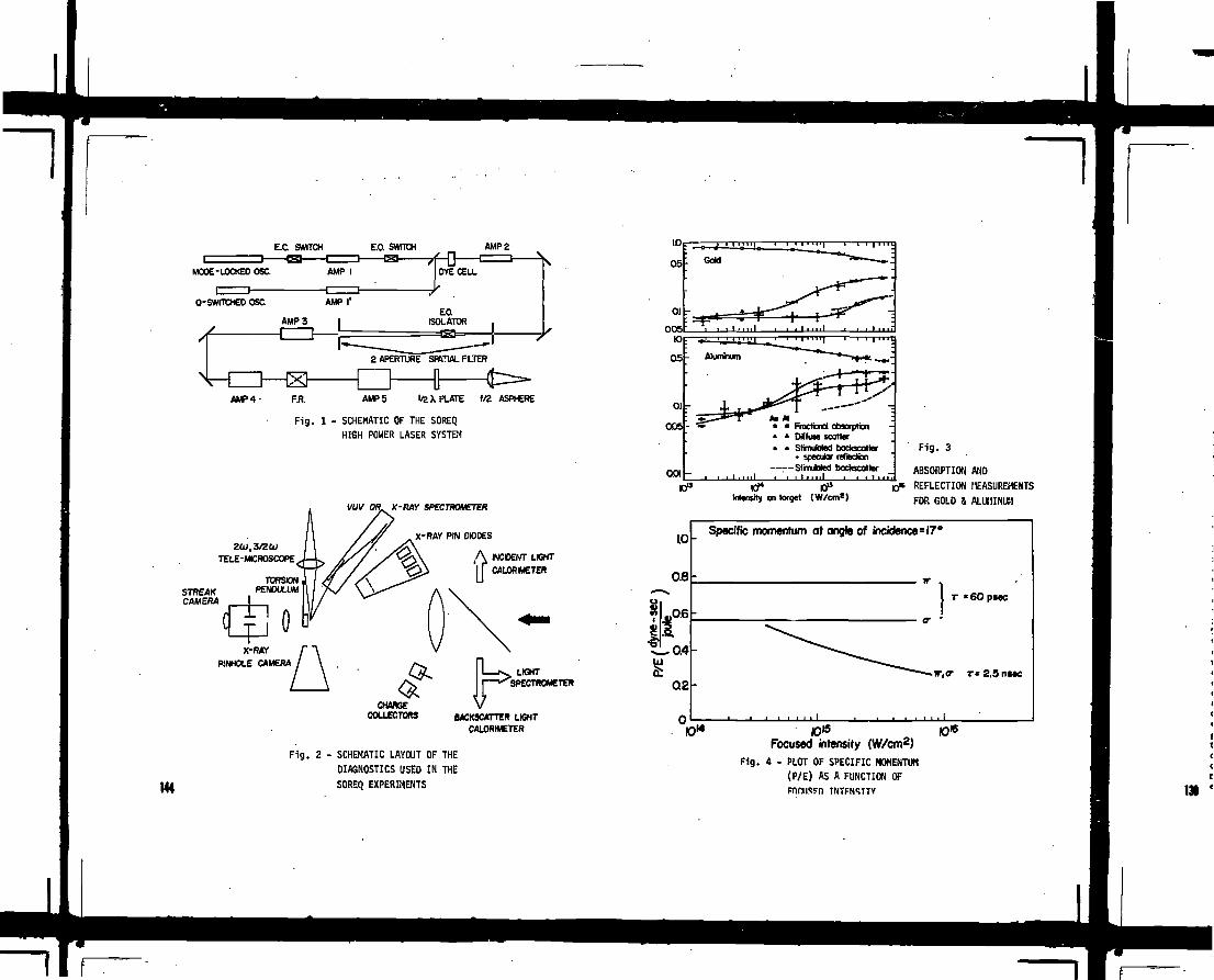
EX. SWITCH E.O. SWITCH
MODE-LOCKED OSC. AMP IH>
AMP 2
DYE CELL
Q-SWITCHED OSC. AMP I1
AMP 3 I
A M P 4 - AMPS 1/2 X PLATE f /2 ASPHERE
Fig. 1 - SCHEMATIC OF THE SOREQHIGH POWER LASER SYSTEM
-RAY SPECTROMETER
-RAY PIN DIODES
INCOENT LIGHT
CALORIMETER
144
CHANGECOLLECTORS
I i x . LIGHTI ^SPECTROMETER
BACKSCATTER LIGHTCALORIMETER
Fig. 2 - SCHEMATIC LAYOUT OF THEDIAGNOSTICS USED IN THESOREQ EXPERIMENTS
• Fractional absorption» Diffuse scatter• SfimutaM bockscatler
• specular reflection:—SimJotod bockscottor001 -
IIt
10» 10°Intensity on target (W/cm1)
Fig. 3
ABSORPTION ANDREFLECTION MEASUREMENTSFOR GOLD & ALUMINUM
1.0
0.8
0.6
0.4
0.2
n
Specific momentum at angle of incidence
^
=17°
\
, , . i
T «60 PMC
r r*2.5riMC
Focused intensity (W/cm2)
Fig. 4 - PLOT OF SPECIFIC MOMENTUM(P/E) AS A FUNCTION OF
TNTFNSTTY
10*

HOT ELECTRON ENERGY TRANSPORT ANDABLATION PROCESSES IN LASER PLASMAS
K. MIMA, T. YABE, K. NISHIHARA,T. SUGIYAMA, R.E. KIDDER*. H. DAIDO,H. FUJITA, S. NAKAI, C. YAMANAKAILE, Osaka, University Suita,Osaka, Japan
* LLNL, University of California,Livermore, California,United States of America
Abstract
Theoretical and computational works have been done on the ab-
lation processes and the heat transport. The objects are the laser
intensity and wavelength dependences of the ablation rate and pres-
sure, and the linear and nonlinear analysis of the heat flux driven
instabilities. In particular, the hot electron driven ablation and
instabilities are investigated. The results are compared with re-
cent experimental observations qualitatively.
1. Introduction
Many theoretical and experimental works have been done on the
ablation processes and the heat transport. In this paper, we dis-
cuss the laser intensity and wavelength dependences of the ablation
pressure, and the mass ablation rate and the linear and nonlineat-
processes of the heat flux driven Instabilities.
In the first part, we apply a self-regulated flow model to
conventional ablation and hot electron driven ablation to estimate
the Chapman-Juge point density,and the ablation rate and pressure.
The simple model analysis are checked by one dimensional fluid sim-
ulation including-hot electron transport. As the results, it is
found that the hot electron effects enhance significantly the mass
ablation rate and the ablation pressure. The similar effects are
observed In O.53i*, 1.061*1 and 10.6pm laser experiments, although
the lateral heat transport and plasma expansion are also important.
The Intensity dependence of the ablation pressure is found to be
I L°"9 in the case of hot electron driven ablation. The C0 2 laser
experiments indicate the similar scaling law.
In the second part, we investigate the heat flux driven in-
stabilities. When the hot electron flux becomes high enough, the
ion acoustic instability and the electromagnetic two-stream insta-
bility set on. Since the Ion acoustic Instability excites predom-
inately short wavelength modes propagating against the heat flux,
the transport coefficients like electrical and heat conductivities
are affected by the Instability. On the other hand, excited elec-
tromagnetic waves have much longer wavelengthes which could be the
order of laser spot size and/or pellet radius. Hence, the heat
flux is perturbed laterally, and the ablation front is distorted in
a large scale by a growing magnetic field. Employing the linear
mode analysis, we estimate the spatial growth of a hot electron
flux perturbation generated at the critical point to know how the
laser illumination non-uniformity affects the ablation front.
MS

The nonlinear stages of the instability are studied by two
dimensional fluid and PIC simulations. It 1s found that the satu-
rated magnetic field intensity is higher for longer wavelength modes.
2. Intensity and Wavelength Scaling of Ablation Process:
Self-Regulated Flow Model
In Fig. 1, the typical density, temperature, potential and
hot electron density profiles are shown. These profiles are ob-
tained by 1-D Hydrodynamic Simulation Including hot electron dynam-
ics described by multi-group diffusion model. From the temporal
evolutions of those profiles, you can easily find that the ablation
structure consists of three parts; 1) stationary deflagration,
ii) isothermal expansion and iii) anomalous region near the crit-
ical point. In the anomalous region, the ion acoustic Instability
occurs and the blow-off cold electrons are strongly joule-heated
and the hot electrons lose the appreciable fraction of energy which
may .be converted into the fast 1on energy. We represent the energy
loss by f|. In Fig.2, pressure profile and the Merit number of the
ion flow velocity are shown together with the temperature profile.
As it Is expected, the flow crosses the sonic point (Chapman-Juge
point) at the boundary between the regions of 1) and 11), where the
temperature gradient changes from a finite value to zero. Because
of the self-regulation, the plasma thickness between the critical
point and the C-J point may be determined by
Ml
f x£7 J .9
1 u>
Here, x*0 and x-_, are the hot electron emission surface and the
Chapman-Juge point respectively and AR(x) is the hot electron mean
free path. Using the self-similar solution, we carry out the in-
tegration of Eq.(l) to obtain the mass density of Chapman-Juge
point, Pg_j
where 6pcr is the density at the hot electron emission surface and
Xo is the hot electron mean free path for the critical density.
Using the energy balance equation; *Pr,_jcs
the ablation pressure,
>» we obtain
13}
where Cs*[1/3
and "ab is *!* absorbed 1aser
If the hot electron average energy is estimated by Estabrook and
Kruer's formula, the ablation rate, Am and the ablation pressuré
are obtained as follows,
Aft - Uand
fUt.t? O.1t e.£2
M. Ai.
where t is the laser pulse duration in the unit of nsec, rijb the
absorption efficiency, XL the laser wave length in pm and IL the
laser intensity in 1015W/cm3.

Setting O - f ^ n ^ -15, t=0.255nsec, *L=lpm and IL=6xl015W/cm2,
we obtain p b i ZOO Mbar. which agrees with the simulation result
of Fig. 2. In Fig. 3, we show the C02 experimental results with
the theoretical results (Dash-Dot line) for 1-^=0.5 and t=l nsec.
The approximated formula yielding f j is
which'is obtain from the jump conditions at ths critical point.
For shorter wavelength and lower intensity irradiation, we
apply the similar self-regulated flow model to the one electron
temperature plasma. After the mànupulation same as for the hot
electron case» the ablation mass rate and pressure are given as
fol 1ows,
and
pab
where g(t, lib>>\) = [ (1 + — — ) 1 / 2
_ ( t jl/2 j-1/3. In Fig. 4, we show the wavelength
dependences of Am and Pab with recent experimental results. Let
us note here that, as far as planer targets are concerned, 10.6pm
laser generates the ablation pressure efficiently because of the hot
electron energy transport and a few pm wavelength lasers are worse.
3. Heat Flux Driven Instabilities and Non-Unifor» Illumination
Effects
3.1 Linear Analysis of Instabilities
As shown in Fig. 5, the hot electrons expand from the crit ical
point and the cold electron return current Is Induced. When the
hot electron flux is high enough,, multi-streams among hot and cold
electrons and ions cause instabilities. We set velocity distribution
functions of each species being shifted Maxwellians and derive a
dispersion relation for a coupled electromagnetic and electrostatic
mode. The dispersion relation is given as follows,
where
and
Here vQ is the collision frequency and Uo is the drift velocity.
Note that for k-Ua-O, e^O and et»0 yield the dispersion relations
for the electrostatic modes and the electromagnetic modes respect-
ively. The dispersion relation, Eq.(6) is solved numerically, and 147

growth rate and real frequency depending on propagation direction
and wave number are shown in Fig. 6. For short wavelength modes;
k X ^ A O O ) , unstable modes are essentially ion acoustic waves and
the growth rate becomes maximum at 8=0 and the real frequency is
given by kC£ and independent of 9. For the longer wavelength case
where (kC/u ) Z £ (U c/v c)2, the unstable node becomes electromagnetic
and the fastest growing modes propagate perpendicularly to the heat
flux. When a wavelength increases, a real frequency of the perpen-
dicular mode decreases to zero at the critical wavelength and the
instability sets on.
3.2 Particle Simulation and Nonlinear Saturation
By two dimensional particle simulation, the temporal svolu-
tions of the Instability are investigated. The results are shown
1n Figs. 7 and 8. Fig. 7 shows that the linear growth rate agrees
with the linear dispersion relation, and the saturated magnetic '
field amplitude 1s « c 2; 2.5xlO"2u> or 5MG at ne * 10
21 I/cm3. The
electron velocity distributions In the directions perpendicular and
parallel to the heat flux are shown in Fig. 8. Note that the per-
pendicular temperature, Tj,Increases compared with the parallel tem-
perature, T ^ . According to the linear dispersion relation, the
present Weibel Instability 1s stabilized when
(7;
141
is met. The quasi-linear equation including the collisional relax-
ation; C ,
yields the temperature anisotropy. The temperature anisotropy is
determined by the balance between the anisotropic heating by the
fluctuations and the collisional relaxation, as follows,
11 4-{eA/Tj2Vc7Ca
where A is the vector potential for the magnetic fluctuation. The
stability condition and Eq.(9) yield the saturation level;
which reasonably agrees with the simulation results. This satu-
ration level is quite high and may cause serious effects on the im-
plosion symmetry.
3.3 Instabilities In an Inhomogeneous Plasma and ImplosionSymmetry
According to our normal mode anaylsis in an Inhomogeneous
plasma, the electromagnetic Instability 1s not absolute instability
but convective Instability except unrealistic parameter range.
Therefore, we investigate the spatial growth of the perturbation
generated arond the critical surface by non-uniform irradiation.
Using the self-consistent density profile of the hot electron driven

ablation, we evaluate the hot electron density perturbation by the
wave equation,
" «A
A,
In Fig. 9, a typical spatial profile is shown. A hot electron den-'
sity fluctuation corresponding to laser intensity non-uniformity
grows, reaches maxima and decays toward the ablation front. We de-
fine the instability condition by (6nh at the ablation front)/{6nh
at the critical point) >_ 1 and illustrate the unstable region 1n
laser wavelength and intensity parameter space. The unstable re-
gion becomes broader when the perturbation scale length increases
and is located in the short wavelength and high Intensity region.
We compare our parameter space "shadow" with Bodner's window In Fig. 9.
The hot electron flux fHametation (self-foreusing) and the
magnetic field generation in the colHsional region have been in-
vestigated by 2-D simulation of two coliisional electron fluids.
The magnetic field generated at the critical point and the hot elec-
tron density perturbation are found to grow instead of decay due to
the magnetic field diffusion. In Figs. 10-{a) and (b), the mag-
netic field and the hot electron density contours are shown. It
is seen that the flux is strongly pinched when i t propagates into
a plasma. As the results, we tsy conclude that the magnetic f ield
generated around the critical surface does not diffuse but increases
and enhances the heat flux non-uniformity. The situation is very
similar to the self-focusing of a laser l ight. Hence, the focused
laser light pattern may be transferred to the hot spot on the ab-
lation surface.
a s t o s o u n IO »UOIUS C )
(a) Soalial pranks of ion density a, and thermal elec-tonlentpcralurer.iiilheccHiieortiine. A.
<b) Spatial profiles of hot electron density «» ifl thecourse of time.
Fig. 1. Density, temperature, hot electron denstly and electro-
static potential profiles from the hydrodynamic code sim-
ulation. 14)

100
I Mach number
relative to
I" ablation surface
relative to
jump
Fig.
100 200
DISTANCE (firn)
Cold and hot electron pressure, cold electron temperature
and mach numbers at a time 0.255 nsec after the laser In-
put.
151
1OO
.o
s
o
•s3< 1.O
1O1.13
a ; cold electron X^SM fi mb; hot electron AL=1.O6 pmc; hot electron AL=io.6
1O1 1O" 1O.16
Laser Intensi ty < W / c m 2 )
Fig. 3. Intensity dependences of ablation pressure for 10.6um and
1.06pm lasers.
{-•-•-) for X|_*10.6)im and hot electron driven ablation.
( ) for XL»1.06pm and conventional ablation.
(•••••) for XL*1.06pm and hot electron.
( x ) are experimental data points for AL=10.6uin.

100
0.5 1.0 50 10
Laser Wavelength (//m)
14 *3
a,b ; 10 w /cm2, t = 1.O nsecc ; 20X10 1 w/cm2 , t=0,5nsec
14 oà ; 3.0x10 w/crrr, t =1,O nsece ; 4.8 X10¹³ w/cm2 , t =1.0 nsec
PLASMA DENSITY
COLDELECTRON
LZRETURN CURRENT
HOT ELECTRON FLOW
LASER LIGHT
VELOCITY ( V )
185
Fig. 4. Wavelength dependences of Ablation mass rate and pressure.
for one electron temperature ablation and
for hot electron driven ablation, t and A are experimental
data for ablation rate and ablation pressure.
Fig. 5. SctMMtical diagrams of hot electron and cold electron cir -
culation and particle velocity distributions.
IS

~I10 :
DEPENDENCE ON PROPAGATION DIRECTION
60" 90'ANGLE BETWEEN WAVE VECTOR t
HOT ELECTRON FLOWZ - 1 . Th-3.27k«V.Tc - 2 0 4 » V ,Ti - 1 Oa VMI /M«=2000 . Nh /Nc=C5 . Vde /Vc»0 .2
ANGLE BETWEEN WAVE VECTOR tHOT ELECTRON ROW
k -C /w p c • »:S5., b:S., e:0 Md:o.ias, *:o.os
• - W •!< •SQRTOTc/MiUZ'Nl/NcS
Fig. 6. Growth ratt and rta l fraqutncy vSut propagation direction
for various wavanumberr"
aUJ
(3
SE
5
-
ni
11 \
i
" tf
kT
•
• i 1 i
fi
• i i i i
i i i • i .
-
f
1Ï1 \
I
1 i i i i
500 XXX)TIME (cup,,)
1500 10*.WAVE NUMBER ( k v i c / ^
Fig. 7. Magnetic f ield amplitude versus time and growth rate in the
linear regime for 2-D PIC simulation.
152 Fig. 8.
-2.0 -1.0 0.0 1.0 2.0 -2.0 -1.0 0.0 1.0 2.0
VELOCITY PARALLEL TO FLUX VELOCITY NORMAL TO FLUX
(V/V,h) (V/Vu,)
Perpendicular and parallel electron velocity distributions at the saturated state.131

SPATIAL PROFILE INTENSITY-WAVELENGTH WINDOW
23
1.O 0.5 O^ PLACE ( X / L m ( p ) ^
SOLID CUT OFF
IL:1O15 W/cm2 ,A :20,um
ïu5
EN
SIT
gceLJU)
_J
1O16
1O15
10 1 4
10 1 3
1O12
ni UN " = a ^Iff STABILIZED K_ iil«iitsAojiti.lWg!fJI3|g\
\
\
•.
\ Th>7
• . \
\
• \
\
\
\
\
^ % \ •
Nh<Z-Nî\
STABILIZED
i
,Z!2.7
Fig. 9. a) Spatial profile of hot cltctron dtnsity perturbation
b) Unstable region in Intensity and wavelength parameter
space.
.5 1 5 1OLASER WAVE LENGTH C/xm)2:2.7
153

-- 7.6
0 - J.U..AJ.V i •,.! i i i i i i.l i i i i 1 i i i i 1
ta) Y / Lh Y / Lh
Fig. 10. Magnetic f i t l d tnd hot electron density contour from 2-D fluid simulation.
154

SOME ASPECTS OF TRANSFORMATION OF THENONLINEAR PLASMA EQUATIONS TO THESPACE- INDEPENDENT FRAME
S.N. PAUL*, B. CHAKRABORTYDepartment of Mathematics,JaJavpur University,Calcutta, India
ABSTRACT » Relativistically correct transformation of
nonlinear plasma equations are derived in a space-
-independent frame. This transformation is useful in
many ways because in place of partial differential
equations one obtains a set of ordinary differential
equations in a single independent variable. Equations
of Akhiezer and Polovin (19S6) for nonlinear plasma
oscillations have been generalised and the results of
Arons and Max (1974), and others for wave number shift
and precessional rotation of electromagnetic wave are
recovered in a space-independent frame.
I. Introduction i Winkles and Eldridge /~1_7#
Clemmow ^~2,3,ijft Lerche £$J, Chian and Clemnow
^~6_7, Kennal and Pellat ^~7_7# Decoster Ç&J «nd
others have shown that Lorentz transformations are very
useful to transform the field equations from space-time
dependent frame S to a space independent frente S',
where solutions of nonlinear higher order plasma equa-
tions can be found out easily, because in a space-
-independent frame nonlinear partial differential
equations become ordinary differential equation. Some-
times, it is found very difficult to obtain solutions
*permanent Address : Department of Physics, RajaRammohun Roy Mahavidyalaya,P.O. Nangulpara.Dt.Hooghly,west Bengal, INDIA.
of some problems of nonlinear plasmas in the closed
form because refractive index in the right circular
polarisation becomes inhomogeneous. For this reason,
Chakraborty et al ^~9_7 used WKB approximation in
deriving the: expressions for nonlinear Faraday Effect.
But if from the beginning, equations are transformed
relativistically into a space independent frame, it
is expected that difficulties arising from the non-
linearly developed refractive index can be bypassed
mathematically because in place of partial differenti-
al equations only ordinary differential equations have
to be solved.
In the present paper, we use transformation of the
cold, relativistic plasma equations from a laboratory
inertial frame to a space independent frame. Using
these transformed equations we make generalisation of
the nonlinear equations to derive the expressions of
wave number shift and precessional rotation of an elli-
ptically polarised electromagnetic wave in a cold,
relativistic, collisionless, unmagnetised plasma. Wave
number snift and precessional rotation of a strong
laser beam has been numerically calculated. Another
consequence is a generalisation of some important
results obtained first by Akhiezer and Polovin 7^*10^7.
II. Assumptions and basic equations i We assume
(i) Plasma is stationary, cold and homogeneous* (11)
The incident wave strong enough for the occurence of
relativistic electron motion; (ill) For radiation
intensities less than approximately 3 x 10 N/cm,
the ion velocity remains below the electron velocity
£l\J. The ion motion has little effect on the pro-
pagation of electromagnetic waves and we neglect this
motioni (iv) incident electromagnetic wave is trans-
verse, ellipticaily polarised and sinosoidal. 155

~1(v) Plasma is below a certain threshold power limitso that self-focussing and self-trapping mechanismsare insignificant, under the threshold power Stimu-lated Raman Scattering is minimum; (vi) Self-actioneffects arising out from the pondermotive force andthermal instabilities are negligible; (Tii) The forcesarising due to collision and gravitation are negli-gibly small in comparison with other forces presentin the medium..
under the above assumptions the field equationsin an inertial frame 'S' can be written as
The phase transformation is
with
where, the wave is propagating along znUrectlon, Niand H arc the number density of ions and electrons,n^ and • are the rest mass and charge of an electron»other parameters have their usual meanings.
XII. and transformation ofIjorentz transformation
from the S-frame to the S'-frame moving relativelywith velocity VQ parallel to the z-axls is given by
V»Vwhere.
. (7)
where H. and CO are the wave number and frequency,|[S?Wfc.Following Winkles and Eldridge ^~1_7 "^ assume
V»-Î cVv = K.Cl/ci>> V(=«<YK) being the phase velocity ofthe wave. So, (7) reduces to
where, eo'-= co j l-p.'-s <^fAo > *• = "T"» This transforma-tion enables us to change the variables from thespace-tine dependent frame s to the space independentframe S*. Me can now write,V a = 2 = V- C V / ^ , A ^ , ^ = - - ... (9)
The transformation of important physical variablesfrom the space-time dependent S-frame to our space--independent S'-frame are
N=
T*. Transformation o£ the field equations te thespace-independent frame i Considering the trans-
formations of Section-II, we obtain from equation(la)

The equation of continuity l(b) becomes
. . . (12)
where H is a constant.o
From the first equation of (2), the equation for
is
„ and ao,B* « Constant ...(13a)
Similarly, from second equation of (2), we obtain
B' • Constant ...(13b)
Introducing transformation relations for the spaceindependent frame, equation (3),yield.
... (14)
a n d
V. Derivation» of nonlinear equations i Differentia*
ting equations of (11) with respect to the time-
-variable T of the space-independent frame-S1 and then
using the relations of (14), we obtain
where, 6>£= t(iTN.«Vnn. ,^' /m,a , Jl-
Akhiezer and Polovin ^"lO_7 derive «on» non-
linear equations Including l*cr»ngian and Monwntum
from \thlch nonlinear oscillations of longitudinal and
transverse waves are well understood. Nonlinear equa-
tions derived here are more generalised than that of
Akhiezer and Polovin. It is to be reaeabered that
oscillations of longitudinal wave can be studied, assu-
^ ^ » 0 and for transverse wave, 12is equal to
zero.
i precesslonal rotation ofi frequency and wave num-
ber of waves are changed due to nonlinear effects in
plasmas. Montogomezy and Tidman ^~12_7 obtained an
expression for the frequency shift (as nonlinear co-
rrection) for both travelling and standing waves in
plasmas. Using a plane polarised transverse wave,
Sluijtar and Montogomery £xsj derived the expression
for the shift of frequency and wave nuntoer considering
nonlinear Interaction of a wave with « plasma which
has static Ions, moving electrons and no magnetic field.
TidBtan M d Staiasr C^J» *>•* £~IS* 16_7» B o ï d C^J'
Chandra Cx%» 1 9 - 7 ' Minkl^> and Eldridge /"l_7, Gold-
stein and Salu ^"2O_7. schindler and Janick £zij and
other* also obtained the results of frequency and wave
number shift under different situations In plasma.
Some non-relativlstlc results for the frequency shift
were earlier obtained by sturrock C22S' D""*on ^~23j?
and Jackson C2KJ'
Recently Arons and Max ~25_7 reconsidered the
problem of Sluitjer e»d. Montogomery C^iJ using ellip-
tlcally polarised wave and showed that the nonlinear
effects give rise to precession of polarisation ellipse
without affecting the «lllptlclty. Later, Katz et aL,
C U J a"1 U * and Wonnacett <f27_7 described the
precession of polarisation axis with the aid of usual
technique of classical mechanics. Chakraborty /~28_7 1S7

15t
developed the theory of precessional effects due to
interaction of four waves in a cold unmagnetlzed
plasma. He found that when the plasma is subjected
to two strong fields sharp band of monochromatic noise
transform into growing continuous spectra» Chakraborty
and Chandra 4~29_?» Khan and Chakraborty ^3O_7, Bha-
ttacharyya and Chakraborty ^~31_7» Chandra ^~32_7,
Decoster /~8_7 also derived the expressions of the
frequency and wave number shift including precessional
rotation of electromagnetic waves due to nonlinear
effects in plasmas.
Rotations of polarisation ellipse of laser beam
have been experimentaly detected in the medium like
liquid-filled absorption cell /~33_7» fused quartz,
borosilicate crown glass and crystals ^~34,/35, 36_7.
Hong and Shen /~37_^7 studied experimentally the pre-
-transitional behaviour of laser-filled induced mole-
cular alignment of two isotropic neumatic compounds
(viz. »BBA and EBBA). For electron plasma, waves
propagating in the presence of axial magnetic field
frequency shift and wave number shift have been expe-
rimentally observed /~38, 39, 4O_7. But for prece-
ssional frequency frequency of electromagnetic wave-
-interaction in plasmas there is no report of experi-
mental investigations
In.the following section, we have derived the
expressions of wave number shift and precessional
frequency of an elliptically polarised electro-magnetic
wave due to nonlinear effects in a cold, collisionleas,
unmagnetised relativistic plasma in a space-independent
frame»
In a space-independent frame, nonlinear equations
correct upto third order of small quantities are de-
rived in the following manner
15+= T^-eE^/w^. • ...(16)
where, 1»i=
T^ and vy are the first order velocity components in
the direction parallel to OX and OY, Si£is the 2nd
order velocity along OZ, subscripts with plus (+) and
minus (-) signs Indicate right and left circular pola-
risation. Ijow1*
Me obtain, v±~ e(-a su
and Si»»=- e?
How, the nonlinear equation forelectrlc field correct
upto third order Is
From these relations nonlinear dispersion relation for
left and right polarised wave can be derived as
where,
To get the results In the laboratory inertial fra-
me we put aj£=6&j,|(from our previous transformation
relation,where A,r-* co% /(*>£- K £ C » ) .If we now consider the spatial evolution problem
we can write, X ^ ~ )c-t-£i r > eo^s aa • Therefore,
&4 «J^
... (19)
.. (20)Therefore,
Expressions (20) and (21) give the wave numbershift and precessional frequency for the elllptically

polarised electromagnetic wave. Theae are identical
to the results of Arons and Max ÇiSj* Equation (21)
also shows the birefrlgence effect in a plasma medium
for an electro-magnetic travelling wave. Moreover, if
P>- 0, equation (20) leads to the formula for wave num-
ber corrections of Sluijter and ttontogomery ~13_7.
numerical Estimation t He assume, laser beams of
neodium-glass having wave length « 1.06JUm, w -
1'78xios/£ec. propagate through a dense plasma
Ho-Sx.\o**/e*P. in this case, laser flux <F> is
lO^W/a*" 1 which is less than the threshold power
( VtTt<= ioao'W/e-*na ) for generating self-focussing
and other nonlinear effects, under this situation
el*=»(fca&"o.o5 . So, the electromagnetic wave will have
wave number shift. ft6tfX\G%p*em£.L.e. wave length
shift -9°4*XJtaû)and l°precessional rotation will be
created through a distance 5-KO It xtO"*c-»>.
REMARKS t In the cases, where effects of collision,gravitation. Kinetic temperature, static magneticfield etc.are considered, these nonlinear effects e.g.predessional rotation will be more interesting and itwould give some important results in the study of non-linear Faraday Rotation, Inverse Faraday Effect etc.we desire to Investigate these problems in future.
REFERENCES t
1 . Winkles, B.B. & Eldrldge, o . , Phys.Fluids, 1,5(1972)
2. Clmmow, P.C., J. Plana Fhys. 12. (1974) 297 .1790
3. OIOTCTOW, P.C.; J. Plaaaa Phys. U (197$) 231.4. CXemow, P.C., Plass» Phys. 12.U97?) 301.5. Lerche, I . Plasaa Phys. 2L U974) 955.6. Chain, A.C.L., and Cleanov, P.C., J. Plassa Phys. 14 (1975)
""" 505.7. Kennal, C.P. and Pellat, R., J. Plasm Fhys. 15 (1976) 9628. Decoster, A., Physios Reports 47. (1976) 285. —9. Chakraborty, B., Khan, H.B, arid Bhattaeharyya, B. (1931)/
10. Akhieier, A.I. « Polovin, B.V., Soviet Phys/(unpublished)JETPX (1976) 696.
11.12.13.14.15.16.17.18.19.2021.22.23.24.25-26.27.28.29.30.
31.32.33.
34.35.36.
39.40.
I » , P and Itawson, J. , Phy». Fluids 11 (1970) 472.Montogorasry, D. & and TldMn, D.A., Phy». Fluid». K7. (1964)Sluijter, A.W. and Montogonery, D. Phrs. FluUs 242
Tidnin, O.A. It Stainer, H.M., Phrs. Fuid 8*(1965) 345.Das, K,P., Phys. Fluid» 2a. (1971) 2235 *~D»s, K.P., Phy». Fluids 11 (l9t8) 2055-Boyd, T.J.K., Phy». Fluids 12. (1967), 896.Chandra, S.K. Cieoh,J. Phys. BjJ (1974) 1338.Chandra, S.K. Ph. D. Thesis, Jadavpur UniT. 1979»Goldstein, S. and Salu, Y., J. Plaaw Phys. 10 (1973) 231.Sehindler, K. and Janick, L., Fhys. I«tt. Â&5. (1973) 91.Sturroek, P.X., Proe. Roy. Soc. London, A2t2 (1957) 277.Dswson, J., Phys. Rev. U£. (1959) 383-Jackson, E.A., Phys. Fluids J. (i960), 831.Aron», J. & Max, G.E. Phys. Fluids VL (1974) 1983.Katz, I., Parks, D.E. & Totenburg, H. Fhys. Fluids 18.(197*)Lie, C.S. & Honnaeott, E., Canad. J. Phys.5^ 895
(1976) 9621Chakraborty, B., Phys. Her. A 16 N o . ^ (1977) 1297.Chakraborty, B., & Chandra, S.K., Phys. Fluids j i »
(1977) 2336.Khmn, H., & Chakraborty, B., J. Appl. Phys. 50(12) (1979)
79^7.Bhattaeharyya, B. & Chakriborty, B. Phrsica 97C (1979J 257.Chandra, S.K., Act» Physic» Polonies A57 (80) 645.Hater, P.D., Terhune, R. W. & Savagt, C. H. Phys. Hev.
Istt 12, (1964) 507.Maker, P.D. & Tarhene, B.W, Phys. Rev. A 137 (1965) 801.Kevin», P. & Sealer, D.A,. Appl Phys. I«ttT3.(1966)278.Owyoung, A., Helworth, R.tf. & George,H. Phys.Rev.B5.
(1972) '
Vidnar,P.J.,Malaberg,J.H.&Starke,T.P.Phys.Fluidsl2(l976)32.


TEMPORAL AND SPECTRAL ANALYSIS OFENHANCED STIMULATED BRILLOUINSCATTERINGFROM A CO2 - LASER IRRADIATED PLASMA
S.A.H. RIZVI*, J. HANDKE, B. KRONASTExperimentalphysik V,Ruhrurîiversilat Bociium,Bochum, Federal Republic of Germany
ABSEBauJ
Some Important aspects of Stimulated Brillouin .Scattering (sBs)
has been investigated experimentally. Our study shows the
possibility of 100/5 reflectivity from an homogeneous H£
Our
results can be understood in terns of simple theoretical models.
underdense plasma at laser intensity below 10 ' t*n~ .
Considerable attention CM bt»n given to the problem of SBS inconnection with the laser fusion work.Inspit» of a numbeT ofexcellent experimental «oriel1"*, i t is obviously vary difficult to«•tabliih m i l defined and known conditions for the interaction.The plama «hould be prefomed and well diagnosed,before one per-forne the etudy of laaer plasu intsraotion.Hare,we investigate the problea of SBS under «ell knom later andplasna oanditiona.PlaMa was proiuoed in a dynaaio Z-plnoh derlceof 20KJ disoharge energy and was investigated extensively* .Itxembined homogeneoue and stationary for 80 m at naxiBvua oonpresaionwith T -T.-10 eV, and Z-.-Z-l.Plasma «a* then irradiated with anode looked pulsed 00? laser aysts»/' .Laser pulses were foousedonto the plaeaa by near diffraotion lisited 70 and 150 cm salt
lenaea.Experimental detai l s are described elsewhere'11
• Faraanent Mdreaat ftkistui Atonic Qierar Comnitssion,Pinstech, Hilore, Rawalpindi, FaJciatan
The relative backscabtering values Pj/P. are plotted against laaerflux in P i g . l . SBS W « one and the aaa* sequence of laaer pulseadisplayed leaa acatter (see insert in Fig. l ) than tboae betweendifferent laaer ahota.In addition i t bacaue obvious that the highestbacksc'attering value» near 100$ «ere associated with longer laaerpulaea. whereas lover values at the aaaa flux levels originated fromlaaer pulaea comparable with,or shorter than, the coabinsd risetineof detection channel of 1.3 ns.Sueh pulsea ««re investigated withanother detection channel, where we used a Tektronix 7104 o s c i l l o -scope and a fast pyrodatector.One of these backacattered pulseai* diaplayad in Fig.2. . I t indicatea an unfolded half width of leaathan 200 ps and a «ucb. shorter riset iae after deoonvolution.Thisproves that backscattering signals obviously vary over a certainrange of duration.Du» to the United risetiae of the syatem thesignala were attenuated accordingly.In this way a larger part ofthe value scatter, especially near threshold, auat be attributed topulse reduction by r ieet ise liaiitation.Backacattaring riaetineanuch shortsr than 200 ps do not coas as a surprise.Vith the valu»»
obtained for P^A.T^Tj and n # , the reciprocal growthrate» givene .g . by Drake at al 1Z cone to l i « in the vicinity of 25 pa nearthreshold and drop to about 10 ps in the EQ ' -range.
In spite of the limited time resolution of our detection systems wehave tried to gain aome inaight into the tiae behaviour of backacatteringrelative to that of the incident laser pulss.Carefully determiningthe time of f l ight differences batmen the two pulsea v i t h the helpof mirrors we were able to establish their temporal coincidence asdepicted in Fig .3 . Both in low and high backacattering caaea a timeinterval of 400 to 500 pa ia observed between exceeding SBS-threaholdand appearance of large backacattering. With auch a long period i t i seaay to explain the growth of backacattering intensity over about nineordera of magnitude atarting from thernal density fluctuation* withoutresorting to greatly enhanced density fluctuations in the target plasma.This impliea that there waa no tùbulence level in the vicinity of thewave vector of the Brillouin wave, either in the in i t ia l target plasm»or caused by the in i t ia l laaer heating of the backscattering volume. 1f|
we
of
the
The
whi
appl
tem|
elec
foil
and
whei
depi
us [
last
elec

1S2
Energy absorption in plain* «nd it» transport, although very important,are poorly understood subject .Many complex theoretical interpretationshave been put forward.When the classical theory breaks down, the heatflow i s generally described as a flux limited diffusion.lt vas foundout experimentally that the heat flow is overestimated in this way.
We have also observed a red frequency shift of 17 GHz and 25 GHs nearthreshold and near 100$ SBS respectively,Fig.4. It permits to
de^mine the phase velocity of the scattering ion acoustic wave and,hence,the weighted sum of electron and ion temperature.We found thata simple equilibrium between linear inverse bremsstrahlun?' *absorption and Spitzer classioal heat conduction can explain thechange of plasma conditions by laser irradiation and permit thecalculation of temperature.For our oaie.it predicts Tfl«45 eV and1^-15 eV at threshold,which is in good agreement with the observedfrequency shift of 17 CHs near threshold.
The validity of this equilibrium could be checked by the constancyof the term (P/A) -t0 and by the variation of the frequency shift withthe laser intensity asAtfe! (P^A)1 '8 . Both were experimentallyconfiraedC Pig.5 ) .Moreover,ths observed threshold values and growth rates of H2 under-dense plasma at different densities were found in reasonableagreeaaat with the theory.Theoretical values of various other gasessuch as He and Deutrium at different densities were also experimentallydetermined and ware found in accordance with the theory.We could explain our expérimental results through a rather simple
model .Init ial ly , we have T -T. . When plasma is irradiated by -the laser,electron temperature increases muoh faster than ion temperature andhence T / T . increases.AS soon as T /T. exceeds 3, Landau dampingbecomes ineffective and threshold i t aohieved.T^/Tj increases beyond3,when intense laser pulses heat the plasma and high amount of SBS isobserved.Experimentally observed red frequency shift of 25 GHi nearlOOyb SBS, predicts T / ? , • 5.5, again utisg the same simple model.Here,we have also assumsd that ions are relatively insensitive to
heating by our short laser pulses.In our cass,th* only saturationmechanism may be ion trapping ,then
IZTJ1'2 - {3^/z^)1 '2 J 2 (1)Sn/np - 0.5
1 ft
r1 ft
On ths other hand.Kruer has predicted the backscattered reflectivity
R • Tanh30
Ô -«(Sn/n )L,where
L is the scale length,n_ is the plasaa density and n e r i s the crit ic i ldensity.For our experimental conditions, Sn/n » 0.14,which predictsabout 98j( reflectivity Pig.6).We also changed the FWHH of laser pulses from 2 to 8 ns to observe theeffect of the rise time of the laser pulses.SBS decreases drasticallyas expected, since the slow risetime of the laser-pulse does notallow Te/T i to go much beyond 3 . Late backscattering was alsoobserved due to spikes in laser output.Self focussing could affect SBS drastically. Recently Baldis et al^found that an unstructured focal distribution ,which we were able toachieve in al l of our investigations, did not lead to self-focussingupto flux-values of lO1^ tfm"2 in an underdense plasma.We believe that the various factors *uch as small scale length,inhomogenieties and dynamical effects in plasma,non-uniform laserfocus,spikes in laser output and background heating greatly affectSBS.One of the authors (S.A.H.Bisvi) i s grateful to Prof.CJ'urtaza,P.Shukla and H.U.Hehman for useful discussions during SpringCollege on Fusion Energy at I.C.T.F.,Trieste,Italy.
A.A.Offenberger, "Koder n Flasaa PhysicsAtoaio Energy Commission,Viennafl98l}
F.437,International
M.J.Herbet,CE.Clayton,W.A.Paebles and F.P.Chen, Fhys. Fluids,23.,1319{198Ojand many références therein

J
B .H .Hipin,F .C,Xauag, 3 .Ai S tamper, C X .Armstrong,». .Decoate ,E .A .McLeanand S.S.Bodner, Phya. Rev. Lett. 22,611(1977)4R.SJtassey,Z.A.Pietriyk,and D.W.Scudder, Pbys. Fluida 21,396 (1978)
5Ha.Baldi« and F.B.Corlna, Fhys. Rev. Lett 42,1260 (1980)âE.H.Finken,O.Bertsohinger,and R.3.Hornady, Z.Katurforaoh. 31»,13l8(l976)7K.H.Finken,Q.Bertaohinger,SJ(aurmann,and H.-J.Kuni«,J.Quant.Speotroac. H«Jiat. Transfer 20,467 (1978)8G.B.rt«cfcin«er, Ph.D.Th.ai», Buhr University Boohua (1980)9B.Gellert,J.Hendke,and B.Kronaet,Appl. Phy».
1 0
(1979)
P .B .CorlniB, A ,J .Alcook, D ,J ,J«m«e,K. J .indrewa,K .B .Leopold ,D .P .Rollin,J.O.SanaoniLaMr Int»r»otion Belst. Plaaaa Fheno». 4», 143 (1977)11J.HandkerSU.H.Biiri, and BJCronaat, acoepted for publication inAppl. Phy».12J.PJ)r«k«,P.lCJCaw,T.0.U»,O.Sohjiidt,0.3.Liu,»nd M.V.Roaenbluth,Phya, Fluid» r[,778 (1974)13H.Hor«,H.Vilhel»,Huol»ar Fualot. 10,111, (1970)14K.«.Bill»an,and J.R.3t»lloop,APPL. Phya. Lett. 28, 704, (1976)
^ Phy a, of fully loniied g«t«a,Int«raoi»not Publiah»ra(19Sî)
16JJ(.Daw»on,W.LJCru»r and B.Roaen in 'Oynaaios of loniaad. 0a«a'.edited
by H.Lighthill.I.Iaai and H.Sato (Unlveraity of Tokyo Pre«a,Tokyo,1973)P.47
^ Phy a. Fluids, 2^, 1273, June (1980).
1 0 - 1 -
p- f CWm2)
Fig.l Flux dependanoe cf relative baokaoatterin» power (PBiP0
backacattered and inoident poweriA radiation oroaa-eeetion in th«
plaiaa).Croaae» refer to electron denaity 1.6 x 10²* •"' and A- Baa2,
open oirolea to 1.6 x 1624 »"3 and 0.O7 »»2,full oirolca to O.7X 1O24
• and 0.07 «• .The daahed linea 4,fl,/denote the raapeotiva threshold.
113

QUl
LUUJ
1o<
Fig.2 Backacattering* pomr dataeted with broadband faat-d«t«otor
and diaplajad on a Tektronix 7104 Oieilloaoop* of about 350 pa riactim».
in
"E3
ce.UJoa. THRESH,
•4 F
V'.-0-6
H 1 1 h
1H
t ( n s )
ps 400 ps
Pi».3 Ti«» ooinoid«nc« of baokaoattarlnc pomr (daihtd ouzraa)and ineliafat la i tr pomr (ful l eurra).Xndicattd ara tha pomr laroliand tim«a at vhioh thraahold ia azcatdad and tha onaat of baekaoattarincaignal denoting tha aarliaat tiaaa at which backaeattarinc tiaooaaariaibla with tha dataotor
( ns)

:îFig.4 Frequency apectra of incident ind backicattered later
radiation* F20 is the laeer line.Bacfcacattered radiation «horn a frequency
shift of 17 CHa naar threahold which increaeea to 25 CHi(dott«d lina)
near lOO* SBS.
t, ••
3 ••
2
1
i
QÛ5 0,1 0,5L
mm
Fic.5 (p / i ) f i i plotted a«ainat l u i r fooua radiu%Po.A•ariaa orar t«o ordarc of aajnitudarbut (P/A^,-çla alaoit oonatantnaar thraahold.witliUJ tha axpariaantal arrora.
PiC.6 Dependence of In/np on T#/T i la plotted aooordiaj to e q . ( l ) .16

J,SIC*
10-
152

ABOUT THE GENERATION OFELECTROMAGNETICRADIATION BY A STRONG-TURBULENT PLASMA
A.M. RUBENCH1KInstitute or Automation and Electrometry,Siberian Branch,USSR Academy of Sciences,Novosibirsk. USSR
Abstract
A wide rang* of phenomena where the generation of electro-
magnetic radiation is caused by plasma turbulence with a high
level of oscillations is studied in detail in the last years,
first of all we mean the generation of incident radiation har-
monics in laser plasmas and also a number of astrophysical
phenomena, within the strong-turbulent regime plasma oscilla-
tions form localized cavities, as a result of the modulation
instability development, which collapse in a finite time. As a
result of the Langeuir collapse there occurs enargy dissipa-
tion. Simultaneously the collapsing cavities generate electro-
magnetic radiation whose parameters can be easily determined,
because the evolution of a single cavity is well studied at
present.
In the paper we calculate conversion coefficients, i.e.
ratio of the energy radiated at a given frequency to the
energy absorbed by the collapse process. Che coefficients are
universal and they depend on plasma temperature and the level
of plasma turbulence.
Vain results of this paper is devoted to laser plasmas,
in particular to the problem of harmonics generation. As tro-
physical applications were studied in [ i , 2 ]
Strong Langmuir turbulence
She modulational instability development in a plasma with
a high level of Langmuir oscillations ^o (strong turbulence)
results in spatial inhomogeneity of the plasma [3]. She cha-ff
racteristic scale of the inhomogeneity i and the density mo-
dulation o n are equal to [3]
in/n. ~ Wo/n,T <2)
On this background, creation of Langmuix cavities and theirp
collapse taies place. Initial scale of the cavity is about t
and of the order of the distance between the cavities,
furing the collapse the energy of the cavity is conserved,
VV V = W L- • W » collapse time-scale can be estimated as
Y ~A ,= LO" (v*T/w Vand intensity in the center of the cavity
changed twice to (^ vy nT). vy nT).The cavities compress up to a minimum sise U m ; or wave
number rise up to K . It is possible to estimate this
sizs from the condition
1Y - Landau damping of oscillations. .
For Uenellian distribution (K !" C\ - ~à ~ "T and
doesn't depend essentiftlly on the turbulent level. As a resuit ||7

of heating, via collapse processes formation of electron
tails takes place and (K I~J ) is decreasing.
Harmonic generation in a strong turbulent plasma.
Let us start from the generation of 2. ui harmonics inAt
laser plasmas. This process takes place near n,c /4 as a re-
sult of Languir wave and fundamental radiation uJ co-
uplingw o +
^ K ~~* ^ * "' K» + K t ~ * ** <3>
The Tiangmuir oscillation electric field Ep (r) changing on
the scale of the order of the cavity scale together with the
incident electromagnetic wave field & o , generates nonlinear
current at the ~ \X>o frequency
T e r J. C ttL\
i ~ — t <**>.\r Cf W
It is this current which causes dipole radiation of the cavity
with an intensity
In the calculation of the cavity dipole moment it is nessecary
to take in to account the a variation cf the laser field on
the cavity scale which results in a decrease of the radiation
intensity (K. t ) times I K t » ° / C . Thus, we have
(6)
Mote that ojoadrupole radiation has the same order of magnitude.
As W C does not change during collapse, the initial stage
of the collapse makes the nain contribution to the radiation.
The total intensity of radiation depends on the geometry of a
turbulent region and is not very suitable for further inves-
tigations. Introduce the transformation coefficient % as a2
ratio of the energy irradiated at the harmonic 4- lX> to the
absorbed one. Taking into account the fact that characteristic
time of the cavity collapse and, thus, of absorption of the
energy contained in it [ 3 ] is t ~ Y ~ , ~
we obtain that W J
Tor calculation of 2 u> generation we must substitute Ey c
on E(.r) in eq. (4). The dipole type of cavity radiation is
absent in this case [5j and intensity of quadrupole cue is
equal to
UJ. (we3/
Furthermore, all stages of the collapse are important for
this radiation process. The conversion coefficient 'X.^ is
(8)
UJ. harmonic is a result of à three-wave coupling and it's
intensity is
I (9)

la thii situation radiation occurs in the final collapse
stage fo* t ~ t. mlH_ . The transformation coefficient for
this procaaaea is equal to
m—
*• se*, that the efficiency of the high harmonic radiation
d«cr««M vary rapidly, especially if the tail generation is
eaaential.
3/2 harmonic generation is Laser Plasmas
Let us discuss, in more detail, 3/2 U->o harmonic genera-
tion and comparison with experiments. It is seen from the
conservation la» (3) that for generation of 3/2 uo , long-
-wave Langmuir quanta are required. In the strong Langmuir tur-
bulence The spatial plasma inhomogeneity means that in the
Langmuir oscillation spectrum there is a long-wave component
and, thus, process (3) is possible.
If we calculate the emission intensity with the kinetic
wave equation, it «ill be proportional.to W , i.e., to the
plasmon energy with the wave vectors K o • Result (6)
can be obtained if W ~ W Q (Ko / K )3 , i.e., on th» assump-
tion of uniform oscillation distribution over the phase space
(the multiplier (Ko/ K- ) described smallness of phase folume
of the oacillations with K ~ <-^b/c ). There is also a number
of other mechanisms generating long-wave lengths quanta.
1. The long-wave Langmuir oscillations can directly appear
as a result of the parametric instability development in the
region of densities close to a qaater of the critical one.
2. Propagating in the inhomogeneous plasma along the den-
sity gradient, the oscillations with great K can reduce their
wave vectors up to the required value.
3. In the weak turbulence theory approach, the main nonli-
near process in an isothermal plasma, in induced ion scattering
(dacaya in ion-sound and Langmuir wave in nonisothermal plasma).
Is a result of series of decays, there occurs Langmuir plasmon
energy decrease and, thus, cascading of the plasmons into the
small wave vector region.
For long-wave quanta the threshold for modulational insta-\X// A - V1 ftr /Y*
bility is very low ^yyCT ^ K^ £ ) ~VT/c.J*nd we returns to
previsusiy pictures. For spontaneously arising inbomogenetty
t2) to be more significant than the external one, at high tur-
bulence level the condition
or
is sufficient. For typical of the experiment, temperatures
T~1 kev and external scale ~ 10 cm this condition in the
range nc fa is very weak ^^ir^lO""*.We now turn to the discussion of the weak turbulence
theory. From rough estimates the ranges of its applicability

( V < I/O , y. is the parametric instability growth rate»
Op s OP . »
even for the flux P~1O w./cm , i.e., in typical laser expe-
riments with long pulses, are already broken. In our opinion
there is an experimental support to this fact.
In Fig. 1 taken from paper 6 radiation spectra on the
harmonic 3/2 U*>o are shown. In the experiment the integral
MOO TOO* TOW TON W10 M M X M — .
1'lHt CMCUUltD
Tig. 1. 3L\JO^ line shapes (densitometer traces) fro*
various target plasmas. Peak intensities «re norma-
lised relative to the deuterium target (with the
Y -curve of the plate).
Singularity of turbulent spectra and their modulational
instability leads to break-down of weak turbulence theory
IH at lower light intensity.
radiation is registered, from the regions with various mis-
matches, and, thus, one should expect that the spectra are
broadened to the red by the " ^ ( K ^ ^ rj ") magnitude. The
possible value of the wave vector of parametrically
excited oscillations is defined by the Landau damping
( K ^ ^ T J ) ~ 0.3, while in the experiment A U O / Ù U ~ io~2.
The controdiction can be explained by a high collision fre-
quency, i.e., the oscillations with large K damp earlier
than they are cascaded in the small wavelength region. In
this case, however, the spectrum width should depend substan-
tially on the collision frequency û ^ / u 1 ~" V e l . pig. 1
shows &. IAJO line shapes for various materials and
though their collision frequencies change more than by an
order of magnitude, the spectrum width remains practically
unchanged. Thus, the experimental results contradict the weak
turbulence theory concepts.
The radiation spectrum 3/2 W o (Fig. 1) has a characteristic
feature, i.e., shift towards the blue side, which considerably
exceeds the Soppier one. To explain this fact we write down
decay conditions for the process leading to the oscillation ex-
citement ~» _^ —*
It is seen that oscillations with the frequencies higher and
lower than t00 /2 result from the instability. They provide
red and blue satellites of the radiation 3/2 , when coupling

with the Initial wave [7 j Frequency difference between the
satellites is
For ( K ^ ^ Tj^ ~ 1/3, A w°/U> ~ 2^10~2, which is in a good agree-
ment with the common spectrum width. Broadening because of the
modulation instability is substantially less
I V M nT I iU
Red shift of the whole spectrum occurs as, during instability
development, a part of the energy is transferred to ion mo-
tions. At very small intensities when K ~ ^ p / C (only
such waves can participate in generation of 3/2 IA^ ) when the
characteristic spectrum width is <r> I , and it was suggested in
paper I 7 J to measure temperature by the distance between blue
and red satellites.
At great intensities the main contribution to radiation is
introduced by the ranges with large K. . Because of the turbu-
lence spreading in angles (11), its turbulent broadening duct
to the modulational instability, the gap between blue and red
satellites is blurring, however, for materials with large
the blurring is less, and one can see a two-hump structure [6 j.
Unfortunately, the maximum position is defined by the broa-
dening mechanism too, though the distance between the humps is,
evidentely, a temperature function. In our opinion studying
the harmonic spectrum in numerical experiments and its iden-
tifying with the experimental data with the aim of the tempera-
ture diagnostics look promising.
One of the peculiarities of 3/2 ix>. generation is the -
absence of the definite dependence of UJ(lc) . In the numeri-
cal simulation [sj the spectrum of longwave quanta was inves-
tigated. It was shown that frequency spectrum of the mode with
Ksv U-'f/C is very similar to the experimental one. There were
the red and blue shifts and two humps structure. The spectral
width fits well with the one estimated above.
The value of V << for absorption via 2 UJ instability
was obtained in the paper I 4J
The level of turbulence is defined from conditions
Substituting (13) in the (7) we find
Taking into account, that the portion of the absorbed energy
near nc/^ iB
we find the conversion coefficient (relative insident energy)
171

~ \
In a number of experiments fast growth of the harmonic
3/2 to was observed as the pumping intensity increased, and
then the saturation set in. In our opinion this can be explai-
ned as follows. The formula (15) demonstrate the strong depen-
dence from I and increasing of I leads to fast increasing
\ , . Let us suppose that energy £> S absorbed near - -<
earring out by "limited" heat flux Q.~oivC\ \TT , A s a result
wee see, don't including of variation of gradient
and
For very high intensity the profile steepenig becomes essential
and 2 UO instability is stabilized by this effect. As a re-
sult the saturation of and decreasing X -, takeB place.!
Non-collective radiation mechanisms
Recently some experiments have appeared 19-10J, in which
high (up to eleventh) harmonics of fundamental frequency were
registered. She radiation on high harmonics was observed for
high fluxes of the incident radiation E > & 3 T K T during
experiments with C02 and neodymium lasers.
As it was shown above, plasma mechanisms can not prof id*
efficient high harmonic generation. As for the experimental
results, they can be explained in the following way. A density
jump is formed for ft ~ H c under the action of ponderomotiv*
forces near the reflection point. And as plasma density exceeds
the critical one on the upper boundary of the jump, the elec-
tric field decrease exponentially deep into the plasma. As for
the transverse direction, the laser beam is strongly modulated
there, both because of the laser beam itself and self-focusing
instability development [11J and instability of the density
jump hold by ponderonotive forces [i2j.
Sous, presence of the jump means that in the H > H c re-
gion there are localized electric field cavities comparable in
sise to the wave length. As electron motion in a strong field
is substantially nonlinear, radiation on all the harmonics
appear. Physically such mechanism of harmonic generation is
similar to their generation by laser impulse reflected from
metal surface when harmonic radiation is caused by nonlinearity
of electron motion in the skin ji3 J. There are two types of
nonlinearities in the equation of motion for electrons, they
•ret electron nonlinearities with characteristic times
« ^ relativistic ones T, - vOo - ^ — r .
ç, •>'^Ln' ^% intensity of high harmonics de-Because Ko "-
crease as I .In recent Los-Alamos's experiments and simulations very
high (up to 28 WJ&) harmonics were observed for /tfjrnT *"
It is interesting, that the intensity of the harmonics first
decreases very slowly and then drops very rapidly.
Shis could be understood if electric field would have a com-
ponent perpendicular to the density jump. Electrons passing
the steep jump have a constant frequency spectrum till

O W J O — - — ( a - width of the Jump, VJO - oscillatory
Telocity in the direction perpendicular to the jump).
It is easy to chaclc the above mechanism. In the numerical
simulation we must compare toe spectrum of radiation with fre-
quency spectrum of one electron. They must be very similar
for the noncollective type of the absorption mechanism.
11.?. Sa.*, G. Scbaidt, Œ. tfilcox. Phys. Fluids 16.1532.1973.
12.R.2. Sagdeav, V.D. Shapiro. Zh. Heap. Sear. Fi*. 66,
1974.
13.N. Bloembergen et al. Phys. Rev. Let. 16, 986, 1966.
R E F E K E N C E S
1. E.H. Kruchina, R.Z. Sagdeev, V.D. Shapiro. Pis'ma v Zh.Sksp.
•iieor. Bis. 32, 1*3» "1980.
2. B. Hafizi, M.V. Goldman. Phya. Fluids. 24.145.1981.
3. V.E. Zakharov. Zh. Exp. îeor. Fia. 62.1?t£, 1972.
4. A.M. Bubenchilc. Frocediugs of XIH International Conference
on Effects m ionised gases. Berlin, 1977.
5. B.H. Breizman, Ii.S. Peidcer. Phys, iett. 65A, H 2, 1978.
6. H. Pant et al. Preprint Max-Planolc. Institute fur Plasma.
Phys. IPPIT/85 September 1975.
7. A.I. ivrov et al. Hs'ma v Zh. Eksp. Seor. Fis. 2^,293,1976.
8. S.I. ABisimov et al, Poicl, Acad. Nauk SS3R, 258.78.1931.
9. N. Burnett et al. Appl. Phys. Lett. 31.172. 1977.
lO.H.Baldia st al. XIX International conference on Laser-plana
interaction. Uoscow, 1978.
173


INVESTIGATION OF PLASMA CORONADYNAMICS
AS. SHIKANOV, G.V. SKLIZKOV, Yu.A. ZAKHARENKOVP.N. Lebedev Physical Institute,USSR Academy of Sciences,Moscow, USSR
ABSTRACT
Various methods of experimental study of basic pa-
rameters, responsible for efficient acceleration of
thin target by the powerful laser radiation are con-
sidered. It is demonstrated that plasma corona dyna-
mics turns to be one of the main sources of the ne-
cessary data for correct understanding of hydrody -
naraic processes in laser-produced plasma.
1. INTRODUCTION
The most profound understanding of such processes
as powerful laser interaction with dense plasma
and acceleration of nonevaporated target part strongly
requires experimental data on important hydrodynamic
plasma corona parameters, i.e. mass evaporated re te,
pressure, applied to the nonevaporated solid layar ,
position of laser energy absorption region. In recent
laser-produced plasma investigations more attention
was paid to the questions of corona density profile
modifications and generation in this area of super-
thermal electrons and fast ions. Experimental study
of such processes is impossible without specific de-
velopment of conventional plasma diagnostics methods
as well as the invention of principally new diagnos-
tic methods •
2. CORONA OPTICAL IROBI1I6
Plasma corona optical probing allows one to deter-
mine spatial distribution of the refractive index
mainly dependent on free electron number density .
The use of pulsed light sources and high-speed photo-
registratora make» it possible to define the time
evolution of the electron concentration profile. The
range of the measured electron densities directly de-
pends on the wavelength of the probing radiation.Here
the study of dense plasma (ne«»10'*-10 cm"-3) may be
performed only with the use of UV light sources be-
cause the critical electron concentration nc is re-
lated with the probing radiation wavelength .71 in
the following way s nc(cm"3) * 1.1.1021J\ ~2( ;um ).
Shortening the wavelength of the probing radiation
leads to the decrease in the refraction angle 6 of
the beams in the plasma corona sQ«* neX I/O., (L is
the longitudinal plasma dimension; Q. ia characteristic
density scale-length).
While chosing the probing source one should take
into account the following specific requirements :
high spatial (up to 10"*cm) and time {7 10~ 1 0B) reso-
lution, accurate synchronization of the probing light
source, the protection of the photodetector from the
plasma emission exposure. Fig. 1 shows the dependen-
ces of the required light source parameters and the
interferomentricaily measured maxinal plasma electron
density on the probing radiation wavelength /1/ .
A considerable steepening of the density profile
(in the region n#3> 10 cm"3), typical for the laser-
produced plasma, leads to significant refraction of
the probing beam». Thus, even at the use of a suf-
ficiently high collection aperture objective
the processing of interferograms «*y turn to be
impracticable because of the crowding of the inter-
ference fringes.175

to'
ami
WO 300 |HO WOO
ITS
Fjg.1. Laser powtr (1,2),probing beam divergence
(3,4) and maximum electron oonotntration (5,6)versus
the probing radiation wavelength.Plasma parameters:
1,3,5 - L»2.10"2cm, a • 5.iO"3 cm;,3,52,4,6 - L»1O~3 cm, 3.10,-4 cm
~lTo eliminate the accuracy loss in this region
one should apply the shearing interferometers. Theshearing interferogram is produced by the interfe-rence of two object beams that are passing plasmaat certain distance from.each other.The advantages ofthe developed interferometers (lateral and radialshearing) /2/ are as follows: simplicity of the opti-cal scheme and the operation convenience at complexexperimental arrangements, and the feasibility ofimproving the accuracy of processing the interfe -rograms in the most interesting region of the inho-mogeneous plasma.
3. HEGISTERING OF PLASMA CRITICAL DENSITY HOSICK
In order to include to the measured range theelectron densities up to the critical value ( n_ «« 10 cm J) for the Nd-laser frequency W o we havedeveloped a method for studying the corona localregions with ne»nc and ne-nc/4 during the action ofthe heating puis» /3/.ThiB method ia based on the pro-cesses of nonlinear laser interaction that are ma -nifested in the generation of harmonics 2 OJO and3/2 COe . By means of a streak camera one observesthe evolution of the plasma emitting regions(Fig.2)simultaneously in two spectral regions.
Fig.3 shows r-t diagrams of the plasma corona re-gions of the shell target having different electrondensity values obtained by simultaneous usage ofthe shearing interferometry and the method of re-gistering plasma luminosity at S0Oa and 3/2 6ûo •
In the corona region of the rarefied plasma (ne«<<nc) there takes place a transition from isothermal

CH mo
Fig.2. Dynamics of the plasma regions emitting
at 2(00{a) and 2/2(*iaW. Polystyrene target:
180 ;um in dia, nail thickness 2.4 fm .
expansion to an adiabatic regime, and the character
of the density space distribution formed in the re-
gion of the highest pressure gradient remains un-
changed within the velocity eoordinateo V «r/t .
From the similarity of the expanding plasma corona
one may determine the mass rate m(r,t)«4JTr jJ (r,t)v,
where J> » poexp(-r/0.) is the density obtained from
interferograms. Prom this we have: A«t VJ«Xp(-V/Cs),
« S i 15 I. a 3 15
t
Pig.3.R-t diagrams of the plasma corona isoden3ities.
where Cs=<l/t, is the plasma sound velocity in the
isothermal region. It is obvious that maximum mass
rate is reached at V m«3 C& .
4. ION ENERGY SPECTRUM DIAGNOSTICS.
For measuring the ion velocity distribution in the
experiments we have widely used the method of ion col-
lectors.They are the deteectors of the plasma ion cur-
rent which are located at long distances from target:
Itt)*eï(t}n(tJVttJoerhz/5 . it is obvious that the ioncurrent oscillogram is closely associated with the
density profile of plasma in the initial state of ex-
pansion. In this way- it is possible to effectively add
the interferometric results by the results from col-
lector method.
Quantitative measurements by means of ion collec-
tors are possible only at a simultaneous measuring 177

of the mean charge z (and atomic weight Â) versus ion.
velocity. The most reliable data may be obtained with
the Thomson mass-spectrometer.Typical features of the
ion energy spectrum at "Kalmar" installation /4/ are
as follows: maximum energy of the carbon ions usually
amounts 60-70 iceV, maximum proton energy varies
within a wider range 35-70 keV. However, in certain
shots the maximum energy reached »150keV (velocity
= 1.5-108cra/s) for carbon ions and 90 keV Cv^s4.2.108
cm/3) for protons.The protons having E 9?10 keV are
totally fast ions (V> 10 cm/s). Regularly observed
fluctuations of their energy spectrum are,apparently,
connected with temporal changes in the acceleration
electric field. Expansion of the thermal ions is des-
cribed mainly by hydrodynamic equations and,therefore,
the carbon ions with different charge have the same ma-
ximum energy.
The signal of the ion collector corresponding to
Y>108cra/s turns to be a direct measurement of the
proton distribution function «IH/cIV versus velocity.
The comparison of this function with the proton ener-
gy spectrum obtained with Thomson mass-spectrograph
demonstrates their identity (Pig.4).
in
5. DISCUSSION OP RESULTS OU PIASMA IiULSS RATE
Determination of the ion energy spectra as well as
the interferometric measurements allow one to calcu-
late the value of mass rate m at the target surface,
and then the pressure accelerating the nonevaporated
part v>f the target and the hydrodynamic efficiency rç -
l'atio of final shell kinetic energy to the absorbed
laser energy. These values depend considerably on the
3tate of the plasma corona which is determined by
FiK.4. Ion velocity spectrum obtained with ion col-
lector (O ) and mass-npeetrograph (A ) (in relative
units).In the upper right is shown ion current trace.
by the parameters of the laser pulse (flux density,
time duration, radiation wavelength) and the target
(radius, density, composition). It must be noted that
maas rate values for different experiments were de-
termined by other methods as «ell: X-ray spectroscopy
of complex targets, measuring the burning time of
the foils, measuring the plasma X-ray radiation

rtiCM";
•*•.
•M
'»•' il"
Pig.5. Mass rate dependence on absorbed flux density:
Q- interferometric data of Lebedev Phys.Inst. (3,18);
A - ion collector data of NRL (1), EP (Koole Polytech-
nique) (9, 21), Lebedev Phys.Inst.(i4),KMS (15), ILL
(16), ILE(Osaka) (17)i
O ~ X-ray spectroacopy data of Rutherford Lab. (5),
ILE (6,25), LLE(Rocheater)(12); KRL(13);
id- foil burning data of Sandia (1), EP (10,11,23,41)!
• ^ X-ray attenuation data of Limeil (4);
O - Numerical calculations of LIB (7),EP(8),Limeil(i2);
Shell targets are marked by an additional circle,©
1-19 - data for 1.06 urn; 21-26 - 0.53 «m;
41 - 0.265 van.
attenuated by the thickness of nonevaporated layer.
Experimental and numerical calculation results for
flux densities 1012-1015W/cm2 are shown in Pig.5 .
The most part of the experiments is fitted by the fol-
lowing relation: mot q,av , v/here -J =0.75±0.1 .
At the increase, of ya the critical region lies at
a considerable distance rQ from the initial target
radius rQ> so part of the absorbed energy is con-
sumed on heating the expanding plasma within the re-
gion between rQ and rc. It is clear that f|<'Jnl ,
where rç,^ depends on the relative value of the tar-
get evaporated mas3 (optimum value of rçm «20-30 %
is reached at m. (t)/m»»0.2).
6. CONCLUSION
Thus, it has been shown that the experimental study
of the plasma corona dynamics turns to be one of the
main sources of the data, which are necessary for
thorough understanding of the processes associated
with the target acceleration by the laser radiation.
REFERENCES
1. DEHUS,S.,EROKHBI,A.A.,ZAKHAREHKOV,YU.A., et al.,
Pizika Plazmy 2 4 (1981 ).
2. ZAKHARENKOV.YU.A., SKLIZKOV.G.V., SHIKA1J0V.A.S.,
Pizika Plazmy 6. 2 (1980) 453 .
3. ZAKHARENKOV.YU.A.,ZOREV,H.N.,KROKHIN,O.N., et al.,
Pis'ma v JETP 21 9 (1975) 557 .
4. BASOV.H.G.,ZAKHARENKOV.YU.A.,ZOREV,N.N., et al.,
Zh.Ehksp.Teor.JFiz. Jl 5 (1976) 1788 .
179


EFFECTS OF DENSITY PROFILE STEEPENINGON GENERATION OF SUPRATHERMALPARTICLES,HARMONICS AND MAGNETIC FIELDSIN A LASER PRODUCED PLASMA
V.STEFANBoris KidriC Institute of Nuclear Sciences,VinCa, Beograd, Yugoslavia
CONTENTS: 1. Introduction, 2. Leaking Surface Waves, 3. Linear Conver-sion of Laser Radiation into Leaking Surface Waves , 4 . Gene-ration of Suprathermal Particles, 5. Linear Generation ofMagnetic Fields, 6. Nonlinear Generation of Laser RadiationSubharmonics in Quarter Critical Density, 7. Conclusion,8. References.
The propagation of obliquely incident p-polarized laser radiationthrough a laser plasma with a density profile steepening in the domain of thecritical point is considered. Such a density profile seems to be a long termprofile in a laser produced plasma / I / . It is shown that the structure of thelaser radiation electric field is significantly changed in reference to Ginz-burg's treatment / 2 / . In the case of tctal absorption of the laser radiation/ 3 / a simple expression for the electric field is obtained. The effects of sucha new structure of the electric field on the generation of suprathermal parti-cles, harmonics and magnetic fields is considered. It is shown that in thisfield, ions (due to the ponderomotive force) could be accelerated up to theenergies of the order of 10 keV. It is also shown that such a structure of theelectric field significantly affects generation of magnetic fields (by the p-component of the laser radiation electric field / 4 / ) in plasma, finally, itis shown that due to the density profile steepening a direct transformation(as a consequence of parametric instability) of laser radiation into "%"harmonic takes place. "~
1. INTRODUCTION (Laser produced plasma)
Laser radiation-plasma interaction attracts much attention mainlydue to the possibility of succesful use of laser radiation in fusion experiments/ 5 / . Intense laser radiation, focused in spherical symmetry onto a deuterium-tritium (DT) pellet is expected to heat D-T matter to fusion temperatures(Ti <v 10 keV) within a few monoseconds before the hot plasma blows apart.
j l phenomena in laser-fusion plasma interaction could be dividedinto two general groups. The first one relates to the absorptive processeswhich lead to the transfer of laser radiation energy to plasma collectivemodes and consequently to plasma heating, while the second one relates tothe processes by which the laser energy is lost. The latter phenomena aregeneration of suprathermal plasma particles, generation of laser radiationharmonics and generation of magnetic fields. In this paper the above listedphenomena are considered in presence of a density profile steepening inthe domain of critical point. In short, the evolution of laser produced plas-ma density profile could be described as follows : •for large laser radiationirradianc« /(,/ (DJ>5H0W Wlttlf Wx~ ) and for oblique incidence in the do-main of critical point a significant ponderomotive force arises which inducesthe appearence of cavities / 7 / . The dimensions of the cavity are approxima-tively "Xo ~ *gç and the time interval needed for its appearence A i a ~ ^2-v/here V;, is the averaged velocity of the accelerated ions by the ponderomotiveforce. After the appearence of the cavity, the density perturbation convectsaway with the expanging plasma (the plasma velocity Vp(, could be subsonic,sonic CR supersonic depending upon the laser jrradiance and the dimensionsof the target / 5 / . The cavity is then replaced by a more characteristic longterm profile with density steepening in the domain of the critical point (Fig. 1) .The time of growth of the density jump is approximative^ At<j ~ -regwhere Vffc is density gradient scale length in the domain of the criticarpoint.For Nd-laser of jrradiance I -v, \(fi 3§-j» , £, takes to a value of £~ jn. f5"/I/,
Nl-IASEB.
ou ./
/
ic
b
-A. *- 1
t
IL!
cE
sô—'
/Axt
alta
Fig. 1
In the description of the phenomena, in what follows, the crucial role willbe played by the so-caled leaking surface waves / 8 / . They appear to beeigenmodes of the plasma with strong inhomogeneity in the critical point(Fig. l , c ) . If the distance between the quasiclassical reflection point andthe resonance region is sufficiently large. The main characteristic of thesewaves is that their damping is partly caused by energy loss due to radiation("leaking") into the transparent region / 8 / .

2. LEAKING SURFACE WAVES
Dispersion relation for leaking surfice waves (LSW) were obtainedconsidering propagation of self-consistent electromagnetic field in a plasmawith density profile shown in Fig. 2. For the description of the propagation,a known equation for the B-component of the EM field:
Jt CL J o *•! 12- 0
(A O 1 CAfc- CAO -J- n. /"->
is used. This equation (1) can besolved in regions 1 and 3 (Fig. 2)by use of WKB method and in region2 under the assumption that the va-
riation of the B-cpmponent is smallat distance ^., Bg lL^O .Thenby matching the solutions at pointsZ.=2:O- t = O and l=-CO> for thedispersion relation of the leakingsurface waves the following expre-ssion is obtained :
The frequency of leaking surface waves could be obtained form (2) puttingR e D = 0 . T h e n i f X £ ) l
1
2 .
fte)
(2)
Here Ç i s the wave vector of the leaking surfg.ee waves perpendicular to thedensity gradient and
'V--K,,—3- tCA!v,*j . ( 3 )
The reflecting point ï=lzo and the ÛIHTICAL. point t='îfc, are defined by=O and £ftci= O. In ( 2) we used a Plemelj relation
(4)£. -112
(( ife.fdependence of the leaking surfice waves is shown in Fig. 3. Leaking zoneof Fig. 3 corresponds to the zone
-i/i^.^.^0 iN THE F l G - 2 .Note that the existance of the leakingsurfcce waves (5) strongly dependson the conditions GLL(O.) T O andle^CU^i. . If they are not satisfied
LSW degenerate to ordinary Langmuirsurface waves / 9 / . The main charac-teristic of LSW with respect to the
ordinary Langmuir surface waves or Langmuir waves is the existence of thethird Chanel of linear dissipation-leaking into the transparent region. Theother two chanels are due to collisions and convection of waves.Imaginarypart of ( 2 )çdescribing "leaking" dissipation is givgn by:
(6)
The structure of the LSW electric field is shown in Fig. 4 /S/. Amplification^ ' of electric field at Z=2c. is connected to the
plasma resonance E.BSIOH £.(.^|ît) = O.For £.^2e>the jield amplitude is nearlyconstant and it defines the "leaking" powerflux.
Fig, 4
3. LINEAR CONVERSION OF LASER RADIATIONINTO LEAKING SURFACE WAVES
At the beginning ol this section let us note that under a density pro-file steepening the thresholds for parametric decay and the oscillating two-stream instabilities are significantly enhanced so that the dominant absor-ption mechanism appears to be linear conversion of incident laser radiation.
The structure of the p-component of laser radiation propagatingthrough the plasma (Fig. l , c ) at angle 0 could be studied trough the mag-netic B-component of laser radiation WITH USF OF Ei(l)=Et>= ^ ^ W )The problem of laser radiation propagation trough region o l(Fig. 2. ) is solved under the assumption that the length "a" of strong den-

sity variation is much shorter than the variation length scale of magneticfield. Then, the following dispersion relation desribing the propagation ofp-polarized laser radiation through the domain O -* Z -^ o , ( Fig. 2. )
, (7)iWCTfcfe) i s dielectric permitivity of a cold,
-iiSprlS) • Relation (7) is obtainedu,,ut. -.I= uoo>*»..F«™ -g—1—g- ^ . j ^ and represents the dispersion rela-tion of the leaking sur&ce waves (see SEC.(2)).
The propagation of laser radiation through the region of weak in-homogeneity (regions n , III and V), (Fig. l ,c ) is considered by the use ofthe quasiclassical (WKB) method avoiding the singular point of the field ati = é© where "Xi^^j=O. By matching the solutions, the following expression
for the magnetic field (B) in the region of the density jump
fc-*- *•—I— i v ° 2-i (e)
At this angle o£ incidence p-component oî electric field takes the formt
is obtained. Here,collisionless plasma andunder the assumption ^
is obtained. Here B is the amplitude of the magnetic component of laserradiation field in vacuum
The maximum amplitude of the magnetic field is reached if•0 a.)
(9 )
(10)
is satisfied. The expression (10) represents the condition for resonance ofthe incident radiation with "leaking" surface waves, while (40b) imposes anscesity that the dissipative damping of leaking surfice waves due to lineartransformation in local plasma waves and due to collisions is fully compen-sated by the radiation inflow. If ( 10) is satisfied, a total absorption of theincident laser radiation in the region of critical point takes place / 1 0 / . Fromthe relation ( 10) the angle of incidence &o a t which we have the maximumamplification of p-component of electric field in the domain of critical pointis obtained t
Sflfc,o £,4 ££ ) , \at
Here E is the free space value of the electric field and e^is the effectivecollision frequency defined by the dominant dissipative processes at the cri-tical point (collisions or convection of Langmuir waves into the transparentregion): 3e{{ = tuo^c (\>eX l U30 (_ *fè) A \ •
4. GENERATION OF SUPRATHEEMAL PARTICLES
From ( 12) it is evident that the maximum amplitude of the electricfield is increased if the density gradient is increased in the region of thestrong inhomogeneity if it's dissipation is defined by electron-ion collision,
. For large enough density jumps such that,
U to = «f Tk 7$i 3 i U) (VCis satisfied, the dissipation of the electric field energy in the domain of plas-ma resonance (critical point) i s defined by the convection of Langmuir waves.In ( 13)Tê_is the electron temperature in keV, ?Vothe wavelength of the inci-dent laser radiation in jU.m and -h. the ion charge. If convection is the maindissipative process, then (/_
(14)
decreases with the steepening of density profile. Finally, it could be concludedthat Ej rufc^surpasses the corresponding quantity in the case of weak inhomo-geneity1 Evuo^- j & ^ f r • & * , if C> to ^K). In thatway, the existance otdensity profile steepening affects essentially the distribu-tion of the electromagnetic field in a plasma.
The problem of acceleration of plasma particles, will be consideredin the frame oî Silin's model / l l / . According to this model, based on pressurebalance, we have:
f ^ U ^ y (15)HereEjfe^is the electric field intensity in the critical point,Vo(^ lONvelocity (aswell as electron velocity due to the ambipolar attraction) at point î^and XTe.the thermal pressure. Note that for relatively Weak intensities of electric field€ % ^ ^<i U/K."Ie., -this model is not applicable and that equation (15) is va-
lid just for the stationary state which is reached in the time interval Ats(~(5Jv£-If the electric Held pressure of the laser radiation in the domain of the criticalpoint is much stronger than the thermal pressure, from (45) for the maximumion velocity the following expression could be obtained :
113

114
If the free space amplifude E^ is rather strong, the time of growth of electricfield Ithei
d (E^IMOCX) Aia~ ;£ja»oulcl be comparable with the dissplacement time ofions Ai; >v -?— . In tnat case for SJaot1^ <T— could be used so that,
We shall consider an action of p-polarized laser radiation in the
The expression ( 17) is to be considered as a limiting value for \\, when densityprofile steepening and displacement of ions must be considered as simultaneousprocesses. It is also to be noted that expression ( 14) is obtained in the frameof linear theory with respect to the free space amplitude E . Nonlinear treat-ment, when decay and oscillating two-stream instabilities appear is adequate,however, for extremely high E , because the strong inhomogeneity significantlyaffects the instabilities tresholâ / 1 2 / .
A uniform intensity of the electric field of the laser radiation overthe whole focal spot is considered, i . e . , spatial-temporal evolution of the la-ser radiation is neglected /13A Also, only very short laser pulses are takeninto account, as long pulses (Yls duration) cannot effectively accelerate a noti-ceable portion of the ions to suprathermal velocities /14 / . Then, for the totalnumber of accelerated ions and for the energy of maximally accelerated ions itcould be written approximately as :
(18)
Here,%. is the particle density of ions and S = ( ^ O o l (Re-curvatureradius of the target) is the surface from which emission of accelerated ionstakes place. For Nd glass laser of irradiance3j\.(o"^gïand electron temperçt-ture T e A l b&V , values of the order of 10 keV aro obtained for 2^ . For dTfU,~1012 ions per focal spot with a,radius o£ 100 m could be obtained. The timeof acceleration is Atacc" - "7e?J- *n conclusion it is to be noted that accelera-
occurs l7eJ
tion of ions considered here occurs after a time interval —^—Mtt,
when a more characteristic long-term profile with a large density gradientis built up. So, in a laser produced plasma /^additional enhancement of thetotal number of accelerated ions is to be expected due to this effect.
5. LINEAR GENERATION OF MAGNETIC FIELDS
Theory of generation of quasistationary magnetic fields by p-pola-rized laser radiation is given in / 1 5 / . However ref. / 1 5 / does not include inconsideration existance of density profile steepening in the domain of criticalpoint and total absorption of laser radiation as a consequence of such a densi-ty profile. In what follows it will be shown that due to density jump in the do-main of critical point a significant inhancement of generated magnetic fieldtakes place.
form:
OUplasma with density profile given in Fit). 2. For the description of thegeneration process we shall use the following system of equations :
(20)
(21)
Here 11^ Ng are slowly-varying parts of electron density and electron velo-city and E, B quasistationary electric and magnetic fields, respectively.SçÀ is the electron-ion collision frequency. An influence of high frequencyfield on slowly-varying components is given through a force of radiation pres-sure F and nonlinear current ^ ..nt ^
(23)
(24)
Here ./...."^> denotes averaging over T = "5J~- As a function of externalelectric field (23) and (24) have the form °
(25)
From the system (20-22) and(2$-26) the following equation describing gene-ration of magnetic fields is obtained :
Here, (o is the plasma conductivity, b~% T}6'-» a n c ' Q» generating termgiven by
(27)
E
(28)
i 1ère Ew is_component of electric field normal to the density gradient(fig. 2.) and E ^ component which is paralel to the density gradient. Un-der the condition of the total absorption of laser radiation (see Sec. 3) for

the generates, magnetic fields in the domain (Fig. 2)
( 2 9 )
is obtained. Here\/E=i^^-is oscillating velocity of electrons in high-frequen-cy field. In the point z = z t we have maximum magnetic field given by
(30)
and is 7 times ( ifl = ^° *r ( '^yh \ , \ , short inhomogeneity scalelength anduong inhomogeneity scale length) larger than the correspondingquantity for the plasma without density jump /15/.For Nd-laser of irradianciesof I = 101 ; l-101 5 -^3.» B reaches values of 10 Me. In the case of strongerirradiancies enormously mgh magnetic f ieldsare produced as predicted by ( 30) .However, in this case the retro action of generated magnetic field on thesource as well as nonlinear (parametric) / 1 6 / processes must be taken intoaccount. The geometry of the generation process is shown in Fig. 5.
Fig. 5
6. NONLINEAR GENERATION OF LASER RADIATIONSUBHARMONICS IN QUARTER CRITICAL DENSITY
In this section we shall discuss the generation of s{^ harmonicsdue to the parametric excitation of two counter propagating leaking surfacewaves in the domain of quarter critical density. The steepening of densityprofile in this domain could be caused by the development of two-plasmon pa-rametric turbulence. We shall consider the plasma with density profile s te-epening in the quarter critical density in interaction with p-polarized obliqu-ely propagating laser_radiation. The x-component oi the pump electric fieldhas a form: §((fo]=Ei)t(*) %tVV,(ft)jt — ^o X~) , , t - The z-component is thengiven by ET0:l=- T ^ i ^ l j - where lgt=\e£- ^ . £ ÇWo,i) . Thepropagation of laser radiation through plasma is described by the followingequation:
The perturbation electric field is given by:
^ U K X - r ï L K o J A ] . (32)
We shall limit ourselves to the Stokes' (Jlrf^l" -A)excitation so that paramet-ric dispersion relation has the form : «^
Here T is parametric increment, "^ linear damping rates of excited leakingsurface waves, Ex»s the electric field of LSW and
w n e r e J>L^ — (~-r •*--~vj«t_Trt.— --> .T»VI*-W ^^-W.^*^^ T^E.— \ ^~ == c_v^*
For the maximum parametric increment ( SZ-£=_S.i> = - S l | 2-1.=So"-' ^from (32) we obtain:
t (35)
+= iffa^f— and l/L- -TS—where Eo o is free space amplitude andi _ . Tho geometry of excitation i s shown in Fig. 6.
The following problem is how to find asaturation level o£ these parametricallyexcited LSW. The excited modes can far-ther decay into two 0*9~ modes and soon. Interaction of these modes with in-coming radiation can bring ^j?~, ^^"harmonics. Nonlinear theory is in de-veloping phase and will be publishedelsewhere / 1 7 / .
«AM

7. CONCLUSIONFrom the given presentation it could be seen that density profile
steepening significantly affects "generation" processes in plasma. As first,the structure of the electric field in plasma is completely different whencompared to Ginzburg's expression. In such a density profile eigen-modesof plasma are leaking surt&e waves with important characteristic embodiedin presence of "leaking" dissipation. Due to the density profile steepeningthe energy of accelerated ions is for the order of magnitude larger thanin the case of Ginzburg's profile. As well, the enhancement of linearlygenerated magnetic fields takes place due to the density profile steepening.Finally, in quarter critical density a direct generation of ^ harmonic ispossible due to the density profile steepening.
In reference to the experiments it must be noted that phenomenaconsidered in this paper are to be registered after a time period needed forcavity formation and density steepening, i . e . they are to be registered inexperiments with a high time resolution.
9. V. L. Ginzburg, A. A. Rukhadze, The Waves in Magnetized Plasma,Nauka, Moscow, 1975.
lO.Yu. M. Aliev, O. M. Gradov, A. Yu. Kyrie, V. M. Chadech, S. Vuko-vié, Phys. Rev. A, 15_, 5, 2120 (1977).
l l .V .P . Silin, JETP Pisma, 21, 333 (1975).
12. V. Stefan, Generation of Suprathermal Particles, Harmonies and Mag-netic Fields in Laser- Produced Fusion Plasmas, X Int. Symp. on thePhys. of Ionized Gases, Progress Report Lecture, Dubrovnik, 1980.
13.D. Baboneau, G. Dibona, P. Chelle, M. Decroisette and J. Martineau,Phys. Lett. 57A.247 (1976).
14. P. Mulser, C. Van Kessel, Phys. Lett. 59A, 33 (1976),15. Yu. M. Aliev, V. Yu. Bychenkov, FIAN preprint No. 15, Moscow, 1980.16. Yu. M. Aliev, V. Yu. Bychenkov, Sov. Phys. JETP 49, 656 (1979)17. Yu. M. Aliev, V. Stefan, to be published —
m
8. REFERENCES
1. K. G. Estabrook, E. J. Valeo, W.L. Kruer, Phys. Fluids 1(5, 1151 (1975)
2. V. L. Ginzburg, The Propagation of Electromagnetic Waves in Plasmas,Pergamon, 1964, chap. 5.
3. Yu. M. Aliev, V. Stefan, Phys. Lett. A, 74, No. 3, 4, 208 (1979)
4. J.J. Thomson, C. E. Max, K. Estabrook, Phys. Rev. Lett. 35, 663 (1975).
5. Yu. V. Afanasiev, N. G. Basov, O. On. Krokhin, V. V. Pustovalov,.V.P. Silin, G. V. Sklizkov, V. T. Tikhonchuk, A. S. Shikanov, Inter-action of a Strong Laser Radiation with Plasma, VINITI, Moscow(1978), in Russian
6. K. Nishikawa, Nucl. Fusion ^2, 1 , 125 (1979)
7. V. P. Silin, Nonlinear Laser Plasma Interaction and Heating, X Inter-national Symposium on the Physics of Ionized Gases, Invited Lecture,Dubrovnik, 1980.
8. a) Yu. A. Romanov, I2V. Vyssh. Vchebn. Zaved. Radiofizika, 7, 2,242(1964);b) Yu. A. Romanov, Izv. Vyssh. Vchebn. Zaved. RadiofizikaU, 10, 1532(1968);c) Yu. M. Aliev et AI., FIAN preprint, No. 12, Moscow, 1979.

EBT-P: THE PROOF OF PRINCIPLE EXPERIMENTFOR THE EBT REACTOR CONCEPT*
W.B. ARD, R.J. KASHUBAMcDonnell Douglas Corporation,Si. Louis, Missouri,United Sûtes of America
The EBT concept, developed principally by R. A. Dandl at ORNL in the early1970's, employs a high beta electron ring to produce a magnetic well at the surfaceof a toroidally confined plasma in a simple bumpy torus. The validity of the basicconcept was demonstrated in the EBT-1 experiment at ORNL in 1974. Further ex-periments conducted at ORNL and Nagoya University in Japan have established arange of operation in which, a quiescent plasma is obtained and have shown thatwithin this range, energy confinement is consistent with neoclassical transporttheory.
The EBT-P experiment has been designed to extend the operating range to ob-tain plasma parameters required to determine the transport scaling in the reactorphysics regime and to address the question of the stability of the coupled ring-coreplasma system with significant core plasma beta (5%). In the expected operatingmode of EBT, a negative ambipolar potential is established which governs the con-finement in the neoclassical transport regime. This operating range of the presentexperiment suggests constraints on available EBT plasma performance. The resul-tant expected performance of the EBT-P experiment is discussed.
1. INTRODUCTION.c
The bumpy torus, a number of simple magnetic mirrors joined to form atorus, confines plasma through the poloidal drifts caused by the radialmagnetic gradients in the mirror regions. However, the simple bumpy torusis unstable because Jdl/B increases with minor radius. In the. EBT, devel-oped at the Oak Ridge National Laboratories in the early 1970's principallyby R.A. Dandl[l], a high beta annular hot electron plasma is formed in themirror sections at the surface of the toroidal plasma. If the beta of the an-nular plasma is sufficiently high a region is produced at the plaama surfacein which /dl/B decreases with minor radius and the toroidal plasma can bestabilized[2]. The hot electron plasma is stabilized not by its own magneticwell but by the cold plasma background at the edge of the toroidalplasma[3|.
The basic stability properties of the EBT were confirmed by the EBT-Iexperimental results[4]. With sufficient beta (-.15) in the hot electronrings, a quiescent mode of operation was achieved and energy confinementin the toroidally confined plasma increased with increasing toroidal elec-tron temperature consistent with predictions of neoclassical transport the-ory[5). Later experiments in EBT-S, EBT-I operated at higher magnetic
Work supported by ORNL under contract to. U. S. Department ofEnergy.
field, and NBT at Nagoya University in Japan[6,7) have confirmed that arange of stable operation exists in which energy confinement improves withelectron temperature.
In October, 1978, EBT was selected by the U.S. Department of Energyas the alternate fusion concept for a proof-of-principle level experimentalprogram. In 1979, five program definition studies were funded by the OakRidge National Laboratories. One study was performed at the Oak RidgeNational Laboratory, and four industrial teams headed by Ebasco Services,Griunman, McDonnell Douglas, and Westinghouse were selected to performindependent studies simultaneously. These studies culminated in the EBT-P proposal submitted to the Department of Energy by the Oak Ridge Na-tional Laboratory in January, 1980.
The objective of the EBT-P program is to successfully resolve the keyphysics issues in the EBT concept These issues can be summarized asfollows:
1. Hot electron annulus scaling; power balance, production and controlmechanisms, and stability.
2. Transport scaling: dependence of confinement on magnetic fieldstrength, ion and electron temperatures, plasma density, ambipolarpotential, and aspect ratio.
3. Beta limits on the toroidal plasma: dependence of the maximum sta-ble core beta on ring and core plasma operating parameters.
These issues should be addressed in the reactor relevant ,r aysics regime.That is, if the resolution of these issues is favorable in EBT-P, an equiv-alent Q ~ l EBT device could be designed with confidence.
The design of the EBT-P device is based on meeting the physics objec-tives at minimum cost and within an acceptable level of risk. The basic pa-rameters of the EBT-P device are shown in Table 1. The parameters ofEBT-S are also shown for comparison. The expected plasma performanceof EBT-P is shown in Table 2. The rationale for the suitability of this pa-rameter range to the proof of principle experiment, the basis on which theplasma parameters are estimated and a summary of the design of the de-vice and subsystems are given in the following sections.
2. CORE PLASMA CONFINEMENT
The expected performance of the EBT-P toroidal core plasma is scaledfrom EBT-I/S experimental results(4] and neoclassical transport theory[5].The experimentally observed quiescient operating range in EBT, with ringbeta sufficient to reverse the radial magnetic field gradient and satisfy theconditions for MHD stability, is expected to be characteristic of thebaseline operation of EBT-P. Although the plasma density in EBT-P is ex-pected to be about 10 times the EBT-S density, most of the dimensionlessplasma parameters that govern transport scaling will be in the same rangeas EBT-S, and also the range expected in an EBT reactor. 117

The stable operating range of the present experiments can be describedby neoclassical transport in bumpy tori in the regime in which the elec-trons are mildly collisionless, the ratio of the electron collision frequency tothe bounce averaged poloidal drift frequency, "Jil,,, is 1 > vjQe > 0.1. Inthe present EBT experiments, the ambipolar electric field is radially in-ward pointing. This sign of electric field produces E X E drifts that, whenadded to the gradient B drifts, increase the electron drift frequencies andreduce the ion drift frequencies, making the polodial drift frequency ap-proach zero for a class of ions. This results in a "plateau" type transportfor ions[8]. The ion flux is primarily controlled by the electric field whichadjusts itself to make the ion and electron fluxes equal. Since the ions areessentially electrostatically confined in this regime the electric potential isof the order of the ion temperature and the particle confinement is essen-tially determined by the electron transport.
Electron transport in the negative electric field regime is determined byKovrizhnykh scaling[9].
The confinement time, T, scales as
T OC— f 1 + 5ç eg \2
i Te' (1)
where A is the magnetic aspect ratio, Rr/Rc, RT >S t n e major radius of thetorus and Rc is the magnetic curvature associated with the bumpy field, ris the plasma radius and <j> is the ambipolar electric potential. The effect ofthis confinement scaling is seen in Figure 1 which shows the dependence ofdensity, ion and electron temperatures, and energy confinement time onheating power coupled directly to ions with constant power coupled to elec-trons. These results are obtained from a one dimensional transport codemodel of EBT-P. As the power coupled to the ions is increased, the iontemperature rises but the plasma density and electron temperature also in-crease. The increase in electron temperature is due to both the decrease inelectron energy coupled to ions as the ion temperature increases and in theimprovement in electron energy confinement as the electrostatic potentialrises with ion temperature.
Although the present EBT experiments exhibit behavior charac'r .istic ofthis negative electric field solution of the transport equations solutionswith positive electric field are theoretically possible. With a pos> *e electricfield, ion drifts are increased by the E X B drift and ion transport is givenby the Kovrizhnykh form as in equation 1. The electron flux is then deter-mined by the electric field. The equilibrium with positive electric fieldwould allow considerably improved plasma confinement because the con-finement would scale with ion collison frequency rather than electron colli-sion frequency.
The EBT-P experimental program will explore possible methods of pro-iH ducing toroidal plasmas with positive ambipolar field. Possibilities include
initiating the toroidal plasma with ion heating and establishing an ion richplasma by accumulating hot ions from molecular beam injection. If anequilibrium with positive electric field can be maintained stably under re-actor conditions, ignition could be achieved with smaller aspect ratios,RT/RQ, and hence the minimum size of an ignited reactor would bereduced.
3. ANNULUS SCALING
The hot electron annulus is essential for the stability of the EBTtoroidal core plasma. The rings themselves are stabilized by the cold plas-ma background^]. In the present experiments with ECRH core plasmaheating the rings form near the edge at the location of the second harmonicresonance. A primary objective of the EBT-P experiment is to investigatemethods of annulus production and control to determine annulus volumeand temperature scaling because these will ultimately determine the powerrequirements to sustain the rings.
The first step in determining the power requirements for the annulus isto examine the classical energy loss processes[10]. The main classical lossprocesses are drag due to energy loss to the background cool electrons, par-ticle loss from the arinulus due to scattering into the mirror loss cone, andemission of radiation by synchrotron and Bremsstrahlung processes. Theseprocesses have been treated theoretically in considerable detail and thetheoretical results have been verified experimentally over a wide range ofelectron energy. The classical energy loss per particle is shown in Fig. 2 asa function of electron kinetic energy. To simplify the presentation of thedata, the core plasma electron density, N,, at the annulus is expressed as afraction, f, of the microwave cut-off density, Nc, for the resonant heatingfrequency at the annulus. Thus Ne = fNc = flO13 B2, where B is the mag-netic field at the annulus in tesla and density in cm'3 . With this substitu-tion for Ne in both the drag and scattering losses all the classical lossesscale with B?.
As can be seen from the behavior of the classical losses with electron en-ergy the temperature of a hot electron annulus would be expected to corre-spond to electron energies near the minimum in the classical loss curve. Toraise the temperature above this value power would have to be added toovercome the synchrotron radiation losses which rise rapidly with electronenergy.
In a device with a finite magnetic field with gradients, electron energiesare ultimately limited by non-adiabatic particle behavoir. In ' apnptic mir-ror fields such as the sectors in EBT, this behavior results in a greatly en-hanced loss out to the mirrors. A rough estimate[ll) of the requirementsthat must be satisified for adiabatic particle behavior is given by the fol-lowing condition:
V dB _,!!B ds """ N (2)

where V is the particle velocity, $2 the cyclotron frequency, and N a con-stant with a value around 20-25.
In Fig. 2 the limits of adiabatic behavior for the present EBT's and forEBT-P are indicated by the vertical bars. The calculation is based on anestimate of the scale length which is taken to be 6 cm for NBT, EBT-1 andEBT-S and 16 cm for EBT-P. The adiabatic energy limit roughly equalsthe measured hot electron ring temperature in the current experiments[12].This result gives strong evidence that this loss process determines the ringenergy for these devices. However, for EBT-P the adiabatic energy limit isabove the minimum in the energy loss curve so that the ring temperatureshould be closer to the minimum energy expected from classical loss pro-cesses. The EBT-P will be the first EBT experiment which is not con-strained by the adiabatic limit.
The total power required to sustain the rings is dependent on the annu-lus volume. At present there is no firm understanding of the volume andwhat if any controls for the volume are available. If the hot electron tem-perature in present devices is indeed determined by adiabaticity limits andthe minimum ring thickness is limited to a few electron gyro-radii, littlecontrol of ring geometry has been available. However with hot electrontemperature in EBT-P determined by classical energy loss processes, theratio of electron gyroradius to magnetic field scale length will be reducedconsiderably in EBT-P and a broader range of ring geometry will boavailable.
4. CORE PLASMA BETA LIMITS
Earlier estimates of the maximum beta for stability of the toroidal coreplasma were based on the assumption of a rigid hot electron ring(2]. Morerecent investigations[13) of stability of the ring-core plasma system includeelectromagnetic coupling between the ring and core plasmas and find thatstability against low frequency modes required the following condition:
(i + (V
Bc is the ion beta in the core, à is the ratio of the half thickness of the ringto the magnetic radius of curvature in the mirror and ft, >8 t"* r'nB beta.
The EBT-P experiment can test this result at the maximum core betaexpected to be achieved (~ 0.05) provided sufficiently thin rings can beproduced. With a ring beta of 0.3 and a radius of curvature of 37 cm of thofield lines at the plasma surface, a ring thickness less than 2.5 cm will berequired. This is approximately the thickness of the rings in the presentdevices. Because the electron energy in the EBT-P rings will be limited bysynchrotron radiation the gyroradius of ring electrons in EBT-P should beno larger than in present devices and it seems possible, that thin rings canbe produced in EBT-P.
A more detailed investigation of the stability properties of EBT is beingactively pursued[14]. The actual determination of instability requires aneigenmode approach. The basic equations for studying normal modes havebeen developed from the momentum transfer equation with the pressuretensor obtained by solving the drift kinetic equation for the distributionfunction. The most sensitive results are obtained for radial wavelengthlarger than the annulus width. The long wavelength mirror mode is stabi-lized when
kij. V^ AB/ Ec >Si? (3)
where kT is the transverse wave number, VA the Alfven speed, !ij the ioncyclotron frequency and AB is the gradient-'B scale length. This mirror-typeinstability is significant especially when the hot electron curvature driftand ion cyclotron frequency are nearly equal. With some control of ringtemperature in EBT-P the hot electron drift frequency can be varied andsensitivity of these modes to the relation of the hot electron drift frequencyand ion cyclotron frequencies can be investigated.
S. EBT-P DKVICE AND FACILITIES
The baseline proof of principle program requires the continuous oper-ation of EBT-P with a magnetic field of 1 Tesla at the location of the hotelectron rings. This requirement dictates that the EBT-P magnets besuperconducting. Other design criteria affected in a major way by the re-quirement for continuous operation are the vacuum liner cooling and theshielding of continuous hard x-rays produced by the hot electron rings. Theestimated maximum source strength is about 150 watts of hard x-rays pro-duced in each of the 36 sectors. This level of x-ray flux requires that thedevice enclosure be designed as a biological shield, the magnets be shieldedto reduce x-ray heating inside the cryostats and that much of the instru-mentation be located outside the enclosure or shielded. It also severely lim-its the use of elastomeric vacuum seals in the vicinity of the torus.
Figure 3 is a drawing of one of the 36 sectors of the torus showing themagnetic field lines and the location of magnetic surfaces where resonantheating will occur and the high beta ring will be located. The plasma minorradius is controlled by limitera located near the throats of the magneticcoils. Withuji ïimiters, the inward shift of the magnetic axis would resultin severe heat loads on the inside edges of the coil throats. Although thevacuum liner is extensively water cooled, this heat flux would produce ther-mal stresses that would severely limit the useful operational life of thevacuum liner.
The placement of the torus in the device enclosure is shown in Figure 4.The torus is attached to the outside of a large concrete ring which providesuniform support against the radially inward magnetic forces on the coil sys-tem. The ring itself rests on nine concrete pillars. The walls of the enclo-sure are 1.5 m thick concrete to provide x-ray shielding for personnel in theoutside working areas.

An important consideration in achieving the level of plasma performancerequired for the proof of principle physics experiments is the capacity andversatility of the plasma heating sources. The plasma heating sources forEBT-P include 0.4 MW of microwave power at 28 GHz for heating the ringelectrons at their fundamental electron cyclotron resonance, 1.2 MW ofpower at 60 GHz for heating core electrons at the fundamental and ringelectrons at the second harmonic of the cyclotron resonance, and 1.0 MWof rf power for heating core plasma ions at the second harmonic of their cy-clotron frequency. This makes a total of 2.6 MW available to achieve therequired plasma density and temperature.
The availability of power sources that couple primarily •A) ring electrons,core plasma electrons and core plasma ions offers independent control ofring and core electron temperatures and beta and also a measure of inde-pendent control of core plasma ion and electron temperature. In EBT boththe ion and electron temperatures have a strong effect on transport in thecore through the degree of collisionality and their effect on the equilibriumambipolar space potential.
The toroidal magnetic field coils for EBT-P use NiTi superconductorimbedded in Cu with about a 2.5 to 1 ratio of Cu to NiTi. The coils are de-signed to be dynamically stable for operation with a magnetic field at the(ing location of 1.5 Tesla and a core plasma electron heating frequency of90 GHz. The maximum design field at the coil is about 7 Tesla.
The schedule for EBT-P calls for installation and preoperational testingof the device and subsystem to be completed in April 1985. The pacingitem in the present schedule is the superconducting magnet system whichincludes testing of two development magnets, one prototype magnet andconstruction of the 36 production magnets. The present experimental planis tn operate the device in a shake-down mode for the device anddiagnostics the first year and begin the proof of principle level physics ex-periments the second year.
References[1] Dandl, R. A., et al, Plasma Physics and Controlled Nuclear Fusion
Research (Proc. of the Fourth International Conference, Madison,U.S.A.), IAEA, Vienna (1971) VOL. II, 607.
(21 Nelson, D. B. and Hedrick, C. L., Nuclear Fusion 19, 283 (1979)and Nelson, D. B., Phys. Fluids 23, 1850 (1980).
[31 Krall, N. t . Phys. Fluids 9, 820 (1966) and Dominguez, R. R. andBerk, H. L., Phys. Fluids 21, 827 (1978).
[4] Dandl, R. A., et al., Plasma Physics and Controlled Nuclear FusionResearch (Proc. of the Seventh International Conference, Inns-bruck, Austria) IAEA, Vienna (1978) VOL. II, 365, and EBT Ex-perimental Group, "Summary of EBT-I Experimental Results",Oak Ridge National Laboratory TM-6457, June (1978).
[5] Hendrick, C. L , et al., Nuclenr Fusion 17,1237 (1977).
[6] Fujiwana, M., et al., To be published in Plasma Physics and Con-trolled Nuclear Fusion Research (Proc. of the Eighth InternationalConference, Brussels, Belgium (1980)) IAEA, Vienna.
|7J Uckan, N. A., et al.. To be published in Plasma Physics and Con-trolled Nuclear Fusion Research (Proc of Eighth InternationalConference, Brussels, Belgium (1930)) IAEA, Vienna.
[81 Hazeltine, R. D., Krall, N. A., Klein, H. H., and Catto, P. J., Nu-clear Fusion 19, 1597 (1979); Jaeger, E. G., Hedrick, C. H., andSpong, D. A., Nuclear Fusion 19,1627 (1979); Hazeltine, R. U , andCatto, P. J., Phys Fluids 24, 290 (1981).
[9] Kovrizhnykh, L. M., Zh. Eksp. Teor Fiz. 56, 877 (1969) (Sov. Phys.- JETP 29, 475 (1969)1.
|10] Kashuba, R. J., and Ard, W. B., Proc. of the JIBT Ring PhysicsWorkshop, Oak Ridge National Laboratory CONF-791228, OakRidge (1980).
[11] Foote, J. H., Plasma Physics 14, 543 (1972).
[12] Haste, G. R., and Hillis, D. L., Bull. Am. Phys. Soc. 25, 831 U9S0).
(13) Van Dam, J. W., and Lee, Y. C, in Proc. of the EBT Ring PhysicsWorkshop, Oak Ridge National Laboratory CONF-791228, OakRidge (1980).
[14) Van Dam, J. W., and Berk, H. L., private communication.

1 ~ \
NUMBER OF SECTORS
MAJOR RADIUS
MINOR RADIUS
MAGNETIC FIELD (RESONANCE IN CORE)
CORE ECRH HEATING FREQUENCY
TOTAL PLASMA HEATING POWER(CORE ECRH, RING ECRH, CORE ICRH)
EBT-P
36
4.5 M
0.17 M
2T (3T MAX)
60 GHz (90 GHz MAX)
2.6MW(7MW DESIGN)
EBT-S
24
1.5 M
0.10 M
1 T
28 GHz
0.4 MW
Table 1. Basic parameters for the EBT-P device.
ESTIMATED PLASMA PERFORMANCE
n (cm—3)
Te (keV)
T| (keV)
j3 (ANNULUS) (%)
Te (ms)
nTe (cm-3s>
3X10¹³
3.5
2.0
S.0
75
2X10¹²
Table 2 . Expected plasma performance.
m

VACUUM LINER MIRROR CAVITY
Figure 1 .
3.0
Z5
0.5 1 1.5P; IMW)
EBT-P plasma performance as a function of Ion heating power.
- :NBT (8.S)\ 1
2.0
1.0JAOIABATIC LIMIT
0.06 0.1 02 OX 1.0ENERGY - M»V
2.0 E.0
1SZFigure 2 . Dependence of electron power loss on energy with adiabatic
energy l imits for di f ferent experiments.
14.Scm NCENTERLINE OF TORUS460 cm RADIUS
LIMPTERITYPI
Figure 3. Torus section.
MAGNET PROTECTION EQUIPMENTK SUPERSTRUCTURE
MAGNET COIL
~^ ^CONCRETE FLOOR
Figure 4. Device *rranger*nt.

PLASMA CONFINEMENT IN ECH BUMPY TORUS
M. FUJIWARA, T. KAMIMURA, H. IKEGAMI, NBT GROUPInstitute or Plasma Physics,Nagoya Univt-sity,Nagoya,Japan
ABSTRACT: Theoretical and experimental researches are reviewedon plasma confinement in ECH bumpy torus. Numerical study onparticle confinement found that the particle confinement byvacuum magnetic field .is the combination of toroidal and mirror-like trap depending strongly on spatial position. The ambipolarpotential improves confinement greatly and the critical energy ofconfined particles W is up to et'iefy) (here et and $ are theinverse aspect ratio and plasma potential well or hill), whileW -v e* in tandem mirror configuration. Some useful suggestionsare given to conventional neoclassical transport theory. Experi-mental results are also surveyed, especially focused on thescaling laws of the toroidal core plasma and hot electron ringparameters. The formation of hot electron rings is possible undersome special conditions where ECH heating overcome the Coulombdrag cooling by background plasmas. In other words this conditiondetermines the maximum density of toroidal core plasma. Attain-able beta value or stored energy of hot electron rings issummarized by using experimental data of various machines. Briefreport is presented on recent experiments of ICH in NBT device.ICH not only contributes to ion heating, but affects the plasmapotential which has an important effect on transport. Someresults are also reported with respect to theoretical analysis ofstability and equilibrium.
1. INTRODUCTION
Theoretical and experimental research is reviewed on theplasma confinement by the ECH bumpy torus system which is consid-ered to be one of the most promising candidates for the fusionreactor because of the following merits: (1) possible steadystate operation, (ii) stable confinement of a high 3 plasma,(iii) easy maintenance and good accessibility resulting from thesimple structure of the magnetic coil systems.
The bumpy torus is a toroidal magentic trap consisting of aset of linked magnetic mirrors. The main characteristic featuresof the ECH bumpy torus are thé HHD stable confinement by thelocal magnetic well owing to the high 6, high energy hot electron
plasma ring heated by the electron cyclotron resonance using highpower microwaves, and the greatly improved confinement of theplasma particles by the ambipolar electric field. The contentsof this review are,. (1) characteristics of the bumpy torus mag-netic configuration and particle drift orbit, (2) plasma trans-port, (3) hot electron annulus and HHD stability, (4) electroncyclotron heating and ion cyclotron heating, and (5) presentstatus and the future research program of the bumpy torus.
2. NUMERICAL STUDIES ON PARTICLE CONFINEMENT IN BUMPY TORUS
Bumpy torus is a magnetic confinement system consisted oftoroidally connected mirrors, and is considered to be an S. = 0stellarator with Et « e^, which has no rotational transform ofmagnetic field lines. Typically the magnetic mirror ratio E M "Bmax/Bo of each mirror section is roughly equal to 2, where Bmand Bo are the maximum and minimum magnetic field strength on thetoroidal axis, and the mechanical aspect ratio ci1 = Ro/rc
is 10>where Ro and rc are major radius and coil radius.
The orbit of a charged particle is closed in the poloidalplane by the poloidal drift due to the curvature of magneticfield lines and grad B. The poloidal precessional velocitydepends strongly on the pitch angle of the particle velocity,and especially for v,,/v = 1 it is one order of magnitude, that is,by et times, smaller than that of a trapped particle. The orbitof the particle with v,,/v = I/I'SM does not close within thetoroidal vessel because the poloidal drift is cancelled out bythe positive (at the midplane) and negative curvatura (near themirror throat) of the mirror field lines.
Computed drift orbits in NBT device are shown in Fig.l fortrapped particles with v,r/v » 0.3015, escaping particles v,,/v *1/i^H and toroidal passing particles v,,/v • 1. The circle oftriangular points shows the shadow of the coil casing, i.e., themirror throat opening'to the midplane along the field line. Fromthe figure, it is concluded that the mirror-trapped particles arewell confined in each mirror sector, however, the particle passingthrough each mirror is rather poorly confined and the area, of theclosed orbit is narrow and localized in the area close to theinside wall of the torus.
The spatial dependence of the loss cone in velocity space isshown in Fig.2. The region close to the inside wall of the torusis characterized by both mirror and toroidal confinement ofparticles with a narrow loss cone at v,,/v = 1/VEM and the confine-ment of particles in the outside of the torus is similar to thatof an ordinary mirror machine which has the loss cone at v»/v <1/vEjjï except that in case of the bumpy torus configuration, theparticle in the loss cone v,,/v < I/I'ÊM drift out to the wallsapproximately with the toroidal drift velocity and the loss ratedecreases with increasing magnetic field, while in a mirrordevice particles are rapidly lost in the transit time of L/v, 1S3

1M
which is generally much smaller than the 90" Coulomb scatteringtime.
The plasma potential has a strong effect on the confinementcharacteristics because the E x B drift due to the ambipolarpotential is comparable to the magnetic drift (Er/B = <|>/Ba =T/BRC) for particles with the thermal energy T. The effect ofthe potential on the particle confinement, that is, on the lossregion, is shown in Fig.3 by changing the particle energy andpitch angle for both cases of radially inward (N-type) and outward(P-type) electric field. The amazing feature is that the lossregions for the particles with 500-1000 eV are considerablyreduced in spite of the 40 V potential well in the N-type, and inthe P-type with 100 V of peak, potential. Probable reason is thatthe critical boundary between confined and unconfined regime isdetermined by the condition of balance between toroidal drift andE x B drift, H/RCB = $/aB. From the result, it is concluded thatmost of the plasma particles with the energy W < (R0/a)e<p arewell confined in the whole cross-sectional area of the torus.When compared with the potential plugging of the tandem mirrorconcept, the drastic difference exists in the fact that thecritical energy of confined particles in tandem mirror is H = etwhile in bumpy torus it is W = (e*)(Ro/a) [1].
The feature is visualized in Figs.4(a) and (b). Figure 4(a)shows loss cones expressed in the perpendicular and parallelenergy space for various radial positions in the N-type potential,and Fig.4(b) is in the P-type potential. All these calculationshave been carried for ions. The magnetic drifts tend to becancelled by E r x B drift in the N-type potential, while bothdrifts are added in the P-type. For electrons, the situations inthe N and P types are reversed except the lack of potential rimin the reversed P type for electrons. In the numerical studies,the potential height and profile are adopted to best fit thepotential profile observed in EBT (Type N) and NBT (Type P).Assumptions are that the potential is constant along the magneticfield lines. The plasma potential is possibly determined by thebalance of loss rate between the ions and the electrons, so thatit is the ambipolar potential. More precisely, the diffusion ofelectron and ion associated with plasma potential must be cal-culated in a selfconsistent way.
The essential differences between the numerical resultsdescribed above the conventional neoclassical transport theory[2]are as follows: (1) The available region of neoclassical theoryis localized in a narrow space around the drift axis of passingparticles, and with the potential present the loss cone area isfilled with passing particles with so-called banana orbits (E-banana). (2) The maximum energy of the confined particle is givenby H = (e4>)(Ro/a) where $ is either potential depth for N-type orpotential peak for P-type, as one can immediately notify, bumpytorus with N-type potential configuration (EBT) is lossier thanthat with P-type potential configuration (NBT). In fusion reactor
plasma, the plasma potential may be 10 kV (* * Te) and it ispossible to confine most of the fusion plasma particles whoseenergy W is less than several hundreds of keV. The particleswith W - 100 keV contribute mainly to the production of fusionenergy. Even alpha particles with the energy as high as 3.5 MeVcould be well confined until they give up most of their energy tothe core plasma.
3. THE SURVEY OF THE EXPERIMENTAL RESULTSOF NBT-1, EBT-1, and EBT-S
The ordinary bumpy torus can confine charged particles asis discussed in Section 1, but has been anticipated to be suscep-tible to various MHD instabilities. In the past, various methodswere developed to overcome the difficulties and plasma stabiliza-tion has been successfully achieved by the use of internalpoloidal rings which can produce rings of null magnetic fieldsurrounding the plasma poloidally. In case of Electron CyclotronHeated Bumpy Torus, energetic electrons are produced to form aring, which has been known as a hot electron ring. The ring isobserved to have a similar effect to the poloidal ring coil insuch a way that the plasma is stabilized by the min.B configura-tion [3].
Bumpy torus plasmas employing electron cyclotron heating(ECH) are currently being studied in the ELMO Bumpy Torus (EBT)[4] at Oak Ridge National Laboratory and in the Nagoya Bumpy Torus(NBT) [5] at the Institute of Plasma Physics, Nagoya University.A consistent and expanding data base exists for the two machines— EBT, which has been operating since December 1973, and NBTsince February 1978. Similar plasma characteristics are observedin both devices, so that a generic machine can be defined.
Both NBT and EBT consist of 24 mirror sectors of nearlyidentical dimensions (see Table I). The vacuum wall in EBT isaluminum, while in NBT it is gold-plated stainless steel. Forall frequencies except the 28-GHz power on EBT, ECH power is fedto each mirror sector by means of a fundamental waveguide distri-bution system, and the polarization at the injection port is inthe ordinary mode.
The NBT machine could be referred to as EBT-I when 18 GHz isused as the primary heating frequency and as EBT-S when 28 GHz isused. The plasma diagnostics used for all measurements areessentially the same diagnostics currently employed on tokamakexperiments for measurements of density, temperature, impurities,etc. with two notable additions — a heavy ion beam probe todetermine the local plasma potential (EBT/NBT) and a Li beamprobe to determine the local electron density (NBT).
Electron-cyclotron-heating bumpy torus plasmas exhibit threedistinct operating modes (called C for cold, T for toroidal, andM for mirror). The dependence of several plasma parameters on

ambient neutral gas pressure is shown in Fig.5, which coversthose three modes of operation for constant ECH power and mag-netic f ie ld. The C-mode is characterized by a relatively highelectron density but a low electron temperature and no appreci-able hot electron ring. The T-mode is characterized by theexistence of high-e hot electron rings, an electrostatic poten-t ia l well, and improved confinement. The M-mode is characterizedby a very tenuous and unstable plasma with extremely high-B rings.Confinement results hereafter are presented only for the T-mode.
The plasma parameters obtained by NBT/EBT machines arelisted in Table 1. The scaling laws for plasma parameters arestudied vigorously by both groups and the present status issummarized as follows:
(1) The density of toroidal core plasma increases with themagentic f ield and the input powsr in the ordinary mode from themidplane of the outside wall
I/o p
The plasma density in T mode is determined in the followingmanner. Roughly speaking, the plasma density decreases withdecreasing the ambient gas pressure pc in C mode regime and atsome pressure and plasma density range the hot electron ringsbegin to build up by overcoming the barrier of the Coulomb dragcooling described in later part of this section. The density ofthe toroidal core plasma in T mode is fixed just at this oper-ating point. The parametrical dependence of C-T transition is
P_ r -r a <^PT and n_ ,. T <v n. T « /p~ .ro,C-T u e,c-T e,T uThe dependence of n e on B or fu is theoretically predicted by thecut-off condition fv = fpe for ordinary mode, but at presentexperiment the plasma density in T-mode is somewhat below thecut-off density except FR operation examined by NBT.
(2) The electron temperature varies linearly with the inputpower [6], 1.0-1.5
The electron energy transport is compared with the neoclassicalone including the favorable effects of ambipolar electric field,and experimentally it is verified that the energy confinementtime with the assumption of the net input power is selfconsistentwith the particle lifetime observed as the ratio of Ha lineintensity to electron plasma density, that is, in the steadystate plasma like bumpy torus plasmas, the particle confinementis essentially determined by the ionization time of neutralparticles within the plasma. But difficulty in the estimation ofthe net input power introduces ambiguity.
(3) Ions are heated by electrons through Coulomb interac-tion, but the temperature is relatively low. The ion energytransport is dominated by charge exchange loss rather than thermalconduction such as neoclessical transport, since the electrondensity of the plasma is not high enough to prevent neutral hydro-gen atoms from the wall penetrating into the central part of aplasma. The parameter range is shown in Fig.6 it) which NBT, EBTand EBT-P plasmas are plotted for the ionization meanfree path Ai,the plasma radius ap and the electron density. Neutral-freeplasmas can be expected in the next step devices such as EBT-P,where the energy transport determined by plasma itself will beexamined.
( ) p p * Te. For NBT itis positive P-type, while in EBT it is observed to be N-type. Thedif b i d h diff i h ll t
(4) The plasma potential is observed asositive P-type, while in EBT it is observe
difference may be ascribed to the difference in the wall material.
(5) The behavior of the hot electron rings, which plays acrucial role to the macroscopic stability of bumpy torus plasmas,is studied in detail by NBT, EBT-1 and EBT-S device [7]. Thescaling law for hot electron annul us parameters are observedexperimentally „
Th " B • nh - B »
and consequently Bh is proportional to B as shown in Fig.7. Theenergy balance for hot electron rings is determined by
Wi-nPpT,,. (1)
Here xn, ti and pu are the energy confinement time, the absorptioncoefficient of incident electromagnetic wave in a mildly rela-tivistic electron plasma and the input power. The energy lossprocesses are Coulomb-drag by background plasma, synchrotronradiation and ionization of background neutral atoms. The othermechanisms are non-classical ones such as non-adiabaticity andanomalous scattering by high power microwave fields. The mostprobable mechanism for energy loss is considered to be Coulomb-drag in the currently existing devices NBT, EBT-1 and EBT-S.
As shown in Fig.8, recent NBT experiment on the measurementdecay time of the X-band synchrotron emission, which is propor-tional to hot electron energy density, reveals that the lineardecrease of the decay time with background plasma density, whichis well explained by Coulomb-drag processes. As is described inthe scaling of toroidal plasmas, the maximum density of toroidalcore will be determined by the condition under which the hotelectron annul us can be formed without strong cooling. In thisway, not only for MHD stability, the hot electrons and toroidalplasmas are strongly coupled with each other. The stored energy,especially the density nn of the hot electron ring is observed toincrease linearly with p y, but levels off at 4-5 kW input perring. Several mechanisms are proposed such as the increase of
1S5

Coulomb drag because due to Increase In ne with /jv, reduction ofn by the increase of n e and nn> reduction of n due to increase inTe or T n, etc.
(6) In the same way as in tokamaks with joule heating only,ions are heated by Coulomb collision with electrons which areheated by ECH of high power microwaves. Additional heating forions must be necessary 1n future because of the decrease of theenergy exchange between electrons and ions in high temperatureplasmas. Since neutral beam heating causes the increase of theplasma density and spoils the merit of steady state operation,ion cyclotron heating 1s more favorable. In NBT device, ICH withthe slow wave mode 1s extensively studied on the plasma densitywhich 1s still too low to excite the fast wave mode effectively(ne = 0.5-1 x 10 1 2 cm"3) for m * 0, m • 1 modes. The excitationof RF waves In the slow wave mode is very sensitive to the loca-tion of an antenna and the waves is observed to propagate deeplyinto the toroidal plasma and along the magnetic field line overtwo or three cavities when the antenna 1s located near the mirrorthroat. In this case loading resistance Increases and efficiention heating Is detected from the Doppler broadening of Ha linesas shown In Fig.9, when the excited frequency is tuned to the ioncyclotron frequency at the axis in the midplane. The wave isheavily damped at the magnetic beach. The other interestingresult Is the change of the ambipolar potential associated withion heating, that Is, the P-type potential is enhanced and theeffect on the plasma transport which is anticipated to beimproved, is now under study (Fig.10).
3. ANALYSIS OF EQUILIBRIUM AND STABILITY IN A BUMPY TORUS
The main role of the hot electron ring is to stabilize thetoroidal core plasma magnttohydrodynamically. Actually the lowfrequency fluctuation 1s observed to decrease drastically in Tmode around the hot electron rings. In the present NBT and EBT,the beta value of the toroidal plasmas is still less than 1 % andthe critical beta for stable confinement must be studied experi-mentally and theoretically from the viewpoint of the feasibilitystudy on fusion reactors by ECH bumpy torus. Numerical analysisof equilibrium and stability 1s carried out on a bumpy cylinder.
Dynamical tensor pressure equilibria of a bumpy cylinder areinvestigated numerically by using the two-dimensional magneto-hydrodynamic (MHD) equation. An Isotropic bulk plasma pressureand an anisotropic hot electron pressure are assumed, and thenonlinear evolution of two dimensional MHD equation are studied,revealing that the hot electron rings play an important role inthe equilibria of bumpy cylinder. Several stability criteria arealso studied on a class of MHD Instabilities from the numericalequilibrium solutions. The attainable beta value of the bulkplasma for MHD equilibrium is estimated to be somewhat smaller
... than that predicted by the stability analysis of the rigid ringIK model.
One example of the calculation is shown in Fig.11, where theinitial beta values of the bulk plasma and the hot electron ringare about 1 % and 25 % at the center, respectively. An equilib-rium state in this case is defined after the time step t = 10.24,namely, approximately ten times the Alfvén transit time. Figure1 gives contour levels of the flux and indicates the local mini-mum B produced by the diamagnetic current of the hot electrons.The magnetic gradients are increased in the vicinity of the hotelectron ring, while the curvature is hardly changed.
Some results on the stability criteria for flute and balloon-ing modes are shown in Fig.12. The numerical equilibrium solu-tions are obtained from the field Tine integration in thestability criteria. The results are shown in Fig.2; the condi-tion stable against flute and ballooning modes ( O ) , stable forflute modes but unstable for ballooning modes (A), and unstableagainst both flute and ballooning mode Ht). The condition givenby Van Dam and Lee [8] is also illustrated for comparison. Theresults presented here would be subject to further improvementsfor more realistic and improved models, numerical calculation,the geometry and profile effects such as the variations on thelength and width of the hot electron ring, differnet pressureprofiles, etc.
In contrast to the rigid ring model, the present study show,that the position of the hot annulus at the equilibrium isshifted inside or outside depending both on the pressure profilesand on the value of the ratio Sn/Bh. The shift may produce somecompression of the bulk plasma, which could modify the equilibriumand stability properties of the bumpy torus.
The flute modes could be stabilized by the self-dug well ofthe ring over most of the ring region, however, a the outer edge,some line tying may be necessary if the plasma pressure extends .beyond the edge of the magnetic well.
For the ballooning modes, stability criterion is more diffi-cult than that for flute modes because these modes distort andstretch the magnetic field lines, and the criterion involvesonly curvature which is not effectively modified by the finitebeta.
For more realistic analysis on the stability of ECH bumpytorus plasmas, geometry and profile effects such as variations inthe length and width of the hot electron ring and pressure pro-files should all be incorporated into the numerical calculationsof the equilibrium and the stability analysis.
4. SUMMARY
In closing this brief review on the bumpy torus concept, wepresent some remarks on undergoing experimental and theoretical

researches: (1) Conventional neoclassical transport must be re-examined carefully in the meaning described in Section 1. (2)Experimental study is urged on the seal ing-law for the maximumdensity of toroidal plasmas, especially in relation to build upand sustaining of hot electron ring. (3) Theoretical analysis ofstability is now in chaotic phase, so the experimental examina-tion must be carried out against these theoretical results. Thestabilizing effect of hot electron ring on the toroidal plasmasin T mode can be checked at least in existing devices NBT-1 andEBT-S.
As shown in Table II, only two machines are operating in theworld and the confinement studies have just started in the areaof bumpy torus. High field devices are planned near future bythe use of superconducting magnets and high power millimeter-wavesources such as gyrotrons. The main subject of these devices isto demonstrate the confinement of high density and high tempera-ture plasmas by the use of intense ion cyclotron heating and bycareful treatment against impurities employing material or mag-netic limiter, etc.
REFERENCES
[1] DIMOV, G.I., ZAKAIDAKOV, V.V., KISHINEVSKII, M.E., FizikaPlasma 2. (1976) 597; FOWLER, T.K., LOGAN, B.G., Comwntson Plasma Physics and Controlled Fusion 2 (1977) 167.
[2] Proc. of the EBT Transport Workshop, D0E/ET0112 (August,1979).
[3] MOHRI, A., HATSUDA, S., U0, K., Memoirs of Faculty ofEngineering, Kyoto University, 32 (1970) 78; MOHRI, A.,INDUE, H., Phys. Letters 35A (1971) 69; UCHIDA, T., et al.,in Plasma Physics and Controlled Nuclear Fusion Research(Proc. 4th Int. Conf. Madison) Vol.3, IAEA, Vienna (1971)169; SYKOV, V.6., et al., Sov. Phys. Tech. Phys. 19 (1975)1063.
[4] DANOL, R.A., et al., in Plasma Physics and Controlled NuclearFusion Research (Proc. 5th Int. Conf. Tokyo) Vol.2, IAEA,Vienna (1975) 141.
[5] FUJIWARA, M., et al., in Plasma Physics and ControlledNuclear Fusion Research (Proc. 8th Int. Conf. Brussels)CN-38/BB-4, IAEA, Vienna.
[6] BIGHEL, L., COBBLE, J.A., Oak Ridge National LaboratoryReport, ORNL-TM-7437 (1980).
[7] UCKAN, N.A., et al., in Plasma Physics and Controlled NuclearFusion Research (Proc. 8th Int. Conf. Brussels) CN-38/BB-3-2,IAEA, Vienna.
[8] VANOAM, J.W., LEE, Y.C., Proc. of the EBT Ring PhysicsWorkshop (Oak Ridge, 1979).
197

TABLE I
EXPERIMENTAL VALUES
Mirror Ratio/Aspect Ratio
Bros (T)
Bulk Heating Power (W)
Profile Heating Power (W)
Power to Core Plasma (W)
Average Core Plasma Radius (tu)
Major Radius R (m)
Central Density n in"3)
Central Electron Temp. T ( 0 ) (eV)
NBT-SR
1.9:1/8:1
0.3
3 x 10⁴ (8.5 GHz)
1 X 10⁴(10.5 GHz)
•y. 5 x 10⁴
0.06-0.09
1.6
3-5 X 10¹⁷
50-140
NBT-FR
1.9:1/8:1
0.18
EBT-1
2:1/9:1
0.65
EBT-S
1.0
6 X 10⁴ (8.5 GHz) 5 x 10⁴ (18 GHz) 4.4 x 1Û4 (28 GHz)
1 x 10⁴(10.5 GHz) 2 x 10⁴(10.6GHz) 5 x 10³ (18 GHz)
Central Ion Temp. ^ . (0 )
Ion Tail Temp. T t
Potential Well Depth V
Neutral Density nQ
CALCULATED VALUES
Dne Experiment
Dne Theory
(eV)
(eV)
(V)
(m"3)
(«V1)
(s)
(m3s)
50-70
(0.5-1) x 1016
0.2-0.4
0.1-0.43
(2-4) x 10"4
0.09
1.6
,18. 1 x 10
12.5-20
(0.5-1) X 10,16
(4.5-6.2) x 103
0.077
1.5
1018
250
80-90
•v. 400
•v. 190
(0.5-1) x 1016
0.45-0.9
0.7-1.4
(0.6-2) X 10,14
(1-2) X 10
(1-2) X 10
(4.6-6).x 10
0.068
1.5
(1.2-2) x 10
•x. 500
•v- 100
•\, 400
•v. 250
,18
(0.5-1) X 10
0.53-1.0
0.9-1.4
(1.2-2.8) x 10
(1.4-5.6) x 10
,16
181

Table I I
B res <T>
R ( m)
fE
A
à (m)
Nco1l
n (cm'3)
Te (keV)
^ (keV)
nt (s/cm )
f
IN
NBT-1
0.3
1.6
1.0
8.0
0.1
2*
MO1 2
0.1-0.2
0.05+irO.I(ICH)
MO9
8.5 GHz
OPERATION
EBT-1
0.64
1.5
1.0
9.3
0.1
24
I.SxlO12
0.3
0.06
1010
18.0
EBT-S
1.0
1.5
1.0
9.3
0.1
24
4xlO1 2
0.5
0.1
2x1O10
28
OPERATION IN 1982
NBT-1H
1.0
1.4
1.0
10.0
0.1
24
4xlO12
0.5
0.1
2X10¹⁰
28-35
PLANNING
EBT-P (S.C.)
2.1
4.S
1.0
16
0.18
36
1.7x10¹³
2
0.4
SxiO11
60-110
NBT-2 (S.C.)
2.5-3.5
3.5
S 1.5
15
0.2
40
3x10¹³
1-2
0.5
MO1 2
60-110
~i

(a)
(b)
(c)
288
nr|i1Tr[iiTTrrrrr"ï""
y J ymjiff i P; ;Stftîîii! lj =! = M m = = =
: : : : i j j | i '{\ : : : : : : : : : : : :Mil ; i if i i [i M i M i M i i i
1- flflillllll
M Ji Vf\\\
; H^K : ; ; : ; :
Fig.2 The spatial dependence of loss cone in WT-1 withoutanbipolar potential. Vertical scale is pitch angle 6 •cos-Hv,,/y), and horizontal scale is radial position inthe meridional plane of the torus. Particles in losscone are eliminated by hitting the coil throat. Theregion occupied with open circles is confined region anddotted part is loss region.
Fig.l
The drift surfaces of particles with various pitch angle(a) v,,/v - 0.3. (b) vn/v • 0.775 and (c) v,,/v = 1. Thesolid lines and broken lines in case, of (c) are calcu-lated by the longitudinal Invariant J» = 4v»d£ = const.The dotted star is computed by tracing the particles'using the equation of guiding center motion.

(b)
140MAJOR RADIAL DIRECTION
160MAJOR RADIAL DIRECTION
180
Fig.3 The effect of ambipolar potential on spatial dependentloss cone 1s studied by changing the profile of thepotential and the energy of particles, (a) correspondsto potential well (N-type, <fw - 40 V) similar to theobserved profile in EBT. The potential profile has peaksat 147 cm and 119 cm and constant along field lines, (b)is in the case of potential hill (P-type) whose peak islocated at 157.2 cm. In both cases particles (w £.500 eV)are well confined and the loss cone resembles to thevacuum magnetic field for high energy particles (w > 2000eV).
2fl

°o.oo i.oo a.oo 3.00PfiRR ENERGT 1 KEV )
11.00
LOSS HE010» ( P0rcNT[flL TTPE ( A
( xnn • isa.o l
1.00 2.00 3.00
PRRfl ENERGY ( KEV )t.oa
PflflTICLE LOSS RECION ( POTENTISL TÏPE I A
( XH« • 160.0 I
1.00 2.00 3.00PfiRfl ENERGY ( KEV )
1.00
PHRtICLE LOSS BEG10» ( POrENTtm. trPE I A .
( XHM - 152.O I
°O.00 ' 1.00 2.00 3.00 U.PfiRfi ENERGY I KEV )
\PBBHCLE LOSS REGION 1 POTENTtfil TTPE
t XMM ~ 1GH.0 1
°0.00 LOG 2.00 3.00PflRfi ENERGY ( KEV )
PBRriCLE LCSS P.EGJ0N I POTENTlML TTPE (A •
xm - iss.o i
.00 1.00 3.00 3.00PRRfi ENERGY ( KEV )
•4.00
212 Fig.4(a)
pnnriCLE LOSS BEGION < POTENTIAL TTPE I/% . v i i
t XHM - no. a )
Fig.4 The loss cone angle expressed in the parallel energy andperpendicular energy space in cases of (a) potential well(N-type) and (b) potential h i l l (P-type).

" • - . ' • . • • • . • «
O0.00 1.00 2.00 3.00 4.00
PRflf) ENERGY t KEV I
PflflnCLE LOSS flEGICN I POrENIlflL TtPE ( S .
c xnn - i s o . o i
00
mm•-. "•• "*. "• °. '• • -
°o!oo 1.00 2.00 3.00
PHRfl ENERGY 1 KEV )4.00
pnnncLE L3SS REGION I POIEHUHL rrPE < g .
( XHB . 153.0 1
D
a:
EN
ER
Gl
J.O
C
O- o0C o -Œ ^û_
g
^ ; v > . •,•••.•••.••-.•••••.
: '• • " . • ' • • •
°o.oa 1.00 2.00 3.noPHRfl ENERGY [ KEV )
1.00
LOSS RECtON < POTENIiDL r>PE I t
f xnn • ISfî.o i
i.bo a.aoPRRA ENERGY I
n.oo
PBBTtClE LOSS REGION I POTENT IM. ftPE I 8 ,
( XHH • 1G0.0 I
°0.00 1.00 2.00 3.00
PHRR ENERGY I KEV )
: LOSS BEG;GN I PG;EM;:^L TTPE t 8 .
1.00 1.00 ' 2.00 3.Ô0
PflRfl ENERGY ( KEV )
(•nnricLE LOSS REGION I POTENTIAL TYPE ( 8 . v i i
i xim • no.o i
213

25
- , 20
15 —
10
I 1 1 1P(18GHz) = 4P (10.6 GHz) =
M-MODE U T-MODE -W .^arbitrary units)
/ 1 ! l\
1 10 KW0-•—C-MODE--
1 1
— 300
200
100
d 10 12 14 16P U fO"6.torr)
18 20
fB =1.8 kAP,.,=4S kW
! 4
M
S 3
• i2i
f-d
S
_ <
/
^ \ .\
%"v^—
30
'20- C
10
REACTORo
21410
l> i»10" * torn20
,TOKAMAKS
EBT-P>k\NBT-I '
20keV
lOkeV
n. (i/cc)Fig,6 The plasma parameters in existing devices NBT-1, EBT-1,
EBT-S and predicted parameters in planning machines areplotted in the diagram of ne , plasma radius ap andionization mean free path \\.
Fig.S
(a) Line integral density and potential well depth as afunction of ambient neutral density in EBT-I. Alsoshown in the stored ring energy, W,.
(b) Line integral density, x-band synchrotron radiation,and dianagnetic loop signal as a function of ambientneutral density in NBT.

U/ce)
Fig.7 The scaling of hot ring parameters.
10010 15
OJ
V , A
\WITHOUT \RF 5
15eV
/ WITH RF
\
*p..B.
f
=6ûkW=2.2 kG
M 5 W
—. X
.]50 100 150
E.leV)
300
200
10 15
<n,l > ( x 10" cm" )
Fig.8 The dependence of the energy decay time of hot electronring on the density of background toroidal plasmas.
Fig.9 Ion temperature measured by the Doppler broadening ofline with and without ion cyclotron heating.
200
40 60*P«(kW)
Fig.10 The increase of plasma potential associated with ioncyclotron heating.
i2K

Mod-B & Flux15
—.1
%
m••
10
O i stable [f luteballooning
•A-: Stable fluteUnstable ballo oning
•A" Unstable [ fJ",\e
ballooning
Van Dam—Lee
Fig.12
Fig.11 Kod-B and levé] contours of flux <t> are shown, which indi-cate the local minimum in B created by the diamagneticcurrent of the annulus. Bn ~ 25 % and Bp = 1 %,
to
Results on stability criteria for flute and ballooningmodes. Stable against flute and ballooning modes ( O ) ,stable for flute mode but unstable for ballooning mode(A), and unstable against flute and ballooning modes(it). For comparison, the result by Van Dam and Lee isalso plotted.
L

PHYSICS ISSUES OF AN EBT REACTOR
N. A. UCKAN, EBT THEORY GROUPOak Ridge National Laboratory,Oak Ridge, Tennessee,United States of America
ABSTRACT
The ELMO Bumpy Torus (EBT) concept provides a unique basisfor a steady-state fusion reactor in a favo.'able geometry, and ithas the potential for a high power density with a significant Qvalue. The similarity of the dimercsionless parameters of the pre-sent experiments to a reactor grade plasma and observed confine-ment characteristics indicates plausible extrapolations and pro-jections for a reactor; however, there are a number of physics(as veil as technology) issues to be resolved. There are diffi-culties in extrapolating results of simplified (and/or untested)theoretical models to an actual closely coupled, hybrid (toroidalcore, hot electron ring, surface plasma, etc.) geouctry. Thereare also uncertainties in extrapolating experimental results fromlow density, low temperature (low beta) plasm»» to predict thebehavior of a burning plasma.
Basically, the plasaa physics areas that Influence the opera-ting characteristics of EBTs are the following: (1) particle or-bits, equilibrium, and magnetic; (2) stability boundaries of bothcore and ring plasmas; (3) transport scaling; (4) heating; and(S) ring-core interaction and power balance. In addition tothe "conventional" mode of EBT operation, innovative ideas thatenhance the reactor performance Include: (a) the us* of supple-mentary (and/or trim) coils to Improve confinement (ana/or sta-bility); (b) control of ambipolar potential (and Its sign, I.e.,positive electric field) to enhance confinement (and to be ableto burn alternative fuels, i.e., D-D, etc., in a reasonablysized reactor); and (c) the possibility of "fundamental ring"mode heating to reduce microwave frequency requirement* by afactor of 2. This paper reviews each of these areas brieflyand discusses their projections to a reactor.
1. IHTRODUCTIOH
The ELMO Bumpy Torus (EBT) concept combines many pf the de-sirable features of both tokamaks and mirrors Into an attractivereactor configuration. Bumpy torus plasmas employing electroncyclotron heating (ECU) are currently being studied in I1T [1-3]at the Oak Ridge National Laboratory (ORHL) and in the MagoyaBumpy Torus (HBT) [4] at the Institute of Plasma Physic», NagoyaUniversity.
The key element of EBT is the high beta, hot electron ring(annulus) formed in the midplane of each mirror section by micro-wave heating. The local magnetic wells produced by these annulistabilize the toroidally confined plasma [S] (in an average "mini-mum-B" stabilization). Both the theoretical studies [5] and theexperiments [1-4] have demonstrated the existence of a macroscopi-cally stable plasma confinement regime. The observed confinementproperties of the core [1-4] and ring [6] plasma agree well withthe classical and neoclassical theoretical losses [7-11].
Although achieved plasma parameters in the present EBT andNBT experiments have been modest, the experiments, with the ex-ception of toroidal core beta, have been operating in the dimen-sionless parameters regime reraarkedly close to a reactor [3, 12]with an observed [1-4] collisionless scaling of Q T t T V 2 . Thisfavorable scaling of nT (coupled with the constancy of most of thedimensionless parameters) gives promising reactor projections.
Many years of steady progress in EBT research, as well as inits reactor potential, have led to plans for constructing the EBTFroof-of-Frinciple (EBT-P) experiment [13], which is a large-scaleEBT. The task involved with EBT-P [13, 14] will be to study con-finement scaling, power balance, and stability boundaries of bothcore and ring plasmas, while raising the important physical quanti-ties (n, T, T, etc.) to a level that could test whether the EBTconcept has the capability to lead to a viable D-T burning device.
2. CHARACTERISTICS OF EBT PLASMA
In electron cyclotron heated bumpy tori (EBT and NBT), thetwo principal plasma components are high beta, hot electron ringsand warm toroidal core plasma. While the hot electron rings pro-vide the minimum-B that is necessary to stabilize the toroidalcore plasma [S], cooler electrons (provided by the toroidal coreplasma) are required for the stability [6, IS] of the rings. Thering beta (( , t 5-1SZ), at which the quiescent mode of opera-tion was achieved [1], agrees with the theoretical estimates ofthe beta value required to produce a local minimum in the magneticfield [5]. The confinement properties [1-4] in this mode areconsistent with the neoclassical theoretical predictions [8, 9](i.e., confinement time Increases with electron temperature).
The hot electron rings form at the location of the second har-monic (u> ** 2oi ) resonance with a radial width 6. of a few hotelectron gyroradii p ( R and an axial length tR $ plasma radius a[6]. Electrostatic potential well forms in the quiescent mode,and the rim of the potential well is located in the region of therings and defines the radius of the stable core plasma. Theelectric field is radially inward inside the ring and outwardoutside the ring. Improvements in plain* parameters (both ringand core) and confinement were observed with an Increase inmicrowave power and frequency (or resonant magnetic field, f "-
'res*'The EBTs are closed field line devices and necessitate a mag-
netic field symmetry for particle confinement. The field error inthe system can cause enhanced fluctuations, increased particle dif- 217

fusion, deterioration of plasma parameters, etc., if it exceeds acritical value of (4B/B)cr * p/L, where p and L are the particlegyroradius and effective scale length (y magnetic field radius ofcurvature) of the torus, respectively [16, 17]. This value isabout 1CT3 in the present EBT (the design value of EBT-I/S is 10"1»).In the experiment», the optimization of plasma parameters occurswhen magnetic error fields are globally cancelled (by superimposed,weak, quadrupole magnetic fields) •
Collisionless scaling (v/R < 1, where v is the collision fre-quency and B is the poloidal prccessional drift frequency) hasbeen observed in experiments where the electron energy confine-ment time Increases with temperature (t_ *• T'' Z ) . The detailedtheoretical calculations [8-103 compare favorably with experimen-tal results and confirm that the gross behavior of the toroidalcore density and temperatures is dominated by the neoclassicalelectron transport coefficients [7] (while ion transport deter-mines the electric field to maintain amblpolarity [8-10]). Thisleads to EBT scaling of [2, 3]
^ AZ =* f 1) for v/a < 1, (1)
2H
where v/Q "v> nBRji/T^/2; a is the mean plasma radius; A is the mag-netic aspect ratio defined as H/Kj! and R, «j, and «j arc themajor radius of the torus, the magnetic radius of curvature, andthe electric field scale length, respectively. The potential etis approximately proportional to the ion temperature T.. Equation(1) can be modified by several improvements that include: (1) oper-ation at a lower colllsianality due to better control of plasma(for example, separate control of core and ring heating)i (2)direct ion heating leading to larger potential well and betterconfinement; (3) modification of aspect ratio by aspect ratioenhancement (AM) or symmetrizing [18] (SYM) coils (the effectiveaspect ratio A „ - Af. with an aspect ratio enhancement factor
f, t 1.5-2.0), leading to better single particle orbits and tobetter confinement; and (*) operation at higher frequencies (mag-netic fields).
The existence of stable equilibria for the hot electron ringsand the ability to sustain them with acceptably low amounts ofmicrowave power are central to the successful operation of EBTs(and to the viability of the IRT reactor concept)• The high betaring is shown to provide a minimum 1 equilibrium, which producesa localized magnetic well and increased magnetic gradients In thevicinity of the ring. The dominant ring losses are dreg cooling,scattering, and synchrotron radiation [6, 19]. In IBT-I and EBT-S, this power is modest 0^3-10 ktr) and la reasonably well esti-mated by the theoretical models It, 11, 13]. Studies (6J indicatethat the following parameters are Important for the ring powerloss P R: ring beta B^; ratio of cold to hot plasms density fR re-quired far ring stability [15]; magnetic field at the ring loca-tion Bj! fraction of microwave cutoff fe; and ring volume Vg.
Experiments in EBTs (and NBT), as well ** early ECH mirror experi-ments, indicate that the ring energies are probably limited byadiabaticity 16, 11] and P^/Rj "<• 5-6 x 10"z.
A comparison of the observed ring and core plasma parametersin past (ELMO and simple mirrors for the ring properties) and pre-sent (EBT-7, EBT-S, and NBT for both ring and core) experimentssuggests that most of the dimenslonless parameters are constant[3, 6, 11, 12].' When the dlaensionless parameters required foran EBT reactor, as well as for EBT-P, are examined one finds thatwith the exception of core beta, the EBT-I/S experiments are al-ready operating in the correct regimes [3]. The dimensionlessparameters that are known to Influence stability, transport, andring scaling are listed in Table I for EBT-I/S, -along with thoseprojected for EBT-P and a reactor'.
3. PHYSICS ISSUES
3.1 Equilibrium, particle orbits, and magnetics
In EBT most of the drift orbits of toroidally passing (V.. *V) and mirror trapped (V. * 0) particles are nearly concentric cir-cles shifted Inward from the minor axis toward the major axis ofthe torus. This shift of drift orbits, which scales as I/A (whereA Is the magnetic aspect ratio), plays a major role in diffusiveand direct particle losses. For toroidal core plasma the dominantloss mechanism is diffusion [3, 8-10] (thus nT t AZT|/2}, whereasthe direct particle losses are the dominant mechanism for highenergy ring electrons and alpha particles. Increasing the aspectratio reduces the drift orbit shift and improves the confinementof all classes of particles. There are ways to modify the vacuummagnetic field in order to decrease the dispersion in the driftorbits without increasing the physical size of the device. Theseare generically called "aspect ratio enhancement" methods that in-clude magnetic configurations [18] such as A U and SYM coils. Theuse of SYM coils offers the most promise of good plasma performancein reactors that are smaller (by up to 50X) than reactors that donot employ supplementary coils [18].
The spatial position of hot electron rings is critical toefficient utilization of the magnetic volume within the vacuumchamber. [Sings form near contours of constant IB
V,BUUJ l n tl»e
midplane at the location of the second harmonic resonance ID *>2 u .] The three-dimensional (3-D) tensor pressure equilibriumcalculations in a reactor indicate that the maximum radius of thehot electron rings (as wall as the core plasma) CIIN be niarlydoubled by the effect of field symmctrlzstlon (by SKI calls [18]).
3.2 Stability
The stability requirement." .'. hot electron rings and the to-roidal core plasma are closely .ouplcd, and their interaction de-fines stable operating regimes for the toroidal core and ringplasmas and predicts B , limits [6, 20, 21]. An EBT reactor

r«quir«« the «tabla confinement of a toroidal plasma with an avar-f t f h i lag* beta, < & e
pc h« rang* of •vlO-lSt. Because of th« siaul-
tan«ous importance of the klMtlc, finit» geometry, and profil*affects, tha general problem of ring-core stability la complex andhas baan examined only with simplified models.
loth magnctohydrodynaalc (MB) [5] models (darlvad fro* modl-flad energy prlnclpla) and kinatlc a»dals lit alab geometry [20,21] show that tha cora plasma la atabllliad only If tha ringbeta exceeds the critical valu* required to product a distinctlocal «fn-ti» In 1 (»erlt
% r i nI radial thicknasa/aun radlua ofcurvatura * 10-151). At highar values of ring bat», tha aarliardccouplad HHD caleulationa [5] Indicated atabl* cora batas to baas high as tha ring bâta (» c o r. S
fzrit * 3O-4OX). Couplad ring-
cora klnatic calculationa [20, 21], on tha other hand. Indicate asaturation In cor* beta to values near 0(* e r l £K
n* details ofbeta limit» and their Implications far a reactor ara discuaaedin Ref. [22].
3.3 Transport scaling
Flasaa confinement in H T dependa on the modifications of th*toroidal vertical drift by th* poloidal VB and ExB drifts (pro-duced by bumplncss in the toroidal field and by the «bipolarelectric field). Theory, and experimental observations of EBTplasmas suggest that there is a aacroscoplcally stable regime ofoperation (quiescent mode) in which the radial plasma losses aredominated by neoclassical collislonal processes.
The displacement of drift orblta Ax • v /0 acts as a basic
step size for diffusion or particles and energy, where v * T/aBR
is tha toroidal drift velocity and a * T/(«BHBr)(l + e E ^ / T ) la
the poloidal precesaional drift frequency; E ( t/kg) is the
radial electric field. For the experimentally obaarved sign of
the electric field [2], radially pointing Inward, |E IL la nega-
tive for ions and poaitive for electrons, thus causing ft * 0 for
a class of ions. In the collislonlcss limit («,/<>, < li as in
the experiments), the diffusion coafficlant for electrons (for
negative electric fields) Is given by 17]
and
(2)
(3)
which basically leads to EBT seeling, given In Eq. (1).In order that electron and ion fluxes balance locally, a self-
consistent, radial electric field must build up to establish ambi-polar particle transport. Transport coefficients for ions (with
negative electric field) exhibit collislonal £7] (v/flo > 1), pla-
teau [23] (e3/2 •< v/nQ < 1), and banana £10, 24] (v/flo < e3/2)
transport regimes (y • col? &sion frequency, fl * poloidal 7B
drift frequency, e - s/R inverse aspect ratio). The plateau re-
gime [23], where D. is independent of \>, is believed to be more
relevant to past, present, and near-term experiments, and the re-
sults of one-dimensional (1-D) (or li-D) transport calculations
are in good agreement with the experimental observations [8, 10].The extrapolation of this transport scaling model, which ex-
plains the present experiments, to reactor conditions is presentlyuncertain. These uncertainties include the influence of alphaparticle containment on anbipolar electric fields, details ofplasma-wall interaction, and ring-core coupling.
The 1-D (or li-D) transport calculations show thermally sta-ble, steady-state solutions [6, 9] with the negative electricfield (as is observed in the experiments) • The same calculationsalso indicate the possibility of positive electric field solutions,in which case the roles of electrons and ions are interchanged.The equilibrium with positive electric fields would enhance plasmaconfinement due to scaling of confinement with ion collision fre-quency instead of electron collision frequency. This possibilitymakes it possible for EBTs to burn alternative fuels (D-D) in areasonably sized reactor. The near-term experiments (EBT-F) areexpected to explore the possibility of methods for controlling thesign of electric field and «bipolar potential [14].
3.4 Beating
Electron cyclotron heating, neutral beams, ion cyclotronheating (ICH), etc., are all possible candidates for heating of anEBT reactor plasma. The use of ICH for direct ion heating and forcontrolling the ion distribution offers a number of advantagesover neutral beam injection 113, 14]. A pure ICE or neutral beam(or a combination of each with ECH) heated EBT core plasma may,however, have a different thermal stability and transport pro-perties than a plasma heated by ECH only. This is currentlyunder investigation, theoretically; ICH experiments are presentlytested on EBT-S.
For an Ignited reactor, the cor* heating would be turned offafter ignition; however, the ring ECH power would have to be sus-tained throughout the steady-state operation. It is desirable tohave a separate heating source for the core and ring plasmas, notonly for Independent control over the core-ring heating ratio, butalso to control the possible stable operating regime of B and"ring t n r o u*h independent tailoring of the density and temperatureprofiles. The possibility exists of establishing hot electronrings by fundamental resonance heating at the ring location ratherthan second harmonic heating. The experiments on EBT-S and NBTare presently under way to. test this "fundamental ring" mode oper-ation. If successful, this would reduce microwave frequency re-quirements by a factor of 2, and the EBT reactor could use the60-GHz tubes developed for EBT-P (at higher power levels, of •'course). m

3.5 Sing power losses and scaling
Good agreement between ch* experimental measurements and thetheoretical estimates of ring power loues for past (ELMO) andpresent (EBT-I/S and NBT) experiments provides the same level ofconfidence in the identified energy loss processes (drag, scat-tering, and radiation) and in the estimates of eneriy loss as afunction of ring and toroidal plasma parameters {6]. For ring tem-peratures characteristic of present and near-term EBTs (T, < 1.5MeV). drag losses dominate and ring energies are limited by thenonadi_oatic particle behavior; ECH experiments conducted aver atwo decade period (6] obey the P,R/Rj 5-6 x 10~2 scaling. How-ever, in a reactor plasma the ring temperature (Tg > 2 MeV) isexpected to be in radiation (synchrotron) dominated regime, andring energies will be limited by radiation cooling. The microwavepovgr required to sustain the rings, P _, can be approximated (inmks units) to be
m
(MH/m3) » O.16BRBJ[
-1.2
0.5(Y - 1) + 15 fc ~ 1
jBj ( Y T»/S11-I- 0.06—
1 BjBj (
fR(Y2 - 1)[,(4)
where S^ n*T*/B|) Is the toroidal core plasma beta near the vi-cinity of the ring, which enters into the stability calculations,and T A is the core plasma temperature near the ring location(other quantities are defined earlier). Defining a reactor Qvalue that is roughly the ratio of the fusion power produced( Z I >) h d ki i(P
th82Blt) to «he ring sustaining power and taking into account
the appropriate conversion efficiencies (i.e., thermal-to-electricconversion and microwave coupling), the overall reactor Q-
^electrlc) .value can be ilven as [11, 22]
Q_ - 7.7 x 10 1 7 • 1- • — < « v > D T - | -T / B2!* |G(Y.*)|
« 4 x 10 1 § • f, • - • <ov>n_ • K2 • |C(Y,*)>-1 . (5)
when V is the toroidal plasma volume, G(Y,*) is the quantity incurly brackets given in Eq. (4), it - n/tu " T/TA is the profilefactor, and c - sti/*-l (ring thickness/radius of curvature), whichis one of the key parameters that enters in the determination oflimits on S* (core plasma is stable if S* < ac with the numericalfactor a *<• 2-4). As pointed out earlier, the stability of hotelectron rings requires an appreciable cold electron density com-ponent near the vicinity of the rings (I.e., fg » 1). In a re-actor plasma, fR i> 0(10* - 10
2) which leads to Qt values ranging
from as low as a few ( 2-5) to t<50 depending on the uncertaintiesin ring scale lengths and 6* limits [22]. There is a close coup-ling, which should be considered simultaneously, between ringthickness, toroidal core plasma/ring stability, transport proper-ties, and power losses.
REFERENCES
[11
[2]
[3]
[4]
[5]
[6]
[73
[8][9]
DANDL, R. A., et al., The ELMO Bumpy Torus Experiment, OakRidge National Laboratory Rep. 0RHL/TM-3694 (1971) ; DANDL,R. A., et al., Plasma Physics and Controlled Nuclear FusionResearch 1974, Vol. 2. (1975) 141.DANDL, R. A., et al., Plasma Physics and Controlled NuclearFusion Research 1978, Vol. 2_ (1979) 365.BERRY, L. A., HEDRICK, C. L., UCKAN, N. A., ELMO Bumpy Torus,Oak Ridge National Laboratory Rep. ORNL/TH-6743 (1979).FUJIWARA, M., et al., BAITY, F. W., et al., Experimental stu-dies of plasma confinement in the bumpy torus, to be publishedin Plasma Physics and Controlled Nuclear Fusion Research 1980,IAEA, Vienna.NELSON, D. B., HEDRICK, C. L., Nucl. Fusion 19 (1979) 283;GUEST, G. E., HEDRICK, C. L., NELSON, D. B., Phys. Fluids 18(1975) 871.UCKAN, N. A., Ed., EBT Ring Physics: Proc. of the Workshop,Oak Ridge National Laboratory COKF-791228, (1979).KOVRIZHNYKH, L. M., Sov. Phys. JETP 29 (1969). 475; SPONG, D.A.,HARRIS, E. G., HEDRICK, C. L., Nucl. Fusion 19 (1979) 665.JAEGER, E. F., et al., Nucl. Fusion 19 (1979) 1627.JAEGER, E. F., HEDRICK, C. L., ARD, V. B., Phys. Rev. Lett.43, (1979) 855.
[10] CATTO, F. J., et al., EBT transport, heating and stability, tobe published in Plasma Physics and Controlled Nuclear FusionResearch 1980, IAEA, Vienna.
[11] UCKAN, N. A., et al., Physics of hot electron rings In EBT:theory and experiment, to be published in Plasma Physics andControlled Nuclear Fusion Research 1980, IAEA, Vienna.
[12] \KUM, H. A., et al.. Plasma Physics and Controlled NuclearFusion Research 1978, Vol. £ (1979) 343; UCKAN, N. A., Over-view of EBT reactor projections, to be published in Nucl.Engineering Design.
[13] I1T-P Proposed Reference Design Report, Oak Ridge Nationallaboratory Rep. ORNL/TM-7191 (1980).
[14] ARD, H. »., KASHUBA, R. J., EBT-P the proof of principleexperiment for the EBT reactor concept (in this proceedings).
[IS] DOMIMCUEZ, R. R., 1ERK, H. L., Phys. Fluids 21 (1978) 827.[16] QUON, I. H., et al., Effects of Global Field Errors on ELMO
lumpy Torus, Oak Ridge National Laboratory Sep. ORNL/TM-6075(1977).
[17] UCKAN, T., et al., Field errors in EBT and their effects onamblpolar potential, CALLEN, J. D., Magnetic field erroreffects on ambipolar potential, to be published in Proc.Ambipolar Potential Formation and Control, CONF-810511.
[18] OWEN, L. W., UCKAN, N. A., EBT reactor magnetics and part-icle confinement, to be published in J. Fusion Energy.

[19] BOROWSKI, S. K., UCKAN, N. A., JAEGER, E. F., KAMMASH, I.,Nucl. Fusion 20 (1980) 177.
[20] VAN DAM, J. W., LEE, ï. C , Stability analysis of a hotelectron EBÏ plasma, in EBT Ring Physics: Froc. of theWorkshop, UCKAN, N. A., Ed., Oak Ridge National Labora-tory CONF-791228, pp. 471-489 (1980).
[21] NELSOH, O. B., Phys. Fluids 23 (1980) 1850.[22] UCKAN, K. A., SPONG, D. A., NELSON, D. B., Beta Limits in EBI
and their Implications for a Reactor (in this proceedings).[23] SPONG, D. A., HEDRICK, C. L., Phys. Fluids 23 (1980) 1903.[24] HAZELTINE, R. D., et al., Nucl. Fusion 19 (1979) 1597. .
Table 1. Dimenslonless parameters
pe/a
P±/a
upe/uce
A
et/kT
Bring
%>ci
ncold/nhot
VP.R/RB
VVp
(«A»,
Bcoï. (' v«'* e )
EBT-I/S
1IO-3
12 x 10"2
5-3
<0.7
ilO
il
0.1-0.3
>1
i3-5
0.1-0.2
5-6 x 10⁻²
Î0.1
M).4
0.001
EBT-P
14 x 10"1*
<vr2
4-1
10.7
115
il (?)
0.2-0.4
10.8-0.2
15-10
10.9 (?)
5-6 X 10"2
10.1
10.2
>0.05
0.02
EBT-ft
ilO-
4 x lO"3
il
>0.8
>15
il (?)
0.2-0.5
10.1
10.1 (?)
?
10.02
10.2-0.5
<0.01
0.10
Criticalvalue
(if any)
H O
•>
>B c r l t 1 10X
? -N
>few PeR/a
?
«1
Same or in thedirection ofincreased sta-bility and/orimproved
•* confinement
Ring scaling —EBT-P will pro-vide better
" understanding
Same or Improvedh confinement —
EBT-P will providebetter understanding
Change appreciably
211


BETA LIMITS IN EBT AND THEIRIMPLICATIONS FOR A REACTOR
N.A. UCKAN, D.A. SPONGOak Ridge National Laboratory,Oak Ridge, Tennessee
D.B. NELSONOffice of Fusion Energy,Department of Energy,Washington, D.C.,United States of America
ABSTRACT
Theoretical models indicate limits on core beta ranging from
a few percent to 10-20% depending on the models and/or assumptions.
Some of the parameters that enter into these beta limits are: the
ratio of the ring radial scale length to the average radius of cur-
vature, e - &'/Rc> tl>e ratio of the cold to the hot plasma density,
fR " n
coii/nhot»
t h e ratios of the hot electron drift frequency to
the ion cyclotron frequency, "^/"^^ a n d t o t n e d r* f t Alfvén fre-
quency OJ ,./kVA; the ratio of the ring electron temperature to the
core ion temperature, T_/T,; the ring beta B,; etc.
Because of uncertainties in extrapolating results of simpli-fied models to a reactor plasma, the above parameters that influ-ence the beta limits cannot be determined accurately at the pre-sent time. Also, reasonable changes .within the models and/orassumptions are seen to affect the core beta limits by almost anorder of magnitude. Hence, at the present, these limits cannot beused as a rigid (and reliable) requirement for ELMO Bumpy Torus(EBT) reactor engineering considerations. However, sensitivitystudies can be carried out to determine the boundaries of theoperating regime and to demonstrate the effects of various modes,assumptions, and models on reactor performance (Q value). Firstthe nodes believed to limit the core B and ring plasma performanceare discussed, and the simplifications and/or assumptions involvedin deriving these limits are highlighted. Then, the implicationsof these limits for a reactor «re given.
1. INTRODUCTION
In the ELMO Bumpy Torus (EBT), the stability requirements ofring and core plasmas are closely coupled, and their interactiondefines stable operating regimes of both plasmas and determinescore S limits [1-3]. The economic viability of an EBT reactorimproves significantly if the average core beta *B r > exceedsM.0% and an average "minimum-B" stabilization requires 6 , >10-15Ï [1,41. r l n g
The role of high B, hot electron rings in maintaining thestability of the toroidal plasma against flute and interchangemodes may be seen from Fig. 1 and the simple stability criteriongiven below [1]:
(p- + ypD'/D) (U- - p' f d*/B3) > 0 (1)
where V - f dl/B and ' - d/d*>. For stability, Eq. (1) must besatisfied on each flux surface i|>. In Fig. 1, typical profile*of f dl/B, the magnetic field B, and the pressures (core andring) are given as a function of the radius at the midplane.Equation (1) Indicates that in the central plasma region, stabi-lity is attained if either p' • 0 or pTJ > -YpB'; i.e., pres-sure gradients may be stably supported up to some critical slope.At the inside of the plasma edge, where p' < 0 and U' > 0 and in-creasing, somewhat larger pressure gradients can fee toleratedbecause (see Fig. 1) 0' (inside edge) > V (central region).Finally, at the outer edge where p -*• 0, p" < 0, and V < 0, sta-bility is possible if |p'| < \V\lf dl/B3. Thus, the electronring modifies the B field and f dl/B in such a way as to stablysupport plasma pressure gradients in the regions in which theyare largest. The stability threshold is then related to thecritical value of ring beta required to make D" < 0, where 0"may be written as
0" - - i dl(K/r + »B/3*)/B2 < 0 (2)
for stability. Considering the regions of positive and negativecurvature K for field lines and using the appropriate scalelengths, one then finds the necessary value of ring beta to re-verse the gradient* is to be given as follows [1]:
^ring'crit2tl R (3)
where A « ring «cale length and K * magnetic radius of curva-ture (midplane). This xing beta (&ri **• 5-15Î) agrees with theexperimental observation of the transition to the quiescent mod»of operation (C-T transition [5]).
Both magnetohydrodynamlc (HHD) models [1] (derived from modi-fied energy principle) and kinetic models in slab geometry [2-3]show that the core plasma is stabilized only if the ring beta ex-ceeds the critical value given by Eq. (3) that is required to pro-duce a distinct local minimum in B. At higher values, of ring beta,the earlier decoupled HHD calculations [1] indicated stable corebetas to be as high as the ring beta (B c o r t "» 3O-40X). Coupledkinetic calculations [2-3], on the other hand, indicate a satu-ration in core beta to values near 0(8 - ) . The various aspectsof the EBT stability were treated in a recent workshop, and acompilation of the papers can be found in Kef. [6].
In the present experiments, the core S is limited to B <0.5Ï because of transport and heating considerations (smell size
) Xas well) rather than stability, whereas Br i
10-40X is routinely 213

attained and the stabilization of a low B plasma by the hot
electron rings has been amply demonstrated [5]. Experimental
confirmation of high g predictions are not possible at the
present time. However, the next planned device. The EBT Proof-
of-Prlnciple (EBT-F) experiment, is expected to have 6 values
on the order of a few percent that could be able to test a one ofthe predictions.
In this paper, we will briefly discuss the results of coupledcore-ring stability calculations, the stability of the hot elec-tron rings, and the implications of these stability limits for areactor.
2. COUPLED CORE-RING STABILITY LIMITS
At present, EBT stability calculations have indicated theexistence of three nodes which can limit the core 6, core density,and ring density; these are the core interchange, the compres-sional Alfvln wave stability, and the hot electron interchange[6-8]. For simplicity, these are often treated as separate nodesand will be considered as such in the following. However, calcu-lations in slab geometry which take all three modes into accountindicate that [9-10] in certain parameter ranges two of thesemodes can become coupled, resulting in lower stability boundariesthan would be found by considering each mode separately [8].Such coupling requires further examination in the reactor case,
2.1 Core interchange and HHD ballooning nodes
These are low frequency modes and are identified as the modesresponsible for the quiescent mode 'of operation (C-T transition[5]). These codes are driven by the magnetic drifts u., and dia-magnetic drifts uA. of the hot electrons. Therefore, Cue stabilityboundary is sensitive to the hot electron distribution function.They are stable if [2-3]
Bring
8core " B* ï
(4a)
<4b)
214
where a •*> 2-4, depending on the hot electron distribution function,
e - 4/Rc is ths ring radial scale length divided by the radius of
curvature within the ring length, and 6 is the perpendicular com-
ponent of the hot electron pressure (beta). The first inequality
[Eq. (4a), which is the sane as Eq. (3)] is the requirement that
the hot electrons form a magnetic well, and the second inequalityis the fundamental S limitation in that well, which is nor-
coreBally in the 5-15Z level for a reactor.
The estimate given by Eq. (4b) 1B based on a slab model thatneglects variations along the field lines. Such variations have
been taken into account in a generalized energy principle [11] de-rived for low frequency modes (u « u^. • «*_)• Preliminary esti-mates of the beta limit from the energy principle indicate valuesin the same range as Eq. (4b). However, by taking into accountdetails of the equilibrium fields and modifications introduced inK c by supplementary field shaping [i.e., aspect ratio enhancement(ARE) and symmetrizing (SYM)] coils [12], it may be possible tooptimize the BA limit to higher values than would be predicted bythe simplified local slab theory.
2.2 Compressional Alfvén sodé
The compressional Alfvén mode places a limitation on the coreplasma density [8-10]. This does not appear to be a severe prob-lem for either present-day or reactor-like devices provided themode is sufficiently localized to the ring region. For radialwavelengths on the same order as the ring thickness (k A > 1), alocal slab model predicts [8] for stability
kM » *<W"m <5)
where kf » k| + k|; kr - 2n/A with n « 1, 2, ... ; kfl - m/a with
m » 1, 2, ... and a the plasma radius; V^ is the Alfvén velocity;
Ag = 2A/BR is the finite 6 ring VB scale length; and ufi - kgVB
(• u ^ ) is the VB hot electron drift frequency.
2.3 Hot electron interchange node
The hot electron interchange mode results in a lower limiton the ratio n , ./n, (= n _ /n . ) . This mode is stable in
cola not core ringthe local slab model [8] if
<«VA/âBRc>Vkl)2 (6)
It is conjectured in R*fs. [8-10] that this mode could exist nearthe T-K transition in EBT [5], «specially when its coupling withthe compreseional Alfven mode is taken Into account. For a re-actor, this mode will result in an upper limit on the hot electronbeta (Bg)> but this should be in ixci» of what is required to re-verse the magnetic fitld gradient and create a well.
3. STABILITY OF HOT ELECTROH RIMGS
As has been observed in earlier electron cyclotron heating(ECH) experiments in simple mirrors [13], the rings themselves naybe subject to various macroscopic and microscopic instabilities.
One of the more fundamental electron ring stability limits isthe mirror instability, which may be related to a loss of equilib-riua. Conditions for the stabilization of this aode (driven bypressure anisotropy pj » P|j) relate to properties of the ECH

process, particularly che effective (mirror) ratio at the re-sonant magnetic field. In both theory and experiment 113], if
/ V l < / «^g y
Bres/Bmin * U2' then V T H l~ <Bres/BBres/Bmin res/BBin c a n b e k e p t be"nlow a certain threshold and the plasma is relatively free of theinstabilitiy. In addition, a class of MHD instabilities occurs;these are flute interchanges at fairly low values of ring betaand finite beta ballooning modes. Interchange modes have beenexamined using both guiding center theory [14] and Vlasov-Maxwellkinetic models [15]. These show that the modes could be stabi-lized by the self-dug well, provided BR i 15% [IV], and by the pre-sence of sufficient cold plasma density £15]. At sufficientlyhigh ring beta, ballooning mod^s are also energetically possible,but kinetic treatments of these instabilities have indicatedthat they may be significantly stabilized by the large driftfrequency of the hot electrons relative to the ion cyclotronfrequency [4] and by the presence of cold plasma [16].
Host of the possible ring microinstabilities are driven bythe anisotroplc nature of the ring distribution function. Suchmodes could potentially, have an adverse effect on ring powerbalance. However, it has been experimentally observed thatnearly classical ring energy losses are obtained if off-resonantheating is applied [17], An example is the Whistler instability»which is an electromagnetic mode. A relativistic analysis [18]of this instability indicates that sufficient relativistic spreadin the electron cyclotron frequency results in resonant particlesin the high energy tail contributing damping rather than growth.Such instabilities could be suppressed by building up the taildensity of hot electrons to some critical level. A recent study[19] indicates a similar damping effect; however, the instabilitypersists if T. /T.. is large enough. A second type of microinBta-bility is the Timofeev half-harmonic modes. These are electro-static modes and are commonly seen in ELMO but not in EBI. Themodes are stabilized if T|| /Tx is sufficiently large (I.e., ifT../T > 1/6) [20]. In the experiments this is attained by addedoff-resonant heating [17],
4. DISCUSSION OF THE RESULTS AND THEIR IMPLICATIONS FOR A REACTOR
.As discussed in the previous sections, the theoretical modelshave indicated the existence of several modes that can limit theperformance of the ring and core plasmas. All of these analysespredict a stable finite beta operating regime with reasonable andself-consistent parameters. However, predicted limits on corebeta range fron 6t i< few percent to BA > 10-20Î for reasonable butdifferent parameters and/or assumptions within the same model.Some of the parameters that enter into these beta limits are a,c - 4/Ro. VRC. *k " W h a t * Udh/Uci' "W'V VTi> BR' etC-Some of these parameters change significantly in going frompresent-day experiments to reactor-like devices* Because of un-certainties in extrapolating results of simplified models to areactor plasma, dependence of stability limits on the above para-
meters cannot be determined accurately at the present time. Inthe following, we will show the sensitivity of the reactor Qvalue to so»! of these uncertainties. It should be pointed outthat it is not clear what the nonlinear consequences of thevarious instabilities will be and it is not clear that the sys-tem has to be stable against all of the possible modes.
The core interchange is one of the moat serious modes thatwill limit the core B, with two key parameters a and e determin-ing this limit; core plasma is' stable if 6* < ae [see Eq. (4b)].Depending on the hot electron distribution function and detailsof the equilibrium fields, a varies from 2 to 6. An accuratedetermination of e « A/R in a reactor requires knowledge of thering thickness A and the radius of curvature K , both of whichare difficult to extrapolate at the present tine. Using scalingdata from the present experiments, c - 10"2 - 5 < 10"2 is likelyin a reactor. In the experiments, the hot electron rings format the location of the second harmonic (u i< 2u ) resonance witha radial half-width A of a few hot electron gyrondii p _ [13].
For ring temperatures characteristic of past, present, and near-term ECU experiments (TR < 1.5 MeV), drag losses dominate [13]and ring energies are limited by nonediabatic particle behavior,obeying p -/A. t 5-6 x 10"2 scaling [21]. In a reactor, the ring
GK Dtemperature (TR >, 2 MeV) is expected to be In a radiation domi-nated regime, and ring energies will be Halted by radiationcooling.
Defining » reactor Q value that is roughly the ratio of thefusion power produced (?ch B2»*) to the Ting sustaining power(PJlR •>• BRBJJ •>. f^BJjBj) and taking into account, the appropriateconversion efficiencies, the overall Q_ (Q , . ) value can begiven as [13,22] E e l « « l c
(7)
Q E - 7.7
= 4 x 10 1 8 • fR • e"' 'DTwhere Vp and VR are the toroidal and ring plasma volumes (Vp/VR -1.3/e for a system with • mirror ratio of 2-2.3), Bt i» n^Tg/BJ!is the toroidal core plasma beta near the vicinity_of the ring(which enters in the stability calculations), k - nVn» » T/TA isthe profile factor, (tii T/B2 t Btfc
z/2 is tlie volume average corebeta,, v is the relativistic factor, and G(r,BA) is given by
G(Y,IV - - 1 + 1.3 x 10"lt(Y2 - DVB»]" 1 . (8)
Figure 2 shows the variation of °-E/fR with the ring tempera-
ture for the possible range of uncertainty levels Involved in eand a. As pointed out earlier, the stability of hot electronrings requires an appreciable cold electron density componentnear the vicinity of the rings and the value of f_ in a reactor 2fS

is OdO'-lO 2). This leads to Q_ values ranging from as low asfew (1-2-5) to -vSO depending en the uncertainties in ring scalelengths (Fig. 2a) and B* limits (Fig. 2b). It can be seen fromFig. 2 that at low temperatures (T < 1.5 MeV), where drag lossesdominate» Q_ indicates an almost inverse linear dependence to ringscale lengths for fixed a (basically dependence on ring volumeand not on core beta 8»). At high ring temperatures (TR » 1MeV), there is an almost linear dependence of QE on BA for fixedscale lengths.
As pointed out, the compressional Alfvén mode does not ap-pear to be a severe problem for a reactor and imposed core den-sity limitations are in excess of what is needed in a reactor.However, the hot electron drift node, which Is stable (see Refs.[4.16]) if
"dh ci andold'"hot
(9)
or the hot electron interchange, which is stable (ace Ref. [8]) ifEq. (6) is satisfied or, alternatively,
V(10)
requires careful analysis and trade-off. In a reactor, achievingthe first inequality in Eq. (9) will require cither very energetic0(>10 MeV) electrons or very «mall A, i.e., very snail e. Simi-lar conclusions can be drawn from Eq. (10); however, the pictureis somewhat complicated because of the involvement of variousmode numbers (fc./l^). In both cases there is a trade-off betweenthe hotter electrons, which cause severe radiation losses, andsmaller e (smaller A), which lowers the 6A limit. This trade-offcan be seen from Fig. 2.
ACKNOWLEDGMENTS
The authors would like to thank J. W. Van Dam, C. L. Hedrlck,and H. L. Berk for many helpful discussions.
REFERENCES
[1] NELSON, D. B., HEDRICK, C. L., Nucl. Fusion 19 (1979) 283. '[2] VAN DAM, J. W., LEE, Y. C , Stability analysis of a hot
electron EBT plasma, EBI Ring Physics: Prod, of the Workshop
(UCKAN, N. A., Ed.), Oak Ridge National Laboratory CONF-791223 (1980) 471-489.
[3] NELSON, D. B., Phys. Fluids 23 (1980) 1850.[4] GUEST, 6. E., HEDRICK, C. L., NELSON, D. B., Phys. Fluids 18
(1975) 871.[5] DANDL, R. A., et al., Plasma Physics and Controlled Nuclear
Fusion Research 1978, Vol. 2_ (1979) 365; DANDL, R. A., et al.,Plasma Physics and Controlled Nuclear Fusion Research 1974,Vol. £ (1975) 141.
[6] UCKAN, N. A., Ed., EBT Stability Theory: Proc. of the Workshop,Oak Ridge National Laboratory CONF-810512 (to be published).
[7] SPONG, D. A., Review of recent EST coupled ring core stabilitytheory, in Ref. 16].
[8] VAN DAM, J. W., et al., Radially-depenâent stability theoryfor EBT; SPONG, D. A., et al., Numerical solutions ofthe EBT radial elgenmode problem. In Kef. (6].
[9] SPONG, D. A., EL-NADI, A.M., The interchange mode in three-species bumpy torus plasmas, Bull. Am. Phyi. Soc. J25 (1980)964.
[10] TSANG, K. T., CHENG, C. Z., Stability of not electron plasmain the E U » bumpy torus; CHENG, C. Z., TSANG, K. T.,Analytical theory of interchange and compressional Alfveninstabilities in EBT, in Ref. [6].
[11] VAN DAM, J. W., ROSENBLDTH, H. M., LEE, T. C , A GeneralizedKinetic Energy Principle, IFS Report f 12 (1981).
[12] OWEN, L. W., UCKAN, N. A., EBT reactor magnetics and particleconfinement, J. Fusion Energy (to be published).
[13] UCKAN, N. A., Ed., EBT Ring Physics: Proc. of the Workshop,Oak Ridge National Laboratory CONF-791223 (1980).
[14] GUEST, G. E., HEDRICK, C. L., NELSON, D. B., Oak RidgeNational Laboratory Rep. ORNL-TH-4077 (1972).
[15] BERK, U. L., Phys. Fluids 19 (1976) 12S5.[16] DOMINCUEZ, R. R., BERK, H. L., Phys. Fluids 21. (1978) 827;
DOKINGUEZ, R. R., Flute interchange stability in a hotelectron plasma, in Ref. [13], pp. 383-407.
[17] DANDL, K. A., et al., in Plasma Physics and ControlledNuclear Fusion Research, Vol. 1_ (1969) 435; Plasma Physicsand Controlled Nuclear Fusion Research, Vol. 2_ (1972) 607;DANDL, R. A., Review of ring experiments, in Ref. [13],pp. 31-57.
[18] HEDRIC1 , C. L., Suppression of the Whistler Instability byRelativlstic Effects, Oak Ridge National Laboratory Rep.ORNL-4688 (1971) 6-9.
[19] GLADD, N. T., et al., Hicrostabillty of EBT boundary, inRef. [6]. .
[20] GUEST, G. E., SIGHAR, D. J., Nucl. Fusion U (1971) 151.[21] UCKAN, N. A., Adiabatic energy limit in ECH hot electron
plasmas (unpublished).[22] UCKAN, N. A., Physics issues of an EBT reactor (in this
proceedings).
218

uS/£
MAGNETICFIELD
CENTRAL ! INSIDEREGION
p'<0
p'» O'RESSURES
EDGEUOUTSIDEj
T EDGE" I
2.0
4.0
I I I I I 1 I I I
T.*40ktVI I I I I II I I I I
2 5 40* 2 5RING TEMPERATURE (K»V>
4.0
0.5
0.2
0.4
I i l l
I I I I I I I !40* 2 5 40* 2
RING TEMPERATURE (keV)
MIDPLANE RADIUS
Fig. 1
Typical profiles of U ï f Hit. the magnetic fitld S, andthe preMurea (core and Ting) are given aa a function ofradius at the mldplane. Kings Modify f dl/B and B tosupport pressure gradients in regions where they arelargest.
Fig. 2 Variation of overall reactor QE value (for givenfR - n
c o ia /nn o t^ "i** r i n 8 temperature indicates
(a) an almost inverse linear dependence to ring scalelengths for fixed a at low ring temperatures (T_ <1.5 MeV, QE i. 1/e t> I/ring volume) that i s basicallydue to change in ring volume and (b) an almost lineardependence on a or SA(* ae) ."or fixed scale lengthsat high ring temperatures. The value of f- in a re-actor i s '"'"1 '"2*
2Ï7


THE PRODUCTION OF PLASMA CURRENTSUSING ROTATING MAGNETIC FIELDS
W.N. HUGRASS*. I.R. JONES, K.F. McKENNA**The Flinders University of South Australia,Bedford Park,South Australia
The use of a rotating magnetic field to drive a steadyazimuthal current in a plasma cylinder has been investigatedThe results of theoritical and experimental studies showthat a rotating magnetic field of suitable .jmplitude androtation frequency penetrates into the plasma raucti fartherthan the classical skin depth. This enhanced penetration isaccompanied by the generation of a steady azimuthal currentin the plasma cylinder • This technique has been utilized toset up a compact torus plasma configuration : The Eotamak.Current and field measurements carried out on a preliminaryexperiment have verified the generation of toroidal currentof about 7 KA in a spherical discharge vessel of 6.k cm radius.
1. The use of a rotating magnetic field to drivea steady current in a plasma cylinder.
We consider an infinitely long plasma cylinder of radius8 lying in a uniform axial magnetic field , Ba (Fig. 1).A uniform transverse magnetic field which rotates aboutthe cylindrical axis is applied to this plasma column. Theamplitude .B,,, and the rotation frequency,u) of this rotatingfield are chosen so that :
wc| ^ co ^ t« e (i)
where u>e; and <*>ce are the ion and electron cyclotronfrequencies calculated with respect to the amplitude of therotating field . We make the following assumptions :(i> All quantities are independent of z .(ii) The ions form a uniformly distributed neutralizing
background if fixed positive charges.
(iii) The plasma resistivity is a scalar quantity which isuniform and constant.
(iv) The electrons1 inertia is neglected ,ie, we assume
« «<%.-where J>t; is the electron-ion momentum transfercollision frequency.
Accordingly , the momentum equation for the electron fluidhas the simple form :
- A. (Ë? + TAX IT ) - j, . TA =0 (2)«n el. *
It can be shown CU that all the field and currentcomponents can be given in terms of the z components of themagnetic field and the vector potential . These twocomponents satisfy the equations:
10
O
and (3)
•at .= X VA.
1 V =88 '
in the region p ' S R
where V = _!_ 3 — (r jl )
and n is the number density.
The boundary conditions £1.2] correspond to anexternally applied magnetic field :
6, =
* On leave from Cairo University , Cairo , EGYPTmi On leave from Los Alamos Scientific Laboratory
Los Ala:r.os , I1H , U.S.A.
(7) Fig.where T is the e folding time 21)

Approximate steady state solutions to equations 3 and kcan be obtained analytically in the limits :
The solution in the general case is obtained numerically £2 3using a finite difference method
We present here the main results of a number ofnumerical calculations carried out for a plasma cylinder of2 cm radius and a number density n = 2x10zo m"3. A rotatingmagnetic field of rotation angular frequency O = 5x10* sec"1
is applied at t=0 . The amplitude of this field rises fromzero to a steady state value , 8 • with an e folding time of
u>
0.4-Msec. It is found that the rotating field induces asteady azimuthal current ,1, , in the plasma cylinder .Obviously , the maximum possible azimuthal current (per unitlength ) is : ? _ I ne«)r* (8)
e - z. - v
221
Fig. 2 shows the quantity tx = ^»'*j plotted against %, forthree values of the plasma resistivity , "\ . It is seen that•< 4C I for very small values of 8«. For each value of **[_there is a range of Sw in which the curve is very steep •For large rotating field amplitudes « assymptoticallyapproaches its maximum possible value , 1 . It is importantto note.that , above a certain threshold value , only littlegain can be achieved by increasing g u. Fig. 3 shows thedevelopment of the field lines in a plasma cylinder of 2.5K10 JI.m resistivity (&=2.8 mm and R/S =7.1 ) for rotatingfield amplitudes of a) B^=30 Gauss and b) ,=50 Gausa .It is seen that the rotating magnetic field does notpenetrate into the plasma column for ^,=30 Gauss whereasit does penetrate for B =50 Gauss. We note that thethreshold value is about 35 Gauss (see Fig. 2 ) .
The results of an experimental study £33 carried out forargon plasma in a discharge tube 70 cm long and of 2.5 cmradius are ia good qualitative agreement with the theory •
2. The Rotamak ft-6]
In the Rotamak configuration , a compact torus plasmaequilibrium is obtained by the interaction of a toroidalcurrent ring (driven by a rotating magnetic field of suitablemagnitude and frequency ) and a mirror magnetic field .Fig. k shows a schematic diagram of a preliminary device .The rotating magnetic field rotates about the Z-axis andis generated by a pair of Helmholtz coils. These two coilsare fed by two radio frequency currents of the same amplitude(~ 2 KA) and the sane frequency (~ 0.6? MHz ) but dephasedby 90° . The amplitude of the rotating magnetic field at thecenter is 700 Gauss. The mirror field required forequilibrium is produced by means of a pair of circular coilsas shown in the figure. In a modified version of the Rotamak
device , a toroidal magnetic field can be applied bypassing a steady current along the Z-axis . Argon was usedin the experiments both to ensure that the inequality :
CO >5> co<-i is well satisfied and to take advantage ofits relative ease of ionisation at the low filling pressure(1.7 m Torr) used in typical conditions .
The total toroidal current driven by the rotatingmagnetic field.was measured using the Rogowski coil shownin the figure . The toroidal current pulse , I+(t),obtainedin three different experimental situations are shown inFig. 5a-c and the radio frequency pulse .used to generate therotating field is shown in Fig. 5d .. Fig. 5a shows thetoroidal current obtained with no mirror field . It can beseen the current rises initially to a peak value of about5 ka , then it decays gradually . This decay is attributedto the lak of equilibrium since the current ring starts toexpand immediately after its formation and the outer layersof it are scraped progressively as they come into contactwith the discharge vessel wall . Fig. 5b shows the toroidalcurrent pulse obtained in the presence of a mirror fieldof 350 Gauss at the center . We note that I + increasesinitially to a peak values of about 10 KA . It remainsfairly -constant (at about 7 KA) during the interval 10-16'Msec. The eventual final decrease in 1$ coincides with thetermination of the radio frequency pulse . He refer to theinitial period 0-10/Isec. as the formation phase and theinterval 10-16 sec. as the steady phase . Detailedmeasurements C5«63 show that the steady phase ischaracterised by a steady-magnetic field distribution anda constant influx of the radio frequency power . Fig. 5cshows the toroidal current pulse obtained in the presenceof both a mirror magnetic field and a toroidal magneticfield . It is seen that the 14 remains roughly constantduring the radio frequency pulse . Detailed measurementsC.63 show that a formation and a steady phase exist. Thegeneration of a paramagnetic poloidal current was alsoobserved .
The Rotamak has the advantadge of being a steady-state device with a compact torus plasma geometry . The useof a rotating magnetic field to drive the Rotamak toroidalcurrent is reasonablly understood (for collisjonal plasma) .A rigorous equilibrium and stability analysis of the Rotamakconfiguration is very difficult since the magnitude of theradio frequency field is of the same order as the.steadyfield . A great deal of experimental and theoritical workis required to study the properties of the Rotamak plasmasuch as stability,transport and particle and energyconfinement. The feasibility of scaling the Rotanak up tothe reactor size depends on the required radio frequencypower .This cannot be estimated accurately at the presentstage.

References
£1] I.E.JOUES , and VI.H.HUGRASS , "Steady State Solutionsfor the Penetration of a Rotating Magnetic Field intoa plasma Column" Flinders University Report FUPH-R-166(1980) .
C3] W.K. HUGRASS and R.C.GRIMK , "A Numerical Study ofthe generation of Azinuthal Current in a PlasmaCylinder using a Transverse Rotating Magnetic Field1!,Flinders University Report FBPH-R-167 (1980) .
[3D W.N.HUGRASS , I.R.JONES and H.G.R.PHILLIPS , " AnExperimental Investigation of Current Production bymeans of Rotating Magnetic Fields " ,Flinders University Report FUPH-R-168 (1980) .
Ctl I.R.JOMES , " The Rotamak Concept " ,Flinders Univesity Report FUPH-151 (1979) •
[53 W.H.HUGRAS3 , I.R.JONES i K.F.KcKENNA , M.G.R.PHII.LIPS, R.G.STORER and H.TUCZEK ,Phys Rev Lett ,kk (1980) 1676 .
[63 W.H.HÏÏGRASS , I.».JONES and K.F.KcXEHNA , " A CompactTorus Configuration Generated by a Rotating MagneticField : The R'otamak " , Proceedings of the ThirdSymposium on the Physics and Technology of CompactToroids in the Magnetic Fusion Energy Program ,Los Alamos (198O) 105 .
Axial field . BQ
miRotatingfield . Bw
60 60 100Bw I Gauss)
120 U0 160
FIQ a •(=! /I^ plotted against BM
FIQ 1 The physical model 221

FIS h A schematic diagram of the Eotamak
(d)
iaw
FIG 3
222
12.0
The development of the magnetic field lines in a plasmacylinder of = 2.5 x10 . m for :a) B = 30 Gauss , b) B = 50 Gauss
FIG 5 The toroidal current pulse I^(t) for:a) no vertical (mirror) field ,no toroidal fieldb) mirror field and no toroidal fieldc) both mirror and toroidal fieldd) Characteristics of the radio frequency pulse used to
generate the rotating field .

RESISTIVE INSTABILITIES INREVERSED FIELD CONFIGURATIONS
M.A.M. SANTIAGO+, R.M.O. GALVÂO, P.H. SAKANAKAInslituto de Fîsica "Gleb Wataghin",Universidade Estadual de Campinas,Campinas, Sio Paulo, Brazil
ABSTRACT
Resistive modes are studied in reversed- fieldconfigurations including the effect of the rovitionof the plasma column. It is shown that the s«0 node,where, m is. the azimuthal mode number, reduces tothe usual tearing mode only in the limit ofvanishing plasma rotation. For a finite value ofrotation, the m=0 mode becomes compression»1 withits growth rate proportional to the 1/3-power ofthe plasma resistivity. The effect of a shearedrotation profile on the resistive m-1 mode is alsostudied. It is shown that in the presence ofsheared rotation the growth rate becomes complexand the mode may be stabilized.
INTRODUCTION
We consider magnetic confinement configurationswith parallel field lines such that the magneticfield reverses direction inside the plasma and theplasma column rotates with an angular velocity n.Galvâo and Santiago have shown that an m*1 resis-tive mode can be excited in these configurationsleading to the breaking of the cylindrical plasmacolumn into separate rings [lj . In the limit of
1 Permanent address:
Instituto de FTsicaUniversidade Federal FluminenseNiterôi, Rio de Janeiro 24.000Brasil
long wavelenghts and small rigid rotation, i.e.n2Tj;-k2r;?<<l , the frequency of the mode is given by
where the Alfvén characteristic time is given byTA = (kVA>"'' VA = (rodB/dr0V(4irp)Vi, T = 4itr|/niS the rfsistivf diffBsion time, n is thé plasmsresistivity, k is the longitudinal mode wave number,r is the radius where the magnetic field vanishes,i:e., B(r ) = 0, and A is a parameter of order one.Thus, the growth rate of this mode is largerthan the growth rate of the tearing mode thatscales with (T A/*_)
3 / 5> T«/ Tr <<
1-In this paper, we extena the work of Galvâo and
Santiago to include the m=0 node and the effect ofsheared rotation, a = n(r), on the m=l mode. Them=0 mode is particularly relevant because this modeis stable in the ideal magnetohydrodynamic limit asopposed to the m=l mode which can be ideally un-stable with large growth rate [2,3]. It is shownthat the growth rate of the m=0 mode scales alsowith (T,/T )" 3 when njiO; for' n=0, this mode reducesto the Usual tearing mode.
II. BASIC EQUATIONSWe consider a reversed-field confinement con-
figuration with the equilibrium magnetic field inthe - z-direction. The plasma current flows in thee-direction and is concentrated in a narrow layeraround r=r . The basic equations describing theequlibrium and stability of this configuration are
(^ + v-y)v « J- [(vxB) x §]- vp,
ff * vx(îxS) -
0,
and
+ v.(pv) = 0,
0,
(1)
(2)
(3)
(1)
(5) 223

where p is the plasma density, v is the fluid veloc-ity, S is the self-consistent magnetic field, p isthe plasma pressure, and n is the plasma resistivity.We do not assume incompressibility at the onset ofthe calculations as in Ref.[lJ. Me will see that theplasma compressibility is important for the m=0 mode.The plasma resistivity is assumed small in the sensethat T is much larger than any characteristic timeof the problem.
The equilibrium is described by the balancebetween the centrifugal force and the gradient ofthe total pressure, i.e.,
The asymptotic solut ion of Eq.(8) as x*0 is givenby
Si S2Ç = ClX + C2X , (10)
where, c, and c2 are constants andSi - [- 1 + ( l -4D)^] /2 and s2 = [- 1 - (l-4D)V2]/2.For m>l modes, we can assume that the plasma isincompressible. Then, close to r=0, Eq.(7) reducesto
IF IT) (6) d_ (11)
The perturbations about the equi l ibr ium areFourier-decomposed with respect to the ignorablevariables e,z, and t , i . e . , x ( r , e , z , t ) =x i ( r ) exp [ i { - ut + me + k z ) ] , where £ ( r , e , z , t ) isany perturbed quant i ty. The plasma r e s i s t i v i t y istaken in to account only inside .a res is t ive layerof small thickness around the point where B(r) = 0.Outside th is layer, the l inear iza t ion of Eqs.( l) to(5) leads to the ideal magnetohydrodynamic equationderived by Spies [3]
d AC3r
+ £ ( r e > (7)
where K is the radial component of the perturbedfluid displacement and A,C,D,F, and • are functionsof the equilibrium quantities and of m and k. Theyare defined in Ref.[3]. The appropriate solution ofthe resistive equations inside the resistive layerhas to match asymptotically to the solution of theEq.(7). The value of the growth rate of the modeis determined from the matching condition. Closeto r=r , the magnetic field is given by B =(rdB/dr)r_ x, where x = (r-r_)/r_, and for m=u=0Eq.(7) refluces to ° °
dax
where.
dc
air0 ,
224 Yp0(rdB/dr)2 (rdB/dr)*
(8)
(9)
and the asymptotic solution for m*l is given by
— + d2Jtnx + d3 . . . . (12)
where d j , d2 , e tc . . . . are constants.
I I I . RESISTIVE EQUATIONSHe define the "inner" radial variable inside the
resistive layer as x * ( r" rn ) / * rn« where 6 is the
thickness of the layer that wi l l be determined self-consistently with ordering of the resistive equa-tions. Following the procedure described 1n Ref.[_l],we write the linearized equations obtained fromEq.(l) to (6) in terms of normalized quantitiesdefined by the relations
»e
,z
- ikr.. dB.
a?'(13)

and
where t = (k>"nl(1l'm" • !Ta/itr'<<) ' no = n<ro>' and
A'v T,I T,tp -V.Ç >4ç tç te' (1). The choice of the expo-nents a to grfor tne different modes is fixed bythe ordering in terms of the small parameter e.This ordering is carried out by requiring that theresistive terms in the linearized equations becomeof the same order of the other relevant terms andthat the resulting set of equations has a solutionwhich matches asymptotically to the ideal magneto-hydrodynamic solution outside the resistive layer.To proceed, we have to consider the m =0 amd m-1modes separately.
I l l .1 . m=0For the m-0 mode, we can neglect the e-component
of the perturbed quant i t ies , i . e . , cB = *a = 0, andthe shear in the ro ta t ion ve loc i t y , i . e . , n ( r ) =n = const..We also take *_ = * 0
+ E * r , » * 0 = const,
to allow for a solut ion with i[ir°const. as i t isappropriate fo r the tearing mode. Then, the relevantequations become
(14)
(15)
and
^ E " 2 a + b + c + h x * r • (krA2 r i ° dx2
- - < r d B / d r o) - 2 . + c ,A2 4*YP °
(16)
The terms proportional to different powers of I/Aare the terms that vanish when n*0. In order tobalance the largest terms In Eqs.(14) »nd (15), wehave to require
b-c = l-a-2b+h * e-h • 0. (17)
Ti.e order of the l a rgest terns In Eq. (16)depends on whether li<0 or np<0. For n«0, i t 1s easyto see t h a t these terms are b t l incèd and Eqs . (17)are sat is f ied i f a>3/5 and b-c-h-e«2/5. In this
Eqs.(14), (15), and (16) reduce siwply to
(18)
22S

which is the usual tearing mode equation. Thisequation has a solution that behaves as 1 /x as x-»°>which matches to the ideal solution, Eq.(lO), forn=0. Carrying out the matching of the discontinuityin the logarithmic derivative of * on the two sidesof the resistive layer as described in Ref.[4], wefind
[r(3/4)] =(19)
where A1 is the usual jump in the logarithmicderivative of * across the resistive layer.
For ftMO, Eqs.(17) are satisfied and the largestterms in Eq.(16) are balanced if *n=h=e=0 anda=b=c=d=l/3. In this case, Eqs.(lV), (15), and (16)reduce to
dx2 A2
and(20)
(21)
2»
Here we have used the equilibrium equation towrite dp/dr = pQ2r . Eqs.(20) and (21) have asolution that matches properly to the outside solu-tion, Eq.(lO).
We see that for afO the m=0 mode cannot bedescribed by the "constant-*" approximation. Todetermine the eigenvalue, the global solutions ofEqs.(7) and (20)-(21) have to be determined andmatched asymptotically. However, the basic featuresof the m=0 mode for nfO can be established withoutsolving these equations. From Eqs.(13) we see thatthe growth rate is proportional to ( T . / O 1 / 3 andfrom Eq.(20) it is clear that the compressibilityplays an important role for this mode.
III.2. m=lThe basic features of the m=l mode were • already
in Ref.[l]. In this section, we include the effectof the shear in the rotational velocity on this mode
by writting
n(r) = n • (r (22)
Then, using the same ordering and the long-wavelengthapproximation used in R e f . Q j , we obtain
im(Tf lrodn/dro)
A+ira(TArodn/dro)x A2 dx2
k2r2A2T.A+im(TArodfl/dr0)x]
(23)
and
[A + im(TArodn/dro)x] i f r - AXEr + (24)
He have not yet solved Eqs. (23) and (24). However, theoccurence of the imaginary tern U(T,r da/dr0) inthese equations indicate that the eigenvalue A iscomplex. Thus, it may be that, although the rotationdoes not estabiiize the m=l node [1], the shear inthe rotation does.
IV. CONCLUSIONWe have studied the resistive nodes ««0 and m=l
in reversed-field configurations without shear. Ourmost important result is that the n*0 mode has agrowth rate that scales differently with the resis-tivity depending on whether the plasma column isstatic or rotates with a velocity n. In the lattercase the growth rate 1s much larger than in theformer.
REFERENCES
[1] Galvào, R.M.O.and Santiago, H.A.H., Phys.Fluids 24, March (1981)
[2J Freidberg. J.P. and Wesson, J.A.. Phys. Fluids 13r (1970) 1117[3] Spies, G.O.-, Phys. Fluids 21 (1978) 580[4] Basu, B. and Coppi, B.- NucTear Fusion 17 (1977)
1245 ~~

ON THE THEORY OF STATIONARYCHARGED PARTICLE ENSEMBLES INSTRONGLY NON-HOMOGENEOUSAZIMUTHALLY SYMMETRIC MAGNETIC FIELDS
S.K.H. AULUCKNeutron Physics Division,Bhabha Atomic Research Centre,Trombay, Bombay, India
AbstractA method of treating problems involving strongly nonadia-
batic particle orbits in a magnetic field is described for thecase when the system is long-lived on the collisional time scale.A canonical distribution
P = Z"i«*f>-0CH+.n.rfc)results from maximization of entropy subject to conservationof the Hamiltonian |-| and canonical angular momentum fc for anazimuthally symmetric system. By taking the MIGMA problemas an example, the method of determining the constants ($,•£!,"2from the average energy, average angular momentum and thetotal number of particles is illustrated. Associated physicaleffects are discussed.1. Introduction
In some situations of interest in Fusion Physics, the magne-tic field experienced by a charged particle may vary widely in thecourse of a (ingle Larmor orbit( | ^ rYlVl V1 BCf)"11"4 ,' VV thetransverse velocity). Some examples are: the MIGMA fusionconcept / I / , the 'vortex like1 structures in plasma focus 12/ andlaser produced plasmas lit, the 'micropinches' believed to existin exploding wire and vacuum spark plasmas HI, In such a case,the partiel* senses the detailed magnetic field profile and whencertain conservation law* are fulfilled, the particle motion will bestrongly correlated in space to the magnetic field profile. As aresult, particle motions appear to be 'ordered' into a well defined'structure1. Some of these structures /2, 4, 9/ are found to bevery much long-lived on the collisional time scale. Conventionalformalisme of plasma physics cannot be applied to study thesecases because in these structures, scale lengths of density varia-tion may be comparable to (e.g. micropinches) or less than (e.g.
in migma) than the typical ion Larmor radius so that the interac-tion of a test particle with all other particles cannot be describedusing a local property like a dielectric function.
It is tempting to use equilibrium statistical methods todescribe such long-lived systems. By Jeans' theorem, the steadystate phase space distribution function must be a function of theintegrals of motion. For the case of azimuthal symmetryassumed here, the integrals of motion are the Hamiltonian Hand the canonical angular momentum (CAM) J given by
H(1)
fci
where Agl'/î) is the 6 -component of the magnetic vectorpotential, $ (r , l ) is the electrostatic potential, 1 is the chargeand m the mass of the particle. We assume that the plasma para-meter is sufficiently small so that particle-particle correlationeffects are small and each particle sees only a 'global' field d>/5/.Also the total Hamiltonian of all the particles simply becomes asum of individual Hamiltonians. If we further assume that allparticles "collide" with each other via central forces, then it iseasy to see that the total canonical angular momentum and thetotal Hamiltonian of all the particles will be constant althoughparticles exchange energy and angular momentum in these colli-sions. For a system long lived on the collisional time scale theH-theorem76/. prescribes a macrocanonical distribution functionwhich can be simply obtained by maximizing the entropy function/ll. 6/
subject to the constraints
Tp P(H,tfc) s N
Zji H P(H, t>«} = £
TKI,P(H,»,) = Lwhere Tn denotes sum over all allowed values of H and f>« ,N. E and U are the total number of particles, total Hamiltonianand total CAM of all particles. We obtain
227

221
where ^ . A and 2 are related to the Lagrange multipliers. Thisdistribution function has recently been used to investigate theformation and condensation of a magnetically and electrostaticallyconfined pure electron plasma 111.
In the following sections the- problem of application of [hisdistribution function, to such highly ordered and space structuredsystems is discussed with emphasis on MIGMA as an example.
2. Classification of ProblemsBy integrating (3) over momentum space we get the volume
density of particles.
The constant i l is seen to have the significance of an angu-lar velocity of rigid-body rotation, which contributes a centri-fugal potential mrfrVi '• The quantities 1,»V», •<>., fi, % andof courseYl are different for different particle species. Forconvenience we shall assume that the only particle speciespresent are deuterons and electrons.
The charge and current densities are found to bef(r,j)= «n,-(r,z> - entir, a ( S )
and£(r,2)3 «rain,-!»;*) - «««««(es) if)
All the properties of the system can be found provided onecan assign values to the undetermined constants &{,£«, f t,f 2 i,Zeand specify the exact forms of Ae(r,î) and $(t,i) . Strictlyspeaking Ag and $ must be self consistently determined usingthe charge and current densities given by (5) and (6) togetherwith any external fields. But in some cases, the selfconsiatentcorrections maybe quite small at> compared to external fields(e.g. migma) whereas in some others, the reverse may be true(e.g. 'vortices'in plasma focus). Four classes of problemspresently appear to be amenable to analysis, (a) Both the fields
Ao * n d • are externally controlled (example: migma with a'clearing electric field III to keep the electron fraction down)(b) only A* externally controlled and the ensemble is quasi-neutral (example: electron impregnated migma) (c) Both Ac >»d £self consistent and the ensemble is quasineutral (example: vortexlike structures in plat ma focus) (d) Both A9 and S selfconsistentand the ensemble is nonquasineutral (hypothetical problem). Forthe quasineutral case, $ can be found in terms of Af and thethermodynamic variables by equating flj and Y)t. In the non-
quasineutral case 4> must be determined from Poisson's equationusing (5). In this paper, we shall limit outselves to type (a) and(b) problems with the selfconsistent corrections assumed sm&Ucompared to external fields and discuss the problem of assign-ing values to SLitSLtl pi, f>t,T- i. Z c .3. The General Problem
The single particle partition functions 2i/t(.?i.?t,O-i.^lt)are essentially determined by the normalisation conditions
This integral can be simplified if.one uses the fact thatthe simultaneous conservation of Hand t^ forces an uncor rela-ted particle to move on the hypercuvveC of intersection of thetwo hypersurfaces in
andThe number of states accessible to this particle withft il is given by
where £ is the spin multiplicity. Defining the single particledensity of states
the single particle partition functions 2 i , e ( p ifor uncorrelated particles are found So be '
where the limits of integration for 1 are formally designated as±oo with the understanding that corresponding to a given £,
the density of states would be zero for values of t outside acertain interval. The values of -&i,-Clt,$i, fit can be foundfrom the four equations (1O) and (11) '

system which are controlled by Che ion and electron injection-apparatus in the migma case.4. Illustration: The MIGMA Problem
The migma problem / I /corresponds to
= 8. ("Vl - k r*t* ft- + kr^/g'-) ( x 2)where Bt t Ic and &• are parameters of the-system. FromEqn. (8)
For a type a) problem, flg and # are both known sothat VCt,t) can be found by direct integration and all otheroperations can be followed through in principle. P Ct,i) j jentirely determined by Ag and d) .
For ï type (b) problem, equating r>j with 1\t gives
where
S.
:Se
6 being the electronic charge.Because of these relations, the density of states become»
a function of the thermodvnamic variables.Equations (12), (13) and (14) taken together show that the
physical constraint h'"?/O restricts the particle to afinite domain in IT ana î for given values of B and t • Takingthis to be the domain of integration in (13) with the limit on 3
we get after simplification
Here Tm,/*)*) and 1Cv,iflCt,W are the highest and lowestvalues allowed by the constraint f»1 ^0 • Examination ofequation (16) shows that there are terms containing negativepowers of f on the righthand side, which will diverge if
•mïrt fMH 0 The restriction t£"l,o allows «n,vr»Oonly for l~O . The divergence can be understood as ari-sing from the fact that all the l-o orbits pass through the
r*so line and the self-field because of the resulting linecharge will diverge as r~J over the cylinder it £ >j> , > jbeing the Debye length. Thus if we had used an exact selfconsistent electrostatic potential rather than the ambipolar poten-tial, the constraint tt~?,0 would have excluded the cylinder
P S Xj from the region of integration. Because of quasi-neutrality, this exclusion is not automatically guaranteed, butwould have to be externally provided. One way of doing this isto assume that the potential has the form -fis C~llf1(Pi+£tYi-at small I* , where -f is an empirical numerical factor. Thisform is suggested by the fact that in our problem, we haveaverage energies of the order of (?i + pt)*l and the failureof quasineutrality occurs over a distance 7kg • Then
Using (5) with Poisson's equation, we get
* *
Using rC£»lJ calculated from ?l6)f the six equations9, If, 11 have to be solved for pi , jfe, i l i , Sle, Zt, le f o r
given Ei, E«, Li,Lt, Ni, Ne which involves conver-gence of numerical iterations in a six dimensional parameterspace and is outside the scope of this work. We shall confineoutselves to a discussion of physical effects contained in thisformalism.
5. Physical EffectsTo begin with, the conservation of canonical angular
momentum will not be perfect because of deviations from azi-muthal symmetry and because of emission of radiation. Theseimportant effects have been discussed for a pure electronplasma by O'Neil 111. However, as the migma device is conti-nuously replenished, a stationary phase space distribution iscertainly achieved. The weakly conserved (> can still beused to construct this distribution function. m

231
Secondly we have neglected the exchange of energy anaCAM between the ions and electrons and assumed that the total
H and (• are conserved for both species separately. Thisis justifiable since the ion and electron injection mechanismsare independently controllable and different average values of- E and L can be maintained constantly.
Thirdly,we have assumed that the free energy of thesystem is minimum in order to derive the canonical distributionfunction. Thus no instabilities can develop from azimuthallvsymmetric perturbations. An azimuthally nonsymmetricperturbation (e.g. of ^ ) would lead to a non zero p inHamilton's equations of motion so that the total CAM1 s L j and
t,c would change with time leading to a change in all the thermo-dynamic variables. The result may, in some cases, be alowering: of free energy in which case the perturbation maygrow or excite other perturbations. Thus a mapping of the freeenergy surface in the six dimensional input parameter space
NtiNe.Ej E c , L i , I « e would help settle the questionof the ultimate mig'ma stability /8/ : if a dimple is found toexist on this surface, the migma will be absolutely stable insidethat dimple. It is interesting to note in this connection, thecontroversy about the origin of plasma rotation in the lineartheta pinch / 9 / . The foregoing arguments indicate that the mini-mum free energy state of the theta pinch is likely to possess arotational velocity so that all physical processes which increaseth« entropy would tend to take the system from a zero-rotationhigh free energy state to a rotating lower free energy state.The connection between viscosity and plasma rotation hasalready been shown.
The assumption of quasineutrality can be physically justi-fied on the grounds that if fit and Y)t have widely differingprofiles, the resulting electric field will have a more dominanteffect on the electron motion than the magnetic field profile iffor electrons |\7 fY\Vl 1~* 8(r*.r*| « 1 so that they seeonly a weakly nonhomogeneous magnetic field locally. Thiswould not be true if the electrons were ultrarelativistic. Inother words, while forming a migma. it is the magnetic fieldprofile which controls the ion density distribution in apace andthe electrostatic potential created by the ion profile forcesthe electron density distribution to coincide with the ion pro-file.
We have neglected the selfconsistent contribution to themagnetic field. This will become important as the densityincreases, although it may be significant.only in the centralregion of the core. It is important to note that whethe r themagnetic field will increase or decrease will depend on the
relative strengths of -fl-i and -fl-t . As a control can be esta-blished over A{ and H* through control of the input parameters
Ni,Nf,Ei,E« \ . i ,L« t n e £ e l f consistent contribution tois also subject to control. In the same way, the density profilecan also be controlled since it depends on £ i , jj« .fli(-£l« , ï i ï «
The derivation of PC€,J) shows two important features:(i) that P is proportional to the magnetic field profile constant
fc/ft1 and to the square of peak field strength, (ii) P CÊ,4)is likely to vary more sharply than the f1'1 free particledensity of states. The first feature, to some extent, validatesthe migma concept of forming a minimum free energy ensem-ble of nonadiabatic, low angular momentum deuteron orbitsin a precetron type magnetic field. The second feature showsthat although we have a collisional ensemble which reachesa maximum of entropy, the low energy end of the distributiondiffers significantly from a maxwellian distribution. This factis of importance in considerations of dynamic friction betweendeuterons and electrons in a migma /10/.
The most important physical effect contained in thisformalism is that the constants fi^jle, 3î,ïe,-^-v-ft'< deter-mine how much of the input kinetic energy of ions goes intoenergy of the rigid body rotation and energy of the elects) staticfield. It is only the remaining energy which is available as thekinetic energy of the reacting particles. This effect will not betaken into account if these six constants are not found by itérative solution of equations I?). (10), (11).6. Conclusion
The purpose of this paper is to outline a formalism whichis applicable to situations in which magnetic field scale lengthsare comparable to the Larmor radius (lyiT) V*t 1"l8{p'.r1|>-« 1 }and density scale lengths are much smaller than the Larmorradius. Although it is applicable only to relatively stableconfiguration! becaute of the minimum free energy conditionthere are a important physical situations where it is applicable.
The proposition that a minimum free energy ensembleof ions at high collisional energies can be formed by u ing anappropriately shaped magnetic field and by selectively popula-ting low angular momentum orbits i s to some extent validatedby the foregoing analysis of the problem. However, actualnumbers for th« operating parameter space must be obtainedbefore tht validity of this proposition can be taken for granted.7. Acknowledgements
The author would like to thank his colleagues Drs. B. K.Godwal, S. V. Lawande and V. C. Sahni for their criticalreview of the manuscript. Grateful thanks are due to ICTPTrieste, for their hospitality. The author would like to acknow-ledge that this work was inspired by references (8) and (3).

and encouraged by Mr. M. Srinivasan, Dr. R. Chidambaramand Dr. P. K. Iyengar. This work could not have been donewithout the substantial contribution to the author's educationby Or. Erik A. Witalis.
Reference»III Maglich. B.C., Nucl. Inst. Methods,UJ.(1973) 213.Ill Na*di, V., Phys. Rev. Letts, «5 . (197B) 718
Auluck, S.K.H.. Atomkernenergie Kerntechnlk, 36.(1980)173.HI Hasegawa, A. e ta l . , frhys. Rev. Letts. (1978)1656.Ml Bykovski Yu. A.," Lagoda, V. B. and Sheroziya, G.A.,
JETP Letts. î\ (19BC) 243.IS! Lawson, J.D., "The physics of charged particle beams"
Clarendon Press.-(1977) 176.Ibl ter Haar, D., "Elements of statistical mechanics". Holt,
Rincnart and Winston, New York (1960) 361.Ill O'Neil, T.M., Phys. Fluids 23. (1980) 725.HI Gratton, F., Atomkernenergie Kerntechnik 32.(1978) 121,191 Wiuli». E. A., "Magnetized whirls in plasma focua
discharges" Invited lecture at the 2nd Int. Conf. onEnergy Storage, Compression and Switching, Venice,D«c. 5-8, 1978.
/10/ Maglich, B.C.,Nucl. Instr. Methods 144 (1977)33.IU1 Jaynes, E.T.,Fhys. Rev. 106.(1957) 62C
231


~1CHARGED PARTICLE CONFINEMENTIN MAGNETIC MIRROR
D. BORA, P.I. JOHN, Y.C. SAXENA, R.K. VARMAPhysical Research Laboratory,Ahmedabad, India
Abstract:
The behavior of single charged particle trapped in amagnetic mirror has been investigated experimentally. Theparticle injected off axis and trapped in a magnetic mirror,leak out of the mirror with the leakage characterised by-multiple decay t imes. The observed decay times, are in goodagreement with predictions of a "wave mechanical like" modelby Varma, over a large range of relevant parameters.
1. Introduction:
Study of behavior of charged particles in a magneticconfinement system still draws considerable interest. Therenewed interest in this problem is due to its importancefrom the point of view of design considerations of largemachines as the nonadiabaticity of the magnetic momentconstitutes another mechanism for the loss of particles froma magnetic mirror. The experimental results often deviatefrom the adiabatically predicted theoretical values. Therehave been single particle experiments to study the deviationsin the behaviour of charged particles from the adiabatictheory in a magnetic mirror [ 1 , 2 , 3 j . Our recent experi-ments have clearly demonstrated the existence of distinctmultiple life times for the leakage of charged particles injectedoff axis with same initial energy and magnetic moment [4 ,5 ] .These results are in qualitative agreement with the "wavemechanical like" model for the leakage of charged particlesfrom a magnetic barrier[6] . These experiments were,however carried out on the particles injected into the mirrorat pitch angles close to but greater than the loss cone angleof the mirror. The calculations based on the model [6 jindicate that the results are very sensitive to the exact valueof the pitch angle for ang les close to the loss cone angle. The
experiments have therefore been repeated with particles inje-cted at a larger pitch angle. In order to check the range ofvalidity of the model the experiments have also been conductedon particles injected at different radial positions and atdifferent particle densities. The magnetic field configurationhas also been altered and the experiment performed for suchvaried conditions. These results are presented in the following.
2. Experimental System.
The schematic of the experimental system is shown inFig. la. The stainless steel experimental chamber is evacuatedto a pressure o f / v 5 i 10 Torr. The electron gun, placed atone end of the system acts as the source of charged particle.The particles are injected at pitch angles 0 * 3 5 ° and 33°. Dueto the physical dimension of the system, it was not possibleto inject the particles at higher pitch angles. The magneticfield coils placed at different axial positions togethergenerated the desired static magnetic field profiles which areshown in fig. lb. Different field profiles were generated byadjusting the axial position of the coils or by adjusting thecurrent passing through different coils. In these cases, toreduce the current through certain coils, shunts of lowresistance and high current rating in the form of stainlesssteel strips of different thickness, width and length are used.The field configurations are numerically calculated followinga minimisation scheme.
For effective confinement of the charged particles, theinjected particles must be made to feel some change in theparameters of the experimental system. For this purpose,the magnetic field value at the mirror throat near the injectionpoint is lowered during injection. To confine the electrons,the magnetic field value at the mirror throat at the injectionend is raised to its initial value equal to the value at the othermirror point before the reflected electrons approach themitïor. This is achieved by means of pulsed magnetic fieldsuperimposed on the static magnetic field at the mirror throat.Pulsed current is fed to a small coil placed near the source.To form this high current rectangular pulse, a coaxial cableterminated with its characteristic impedance is used.
The required pulse duration and the magnitude of thefield value used are dependent on the energy of the electronbeam. Since minimum dispersion in the beam energy isdesired, sufficient care is taken while constructing the pulse 233

234
farming network. A 100 amp current pulse of 150 nsecduration with a fall time of 30 nsec is used to produce thepulsed magnetic field. Fig. 2(a) shows the trace from anoscillogram of the current pulse registered with the help of acurrent transformer (Pearson model no.411). The magneticfield produced by this current is measured with the help of amagnetic probe. Fig.2(b) is a signal registered with the helpof the magnetic probe.
A low current electron gun is used for the experiment.The energy of the electrons can be varied upto 5 kev with abeam current of G. 2 —0.4 /U-A. Since the experiment dealtwith single particle phenomena, the density of the beam iskept low. typically of the order of 10 particles/cc. Thebeam pulse duration is 30 nsec. To form the pulsed beam agrid is placed infront of the cathode and the grid is kept atnegative potential along with the cathode with respect to theaccelerating electrodes. A 300 V pulse with 30 nsec durationis applied to the cathode making the grid 300 V positive withrespect to the cathode. During this time a pulse of electronsescapes through the grid and is accelerated through thecylindrical electrodes.
An electrostatic analyzer placed outside the mirror throatis used to measure the current due to the leakage of the parti-cles . This signal is fed to the current to voltage converter ,the inverted output is logarithmically amplified, digitized bymeans of an A/D converter and then recorded on a digitaltape recorder. Recorder data is analysed with the help ofIBM 360 computer. The digitization error for the signal was
%
The radial position of the source can be varied with thehelp of an Ultra High Vacuum feed through. The source isplaced about 11 cm away from the mirror throat.
3. Results and Discussion:
The semilog plot of leakage current as a function of timefor different magnetic field values does not represent astraight line. This suggests the existence of more than onelife time characterising the decay curve. To see if this indeedis the case and to determine the life times, the signal isanalysed in terms of a sum of exponentials with differente folding times and amplitudes. The life times ( Kn ) thusobtained, are measured as a function of magnetic field
strength for different energy of particles and different pitchangles. 9jn Kn values are plotted as a function of differentmagnetic field values for different energy of the particlesand different magnetic field scale lengths. The slope values( (Y)o ) thus obtained is compared with Ihe theoretically obtainedslope values. The mn can be written as
It is seen that the slope values corresponding to different lifetimes vary as multiple integers of the lowest.
As reported earlier £.7j it is observed that the ratio(m2 /mi) has value close to 2 and the scatter of the valuesaround the theoretically predicted value of 2 is smaller forlarger pitch'angle than for the smaller pitch angle.
Using the experimental s lc ie values, pitch, angle valueswere calculated and are tabulated in table I. The extent ofthis range is smaller than the previous results. This suggestsa decrease in sensitivity of the slope on the pitch angle asone moves away from the adiabatic loss cone angle.
To see the radial dependence of the slope values, thesource is shifted radially with the help of an Ultra HighVacuum feed through. The life time variation as a functionof the magnetic field is measured at four different radialpositions. The slope values obtained for the two lifetimesalongwith their ratios are tabulated in table II. The slopevalues increase as the source is moved radially outward. Itwas observed that the second life time for the chargedparticles increased sharply as a function of magnetic fieldvalues for radially inner positions. However, the first lifetimedid not show any tendency of saturation at these magneticfield values. The homogeneity in the radial magnetic field isof the order of 80 % over a radius of 4 cm around the axis ofsymmetry.
The density of ihe beam is varied by varying the emissioncurrent at the source. However, higher emission currentsspoil the UHV conditions, thereby limiting the beam currentsupto ^ a: 1.5/OA. Table m shows the slope values (m^n^)and the ratio of the slope values m2/mi f°r three differentbeam currents keeping the initial energy, magnetic fieldscale length and the pitch angle constant. Within

~1this range of variation of the beam current, the ratio of theslope values lie within the range 1. 7 to 2.08.
In general, two decay times with different fractionalamplitudes can be fitted through the curves. However, incertain cases, the fit is better for three life times. Fig.3shows a semilog plot of the three time scales as a function ofthe maximum magnetic field. The time scales alongwith theamplitude values are tabulated in table IV. It is seen thaterror levels on the amplitudes corresponding to third lifetime are significantly large . However, the ratio of the slopesof these curves is 1:2. 3:3.2, in good agreement with thetheoretical model.
In the theoretical model£qj the magnetic field configurations near the mirror region has been represented by thepotential of the îorm/u.Q.MK-4eeiiTf*>,where / t - action ofthe particle, £LML* cyclotron frequency at the maximummagnetic field, while the configuration used in experiment isdifferent (narrower, as shown in fig. 1). Experiments havealso been carried out for a magnetic configuration close tothe one assumed theoretically. The l<1 £„ VS B curve forthis particular configuration is plotted in fig. 5 for E=2.2 kev.o(*1= 9 cm and © a-' 33°. The experimental slope values forsuch a potential .are compared with the slope values for£=2.2 kev and oC"1 = S cm for the previous field configuration(of fig. 1) and are found to be larger by a factor of about four.
The ratio of slopes corresponding to the second and firstlife time in this case is found to be 2. 3.
4. Conclusions:
In the range of variations of different parameters of thesystem, two life times are distinctly observed. Three decaytimes were observed for some experimental parameters.Although the ratio of the slopes are in agreement with thetheoretical predictions» the error bars on the values of thethird decay time and corresponding amplitudes are large.
REFERENCES.
[ l ] Balebanov V.M and Semashko N. N, Nucl. Fus. 7,207 (1967).
[2j Dubinina A.N; Rrasitskaya L.S and Yudin Yu. N; PlasmaPhys. H. 551 (1969)
[3] Ponomarenko V. G; Tranin L. Ya; Yurchenko V.I andYasnetskiiA.N; Sov. Phys. JETP, 23, 1, (1969).
[4] Bora D; John P.I; Saxena Y. C; Varma R. K; Phys. Lett.75A, 60 (1979).
[5] Bora D; John P.I; Saxena Y. C; Varma R. K. ; PlasmaPhys. 22, 563 (1980).
[0] Varma R. K; Phys. Rev. Lett. 26, 417, (1971).
[7] Bora D; John P.I; Saxena Y.C; Varma R. K.;Proceedings of International Conf. on Plasma Phys;Nagoya; Japan, 7P II 26 (1980).
Table I.
THEORETICALLY CALCULATED VALUES OF THEPITCH ANGLE.
Si .No.
1
2
3
4
S
6
E(Kev)
2 .2
1 2.9
3 . 7
4 . 5
2 .9
2 .9
rf-l(cm)
8
8
8
8
11
13
m. x 10 ~3
1
5.56+ .18
4.9 + .24
4 .54+ . 3
3.96+ .42
6.16 + .18
8.24 + . 3
e°(theoretical. )
34° 19" 57"
34° 21' 12"
34° 21' 12"
34° 20' 20"
34° 18' 22"
34° 20- 56"
235

~1
Table II.
SLOPE VALUES FOR DIFFERENT RADIAL POSITIONS
Tabla IV
TIME SCALE AND AMPLITUDE FOR THREE LIFE TIMES
r(cm)
1:8
2 . 2
3 .0
3.5
E = 2.2
m l
0.42 j0.55 j0.56 j0.86 j
Kevs /
xlOO
:0.02
;0.07
.0.02
.0.08
"1 =
0
1
1
1
8 cm
m 2 x
.71 +
.02 +
.19 +
.47 +
100
0.030.180.050.04
e =
m
1
1
2
1
35°
2 / m l
. 7
. 8
. 14
. 7
Table III
SLOPE VALUES FOR DIFFERENT BEAM CURRENTS
I
0
0
1
(/UA)
.16
.66
.30
E * 2.
mlX
0.10
0.33
0.26
2 Kev ;
100
+ 0.+ 0.
to-
ol07
02
- 2
0 .
0 .
0 .
18
35
54
8 cm ;
100
+ 0
+ 0
+ 0
. 0 7
.04
.04
e « 33°; r = 3 cri
m
1
1
2
2 /mi
75
70
10
E-a.7KtVi «f"1 • 8 cm ; Q ' 33°
BfGauM)
270
335
400
470
540
B(Gaun>
270
335
400
470
540
Tjdn Sac)
0.227
0.2M
0.242
0.255
0.2M
AX(W
75+ 12
6 7 + 8
7 0 + 9
8 7 + 8
74 + 11
T2(mS,c)
0.475
0.514
0.5*50.6280.M7
A,»)
30 + 4
26 + 5
2 6 + 6
2 7 + 5
2 6 + 5
TjftnSec)
0.823
0.954
1.060
1.150
1.300
A,»»
5 + 2.0
2.3 + 2.0
2.5 + 2.0
3 .7+2 .0
2.3+ 1.5
2»

ELECTRON " PULSED MAGNETIC STATIC MAGNETICFIELD COIL FIELD COLSFIELD CO
ELECTROSTATICANALYSER
E B B [ l l ID B E
"Fig. 1: (a) Schematic of the experimental system.(b) Axial distribution of magnetic field (fromthe centre of the system to one mirror end)for different scale lengths (I) 13 cm (II) 11 cmand p i ) 8 cm.
m L
tLUCD
P U
1 1 1
" /
" /
r>—*»
1 1 1
1 1 1 1 '
.—^>-
1 1
1
-
—*
-
TIME 50 n Sec/div
Fig. 2: Current pulse shape (1) and the shape of resultingmagnetic field (2).
237

~l
231
5 0
0-2
0 1
E*2-9 kev
m, : m2 : m3 « 1:1-82 •• 3'03
320 360 4 0 0 440 480 520
MAGNETIC FIELD Bm (gauss)
u8
0-6
0-5
04 -
0.3 -
0.2 -
t- E *
• <fx a1-
-
- J-
• i •
2.2 K*V• 8 cm
9 cm
m,
-4-
i • 1 ' 1 •
J n«2.
-m 2>î0.306±X»4) l6 2
m 2 =(O.638±J)«:
=O288±-OI8)1O3
m, • (0-128+1
I)1Ô3 -
I n-l-
r33110*
J 1—
MAGNETIC FIELD B m (gauss)
Fig. 3: Three life times as function of the maximummagnetic field B at the mirror throat.
in
Fig.4: Dependence of the life times on the magnetic fieldfor two different shapes of the field at mirror throat.

TANDEM MIRROR RESEARCH PROGRAMIN UNIVERSITY O f TSUKUBA*
S. MIYOSHI, M. INUTAKE, K. ISHII, A. ITAKURA,I. KATANUMA, T. KAWABE, Y. KIWAMOTO, T. SAITO,K. SAWADA, D. TSUBOUCHI, K. YATSUPlasma Research Center,University of Tsukuba,Sakuramura, Ibarakiken,Japan
(Abstract)
In addition to the first tandem mirror machine Gamma 6,which came to operation in 1978, a larger scale tandem mirrormachine Gamma 10 program is being promoted in Plasma ResearchCenter, The University of Tsukuba. We report major experimentalresults in Gamma 6 and conceptual design and main physicalissues on Gamma 10.
1. Experimental Results of Gamma 6
Gamma 6 is a tandem mirror machine which came Into operationfirst in the world in 1978. The magnetic field strength is 4 kGat the center of plugs and 1.5 kG in the central cell. Themirror ratio is 2.3 and 6 at the plugs and at the central cellrespectively. A circular magnetic flux of 6 cm in dia. at theplug midplane deforms into an ellipse of 2.8 cm x 37 cm at thecentral cell. Major plasma parameters are listed in Table 1.Major experimental attainments in Gamma 6 are the verificationof the ambipolar potential barrier formation at the minimum Bplugs1' and the confirmation of the Pastukhov type scaling lawof tandem mirror confinement. ' This machine is currently beingused for radial diffusion studies and for potential barrierenhancement studies with REB.
* Reported by Y. Kiwamoto
2. Tandem mirror Gamma 10 program
2.1. Major objectives
In Gamma 10 machine, the dual role of minimum B region inthe basic tandem mirror is shared by baseball coils as MHDanchor and by simple mirrors added on both ends which serve aspotential plugs. A theraal barrier will be added between theanchor and the plug. Major objectives of the program are asfollows:
(i) To create an axisymnetric configuration in order to reduceradial losses caused by non-axisymmetric components of themagnetic field.
(ii) To form a sloshing ion density distribution in the endmirrors for imporovement of microstability and to forahot electron rings near the midplane of. the end airrorsto strengthen macrostability. Hot electrons aay be pro-duced in the minimum B region to further the MHD stabiliz-ing power of the anchor.
(ili) To fora a thermal barrier between the plug and the centralcell in order to reduce microwave power requirement forplug electron heating.
Expected plasma parameters in Gamma 10 are listed in Table 1.
2.2. Axisynnetric configuration of Gamna 10
Gamma 10 plasma is basically MHD anchored by a high gplasma in the minimum B magnetic wells. Non-axisyametriccomponents in baseball ceils, however, may cause resonantradial diffusion which will eventually Unit the confinementtime of tandem mirror central cell ions.3' With the dimensionof Gamma 10 butwithout axisymmetrization the limit will bemx •>• 2X1011 cm~3sec. In order to circumvent such limitation,the magnetic flux cross-section of Gamma 10 is made circularin any region where central particles are reflected. Becausethe most dangerous resonant diffusion is associated with uncan-celed azimuthal drift •>> ir/2 on each reflection, our syanetriza-tion, which makes the azlnythal drift much less 1, will increasenTi much larger than lxlQ1* cm~3sec. Computer simulation studiesare being made to evaluate the amount of improvement In ntx.
Figure 1 shows the magnetic coil configuration of Gamna 10.The associated magnetic flux tube is shown in the bottom ofFig.1. Non-axisymmetric magnetic field is limited to the minimumB and recircularizing coil region where special care will bemade so that only a negligible fraction of central particles arereflected there. For this, a hot anchor plasma with modestdensity is required to reduce the height of the potential hillwith the same 6 value for stabilization.
The coils are energized by 800 MJ electric power generatorwhich delivers 250 MH 2 sec flat-top electric power to theGamma 10 system. At the full-power operation, the maximummagnetic field at the end mirror is 33 kG. The magnetic fieldstrength distribution on the axis in this condition is shown 23S

~1
241
at the top of Fig.2 which describe the right half of the Gamma 10coil system. The central cell is to the left of the figure.The middle figure describes the plan views of the mod. B surface(upper) and the magnetic field line distribution (lower). Thebottom figure shows the elevation view of the magnetic fieldline distribution.
2.3. MHO stability of Gamma 10
Interchange stability of the Gamma 10 plasma with variousconfiguration has been examined with MUD stability code. Theresults for the standard configuration (Fig.3) are shown inFig.4. The |B| distribution on the mirror axis, Fig.4(a) is thesame as that Fig.3. The plasma stability on the field linecrossing the central midplane at x » 7 cm and y » 7 cm asspecified in Figs.4(c) and (d) is examined. The magnetic fieldstrength |B|, the plasma pressure p± + p,, , and the normalcurveture K^ change along the field line as shown in Fig.4(b),(e) and (f), respectively. Figure 4(g) shows the stabilityintegrand
The running integral
is shown in Fig.4(h).
2.4. Sloshing ion distribution
The mirror ratio at the end mirror is changeable from 3.6to 10 . At large nirror ratio a 30' injected neutral beam formshot ions sloshing back and forth in the nirror and a density dipwill be created at the midplane. The sane NBI works as a pumpingbeam to take out deeply mirror trapped ions in order to maintainthe density dip. At low mirror ratio 40* injection of neutralbeam will be employed to form the sloahing ion distribution,while the 30* NBI works for pimping. The density dip at thenidplane is associated with a potential dip which serves for twopurposes:(i) A nodest density of cold ions are electrostatically trapped
to fill the loss-cone distribution so as to assure micro-stability.
(il) The electrons at the outer hill of the sloshing ion distri-bution are heated to a few keV to form a potential plugagainst the central ions. In order to heat the plug elec-trons selectively, the central electron efflux through thenidplane wist be effectively decreased by the potentialdip which serves as a thermal barrier.
Because compatibility of NBI and ECRH in the end mirror isa serious problem in terms of neutral gas loading, applicationof RF power is being studied for sloshing ion formation and forpumping.
2.5. Thermal barrier and plug cell
Gamma 10 can be operated as a basic tandem mirror by usingonly the cenral solenoid and bounding base-ball coils. Additionof an axisymmetric barrier/plug cell at each end will improvethe confinement time of central cell ions. Required power toheat the plug electrons decreases drastically if the thermalconduction between the plug electrons and central cell electronsis reduced by a thermal barrier. Gyrotrons will be used forplug electron heating. Because the efficiency of microwaveabsorption increases as the electron temperature is raised, theplug electrons may be heated by electron beam injection atstart-up. This may be also helpful to create a magneticallytrapped hot electron cloud at the thermal barrier. Electronphysics in the thermal barrier/plug cell indicates that asubstantial fraction of the barrier electrons (which dependson the mirror ratio) should be replaced by the magneticallytrapped hot electrons in order to attain the target parametersof Gamma 10.
2.6. Start-up of Gamma 10
We are currently studying the feasibility of head-on in-jection of gun-produced plasmas across central magnetic fieldto create the initial target plasma. Use of coaxial type orrail gun type HFO arc jets or titanium rail guns is being exam-ined. Because the plasma density builds up from the central cellside, the gas loading in the thermal barrier/plug cell may bereduced. We are examining various methods to reduce the neutralgas concentration in the thermal barrier/plug cell. To producea low density and high temperature plasma in the minimum B region,RF plugging may be employed at the start-up phase.
3. Schedule of Gamma Project
The schedule of activities in Gamma 6 and Cais shown in Table 2.
REFERENCES
10 program
[11 Yatsu, K. et al., ?hys. Rev. Letters 43 (1979) 627.[2] Hiyoshl, S. et al., 8th International Conference on Plasma
Physics and Controlled Nuclear Fusion Research (1980)IAEA-CN-38/F-2-2.
(3) Ryutov, D.D. and Stupakov G.V., JETP Lett. 26 (1977) 174;Fix. Plasmy 4 (1978) 501; Dokl. Akad. Nauk. SSSR 240 (1978)1086.

~ \
GAMMA 6 PLASMA PARAMETERS ANDEXPECTED GAMMA 10 PLASMA PARAMETERS
riT tcrfi^sl
fcm3l
Tj tkeVî
(keV)
çeU.centerplug
centerplugcenter
PUu g _>nterpmg
GAMMA65-101~2 x 10⁹
10135 x 1013
0.04
0.02
GAMMA 101012
5x10111013
5 x 1Q121.0
30.0/15.01.03.0
GAMMA PROJECT MILESTONESFY 78 I 79 I 80 81 I 82 I 83 84
GAMMA 6 " IQPERATE
GAMMA 10lOMJ
fER SUPPLY |PLAN|BUILD|OPERATE
HEATING SYSTEM(NBI.EBI.ECRH.ICRF)
DIAGNOSTICS 8.DATA PROCESSING
|PLANJBUILD|OPERATE
|PLAN|BUILD|OPERATE
PLAN|BUILD|OPERATE
GAMMA 20 CONCEPTUALDESIGN
TABLE la Ganma 6 plasma parameters and expected parameters ofGanma 10.
TABLE 2. Grana project nilestones.
241

Central Solenoid
Ramp coil
MIH.B & Recircularizinq Coil
AXISYMMETRIC MIRROR Coil
Plug/Barrier ElectronMicrowave Heating
Start Up Plasma Gun
GAMMA 10MIID Anchor Neutral Beam
Sloshing Neutral Beam
Pumping Neutral Beam
Start Up Electron Beam
~i
212 FIG.l. Gamma 10 configuration

i..is S..M :.••-: »._•• ' • • » ' - J ' - • " ' • • " * - • * * ' * ' * • " ' • " ' • • " ' • • " ' • ' • " ' • ' * • ' " • " ' • ' • " ' » • » * '.»•>» ' > • » ' . ' • «
7XÏ 7M TM J'M J'M CM 4'.»: »
• M . i . M • . a.'.a «,.aa ».•« ».aa > .« ! • « V " '••*» t.ia i» it.aa it.ia II.JI lily, I I . I I
r.H I'.IS i'.ca y*u f.a» v<w II<H H.»a a w •:•»
G-10 CflSE-0FIG.2, Magnetic field distribution of Gamma 10 (full power
operation)Upper : |B| distribution on mirror axis
Middle: Plan view of magnetic field line distributionand Mod* B surfaces
Lower : Elevation view of magnetic field line distri-bution
il u J û j»
243

M ;..« I..M I..15 !,K t.tt !..« » .« «..M <••« t.» * . « »••" V » » • »••» I .O »••« ».M «.-» I>-M •>•» •)•»» I.l-H <>•«» U-K '.«-g» II ti l<
; M ,'.A :'.»' V» l'u <'.« I'.M Tiî l'ta f.B Ta TH M Î S» JÏÏâ î\îî 7» iïlï iTt» ÎÎJJ IV!B ii.» ,1.1: u.a^ ».u
I..M T.» y » i.« «..t» t. M it.w U.tJ lï->3 II.K JVSÏ *1*8 » !
0-10 Cf)SE-l
244FIG.3. Magnetic field distribution of Ganrna 10 (standard
configuration) Same as FIG.2.

FIBS(B) RLOMG Z - RXIS
tn 2O
X
g
20.
ojas
i
—=1
1
>
/A
f
/\
\ /
Ai
\\\
i1J}
\\\\\\
[siZ - flXIS
flBStBl flLONG H. F. LINEgl 00 160.00 320.00 480.00 6110.00 800.00 960.00 1120.00 1280gDO
±
\Kb)
S g°oioO ' 160.00 ' 320.00 ' 480.00 ' 640.00 ' 600.00 ' 960.00 ' 1120.00* 1280?00
Z - FIXISH. F . LINE C T - Z ) PLRNE
gl.00 160.00 | 320.00 t 180.00 t 6MO.00 < 800.00 , 960.00 1I2O.OD| 1280g00
§
160.00 ' 320.00 ' HBO.00 ' 6uà.OO ' 800.00 ' 9GD.00 ' 112U.0o' 1280?00Z - RXIS
H. F. LINE C X - Z ) PLflNEgl.00 [ 160.00 320.00 , 180.00 | 640.00 | 800.00 9SÛ.00 1120.00|
160.CO 320.00 180.00 610.00 800.00 960.00 1120.00 1280?00Z - flXIS
FIG.4. Interchange stability analysis on a Magnetic field ofGama 10 in standard configuration. Right half isshown.
(a)(b)
distribution on the axis.distribution along Che field line specified in4 ( ) d (d)FIG.4(c) and (d).
(c) Elevation view of the field line.(d) Plan view of the field line.
245

PLFtSMH PRESSUREJ3J.0O 160.00 320.00 1480.00 610.00 600.00 960.00 1120.00 1230J200
•I(e)
°0.00 160.00 320.00 490.00 610.00 BOO.00 950.00 1120.00 1280?00Z - flXIS
NORHfiL CURVATURE OF H. F.
h-\-
r*•*t
XJ -
-1-
-fii\ fwM
-
0.00 160.00 320.00 H60.00 640.00 800.00 960.00 1120.00 1280.00
z - nxisOIF OF STHBILITT - OGRMMR -
,,p.00 160.00 t 320.00 , 180.CD | 61)0.00 BOD.OO 960.00 1120.00 1280^00
O.OQ IRQ.00 320.00 U8Q.00 540.00 800.00 960.00 1120.00 1280.00
Z — RXISSTOBILITT - GRHHR -
^Q.QQ 180.00 320.00 , -480.00 t SHQ.OD 800.00 960.00 1120.00 1280^00
'O.OO 160.00 320.00 «0 .00 610.00 BOO.00 9B0.00 1120.00 1280*00Z - RX1S
PIO. 4 (cant.)
(e) Plasiw pressure distribution f>±+f>,, along the fieldline.
(f) Normal curveture K of the field line.
(g) Stalibity integrand |j- - i (Pi+P,,)^
(h) Running integral Viz) dz |

ON THE STEADY STATESOF A PARTIALLY IONIZEDGAS NEAR A WALL
A. NOCENTINIIstituto di Meccanica dell'Universilà,Trieste
A. SESTEROAssociazione Euratom-CNEN Fusione,Centra CNEN,Frascati, Italy
ABSTRACT
The problem of the steady states of a clean plasma infront of a wall is studied with kinetic equations. It is shownthat it is possible to distinguish between two characteristiclengths: the charge exchange length, on which "temperature"equilibration between ionized and neutral particles is reached,and the longer charge exchange-ionization length, on which theusual fluid treatment is applicable.
1. INTRODUCTION
The problem of the steady states of an ionized gas in
front of a wall has been studied over many years, in particular
in connection with the problem of fusion ( ). In these papers
the kinetic equation for the distribution function of the neu-
tral particles is written and solved for a particular choice of
the ion distribution function (usually a maxwellian), following
the idea that this one is determined by the plasma properties,
more than by the interaction with the neutrals. In this paper
we relax this condition, and study the problem of the determi-
nation of both distribution functions in a steady state. The
situation ue have in mind is a tokamak plasma in the shadow of
the limiter, or in a divertor chamber.
In Section 2 we precise our model and discuss the relative
importance of the collision mechanisms. In Section 3, on the
basis of this discussion, we solve the problem (which turns out
to be linear) in the presence of charge exchange only. In Sec-
tion 4 we include ionization, which leads to a non-linear prob-
lem, solve it in the linearized approximation and treat then
approximately the effect of the con linear term. Section 6 is
deserved to a breaf discussion of the results.
2. THE MODEL
We consider a clean, one-dimensional, hydrogen (or deute-
rium) plasma, filling the half-space x > 0 , bounded by the plane
x = 0 (see Fig.l). The electrons are assumed to provide electric
neutrality and to have uniform temperature. They do not enter
otherwise into the problem. A uniform magnetic field, perpendi-
cular to the plasma boundary, is present.
He consider temperatures of the order of lev. Let us com-
pare, in this case, the relative importance of Coulomb colli-
sions, charge exchange and ionization* The ionization rate
<o;<)JIv> (6) is much smaller, by some orders of magnitude,
than the charge exchange rate < oc e ; c
v > ( ) • as shown in Fig. 2.
In order to compare the relative importance of charge exchange
and Coulomb collisions in the equation for the ions, we have to
compare the relative collision frequencies, < o v> ïï and
< a v > N. and this requires an evaluation of the ratio
Nn /ll of the neutral to the ion density. In Fig.2 we have
drawn the line < °ccv > N( /Nn assuming coronal equilibrium,
i.e. N(/Nn = <°(ollv>/<or(icv>,where < o.ecv > is the re-
combination rate ( ). By comparison of the lines <a v>N. /N
and < o v > we see that charge exchange dominates for
waftplasma
x-ox
Fig . l . The geometry. 247

T<leV. Assuming coronal equilibrium we actually underestimateS 9
heavily the neutral density ( ' ) • Moreover, we think of a sit-
uation where the neutral particles flow into the plasma region
to replace the ions which flow into the wall, hence we expect a
neutral density larger than that relative to local equilibrium.
For these two reasons, charge exchange should be dominant up to
temperatures somewhat larger than 1 eV.
Just in front of the wall a Debye sheath will be present.
The Debye length, for temperatures of the order of 1 eV and
number densities of the order of 10 cm is of the order of-4
10 cm, i.e. smaller by several orders of magnitude than the
charge exchange length (which for the same choice of the param-
eter is of the order of 1 cm).
10 -
On this basis, we study in the next Section the steady
state kinetic equations without electric field, assuming that
charge exchange is the only collisional mechanism present.
3. THE STEADY STATE PROBLEM WITH CHARGE EXCHANGE
The 1-D steady state equations with charge exchange as
the only collisional mechanism read
5. 10.
241 Fig.2. The collision rates.
(1)
(2)
where o = <ocrx
v> is the charge exchange rate, N( n and f( n
are the number density and the distribution function (i for
the ions, n for the neutrals). From eq.(l,2), introducing the
total distribution function F = ff + f and the total number
density N=/Fdv we easily get
(3)
V -=r— + ONf = ON F . (t)
Hence, once F has been assigned, the problem reduces to the
solution of eq.(4), a linear integrodifferential equation of
the sane kind of that appearing in the classical Landau prob-
lea. Eq.(4) has already been studied for a aaxwellian F in
the context of the kinetic theory of g»e« near boundaries ( >.
We want to solve it here without Making any particular a-priori
F
Fig.3. Typical shape ofthe function F.

choice for F . Actually we have in mind a situation where rela-
tively hotter plasma ions flow toward the wall and are replaced
by relatively colder neutral particles emitted from the wall,
hence a distribution function F of the shape shown in Fig.3.
We will assume, as the only condition on F ,
T = /dvvF = 0 (5)
the generalization to distribution functions which do not ful-
fill eq.(5) being straightforward.
We will look for solutions regular at infinity. This puts
immediately the constraint
r = o (6)
where 1^ is the flux of neutrals. In fact, denoting with P=
/dvv'f the "pressure", from eq. (4) we get easily
dx = 0 -2- p = -ON? = constant,dx « «
(7)
and a constant pressure gradient is incompatible with the re-
quirement of regularity at infinity, unless the constant itself
is zero. The physical explanation of the presence of the con-
straint eq.(6) is straight: due to the fact that charge exchange
conserves the number of neutrals, in a steady state the flux of
neutrals has to be indipendent of x; on the other hand, in or-
der to drive a constant flux against charge exchange collisions
a constant force is necessary, and this can be only due to a
constant pressure gradient, which is incompatible with our reg-
ularity assumption.
The constraint eq.(6) is in contrast with the idea of re-
cycling we have in mind. We will see in the next Section that
the introduction of ionisation, no matter how small, relaxes
this constraint, allowing us to obtain solutions with the desi-
red features: regularity for x •» ~ , T = 0 , Tn> 0 .
In spite of this, we will solve in this Section the problem
with charge exchange only, because it is illuminating as far as
the effect of charge exchange is concerned, and because the sami
nethod of solution will be used for the more complete problem
of the next Section.
Our method of solution is suitable to be directly applied
in a numerical treatment. We discretize the velocity space and
write:
F(v) = f. NfBtv-v,) , (8)
f,(x,v) = (9)
where v > ... > v_ > o > vp> >... > vm . Eq. (4) becomes then a set
of • equations for the m components n of the vector n(x) and
can be written
dn
where
ZiThe search for solutions of the form
kx
(10)
(11)
(12)n(x) = n(0)e
becomes then the eigenvalue problem for the matrix a . The
characteristic equation
det{o + kO}= 0 , (13)
where 2 *• t n e unit natrix, can be easily seen to reduce to
S ""''I ON + kv,
= 1 (!••)
which has (see Fig.4) m solutions (two of which coincide with
*ero) k(J<...<k( = 0 a l ^ c . k , and correspondingly m lin-
early independent eigenvectors. Notice that, in the absence of
the r.h.s. of Eq.(4), the eigenvalues would be equal to -ON/v( .
Hence the effect of the r.h.s. of Eq.(4) consists in a more or
less small displacement of the eigenvalues toward zero. 249

The eigenvector corresponding co the eigenvalue k (for
Jr'm ) has components
(15)
The corresponding solution of eq.(lO) depends on space as e ' ,
hence it is constant for j =1. The m-th eigenvector ,• correspond
ding to the second zero root of eq.(14), is not needed in the
following and we report here its components for completeness,
T,M (16)
the corresponding' solution of eq.(10) being N, (x-v /Oll)/H4/' .
The matrix T diagonalizes the matrix c (T'ViT =K where
K.. = k- -y ).The boundary value problem reduces to the determi-
nation of the coefficients (£=I^.n(o) ) of the linear combina-
tion of eigenvectors which gives the boundary condition ii(o).
It is clear that the solution will have in general an exponen-
tially growing behaviour at infinity, the requirement of regu-
larity at infinity leading to the condition c =0 for j > ptl.
Hence we are naturally led to formulate the solution to the
boundary value problem as follows.
The solution regular at infinity corresponding to the
boundary condition n((0), i=l,...p (i.e. the distribution
function of the neutrals entering into the plasma has to be as-
signed) is
n((x) ^ i = 1,. (17)
251
Fig.4. The typical dispersion relation eq.(14)*
where(18)
being R the square matrix pxp constructed with the first P
elements of the first p rows of the matrix T :
R,/B 7ii (i'j = 1'---p)(19)
It can be shown that detR^O , the solution is unique, and
if the boundary condition fulfills the coherency condition N( >
nf(0)>0 (i=l,...p) then also the solution fulfills the coher-
ency condition Kt >nlix')1>0 (i=l,...m) .
It is immediate to recognize that
(20)
which proves that charge exchange equalizes the "temperatures"
on a length of the order of the charge exchange length (and a
corresponding density variation is in general induced, due to
the constraint P, = constant).This effect (eq.20) could be di-
rectly inferred from the structure of the charge exchange col-
231

1.5-
Tn(*Vi
1.JI ^
. b -
. 1 -
0.
Y
XL i
i .5
__
ii.
- 7 .
- 5.
- 3 .
x(cm)
Fig.5. Density and temperature profiles of the neutrals in thetwo cases of high spaed (upper lineB) and low speed (lo-
wer lines) neutral emission from the wall. The function F ismaxwellian, with temperature O.S2 eV.
lision term (see eq.4) which is the same as a BGK collision
term conserving the number of particles, with F in place of a
maxwellian function.
In Fig.S we show the density and temperature profiles of
the neutrals in the case of a maxwellian F and two extreme
boundary conditions: neutrals entering into the plasma with a
very low speed (n( (0) = 0 fori=l,.. .p-1) and neutrals entering
into the plasma with a very high speed (n( (0) = 0 for i=2,...p).
The temperature of the neutrals hitting the wall is smaller in
the first case, larger in the second one, than the temperature
of F .
4. INCLUSION OF IONIZATION
In the presence of ionization, eq.(3) keeps its valid-
ity, while eq.(4) becomes
(21)
where "cex and olom are the rates for charge exchange and io-
nization respectively, and o = a +o_v J* cex ion
The constraint (6) is no more present, because eq»{7) are
now replaced by (in the presence of eq.S)
dr dP)r. (22)
dx dx
Hence the solutions regular at infinity are characterized now
by r>> 0 (and not by eq.6).
In view of the smallness of ». la the r.h.s. ofI OH CtX
eq.(21) can.be neglected, and to a first approximation the
problem is again linear:
3f (23)
2-5,This equation has been studied ( ) for a particular choice of
F (usually a maxwellian). Without making any assumption on F
eq.(23) can be solved with the same method used in the prece-
ding Section. The dispersion relation reads now
= 1
which has m roots, slightly displaced with respect to the
roots of eq.(4). This displacement is on the other hand very
important for the two zero roots of eq.(A), which become
(25)
251

252
~1Hence the constant: eigenfunction of the preceding Section is
replaced by an eigenfunction which decays exponentially, with
characteristic decay length The correspon-C I
ding eigenvector is distorted, with respect to the preceding
Section, in the positive direction. The solution to the bounda-
ry value problem is again given by eq.(17-19).
In fig.6a we show the density and temperature profiles of
the neutrals in the case of a tnaxwellian F , for a /°cex- 1°~\
4.10
2.10^
T(eV)
10.
Fig.6. Density and tenpen-ture profiles of the
neutrals in the presence ofionization, for a maxwellianF with temperature 0.52 «V,in the two cases of neutralsemitted fro» the wall with ahigh speed (a) or with a lowspeed (b).
-4.1. *fem>
in the case of neutrals entering into the plasma with high
speed (nf (o) = 0 for i = 2,...p).It appears clearly the rapid
(on a scale \ex ) temperature equilibration which, due to the
relatively small pressure variation generates a rapid neutral
density increase, and then the slow (on a scale V^etx\OH
density decrease at constant temperature. In fig.6b we show, on
a logarithmic scale which evidences the presence of two scale
lengths, the neutral density profile in the case of neutrals
emitted from the wall at a low speed (n{ (o) for i=l,...p-l)
again for a naxwellian F and for o a = 10~* .
It is clear from tua preceding treatment that the non lin-
ear term will have only a very small importance, and that its
effect will be not completely negligible only on the long scale
length. To be shure of this, as a first approximation, let us
include the r.h.s. of eq.(21) substituting for X, in it the
result of the linear treatment. Then the equation to be solved
i* again eq.(23), with o = a^^ +o(<>|t(l-Nie(x)/N) = o(x).
The weak x dependence of a introduced in this way allows us to
apply a HKB treatment, and it is easy to see that in practice
only the eigenvalue k, acquires an x dependence, on the other
hand very weak. The corresponding eigenfunction is
«T,,.£ (26)
whereki(x') = -f N(«-N,(x'))/ni/T|fa<!c:[O(<)|i (27)
being (/'(x) the neutral density of the linear approximation.

5. CONCLUSION DEFERENCES
We have studied the problem of the steady states of a pla-
sma in front of. a wall, assuming temperatures of the order of
1 eV or less, at which charge exchange is the dominant colli-
sion mechanism. We have shown that within a distance from the
wall of the order of the charge exchange length (calculated
using the typical speed of the neutrals emitted from the wall
and the total number density, of ions and neutrals, at the
wall) temperature equilibration occurs. More precisely, both
distribution functions, of ions and neutrals, become, apart
from a factor * (l-?v) which takes into account the fact that
the fluxes do not vanish, proportional to each other. It is
then obvious that this region cannot be described by fluid
equations. On the other hand, at larger distances, having
reached temperature equilibration, a fluid treatment is cer-
tainly applicable. In fact the well known result is obtained
that the density of the neutral particles decreases exponen-
tially, at these distances, with a decay length which is the
geometric average of the charge exchange and the ionization
lengths, calculated using the thermal speed (which is the same
for ions and neutrals), the total number density and the ion
number density.
( ) C. Cercignani, in "Mathematical nethods in kinetic theory",Plenum Press, N.Y. (1969).
2( ) J. F. çlarke, D.J. Sigmar, Proc. VII European Conference on
controlled fusion and plasma physics, Lausanne 1975, Vol.1,134 (1975).
(3) J. U. Connor, Plasma Phys. 19, 853 (1977). See this paperfor the preceding literature.
(*) T. F. Volkov, Yu. L. Igitkhanov, Sov. J. Plasaa Phys. 2»668 (1977).
(5) J. Hackaann, Y. C. Kia, E. K. Souw, J. Uhlenbusch, PlasmaFhya. 20, 309 (1978).
( ) D. F. Dilchs, D. E. Post, P. U. Rutherford, Nucl. Fus. 17,565 (1977).
( ) Yu. N. Dnestrovskij, S. E. Lysenko, A. I. Kislyakov, Nucl.Fus. JL9, 293 (1979).
(8) R. W. P. McWhirter, A. G. Hearn, Proc. Phys. Soc. 82, 641(1963). ~~
(9) H. J. Goedheer, Rijnhuizen Report 78-110 (1978).
(10) L. D. Landau, Zh. Eksp. Teor. Fiz. 16, 574 (1946), J. Phys.USSR 10. 25 (1946).
2S3


OMNIGENOUS MAGNETIC FIELDS
G.V. STUPAKOVInstitute of Nuclear Physics,Novosibirsk, USSR
ABSTRACT! In omnigenous magnetic fields particles'
drift surfaces coincide with plasma magnetic surfa-
ces» In this paper we formulate equations of omnige-
nous magnetic fields in natural curvilinear coordi-
nates» An analysis of fields which are omnigenous
only in the paraxial approximation is presented»
1» INIROPUCTION
Proposed a few years ago, tandem mirrors L1>21
retain the advantages of conventional mirrors, at
the same time allowing considerable increase in lon-
gitudinal ion confinement in comparison with simple
mirrors» Yet as was shown in Ref •(. J • nonaxisymmet-
ry of these traps may result in substantial increase
of transverse transport as compared to the classical
case» The reason i s that drifts in the nonaxisymmet-
ric f ie ld shift a particle's guiding center from a
magnetic surface» The magnitude and direction of
the drifts depend on the particle's energy and mag-
#>By magnetic surfaces we mean herein the surfaces ofconstant pressura»
i l r
ne tic moment, and Coulomb col l i s ions , changing these
integrals of motion, result in particle having ran-
dom jumps from one magnetic surface to another» In
the most unfavorable regimes this mechanism of tiun-
Bport (which i s usually refered to as neoclassical)
may lead to reduction of the plasma confinement time
to an ion-ion col l is ion time»
The most radical way to suppress neoclassical
transport would be to create a magnetic f ie ld in
which a l l the plasma particles do not leave their
magnetic surfaces in the course of drifting. This
f ie ld i s often called "omnigenous"!. J and an idea for
using such a f ie ld for transport suppression was
f irs t proposed in Ref.L'J.
An additional advantage of omnigenous f ie lds i s
that in a scalar-pressure plasma embedded in this
f ie ld longitudinal currents are not generated!.8'^J .
Shis can be important for long tandem mirrors where
even small asimuthal and radial f ie lds created by
the parallel current strongly distort magnetic surfa-
In this paper we formulate equations of omnige-
nous magnetic fields L12J in curvilinear coordinates
related to the magnetic f ie ld . An analysis of f ie lds
which are omnigenous only in the paraxial approxima-
tion i s presented.2S5

~12. OMHIGStrilY CONDITION
We consider a potential magnetic f i e ld B sa-
tisfying the equationshot B = O , d.v B = O . (D
Particles in potential fields, as i s well known,
drift in the direction of the binormal to the field
line (see, for exampleL1 J)s
CVu- <=< 0 & »^Bi . (2)For a magnetic field to be omnigenous, the drift ve-
locity VT and parallel velocity T?i, (if, ocU") at
a given point should not displace the particle out
of the magnetic surface» This means that these vec-
tors are to be tangential to the magnetic surface
passing through the point considered, their cross
product {_(Tj>-*irB] boing anormal to the surface»
Defining a rector in directed along [ U*. » V» J ,
251
and introducing a function F (?) so that
F(P) • oonst i s an equation for an omnigenous
magnetic surface, we see that the vectors fr\ and
V F muet be co-llneari
•& '* ' _ + o c (•>
Taking the curl of both sides of the last equation
and multiplying the result by W yield a condition
which an omnigenous magnetic field should satisfy.
Although we have derived this equation as a necessa-
ry condition one can show that i t i s also a suffici-
ent one. Inserting eq. (3) into eq. (5) gives the
omnigenlty condition in terms of B j
which together with (1) completely determines poten-
t ial omnigenous fields» I t was first derived by Pa-
novl J (in another way) who gave also i t s geometri-
cal interpretation. The high nonlinearity of eq»
(&) makes i t s analysis very difficult» We shall see
in the following section that in a special curviline-
ar coordinate system i t takes a form which in some
respect i s simpler.
Though our consideration i s restricted to poten-
tial fields we note here that a more general class of
omnigenous fields i s determined by eq» (6) together
with the following equations
B • l-*±t a O , olîv B a O (7)
(instead of (1)). She first, from eq» (7), means the
absence of parallel currents in the plasma» In this
case the drifts are also directed in the binormal di-
rection [13J and the derivation of (6) given above re-
mains valid. On the other hand, i f "S - r£%

the drift ve loc i ty bae both normal and binormal com-
ponents and the f i e l d i s necessarily nonomnigenous.
Thus, eqs. (6) and (7) determine also the most gene-
ral case»
3. CURVILINEAR COORDINATES
Henceforth we again res tr i c t our consideration
to potential f i e l d s only.
Let oC, s , «f be curvilinear coordinates defined
by a transformation 06 - o6C*,g ,E ) , ^ = p ( x ^ , Z ) ,
u>= if (x ,y , ï ) . The inversa transformation
from ot , B, «|> to 1 , 4 , 1 we denote by the vector
function P «T* («<. f,4>) .
The function if(Ê) i s chosen to be a potential
of the magnetic field,
V l f * B ( 8 )
and °i and S are flux coordinates!.14],
[v-t^f]=t, (9)constant along f ie ld lines* Of course, ei, and B are
not uniquely determined by eq. (9); any transformati-
on <=C =• oL (c<,p.), p=.p ( W ( p with a unit Jaco-
bian,
i s tolerable because i t does not change the cross
product £ W * V p ] . For example, in an omnigenous
field one can always choose the surfaces of constant
06 to be magnetic surfaces.
In the thus defined curvilinear coordinate sys-
tem, covariant components of & are determined by
eq. (8):
E>c = (O, 0, -I)
and i t s contravariant components by eq. (9)t
(10)
where Q= oU-t II cv.l| and <iiK is "the metric ten-
sor. Since these components are related by &i »
> ^CK.6 K , from the expressions (10) and (11) it
immediately follows that
Conversely, if a curvilinear coordinate system has
the property (12), a vector field & having covariant
components (10) (and contravariant components (11))
is a solution of eqs. (1).
Let us now consider how the omnigenity condition
looks in the coordinate system defined above. Inste-
ad of using eq. (t>) we employ another equivalent
approach requiring that a function ?(•<,») should
exist, so that -J- » const is an equation for an
omnigenous magnetic surface. Since j- does not de-
pend onlf , field lines lie on the surfaces of con-
stant ^ and the motion along B does not displace
particles from magnetic surfaces» In order that the
drift leaves particles on magnetic surfaces it must 257

be tangential to them:
=0.I t easy to check that eq. (13) i s equivalent to the
requirement that the component Q i3 depends on oL
and ft through the function y •
Thus we have formulated eqs.(1) end (6) as con-
straints on the metric tensor of the curvilinear
system, noting that
one can rewrite them as equations for the function
r(ol,ft, vf>) . Prom (12) it follows that
(15)
where the eubscriptes denote differentiation with
respect to the corresponding variable» The omnigeni-
ty condition (14) means that only those solutions of
(15) should be selected for which depends en in the fol-
lowing manner:
Another useful form of (1b) i s obtained by calcula-
ting the derivative:
(17)
and i s fully equivalent to (1b).
251
The general solution of the system (15), (16)
has not thus far been obtained» In the next section
we present its approximate solution in the parazial
approximation for tandem mirrors»
3» PARAXIAL APPROXKaATIOIt
Let choose a Cartesian coordinate system so
that % - axis is directed along the magnetic axis
and the X2 and ^2 planes are the symmetry pla-
nes of the tandem mirror» Eq. (15) then has the fol-
lowing form:
(is)
Taking into account the symmetry of the tandem
field we choose ei,, a coordinates so that reflecti-
on in the ï î plane changes the sign of oC and
reflection in the MS plane changes the sign of B :
' (19)
The line 0 is the magnetic axis»

Hear the axis oL and 6 are small and the func-
tions =C/ y, ï can be expanded on powers of at andb
(20)
In these expansions eqs. (19) are taken into account-
Inserting (20) into (18) i t i s easy to check that the
functions X^and j * can be chosen arbitrary and
zLo *£* Z t a r e &ven b v t h e followingformulae
Arbitrariness of X, , and iCi simply corresponds to
the fact that in the f i r s t paraxial approximation
the tandem f ie ld i s determined by two components!
the strengths of the axially-symmetrie f ie ld on the
axis and the quadrupole component*
In the approximation (19)
and the omnigenity condition (17) gives
To simplify i t we introduce instead of functions
Xi (*f) and Y, (HO the functions X (a) and
by the definition
They have a simple meanings oc = »t i»-Ca) i s
equation of f ie ld l ines in the a c ï plane; ij
gives f ie ld l ines in the 42 plane» Simple algebra
yields
(22)
where C is a constant. We see that, for the field
to be omnigenous, one of these functions can be ar-
bitrary; the other is to be determined from eq. (22).
The function ^(.°<,s) is easily found in the
approximation considered:
This expression shows that sign of the constant &
i s very important. Positive constants correspond to
nested magnetic surfaces with e l l ip t ica l cross-secti-
ons; negative ones correspond to hyperbolic cross-
-sections. For particles to be confined near the
axis of the device only the f i r s t case i s suitable,
of course»
259

4 . OONCLUSIOH
ffe have shown that in the f i r s t approximation of
the paraxial expansion there ex i s t s a wide c lass of
omnigenous f i e l d s . Their determination consists of
finding two functions, X and 2 t related by one
equation (22)• A question which arises i s whether
i s i t possible to improve omnigenity by considering
the next order of paraxiality (retaining terms up to
order ol4* and & in expansion (19) )• I t turns out
that in th i s approximation two additional functions
appear (so that there are four functions together
with X i n " ? ) and three new equations (in addit i-
on to eq. (22)) for these functions must be s a t i s -
f ied . In yet higher orders the number of equations
becomes larger than the number of funotions. This
means that in higher orders only some degenerate so-
lut ions are possible .
R E F E R E N C E S
1. G.I.Dimov, V.V.Zakaidakov, U.S.Kishinevskij.
ï ï z . Plasmy, g, 597 (197b).
2. T.K.Fowler, B.Q.Logan. Comments on Plasma Phys»
and Contr. Fusion, g, 1b7. (1977).
3» D.D.Ryutov, G.V.Stupakov. Pis'ma Zh« Ehksp.
Teor. Fia . , gb (1977).
4 . D.D.Ryutov, G.V.Stupaîcov. F i s . Plasmy, 4, 501
(1978).
5. D.D.Ryutov, G.V.Stupakov. Dokl. Akad. Hauk
SSSR, 2^0, 108b (1978).
6. L.S.Hall, B.MclIanara. Phys. Fluids, .18, 552
(1975).
7. D.E.Baldwin, l .D.Pearlste in. memorandum KPE/TC/
78-189, UJa , 1978.
8 . G.Y.Stupakov. Piz. Plaamy, 5., 958 (1979).
9 . P.J.Catto, R.D.Hazeltine. Phys» Rev. Let t . , £b,
1002 (1981).
10. G.V.Stupikov. F i s . Plaamy, 1 , 871 (1979).
11. L.D.Pearlstein, T.B.Kaiser, W.A.Newcomb.
IINL report UCRL-85039, (1980).
12. D.A.Panov, private communication.
13. A.I.Korozov, L.S.Solovjev. Voproey Teorii
Plasmy, vol . 2, 19b3.
14. T.G.Northrop, E.Teller. Phys.Rev.,117,215 (19bO).
2M

SOLITON SCATTERING OFRELATIVISTIC ELECTRON BEAM
R.N. SINGHSchool of Applied Sciences,Institute of Technology,Banaras Hindu University,Varanasi, India
Abstract:- The passage of relativistic electronbeam through a gas chacfoer has been considered. Thepassage of relativistlc electron beam generates denseplasma in a gas chanter. The large amplitudeLangmuir waves are excited which satisfy thenonlinear dispersion relation. The nonlinearSchrô'dinger equation in dense plasma admits modula-tionally unstable envelope solitons. The experimentalplasma conditions have shown existence of a largenunber of stationary solitons.
Considering the number density of solitons theirwidth and separation, we have studied the problem ofscattering of relativistic electrons. An appropriateform of potential distribution resembling with thesoliton potential has been considered. Solitonscattering cross-section has been computed using thepotential scattering theory. The computed totalcross-section conforms well with the measuredrelativistic electron beam current. The ansul&rscattering measured with the help of angle analyserhas been found to deviate from the Gaussiandistribution. The departure from the Gaussiandistribution of scattering angle is interpreted toarise from soliton scattering. The enhanced cross-section results into excessive attenuation andbreaking of t>ie relativistic electron beam. Variousother related aspects have been discussed in thispaper.
1. Introduction
Theoretical interest in study of potentialityof relativistic electron beam began long ago [1,21.A clear cut limit of maximum current flow throughplasma was envisaged by Alfven.
I AK 17000 p
where Y~ = 0 - 0 )"* andjS = Vb/c. The energydeposition by relativistic electron beam is one of
the most intensively studied problems in plasma heat--ing £3]. The collisional damping of relativisticelectrons for low density plasma, is rather poor ff].In practice the range of attenuation of relativisticelectron beam is much smaller. The increasedattenuation of the relativistic electron beam has beeninterpreted in terms of collective behaviour of ambientplasma. Two important collective phenomena of plasmaheating have been studied (i) two stream interactionbetween BEB and the plasma 15)6] and (ii) returncurrent driven instability between plasma electronsand ions £7,8J. These two mechanisms have beenproposed and have beei. worked out extensively. Theexperimental results do not conform to these heatingmechanisms and call for additional mechanism of heattransfer and BEB attenuation.
In the present paper, we have analyzed the resultsof BEB experiment. The measurements of angular scat-tering of REB and the existence of maximum plasmacurrent have been analysed in terms of collisiontheory and it is shown that the collision cross-sectionis not adequate to explain the observed current inplasma chamber. The passage of BEB generates denseplasma in a gas chamber. The large amplitude plasmawaves satisfy the nonlinear Schrodinger equation whoseone dimensional solution is modulationally unstablesolitons. In this paper, we have considered thestationary solitons as potential distribution whichscatter the HEB particles. Erora analogy with thebinary collision picture and considering the solitonsas potential scatterers, we have obtained an estimateof scattering cross-section which is consistent with'the growth and decay of measured plasma, current.Enhanced potential scattering by closely packedsolitons may break the RSB and result into excessiveattenuation and plasma heating.
2. Relativistic Beam Parameters
The BEB current and angular scattering data havebeen taken from the experiment carried out in POMInstitute, Amsterdam £9,10], The experimental set-upi s shown in Eig. 1(a,b). The scattering angleanalyzer kept in the gas chanber i s shown in î ïg . (1b ).The relat iv ist ic beam parameters are:
2.5 m gas chanber30 cm diameter102 0 plasma density m"31018 beaa density m-3 211
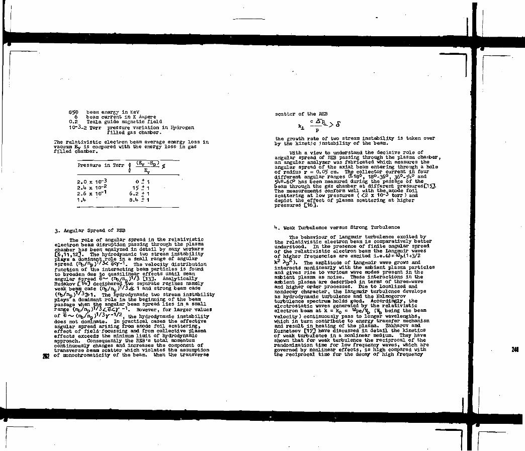
850 beam energy- in KeV6 beam current in K Ampere
0.2 Tesla guide magnetic field10-3-2 Torr pressure variation in Hydrogen
filled gas chaiiber.
The relativistic electron beam average energy loss invacuum Ey is compared -with the energy loss in gasfilled chanber.
Pressure in Torr
2.0 x2.h x2.6 x
10-310-210~1
00
68
(I
015.2.h
+ 1
+ 1+ 1
+ 1
3. Angular Spread of REB
The role of angular spread in the relativisticelectron beam disruption passing through the plasmachanber has been analyzed in detail by many workersC6,11,12j. The hydrodynamic two stream instabilityplays a dominant role in a small range of angularspread (nb/np)1/3< e<y-1. The velocity distributionfunction of the interacting beam particles is found
d t i l i f f t t i li g p
to broaden due to quasilinear effects until meanI ~ (1^/^)1/3 O3JN A l y t i l l y
deciphered two separate regimes namelyV / / i ^ 1 d t b
due to quasilinear effects until meanead I ~ (1^/^)1/3 O3JN Analytically3 d i h d t i l
212
angular sRudakov £ 3 p p g yweak beam case V^/n^r/i^S. 1 and strong beam case( t / n p ) 1 ' ^ - ! . The hydrodynamic two stream instabilityplays a dominant role in the beginning of the beampassage when the angular beam spread lies in a smallrange (.r^/iip^/icecy " 1 . However, for larger valuesof ë ~ (n t,/np)1/3jr-1/2) the hydrodynamic instabilitydoes not dominate. In practical cases the effectiveangular spread arising from anode foil scattering,effect of field-focussing and from collective plasmaeffects exceeds the minimum limit of hydrodynamicapproach. Consequently the REB's total momentumcontinuously changes and increases the component oftransverse beam scatter which violates the assumptionof monochromaticity of the beam. When the transverse
scatter of the REB
the growth rate of two stream instability is taken overby the kinetic instability of the beam.
With a view to understand the decisive role ofangular spread of REB passing through the plasma charrber,an angular analyzer was fabricated which measures theangular spread of the axial beam entering through a holeof radius r = O.GJ cm. The collector current in fourdifferent angular ranges CJÏ-180, 18°-36°, 36°-54° and5*f°-6O° has been measured during the passage of thebeam through the gas chanber at different pressuresOSJThe measurements conform well with the anode foilscattering at low pressures ( <2 x 10⁻³ torr ) anddepict the effect of plasma scattering at higherpressures C163.
*)-. Weak Turbulence versus Strong Turbulence
The behaviour of Langmuir turbulence excited bythe relativistic electron beam i s comparatively betterunderstood. In the presence of finite angular spreadof the relativistic electron beam the Langmuir wavesof higher frequencies are excited ±.e.Ld= <Of,(1+3/2k2 ^n ). The amplitude of Langmuir wave grows andinteracts nonlinearly with the anfcient plasma particlesand gives rise to various wave modes present in theantoient plasma as noise. These interactions in theanbient plasma are described in terms of three-waveand higher order processes. Due to localized andnondecay character, the Làngmuir turbulence developsas hydrodynamic turbulence and the Kolmogorovturbulence spectrum holds good. Accordingly, theelectrostatic waves generated by the relativisticelectron beam at k = kç, = xape/^J (Vj, being the beamvelocity) continuously pass to longer wavelengths,which in turn contribute to energy transfer mechanismand result in heating of the plasma. Zakharov andKuanetsov £17] have discussed in detail the kineticsof weak turbulence in a nonlinear medium. They haveshown that for weak turbulence the reciprocal of therandomization time for low frequency waves, which aregoverned by nonlinear effects, is high compared withthe reciprocal time for the decay of high frequency

plasma waves. This condition is satisfied whenWe/nkT <. k * D (m/M)
1/3 which conforms vd.th thelocalized nature of Langmuir turbulence. On the otherhand, in practical situations the bandwidth of theLangtair spectrum A U decreases and becomes smallerthan the critical value needed for the validity ofweak turbulence. For resonant interaction
where k— ko0* up/'b- When dM>—»AI^CT— Y", the electronbeam energy approaches or exceeds the plasma thermalenergy which violates the applicability of weakturbulence. This situation has been discussed byPereira and Sudan L18J. The presence of largeamplitude high frequency fields in ambient plasmaimposes a limit on width of the Langmuir spectrum.The ponderomotive force arising from the high frequencyfields gives rise to an ion density perturbation
|SnL, |E|2 _ 2
no k ?„
The inhomogeneity caused by the ponderomotive forcegives rise to a frequency shift
8 IT nQ k T e
- 3
As a result of this situation the dispersion relationfor electrostatic Langmuir waves becomes C19J
1+-(k^ D ) 2 +- — bjj. . 2 D 2 n J h n
- h
When the frequency shift produced by the high frequencyponderomotive force approaches or exceeds the frequencyshift generated by the relativistic electron beam, wefind o
8 7T no k Te
It is shown by Vedenov and Eudakov C2CQ that in suchcases the weak turbulence approximation becomesinapplicable. Thus, ft emerges that the weak turbulencetheory is applicable in a very narrow spectral rangeand the larger and the smaller values of W tend toinvalidate the weak turbulence approximation. In arelativistic electron beam passage through plasma,with finite angular spread, the weak turbulence appro-ximation results into over simplification of dynamicbehaviour of wave-particle interaction. When
W/nkT> è(k^D) 2, the Langmuir waves start collapsingto smaller and smaller sizes and these waves formlocalized dumps of wave energy which are calledsolitons, spikons or cavitons f21]. These localisedclumps of wave energy play an important role in strongturbulence theory. The analytical solution of theactual problem in practical cases becomes almostimpossible and useful information is obtained bycomputer simulation studies. Zakharov C223 showedthat the large amplitude Langmuir plasma oscillationscan be described by a nonlinear Schrodinger equation.The solution of this equation characterizes most ofthe properties of solutions. These properties ofsolitions have been used with success to explain manyphenomena associated with strong turbulence C23»2l0»Morales et al. |]25] modified the Schrodinger equationto include a monochromatic and homogeneous pump waveat plasma frequency. The solition solution obtainedin such a case conforms to a narrower width whoseintensity increases faster than exponential. Valeoand Krueï1 £263 in a particle simulation study haveshown that the solitons develop in the form of veryintense and narrow spikes which are accompanied by aself consistent density depressions. Kainer et al.J"£/Jhave shown that an electron beam of r^/n» = 2x10"2
with a velocity of 'b/Vt=i 25 first excitesthe electrontwo stream instability. This leads to the formationof large amplitude, long wavelength (kg Tip; u)o)plasma waves. These plasma waves work as pump andgive rise to solitons.'. The width of solitons thusgenerated is approximately 10 aD. The computer
simulation studies of Valeo and Kruer EJ26J depict thesoliton width in the range of (10-20)^D and thesolitons are found to persist for a time period inexcess of 500lû1
213

5. Beam Currant Attenuation and Effective ScatteringCross-section
Current through gases is attenuated due to scat-tering of electrons from atomic scatterers. This i sexpressed by a simple expression
IA = i o e"N(îx - 6
where N, Q and x respectively are number of scatterersca"3, scattering cross-section cm+2 and the currentpropagation distance. The measured values of HEBcurrent at various pressures are shown in Fig. (2).Taking the maximum and minimum value of tiie beamcurrent, we obtain
NQ = - I nx
2.3 x Iff,-2 _-1 - 7
264
where x = 110 cm for the current measurements shown inFig. (2).
At low pressures ( £ 2 x 10~3 torr) the currentmeasured by the angular analyzer remains almost constantduring the steady phase of the beam passage althoughthe magnitude of the axial beam current i s small. Thereduction in the axial beam current at low pressuresi s presumably due to reflection of beam electrons fromin i t i a l formation of the space charge along the axisin the vicinity of the cathode. With increasing gaspressures the space charge depletes and the maximumcurrent flows. When the role of collective effectsof plasma comes into play, the axial beam currentrecorded by the angle analyzer shows significanttemporal changes on a fast time scale. Some typicalanalyzer current variations are shown in Fig. (2).The current measured by Rogowaski coil i s seen tovary significantly with pressure and time. Theplasma at these pressures i s fully ionized andcol l is ionless , therefore, the current variations canbe interpreted in terms of scattering and attenuationarising from collective plasma phenomena.
6. Solitons as Potential Scatterer of REB
It i s well known that the hydrodynamic instabilitydoes not play essential role in the attenuation of REB.The REB attenuation i s mainly governed by the kineticinstabil i ty QI1)-]. The nonlinear development of
solitons in dense plasma i s well known. The plasma wavesgenerated in the gas chamber by REB satisfy the non-linear Sehrodinger equation £283-
- 8
According to Karpman and Krushkal £29] the solitonssuffer modulational instability when
- 9
The potential distribution of travelling solition is
*f + *•max ^" SBcil I T max-10
Q1/2(2U)-1/2x3
Using the strong turbulence criterion and REB parameters,we have computed shape of travelling solitons which areshown in Fig. (3).
Scattering of charged particles from arbitrarypotential distributions are very complicated. There-fore, we have assumed the solition potential tosatisfy the logarithmic potential of rhe form
V(r) = ejln -
where £ i s maximum potential energy governing theamplitude of the potential. Using this shape of thesoliton potential, ve have obtained an estimate ofeffective scattering cross-section from Gesztesy andPlfctner's formulation C3°D« Taking the conplexconjugate of scattering amplitude in the form ofasymptotic expansions, we obtain an expression for thedifferential scattering cross-section
- 12The beam electron energy E = 0.8 x 10 eV and

'"2ra{E-V(r)}j
L
- 13
-Ah
The J and H are Bessel and Hankel functions of denotedkind and order. The total scattering cross-section i sobtained by integrating eqn (12)
- 1 5-rThe variation of total scattering cross-section forlogarithmically varying potential distribution iashown in Fig. OO. The scattering cross-sectioncorresponding to core potential of the soliton iamaximum and decreases with increasing distance fromthe core of the sol i t ion. This cross-section ia Inagreement -with the minimum cross-section evaluated, ineqn (7). The beam particles would see the sol i t ionpotential as l ines of variable lengths depending ontheir direction of arrival with respect to the axi l .The proposed scattering mechanism provides a workingmodel to estimate the scattering of re lat iv i s t ic beamelectrons and to evaluate the energy attenuation ofre la t iv i s t i c electron beam in plasma chanber. Theenhanced scattering and attenuation of KEB by solitonsmay provide adequate heating of plasma for fusionreaction.
Conclusion
Present study leads us to conclude that bysuitably monitoring the beam and plasma parametersthe train of s o l i t ons can be generated* Interactionof REB with solitons results into enhanced attenuationof REB and additional heating of plasma to fusiontemperature*
Acknowledgement:- The author i s thankful to theDirector, F.O.M. Institute for Visiting S c i e n t i s t soffer where vork was started and their data was used.
References
Bennet, W.H., Fhys. Rev. i S (1931*) 89O; 9J (1955)
[2J Alfven, H., Phys. Eev. 52 (1939) 2?.[3] Brejzman, B.K., Eyutov, D.D., Nuclear Fusion 1Σ: , (19ï«O873.IV) Kamash, T., "Fusion Reactor Physics", Ann Arbor
Science Publ. (1975).[5j Thode, L.E., Sudan, R.N., Phys. Rev. Letters 30r -1 (1973) 732.[6J Thode, L.E., Sudan, R.N., Phys. Fluids 18 (1975)
1552r T 55m Lovelace, R.V.E., Sudan, R.H., Phys. Rev. Lettersr , 2Z CI9715 1256,\S] GuiOlory, J . , Benford, G., Plasma Phys. Ijf (1972)r 1 1131 *[9] de Haan, P.H. et al., 3rd Int. Top. Conf. High
Power Electron and Ion Beam Research and. Technology, Novosibrisk, USSR.
hoi de Haan et al., J. Phys. Sci. Instrum. 10 (1981 )373. ' *
Cli]Ferch, R.L., Sudan, H.H., Plasma Pays. 12 (1975)r i9°5.112] Thode, L.E., Phys. Fluids 12 (1976) 831.D3]Fainberg, ï a . B. et a l . , Soviet Phys. J.E.T.P 30, , , (1970) 528.tl^Rudakov, L.I . , Soviet Phys. J.E.T.P. 32 (1971)
1 1 Ol
11D 5] De Haa*t,P.H., Sm^,,R.H.,Hft*"«>*V>«.X^Tenssen,<i.c.A.M
, /jyvunnzniiM., tf.H.A- « * d SfrelKov, Rs.,T.rîkyS .^ , / â (W80373[16] Singh, R.N. , de Haan, P.H., Internal Report F.O.M.) No. h7.2<&- (1979).P 7 ] V E . K[i8]Pereria, N.R., Sudan, R.N., LPS 191, 1976, Cornell
University, USA (1977).[i9lAbdulloev e t a l . , Nuclear Fusion IS (1975) 21.[20]Vedenov, A.A., Rudakov, L.I . , Soviet Phys. DOKLADY
2 (1965) 1073-[21] Hanheimer, W.N., Papadopolous, K., Phys. Fluids 18
[22]Zakharov, V.E., Soviet Phys. J.E.T.P. 35 0972) 903.[23JKingsep, A.S., Soviet Phys. J.B.T.P. hZ (1978) 51.[24]Thomson, J.R. e t a l . , Phys. Rev. Letters 31 (1973). 918; 21 (1978 ) 2032.[25j Morales, G.J. e t a l . , Phys. Rev. Letters 31 (197*)
[26]Valeo. E. J . , Kruer, W.L., Phys. Rev. Letters 33.

~lj*27] Kainer, S. e t a l . , Phys. Fluids 15 (19?2) W93i
16 (1973) 1382.£28} Ilasegawa, A., Plasma Inst . and nonlinear Effects
Springer-Verlag, 197?.C29] Karpman, V . I . , KrushKal, E.M., Soviet Phys.
J-.S.T.P. 28 (1969) 277.{"301 Gesztesy, F . , P i t tner , L., J . Phys. A. Math. Gene.
12. (1979 ; 1091.
400c
to scope
Fig. 1(a) Sohem. '-' ram of REB scyiree andplasma _. e i .
1 (b ) Schematic diagram of angle analyzer.
252

5. a
AI l»HO"'Torr 8<0Amp.Fiill Seal»A!î-«llO"'Twr 7 0 A n * . * *Al 7-4 Tut S-0Amp.ru» Scan
50 100 ISO 200TIME IN NANO SECONDS
250
:
Fig. 2 REB current variations at differentpressures. Fig. 3
EXTENT IN Cm
Evolution of solitons in plasma chargerdue to passage of REB.

10 20 30 40 50 60 70 80 90SCATTERING ANGLE IN DEGREES
Kg. h Scattering cross-section variation.
m

DETERMINATION OF REFERENCE DATAOF REB DIODES BY USING ANUMERICAL METHOD FOR DIFFERENTAPPLICATIONS
S.SINMANMiddle East Technical University,Electrical Engineering Department,Plasma Engineering Laboratory,Ankara
A.SINMANAnkara Nuclear Research and Training Center,Electron Physics Laboratory,Ankara, Turkey
Abstract
type of transformer and or a LC ringing puiser (gated or ungatedmodes), it is generally at a situation of the terminating of apulse forming line which is using (time varying and non-linear).On the other hand, according to the selected research problem,it is necessary to realize a FED at a certain performance,
In this work; bearing in mind the both formalisms of DePackh /4/ and Child-Langmuir /5/ a comprehensive analysis of aFED terminated with a changed transmission line is performed witha numerical method.
By the aid of the theories about transmission line, signaland wave shaping, the algorithm of the numerical model has beendeveloped using a series depending only on reflection coefficientof the transmission line and taking also into attention of FEDphysics. The mathematical model is in a dynamical character. Inour previous study I6J, it had only been investigated the waveshaping of a FED making an appropriate approximation. But herethis time among the findings obtained from the computational expe-riment, the time history of some other important parameters aregiven. In addition from the view point of design, the correlationswhich will make the selection of the FED easier are also repren-sented.
DETERMINATION OF REFERENCE DATA OF REB DIODES BY USINGA NUMERICAL METHOD FOR DIFFERENT APPLICATIONS
la this study, some reference data of a REB diode arepresented functionally. These given characteristics are consistedof the computational results. Generally the numerical schemedepends upon the essential parameters of the charged transmissionline and Child-Langmuir's diode model. By this system) furtherthe correlation functions, some other definite functions such asthe voltage of transmission line VL(t), the diode voltage V^tt),the diode current I^(t), the diode impedance Bjft), the diodeinput power »d<t>' the dissipated energy Ud(t), the efficiency $,the beam density nb(t), the relatiyistic beam energy Ub<t), andthe intrinsic impedance Z±nt<t) have also been investigated.
1, INTRODUCTION
Besides the utilization of Relativists Electron Beam (REB)generators in inertial confinement schemes directly, wide rangeof application possibilities of it in other research areasdepending on the fusion indirectly such as collective 1onacceleration /I/, microwave production HI and TEA-Laser excita-tion are also known /3/.
The heart of REB generators is field Emission .Diode (FED),Let FED be to be driven by whether a Marx generator or a Tesla
2, MODEL
It is known that the actual REB systems are generally com-posed with a charged transmission line and a field.emission diodein gated or ungated beam modes. Particularly the diode demonstra-tes a non-linear and time varying property, The electrical mecha-nism is in the form of which a charged transmission U n e is dis-charge onto a diode having these specifications, If the diodeshows a time invariant and passive property, then the phases ofthe discharge ca* easily be explained by the known transmission,line theory. When a charged transmission line is terminated by aload of RL which is different from the characteristic impedanceof Zo (e,g,, RL > Z o ) , it is discharged onto the load at theshape of decreasing steps. On the contrary in the case of RL < Zo,the discharge exhibits a specification of the periodical functionconsisting of decreasing steps. Mathematically each steps aredefined by a shifted step function of,
S ( t ) - Z jU(t-jT)j-o
(1)
where jT - a; U(t) - 0 for t < a and U(t) - 1 for t > a.For the open circuit transmission line loaded via a resis-
tor Rch in series, the time domain terminating voltage; In thef i rs t Iwo-Way-Travel-Iime (THTT) are given by,

V° - VL(o) / | b(t) (2)
where VL(O) is the charging voltage and b-Rcn(t)/Z0
In the second TWTT the expression is,
2v£(t) + r (t)v[(t) (3)For the voltages in the third and successive TWTT's, the
following equations can be written as,
Vt(t) - 2vf|(t) + r
- 2v£(t) • r
vLn+1(t)-2v£ + r (t)vC(t)
where the reflection coefficient y ( t ) is ,
' r (t) - | RCh(t)-z0 I /1 "cht*)^ I
In addition for the Eqs. (3 ) , (4) and (5) in the forms of,
Vf.(t) - vfrt) | 2 • r (t) |
v°(t) | 2 + 2 r(t) + rz(t)|
i- v°(t) ; 2 + 2 r(t) + 2 r2(t) * r3(t)|
can be given and more generally according to Eq. (1),
v?r(t) - 2V?(t) | z rj(t) + r (t) / 2 | (t-jT)LS L j-o
(•)
(5)
(6)
(7)
(8)
(9)
(10)
can be found.In the first TWTT, the discharge of this system onto R_h
resistor is characterized by,
' (il)v° ( t ) d c h - vL(o) | i - ( b ( t ) + i ) " ' | | i+r ( t ) /2 I
For the second TWTT,
VL ( t )dch " V ° > - I 2VL(o)/(b(t)4l) | | l+r( t ) /2 | (12)
can be written. Thus subtracting the results of Eqs. (7), (8)
and (9) from the charging voltage V,(o). one can convert to dis-charge model . In tnese equations, using tne Child-Langmuir dioderelation instead of Rch in b(t) ten».
is found or according to Packh (parapotential model),
Can be given. Where,
- 8500(Rc/dac)(Vb/c)VLn
and
yk - 1+1.96x10' (v b / c ) k - | l - (
U 3 )
(14)
(15)
(16)
In the simulation algorith, the general system parametersor its identity should be described with Xy(tj) or with X^. Here,y is generally symbolizing a component orthe REB system. Thesampling time dt, is equal to tJtl-t- or to its foldings
tj+1/(j+i) depending on ji where j-0, 1 n. In some situationsit has been used tne symbol of j+i- K. The results of tne analy-tical solution have been written in time-domain based on aboveconcepts.
Of course, the Eqs. (11) and (12) in the discharge modelhave been given only as an example. Besides, by means of the de-finition (10), the discharge model can be generalized. Furthermo-re, at the end of each sampling times, taking into attention thetotal dissipated energy, it has been performed the needed correc-tion through charging voltage VL(o).
3. COMPUTATIONAL RESULTS
In this given model, it has been possible to use the resultsof De Packh or Child-Langmuir formalisms. Here, the important po-int was to be known the numerical results of diode impedance inthe Eqs. (13) and (14).
As an example in this study, an analysis of foil diode ac-cording to the Child-Langmuir is submitted.
In the REB diodes, the wave shape can be determined computa-
271

tionally or by a high-speed oscilloscope combined with an analogor digital processing system. As a basic informations, from thewave shaping some other required data can be obtained by meansof a mini computer. This is a solution of a soft-ware problem.
Principally, for the evaluation of this study the characte-ristic impedance of transmission line Zo, the T_wo-W.ay-Iravel-Xime(TWTT), the anode-cathode gap dac, the plasma velocity vn ; andthe initial voltage and energy of the transmission line V[_, ULhave been selected as the parameters. In addition, they have Beenexamined the variations of mean values of the relativistic energyTJj,, the dissipated energy TTd, the electron density ne and thediode current T d with respect to the ratio of the cathode radiusto the anode-cathode gap Rc/dac-
The time domain analysis has been carried out. For the sam-pling time ts, it has been accepted as TWTT/10. In the statisti-cal estimations, the standard deviations s, have also been takeninto account.
In Figs. (1) and (2), the mean values of the diode currentsand the dissipated energies in the diode as a function of Rc/dacratios are seen. In addition, the statistical results of s/Djand s/Td have also been given. In the figures, except theanode-cathode gap dac, all other parameters are the same,
The mean diode currents for Rc/dac - 1 (Fig.l.) andRc/dac - 1.4 (Fig.2.) are close to each other, but the increa-ses in the diode current T d and the dissipated energy TJd corres-ponding to the values of "c^ac > 2 are nearly two times.
For Rc/dac - 2.2 (Fig.l.), the energy distribution 1s rath-er homogeneous ; that is to say the s/Ud curve passes from aminumum. The shape of current pulse, with respect to the Rc/dacvalues in the range of 2.5 and 4.5 is fairly smooth (s/T> 0.3).Whereas, in Fig. 2(dac - 0.5 cm), the minumums of s/Ud and s/Xjare taking part in a narrow region of Rc/dSç between 2 and 3, Inother words, the homogenity of energy distribution and the neces-sary geometrical conditions for a reasonable performance in wave-shaping are limited.
The plots of ÏÏA, TJD, ïïd and T d against the Rc/d,c for theconstant condition of d- c-0,7 cm, V. - 2 MV and U, - 3b kJ aregiven in Figs. (3) and (4). L L
At the Fig. 3, the mean values of beim density Tf. and the••-" ' " - - " 'd,. have been drawn andd,c
b have also been il lust-relativistic beam energy TJj, versusthe statistical results of s/ne and s/rated.
It is observed that as the electron density is decreasingexponentially, the relativistic beam energy and its distributionremain almost constant. Particularly, in the range between 2 and4 of Rc/dac ; both of these functions can be accepted in uniformly.
In Fig. 4; similarly to Fig. 1, variations of diode currentand energy dissipated in the diode with respect to Rrfàic aresubmitted. The function of Td(Rc/dac) has a minunum between thevalues of 2 and 3 of Rc/dac. In this region, the wave shape ofcurrent pulse is very close to the square wave. However forRc/dac 1.25 - 3.0 the energy distribution is rather homogeneous.
4: CONCLUSION
In this paper, all time dependent functions mentioned inthe abstract have been investigated and their results have beenpresented in the form of correlation functions.
On the correlation functions plotted (Figs. 1., 2., 3. and4.,) it has been determined some regions where the ripples of fun-damental time dependent functions are minimum, Under the contri-bution of Child-Langmuir expression, it is understood from theresults found; for instance that for which type of diode confi-guration, the optimum wave-shaping can be obtained or how a ho-mogeneous energy distribution can be produced. The same resultsmay naturally be found for Oe Packh or for any other formulati-ons too.
By means of this method, it is possible to find out the va-riation of the intrinsic impedance Z- .— 377(v|j/c) with respectto IWd a c and to illustrate the correlation functions of T d, TJDand lid all together. So in the case of TEA Lasers for instance,the interface problem between the REB diode and Laser cavity fromthe view point of propagation may be optimized. The same consi-deration is also applicable to micro-wave generations. On theother side, the variation of limiting currents of REB diode aga-inst the ratio of Rc/dac can be discussed together with the beamdensity, the beam current and the relativistic energy. Thus forthe collective ion acceleration, the optimum operational conditi-ons can be determined.
REFERENCES
IM OLSON, C.L., IEEE Trans. Nucl, Sci-NS-22 No.3 (1975) 962.
III BEKEFI, G., and ORZECHOHSKI, T.J., Phys. Rev. Lett. 37(1976) 379. ~
IV HARRIS, N.W., et al.. Rev. Sci. Instrum. 48 (1977) 1042./4/ De PACKH, D., Naval Research Lab., Radiation Proj. Int. Rep.
7 (1968)./5/70NAS, G., et al., Nucl. Fusion 14 (1974) 731./6/ SINHAN, S.. and SINMAN, A., 9th European Conf. on Cont. Fusi-
on and Plasma Physics, Contributed Papers, UP-30 (1979) 124. 271

tkJ)
îd(kA) ^x VL=IMV, UL=
80
-60
.5- 40
20
0.7cm
-ao
-1.0
-2
2-f-
(kJ)
! (kA) V MV> UL" 9 k J • T W T T * > 8 ! n $ >
IGO Z 0 * 5 f t « <l<icl0-5*m' vp*4xK)€cmi'1
120
-80
40
2 3 5 6Rc / dac
FIG.l. Dissipated energy TJ and diode current T., variations withRc/dac for UL - 9.0 kJ and dac - 0.7 cm.
FIG.Z. Plots of dissipated energy ïïd and diode current T d,against Rc/dac for dac - 0.5 cm.
272

CO
2
£ VL* 2 MV, UL» 36 kJ, TWTT =
f * * ^ * doc' o r cm- V A
181 ns, Z 0 «5 i l ,
4xlO6 cms"1
2.0
10
ud(kJJ
6-
4-
2-
0
id(kAl200
-150
•100
•50
. V.* 2 MV,4| TWTT«I8I11\
V\
0L» 36
n», v p *
ko. Z-. 5n. Ï >6 1 x
4x10 cms, jf
dqc.0.7cm / û d y
^*"
' "-x>
X /
^ /
S y
/X
//
o•o
I » -
-2O
1.0
0
QC 4 Rc /dac
FIG.3. Relativistic electron beam density rîe relativistic beamenergy Ub versus Rc/dac.
FIG.4. Dissipated energy Ud and diode current fd as a functionof Rc/dac for UL - 36.0 kJ.
273


~1NEUTRON YIELD, CURRENT SHEATH MAGNETICSTRUCTURES AND THERMONUCLEARFEATURESOF THE DENSE PLASMA FOCUS
R. GRATTON, C. FERRO FONTAN, H. KELLY, i. POUZO,M. MILANESE, A. SICARDISCHIFINO, G. CASIN, M. ESPERLaboratorio de Fisica del Plasma,Facultad de Ciencias Exaclas y Naturales,Universidad de Buenos Aires,Buenos AiresandDirection General de Investigation y DesarroIIo,Ministerio de Defensa,Buenos Aires, Argentina
ABSTRACT
NEUTRON YIELD, CURRENT SHEATH MAGNETIC STRUCTURES ANDTHERMONUCLEAR FEATURES OF THE DENSE PLASMA FOCUS.
We report recent measurements and discuss ideas currentlybeing developed at this laboratory, concerning the productionof fusion reactions in Plasma Focus (PF) devices and theirscaling.
1. INTRODUCTION
Plasma Focus discharges in pure deuterium produce a dense,hot and short lived thermonuclear plasma, with a relatively highneutron yield. In our laboratory we have been operating a small(1 kj) machine, which currently yields several 107 neutrons inDz (record shot 3*10*). A second machine (22 kJ, 30 kV) hasrecently been completed and should produce from 10° to 10*°neutrons in deuterium. The physics of this device is an attrac-tive subject by itself, both fro» the experimental and thetheoretical points of view. Besides its intrinsic interest,the PF also provides a good testing ground for diagnostics whichare specific to plasma physics.
In this paper, we report Measurements of the spatialanisotropy of neutron production and an investigation of theinner magnetic structure of the current sheath (CS) during thecoaxial propagation stage, carried out in the 1 kJ, 20 kVapparatus. The anisotropy A-»(0')/«(90') is in the range 1.6-2.3 and increases with the number of neutrons of the shot,while decreases at higher pressures, as found by other authors
at higher energies. Very snail magnetic probes (•-0.3-0.4 mu)were used to measure the radial and azimuthal Magnetic compon-ents, B and Be, in the CS. It is found that the radial signal isstrong and comparable in the best shots with the azinuthal field.Simultaneously, the neutron yield Y for deuterium was registeredand a good correlation with Br was found, in the sense that highyield shots correspond to strong B r signals. However, as expected,Y and Bg were not correlated. It is known that Y has a maximum ata certain pressure pjj, after which a drastic descent takes place,which occurs when the energy available per particle in the.CSbecomes less than the ionization potential of the gasl1].According to the correlation mentioned above the observed Br
also decreases strongly for P^M»
A mechanism which can explain the. origin and main featuresof the CS radial magnetization was theoretically investigated.The physical idea behinc* such mechanism is to consider the sheathas a thermoelectric junction; in laser plasmas it easily explainsthe production of megagau'ss magnetic fields. From the analysisone gets under PF conditions: the right order of magnitude ofscale length and e-folding time of the instability (">• 1 usec),alternating radial magnetic fields (filaments) which saturateat 1-10 kgauss, and the quenching of the instability as theelectrons become colder than 10 eV. Since the electron temperat-ure in the CS i* a decreasing function of the filling pressure,this effect naj explain the high pressure cutoff on Br experiment-ally found, and correlates very well with the specific cutoffenergy introduced in II].
We find that several relevant features of the PF could besimply explained in terms of the old pinch concept, with somemodifications. In this context, the frozen-in Br components of thecoaxial stage become axial components Bz in the pinch column. Ifone assumes that 6Z has a stabilizing effect, one can understandthe long life of the column and hence the high neutron production.Furthermore, the observed correlation between Y and B r would havea naturel explanation. Moreover, the empirical fact, generallyaccepted, that Y is determined basically by the current I at thefocus stage could be interpreted as a simple consequence of thepinch hypothesis, as we shall show. There is, of course, abundantexperimental evidence that indicates the presence of non-thermalmechanisms in the PF which may account for a fraction of Y.However, we maintain that another part of the yield can be accoun-ted as thermonuclear in origin, and is relevant enough to determinethe order of magnitude of Y.
2. PROPERTIES OF THE NEUTRON FLUX
The lkJ, 20 kV, PF-I machine was used to perform measurementsof the spatial anisotropy of neutron production and an investigationof the inner magnetic structure of the CS during the coaxial pro-pagation stage, varying the filling pressure p. 215

The anisotropy A* •(0*)/*(90*) (» is the neutron flux) wasdetermined using tiM resolved and tine integrated neutron detec-tors. Both type of detectors gave similar results, within statis-tical errors. The main characteristics of A can be summarized asfollows: s) A (like the neutron production Y) fluctuates fromshot to shot. For exasiple, in Fig. 1 we show values of A from in-dividual shots as a function of Y, for p- 1.8 torr. A rangesbetween 1.5 and 2.3 independently of Y, and fluctuations arealso present in shots having the sane Y. A similar behavior isfound for other pressures, whenever 1.05<p<2.25 torr. b) In Fig.2we give the average A as a function of p. A takes values in theneighbourhood of 2 and is rather constant for 0.5<p<2 torr,while for p>2 torr A descends monotonically. In' Che same graphwe show the average of the neutron yield Y for comparison purpo-ses. Calculations made with a two-dimensional model for thecurrent sheath [2], show that the decreasing of Y in the highpressure regime occurs when the energy avt'.lable in the CS be-comes less than the ionization potential of the gas, in accor-dance with the cutoff proposed in Ref. [1]. c) The behavior ofA with Y is presented in Fig. 3 for two pressure, ranges: for0.9 <p< 2 torr, corresponding to the optimum Y (Fig. 3a), nomarked dependence between A and Y can be found except for thebest shots (Y > 1.3x 10*) where A rises above the mean, attai-ning a maximum of 2.6. For p> 2.6 torr, corresponding to the dropin Y (Fig. 3b). A increases with Y, reaching values similar tothe preceding case only for the best shots. The minimum valueof A obtained in this case was A - 1.3.
The values of A reported here are in accordance with thedata published by other authors working with Mather-type PlasmaFoci [3], who have found that A increases with Y and decreaseswith p. However, large values of A cannot be attributed as ageneral property of Mather-type Plasma Focus devices, becauselower values of A have been reported [4 ] in devices operatingin a broad range of energies.
Concerning our data, we find very difficult to interpretthe values of A>2 in terms of a moving boiler model. On theother hand, a beam-target mechanism, with a deuteron beam energyE= 100 keV, can easily explain the measured anisotropy, as wellas Y, if the total number of particles in the beam is of theorder of 10* - 101! . Also, the neutron production time (=80 nsin our device) can be understood, because the transit time ofdeuterons of 100 keV along the discharge camera is "50 ns, towhich we must add the time of beam production. ThiB last- timeis taken to be 20-30 us, in accordance with the duration o£ thehard X-ray pulse emitted with the neutron burst. As furtherevidence of the importance of beam processes in our device, wefound a strong correlation between the amplitude of the hardX-ray signal and Y (see Fig. 4).
271
3. MAGNETIC FIELD STRUCTURE IN THE CURRENT SHEATH
An investigation of the CS inner magnetic field was carriedout, using very small magnetic probes (4" 0.3-0.4mm). The probeswere located within the coaxial gun, at = 1 cm from the end ofthe inner electrode and radially separated 3 mm from it. Theywere oriented to record the radial and azimuthal magnetic fieldcomponents, B and B», in the CS. Simultaneously, the neutronyield (Y) was registered. It was found that the B. signal vasnot correlated (neither in amplitude nor in shape) with Y. Onthe other hand, we have detected a B signal, poorly reproduci-ble, as large as the tg signal for the best yield shots. In£ig. 5a we give the average B as a function of p, showing alsoY. It should be pointed out that the presence of_the pr_obe re-duces Y by a factor larger than two. In Fig. ib Y vs. B isgiven for p » 1 torr. As can be seen, B is correlated with Y.However, this result must be consideredras preliminar, becausethe total number of data we used to draw Figs. 5a-b was some-what scarce (= 30 shots), due to the fragility of the miniatu-rized probes. We tried to circumvent this difficulty by usinglarger probes (• > 2mm), but no B signal could be detected upto now. A possible explanation of this negative result may bethat the increased perturbation of the plasma produced by thelarge probe destroys the local current distributions which ori-ginate the B f component. As a matter of fact, Y results practi-cally negligible when the large probe is used.
4. GENERATION OF RADIAL MAGNETIC FIELDS IK THE CURRENT SHEATH
In this 'section we present a tornado-like mechanism, adap"ted to the FF conditions, which explains the generation of the ra-dial magnetic fields embedded in the CS during rundown. Ii. thenext section, we shall assume that these magnetic filaments playa significant rOle in the dense focus stage. A more detailed expo-sition of this model has been published elsewhere [ 5]. We shallrefer to the local reference frame attached to the CS. For con-venience, plane geometry is assumed, with the x-y plane parallel tothe electrodes and the y axis along the gun.
The complete set of equations for the ion and electronfluids is too complicated and it is clear that a satisfactorysolution can only be obtained at the prize of a numerical simula-tion. However, a simplified model which gives a clear insight ofthe mechanism involved is the following. The instability resultsfrom the combined effect of the so called baroclinic magneticsource term
" I - *° ne x - Te ' »>and the electron thermal drift in a magnetic field
- K b x 7 TA — e (2)
where b_ is a unit vector parallel to B_ and K A = KJ^TU in the weakfield limit. As usual, T is the electron collisionalc time and u
_ J

_J~l
the electron gyrofrequency. The dependence of K A on the ionizationdegree Z is given by' Braginskii [ 6] .
The expression (1) is most easily deduced from the collision-less equation of motion for each species
ms dt~ vs * 1S (I. + Zg. x 5) „" ?- Ps W)
by substituting Faraday's law and the ideal gas equation of stateinto the curl of (3). We get
-- £ (V x VS • »cs) - V * ns x 7 TS • «»««*» (A)
whereucs q a rasc. (5)
Due to the smallness of me, the vorticity vector in the left hand sideof (A) is usually neglected when considering the electron fluid.However, .this argument cannot be repeated for ions and one seesfrom (A) that, in general, vorticity is created together with amagnetic field. This is an all-important conclusion.
If an electron temperature perturbation along the sheath ap-pears, given by a small Ti(x,y), the baroclinic vector (1) gene-rates a B z component, and a positive energy feedback is establi-shed through (2) when the zero order gradients are parallel
0.£06i n e ) o . V(r e) o > 0. (6)
This mechanism results in an unconditionally growing instability.However, some stabilization is always present due to magnetic dif-fusion and heat conduction. If, for simplicity, we assume thatperturbed quantities are weakly dependent on y, the direction per-pendicular to the CS, we can write
(7)
(8)-l7Tel3T,
3t 3*
where vm - c2/4iro » 1.4 x 10" /ner is the magnetic viscosity and
K± = ZTet/me is the thermal diffusivity of the plasma across themagnetic field. One recognizes in (8) Fourier's equation with thedivergence of the thermal drift,(2), included. In these equationswe neglected advection, a procedure which can hardly be justified.However, the main effect of advection is to prevent the indefinitegrowth of the magnetic field.
Equation (7), which describes the generation of the magneticfield, can be interpreted as an electric circuit equation. In fact,in the CS there are large gradients of the thermodynamic quanti-ties, which create an upstream electron diffusion current and,correspondingly, a thermoelectric emf which opposes diffusion. Itsmagnitude is given by the electron thermal energy. If the electrontemperature is not homogeneously distributed over the CS, e.g. ifa temperature fluctuation T, appears, the excess ëmf V- T, /e isno longer equilibrated by the diffusion current, and current loops,
of intensity I, are driven across the CS, which can be modeled asa parallel array of fluctuating emf's, like in Fig.6. In thisexample, the perturbing temperature T( is represented as a singleperiodic Fourier mode with wave number k.
Let R and L be the electric resistance and magnetic induc-tance of the loops, respectively. In gaussian units they are defi-ned as
R - In k? Mita (9)
L - V e 2 lUnHy) - *n(cm>l (10)
where t^ is the density gradient scale length. Now it is easy totransform (7) (3/9x - ik) by using Ampere's law
B - kl/c
In terms of R, L and I, (7) reads
(11)
(12)L — « V - RIdt
Note that V^i^ /e appears shifted a quarter of a period with res-pect to the field. In this context, (8) describes the time evolu-tion of the thermoelectric emf V due to the cross field and normalthermal conductivities of the plasma. Beyond the instability thres-hold, the CS equivalent circuit is magnetized by an exponentiallygrowing emf. This means that, under suitable conditions, the ins-tability converts a portion of the thermal energy into magnetic,ordered, energy. The phenomenon is reminiscent of the Bernard pro-blem in hydrodynamicsf in which, at a well defined critical valueof the temperature gradient, a fluid heated from below in the gra-vitational field develops an ordered pattern of convective flow.Glansdorf f and Prigogine [ ? 1 pointed out that such kind of insta-bilities are analogous to phase transitions and that the evolutionof the system is a consequence of the tendency to reach a stateof higher thermodynamic efficiency, in which the generalized en-tropy production is a minimum.
5. PINCH INTERPRETATION OF THE NEUTRON YIELD SCALING LAW
We shall sketch some qualitative considerations-about thescaling law for the neutron yield Ï, which may arise from theassumption that the column in Plasma Foci devices behaves "grossomodo" like a thermonuclear pinch. If a dynamic equilibriumexists, the well known Bennett's relation
I2 * 3.2 x 10"M S T (1)
should hold, where I (Amp) is the total current, N (cm'1) is thelinear density and T (°K) is a characteristic value of the tempe-rature (assumed to be of the same order for electron and ions).The radial scale does not appear in (1) because as the cross sec-tion of the column varies, the energies associated with magneticcontraction and thermal expansion in the radial direction change 277
xtmmmmmmmmmk

_l
with the radius in the sane way. Therefore a relationship suchas (1) should hold for a large set of possible equilibrium confi-gurations characterized by very different values of the radius r,the density n and the current density, under the general hypothe-ses of cylindrical geometry and ideal gas statistics. A calcula-tion of the actual radius of the column,considered as a whole,or the radii of segments of the column, would require supplemen-tary hypotheses on the phenomena intervening in the energybalance such as transport processes. Summarizing, it seemsreasonable to take as a starting point that, if a state of dyna-mic equilibrium is achieved (as suggested by the relatively longlifetimes of the columns observed in plasma foci), then a rela-tionship like (1) must hold between I, N and T.
However, cylindrical configurations of this kind are HHDunstable, so that their lifetime should be of the order of fewns for the parameters typical in plasma foci columns (r-01-lcm,sound speed = lu" ens') unless some stabilization mechanism ispresent.
As a guess, we assume that stabilization is provided by thepresence of B components in the column, resulting from the evolu-tion of B components produced in the previous coaxial stage; ifthis is tne case, the creation of B components during the CS pro-pagation would be a necessary condition for the formation ofstable configurations in the focus stage, for a wide range of sizeand shape of these configurations. Of course, the relationship (1)should be Modified» because the presence of B components nay playa role in the dynamic equilibrium. In the spirit of the qualita-tive treatment here developed, we merely assume that a magneticpressure tern should be added to the kinetic pressure so that (1)takes the form
271
I2 - 3.2 x KT» N T B"1 C2>with 6 - K, the minimal value necessary to produce a stabilizingeffect.
ïhe «ell known strong correlation observed between the yieldY and I suggests that only parameters such as N and T should deter-mine Y, and not the actual radii and densities. A reasonable way(though not unique) in which this may happen arises from the fol-lowing assumptions:
a) the lifetime of the plasma column is given by its lengthI divided by the sound speed (proportional to T ) , that is, thereis no axial confinement of the plasma;
b) there exists an aspect ratio v " lr~' which does notstrongly vary from one device to another.
Under these hypotheses, the yield Y is given by:
• A u 1 N* < o v ) T" (3)
where A is a constant and { ov) is the usual fusion reaction ratefor i aaxwellian distribution at the temperature T.
The expression (3) must be considered together with (2), sothat
Y =• A1 ua <ov> f " I4 (4)
In the following table we give values of A' < ov> T* w forthe range of temperature of interest.
TABLE: Values of A* (ov> T"*4
Temperature (keV) A' { ov> T~S/4 10" (neutron/Amp4)
13591520
0.070.911.561.941.751.49
It can be observed that A1 < ov) T rises steeply at T= 3 keVto reach a sort of plateau. __,
Clearly, this behavior of A1 ( ov> T suggests an approxi-ymate scaling law for Y of the form
Y » v2 a I* <5)
where a = 1 * 2 x 10"".À thorough analysis of experimental data [8] gives as the
best fit
Y = 2 10-" I433 (6)
which is very near to (5).It should be noted that values of T > 3 keV, in the plateau
of the function A1 { ov ) T'V2 imply that the linear density Nshould be below a limiting value N L given by
= 0.5 x 10* I* (7)
According to this scheme if the linear density when thecolunn is formed is higher than N^, the neutron production shouldbe very low until N becomes of the order of N L through axiallosses. However, in the case of low current plasma foci such asthat described in this work (I = 1.5 * 2 x 10s Amp), the resultingHj, (= 2 x 10" cm"1 ) is below the limit S Q = 10
n cm"1 for theonset of the resistive instability 19). In this situation anabrupt increase in the resistivity by a factor 10' * 10* abovethe classical value is possible in the stage of high neutron pro-duction. Therefore the thermonuclear yield may be nixed with thebeam-target yield resulting from the acceleration of deuterons inthe strong field due to the abrupt increase of the resistivity.
REFERENCES
I 1 I GRATTON, J.,KELLY, H., MILANESE, M., POUZO, J., Fhys. Lett.A.62. (1977)422.
[ 2 ) GRATTOH, F., VARGAS, J.j Proc. VII Conf. on Contr. Nucl. Fus.(1975), Vol. I , Lausanne (1975)64.
.J

[ 3 I PATOU, C , SDMONET, A. and WATTEAU, J. P., Phys. Lett. A29. (1969)1; BERNARD, A., CESARI, G., COUDEVIELLE, A., JOLAS,A., de MASCBREAU, J. and WATTEAU, J. P., Proc. 4 t h Conf. onPlasma Phys. and Conf. Nucl. Fus. Res., Vol. I, IAEA, Vienna(1971) 553.
[ 4 ] MICHEL, L., SCRONBACH, K. H. and FISCHER, H., Appl. Fhys.Lett. .24 (1974)57; LEE, J. H., SHOMO, L. P. and KM, K. H.,Phys. Fluids 15(1972) 2433; BERTALOT, L., BILBAO, L.,BRDZZONE, H., GENTILINI, A., GOURLAN, C , GULLICKSON, R. L.,KROEGLER, H., PODDA, S., RAGER, J.P., ROBOUCH, B. V. andSTEINMETZ, K., 9th Eur, Conf. on Contr. Fus. and Plasma Phys.Oxford, (1979), DP14.
[ 5 ] FERRO FONTAN, C , SICARDI SCHIFINO, A., Proc. II Inter. Conf.on Energy Storage, Compression and Switching, Venice 1978,Plenum Press.
[ 6 ] BRAGINSKII, S. I., in: Reviews of Plasma Physics (ed. by M.A.LEONTOVICH), Vol. I, Consultants Bureau, New York (1965)205.
t 7 ] GLANSDORFF, P., PRIGOGINE, I., Physica 30:351 (1964).[ 8 ] POUZO, J. 0., Ph.D. Thesis, University of Buenos Aires, 1979.[ 9 1 VIKHREV, V. V., and KORZHAVIN, V. H., Sov. J. Plasma Physics
4(1978)411.
Y(xlO7)
Y(xlO' )Fig.l: The anisotropy A as afunction of the neutron yieldY in single shots, p=1.8 torr.
p(torr)Fig.2: Average anisotropy and neutron yield V as afunction of the pressure.
a )
II1
nFa. b)
•n* " " Y(xlO7)» Y(xlO1)
Fig.3: a) S as a function of Y for 0.9cps2 torr.b) The same as a) for p»2.6 torr.
I (a.u.)B_(a.u.) Y(xlO*)
a) . B r
. 7
i
y^ . 1
*
YOtlO*)
*Y(xlO 7) f~ p(torr)fig.4: Hard X-ray sig- Fig.5: a)Average of the radial compo-nal Ix,(in arbitrary nent of the magnetic field as a func-units), as a function tion of p. b) Correlation between 7of Y. and B for p* I torr.
Fig.6: Cross section of the CS, showing themagnetic filaments and the thermoelectricemf's and currents.
279


~1ON SOME HIGH-FREQUENCY OSCILLATIONSIN A REFLEX DISCHARGE
S.K.GUHARAYSaha Institute of Nuclear Physics,Calcutta, India
I. INTROIWCTIOH
Oscillations in a reflex discharge have been investigated
by numerous workers. 1"° Depending upon the conditions of the
discharge, viz. gas pressure, magnetic field strength, discharge
current, discharge voltage and, above all, nature of cathodes,
various kinds of oscillations can develop. Particularly, situations
with cold cathodes, operating in the neighbourhood of 10** Xorr,
show up interesting results as both lov-and high-frequency oscillations
can occur there due to the presence of a radial electric field as veil
as a strong potential drop across the cathode sheath. It is iaportant
to examine the oscillations under various conditions of discharge
parameters in order to characterize them. Such a study is warranted
particularly on the tut. oscillations in a reflex discharge. The
aim of the present work is to delineate a controlled experiment
with a cold-cathode reflex discharge to acknowledge the nature of
the iuf. oscillations. It is observed that oscillât ions of frequency
in the neighbourhood- of the ion dynamics are excited through the
interaction of counterstreaaing electron beans with a background
plasma.
Experimental arrangement is described in Section IL
Experimental results and discussions are given In Section III and
Section 17 contains conclusion.
IL. EXPERIMENTAL ARRANGEMENT
The schematic diagram of the reflex or Penning discharge, as
used here, is shown in Fig. 1. The device has been described in an
earlier article.? The spacing between the two aluminium cathodes is
h? cm and its diameter is 1.8 cm. A number of langtnulr probes were
used to measure the plasma parameters and to detect oscillations as
well. An external dipole antenna was also kept for high-frequency
pick-up from the plasma. The spectrum of the h. f. oscillations was
studie.i by a Type 91 Tektronix spectrum analyser.
I U . EXPERIMENTAL RESULTS AN» DISCUSSIONS
Observations were made through wide ranges of pressure
p(5x10"2 - 6x10"^ Torr), magnetic field strength B (100 - 1100 G),
and discharge current I d (5-200 mA). In this operating region,
oscillations were observed in two distinct frequency ranges î(i) low
frequency (1-20 kHz) and (ii) high frequency (10-100 MHz). A typical
example is shown in Jig. 2. To recognize the driving agent of the
oscillations, two symmetric grid structures were inserted across the
plasma column as shown in Tig. 1 and they were operated as follows :
(1) grids kept floating, and
(2) grids biased at anode (ground) potential.
It was observed that the situation corresponding to floating
grids favoured the excitation of both lov-and high-frequency waves *,
while for grids at anode potential, only high-frequency waves could
appear. This suggested that the 1. f. oscillations were due to some
radial gradients of plasma parameters and that the b. f. oscillations
could be due to the interaction of the counterstreaming electron 211

beams from the cold cathodes with the background plasma. The 1. f.
oscillations in the reflex discharge were studied and reported7 8earlier.'1 The results on b. f. oscillations will be discussed here.
For the excitation of the tuf. oscillations, discharge voltage
was observed to bear the most significant role. At a particular gas
pressure p, with either the decrease of discharge current Xd keeping
B fixed or increase of the magnetic field for certain Id , the b. f.
oscillations gradually disappeared. In both the situations i t vas
necessary to lower the discharge voltage. This revealed that, unless
the potential drop across the cathode sheath was strong enough to
render electron beaas emitted from the cathode surface much «ore
energetic than the thermal energy of the plasma electrons, the inter»
action of the electron beams with the background plasma could not
yield growing waves.
d e spectra of some of the oscillations recorded under various
discharge conditions are presented in H e 3. Two distinct peaks ver*
observed In a l l the plots. However, analyses have been made on the
lower frequency coaponent in each case. She frequency f is determined
from the relation
* - *«*•*•where fc corresponds to the centre of the reference coordinate, 4
i s the dispersion, and H is the number of divisions the component
f i s displaced from fQ (+ ve sign for displacement towards left
and -v* for displacement toward* Fight). The results corresponding to
Fig. 3 are tabulated below.
212
Table I
Case
(a)
W(c)
(d)
(•>
( f )
Pressure p(Torr)
3 x 10"2
6.5 x 1CTV
6. 5 x 10"^
6.5 X10"1*
6.5x10-^
6.ÎI104
Magnetic field B(Gauss)
325
325
650
1100
1100
1100
Dischargevoltage Ï .
(volt) d
1500
1000
750
600
600
600
Dischargecurrent I,»
(B&) d
200
200
200
200
175
150
Observedfrequency f
(MHl)
191V
13.5
13.5
13.5
It is noted that, apart iron the result in the case of higher
gas pressure (3x1 o"~ Torr), frequency of oscillation increases, in
general, with the increase of discharge voltage, in other words, the
variation of frequency occurs similarly as that of the energy of
electron beams. However, as the collision free path of. electrons is
less at higher gas pressure *, the electron beans, while passing through
the background plasma, can not maintain their energy acquired from the
potential drop across the sheath. At p = 3x10 Torr, the mean free
path of electrons in nitrogen gas is about 1. 5 cm corresponding to
the case as referred j while for p = 6. 5 x 10 Torr, the free path is
about 68 cm.^ As the length of the plasma column is h? cm, it. is likely
that the effective energy for interaction of the electron beams with
plasma is reduced at higher pressure.

It i s apparent that the observed frequencies can not be related
to any characteristic motion of electrons', rather they are in the
neighbourhood of frequencies involving ion dynamics. Such waves may
grow due to the following three possibilities10 ;
( i ) interaction of slow space charge wave on the beam with
the forward plasma wave *,
( i i ) interaction of slow cyclotron wave with the forward
plasma vave \
( i l l ) reactive medium amplification between ion-cyclotron and
lower hybrid frequencies.
For the sake of simplicity, the analysis is made here using
the dispersion relation for a filled waveguide following Vermeer.11
The potential disturbance T in a cylindrical waveguide is taken of
the fora
V = A J_ (pr) exp (jttt-^kz ) , (1)
where A is a constant, JQ (pr) is the n-th order Bessel function of
the first kind, p and k are the transverse and axial wave numbers
respectively. Assuming the signals to be weak to permit linearization
of the relevant equations and also the quasi-static approzioatlon
vL/c 2 « 1 (v . being the phase velocity of the wave and c the
velocity of light) to be velld, the dispersion relation for a filled
wave guide i s obtained as
• ' I (2)
where M6 ) 1
- K V k ) *
H = 1 _
ubi i ° k ' ael > wce correspond to ion-plasna, electron-plasma, Ion-
cyclotron and electron-cyclotron frequencies, respectively. oJ^ls
the plasma frequency of electron beam and T^ IS i t s velocity. It can
be shown that fer the Interaction of the cyclotron wave
CO = XV. + uce '
and for the space-Charge wave
0) = XVb + R
(3)
(«0
where + correspond to slow and fast waves, respectively, and fl It
given \*r
> • * . (5)
In order to evaluate O from Eqns. (3) and (•••), it Is necessary to
determine rb, density of beat! «lections, k, and p.
Backua showed that Ions strike the cathode* with an energy
approximately equal to the discharge voltage. So i • may be taken that
the secondary electrons (beam electrons) emitted from the cathode
surface due to the bosbardaent of ions, acquire velocity v b corres»
213

ponding to
V k i:
Kfaere Td i s the discharge -voltage. The density
i s determined from
vbeS
of the tea» electrons
(7)
where Ib is the beaa current and S is the cross-section of the
cathode surface. Backus measured the effective nunber of secondary
electrons in a reflex discharge. Using these results, it is estimated
that for the region of operation of the present discharge
it - V3-
So, from the Eqps. (6), (7), and (8) it is obtained that
( 8 >
(9)
viier» r. la the radius of cross-section of the bean (cathode).
The density of beam-generated plasma electrons will be
•n<rvbL (to)
Wiere a is the density of neutral «a», S is the ionisation cross-section of electrons on neutrals, L is the length of the plasmacolumn and Tfl corresponds to the drain velocity of plasma, given by
2M
, (11)H
there K Is the Boltzmann constant. For a typical case : p = 6. 5 x 10~
Torr, B = 1100 6, T d s 600 volt, and I d = 200 «A, When KT# x 20 eV,
it is obtained that :
Tb î : 1 A X 10° OB/seC,
Taking k = * and p i = 2. *K)5 ( being the transverse scale length
of variation of the r.f> potential disturbance), it is determined
from Bqns. (if), (6),and (9) that growing wave would occur by inter-
action of the slow space charge wave with the forward plasma wave at
frequency fint
= 0.633 V* - 26.3 (12)
«her* V d «nil Id «re in rationalised aks unit. Taking Id * 200 mk,
a curve for f^versus T & is plotted In Sis» t. It is noted that the
observed frequencies agree well with the calculated values. Kip.(12)
reveals that discharge voltage plays the «oit significant role In
determining f ^ . The second tera In Ecu (12) involving Id acts as a
correction tera. Is In the results in Table I, variation of I d was
between 150-200 «UL, its influence on f]At could not be detected. The
spectral power density was observed to depend, strongly on the discharge
voltage and gas pressure. The amplitude is larger corresponding to
higher values of interaction energy of bea« electrons.
_l

I t was checked experimentally that, for the other types of
Interaction as «entloned ear l ier , the dependence of frequency on
plasma parameters vas different Iron the observed results . The
characteristics of the higher frequency component In each spectral
could not be identi f ied in the present experiment.
IV. COHCL0SIOH
Previous Investigators observed various types of Interactions
in the present operating region of the discharge and osci l lat ions
from a few ffis t o the range o f GHs -«ere reported. The significance
of the present work l i e s in the observation of some r. f. osci l lat ions
(within a few tens of MHz) due to the interaction of counterstreamlnc
electron beans with a background plasma in a, cold-cathode ref lex
discharge. I t has been established from the present study that, apart
from the low-frequency gradient driven ins tab i l i t i e s (frequency « loo-
cyclotron or ion-plasma frequencies),'» growing waves In the neigh-
bourhood of the characteristic ion-plasma osci l lat ions could occur In
a cold-cathode ref lex discharge due t o the interaction of the «low
space charge electron beam wave with the forward plasma wave.
ACKNOWLEDGMENT
The author wishes t o extend sincere thankt to Professor S. ». SmQupta
for helpful discussions.
BEÏBRSHCBS1J.F. Bonnal, G. Briffod, and C. Maims, phys. Her. l* t t . 6, 665 (1961).2G. Briffod, H. Grégoire, and S. Griiber, plasma Phys.
(J. Duel. Energy, Pt.C) 6, 329 (196V).
O.S. Pavllchenko, I» A. Dushin, I.K. Nikol 'ski l , and I»V. Brihachko,
Sort. phys. - Tech. phys. 2 , >*59 (I96>f).
O.S. Pavlichenko, L.A. Doshin, Tu. K. Kuznetsov, and I . Tu. Adaaov,
Sovt. Phys. - Tech. phys. 1£, 1082 {1966).
Tbnmassen, J. Appl. Phys. 22, 5017 (1968).
Hooper, Jr . , Plasma Phys. IS, «5C (1970).7S.K. Guharay, S.H. SenGupta, and M.K. Gupta, J. Appl. Phys. Jf2,
5809 (1978).
S.K. Guharay and S.M. SenGupta, J. Appl. Phys. ££>, 5522 (1979).
' s . C Brown, Basic Pata of Plasma Physics (H.I.T. press, Cambridge, 1966).
R.J. Brlggs, Electron-strea» Interaction with Plesoas (M.I.T. press,
Cambridge, 196U-),11.
8S
12
A. Termeer, Ph.0. S i e s i s , 7.0» Hi Instituut voar Atoow - en -
Holecuulfysica, Amsterdam, 1968.
J. Backus, In the Characteristics of Electrical Discharges In
Magnetic Fields, ed. A. Guthrle ana H.K. Wakerlins
(McGrawHlU Book Co., Inc . , H.Ï . , I9V9), Ch.11.
2tS

« A Gx 6 A
XFig.1 Schematic diagram of the discharge system. K:
Cathode, A: Anode, &: Grid
13 MHz
Fig.2 For p=7x10~3 Torr, B = 3 2 0 G , I<j=45mA: ( i) U«.floating
potential oscillation»sweep speed:50 vus/cm* (ii) h.f-
spectral plot.
2K

_J
2 8-5 MHz t 28-5 MHz
Fig.3 Power spectra for discharge conditions (a)—(f )as in Table I . Ordinate: relative scale, &5MHz/cm.
10400 t?00
Fig.4 f ,nlv* vd plotj solid l int:lhtortticil ,
o: txptr imtntkl .
217

2 5 0
_J

~1REVIEW OF PLASMA PHYSICS RESEARCH INMALAYSIA
S.LEEPlasma Laboratory, Physics Department,University of Malaya,Kuala Lumpur, Malaysia
Abstract
The energy trends of Malaysia projected for the next fewdecades are briefly discussed as a background to the rationale forMalaysian research into new forms of energy including plasma fusion.The planning of this research started nearly two decades ago.Today research facilities at PLUM centre on two capacitor banks,one rated at 40 kV, 48 kJ, 2 MA short circuit current and the otherat 60 kV, 40 kJ, 2MA. Other equipment include several smallercapacitor banks, vacuum systems, oscilloscopes, diagnostic systems,a screened room, a transient digitizer, an Iraacon camera and a100 MW pulsed ruby laser for discharge initiation and diagnostics.The research devices include two plasma focus machines, one vacuumfusion spark, a shock tube and minor experiments like the glowdischarge. The main focus facility, the UMDFFI, was designed andbuilt entirely by Indigenous effort, using 40 kV capacitors donatedby Britain under the Colombo Flan. Difficulties were encounteredespecially in the need to adapt what is locally available orreadily importable to all phases of the design, construction,testing and measurement. Nevertheless, the focus group has achievedthe following results: measurement, in 1973, of neutrons producedin the deuterium focus; current, voltage, magnetic field andpressure measurements to interpret plasma dynamics and focusmechanism and to compare with computer simulation of plasmatrajectory and configuration; soft x-ray measurements to determineelectron temperature; study of the effect on the focus of rotationand multiple ionization up to Argon XVIII; and optimuzation offocus performance as judged from neutron yield.
In 1977 PLUM acquired the Julien DPFI which was reassembledas a fast focus, the UMDPF2. -This device has been converted tooperate as a vacuum spark with the aim of demonstrating the sparkas a neutron source when using a deuterided anode. We havemeasured temperatures of 8 keV in the dense plasma spots.
Plasma research work here has produced some interestingresults and postgraduate theses including a Ph.D. thesis. A.small low-cost Tokamak is being planned to extend the scope of thework.
Introduction
At the Seminar on Energy Options for Developing Countriesheld in Madras in February 1981 it was pointed out that despiteall conservation measures that may be taken the rate of increaseof energy consumption world-wide would result in a doubling timein energy consumption of about 20 years It was also pointed outthat renewable resources couid only be planned, and optimisticallyat that, to provide 10-20% of the world1s energy .needs towardsthe early part of the 21st Century-
These conclusions together with estimates of the logisticproduction curves of fossil and fissile ores give us a scenarioas depicted in Figure 1. Inexorable social and economic pressuresdictated by an increasing population and an innate world-widedemand towards an universal reasonable standard of livingcompatible with the average human intelligence require the energyconsumption curve to rise at a minimum rate of 3% towards a pointsome 20 times above present consumption, However, well beforethis 20 times point is reached, a critical point is reached whenthe total of all energy supplies, fossil, fission (with breeding)and renewables, is insufficient to support any further increasein consumption {]}.
This would be a critical point in human history at whichhuman hopes would forever by extinguished unless a limitlesssource of energy such as fusion were to be developed. The presentincreasing international effort to built a fusion reactor isprimarily motivated by such a scenario. Realising that thisproblem is crucial to all humanity, developing countries inclusive,many scientists in developing countries must have pondered as wedid in Malaysia how we may attempt to play a role at least firstlyin carrying out some experiments to enable us to understand, atfirst hand, some of the problems regarding the physics of fusion.
Energy trends in Malaysia
The energy trends in Malaysia {I} tisvn been extrapolated tothe middle of the next century by fsoft-energy? proponents asshown in Figure 2. It is certain that a study of the land areaand the construction materials required to support the energy-
growtn in energy consumption, /A per annum, naiaysia aoes nave abreathing space to plan her energy policy and research withoutthe strangle-hold of immediate energy crisis. The result is thata fairly comprehensive range of energy research now thrives inMalaysia including solar energy research and plasma fusionresearch.
219

~1
299
Plasma Research in Malaysia
Plasma research at the University of Malaya started in theearly I9601s with the studies of oscillations in the glow discharge{2}. At the same time components for a 40 kV, 60 MF capacitor bank,including capacitors, transformers, thyratrons and other electricalparts were secured from the U.K. government through the ColomboFlan. Assembly of the capacitor bank was started but progresswas slow because of inadequate understanding of the technicalaspects of capacitor bank switching and associated timing andsynchronising problems. During this time shock wave research vascarried out {3-6}.
Capacitor bank
These problems were resolved in I97O when a decision wasmade to use ignitrons to switch the bank. A modular design wasadopted {7,8} dividing the 60 MF bank into four modules each with25 capacitors. Each module was switched by two 7703 ignitrons asshown in Figure 3, with all 8 ignitrons controlled by one masterkrytron. A novel feature of this bank was the confinement of thefull capacitor voltage to the capacitor terminals by means ofauxilliary spark gaps so that although the capacitors were chargedat 40 kV, only 20 kV appeared on the ignitrons until the ignitronsare switched. This reduces the problem of corona and also enablesthe use of 7703 ignitrons (rated at 20 kV) to switch the 40 kVbank. Discharged into a short-circuit load, the bank delivereda measured current of I.93 MA on 23rd March I972. The inter-ignitron jitter was determined to be ±50 ns and synchronisationjitter between the start of the current and the master triggerpulse was of the same order. Since 1972 the 8 ignitrons haveswitched in excess of 10000 times between 15 to 30 kV. Themaintenance was minimal until the end of 1980. The ignitronsneed to be replaced now.
Plasma Focus
In late 1970 with the capacitor bank partially operationala decision was made to operate a plasma focus as this deviceappeared to be the most promising, given our limited facilities,for the production of a plasma hot and dense enough for detectableplasma fusion. A Mather-type focus was designed {9} with suitableparameters so that focus could occur at or slightly after peakcurrent. Considering a snow-plow model and taking into accountthe effect of the dynamic impedance of the focus tube on thecircuit current the tube parameters were provisionally fixed at:diameter of inner electrode « 5 cm, length of inner electrode •25 cm, operating pressure * 1 torr in deuterium for an operatingvoltage of 20 kV generating a plasma current of 500 kA. Theouter electrode was interchangeable using either a copper cylinderof 8.2 cm diameter or a glass cylinder of 10 cm in diameter tofacilitate photography.
Diagnostics
By early 1971 this focus tube was operational with thepartially completed capacitor bank. Magnetic probes were usedsystematically to establish the symmetry, structure and dynamicsof the current sheath in the accelerator region. Voltage andcurrent probes were used to establish focus dynamics and energetics.These probes were all of the simplest designs. We also proceededto develop soft x-ray techniques for the estimation of electrontemperatures. For neutron measurements we designed indium foilactivation counters and also tizae-of-flight systems in order tomeasure the energy of the neutrons. The time-of-flight systemsincluded two detectors spaced 10 m apart. Each detector consistedof a plastic (NE102) scintillator and a fast photomultiplier. Thesensitivity of each detector to neutrons was estimated and thencompared with a calibration using a standard polonium-beryliumneutron source. In this way the time-of-flight system could alsogive information on the neutron yield.
Results
By late 1971 the gross dynamics of our plasma focus hadalready been established both in the. run-down region and in thefocus region. Trajectories of the luminous plasma were obtainedusing the Imacon in framing and streak modes. Trajectories ofthe current sheath were obtained using magnetic probes {9}. Softx-ray pictures of the focussed plasma were obtained and using amultiple foil technique the plasma electron temperature wasestimated to be between 0.8 - 2.5 keV {10}.
In October 1973 from a deuterium plasma focus we measureda burst of neutrons with an energy of 2.2± 0.1 MeV (see Figure 4)in the backward direction {11}. In the forward direction theneutron energy was measured to be 2.6 ± 0.1 MeV. Thus theevidence indicated that the neutrons were produced from the D-Dreaction (neutron branch) from a plasma with a centre-of-massmoving in the forward direction. The distribution of neutronsfrom the focus was later studied {12} with a view of relatingthe distribution to one of the three popular models namely thebeam-target, the moving boiler and the converging-ion model. Atypical distribution is shown in Figure 5. The conclusion of thisstudy was that these models were not adequate to explain theneutron production.
mass tiow measurement was made witn a piezoelectric probe ing- °)in the run-down region and concluded that only 4-7% of the ambientmass swept up by the current sheath arrives in time to participatein the focussing action {13}. The 1-D radial collapse model which

~ \
we developed {14} has an equation of motion of the form:2
where the LHS represents the rate of change of momentum per unitlength of the focussing plasma and the first term of the RHSrepresents the corresponding focussing force supplied by theself-magnetic field of the cylindrical focus current sheath. Theterm f(P) represents a retarding force exerted by the kineticpressure of the plasma. This retarding force is calculated usinga shock wave-current sheath model; and divides the collapsingregion into 3 phases, the incident shock phase, the reflectedshock phase followed by a phase of adiabatic compression. Thetrajectory computed from the model, using Initial values of ZOQand dr/dt consistent with experimental observations, agrees withhigh speed photography of the inward-co11apse and with soft x-rayestimates of minimum focus radius. However the current sheathrebound predicted by the model was not observed experimentally.Indeed, voltage and current measurements were used to show thatas the focus diameter approached the minimum value, the currentsheath abandoned its snow-plow cylindrical configuration, rapidlydiffused through the plasma and flowed on-axis. This is anecessary consequence of the large electron Hall parameter asthe radius decreases. For .example the electron Hall parameter isestimated as 500 for a typical, focus radius of 1 mm. The plasmaconductivity of the focus is therefore reduced by a factor of250000 from its Spitzer value.
Together with the development of the I-D radial collapsemodel, two projects were also carried out, one to investigateplasma focus rotation in the presence of an axial bias field{15}and the other to compute the degrees of ionization in an argonfocus {16,24}.
The next major project was the optimization of the focus.We had already observed earlier that attempts to increase theneutron yield by a reduction of operating pressure so as toenhance plasma speeds resulted in very erratic operation and toshattering of the back-wall insulator. This had led to theconclusion that the focus seems to operate best at a speed of6 cm/|is to 9 cm/us* The detailed optimization procedure adoptedby us {17,18} eventually enabled reproducible neutron productionin a high-pressure neutron optimised regime, as distinct from alow-pressure beam optimised regime. A comparison of the neutronyield of various DPF devices reported in the literature is shownin Figure 7.
Currently we are developing laser diagnostics of theplasma focus. We started with laser shadowgraphy {19} and arenow proceeding to laser holographic interferometry. Figure 8shows some shadowgraphs of our plasma focus.
Laser-initiated vacuum spark
In 1975 a link was developed with the Institut fuerPlasmaphysik of the Nuclear Research Centre (KFA) Juelich,Federal Republic of Germany, which resulted in the transfer ofthe Juelich DPFI facility to our laboratory under the sponsorshipof the Alexander von Humboldt Foundation post-fellowshipprogramme. This is a 60kV, 40kJ machine originally operated asa fast focus but converted in its last year at the Institute forRea -cor Development Juelich into a vacuum spark {20} . A 100 MWpulsed ruby laser was also donated by the AVH Foundation.
With the vacuum spark we have obtained a high densitypoint plasma having a measured temperature of 8 keV. We arecurrently attempting to generate fusion neutrons in this deviceby using an anode with a LiD insert {21}.
Tokamak
Since 1977 our Group has been in discussion to build asmall Tokamak {22} with the aim of enabling us to developmeasurement techniques of a plasma which is less transient thana plasma focus. We have been encouraged by the 1978 Report ofthe IAEA Consultants1 Meeting on Fusion Programme forDeveloping Countries {23} t and recently we are completing adesign for a small Tokamak specifically to operate from ourexisting capacitor banks.
With this constraint we shall be using our 40 kV bank toprovide about 21 kJ to the stabilizing field of the Tokatnak.This limits severely the energy we can supply to the plasmaheating current for which we could not use more than 1 kJ froma 10 kV, 100 uF bank, in order not to exceed the Kruskal-Shafranov limit for the plasma current. Despite this energylimitation the scaling laws show that we should still be ableto obtain a plasma for the purpose of diagnostic development.The design parameters for our small Tokamak are shown in thefollowing table.
Design Parameters of PLUM Tokamak
Major radiusMinor radiusAspect ratioToroidal fi^ldPlasma currentSafety factorIon temperature
0.25 m0.05 m52 T40 kA2.50.1 keV
Electron temperature 0.) keVConfinement time 1.4 msParticle density 3xlO13 cm"3
Stabilization Bank
CapacitanceCoil InductanceNumber of turnsCoil currentRise tineCharging voltage
Plasma Heating Bank
CapacitanceCoil inductanceNumber of turnsCoil currentRise timeCharging voltage
60 UF63 uH10025 kA100 us26 kV
100 uF3R0 uH202 kA300 U8U kV
2SI

Conclusion
Much of the work reviewed in this paper would not havebeen possible without the material support given in the early1960's by the British Government through the Colombo Plan andmore recently by the Nuclear Research Centre (KFA) Juelich andthe Alexander von Humboldt Foundation. The projects have alsobeen given added momentum by the collaboration between individualmembers of the PLUM Group and members of the Institut fuerPlasmaphysik of KFA Juelich and the Institut fuer Plastnaforschungof Stuttgart University. We hope chat we can extend ourinternational contacts in this research. We also hope that we atPLUM nay be able to play a role in the strengthening of plasmaresearch and- plasma research collaboration in the developingcountries. The goal is ever before us - infinite energy throughplasma fusion.
References
{1} LEE S.,'Conventional Energy Supplies and Non-ConventionalEnergy Research in Malaysia', COSTED Seminar on Energy Optionsfor Developing Countries, Madras (1981).
{2} LEE K.W., "Current Oscillations in Glow Discharges', M.Sc.Thesis, Universiti Malaya (1972).
{3} LEE S., 'Some Shock Wave Phenomena in a Ring-Electrode System',M.Sc. Thesis, Universiti Malaya (1966).
{4} PANG C.K., 'Shock Wave Studies in a Ring-Electrode Shock Tube",M.Sc. Thesis, Universiti Malaya (1969).
{5} TEH H.H..LEE S., Int. J. Electronics, 22 (1967) 193.{6} LEE S., Malaysian J. of Science, 3B (1975) 165{7} LEE S., CHEN Y.H..CHOW S.P..TAN B.C.TEH H.H..THONG S.P.,
'High Current Discharge in Plasma Focus Experiment, Procs.Symp. on Phys., Singapore (1971) 182.
{8} THONG S.P..LEE S., Malaysian J. of Science, 2B (1973) 157.{9} CHOW S.P..LEE S..TAN B.C., J. of Plasma Phys, S (1972) 21.-
CHOU S.P., 'Current Sheath Studies in a Coaxial Plasmalocus Gun', M.Sc. Thesis, Universiti Malaya (1972).
{10} CHEN Y.H.,LEE S., Int. J. of Electronics, 35 (1973) 341.CHEN Y.H., Study of Coaxial Plasma Guns in Mode I Operation1,M.Sc. Thesis, Universiti Malaya (1972).
{11} LEE S..CHEN Y.H., Malaysian J. of Science,. 3B (1975) 159.{12} WONG C.S..LEE S..MOO S.P., 'Distribution of Neutrons from a
Plasma Focus' - accepted for publication Malaysian J. ofScience.WONG C.S., 'Some Neutron Measurements of the Plasma Focus',M.Sc. Thesis, Universiti Malaya (1978).
{13} LEE S..TAN T.K., 'Dependence of Focus Intensity on Mass andField Distribution' Frocs. of Seventh European Conf. onControlled Fusion and Plasma Phys., Lausanne (1975) 65.
{14} LEE S..CHEN Y.H., 'A Radial Trajectory Computation of thePlasma Focus', Frocs. of Twelfth Int. Conf. on Phenomena
292 i n Ionized Gases, Eindhoven (1975) 353.
{15} CHEW A.C., 'The Plasma Focus in an Axial Magnetic Field',M.Sc. Thesis, Universiti Malaya (1974).
{16} YONG Y.C., 'Multiple Ionizacion in an Argon Plairaa Focus',M.Sc. Thesis, Universiti Malaya (1978).
{17} CHEN Y.H., 'Parametric Study of Focus Optinization', Ph.D.Thesis, Universiti Malaya (1978).
{18} I.EE S..CHEN Y.H., 'Geometrical Optimization of the DensePlasma Focus', Paper in Symposium on Flasna Research, Thonvyand Experiment, Trieste (1981).
{19} CHIN I.H., 'Shadowgraphic Studies of a Plasna Focus', M.Sc.Thesis, Universiti Malaya, to be submitted.
{20} LEE S...CONRADS H., Phys. Lett., 57A (1976) 233.{21} WONG C.S., 'Vacuum Spark as a Fusion Device', Paper in
Symposium on Plasma Research, Theory and Experiment,Trieste (!5SI).
{22} LEE S., Bulletin of the Malaysian Institute of Physics,J_,2 (1980) 14.
{23} Report of the IAEA Consultants' Meeting on Fusion Programmefor Developing Countries (1978).
{24} LEE S., Ed., Procs. Symp. on Plasma Focus Work in KualaLumpur (1976).

10-
1900
10000'
8000'
6000
4000'
2000'
:— Lignite
==ggH=§— Natural gas
i— Solar c e l l s
;— Hydro
2000 2100
Year —
Figure 1: Impact of Fusion Energy on
Future of Civilisation.
2200 1980 1990 2000 2010
Year - •
2020 2030 2040
Figure 2: Energy Supply Sources for Malaysia till 2040.(altar Wong Ki*n Ktong) 2S3

«)KV CHARGER DISTRIBUTOR CAPACITOR BANK IGN1TRONS
Figure 3: Circuit diagram far a module of 25 capacitors,shewing charging circuit, distributor, capacitor bank,voltage division spark-gaps, ignitrons and load.
Figure 4: Time-of-flight oscillogram obtainedin the measurement of neutron energy. Toptrace records output from near detector. Bottomtrace records output from far detector placed10.2 m behind near detector. Horizontal scale200 ns per cm.
284
Patou «t al
J.HXee et at
present results
0 10 20 30 40 50 60 70 80 «0
Figure 5: Results of angular distributionof neutrons from plasma focus.
_l

Brass Cap Front Face 0.003"
Twisted Pair Of Wires
iCticCoil /Br tss Cap Wall0.005"
/
•A'/'/'/O Bra5S Bacti'"! RoJ 'Y'///vf77'/'7'2i/''/-'/'f''f-'A
•»K—60 cm t o -other end
FIGURE 6. Combination probe for measuring plasma total pressure and magnetic field.
- 1 0 "
NeutronYi .W
-JO10
LA
TEN;
10"
M MOS
Figure 7: Neutron production as a function of energy.
F=Erascati; IA=los Alarms; S=Stug(|art; A=E1 SequndaAerospace; 1EN=Tennessee; M0S=Moscow; J=Julich;SA=Sandia; SN=Steven; T=Texas;M1=UMDPFl; »UUMffiH=Hoboken; D=Darmstadt.
Figure 8: Shadowgraphy of the Plasma locus
Left: 50 ns before minimum radiusRight: Just before minimum radius
IKJ 10KJ 100 KJ2S5


GEOMETRICAL OPTIMIZATION OF THEDENSE PLASMA FOCUS
S. LEE, Y.H. CHENPlasma Laboratory, Department of Physics,University of Malaya,Kuala Lumpur, Malaysia
Ab«tract:
A 12 kJ DFF device with a periodic tine of I2lisec,UHDFFI ha» been optimized geometrically to produce ahigher neutron yield of l.ix 10' at 10 torr fillingpressure than from the lame device before optimization.With the same optimization procedure a faster DPFdevice with a periodic time of 3.7usec, UMDPF2, of the•s»e energy has also been optimized to give a peakneutron yield of 6.3 x 10⁹ at 16 torr filling pressure.Experimental evidence shows that over and above theincrease in neutron production due to an increase incurrent according to the l3»3 icaling law, a fastercurrent rite time may have an additional effect ofenhancement in neutron production.
The outcome o£ this project is that a new highpressure regime of 16 torr with an enhanced neutronyield of 6.3 x H)9 and improved yield reproducibilityfor an input energy of 12 kJ has thus been established.
Theie is every reason to believe that thisoptimization procedure can be extended to otherDPF devices.
I Introduction
Considerable effort has been made to enhance the neutronyield in middle-energy DFF devices in the attempt to develop areproducible and reliable pulsed neutron source {I}. In thispaper, the results obtained in optimizing two middle energy DFFdevices, UMDPF1 (Dniversiti Malaya Dense Plasma Focus I) with aperiodic time of 12 usec and UMDPF2 (Universiti Malaya Sense Plasmiacus 2) with a periodic time of 3.7 usec are presented. Thegeometrical influence and the effect of the current rise time onneutron production are also discussed.
The DPF devices used in this project are of Mather-type.A DFF device is a coaxial plasma accelerator but with a truncatedinner electrode as shown schematically in figure 1. In thisoptimization project, the outer electrode consists of evenlyspaced rods.
II Experimental Procedure
In this optimization program, the effect of the sevenoperational parameters of DPF devices on neutron yield has beeninvestigated in detail. These seven paraaeters are innerelectrode diameter, inner electrode length, outer electrodediameter, outer electrode length, insulator length, breakdowngap and filling pressure.
The neutron flux is Matured with an indium activationcounter and a silver activation counter. All data on neutronyield presented in this paper are the average of «ore than 20shots each. After every experiment, the neutron detectors arecalibrated ir. situ with a neutron source of known strength.In calculating the calibration factor, the abundance of excitedatoms, the half time of the decay schemes as well as the .leadtiae correction were taken into account. The accuracy of thecalibration factor is estimated to be batter than SZ.
The hard x-ray and neutron pulses are measured by aNE 102A scintillator-photoaultiplier detecting sy*te». Thecutrent is measured by a Rogowski coil operated as a currenttransformer.
In the procedure, we first 'Optimize the inner electrodelength for a fixed inner electrode diameter with variation ofthe filling pressure. This, in effect, is to shift thefocussing action so that the focussing action occurs at thetime of the peak current in order to have maximum efficiencyin utilizing the stored capacitor energy {2,3}.
The optimum inner electrode length is achieved when theneutron yield versus pressure curve is symmetrical and theneutron yield is reproducibly the maximum. Then the outerelectrode diameter, outer electrode length, insulator lengthand breakdown gap are optimized with variation of fillingpressure, one by one sequentially until the peak neutronyield is the maximum. After that the inner electrode diameteris varied and the above optimization procedure is repeateduntil the inner electrode diameter has »l»o been optimized.This is indicated by the maximum neutron yield and thesymmetry of the neutron yield vercuo pressure curve. Theoptimization procedure is summarised in figure Z.
III Optimization of the 0MDPF1 and results
The geometrical parameters and the characteristic ofUMDPFI at various stages of optimization are shown in table I.It was found that the filling pressure, the inner electrode
297
_J

m
length, the inner electrode diameter and the outer electrodedimeter are the strong, parameters. They have great influenceon the neutron production and have to be optimized properly forhigh reproducibility and maximum neutron yield. The otherparameter like the outer electrode length, the insulator lengthand the breakdown gaps are weak parameters because their effecton neutron production is less significant than that due to thestrong parameters.
The optimization results are summarised in figure 3 andfigure 4. Figure 3 shows the dependence of the neutron yield onthe inner electrode length. At the optimum inner electrodelength of \6 en, the curve is synsaetxical and the peak, neutror.yield is the highest. 'Figure 3 also shows that with a reductionin the inner electrode diameter at the optimized inner electrodelength, the neutron yield remains unchanged but the optimumfilling pressure is shifted from 2.0 torr to )0.0 torr. Theinfluence of the outer electrode diameter on the neutronproduction is also shown. At the optimum outer electrodediameter of 85 mm, the peak neutron yield is 1.5 x 10^ with noshift in the optimum operating pressure. For an optimizeddevice, the neutron yield variation for more than 10 shots onthe same filling is less than 10Z. With a single gas fillingneutron production has been obtained for more than 30 shotsconsistently. These results are similar Co those alreadyreported earlier {1,4}.
IV Geometrical influence on neutron production
It has been reported that at all operating conditionsthe product of the filling pressure and the optimum innerelectrode length is a fixed constant for a particular DPF deviceand they can compensate each other in optimization {3,5}. Ouroptimization results show that this constant product rule needsto be qualified once the inner electrode diameter is varied,which involves a variation in the axial acceleration force ofthe current sheath die to the 1 /r dependence of the magneticfield. Experimental evidence shows that the effect of thevariation of the inner electrode diameter on the time offocussing action is not capable of being compensated by thevariation of the filling pressure alone. Hence the innerelectrode length as well as the filling pressure need to beadjusted for maximun neutron production. This leads to a newconstant for the same device. The optimum product of the fillingpressure and the inner electrode length changes from 36 torr-crafor inner electrode diameter of 50 ran to 160 torr-cm for that of25 mn.
Experimental results indicate that there exists an optimuminner electrode dimeter and an optimum ratio of the outer andinner electrode in order to have an optimum operating condition
at which the neutron yield is resproducibly the maximum. Onreviewing the total body of experimental re*ult> includingframing photographs and magnetic probe measurements it appear*that the existence of an optimum inner electrode diameter isrelated to the dependence of the azimuthal «elf magnetic fieldto the inner electrode diameter. Thus when the inner electrodeis too large, the magnetic field is too null for effectivedriving. On the other hand with decreasing inner electrodediameter the time for the radial compression stage has also beenreduced correspondingly. The dynamics of this stage has beenfound to be significant for the formation of the final focusand Hence the total neutron yield {6,7,8}.
Similarly, it appears that the existence of an optimumratio of the outer to the inner electrode diameters also dependson two conflicting conditions. The smaller the ratio the largerthe pinch current tends to be from the impedance point of view.This factor encourages a higher neutron yield. However,experimental observation of radial restrike* indicate that for agiven inner electrode diameter and a fixed capacitor voltage, itis necessary to have a minimum interelectrode gap to minimize theoccurance of radial restrikes which invariably leads to currentshedding {9,10,11,12}, resulting in a lower pinch current. Thu»the optimum ratio of the two diameters is that ratio which givesthe largest drive current without incurring significant radialrestrikes.
An optimum ratio of 3.4 was observed in these experimenton UMBPFI as opposed to a factor of 2 as suggested by Mather {2}.
V. Effect of the current rise time on neutron yield
The UHDPF2, formerly the DPF1 {13} in Jîilich, FederalRepublic of Germany, is one of the fastest DPF devices availablein middle energy range. The operating parameters of this devicehave also been optimized using the experimental procedurediscussed in Section III. The seven optimized parameters andthe characteristic of UMDPF2 at 27 fcV and 33 kV afteroptimization are shown in table 2.
Experimental result shows that when the charging voltageincreases Erom 27 kV to 33 kV, the peak neutron yield increasesfrom 3.5 x 10? to 6.3 x 10» with a shift of the optimum fillingpressure from 13.5 torr to 16 torr as shown as figure 4. Theincrease in neutron yield obeys the I3-3 scaling law. Howeverthe neutron yield of 6.3 x 10' for UMDPF2 is more than 4 timesthat from UHDPFI at the same input energy of 12 kJ.
Comparing the neutron yield obtained from UNDPFI at 20 kVand that from UHDPF2 at 27 kV, the neutron yield of 3.5 x 10⁹ at620 kA from the UMDPF2 is too high for the I3-3 scaling law in
P«
it
ca
el
tb
So
Xh
«01
CO]
m
_ i

order Co be in agreement with that of 1.3 x 10⁹ at 520 kA fromthe UMDPFI. If the I3"3 scaling law is employed, a neutronyield of 2.7 x 10' instead of 3.5 x 10⁹ is expected. Thisreproducible 30% increase in the' neutron yield is most probablydue ta the effect of the faster current rise time of 0.9 Msec forthe UMDPF2, compared with that of 3 usec for the UMDPFI. Thisenhancement effect could b» related to an increased ratio offocus curreni: to totaï tube current.
VI Concl sion
This project shows that the total neutron yield can beincreased by optimizing the geometrical dimensions of the DPFdevices. The inner electrode length, inner electrode diameter,outer electrode diameter and filling pressure are the strong
. parameters that bave greater influence on the neutron productionand need to be optimized with great care for high reproducibilityand maximum neutron yield. The other parameters such as outerelectrode length, insulator length -,nd breakdown gap are weakparameters, whose influence on neutron yield is insignificant aslong as they are within reasonable limits.
The outcome from this project is that the operatingpressure has been extended from 2 torr with a neutron yield of1.0 x I09 to 16 torr with a higher yield of 6.3 :: 109 operatingwith the same amount of input energy, 12 kj. A new high pressureregime of focus operation with enhanced neutron yie'*d andimproved yield reproducibility has thus been established.
VII Acknowledgement
One of the authors, Y.H. Chen acknowledges the originalsuggestion of 6. Decker for the start of the optimizationprogram during his stay at the Institut fur Plastfaforschung,Stuttgart. The optimization program was repeated and extendedusing UMDPFI and UMDPF2 at the Plasma Laboratory, UniversitiMalaya, Malaysia. He is also grateful to German DAAD fellowshipfor the financial support during his stay in Stuttgart.
We are indebted to the Kernforschungsanlage (NuclearResearch Establishment) Julich and the Alexander von HumboldtFoundation, Federal Republic of Germany for the gift of theJulich DPFI which has been reassembled in Plasma Laboratory,Uni.versi.ti Maltya, Malays?» a» UMDPF2, on which part o£ Chi*work was done.
VIII Reference»
{1} CHEN Y.H.,DECKER G..FLEMMING L..KIES W..OPPENLXNDER T.,PROSS G.,RuECKLE B.,SCHMIDT H., SHAKHATBE M., TRUNK M.,8th European Conf. Controlled Fusion and Plana Physics,Prague (1977), Paper 65.
(2) MATHER J.W. in Grien R.A. and Loveberg K.H. "Methods ofExperinental Physic* Vol. 9 Fart 8" Acadeaic Press (1970).
{3} TRUNK M., Plasma Phys. \T_ (1975) 237.W KIES W., "Experimentelle Paraneterstudien an Plasaafokus
Minifokus", Stuttgart University, Institut fiir Plasaaforschung,Internal Report (1977).
{5} RAPP H., Phys. let. « A 5 (1973) 420-421.{6} SCHMIDT H., NAHRATH B., RUCKLE B., 7th European Conference on
Controlled Fusion arid Plasma Physics, Proceedings (1976)PP 57.
{7} TOEPFER À.J. .SMITH D.R.,BECKNER E.U., Phys. Fluids \k_ (1971)52.
{8} PEACOCK N.J.,HOBBY M.G.,MORGAN P.D., 4th IAEA Conf. on PlasmaPhysics and Controlled Nuclear Fusion Research, Tokyo,IAEA-OJ-28 (D-3) (1972).
{9} LEE S..CHEH Y.H. ,CROW S.P..TAN B.C.,TEH H.H., THONG S.P., Int.J. Electronics, 35 (1972) 85.
{10} CHEN Y.H. ,l£E S., Int. J. Electronic», 3 (1973) 341-352.{11} Pros» G 1975 "Zuordnung von Neutronenausbeute und
Zuverlassigkeic Zur Wahl Experiaentaller Parameter bei einerPlasmafokus - Maschine", Ph.D. Thesis, IPF, UniversitatStuttgart, Feceral Republic of Germany.
{12} LEE S..TAK T.H., 7th European Conference on Controlled Fusionand Plasma Physics, Proceedings (1975) pp 65.
{13} CLOTH P..CONRADS H., Nuclear Science and Engineering, 62(1977) pp 591-600.
inte:
plasi
char;
couli
IV. <
1» tl
froa
of tl
(«it!
eleel
disc}
froa
cycl<
bourl
a co]
spac<
AClQft
The i
for 1
313 m
! _ J

Table 1
Parameters of UMDPF1 at various stageof optimization.
Parameters of UMDPF1
D. 50 mm
1. 18 cm
1. _ 18 cm"o.e.
"o.e.
xeff
115 mm
40 mm
14 cm
25 mm
16 cm
16 cm
85 mm
43 mm
11.7 cm
Characteristic of UMDPF1at 20 kV
C
T
E
I
P
Y
60 PÏ1
12.4 usec
12 kJ
550 kA
2.0 torr
1.0 x 10 9
60 UF
13 usec
12 kJ
520 kA
10 torr
1.5 x 10 9
11 mm
13 cm
13 cm
65 mm
43 mm
8.7 cm
30 UF
14 vist"-
12 kJ
450 kA
13.5 torr
8 x 10⁸
Table 2
Parameters of UMDPF2 afteroptimization.
Parameters of UHDPF2
Di.e.
Xeff
8.5 cm
15 cm
25 mm
65 nun
2.8 cm
5.7 cm
3 mm
Characteristic of UMDPF2at 27 kV and 33 kV
Vc£
T
I
P
Y
27 kV
22 UF
8 kJ
3.7 usec
620 kA
13.5 torr .
3.5 x 10⁹
33 kV
22 UF
12 kJ
3.7 usec
760 kA
16 torr
6.3 x 10 9

GapInsulatorr
«•• R,r—r
^ y^y v"^ %.XMi
DiagnosticPorts
\ ^Copper Outer Électrode "^ ^ N
\
Figurai: Schematic representation of adans* plasm» focus (DPF) device
fSTARTV
Fix P.I .d . I .1 -9 -d. I• la oa oa l__ la I
OptimizedJ.»
— ""ta*
^ptimizerf^
"j aa
^ ^Optimi i « d ^
Optlmind,^JWaa
* ^ * î a * * * * *Optimizad^^^v^ » ^^^
•«w, No
^ No
»j No
^ No
>^ No
• ^ Mo
'IJ~T_j ~
*Jj ~
T.
•
1j "1
Vary *
v.,vi iB
v, r ï i M
V t' * i
• •
Va<y g
Vary dia
hh
1
h1
JI1h
—»>—*
•-.—¥
END
Figura 2: Flowchart of lha Optimlcation Procadura
311
_ J

1.6
14
1.2
H 0-8
S 0.6
3z
0.40.2
II
liSmm«)«, f t -18cm
î) dÎB = 25 mm, do(j = 115 mm
b)£ j e = 18cm
<*) Jtlt* 10cm
3) à. - 25mm, d = 85mm
\.(•)
10PRESSURE «ntorrl
16 20
Figure 3: Experimental eurvt* ol nculrm yitld vtnui fHHng prtitur* «tvarious Inntr «Itetradt diimtttr, oultr alaelrad* dlamalarand tnnar etectrade langth.
25
70
6.0
o
S 4 0
30
20
1.0
0
2
5.0
r
/ >
ïh
/
(«I =27kV(b)=33kV(c)=20kV
\(b)
\T
10-0 15-0
PRESSURE (in torrl
2 0 0
Figur» 4: cxparlmantal eurvtt of nautron yield vartutfilling prattura at various charging voltagttfor operation with optimized parameters forUM0PF2.
2 5 0
312

sK
> •
SUl
* •
ZOKh-3Ul
6-0
5-0
4 0
3-0
2 0
1-0
0
•
m
UMOPF227 kV620 kA
V/
T /
f 'UMDPF230 kV760 kA
//
/ l 3
1/f//
J/uMOPFI/ 20
/ .
kV1 kA
y •3 law
•
a i
1
400 500 600 100 800 900PEAK CURRENT (in kA)
Figura S: Tha | 3 ' 3 Scaling Law
3S3
~ \

DOUBLE LAYERS WITH AN EXPANDING PLASMA
S.K. MATTOO, Y.C. SAXENA, A.N. SEKARPhysical Research Laboratory,Ahmedabad, India
Abstract:
Double layers with thickness # Debye length are observed.They precede a plasma expanding with a velocity <V5(kTe/mi)*
1. Introduction:
A double layer may be thought of as the region of transitionbetween two plasmas at different potentials, far from anyboundaries. Most of the theoretical models of double layershave invoked a relative electron-ion drift fjl and referencestherein] and thus a plasma current. But recent computersimulations £2, 3J and studies of thermal barrier cells intandem mirror devices J4,5} have found abrupt plasma potentialtransition regions with little or no plasma current. A theore-tical model of double layers without current has been construc-ted by Perkins and f éJ
Experimentally» double layers have been detected in nume-rous laboratory experiments in different types of laboratoryplasmas. The existence of double layers in unmagnetized andmagnetized plasma is now well established£l] . High densi-ties in these experiments prevented detailed measurements ofthe structure of the double layers. With the advent of doubleand triple plasma devices, it has now become possible toresolve the internal structure of the double layers mainlybecause these devices contain a large volume of collision freeand quiescent plasma at such low densities that the Debyelength is /»» 1 mm or more.
Quon and Wong [7} claim to have produced double layersat low plasma densities «-v 101 4 m~3 in a ftVtment dischargetype double plasma device. In another experiment, Coakleyand Hershkowitz [ 8 , 9 j were able to establish strong doublelayers in their triple plasma device. They also attempted toproduce double layers in their double plasma device. Althoughthey were unable to achieve double layers in their double plasmadevice, they could produce what they have called pseudo doublelayers Q9J . The existence of pseudo double layers was
attributed by them to the existence of the metastable statesin the plasma.
All our attempts to produce double layers in a double plasmadevice have failed even after providing a grounded grid at theend of the target chamber and critically adjusting the neutralgas pressure. Establishment of a double layer in multipleplasma devices seems to critically depend upon the pressureof the neutral gas in the device [ l O ] . At the critical pressurewe have instead observed another phenomenon which canexplain the observations of Coakleyand HershkowitzOO • Wehave observed potential discontinuities resulting in due to theionisation of a very minute amount of gas that leaks into thesystem during scanning of the plasma by a probe. This paperpresents these results.
2. Experimental System:
The experimental arrangement is shown in Fig. 1. Thevacuum chamber is divided into two electrically insulatedchambers. The two chambers are separated by two fine wiremesh grids Gl and G2. Another grid G3 is provided at the endof the target chamber. The experiments were carried outunder conditions of continuous pumping and the introduction ofargon gas through a needle valve. The base pressure in thechambers was below 10*^ torr and the working pressure ran-ged between 5 x 10"5 to 3 x 10"4 torr. Plasma in the sourcechamber is produced by bombardment of the neutral gas with60 eV electrons emitted from 24, 8 cm long tungsten filamentsplaced at one end of the chamber. The plasma in the targetchamber is due to plasma flow from the source chamber. Theparameters in the target chamber are as follows:<n»10r* m~*ndTe Al 2 eV.
Characteristics of the plasma were obtained by variousLangmuir collecting and emitting probes. Collecting probeswere used to determine electron temperature, densities anddistributions in the two chambers. For measurement of iondistribution an energy analyser was deployed. The emissiveprobes were used to measure the spatial plasma potential pro-files in the two chambers. The velocity of the expandingplasma was measured by both the collecting and emittingLangmuir probes. The probe shafts were insulated from theplasma.
315
I

In the normal mode of operation grid Gl was biased O Vwith respect to the source and G2, 0-10 V with respect to thetarget chamber. The end grid G3 was grounded and the lowenergy reflected electrons from its sheath served as a virtualsource of trapped electrons required for the formation of adouble layer. The walls of the target chamber were grounded.The source chamber was at the floating potential. The plasmapotential of the source plasma was varied by applying anappropriate voltage bias with respect to the target chamber.
Exults:
By birring the source plasma negative with respect to thetarget chamber, a large electron current flows from thesource to target chamber. Depending upon the pressure ofargon neutral gas; the space charge effect of this current isto lower the plasma potential in the entire target plasma.
Illustration of how pressure of the neutral gas affects thespatial variation of the plasma potential in the target plasmais shown in Fig.2. These results were obtained with scanningof the plasma potential of the target plasma by moving anemissive probe along the axis of the target chamber.
At 7 x 10 torr., a minimum in the plasma potential isformed adjacent to the second control grid G2. The locationof this minimum does not seem to depend upon the bias ongrids Gl and G2. Apparently, the location of the observedminimum is related to the electron temperature of the sourceplasma. The plasma potential increases monotonically from
-40 V at the minimum to-28 V in about 20 cm. Thus, a poten-tial structure with a thickness of 1000 Debye lengths is esta-blished in the plasma. Of the applied 40 V across the twochambers, nearly hall appears across this extended plasmapotential structure and the rest appears across the sheathformed around the end grid G3.
The measured electron distribution under these conditionsshowed that electron distribution does not consist of any beamcomponent. The obtained distribution function can neither bedescribed as a bump on tail. However, the electron distribu-tion function could be well represented by two population ofelectrons, hot and cold. While the temperature of the coldcomponent remained nearly constant with distance, the tempe-
i rature of the hot component varied from 3 eV adjacent to the
~lcontrol grid G2 to 8 eV near G3. The density of the hot com-ponent was 1/3 of the cold component.
As the gas pressure is increased, the spatial variation ofthe plasma potential gets modified; the potential near the gridG2 becomes more positive and the potential near G3 morenegative. This trend continues till a critical gas pressure isreached. At a critical neutral gas pressure, determined byrelative biases on grids and between the two chambers, theplasma potential undergoes a very sudden transition. Thetransition occurs over a distance*Debye length. Inset ofFig. 2 illustrates the details of such a sharp potential jump inanother typical case.
Profile A is obtained while the emissive probe is movedaway from the grid G2. At a certain position in the targetchamber, the plasma potential makes a sharp transition froma low-state of-6 V to a high-state of 4.4 V in a distance of lessthan 0.2 cm. At this instance, there occurs a visible increasein the plasma glow, indicating that an enhanced ionisation ofthe gas has occurred. All the collecting Langmuir probes,placed at different positions in the target chamber, showedincrease in the plasma density. The maximum increase inplasma density is registered by the probe placed in the régiraclose to the grid G2. At this location,, the plasma densityincreases to 4 times the ambient value. From the analysis ofthe characteristics of the Langmuir probes, we do not find anyevidence of the presence of electron beam with energy lessthan or equal to potential jump. The profile B corresponds tothe measurements obtained while the emissive probe is movedfrom the region of high-potential state towards the grid G2immediately after the profile A is obtained. This is indicatedby the branch I of the profile B. The plasma density falls tothe ambient value. Occasionally, the plasma potential doesnot make any such transition and the entire plasma remainsat the high-potential state (branch II of profile B) and then torealise the initial conditions it becomes necessary to disturbthe device controls like the needle valve which maintains thegas flow or the relative bias between the two chambers.Apparently resetting of the device controls leads to reductionof the ionisation of the neutral gas in the target chamber toan extent that space charge of the electron current is notcompletely neutralised.

Two collecting Langmuir probes, placed near G2 and G3separated by 30 cm, are biased to collect the saturationelectron current. Fig. 3 displays that the onset of the increasein electron density occurs earlier at the probe near G2 thanat the probe near G3,. «hen a transition in the plasma poten-tial is affected by moving the emissive probe away from thegrid G2. This indicates that the potential jump is accompa-nied by a moving plasma. The plasma moves in the directionaway from G2 and towards G3 at a velocitywlO m S"*. At agiven position in the target plasma the onset of the increasein the electron density occurs simultaneously with the increasein the plasma potential at that position. Also, the velocitymeasured by two spaced emissive probes1 is the same asmeasured by two spaced collecting probes collecting electrons.The velocity direction remains the same even when the tran-sition in the plasma potential is affected by moving the emissi-ve probe towards the grid G2. Thus the plasma potentialjumps shown in Fig. 2 are not stationary structures.
To locate the source of the moving plasma , we noted thevariation of the plasma potential near the grid G2 as the neu-tral gas pressure was varied. This is shown in Fig. 4. Itshows that as the pressure of the neutral gas is changed from1. 3 x 1Ô4 to 1.35 x 10 torr, the plasma potential makes anabrupt jump from-13.2 to 6 V. The implication of this resultis that a sharp transition of the plasma potential can be affec-ted by a minute amount of the neutral gas and this can occuronly when the device is tuned to a critical pressure. Thevalue of the critical pressure depends upon the relative biasbetween the two chambers. At larger bias voltages, thecritical pressure is lower. As discussed later, we view thatduring the movement of the probe a very minute amount of thegas leaks into the device and ionisation of this gas on reachingthe grid G2 leads to the source of the moving plasma.
Another feature of the potential jumps is that high-stateplasma potential is related to the potential of the grid G2. Thevalue of the high-state potential increases with the bias voltageof the grid G2 JjlJ .
At 8 x 1Ô torr the entire target plasma attains an uniformpotential. The difference between the source and target plasmapotential becomes very small. The applied bias voltageappears across the space charge sheaths of G3 and the end plateof the source chamber. Any further increase in pressure of
the neutral gas makes very little change in the spatial variationof the plasma potential profile in the source and target, chambers.
Discussion:
Below a critical pressure, the electron current extractedfrom the source establishes an extended potential structure inthe target plasma. The important differences between this andthe other laboratory produced double layers £l , 6-10"Jaresummarized in Table. I.
What seems to be sustaining the extended potential structurein. our case is the variation in the electron temperature of thehot component of the electron distribution. Adopting a fluidmodel, the calculations indicate that a potential change of S Vcan be expalined by the observed temperature and density gra-dients where as the observed potential variation is 15 V. Itthus seems that we shall have to look for a solution to Vtasov-Poisson equations with distribution function of the particlesspecified by the observed distribution functions of electrons andions at various spatial points in the target plasma. These calcu-lations are under progress and will be reported elsewhere.
If a potential double layer is to exist, the ion density in thelow potential region must be less than the electron density.This explains why a critical adjustment of pressure of theneutral gas is required to produce a double layer p o j . Inour device, the double layers of the type reported in the litera-ture are not produced even after making a critical adjustmentof the pressure. At the critical pressure, we instead observesharp potential jumps which have characteristics very differentfrom double layers. These potential jumps have thickness of/VDebye length.
We have demonstrated that the observed potential jumpsare accompanied by a moving plasma. Fig.4 suggests that theorigin of the plasma blob may be in the enhanced ionisation of avery minute amount of the gas that leaks into the system by themovement of the probe. That the plasma blob is formed in theregion adjacent to the grid G2 is evidenced from the measure-ments of the velocity. This also rules out explanation of theobserved potential jumps in terms of the separation of the anodesheath [ l ] . The measured velocity of the leading edge of theplasma blob is/flp4 m S , which is greater than theion acouiticspeed, (kTe/mi)'. of argon plasma of 2 x 10³ m S1 at electron 317
_l

temperature of 2 eV. This shows that leading edge of thecreated plasma]is expanding into a low density plasma at a speedof tf 5 (kTe/mi)5.
The observed velocity of the plasma is due to the expan"sion of the plasma. The expansion of the plasma results in dueto the thermal pressure in the plasma. The initial response ofthe plasma to the thermal pressure is that warm electrons willseparate out to form a region of electron charge concentratednear the density discontinuity. The electrons on the averagewill separate from the ions by a distance of a Debye length, sothat at the boundary there will be formed a double layer of thickness of H Debye length. The electrons cannot go further due tothe electric field and ions which immediately follow will beaccelerated. This would mean that leading edge of the ions andthe double layer will be moving at a faster velocity than the ionacoustic speed. Computer simulations [ l2j that do not useBoltzmann approximation for the electron density and chargeneutrality indicate a maximum expansion velocity of the leadingedge of A'5 (kTe/mi)2 which is the same as our observed value.What is important is not that the measured velocity can be expla-ined by the expansion of a plasma blob. The important point tonote is that the expansion of the plasma is accompanied by adouble layer at the leading edge of the plasma blob and itsthickness is|» Debye length. An estimate of the potential jump,ùlf , from the observed velocity of the leading edge gives &ÇpH
5 kTe. For kTe N 2 eV» the potential jump f* 10 V. Thisis in agreement with the observation. Thus it seems likelythat potential jumps are corresponding to the moving doublelayers formed as a consequence of the expansion of the plasmacreated due to the ionization of the leaked gas adjacent to thegrid G2.
Although the agreement between the observations andcomputer simulations of the expansion of the plasma into thevacuum is very good, we do not wish to high light it in view ofthat the presence of an ambient plasma can affect the expansionin several ways [12] , The most Important effects areacceleration of the ambient ions in the electric field of thedouble layer and dissipating effects if any turbulence is genera-ted. To ascertain role of the ambient plasma, a detailedmodelling is required.
An interesting outcome of our explanation of the observedpotential jumps is that Aj> should be correlated with the electron
temperature. We could not verify this point because we do nothave control over this parameter in our device.
We have observed that potential jumps occur only when thedevice is tuned to a critical pressure. Having identified thecause of these jumps in the formation of a plasma blob, it neansthat enhanced ionisation of the gas that leaks into the systemduring the movement of the probe occurs only when the deviceis at a critical pressure. In view of that ionisation mean freepath of ionising electrons in the target plasma decreases verynegligibly when the gas pressure changes by a. very small frac-tion of the ambient pressure, an explanation is required for thecause of the enhanced ionisation at the critical pressure. Weexplain it as follows:
The energetic electrons in the target chamber ionise a frac-tion of thp leaked gas at the high potential end, producing ions andlow energy electrons. The low energy electrons are trappedbetween the sheath around the grid G3 and the potentialminimum located near the grid G2. The ions in the highpotential side are accelerated towards the potential minimaand reflected at the sheath of the grid G2. These reflectedions reduce the net space charge near the grid G2. Thus, thepotential well near the grid G2 becomes shallower. This inturn allows more electrons to be extracted from the sourceand hence more ionisation of the gas. The critical effect maybe arising due to the fact that, at this pressure, the plasmaregion adjacent to the grid G2 attains momentarily an accele-rating potential of the order of ionisation potential of the gaswith respect to the source. Since the ionisation cross sectionof the gas increases rapidly at the ionisation potential, theaccelerated electrons extracted from the source leads to anenhanced ionisation of the gas adjacent to the grid G2. Thiscreates s plasma blob in which a potential double layerdevelops nt the leading edge at a later stage.
Our observations of potential jumps may be similar tothose obtained by Coakley and Hershkowitz Q93 • However,we do not attribute these potential jumps to the existence oftwo metastable states in the plasma. We wish to state thatinvoking existence of metastable state would require far morecomplicated plasma physical processes than ths simpleexplanation offered in this report.

rteferences:p3 Torven, S . , "Wave Instabilities in Space Plasmas"
(P. J.Palmadesso and K.Papadopoulos Eds) D.ReidelPublishing Company (1979) 109.
[2] Sato. T . . and Okuda, H., Phys.Rev.Lett 44 (1980) 740.
[3] Wagner. J .S . . Tajima. T. , Kan, J.R. , Loboeuf, J.N.,Akasofu, S.I . , and Dawson, J.M., Phys.Rev. Lett. 45(1980) 803.
\i} Cohen, R.H., Lawrence Livermore Laboratory Rep,UCRL 85535 (1980).
[ s j Kesner, J. , Knorr. G., and Nicholson, D.R., Universityof Iowa, Rep. 80 11 (1980).
Qî] Perkins. A.W., and Sun. Y.C., Phys.Rev. Lett.46(1980) 115.
Ill Quon, B.H., and Wong, A. Y., Fhys.Rev.Lett.37(1976) 1393.
CBJ Coakley, P . . Hershkowitz, N. , Hubbard, R., andJoyce. G., Phys.Rev.Lett.40 (1978) 230.
[g] Coakley, P . , and Hershkowitz, N . , Phys.Fluids 22(1979) 1171.
[lo] Leung. P . . Wong. A.Y. , and Quon, B.H., Phys.Fluids23 (1980) 992.
fl l] Mattoo. S.K.. Saxena.Y.C, and Sekar. A.N. ,Pramana 15 (1980) 525.
£l2j Goldenbaum, G.C., and Gerber, K.A., Phys.Fluids16 (1973) 1289.
Table.I
COMPARISON OF THE CHARACTERISTICS OF THE DOUBLE LAYERS ANDEXTENDED POTENTIAL STRUCTURES
Characteristics
1. Thickness (A*)
2. Threshold
3. Potential jump
4. Particledistribution
5. Boundaryconditions
Double Layer
A5C
Drift velocity ofelectrons must exceedthermal velocity ofelectrons.ionisation potential ofthe neutral gasRelative electron iondrift; electron beam;ions and trapped elec-trons are present.
Isolated regions ofpotential jumps aresurrounded by regionsof constant potentialand quasi-neutral plasma
Extended potential structures
ft 1«M
No threshold. At a large relative bias voltage,the structure is unstable.
/V 20 V and depends upon the relative biasbetween the source and target chambers.Two population of alectrons; hot and cold.The temperature of the hot component increa-ses alongvrith the potential.
Potential structure it surrounded by thesheath regions of the grid G2 and G3.
_j

'Vs-T-40cm -85cm H
Fig. 1 Schematics of the double plasma device. Driftingelectrons are produced by biasing the source chambernegative with respect to the target chamber. F-Filaments,PI, P2, P3-Collecting Langmuir probes, H-Emissive probe.Grid Gl is biased OV with respect to the source, potentialof grid G2 is varied between 0-10V with respect to the targetand end grid G3 is grounded.
Fig.2: The axial plasma potential distribution in the targetchamber at various indicated pressures, obtained by the emi-ssive probe. The inset is a typical potential variation at thecritical pressure. Profile A correspond* to when the emissiveprobe is moved away from the grid G2, and profile B when theemissive probe is moved towards the grid G2. The dashed line(branch H of the profile B) shows that occasionally the entireplasma potential remains at high state.
311

t
50ft Stc/div.NEUTRAL GAS PRESSURE (10 Horr.)
Fig. 3: Oscilloscope trace of time profile of saturation electroncurrents obtained by collecting Langmuir probes PI and P3,separated by 30 cms. Fig. shows that the arrival of the plasmablob at P3 is delayed by 30/l.S with respect to the same at PI.
Fig. 4: The plasma potential near G2 is plotted for variousneutral gas pressures. The device control settings areGl = OV, G2 = 10V. G3 is grounded and VS-T =-8.3 V. Notethe sharp transition in the plasma potential between 1.3 to1. 35 x Iff* Torr.
311

J

ION CONFINEMENT BY HIGH-DENSITYPLASMOIDS AND WALL-MATERIAL DAMAGE
V. NARDI, W.H. BOSTICK, J. CHOI, H. KILIÇ, W. PRIORStevens Instiiule of Technology,Hoboken, New Jersey, USA
A. BORTOLOTTI, C. CORTESEUniversity of Ferrara and IENGF,Torino, Italy
Plasma lumps with a density > 10 1 8 cm"3 and sharply definedboundaries (plasmoids) are produced and ejected simultaneouslywith electron and ion beams (1 keV - 2 MeV) during the subnano-second disruption of a MA current channel in deuterium plasma bya plasma-focus discharge. The internal structure of plasmoidsand ion beams is recorded by the induced damage on targets ofvarious materials (the space resolution of the beam structure isbetter than 1 an; the space resolution of the structure of theplasmoid boundary on the plasmoid image by a contact print onplastic materials is about 50 jpn or tetter). We report here ob-servations of damage on Al, Al oxide and stainless steel underplasma conditions by which extreme values of radiation-dose rateare provided by ion beams and by plasmoid inpact on the target.
I) Introduction: Plasma focus discharges generate ion and elec-tron beams with particle energy with up to >2-3 MeV by an appliedvoltage of only "15 kV on the electrodes. Plasma lunps withsharply defined boundaries, long-life time (>5-10 us) and a den-sity of 10 1 8 - 10 1 9 particles/cm2 (i.e., plasmoids) are producedin the axial region of the discharge and can be ejected in thedirection of the electrode axis with a translation speed of > 10e
cm/sec. The internal structure of particle beams and of plas-moids has been analyzed by observation of the induced damage onconveniently prepared targets [1,2]. This method of observationincludes ion track etching on plastic material targets. Ion fil-tering by absorbing foils (mylar) on the target surface producesimages by a selected component of the ion-energy spectrum [1]. Amaximum o£ space resolution (a few un) can be observed by targetdamsge analysis. Further, this method can discriminate the beamions from the high-energy ions which are deposited by the plas-moid on the targets. He present here only data obtained by Al,Al oxide and stainless steel targets which are not sensitive tosingle-ion damage but provide useful information on the cumula-tive effects of all components of the ion-energy spectrum.
In a usual radiation test by ion bombardment of solid materials atypical dose of >1017 ions/cm2 is obtained by several minutes oftarget exposure to an ion beam in a «10~ 5 Totr vacuum system.Alternatively, target exposure to a plasma-focus discharge (withinitial pressure P =• 1-10 Torr in the discharge chamber) providesion-dose rates ten-orders-of-magnitude higher than by the firstmethod. The irradiation process in a single plasma focus dis-charge is completed in a time interval of 1-5 us. Some of thedata we have obtained by our experiments can provide useful in-formation also for the radiation tests of the CTR surface andmaterials program. We present here ony a brief selection of datawhich may have some bearing in this research field.
II) Experimental Systqm: Two plasma focus machines wiui anidentical geometry (Mather type; center électrode dia. = 3.4cm, outer elect, dia. 10 cm, 75 j>F at IENGF, 45 juF at SIT; V Q =12-19 kV) have been used to generate ion beams. The spatialstructure of the ion beam in the forward direction.(0°) is detec-ted in this experiment by the non-uniform distribution of beam-induced holes and blisters on the surface of metallic and non-metallic targets as it was done by previous work (31. Some ofthe targets during the beam bombardment were kept at a tempera-ture (T) above room temperature (below the melting point of thetarget material) by fitting the target inside a small oven in thedischarge chamber. The purpose was to assess ihe influence onbeam-induced damage and of possible target heating by plasmawind, EH radiation and plasmoid inpact by comparing the targetresponse for different values of T. The experimental arrangementis presented in Figure 1. The propagation speed and the energyof the low-energy tail (1-5 keV) of the ion emission have beendetermined also by Kxjcwski Coil (RC) signals from the ion cur-rent at 0 u by assuming that the ion emission occurs f com a local-ized source (linear dimensions vl cm) at the time of axial-pinchdisruption (t « 0 is the time of the peak of the] dl/dt | signalfrom the electrode current I). The onset of the Rogowski Coilsignal corresponds to the passage of the bulk of the low-energytail o<: the ion beam (<v4-5 keV D+) through DC. RC screeningwith a brass shield is necessary to eliminate noise pick-up.
III) Energy Spectrum of the Ion Emission and Temperature Effect;The deuteron time-of flight A t from a point source to the oDser-vation point at distance d can be conveniently used [4] to deter-mine the energy spectrum"fyj(E) for values of the ion energy E >50 keV. Below 50 keV we obtain N0(E) by a different methodwhich is based on the observation of the penetration range (E)• skin, thickness of ion-induced blisters in a metal target (Al).We measure the target area - Xini[j\(B>«D«Dil BJAE which iscovered by blisters with skin thickness between (E) andA(Etf);nil A , D U E is the number of blisters with diameter O and akinthickness betweenA(E) andA(E+ *E) per unit area [4]. He take
313

314
then as a number of ions with energy between E and E+ A E thequantity % J ( E ) A E = 2iniDi*E> The resulting spectrum and thespectrum from the time-of-flight method [4] are in good agreement(see Figure 2). The target damage gives also the space structureof the non-uniform beam and the variations of the ND(E) spec-trum at different locations inside the beam cross-section. Byprevious work [3], it was not clear the role (if any) of thetarget-surface heating during damage formation. In the presentexperiment we have observed how externally controlled heating at58u°C (and lower temperatures) of an Al target during targetexposure modified the target response to ion bombardment and toplasma contact (see Figure 3). This test indicates that heatingof the surface layer of the target (by plasma wind, EH radiation,etc.) does not significantly occur (except, possibly, in local-ized regions with .linear dimensions of a few quit's) to become andimportant factor in the damage formation. In fact when externalheating up to 580°C is used the target responds differently tothe irradiation process. The morphology of beam-induced damageat 580°C is significantly changed as compared to the damage in atarget without external heating (see Figure 3). In the lattercase plasma-induced heating of the target surface can only weaklymodify the ion-induced damage, e.g., by enhancing blister exfoli-ation. This exfoliation does not prevent [3], however, an esti-mate of the skin thickness U ) at the edge of a blister as we cansee, e.g., in Figure 3a. Estimates of ÎK become frequently impos-sible in an Al target when external heating is applied (Figure3b). The formation of clusters of blisters as in Figure 3 caneasily be explained if a strong correlation exists among stringsof ions which produce a cluster of blisters. By an equivalentlanguage we say that these ion strings form an ion cluster. Inthe case of a strong correlation of motion among ion strings theimpact of several (> 10) ion strings close to the same target'location (Figure 3) should occur also at the same time. About104 clusters of blisters are formed on about 1 cm2 of target area(Xto the electrode axis) where all damage is concentrated. Thecorrelation among these <v 10* components (i.e., clusters ofstrings of ions or ion filaments) of the ion beam is relativelyweak as compared to the correlation among ion strings within thesame cluster. This is indicated by the random distribution ofthe 10* clusters within the target area (>wl cm2) of damage con-centration. Blisters without Skin exfoliation or with partialexfoliation in Al, Cu, stainless steel targets have also been ob-served after exposure to a single plasma-focus discharge. Non-exfoliated blisters with a large diameter (> 20-100 jam) have thesame appearance of the blisters which are produced by uniformirradiation with a monochromatic beam as in a typical test onradiation damage with > 103 sec of irradiation time. The clus-ters of blisters as in Figure 3a implies however an unusual mech-anism of blister formation which seems typical of the irradia-tion by plasma-focus discharge where extreme values of the dose
rate (> 10 2 6 ions cm"2 sec"1) are usually reached. By our esti-mate of the ion dose N Q dE/cm2 (E-integration on <4 E "3100-400keVi > 10 1 8 cm"2 with a beam duration of = 50-200 ns (from thetypical F W H of a neutron pulse « EVMM of ion pulse) we estimatea peak current of ions > 10*-105 Amp. The same value for thepeak ion current is obtained by the time-of-flight method [41.Consistent data are obtained by nuclear activation. The observedft+ decay of N 1 3 nuclei from Uie C 1 2 (d,n) K 1 3 reaction on a 0°target corresponds to > 10 i 2 of 1 MeV deuterons in a singleshot.
IV) Radiation Damage Reduction by Means of an Anodized Layer;During a continuing investigation of radiation damage to solidspecimens from a plasma focus device [3], a series of materialsconsidered as candidates for future nuclear fusion devices wereincluded as samples exposed to radiation from a single plasmafocus discharge (D2 filling; P = 5.6 Torr). These samples in-cluded Al, a 6061 Al alloy, and an austenitic (316) stainlesssteel. Target- of an annealed Al alloy - whose surface wascovered with a conventionally-produced anodized layer of M 10 ymthickness have also been irradiated by identical conditions asunanodized targets.
In some samples only one half of the target surface was ano-dized. Examination (by scanning electron microscope and by opti-cal microscope) of the unanodized sanples after exposure to asingle plasma focus discharge showed results similar or relatedto our previous observations [3]. A striking finding was thatthe anodized Al alloy samples appeared bo be essentially undam-aged with the possible exception of some localized changes incolor. The particle radiation from the plasma focus discharge(including <wio keV - 2 MeV deuteron beams [3]) is mainly concen-trated in a lO'-lS" cone on the electrode axis. To be certainthat the radiation cone (area ~ 1 cm2 at the target surface at adistance of 10 cm from the anode end) had not actually missed thesamples, a series of Al alloy samples with only portions of theirsurfaces anodized were exposed to the discharge. By observationof the damage on the boundary line separating the anodized fromthe unanodized region of the surface, we verified that the radia-tion blast had indeed reached the sanple.
The results obtained are partially illustrated in Figure 4c (lowmagnification optical micrograph) which shows the boundary be-tween the anodized and unanodized portions of an Al alloy sample.The damage on the low side of this figure (craters, pittings,furrows, blistering, -vlO jan deep erosion) illustrates typicaldamage from the plasma discharge to a "bare" alloy surface; upperside of Figure 3c displays an anodized region of the surface ex-posed to the same discharge at the same time but exhibiting asurface apparently free of erosion, pitting, or large-diameterblisters.
~i

~1Higher magnification by scanning electron micrographs of eachregion show details of the gross damage of the unanodized Alalley surface (Figure 3a) and superficial damage of the anodizedfilm (Figure 3b).
The protective nature of the anodized film against beam damage isbelieved to be one or a combination of the following:
(1) Following a known theory [5], a porous, rough surface oouldeffectively reduce the damage by enhancing re-emission ofthe impinging species.
(2) It is well known that H 2 (and tç) diffuses rapidly in Al; anelevated temperature of the target surface and the porosityof the anodized film could have combined effects ori en-hancing this diffusion.
(3) The fact that AI2O3 has a very high melting point comparedwith the Al alloy could reduce the damage due to a thermalshock wave.
Charge buildup on the target, particularly on the anodized re-gions, can hardly bring about any significant deceleration of theincoming particle beam. The high-energy component ( 100 keV)and the intermediate energy component (10 - 100 keV) of the ionbeam are not significantly slowed down because the formation ofdecelerating high voltages on the target surface is prevented bythe relatively low breakdown voltage ( «/I kV) of the fillinggas.
On the other hand, the low energy component ( 1 - 1 0 keV) is partof an ionization shock wave which is short-circuiting all regionsof space which are swept by this wave. In addition to the di-rected energy of the ion beam other causes of damage must be con-sidered as plasmoids and plasma wind.
The protective effect of the anodized film against damage byplasma wind and plasmoid impact can be explained by the low con-ductivity of the anodized surface. Specifically, the aluminumoxide can prevent the formation of current channels through whichthe plasmoid energy can be discharged on localized regions of thetarget by an explosive decay process of the plasmoid.
V) Damage in fll and Stainless Steel! The region of impact of aplasmoid (within « I a n from the electrode axis) and of the ionbeam on a target is recorded by the complete map (SEM photo-graphs) of the damage for many targets (see Figure 5,7). Exfoli-ated and nonexfoliated blisters are formed in Al, AI oxide (thishas smaller blisters than Al, see Figure 6A, B) and stainlesssteel. The partially-collapsed blister in the stainless steel ofFigure 7a is probably produced by the same type of ion clusters
which can generate also the damage of Figure 4. This conclusionis based on the observation that both types of damage can befound isolated (at a large distance 50-100 um) from other(similar or different) damage . As a possible cause of the sur-face déformation in Figure 4a, Figure 5, and Figure 7a,c, we con-sider the impact of a plasmoid. A relatively-long ( <v lps) timeof contact of the plasmoid with the target surface can causeplastic deformations of the surface. All targets in this experi-ment have been kept at a floating potential. Under this condi-tion, the target response is clearly different from the responseof targets which are kept at ground potential during the dis-charge. Target at a floating potential shows current-induced ef-fects only in very localized areas A» 10 /an x 10 jm where aVanselov structure may form [3].
VI) Conclusions; The rapid transition (on a distance offim) from large diameter blisters (of > 10 jm) to small diameterblisters ( d < 10 jxn) and other elements of the damage morphologyon large regions (with linear dimensions 1-10 inn) are consistentwith corresponding features in the contact-print image of a plas-moid as it is obtained by ion-track etching on targets of plasticmaterials [1]. Nonmetallic materials give a better space resolu-tion and a better quantitative estimate of particle energy andenergy distribution within the beam structure [2] and within theplasmoid structure. Metallic targets, however can withstand ahigher level of power deposition per unit surface and can providequantitative information on the effect on the target of the inte-grated energy spectrum. By our tests it becomes clear thatplasma regions with a high density of energy can travel over longdistances (> 10-50 cm) without appreciable relaxation of theboundary. Strong self-fields, which preserve the plasmoid struc-ture must be generated by internal currents within layers < 100jm thick. Similar elements have been detected by particle beamswhich are ejected in the sane type of plasma-focus discharges
We thank Ms. Nancy Jaffer for her help in editing this paper andMr. E. vecchiotti for his contribution in the laboratory.
Work supported in part by CNR-NSF
REFERENCES
international program.
[1] BOSTICK, W. H., et al, Proc. Int. Conf. Energy Storage,Compression and Switching, Venice, (Ptoium, N.Y.) Dec. 1978
[2) NAKDI, V., BOSTICK, W. H., FEO3EAS, J., PRIOR, W, Phys.Rev. A, 22, 2211 (1980)
[3] BOSTICK, w. H., et al, J. Nuclear Materials, 63, 356 (1976)[4] MARDI, V., et al, Plasma Phys. and Controlled~Huclear Fusion
Research (Innsbr uck 1978) IAEA, Vienna , p. 143.[51 EVANS, J. H., J. Nucl. Mat. 61, 117 (1976)
315

—COffW QUICK CktTROM
MASS FLOW-UoAHEAD OF CS
[INCS FRAME OF REF)
^ - H O U O W CEH1
1 1 ' f t f l f I ' f f ' ' •
id"-
l M*
ti
, i\ i
Hili
K>' E ( keV )
FIGUBE 1: Schematic of plasma-focus electrodesf ion-beam drift chamber Ufapyrex pipe) and target (T) inside oven. RogowsXi Coil (RC) signals aremonitored when T sod oven are not in place. The current sheath (CS) i sdepicted at two successive times ([2] after formation of axial pinch).
FIGURE 2; Ion energy spectrum from time-of-flight method (I) SIT singleshot, ED = niQ (d/4t)2/2 and from UENGF, 1 shot) blister skin thickness(0), ED = ED(Ji). Same data of Réf. (4J.
316
I

FIGURE 3: Typical damage on Al targets (target = 10 cm). No externalheating during target irradiation was used in,(a). Target at 580°C duringdifferent discharge in (b). Neutron yield n = ID8 (IENGF system). Exposureto a single shot in each case. Scanning-electron microscope photograph.
FIGURE 4a: Unanodized portion oE Al alloy sample (as in lower side oE Fig.4c but D(50 X larger, using scanning electron microscope SEM).
b) Anodized portion of exposed Al alloy sample (as in upper side ofc, but 50 X larger, SEM photograph).
(c) Adjacent anodized and unanodized portions of an Al alloy (6061) targetty 10 em from end of plasma-focus anode (low-magnification optical
micrograph).317

311
FIGURE 5: The scanning on unanodized Al target is repor ted by a series ofSEM photographs. The center of the "cross" of photographs in (A) fits thecenter of the damaged area. B, C, D, and E are the continuation of thecross arms along the -x, +x, -y, 4y axes respectively (each arm is broken inseveral segments). Tfce arrow in (B) indicates the scanned area (betweendashed lilies) to generate the histogram in Fig. 6B.

1
N»
to
«
I —
~L
3
A
FIGURE 6; Histogra-n (A) reports the number of blisters (Nn) as a functionof blister diameter (D) for a scanned area a = 7 X 10~3 mm" of anodized Altarget (lower right corner if Fig. 4b) with a total *|^JB(D) = 303blisters (space resolution in blister counting was r s = + 0.2/im in one X750 SEM photograph). Note that a («w 1/10 of target area in Fig.4 b)includes blisters with maximum dTameter (<*7jnn) on target surface. SE Dmeans suirmation on a l l observed values of D. Histogram (B) reports NQvs. D for a ten-tines larger area (7 X 10"z tan) of an unadoniïed Al target(Fig. 5B) with a total of rcfB<D> = 212 blisters (r s = ^ 0.5 urn on a X200 SEM photograph accounts for the smaller value of 2 j^IB). To obtainB we used a different target with a relatively milder damage than targetarea in Fig. la'. The scanned area is the transition region between adeep-damage area (A/10 un deep) and area with shallow damage (1-2 um).Ref. Fig. 5B.
FIGURE 7; (a) collapsed blister (with open dame at right side) in stainlesssteel (SS). b, c report a different type of erosion of an SS target whichdoes not show other types of blistering besides the type of blistersreported in a. a, b, from same target irradiaiton at room temperature,single discharge, (the blister in a is visible also in b). J]


~l ~1FISSIONING OF NONLINEAR ION-ACOUSTICRAREFACTIVE PULSE IN A HOMOGENEOUSQUIESCENT PLASMA
Y.C. SAXENA, S.K. MATTOO, A.N. SEKARPhysical Research Laboratory,Ahmedabad, India
Abstract:
A finite amplitude rarefactive ion-acoustic wave isobserved to fission resulting in two minima. After fissioningthe two minima travel at different speeds, one at 0.8 (2s andthe other at 1 .2fe , where £s is the ion-acoustic speed.
1. Introduction.
Korteweg de Vries (KdV) equation is known D l todescribe weakly nonlinear ion-acoustic waves with dispersion.Compressive ion-acoustic pulse evolves into a set of ion-acoustic solitons, which result from the balance of nonlinear-ity and dispersion and are stationary solutions of the KdVequation. A finite amplitude rarefaction pulse is also subje-cted to nonlinear steepening» but unlike the compressivepulse case» the KdV equation does not give any stationarysoliton solutions for the rarefactive initial condition.
Ion-acoustic solitons have been the subject of largenumber of theoretical and experimental studies [ 2 , 3] becauseof their interesting characteristics. The experimentalinvestigations on the rarefactive ion-acoastic pulses havebeen comparitively few [4,5,6J . Experiments in doubleplasma device £4 ,53 have shown that a train of peaksdevelop on the rising part of the rarefaction pulse and norarefactive solitons exist. While detailed measurements on thepeaks generated at the rising part of the rarefactive pulsehave been conducted» the behaviour of the rarefactive pulseitself has not been studied in details. In the present commu -nication we present experimental results on the propagation ofthe rarefaction pulse and results of the numerical solution ofKdV equation for rarefactive initial conditions.
2. Experimental System:
The experimental device consists of a cylindricalstainless steel chamber of 40 cm diameter and 1 m lengthevacuated to a base pressure of < 10 Torr. Plasma isproduced by electron impact ionisation of argoii gas at apressure of 10"* Torr. The plasma is uniform over thechamber dimensions, except close to the walls» and hasfollowing parameters: the plasma density ner? 2.10" cm" ,T e e 1 eV; T j ^ T e / 20 . The ion-acoustic speed as measuredthrough low amplitude ion-acoustic wave propagation is= 1.66 x 105 cm/sec .
A grid of diameter 20 cm, is immersed in the plasma andbiased to a large negative voltage w .r . t . to plasma potential.The waves are launched by imposing a step voltage to the grid.For wave detection a Langmuir probe biased to collectelectron saturation current is employed.
3. Experimental Results:
During the experiment both positive (compressive) andnegative (rarefactive) pulses were launched. The compressivepulses evolved into well known solitons, displaying chara-cteristic relationship between amplitude, width and the speed.
For the case of negative pulse no rarefactive solitonswere observed. Close to the launching grid, but outside thegrid sheath, the negative pulse was seen to be a symmetricsingle pulse with pulse width— 10A D. The propagationcharacteristics of pulses with initial amplitude 4 0.5 % areshown in Fig. 1. The pulses are observed to broaden as theymove away from launching grid with speed less than butclose to ion acoustic speed.
Fig. 2 which shows density fluctuations as function of timeat different axial positions, illustrates the typical propaga-tion characteristics for larger amplitude (0.6 %-10 %)pulses. The rarefactive pulse starts out as a symmetricnegative pulse together with a wavetrain with prominentcompressive spike at the rising end of the negative pulse.Further propagation leads to (i) broadening of the trough and(ii)stcepening of the rising part of the density and generationof wave train at the trailing edge. The broadened trough nextfissions near the minimum resulting in the generation of twominima separated by a local maximum. After this fissioningor breaking, the two troughs travel with different speeds and 321

322
move away from each other. The wavetrain at the trailingedge also separates along with newly created trough. Theprocess of broadening of the trough and steepening at thetrailing edge (near the rising part of the density) continuesfor both the troughs as they propagate further after thefissioning and for the case of pulses of larger initial amplitude(^ 5%) each of the troughs undergo fissioning process as thewave propagates further (Fig. 3).
In Fig.4, we have plotted time of flight of the pulseminimum to different initial amplitude. The path followed bynewly created trough after the fissioning is shown by thedashed line. The solid line in each plot represents the pathwhich the trough would have followed if it travelled withion-acoustic speed. An examination of these plots revealsthe following.
(i) The rarefaction pulse travels with a speed ^ C sinitially, and this speed depends upon the initial amplitude ofthe pulse. The speed decreases with increase of the initialamplitude, (ii) After the fissioning, the first trough acquiresa speed > C s (branch 1) while the newly created trough andthe wavetrain which separated along with newly created troughtravel with a speed < C s • (iii) The distance to which therarefaction pulse propagates before fissioning reduces asinitial amplitude decreases, (iv) For pulses of initial amplitudesbetween 2 % and 4.5 %, the speeds of the two troughscreated through the fissioning of original trough are 1.2 C sand 0. S C s . This separation of ±0. 2 C s in the speeds offast and slow troughs from the ion-acoustic speed Cs is,however, not maintained in case of pulses of higher initialamplitude, though after each fissioning, one of the troughshas sub-sonic speed while the other one is supersonic.
Fig. 5 shows the variation of the amplitude of therarefactive pulses as they propagate in the plasma. The ampli-tude of the newly created trough after the fissioning isindicated by dashed line on each curve. It is seen that,
(i) the attenuation of the pulse amplitude is not characterisedby a single attenuation length for pulses of different initialamplitude (ii) the slower trough generated after the fissioningattenuates tester and (iii) for pulses of larger initialamplitudes, the slower trough grows in amplitude over acertain length before attenuation sets in.
4. Numerical Solution of KdV equation.
KdV equation has been solved numerically for rarefactiveinitial conditions. The results of the calculations for the caseof rarefactive initial conditions is shown in figure 6. Theshape of the initial" pulse is taken to be Sech ( J / J , ) andthe amplitude is taken to be negative. As seen in the figurethe rarefactive pulse travels to the left in ion-acoustic waveframe,implying a speed less than the ion-acoustic speed inlaboratory frame, as it evolves intime. Further while theleading edge gets stretched, the trailing edge steepens anda wave train is generated at this edge. However, the numeri-cal calculations do not show any breaking of the rarefactivepulse near the minimum, which continuously reduces inamplitude . Calculations, further show-that the number ofpeaks in the wave train grow as the wave propagates further.The speed of the wave depends upon the initial amplitude ofthe pulse and decreases with increasing amplitudes.
5. Discussion.
The experimental results reported in section 3, aredifficult to understand on the basis of the KdV equation alone,as according to the theory of KdV equation [ 7 , 8 ] and theresults of numerical solutions presented above (section 4), ararefactive pulse evolves into a wavetrain and no fissioningis expected to occur.
Okutsu and Nakamuro 5 have observed ion-acousticsoliton like pulses evolving from rarefactive initial conditions.The compressive pulses thus produced have been interpretedin terms of the solution of KdV equation. The evolution of therarefactive part has not been discussed in details.
The behavior observed in present experiment prior tobreaking is similar to the behavior observed by Okutsu &Nakamura Jji] and as predicted by numerical calculation inall essential aspects. The present experiment, however, doesnot show as many peaks in the wave train as expected onthe basis of numerical calculations. This is understandablein view of the fact that while slow wave train is subjected toLandau damping in actual experiment, the KdV equation doesnot account for this damping.
Additional features found in the present experiment isthe fissioning resulting in the generation of two troughs fromthe original narrow pulse, and the difference in the speedsof these troughs.
Essential difference between the earlier expérimentas]and the present experiment is in the shape and width of theinitial perturbation. While in former case, the initialperturbation is close to single sinusoidal pulse with widths^ 100 A>Q in the present experiment the initial perturbationis better approximated by a Sech2 ($/X ) w i t n typicalwidth <• 10 A D - The rarefactive pulse, in the present case,thus contains higher K- numbers and hence subjected tolarger dispersive effects than the broader pulse in the earlierexperiments. It thus appears that the steepening of thesenarrow pulses at their trailing edge results in generation ofhigher K-numbers and higher order dispersive term, negle-cted in deriving KtfV equation, may start becoming important»Further , as the potential associated with density depletionis an attractive potential for the ions, for finite ion tempe-rature the ion distribution function may be getting modifiedin presence of the wave.
It has been shown £9j that the kinetic equation forion waves exhibit different properties, whether or not •terms of order higher than quadratic were included.Further recent theories [10 , l l j give significant correc-tions to the solutions of KdV equations arising out of thehigher order dispersive and non-linear terms.
Preliminary numerical calculations including the contri-bution of higher order terms to KdV equation [ 10] butneglecting the finite ion temperature effects, show that thesehigher order terms do not contribute significantly [12] tothe rarefactive part of the wave but only modify the wavetrain at the trailing edge. The higher order terms alone thusdo not appear to explain the observed breaking of the trough.
Calculations based on kinetic equations for ions andtaking into account higher order nonlinearity and dispersionterms are proposed to be carried out to examine the causeof the observed breaking. Experimental measurement of theion distribution function within the wave is also envisagedin this connection.
6. Conclusions.
A rarefactive ion acoustic pulse is observed to fissioninto two,' besides developing the expected wavetrain at itstrailing edge, as it propagates in a homogeneous quiescentplasma . After the fissioning, the two troughs travel withdifferent speeds.one of which is subsonic and the other onesupersonic. KdV equation does not account for observedfissioning.
REFERENCES.
[ l l Davidson R. C. . "Methods of Nonlinear Plasma Theory"Academic Press (1972)27.
[2] Ikeziff., "Solitons in Action", (K E. Lonngren and A.Scott. Eds). Academic Press, N. Y. (197£ 123.
[3] Tran M.Q., Physica Scripta 20, (1979) 317.
[4] IkeziH.. Phys. Fluids, 16 (1973) 1668
[5] Okutsu E. , Nakamura Y.. Plasma Phys. 21 (1979) 1053
[6] WatanabeS., J. Plasma Phys. 14. j(1975) 353.
[7] Gardner C. S., Greene J. M.. Kruskal M.D and MiuraR. M.. Phys. Rev. Lett. 19 (1967) 1095.
[8] WhithamG.B.. "Linear and Nonlinear Waves".. WileyInterscience (1974).
[9] WatanabeS.. J. Phys. Soc. Jap. 44 (1978) 611.
[10] Ichikawa Y.H., Mitsuhashi T.. KonnoK., J. Phys. Soc.Jap. 41 (1976) 1382.
[ i l ] Kodama Y and Taniuti T. . J. Phys. Soc. Jap. 45. (1978)298.
£12] Sen A and Saxena Y.C., Private Communication.
323
_ J

Fig. 1 Low amplitude (I^-JISO. 5 %) rarefaction pulsepropagation in plasma. Successive traces areobtained at axial positions separated by 2 5 A D -Horizontal axis is time of flight and verticalaxis is the amplitude.
324
TIME OF FLIGHT—»-(5/i Sec/div.)
Fig.2 Typical example of rarefaction pulse propagationin the plasma. Successive traces (1 to 10) aretime records taken at axial position separated by12.5 Aj, . Horizontal axis is time of flight inJBAsec/div and vertical axis gives amplitude ( n fa)in 1.6 % per division. Amplitude of step pulseapplied to grid for all the traces is 1 volt.

î -
"3oCM
IIO
DISTANCE (l2SX0/Div)—»
Fig. 3 Example of multiple fissioning of the rarefactivepulse .Axes and scales are same as for Fig.2.The initial pulse amplitude in this case is 10 %and traces shown here are at positions awayfrom the position at which first fissioningoccurred.
Fig. 4 Time of flight vs . Axial position for therarefactive pulses of different initialamplitudes 2 % to 4.5 %. The initialamplitudes are indicated on right hand side.
325

DISTANCE (I2<5XD/Dlv>
Fig. S Amplitude vs. axial position for rarefactive pulsesof different initial amplitudes. Cases 1 to VIcorrespond to cases I to VI of Fig 4 (a). Openpoints represent the amplitude of the original pulseand the darkened points denote the amplitudeof new trough created after the fissioning.
326
019
0 0
-OIS
OIS
0 0
-OIS
015
0 0
-0-1»
01»
0
•OIS
V
->• -lit •«• -M - I I 00 I t (4DISTANCE (tVTC)-»
Fig. 6 Evolution of the rarefactive pulse accordingto the calculations based on the KdV equation.

PRELIMINARY RESULTS OBTAINEDFROM A DENSE PLASMA FOCUS
S.SINMANMiddle East Technical University,Electrical Engineering Department,Plasma Engineering Laboratory,Ankara,
A. S1NMANAnkara Nuclear Research and Training Center,Electron Physics Laboratory,Ankara, Turkey
Abstract
PRELIMINARY RESULTS OBTAINED FROM A DENSE PLASMA FOCUSIn this study, for the data processing in our Dense Plasma
Focus (DPF) system, a multiparameters numerical hierarchy obtainedfrom the fundamental equations based on the snowplows model andits conclusions have been developed. Evaluating the data alongthe transients of the total plasma current, the anode current andthe focus voltage recorded by on oscilloscope, they have beenpossible to determine the time domain plasma parameters such asthe "hoc* thickness, the sheat temperature, velocity and electrondensity, the pressure at the focus phase and the plasma temperature.Besides, the dissipated energy through the focus natch or in otherwords, the plasma temperature has also been calculated by means ofthe numerical integration. In the text, a performance charttogether with soma other correlation curves for the optimizationof the DPF systems are submitted and discussed.
1 . INTRODUCTION
It is well known that the investigations carried out on DPFare generally directed towards the two main subjects: (1) theplasma parameters; (ii) the electrical characteristics. Althoughthe neutron production mechanism during the plasma focus 1s notexactly known, it has been tried to explain this mechanismdepending on thermal plasma |1|. the beam target |2| and the 1onconverging |3| models. Because of the DPF systems can also beoperated as an electron or ion accelerators |4|, they have beencaused to researchs on to find out the peculiarities of highenergy electrons and Ions extracted «long the focus, Typically,
creating a solid dense plasma medium (10Zcm ) via DPF, it ispossible to realize the fusion reaction D(d,n)He and to examinethe specifications of particle dynamics of the fusion products|5|. To become explainable thé behaviour of the pinch dischargedynamics in a DPF by the snowplows model being still valid andattractive; and to be known the active role of the inductiveeffects after the pinch phase on the particle acceleration, theybring into view the different abilities to see of the problems onthat of the DPF systems.
In all of these studies, they have not been generally carriedout any multi-parameter analysis on a definite method, but theyhave specifically been used sane known particular diagnostictechniques.
In this study a simple numerical hierarchy in which theexperimental data can be used and computational model based onthe snowplows theory (and its complementary equations) has beendeveloped and by means of a versatile dense mini-Focus system(Mather type), it has been verified experimentally.
Because of the storage energy of mini-Focus system is limited,experimental data of some other similar studies |6—7] has beenutilized in this numerical hierarchy and it has been observedthat the obtained results from the model and from the originalstudy are very close to each other. On the other hand, expectedexperimental results has been found by extrapolation and for theoptimization of DPF systems, a multi-parameter performance charthas been able to be drawn. Besides, the correlations among themain plasma parameters, the electrode geometries and the electricalreference data are submitted and they have been discussed fromthe view point of the system concept of DPF.
2. SYSTEM
The plasma focus (Mather type) is consisting of l.S kJcondenser bank, a controlled spark-gap switch, a co-axialaccelerator (internal and external electrode radii are 1.0 cm and2.0 - 3.0 cm respectively and accelerating tunnel is 10.0 -12.5 cm) and needed electronic control and measuring systems.
3. PRELIMINARIES
It is known the fact that the plasma focus development ina plasma system depends upon the breakdown, acceleration andcollapse phases respectively. For the plasma focus dischargeswhich contain all these three phases, a modified electricalcircuit model 1s seen in Fig.1. In the Figure; C h Is the bankcapacitance. Vh(0) the bank voltage (fully charged), IU0) 327
_ J

the initial storage energy, Lb the inductance of the capacitor
bank, Le the external inductances, J-of the inductance of the
focus electrode system, Z Q f the characteristic impedance of the
electrode system and Ld(t) and Rd(t) are the inductance and the
resistance of the discharge respectively. The discharge voltagesignal which can be recorded on the oscilloscope, may approximatelybe written as,
Vd(t) = (d/dt}[ Ld(t)Id(t) ] + Id(t)Rd(t) (1)
On the other side an improved time varying discharge resistancecan be given to be,
- The electron temperature by means of Eqs. (3) and (9) ;
V 2/3
where Td is discharge period, V^O) and V2(Td' a r e t h e o n s e t and
the one period after amplitudes of the discharge, the correctioncoefficient y = Vb(O)/Vb(Td/2), here Vb(Td/2) = [ 2iyt)/Cb ]
1 / 2
and Ub(0) - Uf(Tp/2) = Ub(t).Ub(O) = 0 . 5 ^ ( 0 ) numerically butUf(T /2) by the numerical integration method can be found. By thereason of the numerical hierarchy other fundamental equation ofplasma focus |8| are: , , , ,- Spitzer's resistivity relation; p = 3.3xlO'°/Tg' onm-cm (3)- The velocity of current sheat with respect to snowplows;
2 2 1 / 4 (4)
(5)
(6)(7)
y(c2E2/4*p0)1/4 an/sec
(2u )'7c«"1/2 cm- The shock thickness
where a'1/2 = 2.9xlO"3ng/2/B
- Magnetic pressure B2/8ir = eMTe+T.j) dyne/cm2
- Minimum compression radius |9| r » c /4irg-.v_ cmIII t S g
where the turbulent electrical conductivity g t - %T^dcTg)^ cycle/sec.
4. NUMERICAL HIERARCHY
The fundamental focus parameters can be calculated by thehelp of the following equations:
- The shock thickness from Eo.(5)i T$(t) - Const/Id(t) cm (8)
- The plasma resistivity using Eq.(8) ;
p(t) - Vd(t)7rT2(t)/Id(t)Xf ohm-cm (9)
328
Te( t)y
] 2 / 3.Sx lO-Vf t ) ] 2 / 3 keV- The electron density from Eq.(4);
(10)
np(t) - [ ] Const [ \./t n-3
where dac is the gap between the anode and cothode, Af is the
length of the electrodes.
5. RESULTS
As is seen in the electrical equivalent circuit of the focussystem (Fig.l), the geometric inductances Lb, L g and L Q f are beingmore effective on the discharge period. Although the plasma
impedance, 7 (t) = [ LJj(t)u2 + R2(t) ] 1 / 2 has a non-linear property
(e.g., in the focus phase it is 185 mohms) depending on thepressure and using gas (H, D or He), the half period (T./2)=3.5ysec typically) has approximately shown a maximum increase of .45 o/o. The inductances per conventional power capacitor group(Cb=4pF, Vb(0)=10-15 kV, Ub(0)=200-450 0) have been found asLb=62.9 nH, Le=7O nH and the inductance of focus accelerator as
16 nH. Using a versatile bank system; at the 0.2, 0.4 and 0.6 kJenergy levels, experiments have been done and extrapolating forthe energy thresholds of the 1.1, 1.8, 3.5 kJ they have beenarrived to those expecting results. As it has mentioned in thenumerical hierarchy, during evaluation too, current and voltageoscillograms and the physical parameters of the DPF system havebeen accepted to be basic data. Besides, the oscillograms takenfrom the studies done by the others |6-7|, have also beenevaluated by this method and it has been noticed that the numericalresults obtained is very close to original ones. As it is known,the first half period contains of breakdown, acceleration andcollapse phases. The different input energy levels being as aparameters, the functional relation between the plasma temperatureand the efficiency is seen in Fig.2. The efficiency has beencalculated from the value of energy used in first half period. Acorrelation between the electron density and plasma temperatureis given in Fig.3. Here too, the same parameters in Fig.2 havebeen taken into account. It has been understood that after theenergy level of 0.6 kJ, the density increases with the temperature.For a constant geometry, using Hydrogen gas, the plasmatemperature has a minimum at the energy level of 0.6 kJ. In Fig.4a performance chart is presented. In the chart, the gases to beused (H. D and He), the gap between focus electrodes (1.25, 1.75,

12.0 and 2.25) and the input energy hevels have been selected as_the parameters and the correlation between the electron densityne and the electron temperature (for the most probable distribution)
has been shown. Thus, it has been possible to define a DPF systemtogether with the physical and electrical parameters depending onthe specifications of discharge medium.
6. CONCLUSION
A 'Mather1 type versatile DPF system has been realized.Controlling in a wide operational range of the input energy witha constant bank voltage but with a variable bank capacitor {Td
J
constant) and using various electrode geometries, the propertiesof the different plasma media (H, D and He at the pressure range1.0 - 10.0 Torr) has been determined by a simple and alternativemethod. This can also be converted into fully automatic digitaldata processing system. On the other hand, it can be possibleto investigate and optimize the system arrangement of DPF by meansof a simpler way, for the different employments. The preliminarycomparison have exhibited the accurary of the method.
REFERENCES
|1| BOTTOMS, P.J., et al., Plasma Physics and Controlled NuclearFusion Research (Proc. 3rd Int. Conf. Novosibirsk, 1968) II,IAEA, Vienna (1969) 67.
|2| MESKEN. O.A., et al., Bull. Amer. Phys. Soc. ]Z (1967) U57.|3| LEE, J.H., et al., Phys. Fluids J4 (1971) 2217.|4| NARDI, V., et al., Plasma Physics and Controlled Nuclear Fusion
Research (Proc. Seventh Int. Conf. Innsbruck 1978) II, IAEA,Vienna (1979) 143.
|5| SAKURAI, A., et al., Japan.J. Appl. Phys. ]T_ (1978) 1687.|6| HIRANO, K., et al.; Japan. J. Appl. Phys. ]]_ (1978) 1619.|7| Réf., 1.
|8| GRIM, H.R., and LOVBERG, R.H., Plasma Physics, New-York,Academic Press., Part A, Ch., 6., Part B, Chs., 11 and IS,(1971).
|9| KAEPPELER, H.J., Plasma Physics and Controlled Nuclear FusionResearch (Proc. Sixth Int. Conf. Berchtesgadcn, 1976) III,IAEA, Vienna (1977) 437.
•b10) Lb L,
\
FIG.l. Equivalent electrical circuit for DPF.
1.0
.8
Ef.
.6
A-
Ve«IO.OkV
0.6 ) T " " >
•"«•„,.• 1.14cmlac" L2.Scm
X3.5
Ue*0.2k
d « I . I 4 cmacla c« 12.5 cmT » k(T#+ T, )
P - 0 . 2 - 3 . 0(Torr)
800 1000 1200 1400 WOO TpUV)
FIG. 2. Efficiency of DPF system.
329
J _J

1810
tern'3)
17K>
16iO
HydrogtnVc«K).OkV ~s"
i(o.6
^"^ . , , 0 . 4
1^*12.5 cm
>3.5*K8
T P -V P «
1.14 cm12.5cm
0.2-30(Torr)
0 . 2 k j *
900 1000 1200 1400 Tp(.V)
FIG. 3. A typical correlation functionfor DPF system*
.0»
2XTZZ5\
H DtuHrium -H
P-0.15-2.5 Torr ' Vc«IO.OkV
(1.2561c.,)
\fOk.L75 / FT
2 4 6 T, t k«V)
FIG.4. Performance chart of DPF system.
K>
331

EXCITATION OF CURRENTS AT THEPLASMA-NEUTRAL GAS INTERFACE AND ITSROLE IN THE BRAKING OF PLASMA MOTION
N. VENKATARAMANI, S.K. MATTOOPhysical Research Laboratory,Ahmedabad, India
Abstract:
Plasma-neutral gas interaction is characterized byAlfvén's critical velocity and there is no such threshold aspredicted by Varma. Plasma stream retards far more rapidlythan what can be expected from processes of ionisation. Aspace charge sheath accompanied by a closed current structure,is formed during the interaction.
Introduction:
An interaction between a plasma and a neutral gas inrelative motion in perpendicular magnetic field is characterizedby Alfvén's critical velocity, V c r , given by the relation
* M n vcr2 = e 0 ion U)where Mn is the atomic mass of the neutral gas and 0 i o n isits ionisation potential. Basing arguments on energy considera-tion, Varma's theory fjl3 predicts that the interaction willnot ensue unless the relative velocity exceeds the thresholdvelocity, " a , given by the relation
i Mj Vth = e 0ion (2)where Mj is the mass of the plasma ion. Furthermore, therelative velocity after the ionising interaction is the same asthe Alfvén's critical velocity given by eq. (1). Whereas theoccurrence of the critical velocity phenomenon has beendemonstrated in several experiments ["2 and referencestherein] , the predicted Varma's threshold was not observedin the experiment of Mattoo and Venkataramani '1"*
The present understanding of these experiments is thatneither ions nor electrons have reasonable cross section attheir initial energy to explain the observed rapid ionisationassociated with the Alfvén's critical velocity phenomenon. For
enhanced ionisation to occur, the electrons would have to getenergized to about 100 eV at the expense of the ion driftenergy.
Various argument» have been forwarded to say that theprimary drift between electrons and primary/secondary ionsmay not explain the required rapid heating of electrons [4]J .Presence of inhomogeneiiy and non-thermal Ions leads to theformation of a space charge £l» 4 j which can rapidly energizeelectrons either through electrostatic acceleration as InVarma's model [ l j or through the excitation of modified two-stream instability by an unutable secondary electron currentf 5 j . The attractive feature of these theories is that thewhole electron gas is rapidly energised.
Venkataramani and Mattoo QQ have shown that theclassical collisional processes play only a. partial role in theplasma retardation. The mechanism of plasma retardationmust then invoke some ncn-collisional processes.
This paper presents results on the Alfvén's criticalvelocity, the Varma's threshold velocity, formation of thespace charge sheath and retardation of the plasma stream.Specific attention is given to the role of the current structureaccompanying the space charge sheath.
Experiment:
The experimental set-up, shown in Fig. 1, consists of aninteraction chamber kept at a base pressure of 10** torr,separated by a drift tube of 1.5 m long from a co-axial plasmagun which is capable of producing plasma streams withn - 5 x 10¹⁸nf3 and Te~ 5 eV. The plasma stream velocity canbe varied in the range of 3-100 km s . Transverse to theplasma stream direction, a magnetic field of upto 1000 G existsin the interaction region. An electromagnetic valve injectsneutral eas cloud whose density can be varied between1017-1021 m3. The drift tube is provided with a guide field of2500 G to avoid plan ma losses. The diagnostics deployed inthe experiment are: V x B-probe, collecting Langmuir probes,mm-wave interferometer, iori beam probe, reflex dischargeprobe, pyroelectric crystal detector. Rogowski coil andmagnetic probes.

~1Results:
In Fig.2, open triangles and circles give a plot of thepeak argon velocity, V, before it interacts with neutralhydrogen gas cloud against the plasma velocity at 2 cm behindthe centre of the gas cloud in the interaction region whereplasma was decelerated. The plotted velocity measurementswere obtained with Vx B-probes and by time-of-flight method.At very low velocity the plasma was not decelerated as itpenetrated into the neutral gas cloud. For V>51 km s"1 V c rfor hydrogen, the plasma was decelerated to a value ~ v ç j . .These results confirm results obtained by other workers}?, 3j .
Solid triangles and circles in Fig. 2 refer to theinteraction between hydrogen plasma and argon neutral gas.It can be seen that even when hydrogen olasma velocity is<Vth,the plasma is decelerated to V c r = 8.7ims~ for argon. Accor-ding to Varna's model hydrogen plasma with v < v t h shouldhave penetrated the gas cloud without suffering any decelera-tion.
Fig. 3 shows the variation of the velocity of hydrogenplasma as it streams through the argon neutral gas cloud atdifferent gas densities. The velocity decreases, rapidly athigh gas densities, as the plasma penetrates into the neutralgas. Defining velocity retardation scale length, as thee-folding distance, we have tabulated the observed retardationlengths at different gas densities in Table I. This table alsoshews the observed retardation length in the cases whereO, N, Ne and A plasma interact with the argon gas cloud.These values are compared with the expected retardationlengths (numbers in brackets) if it is assumed that plasmaretardation is determined by the processes of ionisation [îf] .
The results summarized in Table I clearly indicatethat the retardation scale length. L. does not scale as (Mj/Mn).At any neutral gas density, we do not observe the expectedincrease in scale length by a factor of 40 as the mass of theplasma ion is varied from 1 for hydrogen to 40 for argon.This was verified further by studies in which mass ratios wereinverted. The maximum increase in the retardation length isby a factor of 3,5 at ng - 2 x 10¹⁷m 3 when Mj / Mn increasefrom 1 to 40.
The variation of L with the gas cloud density is such thatit increases as tig decreases. However, L does not scale
332 inversely with n- • An emperical fit shows that L « n» where
oi ranges from 0.15 for asymmetrical ( M j ^ M n ) to 0.5 forsymmetrical ( M i = Mn ) interactions.
Fig. 4 a shows the floating potential of a Langmuir probewhen argon plasma stream traverses the interaction regionwithout gas cloud. Although plasma velocity and density varyover the pulse width, the floating potential seems to remainnearly constant at 30 V. The effect of introducing a gas cloudin the interaction region is shown in Fig.4 b . . we observed apositive spike of greater than 50 V followed by a negativeplateau. The pl&teau after the peak is similar to what wasobserved in Fig.4 a. On an expanded time scale, we notedthat floating potential actually rises to about + 150 V in about2f*s. The potential remains steady for 1 us and then decays toa negative plateau of 3C V in about 2 |U£
The observed changes in floating potential are identifiedwith variation of the plasma and the gas. The initial increasein floating potential is ascribed to the presence of a sheath.
From a variety of experiments we have done, the notedcharacteristics of the sheath ars: (1) the maximum sheathpotential is 50- 200 V. The value of the potential does not
. depend upon the initial plasma ion kinetic energy so long as theplasma drift velocity is well above VCr • (H) T he electric fieldin the sheath is of- 10%/m and is along the direction of thestream at the beginning of the sheath region and against at thetermination. Along the direction of the magnetic field there isno electric field. (Ui) The sheath thickness varies between 5 cmat n = lO1^ m to 11 cm at n 1017nf3 Also thickness
()at n e = lO1^ m to 11 cm at n g = 1017nf3 . Also, thicknessof the sheath is much smaller than the length of the plasmastream and is always located at the head of the stream, (iv)While velocity of the sheath quickly reduces to V c r , theplasma trailing behind it remains at higher velocity until thewhole plasma is retarded to V c r . (v) The sheaths are accom-panied by a single current loop.
During the interaction the change in the magnetic fieldwas sensed by a three-axis magnetic probe. A change in themagnetic field A B ~ 10G was observed. The current flowseemb to be in u single closed loop and its characteristicsare: (i) The total current flow i s ~ 170 A giving rise to currentdensity of ~10 5 A/m 2 for ng—101 9 m 3 (ii) The orientationand direction of the current structure is diamagnetic. (iii) Thecurrent density decreases marginally by a factor of *• when ng
J

is decreased by 3 orders of magnitude, (iv) The currentdirection refers to the secondary electronic drift derived fromthe s.heath electric field. (vi) The current loop closes at theboundary of the plasma column and not through the body ofthe plasma, (vii) The magnitude and topology of the currentloop does not seem to depend upon whether the interaction issymmetric or asymmetric.
To identify the role of the magnetic field, the interactionwas studied without this field and with varying field. Withoutmagnetic field no sheath was formed and no plasma retardationwas observed. However, as the magnetic field was increasedwe began to observe the sheath and retardation of the plasmaonly when magnetic field was more than 50 G. The results atsuch low magnetic fields were irreproducible. The reprodu-cibility was observed only when the magnetic field was about300 G or more. These results can be treated as an evidencefor the necessity of transverse magnetic field for the formationof the sheath and for Alfvén's critical velocity phenomenon tuoccur.
Discussions:
Our results unambiguously establish that the only charac-teristic velocity in the plasma-neutral gas interaction is theAlfvén's critical velocity and that there is no such thresholdas predicted by Varma's theory. The prediction is based onthe assumption that the entire kinetic energy of plasma ion istaken up by a plasma electron on the average. Our resultsinvalidate this assumption. Another important outcome of ourstudies is that Alfvén's critical velocity phenomenon isindependent of
The discrepancy between the observed and the expectedretardation scale lengths (calculated on the basis that theplasma retardation is determined by the processes of ionization)can be reduced by taking into account the loss of momentumsuffered by the plasma during the interaction through binaryencounters. We have considered ion-neutral (elastic, resonantand non resonant charge transfer, and ionisation) and ion-ioncoulomb collisions. We have also considered the momentumlosses to the walls. The conclusion of these calculations are:(i) The resonant charge transfer collisions are the mostimportant at high densities (ii) A plasma can partially lose itsmomentum/energy (-50% of the initial value) through binary
_J
collisions only when it is interacting with the dense gas cloud{ n g - 101 9 m 3). (in) At n g ~ 101 7 m 3 , the collisions canaccount for 5% of total loss of momentum and at such low den'sities there is a need for invoking a far more efficient momenturn loss mechanism than binary collisions.
We now compare the characteristics of the sheath withpredictions of various theories. The sheath of Varma [ l jconsists of a negative charge layer followed by a positivelayer. Also, the sheath is stationary over the time scale lessthan the ion gyro-period and has a component along the magne-tic field. None of these characteristics are implied in ourobservations. On the other hand Lehnert's [j>J model also doesnot seem to be applicable to our situation. This is because wedo not see any oscillating potential structure in the sheath andthickness of the sheath <• ion gyro radius. Further, themaximum potential is < initial kinetic energy of the ion and thesheath consists of space charge of ions only. Thus the forma-tion of the sheath has to be reconsidered in the light of ourobservations.
With the observed sheath electric field of 103-104 V/m,the electrons acquire a drift velocity ranging between10 *- Kfm s . The calculated drift velocity is > ionsound speed of 2 x 10 3m sr for 5 eV hydrogen plasma.Noting that the electron drift velocity is perpendicular to themagnetic field, the threshold condition for the excitation ofmodified two stream instability is satisfied. Another evidencefor modified two-stream instability is related to the observa-tion of lower limit on the magnetic field foi Alfvén's criticalvelocity phenomenon to occur. P.aadu£sJ has shown that if
"Vpj <S«')'ce» t n e electrons are energised mainly parallel tothe magnetic field by modified two stream instability. Thiasituation is realised in our device at magnetic field of 50 G.The non occurrence of the critical velocity phenomenon atfields < SO G may be related to the fact that unless parallelelectron heating takes place, the interaction is prevented fromoccuring.
Another application of the observed current in the sheathmay be in the transfer of momentum from plasma to the ioniiedcomponent of the gas through J x B force. However, ourcalculations indicate that there is a fairly good agreement withthe observed retardation length only at n g = 1 0 1 ' m"3. Theobserved current density is not enough to explain the retardation at n g~10 1 8 - 1019 nï5.

References:
[l] Varma, R. K.. Astrophys.Space,Sci. 55 (1978) 113.£2} Venkataramani, N and Mattoo S. K., Ffcys.Lett.A 79
(1980) 393.[3) Mattoo, S.K.. and Venkataramani, N., Fhys.Lett.A 76
(1980) 257.[4] Piel.A., MSbius, E. , and Himmel. G., SFB Plasma
Physik Bochum/Julich, Rep. 78-M2-037.M fiaadu. M.A., Royal Inst.Tech.Rep. TRITAEPP-75-28
. (1975).[6J Lehnert, B . . Phys.Fluids 10 (1967) 2216.
334
Retardation
Plasma
H
N
O
Ne
A
Table I
lengths in cm. of indicated plasma going throughargon gas cloud Mj ;£ Mn
1020
0.5 m
0.5(0.14)
0.5(0.16)
0.5( - 2 )
0.5( . 4 )
n
1019
4 . 5
2.0(1.4)
2.5(1.6)
2.0( 2 )
4.0( 4 )
(m 3 \
1018
7.0
4.0(14)
3.0(16)
10.0(20)
7.0(4o)
2 x 10¹⁷
10.0
7.0( 70 )
10.0( 80 )
30.0( ioo )
35.0(200 )
~]Port for nn beam tftHctiwi
Foil tor «Metricfield measurement
Port tar neutralpuke weeeurewewt
97, CHl M O H M s ' plowno «un
kiterociMMregion
Electromagnetic gas valve
-Port for ion bean injection
Fig. 1 The experimental set-up.
Î ' W î 56Mld1 5-WKV
10
PLASMA— HYDROGENPL ASM» — «RCWI
-A A TRANSIT TIMC MEASUREMENTS
NEUTRAL GAS — ARGON A i
NEUTRAL GAS - » HTDROGEN A •
VC*ITIC*l f ALFVCM)
10INITIAL VELOCITY |MS''|
Fig. 2 Terminal velocities of plasma plotted against itsinitial velocity. Open circles and triangles refer toargon plasma-hydrogen gas interaction; solid circlesand triangles refer to hydrogen plasma-argon gasinteraction.

I
5?
(04
PLASM»-HYDROGENNEUTRr, GAS -ARGON
N'.uTRAL GAS DENSITY
0PIMMNcutrst f a lBoundary
1 2 3 4 5DISTANCE (CM)
100TIME
Fig. 3 Hydrogen plasma velocity at different points in theargon gas cloud of indicated gas density. The plasma-neutral gas boundary is the position in the experimen-tal region upto which the plasma moves unretarded.The Alfvén s critical velocity for argon is 8.7 km a .
Fig. 4 Floating potential profiles obtained by a Langmuirprobe when argon plasma stream passes through theinteraction region (a) in the absence of gas cloud (b)in the presence of argon gas cloud ( Ng = l<r9m~3 )•
335

•n1

VACUUM SPARK AS A FUSION DEVICE
C.S. WONG, S. LEEPlasma Physics Laboratory,Physics Department,University of Malaya,Kuala Lumpur, Malaysia
Abstract
The existence of extremely hot and dense plasma state in avacuum spark has inspired the investigation of the possibility ofdeveloping it as a fusion device. Effort to achieve this aim hasbeen carried out in the Plasma Physics Laboratory, University ofMalaya and this is presented in this paper. A reproducibleand consistent vacuum spsrk system vith input energy of 13 kJ hasbeen built and tested. The electron temperature of the plasmaproduced in this vacuum spark system has been estimated to beabout 4 to 10 kev. Attempt to introduce LiD into the system inorder to achieve fusion is also described.
1. Introduction
The vacuum spark is considered to be one of the simplestdevice that is capable of producing in the laboratory hot denseplasma with highly stripped ions such as Fe-XXVI, Cu-XXVIII andTi-XXII{l}. Research on this device is mainly concentrated intwo areas: Firstly, it is being utilised as a pulsed x-ray sourcefor spectroscopic study of high Z materials{2-6}. In this case,the material being studied is made into the anode. Secondly,there has been considerable effort in trying to relate the vacuumspark discharge to the solar flare phenomenon{7,8}. It has beenshown that the x-ray spectrum observed in the vacuum spark showsgreat resemblance to that of the solar flare.
During the vacuum spark discharge, there is extremely highconcentration of energy in plasma spots with diameter ofapproximately 10 lira. This results in the compression and heatingof the plasma to very high density and temperature. Typicalvalues{9} of the plasma parameters of the vacuum spark are:Te -V. 8 kev, Ne •>< 10" car
1, Tj ^ 20 kev and % i> 10' ' <cra"'.
The above mentioned plasma conditions have been obtainedfrom a vacuum spark device using high Z anode materials such as Fe,Cu, Ni and so on. However, due to the existence of these plasmaconditions, it is reasonable for us to consider the feasibilityof developing the vacuum spark as a fusion device. Thisimmediately imposes two crucial questions: (i) can the same value
of Ne t> 10 cm"3 be achieved in a deuterium plasaa produced bythe vacuum spark ? (ii) if so, can the ion temperature of 20 kevas in the case of high Z plasma be maintained 1
These questions have initiated the present project which isaimed at developing the vacuum spark as a fusion device. Thepreliminary experiments on this project have been performed inJulien of the Federal Republic of" GermanyOOK By using an anodewith a central channel of LiD, neutron yield of tbe order of 107
per burst had been obtained and the neutron energy had beenmeasured to be about 2 to 3 Hev{10}. In order to increase theneutron yield of this device, several modifications have beennadefll}. These include the increase of maximum input energyfrom 3 kJ to 13 kJ and the use of high power pulsed ruby laserfor the initiation of the discharge. The latter modificationwill improve the selectivity of anode material vaporisation sothat the amount of high Z impurities in the deuterium plasmaformed can be reduced.
2. The vacuum spark system
A schematic diagram of the vacuum spark device used in thisproject is shown in Fig.I(a). It consists of a sharp pointedcylindrical anode separated from the cathode by 5 mm. The anodeis screwed on a brass cylindrical holder which is mounted ontothe positive plate of the capacitor bank. This anode holder isinsulated from the earth plate by perspex and silicon rubber*The cathode, which is cylindrical and has a one inch diameterchannel through its center, is mounted on the aluminium vacuumchamber which also provides the return path of the discharge.The perspex window above the cathode is provided to allowtransmission of laser light into the chamber. Laser beamfocussing is achieved by using a 7 cm focal length biconvex lens.
:o operate the vacuum spark device, the capacitor batik isfirst charged up to 20 to 35 kV. Since the electrodes of thesystem are connected directly to the capacitor bank, and thechamber is evacuated to a low pressure < < 10"5 torr ) , thevoltage will be held across the electrodes until some form oftriggering is activated. Conventionally this is done byintroducing a third electrode into the system and a high voltagepulse is applied across a ceramic surface between this electrodeand Che cathode{l-6}. The surface discharge produces electronswhich are accelerated towards the anode tip. The main dischargewill then start. Recently, the vaporisation effect of highpower pulsed laser on metallic surface has been utilised forthis purposed), 12,13}.
In this project, a 60 MW ruby laser pulse is used toinitiate the vacuum spark discharge. It is focused onto the tipof the anode to a spot size of approximately 2 mm in diameter{)4). 337

This corre«pondE to a laser irradiance of the order of 10'.wattsper cm2 at the anode tip. The discharge is powered by a 22 pFcapacitor bank which can be charged to a maximum voltage of 60 kV.However, due to the limitation imposed by the insulation, thesystem can only hold a maximum voltage of 35 kV which correspondsto an input energy of 13.5 kj. The overall inductance of thesystem ii estimated to be about 40 nH.
3. Experimental results
3.1. System performance of the vacuum spark device
In the effort to develop the vacuum spark as a fusiondevice, it is important to ensure that the system performsconsistently and reliably. It is required to investigateseveral mechanical and electrical parameters such as theinter-electrode separation and the discharge voltage to establishan optimum system configuration at which the desired plasmaconditions can be obtained consistently.
The performance of the vacuum spark system is studied withreference to the measurement of the discharge current, the time-resolved x-ray signals and the x-ray pinhole imaging. Thedischarge current is measured by a Rogowski coil operated as acurrent transformer. This measurement provides informationconcerning the electromechanical behaviour of the vacuum sparkdischarge. The time-resolved x-ray signals are measured by apair of double-diffused silicon PIN diodes which have risetimeof about 2 nsec. In order to obtain the x-ray image of theplasma formed in the vacuum spark, a covered pinhole of diameterof 600 um or 300 urn is employed and the image formed is recordedon Polaroid Film Type 667.
The current and x-ray signals together with the x-ray imagerecorded simultaneously for a typical vacuum spark discharge .with solid stainless steel anode are shown in Fig.2(a). Currentdipt are clearly observed at the time of "" 400 nsec after thestart of the discharge and near the peak of the current. Thesedips usually correspond to strong bursts of x-ray from the vacuumspark» Meanwhile, bright plasma spots and clouds are observedon the pinhole picture indicating that intense x-ray fluence isbeing emitted from a small region between the electrodes. X-rayis also observed to be emitted from the surface of the anode tip.The anode tip is thus visible in the x-ray photograph and istaken as reference to locate the position of the plasma ipot.
The macroscopic behaviour of the vacuum spark discharge asvisualised from the current and x-ray observations is as follows:
On hitting the anode tip with laser irradiance of ^ 10'watts/cm2, some of the anode material will be vaporised and
JJ| resulting in a blowoff from the anode surface. This is further
heated by the laser l'^at energy to form a plasma consisting ofelectrons, ions, neutral atoms as well as some small particles ofthe molten material. This plasma will soon expand to fill theinter-electrode gap and discharge will then occur. Since theelectrons are moving much faster than the ions, we may considerthe discharge current to be carried mainly by a beam of electronsaccelerating towards the anode in a background of ions, atoms andmicro-particles.
As the current-carrying electron beam is accelerated towardsthe anode, it may either interact with a cloud of plasma duringwhich Bremsstrahlung x-ray is emitted; or it may impinge onto amicro-particle upon which a large portion of the beam energy isdeposited to heat the micro-particle to form a hot dense plasmaspot. This may cause the sharp decrease of the discharge currentas observed from the current oscillogram.
The consistency of the vacuum spark discharge has beenobserved to be dependent on the inter-electrode separation.Generally, by refering to the current and x-ray signals and thex-ray pinhole image, the system seems to have a betterreproducibility at inter-electrode separation of less than 1 cm.At a separation of 2.2 cm, the effect of increasing the dischargevoltage will enhance the possibility of electron beam hitting theanode instead of interacting with the micro-particle. It can beseen from Fig.2b that the current signal obtained from thedischarge of a vacuum spark system with such configuration isdifferent from those obtained from typical discharge as shownin Fig.2a. The starting portion of such current signal isflattened indicating that energy of the system is beingdissipated through electron-anode bombardment which results inthe emission of x-ray from the whole surface of the anode asshown in the x-ray pinhole picture of Fig.2b. On the other hand,the system is observed to be very reproducible at separation of0.5 and 0.8 cm, with over 80 Z of the shots fired being able toproduce the plasma spot.
3.2. Estimation of electron temperature
The electron temperature of our vacuum spark has beenestimated by the foil-absorption technique{I5K Although it hasbeen shown that{l6,l7} the error incurred by neglecting thecontribution due to free-bound transition can be as high as 50 Zfor a high Z plasma, an estimation of the electron temperaturecan be obtained by taking into account the classical Bremsstrahlungcontinuum only. The lassical x-ray Bremtstrahlung continua atvarious electron f-^psratures are shown in Fig.3.
In our experiment, the x-ray flux is measured by two PINdiodes which face the vacuum spark through identical windowscovered with two thousandth inch of mylar sheet. Additionalaluminium foil of 60 um thickness is added so that only x-ray

~1with wavelength shorter than I.65 A will contribute to thediode signal.
To estimate the electron temperature of the vacuum sparkplasma, the ratio of the amplitudes of the two detectors, withone of them having additional aluminium foils of thicknesses20 lira, 40 Um, 60 urn and so on, are obtained for a series ofdischarges. These data are then compared with the theoreticalcurves as shown in Fig.4. It is concluded from this comparisonthat the electron temperature of our vacuum spark plasma is ofthe order of 4 to 10 kev.
3.3. Neutron production from the vacuum spark
The feasibility of operating the vacuum spark as a neutronproducing fusion device has already been demonstrated{10}. It isbelieved that both the reactions JD(D,n)3He and 7Li(D,n)BBe areresponsible for the neutron yield if LiD is used{l0}. This ismainly based on two facts: (i) It has been observed that particleenergy of above 1 Mev is possible in the vacuum spark plasma{7};and (ii) in experiments where particle beams of 7Li and 'D arebombarded at deuterium targets, the neutron yields for thereaction 7Li(D,n)*Be are more than an order ol magnitude higherthan that of the D-D reaction at particle energy range above1 Mev{l8}. Hence in any realistic estimation of neutron yieldfrom this device, both reactions have to be taken into account.
The main difficulty that is confronting us at present is thefabrication of the deuterided anode. In the original designflO},LiD is fused into a small capillary of diameter 0.2 mm at the tipof the anode. During the process of fusing the LiD, it is requiredthat the handling of LiD be carried out in an environment of drynitrogen to prevent oxidation of the LiD crystals. It is alsonecessary to heat the LiD to a temperature of 700cC at which itwill melt. Finally, it is allowed to cool down and solidify indeuterium. The use of only 0.2 rare diameter channel of LiD «illalso increase the possibility of high Z contamination of thedctterium plasna.
Several other anode designs have been tried in order toeliminate the difficulty in fusing the LiD and also to enhancethe purity of the deuterium plasma. These are shown in Fig.Kb).Design A is the original design which has produced the neutronyield of 107 neutrons per burst when LiD is fused into thecentral channel. In design B, the anode is a solid piece witha hole of diameter and depth of 3 mm each which is filled withLiD crystals. Experiments using this anode has not been sucessfulmainly due to the throwing out of the LiD crystals during thedischarge. This is evident from the fact that after just onedischarge using this anode, no more LiD is found in the hole atthe anode tip and pieces of LiD crystals are observed inside thealuminium chamber. In order to prevent this, design
C is proposed which consists of a central channel of diameter3 ran. The lover part of this channel can be filled with LiDcrystals or pellets. This will prevent discharge current toflow through the central part of the anode. This design willbe tested in the very near future.
4. Conclusion
From the data we have obtained so far, it is reasonable-tobelieve that the vacuum spark is feasible to be developed intoa fusion device which may be able to find its application as apulsed neutron source which may be useful in the design of &fusion reactor. Our present tasks are to simplify the processof anode fabrication so that the system can be set up easily,and to investigate the possibility of increasing the neutronyield from such a device.
Acknowledgement
The capacitor bank and the pulsed ruby laser used in thisproject are presented to the Physics Department, University ofMalaya by the Alexander von Humboldt Foundation and KemforschungsanlageJuelich of the Republic of Germany.
References
{1J Lie.T.N. and Elton.R.C., Phys. Rev.A 3 3_(1971)865.{2} Handel,S.K.,Ark. Fys. 28 27(1964)303.{3} Beier.R. and Kunze.H.J., Z. Fhys. A 285(1978)347.{4} Fraenkel,B.S. and Schwob.J.L.,Phys. Lett. 40A 2.(1972)63.{5} Turechek.J.J. and Kunze.H.J., Z. Fhys. A 273(1975)111.{6} Cillier.W.A., Datla.R.U. and Grien,Hans R., Phys. Rev. A
12 4(1975)1408.{7} Elton.R.C. and Lie.T.N., Space Sci. Rev. 13(1972)747.{8} Gol'ts.E.Ya., Zhitnik,I.A., Kononov.E.Ya., Mandel'shtam.S.L.
and Sidel'nikov.ïu.V., Sov. Phys. Dokl. 20 J/1975)49{9} Lie.T.N., Proc. 2nd. Topical Conf. on Pulsed High Beta
Plasmas(l972), ed. Lotz.U., paper G-7.{10} Lee,S. and Conrad»,H., Fhys. Lett. 57A JH'976)233.{11} Wong.C.S. and Lee,S., Bui. Fizik Malaysia, 2 10981).{12} Lee.T.N., Astrophys. J. 190(1974)467. ~{13} Negus,C.R. and Peacock.N.J., J. Phys. D: Appl. Phys.12(1979)91.{•4} Wong.C.S. and Lee.S., Bui. Fizik Malaysia 2 20981).{15} Jahoda.F.C, Little.E.M., Quinn,W.E., Sivyer.G.A. and
Stratton.T.F., Phys. Rev. 119 2(1960)843.{16} Seka,W., Breton.C, Schwob.J.L. and Minier,C, Plasma Phys.
12(1970)73.{17} Sinha.B.K., J.Fhys.D: Appl. Phys. 13(1980)1253.{18} Burrill.E.A., "Neutron Production and Protection", Report
of High Voltage Engineering Corporation, Burhington,Massachusetts.
331
_J

(.•«or b«»m
ersjM» window
<—AL- chamber
Fig.1a: Schematic diagram of the Vacuum Spark
/LiO A LiD-
Suinla»" ttttl
Stalnlt»"" itMl
1X10"*«/di»
Currant(5«4kA/div)
X-RAY
X-RAYPINHOLEPICTURE
A B
Fig. 1b: Anoda designs
Fig.2a: Currant, x-ray otcillograms•nd x-ray pinhota plcturaof a typical vacuum sparkdischarga; oltctrodtMparation = S mm
Fig.2b:Tha aama at alactrodaMparation of 2-2 cm

sS
wùc•ara
I
1.0
0.8
!o.en
1
| 0.4
0.2
0.1 1.0 - . 10
ligMk!wavtlmgth In k unit]
Fig.3: X-ray Brwmstrahlung continua
100 200 300
AL- fell thick!»» (micron»]
Flj.4: Tnnaminlon al x-r*y threugh AL-fail»

~1
321

HIGHER ORDER CHAPMAN-ENSKOG METHODIN PLASMA APPLICATIONS
T. BLENSKIComputing Center CYFRONET,Institute of Nuclear Research,Swierk, Otwock,Poland
A b s t r a c t
A Chapman-Enskog method, based on the singular pertur-bation method, 1E applied to the Iiorentz model forcollisional electrons in quasineutral plasma. She fluidand initial layer solutions are constructed up to secondorder in the small parameter. The corrections for theinitial conditions for the fluid quantities are found.
Introduction
In plasma physics in collisional regime there are situa-tions where higher order Chapman-Enskog solutions areneeded(21. In this paper the Ch.-E. method for a Eokker-Planek vlasov equation for electrons is considered fromthe point of Tiew of the singular perturbation method[2-4] . This approach besides the known asymptotic /fluid/equations proTides also so called •initial layer" solu-tions which are responsible for corrections in the initialconditions for the fluid equations.The difference between the present method and those knownfrom the literature[5] is the division of the quantitiesinto "fluid" and "nonfluid" before the perturbationalexpansion. Instead of one equation one gets then a systemof equations, one of which being singularly perturbed.For such systems special algorithms have been developed[2-4] . One of these is applied in this paper [8] .The aim is to show how to construct, on the basis of thisalgorithm, the Ch.-E. method up to second order in th«small parameter.Th h i l it
We assume that plasma is quasineutral, the cyclotronfrequency ">«.>>lvt-0, wheret^ is the collision time,and that the time dependence of the fields F(;,t;and Bivt) is weak on the time scale of ?t°u -let us write y , the velocity, in the frame of referenceconnected with B [6].
V » V,,Jb + V
where fe = g IBC* , <zx and |> form a local positive triplet;
pThe physical situation corresponds to the one analysedThe
Xk. . ± ix v.felIt is also useful to introduce
.M. = v,i ivr1
We may write/i/in the form
where we insert parameters? and s which indicate theorder of terms, we will treat/!'/as for sx.?•« e « ihowever the parameters eutd? serve here only aslabels and shall be put equal to unity at the «adof the calculations.How, if we introduce the expansion Ç = f"',3ti'V. •we have ' T '
and in the xeroth order
Integration of /2/ In respect to ft yields thefollowing oonstraint [6]:
2, J**let us consider the F.-P. V. equation for electrons
c I* «B<**»]^¥tw« - CCO . /I/
where < > - & y
The above equation describing the parallelelectron dynaolos will be the subject of ourinvestigations.Generally Cft) 343
_J

ïurther we use the Landau eollision ter» for <•«•with yiUiO /ion average velooity/som. Withthe accuracy to Of»./»-) the oollisional invariantsin /3/ are 1 and «»* . The solution to CC4) «Ois the local Maxwelllan
We shall look for the solution» to /}/ in thaform:
wheze
/6a/
/6b/
Kultiplying /3/ by the colllaional invariants andintegrating in x yields the usual conservativeequations:
/7a/
344
77b/
Putting /5/ into /3/ and utilising /7/ leads tothe equation for g :
(en/7c/
We use the fact thatand, since |j tto check that
is orthogonal to h, it is easy
Hence we nay write
/&/nnderstandlng that the time derivative on the DESdoes not act on the time dependence of <*••the equations /7/ with /6/ may be viewed asa singularly perturbed system of evolution equa-tions f2-4]. The singularity cooes from the factthat if /7c/ is multiplied bytthen the small para-aeter stands by the derivative tern.
3.
let us introduce a symbolic notation A. - Land write our system /7/-/6/ in the form:
= 0.
/9a/
/9b/
/9e/
331

The algorithm of Vasilieva and Butusov ( 2]hasteen developed fox systems of ordinary differen-tial equations in IR" where its convergence wasrigorously proved. Here we will use it formallyto /9/ where in A and D there are unboundeddifferential operators. let us therefore assumethat the x and x dependence in g and x in nshould be appropriately smooth. ~In the algorithm one looks for the uniformlyconvergent approximations tod*and g in the formof following sums:
First order
/13a/
/13b/
iM O
z1 ;/10a/
/13d/
3 w = 3 U> >3 &) - Z &Vw Z.Vt*)n=o " n«o /10b/
where bar denotes the asymptotic /outer/and tilda the initial layer /inner/ solutions,respectively. It is also demanded that the initiallayer solutions tend to aero for (fc/e-)->°° sincetheir only role is to match the exact solutionsfor t of the order of feThe characteristic feature of the method is thatthe time t and "the stretched time" r= t/t aretreated as independent variables. It manifestsitself in the following division of each of theoperators in /9/
!^)^ c . /I3f/Second order /without the equation for g,/
) V " A
T)] c  * A ;
which determines the expansion in € of /10/ toge-ther with the relation A = *£%= :Zero order c
/12a/
/12b/
/12e/
,(/12d/
'/12e/
= 0. /12f/
, (.I)
/14d/
=oAbove we use the shortened notation:
A»
345

The subscript denotes the derivation with respectto the inserted variable.The asymptotic /outer/ solutions correspond to theHilbert solutions T5] . The initial conditionsshould be fulfilled acooxding to /10/:
/15a/
Second order
.0
«. o -, ,
= o -, vo 0. /f 5b/«jactf v •èji.tci) - sip) , $«.co)
The above relations and the form of the equations/12/-/14/ suggest the following method of successivesolution. In each order k first the equation for ïnCt)is solved since it contains only the lower ordersolutions. Then /15a/ provides the initial condition&>.(.«) , which allows to solve the asymptotic equa-
tions for dCwOV, 3«o)ana, in turn, gives gKco) from/15b/. The final step is to obtain g^tt).
The_Cha]jman-Enskog Method
A question appears how to connect the Ch.-E. 14.with the above approach. The Ch.-E. M. nay beviewed as a nodiiieatioa of the Hilbert method.However we recall that both Hilbert aad Ch.-E.solutions are asymptotic in time and correspondto our "bar" solutions. In both these methods itis necessary to include the inner solutions tocover also the initial layer and fulfil the actualinitial conditions.let us note that if we add the outer /bar/ equa-tions for2*0»>/multiplied bye*/» colect the ex-pansion ine'Xitfjand return to the dependence
on ZM* £ fc"A*W ; it leads to the error of theorder 0(t""> . This procedure nodifi.es the outerequations as follows:Zero order
ccii*',s-
First order
/ 1 6 a /
/16b/
/ 1 6 c /
/17a/
/ 1 7 c /
/18a/
/18b/
f; /18e/
' /18d/
and so on.The above equations constitute the desired Ch.-E.M.However the equations /d/give the corrections to theinitial conditions coming from the initial layersolutions. Usually only these corrections are impor-tant since the most interesting are the solutionsfor large t.
5. Hssults_for_the_iorents_Model
We take [1,7]
where
ïi.-r,-
or, with
/19a/
is the collision frequency ,
/19e/
We. now present some results of the Chapman-Enskogmethod /16/V/16/ applied to the system /7/-/6/ withthe collision term given in /19/. We recall that theshortened notation was introduced in /9/ in Section 3.The initial layer solutions were obtained from thealgorithm given in /12/-/14/.Zero order
We immediately have:
.s1) =which yields
s wots.") i
34S/20a/
J

The equation for g.U.v,'".,'1) . /12d/, is
Hence we look for its solution in the form:
AoU.v.^.T) «!,*<*) a.;IT,i,v> / V
since ^(.vW&xXt*-) = - M ^ O V » ) . t-«,i.i,-- . /2VIn /20b/ 1=0 is excluded because of /12f/.The formula /21/ immediately yields
] )/20 c/
where aï c°i£iv) ' are the moments /in respect to •»• /of the initial distribution
,v)i /20d/
First orderThe outer equation for g4, /17b/, gives
After some calculations
where v\ -^j^f) m t .A
Substituting into /17a/:
/22b/
/22c/
is the resistivity.
/22d/
âh.e " "M • / 2 2 e /
" JZ)
/22g/
From /13d/
where
Similarly
/ 2 /5fs recall that the initial conditions for /22d/ and/22e/ are /see /I7d//s
fl»,») = T « U ) " e^t£.°>- /22i/The equation for g,ti,v,*,x) /I3c/is more complex. Wepresent here its P^^part since it_ gives the onlynonwro contrioution to n w.xi and TJutS.'
1) '.
where aj fulfils the equation
< h - v ^ f e ^ | a»
V 2 2 k
and a' and at in th» source term depend one,«and v.To integrate /22k/ we take from /15b/
Second orderAB previously we note_ftiat only g is.v.*.*)gives a non-sero contribution to u^ and q^ . In the source termin /18b/ the only term proportional tox comes fromthe time derivative of g* /see /B/ and the remarkft it/after it/:
/23a/ 347

and the second order equations for the fluidquantities /18a/ are
- 5"ï E
«• fe*v>5.nO i
By integration one gete
* ^ & u s * > ] /23b/
/23C/
/23d/f
/23e/
iC) ; /23f/
,«•) = To CaV- fc 1 (. s .0) - ê n. (.5 (c) /23g/The equations for 3*1*,?) and tfjU,*) are rather complex.However in /23ff g/ we need onlj n ^ ^ a n d TiCs.o).From /14c/ and th« requirement n^j^-i^-yj» we get
ï
From /18d/
TakingT=O, substituting the explicit expressions andperforming the integration with respect tot1yields
r M f
/3The integration in the last.term may be performedusing /22k/. let us note thai the resulting expressionfor n&£)/it holds also for T^w>) / contains doubleintegrals in velocity of a (o,i,v) and a^o,&,v).
6, ConclusionsWe present a systematic derivation of the Chapman-Enskog method for the lorentz model up to second orderin the small parameter. The solutions consist of thefluid /asymptotic/ and the initial layer solutionswhich decay with the characteristic time of the orderof t w . However the initial layer solutions give non-negligible corrections to the initial conditions forthe fluid equations.The algorithm casts some light on the problem howto treat the fluid second order equations /23d,e/and /23b,c/ and /23b,o/. In particular adding/23b,c/ multiplied by to /22b,c/, respectively,and treating the resulting equations as differentialequations in time, the approach proposed inl.1] , seemsto be uncorrect.
References
L1] A.B. Hassam, Phys. Fluids 2^-/1/, 38-43 /1980/[2] A. Vasilieva, B. Butusov, "Asymptotic Expansions
of Solutions to Singularly Perturbed Equations",Nauka, Mosow /1973/, in Russian
[3l J. Kika, J. Kath. Anal. Appl. 5§_, 189-201 /1977/[4] T. Elenski, Modified singular perturbation
method for a stiff system of linear evolutionequations, J. Math. Phys., in print
[5] J.H. ?erziger, H. S. Kaper, "Mathematical Theoryof Transport Processes in Gases", North-HollandAmsterdam - London /I972/
\6] R.D. Haaeltine, Plasma Physics, 15, 77 - 60/I973/
[7] S.I. Sraginskii, in Reviens of Plasma Physics,edited by K.A. leontovich /Consultants Bureau,New York/, vol. I p. 2C5 /1965/
341
-J

THE COMPRESSIONAL ALFVÉNINSTABILITY IN ECRH PLASMAS
A. EL NADIOak Ridge National Laboratory,Oak Ridge, Tennessee, U.S.A.andDepartment of Electrical Engineering,Cairo University,Giza, Egypt
ABSTRACT. It ia shown that the hot electron compon-ent present in an electron cyclotron resonance heatedplasma can destabilize the compressional Alfvén waveif p of the background plasma exceeds a certain limit.The relevance of the result to the Elmo Bumpy Torusexperiment is discussed.
A renewed interest in the experimental and theo-retical study of electron cyclotron resonance heated(ECRH) plasmas was prompted by the recent success inproducing a stable plasma in Elmo Bumpy Torus (EBT).EBT consists mainly of a number of simple magneticmirror machines which are longitudinally connectedand bent into a torus. The injection of microwavepower produces a finlte-p annulus of resonantly hea-ted electrons which provides a local diamagnetic well(p is the ratio of kinetic pressure to magnetic pre-ssure). Within this minimum-average- B layer, a sta-ble warm core plasma is obtained C 1 ] .
It is essential that the non-resonant fluid mod-es are stable in a successful fusion device. Previouswork has shown that the stability of a finite-B plasmato the low frequency interchange mode is related tothe presence of a minimum-average-B surface in the va-cuum magnetic field and not to the diamagnetic well
dug by the plasma [2,31 . For this m o d e « / A c i « 1and k. B = o where» is the mode frequency,JJ.cl isthe ion cyclotron frequency, k is the wave vectorand B is the magnetic field. The effects of thepresence of a hot electron component on the modewere later taken into account C4,53 . It was shownthat the hot electrons can provide stability if
*e -Ph<Pw< 4«/d + ph) (l)
where € = Ln/Rc , Ln = Jï[ln n (x)]/*x J ~'1
is the density scale length in the slab model withthe density decreasing in the x-direction, Rc isthe radius of curvature of the magnetic field andthe subscripts w and h refer to the warm and hotplasma components respectively. We may note fromthe above condition that a reversal of the direct-ion of the magnetic drift of the charged particlescaused by the diamagnetic well is necessary forstability, contrary to the case when hot electronswore absent.
The high frequency interchange instability ofthe hot electron component has also been investig-ated in the zero and finite-p limits £6-93 • Forthis mode « ~ k v d h where v d h is the average dr-ift velocity of the hot electrons in the vacuummagnetic field. It was found that the instabilitydisappears if the ratio of the warm electron dens-ity to the hot electron density, new/nj!t exceeds acertain threshold. In effect, this sets a lowerbound on B w for stability.
The purpose of this work is to show that anew high frequency instability may be present inan ECRH plasma, driven by the destabilizing influ-ence of the hot electrons on the compressions!
349

Alfvén oscillations. The related stability thresh-
hold is derived.
We begin by using the two fluid equations to
derive the dispersion relation for the compression
nal Alfvén mode in a two component inhomogeneous
cold plasma. The necessary equations are:
» n,j + V. (n0
f "u ed •
•3 *Lj' = °
( 1 l + " l d
0
Ti A V
"oj e3 V1J;1
( 2 )
XBO) (3)
(4)
(5)
. (6)
351
The subscripts o and 1 refer to the equilibrium
and perturbed values respectively, E is the elec-
tric field, e., is the particle charge of species j
and "v* is the particle velocity. Adopting a slab
model in the local approximation with the equilib-
rium magnetic field pointing in the z-direetion and
the density decreasing in the x-direction and not-
ing that the mode is characterized by the field com-
ponents Ex, E and B gv* exp [ -i (<ot-ky)3we can
solve for the dispersion relation to obtain
w 2 - k2 v| (i -Sw/-n.ci) (?)
where VA - £ B | /(/»O nQ M )] is the Alfvén
spee^M is the ion mass and if » l/(kLn>. It is
easy to show that the wave is always stable. . The pr-
esence of a density gradient appears through the par-
ameter £' and can be important in some limits [ lo] .
We now turn to the case when a hot electron com-
ponent is present. For simplicity we assume all
three components to posses the same density scale
length and replace the magnetic curvature by cut. equ-
ivalent gravity "g*. = (2 v^2 / Rc) "ex, where v^ is
the thermal speed of species j C 2 3 • The hot elec-
trons will be assumed to be monoenergetic with a
distribution function given by
foh = noh
where Wj_ and W(| are the kinetic energies perpendic-
ular and parallel to the magnetic field respectively,
W& is a constant and & is the Dirac delta-function.
This choice eliminates the need to compute the resi-
dues and offers a good approximation to the more rea-
listic maxwelllan distribution C 93 . The diamagnetic
well can be obtained directly from Eq. 8 and Ampere's
law
X, (9)
To obtain the dispersion relation, we solve the lin-
earized Vlasov equation for the perturbed hot elec-
tron distribution function in the standard manner to
obtain [2,3]
(Ey,-
h) f(10)
'dh
wh«r« b and kvflh
We may now evaluate the perturbation in the hot ele-
ctron charge and current densities, to be added to
the cold contributions present in Eqns. 4 and 5.

Assuming for simplicity that noj/n0i is negligibly-
small but that p h remains finite, we obtain finally
the dispersion relation
O3 /CO - 1 /
In the practical EBT limit » d h ê'/Ji. c i » 1, the
stability condition becomes
which can be written as
14/n . 1%, < 1.3 x lO-'-Vb cm'-1 (12)
for a hydrogen plasma. Near the stability boundary
b > ~ 2 A 1 /&' and thus the instability is a high
frequency one since S must be < 1 to justify the
use of the local approximation. An increase in the
depth of the diamagnetie well obviously reduces the
maximum achievable core plasma density.
It is not difficult to account for the finite
temperature effects of the background plasma t111.
The stability condition for the tnagnetosonic wave
then becomes
ion to the more realistic case when the radial var-
iation of the perturbed quantities is taken into
account £ 12 ] .
In conclusion we have shown that the presence
of the hot electron component in an ECRH plasma can
lead to the déstabilisation of the compressional
Alfvén instability. A simple expression for the
maximum achievable warm plasma density was obtained.
This may be useful in the design of future devices
which incorporate electron cyclotron resonance hea-
ting, such as the Elmo Bumpy Torus and the Tandem
mirror.
ACKNOWLEDGEMENT. The author wishes to thank C.L.
Hedrick for suggesting the study of the high freq-
uency effects and for many useful discussions. The
helpful comments of H,L. Berk, M.N. Rosenbluth,D.A.
Spong and J.w. Van Dam are gratefully acknowledged.
4 «•
4 b (13)
where T w is the ratio of the warm electron temper-
ature to the ion temperature, ¥ * aj/*"n a n d Bi *B
the ion larmor radiut. The maximum achievable p w
is then always lower than that obtained by consid-
ering the stability of the background plasma to the
interchange mode, given by Eq. 1. It has also been
shown that the local solution is a good approximat-
REFERENCES
[l7 DANDL, R.A., et al., in Plasma Physics and
Controlled Nuclear Fusion Hesarch (Proc.7th
Int. Conf. Innsbruck, 1978) Vol.2, IAEA,Vienna
(1979).
[2] ROSENBLUTH, M.H., KRALL, N.A., ROSTOKER, K.,
Nucl. Fusion Suppl. Pt. 1 (1962) 143.
EL NADI, A.Li., EMVERT, G.A., Plasma Physics 16
(1974) 365.351
_l

I."4] VAN DAM, J.W., LEE, Y.C., «Stability Analysisof a Hot Electron EBT Plasma", EBT Ring Phys-ics (Proc. of the Workehop, Oak Ridge, 1979)ORNL CONF-791228, Oak Ridge (1980) 471.
[5] NELSON, D.B., Phys. Fluids 22 (1980)1850.Z&1 KRALL, N.A., Phys. Fluids 2 (1966) 820.[7j GUEST, G.E., HEDRICK, CL., NELSON, D.B.,
Phys. Fluids 18 (1975) 871.[8] BERK, H.L., Phys. Fluids 19. (1976) 1255.[9J DOMINGUEZ, R.R., BERK, H.L., Phys. Fluids 21
(1978) 827.ClO] BERK, H.L. (private communication).£ll] EL NADI, A.M., "On the Fluid Stability of an
EBT Plasma", (to be submitted to Phys.Fluids).fl2] EL NADI, A.M., HASSAN, H.F., TSANG, K.T., (to
be published).
352
_J
_l

DIELECTRIC RESPONSE OFPARTICLE-ANTIPARTICLEPLASMAS IN A MAGNETIC FIELD
N.E. FRANKEL, U.C. HINES, V. KOWALENKOSchool of Physics, University of Melbourne,Farkville, Victoria, Australia
1. ABSTRACT
We have considered the longitudinal dielectric responseof an ultra-degenerate relativistic plasma composed of elect-rons and positrons. We have used the relativistic Hartreeself-consistent field method to investigate the dispersionrelations and damping parameters of such a plasma in the pre-sence of a magnetic field. These properties must be studiedin the various regimes appropriate for a relativistic plasmaas detailed by Tsytovich and Jancovici. Although it is hop-ed that this work will yield new insight into certain astro-physical phenomena (such as pulsars), it is interesting tonote that laboratory electron-positron plasmas may be a thingof the immediate future as a result of suggested new experi-ments using an intense relativistic electron beam.
2. INTRODUCTION
In recent years it has become clear that relativisticplasma physics is an essential tool for astrophysics, quiteapart from its increasing relevance for large scale fusiondevices. Much of the work completed so far has teen of anextremely formal, field theoretic nature, with the directastrophysical applications being potential rather than actual.Alternatively, astrophysicists have studied the accretionrates for electrons and positrons from a basically heuristicviewpoint.
There has so far been very little work on the directstudy of plasma response theory for pair systems. This pap-er is concerned with the development of such a response theoryfor an electron-positron plasma. It seems to us that thedirect calculation of the modes of oscillation and of the dam-ping parameters needed for astrophysical work can best becarried through by this technique.
For the pair plasma in the absence of a magnetic fieldthe astrophysical motivation comes from the fact that theinterior of dense white dwarf stars corresponds to conditionsjust slightly above pair threshold. This field-free electron-positron plasma has been studied by Jancovici (1), Tsytovich[2) and Cusing the response theory approach) Delsante andFrankel [3].
We present here the response theory for the pair plasmain the presence of a magnetic field. The mode structure inthis more complicated case must be unravelled before the emiss-ion from pulsars can be completely understood. Although therehave been many theories of the pulsar emission mechanism, asdetailed in Manchester and Taylor [4] and Irvine [5], no comp-lete investigation of the behaviour of the pulsar magnetosphe-re, consisting of dense relativistic electrons and positronsin magnetic fields of the order of 1012 G, is possible untilthe properties of the pair plasma as a problem in plasma phys-ics have been elucidated. The. first treatment of the magnet-ized pair plasma is due to Svetozarova and Tsytovich [6] andrepresents an extension of the work of reference [2].
As a final 'way out' astrophysical application of thephysics of pair plasmas, mention may be made of the late lep-ton era of the early universe where the tenperature (circa1011 °K) is still above the pair threshold.
Electron-positron plasmas are also beginning to comeinto serious consideration in the laboratory. Tsytovich andWharton [7] have discussed the possibility of creating a pairplasma by means of intense relativistic electron beams andthey suggest a variety of experiments involving linear andnonlinear wave propagation which it would be important tocarry out.
For the relativistic electron-positron plasma the class-ic papers are those of Tsytovich [2] and Jancovici [1].Tsytovich has used a relativistic quantum propagator approachto develop both longitudinal and transverse response functions,although the transverse interaction has not been considered.Later Svetozarova and Tsytovich extended this work to includethe presence of an external magnetic field.
Jancovici used a quasi-boson Hamiltonian and includednot only the particle ring diagrams (taking account of theCoulomb interaction between particles) but photon ring diag-rams as «ell. For the work of Tsytovich and ourselves thephotons are included implicitly either in the field theoryformalism or in the structure of the Dirac Hamiltonian. Jan-covici1 s results tend not to hold for conditions such thatthe approximate results of Tsytovich are valid, and where thetwo sets of results do overlap, they do not always agree.
Following this pioneering work, the subject remaineddormant for a number of years until interest in the phenomenamentioned earlier sparked a new surge of development duringthe last decade. In 1971 Bezzeride» and Dubois (S] initi-ated a formal investigation of a covariant-framework fortreating ultrarelativistic plasmas. They employed a combin-ation of non-equilibrium statistical mechanics and quantumelectrodynamics. Although this approach is extremely rigor-ous, it does not lead readily to numerical results on the modestructure of the plasma.
Somewhat before our own work on relativistic plasmas,Bakshi, Cover and Kalman returned to the problem using much 353

the same methods as Tsytovich. Their particular concern tobegin with was the vacuum polarization in the presence ofstrong magnetic fields. They went on in a sequence ofpapers [9] to calculate the electromagnetic response of anelectron gas and also of the vacuum in very strong magneticfields.
Recently the Melbourne group has used a relativisticgeneralization of the Hartree . self -consistent field methodto calculate the longitudinal dielectric response of a rel-ativistic ultra-degenerate electron plasma both with and with-out an external magnetic field. In the first paper of thisseries Delsante and Frankel [ 3] were able to obtain the res-ponse function itself and to exhibit the dispersion relationsand damping characteristics of the plasma, both parallel andperpendicular to the magnetic field.
Here we have extended the calculations referred to aboveto include an additional positron component within the plasma.Although the numbers of electrons and positrons in the plasmaare given input data rather than being determined by outsidequantum electrodynamic processes with, say* an astrophysicalorigin, the plasma nevertheless remains quasineutral as aresult of assumed positive and negative smoothed out back-grounds of charge with the appropriate magnitudes'.
The treatment and results of the present work are entire-ly restricted to the longitudinal response function of theplasma. This restriction helps to keep the formalism forthis paper relatively simple. It is our contention that theEPA - self-consistent field dielectric constant method rep-resents a direct and physically transparent way of obtainingactual results for a relativistic plasma.
The same technique could be used to calculate the fulldielectric tensor, so including the transverse componentsneeded for a discussion of electromagnetic wave propagation.Since we have neglected the transverse effects in this paper,we are concerned to develop the response theory for calculat-ing the real and imaginary parts of the dielectric constant,the dispersion relations and damping parameters in the variousregimes appropriate for a relativistic electron-positronplasma. This programme has been developed first for thefield-free plasma and then, using the appropriately alteredmatrix elements, for the more important case of the relativ-istic electron-positron plasma in an external magnetic field.Although our procedure is quite different, the resultsshould agree with those obtained by Bakshi, Cover and Kal-man [9].
3. FORMALISM
The second quantized form of the Hamiltonian is ident-ical in form to that given by Delsante and Frankel [ 3] ,
354 a n d the essence of the present problem consists in the imp-
licit difference in interpretation of the following
expression: j ^ f ^ f c ^ . <4«fcj+ (3*<Jf (A
... (1)In contrast to the earlier work, the field operatorijT (x) must be expanded in terms of both the positive ener-gy and the negative energy eigenfunctions of the Diracequation in order to include the positrons in the calcul-ation . Thus
x) -£ZKjf (Ç
... (2)in which the creation and annihilation operators (b's and d's)and Dirac eigenfunctions (u's and v's) conform to the notationof Sakurai [10 ].
The expression for the charge density
may be Fourier transformed according to the formula
f>Cï ,t) = I (°fy,t)e'^a where f>(f,t) =^|l'*.The Hamiltonian of the system may now be recast in the
where the interaction part of the Hamiltonian is
4.
...(5)
...(6)
THE DIELECTRIC CONSTANT
Using -the physics of the previous section one is now ableto follow the same procedure as detailed in Delsante andFrankel [31 . The main difference is that more terms mustbe carried to take account of the presence of the positroncomponent in the plasma. The end result of all this is thegeneral form for the full dielectric constant of the plasma.This result, which we now give, is correct whether or not thereis an external magnetic field.
& -<)

}_With these solutions of the free-particle Oirac equation,
the various matrix elements appearing in equation C7) can beevaluated as follows:
p ) ***** I V.s' ) *
In equation (7) n+refers to the equilibrium Fermi-Dir-ac distribution function for the positrons and n" for the el-ectrons. The first term is the electron gas result of Dels-ante and Frankel. This would be tJie complete expression ifthe positrons were switched off. Likewise, the second termrefers to the positrons alone. The third and fourth termsrefer to spontaneous emission and absorption processes occurr-ing in an electron-positron plasma. Tsytovich refers tothese as the pair production terms. These, mixed terms donot vanish when TF = ri" - 0. In order to overcome thisproblem the responce function has to be renormalized (renor re-alization of the vacuum), which has the effect of taking thereal part of the vacuum or 1-terms to zero.
We now consider explicit results for the field-free andmagnetic field cases.
A External Field Zero.
In calculating the matrix elements for zero field weuse the standard plane wave solutions of the Dirac equation.We quote them first for electrons of momentum p with spin up(s - 1) and spin down (s = 2):
This completes the work for the zero field case.
M -... (8)
and then for the positrons, also for the '.wo spin possibilit-ies:
(9)
« •
o
'...(10)
&_ Non~Zero Magn-.-tir
The only modification required in the previous workwhen there is an external magnetic field concerns the matr-ix elements. The new matrix elements may be readily eval-uated (see e.g. Johnson and Lippmann [11]). We designatethe matrix elements in the order in which they occur inequation (10) by I, , I,. , I, and I» respectively.When a magnetic field is present these matrix elementsbecome:
I- - i
where
and
with similar expressions for the other three I'swhich we have insufficient space to quote here.
...(11)
355

Xn equation (11)
and H is a Hermite polynomial. The single-particle energy
£ ,,The matrix elements calculated in this way may now be
introduced into equation (7) to yield the longitudinal diel-ectric response function. In the next section we go on toconsider the made structure of the plasma both with and with-out the external field.
5. THE MODES
A External Field Zero.
As this paper is concerned mainly with the magneticfield case, there is no space to give the full dispersionrelation for zero field. He shall later present the fullresponse function for the magnetic field case. Here weshall be content to look at the dispersion and damping ina few limiting cases of interest.
These results are in gene.ral agreement with the workof Tsytovich [2]. The conclusion is that the dan-ping inboth cases is extremely weak.
There is an additional regime where the damping can befound. Tsytovich refers to this as pair-production damp-ing. It only occurs in the ultra-relativistic region andrequires that the dispersion curve for the longitudinaloscillations must intersect the curve «"• = 4ml + ql .To find whether a solution does indeed1 exist for this cond-ition on c<3 , we introduce ««»* - 4 i * t q* into the gener-al response function and take the small q limit to obtain
Noting that p^ is the Fermi momentum, we can set theabove expression equal to zero to obtain the density atwhich the real part of the response function will vanish.These densities are such that frfo >J»S4» . Let qs and«Oi represent the solution to the dispersion relation where*>î = 4 m*- + qj . Standard procedures may now be usedto obtain the damping constant for this regime:
...(20)
Non-Zero Magnetic Field.
We consider first the region u x q .dispersion relation
we get the solution
By solving the
...(13)
** + '**. ...(14)
Now by introducing tO-o>*+ A W and q = Wj+ A q , i.e. pert-urbing about the solution in q and oJ space, the imaginarypart of the dielectric function may be obtained from thecomplete expression for£(q,<4). This leads to the follow-ing egression for the dairying constant:
We begin this section by giving first the real partof the response function correct to order qL :
" i£w
358
where we have used the general expression
y » -l^etj.w)/.^ &£($,«)Again, by solving Re 6 (co , <0+4q) - 0,
we obtain:
for the dispersion relation and the result
for the damping constant.
.(15)
.(16)
(17)
.(18)
t Hi'y* i»o»
_J

' "^ L fc ~f ***• "i
_ j; cf -^SW83JT + ^- _« i \ 1
...(21)
As in the field-free case treated earlier, a rencrmal-ization procedure has been used to obtain this result. Ashas been pointed out by Cover, Kalman and Bafrshi [9] , thevacuum cannot be omitted in determining the real part of theresponse function when a magnetic field is present. Inobtaining equation (21) we have used the renormalizationprocedure recomnended by the above authors.
6. DISCUSSION
Analytical studies of equation (21) for the responsefunction are in progress. Although the expression isextremely complicated, it is hoped that the mode st ucturefor certain regime! can nevertheless be extracted. Bakshi,Cover and Kalman [9] have already investigated the modes tolowest order for the plasma, i.e. the qz « 0 limit. Theirwork should be a useful guide in dealing with our own result(correct to order q 2 ) .
It should be emphasized that everything done so farrefers to the situation where £ is parallel to the magneticfield. Thus the general procedures of sections 3 and 4need to be repeated for q perpendicular to the externalmagnetic field. This will prove more difficult since alth-ough the particle contribution (without the 1-tenns) seemstractable, we are uncertain about the procedure for determin-ing the vacuum contribution in this case. A search forthese modes must await the solution of this renormalizationprocedure either by ourselves or others.
Finally, for the investigation of electromagnetic wavepropagation in the plasma we must include the effect of thetransverse photons. It is our intention to work out thefull dielectric tensor using the plasma conductivity and toinclude some relevant quantum electrodynamic effects. Someformal results for the propagating modes have been given bya number of Russian authors whom we shall reference in alater paper.
7. REFERENCES
tl] JANCOVICI, B., Nuovo Cimento 25 (1962), 428.(2] TSYTOVTCH, V.N., Sov.Phys.JETP 13 (1961), 1249.[3] DELSANTE,A.E.,FRANKEL,N.E.,Ann.Phys.(N.Y.)125 (1980),
135.[4] MANCHESTER,R.N.,TAYLOR, J.H.,Pulsars,Freeman, 1977.[S) IRVTNE, J .H . , Neutron S tars , O.U.P-, 1978.16] SVETOZAROVA,G.I., TSÏTOVICH,V.N.,IZV.VyS3h.Ucheb.
Zaved. Radiof iz . £ (1962), 6S8.[7] TSYTOVTCH,V.II.,WHARTON,C.B., Comn.P.Phys.4_( 1978)91.[S] BEZZESIDES/B., DUBOIS,D.F.,Ann.Phys.(N.Y.)70(1972)10.191 BAKSHI,P.,COVER,R.A., KMJRK.G. .Phys.Rev.I^tt.33(1974)
1113; Phys.Bev.D 14 (1976)2532; Phys.Rev.D20(1979) 3015.(101 SAKURAI,J.j., Advanced Quantum Mechanics, Addison-
Wesley (1967).[11] JOHNSON,M.H.,LIPPMWm,B.A., Phys. Rev.76(1949) ,828.
357
J


FREE-BOUNDARY PROBLEMS INMAGNETOHYDRODYNAMICS
J.P.COEDSLOEDAssociation Euratom-FOM,FOM-lnstituut voor Plasmafysica "Rijnhuizen",Nieuwegein, The Netherlands
ABSTRACTIt is demonstrated that the free-boundary equilibrium of a high-B
tokamak exhibits features that are basically different from previous fixed-boundary analyses, in particular as regards B-limits with respect to globalequilibrium and stability properties.
1. INTRODUCTIONIn fusion-oriented equilibrium and stability studies of axially sym-
metric toroidal plasmas certain basic parameters appear, viz.
(1)
{B/e)-q*2
w
roughly measuring the prof i t to cost rat io of magnetic confinement, and
3/RBJdJl (2)
which is rela.ted to the geometry of the magnetic field lines. In previousstudies (11 of the skin-current model of a high-B tokamak it was found ex-pedient to replace the lattar parameter by one that measures the toroidalcurrent:
q* = 2ira2 B./R I. , (3)
where a is the half-width of *.he plasma and the rest of the symbols has theirusual meaning. Introducing B = 2p/<B > 2, where < B p > is the poloidalfield averaged along the poloidal cross-section of the plasma, the followingscaling law for high-B tokamaks is found:
where B =a/R and q* ~ 1.Global equilibrium and stability properties are described by the val-
q*, where the maximum permissible value of B/E is found fromues of eB and
(5)
Here, (e B D ) m a x is determined by the equilibrium requirement that the separa-trix of the vacuum field should not touch the plasma. For a circular plasmacross-section this condition gives (e & p ) m x
= ^ 1 6 ^ .617. The value of q*roinis determined by the stability requirement for the external kink modes,which is the finite-6 generalisation of the Kruskal-Shafranov limit q*min =1.For a circular plasma cross-section q*mi-n = I-
7 at tne equilibrium limit sothat (8/e) x = .21 for that case, which is the well-known result derived byFreidberg and Haas [2]. In Fig. 1 we have plotted the equilibrium and stabil-ity diagram in B/e - nq* space resulting from these simple considerations.
The purpose of the present paper is to show how these results aremodified if we do not prescibe the shape of the plasma cross-section (fixed-boun^ry equilibrium model) but if we prescribe the cross-section of the walland ïêc the plasma determine its Own shape (free-boundary equilibrium model).At low-g the presence of the wall does not influence the Kruskal-Shafranovlimit, but a stable region appears at small q* so that the unstable regionshrinks to az/b2 < nq* < 1. We will see this region disappear altogether inthe free-boundary model by the self-consistent shaping of the plasma cross-section through the interaction with the wall if 8 is sufficiency high.
2. FIXED-BOUNDARY EQUILIBRIUM PROBLEMSApart from the physical motivation to study the free-boundary problem,
there is also'a mathematical reason why one would like to drop the study offixed-boundary equilibrium problems. This is the fact that they lead to anill-posed problem for the solution of the external field equations.
As an example consider the well-known equilibrium of a straight ellip-tic plasma cylinder with a homogeneous current distribution [3]. The internalproblem consists of solving Poisson's equation AIJJ = J with the boundary con-
359

dition ty * * , which is well-posed. The solution reads
,(6)
where u and v are the elliptic coordinates and c is the excentricity of theellipse. The external problem, however, consists of solving Laplace's equa-tion &$* 0 with the two boundary conditions î> = <liQ and 3*/3u - (d<l>/3u)Q atthe plasma-vacuum boundary. This is an ill-posed problem (Cauchy conditionsfor an elliptic partial differential equation), which may be solved by thetechnique of analytic continuation, giving
^ | (7)
This solution develops a stagnation point at u • 2uQ, v = TI/2.The location of the stagnation point of the vacuum field is fairly
insensitive to the current distribution [4], but very sensitive to the shapeof the plasma cross-section. This may be illustrated by considering the el-lipse-like shape
- JTTc?) cos 2e , (8)
which is the truncated expansion of an ellipse with the same factor cf elon-gation. This shape is only slightly rounded off as compared to the ellipse,but the stagnation point is located at a distance approximately a factor of/? further away from the plasma. This remains true as c2 •<• o, so that arbi-trary small changes in the shape of the plasma cross-section produce largedisplacements of the stagnation point. This is the way in which the ill-posedness of the fixed-boundary equilibrium model 1s manifested. See alsoRef. 5.
For the B-dependent stagnation point at 8 » n of the toroidal high-etokamak with skin currents and circular cross-section the same phenomenonoccurs. If we consider the expansion of the vacuum flux function
1înr + 8p(r - 1/r) cos 6 + ... (9)
311
the truncated expansion yields the (incorrect) result that the stagnationpoint is located at r$ * 2/e B., whereas the exact expression gives a stag-
nation point that is a factor of 2 closer: r$ * 1 / E B .Two conclusions may be drawn: 1) q is a bad parameter for studying
global equilibrium properties as it depends sensitively on the location ofthe stagnation point (q •* » as the stagnation point approaches the plasmaboundary) and, hence, very sensitively on the shape of the plasma cross-section. This was the reason for replacing it with q*. 2) It is important tolet the plasma determine its own shape. This leads to a consideration of thefree-boundary problem, which is well-posed, but non-linear.
3. FREE-BOUNDARY EQUILIBRIUM PROBLEMConsider a plasma of half-width a with a poloidal cross-section C ,
situated inside a conducting shell with poloidal cross-section C, (Fig. 2).Let Cj be given (a circle in the present investigation) so that CQ is nowunknown. From now on the inverse aspect ratio will be defined in terms ofthe radius b of the tube : e = b/R0» so that the high-$ tokamak scaling lawof Eq. (4) is to be replaced by
a e 8 n = (8/aE).q«,
R0»
(10)
where B ~ e « 1 and q* ~ 1. Since we want to generalize the Kruskal-Shafranovlimit for high-B» which is known to be independent of the current distribu-tion at low-B» it appears appropriate to exploit skin currents again in thestudy of the free-boundary model.
In the free-boundary problem the plasm is allowed to find its own po-sition for given values of the plasma thickness a and of the poloidal betaa e B . (which determines the toroidal shift A). Since this configuration isexpected to be energetically more favourable than the one resulting fromprescribing the plasma cross-section C we anticipate improved stability. Be-fore we can study this problem, however, we first have to solve the non-linearequilibrium problem. (It should be mentioned in passing that the reason forthe extensive investigations of the fixed-boundary skin model derives from thefact that this part of' the problem could be skipped: The stability of thismodel depends exclusively on the shape of the cross-section CQ, so that thereis no equilibrium problem to be solved if C Q is prescribed.]
The non-linear high-B tokamak equilibrium problem is solved by split-ting it into a linear and a non-linear part:
_l

I. Linear problem. For fixed-boundary CQ solvea) The external problem:
on o v
with boundary conditions
(11)
on CQ,bThis is a well-posed problem which should provide the poloidal f ie ld b =
b) The internal problem:
(12)
which gives a second expression for the poloidal field b' = f(9)-
[This part is trivial for the skin-current model. For a diffuse model itshould be replaced by solving the Grad-Shafranov equation Aj^ = F(i|>, ...) on(P, subject to the boundary condition <|i = i|i on C . Again, a well-posed prob-lem.]II. Non-linear problem. We now consider C to be a free boundary and iterateon it until
6* (9) = 6^(9) . (13)
This part of the problem is carried out by moving the boundary in responseto the imbalance of the total pressure in terms of Fourier harmonics.
To solve the problem numerically with fast Fourier transformations onenotes that the toroidal shift A creates a large number of harmonics in theFourier representation of C . For A > a a straightforward application ofFourier expansions is even impossible. Therefore, a trick is applied consist-ing of a Moebius transformation which transforms the unknown curve Co in thephysical z-plane into another unknown curve C' in the ç-plane, which is cen-tred with respect to the origin and, hence, requires much less harmonics tobe accurately represented:
Here, 6 is uniquely determined by a and A. The external problem (11) is in-variant under this napping and is solved by means of a simple integral equation.
Results have been reported in Ref. 6. The main characteristic of thesefree-boundary equilibria as compared to the fixed-boundary equilibrium is thetendency to develop a wide minimum in the poloidal field b at 6 • it (the in-side of the torus). For the fixed boundary model the equilibrium limit isreached when the séparetrix hits the plasma boundary, so that the poloidalfield as a function of arclength develops a cusp-shaped minimum at 6 = 71 (Fig.3a). In the free-boundary aodel a separatrix does not (and cannot) occur, butinstead the whole region left to the plasma becomes a region of vanishing po-loidal field (Fig. 3b). This qualitative behaviour has been discussed previ-ously by Zakharov and Shafranov [7], The limiting values of the poloidal betarange from acB,, = tr2/16 * .617 for a = 1 (coincident with the fixed-boundaryresult as the plasma fills the tube completely) to a eg = 16/w2 * 1.621 fora = 0 (infinitely thin plasma).
4. HUBERT TRANSFORMS AND CONFORMAI. MAPPINGWe now have a stability problem to solve for a rather complicated geo-
metry in the c-plaoe, where the wall is represented by the circle CJ but theplasma boundary C' has a shape that" strongly deviates from a circle at high-8. Is there a way to transform this problem to Of.e of two concentric cir-cles, so that boundary conditions are easy to apply? The well-known Rie-mann mapping theorem for simply connected regions and its counterpart fordoubly connected regions here suggest the tool of conformai mapping. This isillustrated in Fig. 4 where we show the required internal mapping of the plas-ma region enclosed by the curve p = |ç| = g(iî) in the ç-plane (C') to a cir-cular disk |w| <, p in the w-plane and the external mapping of the vacuum re-gion enclosed by the curves C^ and Cj to the annulus p < |u| < 1 in the bi-plane, where the modulus p is determined by the external mapping. Notice thatthe two mappings are different in general so that a point at the boundary Cgrepresented by the angle * in the ç-plane will transform into points in.he w- and u-plane where the polar angles t and T will differ.
If we are able to construct the two conformai mappings ç(w) and ç(u)the sharp-boundary stability problem is simplified considerably because wehave shown already in Ref. 1 that in the high-6 tokamak ordering this problemreduces to solving Laplace's equation in two dimensions: For the plasma re-gion the perturbations are described by the perpendicular- displacement £, jg|

which may be derived from a stream-function x> £j_ = 7*x> wnere A'X » 0- The
vacuum perturbations are described by the perpendicular magnetic field per-
turbation j^ = V*iji, where Aj i = 0. Tha two stream-functions are connected by
the boundary condition i = Fx along C^, where f = i B,- V. These problems may
all be considered as solved if the two conformai mappings are known.
In order to appreciate the latter point consider the similar problem of
two-dimensional potential flow in fluid dynamics:
(15)
where * is the potential and * the stream-function. The functions <t> and *may
then be combined in a complex potential fl:
tfl(z) =*(x,y) + i4(x,y) , (16)
where V* = dn/dz. Since £2 is an analytic function of z = x+iy the boundary
functions *0 and *Q are related to each other through a kind of Hilbert trans-
form relation. For a circular boundary this takes the form
1/vx
vvy
3*• ax
. 3 *ay
3 *3y '
_ 3 *
3X '
•0(e) c + P <j> cotg-j(8-e')*o(e1)de' . (17)
Similarly, for a doubly connected region bounded by two concentric circles
two integral relations are obtained for the function pairs '^(6), ^ ( 6 ) and
*0(9). *!(8)-
In the present context these Hilbert transforms are used for two pur-
poses:
1) They provide the means of explicitly constructing the mapping of an arbi-
trary curve onto the circle (the internal mapping) and of two arbitrary
curves onto two concentric circles (the external mapping).
2) They are used to solve the above Laplace's equations for the plasma ar.d
vacuum stream-functions x and *. which take the form of integral equations
along C Q in the final stability analysis (Section 5).For the first application consider the analytic function
Inserting real and imaginary parts into Eq. (17) then results in Theodorsen's
non-linear integral equation (1931) for the determination of the connection
i> = tfin(t) between the angles <> and t:
- t = i P K(t-t') l!ng(i>1n(t'))dt' . (19)
This is all the information about the internal mapping that we need. Similar-
ly, the connection 9 = "(x) between the angles ù and x are found from ' \r-
rick's non-linear integral equation (1936) which provides the external map-
pihg. In the final stability analysis all quantities have to be expressed
either in terms of t (the internal representation) or in terras of t ( the ex-
ternal representation). Here, we have chosen for the last option so that the
connection t = t(x), found by inverting tfln(t) = ( x ) , is needed to express
all internal boundary functions of t in terms of x.
Methods for the iterative solution of the Theodorsen and Garrick in-
tegral equations are extensively discussed by Gaier [8]. It is interesting
to recall that the First equation arose from an attempt to solve the problem
of potential flow around wings of arbitrary shape, whereas the second equa-
tion was exploited for the similar problem of potential flow around biplanes.
This very old subject was recently revived by the introduction of the fast
Fourier transformation in the solution of the two integral equations [91.
This makes the method very easy to apply and leads to a high degree of cccu-
racy to be obtained with a modest number of Fourier harmonics.
5. STABILITY
The stability problem of external kink modes is solved starting
from the variational principle derived in Ref. 1, in which the stream-
functions x a nd $ and their normal derivatives xv ant' i\> occur. By means of
the Hilbert transform (17) and its counterpart for the external region the
complete stability proolem may now be cast into a one-dimensional variational
principle, where the plasma and vacuum solutions to Laplace's equation and
the boundary conditions are absorbed [10]:
$n*(T)N(x,x1)n(xl)dxdT1
382 «n[ç(w)/wj - t) . (18)$
(20)

Here, n = dx/dr = H(x) ç ( T ) , where ç is the normal component of the boundary
displacement and H(t) is the scale factor of the external map-ping:
H(x) = |dz/du|. The kernels N and D are defined as follows:
N(T.T') = (nq»)2D(T,T')-irS(T)5(T-T')
D(T.T') s-«n|2sin|{t(T)-t(x'))| ,
D ( T . T ' ) S . ^ )
(21)
where *, is the theta-function, n is the toroidal mode number, the operator
F is defined in Sec. 5 and S is the crucial surface term determining stability:
S(T) ~ (22)
Here, K is the poloidal and <t is the toroidal curvature.
Notice that the stabilizing influence of the wall enters in two ways:
Directly, through the factor p in the kernel D(T,T') and indirectly, through
the influence of the wall on the shape of the plasma equilibrium cross-section.
The stability problem now depends on the parameters aeB • nq*, and a, where
the first two. parameters determine B/(aen2) through Eq. (10) and a determines
the value of p.
In Figs. 5 we have shown the results for a = .8 and a = .6. At low B
the unstable region a2 < nq* < 1 (mentioned in Sec. 1) is recovered. At high-
er values of 6 we find an effect distinctly different from the one found in
the fixed-boundary model without a wall: Rather than a more severe current
limitation a less severe limitation than the Kruskal-Shafranov limit is found.
If the value of 6 is sufficiently high the two branches of the stability bound-
ary even join onto each other so that complete stability for all values of
q* is reached where B > 8ml-n. The values of Bmjn found are: Bm^n = .59* en2
for a = .8 and 6 • = 1.24xen2 for a = .6. It is clear that satisfaction ofminthis condition requires extremely high values of B for n > 1. However, even
if such extreme high values of B are not reached, it still remains true that
the stability limit for external kink modes is modified substantially in the
free-boundary model and that the Kruskal-Shafranov limit may be surpassed
without exciting external kink modes if the wall is sufficiently close.
A more extensive discussion is to be found in Réf. 11. A generaliza-
tion to non-circular walls, force-free fields instead of vacuum fields, and
analytic approximations are given in Refs. 12 and 13.
6. CONCLUSIONS
1) With respect to the free-boundary equilibrium:
- very accurate solutions are obtained (error <. 10"5),
- the equilibrium is qua 1 datively.different from the fixed-boundary model
(higher values of aef, o e possible).
2) With respect to Hilbert transforms and conformai mapping:
- another example is obtained exhibiting a fruitful analogy between dif-
ferent parts of physics.
- the accurate and fast construction of conformai mappings of simply and
doubly connected regions provides the means of effectively solving the
free-boundary plasma stability problem.
3) With respect to stability:
- a new one-dimensional variational priciple for external kink modes has
been derived,
- the stability limit is qualitatively different from that for the fixed-
boundary model: rather than a more severe current limitation a less se-
vere limitation is found at high B.
- for fat plasmas complete stability may be obtained for B > Bml-n so that
the Kruskal-Shafranov limit no longer applies.
ACKNOWLEDGEMENTS
The author is indebted to Dr. J. Rem and Mr. J.M. Akkermans for many
enlightening discussions in the course of this investigation.
This work was performed under the Euratom-FOM association agreement
with financial support from ZWO and Euratom.
REFERENCES
[1] D.A. D'Ippolito, J.P. Freidberg, J.P. Goedbloed, and J. Rem, Phys. Fluids
21, 1600 (1978).
121 J.P. Freidberg and F.A. Haas, Phys. Fluids 16, 1909 (1973).
383
_J

.[3] R. Gajewski, Phys. Fluids 15, 70 (1972).[4] W. Kerner, D. .Pfirsch, and H. Tasso, Nucl. Fusion 12, 433 (1972).[5] J. Rem, Rijnhuizen Report 81-130 (1981)[6] J.P. Goedbloed, Proceedings of the IXth European Conference on Controlled
Fusion and Plasma Physios (Oxford, 1979) p. 171.(71 L.E. Zakharov and V.D. Shafranov, Problems of the Evolution of the Equi-
librium of a Toroidal Plasma, Kurchatov Institute of Atomic Energy IAE-3075 (1978), [Oak Ridge National Laboratory, Translation ORNL/TR-4667(1980)].
[8] D. Gaier, Konstruktive Methoden der Konformen Abbildung (Springer Verlag,1964).
[91 P. Henrici, SIAH Review 21, 481 (1979).[10] J.P. Goedbloed, to appear under the title 'Stability of External Kink
Modes at High Beta1.[11] J.P. Goedbloed, to appear under the title 'Free-Boundary High-Beta Toka-
maks '.[12] J.M. Akkermans and J.P. Goedbloed, Proceedings of the Xth European Con-
ference on Controlled Fusion and Plasma Physics (Moscow, 1981).[13] J.M. Akkermans, to be published.
o.a •
1 . 0 l . S 2 .0
nq-
384Fig. 1. Equilibrium and stabi l i ty diagram of fixed-boundary
high-B tokamak with circular plasma cross-section.
Fig. 2. Free-boundary equilibrium model.
(a)
;p2.o
t 1>s1 1.0
o.s0c ¥ 2
Fig. 3. Equilibrium limit for fixed-boundary model (a) andfree-boundary model (b).
_ J

Fig. 4. Internal conformai mapping ç(w) and external confor-mai mapping ç(u).
0.4 0.8 1.2 1.6
- ng"
Fig. 5. Equilibrium and stability diagram of free-boundaryhigh-6 tokamak with circular cross-section of the wall,a) a * .8, b) a * .6.
365
_J


MAGNETIC AND TEMPERATURE EFFECTS ONTHE ENERGY LOSS RATE OF TEST IONS
M.H.A. HASSAN+Department of Applied Mathematics and
Theoretical Physics,University of Liverpool,Liverpool, United Kingdom
and
P.H. SAKANAKAInstituto de Fisica,Universidade Estadual de Campinas,Campinas, SP, Brazil
ABSTRACT - The energy loss rate, E, of test ions injected with velocity V
into a Maxwellian electron-ion plasma in the presence of an external magne-
tic field is studied. Most of the integrals appearing in the expression for
E are evaluated analytically and the remaining integrals are evaluated nume-ne v Te
rically for various values of the parameters r| » — , x - , r » =-, ande e i
the angle of injection 0. It is shown that the effect of the magnetic field
is rather small except for r\ > 1, the temperature ratio is important for
small x (x 0.2), and the injection angle is not important.
1) Introduction
One of Che fundamental problems of plasma heating by beam inje£
tion is to evaluate the rate of energy loss of the injected ions. Several
authors have derived expressions for the rate of energy loss by a test
ion in a Maxwellian electron plasma in the absence of an external magnet-
+ Permanent address: School of Mathematical Sciences, University of
Khartoum, Sudan.
ic field (for a review see May, 1969). A formal expression of the loss
rate in the presence of an external magnetic field was first derived by
Honda et al.(1963). However, the expression was reduced to usable form
only for values of the test ion spread, V, that are much larger than the
electron thermal velocity, vg, i.e. x = — >> 1. More recently May and
Cramer (1970) extended the result of Honda et al. to arbitrary values of
x. They found that the magnetic field corrections to the loss rate were
small when compared with the field-free terms. Their final results ,
"e .however, were tabulated in the limits of large or small r\ (when TJ = — is
the ratio of the electron Cyclotron frequency to the electron plasma fre-
quency). Furthermore, their formal expression for the energy loss rate
was derived on the basis of two assumptions: 1) the term in the colli-
sion integral describing 'diffusion* was small compared with the de-
scribing dynamic friction and was therefore neglected and 2) there was
no energy loss to the plasma ions.
In this paper we derive a formal expression for the energy loss
.rate of test ions in a magnetized plasma using the Magnetized Balescu-
Lenard equation without making either of the above assumptions. The final
results is obtained in terms of three almost intractable integrals. TheseTe
integrals were solved numerically for various values of n, x, r » =— andTi
the angle of injection 0. The results are summarized in section (3).
2) Derivation of the Energy Loss Rate
We consider a two component ion - electron plasma situated in
an external magnetic field. Test ions are injected into the plasma with
velocity \T and loose their energy to the plasma through Coulomb colli-
367
_J

sions and also through interactions with 'plasma waves'. To evaluate the
rate of energy loss of the injected ions we use the 'magnetic Balescu-
Lenard equation1 in the form derived by Hsssan and Watson (1976). If we
assume that the magnetic field is not so strong as to affect the motion% m.
of the ions, in which case r\ = — << — , the kinetic equation for a spa-
<"e metially uniform plasma takes the form
Here, Po
is(dj-k.v) + iwt + iY,,ke B m
k 4 | e (k ,») | 2
k.v,1Yg = -±— { sin v' - sin(u' + ngt)} - k//V/'t
(1)
S!gt)
2 2e i e B
(2)
c(k,u) is the ion - electron magnetized plasma dielectric function,
the vectors k and v1 are expressed in cylindrical polar coordinates with
polar angles 4> and x respectively, and v' » (i - x •
If we now consider the case in which the plasma field particles are
.Maxwellian, i.e.,
exp H368
and make use of the integrals:
S
FB,
(3)
equation (1) reduces to, after performing the s and w integrations,
3f. — R.R 9 a r . kF (fc.k.v) m v^
where k is the inverse of the electron Debye length, u is the plasmae p
frequency and F. is defined below. The plasma dielectric function, e(k,co),P —
for a Maxwellian plasma takes the form:
E(k,u) - 1 + - | [G(k,ai) + i F(k,oi)] ,
where
G(k,u) - 1 + -4 - G (k,<i) - G.(k e l
(5)
F.(k,u) ,F(k,ui) - Fe(k,
G •» in J e e sin ut dt ,
ci /
v 2t 2
e e cos
<-£->'
k2
u -| J" e" i sin ut dt ,
le mi ^ "S •
ut dt , F. -• m -7 / e l cos mt dt ,
1 K °v2t2k2

The expression for the energy loss rate can be derived by multâ
plying equation (4) by l/2m.v and' integrating over the velocity \r. If we
assume that f.Ov) » <5(v - V) and integrate by parts, we obtain
dE keRiB ( d3k f B 2, 2tr— vnk6" 3
3 1 FB(k,k.V)(7)
|e(k,k.V)|
The terms B=e and B=i in (7) give the energy loss rate due to collisions
with plasma electrons and plasma ions, respectively. For a single species
electron plasma equation (7) reduces to that obtained by Hay and Cramer
(1970) if the second term in the expression between curly brackets is
ignored. It has been found, using numerical calculations, that if — £0.2
this term contributes significantly to -r- (see below).
Following Hay and Cramer (1970) we express d k in spherical po-
lar coordinates with the z-axis along V, so that,
^-£ - sin 0' d0' dc|> dk - - x dx d* dk .k 2
Thus, using the dimensionless parameters
h-l k vs - -r > K - -j-— , and x » , we can write (7) in the form
e e e e
dE RiB f c2
fc.l(8)
Here, the integral over K is cut off at A • -r-— (k« being the inverse of
the classical distance of closest approach) to avoid divergence for large
values of K .
Finally, if we carry out the partial differentiation in (8) and
use (5), we arrive at:
f " ' C { *%iK jj"d* J_x [«(V*l>-£<Vi.Hi>] ( K 2 ^ 2 + F 2 ' <9>
«here
- 2FgF')
F2 + (G + K 2 ) 2
(10)
G = 1 + r -
F =
w> » 2G = 2XT f e~Y sin (2xTy)dy , G. - 2xxr / e~py sin(2xxy) dy ,e 'O 1 '0
f" -V r" -VG' = 2 I e sin (2xty) dy + 4XT / ye cos (2xTy) dy ,
6 JQ ' 0
Xa> 2 /"°° -
e~uy sin(2xTy)dy + Axtr / ye~vy cos(2xxy) dy ,u J0
f •» 2
e cos(2xTy)dy , F. * 2XT / e~uy cos(2xty) dy = (11)
X™ - Y r°° - Y
e cos(2:tTy)dy - 4XT / ye sin(2xxy) dy ,u y 0
Jr » 2 r°> 2
e~vy cos(2xxy) dy - 4xxr I ye"w y s in(2xxy) dy ,n 'n
2 2,
Y - y2 [cos 2 * + r. sin2(ny/K
_ |

_l
2 1/2cos a = Tcos6 + (1 - T ) sin 8 cos4> , 8 is the angle between V and the
direction of the magnetic field,
Q T T e2 k2v
n = ^ p , r = ^ , u = ; p ^y.and C = —*
The expression (9) for the energy loss rate is exact; but the
remaining three integrals are not amenable to exact analytic treatment. A
numerical code has been developed to evaluate (9) for various values of
x, n, 6 and r. The results are discussed below.
3) Results and Discussions
Equation (9) was solved numerically using analytic solutions
whenever it was possible. The results are summarized in Figures 1-4.
Fig. 1 shows that the energy loss rate depends very much on
beam velocity, and does not depend on the temperature ratio» r, above
x = 0.5. For small values of x the beam gains energy, instead of loos-
ing it. Fig. 2 shows that the variation of E with the temperature ratio
r is small, except for values of r above 10 or for values of x small.
Fig. 3 examines the variation of Ê with the magnetic field strength, n .
This shows that n affects E for values of n above 1. However the variation
of Ë with n as compared to the average value of Ê is small. Fig. 4 shows
the dependence of Ê on the injection angle.
In conclusion, a formal expression for the energy loss rate of
test ions in a magnetized two component plasma is derived. The variations
of the energy loss rate with the magnetic field, the temperature ratio,
Vlti the test ion speed and the angle of injection have been examined numeri-
cally. In general, there is a slight dependence of the loss rate on the
magnetic field, the temperature ratio, and the angle of injection pro-
vided that the test ion speed is larger than one fifth of the electron
thermal velocity. There is a strong dependence of the energy loss on the
injection speed, reaching a maximum at about twice the electron thermal
velocity. For the test ion speed smaller than one fifth of the electron
thermal velocity the test ions may gain energy.
Acknowledgment
We gratefully acknowledge the financial support provided by the
International Centre for Theoretical Physics, Trieste, The Brazilian re-
search Council, FAPESP, and the British Council.
References
HASSAN, M.H.A. and WATSON, C.J.H. (1976), Plasma Phys. 19, 237.
HONDA, N., AONO, 0. and KIHARA, T. (1963), J. Phys Soc. Japan 18, 256
MAY, R.M. (1969) Australian J. Phys. 22, 687.
MAY, R.M. and CRAMER, K.F. (1970), Phys. of Fluids 13, 1766.

_ J _l
><
•Ul
50.0
0
—
r=I.O_
1
(b)
I
J1
•tu
0.02 0.05 0.10 1.0 5.0
47.0
43.0
0
-10.0
_onn
(a)
—
1
X = I.O
N. 0.1
\(b)
\
1
0.1 1.0 10.0 200
85
FIG. 1 - Dependence of É with respect to x. The given parameters are:
nij/m = 2000, r| = 1, and 0 = 90°. For small beam velocity, x,
ions gain energy. The maximum of energy loss rate occurs at
x = 2.
FIG. 2 - Dependence of E with respect to r. The given parameters are:
mi'me = 2000> 1 " *» a n d 9 =90°. Curve (a) represents É for x = 1
and curve (b) for a small values of x. In both cases E drops as
r increases.371

I^WMHMvl
5.0
•tu
-5.0 -
-10 1 1 1
\ 1.0
\
(a)
(b)
\
48
46 -
5 -
2•tu
0
- 50
0.01 0.1 100 100.0
45
e90
372
FIG. 3 - Dependence of AÊ(n) - E(n) - E(0) with respect to n. The given parameters are:
m./m « 2000, r - 5, and 8 » 90e. Curve (a) represents Ê for a small value of
x. It shows some variation as n increases. Curve (b) represents the case for x
values near the maximum of E. In this case E(n) drops as n increases. The un-
magnetized values of the energy loss rate are: E(0) = -3.70 (a) and 46.70 (b) .
FIG. 4 - Dependence of Ê with respect to 9. The parameters corresponding to each
curve are: (a) x " T ) » r " l , (b) x * 0.20 and n » r « 5, and (c)
x » 0.20, T| » 1, and r œ 5. In general 8 dependence is slight, except
such a case as in (b).
_J

PLASMA PHYSICS STUDIES IN SINGAPORE
R. JONESPhysics Department,National University of Singapore,Singapore
Abstract:
We briefly outline the plasma physics .research programbeing conducted in the Department of Physics of the NationalUniversity of Singapore. The work places particular emphasis onopen system end plugging, ion source development, and anomaloustransport studies.
Introduction:
The Physics Department of the National University ofSingapore has a small plasma physics group (composed of fourmembers of the academic staff and several technicians) doingfundamental studies related to the problems of thermonuclearfusion. The group currently has in operation a hot filament arcbased experimental facility (the "U-3") and a second "bench top"plasma research device (1) is in the advanced pluming stage.The Department also conducts related ongoing programs in atonicphysics (e.g. negative ion procasses), spectroscope, and nuclearphysics (a D-T beam-target neutron source is in regular use).
Principal Lines of Research:
Our interests involve theoretical as well as experimentalwork and are quite broad, with particular eaphasis being given tothree principal lines of research: 1. end plugging, 2. ion sourcedevelopment, and 3. anomalous transport studies.
1. End Plugging Studies
The viability of any number of open magnetic confinementsystems may depend critically upon the eventual development of aneffective end plugging technique. He are continuing to evaluatea variety of potential candidates including:
A. Tandem Cusps - It is possible to plug the line andpoint leaks of a cusp ended theta pinch or solenoid by joiningthese apertures to auxiliary toroidal and tandem spindle cusps (2).Electrostatic potential wells have been generated in this geometrywhich confine ions while the overall positive plasma potentialconfines electrons (3).
Tandem cusped theta pinchs with microstabilized sheathslook especially promising. Kith B > 200kGauss, n * 1017cm"3,T= 1C1* eV — < 10"1 we estimate:
n2
S - 10"2cn andtE- y ^ expffi) - 10"3s for reactor
lengths of -10 meters. Even in the event of Tokamakcommercialization such devices may well make attractive "secondgeneration" power plants in the years beyond the 1990s. (A "onecycle" fusion economy seems simplistic from our point of view.)
B. Cusp Leak Width Reduction - Electron gyrodiameter andhybrid sheaths are unstable (4) leaving the ior gyrodiameter thenatural scale width for turbulent magnetoplasma line cusps (2).
^ e Te
'i L6 > 2
- ne
dn.
in the presence cf Bohm-like resistivity
The application of RF feedbf-.k stabilization to the cuspplasma reduces the level of turhul.nce and the observed leakageaperture (5).
Additional cusp losses can arise due to the Simon shortcirctiting electron flow through the (conducting) cusp boundary ordue to electron influx from (secondary) boundary sources. ThesenontuTbulent leak width enhancements have been suppressed by anelectrostatic boundary electrode array (6). The Simon shortcircuiting is defeated by resisti.-e segments interrupting thecrossfield current path whils any secondary electrons are activelystripped from the cusp edge by positive (outer) electrode biases.Factor of two leak width reductions have been obtained by thistechnique.
C. Turbulent Thermal Insulation - Ion acoustic waves caninduce an anomalous plasma resistivity and have been used toreduce electron heat conduction along lines of magnetic induction
( 7 8 )L W
TE • C^»2V||B • v| |B - \ sfcisr1 * \ 577without excessive turbulent enhancement of the crossfield losses(9): D VA "fringe benefit" of turbulent thermal insulation is theconcurrent turbulent heating: dT „
C n•ar: eJ|B
plasma" involving this technology might have• 10" eV, _L . ^ , 10-3 s> L . 2 0 Q m e t
r - cir "' B
A typical "LawsonB : 200k Gauss, T
n s 10 1 7 cm"3 and r - cir ,
If one wants very small reactors (L < 200 meters) somereduction in the electron self heating is required (10). Sincestochastic wave-particle heating is not expected to occur in the
373

_J
frame in which a wave is at rest we have studied the use of"stationary turbulence" parawetrically excited by counterstreamingelectron beans (7):
•• v.
»2 * "3 =
«2 k2 = kl + k3
0,
374
For equal beam densities and velocities, V. = V^ ,k, • -k-, and 3jk3 = k-, such stationary T 2(D.C.) electrostatic fields have actually been excited deepwithin a magnetoplasma column and provide axial thermal insulationwithout excessive heating. Low velocity waves (high momentum, k,low energy,») are also needed for RF end plugging and currentdrive applications.
D. Lentz Force Induction - In addition to the usual D.C.confining forces a pulsed (or moving) mirror induces an azimuthalplasma current which augments the end plugging via a timedependent Lentz force (11). Factor of two enhancements incontainment have been obtained in a small scale model experiment.
E. Surface Electrostatic Traps - Multiple layer picketfences ("skin traps" or "surface magnetic confinement") can beelectrostatically plugged by injecting plasma between theconductor arrays. With 3 layers and variable injection a thermalbarrier can also be built up.
2. Ion Source Development
Much of the progress being made today in controlledthermonuclear research can be traced to the advent of intense andefficient neutral beam injectors. Conversely: these promisingresults serve to spur on the development of still more efficientsources having improved characteristics. Our current effort istwo-fold and is intended to improve our understand of existingtechnologies (A) as well as develop new techniques (B),
A. Discharge Physics Studies - Despite a quiteconsiderable effort, worldwide, there is still only a partialunderstanding of the operation of existing ion source devices.
i. Degree of lonization - When the mean free path of arefueling neutral becomes less than the desired plasma dimensions,
• < L, arc starvation restricts the degree of ionization (1).
This limitation can be relaxed in several ways. In highertemperature plasmas (T, or T ) ions which neutralize on the wallreturn as relatively energetic neutrals (V high). The plasma
can also be created in a "high" neutral pressure environment andthen extracted into a differentially pumped (ion source) volume.This results in improved gas efficiency.
ii. Temperature and Neutral Pressure Limitation - In a timeindependent steady state the ion loss rate must balance the volumeionization rate. If we require that the electron distribution bepurely Maxwellian then the maximum in the electron-gas ionizationrate coefficient results in a minimum neutral pressure consistentwith discharge particle balance and Tfi becomes an inverse functionof n . In primary ionization dominated plasmas the Langmuirsheath stability equation, J < JjOn./m )Ji and the gas ionizationrate equation, I. * Z°nnI
L combine to impose a (space charge)limitation on the neutral fill density:
(zr-r* rr Ci Loss AreaDischarge Volume'
Power and particle balance again impose an inverse functionaldependence on Te vs i^.
iii. Quiescence - Fluctuations may be detrimental to arcconfinement and beam quality. Ionization instabilities can beavoided by primary dominated ionization. Unfortunately, sourcesinvolving magnetic insulation (e.g. P.I.G. devices) may notautomatically balance ion and electron losses in the absence ofinstabilities (1).
iv. Multiple Anode Discharges - It is common practice tobi8s the source walls negative, in order to confine prinaryelectrons, and use (as small as possible) a positive anode, V ,(of area A ) to maintain a plasma potential V > 0 (as requiredfor subsequent ion extraction into the outside"world at groundpotential). Particle balance in such a "double anode" dischargerequires that:
e(V, - V ) "I
B. New Source Designs
i. Nonequilibriunn Sheaths - In the steady state operationof contemporary sources ions are extracted through a stationarysheath. In the case of & dynamic sheath a modified version of theBohm criterion must be employed which allows us to preferentiallydeposit energy in ions (12).
ii. Unidirectional Sources - An asymmetric axial plasmapotential gradient or a potential maximum located at one end ofthe source discharge would be useful (in conjunction withsolenoidal magnetic confinement) in creating an efficientunidirectional scarce of ions. A weak (SO Gauss), inhomogeneousaxial magnetic field has been employed successfully to enforce anaxial plasma density and potential inhemogeneity sufficient toensure that > 901; of the ions exit unidirectionally.

An alternative technique has been studied by computationalmethods and involves a plasma assisted differential vacuumpumping (1) which introduces a strong axial dependence into theelectron-gas ionization rate (leading, in turn, to an axialdensity variation).
3. Anomalous Diffusion and Transport
Anomalous cross-field heat losses plague most plasmadevices and remain a largely unsolved mystery. Current researchcenters around finding the source of this energy drain andcontrolling it.
A. Monlinear Drift Waves - The linear growth of a driftinstability induces an RF field maximum near the pressure gradientmaximum (e.g. — m a x ) . The local wave enhanced diffusive fluxresults in a l<Jcal nonlinear relaxation of the pressure gradientand the plasma "pump-out" generated within this high field repioncauses locally (and briefly) enhanced gradients just outside thislayer. The nonlinear gradients so induced are just those causedby the radial displacement of particles by the original wave(s)and they serve to excite new (nonlinear) modes spatially localizedabout the new pressure gradient maxima. The newly excited modes(and subsequent cascade waves) act back on the original waves in
a similar fashion and temporal and spatial relaxation oscillationsare observed (13).
B. Ion Wave Induced Particle Transport - We have excitedion acoustic turbulence having variable transverse and parallelwave vectors and adjustable amplitude. This turbulence gives riseto an anisotropic plasma resistivity
.V me tJ
11 = ï « <U
and enhanced particle diffusion (9): Din « ni B ?* niii
In large access area tokamaks, stellarators, and other non-axisyirmetric toroidal fusion devices, however, diffusion may be ofthe form: 3
IB L IR B D I | B
Anisotropic resistivity can then be employed to enforce \» \^>> \i|Band reduce D i _ •*-
Diffusion
J_B.
ere launching of fist waves on a magnetized plasma
Expe- The
column modifies the electron distribution function, reduces themeasured bulk plasma resistivity, and causes a decrease in theobserved cross-field particle diffusion coefficient to valuesbelow the classical level.
D. Impurity Flow Reversal - RF fields may be used (inconjunction with particle recycling or injection) to enhance theeffective ion-impurity collisional friction resulting in an
outflow of higher Z ions and a net influx (containment) of IOK Zfuel (14, IS).
Other Research Projects:
1. Neutral Particle Modeling
Computational models have become an important tool in thedetailed analysis of plasma confinement systems. In order tocomplete the set of particle and energy balance equations in suchcodes it is necessary to include a dynamical description of thebehaviour of the neutral refueling gas. In the past the variousneutral particle assumptions (16, 17, 18) have generally been usedwholly independent of one another and theiT impact on the finalresults of simulations has gone unnoticed. We have sought todetermine the impact of the variety of neutral models on a singlecoFu-on global plasma code and have found that they are by no meansequivalent but may lead, instead, to divergent results (for theplasma parameters ne, T , T., etc) Consequently, computationalconfinement studies based on individual (single) neutralassumptions must be received with a healthy degree of scepticism.
2. Energy Compression for Beam Driven Fu« ij_
Absolute and Oscillating beam-plasm» instabilities are ableto deposit > 15% of the initial beam energy into a plasma(n > 1020 cnT3, T > 101* eV) of characteristic dimensions:
2*V.: 1 cm
which is suitable for driving pellet and liner inertial confinementfusion systems by direct ion saturation power flow (electronsaturation may be possible for biased targets):
P = n eT e3 / 2 rf* > 10 1 3 W/cm2
Conventional convective instabilities have longer energydeposition lengths and are not suitable for heating such smalltarget plasmas.
3. Annulus Stabilized Torus
Bumpy torus equilibria offer substantial promise as steadystate high beta fusion reactors having good accessibility andreasonable aspect ratio. MND stabilization by internal conductorsor hot electron rings introduce considerable difficulties, however.
Alternatively, diaphragm limiters in the mirror throats might beused to line-tie an external cool plasma annulus which, in turn,would serve to stabilize the internal hot fusion plasma torus.
Acknowledgements : The work reviewed here is now a collaborativeeffort of the author with K.L. Tan, P.P. Ong, and A. Rajaratnam,The work is financially supported by NIIS grant RP/36/80.
375

1References:
(1) Jones, P... Phys. Reports 61 (1980) 295(2) Jones, R., Plasma Phys. 2Ï""(1979) SOS(3) Jones, R., Plasma Phys. 2T (1981) 31(4) Yoshino, R., Sekiguchi, T7, J . Phys. Soc. Japan 44 (1978)1384(5) Jones, R., Plasma Phys. 22 (1980) 355(6) Grad, H., HftSH-289 (19S5T"unpublishedCO Jones, R., Nuovo Cimento 40B (1977) 182(8) Jones, R., Plasma Phys. 2TT1980) 7S3(8) Jones, R., I.E.E.E. Trans? Plasma Sc i . 8 (1980) 14(10) Boozer, A., Comm. on P.P. and Cont. FusTon 4 (1978) 31(11) Jones, R., Nuovo Cimento 49B (1979) 169 ~(12) Jones, R.,- Phys. Lett . 62A"7T977) 493(13) Jones, R., Can. J . Phys?"55 (1977) 1356(14) Jones, R., ?. Afr. J . S c i 7 ^ 4 (1978) 470(15) Jones, R., J. Ind. Inst . ScT7 61 (1979) 187(16) McBride,-J.B., Sultan, A.L., Nuclear Fusion 18 (1978) 285(17) Jaeger, E.F. , Fedrick, C L . , Ard, W.P., PhysTTlev. Lett. 43
(1979) 855 ~(18) Jaeger, E.F., Hedrick, C.L., Nuclear Fusion 19 (1979) 443
37S

PARTICLE ACCELERATION BYELECTROMAGNETIC PULSES
H.M. LAIDepartment of Physics,The Chinese University of Hong Kong,Hong Kong
transverse and parallel to the direction of wave propagation(taken to be along the z-axls), K is the kinetic energy, A isthe vector potential of the wave, q is the charge of theparticle and c Is the speed of light. To make it simple, welet the charge be Initially stationary at position z»0 andthe pulse interact with the particle only after tine t-0, sothat the two above expressions becoae
at/c (1)
Particle interaction with plane electromagnetic pulsesis studied. It is shewn that particle acceleration by a wavypulse, depending on the shape of the pulse, nay not be «mall.Further, a diffusive-type particle acceleration by multipleweak pulses is described and discussed.
X. INTRODUCTIONThe study of particle Interaction with an intense
plane electromagnetic pulse in vacuum has attracted continuedattention [1-12], not only because of its theoretical interestbut also because of its relation to practical problem* suchas free electron laser, particle acceleration and plasmaheating. A basic question concerned in this study is how muchmomentum a particle will gain after the passage of such apulse. Studies [12] neglecting radiation damping have shownthat the gain will be considerable If the pulsa is solitaryor non-oscillatory and that the gain will be negligible if thepulse is wavy or contains many oscillations. On the otherhand, studies which include radiation damping [4,7,10,11] haveindicated a finite amount of momentum gain even if the pulseis wavy, the reason being that radiation damping results asmall phase shift of the particle velocity relative to theelectric field and thus a forward averaged Lorentz fores.
The present paper reports two recant results from ourstudy on this problem. First we have found that a wavy pulse,under certain conditions, can transfer to tha particle afinite amount of momentum which is not at all small (not tomention negligible), especially when compared with that due toradiation damping. This will be described in Section II.Furthermore, we have found an interesting mechanism of parti-cle acceleration by multiple random weak pulses. Althougheach pulse transfers only a minute amount of momentum to aparticle, multiple pulses can result in particles of finitemomentum through a process similar to the rendom walk pro-cess in momentum space. This will be presented In Section III.
II. PARTICLE ACCELERATION BY A WAVY PULSEFor such a study, i t Is convenient^to «tart with the
two wejl-known constants of motion [ 2 ) : px+qA/c and K-p, c,where p± and p, are, respectively, the momentum components
K - P, c - (2)
where the vector potential is a function of_ Ç = t-z/c onlyand is related to tha wave electric field E(Ç) by
E(n)dn (3)
Note that the last equality in Eq. (2) coaes from K »2 7 2 1( 2
(p +o c ) c-mc , with u being the rest mass. Also note thatp,/px is a small quantity for non-relativistic cases. FromEqs. (1) and (2), it is obvious that the final aonentum ofthe particle after the paasage of the pulse is uniquelydetermined by the asymptotic value of the vector potential:A, S A(Ç-«°). Consider two electromagnetic (field) pulsesof similar energy content, one Is solitary or non-oscillatoryand the other is wavy. The solitary pulse will give a vectorpotential which clearly Increases monotonicallv with 5 toits asymptotic value at large Ç, while the wavy pulse willgive a vector potential which increases and decreaaesalternatively and eventually may end up with a small value.He thus see that the momentum gain by the particle after anencounter with a solitary pulse will be most efficient.
Exactly how small the momentum gain from a wavy pulsewill be depends on the exact shape of the electric fieldand this in turn depends on the emission mechanism of thewave. Suppose the wave is emitted from a damped harmonicoscillator, initially excited by a collision, say. Theelectric field of the wave may then be given by
' V (4)
end the asymptotic vector potential can be easily calculated.This readily leads to a momentum gain, in units of me,
(q£oT/mc)
which becomes, for a wavy pulse ( i . e . , U T » 1 ) ,
ûpA/mc qE /mcco
(5)
(6) 377

378
He immediately recognize that this is the same expressionfor the maximum momentum that a charge q «ill have duringthe time of interaction with a harmonic wave of amplitudeE and frequency ID! At this point, we like to emphasizethat the momentum gain depends on the pulse shape in avery sensitive way. Should the function sin(<jj£) in Eq. (4)Le replaced by cos(uÇ) or Çcos(<i)Os>the gain Apj. in Ea. (6)would have been proportional to E T / ( U T ) ««rfh*M<M)«« • p a a M M a A p in the limit u>T»l. "Nevertheless" the momentumgain from a general wavy pulse may be given by
(qEoT/mc)-S(u)T) (7)
where S(CDT) > a function of UIT and whose functional formdepends on the shape of the field pulse, approaches zero asur tends to infinity. For many cases in whichut is not toolarge, the gain In momentum may not be negligible. Notethat Eq. (7) applies for waves of linear polarization,results for other states of polarization can be obtainedvia linear superposition.
We now compare Eq. (7) with the momentum gain due tothe mechanism through radiation damping. A recent calcula-tion [101 has shown that such a momentum gain, for aninitially stationary electron and to the lowest order, maybe written as
< ro Eo T / 3 m c ) êz
2 2where r = e /me is the classical electron radius. Theratio or the two values in Eqs. (7) and (8) is thus
3(Ec/Eo) S(OJT) (9)
-= e/r2 * ,19where E = e/r' • 10 V/cm is the electric field producedby an electron at distance rQ. Since E is a huge quantity,E /E is generally very large. Even for an intense.wavy ,pulse of radiation power density of the ordex of 10 W/cm ,the ratio E /E is still of the order of 10 ! He thereforesee that, afthSugh S (tux) is a small quantity, the ratio inEt;. (9) mty very well be a large quantity. This is especi-ally true for a weak pulse or for a short wavy pulse.
III. ACCELERATION BY MULTIPLE PULSESIn this section, we shall discuss a mechanism of
particle acceleration by multiple pulses. The pulses areassumed to be random so that any two pulses are completelyuncorrelated in terms of phase, polarization and direction.Furthermore, they are also assumed to be «eak so that theeffect of radiation damping may be neglected. Since
px+qA/c and K-cp# are constants of motion, every pulse,after overtaking a particle, will transfer to the particlean amount of momentum Ap:
APj. • -qAA/c
Ap, - AK/c
where AA - -c J2(n)dn
(10)
(11)
(12)
with E being the electric field for that particular propa-gating field pulse. For simplicity, we shall restrict tononre,lativis£ic ca.ses so that Apn may be neglected comparedto Apx and Ap - Apj,. Since the pulses are random, themomentum gains Ap's by a particle In successive encounterswith the pulses are also random and it is then impossibleto predict precisely the total momentum of the particleafter a large number of encounters. However, if we considera system of many non-interacting particles, each encounteringwith a large number of pulses, it is possible to get theaveraged value over these particles. This is exactly likethe problem of diffusion of test particles in momentumspace [13]. The root-mean-square value of the totalparticle momentum gain after N encounters is thus
AP (13)
where Ap is the root-mean-square value of the momentumgain in one encounter. He thus see that, even if Ap r m s isa minute quantity, a good portion of the particles caneventually gain a finite amount of momentum provided N issufficiently large.
As an example, we discuss the effect the abovemechanism will bring to the charged particles in our Galacticspace which is permeated by electromagnetic pulses of variouskinds from the stars. The pulses may be considered random.Suppose we have a set of charges of one specie initially atrest. After encountering with N pulses, the root-meah-squaremomentum gain is given by Eq. (13) and the correspondingroot-mean-square value of the particle displacement may bedescribed by
AR_ N T Û P r m s / n (14)
where T is the averaged time between two consecutive encoun-ters by a particle. He vint AR to be limited by the sizeof the Galaxy so that a large portion of the particles w.illstill remain in the Galactic space after H encounters. Thisgives a limit to N, using Eqs. (13) and (14),
H S (R./cT)2/3(ûpr ./»c)2/3 (15)

where IL, is the radius of the Galaxy. This further gives alimit to the momentum
AP^/mc S (RG/cT) 1/3
"Prms / a c ) (16)
Since Ap is independent of the mass we see that themomentum giin is proportional to the cube root of theparticle mass. He may make a rough estimate of the gain bytaking the size of our Galaxy to be 10 light-years, theaveraged radiation energy densityto be 1 eV/cm [14], theaveraged pulse width to be T5= 10" sec and T = T, theaveraged frequency to be 10 sec" rnd assuming the pulseshape given by Eq. (4). The result is
10-2 (17)
This value of course cannot account for the existence ofenergetic cosmic rays, but nevertheless indicates a certainamount of particle momentum possessed by the backgroundparticles. Furthermore, ve want to stress again that thevalue in Eq. (17) depends very much or. the pulse shapechosen. Had we assumed a different pulse shape, the valueobtained would have been quite different. Finally, welike to mention that the above consideration is classical.Quantum consideration is of Interest and should provide adeeper understanding of the problem.
References
[1] McMillan, E.M., Phys. Rev. .79. (1950) 498.[2] Landau, L.D., Lifshitz, E.M., "Classical Theory of
Fields", Addlson-Hesley, Reading, Massachusetts (1962)128.
[3] Morczov, A.I., Solovev, L.S., in "Reviews of PlaBBiaPhysics" (Leontovich, M.A., Ed.) , Consultants Bureau,New York (1966), Vol. II, 203.
[4] Kibble, W.B., Phys. Rev. Lett. 16 (1966) 1054, 1233.[5] Boyd, T.J. M., Sanderson, J.J.,*"IrPlasma Dynamics",
Barnes and Noble, New York (1969) 28.[6] Chan, Y.W., Phys. Lett. 30A (1969) 270, 35A (1971) 305.[7] Steiger, A.D., Hoods, C.H., Phys. Rev. A5 (1972) 1467.[8] Schmidt, G., Wllcox, T., Phys. Rev. Lett, ii (1973) 1380.[9j Kaw, P.K., Kulsrud, R.M., Phys. Fluids .16. (1973) 321.[10] Fradkin, D.M., Phys. Rev. Lett. 42 (1979) 1209; Phys.
Rev. D 22. (1980) 1018.[11] Schmidt, G., Phys. Lett. j^A (1979) 222.[12] Lai, H.M., Phys. Fluids 23. (1980) 2373.[13! Spitzer, L., Jr . , "Physics of Fully Ionized Gases", 2nd
Ed., Interscience Publ. (1962) 123-124.[14] Ginzburg, V.L., Pr.uskin, V.S., Rev. Mod. Phys. 48_ (1976)
161.
Acknowledgment- The author i s grateful to Dr.Young for fruitful discussions.
K.
379


ION ACOUSTIC-LANGMUIR INTERACTIONSIN COLLISIONAL AND VISCOUS PLASMAS
M. MOHAN, B. BUTIPhysical Research Laboratory,Ahmedabad, India
A b s t r a c t
A pair of modified Zakharov equations couplingth-T nigh frequency Langtnuir oscillations to the lowfrequency ion acoustic perturbations in a turbulent,collisions! plasma with a neutral background isderived. The time evolution of the coupled ionacoustic-Langmuir solitons show that the electron-ion and electron-neutral collisions damp theLangmiir oscillations and let the ion density pertur-bations radiate avJay. On the other hand, the ion-neutral collisions damp the ion density perturbationsletting the Langmuir oscillations flow out. In thecase of ion viscosity, however, both the ion densityperturbations and Langrruir oscillations radiate awayone after the other. In these processes, elsctron-ion and electron-neutral collisions seem to dominateover the other two.
1. introduction
In an unmagnetized turbulent plasma, theinteraction between high frequency Lanymuiroscillations an<5 the low frequency ion acousticperturbations in the snail I-iach numbers limit can bedescribed by the Zakbarov equations0^ But: as theMach number increases, the ion nonlinearity increasesand the wave equation in the zakharov equation isreplaced by a K-dV eguatlonwwhich also admitssolitary wave solutions®.
In the following analysis we study the effectsof collisions between electrons and ions, electronsand neutral particles, ions and neutral particlesand ion viscosity on the ion acoustic-L.ançrnuir inter-actions. We derive a pair of modified Sakharovequations and follow the time development of solitarywaves numerically.
2. Modified aakharov Equations of the Ion AcousticLanci.Tiuir V.'aves
We consider an unmagnetized turbulent plasmawith hot electrons ai-1 csld ions and nrautral par t i -cles. The high frequency Lccsjiruir oscillations aredescribed by the equations,
(i)
anci
We t ake .
TV. =
and
(3)
(4)
(5)
(6)
(7)where s and f denote slow aid fast oscillations. Asfar as the fast Langmuir oscillations ars concerned,we assume M;—K a n d ^ n -fn. «Jn. But the differenceSiV.-iTn. ) will tie accounted for in the slow ion acou-stic oscillations.
We put (4)-(7) in (l)-(3) and neglect the non-linear terms containing the fast variations alone.Then after eliminating fni and SVJ, we have.
where ;d-aflne
Here, E(x,t) is a slowly varying function of x and t .Substituting for E in (S) and neglecting the second
_ J

or-3-ïr tin-;- variation of K wo get ('or
(30)
This is a nonlinear Gchrfjdirwor enijLanrirnuir field «aplitude E.
for t.hf;
Next ws an over to the slow oscillations. Theslow fluctuations in thr- electron density is got byaverajing (2) anfl neglecting the electron inertia,T'nis yielâs.
-HVi«r»vee)i J,where the termlEl tTTTVpf represents the pondero-motive force due to the high frequency Langnuir field.
The equations for the slow ion acoustic motion
+ 2-fw. V;) = 0, (:2)
Hi
and
(13)
. . . . - (14)
where Vj-. and Vf^are the ion-neutral and ion-electroncoll is ion frequencies and is the ion viscosity. In(13) cha term j / . (V.-n/: ) i s neglected since V. ~V".
Following the reductive perturbation method (*•"'we use the stretched variables!
where Cs=we expand.
the ion sounrt speed. Further,
I U < " + • • • (16)
W 4 - • • • • ( 1 7 )
and
312
H- re & i s chosen such that (Sn)x {Jn =: a-n°^J and (£f l ,are of th« sarra order. Defining | e | = 6«« |E'|, JJ - £?p1!end IJJ: •/"( where<<;/3 end Y are. of order u-ii*-y andf> ana y are +-V£ number». Front (12)-{14) to tht inv-est ordar in £ , we have.
& » î x iTei~eu)i- 7% (23)Goin? over into (st,t) frame of reference and
writing/e'l'y.' and <n'in terms of f£J ,>>. and ••>/ respect-ively, {2-ii becomes ' * l
(24)
On using the normalization 9t-»*(Yï
' 4(24) reduce €ô"the forms.
and
3 ^ «i'with • /= 3, (10) and
AI
£ i ^ j / j w ^ 1 , 7>wse are the modifiedHa'<harov equations.
3. Discussions
When v = V. i i i :C i (25) and (26) have the
(25)
(26)

so l i tary wave solut ion,
E = a Sech $ x Tanh 4 H
and
with X x zt-Mb- ^ (3/,o) W-Q-n-r>- - Q/A0 (&*-
the wave.
(27)
a =
ar'd H a s t h e M a c h of
For nonzero values of T£. 3 - and •»£ , we studythe time evolution of a wave given by 027) and (28)numerically. We apply the Crank-Nicholson scheme for(27) and. the zabusky-Krusfcal scheme<*>for (28) as .
and
- o. (30)
The typical values of the paraneters for somerotating plasma devices are, >4 ~ >i -. ,-~i .,--1
and
References
(1) Zakharov, V.E. , J.E.T.P. , 3% (1972) 1003.(2) Ikezi, H., Nishikawa, K., Hajo, H. and Mima, K.,
Plasma Physics and Controlled Nuclear FusionResearch (International Atomic Energy Agency,Vienna) II (1975) 609.
(3) Appert, K« and Vaclavik, J., Phys. Fluids, 20(1977) 3.845.
<4) Taniuti, T., Prog. Theor. Phys. Suppl. No.55,(3974) 1.
(5) Danielsson, L., Astrophys. and Space Sci. 24(1973) 459.
0-5
IEI0
N-0.5
0.5IEI
0N
•0.5
0-5IEI
0N
-0.5
0-5IEI0
N-0-5
I-I5-0
t-9.0
1.4.0
t'0.0
10
ve - 1.02 X 10"2, vt = 0.0,
M - 0.5, a » 1.0, h = -0.75
0.0,
Fig.(l) corresponds to the case of electron-Ionand electron-neutral collisions alone. Here we seethat the Langmuir waves danp. Then because of thedecrease in the ponderomotive force, ion densitydepression emits ion acoustic radiation. 313
_l

OSIEI
ON
-O5
asIEI
oN
-0.5
0-5IC,
oN
-as
asIEI
oN
-as
- I'T.S
" t*4.5
1*8.0
1*0.0
D
_ _ - -
•- S
\ _ ^
\ rV0
1
5 IC
\>e » 0 .0, vt * 1.93 x 10"1,
M « 0.5, a » 1.0, h » -0.75
0.0,
Fig. (2) is for the case of ion-neutral colli-sions. Here the ion density perturbation da-npscausing the trapped Langmuir field to flow out.
314
OSIEIo
N-OS
0-5IEI0
N-05
0.5IEI
0N
-0.5
0-5IEI
CN
-0-5
- . . . 0
-
1*4.0
• *0.0
-
^ ^
y'
y
%
V
V
\ / 1
-10
«e = 0.0, vt = 0.0, <l = 5.18 X 10"1,
M * 0.5, a » 1.0, h ' -0.75
Fig.(3) shows the effect of ion viscosity. Inthis case, after undergoing a slight <?.eforris*!on, theion density perturbation radiates away followed bythe langmuir field.
_l

0-5
IEI
0
N
-0.5
0.5
El
o!N
-0.5
0.5
IEI
0
N
-0.5
1- 1-6.5
-10
v e » i .02 x 10"2, \>± =• 1.93 x 10"1, ti - 5.18 x 10
M * 0.5, a » 1.0, h • -0.75
- 1
0-5IEI
0|N
-0 .5
05IEI
o|N
-0.5
0.5IEI
01N
-0 .5
0.5IEI
CN
-0-5
= 2.5
(- t • 0 0
-ÏÔ"
« = Z.Ik x 1 0 ' 2 , v1 = 2.37 x 10"1, D = 6.91 x 10- 1
M = 0 .5 , a » 1.0, h » -0.75
Pig. (4) and (5) show the time evolution whenall the dissipatlve forces are present. It is seenthat the effect of electron-ion and electron-neutralcollisions dominate over the other two.

1 _J

COALESCENCE OF MAGNETIC ISLANDS
R. PELLATGroupe de Recherche du CNRS n*48,Centre de physique théorique,Ecole Polytechnique,Palaiseau, France
We give the analytical theory ci' the coalescence instability and of
a nev, one island, instability. These instabilities are expected to be relevant
for the disruptions observed in Tokomak experiments and astrophysical plasmas.
It is well known that in a current carrying plasma collisionless
or collisional tearing modes may lead to magnetic islands forming a new,
magnetically reconnected configuration : this configuration may be in
equilibrium for a nonlinearly saturated island chain or slowly changing
in time in the Rutherford regime . Both situations are experimentally obser-
ved in Tokomak experiments for the modes which have been proposed to explain
the main disruption : m 5 2, n = 1,2, where m and n are respectively the
poloidal and toroidal wave numbers. The internal disruption) attributed to
the m= 1, n = 1 mode is always observed at the end of a "sawtooth", but occurs
for a finite island size in contrary to the results of computer modélisation*
There arises the question about the stability of this configuration : it is
well known that parallel currents in neighbouring islands tend to coalesce
into larger units . For a col 1isiontess plasma the coalescence instability
has been predicted in plane geometry by Biskamp and Schindler with a growth
rate somewhat larger than the col 1isionlcss Tearing mode. This is in fact
5 6a magnetohydrodynaraic instability with no threshold in island size .
The nonlinear development of the coalescence instability in a weakly col-
lisional plasma is of particular interest for the magnetic reconnection,
or field line merging across a X-type neutral point. It gives the transition
between a Tearing instability and the stationary models effast reconnection,
the most famous one being the Petschek model. These numerical simulations
have been achieved in plane geometry and the only available semi-analytical
treatment of Finn and Kaw gives a finite threshold in island size not obser-
ved numerically. Moreover, involving two islands, the coalescence instability
is compatible with toroidal periodicity for a m = 2, n=2 mode relevant for
the internal disruption but not compatible for them- 2,3, m l nodes
observed during the main disruptions in Tokomak experiments. In fact the
plasma displacement used by Finn and Kaw is a poor approximation of the real
displacement with two consequences : the coalescence instability has in fact
no threshold and a new, one island instability occurs in the Rutherford regime.
The main assumption in previous works, both analytical and numeri-
cal, is to start from a magnetically reconnected configuration in equili-
brium. In this case and following our analytical results the one island
instability does not exist because the available energy is negative, ofo
order -e where e = +«/^NR i s the ratio between the reconnected Magnetic
flux +_ and the non reconnected one in the initial stage.H
Let us remember that e =• I tr—1 where AX/X is the ratio between the
island size and the plasma gradient scale. We also compute the growth rate
3/4of the coalescence instability and find : r~ (V /X > c , in agreement with
the results of Pritchett and Wu for the absence of threshold but not with
their finding of a finite slope df/dc when c-iO. In fact, a much more inte-
317

resting situation is provided by the self similar behaviour (e/eo ~ '*/*„)
of a non saturated m > 2, n = 1 Tearing mode growing in the phase predicted
by Rutherford. In this case the available energy, 6W for the one island
(and the coalescence) instabilities is of order of : (X^M.
We find consequently a large growth rate, i.e f(t) = o/bt(Lnt ) ="
(V /X ) e3' (X A') where A' has the usual meaning of the resistiveA o o
theory for the growing Tearing mode. Such a result gives an explosive type
behaviour on a MHD time scale, both for the coalescence of a i» « 2, n-2
mode and for the one island instability of a m » 2, n*l and m»3, n»l,2
modes•
pop2 J1 dxdy |T J" +c
26V c = J*dx dy ( |T+c I
(3)
(4)
p , Bx , 3 are respectively the equilibrium density transverse magnetic
field (B = z x W ) and equilibrium current.*o o
In the following, we liait our investigations to perturbations
invariant along z, which allow an exact treatment without other peculiarity.
We first consider an equilibrium example
The main theoretical difference with the approach of Finn and Kaw
is to start from a different form of* the two dimensional standard MHD
equations in the incompressible limit (to be justified below) in plane
geonuitry :
ô/6t+ • n.vu = o
(û/bt • V.V)v2u = B.VJ
(1)
(2)
with B z, = J.
These equations are easily generalized to more complex geometries and to
remove the ideal MHD assumption • Equations (1) and (2) have an ene-rgy
integral which is a powerful tool of stability analysis. After lineari-
zation, we obtain the following variational MHD energy principle for ag
normal mode (+c ~ +c exp pt) :
(X,Y) = KB Ln(coshKX* ccosKÏ)o *o (5)
with boundary conditions at infinity. The well known marginal tearing
.solution (for c-»0) is +_(X) cos KY with +_(X) = 1/cos hKX. Finn and Kaw tookK n
subhurmanic solutions uxp ± i(2n+l) KY/2 and found a finite threshold in e
for instability (6W(;<0). To explain our different choice of solution, let
us start with th<» Eu 1er equation of the energy principle (4) :
2(1 -E2)(coshKX+CcosKY)"2]+ =0c
(6)
For e-»0, we have the standard solutions +c = +R(X) cos KY and <|>c = +R(X) sin KY.
But we may also choose +c = <I<R(X) sinKY for O<:KY<2« and ^ =0 for Y£ 0,
KY> S«t XtyMltM. This choice is possible because it is allowed to introduce
2 *a discontinuity in b /&*"(+ ) where + vanishes without changing the valueofoW.
This property is general and to the lowest order in c, one will always have
6V £6Wn , independently of the invariance of the perturbation along Z andC K

of the given island magnetic field. Our choice is obvious for a one island
configuration (i.e the fundamental Fourier component of any m, n mode
in toroidal geometry). Another perturbation is convenient for the
coalescence of two magnetic islands (i.e the harmonic Fourier component
of a m = 2, n=l mode) : -+R sin KY in 2 K < K Y £ O , in 0<KYS2n
and + =0 for KY<L-2jrand KY> 2JI . Our procedure i s in fact similar
to the classical procedure of Newcomb for the cylindrical pinch • Expanding
in 6W bJ /b+ in powers of e, we may also expand + . We find that + » +, •c o o c ex
sinKY(coshKX + e cos KY) for O<KY<2n gives the minimum, positive, value of
ÔW : 64;te/15. But starting with a K component and i t s harmonics, we donnot take
profit of the init ial sheet pinch instability for subharmonics of K. Thi» i*
of course not possible for a one island instability but this i s easy to find
for the coalescence of two islands. We take as a trivial flux function
+ = +1 + alt . cos KY/2 - f . cos 3KY/2) in 0<KY<^J f are the well known
periodic solutions of (6> : (1 t(njj Ihltx) exp J nK)j/2 for respectively X * 0.
With (7) one finds 6W = - TO2/3 - 8œ/3 • 0(e) which prouves the absence of
threshold. Our choice gives a finite displacement in both the O and X
points and agroe.s with numerical results . If we keep +j in - 2 n < KY < 2s
the a contribution disappears : the collupse is more unstable than two
"une island" instabi l i t ies .
We confirm analytically the numerically observed absence of thres-
hold for the coalescence instability. We may also compute its kinetic energy
and growth rate. It is convenient to make a boundary layer analysis (equiva-
lent to the standard constant + approximation valid for m> 2, n»l) in the
vicinity, K |x|~e , of X»0. We expect U to be large, of order e" , only
in this layer which after volume integration gives the dominant contribution
of order e J/ to the kinetic energy. Taking, for small a, the solution of
equation (1) one finds in 0 <KY£ 2n and for respectively X^O : c (U /p) «
-X*(X2 + e« cos2KY/2) f21 e1, with £"=268^ /K. (For the coalescence insta-
bility of abus 2, n=2) mode, one takes -U in -2n<KY<0). The main
contribution to the kinetic energy is due to V C-B/6 X<UC)|
t n e Pl««"a velo-
city in the direction of coalescence. For X = O, V (Y) agrees perfectly with
the numerical results of Pritchett and Wu :
V - - p / e 1 for O<KY?2TI and V =*p/e> for -2n<KY£0
In the plane of symmetry of the magnetic island, the one island instabilityg
is an instability of translation due to ellipticity and the coalescence
instability nothing else than the combination of two instabilitiea of trans-
lation. This obvious interpretation is new and possible because of an explicit
analytical treatment.
From our results it is clear that one can expand safely the flux function
U in harmonics of sin KY but not the stream function U , no more than the
plasma displacement as was done by Finn and Kaw . As a last remark on II i
the flux function + being antisymmetric in each island, ($ —— + vanishes
and the incompressibility assumption is verified, as was already found
tor the m = 2K + l, n = 0 instability of a Tokomak with non circular cross
gsections .
With U as given previously, one can compute analytically the kinetic energy
with complete elliptic integrals. We obtaino 2 "i/Z Z
a. K c ' )p and our
3/hfinal estimate growth rate is : r=-e KVAI"~2* i
6W \ l / 2
• A complete minimi- 311

zation with respect with the parameter a introduced in the trial function,
3/4 6gives f =» O,4O e KV in good agreement with numerical results .
V is the Alfven velocity in the transverse field (the poloidal field in a
Tokomak experiment). We may include easily the stabilizing effect of one
conducting wall in X = Xp (convenient for the cylindrical geometry), where
i|/ must vanish. One obtains ! 6w = 6W +n[2KX + sinsh2KX ] " . If there isc c p p
also a conducting wall in X= -X , the stabilizing contribution is doubled.
These results apply .directly to the cylindrical example of Finn and Kaw
for an hard-core pinch configuration. In a Tokomak configuration, in the
cylindrical approximation as well as in the toroidal geometry, one nay -
proceed in two steps. The first step consists in neglecting curvature effects
of order of the square of the inverse of the aspect ratio. In the second
step, one can include curvature corrections which are destabilizing in
cylindrical geometry but stabilizing in toroidal geometry. The competition
between these two effects : a finite island size, and curvature effects, is
left for further numerical work. Nevetheless, one may understand why a
saturated magnetic island following the Rutherford phase of a Tearing node
may bo stable with respect to the one-island instability. On the contrary
let us consider an island growing in the Rutherford phase : e » G {t/t ) ,
o owith a finite 6W=-2jtr A'. We obtain for the one-island instability and
o
t » t f the following behaviour of Die flux function :
A O c»(r
O
which givoti a very slow growth at the initial atage (a small island) and a
fast MHD instability for an island of finite size. One finds, in order of
magnitude, the time for + H to he equal to ^ , the reconnected flux, to be also
the time necessary for the island to reach a finite size, but the behaviour
of + (t) is an explosive one!
Our conclusions remain qualitative because A* is time depending and also
because the nonlinear behaviour of the one-island instability is not yet
known, tn toroidal geometry this instability should appear as an helical
motion* Its relevance for the disruptions observed in Tckowaks needs further
work and also to be compared with the destruction of magnetic surfaces by
overlapping of magnetic islands with different helicitiea. We stress again
the absence of threshold for the coalescence instability of the nonlinear
harmonics of all (m,n) fundamental Tearing modes. Two rettarks are necessary
12to apply this theory to*the internal disruptions : the standard MHD ÔW
for the m = l , n = l component is usually positive in toroidal geometry. Vie
dunnot expect a one island instability for this reason and the coalescence
instability is not allowed by the toroidal periodicity. Nevertheless the
behaviour of the internal mode is highly nonlinear and we do expect the
coalescence of the islands of the harmonic components*
We have solved exactly an explicit example of the coalescence
of two magnetic islands (and also a one island instability) and found an
MHD instability of the plane reconnected sheet pinch without threshold.
Aa expected, the growth rate is a non analytical function of the ratio e
between thn reconnected and the nun reconnected magnetic flux* This secon-
dary instability, as found in numerical simulations, implies an explosive
nonlinear behaviour of tin» Tearing modes. Fruitful discussions with D. Edery,
M. Dubois, J.L. Sonlé ami A. Snrmiin are gratefully acknowledged.
_ J

REFERENCES
1. H.P. Furth, J. Kill-»en and M.N. Rosenbluth, Phys. Fluids, 6_, 459 (1963)
G. Laval, R. Pellat and M. Vuillemin, in Plasma Physics and Controlled
Nuclear Fusion Research (I.A.E.A., Vienna, 1965) Vol. Ill, p 259.
2. P.H. Rutherford, Phys. Fluids, 16, 1903 (1973)
3. B. Coppi, R. Galvao, R. Pellat, M.N. Rosenbluth, P. Rutherford, Fizika-
Plasmy 6, 961 (1976).
4. D. Biskamp and K. Schindler, Plasma Phys. 13., 1013 (1971).
5. J.M. Finn and P.K. Kaw, Phys. Fluids 20, 72 (1977).
6. P.L. Pritchett and C.C. Uu, Phys. Fluids 22, 2140 (19.9).
7. D. Biskamp and H. Welter, Phys. Hev. Lett. 44_, 16, 1069 (1980).
8. E.J. Valco, P.K. Kaw, D.A. Monticelli and R.D. White, PPPL. 1487, Piasaa
Physics Laboratory, Princeton University (1978).
9. G. Laval, R. P=llat: J L. Souiô, Phys. Fluids 17_, 835 (1974).
». Edery, R. Pcllat, J.L. Souié, EUR-CEA-FC 1013 (1979).
10. W. Newcombe, Annals • f Physic», 10, 232 (1960).
11. D. Edcry, G. Laval, R. Pellot, I.L. Soulé, Phys. Fluids, 19 (1976).
12. M.N. llussac, D. Edory, R. Pollat, J.L. Snulr, Phys. Rev. Lett. 35, I638 (1975).
331


RAPID RECONNECTION OF FLUX LINES
A. SAMAINAssociation Euratom-CEA sur la fusion,Déparlement de recherches sur la fusion contrôlée,Centre d'études nucléaires,Fontenay-aux-Xoses,France
APSIRACT
The rapid reconnection of flux lines in an incompressiblefluid /I/ through a singular layer of the current density is dis-cussed. It is shown that the liberated magnetic energy oust par-tially appear in the form of plasma kinetic energy. A laminar struc-ture of the flow is possible, but Alfven velocity must be achievedin eddies of growing size at the ends of the layer. The gross struc-ture of the flow and the magnetic configuration may be obtainedfroat variational principles.
I. Introduction
The free reconnection of magnetic surfaces in a toroidalconfiguration has been proposed by Kadomtsev /I/ as a situationwhere the configuration liberates magnetic energy, «hile preser-ving the MHD constraint except- in a thin layer near 2 separatrixdelimiting a growing magnetic island. In this layer, controlledboth by resistivity and inertia, a singularity of the current den-sity and of the plasma velocity appears. A rapid grewth of theisland is possible because the liberated magnetic energy may bedissipated at a high rate in the layer, at least by Joule effect.It is not clear whether the liberated energy appears in the formof Joule energy only, or also in form of kinetic energy. The linearphase of tearing modes 111, where the liberated magnetic energyis shared into Joule and kinetic energy, would favor the secondcase. Also the cumerical simulations of the q « 1 reconnection inTokamaks /3/ seem to indicate the production of eubstantial kineticenergy. However a kinetic energy of the order of the magneticenergy means that the plasma velocity is of the order of the Alfvenvelocity CA in a large domain. It is not easy to understand how thiscan occur through the traditional flow of incompressible plasmaalong the thin singular layer at the velocity C^ I hi, if this flowsimply expands into the island. The aim of this paper is to showthat a laminar free reconnection does produce a kinetic energycomparable to the available magnetic energy, but that this ispossible only through more complex magnetic and kinetic structures.
II. Slow and free reconnection»
A slow reconncction 151, 16/ consists of a sequence ofquasi equilibria with regular current profilée. This iaplics «normal separatrix between the reconnecting domains I, II and theisland III (see Fig. I), with a finite angle of the two branchesat the X point. It is convenient 111 to follow the evolution ofthe magnetic field B through evolution in the regions I, II, IIIof the function G($,t) which relates the magnetic flux ty (x.y.t)(Bj, - 3it/8y, By - - 3^/3x) on the magnetic line passing by (x,y)to the area 4) (x,y,t) embraced by this line
= G (•(*.>.*>,.}
The total electrical currentis given by
(along z) inside the line
(1)
where F (<f>) depends on the shape of the magnetic lines only
d% SI) U)
being s the abscisse along the line $ and £1 the distance atabscissa a between the lines $, $ + £$• With a normal separatrixthe functions P ($) and G ($»t) tend logarithmically to 00 and oat the separatrix value $ " so that
The plasma equilibrium implies that the magnetic energy
where the function G($,t) is held constant, is a minimum withrespect to the shape of the magnetic lines (which appears in (4),through the function P(4>)). On the other hand the generalized Ohmlaw E + vxB/c - ni (E « - 3<|)/c3t, 4itl/c - - AiM implies that
393

where < I iis the space averaged value of the current densitybetween th?lines $,$ + £$. In view of (1) thisequation becomes
"bk i< n a * *
3M
(6)
The equations (6), (3) and the variational principe (4)determine the evolution of the magnetic configuration. In the slowtype of reconnection the island growth is possible only if thefunction G($,t) is smoothed by the resistive equation (6) so thatthe magnetic energy (4) decreases in the process. As long as thisresittive effect is necessary in the bulk of the regions I, II,III, the scale time of the reconnection is a resistive time
T_ « (n c /4TT) a-, where a is a bulk scale. It is possible however
that situations arise where the resistive effect is only necessarynear the separar.rix. The evolution then becoses more rapid. Thefunction G($,t) becomes time invariant in the bulk of the regionsI, II, III and the slope 3G/3ij> becomes finite (rather than tocancel logarithmically) near the separatrix in the reconnectingregions I, II. In view of (1) and (2) the function P(<{>) becomesfinite there and the flux lines tends to become regular near theX point, corresponding to a sharp variation of the magnetic fieldfrom I to II. A large value of the current density appears allalong the separatrix. A free reconnection regime where inertiaplays a role may be expected to emerge from such situations.However it is possible to show 111 that a continuous transitionbetween slow and free reconniction regimes ib impossible. This isa first clue that free reconnaction needs a change of magneticand kinetic structure.
III. Simple free reconnection
A free reconnection takes place with a time scale ïwhich muse increase with the resistivity n and the mass densityÇ . We may assume that the ratio T/T R and TA/T (TA » a/CA) areextremely small. We will discuss the simple traditional patternaccording to which the magnetic lines reconnect at the X point ofa unique island by extracting the plasma along the separatrix.Ve exclude Fetschek torsional shock waves /8/, because ehey cannotbe consistent with the mechanical and resistive laws in an incom-pressible fluid. Then a singular layer of current density may on»ytake place along the separatrix. We remark that the current densityIr in such a layer and its width &. are typically given by E~n I,with E~Ba/TC and 4TTIL/C ~ B/6L 7 so that «L - a T/TR.
For the liberated magnetic power ~ B a Ix to be absorbed at leastpartially by Joule effect, the layer must extend over a leugth 1of the order of the bulk scale a. It will be apparent thatthe velocity V in the layer may be at most of the order of C. andthe present configuration contains a negligible amount of kineticenergy.
At a distance ô > 6. from the separatrix the field Bhas a variation scale >, S and we must have I -S IL 6, /6. Usingsmall enough values of 6,, the term n I in the generalized Ohm Lawis therefore negligible as near as we want from the separatrix.The time variation of the function G(iJ>,t) given by (5) is thennegligible. The function G(4>) in the reconnecting domains I, IImaintain its initial value. In the island III it builds up throughthe continuity equation
These statements impose finite values of the derivative
near the separatrix. By differentiation of (7) we obtain overcontours near the separatrix
I
The fact that the integral J ds/B has its bulk value upto the separatrix means that the propagation time of Alfven wavesalong flux lines is ~ a/CA « T. Plasma equilibrium (I constant onmagnetic lines) is then achieved, as long as the fluid velocityalong the flux lines is « CA. with the present topology this maybe not the case in the island III but, because of incompressibility,only withir. a domain the extension of which cancels with 6,.Writing the dynamical equation in the form
where the closed contour R consists of R, or R as shown on fig. 2,we obtain that the velocity V in the layer is at most the Alfvenvelocity (as stated above) and on the other hand that the variationof the squared magnetic field B2 across the separatrix cancels.This last statement and the equilibrium up to the separatrix im-plies that at a given time, i.e., for given area of the regionsI, II, III and given G($) in these regions, the magnetic configu-ration, including the shape of the separatrix, is determined bymaking the magnetic energy (4) minimum.
A first possibility (wh'.ch could result by continuityfrom a slow reconnection regime) is that the separatrix consistsof two regular curves tangent at the X point, as shown on fig. 3a.

As we have seen above, the current singularity must extend overa finite length to insure Joule consumption of the magnetic energyand a constant discontinuity of B2 across each branch of the sepa-ratrix is necessary. Of course the value of B is smaller in theisland region III. This contradict the relation (8). The otherpossible topology is the one given by the fig. 3b, with twoSyrovatskii points S,S' [9]. The angle of the diverging flux linesat these points Î3 obtained from the principle (4) and cannot can-cel without, returning to the first possibility. In these conditionsthe magnetic field cancels in all directions at the Syrovatskiipoints, and is continuous except through the interval SS'. Themajor difficulty with this scheme may be expressed by writing thedynamical condition (9) over the closed contour R shown on fig. 3b.The left hand side cancels while the right hand side is at leastequal to the finite variation of the magnetic pressure B2/8ir frominside to outside the current layer at the X point. One may consi-der also the flux of the Poynting vector through the closed contourA shown on the fig. 3b. As long as the equilibrium and the conti-nuity of the magnetic configuration is achieved outside A, thisflux is equal to the variation rate of the available magneticenergy. On the other hand, it is equal to EJ"^ I dx dy.
But inside the I profile in the layer, the term v x B/C in the gene-ralized Ohm Law is of the same importance as the term t] I, so thatthe quantity/£E I dx dy is significantly larger than the Joule
power (L n I2 dx dy. Therefore the magnetic energy cannot be con-sumed by Joule effect, only. A part of th:..» energy must appear inthe form of kinetic energy, in c<-..i.ra<îiction with the presentpattern. It may be noticed that the above arguments would not bevalid if the ions experienced a drag force larger than the inertiaforce 6 V.W in the layer. Such a force would allow mechanicalequilibrium in the domain A. But again in that case the magneticenergy would not appear only in the form of Joule energy but aswell in the form of ion energy induced by the drag force.
IV. Free reconnection with kinetic Eddies
It seems that the simplest scheme which escapes the abovedifficulties is the one shown on fig. A : the kinetic energy atAlfven velocity provided in the layer SS1 accumulates in the gro-wing magnetokinetic eddies IV, V, VI, VII. The current density isregular except near the separatrix and again the function G(ij>,t)is time invariant in each domain I VII, being specified by (7)in the growing domains III VII.The transverse velocity mustbe « C. to preserve the bulk value of the electric field, and thastream function U (x.y.t) (V^ • 3U/3y , V --3U/3X) is nearly a
function of <|>(x,y,t) : U - H(*»t). The function H($,t) is nottime invariant, but so is the Kelvin integral
j> v o/s = - P{$)
Being given at a given time the functions G($) and H(<f>) in eachregion I, ..., VII, and the area of these domains, the magneticand kinetic configuration may be determined by making the quan-tity
dtextremum with respect to the shape of the magnetic lines. The rateby which the normal island III and the streaming domains IV, ...,VII increase may be determined by expressing that the variationsof the magnetic energy and of the kinetic energy are respectivelyequal to the quantities
in the layer near the separatrix.
The present configuration is energetically less favou-rable than the traditional pattern, due to the presence of thekinetic energy and to the fact that the slopes 3G/9(j> in thedomains III, ... VII are larger, resulting in larger magneticenergy in these domains. It is plausible that it is continuouslydistroyed by instability. An open question is to know whether theresulting turbulence simply incorporates in the island III or ifit changes the mechanisms controlling the reconnection layer.In that second case the turbulent field 5B, 6V superimposing in afinite domain to the averaged field B, V responsible for a magne-tic structure of the type given on fig. 1, would induce an evo-lution law for the function G(<|>,t) associated to B
-.I (i suThe reconnection of the regions I, II into the island III wouldbe specified by this equation (replacing (6)) and the extremumprinciple (4). Such a mechanism could in principle explain therapid reconnections near the q » 2 surfaces which take placeduring soft disruptions in Tokamaks.
395
J

REFERENCES
[1] KADOMTSEV, B.B., Fizika Plasniy l_ (1975) 7!O.[2] FURTH.H.P., KILLEEN, J., and ROSENBLUTH, M.N., Phys. Fluids
6_ (1963) 459.[3] WHITE, R.B., MONTICELLO, D.A., ROSENBLUTH, M.N.
and WADDELL, B.V., in Plasma Physics and Controlled NuclearFusion Research (Froc. 6th Int. Conf. Berchtesgaden, 1976)Vol. 1, IAEA, Vienna (1977) 569.
[4] PARKER, E.N., As trophy s. Journal, Suppl., Ser. 77, 8 (1963) 177.[5] RUTHERFORD, P.H., Phys. Fluids Ï6_ (1973) 1903.[6] REBUT, P.H. and SAMAIN, A. in Controlled Fusion and Plasma
Physics (Proc. 5th Europ. Conf. Grenoble, 1972) Vol. 1(1972) 29, Vol. 2 (1972) 232.
[7] DUBOIS, M. et SAMAIN, A., Nuclear Fusion 20 (1980) 9.[8] PETSCHEK, H.E., A.A.S. Symposiuo on the Physics of Solar Flores,
NASA Special Publ. SP-50 (1964) 425.[9] SYROVATSKII, S.J., Zh. Exsp. Teor. Fiz. 60 (1971) 1727
(Soviet Physics JETP, 33 (1971) 933.
Figure 3 - Reconnection geometries (a) without and (b)with Syrovatskii points
Figure 1 - Island Geometry
Separatrix
338 Figure 2 - Contours R for Eq.(9)Figure 4 - Reconnection geometry with magnetokinetic
eddies IV,..., VII.
J

APPLICATION OF THE DESCRIPTIVE FUNCTIONON NON-LINEAR ELECTROMAGNETICPHENOMENA
H.T.SilvaDepartamento de Electrônica,Universidad del Norte,Arica, Chile
INTRODUCTION
Owing to present possibilities to succeed in obtain-
ing intensive electromagnetic field, the circle of ondula-
ting non-linear phenomena expands uore and more, especial-
ly in the micro-waves range and in the laser frequency.
The differential equations that rule the behaviour
of these processes must be normally solved by altgarithms.
The problem is normally quasi-lined in order to effect
later on corrections due to the non-linear ends.
Regarding the propagation of electromagnetic waves,
either on a limitless medium or on guides, and wban the
flow makes harmonious oscillations with a W-frequency, the
approximation of the prefixed field[i3 is used, that is,
the component of the field corresponding to the primary
harmonic (W) is determined beginning with Maxwell's linear
equations. Once this field is determined, for instance E
(W) operates as a prefixed function in the equations that
rule for the superior harmonic.
However, this method does not make provision for the
response from the non-linear aediusi in regard to the fra-
quential components of the initial flow or to the elestro-
magnetic field free of primary frequenoy (W).
In this work the descriptive function technique used
in non-linear control is stated as a tool that can be usa-
ble in ondulating processes and which allows to analyse
the response from the medium against the O.E.M. propagation
of primary frequency (W).
A plane transverse O.E.M. is considered in a limit-
less medium for the sake of simplicity in the solution and
due to the utility that it offers in more complex problems.
I. MAIN EQUATIONS OP ELECTRODYNAMICS
1.1 Maxwell's Equations System and Constitutive Relation-
ship.
The characterization of an electromagnetic field in a
certain point in the space is given by the existing relation-
ship among the vectors E (electric field); H (magnetic field);
B (magnetic induction); D (electric displacement); J (current
density) and P (charge density).
o).S= r
With the following functional relationships of the
aforementioned vectors with the electric polarisation (P),
the magnetisation (M) and the current density equivalent to
the flow J ext. [a].
?--
When the medium is linear, homogeneous and isotropous
are:
3»:irE
O) 397
_J

in that é, ji% & correspond to the permittivity, permeability
and conductivity of the medium respectively.
Owing to the importance of the fields that oscillate
harmonically, it is useful to represent the Maxwell's equa-
tions in their complex way where:
E (x, y, z, t)-f>Ê (x, y, z) exp Jwt...etc.
and developing the functions E (t).,.etc.•.etc...
in Fourier series under type [3]
K (x, y, z, t) - £_2n (nw) exp ant
it is had for any non-linear medium, the infinite equations
system.
Ê K
CO
1.2 Wave Equations for a Non-linear Dielectric Medium.
If we consider an homogeneous and isotropous dielectric
medium, the wave equations for E and H are obtained beginning
with: Pv\ - & v 1
where Hn is the complex factor that takes into account the
response from the medium to the propagation of the wave (E).
(N(E) = 1 for a linear dielectric).
That way, the wave equations for an electromagnetic
field take the form of:
where Fn is a complex function that takes into account the
external flows and the prefixed functions. Normally for n = 1
F1 corresponds to the external flow of primary frequency, for
n ^ 1, Fn corresponds mainly to the prefixed functions to
those of order n - 1, previously determined,for the case of
magnetic non-linears, the function appears in the wave equa-
tion of the magnetic field.
II. DESCRIPTIVE FUNCTION AND ITS APPLICATION TO THE WAVE
EQUATION SOLUTION.
2.1 Descriptive Function
The descriptive function [*J assumes that the high
frequencies of the outlet signal have poor effects upon the
system characteristics, when at the inlet of the non-linear
system a sinusoidal signal is applied. It is defined as the
complex relationship of the primary component of outlet
signal at the inlet sinusoidal signal.
388
In order to simplify
tor is defined as:
the displacement complex vec-
in that D^senwt is the inlet signal and D1 is determined by
the expression
_ J

- n
where ds(t) is expressed by the Fourier aaries:
exp (J n w t)
(1)
Cio)Once N is determined, the non-linear system can be
analysed in the same way that in a linear system.
If it is desired to apply the descriptive function to
characterize a non-linear medium, the expression (6) cen be
considered with n • 1, we associate it with the expression
(8) in that D^ is considered as an "outlet" and fE^as the
"inlet" resulting in:
Once the descriptive function is obtained explicitly,
it is introduced into (7) and then we are in conditions to
resolve the wave equation of the primary frequency.
2.2 Linear Polarization
If we consider the propagation of a linearly polarized
transverse wave, for example, the electric field according
to the axis X, the magnetic field according to the axis Y and
the propagation direction according to the axis Z, the expre-
ssions (7) for n = 1 result in:
('30
where r is the propagation constant. Here J ext » o has been
considered and the solution of (12) is obtained by applying
edge condition in the separation interface (Z =o), between a
limitless linear medium (Z <C0) and the non-linear medium
(Z>-0). When it is possible to express N-](Ei) as:
N-l(Ei) - 1 + R(Ei); the equality:
allows to reduce the second order differential equation to
another of a first grade resulting in:
= ï
obtaining that way solutions such as:
OS)In this case, the descriptive function is not restricted
bo the field E be a slowly variable function with Z. In case
that it were so, the method WKB enables to obtain solutions
for E(Z> which show an effect similar to the called Kerr
effect. The latter is produced by the interaction between a
field of primary frequency and another of null frequency.
Instead, the former is produced by the non-linear medium res-
ponse in front of the E-i(Z) wave propagation of primary fre-
quency. Other solutions obtained are on a basis of elliptic
exhaustive analysis is required [57 .
If we consider the particular case of a dielectric with
a cubic type lineality,
Be D - ÉE - c E3
CO .
^MnMBM»

using (9) and (11), we have
integrating (13) it turns out |_6],
K K
K depends on E o which is the value of the electric field in
Z - 0. If c -» 0; a, K—*00; E-i (Z)—*£0 exp (- )pl ) which is
the solution for a wave that is propagated in a linear medium.
(Che wave reflected in the second medium is not considered
since this is limitless.
When the K factor —3> 1 It ! <P = ° t % > ïï e*"c -•
which means that E o » +<^-E0 Ç? a; it is obtained:
(••0In the case that the propagation constant be approxima-
tely equal to the face constant
411 olus
not having now the argonent (wt - T3f)« characteristic of th«electromagnetic wave propagation, but rather «omething similarto stationary waves.
If i t i s considered the relationship (16) with symbol
in that E o = + J; E o >> a
This kind of solutions would correspond apparently to
quasi-solitones.
2.3 Circular Polarization
If we superpose another linearly polarized wave propa-
gating in the same direction 2 and of equal range but whose
corresponding fields E and H are in space quadrature and 90%
face in regard to the first wave, and then the resulting wave
incident to the non-linear medium is said to be polarized in
a circular way. Such wave is described mathematically in Z » 0
as:
e -
= C-M + 3 H*
with a positive helix, one of the possible solutions for the
non-linear medium will be:
- C-j*+3]iL
The field distributions that are obtained are those
shown in Fig. 1 for the case in that if &;Jp with E (fc) in the
plane XZ and H (Z) in the plane YZ, the vectors E, H rotate in
the plane XY at the speed of W for a Z constant, obtaining
that way a rotatory/stationary field.
_J

3. Qualitative Discussion on Hybrid Confinement of Plasmas
The usual confinement of plasmas for purposes of nuclear
fusion are by magnetic bottles and through the inertial me-
thod with high power lasers. The confinement systems by mag-
netic mirrors and those called theta pinch, despite the fact
they present a better pressure rate of the plasma to the mag-
netic pressure, they have the disadvantage that the plasma
leaks through the opened ends.
The elementary idea that is discussed below is as fol-
lows: if. it were possible to obtain, through powerful lasers,
distributions of stationary field as those described by the
equation (23), perhaps it .could be applied to the open ends
of a cylinder of plasma magnetically confined for the theta
pinch. By that, it could be obtained a combined confinement-,
taking advantage of the straight magnetic field of the
azimuthal current and the wheelcart type electromagnetic
field covering the cylinder ends.
In the case of having a high temperature plasma, with
few collisions between particles dynamics, in the cylinder
ends, it indicates that ic could have a short-circuit effect
for the particles, controling that way the gross instabili-
ties and some kinetic microinstabilities.
Anyway, there is a need for a much more exhaustive
analysis to exploit that idea.
CONCLUSIONS
It has been described the way of solution of the non-
linear plane wave equation. The descriptive function appears
as a useful tool to describe the medium response when it is
possible to consider intensive electromagnetic response.
Despite it has been considered an ideal situation of a limit-
less non-linear medium, the results constitute a solid basis
to mold more complex processes, such as those which take .
place in the plasma physics.
REFERENCES AND BIBLIOGRAPHY
Van Del Ziel, A. (1975). Electronica Fisica del Estado
Sôlido. Prentice Hall Int., chapter 20: 517-528.
Jordan, E. & Balmain, K. (1973). Ondas Electromaroêticas
y Sistemas Radiantes. Paraninfo: 34-2-344-•
Nikolsky, V. (1973). Electrodinâmica y Propagaciôn de
Ondas de Radio. Mir, chapter 6: 618-623.
Hsu, J. & Mayer, J. (1968). Modern Control Principles
and Applications. Me Graw-Hill: 342-344.
Davis, H. (1960). Introduction to Linear Differential
and Integral Equations. Dover Pub., chapter 6.
Giagoletto, L. (1977).Electronics Designer's Handbook.
2nd Ed., Me Graw-Hill, chapter 1: 1-59.
Gibson, J. (1963). No Linear Automatic Control. Me Graw-
Hill: 350-351.
Miles, W. J., (1977). "Obliquely Interacting Solitary
Waves", Journal of Pluid Mechanics. Vol. 79s 157-168.
Whitman, B. G. (1970).' "Two-timing, Variational Principles
and Waves", Journal of Fluid Mechanics. Vol. 44:
373-395. 401


TEARING AND RECONNECTION
T. TAJIMAInstitute for Fusion Studies,University of Texas,Austin, Texas,United States of America
Abstract
Important characters of magnetic field-line reconnectionat the singular layer (k»Bg = 0) or the reversed-field regionare determined by the plasma compressibility. For a collision-less plasma when it is compressible or with a weak or no toroidalfield, the reconnection involves laminar but singular plasma flowaround the x-point and is characterized by the collisionlessversion of the Sweet-Parker process, followed by the second,faster process and/or eventually by the explosive process. Whenit is incompressible or with a strong toroidal field, the recon-nection involves turbulent but non-singular plasma flow and ischaracterized by the saturated collisionless tearing instability:the reconnected fluxes slowly increase linearly in time. For acollisional plasma with compressibility, the Sweet-Parker regimeis followed by the faster second regime where the reconnectedfluxes 1(1 Œ ta with a being the ratio of density inside of thesingular layer to the outside.
I. Collisional Plasma
Understanding of the process of the magnetic field-linereconnection is crucial to the problems of stability and confine-ment of tokamak plasma, reverse-field pinch plasma, and plasmasin other devices. For example, the second stability domain ofballooning in tokamaks may be subject to such a process. It isalso crucial to the problem of fast conversion of magnetic tokinetic energies in the solar flare plasma, geomagnetic tail, etc.
He have conducted a systematic study of the field-line tear-ing and reconnection in collisionless as well as collisionalplasmas with or without the toroidal field via simulation andtheory. The compressibility of the plasma is determined by themagnitude of the toroidal field. The configuration for electro-magnetic particle simulation is a slab in the x-y plane with ex-ternal current sheets parallel to the x-direction flowing in thez-direction similar to [1]. The toroidal field is applied in thez-direction. The configuration for MHD particle simulation 1Bsimilar to the above (see [2]). The summary of these studies isas follows.
When there is no toroidal field applied, the plasma is com-pressible. The plasma is depressed by the applied current out-side of the singular layer. This causes magnetic pressure toinitiate a plasma flow toward the x-point. Let i* the poloidalflux (or Az as the vector potential in the slab) and Be the mag-netic field strength outside of the singular layer Be«Bx(y»a).Since the pinch by the external current causes the flow towardthe x-point (to be formed) vj and away from the x-point u, we canwrite down a continuity equation where the MHD approximation isappropriate :
ViL (1)
where 2L is the length of impinged plasma, 2a the thickness ofthe current channel, and rig and n^ are densities outside andinside of the resistive layer. In the resistive layer with theresistivity n
n B£/a
Therefore we obtain
# - n: B e(n iu/n eL)1 / 2 t
(2)
(3)
This is the Sweet-Parker regime for reconnection. ï*j/ne istypically
ni/ne - (1 + (T1 + (ÇV^/ d + Bj1)172
with 3p and &j. being the poloidal and toroidal 6. As the con-tinuous reconnection sets in, the x-point forms a certain anglea. This can be calculated as
(4)
where L is the x-directional length when the field-line fanstretches.to y-a with pitch angle a. With Eq. (1), we obtainequation ij - (ni/ne)i|)/t, or
* o ' ^ (5)
Figure 1 shows the change of poloidal fluxes in time fromthe simulation. In the first stage we observe the Sweet-Parkerregime il iySt (we changed n and confirmed ir5 dependence), then afaster second regime, where îfi t5; while n^/ne - 5 in the simula-tion, suggesting a good agreement with Eq. (5). If the plasma
413
_ J

4M
is incompressible, of course, n^ =• ne in Eq. (5); therefore, wehave simply the Sweet-Parker process all the way. In fact, [3]reported a Sweet-Parker behavior for the incompressible plasma.Further nonlinear discussions will be given elsewhere.
II. Collisionless Plasma
(a) Compressible Case
With a weak enough toroidal field, the plasma is compres-sible. The sheet currents in this case can cause a laminar flowtoward the x-point where the flow bifurcates and directs awayfrom it. The reconnected fluxes <|< are proportional to time (seeFig. 2), suggesting the collisionless equivalent to the Sweet-Parker mechanism of reconnection (see Fig. 3). Perhaps, due tothe geometric restriction, the regime quickly turns into a veryfast, seemingly explosive regime. (If the system is largeenough, we might have been able to discern the second regimeI|I = t°- with a - ni/ne.)
(b) Incompressible Case
The most salient effect of applied toroidal field is thata strong enough toroidal field can prohibit the fast reconnectionwe discussed in the above from occurring. The process now isreconnection with i|i approximately linearly Increasing in time(<i> <* t) much slower than the collisionless equivalent to theSweet-Parker mechanism of II(a). The plasma flow pattern isentirely different from the laminar singular flow of Sweet-Parker around the x-point: It is turbulent (see Figs. A(a) and(b)l and shows no singular pattern. This is the case either inthe Laval regime [4] or in the non-Laval regime. The lineargrowth rate is much too large to explain this and the appearingisland size is that of the current channel. We expect that thelinear collisloriless instability has saturated and the processmay have become the saturated semi-collisional regime [5] or thesemi-turbulent-collisional regime. If the electron bounce timeODg1 in the island is shorter than the collision time, we are inthe latter regime. We point out, however, that although the semi(-turbulent-) colllslonal saturation transition from the exponen-tial growth to an algebraic growth [5] is qualitatively the case,quantitative agreement cannot be reached. For example, simula-tion shows that the reconnected fluxes are approximately linearin time, while the theory predicts I|I <* t2; th^ island width isabout constant in time in the simulation, while it is linear intime according to theory.
In our particular case, since the bounce time is shorterthan the collision time, we construct a theory for a turbulentcollisional case in the following. The electron diffusion inthe x-y plane due to the islands may be calculated by renormal-
ization of turbulence effects.is expressed as
The diffusion coefficient D
(6)
while the correlation time T is given by T = 1/k2 D. Therenormalized diffusion coefficient, therefore, is given as
ft) (7)
atisfy kxveBx/Bg - u)],, they con-y <. w, where 2w is the island
Since the resonant electrons sattribute to the diffusion when y ,width. Here, the velocity v x is projected from the paralleldirection v x • veBx/BQ with ve the electron thermal velocitybecause of resonance. The renoraalized n,i [ cf. Eq. (2)] isnow given as
On the other hand, the flux change is given by
* " "D I Bx(y * w) • (9)
where 2L is the island length and u_ is the diffusive flowvelocity :
Up - 2D/L (10)
From the flux continuity equation, we obtain a ta. Eq. (1)
„ _ ïï Ç (11)
which yields W-4.7&, while simulation gives w - 4A in goodagreement. The rate of change of flux, Eq. (9), is
(12)
If the right hand side of Eq. (12) i» roughly constant, f isproportional to time. Thi» gives about 1> ~ l.lxiO"3t with thesimulation parameters, where units are ty In eB/muip and t in(i)"1. On the other hand, Fig. 4(c) give* ij; - 1.3xlO"3t inreasonable agreement with Eq. (12). Since Eq. (12) dependson Bx(y - i») that increases weakly in tiae, simple integration
_l

yields a slightly higher power dependence than IJJ Œ t. Theobtained simulation result Oil = t) might result due to thesaturating effects of finite w/Ls [5], where Ls is the shearlength which tends to balance the opposite effects of temporaryincreasing Bx> although Fig. 5 hints slight upwards deviationfrom 1(1 » t at late stages.
Collaboration with Dr. F. Brunei in Sec. I is gratefullyacknowledged.
References
1. LEBOEUF, J. N., TAJIMA, T. and DAWSON, J. M. , submitted toFhys. Fluids [IFS Report #15].
2. BRUNEL, F. , TAJIMA, T., and DAWSON, J. M. , 1981 SherwoodMeeting paper 2B39 (1981).
3. PARK, W., HONTICELLO, D. A., WHITE, R. B. and TAYLOR, J. B. ,1981 Sherwood Meeting paper 2B22 (1981).
4. LAVAL, G., PELLAT, R. and VUILLEMIN, M. in Plasma Physicsand Controlled Nuclear Reaction Research (IAEA, Vienna, 1965)Vol. Ill, p. 259.
5. DRAKE, J. F. and LEE, Y. C., Phys. Rev. Lett. 39, 453 (1977).
6. WHITE, R. B. . MONTICELLO, D. A., ROSENBLUTH, M. N. andWADDELL, B. V., Phys. Fluids 20_, 800 (1977).
5"
Fig. 1 Poloidal flux ty (or vector potential Az) as afunction of time. From MHD particle aiaulation with notoroidal field we obtain the Sweet-Parker regime (IJJ » t)until t » 4n, thereafter i|) °= t 5 (the second regime).
Work was supported by U.S. Department of Energy Grant# DE FG05-80ET-53088.
Fig. 2 Poloidal flux iji as a function of time. Toroidalfield BT - poloidal field Bp. System sise x'y - 256ÛX16Aand ve - 0.5 UpA with A the grid spacing. T » 0.5 Teand toroidal (0ce » 2hv. 4K

Figs. 3a and 3b "Sweet-Parker configurations"^ Themagnetic x-points have narrow pitch angle a = 13° .
TOTAL FIELD tt)p«t=5O
Fiji. 3a toroidal field » 0, the system 128A*32A.
Fig. 3'b BT « Bg and the system 256&X16A (same parametersas in Fig. 2) . The pitch angle a = 17° .
500 10OO
Fig. 4 Incompressible coll isionless plasma . The plasma flowsand fields are turbulent. Bj - 2Bp, system size 256A*16A,ve » 0.5UUÛ, and Ti/Tc - 20. (a) the field line pattern at anearly time (t » EOuip1) while (b) the la ter pattern at t = 1000 aip1
(c) the jioloidal flax t|) in Line.
406

LIST OF VISITORS
Hani» and Institut» Jtenber State llame and Institut» Mi «b«r Stat»
1 . R.E. AAMODTScience Application, Inc.Plasma Research Institut»934 Pearl StreetBoulder, Colorado 80302U.S.A.
U.S.A. 8. K.N. BARALDepartment of PhysicsAmrit Science CampusLainchourKathmanduNepal
Nepal
2. A. ABBASDepartment of PhysicsFaculty of ScienceUniversity of AssiutAssiutEgypt
3. H.A. ABDALLAHDepartment of Physic»University of CaliforniaLos Angeles, Ca. 90024U.S.A.
4* M.A. ABDUL JOHEtfDepartment of PhysicsKing Abdul Aziz UniversityP.O.Box 9023JeddahSaudi Arabia
5. H.O. AKERSTHWInstitute of TechnologyUppsala UniversityBox 534S-75121 UppsalaSweden
Egypt
U.S.A./Egypt
Saudi Arabia
Sweden
9* T.S. BASHADepartment of PhysicsFaculty of ScienceUniversity of AssiutAssiutEgypt
10. H. BERKInstitute for Fusion StudiesUniversity of TexasAustin, Texas 73712U.S.A.
11. B. BHA1TACHARYÏADepartment of MathematicsJadavpur UniversityCalcutta - 700 032India
12. R.J. BICKERTON (Director)Jet Joint UndertakingJoint European TcrumCulhan LaboratoryAbingdon
. Oxfordshire 0X14 3EAU.K.
Egypt
U.S.A,
India
U.K.
6. W.B. ARDBldg. 31McDonnell Douglas CorpP.O.Box 316St. Louis, Ho. 63166U.S.A.
U.S.A. 13. T. BLEHSKIComputing Center CYFRONETInstitut» of Nuclear ResearchSwierlc05-400 OtHoekPoland
Poland
S.K.H. AULUCKNeutron Physics DivisionBhabha Atomic Research CenterTrombayBombay 400 O85India
India14. D. BORA
Physical B»s»areh LaboratoryNavrangpuraAhnedabad 380 009India
India
407
L

Kama and Institute Member State Name and Institute Member State
15. J . BRYKOLFInst i tute of TechnologyUppsala UniversityBox 534S-751 21 UppsalaSweden
Sweden 22.. B.E. CHAKRABORTÏDepartment of Chemical TechnologyBombay UniversityKatungaBombay - 400 01°.India
India
16. J.A. CABRERA JIMENEZDivision de FusionJunta de Energia NuclearCiudad UniversitariaMadrid - 3Spain
17. V.H. CADEZInst i tute of PhysicsStudentski t rg 12/vP.O. Box 5711000 BeogradYugoslavia
18. I .L . CALDASInst i tuto de Fis icaUniversidade de Sao FauloCidade UniversitariaCaixa Postal 20516Saa PauloBrazil
Spain
19.
20.
Yugoslavia
Brazil
4SI
J.D. CiLLENNuclear Engineering DepartmentUniversity of WisconsinMadison, Hi. 53706U.S.A.
CAMPBELLLaurence Livermore National LaboratoryUniversity of CaliforniaP.C.Box 55IILivermore, Cm. 94550U.S.A.
21 . J . CASTHD BLANCODepartanento de Fi t icaUniversidad Industrial d* SantanderApartado A«r«o 678B/kang»Colombia
U.S.A.
U.S.A.
Colombia
23- fi.S. CHHASRADepartment of RiysicsUniversity of RajasthanJaipur - 302 004India
24. R.K. CHKAJLANISchool of Studies in Physic»Vikraiu UniversityUjjain, (H.P.) 456 010India
25. J .P . CHRISTIANS!!]Culhan LaboratoryAbingdonOxfordshire 0X14 3DBU.K.
H. CHUiQUIInctituto da Fis ic»Pont i f ici». Universidad Catfllica
de ChileCaaill» 114-0SantiagoChile
£7* A. COBAHTeael Bi l inler P»Wtlte»iKaradcnis Telcnik Univ«rsit*iiTrabaonTurkey
28. R.H. COHMLawrence Liveraore National LaboratoryUniversity of CaliforniaP.O.Box 5511Livemore, Ca. 94550U.S.A.
India
India
U.K.
Chile
Turkey
U.S.A.
Name and Institute Member State Name and Institute Member State
29. B. COPPIDepartment of PhysicsMassachusetts Inst i tute of TechnologyCambridge, Ma. 02139U.S.A.
30. J.G. CORDKÏCulham LaboratoryAbingdonOxfordshire 0X14 3DBU.K.
31. C.A. COTTRELLCulham LaboratoryAbingdonOxfordshire 0X14 3DBU.K.
32. M. COXCulham LaboratoryAbingdonOxfordshire 0X14 3DBU.K.
33. M.P. DASPost-Craduate Department of PhysicsSambalpur UniversityJyoti Vihar - 768 017Sambalpur, OrissaIndia
34. B. DASGUPTASaha Institute of Nuclear Physics92 Acharya P.C. RoadCalcutta - 700 009India
35« N. DASGUPTADepartment of PhysicsUniversity of BurdwanBurdwan 713 104West BengalIndia
36- J . - C . DH.VILLECentre d «Etudes de Bruyers le-ChatalService CEHB.P. 56192542 HontrougeFrance
U.S.A./ltaly
U.K.
U.K.
U.K.
India
India
India
Franca
37. J.A.H. DE VILLIERSPlasma Physics DivisionAtomic Energy BoardPrivate Bag X256Pretoria 0001South Africa
38. P.H. DIAM0HDInstitute for fusion StudiesUniversity of TexasAustin, Texas 78712U.S.A.
39. G.A. DISSANAIKEDepartment of PhysicsFaculty of ScienceUniversity of PeradeniyaPeradeniyaSri Lanka
40. J.-L. DORYCentre d'Etudes de LiraeilB.P. 2794190 Villeneuve St. GeorgesFrance
41. M.Ï. EÛ-ASHfiïPhysics DepartmentFaculty of ScienceSuez canal UniversityIsmailiaEgypt
42. A.M. £L HAMElectrical Engineering Departmentfaculty of EngineeringCairo UniversityGixa, CairoEgypt
43. H.M.A. FERDINiNDERijksunivsrsitait GentLaboratoriuu voor KernfysicmProeftuinstraat 86B-9OOO G»ntBelgiua
South Africa
U.S.A.
Sri Lanka
France
Egypt
Egypt
Belgium

Name and I n s t i t u t e Member State Kane and I n s t i t u t e Member State
44.
46.
47.
48.
49«
50.
51.
410
C. FERRO-TONTANDepartamento de FfsicaFacultad Ciencias Exactas y Natural es1428 Buenos AiresArgentina
T.K. FOWLERLawrence Livermore National LaboratoryUniversity of CaliforniaP.O.Box 5511Livermore, Ca. 94550U.S.A.
M. FUJIWARAInstitute of Plasma PhysicsNagoya UniversityNagoya 464Japan
H.P. IURTH (Director)Department of PhysicsPrinceton UniversityPrinceton, New Jersey 08540U.S.A.
K. GADEBEBSPhysics DepartmentRiso National LaboratoryPostbox 49DK-4000 RoslcildeDenmark
GOEDBLOEDFDM - I n s t i t u u t voor PlasmafysicaRiBtbus 7JutphaasThe Netherlands
p . GOLDSTEINI n s t i t u t * o f Nuclear ResearchWarsawPoland
J . CRATTOHLaboratorio de F f s i c a del PlasmaFacultad de Ciencias E n c t a s y NaturalesPabellfa 1Ciudad Universitaria1428 Buenos AiresArgentina
Argentina
U.S.A.
Japan
U.S.A.
Denmark
Netherlands
Poland
Argentina
52. S.K. GUHARAÏSana Institute of Nuclear Physics92 Acharya Prafulla Chandra RoadCalcutta 700 009India
53. P.D. GUPTALaser SectionBhabha Atomic Research CentreBombay - 400 O85India
fi.K. GUPTADepartment of fhysicsFanjab UniversityChandigarh - 160014India
55. A.H.M.A. HASNANDepartment of PhysicsUniversity of IfeIle-IfeNigeria
56. H.H.A. HASSAKSchool of Mathematical Science*University of KhartounP.O.Box 321KhartouaSudan
57. 0. HAS5ELBER0Instituut voor PlasnafysicaPostbu» 7JutphaiiThe Netherlands
58. J.J. HHJNIHOAtomic Eatrgy BoardPrivate Bag X256Pretoria 0001South Africa
India
India
India
Nigeria/Banglader.h
Sudan
Netherlands
South Africa

Maine and Institute Member State Name and Institute Masber State
59. J. HEHRERACentro de Estudios NuclearesUnivc-rsidad Hacional Autonoma de MexicoA.P. 70-543Mexico 20, O.P.Mexico
60. K.C. HINESSchool of PhysicsUniversity of MelbourneParkvilleVictoria 3052Australia
Mexico
6 1 .
62 .
63.
64.
Australia
G.I. HfflHUSSCentral Research Institute for PhysicsP.O.B. 491525 BudapestHungary
U.K. HUGRASSDepartment of Electrical EngineeringUniversity of CairoGiza, CairoEgypt
E. IKBGAMIInstitute of Plasma PhysicsHagoya UniversityNagoya 464Japan
S. JARDHIPlasma Physic» laboratoryPrinceton UniversityF.O.Boi 451Princeton» H.J,, O854OU.S.A.
65. R.W. JOHESnational university of SingaporeBukit Timah CaapusBukit ffijnah RoadSingapore 1025
Hungary
Jspan
U.S.A.
Singapore/U.S.A.
66. B.B. KAD0HTS2V (Director)Kurchatov InstituteMoscowU.S.S.R.
67. H. KAKIHANA (Director)Institute of Plasma PhysicsNagoya UniversityHagoya 464Japan
63. M. KHANDepartment of MathematicsJadavpur UniversityCalcutta - 700 032India
69. A.H. KKAŒ8Department of MathematicsFaculty of ScienceAssiut UniversityAssiutEgypt
70. H. KILICStevens Institute of TechnologyCastle Point StationPhysics DepartmentHobolcen, H.J. 07030U.S.A.
71. S.H. KtMFusion Energy DivisionOak Ridge National LaboratoryOak Ridge, to. 37830U.S.A.
72» Y. UHAMOT0Flasoa Researoh CenterUniversity of TsukubaSakura-oura Hiihari-gunIbar«ki-ken 305Japan
73» N. KHAPPDepartoent of PhysicsFaculty of Electrical EngineeringP.O.Box 17041001 ZagrebYugoslavia
* Mot attending College.
U.S.S.R.
Japan
India
Egypt
U.S.A./lurkey
U.S.A./Jtorea
japan
Yugoslavia
411
_l

Name and Ins t i tu te Member State Marne and Ins t i tute Member State
74.
75.
76.
77.
78.
79.
80.
P. KROCQCInstitute of FLasma PhysicsCzechoslovak Academy of SciencesPod vodàrenekou vezi 4182 00 Prague 8Czechoslovakia
A.D. KRUMBEINSoreq Nuclear Research CentreYavne 70600Israel
K. LACKNERMax-Planck-Institu* fflr PlasmaphysikEURATOM AssociationCarchingFed. Rep. lermany
H.-M. LAIDepartment of PhysicsScience CentreThe Chinese University of Hong KongShatin, N.T.Hong Kong
E. LEALDepartamento de FlsicaUniversidad Simon BolivarApartado Postal 8O6S9Caracas 1080Venezuela
S. LEEPlasma Physics LaboratoryPhysics DepartmentUniversity of MalayaKuala LumpurMalaysia
P.C. LIEWERDepartment of Applied PhysicsCalifornia Institute of TechnologyPasadena, Ca. 91125U.S.A.
Czechoslovakia
Israel
Fed. Rep. Germany
Hong Kong/china
. Venezuela
Malaysia
U.S.A.
412
81. H. LONTANOIstituto di Fisica del PlasmaCNR - EURATOMVia Bassini 15SOI33 MilanoItaly
82. B. HAGLIChFucion Energy Corporation3684 U.S. Route 1P.O.Box 2OO5Princeton, Hew Jersey 08540U.S.A.
83. S.Q.Q. MAHTABOALLTDepartment of PhysicsRajshahi UniversityRajshahiBangladesh
84. B. HALAVIÏA(Present)Ed. 44 - F i s i caOCR - EURATOM21020 Ispra (Varese)Italy
(Permanent)Renaselaer Polytechnic Institut*Troy, Hew York 12181U.S.A.
85. K. MARTIN GARCIADivision de fusionJunta da Eoergia NuclearCiudad UnivertitariaMadrid - 3Spain
86. MASUD AHMADPakistan Atomic Energy CommissionP.O.Box 1331IslaoabadPakistan
87. K.C. XATHDR.Department of PhysicsUniversity of Roorks*Roorkes - 247672India
Italy
U.S.A.
Bangladesh
Italy/u.S.A./lnrfia
Spain
Pakistan
India
I

Name and Inst i tut» Jleaber State Name and Inst i tute Member State
88. H. HATSUKOTOIonosphere Research LaboratoryKyoto UniversityKyoto, Uji 611Japan
Japan 95» M. MOHANPhysical Research LaboratoryNavrangpuraAhmedabad 380 00?India
India
B 9 . S.K. KMTOOPhysical Research LaboratoryNavrangpuraAhmedabad 380 009India
India 96. H. MOMOTAInstitute of Plasma PhysicsNagoya UniversityNagoya 464Japan
Japan
go. B. McNAMARA (Director)Lawrence Li'vernore National LaboratoryUniversity of CaliforniaP.O.Box 55i lLivermore, Ca. 94550U.S.A.
91. C. MERCIERSCP - CBtFARB.te Postale n. 692260 ïbntenay Aux RosesFrance
U.S.A./U.K.
France
97. A. H0NTÏHICentral Research Institute for PhysicsP.0.Box 49H-1525 Budapest 114Hungary
98. R.L. HORSEPlasma ïusion CenterHassachussetts Inst i tute of Technology16? Albany StreetCambridge, Ha. 02139U.S.A.
Hungary
U.S.A.
92.
93.
94.
S. MERCURIOIs t i tu to di Fi»ica Coaaica
ed I n f o n a t i e a del C.H.R.Via Archirafi 3690123 PalernoItaly
P . NICHELSOrRiso National Laboratory4000 Roskilde
Italy
K. MIHi.Ins t i tute of Laser BigineeringOsaka Universityramada-KaniSuitaOsaka 565Japan
Oennarlc
Japan
99- 0. MURTAZADepartment of PhysicsQoaid-i-Azan UniversityIslamabadPakistan
100. I.C. NASCIHOm)Instituto de Fl»icaUniversidade de Sao PauloCidade UhiversitariaCaiza Poital 20516Sao PauloBrazil
101. S. NASEER HAIDERCentre for Nuclear StudiesFINSTECHP.O. NiloreRawalpindiPakistan
Pakistan
Brazil
Pakistan
413
_J

Kane and Institute Member State Name and Institute Member State
102. J.D. NEETHLINGPhysics DivisionAtomic Biergy BoardPrivate Bag X256Pretoria 0001South Africa
103. K. NIEDERLInstitute of Theoretical PhysicsTechnical University of GrazFetersgasse 16A-8010 GrazAustria
104. X. NISHIKAHA (Director) *Paculiy of ScienceHiroshima UniversityHigashisenda-machiHiroshima CityJapan
105. A. NOCQJTIHIIstituto di HeccanicaUniversitS degli StudiPiazzale Europa 134127 TriesteItaly
106. J.-R. NONIKC.E.A.Centre d'Etude de LimeilB.P. 2794190 Villeneuve St. George»{ranee
107. K. OZALPTeael Bilimler FaktUtesiKaradeniz Teknilc Universités!TrabzonTurkey
108. P.M. PAILLESEC.E.A.Centre d'Etude de LimeilB.P» 2794190 Villeneuve St. GeorgesFrance
South Africa
Austria
Japan
Italy
France
Turkey
France
109. (1. PANTISDepartment of PhysicsUniversity of IoanninaloanninaGreece
110. S.N. PAULDepartment of MathematicsJadavpur UniversityCalcutta - 700 032India
111. R. PELLATCentre de Physique Théorique de
l'Ecole PolytechniquePlateau de Palaiseau91123 Paliaseau, CedexFrance
112. M. PENGOak Ridge National LaboratoryP.O. Box ÏOak Ridge, Tennessee 37830U.S.A.
113. S. POBERAJInstitut Jozef StefanJamova 3961001 LjubljanaYugoslavia
1 1 4 . •-•. RAMOSDepartment of PhysicsCollege of Arts and SciencesUniversity of the PhilippinesDilioan, Quezon City 3004Philippines
J.X. RIEDLERInstitute of Theoretical PhysicsTechnical University of GrasFetersgasse 16A-8010 GrazAustria
* Not attending College.
Greece
India
France
U.S.A.
Yugoslavia
Philippines
Austria

Name and Institute Member State Name and Institute Member State
116. S.A.B. RIZVIInst i tut fiïr Experimental phyeikRuhr-UniversitSt BochumUniversitStstrasse 150463 Bochum-QuerenburgFostfach 2148Fed. Rep. Germany
117. K.V. ROBERTSCulhain LaboratoryAbingdonOxfordshire 0X14 3DBU.K.
118. A. HOQISTERInst i tut fur FLasmaphysik
KernforschungsanlageJulioh GmbHHJRATOM-KFA5170 Jf l l ichfed . Rep. Germany
119. P. ROSATELLIHucleare I t a l i a n a Reattori AvanzatiPiazza Carignano 216128 GenovaItaly
120. M. ROSHJBUJTH (Director)Institute for fusion StudiesUniversity of Texas at AustinAustin, Texas 78712U.S.A.
121. V . ROZANOVF.H. Lebedev Physical InstituteAcademy of Sciences of the USSRLenineky Prospect 53117924 MoscouU.S.S.R.
122. . A.H. RUBHBHHCInst i tute of Automation and ELectrooetrySiberian BranchUSSR Academy of SciencesNovosibirsk 90U.S.S.R.
Fed. Rep. Germany/Pakistan
U.K.
Fed. Rep. Germany
Italy
U.S.A.
U.S.S.R.
U.S.S.R.
123. F.H. SAKANAKAInstituto de FisicaUNIGAHP13100 Campinas, S.F.Brazil
124. A. SAMAINSCP - CÎMFARBoite postale N. 692260 Fontenay Aux RosesFrance
125. M.A.M.'SANTIAGOInstituto de Fisica - DBQUniversidade Estadual de Campinas13.100 Campinas, 3.P.Brazil
126. N.A. SAYEDDepartment of PhysicsRoyal Holloway CollegeEghan HillEghan, Surrey TW20 OIXU.K.
127. H.J. SCHAFFERGeneral Atomic CompanyP.O. Box 81608San Diego, California 92138U.S.A.
128. A. SEHATORSKIInstitute of Nuclear ResearchWarsawPoland
129. H. SHAFII-HOUSAVIP.O.Box 262Faculty of Scienc»Mathematics DepartmentKermansbahIran
Brazil
France
Brazil
U.K.
U.S.A.
Poland
Iraa
41S

Name and Institute Member State Name and Institute Member State
130.
131.
132.
133.
134.
135.
S.A. SHAHEBf(present)Institut fur Theoretische Physilc 1UniverBitatstr. 1 Geb 25.324000 SusseldorfFed. Rep. Germany(Permanent)Islands. UniversityBahawalpurPakistan
S.R. SHARHADepartment of PhysicsUniversity of RajasthanJaipur 302 004India
M.A. SHAUKATFhysics DepartmentPunjab UniversityHew CampusLahorePakistan
J.-W. SHE»Institute of PhysicsChines* Academy of SciencesP.O.Box 603BeijingPeople«s Republic of Chins
A. SHOAIBDepartment of PhysicsQuaid-i-Azam UniversityIslamabadPakistan
P.K. SHUKLAInstitut fSr Theoretische PhyaikRuhr - UniversitSt Bochum4630 Bochu»Fed. Rep. Germany
Fed. Rep. Germany/Pakistan 136. U.K. SIGMAROak Ridge National LaboratoryFusion Energy DivisionBldg. 9201-2, MS 2P.O. Box ÏOak Ridge, In 37030U.S.A.
U.S.A.
India
137.
138.
Pakistan
China
Pakistan
Fed. Rep. Germany/T >Ua
R.N. SINGHInstitute of TechnologyApplied Physics SectionBanaras Hindu UniversityVaranasi 221005India
A. SINMANAnkara Nuclear Research and
Training CentreBesevierAnkaraTurkey
139. S. SINMANMiddle East Technical UniversityElectrical Engineering DepartmentAnkaraTurkey
140. K.H. StCORICInstitute of Nuclear Sciences
"B. Kidric"Atomic Physics LaboratoryP.O.Box 52211000 BeogradYugoslavia
141. A. SKORUPSKIInstitut* of Nuclear ResearchWarsawPoland
142. soEoncaDepartment of PhysicsInstitut Tekaologi landuagGantsha 10BandungIndonesia
India
Turkey
Turkey
Yugoslavia
Poland
Indonesia
41S
_l

Name-and Institute Member State Name and Institute Member State
143. S. SRI RANIndian Institute of TechnologyIII Act OfficeKanpur - 208 OleU.P.India
India 150. N.A. TAHIHDepartment of Natural PhilosophyUniversity of GlasgowGlasgow G12 8AAScotlandU.K.
U.K./Pakiatan
144. K.H. SRIVASTAVADepartment of MathematicsUniversity of RoorkaeRoorkte - 247 672India
I45. V.K. SRIVASTAVADepartment of FhysicB and KathematicaIndian School of Mine»Dhanbad 826 004India
146. V. STEFANInstitute for Nuclear Sciences
"Boris Kidric"Vinca - 11011 BeogradYugoslavia
India
India
Yugoslavia
151. T. TAJIHAInstitute of fusion StudieaUniversity of TexasAustin, Texas 78712U.S.A.
152. W.H. TANGPlasma Physics LaboratoryPrinceton UniversityP.O. Box 451Princeton, N.J. O8344U.S.A.
153. D.P. TEWARIDepartment of PhysicsIndian Institute of TechnologyHauz XhasNew Delhi - 110016India
O.S.A./japan
U.S.A.
India
I47. G. STUPAKOV
MoscowU.S.S.R.
148. E. SZICHMANSoreq Nuclear Research CentreYavne 70600Israel
149. S.G. TAGARESchool of KathanaticsUniversity of Hyderabad"Golden Threshold"Nampally Road StationHyderabad - 5OOOOIIndia
U.S.S.R.
Israel
India
H.R. TORRES S IL VADepartamento de ElectronicaUniversidad del Norte18 de Septiembre 2222AricaChile
N.A. UCKANFusion Qiergy DivisionOak Ridge National LaboratoryP.O. Box ÏOak Ridge, Tennessee 37830U.S.A.
P.O. UDDHOLMDepartment of Plasma PhysicsUmea Univers i tyS-901 87 UmeaSweden
Chile
U.S.A./ lUrkey
Sweden
417

Name and Institute Member State Marne and Institute Member State
157. D. VAN HOUTTED.R.F.C./S.I.O.Centre d'Etudes Nucléaires85 X38O4I Grenoble, CedexFrance
Prance 164. C.S. HONGPhysics DepartmentUniversity of HalayaLembah PantaiKuala Lumpur 22-11Malaysia
Malaysia
R.K. VAiOU (Director)Physical Research LaboratorytovrangpuraAhmedabad - 380 009India
India I65. M.L. XUEPlasma Fusion CentreMassachusetts Institute of TechnologyCambridge, Mass. 02139U.S.A.
U.S.A./
159» J>H> VASQUESDepartment of FhysicsUniversidad Nacional Mayor de San MarcosAv. Republica de Chile 295Una 1Peru
Peru 166. B> YAAKOBILaboratory for Laser EnergeticsUniversity of Rochester250 Bast River RoadRochester, N.Y. 14623U.S.A.
U.S.A.
160. R.M. VAZQUEZInstituto Nacional de Investigaciones
NuclearesBsnjamin Franklin # 161Mexico 11, S.F.Mexico
Mexico 167. *• ZAKHARENKOVP.N. Lebedev Physical InstituteAcademy of Sciences of the USSRLeninsky Prospect 53117924 MoscowU.S.S.R.
U.S.S.R.
161.
162.
163.
411
S. VUKOVICInstitute of PhysicsStudentski trg 12P.O.Box 5711001 BeogradYugoslavia
S.-J. HANGInstitute of PhysicsChinese Academy of SciencesP.O.Box 603BeijingPeople's Republic of China
H. WOBIGMax-Planck-Institut fïïr PlaBmaphysik8O46 Garching bei MSnchenFad. Rep. Germany
Yugoslavia
China
Fed. Rep. Germany
168. V. ZAMBREANUCentral I n s t i t u t e of PhysicsI n s t i t u t e for Physics and Technology
of Radiation DevicesP.O. Box MG-7Magurele, R-769OOOBucharestRomania
169. C.-Y. ZHANGInstitut* of PhysicsChinese Academy of SciencesP.O. Box 603BeijingPeople«a Republic of China
Romania
China