
Rev 0 to "Auxiliary Power Upgrade Summary & Design ...
198
FLORIDA POWER AND LIGHT COMPANY TURKEY POINT UNITS 3 AND 4 AUXILIARY POWER UPGRADE SUMMARYAND DESIGN EVALUATION DOCKET NOiS 50-250 AND 50-25l JPE-L84- I 2 May, I 984 Revision 0 840b2b0294 840b2b PDR ADOCK 05000250 I P PDR
-
Upload
khangminh22 -
Category
Documents
-
view
0 -
download
0
Transcript of Rev 0 to "Auxiliary Power Upgrade Summary & Design ...
FLORIDA POWER AND LIGHT COMPANYTURKEY POINT UNITS 3 AND 4
AUXILIARYPOWER UPGRADESUMMARYAND DESIGN EVALUATION
DOCKET NOiS 50-250 AND 50-25lJPE-L84- I 2
May, I 984Revision 0
840b2b0294 840b2bPDR ADOCK 05000250 I
P PDR


FLORIDA POWER AND LIGHTCOMPANYTURKEYPOINT UNITS 3 AND 4
AUXILIARYPOWER UPGRADESUMMARYAND DESIGN EVALUATION
DOCKET NO'S. 50-250 AND 50-25lJPE-LN-I2
Revision 0
Prepared By<
. J Keller Date
. 0'eills /7 8cate
Approved By:
~ ~
. Sheetz, Supervising Engr~ r
Approved By:
7
. lid< gP. G. Flugger, Maha r
-~i 7Dat
Dategj.
Issue Date: May, I984

e

JPE-LQ- I 2Rev. 0
NUCLEAR SAFETY RELATED
Reviewed By:
. Vincent Date
. Reckfor Date
. F. Pabst Date
JPE INTERFACES
~Disci line
Mechanical/Nuclear
Electrical
,Instrumentation Bc
Control
Civil
Technical Licensing
Yes No
X
LeadNon-LeadInitials/Date
~C- d ~(7s Sf
8/~ 5'ig rt
Krl 8
.5 ~ n
EXTERNAL INTERFACES
No ExternalInterfaces
General Engineering
Nuclear Energy
Nuclear Plant
X
Quality Assurance
Nuclear Analysis
Security
Nuclear mutualLimited (NML)

JPE-L84- I 2Rev. 0Page I of 25
TABLE OF CONTENTS
I.O INTRODUCTION& SUMMARY
I. I Background Information
2.0 SUMMARYOF EXISTING AND ALTERNATIVEDESIGNS
2.I2.22.32.42.5
Original Plant Design ConsiderationsOriginal System DesignAuxiliary Power Modification Design ConsiderationsAlternative DesignsSelected Alternative - Auxiliary Power Upgrade
3.0 DESIGN
3. I Auxiliary Power Upgrade Design
3. I. I Station Blackout Subsystem3.I.2 Switchyard Relay Protection3.I.3 DC System and I 20VAC System Changes3. I.4 Electrical Loads Transferred to C Bus3.I.5 Auxiliary Power Upgrade, Partial Implementation
3.2 Comparison with NRC Requirements
3.2.I Comparison with FSAR and.Technical Specifications Criteria
3.2.2 Impact on Fire Protection Safe Shutdown Equipment3.2.3 Emergency Operating Procedures Review3.2.4 Comparison with Technical Specification Operability
Requirements
3.3 Failure Mode Effect Evaluation3.4 Reliability (Fault Tree) Evaluation
4.0 SAFETY EVALUATION
4. I Criteria4.2 Evaluation
5.0 CONCLUSIONS
APPENDIX A -" Auxiliary Power Upgrade Related Plant TripsAPPENDIX B - Evaluation of Compliance with FSAR CriteriaAPPENDIX C - Evaluation of Compliance with Technical Specification CriteriaAPPENDIX D - Tabulation of C Bus LoadsAPPENDIX E - Failure Mode Effect AnalysisAPPENDIX F - Reliability (Fault Tree) Evaluation
JPE-L84- I 2Rev. 0Page 2 of 25
LIST OF TABLES
TABLE I - Anticipated Electrical Load Growth Items From !98I tol990
TABLE 2 - Appendix R Safe Shutdown Equipment ReqyiringEvaluation
TABLE 3 - Comparison with Technical Specification OperabilityRequirements
TABLE 4 - Fault Tree Equipment Line-up Assumptions
LIST OF FIGURES
FIGURE I - Main One Line Diagram of Station Electrical System l973
FIGURE 2 - Main One Line Diagram of Station Electrical System ForAuxiliary Power Upgrade
FIGURE 3 - C Bus Auto Transfer Logic Diagram
FIGURE 4- Main One Line Diagram of Present Auxiliary PowerUpgrade

JPE-L84- I 2Rev. 0Page 3 of 25
I.O INTRODUCTION8 SUhhMARY
On February l2, l984, a relay problem on the Turkey Point fossil unitsstartup transformer led to a stripping of the switchyard's northeast bus.Loss of the northeast bus resulted in a Unit 3 trip. While trying to re-energize one of Unit 3 s busses, a Unit 4 plant trip occurred. A trip of bothUnits, initiated by relay-related events, also occurred on February l6,l984. Appendix A provides a brief discussion of these trips.
Because of these plant trips, NRC Region II requested that FPL defercompletion of implementation of the Auxiliary Power Upgrade pendingNRC review. Upon completion of NRC review of the proposed change,FPL will complete implementation of the design changes. This reportprovides the design summary and evaluation of the Auxiliary PowerUpgrade requested by the NRC.
The report is written primarily in the present tense to provide a clear,vndemtandabte presentation. dn-actual the majority of the AuxiliaryPower Upgrade related work has been implemented. The major work yet tobe implemented consists of the new electrical ties between the plant island.and the switchyard.
~ The Auxiliary Power Upgrade modification moves non-safety loads to anew non-safety related C train that derives its power from a new C Bustransformer. One C Bus and its associated transformer are provided forUnit 3 and one for Unit 4.
The non-safety related loads are loads that are not necessary (i.e., vital) toassure the integrity of the reactor coolant pressure- boundary, thecapability to shutdown the reactor and maintain it in a safe (hot) shutdowncondition, or the capability to prevent or mitigate the consequences ofaccidents which could result in off-site exposures comparable to the-.guideline exposures of IO CFR l00. This nuclear safety related definitionis the basis upon which the plant was designed, licensed and is operated;The original plant design was such that loads that are nuclear safetyrelated and non-safety related were powered from the vital A and B busses.Only non-safety related loads are transferred to the new non-vital C Bus.
The C Bus transformer is powered by a separate feed from the switchyard.Connections in the switchyard for Units 3 and 4 are made at opposite endsof the switchyard. Breakers are provided in the switchyard to isolate the CBus'from the fossil units and from its respective units'tartup transformer.A separate non-safety related DC system and l20V uninterruptible ACsystem is included in the design.
In February, l984 a demand for a unit runback to 509o power upon loss of CBus Transformer occurred. Failure to successfully runback caused unittrip. This situation is prevented in the Auxiliary Power Upgrade design bya fast auto-transfer of the Unit 3 6 4 C Bus loads. The transfer logic issimilar to the fast auto transfer that currently exists between the auxiliaryand startup transformers. Each C Bus transformer has two secondarywindings, each winding is designed to supply all C Bus loads on one unit.

0

JPE-L84- I 2Rev. 0Page 4 of 25
The existing station cranking diesels (non safety-related) are directly tied(electrically) to the C Bus to enhance the Turkey Point Station's blackoutcapability. Heretofore they could only be connected to the nuclear unitsvia the switchyard. Interlocks prevent the accidental closing of thecranking diesels onto the C Bus. The closing of the tie between the C Busand nuclear safety related busses is also electrically interlocked and isrestricted to only Station Blackout conditions. Breakers are also to bemaintained racked-out to supplement C Bus interaction protection asdescribed in Section 3.l.l.
The Auxiliary Power Upgrade has been reviewed against the plants'inalSafety Analysis Report (FSAR) and Technical Specifications, and wasshown to satisfy the plant's design basis. The design proposed offersseveral benefits, namely;
o it improves the separation of safety related and non-safetyrelated loads by moving non-safety related loads to the C Bus,
o it eliminates AC system undervoltage operating constraints onthe concurrent operation of certain major pieces of equipmentthat are required prior to completion of C Bus implementation,
o it provides a direct electrical station blackout tie from thestation's cranking diesels to the units'. I 6 kV busses, and
o it provides additional electrical ties from the nuclear plants tothe switchyard.
A failure mode effect analysis (FMEA) was conducted. Additionally faulttrees were constructed to analyze the combinations of events that couldresult in loss of one or more of the 4. I6 kV busses. The fault trees modelthe 4.I6 kV system at the equipment level (i.e. breakers, transformers,etc.). The relays which control the fast transfer of bus power supply(Auxiliaryto Startup Transformer for A and B busses; Auto-C Bus Transferfor 3C and 4C busses) were also included in the fault model.
The FMEA and fault tree evaluations indicate that the installation ofadditional circuit breakers in the switchyard will prevent a recurrence ofthe February l2, l984 incident where a fossil unit malfunction caused thetrip of a nuclear unit. The fault tree evaluation indicates that the C Busprovides an additional reliable power source to the facility. The calculatedunavailability of the 4. I 6 kV vital A Bc B busses and non-vital C Bus are:
UNIT 3 UNIT 4
A BusB BusC BusAxBxC busses(Loss of all4.I6 kV busses)
8.3 x l0-58.l x IO-56.l x IO-5I.2 x I 0-7
8.2 x IO-58.0 x l0-56.I x l0-5I.2 x I 0-7
JPE-L84- I 2Rev. 0Page 5 of 25
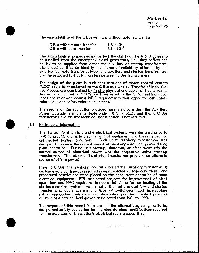
The unavailability of the C Bus with and without auto transfer is:
C Bus without auto'transferC Bus with auto transfer
I.8 x IO-36.l x IO-5
The unavailability numbers do not reflect the ability of the A 8 B busses tobe supplied from the emergency diesel generators, i.e., they reflect theability to be supplied from either the auxiliary or startup transformers.The unavailabilities do identify the increased reliability afforded by theexisting fast auto transfer between the auxiliary and startup transformers,and the proposed fast auto transfers between C Bus transformers.
The design of the plant is such that sections of motor control centers(MCC) could be transferred to the C Bus as a whole. Transfer of individual480 V loads are constrained by in situ physical and equipment constraints.Accordingly, non-vital MCCs are transferred to the C Bus and individualloads are reviewed against NRC requirements that apply to both safetyrelated and non-safety related equipment.
The results of the evaluation provided herein indicate that the AuxiliaryPower Upgrade is implementable under IO CFR 50.59, and that a C Bustransformer availability technical specification is not required.
Back round Information
The Turkey Point Units 3 and 4 electrical systems were designed prior toI970 to provide a simple arrangement of equipment and busses sized foranticipated loading conditions. Each unit s auxiliary transformer wasdesigned to provide the normal source of auxiliary electrical power duringplant operation. During unit startup, shutdown, or after plant trip thenormal source of electrical power was the respective unit's start-uptransformer. (The other ynit's startup transformer provided an alternatesource of offsite power).
Prior to C Bus, the auxiliary load fully loaded the auxiliary transformers;certain electrical line-ups resulted in unacceptable voltage conditions; andprocedural restrictions were placed on the concurrent operation of someelectrical equipment. FPL originated projects for improvement of plant
~ operations and NRC requirements necessitated the further loading of thestation electrical system. As a result, the station's auxiliary and startuptransformers, cable system and 4.I6 kV switchgear fault interruptingratings approached their maximum allowable capacities. Table I providesa listing of electrical load growth anticipated from l98I to I 990.
The purpose of this report is to present the alternatives, design criteria,design, and safety evaluation for the electric plant modifications requiredfor the expansion of the station s electrical system capability.


JPE-L84- I 2Rev. 0Page 6 of 2S
2.0 SUMMARYOF EXISTING AND ALTERNATIVEDESIGNS
2.I Ori inal Plant Desi n Considerations
2.2
Turkey Point Units 3 and 4, received their operating licenses in l972 andl973, respectively. The design criteria by which they were licensedincluded the use of draft General Design Criteria proposed by the AEC. Inaddition to these requirements, FPL developed additional designconsiderations which were included in the FSAR (see Appendix B).
Ori inal S stem Desi n
Based on the design considerations referenced in the previous section thefollowing original design was developed and approved for the two plants.
The 240 kV switchyard arrangement provides east and west busses whichconnect off-site power from FP&L's transmission network with the twofossil and two nuclear unit power lines. This assures that even if bothnuclear Units 3 and 4 are inoperative, power would be available at the 240kV switchyard from Turkey Points Unit I and 2 or from one of the 240 kVcircuits from off-site.
The basic components of the station electrical system of I 973 are shown onthe main one line diagram, Figure I. Each nuclear unit had an auxiliarytransformer to serve as a normal source of auxiliary electrical powerduring normal operation. Each transformer was capable of supplying allthe electrical power requirements associated with its unit as well as someloads shared by both units (e.g. water treatment plant). Each auxiliarytransformer provided power to an A and B 4.I6 kV nuclear safety relatedbus under normal operating conditions. These two busses (A & B) suppliedpower to all loads in the nuclear plant. Redundant trains of safety-relatedsystems were separately powered from these busses.
In addition to the auxiliary transformer, a start-up transformer wasprovided for each unit. The start-up transformers were connected to the240 kV busses on the primary side, and the A and B 4. I6 kV busses for itsunit and the A 4. I6 kV bus for its adjacent unit on the secondary side. Thestart-up transformer was designe'd to normally serve the unit during startup, shutdown, and after unit trip. The start-up transformer of one unit wasadequate to simultaneously supply minimum engineered safety features ofone unit, and safely shut down the other unit, without assistance from on-site power generation. The startup transformer for the adjacent nuclearunit is available as a redundant source of emergency power for the A Busonly.
Each nuclear Unit's A & B 4. I6 kV Bus was fed from a separate secondarywinding on its auxiliary transformer under normal operating conditions.Loss of power from the auxiliary transformer initiated a fast automatictransfer to the startup transformer. Complete loss of power at both the A& B 4.I6 kV busses of either unit caused the emergency diesel-generatorsto start and feed power directly to the affected busses.
JPE-L84- I 2Rev. 0Page 7 of 25
The two 4.I6 kV busses (A & B) fed four 480 volt busses through fourtransformers. Two 480V transformers were energized from the 4.I6 kV ABus, and two 480V transformers were powered from the 4.I 6 kV B Bus.
The Auxiliary Power Upgrade design discussed in this report does not alterthe basic nuclear safety related design concept licensed in I973. It adds anew, independent, non-safety related subsystem to the system describedabove.
2.3 Auxiliar Power M'odification Desi n Considerations
Design criteria associated with an upgrading of electrical system capabilityare:
000
Compliance with FSAR criteria and Technical Specificationrequirements.Compliance with non-safety related NRC requirements, e.g.,Appendix R.Meet or exceed existing electrical load requirements.Capability to provide for future electrical loads.Adequate physical space to accommodate new equipment, andprovide for required maintenance and surveil lance activities.Accommodate load rating, undervoltage and short circuitcapability requirements.No single failure in the switchyard willcause a nuclear unit tripconcurrent with the loss of its startup transformer.No single failure shall cause the loss of both nuclear units, orthe loss of-both startup transformers, or ~ the loss of both Cbusses.Loss of a C Bus with a subsequent reactor trip willnot result inthe loss of a startup transformer.
2.4 Alternative Desi ns
In order to arrive at the design modification discussed hereinafter forTurkey Point, the available design alternatives are evaluated. Basicallythere are four alternatives available, namely; administrative controls,cross connect to fossil units, upgrade existing equipment, or provide newequipment. These alternatives are discussed in the following paragraphs:
Modify use of existing system with administrative controls. Use ofthis alternative would restrict the loadings on the A & B bussesthrough a continuous review of equipment power priorities andreliance on a manual load management scheme. This alternativeshould normal ly be rejected because the potential for errorintroduced by complex load schemes is considerable, and at best thesolution provides interim relief with the potential for only limitedsystem growth.
Unit trips in February were Initiated because of loss pf the C Buspower supply to the 3B steam generator feed pump. This pump (7000


JPE-L84- I 2Rev. 0Page 8 of 25
hp) and the 3C condensate pump (2500 hp) are two large non-safetyrelated loads transferred to C Bus. They cannot be returned to the A& B busses primarily due to undervoltage and short circuitconsiderations associated with the A & B busses. Removal of themotors from the A & B safety related busses reduces the short circuitcurrent to these vital busses and reduces the likelihood ofunacceptable under voltage conditions on the busses. With thesemotors powered from the A & B busses, there are combinations ofmotors that can't be run simultaneously, e.g.,
Case I
Case 2
B & C Condensate PumpsB & C Component Cooling Water PumpsA & B Intake Cooling Water Pumps
o A & C Condensate Pumpso B & C Component Cooling Water Pumpso A & B Intake Cooling Water Pumps
Design margins are at a point where administrative controls are not aviable alternative.
II. Use the fossil units startup transformer to support additional Unit 3and 4 loads. This alternative was rejected because it creates crossties between the fossil and nuclear units, which introduce thepotential for losing more than one unit due to equipment failure.
III. Upgrade existing Turkey Point system with larger size transformer,switchgear, etc. There is a basic disadvantage associated with thisalternative, namely, higher rated switchgear and transformers arephysically larger than those presently installed. This alternative wasrejected because of space limitations, and the extensive downtime toremove and replace the plants'. I 6 k V system.
IV. Add an additional 4. I 6 kV bus (C Bus) to both Units 3 and 4 to providepower for additional auxiliary loads. This alternative would changethe configuration which routes all loads through either the A or Bsafety'elated busses. It provides a non-safety related bus which.would be used for non-safety related loads, either anticipated orpresently on the system. It can be implemented in a manner thatsatisfies the design criteria cited above.
Several of the more viable options associated with this designapproach are as follows:

JPE-L84- I 2Rev. 0Page 9 of 25
(a)
(b)
(c)
Feed C Bus from the high side of the main transformers.Rejected because the C Bus would not be available for aunit startup. (There is insufficient space for a generatorbreaker.)Feed C Bus from the startup transformers. Unacceptablebecause loss of C Bus could cause a loss of the startuptransformer concurrent with a unit trip.Provide new switchyard bays, which would feed the new CBus for each unit.
2.5 Selected Alternative - Auxiliar Power U rade
The evaluation of the available alternatives, discussed above, resulted inthe selection of the C Bus, Alternative IV, option c. This alternative, isdesignated "AuxiliaryPower Upgrade." The following considerations favorthis alternative:
(I) The need for administratively controlling the load on thenuclear safety related busses is eliminated.
(2) Sufficient capacity is provided to power equipment backfittedon Turkey Point as a result of NRC requirements.
(3) Capacity is provided to power equipment being backfitted onTurkey Point to improve plant operability and reliability. Forinstance, the condensate polishing equipment, which has beenadded to improve steam generator water .chemistry, will bepowered from the C Bus.
(4) Margin is provided for the addition of future safety and non-safety related loads.
(5) Loads on the nuclear safety related busses and switchgear arereduced.
(6) A readily accessible source of power to the plant's 4.I6 kVbusses is provided to accommodate the postulated "StationBlackout" scenario (i.e., loss of both offsite power and theemergency diesel-generators). The power source for thisoperation is the existing Turkey Point Units I and 2 CrankingDiesel Generators.
(7) Additional flexibility is provided for powering non-safetyrelated equipment.
(8) Some non-safety related loads are removed from the nuclearsafety related busses thereby providing additional separation ofnuclear safety related and non-safety related equipment.


JPE-L84- l 2Rev. 0Page l 0 of 25
(9) The modification can be made within the existing physical(spatial) constraints at the facility.
(l0) The modification can acceptability accommodate present NRCrequirements applicable to the Turkey Point facility.
(I I) Removal of non-vital MCC's to the C Bus eliminates the needto automatically load shed these loads upon loss of offsitepower.
JPE-L84- I 2Rev. 0Page I I of 25
3.0 DESIGN
The function of the Auxiliary Power Upgrade is to augment the AC andDC auxiliary electrical power system by providing new non-safety relatedswitchgear and load centers. This new equipment accommodates theremoval of some existing non-safety related equipment from the
plants'uclear
safety related busses.
Existing motor control centers (MCC's) are designated vital (nuclear safetyrelated) or non-vital (non-safety related). The physical limitations of theplant essentially preclude the physical relocation of MCC's, and the abilityto install new MCC s is limited. Accordingly, a non-vital MCC istranferred to the C Bus by removing the bus section that interconnectsvital and non-vital sections of an MCC. The non-vital section is thenconnected to a C Bus power feed. In theory this process should bestraightforward since it merely involves the physical separation of nuclearsafety related and non-safety related sections of an in situ MCC. Inpractice, however, the separation is complicated by the fact that NRCrequirements are associated with non-safety related equipment, e.g.,Appendix R and TMI.
The basic design philosophy adopted for the, Auxiliary Power Ugrade is to:
(I) provide a non-safety related C Bus that is not powered from theplant's nuclear safety related busses (A & B busses),
(2) place loads on the C Bus that are:(a) non-safety related,(b) not required to achieve and maintain the plant in a
safe (hot) shutdown condition, and(c) not required to prevent or mitigate the
consequences of accidents which could result in off-site exposures comparable to the guidelineexposures of I 0 CFR l00.
(3) assure separation of the nuclear safety related busses and the"not" nuclear safety related C Bus, and
(4) assure separation of the "not" nuclear safety related C Bus andthe station's cranking diesels during operating configurationsthat do not require power from the cranking diesels.
The C Bus switchgear is non-safety related; located outdoors; not designedto the single failure criterion; and not procured to Class IE requirements.
3. I Auxiliar Power U ade Desi n
Power for the Auxiliary Power Upgrade is from the Turkey Point 240 kVSwitchyard (see Figure 2). Unit 3 receives power from a new Bay 3 throughtwo oil circuit breakers; one from the Northwest Bus and one from theNortheast Bus. Unit 4 receives power from a new Bay IO through a breakerand a half scheme off the Southwest and Southeast busses. Each unit's 240kV feeder from the switchyard provides. power to a C Bus

0

JPE-L84- I 2Rev. 0Page l2 of 25
transformer. The Unit 3 and 4 feeders are well separated, originating fromopposite ends of the switchyard.
The C Bus transformer is similar in rating to the existing startuptransformer. The output of each C Bus transformer feeds the 3C and 4Cbusses through its two secondary windings. Normal operation providespower to the 3C Bus from the 3C transformer, and the 4C Bus from the 4Ctransformer. In the event that one transformer is not available, eachtransformer is sufficiently sized that it can supply all the 3C and 4C loadssimultaneously through its dual secondary windings.
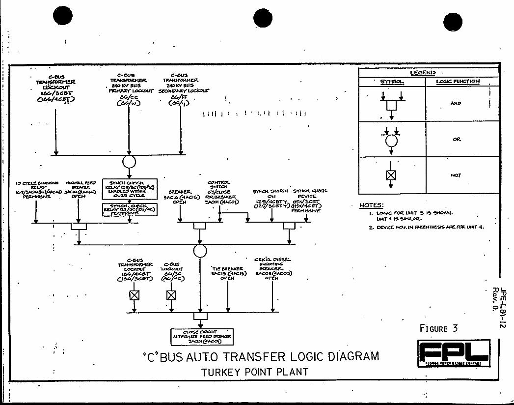
To maintain continuous power supply to important operational equipment, afast automatic transfer between the two C Bus transformers is provided inthe event that either C Bus transformer is lost. This transfer scheme isdesigned to occur within IO cycles following the loss of a "C" bustransformer. A description of the operation of the fast transfer ispresented for Unit 3 (refer to Figure 3), Unit 4 is similar.
The fast auto transfer between C busses allows the plant to accommodate,without trip or runback, a disruption in the power supply to a unit s C Bustransformer. The fast auto C Bus transfer would have prevented theFebruary, I 984 unit trips that resulted from loss of a C Bus transformer. Itis also shown in the failure mode effect analyses (FMEA), of Section 3.3,that a fast auto transfer can prevent simultaneous runbacks on both unitsthat could result from a,fault in either breaker 3ACOI or 4ACOI. TheFMEA indicates that auto transfer eliminates turbine runback as aconsequence of events that cause loss of the C Bus transformer.
/
The fast transfer from the normal feed breaker 3ACI6 to the alternatefeed breaker 3ACOI will occur when the feed from breaker 3ACI6 is lostdue a C Bus transformer lockout or a C Bus transformer 240 kV buslockout. The transfer will be prevented if: (I) the cranking dieselgenerator incoming breaker 3AC03 is closed, or (2) the tie breaker to thevital busses, breaker 3ACI3 is closed, or (3) the Unit 3 C Bus is locked out,or (4) the Unit 4 C Bus transformer is locked out or (5) the sync-checkpermissive is not present.
The design of the transfer scheme utilizes a fast sync-check relay whichwill monitor the Unit 3 "C" bus decaying voltage and the Unit 4 C Bustransformer voltage, which is the alternate supply. This relay will providea permissive contact to allow the transfer to occur. A normally closedauxiliary contact from breaker 3ACI6 will initiate the transfer when thebreaker is opened under the conditions described above. The transfer willbe blocked if not performed within IO cycles after breaker 3ACI6 isopened. The sync-check relay is included as a protection feature whichwill prevent the transfer from occuring if out-of-phase conditions arepresent. The transfer back to the normal supply will be accomplishedmanually.

JPE-L84- I 2Rev. 0Page l3 of 25
The C busses are comprised of 4. I 6 kV switchgear, 3AC and 4AC for Units3 and 4 respectively. This switchgear is non-safety related andaccomodates only non-safety related equipment loads. Switchgear 3ACand 4AC, located outdoors just east of the discharge canal, are rated for anominal interrupting capability of 350MVA.
The C busses provide power to 480V load centers 3E, 3F and 3G for Unit 3and 4E, 4F and 4G for Unit 4. Load centers 3E and 4E were previouslypowered from the vital busses whereas 3F, 3G, 4F and 4G are new outdoorload centers. In general, loads between IOO hp and 300 hp will beconnected directly to the 480V load centers. Smaller loads are connectedto the Motor Control Centers (MCC) which receive power from the LoadCenters.
3.l.l Station Blackout Subs stem
A Station Blackout scenario can only be postulated assuming a concurrentloss of the offsite and onsite AC power supplies. To facilitate the plantscapability to accommodate such an event, the Auxiliary Power Upgradeprovides an additional source of power to the A and B 4.I6 kV nuclearsafety related busses'(See Figure 2). The power is from the Fossil Units I
and 2 Cranking Diesel Generators through a feeder to the Units 3 and 4 Cbusses. This feeder is rated at 5000KVA which is basically the equivalentof two nuclear plant emergency diesel-generators. The C Bus, in turn, iscapable of providing power to the A and B busses through a feeder to theexisting A and B bus tie.
The Station Blackout 4. I6 kV bus connections are installed for use during astation blackout condition. To prevent inadvertent breaker operationduring normal operating conditions, the following design measures areprovided. Electrical interlocks assure proper sequential operation ofbreakers to make the cross connections. In order to close the CrankingDiesel-Generator Output Breaker (4W26466), breakers 3AC03 and 4AC03 atthe C busses must be open. Breakers 3AC03 or 4AC03 cannot close unlessBus 3C or 4C respectively is isolated from its transformer and breaker4W26466 is closed. (Breakers 3ACOI and 3ACI6 or 4ACOI and 4AC I6 mustbe open to isolate the transformers from the Unit 3 or 4 C Bus.) Finally,the tie breakers, 3ACI3 or 4ACI3, to the nuclear safety related bussescannot be closed unless breaker 3AC03 or 4AC03 is closed. These nuclearsafety related tie breakers cannot be closed if either 3ACI6 or 3ACOI isclosed on Unit 3, or either 4AC I 6 or 4ACO I is closed on Unit 4. The designof the interlocks is such that the likelihood of an inadvertent, unintentionalcross connection is minimal because the C Bus would first have to be de-energized before the C Bus could be connected to the cranking diesels.
ln addition, the normal operating conditions are such that Breakers 3AC03and 4AC03 (C Bus input from the Cranking Diesel-Generators), 3ACI3 and4ACI3 (connection from C busses to the A and B bus ties), 3AA09, 4AA09,3AB22 and 4AB22 (A and B bus tie breakers) willbe racked out.


JPE-L84- l 2Rev. 0Page l4 of 25
3.1.2 ~RI P
The Turkey Point Switchyard consists of East and West Operating busses asshown on Figure 2. Offsite transmission lines and onsite AC power systemsare connected to these switchyard busses in a breaker and a halfconfiguration. The east and west busses are further divided into North andSouth bus sections by normally closed breakers 6/7B and 5/6A. Thisswitchyard bus segmentation scheme allows the switchyard to acceptablyaccommodate a fault on one of the power lines or bus sections. !t alsoprovides the necessary flexibility for performance of switchyardmaintenance and modifications.
Should a fault occur on one of the four busses, the relay protection systemis designed to open and lockout all the breakers connected to the bus andopen the appropriate tie breaker between the North and South sections;thereby isolating the faulted bus from the three operating busses. Backuprelaying is provided for all the 240 kV breakers in case one should fail toopen within a preset time. This backup protection opens the next set ofbreakers away from the bus to clear the fault.
Protection and isolation of the switchyard from a fault on one of the linescoming from the plants is provided by primary and secondary differentialrelay schemes which trip associated breakers in the plant and switchyard toisolate a fault.
The failure mode evaluation in Section 3.3 and the fault tree model inSection 3.4 include the busses and oil circuit breakers in the switchyard.
3.I.3 DCS stem and l20V AC S stem Chan e
The Auxiliary Power Upgrade includes the installation of a new non-safetyrelated DC system and a non-safety related l20V AC UninterruptiblePower Supply. The new l25V DC system provides DC control power for theAuxiliary Power Upgrade switchgear and future non-safety related DCloads. Additionally, some non-safety related loads transferred to the newDC system provide spare capacity to meet projected nuclear safety relatedload growth. The l20V AC Uninterruptible Power Supply provides foressential non-safety related loads such as the telemetering system.
3.I.4 Electrical Loads Transferred to C Bus
The Auxiliary Power Upgrade augmented the capabilities of the onsitepower distribution system by providing a new non-safety relateddistribution system. Appendix D provides a tabulation of the loads thatwere transferred from the safety-related distribution system to the newnon-safety related distribution system.
A basic design premise on which the plant is licensed is that only nuclearsafety related (vital) items are essential to;

JPE-L84- I 2Rev. 0Page IS of 25
o the integrity of the reactor coolant pressure boundary,
o the capability to shutdown the reactor and maintain it in a safe (hot),.shutdown condition, and
o the capability to prevent or mitigate the consequences of accidentswhich could result in off-site exposures comparable to the guidelineexposure of IO CFR l00.
4
Items not essential to these functions are non-safety related, and arepowered by non-vital power supplies, or can be separated electrically froma vita I power supply.
The loads in Appendix D are reviewed to ensure NRC commitments andrequirements are still met (see Section 3.2). As a result of this review,,some individual non-vital loads are relocated to derive their power supplyfrom a vital A or B bus. These include:
o One CRDM cooler fan for Unit 4,
o The sample pump associated with containment radiation monitorsR-I I and R-I2, and
o Wide range noble gas effluent monitors installed pursuant to NUREG0737 requirements.
3.I.5 Auxiliar Power U ade Partial lm lementation
Figure 4 shows the existing, interim, C Bus arrangement. It is operatedwith the Unit 3 C Bus transformer supplying the Unit 4 C Bus, and the Unit4 C Bus transformer supplying the Unit 3 C Bus. The availability of theUnit 3 and 4 startup transformers is required by NRC in this operatingconfiguration. Assuming Unit 3 is modified to derive its C Bus powersource from Bay 3 of the switchyard and Unit 4 is in the interimconfiguration, then, normal operation would remain with the C Bustransformers cross-tied as in the interim configuration. The basis follows:
(I) loss of the Unit 3 C Bus transformer would cause Unit 4 to runback. If runback fails and the unit trips, Unit 4 would auto-transfer to its startup transformer. The Unit 3 startuptransformer would not be affected, and Unit 3 would remainonline,
(2) loss of the Unit 4 C Bus transformer would cause Unit 3 to runback. If runback fails and the unit trips, Unit 3 would auto-transfer to its startup transformer. The Unit 4 startuptransformer could become unavailable, but Unit 4 would remainonline with power from the Auxiliary Transformer,
(3) if the Unit 4 startup transformer were out of service andisolated, the Unit 4 C Bus transformer would be unavailable.Thus, Unit 3 could not be run.without powering the, Unit 3 C Busfrom the Unit 3 C Bus transformer.

JPE-L84- I 2Rev. 0Page I 6 of 2S
(4) if the Unit 3 startup transformer were unavailable and isolated,both Unit 3 and 4 C Bus transformers would be available. Therewould be no physical power limitation on either unit.
A similar scenario results if Unit 4 is modified to derive its power fromBay IO of the switchyard, and Unit 3 is in the interim configuration.
From the above, it is concluded that the operation of the C Bus in theinterim cross-tied configuration will be continued until both Unit 3 and 4 CBus transformers feeds to switchyard Bays 3 and IO are placed in service.
3.2 Com arison with NRC Re uirements
The C Bus design and loads transferred to C Bus are reviewed against:
o Electrical power system requirements cited in the FSAR
o Electrical power system requirements cited in the TechnicalSpeci fications
o Appendix R fire protection safe shutdown equipment requirements.
o Equipment operability requirements set forth in the TechnicalSpecif ication
o Emergency Operating Procedures
The comparison with-the above NRC requirements are provided in theparagraphs that follow.
3.2. I Com arison with FSAR and Technical S cification Criteria
The FSAR and Technical Specification criteria provide for reliable,redundant power supplies to nuclear safety related equipment. TheAuxiliary Power Upgrade was specifically designed to assure compliancewith this criterion. The C Bus r'emoves some non-safety related loads fromthe A and B nuclear safety related busses. Since these non-safety relatedloads are further isolated from safety related busses, the modificationimproves the separation between those loads vital to nuclear plant safetyand those that are not. In addition, the design improves the margin in thenuclear safety related electrical system for undervoltage and overcurrentconditions.
Power for the C Bus is provided from the switchyard and is independent ofthe plant operating condition.
The loads transferred to the C Bus are primarily loads powered from non-vital sections of the 480V MCC's. These loads would not normally bepowered from the station's emergency diesels, and thus, are not vital tomaintaining the plant in a safe shutdown. condition, and are not vital for


JPE-L84- I 2Rev. 0Page l7 of 25
3.2.2
mitigating the consequences of accidents. This notwithstanding, the C Busis provided with alternate power supplies to assure power to it during non-normal conditions, namely, from a separate winding on the other unit's CBus transfor'mer or from the station's cranking diesels.
A comparison of FSAR criteria and Technical Specification requirementsassociated with the Auxiliary Power Upgrade design is presented inAppendices B and C. The C Bus design acceptably accommodates theserequirements.
The review included the Turkey Point Units 3 & 4 Technical Specificationsthrough Amendment l02/96 dated 3/l3/84.
tm act on Fire Protection Safe Shutdown E ui ment
The fire protection modifications required by IO CFR 50 Appendix RSection lll.G (Fire Protection of Safe Shutdown Capability) and Ill.i(Alternative Shutdown Capability) are in the process of being designed.The schedule for completion of these modifications is presently beingcoordinated with the NRC. To assure that the Auxiliary Power Upgradedoes not invalidate the Appendix R work, a review of the Auxiliary PowerUpgrade was performed to identify its impact on the safe shutdownequipment power supplies identified in the Appendix R submittal.
Some equipment transferred to the C busses is assumed in Appendix Revaluations to be available for safe shutdown in the event of a concurrentloss of offsite power and a fire. A standby Steam Generator Feedpump isprovided for each unit. It is powered directly from the C busses, and isprovided to accommodate safe shutdown requirements for a fire in theAuxiliary Feedpump area. Credit was taken for powering these pumpsfrom the cranking diesel generators in the Appendix R submittal.
The design criteria for fire protection does not assume a loss of both onsiteemergency diesel generators so that the connection of the Unit I and 2cranking diesel generators would be made up only to the C Bus. Thesafety related busses would still be separated from the C Bus with powerbeing provided for A and B busses from the emergency diesel generator(s).In this configuration C Bus tie breakers 3ACI3 and 4ACI3 remain rackedout.
A review of Appendix R safe Shutdown equipment indicated that severalloads (see Table 2) are powered from C.Bus, some as a result oftransferring non-vital load blocks. These C Bus loads willbe evaluated todetermine if power supply changes are necessary. Any modificationsidentified will be consistent with the Appendix R requirements.
3.2.3 Emer enc 0 eratin Procedures Review
The modifications to the plant electrical distribution system described inthis report have been reviewed against. the Emergency Operating


JPE-L84- I 2Rev. 0Page I 8 of 25
Procedures (EOP's) to ensure that these procedures were not adverselyaffected by the design changes.
The following EOP's were included in this review:
(I 2/22/83)(02/02/84)(Ol/l2/84)(04/07/83)(02/23/84)(IO/27/83)(02/02/84)
EOP 20000EOP 2000IEOP 20002EOP 20003EOP 20004EOP 20005EOP 20009
Immediate Actions and DiagnosticsLoss of Reactor CoolantLoss of Secondary CoolantSteam Generator Tube RuptureLoss of Offsite PowerControl Room InaccessibilityContainment Post Accident MonitoringSystem Operating Instructions
The purpose of this review was to verify that emergency actions identifiedin the EOP's could be carried out without the C Bus energized.
This review concluded that the minimum actions required to perform anorderly shutdown or respond to an accident could be performed when theemergency diesel generators are the only source of onsite power.
Each EOP was reviewed assuming that offsite power was not available.Each action required by these procedures was checked against the poweravailability of the emergency diesel generators. Any time a piece ofequipment was called on to operate, its power source was checked toassure that it would be available when only diesel generators providedonsite power. All pump operations, valve manipulations and indicationrequirements were checked to ensure that power would be available duringan accident recovery.
3.2 4 Com arison with Technical S cification 0 rabilit Re uirements
3.3
C Bus loads have been reviewed with regard to their potential associationwith Plant Technical Specifications equipment operability requirements(see Table 3). The C Bus related equipment that would impose operatingrestrictions on the plant as specified in the Technical Specifications arethe air particulate and gas monitors R-I I and R-l2 which monitorcontainment atmosphere for purging and RCS leak detection. Loss of thisequipment will require remedial action or plant shutdown.
Failure Mode Effect Anal sis
A failure mode effect analysis at the equipment level was conducted forthe proposed C Bus design. Equipment from the switchyard grid down tothe A, B and C 4.I6 kV busses was analyzed. The failure mode effectanalysis (FMEA) is provided in Appendix E.
The FMEA was conducted for the plant condition where:

JPE-L84- l 2Rev. 0Page l9 of 25
Both Units 3 & 4 are at full powerThe auxiliary, startup and C Bus transformers are aligned in theirnormal configurationOil circuit breakers (OCB's) in the switchyard are in their normalposition.Plant loads are powered from their normal power supply.
The FMEA is a non-mechanistic, first contigency evaluation. For example,a breaker is assumed to go from its normal to its non-normal positionregardless of relaying provided to prevent this action. Similarly thebreaker is assumed to fault regardless of whether it is open or closed. Theplant's reaction to 'such an event is then analyzed without additionalfailures. A resulting 4. l6 kV bus lockout is assumed to initiate trip signalsto all 4. l6 kV breakers (and OCB's if necessary) required to achieve the buslockout —the breakers are assumed to open.
Multiple failures that could cause loss of a 4. I 6 kV bus are provided by the'aulttree evaluation in section 3.4.
From the FMEA and Figure 2 the following conclusions can be made:
(2)
(3)
(5)
(6)
A fault asso'ciated with the fossil unit's startup transformer willnot affect the availability of the Unit 3 or 4 startup or C Bustransformers.A fault associated with the fossil Units I and 2 generator ormain transformer will not affect the availability of the Unit 3or 4 startup or C Bus transformers.A single failure will not allow the cranking diesel StationBlackout tie to be closed on to the C Bus while it is poweredfrom either unit's C Bus transformer.A single failure will not close the Station Blackout tie betweenthe A and B, and C busses while the C Bus is powered fromeither unit's C Bus transformer.A fault associated with either unit's C Bus or its associatedtransformer, will not affect the availability of either unit'sstar tup transformer.A fast-auto transfer between C Bus transformers reduces thelikelihood of turbine runback and unit trip.
The conclusions reached by the FMEA remain valid as long as the failuresare random and independent. Common cause effects that can causemultiple equipment failures from a single event, such as the door-vibration-related trips of February l 6, l 984 are not addressed by an FMEAof this scope. The fault tree approach provided in Section 3.4 analyzes theeffects of failure combination modes more effectively than the FMEA.
3.4 Reliabilit (Fault Tree) Evaluations
An evaluation was performed on the C Bus design using fault tree analysis.The fault tree technique provides a systematic method for studying the4.l6 kV system that allows for the modeling of the interaction of

0

JPE-L80-I 2 .Rev. 0Page 20 of 25
components and subsystems. Evaluation of the overall system, can definefailure combinations that are not apparent when a component or subsystemis evaluated as a separate entity.
The fault tree modeled the switchyard and the inplant 4.I6 kV electricalsystem to the equipment level. It did not model explicitly all associatedrelaying or the diesel generator auto-transfer. Modeling of 4.I6 kV andswitchyard relay-related events was sufficient to define the interactionsbetween components in the fault tree. Accordingly, the fault tree modelprovided by Appendix F is designed to identify combinations of events andfailures that:
could cause loss of any 4. I6 kV bus (i.e., 3A or 38 or 3C or 4Aor 48 or 4C),could cause loss of both C busses (3C and 4C),could cause loss of all 4.I6 kV busses on a unit (3A and 38 and3C, or 4A and 48 and 4C).
Table 4 provides the equipment lineups assumed in the fault tree. Thetypes of faults modeled include:
normally operating component fails in service,standby component fails when demanded or during subsequentservice,spurious component action
The fast auto-transfer between C Bus transformers and Auxiliary to,Startup Transformers was modeled to the relay level. The objective of themodeling was to ensure that the C Bus transfer availability is comparableto the availability of the existing auxiliary to startup fast auto transfer.
The analysis further assumed the current technical specifications arefollowed; loss of busses 3A or 38 or 4A or 48 results in a reactor/turbine-generator trip; and loss of 3C or 4C results in a turbine runback requiringquick operator action to prevent a reactor trip.
The fault tree model provided in Appendix F was quantified and solvedutilizing SETS, (CDC version 'I.02).
The cut sets for the 4. I6 kV system indicate that there are no cut sets oforder 2 that could cause loss of the main generator and offsite powersupply for all three 4. I6 kV busses on a unit. Or stated differently, at least3 fault events are required to cause the concurrent loss of the A, 8 and Cbusses. The most probable concurrent three events on Unit 3 or 4 has aprobability of 5.4 x IO-~. The following must occur concurrently for thisscenario:
o C Bus local faulto Startup Transformer local faulto Unit trips after failure to runback

JPE-L84- l 2Rev. 0Page 2l of 25
Even if this scenario were assumed, the A and B busses could still besupplied from the emergency diesel generators.
There are cut sets of order 3 that could cause loss of offsite power to allthree 4.I6. kV busses. The combined probability of any one of thetwenty-six (26) scenarios occuring is 9.7 x l 0-8.
The loss of main generator and offsite power to both 4.I6 kV C bussessimultaneously cannot be initiated by a single event. There are forty six(46) cut sets of order two (2) that could cause this to occur. The combinedprobability of any one of these 46 cut sets occuring is 3.3 x l0-6. The mostprobable cut set of order two (2) has a probability of occurence of2.56 x l0-6. All forty five (45) other cut sets are of order of magnitudel0-7 or less. The most probable cut set assumes the following occursimultaneously:
o Unit 3 C Bus Transformer faulto Unit 4 C Bus Transformer fault
Even if both C Bus tranformers are assumed to fault concurrently, the Cbusses can be supplied from the station's cranking diesels.

0

JPE-L84- I 2Rev. 0Page 22 of 25
4.0 SAFETY EVALUATION
4. I Criteria
The following criteria were used for performing a safety evaluation of thedesign of the Auxiliary Power Upgrade:
o Is there an increase in the probability or consequences of anaccident previously evaluated?
o ls there a possibility that an accident may be created which isof a different type than any previously evaluated?
o Is there an increase in the probability of occurrence orconsequences of equipment malfunctions previously evaluated?
o ls there a possibility that an equipment malfunction may becreated which is of a different type than previously evaluated?
o Will a reduction result in the margin of safety contained in thebases for Technical Specifications?
o Are new or modified Technical Specifications required?
4.2 Evaluation
As is indicated in Section 3.0, the Auxiliary Power Upgrade is consistentwith the General Design Criteria in the FSAR Sections l.3, 8.I andAppendix 5A. In addition, the review of Technical Specif icationsassociated with the electrical distribution system indicate that theAuxiliary Power Upgrade is consistent with the criteria in Sections l.2,
,B3.7, and B4.8. Additionally:
o Equipment transferred to the C Bus is not nuclear safetyrelated. By design it is not relied upon to protect the publichealth and safety, and thus is not powered from the emergencydiesel generators for accomodating design basis events.
The only inter-tie between nuclear safety related and nonsafety related busses incorporated in the design provides abackup power supply to the nuclear safety related busses forStation Blackout conditions.
The nuclear safety related system is separated from the non-nuclear safety related system by a nuclear safety relatedbreaker at the A & B busses, and a C Bus non-safety relatedbreaker. The latter is provided with a protective interlockingscheme to prevent closure unless Station Blackout conditionsexist.
Component failure or loss of power to the C Bus could causeunit trip without fast auto-transfer of the C Bus.

JPE-L84- l 2Rev. 0Page 23 of 25
o Removal of loads from the nuclear safety related bussesincreases the ability to accommodate undervoltage conditionsthat can be associated with the nuclear safety related busses.
o The C Bus design brings two new independent power sources tothe nuclear plants, namely, direct ties to switchyard Bays 3 andl0, and a direct tie to the stations cranking diesels. Thisprovides additional power sources to the nuclear units.
o More equipment is added to the non-safety related portions ofthe plant design. This increases, somewhat, the likelihood of aunit trip due to interruptions in the C Bus switchyard powersupply. A unit trip is an anticipated operational occurrencethat is routinely accommodated by the plant.
The C Bus design improves the nuclear safety related aspects of the plantdesign vital to protection of public health and safety. This is achieved withsome small increase in the likelihood of unit trip associated with theunavailability of the C Bus. The fault tree analysis demonstrates that thisincreased probability is quite small, and that the C Bus availability is asgood as the A or B busses switchyard availability. Accordingly, it isconcluded that any increase in the frequency of a unit trip introduced bythe C Bus addition is more than offset by the increased ability of thenuclear safety related busses to accommodate undervoltage conditions.
The Appendix R safe shutdown equipment identified hereinbefore will beevaluated to ensure that the NRC Appendix R commitments remain valid.
With regard to the RCS leakage monitoring function, the TechnicalSpecifications place a 48 hour inoperability limit on the containment gasand particulate monitor. This in effect puts a 48 hour limit on theconcurrent inoperability of the C busses. Movement of this monitoringfunction back to a power source from the A or B busses eliminates thisC Bus Technical Specification interaction.
There has been no instance identified where the Emergency Procedureshave been unacceptably impacted by the transfer of loads to the C Bus.Prior to C Bus non-vital loads could be selectively aligned to theemergency diesel generators during a loss of offsite power providedsufficient diesel generator capacity was available. The non-vital loadscurrently powered from the C Bus cannot be aligned to the emergencydiesel generators during a loss of offsite power because of the interlockingof the C Bus tie breaker(s). Since these non-vital loads are not designed toaccommodate severe natural phenomenona, they are not relied upon fordesign basis events. A sustained loss of offsite power for other than theoccurrence of severe natural phenomena, is not anticipated to last morethan 'h hour. Thus, the C busses could be powered from either Bay 3 or Bayl0 of the switchyard shortly after the occurrence of the loss of offsitepower event. Additionally, the cranking diesels provide a backup powersupply to the C busses. The FMEA and fault tree analyses demonstratethat the C busses provide an additional reliable source of 4.I6 kV power.For the majority of off-normal conditions the non-vital C Bus loads willbeavailable.

JPE-L84- l 2Rev. 0Page 24 of 25
Based on the above evaluation the following conclusions can be drawn.
o The probability of occurrence or the consequences of anaccident previously evaluated will not be increased becausethe C Bus modification does not affect equipment associatedwith these events. Any loads required to follow the course, orevaluate the severity of an accident will remain on anappropriate source of power.
o An accident should not be created which is of a different typethan any already evaluated because the original functions ofthe affected components have not changed. Although theauxiliary power source, originally supplied directly from thegenerator, is now supplied from both the generator and theswitchyard, the types of accidents (loss of off-site power orloss of AC power) and their consequences remain unchanged.
o The probability of occurrence and consequences of equipmentmalfunctions vital to the nuclear safety related functions,which have already been evaluated is not increased becausenone of the affected components are associated with the C Bus.
o A malfunction of equipment vital to nuclear safety has not beencreated which is of a different type than any already evaluatedbecause these components are not transferred to the C Bus andthe design does not change the function of the components nordoes it alter the consequences of their failure.
o There is some increase in the probability of a unit trip. FastC Bus auto. transfer ensures that this increase in probability isacceptably low.
o As shown by Appendix C, the Technical Specifications are notchanged by the AuxiliaryPower Upgrade.
o The need for a new Technical Specification has not beenidenti fied.
o The margin of safety as defined in Technical SpecificationsB3.7 and B4.8 is not reduced because power requirements of thenuclear safety related loads are still met, and no increase inloads on the nuclear safety related busses has occurred. Thereliability of the 4.l6 kV nuclear safety relapsed electricalsystem has not decreased since the modification reduced theloads on the nuclear safety related busses and the modificationsdo not effect the ability of the emergency diesel generators tosupply nuclear safety related loads.
The result of this evaluation is that the C Bus design is implementable suchthat there is no unreviewed safety question and no modification ofTechnical Specifications associated with the Auxiliary Power Upgrade.


JPE-L84- I 2Rev. 0Page 25 of 25
5.0 CONCLUSIONS
The information included in this report outlines the steps taken by FPL inresponse to the need for modifying the plants electrical-distributionsystem. After the concerns regarding the adequacy of the system wereidentified, a review of available options was made. This review included;review of the design criteria, updating design requirements to cover newcircumstances, investigation of design alternatives, and the selection ofthe best alternative design for the plant.
FPL believes this design meets all design criteria stated in the FSAR. Theaddition of the C Bus to the auxiliary power system has added a non-safetyrelated bus to a system which previously powered all loads through nuclearsafety related busses. Since only non-safety related loads will be poweredby the C bus, nuclear safety related equipment will not be affected by thechange.
The safety evaluation indicates that the design proposed herein isimplementable under IOCFR50.59 since; (i) an unreviewed safety questionhas not been identified, and (ii) the need for a modification to the plantsTechnical Specifications has not been identified.
FPL requests that the NRC review and approve these modifications so thatthe final design changes can be incorporated.

JPE-L84- I 2Rev. 0
TABLE I
Anticipated Electrical Load GrowthFrom l98I to l990
ITEMCondensate PolisherTechnical Support CenterCable Spread Room Air ConditioningService Air CompressorWarehousesMiscellaneous Motor Operated ValvesSewage Treatment PlantComputer Room Air ConditioningNuclear Administration BuildingNuclear Stores BuildingSpent Fuel Pump New Power SupplyInstrument Air CompressorsControl Room HVAC UpgradeSecurity System ExpansionAmertap System
EXPECTED POWER REQUIREMENTS50 K per unit
500 KVAI5 KVA
200 KVAper unit400 KVA20 KVAper unit
300 KVA20 KVAI50 KVA50 KVAl00 KVAper unit70 KVAper unit
UndeterminedUndeterminedl40 KVAper unit

O
0

JPE-L84- I 2Rev. 0
TABLE2
APPENDIX R SAFE SHUTDOWN EQUIPMENTREQUIRING EVALUATION+
EtiuEi>ment
Standby Steam Generator Feedpumps
Auxiliary Building Supply & Exhaust Fans
VCT Low-Level Isolation ValvesLCV-3-I I SCLCV~I I 5C
Excess Letdown Valves HCV-3- I 37 and'HCV-4-I37
Present Power Su I
C Bus
MCC-D (Non-Vital Section)
MCC-3B (Non-Vital Section)MCC-4B (Non-Vital Section)
Lighting panel 50 (MCC-DNon-Vital Section)
+MCC feeder breakers for MCC's 3A,38, 3C, 3E, 4A, 4B, 4C; 4E, D, F are alsoreferenced in the Appendix R safe shutdown report submitted to NRC and willbeevaluated.

JPE-L84- I 2Rev. 0Page I of 3
TABLE3
Com arison With Technical S cification 0 erabilit Re uirements
C Bus LoadPotential Tech. SpecAssociation Evaluation-Basis
Rod Control SystemBackup Transformers3X I8; 4X I8(MCC's 3B & 4B)
Rod Position Inverter3YO3; 4YO3(MCC's 3C & 4B)
3.2-4.a - "No more thanone inoperable control rodshall be permitted..."
3.2-5" If... the roddeviation monitor alarm isnot operable, rod positionsshall be logged..."
A functional control rodsystem is required for
~ normal plant operation.Loss of control rod powersupplies wilI not impactsafe shutdown or accidentmitigation. In additionthese serve as a backuppower supply and loss willnot affect even normaloperation.
Rod position indication isrequired for normal plantoperation. Loss of rodposition indication willnotimpact safe shutdown oraccident mitig'ation. Inaddition, these serve as abackup power supply andloss willnot affect evennormal operation.
tn-core drive system(MCC's 3B & 4B)
Steam Generator FeedPump 3B (4B) Breakers
3.2-7.a "A minimum ofI 6 thimbles... (and)associated detectorsshall be operable..."
3.5 Instrumentation re-quirements includeAuxiliary Feedwater Ini-tiation on "Trip of bothMain Feedwater PumpBreakers" and FeedwaterLine Isolation on "Safety "
Injection".
This equipment is used toconduct survei I lance ofnuclear instrumentation. Lossof in-core instrumentationwillnot prevent safe shut-down or accident mitigation.
Loss of the C Bus causes aloss of power to the feed-water pump and initiatesAuxiliary Feedwater flow.Operation of main feedwaterpump is not required forsafe shutdown or accidentmitigation. Securing ofmain feedwater flow isassumed in main steam linebreak analysis.
JPE-L84- I 2Rev. 0Page 2 of 3
TABLE3 (con't.)
C Bus LoadPotential Tech. SpecAssociation Evaluation-Basis
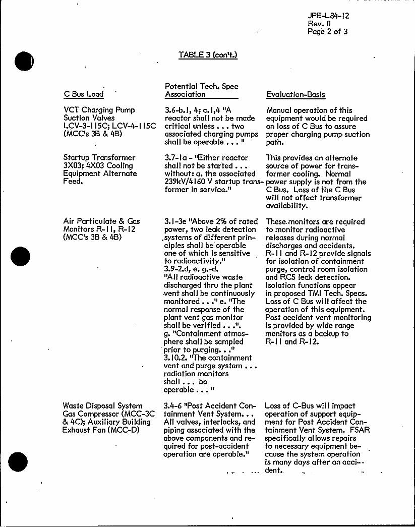
VCT Charging PumpSuction ValvesLCV-3-I I 5C; LCV-4-I I SC(MCC's 3B & 4B)
3.6-b.l, 4; c.l,4 "Areactor shall not be madecritical unless... twoassociated charging pumpsshall be operable... "
Manual operation of thisequipment would be requiredon loss of C Bus to assureproper charging pump suctionpath.
Startup Transformer3X03; 4X03 CoolingEquipment AlternateFeed.
3.7- I a - "Either reactorshall not be star'ted...
This provides an alternatesource of power for trans-
without: a. the associated former cooling. Normal239kV/4I60 V startup trans- power supply is not from theformer in service." C Bus. Loss of the C Bus
wilI not affeet transformeravailability.
Air Particulate & GasMonitors R- I I, R- I 2(MCC's 3B & 4B)
Waste Disposal SystemGas Compressor (MCC-3C& 4C); Auxiliary BuildingExhaust Fan (MCC-D)
3. I-3e "Above 2% of ratedpower, two leak detection
.systems of different prin-ciples shall be operableone of which is sensitiveto radioactivity."3.9-2.d, e. g.-d."AII radioactive wastedischarged thru the plantvent shal I be continuouslymonitored..." e. "Thenormal response of theplant vent gas monitorshall be verified...".g. "Containment atmos-phere shall be sampled
"prior to purging..."3. I 0.2. "The containmentvent and purge system...radiation monitorsshall... beoperable... "
3.4-6 "Post Accident Con-tainment Vent System...All valves, interlocks, andpiping associated with theabove components and re-quired for post-accidentoperation are operab le."
These. monitors are requiredto monitor radioactivereleases during normaldischarges and accidents.R- I I and R- l2 provide signalsfor isolation of containmentpurge, control room isolationand RCS leak detection.Isolation functions appearin proposed TMI Tech. Specs.Loss of C Bus willaffect theoperation of this equipment.Post accident vent monitoringis provided by wide rangemonitors as a backup toR-I I and R-I2.
Loss of C-Bus will impactoperation of support equip-ment for Post Accident Con-tainment Vent System. FSARspecifically allows repairsto necessary equipment be-cause the system operationis many days after an acci--dent.

JPE-L84- l 2Rev. 0Page 3 of 3
TABLE3 (con't.)
C Bus LoadPotential Tech. SpecAssociation Evaluation-Basis
Screen Wash Pumps 3. l4.2b "With one watersupply below the minimumspecified limit for oneday, connect the spoolpiece to make the screenwash pumps available forfire water supply."
The screen wash pumps providea backup source of firesuppression water in the eventthat the normal source is belowits minimum level. Loss of theC Bus affects this backup source.Appendix R modifications thatare presently being installedwilI eliminate reliance on thisbackup source of water.


JPE-L84- I 2 .
Rev. 0
TABLE 4
FAULTTREE EQUIPMENTLINEUP ASSUMPTIONS
ModeRormal
Bus'333
3B3C4A4B4C
Bus Su I
f13 uxiliary TransformerSE3 Auxiliary TransformerPP3 C Bus Transformer/P4 Auxiliary TransformerSA Auxiliary TransformerP/4 C Bus Transformer
Star tup/Shutdown 3A3B3C4A4B4C
PE3 Startup Transformer/$3 Startup Transformerf/3 C Bus Transformer//4 Startup Transformer84 Startup Transformer/34 C Bus Transformer
Auto Transfer 3A and 3B
3C
4A and 4B
4C
Transfer to /j3 startup on aN3 Generator tripTransfer to //4 C Bus trans-former on PP3 C Bus trans-former lossTransfer to f74 startup on a84 generator tripTransfer to N3 C Bus trans-former on /$4 C Bus trans-former loss
AlI switchyard oil circuitbreakers assumed normallyclosed

L,AUPFRPA LE DAOS fLhtjhHl 2 DAYIS 2 fib%A'4l I DA'4lS I5OUTHWESTBUS
8AY 9 BAY S
5QA SAy 5
NORTHWAYST
+US
mt'2
qA527A
52Qrh
625A
624h
5'22h
52qAAA
52SAG
s~ f i")! ~
95
521AS
8~QT4
5'2
'2+asS2
SNeq
52
524A6
S9.
SouTH OA&TSOS
MAIi4TRASK- 4
Uun AuxTRAN5P 4
STA,'lO UPTRk,NSF 4
S7lb
MAIHTRLNSP 5
UN<T AUXTo~Sr. 3
START UPTRAuSF b
haAiQTtVesp'Z
NORTHEASTOUSSTART UPTAAi445UiiiTS 1+2
MAWTRANS|'
NOTEl BREAKER NUMBERS SHOWN
ON FIGURE 2
~( C yA( ( ( sat t
C p
FIGURE j.
QCI<mol
MAIN ONE LINE DIAGRAM- TURKEY POINT l973


FLORlDAClTY
Sou THweaTsu5
SP Y la NAYI
DORA1 DADe
CITY 7
DAV1S 3
~'~ eaYS BAY4
NoRTHwLOTsu&
8AYS
ClAQAHl 'i . OAY1S 'R fLAOIMl I QAVI5 l
6AY2
.52 SZloA qA
$'25A
5%7h
52OrA
625A
624h
52gA
S2lOAS
521OB
'52'7AAA
03.
St7b
5R+AS
-5fCe
5IS
scab
S2
4AAA
52'CA5
52CB
SOOTHSAYbus
HAlHTlQ44SF
4'lllTAux
RANSF 4START VPTRlulBF4
MAIMTRAN5P 5
ug1T 4V)cTRANSP 3
6TARTutTRAuhe'b
MA1QTAA'@OF:g
/EH'Nt2
llORlHeASTbu5START UPTltA14bt
ul41T5 l+i
GEM.Ha.l
c EiusTRANS F
N00Ill
O 0tO
'4B(+ ( an. 5 <( 4( ~
4AS22 (~ 800
4C
(4A,C13
lh0 O
( <( ~( ~3A gt) Eo cA
o%l
(4ACol < "gc( SAcl'5
(4ACos
Ill0 08 0
SS (e( 111
('3A522
"c ausQICAHFQ
%5
( 3ACl&
( 3p,co3
: P-,9:9,9.9-
MAIN ONE LINE DIAGRAM-TURKEY POINT PROPOSED FiGURE 2.
"C" BUS ADDITlON PAL

c cosTKP4LStO~CC
LdClC&lillb'/5C
%T'ar/4cyP
C SVSl%44sro~5g,$4O iOI tkIS
PAHHtr Loacourm/ec
$64r au)
C duSTlCHCSFOILH5g,
Z+ikYALIISSceeen~ Lociioiir
ac/A'/q>
SCENDLAXelC FUi4CrION
:Iil ~' t I.II ~l:l~
IO CtCLC PLCCIOHS WXRHLI Fgg7RCLAY'FfAKFA
v t/bPce5r ~g ~<~gy~ss~ orcH
Sll4CH CH~RCue ~ILV Ce~g
C425 ~IICVMV t1/5~CRT/Ac)
rCRHtfsI~
COKTROLgtllrCH
OamICIZ. C~e,5PCIC QWmIC') ear.sIL~ac
OPKH 5PGW CEPCO0
~ swIrcH 5~H. cpEQcCM PCVICC
Iz5/~dr'Y es+scdrOzW/Sc dr~) Case'4c.dr)
IVJCVIISSI&gNOTE5:
i. ~IC FOR UHIT S IS ~.LIHIT4 IS ~use,.OCVICc HOP. IH ~HTHcsI5 PRE fCr LIHIr4.
C-bLISTOPHET roio4CF:
LoacourlbC'r/4Cdl
gian/@cd'
SIISLOCKOUT
eC /SC(~/~3TIC 6CEIKCC~I>CA~IS)
OPCH
CICIC6. PI CSCIIHCOHIlv4dCC4C
CF'ILCO>$4aCO>)orcH
CLOSC namIrM.TCILHNC FCCO te&KCR
"C'BUS AUT.O TRANSFER LOGIC DIAGRAMTURKEY POINT PLANT
FIGURE 3
%PI


FLMIDAClTY'ouTHwebY
Bub5AYlO bLY%
OOhAL
SAY b
oAoe QAvlb 6 FLAqAMl 'a . aAvib 2
~A SAY6 8AY4
NORTHWCOTIu&
8AY4
Pl.AOAMl l WV<S l
52l4J95
58/OS
52QA
Il '*, ' 52, I j! I
bhb
5C7A
l 52
627b
52QA
5QAS
625A
)5Qsm
Ã3 .I5255
624h
t!624XS
SOOTH SA,STSUS
~SF 4
uuiT AuxQ'4 btAhT ulTRANS'
Ci74
aeaW TILANSF 5
ug>T AukTRANSF 5
CaaSL.Ni3
START ufTRAuSl'
Ihkl4TAAal5f'g
NOhlHEA'LTbubSTARt OPTRANSPuetb lit MAul .
TRLM5'S l
dishHei
c» susTILA'4C >
«ciausTsa~FeeS
NOTEl'HREAKER. NUMBERS
SHOWN ON FIGURE 2
gpt ( l
4C
( (
Set C
(
pppppQC6<m
MAIN ONE LINE DIAGRAM-.TURKEY POINT.PRESENT
ISB3-l984 '".C'BUS ADDITION, AI
JPE-L84- I 2Rev. 0Page I of 2
APPENDIX A
AUXIL'IARYPOWER UPGRADE RELATED PLANT TRIPS
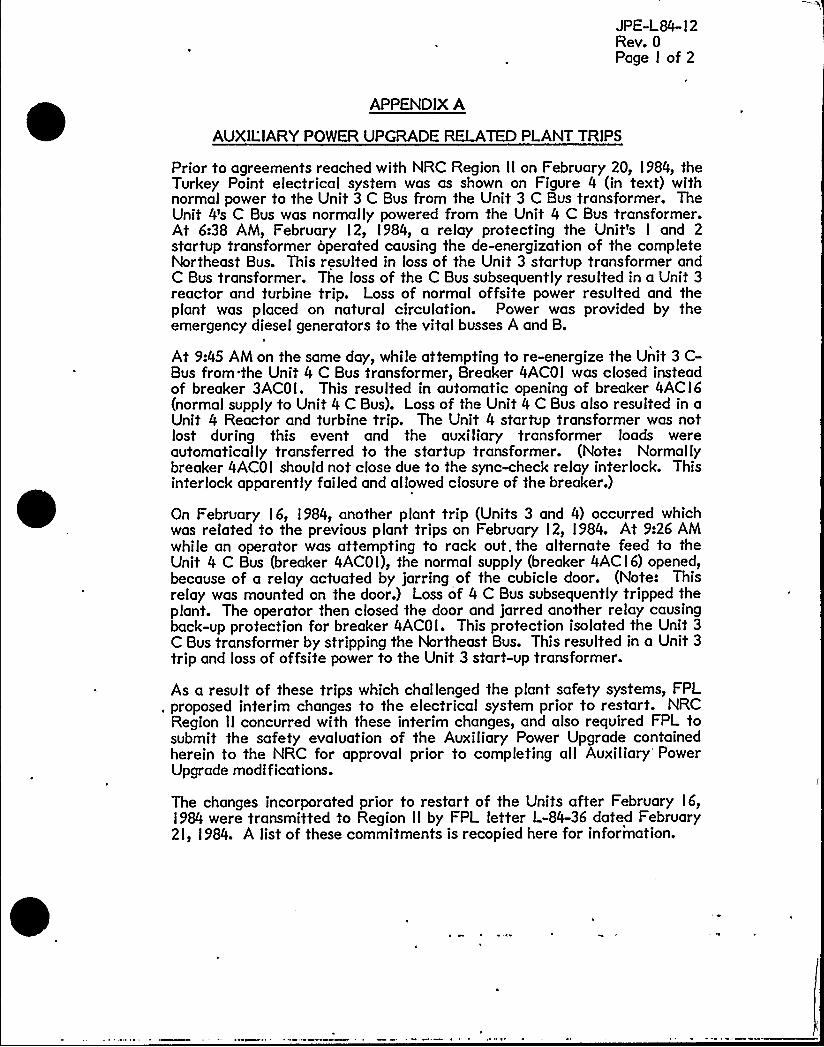
Prior to agreements reached with NRC Region II on February 20, l 984, theTurkey Point electrical system was as shown on Figure 4 (in text) withnormal power to the Unit 3 C Bus from the Unit 3 C Bus transformer. TheUnit 4's C Bus was normally powered from the Unit 4 C Bus transformer.At 6:38 AM, February l2, l984, a relay protecting the Unit's I and 2startup transformer operated causing the de-energization of the completeNortheast Bus. This resulted in loss of the Unit 3 startup transformer andC Bus transformer. The loss of the C Bus subsequently resulted in a Unit 3reactor and turbine trip. Loss of normal offsite power resulted and theplant was placed on natural circulation. Power was provided by theemergency diesel generators to the vital busses A and B.
At 9:45 AM on the same day, while attempting to re-energize the Unit 3 C-Bus from the Unit 4 C Bus transformer, Breaker 4ACOI was closed insteadof breaker 3ACOI. This resulted in automatic opening of breaker 4ACI6(normal supply to Unit 4 C Bus). Loss of the Unit 4 C Bus also resulted in aUnit 4 Reactor and turbine trip. The Unit 4 startup transformer was notlost during this event and the auxiliary transformer loads wereautomatically transferred to the startup transformer. (Note: Normallybreaker 4ACOI should not close due to the sync-check relay interlock. Thisinterlock apparently failed and allowed closure of the breaker.)
On February l6, l984, another plant trip (Units 3 and 4) occurred whichwas related to the previous plant trips on February l2, l984. At 9:26 AMwhile an operator was attempting to rack out.the alternate feed to theUnit 4 C Bus (breaker 4ACOI), the normal supply (breaker 4ACI6) opened,because of a relay actuated by jarring of the cubicle door. (Note: Thisrelay was mounted on the door.) Loss of 4 C Bus subsequently tripped theplant. The operator then closed the door and jarred another relay causingback-up protection for breaker 4ACOI. This protection isolated the Unit 3C Bus transformer by stripping the Northeast Bus. This resulted in a Unit 3
trip and loss of offsite power to the Unit 3 start-up transformer.
As a result of these trips which challenged the plant safety systems, FPL„proposed interim changes to the electrical system prior to restart. NRC
Region II concurred with these interim changes, and also required FPL tosubmit the safety evaluation of the Auxiliary Power Upgrade containedherein to the NRC for approval prior to completing all Auxiliary PowerUpgrade modifications.
The changes incorporated prior to restart of the Units after February l6,l984 were transmitted to Region II by FPL letter L-84-36 dated February2l, I 984. A list of these commitments is recopied here for information.

Appendix AJPE-L84- I 2Rev. 0Page 2 of 2
I. Switch realignments will be made in Bay 6 and on the FlagamiK/2 line which will assure electrical isolation of the nuclearunits and the fossil units, and isolation between the nuclearunits in the switchyard.
2. Pending long term design changes and modifications, Units'3and 4 will be operated with each units C Bus powered from the'ther units C Bus transformer. The feed breaker from eachunits C Bus transformer to its respective C Bus will bemaintained in a racked out configuration to precludeinadvertent operation.
3. Plant procedures for the alignment and administrative controlof offsite and onsite power sources will be finalized, reviewedby the Plant Nuclear Safety Committee, and required operatortraining will be complete.
4. Administrative controls will be in place which will assure thatboth startup transformers are operable whenever either nuclearunit is above 50% rated feedwater flow.
'
5. Three vibration sensitive relays on each of the 3C and 4C 4kVswitchgear panels will be relocated to stationary panels.
6. In addition to reviews by the Plant Nuclear Safety Committee,the Company Nuclear Review Board has reviewed andconcurred with the C Bus modification and proposed interimoperating configuration prior to returning either unit to poweroperation.
For the long term, changes will be incorporated which increase thereliability of the C Bus power supply, and which separate this supply fromthe Units startup transformer. Additionally, relays susceptible to vibrationinduced plant trip will be reviewed to minimize the reoccurrence of thistype of event. Accordingly, there should be fewer challenges to the plantsafety systems, and a loss of the Unit'3 C Bus transformer wilI not result ina loss of the Unit 3 startup transformer. The design modification ispresented in Section 3.0

JPE-L84- I 2Rev. 0Page I of 6
APPENDIX B
EVALUATIONOF COMPLIANCE WITH FSAR CRITERIA
Criteria
Page l.9-2 Section l.9 Quality Assurance Programl.9.2 Applicability
"The systems and structures to which this program is applicable are set forthbelow. It is understood that such systems and structures include associatedtanks, pumps, valves, piping, controls, instruments, supports, enclosures, wiringand power supplies. In general, these systems, components and structures have avital role in the prevention or mitigation of the consequences of accidents whichcould cause risk to the health and safety of the public."
Page 5A-I Section Appendix 5A Seismic Classification and Design Basisfor Structures, Systems and Equipment
"The basic design criteria for the maximum hypothetical accident andearthquake conditions is that there be no loss of function if that function isrelated to public safety."
Evaluation
The C Bus contains no loads (see Appendix D) which have a vital role in theprevention or mitigation of the consequences of accidents which could cause riskto the health and safety of the public. The safety related systems are poweredfrom the A and B 4.16kV busses. The breaker between C Bus and the existing Aand B 4.I6kV tie bus is interlocked to prevent its being closed,- except under aStation Blackout abnormal condition, to preclude interaction of the C Bus andthe nuclear safety related busses during normal and emergency conditions. TheC Bus was classified as a non-safety related bus because it contained no nuclearsafety related loads vital to maintenance of the reactor coolant pressureboundary, vital to the prevention and mitigation of accidents, and vital toachieving and maintaining hot safe shutdown conditions.
Criterion
Page l.3- I Section l.3. I Overall Requirements (GDC I-GDC 5)
"Class I systems and components are essential to the protection of the health andsafety of the public... All systems and components designated Class I aredesigned so that there is no loss of capability to perform their safety function inthe event of the maximum hypothetical seismic ground acceleration..."
Evaluation
There has been no change in the power supply for any nuclear safety related(Class I) load. Some of the loads classified as non-Class I were removed fromthe A and B 4.16kV busses and put on the C Bus. Because there are no seismicclass loads on the C Bus the design of the C Bus does not meet seismic criteria.
Appendix BJPE-L84-12Rev. 0Page 2of 6
Criteria
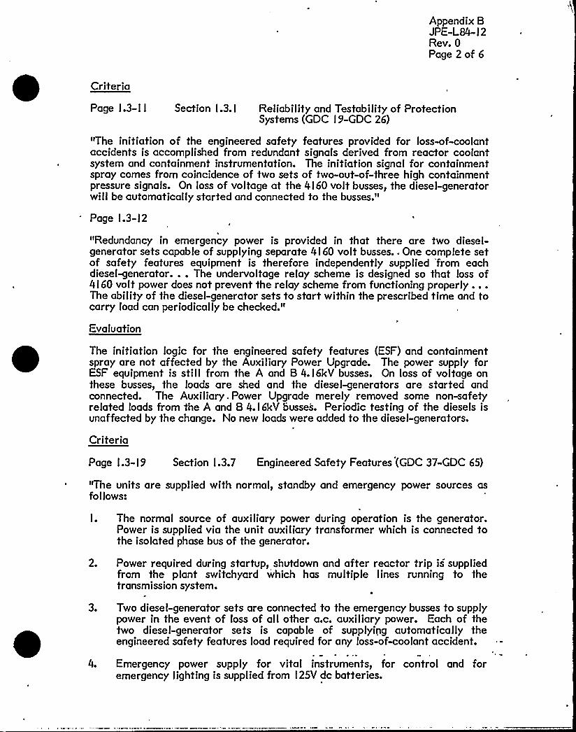
Page 1.3-11 Section 1.3.1 Reliability and Testability of ProtectionSystems (GDC 19-GDC 26)
"The initiation of the engineered safety features provided for loss-of-coolantaccidents is accomplished from redundant signals derived from reactor coolantsystem and containment instrumentation. The initiation signal for containmentspray comes from coincidence of two sets of two-out-of-three high containmentpressure signals. On loss of voltage at the 4160 volt busses, the diesel-generatorwill be automatically started and connected to the busses."
Page 1.3-12
"Redundancy in emergency power is provided in that there are two diesel-generator sets capable of supplying separate 4160 volt busses.. One complete setof safety features equipment is therefore independently supplied 'from eachdiesel-generator... The undervoltage relay scheme is designed so that loss of4160 volt power does not prevent the relay scheme from functioning properly...The ability of the diesel-generator sets to start within the prescribed time and tocarry load can periodically be checked."
Evaluation
The initiation logic for the engineered safety features (ESF) and containmentspray are not affected by the Auxiliary Power Upgrade. The power supply forESF equipment is still from the A and B 4.16kV busses. On loss of voltage onthese busses, the loads are shed and the diesel-generators are started andconnected. The Auxiliary.Power Upgrade merely removed some non-safetyrelated loads from the A and 8 4.16kV busses. Periodic testing of the diesels isunaffected by the change. No new loads were added to the diesel-generators.
Criteria
Page 1.3-19 Section 1.3.7 Engineered Safety Features (GDC 37-GDC 65)
"The units are supplied with normal, standby and emergency power sources asfollows:
I. The normal source of auxiliary power during operation is the generator.Power is supplied via the unit auxiliary transformer which is connected tothe isolated phase bus of the generator.
2.
3.
4.
Power required during startup, shutdown and after reactor trip is suppliedfrom the plant switchyard which has multiple lines running to thetransmission system.
4
Two diesel-generator sets are connected to the emergency busses to supplypower in the event of loss of all other a.c. auxiliary power. Each of thetwo diesel-generator sets is capable of supplying automatically theengineered safety features load required for any loss-of-coolant accident.
Emergency power supply for vital instruments, for control and foremergency lighting is supplied from 125V dc batteries.

Appendix BJPE-L84- l 2Rev. 0Page 3 of '6
The 4!60V bus arrangement and logic network provides the capability to transfermanually component loads to the remaining diesel following the failure of onediesel-generator unit to start."
Evaluation
With the addition of the C Bus auxiliary power during operation is provided bythe generator and the switchyard. All nuclear safety related equipment is stillpowered from the generator during normal operation. Several non-safety relatedloads were removed from the nuclear safety related A and B busses and placedon the C Bus. Only loads not vital to nuclear safety related functions arepowered from the switchyard during normal operation.
Power required during startup, shutdown and after reactor trip is still suppliedfrom the switchyard.
The connection of the diesel-generators to the vital busses, load sequencer andequipment needed for accident conditions is not affected by the Auxiliary PowerUpgrade. Emergency power supply for vital instruments, for control and foremergency lighting is stil I the vital l 25V DC system.
Criterion
Page 8.l-l Section 8.I. I Principal Design Criteria
Performance Standards
"Those systems and components of reactor facilities which are essential to theprevention of accidents which could affect the public health and safety or themitigation of their consequences shall be designed, fabricated, and erected toperformance standards that will enable the facility to withstand, without loss ofthe capability to protect the public, the additional forces that might be imposedby natural phenomena such as earthquakes, tornadoes, flooding conditions, winds,ice and other local site. effects. The design bases so established shall reflect: (a)appropriate consideration of the most severe of these natural phenomena thathave been recorded for the site and the surrounding area, and (b) an appropriatemargin for withstanding forces greater than those recorded to reflectuncertainties about the historical data and their suitability as a basis for design."(GDC 2)
Evaluation
Systems and components which are essential to prevention and mitigation ofaccidents are still powered by the A and B 4.I6kV busses. The Auxiliary PowerUpgrade removed some non-safety related equipment from these busses, thereby,providing additional margin for short circuit and undervoltage conditions.
Criterion
Page 8. I-2 Section 8.I. l Principal Design Criteria
"Alternate power systems shall be provided .and. designed vyith adequateindependency, redundancy, capacity and testability to permit the functioning

'

Appendix BJPE-L84- l 2Rev. 0Page 4 of 6
required of the engineered safety features. As a minimum, the onsite powersystem and the offsite power system shall each, independently, provide thiscapacity assuming a failure of a single active component in each system." (GDC39)
Evaluation
The criteria above is unaffected by the Auxiliary Power Upgrade. The onsitepower system and the offsite power system still, independently, provide capacityfor the functioning required of the engineered safety features. All engineeredsafety features are still supplied from the A and B 4.I6kV busses. The removalof non-safety related loads from the A and B busses and placement on the C Busdid not affect any of the engineered safety features. The interconnection of theC Bus to the existing A and B tie bus,provides two series breakers between the Cand A bus and the C and B bus. interlocks prevent the inadvertent closing of thebreaker at the "C" bus.
Criterion
Page 8.2- I Section 8.2. l Network tnterconnections
"Even when both nuclear Units 3 & 4 are inoperative, power will be available atthe 240kV switchyard from Turkey Point Units I and 2 or from one of the 240kVcircuits."
Evaluation
The offsite circuits have ample capacity to supply power to the required safeshutdown loads via the startup transformers. This is not affected by theAuxiliary Power Upgrade.
Criterion
Page 8.2-2 Section 8.2.2 Station Electrical System
"The station electrical system is designed to provide a simple arrangement ofbusses, requiring a minimum of switching to restore power to a bus in the eventthe normal supply to that bus is lost."
Evaluation
tn all cases a minimum of switching to restore power is still maintained. The C-Bus addition does not change the validity of this criterion. The C Bus is notloaded on the generator and would not have to be switched in the event of a unittrIpe


Appendix BJPE-L84- I 2Rev. 0Page 5 of 6
Criterion
Page 8.2-3 Section 8.2.2 Electrical SystemUnit Auxiliary, Startup Transformers and C-Bus Transformer
"Each of the two units has an auxiliary transformer connected to the generatorisolated phase bus to serve as the normal souce of auxiliary electrical power."
Evaluation
The auxiliary transformer still provides the normal source of auxiliary electricalpower for all nuclear safety related equipment. Some non-safety relatedequipment which is not required to be powered from the generator is nowpowered from the grid via the C Bus transformer.
Criterion
Page 8.2-3 Section 8.2.2 Station Electrical SystemUnit Auxiliary, Startup Transformers and CBus Transformer
"The startup transformer serves the unit during startup, shutdown, and after aunit trip. It also constitutes a standby source of auxiliary power in the event theloss of the unit auxiliary transformer during normal operation. In the event theturbine trips, an automatic transfer connects the 4.I6kV busses to the unitstartup transformer."
Evaluation
The startup transformer serves the unit's A & B busses during startup, shutdownand after plant trip. It still provides a standby source of power in the event. thatthe auxiliary transformer is lost. In the event of turbine trip the A and B 4. I6kVbusses automatically transfer to the startup transformer. The C Bus transformer'provides power to the C Bus for normal operation, startup, shutdown or planttrip. The C Bus also provides emergency power to the A and B 4.I6kV busses inthe abnormal condition of station blackout. Interlocks prevent interactionbetween these busses during normal operations.
Criterion
Page 8.2- I 5 Section 8.2.3 Emergency PowerOffsite Sources
'The offsite source of power for each unit is its associated 240 - 4.I6kV startuptransformer. Each transformer is supplied through overhead cable leads fromthe 240kV switchyard which in turn is supplied by two 432 MW fossil fuel firedgenerating units and the two nuclear units...
Each startup transformer normally will be connected to a different 240kV bus.In the event of a bus fault, at least one startup transformer could be quicklyrestored to service. Tie breakers in the east.bus,. and in the west bus, are „.located so that the Unit 3 startup transformer will be fed from the north section
Appendix BJPE-L84- l 2Rev. 0Page 6 of 6
and Unit 4 transformer from the south section. Thus, a bus fault will result inthe loss of only one star tup transformer."
Evaluation
The offsite source of power for each unit is the startup transformer for safetyrelated and some non-safety related loads, and the'C Bus transformer for onlynon-safety related loads. Each of these transformers is supplied from theswitchyard. Each startup transformer is normally powered from different 240kVbusses to assure that a single failure will not result in the loss of both startuptransformers. Thus adequate electric power is available through offsite sources.Additionally, the design of the C Bus power supply is such that a loss of theC Bus transformer willnot result in the loss of a startup transformer.
JPE-L84- I 2Rev. 0Page I of 4
APPENDIX C
Criterion
Page I -6
EVALUATIONOF COMPLIANCE WITHTECHNICALSPECIFICATION CRITERIA
Technical Specification l.20Safety Related Systems and Components
"Those plant features necessary to assure the integrity of the reactor coolantpressure boundary, the capability to shutdown the reactor and maintain it in asafe shutdown condition, or the capability to prevent or mitigate theconsequences of accidents which could result in off-site exposures comparable tothe guideline exposures of l0 CFR l00."
Evaluation:
The Auxiliary Power Upgrade does not change the power supply to any equipmentwhich is necessary I) to assure integrity of the reactor coolant pressureboundary, 2) for the safe shutdown of the reactor 3) to maintain the reactor ina safe shutdown condition, or 4) to prevent or mitigate accidents which couldresult in off-site exposures comparable to the guidelines in IOCFR Part l00.Appendix D is a tabulation of the loads on the C-Bus. The nuclear safety relatedsystems meeting this technical specification definition are powered by the A andB nuclear safety related busses.
Criterion
Basis page 3.7-l Technical Specification 3.7Electrical Systems
'%he electrical system equipment is arranged so that no single contingency caninactivate enough safety features to jeopardize unit safety. The 480
volt'quipmentis supplied from 4 load centers and the 4I60 volt equipment issupplied from 2 busses for each nuclear unit."
Evaluation
The Auxiliary Power Upgrade is consistent with the design philosophy that nosingle contingency will inactivate enough safety features to jeopardize plantsafety. No safety related equipment is provided power from the C-Bus. Allsafety related equipment is still powered from two nuclear safety related 4I60VBusses (A and B) and four nuclear safety related 480V Load Centers (A, B, C andD). This aspect of the plant design has not been altered.
Criterion
"Multiple outside sources supply power to the nuclear units. The auxiliaryequipment is arranged electrically so that multiple items receive their powerfrom the two different sources."
Appendix CJPE-L84- I 2Rev. 0Page 2 of 4
Evaluation
Power is available at the 240 kV switchyard from Turkey Point Units I or 2 orfrom one of several off-site 240 kV circuits. Normal power supply to nuclearsafety related equipment is from the main generator, through the auxiliarytransformer and two 4.I6 kV Busses. The alternate source of power is thestartup transformer. This aspect of plant design has not been altered.
Criterion
"One outside source of power is required to give sufficient power to run normaloperating equipment. One transmission line can supply all the auxiliary power.One 239-4.I6KV startup transformer can supply the auxiliary loads for itsassociated nuclear unit and emergency loads (MHA) for the other nuclear unit."
Evaluation
The power requirements for safety related equipment was not affected by theAuxiliary Power Upgrade since no new safety related loads were added to theplant. As such, this criterion was not affected by the modification.
Criterion
"The bus arrangements specified for operation ensure that power is available toan adequate number of safeguards auxiliaries. With additional switching, moreequipment could be out of service without infringing on safety."
Evaluation
The nuclear safety related bus arrangement specified by Technical Specification3.7.I and 3.7.2 are not changed by the Auxiliary Power Upgrade since only non-safety related loads were transferred to the new AC and DC distributionsystems.
Criterion
"Each diesel generator has sufficient capacity to start and run the requiredengineered safeguards for a MHA in one unit and safe shutdown of the secondunit. The minimum diesel fuel oil inventory at all times is maintained to assurethe operation of either diesel carrying I 68 hour rated load for seven days."
Evaluation
The Auxiliary Power Upgrade neither added new safety related loads normodified safeguard equipment. The addition of the C-Bus and associatedequipment has no effect on the loading or loading sequence of the emergencydiesel-generator. As such, this criterion is not affected by the modification.


Appendix CJPE-L84- l 2Rev. 0Page 3 of 4
Criterion
"With 4 battery chargers in service, the batteries willalways be at full charge inanticipation of a loss-of-ac power incident. This ensures that adequate dc powerwillbe available for emergency use."
Evaluation
The Auxiliary Power Upgrade included installation of a new non-safety relatedDC system that is independent of the existing DC systems. Some non-nuclearsafety related loads were transferred from the safety related DC system andthus provided additional capacity in the nuclear safety related DC power system.
Criterion
"A unit can be safety shutdown without the use of off-site power sin'ce all vitalloads (safety systems, instruments, etc.) can be supplied from an emergencydiesel generator."
Evaluation
The Auxiliary Power Upgrade neither added nor modified safe shutdownequipment. As discussed in Evaluation (S) above, this criterion is not affected bythe modification.
Criterion
Basis page B4.8-l Technical Specification 4.8Emergency Power System Periodic Test
"The tests specified are designed to demonstrate that the diesel-generators willprovide for operation of equipment. They also assure that the emergencygenerator system controls and the control systems for the safeguards equipmentwill function automatically in the event of a loss of normal power.
The testing frequency specified is often enough to identify and correct anymechanical or electrical deficiency before it can result in a system failure. Thefuel supply and starting circuits and controls, are continuously monitored. Anyfaults are annunciated. An abnormal condition in these systems would besignaled without having to place the diesel-generators themselves on test.
Each unit, as a backup to the normal standby AC power supply is capable ofsequentially starting and supplying the power requirement'df the required safetyfeatures equipment. gacP gill assume full load within 60 seconds after theinitial starting signal. < l)(2~(3~
The specified fuel supply willensure power requirements for at least a week.
Station batteries will.deteriorate with time, but precipitous failure will notoccur. The surveillance specified is that which has been demonstrated over theyears to provide an indication of a cell becoming unserviceable long before itfails.

Appendix CJPE-L84- l 2Rev. 0Page 4 of 4
The equalizing charge will maintain the ampere-hour capability of the battery."
Evaluation
As discussed for the previous Tech. Spec. the Auxiliary Power Upgrade did notimpact the emergency diesel-generator controls or loads. The station batterieswere affected only in the sense that some non-safety related loads were removedfrom the nuclear safety related DC system. This provides additional capacity inthe nuclear safety related DC system. This Technical Specification is notchanged or adversely affected by the AuxiliaryPower Upgrade.

JPE-L84- I 2Rev. 0Page I of 9
Unit 3 C Bus
APPENDIX D
TABULATIONOF C-BUS LOADS
Steam Generator Feedpump 3BCondensate Pump 3C480V Load Center 3E480V Load Center 3F480V Load Center 3GStandby Steam Generator FeedpumpEmergency Tie to Unit I/2 Cranking Diesel GeneratorsEmergency Tie to Vital Busses 3A and 3B
480V Load Center 3E
MCC 3G Amertap SystemMCC 3B43 Condensate PolishingNon-vital Section of MCC 3B
480V Load Center 3F
MCC F, Water Treatment AreaMCC RB, Radwaste BuildingTie to L.C. 4FNon-vital Section of MCC D (Alternate Supply)Tie to L.C. 3G
480V Load Center 3G
Technical Support Center (Alternate Supply)Non-vital Section of MCC 3C (Fuel Area)Spent Fuel Pump Motor 3P2I2BTie to L. C. 3F
MCC 3B Non-Vital Section
Welding Receptacles No's. I7 and l7ARod Control System Backup Transformer 3XI8C-Battery Room HVACControl Building Kitchen Panel DPI 3Primary Water Makeup Pump 3B (3P I 6B)Containment Sump Pump 3A (3P23A)Lighting Transformer 36A (3X036)Panel 3P82Battery Room A/C E I 6EWelding Receptacle No. 5Main Steam Penetration Cooling Fan 3A (3V3IA)RCS Drain Tank Pump 3A (3P2I8A)Steam Generator Feedpump Room Exhaust Fan 3B (3V I4B)Auxiliary Transformer Cooling Equipment 3 (Alternate Feed)Startup Transformer Cooling Equipment.3. (Alternate Feed)Gland Steam Condenser Exhaust Blower 3B(3V6B)

Appendix DJPE-L84- I 2Rev. 0Page 2 of 9
RCP 3B Oil LiftPump 3P232BIsolated Phase Bus Fan 3B (3VI9B)Steam Generator Feedpump 3B Auxiliary Lube Oil Pump (3P34B)New Fuel Building Elevator 3H9Air Particulate and Gas Monitor 3V36Miscellaneous Containment Distribution Panel No. 2 (3P I I)
including ln-Core Drive SystemWelding Receptable No.'s 6, 6A and 6BSewage Pump B (PS I 8)Lighting Transfer 3X3 I I
Containment Lighting Transformer 36ASwitchyard Distribution Transfer Switch DP-7, Alternate FeedFeedwater Penetration Cooling Fan 3A (3V32A)Reheater 3C Steam Block Valve MOV-3-l433Reheater 3D Steam Block Valve MOV-3-l434VCT Charging Pump Suction LCV-3-I I 5CCondenser Pit Sump Pump 3B (3P28B)Main Transformer Cooling Equipment 3 (Alternate Feed)CRDM Cooler Fan 3A (3Y2A)
MCC 3C Non-Vital Section
Gas Stripper Panel 3C30Fuel Area Miscallaneous Power Panel DPI I (3P I2)Spent Fuel Pit Heat Exchanger Room Supply Fan 3VI2Monitor Tank Pump 3 (P206A)Waste Evaporator Condensate Pump 3 (P22IA)RCS Drain Tank Pump 3B (3P2I8B)Refueling Water Purifying Pump 3P209Lighting Transfer 39 (Spent Fuel Pit)Receptacle No. 8Fuel Tilting Winch Panel 3C09Space Heater Transformer 38Deaerated Water Transfer Pump 3P I2RHR Room B Area Sump Pump 3A (3P26A)RHR Room Heat Exchanger Area Sump Pump 3A (3P24A)RHR Room A Area Sump Pump 3A (3P25A)Deaerator Vacuum Pump Oil Heater 3P35Rod Position Inverter 3 (3Y03)Lighting Transformer 37Waste Disposal System Basement Sump Pump 3 (P27A)Primary Water Makeup to Surge Tank MOV-3-832Gas Stripper Feedpump 3P204ARCP 3C Oil LiftPump 3P232CMiscellaneous Containment Distribution Panel'o. I 3P IOBoric Acid Evaporator Control Panel 3C33Waste Disposal System Gas Compressor 3 (C200)Deaerator Vacuum Pump 3P35CRDM Cooler Fan 3B (3V2B)New Fuel Storage Area Supply Fan 3VI3Containment Sump Pump 3B (3P23B)Spent Fuel Pit Exhaust Fan 3V2lSpent Fuel Pit Skimmer Pump 3P2I 3


Appendix DJPE-L84- I 2Rev. 0Page 3 of 9
MCC D Non-Vital Section
Lighting Transformer X50Containment Sampling PumpLighting Transformer X43Machine Shop Power Panel BI4Auxiliary Building Air Supply Fan 3A (VIO)Auxiliary Building Air Supply Fan 3B (Vl I)Gas Stripper Feedpump 3S (3P204B)RHR Room B Area Sump Pump 3B (3P26B)Hold-up Tank Recirculation Pump 3 (P208)RHR Room B Area Sump Pump 4B (4P26B)Laundry Waste Water Pump P84ARHR Room HX Area Sump Pump 3B (3P24B)Spare Ammonium Hydroxide PumpHydrazine Pump P2 I
RHR Room A Area Sump Pump 3B (3P25B)Steam Generator B Addition PumpWaste Evaporator Feedpump 3 (P220)RHR Room HX Area Sump Pump 4B (4P24B)RHR Room A Area Sump Pump 4B (4P25B)Laundry Waste Water Pump P84BReceptacle No. 9Receptacle No. IOLighting Transformer X80Drumming Station Crane H2 I 0Concentrates Holding Tank 3 Heater T2IOSpent Fuel Cask Crane H4Auxiliary Building Exhaust Fan 3B (V-8B)Lighting Transformer 33 (Control Room Lighting)Diesel Generator Building Lighting Transformer 3I5Control Building Exhaust Fan V26Code Cal I TransformerRecirculation Pump P53BSpace Heater Distribution Transformer 303Primary Water Makeup Pump 4A (4P l6A)Auxiliary Building Exhaust Fan 3A (V8A)Primary Water Makeup Pump 3A (3P I 6A)
MCC 3E
MOV-3-14 I 6 Circulating Water Pump 3A I Discharge ValveMOV-3-l4I4Circulating Water Pump 3BI Discharge ValveCirculating Lube Water Pump 3BSpace Heater Transformer - MCC 3EChlorinator Evaporator Heater A (S I A)Chlorine Bottle Hoist Hl3Traveling Screen 3B I (3F IB)Traveling Screen 3B2 (3F I D)Screen Wash Pump 3 (3P I4)Traveling Screen 3A I (3F I A)Traveling Screen 3A2 (3F I C)Intake Structure Bridge Crane H2

Appendix DJPE-L84- I 2Rev. 0Page 4of 9
Distribution Panel for Trash Rake Hoist HI2Screen Wash Pump 3S (P I4)MOV-3-1415 Circulating Water Pump 3A2 Discharging ValveMOV-3-l4I3 Circulating Water Pump 3B2 Discharging ValveReceptacle No. I I and No. I2Lighting Transformer 3 I 4 (Lighting Panel LP3 I 4)Chlorinator Evaporator Heater B (SIB)
MCC F
Water Treatment Shack Air Conditioning UnitWater Treatment Elevator HlOCCaustic Pump 3A (P48A)Acid Pump 3B (P47B)Mixed Bed Air Blower 3 (V22)Brine Pump 3 (P45)Raw Water Pump 3B (PI7B)Demineralizer Feedpump 3A (P33A)Demineralizer Feedpump 3B (P33B)Treated Water Pump 3A (P!8A)Treated Water Pump 3B (PI8B)Caustic Pump 3B (P48B)Acid Pump 3A (P47A)Receptacle I 3Chemical Storage Building Lighting Transformer
(Lighting Panel LP3 I 8)Coagulator Agitator 3 (T24)Lime Feed Tank Agitator 3 (T46)Space Heater MCC FCoagulator Recycle Pump 3 (P44)Raw Water Pump 3A (P I7A)Caustic Storage Tank 3 Heaters (TI6)
MCC RB
Welding Receptables No.'s I and 2 and Trash CompactorRadwaste Exhaust Fan V36Waste Evaporator Feedpump P229CMonitor Tank Discharge Pump P230AWaste Evaporator Feedpump P229ALighting Transformer X60
'istribution Panel DP66Tunnel Sump Pump P-62AHeat Tracing Transformer IA (X63)MCC RC
MCC RC
Distillate Pump P232AConcentrate Pump P23I AControl Transformer for Waste Evaporator Panel No. I
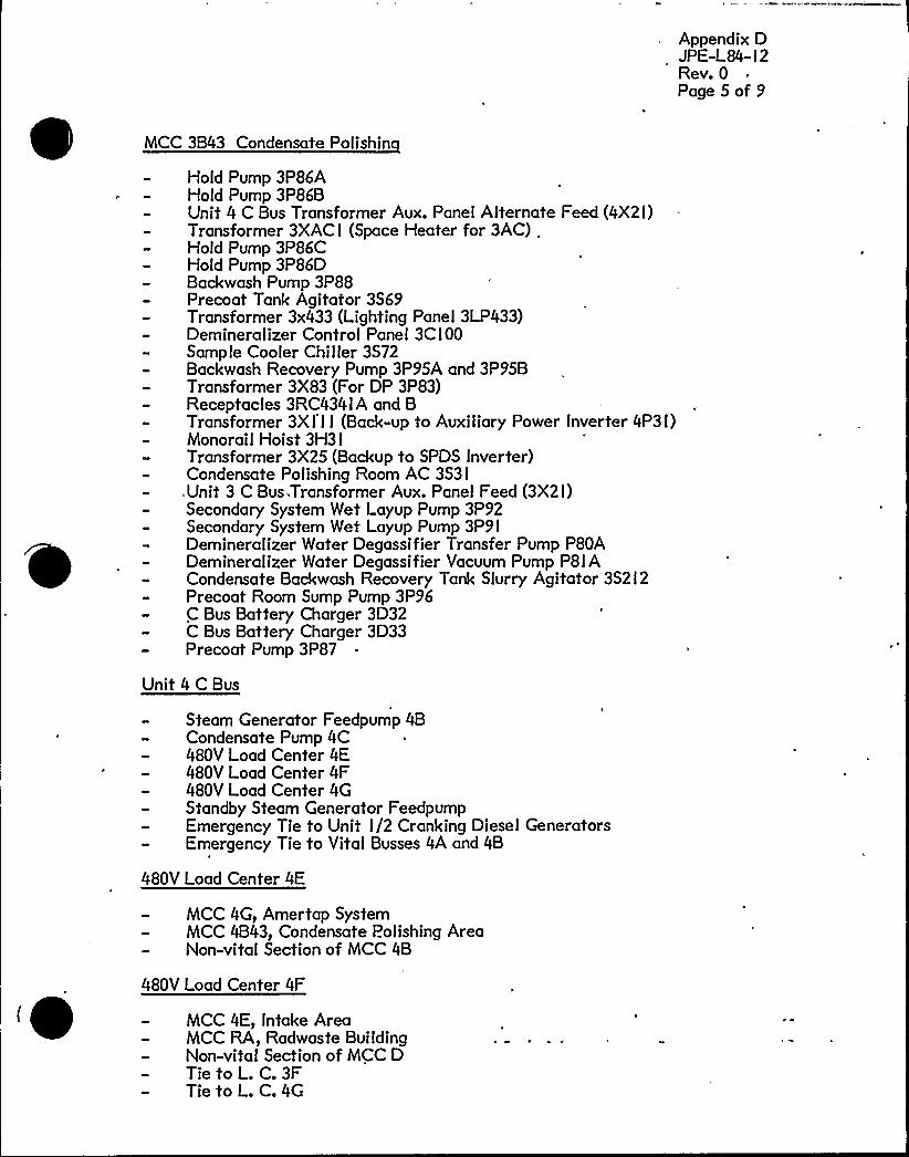
Appendix DJPE-L84- I 2Rev. 0Page 5 of 9
MCC 3B43 Condensate Polishin
Hold Pump 3P86AHold Pump 3P86BUnit 4 C Bus Transformer Aux. Panel Alternate Feed (4X2l)Transformer 3XACI (Space Heater for 3AC) .
Hold Pump 3P86CHold Pump 3P86DBackwash Pump 3P88Precoat Tank Agitator 3S69Transformer 3x433 (Lighting Panel 3LP433)Demineral izer Control Panel 3C I 00Sample Cooler Chiller 3S72Backwash Recovery Pump 3P95A and 3P95BTransformer 3X83 (For DP 3P83)Receptacles 3RC434I A and BTransformer 3X I I I (Back-up to Auxiliary Power Inverter 4P3 I)Monorail Hoist 3H3 I
Transformer 3X25 (Backup to SPDS Inverter)Condensate Polishing Room AC 3S3 I
,Unit 3 C Bus.Transformer Aux. Panel Feed (3X2I)Secondary System Wet Layup Pump 3P92Secondary System Wet Layup Pump 3P9IDemineralizer Water Degassifier Transfer Pump P80ADemineralizer Water Degassifier Vacuum Pump P8I ACondensate Backwash Recovery Tank Slurry Agitator 3S2I2Precoat Room Sump Pump 3P96C Bus Battery Charger 3D32C Bus Battery Charger 3D33Precoat Pump 3P87
Unit 4 C Bus
Steam Generator Feedpump 4BCondensate Pump 4C480V Load Center 4E480V Load Center 4F480V Load Center 4GStandby Steam Generator FeedpumpEmergency Tie to Unit I/2 Cranking Diesel GeneratorsEmergency Tie to Vital Busses 4A and 4B
480V Load Center 4E
MCC 4G, Amertap SystemMCC 4B43, Condensate Polishing AreaNon-vital Section of MCC 4B
480V Load Center 4F
MCC 4E, Intake AreaMCC RA, Radwaste BuildingNon-vital Section of MCC DTie to L. C. 3FTie to L. C.4G


Appendix DJPE-L84-I 2Rev. 0Page 6of 9
480V Load Center 4G
Spent Fuel Pump Motor 4P2I2BNon-vital Section 4C (Fuel Area)Tie to L. C.4F
MCC 4B Non-Vital Section
Welding Receptacles No.'s l7 and l7ARod Control System Backup Transformer 4X I 8Panel 4P82Containment LightingPrimary Water Makeup Pump 4B (4P I6B)Containment Sump Pump 4A (4P23A)Lighting Transformer 46 (4X046)Auxiliary Building AC Panel DP I4Main Steam Penetration Cooling Fan 4A (4V3 I A)RCS Drain Tank Pump 4A (4P2I8A)Steam Generator Feed Pump Room Exhaust Fan 4B (4V I4B)AuxiliaryTransformer Cooling Equipment 4 (Alternate Feed)Startup Transformer Cooling Equipment 4 (Alternate Feed)Gland Steam Condenser Exhaust Blower 4B (4V6B)RCP 4C Oil LiftPump 4P232CIsolated Phase Bus Fan 4B (4V I9B)Steam Generator Feed Pump 4B Auxiliary Lube Oil Pump (4P34B)New Fuel Building Elevator 4H9Air Particulate and Gas Monitor 4V36Miscellaneous Containment Distribution Panel No. 2 (4P I I),
including In-Core Drive SystemLighting Transfer 4 I I (4X3 I I)Feedwater Penetration Cooling Fan 4A (4V32A)Reheater 3C Steam Block Valve MOV-4-I433Reheater 3D Steam Block Valve MOV-4-I434VCT Charging Pump Suction LCV-4-I I5CCondenser Pit Sump Pump 4B (4P28B)Main Transformer Cooling Equipment 4 (Alternate Feed)CRDM Cooler Fan 4B (4V2B)Rod Position Indicator Inverter No. 4 (4Y03)
MCC 4C Non-Vital Section
Gas Stripper Panel 4C30Fuel Area Miscellaneous Power Panel DP I I (4P I2)Spent Fuel Pit Heat Exchanger Room Supply Fan 4VI2Monitor Tank Pump 4 (P206B)Waste Evaporator Condensate Pump 4 (P22IB)RCS Drain Tank Pump 4B (P2I8B),Refueling Water Purifying Pump 4P209Lighting Transformer 49 (Spent Fuel Pit)Battery Room Air Conditioner EI6FFuel Tilting Winch Panel 4B (4C09)Space Heater Transformer 48Deaerated Water Transfer Pump 4P I 2

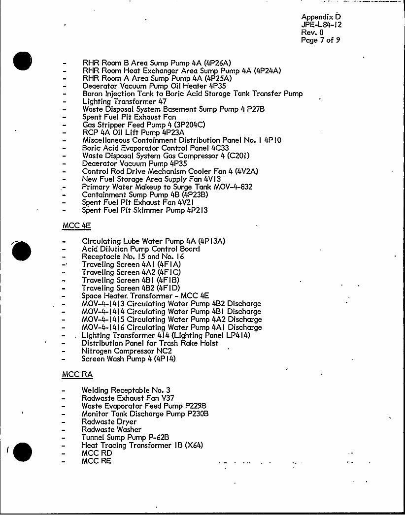
Appendix DJPE-L84- I 2Rev. 0Page 7 of 9
RHR Room B Area Sump Pump 4A (4P26A)RHR Room Heat Exchanger Area Sump Pump 4A (4P24A)RHR Room A Area Sump Pump 4A (4P25A)Deaerator Vacuum Pump Oil Heater 4P35Boron Injection Tank to Boric Acid Storage Tank Transfer PumpLighting Transformer 47Waste Disposal System Basement Sump Pump 4 P27BSpent Fuel Pit Exhaust FanGas Stripper Feed Pump 4 (3P204C)RCP 4A Oil LiftPump 4P23AMiscellaneous Containment Distribution Panel No. I 4P I 0Boric Acid Evaporator Control Panel 4C33Waste Disposal System Gas Compressor 4 (C20I)Deaerator Vacuum Pump 4P35Control Rod Drive Mechanism Cooler Fan 4 (4V2A)New Fuel Storage Area Supply Fan 4VI3Primary Water Makeup to Surge Tank MOV-4-832Containment Sump Pump 4B (4P23B)Spent Fuel Pit Exhaust Fan 4V2ISpent Fuel Pit Skimmer Pump 4P2I3
MCC 4E
Circulating Lube Water Pump 4A (4PI3A)Acid Dilution Pump Control BoardReceptacle No. I5 and No. I6Traveling Screen 4A I (4F I A)Traveling Screen 4A2 (4F I C)Traveling Screen 4B I (4F I B)Traveling Screen 4B2 (4F I D)Space Heater. Transformer - MCC 4EMOV-4-l4I3 Circulating Water Pump 4B2 DischargeMOV-4-I 4 I 4 Circulating Water Pump 4B I DischargeMOV-4-I 4 I 5 Circulating Water Pump 4A2 DischargeMOV-4-l4I6 Circulating Water Pump 4AI DischargeLighting Transformer 4 I 4 (Lighting Panel LP4 I 4)Distribution Panel for Trash Rake HoistNitrogen Compressor NC2Screen Wash Pump 4 (4P I4)
MCC RA
Welding Receptable No. 3Radwaste Exhaust Fan V37Waste Evaporator Feed Pump P229BMonitor Tank Discharge Pump P230BRadwaste DryerRadwaste WasherTunnel Sump Pump P-62BHeat Tracing Transformer IB (X64)MCC RDMCC RE
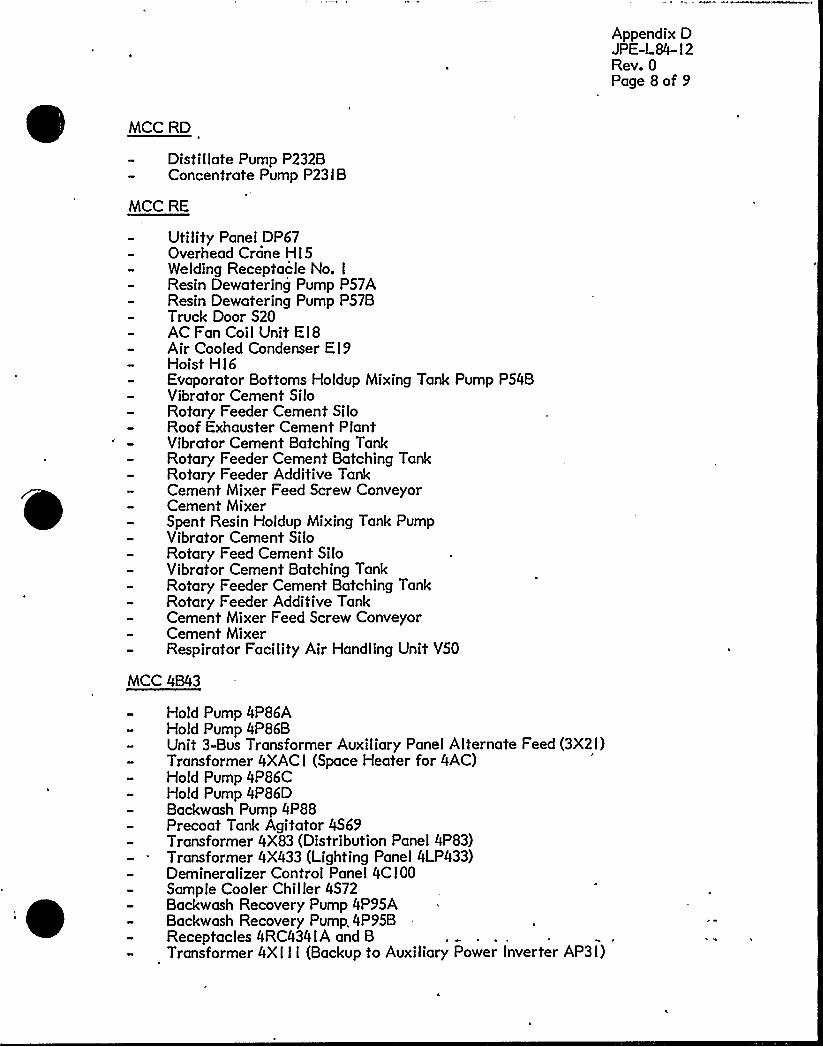
Appendix DJPE-L84- I 2Rev. 0Page 8of 9
MCC RD
Distillate Pump P232BConcentrate Pump P23 I B
MCC RE
UtilityPanel DP67Overhead Crane HI5Welding Receptacle No. I
Resin Dewatering Pump P57AResin Dewatering Pump P57BTruck Door S20AC Fan Coil Unit E I 8Air Cooled Condenser EI9Hoist HI6Evaporator Bottoms Holdup Mixing Tank Pump P54BVibrator Cement SiloRotary Feeder Cement SiloRoof Exhauster Cement PlantVibrator Cement Batching TankRotary Feeder Cement Batching TankRotary Feeder Additive TankCement Mixer Feed Screw ConveyorCement MixerSpent Resin Holdup Mixing Tank PumpVibrator Cement SiloRotary Feed Cement SiloVibrator Cement Batching TankRotary Feeder Cement Hatching TankRotary Feeder Additive TankCement Mixer Feed Screw ConveyorCement MixerRespirator Facility Air Handling Unit VSO
MCC 4B43
Hold Pump 4P86AHold Pump 4P86BUnit 3-Bus Transformer Auxiliary Panel Alternate Feed (3X2I)Transformer 4XAC I (Space Heater for 4AC)Hold Pump 4P86CHold Pump 4P86DBackwash Pump 4P88Precoat Tank Agitator 4S69Transformer 4X83 (Distribution Panel 4P83)Transformer 4X433 (Lighting Panel 4LP433)Demineralizer Control Panel 4C I 00Sample Cooler Chiller 4S72Backwash Recovery Pump 4P95ABackwash Recovery Pump. 4P95BReceptacles 4RC434IA and BTransformer 4XI I I (Backup to Auxiliary Power lnverter AP3I)

Appendix DJPE-L84- I 2Rev. 0Page 9 of 9
Monorail Hoist 4H3 I
Condensate Polishing Room AC 4S3IUnit 4 C Bus Transformer Auxiliary Panel Feed (4X2I)Secondary System Wet Layup Pump 4P92Secondary System Wet Layup Pump 4P9lDemineralizer Water Degassifier Transfer Pump P80BDemineralizer Water Degassifier Vacuum Pump P8I BPr'ecoat Room Sump Pump 4P96C Bus Battery Charger 4D32Precoat Pump 4P87Backwash Tank Agitator
DC Control Center 3D3I
Emergency Bearing Oil Pump 3P30Air Side Oil Backup Pump 3P38480V Load Center 3E, 3F, 3GSwitchgear 3C (3ACO I)C Bus Transformer (3X2l)C Bus Transformer Relay Panel (3C260)Inverter to I 20V Uninterruptible Power Supply (3YI I)Ref lasher (C256)SPDS tnverter (3Y25)
DC Control Center 4D3 I
Emergency Bearing Oil Pump 4P30Air Side Seal Oil Backup Pump 4P38SPDS Inverter (4Y25)480V Load Center 4E, 4F, 4GSwitchgear 4C (4ACO I)C Bus Transformer (4X2l)C Bus Transformer Relay Panel (4C260)Inverter to l20V Uninterruptible Power Supply (4YI I)
I 20V AC Uninterru tible Panel Boar'd 3P3 I
Telemetering (C Bus Transformer)Fire Detection for DC Enclosure BuildingC Bus Transformer DelugeSecurity System
l20V AC Uninterru tible Panel Board 4P3 I
Telemetering (C Bus Transformer)DC Enclosure Building VentilationC Bus Transformer Deluge SystemSecurity System


APPENDIX E
FAILURE MODE EFFECT AHALYSIS
JPE"L84-12REV. 0PAGE I OF 20
PART 'ODEBREAKER 3AA02-
OPEH'ORMAL
SUPPLY TO THE :
3A BUS
LOCAL EFFECT
<OSS OF POQER TO THE A BUS
-A BUS STRIPS LOADS
SYSTEM EFFECT
UHIT 3t D/G STARTS AND PICKS UP THE
A BUS LOADSf UNIT TRIPSI B BUS TRANSFERS
TO THE SU TX
UHIT 4t HONE
BREAKER '3AA02" FAULT
NORMAL SUPPLY TO THE
3A BUS
-LOCKOUT 3A BUS
H BUS DEAD
-LOCKOUT 3 AUX TX
UHIT 3I UHIT TRIPS' BUS TRAHSFERS TO
THE SU TX
UNIT 4I HONE
BREAKER 3AA05- CLOSE
ALTERHATE SUPPLY TO
THE 3A BUS
-A BUS SUPPLIED FROM BDTH THE AUX AHD UHIT 3I NONE
THE SU TX UHIT 4I HONE
BREAKER 3AA05- FAUL'T.
ALTERHATE SUPPLY TO
THE 3A BUS
W BUS LOCKOUT
-A BUS DEAD
UNIT 3o LOCKOUT SU TXI D/G PICK UP B BUS
LOADS'HIT TRIPS
UHIT 4t HONE
BREAKER 3AA09- CLOSE
TIE BETMEEH THE
A BUS AHD THE B AHD.
C BUSSES
-HOHE UNIT 3e NOHE"
UHIT 4t NONE
BREAKER 3AA09- FAUlT;"TIE BETHEEH THE
A BUS AND THE B AHD
C BUSSES
-LOCKOUT OF A BUS
-A BUS DEAD
UNIT 3t UHIT TRIPI B BUS AUTO TRANSFERS
TO THE 3 SU TX
UHIT 4! HONE
BREAKER 3AA22- CLOSE
ALTERHATE SUPPLY
TO THE 3A BUS
FROM THE 4 SU TX
-BUS FED FROM BOTH THE
4 SU TX AHD THE 3 AUX TX
UHIT 3t HOHE
UHIT 4t NONE
BREAKER 3AA22- FAULT ."
ALTERHATE SUPPLY
TO THE 3A BUS
FROM THE 4 SU TX
-LOCKOUT OF 3A BUS
-LOCKOUT OF 4 SU TX
-A BUS DEAD
UNIT 3 ~ UHIT TRIPI B BUS AUTO TRAHSFERS
TO 3 SU TX
UHIT 4e NONE

FAILURE MODE EFFECT ANALYSIS
APPEHDIX E
JPE-L84-12
REVo 0
PAGE, 2 OF 20
PART MODE LOCAL EFFECT SYSTEM EFFECT
BREAKER 3AB02- OPEH:"
HORMAL SUPPLY TO THE
3B BUS
-LOSS OF POMER TO THE B BUS
-B BUS STRIPS LOADS
UHIT 3t UHIT TRIPSI A BUS TRANSFERS TO
THE SU TXI D/G STARTS AHD PICKS UP THE
B BUS LOADS
UHIT 4t HONE
BREAKER 3AB02- FAUL'T
NORMAL SUPPLY TO THE
3B BUS
-LOCKOUT 3B BUS
-B BUS DEAD
-LOCKOUT 3 AUX TX
UHIT 3t UHIT TRIPSI A BUS TRANSFERS TO
THE SU TX
UHIT 4! HONE
BREAKER 3AB05- CLOSE
ALTERHATE SUPPLY TO
THE 3B BUS
-B BUS SUPPLIED FROM BOTH THE AUX AHD UHIT 31 HONE
THE SU TX UHIT 41 HONE
BREAKER 3AB05- FAULT-
ALTERHATE SUPPLY TO
THE 3B BUS
-B BUS LOCKOUT
-B BUS DEAD
UHIT 31 LOCKOUT SU TX1 D/G PICK UP A BUS
LOADS'UNIT TRIPS
UHIT 41 HONE
BREAKER 3AB22-
TIE BETMEEH THE B
BUS AHD THE A AND
C BUSSES
CLOSE -HOHE UHIT 35 HOHE
UHIT 41 HOHE
BREAKER 3AB22- FAULT
TIE BETHEEH THE
B BUS AHD THE A AHD
C BUSSES
-LOCKOUT OF B BUS
-B BUS DEAD
UNIT 3! UHIT TRIPi A BUS AUTO TRANSFERS
TO THE 3 SU TX
UHIT 41 HONE
BREAKER 3AC01- CLOSE
ALTERHATE SUPPLY TO
THE 3C BUS FROM THE
4C TX
< BUS SUPPLIED FROM BOTH THE
3C TX AHD THE 4C TX
UHIT 31 HONE
UHIT 4t H0HE

0

FAILURE MODE EFFECT AHALYSIS
APPENDIX E
JPE-L84-12REVo 0
PAGE 3 OF 20
PART MODE
BREAKER 3AC01- FAULT
ALTERHATE SUPPLY TO
THE 3C BUS FROM THE
4C TX
LOCAL EFFECT
-LOCKOUT 3C BUS
<OCKOUT 4C TX
SYSTEM EFFECT
UHIT 31 TURBIHE RUHBACK
UHIT 4 HITHOUT AUTO TRAHSFERI LOSS OF
4C BUS$ TURBIHE RUNBACK
UHIT 4 HITH AUTO TRANSFERS CLOSE 4AC01
BREAKER 3AC03
SUPPLY FROM THE
CRAHKIHG DIESELS
CLOSE -HONE UNIT 3t HONE
UHIT 4! HONE
BREAKER 3AC03
SUPPLY FRON THE
CRAeIHG DIESELS
'FAULT "LOCKOUT OF 3C BUS UHIT 31 TURBIHE RUNBACK
UHIT 41 HOHE
BREAKER 3AC13- CLOSE
TIE BETMEEH THE
C BUS AHD THE A
AHD B BUSSES
-HONE UHIT 31 HOHE
UHIT 41 HONE
BREAKER 3AC13-
TIE BETHEEH THE
C. BUS AHD THE A
AND B BUSSES
FAULT -LOCKOUT OF 3C BUS UHIT 31 TURBIHE RUHBACK
UHIT 4! HOHE
BREAKER 3AC16 OPEH
HORMAL SUPPLY TO THE
3C BUS
-LOSS OF POHER TO THE 3C BUS UHIT 31 TURBIHE RUHBACK
UHIT 41 NOHE
BREAKER 3AC16 FAULT
HORNAL SUPPLY TO THE
3C BUS
<OCKOUT OF 3C BUS
<OCKOUT OF 3C TX
UHIT 31 TURBIHE RUHBACK
UHIT 4$ HONE
BREAKER 4AA02- OPEH'.
HORMAL SUPPLY TO THE .
4A BUS
-LOSS OF POMER TO THE A BUS
-A BUS STRIPS LOADS
UNIT 41 D/G STARTS AHD PICKS UP THE
A BUS LOADS1 UNIT TRIPSt B BUS TRANSFERS
TO THE SU TX
UHIT 31 NONE


FAILURE MODE EFFECT ANALYSIS
APPEHDIX E
JPE-LSh-12
REVi 0
PAGE 4 OF 20
PART MODE LOCAL EFFECT SYSTEM EFFECT
BREAKER 4AA02- FAOET
HORMAL SUPPLY TO THE
4A BUS
-LOCKOUT 4A BUS
-A BUS DEAD
<OCKOUT 4 AUX TX
UNIT 4o UHIT TRIPSI B BUS TRANSFERS TO
THE SU TX
UNIT 3o HOHE
BREAKER 4AA05" CLOSE
ALTERNATE SUPPLY TO
THE 4A BUS
-A BUS SUPPLIED FROM BOTH THE AUX AHD UHIT 3e HONE
THE SU TX UHIT 4'e HOHE
BREAKER 4AA05- 'AULTALTERNATE SUPPLY TO
THE 4A BUS
-A BUS LOCKOUT
-A BUS DEAD
UHIT 4» LOCKOUT SU TXP D/G PICK UP B BUS
LOADSr'HIT TRIPS
UHIT 3'e NOHE
BREAKER 4AA09- CLOSE
TIE BETHEEH THE
. A BUS AHD THE B AHD
C BUSSES
UHIT 3t HONE
UNIT 4e NONE
BREAKER 4AA09- FAULT'.
TIE BETHEEH THE
A BUS AND,THE B AHD
C BUSSES
-LOCKOUT OF A BUS
H BUS DEAD
UHIT 44 UHIT TRIP) B BUS AUTO TRAHSFERS
TO THE 4 SU TX
UNIT 3o HOHE
BREAKER 4AA22- CLOSE
ALTERNATE SUPPLY
TO THE 4A BUS FROM
THE 3 SU TX
-BUS FED FROM BOTH THE
3 SU TX AHD THE 4 AUX TX
UHIT 3s HOHE
.. UHIT 4s HONE
BREAKER 4AA22- FAULT'.::ALTERHATE SUPPLY
TO THE 4A BUS FROM
THE 3 SU TX
<OCKOUT OF 4A BUS
-LOCKOUT OF 3 SU TX
-A BUS DEAD
UHIT 4 ~ UHIT TRIPI B BUS AUTO TRANSFERS
TO 4 SU TX
UHIT 3e HONE


PART MODE
BREAKER 4AB02- ~ OPEH
NORMAL SUPPLY TO THE. i .
4B BUS
FAILURE MODE EFFECT ANALYSIS
LOCAL EFFECT
-LOSS OF POBER TO THE B BUS
-B BUS STRIPS LOADS
APPEHDIX E
JPE-L84-12REU» 0
PAGE 5 OF 20
SYSTEM EFFECT
UHIT 4» UHIT TRIPS' BUS TRAHSFERS TO
THE SU TXi D/G STARTS AHD PICKS UP THE
B BUS LOADS
UHIT 3t NONE
BREAKER 4AB02- - FAULT
NORMAL SUPPLY TO THE
4B BUS
<OCKOUT 4B BUS
-B BUS DEAD
-LOCKOUT 4 AUX TX
UHIT 4 ~ UHIT TRIPSI A BUS TRANSFERS TO
THE SU TX
UHIT 3» HONE
BREAKER 4AB05- CLOSE
ALTERNATE SUPPLY TO
THE 4B BUS
-B BUS SUPPLIED FROM BOTH THE AUX AND UHIT 3» NONE
THE SU TX UHIT 4» HONE
BREAKER 4AB05- . ''FAUET- i.:ALTERHATE SUPPLY TO
THE 4B BUS
-B BUS LOCKOUT
"B BUS DEAD
UNIT 4» LOCKOUT SU TXS D/G PICK UP A BUS
LOADS> UHIT TRIPS
UHIT 3» HONE
BREAKER 4AB22- CLOSE
TIE BETHEEH THE B
BUS AND THE A AHD
C BUSSES
-HOHE UHIT 3t HONE
UHIT 4» NOHE
BREAKER 4AB22- FAULT"'IE
BETHEEN THE
B BUS AHD THE A AHD
C BUSSES
-LOCKOUT OF B BUS
-B BUS DEAD
UNIT.4» UHIT TRIPi A BUS AUTO TRAHSFERS
TO THE 4 SU TX
UHIT 3» HOHE
BREAKER 4AC01- CLOSE
ALTERHAME SUPPLY TO
THE 4C BUS FROM THE
3C TX
-C BUS SUPPLIED FORM BOTH THE
3C TX AHD THE 4C TX
UHIT 4» HONE
UHIT 3» NOHE
BREAKER 4AC01- FAULT
ALTERHATE SUPPLY TO
THE 4C BUS FROM THE
3C TX
-LOCKOUT 4C BUS
<OCKOUT OF 3C TX
UNIT 4» TURBIHE RUNBACK
UHIT 3 HITHOUT AUTO TRANSFER» LOSS OF
3C BUS1 TURBINE RUNBACK
UHIT 3 HITH AUTO TRANSFER» CLOSE 3AC01

FAILURE NODE EFFECT ANALYSIS
APPEHDIX E
JPE<84-12REVo 0
PAGE 6 OF 20
PART MODE LOCAL EFFECT SYSTEH EFFECT
BREAKER 4AC03
SUPPLY FRON THE
CRANKIHG DIESELS
CLOSE +ONE UHIT 41 HOHE
UHIT 3t HOHE
BREAKER 4AC03
SUPPlY FRON THE
CRAHKIHG DIESELS
FAULT -LOCKOUT OF 4C BUS UHIT 41 TURBINE RUHBACK
UNIT 3t HONE
BREAKER 4AC13- CLOSE
TIE BETMEEH THE
C BUS AHD THE A
AHD B BUSSES
-HONE UHIT 31 HONE
UHIT 4t HONE
BREAKER 4AC13" FAULT
TIE BETMEEH THE
C BUS AHD THE A
AHD B BUSSES
-LOCKOUT OF 4 C BUS UNIT 4t TURBIHE RUHBACK
UHIT 3t NOHE
BREAKER 4AC16 OPEH
NORNAl SUPPLY TO THE
4C BUS
-LOSS OF POMER TO THE 4C BUS UHIT 41 TURBINE RUHBACK
UHIT 31 NONE
BREAKER 4AC16 FAULT
HORHAL SUPPLY TO THE
4C BUS
<OCKOUT OF 4C BUS
<OCKOUT OF 4C TX
UHIT 41 TURBINE RUNBACK
UHIT 31 HOHE
BUS HORTHEAST SHORT) OR SHORT
TO GROUHD
<OCKOUT OF HORTHEAST BUS BY OPENING
OF BREAKERS 2Bt3Bi4Bi5B)6Bi6/7BUHIT 3t HOHE
UHIT 41 HOHE

0
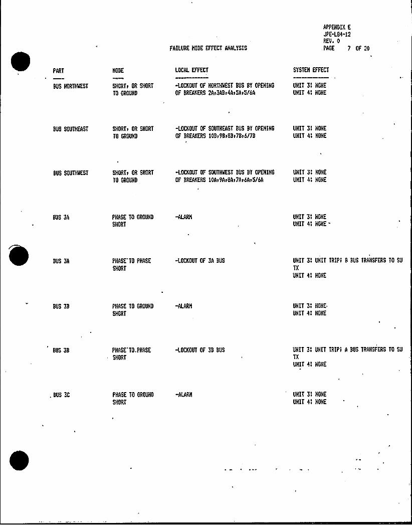
FAILURE MODE EFFECT AHALYSIS
APPEHDIX E
JPE-L84-12REVe 0
,PAGE 7 OF 20
PART
BUS HORTIQEST
MODE
SHORTr OR SHORT
TO GROUND
LOCAL EFFECT
<OCKOUT OF NORTlQEST BUS BY OPEHIHG
OF BREAKERS 2Ar3ABr4Ar5Ar5/6A
SYSTEM EFFECT
UHIT 31 NONE
UHIT 41 HOHE
BUS SOUTHEAST SHORTr OR SHORT
TO GROUND
<OCKOUT OF SOUTHEAST BUS BY OPEHIHG
OF BREAKERS 10Br9Br8Br7Br6/7BUHIT 31 HONE
UHIT 41 HOHE
BUS SOUTHMEST SHORTr OR SHORT
TO GROUHD
<OCKOUT OF SOUTHMEST BUS BY OPEHING
OF BREAKERS 10Ar9Ar8Ar7Ar6Ar5/6AUHIT 31 HOHE
UNIT 4l NONE
BUS 3A PHASE TO GROUHD
SHORT
-ALARM UNIT 31 HONE
UHIT 41 HOHE-
BUS 3A PHASE TO PHASE
SHORT
<OCKOUT OF 3A BUS UHIT 31 UHIT TRIPi B BUS TRAHSFERS TO SU
TX
UHIT 41 HONE
BUS 3B PHASE TO GROUHD
SHORT
MARM UNIT 3t NOHE.
UHIT 4! HOHE
BUS 3B PHASE TO.PHASE
SHORT
<OCKOUT OF 3B BUS UHIT 3! UHIT TRIPS A BUS TRANSFERS TO SU
TX
UNIT 4C HONE
, BUS 3C PHASE TO GROUHD
SHORT
-ALARM UHIT 31 HOHE
UNIT 41 HONE

FAILURE MODE EFFECT ANALYSIS
APPEHDIX E
JPE-LBh"i2
REVo 0
PAGE 8 OF 20
PART MODE LOCAL EFFECT SYSTEM EFFECT
BUS 3C PHASE TO PHASE
SHORT
-LOCKOUT OF 3C BUS UHIT 3o TURBINE RUHBACK
UHIT 4o HONE
BUS 4A PHASE TO .GROUHD
SHORT
UHIT 3o HONE
UHIT 4e HONE
BUS 4A PHASE TO'PHASE
SHORT
-LOCKOUT OF 4A BUS UHIT 4t UHIT TRIPt B BUS TRANSFERS TO SU
TX
UNIT 3e HONE
I
BUS 4B PHASE TO GROUHD
SHORT
UHIT 3I HO)'E
UHIT 4e HONE
BUS 4B PHASE TO PHASE
SHORT
<OCKOUT OF 4B BUS UHIT 4 ~ UHIT TRIPt A BUS TRANSFERS TO SU
TX
UHIT, 3I NONE
BUS 4C PHASE TO GROUHD
SHORT
UHIT 3$ HONE
UHIT 4o HOHE
BUS 4C PHASE TO PHASE
SHORT
<OCKOUT OF 4C BUS UHIT 4e TURBIHE RUHBACK
UHIT 3o HOHE

t PART NODE
GEHERATOR UHIT 3 OPEH OR'SHORT
FAILURE NODE EFFECT ANALYSIS
LOCAL EFFECT
-GEHERATOR LOCKOUT BY OPEHING OF
BREAKERS 7B)7ABt3AA02i3AB02
-CLOSE SIGHAL TO BREAKERS 3AA05t3AB05
APPEHDIX E
JPE<84" 12REU» 0
PAGE 9 OF 20
SYSTEN EFFECT
UHIT 31 UHIT TRIPI A AHD B BUSSES AUTO
TRAHSFER.TO SU TX
UNIT 4t HONE
GEHERATOR UHIT 4 .OPEN OR SHORT <EHERATOR LOCKOUT BY OPEHING OF
BREAKERS 9Bi9ABs4AA02t4AB02
-CLOSE SIGHAL TO BREAKERS 4AA05t4AB05
UNIT 41 UNIT TRIP1 A AHD B BUSSES AUTO
TRAHSFER TO SU TX
UHIT 31 HONE
ISO PHASE BUS UHIT 3 SHORT <OSS OF 3 AUX TX
-TRANSFER TO 3 SU TX
-OPEH BREAKERS 7ABi7B
UNIT 31 UHIT TRIP
UNIT 41 HONE
ISO PHASE BUS UHIT 4 SHORT <OSS OF 4 AUX TX
-TRAHSFER TO 4 SU TX
MEH BREAKERS 9ABr9B
UNIT 4! UHIT TRIP
UHIT 3! NONE
LINE< BUS TX UHIT 3 SHORT OR SHORT TO
TO BAY 3 GROUHD
-OPEH BREAKERS 3ABt3Bt3AC16
<PEH SIGHAL TO BREAKER 4AC01
UHIT 3 MITHOUT AUTO TRANSFERS LOSS OF
C BUSS TURBIHE RUNBACK
UHIT 3 MITK AUTO TRAHSFERt CLOSE 3AC011
C BUS POMERED FRON 4C TX
UHIT 4t NONE
LIHE"C BUS TX UHIT 4 SHORT OR SHORT TO
TO BAY 10 GROUND
<PEH BREAKERS 10AeiOABi4ACI6
-OPEH SIGHAL TO BREAKER 3AC01
UHIT 4 MITHOUT AUTO TRANSFERI LOSS OF
C BUSr'URBINE RUHBACK
UHIT 4 MITH AUTO TRAHSFERI CLOSE 4AC011
C BUS POMERED FROH 3C TX
UHIT 31 HOHE
LIHE-DADE SHORT OR SHORT TO <PEH BREAKERS 8AiGAB
GROUHD
UHIT 31 HONE
UNIT 41 HOHE
LINE-DAUIS 1 SHORT OR SHORT TO -OPEN BREAKERS 2Al2AB
GROUHD
UHIT 31 HOHE
UHIT 41 NONE

~

FAILURE MODE EFFECT AHALYSIS
APPENDIX E
JPE<84-12REVo 0
PAGE 10 OF 20
PART MODE LOCAL EFFECT SYSTEM EFFECT
LINE-DAUIS 2 SHORT OR SHORT TO <PEH'BREAKERS 5Ar5AB
GROUHD
UHIT 3t NONE
UNIT 41 HOHE
LINE-DAVIS 3 SNORT OR SHORT TO <PEH BREAKERS 7Av7AB
GROUHD
UHIT 3t HOHE
UHIT 41 HONE
LIHE-DORAL SNORT OR SHORT TO <PEH BREAKERS 9As9AB
GROUND
UHIT 31 NOHE
UHIT hl NONE
LINE-FLAGAMI 1 SHORT OR SHORT TO <PEH BREAKERS 4At4AB
GROUND
UHIT 3t HONE
UHIT 41 HOHE
LIHE-FLAGAMI 2 SHORT OR SHORT TO <PEH BREAKERS 6A)6AB
GROUHD
UHIT 3t HOHE
UHIT 41 HONE
LIHE-FLORIDA CITY SHORT OR SHORT TO -OPEN BREAKERS 10AB~10B
GROUND
UHIT 31 HOHE
UNIT 41 HONE
LIHE-MATH TX UHIT 1 SNORT OR SNORT TO
TO BAY 2 GROUHD
-OPEH BREAKERS 2AB)2B
-OPEN APPROPRIATE LOHSIDE UHIT 1
AUX TX BREAKERS
UHIT 31 NONE
UHIT ht HONE
UHIT lt UHIT TRIP

FAILURE MODE EFFECT ANALYSIS
APPENDIX E
JPE-L84-12REVo 0
PAGE 11 OF 20
PART MODE
LINE-MAIN TX UHIT 2 SHORT OR SHORT TO
TO'BAY 5 GROUND
LOCAL EFFECT
-OPEN BREAKERS 5AB)5B
<PEH APPROPRIATE LOMSIDE UHIT 2
AUX TX BREAKERS
SYSTEM EFFECT
UHIT 3l NONE
UHIT 41 HOHE
UHIT 2t UHIT TRIP
LIHEMIH TX UNIT 3 SHORT OR SHORT TO
TO BAY 7 GROUND
<PEN BREAKERS 7AB)7Bt3AA02)3AB02
AROSE BREAKERS 3AA05t3AB05
UHIT 31 UHIT TRIPi TRANSFER A AND B
BUSSES TO SU TX
UHIT 41 HOHE
LINE-MAIN TX UHIT 4 . SHORT OR SHORT TO
TO BAY 9 GROUHD
<PEH BREAKERS 9AB)9B)hAA02)4AB02
<LOSE BREAKERS 4AA05)4AB05
UNIT 41 UHIT TRIPt TRANSFER A AHD B
BUSSES TO SU TX
UNIT 31 HONE
LINE-SU TX UNIT 3
TO BAY 6
SHORT OR SHORT TO -OPEH BREAKERS 6AB)6B
GROUND -TRIP SIGHAL TO EHSURE OPEHIHG OF
BREAKERS 3AA05)3AB05)4AA22
UHIT 31 HOHE
UHIT 41 HOHE
LIHE-SU TX UHIT 4
TO BAY 8
SHORT OR SHORT TO -OPEH BREAKERS BAB)GB
GROUND -TRIP SIGHAL TO EHSURE OPEHING OF
BREAKERS 4AA05)4AB05)3AA22
UHIT 31 HONE
UNIT 41 HOHE
LIHE"SU TX UHITS 1!2 SHORT OR SHORT TO <PEH BREAKERS 4AB)4B UNIT 31 HOHE
TO BAY 4 GROUND -OPEH APPROPRIATE LONSIDE SU TX BREAKERS UNIT 41 HONE
OCB 2A OPEH -HOHE UNIT 31 HONE
UHIT hs HOHE
-OCB 2A SHORT TO GROUND <OCKOUT OF HORTHMEST BUS BY OPEHING OF UHIT 31 HONE
BREAKERS 2AB)3AB)4A)5A)5/6A UHIT 41 HOHE
-LOSS OF DAUIS 1 LIHE

0'

FAILURE NODE EFFECT ANALYSIS
APPEHDIX E
JPE<84-12REVo 0PAGE 12 OF 20
PART NODE LOCAL EFFECT SYSTEN EFFECT
OCB 2AB OPEH +ONE UHIT 31 HOHE
UHIT 41 H0HE
OCB 2AB SHORT TO GROUHD <PEHIHG OF BREAKERS 2Ar2B-OPENIHG OF LOMSIDE UHIT 1 AUX
TX BREAKERS
<OSS OF DAVIS 1 LINE
UHIT 31 HONE
UHIT 41 HOHE
UHIT 11 UHIT TRIP
OCB 2B OPEH -HOHE UHIT 31 HOHE
UHIT 41 HONE
OCB 2B SHORT TO GROUND <OCKOUT OF HORTHEAST BUS BY OPEHIHG OF UHIT 31 HOHE
BREAKERS 2ABr3Bt4Br5B~ 6Bt6/7B 'NIT 41 HOHE
-OPEHIHG OF LOMSIDE UHIT 1 AUX UHIT 1'» UHIT TRIP
TX BRFNERS
OCB 3AB OPEH -HONE UHIT 3o HONE
UHIT 41 NONE
OCB 3AB SHORT TO GROUND <OCKOUT OF NORTNMEST BUS BY OPEHIHG OF UNIT 3 MITHOUT AUTO TRANSFERS TURBINE
BREAKERS 2Ar3Br4Ar5Ar5/6Ar3AC16 RUNBACK
<PEH SIGHAL TO BREAKER 4AC01 UNIT 3 MITH AUTO TRAHSFERI CLOSE 3AC01
UHIT 41 HONE
OCB 3B OPEH +ONE UNIT 3t HONE
UHIT 4t HONE

0'
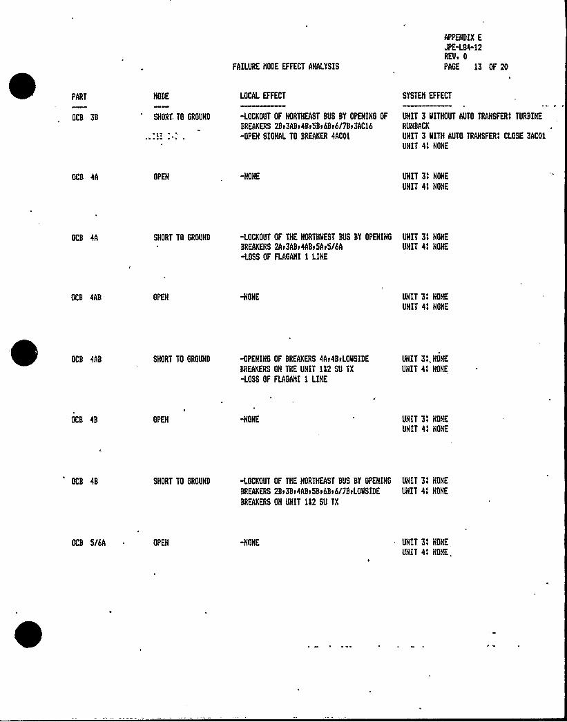
FAILURE MODE EFFECT ANALYSIS
APPEHDIX E
JPE<G4" 12REVs 0
PAGE 13 OF 20
PART
OCB 3B
MODE
SHORT TO GROUHD
LOCAL EFFECT
<OCKOUT OF HORTHEAST BUS BY OPEHIHG OF
BREAKERS 2Bt3ABt4Bt5Bt6Bt6/7Bt3AC16-OPEH SIGHAL TO BREAKER 4AC01
SYSTEM EFFECT
UHIT 3 llITHOUT AUTO TRANSFERS TURBINE
RUHBACK
UHIT 3 IIITH AUTO TRANSFERS CLOSE 3AC01
UHIT 41 HOHE
OCB 4A OPEH UHIT 31 HOHE
UNIT 41 HONE
OCB 4A SHORT TO GROUHD <OCKOUT OF THE HORTNHEST BUS BY OPEHIHG UNIT 31 HONE
BREAKERS 2At3ABt4ABt5At5/6A UNIT 41 HONE
-LOSS OF FLAGAMI 1 LINE
OCB 4AB OPEN HONE UHIT 31 HONE
UHIT 41 HONE
OCB 4AB SHORT TO GROUND -OPEHING OF BREAKERS 4At4BtLOMSIDE
BREAKERS OH THE UNIT 122 SU TX
<OSS OF FLAGANI 1 LINE
UNIT 31. NOHE
UHIT 41 HONE
OCB 4B OPEH -HOHE UHIT 31 NONE
UHIT 41 HONE
OCB 4B SHORT TO GROUHD <OCKOUT OF THE NORTHEAST BUS BY OPEHIHG UNIT 3! HONE
BREAKERS 2Bt3Bt4ABt5Bt6Bt6/7BtLOHSIDE UHIT 41 HOHE
BREAKERS OH UHIT 112 SU TX
OCB 5/6A OPEH UHIT 31 HOHE
UHIT 41 NOHE.


FAILURE NODE EFFECT AHALYSIS
APPEHDIX E
JPE<84-12REVo 0
PAGE 14 OF 20
PART lOCAL EFFECT SYSTEH EFFECT
OCB 5/6A SNORT TO GROUHD -LOCKOUT OF MEST BUS BY OPEHIHG OF
BREAKERS 2Ar3ABrhArSAr6Ar7ArBAr9Ar10A
UHIT 3t HONE
UHIT 4! HOHE
OCB SA OPEH -HONE UHIT 31 HOHE
UHIT 41 HONE
OCB 5A SHORT TO GROUND <OCKOUT OF THE HORTHMEST BUS BY OPEHING UHIT 3t HONE
BREAKERS 2Ar3ABr4Ar5ABr5/6A UHIT 41 HOHE
-LOSS OF DAVIS 2 LINE
OCB SAB -HONE UHIT 31 HONE
UHIT 41 HONE
OCB 5AB SHORT TO GROUHD -OPEHIHG OF BREAKERS SArSB
-OPENIHG OF LOMSIDE UNIT 2 AUX
TX BREAKERS
-LOSS OF DAVIS 2 LIHE
UHIT 34 HOHE
UHIT 41 HOHE
UHIT 21 UHIT TRIP
OCB 5B OPEN -HONE UHIT 31 HOKE
UNIT 41 NOHE
OCB 5B SHORT TO GROUHD <OCKOUT OF THE NORTHEAST BUS BY OPENIHG UHIT 31 HONE
BREAKERS 6/7Br6Br5ABr4Br3Br2B UHIT 41 NONE
-OPEHIHG OF .LOMSIDE UNIT 2 AUX UNIT 21 UHIT TRIP
TX BREAKERS

FAILURE NODE EFFECT ANALYSIS
APPENDIX E
JPE-LGI-12REVi 0
PAGE - 15 OF 20
PART
OCB 6/7B
NODE LOCAL EFFECT
-HOHE
SYSTEM EFFECT
„UHIT 3'ONEUNIT 41 HONE
OCB 6/7B SHORT TO GROUND <OCKOUT OF EAST BUS BY OPENING OF ~ UHIT 31 HOHE
BREAKERS 2Bt3Bt4Bt5Bt6Bt7BtGBt9BtiOB UHIT 4 ~ NONE
OCB 6A OPEH UHIT 31 HONE
~ UNIT 41 NONE
OCB 6A SHORT TO GROUND <OCKOUT OF THE SOUTlmEST BUS BY OPENING UHIT 31 HONE
BREAKERS 10At9AtBAt7At6ABr5/6A UNIT 41 HOHE
<OSS OF FLAGAMI 2 LINE
-HOHE UHIT 31 HOHE
UHIT 41 HONE
OCB 6AB
OCB 6B
SHORT TO GROUHD
OPEH
<PEXIXG OF BREAKERS 6At6B UNIT 31 HONE
MSURE LOCKOUT OF 3 SU TX BY OPEHIHG OF UHIT 41 HONE
BREAKERS 3AA05t3AB05
-OPEH SIGNAL TO BREAKER 4AA22
<OSS OF FLAGAHI 2 LIHE
UHIT 3f XONE
UNIT 4! XONE
OCB 6B SHORT TO GROUHD <OCKOUT OF THE HORTHEAST BUS BY OPEHING UNIT 31 HOXE
BREAKERS 6/7Bt6ABt5Bt4Bt3Bt2Bt UNIT 41 NONE
-EHSURE LOCKOUT OF 3 SU TX BY OPENIHG
3AA05t3AB05
<PEN SIGHAL TO BREAKER 4AA22
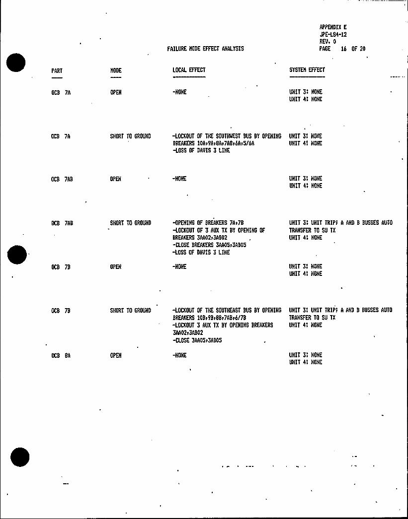
FAILURE NODE EFFECT AHALYSIS
APPEHDIX E
JPH.84-12REVi 0
PAGE 16 OF 20
PART
OCB 7A
MODE
OPEH
LOCAL EFFECT
-HOHE
SYSTEN EFFECT
UHIT 31 HOHE
UNIT 41 HOHE
OCB 7A SHORT TO GROUHD <OCKOUT OF THE SOUTHMEST BUS BY OPEHIHG UHIT 31 HONE
BREAKERS 10At9At8At7ABt6At5/6A UHIT 41 HOHE
<OSS OF DAVIS 3 LINE
OCB 7AB OPEH UNIT 3! HOHE
UHIT 41 HOHE
OCB 7AB SHORT TO GROUHD <PEHIHG OF BREAKERS 7At7B
<OCKOUT OF 3 AUX TX BY OPEHIHG OF
BREAKERS 3AA02t3AB02
-CLOSE BREAKERS 3AA05t3AB05
<OSS OF DAVIS 3 LINE
UHIT 31 UHIT TRIPt A AHD B BUSSES AUTO
TRAHSFER TO SU TX
UHIT 41 HOHE
OCB 7B OPEH UHIT 31 NOHE
UNIT 41 HONE
OCB 7B
OCB GA
SHORT TO GROUHD
OPEH
<OCKOUT OF THE SOUTHEAST BUS BY OPENING UHIT 31 UHIT TRIPt A AHD B BUSSES AUTO
BREAKERS 10Bt9BtBBt7ABt6/7B TRANSFER TO SU TX
-LOCKOUT 3 AUX TX BY OPENIHG BREAKERS UHIT 41 HOHE
3AA02t3AB02
<LOSE 3AA05t3AB05
UNIT 31 HOHE
UNIT 41 HOHE
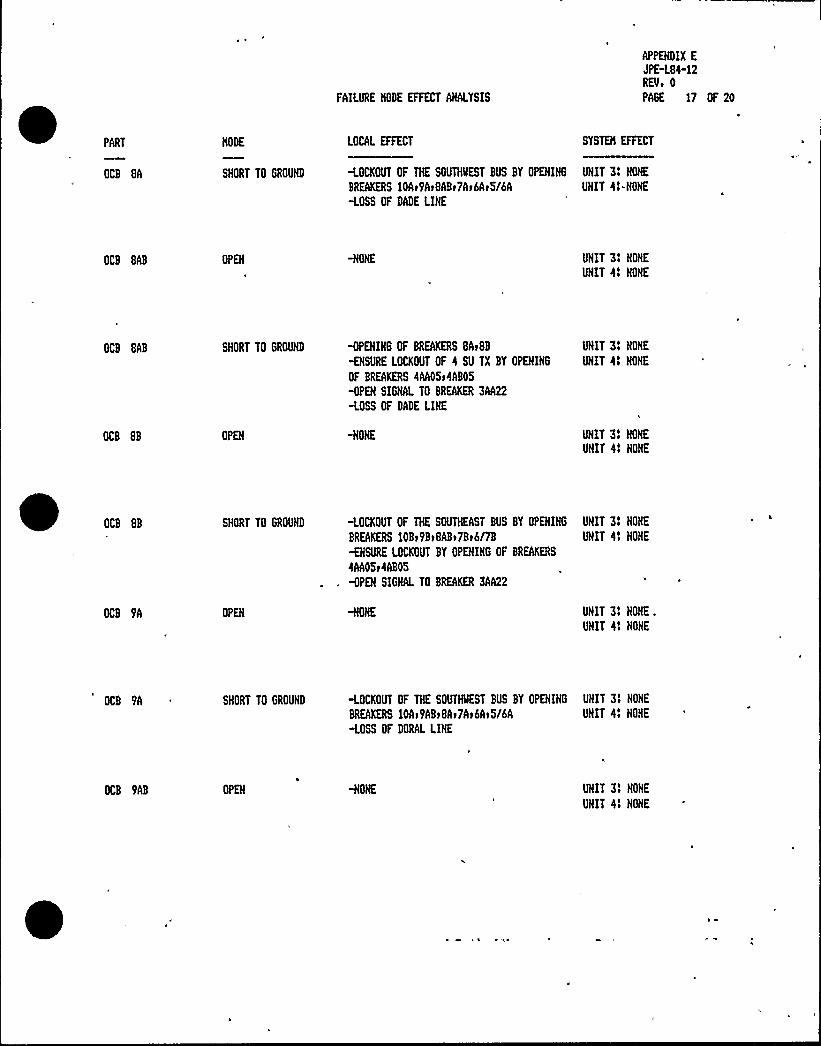
FAILURE liODE EFFECT AHALYSIS
APPENDIX E
JPE-L84-12REV» 0
PAGE 17 OF 20
PART
OCB GA
NODE
SHORT TO GROUHD
LOCAL EFFECT SYSTEN EFFECT
<OCKOUT OF THE SOUTHQEST BUS BY OPEHIHG UNIT 3» HOHE
BREAKERS 10Ar9Ar8ABr7Ar6Ar5/6A UHIT 4»-HONE
<OSS OF DADE LIHE
OCB GAB OPEH UNIT 3» NOHE
UNIT 4» HONE
OCB 8AB SHORT TO GROUND MEHING OF BREAKERS 8ArGB
MSURE LOCKOUT OF 4 SU TX BY OPEHIHG
OF BREAKERS 4AA05r4ABOS
<PEH SIGNAL TO BREAKER 3AA22
<OSS OF DADE LINE
UHIT 3» NOHE
UNIT 4» HOHE
OCB GB OPEH -HOHE UHIT 3» HOHE
UNIT 4» HOME
OCB 8B SHORT TO GROUHD <OCKOUT OF THE SOUTHEAST BUS BY OPEHIHG UHIT 3» HONE
BREAKERS 10Br9BrGABr7Br6/78 UHIT 4t NOHE
MSURE LOCKOUT BY OPEHIHG OF BREAKERS
4AA05r4AB05
<PEH SIGNAL TO BREAKER 3AA22
OPEH UHIT 3t HOHE.
UHIT 4» HOHE
OCB 9A SHORT TO GROUHD <OCKOUT OF THE SOUTNMEST BUS BY OPEHIHG UNIT 3» NOHE
BREAKERS 10Ar9ABrBAr7Ar6Ar5/6A UHIT 4» NOHE
<OSS OF DORAL LIHE
OCB 9AB OPEH UHIT 3t HONE
UHIT 4» HOHE


FAILURE NODE EFFECT ANALYSIS
APPEHDIX E
JPE<G4-12
REVo 0
PAGE 18 OF 20
PART LOCAL EFFECT SYSTEH EFFECT
OCB 9AB ; SHORT. TO GROUND MENIHG OF BREAKERS '9Ar9B
<OCKOUT OF 4 AUX TX BY OPEHIHG OF
BREAKERS 4AA02r4AB02
MUSE BREAKERS 4AA05r4AB05
<OSS OF DORAL LIHE
UHIT 41 UNIT TRIPI A AND B BUSSES AUTO
TRAHSFER TO SU TX
UNIT 31 HONE
OCB 9B OPEN UHIT 31 HONE
UHIT 4$ HOHE
OCB 9B 'HORT. TO GROUHD <OCKOUT OF THE SOUTHEAST BUS BY OPEHIHG UNIT 41 UHIT TRIP1 A AND B BUSSES AUTO
BREAKERS 10Bt9ABrBBt7Br6/7B TRANSFER TO SU TX
<OCKOUT 4 AUX TX BY OPEHIHG BREAKERS UHIT 31 NOHE
4AA02t4AB02
-CLOSE 4AA05r4AB05
OCB 10A OPEH UHIT 31 HONE
UHIT 41 HOHE
OCB 10A SHORT TO GROUHD -LOCKOUT OF SOUTHMEST BUS BY OPEHIHG OF UNIT 4 MITHOUT AUTO TRANSFERI TURBINE
BREAKERS 10ABr9ArGAr7At6Ar6/7At4AC16 RUHBACK~ SIGNAL TO BREAKER 3AC01 UHIT 4 MITH AUTO TRANSFERI CLOSE 4AC01
UHIT 31 NOHE
OCB 10AB OPEH UHIT 31 HONE
UNIT 41 NONE
OCB 10AB SHORT TO GROUHD <PENING OF BREAKERS 10AtiOBr4AC16
WEH SIGNAL TO BREAKER 3AC01
-LOSS OF FLORIDA CITY LIHE
UHIT 4 MITHOUT AUTO TRANSFERS TURBIHE
RUHBACK
UHIT 4 MITH AUTO TRAHSFERI CLOSE 4AC01
UHIT 3l HOHE

FAILURE NODE EFFECT AHALYSIS
APPEHDIX E
JPE-L84"12REVo 0PAGE 19 OF 20
PART
OCB 10B
NODE
OPEH
LOCAL EFFECT
-NOHE
SYSTEN EFFECT
UHIT 31 HOHE
UHIT 41 HONE
OCB 10B SHORT TO GROUHD <OCKOUT OF THE SOUTHEAST BUS BY OPEHING UNIT 31 HONE
BREAKERS 10ABt9BtBBt7Bt6/7B UHIT 41 HOHE
<OSS OF 'FLORIDA CITY LIME
TX AUX UHIT 3 OPEH .OR:SHORT -LOCKOUT 3AUX TX BY OPENING OF BREAKERS
7Bt7ABt3AA02t3AB02
-CLOSE BRMERS 3AA05t3AB05
UNIT 31 UNIT TRIPt A AHD B BUSSES AUTO
TRAHSFER TO SU TX
UHIT 41 NONE
TX AUX UHIT 4 . OPED OR:SHORT -LOCKOUT 4 AUX TX BY OPEHIHG BREAKERS
9Bt9ABt4AA02t4AB02-CLOSE BRMERS 4AA05t4AB05
UHIT 4'HIT TRIPS A AHD B BUSSES AUTO
TRAHSFER TO SU TX
UNIT 31 NONE
TX C UHIT 3 OPEH OR SHORT <OCKOUT C TX BY OPEHIHG OF BREAKERS UHIT 3 NITHOUT AUTO TRANSFERS LOSS OF
3Bt3ABt3AC16 C BUS't TURBIHE RUHBACK
<PEH SIGHAL TO BREAKER 4AC01 UHIT 3 ARITH AUTO TRANSFER» CLOSE 3AC01
UNIT 41 HOHE
TX C UNIT 4 OPEH OR SHORT <OCKOUT C TX BY OPEHIHG OF BREAKERS
10At10AB t4AC16
MEH SIGHAL TO BREAKER 3AC01
UHIT 4 IIITHOUT AUTO TRAHSFERI LOSS OF
C BUSt TURBIHE RUHBACK
UHIT 4 UITH AUTO TRANSFERS CLOSE 4AC01
UHIT 31 HONE
TX HAIN UNIT 3 OPEH OR. SHORT <OCKOUT OF HAIN TX BY OPEHING OF
BREAKERS 7Bt7ABt3AA02t3AB02 .
<LOSE BREAKERS 3AA05)3AB05
UHIT 31 UHIT TRIPI A AHD B BUSSES AUTO
TRANSFER TO SU TX
UHIT 41 HOHE
TX HAIN UNIT 4 .:OPEH OR 'SHORT <OCKOUT OF HAIN TX BY OPENIHG OF
BREAKERS 9Bt9ABt4AA02t4AB02
<LOSE BREAKERS 4AA05t4AB05
UHIT 41 UHIT TRIPt A AHD B BUSSES AUTO
TRAHSFER TO SU TX
UHIT 31 HOHE

FAILURE MODE EFFECT ANALYSIS
APPEHDIX E
JPH.84-12REVo 0
PAGE 20 OF 20
PART LOCAL EFFECT SYSTEM EFFECT
TX SU UHIT 3 OPEH OR SHORT <OCKOUT SU TX BY OPENING OF BREAKERS UHIT 3I HOHE
6Br6ABr3AA05r3AB05 UHIT 4e HOHE
MEN SIGHAL TO BREAKER 4AA22
TX SU UNIT 4 OPEH OR SHORT <OCKOUT SU TX BY OPEHIHG OF BREAKERS
BBrGABr4AA05r4AB05
MEH SIGNAL TO BREAKER 3AA22
UHIT 3t HOHE
UNIT 4t HOHE

JPE-L84- I 2Rev. 0Page I of 7
APPENDIX F
RELIABILITY(FAULTTREE) EVALUATION
INTRODUCTION AND PURPOSE
This appendix provides the results of a reliability evaluation performed for theTurkey Point 4.16 kV electric power distribution system. A fault tree model ofthis system was constructed, quantified and solved in order to identify thecombinations of events and equipment failures leading to loss of the normaloffsite power supply to the plant's 4.I6 kV busses. While the Failure Modes andEffects Analysis (Appendix E) identifies the effects of single equipment failures,the fault tree process provides a deeper understanding of the interactionsbetween equipment and the effect of multiple failures on the system. Theassignment of probability values to the fault tree events provides an estimate ofthe system's numerical availability and also of the relative importance of thecomponents comprising the system.
METHODOLOGY
The Turkey Point Plant electric power distribution system is typical in that itemploys an arrangement of relaying designed to ensure a high availability ofpower at the 4. I6 kV busses and to provide reliable, localized isolation of faultedequipment. The fault tree modeling process was chosen for this reliabilityevaluation due to its ability to explicitly and graphically depict combinations ofequipment failures which may initiate a bus/supply fault and may result in itsfurther propagation. The failure events identified by the model were assignedprobabilities based primarily on generic, industry-wide, data sources (ReferencesI, 2 and 4). The fault tree was solved and quantified by application of the SetEquation Transformation System. (SETS) computer code. This analysis code hasbeen used in NRC-sponsored Probabilistic Risk Assessments, such as the InterimReliability Evaluation Program, and is a powerful tool for the solution of largefault models.
ASSUMPTIONS
The 4.I6 kV distribution system fault tree was constructed in accordance withthe general guidelines defined by NUREG — 0492, Fault Tree Handbook(Reference 3). In general, the following types of faults are considered:
normally operating component fails in servicestandby component fails when demanded or during subsequentoperationspurious (premature) component action
The specific equipment failures identified are typical in that they include shorts,open circuits and ground faults. Unspecified faults of normally operatingequipment (e.g., transformer fault) are assumed to result in a demand forprotective relay action. The following list of assumptions are specific to thisfault tree:

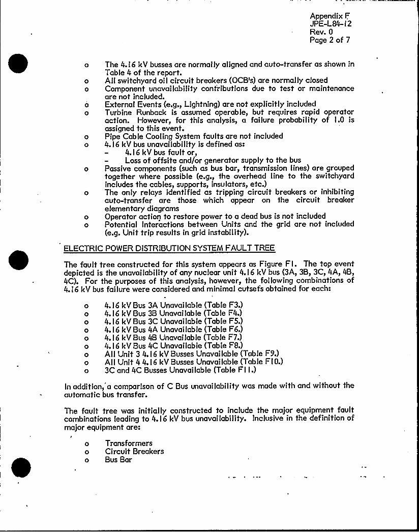
Appendix FJPE-L84- I 2Rev. 0Page 2 of 7
The 4. I 6 kV busses are normally aligned and auto-transfer as shown inTable 4 of the report.Allswitchyard oil circuit breakers (OCB's) are normally closedComponent unavailability contributions due to test or maintenanceare not included.External Events (e.g., Lightning) are not explicitly includedTurbine Runback is assumed operable, but requires rapid operatoraction. However, for this analysis, a failure probability of I.0 isassigned to this event.Pipe Cable Cooling System faults are not included4. I6 kV bus unavailability is defined as:
4. I 6 kV bus fault or,Loss of offsite and/or generator supply to the bus
Passive components (such as bus bar, transmission lines) are groupedtogether where possible (e.g., the overhead line to the switchyardincludes the cables, supports, insulators, etc.)The only relays identified as tripping circuit breakers or inhibitingauto-transfer are those which appear on the circuit breakerelementary diagramsOperator action to restore power to a dead bus is not includedPotential Interactions between Units and the grid are not included(e.g. Unit trip results in grid instability).
ELECTRIC POWER DISTRIBUTIONSYSTEM FAULTTREE
The fault tree constructed for this system appears as Figure Fl. The top eventdepicted is the unavailability of any nuclear unit 4. I6 kV bus (3A, 3B, 3C, 4A, 4B,4C). For the purposes of this analysis, however, the following combinations of4. I 6 kV bus failure were considered and minimal cutsets obtained for each:
4. I6 kV Bus 3A Unavailable (Table F3.)4. I 6 kV Bus 3B Unavailable (Table F4.)4. I6 kV Bus 3C Unavailable (Table F5.)4. I6 kV Bus 4A Unavailable (Table F6.)4. I 6 kV Bus 4B Unavailable (Table F7.)4. I6 kV Bus 4C Unavailable (Table FS.)AlI Unit 3 4. I 6 kV Busses Unavai lab le (Table F9.)All Unit 4 4. I6 kV Busses Unavailable (Table FI 0.)3C and 4C Busses Unavailable (Table F I I.)
In addition, a comparison of C Bus unavailability was made with and without theautomatic bus transfer.
The fault tree was initially constructed to include the major equipment faultcombinations leading to 4. I6 kV bus unavailability. Inclusive in the definition ofmajor equipment are:
o Transformerso Circuit Breakerso Bus Bar


Appendix FJPE-L84- l 2Rev. 0Page 3 of 7
Disconnect SwitchesCableOverhead Transmission LinesPipe Cable
Events which challenge the automatic transfer capability of bus power supply areexplicitly included (i.e. Reactor/Turbine Generator Trip results in demand fortransfer of A and B bus supply from the Auxiliary to the Startup Transformer).The relays which effect this auto-transfer were also included in the fault model.The intent of this additional level of detail is to identify combinations ofprotective relay failures leading to bus unavailability and potential commonmode failures such as occurred on the February l2, l984 Turkey Point Unit 3 and4 trips.
The fault model boundaries are identical to those of the FMEA. tncluded are the4. I 6 kV busses, their normal and alternate power supplies, the Turkey Point Plantswitchyard and the offsite transmission lines. Bus or supply faults incombination with a single stuck circuit breaker were considered. A fault incombination with failure of the primary and secondary fault clearing breakerswas not considered and not modelled.
FAULT TREE STRUCTURE
This section describes the structure of the electric power distribution systemfault tree (Figure Fl). 4.I6 kV busses 3A, 3B, 4A and 4B have similar equipmentarrangements (supply components, protective and auto-transfer relaying) as dobusses 3C and 4C. The fault logic is described below for busses 3A and 3C and istypical of the other busses.
Bus 3A Fault Lo ic
Bus 3A is normally supplied through the No. 3 Auxiliary Transformer when theunit is on-line. Any event causing Reactor/Turbine-Generator (RTG) trip willresult in an attempt to automatically transfer supply- to the No. 3 StartupTransformer. However, local bus faults or certain signals resulting in spuriousopening of circuit breaker 3AA52 will deenergize the bus and not permit auto-transfer. The top logic of the bus sub-tree reflects this arrangement. The event"Bus 3A Deenergizes/Lockout" identifies th'e single failures and spurious relayactions which do not allow auto-transfer. The event "3A Supply Failure" thendevelops the combinations of events which result in failure of both the normal(Aux. Transformer) and alternate (Startup Transformer) supplies. As discussedabove, any event leading to RTG trip will result in an auto-transfer attempt. Aninteraction between busses exists here since failure of the normal 3A or 3B bus
supply or failure of 3C bus supply (with turbine runback failure) will result inRTG trip and subsequent loss of the 3A bus normal supply. This logic is modeledunder the event "Unit 3 RTG Trip (3A)".
The alternate supply to bus 3A can fail if the normal supply breaker (3AA iIl2)
sticks closed, if there are faults in the auto-transfer circuitry, or if the alternatesupply is unavailable. Faults developed under these events include relay failures(auto-transfer), alternate supply breaker (3AA95) opens spuriously followingauto-transfer and Startup Transformer and its.supply. faults..


Appendix FJPE-L84- I 2Rev. 0Page 4of 7
Supply failures to both the Startup and Auxiliary Transformers are developedback to the Switchyard bays. The protective relay logic is modeled implicitlyhere. A fault occurring on a switchyard bus is assumed to result in opening of alloil circuit breakers (OCB's) required to clear the fault. If one OCB sticks closed(in response to a fault event), the next (OCB's) required to clear the fault isassumed to open. Using this implicit logic, single and double faults resulting inloss of Transformer supply are identified. In addition, to identify potentialcommon mode failures, single and double faults which result in loss of the east orwest bay supply to a transformer were modeled. For example, a fault on theUnits I and 2 Startup Transformer in combination with a stuck OCB 4B willresult in a loss of east supply to both the /83 Startup Transformer and the N3CTransformer. The west supply of these transformers remains energized,however, and additional faults are required to lose the west supply.
Bus 3C Fault L ic
Bus 3C is similar to 3A in that there are a number of local bus or spurious relayaction faults which may result in deenergization of the bus without permittingauto-transfer. The 3C bus supply does not auto-transfer on RTG trip. Loss ofthe 3C transformer or its supply will initiate an auto-transfer to a secondarywinding of the 4C transformer. The fault sub-tree develops faults of the normaland alternate supply as well as faults of the auto transfer circuitry. Theswitchyard bay faults developed are similar to those of Bus 3A.
FAULTTREE EVENT QUANTIFICATION
The fault tree allows an estimate of the numerical system failure probability tobe calculated by combining the system s equipment failure probabilities. For thisanalysis, the distribution system average unavai lab ility is the parametercalculated. Unavailability. is defined as the probability that the system orequipment is unable to perform its intended function. For this system, most ofthe equipment is normally energized with some equipment in standby (StartupTransformers and associated circuit breakers). To calculate the averageunavailability of a normally in-service component the following equation is used:
A xADTBBBII
where
ADT =
Average Unavailability
Equipment Failure Rate (failure/year)
Average Equipment Down Time (hours)
The primary data source for both failure rates and down time was IEEE-STD-493-l980 (Reference I). Turkey Point Plant Startup/Shutdown Logs were used toobtain information about the Reactor/Turbine-Generator trip frequency andsubsequent outage duration. EPRI-NP-2230 (Ref. 4) was used to obtain thespurious Safety Injection frequency.

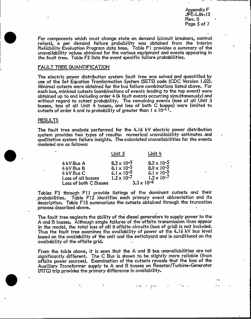
Appendix FJPE-L84- I 2Rev. 0Page S of 7
For components which must change state on demand (circuit breakers, controlrelays), a per demand failure probability was obtained from the InterimReliability Evaluation Program data base. Table Fl provides a summary of theunavailability values obtained for the various equipment and events appearing inthe fault tree. Table F2 lists the event specific failure probabilities.
FAULT TREE QUANTIFICATION
The electric power distribution system fault tree was solved and quantified byuse of the Set Equation Tranformation System (SETS) code (CDC Version I.02).Minimal cutsets were obtained for the bus failure combinations listed above. Foreach bus, minimal cutsets (combinations of events leading to the top event) wereobtained up to and including order 4 (4 fault events occurring simultaneously)
and'ithoutregard to cutset probability. The remaining events (loss of all Unit 3busses, loss of all Unit 4 busses, and loss of both C busses) were limited tocutsets of order 4 and to probablllt'y of greater than I x I0-I I
RESULTS
The fault tree analysis performed for the 4.I6 kV electric power distributionsystem provides two types of results: numerical unavailability estimates andqualitative system failure insights. The calculated unavailabilities for the eventsmodeled are as follows:
Unit 3 Unit 4
4kVBus A4kV Bus B4kV Bus CLass of all bussesLoss of both C Busses
8.3 x l0-5 8.2 x IO-S8.l x lo-5 8,0 x Io-S6.I x IO-5 6.I x IO-SI.2 x I0-7 l.2 x IO-7
3.3 x IO-6
Tables F3 through Fl I provide listings of the dominant cutsets and theirprobabilities. Table FI2 identifies each primary event abbreviation and itsdescription. Table FI3 summarizes the cutsets obtained through the truncationprocess described above.
The fault tree neglects the ability of the diesel generators to supply power to theA and B busses. Although single failures of the offsite transmission lines appearin the model, the total loss of all 8 offsite circuits (loss of grid) is not included.Thus the fault tree examines the availability of power at the 4.I6 kV bus levelbased on the availability of the unit and the switchyard and is conditional on theavailability of the offsite grid.
From the table above, it is seen that the A and B bus unavailabilities are notsignificantly different. The C Bus is shown to be slightly more reliable (fromoffsite power sources). Examination of the cutsets reveals that the loss of theAuxiliary Transformer supply to A and B busses on Reactor/Turbine-Generator(RTG) trip provides the primary difference in availability.

0

Appendix FJPE-L84- I 2Rev. 0Page 6 of 7
The dominant cutsets for A and B busses of both units are identical. Thefollowing six events contribute 88% of the total bus unavailability:
a) Inadvertent Opening of the Normal Supply Breaker (4I%)(3AAg2SPR, 3AB92SPR, 4AA92SPR, 4ABg2SPR)
b) Local Bus Fault causing Bus Lockout (30%)(B3ALF, B3BLF, B4ALF, B4BLF)
c) Unit Trip with Startup Transformer Unavailable (6%)(U3TR x 3SUXMERF, U4TR x 4SUXMERF)
d) Unit Trip with Failure of Startup Feeder Breaker To Close (4%)(U3TR x 3AA95LCL, U3TR x 3AB95LCL, U4TR x 4AA95LCL,U4TR x 4AB95LCL)
e) Unit Trip with Failure of Auxiliary Transformer Feeder Breaker to Open(4%)(U3TR x BK3AAg2SC, U3TR x BK3AB92SC, U4TR x BK4AA52SC,U4TR x BK4ABg2SC)
f) Startup and Auxiliary Tran'sformer Unavailable (3%)(3AXMERF x 3SUXMERF, 4AXMERF x 4SUXMERF)
The remaining cutsets each contribute less than 2% to the total busunavailability. Cutsets 24 through 3I (2l through 28 for Busses 4A and 4B)represent spurious relay actions which open the normal supply breaker and do notpermit auto-transfer to take place.
The dominant cutsets for the C Busses are also identical. They include thefol lowing:
a) Inadvertent Opening of the Normal Supply Breaker (55%)(3AC I 6SPR, 4AC I 6SPR)
b) Local Bus Fault (3 I%)(B3CLF, B4CLF)
c) 3C and 4C Transformers Unavailable (4%)(4CXMERF x 3CXMERF)
d),Faulted Normal Supply Transformer and Alternate Supply Breaker Fails toClose (3%)(3CXMERF x 3ACSILCL, 4CXMERF x 4ACSILCL)
e) Faulted Normal Supply Transformer and Normal Supply Breaker Fails toOpen (3%)(3CXMERF x BK3ACI6SPR, 4CXMERF x BK4ACI6SPR)
The remaining cutsets contribute, less than l% each to the total busunavailability. Note that cutsets IO through l6 are single events leading to busunavailability. These events are spurious relay actions which trip the normalfeed breaker without allowing auto-transfer.

0

Appendix FJPE-L84- I 2Rev. 0Page 7 of 7
Simultaneous loss of offsite power to the three 4.I6 kV busses of a unit isdominated by the following two scenarios:
a) Inadvertent Opening of Normal Feeder Breaker to 3C Bus, Failure of theUnit to Runback (Unit Trips) and Unavailable Startup Transformer (47%)(3AC I6SPR x U3TRF x 3SUXMERF, 4AC I 6SPR x U4TRF x 4SUXMERF)
b) Local C Bus Fault/Lockout, Failure of the Unit to Runback and UnavailableStar tup Transformer (26%)(B3CLF x U3TRF x 3SUXMERF, B4CLF x U4TRF x 4SUXMERF)
The remaining major cutsets are similar to the above in that they involve afaulted C Bus (with no auto-transfer permitted), failure of turbine runback andan unavailable Startup Transformer or its supply. As noted above, the turbinerunback failure probability was assumed to be I.O for this study. Since alldominant cutsets contain this term, an improvement in the reliability of runbackwould have a major benefit in preventing loss of offsite power to the 4.I6 kVbusses.
The simultaneous unavailability of both C busses is dominated by'heunavailability of both C transformers(78%) (4CXMERF x 3CXMERF). Theremaining cutsets generally involve the unavailability of one C transformer incombination with faults in the supply to the other C tranformer.
Although a fault tree was not constructed for the C Bus without auto-transfer,the unavailability of such a scheme can be estimated by consicaering the majorequipment unavailabilities:
Failure Event
C Bus Local FaultSupply Breaker Opens (Spur.)Transformer UnavailablePipe CableDisconnect Switch (x2)
~Probabilit
1.9 x IO-53.4 x I 0-5l.6 x IO-32e5 x IO-5l.2 x I 0-4I~8x lg
Comparing this value to that of a C Bus with auto-transfer shows anunavailibility improvement of almost two orders of magnitude by utilization ofthe auto-transfer feature.
References
I. IEEE-STD 493-I 980, IEEE Recommended Practice for Design ofReliable Industrial and Commercial Power Systems.
2. Component Failure Rates for Nuclear Plant Safety System ReliabilityAnalysis, Nuclear Regulatory Commission (Draft report issued9/23/80 for use by IREP).
3. NUREG - 0492, Fault Tree Handbook, January I 98l.
4. EPRI-NP-2230, ATWS: A Reappraisal, Part 3: Frequency ofAnticipated Transients. Electric Power Research Institute,January l982.


Appendix FJPE-L84-12Rev. 0
Bus:
E i ment/~Com nent
ABCIso PhaseSwitchyard
Failure ModeBA
Unavailabilit /Failure Probabili
2.5 x 10-52.3 x 10-51.9 x 10-53.6 x !0-66.0 x 10⁻⁶
Circuit Breaker(AII)
Transformer:MainAuxiliaryStartupC
Cab le: Swgr-Xmer (Aux., C)Swgr-Xmer (S/U)Overhead to Swyd.Pipe Cable
Disconnect Switch
Relays: ActivePassive
Fuses
Unit 3 RTG TripUnit 4 RTG Trip
Spurious Safety Injection
Turbine Runback Failure
Offsite Power Supplies(Single Circuit)
Unit I TG Trip
Unit 2 TG Trip
Stuck (Fail to Open)Failed in ServiceFailed To Close
Fail To TransferNC Contacts Fail Open
Fail Open
1.0 x 10-33.4 x 10-51.0 x 10 3
1.9 x 10<1.6 x 10-31.6 x 10-31.6 x 10⁻³
8.4 x 10-71.8x 10 6
2.5 x 10-52.5 x 10-5
6.1 x 10⁻⁵
1.0 x 10⁻⁴I.I x 10-7
1.2x 10 5
3.3 x 10-33.1 x 10-3
1.8 x 10⁻⁵
1.0
3.5 x 10⁻⁴
3.6 x 10⁻³
3.3 x 10⁻³
E i ment Unavailabilit Assumedor ault ree Quantification
Sht. I of I

Appendix FJPE-L"84-12Rev. 0
1+ 9E-52i3E-52o5E-52o3E-51+ 9E-52+5E-5
B3CLFB3RLFB4ALFR4RLFB4CLFB3ALF
4.16KV Bus Faults/
1 ~ 6E-3iebE-31 ~ 6E-3ii9E-41 ~ bE-31~bE-31 ~ 6E-31.9E-4iobE-3
3CXMERF4CXMERF3AXMERF3MXMERF4SUXMERF3SUXMERF4AXMERF4MXMERF12SUXFT
Transformer Faults
biOE-6boOE-6biOE-6boOE-6
SERFTSMBFTHEBFTN4IBFT
3. 1E-33.3E-33+3E-33+3E-3
U4TRU3TRU2FTU1FT
Switchyard. Bus Faults Unit Trip Unavailability
3 'E-43e5E-43.5E-43o5E-43oSE-43 'E-43s5E-43i5E-4
DAV3FTFLORFTFLAG2FTDAVlFTFLAG1FTDAV2FTDORFTDAD1FT
iiO1 oO
U3TRFU4TRF
Turbine Runback Failure
Transmission «Leone Faults
Table F2 - Electric Power Distribution System Fault Tree Basic EventProbabilities (Sheet 1 of 4)

0
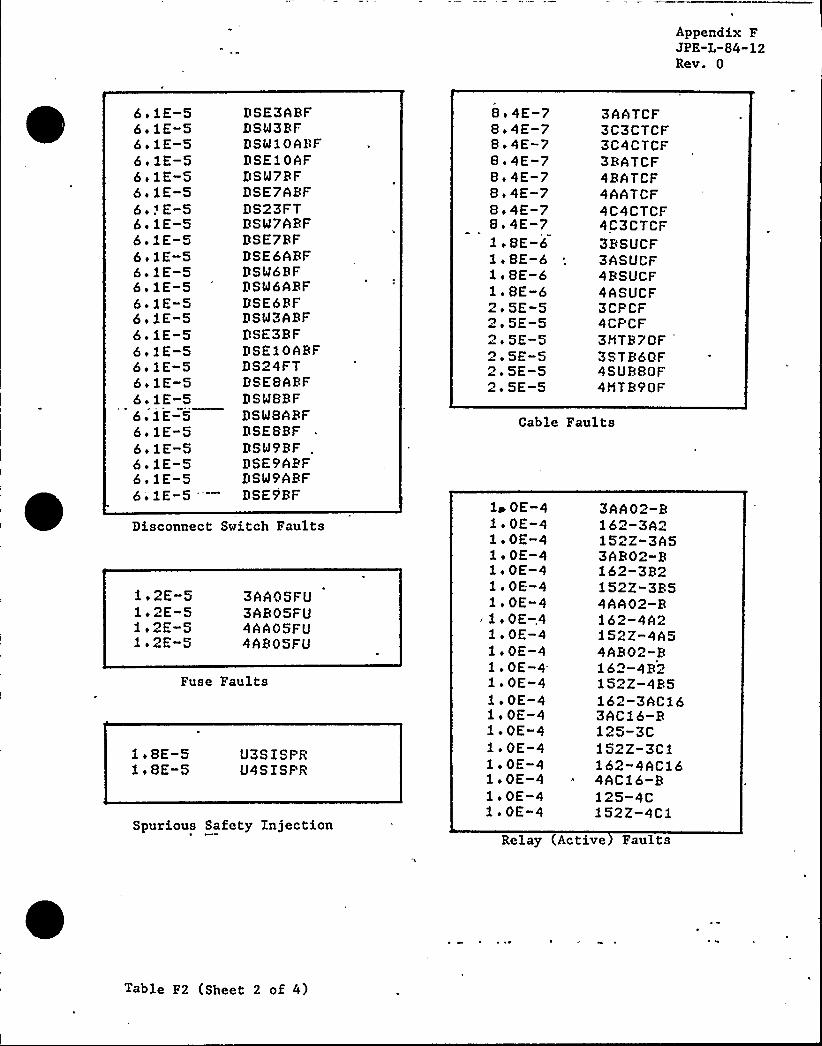
Appendix FJPE-L-84"12Rev. 0
6 o 1E-56o iE-56 'E-56 'E-56.1E-5bo 1E-56 ~ f E-5bolE-56 ~ 1E-56 o 1E-5bofE-56oiE-5boiE-56o iE-56 o 1E-56 ~ 1E-5SolE-56olE-56o lE-56 'E-56o iE-5bo 1E-56o 1E-56olE-56'1E-5'
DSE3ABFDSM3RFDSM10ABFDSE10*FDSW7RFDSE7ABFDS23FTDSM7ARFDSE7RFDSE6ARFDSM6RFDSM6ARFDSE6RFDSM3ABFDSE3RF9SElOARFDS24FTDSESARFDSWSRFDSWBABFDSESRFDSW9RFDSE9APFDSW'9ARFDSE9RF
Disconnect Switch Faults
io2E-51 o2E-5lo2E-51.2E-5
3AAOSFU3AB05FU4*A05FU4AB05FU
Fuse Faults
1 o SE-51 ~ SE-5
U3SISPRU4SISPR
Spurious Safety Injection
8.4E-7Bo4E-7So4E-7Bo4E-7Bo4E-78 'E-7Bo4E-78.4E-7loSE-6loBE 6USE-61.8E-b2+5E-52 'E-52 'E-52.5E-52 'E-52o5E-5
3AATCF3C3CTCF3C4CTCF3RATCF4RATCF4AATCF4C4CTCF4C3CTCF3BSUCF3ASUCF4RSUCF4ASUCF3CPCF4CPCF3NTB7QF
'STB60F
4SURBOF4HTB90F
Cable Faults
1& OE-41 ~ OE-41 oOE-41 ~ OE-4loOE-41 ~ OE-41 ~ OE-41 o OE-.41 o OE-41 ~ OE-41 ~ OE-4.1.0E-41, oOE-4ioOE-41 ~ OE-41 ~ OE-4ioOE-41 o OE-41 o OE-41 ~ OE-4
3AA02-R162-3A2152Z-3A53AR02-R162-3B2152Z-3R54AA02-R162-4A2152Z-4A54AB02"Rib~-4Ro152Z-4R5162-3ACfb3AC16-R125-3Cf52Z-3Clf. 62-4 AC164AC16-R125-4C152Z-4C1
Relay Active Faults
Table F2 (Sheet 2 of 4)

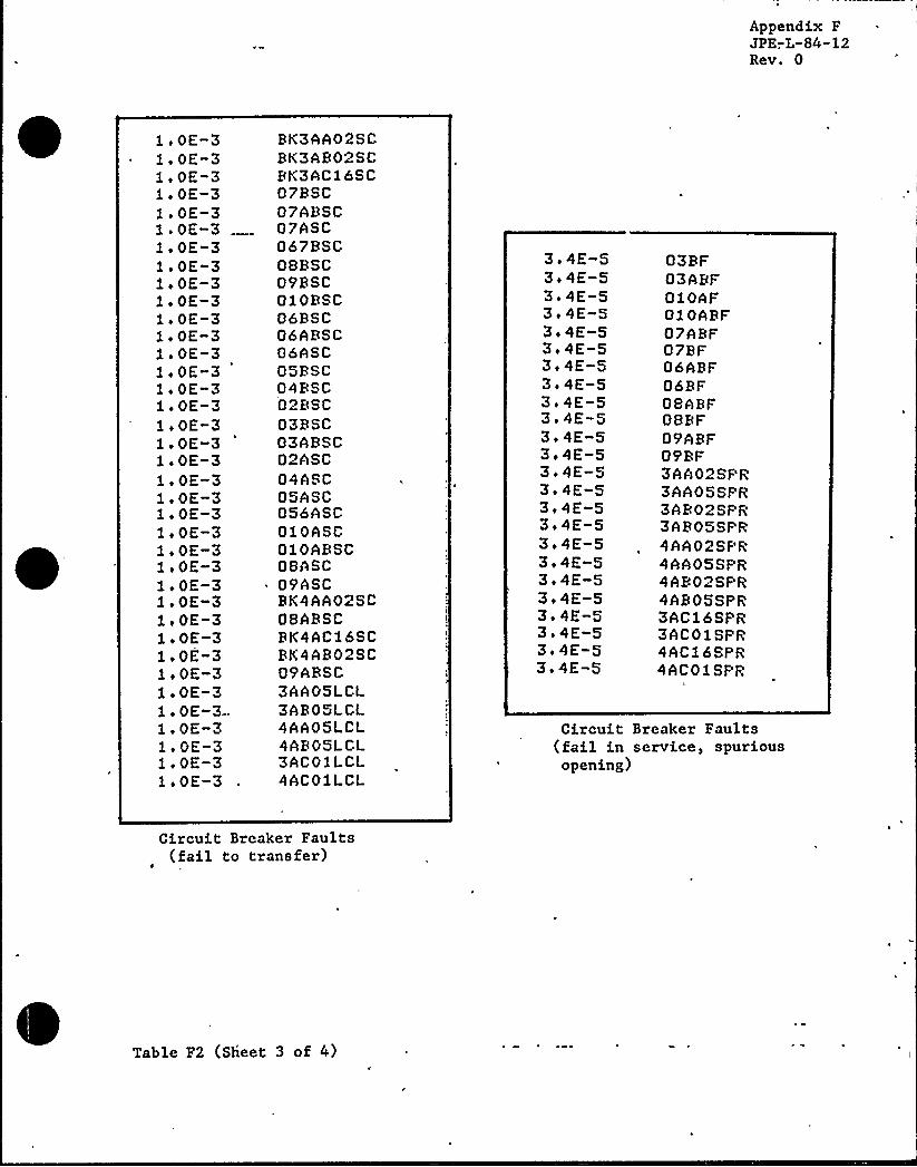
Appendix FJPE-,L-84"12Rev. 0
.OE-3
.OE-3
.OE-3~ OE-3.OE-3o OE-3,oOE-3oOE-3iOE-3iOE-3iOE-3+OE-3oOE-3+OE-3+OE-3iOE-3oOE-3.OE-3.OE-3~ OE-3~ OE-3+OE-3oOE-3+OE-3oOE-3iOE-3iOE-3iOE-3.OE-3~ OE-3oOE-3~ OE-3. OE-3-~ OE-3~ OE-3~ OE-3~ OE-3
RK3AA02SCRK3AB02SCBK3AC16SC07RSC07ARSC07ASC067BSC08RSC09RSC010BSC06RSC06ABSC06ASC05RSC04BSC02BSC03BSC03ARSC02ASC04ASC05ASC056ASC010ASC010ARSC08ASC
~ 09ASCRK4AA02SC08ARSCBK4AC16SCBK4AR02SC09ARSC3AA05LCL3AR05LCL4AA05LCL4*B05LCL3AC01LCL4AC01LCL
3+4E-53o4E-53o4E-53i4E-53o4E-53+4E-53 'E-53o4E-53.4E-S3o4E-53o4E-53i4E-53.4E-53o4E-53i4E-53o4E-53i4E-53+4E-53.4E-53e4E-53.4E-53o4E-53 'E-53.4E-5
03RF03ABF010AF010ARF07ARF07BF06ARF06RF08hBF08BF09ARF09BF3AA02SPR3AA05SPR3ARO>SPR3AROSSPR4AA02SPR4AA05SPR4AB02SPR4AB05SPR3AC16SPR3AC01SPR4AC16SPR4AC01SPR
h
Circuit Breaker Faults(fail in service, spuriousopening)
Circuit Breaker Faults(fail to transfer)
Table F2 (Sheet 3 of 4)


Appendix FJPE-L-84"12Rev. 0
1 ~ 1E-71. 1E-71 ~ 1E-7fofE-7iofE-7fofE-7l. 1E-71 ~ 1E-7foiE-71.1E-71.2E-7fofE-71 ~ 1E-7fofE-72 o iE-71. 1 E-7foiE-71 ~ 1E-71 ~ 1E-71 ~ 2E-72 ~ 1E-72 ~ 2E-7fifE-72 ~ 1E-72 iiE-7fofE-7iofE-71 o 2 E-72 i 1E-71 ~ 1E-71 ~ 1E-7foiE-71 o f,E-7ioiE-7
'.1E-7f.fE-71. 1E-71.2E-71. 1E-72.1E-7foiE-7fofE-71+ iE-72 o iE-72.1E-7
86GT-G3286-G3186X-3h150A3R151-A3A151-A3AiSI3-2 1X186-ST3127X1-3AR386RU-ST386G150-S3A1 51-S3132 51-S3A13
" 3A5152-HH186X-3R15093R252-R3A151-B3AiSI3R2f27Zi-3AR3150-S3R151-S383151-S3R133R5252-HH86GT-G4286-G4186X-4A150A4R152-A4Af51-A4A1.S14-12X186-ST4127X1-4AR386BU-ST486K150-S4A151-S3A4151-S3A244A5252-HH186X-4R250-R4R2 51-R4A152-R4A2SI4R2
fofE-71. 1E-71.1E-7fofE-71 ~ 1E-7fofE-7fiiE-7foiE-7fofE-7iofE-71 o 2E-72 o 1E-72 i 2E-72 iiE-71.1E-7fofE-7fofE-7fofE-7fofE-7iofE-72 + 1E-71 ~ lE-72 o iE-71 o iE-72 o iE-7ioiE-72+2E-7iiiE-7iofE-7iofE-7fofE-72 + iE-71. 1E-71.1E-71 o iE-71 ~ 2E-71. 1E-71. 1E-7fifE-7feiE-72+2E-72 o 1E-72 o 1E-7fofE-72+iE-7
2 27Z1-4AR3150-S4R151-S3R4 ~
151-S3R144R51 52-HH186-3C186-3CRT127X-3C186-EE86-FF150-3CRTX25f-3CRTX152-3CRTXl3152- TOC186-4CRT3AC03-R3AC13-R86-M86- Y150-4CBTYf 51-4CBTY152-4CRTY1186-4C127X-4C1150-4CBTX151-4CRTX151-4CBTXl4152- TOC4AC03-B4AC13-B152-3CRTY1150-3CBTY151-3CRTY174-4C2174-4C6174-3Cf174-3C6174-3A2174-3A5174-3R2174-3R5274-4A2174-4A5174-4R2174-4B5
Relay (passive) faults
Table F2 (Sheet 4 of 4)

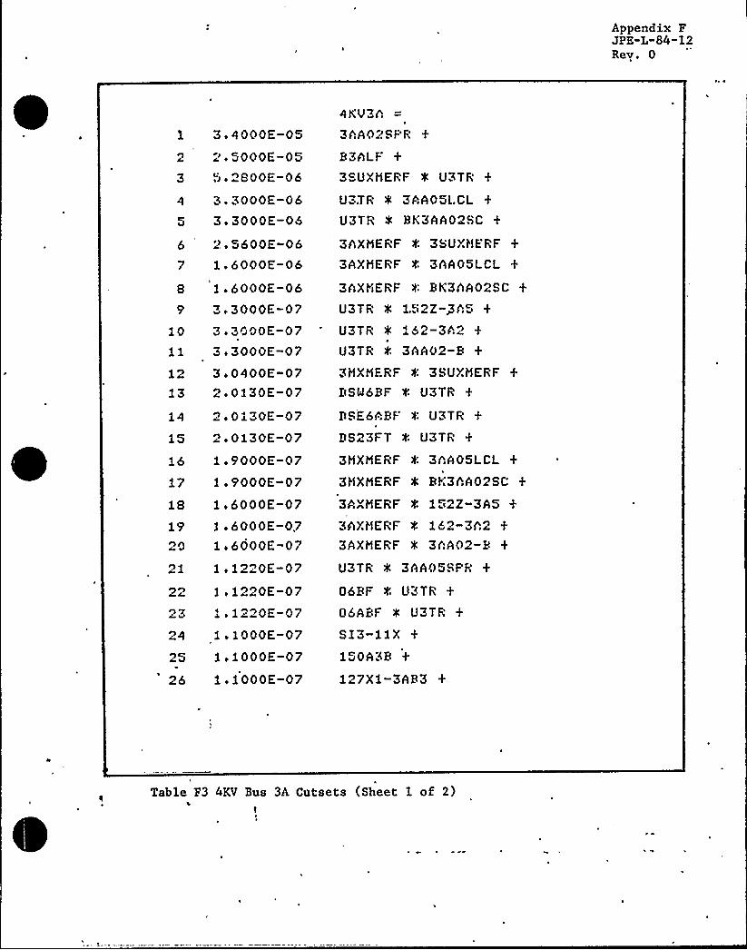
Appendix FJPE-L"84-12Rey. 0
21
26
1.6000E-07le1220E-07l . 1220E-071.1"20E-07lolOOOE-071,1000E-071.1000E-07
1 3.4000E-052 ".5000E-053 5.2SOOE-06
4 3.3000E-065 3.3000E-05
6 2 '600E-067 1.6000E-068 lo6000E-069 3.3000E-07
10 3.3000E-0711 3.3000E-0712 3o0400E-0713 2.0130E-07
14 ~oOliOE-0715 2+ 0130E-07
16 io9000E-0717 1.9000E-0718 ii6000E-0719 le 6000E-07
4KU3h3hA02Sl"R
B3hLF3SUXMERF '4 U3TR
U3TR 0 3AAOSLCL
U3TR 8K3AA02SC
3hXMERF f 3SUXHERF
3AXMERF f 3hA05LCL
3hXYiERF 4 BK3hA02SC
U3TR f 1.52Z-Ph5
U3TR 0 152-3h2U3TR il'AA02-B3HXMERF 0: 3SUXHERF
BSM6BF '4 U3TR
DSE6ABF 4 U3TR
DS23FT 4 U3TR
3MXMERF f 3AA05LCL
3HXMERF 4 BK3AA02SC
3*XMERF 4 1 2Z-3A53hXHERF '0 162-3h23AXMERF 0 3AA02-8 +
U3TR 0 3AAOSSPR +
06BF f. U3TR +
06ABF 0 U3TR +
SI3-liX150A3B
127Xi-3AB3
Table F3 4KV Bus 3A Cutsets (Sheet 1 of 2)'
t

hppendix FJPE-L-84-12Rev. 0
27 1.1000E-0728 1.1000E-0729 5 o 1000E-07
30 iiiOOOE-0?31 1 i 1000E-0?32 9.7600E-OS33 9o?600E-OB
34 9,7600E-OS35 9.7600E-OS
36 9.7600E-OS37 8>2500E-0838 6.1000E-0839 6~1000E-08
40 6.1000E-OB45. 6olOOOE-08
42 5.4400E-OS43 5i4400E-0844 5.4400E-OS
45 5.4400E-OB
46 5o4400E-0847 5o4400E-OS
4 'a 440'OE-0
49 4.0000E-OS50 4oOOOOE-08
174-3A55 55 -h3h1 +
186X-3h574-3A2151-P.'3h
3AXHERF 0 DSMbBF
3AXNERF f. DSEbABF
3AXNERF 0 DS23FT +
DSE?ABt P 3SUXMERF
DSM7BF f. 3SUXHERF +
3STB60F 0 U3TR
DSE7ABF t. 3AA05l.CLDSM7BF t 3hA05l.Cl.. +
DSE7ABF 0 BK3hA02SC
DSM7BF 0 BK3AA02SC
3AXHERF 4 3AA05St"R
3AXNERF 0 06BF +
3AXHERF f. 06ABF +
3SUXHERF 0 3AB02SPR
0?RF 4 3SUXNERF07ABF 0 3SUXNERF
3SUXHERF ~: U.TRF 8 3hC56SF'R
3hXNERF 4 3&iTB60F3HTB70F 0 3SUXNERF
Table F3,(Sheet 2 of 2)


Appendix FJPE-L-84"12Rev. 0
1 8.4000E-052'000E-05
3 5.2800E-063.3000E-06
5 3.3000E-066 2i5600E-067 1.6000E-068 1.6000E-06
3.3000E-07
10 3 8000E-0711 3o3000E-07
12 3.0400E-07
13 2. 0130E-07
14 ", i 0130E-0715 2 i 0130E-0716 1.9000E-0717 li9000E-0718 1+6000E-0719 iobOOOE-07-
20 libOOOE-0721 1 o 1220E-07
22 1 . 1220E-07
23 . 1.1220E-0724 ieiOOOE-07
25 1 e 1000E-0726 1.1000E-07
4KV3B
3AB02SPR
B3BLF
3SUXMERF 0 U3TR
U3TR 0 3AB05LCLU3TR 0 BK3AB02SC +
3AXMERF 0 38UXMERF
3AXMERF '4'AB05LCL3AXMERF 0 BK3AB02SC
\
U3TR 4 152Z-3B5
U31R 0 lb"-~B"U3TR t. 3AB02-B
3HXMERF '4 38UXMERF
DS4lbBF 4 U3TR
DSE6ABF 4 U3TR
DS23FT 0 U3TR +
3MXMERF 0 3AB05LCL
3MXMERF 0 BK3AB02SC
3AXMERF '4 152Z-3853AXMERF 0 162-3823AXMERF e 3AB02-B +
U3TR t. 3AB05SPR +
06BF 0 U3TR +
06ABF 0 U3TR
SI3B2150B3B
i27Z]-3AB3 +
Table F4 4KV Bus 3B Cutsets (Sheet l of 2)
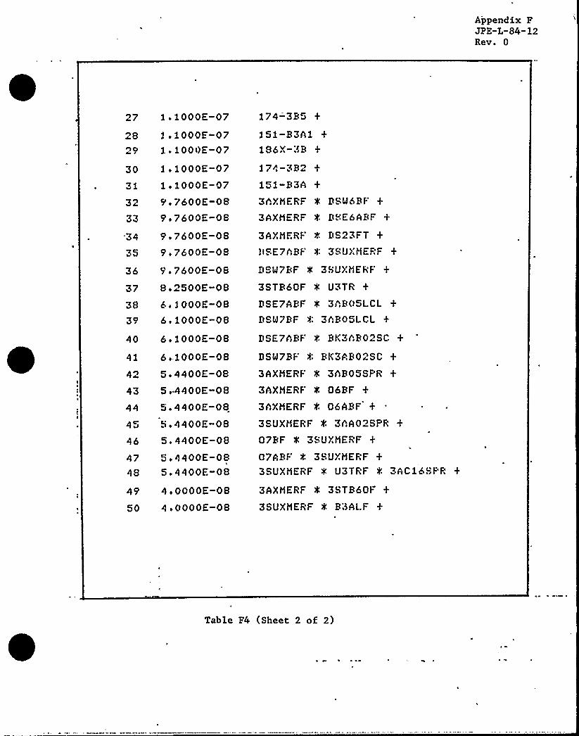
Appendix FJPE-L-84-12Rev. 0
27 lo1000E-0728 ls2000E-0729'.1000E-0730 1 i 1000E-0731 1 i 1000E-07
32 5' 7600E-0833 5'.7600E-08'34 5'.7600E-0835 9.7600E-OS
36 9.7600E-OS
37 8+2500E-0838 6 ~ 1000E-0835'. 1000E-08
40 6. 1000E-08
41 6.,1000E-OS
42 5 '400E-0843 5o4400E-0844 5 '400E-0845 5i4400E-0846 5,4400E-0847 5+4400E-084S 5.4400E-OS
45'iOOOOE-0850 4 i OOOOE-08
174-3B5
151-B3A11S6X-3B
l?4-3B2151-B3A3hXMERF '4 DSM6BF
3AXMERF 0 DHE6ABF
3AXMERF DS23FT
llSE?hBF 0: 3SUXMEPF
DSM?BF 0 3SU>,'MERF +
3STB60F 0 U3TR
DSE7ABF f. 3hB05LCLDSM?BF 0: 3hBOSLCL
DSE7ABF 0 BK3hB02SC
DSW?BF '4 BK3AB02SC
3AXMERF 0 3AB05SPR
3hXMERF t 06BF
3AXHERF f. 06ABF +
3SUXMERF '4 3hAO2SPR
07BF 0 3SUXMERF
07ABF f 3SUXHERF3SUXMERF 0 U3TRF 4 3ACibSPR
3AXHERF 0 3STB60F
3SUXHERF 0 B3ALF
Table F4 (Sheet 2 of 2)

Appendix FJPE"L"84"12Rev. 0
6
iobOOOE-06lebOOOE-07
7 1.6000E-07iibOOOE-07
2 i6000E-0710 io2000E-07
2 '7
1. 1000E-072oiOOOE-07
13 1.1000E-0714
15
ii2000E-07iilOOOE-07
16 1.2000E-0717 9 '600E-0828 9+7600E-0819 9i7600E-0820 9.7600E-OS
6.1000E-OS.6 1000E-08
1 3 '000E-051 ~ 9000E-052 '600E-06iibOOOE-06
4KV3C
3AC26SPR
B3CLF
4CXMERF 4 3(:XHERF
3CXMFRF 4 3AC02LCL3CXHERF 0: RK3AC16SC
3CXMERF 0 252Z-3C23CXHERF f l25-3C +
3CXMERF 4 3AC26-B
3CXMERF '4 162-3hC26
252-3CRTX
150-3CBTX
127X-3Cl186-3C +
174-3C6
151-3CBTX1174-3C1
DSE1 OAF 0 3CXHERF
DSW10ABF f. 3(:XHERF
4CXHERF t. DSW3BF +
4CXMERF 0 DSE3ABF
DSW3BF 0 3AC01LCLDSE3ABF 0 3AC01LCL
2324
26
6.1000E-OS6 1000E-OS
5.4400E-OS
5.4400E-08
DSW3BF 0 BK3AC16SC +
DSE3ABF t BK3AClbSC
020ABF f. 3(:XHERF
020AF f. 3(:XMERF +
Table F5 4KV Bus 3C Cutsets (Sheet 1 of 2)


Appendix FJPE-L-84"12Rev. 0
27 bi4400E-08
28 5.4400E-0829 5+4400E-08
30 4.0000E-0831 4iOOOOE-0832 3i4000E-08
33 > 3i4000E-0834 3o4000E-08
35 '3.4000E-0836 ~.5000E-08
37 2i5000E-0838 bo1000E-0939 belOOOE-0940 6.1000E-09
41 . biiOOOE-0942 bo1000E-'09
43 boiOOOE-0944 boiOOOE-09
45 6.1000E-0946 3o7210E-09
47 3i7210E-0948 3,7210E 0
49 . 3 i7210E-0950 3i4000E-09
3GXNERF f 3hCG1SPR
4CXNERF f. 03ABF
4CXMERF 0 03RF
4CPCF '4 3CXNERF
4CXHERF '4 3CPCF
03ARF 0 3hC01LCL
03RF 4 3ACOiLCL03ARF 0 RK3hCibSC
O3RF f. BK3AC16SC
3CPCF 0 3AC01LCL
3CPCF 0 Rfi3AC16SC
DSM3RF 'f 1522-3ClDSE3ABF 0 1527-3f:1DSM3RF 0 125-3C
DSE3ABF t 125-3CDSM3RF f 3AC16-B
DSE3ARF f 3AC16-BDSM3RF 0 162-3AC16
DSE3ABF f 162-3AG16
DSM3BF 4 DSE10AF
DSE3ABF 0 DSE1 OAF
DSW3BF f DSM.'.OABF
DSE3APF 0 D&MiOARF
03ARF >l: 1:?5-3C
Table F5 (Sheet 2 of 2)

Appendix FJPE-L-84-12Rev. 0
3o4000E-052i5000E-054+9600E-06
4 3iiOOOE-06
3ifOOOE-066 2.5600E-067 ii6000E-068 1.6000E-069 3ifOOOE-07
f0 3 '000E-07ll 3.1000E-07
3.0400E-0713 1.9000E-0714 1.9000E-0715 1.8910E-0716 ii8910E-0717 ie8910E-07
4KV4A
4AA02SPR
B4ALF
4SUXMERF t U4TR +
U4TR 0 4AAOSLCL
U4TR 0 BK4AA02SC
4SUXMERF 0: 4AXMERF
4AXMERF f. 4AAOGLCL
4AXMERF 4 BK4hA02SC +
U4TR 4 1"'<~Z-4C'I
U4TR 0 162-4A2U4TR 4 4AA02-B
4SUXMERF 0 4MXMERF
4MXMERF 0 4Ah05LCL4MXMERF 8 BK4hh02SCU4TR t. DSMBRF
U4TR 0 DSEBABF
U4TR 4 DS24FT +
f8
'0 0
fibOOOE-071.6000E-071.6000E-07
4AXMERF f 152Z-4A54AXMERF 0 162-4A24AXMERF 4 4AA02-B
1+fOOOE-07 '50A4B
g C'sl iefOOOE-07
1.1000E-07
1.1000E-071 ~ 1000E-07
24 f.fOOOE-07
SI4-1 f~127Xf-4AB3174-4A5186X-4A
f51-h4A1
Table F6 4KV Bus 4A Cutsets (Sheet 1 of 2)

I

Appendix FJPE"L-84-12Rev. 0
27 ioiOOOE-07
28 1 ~ 1000E-0729 li0540E-0730 io0540E-0731 1,0540E-0732 9+7600E-0833 9o7600E-0834 9i7600E-08
35 9.7600E-OS
36 9i7600E-0837 7i7500E-0838 6. 1000E-08
39 6 o 1000E-08
151-A4h174-4A2U4l R 4 4AA05SF'R
U4TR f OBBF
U4TR e OHABF
4AXMERF 4 DSLJBBF +
4AXMERF 0 DSEPABF +
4AXMFRF 0 DS24FT
4SUXMERF 0 DSE9ABF
4SUXMERF 4 DSW9BF
U4TR 0 4SURSOF +
DSE9ABF 4 4AA05LCL
DSW9BF 0: 4AA05LCL
40 6.1000E-OS DSF9ABF 4 BK4hAO SC +
.41 6+ 1000E-0842 5o4400E-08
43 5.4400E-OS44 5o4400E-08
45 5+440OE-08
46 5 '400E-0847 5o4400E-08
48 5i4400E-08
49 4.0000E-OS
50 4.0000E-OS
DSM9BF '4 BK4AA02SC
4AXMERF 0 4AA05SPR
4AXMERF 0 OSBF
4AXMERF 0 OSABF
4SUXMERF 0 4hB02SF'R
4SUXMERF 0 09BF
4SUXMERF 0 09ABF
4SUXMERF 0 U4TRF 4 4AC16SPR +
4AXMERF 4 4SUBSOF
4SUXMERF 4 4MTB90F
Table F6 (Sheet 2 of 2)


Appendix FJPE-L-84-12Rev. 0
1 3 o 4000E-052 2o3000E-053 4i9600E-064 3.1000E-055 3i2000E-066 2e5600E-067 iibOOOE-068 2,5000E-C6
9 3+2000E-072 0 3. 1000E-07ll 3o2000E-0712 3.0400E-0713 2+900OE-0714 f.9000E-0715 1.8910E-0716 1.8910E-0717 ii891OE-07
4KV4B
4AR02SPR
84RLF
4SUXMERF 0 U4TR
U4TR 0 4AR05LCL
U4TR f RK4hB02SC +
4SUXMERF 4 4hXMERF
4AXMERF 0 4AR05LCLOAXMERF 0 RK4hR02SC +
'U4TR f 152Z-4R5U4TR 0 162-4R2 +
U4TR t 4AB02-B4SUXMERF 0 4MXMERF
IMXMERF f. 4AR05LCL4MXMERF '4 RK4AB02SC
U4TR f. DSW8BF +
U4TR 0 DSEBABF
U4TR 4 D824FT18 3+6000E 07 4AXMERF 0 152Z 4R5
19 1+6000E-0720 2 '000E-0721 iiiOOOE-0722 ii2000E-0723 ii2000E-0724 2,2000E-0725 .2iiOOOE-07
26 1 i 1000E-07
4AXMERF 0 162-4R24AXMERF f 4AB02-R,+250-R4R
Sr4R2 +
127Z1-4AR3
174
186X-4R
151-R4Ai
Table F7 4KV Bus 4B Cutsets (Sheet 1 of 2)


Appendix FJPE-L"84-12Rev. 0
l9
1, 1000E-0?
l i1000E-0?1.0540E-07
151-B4A174"4P2U4TR 0 4hBOSSPR
30 ' i 0540E-07io0540E-079o?600E-08
33 9.7600E-OB34 9+7600E-08
9.7600E-OB36 9i?600E-0837 ?i?500E-0838 6.1000E-OS
394041
6 i 1000E -08b. 1000E-086 o 1000E-08
47 5.4400E-OB5.4400E-OB
49 4eOOOOE-08
50 4oOOOOE-08
42 5i4400E-0843 5+4400E-08
44. 5i4400E-OB.45 5i44QOE-0846 5.4400E-OB
U4TR 0 OBBF +
U4TR 0 08ABF +
4AXHERF 0 DSMBRF
4AXHERF 0 DSEBABI-
4AXRERF 0 DS24FT
4SUXMERF 4 DSE9ABF
4SUXtlERF 0 DSM98F +
U4TR 4 4SUBBOF
DSE9ABF 0 4ABOSLCL
DSM'9BF 4 4AB05LCL
DSE9ABF f BK4AB02SCDSM9BF 0 BK4AB02SC
4AXHERF 4 4ABOSSPR
4AXHERF 0 088F +
4AXNERF 0 OBABF
4SUXMERF 4 4AA02SPR
4SUXllERF 'k 09BF
4SUXMERF 0 09ABF
4SUXNERF 4 U4TRF f 4AC16SPR
4AXNERF 0 4SUBBOF
4SUXNERF 0 B4ALF
Table F7 (Sheet 2 of 2)
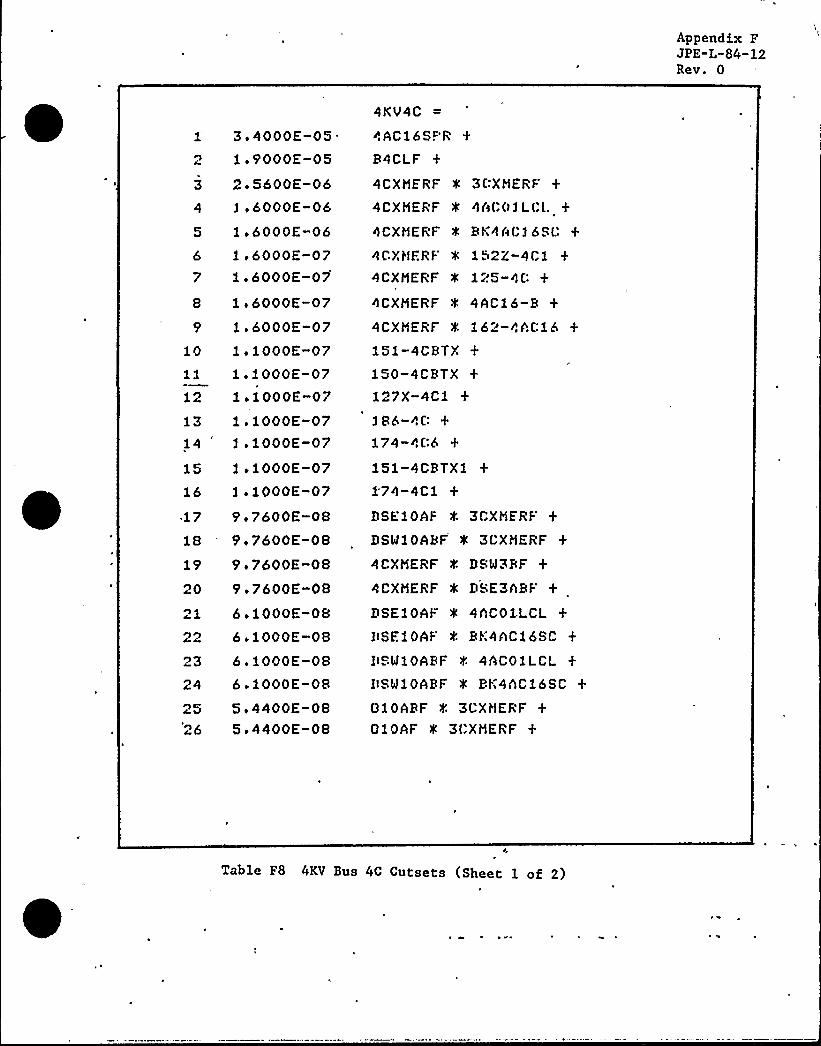
Appendix FJPE-L-84-12Rev. 0
3
3 '000E-05.1 i 9000E-052.5600E-06iobOOOE-06
5 iobOOOE-066 1 ibOOOE-077 1+6000E-07
8 lobOOOE-07
9 1.6000E-0710 liiOOOE-07
loiOOOE-071 iiOOOE-07
4KV4C
4AC16SPR
R4CLF
4CXMERF 0 3CXMERF
4CXMERF 0 4A(:01L(:L
4CXMERF '4 BK4AC16SC
4CXMFRF 0 152i-4C14CXMERF 0 125-404CXMERF 0 4AC16-R
4CXMERF f. 162-4AC16 +
151-4CRTX150-4CRTX127X-4C1
13 loiOOOE-07 186-4C14 1 ~ 1000E-07
15 1 i iOOOE-07
16 1 i 1000E-07-17 9+7600E-0818 9o7600E-08
174-406151-4CBTX11'74-4C1
DSEiOAF f 3CXMERF
DSM10ARF 0 3CXMERF +
19 9 '600E-08 4CXMERF 0 DSM3BF
20
)3
2526
9e7600E-086+1000E-086 '000E-08boiOOOE-086 '000E-085i4400E-085.4400E-08
4CXMERF 0 DSE3ARF
DSE10AF 4 4hC01LCL
IISE10AF 4 BK4hC16SC
IISM10ARF 0 4ACOlLCLIISMiOARF f BK4hC16SC
010ARF f 3CXMERF
010AF 0 3(:XMERF
Table F8 4KV Bus 4C Cutsets (Sheet 1 of 2)


Appendix pJPE L"84-12Rev. 0
5 4400E-0828 5.4400E-08
29 5,4400E-0830 4iOOOOE-08
31 4+OOOOE-08
32 3.4000E-0833 3e4000E-0834 3.4000E-0835 3.4000E-0836 r?i5000E-08
37 2.5000E-0838 6+ 1000E-09
39 6+ 1000E-0940 6.1000E-0941 6 i 1000E-0942 6oiOOOE-0943 6 ~ 1000E-0944 6olOOOE-09
45 6+1000E-09
46 3i7210E-0947 3.7210E-09
48 3.7210E-0949 3. 7210E-0950 3i4000E-09
4CXMERF f. 4hCOiSPR4CXMERF f 03ABF
4CXMERF f. 03RF
4CPCF 4 3CXMERF
4CXMERF 0 3CPCF
010ABF f. 4hC01LCL
010ABF 0 RK4hC16SC010AF 4 4ACOlLCL
010AF 0 BK4AC15SC
4CPCF 4 4hCOiLCL
4CPCF 0 BK4AU16SCDSE10AF 0 152Z-4C1
DSEiOAF 4 125-4CDSE10AF 4 4hC16-RDSE10AF 0 162-4AC16DSMiOABF 0 1. 2Z-401DSMiOABF 0 125-4CDSW10ARF 4 4ACi 6-BDSM10ARF '4 162-4hC16
DSM3RF 0 DSEiOhF +
DSE3hBF 4 DSE10AF
DSM3RF 4 DSW10ABF
DSE3ABF e DSb!10ARF +
010AF 4 152Z-4C1
Table F8 (Sheet 2 of 2)


Appendix FJPE"L-84"12Rev. 0
1 5,4400E-OS3+0400E-OS
0960E-094 2.5600E-095 2i5600E-096 2,0740E-097 2o0740E-09
S 2i0740E-09> ~ 1590E-09
10 io2590E-09
11 ii2590E-0912 ii2560E-0913 io2560E-0914 Si5000E-20
15 6. 4600E-10
16 bi4600E-2017 4 ~ 7500E-101S 2o5600E-20
UNIT34KV
3SUXNERF >!: U3TRF 0 3AC1 SPR
3SUXMERF,f U3TRF f B8CI.F
4CXMERF 4 3SUXJIERF ".: 3CXMERF 4U3TRI-'SUXHERF
0 8CXMERF 8 U3TRF:K 3AC011 CL
3SUXNERF 0 3CXHERF 0: U3TRF 0 BK3ACibSC
DSP!6J<F 4 U3TRF 0 3hC16SPR
DSEbh&F '4 U8TRF 4 3AC26SPR
DS 3FT e U3TRF e 3AC26SPR
DSEb*PF 0 U3TRF 0 83CLI:DS23FT f U3TRF 0 B3CI.F
DSMbRF 4 U3TRF, 4 B3CI,.F
06BF 0 U3TRF 4 3AC2 6SPR
06ABF f U3TRF t. 3hC16SPR
3STB6VF 4 U3TRF 0 3hC16SI"R
06ABF. 0 U3TRF 0: B8CLF
06BF 0 U3TRF f. B3CI F
3STB60F U3TRF 0 &3CLF3SUXMERF 0 3CXMERF f U3TRF 0 152Z-3Cl
19 2i5600E-10 . 3SUXMERF 4 3CXHERF 0 IJ3TRF 0 225-3C
23
25
2+5600E-20
2o5600E-201 7'952E-2 0
ii7600E-202 i7600E-20io7600E-202.7600E-10
3SUXMERF 0 3CXMERF 0 U3TRF 0 3hC26-B
3SUXMERF 0 3CXMERF f U8TRF 0 262-3hC36
3SUXMERF 4 U3TR 0 3AC16SPR
3SUXNERF 0: U3TRF 4 lbi-3CBTX3SUXMERF' U3TRF 0 lbl-3CR'!Y23SUXHERF f UBTRF 4 1: 7X-3C1
3SUXHERF 4 U3TRF f 286-3f:
Table F9 Unit 3 4KV Busses'All) Cutsets (Sheet l of 2)


~ Appendix FJPE-L-84"12Rev. 0
l7'1 8
fi7600E-10fo7600E-10fo7600E-10
34 1+5616E-101 i 563 6E-10
36 f i5616E-1037 fi0032E-10
9e/600E-ff39 9e7600E-if40 5'i7600E-ff41 9 o 7600E-1 1
4o 9.7600E-ii43 9i7600E-ii
30 fo5616E-1031 ii5616E-10
I i 561 6E-1 0
33 ii56fbE-iO
3SUXNERF '4 U:3TRF 4 174-3013SUXMERF 4 U3TRF 4 174-8063SUXHERF 4 U3TRF 0 150-3CRTX4CXMERF f DSW3BF 4 3SUXMERF 0 U3TRF
4CXNERF 0 DSE8hBF 4 3SUXMERF 0 U3TRF
DSE10AF 0 3SUXMERF 0 3CXMERF 0 U<TRF
DSMiOARF 4 3SUXMERF 4 3CXMERF' U8TRF
4CXMERF 4 DSMbRF 4 3CXHERF f. U3TRF
4CXMERF 0 DSE6ARF 4 3CXMERF 0 U3TRF4CXMERF 0 DS23FT f. 3CXMERF 0 LI;3TRF
3SUXMERF I U8TR 0 R;3CLF
DSM3BF 0 3SUXMERF 0 U3TRF 0: 3AC01LCLDSE3ARF 4 3SUXMERF 0 U3TRF 4 3ACO1LCLDSW3BF 0 3SUXMERF 0 U3TRF 0 BK3hCibSCDSE3ARF 0 3SUXMERF 0 LIHTRF 4 RK3AC]6SCDSW6BF 0 3CXMERF U3TRF '4 3ACO|LCL
DSE6ABF 0 3CXMERF 0 U3TRF f. 3AC01LCL44 9s7600E-if
9.7600E-11DS23FT 4 3CXMERF 0 U3TRF 4 3AC01LCLDSW6RF 0 3CXMERF '4 U3TRF 0 RK3AC16SC
46 9o7600E-ff47 9.7600E-fi48 8.7040E-1149 8.7040E-11
DSE6ARF 0 3CXMERF 0 U3TRF 4 BK3AC16SC
DS23FT 4'CXMERF 4 U3TRF ~ RK3ACibSC4CXMERF t 03BF 4 3SUXMERF 4 U3TRF
010ARF 0 3SUXMERF f 3CXMERF I U8TRF
50 8o7040E-if 010AF 0 3SUXMERF 0 3CXMERF 4 U3TRF
Table F9 (Sheet 2 of 2)
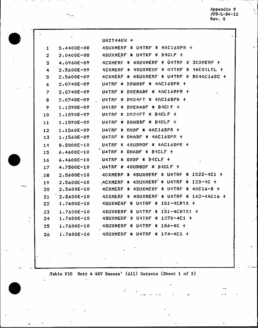
Appendix FJPE-L-84"12Rev. 0
1 5i4400E-082 3o0400E-083 4e0960E-094 2.5600E-095 2o5600E-096 2o0740E-09
7 2i0740E-098 2i0740E-099 1 i 1590E-09
10 1.1590E-09li io1590E-09
1 ~ 2560E-091 i 1560E-09
8.5000E-1015 6.4600E-1016 6+ 4600E-10
UNIT44KV
4SUXMERF f. U4TRF f- 4AC16SF'R
4SUXMERF 0 U4TRF 0 B4CI F
4CXMfRF 0 4SUXMERF 4 U4TRF 8 3f:XI"fRF
WCXHERF 0 4SUXMEI<F 0 IJ4TRF f AAC01LCL
4CXHERF 0 4SUXMERF 0 U4TRF '4 Bl<4AC16SC
U4TRF 4 DSM8BF 0 4AC16SF'R
U4TRF 4 DSESABF 4 4ACibSI"R
U4TRF '4 DS24FT f 4AC16SPR
IJ41RF 4 DSEBABF 0 B 'ICI F
U4TRF f. DS24FT f. B4CI. F
U4TRF 0 DSMSBF 0 B4CLF
ll4TRF f. QBBF 0 4AC16SI"R
U4TRF 0 QfsABF 0 4AC16SI" R
U4TRF f. 4SUBBOF 0 4AC16SI'R +
U4TRF 0 QBABF 0 B4CI..F
U4TRF 0 OSBF 0 B4CLF.
1? 4 '500E-10 .U4TRF f. 4SURSOF 4 B4CLF
, 18 2 i 5600E-,10 4CXMERF 0 4SUXHERF 0 U4TRI' 152Z-4Ci
19 2i5600E-1020 2 i 5600E-10
.4CXMERF 0 4SUXMERF
4CXHERF 0 4SUXMERF
U4TRF 0: 125-4CU4TRF f 4AC16-B
21 2i5600E-101 i 7600E-10
4CXHERF '4 4SUXMERF 0 U4TRF 0 162-4AC164SUXMERF 0 U4TRF f. 151-4CR1X
1.7600E-101. 760OE-10
4SUXMERF 0 U4TRF
4SUXMERF 8 O'ITRF151-4CBTX1127X-4C1
25 ii7600E-10 4SUXMERF 0 U4TRF f. 186-4C
26 ii7600E-20 , 4SUXMERF 0 U4TRF 4 174-4Ci
,Table F10 Unit 4 4KV Busses'All) Cutsets (Sheet 1 of 2)

AppendixF'PE-L"84-12
Rev. 0
27 1.7600E-10 4SUXMERF '4 U4TRF + 174-4C6
28 1.7600E-20 4SUXHERF 4 U4TRF 8 150-4CBTX
29 1.6864E-10 4SUXMERF 4 U4TR f. 4AC36S(-"R
30 1 5616E-10 DSE10AF I('8UXMERF 0 U4TRF f. 3(:XHERF
31 1.5616E-10 DSM10ABF 0 48UXMERF 0 U4TRF 4 3CXHERF +
32 io5616E-1033 1+ 5616E-10
34 I ~ 5616E-1035 1 o 5616E-10
h
36 1 o 5616E-10
4CXHERF 0 DSM3RF 4 48UXHERF ~ U4TRF
4CXMERF 0 DSE3ABF 8 4SUXMERF 0 U4TRF
4CXHERF t U4TRF 4 DSMBBF 0 3(:XHERF
4CXMERF 0 U4TRF 0 DSEBARF ~ 3(:XHERF
4CXHERF '4 U4'(RF 0 D824FT 4 3CXMERF
37 9.7600E-ii DSE10AF 0 48UXHERF 4 U4TRF t. 4ACOiLCL
38 9.7600E-li DSM10ARF e 4SUXHERr- e unTRF e 4AC01LCL +
39 9 i 7600E-11 DSE10AF '4 4SUXHERF 0 U4TRF f. BK4ACf6SC
40 9 7600E-11 DSMlOABF '4 48UXMERF '4 U4TRF 0 BK4AClbSC
41 9 o 7600E-11 4CXHERF 0 U4TRF 0 DSM8RF 4 4AC01LCL
42 9.7600E-ii 4CXMERF 4 U4TRF 4 DSE8ABF 0 4ACOlLCL +
43 9 7600E-11 4CXMERF 4 U4TRj 0 D824FT, 0 4AC01LCL
44 9o7600E-11 - 4CXHERF f U4TRF 0 DSM8RF f BK4AC16SC
45 9o7600E-li46 9e7600E-1147 9 o4240E-1148 8.7000E-ll
WCXHERF 0 U4TRF 0 DSEHABF 8 RK4AC16SC
4CXHERF 0 U4TRF 0 DS24FT 0 RK4ACibSC
4SUXMERF f. U4TR 0 R4CLF
010AF 0 CSUXHERF '0 U", TRF '4 3CXHERF
49 Bi/040E-li 4CXHERF 0 03ABF '4 4SUXMERF 0 U4TRF
50 8.7040E-11 4CXHERF 4 03RF 0 48UXHERF 0 U4TRF
Table F10 (Sheet 2 of 2)
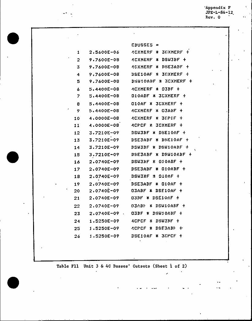
'Appendix FJPE"L-84-12Rev. 0
1 2o5600E-062 9 '600E-083 9+7600E-084 9i7600E-085 9+7600E-08
6 5,4400E-087 5e4400E-08
9
5i4400E-08'5i4400E-08
17
18
1990
)3
2+0740E-092+0740E-092+0740E-092.0740E-092i0740E-092.0740E-092o0740E-09ii5250E-091.5250E-09io5250E-09
10 4oOOOOE-08
11 4oOOOOE-08
3 '210E-093o7210E-09
14 3 o 7210E-093+ 7210E-09
16 2i0740E-09
CBUSSES
4CXMERF 0 3CXMERF
4CXMERF 0 DSM3RF
4CXMERF 0 DSE3ARF
DSE10AF 0: 3CXMERF
DSMIOARF 'K 3CXMERF
4CXMERF '4 03RF
010ARF 0 3CXMERF
01 OAF 0 3CXMERF
4CXMERF 0 03ARF
4CXMERF 0 3CPCF
4CPCF f. 3CXMERF +
DSW3RF 0 DSE10AF
DSE3ABF 0 DSEiOAF
DSM3BF 0 DSM10ARF +
DSE3ABF 0 DSM10ARF +
DSW3RF 0 010ABF
DSE3ARF, 4 010*BF +
DSW38F 8 010hF
DSE3ARF 0 010AF03ABF 4 DSE10AF
03RF 0 DSElOAF
03ABI-', DSM10ARF
03BF 0 DSMiOABF
4CPCF 0 DSW3RF
4CPCF 0 DSE3ABF +DSE10AF 4 3(:I-'CF
Table Fll Unit 3 & 4C Busses'utsets (Sheet 1 of 2)

Appendix FJPE-L-84-12Rev. 0
27 1 o5250E-09 DSM10ABF 4 3(;P(:F
28 ] o 1560E-09 03ABF 4 010AF29 io1560E-09 03BF 0 010AF
30 1o15bOE-09 03ABF 4 010ABF
31 1.1560E-09 03BF 0 010ABF
32 1 i 1560E-OY 3AC16SPR '4 4AC16SPR
33 So5000E-10 4CPCF 0 03ABF
34 Bo5000E-10 4CVCF '4 03BF
35 8 o 500OE-10 010ABF 0 3(:V(:F +
36 8 o 5000E-10 010AF 0 3UPCF
37 6 e 4600E-10 84CLF 4 3AC16SVR
38 6 ~ 4600E-10 B3CLF f 4AC16SVR +
39 6 ~ 2500E-10 4CPCF 4 3(:VCF
40 5,6000E-10 FLORFT 0 010ABSC f. 3(:XMERF
41 3+610OE-10 B3CLF 4 B4CLF
42 io7600E-10 3CXMERF 0 86-Y43 ii7600E-20 4CXMERF '4 86-EE
44 1 ~ 7600E-10 3CXMERF 0 18b-WCBl +
45 1.7600E-10 4CXMERF 4 Sb-FF +
46 1.7600E-10 4CXMERF f. 186-3CBT
47 $ .7600E-10 3CXMERF f. Sb-b!
48 5.4400E-11 4CXMERF f 3AC16SPR f. 4ACOiLCL
49 5o4400E-ii 3CXMERF 4 3AC01LCL '. 4AC1 6SPR
50 5.4400E-ii 3CXMERF 4 BK3AC168(' 4AC16SPR
Table Fll (Sheet 2 of 2)

Appendix FJPE-L-84-12Rev. 0
LIST OF THE 255 PRI'NARY EVENTS AND THEIR DESCRIPTIONS
BK3Ah02SC
RK3AR02SC
BK3AC16SC
BK4AA02SC
BK4A802SC
BK4AC16SC
R3ALF
83RLF
83CLF
84ALF
84BLF
84CLF
DAD1FT
DAV1FT
DAV2FT
DAV3FT
DORFT
DSE10ARF
DSE10AF
DSE3ARF
DSE3BF
DSE6ARF
BKR 3AA02 STUCK CLOSED
BKR 3A802 STUCK CLOSED
BK 3AC16 STUCK CLOSED
BKR 4AA02 STUCK CLOSED
BKR 4A802 STUCK CLOSED
4AC16 STUCK CLOSED
RUS 3A LOCAL FAULTS
BUS 3R LOCAL FAULTS
BUS 3C LOCAL FAULTS
BUS 4A LOCAL FAULTS
BUS 48 LOCAL FAULTS
RUS 4C LOCAL FAULTS
DADE-1 FAULT
DAVIS 1 FAULT
DAVIS 2 FAULT
DAVIS-3 FAULT
DORAL FAULT
DISC SM E10AB FAULT
DISC SM E1OA FAULTS
DISC SM E3AB FAULTS
DISC SM E 38 FAULTS
DISC SM E6AR FAULTS
Table F12 Fault. Tree Primary Events & Descriptions (Sheet ] of 12)


Appendix FJPE-L-84-12Rev. 0
DSESRF
DSE7ARF
DSE78F
DSE8ABF
DSE88F
DSE9ARF
DSE98F
DSM|OARF
DSM3ARF
DS4I3RF
DS4ISABF
DSM68F
DSM7ABF
DSM7RF
DSW8ABF
DS4I88F
DSM9ABF
DSM9RF
DS23FT
DS24FT
. FLAGlFT
FLAG2FT
D'XSC SM E68 FAULTS
DISC SM E7AB FAULTS
DISC SM E78 FAULTS
DISC S4l E8AR FAULTS
DISC SM E88 FAULTS
DISC SM E9AB FAULT
DISC SM E9R FAULTS
DISC SM W10AB FAULTS
DISC SM M3AB FAULTS
DISC SW M38 FAULTS
DISC S4l MSAB FAULTS
DISC SM MSB FAULTS
DISC SM M7AR FAULT
DISC SW M78 FAULTS
DISC SM M8AB FAULTS
DISC SW MGR FAULTS
DISC SM M9AB FAULTS
DISC SM W9R FAULTS
DISC SM 240 J26423 FAULTS
DISC SM 240J26424 FAULTS
FLAGAMI-1 FAULT
FLAGAHI-2 FAULT
Table F12 (Sheet 2 of 12)

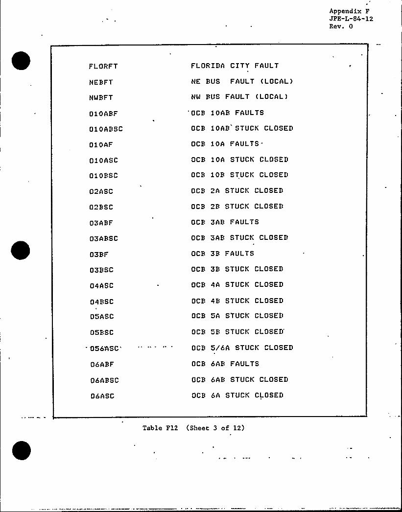
Appendix FJPE"L-84-12Rev. 0
FLORFT
NERFT
NMBFT
010ABF
010ABSC
010AF
010ASC
010BSC
02ASC
02RSC
03ARF
03ARSC
03BF
03RSC
04ASC
04BSC
05ASC
05BSC
056'ASC
'6ABF
06*BSC
06ASC
FLORIDA CITY FAULT
NE RUS FAULT (LOCAL)
NW RUS FAULT (LOCAL)
'OCR 10AR FAULTS
OCR 10AR STUCK CLOSED
OCB 10AFAULTS'CB
10A STUCK CLOSED
OCR 10R STUCK CLOSED
OCB 2A STUCK CLOSED
OCR 2R STUCK CLOSED
OCR 3AB FAULTS
OCB 3AB STUCK CLOSED
OCR 3B FAULTS
OCB 3B STUCK CLOSED
OCR 4A STUCK CLOSED
OCB 4B STUCK CLOSED
OCB 5A STUCK CLOSED
OCB 5B STUCKCLOSED'CB
5/6A STUCK CLOSED
OCB 6AB FAULTS
OCR 6AB STUCK CLOSED
OCB 6A STUCK CLOSED
Table F12 (Sheet 3 of 12)

Appendix FJPE-L-84-12Rev. 0
06BF
06RSC
067BSC
07ABF
07ABSC
07ASC
07BF
07BSC
08ABF
08ABSC,
08ASC
08BF
08BSC
09ABF
09ABSC
09ASC
09BF
09BSC
SERFT
SI3B2
SI3-iiXSI4B2
SI4-iix
OCB 6R FAULTS
OCB 6B STUCK CLOSED
OCB 6/7B STUCK CLOSED
OCR 7AB FAULTS
OCR 7AB STUCK CLOSED
OCB 7A STUCK CLOSED
OCB 7R FAULTS
OCR 7R STUCK CLOSED
OCB 8AB FAULTS
OCB 8AB STUCK CLOSED
OCR 8A STUCK CLOSED
OCB 8B FAULTS
OCR 8B STUCK CLOSED
OCB 9AB FAULTS
OCB 9AB STUCK CLOSED
OCB 9A STUCK CLOSED
OCB 9B FAULTS
OCB 9R STUCK CLOSED
SE BUS FAULT (LOCAL)'I
RELAY 3R2
S I RELAY 3-1 iX
SI RELAY 4R2
S I RELAY 4-1 i X
Table F12 (Sheet 4 of 12)

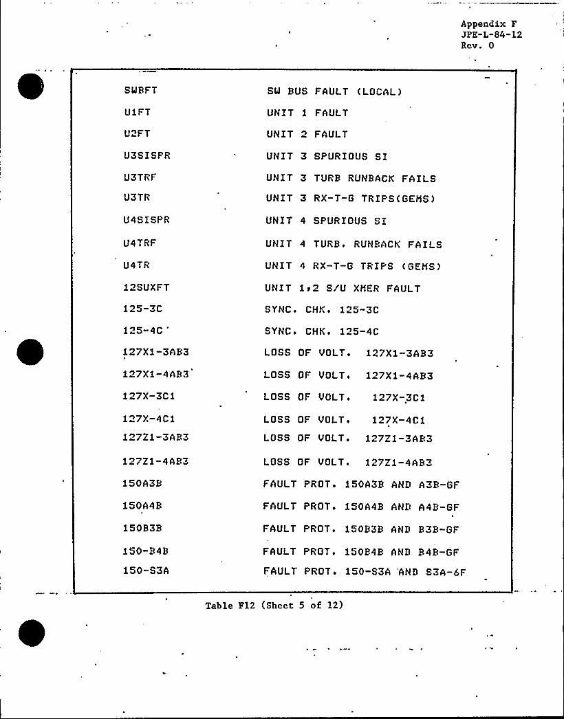
Appendix FJPE-L-84-12Rev. 0
SWBFT
U1FT
U2FT
U3SISPR
U3TRF
U3TR
U4SISPR
U4TRF
U4TR
12SUXFT
125-3C
125-4C
'27X1-3AB3
127xl-4AB3
127X-3Cl
127X-'4Ci
127Z1-3AB3
127Z1-4AB3
150A3B
150A4B
150B3B
150-B4B
150-S3A
SW BUS FAULT (LOCAL)
UNIT 1 FAULT
UNIT 2 FAULT
UNIT 3 SPURIOUS S IUNIT 3 TURB RUNBACK FAILS
UNIT 3 RX-T-G TRIPS(GEMS)
UNIT 4 SPURIOUS SI
UNIT 4 TURB ~ RUNBACK FAILS
UNIT 4 RX-T-G TRIPS ( GEMS )
UNIT 1 r 2 S/U XMER FAULT
SYNCo CHKo 125-3C
SYNCo CHKo 125-4C
LOSS OF VOLT o 127Xl-3AB3
LOSS OF VOLT» 127Xi-4AB3
LOSS OF VOLTo 127X-3Ci.
LOSS OF VOLTo 127X-4C1
LOSS OF VOLT. 127Zi-3AB3
LOSS OF VOLT. 127Z1-4AB3
FAULT PROTo 150A3B AND A3B-GF
FAULT PROTo 150A4B AND A4B-GF
FAULT PROT, 150B3B AND B3B-GF
FAULT PROTo 150B4B AND B4B-GF
FAULT PROTo 150-S3A 'AND S3A-6F
Table F12 (Sheet 5 of 12)

0

Appendix FJPE"L-84"12Rev. 0
150-S3R
150-S4A
150-S4R
150-3CBTX
150-3CBTY
150-4CBTX
150-4CBTY
151-A3A1
151-A3A
151-A4A1
151-A4A
151-B3Ai
151-R3A
151-B4A1
151-B4A
151-S3A13
151-S3A14
151-S3A3
151-S3A4
151-S3B13
151-S3B14
151-S3B3
FAULT PROT'50-S3B AND S3B-6F
FAULT PROT'50-S4A AND S4A-6F
FAULT PROT'50-S4B AND S4B-6F
FAULT PROT+ 150-3CBTX~ GF
FAULT PROT 150-3CBTY GF
FAULT PROT'50-4CBTXr GF
FAULT PROT'50-4CBTY~ GF
BU OVERCURRENT 151-A3ki
OVERCURRENT 151-A3A
RU OVERCURRENT 151-A4A1
OVERCURRENT 151-A4A
BU OVERCURRENT 151-B3A1
OVERCURRENT 151-R3A
BU OVERCURRENT 151-B4hi
OVERCURRENT 151-B4A
8U OVERCURRENT 151-S3A1-3
BU OVERCURRENT 151-S3A1-4
OVERCURRENT 151-S3A-3
OVERCURREHT 151-S3A-4
BU OVERCURRENT 151-S3Bi-3
RU OVER CURRENT 151-S3Bi-4
OVERCURREHT 151-S3B-3
Table F12 (Sheet 6 of 12)r

il
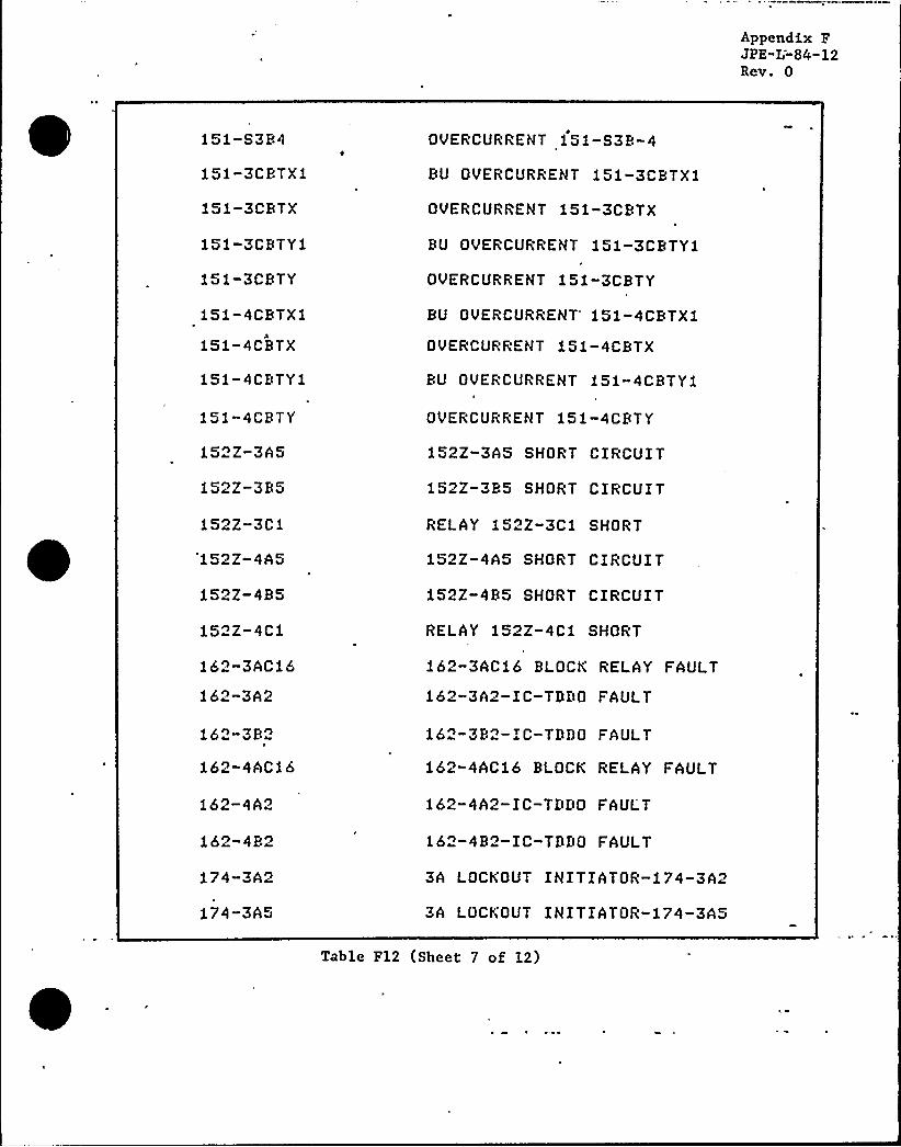
Appendix FJPE"L-84-12Rev. 0
151-S384
151-3CBTX1
151-3CBTX
151-3CBTYi
151-3CBTY
151-4CBTX1
151-4CBTX
151-4CBTY1
151-4CBTY
152Z-3A5
152Z-385
152Z-3C1
'152Z-4A5
152Z-485
1522-4C1
162-3AC16
162-3A2
162-3P2
162-4AC16
162-4A2
162-4P2
174-3A2
174-3A5
OVERCURRENT 151-S38-4
BU OVERCURRENT 151-3CBTXi
OVERCURRENT 151-3CBTX
BU OVERCURRENT 151-3CBTY1
OVERCURRENT 151-3CBTY
BU OVERCURRENT'51-4CBTXi
OVERCURRENT 151-4CBTX
BU OVERCURRENT 151-4CBTYi
OVERCURRENT 151-4CBTY
152Z-3A5 SHORT CIRCUIT
152Z-385 SHORT CIRCUIT
RELAY 152Z-3C1 SHORT
152Z-4A5 SHORT CIRCUIT
152Z-485 SHORT CIRCUIT
RELAY 152Z-4Ci SHORT
162-3AC16 BLOCK RELAY FAULT
162-3A2-IC-TDDO FAULT
162-382-IC- TDDO FAULT
162-4AC16 BLOCK RELAY FAULT
162-4A2-I C-TDDO FAUL"T
162-482-IC- TDDO FAULT
3A LOCKOUT INITIATOR-174-3A2
3A LOCKOUT INITIATOR-174-3A5
Table F12 (Sheet 7 of 12)

Appendix FJPE"L-84"12Rev. 0
174-3R2
174-3R5
174-3ci
174-3C6
174-4A2
174-4A5
174-4B2
174-4R5
174-4C1
174-4C6
186X-3A
185X-3B
186X-4A
186X-4R
185-ST3
186-ST4
186-3CBT
185-3C
186-4CBT
186-4C
286-G3
286-G4
3B LOCKOUT INITIATOR-174-3B2
3R LOCKOUT INITIATOR-174-3R5
3C LOCKOUT INITIATOR 174-3Ci
3C LOCKOUT INITIATOR 174-3C6
4A LOCKOUT INITIATOR-174-4A2
4A LOCKOUT INITIATOR-174-4A5
'B LOCKOUT INITIATOR-174-4R2
4B LOCKOUT INITIATOR-174-4B5
4C LOCKOUT INITIATOR 174-4Ci
4C LOCKOUT INITIATOR 174-4C6
3A RUS LO 186-3A
3R BUS LO 186-3B
4A BUS LO 186-4A
4B BUS LO 186-4R
3 SU XMER LO 186-ST3
4 SU XMER LO 185-ST4
3C XMER LO 186-3CBT
RUS C LO 186-3C
4C XMER LO 186-4CRT
BUS 4C LO 186-4C
GENo3 LO 286-G3 (SECONDARY)
GEN+4 LO 286-G4 (SECONDARY)
Table F12 (Sheet 8 of 12)

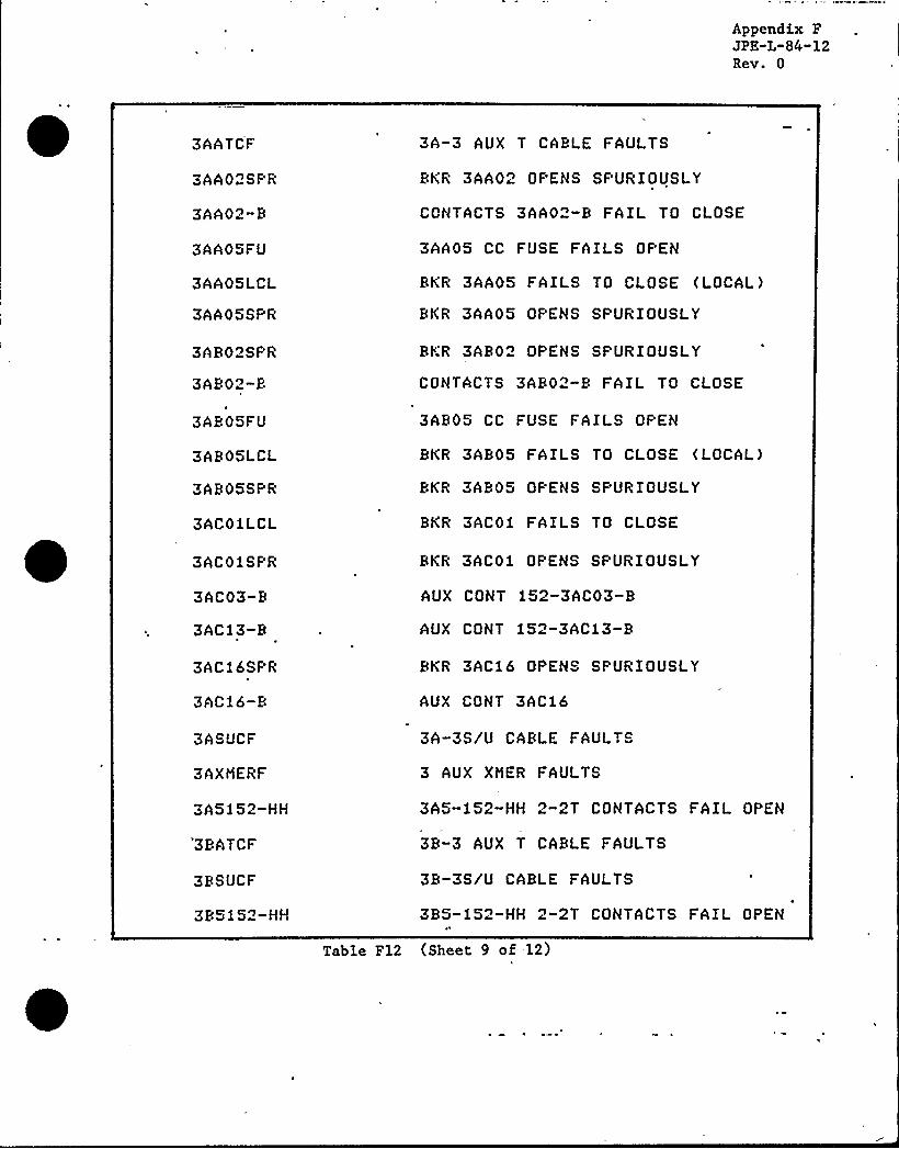
Appendix FJPE"L"84"12Rev. 0
3AATCF
3AA02SF'R
3AA02-R
3AA05FU
3AA05LCL
3AA05SPR
3A802SPR
3A802-8
3A805FU
3A805LCL
3ABOSSPR
3AC01LCL
3ACO f SF'R
3AC03-8
3AC13-8
3AC16SPR
3AC16-8
3ASUCF
3AXNERF
3A5 1 52-HH
38ATCF
3RSUCF
385152-HH
3A-3 AUX T CABLE FAULTS
RKR 3AA02 OPENS SPURIOUSLY
CONTACTS 3AA02-8 FAIL TO CLOSE
3AAOS CC FUSE FAILS OPEN
RKR 3AA05 FAILS TO CLOSE (LOCAL)
BKR 3AA05 OPENS SPURIOUSLY
RKR 3AR02 OPENS SPURIOUSLY
CONTACTS 3AR02-8 FAIL TO CLOSE
3A805 CC FUSE FAILS OPEN
BKR 3A805 FAILS TO CLOSE (LOCAL)
BKR 3A805 OF'ENS SPURIOUSLY
BKR 3ACOi FAILS TO CLOSE
BKR 3AC01 OPENS SPURIOUSLY
AUX CONT 152-3AC03-8
AUX CONT 152-3AC13-8
BKR 3AC16 OPENS SPURIOUSLY
AUX CONT 3AC16
3A-3S/U CARLE FAULTS
3 AUX XMER FAULTS
3A5-fS2-HH 2-2T CONTACTS FAIL OPEN
38-3 AUX T CABLE FAULTS
38-3S/U CABLE FAULTS
385-152-HH 2-2T CONTACTS FAIL OPEN
Table F12 (Sheet 9 of 12)

(

A'ppendkx.F,JPE"L-84-12Rev. 0
3CPCF
3CXMERF
3C3CTCF
3C4CTCF
3ISOPFT
3MTR70F
3MXMERF
3STB60F
3SUXMERF
3i52-TOC
4AATCF
4AA02SPR
4AA02-B
4AAOSFU
4AA05LCL
4AA05SPR
4AB02SPR
4AR02-B
4AB05FU
4AB05LCL
4ABOSSPR
4ACOiLCL
4ACOiSPR
3C PIPE CARLE FAULTS
3C XHER FAULTS
3C-3C XMER CABLE FAULTS
3C — 4C XMER CARLE FAULTS
3I SOPHASE BUS FAULTS
3 MT-BAY 7 OVHD FAULTS
3 MAIN XMER FAULTS
3S/U-BAY6 OVHD FAULTS
3 S/U XMER FAULTS (LOCAL)
AUX CONTo 3-i52-TOC
4A-4 AUX T CABLE FAULTS
BKR 4AA02 OPENS SPURIOUSLY
CONTACTS 4AA02-B FAIL TO CLOSE
4AAOS CC FUSE FAILS OPEN
BKR 4AA05 FAILS TO CLOSE (LOCAL)
BKR 4AA05 OPENS SPURIOUSLY
BKR 4AB02 OPENS SPURIOUSLY
CONTACTS 4AR02-R FAIL TO CLOSE
4AR05 CC FUSE FAILS OPEN
BKR 4AR05 FAILS TO CLOSE (LOCAL)
RKR 4AB05 OPENS SPURIOUSLY
BKR 4ACOi FAILS TO CLOSE
RKR 4ACOi OPENS SPURIOUSLY
Table F12 (Sheet 10 of 12)

Appendix FJPE-L-84-12Rev. 0
4AC03-B
4AC13-B
4AC16SPR
4AC16-B
4ASUCF
4AXHERF
4A515o-HH
4BATCF
4BSUCF
4 B5152-HH
4CPCF
4CXHERF
4C3CTCF
4C4CTCF
4ISOPFT
4HTB90F
4HXMERF
4SUBSOF
4SUXMERF
4152-TOC
86BU-ST3
86BU-ST4
AUX CONT 152-4AC03-B
AUX CONT 152-4AC13-B
BKR 4AC16 OPENS SPURIOUSLY
AUX CONT 4AC16
4A-4S/U CABLE FAULTS
4AUX XHER FAULTS
4A5-152-HH 2-2T CONTACTS FAIL OPEN
4B-4AUX T CABLE FAULTS
4B-4S/U CABLE FAULTS
4B5-!52-HH 2-2T CONTACTS FAIL OPEN
4C PIPE CABLE FAULTS
4C XMER FAULTS
4C-3C XMER CABLE FAULTS
4C-4C XHER CABLE FAULTS
4 ISOPHASE BUS FAULTS
4 MT-BAY 9 OVHD FAULTS
4 ..HAIN XMER FAULTS
4S/U — BAY 8 OVHD FAULTS
4 S/U XHER FAULTS (LOCAL)
AUX CONTi 4-152- TOC
RELAY 86BU-ST3
RELAY 86BU-ST4
Table F12 (Sheet ll of 12)


Appendix FJPE"L-84-12Rev. 0
86GT-G3
86GT-G4
86G
86K
86-EE
86-FF
86-M
86-Y
GEH. 3 LO 86GT-G3 (PRIMARY)
BEN+ 4 LO 86GT-G4 (PRIMARY)
RELAY 86-G OR 86-R
RELAY 86-K
C XMER PRI. LO 86-EE
C XMER SEC. LO 86-FF
4C XHER PRI+ LO 85-M
4C XMER SEC. LO 86-Y
Table F12 (Sheet 12 of 12)

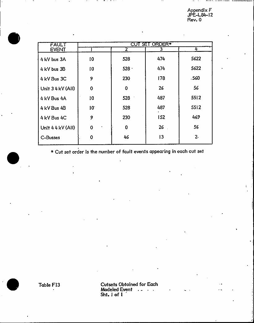
Appendix FJPE-L84-12Rev. 0
U TEVENT
4 kV bus 3A
4 kV bus 3B
4 kV Bus 3C
Unit 3 4kV(AII)
4 kV Bus 4A
4kV Bus 4B
4kV. Bus 4C
Unit 44 kV (All)
C-Busses
10
10
10
10'28528
230
528
528
230
U
474
474
178
26
487
487
152
26
13
5622
5622
.560
56
5512
5512
469
56
J
+ Cut set order is the number of fault events appearing in each cut set
Table FI3 Cutsets Obtained for EachModeled EventSht. I of I

I ~
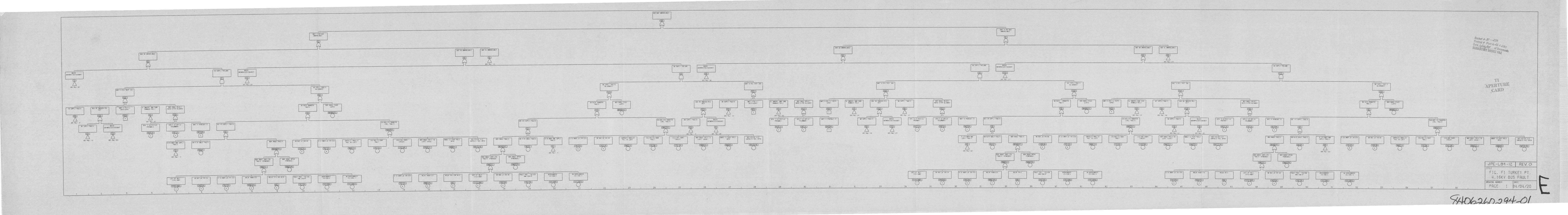
~m m~VtV IN!5 UNIVRILRS'
INN! .'cf UaUHRY47155
Sus .5 UMYAIL45'f Nls 3 ~ NNVRIL ARE
SU5 4A NNVRILRRC
Jh!1 t SIT UU5IhhI4 IIAbIE
SUS NI 544YAIIIVIIE SUS 4 VNUI4ILASIE
Oocr(e
~lt~ol ~ ~~~~e ~ .-
~~~(( ol~~~D()CX~ ""~~~F~
SftlhkC: t>ACNND
1R SUP' UILUR RUSS!
OC NEh'IMSAO KOJI
Sf. 57! 2
55 SVYR I Al.uk sus'lhDf VEII !MSACKSJI
M Mr..! rahaIOsale
>TINEACIIll/LOCKDJ!
Sff PAC'l
'lh SUP'll P41LURE
Stt PRC I 25
NDT 5 IDC Ihl~ .Shl
Sf. 5 I 25!
34 5U "Ll FRULYS'JILTERFRIE'5 5JP 7 FRULI>!RIEMI
-'E. II'! 2C
III ' I Pk'F!Ri'C5441
'Jl'I' 51 IP tTS Ul 'AN,S
ULICR IRT
5 Sul il hkls SUS 55 IINUCl> !llC1 sir
UN!1 ) tl-I;a!F5 IC IIS
SEf IC. '. 5
75 FJPTLI F4lkl)
lft 4! 51 Mt PR" I 25)
SUSMXfNE!ICTITSACMOJT
UNAYAll RNS IIN5YLMN"5 TRI,
5P UC '1ICtN., 5 . l11-C)
!T 'D INIII 1
5th 5RIQ 'Nihil51515 5" I RLLSJEQ
cfv,s 1st-c5IS MINNI!I
1 /U KREl RNU MP, IAla it
5CF RC I 71
UN!I ) I'JRIOJS I
SD> /U Chd 1 IWLIS
M S "J CUP" I I'IUILIS
~th SRRQ PRJLIC
Kt >RRIS Cb'D. Ih4UIM
ISPINTSJS''I
RN5 ulfLVSI'al'MiI
34 SJS 5 Iee-14
34IIQS Ch NS
C P UIII5J5L I
IP 4 344>2 TUCKLbll>
3 TJ tlu'I ' !M.SIS CC'Dh 11 illa .5RIL M ib!E
34-Ikll-5 U IRSNFEIICIR . RIL!5
162-55 -I IDSC 162 sac shatC A U!1
sa shhos ra!.115.ce r. Ceca.
MACL C MSE AliiSPEV
37 5/U Sur',I 4NIS
Ml 152 hkau a.! a! ertc
5th IRS>1 faulll 75. 7. /U CINL FRJLIS
sa >MM c>D..laRulis !5PNI!dJSI
5th MM' 'Istukl5 Jsi!
tl KNEI 4RI Cur IFI4415
5ltlh '
75 RJIO III4NSFEYSUITS
PJ SID l5 Itl-M
Mt 5'URL fib,"K
CIIV!A 15 MSCJ-54!I 13,!bc
55-4UK-CAY !UANC ttClllh AULIS
Mi.MC"I -IRDOMLI
I 1.3lc lhlhlCulccl'I
Suc M INDUCE> RICIII!P
ss surpil rhkfs
SR 5UPP 'hu!15 ous>tDEERE'tC!MS/LS Lal
Sf UL I I 5fl 'A' 20
SKR 145>1 fh;II,S!! I.L5LA'RS 5 C Fust 4!i
0 El
IRII 3 ~ IC I!I'P IM
Nl)1 3 'N"I-IIIY5!CPISI
355.712.IN 1-21CUYIRCIS FIIIL CI V
)C LRR'IA! INO IINS~ UNM t . Rlis
St. R IllCEY, c,s !ICI 23
IrII!IMD:
aa sss>2 RDa:IRf15 I- Ch 4'Lchat
«tv. ~ .5 lee.c>'SECOINhhl;
IIN!1 5 ~ T-i.c 15:PS:C 'IP
UN!I ) ~ Uk!4'5 5
INI 4 RIC DIIP ICRI
'lL. UNIYRIL Rhu LUAU
RVHSRJK '4!Lt
511 Rc'
15 SN'PLT Y4ULI1
M. Rc'!5 51. A 1 27
DR> 15 'INDUCE> 511 Vh SN'. ll'AJLISItc
OSU515 E'I. I Lb 1/Cl-llsftKVD Es to,a>'ftlhRVI!
M'I uulu ~ Lhl',RUT> 2- fh IILLMM:
CTV.4 Ls 216'.f SKRV"
UNI t . ~ Uhl& '1 51
4 5 Rl tuft RNI
Kt Ph, I 22
SE. Ph
64.VS/u CAS.T 4JL!s 5th VA4,": lAAIS
5th VRIL15 CdVI.C!R. 4IRT IIPUAISJ5
Sll SR SN',I /~IS
5th IIAILIS 5 VI.'I'IhlIdJSL I
IA du6 .5 Ilc.ta
IA 4'Jl> uularftRV IC
'I SU tuft I» '6-511
>IN IIL4 sluclCib'I>
CSV!4 5 '144
UNIT I kf-1-. It!rs!CfYS
!42-IIA -I - QD>5'Jl!
21.NIS 5!LICIC]h UI ~
O'I IRRYRH AVO rifbhUURA I'R I!
D'14.RJI.S.VI IARHSF 'I17th AJIIS
V. VUP'I'I Rr,l 545 Nl IKUCE> 5I It'
5 t 'RC'
14 5U I, 4JLTS
dtt 'IAhtf fR!15 lb15 IC d
4C I 26!
OJ 64DETK >1 ES LDCCUJ'I
CTV. I ib S C!'rh 4'I"
'41-152-uh
2- "
OVIR 15 Yh!, IPIV
SK I M> t 4'A 'I> I-rfh RELSra
Cfh.cl Ib irSC. 1
'SfalOUH '.
Ull! I TPMIOJS 5
Mt ~Ill>t FRJ'» 'lb-IS/U CI'Sif fah
5th 44535 MVI.L.!tIWLJ NIMMM)
elk sts>s a tus.PU514JSIT
lt SUP ILILI5
1 5/0 slut CIVD
SUP T FRNIS
5EE 4 I 72
tb 4'Jl>-IIIAUSFEYAll'5
SDI VM>2 )IUCLcia!I>
C4'JI4 11 VM> -IIRli 15 NS
5 5-545-5 V 'IhRMS~ I
C!RC. RJLIS
1121"655 SIUI'I'IIhCU I1
152 tb -I !DDT Ihh SR>11 FAILS 15Lb "1 ~~R.
NNDS CC fUSt PAILS~ TV
441-II'2-UV 2-21<D'<IR,TS 1!I 5 SV
LMS 0 Yb I! 1121. NISI
3* Ucs .5 ! Yt-la 3 PJ Khtk ib !'1-DS kt 4 IC45U-515 Af ~ O'I 56 P lh!Ll tbh !35-574LIN 5>ll-4I
4YCI Uht 'D! 51-514.7
-13 3
~U UlftcIN'ICYT!51-MR!-'.
> 'u 2Ks La ! ee-115 4 Al KIRI-513 RELOT C. >t 65 !I Ld'I O'5.1!I 2!-NI57
35 Suc 5 IM-tS FAULT .5,:55-S15RVD 555-5!
5/PICIRIKVI!51.535-'I
55 dYPIDIRS!'ll151- M:-I
LS'5 J'S 1.'27D'Ihh>
14 sus ia es-14 54 tuft ib !56 SI'I Al FSV-314 hfihl SS-I FAULT t '. !IDS'ulRYD 5'ul"6
OYCRCIHIEEVI151-535"'I
au Clctcak ~!11-134 .V
NELRI elhi-!I'I
44 45 46
RELAY 56-K tbc'l Yd,l!27TI.VILI'l~ US d !4 -Vb FRUIT I>. !SD)ISRVD S4 ~
-6'YCcilhl'!51.5M.I
KKV th 56.511
OU dTCII'Ihihltl15 Pal'! - 'I
15 SUS IO '.15
~F'E-L~'}-iZ REV. 0TITLE
FI(.. > I TURKEY PT.u. IE'KV BUS FfiUIT
3 6 8 I 9 10 12 13 15 !6 17 18 I l9 21 22 23 I 24 >5 26 27 28 I 29 30 I 3! 37 34 39 41 4'I 43 I 48 49 50 51 52 53 54 Sc 56
ORRUINC NUNOER ORTE
P~GE I ~iO~r~p
aan~ e4~/.

INS IC UWNI'I!SO!C
SEE PACES: CNI
OUS N LNAL I'Nal
OOUI sl'JCEUCCCINO/LSCCOJT
Sla 'N If CSV!. LIE'SJ!15 !IPURISJ51
ml m !0 4 UlSPUR IUJN I
ll mts TARNPE ~
f41LNIE
ll SLUf!I IRI\Nll
m Nrt!T FAULTS
Oockot EO W-+~>Control EO ~~~088c 0 FedOnto - of Oocurnolb
REOO TO f OOCIIET FILE
NI5 I!. Il:45-IL L054VCT'2!I-S !
dlflCNtlfLIT
Il:.IN!2SU O'IEICURIEVI
: 5: -3&171pmLT . Ro:.50-3&13. f
LSJJ:Jt !SIIIRIOV!IL-XI
Ld CSUI IAITISTCC!Il-1 5
4C slate STU fmasm
12 . 'll NLV C4t 1'4'!LI3
'll N!fl PNP 15 lt: P!t- CRN taals INI I AN 5lrt.lFUNIS
Sc a: I mrtlr raN tl
SN Cdfl. I !52-14 :SI-Iaml SLO.CCC 4! I'Na!
Ir'I Cftlt 3R !C
72 at Ita.". rad.ts
Slt!C. NL !25-3 tll I!Ul Ld I Sf-SQI Sla 3ACOI I'all5 IlId'
.A'S21-I '. Sm'll SN Cl VI ICI SLAIN 5 0 I Lmt !52 IIICN-4
DNUO! Stl P AILII 4AL I 4IN 'Jft'INa 15
m ! N
OL~ 34m: 4p Us5PINIOUSL"
~Lll sa SI CSV . ~: ~RIC15 IItlalWSI
I INI PSNTS N PET Lasm PNats SL-3C Safl CCRC
Ica 11
m Nas Ls 151-3 N
411 34 H IL.SNU!~ I- Tl
css! Tlml
1 Naa fat. 5 sl.f
Sff Pa ')Nts s. La!ea-s. LNS 0 N.i
'.111-5!:I Ilrl Ld !Ill-1 5 'lC IIL'I al!. ~ 0 ll-l I al"I 5 C, LC dC"I fmLI fl5
50-'ICSIT,e rfvlsaa.'N
:Sl-'IISTTNl 4lflCINILSI
:Sl-'I 4'ITI
TIAPERTURE
CARD
0 PE- L80-l2 REV. 0TTTLE
2 I 3 4 3 7 8 t 9 TQ I 3 3 ! ". !3 7 !4 I !8 !7 !8 !9 20 2! 22 23 24
F I G . F I TURKEY P T .
4 . ! l3 K V B U S F R U L T
DRAM!AC NUMBER 9ATE
P R G E 2 4 /0 4 /2 0

$4 SN'. Lt FA'JIT5 5 445 SACS FWC TSIN" !'0 IWI SUFFL
'AN.TS
SCE PQCCS.I. t SCE FNE5: ~ .ISC I'l"CS:
N-5 Wll I CASLE!'44!15
5 NIS NIH . Wf 15 5 4'Jl $4 ~ PURIS SAUK IUWS 5INFLTAUL'15 aSU SU5 F 444 STUCK
QQI IOR
8
DISC 5U UIOAS FAUIIS fL 'I CTIV F4IT,I AINSTUCK CN 1045
Q!SC SU E!44 I'INL'ls 4 5 !tN I'AULIS OJI ItN5 . 4'JLTS 15!5 5 54" !4 ERST.'N51 SIF, ~ I
.,Oocket8 X'M" eentreleIe~,a~a/p~'-.4
ef Become@KET Ag
NEER I SI
0:54 NISC SUS FNILTS 0 ARIA WNR FWILTS 5 Ut IIAI 1 SVUD
PURISSAT'I IN! NI~ PLV
. AIS'!0 58 54$ FAAI Ilsdll! ~N ICR UBICC Clstts FLUNIN llv FALRT 480 1445 STUCKCLOSES
!NS 0" SAT ID SRS!SUf. I'a 8 5f SRT !0 UESI
NAFLV
SC SUS P' SN SIUCKSN '8
0!SC N UIS FRJLTS DAVIS 5 '\ ATQStsCt SJ'40
Qts Sll CIN! ISAIS Dls !RS I4IA !1 DCS IS FNILT L05$ 0 SA"ERSIJUCS! SUFI'
flsVICA 111 AUII DISC Ui EDDAS RJLI SE ¹ LI INQ STUCKSN IQS
DISC Sa 1!IN FA'LTS SU 45$ fals15 W4: Q!
vt 5'Js PANT ALNSTUCK 0 5 5/04
SC SU5 FAN'lS 4! ' 4 14 5IUCC CLSIEO INT1$-1 ISC! asa Tss STUCL N. CQ LQ 5 5'4! I VCSTSUFFL'I
Ld!1 SF 441 I Cal,5UFNT
SL SJI AJI'$~ 5 5 !.04 Stl 1 "'5!ES 58 $45 fs'Jll 15!IKI NAIA! Flt 444 114 KSNI N
SAN-I flt asa stUCKSdl 84
NIVIS 1 \ Ala5!SCt 4 8 !4 af!41.1 I' AWI STULC NI SIU fRULT:Ls IK!
5N 844!8 sf"A STUCt
.Ls-.a
INITC-S FANI NC55 555, !1 ARO 5TUCK. SISS FRATacs La
N SN fLI NN STACK0!~ SNS
O!5 54 E'IS 4'Jill N QIN F ILATS ( 54!SDRAL E4'JL1 DUISA 51!NK CICNED !WIDE!I FANE 414 FA STUCK WINED Qstt ~ 5 F4N! 14 SIUCK IXSIEQ DF'QW", 1 FAIRI AN ~ II STUN KISSES
SU SUS FAIKI ILCJSL! SJI Tf SIU 1 TSCSES
SEE PAJI ~
SE 8US fNAI $ Al 4S.TI NEA . Lt 440FSTUCk ON M
Usl'I 8 FLT AUD STINKVls 44
Fls'I !1! Fit ASD
C!SCK CBI IQS
SE- RC! !Ol 8EE pall lll SCC PIN ! IEI
DRAU INC NUTIBEIL DAIE
PAGE 3 4/04/20
J P E - LB'I - I Z REV. 07 I ILE
FIG. Fl TURKEY PT.4. 16KV BUS FAULT
2 I 3 I 7 I 8 9 I
DRALIIN NUNDEUR DATE
PAGE 4 4/04/20
JPE- LSH-IZ REV. 0TITLE
FIG. Fl TURKEY PT.4. 16KV l3US FAULT
3 I 4 7 8 9 I ID 17 13 I 14
JPE-L8't -l2 REV. 071TLE
FIG. Fl TURKEY PT
4.16KV BUS FAULTDRAUINC NUtTDUR DATE
P R G E 5 4/04/20

11 1JFFL" 'RSLIS 1 .EI KAC~ Aai lurrlIRULTS
SAI 1!llO FJF. L
'RULTS
ROS: I. 1
I 101 tÃs F4% IS 19-1 Rut I visit'al I11 SRI KNLL . RJL'l5
'L0UILI5 /II"54!0 0lsl
'IUl1$
CSC 4 1:1.1
RAIS RNV SUFFLRULTS ONsc st TIOTCEULS
'URTSNE 00$ Fit 411 5 UCC
$ VI 1$0!Sc ' ESRS FA'JLTS Du 0US Fit Nau S!UCC
. Rs
SES I'RNS: !1
II!5K 51 Uls FAIL!5 aui SS FA'JI,TS 1JI 145 Rulll is II 511 1
tssi/u st 'siirrit
DOClj@8 MW cc'SV5Ngflg g CP+'C'/I'UL'UPON@!/5
SStl OS 2E g go!I!I~Y 06557 Fll,f
4!'5 E'll RULT5 D sc 52 Jls . C'Jlls 0 0 1$ 0 FRIILTS $1 RV5 fasil/STJ.tSla 5$
1 II FA F4UL!5 fis - '1'JLT/S,UCt LS!5 a I'4 E
40!.VEST EtrritNK SJS I'LT . AJll
! CC!CI,I II 11 STUCK QD510 Ul llu5 fsul! ILD ALI acs 149 1!ucr. CLRMD DID"5 Or 1st - 1151
Ivr llLOSs lf sar 9 Jtst
!Jt, Lt
IIC 0% .' . Iul!"5 SLI
0!1 10 STVCK CL SCS fill ILtl "2 FAUL1 010 fA. "TUCK C'5 C" LJ!S N SAI 1 JCStI'Jtl"i I
LSCS Dr 1st CA51!Vf 1
$1 SU5 .!1 Ru 5 UCE
SA 1/ISNE 9US FAR IS llsS''ll SJ C 18 a!ITS ru llu5 rslatS RI4'1! 0!5 SJ 1544 'WILIS N Sus f:'I Rvu STUCK
5/54
FLINILRI-2 fR*l DISC TJ JSRR IIUiT5 JT C 5$ 151 'WJll5
SV 1UR FAULT !LS,AL 0UI CA 5'IUCC CLSRS Dl Vus fil !RIILT:l RL I
91 tls fLT 'ITS 51UCKsa aa
NC DUS fala15 Ias
EN;I 2 .2 411 sTJ!EKCis $ 0
Ul. 1 V CR !\ FAJLO'll 51'J.l 5 0 15
SEC 'act IS
UNIT: .' RUD STFCCSLS t!
51 1st FLT Rua 5!INNSa 5/S
5.1 FACI 15I
NC sus t!T FAUL'I'Lova!
UNIT Q 'I REO STUCKtca 50
SN RCI I'V
Ul "5 J 1!UN 'R*1
I!NO 5 LCC 1 1 10
511 fa ! )$1
O'JNII I fi'DD STUCF U-1 '/1 CRCS 4'Jl'I5$ & RUI STINK 0 0 Fs
Stt ~ 'al1 .'l CNE!I FARL 5
!lJ'All
Nu VJR 'IWL Qa 4
aca es STULD Qs.ES OAFI5 fs'll
Rl!1 1 RNI 51UCK520 OR
1 0 14 STUCK idtES FLA 011-I Faul1
f'a. I FL 1'UIsluct scs 'l4
5 144 stucs cLS Ea 0A!IS I FAQT
1 2 N RQ
0& 9/Ds S!lfCC
SC0 LA STUCK Cist O
51 'Rc I I'l 5t Alt !51 Sft 'll! 11!
5RALIIVC MEMBER 9 ATE
P RG E 6 4 /0 LI/2 0
3 PE-LB'I-IZ REV. 0TITLE
. FIG. ~I TURKEY PT.4.16KV BUS FAULT
3 I 9 8 9 I 10
4 PE-LS'I-lz REV.OT!TLE
FIG. Fl TURKEY PT.LI.IBKV BUS FAULT
BRALSINC NUBBER 5ATN
P A G E 7 4 /0 LI /2 0! 2 3 I 9 7 I P 9 15 13
T II!.E
JPE-LB%-lZ.. IREE'V. 0
FIG. Fl TURKEY PT.U.16KV BUS FAULT
5RALLINC NLTNBER BATE
PRGE 8 LI/Otl/20
9 0(ADaf

At 555 ' Aaa WUCC
I C
IIZw tns
IIC. AC(5nl.zl
55n IAE'I FLI ANISTOT( A a 5.
5'.
INIT I FLI AIIC NUCC fLW Clll Fct IWOSIUCC SQI las
SC SN I' WN 51UC(wa sns
Ual1 I . 'I SNI SIUCL'CS 5 ~
UI. SAI ZILA FAULIAWI STUC( D"5 'N
5(( (NEW 'I ~
aWI I FLT sW ITIN(OCS la
A( SUC' fa'"I
Ils A'a s sns Sazu
CWFLN
5 5 "J (5(5 FNC 5
EDJI ISJI CD STI' CLSIED NC 1 'I(-I- ISLES
ICE551SN 59 FIUCZ CIST.a fLINTW C:11 FOUL'I.. Ika ILN STSC( CLOSED St AW fWat ILOCALI sw ans Nacc
claat9LNII 9 FWAI acs ss watt Ital(9 LNI'I Gz 5/U SDEA
FIWLIs.s as Stwt N aIIS NIITI FIWL'I SCS Za STWS Culf(9
F
g yggg ALE
Apggg~CA~j
ORRV!NC NUTTB !I DAT
PAGE 9 4/04/20
JF'E-LSW-I Z REV. 0TITLE
FIG. Fl TURKEY PT.4.16KV BUS FAJLT
DRAM]MG MUHB 9 OAT
PRGE 10 4/04/20
4 PE-L8+-IZ REV. 0TITLF
cIG F 1 TURKEY PT.4.!GKV BUS FRULT
4 PE- L8't. IZ REV. 0TITLE
FIG. F! TURKEY PT.4.16KV BUS FAULT
DA EORANT'HC MUHB 4
PAGE ll 4/04/2'0
4 PE-Le+-!2 RE.V. 0TITLE
FIG. ~1 TURKEY PT.4. 16KV BUS FAULT
DATEDRAIJIMG MUNBER
PAGE 12 4/04/20
J PE -L8 f- l2 REV. 0TITLE
FIG. Fl TURKEY PT.4. 16KV BUS FRULT
DATEORAVIHG HUNBER
PAGE 13 4/04/20
0 PE- LB% -I Z. REV. 0
TITLE
F IG. F'1 TURKEY PT.4. 16KV BUS FAULT
DATEORALIING NUMBER
PAGE 14 4/04/20
APE-L84-IZ REV. 0TITLE
FIG. Fl TURKEY PT.4. 16KV BUS FAULT
BRAVING NUMBER DATE
PAGE !S 4/04/20
APE-La%-12. REV. 0TITLE
FIG. Fl TURKEY PT.4.16KV BUS FAULT
DATDRAVIMG HUNBER
PAGE 16 4/04/20
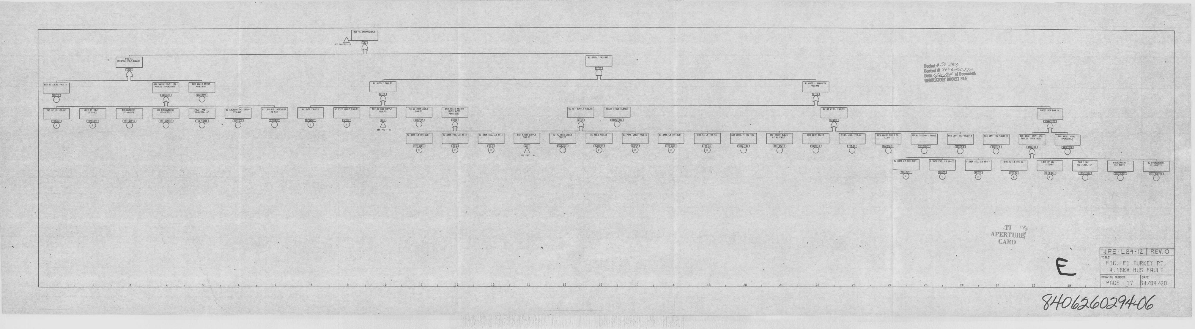
5!5 VC IIKVAILASLE
!5tt FR" f5!K!I
555 VC LOCK FSLVII
aes acKCSEAC! EtDAKMJI
scs ascls covl. cle!NI.!5 Qratlelsl
ess ssc! I erne5PIKINJSIT
SC 5UI'I'Ll FRKTI
IC IUPPLI 141155
VC Asia - IKKK'Cs, sr!UK
geggeW P~o~y S'+ETd>6C g~19t 90CIIIIINL
soccer ALE
KK K 10 ISS"VC LSIT et VKI.2 1-451
SVfSCUSSESI!Sl-ICSTI
sa a!tan!stts1$ 1-SCSII I
rNN! res.! $5-IDTL
IC IOQdUT INK!4TSI77$ -% I
IC LAQOJI 757175755175- PCS
SC Rica FKAII IC ts f LRKE PANTS 557 10 Sse 5IUP~ Ilss 15 .
IC-SC Ivft 55 I. KATI
SCI VKIS llf'!$UKT4 I-I 1
ERN!11fa!
K !87 1st Ll FKAIS IIAC!a 5TUCI C'-Ssf0 IC AI CIRC. Falsls KICOI 115 FRK15
stC Fs ! IlIC SSfll Le !$5 VCSI IC Isa Ptl. 0 IS-5 IUNS KQ 0 IV-I SSI I RNS SUPt!l
K!L!$ac-sc 55 I 155!c
ta'J!11IC INES FKIL15 I I'!." Q!SLE rKAK SC 5515 L4 !Si 1&7 SSS 11 LI Iss-SC SJI CNQ. 5.112.15 !52-Ilels SIO C
ICLAI FKATKlt COIN VKIS SUA. QK. !ts-5 W'I VKSI I'511515
asst~CLAT ltll.VCI $KKI 545 COIT 152 KIC55-5 KU! CSVT 1st-VSC!5 5 Kll tlLJI! QINT. 15
KA'l5 15PNIKKIIUS WQI! StCN5
It!K7SJIL I
Stt tS ! Rl
K INES Lt !55-5&1 C Kits PRK !0 as EE C KIES SEQ 5 51-Fr sin ac 14 Iss 4c LS!I St VS I,!271 SC!
POKI PR57.$5-SQ!'ll. ~ ' ERCUIKENI
151-5C4TI It!"SCSIT!
;hIv~h"I
~ERTURgCARD
J F' - L 8'1 -l 2. R EV, 0
TITLE
F I G . F 1 TURKEY P T
4 . 1 6 K Y B U S F A U L T
ORRISIRC MURRER CATE
PAGE 1 7 4 /04 /2 02 7 3 ! 4 8 ! 9 \ 10 ! II 12 13 I4 15 16 17 ! !8 ! 19 26 I 21 22 23 ! 24 25 26 27 ! 28 29

IC UWIQIIL INI IIIIN1
IIINNXE FAI'
Ie
IN NWFII FM TI
titeIff FNSSLI I
I Mt SINIL fAIATI
t~fE FACIALII.El
Wl IUI'FLT FAIAt5
f t, WX5L I, I
NI Ic LINUIIILIWLE
Iff fSCI I'l
Will I TNS. EINNIX1 5115
Sll-IIWI I CQSLEfNA15
I lkN EUEA FIUAIS
Sff I'IICt FA
~Wff WIEA 1'SW,15
II IIOFINIE ILNF ISA IS
~ INIII IIWA FSIAt5
I SIN WOS SIOFLIfWIL15
I III-SAT I STUDFAIATI
IIAI ~ WW 5IUtll.'NA 15
~~y ~-.768SI Y~d~ddan~td
MBUIITANA . IlBBJTB@fL
y~HLK
'I QUI EllfS FWAII
511 FOCI EU'I
N-I AUI I CINifI'NATI
51 SUS FLI AN ITUCISCD N
OTIC IU NS fWATI DNSL f' Nll IIUtXSCS WIS
5155 Wl ESAS FQIAT NO IWI FNAII Ml Wl fIXII LOII Ot SAI ~ENIFIWIT IIOFLI
5f SUI I'WAT 1IICNI I ~ % STIICE ll55NI IWIIA FM.I DLO55 D M'I I EILI5IOFLI
LC55 Sl Nil 5 IXIIQOW I
UE SUS Fit IND SINX5 I IFTS
IE IWS FWAIS IAAF W OTIC Wl EN flWIII DSIIAL FNAT Sll 5UI F I SIW ITNXAO SA
DTI Cll UNI FAIL'IS
Sff FACI St
Sf SIW FAUIT ASWAI ~AFU IUES f' AINSIIICE OCA Wl
f'lICITT . I Ml51'JtX SCS IDS
INI'I I I AIN STIICCSCS 15
IU IWI flWll ASWI'
Mf ~ IX I ID Nf tQCI lil
N
m "":':!
gPKRTACCARD
BRAUIMC HUNBER BATE
P R G E 1 8 4 /0 4 /2 0
APE-LS'1-i2 REV. 0TITLE
FIG. Fl TURKEY PT.4. 16KV BUS FRULT
JPE-t 8+-12 REV. 0TITLE
FIG. Fl TURKEY PT
4. 16K V BUS F RUL T.
ORAUIMC NUMBER DATE
P R G E 1 9 4 /0 4 /2 0I I 2 3 I 5
4 PE.-LB% - l2 RE'V. 0TITLE
F I G. F 1 TURKEY PT.4.16KV BUS FAULT
BRAUINC MUHBER . BATE
P R G E 2 0 4 /0 4 /2 0
FPsaa~4w ~
4 PE- LBR-1Z RFV.OTITLE
FIG. F 1 TURKEY PT.4.16KV BUS FAULT
BRAUIMC NUMBER BAT
P R G E 2 1 4 /0 4 /2 0

I 5/Ul CACO SUS
W
IUP,LT FAULTS
Slf FAWN L I
nil I LI WW STUIX
55 5 I
Ml I~
5 PAC'55 CO'
ICI PKfsil, I
S nsvsvi INO IUNISWWWX FUIL5
I 5/5 Wlea fWAICILOCSL I
OISC 55 CSIUI FAULTS
55/U - SAI e ens. sais
55 Sill fWAI/IIWXOCS 55
ssv e Nw sstiv. IN.15
elec se lnnsele, IWLI5
SWU - I FSIILI/SINX~C. SWI
1555 U'lf 5 WIST /Ksv sara Bi
1'ILpga~
CAggp
nil 3 el-'I-CIslt5 ICCAI!
5CF PAC I I)
nil 5 IUn slewaccFAILS
a;s es svsa cissm OAK.I FNILI OQI SAS $1KI Cissis Lsss 5 SAI ~ 5151Sse I
Ls:s er sav e easy
+5 Qs
OKC-I flWLI Osv OU5 p' Aeo 515cc elec5 5 55
55 VWW FIWLTS 55 $55 fNATS silva OIS Sl In tasvs IN Nls I'l inl STOOLI/IS
SU NU FAN I f,NSII ~n 54 51KC CLSIFU 51 NW FWILI AS W) IWII I F' 555 $1UIXocs n
F N CIII F' SICISIUCC KSTUV
OU'll I il NIO STOKKS 1$
~- IP/S nl FAULTIis SLI
Onl 5/Ul IIU 5CLOVCO
SCPA IIII KC PW.I 111 $1. PACT 13
ps
2 3 i 7 8 IO
ORAlllMO MUMOER RATE
P R G E 2 2 4 /0 Ll/2 0
4 P E - L8'1 - ( 2 R EV. 0TITLE
FIG. Fl TURKEY PT.0.16KV BUS FAULT
JPE- L8%-f2 REV. 0TITLE
FIG. F 1 TURKEY PT
4.16KV BUS FAULTORAUIles MJMRER KiTE
PRCE - 23 0/04/20
4 PE- LB@-1Z. REV. 0'I ITLP
FIG. Fl TURKEY PT4.16KV BUS FAULT
ORAUIMC MUMOER - RATE
PACE 24 4/04/20
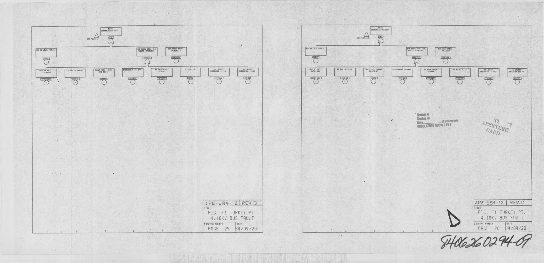
5EE ILJST 4 I
SII$3S
OfFWIICIIE$ILSIXNI
I N
~4$ 1AWfWIN IE IAAIEOIIT
1tt, ACES. I. I
N5 ~ LS X FIIUL 1 Stl $W'SIIT. Clk5147$ t5FWIOJSI
475 aaaN OffasSFUSTISISLI
N5 14 LNX fSIET$ Wa WW CS . Cta. AXIS ISFWINS:
Scil IIAAS OFEUSFWTNKI
ll45 4F IAT11111 $NT
35 Sla LS 1$ $-3$ FIW fN .:CONSAW 53$ -CF
lltfNWafal ISI.47tl AU SKacwlfslI 5 I WAIL
SI AELSI 31 3$ LCCNI'JlISITI4144-I'l-7SI
55 LSIEOJIIATITATW.IT~ NS
LN1 OF W;I17731~
SS SUS LS 155-tal AULI FWI: I SANS44 aas-c
OUESCWafal 151~4 SU OKSCIaalflA1$ 1-AWII
51 UELSI 1.111 IS L4CCICII151114151-115 IAI
al LIAEAII157114145-lla-Wl
'ch4k4'4
444 al AUIUAKA
~gg~ggg P05KT RLE
3
ORAUINC NU!!BEN OATF
P A G E 2 5 4 /0 4 /2 0
4 PE- LB+-I2 FL'EV.OTITLE
FIG. Fl TURKEY PT.4.16KV BUS FAULT
I 4
JPE-L8+- l2 REV.OTITLE
FIG. Fl TURKEY PT
4. I6KV BUS FAULTOA!IL!INC NUNBEN BATE
PAGE 26 4/04/20

5OASIS
SC RERCIT&ANCOlfl
CIIEE FACI'Icl,i
CCEININTIE ILSCCNn
IE INES:1.3
NN CS LNRL FAIAIS555 SCSO COAT. ~ It
44'S ISFVRISOSISct 54651 4FESA
1155:IANLT
NS Nl 15"Al FNIIIS tct Iaua Can CltAIRTI IIF5515551
SCS 3ARIN SFEINCFCSTS'Jtl I
SIC 4. TALII III-SCAT
Nl NIS LS IC6-15 FRAT FRS ..'14515444 INS- f
OIERC'JNIERI 151-SLS Nl O'ICIICINSfAl151-5141
51 IIELSI 14 N IACI'SJISIT!4144-1 1&-'151
15 LCKSJTRl'114'151-115-'SLC
LSN Of TN,T131 3433
N NN IS 116 Nl 5141 FIST.:-4435RN 535-Cr
5'IEACSttf41 131-434 55 I'IESCNISEST131-4511
Sl SILAT I I I 34 LsnclclIRITIA'ISS I'IS-RI
IR LONNITIRIIISTNI I 5-NI5
1
~y 8"+dF'444 dÃ86Of QOCOIW
yggg HLK
3 I
ORAUTMC MURDER DATE
P RG E 2 7 0 /0 0 /2 0
4 PE-L8+-lZ. REX 0TITLE
F1G. F1 TURKEY PT.4.16KV BUS FRULT
3
4 PE-LB f-1? FC'FV.OTITLE
FIG. Fl TURKEY PT.4. 16KV BUS FRULT
ORAUIMC MUMMER DATE
PRGE 28 0/QL1/20