Job Aid:Installing the upgrade memory kit in the G450 / G430 ...
Upload
khangminh22Category
view
1download
0
Kit InstructionsTrackball Upgrade
7350-K036Issue A

The product described in this document is a licensed product of NCR Corporation.
NCR is a registered trademark of NCR Corporation. NCR SelfServ™ Checkout is a trademark of NCR Corporation in the UnitedStates and/or other countries. Other product names mentioned in this publication may be trademarks or registered trademarks oftheir respective companies and are hereby acknowledged.
The terms HDMI and HDMI High-Definition Multimedia Interface, and the HDMI Logo are trademarks or registered trademarksof HDMI Licensing LLC in the United States and other countries.
Where creation of derivative works, modifications or copies of this NCR copyrighted documentation is permitted under the termsand conditions of an agreement you have with NCR, NCR's copyright notice must be included.
It is the policy of NCR Corporation (NCR) to improve products as new technology, components, software, and firmware becomeavailable. NCR, therefore, reserves the right to change specifications without prior notice.
All features, functions, and operations described herein may not be marketed by NCR in all parts of the world. In some instances,photographs are of equipment prototypes. Software screen images are representative, and in some cases, may not match acustomer’s installed software exactly. Therefore, before using this document, consult with your NCR representative or NCR officefor information that is applicable and current.
To maintain the quality of our publications, we need your comments on the accuracy, clarity, organization, and value of this book.Please use the link below to send your comments.
Email: [email protected]
Copyright © 2020By NCR CorporationGlobal Headquarters864 Spring St. NWAtlanta, GA 30308United StatesAll Rights Reserved

i
Revision Record
Issue Date Remarks
A Apr 2020 First Issue

Trackball Upgrade
The Trackball allows users with restricted reach to select items on the top portion of thetouch screen that they would not be able to reach otherwise. This publication providesprocedures for installing a Trackball to any of the following SelfServ Checkout units:
• NCR SelfServ™ Checkout (7350)
• NCR SelfServ™ Checkout (7350) R6 Lite
• NCR FastLane SelfServ™ Checkout (7358)
Note: For the purpose of illustration only, this publication shows images using anNCR SelfServ™ Checkout (7350) R6 Lite unit.

2 Trackball Upgrade
Kit Contents
Part Number Description
497-0475616 7350-K036 Track Ball Upgrade Kit
497-0453487 38 mm Panel Mounted Trackball
497-0459231 Assy - Cover - Scan Surface - Top With Topaz/ Biometric/Trackball Blanks
497-0455587 Bracket -Stainless - Track Ball
497-0455585 Bracket - Hold Down - Track Ball
006-8604575 Clamp, Cable, 5/16
497-0462484 Click Button and USB Cable for Trackball D509441 - ROHS
006-8611143 Nut - Keps, 8–32, Steel, Blue Zinc (7 pcs)
006-8611456 Nut-Keps 4–40 (2 pcs)
006-8612446 Screw - 8–32 x 0.375 in Phil Pan, Self Tapping - Type F
* 497-0423108 Instructions Kit (Reference Sheet)
* Items marked with an asterisk are not called out on the image.

Trackball Upgrade 3
Installation ProceduresTo install the Trackball, follow these steps:
1. Turn off the NCR SelfServ Checkout hardware and software systems.
2. Open the Upper Cabinet Door. For more information, refer to Opening the UpperCabinet Door on page 7.
3. Remove and set aside the Scanner/Scale. For more information, refer to Removing theScanner/Scale on page 8.
4. Depending on the SelfServ Checkout unit, disconnect the Trackball cable from theI/O Box or E-Box.
7350 R6 Lite Unit (I/O Box Cable Connection)

4 Trackball Upgrade
7350 Unit (E-Box Cable Connection)
5. Remove the existing Top Plate from the Core Cabinet. For more information, refer toRemoving Top Plate on page 10.
6. Assemble the Trackball device. For more information, refer to Assembling Trackball onpage 12.
7. Install the new Trackball Assembly on the Top Plate. For more information, refer toInstalling Trackball Assembly on page 16.
8. Install the new Top Plate on the core. For more information, refer to Installing TopPlate on page 18.

Trackball Upgrade 5
9. Depending on the SelfServ Checkout unit, route the Trackball cable up and over tothe I/O Box or the E-Box.
Note: Secure the cable using cable ties as shown in the image above. Ensure thatthere is enough cable slack to avoid cables from being stretched during installationor removal procedures.
7350 R6 Lite Unit (I/O Box Cable Connection)
7350 Unit (E-Box Cable Connection)

6 Trackball Upgrade
10. Install the Scanner/Scale. For more information, refer to Installing the Scanner/Scale onpage 20.
11. Turn on the SelfServ Checkout unit. Verify that the Trackball and button work in theSelfServ Checkout application.

Trackball Upgrade 7
Opening the Upper Cabinet DoorTo open the Upper Cabinet Door, follow these steps:
Note: For the purpose of illustration only, this procedure shows images using anNCR SelfServ™ Checkout (7350) R6 Lite unit. An NCR SelfServ™ Checkout (7350) R6Lite unit uses RealScan 79e Scanner/Scale while an NCR SelfServ™ Checkout (7350) usesRealScan 78 Scanner/Scale.
1. Insert key into lock on door latch and turn key counterclockwise.
2. Remove key and then press the keylock to unlatch the door.
Caution: Ensure that the door is pushed down while lock is pressed because thedoor will automatically open.
3. Lift the door open.

8 Trackball Upgrade
Removing the Scanner/ScaleTo remove the Scanner/Scale, follow these steps:
Note: For the purpose of illustration only, this procedure shows images using anNCR SelfServ™ Checkout (7350) R6 Lite unit. An NCR SelfServ™ Checkout (7350) R6Lite unit uses RealScan 79e Scanner/Scale while an NCR SelfServ™ Checkout (7350) usesRealScan 78 Scanner/Scale.
1. Remove the Scale Plate.
2. Grasp the front of the Scanner and lift up.
Trackball Upgrade 9
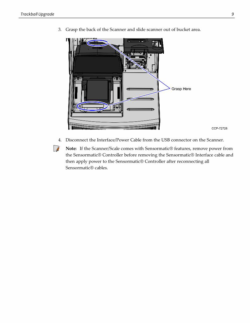
3. Grasp the back of the Scanner and slide scanner out of bucket area.
4. Disconnect the Interface/Power Cable from the USB connector on the Scanner.
Note: If the Scanner/Scale comes with Sensormatic® features, remove power fromthe Sensormatic® Controller before removing the Sensormatic® Interface cable andthen apply power to the Sensormatic® Controller after reconnecting allSensormatic® cables.

10 Trackball Upgrade
Removing Top PlateTo remove the Top Plate, follow these steps:
1. Unlock and open the Security Door.
2. Unscrew the four (4) nuts securing the top plate to the SelfServ Checkout core.

Trackball Upgrade 11
3. Depending on the SelfServ Checkout unit, verify if there is a screw on the Top Platenext to the printer. Remove the screw, as shown in the image below.
4. Grasp and pull the top cover to disengage the clips.
5. Lift the top plate from the unit.

12 Trackball Upgrade
Assembling TrackballTo assemble the Trackball device, follow these steps:
1. Place the Trackball gasket on top of the device, as shown in the image below.
Note: The Trackball gasket is located between the packing foam and top of theTrackball box.
2. Verify if there is a Switch Position at the back of the Trackball device. If there is aSwitch Position, change the setting orientation of the Trackball by switching SwitchPosition 5 from OFF to ON, as shown in the image below.

Trackball Upgrade 13
3. Connect the Button Assembly and I/O Box/E-Box cables to the Trackball, as shownin the image below.
4. Place the Trackball device over the Trackball mount and place the Hold DownBracket over the Trackball, as shown in the image below.

14 Trackball Upgrade
5. Secure the Hold Down Bracket over the Trackball using two (2) nuts.
6. Do the following:
a. Place the Button assembly over two PEM studs on the Trackball Assembly.
Note: Ensure that the cable going to the I/O Box or E-Box is on the opposite sideof the square button cutout as shown in the image below.

Trackball Upgrade 15
b. Secure the Button assembly to the Trackball Assembly using two (2) nuts.
Note: Ensure that the cable connection between the Trackball assembly to theButton assembly is secure.

16 Trackball Upgrade
Installing Trackball AssemblyTo install the Trackball Assembly, follow these steps:
1. Assemble the Trackball device. For more information, refer to Assembling Trackball onpage 12.
2. Secure the Trackball and Button Assembly to the Top Plate using four (4) nuts.
3. Attach the grounding lug (black wire) from USB cable to one of the rear most studswhere the Trackball and Button Assembly is mounted, as shown in the image below.

Trackball Upgrade 17
4. Route the cable to the bottom of the Top Plate using a small cable clamp and secureto the stud using one (1) nut as shown in the image below.

18 Trackball Upgrade
Installing Top PlateTo install the Top Plate, follow these steps:
1. Mount and secure the Top Plate to core using four (4) nuts, as shown in the imagebelow.

Trackball Upgrade 19
2. Depending on the SelfServ Checkout, secure the Top Plate in place using a screw, asshown in the image below.
3. Close and lock the Security Door.

20 Trackball Upgrade
Installing the Scanner/ScaleTo install the Scanner/Scale, follow these steps:
Note: For the purpose of illustration only, this procedure shows images using anNCR SelfServ™ Checkout (7350) R6 Lite unit. An NCR SelfServ™ Checkout (7350) R6Lite unit uses RealScan 79e Scanner/Scale while an NCR SelfServ™ Checkout (7350) usesRealScan 78 Scanner/Scale. For more information on installing RealScan 78Scanner/Scale, refer to
1. Connect the scanner cable to the "USB Client" port.
Note: To streamline the installation procedure, install the Sensormatic®components before installing the Scanner/Scale in the SelfServ Checkout unit.

Trackball Upgrade 21
2. Place the Scanner/Scale on the scanner bucket.
3. Lower the Scale Plate.
4. Close the Upper Cabinet Door.
Note: The Scanner/Scale must be calibrated before the system goes live. For moreinformation, refer to NCR SelfServ™ Checkout (7350) Hardware Service Guide (B005-0000-1827).

22
Copyright © 2022 FDOKUMEN