Research Portal Dépôt Institutionnel - Institutional Repository ...
183
Institutional Repository - Research Portal Dépôt Institutionnel - Portail de la Recherche THESIS / THÈSE researchportal.unamur.be University of Namur DOCTOR OF SCIENCES Synthesis and applications of novel fullerenes and silsesquioxanes based structures Cinà, Valerio Award date: 2020 Awarding institution: University of Namur Link to publication General rights Copyright and moral rights for the publications made accessible in the public portal are retained by the authors and/or other copyright owners and it is a condition of accessing publications that users recognise and abide by the legal requirements associated with these rights. • Users may download and print one copy of any publication from the public portal for the purpose of private study or research. • You may not further distribute the material or use it for any profit-making activity or commercial gain • You may freely distribute the URL identifying the publication in the public portal ? Take down policy If you believe that this document breaches copyright please contact us providing details, and we will remove access to the work immediately and investigate your claim. Download date: 26. Jan. 2022
-
Upload
khangminh22 -
Category
Documents
-
view
0 -
download
0
Transcript of Research Portal Dépôt Institutionnel - Institutional Repository ...

Institutional Repository - Research PortalDépôt Institutionnel - Portail de la Recherche
THESIS / THÈSE
Author(s) - Auteur(s) :
Supervisor - Co-Supervisor / Promoteur - Co-Promoteur :
Publication date - Date de publication :
Permanent link - Permalien :
Rights / License - Licence de droit d’auteur :
Bibliothèque Universitaire Moretus Plantin
researchportal.unamur.beUniversity of Namur
DOCTOR OF SCIENCES
Synthesis and applications of novel fullerenes and silsesquioxanes based structures
Cinà, Valerio
Award date:2020
Awarding institution:University of Namur
Link to publication
General rightsCopyright and moral rights for the publications made accessible in the public portal are retained by the authors and/or other copyright ownersand it is a condition of accessing publications that users recognise and abide by the legal requirements associated with these rights.
• Users may download and print one copy of any publication from the public portal for the purpose of private study or research. • You may not further distribute the material or use it for any profit-making activity or commercial gain • You may freely distribute the URL identifying the publication in the public portal ?
Take down policyIf you believe that this document breaches copyright please contact us providing details, and we will remove access to the work immediatelyand investigate your claim.
Download date: 26. Jan. 2022

Università degli Studi di Palermo Université de Namur
Dottorato di Ricerca in Doctorat en Sciences
Scienze Molecolari e Biomolecolari Faculté de Sciences
Dipartimento STEBICEF Département de Chimie
S. S. D. – CHIM/06
SYNTHESIS AND APPLICATIONS OF NOVEL FULLERENES AND
SILSESQUIOXANES BASED STRUCTURES
PhD STUDENT COORDINATOR
VALERIO CINÀ PROF. PATRIZIA DIANA
TUTOR TUTOR PROF. FRANCESCO GIACALONE PROF. CARMELA APRILE
CICLO XXXII
2019


i
Table of contents
Acknowledgment iv
Chapter 1 General introduction 1
1. Introduction 2
1.1. Carbon Allotropes and its Nanoforms 3
1.2. Applications of main Carbon Nanoforms 6
1.2.1. Graphene 7
1.2.2. Carbon Nanotubes 7
1.2.3. Fullerene 9
1.2.3.1. Synthesis 9
1.2.3.2. Properties 10
1.2.3.3. Common application 11
1.3. Silicon and its evolution 15
1.3.1. Silicon Dioxide 16
1.3.2. Mesostructured Silica 18
1.3.3. Polyhedral Oligomeric Silsesquioxanes 20
1.3.3.1. POSS Common applications 22
1.4. Aim of the Thesis 30
1.5. References 34
Chapter 2 Bisoxazoline-C60 Hybrid Systems for Asymmetric Catalysis 50
2. Introduction 51
2.1. C60-Fullerene in Catalysis 51
2.1.1. C2-Symmetry catalysts 54
2.1.1.1. Bisoxazoline (BOX) 55
2.2. Aim of Chapter 58
2.3. Results and discussion 59
2.3.1. Synthesis and characterization of catalysts 59
2.3.1.1. BOX Synthesis 59
ii
2.3.1.2. Synthesis of C60-BOX (monoadducts) 62
2.3.1.3. Synthesis of C60-BOX6 (hexakisadducts) 65
2.3.1.4. Synthesis of IL Hybrids (C60-IL10-BOX) 68
2.3.2. Catalytic applications 72
2.3.2.1. Asymmetric Henry 72
2.3.2.2. Asymmetric Diels-Alder 78
2.4. Conclusions 81
2.5. Experimental section 81
2.6. References 91
Chapter 3 Novel nanobuilding blocks for 3D emitting materials 97
3. Introduction 98
3.1. Photochemistry of Lanthanides 100
3.2. C60-BOX6: complexation study of novel Carbon building-blocks 101
3.3. Conclusions 106
3.4. References 108
Chapter 4 110
Tuneable Emission of Polyhedral Oligomeric Silsesquioxane- Based
Nanostructures Self-Assembled in the Presence of Europium(III) Ions: Reversible
trans-to-cis Isomerization
4. Introduction 111
4.1. Results and Discussion 113
4.2. Conclusions 129
4.3. References 131
Chapter 5 Photoluminescence Lanthanide@POSS-based materials 135
5. Photoluminescence Lanthanide@POSS-based materials 136
5.1. 139La-NMR characterisation 140
5.2. Replacing water molecules 143
5.3. “Rainbow” full emission spectrum 149

iii
5.4. Conclusions 152
5.5. Experimental Section 154
5.6. References 156
Chapter 6 General conclusions 157
6. General conclusions 158
Chapter 7 Outlooks 160
7. Outlooks 161
7.1. C60-PyBOX asymmetric catalysts 161
7.2. POSS terpyridine evolution 163
7.3. References 165
List of abbreviation 167
Curriculum vitae 170

iv
Acknowledgements
Thanks go, first of all, to the University of Palermo and the University of Namur
for the co‐funded PhD fellowship.
In particular part of this research used the resources of the “Plateforme
Technologique Physico-Chemical Characterization” (PC2) and the resources of the
“Plateforme Technologique Morphologie – Imagerie” (MORPH-IM). Many thanks
therefore go to the staff of the platforms: Valérie Charles and Nicolay Tumanov for
the PC2 and Corry Charlier of the electron microscopy service. Thanks also to
Giuseppe Barbera of the “Unité de chimie organique et biorganique
supramoléculaire” for solving many technical and instrumental problems.
Special thanks go to my two tutors, Professor Carmela Aprile and Professor
Francesco Giacalone, for welcoming me into their laboratories and giving me this
opportunity for professional growth. Thanks go also to Professor Michelangelo
Gruttadauria for welcoming in his research group.
Thanks go also to Professor H. Garcia that welcomed me at the “Instituto de
Tecnología Química (ITQ) at the Polytechnic University of Valencia (UPV) were I
spent two month learning that not always all results are positive, but it is possible,
in any case, to learn something.
I want to thanks Dr Esther Carbonell LLopis for following me during the first part
of my PhD, for helping me prepare for my mid-doctoral exam, for supporting me
during my journey to the ITQ and for being available always to talk about the results
obtained even when she was no formally part of the University staff.
Special tanks go to Dr Luca Fusaro, who taught me how to work with nmr and
trusted me by letting me work alone with the instrument under his responsibility,
for the wise advice and above all for motivating me to work hard in times of low
productivity.
A special thanks also go to Dr. Vincenzo Campisciano who, with his experience in
the laboratory suggested to me many small tricks to improve operationally and
manually my laboratory skills, and with his computing experience, has taught me
how to process data in the best way.

v
I want to tank also Alvise Vivian and Andrea Carletta with whom I shared special
moments during my periods in Belgium and with whom I have forged a special
friendship.
Last but not least special thanks go to my family that supported me during these
three years and to Elena that, with her love, has sustained and encouraged me also
and above all at a distance.

1
Chapter 1
General Introduction

2
1 Introduction
When we talk about matter in its Nanoform we are led to think that it is a prerogative
of modern science, whereas nanoparticles have a surprisingly long history. The term
“nano” comes from the ancient greek word να̃νος (nanos) through the Latin nanus
meaning literally dwarf and, by extension, very small. Within the convention of
International System of Units (SI) it is used to indicate the reduction factor of 10-9
times, and “nanoscale” generally refers to objects with a dimension between 1-100
nm. But what defines nanomaterials are not only their dimensions. Obviously, what
attracts are their peculiar properties. In fact, isolated molecules exhibit properties
that follow quantum mechanical rules, while the chemical and physical properties
of bulk materials obey the laws of classical physics. In the middle, nanosystems
display electronic, photochemical, electrochemical, optical, magnetic, mechanical
or catalytic properties that differ significantly not only from those of molecular
units, but also from those of macroscopic systems.1
Their preparation is neither an exclusive result of modern research nor restricted to
man-made materials. Naturally occurring nanoparticles include organic (proteins,
polysaccharides, viruses) as well as inorganic compounds (iron oxyhydroxides,
aluminosilicates, metals) and are produced by weathering, volcano eruptions,
wildfires or microbial processes.2
Most current nanoparticles and nanomaterials can be organized into four categories:
Carbon-based nanomaterials that include carbon allotrope forms, Organic-based
nanomaterials that include nanomaterials from organic matter (excluding the
carbon-based ones), Inorganic-based nanomaterials and Composite nanomaterials.
All of these are further classified depending their crystalline forms and chemical
composition,3 their dimension, their spatial arrangement (0D, 1D, 2D, 3D),4 and
their production. In the latter case, nanomaterials can formed in nature either by
biological species or through anthropogenic activities,5 or are synthesized by
physical, chemical, biological or hybrid methods.6
Among all the existing elements studied and by ever used, Carbon and Silicon-
based solids are two of the most important materials involved in the history of
science and technology development.7 In fact, carbon-based chemical industry has
produced the various synthetic materials for daily life and silicon-based

3
semiconductor industry has moved people to digital age. In recent decades, the
discovery and synthesis of carbon (e.g., fullerenes, carbon nanotubes, graphene)
and silicon nanostructures (e.g. Si quantum dots, Si nanowires) have pushed the
rapid advancement of nanoscience and nanotechnology. Nowadays, carbon and
silicon nanostructures are finding application in various fields, such as electronics,8
photonics,9 sensors,10 biotechnology,11 and recently, in energy related applications
such as catalysis,12 batteries,13 solar cells.14
1.1 Carbon Allotropes and its Nanoforms
By the very first human activities, carbon-based materials played immediately an
important role. In China there is evidence of the existence of a coal mine dating
back more or less to 1000 BC.15 It is known that also the Greeks used coal in their
in everyday life for example after reducing it to powder they mixed it with wine to
treat toothache. In Roman times, in England, coal was used not only to heat up, but
also to create jewellery and ornaments of various kinds given its shiny black
colour.16 In the late Middle Ages, it was used by blacksmiths to produce lime, salt
and to provide the minimum energy necessary for domestic life. It was then around
1750, with the Industrial Revolution, that coal acquired its true importance
becoming the main source of energy for man.17
Carbon is a chemical element with the symbol C and atomic number 6. The fourth
most abundant element in the universe, it is the sixth element of the periodic table.
It is non-metallic and tetravalent, and it naturally occurs in three isotopes, 12C and
13C being stable, while 14C is a radionuclide, decaying with a half-life of about 5,730
years.18
Carbon is an ancient fossil mineral originating from the carbonification of material
and plant residues that have accumulated in an anaerobic environment.19 Carbon,
due to its valency, can form many allotropes. Well-known allotropes of carbon
include diamond and graphite (Figure 1.1).

4
Figure 1.1 The two most know carbon allotropes graphite and diamond. In figure,
representative atoms arrangement in the space.
Both are known by ever; graphite owes its name to Abraham Gottlob Werner that
named it in this way, from the greek γράφειν (graphein), "to draw/write",20 for its
use in pencils. Graphite is a crystalline form of carbon with its atoms arranged in a
hexagonal structure. In graphite the bonds are hybridized sp2 and the atoms form in
planes with each bound to three nearest neighbours 120 degrees apart. It occurs
naturally in this form, and it is the most stable form of carbon under standard
conditions. Graphite is structurally composed of planes of polycyclic carbon atoms
in an hexagonal structure.21
Graphite possess delocalized electrons that are free to move throughout the plane
(above and below the planes of the carbon atoms), and for this reason it conducts
electricity along the planes, but does not through the planes. These conductivity
properties allow to use the graphite in electronic products such as electrodes,22
batteries,23 and solar panels. 24
In diamond the bonds are hybridized sp3 and the carbon atoms are arranged in space
in a tetrahedral arrangement. These tetrahedrons together form a 3D network of six-
membered carbon rings (similar to cyclohexane), in the chair conformation,
allowing for zero bond angle strain.25 This stable network of covalent bonds and
hexagonal rings is the reason that diamond is so strong.
Figure 1.2. Some graphite and diamond applications: lead pencil (left), diamond blade
(middle), graphite solar panel (right)

5
Diamond is the hardest known natural mineral in which carbon atoms are arranged
in a crystal structure called diamond cubic. Diamond has the highest hardness and
thermal conductivity of any natural material, properties that are utilized in major
industrial applications such as cutting and polishing tools.26 Furthermore its
hardness, the high dispersion of light of diamond make it useful in jewellery.
But the carbon allotropes family has not only two members. In fact, although these
two were the only ones known for years, in the middle of 1980’s the discovery of a
new allotrope starts to open the doors towards the exploration of this big family that
is the family of the Carbon Nanoforms (CNFs).
In particular the date that changed the way the scientists look at the Carbon was the
1985 with the discovery of the Buckminsterfullerene by Kroto, Smalley and Curl
that won for this the Nobel prize.27
Although already theoretically hypothesized in 1966 by D.E.H. Jones that
considered the possibility of making large hollow carbon cages, structures now
called giant fullerenes,28 (without finding positive reactions from the scientific
community). Later, in 1970 Osawa proposed a spherical Ih-symmetric football
structure for the C60 molecule, simulated by the synthesis of the bowl shaped
corannulene (Figure 1.3),29 by.30
Figure 1.3. Corannulene structure and fullerene hollow cage.
In 1984 it was observed that, by laser vaporization of graphite, large carbon clusters
Cn with n = 30–190 can be produced. Unfortunately, despite being present in the
produced soot, fullerene was not detected.31 The year of the breakthrough was 1985,
when Kroto met Smalley at Rice university in Huston. There they started together
to simulate the conditions under which carbon nucleates in the atmospheres of red
giant stars with a mass spectroscopy method developed by Smalley. To this
purpose, they began bombarding a graphite rod with a pulsed laser. These studies
found that, under specific clustering conditions, the 720 mass peak attributed to C60,

6
and to a lesser extent the peak attributed to C70, exhibits a pronounced intensity in
the spectra.32
As already said, this discovery was a turning point in the development of the CNFs.
In fact, just few years later, in the 1991, Iijima wrote in an abstract of a Nature
article: “Here I report the preparation of a new type of finite carbon structure
consisting of needle-like tubes”. Announcing the discovery of a new nanocarbon
allotrope, the Carbon Nanotube (CNT).33
Fascinatingly, Carbon Nanotubes and Fullerene are only the tip of the iceberg. In
the years that followed their discovery, a wide variety of new carbon Nanoforms
such as nanohorns, nano-onions, cup-stacked nanotubes, nanotori, nanobuds, and
graphene, have emerged (Figure 1.4).
Figure 1.4. Representative Carbon Nanoforms (CNFs)
1.2 Applications of main Carbon Nanoforms
Since the discovery of Kroto, carbon-based nanostructures have become one of the
most investigated class of nanomaterials in the world. During the past years
research efforts have mainly been devoted to the investigation on fullerene, carbon
nanotubes and graphene although the ability of carbon to exist in many allotropic
forms has provided a variety of nanoscale sized structures with fascinating
properties.

7
1.2.1 Graphene
Graphene is defined as the “oldest and the newest of the carbon nanoform”.34 It is
a two-dimensional near planar structure that consist of hexagonal rings constructed
from sp2-hybridized carbon atoms.35 The discovery of this carbon allotrope was
awarded with the Nobel Prize for Physics in 2010.36 About its production, the
techniques to produce it are developing rapidly, just for mentioning a few:
exfoliation, hydrothermal self-assembly, chemical vapor deposition, spin coating,
supersonic spray, laser, microwave-assisted oxidation etc.34 In general, different
production methods can be divided into three classes: the first consists in removing
layers from graphite, via mechanical exfoliation (scotch tape method),37 using
surfactants to disperse graphite layers.38 The second lie on exfoliation of graphene
from SiC films via heating bulk SiC (graphene is then formed by Si removing).39
The third one uses epitaxial growth (the most promising for large-scale
production).40
Regarding its application, it is still under investigation or at proposal stage. Due to
its electrical and structural properties, graphene is considered transparent and
flexible conductor that shows great promise for numerous material/device
applications, such as solar cells,41 light-emitting diodes (LED),42 touch panels and
smart windows or phones.43 It was successfully employed to improve mechanical
properties of solid material like in coating epoxy plastic increasing significantly
Young’s Modulus of the final material.44 Graphene based transistors have been
successfully produced and tested establishing the state of the art for graphene
transistors.45
1.2.2 Carbon nanotubes
A carbon nanotube can be imaged as a rolled graphene single layer33 (Figure 1.5).
Carbon nanotubes display intriguing electronic46 and mechanical47 properties that
have attracted the attention of many scientists all around the world. About CNTs a
first splitting can be done focusing on their morphology. There exist in single-
walled nanotubes (SWNT) and multiwalled nanotubes (MWNT) of different
lengths and diameters.

8
Figure 1.5. Fictional way to represent CNT formation (left). Multiwalled Carbon Nanotube
(right).
In the case of the single walled nanotubes, beside dimensions, the way the graphite
layer is rolled influences the final properties of the tube.
According to IUPAC, a whole new system has been established to classify carbon
nanotubes in order to distinguish between different tubes, but also to understand
certain properties: zig-zag, armchair, and chiral carbon nanotubes (Figure 1.6).
Figure 1.6. CNTs classification accordingly with the way they are rolled.
All the different CNTs possess various interesting properties and they found
applications in several fields. A great variety of CNT derivatives can be realized by
different synthetic approaches. CNTs can be chemically modified by the following
strategies: (a) functionalization of defects on the sidewall and on the rims; (b)
noncovalent interactions; (c) sidewall covalent functionalization and (d) endohedral
inclusion (Figure 1.7).
Figure 1.7. Different ways of CNTs functionalization

9
Among the others, CNTs can be employed in electronic as tips in atomic force
microscopy,48 in field emission (with an electric field applied, carbon nanotubes are
able to emit electrons from their tips),49 field effect transistors,50 as sensor (physical
or chemical),51 as support for catalyst,52 hydrogen storage,53 carrier for systems in
targeted drug delivery to living cells.54
1.2.3 Fullerene
1.2.3.1 Synthesis
The discovery of fullerene has represented the real turn off in the development of
nanocarbon materials. An innovative method that allowed to obtain fullerene in a
larger scale, making it available to the scientific community, was firstly reported by
Krätschmer and Huffman.55 They found that during the vaporization of graphite in
helium atmosphere it was possible produce fullerene in a 10% yield.
Macroscopic amounts of fullerenes can be nowadays produced in different ways
grouped in three categories: a) fullerene production by vaporization of graphite, b)
fullerene synthesis in combustion, c) fullerenes production by pyrolysis of
hydrocarbons.
The first group consists of three methods. One, resistive heating of graphite,
consists of applying a voltage to two graphite rods (one with a conical shape end,
and the other one with a flat shape end) kept in contact by a spring under a Helium
pressure of 140 mbar. This method produces a carbon soot with a 10% yield in
fullerene.55
Alternatively, there is the arc heating of graphite.56 The difference to the first one
is that graphite rods are not strictly in contact and when a voltage is applied power
is dissipated in an arc and not in Ohmic heating. The method reaches the highest
performance when the electrodes are barely in contact and it allows to produce
fullerene in 15% of yield.56a About the other two members of this group must be
underlined that they are only proof of concept in fact they produce fullerene in very
low yield. One consists in focusing sunlight, with a parabolic mirror, onto a tip of
a graphite rod. Producing so a carbon soot leveraging solar light.57 Fullerene can
also be produced by direct inductive heating of a carbon sample. Evaporation at

10
high temperature (2700 °C) in a He atmosphere affords a soot containing less than
1% of yield.58
But if we want to talk in term of industrial production, the methods above are not
suitable. The ideal method is the fullerene synthesis in combustion. In this way a
pilot plant of the Mitsubishi’s Frontier Carbon Corporation is operating. The
method consists in producing a soot burning a mix of benzene, oxygen and argon,
under a range of conditions that include different pressures, temperatures and
carbon-to-oxygen ratios. The yield of fullerenes, as well as the C70:C60 ratio,
strongly depends on the operation mode. Just to have an idea, the yields varies from
2 · 10−4 to 0.3% for a non-sooting flame, at a pressure of 20 Torr, a carbon: oxygen
ratio of 0.995 with 10% argon and a flame temperature of about 1800 K. The
C70:C60 ratio varies from 0.26 to 5.7, which is much larger than that observed for
graphite vaporization methods (0.02–0.18).59
1.2.3.2 Properties
Fullerene family consists of several members that differ each other by the number
of carbon atoms. In principle the building method follows the Euler’s principle:
Fullerene contain 2(10+M) carbon atoms divided in 12 pentagons and M hexagons.
Following this principle, the smallest member of the family should be the C20, but
it is unstable. On the contrary, the C60 [60-Ih] fullerene is the smallest stable
fullerene built up of fused pentagons and hexagons in which the pentagons provide
curvature, and its structure was theoretically and experimentally demonstrated.60
Two features of the C60 structure are of special significance: a) all twelve pentagons
are isolated by hexagons; b) the bonds at the junctions of two hexagons ([6,6]
bonds) are shorter than the bonds at the junctions of a hexagon and a pentagon ([5,6]
bonds). The bond length alternation in [60-Ih]fullerene shows that, in the lowest
energy Kekulé structure, the double bonds are located at the junctions of the
hexagons ([6,6] double bonds) and there are no double bonds in the pentagonal
rings. Each hexagon in [60-Ih]fullerene exhibits cyclohexatriene character and each
pentagon a radialene character. Regarding its reactivity, theoretical calculations of
the molecular orbital levels of C60 show that the lowest unoccupied molecular
orbitals (LUMO) is triply degenerated Therefore, C60 was predicted to be a fairly

11
electronegative molecule, being reducible up to the hexa-anion.61 This was
supported by cyclic voltammetry studies carried out with C60 in solution which
showed that it can accept up to six electrons. This electronic and geometric
properties imply that C60 behaves like an electron-poor conjugated polyolefin,
rather than a “super-arene”. Consequently, C60 undergoes various nucleophilic
additions with carbon, nitrogen, phosphorous and oxygen nucleophiles.
Functionalization has been done through various methods such as, cycloaddition,
electrophilic reaction like, halogenation, alkylation, arylation, oxidation, reduction,
free radical addition, metalation, hydrogenation, and polymerization by using
various reagents (Figure 1.8).62
Figure 1.8. C60 possible functionalization strategies.
1.2.3.3 Common applications
Fullerene, with its symmetrical hollow carbon structure, since its discovery has
been the object of intensive research. The wide number of books, and articles
(Figure 1.9) published on fullerene reactivity, properties and applications in

12
different areas evidences the progress made in the knowledge of these unique three-
dimensional structures.63
Figure 1.9. Trend of the topic fullerene searching in scopus database since its discovery by
now.
[60]Fullerene has been investigated in several fields of chemistry, biomedicine, in
the development of solar based cells, photovoltaic instruments, cosmetics, etc
(Figure 1.10). C60 has a broad range of charming properties, such as high electronic
conductivity, large specific surface area, good biocompatibility, inert behaviour,
stable structure and good adsorption capacity towards organic molecules.
Figure 1.10. Graph of different field of investigations.

13
Since it was discovered that films based on the fullerides compounds (alkali
elements doped C60 obtained by Diels-Alder cycloaddition reaction)64 showed
excellent conductivity at room temperature, a road in the direction of understanding
these properties of fullerene was opened.65
Photoinduced charge transfer from the polymer to the fullerene cage, was first
identified by Sariciftci et al., who showed the potential of C60 in the solar cell
field.66 Recently, Chengbo et al. reported two novel fullerene derivatives with
different specific functional groups, namely benzylthiophene-C60 bisadducts
(BTCBA) and 2-(4-methoxybenzyl)thiophene-C60 bis-adducts (MBTCBA), which
have been utilized as acceptors for polymer solar cells (PSCs).67 The MBTCBA
PSCs showed a power conversion efficiency superior to that of [6,6]-phenyl-C61-
butyric acid methyl ester (PCBM) based control devices (utilized as a role model
and reference acceptor for all kinds of fullerene acceptors, because of easy
preparation, good solubility, electron mobility, low lying LUMO energy levels, and
stability than comparing with their pristine fullerenes).
In 2019, Kielar et al. reported the preparation of organic optoelectronic rubrene-
fullerene diodes as tactile sensors for soft-touch applications.68 This organic
optoelectronic diode can act as light emitters or detectors as well as solar cells
solving the need of having separate light sources and detectors. In fact, the use of
fullerene in the preparation of electrochemical sensor and biosensor led to the
development of a variety of new nanomaterials. Due to its excellent electron
accepting capacity and its ability to accelerate charge separation in any
electrochemical process, fullerene can be used in various types of sensors, e.g.,
potentiometric, ampero-metric, piezoelectric, etc.
Planning biosensors for versatile biomedical applications is a challenge and the use
of modified C60 fullerene can open the doors for today and tomorrow's nanoscience
and nanotechnology. Fullerene-based material revealed to be suitable nanosensors
for the detection of glucose and as urea biosensor.69 Remaining in biological
application of fullerene, gadolinofullerenol was successfully tested to modulate
tumour microenvironment (TME) rather than kill cancerous cells directly.70
Although C60 fullerene and its derivatives are daily investigated as possible drug
carrier as well as in the treatment against of some diseases, their potential side

14
effects still need to be deeply investigated. A recent study was conducted to verify
the effect of buckminsterfullerene on Drosophila melanogaster at DNA, tissue and
organism levels.71 A first result indicates that pristine C60 at the concentration of 20
μg/mL and 40 μg/mL induced high level damage in DNA, but astonishingly there
are not effects at the organismal level, and this could be explained by the activation
of repair systems or by active elimination of damaged cells. The study demonstrated
also that at the concentration of 40 μg/ml does not exert any genotoxic effect on
adult organism, pristine C60 also does not affect the reproductive system and
embryogenesis.
Very recently, Elessawy et al., proposed an innovative synthesis of functionalized
magnetic fullerene nanocomposite (FMFN) via catalytic thermal decomposition of
PET bottle wastes as feedstock and ferrocene as a catalyst and precursor of
magnetite.72 This kind of material was then used for removing pollutants from the
environment, thanks to its porous and high surface area in addition to
superparamagnetic property, to adsorption of Ciprofloxacin antibiotic from
aqueous solution.73
Fullerene is finding application also in catalysis, although in this filed in the past
decades it has been less exploited, it is now experiencing a novel renaissance.74 C60
has been, for instance, directly functionalized with metals such as Palladium and
used as catalyst for the catalytic hydrogenation of acetylenic alcohols,75 or it has
employed as support for catalysts such as proline for asymmetric reactions.76 The
use of fullerene as catalyst is one of the topics of this Thesis because was widely
demonstrated its ability as molecular scaffold allowing easy handling of the
resulting catalysts. Thus, several aspects of fullerene in catalysis will be discussed
later in the present Thesis.

15
1.3 Silicon and its evolution
If today we can put a calculator in our pocket or wear a clock that also measures
our heartbeats and air temperature, if we talk about telematic networks, computers
and information highways, we owe much to the extraordinary capabilities of the
silicon. Silicon is the 7th most abundant element in the universe and the second most
abundant element in the earth's crust (27.7%) second only to the oxygen. The name
Silicon (assigned by Berzelius) comes from the Latin “silex”, meaning flint. Silicon
was first identified by Antoine Lavoisier in 178777 and was later mistaken for a
compound by Humphry Davy in 1800. In 1811 Gay Lussac and Thenard probably
prepared impure amorphous silicon by heating potassium with SiF4. In 1824
Berzelius prepared amorphous silicon using the same method as Lussac, isolating
it and describing it as an element.78
It is found in clay, feldspar, granite and quartz, mainly in the form of silicon dioxide
(SiO2), silicates and metallosilicates (compounds containing silicon, oxygen and
metals). Silicon is the main component of glass, cement, ceramic, etc. Crystalline
silicon was obtained only after 1854, when it was obtained as a product of
electrolysis.79 The manufacture of glass containing SiO2 was carried out both by the
Egyptians at least as early as 1500 BC and by the Phoenicians. Certainly, many of
the naturally occurring compounds called silicates were used in various kinds of
mortar for construction of habitat by the earliest people.78
Two allotropes of silicon exist at room temperature: amorphous and crystalline.80
Amorphous appears as a brown powder while crystalline silicon has a shine metallic
and greyish colour. Single crystals of crystalline silicon can be grown with a process
known as the Czochralski process. These crystals, doped with boron or gallium or
germanium or phosphorus or arsenic, are used in the manufacture of solid-state
electronic devices, such as transistors, solar cells, rectifiers and microchips.81
But talking about silicon it is mandatory to spend some word on the most common
Si compound that is the Silicon dioxide (SiO2). It usually takes the form of ordinary
sand, but also exists as flint, quartz, etc. SiO2 is largely used in the manufacture of
glass and bricks. Silica gel, a colloidal form of SiO2, is able to absorb moisture and
is then used as a desiccant. Silicon forms compounds that is possible to found in
daily use as: Silicon carbide (SiC), hard as diamond and used as abrasive,82 Sodium

16
silicate (Na2SiO3), used in the production of soaps83 and adhesives84 and Silicon
tetrachloride (SiCl4), used to create smoke screens. Silicon is also an important
ingredient in silicones, a class of material used for such things as electrical
insulators, lubricants, medical implants and polishing agents.
1.3.1 Silicon dioxide
As already mentioned, silicon dioxide (SiO2), generally named Silica (Figure 11),
is the most common form of Silicon. Pure silica looks like a white crystalline
powder, but can be found in different forms: hydrate (diatomaceous earth or
kieselguhr); anhydrous (pumice stone, molten silica, quartz glass); crystalline
(quartz, tridimite and cristobalite)
In these solids, the internal arrangement of the silicon and oxygen atoms can take
on a regular or disorderly course. In the first case we talk about free crystalline
silica. In its crystalline state each silicon atom is tetrahedron bound to 4 oxygen
atoms, and each oxygen atom is tetrahedron bound to two silicon atoms (Figure
1.11). While in the second case we talk about free amorphous silica (hydrated and
anhydrous).85
Figure 1.11. Schematic silica representation (left) Solid crystalline silica.
Silica is present in many minerals that, together with oxygen, make up about 75%
of the earth's crust: It is present in granite and sedimentary rocks (e.g. sand,
radiolites and quartzites), in marble and in various minerals in their raw state (such
as plaster and quartz). The latter is the primary constituent of many volcanic,
sedimentary and metamorphic rocks and represents the most common form of free
crystalline silica present in nature. Cristobalite and tridimite are rarer but are present
in products used by industries.

17
The high bonding energy leads the silica having a rather high melting temperature
(1710°C) and is chemically inert (it only reacts with F2, HF and strong alkali at high
temperature).
Pure silica is obtained by reaction between silicon tetrachloride and oxygen
(Scheme 1.1) and depending on the final content of OH-groups, silica is commonly
divided into dry and wet silica (respectively, low or high content of OH-groups).
Pure silica gives to the water a slight acidity (a suspension of 40 g in a litre of water
has a pH between 3,7 and 4,7).
Scheme 1.1. Preparation scheme of SiO2 by burning SiCl4 in an oxygen-rich hydrogen
flame to produce a "smoke" of SiO2
Silica found applications in our daily life: It is used in ceramic materials86 as an
insulator and one example is the heat shield of space probes or space shuttles or as
refractory material in ovens.87 To realize the isolation oxide inside the integrated
circuits, and the gate oxide of the MOSFET transistors.88 Together with its
derivatives it is one of the materials of choice in analytical chemistry for separating
compounds by chromatography: most stationary phases for chromatography
contain silica derivatives or pure silica.89 SiO2 is used as modern tyre component to
reduce rolling resistance and improve wet grip.90 Having hardness 7 in the Mohs
scale is a relatively hard material, therefore it is used as an abrasive.82
Unfortunately, all that glitters are not gold. The crystalline forms of silica, in
addition to be the most common in nature, are also most analysed because they are
more dangerous to health and responsible for diseases of a disabling nature.91 The
minerals and rocks mentioned above, in fact, do not represent any kind of problem
if they remain intact, but you cannot say the same when they are subject to
processing. In this case, cutting, grinding, crushing and similar operations produce
dust which, if inhaled, damages the lung tissue, causing serious damage to health.92
Among the diseases caused by inhalation of these powders, the most common is
silicosis:93 lung disease responsible for lung granulomatosis (presence of
granulomas in the lungs) and pulmonary fibrosis (cicatrisation of lung tissue that

18
interposes between the alveoli). The people most at risk of contracting this disease
are people working in mines and quarries who come into contact with minerals,
rocks, granite and sand; workers in steel mills, foundries and cement works; potters
and glassmakers.94 Depending on the duration of exposure to silica dust and the
quantities inhaled, silicosis can occur in more or less severe forms ranging from
chronic (the most common form that occurs after exposure of 15-20 years to low
levels of silica) to acute (occurs after inhalation of high levels of silica dust, even if
only for a few years).95
1.3.2 Mesostructured Silica
Mesoporous materials are, according to IUPAC definition, materials having pore
size in the range of 2–50 nm. Mesoporous silica is synthesized by reacting tetraethyl
orthosilicate with a template agent, a surfactant. By removing this one, by
calcination or extraction, porosity is generated
The first article in which the words silica and mesoporous appear together is a report
on the measurement of the porosity of mesoporous materials, and dates back to
1971.96 The first mesoporous silica material as meant it today was reported in 1992
by Mobil Research and Development Corporation, who synthesize mesoporous
solids using liquid crystal template mechanism (Figure 1.12). They designated it
as (Mobil Crystalline Materials or Mobil Composition of Matter) MCM-41.97 Six
years later, silica nanoparticles with much larger pores (4.6 to 30 nm) were
produced at the University of California, Santa Barbara.98 The material was named
Santa Barbara Amorphous type material, or SBA-15.
Figure 1.12. Schematic representation of mesoporous silica (left) and a TEM image of an SBA-15.

19
The pore size of the final material can be tuned by varying the surfactant used, the
starting precursors and the synthesis conditions such as: source of silica, ionic
strength, pH, composition of the reaction mixture, temperature and duration of
synthesis. For example, MCM-41 is hexagonal with a pore diameter of 2.5 to 6 nm
wherein cationic surfactants were used as templates.99 Changes in the ratio between
silica and surfactant are reflected to strong changes in the geometry of the pores. In
fact, when the surfactant/silica ratio is less than 1, the hexagonal structure of the
MCM-41 is obtained, while when this ratio is higher than 1, the result is the MCM-
48, that shows a cubic arrangement.100 Same concept can be applied to the synthesis
of the SBA type mesoporous silica; it is possible to change geometry of the pores
passing from SBA-11 (cubic) to SBA-12 (3-d hexagonal) to SBA-15 (hexagonal)
and SBA-16 (cubic cage-structured) by only changing the copolymer used as
templating agent and the ratio between the copolymer and the silica.98
Due to its porous and morphological characteristics, mesoporous silica found
application as supports for immobilizing biomolecules, catalysts, agents for
polymers reinforcement and templates for the synthesis of other materials.
Mesoporous silica (MS) are suitable materials, due to their high surface area and
their organized porous structure, as stationary phases for high performance liquid
or gas chromatography.101 The chemical nature of the surface and the morphologic
and porous properties determine the efficiency of the separation. Recently was
reported a separation of a mixture of alkane (C5-C10), using a new type of pillar with
mesoporous silica. A good separation performance was realized (the peak area of
nonane is increased by 349.8%) by using a MS with large specific surface area as
stationary phase, which would have a greatly application prospect in the micro gas
chromatography system.
Ordered mesoporous silica was fabricated as a nickel catalyst support for CO
methanation. This exhibited very high activity for CO methanation from 240 to 600
°C, due to the highest dispersion of Ni. In addition, the catalyst shows superior anti-
coking and anti-sintering properties than the SiC catalysts used as reference. The
good performance of the catalyst can be attributed to a good thermal conductivity
and stability, to the confinement effect of the mesoporous structure and the strong
metal–support interaction.102 Also in catalysis, to prove the importance of a pre-

20
ordered structure, a recent work demonstrate that SBA-15 is able to improve
catalytic effect of the Bu4NI salt in the conversion of epoxides into cyclic
carbonates with CO2.103 The pre-organization of reactants and catalyst on the
surface leads to a decrease of the activation energy of the reaction, leading to high
yields and selectivity for a wide variety of substrates under mild conditions (80°C).
1.3.3 Polyhedral Oligomeric Silsesquioxanes
Commonly named with their acronym, POSS, Polyhedral Oligomeric
Silsesquioxanes are hollow Nanoform of silica. They are almost cubic shaped
organosilicon compounds with empirical formula RSiO1.5 (Figure 1.13) where R,
can be hydrogen or any alkyl, alkylene, aryl, arylene, or organofunctional derivative
of alkyl, alkylene, aryl, or arylene groups.
Figure 1.13. Schematic representation of POSS almost cubic structure.
Silsesquioxanes are known in molecular form with 6, 8, 10, or 12 Si vertices, as
well as polymers and the cages are sometimes labelled T6, T8, T10, and T12,
respectively (T = tetrahedral vertex). The term sil-sesqui-ox-ane indicates that each
two silicon atoms are connected to three oxygen atoms.104
This nomenclature can be understood as follows:
• sil = silicon;
• sesqui = each Si atom is bound to an average of one and a half oxygens;
• ane = Si atom bound to one hydrocarbon group.
Polyhedral silsesquioxanes are compounds with structures based on several Si-O
linkages forming a cage having a silicon atom at each vertex. Substituents on the
cage are located on the eight silicon vertices. The R groups are important due to
their strongly influence on the physical and chemical properties of the nanocage,
while the silica core confers rigidity and thermal stability. The architecture of these

21
compounds varies. Although ideally the POSS have completed condensed
structures (Figure 1.14a), however there exist also not completely condensed POSS
in which in one corner a Si atom is missing (Figure 1.14b). In this case the oxygen
atom of the hydroxy group can complex metals resulting in a so called metalla-
silsesquioxane. Metallasilsesquioxanes can also result in completely condensed
cage structure as reported in Figure 1.14c.
Figure 1.14. Different POSS structures: a) completely condensed cage, b) partially
condensed and c) metallasilsesquioxane (M = metal).
Regarding their synthesis, a first preparation of a silsesquioxanes structure,
obtained by hydrolysis of alkyltriethoxysilanes in water, was reported by Andrianov
in 1937,105 but unfortunately a misunderstanding in the publication language and a
diffused distrust in eastern publications, has seen this early pioneering work not
generally acknowledged. After this work, a series of silsesquioxanes were
synthetized with hydrothermal treatment of organochlorosilane.106 A first complete
report on the preparation and characterization of a POSS dates back to 1946, when
Scott described the synthesis of a (CH3SiO1,5)n obtained in a two-step synthetic
process started with the hydrolysis of methyltrichlorosilane to form the trisilanol
derivative, followed by condensation to form a silsesquioxane oligomer.107
The common method that is still used in the synthesis of polyhedral oligomeric
silsesquioxanes, is the hydrolytic condensation of trifunctional monomers RSiX3,
where R is an organic substituent, and X is a highly reactive substituent such as Cl
or alkoxy (Scheme 1.2).
Scheme 1.2. Schematic sequence of reaction for the silsesquioxane condensation.
The first step of the hydrolytic condensation reaction is always the hydrolysis of the
monosilane to give the corresponding trisilanol. It was then suggested, for the

22
second step, an intramolecular hydrogen bonding transition state108 and finally an
intramolecular condensation leading to the cage-like structure.109
In addition, it was found that factors that may influence the condensation reaction
include the nature of the organic group R and the nature of the exit group X, but
also the reaction time and temperature, the solvent used and the amount of water
and, finally, the amount of silane used.110
The interesting aspect of this kind of material is that is possible to tune properly the
synthetic pathway, by changing the organic moiety, in order to obtain unique
organic-inorganic hybrid materials. It means inorganic oxygen-silicon scaffold with
peculiar thermal and mechanical properties of the nanosilica compounds, in
addition to enormous potential of the really big class of organic molecules suitable
for different fields, e.g. catalysis, polymer chemistry, photochemistry, chemistry of
material, biomedicine, etc.111
Scheme 1.3. Schematic representation of the synthetic way for the synthesis of
functionalized POSS.
So basically, to obtain a given functionalised-POSS, it is possible to proceed in two
different ways (Scheme 1.3):
1) to choose an organochlorosilane with the organic moiety of interest,
proceeding with the hydrolytic condensation and obtaining hence a POSS
that already has the organic group for the desired purposes;
2) to leverage the chemistry of an organic functional group in the POSS for a
post-functionalization of the structure with molecule suitable for the
particular needs.
1.3.3.1 POSS Common applications
Looking toward its applications, one that has attracted particular attention was the
use of the POSS as possible molecular heterogeneous catalyst. As soluble molecular

23
analogues of silica, POSS was used to mimic the structure and chemistry of bulk
silica. The silsesquioxane family represents the best molecular equivalent of the
silica surface. Silsesquioxane-based homogeneous models for heterogeneous
catalysts offer a unique opportunity to understand heterogeneous catalysis on a
molecular level. In some case these models exhibit catalytic activities comparable
to, or even better than, those of commercially used heterogeneous silica-supported
catalysts.112
There are two ways to use POSS as catalysts: a) metallasilsesquioxanes and b) as
molecular scaffold for the catalyst.
About metallasilsesquioxanes, Duchateau reported the use of an incompletely
condensed POSS, a silsesquioxane disilanol complexed with a Zn species.113 The
complex was tested as catalyst for the copolymerization of cyclohexene oxide and
CO2 (Figure 1.15).
Figure 1.15. Example of uncondensed POSS-Zn based catalyst.
At 120°C, in the absence of CO2, the complex promotes the homo-polymerization
of cyclohexene oxide to poly(cyclohexene oxide). Otherwise, in presence of carbon
dioxide the promoted reaction is the formation of the poly(cyclohexene carbonate).
Remaining within the area of CO2 valorisation, our group of investigation recently
reported a POSS functionalized with imidazolium chloride moieties used as catalyst
for the conversion of CO2 and epoxides into cyclic carbonates (Figure 1.16) with
excellent results in terms of yields and selectivity.114

24
Figure 1.16. Example of POSS used as molecular scaffold for catalyst.
The catalyst displayed excellent catalytic performances in the synthesis of styrene
carbonate and, under the best reaction conditions, an almost total conversion and
complete selectivity was obtained. Moreover, the catalyst was recovered by simple
extraction from the reaction mixture, demonstrating that the use of molecular
nanoform of silica can act successfully as a bulk, easy recoverable, catalyst.
The use of POSS as a substituent in polymers and copolymers is an area of research
that has gained great popularity in recent years.115 The idea to have a high
thermically and mechanically stable building block to insert in polymer matrixes to
improve properties of the resulting polymeric materials, stimulated scientist all over
the world. POSS copolymers have been synthesized by free radical
polymerization,116 anionic polymerization,117 ring-opening metathesis
polymerization,118 step-growth polymerization,119 grafting,120 etc.
POSS -based polymers found application in different fields. Monovinyl-functional
silsesquioxane cage was copolymerized with ethene and propene (Figure 1.17) to
give high molar mass copolymers containing pendant octasiloxane cubes.121
Figure 1.17. Schematic representation of POSS-based polymers.

25
Incorporation up to 25 wt % (1.2 mol %) of the POSS-based monomer accounted
for:
• a decrease of the melting temperature with respect to polyethene;
• improvement of the thermostability under air in the polyethene copolymer
in comparison to polyethene.
The novel copolymers poly(ethene-co-decenyl heptaethyl octasiloxane) and poly-
(propene-co-decenyl heptaethyl octasiloxane) are interesting materials with respect
to the effect of T8 cage as a structural irregularity on the crystallization and
morphology of polypropene and polyethene.
As already mentioned, owing to their biocompatibility and ability to be easily
incorporated into different polymers, POSS can be used in various biomedical
applications. Thanks to their inert nature and low inflammatory response, POSS
frameworks, consisting of Si-O and Si-C, are very similar to that of silicone which
was used since the 1960s in breast implants.122 An interesting application reported
the use of nanocomposite material for cardiovascular implants obtained introducing
POSS moieties into poly(carbonate-urea)urethane (POSS-PCU) as a pendent chain
group.123 The material was successfully employed for the construction of a
prototype of a trileaflet heart valve.
POSS found application also in electronics124 and energy applications. They are
used as materials to enhance performance in various electronic, optical and energy-
related applications such as their use in liquid crystal phase in LC devices, in light-
emitting, in fabrication of electronic and optical devices in sensor systems, and in
fuel cell membranes and battery electrolytes.125
Starting from the 90’s, a series of vinyl-functionalized mesogens POSS, were
synthesized with the idea of create a range of side-chain liquid crystalline
polysiloxanes126 exploiting the flexibility of the POSS backbone as an advantage in
allowing mesogens to align (Figure 1.18). In 1999 Mehl et al. reported the use of
an octa(hydridosilsesquioxane), Si8O12H8 (T8H8) to prepare liquid crystal.127

26
Figure 1.18. POSS-based LC. The POSS imparts right shape to the structure.
They used the T8 symmetry of the POSS with its almost cubic shape to provide the
right shape to liquid crystals allowing the tailoring of glass transition temperatures,
the type of liquid-crystalline phases and phase transition temperatures over a wide
temperature range.
The use of POSS in electronics is not limited in LC applications. POSS structures
Properly functionalized, with chromophores and fluorophores were extensively
investigated as electroluminescent (EL) materials, or as sensors in order to improve
performance, lifetime, stability and colour balance of the unsupported common
materials (analogues?). The idea lies in the fact that all photoluminescent materials,
which can be light emitting diode (LED), organic light emitting diode (OLED),
electroluminescent displays, solar cells, photovoltaics, sensors, thin film organic
transistors, lasers and light-emitting electrochemical cells, can undergor
degradation due to the formation of aggregates, excimers and simply physical
degradation of the material itself. The strategy is to introduce in the structure the
POSS as support, improving the stability of the final product.
As often happens, the need to make improvements to a device derives from some
problems inherent in the device itself. For example it just to think of the much-
needed blue emission in OLED technology.104 One of the most studied organic
fluorophores for this kind of emission is the PFO (polydioctylfluorene).128 PFO and
its derivatives are widely used as blue light emitters because they have high solid-
state quantum yields, good solubility, and good chemical and thermal stability.
Unfortunately, lateral chains of the PFO aggregate each other causing formation of

27
lower wavelength emitting excimers responsible of undesirable blue-green light
emission, and in quenching. The functionalization of the PFO on a Si8O12 leaded to
the formation of a material in which the thermal stability was enhanced by 50°C
and the solubility in organic solvent and the coating quality were improved. It is
worth noting that the POSS reduced the excimer emission.129
In the field of sensors, Hartmann-Thompson reported a series of POSS nanosensors
functionalized with fluorophores (Figure 1.19).130
Figure 1.19. POSS used as support for fluorophores.
Each nanosensor is functionalized with a different wavelength shifting fluorophore
and it was used to generate fingerprints for a diverse range of analytes, including
common organic solvents, toxic industrial chemicals (TICs) and chemical warfare
agent simulants. POSS was used first for its ability to form aerosols, making it
suitable for threat cloud applications and as suitable nanoscaffold to generate a
system with more sensor groups per unit of mass and greater sensitivity than a
microscaffold system.
Remaining in the field of the photophysics, recently Liu et al. reported the synthesis
of an octa functionalized POSS with eight azobenzene moieties (Figure 1.20).131

28
Figure 1.20. Octa-azabenzene-POSS
They demonstrated the good thermal stability of the inert support together with
good emission of the fluorophores that exhibited fluorescence emission at 400 nm,
making this material suitable for blue emitting devices.
Furthermore, Li et al. proved that octa functionalized POSS can be a good candidate
for emitting not only alone but in a 3D polymer. They obtained a dendrimer with
β–diketone–substituted POSS able to complex Eu and Tb ions to achieve novel
photoluminescent materials (Figure 1.21).132
They finally incorporated the dendrimer in a poly(methyl methacrylate) matrix to
obtain hybrid emitting nanocomposites with high thermal stability.
In the present Thesis, POSS will be presented as scaffold for novel organic-
inorganic photoluminescent materials. In particular an eight branched
silsesquioxane opportunely functionalized with a ligand displaying high ability to
complex metals fluorophore, will be present as promising solid-state emitting
material and as sensor for metals.

29
Figure 1.21. Octa-β–diketone–substituted POSS

30
1.4 Aim of the Thesis
What was discussed in the introduction led to the idea that both carbon and silica
Nanoforms, or rather silica in the case of POSS, can be extensively used for a wide
variety of purposes. Here specifically, the C60 fullerene and the Polyhedral
Oligomeric Silsesquioxanes (POSS) were chosen as representatives of the two
respective groups of Nanoforms.
The idea is to use both cages to obtain nano building blocks with well-established
geometry that will be used in catalysis or in the creation of photoluminescent (PL)
materials. In fact, both nano-cages are suitable to be functionalized in order to
achieve materials with a cubic or an octahedral o pseudo-octaedral geometry
(Figure 1.22).
Figure 1.22. Schematic representation of the C60 octahedral (left) and POSS cubic (right)
building blocks.
Regarding the fullerene, the idea was to functionalize C60 with molecules of
catalytic interest and in particular, chiral molecules for enantioselective catalysis.
Bisoxazoline (BOX) ligands that are (once complexed with a metal) widely used in
asymmetric catalysis, were selected as suitable ligand to functionalise the fullerene
cage133 (Figure 1.23).
Figure 1.23. C60 fullerene support (left) and BOX-type ligand chosen to build novel
catalytic systems.
The idea behind is trying to use the C60 fullerene as molecular scaffold instead of
the common bulk supports for catalysts. In fact, usual bulk supports used to anchor

31
catalysts make these lasts heterogeneous with all the advantages and disadvantages.
Although heterogeneous catalysts are useful because allow an easy separation of
the catalysts from the reaction media making them reusable, they have a reduced
activity in terms of interaction with the substrates.134 On the other hand, a molecular
scaffold can confer to the catalyst a double advantage. Firstly, it can thought as a
homogeneous catalyst, since it gain the solubility profile that one want to confer to
the catalytic system allowing him to work in solution closely to the substrates
resulting in an more efficient catalysis and, once ended the reaction, it can be
recovered by precipitation by changing the polarity of the reaction media. In
addition, there is the possibility to functionalize the support in order to change the
catalytic loading, allowing to drastically reduce the amount of support used. Here,
for all these purposes, C60 fullerene was selected as support because it can be easily
functionalized with organic molecules forming multiple adduct and because of its
easier separation from the reaction mixture which can allow a facile reuse in
multiple cycles.74
Therefore, different BOX ligands, which differ in the type of substituent on the
oxazoline moiety were synthesized in order to obtain different systems to test as
catalytic systems.
In particular fullerene was functionalized to obtain three different series of catalytic
systems (Figure 1.24) with three different solubility profiles and all the systems
were tested in asymmetric Henry and Diels-Alder reactions.
Figure 1.24. C60-BOX based catalyst synthetized: C60-Monoadduct (C60-BOX), C60-
Hexakisadduct (C60-BOX6) and Ionic liquid hybrid (C60-IL10-BOX).

32
Moreover, due to excellent ability of the BOX in complexing metals, a second goal
was to use the Hexa-adduct of the C60, leveraging its octahedral geometry, to
prepare a self-assembled 3D material with peculiar properties (Figure 1.25).
Figure 1.25. Schematic representation of the 3D self-assembled C60-BOX6-M.
In particular the idea is to complex the C60 hexakis-adduct with a light emitting
behaviour metal to have a novel three-dimensional material with photoluminescent
properties. Due to the excellent light-emitting performance of the lanthanides,135
the attention was focused to this series and in particular to, Eu trivalent ions which
usually exhibit intense emission bands from f-f electronic transitions.136
Since also the POSS has a rigid scaffold, with well-established geometry, the idea
to use it as possible building block to prepare self-assembled 3D structure in
presence of a metal was take into account (Figure 1.26).
Figure 1.26. Hypothetical 3D POSS-M self-assembled structure.

33
Part of the work was then dedicated to the synthesis of materials based on
polyhedral oligomeric silsesquioxanes functionalized with a derivative of
terpyridine. Mono- and octa-vinyl-POSS (MV and OV, respectively, in Figure
1.27) were selected as building units. The presence of the double bond on both
structures may allow obtaining complexes in which the final properties can be tuned
via the trans to cis isomerization of this group. Both POSS nanocages were
functionalized with 4'-phenyl-2,2':6',2''-terpyridine moieties chosen for their
extraordinary binding affinity toward several metal ions.
Figure 1.27 Monovinyl-isobutyl substituted POSS (MV), Octavinyl POSS (OV).
The materials obtained by the complexation of the POSS-Terpyridine based
systems were studied as possible sensor for metals and as photoluminescent
materials. Herein, not only the Europium was used as light-emitting metal centre,
but a complete screening of all the members of the lanthanides family was made
with exciting result.
Just to summarize, the goal of the present work was to play with two different
hallow nano caged scaffolds, opportunely functionalized, to synthesized innovative
molecular materials useful in the field of catalysis and in the field of sensors and
photoluminescent materials by complexing the resulting material with right metals
(Figure 1.28).
Figure 1.28. Working plan.

34
1.5 References
1. Irshad, A. W., Nanomaterials, Novel Preparation Routes, and
Characterizations. In Nanotechnology Applications for Improvements in Energy
Efficiency and Environmental Management, IGI Global: Hershey, PA, USA, 2015;
pp 1-40.
2. (a) Lead, J. R.; Wilkinson, K. J., Aquatic Colloids and Nanoparticles:
Current Knowledge and Future Trends. Environ. Chem. Lett. 2006, 3 (3), 159-171;
(b) Hough, R. M.; Noble, R. R. P.; Reich, M., Natural gold nanoparticles. Ore Geol.
Rev. 2011, 42 (1), 55-61.
3. Gleiter, H., Nanostructured materials: basic concepts and microstructure.
Acta Mater. 2000, 48 (1), 1-29.
4. Pokropivny, V. V.; Skorokhod, V. V., Classification of nanostructures by
dimensionality and concept of surface forms engineering in nanomaterial science.
Mat. Sci. Eng. C 2007, 27 (5), 990-993.
5. (a) Hochella, M. F.; Spencer, M. G.; Jones, K. L., Nanotechnology: nature's
gift or scientists' brainchild? Environ. Sci. Nano 2015, 2 (2), 114-119; (b) Sharma,
V. K.; Filip, J.; Zboril, R.; Varma, R. S., Natural inorganic nanoparticles –
formation, fate, and toxicity in the environment. Chem. Soc. Rev. 2015, 44 (23),
8410-8423.
6. Wagner, S.; Gondikas, A.; Neubauer, E.; Hofmann, T.; von der Kammer,
F., Spot the Difference: Engineered and Natural Nanoparticles in the
Environment—Release, Behavior, and Fate. Angew. Chem. Int. Ed. 2014, 53 (46),
12398-12419.
7. Zhong, J.; Zhang, H.; Sun, X.; Lee, S. T., Synchrotron Soft X‐ray
Absorption Spectroscopy Study of Carbon and Silicon Nanostructures for Energy
Applications. Adv. Mater. 2014, 26 (46), 7786-7806.
8. Tans, S. J.; Verschueren, A. R. M.; Dekker, C., Room-temperature transistor
based on a single carbon nanotube. Nature 1998, 393 (6680), 49-52.
9. Gudiksen, M. S.; Lauhon, L. J.; Wang, J.; Smith, D. C.; Lieber, C. M.,
Growth of nanowire superlattice structures for nanoscale photonics and electronics.
Nature 2002, 415 (6872), 617-620.

35
10. Kong, J.; Franklin, N. R.; Zhou, C.; Chapline, M. G.; Peng, S.; Cho, K.; Dai,
H., Nanotube Molecular Wires as Chemical Sensors. Science 2000, 287 (5453),
622-625.
11. (a) Baughman, R. H.; Zakhidov, A. A.; de Heer, W. A., Carbon Nanotubes-
-the Route Toward Applications. Science 2002, 297 (5582), 787-792; (b) He, Y.;
Fan, C.; Lee, S.-T., Silicon nanostructures for bioapplications. Nano Today 2010, 5
(4), 282-295.
12. (a) Kang, Z.; Liu, Y.; Tsang, C. H. A.; Ma, D. D. D.; Fan, X.; Wong, N.-B.;
Lee, S.-T., Water-Soluble Silicon Quantum Dots with Wavelength-Tunable
Photoluminescence. Adv. Mater. 2009, 21 (6), 661-664; (b) Pan, X.; Bao, X., The
Effects of Confinement inside Carbon Nanotubes on Catalysis. Acc. Chem. Res.
2011, 44 (8), 553-562.
13. (a) Ji, L.; Rao, M.; Zheng, H.; Zhang, L.; Li, Y.; Duan, W.; Guo, J.; Cairns,
E. J.; Zhang, Y., Graphene Oxide as a Sulfur Immobilizer in High Performance
Lithium/Sulfur Cells. J. Am. Chem. Soc. 2011, 133 (46), 18522-18525; (b) Sim, S.;
Oh, P.; Park, S.; Cho, J., Critical Thickness of SiO2 Coating Layer on Core@Shell
Bulk@Nanowire Si Anode Materials for Li-Ion Batteries. Adv. Mater. 2013, 25
(32), 4498-4503.
14. (a) Shen, X.; Sun, B.; Liu, D.; Lee, S.-T., Hybrid Heterojunction Solar Cell
Based on Organic–Inorganic Silicon Nanowire Array Architecture. J. Am. Chem.
Soc. 2011, 133 (48), 19408-19415; (b) Song, X.; Hua, W.; Ma, Y.; Wang, C.; Luo,
Y., Theoretical Study of Core Excitations of Fullerene-Based Polymer Solar Cell
Acceptors. J. Phys. Chem. C 2012, 116 (45), 23938-23944.
15. Lavinsky, D. R., Crystalline treasure book. The Arkenstone: 2013.
16. Smith, A. H. V., Provenance of Coals from Roman Sites in England and
Wales. Britannia 2011, 28, 297-324.
17. Fernihough, A., Coal and the european industrial revolution. NBER 2014,
19802.
18. Britannica, E., Carbon.
19. (a) Jones, D. T.; Wheeler, R. V., LIX.—The constitution of coal. J. Chem.
Soc., Trans. 1916, 109 (0), 707-714; (b) Major, T. J., Genesis and the origin of coal
and oil. Apologetics Press, Inc. : 1996.

36
20. Werner, A. G., Complete Dictionary of Scientific Biography. In
Encyclopedia.com.
21. (a) Delhaes, P., Graphite and Precursors. Taylor & Francis: 2000; (b)
Pierson, H. O., Handbook of Carbon, Graphite, Diamonds and Fullerenes:
Processing, Properties and Applications. Elsevier Science: 2012.
22. Burns, R. M.; Hulett, G. A., Some properties of graphite. J. Am. Chem. Soc.
1923, 45 (3), 572-578.
23. Armand, M.; Touzain, P., Graphite intercalation compounds as cathode
materials. Mat. Sci. Eng. 1977, 31 (C), 319-329.
24. Ralph, E. L.; Linder, E. B. In Advanced solar panel designs, Conference
Record of the Twenty Fifth IEEE Photovoltaic Specialists Conference - 1996, 13-
17 May 1996; 1996; pp 297-300.
25. Bragg, W. H.; Bragg, W. L., The Structure of the Diamond. Nature 1913,
91 (2283), 557-557.
26. Halliday, D.; Resnick, R.; Walker, J., Fundamentals of Physics. Wiley:
2002.
27. Robert F. Curl, H. K., Richard E. Smalley The Nobel Prize in Chemistry
1996. https://www.nobelprize.org/prizes/chemistry/1996/press-release/.
28. David, E. H. J.; Wasserman, E.; Applewhite, E. J.; Kroto, H. W.; Iijima, S.;
Haddon, R. C.; Pillinger, C. T., Dreams in a Charcoal Fire: Predictions about Giant
Fullerenes and Graphite Nanotubes [and Discussion]. Phil. Trans. Phys. Sci. Eng.
1993, 343 (1667), 9-18.
29. Barth, W. E.; Lawton, R. G., Dibenzo[ghi,mno]fluoranthene. J. Am. Chem.
Soc. 1966, 88 (2), 380-381.
30. (a) Osawa, E., Superaromaticity. Kagaku (Kyoto, Japan) 1970, 25 (9), 854-
863; (b) Z. Yoshida, Z. O., Kagakudojin: Kyoto 1971, 174.
31. Rohlfing, E. A.; Cox, D. M.; Kaldor, A., Production and characterization of
supersonic carbon cluster beams. J. Chem. Phys. 1984, 81 (7), 3322-3330.
32. Kroto, H. W.; Heath, J. R.; O'Brien, S. C.; Curl, R. F.; Smalley, R. E., C60:
Buckminsterfullerene. Nature 1985, 318 (6042), 162-163.
33. Iijima, S., Helical microtubules of graphitic carbon. Nature 1991, 354
(6348), 56-58.

37
34. Suarez-Martinez, I.; Grobert, N.; Ewels, C., Encyclopedia of Carbon
Nanoforms. 2012; pp 1-65.
35. Geim, A. K.; Novoselov, K. S., The rise of graphene. Nat. Mater. 2007, 6
(3), 183-191.
36. Geim, A.; Novoselov, K. The Nobel Prize in Physics 2010.
https://www.nobelprize.org/prizes/physics/2010/summary/.
37. Novoselov, K. S.; Geim, A. K.; Morozov, S. V.; Jiang, D.; Zhang, Y.;
Dubonos, S. V.; Grigorieva, I. V.; Firsov, A. A., Electric Field Effect in Atomically
Thin Carbon Films. Science 2004, 306 (5696), 666-669.
38. Hernandez, Y.; Nicolosi, V.; Lotya, M.; Blighe, F. M.; Sun, Z.; De, S.;
McGovern, I. T.; Holland, B.; Byrne, M.; Gun'Ko, Y. K.; Boland, J. J.; Niraj, P.;
Duesberg, G.; Krishnamurthy, S.; Goodhue, R.; Hutchison, J.; Scardaci, V.; Ferrari,
A. C.; Coleman, J. N., High-yield production of graphene by liquid-phase
exfoliation of graphite. Nat. Nanotechnol. 2008, 3 (9), 563-568.
39. Berger, C.; Song, Z.; Li, T.; Li, X.; Ogbazghi, A. Y.; Feng, R.; Dai, Z.;
Marchenkov, A. N.; Conrad, E. H.; First, P. N.; de Heer, W. A., Ultrathin Epitaxial
Graphite: 2D Electron Gas Properties and a Route toward Graphene-based
Nanoelectronics. J. Phys. Chem. B 2004, 108 (52), 19912-19916.
40. Berger, C.; Song, Z.; Li, X.; Wu, X.; Brown, N.; Naud, C.; Mayou, D.; Li,
T.; Hass, J.; Marchenkov, A. N.; Conrad, E. H.; First, P. N.; de Heer, W. A.,
Electronic Confinement and Coherence in Patterned Epitaxial Graphene. Science
2006, 312 (5777), 1191-1196.
41. Pang, S.; Hernandez, Y.; Feng, X.; Müllen, K., Graphene as Transparent
Electrode Material for Organic Electronics. Adv. Mater. 2011, 23 (25), 2779-2795.
42. (a) Diker, H.; Bozkurt, H.; Varlikli, C., Dispersion stability of amine
modified graphene oxides and their utilization in solution processed blue OLED.
Chem. Eng. Trans. 2020, 381, 122716; (b) Chen, D.; Chen, S.; Yue, S.; Lu, B.; Pan,
X.; He, H.; Ye, Z., N-ZnO nanorod arrays/p-GaN light-emitting diodes with
graphene transparent electrode. J. Lumin. 2019, 216, 116719.
43. Vlasov, A. I.; Terent’ev, D. S.; Shakhnov, V. A., Graphene flexible
touchscreen with integrated analog-digital converter. Russian Microelectronics
2017, 46 (3), 192-199.

38
44. Rafiee, M. A.; Rafiee, J.; Wang, Z.; Song, H.; Yu, Z.-Z.; Koratkar, N.,
Enhanced Mechanical Properties of Nanocomposites at Low Graphene Content.
ACS Nano 2009, 3 (12), 3884-3890.
45. Huard, B.; Sulpizio, J. A.; Stander, N.; Todd, K.; Yang, B.; Goldhaber-
Gordon, D., Transport Measurements Across a Tunable Potential Barrier in
Graphene. Phys. Rev. Lett. 2007, 98 (23), 236803.
46. Gong, K.; Yan, Y.; Zhang, M.; Su, L.; Xiong, S.; Mao, L., Electrochemistry
and Electroanalytical Applications of Carbon Nanotubes: A Review. Anal. Sci.
2005, 21 (12), 1383-1393.
47. Xie, X.-L.; Mai, Y.-W.; Zhou, X.-P., Dispersion and alignment of carbon
nanotubes in polymer matrix: A review. Mat. Sci. Eng. R 2005, 49 (4), 89-112.
48. Romanishina, S. A.; Barchukov, D. A.; Slobodyan, S. M. In The Stability of
Single-Walled Carbon Nanotube: Lyapunov Function for Probe Needle, 2019 IEEE
39th International Conference on Electronics and Nanotechnology (ELNANO), 16-
18 April 2019; 2019; pp 21-25.
49. Rinzler, A. G.; Hafner, J. H.; Nikolaev, P.; Nordlander, P.; Colbert, D. T.;
Smalley, R. E.; Lou, L.; Kim, S. G.; Tománek, D., Unraveling Nanotubes: Field
Emission from an Atomic Wire. Science 1995, 269 (5230), 1550-1553.
50. (a) Tamersit, K.; Djeffal, F., Carbon Nanotube Field-Effect Transistor With
Vacuum Gate Dielectric for Label-Free Detection of DNA Molecules: A
Computational Investigation. IEEE Sens. J. 2019, 19 (20), 9263-9270; (b) Freitag,
M.; Johnson, A. T.; Kalinin, S. V.; Bonnell, D. A., Role of Single Defects in
Electronic Transport through Carbon Nanotube Field-Effect Transistors. Phys. Rev.
Lett. 2002, 89 (21), 216801.
51. Rasheed, T.; Nabeel, F.; Adeel, M.; Rizwan, K.; Bilal, M.; Iqbal, H. M. N.,
Carbon nanotubes-based cues: A pathway to future sensing and detection of
hazardous pollutants. J. Mol. Liq. 2019, 292, 111425.
52. (a) Tessonnier, J.-P.; Pesant, L.; Ehret, G.; Ledoux, M. J.; Pham-Huu, C.,
Pd nanoparticles introduced inside multi-walled carbon nanotubes for selective
hydrogenation of cinnamaldehyde into hydrocinnamaldehyde. Appl. Catal. A-GEN
2005, 288 (1), 203-210; (b) Nhut, J.-M.; Pesant, L.; Tessonnier, J.-P.; Winé, G.;
Guille, J.; Pham-Huu, C.; Ledoux, M.-J., Mesoporous carbon nanotubes for use as

39
support in catalysis and as nanosized reactors for one-dimensional inorganic
material synthesis. Appl. Catal. A-GEN 2003, 254 (2), 345-363; (c) Serp, P.;
Corrias, M.; Kalck, P., Carbon nanotubes and nanofibers in catalysis. Appl. Catal.
A-GEN 2003, 253 (2), 337-358.
53. Dillon, A. C.; Jones, K. M.; Bekkedahl, T. A.; Kiang, C. H.; Bethune, D. S.;
Heben, M. J., Storage of hydrogen in single-walled carbon nanotubes. Nature 1997,
386 (6623), 377-379.
54. Seyfoori, A.; Sarfarazijami, S.; Seyyed Ebrahimi, S. A., pH-responsive
carbon nanotube-based hybrid nanogels as the smart anticancer drug carrier. Artif.
Cell. Nanomed. B 2019, 47 (1), 1437-1443.
55. Krätschmer, W.; Lamb, L. D.; Fostiropoulos, K.; Huffman, D. R., Solid
C60: a new form of carbon. Nature 1990, 347 (6291), 354-358.
56. (a) Haufler, R. E.; Conceicao, J.; Chibante, L. P. F.; Chai, Y.; Byrne, N. E.;
Flanagan, S.; Haley, M. M.; O'Brien, S. C.; Pan, C.; et al., Efficient production of
C60 (buckminsterfullerene), C60H36, and the solvated buckide ion. J. Phys. Chem.
1990, 94 (24), 8634-8636; (b) Cyvin, S. J.; Brendsdal, E.; Cyvin, B. N.; Brunvoll,
J., Molecular vibrations of footballene. Chem. Phys. Lett. 1988, 143 (4), 377-380.
57. (a) Chibante, L. P. F.; Thess, A.; Alford, J. M.; Diener, M. D.; Smalley, R.
E., Solar generation of the fullerenes. J. Phys. Chem. 1993, 97 (34), 8696-8700; (b)
Fields, C. L.; Pitts, J. R.; Hale, M. J.; Bingham, C.; Lewandowski, A.; King, D. E.,
Formation of fullerenes in highly concentrated solar flux. J. Phys. Chem. 1993, 97
(34), 8701-8702.
58. (a) Peters, G.; Jansen, M., A New Fullerene Synthesis. Angew. Chem. Int.
Ed. 1992, 31 (2), 223-224; (b) Jenkins, G. M.; Holland, L. R.; Maleki, H.; Fisher,
J., Continuous production of fullerenes by pyrolysis of acetylene at a glassy carbon
surface. Carbon 1998, 36 (12), 1725-1727; (c) Todorovic-Marković, B.; Marković,
Z.; Mohai, I.; Károly, Z.; Gál, L.; Föglein, K.; Szabó, P. T.; Szépvölgyi, J., Efficient
synthesis of fullerenes in RF thermal plasma reactor. Chem. Phys. Lett. 2003, 378
(3), 434-439.
59. Howard, J. B.; McKinnon, J. T.; Makarovsky, Y.; Lafleur, A. L.; Johnson,
M. E., Fullerenes C60 and C70 in flames. Nature 1991, 352 (6331), 139-141.

40
60. (a) Schulman, J. M.; Disch, R. L.; Miller, M. A.; Peck, R. C., Symmetrical
clusters of carbon atoms: The C24 and C60 molecules. Chem. Phys. Lett. 1987, 141
(1), 45-48; (b) Lüthi, H. P.; Almlöf, J., AB initio studies on the thermodynamic
stability of the icosahedral C60 molecule “buckminsterfullerene”. Chem. Phys. Lett.
1987, 135 (4), 357-360; (c) Scuseria, G. E., Ab initio theoretical predictions of the
equilibrium geometries of C60, C60H60 and C60F60. Chem. Phys. Lett. 1991, 176
(5), 423-427; (d) Häser, M.; Almlöf, J.; Scuseria, G. E., The equilibrium geometry
of C60 as predicted by second-order (MP2) perturbation theory. Chem. Phys. Lett.
1991, 181 (6), 497-500; (e) David, W. I. F.; Ibberson, R. M.; Matthewman, J. C.;
Prassides, K.; Dennis, T. J. S.; Hare, J. P.; Kroto, H. W.; Taylor, R.; Walton, D. R.
M., Crystal structure and bonding of ordered C60. Nature 1991, 353 (6340), 147-
149.
61. Echegoyen, L.; Echegoyen, L. E., Electrochemistry of Fullerenes and Their
Derivatives. Acc. Chem. Res. 1998, 31 (9), 593-601.
62. Hirsch, A.; Brettreich, M.; Wudl, F., Fullerenes: Chemistry and Reactions.
Wiley: 2005.
63. (a) Langa, F.; De La Puente, F. L.; Nierengarten, J. F.; Chemistry, R. S. o.,
Fullerenes: Principles and Applications. Royal Society of Chemistry: 2007; (b)
Hirsch, A., Principles of Fullerene Reactivity. In Fullerenes and Related Structures,
Hirsch, A., Ed. Springer Berlin Heidelberg: Berlin, Heidelberg, 1999; pp 1-65.
64. (a) Rosén, A.; Wästberg, B., Buckminsterfullerene C60 — a surface with
curvature and interesting properties. Surf. Sci. 1992, 269-270, 1121-1128; (b) Wudl,
F., The chemical properties of buckminsterfullerene (C60) and the birth and infancy
of fulleroids. Acc. Chem. Res. 1992, 25 (3), 157-161.
65. Haddon, R. C., Electronic structure, conductivity and superconductivity of
alkali metal doped (C60). Acc. Chem. Res. 1992, 25 (3), 127-133.
66. Sariciftci, N. S.; Smilowitz, L.; Heeger, A. J.; Wudl, F., Photoinduced
Electron Transfer from a Conducting Polymer to Buckminsterfullerene. Science
1992, 258 (5087), 1474-1476.
67. Tian, C.; Chen, M.; Tian, H.-R.; Nan, Z.-A.; Liang, Y.; Wei, Z., Tuning the
molecular packing and energy level of fullerene acceptors for polymer solar cells.
J. Mater. Chem. C 2019, 7, 12688-12694.

41
68. Kielar, M.; Hamid, T.; Wu, L.; Windels, F.; Sah, P.; Pandey, A. K., Organic
Optoelectronic Diodes as Tactile Sensors for Soft-Touch Applications. ACS Appl.
Mater. Interfaces. 2019, 11 (24), 21775-21783.
69. Afreen, S.; Muthoosamy, K.; Manickam, S.; Hashim, U., Functionalized
fullerene (C60) as a potential nanomediator in the fabrication of highly sensitive
biosensors. Biosens. Bioelectron. 2015, 63, 354-364.
70. Li, J.; Chen, L.; Su, H.; Yan, L.; Gu, Z.; Chen, Z.; Zhang, A.; Zhao, F.;
Zhao, Y., The pharmaceutical multi-activity of metallofullerenol invigorates cancer
therapy. Nanoscale 2019, 11 (31), 14528-14539.
71. Yasinskyi, Y.; O, P.; O, M.; V, R.; Prylutskyy, Y.; Tauscher, E.; Ritter, U.;
Kozeretska, I., Reconciling the controversial data on the effects of C60 fullerene at
the organismal and molecular levels using as a model Drosophila melanogaster.
Toxicol. Lett. 2019, 310, 92-98.
72. Vendrame, L. F. O.; Zuchetto, T.; Fagan, S. B.; Zanella, I., Nanofilter based
on functionalized carbon nanostructures for the adsorption of pentachlorophenol
molecules. Comput. Theor. Chem. 2019, 1165, 112561.
73. Elessawy, N. A.; Elnouby, M.; Gouda, M. H.; Hamad, H. A.; Taha, N. A.;
Gouda, M.; Mohy Eldin, M. S., Ciprofloxacin removal using magnetic fullerene
nanocomposite obtained from sustainable PET bottle wastes: Adsorption process
optimization, kinetics, isotherm, regeneration and recycling studies. Chemosphere
2020, 239, 124728.
74. Campisciano, V.; Gruttadauria, M.; Giacalone, F., Modified Nanocarbons
for Catalysis. ChemCatChem 2019, 11 (1), 90-133.
75. Sulman, E.; Matveeva, V.; Semagina, N.; Yanov, I.; Bashilov, V.; Sokolov,
V., Catalytic hydrogenation of acetylenic alcohols using palladium complex of
fullerene C60. J. Mol. Catal. Chem. 1999, 146 (1), 257-263.
76. (a) Chronopoulos, D. D.; Tsakos, M.; Karousis, N.; Kokotos, C. G.;
Tagmatarchis, N., Fullerene–proline hybrids: Synthesis, characterization and
organocatalytic properties in aldol reactions. Mater. Lett. 2014, 137, 343-346; (b)
Andrés, J. M.; González, M.; Maestro, A.; Naharro, D.; Pedrosa, R., Recyclable
Chiral Bifunctional Thioureas Derived from [60]Fullerene and Their Use as Highly

42
Efficient Organocatalysts for the Asymmetric Nitro-Michael Reaction. Eur. J. Org.
Chem. 2017, 2017 (19), 2683-2691.
77. Lavoisier, A., Traité élémentaire de chimie, présenté dans un ordre nouveau
et d'après les découvertes modernes. Paris: Cuchet: 1793.
78. Britannica, E., Silicon.
79. scientifique, A. d. s. C. n. d. l. r., Comptes rendus hebdomadaires des
séances de l'Académie des sciences. publiés avec le concours du Centre national de
la recherche scientifique par MM. les secrétaires perpétuels: 1854.
80. Hart, P. R. In Crystalline vs. Amorphous Silicon — a Comparison of their
Respective Properties and their Significance in Photovoltaic Applications,
Dordrecht, Springer Netherlands: Dordrecht, 1987; pp 521-527.
81. (a) Benster, B., The MPU revolution. Ind. Commerc. Train. 1978, 10 (10),
404-411; (b) Ghergia, V., New materials for optoelectronic devices. Ceram. Int.
1993, 19 (3), 181-190; (c) Kanemitsu, Y., Light emission from porous silicon and
related materials. Phys. Rep. 1995, 263 (1), 1-91; (d) Prince, M. B., Silicon Solar
Energy Converters. J. Appl. Phys. 1955, 26 (5), 534-540.
82. Alpas, A. T.; Zhang, J., Effect of SiC particulate reinforcement on the dry
sliding wear of aluminium-silicon alloys (A356). Wear 1992, 155 (1), 83-104.
83. Foletto, E. L.; Gratieri, E.; Oliveira, L. H. d.; Jahn, S. L., Conversion of rice
hull ash into soluble sodium silicate. Mater. Res. 2006, 9, 335-338.
84. Rego, S. R.; Gomes, K. C.; Rosas, M.; Torres, S. M.; de Barros, S.,
Application of Geopolymeric Adhesives in Ceramic Systems Subjected to Cyclic
Temperature Environments. J. Adhes. 2014, 90 (1), 120-133.
85. (a) Lowry, T. M., The Properties of Silica. Nature 1929, 123 (3091), 122-
123; (b) Wiberg, E.; Holleman, A. F.; Wiberg, N.; Eagleson, M.; Brewer, W.,
Inorganic Chemistry. Academic Press: 2001.
86. Pratsinis, S. E., Flame aerosol synthesis of ceramic powders. Prog. Energy
Combust. Sci. 1998, 24 (3), 197-219.
87. Houldsworth, H. S.; Cobb, J. W., The reversible thermal expansion of
refractory materials. J. Am. Ceram. Soc. 1923, 6 (5), 645-662.
88. (a) Madou, M. J.; Frese Jr., K. W.; Morrison, S. R., The silicon/silica
electrode. physica status solidi (a) 1980, 57 (2), 705-712; (b) Kobayashi, Y.;

43
Fukami, A.; Suzuki, T., Zone-melting recrystallization of polycrystalline silicon
films on fused silica substrates using RF-Heated carbon susceptor. IEEE Electron
Device Lett. 1983, 4 (5), 132-134; (c) Kobayashi, Y.; Fukami, A.; Suzuki, T., RF
recrystallization of polycrystalline silicon on fused silica for MOSFET devices. J.
Electrochem. Soc. 1984, 131 (5), 1188-1194.
89. (a) Horváth, C., Reversed-phase chromatography. Trends Anal. Chem.
1981, 1 (1), 6-12; (b) Stahl, E., A Quarter Century of Thin-Layer
Chromatography—An Interim Report. Angew. Chem. Int. Ed. 1983, 22 (7), 507-
516; (c) Wulfson, A. N.; Yakimov, S. A., HPLC of nucleotides. II. General methods
and their development for analysis and preparative separation. An approach to
selectivity control. J. High Resolut. Chromatogr. 1984, 7 (8), 442-460.
90. Limper, A.; Schramm, D., Better Process Description for the Extrusion of
Silica and Carbon Black Compounds. Rubber Chem. Technol. 2001, 74 (5), 899-
914.
91. The silicosis scheme. Lancet 1919, 193 (4995), 907.
92. Middleton, E. L., The ætiology of silicosis. Tubercle 1920, 1 (6), 257-262.
93. (a) Silicosis. Lancet 1921, 198 (5106), 83-84; (b) Pratt, R., Silicosis and
tuberculosis of the lungs. Lancet 1922, 199 (5146), 761-762.
94. (a) Ndlovu, N.; Richards, G.; Vorajee, N.; Murray, J., Silicosis and
pulmonary tuberculosis in deceased female South African miners. Occup. Med.
2019, 69 (4), 272-278; (b) Burki, T. K., The true scale of artisanal mining. Lancet
Respir. Med. 2019, 7 (5), 384-385.
95. Bukovitz, B.; Meiman, J.; Anderson, H.; Brooks, E. G., Silicosis: Diagnosis
and Medicolegal Implications. J. Forensic Sci. 2019, 64 (5), 1389-1398.
96. Mieville, R. L., Measurement of microporosity in the presence of
mesopores. J. Colloid Interface Sci. 1972, 41 (2), 371-373.
97. Kresge, C. T.; Leonowicz, M. E.; Roth, W. J.; Vartuli, J. C.; Beck, J. S.,
Ordered mesoporous molecular sieves synthesized by a liquid-crystal template
mechanism. Nature 1992, 359 (6397), 710-712.
98. Zhao, D.; Feng, J.; Huo, Q.; Melosh, N.; Fredrickson, G. H.; Chmelka, B.
F.; Stucky, G. D., Triblock Copolymer Syntheses of Mesoporous Silica with
Periodic 50 to 300 Angstrom Pores. Science 1998, 279 (5350), 548-552.

44
99. Narayan, R.; Nayak, U. Y.; Raichur, A. M.; Garg, S., Mesoporous Silica
Nanoparticles: A Comprehensive Review on Synthesis and Recent Advances.
Pharmaceutics 2018, 10 (3), 118.
100. Øye, G.; Sjöblom, J.; Stöcker, M., Synthesis, characterization and potential
applications of new materials in the mesoporous range. Adv. Colloid Interface Sci.
2001, 89-90, 439-466.
101. Yang, X.-L.; Zhao, B.; Feng, F.; Zhou, H.-M.; Yang, H.; Li, X.-X., High
Performance Micro Gas Chromatography Column Using Mesoporous Silica as
Stationary Phase. Chinese J. Anal. Chem. 2019, 47 (6), 832-837.
102. Han, Y.; Quan, Y.; Hao, P.; Zhao, J.; Ren, J., Highly anti-sintering and anti-
coking ordered mesoporous silica carbide supported nickel catalyst for high
temperature CO methanation. Fuel 2019, 257, 116006.
103. Lagarde, F.; Srour, H.; Berthet, N.; Oueslati, N.; Bousquet, B.; Nunes, A.;
Martinez, A.; Dufaud, V., Investigating the role of SBA-15 silica on the activity of
quaternary ammonium halides in the coupling of epoxides and CO2. J. CO2 Util.
2019, 34, 34-39.
104. Hartmann-Thompson, C., Applications of polyhedral oligomeric
silsesquioxanes. Springer Science & Business Media: 2011; Vol. 3.
105. KA, A., J Gen Chem (USSR) 1938, 8, 1255.
106. (a) Andrianov KA, B. B., J Gen Chem (USSR) 1947, 17, 1522; (b) Barry
AJ, G. G. 1949.
107. Scott, D. W., Thermal Rearrangement of Branched-Chain
Methylpolysiloxanes1. J. Am. Chem. Soc. 1946, 68 (3), 356-358.
108. (a) Kudo, T.; Gordon, M. S., Theoretical Studies of the Mechanism for the
Synthesis of Silsesquioxanes. 1. Hydrolysis and Initial Condensation. J. Am. Chem.
Soc. 1998, 120 (44), 11432-11438; (b) Kudo, T.; Gordon, M. S., Theoretical Studies
of the Mechanism for the Synthesis of Silsesquioxanes. 2. Cyclosiloxanes (D 3 and
D 4). J. Phys. Chem. A 2000, 104 (17), 4058-4063.
109. (a) Voronkov, M. G.; Lavrent'yev, V. I. In Polyhedral oligosilsesquioxanes
and their homo derivatives, Berlin, Heidelberg, Springer Berlin Heidelberg: Berlin,
Heidelberg, 1982; pp 199-236; (b) Kudo, T.; Gordon, M. S., Exploring the

45
Mechanism for the Synthesis of Silsesquioxanes. 3. The Effect of Substituents and
Water. J. Phys. Chem. A 2002, 106 (46), 11347-11353.
110. Pescarmona, P. P.; Aprile, C.; Swaminathan, S., New and Future
Developments in Catalysis: Chapter 16. Silsesquioxanes and Their Use as
Precursors for Catalysts and as Model Compounds. Elsevier Science: 2013.
111. (a) Chen, Y.; Xia, L.; Liang, R.; Lu, Z.; Li, L.; Huo, B.; Li, G.; Hu, Y.,
Advanced materials for sample preparation in recent decade. Trends Anal. Chem.
2019, 120, 115652; (b) Chen, F.; Lin, F.; Zhang, Q.; Cai, R.; Wu, Y.; Ma, X.,
Polyhedral Oligomeric Silsesquioxane Hybrid Polymers: Well-Defined
Architectural Design and Potential Functional Applications. Macromol. Rapid
Commun. 2019, 40 (17), 1900101; (c) Żak, P.; Pietraszuk, C., Application of olefin
metathesis in the synthesis of functionalized polyhedral oligomeric silsesquioxanes
(POSS) and POSS-containing polymeric materials. Beilstein J. Org. Chem. 2019,
15, 310-332.
112. Abbenhuis, H. C. L., Advances in Homogeneous and Heterogeneous
Catalysis with Metal-Containing Silsesquioxanes. Chem.: Eur. J. 2000, 6 (1), 25-
32.
113. Duchateau, R.; van Meerendonk, W. J.; Huijser, S.; Staal, B. B.; van Schilt,
M. A.; Gerritsen, G.; Meetsma, A.; Koning, C. E.; Kemmere, M. F.; Keurentjes, J.
T., Silica-Grafted Diethylzinc and a Silsesquioxane-Based Zinc Alkyl Complex as
Catalysts for the Alternating Oxirane− Carbon Dioxide Copolymerization.
Organometallics 2007, 26 (17), 4204-4211.
114. Bivona, L. A.; Fichera, O.; Fusaro, L.; Giacalone, F.; Buaki-Sogo, M.;
Gruttadauria, M.; Aprile, C., A polyhedral oligomeric silsesquioxane-based catalyst
for the efficient synthesis of cyclic carbonates. Catal. Sci. Technol. 2015, 5 (11),
5000-5007.
115. Kausar, A., State-of-the-Art Overview on Polymer/POSS Nanocomposite.
Polym. Plast. Technol. 2017, 56 (13), 1401-1420.
116. (a) Haddad, T. S.; Lichtenhan, J. D., Hybrid Organic−Inorganic
Thermoplastics: Styryl-Based Polyhedral Oligomeric Silsesquioxane Polymers.
Macromolecules 1996, 29 (22), 7302-7304; (b) Wu, J.; Haddad, T. S.; Kim, G.-M.;
Mather, P. T., Rheological Behavior of Entangled Polystyrene−Polyhedral

46
Oligosilsesquioxane (POSS) Copolymers. Macromolecules 2007, 40 (3), 544-554;
(c) Zhang, W.; Fu, B. X.; Seo, Y.; Schrag, E.; Hsiao, B.; Mather, P. T.; Yang, N.-
L.; Xu, D.; Ade, H.; Rafailovich, M., Effect of methyl methacrylate/polyhedral
oligomeric silsesquioxane random copolymers in compatibilization of polystyrene
and poly (methyl methacrylate) blends. Macromolecules 2002, 35 (21), 8029-8038.
117. (a) Hirai, T.; Leolukman, M.; Jin, S.; Goseki, R.; Ishida, Y.; Kakimoto, M.-
a.; Hayakawa, T.; Ree, M.; Gopalan, P., Hierarchical self-assembled structures
from POSS-containing block copolymers synthesized by living anionic
polymerization. Macromolecules 2009, 42 (22), 8835-8843; (b) Hirai, T.;
Leolukman, M.; Hayakawa, T.; Kakimoto, M.-a.; Gopalan, P., Hierarchical
nanostructures of organosilicate nanosheets within self-organized block copolymer
films. Macromolecules 2008, 41 (13), 4558-4560.
118. (a) Piotti, M. E., Ring opening metathesis polymerization. Curr. Opin. Solid
St. M. 1999, 4 (6), 539-547; (b) Xu, W.; Chung, C.; Kwon, Y., Synthesis of novel
block copolymers containing polyhedral oligomeric silsesquioxane (POSS)
pendent groups via ring-opening metathesis polymerization (ROMP). Polymer
2007, 48 (21), 6286-6293.
119. (a) Fu, B. X.; Hsiao, B. S.; Pagola, S.; Stephens, P.; White, H.; Rafailovich,
M.; Sokolov, J.; Mather, P. T.; Jeon, H. G.; Phillips, S.; Lichtenhan, J.; Schwab, J.,
Structural development during deformation of polyurethane containing polyhedral
oligomeric silsesquioxanes (POSS) molecules. Polymer 2001, 42 (2), 599-611; (b)
Wang, W.; Guo, Y.-l.; Otaigbe, J. U., The synthesis, characterization and
biocompatibility of poly (ester urethane)/polyhedral oligomeric silesquioxane
nanocomposites. Polymer 2009, 50 (24), 5749-5757; (c) Brunsvold, A. L.; Minton,
T. K.; Gouzman, I.; Grossman, E.; Gonzalez, R., An Investigation of the Resistance
of Polyhedral Oligomeric Silsesquioxane Polyimide to Atomic-Oxygen Attack.
High Perform. Polym. 2004, 16 (2), 303-318; (d) Wright, M. E.; Schorzman, D. A.;
Feher, F. J.; Jin, R.-Z., Synthesis and thermal curing of aryl-ethynyl-terminated co
POSS imide oligomers: new inorganic/organic hybrid resins. Chem. Mater. 2003,
15 (1), 264-268.
120. (a) Fang, Y.; Chen, L.; Chen, S., Facile and quick synthesis of poly(N-
methylolacrylamide)/polyhedral oligomeric silsesquioxane graft copolymer

47
hybrids via frontal polymerization. J. Polym. Sci. Pol. Chem 2009, 47 (4), 1136-
1147; (b) Kang, J.-M.; Cho, H.-J.; Lee, J.; Lee, J.-I.; Lee, S.-K.; Cho, N.-S.; Hwang,
D.-H.; Shim, H.-K., Highly bright and efficient electroluminescence of new PPV
derivatives containing polyhedral oligomeric silsesquioxanes (POSSs) and their
blends. Macromolecules 2006, 39 (15), 4999-5008; (c) Drazkowski, D. B.; Lee, A.;
Haddad, T. S., Morphology and Phase Transitions in Styrene−Butadiene−Styrene
Triblock Copolymer Grafted with Isobutyl-Substituted Polyhedral Oligomeric
Silsesquioxanes. Macromolecules 2007, 40 (8), 2798-2805.
121. Tsuchida, A.; Bolln, C.; Sernetz, F. G.; Frey, H.; Mülhaupt, R., Ethene and
Propene Copolymers Containing Silsesquioxane Side Groups. Macromolecules
1997, 30 (10), 2818-2824.
122. Silver, J. H.; Lin, J.-C.; Lim, F.; Tegoulia, V. A.; Chaudhury, M. K.; Cooper,
S. L., Surface properties and hemocompatibility of alkyl-siloxane monolayers
supported on silicone rubber: effect of alkyl chain length and ionic functionality.
Biomaterials 1999, 20 (17), 1533-1543.
123. (a) Kannan, R. Y.; Salacinski, H. J.; Ghanavi, J.-e.; Narula, A.; Odlyha, M.;
Peirovi, H.; Butler, P. E.; Seifalian, A. M., Silsesquioxane Nanocomposites as
Tissue Implants. Plast. Reconstr. Surg. 2007, 119 (6), 1653-1662; (b) Kannan, R.
Y.; Salacinski, H. J.; De Groot, J.; Clatworthy, I.; Bozec, L.; Horton, M.; Butler, P.
E.; Seifalian, A. M., The Antithrombogenic Potential of a Polyhedral Oligomeric
Silsesquioxane (POSS) Nanocomposite. Biomacromolecules 2006, 7 (1), 215-223.
124. Kato, K.; Gon, M.; Tanaka, K.; Chujo, Y., Stretchable Conductive Hybrid
Films Consisting of Cubic Silsesquioxane-capped Polyurethane and Poly(3-
hexylthiophene). Polymers 2019, 11 (7), 1195.
125. Zhang, Q.; Liu, Y.; Ma, J.; Zhang, M.; Ma, X.; Chen, F., Preparation and
characterization of polypropylene supported electrospun POSS-(C3H6Cl)8/PVDF
gel polymer electrolytes for lithium-ion batteries. Colloids Surf. 2019, 580, 123750.
126. Teyssié, D.; Boileau, S., Liquid Crystalline Silicon-Containing Polymers. In
Silicon-Containing Polymers: The Science and Technology of Their Synthesis and
Applications, Jones, R. G.; Ando, W.; Chojnowski, J., Eds. Springer Netherlands:
Dordrecht, 2000; pp 593-613.

48
127. Mehl, G. H.; Saez, I. M., Polyhedral liquid crystal silsesquioxanes. Appl.
Organomet. Chem. 1999, 13 (4), 261-272.
128. Palilis, L. C.; Lidzey, D. G.; Redecker, M.; Bradley, D. D.; Inbasekaran, M.;
Woo, E. P.; Wu, W. W. In Bright and efficient blue light-emitting diodes based on
conjugated polymer blends, Organic Light-Emitting Materials and Devices III,
International Society for Optics and Photonics: 1999; pp 383-397.
129. (a) Xiao, S.; Nguyen, M.; Gong, X.; Cao, Y.; Wu, H.; Moses, D.; Heeger,
A. J., Stabilization of Semiconducting Polymers with Silsesquioxane. Adv. Funct.
Mater. 2003, 13 (1), 25-29; (b) Shin, S.-B.; Gong, S.-C.; Jang, J.-K.; Gong, M.-S.;
Chang, Y.-C.; Sun, Y.-B.; Chang, H.-J., Properties of polymer light-emitting diodes
coated on surface-treated ITO/glass substrates. J. Appl. Polym. Sci. 2008, 110 (6),
3678-3682.
130. Hartmann-Thompson, C.; Keeley, D. L.; Pollock, K. M.; Dvornic, P. R.;
Keinath, S. E.; Dantus, M.; Gunaratne, T. C.; LeCaptain, D. J., One-and two-photon
fluorescent polyhedral oligosilsesquioxane (POSS) nanosensor arrays for the
remote detection of analytes in clouds, in solution, and on surfaces. Chem. Mater.
2008, 20 (8), 2829-2838.
131. Liu, Y.; Yang, W.; Liu, H., Azobenzene‐Functionalized Cage
Silsesquioxanes as Inorganic–Organic Hybrid, Photoresponsive, Nanoscale,
Building Blocks. Chem.: Eur. J. 2015, 21 (12), 4731-4738.
132. Li, L.; Feng, S.; Liu, H., Hybrid lanthanide complexes based on a novel β-
diketone functionalized polyhedral oligomeric silsesquioxane (POSS) and their
nanocomposites with PMMA via in situ polymerization. RSC Adv. 2014, 4 (74),
39132-39139.
133. (a) Lowenthal, R. E.; Abiko, A.; Masamune, S., Asymmetric catalytic
cyclopropanation of olefins: bis-oxazoline copper complexes. Tetrahedron Lett.
1990, 31 (42), 6005-6008; (b) Evans, D. A.; Woerpel, K. A.; Hinman, M. M.; Faul,
M. M., Bis(oxazolines) as chiral ligands in metal-catalyzed asymmetric reactions.
Catalytic, asymmetric cyclopropanation of olefins. J. Am. Chem. Soc. 1991, 113
(2), 726-728.
134. Rothenberg, G., Catalysis: concepts and green applications. John Wiley &
Sons: 2017.

49
135. Wang, X.-J.; Qu, Y.-R.; Zhao, Y.-L.; Chu, H.-B., Effect of the composition
of lanthanide complexes on their luminescence enhancement by Ag@ SiO2 core-
shell nanoparticles. Nanomaterials 2018, 8 (2), 98.
136. Takahashi, S.; Hashimoto, S.; Shimogori, Y.; Matsumoto, N.; Nakashima,
T.; Tsuchimoto, M., Luminescent europium(III) complexes of tripodal heptadentate
N7 ligands containing three imidazole groups. Polyhedron 2011, 30 (12), 2026-
2031.
50
Chapter 2
Bisoxazoline-C60 Hybrid Systems
for Asymmetric Catalysis
51
2 Introduction
2.1 C60-Fullerene in Catalysis
Since their discovery, carbon nanoforms (CNFs) have attracted the attention of
researchers all over the world. This has meant that their use ranges from chemistry,
to sensors, to electronics and optoelectronics, and even to medicine.1 In the
chemical field, one of the most recent applications is certainly catalysis.2
Fullerenes, nanotubes, graphene and other nanostructures are finding application as
support for catalysts.3 In this regard, fullerene can be considered as a molecular
model for catalysts as CNFs-based heterogeneous catalysts. It is known that, despite
its graphic representation, the fullerene does not behave like an aromatic molecule,
but rather like a polyolefin allowing different synthetic strategies for its
functionalization.
Since C60 became available in ponderable amounts, the synthesis, study and
application of hybrid materials composed by metal complexes or metal
nanoparticles and fullerenes started to grow.4
A first example of catalytic applications of a fullerene-based metal complex was
reported by Nagashima and co-workers. They used a Pd2(dba)3-C60 derivative
heterogeneous catalyst in the hydrogenation of alkenes.5
Exploiting the interaction π - ion with atoms of transition metals, it was possible to
obtain compounds catalytically active with platinum,6 palladium7 or rhodium.8
Subsequently, the development of proper protocols for the chemical
functionalization of fullerenes (e.g. Prato reaction9 and Bingel reaction10) allowed
the anchoring of organic molecules of catalytic interest on C60. The proposed
strategy allows combining the already known catalytic activity of the organic
moieties with the peculiar solubility profile of C60 which opens up to the possibility
of recovery and recycling. Fullerene has served thus as support or as an active part
of organo- and organometallic catalysts for promoting both asymmetric and non-
asymmetric processes. In some cases, the results obtained pointed out that further
optimization is still needed, while in others the C60-based heterogeneous catalysts
displayed outstanding performances. As support in organocatalysis, C60 was
employed for the immobilization of 2,2,6,6-tetramethylpiperidine-1-oxyl

52
(TEMPO) moieties and the final solid showed excellent performance in the
oxidation of primary and secondary alcohols (Figure 2.1).
Figure 2.1. C60- TEMPO hybrid organocatalyst used in the oxidation of alcohols.
Different C60-TEMPO systems endowed with two (C60-T2), four (C60-T4) and
twelve (C60-T12) TEMPO moieties, respectively, were tested in the oxidation of
alcohols allowing, in the latter case, a really reduced use of material, due to the high
loading of catalyst on the surface of the C60.11 These systems have shown good
applicability with a wide range of alcohols and were easily recovered and reused in
multiple catalytic cycles.
An interesting evolution of the catalyst just described has been made
functionalizing the C60-TEMPO (C60-T2) with ten “ionic liquid-like” arms of 1-
propyl-3-methylimidazolium bromide (Figure 2.2).
Figure 2.2. IL-TEMPO-C60 hybrid for the oxidation of alcohols
Many approaches have been developed for the immobilization of catalysts in
supported ionic liquid phases. Heterogenization of ILs offers many advantages in a

53
great number of reactions, one of these being easy separation from the reaction
products for further reusability. Until now, several types of immobilized ILs
materials have been proposed and the corresponding acronyms are widely used in
the literature, being SILP (Supported Ionic Liquid Phase based on functionalized
silica) one of them.12 The research group where this PhD work has been carried out
has already reported the synthesis of several types of this kind of materials.
The introduction of imidazolium functionalities, in addition to reducing the
necessary catalytic load (only 0,1% in moles), greatly improved its recyclability: in
fact, the catalyst can be recovered at the end of the reaction thanks to the interaction
between the IL-TEMPO-C60 hybrid and a IL-cross-linked polymeric network and
released in further cycles through a mechanism named “release and catch”.13
More recently, a C60/IL dodecakis-adduct has been used to stabilize palladium
nanoparticles and employed to catalyse coupling reactions (Suzuki, Heck) at 0.2%
in moles. At the end of the reaction, the catalyst was recovered by simple
centrifugation and reused up to 7 times without loss of activity. 14
In 2017 Pedrosa and co-workers reported an interesting example of
fullerothioureas, prepared according to Prato's methodology, able to act as
organocatalysts in the enantioselective nitro-Michael addition reaction between
1,3-dicarbonyl compounds and β-nitrostyrene (Figure 2.3).15
Figure 2.3. Structure of fullerothioureas-based organocatalysts employed for the
asymmetric nitro-Michael reaction.
After exploring different conditions, they found that it is possible to obtain high
yields and excellent diastereo- and enantioselectivities by carrying out the reactions
in 1–10 h at room temperature. Noteworthy, the catalysts were able to promote the
reaction even when very low loadings (0.5–2.0 mol%) were employed and were
successfully recovered by filtration and re-used 5 times.

54
2.1.1 C2-Symmetry catalysts
In the field of asymmetric catalysis,16 some of the most common chiral binders are
those with C2 symmetry that are generally bidentate binders but have been also
employed as organocatalysts (Figure 2.4).17
Figure 2.4. Common chiral C2-symmetry catalysts.
This class includes phosphorus-based catalysts as Chiraphos, DIPAMP, Binap as
well as O-ligands such as chiral diols or binaphthyl-derivatives (Figure 2.4).
Palladium complexed with Chiraphos were used to catalyse asymmetric conjugate
addition of arylboronic acids to 2-nitroacrylates.18 DIPAMP was used to complex
rhodium in order to promote C–C bond formation.19 On the other hand,
Binap/copper-based catalysts were used in the photo-reductive pinacol-type
couplings.20 Chiral diols were employed with L-proline to catalyse aldol reaction21
and binaphthyl-derivatives were used in electrophilic alkynylation of cyclic keto
esters and amides with benziodoxolone.22 In catalysis, nitrogen-based chiral C2-
symmetry ligands are commonly used and represent and important class.
Bisoxazolines (BOX) are part of this family of ligands. They are systems made up
of two variously substituted oxazoline rings connected through a bridge that, in the
simplest case, is a methylene (Figure 2.5).23

55
Figure 2.5. Different types of substituted bisoxazoline ligands with different bridge
junction.
2.1.1.1. Bisoxazoline (BOX)
Even though BOXs are commercially available, the literature is plenty of examples
in which they are freshly synthesized, because of the simplicity and economicity of
their direct preparation and purification. Talking about BOX’s synthesis, three
different processes are involved:
• the formation of the oxazoline ring;
• the functionalization of the methylene bridge;
• the modification of chiral functional groups.
The main structure of a bisoxazoline is commonly prepared from a malonic
derivative (ester, amide, chloride) and two equivalents of an α-aminoalcohol
(Figure 2.6).24
Figure 2.6. Example of BOX’s synthesis. In the reaction an optically pure amino alcohol
reacts with diethyl malonimidate (dihydrochloride) to give the chiral bisoxazoline.
Starting from an optically pure alcohol, it is possible to obtain a chiral BOX
enantiomerically pure, in which the substituents of the amino alcohol will become
the substituents of the oxazoline ring. The protons of the methylene bridge are
acidic and, using a proper base, it is possible to generate an anionic and nucleophilic
species that can take part in different reactions, and this allows inserting other
functions on the bridge. Thanks to the easy synthesis and modification of these
systems, more than 140 different types of BOX have been developed so far.25
The first example of catalytic applications of BOXs dates back to 1989, when
PyBOX (pyridine bridged bisoxazoline) complexes were used by Nishiyama26 in
the asymmetric hydro-silation of ketones.
The first work of catalysis with BOX with methylene bridge, was reported few years
later by Masamune and co-workers, who used chiral copper complexes in the
asymmetric cyclopropanation of alkenes, obtaining enantiomeric excesses (ee)
higher than 99% with only 1 mol% of catalyst.27 Although the literature contains
examples of BOX complexes with various transition metals, the most widely used

56
are copper and iron salts. In the 1990s the works of Evans24 and Corey28 pioneered
the way for the use of these catalysts and were the basis for all subsequent
researches in this field. Evans employed a 1 mol% Cu(I) complex in the reaction of
an alkene with diazoacetate, while Corey used a Fe(III) complex as catalyst for the
Diels-Alder reaction. Both obtained high enantioselectivities (greater than 90%),
although high catalytic loads (up to 10 mol%) were needed in the Diels-Alder
reaction.
Heterogeneous BOX-copper complexes were also synthesized. One example,
regards the anchoring of a bisoxazoline onto a polystyrenic support applied in the
enantioselective Henry reaction;29 a second example regards the covalent grafting
of bisoxazoline ligands on amorphous silica and mesoporous MCM-41 to be
applied in enantioselective Friedel–Crafts hydroxyalkylations.30
In addition to the above mentioned catalytic application, bisoxazoline-based
catalysts were used in the asymmetric aziridination reactions,28 aldol reactions,31
Michael reactions,32 Mannich reactions33 and 1,3-dipolar cycloadditions.34
Among the various catalytic applications in which BOX-ligands are used, Henry
and Diels-Alder reactions are still attracting interest in the scientific community
The Henry reaction, consists of an aldol reaction in which the nucleophilic species
is a nitronate, generated by the action of a base to a nitroalkane.35 The product
obtained, a β-nitroalcohol, contains a new chiral centre and represents an important
precursor for other molecules of interest. In fact, through simple reductions and
oxidations it is possible to obtain a) amino-alcohol, b) amino acids, c) nitroalkenes,
etc. (Figure 2.7).
Figure 2.7. Possible fates of the products of Henry’s reaction.
Henry's reaction was found to be a key step in the total synthesis of Bestatin, a
protease inhibitor, currently under investigation as anticancer drug36 and, among

57
other, in the synthesis of the carbohydrate subunit of the anthracycline class of
antibiotics, L-Acosamine.37
The Diels-Alder reaction,38 on the other hand, is of more general application; in this
[4+2] cycloaddition a conjugated diene and an alkene (acting as a dienophile) react
to give a six membered ring (Figure 2.8).
Figure 2.8. Schematic representation of a general Diels-Alder reaction.
There are many examples in which this reaction is used in the preparation of
molecules of interest: the first historical application dates back to the famous
Woodward synthesis of cortisone,39 and to Corey’s prostaglandin preparation.40
The Diels-Alder reaction occurs with a concerted mechanism, and, in the case in
which diene and dienophile are not symmetrical (e.g. due to the presence of
substituents) two transition states called endo and exo are possible. We talk about
the endo transition state (or adduct) when the substituent on the dienophile is
oriented towards the π system, and the exo transition state when the substituent is
on the opposite side (Figure 2.9).
Figure 2.9. Diels-Alder reaction’s transitional states.
Without a proper stereochemical control, a mixture of four products will form
during the reaction and even in this case, asymmetric catalysis can provide an
effective solution to the problem.
Furthermore, in the asymmetric Diels-Alder reactions conducted with BOX,
published in literature, it is reported that big amount of catalyst is required (1-10
mol%). It is therefore clear that it becomes desirable to take into account the
recovery and recycling of the catalysts. Among various strategies that it is possible
to adopt, one is certainly the heterogenization of the catalyst.

58
2.2 Aim of the Chapter
Herein, a series of BOX (Figure 2.10a) was anchored on C60 fullerene in order to
form different adducts: mono-adducts (C60-BOX) and hexakis-adducts (C60-BOX6)
(Figure 2.10b).
Figure 2.10. Series of synthesized chiral BOX (a). Different types of C60-adducts obtained
Mono-adducts were also post-functionalized with ten 1,2-dimethylimidazolium
moieties in order to get hybrid fullerene-ionic liquid-BOX with different solubility
profile (C60-IL10-BOX) (Figure 2.11). All the systems were employed, along with
copper(II) salts, as catalysts in asymmetric Henry and Diels-Alder reactions.

59
Figure 2.11. Fullerene-Ionic liquid-BOX hybrid
2.3 Results and discussion
2.3.1 Synthesis and characterization of catalysts
2.3.1.1 BOX Synthesis
BOXs derivatives (Table 2.1) were obtained by reacting the diethyl malonimidate
dihydrochloride with 2 equivalents of the respective aminoalcohol (Scheme 2.1).
Scheme 2.1. BOX syntheses

60
In the case of PhBOX, iPrBOX and tBuBOX derivatives, the reaction took place in
dichloroethane in presence of triethylamine as a base and the products obtained
were purified using silica gel columns. Particular attention must be paid to the
purification step: since bisoxazolines are sensitive to acids, the silica must be
deactivated by adding to the eluent mixture 0.2 v/v% of a base, in this case
triethylamine.
Table 2.1. Series of aminoalcohols used for the synthesis of the corresponding BOXs with the
respective yields.
Aminoalcohol BOX Yield (%)
1a
67%
1b
63%
1c(R,S)
65%
1c(S,R)
62%
1d
57%

61
The synthesis of IndaBOX (1c(R,S) and (S,R)) was much simpler: this was obtained
by reacting the malonic derivative with 1-amino-2-indanol in dichloromethane,
without base addition and the purification consists of recrystallization by
isopropanol. Two different IndaBOX have been obtained using two different amino
indanols: (1R,2S)-(+)-cis-1-amino-2-indanol and (1S,2R)-(+)-cis-1-amino-2-
indanol (Figure 2.12).
Figure 2.12. Different aminoindanols used for the synthesis of the IndaBOX.
The products obtained were characterized by 1H-NMR spectroscopy. In Figure
2.13 the spectrum of PhBOX 1a is reported as an example.
Figure 2.13. 1H-NMR spectrum of the PhBOX (300 MHz, CDCl3).
The 1H-NMR spectrum in Figure 2.13 displays the signals for all the protons of the
PhBOX with the right pattern. It is interesting to note that the protons labelled as
“d”, corresponding to the methylene bridge, will disappear in the C60 conjugates,
since, as we will see later, the functionalization will take place precisely by
exploiting the reactivity of these acidic protons which.

62
2.3.1.2 Synthesis of C60-BOX (monoadducts).
The mono addition of the BOX on the C60, was achieved by the Bingel-Hirsch
reaction .10, 41
Bisoxazoline was reacted for 24 hours with 1.3 equivalents of fullerene in 1,2-
dichlorobenzene (o-DCB) in the presence of tetrabromomethane (CBr4) and 1,5-
diazabiciclo(5.4.0)undec-7-ene (DBU) as base (Scheme 2.2).
Scheme 2.2. Mono-adduct synthesis.
The first part of the reaction is the in situ generation of the bromine derivative of
the BOX using CBr4. Then the base removes the proton from the methylene bridge
with consequential generation of a carbanion that reacts hence with a double bond
on the fullerene. The nucleophilic addition on the double bound of the fullerene
generate again a carbanion that reacts in an intramolecular nucleophilic aliphatic
substitution with the bromine resulting in a ring closure obtaining finally the
cyclopropanation (Scheme 2.3).

63
Scheme 2.3. Bingel’s reaction mechanism for the C60 functionalization.
The mixture of products obtained was purified by flash chromatography in SiO2,
eluting with 5:1 toluene/ethyl acetate (+0.2 v/v% of triethylamine). An excess of
fullerene was used to minimize the formation of multi-products and to maximize
the formation of monoadducts.
The obtained monoadducts were successfully characterised by means of 1H- and
13C-NMR, and by FT-IR spectroscopy. In the 1H-NMR (Figure 2.14) it is possible
to observe the disappearance of the signal for the methylene bridge, together with
the integrity of the bisoxazoline, confirmed by the unchanged pattern of signals.
In the FT-IR spectra covalent functionalization is confirmed by the presence of the
1661 cm-1 band related to the C=N bond of the oxazoline ring along with the bands
at 523 and 697 cm-1, characteristic of the fullerene cage.

64
a)
b)
Figure 2.14. a) 1H-NMR spectra of the PhBOX (red line) and the C60-PhBOX 2a (blue
line) in which is possible to note the disappearance of the protons of the methylene bridge.
b) FT-IR spectrum of the C60-PhBOX.

65
2.3.1.3 Synthesis of C60-BOX6 (hexakisadducts)
The C60-BOX6 syntheses were performed by following the procedure reported by
Seifermann et al.,42 reacting C60 with 10 equivalents of the proper BOX with a large
excess of CBr4 (100 eq.), DBU as base in o-DCB as solvent (Scheme 2.4).
Scheme 2.4. Synthesis of the hexakis-adducts.
The synthesized hexakisadducts are listed in Table 2.2 with their yields. The
mixture of products has been purified by silica gel column (toluene/ethyl acetate
9:1+ 0.1% v/v MeOH + 0,2% v/v triethylamine) and characterized.

66
Table 2.2. Series of hexakisadduct synthesized with respective yields.
BOX Hexakisadduct Yield (%)
1a
C60-PhBOX6 (3a) 68%
1b
C60-iPrBOX6 (3b) 67%
1c (R,S)
C60-IndaBOX6 (3c(R,S)) 65%
1d
C60-tBuBOX6 (3d) 67%
The structure of the hexakis-adducts was confirmed by 13C-NMR analysis. In
Figure 2.15, all the signals related to the PhBOX carbons are presents (black
square). The octahedral substitution pattern, typical for hexakis functionalised
fullerenes, can be clearly discerned.43 In particular, the signal at δ 70.20 ppm (violet
diamond), is related to sp3 functionalised carbon of the nanocage, whereas at δ
141.45 ppm and δ 145.58 ppm (green pentagons), it is possible to observe the
signals for the sp2 carbons of the C60. All these signals, along with that at δ 34.92
ppm belonging to the methanofullerene bridgehead, confirm the achievement of the
Th symmetry of the obtained product (Figure 2.15).
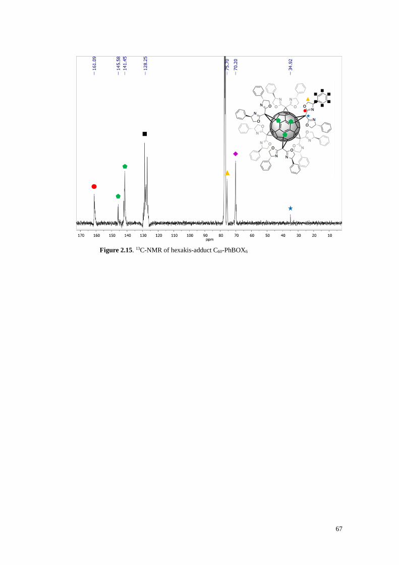
67
Figure 2.15. 13C-NMR of hexakis-adduct C60-PhBOX6
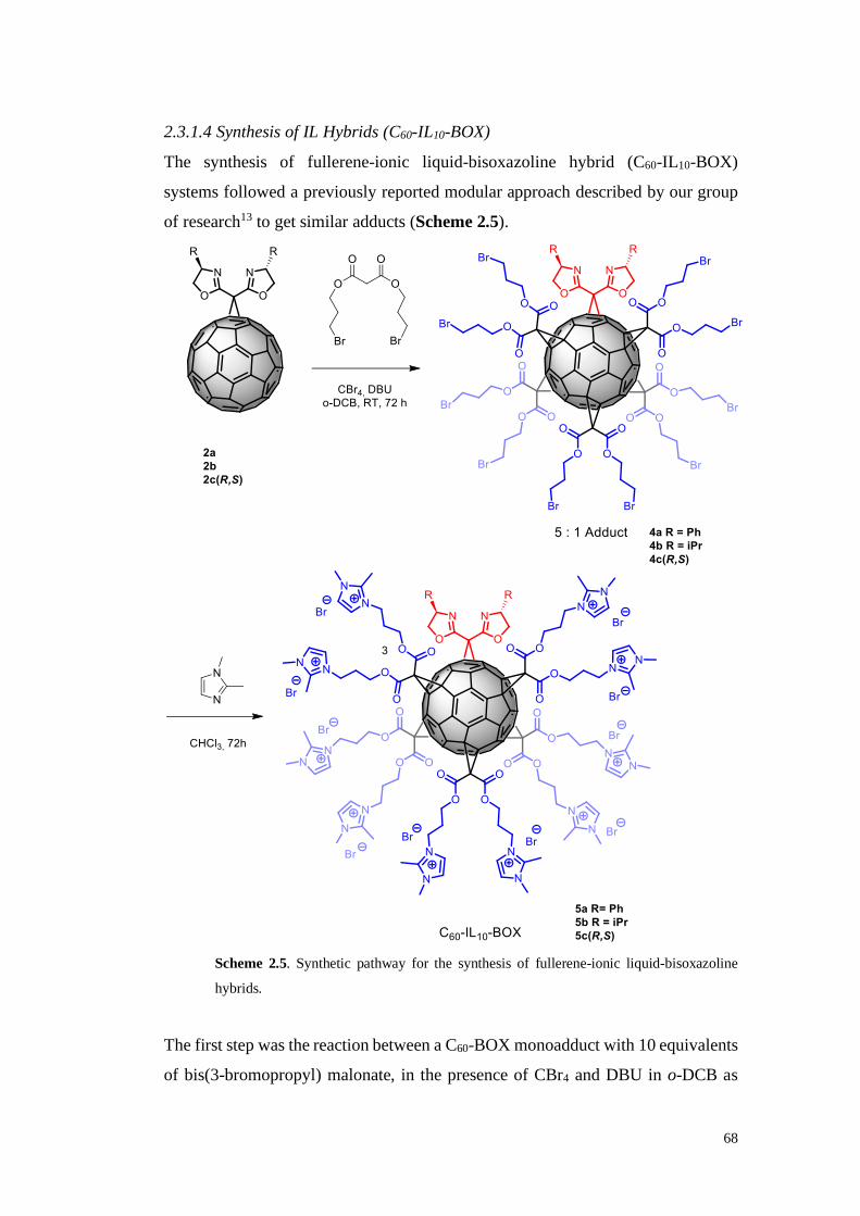
68
2.3.1.4 Synthesis of IL Hybrids (C60-IL10-BOX)
The synthesis of fullerene-ionic liquid-bisoxazoline hybrid (C60-IL10-BOX)
systems followed a previously reported modular approach described by our group
of research13 to get similar adducts (Scheme 2.5).
Scheme 2.5. Synthetic pathway for the synthesis of fullerene-ionic liquid-bisoxazoline
hybrids.
The first step was the reaction between a C60-BOX monoadduct with 10 equivalents
of bis(3-bromopropyl) malonate, in the presence of CBr4 and DBU in o-DCB as

69
solvent. The so obtained [5:1] adducts were isolated after purification with flash
chromatography, characterized (Figure 2.16 and 2.17) and subsequently reacted for
72 hours with 1,2-dimethylimidazole in chloroform to give the corresponding ionic
liquid hybrids with quantitative yields (Table 2.3)
Table 2.3. [5:1] adducts and IL Hybrid obtained with the corresponding yields.
[5:1] Adduct Yield IL Hybrid Yield
[5:1] PhBOX (4a) 31% C60-IL10-PhBOX (5a) 87%
[5:1] iPrBOX (4b) 36% C60- IL10-iPrBOX (5b) 97%
[5:1] IndaBOX (4c(R,S)) 38% C60- IL10-IndaBOX (5c(R,S)) 93%
Figure 2.16. 1HNMR of [5:1] adduct of the PhBOX (4a). Black stars point out PhBOX
while black squares -CH2 related to bis(3-bromopropyl).
In Figure 2.16 1H-NMR of the [5:1] adduct of the PhBOX. It is possible to see,
labelled by black squares, the pattern of the protons of the aliphatic chain of the
bis(3-bromopropyl) malonate and at the same time the signals related to the PhBOX
(black stars). In the spectrum is also possible to see that the integrated area confirms
the right functionalization of five bis(3-bromopropyl) malonate and one PhBOX.

70
FTIR spectrum also confirm the functionalization of the C60-BOX monoadduct with
five malonate moieties (Figure 2.17).
3500 3000 2500 2000 1500 1000 500
-50
-40
-30
-20
-10
0
10
T%
Wavenumber cm-1
1749
1239
527700
Figure 2.17. FT-IR spectrum of the [5:1] adduct of the PhBOX (4a).
In particular is possible to observe: 1) the bands at 1749 cm-1 (C=O stretching) and
1239 cm-1 (C-O starching) that confirm the presence of the malonate bands and 2)
the bands at 700 cm-1 and 527 cm-1 that confirm the presence of the fullerene.
About the IL-Hybrid in Figure 2.18 is reported 1H-NMR of the 5a. Signals labelled
with black squares are related to 1,2-dimethylimidazole. In particular at 2.65ppm
and 3.83ppm are related to the protons of the methyl group. Otherwise, stars point
out the signals of the proton of the bis(3-bromopropyl) malonate.

71
Figure 2.18. 1HNMR of IL-Hybrid of the PhBOX (5a). Black stars point out -CH2 related
to bis(3-bromopropyl) while black squares Signals of 1,2-dimethylimidazole.
The three types of fullerene-BOX systems (monoadducts, hexakisadducts and C60-
IL10-BOX hybrids) show different solubility profiles:
• the monoadducts displays a solubility similar to the non-functionalised
fullerene: they are very soluble in toluene and slightly soluble in chlorinated
solvents.
• The hexakisadducts, on the other hand, having less C60 surface area exposed
than the parent fullerene, are very soluble in dichloromethane and
chloroform and, basically, they acquire the solubility of the BOXs.
• C60-IL10-BOX hybrids are soluble in polar solvents such as methanol,
ethanol and water, thanks to the presence of numerous imidazolium bromide
moieties.
The above systems with different solubility profiles could be useful for catalysis
purposes, since explore a number of solvent media in order to obtain the best
reaction conditions. The three classes of compounds, finally, are insoluble in non-
polar solvents (hexane, petroleum ether, diethyl ether) and this feature could be
exploited to separate and recover catalysts at the end of each catalytic cycle.

72
2.3.2 Catalytic applications
2.3.2.1 Asymmetric Henry
As already said, Henry reaction takes place between a nitroalkane and an aldehyde
using a copper salt as catalyst (Figure 2.7). In order to make the reaction
asymmetric, it is possible to complex the copper salt with a proper chiral ligand that
can provide the desired configuration to the final product.
Based on previous studies in literature, 4-bromobenzaldehyde was chosen as
benchmark substrate, given that it provides the best compromise between
conversion and enantiomeric excess.29, 44
Preliminary tests were performed to find the best reaction conditions by varying
solvent, amount of catalyst and metal salt (Table 2.5). In these tests the
hexakisadduct 3a was chosen as it represents the system with the highest catalytic
loading per fullerene molecule.
Table 2.5. Screening of the reaction conditions for the asymmetric Henry reaction.a
Entry Conditions Time (h) Conv. (%)b ee (%)c
1 CH3NO2, 3a 2 mol % + Cu(OAc)2 48 14 34
2 EtOH 4:1, 3a 2 mol % + Cu(OAc)2 48 44 26
3 EtOH 4:1, 3a 2 mol % + Cu(OTf)2 48 26 21
4 EtOH 2:1, 3a 2 mol % + Cu(OAc)2 48 48 33
5 EtOH 1:1, 3a 5 mol % + Cu(OAc)2 24 82 31
a) Reaction conditions: 0.4 mmol aldehyde, 4 mmol nitromethane, CH3CH2OH according to the
reported ratio with nitromethane. b) Determined by 1H NMR spectroscopic analysis of the crude
product. c) Determined by HPLC using a chiral column (OD-H hexane-iPrOH 90:10).
The chosen catalyst, the copper salt and the solvent were mixed for 30 minutes in a
vial resulting in a homogeneous system for the hexakisadducts and for the C60-IL10-

73
BOX hybrids, while resulting in a heterogeneous system for the monoadducts. Then
aldehyde and nitromethane were added, and the mixture was left under stirring for
the appropriate time at room temperature.
The best reaction conditions resulted those reported in entry 5: 5 mol % of ligand,
using copper acetate as salt and 200 μL of EtOH as solvent. Using these conditions,
other substrates were tested for analysing the effect of substituents on the aldehyde
(Table 2.6).
Table 2.6. Asymmetric Henry reaction promoted by C60PhBOX6 on a set of aromatic aldehydes.a
Entry R Conv. (%)b ee (%)c
1 4-Br 82 31
2 2-NO2 91 11
3 4-NO2 92 6
4 4-CN 65 2
5 2,4-OMe 42 5
6 4-OMe 10 16
7 4-Cl 96 6
Reaction conditions: 0.4mmol aldehyde, 4mmol nitromethane, 200μL CH3CH2OH. b) Determined
by 1H NMR spectroscopic analysis of the crude product. c) Determined by HPLC using a chiral
column OD-H (hexane-iPrOH 90:10).
As expected, since Henry's reaction is a nucleophilic addition to carbonyl
compounds, the electron-withdrawing substituents had a positive effect on the yield
(entries 1,2,3 and 7). However, although in several cases almost quantitative
conversion was achieved (entries 3-7), the enantiomeric excesses resulted low.
Nevertheless, in all subsequent tests, 4-bromobenzaldehyde remained the
benchmark substrate in the asymmetric Henry reaction for the assessment of the

74
catalytic activity of all the prepared C60-BOX systems. The results are collected in
Table 2.7.
Table 2.7. Results of catalytic tests for all the catalytic systems.
Entry Cat. Conv. (%)b ee (%)c
BO
X
1 PhBOX (1a) 5% mol + Cu(OAc)2 27 -10
2 iPrBOX (1b)5% mol + Cu(OAc)2 43 -50
3 IndaBOX (1c(R,S)) 5% mol + Cu(OAc)2 27 33
4 IndaBOX (1c(S,R))5% mol + Cu(OAc)2 57 -39
5 tBuBOX (1d)5% mol + Cu(OAc)2 60 -53.4
C6
0-B
OX
6 C60-PhBOX (2a) 5% mol + Cu(OAc)2 24 -4
7 C60-iPrBOX (2b) 5% mol + Cu(OAc)2 20 racemic
8 C60-IndaBOX (2c(R,S)) 5% mol + Cu(OAc)2 22 13
9 C60-IndaBOX (2c(S,R)) 5% mol + Cu(OAc)2 27 -17
10 C60-tBuBOX (2d) 5% mol + Cu(OAc)2 39 Racemic
C6
0-B
OX
6
11 C60-PhBOX6 (3a) 5% mol + Cu(OAc)2 46 -10
12 C60-iPrBOX6 (3b) 5% mol + Cu(OAc)2 19 -4
13 C60-IndaBOX6 (3c(R,S)) 5% mol + Cu(OAc)2 67 46
14 C60-tBuBOX6 (3d) 5% mol + Cu(OAc)2 13 -4
IL-H
yb
rid
15 C60-IL10-PhBOX (5a) 2% mol + Cu(OAc)2 54 -10
16 C60-IL10-iPrBOX (5b) 2% mol + Cu(OAc)2 65 -14
17 C60-IL10-IndaBOX (5c(R,S)) 2% mol + Cu(OAc)2 68 18
Reaction conditions: 0.4 mmol 4-bromobenzaldehyde, 4 mmol of nitromethane, 200 μL of ethanol.
b) Determined by 1H NMR spectroscopic analysis of the crude product. c) Determined by HPLC
using a chiral column (OD-H hexane-iPrOH 90:10).
Firstly, the unsupported BOXs 1a-1d were tested under the same conditions in order
to have an insight on the performances of the catalytic systems without fullerene
(entries 1-5).
Fullerene-BOX monoadducts showed, generally speaking, low conversions in
comparison with the unsupported systems (entries 6-10), being derivative 2c(S,R)

75
the most active of the series (entry 9). This finding could be probably due to the
fact that C60-BOX hybrids were not soluble in ethanol and took part in the reaction
as heterogeneous catalysts. Monoadducts remain suspended in the reaction mixture
as solids and suffer from mass transport limitations.
On the other hand, hexakisadducts endowed with aromatic substituents (PhBOX,
IndaBOX) showed better result than the corresponding mono-adducts but also than
the unsupported BOXs (entries 11, 13). This fact can be ascribed to their improved
solubility in the nitromethane, which allows them to take part to the reaction as
homogeneous catalysts. Conversely, C60BOX6 systems 3b and 3d with alkyl chains
displayed similar performances than the parent monoadducts (entries 12, 14).
Regarding C60-IL10-BOX hybrids, these were used at 2 mol% to reduce the amount
of substance employed in each reaction, given their high molecular weights. Even
in this case, they took part in the reaction as homogeneous catalysts since they were
soluble in ethanol, giving the highest levels of conversion among all the hybrids
tested, included the unsupported (entries 15-17).
Unfortunately, enantiomeric excesses were low and worse than those obtained with
the other systems.
For all the catalytic tests, the chirality of the major enantiomer was S and depended
on the stereochemistry of the catalysts used (PhBOX, iPrBOX and tBuBOX
derivatives).
Separate considerations should be made for the IndaBOXs derivatives. In fact, they
were synthesized in two different stereoisomers: 1c(R,S) from (1R,2S)-(+)-cis-1-
amino-2-indanol and 1c(S,R) from (1S,2R)-(+)-cis-1-amino-2-indanol (Figure 10).
As expected, they gave back opposite results: in fact, the 1c(R,S) catalysed the
formation of the enantiomer (R) for the nitroaldol adducts, while the 1c(S,R) the
formation of the (S) enantiomer (Figure 2.19).

76
Figure 2.19. Comparison of different IndaBOX enantiomers.
The different asymmetric induction is rationalized by means of the specular
transition states formed during the catalytic cycle with the two different
enantiomers, as described in Scheme 2.6. These have a distorted square pyramidal
configuration with the nucleophiles in an axial position in correspondence to the
less bulky face of the electrophile, which is instead on the plane of the ligand.45
Scheme 2.6. Transition state in asymmetric Henry reaction with BOX ligands
Among all the prepared systems, IndaBOX derivatives showed the best results in
terms of conversion and enantiomeric excess. In Figure 2.20 IndaBOX-derivatives
1c(R,S), 2c(R,S), 3c(R,S) and 5c(R,S) are collected for comparison.
In this series, the mono-adduct 2c(R,S) is the less active whereas the hexakis-adduct
3c(R,S) and the IL-hybrid 4c(R,S) gave good result in terms of conversion, even
better than the unsupported 1c(R,S). In addition, the hexakisadduct gave also a
higher enantioselectivity than the unsupported IndaBOX.
-40
-20
0
20
40
1c(R,S) 1c(S,R) 2c(R,S) 2c(S,R)
ee% 33 -39 13 -17
IndaBOX

77
Figure 2.20. Comparison of all the IndaBOX-based catalysts.
Finally, the recyclability of the synthesized adducts that gave the best performance
(IndaBOX derivative 3c(R,S)) was tested. At the end of each reaction, the catalyst
was precipitated by adding diethyl ether, recovered by centrifugation and used in a
new cycle. In fact, the low solubility of the catalyst in diethyl ether represents an
outstanding advantage over unsupported boxes, which cannot be separated from the
reaction mixture and, moreover, quickly decompose at the end of the fist cycle. The
recovered catalyst was reacted with fresh copper salt to reform the catalytic
complex and then aldehyde and nitromethane are added for a new cycle. The
catalyst showed good recyclability, maintaining the same conversion level for up to
five consecutive reactions (Figure 2.21).
Figure 2.21. Recycling tests for the hexakisadduct 3c(R,S) (C60-INDABOX6).
0
20
40
60
80
1c(R,S) 2c(R,S) 3c(R,S) 5c(R,S)
Conversion% 27 22 67 68
ee% 33 13 46 18
IndaBOX (R,S)
010203040506070
I II III IV
Conversion% 67 64 50 70
ee% 46 9 27,4 22,4
Recycling tests

78
2.3.2.2 Asymmetric Diels-Alder
As stated, Diels-Alder [4+2] cycloaddition occurs between a conjugated diene and
an alkene (Figure 2.8). Here, asymmetric Diel-Alder tests were conducted on a
scale of 0.33 mmol of alkene, 3-acryloyl-2-oxazolidinone (as dienophile), copper
triflate and the fullerene-based adduct to drive the stereochemistry of the
cycloaddition, using known reaction conditions.31b, 46 The chosen ligand and copper
triflate were mixed for 30 minutes in a vial in DCM. After 30 minutes, freshly
distilled dienophile and cyclopentadiene were added and allowed to react for 24
hours at room temperature.
Then, the reaction mixture was purified by means of a silica gel pad (hexane/ethyl
acetate 3:1) and the crude was analysed by 1H-NMR in order to determine the
conversion and the endo/exo ratio (Figure 2.22). The enantiomeric excess was
determined by chiral HPLC (Chiralcel OD-H, hexane/isopropanol 90:10).
Figure 2.22. 1H-NMR spectrum of Diels-Alder reaction crude. In the inset, the
magnification highlighting the signals for the endo and exo products is reported.
As for the study of the Henry reaction, initially, the unsupported BOXs 1a-1d were
tested under the Diels-Alder conditions in order to have an insight on the
performances of the catalytic systems without fullerene (entries 1-3). All the
systems gave almost quantitative conversions but the selectivity was rather low,

79
except in the case of IndaBOX that is known to be the among best catalysts in
asymmetric Diels-Alder reaction (entry 3).25, 47
Both mono- and hexakis- C60-adducts showed very low ee values compared to the
unsupported BOXs (entries 4-9), comparable to the values obtained in the presence
of Lewis acid (Cu(OTf)2) alone (entry 13). Regarding the C60-IL10-BOX hybrids
(entries 10, 11, 12), the different activity of the catalysts in terms of endo/exo ratio
can be attributed to the fact that the hybrids were insoluble in the reaction media
(DCM) compared to the other two classes of adducts. This led to a lower
complexation with the metal, and to a generic and not asymmetric catalysis.
Table 2.8. summary table of the data of the asymmetric reaction of Diels-Alder.
Entry Catalyst
Conv.(%)b
Endo/Exob
ee (%)c
BO
X 1 PhBOX (1a) 5% mol + Cu(OTf)2 92 82 : 18 12
2 iPrBOX (1b) 5% mol + Cu(OTf)2 99 85 : 15 4
3 IndaBOX (1c(R,S)) 5% mol + Cu(OTf)2 95 90 : 10 76
C6
0-B
OX
4 C60-PhBOX (2a) 5% mol + Cu(OTf)2 93 78 : 22 0
5 C60-iPrBOX (2b) 5% mol + Cu(OTf)2 97 80 : 20 4
6 C60-IndaBOX (2c(R,S)) 5% mol + Cu(OTf)2 94 80 : 20 20
C6
0-B
OX
6
7 C60-PhBOX6 (3a) 5% mol + Cu(OTf)2 95 87 : 13 0
8 C60-iPrBOX6 (3b) 5% mol + Cu(OTf)2 94 86 : 14 4
9 C60-IndaBOX6 (3c(R,S)) 5% mol + Cu(OTf)2 90 83 : 17 20
IL-H
yb
rid
10 C60-IL10-PhBOX (5a) 2% mol + Cu(OTf)2 88 90 : 10 0
11 C60-IL10-iPrBOX (5b) 2% mol + Cu(OTf)2 93 90 : 10 2
12 C60-IL10-IndaBOX (5c(R,S)) 2% mol +
Cu(OTf)2 91 90 : 10 8
13 5% Cu(OTf)2 92 82 :18 -
The high conversion values and the low ee obtained, in all cases, indicate that the
cyclopentadiene, under the conditions examined, is too reactive and follows a
general Lewis acid-mediated cycloaddition, ignoring the chiral induction due to the
presence of chiral BOX-copper complex. However, the possibility to recycle the
catalytic system was investigated for the Diels-Alder reaction. At the end of each

80
reaction, the C60-INDABOX6 adduct (3c(R,S)) was precipitated from ethyl ether
and reused in a new cycle adding fresh reagents. The hexakis-adduct has proved to
be the most stable system, maintaining almost unchanged both activity and
selectivity (Figure 2.23).
Figure 2.23. Recycling tests for the Diels-Alder reaction with hexakisadduct 3c(R,S)
To verify the catalytic properties of these adducts with respect to the asymmetric
Diels-Alder reaction, an attempt was done using the less reactive 1,3-cyclo-
hexadiene, under the same conditions.
Unfortunately, the results were not satisfying (Table 2.9). Conversions resulted, as
expected, lower than those achieved with pentadiene and, furthermore, for this
substrate it was not possible to determine the enantiomeric excess.
Table 2.9. Diels-Alder reaction with 1,3-cyclohexadiene.
0
20
40
60
80
100
I II III
Conversion% 94 95 91
ee% 15 20 20
Recycling tests
Entry Catalyst Conv.(%) Endo/Exo ee(%)
BO
X 1 PhBOX (1a) 5% mol + Cu(OTf)2 37 48 : 52 -
2 iPrBOX (1b) 5% mol + Cu(OTf)2 36 47 : 53 -
3 IndaBOX (1c(R,S)) 5% mol + Cu(OTf)2 39 47 : 53 -
C6
0-B
OX
6
4 C60-PhBOX6 (3a) 5% mol + Cu(OTf)2 40 47 : 53 -
5 C60-iPrBOX6 (3b) 5% mol + Cu(OTf)2 39 49 : 51 -
6 C60-IndaBOX6 (3c(R,S)) 5% mol + Cu(OTf)2 56 45 : 55 -
7 5% Cu(OTf)2 No reaz. - -

81
2.4 Conclusions
A set of chiral bisoxazolines were prepared through simple one-pot reactions, and
subsequently they were anchored to C60 fullerene to form three types of hybrid
molecular systems with possible catalytic applications: monoadducts,
hexakisadducts and hybrid [5:1] adducts with ionic liquids. The simple steps of
separation and purification allowed obtaining comparable or superior (in the case
of hexakisadducts) yields to those reported in the literature. The structure and the
addition patterns of the products have been confirmed by carbon and proton NMR
and IR spectroscopy. These systems were tested, along with copper salts, as
asymmetric catalytic systems in the Henry and the Diels-Alder reactions. In both
cases the catalysts did not give very high selectivityies but, especially for nitroaldol
reactions, an increase in conversion and enantiomeric excess was observed
compared to the unsupported boxes. This finding, together with the possibility to
easily recovery and to recycle the catalysts without significant loss of activity, pave
the way to further studies on the subject. This work, in fact, represents the first real
application of C60-bisoxazoline adducts as catalytic systems for asymmetric
reactions.
In consideration of the results obtained, it is clear that further optimisations are
necessary in order to allow these materials to fulfil their potential and to provide
the best performances: both at the level of the catalysts, through better chiral
substituents or different bridges between the oxazoline rings, and at the level of the
reaction conditions, operating a greater control over the temperature and using
different solvents and metal cations.
2.5 Experimental section
All the reagents and solvents in this work were used as purchased from the
respective companies (Merck, TCI, Fluorochem). The FT-IR spectra of the products
obtained have been recorded on an Agilent Tech CARY630 FT-IR spectrometer.
1H-NMR were performed at the University of Palermo with a bruker 300 MHz
spectrometer, 13C-NMR were performed at the University of Namur on a Varian

82
VNMRS spectrometer. Enantiomeric excesses were determined with a LC10 AD
Shimadzu Liquid Chromatograph HPLC (Chiralcel OD-H).
General procedure for the synthesis of PhBOX and iPrBOX
In a round bottom flask containing 30 ml of 1,2-dichloroethane, 4.33 mmol of
diethyl malonimidate dihydrochloride, 2 equivalents of the corresponding amino-
alcohol and 2 equivalents of Et3N were added. The reaction mixture was stirred 18
hours at 84°C in inert atmosphere. The mixture was poured into 50 ml of distilled
water and extracted three times with dichloromethane; organic fractions were
collected, dried over MgSO4, and the solvent removed under reduced pressure. The
product was purified by column chromatography (dichloromethane/methanol 99:1
+ 0.2% v/v of Et3N).
PhBOX: Diethyl malonimidate dihydrochloride (1,00 gr) and L-(+)-α-
phenylglycinol (1,25 gr) reacted in accordance with the general procedure. The
product was obtained as a viscous yellow liquid, with a yield of 67%.
1H NMR (300 MHz, CDCl3) δ = 7.32 (q, J = 4.9, 10H), 5.28 (t, J = 9.0, 2H), 4.72
(dd, J = 9.6, 9.0, 2H), 4.33 – 4.03 (m, 2H), 3.69 – 3.50 (m, 2H).
13C NMR (101 MHz, CDCl3) δ = 168.27, 166.15, 164.63, 163.03, 141.96, 141.38,
138.76, 128.84, 128.01, 126.79, 77.35, 77.03, 76.71, 75.35, 69.71, 35.01, 28.39.
UV (CH2Cl2, nm) λ = 270 nm.
iPrBOX: Diethyl malonimidate dihydrochloride (1.00 gr) and L-valinol (1.012 mL,
d=0.926gr/mL) reacted in accordance with the general procedure. The product was
obtained as a viscous yellow liquid, with a yield of 63%.
1H NMR (300 MHz, CDCl3) δ = 7.56 – 7.02 (m, 1H), 4.46 – 4.14 (m, 2H), 4.09 –
3.77 (m, 4H), 3.35 (s, 2H), 1.91 – 1.61 (m, 2H), 1.16 – 0.70 (m, 12H).
13C NMR (101 MHz, CDCl3) δ = 167.12, 163.33, 161.54, 77.34, 77.02, 76.70,
72.11, 70.52, 64.38, 57.83, 34.55, 32.42, 28.32, 18.61, 17.96. UV (CH2Cl2, nm) λ
= 273 nm.

83
Synthesis of tert-Leucinol
Tert-Leucine (16 mmol) was dissolved in 45 mL anhydrous THF with 2.5
equivalent of NaBH4 in inert atmosphere at 0 °C. A solution of I2 (19 mmol) in
anhydrous THF was added to the tert-Leucine solution via cannula under stirring
maintaining the solution at 0°C in inert atmosphere for 15 minutes and the reaction
was refluxed overnight.
Then the reaction is brought at room temperature and methanol is added until the
powder at the bottom of the flask was completely dissolved (30 mL) and then the
solution was stirred for 30 minutes. Hence, time 100 mL KOH solution (20%) is
added and the resulting solution is stirred at room temperature for 4 h. Then the
organic fractions were, dried over MgSO4 and, the solvent removed under reduced
pressure until obtaining the desired product in 75% of yield.48
Synthesis of tBuBOX
Diethyl malonimidate dihydrochloride (1.00 gr) and tert-Leucinol (1.06 gr) reacted
in accordance with the general procedure. The product was obtained as a viscous
yellow liquid, with a yield of 65%.
1H NMR (300 MHz, CDCl3) δ = 4.28 – 4.05 (m, 4H), 3.91 (t, 2H), 3.37 (s, 2H),
0.91 (s,18H)
Synthesis of IndaBOX
In a round bottom flask containing 52 ml of DCM, 2.5 mmol of diethyl
malonimidate dihydrochloride and 4,7 mmol (1R,2S)-cis-1-amino-2-indanol were
added. The reaction mixture was stirred for 18 hours in argon. The mixture was
poured into distilled water and extracted with dichloromethane. The organic
fractions were, dried over MgSO4 and, the solvent removed under reduced pressure.
The resulting solid is recrystallized from isopropanol, giving white needle-shaped
solid with a yield of 57%.
1H NMR (300 MHz, CDCl3) δ = 7.46 (dt, J = 12.9, 6.3, 2H), 7.37 – 7.19 (m, 6H),
5.58 (t, J = 6.7, 2H), 5.36 (tt, J = 5.5, 2.7, 2H), 3.51 – 3.07 (m, 6H).
13C NMR (101 MHz, CDCl3) δ = 161.96, 141.61, 139.64, 128.50, 127.44, 125.22,
83.57, 77.37, 77.05, 76.73, 76.66, 39.66, 28.71. UV-Vis (CH2Cl2, nm) λ = 266 nm.

84
General procedure for the synthesis of C60-BOX
3,5 mmol of the corresponding BOX, 2 equivalents of CBr4 and 4 equivalents of
DBU were added to a C60 fullerene solution (1,3 equivalents) in 30 mL of o-DCB.
The mixture was stirred for 18 hours at room temperature. After removing the
reaction solvent under vacuum, the crude was purified by column chromatography
(SiO2), eluting first with toluene, to eliminate the not reacted C60, then with
toluene/ethyl acetate 5:1 (+0.2% v/v of triethylamine). The solvent was removed
under reduced pressure and the solid was re-dissolved in the minimum amount of
chloroform and re-precipitated in hexane.
C60-PhBOX: brown solid, yield 48%.
1H NMR (300 MHz, CDCl3) δ = 7.59 – 7.04 (m, 10H), 5.78 – 5.42 (m, 2H), 5.13–
4.81 (m, 2H), 4.51 (dt, J = 21.0, 8.4, 2H).
13C NMR (101 MHz, CDCl3) δ = 160.64, 146.41, 146.29, 145.47, 145.30, 145.21,
144.89, 144.68, 143.89, 143.03, 142.96, 142.17, 141.25, 140.89, 138.88, 138.84,
77.32, 77.00, 76.68.
FT-IR (KBr, cm-1) ν = 523, 697, 1661. UV-Vis (CH2Cl2, nm) λ = 253, 320.
C60-iPrBOX: black crystalline solid, yield 39%.
1H NMR (300 MHz, CDCl3) δ = 7.40 – 7.04 (m, 2H), 4.71 – 3.97 (m, 5H), 1.43 –
0.69 (m, 12H).
13C NMR (101 MHz, CDCl3) δ = 158.78, 146.78, 146.33, 145.53, 145.28, 145.18,
145.14, 144.79, 144.70, 144.61, 144.52, 143.89, 143.83, 142.96, 142.89, 142.18,
142.13, 142.07, 141.93, 140.84, 140.74, 138.74, 138.66, 77.33, 77.01, 76.69, 73.39,
72.74, 71.46, 33.34, 19.36, 18.49.
FT-IR (KBr, cm-1) ν = 527, 1668. UV-Vis (CH2Cl2, nm) λ = 254, 316.
C60-IndaBOX: light brown solid, yield 46%.
1H NMR (300 MHz, CDCl3) δ = 7.67 – 6.84 (m, 8H), 5.96 – 5.77 (m, 1H), 5.73 –
5.46 (m, 1H), 3.69 – 3.13 (m, 2H).

85
13C NMR (101 MHz, CDCl3) δ = 159.44, 145.99, 145.16, 145.04, 144.55, 144.46,
144.22, 144.15, 143.79, 143.64, 142.83, 142.81, 142.70, 142.64, 142.09, 142.02,
141.88, 141.82, 140.50, 139.20, 139.01, 138.23, 77.34, 77.02, 76.70, 39.86, 21.46.
FT-IR (KBr, cm-1) ν = 523, 738, 1660. UV-Vis (CH2Cl2, nm) λ = 256.
General procedure for the synthesis of C60-BOX6
10 quivalents of the corresponding BOX, 100 equivalents of CBr4 and 20
equivalents of DBU were added to a solution of C60 (0,1 mmol) in o-DCB (7 mL).
The mixture was stirred for 72 hours at room temperature. The reaction mixture
was precipitated in 100 mL of hexane and the crude collected by centrifugation.
The crude was dissolved in dichloromethane and washed with water. The organic
layers were dried over MgSO4 and the solvent eliminated under vacuum. The
product was purified by column chromatography (SiO2, toluene/ethyl acetate 9:1 +
0,2% v/v of triethylamine). The solvent was removed under reduced pressure and
the solid was re-dissolved in the minimum amount of chloroform and re-
precipitated in hexane.
C60-PhBOX6: crystalline light brown solid, yield 68%.
1H NMR (300 MHz, CDCl3) δ = 7.71 – 6.89 (m, 60H), 5.82 – 5.15 (m, 11H), 5.10
– 4.59 (m, 10H), 4.56 – 4.17 (m, 10H).
13C NMR (101 MHz, CDCl3) δ = 160.97, 145.86,145.58, 142.09, 142.03, 141.65,
128.73, 127.01, 35.66 – 34.13.
FT-IR (KBr, cm-1) ν = 528, 702, 1660.
C60-iPrBOX6: crystalline light orange solid, yield 67%.
1H NMR (300 MHz, CDCl3) δ = 7.56 – 7.02 (m, 1H), 4.46 – 4.14 (m, 2H), 4.09 –
3.77 (m, 4H), 3.35 (s, 2H), 1.91 – 1.61 (m, 2H), 1.16 – 0.70 (m, 12H).
13C NMR (400 MHz, CDCl3) δ = 165.05, 159.85, 68.55, 62.76, 58.22, 57.74, 36.92,
29.15, 19.56, 18.67, 18.02, 17.56.
FT-IR (KBr, cm-1) ν = 668, 1390, 1538, 1670,
C60-IndaBOX6: crystalline light brown solid, yield 65%.

86
1H NMR (300 MHz, CDCl3) δ = 7.51 (d, J = 6.6, 1H), 7.44 – 7.21 (m, 6H), 5.81 –
5.51 (m, 3H), 3.41 (dd, J = 18.0, 6.9, 2H), 3.22 (dd, J = 17.7, 9.3, 2H), 1.62 (s, 1H),
1.27 (s, 1H), 0.09 (s, 1H), 0.02 (s, 1H).
13C NMR (400 MHz, CDCl3) δ =159.39, 144.72, 144.33, 143.43, 141.30, 139.24,
128.43, 127.45, 125.58, 84.17, 45.99, 36.65, 8.62.
FT-IR (KBr, cm-1) ν = 526, 698, 1666.
Synthesis of Dibromopropyl malonate
To a solution of 3-bromo-1-propanol (1,7 mmol) and pyridine (1 equivalent) in 35
ml of 1,2-dichloroethane at 0°C in inert atmosphere, 1 equivalent of malonyl
dichloride is added dropwise. The mixture was stirred 1 hour at 0 °C, then 48 hours
at room temperature. The reaction mixture is then washed twice with a 5% HCl
solution, then twice with a saturated NaHCO3 solution. The organic layers were
collected, dried over MgSO4 and the solvent removed by reducing pressure. The
resulting blue oily liquid is purified on a silica gel column (petroleum ether/ethyl
acetate 15:1 and 9:1). The final product is obtained as a colourless liquid with a
yield of 52%.
General procedure for the synthesis of C60-dibromopropylmalonate5-BOX
([5:1] adducts)
To a solution of the corresponding C60-BOX (0.8 mmol) in 9 ml of o-DCB, 10
equivalents of dibromopropyl malonate were added, 50 equivalents of CBr4 and 20
equivalents of DBU. The mixture was stirred for 72 hours at room temperature.
After removing the solvent under vacuum, the crude was purified by column
chromatography (toluene/ethyl acetate 10:1 +0,2% triethylamine).
C60-dibromopropylmalonate5-PhBOX: red solid, yield 31%.
1H NMR (300 MHz, CDCl3) δ = 7.43 – 6.85 (m, 10H), 5.44 (s, 1H), 4.58 (t, J =
57.5, 9H), 3.48 (d, J = 4.6, 11H), 2.62 – 2.00 (m, 12H), 1.59 (s, 4H), 1.27 (s, 1H),
0.09 (s, 1H), 0.01 (d, J = 5.0, 1H).
13C NMR (400 MHz, CDCl3) δ = 163.56, 163.17, 160.69, 145.75, 141.34, 140.92,
128.68, 127.72, 126.99, 75.76, 70.20, 69.00, 64.69, 53.42, 31.31, 29.03.

87
FT-IR (KBr, cm-1) ν = 541, 703, 1238, 1744.
C60-dibromopropylmalonate5-iPrBOX: red solid, yield 36%.
1H NMR (300 MHz, CDCl3) δ = 7.28 (s, 1H), 5.32 (s, 1H), 4.28 (d, J = 107.0, 6H),
3.47 (s, 5H), 2.28 (s, 4H), 1.60 (s, 1H), 1.28 – 0.53 (m, 3H).
13C NMR (400 MHz, CDCl3) δ =163.54, 163.17, 145.64, 141.15, 140.84, 134.42,
129.67, 128.97, 72.98, 70.91, 68.96, 64.66, 53.42, 31.30, 29.67, 29.05, 19.16, 18.14.
FT-IR (KBr, cm-1) ν = 529, 712, 1239, 1748.
C60-dibromopropylmalonate5-IndaBOX: red solid, yield 38%.
1H NMR (300 MHz, CDCl3) δ = 7.57 – 6.88 (m, 8H), 4.47 (dd, J = 18.1, 6.2, 11H),
3.83 – 3.25 (m, 12H), 2.27 (dd, J = 43.7, 38.1, 12H), 2.07 – 1.25 (m, 6H), 1.38 –
1.02 (m, 3H).
13C NMR (400 MHz, CDCl3) δ =163.64, 163.13, 159.29, 145.54, 142.67, 140.74,
128.48, 125.88, 125.74, 64.64, 54.42, 31.33, 29.67, 29.05.
FT-IR (KBr, cm-1) ν = 525, 712, 1232, 1744.
General procedure for the synthesis of C60-IL10-BOX
0,2 mmol of the corresponding C60-dibromopropylmalonate5-BOX were
dissolved in 2 mL of chloroform and 100 equivalents of 1,2-dimethylimidazole
were added. The reaction mixture was stirred for 72 hours at room temperature. The
solvent was removed under vacuum and the residue obtained is dissolved in the
minimum amount of methanol, precipitated from ethyl ether and centrifuged.
C60-IL10-PhBOX: black viscous liquid, yield 87%.
1H NMR (300 MHz, MeOD) δ = 7.84 – 7.30 (m, 24H), 4.32 (dd, J = 16.0, 7.8, 48H),
3.85 (s, 44H), 3.06 – 2.34 (m, 45H), 2.34 – 2.28 (m, 6H).
13C NMR (400 MHz, CDCl3) δ = 162.84, 144.94, 14.69, 124.96, 124.08, 121.59,
120.83, 119.57, 119.05, 118.82, 118.67, 78.04, 77.79, 76.94, 57.61, 44.87, 34.46,
34.21, 34.06, 31.68, 28.37, 8.96, 8.62, 8.16.
FT-IR (KBr, cm-1) ν = 538, 668, 1628.

88
C60-IL10-iPrBOX: black viscous liquid, yield 97%.
1H NMR (300 MHz, MeOD) δ = 7.94 – 7.21 (m, 24H), 4.25 (dd, J = 63.1, 55.4,
34H), 3.85 (s, 40H), 3.04 – 2.34 (m, 50H), 2.34 – 2.30 (m, 4H).
13C NMR (400 MHz, CDCl3) δ = 144.80, 123.46, 123.41, 122.52, 122.47, 121.71,
121.56, 121.35, 120.79, 120.61, 119.89, 64.20, 45.27, 34.41, 34.14, 28.20, 27.31,
8.86, 8.58, 8.49.
FT-IR (KBr, cm-1) ν = 668, 1635.
C60-IL10-IndaBOX: black viscous liquid, yield 93%.
1H NMR (300 MHz, MeOD) δ = 7.51 (dd, J = 67.8, 49.2, 24H), 4.62 (t, J = 76.9,
48H), 3.85 (s, 17H), 2.70 (s, 19H), 1.94 (d, J = 242.4, 16H).
13C NMR (400 MHz, CDCl3) δ = 163.44, 159.68, 144.79, 141.62, 140.89, 124.79,
123.33, 122.60, 121.74, 120.14, 63.71, 45.27, 34.38, 28.36, 8.73.
FT-IR (KBr, cm-1) ν = 668, 1628.
General procedure for asymmetric Henry's reactions
The fullerene-BOX ligand, the copper(II) salt and the solvent were mixed in a screw
cap vial and stirred for 30 minutes at room temperature. Then 0,4 mmol of aldehyde
and 10 equivalents of nitromethane were added and the system were allowed to
react for the proper time. The progress of the reaction was monitored by TLC
(hexane/ethyl acetate 5:1). The mixture was purified by silica gel plug,
(hexane/ethyl acetate 5:1 + 0.2% v/v of triethylamine). The conversion was
estimated by 1H-NMR of the crude, while the enantiomeric excess was determined
by HPLC with chiral column Chiralcel OD-H (hexane/isopropanol 90:10, 1,2
ml/min, 215 nm).
Synthesis of 2-Oxazolidinone
Equimolar amounts of urea and 2-aminoethanol (0.12 mol) were reacted in DMF
for 6 hours at 160 °C. The mixture was brought to dryness and the remaining solid
was recrystallised from butanone. The final product was obtained as a white solid
with a yield of 85%.

89
1H NMR (300 MHz, CDCl3) δ = 6.54 (s, 1H), 4.44 (dd, J = 8.7, 7.3, 1H), 3.64 (t, J
= 8.0, 1H).
Synthesis of 3-acryloyl-2-oxazolidinone49
To a suspension of NaH (0,025 mol) in anhydrous THF (20 ml), a solution of 2-
oxazolidinone (1 equivalent) in 25 ml anhydrous THF was added via cannula. The
mixture was stirred for 1 hour at room temperature in inert atmosphere. 1 equivalent
of acryloyl chloride was then slowly added and the mixture stirred for 3 hours. The
reaction mixture was then cooled to 0 °C and quenched with 30 ml of cold distilled
water. The mixture was extracted with ethyl ether (3 times) and dichloromethane
(3 times), and the organic fractions dried over MgSO4 and. The solvent was
removed under vacuum and the residual solid was purified by column
chromatography (SiO2, hexane/ethyl acetate 1:1). The final product (yield 53%)
was collected as a white solid.
1H NMR (300 MHz, CDCl3) δ = 7.51 (dd, J = 17.0, 10.5, 1H), 6.57 (dd, J = 17.0,
1.8, 1H), 5.92 (dd, J = 10.5, 1.8, 1H), 4.46 (t, J = 9.7, 6.3, 2H), 4.10 (t, J = 8.0, 2H).
General procedure for asymmetric Diels-Alder reactions
In a vial with a screw cap containing 1 ml of dichloromethane, the fullerene-BOX
and Cu(OTf)2 were added and stirred for 30 minutes at room temperature. Then
0,33 mmol of 3-acryloyl-2-oxazolidinone and 4 equivalents of freshly distilled
cyclopentadiene were added. After 24 hours the mixture is purified by silica gel
plug (ethyl hexane/acetate 3/1 +0.2% ET3N). The conversion and diasteromeric
ratio were determined by 1H-NMR of the crude, while the enantiomeric excess was
determined by HPLC (chiral column Chiralcel OD-H, hexane/isopropanol 90/10,
0,7 ml/min, 215 nm).
General procedure for catalyst recycling
At the end of a reaction conducted according to the general procedure, 3 ml of
diethyl ether were added in the vial and the precipitated fullerene-BOX system was
recovered by centrifugation.

90
The ether solutions were dried under vacuum and purified by silica gel plug as
indicated in the general procedure, and the obtained products were analysed by 1H-
NMR and HPLC. New reagents and solvents were added to the residual solid for a
new catalytic cycle.

91
3.6 References
1. (a) Roth, S.; Park, H. J., Nanocarbonic transparent conductive films. Chem.
Soc. Rev. 2010, 39 (7), 2477-2483; (b) Su , D. S.; Schlögl, R., Nanostructured
Carbon and Carbon Nanocomposites for Electrochemical Energy Storage
Applications. ChemSusChem 2010, 3 (2), 136-168; (c) Vilatela, J. J.; Eder, D.,
Nanocarbon composites and hybrids in sustainability: a review. ChemSusChem
2012, 5 (3), 456-78.
2. Campisciano, V.; Gruttadauria, M.; Giacalone, F., Modified Nanocarbons
for Catalysis. ChemCatChem 2019, 11 (1), 90-133.
3. Su, D. S.; Perathoner, S.; Centi, G., Nanocarbons for the development of
advanced catalysts. Chem. Rev. 2013, 113 (8), 5782-816.
4. Balch, A. L.; Winkler, K., Two-component polymeric materials of
fullerenes and the transition metal complexes: A bridge between metal–organic
frameworks and conducting polymers. Chem. Rev. 2016, 116 (6), 3812-3882.
5. Nagashima, H.; Nakaoka, A.; Tajima, S.; Saito, Y.; Itoh, K., Catalytic
hydrogenation of olefins and acetylenes over C60Pdn. Chem. Lett. 1992, 21 (7),
1361-1364.
6. Fagan, P. J.; Calabrese, J. C.; Malone, B., The Chemical Nature of
Buckminsterfullerene (C60) and the Characterization of a Platinum Derivative.
Science 1991, 252 (5009), 1160-1161.
7. Sulman, E.; Matveeva, V.; Semagina, N.; Yanov, I.; Bashilov, V.; Sokolov,
V., Catalytic hydrogenation of acetylenic alcohols using palladium complex of
fullerene C60. J. Mol. Catal. Chem. 1999, 146 (1), 257-263.
8. Toganoh, M.; Matsuo, Y.; Nakamura, E., Synthesis and catalytic activity of
rhodium diene complexes bearing indenyl-type fullerene η5-ligand. J. Organomet.
Chem. 2003, 683 (2), 295-300.
9. Maggini, M.; Scorrano, G.; Prato, M., Addition of azomethine ylides to C60:
synthesis, characterization, and functionalization of fullerene pyrrolidines. J. Am.
Chem. Soc. 1993, 115 (21), 9798-9799.
10. Bingel, C., Cyclopropanierung von Fullerenen. Chem. Ber. 1993, 126 (8),
1957-1959.

92
11. Beejapur, H. A.; Campisciano, V.; Franchi, P.; Lucarini, M.; Giacalone, F.;
Gruttadauria, M., Fullerene as a Platform for Recyclable TEMPO Organocatalysts
for the Oxidation of Alcohols. ChemCatChem 2014, 6 (8), 2419-2424.
12. Giacalone, F.; Gruttadauria, M., Covalently Supported Ionic Liquid Phases:
An Advanced Class of Recyclable Catalytic Systems. ChemCatChem 2016, 8 (4),
664-684.
13. Beejapur, H. A.; Campisciano, V.; Giacalone, F.; Gruttadauria, M.,
Catalytic Synergism in a C60IL10TEMPO2 Hybrid in the Efficient Oxidation of
Alcohols. Acc. Chem. Res. 2015, 357 (1), 51-58.
14. Campisciano, V.; La Parola, V.; Liotta, L. F.; Giacalone, F.; Gruttadauria,
M., Fullerene–Ionic-Liquid Conjugates: A New Class of Hybrid Materials with
Unprecedented Properties. Chem.: Eur. J. 2015, 21 (8), 3327-3334.
15. Andrés, J. M.; González, M.; Maestro, A.; Naharro, D.; Pedrosa, R.,
Recyclable Chiral Bifunctional Thioureas Derived from [60] Fullerene and Their
Use as Highly Efficient Organocatalysts for the Asymmetric Nitro‐Michael
Reaction. Eur. J. Org. Chem. 2017, 2017 (19), 2683-2691.
16. Wynberg, H., Chance, necessity and asymmetric catalysis. Recl. Trav.
Chim. Pays-Bas 1981, 100 (11), 393-399.
17. (a) Shaw, S.; White, J. D., Asymmetric Catalysis Using Chiral Salen–Metal
Complexes: Recent Advances. Chem. Rev. 2019, 119 (16), 9381-9426; (b)
Kadassery, K. J.; MacMillan, S. N.; Lacy, D. C., Resurgence of
Organomanganese(I) Chemistry. Bidentate Manganese(I) Phosphine–Phenol(ate)
Complexes. Inorg. Chem. 2019, 58 (16), 10527-10535; (c) Durand, D. J.; Fey, N.,
Computational Ligand Descriptors for Catalyst Design. Chem. Rev. 2019, 119 (11),
6561-6594; (d) Whitesell, J. K., C2 symmetry and asymmetric induction. Chem.
Rev. 1989, 89 (7), 1581-1590.
18. Petri, A.; Seidelmann, O.; Eilitz, U.; Leßmann, F.; Reißmann, S.; Wendisch,
V.; Gutnov, A., Pd-catalyzed asymmetric conjugate addition of arylboronic acids
to 2-nitroacrylates: a facile route to β2-homophenylglycines. Tetrahedron Lett.
2014, 55 (1), 267-270.
19. König, A.; Fischer, C.; Alberico, E.; Selle, C.; Drexler, H.-J.; Baumann, W.;
Heller, D., Oxidative Addition of Aryl Halides to Cationic Bis(phosphane)rhodium

93
Complexes: Application in C–C Bond Formation. Eur. J. Inorg. Chem. 2017, 2017
(13), 2040-2047.
20. Gaálová, J.; Hejda, S.; Stavárek, P.; Sýkora, J.; Fajgar, R.; Kluson, P.; Izák,
P., Pervaporation of (R)/(S)-methyl 3-hydroxybutyrate (∑MHB) from a mixture
containing an ionic liquid, methanol and Ru catalyst. Sep. Purif. Technol. 2019,
222, 45-52.
21. Zhou, Y.; Shan, Z., Chiral Diols: A New Class of Additives for Direct Aldol
Reaction Catalyzed by l-Proline. J. Org. Chem. 2006, 71 (25), 9510-9512.
22. Fernández González, D.; Brand, J. P.; Mondière, R.; Waser, J.,
Ethynylbenziodoxolones (EBX) as Reagents for the Ethynylation of Stabilized
Enolates. Acc. Chem. Res. 2013, 355 (8), 1631-1639.
23. (a) Das, D.; Mal, R.; Mittal, N.; Zhu, Z.; Emge, T. J.; Seidel, D., Chiral
bisoxazoline ligands designed to stabilize bimetallic complexes. Beilstein J. Org.
Chem. 2018, 14, 2002-2011; (b) Kitagaki, S.; Murata, S.; Asaoka, K.; Sugisaka, K.;
Mukai, C.; Takenaga, N.; Yoshida, K., Planar Chiral [2.2]Paracyclophane-Based
Bisoxazoline Ligands: Design, Synthesis, and Use in Cu-Catalyzed Inter- and
Intramolecular Asymmetric O–H Insertion Reactions. Chem. Pharm. Bull. 2018, 66
(10), 1006-1014.
24. Evans, D. A.; Woerpel, K. A.; Hinman, M. M.; Faul, M. M., Bis(oxazolines)
as chiral ligands in metal-catalyzed asymmetric reactions. Catalytic, asymmetric
cyclopropanation of olefins. J. Am. Chem. Soc. 1991, 113 (2), 726-728.
25. Desimoni, G.; Faita, G.; Jørgensen, K. A., C2-Symmetric Chiral
Bis(Oxazoline) Ligands in Asymmetric Catalysis. Chem. Rev. 2006, 106 (9), 3561-
3651.
26. Nishiyama, H.; Sakaguchi, H.; Nakamura, T.; Horihata, M.; Kondo, M.;
Itoh, K., Chiral and C2-symmetrical bis(oxazolinylpyridine)rhodium(III)
complexes: effective catalysts for asymmetric hydrosilylation of ketones.
Organometallics 1989, 8 (3), 846-848.
27. Lowenthal, R. E.; Abiko, A.; Masamune, S., Asymmetric catalytic
cyclopropanation of olefins: bis-oxazoline copper complexes. Tetrahedron Lett.
1990, 31 (42), 6005-6008.

94
28. Corey, E. J.; Imai, N.; Zhang, H. Y., Designed catalyst for enantioselective
Diels-Alder addition from a C2-symmetric chiral bis(oxazoline)-iron(III) complex.
J. Am. Chem. Soc. 1991, 113 (2), 728-729.
29. Maggi, R.; Lanari, D.; Oro, C.; Sartori, G.; Vaccaro, L., Heterogeneous
Bisoxazoline/Copper Complex: A Green Catalyst for the Enantioselective Reaction
of Nitromethane with Substituted Benzaldehydes. Eur. J. Org. Chem. 2011, 2011
(28), 5551-5554.
30. Corma, A.; García, H.; Moussaif, A.; Sabater, M. J.; Zniber, R.; Redouane,
A., Chiral copper(ii) bisoxazoline covalently anchored to silica and mesoporous
MCM-41 as a heterogeneous catalyst for the enantioselective Friedel–Crafts
hydroxyalkylation. Chem. Commun. 2002, (10), 1058-1059.
31. (a) Jørgensen, K. A.; Johannsen, M.; Yao, S.; Audrain, H.; Thorhauge, J.,
Catalytic Asymmetric Addition Reactions of Carbonyls. A Common Catalytic
Approach. Acc. Chem. Res. 1999, 32 (7), 605-613; (b) Johnson, J. S.; Evans, D. A.,
Chiral Bis(oxazoline) Copper(II) Complexes: Versatile Catalysts for
Enantioselective Cycloaddition, Aldol, Michael, and Carbonyl Ene Reactions. Acc.
Chem. Res. 2000, 33 (6), 325-335.
32. Christoffers, J.; Baro, A., Construction of Quaternary Stereocenters: New
Perspectives through Enantioselective Michael Reactions. Angew. Chem. 2003, 42
(15), 1688-1690.
33. Lee, A.; Kim, W.; Lee, J.; Hyeon, T.; Kim, B. M., Heterogeneous
asymmetric nitro-Mannich reaction using a bis (oxazoline) ligand grafted on
mesoporous silica. Tetrahedron: Asymmetry 2004, 15 (17), 2595-2598.
34. Gothelf, K. V.; Jørgensen, K. A., Asymmetric 1,3-Dipolar Cycloaddition
Reactions. Chem. Rev. 1998, 98 (2), 863-910.
35. Wisniak, J., Louis Henry: The Henry reaction and other organic syntheses.
Rev. Ciencia Quim. 2018, 49.
36. Gogoi, N.; Boruwa, J.; Barua, N. C., A total synthesis of (−)-bestatin using
Shibasaki’s asymmetric Henry reaction. Tetrahedron Lett. 2005, 46 (44), 7581-
7582.
37. Luzzio, F. A., ChemInform Abstract: The Henry Reaction: Recent
Examples. ChemInform 2001, 32 (22).

95
38. Diels, O.; Alder, K., Synthesen in der hydroaromatischen Reihe. Liebigs
Ann. 1928, 460 (1), 98-122.
39. Woodward, R. B.; Sondheimer, F.; Taub, D.; Heusler, K.; McLamore, W.
M., The Total Synthesis of Steroids1. J. Am. Chem. Soc. 1952, 74 (17), 4223-4251.
40. Corey, E. J.; Weinshenker, N. M.; Schaaf, T. K.; Huber, W., Stereo-
controlled synthesis of dl-prostaglandins F2. alpha. and E2. J. Am. Chem. Soc.
1969, 91 (20), 5675-5677.
41. (a) Lamparth, I.; Hirsch, A., Water-soluble malonic acid derivatives of C60
with a defined three-dimensional structure. J. Chem. Soc., Chem. Commun. 1994,
(14), 1727-1728; (b) Hirsch, A.; Lamparth, I.; Karfunkel, H. R., Fullerene
Chemistry in Three Dimensions: Isolation of Seven Regioisomeric Bisadducts and
Chiral Trisadducts of C60 and Di(ethoxycarbonyl)methylene. Angew. Chem. 1994,
33 (4), 437-438; (c) Djojo, F.; Hirsch, A., Synthesis and Chiroptical Properties of
Enantiomerically Pure Bis‐ and Trisadducts of C60 with an Inherent Chiral
Addition Pattern. Chemistry - A European Journal 1998, 4 (2), 344-356.
42. Seifermann, S. M.; Réthoré, C.; Muller, T.; Bräse, S., Soccer goes BOXing:
Synthetic access to novel [6:0] hexakis[(bisoxazolinyl)methano]fullerenes. Sci.
Rep. 2013, 3, 2817.
43. Hirsch, A.; Lamparth, I.; Groesser, T.; Karfunkel, H. R., Regiochemistry of
Multiple Additions to the Fullerene Core: Synthesis of a Th-Symmetric Hexakis
adduct of C60 with Bis(ethoxycarbonyl)methylene. J. Am. Chem. Soc. 1994, 116
(20), 9385-9386.
44. Zhou, Z.-M.; Li, Z.-H.; Hao, X.-Y.; Zhang, J.; Dong, X.; Liu, Y.-Q.; Sun,
W.-W.; Cao, D.; Wang, J.-L., Catalytic effect and recyclability of imidazolium-
tagged bis(oxazoline) based catalysts in asymmetric Henry reactions. Org. Biomol.
Chem. 2012, 10 (10), 2113-2118.
45. Evans, D. A.; Seidel, D.; Rueping, M.; Lam, H. W.; Shaw, J. T.; Downey,
C. W., A New Copper Acetate-Bis(oxazoline)-Catalyzed, Enantioselective Henry
Reaction. J. Am. Chem. Soc. 2003, 125 (42), 12692-12693.
46. (a) Didier, D.; Schulz, E., A Reusable TNF-Tagged Chiral Bis(oxazoline)-
Copper Catalyst for Diels- Alder Transformations. 2012; Vol. 23, p 1309-1314; (b)
Le Maux, P.; Dorcet, V.; Simonneaux, G., Asymmetric copper-catalyzed Diels–

96
Alder reaction revisited: control of the structure of bis(oxazoline) ligands.
Tetrahedron 2013, 69 (38), 8291-8298; (c) Meracz, I.; Oh, T., Asymmetric Diels–
Alder reactions in ionic liquids. Tetrahedron Lett. 2003, 44 (34), 6465-6468.
47. Reymond, S.; Cossy, J., Copper-Catalyzed Diels−Alder Reactions. Chem.
Rev. 2008, 108 (12), 5359-5406.
48. McKennon, M. J.; Meyers, A. I.; Drauz, K.; Schwarm, M., A convenient
reduction of amino acids and their derivatives. J. Org. Chem. 1993, 58 (13), 3568-
3571.
49. Narasaka, K.; Iwasawa, N.; Inoue, M.; Yamada, T.; Nakashima, M.;
Sugimori, J., Asymmetric Diels-Alder reaction catalyzed by a chiral titanium
reagent. J. Am. Chem. Soc. 1989, 111 (14), 5340-5345.

97
Chapter 3
Novel nanobuilding blocks for 3D
emitting materials

98
3 Introduction
As mentioned previously, the aim of this thesis is the synthesis of novel building
blocks based on nanocaged molecular bricks such as C60 and POSS (Figure 3.1).
Figure 3.1. C60 Fullerene and Polyhedral Oligomeric Silsesquioxane (POSS).
The main goal stands in exploiting the well-defined geometry of these two
complementary nanocages (Figure 3.2), in order to access to 3D metallo-polymeric
network which could find applications in various fields1: from catalysis to
optoelectronics, from gas storage to water remediation.
Figure 3.2. C60 and POSS 3D geometries.

99
In the past decade, investigations on 3D materials experienced an exponentially
growth. One of the most explored family of this kind of solid materials is
represented by those hybrid structures named metal-organic frameworks (MOFs).
The establishment of porosity in these polymeric metal-organic structures has been
a challenging goal during the development of this field. Such a wide class of
materials possess high porosity due to free inner volumes greater than 90% and high
surface area that extends over 6000 m2/g. These properties, together with the
extraordinary degree of variability for both the organic and inorganic components
of their structures, make MOFs of interest for potential applications in diverse areas:
chemical separations, ion exchange, sensing and catalysis.2
Classical MOFs are synthesized by metallic cation (MC) units connected by organic
linkers (OL). Choosing suitable metal centres and organic linkers it is possible to
tune the materials morphology as well as to modify their macroscopic properties.
The MCs can display different geometries in function of the nature of the selected
metal (Figure 3.3).
Paddle Wheel Octahedral Trigonal prism
Figure 3.3. Metallic cations common geometries.
The final 3D organization of the MOFs is highly influenced by the geometry of the
MC as well as by the structure and the coordination properties of the organic linkers.
Various OLs, usually constituted by structures with an aromatic core and carboxylic
functionalities, have been already described in the literature.3
In order to achieve our goal, a set of suitable ligands, able to further coordinate
metal centres, were initially thought to functionalize the C60 and POSS in an
octahedral or cubic fashion, respectively. At this purpose, ligands such as 2,2′:6′,2′′-
terpyridine and bisoxazolines (BOX)-like moieties were covalently anchored
respectively on the POSS and on the C60 nanostructures. The resulting derivatives
were used for complexing different cationic species (e.g. Eu(III), Tb(III)).

100
The choice of the metal cations was motivated by the specific goals of the research
field which are related to the tuning of the emission properties of the final 3D
structures. From a more fundamental point of view, the understanding of the
coordination properties of the nanocaged building blocks will contribute to extend
the general knowledge on the 3D organization obtained via self-assembly of organic
nano-entities mediated by metal centres. These new 3D polymeric structures may
find application in sensing and nanotechnology (e.g. light emitting diodes).
3.1 Photochemistry of Lanthanides
The extraordinary properties of the Lanthanides attracted the attention of the
researchers by very far.4
The intense line-like emission is one of the most attractive features of luminescent
lanthanide compounds, that results in a high colour purity of the emitted light. The
coloured emission depends on the nature of the lanthanide ion as well as on the
environment (coordination shell and nature of the ligands) of that given ion. The
electronic [Xe]4fn configurations (n = 0–14) indeed generate a rich variety of
electronic levels. The trivalent ions of the lanthanide series are characterized by a
gradual filling of the 4f orbitals, from 4f0 (for La3+) to 4f14 (for Lu3+).5 One of the
most interesting features of these ions is their photoluminescence. Several
lanthanide ions show luminescence in the visible or near-infrared spectral regions
upon irradiation with ultraviolet radiation. The colour of the emitted light depends
on the ion: for example it goes from the Gd3+ that emits in the ultraviolet, passing
through the Eu3+, Tb3+, Sm3+ and Tm3+ that emit in the visible to Yb3+, Nd3+ and
Er3+ that are well-known for their near-infrared luminescence covering , in this
way,the entire light emission spectrum.6
It deserves to be mentioned that in the discussion of lanthanides emission we refer
often to “luminescence” rather than “fluorescence” or “phosphorescence”.
Considering the mechanism leading to emission: fluorescence is singlet-to-singlet
emission (i.e., a spin-allowed transition)7 and phosphorescence is triplet-to-singlet
emission (i.e., a spin forbidden transition).8 In the case of lanthanides the energy
levels are well defined since their emission comes from transitions in the 4f shell,
that are shielded by the 5s2 and 5p6 sub level.

101
Although photoluminescence of lanthanide ions can be an efficient process, all
lanthanide ions suffer from weak light absorption. They have in general small molar
absorption coefficients (ε) and as a consequence, a very limited amount of radiation
absorbed by direct excitation within the 4f levels. The luminescence intensity is not
only proportional to the luminescence quantum yield (defined as the number of
photons emitted as the number of photons absorbed)9, but also to the amount of
light absorbed; weak light absorption results in weak luminescence.5 However, the
problem of weak light absorption can be overcome by the so-called antenna effect
(or sensitization).
The ligands can sensitize the central lanthanide ions by ligand-to-metal energy
transfer, the so-called “antenna effect”.10 Usually, ternary lanthanide complexes
utilizing organic ligands have shown really efficient luminescence properties.
Aromatic ligands, can efficiently absorb light and transfer energy to the lanthanide
ions.11 Furthermore, the introduction of ligands with high affinity properties
through the metal cations can replace the solvent molecules coordinated with
lanthanide ions to reduce the quenching effect thus enhancing the overall
emission.11b, 12
3.2 C60-BOX6: complexation study of novel Carbon building-blocks
In the previous chapter C60 functionalized with bisoxazolines were synthesized and
employed as efficient catalysts (Chapter 2). What already discussed in the previous
chapter has revealed that metal complexes of hexakis-adducts of fullerene are
promising catalytic systems that can be used in the field of asymmetric catalysis.
Herein, these hexakis-adducts properly complexed with a lanthanide (III) ion
(Figure 3.4), will be used with the aim of obtaining 3D polymeric materials with
photoluminescent properties.
Eu(III) and Tb(III) were selected as target metals to achieve this goal were because
of their well-known photoluminescent properties.13 Before investigating the
absorption and emission properties of the fullerene-BOX hybrid once complexed
with those cations, a preliminary investigation was conducted on the corresponding
C60-BOX mono-adduct (easier to prepare and to study) which will be used in the
further studies as reference compound.

102
Figure 3.4. Ln3+ complex of C60- hexakis-adduct.
The ability of the unsupported BOXs to complex both cations was initially
evaluated via UV-Vis absorption titrations experiments.
First of all, titration experiments were performed adding increasing amount of Eu
triflate (dissolved in CH3CN) to a solution of BOX-based ligand dissolved in DCM.
The titration was followed via UV-Vis spectroscopy. From Figure 3.5 it is possible
to note that by adding a metal solution to the ligand solution, the absorption band
of the ligand start to increase suggesting that the complexation takes place.
Looking at the plots of the maximum of absorption vs the equivalent of metal added
(Abs vs [M]/[L]) it is possible to note that in the case of the iPrBOX (Figure 3.5b)
and INDABOX (Figure 3.5d) the complex formed has a 2:1 stoichiometry. These
experiments indicate that the Eu3+ is complexed by two ligands. On the other hand,
in the case of the PhBOX the plot suggests an initial formation of a complex with
2:1 stoichiometry that, after further addition of metal, gives rise probably to the
formation of a complex with 1:1 stoichiometry. Exactly the same behaviour has
been obtained using Tb triflate as the metal salt.
Once ensured that both metal ions are able to form complexes with BOX ligands,
analogous experiments were performed using the C60-BOX mono-adducts.

103
Figure 3.5 UV-vis absorption spectra of BOXs in CH2Cl2 (1.3 x 10⁻⁵ M) upon titration with
Eu(OTf)3 in CH3CN (1.4 x 10⁻³ M). Maximum of absorption vs equivalent of metal added
(second row).
Unfortunately, due to the elevate extinction coefficient of the fullerene,14 , the
spectra are dominated by the absorption of the C60 (Figure 3.6), and it is not
possible to understand if the complexation take place or not. In order to have some
insight on the possible formation of a complex, an attempt to plot the variation of
the maximum of abs vs the M/L ratio was performed. However, as it can be clearly
observed in the figure, no clear trend emerged.

104
Figure 3.6. UV-vis absorption spectra of C60-BOX in CH2Cl2 (1.3 x 10⁻⁵ M) upon titration
with Eu(OTf)3 in CH3CN (1.3 x 10⁻³ M).Europium (first row). Maximum of absorption vs
equivalent of metal added (second row).
Although in C60-PhBOX (Figure 3.6 e, f) spectra seems that a decreasing of the
absorption band of the adduct is occurring, a more accurate analysis indicates that
such decreasing is not indicative for a complexation; in fact, the decrease is only of
0.05 absorbance units and can be ascribed to a dilution factor. Basically, these
titrations do not give any useful information about the complexation of the
Europium with the C60-BOXs.
Prompted by the fact that titration experiment on the unsupported BOXs showed
that is possible to form this kind of complexes, emission experiments were
performed to definitely check if these systems are suitable for the formation of

105
novel 3D carbon-based emitting materials. Emission titration experiments were
performed firstly on the unsupported BOXs and then on the fullerene-adducts
(Figure 3.7).
Figure 3.7. Emission spectra of both BOXs (a, c, e) and C60-BOX monoadducts (b, d f) in
CH2Cl2 (1.3 x 10⁻⁵ M) upon titration with Eu(OTf)3 (1.3 x 10⁻³ M): 0 eq. - 1 eq.
By analysing the emission spectra of the BOXs, it is possible to see that under the
selected conditions, only minor changes in the emission spectra occurred. No
emission band related to the formation of of Eu@BOX complex can be observed.
In addition, the characteristic line-like Eu(III) emission bands, in the region
between 550-700 nm were not detected.

106
This can be due to the fact that probably the so-called antenna effect, it is not so
efficient to result in a strong emission of the metal centre.
In the case of the C60 monoadducts (Figure 3.7 b, d, f), in addition, there is a reason
strictly related to the kind of support used.
In particular, Sariciftci and co-workers, reported that the emission of a polymer,
polyl[2-methoxy,5-(2'-ethyl-hexyloxy)-p-phenylene vinylene] (reported as MEH-
PPV), is completely quenched after its grafting onto a C60 fullerene.15
Later on, Nierengarten and co-workers, report the complete quenching of
oligo(phenylenevinylene) (OPV) fluorescence when this moiety is covalently
anchored onto C60.16 They argued that once the OPV catch the light an energy
transfer process from the OPV singlet to the C60 singlet state occurs. Under such
conditions, the intense fluorescence band characteristic of the OPV moiety is not
observed, whereas the typical fluorescence band of the fulleropyrrolidine fragment
is detected.
In both cases the intense photoluminescence of MEH-PPV in the first example, and
of the OPV in the second, is however, almost completely quenched, implying a
strong interaction of the two components in the excited state.
Considering the above, the C60-BOX systems, although showed good applicability
in catalysis, are not suitable for photoluminescent materials and as a consequence
hexakis-adducts were not further tested.
Hence, at this point, the nano-scaffold was replaced in order to have an inert support
with well-established geometry able to form, when properly functionalized, auto
assembled 3D material in presence of metal, with particular emission properties.
The use of a proper ligand with high molar absorption coefficient and high affinity
toward the complexation of metal and possessing also the ability to behaves as
antenna system was envisaged.
3.3 Conclusions
Innovative building blocks, based on C60 with well established geometry were
synthesized with the aim of obtaining, in the presence of suitable metals, auto-
assembled photoemissive 3D materials. In particular, octahedral C60 bisoxazoline
hexakis-adduct (C60-BOX6) complexed with Europium and Terbium ions were

107
obtained and characterized also focusing on their photophysical behaviour. In order
to better understand the mechanisms involved in the complexation with the Eu3+
and Tb3+ ions, a complete study on the unsupported ligands was performed as well.
Subsequently, once anchored on the fullerene, all the resulting materials were
exhaustively investigated.
Although the fullerene-based systems proved to be active catalysts (Chapter 2) once
complexed with Copper, they did no display a similar promising behaviour when
employed for photophysical investigations. The selected ligands exhibit an
inefficient ligand to metal energy transfer (LMCT). Furthermore, a more in-depth
bibliographic research has revealed that C60 fullerene is not a good scaffold for the
selected purpose since harvests the light absorbed by the ligand preventing the right
transferring to the metal. As a consequence, the bisoxazoline-C60 systems were not
further considered as possible emitting materials.
In order to preserve the initial objective related to the synthesis of building units for
the construction of 3D organization while considering the possibility of
photophysical application, the use of silsesquioxanes-based structures was
considered. Polyhedral oligomeric silsesquioxanes (POSS) constitutes an inert
(from the photophysical point of view) scaffold. Moreover, it presents a series of
additional advantages as a thermal and chemical stability as well as the possibility
of an easy functionalization. In the next chapter the synthesis of novel POSS-based
ligands will be presented.

108
3.4 References
1. (a) Lin, R. B.; Xiang, S.; Xing, H.; Zhou, W.; Chen, B., Exploration of
porous metal–organic frameworks for gas separation and purification. Coord.
Chem. Rev. 2019, 378, 87-103; (b) Asatkar, A. K.; Bedi, A.; Zade, S. S., Metallo-
organic conjugated systems for organic electronics. Israel Journal of Chemistry
2014, 54 (5-6), 467-495; (c) Lusby, P. J., Supramolecular coordination chemistry.
Annual Reports on the Progress of Chemistry - Section A 2013, 109, 254-276; (d)
Burnworth, M.; Knapton, D.; Rowan, S. J.; Weder, C., Metallo-supramolecular
polymerization: A route to easy-to-process organic/inorganic hybrid materials.
Journal of Inorganic and Organometallic Polymers and Materials 2007, 17 (1), 91-
103.
2. James, S. L., Metal-organic frameworks. Chem. Soc. Rev. 2003, 32 (5), 276-
288.
3. Ali Akbar Razavi, S.; Morsali, A., Linker functionalized metal-organic
frameworks. Coord. Chem. Rev. 2019, 399, 213023.
4. Vleck, J. H. V., The Puzzle of Rare-earth Spectra in Solids. J. Phys. Chem.
1937, 41 (1), 67-80.
5. Binnemans, K., Lanthanide-based luminescent hybrid materials. Chem. Rev.
2009, 109 (9), 4283-4374.
6. Elbanowski, M.; Ma̧kowska, B., The lanthanides as luminescent probes in
investigations of biochemical systems. J. Photochem. Photobiol. 1996, 99 (2), 85-
92.
7. Melhuish, W. H., Nomenclature, symbols, units and their usage in
spectrochemical analysis-Part VI: molecular luminescence spectroscopy. In Pure
Appl. Chem., 1984; Vol. 56, p 231.
8. Verhoeven, J. W., Glossary of terms used in photochemistry (IUPAC
Recommendations 1996). In Pure Appl. Chem., 1996; Vol. 68, p 2223.
9. Basic Principles of Fluorescence Spectroscopy. In Handbook of
Fluorescence Spectroscopy and Imaging, pp 1-30.
10. (a) Wu, J.; Ye, Z.; Wang, G.; Jin, D.; Yuan, J.; Guan, Y.; Piper, J., Visible-
light-sensitized highly luminescent europium nanoparticles: preparation and
application for time-gated luminescence bioimaging. J. Mater. Chem. 2009, 19 (9),

109
1258-1264; (b) Zhang, D.; Wang, X.; Qiao, Z.-a.; Tang, D.; Liu, Y.; Huo, Q.,
Synthesis and Characterization of Novel Lanthanide(III) Complexes-
Functionalized Mesoporous Silica Nanoparticles as Fluorescent Nanomaterials. J.
Phys. Chem. C 2010, 114 (29), 12505-12510.
11. (a) Zhao, Y.-F.; Chu, H.-B.; Bai, F.; Gao, D.-Q.; Zhang, H.-X.; Zhou, Y.-
S.; Wei, X.-Y.; Shan, M.-N.; Li, H.-Y.; Zhao, Y.-L., Synthesis, crystal structure,
luminescent property and antibacterial activity of lanthanide ternary complexes
with 2,4,6-tri(2-pyridyl)-s-triazine. J. Organomet. Chem. 2012, 716, 167-174; (b)
Kong, L.; Kong, K.; Zhao, Y.; Chu, H., Tuning the luminescence properties of
lanthanide coordination polymers with Ag@SiO2 nanoparticles. Dalton Trans.
2017, 46 (19), 6447-6455.
12. Wang, A.-L.; Zhou, D.; Chen, Y.-N.; Li, J.-J.; Zhang, H.-X.; Zhao, Y.-L.;
Chu, H.-B., Crystal structure and photoluminescence of europium, terbium and
samarium compounds with halogen-benzoate and 2,4,6-tri(2-pyridyl)-s-triazine. J.
Lumin. 2016, 177, 22-30.
13. Wang, X.-J.; Qu, Y.-R.; Zhao, Y.-L.; Chu, H.-B., Effect of the Composition
of Lanthanide Complexes on Their Luminescence Enhancement by Ag@SiO2
Core-Shell Nanoparticles. Nanomaterials 2018, 8 (2), 98.
14. Palit, D. K.; Sapre, A. V.; Mittal, J. P.; Rao, C. N. R., Photophysical
properties of the fullerenes, C60 and C70. Chem. Phys. Lett. 1992, 195 (1), 1-6.
15. Sariciftci, N. S.; Smilowitz, L.; Heeger, A. J.; Wudl, F., Photoinduced
electron transfer from a conducting polymer to buckminsterfullerene. Science 1992,
258 (5087), 1474-1476.
16. Figueira-Duarte, T. M.; Gégout, A.; Nierengarten, J.-F., Molecular and
supramolecular C60–oligophenylenevinylene conjugates. Chem. Commun. 2007,
(2), 109-119.

110
Chapter 4
Tuneable Emission of Polyhedral
Oligomeric Silsesquioxane- Based
Nanostructures Self-Assembled in the
Presence of Europium(III) Ions:
Reversible trans-to-cis Isomerization
This chapter is based on:
ChemPlusChem, 2019, Accepted Author Manuscript. doi:10.1002/cplu.201900575
111
4 Introduction
Polyhedral Oligomeric Silsesquioxanes (POSS, T8) with their cubic symmetry
represent an ideal building block for the construction of 3D networks. POSS
exhibits an inner inorganic nanocage surrounded by eight organic moieties, which
can be easily functionalized thus offering a wide range of possibilities for the
synthesis of novel hybrid solids.1 POSS nanostructures have attracted an increasing
interest in recent decades. Due to their exceptional features, they found application
in several fields from catalysis2 to polymer sciences.3 Imidazolium functionalized
POSS nanostructures were efficiently employed as catalysts in the conversion of
CO24 or as support for Pd nanoparticles.5 The exceptional chemical-physical
characteristics of the nanocage (rigidity and thermal stability) were also exploited
to improve the thermal stability of a number of polymers.6 POSS functionalized
with proper fluorophores successfully acted as nanosensors for the detection of
toxic industrial chemicals and chemical warfare agent simulants,7 whereas when
the POSS rigid core is endowed with mesogenic moieties, the resulting hybrids
show liquid crystal properties.8 Recently Carbonell et al. proposed the use of POSS-
based nanocages functionalized with terpyridine moieties as efficient nanostructure
for the formation of luminescent metallopolymers in presence of Zn2+ and Fe2+
cations.9 Moreover, it was also described by Cheng et al. that when POSS units are
functionalized with fluorescent dyes, the resulting materials display an efficient
emission intensity due to a combination of the improved dispersion of the
fluorophore along with the increased thermal stability as a consequence of the
inorganic core.10
Due to their peculiar luminescent properties, lanthanides trivalent ions (Ln(III)) and
in particular Eu, Tb and Yb, have attracted the raising attention of the scientific
community for the design of advanced functional materials11 with possible
applications in fields as different as electronics or bio-medicine.12 The unique
properties of Ln(III) include long-lived excited states, sharp line-like emission
bands and large Stokes shifts. However, direct excitation of these cations is hardly
obtained without laser sources due to the strongly forbidden character of the f–f
transitions. For this reason, a species able to absorb photons at short wavelengths
and to transfer the energy to the lanthanides, which emit lights at much longer

112
wavelength, is normally used in the process usually called “antenna effect”.
Terpyridine-based ligands are largely employed for this purpose because of their
light-harvesting antenna effect combined with high-affinity metal-bindings.13
Moreover, it is known, that independently from the ligand used, the local chemical
environment has a strong influence on the emission of Ln(III).14
On the other side, it would be interesting to have systems in which a controlled and
tuneable emission can be obtained only via slightly chemical modification of the
structure of the ligand not requiring an ex-novo synthesis pathway. For this purpose,
the photochemical cis-trans isomerization of double bonds (vinyl, stilbene and azo
compounds), have been the subject of a large variety of investigations. In some
cases configurational changes can be associated with different fluorescence
emissions regulated by the photoisomerization process, as well as even on/off
fluorescent switching15 and photostabilization16 via reversible cis-trans
isomerization.17
To the best of my knowledge, photoisomerization studies in presence of POSS-
based hybrid materials have never been carried out. Herein, two novel Eu3+
complexes are proposed. employing as ligands POSS nanostructures functionalized
with one (M-POSS) or eight (O-POSS) terpyridine moieties. The reversible trans
to cis isomerization of the carbon-carbon vinyl moiety connecting the POSS
nanocage to the terpyridine ligand is presented (Scheme 4.1). The O-POSS
architectures display a switchable blue-green emission as consequence of the
configurational changes. This switchable behaviour is even more evident in
presence of Eu species. In this case a reversible “blue-red-green” emission can be
easily achieved making the O-POSS-based Eu(III) complex an extremely promising
and innovative material for organic-inorganic hybrid emitting devices.18

113
Scheme 4.1. Trans-cis isomerization of M-POSS
4.1 Results and Discussion
The synthesis of functionalized polyhedral oligomeric silsesquioxane with 4'-
phenyl-2,2':6',2''-terpyridine units was achieved via Heck coupling reaction
following a procedure previously described in our research group.9 The M-POSS
was achieved reacting for three days at 100°C in dimethylformamide (DMF) the
monovynil-heptaisobutyl POSS (MV) with Br-terpyridine derivative using a specie
of Pd as catalyst, obtained in situ mixing Pd(OAc)2 and tris(o-tolyl)phosphine. After
the reaction, Pd0 is filtered off and the M-POSS is obtained by precipitation from
the cooled reaction solvent as with powder in 80% of yield.
The O-POSS was obtained by reacting octavynil-POSS with Br-terpyridine
derivative with the above mentioned catalyst in DMF for 1 week. After, the Pd°
was removed by filtration and the crude was precipitated in water. The final product
was obtained in 68% of yield after several washing of the crude with methanol,
acetonitrile and acetone.
The structures of the corresponding mono- (M-POSS) and octa-functionalized
POSS (O-POSS) are presented in Figure 4.1.
Figure 4.1. Functionalized M-POSS and O-POSS.

114
Both M- and O-POSS were characterized via 1H-, 13C- and 29Si-NMR. In the case
of the M-POSS, proton NMR helped to understand if the functionalisation has taken
place. This can be possible by comparison of the spectra of 4'-phenyl-2,2':6',2''-
terpyridine and of the monovinyl-heptaisobutyl-POSS with the spectrum of the
final material (Figure 4.2).
Figure 4.2. Selected region of the 1H-NMR spectra of the MV (a) and M-POSS (b).
In Figure 4.2a it is possible to see the loss of the multiplicity of the proton in the
vinyl region of the starting material and in Figure 4.2b the typical pattern of the
aromatic protons of the terpyridine in the aromatic part of the spectrum, together to
the signal of the vinyl proton at 6.3 ppm that suggests the right functionalisation of
nanocage.
To confirm this finding, the solid state 13C-NMR of the starting material and the
final product are reported in Figure 4.3 for comparison.
Figure 4.3. Solid-state 13C CP-MAS spectra of MV (a) and M-POSS (b). Stars indicate
spinning side bands
(a)
(b)

115
The spectrum in Figure 4.3b shows the pattern related to the terpyridine carbons,
confirming the good outcoming of the reaction.
In addition, solid state 29Si-NMR were registered in order to check the integrity of
the hollow nanocage (Figure 4.4).
Figure 4.4. Solid-state 29Si MAS NMR spectra of MV (a) and M-POSS (b).
The spectra show that the structure of the skeleton of the POSS, before (Figure
4.4a) and after the functionalisation (Figure 4.4b), did not change, thus confirming
the structural integrity. 29Si MAS solid state NMR spectra of monovinyl-
heptaisobutyl POSS and M-POSS display two signals in the region of the T3 units
with a relative abundance of 7:1, corresponding to the Si atoms linked to the
isobutyl groups and to the vinyl functionality.
Analogous characterizations were performed on the O-POSS. However, in this case
the direct comparison with the starting materials via 1H-NMR was not possible. O-
POSS structures present a combination of two broad bands in 1H-NMR. This
behaviour was previously observed in literature and it is attributed to the to the
presence of aggregates as consequence of the − stacking interactions between
terpyridine moieties (Figure 4.5).
Figure 4.5. Selected region of the 1H-NMR spectrum of the O-POSS. The broad signal is
due to the 𝜋 − 𝜋 stacking interaction between the terpyridine.

116
Due to the difficulties encountered with the solution-state NMR characterization of
O-POSS, 13C- and 29Si- NMR spectra were recorded in solid state conditions. Solid-
state 13C CP-MAS confirmed the pattern for the carbon of the terpyridine moieties
(Figure 4.6) whereas the solid-state 29Si MAS NMR validate the integrity of the
structure (Figure 14).
Figure 4.6. Solid-state 13C CP-MAS of the OV (a) and O-POSS (b) Stars indicate spinning
side bands
In particular, 29Si-NMR displays one signal typical of a closed T8R8 structure
corresponding to completely condensed T3 silicon units. It is interesting to note that
this resonance line is dramatically broadened. It is known that the solid-state 29Si-
NMR spectra are strongly dependent on the T−O−T angle;19 the broadening of the
signals can hence be ascribed to the distribution of conformations with the
consequential distortion of the T−O−T angles (Figure 4.7).
Figure 4.7. Solid-state 29Si MAS NMR spectra of the OV (a) and O-POSS (b)
Due to the notable light-emitting performance of the lanthanides, our attention was
focused to this series of cations in order to form binary metal complexes (in
presence of M-POSS) or 3D supramolecular assemblies (with O-POSS) generated
through coordination of the POSS-based nanostructures with the selected metal. In

117
particular, Eu trivalent ions were selected as target cations since they exhibit intense
emission from f-f electronic transitions. Moreover, both POSS structures depicted
in Scheme 4.2 have trans carbon-carbon double bonds that can be isomerized to
the cis form with important implication for both emission and coordinating
properties.
Prior to the investigation of the luminescent behaviour as function of the trans-cis
isomerization, the stoichiometry of the Eu@POSS complexes (both mono- and
octa-functionalized) was addressed selecting the M-POSS as initial benchmark.
Quantitative information on the stoichiometry of the complex in function of
increasing amount of Eu(III) were obtained via 1H-NMR titration experiments
(Figure 4.8).
Figure 4.8. 1H-NMR titration of M-POSS with 0, 0.25, 0.5 and 1 eq of Eu(OTf)3. Black
square indicates aromatic proton signals of the terpyridine, red circle indicates one of the
signals related to the 2:1 (Eu@2-M-POSS) complex and blue triangle indicates one of the
signals related to the 1:1 complex (Eu@M-POSS).
The variations of the normalized integrated areas of selected signals upon addition
of increasing amounts of Eu(OTf)3 are reported in Figure 4.9a. A progressive
disappearance of the M-POSS free ligand contribution was observed after addition
of increasing amount of Eu(III). The characteristic terpyridine signals (at 8.5 ppm),
labelled with a black square, were followed for this investigation.
The complete disappearance of these signals was achieved in correspondence of 0.5
eq of Eu3+. This result suggests the formation of a complex characterized by a metal

118
to ligand stoichiometry of 1:2 (Eu@2-M-POSS). It should be mentioned that a
novel pattern of signals corresponding to the formation of the terpyridine-Eu(III)
complex (red circles) was evident immediately after the first additions of Eu(III)
(see Figures 4.8 and 4.9a).
Figure 4.9. Changes in normalized integrated areas of selected signals of 1H-NMR titration
experiments in CD3Cl:CD3CN (7:3) of (a) M-POSS (b) O-POSS upon addition of 0-1.2
equivalents of Eu(OTf)3 (■ = free ligand; ● = 1:2 complex; ◄ = 1:1 complex) Line
connecting the point in the plot are guides for the eyes.
Finally, in the presence of an excess of Eu(OTf)3, an additional set of signals
appears (blue triangles) which can be reasonably attributed to the formation of the
1:1 complex (Eu@M-POSS) (Figure 4.10).
Figure 4.10. Schematic representation of the two different type of complexes: to the left
the Eu@2M-POSS and to the right the Eu@M-POSS.
Furthermore, in order to assign each proton to the respective 1H-NMR signal, a two-
dimensional nuclear magnetic resonance spectroscopy (2D-NMR) correlation

119
spectroscopy experiment (COSY) was performed to a solution of the 2:1 complex
(Figure 4.11).
Figure 4.11. 2D-NMR COSY of Eu@2M-POSS complex.
COSY spectra are a routine procedure for the structural determination of organic
compounds. The homonuclear 1H shift correlation obtained with this experiment
allows assigning precisely the chemical shift to the different protons (as evidence
in the figure). Moreover, in our case the presence of the paramagnetic Eu(III) ion
causes a shift to higher or lower frequencies (compared to the non-complexed
ligand) of almost all signals.
This shift is mainly due to pseudo-contact (dipolar) contribution, which depends
from the structure of the complex. It is related to the distance between the
paramagnetic centre and the position of the nucleus under study. The shift is larger
for nuclei close to the metal centre and it may have positive or negative sign as a
function of the angle between the principal magnetic axis of the system and the
vector connecting the paramagnetic centre with the proton.20
In addition, the relaxation rate may be significantly increased by the interaction
with the metal centre. This phenomenon, called paramagnetic relaxation
enhancement (PRE), may be responsible of significant broadening of the signals.
This effect strongly depends from the distance between the paramagnetic metal and

120
the nuclei under investigation (1/r6), and it may broaden the signals under study
beyond detection.
Indeed, the signal of the proton labelled “i” is not observed in the spectrum because
the large PRE, while all the other expected signals are observed, despite some
broadening is observed for the signal closer to the metal centre.
The complexation properties of the O-POSS in presence of Eu(III) species was
assessed as well. 1H-NMR spectrum of O-POSS shows a very broad band in the
aromatic region due to the - stacking interactions (Figure 4.5) between the
terpyridine units, as reported previously.9 Hence, the formation of the Eu(III)
complex was indirectly followed by monitoring the disappearance of the 1H bands
upon addition of Eu(OTf)3 (Figure 4.12). The complete disappearance of the 1H
contributions was achieved in correspondence of 0.5 equivalents Eu(OTf)3 (Figure
4.9b) thus indicating the formation of 1:2 complex (Eu@2O-POSS), as previously
observed when M-POSS was selected as ligand. Considering that lanthanides
cations can accommodate up to nine coordinating atoms, the formation of
complexes characterized by a metal to ligand stoichiometry of 1:2 could be
considered as a consequence of the steric hindrance of the POSS nanostructure and
indicates that the coordination shell of Eu(III) is only partially completed by the
terpyridine moieties. Interestingly, a more detailed analysis of the aliphatic region
in the 1H-NMR spectrum of O-POSS evidenced the shift of another signal at 1.9
ppm during the titration experiments (Figure 4.12).
Figure 4.12. 1H-NMR titration of O-POSS with Eu(OTf)3 (left). Part of the aliphatic region
of de spectrum (1-2 ppm) highlighting the shift of the signal of water (right).
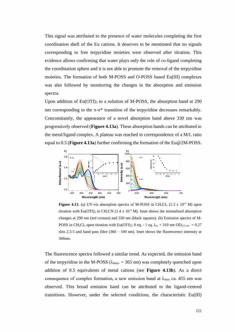
121
This signal was attributed to the presence of water molecules completing the first
coordination shell of the Eu cations. It deserves to be mentioned that no signals
corresponding to free terpyridine moieties were observed after titration. This
evidence allows confirming that water plays only the role of co-ligand completing
the coordination sphere and it is not able to promote the removal of the terpyridine
moieties. The formation of both M-POSS and O-POSS based Eu(III) complexes
was also followed by monitoring the changes in the absorption and emission
spectra.
Upon addition of Eu(OTf)3 to a solution of M-POSS, the absorption band at 290
nm corresponding to the -* transition of the terpyridine decreases remarkably.
Concomitantly, the appearance of a novel absorption band above 330 nm was
progressively observed (Figure 4.13a). These absorption bands can be attributed to
the metal/ligand complex. A plateau was reached in correspondence of a M/L ratio
equal to 0.5 (Figure 4.13a) further confirming the formation of the Eu@2M-POSS.
Figure 4.13. (a) UV-vis absorption spectra of M-POSS in CH2Cl2 (1.3 x 10⁻⁵ M) upon
titration with Eu(OTf)3 in CH3CN (1.4 x 10⁻³ M). Inset shows the normalized absorption
changes at 290 nm (red crosses) and 330 nm (black squares). (b) Emission spectra of M-
POSS in CH2Cl2 upon titration with Eu(OTf)3: 0 eq. - 1 eq. λex = 310 nm OD315 nm = 0.27
slits 2.5-5 and band pass filter (360 – 100 nm). Inset shows the fluorescence intensity at
366nm.
The fluorescence spectra followed a similar trend. As expected, the emission band
of the terpyridine in the M-POSS (λmax. = 365 nm) was completely quenched upon
addition of 0.5 equivalents of metal cations (see Figure 4.13b). As a direct
consequence of complex formation, a new emission band at λmax ca. 455 nm was
observed. This broad emission band can be attributed to the ligand-centred
transitions. However, under the selected conditions, the characteristic Eu(III)

122
emission (in the region between 550 – 700 nm) was not detected. This behaviour
could be attributed to the incomplete energy transfer from the terpyridine to the
europium and/or the influence of the solvent polarity as well as the presence of
water molecules. M-POSS possess seven hydrophobic isobutyl groups surrounding
the nanocage with consequent generation of a “hydrophobic shell” influencing the
self-association process.21 In order to better understand the reason behind the
absence of this emission, a novel set of experiments employing a mixture of
solvents of different polarity ((CH3CN (97%):CH2Cl2 (3%)) was performed as well.
Figure 4.14. Typical Europium line like emission centred at 616 nm clearly visible in the
presence of Eu@2M-POSS dissolved in the following mixture of solvents: CH3CN
(97%):CH2Cl2 (3%).
Figure 4.14 shows a non-resolved emission centered at 617 nm clearly visible in
the novel mixture of solvent thus confirming the role played by the solvent on the
emission of M-POSS structures.
However, a different behaviour with an improved emission should be expected in
presence of O-POSS based ligands in which the isobutyl groups are replaced by
terpyridine moieties.
As expected, the addition of Eu(OTf)3 to a solution of O-POSS, the absorption band
at 290 nm corresponding to the -* transition of the terpyridine start to decrease.
At the same time, the appearance of a new absorption band above 330 nm was
progressively observed (Figure 4.15).
500 550 600 650 700 750
0
100
200
Inte
nsit
y (
a.u
.)
Wavelength (nm)

123
The plot of the absorption bands in function of the equivalent of metal added
confirmed the stoichiometry of the complex. Looking in Figure 4.15 it is possible
to see that, after adding 0.5 equivalent of Eu(III), the plateau was reached
Figure 4.15. UV-Vis absorption spectra of O-POSS in CH2Cl2 (1 x 10⁻⁵ M) upon titration
with Eu(OTf)3 in CH3CN (1.4 x 10⁻³ M) (a). Normalized absorption changes at 290 nm (red
circles) and 330 nm (black squares) (b).
Continuing with the emission titration, as expected, the addition of Eu(OTf)3 causes
a progressive decrease of the terpyridine emission band (λmax = 390 nm) with a
complete disappearance in correspondence of 0.5 equivalents of metal (formation
of 1:2 complex, Figure 4.16a).
Figure 4.16. (a) Emission spectra of O-POSS [1x10⁻⁵ M] in CH2Cl2 upon addition of
Eu(OTf)3 [1.4x10⁻³ M] in CH3CN (λex = 313 nm OD= 0.15 slits 5 nm). Inset shows the
characteristic Eu(III) line-like emission. (b) Picture of visible emission of O-POSS
solutions under UV irradiation at 356 nm. In blue free O-POSS emission and in red
Eu@2O-POSS complex emission.

124
Also in this case, a broad emission ligand centred band was still present. It is
noteworthy that once the complex was formed, the characteristic Eu(III) line-like
emission was clearly observed. The five sharp emission peaks at 580, 591, 617, 650
and 698 nm (inset Figure 4.16a), were assigned to the 5D0 → 7FJ (J = 0, 1, 2, 3, 4
and 5) transitions, with the most intense at 617 nm corresponding to the 5D0 → 7F2
emission. It is important to underline that, under the highly diluted conditions (10-
7M) employed to monitor the absorption and emission features of the Eu@O-POSS
complex, a perfectly homogeneous and transparent solution was always obtained
during the titration experiments and this solution was characterized by a red
emission evident also to the naked eyes (Figure 4.16b).
However, precipitation of the Eu@2O-POSS assembled structure in the solid state
was achieved. By mixing a solution of O-POSS in DCM and a solution of Eu
triflate, a form of a pale-yellow powder can be easily obtained in more concentrated
solution.
Figure 4.17. (a) Solid state emission of Eu@2OPOSS complex.
Hence, solid state emission properties of the Eu@O-POSS complex were evaluated
as well. As can be clearly seen in Figure 4.17, the emission spectrum of the solid
displays excellent features characterized by a strong emission intensity as well as
by a narrow half emission width of c.a. 10 nm. Moreover, the decrease of the
intensity of the emission band of the complexed ligand suggests that the energy
transfer from the terpyridine ligands to the Eu(III) is more efficient in the solid state.
The more intense emission of Eu@O-POSS complex, compared to the M-POSS-
based structures, can be considered as a consequence of the increased local
concentration of the terpyridine surrounding the nanocage. This constitute an
350 400 450 500 550 600 650 700 750 800
0.0
2.0x10⁴
4.0x10⁴
6.0x10⁴
Inte
nsit
y (
a.u
)
Wavelength (nm)

125
indication of the important role played by the 3D metallopolymeric network
protecting Eu(III) against non-radiative deactivation. These differences in the
emission arising from the different environments in the assembled coordination
complexes could be due to the molecular packing inducing higher emission.22
Once proved the emission properties of the Eu@O-POSS, an investigation of the
trans-cis reversible isomerization was performed. It is well known that UV light
irradiation may promote trans to cis isomerization of the vinyl group. The formation
of the cis-isomer was monitored via 1H-NMR spectroscopy selecting the M-POSS
as target molecule. The formation of an almost equimolecular mixture of cis and
trans isomers was achieved through irradiation of the trans-M-POSS at 356 nm. As
can be clearly seen in Figure 4.18, the initial 1H-NMR spectrum displays, in the
vinyl region, only one signal at 6.22 ppm (coupling constant J = 19.1 Hz)
corresponding to the vinyl group in trans configuration. After 1h irradiation, a novel
signal at 5.70 ppm (coupling constant J = 15.2 Hz) corresponding to the cis form
appears together with a series of signals in the aromatic part of the spectrum.
Figure 4.18. 1H-NMR spectrum of M-POSS (a) before and (b) after irradiation at 356 nm.
* in the figure, indicate the 13C satellites
Once proved the possibility to form the cis-M-POSS structure, the trans-to-cis
photoisomerization process was followed at different irradiation times via UV-
visible and fluorescence spectroscopies. Upon irradiation, a decrease of the
absorbance of the UV-Visible band centred at 290 nm and the concomitant
appearance of a shoulder were observed (Figure 4.19). A more evident transition

126
was clearly distinguished in the fluorescent spectra. An almost complete
disappearance of the emission band of trans-M-POSS at 366 nm together with the
appearance of a novel emission band at 460 nm (attributed to the cis form) was
observed after 60 minutes of irradiation at 356 nm (Figure 4.19, green line).
Interestingly, under the conditions employed in the fluorescence experiments, a
total trans-to-cis conversion was achieved after 1h irradiation.
Figure 4.19. UV-Vis absorption (left) and emission (right) spectra of M-POSS in CH2Cl2
(1.3 x 10⁻⁵ M) upon different irradiation times at 356nm. (λirrad = 356 nm); λex = 314 nm,
slits 2.5, 5 nm (bandpass filter 360 – 1100 nm).
The reversibility of the isomerization process was achieved via thermal treatment,
heating the M-POSS solution at 50 °C during 1h (Figure 4.20a). Indeed, after
thermal treatment at 50 °C the band at 460 nm disappeared while the contribution
at 366 nm was completely restored. The process can be repeated multiple times with
highly consistent results. Excitation spectra of the M-POSS at the maximum of the
respectively emissions (370 nm for the trans- form and 460 nm for the cis- form)
were recorded being practically coincident with the corresponding absorption
spectra of trans- and cis- configurations, respectively (Figure 4.20), indicating that
the detected emission corresponds to the trans- and to the cis- forms without
observing of the excimers formation in these conditions.
Analogous irradiation experiments were carried out in presence of O-POSS. The
photoisomerization process of O-POSS at different irradiation times was followed
by UV-Visible and fluorescence spectroscopies.
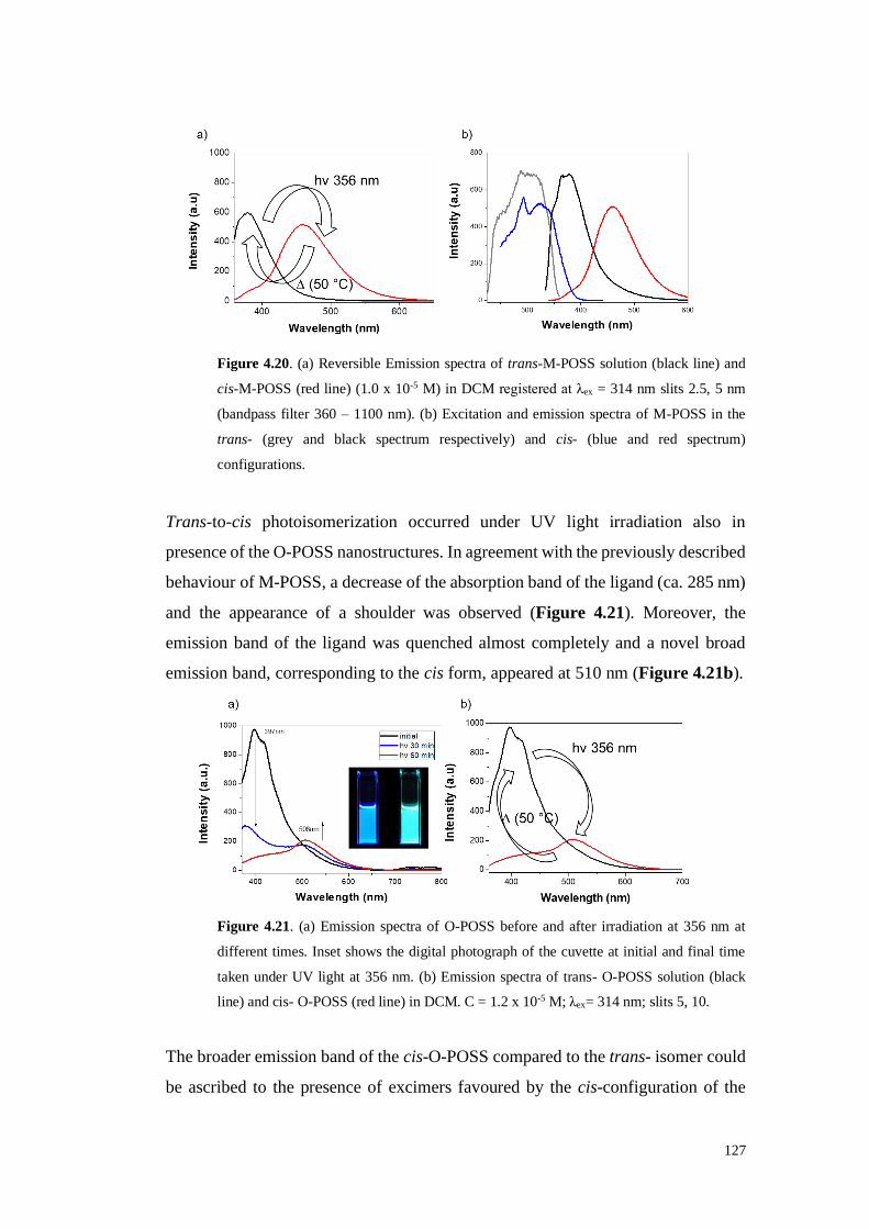
127
Figure 4.20. (a) Reversible Emission spectra of trans-M-POSS solution (black line) and
cis-M-POSS (red line) (1.0 x 10⁻⁵ M) in DCM registered at λex = 314 nm slits 2.5, 5 nm
(bandpass filter 360 – 1100 nm). (b) Excitation and emission spectra of M-POSS in the
trans- (grey and black spectrum respectively) and cis- (blue and red spectrum)
configurations.
Trans-to-cis photoisomerization occurred under UV light irradiation also in
presence of the O-POSS nanostructures. In agreement with the previously described
behaviour of M-POSS, a decrease of the absorption band of the ligand (ca. 285 nm)
and the appearance of a shoulder was observed (Figure 4.21). Moreover, the
emission band of the ligand was quenched almost completely and a novel broad
emission band, corresponding to the cis form, appeared at 510 nm (Figure 4.21b).
Figure 4.21. (a) Emission spectra of O-POSS before and after irradiation at 356 nm at
different times. Inset shows the digital photograph of the cuvette at initial and final time
taken under UV light at 356 nm. (b) Emission spectra of trans- O-POSS solution (black
line) and cis- O-POSS (red line) in DCM. C = 1.2 x 10⁻⁵ M; λex= 314 nm; slits 5, 10.
The broader emission band of the cis-O-POSS compared to the trans- isomer could
be ascribed to the presence of excimers favoured by the cis-configuration of the

128
double bond. Interestingly, in the case of O-POSS nanostructures the trans to cis
isomerization was accompanied by an evident change in colour that passed from
blue (trans-O-POSS) to green (cis-O-POSS). As previously observed for the M-
POSS, also the octa-functionalized analogues display a reversible isomerization.
Due to the relevant interest that could present a tuneable photochromism of the self-
assembled 3D network, the isomerization process of the Eu@O-POSS complex was
followed as well via UV-Visible and fluorescence spectroscopies It is worth
highlighting that under UV irradiation the Eu@O-POSS complexes release almost
completely the coordinated Eu(III) ions.
Figure 4.22. (a) UV-visible and (b) emission spectra of Eu@O-POSS (1:2) before (black
line) and after irradiation (red line) at 356 nm for 60 minutes. [O-POSS] = 1.3 x 10⁻⁵ M;
λex= 314 nm; slits 5, 10; (bandpass filter 360 – 1100 nm).
As we can observe in the Figure 4.22, the characteristic Eu(III) emission bands
disappeared after 1h irradiation. This behaviour can be ascribed to elevate steric
hindrance of the O-POSS in the cis forms hindering the coordination of the metal
centre. Changes in fluorescence emission of the Eu@O-POSS under UV light
exposure can be detected also at naked eyes (Scheme 4.3).
Trans-O-POSS (a) displays an evident blue emission, after formation of the
Eu@trans-O-POSS complex a shift through the red is clearly observed (b), UV-
irradiation of the Eu@trans-O-POSS causes the release of the Eu(III) ions due to
the formation of the cis-O-POSS isomer whose free (non-complexed) form emits
in the green (c).

129
Scheme 4.3. Schematic representation of the tuneable emission of (a) trans-O-POSS in
dichloromethane solution; (b) Eu@trans-O-POSS; (c) cis-O-POSS after irradiation at 356
nm (60 minutes) under UV lamp. (R = phenyl-2,2':6',2''-terpyridine.
After thermal treatment the cis-O-POSS can be completely converted in the trans
isomer and the cycle can be repeated without detrimental effect on O-POSS
nanostructure.
Moreover, in presence of small amount of solvent the solid Eu@O-POSS can be
easily shaped as a film as illustrated in Figure 4.23. This behaviour can pave the
way toward the application in materials science.
Figure 4.23. Film of the acronym of the University of Namur designed employing the
trans-O-POSS (first two letters on the right), Eu@trans-O-POSS (letters in the middle) and
cis-O-POSS (last two letters on the right) under UV lamp (356 nm).
4.2 Conclusions
The absorption and emission properties of two novel silsesquioxane-based Eu
complexes were investigated. The stoichiometry of the complexes (Eu@2M-POSS
and Eu@2O-POSS) was evaluated via 1H-NMR as well as UV-Vis and
fluorescence titration experiments. The solutions of Eu@2O-POSS display a

130
bright-red luminescence under UV light at room temperature and an even more
intense emission can be achieved in solid state. Interestingly both M- and O-POSS
nanostructures display a reversible trans to cis isomerization of the carbon-carbon
double bond linking the silsesquioxane core to the terpyridine moieties. In the case
of O-POSS nanocages this isomerization was monitored also in presence of Eu(III)
cations and was accompanied by an evident modification of the colour which
passed from blue (trans-O-POSS) to red (Eu@trans-O-POSS) and finally to green
(cis-O-POSS) as consequence of the release of the metal cations. After thermal
treatment, the cis-O-POSS can be completely converted in the trans isomer and the
cycle can be repeated without detrimental effect on O-POSS nanostructure. This
switchable and reversible “blue-red-green” emission together with the easy
dispersion, solubility in organic solvents and the possibility of forming films makes
the emitting solid promising for applications in materials science and in particular
in the preparation of advanced light emitting devices.

131
4.3 References
1. Pescarmona, P. P.; Aprile, C.; Swaminathan, S., Silsesquioxanes and their
use as precursors for catalysts and as model compounds. In New and Future
Developments in Catalysis, Suib, S. L., Ed. Elsevier: 2013.
2. (a) Duchateau, R.; van Meerendonk, W. J.; Huijser, S.; Staal, B. B. P.; van
Schilt, M. A.; Gerritsen, G.; Meetsma, A.; Koning, C. E.; Kemmere, M. F.;
Keurentjes, J. T. F., Silica-Grafted Diethylzinc and a Silsesquioxane-Based Zinc
Alkyl Complex as Catalysts for the Alternating Oxirane−Carbon Dioxide
Copolymerization. Organometallics 2007, 26 (17), 4204-4211; (b) Kunthom, R.;
Jaroentomeechai, T.; Ervithayasuporn, V., Polyhedral oligomeric silsesquioxane
(POSS) containing sulfonic acid groups as a metal-free catalyst to prepare
polycaprolactone. Polymer 2017, 108, 173-178; (c) Wada, K.; Nakashita, M.;
Mitsudo, T., Active catalysts prepared using a vanadium-containing
oligosilsesquioxane for selective photo-assisted oxidation of methane into
methanal. Chem. Commun. 1998, (1), 133-134.
3. (a) Kannan, R. Y.; Salacinski, H. J.; Ghanavi, J.-e.; Narula, A.; Odlyha, M.;
Peirovi, H.; Butler, P. E.; Seifalian, A. M., Silsesquioxane Nanocomposites as
Tissue Implants. Plastic and Reconstructive Surgery 2007, 119 (6), 1653-1662; (b)
Rizvi, S. B.; Yang, S. Y.; Green, M.; Keshtgar, M.; Seifalian, A. M., Novel POSS–
PCU Nanocomposite Material as a Biocompatible Coating for Quantum Dots.
Bioconjugate Chem. 2015, 26 (12), 2384-2396; (c) Zhang, C.; Babonneau, F.;
Bonhomme, C.; Laine, R. M.; Soles, C. L.; Hristov, H. A.; Yee, A. F., Highly
Porous Polyhedral Silsesquioxane Polymers. Synthesis and Characterization. J. Am.
Chem. Soc. 1998, 120 (33), 8380-8391.
4. Bivona, L. A.; Fichera, O.; Fusaro, L.; Giacalone, F.; Buaki-Sogo, M.;
Gruttadauria, M.; Aprile, C., Polyhedral Oligomeric Silsesquioxane Based Catalyst
for the Efficient Synthesis of Cyclic Carbonates. Catal. Sci. Technol. 2015, 5, 5000
- 5007
5. (a) Calabrese, C.; Liotta, L. F.; Giacalone, F.; Gruttadauria, M.; Aprile, C.,
Supported Polyhedral Oligomeric Silsesquioxane-Based (POSS) Materials as
Highly Active Organocatalysts for the Conversion of CO2. ChemCatChem 2019,

132
11 (1), 560-567; (b) Bivona, L. A.; Giacalone, F.; Carbonell, E.; Gruttadauria, M.;
Aprile, C., Proximity Effect using a Nanocage Structure: Polyhedral Oligomeric
Silsesquioxane-Imidazolium Tetrachloro- palladate Salt as a Precatalyst for the
Suzuki–Miyaura Reaction in Water. ChemCatChem 2016, 8 (9), 1685-1691.
6. Tsuchida, A.; Bolln, C.; Sernetz, F. G.; Frey, H.; Mülhaupt, R., Ethene and
Propene Copolymers Containing Silsesquioxane Side Groups. Macromolecules
1997, 30 (10), 2818-2824.
7. Hartmann-Thompson, C.; Keeley, D. L.; Pollock, K. M.; Dvornic, P. R.;
Keinath, S. E.; Dantus, M.; Gunaratne, T. C.; LeCaptain, D. J., One- and Two-
Photon Fluorescent Polyhedral Oligosilsesquioxane (POSS) Nanosensor Arrays for
the Remote Detection of Analytes in Clouds, in Solution, and on Surfaces. Chem.
Mater. 2008, 20 (8), 2829-2838.
8. Mehl, G. H.; Saez, I. M., Polyhedral liquid crystal silsesquioxanes. Appl.
Organomet. Chem. 1999, 13 (4), 261-272.
9. Carbonell, E.; Bivona, L. A.; Fusaro, L.; Aprile, C., Silsesquioxane–
Terpyridine Nano Building Blocks for the Design of Three-Dimensional Polymeric
Networks. Inorg. Chem. 2017, 56 (11), 6393-6403.
10. Cheng, C.-C.; Chu, Y.-L.; Chu, C.-W.; Lee, D.-J., Highly efficient organic-
inorganic electroluminescence materials for solution-processed blue organic light-
emitting diodes. J. Mater. Chem. C 2016, 4 (27), 6461-6465.
11. Escribano, P.; Julián-López, B.; Planelles-Aragó, J.; Cordoncillo, E.; Viana,
B.; Sanchez, C., Photonic and nanobiophotonic properties of luminescent
lanthanide-doped hybrid organic–inorganic materials. J. Mater. Chem. 2008, 18 (1),
23-40.
12. Syamchand, S. S.; Sony, G., Europium enabled luminescent nanoparticles
for biomedical applications. J. Lumin. 2015, 165, 190-215.
13. (a) Schubert, U. S.; Winter, A.; Newkome, G. R., Metallo-Supramolecular
Architectures Based on Terpyridine Complexes. In Terpyridine-Based Materials,
Wiley-VCH Verlag GmbH & Co. KGaA: 2011; pp 129-197; (b) Kotova, O.;
Comby, S.; Lincheneau, C.; Gunnlaugsson, T., White-light emission from discrete

133
heterometallic lanthanide-directed self-assembled complexes in solution. Chem.
Sci. 2017, 8 (5), 3419-3426.
14. Bekiari, V.; Lianos, P., Multicolor emission from terpyridine–lanthanide ion
complexes encapsulated in nanocomposite silica/poly(ethylene glycol) sol–gel
matrices. J. Lumin. 2003, 101 (1), 135-140.
15. (a) Chung, J. W.; Yoon, S.-J.; An, B.-K.; Park, S. Y., High-Contrast On/Off
Fluorescence Switching via Reversible E–Z Isomerization of Diphenylstilbene
Containing the α-Cyanostilbenic Moiety. J. Phys. Chem. C 2013, 117 (21), 11285-
11291; (b) Dugave, C.; Demange, L., Cis−Trans Isomerization of Organic
Molecules and Biomolecules: Implications and Applications. Chem. Rev. 2003,
103 (7), 2475-2532.
16. Lima, P. P.; Nolasco, M. M.; Paz, F. A. A.; Ferreira, R. A. S.; Longo, R. L.;
Malta, O. L.; Carlos, L. D., Photo–Click Chemistry to Design Highly Efficient
Lanthanide β-Diketonate Complexes Stable under UV Irradiation. Chem. Mater.
2013, 25 (4), 586-598.
17. Lin, L.-R.; Tang, H.-H.; Wang, Y.-G.; Wang, X.; Fang, X.-M.; Ma, L.-H.,
Functionalized Lanthanide(III) Complexes Constructed from Azobenzene
Derivative and β-Diketone Ligands: Luminescent, Magnetic, and Reversible Trans-
to-Cis Photoisomerization Properties. Inorg. Chem. 2017, 56 (7), 3889-3900.
18. (a) Bian, M.; Wang, Y.; Guo, X.; Lv, F.; Chen, Z.; Duan, L.; Bian, Z.; Liu,
Z.; Geng, H.; Xiao, L., Positional isomerism effect of spirobifluorene and
terpyridine moieties of “(A)n–D–(A)n” type electron transport materials for long-
lived and highly efficient TADF-PhOLEDs. J. Mater. Chem. C 2018, 6 (38), 10276-
10283; (b) Zych, D.; Slodek, A.; Matussek, M.; Filapek, M.; Szafraniec-Gorol, G.;
Krompiec, S.; Kotowicz, S.; Siwy, M.; Schab-Balcerzak, E.; Bednarczyk, K.;
Libera, M.; Smolarek, K.; Maćkowski, S.; Danikiewicz, W., Highly Luminescent
4′-(4-ethynylphenyl)-2,2’:6’,2’’-Terpyridine Derivatives as Materials for Potential
Applications in Organic Light Emitting Diodes. ChemistrySelect 2017, 2 (27),
8221-8233.
19. Cordes, D. B.; Lickiss, P. D., Preparation and Characterization of Polyhedral
Oligosilsesquioxanes. In Applications of Polyhedral Oligomeric Silsesquioxanes,

134
Hartmann-Thompson, C., Ed. Springer Science and Business Media: London,
2011; pp 47-133.
20. Peters, J.; Huskens, J.; Raber, D., Lanthanide induced shifts and relaxation
rate enhancements. Progress in Nuclear Magnetic Resonance Spectroscopy 1996,
28 (3-4), 283-350.
21. Au-Yeung, H.-L.; Leung, S. Y.-L.; Tam, A. Y.-Y.; Yam, V. W.-W.,
Transformable Nanostructures of Platinum-Containing Organosilane Hybrids:
Non-covalent Self-Assembly of Polyhedral Oligomeric Silsesquioxanes Assisted
by Pt···Pt and π−π Stacking Interactions of Alkynylplatinum(II) Terpyridine
Moieties. J. Am. Chem. Soc. 2014, 136, 17910−17913
22. (a) Andres, J.; Chauvin, A.-S., Europium Complexes of Tris(dipicolinato)
Derivatives Coupled to Methylumbelliferone: A Double Sensitization. Eur. J.
Inorg. Chem. 2010, 2010 (18), 2700-2713; (b) Divya, V.; Freire, R. O.; Reddy, M.
L. P., Tuning of the excitation wavelength from UV to visible region in Eu3+-β-
diketonate complexes: Comparison of theoretical and experimental photophysical
properties. Dalton Trans. 2011, 40 (13), 3257-3268; (c) Zhang, Z.-M.; Han, F.-F.;
Zhang, R.; Li, N.; Ni, Z.-H., Design, syntheses and aggregation-induced emission
properties of two new enlarged tetraarylethene-based luminogens. Tetrahedron
Lett. 2016, 57 (17), 1917-1920.

135
Chapter 5
Photoluminescence
Lanthanide@POSS-based materials

136
5 Photoluminescence Lanthanide@POSS-based materials
As already reported in literature (and mentioned in the previous chapter), Eu3+ ions
should be able to accommodate up to nine coordinating atoms/molecules.1
However, in the case of the systems described in paragraph 4.1, the steric hindrance
of the POSS-based structures hinders the formation of complexes in which the
metal cation can accommodate 3 silsesquioxanes-based ligands. As commented
previously (see part 4.1) the coordination shell of the metal is hence completed by
solvent molecules, most probably water (Figure 4.11).
Since it is well known that water can negatively affect fluorescence emission,2 an
attempt was done to remove these water molecules from the Eu@POSS complexes
adding less hindered and highly coordinating ligands to the reaction mixture. In
order to achieve this goal, two strong co-ligands able to absorb photon and promote
an energy transfer to europium were selected: 2,2'-oxydiacetic acid (ODA), and
2,2':6',2''-terpyridine (Tpy). In the next paragraph we will report the results of these
studies.
Due to the poor solubility of the ODA in the mixture of solvent employed in the
previous experiments (CDCl3:CD3CN or CH2Cl2:CH3CN), a series of titration
experiments (followed via 1H-NMR as well as via UV-Vis and emission
spectroscopies) were conducted to study the behaviour of the POSS-Eu systems in
a different media. The novel mixture of solvents employed in this study was
constituted by CH2Cl2:MeOH.
Since the nature of the solvent could strongly influences the coordination properties
of the selected ligand, titration experiments similar the ones reported in the previous
chapter where performed in presence of CH2Cl2: MeOH.
The UV-Vis spectra of both M-POSS (Figure 5.1a) and O-POSS (Figure 5.1b)
show that the free terpyridine absorption band centred at 290 nm decreases during
the titration and a new band, assigned to the formation of the Eu@POSS complex,
appears at 330 nm. A plateau was reached after addition of 0.5 eq of Eu(OTf)3
solution (inset) suggesting an Eu(III) to ligand stoichiometry equal to 2:1. These
results are in agreement with the ones obtained in presence of CH2Cl2:CH3CN.

137
Figure 5.1. UV-Vis absorption spectra of M-POSS and O-POSS in CH2Cl2 (1.3 x 10⁻⁵ M)
upon titration with Eu(OTf)3 in MeOH (1.3 x 10⁻³ M)
Emission spectra (Figure 5.2) confirmed further this behaviour. Both experiments
allow excluding a major role of methanol as co-ligand under the conditions
employed for the absorption and emission studies.
Concerning the M-POSS (Figure 5.2a), the emission band of the terpyridine at 365
nm was completely quenched upon addition of 0.5 equivalents Eu3+and a new
emission band at 455 nm was observed. This second emission band can be attributed
to the ligand-centred transitions.
Figure 5.2. Emission spectra of (a) M-POSS and (b) O-POSS in CH2Cl2 upon addition of
Eu(OTf)3 in MeOH. Solution of M-POSS and O-POSS in DCM at C = 1.3x10⁻⁵ M were
titred with Eu(OTf)3 in MeOH C = 1.3x10⁻³ M.(M-POSS: λex = 335nm slits = 2.5-5nm
bandpass filter 360 – 1100 nm; O-POSS: λex = 335nm slits = 5-5nm bandpass filter 360 –
1100 nm).
A similar behaviour was observed in the case of O-POSS (Figure 5.2b). In this
case, the quenching of the free terpyridine emission band (400 nm) and the
simultaneous increases of the ligand centred transition emission band (490 nm) was
detected. This last band disappears slowly during the titration and, as consequence

138
of the energy transfer from the terpyridine to the Eu, the typical Eu line like bands
in the region between 580 and 698 nm (assigned to the 5D0 → 7FJ transitions)
appear.
Titration experiments were also performed following the evolution of the typical
signals of the terpyridine via 1H-NMR. However, a slightly different behaviour was
observed in presence of the novel mixture of solvents [CDCl3:MeOD] when the
titration experiment was followed via 1H-NMR. This different behaviour could be
attributed to the higher concentrations employed in the NMR experiments.
In the previous 1H-NMR experiments performed in chloroform:acetonitrile we
observed: (1) the formation of the Eu@2M-POSS (2:1 complex) (2) the complete
disappearance of the free terpyridine after adding 0.5 eq of Eu3+ and (3) the
formation of Eu@M-POSS (1:1 complex) after adding an excess of metal (Figure
4.8 and 4.9a). On the other hand, when methanol (instead of acetonitrile) is added
to the reaction mixture, different species form in solution (figure 5.3).
Figure 5.3. 1H-NMR titration of M-POSS solution in CDCl3:MeOD 3:1 with Eu(OTf)3.
It is important to underline that the formation of a M-POSS/Eu complex was always
observed. This is evident by looking to the shift of different signals in the aromatic
region of the spectra (protons related to the aromatic rings of the terpyridine) and
by observing the region between 5.6 ppm and 6.2 ppm which corresponds to the C-

139
C double bond. In this last region it is possible to note the disappearance of the
signals attributed to the vinyl group of the free terpyridine (when titration is
performed with CDCl3:CD3CN solvent mixture). However, by changing solvent
mixture (using CDCl3:MeOD as solvent) two major differences can be immediately
detected. First of all, the completely disappearance of the signals corresponding to
the free terpyridine (black squares) was never observed even when a large excess
of metal was added to the mixture. Moreover, an equilibrium between three
different species: the free ligand, the 2:1 complex (Eu@2M-POSS black circles)
and the 1:1 complex (Eu@M-POSS black stars) was observed.

140
5.1 139La-NMR characterisation
So far, the formation of complexes was studied only by 1H-NMR titration
experiments. Besides, it was interesting to confirm previous results directly by
recording NMR spectra of the metal centre of interest. However, since Eu+3 is
paramagnetic and cannot be easily studied by NMR, it was preferred to choose a
diamagnetic metal of the lanthanide series, as the lanthanum. Replacing Eu+3 with
La+3 is supposed to not significantly affect the formation of coordination
complexes, as the elements of lanthanide series are chemically similar. La has two
quadrupolar NMR active nuclei: 138La and 139La. The latter was chosen because is
characterised by sharper resonance lines and higher natural abundance (99.9%).
139La (I=7/2) yields broad signals because of the efficient quadrupolar relaxation
mechanism. Its signal become even broader when La is found in complexes
(because reduced molecular tumbling) or in asymmetric environments.
Two different experiments were performed to verify the formation of MPOSS-La
complexes in equilibrium with the free ligand (Figure 5.4). The 139La-NMR spectra
reported in Figure 5.4a show the NMR spectrum of the La triflate. Its signal
(labelled with black square) is observed at -30 ppm (with respect to LaCl3 in water
at 0 ppm) and is characterised by a linewidth at half height (LW) of 2.3 kHz. Upon
addition of M-POSS was observed a significant decrease of its integrated area and,
at the end of the titration experiment, the presence of a new, broad signal (LW =
6.7 kHz), at around 90 ppm (labelled with black star) which is assigned to the bound
La+3 in slow exchange on the chemical shift time scale.
Figure 5.4. a) 139La-NMR titration of La(OTf)3 in CDCl3:MeOD 3:1 with M-POSS and b)
139La-NMR titration of M-POSS in CDCl3:MeOD 3:1 with La(OTf)3. In Figure stars point
out complexed metal while squares free metal.

141
This result is in agreement with data reported in the literature. 3 Indeed, both the
LW and the chemical shift are generally increased when the water molecules in the
first coordination shell are replaced by nitrogen or oxygen donor sites.
A counter-experiment was performed starting from M-POSS and adding La(OTf)3.
upon addition of a small amount of La+3, the appearance of a signal at 90 ppm
(labelled with black star) was observed, confirming the formation of MPOSS-La
complexes and the assignment of the resonance line. Immediately after a second
addition of metal, a second signal (labelled with black square) at -30 ppm appears,
confirming the equilibrium between the free metal and the complexed one.
The formation of M-POSS-La3+ complexes was studied by 1H-NMR, by adding
La(OTf)3 to a solution of M-POSS (Figure 5.5). Upon addition of only 0.12 eq. of
La3+ a new series of signals was observed (black stars in Figure 5.5). After the
addition of 0.5 eq of La3+, a series of signal was observed (stars in figure 5.5). The
intensity of all these resonance lines increase at increasing amounts of La3+. All
these new signals remain in their positions till the end of the titration confirming
the results obtained following the 139La. Hence, the formation of M-POSS-La
complexes in equilibrium with the free ligand.
These findings have been confirmed by means of a counter titration carried out by
adding M-POSS to a La(OTf)3 solution.
Figure 5.5. 1H-NMR titration of M-POSS solution in CDCl3:MeOD 3:1 with La(OTf)3 In
Figure stars point out signals related to the complex.

142
The NMR data confirm that methanol can act as co-ligand competing with water
molecules to complete the coordination shell of the metal centre. Otherwise, when
CH3CN was present in the mixture the coordination shell was completed by the
residual water molecules.
This represent a good indication that water molecules can be replaced if another co-
ligand is present in the mixture. The next step was hence the use of active ligands
able to replace water (and methanol) in the metal coordination shell and at the same
time enhancing the emission of the final complex.

143
5.2 Replacing water molecules
The first attempt to replace water molecules from the coordination sphere of Eu(III)
in the Eu@POSS complexes has been carried out on the Eu@2M-POSS by adding
ODA molecules (Figure 5.6).
Figure 5.6. (a)Emission spectra of Eu@2M-POSS in CH2Cl2 (1.3 x 10⁻⁵ M) upon titration
with ODA in MeOH (1.3 x 10⁻³ M) (b)Emission intensity at 422 nm versus ligand
concentration (intensity vs [ODA]/[M-POSS]). (λex = 335nm slits = 2.5-5nm bandpass filter
360 – 1100 nm).
The emission band of M-POSS (black line) centred at 368 nm was almost
completely quenched after the addition of 0.5 eq. of metal (Figure 5.6a).
Consequently, a new emission band centred at 422 nm (red line) appeared. This
weak emission is attributed to the formation of the Eu@2M-POSS complex.
Interestingly, upon addition of increasing amount of ODA a significant (above 5-
fold) increase of the emission intensity was observed. This change in intensity is
also clear to the naked eye. Eu@2M-POSS-ODA displays higher emission intensity
as shown in the inset (Figure 5.6a). Analogous experiments were performed adding
terpyridine as co-ligand (Figure 5.7). The first step was the formation of the
Eu@2M-POSS complex. Then a Tpy solution in DCM was added until 0.5
equivalents of co-ligand were reached.
In this second experiment the trend was similar of the first one. It is possible observe
the initial quenching of the emission band of the M-POSS, centred at 366 nm, due
to the complexation with Eu3+ ions followed by the formation of a new band at 439
nm attributed to the ligand-centred transitions.
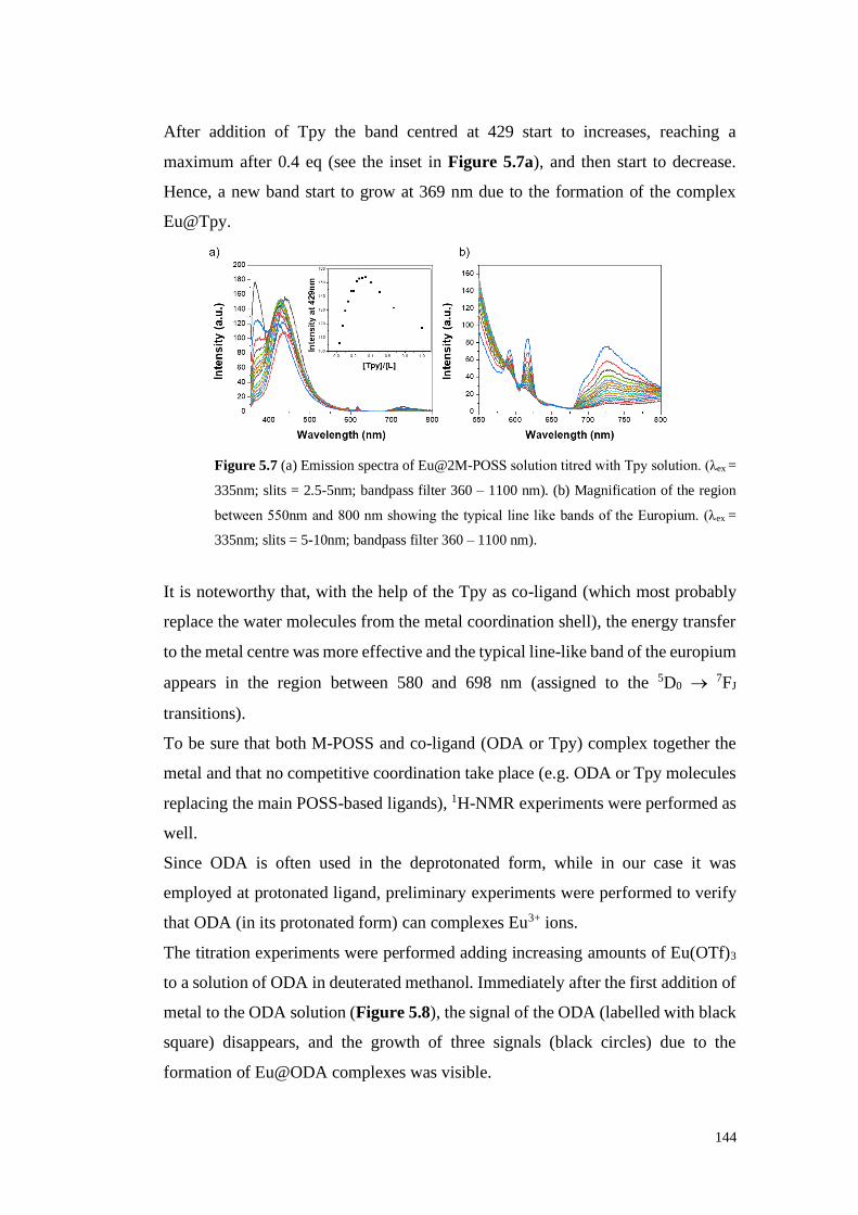
144
After addition of Tpy the band centred at 429 start to increases, reaching a
maximum after 0.4 eq (see the inset in Figure 5.7a), and then start to decrease.
Hence, a new band start to grow at 369 nm due to the formation of the complex
Eu@Tpy.
Figure 5.7 (a) Emission spectra of Eu@2M-POSS solution titred with Tpy solution. (λex =
335nm; slits = 2.5-5nm; bandpass filter 360 – 1100 nm). (b) Magnification of the region
between 550nm and 800 nm showing the typical line like bands of the Europium. (λex =
335nm; slits = 5-10nm; bandpass filter 360 – 1100 nm).
It is noteworthy that, with the help of the Tpy as co-ligand (which most probably
replace the water molecules from the metal coordination shell), the energy transfer
to the metal centre was more effective and the typical line-like band of the europium
appears in the region between 580 and 698 nm (assigned to the 5D0 → 7FJ
transitions).
To be sure that both M-POSS and co-ligand (ODA or Tpy) complex together the
metal and that no competitive coordination take place (e.g. ODA or Tpy molecules
replacing the main POSS-based ligands), 1H-NMR experiments were performed as
well.
Since ODA is often used in the deprotonated form, while in our case it was
employed at protonated ligand, preliminary experiments were performed to verify
that ODA (in its protonated form) can complexes Eu3+ ions.
The titration experiments were performed adding increasing amounts of Eu(OTf)3
to a solution of ODA in deuterated methanol. Immediately after the first addition of
metal to the ODA solution (Figure 5.8), the signal of the ODA (labelled with black
square) disappears, and the growth of three signals (black circles) due to the
formation of Eu@ODA complexes was visible.

145
Upon addition of increasing amount of Eu(OTf)3 a progressive shift of these signals
was also observed indicating that ODA is complexing the metal.
Figure 5.8. 1H-NMR titration of ODA solution in MeOD with Eu(OTf)3.
Then, a series of titration experiments was performed by mixing together M-POSS
and ODA in order to verify that the simultaneous complexation of the metal occurs.
In particular, for this investigation three different ratios between the M-POSS and
the ODA (2:1, 1:1, 1:2 M-POSS:ODA) were selected. The titration performed using
a solution of M-POSS:ODA in 1:1 ration is reported in Figure 5.9. As can be clearly
seen in the figure a shift of the typycal signals corresponding to the M-POSS based
ligand (mainly in the aromatic region) together with a relevant modification of the
pattern corresponding to the ODA is present.
It is possible to see that the signal of the ODA (black square) decreases until
disappearance and at the same time, signals related to the M-POSS (black circles)
shift in a new position. This experiment proves that both silsesquioxane-based
ligand and ODA co-ligand are playing an active role in the complexation of
europium and, more importantly, ODA is not competing with the M-POSS
replacing it from the metal coordination shell. In Figure 5.10 the shift of the vinyl
proton in function of the equivalent of metal added is reported, confirming that the
stoichiometry of the final complex is Eu@2M-POSS-ODA.

146
Figure 5.9. 1H-NMR titration of M-POSS:ODA 1:1 solution in CDCl3:MeOD 3:1 with
Eu(OTf)3.
From Figure 5.10a emerged that if the modification of the chemical shifts (of some
selected signals) is plotted in function of the Europium/total ligand ratio (M/L
where L indicates the concentration of M-POSS ligand + ODA co-ligand) a plateau
is reached in correspondence of a M/L value of c.a. 0.3 indicating that the complex
is formed by 3 ligands per each metal centre.
On Figure 5.10b is represented a similar plot in function of a Europium/POSS-
based ligand (M/L-POSS) ratio. In the last case a plateau is reached in
correspondence of M/L-POSS ratio of c.a. 0.5 indicating that 2 M-POSS based
ligand are present per each metal centre. This investigation suggests the presence
of a complex in which 2 silsesquioxane-based ligands are coordinating the metal
centre while the coordination shell of europium is completed by one molecule of
ODA, hence supporting the hypothesis of the formation of a Eu@2-M-POSS-1-
ODA.

147
Figure 5.10. Plot of the shift of the signal at 6.16 ppm in function of the equivalents of
Europium added in relation of the total amount of ligand (a) and in function of the
equivalents of Europium added in relation of the M-POSS (b).
Analogous experiments were conducted on Tpy, firstly monitoring the evolution of
the Tpy signals in complexing the metal in 1H-NMR titration. After adding 0.3
equivalents of europium, two new signals appeares in the region between 5.5 ppm
and 7.0 ppm (black circles in Figure 5.11). Suggesting the formation of the
Eu@2Tpy complex. Once 0.5 equivalents of Eu3+ were added, a new set of signals
at 9.5 ppm , 6.8 ppm and 5.1 ppm start to grow (black stars) suggesting now the
formation of Eu@Tpy complex. Also in this case, the different species that are
formed in solution are in equilibrium. This bahaviour is particularly evident in the
last spectrum in wich in presence of 1 equivalent of metal an equilibrium between
three different species is present in solution.
Hence, in agreement with the previous observation in the case of the M-POSS, at
the end of the titration three different species are in equilibrium: free Tpy,
Eu@2Tpy and Eu@Tpy.
As for the M-POSS:ODA system, in order to verify the simultaneous complexation
of the metal by the two ligands, a series of titrations were performed by mixing
together M-POSS and Tpy.

148
Figure 5.11. 1H-NMR titration of Tpy solution in CDCl3:MeOD 3:1 with Eu(OTf)3.
In particular, three different ratios between the M-POSS and Tpy were chosen: 2:1,
1:1, 1:2. In Figure 5.12 the titration performed with a 1:1 M-POSS:Tpy ratio is
reported. In this case, however, the signals of the phenyl-terpyridine in M-POSS as
well as the protons of the free-terpyridine, are overlapped in the aromatic region of
the spectrum making difficult both the discrimination of each single contribution
and the evolution of the complexes in solution. Focusing the attention to the region
between 5.2 ppm and 7.0 ppm, can be argued that both ligands take part to the
complexation since it is possible to recognize the typical of pattern (black stars)
corresponding to the formation of europium complexes with M-POSS or with the
Tpy (see Figure 5.12).
Similar 1H-NMR experiments in presence of O-POSS were not performed, due to
the fact that signals in O-POSS are very broad and it is not possible to diversify and
assign the different contributions to each species. Hence, emission investigations
aimed to verify the possibility to improve the emission properties in the Eu@O-
POSS complexes were performed.

149
Figure 5.12. 1H-NMR titration of M-POSS:Tpy 1:1 solution in CDCl3:MeOD 3:1 with
Eu(OTf)3.
5.3 “Rainbow” full emission spectrum
As seen in section 4.1 emission titration experiments revealed that the emission
band of O-POSS (black line) centred at 410 nm is completely quenched after adding
0.5 eq. of metal as consequence of the complexation with the Europium (Figure
4.15a). Furthermore, the energy transfer from the terpyridine to the metal, allow
transition in the f-f shell of the metal and the typical line like band of the Europium
resulted clearly visible (Figure 4.15a inset).
Interestingly, after addition of ODA as co-ligand, an increase of the europium
emission (at 590 nm and 620 nm) as well as an increase of the emission band at 490
nm corresponding to the ligand centred emission band were observed (Figure 5.13).
As we can see in the inset (Figure 5.13b), different emission properties were
observed for Eu@2-POSS complexes in the absence (right) or in presence of ODA
as a co-ligand (left).

150
Figure 5.13. (a) Emission spectra of Eu@2O-POSS solution titred with ODA solution (λex
= 335nm; slits = 5-5nm; bandpass filter 360 – 1100 nm); in the inset plot of the intensity at
481 nm vs equivalent of ODA added. (b) Magnification of the region between 550 nm and
800 nm showing the typical line like bands emission of the europium (λex = 335 nm; slits =
10-10 nm; bandpass filter 360 – 1100 nm).
Emission titration experiments were performed for the Eu@O-POSS in the
presence of Tpy as a co-ligand. (Figure 5.14).
The intensity of the line like band of the europium, in the region between 580 and
698 nm (assigned to the 5D0 → 7FJ transitions) increases and a shift of the metal
ligand band is observed (Figure 5.14b).
It is observed a red-shift in the presence of ODA and a blue-shift in the presence of
Tpy. The shift on the band indicates that the co-ligand added (in our case ODA or
Tpy) is also coordinating the metal centre. However, this coordination may result
in a different symmetry.
Figure 5.14. (a) Emission spectra of Eu@2O-POSS solution titred with Tpy solution (λex
= 335nm; slits = 5-5nm; bandpass filter 360 – 1100 nm). (b) Magnification of the region
between 550 nm and 800 nm showing the typical line like bands of the europium (λex =
335nm; slits = 10-10nm bandpass filter 360 – 1100 nm).

151
In the previous chapter the tuning of the emission properties of the Eu@O-POSS
complexes was achieved via cis- trans- isomerization of the double bond (blue-
green emission).
In the present investigation the role played by the use of co-ligands as ODA (purple
emission) or Tpy was also proved. In order to challenge even more our system an
additional investigation was performed. The objective was to achieve a fine
modulation of the emission properties of the Eu/O-POSS systems combining the
different possibilities (cis-trans isomerization and use of co-ligands) with the use
of other metal centres. On this topic, it was recently published an article in which
the Europium is combined with terbium to obtain compounds with different
emitting properties.4 For this reason the Terbium was selected as target metal for
our investigation. Moreover, it possesses characteristic bands at 490 nm, 544 nm,
585 nm and 622 nm that fall in the region of interest.
So we prepared different complexes with different ratio of metals (Eu:Tb 2:1 and
Eu:Tb 1:1. the
In the case of Eu0.66Tb0.33@O-POSS solution (ratio Eu/Tb = 2) was observed a
combination of the typical emission bands of the Terbium (544nm, 585nm) and the
Europium, see Figure 5.15a. With this complex an orange emission was observed.
Other O-POSS complexes were prepared with another metal ratio.
Particular relevant was the Eu0.5Tb0.5@O-POSS-Tpy (ratio Eu/Tb = 1 in the
presence of Tpy as co-ligand). The last complex allows obtaining a yellow
emission.
Figure 5.15. (a) Emission spectra of Eu0.66Tb0.33@O-POSS.(b) Emission spectra of
Eu0.5Tb0.5@O-POSS-Tpy. (λex = 335 nm; slits = 10-10 nm; bandpass filter 360 – 1100 nm).
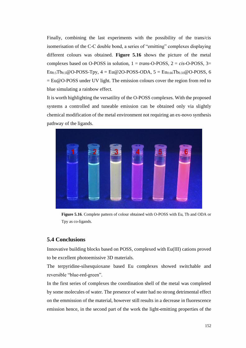
152
Finally, combining the last experiments with the possibility of the trans/cis
isomerisation of the C-C double bond, a series of “emitting” complexes displaying
different colours was obtained. Figure 5.16 shows the picture of the metal
complexes based on O-POSS in solution, 1 = trans-O-POSS, 2 = cis-O-POSS, 3=
Eu0.5Tb0.5@O-POSS-Tpy, 4 = Eu@2O-POSS-ODA, 5 = Eu0.66Tb0.33@O-POSS, 6
= Eu@O-POSS under UV light. The emission colours cover the region from red to
blue simulating a rainbow effect.
It is worth highlighting the versatility of the O-POSS complexes. With the proposed
systems a controlled and tuneable emission can be obtained only via slightly
chemical modification of the metal environment not requiring an ex-novo synthesis
pathway of the ligands.
Figure 5.16. Complete pattern of colour obtained with O-POSS with Eu, Tb and ODA or
Tpy as co-ligands.
5.4 Conclusions
Innovative building blocks based on POSS, complexed with Eu(III) cations proved
to be excellent photoemissive 3D materials.
The terpyridine-silsesquioxane based Eu complexes showed switchable and
reversible “blue-red-green”.
In the first series of complexes the coordination shell of the metal was completed
by some molecules of water. The presence of water had no strong detrimental effect
on the emmission of the material, however still results in a decrease in fluorescence
emission hence, in the second part of the work the light-emitting properties of the
1 2 3 4 5 6

153
selected systems were further enhanced replacing the molecules of water with
selected ligands. The use of ODA and terpyridine helped to replace water molecule
from the coordination sphere of the metal during the complexation improving the
emission of both Eu@M-POSS and Eu@O-POSS complexes. Moreover, fine
tuning of these two co-ligands, together with the use of terbium ions, led to the
development of a series of luminescent materials with interesting emission
properties and able to cover the complete visible spectrum of colours, from the blue
to the red passing by the green, the yellow, the purple and the orange. What makes
the last part of the work extremely promising is the fact that the entire range of
colours was obtained only employing a single material, two metals and two co-
ligands and that no ex-novo synthesis was needed.
154
5.5 Experimental Section
Materials and method: Monovinyl-isobutyl substituted POSS (MV), octavinyl
POSS (OV), DMF anhydrous, Et3N (99.5%), Eu(III) and Tb(III) triflate (99.999%)
were purchased from Sigma Aldrich. 4′-(4-Bromophenyl)-2,2′:6′,2″-terpyridine,
Palladium acetate, tris(2-methylphenyl)phosphine were purchased from TCI
chemicals. Acetonitrile (CH3CN) and dichloromethane (DCM) used for the
spectrofluorometric measurements were of spectroscopic grade and these were
purchased from Carl Roth. Quantitative 1H-NMR experiments were performed at
25 °C on a Varian VNMRS spectrometer. UV-visible measurements were
performed on Cary 5000 Spectrophotometer (Varian) and fluorescence
measurements were performed on Cary Eclipse (Agilent technologies). The
measurements were carried out using 10 mm suprasil quartz cuvettes from Hellma
Analytics. Irradiation test were performed with an ASASHI SPECTRA Xenon
Light Source 300W MAX-303.
Synthesis of M-POSS: To an oven-dried, double neck 50 mL flask under flowing
N2, 400 mg of MV (0.42 mmol), 10.8 mg of palladium acetate, 29.2 mg of tris(2-
methylphenyl)phosphine (0.096 mmol), 280 mg of 4′-(4-bromophenyl)-2, 2′:6′, 2″-
terpyridine (0.72 mmol), 14 mL of anhydrous DMF and 4 mL of Et3N were added.
The reaction mixture was heated at 100 °C for 3 days under N2 atmosphere. After
that, the mixture was cooled at room temperature and filtered to remove the
palladium metal. The filtrate was cooled down precipitating the M-POSS.
M-POSS, white powder. Yield: 80 %. 1H-NMR (400 MHz, CDCl3) δ (ppm) = 0.69-
0.62 (m, 14H), 0.95-1.00 (m, 42H), 1.81-1.95 (m, 7H), 6.27-6.22 (d, 1H), 7.27-7.22
(d, 1H), 7.37-7.34 (t, 2H), 7.59-7.57 (d, 1H), 7.92-7.86 (m, 4H), 8.69-8.67 (d, 2H),
8.74-8.73 (d, 2H), 8.75 (s, 2H). 13C-NMR (100 MHz, CDCl3) δ (ppm) = 22.60,
23.96, 25.82, 118.77, 119.81, 121.47, 123.96, 127.43, 127.61, 136.99, 138.39,
138.65, 147.38, 149.24, 149.77, 156.06, 156.30. MAS 29Si-NMR (99.3 MHz) δ
(ppm) = -68.27, -80.17. Elemental analysis (%) for C51H79N3O12Si8; calculated: C
= 53.23, H = 6.92, N = 3.65; found: C = 52.45, H = 6.79, N = 3.22.

155
Synthesis of O-POSS: To an oven-dried, double neck 50 mL flask under flowing
N2, 135 mg of OV (0.21 mmol), 20.8 mg of palladium acetate (0.09 mmol), 58 mg
of tris(2-methylphenyl)phosphine (0.018 mmol), 1 g of 4′-(4-bromophenyl)-2, 2′:6′,
2″-terpyridine (2.57 mmol), 14 mL of anhydrous DMF and 4 mL of Et3N were
added. The reaction mixture was heated at 100 °C for 7 days under N2 atmosphere.
After that, the mixture was cooled and filtered to remove the Pd0 and then
precipitated in 50 mL of deionized water. The precipitate was, for first, washed with
water (2 x 25 ml) sonicating in a bath and centrifuging 10 minutes at 4500 rpm. The
same procedure was repeated washing the solid with acetonitrile (5 x 25 ml), then
with methanol (5 x 25 ml) and finally with acetone (2 x 25mL). O-POSS was
obtained as a pale brown powder. Yield: 68 %. MAS 29Si-NMR (99.3 MHz) δ (ppm)
= -80.29. Elemental analysis (%) for C51H79N3O12Si8; calculated: C = 71.48, H =
4.17, N = 10.87; found: C = 67.04, H = 3.99, N = 9.78.
Synthesis of Eu@2O-POSS: In a single-neck 50 mL flask 50 mg of O-POSS
(0.016 mmol), 39 mg of Eu (III) triflate (0.065 mmol) and 20 mL of a mixture of
DCM and CH3CN (65%:35%) were added. The mixture was cooled at 50°C for
24h. After this time, the volume of the mixture was reduced by evaporation under
reduced pressure and a pale yellow precipitate was collected under vacuum. The
solid was washed on the filter with DCM and CH3CN and dried under vacuum.
Irradiation procedure: Irradiation tests for 1H-NMR were performed in “5 mm
Thin Wall Natural Quartz NMR Sample Tubes” from NORELL. Absorption and
emission experiments were performed in 10 mm suprasil quartz cuvettes from
Hellma Analytics. All the irradiation tests were carried out by placing the samples
at a distance of 21 cm from the UV source.

156
5.6 References
1. (a) Gangan, T. V. U.; Sreenadh, S.; Reddy, M. L. P., Visible-light excitable
highly luminescent molecular plastic materials derived from Eu3+-biphenyl based
β-diketonate ternary complex and poly(methylmethacrylate). J. Photochem.
Photobiol. 2016, 328, 171-181; (b) Maynard, B. A.; Smith, P. A.; Ladner, L.; Jaleel,
A.; Beedoe, N.; Crawford, C.; Assefa, Z.; Sykora, R. E., Emission enhancement
through dual donor sensitization: modulation of structural and spectroscopic
properties in a series of europium tetracyanoplatinates. Inorg. Chem. 2009, 48 (14),
6425-6435; (c) Foster, D. R.; Richardson, F., Magnetic circularly polarized
luminescence of 9-coordinate europium (III) complexes in aqueous solution. Inorg.
Chem. 1983, 22 (26), 3996-4002.
2. Dobretsov, G. E.; Syrejschikova, T. I.; Smolina, N. V., On mechanisms of
fluorescence quenching by water. Biophysics 2014, 59 (2), 183-188.
3. Peters, J.; Huskens, J.; Raber, D., Lanthanide induced shifts and relaxation
rate enhancements. Progress in Nuclear Magnetic Resonance Spectroscopy 1996,
28 (3-4), 283-350.
4. Zhou, Y.; Zhang, H.-Y.; Zhang, Z.-Y.; Liu, Y., Tunable Luminescent
Lanthanide Supramolecular Assembly Based on Photoreaction of Anthracene. J.
Am. Chem. Soc. 2017, 139 (21), 7168-7171.

157
Chapter 6
General conclusions

158
6 General conclusions
The aim of the present Thesis was exploring the properties of carbon and silica
nanoform derivatives.
In particular C60 fullerene and polyhedral oligomeric silsesquioxane (POSS) were
chosen, as representative of each class, for their peculiar geometry. They were
thought as suitable starting materials for the synthesis of innovative molecular
building blocks to be employed, once complexed with metals, in the creation of
auto assembled three dimensional structures to be applied in the fields of catalysis
and as photoluminescence materials.
About the C60, even if already combined with BOX ligands, it has never been
employed as possible asymmetric catalyst. Herein, fullerene was successfully
functionalised with different chiral BOXs obtaining 12 catalytic systems to test as
possible chiral inducer in the asymmetric Henry and Diels-Alder reactions. The idea
was to prepare different materials with different solubility profiles in order to
evaluate different aspects in the reaction conditions as well as the possibility of
recycling and reusing a homogeneous catalyst, which normally is not reusable. In
fact, even if BOXs were widely used in asymmetric catalysis, never were recycled
and reused due to their low stability and ease of degradation. Tests performed with
all the materials showed that, once anchored on the fullerene, BOXs gain robustness
and stability, allowing recovery and reuse without loss in terms of activity.
C60 adducts, and in particular the hexakis adducts with their tetrahedral symmetry,
seemed to be suitable for the construction of 3D photoluminescence material. To
this purpose C60-BOXs were then tested, once complexed with Europium and
Terbium ions, as possible emissive materials. Unfortunately, due to the fullerene
peculiar photophysical properties along with the weak ability of the BOXs to
transfer the harvested light energy, these systems have been dismissed as possible
emitting materials.
On the other hand, maintaining the goal of building 3D photoluminescence auto
assembled materials, the POSS showed really interesting results. The POSS with
its really high thermal and mechanical stability and with its peculiar inert nature,
together with the terpyridine, that showed good ability in the so called antenna

159
effect, proved to be ideal nanobuilding block for the construction of unprecedented
3D emissive organic-inorganic hybrid materials.
In particular, POSS-terpyridine alkenyl bridged showed exceptional tuneable blue-
red-green emission in presence of Europium ions. In fact, under irradiation, trans-
OPOSS shows blue light emission, once complexed with the Europium,
Eu@OPOSS, shows bright red luminescence and cis-OPOSS emits green light.
Furthermore, once the materials are dissolved in the right medium, they can be
shaped as film resulting in thin luminescent materials.
Moreover, from an in depth study of the these metal@POSS materials merged out
that, since the luminescence is affected by the presence of water molecules in the
coordination shell of the metal, under the right conditions it is possible to play with
proper co-ligands to remove and replace these water molecules obtaining different
materials able to emit in different way under UV irradiation.
In fact, OPOSS, complexed with Eu or Tb or a mix of both and in presence of ODA
o Tpy as co-ligand, is able to provide fascinating luminescent solutions that cover
the complete visible spectrum of colours, from the blue to the red.
What emerged from the study of these nanoforms is fascinating and inspiring. On
one hand, certainly, with regard to the chemistry of fullerene, this study allows for
a possible transfer of knowledge, acquired on the C60, to other carbon nanoforms.
Regarding the POSS, on the other hand, new steps were already done towards the
preparation of novel 3D materials. In fact, even if the POSS-terpyridine materials
showed really fascinating results, an attempt to improve the results can be done
trying to synthesise more ordered MOF-like materials in order to obtain crystalline
emitting devices.
This can be achieved by changing the bridge between the POSS hallow cage and
the organic terpyridine moieties. The idea is to change the non-directional alkenyl
group with a more rigid spacer able to direct in the right way the organic part toward
the formation of more rigid and stable structure.

160
Chapter 7
Outlooks

161
7 Outlooks
Unprecedent novel 3D nanobuilding blocks have been synthesized with carbon and silica
nanoforms. In particular, C60 and POSS derivatives properly functionalized to form
innovative materials with well established geometries (octahedral and cubic respectively),
have been successfully achieved. Each type of structures found application in different
fields. The fullerene-adducts in the field of catalysis and the terpyridine-POSS in the field
of emitting materials. Even if the results are promising and exciting, there is always room
for improving the performances.
7.1 C60-PyBOX asymmetric catalysts
The catalytic systems based on the C60-BOX showed good applicability in the asymmetric
Henry and Diels-Alder reactions and, as additional value, showed easy recoverability and
reusability. Although in terms of conversions and enantiomeric excess they showed good
results, if compared with the parent unsupported catalysts, these are too far from the
acceptable values for big scale processes. Since C60 adducts showed good robustness, a
natural consequence could be to change the type of bisoxazoline using those displaying
better performances in asymmetric catalysis. As already mentioned, bisoxazoline can
differ each other, apart from the substituent on the oxazoline moiety, in the bridge that
connect the two rings. In this work were used boxes with methylene bridge, but an
interesting improvement can be done by using pyridine bridged bisoxazoline (PyBOX).
PyBOX were the first type bisoxazoline used in catalysis in 19891 and since then they
were extensively used as catalysts in different asymmetric processes2 such as additions to
C=O and C=N double bonds,3 three-membered ring formation from C=C and C=X double
bonds,4 allylic oxidations,5 Diels–Alder6 and hetero-Diels–Alder,7 1,3-dipolar
cycloadditions,8 and polymerisation and oligomerisation of alkenes and alkynes.9
With the aim to improve efficiency and selectivity of asymmetric reactions the idea is to
change the catalyst and the first step towards the realization of a new catalytic system
based on C60 is the synthesis of the new bisoxazolines. Although the ideas in this chapter
are presented as “possible outlooks”, several synthetic pathways were already examined
and a first PyBOX has been already obtained. The challenge here is to design PyBOX

162
properly functionalized in order to react with fullerene. The solution to these problems
comes from an in-depth literature research: in fact, for comparison of different reported
synthetic procedures was possible to tune a route towards the achievement of the desired
PyBOX properly functionalized with right substituent that allow anchoring on fullerene
cage. Below it is reported the synthesis of a Phenyl-PyBOX already obtained and ready
for the functionalization on the C60 (Scheme 7.1).
Scheme 7.1. Synthetic pathway for the Ph-PyBOX achievement.
Even if the synthesis is reported in literature was not trivial obtain the product 5. In fact,
it was not possible follow only one procedure, but was necessary acting like in the
construction of a puzzle picking up by different reported procedures.10
Once obtained the phenyl derivative 5, it is necessary a suitable group to the
functionalization on the C60. One appropriate can be the azide.

163
Scheme 7.2. Azide derivative of Ph-PyBOX synthesis.
The desired product was obtained by substitution of the chlorinated moiety, and finally,
the right PyBOX is ready for the functionalization on the fullerene to obtain novel
supported asymmetric catalysts C60-based.
7.2 POSS terpyridine evolution
Also talking about the chemistry of the Ln@POSS systems seen in the previous chapter,
it could be possible to improve the already exciting results. In fact, since the materials
obtained showed good results and promising applicability in the field of emitting
materials, the final goal to obtain ordered 3D structure was not achieved. Indeed,
materials obtained don’t showed any crystallinity behaviour, but they appear amorphous.
A possibility could be to change type of connection between the cage and the organic
moiety using a more rigid, longer and directional spacer in respect to the vinyl group that
is not linear (Figure 7.1).
Figure 7.1. Octa-vinyl POSS and Octa-phenyl POSS
The use of this new type of spacer can help in the packaging of more ordered 3D structure
and, furthermore, contribute to improve, with a supplementary π system able two catch
and transfer light harvested acting so as a better “antenna”.

164
In this case too, first two steps were already done (Scheme 7.3).
Scheme 7.3. Scheme for the synthesis of the new POSS-based structure.
For first electrophilic aromatic substitution on the octa-phenyl POSS was performed to
have a suitable organic moiety able to react with an alkyne.11 Then, ethynylphenyl-
terpyridine was allowed to react in the Sonogashira coupling reaction conditions, to
obtain eight rigid arms POSS. The so obtained structure is already under investigation for
the realization of self-assembled, in presence of metal, 3D crystalline structure.

165
7.3 References
1. Nishiyama, H.; Sakaguchi, H.; Nakamura, T.; Horihata, M.; Kondo, M.; Itoh, K.,
Chiral and C2-symmetrical bis (oxazolinylpyridine) rhodium (III) complexes: effective
catalysts for asymmetric hydrosilylation of ketones. Organometallics 1989, 8 (3), 846-
848.
2. Babu, S. A.; Krishnan, K. K.; Ujwaldev, S. M.; Anilkumar, G., Applications of
Pybox Complexes in Asymmetric Catalysis. Asian J. Org. Chem. 2018, 7 (6), 1033-1053.
3. (a) Evans, D. A.; Kozlowski, M. C.; Murry, J. A.; Burgey, C. S.; Campos, K. R.;
Connell, B. T.; Staples, R. J., C2-Symmetric Copper(II) Complexes as Chiral Lewis
Acids. Scope and Mechanism of Catalytic Enantioselective Aldol Additions of
Enolsilanes to (Benzyloxy)acetaldehyde. J. Am. Chem. Soc. 1999, 121 (4), 669-685; (b)
Evans, D. A.; Sweeney, Z. K.; Rovis, T.; Tedrow, J. S., Highly Enantioselective
Syntheses of Homopropargylic Alcohols and Dihydrofurans Catalyzed by a Bis
(oxazolinyl) pyridine− Scandium Triflate Complex. J. Am. Chem. Soc. 2001, 123 (48),
12095-12096; (c) Iwama, T.; TSUJIYAMA, S.-i.; Kinoshita, H.; Kanematsu, K.;
Tsurukami, Y.; Iwamura, T.; WATANABE, S.-i.; Kataoka, T., A New Entry to
Enantioselective Synthesis of α-Nethylene-β-hydroxy Ketones by the Chalcogeno-
Baylis-Hillman Reaciton. Chem. Pharm. Bull. 1999, 47 (7), 956-961.
4. (a) Doyle, M. P.; Protopopova, M. N., New aspects of catalytic asymmetric
cyclopropanation. Tetrahedron 1998, 54 (28), 7919-7946; (b) Doyle, M. P.; Forbes, D.
C., Recent advances in asymmetric catalytic metal carbene transformations. Chem. Rev.
1998, 98 (2), 911-936; (c) Augier, C.; Malara, L.; Lazzeri, V.; Waegell, B., Competition
between catalytic epoxidation and oxidative cleavage of trans-stilbene by ruthenium
complexes associated with bidentate ligands. Tetrahedron Lett. 1995, 36 (48), 8775-8778.
5. (a) Andrus, M. B.; Lashley, J. C., Copper catalyzed allylic oxidation with
peresters. Tetrahedron 2002, 58 (5), 845-866; (b) Schulz, M.; Kluge, R.; Gelalcha, F. G.,
Asymmetric peroxidation of prochiral allylic and benzylic compounds with tert-butyl
hydroperoxide and chiral bisoxazoline–copper complexes. Tetrahedron: Asymmetry
1998, 9 (24), 4341-4360.

166
6. (a) Evans, D. A.; Kozlowski, M. C.; Tedrow, J. S., Cationic bis (oxazoline) and
pyridyl-bis (oxazoline) Cu (II) and Zn (II) Lewis acid catalysts. A comparative study in
catalysis of Diels-Alder and aldol reactions. Tetrahedron Lett. 1996, 37 (42), 7481-7484;
(b) Desimoni, G.; Faita, G.; Guala, M.; Pratelli, C., An efficient catalyst for highly
enantioselective exo-Diels–Alder reaction between alkenoyl-1, 3-oxazolidin-2-ones and
cyclopentadiene. Tetrahedron 2002, 58 (15), 2929-2935.
7. Yao, S.; Johannsen, M.; Audrain, H.; Hazell, R. G.; Jørgensen, K. A., Catalytic
Asymmetric Hetero-Diels− Alder Reactions of Ketones: Chemzymatic Reactions. J. Am.
Chem. Soc. 1998, 120 (34), 8599-8605.
8. Sanchez-Blanco, A. I.; Gothelf, K. V.; Jørgensen, K. A., Lanthanide-catalyzed
endo-and enantioselective 1, 3-dipolar cycloaddition reactions of nitrones with alkenes.
Tetrahedron Lett. 1997, 38 (45), 7923-7926.
9. (a) Nomura, K.; Warit, S.; Imanishi, Y., Olefin Polymerization by the (Pybox)
RuX2 (ethylene)− MAO Catalyst System. Macromolecules 1999, 32 (14), 4732-4734; (b)
Nomura, K.; Sidokmai, W.; Imanishi, Y., Ethylene polymerization catalyzed by
ruthenium and iron complexes containing 2, 6-bis (2-oxazolin-2-yl) pyridine (Pybox)
ligand-cocatalyst system. Bull. Chem. Soc. Jpn. 2000, 73 (3), 599-605.
10. (a) Nesper, R.; Pregosin, P.; Püntener, K.; Wörle, M.; Albinati, A., Palladium (II)
complexes of chiral tridentate nitrogen pybox ligands. J. Organomet. Chem. 1996, 507
(1-2), 85-101; (b) Guo, J.; Wang, B.; Bi, J.; Zhang, C.; Zhang, H.; Bai, C.; Hu, Y.; Zhang,
X., Synthesis, characterization and 1,3-butadiene polymerization studies of cobalt
dichloride complexes bearing pyridine bisoxazoline ligands. Polymer 2015, 59, 124-132;
(c) Lundgren, S.; Lutsenko, S.; Jönsson, C.; Moberg, C., Polymer-Supported
Pyridine−Bis(oxazoline). Application to Ytterbium-Catalyzed Silylcyanation of
Benzaldehyde. Org. Lett. 2003, 5 (20), 3663-3665.
11. Shanmugan, S.; Cani, D.; Pescarmona, P. P., The design and synthesis of an
innovative octacarboxy-silsesquioxane building block. Chem. Commun. 2014, 50 (75),
11008-11011.

167
List of abbreviations
% v/v = volume/volume/ percentage
1H-NMR = proton nuclear magnetic resonance
13C-NMR = carbon nuclear magnetic resonance
0D = zero dimension
1D = one-dimensional
2D = two-dimensional
3D = three-dimensional
a. u. = arbitrary units
Abs = absorbance
BOX = bisoxazoline
BTCBA = benzylthiophene-C60 bisadduct
CDCl3 = deuterated chloroform
CH2Cl2 = dichloromethane
CH3CN = acetonitrile
CNF = carbon nanoform
CNTS = carbon nanotubes
CP-MAS = cross coupling-magic angle spin
dba = dibenzylideneacetone
DBU = 1,5-diazabiciclo(5.4.0)undec-7-ene
DCM = dichloromethane
DMF = dimethylformamide
ED = odd-parity electric dipole
EL = electroluminescence
EQ = electric quadrupole
eq = equivalent
Et3N = triethylamine
FMFN = functionalized magnetic fullerene nanocomposite
FT-IR = Fourier transform infrared spectroscopy
HOMO = highest occupied molecular orbital
HPLC = high-performance liquid chromatography

168
Ih = truncated icosahedron
IL = ionic liquid
IUPAC = International Union of Pure and Applied Chemistry
K = kelvin
L = ligand
LC = liquid crystal
LED = light emitting diode
LUMO = lowest unoccupied molecular orbital
M = metal
MBTCBA = 2-(4-methoxybenzyl)thiophene-C60 bis-adduct
MC = metallic cation
MCM = Mobil Crystalline Materials or Mobil Composition of Matter
MD = even-parity magnetic dipole
MEH-PPV = polyl[2-methoxy,5-(2'-ethyl-hexyloxy)-p-phenylene vinylene]
MeOH = methanol
MLS = MOF like structure
MOF = metal-organic frameworks
MOSFET = metal-oxide-semiconductor field-effect transistor
M-POSS = mono terpyridine polyhedral oligomeric silsesquioxanes
MS = mesoporous silica
MV = monovinyl-heptaisobutyl polyhedral oligomeric silsesquioxanes
MWNT = multiwalled carbon nanotube
ODA = oxydiacetic acid
o-DCB = 1,2-dichlorobenzene or orthodichlorobenzene
OL = organic linkers
OLED = organic light emitting diode
O-POSS = octa terpyridine polyhedral oligomeric silsesquioxanes
OPV = oligo(phenylenevinylene)
OTf = triflate
OV = octavinyl polyhedral oligomeric silsesquioxanes
P = pressure
PCBM = [6,6]-phenyl-C61-butyric acid methyl ester

169
PCU = poly(carbonate-urea)urethane
PET = polyethylene terephthalate
PFO = polydioctylfluorene
Ph-PyBOX = phenyl pyridine bridged bisoxazoline
PL = photo luminescence
POSS = polyhedral oligomeric silsesquioxanes
PSC = polymer solar cells
PyBOX = pyridine bridged bisoxazoline
RT = room temperature
SBA = Santa Barbara Amorphous type material
SILP = supported ionic liquid phase
SiNWs = silicon nanowires
SiODs = Si quantum dots
SWNT = single wall carbon nanotube
TEMPO = 2,2,6,6-tetramethylpiperidine-1-oxyl
THF = tetrahydrofuran
TICs = toxic industrial chemicals
TME = tumour microenvironment
Tpy = 2,2':6',2''-terpyridine
UV-Vis = ultraviolet visible
VDW = stronger van der Waals
VLS = vapor liquid solid
λ = wavelength
λex = excitation wavelength

170
Curriculum Vitae
Personal Information
Surname / First name CINÀ Valerio
Home address via Trabucco, 125 - 90146 Palermo, Italy
Telephones (+39) 349 89 24 006
E-mail [email protected]
Nationality Italian
Place and date of birth Palermo (Italy), 25 November 1986
Gender Male
Education and Training
2016 – Present
PhD position at Department of Biological, Chemical and Pharmaceutical Sciences
and Technologies, University of Palermo (UNIPA), Italy in partnership with Unit
of Nanomaterial Chemistry (CNano), University of Namur (UNamur), Belgium
Research project: “Synthesis and applications of novel fullerenes and
silsesquioxanes based structures”; tutor: Prof. F. Giacalone and Prof. C. Aprile
2016
Master’s degree in Chemistry curriculum Chemistry of Molecular Systems with
mark of 110/110 cum laude. Università Degli Studi di Palermo, Palermo
Thesis title "Characterization and sequestering skills of co-polymers Calixarene-
Cyclodestrin pre- and post-modified”
2013
Bachelor’s degree in Chemistry, with mark 92/110. Università Degli Studi Di
Palermo, Palermo

171
Thesis title: "Synthesis and characterization of chiral Calix[4]resorcarenes".
Pre-University studies
Secondary school diploma: Classical certificate School-Ieaving examination taken
in (year): 2005
Italian secondary school diploma.
Stages
2-month visiting period at ITQ-UPV Valencia, Spain under supervision of Prof H.
Garcia from 31 May 2018 to 31 July 2018
Stage at University of Namur Unité de Chimie des Nanomatériaux in September
2016
Stage at University of Palermo to STEBICEF (Department of Biological,
Chemical and Pharmaceutical Sciences and Technologies) Department, from
March to October 2013.

172
Skills and Techniques
Scientific Instrument and Techniques:
- Advanced laboratory skills in chemistry
- Solution state NMR Spectroscopy (1H, 29Si, 13C)
- Transmission Electron Microscopy
- Scanning Electron Microscopy and EDX analysis
- N2 physisorption analysis
- X-ray powder diffraction (XRD)
- UV-DRS (diffuse reflectance)
- UV-Vis
- Fluorescence
- FT-IR
- HPLC
Language:
Italian Spoken, native Written, native
English Spoken, intermediate Written, intermediate
French Spoken, beginner Written, beginner
Computer skills:
Operating systems: Windows,
Usual programs: Office, OpenOffice.
Scientific programs: Origin (plots of numerical data),
MestreNova, ChemDraw.
Mentoring:

173
Supervision of Bachelor students during their thesis
03/2019 – 07/2019 Michael Tumin.
Supervision of Master students during their thesis
2018/2019 Mariano Guagliardo, Title: “Bisoxazoline-Fullerene systems in
asymmetric catalysis”.
Publications List
Tuneable Emission of Polyhedral Oligomeric Silsesquioxane‐ Based
Nanostructures Self‐Assembled in the Presence of Europium(III) Ions:
Reversible trans‐to‐cis Isomerization
Valerio Cinà, Esther Carbonell, Hermenegildo Garcia, Luca Fusaro, Michelangelo
Gruttadauria, Francesco Giacalone, Carmela Aprile.
In: ChemPlusChem Accepted Author Manuscript. doi:10.1002/cplu.201900575
Pre- and post-modification of mixed cyclodextrin-calixarene co-polymers: A
route towards tunability.
Cinà, V., Russo, M., Lazzara, G., Chillura Martino, D., Lo Meo, P.
In: Carbohydrate Polymers 157, pp. 1393-1403
Chemical and pharmaceutical evaluation of the relationship between triazole
linkers and pore size on cyclodextrin-calixarene nanosponges used as carriers
for natural drugs.
Massaro, M., Cinà, V., Labbozzetta, M., Lazzara, G., Lo Meo, P., Poma, P., Riela,
S., Noto, R.
In: RSC Advances 6(56), pp. 50858-50866

174
Conferences active participation
09/2018 Annual NISM Meeting. Poster contribution:
Light-induced trans-cis isomerization of terpyridine functionalized POSS
nanostructures self-assembled in presence of Eu3+ ions.
12/2018 17th YBMRS 2018. Poster contribution:
Light-induced trans-cis isomerization of terpyridine functionalized POSS
nanostructures self-assembled in presence of Eu3+ ions.
03/2019 Congresso congiunto delle Sezioni Sicilia e Calabria SCI 2019 Oral
Contribution:
Tuneable Emission of POSS-based nanostructures self-assembled in presence of
Eu3+ ions: reversible trans-to-cis isomerization
04/2019 IV China-Italy Bilateral Symposium on Organic Chemistry. Oral
contribution:
Bisoxazoline-Fullerene Hybrid Systems for Asymmetric Catalysis.
08/2019 Europacat 2019. Oral Contribution:
Fullerene-bisoxazoline systems in asymmetric catalysis.
09/2019 XXXIX Convegno Nazionale della Divisione di Chimica Organica
CDCO2019. Oral Contribution:
Fullerene-bisoxazoline systems in asymmetric catalysis.

175
Seminars and courses attended
• “Chaire Francqui 2016/2017 – Prof. R. Lazzaroni: STM, AFM”
• “Le recrutement des chercheurs”
• French course (6 months)
• “Making Public displays Interactive: From Application Design to Long-
Term Deployment”
• “When I’m sixty-four...la sicurezza sociale dei giovani ricercatori: diritti e
doveri degli studenti del dottorato di ricerca e situazione previdenziale”
• “Inside the review process”
• “Pulmunary Drug Administration”
• “Médecine légale, vaste science méconnue mais omniprésente et haute en
couleur”
• “What do you know about colors?”
• “Simples rules to explain the complex beauty of fractals”
• “Publishing in a Nature Research Journal”+ practical worshop”
• “Les céramiques”
• “From Prehistory to Magritte: the artist’s touch through scientific analysis”
• “Easy way from science to the web”
• “Beautiful information: How to use colours in data visualisation”
• “Supramolecular Colorlands”
• “Les couleurs du vivant. Origine, fonctions et applications bio-inspirées”
• “Vision humaine et colorimétrie”
• “Interferential colour and fluorescence in nature”
• “Formation and initiation to documentary research”
• “Utilisation de logiciels de gestion bibliographique
(ENDNOTE | MENDELEY| ZOTERO)”
• Green Chemistry course (3 months)
• "Programma Horizon 2020 - le azioni rivolte alla ricerca d'eccellenza - 11
luglio 2019”.


![Analyse du régime institutionnel du secteur ferroviaire en Belgique (1832-2009) [Analysis of the institutional regime of the rail sector in Belgium (1832-2009)]]](https://static.fdokumen.com/doc/165x107/631556ec5cba183dbf07f139/analyse-du-regime-institutionnel-du-secteur-ferroviaire-en-belgique-1832-2009.jpg)